Long Span Trail Bridge Standard Technical Manual Volume A : DESIGN His Majesty's Government of Nepal, Ministry of Local Development Department of Local Infrastructure Development and Agricultural Roads Trail Bridge Section

Welcome message from author
This document is posted to help you gain knowledge. Please leave a comment to let me know what you think about it! Share it to your friends and learn new things together.
Transcript
Long Span Trail Bridge Standard
Technical Manual
Volume A : DESIGN
His Majesty's Government of Nepal, Ministry of Local Development Department of Local Infrastructure Development and Agricultural Roads
Trail Bridge Section

Long Span Trail Bridge Standard
Technical Manual
Volume A : DESIGN
His Majesty's Government of Nepal, Ministry of Local Development Department of Local Infrastructure Development and Agricultural Roads
Trail Bridge Section

Published by : His Majesty's Government of Nepal, Ministry of Local Development, Department of Local Infrastructure Development and Agricultural Roads (DoLIDAR), Trail Bridge Section with the support of the Swiss Government (SDC) through Helvetas Nepal,
Technical Editing by : SKAT Consulting, Consulting Services for Development Vadianstrasse 42, 9000 St. Gallen, Switzerland
Copyright : Material from this publication may be freely quoted, translated, or otherwise used. Acknowledgment is requested.
Distributors : In NepalTrail Bridge Section, DoLIDAR, Lalitpur, Nepal
Outside Nepal:SKAT Foundation, Resource Center for Development Vadianstrasse 42, 9000 St. Gallen, Switzerland
Edition : First edition - 1983 Second revised edition - 1992 Third revised edition - 2004 (LSTB Technical Manual)
ISBN 3 - 9 0 8 1 5 6 - - 0 8 - 4
The views, interpretations, and calculations in this paper are the author's and are not attributable to TBS/DoLIDAR and Helvetas. Anyone using this manual should verify the calculations according to the specific conditions of the site on which the bridges are to be constructed.
ForewordHis Majesty’s Government of Nepal has decided to decentralize all local level infrastructures including trail bridge. In order to realize this goal and make it operational, the Government is in the process of bringing a national policy called Nepal Trail Bridge Policy & Strategy (NTBPS). This forthcoming NTBPS is to assist Districts in the planning and implementation of trail bridges. Furthermore, the NTBPS is to be based on seven core Handbooks and Manuals providing comprehensive information on any aspect related to trail bridge building.
This Manual is devoted to Long Span Trail Bridges (LSTB) and contains all the norms, standards and specifications that must be observed by bridge builders. The application of the NTBPS and its subsidiary Handbooks and Manuals are mandatory. The Trail Bridge Section (TBS) of DoLIDAR has been assigned to supervise that both will be enforced
S.S. Shrestha Director General DoLIDAR July 2004

ACKNOWLEDGEMENTSThe Trail Bridge Section (TBS) was preceded by a HMG project known as the Suspension Bridge Division (SBD). SBD was established in 1964 when HMG decided to make the construction of trail bridges a national priority. SBD received extensive support from Helvetas and SDC. Initial efforts focused a lot on providing safe crossings along major trade routes resulting in what became known as the “Main Trails” and for which a technology was developed using sound engineering practices and that were later on Incorporated in what became known as the “SBD-Manuals”.
The 1990-ties were marked by developing another bridge type using indigenous technologies and local resources but also based on sound engineering practices in order to make shorter bridges more economical. The development of this bridge type was spearheaded by Helvetas and became then known as the "Bridge Building at the Local Level (BBLL)" project. This project received extensive support from HMG/N and SDC.
As the technology of both bridge types matured, TBS initiated to review the developed technologies to make the two compatible. This resulted in the development of the Nepal Trail Bridge Policy & Strategy (NTBPS), which in turn is based amongst others on a so called demarcation convention. This convention basically states that the more solid and more expensive SBD approach must be reserved for bridges of a long span, and the more elegant BBLL approach with considerable economic benefits to bridges of a short span.
Henceforth TBS revised the two technologies resulting in various Handbooks and Manuals, including the LSTB-Technical Manual and SSTB-Technical Handbook.
I am proud to present here the Long Span Trail Bridge Manual which has been made user friendly and which is also accessible on our website www.nepaltrailbridqes.org.
Furthermore, I on behalf of TBS, acknowledge the valuable efforts put in by the project team and extend my sincere thanks to all those who were Involved in the preparation of this Technical Manual.
Neeraj ShahSection Chief, Senior Divisional Engineer DoLIDAR/TBS July 2004
Despite the rugged topography of the Himalayan State of Nepal, the people established and maintained a traditional trail network for centuries. Footpaths and mule trails are the lifelines for the exchange of goods, the sick going to health posts and the children going to school. Despite great efforts in road construction, a large part of the hill population will continue to depend on the traditional trail network for decades to come.
The Himalayan drainage system consists of countless rivers, which divide the hill areas into many micro economic areas. River crossings are the critical links for roads as well as for trails. For bridging shorter spans, the Nepalese have developed in numerous Regions simple, yet remarkable local techniques.
This LSTB-Technical Manual is the successor of the “SBD-Manual” which represent the outcome of over 30 years experience of pedestrian trail bridge building in Nepal. In fact it even encompasses early practices made at the beginning of the 20th century, when some 30 suspension bridges were built by Scottish engineers arranged by the Rana rulers of that time. In the course of all these years, countless recommendations, suggestions and findings of innumerable engineers, overseers, sub-overseers, site supervisors and consultants of the joint Trail Bridge Programs between SDC/Helvetas and HMG's Suspension Bridge Division have been utilized.
We acknowledge with thanks the efforts provided by the project teams of HMG's Trail Bridge Section, Suspension Bridge Division and Helvetas under the leadership of Gyanendra Rajbhandari of Helvetas and the relentless encouragement of Neeraj Shah from TBS to upgrade the Manual from “SBD” to “LSTB”. We also gratefully appreciate the contribution of Mr. Kamal Jaisi, Suspension Bridge Division, Dr. N.L. Joshi, Bridge Consultancy Nepal, for their careful statical analysis and Prof. A.B. Singh, Institute of Engineering, Tribhuvan University and the external support of SKAT Consulting, Switzerland, for their final technical editing of this Manual. Many thanks go also to Om B. Khadka and L. D. Sherpa who converted all the standard drawings, sketches and photos onto the computer and also did all the desktop publishing.
Our sincere thanks go further to all persons who have been involved in the preparation of this Manual and who forwarded their valuable comments and suggestions. We hope that this Manual will be widely used by technicians appointed to construct a pedestrian trail bridge of long span of more than 120 meters.
HELVETAS Nepal, Swiss Association for International Cooperation P.O. Box 688 Kathmandu, Nepal July 2004
Long span Trail Bridge Standard Volume A
Contents
Volume A: Design
Foreword
Contents
1. Introduction.............................................................................1
2. Standard Design of LSTB...................................................... 2
3. Basic Design Concept.......................................................... 24
4. Material Specifications......................................... 31
5. General Principles for Bridge Planning and Design............ 44
6. Design of Bridge Foundation...............................................61
7. Design of Standard Suspended Bridge..............................111
8. Design of Standard Suspension Bridge.............................138
9. Design of Windguy Arrangement....................................... 199
10. Special Design................................................................... 232
11. Adjacent Works...................................................................248
12. Appendix........................................................................... 268
A Long span Trail Bridge Standard
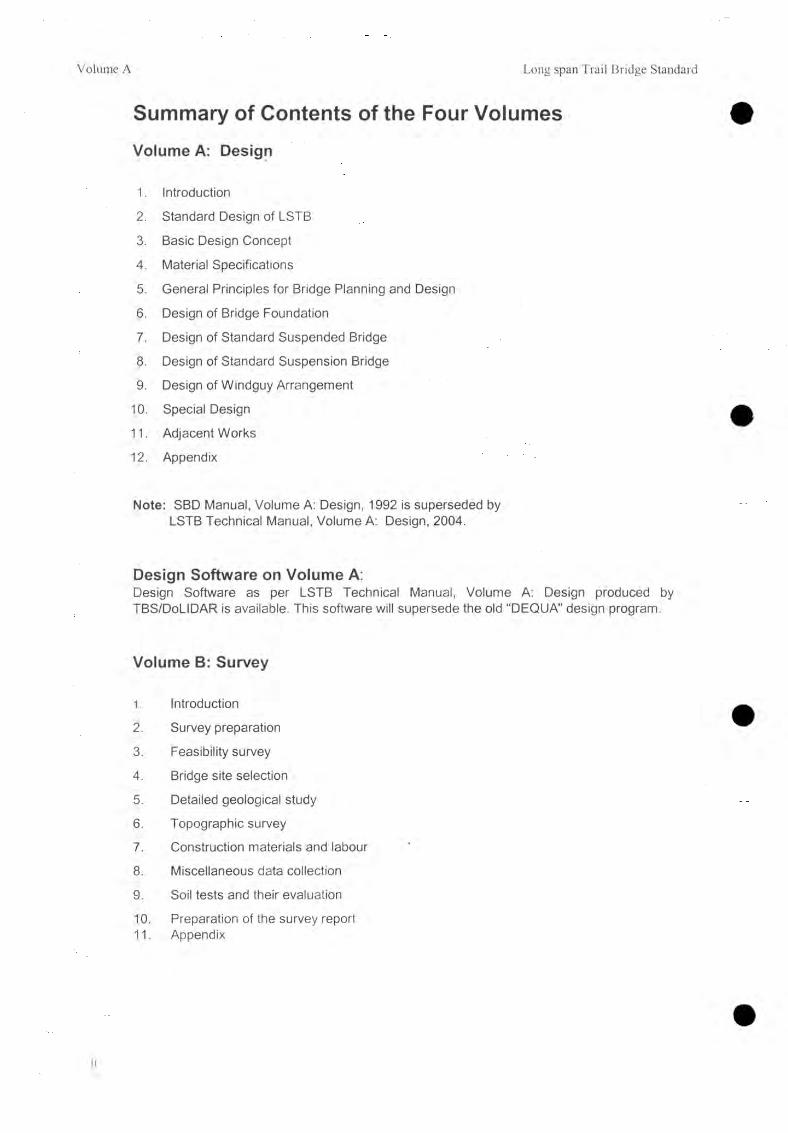
Summary of Contents of the Four VolumesVolume A: Design
1. Introduction
2. Standard Design of LSTB
3. Basic Design Concept
4. Material Specifications
5. General Principles for Bridge Planning and Design
6. Design of Bridge Foundation
7. Design of Standard Suspended Bridge
8. Design of Standard Suspension Bridge
9. Design of Windguy Arrangement
10. Special Design
11. Adjacent Works
12. Appendix
Note: SBD Manual, Volume A: Design, 1992 is superseded by LSTB Technical Manual, Volume A: Design, 2004.
Design Software on Volume A:Design Software as per LSTB Technical Manual, Volume A: Design produced by TBS/DoLIDAR is available. This software will supersede the old “DEQUA” design program.
Volume B: Survey
1. Introduction
2. Survey preparation
3. Feasibility survey
4. Bridge site selection
5. Detailed geological study
6. Topographic survey
7. Construction materials and labour
8. Miscellaneous data collection
9. Soil tests and their evaluation
10. Preparation of the survey report11. Appendix

Long span Trail Bridge Standard Volume A
Volume C: Standard Design Drawings
Part I and II
A. Standard working and assembly drawings
B. Standard structural drawings
C. Special design drawings
D. Design examplesTwo general arrangements (suspended bridge, suspension bridge) related to the design examples of VOLUME A: DESIGN.
Note: SBD Manual, Volume C: Standard Design Drawings, is superseded by LSTB Technical Manual, Volume C: Standard Design Drawings, 2004.
Volume D: Execution of Construction Works
1. Schedule of construction operations and sits, camp
2. Machines and Instruments
3. Setting out of the bridge
4. Excavation
5. Masonry
6. Form work
7. Reinforcement and steel parts
8. Concrete
9. Rendering and surface mortar
10. Rock anchors
11. Cables
12. Bridge erection
13. Stabilization of slopes
14. River bank protection
15. Drainage
16. Bridge access
17. Traits
18. Bridge maintenance
19. Inspection forms

Long Span Trail Bridge Standard Volume A
1. IntroductionHis Majesty’s Government of Nepal has elaborated the Nepal Trail Bridge Policy & Strategy (NTBPS). This Policy lays down the norms, standards, technologies, modalities and approaches amongst the trail bridge builders and other organizations engaged in, or supporting trail bridge building either directly or indirectly. The NTBPS promotes the decentralized process of bridge building in practical terms in accordance with the Local Self Governance Act (LSGA) 2055. The Trail Bridge Section (TBS), of the Department of Local Infrastructure Development and Agriculture Roads (DoLIDAR) within the Ministry of Local Development (MOLD) has been entrusted to enforce the NTBPS. TBS enforces the NTBPS by means of various Manuals. This Manual provides all technical details pertinent to Long Span Trail Bridges (LSTB), hence its corresponding name LSTB -Technical Manual, and supercedes what used to be known as the SBD-Standard design1.
In addition to the technical Manuals, TBS has also issued a Manual on LSTB-Consultants and Contractors which also forms an integral part of the NTBPS.
LSTB bridges have especially been developed for the Main Trails but can also be applied at strategic crossings provided that they comply with a set of predefined socio-economic criteria. The LSTB technology has especially proven to be suitable and cost effective for spans exceeding 120 meters. Technical details for bridges of a shorter span are provided in another Manual notably the SSTB2-Manual. The latter was developed under, what used to be known as the Bridge Building at Local Level Program sponsored by HNG/N, SDC and Helvetas. SSTB has proven to be more economic and more environmental friendly for spans less than 120 meters and allow substantial contribution from the local communities.
In summary, the technical Manuals are based on the following demarcation:Span <120m SSTB-ManualSpan >120m LSTB-Manual
This LSTB-Manual is valid for both types of cable-supported: the suspended- and the suspension bridge.
The LSTB-Manual covers four Volumes: “A” covering Design; “B” covering Survey; “C” covering Standard Design Drawings; and “D” covering Execution.
The cost of a SSTB standard bridge is about 60% or 50% of a LSTB standard bridge for the suspended and suspension type respectively. The main variant of total-cost results from the portering distance and its corresponding costs.
All Manuals reflect the vast experience gained in bridge building. Conservative engineering practice has been combined with empirical data collected over decades to result in the most carefully tuned design.
This LSTB Technical Manual is basically identical to what used to be known as the SBD Manual but has been adapted to match the above demarcation and some modification/improvement, inducing bridge builders to build SSTB bridges for short spans.
1 SBD stands for Suspension Bridge Division.2 SSTB stands for Short Span Trail Bridge
Chapter 1: Introduction 1

Long Span Trail Bridge Standard Volume A
2. Standard Design of LSTB
Table of Contents
2.1 General 32.1.1 Standard Design 32.1.2 Standard Drawings 32.1.3 Other Terms 4
2.2 Standard Suspended Bridge 52.2.1 Description 52.2.2 Layout and Sections 62.2.3 Standard Drawings 72.2.4 Completed Suspended Bridge 8
2.3 Standard Suspension Bridge 92.3.1 Description 92.3.2 Layout and Sections 102.3.3 Standard Drawings 132.3.4 Variation of Anchorage Foundation 132.3.5 Combined Walkway / Tower Foundation with Staircase 142.3.6 Completed Suspension Bridge 15
2.4 Windguy Arrangement 162.4.1 Description 162.4.2 Layout 162.4.3 Standard Drawings 17
2.5 Walkway Deck 182.5.1 Steel Deck 182.5.2 Wooden Deck 18
2.6 Special Design 192.6.1 Description 192.6.2 Special Suspended Bridge 192.6.3 Special Suspension Bridge 202.6.4 Special Windguy Arrangements 212.6.5 Steel Truss Bridge 23
Chapter 2: Standard Design of LSTB 2
Volume A Long Span Trail Bridge Standard
2.1 General
2.1.1 Standard Design
Nowadays almost all construction projects take advantage of standardization, e.g., standardized steel profiles, standardized cement quality, standardized bricks, etc. Standardization facilitates reduction in working load throughout the design and execution process, e.g., the use of standardized drawings reduces the working load and ensures the achievement of a set quality of drawings. Because of variable site conditions it is impossible to produce a 100% standardized bridge design. The degree of standardization chosen for the standard design of suspended and suspension bridges allows the design engineer to adjust the individual design to specific site conditions. Accessibility and the availability of Labor and materials as well as the geological, geotechnical, and hydrological conditions of the site are among the specific conditions that should be considered.
Steel parts as well as the towers for suspension bridges are 100% standardized. These parts may be chosen according to a number of parameters (e.g., bridge span, cable diameter, calculated forces, etc.) by using a specific set of tables, no further design work is necessary. The analysis of the cable structure has to be scrutinized by the design engineer, following a standardized procedure leading to the number and diameter of cables required as well as to the forces to be considered for foundation design. Foundations have to be designed according to the specific site conditions, although basic layout and min./max. dimensions for a number of foundation types are given in the manual. The specific site conditions are determined by following a standardized site investigation procedure (Volume B: Survey).
Standard design offers many possibilities, e.g., reduced design work and uniform quality of different projects, etc. Although some reduction in flexibility has to be accepted and although the standard design does not result in the most economic design for all the sites, the advantages should be assessed by looking at the number and quality of projects realized.
2.1.2 Standard Drawings
The planning, design, and structural analysis of the bridges are based upon the survey results. The execution of this work is described in the following chapters. Design work results in the General Arrangement, showing the bridge in plan and section.
All other designs and drawings required for manufacturing bridge components and for the execution of construction works have been prepared already and compiled into a set of standard design drawings (Volume C). For each particular bridge project they are arranged into a UNIT COMPONENT SYSTEM.
Chapter 2: Standard Design of LSTB

Long Span Trail Bridge Standard Volume A
There are two different groups of standard design drawing.
1. The standard design drawings necessary for the design, manufacture, and construction of the standard program for suspended and suspension bridges. This group contains a standardization (all possible loads, number of cables, dimensions) of all the components of the two standard bridge types.
2. The special design drawings are used for cases in which a deviation from the standard bridge type is necessary. Usually, this group contains design examples to be used as bases for the preparation of new designs according to the requirements of a particular project.
Within the two groups of drawings, there are three different drawing types.
1. Working and assembly drawings having a related structural drawing (e.g., anchorages)
2. Working and assembly drawings without related structural drawings (e.g., windties)
3. Structural drawings (e.g., foundations)
Working and assembly drawings contain all the information needed for manufacturing steelstructures, including steel-part lists with working drawings for each part, weights andsurfaces to be painted or galvanized, and welding details and assembly drawings.Assembly drawings are also for use during construction of the bridge.
Structural drawings contain necessary information for the execution of construction works.These drawings have open dimensions and levels which are determined according to therequirements of the particular bridge project.
For a complete list of standard drawings refer to the Appendix.
2.1.3 Other Terms
Anchorage Steel parts which anchor any tension member (cables, towers).
(Anchorage) Foundation Concrete structures (in which the anchorage steel parts are embedded) which transfer the load of the structure (anchorage) to the soil or rock on which it rests.
Gravity Foundation The media for transmitting the load applied to the structure by its own weight to the soil or rock on which it rests.
Deadman Foundation Predominately passive earth pressure has to be taken into consideration to achieve equilibrium with the load from the structure.
Chapter 2: Standard Design of LSTB 4
Volume A Long Span Trail Bridge Standard
2.2 Standard Suspended Bridge
2.2.1 Description
The standard suspended bridge is a modern version of the traditional chain bridge which is frequently seen in Nepal. The load bearing cables (main cables) are below the walkway system in suspended type bridge. Sagging walkway cables are suspended below their anchorages. A bridge with the main foundations on the same elevation is called a level bridge. The main foundations might not have the same elevation and the bridge is therefore called an inclined bridge.
The cables (steel wire ropes) are directly anchored to the main anchorage founucuion using only small pillars for handrail cable support.
For LSTB standard suspended bridges, i.e. a bridge with a span over 120 m, there are two types of cable anchoring systems. For span up to 210 m drum type anchor is used where the main cables (4 or 6 numbers) are anchored to the concrete drums by rounding around them and end part of the cable is clamped. The cable length is not adjustable after the drums are covered by the concrete. The anchor drum is inside the foundation structure. For greater spans over 210 m (8 to 12 main cables), the cables are secured with thimbles and bulldog grips to hinged anchors with adjustable turnbuckles. This type of anchor is known as open type anchor. The cable length in such anchor is adjustable as the turnbuckle is outside of the foundation block.
The handrail cables are always secured with thimbles and bulldog grips to adjustable anchorages. The main foundations are usually designed as gravity foundations on soil or on rock. Anchorage rods may be provided to stabilize the foundation on rock and might be necessary to stabilize the rock itself.
Both the handrail and the (lower) main cables are the (vertical) load-bearing elements connected throughout the bridge with hanger rods at distances of 1.20 m. The hanger rods are fixed at the top to the handrail cable and at the bottom to the cross-beams which are bolted to the main cables. The cross-beams support the walkway deck which is 1.00 m in width. For details of the deck systems refer to 2.5. Chain-link wiremesh netting fences the walkway. It is fixed at the top to the handrail cable and at the bottom to a fixation cable.
The wind-guy arrangement is required for LSTB standard suspended bridge as a stabilizing measure and to safe guard the bridge from wind load. For details refer to 2.6.
The suspended bridge is an economical design whenever the required freeboard can be achieved along with the geological site conditions allowing its construction.
5 Chapter 2: Standard Design of LSTB

Long Span Trail Bridge Standard Volume A
2.2.2 Layout and Sections
Inclined bridge with gravity anchorage foundation.
A) PlanLEFT BANK RIGHT BANK
main anchoroge foundation on soil
windguy cable anchorage foundation on soil
cros^-beam
cross-bracing
windguy cable (single or double) wtndties
windguy cable onchorage direct on rock
main anchorage foundation on rock
windguy cable anchorage foundation on rock
B) Side Elevation
C) Section of Walkway Support and Deck
Section of walkway support with steel walkway deck
handrail cable
hanger rod
wiremesh netting
stee l walkway deck
fixation cable
cross- beam
mam cables
Chapter 2: Standard Design of LSTB 6

Volume A Long Span Trail Bridge Standard
Section of walkway support with wooden planking (only optional and in general not recommended to use)
hand ra il cable
hanger rod
w irem esh netting
wooden planks ( lo n g itu d in a l)
wooden noiling s tr ip
f ix a t io n coble
c ro s s -b e a m
m ain cab les
2.2.3 Standard Drawings
A) Drum-type Anchorage Foundation
1 unit of 1 unit of 1 unit of 1 unit of
main foundationfor.....main cobleson s o il/ rock
S TR U C TU R A L DRAWINGS j
b ) Open-type Anchorage Foundation
t unit of 1 unit of 1 unit of 1 unit of
f o r .......m ain cab les
7 Chapter 2: Standard Design of LSTB

Long Span Trail Bridge Standard Volume A
2.2.4 Completed Suspended Bridge
For an example of a General Arrangement Drawing refer to the Appendix.
Chapter 2: Standard Design of LSTB 8

Volume A Long Span Trail Bridge Standard
2.3 Standard Suspension Bridge
2.3.1 Description
The standard suspension bridge can be distinguished by its towers and upwardly cambered walkway. The sagging, load-bearing main cables (steel wire ropes) are not under the walkway system. They are supported by the towers and secured with thimbles and bulldog grips (hinged) to adjustable cross-beams on the anchorage rods of the main foundations.
An inclined arrangement of this bridge type (walkway / tower foundation on right and left bank at different elevations) is not recommended. This type of bridge will have non-symmetric geometry and complex stability analysis. Further, there is no practical experience of the behavior of such type of the bridge.
The main foundations might be designed as gravity foundations on soil or rock, as deadman anchorage foundations on soil, or as tunnel anchorage foundations on rock. Anchorage rods might be necessary to stabilize the rock.
The towers are hinged at the base and the main cables are clamped at the top. They are connected to the walkway / tower foundation with anchorage rods to take up possible tensile forces. For long-span bridges, side stay cables, fixed on top of the tower, are necessary to reduce lateral deflections. Towers are constructed with two tower legs connected by the main bracing for lateral stability. Tower legs are constructed with four mild steel angles and tower leg bracing of angles or rods.
The main cables are the only (vertical) load-bearing cables. The suspension of the walkway is brought about-by the means of suspender rods which are unequal in length but adjustable to a fine degree. The suspenders are fixed at distances of 1.20 m and are joined at the top to the main cables and to the bottom giving support to the cross-beams. The span length must be chosen to provide intervals of 2.40 m because of the different lengths of the suspenders, up to 280m. Two spanning cables are attached underneath the cross-beams and anchored to the walkway / tower foundation.
The walkway steel deck supported by the cross-beams is 1.20 m in width. For details of the deck systems refer to 2.5. The walkway is cambered to allow sufficient pre-tension between main cables and spanning cables thus increasing the stability of the bridge. Stabilizing cables, for bridges with spans above 160 m, and also diagonal stabilizers, are provided to damp longitudinal oscillations. Chain-link wire mesh netting fences the walkway and is fixed at the top to a handrail cable and at the bottom to a fixation cable.
The wind-guy arrangement is required for LSTB standard suspension bridge as a stabilizing measure and to safe guard the bridge from wind load. For details refer to 2.6.
9 Chapter 2: Standard Design of LSTB

Long Span Trail Bridge Standard Volume A
2.3.2 Layout and Sections
Bridge with gravity foundations
A) Plan
------------sidestoy cobles ( i f tower height > 2 5 . 2 3 m)
P -------sidestoy coble anchorage foundation on rock
— main cables
— windguy coble clamp (if double windguy cable)
-------- sidestoy cable anchorage combinedwith windguy coble anchorage foundation on r o c k
walkway / tower main cable foundation anchorage
foundation on soil
windguy cable anchorage fo u n d a tion on soil
B) Side Elevation
span
walkway / tower- foundation (without foot)
backstay(main cables)
stabilizing cables ( i f span > 8 4. 40 m)
diagonal stabilizers ------------------------( i f span > 444.40m)
— handrail cables
------- spanning cablesfixation cables
---------windguy cables
— suspenders
Chapter 2: Standard Design of LSTB 10

Volume A Long Span Trail Bridge Standard
C) Section of Walkway Support and Deck
Section of walkway support with steel walkway deck
main cables
cable clamp
suspender (hanger)
handrail cable
wiremesh netting
steel walkway deck
turnbuckle
fixation cable
cross - beam
spanning cable
Section of walkway support with wooden planking (only optional and in general not recommended to use)
hondroii cable
wiremesh netting
wooden planks
wooden noiling strip
turnbuckle
fixation coble
cross-beam
spanning coble
11 Chapter 2: Standard Design of LSTB
Long Span Trail Bridge Standard Volume A
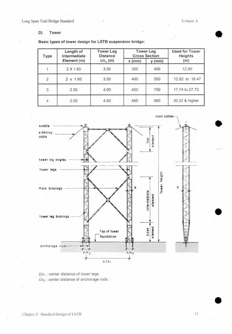
D) Tower
Basic types of tower design for LSTB suspension bridge:
TypeLength of
Intermediate Element (m)
Tower Leg Distance c/c1 (m)
Tower Leg Cross Section
Used for Tower Heights
(m)x (mm) y (mm)
1 2 X 1.85 3.50 300 400 12.90
2 2 x 1.85 3.50 400 550 12.92 to 18.47
3 2.50 4.00 450 750 17.74 to 27.73
4 2.50 4.00 450 900 30.22 & higher
C/c-] : center distance of tower legs. c/c2 : center distance of anchorage rods.
Chapter 2: Standard Design of LSTB 12

Volume A Long Span Trail Bridge Standard
2.3.3 Standard Drawings
assembly of tower, height -
J WORKINGWORKING AND ASSEMBLY DRAWINGS
1 unit of tower base element
1 unit of tower intermediate ele-
t unit of tower top element
t unit of tower saddle for
cobles
1 unit ofdiogonal stabilizer f o r ......main cables
mam cable anchoragefoundation for.......main cables
walkway / tower foundationc/c,=
S TRUCTURAL ORAWINGS
2.3.4 Variation of Anchorage Foundation
A) Tunnel Anchorage Foundation
13 Chapter 2: Standard Design of LSTB

Long Span Trail Bridge Standard Volume A
B) Deadman Anchorage Foundation
1) Use standard working and assembly drawing, "Main Cable Anchorage", with extended anchorage length and structural drawing, Main Cable Deadman Foundation". For design example see Main cable Deadman Anchorage design drawing No. 49/2.
2.3.5 Combined W alkway / Tower Foundation with Staircase
Two types of staircase are standardized, both with a range for H between 1.50 m and 5.50m :
- in good soil conditions (rock, gravel, sandy gravel etc.)
- for medium to unfavorable soil conditions (silt, clay etc.)
Chapter 2: Standard Design of LSTB 14

Volume A Long Span Trail Bridge Standard
2.3.6 Completed Suspension Bridge
For an example of a General Arrangement Drawing refer to the appendix.
15 Chapter 2: Standard Design of LSTB

Long Span Trail Bridge Standard Volume A
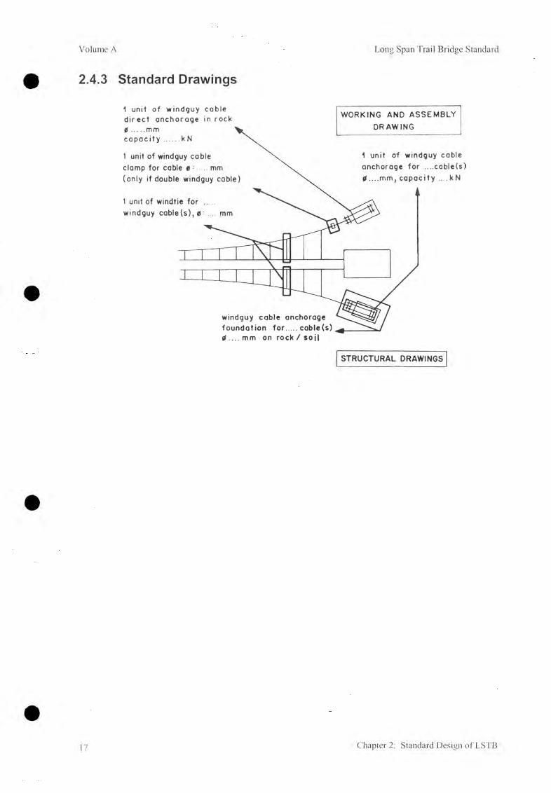
2.4 Windguy Arrangement2.4.1 Description
A windguy system is required for bridges with span of more than 120m.
The walkways of LSTB standard suspended and suspension bridges are laterally supported by the windtie cables which are fixed to the parabolically aligned windguy cables. The windties are fixed to the cross-beams at intervals of 4.80 m. for suspension bridges and 6.00 m. for suspended bridges (with less exposed area).
2.4.2 Layout
Parabolic windguy arrangement
sidestoy cables ( i f tower height > 2 5 . 23 m)
s idestay coble anchorage foundation
— main cables
-w indguy coble clamp (if double windguy cable)
walkway/tower main cable foundation anchorage
foundation
windguy cable onchorage foundation
sidestay coble anchorage combined with windguy coble anchorage foundation
Chapter 2: Standard Design of LSTB 16
Volume A Long Span Trail Bridge Standard
2.4.3 Standard Drawings
STRUCTURAL DRAWINGS
17 Chapter 2: Standard Design of LSTB

Long Span Trail Bridge Standard Volume A
2.5 Walkway DeckThere are two options for walkway deck, i.e., steel deck and wooden deck. Wood are becoming more and more scars, expensive and difficult to find the good quality. Deforestation is the common causes of environmental degradation. Further, wooden planks needs to be frequently replaced.
Therefore, a galvanized steel deck, which will be almost maintenance free, reducing the burden of routine maintenance, is recommended.
2.5.1 Steel Deck
One unit of steel walkway deck of a 1.20 m. bridge span consists of two elements (approx.0.50 m. for a suspended bridge and approx. 0.60 m. for a suspension bridge) which are directly bolted to the cross-beams. The elements are constructed of steel angles arranged longitudinally with a small gap in between and reinforcement bars arranged crosswise welded on top at a distance of about 0.20 m.
2.5.2 Wooden Deck(Only optional and in general not recommended to use)
Longitudinal planks (2.39/1,98/0.05m) are nailed in a staggered arrangement on to wooden nailing strips which are bolted to the cross beams.
Note: In case longitudinal planks are not available, the planks may be arranged crosswise and nailed on to longitudinal stringers which are bolted to the cross beams.
Chapter 2: Standard Design of LSTB 18

Volume A Long Span Trail Bridge Standard
2.6 Special Design2.6.1 Description
When the standard design would obviously result in an unfavorable solution, the design engineer is free to follow a special design. Some recommendations for special designs are given in the manual. Other special designs may be developed according to the specific site conditions encountered. Special designs always require the careful attention of the design engineer and, in some cases, additional control activities are even needed during execution in the workshop and on site. The design engineer has to decide for each specific case if an independent check by a consulting engineer is required or not. Special designs entail a higher degree of responsibility on the part of the project team, especially the design engineer. Special designs are strongly recommended wherever a significant reduction in costs can be achieved.
If some of the standard drawings are used in a special design, the structural analysis has to be checked carefully.
Note: Any bridge in which the anchorage (Windguy) is combined with another anchorage foundation has to be treated as a special design as more load combination might occur.
2.6.2 Special Suspended Bridge
A ) Combined Main Foundation with Staircase
1) Use the standard design "Main Cable Anchorage".For a design example see special design drawing No. 60/4.
19 Chapter 2: Standard Design of LSTB

Long Span Trail Bridge Standard Volume A
2.6.3 Special Suspension BridgeA) With One Tower Only
1)
2 )
3)
Spacing clamp for main cable.For a design example see special design drawing No. 28.Use the modified standard design "Walkway / Tower Anchorage". For a design example see special design drawing No. 91/3.Use the modified standard design, "Main Cable Anchorage", drum type. For a design example see special design drawing No. 60/3.
B) Without TowerPlon
main coble anchorage (drum type) foundatit
main cobles
— WOlkway onchoroge
spacing clamp
j __!.. » ...1 J__L-L--LX ] M
inclined suspenders
in suitable topography
1) Spacing clamp for main cable.For a design example see special design drawing No. 28.
2) Use the modified standard design "Walkway / Tower Anchorage". For a design example see special design drawing No. 91/3.
3) Use the modified standard design "Cable Drum Anchorage".For a design example see special design drawing No. 60/3.
4) Suspenders, use the standard design drawing "Suspenders". Manual calculation of suspender lengths may be required.
Chapter 2: Standard Design of LSTB 20

Volume A Long Span Trail Bridge Standard
C) With Loaded Side Span
Bridge type not recommended !
Refer 10.2.3 for details.
D) Double Span Bridge
Bridge type not recommended !
Refer 10.2.3 for details.
2.6.4 Special W indguy Arrangem ents
Wherever the site location does not allow for the provision of a windguy cable foundation on one river bank, it is possible to combine the windguy cable anchorage with the main foundation of the suspended bridge, the walkway / tower foundation, or the main cable foundation of the suspension bridge respectively. The anchorage forces have then to be included in the statical analysis of the respective foundation.
Note: The full wind load has to be considered for each side, because, depending upon the wind direction, only one side of the windguy arrangement will be activated, either the up- or the downstream part.
21 Chapter 2: Standard Design of LSTB

Long Span Trail Bridge Standard Volume A
A) Suspended Bridge
Windguy cable anchorage combined with main foundation
windguy cable
1) Use the standard design, *Main Anchorage Foundation", with integrated steel parts from the standard working and assembly drawing "Windguy Cable Anchorage Foundation".
B) Suspension Bridge
Windguy cable anchorage combined with walkway / tower foundation.
1) Use the standard design, 'Walkway / Tower Foundation", with integrated steel parts from the standard working and assembly drawing "Windguy Cable Anchorage".
Chapter 2: Standard Design of LSTB 22

Volume A Long Span Trail Bridge Standard
Windguy cable anchorage combined with main foundation and cable support (stay struts) at walkway / tower foundation.
1) Windguy stay struts.See special design drawings Nos. 175, 175/1 (Windguy cable 0 26 mm) 176, 176/1 (0 32 mm), 177,177/1 (0 36 mm).
2) Use the modified standard design "Main Cable Anchorage Foundation" and the working and assembly drawing, "Windguy Cable Anchorage Foundation", for the appropriate cable diameter. For a design example for structural design see special design drawing No. 49/3.
2.6.5 Steel Truss Bridge
For very short spans ( ^ 32 m) and favorable bank conditions a steel truss bridge can be designed.
23 Chapter 2: Standard Design of LSTB

Long Span Trail Bridge Standard Volume A
3. Basic Design Concept
Table of Contents
3.1 Loadings3.1.1 Live Load3.1.2 Dead Load3.1.3 Wind Load3.1.4 Snow Load3.1.5 Temperature Effects3.1.6 Seismic Load
Design and Statical Analysis, Safety Factors3.2.1 General3.2.2 Cable Structure3.2.3 Steel Structure (Tower and Steel Parts)3.2.4 Walkway Structure3.2.5 Foundations
25252626262627
282828282930
Chapter 3: Basic Design Concept 24

Volume A Long Span Trail Bridge Standard
3.1 LoadingsFor designing a bridge structure, a number of different loadings, such as live load, dead load, wind load, snow load, temperature effects, and seismic loads, etc, may be relevant. Suspended and suspension bridges are typical examples of cable-supported structures. These structures show statically very good behavior, although their analysis is quite complicated because of the predominant influence of the deformation of the soft cable structure. The trail suspended and suspension bridges have low stiffness in all directions,i.e., stabilizing gauges are required to guarantee serviceability, durability, and, to a minor degree, the longtime safety of the structure. Under live and Wind load, cable-supported systems exhibit dynamic behavior. Thus stabilizing measures (windguy cables, stabilizing cables, etc) are needed to reduce vibrations in the structure as well as to carry loadings in a lateral direction (e.g., wind).
The standardized procedure, as described in Chapter 2, forms an integral part of the basic design concept and includes some simplifications in comparison to normal designs. Besides dead and live loads, only wind loads perpendicular to the bridge axis need to be considered in the design. Vertical wind loads, snow loads, seismic loads, and temperature effects may be omitted. This procedure for the standard design has been checked and is considered to be adequate and safe.
3.1.1 Live LoadThe live load for a trail suspended and suspension bridge in Nepal was determined by undertaking a thorough investigation of a number of international loading codes.
The agreement that LSTB suspended and suspension bridges, designed and executed according to this standard design, be constructed along the main trails or on strategic crossings throughout Nepal is the basis for this decision. These bridges have to fulfill high requirements with regard to safety, durability, and serviceability standards, and this leads to the determination of a live load within the range of international standards. Reductions in the case of longer span bridges consider the lower possibility of extreme overloading for long span compared to short span bridges. Because of the impossibility of assessing the probability of a crowd loading for a specific site, a difference between a design with crowd load or without crowd load, as allowed, e.g., by the Indian Standard, is omitted. Extreme loadings for short span bridges, as foreseen, e.g., by British or Canadian Standards, are considered irrelevant for flexible structures such as suspended and suspension bridges.
For span, t < 50m, live load, p = 4 kN/m2
„ 50 2For span, l > 50, live load , p - 3 + — kN/m
Figure 3.1: Live load, p, for suspended and suspension bridges (both SSTB and LSTB)
25 Chapter 3: Basic Design Concept

Long Span Trail Bridge Standard Volume A
3.1.2 Dead Load
The dead load includes the weight of all permanent components of the bridge structure and is calculated according to a procedure that is in practice worldwide. Care must be taken that the mass (kg, ton) is properly converted into the force unit (N, kN) according to the "International System of Units".
For LSTB standard suspended type bridge, dead load without weight of Handrail and Walkway (main) cables is around 76.6 kg per meter span (inclusive of wind-guy system).
For LSTB standard suspension type bridge, dead load without weight of Main / Walkway (spanning) cables and excluding pretension in spanning cables is around 111.6 kg per meter span (inclusive of wind-guy system). The pretension in spanning cable is dependent of camber and pulling tension in walkway (spanning) cables.
3.1.3 Wind Load
High wind speeds and gorge effects are often encountered in the valleys of Nepal and bridges of different heights above ground level are common. The design wind load, given as a uniformly acting linear load or uniformly distributed load respectively, considers these factors. Although wind loading on to suspended and suspension bridges may have a horizontal as well as a vertical load component the effect of the latter is considered irrelevant to the design and is, therefore, neglected in the standard design.
The design wind load is taken 0.50 kN per meter span, corresponding to 160 km/hr wind speed. This wind speed of 160 km/hr exerts 1.3 kN/m2 wind pressure. The blunt area of the walkway system is calculated 0.3 m2 per meter span and with a coefficient of 1.3, the wind stagnated on the area gives 0.5 kN/m lateral load to the bridge (refer to Report on Windguy Arrangement for Suspended and Suspension Standard Bridges,Dr. Heinrich Schnetzer, WGG Schnetzer Puskas Ingenieure AG, Switzerland, 2002).
3.1.4 Snow Load
Snow doesn't appear in large quantities in the mid-hills of Nepal, where most of the bridges are located. Because of the high live load and the low probability of a full live load occurring on a bridge loaded by snow, it is taken for granted that the snow load is already covered satisfactorily by the live load '. However, for bridges located at an altitude above about 3500m (outside Nepal it may even be below), investigations on snow loads must be carried out during the survey.
3.1.5 Tem perature Effects
A difference in temperature causes a change in the cable length. Changes in cable length cause changes in the sag and therefore of cable forces also. This effect is omitted in the standard design because it is not considered to be relevant.
Chapter 3: Basic Design Concept 26

Volume A Long Span Trail Bridge Standard
3.1.6 Seismic Load
Earthquakes are common in the seismically active zone of the Himalayan Mountains. The effect of earthquakes of the kind of magnitude occurring in Nepal on suspended and suspension bridge structures was checked for the revision. Because of the high live load and the low probability of a full live load occurring simultaneously with an earthquake, it is taken for granted that the seismic load is already covered satisfactorily by the live load. Therefore a separate loading combination with seismic loads need not be taken into consideration. Nevertheless, it has to be emphasized that the stability of the slopes may be affected by seismic effects and subsequently cause damage to the bridge structure.
27 Chapter 3: Basic Design Concept

Long Span Trail Bridge Standard Volume A
3.2
3.2.1
3.2.2
3.2.3
Chapter '
Design and Statical Analysis, Safety Factors
General
The procedure for statical analysis follows the principles of the traditional system with admissible stresses, and these are compared with the calculated stresses in the structure caused by specified loadings. These loadings represent the effective loadings.
The introduction of the modern system which analyses the structure on the failure level, considering loads multiplied with a loading factor, would result in a completely new procedure. It was not considered to be of sufficient advantage for the time being to justify this change in the revised version, Volume A.
As site conditions (e.g., span, subsoil conditions) for suspended and suspension bridges vary from site to site, individual designs are necessary for the foundations and the cable structure. The procedure to be followed is standardized. Steel parts, towers, and the walkway structure do not depend on conditions that vary from site to site. Therefore, these elements are standardized and, depending upon the calculated forces, the elements are chosen from tables given within the manual; no further design work is required.
Cable Structure
Main cables, spanning cables, and windguy cables are supposed to demonstrate parabolicM
geometry. Thus the cable force Is calculated with the simple formula H = -jj-
q • fi-— > the bending moment" M = g— ." divided by the sag "b" of the cable,
(b = f, for suspension bridges).
To prevent the cables breaking, a minimum factor of safety (linear approach) is required of ys = 3.0 for all cables, regardless of the type of terminal.
Steel Structure (Tower and Steel Parts)
Six independent loading cases have been considered in designing all towers. The designshows a minimum safety factor of ys = 1.6 against the worst case with respect to buckling and yielding of the most critical element of each tower. All other steel parts meet the same requirements. The tower design is based on the Swiss Steel-Code, SIA 161 (1979).
>: Basic Design Concept 28

Volume A Long Span Trail Bridge Standard
3.2.4 W alkway Structure
Steel parts : The walkway structure (walkway deck, cross-beams) Is designed to meetthe safety requirements given in paragraph 3.2.3.
The dominant local loadings are shown in figures 3.2 and 3.3 below with the concentrated loadP = 1.5 kN on an area of 0.01 m2 at the most unfavorable position on any member.
Figure 32: Two porters passing each other (P = 1.5 kN)
hanger/ suspender
walkway deck
cross-beam
Figure 3.3: Porters standing in a row (P = 1.5 kN)
P P P P
29 Chapter 3: Basic Design Concept

Long Span Trail Bridge Standard Volume A
3.2.5 Foundations
Foundation design follows the traditional procedure of soil mechanics. Locally relevant soil parameters are determined by a survey campaign and following soil testing in the laboratory. For all foundations, the safety factor has to be shown against the well-known failure modes such as sliding (Fsl ^ 1 -5), ground shear failure (FBc ^ 2.0), Bearing Capacityof soil/Rock (auit < aperm). and toppling (F j S 1.5). To meet serviceability requirements the eccentricity of the resultant force in the foundation base is restricted. Additionally the stability of slopes affected by the bridge foundation should be checked. The relevant safety factor should be chosen according to the method used for slope stability calculation ( F S i0Pe
;> 1.3 to 1.5, depending upon the method used for analysis).
To improve the sliding safety of the main foundation of suspended bridges on rock, rock anchorage may be used. In such cases a reduced safety factor against sliding ( F s l ^ 1.3) and toppling (F j ^ 1.2), neglecting these rock anchorages, should be shown in addition to the normal procedure.
Chapter 3: Basic Design Concept 30

Long Span Trail Bridge Standard Volume A
4. M aterial Specifications
Table of Contents
4.1 General 324.1.1 Standards 324.1.2 International System of Units 32
4.2 Cable Structures 334.2.1 Steel Wire Ropes 334.2.2 Cable Terminals 344.2.3 Cable Connections 36
4.3 Steel Structures 374.3.1 Structural Steel 374.3.2 Fasteners 384.3.3 Reinforcement Steel 384.3.4 Increase of Permissible Stresses 394.3.5 Rust Prevention 39
4.4 Civil Structures 404.4.1 Concrete 404.4.2 Masonry 414.4.3 Gabion 424.4.4 Timber
4.5 Unit Weight of Construction Material 43
Chapter 4: Material Specifications 31

Volume A Long Span Trail Bridge Standard
4.1 General4.1.1 Standards
The material specifications and permissible stresses for construction materials used for standard trail bridges are based on the latest Indian Standards (IS) available. Where IS were not available, other standards, such as DIN (German) Standards, British Standards, or SIA (Swiss) Standards, were considered.
4.1.2 International System of Units
The International System of Units (SI Units) has been introduced in this revised version according to IS 10005 - 1985.
Quantity SI Unit Multiples
Angle1’ - deg (degree, 360°)- grade (or gon 4009)
degree, minutes, seconds decimals
Length m (meter) (cm), mm
Area m2 (cm2), mm2
Volume m3
Mass kg (kilogram) t (tonne)
Force N (Newton) kN (kilo Newton)
Moment of Force Nm kNm
Note: 1) The angle mode for the design analysis has been chosen to the degree unit (360°). Whereas for the survey, and the inclination of anchorage rods, it depends on the instruments used.
Table 4.1.1: Selection of Common SI Units
Conversion of mass into force:
Force is the effect of gravitation/
g = 9 . S I
'S
mForce = 1 kg • g = 1 kg ■ 9.81 — = 9.81
kg ■ m
on mass, therefore,
9.81 N « 10 N.s ' s '
For practical use, I kg is considered to be equal to 10 N (1 tone = 10000 N = 10 kN).
32 Chapter 4: Material Specifications

Long Span Trail Bridge Standard Volume A
4.2 Cable Structures4.2.1 Steel W ire Ropes
A) Specifications
Steel wire ropes should comply with all the requirements for:IS 1835-1977 Steel Wire for RopesIS 6594 - 1977 Technical Supply Conditions for Wire Ropes and Strands IS 9282- 1979 Specification for Wire Ropes and Strands for Suspension Bridges1 IS 9182 - 1979 Specification for Lubrications for Wire Strands and Ropes
B) Rope Particulars
Nominal diameters: 26, 32, 36, 40 mm- Construction:- Lay:- Core:- Tensile strength of wire:- Preforming:- Coating:- Impregnation:- Elongation:
Nominal diameter: 13 mm- Construction:- Lay:- Core:- Tensile strength of wire:- Preforming:- Coating:- Impregnation:
7x19(12/6/1)RHO, Right Hand Ordinary lay WSC, Wire Strand Core 1570 N/mm2 PreformedGalvanized “A” HeavyNon-drying and non-bituminous typePre-stretched2
7x7(6/1)RHOWSC, Wire Strand Core1570 N/mm2NoneGalvanized "A” Heavy Non-drying and non-bituminous type
C) Compiled Data
NominalDiameter
(mm)
Approximatemass(kg/m)
ApproximateLoad
(kN/m)
MetallicArea
(mm2)
Minimum Breaking Load
(kN)
PermissibleLoad(kN)
13 0.64 0.0064 73 103 34
26 2.51 0.0251 292 386 129
32 3.80 0.0380 442 585 195
36 4.81 0.0481 560 740 247
40 5.940.0594
691 914 305
Mean Value of Modulus of Elastic E = 110'000 N/mm2 =110 kN/mm2Table 4.2.1: Compiled Data of Steel Wire Ropes and Modulus of Elasticity(including Safety Factor ys = 3.0 for all cables and cable ending terminals)
New IS 9282 - 2000 has reduced the breaking load. Nevertheless, for trail bridges, the IS 9282 - 1979 shall be effective.2 Pre-stretching should be done by cyclic loading of the rope to 5% to 40% of the minimum breaking load in sequence of 5% to 10%, 5% to 20% and 5% to 40% loading till elongation stabilizes.
Chapter 4: Material Specifications 33

Volume A Long Span Trail Bridge Standard
4.2.2 Cable TerminalsA) Terminals with Drums in Concrete
Cables may be anchored directly into the foundations with the help of bollards (drums made out of steel) and secured with cable clamps. The cables should be wound 3 times around the drum in order to reduce the tensile force to be secured. The minimum diameter of the drums should be 0.95 m.
The friction factor between the cable and steel is taken to be jLt =0.1.
B) Terminals with Sockets
Sockets should be manufactured from steel conforming to IS 226-1975, specifications forStructural Steel (Standard Quality) with a tensile strength of Gu = 420 to 540 N/mm2, normalized after the completion of machining operations and hot-dip galvanized.
Socketing should be made with pure zinc according to IS 3937-1974 (Part 1), Recommendations for Socketing of Wire Ropes.
Sockets can be used as an alternative to thimbles and bulldog grips for all cable anchorages except for those having diameters of 13 mm.
At present socketing is not used in Nepal.
Nom. Diameter of Rope (mm)
ds(mm)
/(mm)
L(mm)
Di(mm)
d2(mm)
r(mm)
26 30 24 105 63 82 6.032 37 30 130 78 102 7.536 42 34 148 88 115 8.540 46 37 162 97 127 9.0
Table 4.2.2: Dimensions for Sockets
34 Chapter 4: Material Specifications

Long Span Trail Bridge Standard Volume A
C) Terminals with Thimble and Bulldog Grips
Bulldog grips should conform to IS 2361-1970, Specifications for Bulldog Grips. The bridges must be drop-forged and suitably scored to grip a round strand rope of right-hand lay having six strands. Bridges, U-bolts, and nuts should be hot-dip galvanized with minimum zinc coating of 40 //m.
Nom Diameter of Rope (mm)
A(mm)
B(mm)
C(mm)
D(mm)
E(mm)
F(mm)
G(mm)
H(mm)
I(mm)
Approximate Weight (kg)
13 M 12 64 27 32 15 51 12 28 22 0.2826 M 20 118 51 57 31 91 20 46 36 1.1032 M 20 124 54 59 34 94 20 46 36 1.3036 M 22 142 63 67 41 107 22 51 40 1.8540 M 25 157 69 75 44 119 25 58 45 2.40
Table 4.2.3: Dimensions and Weights for Bulldog Grips.
Bulldog grips, when properly applied, afford a simple and effective mechanical means of securing the ends of wire ropes, but have to be inspected after some loadings.
Thimbles are of open type, conforming to IS 2315 - 1978, Specifications for Thimbles for Wire Ropes. They must be forged and hot-dip galvanized with minimum zinc coating of 40 /ym.
Nom. Diameter of Rope (mm)
A(mm)
c(mm)
D(mm)
F(mm)
G(mm)
K(mm)
r(mm)
R(mm)
Approximate Weight (kg)
P(mm)
13 (14) 41 19 68 15 9 12 7.5 9.5 0.12 3826 (29) 82 39 135 31 17 23 15.0 19.5 0.75 7932 (32) 92 43 152 34 19 26 17.0 21.5 1.85 8936 (38) 110 52 185 41 23 32 20.5 26.0 2.75 10740 (41) 124 47 208 44 26 36 23.0 28.5 3.20 121
Table 4.2.4: Dimensions and Weights for Thimbles (Nominal size of thimbles in b rackets)
Thimbles are necessary to give lateral support to the strands of the cable at the bend, and the pin must support the thimble.P ^ A - 3mm
Chapter 4: Material Specifications 35

Volume A Long Span Trail Bridge Standard
Method and Specifications for Applying Bulldog Grips to Wire Ropes
Nominal Diameter of Rope (mm)
Required Number, n, of Bulldog Grips
Gap"G" (mm)
Overlapping Length "L" (mm)
13 3 80 55026 5 155 125032 6 190 170036 7 215 210040 8 240 2550
Table 4.2.5: Terminals: Number of Bulldog Grips, Gap, Overlapping Length
4.2.3 Cable Connections
The bridge of the grip must be fitted on to the working part of the rope and the U-bolt on to the rope tail. The first grip must be fitted as close as possible to the thimble. Grips should be spaced at a distance of approximately six times the rope diameter. The cable end should be protected from fraying with binding wire and, if the cable is too long, it should be fixed to the working part of the cable.
Cable connections may be required because of a change in design or during erection of the bridge. If possible, the connection should be made with the same cable diameter or with the cable diameter that is next in sequence.
A) Cables of Different DiametersCable connections of different diameters (or equal) must be made with the correct cable terminals (refer to 4.2.2 C) and a double pin intersection.
B) Cables of Equal DiameterNominal Diameter of
Rope (mm)Required Number, n,
of Bulldog GripsGap "G (mm)
Overlapping Length "L" (mm)
13 6 80 70026 10 155 170032 12 190 240036 14 215 310040 16 240 3900
Table 4.2.6: Cable Connections: Number of Bulldog Grips, Gap, Overlapping Length
L
C G
) • G ♦ 3 0 0
i G L G L G |_150j_mm
n/2I I "
imin.f
= = 5 ^ --------------- —
n /2
Connections of cables equal in diameter can be made (refer to 4.2.2 C) without thimbles but with twice the number of bulldog grips.
36 Chapter 4: Material Specifications

Long Span Trail Bridge Standard Volume A
4.34.3.1
Steel StructuresStructural SteelA) SpecificationsStructural steel should comply with all the requirements for:
IS 226 -1975 Structural SteelIS 800 -1984 General Construction in Steel
The tower design is based on the Swiss Standard SIA 161 (1979) for Steel Structures.
B ) Steel GradeStandard quality FE 410
C) Compiled Data
Plate thickness (mm) t á 20 20 < tO á 40 t > 40
Stress Case Bars (mm) 0 ^ 20 0 > 20
Permissible Tensile Stress: aa» = 0.6 fy (N/mm2) 150 144 138Permissible Compressive Stress:dac in (N/mm2) for slenderness A, = 0 150 144 138
50 132 127 123100 80 79 78150 45 45 45200 28 28 27250 18 18 18
Permissible Bending Stress in Tension: obt = 0.66 fy (N/mm2) 165 158 152
Permissible Bending Stress in Compression: abc in (N/mm2) (abc ^ 0.66 fy);Elastic Critical Stress in Bending: Fcb = oo 165 158 152
1000 N/mm2 150 145 139500 131 127 123300 110 107 104200 89 88 86100 55 55 5420 13 13 13
Permissible Average Shear Stress: xav = 0.4 fy (N/mm2) 100 96 92
Maximum Permissible Equivalent Stress: Op = 0.75 fy (N/mm2) 188 180 173
Maximum Permissible Equivalent Stress:a e = 0.9 fv (N/mm2) 225 216 207Modulus of Elasticity: E = 200*000 N/mm2Unit Weight: Y = 7850 kg/m
Table 4.3. 1: Permissible Stress in Structural Steel
Chapter 4: Material Specifications 37

Volume A Long Span Trail Bridge Standard
D) Cold-formed Steel
Cold-formed steel should comply with all the requirements for:
IS 811 -1987 Cold-formed Light Gauge Structural Steel Sections
IS 808-1989 Dimensions for Hot-rolled Steel Beams, Columns, Channels, andAngle Sections
4.3.2 Fasteners
A) Specifications
Bolts, nuts, and washers should comply with all the requirements for:
IS 1363 - 1984 (Part 1) Hexagonal Head Bolts and Nuts
IS 1367 - 1983 Threaded Fasteners
B) Grade
Grade C, property Class 4.6
C) Compiled DataStress Case Permissible Stress (N/mm2)
Stress in Axial Tension on Net Area (Jtf 80Stress in Shear on Gross Area: xVf 80Stress in Bearing on Gross Area: a Df 250Combined Tensile and Shear Stress / \
T v f cal Q t f cal
-------------- + ------------------ £ 1 . 4^ T v t ( J t f j
Table 4.3.2: Maximum Permissible Stress in Bolts for Class 4.6
4.3.3 Reinforcem ent Steel
A) SpecificationsReinforcement steel should comply with all the requirements for:
IS 1786 - 1986 High Strength Deformed Steel Bars for Concrete Reinforcement
IS 456 -1978 Plain and Reinforced Concrete
B) Steel GradeFe 415, High Yield Strength Deformed Bars
38 Chapter 4: Material Specifications

Long Span Trail Bridge Standard Volume A
C) Compiled Data
Stress Case Permissible Stress for Fe 415 (N/mm2)Tension Stress in Steel: CTst 230Compression Stress in Steel CTsc 190
Permissible Bond Stress for Anchorage in Cement Mortar I : 1 and 0.6concrete > 1 : 2 : 4 crSB
Modulus of Elasticity: E = 210'OOO (N/mm2)Unit Weight: y = 7850 (kg/m3)
Table 4.3.3: Permissible Stress in Steel Reinforcement
4.3.4 Increase of Permissible StressesFor occasional loadings combined with dead, live, and wind loads, the permissible stresses can be increased as follows:
Load Material Increase of Stress
Dead load, live load, Structural Steel 33%wind load and temperature, Bolts and Tension Rods 25%or Reinforcement Steel 33%wind load and seismic loadErection Structural Steel 25%(Secondary Effects) Bolts and Tension Rods 25%
Table 4.3.4: Increase of Permissible Stress
4.3.5 Rust PreventionTo prevent rusting in steel structures they should be hot-dip galvanized or painted (painting is optional only but not recommended), and should comply with all the requirements for:
IS 8629 - 1977 Protection of Iron and Steel Structures from Atmospheric Corrosion
IS 2629 - 1966 Recommended Practice for Hot-Dip Galvanizing of Iron and Steel
IS 4759 - 1984 Specifications for Hot-Dip Zinc Coatings on Structural Steel
Chapter 4: Material Specifications 39

Volume A Long Span Trail Bridge Standard
4.4 Civil Structures
4.4.1 Concrete
A) Specifications
Concrete should comply with all the requirements for:
IS 456 - 1978 Plain and Reinforced ConcreteIS 269 -1989 Ordinary Portland CementIS 383 -1970 Coarse and Fine Aggregates
B) Concrete Grades
(Mixed by volume units; cement: sand: aggregates)- Lean concrete 1:4:8 used as sub-concrete-Concrete 1:3:6 (M10)- Concrete 1:3:6 mixed with 40% boulders- Concrete 1:3:6 mixed with 60% boulders, used as fill concrete-Concrete 1:2:4 (M15)- Concrete 1: 1/4:3 (M20)
Reinforced concrete should always be vibrated.
C) Compiled Data
Grade of ConcretePermissible Stress (N/mm2)
1: 3: 6 (M 10)
1: 3: 6 + 40% boulders
1: 2:4 (M 15)
1: 11/2 :3 (M 20)
Stress In Compression
bending crc (extreme fiber)
3.0 2.0 5.0 7.0
direct aa 2.5 1.5 4.0 5.0Shear stress, measured as Inclined tension xc 0.3 0.2 0.5 0.7
Stress in bearing 2.0 1.0 3.0 4.0Tension stress in bending (plain concrete) 0.3 0.2 0.5 0.7
Table 4.4.1: Permissible Stresses for Concrete
For occasional loading (wind, erection) combined with dead and live loads, the permissible stresses can be increased by 33%.
Modulus of Elasticity for Concrete 1: 2: 4 (M 15) and 1: 1/4 :3 (M 20): E = 21000 N/mm2
In anchorage steel designs, the bond resistance of connection flats and rods and the bearing resistance of shuttering have generally been neglected.
40 Chapter 4: Material Specifications

Long Span Trail Bridge Standard Volume A
4.4.2 Masonry
A) Specifications
The specifications and permissible stresses given below are based on:
IS 1597 - 1967 (Part 1) Code of Practice for Construction of Stone Masonry SIA 178 - 1980 Swiss Standard for Stone MasonryIS 2250 - 1981 Preparation and Use of Masonry Mortars
B) Types of Masonry
(mixed by volume units; cement: sand)- Rubble masonry 1:6- Rubble masonry 1:4- Block stone masonry 1:4
C) Compiled Data
Permissible Stress (N/mm2)
Type of MasonryRubblemasonry1:6
Rubblemasonry1:4
Block stone masonry 1:4
Stratifiedblocks
Non-stratifiedblocks
Slenderness Ratio h/d* 0.5 2.0 0.5 2.0 0.5 2.0 0.5 2.0Stress in Compression
bending (extreme fiber)
1.3 0.7 1.9 1.1 2.1 1.3 3.7 2.0
direct 1.0 0.5 1.4 0.8 1.6 1.0 2.8 1.5
Tension stress in bending 0.13 0.07 0.19 0.11 0.21 0.13 0.37 0.20* h = height of wall, d = thickness of wall
Table 4.4.2: Permissible Stress for Masonry
If masonry walls are used in combination with concrete and the thickness of the concrete is greater than the thickness of the masonry, the permissible stresses for the appropriate concrete grade have to be applied.
4.4.3 Gabion
A) Specifications of Wire
Gabion wire should comply with all the requirements for:IS 280 -1978 Mild Steel Wire for General Engineering PurposesIS 4826 - 1979 Hot-dipped Galvanized Coatings on Round Steel Wire
B) Diameter of WireMesh wire 10SWG Selvedge wire 7 SWG Binding Wire 12 SWG
Chapter 4: Material Specifications 41

Volume A Long Span Trail Bridge Standard
4.4.4 Tim ber
A) Specifications
Timber should comply with all the requirements for:IS 883 -1970 Design for Structural TimberIS 1141 -1973 Seasoning of TimberIS 401 -1967 Preservation of Timber
B) Types of Timber
- For walkway deck:Group B (Modulus of Elasticity above 9800 and up to 12600 N/mm2)
- For formwork:Group C (Modulus of Elasticity above 5600 and up to 9800 N/mm2)
The wood for decking should be property seasoned and preserved either with coal tar creosote, with a mixture of coal tar and kerosene, or with a chemical-type preservative. If creosote or tar/kerosene are used for protection, a deep impregnation of the preservative must be obtained; surface application has little value.
C) Compiled Data
Stress Case Permissible Stress and Modulus of Elasticity (N/mm2)Group B Group C
Stress in bending tension along grain (extreme fibre) fb 130 70
Shear stress along grain 1.3 1.0
Stress in compression parallel to grain fcp perpendicular to grain fcn
9.03.5
5.01.5
Modulus of Elasticity E 12700 9400Unit Weight (kg/m3) 900 600
Table 4.4.3: Average Permissible Stress, Modulus of Elasticity, and Unit Weight of Timber
42 Chapter 4: M aterial Specifications

Long Span Trail Bridge Standard Volume A
4.5 Unit Weight of Construction Material
The unit weight (mass) of construction material used in standard bridge construction is given in the following table. (For the purpose of load calculation, the weight (mass) is converted into SI units with the approximate value of 1 kg =10 N = 0.01 kN.)
Material Weight(kg/m3)
Load(kN/m3)
Concrete: 2200 22.0Masonry:- dry rubble 2000 20.0- rubble 2200 22.0
Steel 7850 78.5
Gabion 1600 16.00
Water 1000 10.0
Soil (According to survey and 1600 to 2200 16.0 to 22.0geological report)
Timber for walkway deck (sal wood) 900 9.0
Table 4.4.4: Unit Weight of Construction Material
Chapter 4: Material Specifications 43
Long Span Trail Bridge Standard Volume A
5. General Principles for Bridge Planning and Design
Table of Contents
5.1 Information from Detailed Survey
5.2 Final Selection of Axis Line
5.3 Freeboard Profile
5.4 Selection of Bridge Type5.4.1 Economic Criteria5.4.2 Topography5.4.3 Geotechnical Criteria
5.5 Placing of Foundations5.5.1 Distance from River Bank5.5.2 Minimal Embedded Depth5.5.3 Foundation on Rock5.5.4 Minimal Clearances
45
46
49
51515253
5454555758
Chapter 5: General Principles for Bridge Planning and Design 44

Volume A Long Span Trail Bridge Standard
5.1 Information from Detailed SurveyPrior to detailed design, the following information should be procured from the detailed survey:
- site selection;
- fixed axis line or any indications requiring a change of axis line;
- soil / rock investigation data;
- topography of selected site, e.g., contour plot, section along axis line;
- preliminary design with approximate locations for anchorage foundations;
- suggested values for soil / rock parameters (by Engineering Geologist, if necessary);
- other information, for example, drainage and protection requirements, high flood and low water level, general geology, etc;
- localization of bridge site with respect to traditional crossing point; and
- river flow conditions.
For a glossary of geological terms used in this Volume A, refer to:
IS 2809 - 1972 Glossary of Terms and Symbols Relating to Soil Engineering IS 11077-1984 Glossary of Terms on Soil and Water, and
LSTB Technical Manual, Volume B: Survey.
45 Chapter 5: General Principles for Bridge Planning and Design

Long Span Trail Bridge Standard Volume A
5.2 Final Selection of Axis LineBased upon the information received from the detailed survey, check the following and change the axis line if required.
1. No or only minor problems will arise where foundations are to be placed:- on alluvial soil,- on stable or slightly weathered rocks without structural slopes, and- on flat river banks.
2. In case foundations are to be placed on morainic soils, the results of the geological survey must demonstrate their necessary stability and compactness, as well as the absence of seepage and nonbearing layers.
3. If the site is neither alluvial nor flat, try to place foundations on a positive topographical area such as a crest or a dome. However, make sure that the positive topographical area is not a bulge of debris only. This should be the first priority In tower and main foundations. This type of topography is the best guarantee for avoiding unstable slopes, landslides, and gully erosion. Generally drainage is not required in such areas.
IN PLAN:
Chapter 5: General Principles for Bridge Planning and Design 46

Volume A Long Span Trail Bridge Standard
4. Change the axis line of the bridge where foundations are to be placed on convex slopes, showing deposition of loose material. The site is questionable if the slope above the bridge follows the same pattern.
5. If a site is rocky and the rock strongly weathered with open fractures, but without a wedge pattern and without evidence of instability on the river bank and on the slope above the axis, a bridge, preferably a suspension bridge, can be constructed with necessary care.
6 . If the choice is free, give preference to good alluvial layers (coarse material, good compactness, no seepage, no evidence of river bank erosion) instead of weathered rock with open fractures.
7. If an alluvial cliff consists of alternate layers of coarse and fine materials, place the foundations on coarse materials below the fine layer.
8 . Avoid siting foundations on a smooth, thinly laminated soft rock slope with the rock bed dipping in the direction of the slope.
9. If a site can be found with rock within reach beneath the alluvial or morainic layer or beneath the overlaying soil, select this area for foundations and place them on the upper portion of the rock. This is especially recommended in cases where the compactness and friction angle of the overlying soil are low or where there is evidence of seepage or of clay pockets between the rock face and overlying soil.
10. Reject a bridge site If the rock is strongly weathered with open fractures and central and/or center-lateral wedge patterns.
11. Avoid siting foundations and anchorages on wet areas with visible seepage water.
12. Avoid siting foundations on old landslides and rockfalls (angular rock blocks in exploration pits). Old landslides and rockfalls are only acceptable if completely stabilized and more or less buried, and only for suspension bridges. A detailed geological investigation is required.
47 Chapter 5: General Principles for Bridge Planning and Design

Long Span Trail Bridge Standard Volume A
13. Check the selection of the bridge site with regard to the flow conditions of the river.
Important confluences are always questionable for bridge sites, as flood debris and boulders in the main river or the tributary may block the other, affecting the bridge site upstream from the confluence. On the other hand, sudden overflow and strong erosion may wash out the bridge downstream from the confluence. However, a site upstream from the confluence, If sufficient freeboard is maintained, is relatively better than the downstream one. If possible, always select a site away from the confluence.
Chapter 5: General Principles for Bridge Planning and Design 48

Volume A Long Span Trail Bridge Standard
5.3 Freeboard Profile
Generally and in all cases for which no reliable hydrological data are available, the freeboard between the estimated High Flood Level (H.F.L.) and the lowest point of any cable alignment should not be less than 5 m. This value should cover any uncertainty in the estimated High Flood Level ( +3 m) and should also provide sufficient security against damage to the bridge caused by trees carried by the flood ( +2 m).
Draw the freeboard profile before the detailed design stage within the cross-section of discharge, then fix the span and cable systems. Roughly calculate the sag, determine the lowest point of the cable system, and determine the windguy cable alignment. Check whether any cable alignment will be within the required freeboard profile; If there is a cable alignment, raise it and/or the foundation(s) until the desired freeboard is achieved.
Keep minimum freeboard of 5.00 m
Note: The High Flood Level must be determined during the survey by asking local inhabitants, by observing the high flood marks at the proposed bridge site, and by considering other factors such as the Inclination and cross-section of the river near the bridge axis, the presence of forests and/or glaciers in the catchment area, and the size of the catchment area.
49 Chapter 5: General Principles for Bridge Planning and Design

Long Span Trail Bridge Standard Volume A
Special Cases1. If more accurate and long-term hydrological data are available, the freeboard can be
reduced.
2. At bridge sites with flat river banks on one or both sides, the freeboard can be reduced, if it is evident from the topography that a considerable increase in water discharge will result only in a minor increase in flood level.
3. In cases of river sections where sifting of the riverbed is observed, the freeboard should be increased.
4. Bridge sites upstream from major confluences should have increased freeboards as the strong current and debris brought by one river may block the other and consequently raise the highest flood level.
5. In gorges or upstream from gorges, the freeboard should be increased considerably. The difference between annual flood level and highest flood level may be 10 to 20 meters In gorges and consequently the flood level will also increase upstream from thegorge.
6 . If the bridge crosses a river with a catchment area affected by deforestation with unstable slopes, where there is a high risk of landslides, and possible glacier or lake outbursts, the freeboard should be increased considerably to avoid damage from probable spring floods (accumulation of water caused by blockages of the river by landslides and sudden discharge).
Note: It is generally recommended that conservative assumptions be made in determining the freeboard.
Chapter 5: General Principles for Bridge Planning and Design 50
Volume A Long Span Trail Bridge Standard
5.4 Selection of Bridge Type
The main criteria for selecting either a standard suspended or a suspension bridge will include the factors given below.
1. Economy (e.g., material & transportation costs).
2. Topography of river banks and slopes (e.g., flat, inclined, steep, or very steep).
3. Geotechnical qualification of the rock or the soil.
4. The required span of the bridge.
5. The available workmanship.
In some cases, special design bridges will be more feasible than standard ones.
5.4.1 Economic Criteria
Generally a suspended bridge is cheaper than a suspension bridge of the same span for the following reasons:- costs of material, fabrication, and construction are lower,
- less construction materials need to be transported, and
- amendments in the layout or during construction can easily be adjusted. (Increasing/decreasing the span is always possible by adding/omitting the cross-beam, without significant increase in the overall costs.)
Whenever the topography of a bridge site and the geotechnical properties (slope & bank materials) allow for the construction of a suspended bridge, this bridge type should be selected even though it may require a longer span than a suspension bridge, and this can be assessed by carrying out different variants.
51 Chapter 5: General Principles for Bridge Planning and Design

Long Span Trail Bridge Standard Volume A
5.4.2 Topography
In order to achieve the required freeboard, suspended bridges are generally only possible at bridge sites where both sides are inclined or where there are steep river banks.
Topography Recommended Bridge and Anchorage Foundation Type
Suspended bridge not recommended, small span perhaps possible (refer special design drawing No. 60/4).
Suspension bridge with gravity or deadman anchorage foundation recommended.
Suspended bridge questionable, small spans possible (refer special design drawing No. 60/4).
Suspension bridge with one tower possible, suspension bridge with gravity anchorage foundation recommended.
\ y Suspended (and suspension) bridge with gravity anchorage foundation(s) recommended.
Suspended bridge may be possible.Suspension bridge with one tower with gravity or dead man anchorage foundation preferable. Suspension bridge with both towers questionable. On sound and steep rocky banks, direct rock anchorage for windguy cable possible.
Suspended bridge with gravity anchorage foundation recommended.Suspension bridge questionable.Suspension bridge with one tower with deadman or gravity anchorage foundation preferable.On steep sound rocky bank, direct rock anchorage for windguy cable feasible.
Table 5.4.1: Topographical Criteria for Selection of Bridge Type
Chapter 5: General Principles for Bridge Planning and Design 52
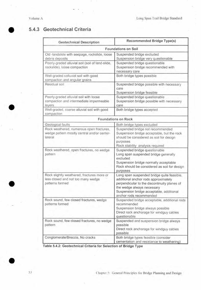
Volume A Long Span Trail Bridge Standard
5.4.3 Geotechnical Criteria
Geotechnical Description Recommended Bridge Type(s)
Foundations on SoilOld -landslide with seepage, rockslide, loose debris deposits
Suspended bridge excluded Suspension bridge very questionable
Poorly-graded alluvial soil (soil of land-slide, rockslide), loose compaction
Suspended bridge questionable Suspension bridge recommended with necessary care
Well-graded colluvial soil with good compaction and angular grains
Both bridge types possible
Residual soil Suspended bridge possible with necessary careSuspension bridge feasible
Poorly-graded alluvial soil with loose compaction and intermediate impermeable layers
Suspended bridge questionable Suspension bridge possible with necessary care
Well-graded, coarse alluvial soil with good compaction
Both bridge types accepted
Foundations on RockGeological faults Both bridge types excludedRock weathered, numerous open fractures, wedge pattern mostly central and/or center- lateral
Suspended bridge not recommended Suspension bridge acceptable, but the rock should be considered as soil for design purposesRock stability analysis required
Rock weathered, open fractures, no wedge pattern
Suspended bridge questionableLong span suspended bridge generallyexcludedSuspension bridge normally acceptable Rock should be considered as soil for design purposes
Rock slightly weathered, fractures more or less closed and not too many wedge patterns formed
Long span suspended bridge quite feasible, additional anchor rods approximately perpendicular to the discontinuity planes of the wedge always necessary Suspension bridge acceptable, additional anchor rods recommended
Rock sound, few closed fractures, wedge patterns formed
Suspended bridge acceptable, additional rods recommendedSuspension bridge always possible Direct rock anchorage for windguy cables questionable
Rock sound, few closed fractures, no wedge pattern
Suspended and suspension bridge always possibleDirect rock anchorage for windguy cables possible
Conglomerate/Breccia, No cracks Both bridge types feasible (consider cementation and resistance to weathering)
Table 5.4.2: Geotechnical Criteria for Selection of Bridge Type
53 Chapter 5: General Principles for Bridge Planning and Design
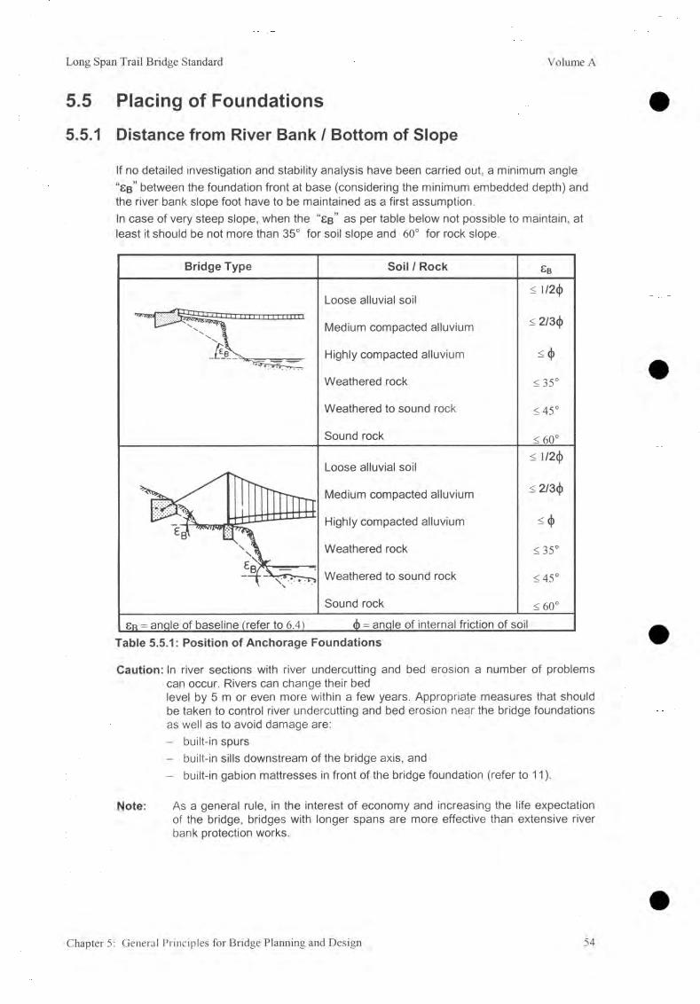
Long Span Trail Bridge Standard Volume A
5.5 Placing of Foundations5.5.1 Distance from River Bank / Bottom of Slope
If no detailed investigation and stability analysis have been carried out, a minimum angle “£ b ” between the foundation front at base (considering the minimum embedded depth) and the river bank slope foot have to be maintained as a first assumption.In case of very steep slope, when the “£ b ” as per table below not possible to maintain, at least it should be not more than 35° for soil slope and 60° for rock slope.
Table 5.5.1: Position of Anchorage Foundations
Caution: In river sections with river undercutting and bed erosion a number of problems can occur. Rivers can change their bedlevel by 5 m or even more within a few years. Appropriate measures that should be taken to control river undercutting and bed erosion near the bridge foundations as well as to avoid damage are:- built-in spurs- built-in sills downstream of the bridge axis, and- built-in gabion mattresses in front of the bridge foundation (refer to 11).
Note: As a general rule, in the interest of economy and increasing the life expectationof the bridge, bridges with longer spans are more effective than extensive river bank protection works.
Chapter 5: General Principles for Bridge Planning and Design 54
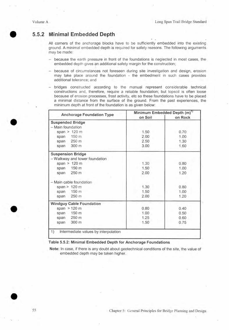
Volume A Long Span Trail Bridge Standard
5.5.2 Minimal Embedded Depth
All corners of the anchorage blocks have to be sufficiently embedded into the existing ground. A minimal embedded depth is required for safety reasons. The following arguments may be made:
- because the earth pressure in front of the foundations is neglected in most cases, the embedded depth gives an additional safety margin for the construction;
- because of circumstances not foreseen during site investigation and design, erosion may take place around the foundation - the embedment in such cases provides additional tolerance; and
- bridges constructed according to the manual represent considerable technical constructions and, therefore, require a reliable foundation; but topsoil is often loose because of erosion processes, frost activity, etc so these foundations have to be placed a minimal distance from the surface of the ground. From the past experiences, the minimum depth at front of the foundation is as given below:
Anchorage Foundation Type Minimum Embed on Soil
ded Depth (m)1’ on Rock
Suspended Bridge- Main foundation
span > 120 m 1.50 0.70span 150 m 2.00 1.00span 250 m 2.50 1.30span 300 m 3.00 1.60
Suspension Bridge- Walkway and tower foundation
span > 120 m 1.30 0.80span 150 m 1.50 1.00span 250 m 2.00 1.20
- Main cable foundationspan > 120 m 1.30 0.80span 150 m 1.50 1.00span 250 m 2.00 1.20
Windguy Cable Foundationspan > 120 m 0.80 0.40span 150 m 1.00 0.50span 250 m 1.25 0.60span 300 m 1.50 0.75
1) Intermediate values by interpolation
Table 5.5.2: Minimal Embedded Depth for Anchorage FoundationsNote: In case, if there is any doubt about geotechnical conditions of the site, the value of
embedded depth may be taken higher.
55 Chapter 5: General Principles for Bridge Planning and Design

Long Span Trail Bridge Standard Volume A
Caution: Where the contour lines are inclined to the axis of the anchorage foundation,retaining structures may be required depending upon the type of foundation and (lateral) loads might have to be considered in the analyzes of the foundation.
Plon
Chapter 5: General Principles for Bridge Planning and Design 56
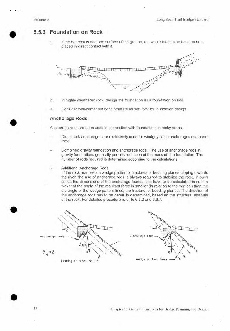
Volume A Long Span Trail Bridge Standard
5.5.3 Foundation on Rock
1. If the bedrock is near the surface of the ground, the whole foundation base must be placed in direct contact with it.
2. In highly weathered rock, design the foundation as a foundation on soil.
3. Consider well-cemented conglomerate as soft rock for foundation design.
Anchorage Rods
Anchorage rods are often used in connection with foundations in rocky areas.
Direct rock anchorages are exclusively used for windguy cable anchorages on sound rock.
Combined gravity foundation and anchorage rods. The use of anchorage rods in gravity foundations generally permits reduction of the mass of the foundation. The number of rods required is determined according to the calculations.
Additional Anchorage RodsIf the rock manifests a wedge pattern or fractures or bedding planes dipping towards
the river, the use of anchorage rods is always required to stabilize the rock. In such cases the dimensions of the anchorage foundations have to be calculated in such a way that the angle of the resultant force is smaller (in relation to the vertical) than the dip angle of the wedge pattern lines, the fracture, or bedding planes. The direction of the anchorage rods has to be carefully determined, based on the structural analysis of the rock. For detailed procedure refer to 6.3.2 and 6.6.7.
57 Chapter 5: General Principles for Bridge Planning and Design

Long Span Trail Bridge Standard Volume A
5.5.4 Minimal Clearances
A) Main Foundation Suspended Bridge
Keep the top of the foundation higher than the existing ground level.
Provide dry stone pitching in front of the foundation. Keep a minimum clearance of 30 cm between the top of the pitching and the lowest point of the cable during full load.
Sect ion A - A
- coble at full load —— dry stone pitching
If necessary provide retaining structures on top and drainage canals around the walkable part of the foundation. Take necessary precautions against bank erosion caused by water accumulating through drainage canals, especially when the bank is constituted of loose or medium compacted soil. If necessary provide a drainage canal up to the main river at low water level or take the drainage canal to the natural drainage system.
Chapter 5: General Principles for Bridge Planning and Design 58

Volume A Long Span Trail Bridge Standard
B) Walkway / Tower Foundation
Keep the top of the walkway tower foundations above the ground level.- at back about 50 cm, and- In front about 100 cm.
If necessary, provide retaining structures at the back, dry stone pitching in the front, and drainage canals around the foundation. However, If possible, divert this water away from the channel in front of the foundation.
Analyze carefully the flow conditions of the river during high flood, especially in turbulent rivers or at curves. If necessary, provide deep foundations for structures exposed to probable erosion, especially if foundations are placed on alluvial soil. Place foundations sufficiently back from the edge of the river. If necessary, provide a gabion wall and mattress on the bank.
59 Chapter 5: General Principles for Bridge Planning and Design

Long Span Trail Bridge Standard Volume A
C) Windguy Cable Foundation
Design the foundation in such a way that the top, in front, remains above the existing ground level, in order to prevent the covering of steel parts and cables by eroded soil.
If necessary, provide retaining structures on top and dry stone pitching in front of the foundation. As far as possible, adapt the retaining structures to the existing terrain.
On flat terrain, provide a channel with stone pitching where the cable can touch the ground.
Chapter 5: General Principles for Bridge Planning and Design 60
Long Span Trail Bridge Standard Volume A
Design of Bridge Foundation
Table of Contents
6.0 Introduction
6.1 Related Symbols
6.2 Loading Forces6.2.1 Forces Acting from the Cable Superstructure6.2.2 Wind Acting Directly upon the Foundation6.2.3 Earth Pressure6.2.4 Load on Top of the Foundation6.2.5 Dead Weight of the Foundation, Groundwater Pressure6.2.6 Resultant Loading Force6.2.7 Ground-bearing Pressure
6.3 Anchorage Rods for Foundation on Rock6.3.1 Direct Rock Anchorage6.3.2 Anchorage Rods for Stabilizing the Foundation6.3.3 Additional Anchorage Rods
6.4 Foundation Design, General Remarks6.4.1 Geotechnical Parameters6.4.2 Topographical Parameters6.4.3 Geometrical Parameters6.4.4 Failure Modes of Foundations
6.5 Foundations on Soil6.5.1 General Procedure, Check List, and Flow Chart6.5.2 Safety Against Sliding Failure6.5.3 Eccentricity of the Resultant Force and
Safety Against Toppling Failure (Overturning)6.5.4 Safety Against Ground Shear Failure (Bearing Capacity)6.5.5 Safety Against Slope Instability (Overall Stability)
6.6 Foundations on Rock6.6.1 General Procedure, Check List, and Flow Chart6.6.2 Safety against Sliding Failure6.6.3 Eccentricity of the Resultant Force and
Safety against Toppling Failure (Overturning)6.6.4 Ultimate Bearing Pressure6.6.5 Safety against Slope Instability (Overall Stability)6 .6.6 Direct Rock Anchorages6.6.7 Additional Anchorage Rods
62
63
65656565717374 77
81818385
8686878787
92929494
94103
104104 107107
108 108 108 109
Chapter 6: Design of Bridge Foundation 61
Volume A Long Span Trail Bridge Standard
6. IntroductionIn this chapter basic principles for design and structural analysis of the bridge foundations (tower foundations and cable anchorages) have been compiled. The introductory paragraph gives some background explanation about the behavior of bridge foundations. It will be helpful for the engineer to study this section before starting on design of foundations. An understanding of the behavior of foundations will make it easier to elaborate a safe and economical solution for bridge foundations.
For details of specific anchorage types and examples, refer to the relevant chapters
7. Standard Suspended Bridge (7.4 Main Anchorage Foundation),8 . Standard Suspension Bridge (8.6 Walkway / Tower Foundation, 8.7 Main
Cable Foundation),9. Windguy Arrangement (9.6 Windguy Cable Foundation).
Guidelines on how to determine permissible stresses (B, p.257), angles of internal friction (B, p.245) angles of friction between rock and concrete (B, p.263), and unit weights (B, p.254) are compiled in the LSTB Survey Manual (Volume B).
The references used as a basis for this chapter are given at the end of the volume.
It should be realized that design and analysis of the foundations require a high degree of care on the part of the engineer. By using wrong assumptions (soil parameters, topographical situation, etc) the engineer may design a foundation that will be different from the one being constructed, therefore the actual safety will differ from the calculations.
Whenever the engineer detects deficiencies in information compiled by the survey and by the geological Investigation, he has to assess whether he is able to fill the gap by making a conservative assumption or if additional investigations by the geotechnical engineer or by the surveyor are required. In this connection, it should be taken into consideration that an assumption that is conservative for one part of the design may not be so for another part. For example, an estimation of the unit weight of soil may be given: on one hand, an overestimation of this results in increased active earth pressure on the foundation (probably requiring an increase of the concrete volume to ensure sufficient safety against sliding), on the other hand, this overestimation could also lead to an overestimation of the bearing capacity, thus having an unfavorable influence on the foundation design.
62 Chapter 6: Design of Bridge Foundation

Long Span Trail Bridge Standard Volume A
6.1 Related SymbolsA Additional load (wall, soil) on top of the foundation kNAs Total cross-sectional area of anchorage rods mm2B Width of the foundation mB* Width of the fictive foundation mB */2 Distance of the resultant force from front of foundation m
Ea Force, total of active earth pressure kN/m
E0 Force, total of earth pressure at rest kN/mEr Force, total of passive earth pressure kN/mF Front edge of the foundation, center of rotation /
Fbc Safety factor against shear failure of ground /
F s l Safety factor against sliding /F t Safety factor against toppling /Hi ,H2 Height of the foundation mL Length of the foundation mL* Length of the fictive foundation m
l-A max Maximum length that can be considered for the load on top of the foundation m
L* ¡nfI Length of the required soil in front of the fictive foundation m
I—¡nfl Length of the required soil in front of the foundation m
Ny. Nq Ground-bearing capacity coefficients /P* Shear resistance of ground kN
PW Wind force kN/mR Resultant loading force at the base of the foundation kN
T, Th, Tm Cable tensions kNW, W1( W2 (partial) weight(s) of the foundation kN
a Distance of the additional load (center of gravity) from the front of the foundation m
d Diameter of anchorage rods mme , e ' Eccentricity of the resultant loading force m
e a Specific active earth pressure kN/m2
e 0 Specific earth pressure at rest kN/m2
e p Specific passive earth pressure kN/m2
9e Topographical correcting coefficient /
ha Total Height of active earth pressure m
haï Height of active earth pressure from top of foundation block m
hp Height of soil in front of the foundation, mHeight of passive earth pressure (deadman foundation) m
hra Height of the rock face at the back of the foundation m
hrt Height of the rock face in front of the foundation m
hT Height to the cable anchorage from the base mhw Distance of the groundwater level from the foundation base level at
the front of the structure mYEah Vertical distance from base (back side) of foundation to the
horizontal component Eah of resultant force of active earth pressure m
Chapter 6: Design of Bridge Foundation 63

Volume A Long Span Trail Bridge Standard
k Coefficient correcting the number of anchorage rods with regard to type and fracturation of the rock /
U Anchored length for anchorage rods mn Total number (of required anchorage rods <)> 25 mm) /s Distance of the anchorage rods (center of gravity) from the back of
the foundation mS y , S q Shape correcting coefficients /t Embedded depth in front of the foundation mtmin Minimum embedded depth of the foundation (refer to 5.5.2) mW Wind load kN/m2X, X' Length of the virtual tensile stress zone (gap) m
a Inclination of the base of the foundation degÔ Angle of wall friction, 8 = 2/3 <T degSr Inclination of the resultant force towards vertical dego, o 1s o 2 Angle of internal friction of soil (ch = subsoil, 4>2 = backfilling) deg^SL Angle of friction between ground and base of foundation degY> Y1, Y2 Unit weight of moist soil ^ = subsoil, y2 - backfilling) kN/m3
Ys Specific weight of soil kN/m3
Yw Unit weight of water kN/m3
K Inclination of the foundation towards vertical (front or back) degCoefficient of active earth pressure /
A-o Coefficient of earth pressure at rest /X,p Coefficient of passive earth pressure /a Equivalent stress in anchorage rods N/mm2
OB perm Permissible bond stress for anchorage rods N/mm2
Omax Maximum ground-bearing pressure N/mm2
Omax.ult Ultimate ground-bearing pressure for foundation on rock N/mm2
Omin Virtual maximum tensile stress at the area of contactbetween concrete and rock N/mm2
Operm Permissible ground-bearing pressure N/mm2
Otperm Permissible tensile stress for anchorage rods or reinforcement bars N/mm2
'tperm Permissible shear stress for anchorage rods N/mm2
Inclination of back-filling soil deg
Indices: H, h = horizontalV, v = vertical RW = retaining wall
64 Chapter 6: Design of Bridge Foundation
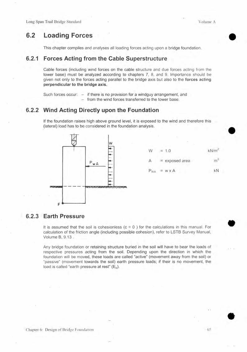
Long Span Trail Bridge Standard Volume A
6.2 Loading ForcesThis chapter compiles and analyses all loading forces acting upon a bridge foundation.
6.2.1 Forces Acting from the Cable Superstructure
Cable forces (including wind forces on the cable structure and due forces acting from the tower base) must be analyzed according to chapters 7, 8 , and 9. Importance should be given not only to the forces acting parallel to the bridge axis but also to the forces acting perpendicular to the bridge axis.
Such forces occur: - if there is no provision for a windguy arrangement, and - from the wind forces transferred to the tower base.
6.2.2 Wind Acting Directly upon the Foundation
If the foundation raises high above ground level, it is exposed to the wind and therefore this (lateral) load has to be considered in the foundation analysis.
w = 1.0 kN/m2
A = exposed area m2
P\/VA = w x A kN
6.2.3 Earth Pressure
It is assumed that the soil is cohesionless (c = 0 ) for the calculations in this manual. For calculation of the friction angle (including possible cohesion), refer to LSTB Survey Manual, Volume B, 9.13 .
Any bridge foundation or retaining structure buried in the soil will have to bear the loads of respective pressures acting from the soil. Depending upon the direction in which the foundation will be moved, these loads are called “active” (movement away from the soil) or “passive” (movement towards the soil) earth pressure loads; if their is no movement, the load is called “earth pressure at rest” (E0).
Chapter 6: Design of Bridge Foundation 65

Volume A Long Span Trail Bridge Standard
In order to develop active earth pressure (ea, Ea), the necessary movement of the foundation is small; about 0 .1% of the supported height; whereas the deformation of the soil needed to develop the passive earth pressure (ep, Ep ) has to reach about 1 % of the height of the soil.
A) Active Earth Pressure
Ea fully developed Ep partly developed
GENERAL CASE: Active earth pressure per m1 of retaining structure:
©ah “ ^ah ha ■ y kN/m2
Eah — 1/2 Gah ha — 1/2 Àah ha y kN/m
>CÖLU = Eah ■ tan(5 - k ) kN/m
EaEah
” cos (8 - k ) kN/m
8 = 1 ® deg
-ah —cos2(0 + k )
c o s 2k 1 +CO S (Ô - k ) • CO S (V| /
66 Chapter 6: Design of Bridge Foundation

Long Span Trail Bridge Standard Volume A
SPECIAL CASE: k = 0 This case normally occurs in connection with bridge foundations.Earth pressure on a retaining structure with length L :
Eah — 1/2 ha Y ‘ L kN
Eav — Eah ’ tanô kN
s 2 ^ 5 " 3 ° deg
YEah - [(ha - ha1 )
32ha1 + ha
ha + h a 1m
Chapter 6: Design of Bridge Foundation 67

Volume A Long Span Trail Bridge Standard
^ah —cos20
1 +I sin (<E + S) • sin (O - y )
COSÔ • COSV)/
<Dk V 25 27V2 30 321/2 35 3714 40 4214
40 / / / / / / 0.43 0.2430 / 1 0.60 0.38 0.30 0.24 0.20 0.16
10 20 0.44 0.37 0.31 0.26 0.23 0.19 0.16 0.1410 0.34 0.30 0.26 0.22 0.19 0.17 0.14 0.12
< 0 0.29 0.26 0.23 0.20 0.18 0.15 0.13 0.11
40 / / / / / / 0.59 0.3530 / / 0.75 0.49 0.39 0.33 0.28 0.24
0 20 0.52 0.45 0.39 0.34 0.30 0.26 0.23 0.2010 0.40 0.36 0.32 0.28 0.25 0.22 0.20 0.17<0 0.35 0.31 0.28 0.25 0.22 0.20 0.18 0.16
Table 6.2.1 : Selected Coefficients of the Active Earth Pressure, Horizontal Component•ah
ô - 0 O V|/ ^ O (ail angles in degree)
68 Chapter 6: Design of Bridge Foundation

Long Span Trail Bridge Standard Volume A
Typical Layouts of the Active Earth Pressure
Soil Rock/Soil
Make a separate calculation for the analysis of the retaining wall (RW).
Chapter 6: Design of Bridge Foundation 69

Volume A Long Span Trail Bridge Standard
B) Passive Earth PressureEarth resistance in front of the foundation is not recommended for common bridge foundations (refer to 5.5.2 for the minimum embedded depth) except fo r :- deadman foundations where the calculations are based on that resistance, and- for the walkway / tower foundations where the earth resistance is taken partially into
consideration.m ovem ent A = | % o f hp
Ea and Ep fully developed
SPECIAL CASE: k = 0kN/m2
kN/m
kN/m
0>K 8 25 2714 30 3214 35 3714 40 4214
> 0 3.47 4.06 4.81 5.76 7.02 8.71 11.06 14.45
- 5 2.85 3.29 3.83 4.50 5.36 6.47 7.96 10.00
0 - 1 0 2.32 2.65 3.053.54
4.14 4.90 5.88 7.17
-1 5 1.86 2.11 2.42 2.78 3.21 3.74 4.40 5.25- 2 0 1.42 1.64 1.88 2.15 2.47 2.85 3.31 3.89
Table 6.2.2: Selected Coefficients of the Passive Earth Pressure, Horizontal ComponentA,ph(all angles in degree)
70 Chapter 6: Design of Bridge Foundation

Long Span Trail Bridge Standard Volume A
C) Lateral Earth Pressure
The soil pressure is acting on the sides of the foundation too. It is not necessary to consider this lateral earth pressure for bridge foundations as long as the foundation is established in even terrain. If the terrain is sloping perpendicular to the main axis, the forces may have to be considered.
ax is
neglect earth pressure at rest (E0)
consider EaL
6.2.4 Load on Top of the Foundation
A vertical load on top of the foundation may be considered only if it is guaranteed. Therefore special care must be taken if the design is changed on site.
As the dimension of the foundation and, therefore, the load on top changes, it should be considered, while designing the foundation, that some of the following formulas are only approximate. This should encourage the designer to calculate different variants in order to find the optimum dimension of the foundation and, later on, finalize the dimension of the retaining structure according to the accurate formulas, and as per the instructions in this chapter.
The length of the structure on top of the foundation taken into consideration must not exceed the length of the foundation. In order to avoid uncontrolled cracks in the (retaining) structure exceeding the length of the foundation, it is recommended that vertical joints be provided. Separate calculations are necessary for the (retaining) structure on top and at the side of the foundation.
Chapter 6: Design of Bridge Foundation 71

Volume A Long Span Trail Bridge Standard
Additional vertical load only in order to stabilize the foundation (e.g., Gabion Boxes).
La max - Lm
A y • h • a-i • L kN
a = B - 1/ 2 a i m
L a max “ L
A = V2 72 • h • ai * L
a = B - 1/ 3 a 1
Retaining wall right at the back of the foundation:
L a max “ L
A = yrw ■ h ■ (a-i + >2 a2) * L
a — B -
a-i2 + ai • a2 + 1/3a22 a° ~ 2ai + a2
a0 * 1/ 2 (ai + 1/ 3 a2)
m
kN
m
m
kN
m
m
m
72 Chapter 6: Design of Bridge Foundation

Long Span Trail Bridge Standard Volume A
Retaining wall and soil on top of the foundation.
L a max = L m
a = B - a0 m
The exact load (A) can be found by summing up the individual loads. The exact distance from the back can be found by summing up the moments about D, and solving for a0 , if IM d = 0.
Approximate formulassay Y2 ~ Yrw kN/m2
A = Y2 • h ■ (as + a-i + 1/ 2 a2) • L kN
3o ~ 1/ 2 (as + ai + Vza2 ) m
6.2.5 Dead W eight of the Foundation, Groundwater Pressure
The dead weight of the foundation is calculated according to the volume and the unit weight of construction material (refer to 4.5).
No groundwater present:
= 1/ 2 Y • B • (hi + h2) • L kN
= 1/ 3 B2h1 + h2 h-i + h2 m
Groundwater present:Above G.W.L:
= ye • B • h ■ L
w-t = 1/2 B
Below G.W.L:
W 2 = % (yc - Yw) ' B • (hwi + hw2) • L
2hwi + hW2w2 = Vz B hwi + hw2
The lateral water pressure can be neglected (because of equilibrium). The active earth pressure must be taken fully into account.
kN
m
kN
m
Chapter 6: Design of Bridge Foundation 73

Volume A Long Span Trail Bridge Standard
6.2.6 Resultant Loading Force
A) General Case
All loads and forces acting on a foundation can be summarized into a single force (R) which is acting at the base of the foundation.
A diagram of forces at the foundation base (in isometric view) is given below.
The components of the resultant loading force:
Vertical component: Rv = Sum of all vertical forces kN
Horizontal components:
- Parallel to B : Rhb = Sum of all horizontal forces parallel to B kN
- Parallel to L : Rhl = Sum of all horizontal forces parallel to L kN
Combined components: R = a/R v2 + Rhb" + Rhl2 kN
Rule for the sign : + = force downwards - = force upwards
74 Chapter 6: Design of Bridge Foundation
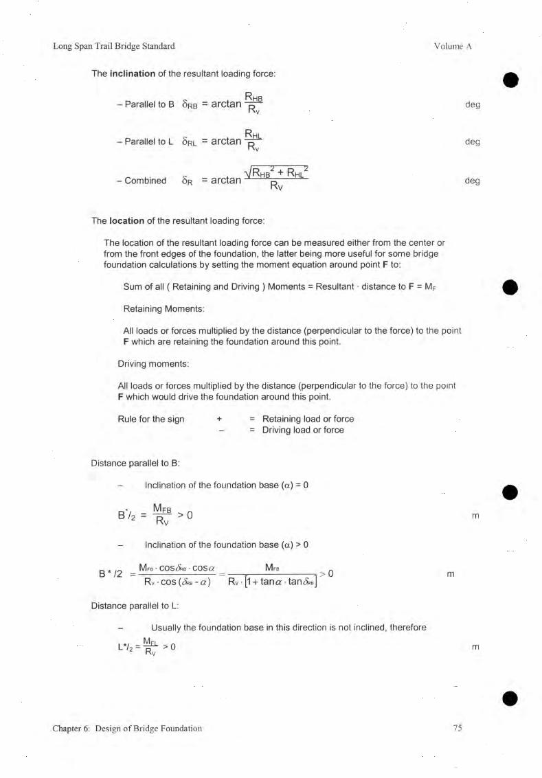
Long Span Trail Bridge Standard Volume A
The inclination of the resultant loading force:
~ Rhb- Parallel to B Ôrb - arctan deg
- Parallel to Lp
ôrl - arctan DKv deg
- Combined Sr = arctan ^ + Kv deg
The location of the resultant loading force:
The location of the resultant loading force can be measured either from the center or from the front edges of the foundation, the latter being more useful for some bridge foundation calculations by setting the moment equation around point F to:
Sum of all ( Retaining and Driving ) Moments = Resultant • distance to F = MF
Retaining Moments:
All loads or forces multiplied by the distance (perpendicular to the force) to the point F which are retaining the foundation around this point.
Driving moments:
All loads or forces multiplied by the distance (perpendicular to the force) to the point F which would drive the foundation around this point.
Rule for the sign + = Retaining load or force- = Driving load or force
Distance parallel to B:
Inclination of the foundation base (a) = 0
b72 = ^ > oKv
Inclination of the foundation base (a) > 0
M fb • COS(X® • COS or M fb
m
B */2 = >0Rv-cos((5rb- o:) Rv[l + tanor-tan<5RB]
Distance parallel to L:
- Usually the foundation base in this direction is not inclined, therefore M
m
l*'2 = fC > 0m
Chapter 6: Design of Bridge Foundation 75

2/wM
Volume A Long Span Trail Bridge Standard
B) Special Case
If there is no horizontal force (or the sum is equal to 0 zero) acting parallel to L, the resultant loading force is located on the axis parallel to B.
Rhl = 0 5rl = 0 L*/2 = L ¡2
Example: XRHl = 0 , and by omitting indices B: Rhb = Rh S r b = 5rNo groundwater present
Components and angle of inclination of R
Rv = W + E av + A - T v
R h = Eah + T h
5r = arctan j r 1
Distance from front:
Mf = W • w + Eav • B + A • a + Eah • (B ■ tana - ha/3) - TH • hT
M f • cosSr ■ cos a M f D / Z — — F ï ^ U
R v-cos(^-a) Rv • [1 + tana • tan&J
kN
kN
deg
kNm
m
76 Chapter 6: Design of Bridge Foundation
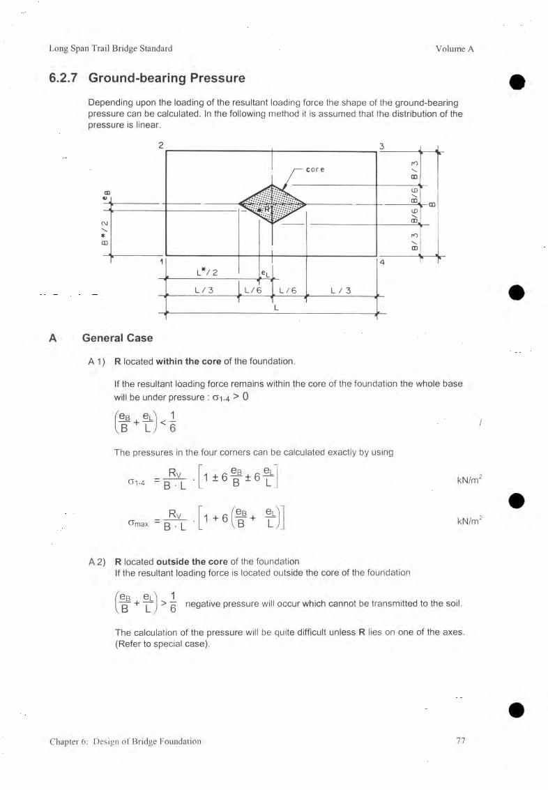
Long Span Trail Bridge Standard Volume A
6.2.7 Ground-bearing Pressure
Depending upon the loading of the resultant loading force the shape of the ground-bearing pressure can be calculated. In the following method it is assumed that the distribution of the pressure is linear.
General Case
A 1) R located within the core of the foundation.
If the resultant loading force remains within the core of the foundation the whole base will be under pressure : cr-1-4 > 0
ea + e u U IB U I
The pressures in the four corners can be calculated exactly by using
Rv<y 1-4 - B ■ L 1 ± 6 b~ ± 6 r kN/m
RvOmax — B • L 1 + 6 1 bb + - kN/m
A 2) R located outside the core of the foundationIf the resultant loading force is located outside the core of the foundation
1> g negative pressure will occur which cannot be transmitted to the soil.
The calculation of the pressure will be quite difficult unless R lies on one of the axes. (Refer to special case).
§ B § LB L
Chapter 6: Design of Bridge Foundation 77
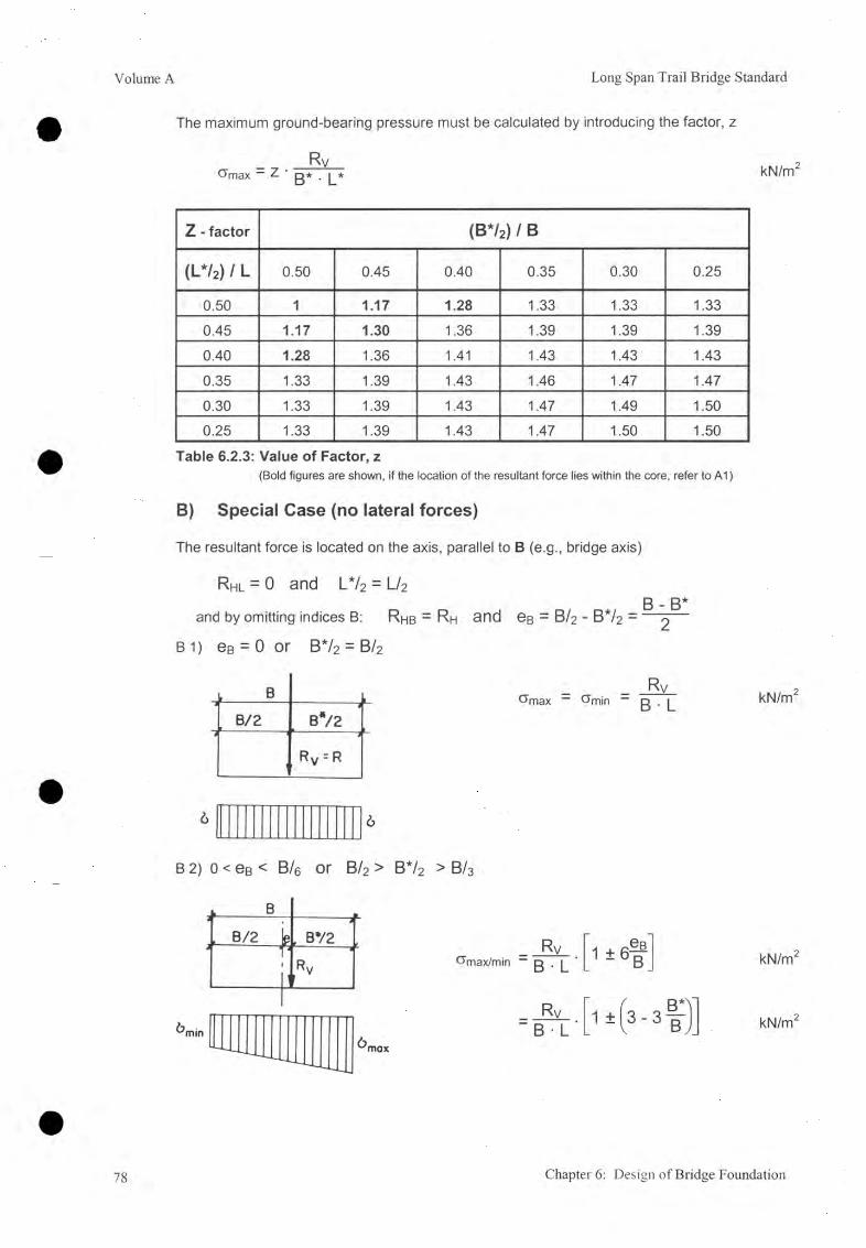
Volume A Long Span Trail Bridge Standard
The maximum ground-bearing pressure must be calculated by introducing the factor, z
RvChnax - Z ß* . [_* kN/m2
Z - factor (B */2) / B
(L*/2) / L 0.50 0.45 0.40 0.35 0.30 0.25
0.50 1 1.17 1.28 1.33 1.33 1.33
0.45 1.17 1.30 1.36 1.39 1.39 1.39
0.40 1.28 1.36 1.41 1.43 1.43 1.43
0.35 1.33 1.39 1.43 1.46 1.47 1.47
0.30 1.33 1.39 1.43 1.47 1.49 1.500.25 1.33 1.39 1.43 1.47 1.50 1.50
Table 6.2.3: Value of Factor, z(Bold figures are shown, if the location of the resultant force lies within the core, refer to A1)
B) Special Case (no lateral forces)
The resultant force is located on the axis, parallel to B (e.g., bridge axis)
R hl = 0 and L */2 = L/2
and by omitting indices B: R hb = R h and eB = B /2 - B */2 = '
B 1 ) e B = 0 or B*/2 = B/ 2
■-------------B/2l________, B*/2i- .5 J
RV = R
_ _ R v _Gmax “ ö’mjn ~ ß . |_ kN/m2
6 6
B 2) 0 < eB < B/e or B/2 > B*/2 > B/3
j.______B_l
jL B/2 g
--------, B72 1
^max/minA Tl
1T1
-------- -*Rv
RvB • L
1 ± 6 f
Rv" B ■ L
kN/m2
kN/m2
78 Chapter 6: Design of Bridge Foundation

Long Span Trail Bridge Standard Volume A
B 3) G — B/6 Of BV2 — B/3
2RyGrnax “ b • L
6 = 0
B 4) e > B/q or B*/2 < B/ 3
L B >3
Le81
3
Rv
a). Negative pressure will be borne by another tension member (e.g., reinforcement or anchorage rod).
L B Rv1 ---------------------------I e B
9 B*/2 ° max/min “ B • Lk ^-1 •—
1 RvB • L
1 * 6 f
1 ± I 3 - 3 |
kN/m2
kN/m2
kN/m2
b) No negative pressure can be transmitted (e.g., to soil, dry stone structures), or the impact of the tension-bearing member is neglected:
B */2
^mox
CJmax / min2 Rv
3 ( B * / 2 - e ß ) L
2 Rv 4Rv3 B * /2 • L ~ 3 B * L
kN/m2
kN/m2
Chapter 6: Design of Bridge Foundation 79
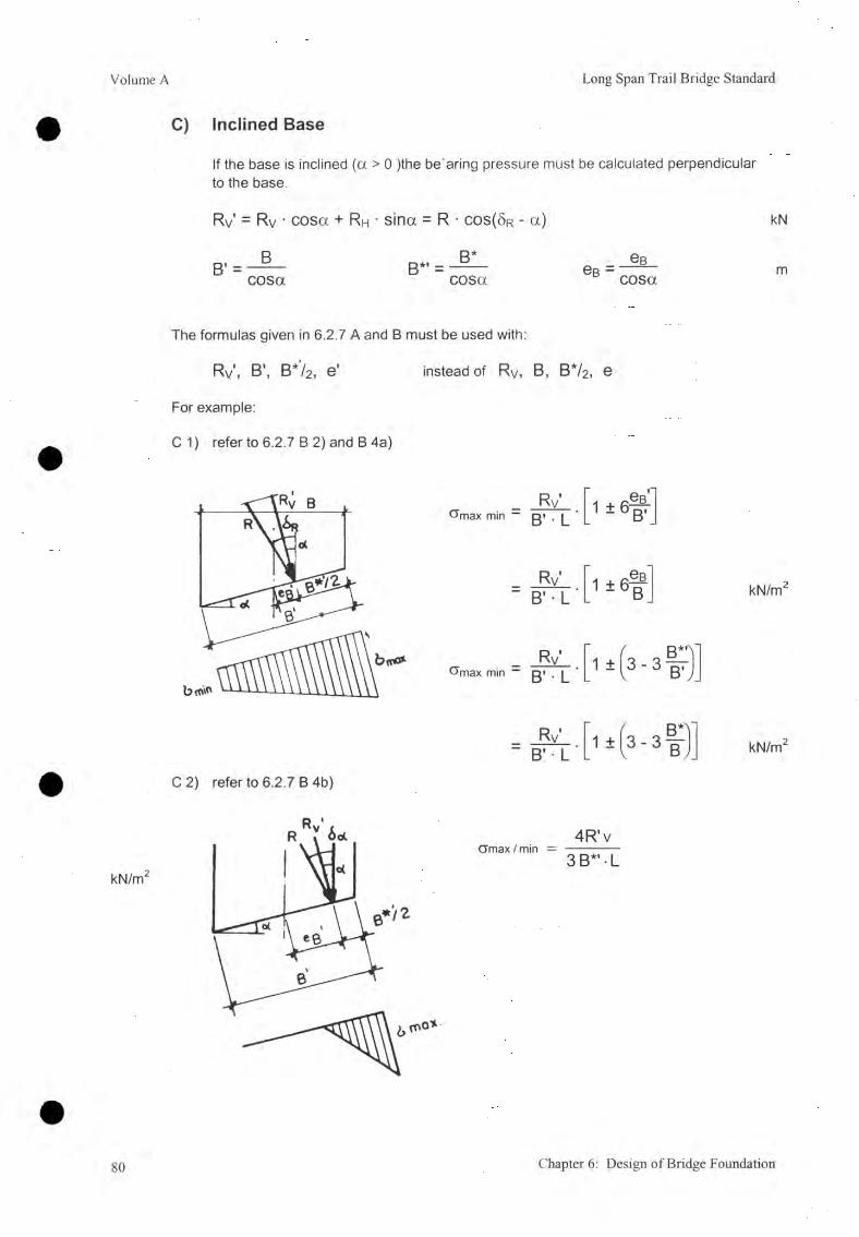
Volume A Long Span Trail Bridge Standard
C) Inclined Base
If the base is inclined (a > 0 )the be aring pressure must be calculated perpendicular to the base.
Rv = Rv ■ cosa + RH • sina = R ■ c o s ( 8 r - a) kN
B' =B
cosaB*. B*
cosae B
B cosam
The formulas given in 6.2.7 A and B must be used with:
Rv’, B’, B */2 , e’ instead of Rv, B, B*/2 , e
For example:
C 1) refer to 6.2.7 B 2) and B 4a)
Rv’ " B’ L
i ± ( 3 - 3 | ) kN/m2
C 2) refer to 6.2.7 B 4b)
80 Chapter 6: Design of Bridge Foundation

Long Span Trail Bridge Standard Volume A
6.3 Anchorage Rods for Foundation on RockSpecifications for anchorage rods
High tensile steel (ripped reinforcement steel bars) (refer to 4.3.3)
Permissible tension stress <Tt perm “ 230 N/mm
Permissible bond stress perm = 0.6 N/mm
Permissible shear stress S-Permx^perm “ ) “ 1oU N/mm
Combined stress (tension and shear) öcomb = + 3 l < CJt perm
Standardized Perfo-Anchorage System (refer to Volume D, 10)
Diameter of anchorage rods: d = 25 mmLength to be anchored la = 2000 mmDiameter of hole: D = 34 mmDistance between two anchorage rods: ®min = 1500 mm
Note: It is very essential to drill the holes with good rock drills, otherwise the necessary anchorage length of 2.0 m may not be achieved.
6.3.1 Direct Rock Anchorage
Past experiences in SBD Nepal have shown that this type of anchorage for windguy cables is only economical during design work. In practice, it had to be redesigned very often into a gravity foundation combined with vertical rock anchorage rods. As it is also hardly possible to drill the holes in the correct direction, this type of anchorage is only recommended for use in very rare optimum cases.
Direct rock anchorages for windguy cables can be provided in plutonic rocks, gneiss, quartzite, possibly in hard sandstone, massive dolomite, and in limestone with few fractures and not weathered.
Design and analysis of the direct rock anchorage will guarantee that the maximum tension force from the cables is safely transferred to the rods, and from them through the bond between the rods and the mortar to the rock. Special care must be taken to ensure that for practical reasons the anchorage rods will not be placed in the same direction as the cable. The cable force therefore will be split into two components:
- a tensile force in the axes of the anchorage rods, and- a force perpendicular to the axes of the anchorage rods.
The anchorage must be designed in such a way that the force perpendicular to the axes of the anchorage rods will be directly transferred to the rock. No bending moment must be allowed to occur in the anchorage rods. The direct windguy cable anchorage must be designed with a required factor of safety F > 1.5.
Chapter 6: Design of Bridge Foundation 81

Volume A Long Span Trail Bridge Standard
The permissible tension (axial tension only) has to be calculated on the net area of the threaded part which is approximately 80% of the gross area of the rod:
1) Safety against tensile failure :
2)
'R tPermissible Tension Force _ n • 0 . 8 As • at
Tensile Force “ Tperm
For one rod (d = 25 mm) the permitted tension will be:
-r- n ' 0 . 8 A s • a t permI t max — p
■ Rt
Safety against bond failure
1 • 0 . 8 1 ^ 7 ^ 1 ' 0 . 2 3 0
1.5
Permissible Boned Force n • d * 7t * la * 0 B Perm . _r K b — ---------- —------ ----—------------------ = --------------—------------ > 1 . 0
Tensile Force T
> 1.5
= 60 kN
The necessary anchorage length needed in order to develop the bond resisting the tension may be calculated as follows:
^ > T , ma>- F RB ^ n - O . S ^ j - C T t p . m r - F R B
n • d ■ 71 * Gb perm PI * d ’ 7T ’ Gb perm *
_ 0-8d • Q~t perm
4 CJb perm
Therefore : la min0.8 • 25 • 230
4 ■ 0.6 1920 mm « 2000 mm
82 Chapter 6: Design of Bridge Foundation

Long Span Trail Bridge Standard Volume A
6.3.2 Anchorage Rods for Stabilizing the Foundation
A) General
Anchorage rods can be provided to prevent the foundation from sliding or toppling or both combined. The anchorage rods should be placed at the back of the foundation to make sure that they are embedded in sound rock.
During sliding, the shear resistance, and during over-toppling, the tensile resistance, of the anchorage rods will be mobilized.
It will not be possible to mobilize the full shear resistance of the rods during sliding. Therefore, because of practical reasons, it is recommended that the permissible shear stress be reduced to:
Tt combined — 75 N/mm
In order to fulfill the formula for combined tensile and shear stress:
CTt comb+
y (Tt perm )Tt comb
Tt perm J
<1 the permissible tensile stress has to be reduce t o :
Otcomb = a t perm ' ' \ / 1 " f y ^ ) 2 - 230 \j V^perm/
(7 5 -y ß V .1 ' I 230 ~ 190 N/mm
The necessary anchorage length needed in order to develop the bond resisting the tension may be calculated as follows:
I t max — A s ’ CTt comb “ 4 ' CTt comb
d 2n! T 4
n ’ d • 71 • CTb perm 0 ■ d ■ 71 CJb perm 4 • n (7b perm
2 5 • 1 9 0Therefore: la min ^ 4 . -| . q g = 1980 mm *2000 mm
If it is riot possible to drill the full anchorage length of 2 m in practice, even though good drilling material is used, the number of required rods may be calculated in proportion to the length required.0 (as per site condition) — B(as per design) ' 2 (m) / la (as per site condition) (m )
If the length achieved is less then 1.5 m, redesign of the foundation is necessary,taking no rods into consideration.
Chapter 6: Design of Bridge Foundation 83
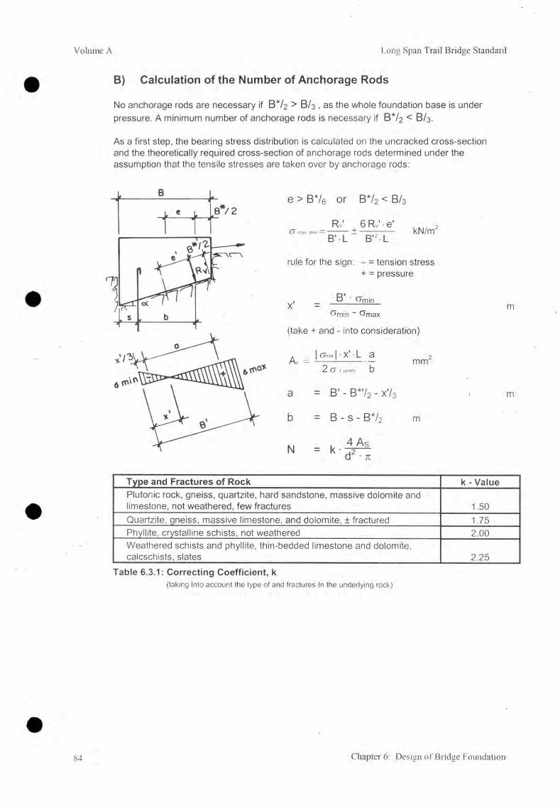
Volume A Long Span Trail Bridge Standard
B) Calculation of the Number of Anchorage Rods
No anchorage rods are necessary if B V 2 > B /3 , as the whole foundation base is under pressure. A minimum number of anchorage rods is necessary if B V 2 < B/3.
As a first step, the bearing stress distribution is calculated on the uncracked cross-section and the theoretically required cross-section of anchorage rods determined under the assumption that the tensile stresses are taken over by anchorage rods:
e > B*/6 or B*/2 < B/ 3
Rv' 6 Rv' • e’C7 max min — ' . + .
B 'L B'2 - LkN/m
rule for the sign: - = tension stress + = pressure
, B ' <7min
Ornin " <7max
(take + and - into consideration)
As =l - x ' L a
2 a Imm
a = B’ - B* '/2 - x ' / 3
b = B - s - B* /2
N k ■4 As d2 • n
m
m
Type and Fractures of Rock k - ValuePlutonic rock, gneiss, quartzite, hard sandstone, massive dolomite and limestone, not weathered, few fractures 1.50Quartzite, gneiss, massive limestone, and dolomite, ± fractured 1.75Phyllite, crystalline schists, not weathered 2.00Weathered schists and phyllite, thln-bedded limestone and dolomite, calcschists, slates 2.25
Table 6.3.1: Correcting Coefficient, k(taking Into account the type of and fractures In the underlying rock)
84 Chapter 6: Design of Bridge Foundation

Long Span Trail Bridge Standard Volume A
6.3.3 Additional Anchorage Rods
Additional 'anchorage rods are used in order to stabilize the rock section on which the foundation is placed. They are not taken into consideration for improving the sliding or toppling safety of the foundation itself.
Rock formations are usually more or less structured by a number of weakness planes caused by cracks and fissures. Cracks and fissures may be closed or open and appear close or at distance. A rock formation loaded with additional loads, e.g., through a bridge foundation may be subject to motion along these weakness planes. Additional rock anchorages must be provided to avoid this.
A) Number of Rods
Determination of the number of required rock anchors for stabilizing a rock mass can be arrived at by analyzing the rock mechanics. In most cases it is very difficult to procure accurate information about the circumstances for the purposes of calculation, and, therefore, a systematic anchorage pattern is used in most cases. This method is proposed for the bridge foundation design as well.
1. If the rock formation is sound, and shows only a few fissures which are closed, a systematic anchorage is not necessary.
2. If the rock formation is more or less fractured but only some cracks with small openings show, a systematic anchorage is proposed with one anchorage rod per 1.5 m2. The number of anchorage rods is calculated, dividing the base area of the foundation by 1.5 m2. The anchorage rods are evenly spread over the foundation base area.
3. If the rock formation shows many cracks or if a great number of cracks are open, the number of anchorage rods in the front half of the foundation base area has to be doubled.
B) Direction of the Rods
Generally, the anchorage rods are placed in a direction perpendicular to the weakness planes or lines of the rock. Refer to the Survey Manual Volume B, 9.2, for determination of the weakness planes or lines of the rock according to Schmidt's planes projection. As this procedure uses grades (or gon) for the identification of angles (both for horizontal and vertical angles), it must be clearly indicated on all sketches and drawings.
For each direction, the same number of anchorage rods is fixed with the exception that, if one system of weakness planes dominates, to stabilize this system a higher number of anchorage rods may be used. Fracture planes not posing any danger (e.g., dipping in a direction opposite the slope) do not have to be considered.
Chapter 6: Design of Bridge Foundation 85

Volume A Long Span Trail Bridge Standard
6.4 Foundation Design, General Remarks6.4.1 Geotechnical Parameters
As these parameters are an essential part of the whole bridge design, attention should be given to being as accurate as possible during the survey. Based on the findings from the geological and geotechnical surveys, the engineering geologist will determine the geotechnical parameters for the location of each foundation based on a proposed bridge axis.It should be stated that these values have been derived from actual on site conditions and they should not be changed for the sake of fulfilling safety factor calculations only.The following table shows how to compile the necessary geotechnical parameters.
Bridge No & Name....................................................... Surveyed Site N o ..........................
Geotechnical parameters for bank (right / left)
ParameterTower
FoundationMain (Cables) Foundation
Windguy Cat Upstream
>le Foundation Downstream
Subsoilat depth (m)USCS Classification
i» i (deg)yi (kN/m3)
Cfperm (kN/m2)G.W.L. at depth (m)minimum embedding(m)
Back-filling$ 2 (deg)72 (kN/m3)
Rockat depth (m)
O sl (deg)
CTperm (kN/m2)k - Value ( / )minimum embedding (m)Rock stabilization at base:- back half (single)- front half (single/double)- direction/inclination (gon)
86 Chapter 6: Design of Bridge Foundation

Long Span Trail Bridge Standard Volume A
6.4.2 Topographical Parameters
The topographical parameters, carefully elaborated during the survey, and plotted in the plan and in the cross-section of the proposed site, are the basic data for the foundation design. Whenever it is necessary to draw other sections from the topographical map, it is recommended that they be checked and compared with the photographs.
6.4.3 Geometrical Parameters
Refer to the concerned chapters and sketches for the minimum and maximum dimensions of the foundation. The minimum dimensions are given according to the size of the steel anchorage parts and the maximum dimensions are derived from the load distribution of the steel anchorage parts in relation to the surrounding concrete.
Care must be taken to ensure that the foundation is firmly embedded into the ground (refer to 5.5.2).
6.4.4 Failure Modes of Foundations
Design and analysis of bridge foundations must guarantee that all loadings (live and dead loadings) acting from the bridge superstructure on to the foundations are safely transferred to the subsoil. To compile these forces a thorough statical investigation of the superstructure is carried out. To test the safety of parts of the superstructure, the stress within these parts may be analyzed and compared with material specifications given in the relevant codes.
For subsoil the procedure is different. Because subsoil conditions vary a great deal, it is necessary to determine the local subsoil parameters by means of geotechnical investigation (e.g., pits, laboratory investigation of samples, etc). Unlike in the analysis of the superstructure, it is not usual during foundation analysis to compute the stress pattern within the soil mass to test the required safety level. During foundation design, a number of failure modes are analyzed by use of different models and for each one a factor of safety is computed. These safety factors are compared with the required values which may differ according to the different models analyzed.
Depending upon the loading and the subsoil conditions, generally one or the other of these models dominates the analysis and gives the final dimensions of the foundation. In most cases the dominating failure mode can be determined by the engineer, according to the loading and subsoil conditions, before the analysis is undertaken. This allows him to commence his analysis cognizant of the relevant failure mode, to determine the required dimensions, and to afterwards show that the other safety requirements are also fulfilled. In general, especially with difficult topography, the relevant failure mode has to be calculated by iteration.
Chapter 6: Design of Bridge Foundation 87

Volume A Long Span Trail Bridge Standard
Following the basic failure modes, the relevant models used for the analysis and design of foundations are explained and illustrated.
A) Sliding Failure
As soon as the increase of the load results in a shear load which exceeds the shear resistance in the foundation base, a flat foundation being loaded by a more or less horizontal load will start sliding on the subsoil. The shear resistance itself is governed by the normal force in the foundation base and the friction angle between foundation base and subsoil. Generally a safety factor of FSL > 1.5 is required against sliding failure. The surface of movement for this failure mode is equal to the contact area between the foundation base and subsoil.
Retaining Forces Driving Forces
N ■ tan<t>S
(W + .... )• tanOE a h + H + . . . .
Deadman FoundationThe process leading to the failure of the deadman anchorage foundation is similar to the sliding failure. The deadman foundation mobilizes the weight of the earth mass in front of the foundation. The maximum resistance is equal to the passive earth pressure. To attain peak resistance, a relatively large deformation is required, so to reduce the deformation a high safety factor of F S l ^ 3.5 is necessary.
The design concept of the deadman foundation is as given below:
The following modes of failure and respective safety factors have been considered in the design.
=> Sliding FSL > 3.5
88 Chapter 6: Design of Bridge Foundation
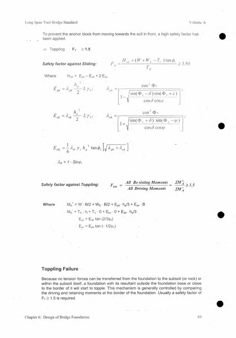
Long Span Trail Bridge Standard Volume A
To prevent the anchor block from moving towards the soil in front, a high safety factor has been applied.
=> Toppling Ft >1.5
S a fe ty fa c to r a g a in s t S lid in g :/ / n;, +(W + WE - ) tan
F,i = --------------------------------------2 3.501 u
Where Huit — Ep Eah + 2 E0|_
hEph - ph0 L ï \ ¡ Á P * = -
cos' Oi'sin(0 , -<5')sin(<I)| + £)
cose) cos
E ah ~ ahL 2 • Kh =COS
1+.[sin(<t>2 +8) sin(<î>2 -i/y)
cos 8cos
E öl ~ ¿ oY\ hp tan^! À ph + Xnh J
À0 = 1 -
Safety factor against Toppling: F = A " ™ ting Moments = ™ i > ( 5D riv ing Moments
Where MA+ = W ■ B/2 + WE • B/2 + Eph • hp/3 + Eav • B
Ma’ = Th • ht + Tv • 0 + Epv • 0 + Eah • ha/3
Eav = Eah tan (2I3<\>2)
EPv = Eph tan (-1/2(1),)
Toppling Failure
Because no tension forces can be transferred from the foundation to the subsoil (or rock) or within the subsoil itself, a foundation with its resultant outside the foundation base or close to the border of it will start to topple. This mechanism is generally controlled by comparing the driving and retaining moments at the border of the foundation. Usually a safety factor of FT > 1.5 is required.
Chapter 6: Design of Bridge Foundation 89
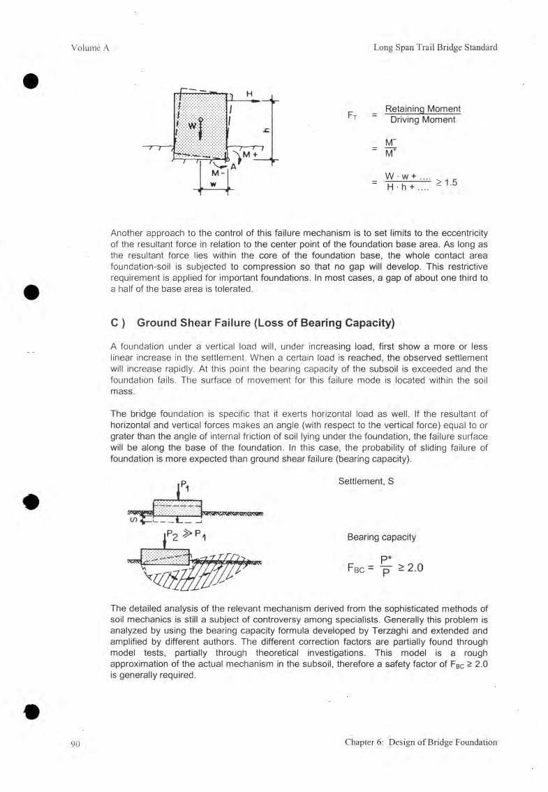
V olum e A Long Span Trail Bridge Standard
Retaining Moment Driving Moment
M~
W • w + .... ' H • h + .... > 1.5
Another approach to the control of this failure mechanism is to set limits to the eccentricity of the resultant force in relation to the center point of the foundation base area. As long as the resultant force lies within the core of the foundation base, the whole contact area foundation-soil is subjected to compression so that no gap will develop. This restrictive requirement is applied for important foundations. In most cases, a gap of about one third to a half of the base area is tolerated.
C ) Ground Shear Failure (Loss of Bearing Capacity)
A foundation under a vertical load will, under increasing load, first show a more or less linear increase in the settlement. When a certain load is reached, the observed settlement will increase rapidly. At this point the bearing capacity of the subsoil is exceeded and the foundation fails. The surface of movement for this failure mode is located within the soil mass.
The bridge foundation is specific that it exerts horizontal load as well. If the resultant of horizontal and vertical forces makes an angle (with respect to the vertical force) equal to or grater than the angle of internal friction of soil lying under the foundation, the failure surface will be along the base of the foundation. In this case, the probability of sliding failure of foundation is more expected than ground shear failure (bearing capacity).
The detailed analysis of the relevant mechanism derived from the sophisticated methods of soil mechanics is still a subject of controversy among specialists. Generally this problem is analyzed by using the bearing capacity formula developed by Terzaghi and extended and amplified by different authors. The different correction factors are partially found through model tests, partially through theoretical investigations. This model is a rough approximation of the actual mechanism in the subsoil, therefore a safety factor of FBc ^ 2.0 is generally required.
90 Chapter 6: Design of Bridge Foundation

Long Span Trail Bridge Standard Volume A
D) Slope Failure
It is obvious that a foundation placed at the top of an inclined slope will fail under a lesser load than the same foundation on flat terrain. To solve this problem, correction factors for the Terzaghi formula were developed. However, for steep slopes this formula is no longer reliable, and other methods have to be used to estimate the load permissible on the foundation. The required safety factors are different depending upon the method applied.
ground shear failure----- slope fai lure
As is easily recognizable from the above description of the failure modes, each mode is more or less characteristic of a special combinatior} of load, topography, and subsoil conditions. For example, a foundation loaded by a horizontal acting force will most probably not suffer ground shear failure but it will start to either slide (sliding failure) or topple (especially in cases where the force is acting high above the foundation base and where a hard subsoil is present). A foundation under a predominant vertical load placed on top of a steep slope will probably be endangered by ground shear or slope failure, etc.
With the knowledge presented above and some experience gained during foundation design work, it should be possible for the engineer to select the dominating failure mode at the beginning of analysis, afterwards going through other failure modes and demonstrating that these safety requirements are also fulfilled.
Chapter 6: Design of Bridge Foundation 91

Volume A Long Span Trail Bridge Standard
6.56.5.1
Foundations on SoilGeneral Procedure, Check List, and Flow Chart
A) General Procedure
This chapter provides information on procedures related to design of foundations on soil. In this respect, it should be mentioned that strongly weathered rock may be treated as soil as well. The flow chart should be useful in assisting the engineer to recognize the relevant failure mode so that a rough first design stage might be completed as quickly as possible and the final dimensions of the foundation produced. The checklist summarizes the requirements for foundations on soil.
B) Check List, Requirements for Foundations on Soil or on Strongly-weathered Rock
Safety Factor Walkway / Tower
Foundation
Main Cable Foundation
MainAnchorageFoundation
WindguyCable
Foundation
Retaining Wall &
Gabions
Fsl > 1.5 >1.5 > 1.5 > 1.5 > 1.5
F BC > 2.0 > 2.0 > 2.0 > 2.0 > 2.0
Ft > 1.5 > 1.5 > 1.5 >1.5 > 1.5
b*/2, l*/2
—11 COAI
LU+ CO
GOAI » !
F slope depending on method ( > 1.3 to 1.5)
a (max) 0° < 15° < 15° < 15° < 15°Other requirements:
- embedded depth (t) according to 5.5.2
92 Chapter 6: Design of Bridge Foundation

Long Span Tr.ail Bridge Standard Volume A
C) Flow Chart for Design Procedure for Foundations on Soil
Chapter 6: Design of Bridge Foundation 93

Volume A Long Span Trail Bridge Standard
6.5.2 Safety Against Sliding Failure
The relevant information about how to calculate the components and the inclination of the resultant force is given in 6.2.6 . For general information about safety against sliding failure refer to 6.4.4 A.
8rRh= arctan —Rv
5« = 8r - a deg
R'v = RV ■ cosa + Rh • sina kN
R'h = R’h • Cosa - Rv • sina kN
generally it is assumed that O sl = O deg
tanOsL • R'v Fsl = R'h
tan Osl _ tan Osl tan(^R-a) tan &
6.5.3 Eccentricity of the Resultant Force and Safety Against Toppling Failure (Overturning)
The relevant information concerning how to calculate the eccentricity of the resultant force is given in 6.2.6. For general information about safety against toppling failure refer to 6.4.4 B .
Toppling failure is controlled by the set limits of the eccentricity, e or B*/2 (refer to the check list).
6.5.4 Safety Against Ground Shear Failure (Bearing Capacity)
For general information about safety against ground shear failure refer to 6.4.4 C.
A) The Bearing Capacity Basic Formula for horizontal terrain and vertical load
Terzaghi Model:- continuous footing- vertical and centric loading- shallow footing t < B, and- ideal soil with horizontal surface.
94 Chapter 6: Design of Bridge Foundation

Long Span Trail Bridge Standard Volume A
P *Fbc = -p > 2.0
P * = B • [c • N c + (y ■ t + q) • N q + 1/ 2 B • y • N , ] kN
Wherein Nc, Nq, - First term
- Second term
- Third term foundation
Nr are the bearing capacity factors :[c • Nc] expressing the effect of the cohesion (not taken
into consideration in the following calculations, refer to 6.2.3)
[ ( y • t + q ) • N q ] expressing the effect of the embedded depth (respectively the surcharge load at depth t)
[ 1/2 B ■ y • N y ] expressing the effect of the width of the
A 1) The Bearing Capacity Factors Nq and Nr
The bearing capacity factors in basic form can be written as:_ _7T tanO .- for the effect of t
- for the effect of B
: N q = e
: N v
• tan (45° + Î4 0 )
1-8 (Nq - 1) • tancb
Values of Nq and Ny:
(deg) = 25 2714 30 3214 35 37% 40 42%
Nq 10.6 13.9 18.4 24.6 33.3 45.8 64.2 91.9
_____ Sz_____ 8.1 12.1 18.1 27.0 40.7 61.9 95.4 150.0
Graphic presentation of Nq and NY according to Lang/Huder
It can be clearly seen that too high an estimate of the value of O will give an extremely high value of N and a wrong impression of safety.
Chapter 6: D esign of Bridge Foundation 95

Volume A Long Span Trail Bridge Standard
A 2) The Length/Area of Influence
The length/area of influence in its basic form for horizontal terrain is given as follows:
L j n fi = B • tan(45° + 1/ 2 0 ) • e °5* ^
Value for Lin,i :
0 25 271/2 30 321/ 2 35 371/ 2 40 421/ 2
Linf, / B 3.3 3.7 4.3 5.0 5.8 6.8 8.0 9.6
B) Bearing C apacity Extended and Am plified Form ula
The basic bearing capacity formula can be extended and amplified with correction factors for the:- s shape of the foundation
d embedded depth- i inclination of the load
b' inclination of the foundation base- g inclination of the baseline
P* = B * • L * • [( Y1 • t + q ) N q Sq dq iq b'q gq + 0.5 yi B * N y . sy dy iT b’y gr] kN
Fbc= £ >2.0
The necessary length/area in front of the foundation must be guaranteed. The formula of Terzaghl for the calculation of the length of influence must be used with B * , instead of B .
L * i nfi = B * ■ tan(45° + 1/ 2 0 ) • e 0 5 ,tta n < lJ
Remember that the correction factors are only approximate. An overall stability calculation may be necessary (e.g., the methods of Bishop or Janbu).
The actual size of the foundation has to be transferred to a fictive foundation base with a centric load only.
96 Chapter 6: Design of Bridge Foundation

Long Span Trail Bridge Standard Volume A
B 1) Size of the Fictive Foundation Base
The size of the fictive foundation base is equal to B* and L* . For calculation of the eccentricity of the resultant force B*/2 and L*/2 refer to 6 .2 .6 . .
The values of the correction factors are given for B* < L * ,
- if B* / L* > 1 to 1.5: take the values forB*/L* = 1 and
- if B* / L* > 1.5: check bearing capacityin
both directions (exchanging B* and L*).
B 2) Shape-correction Factor, S
Shape correction factors consider the limited length (L*) of the continuous footing.
B *Value of sq = 1 + T T ta n O
0> = 25 2 7 Vi 30 32% 35 371/2 40 4214
B*/L* = 1.0 1.47 1.52 1.58 1.64 1.70 1.77 1.84 1.92
0.8 1.37 1.42 1.46 1.51 1.56 1.61 1.67 1.73
0.6 1.28 1.31 1.35 1.38 1.42 1.46 1.50 1.55
0.4 1.19 1.21 1.23 1.25 1.28 1.31 1.34 1.37
0.2 1.09 1.10 1.12 1.13 1.14 1.15 1.17 1.18
00 1 1 1 1 1 1 1 J____
B *Value of SY = 1 —0 . 4 ^
<D = For all OB*/ L* = 1.0 0.60
0.8 0.68
0.6 0.70.4 0.84
0.2 0.9200 1
Chapter 6: Design of Bridge Foundation 97

Volume A Long Span Trail Bridge Standard
B 3) Depth-correction Factor, d
Depth correction factors consider the embedded depth ( t ) of the foundation. The embedded depth must be guaranteed for the whole length of L*infi
? tValue of dq = 1 + 0.035 tanO • (I - sinO) • arctan gT
0 = 25 27Vi 30 327-2 35 3772 40 4272
t / B * = 0.0 1 1 1 1 1 1 1 1
0.2 1.06 1.06 1.06 1.05 1.05 1.05 1.04 1.04
0.4 1.12 1.12 1.11 1.10 1.10 1.09 1.08 1.07
0.6 1.17 1.16 1.16 1.15 1.14 1.13 1.12 1.10
0.8 1.21 1 .20 1.20 1.18 1.17 1.16 1.14 1.13
1.0 1.24 1.24 1.23 1.21 1.20 1.18 1.17 1.15
1.2 1.27 1.26 1.25 1.24 1.22 1.21 1.21 1.17
dY = 1 (for all O )
B 4) Inclination of Load: Correction Factor, i
The (big) effect of the inclination of load (normal to the foundation base) is considered with these correction factors.
s . Rhi5r = arctan 75-KvRh 9
5a = 5r — a = arctan — a < « / 3 0 (or check sliding)
Value of iq = [ 1 — Va tanôa ] 5 = [1 - 1/2tan(Ô R - a ) ]5
5« = 0 5 10 15 20 25 30 /
all a 1.0 0.8 0.63 0.49 0.37 0.27 0.18
Value of( o 7
1 - 0.7- a ' tanôal
8« = 0 5 10 15 20 25 30 /
P II O 1 0.73 0.52 0.35 0.23 0.14 0.08 /5 1 0.73 0.52 0.36 0.24 0.13 0.08 /10 1 0.74 0.53 0.37 0.24 0.15 0.08 /15 1 0.74 0.54 0.37 0.25 0.16 0.09 /
98 Chapter 6: Design of Bridge Foundation

Long Span Trail Bridge Standard Volume A
B 5) Inclination of Foundation Base: Correction Factor, b'
This factor considers the inclination of the foundation base (a).
Value of b'q = e( " 0 035 ' tan0)
<D = 26 271/2 30 321/2 35 371/2 40 421/2
a = 0 1 1 1 1 1 1 1 1
5 0.92 0.91 0.90 0.89 0.88 0.87 0.86 0.85
10 0.85 0.83 0.82 0.80 0.78 0.76 0.75 0.73
15 0.78 0.76 0.74 0.72 0.69 0.67 0.64 0.62
Value of by = ( - 0.047 a0 • tan<t>) c
o = 25 271/2 30 321/2 36 371/2 40 421/2
a = 0 1 1 1 1 1 1 1 1
5 0.90 0.88 0.87 0.86 0.85 0.84 0.82 0.8110 0.80 0.78 0.76 0.74 0.72 0.70 0.67 0.6515 0.72 0.69 0.67 0.64 0.61 0.58 0.55 0.52
B 6) Inclination of the Baseline: Correction Factor, g
This factor considers the inclination of the baseline which may not be the same as the inclination of the surface terrain.
Values of gq = gr = ( 1 - 0 . 2 5 tan£B)5
£b - 0 5 10 15 20 25 30
for all <1> 1 0.90 0.80 0.71 0.63 0.54 0.46
The considerable effect of the inclination of the baseline is clearly visible.
Chapter 6: Design of Bridge Foundation 99

Volume A Long Span Trail Bridge Standard
C) Calculation Procedure
It is assumed that the dimensions of the foundation are already known from the calculation of another failure mode, if not, try to estimate the required dimensions experientially, or take the minimum dimensions as primary data.
C 1) Required Initial Data
1) From survey and final geotechnical report:- Friction angle of sub-soil 0 1 - ........... deg- Unit weight of sub-soil Y1 - ................. ........... kN/m2
2 ) From the topographical survey:- prepare the necessary cross-sections
3) From the dimensions of the foundation:-Width B = ........... m- Length L = ................. ........... m- Base inclination a = ........... deg- Embedded depth (t > tmin) t = ........... M
4) From the calculation of the resultant force:- Vertical component Rv = ................. ........... kN/m2- Inclination ÔR = ........... deg- Location B*/2 = ................. ........... m
and L*/2 = ........... m
C 2) Determination of the Base-line inclination,
Step 1: Make any change of slope with a number beginning with 1 at the front of the foundation on the sketches prepared.
Step 2: Check if any angle of the slope in front is greater that O i — if so, neglect the soilthat is above the angle <t>i at any change of slope.
100 Chapter 6: Design of Bridge Foundation

Long Span Trail Bridge Standard Volume A
Step 3 : Calculate the length of influence required ( L * ) and transfer it to the sketch.
There are several places where the length of influence may cross the slope line :(t > min embedded depth)
a) Lmfi s length 1 to 2 ’- therefore £1 = 8b- draw the baseline with distance t parallel to the slope line 1 to 2 ’.- proceed with calculation.
b) Length 1 to 2’ < L*jnfi < length 1 to 3- draw a line from point 1 to point A where the length of influence cuts the (theoretical)
slope line.- the soil above this line along L*inf| can be considered to be uniformly distributed
kN/m2
load q =(Area 1 to 2' to A) • yi c .,-------------------------= 0 .5 1 • yi
L * infl
- draw the baseline with the distance t parallel to the line 1 to A.
c) L*infl > length 1 to 3- as the direct line 1 to A would be out of the soil, the line has to be drawn through to
point 3.- the soil above this line along L*infl can be considered to be uniformly distributed
[(A re a l to 2' to 3) + (A rea 3 to A to A’ )] yi load q = -------------------------------- — ------------------------------------
L inflkN/m2
Chapter 6: Design of Bridge Foundation 101

Volume A Long Span Trail Bridge Standard
It is not recommended that extreme changes in the slope be taken into consideration. An overall stability calculation might be necessary.
C 3) Calculation of Bearing Capacity
1) Calculate- Surcharge load (y.t + q) =- Bearing capacity factor Nq =
and Ny = .- Correction factors for- Shape Sq =
and SY = .- Depth dq = .
and dy =
— Inclination of load iq =and iy = .
- Inclination of foundation base b'q =
and by = .— Inclination of the baseline CO jQ II CO
2 ) Calculate the bearing capacity P* -
and the safety factor Fbc = .
kN/m
kN
In order to obtain an optimum safety factor of 2, changes in the initial data, or even in the location of the foundation, might be necessary, and the calculation must be repeated.
102 Chapter 6: Design of Bridge Foundation

Long Span Trail Bridge Standard Volume A
6.5.5 Safety against Slope Instability (Overall Stability)
Where there are very steep slopes (close to the angle of friction of the soil), which are broken, or where the bearing capacity by using the Terzaghi formula is not sufficient, the safety of the slope must be investigated through more elaborate analysis. This analysis can be carried out by using one of the methods of slices developed by Bishop or Janbu,
A simplified method, with a plane failure surface is given below. A safety factor of > 1.5 is required, to guarantee a reasonable safety level.
Calculations have to be made for the length (L) of the foundation. The sliding plane starts at the back-base of the foundation, dipping towards the front. Calculations for various sliding planes must be carried out in order to find the critical one (e.g., through point 3 or 4, etc).
Calculate the force-components on the sliding plane
V = Rv + Z Wsoi| kN
H = Rh kN
V’ = V • cos q - H ■ sin q kN
H' = V • sin q + H • cos q kN
II_l</)LL V • tan O, ^
H' - 1 5 /
Chapter 6: Design of Bridge Foundation 103
Volume A Long Span Trail Bridge Standard
6.6 Foundations on Rock6.6.1 General Procedure, Check List, and Flow Chart
A) General Procedure
Regarding the foundations on soil referred to in 6.5, the basic procedure to be followed for foundations on rock will be given. Where a foundation has to be placed on highly weathered rock the procedure for foundations on soil (refer to 6.5) must be followed. The checklist summarizes the requirements for foundations on rock. Intact rock or slightly weathered rock show an increased strength compared to soil. That's why a different failure mode is given for the dimensions of the foundations. For example, where bearing capacity is a typical problem for foundations on soil, toppling failure becomes a problem for foundations on rock.
"Foundation on Rock" refers to a foundation design which makes use of the stability and gravity of the underlying rock formation by providing anchorage rods, thus allowing for a considerable reduction in the mass of the anchorage foundations.
When the underlying rock is strongly fractured or weathered, this anchorage system should not be used and the "foundation on soil" design should be adopted. The calculation model used in this chapter is only a rough approximation of the real mechanism and valid only for the immediate vicinity of the anchorage foundations, but it should lead to sufficient security of the structures in connection with the permissible values for the ground-bearing pressure and with the angle of friction determined according to the directions given in the manual Volume B, Survey. If the permissible bearing pressures, and/or the permissible eccentricity of the resultant force (refer to the relevant chapters), are observed, the calculation model also leads to economical structures.
The calculation model can be used without concern for windguy cable anchorage foundations or for the main anchorages of small span bridges. For main anchorage foundations of long span bridges, the overall stability of the rock formation has to be carefully analyzed, based on the structural study of the rock by using rock mechanics' methodology.
104 Chapter 6: Design of Bridge Foundation
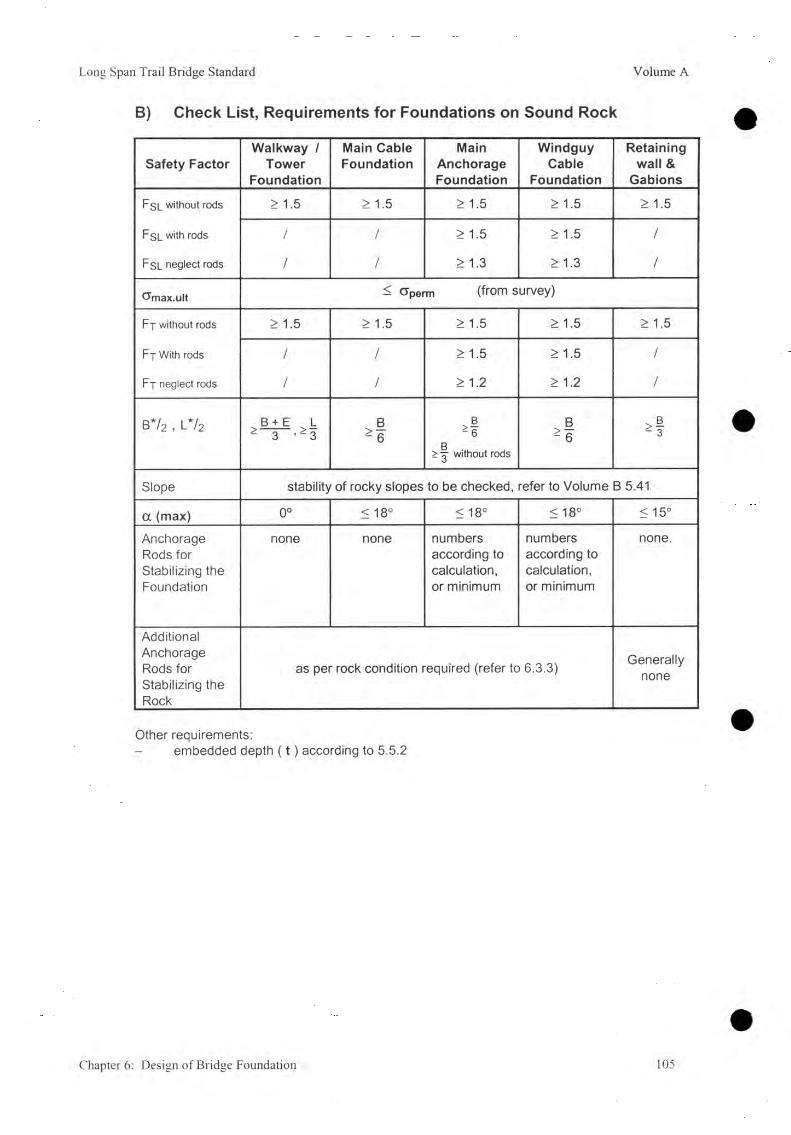
Long Span Trail Bridge Standard Volume A
B) Check List, Requirements for Foundations on Sound Rock
Safety FactorWalkway /
Tower Foundation
Main Cable Foundation
MainAnchorageFoundation
WindguyCable
Foundation
Retaining wall &
Gabions
Fsl without rods > 1.5 > 1.5 > 1.5 > 1.5 > 1.5
FSL with rods / / >1.5 >1.5 /
Fsl neglect rods / / > 1.3 > 1.3 /
tTmax.ult < cjperm (from survey)
Fp without rods >1.5 > 1.5 > 1.5 > 1.5 >1.5
Ft With rods / / > 1.5 > 1.5 /
Ft neglect rods / / > 1.2 > 1.2 /
B* /2 , l * /2 > B+E > L - 3 ’ - 3
CûlcoAI
B^6
> without rods
CûlcoAI 4
Slope stability of rocky slopes to be checked, refer to Volume B 5.41
a (max) 0° < 18°
oCOX—VI < 18° <15°
Anchorage Rods for Stabilizing the Foundation
none none numbers according to calculation, or minimum
numbers according to calculation, or minimum
none.
Additional Anchorage Rods for Stabilizing the Rock
as per rock condition required (refer to 6.3.3) Generallynone
Other requirements:embedded depth ( t ) according to 5.5.2
Chapter 6: Design of Bridge Foundation 105

Volume A Long Span Trail Bridge Standard
C) Flow Chart for Procedure for Foundations on Rock
106 Chapter 6: Design of Bridge Foundation
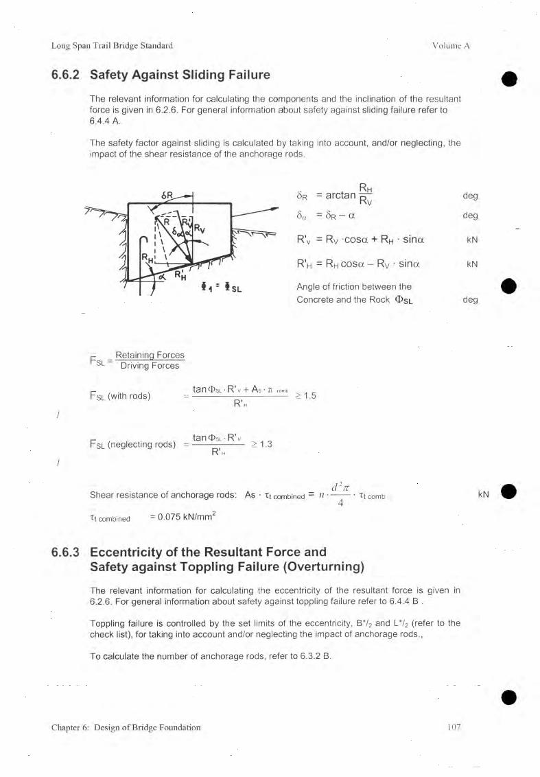
Long Span Trail Bridge Standard Volume A
6.6.2 Safety Against Sliding Failure
The relevant information for calculating the components and the inclination of the resultant force is given in 6.2.6. For general information about safety against sliding failure refer to6.4.4 A.
The safety factor against sliding is calculated by taking into account, and/or neglecting, the impact of the shear resistance of the anchorage rods.
S r = arctan tt1 Ky deg
5a = S r - a deg
R'v = Rv -cosa + Rh • sina kN
R'h = Rh cosa - Rv • sina kN
Angle of friction between the Concrete and the Rock ® sl deg
/
F slRetaining Forces Driving Forces
Fsl (with rods)tanOsL • R' V + As * 7t comb
R’h>1.5
/
Fsl (neglecting rods)tan<TsL-R'v
R 'h>1.3
Shear resistance of anchorage rods: As • i t combined - n ---------Tt comb kN4
Xt combined = 0.075 kN/mm
6.6.3 Eccentricity of the Resultant Force andSafety against Toppling Failure (Overturning)
The relevant information for calculating the eccentricity of the resultant force is given in 6.2.6. For general information about safety against toppling failure refer to 6.4.4 B .
Toppling failure is controlled by the set limits of the eccentricity, B*/2 and L*/2 (refer to the check list), for taking into account and/or neglecting the impact of anchorage rods.,
To calculate the number of anchorage rods, refer to 6.3.2 B.
Chapter 6: Design of Bridge Foundation 107

Volume A Long Span Trail Bridge Standard
6.6.4 Ultimate Bearing Pressure
For foundations on rock, ground shear failure (bearing capacity) is not a problem in many cases, nevertheless the maximum stress on the foundation base has to be limited according to the quality of the rock.
The relevant information about how to calculate the components and the inclination of the resultant force is given in 6.2.6 . For general information about calculating (ultimate) bearing pressure refer to 6.2.7 B and C . For the procedure for determining the maximum pressure in case of double eccentricity of the resultant force (with z-factor) refer to 6.2.7 A2.
The ultimate bearing pressure is calculated by neglecting the impact of the anchorage rods.
An example for B72 < B/3 is given below:
B*. B *
cosa m
R’v = Rv • cosa + Rh ■ sina kN
Cmax ult_4Rv_ 3 B*'L
kN/m2
6.6.5 Safety against Slope Instability (Overall Stability)
The procedure for the investigation of the stability of rocky slopes is given in Volume B, 5.41 .
6.6.6 Direct Rock Anchorages
The relevant information about direct anchorages for windguy cables is given in 6.3.1 . The design and the capacity must be checked accordingly.
108 Chapter 6: Design of Bridge Foundation
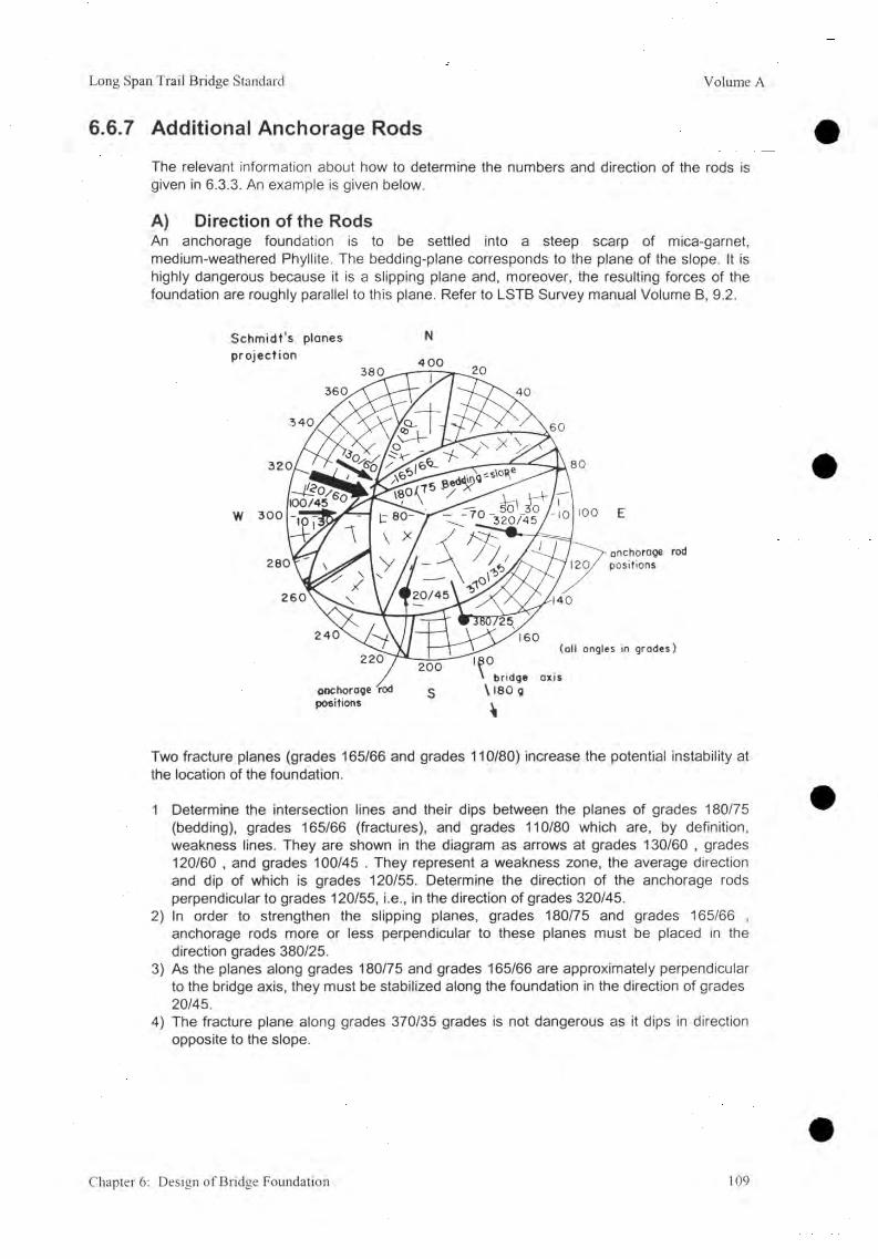
Long Span Trail Bridge Standard Volume A
6.6.7 Additional Anchorage Rods
The relevant information about how to determine the numbers and direction of the rods is given in 6.3.3. An example is given below.
A) Direction of the RodsAn anchorage foundation is to be settled into a steep scarp of mica-garnet, medium-weathered Phyllite. The bedding-plane corresponds to the plane of the slope. It is highly dangerous because it is a slipping plane and, moreover, the resulting forces of the foundation are roughly parallel to this plane. Refer to LSTB Survey manual Volume B, 9.2.
Schmidt's planes
Two fracture planes (grades 165/66 and grades 110/80) increase the potential instability atthe location of the foundation.
1 Determine the intersection lines and their dips between the planes of grades 180/75 (bedding), grades 165/66 (fractures), and grades 110/80 which are, by definition, weakness lines. They are shown in the diagram as arrows at grades 130/60 , grades 120/60 , and grades 100/45 . They represent a weakness zone, the average direction and dip of which is grades 120/55. Determine the direction of the anchorage rods perpendicular to grades 120/55, i.e., in the direction of grades 320/45.
2) In order to strengthen the slipping planes, grades 180/75 and grades 165/66 , anchorage rods more or less perpendicular to these planes must be placed in the direction grades 380/25.
3) As the planes along grades 180/75 and grades 165/66 are approximately perpendicular to the bridge axis, they must be stabilized along the foundation in the direction of grades 20/45.
4) The fracture plane along grades 370/35 grades is not dangerous as it dips in direction opposite to the slope.
Chapter 6: Design of Bridge Foundation 109

Volume A Long Span Trail Bridge Standard
B)
1)
2)
3)
4)
Number of Rods
Number of rods within the back-half of the foundation base
ffback -B-L2-1.5
, e.g., flback -2.9 -3.8 2-1.5
Number of rods within the front-half of the foundation base
rifront -2 B L
6Q-. rifront -2-2.9-3.8
2-1.5 2-1.5
Total number of rods within the foundation base
n (tot) — riback + rifront . 6 -9 -> D (tot) =11 nos.
Distribution to the weakness planes, e.g. ,
- direction 320/459 :- direction 20/459 :- direction 380/259 :
4 rods,4 rods, and 3 rods.
= 3.67 nos.
= 7.33 nos.
5) Draw a separate plan of the foundation base on the "General Arrangement", indicating the location and the direction of the rods.
110 Chapter 6: Design of Bridge Foundation

Long Span Trail Bridge Standard Volume A
7. Design of Standard Suspended Bridge
Table of Contents
7.3
7.4
Flow Chart 112
Layout 113
Design of Main and Handrail Cable Structures 1147.3.1 Introduction 1147.3.2 Related Symbols 1147.3.3 Geometrical Parameters 1157.3.4 Standard Design Parameters 1187.3.5 Limits and Recommendations 1207.3.6 Initial Layout Data 1217.3.7 Calculation Procedure 1237.3.8 Compilation of Final Data 1257.3.9 Related Standard Drawings 127
Design of Main Anchorage Foundation 1287.4.1 Introduction 1287.4.2 Related Symbols 1287.4.3 Design Parameters 1297.4.4 Limits and Recommendations 1317.4.5 Initial Layout Data 1317.4.6 Calculation Procedure 1327.4.7 Compilation of Final Data 1357.4.8 Related Standard Drawings 137
Chapter 7: Design of Standard Suspended Bridge 111

Volume A Long Span Trail Bridge Standard
7.1 Flow Chart
112 Chapter 7: Design of Standard Suspended Bridge

Long Span Trail Bridge Standard Volume A
7.2 LayoutSide view of an inclined (h > 0) suspended bridge with drum-type cable anchorage foundation.
*Note 1) For foundations with drum-type cable anchorages of 4, or 6 main cables- distance from front to saddle = 0.25 m ( / = s + 0.50 m)- distance from foundation top to saddle = 0.25 m
2) For foundations with open-type cable anchorages of 8 , 10, or 12 main cables- distance from front to saddle = 0.50 m ( / = s + 1.00 m)- distance from foundation top to saddle = 0.90 m
Chapter 7: Design of Standard Suspended Bridge 113

Volume A Long Span Trail Bridge Standar
7.3 Design of Main and Handrail Cable Structures7.3.1 Introduction
The procedure followed in this chapter has provision for a windguy arrangement (refer to 9). It is assumed that the full wind load can be borne by this system only. Refer to Chapter 10, Special Design, if in very rare cases it is not possible to provide a windguy arrangement.
The layout and the initial loading is based on the structure under dead load.
The freeboard has to be maintained for any cable alignment (including windguy cables) at dead load case. Enough free space must be provided beneath the walkway in front of the foundations at full load case.
An overview of the main parameters and their relevant loading cases are given below.
Loading Case Load R e le v a n t fo r D e t e r m in in g Refer toHoisting dead load of
handrail and main cables
- hoisting sag of handrail and main cable 7.3
Dead load all dead loads - initial loading case, free board 7.3
Full load dead loads - number and size of handrail and main cables 7.3and live load - design of main anchorage foundations 7.4
Wind load wind load - number and size of windguy cables 9.4acting on the bridge
- design of windguy cable foundations 9.5
N.B. It should be noted that the term "case" is used to clearly distinguish the loads (e.g., dead loads) from the loading case (e.g., full load case = dead loads + live load).
7.3.2 Related Symbols
A Sectional area mm2
E Modulus of elasticity kN/mm2
F Safety factor /H Horizontal component of cable tension kNL Cable length between saddles mT Cable tension kN
Tbreak Minimum breaking load of cables kN
Tmax Total cable tension at higher foundation (all cables) kN
b Sag, measured in the middle of the bridge from the chord me Horizontal distance from the cable saddle at the higher foundation
saddle to the lowest point of the parabola mf Maximum sag, vertical distance from the cable saddle at the higher
foundation saddle to the lowest point of the parabola m
Chapter 7: Design of Standard Suspended Bridge
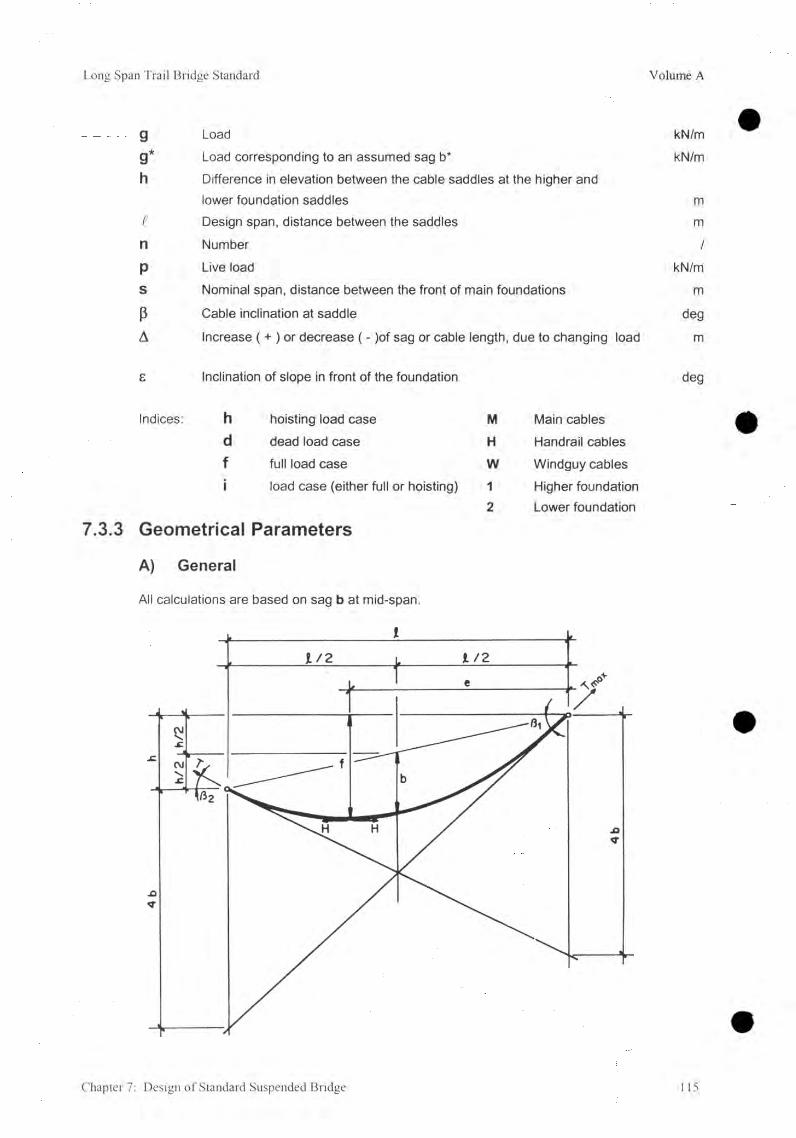
Long Span Trail Bridge Standard Volume A
g Load kN/m
g* Load corresponding to an assumed sag b* kN/mh Difference in elevation between the cable saddles at the higher and
lower foundation saddles mt Design span, distance between the saddles mn Number /P Live load kN/ms Nominal span, distance between the front of main foundations m
P Cable inclination at saddle deg
A Increase ( + ) or decrease ( - )of sag or cable length, due to changing load m
e Inclination of slope in front of the foundation deg
7.3.3
Indices: h hoisting load case M Main cablesd dead load case H Handrail cablesf full load case W Windguy cablesi load case (either full or hoisting) 1 Higher foundation
Geometrical Parameters2 Lower foundation
A) General
All calculations are based on sag b at mid-span.
Chapter 7: Design of Standard Suspended Bridge 115

Volume A Long Span Trail Bridge Standard
1) Cable inclination at saddles:
q . 4Pi = arctan -------- deg
ß2 = arctanA b - h
deg
2) Location of lowest point (distance measured from the higher foundation saddle)
(■(4b+ h) ( (.h8 b
_ (4 b + h)2 T " 16b
2 V + 4b
" b+ 2 + 16 b
m
m
3) Length of loaded cables between saddles:
L = , + l *2 U
v 8+ —
3 \ Jm
4) Total horizontal tension (all cables):
H = * J ‘8 b
kN
5) Total maximum tension (all cables) at the higher foundation saddle:H
1 maxCOS /?,
= H ■ - 1 + tan2 /?, kN
6 ) The distribution of the tension between handrail and main cables is calculated proportionally to the cable gross area.
Main cable tension (all main cables):
- r _ H AmI M
TM.max = T,
cosßi or 2 Am + Ah
Ammax A m + A h
kN
kN
Handrail cable tension (2 cables):
H AhH
Th.ii = T,
cosßi or 2 Am + Ah
Ahmax A m + A h
NOTE: For bridges with foundations at the same level (h = 0) the parameters will be:
kN
kN
ß1 = ß2 = ß deg
e = d 2 mf = b m
T i = t 2 — Tmax KN
116 Chapter 7: Design of Standard Suspended Bridge

Long Span Trail Bridge Standard Volume A
B) Basic Calculation Principle
As the structure at dead load is the initial loading, the sag ( bf ) of the full load case and the sag ( bh ) of the hoisting load case have to be calculated. The maximum full load tension has to fulfil the safety requirements for the cables.
ParameterLoad Case
Hoisting Load Dead Load Full LoadLoad 9h 9d 9fCable length Lh =Ld + (-ALh) Ld Lf = Ld + ALfSag bh = bd + (-Abh) bd bf = bd + AbfHoriz. Tension Hh = Hg + (-AHh) Hd Hf = Hd + AHd
The values of delta ( A ) are the increase ( + ) or decrease ( - ) caused by the elastic properties of the cables.
The different sags ( bf, bh ) can be determined by iteration as follows:
with an assumed sag ( b* ) the corresponding load ( g* ) can be calculated (based on the dead load layout) and then compared with the actual load ( gf or 9h). The difference is then judged.
If necessary a new sag assumption must be made and the calculation repeated until sufficient accuracy is achieved.
Chapter 7: Design of Standard Suspended Bridge 117
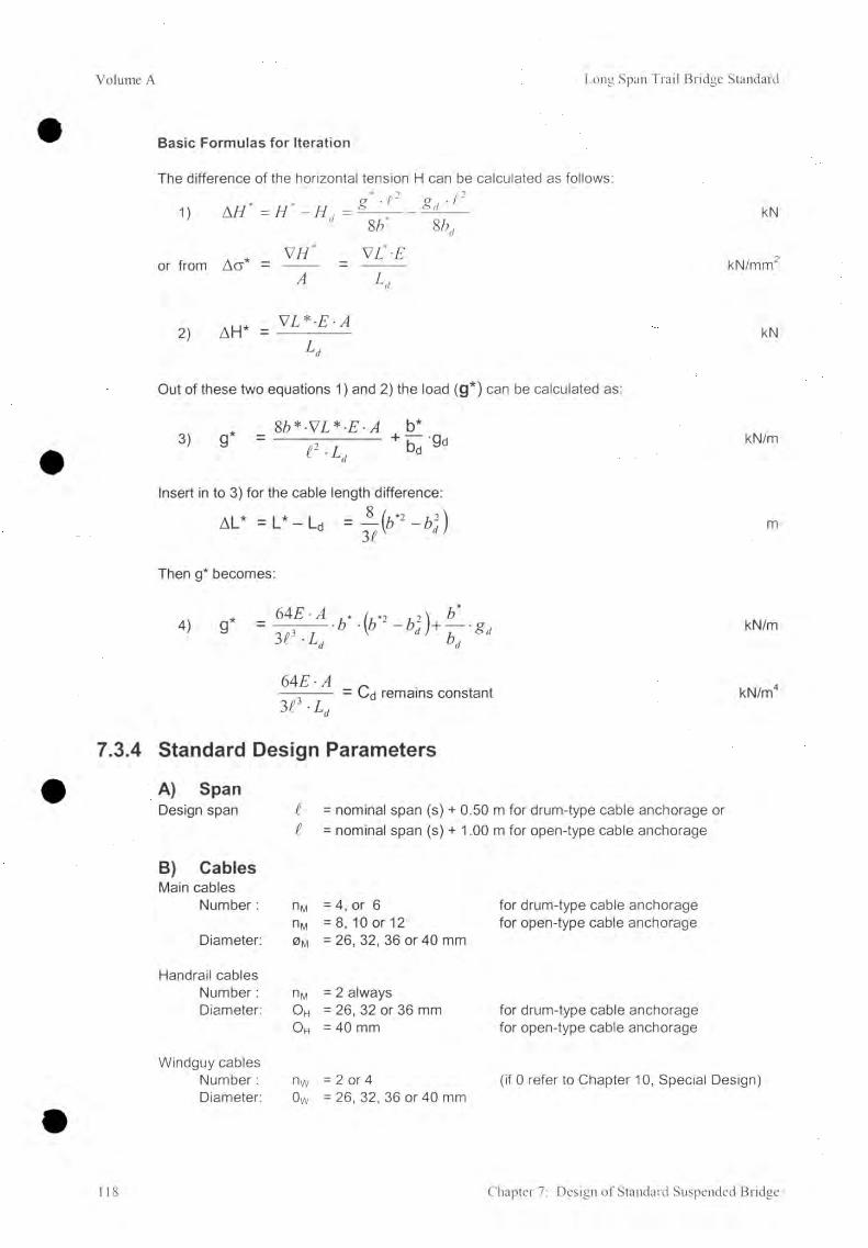
Volume A Long Span Trail Bridge Standard
7.3.4
Basic Formulas for Iteration
The difference of the horizontal tension H can be calculated as follows:
1) AH* = H * - H , = g ' - c 2 g < ' t 2 kNCl oo 00 =x.
* V / /* VL'-Eor from Ag * = kN/mm2
A
V2 ) AH* - kN
Ld
Out of these two equations 1) and 2) the load (g*) can be calculated as:
* 8 b*-VL*-Eb*3> 9 = e - L , * * *
kN/m
Insert in to 3) for the cable length difference:
a l * = l * - l0 m
Then g* becomes:
4)64 E-A31 ■ L
kN/m
64 EE3 e - L .
= Cd remains constant kN/m4
Standard Design Parameters
A) SpanDesign span t = nominal span (s) + 0.50 m for drum-type cable anchorage or
i = nominal span (s) + 1.00 m for open-type cable anchorage
B) CablesMain cables
Number: nM = 4, or 6 for drum-type cable anchoragenM = 8 , 10 or 12 for open-type cable anchorage
Diameter: 0M = 26, 32, 36 or 40 mm
Handrail cablesNumber: nM = 2 alwaysDiameter: 0 H = 26, 32 or 36 mm for drum-type cable anchorage
0 H = 40 mm for open-type cable anchorage
Windguy cablesNumber : nw = 2 or 4 (if 0 refer to Chapter 10, SpecialDiameter: 0W = 26, 32, 36 or 40 mm
Chapter 7: Design of Standard Suspended Bridge

Long Span Trail Bridge Standard Volume A
Anchorage-type
Main Cables Handrail Cables (2 nos.)
Tension (all cables)
Number nM Diameter <j>M (mm)
Diameter <j>H (mm)
1" break(kN)
T perm(kN)
4 32 2 6 3 112 1 0 3 8
4 32 32 3 51 0 1 170
4 36 2 6 3 732 1 2 4 6
4 36 32 4 130 1 3 7 8Drum 4 4 0 26 4 4 2 8 1 4 7 6
4 4 0 32 4 8 2 6 1 6 1 0
6 36 26 5 2 1 2 1 7 4 0
6 36 32 5 6 1 0 1 8 7 2
6 36 36 5 9 2 0 1 9 7 6
6 4 0 26 6 2 5 6 2 0 8 8
6 4 0 32 6 6 5 4 2 2 2 0
6 4 0 36 6 9 6 4 2 3 2 4
8 36 4 0 7 7 4 8 2 5 8 6Open
8 4 0 4 0 9 140 3 0 5 0
10 4 0 4 0 10 9 6 8 3 6 6 0
12 4 0 4 0 12 79 6 4 2 7 0
Table 7.3.1: Standard Cable Combinations, T break and T perm (with Factor of Safety = 3)
Anchorage-type
Main CablesHandrail
Cables (2 nos.) Total (all cables)
nM <Í>M Area, AM,totDiameter
<|>HAreaA h,tot
Area A,ot Load/Weight
(mm) (mm2) (mm) (mm2) (mm2) (kN/m)4 32 1 7 6 8 2 6 58 4 2 35 2 0 .2 0 2
4 32 1 7 6 8 32 88 4 2 6 5 2 0 .2 2 8
4 36 2 2 4 0 26 5 8 4 2 8 2 4 0 .2 4 3
4 36 2 2 4 0 32 8 8 4 3 1 2 4 0 .2 6 8
4 40 2 7 6 4 26 58 4 3 3 4 8 0 .2 8 8
Drum 4 4 0 2 7 6 4 32 8 8 4 3 6 4 8 0 .3 1 4
6 36 3 3 6 0 2 6 58 4 3 9 4 4 0 .3 3 9
6 36 3 3 6 0 32 8 8 4 4 2 4 4 0 .3 6 5
6 36 3 3 6 0 36 1120 4 4 8 0 0 .3 8 5
6 4 0 4 146 26 58 4 4 7 3 0 0 .4 0 7
6 4 0 4 146 32 8 8 4 5 03 0 0 .4 3 2
6 40 4 146 36 1 120 5 2 6 6 0 .4 5 3
8 36 4 4 8 0 4 0 1 3 8 2 5 86 2 0 .5 0 4
Open 8 40 5 5 2 8 4 0 1 3 8 2 6 9 1 0 0 .5 9 4
10 40 6 9 1 0 4 0 1 3 8 2 8 2 9 2 0 .7 1 3
12 4 0 8 2 9 2 40 1 3 8 2 9 6 7 4 0 .8 3 2
Table 7.3.2: Standard Cable Combinations, Metallic Area and Hoisting Load
Chapter 7: Design of Standard Suspended Bridge 119

Volume A Long Span Trail Bridge Standard
Walkway Deck
Width = 1.00 m
Weight/load - sal wood = 0.48 kN/m- steel deck = 0.46 kN/m
D) Live Load
1 < 50 m ----- > p = 4.00 • walkway width = 4.00
. , 5 0 , 50t >50 m ------ > p = (3.00 + — ) • walkway width = 3.00 + —
kN/m
kN/m
7.3.5 Limits and Recommendations
A) Cable Inclination
Cable inclination at saddle of the higher foundation saddle at dead load case Pi, a should not exceed,
Pitd(max) < 12°
and sag of the cable ba should be within the range,
h— to 4
h
4
B) Lowest Point
The lowest point of the parabola of an inclined bridge must remain inside the span for all loading cases. Recommendation for dead load case:
> h/< —
14
C) Safety Factor
Safety factor for all cables and cable terminals £ 3 at full load case.
D) Freeboard
The freeboard must be free of any cable alignment (including the wind-guy arrangement) at dead load case.
120 Chapter 7 : Design of Standard Suspended Bridge
Long Span Trail Bridge Standard Volume A
7.3.6 Initial Layout Data
A) DetermineThe nominal span, S, (free selection, no restriction because of walkway unit length) the location of the foundations, and the cable elevations.
iFix the span, ^and level difference of the saddles, not exceeding h < — (keep h as
minimum as possible).
B) Pre-calculation
1) Main and Handrail Cables
Calculate the approximate maximum cabla tension:Tmax (appx) = 11 • S
(This applies for the present standard loadings and bd
Determine the main cable number and diameter and cable anchorage system (refer to 7.3.4 B) Tmaxfappx)« Tperm
Determine the sectional areas and breaking tension for all cables (n main cables, 2 handrail cables) (refer to 7.3.4)
2) Windguy CablesRefer to Chapter 9, Design of Windguy Arrangement
C) Calculate
1. The design span between saddles, t (refer to 7.3.4),2. The maximum difference in elevation, h, and check (refer to 7.3.5)3. The sag at dead load, bd (refer to 7.3.5)
D) Rough Check of Freeboard
A rough check must be carried out at this point to ensure that any cable alignment lies above the necessary freeboard (refer to 5.3).
The elevations of wind-guy anchorages of both banks are recommended to be placed below the lowest point of the bridge. The vertical clearance between the level of wind-guy cable and the level of High Flood at the point of the bank touching river must be at least 5.0m. The wind-guy cable takes the strait alignment from anchorage to lowest point of bridge.
Required data:i , h, bd, (ed and fd), all cable elevations and, perhaps, also the vertex of windguy
cables.
(kN/m m =) kN
~ t t . h = 0) 23
Chapter 7: Design of Standard Suspended Bridge 121

Volume A Long Span Trail Bridge Standard
Draw the side elevation as shown below (the wind-guy cable elevation upstream and downstream might be different).
E) Loadings
1) Hoisting load case, gh(the hoisting load is self load of all cables)
- Main and handrail cables (refer to 7.3.4 B)Total at hoisting load case: gh = 0.............. kN/m
2) Dead Load case, ga(The dead load of the bridge is load of all parts of walkway including hoisting load of cables)
Hoisting load, gh = 0.............. kN/mWalkway deck = 0.............. kN/mWalkway support (including hangers) = 0.22 kN/mFixation Cables = 0.01 kN/mWiremesh netting = 0.06 kN/mWindguy cables (refer to 9.4.4) = 0 ............... kN/mWindties (average) = 0.03 kN/m
Total at dead load case: ga =................... kN/m
3) Full Load case, gf(The full load in the bridge is the sum of live load and dead load in the bridge)
Dead Load, ga =.................... kN/mLive Load, P =.................... kN/m
Total at full load case: gf =................... kN/m
122 Chapter 7: Design of Standard Suspended Bridge
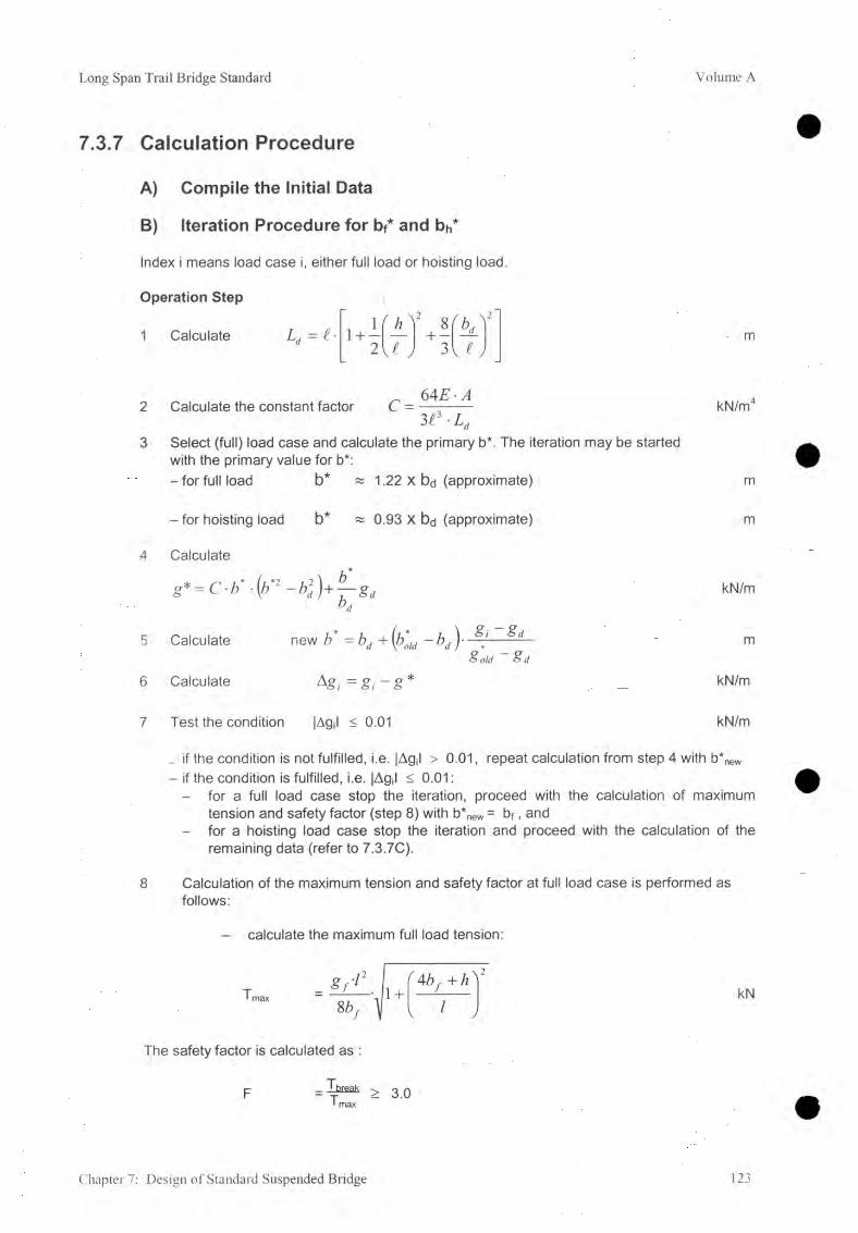
Long Span Trail Bridge Standard Volume A
7.3.7 Calculation Procedure
A) Compile the Initial Data
B) Iteration Procedure for bf* and bh*
Index i means load case i, either full load or hoisting load
Operation Step
1 Calculate
2
3
Ld — l ■ \ + -2
h V
V« J
8 + —
3' O ’
Calculate the constant factor C =6AE ■ A
313 -L;Select (full) load case and calculate the primary b*. The iteration may be started with the primary value for b*:
m
kN/m4
- for full load b* « 1.22 X bd (approximate) m
- for hoisting load b* « 0.93 X bd (approximate) m
4 Calculate
g * = C b - \ b - ^0*
I ^
CNI kN/m
5 Calculate new b = b d +(bM bd\ d m& o ld d
6 Calculate kgi = g , - g * kN/m
7 Test the condition jAgJ < 0.01 kN/m
_ if the condition is not fulfilled, i.e. |Agil > 0.01, repeat calculation from step 4 with b*new - if the condition is fulfilled, i.e. |Agjl < 0 .01 :
- for a full load case stop the iteration, proceed with the calculation of maximum tension and safety factor (step 8 ) with b*new = bf , and
- for a hoisting load case stop the iteration and proceed with the calculation of the remaining data (refer to 7.3.7C).
Calculation of the maximum tension and safety factor at full load case is performed as follows:
- calculate the maximum full load tension:
8 r 72
8bf K1 +
f 4b, + h ^ 'kN
The safety factor is calculated as :
T,= - ™ > 3.0• max
Chapter 7: Design of Standard Suspended Bridge 123

Volume A Long Span Trail Bridge Standard
In order to obtain an optimum safety factor of 3, changes of the initial data might be necessary (for limits refer to 7.3.5) and the iteration must be repeated1.
To calculate the hoisting load sag (bh) proceed from Step 3.
C) Final (Remaining) Data
Calculate the remaining data (refer to 7.3.3 A and 7.3.8) and check Z = 0.
D) Free Space beneath the Walkway in Front of the Main Foundation
A free space of at least 30 cm must be kept beneath the walkway in front of the main foundation if the bridge is fully loaded. Additional rock cutting or dry stone pitching might be necessary (refer to 5.5.4 A).
Determine the line of cutting by drawing a line from cable elevation at an angle Pf° to horizon.
1) Layout for dead load caseIn order to draw the dead load case parabola in the general arrangement section, calculate necessary data as follows:
draw the lowest point elevation (vertex) with ed and fa,fd i
calculate aa = —- ( if it is a level bridge ed = — ----- > a =ed 2
determine d according to the scale of the section,f d
- calculate yid = ad • X2 = ad • (i • d )2 = • ,ed
4fd . 4bdi 2 t 2
draw the sag up to the higher foundation leveli
(check at — with bd and ( = 0 with |3d), and
- the same y ^ ’s can be used to draw the sag up to the lower foundation level.
' If, F > 3, change the cable combination, but do not reduce the sag, which will increase the tension consequently bigger anchorage foundations. If, F < 3, increase the cable sag but within the recommended limits, otherwise change the cable combination.
124 Chapter 7: Design of Standard Suspended Bridge

Long Span Trail Bridge Standard Volume A
2) Parabola for full load caseDraw the lowest elevation point with ef and ff,
ft- calculate af = ——,
e r2 ft d 2 ,2
- calculate y if = a f • X\ = — — ■ i ,e r
- draw the sag In front of the foundation as required (check with Pf),- draw a line 30cm beneath the full load sag,- determine the maximum elevation(s) of rock or dry stone pitching,- determine the inclination of slope in front of the foundation (e-i), and- the same yif’s can be used to draw the sag in front of the lower foundation level.
7.3.8 Compilation of Final Data
Bridge No. & Name............................. Date.................. Designed by
A) Initial Data (refer to 7.3.6 and GA)
Nominal span, S = ........................... mAnchorage type (drum or open) = ........................... /Main cable nM = .......................... /
0 M = ........................... mmAm = ........................... mm2
Handrail cable nH = 2 /0 H = ........................... mmAh = ........................... mm2
Total Metallic Area = AM + AH = ........................... mm2Total Tbreak — break Th,break — ........................... kN
Windguy cable nw = ........................... /0 W = ........................... mm
E - Module = ........................... kN/mm2
Design span ( - ........................... m
h = ........................... mbd = ........................... med (from higher foundation) = ........................... mfd (from higher foundation) = ........................... mPi,d (at higher foundation) = ........................... degP2,d (at lower foundation) = ........................... deg
Cable anchorage elevations:
- Left Bank Windguy cable, upstream = (appx)............... mMain cables = ........................... mWindguy cable, downstream = (appx)............... m
- Right Bank Windguy cable, upstream = (appx)............... mMain cables = ........................... mWindguy cable, downstream =(appx)............... m
Chapter 7: Design of Standard Suspended Bridge 125

Volume A Long Span Trail Bridge Standard
Approximate freeboard Main cables = ........................... mWind cables = (appx)................ m
Loads: - walkway deck (steel or wood) = ........................... kN/m- live load p = ........................... kN/m- hoisting load gh = ........................... kN/m- dead load ga = ........................... kN/m- full load 9f = ........................... kN/m
B) Data from Main Calculation
Full load: bf = ........................... mTmax — ............................ kNSafety factor = ............................. /
Comment
C) Data to be transferred to the General Arrangement
Load CaseLoad
9(kN/m)
TensionTmax(kN
Sagb
(m)
Lowest Point
Horz. Dist. e (m)
Vert. Dist. f (m) Elevation
HoistingDead LoadFull Load
Live LoadFor level bridge, h = 0, Horizontal distance of lowest point, e = and Vertical distance, f = b
Table 7.3.3: Data of Cable Structure
SIDE ELEVATION (dead load)
126 Chapter 7: Design of Standard Suspended Bridge
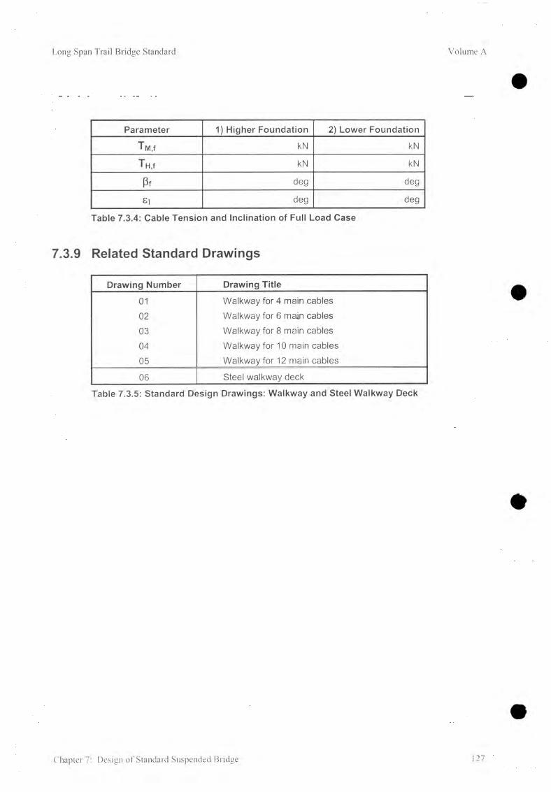
Long Span Trail Bridge Standard Volume A
Parameter 1) Higher Foundation 2) Lower Foundation
Twi,f kN kN
TH,f kN kN
Pf deg deg
£i deg deg
Table 7.3.4: Cable Tension and Inclination of Full Load Case
7.3.9 Related Standard Drawings
Drawing Number Drawing Title
01 Walkway for 4 main cables02 Walkway for 6 main cables03 Walkway for 8 main cables04 Walkway for 10 main cables05 Walkway for 12 main cables
06 Steel walkway deck
Table 7.3.5: Standard Design Drawings: Walkway and Steel Walkway Deck
Chapter 7: Design of Standard Suspended Bridge 27

7.4 Design of Main Anchorage Foundation
7.4.1 Introduction
The scope of this section is the determination of the dimensions of the main anchorage foundations based on the results of the cable structure analysis, on the soil and rock parameters, and on prescribed safety factors.
Basic principles and proceedings for the structural analysis of foundations can be found in Chapter 6 , Foundation Design.
7.4.2 Related Symbols
Volume A Long Span Trail Bridge Standard
As, 1 Total cross-sectional area of foot reinforcement mm2
As,2 Total cross-sectional area of anchorage rods mm2
B Open dimension of foundation, width mHi Open dimension of foundation, height at back mH2 Open dimension of foundation, part of height in front mL Open dimension of foundation, length mM Statical moment in the relevant cross-section for foot reinforcement kNm
N-, Total number of required reinforcement bars (j) 16 mm for foot reinforcement /
N2 Total number of required anchorage rods (j) 25 mm /Tn,f Handrail cable tension of full load case kNTM,f Main cable tension of full load case kN
r|h Lever arm of internal forces (reinforced concrete) m
Indices: V vertical componentH horizontal component
For all other symbols used in this chapter refer to Chapter 6 .
128 Chapter 7: Design of Standard Suspended Bridge

Long Span Trail Bridge Standard Volume A
7.4.3 Design Parameters
A) Main Anchorage Foundation on Soil
SoilDrum type Anchorage
FoundationOpen type Anchorage
FoundationDim. \ nM 4 6 8 10 12
Himin 1.50 2.00 3.70 3.70 3.70max 4.00 4.50 6.70 6.70 6.70
h2min 1.201) 1.201) 2 .001) 2 .001) 2 .001)max 4.00 4.50 5.80 5.80 5.80
Bmin 6.20 7.90 9.50 11.00 12.50max 9.50 11.00 9.50 11.00 12.50
Lmin 2.90 3.30 5.00 5.70 5.70max 5.00 6.50 7.50 8.00 8.00
Table 7.4.1: Limits of Dimensions ( m ) for Foundation on Soil According to the Standard Dimension of Steel Anchorage Structure(For1) refer to 7.4.4 A )
Chapter 7: Design of Standard Suspended Bridge 129

Volume A Long Span Trail Bridge Standard
B) Main Anchorage Foundation on Rock
Drum type Anchorage Open type AnchorageRock Foundation Foundation
Dim. \ nM 4 6 8 10 12
Himin 1.50 2.00 2.90 3.20 3.45max 4.00 4.50 6.70 6.70 6.70
h2min 0.801) 1.001) 1.451) 1.451) 1.451)max 4.00 4.50 5.80 5.80 5.80
Bmin 5.00 6.70 9.50 11.00 12.50max 8.50 9.50 9.50 11.00 12.50
Imin 2.90 3.30 4.80 5.40 5.40
Lmax 5.00 5.50 7.50 8.00 8.00
S 1.00 1.50 1.75 1.75 1.75Table 7.4.2: Limits of Dimensions ( m ) for Foundation on Rock According
to the Standard Dimension of Steel Anchorage Structure (For1) refer to 7.4.4 A)
130 Chapter 7: Design of Standard Suspended Bridge

Long Span Trail Bridge Standard Volume A
7.4.4 Limits and Recommendations
A) Foundation Dimensions
The limits of the foundation dimensions as given in 7.4.3 depend upon the standard dimensions of the anchorage steel structure. The minimum dimensions (H2 (min) ) especially might be superseded by the necessary embedded depth (t) (refer to 5.5.2).
B) Handrail Cable Pillar
For calculation of the height of the handrail cable pillar (vertical distance between saddles) and determination of cable anchorage lengths, refer to standard drawings.For structural analysis, the height of handrail cable pillars can be assumed to be uniform at 1.25 m for drum-type anchorage foundations and at 1.23 m for open-type anchorage foundations. The weight of the pillars can be neglected.
C) Anchorage Rods for Foundations on Rock
Provide number of anchorage rods according to calculations but, if B*/2 < B/3, at least: for foundations with 4 main cables : 4 vertical rodsfor foundations with 6 main cables : 6 vertical rodsfor foundations with 8 , 10, and 12 main cables : 6 vertical rods
The distance between anchorage rods should not be less than 0.75 m for drum-type anchorage foundations and 1.0 m for open-type anchorage foundations.Additional anchorage rods might be necessary in order to stabilize the rock (refer to 6.3.3 and 6.6.7)
D) Soil/Rock Check List
Refer to Chapter 6 . Foundation Design for the check list of limits (for soil 6.5.1, for rock 6.6.1).
7.4.5 Initial Layout Data
A) Define Characteristics of Foundation
1) Type of bridge: level (h = 0) or inclined (h > 0) ? ................. /2 ) River bank: left or right ? ..................... /3) If inclined bridge: higher or lower foundation ? ..................... /4) Cable anchorage: drum or open-type ? ..................... /5) Foundation: on soil or rock ? ..................... /
B) Compile the following Data
1) From cable structure analysis:Number of main cables nM =................. /Main cable tension T M,f = ................... kN
- Handrail cable tension T H,f = ................... kNCable inclination Pf = degFront slope of rock, or stone pitching £1 deg
Chapter 7: Design of Standard Suspended Bridge 131
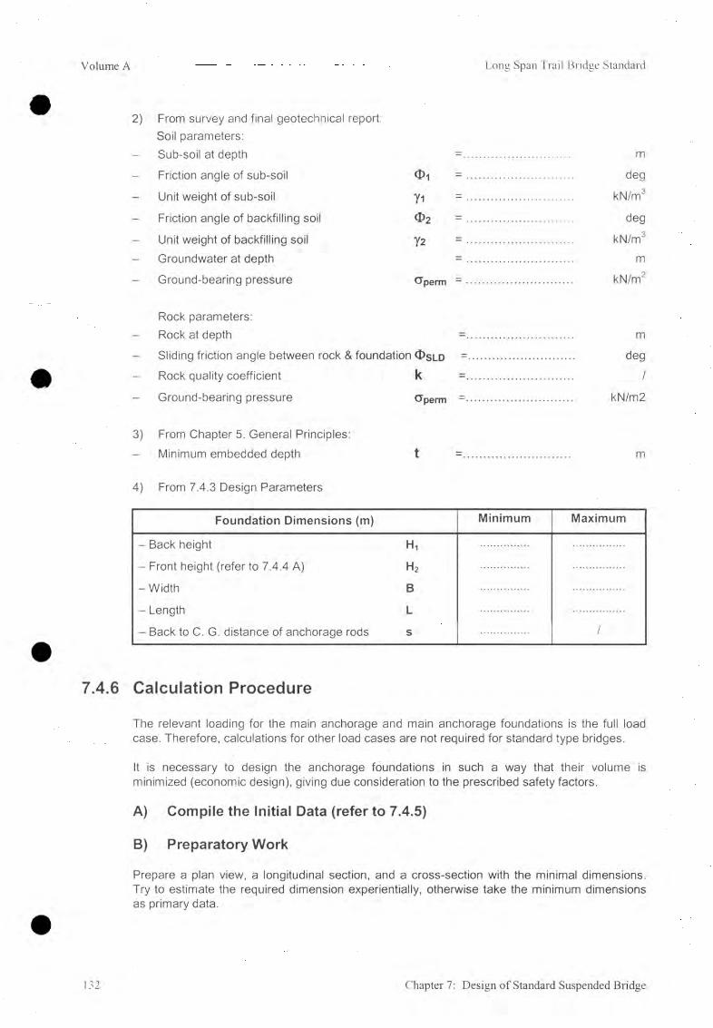
Volume A Long Span Trail Bridge Standard
2) From survey and final geotechnical report:Soil parameters:
- Sub-soil at depth =................................. m
Friction angle of sub-soil O i = ................................. deg
- Unit weight of sub-soil yi = ................................. kN/m3
- Friction angle of backfilling soil O 2 = ................................. deg
- Unit weight of backfilling soil 72 = ................................. kN/m3
- Groundwater at depth = ................................. m
Ground-bearing pressure CJperm = ............................... kN/m2
Rock parameters:Rock at depth =................................ m
- Sliding friction angle between rock & foundation <J>sld =................................. degRock quality coefficient k =................................ /
Ground-bearing pressure <jperm =................................ kN/m2
3) From Chapter 5. General Principles:- Minimum embedded depth t =................................ m
4) From 7.4.3 Design Parameters4) From 7.4.3 Design Parameters
Foundation Dimensions (m) Minimum Maximum
- Back height H,
- Front height (refer to 7.4.4 A) H2
-W idth B
- Length L
- Back to C. G. distance of anchorage rods s /
7.4.6 Calculation Procedure
The relevant loading for the main anchorage and main anchorage foundations is the full load case. Therefore, calculations for other load cases are not required for standard type bridges.
It is necessary to design the anchorage foundations in such a way that their volume is minimized (economic design), giving due consideration to the prescribed safety factors.
A) Compile the Initial Data (refer to 7.4.5)
B) Preparatory Work
Prepare a plan view, a longitudinal section, and a cross-section with the minimal dimensions. Try to estimate the required dimension experientially, otherwise take the minimum dimensions as primary data.
132 Chapter 7: Design of Standard Suspended Bridge

Long Span Trail Bridge Standard Volume A
C) Main Calculation
The basic design principles, the procedure for the structural analysis, and the limits as well, are given in Chapter 6 , Foundation Design.
Calculation example: The calculations are given from examples of a foundation (with foot) on soil, without groundwater, and with a retaining wall at the top. The structural analysis of the retaining wall has to be carried out separately.
For other layouts, similar proceedings should be applied with:- foundations on rock hrt > t , hra > 0- foundations without a foot b = 0- with groundwater hw > 0
1. Calculate the components, inclination, and location of the resultant loading force
Loading Forces Lever arm (m) for M p
Weights (kN):
W, = 0.50 (H1+H2) • B • L - Y c B 2H1 + H? 3 ' Hi + H2
W2 = 0.95 ( B - 1.20)- L ' Y c0.50 B + 0.60
Load on Top (kN):A = (refer to 6.2.4) aEarth Pressure (kN):
- back: Eah (back) = 1/ 2 Xah [0 2, i|/] (ha2- ha12) • L • y2 yEah — H i + H 2
(ha - ha1 ) 2 ha1 + haYEah = t 0 • . . I
3 ha1 + ha
Eav(back) - Eah '2
tan( g $ 2) B
Loads (kN):
T Hh = Th • cosß h2 + 1.95
T Mh = Tm ■ cosß H2 + 0.70
Thv = Th • sinß 1.45
Tmv = Tm • sinß 1.45
Chapter 7: Design of Standard Suspended Bridge 133

Volume A Long Span Trail Bridge Standard
Mf = sum of all statical moments in F kNm
- Vertical component of R
Rv = sum of all vertical forces = W-i + W2 + A + Eav + Thv + Tmv M
- Location of R
B*/2 =_________M r_________Rv ■ (1 + tana • tanSR) m
- Inclination of R
tanSR = ^
2. Select the possible predominant failure mode and proceed according to Chapter 6 .
3. Reinforcement
Reinforcement is required only for foundations with a foot.The required cross-sectional area of reinforcement bars in the foot of the drum-type foundations on soil is determined by means of a simplified formula:
Asi -M >2(1.20 cosa-hLsin OC ) - CTmax * L
' h * at perm 0.9 • (H2 • cos# + 1.20 sin a - 0.20) • 23 (Tmax * L (1.20 cosa - H2 • sin«)2
•100
0.414 (H2-cosa + 1 .20s ina-0 .20)(H2, L in m ; Gmax in kN/m ) mm
Provide minimum reinforcement: Asi (min) = 0.02% • H2 ■ L (H2, L in mm) mm2
Number of required bars 016 mm: N-t 4 A s i 0 2. 71
Asi201 /
134 Chapter 7: Design of Standard Suspended Bridge

Long Span Trail Bridge Standard Volume A
7.4.7 Compilation of Final Data
Bridge No. & Name......................................... Date.............. Designed b y ...............
A ) and B) In it ia l Data (re fe r to 7.4.5)
C) M ain C a lc u la tio n
1 ) Load on top of foundation- Total load A = ..................................... kN- Front to C.G. distance a = ..................................... m
2) Soil / rock heights- Total active earth pressure height ha = ..................................... m- Active earth pressure height from
top of the foundation block hai = ..................................... m- Rock height at back hr = ..................................... m- Embedded depth t = ..................................... m- Depth of additional soil t ' = ..................................... m
3) Soil parameters- Front slope of soil
(top of dry stone pitching) Si = ..................................... deg- Slope of soil baseline SB = ..................................... deg- Length of influence L * nfi = ..................................... m- Back slope of soil vj/ = ..................................... deg
4) Foundation dimensions- Back height Fh = ..................................... m- Front height H2 = ..................................... m- Width B = ..................................... m- Length L = .................................... . m- Base inclination a = ..................................... deg- Distance to resultant force B*/2 = ..................................... m
L*/2 = ..................................... m5) Safety factors
- Sliding Fsl = ..................................... 1- Bearing capacity Fbc = ..................................... /- Toppling Ft = ..................................... /- Slope stability Fs = ..................................... /
6 ) Anchorage rodsNos. as per calculation or minimum Nos. N = .................................... /
D) A d d it io n a l A n c h o ra g e R ods
(from geological report)
Chapter 7: Design of Standard Suspended Bridge 135

Volume A Long Span Trail Bridge Standard
E) Data to be transferred to the General Arrangement
Drum-type anchorage on soil
Open-type anchorage on rock
-c
(Z
«______ B- _______
136 Chapter 7: Design of Standard Suspended Bridge

Long Span Trail Bridge Standard Volume A
7.4.8 Related Standard Drawings
Drawing Number Drawing Title
Drum-Type Anchorage:61 Main Cable Anchorage for 4 main cables (capacity: 1220 kN)
61/1(26), 61/1(32), 61/2(26), 61/2(32)
Main Foundation for 4 main cables (related drawings: 61,63(26) & 63(32)
62 Main Cable Anchorage for 6 main cables (capacity: 1830 kN)
62/1(26), 62/1(32), 62/1(36)62/2(26), 62/2(32), 62/2(36)
Main Foundation for 6 main cables (related drawings: 62, 63(26) & 63(32), 63(36)
63(26), 63(32), 63(36) Handrail cable anchorage (capacity 260/390/494 kN)
Open-Type Anchorage:
64 Main Anchorage / 8 main cables, 2 Handrail Cables 4>40mm (capacity: 2440 & 610 kN)
64/1, 64/2 Main Foundation / 8 main cables (related drawings: 64 & 67)
65 Main Anchorage /10 main cables, 2 Handrail Cables 4>40mm (capacity: 3050 & 610 kN )
65/1, 65/2 Main Foundation /10 main cables (related drawings: 65 & 68 )
66 Main Anchorage /12 main cables, 2 Handrail Cables <f>40mm (capacity: 3660 & 610 kN )
66/1, 66/2 Main Foundation /12 main cables (related drawings: 66 & 69)
67 Saddles and Accessories / 8 main cables
68 Saddles and Accessories /10 main cables
69 Saddles and Accessories /12 main cables
Drawing Numbers: ...... = 'Working and assembly drawing...71 = Structural drawing: Foundation on Soil
= Structural drawing: Foundation on RockTable 7.4.3: Standard Design drawings: Main anchorage Foundation for
Suspended Bridges
Chapter 7: Design of Standard Suspended Bridge 137

Long Span Trail Bridge Standard Volume A
8. Design of Standard Suspension Bridge
Table of Contents
8.1 Flow Chart 140
8.2 Layout 141
8.3 Design of Main Cable Structures 1428.3.1 Introduction 1428.3.2 Related Symbols 1438.3.3. Geometrical Parameters 1448.3.4 Standard Design Parameters 1478.3.5 Limits and Recommendations 1508.3.6 Initial Layout Data 1518.3.7 Calculation Procedure 1538.3.8 Compilation of Final Data 1558.3.9 Related Standard Drawings 156
8.4 Load Combinations with Wind Load 1578.4.1 Introduction 1578.4.2 Related Symbols 1578.4.3 Layout (Isometric View) and Tower Section 1588.4.4 Geometrical Parameters 1598.4.5 Wind Loads 1608.4.6 Calculation Model 1608.4.7 Load Combinations 1628.4.8 Initial Layout Data 1638.4.9 Calculation Procedure 164
8.5 Tower 1678.5.1 Introduction 1678.5.2 Loading Cases 1678.5.3 Tower Capacity Diagram 1678.5.4 Sidestay Cables 1688.5.5 Related Standard Design Drawings 169
8.6 Design of Walkway / Tower Foundation. 1708.6.1 Introduction 1708.6.2 Related Symbols 1708.6.3 Design Parameters 1718.6.4 Limits and Recommendations 1738.6.5 Initial Layout Data 1738 .6.6 Calculation Procedure 1748.6.7 Compilation of Final Data 1798 .6.8 Related Standard Design Drawings 180
Chapter 8: Design of Standard Suspension Bridge 138

Volume A Long Span Trail Bridge Standar
8.7 Design of Main Cable Foundation 1818.7.1 Introduction 1818.7.2 Related Symbols 1818.7.3 Design Parameters 1828.7.4 Limits and Recommendations 1838.7.5 Initial Layout Data 1838.7.6 Calculation Procedure 1848.7.7 Compilation of Final Data 1868.7.8 Related Standard Design Drawings 187
8.8 Determination of Suspender Length 1888 .8.1 Introduction 1888 .8.2 Related Symbols 1888.8.3 Layout and Section 1898.8.4 Calculation Procedure 1908.8.5 Data to Be Transferred to the Standard Design Drawing
"Suspenders" 1918 .8.6 Related Standard Design Drawings 191
8.9 Design of Stabilizing Measures 1928.9.1 Stabilizing the Cable Structure 1928.9.2 Lateral Stabilization of the Tower 1948.9.3 Data to be Transferred to the General Arrangement 1958.9.4 Related Standard Design Drawings 196
8.10 Tower Erection 1978 .10.1 Layout for Erected Tower 1978 .10.2 Data to be Transferred to the General Arrangement 1988.10.3 Related Standard Design Drawings 198
139 Chapter 8: Design of Standard Suspension Bridge

Long Span Trail Bridge Standard Volume A
8.1 Flow Chart
Chapter 8: Design of Standard Suspension Bridge 140
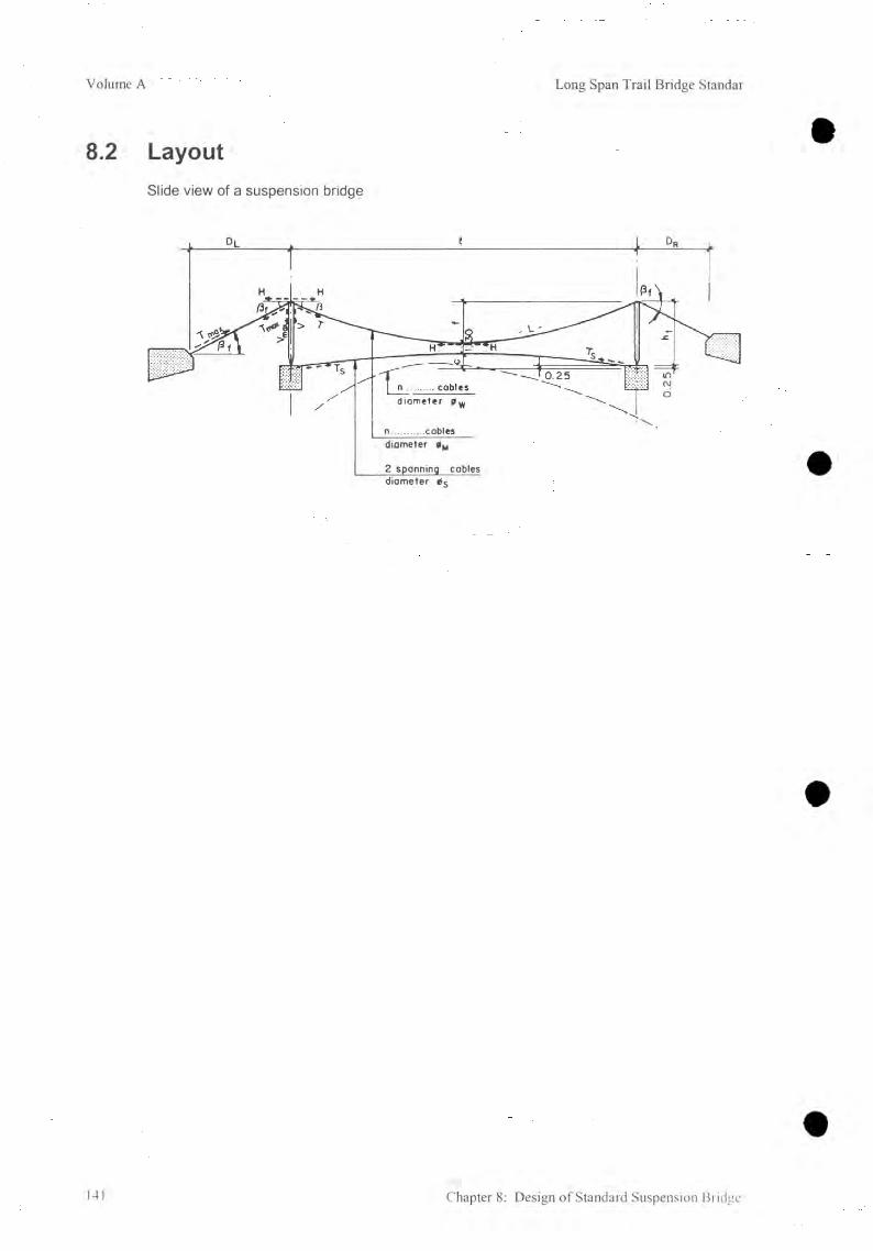
Volume A Long Span Trail Bridge Standar
8.2 LayoutSlide view of a suspension bridge
t 4- Dr
n............coblesdiameter 0M
2 spanning cobles diameter 0S
141 Chapter 8: Design of Standard Suspension Bridge
0.25

Long Span Trail Bridge Standard Volume A
8.3 Design of Main Cable Structures
8.3.1 Introduction
The procedure followed in this chapter has provision for a windguy arrangement (refer to Chapter 9). Refer to Chapter 10, Special Design, if in very rare cases it is not possible to provide a windguy arrangement.
The layout and the initial loading is based on the structure under dead load.
The freeboard has to be maintained for any cable alignment (including windguy cables) at dead load case.
An overview of the main parameters and their relevant loading cases are given below.
Loading Case Load Relevant for Determining Refer toHoisting dead load of main - hoisting sag of main cable 8.3
cablesDead load all dead loads and - initial loading case, free board 8.3
pre-tension of - length of suspenders 8.8
spanning cables - stabilizing measures, tower erection 8.9Full load all dead loads and - number and size of main cables 8.3
live load - design of main cable foundations 8.7Wind load wind load acting on - number and size of windguy cables 9.4
the walkway - design of windguy cable foundations 9.5[A] dead load case and full wind load
wind load acting on- size of spanning cables 8.4
8.5main cables,
- rough check of tower[B] full load suspenders, and
- design of walkway/tower foundations 8.6case and towers1/3 wind load
N.B. It should be noted that the term "case" is used to clearly distinguish the loads (e.g., dead loads) from the loading case (e.g., dead load case = dead loads + pre-tension of spanning cable).
Chapter 8: Design of Standard Suspension Bridge 142

Volume A Long Span Trail Bridge Standar
8.3.2 Related Symbols
A Sectional area of cables • mm2
D — D[_ + Dr mD|_, Dr Backstay distance of main cables, distance between tower axis and
hinge of the main cable anchorage (front of main cable foundation for design drawing 46/1) m
E Modulus of elasticity of cables kN/mm2
H Horizontal component of the cable tension kNL Length of main cables between tower saddles mT Main cable tension at saddle for frontstay kNTappx Approximate maximum tension of cables kNTbreak Minimum breaking load of cables kNTperm Permissible cable tension kNTmax Main cable tension at saddle for backstay (all main cables) kNT Sd Pre-tension of spanning cables for dead load case kNV Vertical component of the frontstay main cable tension kNVmax Vertical component of the backstay main cable tension kNVtot Total vertical load on tower saddle kN
C Camber, vertical distance from the spanning cable anchorage (top ofwalkway & tower foundation minus 0.25 m) and the highest point of the spanning cable
f Sag, vertical distance from tower saddle to the lowest point of themain cable
g Loadsgd Dead weight of cable and walkway structures (subtotal of gd) gp Pre-tension of spanning cables expressed as equally distributed loadht Tower height, vertical distance between top of walkway & tower
foundation and saddlel Bridge span, distance between tower axis
n Numberp Live load
m
mkN/mkN/mkN/m
mm
kN/m
P Frontstay cable inclination at saddlePf Backstay cable inclination = frontstay cable inclination at
saddle for full load Pfo Initial approximation of Pf<|) Cable diameterA Increase / decrease of parameter due to changing load
deg
degdegmm
Indices: h hoisting load case M Main cablesd dead load case S Spanning cablesf full load case W Windguy cablesi load case (either full or hoisting) B BackR Right bank F FrontL Left bank
143 Chapter 8: Design of Standard Suspension Bridge

Long Span Trail Bridge Standard Volume A
8.3.3. Geometrical Parameters
A) Main Cables
1) Cable inclination at saddles - Frontstay angle:
ßF = a rc tany deg
Backstay angle:n n ■ 4ff , 4 (1.05 fd) ßB - ßßt - arctan * arctan—*— -j----- deg
2) Anchorage location out of DL and ßB:
hL - tanßB • Dl - 4ff • DL « 4 ’f d -DL m
hR = tanße-D r = ^ Dr * 4 -2/ L d r m
3) Length of cable (at dead load) between tower saddles:
I - I ■ i + ^ ( f d\ 2LMd - i i + - ( — ) m
4) Length of cable (at dead load) between anchorages (excluding overlapping length for fixation):
L m l-Md +D l + Dr
COSßfm
The sag of the backstay cables should be considered for the hoisting load case only and can be neglected for dead and full load case where the shape of the cables is almost a straight line.
Chapter 8: Design of Standard Suspension Bridge 144

Volume A Long Span Trail Bridge Standar
5 ) Horizontal
H r =
tension
8 f Hb
6 ) Vertical load at saddles
VF = a Vb
7) Maximum tension
TmaxHf
cosßf 1 6 ( } ) 2
kN
kN
kN
B) Spanning Cable
1) Cable inclination:
„ X 4cßc = arctan — deg
2) Tension:
Ts T sh -fls ' r
8 c kN
It has to be mention that depending on the load case and the pre-tension, the spanning cable may become tensionless.
3) Length of cable at dead load between tower axis:
Lsd - 1 + ~ (8 , Cd y?
/ > m
145 Chapter 8: Design of Standard Suspension Bridge

Long Span Trail Bridge Standard Volume A
C) B a sic Calculation P rincip le
As the structure at dead load is the initial load, the sag ( ff ) of the full load case and the sag ( fh ) of the hoisting load case have to be calculated. Wherein the maximum full load tension has to fulfill the safety requirements for the cables.
ParameterLoad case
Hoisting load Dead load Full LoadLoad gh 9d 9fCable length U =Ld+ ( - A L h) Ld L, = Ld + ALfSag fh = fd + (- Afh) fd ft = fd + AffHoriz. Tension Hh = Hd + (-AHh) Hd Hf = Hd + AHd
The values of delta ( A ) are the increase ( + ) or decrease ( - )caused by the elastic properties of the cables.
The different sags ( ff, fh ) can be determined by iteration as follows:with an assumed sag ( f* ) the corresponding load ( g* ) can be calculated (based on the dead load layout) and then compared with the actual load ( gf or gh). The difference is then judged.
If necessary, a new sag assumption must be made and the calculation repeated until sufficient accuracy is achieved.
Basic formulas for iteration
According to J. Melan [1] th '5 increase / decrease of sag remains constant:
Wherein15AL b-AD
Af = ------- + --------- m
15 AU a
b - AD1
a
increasing / decreasing sag caused by a change in cable length
between saddles, and
increasing / decreasing sag caused by a change in cable length at the
backstay cables which results in the displacement of saddles.
Chapter 8: Design of Standard Suspension Bridge 146

Volume A Long Span Trail Bridge Standar
The change of the cable length between the saddles is calculated with the average tension of, _ 2H + T
the main cables (within the span /) I average - 3
The increase / decrease of the cable length between the saddles is calculated as:
2H + T LdD. E A g m
The displacement of the saddles caused by an increase / decrease in cable length of the backstay cables is calculated as
Ad-r- D Ag _
= T • ^ ^ • g + Displacement of saddle caused by changing sag of
backstay cable (influence only on the hoisting sag calculation).
Displacement of saddles for cable hoisting:
ADhR/L -Th • D r /l dh - d d dh2 • D r /L3
E - A , M 9h 24 cosßf U4d Hh1 1
m
8.3.4 Standard Design Parameters
A) Span
Because of different suspender lengths the span must be fixed at an interval of 2.4 m which means that there must be one suspender at mid span. The distance from the tower axis to the first cross-beam (without suspender) is fixed at 1.1 m. With these two conditions, the span length is calculated as follows:
/ = 2.40 i + 2.20 ( i = integer number) m
The total number of suspender pairs:
ns I-(2-2.301 , 1 . 1.20
The total number of cross-beams:
nc/ - ( 2 - 1 . 1 0 ) + 1 _ 7 - 1 . 0 0
1 .20 1.20ns + 2
The total number of steel walkway deck pairs:
7 + ( 2 - 0 . 1 0 ) = / + 0 .2 0
Rc 1 .20 1.20
B) Walkway DeckWidthWeight/Load
- sal wood- steel deck
nc + 1
= 1.20
= 0.61 = 0.50
7 - 3 . 4 0
1.20
/
/
m
kN/mkN/m
147 Chapter 8: Design of Standard Suspension Bridge

Long Span Trail Bridge Standard Volume A
C) Live Load
l < 50 m — > p = 4.00 ■ walkway width = 4.80
l > 50 m — > p = ( 3.00 + 50/ / ) • walkway width = 3.60 + 60 /
D) Cables
Main CablesNumber nM = 4, 6 , or 8Diameter : <|)M = 26, 32, 36, or 40 mm
Spanning CablesNumber : ns = 2 alwaysDiameter: <|>s = 32, 36, or 40 mm
Windguy CablesNumber : nw = 2 (if 0 refer to Chapter 10, Special Design)Diameter: = 26, 32, 36, or 40 mm
Handrail and Fixation Cables (no load bearing function)Number : n = 2 alwaysDiameter: ♦ 13 mm
kN/m
kN/m
Nos. Diam. Hoisting Load Metallic Area Breaking Load Permissible LoadnM 9h Atot 7 break T perm( - ) (mm) (kN/m) (mm2) (kN) (KN)
2 26 0.050 584 772 2572 32 0.076 884 1 170 3902 36 0.096 1 120 1 480 4932 40 0.119 1 382 1 828 6094 32 0.152 1 768 2 340 7804 36 0.192 2 240 2 960 9874 40 0.238 2 764 3 656 1 2196 36 0.289 3 360 4 440 1 4806 40 0.356 4 146 5 484 1 8288 36 0.385 4 480 5 920 1 9738 40 0.475 5 528 7312 2 437
Table 8.3.1: Total gh, A, Tbreai<, Tperm for Main Cables, E = 110 kN/mm2
Nos. Diam. Weight/Load Metallic Area Breaking Load Permissible Loadns <(>s 9 Atot Tbreak Tperm
( - ) (mm) (kN/m) (mm2) (kN) (KN)2 26 0.050 584 772 2572 32 0.076 884 1 170 3902 36 0.096 1 120 1 480 4932 40 0.119 1 382 1 828 609
Table 8.3.2: Total g, A, Tbreak, Tperm for Spanning Cables, E = 110 kN/mm2
Chapter 8: Design of Standard Suspension Bridge 148

Volume A Long Span Trail Bridge Standar
E) Towers
Tower Total Tower Main Cables Recommended Diameter of
Number Height Diameter of Tower legsht Number Possible 0 M Spanning Cables c/c! (m)
(m) Hm (mm) (mm)
1 12.90 4 26 32
2 12.92
3 14.77 A 32 3.504 16.625 18.47 36 32
6 17.74 47 20.24 or 40
8 22.73 6
910
25.2327.73
6
or4
36
4.0011
12
13
30.22 32.721) 35.211)
63640
4014 30.2215 32.721) 8
16 35.211)
- Difference from tower foot to the spanning cable elevation = 0.25 m- Difference from the vertex of spanning cable to the vertex of main cable 1.30 m
hT = f + 1.30 + c - 0.25 = f + c+ 1.05 m1) Bolts with property grade 6.6 required
Table 8.3.3: Standard Towers, Related Number and Diameter of Cables
149 Chapter 8: Design of Standard Suspension Bridge

Long Span Trail Bridge Standard Volume A
8.3.5 Limits and Recommendations
A) Main Cable Inclination
Main cable inclination at saddle at full load case (backstay cable inclination at any load case respectively):Pf(max) =30° — > fd « 0.135 i m
Pi (min) = 20° — > fd ~ 0.09 t m
B) Camber of Spanning Cable
Camber of spanning cable at dead load case:
Cd (max) = 0.03 l m
C d (min) = 0.02 i m
C) Tower Height
The limits for the tower height are based on the limits of bf ( fd ) and cd:
ht (max) = fd (max) + 1.3 + Cd (max)-0.25 = 0.165^+1.05 m
ht (min) = fd (min) + 1.3 + Cd (min) - 0.25 = 0.110^+1.05 m
D) Dead Load Sag
The limits for the dead load sag ( fd ) is based on ht and the limits of Cd and Pf
fd (max) = (ht — 1.05) — 0.02 t < appx 0.135 m
fd (min) = (ht — 1.05) - 0.03 l < appx 0.09 m
Recommended: Select optimum in between minimum and maximum (A, B, C & D).
E) Safety Factor
Safety factor (for all cables and cable terminals) > 3 for the main cables at full load case and for the spanning cables at load case [A] (refer to 8.4.8).
F) Freeboard
The freeboard must be clear of any cable alignment at dead load case.
Chapter 8: Design of Standard Suspension Bridge 150
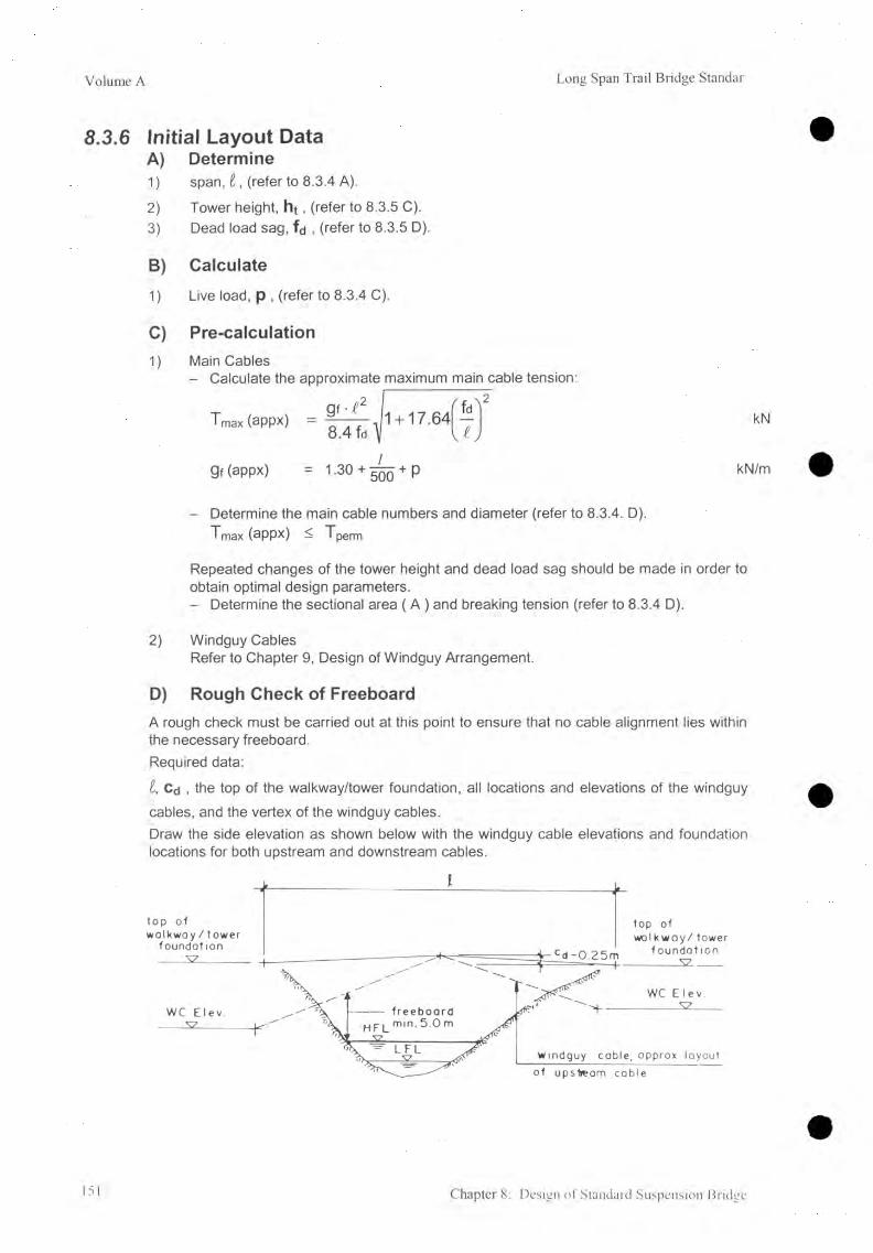
Volume A Long Span Trail Bridge Standar
8 .3 .6 Initial Layout DataA) Determine1) span, i , (refer to 8.3.4 A).
2) Tower height, h t , (refer to 8.3.5 C).3) Dead load sag, fd , (refer to 8.3.5 D).
B) Calculate1) Live load, p , (refer to 8.3.4 C).
C) Pre-calculation1) Main Cables
- Calculate the approximate maximum main cable tension:
Tmax (appx)g f - t 2
' 8.4 fd Vi f * } 2
1 + 17.64 - kNV ^ J
9f (appx)C
L+1°'"o« IO|lo
+oooil kN/m
- Determine the main cable numbers and diameter (refer to 8.3.4. D).Tmax (appx) < Tperm
Repeated changes of the tower height and dead load sag should be made in order to obtain optimal design parameters.- Determine the sectional area ( A ) and breaking tension (refer to 8.3.4 D).
2) Windguy CablesRefer to Chapter 9, Design of Windguy Arrangement.
D) Rough Check of FreeboardA rough check must be carried out at this point to ensure that no cable alignment lies within the necessary freeboard.Required data:
l, Cd , the top of the walkway/tower foundation, all locations and elevations of the windguy cables, and the vertex of the windguy cables.Draw the side elevation as shown below with the windguy cable elevations and foundation locations for both upstream and downstream cables.
151 Chapter 8: Design of Standard Suspension Bridge

Long Span Trail Bridge Standard Volume A
E) Loadings
1) Hoisting load case, gh (<|> in mm)Main cables (refer to 8.3.4 D) = 0................. kN/m
Total at hoisting load case: gh = 0................. kN/m
2) Dead load case, ga (<|> in mm)
a) Dead Weights, g d dHoisting load, gh = 0............ kN/m
- Walkway deck = 0............ kN/m- Walkway support = 0.27 kN/m- Handrail and fixation cables = 0.03 kN/m- Wiremesh netting = 0.06 kN/m- Suspenders (average) =0.17 kN/m- Spanning cables (refer to 8.3.4 D) = 0............ kN/m
Windguy cables (refer to 8.3.4 D) = 0............ kN/m .- Windties (average) = 0.04______ kN/m
Subtotal dead weights, gdd = ................... kN/m
b) Pre-tension in spanning cablesAssumed approximate pre-tension at dead load case = 10% of dead weightsgpd = o.io • gdd = o................. kN/m
Total at dead load case (gdd + gpd): gd =,kN/m
3) Full load case, gfIt is assumed that the pre-tension at full load case is decreased to zero.- Dead weights gdd = ............... kN/m- Pre-tension gp f = 0 /- Live load p = ............... kN/m
Total at full load case: gf = ............... kN/m
Chapter 8: Design of Standard Suspension Bridge 152

Volume A Long Span Trail Bridge Standar
8.3.7 Calculation Procedure
A) Compile the Initial Data
B) Iteration Procedure for f f and f h
Index! means load case 1, either full load or hoisting load.
Step Operation
1) Calculate length of main cables between saddles at dead load
L „ = I l + I V2) Calculate main cable tension at dead load
Td =_ 9 ^
8f„ \ / 1 + 1 6 < 7 > 2Hd g<>-I2
8fd
3) Calculate values of a, b, and ßf0
a = 1 6 ^ [ 5 - 2 4 ( í f ) 2J
b = 1 5 -8
ßfo arctan
n
4.2 fd/
5-36 fd
4) Select (full) load case and calculate the primary f iThe iteration may be started with the primary value of f |- for full load f-| = appx 1.05 fd- for hoisting load fi = appx 0.98 fd
5) T 1 = H 1 • A J 1 + 1 6
6) Al_i ( 2 H i + T - i) • Ld<LU
CO
II
A D i — A D r i + A D l i
ADriT i Dr g i - g d
9i
H 1 = V
E • Am gi+
gh2 • D3r
24 cos ßfoJ ____ 1_ 'Hd2 Hh2
ADL1T i -Dl gi - g d _gn
“ F A . . ' n. L 0/1, , 2 - D lL . / J ,
E • A m gi L 24 cosßfo HV HÍ7 ' J
m
kN
/
/
deg
mm
kN
m
m
m
m
153 Chapter 8: Design of Standard Suspension Bridge

Long Span Trail Bridge Standard Volume A
1) + [....] Only relevant for hoisting load case
r 15 AL-i b • AD-i A f’ = a + a7) m
8 ) The new f-i = fd + Aff m
9) Test the condition | new T — old T | < 0.005 m
- If no (greater): repeat the calculation from step 5 with f| = new f|- If yes (smaller):
- for full load case stop the iteration, proceed with the calculation of maximum tension and safety factor (step 10) with new fi = fi , and
- for the hoisting load case stop the iteration and proceed with the calculation of the remaining data (refer to 8.3.7 C).
10) Calculation of maximum tension and safety factor at full load case is performed as follows:- calculate the maximum main cable tension:
T fT
f max — 8 f f 16 ( }>2 kN
The safety factor is calculated as:
F T break
T f max/
In order to obtain an optimum safety factor of 3, changes of the initial data might be necessary (for limits refer to 8.3.5) and the iteration must be repeated.
To calculate the hoisting load sag (fh) proceed from Step 4.
C) Final data
After calculation ff and fh, calculate the remaining data required for hoisting load case, dead load case, and full load case (refer to 8.3.3. and 8.3.8).
Chapter 8: Design of Standard Suspension Bridge 154

Volume A Long Span Trail Bridge Standar
8.3.8 Compilation of Final Data
Bridge No. & Name.................................. Date............ Designed by
A) Initial Data (refer to 7.3.6 and GA)
Design span / = ............................. mTower height ht = ............................. m
Main cable JIm = ............................. /Am = ............................. mm2Tm,break = ............................. kN
Spanning cable ns = 2 /0 s = ............................. mmAs = ............................. mm2Ts, break = ............................. kN
Windguy cable nw = ............................. /
E - Module = .............................. kN/mm2
Cable anchorage elevations:
- Left Bank Windguy cable, upstream = (appx).................. mSpanning cables = .............................. mWindguy cable, downstream = (appx).................. mMain cables = (appx)................. m
- Right Bank Windguy cable, upstream = (appx)................. mSpanning cables = .............................. mWindguy cable, downstream = (appx).................. mMain cables = (appx)................. m
Approximate freeboard Spanning cables = ............................. mWindguy cables = (appx).................. m
Walkway width = 1.20 m
Loads: - walkway deck (steel or wood) = .............................. kN/m- pre-tension gpa = ............................. kN/m- live load p = ............................. kN/m
- hoisting bad gh = ............................. kN/m- dead load (including gpd) ga = ............................. kN/m- full load 9f = ............................. kN/m
155 Chapter 8: Design of Standard Suspension Bridge

Long Span Trail Bridge Standard Volume A
B) Data from Main Calculation
Full load: ff = .............................. m
Pf = ..................................... degT max = kN
Safety factor = ..................................... /Comment
C ) Data to be Transferred to the General Arrangement
Cable Load Case Load g Tension T Sag f Elevation Displacement ofCamber c of Vertex Saddles
( k N /m ) (k N ) (m) (m ) A D l (m ) A D r (m )
HoistingMain Dead Load 0 . 0 0 0 . 0 0
Full Load / /Hoisting
Spanning Dead LoadFull Load 0 0
Live LoadTable 8.3.4: Data of Cable Structure
8.3.9 Related Standard Drawings
Drawing Number Drawing Title07 Walkway
08 Steel Walkway DeckTable 8.3.5: Standard Design Drawings: Walkway
Chapter 8: Design of Standard Suspension Bridge 156

Volume A Long Span Trail Bridge Standar
8.4 Load Combinations with Wind Load8.4.1 Introduction
The scope of this section is to determine the loads on the walkway / tower foundation caused by both dead load case or full load case, in combination with the wind load acting on the main cables, suspenders, and towers. The calculations are only valid if a windguy arrangement is provided which bears the wind load acting on the walkway.In addition, the results of the load on the tower top allows a rough check of the tower (refer to 8.5).
8.4.2 Related Symbols
Gt Dead load of tower kNHw Horizontal load on tower saddles, perpendicular to the bridge axis and
caused by wind kNPi Vertical reaction at tower base, tower leg I kNP2 Vertical reaction at tower base, tower leg 2 kNPh Horizontal reaction at tower base, perpendicular to the bridge axis kNTs Maximum tension in spanning cables kNTh Horizontal component of the spanning cable tension in the direction of
the bridge axis kNTv Vertical component of the spanning cable tension in the direction of
the bridge axis kNV« Vertical load on top of the tower kN
C/C1 Center distance of tower legs mc /c 2 Center distance of tower anchorage rods at the tower legs m
9o Vertical load kN/m
Ps Pre-tension of spanning cables kN/m
Pmi Load on main cables under wind kN/m
Pst Load on spanning cables under wind kN/mw Wind load kN/mX Horizontal displacement of the bridge center under wind load m
0C1 Inclination angle of the plane of the spanning cables under wind loadIn relation to the vertical deg
n Inclination angle of the plane of the main cables under wind load inrelation to the vertical deg
Indices: o
1f
Initial loading case without considering wind loads, either dead load or full loadLoading case 1, either [A] or [B]Full load
157 Chapter 8: Design of Standard Suspension Bridge
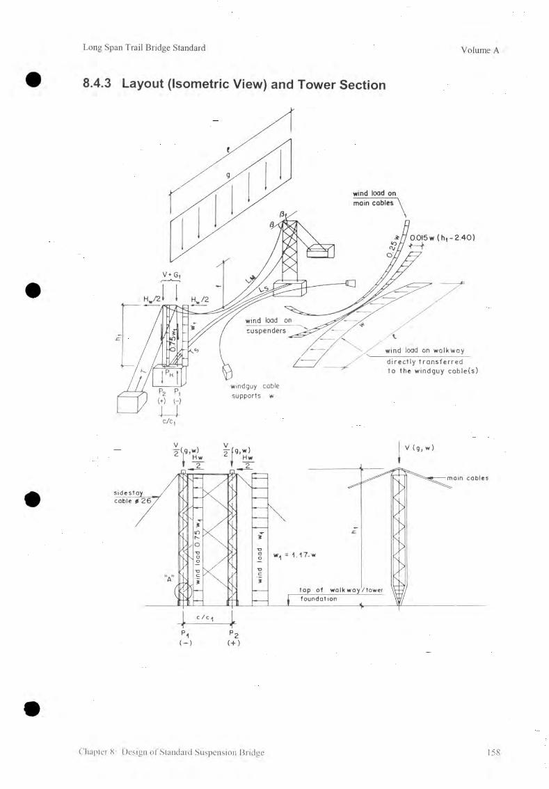
Long Span Trail Bridge Standard Volume A
• 8.4.3 Layout (Isometric View) and Tower Section
Chapter 8: Design of Standard Suspension Bridge 158

Volume A Long Span Trail Bridge Standar
8.4.4 Geometrical Parameters
A) General
It is assumed that the main cable and the spanning cable are moving laterally and will thereby each remain in plane. The cable sag ( f 0 ) is increased by Af and the camber ( CD ) by Ac. The cable forces must fulfill the static equilibrium together with the applied loads go, Pso and Wbo-
B) Basic Calculation Principle
The different sag ( f | ) and camber ( Ci ) can be determined by iteration, and the corresponding cable forces are calculated with an assumed geometrical alignment. The sum of the vertical and horizontal components is then compared with the actual vertical load ( g0 + Pso ) and the actual horizontal load ( W ). The difference should be judged and if necessary a new assumption must be made and the calculation repeated until sufficient accuracy is achieved.
Basic Formulas for the Iteration
The difference of the horizontal cable tension can be calculated as follows (e.g., for the main cables):
kN
or out of Acti - ------ = -------A Ld
AH, AL.-EkN/mm2
Out of the two equations 1) and 2) the load g i can be calculated as:
3) gi8 f, • A L i • E • A f,----- — ------- + - • go kN/m
Insert Into 3) for the cable length difference:
m
Then g, becomes:
kN/m
kN/m4
159 Chapter 8: Design of Standard Suspension Bridge

Long Span Trail Bridge Standard Volume A
8.4.5 Wind Loads
The global wind load has been assumed to be w = 0.5 kN/m. This corresponds to a wind pressure of 1.3 kN/m2 (appx. wind velocity = 160 km/h = 45m/s) (refer to Report on Windguy Arrangement for Suspended and Suspension Standard Bridges, Dr. Heinrich Schnetzer, WGG Schnetzer Puskas Ingenieure AG, Switzerland, 2002).
The effect of a possible vertical load component has not been considered relevant for the design and therefore is disregarded in the standard design.
Different elements receive the following direct wind loads perpendicular to the bridge axis:
Walkway (refer to 8.4.6 and Chapter 9), Www = 1.0 ■ w kN/m
- The wind load acting on the main cables is uniformly distributed and assumedto be w M = 0 .2 5 ■ w kN/m
- The wind load acting on suspenders is assumed to be of triangular distribution with a maximum load of w s = 0 .0 1 5 (h, - 2.4) - w (kN/m) acting at the suspender near the towers. The wind load acting on the suspender at mid-span is assumed to be zero.
- The wind load acting on the tower is uniformly distributed along the tower height Wt = 1.17 w (kN/m), however, the tower leg in front receives 100% and the leg behind receives 75% of the load only.Total on one tower, w , = (1 .0 + 0.75)w-i = (1 .0 + 0 .7 5 ) ■ 1 .17 w = 2.05 w. kN/m
8.4.6 Calculation Model
In order to simplify the analysis the procedure is divided into two separate calculations, the results of which (the displacement of the walkway) cannot be compared.
1. Wind Acting on Walkway
The calculations are made under the assumption that the wind load acting on the walkway perpendicular to the bridge axis is directly transferred to the windguy arrangement (refer to Chapter 9).
2. Wind Acting on Main Cables and Suspenders
For calculating the loads acting on the walkway / tower foundation, the remaining wind loads acting perpendicular to the bridge axis are applied on the bridge, neglecting the windguy arrangement.
Chapter 8: Design of Standard Suspension Bridge 160

Volume A Long Span Trail Bridge Standar
Again a simplified model has been chosen for this calculation.
The wind loads on the main cables and suspenders are applied as one load ( w b) on the walkway location at mid-span.
Force diagram without wind load
Force diagram with wind load
0 = wb PMr sin yt + Psr sinon = wb = W Mo + W So
Pmo - Pso - go PM1- c o s Y 1 - Ps1- cos a i = g0
161 Chapter 8: Design of Standard Suspension Bridge

Long Span Trail Bridge Standard Volume A
8.4.7 Load Com binations
For calculation of the loads acting on the walkway / tower foundation two load combinations are considered.
Load case [A] Dead load case + full wind loadLoad case [B] Full load case + 1/3 wind load
Load case, [A]: w = 0.5 kN/m
- Vertical load (dead load case), ga (including pre-tension of the spanningcable, refer to 8.3) kN/m
- Wind load on main cable:Wm = 0.25 • 0.5 = 0.125 kN/m
- Wind load on suspenders:Wsusp = 'h ■ 0.015 (ht — 2.4) • 0.5 = 0.00375 (ht - 2.4) kN/m
- Wind load on tower:W , = 2.05-0.5 =1.025 kN/m
w b = W m + Wsusp = 0.125 + 0.00375 (ht - 2.4) = 0.116 + 0.00375 ht kN/m
Load case, [B]: w = 1/3 kN/m
Vertical load (full load case), gt (with spanning cable pre-tension decreased to zero, refer to 8.3)
- Wind load on main cables:WM = 1/3 - 0.125 kN/m
- Wind load on suspenders:Wsusp = 1/3 • 0.00375.(ht - 2.4) kN/m
- Wind load on tower:W t = 1/3 • 1.025 kN/m
Wb = Wm + Wsusp = 1/3 (0.116 + 0.00375 ht) kN/m
Chapter 8: Design of Standard Suspension Bridge 162
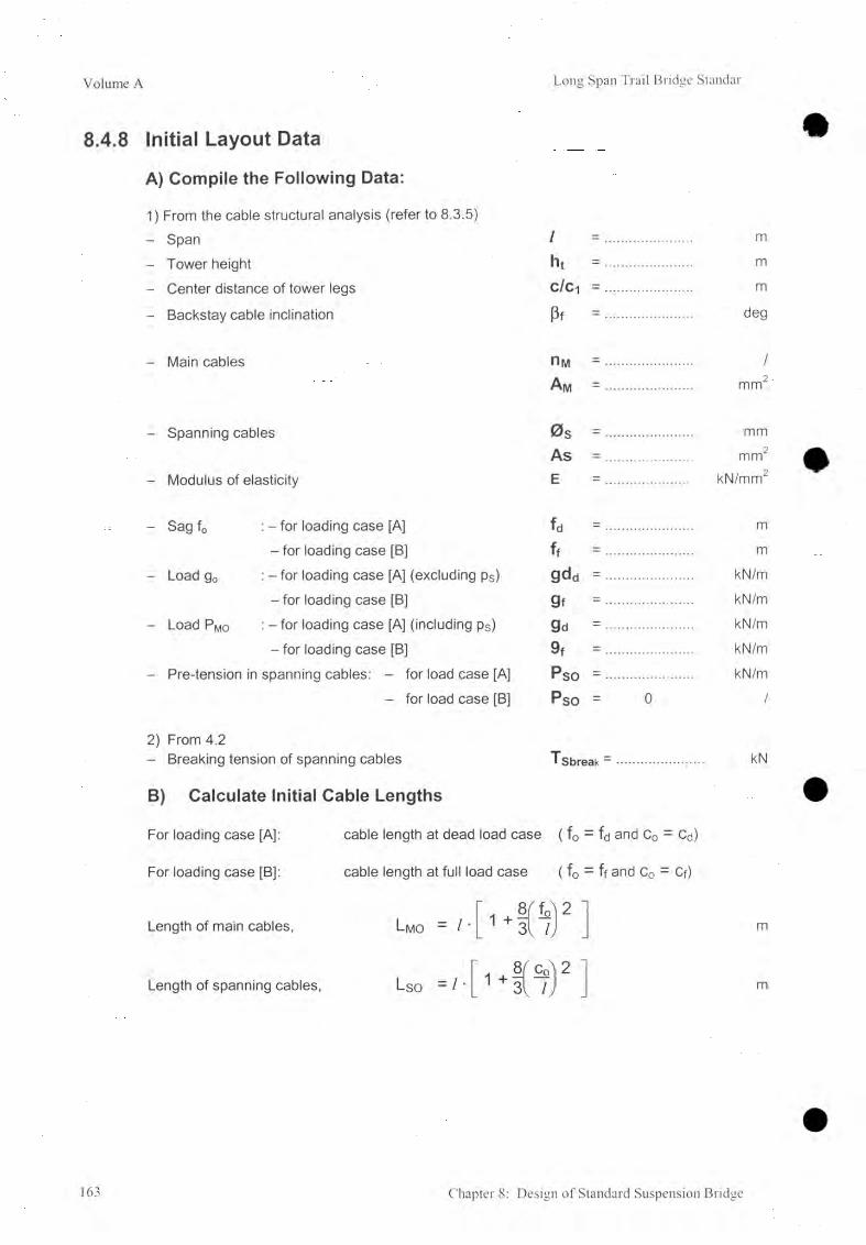
Volume A Long Span Trail Bridge Standar
8.4.8 Initial Layout Data
A) Compile the Following Data:
1) From the cable structural analysis (refer to 8.3.5)- Span / = ..................... m- Tower height ht = ..................... m- Center distance of tower legs c/Ci = ..................... m
- Backstay cable inclination Pf = ..................... deg
- Main cables n^ = ..................... /A m = ..................... mm2
- Spanning cables 0 s = .................... mmAs = .................. mm2
- Modulus of elasticity E = ..................... kN/mm2
- Sag f0 : - for loading case [A] fd = ...................... m- for loading case [B] ff = ...................... m
- Load g0 : - f o r loading case [A] (excluding ps) gdd = ...................... kN/m- for loading case [B] gf = ...................... kN/m
- Load PM0 : - fo r loading case [A] (including ps) gd = ...................... kN/m- for loading case [B] 9f = ...................... kN/m
- Pre-tension in spanning cables: - for load case [A] Pso = ...................... kN/m- for load case [B] Pso = 0 /
2) From 4.2- Breaking tension of spanning cables Tsbreak = ..................... kN
B) Calculate Initial Cable Lengths
For loading case [A]: cable length at dead load case ( f0 - fa and C0 - Cd)
For loading case [B]: cable length at full load case ( f0 = ff and C0 = Cf)
Length of main cables,
Length of spanning cables,
Lmo -
Lso = I '
8 f + 3v
8+ fi
2
2
m
m
163 Chapter 8: Design of Standard Suspension Bridge

Long Span Trail Bridge Standard Volume A
8.4.9 Calculation Procedure
A) Compile the Initial Layout Data (refer to 8.4.7)
B) Iteration Procedure
Index 1 means load case 1 either [A] or [B],Calculate displacement Xi and sag f i with the Iteration method for both loading cases. Draw a force diagram in order to check the results (refer to 8.4.6).
The iteration may be started with the following primary values of x and f,:- Load case [A] : X , = appx. 0.015 / m
f i = appx. 1.002 ■ fd m- Load case [B] : X , = appx. 0.0025 • / m
f i = appx. 1.001- ff mStop Operation
1. Calculate the constant factors C
r _ 6 4 £ A “ ° ' 31’ -L
kN/m4
r 64E-AS L'SO ,
3 / 7Jt ^SokN/m4
2. Calculate:
Yi - a rcs ,n f 1 + 1.30 deg
tt1 " arctan ht + 0.25 - cosyi • (f, + 1.30)deg
ht + 0.25 - cosyi • (fi + 1.30)C i —
COSGti
3. Calculate the load on the main and spanning cables:
Pmi — C mo ' f t • ( f t 2 - fo2) o
Q_+ kN/m
Pst = Cso '
CM0O1CMo \ Ci —.
) + — ’PsoC o
kN/m
Calculate the new f | and the new x-t
new f t = f 0 + A f - (APm - Ag j
AP m J m
with: A f = f l - f o m
AP m II T) g I TJ o kN/m
Ag — X P vertical ~ g0 = ( Pmi • cosyi - Psi ' cosa i) - g0 kN/m
Chapter 8: Design of Standard Suspension Bridge 164

Volume A Long Span Trail Bridge Standar
w b _ __________ Wb__________new xi - X1- X r ZPhorizontai xi • (pM1 . sinyi + p s1 ■ sinai)
5 . Test the condition: I Ag I < 0.02 kN/m- If no (greater): repeat the calculations from step 2 with new f | and new Xi- If yes (smaller): stop the iteration and proceed with the calculation of the other
load case, complete the force diagram, and then calculate the final data.
C) Calculate the Final Data for Load Case [A] and [B]
1. Loads on tower top
Total vertical load VtotPmi ■ / / ' tanpf
= 2 cosy, ' (1 + 4 f , . cosy i) kN
Horizontal load HwPmi ' l
2 ' sinyi kN
2 . Reactions at the tower base = loads on walkway / tower foundation
PtVtot Gt Hw ■ ht 1.025 w • ht2
2 + 2 ~ c/ci ~ c/c i kN
P2Vtot G, H w h , 1.025 w - h ,2
2 2 c/ci c/ci kN
PhPst • /
- Hw + 2.025 w ■ ht + 2 ' sinai kN
Weight of Towers, G,No Tower Weight No Tower Weight No Tower WeightM/C Height kg M/C Height kg M/C Height kg
12.9012.92
15111875
17.74 52106
30.22 10018
14.77 2119 4 20.24 5910 32.72 108244
16.62 3440or 22.73 6609 35.21 124856 25.23 7861 30.22 10040
18.47 3808 27.73 9222 8 32.7235.22
1084612507
165 Chapter 8: Design of Standard Suspension Bridge

Long Span Trail Bridge Standard Volume A
3. Tension in spanning cables
Psi-lTsv = --------- • cosai
2
Psi-I2T sh
8ci
kN
kN
Maximum tension in spanning cables (both cables):
PS,-/2TS
8 Ci- , 1 + 16
Check the safety factor of spanning cable:
XS breakFs Ts A/B> 3
kN
D) Check of Results
Action on tower base and spanning cable = reaction on walkway / tower foundation = 0
Horizontal (perpendicular to the bridge):
XH = 1/2 l • wb + 2.05 ht • w - PH = 0
Vertical:
Zv = 1/4 / g0 + Gt + 1/2 V tot — (Pi + P2 - Tsv) = 0
Chapter 8: Design of Standard Suspension Bridge 166

Volume A Long Span Trail Bridge Standar
8.5 Tower8.5.1 Introduction
The design of the towers is based on the ETH Report [2] and approaches tower height as a function of the span (load). Six independent loading cases were considered in order to determine the worst case with respect to buckling and yielding of the most critical elements of each tower.
8.5.2 Loading Cases
A) Wind in the Longitudinal Direction of the Bridge
Two load cases have been taken into consideration that have a minor influence on the tower design.
B) Wind in a Lateral Direction to the Bridge
- With windguy cables installed: two load cases have been taken into consideration which are equivalent to loading cases [A] and [B] but are not relevant for the tower design (refer to 8.4).
- Windguy cables not yet installed (e.g., during erection): two load cases have been taken into consideration, which turned out to be the worst loading cases for the tower design and the required safety factor of y = 1.6
8.5.3 Tower Capacity Diagram
The tower capacity diagram is drawn according to the safety factor of y = 1.6 for load cases for which the windguy arrangement is not yet installed and which therefore has an appreciable measure of security against loading cases [A] and [B] which are calculated in Section 8.4. However, with those results the towers can be roughly checked.
Plot the characteristic points ( Vtot and Hw) for loading case [A] and for loading case [B] into the capacity diagram. The characteristic points must remain below the capacity line for the tower concerned for both loading cases. The towers seem to be always over-designed, but during construction, when the windguy cables are not yet installed, the required safety level is achieved. Furthermore, any deviation from the wind-bearing calculation model, as explained in 8.4.5, does not result in overloading of the tower.
Safety during erection of the tower, until the main cables are properly clamped to the saddles and the suspenders fixed to the spanning cables, can only be achieved through proper fixation of the towers according to 8.10, Tower Erection.
167 Chapter 8: Design of Standard Suspension Bridge

Long Span Trail Bridge Standard Volume A
Table 8.5.1: Tower Capacity Diagram, Safety Factor = 1.6(for load cases for which the windguy cables are not yet installed)
8.5.4 Sidestay Cables
For tower heights of ht > 25.23 m the lateral deflection of the tower should be controlled by sidestay cables. The cables should be pre-tensioned against each other with about 25 kN. However this load should not be considered in the calculation.
Chapter 8: Design of Standard Suspension Bridge 168

Volume A Long Span Trail Bridge Standar
8.5.5 Related Standard Design Drawings
Each tower requires five standard design drawings. For additional information refer to Standard Design Drawing No. 140 "Guide to SBD Standard Towers'".
Tower Drawing Title and Numberht c/c1 c/c2 Assembly Bass Intermed. Top Saddle
(m) (m) (mm) Drawing Element Element Element Element
12.90 383 145 100 110 120 135
12.92 146 101 111 122 13614.77 3.50
488147 101 111 123 136
16.62 148 102 112 124 13618.47 149 102 112 125 136
17.74 150 103 113 126 137
20.24 550 151 103 113 126 137
22.73 152 103 113 126 137
25.23 153 104 114 127 13727.73 154 105 115 128 137
30.221)4.00
155 106 116 129 13732 721)3) 566 156 106 116 129 13735.211)3) 157 107 117 130 13730.222) 158 .106 116 129 138
32 722,3) 159 106 116 129 13835.212)3) 160 107 117 130 138
1) for 6 main cables2) for 8 main cables3) bolts with property grade 6.6 required
Table 8.5.2: Standard Design Drawings: Towers
tower leg
^ o n c h o r a g e rods
'i:|TEEEHHEETff: , ] ...| c/ c2 c/c4 4
169 Chapter 8: Design of Standard Suspension Bridge
Long Span Trail Bridge Standard Volume A
8.6 Design of Walkway / Tower Foundation8.6.1 Introduction
The scope of this section is the determination of the dimensions of the walkway / tower foundations based on the calculations of the reactions on the tower base and on the spanning cable, on the soil and rock parameters, and on prescribed safety factors.
The basic principles and proceedings for the structural analysis of foundations are compiled in Chapter 6 . Foundation Design.
8.6.2 Related Symbols
Asi Required cross-sectional area of reinforcement steel mm2
As2 Required cross-sectional area of reinforcement steel mm2
B Open dimensions of foundation, width mC Open dimensions of foundation, height of foot mE Open dimensions of foundation, width of foot mH Open dimensions of foundation, height, part of height mL Open dimensions of foundation, length m
Ni Required number of reinforcement bars § 16 mm /
n2 Required number of reinforcement bars § 16 mm /
Pi Loads on foundation (refer to 8.4) kN
P2 Loads on foundation (refer to 8.4) kN
Ph Loads on foundation (refer to 8.4) kN
Tsh Loads on foundation (refer to 8.4) kN
Tsv Loads on foundation (refer to 8.4) kN
Ws Weight of soil surcharge on foot foundation kN
at Tensile stress in reinforcement bars kN/mm2
Gt perm Permissible tensile stress in reinforcement bars kN/mm2
For all other symbols used in connection with bearing pressure, safety factor against sliding, and safety factor against shear failure of ground, refer to Chapter 6 .
Chapter 8: Design of Standard Suspension Bridge 170

Volume A Long Span Trail Bridge Standar
8.6.3 Design Parameters
A) Foundation without a Foot
For Tower: c/c, = (m) 3.50 3.50 4.00 4.00
c/c2 = (mm) 383 488 650 566
B min 2.20 2.90 2.90 3.10B max 4.50 5.00 5.00 5.00
L min 5.50 5.50 6.00 6.00
L max 8.50 8.50 9.00 9.00
H min 2.40 2.40 2.40 2.40H max 9.00 10.00 10.00 10.00
Table 8.6.1: Limits of Dimensions (m) for Walkway Tower Foundations without Foot
171 Chapter 8: Design of Standard Suspension Bridge

Long Span Trail Bridge Standard Volume A
B) Foundation with Foot
For Tower: c/c = (m) 3.50 3.50 4.00 4.00c/c2 = (mm) 383 488 650 566
B min 2.20 2.90 2.90 3.10L min. 5.50 5.50 6.00 6.00
L max 8.50 8.50 9.00 9.00(H + C) min 2.40 2.40 2.40 2.40(H + C) max 9.00 10.00 10.00 10.00
C min 1.00 1.20 1.20 1.20
E min 0.75 1.00 1.00 1.00
Table 8.6.2: Limits of Dimensions (m) for Walkway / Tower Foundations with Foot
Chapter 8: Design of Standard Suspension Bridge 172

Volume A Long Span Trail Bridge Standar
8.6.4 Limits and Recommendations
A) Foundation Dimensions
Foundation dimensions as given in 8.6.3 are dependent upon the standard dimensions of the anchorage steel structures. The minimum dimension H(min), or (H + C) min especially might be superseded by the required embedded depth (refer to 5.5.2).For soil: tmin < hp, for rock: tmin < hrtIt is assumed that the earth pressures acting laterally (on the upstream and downstream side) to the foundation are in equilibrium, and the passive earth pressure in front of the foundation can be activated partially. The maximum value that can be taken into consideration is equal to the active earth pressure which could occur in front of the foundation.
Calculation of reinforcement is not required for foundations without a foot.
B) Foundation Type
The type of foundation is already determined by the selected tower design. Select foundation either with or without a foot, based on economic considerations. For minimal clearances refer to 5.5.4 B.
C) Anchorage Rods for Foundation on Rock
Anchorage rods can be provided but only in order to stabilize the rock. Refer to 6.3.3 and6.6.5
D) Soil / Rock Check List
Refer to Chapter 6 for the checklist of limits (for soil 6.5.1, for rock 6.6.1)
8.6.5 Initial Layout Data
A) Define the Characteristics of the Foundation to be Designed
1) River bank: Left or right bank ? ....................... /2) Foundation: On soil or rock ? ....................... /
B) Compile the Following Data1) From 8.4, Loads on Walkway / Tower Foundation
Center distance of tower legs c/Ci = ................. mCenter distance of tower anchorage rods C/C2 = ................. m
Load case [A] [B]Loads from tower:
Tower leg 1 P, = .......................................... kNTower leg 2 P2 = .......................................... kN
- Horizontal load, perpendicular to the tower PH = .......................................... kNLoads from spanning cable:- Vertical Tsv = .......................................... kN- Horizontal TSh = .......................................... kN
173 Chapter 8: Design of Standard Suspension Bridge

Long Span Trail Bridge Standard Volume A
2) From survey and final geotechnical report Soil parameters:- Sub-soil at depth = ........................ m- Friction angle of sub-soil O i = ........................ deg- Unit weight of sub-soil yi = ........................ kN/m3
- Friction angle of back-filling soil <T>2 = ........................ deg- Unit weight of back-filling soil 72 = ........................ kNm3- Groundwater at depth = ........................ m- Ground-bearing pressure a perm= ........................ kN/m2
Rock parameters:- Rock at depth = ........................ m- Sliding friction angle between rock & foundation O sl = ....................... deg- Ground-bearing pressure Gperm = ....................... kN/m2
3) From Chapter 5, General Principles- Minimum embedded depth t = .......................... m
4) From 8.6.3, Design Parameters
Foundation Dimensions (m) minimum maximum- Width B- Length L- Total height H + C- Foot height C- Foot width E 0
8.6.6 Calculation Procedure
Calculations have to be made from the results of loading case [A] as well as loading case[B].
The reinforcement for foundations with a foot should be determined from the results of loading case [A] only.
A) Compile the Initial Data (refer to 8.6.5)
B) Preparatory Work
Prepare a plan view, a longitudinal, and a cross-section with the minimal dimensions. Try to estimate the required dimensions experientially. Otherwise take the minimum dimensions (without a foot) as primary data.
Chapter 8: Design of Standard Suspension Bridge 174

Volume A Long Span Trail Bridge Standar
C) Main Calculation
The basic design principles, the procedure for the structural analysis, and the limits as well, are given in Chapter 6 , Foundation Design. The forces for the walkway / tower foundation design will always consist of forces on the bridge axis and lateral to the bridge axis.
Calculation example:The calculations are given from examples of a foundation (with foot) on rock, with groundwater, and with a retaining wall at the back. The structural analysis of the retaining wall has to be carried out separately.
For other layouts, similar proceedings should be applied with:- foundations on soil hrt = 0 , hra = 0 , hp > t- foundations without a foot E = 0, C = 0
no groundwater hw = 0
A diagram of forces at the foundation base (in isometric view) is given below.
175 Chapter 8: Design of Standard Suspension Bridge

Long Span Trail Bridge Standard Volume A
1 Calculate the components, inclination, and location of the resultant loading force
Loading ForcesLever arm (m) for
Mxb MyLWeights (kN):
W, = B H • L • yc E/2 0
W2 = (B + E) • C - L • yc 0 0
Ws = (hp + hrt - C) • E • L • y2 B/2 0
Uplift (kN) (hw < hP + hrt):
Wy = (B + E) • hw • L • yw 0 0
Earth Pressure (kN):
- back: Eah (back) = 1/ 2 Xah [<D2 , \|/] (ha2- ha12) • L • y2 ( h a - h a l ) 2ha1 + hayEah + hra = -------------- ------------------- + hra /
3 ha1 + ha
(2 \ B + EEav (back) = Eah - tan ( j 0 2 2 0
h 2- front: Eaht (front) = Xah [0 2, s] • -g- L • y2 h + ^hrt + 3 /
B+EEavt (front) = Eah • tan ( j 0 2J 2 0
Loads (kN):
Pi E/2 C/Ct
2
P2 E/2 C/Ct
2
Tsv E/2 0
Tsh H + C - 0.25 /
P h / H+C
Mx = sum of all statical moments in x (B) - direction at the center of the foundation
My = sum of all statical moments in y (L) - direction at the center
- Vertical component of RRv = sum of all vertical forces = W, + W2 + Ws + (- P1 ) + P2 - Tsv + Eav + Eavt
Location of RMx (B+E)
öx = — > B72 = iE2E2- | e x |
My Ley = --->L*/2 = 2 - i e y i- Inclination of R
fi J (Tsh + 2:eah)2 + p H 2tanöR = —— -----------
R v
kNmkNm
kN
m
m
2. Select the possible predominant failure mode and proceed according to Chapter 6 .
3. Reinforcement
Only required for foundations with a foot.
Chapter 8: Design of Standard Suspension Bridge 176
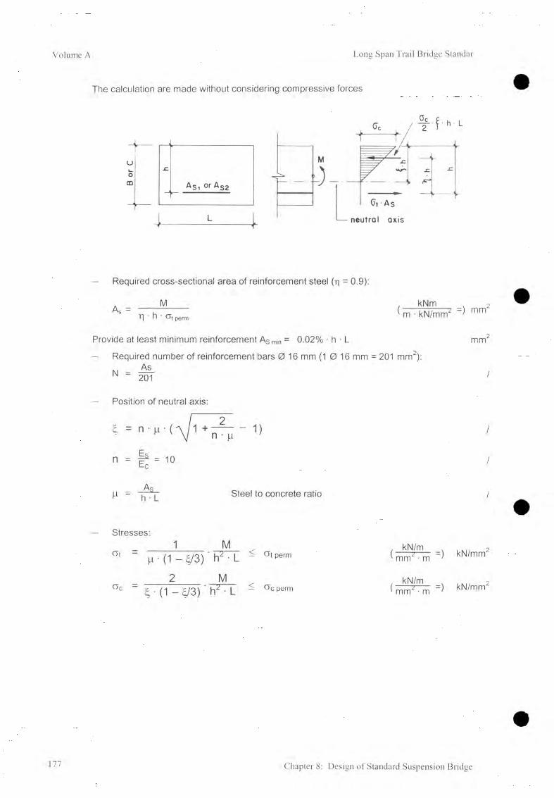
Volume A Long Span Trail Bridge Standar
The calculation are made without considering compressive forces
Required cross-sectional area of reinforcement steel (r| = 0.9):
AsM
1] ’ h ' CT( perm
. kNm ,( m ■ kN/mm2 mm
2
Provide at least minimum reinforcement As min = 0.02% • h • L
- Required number of reinforcement bars 0 16 mm (1 0 16 mm = 201 mm2):
- Position of neutral axis:
n
n • pi
l a _Ec
_Ai_ h • L Steel to concrete ratio
mm2
/
/
/
/
Stresses:1 M
c ‘ ‘ m • (1 - £/3) ' h2 ■
2 Mac " Ç ■ (1 - Ç/3) ’ h2 • I
Gt perm
Gc perm
kN/m ' mm2 • m
kN/m ' mm2 ■ m
kN/mm2
kN/mm2
177 Chapter 8: Design of Standard Suspension Bridge
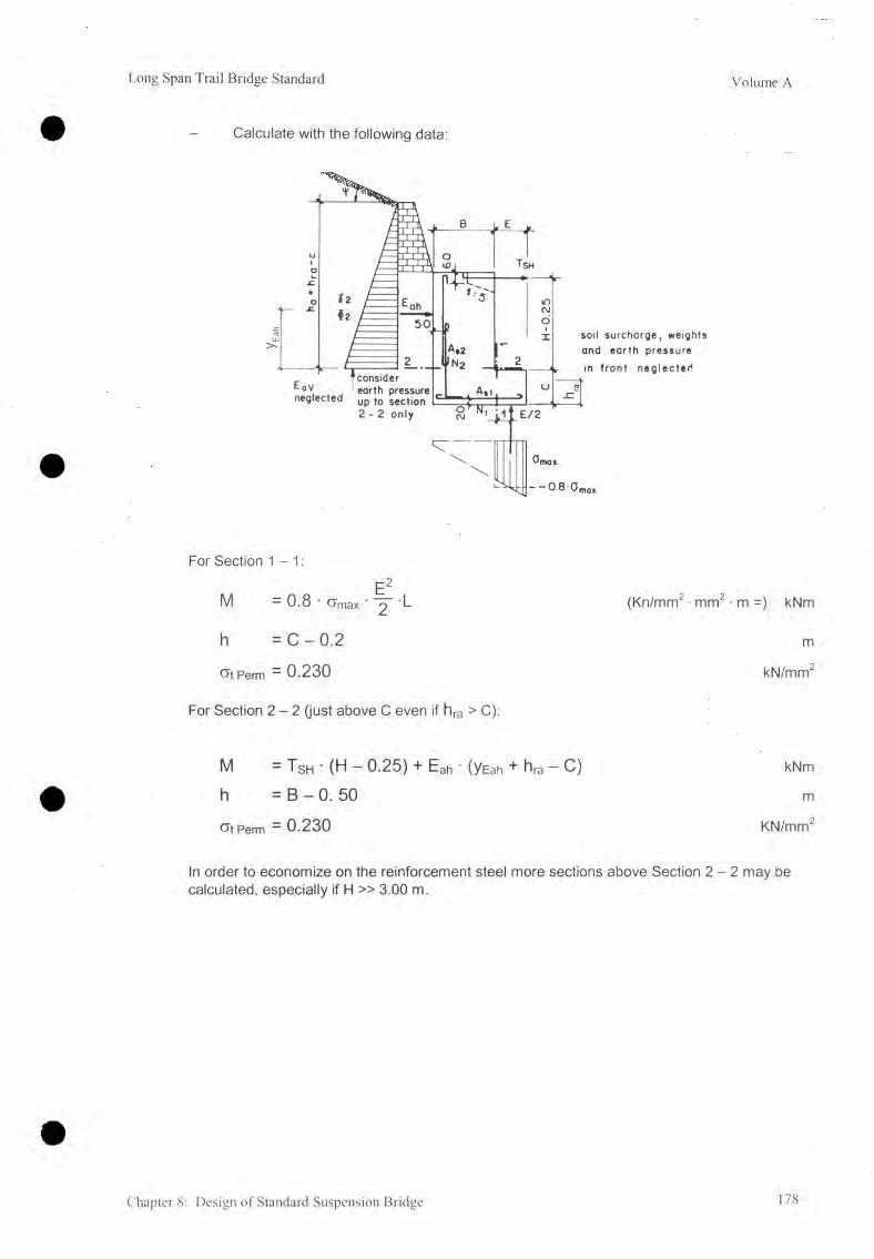
Long Span Trail Bridge Standard Volume A
Calculate with the following data:
For Section 1 -1 :
E2M — 0.8 • C>max ' 2 ^
h = C - 0.2
Of Perm — 0.230
For Section 2 - 2 (just above C even if hra > C):
(Kn/mm2 • mm2 ■ m =) kNm
m
kN/mm2
M - Tsh ' (H — 0.25) + Eah ■ (yEah + hra “ C) kNm
h = B - 0. 50 m
G»t Perm = 0.230 KN/mm2
In order to economize on the reinforcement steel more sections above Section 2 - 2 may be calculated, especially if H » 3.00 m.
Chapter 8: Design of Standard Suspension Bridge 178

Volume A Long Span Trail Bridge Standar
8.6.7 Compilation of Final Data
Bridge No. & Name........................................ Date.................... Designed by
A) and B) Initial data (refer to 8.6.5)
C) Main Calculation
1) Soil / rock heights- Active earth pressure height at back ha = ...................................... m- Active earth pressure height from
top of the foundation block hai = ........................................ m- Rock height at back hra = ...................................... m- Active pressure height in front hp = ...................................... m- Rock height in front hrt = ............................... m- Depth of soil t = ...................................... m- Depth of additional soil t' = ............................... m
2 ) Soil parameters- Front slope of soil
(top of dry stone pitching) £1 = ...................................... deg- Slope of soil baseline £b = ...................................... deg- Length of influence L * nfi = ...................................... m- Back slope of soil Vj/ = ...................................... deg
3) Foundation dimensions- Height H = ...................................... m- Height of foot C = ...................................... m- Width B = ...................................... m- Width of foot E = ...................................... m- Length L = ...................................... m- Distance to resultant force B * /2 = ...................................... m
and L */2 = ...................................... m
4) Safety factors- Sliding Fsl = ...................................... /- Bearing capacity Fbc = ...................................... /- Toppling F j = ...................................... /- Slope stability Fs = ...................................... /
5) Anchorage rodsNos as per calculation N = ...................................... /.
D) Additional Anchorage Rods(from geological report)
179 Chapter 8: Design of Standard Suspension Bridge

Long Span Trail Bridge Standard Volume A
E) Data to be Transferred to the General A rrangm ent
In section In p la n
8.6.8 Related Standard Design Drawings
Drawing Number Drawing Title
9090/1 90/2
Walkway / Tower Anchorage (capacity: 260 kN)Walkway / Tower Foundation, c/c, = 3.50 m c/c2 = 383 mm
9191/1 91/2
Walkway / Tower Anchorage (capacity: 390 kN )Walkway / Tower Foundation, c/c , = 3.50 kN c/c2 = 488 mm
9292/1 92/2
Walkway / Tower Anchorage (capacity: 390 kN )Walkway / Tower Foundation, c/c-i = 4.00 m, c/c2 = 550 mm
9393/1 93/2
Walkway / Tower Anchorage ( capacity: 610 kN)Walkway / Tower Foundation, c/c, = 4.00 m, c/c2 = 566 mm
Drawing Numbers: .... = Working and assembly drawing... 71 = Structural Drawing : Foundation without a Foot .... 12 = Structural Drawing: Foundation with a Foot
Table 8.6.3: Walkway / Tower Anchorage Foundation for Suspension Bridges
Chapter 8: Design of Standard Suspension Bridge 180

Volume A Long Span Trail Bridge Standar
8.7 Design of Main Cable Foundation
8.7.1 Introduction
The scope of this section is to determine the dimensions of the main cable anchorage foundation based on the results of the cable structure analysis, on the soil and rock parameters, and on prescribed safety factors.
The basic principles and proceedings for the structural analysis of foundations are given in Chapter 6 , Foundation Design.
Related Symbols
B Open dimension of foundation, width m
H i Open dimension of foundation, height at back m
h 2 Open dimension of foundation, part of height in front mK Value to determine accurate cable elevation
K = K (P), refer to standard design drawingsL Open dimension of foundation, length m
Indices: V vertical component H horizontal component
For all other symbols used in connection with bearing pressure, safety factor against sliding, and safety factor against shear failure of ground, refer to Chapter 6 .
181 Chapter 8: Design of Standard Suspension Bridge
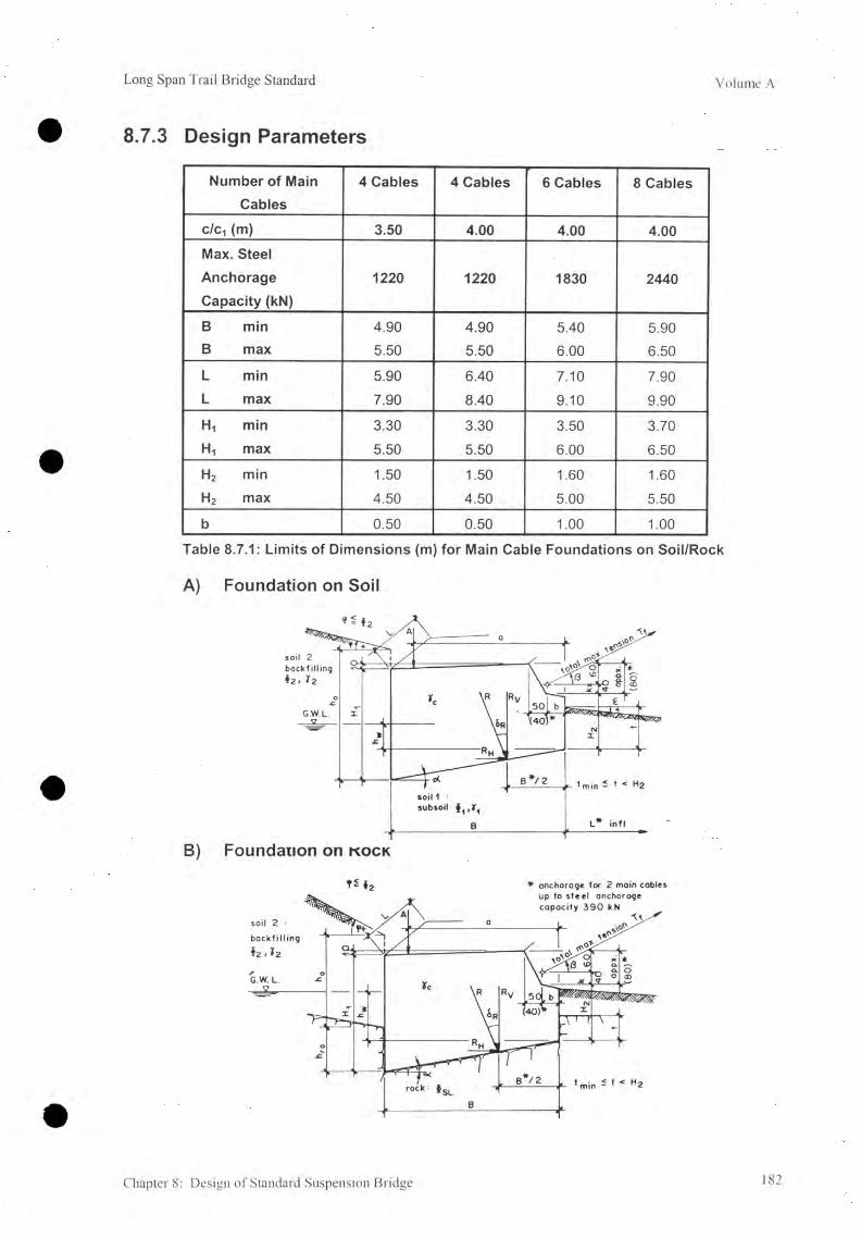
Long Span Trail Bridge Standard Volume A
8.7.3 Design Parameters
Number of Main Cables
4 Cables 4 Cables 6 Cables 8 Cables
c/c-, (m) 3.50 4.00 4.00 4.00Max. SteelAnchorage 1220 1220 1830 2440Capacity (kN)B min 4.90 4.90 5.40 5.90B max 5.50 5.50 6.00 6.50L min 5.90 6.40 7.10 7.90L max 7.90 8.40 9.10 9.90
H1 min 3.30 3.30 3.50 3.70H, max 5.50 5.50 6.00 6.50
h2 min 1.50 1.50 1.60 1.60h2 max 4.50 4.50 5.00 5.50
b 0.50 0.50 1.00 1.00
Table 8.7.1: Limits of Dimensions (m) for Main Cable Foundations on Soil/Rock
A) Foundation on Soil
B) Foundation on k o c k
T * $2 * anchorage for 2 main cables
Chapter 8: Design of Standard Suspension Bridge 182

Volume A Long Span Trail Bridge Standar
8.7.4 Limits and Recommendations
A) Foundation Dimensions
The limits of the foundation dimensions as given in 8.7.3 are dependent upon the standard dimensions of the anchorage steel structure. The minimum dimensions ( H2 (min) ) especially might be superseded by the necessary embedded depth ( t ) (refer to 5.5.2), tmin < t< H2.
Calculation of reinforcement is not required for main anchorage foundations.
B) Foundation Type
The type of foundation is already determined by the number and the diameter of main cables and by the selected tower design.
C) Anchorage Rods for Foundation on Rock
Anchorage rods can be provided but only in order to stabilize the rock. Refer to 6.3.3 and 6.6.5.
D) Soil/Rock Check List
Refer to Chapter 6 , Foundation Design for the check list of limits (for soil 6.5.1, for rock 6 .6 .1).
8.7.5 Initial Layout Data
A) Define Characteristics of Foundation
1) River bank: Left or right ? ....................... /2 ) Foundation: On soil or rock ? ....................... /
B) Compile the Following Data
1) From main cable structure analysis- Number of main cables f<M /- Main cable tension Tivi.f kN- Cable inclination Pf = deg- Tower leg center distance C/C1 kN
From survey and final geotechnical reportSoil parameters:- Sub-soil at depth = m- Friction angle of sub-soil O i deg- Unit weight of sub-soil Y1 kN/m3- Friction angle of back-filling soil 0 2 - deg- Unit weight of back-filling soil Y2 kN/m3- Groundwater at depth = m- Ground-bearing pressure Gperm ~ kN/m2
183 Chapter 8: Design of Standard Suspension Bridge

Long Span Trail Bridge Standard Volume A
Rock parameters:- Rock at depth = ........................ m- Sliding friction angle between rock & foundation O sl = ......................... deg- Ground-bearing pressure a perm = ......................... kN/m2
3) From Chapter 5. General Principles- Minimum embedded depth t = ......................... m
4) From 7.4.3 Design Parameters
Foundation Dimensions (m) minimum maximum-W idth B- Length L- Back height Hi- Front height (refer to para 8.7.4 A) H2- Front toe b
8.7.6 Calculation Procedure
The relevant loading for the main cable anchorage and main cable foundations is the full load case. Therefore, calculations for other load cases are not required for standard type bridges.
It is necessary to design the anchorage foundations in such a way that their volume is minimized (economic design), giving due consideration to the prescribed safety factors.
A) Compile the Initial Data (refer to 8.7.5)
B) Preparatory Work
Prepare a plan view, a longitudinal, and a cross-section with the minimal dimensions. Try to estimate the required dimension by experience, otherwise take the minimum dimensions as primary data.
C) Main Calculation
The basic design principles, the procedure for the structural analysis, and the limits as well, are given in Chapter 6 , Foundation Design.
Calculation example:The calculations are given from examples of a foundation on soil, without ground- water, and with a retaining wall at the top. The structural analysis of the retaining wall has to be carried out separately.
For other layouts, similar proceedings should be applied with:- foundations on rock hrt > t, hra > 0- foundations without a foot b = 0- with groundwater hw > 0
Chapter 8: Design of Standard Suspension Bridge 184

Volume A Long Span Trail Bridge Standar
1. Calculate the components, inclination, and location of the resultant loading force
Loading Forces Lever arm (m) for MF
Weights (kN):
W, = 0.5 (H,+ H2 + k + 0.70) ■ B ■ L • yc B 2 (Hi + 0.1 ) + (H2 + k + 0.6) 3 (Hi + 0.1) + (H2 + k + 0.6)
W2 = - [b • (k + 0.60) ■ L • yc ] - [ b/2 ]
W3 = - 0.5 [b* • (k + 0.60)- L-Yc] - [b'/3 + b]
W4 = - [ 0.5 ( B - 1.00)-0.10-L-Yc ] - [ 2 / 3 (B-1.00) + b' + b]
Wtot = Z W consider (-) consider (-)
Load on Top (kN):A = (refer to 6.2.4) a
Earth Pressure (kN):
- back: Eah (back) = 1/ 2 A,ah [<D2 , v|/] (ha2- ha12) • L •Y E a h - H 1 + H2 + k + 0.50
( h a - h a l ) 2ha1 + hayEah = -----------------------------------------
3 ha1 + ha(2 \
Eav (back)= Eah • ta n k - 0 2) B
Loads (kN):T fh = T f • cosPf
Tfv = T f ■ sinpf
H2 + k
b
= sum of all statical moments in F kNmVertical component of R
RH = sum of all horizontal forces - Eah + Tf h kNRV = sum of all vertical forces = Ew + A + Eav - Tfv kN
Location of R
B72 = • M' mRv(1 + tanatan5R)
Inclination of R Rh
tan5R = ——Rv
2. Select the possible predominant failure mode and proceed according to Chapter 6 .
185 Chapter 8: Design of Standard Suspension Bridge

Long Span Trail Bridge Standard Volume A
8.7.7 Compilation of Final Data
Bridge No. & Name..................................... Date.....
A) and B) Initial Data (refer to 8.7.5)
C) Main Calculation1) Load on top of foundation
Total load A- Front to C.G. distance a
. Designed by.
kNm
2)
3)
4)
5)
Soil / rock heights- Active earth pressure height- Active earth pressure height from
top of the foundation block- Rock height at back- Embedded depth
Soil parameters- Front slope of soil
6 )
D)
ha1h ra
t
m
mmm
(top of dry stone pitching) £1 ............. deg
Slope of soil baseline £b ............. deg- Length of influence L*infl = m
Back slope of soil V ............. deg
Foundation dimensions- Back height H i = ...................... ............. m
Front height h 2 = ...................... ............. m
- Width B ............. m
Length L ............. m
- Base inclination a = ...................... ............. deg- Distance to resultant force B * /2 = ...................... ............. m
and l * /2 = ...................... ............. m
Safety factors- Sliding Fsl = ......................- Bearing capacity Fbc = ......................- Toppling Ft = ......................- Slope stability Fs = ......................
Anchorage rodsNot provided
A d d it io n a l A n c h o ra g e R ods(from geological report)
Chapter 8: Design of Standard Suspension Bridge 186

Volume A Long Span Trail Bridge Standar
E) Data to be Transferred to the General Arrangement
In section In p la n
cable elevation
8.7.8 Related Standard Design Drawings
Drawing Number Drawing Title
48A
48A/1
48A/2
Main Cable Anchorage for 4 main cables (capacity : 780 kN)
Main Cable Foundation for 4 main cables, clc = 3.50m
1Main Cable Deadman Foundation for 4 main cables, c/c = 3.50m
48B
48B/1
48B/2
Main Cable Anchorage for 4 main cables (capacity : 1220 kN)
Main Cable Foundation for 4 main cables, c/c = 3.50m
1Main Cable Deadman Foundation for 4 main cables, c/c = 3.50m
49
49/1
49/2
Main Cable Anchorage for 4 main cables (capacity : 1220 kN)
Main Cable Foundation for 4 main cables, c/c = 4.00m
1Main Cable Deadman Foundation for 4 main cables, c/c-t = 4.00m
50
50/1
50/2
Main Cable Anchorage for 6 main cables (capacity : 1830 kN)
Main Cable Foundation for 6 main cables, c/Ci =. 4.00m
1Main Cable Deadman Foundation for 6 main cables, clc-t =. 4.00m
51
51/1
51/2
Main Cable Anchorage for 8 main cables (capacity :2440 kN)
Main Cable Foundation for 8 main cables, c/c ■, = 4.00m
1Main Cable Deadman Foundation for 8 main cables, c/c, = 4.00m
Drawing Numbers: .... = Working and assembly drawing.... /1 = Structural drawing : Foundation on Soil or on Rock
Table 8.7.2: Main Cable Anchorage Foundation for Suspension Bridges 1 Refer to 10.4
187 Chapter 8: Design of Standard Suspension Bridge

Long Span Trail Bridge Standard Volume A
8.8 Determination of Suspender Length8.8.1 Introduction
The scope of this section is to determine the lengths of the suspenders based on the dead load case and to calculate all other data required for manufacturing suspenders in the workshop.
The results of the calculations have to be transferred to the appropriate working and assembly drawing "Suspenders".
For calculation of the suspender lengths, it is assumed that the main cables and the spanning cables are of parabolic form. The laterally inclined position of the suspenders need not to be taken into consideration and the calculations are made on the basis of the bridge at dead load.
Under these assumptions, the calculated distances are sufficiently accurate, so that probable deviations from the effective values remain within the adjustable length of the turnbuckles.
8.8.2 Related Symbols
N Total number of required suspenders (for one bridge) /
S Total surface of suspender rods r v , 2m
Sn Surface of suspender rods for suspender No. n m2
w Total weight of suspender rods kgWn Weight of suspender rods for suspender No. n kg
c /c n Distance from center of main cables to center of spanning cables forsuspender No. n m
jn Required number of standard pieces for suspender No. n //n Total suspender length for suspender No.n (refer to suspender layout) m
/r Length of extra piece m/rc Cutting length of extra piece ml s Length of standard piece m/sc Cutting length of standard piece mn Running suspender number /
Umax Maximum n /Xn Distance of suspender No. n from the bridge center m
Chapter 8: Design of Standard Suspension Bridge 188

Volume A Long Span Trail Bridge Standar
8.8.3 Layout and Section
3.6 2.4 12 0 1.2 24 3.6 48 6.0 . xn xn
189 Chapter 8: Design of Standard Suspension Bridge
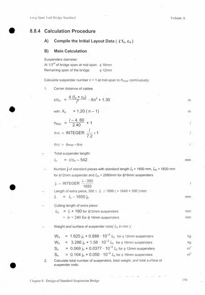
Long Span Trail Bridge Standard Volume A
8.8.4 Calculation Procedure
A) Compile the Initial Layout Data ( e, fd, cd)
B) Main Calculation
Suspenders diameter:At 1/3rd of bridge span at mid span: <f> 16mm Remaining span of the bridge: <)> 12mm
Calculate suspender number n = 1 at mid-span to n max continuously:
1. Center distance of cables
c/cn = 4 • Xn2 + 1.30
with: Xn =1.20 ( n — 1) m
_ 1 - 4 . 60r>Max — 2 40 + ' /
ni6 = INTEGER — + 1 /7.2
m 2 = nmax - ni6 /
Total suspender length:/n = c/cn - 542 mm
Number j of standard pieces with standard length /s = 1650 mm, lsc = 1830 mm
for <j)12mm suspender and /sc = 2080mm for <j)16mm suspenders
j„-= INTEGER /1650
Length of extra piece, 350 < h < 1999 ( = 1649 + 350 ) mm:
h = ln ~1650 jn mm
Cutting length of extra piece:he = /r + 180 for (J)12mm suspenders mm
= /r + 240 for (j) 16mm suspenders mm
Weight and surface of suspender rods( he in mm ):
2 .
Wn = 1.625 jn + 0.888 • 10-3 he for <t> 12mm suspenders kgWn = 3.286 jn + 1.58 • 10~3 he for <|) 16mm suspenders kgSn = 0.069 jn + 0.0377 • 10~3 he for <l> 12mm suspenders m2
Sn = 0.104 jn + 0.050 • 10-3 he for <|> 16mm suspenders m2Calculate total number of suspenders, total weight, and total surface of suspender rods:
Chapter 8: Design of Standard Suspension Bridge 190

Volume A Long Span Trail Bridge Standar
n = maxX W n kg
n = 2
n = max
n = 2
8.8.5 Data to Be Transferred to the Standard Design Drawing "Suspenders"
the suspender list for each suspender:Suspender number n
Center distance of cables c/c
Total suspender length I n
Length of extra piece /r
Cutting length of extra piece I r e
Number of standard pieces I n
Total weight of suspender rods wTotal surface of suspender rods sTotal number of suspenders N
Diameter of suspenders ♦
the steel part list:- Total weight of suspenders including clamps and turnbuckles- Total surface of suspenders including clamps and turnbuckles
8.8.6 Related Standard Design Drawings
Drawing Number Drawing Title
32 Suspenders for 4 main cables
33 Suspenders for 6 main cables
34 Suspenders for 8 main cables
Table 8.8.1: Standard Design Drawings: Suspenders
N/ - 3.40
0.60
W = 2 W i + 4 -
S = 2 S i +4
191 Chapter 8: Design of Standard Suspension Bridge
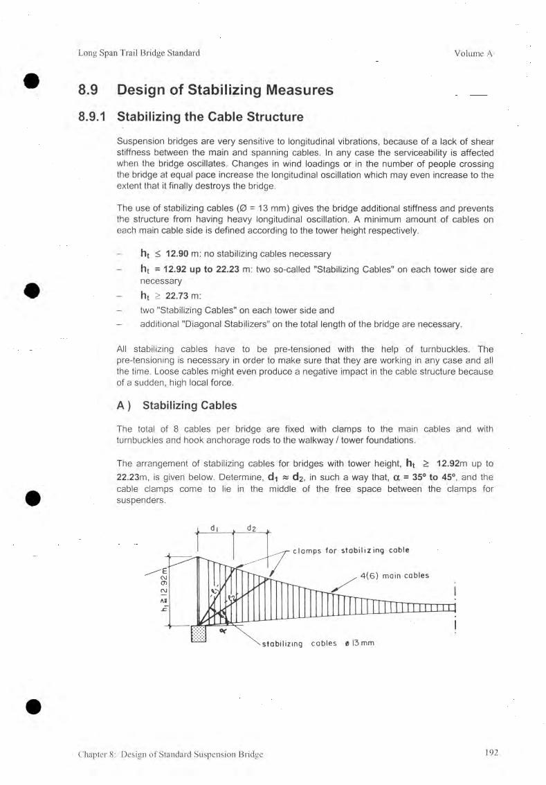
Long Span Trail Bridge Standard Volume A
8.9 Design of Stabilizing Measures
8.9.1 Stabilizing the Cable Structure
Suspension bridges are very sensitive to longitudinal vibrations, because of a lack of shear stiffness between the main and spanning cables. In any case the serviceability is affected when the bridge oscillates. Changes in wind loadings or in the number of people crossing the bridge at equal pace increase the longitudinal oscillation which may even increase to the extent that it finally destroys the bridge.
The use of stabilizing cables (0 = 13 mm) gives the bridge additional stiffness and prevents the structure from having heavy longitudinal oscillation. A minimum amount of cables on each main cable side is defined according to the tower height respectively.
ht < 12.90 m: no stabilizing cables necessaryht = 12.92 up to 22.23 m: two so-called "Stabilizing Cables" on each tower side are necessaryh t > 2 2 .7 3 m:
two "Stabilizing Cables" on each tower side andadditional "Diagonal Stabilizers” on the total length of the bridge are necessary.
All stabilizing cables have to be pre-tensioned with the help of turnbuckles. The pre-tensioning is necessary in order to make sure that they are working in any case and all the time. Loose cables might even produce a negative impact in the cable structure because of a sudden, high local force.
A ) Stabilizing Cables
The total of 8 cables per bridge are fixed with clamps to the main cables and with turnbuckles and hook anchorage rods to the walkway / tower foundations.
The arrangement of stabilizing cables for bridges with tower height, ht > 12.92m up to 22.23m, is given below. Determine, d i « C^, in such a way that, a = 35° to 45°, and the cable clamps come to lie in the middle of the free space between the clamps for suspenders.
Chapter 8: Design of Standard Suspension Bridge 192

Volume A Long Span Trail Bridge Standar
B) Diagonal Stabilizers
Diagonal stabilizers must be provided for bridges with tower height, ht > 22.73 m. Diagonal stabilizers are used in combination with stabilizing cables. The cables are fixed with clamps to the main cables and with turnbuckles and clamps to the spanning cables.
The arrangement of stabilizing cables and diagonal stabilizers for bridges with tower height, ht > 22.73 m is given below.
The clamps for the diagonal stabilizers should be placed in the middle of the free space of the suspenders or cross-beams. Exception: the clamp at the bridge center is placed either close to the clamp for the suspender or close to the cross-beam at center.
The spacings (inclination) of the cable beginning from the bridge center should be as follows:
- Cables inclined towards the tower:- if first at center : spacing = 3.00 m (fix)- near the center : spacing = 2.40 m (5 times, fix)- afterwards : spacing = 3.60 m always- Cable inclination towards the center:- if first at center : spacing = 3.00 m (fix)- near the center : spacing Si = 2.40 m (5 times, fix)- afterwards : spacing S2 = 3.60 m (5 times, fix)
: spacing S3 = 4.80 m (5 times, up to / «210 m): spacing S4 = 6.00 m (for / > 210 m)
- last near tower : spacing S0 = variable (5.3, 6.5 or 7.7),but > than the nearest S3 (or S4)
Determination of the spacings:1. Measure the fixed length from the bridge center: 3.0 + 10 • 2.4 + 10 • 3.6 = 63.00 m
(i f /> 210 m: 63+ 5-3.6+ 5-4.8 = 105.00 m).2 . Add as many times either 3.60 + S3 = 8.40 m or 3.6 + S4 = 9.60 m until it is close to
the tower location.3. Check and arrange the spacing S0 and may be the nearest spacing S3 (or S4) in such a
way that the next spacing is less or equal to the previous.4. Draw the cables starting with the cable near the tower. - At center, the cable clamp may
be either positioned on the main or on the spanning cables.
Determine the location of stabilizing cables as prescribed in 8.9.1 A. Place the clamps inempty free spaces between suspenders.
193 Chapter 8: Design of Standard Suspension Bridge

Long Span Trail Bridge Standard Volume A
8.9.2 Lateral Stabilization of the Tower
Tower sidestay cables (0 = 26 mm) are provided for bridges with a tower height of ht ^ 25.23 m in order to take over sudden high wind loads (refer to 8.5).
The sidestay cables are connected to the tower at the saddles and either anchored to separate foundations or in combination with windguy cables to the windguy cable foundations.(Refer to 9.6.9.)
The dimensions of the standard sidestay anchorage foundation are fixed and designed for a maximum cable tension of 130 kN.
Connection Detail at the Tower Saddle
main cable
main cables
tower saddle
Arrangement
Chapter 8: Design of Standard Suspension Bridge 194

Volume A Long Span Trail Bridge Standar
8.9.3 Data to be Transferred to the General Arrangem ent
To the cable list: Identification, single and total lengths and weights of sidestay cables,and of stabilizing cables.
A) Stabilizing Cables and Diagonal Stabilizers
Identification and length of each cable.
B) Sidestay Cables
Draw separate section of each sidestay cable anchorage foundation.
195 Chapter 8: Design of Standard Suspension Bridge
2.5
0

Long Span Trail Bridge Standard Volume A
8.9.4 Related Standard Design Drawings
Drawing Number Drawing Title20A Diagonal stabilizer for 4 main cables20 Diagonal stabilizer for 6 main cables21 Diagonal stabilizer for 8 main cables22 Stabilizing cable clamp for 4 main cables23 Stabilizing cable clamp for 6 main cables24 Stabilizing cable clamp for 8 main cables
40 Sidestay cable anchorage, working and assembly drawing40/1 Sidestay cable foundation, structural drawing
Table 8.9.1: Standard Design Drawings: Stabilizing Measures
Chapter 8: Design of Standard Suspension Bridge 196

Volume A Long Span Trail Bridge Standar
8.10 Tower ErectionIt is most important that during erection towers are property secured against falling over. Therefore, a temporary tower-stay system has been developed. Tower-stay cables are anchored at the back of the tower to the main cable foundation or to separate tower-stay foundations and at the front to separate tower-stay foundations or, for short span bridges, to the walkway / tower foundation on the opposite river bank. The tower-stay system must stay in use until the following conditions are fulfilled:- the main cables must be clamped at all tower saddles.- the suspenders must be connected to both the main and the spanning cables.
For details refer to standard design drawings and Volume D: Execution of Construction Works.
8.10.1 Layout for Erected Tower
A) For Tower Height, ht < 27.73
General Case
to w e r -s ta y chain
stay chain — anchorage in main cable anchorage fo u n d a t ion
cable a I3 mmspanning cableanchoragefo u n d a tio n
B) For Tower Height, ht ^ 27.73 m
197 Chapter 8: Design of Standard Suspension Bridge

Long Span Trail Bridge Standard Volume A
8.10.2 Data to be Transferred to the General Arrangem ent
Where separate tower-stay cable foundations are required, they should be drawn in on the side elevation on the General Arrangement.
8.10.3 Related Standard Design Drawings
Drawing Number Drawing Title52 Tower-stay cable, working and assembly drawing
(including instructions for tower erection)
52/1 Tower-stay cable foundation, one double cable on one side.Structural drawing
52/2 Tower-stay cable foundation, two double cable on one side.Structural Drawing
52/3 Tower-stay cable foundation, two double cable, one on each side.Structural Drawing
Table 8.10.1: Standard Design Drawings: Tower Erection
Chapter 8: Design of Standard Suspension Bridge 198


Long Span Trail Bridge Standard Volume A
9. Design of Windguy Arrangement
Table of Contents
9.1 Flow Chart 200
9.2 Introduction 201
9.3 Layout 2029.3.1 General 2029.3.2 Suspended Bridge 2029.3.3 Suspension Bridge 205
9.4 Design of Windguy Cable Structure 2069.4.1 Introduction 2069.4.2 Related Symbols (refer also to 9.5.2) 2069.4.3 Geometrical Parameters 2079.4.4 Standard Design Parameters 2109.4.5 Limits and Recommendations 2119.4.6 Initial Layout Data 2129.4.7 Calculation Procedure 2129.4.8 Compilation of Final Data 2139.4.9 Related Standard Drawings 214
9.5 Calculation of Windtie Lengths 2159.5.1 Introduction 2159.5.2 Related Symbols (refer also to 9.4.2) 2159.5.3 Geometrical Parameters 2169.5.4 Standard Design Parameters 2199.5.5 Limits and Recommendations 2199.5.6 Initial Layout Data 2199.5.7 Calculation Procedure 2209.5.8 Data to be Transferred to the General Arrangement 2229.5.9 Related Standard Design Drawings 222
9.6 Design of Windguy Cable Foundation 2239.6.1 Introduction 2239.6.2 Related Symbols 2239.6.3 Design Parameters 2249.6.4 Limits and Recommendations 2259.6.5 Initial Layout Data 2269.6.6 Calculation Procedure 2279.6.7 Compilation of Final Data 2299.6.8 Related Standard Drawings 2309.6.9 Combination with Sidestay Cable Anchorage 231
Chapter 9: Design of Windguy Arrangement 199

Volume A Long Span Trail Bridge Standard
9.1 Flow Chart
200 Chapter 9: Design of Windguy Arrangement

Long Span Trail Bridge Standard Volume A
9.2 Introduction
In order to achieve sufficient lateral stability of a bridge under wind load, windguy arrangements are required. The simplest method is to use wire ropes in a parabolic arrangement for this purpose.
The scope of this chapter is:
a) to present the layout of windguy arrangements for suspension and suspended
b) to calculate cable tension and to select the appropriate windguy cable diameter,
c) to calculate all geometrical data for the parabolic windguy arrangements required for the design of and during erection of the bridge, and
d) to fix type and dimensions of the windguy cable foundations based on cable tensions and prescribed safety factors.
Windguy arrangements are generally designed in such a way that all four ends of the windguy cables are anchored to separate windguy cable anchorage foundations. The connection between the windguy cable and the walkway of the bridge is made by windties (cables 0 13 mm, cable clamps, turnbuckles).
Preferably the windguy arrangement is placed laterally below the walkway as this will contribute most to the serviceability of the bridge. In cases where the windguy arrangement encroaches on freeboard restrictions, the foundations may be placed between the anchorage elevation of the main cables and the lowest point of suspended bridges, or between the anchorage elevation of the spanning cables and the highest point of suspension bridges.
The windties are designed for a permissible load of 8.0 kN and the wind load action on the walkway is assumed to be w = 0.5 kN/m which corresponds to a wind pressure of 1.3 kN/m2 acting on laterally on the bridge area of 0.3 m2 per meter span. (Wind velocity approximately 160 km/h = 45 m/s)
Although the effective form of the windguy cable is a three-dimensional curve, it is assumed for the calculations that the cable is of parabolic form in plan and in side elevation.
bridges,
f e
wind load w -Q .5kN /m
windguy cable
windguy cableanchoragefoundation
Chapter 9: Design of Windguy Arrangement 201

Volume A Long Span Trail Bridge Standard
9.3 Layout
9.3.1 General
Windguy arrangements are required for LSTB bridges, i.e.bridge with spans greater than 120 m.
The shape of the windguy cable from the side view is dependant upon the elevation of the windguy cable foundations, the location of the vertex in the plan, and the location of the vertex of the main cables (suspended bridges) or the spanning cables (suspension bridges).
Whenever the form of the windguy cable cannot be defined clearly, it is recommended that the calculations be made for both the parabolic and the straight form. The longer cutting length must then be taken Into consideration.
In the plan, the sag to span ratio must be the same for both windguy cables.Asymmetrical arrangements both up and downstream from the bridge are not recommended.
For uniformity the data must be measured always from the right river bank.
9.3.2 Suspended Bridge
Generally, in plan, the vertex of the windguy cable, should be placed next to the lowest point of the bridge parabola. But a deviation from this rule is permissible when the geological conditions of the river banks demand a different arrangement.
A) Standard Arrangement
Both elevations of the windguy cable foundations are below or above the vertex of the main cables:
- if the vertex of the windguy cable in the plan view is located at or near the lowest point of the main cables, it is assumed, that the highest point of the windguy cable lies in the plane, defined by the highest point of the main cables and the two anchorage points of the windguy cable at their foundations, and forms an equal parabola in the side view.
202 Chapter 9: Design of Windguy Arrangement

Long Span Trail Bridge Standard Volume A
Plan
Sideelevation
B) Special Arrangements
Both elevations of the windguy cable foundations are below or above the vertex of the main cables:
- If the vertex of the windguy cable in the plan view is located near a main foundation, it can be assumed that the windguy cable in the side view forms a parabola from the windguy foundation on the other side of the river towards the lowest point of the main cables and, from there, an almost straight line towards the windguy foundation near the vertex of the windguy cable.
Chapter 9: Design of Windguy Arrangement 203
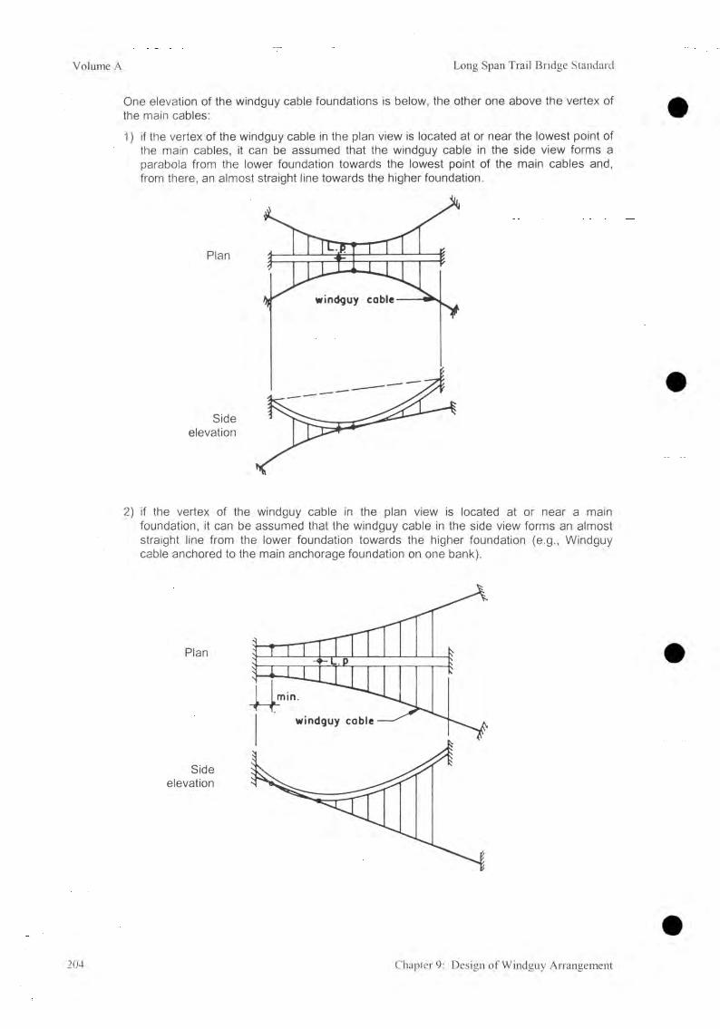
Volume A Long Span Trail Bridge Standard
One elevation of the windguy cable foundations is below, the other one above the vertex of the main cables:
1) if the vertex of the windguy cable in the plan view is located at or near the lowest point of the main cables, it can be assumed that the windguy cable in the side view forms a parabola from the lower foundation towards the lowest point of the main cables and, from there, an almost straight line towards the higher foundation.
2 ) if the vertex of the windguy cable in the plan view is located at or near a main foundation, it can be assumed that the windguy cable in the side view forms an almost straight line from the lower foundation towards the higher foundation (e.g., Windguy cable anchored to the main anchorage foundation on one bank).
204 Chapter 9: Design of Windguy Arrangement
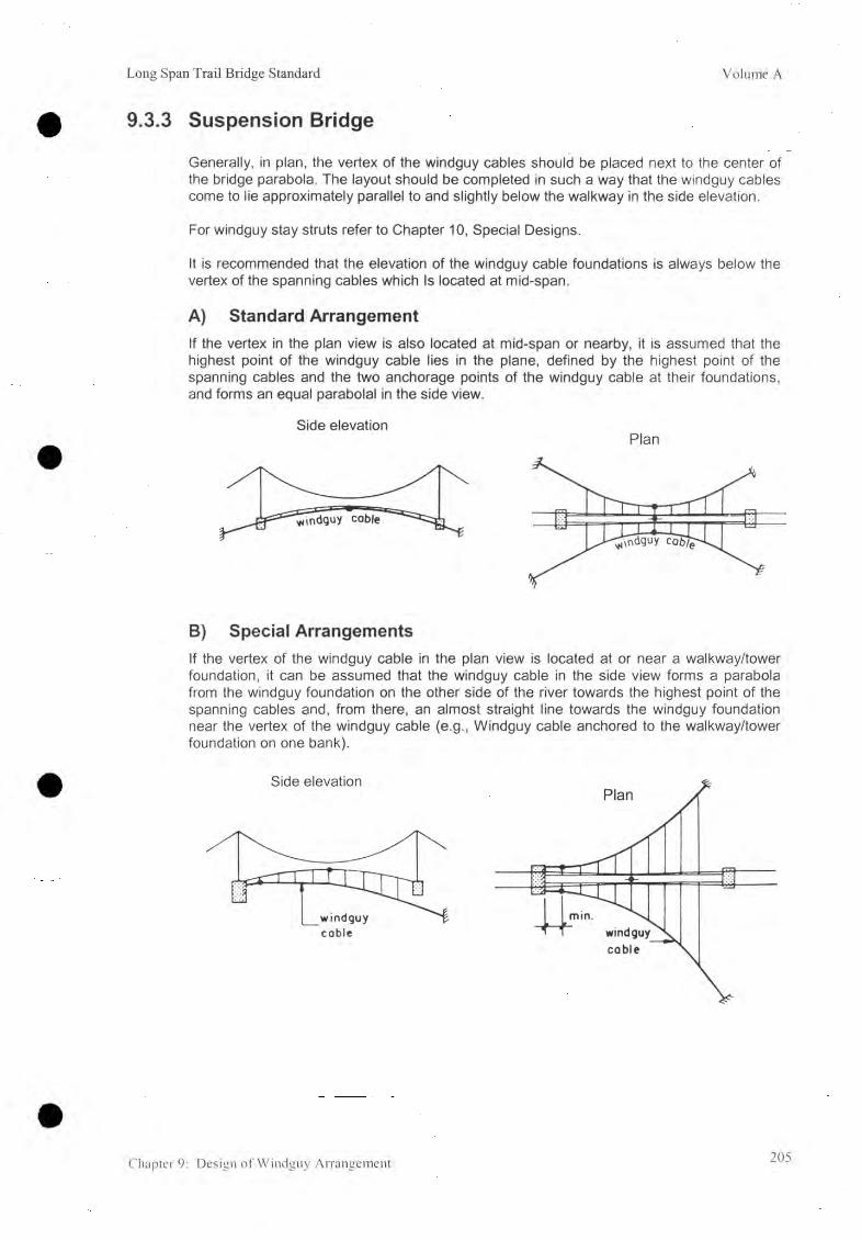
Long Span Trail Bridge Standard Volume A
9.3.3 Suspension Bridge
Generally, in plan, the vertex of the windguy cables should be placed next to the center of the bridge parabola. The layout should be completed in such a way that the windguy cables come to lie approximately parallel to and slightly below the walkway in the side elevation.
For windguy stay struts refer to Chapter 10, Special Designs.
It is recommended that the elevation of the windguy cable foundations is always below the vertex of the spanning cables which Is located at mid-span.
A) Standard ArrangementIf the vertex in the plan view is also located at mid-span or nearby, it is assumed that the highest point of the windguy cable lies in the plane, defined by the highest point of the spanning cables and the two anchorage points of the windguy cable at their foundations, and forms an equal parabolal in the side view.
B) Special ArrangementsIf the vertex of the windguy cable in the plan view is located at or near a walkway/tower foundation, it can be assumed that the windguy cable in the side view forms a parabola from the windguy foundation on the other side of the river towards the highest point of the spanning cables and, from there, an almost straight line towards the windguy foundation near the vertex of the windguy cable (e.g., Windguy cable anchored to the walkway/tower foundation on one bank).
Chapter 9: Design of Windguy Arrangement 205

Volume A Long Span Trail Bridge Standard
9.4 Design of Windguy Cable Structure
9.4.1 IntroductionThe scope of this section is to determine the number, diameter, and layout in the plan of the windguy cable(s). The number and diameter are calculated by assuming a theoretical parabola within the bridge span. Further the layout in the plan view can be determined based on the sag at mid-span. It is assumed that the full wind load on the walkway can be borne by this system only.
The layout and the initial loading is based on the structure under dead load. The necessary freeboard ( 5.00 m ) has to be maintained for any cable alignment (including windguy cables) at dead load case. Therefore it is important to carry out a rough calculation of the windguy arrangement during the design of the main cable structure.
During erection, the windguy cables should be pre-tensioned against each other at about 25% of the permissible tension.
9.4.2 Related Symbols (refer also to 9.5.2)
B|_, B r Distance of the first windtie from the saddle of the main foundation or toweraxis m
C l, C r Distance from the front of the windguy cable foundation to the bridge axis m
C lo> Cro Distance from the windguy cable to the bridge axis measured on the- saddle axis for suspended bridges- tower axis for suspension bridges m
DL, Dr Distance from the front of the windguy cable foundation to the saddleof the main foundation or tower axis.Sign: - inside of span ( - )
- outside of span ( + ) mH Horizontal component of the windguy cable tension kNHi Suspended bridges: main cable elevation on the right side m
Suspension bridges: elevation of the top of the tower foundation minus 0.25 m m Hl, Hr Windguy cable elevation at windguy cable foundation mL.p. Lowest point of the walkway (vertex) for a suspended bridge mTbreak Minimum breaking load of the windguy cable kNT l,Tr Windguy cable tension at the windguy cable anchorage foundation kNT max Maximum windguy cable tension kNT perm Permissible windguy cable tension kNed Horizontal distance from the saddle of the higher foundation to the
vertex of the walkway (refer to 7) md Distance between the windties in the plan mfw Sag of windguy cable at the distance, V , in the plan mhw Value for the theoretical windguy cable parabola within the bridge
span (refer to sketches) mk Distance from the bridge axis to the center of the windtie-connecting
bolt at the cross-beam m
206 Chapter 9: Design of Windguy Arrangement

Long Span Trail Bridge Standard Volume A
/ Design span:- suspended bridges: saddle to saddle of main foundation m- suspension bridges: distance between tower axis m
n Number /r Horizontal distance from the saddle of the main foundation or tower
axis to the vertex of the walkway, measured from the right side mV Horizontal distance from the saddle of the main foundation or tower
axis to the vertex of the windguy cable in the plan, measured from the right side m
w Wind load kNx, y Sheaf of coordinate axis for the windguy cable in the plan /
Xj Value for the theoretical windguy cable parabola within the bridge span (refer to sketches) m
y'j Value for the theoretical windguy cable parabola within the bridge span (refer to sketches) m
0W Diameter of windguy cables mmOCL, OCR Angle between the windguy cable and the bridge axis at the windguy
cable anchorage foundation in the plan degIndices: R Right side L Left side
W Windguy cable
9.4.3 Geometrical Parameters
A) Basic Calculation Procedure
For calculating the cable tension a simplified procedure, on the secure side, is applied:- the cooperative resistance of the bridge against wind load is neglected,- the increase in sag caused by wind load is neglected,- the inclined position of the windguy cables is neglected,- the vertical load of the windguy cable and the windties is omitted.
The cable tension can be calculated without iteration, based on the sag at dead load.
B) Theoretical Parabola
Plan view
hw = positive hw = negative
Chapter 9: Design of Windguy Arrangement 207

Volume A Long Span Trail Bridge Standard
1) The x - axis is identical with the bridge axis2) The y - axis goes through the vertex of the windguy cable3) The coordinates of the vertex of the windguy cable are, therefore: x = 0 , y = 2.20 m4) Distance, hw
hyv = fw •( l - v f
Note : h w < 0 i f v > / 2
h w = 0 i f v = / / 2
5) Sag at mid-span
bw —h * 2 -v 2
16 fw • (— - v)2 2
Note: bw — fw if hw = 0
6 ) Windguy cable tension
v = 2
Hw -w •8 bw
T r = H w ■ 1 +2fw 2
m
m
kN
kN
T|_ - Hw2fw- (j - v) kN
C) Layout
1) Distance from the
y’i = j)!i • x2 + 2.20 m (Xj / y'j : discrete values of X / y ') m
at the vertex location y'o =2.20 m
first windtie from right side y 'R = “ Z • (v - B r)2 + 2.20 m
first windtie from left side y'L = • (/ - V - Bl)2 + 2.20 m
208 Chapter 9: Design of Windguy Arrangement

Long Span Trail Bridge Standard Volume A
2) Inclination between the windguy cable and the bridge axis at the windguy cable anchorage foundation in the plan, which remains the same up to the first windtie.
. 2fw otR = arctan ~ jr • (v - Br) deg
2fwaL = arctan _lÛÛ1>1*—. deg
3) Distance from the windguy cable to the bridge axis measured on the saddle or the tower axis
Cr0 - ^7 ■ (v - Br)2 + tanotR ■ Br + 2.20 m
CLo = ^ • (/ -v - Bl)2 + tanaL ■ BL + 2.20 m
4) Distance from the front of the windguy cable foundation to the bridge axis
CR = ■ (v - Br)2 + tanaR • (BR + Dr) + 2.20 m
CL = ^ • (/ -v - Bl )2 + tanaL ■ (BL + DL) + 2.20 m
Layout of suspended bridge
Sideelevation
* : 25 cm for drum-type foundation50 cm for open-type foundation
Note: The data must be measured from the right side for the calculations followed. If the higher foundation level is on the left bank,—- > Hi = main cable elevation of lower foundation saddle on the right bank.
Chapter 9: Design of Windguy Arrangement 209
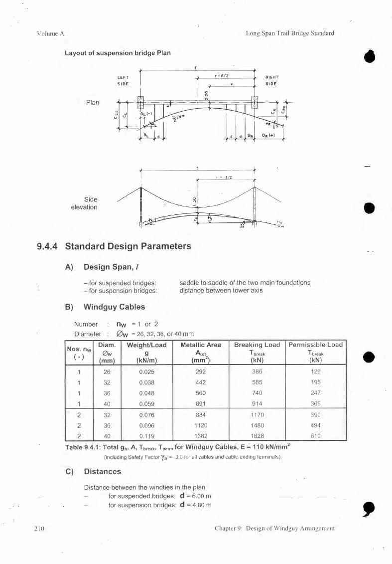
Volume A Long Span Trail Bridge Standard
Layout of suspension bridge Plan
Sideelevation
9.4.4 Standard Design Parameters
A) Design Span, /
- for suspended bridges: saddle to saddle of the two main foundations- for suspension bridges: distance between tower axis
B) Windguy Cables
Number nw = 1 or 2 Diameter : 0 w = 26, 32, 36, or 40 mm
Nos. nw ( - )
Diam.0 W
(mm)
Weight/Loadg
(kN/m)
Metallic AreaA to t
(mm2)
Breaking LoadT break(kN)
Permissible LoadTbreak(kN)
1 26 0.025 292 386 1291 32 0.038 442 585 1951 36 0.048 560 740 2471 40 0.059 691 914 305
2 32 0.076 884 1170 3902 36 0.096 1120 1480 4942 40 0.119 1382 1828 610
Table 9.4.1: Total gh, A, Tbreak, Tperm for Windguy Cables, E = 110 kN/mm2(including Safety Factor y s = 3.0 for all cables and cable ending terminals)
C) DistancesDistance between the windties in the plan - for suspended bridges: d = 6.00 m
for suspension bridges: d = 4.80 m
210 Chapter 9: Design of Windguy Arrangement

Long Span Trail Bridge Standard Volume A
Distance from bridge axis to center of windtie-connecting bolt at the cross-beam- for suspended bridges: k = 0.660 m- for suspension bridges: k = 0.736 m
Distance from bridge axis to the vertex of the windguy cable in the plan- for both bridge types = 2.20 m
Distance, r- for suspended bridges - if the higher foundation is on the right side r = ed
- if the lower foundation is on the right side red- for suspension bridges: r = l / 2
D) Elevation Hi- for suspended bridges: main cable elevation on the right side- for suspension bridges: elevation of the top of the tower foundation minus
0.25m
E) Wind LoadW = 0.5 kN/m
9.4.5 Limits and Recommendations
A) Sag at Mid-span
The sag at mid-span, in plan, of the windguy cable is restricted to be bw = / / 8 t o / / 1 0 m it must have the same value upstream and downstream.
B) Cross-SectionIt is necessary that the cross-section at each windtie is approximately mirror reverse to the bridge axis (equilibrium of forces), in order to achieve a straight (along the bridge axis) and horizontal (in cross-section) walkway. This has to be kept in mind in locating foundations up and downstream.
C) Safety Factor
The safety factor (for all cables and cable terminals) is determined by FS ^ 3
D) Freeboard
The freeboard must be cle of any cable alignment at dead load case.
E) Distance, v ,to the Vertex in the Plan
At the vertex of the windguy cable a connection must be provided to the walkway cross-beam of the bridge:- for suspended bridges: fix the vertex distance as required, assume that there will be a
cross-beam nearby (the maximum possible error in practice will be less than 1.20 / 2 = 0.60 m).
- for suspension bridges: V = ( / / 2 ± 1 .20 i) where mi = an integer, not greater than / / 1 .20
The vertex distance “v” for asymmetric arrangement can be changed by + / - (i ■ d) only.
Chapter 9: Design of Windguy Arrangement 211

Volume A Long Span Trail Bridge Standard
F) Distances to the First WindtiesAs v must be located to a cross-beam, the first possible distance from the saddle of the mainfoundation or tower axis to the windtie must be calculated as follows, with i = integer
v = (d ■ ¡r ) + B r B r — — > B r = v - (d • ¡r ) > d/2 m
( / — v) = (d • ¡l ) +
•
CDAll_i
CD — > bl = l -v - (d • iL) > d/2 m
9.4.6 Initial Layout DataA) Define1) Design span, /, (refer to 9.4.4 A).2) Distance, d , k , and r (refer to 9.4.4 C).
B) Determine1) The approximate location of the front of the windguy cable foundation.2) Analyze carefully the conditions on both river banks. Draw geological, topographical
and hydrological constraints in the plan view of the General Arrangement.3) Determine the theoretical windguy cable parabolas, in the plan, upstream and
downstream from the bridge by trial taking probable constraints into due consideration.
4) Determine the distance, hw5) The possible vertex location (refer to 9.4.5 E).
9.4.7 Calculation Procedure
A )
B )
1)
2)
3)
4)5)
Compile the Initial Data
Calculate the Data of the Theoretical Parabola (refer to 9.4.3 B)The sag at mid-span, bw.Calculate the windguy cable tension for right and left side.Tmax = the larger, maximum tension
The safety factor is calculated as F = T break T max
^ 3
In order to obtain an optimum safety factor of 3, changes in the initial data might be necessary (for limits refer to 9.4.5) and the calculation must be repeated.Select the required number and diameter of windguy cables.Repeat the calculation for the other, up or downstream, side.
C) Calculate the Data of the Layout in the Plan View (refer to 9.4.3C)1) Calculate the location of the first windties (refer to 9.4.5 E).2) Calculate the alpha angles, and the distance from the windguy cables to the bridge
axis, C r0 and C l0- Draw this data in the plan of the general arrangement and locate the accurate axis of the wind cables. Repeat the calculation for the other, up or downstream, side.
3) Draw longitudinal sections along the windguy cables and determine the front of thefoundations (Dr, C r and D[_, C l ) and the windguy cable elevations ( Hr and Hl ) at all four foundations. In order to obtain an optimum foundation location, it may benecessary to change the location of the first windties and this will result in a smallchange in the alpha angle.
4) Check the freeboard (refer to 7.3.6 and 8.3.6)
212 Chapter 9: Design of Windguy Arrangement

Long Span Trail Bridge Standard Volume A
9.4.8 Compilation of Final Data
Bridge No. & Name............................
A) Initial Data (refer to 9.4.6 and GA)
Bridge type (suspended or suspension) ? Design span Horizontal distance
Windguy cable
Date...................... Designed by
.................................. //w = ................................ mr = ................................ m
nw = ................................ /0 w = ................................ mmAw = ................................ mm2Tw,break = ................................ kN
E - Module = ................................ kN/mm2
Cable anchorage elevations:- Left Bank Windguy cable, upstream m
Windguy cable, downstream m- Right Bank Windguy cable, upstream m
Hi mWindguy cable, downstream m
Freeboard Windguy cables m
Loads: - wind load W = 0.5 kN/m
B) Data from Main Calculations
Upstream Downstream
Theoretical parabola hw = ................................................. mbw = ................................................. mfw = ................................................. mT r = ................................................... kNT L = ................................................... kNSafety factor = ................................................. /
Layout ai_ = .............................................. degcxr = .................................................. degC Lo = .................................................. mC Ro = .................................................. mC l = ................................................. mC r = .................................................. mD l = ................................................. mD r = .................................................. mH l =................................................. mH r = .................................................. m
Chapter 9: Design of Windguy Arrangement 213

Volume A Long Span Trail Bridge Standard
C) Data to be Transferred to the General Arrangement
Calculate the distance of the wlndguy cable from the bridge axis at the windtie locations (refer to 9.7.3 B). Draw the windguy cable layout upstream and downstream from the bridge into the General Arrangement.
Plan
Section
9.4.9 Related Standard Drawings
Drawing Number Drawing Title17 Windguy cable clamp for cable 0 32 mm18 Windguy cable clamp for cable 0 36 mm19 Windguy cable clamp for cable 0 40 mm
Table 9.4.2: Standard Design Drawings: Windguy Cable Clamps for Double Windguy Cables
214 Chapter 9: Design of Windguy Arrangement

Long Span Trail Bridge Standard Volume A
9.5 Calculation of Windtie Lengths
9.5.1 Introduction
The scope of this section is to determine the lengths of the windties based on the layout of the windguy cable in the plan, the elevation of the windguy cable foundations, and the bridge type.
For the calculation of the windtie lengths, it is assumed that the cables are of parabolic form with some exceptions (refer to 9.3). The self weights need not to be taken into consideration and the calculations are made on the basis of the bridge at dead load.
Caution: The calculated distances are only approximations, but sufficiently accurate, so that the most probable deviations from the effective values remain within the adjustable length of the turnbuckles. On site, the windguy arrangement has to be adjusted (by means of tightening the windties) in such a way that it forms a parabola in the plan view.
9.5.2 Related Symbols (refer also to 9.4.2)
Dw Inclined distance of windties measured along the windguy cable mEl, Er Inclined distance from the first windtie to the front of the windguy
cable foundation, measured along the windguy cable m
ai...a4 Constants in the formula for the parabola, y = ax2 + c /a5 Constants in the formula for the straight line, y = ax + c /bw Sag of the windguy cable inside the bridgespan in the plan mc/c Total length of the windtie from the center of the windguy cable to the
center of the connecting bolt at the cross-beam m
C1 . . . C 4 Constants in the formula for the parabola, y = ax2 + c /C5 Constants in the formula for the straight line, y = ax + c /Cd Suspension bridge camber at dead load case (to be used as a
negative factor in the calculations) mfd Suspended bridge maximum sag, vertical distance from the saddle at
the higher foundation saddle to the lowest point of the parabola, at dead load case m
fd' Suspended bridge vertical distance from main cable saddle atthe right side to the lowest point of the bridge at dead load case m
x', z Sheaf of coordinate axis for the windguy cable in side elevation /Xj, x'j Discrete values of X, X1 for the windtie i /
y, Horizontal distance from the windguy cable to the windtie connectingbolt for the windtie i m
ylp. Horizontal distance from the windguy cable to the windtie connectingbolt at the vertex of the walkway m
Ahj Vertical distance from the windguy cable to the windtie connecting boltfor the windtie i m
AhL.p Vertical distance from the windguy cable to the windtie connecting boltat the vertex of the walkway m
pL, Pr Vertical inclination angle of the windguy cable at the windguy cableanchorage foundations deg
Chapter 9: Design of Windguy Arrangement 215
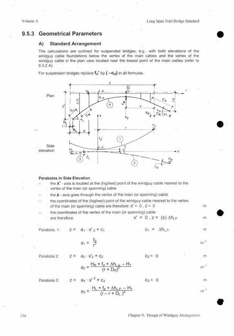
Volume A Long Span Trail Bridge Standard
9.5.3 Geometrical Parameters
A) Standard ArrangementThe calculations are outlined for suspended bridges, e.g., with both elevations of the windguy cable foundations below the vertex of the main cables and the vertex of the windguy cable in the plan view located near the lowest point of the main cables (refer to9.3.2 A).
For suspension bridges replace fd' by ( —Cd) in all formulas.
Plan
Sideelevation
Parabolas In Side Elevationthe x' - axis is located at the (highest) point of the windguy cable nearest to the vertex of the main (or spanning) cablethe Z - axis goes through the vertex of the main (or spanning) cable the coordinates of the (highest) point of the windguy cable nearest to the vertex of the main (or spanning) cable are therefore: x' = 0 , Z = 0 m
- the coordinates of the vertex of the main (or spanning) cableare therefore: x' = 0 , z = (±) Ah|_p m
Parabola. 1: Z = a i • X' 2 + Ci Ci = AhL.p. m
m
Parabola 2: Z = a2 • x '2 + C2
_ Hr fd AhL.p, Hi3 2 - (r + DRr
Parabola 3: Z = a3• x' 2 + C3
_ H|_ + fd + Ahi_p — Hi3 3 " (/ - r + Dl f
c2 = 0
c3 = 0
m
m
m
m
216 Chapter 9: Design of Windguy Arrangement

Long Span Trail Bridge Standard Volume A
Parabola In the Plan View
- the x - axis Is located at the connecting bolts of the cross-beams- the y - axis goes through the vertex of the wind cable in the plan- the coordinates of the vertex of the windguy cable are therefore: X = 0 , y = 2.20 - k m
Parabola 4: y = a4 ■ x2 + c4 C4 = 2.20- k m
fyya4 = v2 m 1
1) Horizontal distance between the vertex of parabola 1 and the vertex of parabola 4
x0 - x'o = r - v m
2) The difference in elevation at the lowest point of parabola 1 to the (highest) point of the windguy cable nearest to
Ah|_.p yLP. • tany(a4 • (r - v)2 + 2.20 - k) (H t — Hr — f(i) • (/ + D r + Dj ) — (P R + r) • (Hi — Hr)
( C r - k) • (/ + Dr + Dl ) - (Dr + r) • (CR - CL) m
axiscross - beam
main cables
•oJCk
Cross - Section
3) The angle between the horizontal to the windguy cable at the foundation
Pr = arctan[ 2 a2 • (BR - r )] deg
Pl = arctan[ 2 a3 • (r - / + BL)] deg
Chapter 9: Design of Windguy Arrangement 217

Volume A Long Span Trail Bridge Standard
B) Special Arrangements
The calculations are outlined for suspended bridges, e.g., with one elevation of the windguy cable foundations below the vertex of the main cables and the vertex of the windguy cable in the plan view located (combined) at a main anchorage foundation (refer to 9.3.2 B2).
For other layouts, similar proceedings might be applied.
1) Parabola 1 and 4 according to standard arrangement (refer to 9.5.3 A).
2) Line 5: z = a5 • x' + c5 0 01 II o m
Hr - H l
35 " / + Dr + Dl/
3) The difference in elevation at the lowest point of parabola 1 to the (highest) point of the windguy cable nearest to
Ah|_.p. = H-i — H r — fd + a s ■ (r + D r ) m
3) The angle between the horizontal to the windguy cable at the foundationPl = arctan ( a5 ) deg
pR = - arctan ( a5 ) deg
218 Chapter 9: Design of Windguy Arrangement

Long Span Trail Bridge Standard Volume A
9.5.4 Standard Design Parameters
A) Cross-SectionWindties connect the windguy cables to the walkway. They are placed symmetrically in pairs and connected to the cross-beams. It is necessary that the cross-sections are approximately mirror reverse to the bridge axis (equilibrium of forces), in order to achieve a straight and horizontal walkway.
Windties are designed for a permissible load of 8 kN . With an assumed wind load of 0.50 kN/macting on the walkway, one windtie can support 8 kN of bridge.
B) Distances (refer to 9.4.4)Distance fa'- for suspended bridges:
- if the higher foundation is on the right side- If the lower foundation is on the right side
- for suspension bridges:
fd ' = fd m
fd '
^0?X1X1M—3
II mfd' = cd m
9.5.5 Limits-and Recommendations
Refer to 9.3
9.5.6 Initial Layout Data
A) Refer to 9.4.8
B) Define
1 ) Distance fa'
Chapter 9: Design of Windguy Arrangement 219

Volume A Long Span Trail Bridge Standard
9.5.7 Calculation Procedure
A) Standard Arrangement
1) Determine parabola 4
2 ) Calculate the difference in elevation (AhL.p) of the lowest point of the main cable parabola (suspended bridge) or the highest point of the spanning cable (suspension bridge) and the(highest) point of the windguy cable nearest to it.
3) Determine parabolas 1, 2, and 3
4) Calculate the windtie data starting from the right side ( i = 1), x-i = v - Br mn _ _ g | \
up to: i (max) = ^ L + 1 continuously, with X i = v — Br — ( i — 1) • d m
The corresponding x'j - values are:- for the first windtie ( i = 1): x ' i = r — B r = Xi + r — V m- and continuously: x'j = r — Br — ( i — 1 ) ■ d = Xj + r — v m
coble
Cross-section
The following procedure is valid if 82 and 83 form parabolas only. If this is doubtful check with a straight line for 82 and/or 83 .
a) The difference in elevation of parabola 1 to the windguy cable at each windtiefor x'j > 0: Ahj = a i • x'j2 + AhL.p. - a2 ■ x ',2 m
for x'j < 0: Ahj = • x'j2 + AhL.p. - a3 • x'j2 m
b) The horizontal difference of parabola 1 to the windguy cable at each windtieYi = a4 ■ Xj2 + 2 .20 - k m
220 Chapter 9: Design of Windguy Arrangement

Long Span Trail Bridge Standard Volume A
c) The angle between the horizontal to the windguy cable at each windtie
for' x'j > 0 : Pi = arctan ( 2 a2 - x'j)
for x'i < 0 : pi = arctan ( 2 a3 - x'j)
d) Length between the windguy cable and the connecting bolt of the cross-beam
c/q = -y/Ahi2 3 + yi2
deg
deg
m
e) Length between the windties on the windguy cable
DWi = — — J a 4 2 -(d + 2xi)2 +1 mCOS P
5) Calculate the length between the first windties and the windguy cable anchorage on the windguy cable
_ B r + D r
R COSOtR • cospR mB|_ + D|_
L|_ = — mCOSCXL ■ COSPl
6 ) Calculate the total length of the cables- for windguy cable(s)
Lw (tot) = X Dw i + Er + El + overlapping length (refer to 4.2.2) m- for windtie cables
Lt (tot) = I ( C/Ci + 0.60) m
B) Special Arrangements
1) Primarily execute all calculations as given for the standard arrangement (refer to 9.7.5 A).
2) Follow the same procedure as given for the standard arrangement (refer to 9.7.5 A) but calculate the length between the windguy cable and the connecting bolt of the cross-beam according to the special arrangement.
E.g., if the windguy cable forms a straight line in the side view (refer to 9.5.3 B):
c/Cj = -y/(ai xi2+AhLP-a5 x'i)2+(a4 Xi2 + 2 .2 0 -k)2 m
3) Check the cutting length of both procedures and take the longer cutting length into consideration. Remark on the general arrangement that the given cutting length might be different from the actual.
Chapter 9: Design of Windguy Arrangement 221
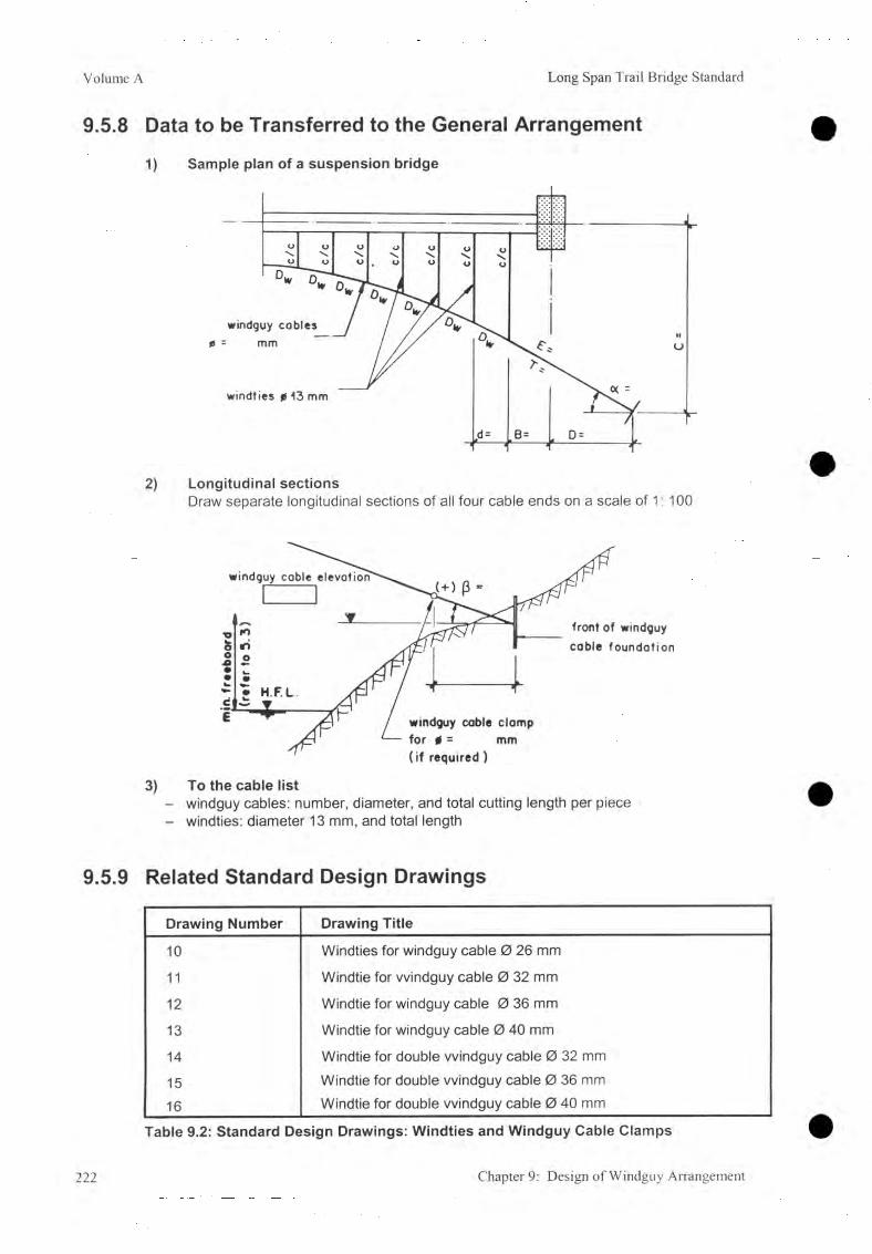
Volume A Long Span Trail Bridge Standard
9.5.8 Data to be Transferred to the General Arrangem ent
1) Sample plan of a suspension bridge
2) Longitudinal sectionsDraw separate longitudinal sections of all four cable ends on a scale of 1: 100
3) To the cable list- windguy cables: number, diameter, and total cutting length per piece- windties: diameter 13 mm, and total length
9.5.9 Related Standard Design Drawings
Drawing Number Drawing Title
10 Windties for windguy cable 0 26 mm
11 Windtie for windguy cable 0 32 mm
12 Windtie for windguy cable 0 36 mm
13 Windtie for windguy cable 0 40 mm
14 Windtie for double windguy cable 0 32 mm
15 Windtie for double windguy cable 0 36 mm
16 Windtie for double windguy cable 0 40 mm
Table 9.2: Standard Design Drawings: Windties and Windguy Cable Clamps
222 Chapter 9: Design of Windguy Arrangement

Long Span Trail Bridge Standard Volume A
9.6 Design of Windguy Cable Foundation9.6.1 Introduction
The scope of this section is to determine the dimensions of the windguy cable anchorage foundations based on the results of the windguy cable structure analysis, on the soil and rock parameters, and on prescribed safety factors.
Basic principles and proceedings for the structural analysis of foundations are given in Chapter 6 , Foundation Design.
9.6.2 Related Symbols
B Open dimension of foundation, width m
Hi Open dimension of foundation, height at back mh2 Open dimension of foundation, total height In front mL Open dimension of foundation, length mT Windguy cable tension kN
Ts Sidestay cable tension kN
hr Height to the cable anchorage from the base m
P Inclination of windguy cable deg
Rule for the sign: + = windguy cable upwards- = windguy cable downwards
For all other symbols used In connection with bearing pressure, safety factor against sliding and safety factor against ground shear failure, refer to Chapter 6 .
Chapter 9: Design of Windguy Arrangement 223

Volume A Long Span Trail Bridge Standard
9.6.3 Design Parameters
A) Windguy Cable Anchorage Foundation on Soil
1] Standard anchorage length (refer to Standard Drawings)
nw 0wDimensions
1 0 26 1 0 32 1 0 36 or 40 2 0 32 2 0 36 or 40
B min B max
2.002.40
2.503.10
2.903.50
3.203.80
4.505.10
L minL max
1.503.50
1.503.50
1.804.00
2.004.20
3.305.30
hT max 2.00 2 ..20 2.50 2.130 3.00For ß (deg) <4.5 >4.5 <6 >6 -3 toO 1 to 6 7 to 12 <4.5 >4.5 -3 toO 1 to 6 7 to 12
hT min 0.401) 0.601) 0.501) 0.701) 0.701) 0.951) 1.201) 0.601) 0.901) 0.701) 1.101) 1.501)
H2 min hT + 0.40 hT + 0.50 hT + 0.80
hT + 0.70
hT + 0.40
hT + 0.80
hT + 0.45
hT + 0.90
hT + 0.65
hT + 0.40
2] Extended anchorage Length (refer to Standard Drawings)
nw 0w Dimensions
1 0 26 1 0 32 1 0 36 or 40 2 0 32 2 0 36 or 40
B min B max
2.503.00
3.203.90
3.604.30
3.904.60
5.205.90
L min L max
1.503.50
1.503.50
o o
CO o 2.004.20
3.305.30
hT_____max 2 .!50 2.80 3.00 3.!50 3.80For ß (deg) <4.5 >4.5 <6 >6 -3 too 1 to 6 7 to 12 <4.5 >4.5 -3 toO 1 to 6 7 to 12
hT min 0.401) 0.701) 0.601> 0.801) 0.701) 1.001) 1.351> 0.651) 1.101) 0.701) 1.201) 1.701)
H2 min hT + 0.40 hT + 0.50 hT + 0.90
hT + 0.65
hT + 0.40
hT + 0.80
hT+0.45
hT + 0.95
hT + 0.65
hT + 0.40
Table 9.6.1: Limits of Dimensions (m) for Foundations on Soil According to the Standard Dimension of the Steel Anchorage Structure (For 1) refer to 9.6.4 A)
Hi = H2 + B ■ tana
224 Chapter 9: Design of Windguy Arrangement

Long Span Trail Bridge Standard Volume A
B) Windguy Cable Anchorage Foundation on Rock
nw 0w 1 0 26 1 0 32 1 0 36 or 40 2 0 32 2 0 36 or 40DimensionsB min 1.70 2.50 2.60 3.00 4.30B max 2.40 3.10 3.50 3.80 5.10L min 1.20 1.50 1.60 1.80 3.00L max 3.00 3.50 4.00 4.20 5.30hT max 2.00 2 .20 2.50 2.80 3.00For ß (deg) <4.5 >4.5 <6 >6 -3 toO 1 to 6 7 to 12 <4.5 >4.5 -3 toO 1 to 6 7 to 12hT min 0.401) 0.601) 0.501) 0.701) 0.701) 0.951) 1.201) 0.601) 0.901) 0.701) 1.101) 1.501)
H2 min hT + 0.40 hT + 0.50 hT + hT + hT + hT + hT + hT + hT + hT +0.80 0.70 0.40 0.80 0.45 0.90 0.65 0.40
s 0.75 0.75 0.75 1.25 1.25
Table 9.6.2: Limits of Dimensions (m) for Windguy Cable on Rock According to the Standard Dimension of the Steel Anchorage Structure (For1) refer to 9.6.4 A)H! = H2 + B • tana
9.6.4 Limits and RecommendationsA) Foundation DimensionsThe limits of the foundation dimensions as given in 9.6.3 are dependant upon the standard dimensions of the steel anchorage structure. The minimum dimensions ( hT (min) especially)might be superseded by the necessary embedded depth ( tmin ) (refer to 5 .5 .2 ).For soil: tmin < t < (hT-0.50 m), for rock: tmin < hrt < (hT-0 .50 m).
B) Anchorage Rods for Foundations on RockProvide the number of anchorage rods according to calculations but at least:
- for foundations with 1 cable: 2 vertical rods- for foundations with 2 cables: 4 vertical rods
The distance between anchorage rods shall not be less than 1.0 m.
C) Soil/Rock Check ListRefer to Chapter 6 , Foundation Design, for the check list of limits (for soil 6.5.1, for rock6 .6 .1).
Chapter 9: Design of Windguy Arrangement 225

Volume A Long Span Trail Bridge Standard
9.6.5 Initial Layout Data
A) D efine C h aracteris tics o f the Foundation
1) River bank: Left or right ? = /2) Side: Up or downstream ? = ..................... /3) Foundation: On soil or rock ? = ..................... /
B) C om pile the Fo llow ing Data
1) From windguy cable structure analysis- Number of windguy cables n w = /- Windguy cable tension T w = kN- Cable inclination P
= deg- Front slope of rock, or stone pitching £1 = deg
2) From survey and final geotechnical reportSoil parameters:- Sub-soil at depth = ...................... m- Friction angle of sub-soil G>1 = deg- Unit weight of sub-soil Y1 = ...................... kN/m3
- Friction angle of backfilling soil <j)2 = ...................... deg- Unit weight of backfilling soil Y2 = kN/m3- Groundwater at depth = m- Ground-bearing pressure CFperm “ ...................... kN/m2
Rock parameters:- Rock at depth = m
- Sliding friction angle between rock & foundation Î*S L = deg- Rock quality coefficient k = ..................... /
- Ground-bearing pressure Gperm - ...................... kN/m2
3) From Chapter 5. General Principles- Minimum embedded depth tmin — m
4) From 9.6.3 Design Parameters
Foundation D im ensions (m) m in im um m axim um
- Width B
- Length L
- Height of cable anchorage (refer to 9.6.4 A) hT
- Back height Hi h2
- Front height h2
- Back to C.G. distance of anchorage rods s /
226 Chapter 9: Design of Windguy Arrangement

Long Span Trail Bridge Standard Volume A
9.6.6 Calculation Procedure
The relevant loading for the windguy anchorage and the windguy anchorage foundations is the full wind load. Therefore, calculations with other load cases are not required for standard type bridges.
It is necessary to design the foundations in such a way that their volume is minimized (economic design), after giving due consideration to the prescribed safety factors.
A) Compile the Initial Data (refer to 9.6.5)
B) Preparatory WorkPrepare a plan view, a longitudinal section, and a cross-section with the minimal dimensions. Try to estimate the required dimension experientially, otherwise take the minimum dimensions as primary data.
C) Main CalculationThe basic design principles, the procedures for the structural analysis, and the limits are given in Chapter 6 , Foundation Design.
Calculation example:The calculations are given from examples of a foundation on rock, without groundwater and with a retaining wall at the top. The structural analysis of the retaining wall has to be carried out separately.
For other layouts, similar proceedings should be applied with:- foundations on soil hrt = 0 , hra = 0 , hp > tmjn- with groundwater hw > 0
1. Calculate the components, inclination, and location of the resultant loading force
Loading Forces Lever Arm (m) for MF
Weights (kN):
W = 0.50 (H, + H2) • B • L ■ yc B 2H, + H? 3 ' H, + H2
Load on Top (kN):
A = (refer to 6.2.4) a
Earth Pressure (kN):
- back: Eah (back) = !4 ? , h [<J>2 , y ] (ha2- ha12) • L • y2
y E a h + hra- (H, + 0.1) + H2
( h a - ha1 ) 2 h a 1 + h ayEah = -----------------------------------------
3 ha1 + h a2
Eav (back) = E a h • tan ( g ^ 2) B
Loads(kN):
Th = T ■ Cosp hT
Tv = T ■ sin[3 0
Chapter 9: Design of Windguy Arrangement 227
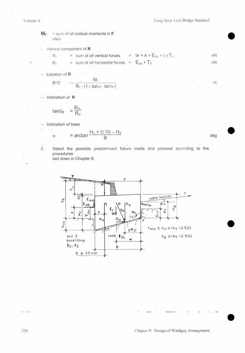
Volume A Long Span Trail Bridge Standard
Mf = sum of all statical moments in FkNm
- Vertical component of RRv = sum of all vertical forces = W + A + Eav + (-) Tv kNRh = sum of all horizontal forces = Eah + Th kN
- Location of RM f
B*/2 = ---------- mRv - (1 + tana • tanSR)
- Inclination of R
. x Rh
- Inclination of base
H-i +O. IO-H2a = a rc ta n ---------- g ---------- deg
2. Select the possible predominant failure mode and proceed according to the procedureslaid down in Chapter 6 .
228 Chapter 9: Design of Windguy Arrangement

Long Span Trail Bridge Standard Volume A
9.6.7 Compilation of Final Data
Bridge No. & Name................................. Date..................... Designed by
A ) and B) In itia l Data (re fe r to 9.6.5)
C) M ain C a lcu la tio n1) Load on top of foundation
- Total load A =................................... kN- Front to C.G. distance a =................................... m
2) Soil / rock heightsActive earth pressure height ha =................................... m
- Active earth pressure height fromtop of the foundation block hai = ........................................ m
Rock height at back h ra =................................... m- Embedded depth t, hrt =................................... m- Depth of additional soil t ' =................................... m
3) Soil parameters- Front slope of soil
(top of dry stone pitching) £1 =................................... degSlope of soil baseline £b =................................... degLength of influence L * nfi =................................... m
- Back slope of soil \j/ =................................ deg
4) Foundation dimensions- Height of cable anchorage h r =................................... m- Back height H i =................................... m
Front height H2 =................................... mWidth B =................................... m
- Length L =.................................. mBase inclination a =.................................. degDistance to resultant force B */2 =.................................. m
- Distance to resultant force L*/2 =.................................. m
5) Safety factorsSliding Fsl =................................... /
- Bearing capacity Fbc =................................... /- Toppling Ft =................................... /- Slope stability Fs =................................... /
6 ) Anchorage rodsNos as per calculation or minimum Nos. N =................................... /
D) Additional Anchorage Rods(from geological report)
Chapter 9: Design of Windguy Anangement 229

Volume A Long Span Trail Bridge Standard
E) Data to be Transferred to the General Arrangement
- Example: wlndguy cable foundation on rockDraw also the position and dimensions of additional loads on top of the foundation
9.6.8 Related Standard Drawings
Drawing Number Drawing Title
4141/1 41/2
41/3
Windguy Cable Anchorage for 1 cable (capacity 130 kN)Windguy Cable Foundation for I cableWindguy Cable Foundation for I cable <j) 26, 32, 36mm with foot, on soil
4242/1 42/2
Windguy Cable Anchorage for I cable (capacity 195 kN) Windguy Cable Foundation for 1 cable
4343/1 43/2
Windguy Cable Anchorage for 1 cable (capacity 305 kN) Windguy Cable Foundation for 1 cable
4444/1 44/2
Windguy Cable Anchorage for 2 cables ( capacity 390 kN) Windguy Cable Foundation for 2 cables
4545/1 45/2
Windguy Cable Anchorage for 2 cables ( capacity 610 kN) Windguy Cable Foundation for 2 cables
Drawing Numbers: .... = Working and assembly drawing.... /1 = Structural drawing: Foundation on Soil ...72 = Structural drawing foundation on Rock
Table 9.6.3: Standard Design Drawings: Windguy Cable Anchorage Foundation
230 Chapter 9: Design of Windguy Arrangement

Long Span Trail Bridge Standard Volume A
9.6.9 Combination with Sidestay Cable Anchorage
The windguy cable anchorage foundation can also provide anchorage for the sidestay cable (refer to 8.9.2). In this case calculate the foundation for a combined loading with the windguy and sidestay cable tensions.
Calculate the resultant loading force with T sv , Tshx and Tshy as additional loads.
windguy cable
windties
windguy cable anchorage combined with sidestay cable onchoroge
sidestay cable
foundat ion
231
Long Span Trail Bridge Standard Volume A
10. Special Design
Table of Contents
10.1 Special Suspended Bridge 23310.1.1 Combined Main Foundation with a Staircase 233
10.2 Special Suspension Bridges 23410.2.1 Suspension Bridge with One Tower 23410.2.2 Without a Tower 24010.2.3 With a Loaded Side span 24010.2.4 Double Span Bridge 24010.2.5 With the Different Walkway / Tower Foundation Elevations 24010.2.6 With Different Tower Heights 240
10.3 Special Windguy Arrangement 24110.3.1 Windguy Stay Strut 24110.3.2 Bridges without a Windguy Arrangement 243
10.4 Design of Deadman Anchorage Foundation 24410.4.1 Introduction 24410.4.2 Related Symbols 24410.4.3 Basic Calculation Principle 24510.4.4 Limits 24510.4.5 Initial Layout Data 24610.4.6 Calculation Procedure 246
Chapter 10: Special Design 232

Volume A Long Span Trail Bridge Standard
10.1 Special Suspended Bridge10.1.1 Combined Main Foundation with a Staircase
Design the combined main foundation with a staircase according to the procedures given in Chapter 6 and 7.
For calculation of the loads acting on the foundation, two load combinations must be taken into consideration.
Load case [A] Dead load case + full wind loadLoad case [B] Full load case + 1/3 wind load
Windload: w = 1.0kN/m2
Wind load acting on the walkway:- for bridges without a windguy arrangement Hw - 0.5 / • w kN- for bridges with a windguy arrangement Hw = 0
Wind load on exposed area A: Pwa = w. A kN
Calculate the stresses created in the base plate (in section 1 - 1 of the base plate):
a t ^ a t perm kN/mm2
ac ^ a c Perm kN/mm2
Related special design drawing (design example)Drawing Number 60/4: Staircase combined with main foundation
2 main cables (related drawings 60 and 63)
ZJO Chapter 10: Special Design

Long Span Trail Bridge Standard Volume A
10.2 Special Suspension Bridges
10.2.1 Suspension Bridge with One Tower
A) Layout
B) IntroductionThe following procedure has the provision for a windguy arrangement (refer to Chapter 9). It is assumed that the full wind load, acting on the walkway up to the handrail cable, can be borne by this system only. The wind load acting on the main cables and suspenders has to be born by the tower (tower/walkway foundation) on one side and by the main (anchorage) foundation on the other side where no tower is provided.
The layout and the Initial loading are based on the structure under dead load.The freeboard has to be maintained for any cable alignment (including windguy cables) at dead load case.
As an approximation, the calculations can be made in the same way as for the system with two towers (refer to Chapter 8 ).
C) Related Symbols(Refer to Chapter 8 )
D) Geometrical Parameters and Calculation ProcedureThe maximum backstay distance, DR (or DL), is limited to » 0.2 l.
St---- Ô S r
Chapter 10: Special Design 234
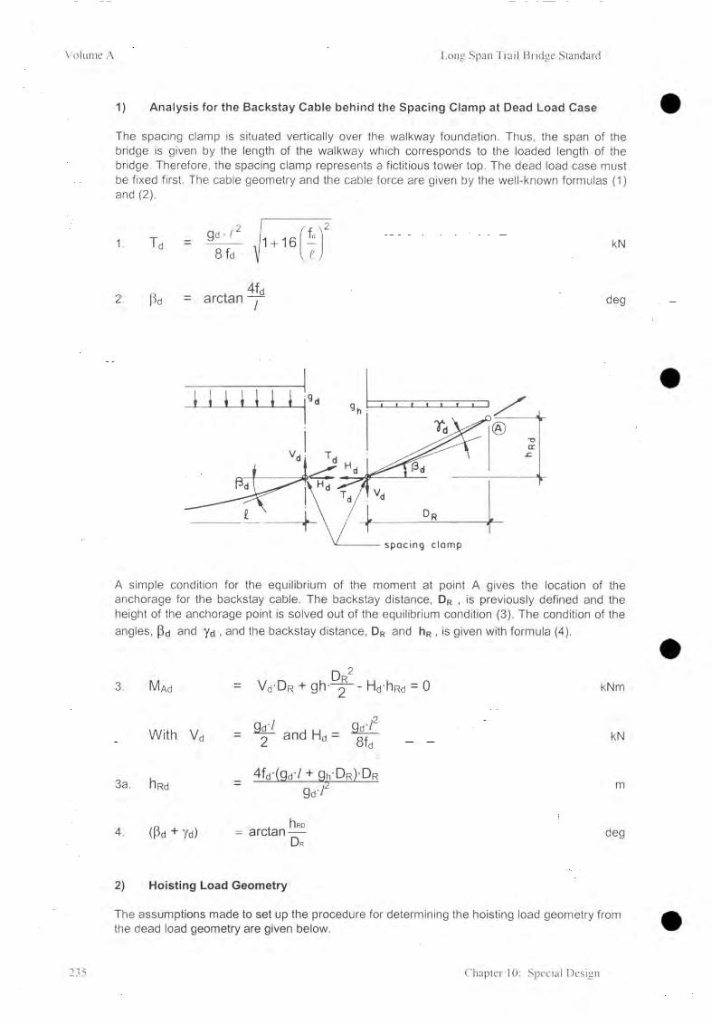
Volume A Long Span Trail Bridge Standard
1) Analysis for the Backstay Cable behind the Spacing Clamp at Dead Load Case
The spacing clamp is situated vertically over the walkway foundation. Thus, the span of the bridge is given by the length of the walkway which corresponds to the loaded length of the bridge. Therefore, the spacing clamp represents a fictitious tower top. The dead load case must be fixed first. The cable geometry and the cable force are given by the well-known formulas (1) and (2 ).
1. Td _ Qd ' >'28 fd \ u
2 . ßd = arctan 4fd/
kN
deg
A simple condition for the equilibrium of the moment at point A gives the location of the anchorage for the backstay cable. The backstay distance, DR , is previously defined and the height of the anchorage point is solved out of the equilibrium condition (3). The condition of the angles, pd and yd , and the backstay distance, DR and hR , is given with formula (4).
3. IVUd = Vd DR + g h D2R -Hd hRd - 0 kNm
With vd 2 d i „ nH H & d t- 2 and Hd - 8fd kN
3a. hRd4fd-(gd-/ + 9 h'DR)D R
g 7 rm
4. (ßd + Yd)hlRD= arctan — D r
deg
2) Hoisting Load Geometry
The assumptions made to set up the procedure for determining the hoisting load geometry from the dead load geometry are given below.
235 Chapter 10: Special Design

Long Span Trail Bridge Standard Volume A
- The horizontal movement of the tower top, DDL (or DDR), is neglected. The magnitudes of these two values are low with respect to the change in cable geometry caused by the change of load and with respect to the different elongation of the cable caused by a change of the applied load (e.g., change from dead load case to hoisting load case, or change from dead load case to full load case
- The dead load geometry of the cable between the spacing clamp and the anchorage point is taken as a straight line without local sag. The dead load length from the spacing clamp to the anchorage point is determined as
Ld » a/D r2 + hR 2 m
- The dead load cable length between the one tower and the main cable anchorage foundation is given with the formula
Ld /a- , 8i fdi + -3 v
y
I d y
+ VD 2 + hR 2 . m
The known values on which to base the calculations are:
Dead load gd,dead load span of the bridge /d,dead load sag fd,backstay distance Dr,hoisting load 9h
The geometry of the main cable for a hoisting load situation is equivalent to the geometry for the cable of a suspended bridge with anchorage points at different elevations. All the formulas for cable geometry, given in 7.3, are very useful.
An iteration leads to the geometry of the hoisting loaded cable. The span of the hoisting loaded cable is enlarged from the original dead load span, /d, to the hoisting load span
/h « Id + Dr m
To start the iteration the value for the cable force, Th , caused by the hoisting load, has to be assumed first. A good initial value for the cable force, Th , can be approximately 15% of the dead load value, T d : preliminary Th ~ 0.5 Td
Once the hoisting load geometry is calculated, the cable length from the spacing clamp to the anchorage point, L Ch, can be determined. The general formula, y = a X2 + bx + C , has to be changed to fit in with the value, /h, bh , and Ii r .
Chapter 10: Special Design 236

Volume A Long Span 'Frail Bridge Standard
The iteration procedure is shown below.
1 Cable length Lh «I Td - T h I -Ld . (T h -T d )-L d
Ld - J--------- - 1----- = U + ------------------ mE • Am E • Am
2. Sag of bh ~ /hLh_J_
lu 2 V /h J- 1 m
3. Cable force Hh g h /y8bh
kN
with tanßh4bh + hR
lu
andHi,
COS ßhkN
237 Chapter 10: Special Design

Long Span Trail Bridge Standard Volume A
3) Full Load Geometry
The length of the cable from the spacing clamp to the anchorage point can be calculated by:
1-Cf «(Tr - Td) • Led
E • A mm
The full load geometry can be calculated using the dead load formulas (3), (3a), and (4).Instead of the dead load, ga , the full load, g t , has to be introduced. The output of formula (3a) then gives the new vertical location of the spacing clamp, ilR f.
The cable between the spacing clamp and the anchorage point is assumed to be straight. The horizontal location of the spacing clamp is then defined with Lc f and Hr f
E ) Main Cable A n ch ora ge Foundation (D rum -type)
The lateral horizontal wind load, H w , has to be taken into consideration., as there is no tower to bear this load (refer to 8.4.9 C1). Analyze for both loading cases [A] and [B].
For the calculation refer to Chapter 6 , Design of Bridge Foundation and 7.4, Design of Main Anchorage Foundation of Suspended Bridges (calculate with T r = 0 ). Additional anchorage rods may be required to stabilize the rock (refer to 6.3).
Related special design drawing (design example)
Drawing Number 60/3: Main cable tunnel foundation2 main cables
Chapter 10: Special Design 238

Volume A Long Span Trail Bridge Standard
F) Walkway Anchorage Foundation
For calculating the tension in the spanning cable refer to 8.4.9 C3. The lateral force that must be considered (refer to 8.4.9 C2) consists only of
P h
Ps. /---------- sinci! KN
For the calculation procedures refer to Chapter 6 , Design of Bridge Foundation. Anchorage rods may be required to stabilize the rock (refer to 6.3).
Related special design drawing (design example)
Drawing Number 91/3: Walkway FoundationSpanning cable <)> 32 mm
G) Spacing Clamp for Main Cables
Provide a spacing clamp at the theoretical location of the tower saddle on the side without a tower.
Related special design drawing (design example)
Drawing Number 28: Spacing clamp for main cable 4 main cable<j> 32 mm
239 Chapter 10: Special Design

Long Span Trail Bridge Standard Volume A
10.2.2 W ithout a Tower
For structural calculation, anchorage and foundation design, spacing clamps, proceed according to 10. 1.
10.2.3 With a Loaded Side span
The design of this type of bridges is more complex. Additional cables between the tower tops are required for the stability of the bridge in compare to the standard suspension bridge. The design of such bridge has to be made in detail for a specific site and can not be standardized. Therefore, this bridge type is not considered in the present handbook.
10.2.4 Double Span Bridge
Additional cables between the tower tops are required for the stability of the bridge in compare to the standard suspension bridge. This type of bridge also not considered in this handbook due to the same reason as explained in 10.2.3.
10.2.5 With the Different W alkway / Tower Foundation Elevations
Suspension bridges with two towers, one, or even without a tower, with the different walkway/tower foundation elevations are not recommended.
10.2.6 With Different Tower Heights
In designing standard towers, the height of the tower is calculated as a function of the Span (load). The smaller tower, in particular, cannot be designed as a standard tower but must be designed according to the effective loads.
Chapter 10: Special Design 240

Volume A Long Span Trail Bridge Standard
10.3 Special Windguy Arrangement
10.3.1 W indguy Stay Strut
On flat river banks where walkway/tower foundations are constructed high above the ground level, the windguy cables can be supported at the walkway/tower foundation by windguy stay struts and anchored to the main cable foundation.
Frontelevation
OCJ
Windguy Cable 0 26 mm 0 32 mm 0 36 mm
h min m 3.00 3.00 3.00
d m 4.50 6.50 8.30
Vperm kN 70.00 100.00 130.00
Table 10. 5.1: Layout Data for Windguy Stay Strut
241 Chapter 10: Special Design
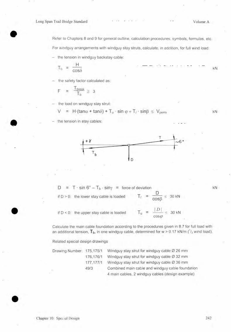
Long Span Trail Bridge Standard Volume A
Refer to Chapters 8 and 9 for general outline, calculation procedures, symbols, formulas, etc.
For windguy arrangements with windguy stay struts, calculate, in addition, for full wind load:
- the tension in windguy backstay cable:
T = —d —b cos5 kN
- the safety factor calculated as:
F = > 3• b
- the load on windguy stay strut:
V = H-(tana + tan§) + Tu ■ sin (p + T / • sinp < V perm kN
- the tension in stay cables:
D = T • sin 6° - Tb • siny = force of deviation kN
if D > 0: the lower stay cable is loaded T/ =D
D < 30 kN cosß
if D < 0: the upper stay cable is loaded Tu =1 D I----- L < 30 kNcos<p
Calculate the main cable foundation according to the procedures given in 8.7 for full load with an additional tension, Tb, in one windguy cable, determined for w > 0.17 kN/m (1/3 wind load).
Related special design drawings
Drawing Number: 175,175/1 176,176/1 177,177/1 49/3
Windguy stay strut for windguy cable 0 26 mm Windguy stay strut for windguy cable 0 32 mm Windguy stay strut for windguy cable 0 36 mm Combined main cable and windguy cable foundation 4 main cables, 2 windguy cables (design example)
Chapter 10: Special Design 242

Volume A Long Span Trail Bridge Standard
10.3.2 Bridges without a W indguy Arrangem ent
It is acceptable to follow the standard procedure if the safety factors (foundation design) are at least 1.0 above the minimum required factors, i.e., F > Fmin + 1.0
If the safety factors are less than 1.0 above the minimum safety factors, the design must be calculated with the actual loadings for all structures.
Load case [A] : Dead load case + full wind loadLoad case [B] : Full load case + 1/3 wind load
Windload: w = 1.0kN/m2
A) Suspended Bridge
The lateral wind load which must be taken into consideration for the design of the main anchorage foundations may be calculated as follows:
- for load case [A]: Ph = 0 .5 / wkN
- for load case [B]: Ph = V3 ■ ( 0.5 / • w )kN
B) Suspension Bridge
The procedure can be followed according to 8.4, but the lateral load, W b , must beincreased by, W ww the wind load acting on the walkway and calculated as follows:
- for load case [A]:
Wb = Www + WM + Wsusp = 0.5 + 0.125 + 0.0038 (ht - 2.4)= 0.616 + 0.0038 ht kN/m
- for load case [B]Wb = 1/3 ( Www + Wm + WSUSp ) = 1/3 ( 0.616 +0.0038 ht) kN/m
Note: The procedure given in 8.4 is a statical analysis only. Owing to the dynamicbehavior of the bridges (especially bridges without a windguy arrangement), the
horizontal deflection, X , and the tension in the spanning cable, p s i , may increase up to double the value.
243 Chapter 10: Special Design

Long Span Trail Bridge Standard Volume A
10.4 Design of Deadman Anchorage Foundation10.4.1 Introduction
The scope of this section is to determine the dimensions of the deadman anchorage foundation based on the results of the cable structure analysis, on the soil and rock parameters, and on prescribed safety factors. This type of anchorage foundation is a very economical main cable anchorage for suspension bridges.
It is important to note that the design philosophy and methodology is limited to shallow foundations (near ground surface) in granular soil.
The principal is to make use of the earth resistance (passive earth pressure) of the soil in front of the foundation. Therefore this type of foundation needs special care:
a) during excavation: as far as possible the soil in front of the foundation must not be disturbed; and if it is (e.g., because of the excavation for the cables), the backfilling soil must be well compacted, and
b) after construction: a prescribed area of the soil in front of the foundation must be protected (e.g., with gabion mattress).
The basic principles concerning earth pressure are given in Chapter 6 , Foundation Design.
10.4.2 Related Symbols
B Open dimension of the foundation, (part of) width mC Back toe, part of height mE Back toe, part of width mH Open dimension of foundation, (part of) height mHu„ Ultimate capacity of the foundation, horizontal component kNL Open dimension of the foundation, length mPL Length in front of the foundation to be protected mWc Weight of foundation kNWE Weight of the earth above the foundation kN
For all other symbols used, refer to Chapter 6 , Design of Bridge Foundation, and to Chapter 8.7, Design of Main Cable Foundation.
Chapter 10: Special Design 244

Volume A Long Span Trail Bridge Standard
10.4.3 Basic Calculation Principle
A) Layout
B) Ultimate Capacity
Calculating the ultimate capacity involves taking into consideration the passive earth pressure in front, the active earth pressure at the back, and the earth pressure at rest, acting laterally on the foundation.
Huit = Eph - Eah + 2 Eql kN
For determining the magnitude of Eph and Eah, refer to 6.2.3.The earth pressure at rest, acting laterally on the foundation, is calculated as:
2 E0l — 2 -o ' Yi 'hp "tanOi ■ [t/^ph "\Aah ] kN
X0 = 1 - sinO-i /
10.4.4 Limits
A) Depth of Soil on Top of the Deadman Foundation
The depth of soil on top of the deadman foundation must not exceed
h < 1/ 3 hp to 1/2 hp m
B) Length in Front of the Foundation to be Protected
The length in front of the foundation to be protected with precautionary measures to ensure adequate safety after completion of construction, is calculated as
PL — hp *\/^ph m
C) Safety against Sliding Failure
In order to reduce the movement of the foundation towards the soil in front of it, a high safety factor is required
FSl > 3.50
245 Chapter 10: Special Design
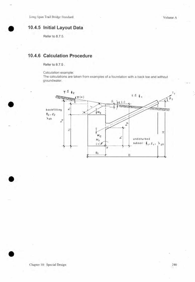
Long Span Trail Bridge Standard Volume A
10.4.5 Initial Layout Data
Refer to 8.7.5.
10.4.6 Calculation Procedure
Refer to 8.7.5 .
Calculation example:The calculations are taken from examples of a foundation with a back toe and without groundwater.
Chapter 10: Special Design 246

Volume A Long Span Trail Bridge Standard
1. Calculate the components, inclination, and location of the -resultant loading force
Loading Forces Lever Arm (m) for MF
Weights (kN):
Wp = h2 ■ Bp • L • yc Bf/2
WE = Bp • L • Il3 • y2 Bf/2
Load on Top (kN):
A = (refer to 6.2.4) a
Earth Pressure (kN):
h 2- back: Eah (back) = Xah [<D2,v|/] • ■ L • y2 3
Eav (back) = Eah- tan(| 0 2)B
h 2- front: Eph (front) = ?iph [®i, e] • -£- • L • y. Ik3
1 0Epv (front) = Eph • tan (-—• ®i) (upwards)
Loads (kN):
Tfh = Tf-cosp hi
Tfv = Tf • sinp 0
MF = sum of all statical moments in F
- Safety against sliding failure
Huit + ( W f + W e - Ttv) • tanOiFsl - --------------- ----------------------------- L----------- > 3. 50
Tfh
2. For other possible failure modes proceed according to Chapter 6 .
Related special design drawing (design example)Drawing Number 49/2:
Drawing Number 50/2:
Drawing Number 51/2:
Main cable deadman anchorage foundation Capacity 1220 kN, c / c = 4.00 m 4 main cables (related drawing 49)Main cable deadman anchorage foundation Capacity 1830 kN, c/c-i = 4.00 m 6 main cables (related drawing 50)Main cable deadman anchorage foundation Capacity 2440 kN, c/c = 4.00 m 8 main cables (related drawing 51)
kNm
/
247 Chapter 10: Special Design

Long Span Trail Bridge Standard Volum e A
11. Adjacent Works
Table of Contents
11.1 Retaining Structures 24911.1.1 Design Criteria 24911.1.2 Gabion Walls 24911.1.3 Dry Stone and Rubble Masonry Walls 25011.1.4 Preliminary Design of Retaining and Breast Walls 251
11.2 Slope Protection 25211.2.1 Slope Erosion and Slope Failure 25211.2.2 Slope Drainage 25311.2.3 Bio-Engineering 25811.2.4 Engineering Structures 25911.2.5 Slope Treatment on Rocks 25911.2.6 Summary of Slope Stabilization Work 260
11.3 River Bank Protection 26111.3.1 Instability of River Bank 26111.3.2 River Bank Protection 263
Chapter l l : Adjacent W orks 248

Volume A Long Span Trail Bridge Standard
11.1 Retaining StructuresAny structure capable of resisting soil pressure is known as a retaining structure. It can be in a variety of forms, such as: retaining walls, reinforced soils, sheet piles, walls tied and anchored to rock, and others.
For the purposes of this manual, we will study only retaining walls of gabion boxes, rubble masonry, and dry stone masonry.
11.1.1 Design Criteria
Regardless of the type of retaining structure, whether gravity or semi-gravity, it is absolutely essential to check the stability with respect to - overturning, sliding, shear failure of the wall, and overall stability of the surrounding soil.
The basic principles, the procedure for the structural analysis, and -the limitations, are given in Chapter 6 , Foundation Design.
11.1.2 Gabion Walls
A) Properties of Gabion Walls
- Homogeneous monolithic structure capable of functioning under tension and also of absorbing unforeseen stresses
- Deformability increasing the strength by drawing into action all the resisting elements- Permeability eliminating the principal causes of soil instability- Easy and speedy construction technology- Possibility of localized repair- Cheaper cost compared to masonry walls
B) Placing of Gabion Walls
Gabion walls are not set with vertical face for heights greater than 3.0 m. For heights greater than 3.0 m, the face is usually battered at not less than 6 degrees (1: 10 inward slope) or is set in position with steps. The gabion boxes should be placed in staggered joints. The minimum size of the stone should not be less than 15 cm.
Example:
249 Chapter 11 : Adjacent Works

Long Span Trail Bridge Standard Volume A
Gabion walls can be classified into four different types: gravity, semi-gravity, wall supporting sloping surcharge, and thin walls with back mesh panels.
11.1.3 Dry Stone and Rubble Masonry W alls
Dry stone or rubble masonry walls are mostly used to retain the earth behind the anchorage blocks of the bridge. Should the earth behind the block be fractured rock either a dry stone wall or a breast wall of rubble masonry is practicable. The choice depends upon different factors, such as: permissible space behind the block, required height of protection and availability of easily dressable sizes of the stones and other material. Usually a dry stone wall is used where temporarily unstable soil conditions prevail.
Chapter IT. Adjacent Works 250

Volume A Long Span Trail Bridge Standard
11.1.4 Prelim inary Design of Retaining and Breast W allsA) Retaining Walls
Type Dry Stone Banded Dry
Stone/Masonry
Cement Masonry Gabion
Low High
Section
Iy Vont jy J 5 p w e e p holes
l mo*onry t \
Top width, W, 0 .6 - 1.0 m 0 .6 - 1.0 m 0.5 - 1.0 m 1 m 1 - 2 m
Base width,w b 0.5-0 .7 H 0.6-0.65 H 0.5-0.65 H 0.6-0.75 H 0.55-0.65 H
Front batter varies varies 10:1 6 : 1 6 : 1
Back batter varies vertical varies varies varies
Inward dip of foundation, n
1 : 3 1 : 3 horizontal or 1 : 6
1 : 6 1 : 6
Foundation depth below drain
> 0.5 m > 0 .5 -1 m > 0 .5 -1 m > 0.5 m > 1 m
Range of height, H
1 - 6 m 6
- 8 m1 - 10 m 1 - 6 m 6 - 10 m
Hill slope angle, a
<35° 20° 35 - 60° 35 - 60° 35 - 60°
B) Breast WallsType Dry Stone Banded dry
Stone/Masonry
Cement Masonry Gabion Horizontal
Drum Wall
Section t J- f k
1 jCT—dry ttorx mort or
J5&y— weep botes — mosonry X
b J l ^
Top width, W, 0.5 m 0.5 m 0.5 m 2 m 1 m
Bass width,w b
0.29H
0.3H 0.33H
> 0.5 m 0.23 H 2 m 1 m
Back batter 3 : 1 4 : 1 5 : 1 3 : 1 3 : 1 3 to 5: 1 3:1Inward dip of foundation, n
1 : 3 1 : 4 1 : 5 1 : 3 1 : 3 1 : 5 1 : 3
Foundation depth below drain
>0.5m
>0.5m
>0.5m
> 0.5 m > 0.5 m > 0.5 - 1 m > 0.25 m
Range of Height, H
<6 m <4 m <3 m 3 - 8 m 1 - 10 m 1 - 8 m < 2.2 m
Hill slope angle, a
35 - 60° 35 - 60° 35 - 70° 35 - 60° < 35°
251 Chapter 11 : A djacent W orks
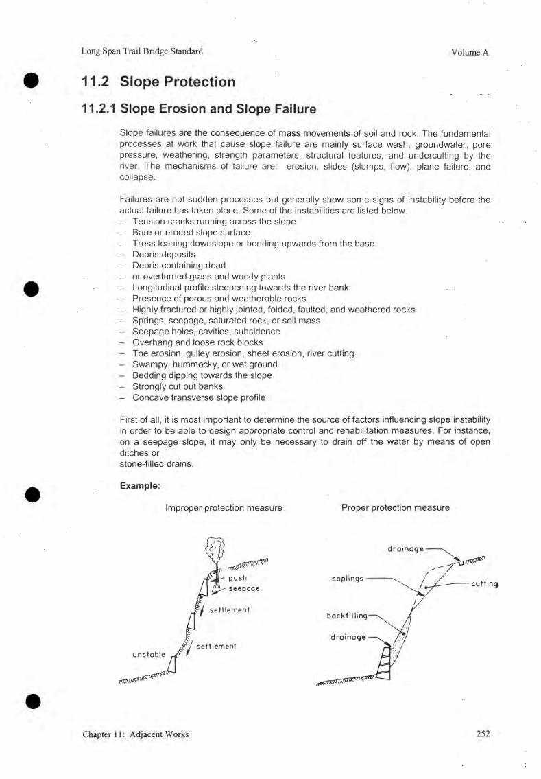
Long Span Trail Bridge Standard Volume A
11.2 Slope Protection
11.2.1 Slope Erosion and Slope Failure
Slope failures are the consequence of mass movements of soil and rock. The fundamental processes at work that cause slope failure are mainly surface wash, groundwater, pore pressure, weathering, strength parameters, structural features, and undercutting by the river. The mechanisms of failure are: erosion, slides (slumps, flow), plane failure, and collapse.
Failures are not sudden processes but generally show some signs of instability before the actual failure has taken place. Some of the instabilities are listed below.- Tension cracks running across the slope- Bare or eroded slope surface- Tress leaning downslope or bending upwards from the base- Debris deposits- Debris containing dead- or overturned grass and woody plants- Longitudinal profile steepening towards the river bank- Presence of porous and weatherable rocks- Highly fractured or highly jointed, folded, faulted, and weathered rocks- Springs, seepage, saturated rock, or soil mass- Seepage holes, cavities, subsidence- Overhang and loose rock blocks- Toe erosion, gulley erosion, sheet erosion, river cutting- Swampy, hummocky, or wet ground- Bedding dipping towards the slope- Strongly cut out banks- Concave transverse slope profile
First of all, it is most important to determine the source of factors influencing slope instability in order to be able to design appropriate control and rehabilitation measures. For instance, on a seepage slope, it may only be necessary to drain off the water by means of open ditches or stone-filled drains.
Example:
Improper protection measure Proper protection measure
Chapter 11 : Adjacent W orks 252

Volume A Long Span Trail Bridge Standard
11.2.2 Slope Drainage
Water should be collected as closely as possible from its origin and be channeled safely to a nearby water course. Springs and surface waters can be safely drained off by means of open ditches or a system of open ditches. For draining off sub-surface water, so-called "covered drains"- are used.
A ) Surface Drainage
Surface water, mostly temporary in nature, causes gully erosion along the slope thus exposing the foundation. It can also percolate into the ground resulting in a change in soil properties under the foundation. Hence surface drainages are provided where 'there is a, large accumulation of water such as in slopes with concave transverse slope profiles or seepage water.
The surface water drainage is usually facilitated by means of drainage channels around the anchorage blocks which lie below the natural terrain. Drains are provided at an angle to (or perpendicular to) the land contours. A drainage system must be provided whenever the tops of anchorages or the foundation lie below the previously existing ground level.
In loose, steep soil slopes the drainage channel must end in a hard, preferably rocky, surface or in the river itself. In a steep channel, steps or rocks jutting out of the channel should be used to regulate the flow of water in order to eliminate scouring.
Example:Drainage around block below natural terrain
- open-stone surface drainage of the surrounding terrain is necessary in places where surface water from natural drains, sources, and irrigation water (e.g., from paddy fields) might, endanger the bridge.
- Open-stone surface drainage must be designed in such a way that an additional accumulation of water, and consequently erosion downside from the canal outlet is avoided.
- To avoid self-scouring, the canal should end in rock or the canal outlet should be protected. Probably cascade construction will be required on steep sections to avoid erosion on the downside of the canal outlet.
253 Chapter 11 : Adjacent Works

Long Span Trail Bridge Standard Volume A
Example:End of drainage
-drainagecanal
concrete, masonry or gabions
The section of the channels is determined according to the expected water discharge.
Example:Sections of channels
B) Sub-Surface Drainage
Increase in soil moisture reduces its cohesion and frictional force, and consequently the load-beading capacity of the soil diminishes. The change in soil moisture results from the seepage of water from adjacent higher ground, and the consequent rise in water table, percolation, and suction. Soil water is especially dangerous when the foundation lies above the impermeable layer; above which the fine soils will flow along with the water thus causing cavities below the foundation. In such cases sub-surface drains are required.
Mostly the anchorages of suspension bridges are built into slopes where the natural water level is below the depth of the foundation; sub-surface drains are rarely provided.
Chapter 11 : Adjacent Works 254

Volume A Long Span Trail Bridge Standard
In wet areas where there is a probable risk of earth slips that might endanger the bridge, sub -surface drainage may be required. There are different types of sub-surface drainage.
Example:Catch-water drainage
Sub-drain types
canal, 1: 4
255 Chapter 11 : Adjacent Works

Long Span Trail Bridge Standard Volume A
The same systems are used for drains behind retaining walls and around anchorages and foundations.
Example:Drainage behind retaining wall
Example:Drainage around anchorage foundation
Chapter 11 : Adjacent Works 256

Volume A Long Span Trail Bridge Standard
Example:Stabilization of an unstable slope
Plan
3.00 m.
Section
257 Chapter 11 : Adjacent Works
sß. 0
0 m.

Long Span Trail Bridge Standard Volume A
11.2.3 B io-Engineering
A cheap, effective, permanent, and probably the best way to establish unstable slopes and river banks is to grow trees, plants such as shrubs or grasses, or to maintain the natural eco-system. The trees have earth-reinforcing effects. The effectiveness of plantation depends upon the depth of the potential slip surface within the slope and upon the plant type. Vegetation improves soil structures and textures. Proper selection of plant type is also very important and should be mainly based upon local experience. The popular vegetations are uthis, sisnoo, simali, local shrubs and grasses, oaks, pines, etc. Vegetation measures can be grouped as follows:
- seeding, grass turfing, and mulching to obtain a grass cover;
- contour waffling, wicker work fencing, contour planting, and fascines (long bundles of sticks bound together); and
- reforestation with pioneer species.
A) Seedings
Very often, before sowing grass seeds on barren slopes, soil and site preparation, such as shaping the slope, spreading humus, and the application of fertilizer, may be required. About 3 kg of grass seed are needed to seed an area of 100 m2. Legume seeds mixed with grass seeds give good results as they are nitrogen fixers. It takes 0.5 to 1.0 working hours to seed 100 m2.
B) Grass Turfing
To regenerate successful vegetation through placement of grass sods, the latter should be placed horizontally on the slope when the surface is wet and during the vegetation period. On very steep slopes, fixation of the grass sods can be done by using sticks to get a firm hold on the slope surface.
C) Mulching
This method requires that a layer of straw, wood fiber, or other organic material be spread on to the soil. Seeds and fertilizers are added and finally the layer of mulching is fixed by spraying a cold asphalt suspension. In this method, the grass cover comes up after a relatively short time because here a favorable micro-climate and growing conditions are created by reducing water losses, surface temperature, and soil crust formation. The seeds are prevented from rolling down the hill and fertilizer is also preserved .
For fixing the straw layer on to the slope surface, an asphalt suspension of 50% asphalt in water is watered down to a 25% solution which is applied to the straw by means of a portable rucksack type sprayer. About 0.5 litters of asphalt suspension per m2. is applied.
D) Contour Waffling and Contour Planting
These methods are useful on steep and high slopes where grass is often not strong enough to prevent erosion, Here, the idea is to break up the slope with horizontal rows of very dense brush which will fix the soil with its long roots and reduce runoff.
Chapter 11 : Adjacent Works 258

Volume A Long Span Trail Bridge Standard
In contour waffling, twigs and branches are bound into long bundles and are pegged down with pointed stakes on to a narrow ledge that cuts the slope contour-wise. The bundles are then covered with earth. The stakes are sharpened at the bottom ends, are 1 - 1.2 m long, and have - diameters of about 5 cm. The internal rows of 1.2 m in width and spaced at 0.5 m from each other have to be driven into the soil, leaving about 15 cm of the stake above the soil surface. A hectare of land requires about 17,000 stakes. A ten man crew can waffle up to 250 m2 per day.
In contour planting, willow slips or other cuttings from about 0.9 - 1.5 m long are laid down across a terrace, then the layer of the slips is covered with the soil realized from the excavation of the upper terrace. The width of the terrace should be 0.5 - 0.6 m. Cordon layers may either continuously follow the contour line or be of a certain length, say 5 m, and overlap each other. With the indicated spacing of a contour planted, 3,500 to 5,000 m of cordon per hectare, would be required.
E) FascinesThe technique is similar to the one used in contour panting. Here instead of putting cross layers on the contour terraces, brushwood is laid out.
The terrace should have a gradient of 20 to 25% towards the slope which should have a width of 0.6 - 1.2 m. The brushwood and cuttings should be about 20 cm longer than the width of the terrace.
F) Practical Examples of Bio-Engineering WorkRefer to Manual, prepared by ITECO: Handbook for Bio-Enginering Methods in Gully and Landslides Stabilization Works, ITECO AG, Switzerland, 1990.
11.2.4 Engineering Structures
Simple engineering works during bridge construction for slope protection are: drystone walls, gabion walls, rubble masonry walls, stone pitching (dry or masonry), and check dams (refer to 11.1.4).
11.2.5 Slope Treatment on Rocks
For protection of unstable rock slopes, measures such as grouting, filling cracks, shot crete geotextile, rock anchorage, rock bolting, and earth reinforcement are commonly applied. Also, by removing the extra weight of the soil from an unstable slope, the driving force can be reduced causing instability in the rock. Extra weight can also be added at the top of the slope to stabilize it.
Example:Rock bolts
259 Chapter 11 : Adjacent Works

Long Span Trail Bridge Standard Volume A
11.2.6 Summary of Slope Stabilization Work
Failure mechanisms Treatment method
1. Erosion
2. Shallow debris slides
3. Small rock slides and wedges
4. Rock falls
5. Deep-seatedtranslational slides (debris & rock)
6 . Deep-seated rotational slides (deep colluvium, weathered, fractured/ disturbed rock)
Vegetation- Vegetated stone walls- Mattress
Check dams- Pitching cascade
- Revetment/retaining wall- Drainage, vegetation- Geotextiles
- Retaining walls- Vegetation
Drainage- Rock trap walls- Rock anchors
Revetment- Detention scaling
Rock bolting- Rock trap wail/netting
- Retaining walls- Vegetation
Drainage regrading- sealing cracks
- Retaining walls- Vegetation- Drainage
Slope regrading- Sealing cracks
7. Flows(debris/mud rock)
Check dams Erosion protection Control of sediment supply
These methods are feasible for suspension bridge sites and are frequently used.
Chapter 11 : Adjacent Works 260
Volume A Long Span Trail Bridge Standard
11.3 River Bank Protection
11.3.1 Instability of River Bank
Instability of the river bank is usually due to two reasons:
- Repeated subjection of river banks to strong currents, thus causing bank erosion or toe undercutting
Erosion of loose excavated materials, which after excavation are cast up on the river bank in front of the anchor block.
Besides the principal reasons, other reasons for river bank instability are:
- the river current directly strikes the bank or there is the possibility of it doing so in future,
- the transverse slope and profile above the bank is concave,
- rivulets or water runoffs are flowing down the slope,
- the rock mass in a rocky bank is highly weathered and fractured with widely opened joints, sometimes filled up with soil or soluble materials like calcite, clay, etc,
- unstable features such as seepage holes, topple figures, fine sandy layers, or impermeable (clay) layers are present in an alluvial bank,
the bank inclination is steeper than the frictional angle of the soil or it is loosely compacted,
the bridge site lies near the confluence of two rivers,
- the bridge site lies on a delta,
the bridge site lies on an old landslide area indicated by inclined trees or fast-growing trees such as uthis, etc,
water seepage is present, and
the river current has created cavities at the bottom of the bank.
261 Chapter 11: Adjacent Works
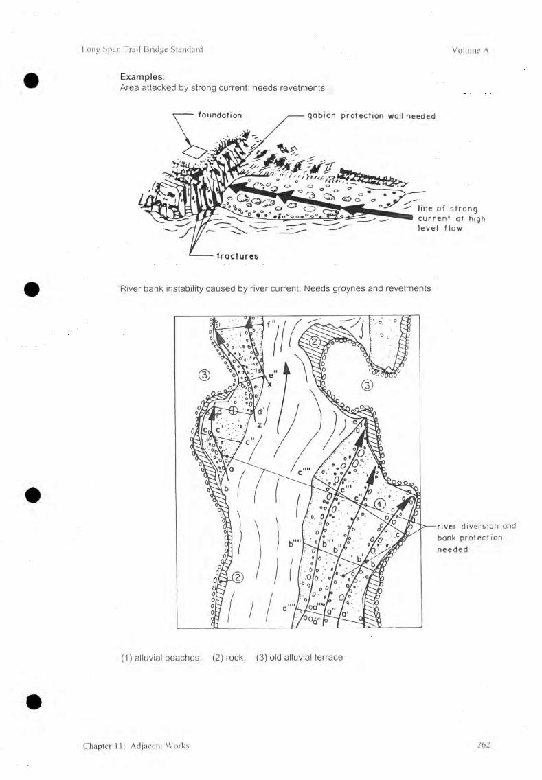
Long Span Trail Bridge Standard Volume A
Examples:Area attacked by strong current: needs revetments
River bank instability caused by river current: Needs groynes and revetments
river diversion and bonk protection needed
(1) alluvial beaches, (2) rock, (3) old alluvial terrace
Chapter 11 : Adjacent Works 262

Volume A Long Span Trail Bridge Standard
11.3.2 River Bank ProtectionMost of the slope protection work discussed earlier is also applicable for river bank protection. In addition to these, river training and revetments are also required in certain cases. The extent of protection work depends upon the site condition, direction, river gradient, and speed of water current.
For river training and revetment, it is usual to practice certain methods, e.g., guide banks, riprap protection, flood embankment, groynes, T-head spurs, etc.
Hereunder are mentioned methods that are generally applied for bridge sites. For details refer [6],
A) GroynesThese structures can be:- backfilled earth and stones,- gabions, and- suitable wooden cribs filled with stone and brushwood.
The purpose of using groynes is to prevent bank erosion, or to divert the flow into required directions, or to control the angle of attack of the current. They are generally used in groups rather than singly. One single groyne can influence a bank length of at least twice its projected length perpendicular to the flow. The spacing can even be up to four times the projected length. Groynes are placed on river banks, inclined or vertical to the bank contours.
They are placed pointing downstream when their purpose is to deflect the flow from the bank. If the bank has to be protected from erosion, they are pointed upstream and this creates a 'cushion' after the groyne.
Example:Timber crib groyne
Sect ion
D es ia n__ _______________________ ZL_________________ 1n ____Q____ o n r> ----^ ------ n O vi/nfpr- o ------ n -------
— n — n n n n n 1 - ■ ......oI_ ___ 0 ___ ___in __ — v~ n ------- ------- n n ------- -------________________ \ . . -------------- --------------_____ Q___ ___ Q____ __ D___ —\ D ____7 ^ 5 o T5------ -------n ------- n--------- n ------ ------ T5--------------n ------------ u -------Q____ o ____-------Q..... .
Plon
263 Chapter 11 : Adjacent Works

Long Span Trail Bridge Standard Volume A
Stone - faced groyne
Sect ion
crest above flo o d level
e a rth f i l l
s tone p itch ing t > 1 .5 D
1.5 H
f o i l in g ap ron
D : d ia m e te r o f s tone--- 1
/f i l t e r la y e r
p o s it io n when- lounched
--------J L K estim a ted depth
of scour H
The tip is more vulnerable so will need larger stones ond wider opron than root
pitched slope
Groyne of dumped stones
Note: Stone sizes must be large enough to resist the calculated maximum velocities
Chapter 11: Adjacent Works 264

Volume A Long Span Trail Bridge Standard
Groyne of gabions
S ection A - A Sect ion B - BGroyne of gobions
265 Chapter 11: Adjacent Works

Long Span Trail Bridge Standard Volume A
B) Apron
Aprons are used to protect the bank from scouring. They are generally placed around a bank having a gentle bend and also along a bank subjected to direct impingement of flow.
The size of stones to be placed on the apron depends upon the scouring pattern of the river. The velocity of the river at the point of attack is also a major factor in selecting the stone sizes. For details refer to [6].
Aprons made of gabions are also very common.
Example:Apron at or below natural bed
la = Apron lengthh = Launched length
P = Launched slope angleH = Estimated scour deptht = Apron thickness0 = Bank slope angle
The required size of stones can be estimated from the figure given below.
St one weight ( kg)1 5 10 20 40 100 20 0 500 1,000 2,000 3,000L i...J I t— i__ t x I a ,i .jl J______ l_____ I________ I
Source: Adapted by Ackers from Neill, C. R., Guide to Bridge Hydraulics, Roads and Transport Assoc, of Canada. Toronto: University of Toronto Press, 1973.
Chapter 11 : Adjacent Works 266

Volume A Long Span Trail Bridge Standard
C) Gabion Protection
Gabions are the most appropriate for bank protection. Their layout has to be carried out according to the site condition.
Gabion protection of steep bank
D) Bank Protection Against Weak Rock
conc r e t e or gobions
tower foundat ion
Protect ion wall
in cose of s t rong cur rent
267 Chapter 11: Adjacent Works
Volume A Long Span Trail Bridge Standard
12. Appendix
Table of Contents
12.1 Cable Statics 26912.1.1 Parabolic Cable 26912.1.2 Catenary 270
12.2 Geometry of the Parabola 27112.2.1 General Case 27112.2.2 Vertex at theOIntersection of the Coordinate Axes 271
12.3 List of Standard Drawings 27212.3.1 Standard Working Assembly Drawings 27212.3.2 Standard Structural Drawings 27312.3.3 Special Design Drawings 275
12.4 Design Examples 27612.4.1 Suspended Bridge 27612.4.2 ' Suspension Bridge 276
12.5 Cost Estimate Norms/Formats (21 Pages)
12.6 Survey Form and Checklist (42 Pages)
Chapter 12: Appendix 268
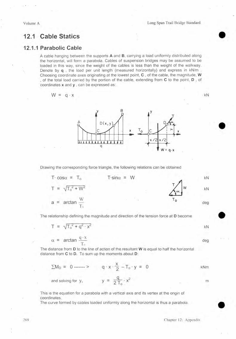
Volume A Long Span Trail Bridge Standard
12.1 Cable Statics12.1.1 Parabolic Cable
A cable hanging between the supports A and B, carrying a load uniformly distributed along the horizontal, will form a parabola. Cables of suspension bridges may be assumed to be loaded in this way, since the weight of the cables is less than the weight of the walkway. Denote by q , the load per unit length (measured horizontally) and express in kN/m . Choosing coordinate axes originating at the lowest point, C , of the cable, the magnitude, W , of the total load carried by the portion of the cable, extending from C to the point, D , of coordinates x and y , can be expressed as:
W = q • x kN
Drawing the corresponding force triangle, the following relations can be obtained
T- cosa = T0 T-sina = Wt / I
kN
T = V t 0 2 + WA h
w kN
a = arctan —T o
T„deg
The relationship defining the magnitude and direction of the tension force at D become
T = a/T o2 + q2 • X2 kN
q • xa = arctan - — deg
T o
The distance from D to the line of action of the resultant W is equal to half the horizontal distance from C to D. To sum up the moments about D:
I M d - 0 --------> q • x \-T 0 ■ y = 0 kNm
and solving for y, q 2y = 2 t 0 x m
This is the equation for a parabola with a vertical axis and its vertex at the origin of coordinates.The curve formed by cables loaded uniformly along the horizontal is thus a parabola.
269 Chapter 12: Appendix

Volume A Long Span Trail Bridge Standard
The length of the cable from its lowest point, C , to its support, B , may be obtained by differentiating the Integral of the arc and using the binomial theorem, resulting in the formula:
Is - * b r-i + — (^ )2_ — ( V41 1 3 ( xB > 5 ' xB '
The series converges for values of the ratio, yB / xB , less than 0.5 ; in most cases, the ratio is much lower than this and only the first two terms of the series need be taken into consideration.
12.1.2 Catenary
A cable hanging between the supports A and B, carrying a load uniformly distributed along the cable itself, will form a catenary. Cables hanging under their own weight are loaded in this way. Denote by q the load per unit length (measured along the cable) and express it in kN/m. The magnitude, W , of the total load carried by a portion of cable of length, s , extending from the lowest point, C , to a point D is:
W = q ■ S kN
The relationship defining the magnitude of the tension force at D become
T = V t 02 + q2 • s2
kN
The distance from D to the line of action of the resultant, W , is not known, as the distance , s , is measured along the cable itself. Refer to the technical literature for the complete formula of the catenary.
The error introduced, by assuming a parabolic shape for cables hanging under their own weight, is small if the cable is tightly stretched.
For the calculation of standard bridges, sufficient accuracy can be achieved by using the formula for the parabola instead of the formula for the catenary.
Chapter 12: Appendix 270

Volume A Long Span Trail Bridge Standard
12.2 Geometry of the Parabola
12.2.1 General Case
A: Vertex (horizontal tangent)
General formula : y = a ■ X2 + b • X + C
_ dy _tangent in x : tana dx = 2 a • x + b
Given: Vertex A (xA , yA) and point B (xB, ye) Determine a, b, and c with:
yA = a ■ xA2 + b • xA + cyB = a ■ xB2 + b • xB + ctana = 2 a • xA + b = 0
12.2.2 Vertex at the Intersection of the Coordinate Axes
A : Vetex (horizontal tangent)2
General formula : y = a • X
tangent in x : tana = 2 a ■ X
Given : Point B (XB , yB) , and
a = xB
Example: XB
a
y
tana =
tanß =
112, and yB 4f7
4 fT8 fTÜ
/
= f
X
• X
271 Chapter 12: Appendix
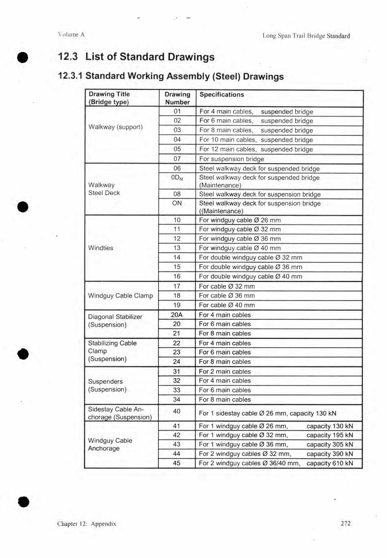
Volume A Long Span Trail Bridge Standard
12.3 List of Standard Drawings
12.3.1 Standard Working Assem bly (Steel) Drawings
Drawing Title (Bridge type)
DrawingNumber
Specifications
Walkway (support)
01 For 4 main cables, suspended bridge02 For 6 main cables, suspended bridge03 For 8 main cables, suspended bridge04 For 10 main cables, suspended bridge05 For 12 main cables, suspended bridge07 For suspension bridge
Walkway Steel Deck
06 Steel walkway deck for suspended bridge0Dm Steel walkway deck for suspended bridge
(Maintenance)08 Steel walkway deck for suspension bridgeON Steel walkway deck for suspension bridge
((Maintenance)
Windties
10 For windguy cable 0 26 mm11 For windguy cable 0 32 mm12 For windguy cable 0 36 mm13 For windguy cable 0 40 mm14 For double windguy cable 0 32 mm15 For double windguy cable 0 36 mm16 For double windguy cable 0 40 mm
Windguy Cable Clamp17 For cable 0 32 mm18 For cable 0 36 mm19 For cable 0 40 mm
Diagonal Stabilizer (Suspension)
20A For 4 main cables20 For 6 main cables21 For 8 main cables
Stabilizing Cable Clamp(Suspension)
22 For 4 main cables23 For 6 main cables24 For 8 main cables
Suspenders(Suspension)
31 For 2 main cables32 For 4 main cables33 For 6 main cables34 For 8 main cables
Sidestay Cable Anchorage (Suspension)
40 For 1 sidestay cable 0 26 mm, capacity 130 kN
Windguy Cable Anchorage
41 For 1 windguy cable 0 26 mm, capacity 130 kN42 For 1 windguy cable 0 32 mm, capacity 195 kN43 For 1 windguy cable 0 36 mm, capacity 305 kN44 For 2 windguy cables 0 32 mm, capacity 390 kN45 For 2 windguy cables 0 36/40 mm, capacity 610 kN
Chapter 12: Appendix 272

Volume A Long Span Trail Bridge Standard
Drawing Title (Bridge type)
DrawingNumber
Specifications
Main Cable Anchorage (Suspension)
48A For 4 main cables 0 26/32 mm,capacity 520 / 780 kN, c/c, = 3.50 m
48B For 4 main cables 0 36/40 mm,capacity 1220 kN, c/c, = 3.50 m
49 For 4 main cables 0 36/40 mm,capacity 1220 kN, c/c1 = 4.00 m
50 For 6 main cables 0 36/40 mm,capacity 1830 kN, cici = 4.00 m
51 For 8 main cables 0 36/40 mm,capacity 2440 kN, cici = 4.00 m
Tower -stay Cable 52 For tower erection
Main Cable Anchorage(drum-type)(Suspended)
60 For 2 main cables, capacity 610 kN (For Suspension)61 For 4 main cables, capacity 1220 kN62 For 6 main cables, capacity 1830 kN
Handrail CableAnchorage(Suspended)
63(26) For 2 handrail cables 0 26 mm, capacity 260 kN63(32) For 2 handrail cables 0 32 mm, capacity 390 kN63(36) For 2 handrail cables 0 36 mm, capacity 495kN
Main Anchorage(open-type)(Suspended)
64 For 8 main cables and 2 handrail cables 0 40 mm, capacity 2440 and 610 kN
65 For 10 main cables and 2 handrail cables 0 40 mm, capacity 3050 and 610 kN
66 For 12 main cables and 2 handrail cables 0 40 mm, capacity 3660 and 610 kN
67 Saddle and Accessories for 8 main cables68 Saddle and Accessories for 10 main cables69 Saddle and Accessories for 12 main cables
Cable Rock Anchorage
70 For 1 windguy cable 0 26 mm, capacity 90 kN71 For 1 windguy cable 0 32 mm, capacity 180 kN72 For 1 windguy cable 0 36/40 mm, capacity 280 kN
Walkway/TowerAnchorage(Suspension)
90 For spanning cable 0 26 mm, capacity 260 kN, c/Ci = 3.50 m, c/c2 = 38.3 cm
91 For spanning cable 0 32 mm, capacity 390 kN, c/c-i = 3.50 m, c/c2 = 48.8 cm
92 For spanning cable 0 32 mm, capacity 390 kN, c/c, = 4.00 m, c/c2 = 55 cm
93 For spanning cable 0 36/40 mm, capacity 610 kN, c/c, = 4.00 m, c/c2 = 56.6 cm
Tower(Suspension)
100-107 Tower base element110-117 Tower intermediate element120 - 130 Tower top element135 - 138 Tower saddle
Tower(Suspension)
140 Guide to LSTB standard towers145-160 Assembly of tower
273 Chapter 12: Appendix

Volume A Long Span Trail Bridge Standard
12.3.2 Standard Structural (Construction) Drawings
Drawing Title (Bridge type)
DrawingNumber
Specifications
Sidestay Cable Foundation (Suspension)
40/1 1 cable 0 26 mm
Windguy Cable Foundation
41/1 1 cable 0 26 mm, on soil41/2 1 cable 0 26 mm, on rock41/3 1 cable 0 26/32/36 mm, on soil (with foot)42/1 1 cable 0 32 mm, on soil42/2 1 cable 0 32 mm, on rock43/1 1 cable 0 36/40 mm, on soil43/2 1 cable 0 36/40 mm, on rock44/1 2 cables 0 32 mm, on soil44/2 2 cables 0 32 mm, on rock45/1 2 cables 0 36/40 mm, on soil45/2 2 cables 0 36/40 mm, on rock
Main Cable Foundation (Suspension)
48A/1 4 main cables 0 26/32 mm, c/c1 = 3.5048B/1 4 main cables 0 36/40 mm, c/c1 = 3.5049/1 4 main cables 0 32/36/40 mm, c/c1 = 4.0050/1 6 main cables 0 36/40 mm, c/c1 = 4.0051/1 8 main cables 0 36/40 mm, c/c1 = 4.00
Main Cable Deadman Foundation (Suspension)
48A/2 4 main cables 0 26/32 mm, c/c1 = 3.5048B/2 4 main cables 0 36/40 mm, c/c1 = 3.5049/2 4 main cables 0 32/36/40 mm, c/c1 = 4.0050/2 6 main cables 0 36/40 mm, c/c1 = 4.0051/2 8 main cables 0 36/40 mm, c/c1 = 4.00
Tower-stay cable Foundation for Tower Erection (Suspension)
52/1 1 cable on one side for tower height < 25.23 m52/2 2 cables on two sides for tower height < 25.23 m52/3 2 cables on one side for tower height > 27.73 - 35.21 m
Main Foundation(drum-type)(Suspended)
61/1(26) 4 main cables 0 32/36/40 mm and 2 handrail cables 026 mm on soil, related drawings 61 & 63(26)
61/2(26) 4 main cables 0 32/36/40 mm and 2 handrail cables 026 mm on rock, related drawings 61 & 63(26)
61/1(32) 4 main cables 0 32/36/40 mm and 2 handrail cables 032 mm on soil, related drawings 61 & 63(32)
61/2(32) 4 main cables 0 32/36/40 mm and 2 handrail cables 032 mm on rock, related drawings 61 & 63(32)
62/1(26) 6 main cables 0 36/40 mm and 2 handrail cables 0 26 mm on soil, related drawings 62 & 63(26)
62/2(26) 6 main cables 0 36/40 mm and 2 handrail cables 0 26 mm on rock, related drawings 62 & 63(26)
62/1(32) 6 main cables 0 36/40 mm and 2 handrail cables 0 32 mm on soil, related drawings 62 & 63(32)
62/2(32) 6 main cables 0 36/40 mm and 2 handrail cables 0 32 mm on rock, related drawings 62 & 63(32)
62/1(36) 6 main cables 0 36/40 mm and 2 handrail cables 0 36 mm on soil, related drawings 62 & 63(36)
62/2(36) 6 main cables 0 36/40 mm and 2 handrail cables 0 36 mm on rock, related drawings 62 & 63(36)
Chapter 12: Appendix 274

Volume A Long Span Trail Bridge Standard
Drawing Title (Bridge type)
DrawingNumber
Specifications
64/1 8 main cables, on soil, related drawings 64 & 67
Main Foundation(open-type)(Suspended)
64/2 8 main cables, on rock, related drawings 64 & 6765/I 10 main cables, on soil, related drawings 65 & 6865/2 10 main cables, on rock, related drawings 65 & 6866/1 12 main cables, on soil, related drawings 66 & 6966/2 12 main cables, on rock, related drawings 66 & 6990/1 Spanning cable 0 26 mm,
c/ci = 3.50, c/c2 = 38.3 cmwithout foot,
90/2 Spanning cable 0 26 mm, c/c, = 3.50, c/c2 = 38.3 cm
with foot,
91/1 Spanning cable 0 32 mm, c/c, = 3.50, c/c2 = 48.8 cm
without foot,
Walkway/TowerFoundation(Suspension)
91/2 Spanning cable 0 32 mm, c/c, = 3.50, c/c2 = 48.8 cm
with foot,
92/1 Spanning cable 0 32 mm, c/c, = 4.00, c/c2 = 55.0 cm
without foot,
92/2 Spanning cable 0 32 mm, c/c, = 4.00, c/c2 = 55.0 cm
with foot,
93/1 Spanning cable 0 36/40 mm, c/c, = 4.00, c/c2 = 56.6 cm
without foot,
93/2 Spanning cable 0 36/40 mm, c/c, = 4.00, c/c2 = 56.6 cm
with foot,
Staircase 94/1 For medium to unfavorable soil conditions(Suspension) 94/2 For good soil conditions
12.3.3 Special Design Drawings
Drawing Title (Bridge type)
DrawingNumber
Specifications
Windguy Clamp for Direct Windguy Cable 25 For windguy cable 0 26 mm, main cable 0 36/40 mm
(Working and Assembly Drawing)Spacing Clamp for Main Cables (Suspension)
28 For 4 main cables 0 32 mm (Working and Assembly Drawing)
Combined Main Cable and Windguy Cable Foundation (Suspension)
49/3 4 main cables 0 32/36/40 mm, c/c-i = 4.00 m,2 windguy cables 0 36/40 mm, c/c, = 2.00 m, (Structural Drawing), related drawings: 49 and 45
Main Cable Tunnel Foundation (Suspension)
60/3 2 main cables (Structural Drawing), related drawing : 60
Staircase Combined with Main Foundation(Suspended)
60/4 2 main cables (Structural Drawing), related drawings: 60 and 63
Walkway and Tower Foundation 90/3 Structural Drawing
Walkway Foundation(Suspension)
91/3 Spanning cable 0 26/32 mm (Structural Drawing)
Walkway and Windguy Cable Anchorage 91/4 For Spanning cable 0 32 mm and windguy cable 0 32
mm (Structural Drawing)Windguy Stay Strut (Working and Assembly Drawings)(Suspension)
175-175/1 Length 4.50 m, for windguy cable 0 26 mm,176-176/1 Length 6.50 m, for windguy cable 0 32 mm177-177/1 Length 8.30 m, for windguy cable 0 36 mm
27 5 Chapter 12: Appendix
Volume A Long Span Trail Bridge Standard
12.4 Design ExamplesOn the following pages, two design examples, are compiled.One for a suspended bridge, refer to
12.4.1 Suspended Bridge
and, one for a suspension bridge, refer to
12.4.2 Suspension Bridge
The calculations have been carried out according to the procedures given in this manual. In cases where similar calculation has to be carried out several times, they are presented for one example only. E.g., the calculation of the windguy arrangement is only carried out for the suspended bridge. Reference has to be made to this example for the windguy arrangement of the suspension bridge. The "General Arrangements" related to the two design examples are contained in: .
LSTB Technical Manual Volume C, Standard Design Drawings, Design Examples.
Chapter 12: Appendix 276

12.4.1 SUSPENDED BRIDGESDESIGN OF MAIN AND HANDRAIL CABLE STRUCTURES [7 . 3]
h u t i a l h r y o u t d a t a [ 7 . 3 . 6 ]
According to General Arrangement
Foujtdaijon locaiipruOn right bank, 7.75 m behind of axis point A On left bank, 16.59 mbehind of axis point B
Njmujml span,S = survey distance AB + 7.75 + 16.59
= 107.76 + 7.75 + 16.59
D e s ig n sjpan b e tw e e n sadd les^ ie = s + 2X 0.25 =132.1 + 0. 5
Cable, ehryjTjwn_s [from topography]Main cables right bank, Hi = 110.85-0.25
l e f t bank, H2 = 105.85-0.25 Windguy cables right bank, upstream
downstream Left bank, upstream
downstream
DifferetU in main caffe eHy_aJions_ between saddles^ h
h - H i - H2 = 110.6 - 105.6 h = 5.0 mCheck for h [7. 3 .5 B]
S = 132.10 m
t - 132.60 m
H, = 111.60 m H2 = 105.60
= 102.60 m= 102.30 m = 97.50 m = 96.40 m
f _14
i.e.
132.614
9.47m > h = 5.0m
the lowest point remains inside the bridge span.
o.k.!
Pgej^caJgtdaJlon ofjgaMe tensiong Main and_ hjxnxfnul cafde_s Approximate maximum cable tension Tn,ax (approx.) = l l x S = l l x 132.1Number and diameter of cables Number of main cables Diameter of main cable Number of handrail cables Diameter of handrail cable
Tmax = 1450 kN
11 m 4
e= 2
0 // = 26

Permissible tension (all cables) Tperm = 1476 kN
Check, for tejisfonTperm = 1476 kN > Tmax = 450 - >
Sectional area (a l l j i a b l e s )[Table 7 . 3 . 2 ]o.k.
A = 3348
Wjndguj cable_s
Windguy cable sag at mid-span
r-p i i l 1 3 2 . 6Take bw = - = —
1 t0 To
b... = 14.7 m
With vertex close to the centre, bw ~ f w = 14.7 m and there will be any problem fo r the placement of Windguy cable foundation on either bank.
AppmQMllMlli. Wjjidguy cabje tension [one cable}
Tl ~ T r = ^ J i / 2x^8 x 6 „, .
0-5x32.6 :8x14.7
V
1 +2x14.7
66.3T = 82 kN
Nurnbez aruf dfajnete_r offWjmdguy_ cabjey
Number of windguy cables (both u/s and d/s) II bo 3
Diameter of windguy cable 0W = 26 mmPermissible tension fo r one cableTpenn = 129 kN
Tperm = 129 kN > T = 82 kN--> ok!
Modulus of elasticity [table 4 .2 . E = 1 10 2
Loadings1. Hoisting load case, nh
Main and handrail cables = 0.2882. Dead load case, gd
hoisting load, gp = 0.288 kN/mwalkway deck (steel) = 0.370kN/mWalkway support (including hangers) = 0.220 kN/m
fixation cables = 0.010 kN/mwiremesh netting = 0.060 kN/mwindguy cables = 0.050Windties (average) = 0.030Total at dead load case v,= 1.028 kN/m

3 . F u l l load case,dead load, live load, P ( = 3.0Total at fu ll load case
Dead_ load_ sa, b,±
bd (max) _f_19
[7. 3. 5]
h_4
132.619
54
= 1.028 = 3.377
g/-= 4.405 kN/m
= 5.73
bd (m23
h_4
132.6 _ 5 23 4
4.52 m
With bd (max) =5.73 m; f load sag, bt ~ 1.22b a
ß jf(max) = arctan4bf + h!
= arctan( 4x6.99 + 5 \i 132.6) V /
= 6.99 m
= 13.96 deg
Approximate maximum tension under fu ll load [7. 3 .3 ]
V f.12
4.405x132.62max __ 8bf .cos ß1f 8 x 99x cos 13.96c
= 1427 < 1476 kN -> ok!
With bd (min) = 4.52
ß If - arctan 4x5.51 + 5' 1326
4.405x132 62 8x5.51xcos11.52°
bf = 1.22 x 4.52= 5.51 m
= 11.52 deg.
= 1804 kN > 1476 kN --> Not ok!
Conclusion— Even with the maximum sag, no next smaller diameter cable can
be chosen.— To obtain minimum sag, the main cable numbers should be
increased, which is uneconomical, if the minimum freeboard can be obtained with larger sag.
— Within perm issible tension, slight change either h or bd or both can be made fo r better stability.
Rev±se_d h qnd_ bdDead load sag Different in elevationApproximate max. tension under fu ll load The left bank cable elevation shall be kept at The right bank cable elevation at saddle shall then be,
H i = H2 + h = 105.6 + 0.5
bj = 5.6 mh = 4.5 m
Tmax= J466 kN~ H2 = 105.6 m
H, = 110.1 m279

Cable imdjjTM+ipn a t saddle under
at higher foundation, ^( 4b
= arctan 4x5.6 + 4.57326
= 7 7.5'
at lower foundation, ß ^4 b .- h ' d
= arctan 4 x5 6 -4 .5132.6
= 7.7"
Horizontal distance of lowest point of parabola from higher
Foundation e , — xd 2
1 +4bd
132.6. 2
- X 1 + 4.54x5.6
; ed = 7 9 .6 2 m
h . h2 4.5 . 2Maximum sag, = b^+ — + = 5.6 + — +
2 ■ d x
Check forThe following lines are drawn side elevation: -
the freeboard line at elevation H FL+5.0 90.88+5.0= 95.88 mthe main cable parabola with its lowest point at horizontal distance of ed (=79.62 m)and vertical distance (=8.08 m) from main cable saddle elevation at higher foundation.Approximate windguycable arrangement elevation fo rupstream or downstream, whichever is lower.
From the above layout, it is found that the freeboard line within water course clears all the cable alignments.
Approximate freeboard: main cables = 11.14 mwindguy cables = 7.60

Length o£_dead loaded cables^ L j
Ld = ix 1 +1 ( h \
2
2+ - ' V
i= 132.6 1 + 4,5 \2 , 8( 5.6 ' 2
132.6+
3 \ 132.6
Lh = 133.31 mConstant factory C
64EA 64x110x3348C =
31s x L 3x132.6c = 0.02528
Sag caJNulation [ 7 . 3 . 7]
HjojsJjjig [oad sag iteration1st iteration
[01 b* = 0.93xbd =0.93x5.6
[ 1 ] = c x b * x ^ b * 2 - b 2 ^ j+ y - x g d
= 0. 02528k 5 .2 1 x { 5.212x 1.0285.60
[ 2 ] new b* = bd + (b*M -bd)x9 i~ 9d \gi = gh= 0.288kN/m\9 M - 9 ,
■ 5.6+ (5.21-5.6)x 0.288-1.0280.401-1.028
[3 ] Ag. = g, -g*=0.288 - 0.425
[ 4 ] | A < 7 , | = 0 . 1 1 3 > 0.01
2nd iteration
= 5.21 m
= 0.401 kN/m
= 5.14 m
= -0.113 kN/m Not ok
[ 0 ] b * = newb*
[ 1 ] g* = 0.02528 x5.5.14
[ 2 ] new b* = 5.6+ (5 .14 -5.6)->
[3] Ag, =0.288-0.302
[4] \5g,\ = 0.014 >0.01
5.600288j-VL028_0.302-1.028
x 1.028
= 5.14 m
0.302 kN/m
= 5.13 m
-0.014 kN/m Not ok !
3ld iteration
[ 0 ] b * = newb*
[ 1 ] g* = 0.02528x5.13x(5 . 13s -5 .6 s )+5.135.60
x 1.028
= 5.13m
0.288 kN/m

0.288-11.0285 .1 3 m[2]
[31
14
new b* = 5.6+ (5.13-5.6)x0.288-1.028
M , = 0.288- 0.288
|A<7(.| =0 < 0.01
= 0
Ok! Stop iteration
9*
Hm jtuig load, sag. bh = 5.13Fjdl load sa_g b j ijeja^ipn
1st iteration
[0] b* = 1.22xbd = 1.22 x5.6 6,83 m
[1] g* = cxb*x(b*2 -b[)+ — *9«
= 0.02528 x 6.83x(6.832 - 5.62)+ — x5.6
[2] new b* = bd+(p*o/d- bd9 o ld _
= 3.894 kN/m
g; = g, = 4.413 kN/m
= 5.6 + (6.83 -5.6) 4.405-1.0283.894-1.028
[3 ] Ag. = g. -g*=4.405-3.894[ 4 ] \f\g.\ = 0.511 >0.01
7.05 m
= 0.511 kN/m Not ok!
2nd iteration[01
[11
[21
b* = new b*
g* =
new
0.02528x7.05 x(7.052
b* = 5.6+ (7.05-5.6)
-5.62)+ — x1.028 ' 5.60
4.405-1.028x-
= 7.05 m
= 4.563 kN/m
= 6.99 m4.563-1.028
282

= 0.158Not ok!
[3] Ag =4.405 - 4.563[4] \Sg \ = 0.158 >
3rd iteration[0] b* = new b*
[ 1 / g* = 0.02528(k
[2] new b* = 5.6+ (6
5.62)+^-x1.028 ' 5.60
4.405-1.0284.376-1.028
[3] Ag, =4.405 - 4.376
[ 4 ] \sg \ = 0.029 > 0.01
— 6.99 m
= 4.376 kN/m
= 7,0 m
= 0.029 kN/m Not ok!
4lh iteration[0] b* = new b *
[1] g* = 0.02528 x 7.0x(7.025.6
[2] newb* = 5.6 + (7.0 - 5.6)x4.407-1.028
[3] Ag,. =4.405-4.407[ 4 ] = 0.002 < 0.01
= 7,0 m
= 4,407 kN/m
= 7,0 m
= 0.002kN/m ok! Stop iteration.
F u ji load sa_gMjnOjmam tension qt_ full load
T —-------- xM 8xb V
4 x bf h~ T ~
4.405x132.6£ 8x7.00
xM + 4_x70_ + 45_132.6
= 7,0 m
= 1424 kN
Safety faxjjrr for cable tension
F =44281424
= 3.11 >3.0 ok!
283

C alcu la tion of final
Symbol Formulas Unit Hoistingload
Deadload
Fullload
t m 132.6
h m 4.5
A m Initial
Layout
data
2m m 2764
A h2m m 584
A 2m m 3348
8 KN/m 0.288 1.028 4.405
b m 5.13 5.60 7.00
Final results
ß i arctan^4x6+6^
l * )
deg 10.7 11 .5 13.8
ß 2 arctan]( 4 x b -
[ t \
deg 6.9 7.7 10.0
e t— X 2
i i + *4x6
\
1______________
m 80.8 79.6 77.0
f , h h26 + - + -------2 16x6
m 7.63 8.08 9.43
Lt X
" l ih ) 1 + -----2 f Z V t )
2 8 i è VH— —3 t J v V J
m 133.21 133.31 133.66
H8x6
k N 123.4 403.5 1383.1
T,„ax H
c o s ß ]kN 126 412 1424
TM. max T x — AkN 8 6 340 1175
Tm H Am------- x ——c o s ß , A
kN 103 336 1159
TH. max _ A,. A
kN 22 72 248
Th H Ay------- X ^ -c o s ß 2 A
kN 22 71 245

c U a ra j ic eCaJxujMMon of_data for dead [oaded cable and
The equation of main cable parabola with its origin at lowest point is-
y =j¥L-'x(jxd)^ with f d=8.08m ; ed = 79.60 and l( n d/f
with fj—9.43 et = 77.00 m
Here, i = integer 1,2,3,4- etc.
Taking d=5.0 m, the ordinates (y,) of the parabola from its lowest point are calculated in the following table
The ordinates fo r all load case are calculated only fo r the flat ground surface in front of main foundation where fu lly loaded cable may not have a minimum of 30 cm clearance above the ground level.
i i.d(m)
Yid(m)
Yif(m)
Remarks
1 5 0.03 Origin at —2 10 0.13 ed= 79.6 mfromhigher foundation at3 15 0.29 dead load case
4 20 0.51 Cf= 77.0 mfrom higher foundation at full
5 25 0.81 load case
6 30 1.157 35 1.568 40 2.049 45 2.58
10 50 3.19 3.98 - cable anchorage at lower foundationat dead load case
11 53 3.58 -4.8112 55 3.86 4.92 - cable anchorage at lower foundation
at full load case13 55.6 - 5.7314 60 4.59 6.7215 65 5.39 7.7916 70 6.25 8.9517 75 7.13 9.43 - higher anchorage at full load case18 77 - -
19 79.6 8.08 - higher anchorage at dead load case
285

Plot ofjnain cable parabola
Mark the lowest point of the parabola at higherfoundation.
With origin at the lowest point, plot the coordinates [(id), from above table on either side of the origin upto the front of main foundation.
Join then the plotted points to get main cable parabola at dead load case.
For fu ll load case, only the points front of either foundation are plotted to measure £/.
286

Compilation of Final Data [ 7 . 3 . 8 ] ; C able S tructures
Bridge No. & Name: Design example Date: April 2004 checked by N. L. Joshi
A) Initial Data (refer to 7 .3 .6 and GA)
Nominal span, s = 132.10 m
Anchorage type (drum) = Drum /
Main cable nM = 4 /
<|>M = 40 mm
Am = 2764 mm2
Handrail cable nH = 2 /
<t>H = 26 mm
Ah = 584 mm2
Total Metallic Area = Am + Ah = 3348 mm2
Total break =Tm,break + Th, break 4428 kN
Windguy cable nw = 2 /
<t>w = 26 mm
E-Module = 110 kN/mm2
Design span t = 132.60 m
h = 4.50 m
bd = 5.60 m
ed (from higher foundation) = 79.60 m
fd (from higher foundation) = 8.08 m
Pi,d (at higher foundation) = 11.50 deg
p2,d (at lower foundation) = 7.70 deg
Cable anchorage elevations:Left Bank Windguy cable, upstream =(appx) 97.50 m
Main Cables = 105.60 m
Windguy cable, downstream =.(appx) 96.40 m
Right Bank Windguy cable, upstream =.(appx) 102.60 m
Main Cables = 110.10 m
Windguy cable, downstream =.(appx) 102.30 m
Approximate freeboard Main cables = 11.14 m
Wind cables =.(appx) 7.60 m
Loads:Walkway steel deck = 0.37 kN/m
Live load p = 3.377 kN/m
Hoisting load 9h = 0.288 kN/m
Dead load 9d = 1.028 kN/m
- Full load 9* = 4.405 kN/m

B) Data from Main Calculation
Full Load: bfT m a x
Safety factor
Comment...........................................
— 7.0 m= 14.32 kN= 3.1 1 /
C) Data to be Transferred to the General Arrangement
Load Case Load Tension Sag Horiz.Dist. e Lowest point Elevationg Tmax b Vert.Dist.f
(kN/M) (kN) (m) (m) (m) (m)Hoisting 0.288 126 5.13 80.8 7.63 102.47Dead Load 1.028 412 5.60 79.6 8.08 102.02Full Load 4.405 1424 7.00 77.0 9.43 100.67Live Load 3.377Data of Cable Structure
SIDE ELEVA TIO N (d e a d load) NOMINAL SPAN
Also transfer all the remaining data and results displayed [
D) Data to be Transferred to the General Arrangement
Parameter 1) Higher Foundation 2) Lower Foundation
T M,f 1175 kN 1159 kN
TH.t 248 kN 245 kN
ß. 13.8 Deg 10 deg
£ i 12 Deg 9 deg
Cable Tension and Inclination of Full Load Case and Actual Front slope
Related standard drawing [ 7 . 3 . 9]Drawing number Drawing title
01 Walkway fo r 4 main cables288

MAIN FOUNDATION DESIGNM a in f o u n d a t io n s r i g h t hanky on r o c k
Initial layout data [ 7 . 4 . 5 ]C J m ra ^ le jjj_ t i£ s _ o f [ o u ju la j j jm
Type of bridge River bankCable anchorage type Foundation
Inclined Suspended Right, higher foundation Drum type, without foot on rock
Cable struyrjureNumber of main cables nM - 4Main cable tension TMf= 1175 kNHandrail cable tension Tut 248 kNCable inclination ß f = 13.8 degFront slope of rock or stone pitching £j - 12 degRock parametersRock at depth = 0 mSliding friction angle 0 , / - 35 degRock quality coefficient k = 1.75Ground bearing pressure Operm “ 450 kN/m2Front slope of rock or stone pitching £/ = 12 deg
Minimum embedded depth t = 1 m
F ou n d a tio n d im en sion s
Foundation dimensions minimum maximumBack height 1.50 4.00Front height H 2 0.80 4.00Width B 5.00 8.50Length L 2.90 5.00Back to C.G. distance ge rods, 1.00 -
Triad va luer fo r founMMdw n [ 7 . 4 . 6 ]
Dimensions (m) T ria lvalues
Remark
Back height H, 2.50 The dimensionsFront height 1.10 compiled were foundWidth B 6.80 by iteration with
regard to economicalLength L 3.10 design
289
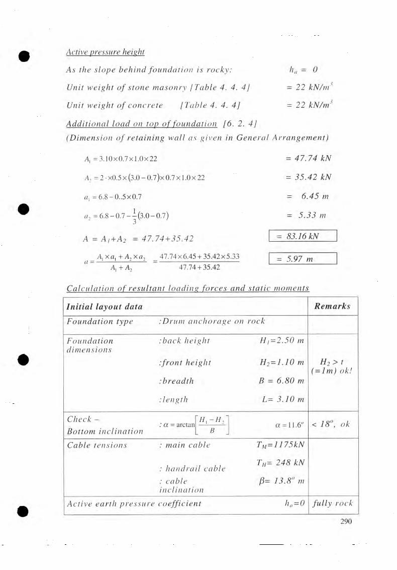
0
Active p ressureheight
As the slope behind foundation is rocky: ha =
Unit weight of stone masonry ¡Table 4. 4. 4] kN/m'1
Unit weight of concrete [Table 4. 4. 4] - 2 2
AAdjjional load on tap o f fo u n ^ j j jm [6. 2. 4](Dimension of retaining wall as given in General Arrangement)
A, = 3.10x0.7x1.0x22
= 2 • x0.5 x (3.0 - 0.7)x 0.7 x 1.0 x 22
a l = 6.8-0..5x0.7
a, =6.8-0.7--(3.0-0.7)3
A - A i +A2 = 4 7 .7 4 + 3 5 .4
_ A,xa, + A2x a 2 _ 47.74x6.45 + 35.42x5.33A, + ~A2~ 47.74 + 35.42
= 47.74 kN
= 35.42 kN
= 6.45 m
= 5.33 m
= 83.16 kN ~
= 5.97 m
Cafctdgjjxm ofj^esijUant loadins for£es_and s4atic_ moments
In itia l layout data Remarks
Foundation type :Drumanchorage on rock
Foundation :back height m dimensions
:front height H.2 = l . l 0
:breadth =
.'length L= 3.10 m
H2 > t(= lm ) ok!
C h e ck - : a = arctan —1----- - 11.6Bottom inclination L B
< 18°, ok
Cable tensions : main cable
, a , i TH= 248 kN :handrail cable: cable (3= 13.8° m inclination
Active earth pressure coefficient fully rock
290

Loading forces moments
L o a d i n g f o r c e L e v e r a rm M o m e n tM f
( k N - m )F o r m u l a
Vert.Rv
( k N )
H o r iz . Ru
( k N )F o r m u l a
Dist.
(m)
L o a d f r o m f o u n d a t i o n W, =0.5 x(/7, + H 2 834.8
B 2 H. +x 1 3,84 3206.33 H x+
W: =0.95 x B x L x y c 440.6 - 0.5 B 3.4 1498.0
L o a d from f o u n d a t io ntopT o t a l l o a d = .A
83.16 - a 5.97 496.5
L o a d f r o m T mi , = T„,
b le te n s io n x c o s ß - 1 1 4 1 .1 H 2 + 0.7 1 (-12054.0
L/n, x c o s ß - 240.8 H 2 + 1.95 3.05 (-1740.5
L Mv = L m x c o s ß280.3
- -0.25 70.5
C:heC x s i n ß 59.2 ~
- 0.25 14.8
I 1698.1 1381.9 2497.3
Volujne_ o f jo u mhrtjj
, W.+W, 834.8 + 440.6Vol = ----- - = ------------------
Y c22
<5«(
- arctanV
Rjl
Rv
\- arctaj
1381.9^ 1698.1 ,
B * _2 Rvx(l + tan6xtan<5ß)
_______ 2497.3__________1698.1 x (l + tan 11.6" x tan 39.1")
Vol = 57.97 m3
39.1 deg
— = 1.26
C heck fo r
— = 1 . 2 6 m > - ( =2 6S a fe ty f a c t o r g_gajjis j_ t o p p l i n g [ 6 . 4 . 4 ]
M5_ _ 5285.7~WT ~ 2788.4
1.9 > ok !
291

S t r e s s d i s j j f ^ i t t m n a n d m tm b e _ rods_ [ 6 . 2 . 7 ]"Uncracked" condition at inclined base
K
B’
B_2
= Rv xcos a + Ru xsin a = 1698. l x cos 11.6" + 1381.9 x sin 11.6" = 1941.3B 6.8
cosa cosí 1.6 '1.26B * l 2 ________
cosa cos 11.6 ° B' B*' 6.94
2= — = ---- = - -------1.29
a =mux ByL 1±
26xe'
B'1941.3
6.94x3.1-x 1±
6x2.186-94
Since B*/2 < B/3, anchor rods are necessary.
X'
a
b
As
N
B'-o „
^ m i n ® max
6.94-(-79.8) (-79.8) - 260.3
- = 4 - 1 . 2 9 - 1 «2 3 3
= 5 - 5 - — = 6 .8 -1 .0 -1 .26 2
Frnin \*2<t
= kx
ocomb
4 x
_ a ~~b
= 1.75x
79.8x1.63x3.1 5.11- x ------ xlOO
2-194x1194.4
4.54
n..d~ 25 ■Minimum number of anchor rods for 4 main cables
UUinmte_ bearing e> re_sB*/2 (=1.26 m) < B/3 (=
4 x R,, 4x1941.3' max .ult 3 B*YL 3x2x1.29-3.1
2 ,
= 6.94 m
= 1.29 m
= 2.18
Gmax = 260.3
°,„in=(-)79.8
= 1.63 in
= 5.11 m
= 4.54 m
=1194.4 mm2
N = 5 nos
= 4 nos
Gmax.uit ( =323.6kN/m2)< operm (= 450
Safety factor against sliding [ 6 . 5 . 2 / 6 . 6 . 1]R '
= 323.6 kN/m2
ok!
As
F s,
Rh xcos a + Rvxsin a = 1381.9xcos 11.6" - 1698.lx s in 11.6 " = 1012.2 kN= N x n / 4x 252 = 5 x n / 4 x 2 5 2
[with anchor rods considered]land , x Rv + As
R,
tan 35" x 1941.3 + 2454 x 0.0751012.2
=1.52 > 1.5 ok!
tan <f> x Rv
Ru[with anchor rods neglected]
tan 35" x 1941.3 1012.2
=1.34 > 1.3 ok!
292
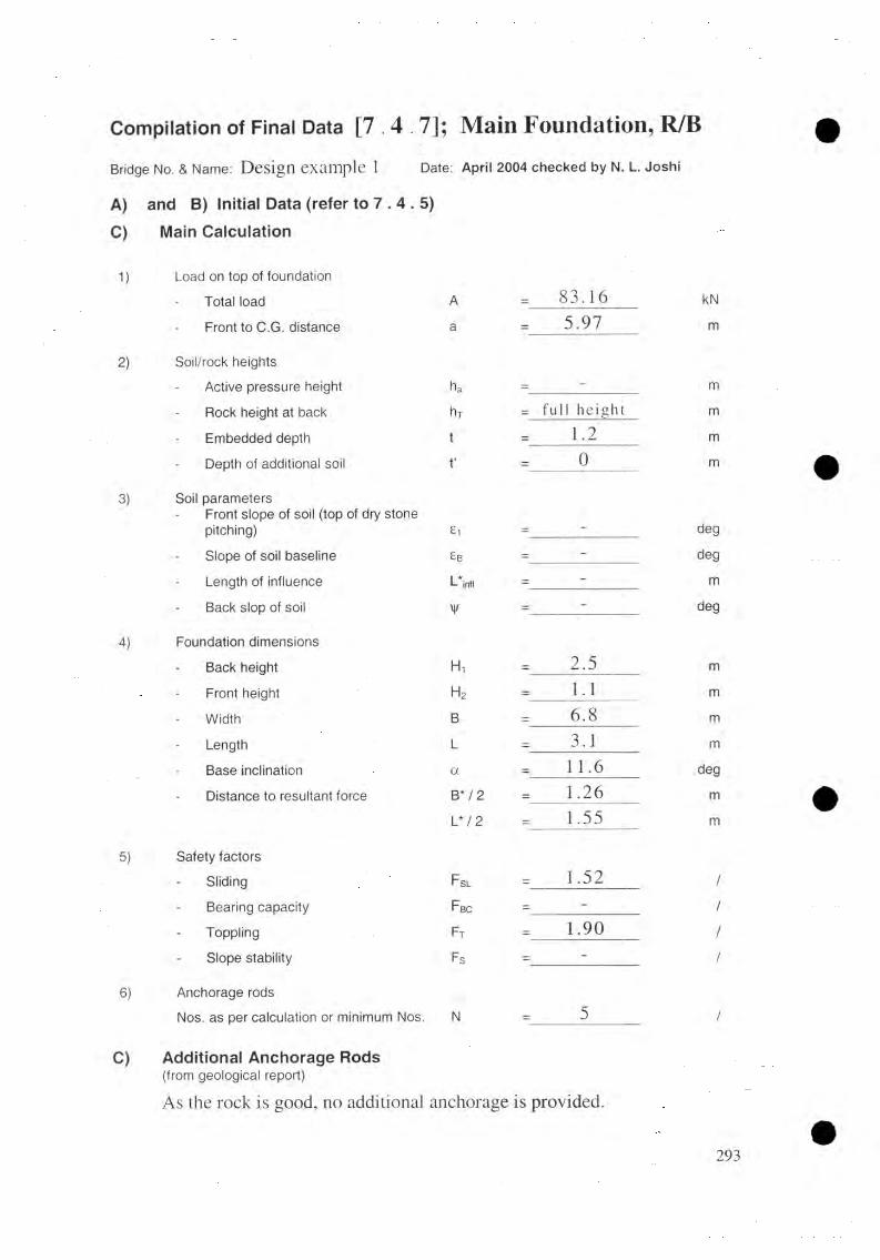
C o m p ila t io n o f F in a l Data [ 7 . 4 . 7 ] ; M a i n F o u n d a t i o n , R / B
Bridge No. & Name: Design example 1 Date: April 2004 checked by N. L. Joshi
A) and B) Initial Data (refer to 7 . 4 . 5 )C) Main Calculation
1) Load on top of foundation
Total load A = 83.16 kN
Front to C.G. distance a = 5.97 m
2) Soil/rock heightsActive pressure height ha = - m
Rock height at back hT = ful l height mEmbedded depth t = 1.2 m
Depth of additional soil t* = 0 m
3) Soil parametersFront slope of soil (top of dry stonepitching) £i = ~ deg
Slope of soil baseline £b = ~ deg
Length of influence L infl = - m
Back slop of soil ¥ = ~ deg
4) Foundation dimensionsBack height Fh = 2.5 m
Front height h2 = 1.1 m
Width B = 6 .8 m
Length L = 3.1 m
Base inclination a = 11 .6 deg
Distance to resultant force B* / 2 = 1.26 mL* / 2 = 1.55 m
5) Safety factorsSliding F SL = 1.52 /Bearing capacity F BC = - /Toppling F t = 1.90 /Slope stability Fs = - /
6) Anchorage rodsNos. as per calculation or minimum Nos. N = 5 /
C) Additional Anchorage Rods(from geological report)
As the rock is good, no additional anchorage is provided.
293
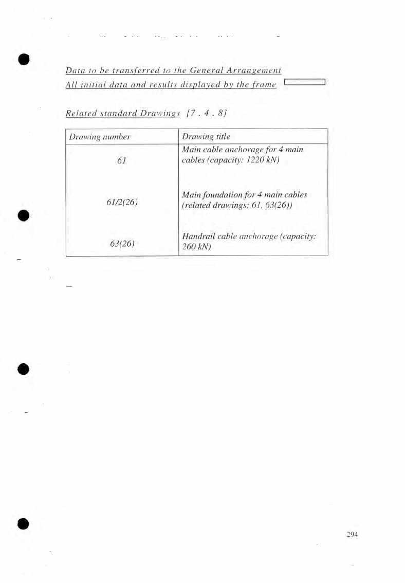
All initial data arid rejufts the frame
Delta to be tjxmjfe_rred_ to t_he G etieral]
Related_ stamdard Drawings [ 7 . 4 . 8 ]
Drawing number Drawing title
61Main cable anchorage for 4 main cables (capacity: 1220 kN)
61/2(26)Main foundation for 4 main cables (related drawings: 61, 63(26))
63(26)Handrail cable anchorage (capacity: 260 kN)

M a in f d u n ^ u t io n on so ils l e f t [ 7 .
l ju t ia l la jo u t da ta [ 7 . 4 . 5]Foundajtion CJmjmcjejnMicAType of bridge River bankCable anchorage type FoundationCable struyyjure characteristics
Inclined Suspended Left, lower foundation Drum anchorage on soil
Number of m a i n cables n M — 4 nosMain cable tension TMf— 1159 kNHandrail cable tension T hj= 245 kNCable inclination ß f = 10 degFront slope of rock stone pitching £ i 9 degSoil parametersSub-soil at depth = 3.2 mFriction angle of sub-soil 0 / = 30 degUnit weight of sub-soil Yi = 18 kN/m2Friction angle of backfilling soil 02 = 22 degUnit weight of backfilling soil 72 = 17 kN/m2Ground water at depth = v e r y d e e p
Ground bearing pressure t-tpe rm 300 kN/m2
Minimum Embedded depth t = 1.7 m
F ou n d a tio n dimen s i o n s
Foundation dimensions (m) minimum maximumBack height H, 1.5 4.0Front height 1.2 4.0Width B 6.2 9.5Length L 2.9 5.0
Trial values for foundation dimensions [ 7 . 4 . 6 ]
Dimensions (m) Trialvalues
Remark
Back height H, 4.0 The dimensions compiledFront height h 2 2.5 were found by iterationWidth B 7.0 with regard to
Length L 4 .7 economical design
295

A c t i v e p r e j j s u r e
E m b e d d e d d e p t h
I n c l i n a t i o n o f f r o n t s l o p e
I n c l i n a t i o n o f b a c k s l o p e
U n i t w e i g h t o f d r y s t o n e m a s o n r y
U n i t w e i g h t o f c e m e n t m a s o n r y
U n i t w e i g h t o f c o n c r e t e
h a = 6 . 0 m haJ = 1.05m
t = 2 . 0 m
£ = 1 9 .0 d e g
y/ = 1 1 . 0 d e g
Yd = 2 0 . 0
Y,n = 2 2 . 0 k N / m 3
Yc = 2 2 .0
A ddijj^ jm l load on tjm o f founda tion [ 6 . 2 . 4 ]
A = —x 0.7 x 1.05 x 4.7 x 222
a = 7 .0 - —x0.7 2
A = 7 6 .0 kN
a = 6 .6 5 m
QoefficUnd o f horizontal active earth pressure [6 . 2 . 3]
K i h ~C O S 2 02
/ sin(02 +ô)xsm(1 +cos <5 xcosy/
w i th 5 = —</>-, 3
cos' 0-,
1 +sin(22 + -x22)xsin (22 -ll)
cos —x 22 x cos 11 3
Aah = 0.4742
Base inclijm
tan a = H . - H , 4 .0 -2 .5B 7.0
a = 1 2 .1 d e g
Check for. ÇL
a = 12.1 d e g < 15 d e g o k !
296

ÇaJçulMjjon ofJ^ogMJjig forçe_s
L o a d i n g f o r c e L e v e r a r mM o m e n t ,
M f ( kN-m)F o r m u l a
V e r t .
Rv( k N )
H o r i z .R h
( k N )F o r m u l a
D is t .
( m )
L o a d f r o m f o u n d a t i o nW, = O . S X ( H , + H 2 )
W2 =0.95x(£-1.2)xLxyr
2 3 5 2 . 4
5 6 9 . 7
~
B 2H . + H ,V 1 3 . 7 7
4 .1
8 8 6 8 . 5
2 3 3 5 . 8
3 77, + IF
0 .5 B + 0 .6
L o a d f r o m f o u n d a t i o n t o p , T o t a l l o a d = A 7 6 .0 - a 6 . 6 5 5 0 5 . 4
A c t i v e e a r t h p r e s s u r e
Fan " 2 xLxy 2
V _ h a + 2K\ ,, h„ ~ K\1 Eah ~ q 'N , . j3 +
- 6 6 1 . 1 y ^ - i f + i t . 0 . 4 ( - )264
Eav = E (lhxtanj^|x0 2
1 7 3 . 0 - B 7 .0 1 2 4 9 . 5
L o a d f r o m c a b l e t e n s i o n
Tmi, = T
Tin, = Thxcos(3
TMv = TMx c o sf>
T hv = T // x.v in j3
2 0 1 . 3
4 2 . 5
1 1 4 1 . 4
2 4 1 . 3
H 2 + 0 . 7
H2 + 1.9
3 . 2
4 . 4 5
1 . 4 5
1 . 4 5
( - ) 3 6 5 2 .
( - ) 1 0 7 3 .
2 9 1 . 9
6 1 . 6
I 3 4 1 4 . 9 2 0 4 3 . 8 8 3 2 2 . 0
V o J jim e o f J o u
, W.+W, 2352.4 + 569.7Vol = --------- - = --------------------
Yc 22
T o t a l v e r t i c a l f o r c e
T o t a l h o r i z o n t a l f o r c e
T o t a l m o m e n t s
T o t a l p o s i t i v e m o m e n t
T o t a l n e g a t i v e m o m e n tA l g e b r a i c s u m o f s t a t i c m o m e n t a b o u t F;
Vol = 1 3 2 .8 m
R v = 3 4 1 4 . 9 k N
R h = 2 0 4 3 . 8 k N
M + = 1 3 3 1 2 . 7 k N - m
M ' = 4 9 9 0 . 7 k N - m M f = 8 3 2 2 . 0 k N - m
297
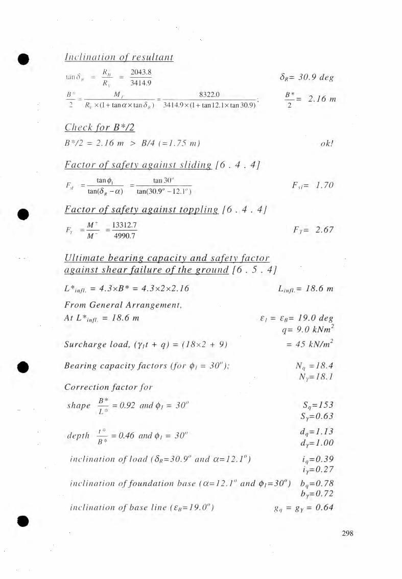
I _ n c l in a t io n
Rlan S „ = ——H _ 2043.8
Rv 3414.9B :' M r 8322.0
Rv x ( l + tanaxtan<5„) 3414.9 x ( l + tan 12. lx tan 30.9) ’
S r = 3 0 . 9 d e g
R *— = 2 . 1 6 m2
Check far BJV2B * / 2 = 2 . 1 6 m> B/4 ( = 1 .75 m)ok!
Factor o£_safety_ a^a insi 4 . 4]_ tan 0, _ tan 30"
s' ~ tan(<5 - a) “ tan(30.9° -12.1")
Factor o£_safety_ against toppling [6 . 4 . 4]M + _ 13312.7 M _ ” 4990.7
F si= 1.70
F j = 2 . 6 7
U ltijna te beanng capacity cmd safety fa c to r a^a ins j shear. faJFure ojÇthe grouird [6 . 5 . 4 ]
jL * infi. = 4.3xB* = 4 . 3 x 2 x 2 . 1 6 1 8 . 6 m
F r o m G e n e r a l A r r a n g e m e n t ,
A t L * i nfi, = 1 8 . 6 m e B= 1 9 . 0 d e g
q = 9 . 0 k N m 2
S u r c h a r g e l o a d , ( y d + q ) = ( 1 8 x 2 + 9 ) = 4 5 k N / m 2
B e a r i n g c a p a c i t y f a c t o r s = 3 0 ° ) ;
C o r r e c t i o n f a c t o r f o r
s h a p e = 0 . 9 2 a n d (pi = 30"
d e p t h — = 0 .4 6 a n d (p/ = "B *
N q =18.4N r= 1 8 . 1
Sq=153S y = 0 . 6 3
d q= 1 . 1 3d Y= 1 . 0 0
i q= 0 . 3 9i n c l i n a t i o n o f l o a d ( S B = 30. 9" a n d
i n c l i n a t i o n o f f o u n d a t i o n b a s e ( o c = 1 2 .1 ° a n d b q= 0 . 7 8b y= 0. 72
i n c l i n a t i o n o f b a s e l i n e ( £B= 1 9.0° )gq = gy = 0 . 6 4
i y = 0 . 2 7
298

Shear_ resO t_ajice_
P* = B * OV + (l ) N ,ls ,ld,l i llb'„ + 7 , * x ¿\.
= 2 x2 .16x4 .7 x |4 5 .0 x l8 .4x l.53 x l.l3 x0 .39 x0 .7 8
+ - x l8 .0 x 2x2.16x18.1 x 0.63 x 1.0 x 0.27 x 0.72 |x 0.64 2
= 6 7 7 8 . 7 kN
6778.7B C
Pj3414.9
= 7.99 2 .0 9 ok!
Gzojund bearing ¡n^jjsurJL [6 • 7]B B * B
T h e c a s e i s : e c c e n t r i c l o a d w i t h — > — > —2 3 3
On inclined bas_e
Rv = Rv cos a + R „ sin« = 3414.9xcosl2.1" + 2043.8xsin 12.1"
B 7.0B' =■
cosa cosl2.1"
B * B*/2 2.16cos« cosl2.1"
<?„ K 1 + 3.i i - i q iB'xL b ' ) \
3767.57.16x4.7
(, 2x2.16')!1 + 3 x
1 7.16 J J
= 3 7 6 7 . 5 k N
= 7 . 1 6 m
= 2 . 2 1 m
= 2 4 5 . 2 k N / m 2 < G,n,nn ( = 3 0 0 o k !
R ^ j j v f o r c ^ j jw n l [ 7 . 4 . 6 ]
ASi =a ...x L
■x-(l.2cos a - H 2sin a )2
0.414 (772 xcosa + 1,2 x s in a -0.20)
245.2x4.7 (l.2cosl2.1" -2 .5 sin 12.1")3-x-
0.414 (2.5 cos 12.1" +1.2 sin 12.1" -0.20)
MJjujmun reinforcem ent
A s i ( m i n ) = 0 . 0 2 % o f H 2XL =0.02x2500x4700
100
= 4 7 0
A .rN o . o f 1 6 m m 0 re in fo rc e m e n t b a rs , N =
= 2 3 5 0 m n f
2350 - 7 7 7201
Provide^ 12 nos Q_J_6 m m n b b e d t o r s t e e ] bars_. 299
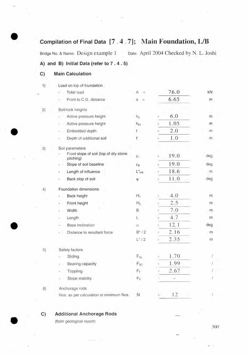
Compilation of Final Data [7.4. 7]; Main Foundation, L/BBridge No. & Name: Design example 1 Date: April 2004 Checked by N. L. Joshi
A) and B) Initial Data (refer to 7 . 4 . 5 )
C) Main Calculation
1) Load on top of foundation Total load A = 76.0 kN
Front to C.G. distance a = 6.65 m
2) Soil/rock heightsActive pressure height ha 6 . 0 m
Active pressure height ha1 = 1.05 m
Embedded depth t = 2 . 0 m
Depth of additional soil t' - 1.0 m
3 ) Soil parametersFront slope of soil (top of dry stone pitching) £1 19.0 deg
Slope of soil baseline £b = 19.0 deg
Length of influence L*infl. - 18.6 m
Back slop of soil ¥ = 1 1 . 0 deg
4 ) Foundation dimensions Back height Ht 4.0 m
Front height h2 - 2.5 m
Width B : 7.0 m
Length L = 4.7 m
Base inclination a -- 1 2 . 1 deg
Distance to resultant force B* / 2 = 2.16 m
L* / 2 : 2.35 m
5 ) Safety factors Sliding F SL 1.70 /
Bearing capacity F BC = 1.99 /
Toppling Ft : 2.67 /
Slope stability Fs : - /
6) Anchorage rodsNos. as per calculation or minimum Nos. N 1 2 /
C) Additional Anchorage Rods(from geological report)
300

AM i j n t i a l d a t a a n d re_sults_ d is th e
Data to be_ tj^m ^ferred W the General
f r a m e <------------->
R e l a t e d , s t a n d a r d D r a w i n g s [ 7 . 4 . 8 ]
D ra w in g n u m ber D ra w in g title
61 M ain c a b le a n c h o ra g e f o r 4 m ain c a b le s (c a p a c ity : 1 2 2 0 kN)
6 1 /1 (2 6 ) M ain fo u n d a tio n f o r 4 m ain c a b le s [ r e la te d d ra w in g s: 61 & 6 3 (2 6 ) }
6 3 (2 6 )H a n d ra il c a b le a n c h o ra g e (ca p a c ity : 2 6 0 kN)
301

DESIGN OF WINDGUY CABLE STRUCTURE [9. 4]
General Ajj^aj i^ m ^ n dW indguy a rra n g em e n t is g e n e ra l ly p r o v id e d f o r LSTB (span > 120m ) bridge.
P la c in g o f w in dgu y a n c h o ra g e fo u n d a tio n s:
The foundation loca tion sh o u ld a v o id
• d r y g u lly (show n b y co n c a ve c on tou rs) on right bank d o w n s tre a m side.
• s tee p s lo p e on left bank d o w n s tre a m o f the axis o r d e r to g e t sm a lle r
a n g le £ f o r b e t te r va lue of ground bearin g capacity .
• the c a b le a lig n m en t sh o u ld be a b o v e the f r e e b o a r d line a t e leva tion 9 5 .8 8 m.
Since the right a s w e l l a s the left ban k u ps tream s id e h as no p r o b le m f o r p la c e m e n t o f fou n da tion s , the left bank d o w n s tre a m fo u n d a tio n , thus, requ ires to be f ix e d fir s t .
F rom g ra p h ic a l de term in ation ,
C L ~ 1 1 .7 0 m D L (-) 1 5 .5 0 m
The u ps tream w in d g u y p a r a b o la sh a ll b e a r r a n g e d s ym m etr ic a l ly to the d o w n s tre a m w in d g u y p a ra b o la .
h n tia lla yo u t data [ 9 . 4 . 6 ]F r o m cable, s truc tu re^ a iu ily jb s
t = 1 3 2 .6 0 m
H , = 1 1 0 .1 0 m
f t = 8 .0 8
r = 7 9 .60 m
F a r s i j s p e n d e f b r i d g e
d = 6 .0 0 m
k = 0 .6 6 m
D e t^ r m j ju U jx m w fnA gury p a r a b o l a in p l a n (Both u pstream a n d d o w n s tre a m )
Vertex ofjjhe p a r a b o l a -
Fix f i r s t c ro ss b e a m a t 0 .4 0 m f r o m sa d d le on r igh t s ide.
F ix ver tex a t 5 4 th c ro ss b e a m f r o m r igh t s id e
V = 0 .4 0 + 5 3 xl.20V = 6 4 .0 m
302

W indcuv c a b le p a r a b o la in [ 9 . 4 . 3 ]
y, = + 2
F o r p r e v a i l i n g t o p o g r a p h i c a l c o n d i t i o n s , f i r s t f i x th e l e f t b a n k d o w n - s t r e a m w i n d g u y c a b l e e n d .
j = 0
y o-- C L X« := 11. m
x„ '■= i - v - d l = 1 3 2 . 6 - 6 4 . 0 9 - 1 5 . 5 = 5 3 . 1 0 m
fw =z l . (y„ - 2.20)642= x (11.7-2 .2 ) f w — 1 3 . 8 0 m
X2 53T
Ç xü jç ijU u u m o f h w »
h\v ~ x 1 = 13.80x 132.6-64 A2
K = -K
64
2.062 x642
- 1
" V216/„■ x
C h e c k i f bw =
i 132.6
J
8 '
16x13.8x
f_'10
132.6
h \y = 2 . 0 6 m
b w = 1 4 . 8 8
-6 4
bw 14.88= 8.91; th u s b IV ~ o k !
W m dguj cable_ tensionwC 0.5x132.62
Hw =8 K 8x14.88
U w = 7 3 . 8 5 k N
\ 2Tr — H w x . j l +
2x / v
v y= 7 3 .8 5 , 1 +
2x13.8 V
64 Tr = 8 0 .4 kN
Tl ~ H wx 1 + 2^ - V > ï = 73.85.11 +f 2xl3.8x(132.6-64
642\2
Tl = 8 1 .4 kN
max = 8 1 . 4 k N
Numbejj and diojiiejer o fjv jjjJ g u j cableN u m b e r o f w i n d g u y c a b l e ( d / s o r u / s ) D i a m e t e r o f w i n d g u y c a b l e
u w = __
(l)w= 2(5 mm
P e r m i s s i b l e t e n s i o n
Check, far tensionTperm( = 1 2 9 k N ) > T max 8 1 . 4 k N )
T p e r m - 1 2 9 k N
o k !

Location o f first wjjidties_Br = V - ( d x i R) = 6 4 - 6 x 8 ; 1 6 .0 m
Bl - ( - V - ( d x i L) = 1 3 2 . 6 6 x 8 ; /?, = 70 .6 m
Cgdculafwn o f ec# and QCj
a R - arctan
= arctan
a L = arctan
= arctan
2 x f w
2x13.8 '— (64-16)
o:p = /7.92 de.g
642
{ ^ ( £ - V - B l )2 x f w
V
2 X 0 ,8 (132.6-64-20.6) 64"
c t l = 17 .92
CadcudatLon of_CR_0 a_nd QLlo
CR0 = y r X ( V - B r )2 + t<mccRx B R +2,2
= (64 - 16)2 + tan 17.92° x 16.0 + 2.2; CR0= 1 5 . 1 4 m64-
CL0 = ^ r X ( t - V - B L)2 +tan ccL x B L +2.2
= x (132.6-64.0-2 0 .6 )2 + tan 17.92" x 20.6 + 2.2; C L 0 = 1 6 . 6 2 m64-
T l ie s e d a t a w i l l b e th e s a m e f o r b o t h u p s t r e a m a n d d o w n s t r e a m w i n d g u y a r r a n g e m e n t s a s t h e y a r e a r r a n g e d s y m m e t r i c a l l y .
Windguy foujjydadwn la y o u t dataT h e p o s i t i o n o f w i n d g u y c a b l e a n c h o r a g e f o u n d a t i o n s a r e d e t e r m i n e d b y -
l o c a t i n g w i n d g u y c a b l e a x e s w i t h th e p l o t o f C R o , C L 0 a n d a a n g l e s in th e p l a n o f G e n e r a l A r r a n g e m e n t .
t r a c i n g t h e o r e t i c a l w i n d g u y c a b l e p a r a b o l a .
d r a w i n g c r o s s - s e c t i o n s a l o n g th e a x i s o f f o u r w i n d g u y c a b l e e n d s .
d r a w i n g f r e e b o a r d l i n e in th e c r o s s - s e c t i o n .
t a k i n g i n t o a c c o u n t th e L i m i t s a n d R e c o m m e n d a t i o n s g i v e n in S e c t i o n 9. 4 . 5.

U p s t r e a m :
d o w n s t r e a m :
/ / / }= 702.6 m Hl = 97.5 mD/?= -75.0 m Dl = - 15.9 m
77*= 702.5 m Hi = 9 6 . 4 m
D a.= -75.5 m Z ) L = - 7 5 . 5
Calcudadion of_C_R and C±F o r d o w n s t r e a m w i n d g u y c a b l e
fCR = y r X ( V - B R) 2 + tanaRx ( B R+ D R) + 2.2
13.8- x (64 -1 6 )2 + tan 17.92" x (16 -13.5) + 2.2
64
CL = y r X ( ( — V - Bl )2 + tan a L x ( + D L) +2.2
13 8= — V x ( l32.6- 6 4 - 20.6)2 + tan 17.92" x (20.6-15.5) + 2.2
64'
C R= 1 0 .7 7 m
C L= 11.61 m
CaJxjdgjjjm o f wmdl_ie_s lengths [ 9 . 5 ]d o w n s t r e a m w i n d g u y a r r a n g e m e n t
1 ) D eJejailllin lion. of_parc 4
y = ct4-x~ + <4; a,f w 13.80v- 642
c4 = 2 .2 -7 ’ = 2 .2 - 0.66
a 4 = 0 .0 0 3 3
c 4 = 1 .5 4
2 ) Ccdcijlajdjmo f A h i . P.
A hLP, = y LP,x tan y
yL.P. = a d r - V ) 2 + 2.2-7
= 0.0037 x (79.6 - 64)2 + 2.2 - 0.66
tan = ( 7 7 ,- / / , - / J x ( £ + D , + D L) - ( D R+ r ) x ( H L - H R) (CR - 7 ) x (£ + D r + D l ) - (Dr + r) x (CR - C , )
( l + D R+ D L) = (l32.6 -13.5 -15.5) = 103.6
( D r + r) = (-13.5 + 79.6) = 66.1(110.1-102.3-8.08) x 103.6-66.1x (96.4-102.3)
y LP= 2 . 3 7 m
tan y( '0.77- n.661/103.6 66.1/i 10./7- '1.6 +
360.981102.92
0 . 3 3
A hLP, = 2.37x0.33 A hLP.= 0 .7 8 m
3 ) D epeziE llU lli£ ll (2f_p L 2
8.08a\ 9r"
P a r a b o l a 1:79.62
£i A/i,,.
a , = 0 . 0 0 1 2 7 5
c i - 0 . 7 8 m
305

P a r a b o l a 2 : (U = H r p f j j ¡2_lp_( r + D R) 2
102.3 + 8.08 + 0.78-110.1(79.6-13.5)'
= 0 . 0 0 0 2 4 2
c 2 = 0
P a r a b o l a 3 : a, =P( t — r + D l )2
_ 96.4 + 8.08 + 078-110.1 (132.6-79.6-15 .5 )2
C 3 = 0
4 ) C c d c u l a t i o n p f j y f n d t j d a t a 5 . 7 ]
c / ci = ^ A /;r + v i 2
= - 0 . 0 0 3 4 4 4
D., = -xcosfi
W h e r e in :
x , = V - - B R- ( i - l ) x d
1 max j Ad
+ 2.\7)2 +1
= 64 -16 - (i -1) x 6 = 48 - (/' -1) x 6
= x, +79.6-64 = x, +15.6
132.6-16-20.6+ 1 = 17
= 0.003358x,2 +1.54y, = <74x, ‘ +2.2 - 0.66
- f o r x i > 0
Mi, = a ^ 'j+ A liLP.-cox ', 2
= 0.001275x ' i 2 +0.78 - 0.00024a-',. 2
= 0.001033a’, 2+00.78
= arctan(2xrt: x .v ',) = arctan(0.000484x'.)
- f o r x ’i < 0
Mi, = aix' i 2+MiLP. - a :x ' , 2
= 0.001275a ' , 2+0.78 + 0,003444a ',. 2 = 0.004719a '2 + 0 .7 7 7
P, = arctan(2 x a3 x a ’,. ) = arctanlO.OOOSSSx .)
S t a r t i n g f r o m r i g h t s i d e ( i = l ) th e d a t a a r e c a l c u l a t e dc o n t i n u o u s l y u p t o th e l e f t s i d e ( I = i max) a s s h o w n in th e f o l l o w i n g t a b u l a r c a l c u l a t i o n .
306

T a J ¿ u la r c¿ah¿ujM l[on l e n g t h s
i X, X i A h i / t a n ß ic /c ,
( m )
Du,( in)
1 4 8 6 3 . 6/
1 0 . 5 2 6 . 2 7
2 4 2 5 7 . 6 8 . 5 7 6 . 2 0
3 3 6 5 1 . 6 6 . 8 7 6 . 1 5
4 3 0 4 5 . 6 5 . 4 2 6 . 1 0
5 2 4 3 9 . 6 4 . 2 3 6 . 0 6
6 1 8 3 3 . 6T a k e
v a l u e s3 . 2 7 6 . 0 3
7 1 2 2 7 . 6 f o r 2 . 5 6 6 .0 1
8 6 2 1 . 6x ’i <
2 . 0 9 6 . 0 0
9 0 1 5 . 6 1 . 8 5 6 . 0 0
1 0 - 6 9 . 6 \ / 1 . 8 8 6 .0 1
11 - 12 3 . 6>K
2 . 1 7 6 . 0 3/ \1 2 - 1 8 - 2 . 4 2 . 7 5 6 . 0 7
1 3 - 2 4 - 8 . 4 T a k ev a l ues
3 . 6 4 6 . 1 3
1 4 - 3 0 - 1 4 . 4 f o r 4 . 8 8 6 . 2 1
1 5 - 3 6 - 2 0 . 4x ’i < o
6 . 4 9 6 . 3 0
1 6 - 4 2 - 2 6 . 4\ /
8 . 4 9 6 . 4 2
1 7 - 4 8 - 3 2 . 4 1 0 . 8 9
I 8 6 . 5 7 9 7 . 9 9
307

5) Ç a J ç u ]a ± io n oj_f^jmç3i_
f iR = arctan[2i/, x (BR - r ) j
= arctan[2 x 0.000242(16 - 79.6)] & = -1 .76 '
f iL = arc tan [2<7, x )]
= arctan[2 x (-0.003444) x (79.6 -132.6 + 20.6)] ; (3l = 12.58°
6 ) Calculationof ER_ a n d J2i_
E — ïLa —R cosaRx c o s f K
1 6 + ( - 1 3 . 5 )
cos 17,92" xcos(-1.76)
Er = 2.63 m
e l =B l + D l
cos a L xcos /3l
20.6+ (-15.5) cos 17.92" xcos 12.58" Ei = 5A9 m
7) CabcuUrjwn ofjjrjçü [en_glh o f _ ç a ble_s
l w( t o t ) = Z D wi + E r + E L + o v e r l a p p i n g l e n g t h
= 97.99 + 2.63 + 5.49 x 1.25 = 108.61 m
E r ( t o t ) = Z (c + 0 . 6 )
= 86.57 +17 = 96.77
U ^ t r ^ m w indguv cable structure
C a l c u l a t i o n f o r u p s t r e a m c a b l e s t r u c t u r e is n o t s h o w n h e r e , b u t b e m a d e s i m i l a r t o th e d o w n s t r e a m c a b l e s t r u c t u r e .
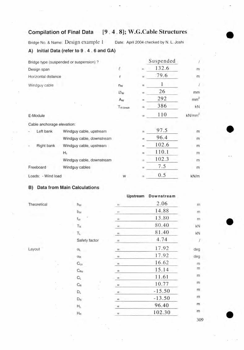
Compilation of Final Data [9.4.8]; W.G.Cable StructuresBridge No. & Name: Design example 1 Date: April 2004 checked by N. L. Joshi
A) Initial Data (refer to 9 . 4 . 6 and GA)
Bridge type (suspended or suspension) ? Suspended /
Design span i = 132.6 m
Horizontal distance r _ 79.6 m
Windguy cable nw _ 1 /
0 W — 26 mm
Aw = 292 mm2
T w ,break — 386 kN
E-Module _ 1 1 0 kN/mm2
Cable anchorage elevation:Left bank Windguy cable, upstream = 97.5 m •
Windguy cable, downstream - 96.4 m
Right bank Windguy cable, upstream = 1 0 2 . 6 m
H, — 1 1 0 . 1 m
Windguy cable, downstream - 102.3 m
Freeboard Windguy cables — 7.5 m
Loads: - Wind load W _ 0.5 kN/m
B) Data from Main Calculations
Upstream Downstream
Theoretical hw - 2.06 m
bw - 14.88 m
fw = 13.80 m •T r - 80.40 kN
Tl = 81.40 kNSafety factor = 4.74 /
Layout otL _ 17.92 deg
OCR = 17.92 deg
C lo = 16.62 m
C r0 = 15.14 m
C l - 11.61 m
C r = 10.77 m
Dl - -15.50 m
D r - -13.50 m
H l- 96.40 m
H r - 102.30 m
309

Data to be_ namfe_rred_ to G eneral
1 ) \n to _ p l a n
A l l r e s u l t s d i s p l a y e d b y th e f r a m e I2 ) I n t o I jrn jp r tu d jjw d s e c t i o n
- S e p a r a t e l o n g i t u d i n a l s e c t i o n o f a l l f o u r c a b l e e n d s
- F r e e b o a r d
- Windguycable e l e v a t i o n ( H ) . i n c l i n a t i o n (/3) a n d t e n s i o n (T) .
H(m)
P(d e g )
T(kN)
R ig h t bank:
u pstream 1 0 2 .6 8 0
d o w n s tre a m 1 0 2 .3 -1 .76 8 0
Left bank:
u pstream 9 7 .5 .... 81
d o w n s tre a m 96 .4 1 2 .5 8 81
3) Into cable UslWi]ujgu_y caM_e_:
U p s t r e a m : n u m b e r = 1
d ia m e te r = 2 6 m m
Tota l cu ttin g length, L w - 1 0 8 . 6 1
d o w n s t r e a m : n u m b e r = 1
d ia m e te r = 2 6 m m
Tota l cu tt in g length, L w (to t) = 1 0 8 .1 8 m
W i n d t i e s : d i a m e t e r = 1 3 m m
T ota l length , L T (to t) [D /S ] - 9 7 m
R elajed stajiAard_ draw ings [ 9 . 5 . 9 ]Drawing number Drawing title
1 1 Windtie for windguy cable 13 mm (|)
310

WINDGUY CABLE FOUNDATION DESIGN [9. 6]In itia l layout data[ 9 . 6 . 5 ]
Foundation CharacteristicsR i v e r b a n k R igh t Left
S i d e d o w n s tre a m d o w n s tre a mF o u n d a t i o n on R o ck so il
W.G. c a b le s tru ctu re ch a ra c te r is t ic s
N u m b e r o f windguyca b le nw— 1 1
W indguy c a b le tension Tw = 8 0 .4 kN 8 1 .4 kN
C a b le inclination P = -1 .76° 12. 58°
F ron t s lo p e £/ = 0 14. 2°
So il p a r a m e te r s
S u b-so il a t dep th = - 2. 5 m
F ric tion an g le o f su b -so il 0/ = - 30°U nit w e ig h t o f su b -so il Yi = - 1 7 kN /m 2
F ric tion a n g le o f backfill ing soil; 02 = - 30°
U nit w e ig h t o f backfill ing soil; Ï2 = - 1 7 kN /m
G ro u n d w a te r a t dep th = - -
G ro u n d bearin g p r e s su re e mi - 2 0 0 kN
R ock p a ra m e te r s
R ock a t dep th = 0. 5 m -
Slid ing f r ic t io n an g le 0s7 = 3 5 ° -
R ock q u a li ty coeffic ien t k = 1 .75 ~
G ro u n d b ea r in g p r e s su re Gperm ~ 4 0 0 kN -
M inim u m e m b e d d e d dep th tmin ~ 0. 5 m 1. 0 m
Design paraj/gMiJ-lSO-L 7 no (fr 26 mm cabje
F o u n d a t i o n o n R o c k S o i lF o u n d a t i o n d i m e n s i o n s ( m ) m a x i m u m m in im u m m a x i m u m m i n im u m
W id th B 2 . 4 0
3
2
1 . 7 0 2 . 4 0 2.00
L e n g t h L 1 . 2 0 3 . 5 0 1 . 5 0
F o r [3 < 45" > 4 5 " - <45" > 4 5 "
F r o n t h e i g h t h j — 0 . 4 0 . 6 2 0.4 0 . 6
F r o n t h e i g h t U 2- H t + 0 .4 - H t + 0 .4
C .G . d i s t a n c e S = 0. 7 5 -
311

M a n u a f C a l c i j U i j j o j i [ 9 . 6 . 6 ]
The m anu al ca lcu la tion are m a d e fo r r ight a n d bank d o w n s tre a m fo u n d a t io n s only.
A d d it io n a l lo a d on top o f foundation
Left bank d o w n s tre a m
S o d ( Y = 1 7 kNAn)
A , — 0 .5 x (1.7+0.5)x l x x 1 7 = 2 8 .0 5 k N
a , - 1 2x1.7 + 0.5 , c- x ---------------- + 1.53 1.7+ 0.5
= 2.1 m
M a so n ry re ta in ing w a l l ( y - 22 kN /m 3)
A2 = 0 .5 x0.4 = 6 .6 k N
Cl2 — 1.1+0.5x 0 .4 = 1 .3 m
A — A , + A 2 = 2 8 .0 5 + 6 .6 A = 34.65 kN28.05x2.1 + 6.6x1.3
28.05 + 6.6a = a = 1.95 m
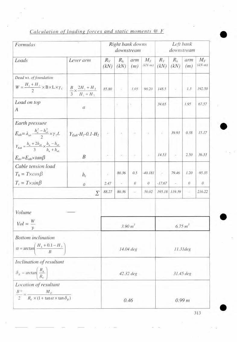
C a l ç j d a j j j o n o f j ^ a d i n g f o r c e s a n d @ F
F orm u las R ig h t bank d o w n s d o w n s tre a m
Left bank d o w n s tre a m
L o a d s L e v e r arm R vm
Rh(kN)
arm(m )
M y(kN-m)
R v(kN)
Rn(kN)
arm(m )
M F(kN-m)
Dead wt. of foundation
W = H ' + H 1 xB x L2 c
B 2/ / , + / / ,— X ----- ---------3 H t + H 2
85.80 - 1.05 90.20 148.5 - 1.3 192.50
L o a d on top
A a- - 34.65 1.95 67.57
E arth p r e s su re
y hn + 2/lnl „ - I Eah Q 7 , 73 K +
Eav= E ahxtan(3
YEah-H,-0.1-H2
B
- - - -
14.53
39.93 0.38
2.50
15.17
36.33
C a b le tension lo a d
7\ = T x c o s f ]
Tv = T x s in f i
h,
0 2.47
80.36 0.5
0
-40.181
0 -17.67
79.46 1.20
0
-95.35
0
1 88.27 80.36 - 50.02 195.18 119.39 - 216.22
V olum e
Vol =—Y< 3.90 in 6.75 rn
B ottom/
a - arctanV
clination
H x + 0 . 1 - / / ,
J 14.04 deg 11.31 deg
Inclinati
5k = arctar
n o f resu ltan ti P \, R"
Rv v J
42.32 deg 31.45 deg
L oca tion o f resu ltan tB * _ M F
2 Rvx ( 1 + tana x tan SR) 0 .4 6 0 .9 9 m
313

RJyJu b a n k , f o u n d a t i o n r o c k
Safety factory aga in s t topp lin g
F t90.2040.18
2 . 2 2 > 1 . 5 ok!
S tress d is tr ib u tw n q m j n u m ber o f a n c h o r rods 7]
“u n c r a c k e d ” condition a t the in c lin ed ba se
Rv = Rvcosa + Rhsin a
8 8 .2 7 x cos 1 4 .0 4 ° + 8 0 .3 6 x sin 14.04" Rv =
B ’B _ 2.0
cosa cos 14.04"
5 * / 2 _ 0.46cosa cos 14.04"
/e
a maxmin
2.062
0.48
1±6 x<?'
B L
105.122.06x1.5
B'
x6x0.55
2.06
Since B *72 < B/3 a n c h o r
B ' = 2 .0 6 m
— = 0 .4 8 m2
e ' - 0 .55m
Tmax = 88.9
Tmin = - 20 .91 kN /m 2
x'
a
b
B \ a ,
^ min ® max
2.06 x (-20.91) -20.91-88.90
= 2 .0 6 -0 .4 8 -0.39
3
= 5 - 5 -
= 2.0 - 0.75 - 0.46
x ' — 0 .3 9 m
a = 1 .45 m
b = 0 .7 9 m
314

Ascr... Ix
2(7 /. p erm
a
1*
| - 20.9 l|x 0.39x1.5 1.45 2.23 0.79
A s= 0 .4 9 cm 2
N, 4 xA s , 4x0.49
= k x -------4. = 1.75x--------- -n x d ~ 2.5'
= 0.
M inim um n u m b er o f a n c h o r ro d s (2 5 = 2 )
P r o v id e 2 nos 2 5 m m 0 v e r t ic a l anchor^ rods.
Uhimate bearing pressure
4 x R w 4x105.12m ax.«//. 3 x B * \L 3x2x0.48x1.5
= 97.33 kN/m
C heck for
<rmax H/, 9 7 .3 3 kN /m 2 <Gperm = ok!
S a fe ty fa c to r a g a in s t s l id in g [ 6 . 5 . 2 ]
R = Rh xcos a-Rvxs ina
= 80.36x cos 14.04" - 88.27 x sin 14.04" = 5 6 .5 5 kN
As
Fsi
71 9 71 o= N x — x25' = 2x —x25~
tan x 7?v + A, x T uomb
R,
= 9 5 7 . 7 r a m
[ w ith a n c h o r rods c o n s id e r e d
tan 35" x 105.12+ 981.7x0.075 56.55
= 2 .6 0
F dtan (t>sl x Rv
7?;[ with a n c h o r rods n e g le c te d ]
tan 35" x 105.12 56.55
= 1 .30
C heck for F s/
Fsi = 2 .6 0 > 1 .50 [w ith a n c h o r rods c o n s id e re d ]
F si - 1 .30 = 1 .30 [with
ok!
ok!315

Left banjjt [oj±iu[aJfo u on soilSafety thctorjigaijjsi toppling [ 6 . 4 .41
F rM 311.57
M95.35
Safety factor against sliding
F s, =tan </>, tan 30°
tan(<5R - a ) tan(31.45°-11.31°)
F t = 3 .2 7
F,i = 1 .5 7
U ltim ate bear in g capacity, a n d safety, fa c to r a g a in s t s h e a r failure o fgw im d [ 6 . 5 . 4 ]
L * nf /. = 5 * x tan(45" + </>, ) x / 5*,an9'
= 2 x 0.99 x tan (45" + x 0, ) x ,an 3(r = 8 .4 9 m
F rom cro ss sec tion in G e n e ra l A rra n g em en t
A tL * M = 8 .4 9 m, t ' = 0 .7 m £/i= 2 0 .0 d e g
4 = - x t ’ x v, = —x 0.7x17.0 2 2
q = 6 .0 kN/tn
YU = 1 7 .0 x 0 .8 Yi t= 1 3 .6 kN/m
B ear in g c a p a c ity fa c to r s (fo r (pi = 3 ( f ) N q = 18 .4
C orrec tion fa c to r s fo r
Shape — = 1.00 and </>, 30"L *
(Note: ifB */L* > 1.0 - 1.5 take value for B*/L* =1.0)
D ep th ----= 0.40 a<j>. = 30"5 *
Inclination o f lo a d (SR = 31 .45° a n d cc
Inclination o f fo u n d a tio n b a se ( a n d (pi 3 0 ° )
Inclination o f b a se line ( £ b — 2 0 ° )
Sq = 1 .58
Sy = 0 .6 0
d q = 1.11
dy 1.0
iq = 0 .3 6
iy = 0 .24
b 'q = 0 .8 0
b 'y = 0 .74
g q = g y = 0 .62
316

Shear resistance of the groundP* = B * x L * [ ( j y + q ) x N i /x Sq x x i q xb'q x
+ -i-xy, x B * x N yx S y x d y xi xg 7]
= 1 .98 x l . 5 x [ ( 1 3 . 6 + 6 . 0 ) x l 8 . 4 x l . 5 8
+ 0 . 5 x 1 7 x 1 . 9 8 x 1 8 .1 x 0 .6 0 x 1 .0 x 0 .2 4 x 0 .7 4 x 0 .6 2 ]
P* = 3 9 5 .2 0 kN
Safety, factor againsl bearing
p* _ 395.20 Rv ~ 195.18
Ground bearing pressure [ 6 . 2 . 7]
Rv R Vxcosa + Rhx s in a
= 195.18xcosl 1.31° +119.39xsin 11.31"
B 'B _ 2.5
cosa cosí 1.31"
B*' _ B*T2_ 0.992 cosa cosí 1.31"
e'
S ince
o maxmin
2.552 1.00
B * B_2 > 3
K— XB L
1 ±6-e'B'
214.802.55x1.5
1 ±6x0.28
2.55
Fbc = 2 .0 2
Ry = 2 1 4 .8 0 kN
B ' = 2 .5 5 m
— = 1 .0 0 m2
e ' = 0 .2 8 m
c „ = 9 3 . 1 5 kN /m 2
a ...= 1 9 .1 6 kN /m 2
U pstreamwindguy cable anchorage foundations
C alcu la tion f o r u ps tream windguycable fo u n d a tio n is n o t sh ow n here. C alcu la tion p r o c e d u r e g iven here f o r d /s w in d g u y c a b le fo u n d a tio n s can be
f o l l o w e d f o r u/s w in d g u y c a b le fo u n d a tio n s

Compilation of Final Data [9 .6 .7 ]; D/S W.G. Cable FoundationsBridge No. & Name: Design example 1 Date: April 2004 checked by N. L Joshi
A) and B) Initial Data (refer to 9 . 6 . 5 )
C) Main Calculation
1) Load on top of foundationTotal load AFront to C.G. distance a
2) Soil/rock heightsActive pressure height haActive pressure height haiRock height at back hrtEmbedded depth tDepth of additional soil r
3) Soil parametersFront slope of soil (top of dry stonepitching) £1
Slope of soil baseline £bLength of influence L*infl.
Back slop of soil ¥
4) Foundation dimensionsHeight of cable anchorage H t
Back height H f
Front height h 2
Width BLength LBase inclination aDistance to resultant force B72
Distance to resultant force L72
5) Safety factors
Sliding Fsl
Bearing capacity F BCToppling Ft
Slope stability Fs
6) Anchorage rodsNos. as per calculation or minimum Nos. N
Rightbank
Leftbank
34.65= - 1.95
3.7= - 1.7= - 0
= 0.3 0 . 8
= - 0.7
0
= - 2 0 . 0
= - 8.49= - 2 0
0.5 1 . 2
= 1.5 2 . 0
= 1 . 1 1 . 6
= 2 . 0 2.5= 1.5 1.5= 14.04 11.31= 0.46 0.99= 0.75 0.75
2.60/= 1.30 1.57= - 2 . 0 2
= 2.24 3.27= - -
2
kNm
m
mmm
degdeg
mdeg
mmmm
degmm
////
/
C) Additional Anchorage Rods(from geological report) As the rock is sound, no additional
anchorage rod is provided.
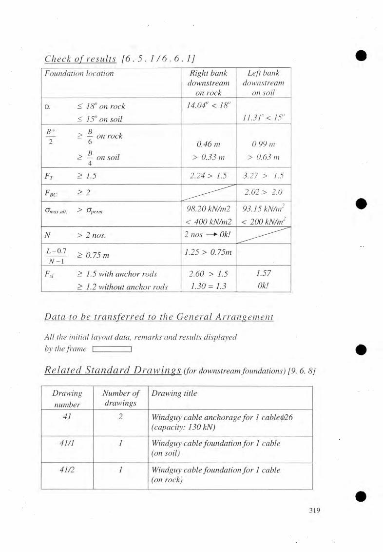
C h e c k o f r e s u l j s [ 6 . 5 . 1 / 6 . 6 . 1 ]
Foundation loca tion R igh t ban k d o w n s tre a m
on rock
Left bank d o w n s tre a m
on so il
a < 1 8 ° on rock
< 15° on so il
14.040 < 18°
11.31° < 15°
B* ^ B , — > — on rock 2 6
> — on so i l 4
0 .4 6 m
> 0 .3 3 m
0 .9 9 m
> 0 .63 m
Al
£
2 .2 4 > 3 .2 7 >
Fbc - 2 2 .02 >2 .0
Gmcix.ult. ^ Gperm 9 8 .2 0 k
< 4 0 0 kN /m 2
9 3 .1 5
< 2 0 0 2
N > 2 nos. 2 nos —► Ok!
L - 0 . 1 . n------- > 0 .7 5 mN — l
1 .25 > 0 .7 5 m
Fs\ > 1.5 w ith a n c h o r rods
> 1 . 2 w ith o u t a n c h o r rods
2 .6 0 >
1 . 3 0 = 1 .3
1 .5 7
Ok!
D a t a t_o be_ t x a j u f e r r e d _ t o A i r a j i g e j i i e j ^
A lt the in itia l la y o u t da ta , rem arks a n d resu lts d is p la y e d
by the f r a m e I I
R e l a t e d S t a n d a r d D jfC F W ijlgS^ (for d o w n s tre a m f o u n d a t i o n s 6. 8 ]
D ra w in g
nu m ber
N u m b e r o f d r a w in g s
D ra w in g title
41 2 W indguy c a b le a n c h o r a g e f o r 1 ca b le (¡)26 (capac ity : 1 3 0 kN)
41/1 1 W indguy c a b le fo u n d a t io n f o r 1 c a b le (on so il)
41 /2 1 W indguy c a b le fo u n d a t io n f o r 1 ca b le(on rock )

12.4.2 SUSPENSION BRIDGE
DESIGN OF M AIN CABLE STRUCTURES [8. 3]
In i t ia l la y o u t d a ta 18. 3. 6
J) Span, 1a p p ro x im a te span, 1 = 1 42 .0 m
. t -2.2 142.0-2.2in teger i = ------- = -----------
2.4 2.4= 5 8
c o rr e c t span t = 2.4 x i + 2.2 = 2.4 x 58 + 2.2= 1 4 1 .4 m
£ -3 .4 141.4-3.4 ns = =1.2 1.2
= 1 1 5 m
n( = tis + 2 = 115 + 2 = 1 1 7
nd =n, + 1 = 117 + 1 = 1 1 8
2) T o w e r height, h,
h, (m ax)= 0 .1 6 5 x i + 1 .05 = 0 .1 6 5 x 1 4 1 .4 + 1 .05 = 2 4 .3 8 m
h, (m in )= 0 .1 1 0 x i + 1.05 = 0 .1 1 0 x 1 41 .4 + 1 .05 = 1 6 .6 0 m
h, (rec) = 0.145x t + 1 .05 = 0 .1 4 5 x 1 41 .4 + 1 .05 = 2 1 .5 5 m
A va i la b le to w e r he igh t n e a res t to h, (r e c ): h ig h e r lo w e r
h, = 2 2 .7 3 m 20. 2 4 m
3) D e a d lo a d sag, L
f d (m ax) = (h, - 1 .05 ) - 0 .02 x i = m 1 6 .3 6 m
f t (m in) = (11,- 1 . 0 5 ) - 0 .0 3 x = 1 7 .44 m1 4 .9 5 m
fc t(rec) = (h t - 1 .05 ) - 0.025x t = 1 8 .1 5 m1 5 .6 5 m
4) C alcu la tion o f live load, P
, . 60 , , 60= 3.6 + — = 3.6 + -------
l 141.4= 4 .0 2 4 kN /M
5) P r e c a lc u la t io n o f a v v r o x im a te t
a) M ain c a b le s- a p p r o x im a te fu l l load,
ig , ( approx) = 1.30 + -------+ P
7 500141.4
= 1.30 + ------- + 4.024500
= 5 .6 0 7 kN/m

With h, = 22. 7 3 m a n d f d (rec) 18 .15 m
Tnva (approx.) = — — X ^1 +17.64 • ( f do-4 x /rf
5.607x141.4 r , ..■>= -------------------- x J l + 17.64x(15.65/141.4)'
8.4x15.65 ^
Tmax = 535 £7V
W67/z h,=2 0 .2 4 m a n d fd (rec) = 75.65 m
5.607x141.4' r . . •>7 (approx .) = ----------------------- x J l + 17.64x(15.65/141.4)'
8.4x15.65
Number; a n d d ia m e te r o f jn a in c a b le s
W ith nM = 4 a n d (¡)M = 3 6 m m
P e r m is s ib le tension, Tpenn = 9 8 7 k N > = 9 4 0 k N
Therefore, a d o p t lo w e r to w e r height.
Tmnx= 9 4 0 kN
B y trial, w ith next lo w e r to w e r a n d m axim um d e a d lo a d sag, in crease in m ain c a b le sec tion is requ ired .
S a fe ty fa c to r for ca b le tension
B reak in g load, = 2 9 6 0 kNT 9%o
Safety f a c to r a g a in s t b reak in g — = —-------= 3.15
S in ce sa fe ty f a c to r (=3.15 —>sligh tly lo w e r sa g is p o ss ib le .
D e a d lo a d cam ber , qc\t = lr,- 1 .05 - f i = 20. 2 4 - 1 .05 - 15.65;
M ain c a b je m c l i n a l i a n . (3j
arctanf4 .2 x f A— arctanf 4.2x15.65")
f\ ) l 1 4 1 4 J
b) W m d g u y ca b les
With ver tex a t V = t / 2 = 141 .4 /2 = 7 0 .7 m,
h\v ~ ~ tof_10
Take bw — fw9
141.49
Cd= 3 .5 4 m
= 24. 9 3 d eg
hyj — 0
= 1 5 .7 0 m
321

A p p ro x im a te w in dgu y c a b le tension
Tr =
i.e. Tn
With n w =
T,perm
^ m x i , 4 2x f "8 x bwV
0.5x 141.42 8x15.7
x J l + 2x15.7 V70.7
Tmax= 8 kN
1 (for u p s trea m o r d o w n s tr e a m ) & (pw = 2 6 m m
1 2 9 kN > 87 .1 kN ok!
6)
7)
8)
F ina l la y o u t d a ta SpanTower height Dead load sag Dead load camber Camber span ratio, c j / t Number o f main cables Diameter o f main cable Sectional area o f main cables (a ll cables)Breaking load Factor o f safety Diameter o f spanning cable Number o f windguy cable (u/s or d/s)Diameter o f windguy cable
Young ’_s M odu lu s (forall c a b le s ) [T a b le 4 . 2 . 1 ] E = 1 10
B a ck s ta y distancesand c a b le a n c h o ra g e e leva tion s
a c c o r d in g to G en era l A rra n g e m e n t w ith due co n s id era t io n o f to p o g ra p h ic a l a n d g e o lo g ic a l condition s.
Walkway elevation Tower height
Saddle elevation
B a ck s ta y an g le
Hw — 84.0 mh, -20.24 m
(Hw+hd-104.24m
ß f = 2 4 .9 3 d e g
G ra p h ic a l ly -
left bank:
righ t bank:
m ain c a b le e leva tio n S a d d le e lev a t io n b a c k s ta y d is ta n c e w in d g u y cab le , u ps tream span n in g c a b le w in d g u y cab le , d o w n s tre a m m ain c a b le e leva tio n b a c k s ta y d is ta n c e
w in d g u y cable , u ps tream spann in g c a b le w in d g u y c a b le d o w n s tre a m
= 9 3 .5 3 m
D l = 1 8 .7 5 m
= 8 3 .2 0 m = 8 3 .7 5 m
= 8 3 .3 0 m = 9 7 .4 0 m
D r = 1 5 .5 0 m= 8 3 .6 0 m = 8 3 .7 5 m = 8 3 .8 0
322

9) Check for freeboard- p lo t a ll the in itia l layou t d a ta in the c ro ss -se c t io n o f the G en e ra l
A rran gem en t.- D r a w a l l the c a b le a lign m en ts w ith re sp e c t to c a b le a n c h o ra g e
eleva tions.- D r a w f r e e b o a r d line a t e lev a t io n H .F .L + 5. 0 = 79 + 5
w ith in the r ive r channel.= 8 4 m
V»
A p p ro x im a te f r e e b o a r d : span n in g ca b le = 5 .3 m
L o w e s t c a b le = 5 .0
L o a d in g sH o is tin g lo a d case, gh
m ain c a b le s = 0 .1 9 2
Tota l a t ho is ting lo a d ca se Si, = 0 . 1 9 2 k
D e a d lo a d case, g h
a) D e a d w eigh ts , gdd- H o is tin g load, gh = 0 .1 9 2 kN/m
- W alkw ay d e ck (s te e l ) = 0 .4 1 0 kN/m
- W alkw ay su p p o r t = 0.270
- H a n d ra il a n d f ix a t io n c a b le s = 0.030- W irem esh netting = 0.060- S u spen ders (a v e ra g e ) = 0.170
- Spanning c a b le s = 0 .0 7 6 kN /m- W indguy c a b le s = 0 .0 5 0 kN/m- W indties (a v e ra g e ) = 0.040S u b to ta l d e a d weights , gdd = 1 .1 2 8 kN /m
b) P re ten s io n in spann in g c a b le

= 0 . 1 1 3
g d = 1 . 2 4 1
A s s u m e d a p p r o x i m a t e p r e - t e n s i o n a t d e a d l o a d c a s e i s 1 0 p e r c e n t o f d e a d w e i g h t s .
Gpd = 0.10x gdd = 0.10x 1.128T o t a l a t d e a d l o a d c a s e , ( g dd+ g pd);
F u l l l o a d c a s e , g f
D e a d w e i g h t s , g dd
P r e t e n s i o n , gpdL i v e l o a d , P
T o t a l a t f u l l l o a d c a s e
= 1 . 1 2 8 k N / m
= 0
= 4 . 0 2 4 k N / m
g / = 5 . 1 5 2 k N / m
Sag cafculadion aj_ lwfM ing ajid_Jull l_oad_ by iteration [8 . 3 .7]
Length ofdead loaded main cables
L r, = i x , 8 ( f d y , 8 15.65 ^21 H— X = 141.4x 1 H— X
3 { ' J . 3l 1 4 1 -4 2
L, / = 1 4 6 . 0 2 m
M a i n c a b l e t e n s i o n a t
H n
T d
g jx / ' _ 1.241X141.42 8x / (/ ~ 8x15.65
H ,x J l + 16( L v — = 198.18x J l + 1615.65141.4
Y
H , = 1 9 8 . 1 8 k N
Td = 2 1 6 . 7 3 k N
C a h r u U i t ja n o f a, , a n d
5 - 24xa
ß fo
f„= 16x — xC
ir 15.65 = 16x------- x
f h V
)
141.45 - 24x
15.65141.4
= 15-8x
= 15-8x
i f \ 2 J d 5 - 3 6 x ' f t ' 2
J
15.65141.4
Vx 5 - 3 6 x
15.65141.4
arctan 4.2 x ^
( 4.2x15.65^= arctaru---------------
1 141.4
a = 8 . 3 3 4
b = 1 4 . 5 5 3
ß fo =24.93 d e g
324
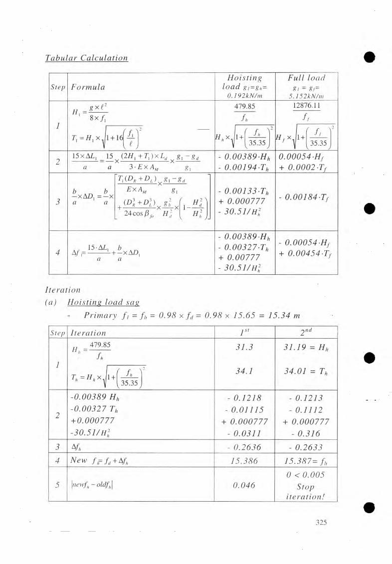
Tabular ÇaJ
Step FormulaHoisting
load g,=gh= 0.192kN/m
Full loadg i =5.152kN/rn
# , =l xF_8 x / ,
479.85
h
12876.11
f t
r , = / / , x . 1 + 16 / . v
v ^ yI f f * * 1 + fh V
35.35Hf x. 1 + ' ffV
35.35J
15xAL, _ 15 _ (2/ / , + r , ) x L „ ^ g, - g „ <7 a 3- E
0 .0 0 3 8 9 H h 0 .0 0 1 9 4
0 .0 0 0 5 4 H f + 0 . 0 0 0 2 -Tf
Z> b—xA £>, = —x « «
t i (d r + d l ) „ 8 i - gdE x A M
, ( R i ± m x i ± x24 cos ¡3 f0 H ]
\ —H 2 'N
* * y
- 0 .0 0 1 3 3 T h + 0 .0 0 0 7 7 7- 3 0 . 5 1 / Hi
- 0 . 0 0 1 8 4 -f
, 15-AL, Z?A /,= ---------L + -x A D ,
a
- 0 .0 0 3 8 9 H h- 0 . 0 0 3 2 7 -Th + 0 .0 0 7 7 7
- 3 0 . 5 1 / Hi
- 0 .0 0 0 5 4 H+ 0 .0 0 4 5 4
Iteration(a) Hois:J±ng l_oad_ sa g
Primary f , = f h = 0 .9 8 x f d = 0 .9 8 x 1 5 .6 5 = 1 5 .3 4 m
Step I t e r a t i o n I s’ 2 nd
l
„ 479.85
fh3 1 .3
3 4 .1
3 1 .1 9 H h
3 4 .0 1 = ThfV7 ; = / / ax . i + •/ a * V (35.35,
2
- 0 .0 0 3 8 9 H h - 0 .0 0 3 2 7 Th
+ 0 .0 0 0 7 7 7 - 3 0 . 5 1 / Hi
- 0 .1 2 1 8- 0 .0 1 1 1 5
+ 0 .0 0 0 7 7 7- 0 .0 3 1 1
- 0 .1 2 1 3- 0 .1 1 1 2
+ 0 .0 0 0 7 7 7 - 0 .3 1 6
3 ¥ h - 0 .2 6 3 6 - 0 .2 6 3 3
4 N e w f r f < t + Afh 1 5 .3 8 6 1 5 .3 8 7 = f h
5 \newfh ~oldfh\ 0 .0 4 60 < 0 . 0 0 5
S t o pi t e r a t i o n !
325

F o r hoisting lo a d c a se
%
(b ) Full loa
P r i m a r y f f = 1 . 0 5 x f ti= 1 . 0 5 1 5 . 6 5 = 1 6 . 4 3 m
S t e p I t e r a t i o n 1 st 2 n d
1
„ 12876.11Mr -
' f f 7 8 3 . 7 0
8 6 4 . 2 1
7 8 1 . 9 8
8 6 2 . 6 5
=Hf
= Tf• y
Tf = H f x , 1+ ff s v 35-35V V J
2- 0 . 0 0 0 5 4 Hf + 0 . 0 0 0 4 5 4 -Tf
- 0 . 4 2 3 2 + 0 .i924
- 0 . 4 2 2 3 + 0 . 3 9 1 6
3 4/} 0 . 8 1 5 6 0 . 8 1 3 9
4 N e w f r fd + A f /1 6 . 4 6 6 1 6 . 4 6 4 = ff
5 | newff - oldff| 0 . 0 3 60 . 0 0 2 < 0 . 0 0 5 S t o p i t e r a t i o n !
F o r f u l l l o a d c a s e
C a l c u l a t i o n o f _ s a f e f a c t o r
Tmax = T f
S a f e t y f a c t o r , F = Tbreak = 3.43 > 3.0
= 8 6 2 . 6 5 k N
o k !862.65

C a f^ u d g O ip n o f f
( a) M a i n C a b l e s
C a b l e i n c l i n a t i o n
ß ( = arctan( 4 x f A
= arctanf 4x16.461 ßf=24.97 deg
l 141.4 JT o t a l U rn g th o f j n a i n c a b l e [ a t d e a d J b e U v e e n
( i n c l u d i n g o v e r l a p p i n g l e n g t h f o r f i x a t i o n )
DR+ D, 15.5 +18.75L,, = L , + —5------ - = 146.02 + -
Lm— 184 mCOS ß f
A m ch pn a jge l o c a t i o n
, 4 x f 4x16.46h, = ----- —xD, =--------------x l8 .75
cos 24.97°
e 141.4
4 x f 4x16.46/;„ = -------- x Z ) , = ------------ x l5 .5
* l R 141.4
Dfgphicemgnt_ of_sadjT[es_ f o r c a b l e
h L = 8.73
h R = 7 . 2 2 m
£ x A M 8h
8h x ^24 cos /3
•xfo
1 ..
» n JH o i s t i n g l o a d c a s e
g h = 0 . 1 9 2
H h=31.19kN/m
T h= 3 4 . 0 1 k N /m
L e f t b a n k : D L- 18 m
R i g h t b a n k : D R= 1 5 . 5 0 m
A D l = - 002 5 m
A D r = - 0 . 0 1 8 m
( b ) N p jxn ju jig caM_esj_ dead_ l o a d
ß nl = arctan 4 * 0i
arctan4x3.54
T „ *8_s_H_BxC,,
141.4
0.113X141.428x3.54
h o l d i n g l o a d c a s e
a 4xCrf ^p rh = arctan ---- -— | = arctan1
4x3.54141.4
T„g Shx t 2 0.076 x 141.428 xC „ 8x3.54
K , f.x, 8 f Cd)
0, 8 ( 3.54 ^
2 “
1 + - X = 141.4x 1 H— X -------------3 lT J 3 1141.4 J
ß c d = 5 . 72d e g
Tsd = 79.7 8 k N
ßch = - 5 . 7 2 d e g
T,h = 5 3 . 6 6 k N
T sd = 1 4
327

C o m p ila t io n o f F in a l D ata [ 8 . 3 . 8 ] ; Main Cable Structures
Bridge No. & Name: Design example 2 Date: April 2004 checked by N. L. Joshi
a) Initial Data (refer to 7 . 3 . 6 and GA)
Design span Tower height
Main cable
Spanning cable
Windguy cable
E-Module
Cable anchorage elevations:Left Bank Windguy cable, upstream
Spanning Cables Windguy cable, downstream Main cables
Right Bank Windguy cable, upstream Spanning cables Windguy cable, downstream Main Cables
Approximate freeboard Spanning cablesWindguy cables
Loads:
Walkway steel deck
Pretensionlive loadHoisting loadDead load (including gpd)Full load
t = 141.4 mht = 20.24 m
nM - 4 /<t>M = 36 mmA m = 2240 mm2T m .break = 2960 kN
n - 2 /<t>s 32 mmAs 884 _ 2 mmTs, break = 1170 kN
nw - 2 /<t>w = 26 mm
— 110 KN/mm2
=i.appx) 83.20 m= 83.75 m=lappx) 83.30 m={appx) 93.53 m=iappx) 83.60 m= 83.75 m=iappx) 83.80 m=i.appx) 97.40 m- 5.30 m= (appx) 5.00 m
gpd = (steel) KN/m
P = 0.113 KN/m= 4.024 KN/m
gh = 0.192 KN/mgo = 1.241 KN/mgt = 5.152 KN/m
b) Data from Main CalculationFull loads: fi = 16.46 m
p< = 24.97 deg
*f"max = 862.65 KN
Safety factor = 3.43 /
Comment

c) Data to be transferred to the General Arrangement
Cables Load caseLoad, g Tension, T Sag, f /
Camber, C (m)
Elevation o f Vertex
Displacem ent o f Saddles
(kN/m) (m) (m) A D L(m) A D r ( i v )
Hoisting 0.192 34 15.39 88.85 -0 .0 3 -0 .0 2
Main Dead Load 1.241 217 15.65 88.59 0.00 0.00
Full Load 5.152 863 16.46 87.78 / /
Hoisting 0.076 54 -3 .5 4 80.21
Spanning Dead Load 0.113 97 3.54 87.29
Full Load 0 0 2.73 86.48
Live Load 4.024
Data of Cable Structure
Also transfer all the remaining data and results displayed by thef r am e I 1
Related Standard Drawings [8 . 9]
Drawing Number Drawing Title07 Walkway08 Steel Walkway Deck
Standard Design Drawings: Walkway
329

LOAD COMBINATIONS WITH WIND LOAD [8 .4](A) In itia l layout data [ 8 . 4
(1) From cable structure analysisSpan t = 141.4 mTower height h, = 20.24 m
Centre distance of tow er leg c/cj ZZ 4 .0 mBackstay cable inclination fit = 24.97 degMain cables: nM = 4
= 36 mmA m zz 2240 min
Spanning cables: <Ps = 32 mmAs = 884 mm2
M odulus of elasticity E rz 1102
kN/m
Sag, f ,: -for loading case [A ] fd = 15.65 m-for loading case [B ] f t z= 16.46 m
Load, Pmo'- :for loading case [A ] gd zz 1.241 kN/m-for loading case [B ] 8 / = 5.152 kN/m
Pre-tension spanning cables:
-for loading case [A ] P s o = 0.113 kN/m-for loading case [B ] P s o = o
(2) Wind load: -for loading case [A ] W = 0.5 kN/m-for loading case [B ] W zr 0.167 kN/m
(2) Breaking tension o f spanning cables: Ps, break = 1170 kN
(4) Calculation o f initial cable lengths
Loading case A B
fo 15.65 m 16.46 m
go 1.128 kN/m 5.152 kN/m
Pmo 1.241 kN/m 5.152 kN/m
P so 0.113 kN/m 0
C o =h,- - f 0 3.54 m 2.73 m
L Mo ~ l x + 8/3 x ( fo /l)2] 146.02 m 146.51 m
§ II X + X ( C 0/ l ) 2J 141.64 m 141.54 m
Calculation o f Wfo r loading case [A],
for loading case [B], Wb
-0 .1 1 6 + 0 .00375 h, = 0.116 + 00375 x 20.24
= - x 0 .19193
= 0.1919
= 0 .0640 kN/m
330

(B) Iteration procedure 9]
Calculation o f constant C
Loading case [A ] [B ]
_64 x E x A m^ MO 0 .3 r
. 3 x f x L mo0.01273 0.01269
^ 64 x E x A s
so ~ 3 x C x L s0
0.00518 0.005184
Iteration
StepLoading case [A ] IB ]
Iteration number 1st 2"d 3rd 1st 2nd
(o) First f i : case[A]; f i ~ 1.002-fd 15.681 15.668 15.657
Case[Bp f ~ 1.001 ff 16.476 16.460
First x: case [A]; x ~ 0.0151 2.121 1.335 1.569
Case[B]; x 2l 0.00251 0.354 0.216
(1)X
Yi = arcsin---------f +1,3 7.175 4.513 5.309 1.141 0.697
Xlx, ] — at tan
h, +0,25-cosy, x ( / , +1,3) 30.216 20.479 23.516 7.422 4.522
C/ = — — sin«, 4.215 3.816 3.932 2.740 2.740
(2) Pm =CMOx f l x ( f i2 - f t?) + F x P MOd o 1.437 1.355 1.285 5.267 5.152
P si — Cso x Cj x (C, — ) + —— x P5(9^ o 0.249 0.162 0.185 0.001 0.001
0 ) /\PM — PMl - PMO 0.196 0.114 0.044 0.115 0
Ag - -g0+ (Pmi’cosYi - Psrcosai) 0.083 0.071 0.018 0.113 0.001
Newfi = /„+ (fi-fo) xl ^ J
15.668 15.657 15.654 16.460 16.460
\ 7 ^ _ V 1.335 1.569 1.562 0.216 0’53XqT<i*
, + Ps, xs in a )
(4) M >0.02 >0.02 <0.02 >0.02 <0.02
Stop iteration!
331

Force diagram: fo r had ing case [A ]
'Without w ind load
f \
332

Calculation of final dataSymbol Unit Values fo r loading case
A B
P Ml KN/m 1.285 5.152Psi KN/rn 0.185 0.001
Yi deg 5.309 0.697or/ deg 23.516 4.522fl 111 15.657 16.460Ci 111 3.932 2.740
V„„ kN 185.98 728.50
Hu kN 8.41 4.43
G, kN 58.0 58.0
Pi kN 26.95 353.30
Pi kN 217.03 433.20
Ph kN 34.37 11.36
Tsv kN 5.22 0
Tsh kN 117.59 0.91
Ts kN117.71
0.91
Fs - 9.94 -
F orm ulas, Rem arks
Values from last iteration
xcosy, x
xsiny.
f x tan1 + ■ '
4 x /, xcosy.
From Table
\ ( vm + g ,)-h, x(tf,„ +1.025xh’X/j()
C/C,
i ( V , c ) , +1.025x w x /i,)2 l ' ' C /C,
//„, + 2.05xwx/i, + Ps lx£-x sin or
P5l x£x sin or
8 xC,
51 X / ‘8 xC,
Tjft/Vfflt / 7j
-x /l + 16 x(C,/f)2
Check o f results„ tEH = - x W b + 2.05 xh,xw-PH
2[A] = 0.5x141.4 x 0.1919 + 2.05 x 20.24 x 0.5 - 34.37[B] =0.5x141.4 X 0.333X 0.1919+ 2.05 X 20.24 x 0 .167- 11.36 0.09 kNXV = 0.5 i go + G,+ 0.5 X V ,ot(P, + P2 - Tsv)[A] = 0.5 x l4 1 .4 x l .1 2 8 +58 + 0.5 X 1 8 5 .9 8 X (26.95 + 217.03 - 5.22)[B] = 0.5 X 141.4 x5.152 + 58+ 0.5 X 728.5 X (353.30 + 433.20) = 0 kN
Check fotj tower capacity [Table 8 . 5 . 4 ]
R e la te d S ta n d a rd D ra w in g s [8 . 5. 5 ]D rawing Num ber D raw ing Title
151 A ssem bly draw ing103 Base e lem ent draw ing113 In term ediate elem ent drawing126 Top elem ent draw ing137 Saddle draw ing

DESIGN OF WALKWAY/TOWER FOUNDATION [8 . 6]
W a]Jcw m y/T pw ^ (au m dajfjm on , b a n k
(A) FuundatwncharacteristicsR iver bank Foundation on :
RightRock; without fo o t
(B) Initial layout data [ 6 . 51
(1) Loads on w alkw av/tow er foundation
Centre distance tow er legs
Centre distance anchorage rodsc/c] = 4 . 0
c /c 2—550 mm
Loads from tower:Tower leg 1
Tower leg 2
Horiz. L oad perpendicu lar to tow er
(A)P i = 26.95 kN
P 2 = 217.03 kN P „ = 34 .37 kN
( B )
353 .30 kN
433 .20 kN
11
- L oads from spanning cables;
Vertical
H orizontal
Tsv = 5.22 kN
Tsh = 177.5kN
0 kN 0.91 kN
(0) From survey and final report:Rock param eters
- Rock a t depth
- Sliding fric tion angle
G round bearing pressure
= up to surface
6 sl - 40 deg
O p e n ,, = 400
(1) M inimum em bedded depth t = 1.0 m
(2) D esign param eters [Table 8 . 6 . 1 ]
Foundation dim ensions (m ) minimum maximum
Width B 2.9 5.0
Length L 6.0 9.0
Total height (H +C ) 2.4 10.0
Foot height C - -
Foot width E - -
334

[1) Foundation dim ensions
Width
Length
Total height
Fool height
Foot width
(C) Main calculation [8. 6
B = 2.9 m L - (5.0
(J l+ C f= 2 A
C = 0
E = 0
(2) Topographical conditions (from layout)
A ctive so il height at the back ha = 0
Soil height in the fron t hp = 0
Depth o f ground w ater hw = 0
(3) Unit weight o f concrete yc = 22
(4) Calculation o f loading forces and moments
Loading fo rces (kN) Lever arm Static moment (kN-m)
Formula Vert. H o r iz . Mx B M yL M, M y
Weight: 918.7W,=B XL XH Xyc
Loads: case (A)
Pi 26.95 0.5 C/C, 2.0 53.90
217.03 o.5 a c , 2.0 434.06
T sv -5.22Tsh 117.59 H-0.25 2.15 252.82P h 34.37 H 2.4 82.49
1157.46 I 252.82 462.65
Tsh 117.59
Pit 34.37
2.0 353.30 0.5 C/C, - 706.60
2.0 433.20 0.5 C/C, 886.40
0 0 00.91 H-0.25 2.15 1.96
2.4 11.36 H 27.26
R v 1705.20 z 1.96 187.06
Tsh 0.91
P h 11.36
335

CjuU julM jjo ji da ta
F o rn 2 a l a /S y r n b o l Unit (A ) (B)
(5) C alculation volume:
wVol = —!
22m 41.76
Location o f resultant:
(6)M y
• ' = K,m 0.22 0
B * _ B | | B * _
2 ~ 2 'Cx' 2m 1.23 1.45
R v€ym 0.40 0.11
L * L| | L *~ T ~ 2 ™
777 2.60 2.89
B * L *C heck fo r ; —— : —
B*/2 > B/3? Ok! Ok!
L*/2> L/3? Ok! Ok!
Inclination o f resultant:
(7) & ^ r c , J ( + E E f ‘ + P» ’ =
V Vdeg 6.04 0.38
M axim um ground bearing pressure:
(8)
B * / 2A t ---------
B
A n d -------- =L
~ 0.42
0.43
0.50
0.48
The Z - fa c to r Z= ~ 1.36 1.07
Rx.«". Z B * 'L * K N /m 2 123.06 108.85
Checkfor<J,mx. :
Omax ^ Opew,(= 400 kN /m 2) ? Ok! Ok!
(9)Safety against toppling: F t checked b y - B*/2and B*/2and L*/2
Safety against slid ing :
(10) F = tan0s' F r sltan ^ - a )
7.93 126.52
C heck for F,,: F., > ?Ok! Ok!
336

Bridge No. & Name: Design example 2 Date: April 2004 Checked by N. L. Joshi
E) And B) Initial Data (refer to 8 . 6 . 5 )
Compilation of Final Data [8 . 6 . 7]; R/B, W/T Foundation
C) Main Calculation
1) Soil/rock heights
- Active pressure height at back
- Rock height at back
- Active pressure height in front
Rock height in front
- Depth of soil
- Depth of additional soil
2) Soil parameters
- Front slope of soil(top of dry stone pitching)
- Slope of soil baseline
- Length of influence
- Back slope of soil
3) Foundation dimensions
- height
- height of foot
- Width
- Width of foot
- Length
- Distance to resultant force
and
4) Safety factors
- sliding
- Bearing capacity
- Toppling
- Slope stability
5) Anchorage rods
Nos. as per calculation
ha = - mH ra - - mH p - - mhrt = - mt = - mt' = - m
C1 = - Deg
£b = - DegL*infl. - - mv - - Deg
H 2.4 mC = - mB — 2.9 mE = - mL = 6.0 mB72 - 1.23/1.45 mL72 = 2.60/2.89 m
F sl 7.93/ 126.52 /F bc = - /F t - Ok /Fs = - /
N /
D) Additional Anchorage Rods(from geological report): as the rock is sound no additional
anchorage rod is provided.
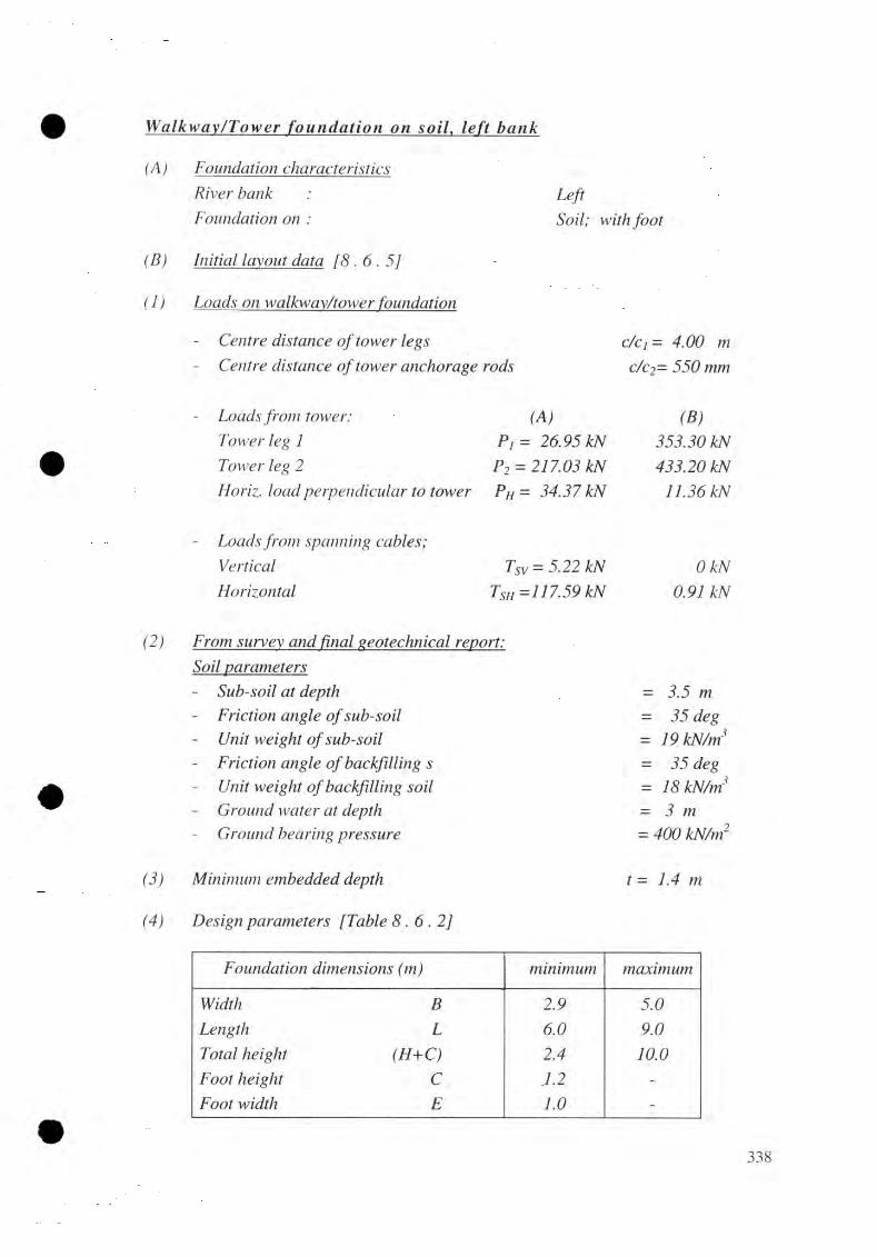
YfaH cw ayfJfow er; f o u n d a t i o n o n . l e f t
(A) Foundation characteristicsR iver bank : Left
Foundation on : Soil; with fo o t
(B) Initial layout data[8 .6 .5 ]
( 1) Loads onwalkway/tower foun
Centre distance o f tow er legs
Centre distance o f tow er anchorage
Loads from tower:
Tower leg 1
Tower leg 2
Horiz. load perpendicu lar to tow er
Loads from spanning cables;
Vertical
H orizontal
4 .00 m
rods c/c2- 550 mm
(A) (B)P , = 26.95 kN 353 .30 kN
P 2 = 217.03 kN 433 .20 kNPH = 34 .37 kN 11.36 kN
Tsv = 5.22 kN 0 kN
Tsh = 117 .59 kN 0.91 kN
(2) From survey.and fund geotechnical report:
Soil param etersSub-soil a t depth =
- Friction angle o f sub-soil = 35 degUnit w eight o f sub-soil 19
- Friction angle o f backfilling s = 3 5 degUnit w eight o f backfilling soil = 18G round w ater a t depth = 3 m
- G round bearing pressu re = 400 kN/m
(3) Minimum em bedded depth t = 1.4 m
(4) D esign param eters [Table 8 . 6 . 2 ]
Foundation dim ensions minimum maximum
Width B 2.9 5.0Length L 6.0 9.0Total height m o 2.4 10.0F oot height C .1.2 -
F oot width E 1.0 -
338

(C) Main ccduMtio[ 8 . 6 . 6 ]
(1) Foundation dimensio (in)
- Width
- Length
- Total height
- F oot height
- Foot width
(2) Topographical cond ition s (from foundation layout)
(3) Earth pressure coefficient
back side:cos2 02
j lsin(02 + <5)xsin(02 -y/) \ cosSxcosy/
ha = 3 .5 m
hp = 1.4 m
hra = 0
hw = 0 .5 m
hrt = 0
V = 3 2 deg= 19 deg
With
cos235°
sin(35" + — x 35") x sin(35" -32")1 + 3
2cos—35" xcos322
1 3Aa/,= 0 .437
r ■ i 1 COS2 0 ,fron t side: Aai„ = -- ~l s in (0 2 + 0 ) x s i n ( 0 2 - £ , )
"y COS0 X C O S £ j
cos2 35"
1 +sin(35" + —x35")xsin(35" +19)
cos-35" xcos(-19") 3
(4) Unit w e igh t o fco
K h,= 0 .1877
Yc = 22 kN/m3
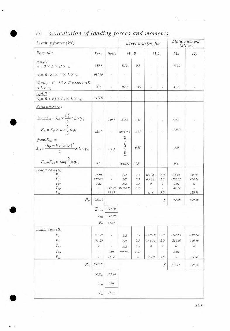
(5 ) Ç ajcidadw n ojyUmdjjtji force_s and_ nwm
Loading fo rces (kN) L ever arm (m) fo r Static m om ent (kN-m)
Formula V ert. H o r iz M X B M yL M x M y
W e ig h t:
W i= B X L X H X ye 880.4 - E/2 0.5 - - -440.2 -
W 2= ( B + E ) x C x L x y<- 617.76 - - - - - - -
W s= ( h P - C - 0.5x E X x E
X L X Yi 3.0 . B/2 1.45 - 4.35 .
Uplift :
W „ = (B + E ) X hiv X L X Yw- 117.0 - - - - - - -
E a r th p r e s s u r e :
h 2- b a c k :E t,h = AahX — X X . 289.1 ha 73 1.17 338.2
-o-X<N | cn
gX>5II
124.7 - (B+E)/2 1.95 - -- 243.2
-
- f r o n t:E ilh, =rv-
to, ( h p -Extane)2 f , h, x ^ x L x / 2 - -11.3
JKC0.35 ~ - -3.9 -
2E m.,= E ah, X t a n ( - X < t> 2 ) 4.9 - (B+Ey2 1.95 - - 9.6 -
L o a d s : c a s e (A )
P i 26.95 - E/2 0.5 0.5 C/Ci 2.0 -13.48 -53.90
p 2 217.03 - E/2 0.5 0.5 C/Ci 2.0 -108.51 434.10
T sv -5.22 - E/2 0.5 0 0 -2.61 0Tsh - 117.59 H+C-0.25 3.25 - - 382.17 -Ph - 34.37 - - H+C 3.5 - 120.30
Rv 1752.52 - 77.58 500.50
Z E * 277.80
Tsh 117.59
Ph 34.37
L o a d s : c a s e (B )
P i 353.30 - E/2 0.5 0.5 C/Ci 2.0 -176.65 -706.60p2 433.20 - E/2 0.5 0.5 C/C, 2.0 -216.60 866.40
T sv 0 - E/2 0.5 0 0 0 0Tsh - 0.91 11+C-0.25 3.25 - - 2.96 -
Ph - 11.36 - - H + C 3.5 - 39.76
R v 2300.26 - 725.44 199.56
Z E „ 277.80
Tsh 0.91
Ph 11.36
340

ÇafxM hxùon oj_ f in a l da ta
Formula/Symbol Unit ( A ) ( B )
(6)
(7)
C alculation volum e
W, ,Vol = - 1------ -
YrLocation o f résultant
Vol.
&B ~ &X ~
B * _" T "
M ,
By
B + E-
eL=
L*
M ,R „
L _ I2 2 Ie'1
S* L*C heck fo r
ex =
B* _2
ey
L * _2
£ */2 >5 + £
L * / 2 > Z / 3 ?
m
m
m
m
m
68.23
-0.04
1.91
0.29
2.71
Ok!Ok!
-0 .3 2
1.63
0.09
2.91
Ok!Ok!
(8)
Inclination o f resultant,
SR - arc tanV R,
8r= deg 12.76 6.91
(9)
Safety factor aga inst sliding
F _ tan<ft, sl tan 0R
Check fo r F .,: > 1.5 ?
Fsi= 3.09ok!
5 . 7 7
ok!
( 10) Safety against toppling:C hecked by B*/2 and
L */2
( U ) M axim um ground bearing pressure
C heck: - + - ^B + E L
Therefore, fo r load case (A)
Z-factor ' E l l . 0.49 an£ 1 1 = 0.45 B + E L
max.ult.
^ max
= Zx- *
/
B*xL*fo r load case (B)
Rv(B + E)xL
l + 6x-(B + E) L
Check . tfmax!
KN/m
KN/m-
KN/m
0.06 > - 6
1.03
87.18
<400
0.10 < - 6
155.54
<400
341

Formulas/Symbols Unit (A) (B)(12) Shear resistance o f the ground
L*m = 5.8xB* m 22.16 18.91
From G eneral A rrangem ent; a t L * ^ ; £b- deg 19 19
9= kN/m2 3.0 3.5
Surcharge load - (hp - hw) X yt + hw X (yi - Yw) + Q = kN/m2 20.6 22.6
Bearing capacity factors (fo r 0/ = 35°) Nq- - 33.3 33.3Ny= - 40 .7 40.7
Correction fa c to rs fo r:B *
- Shape ( — - =0.70 70.56 a nd (¡>¡=35") S„= - 1.49 1.39
- 0.72 0.78
/ _ 1.09 1.10- Depth ( — - = 0.37/0.43 a nd <h=35°)
Bd y- - 1.00 1.00
- Inclination o f load (SR=12.76°/6.91° and a - 0 ) i(J= 0.55 0.73ly - - 0.42 0.64
- Inclination o f found , base (a - 0 and (¡>1=35°) b 'q= 1.00 1.00b \= - 1.00 1.00
- Inclination o f base line (eB = 19°) g'y = - - 0.64 0.64
\fhp hw).y + hw(Yi Y w ) cl \ x N q X S q X d q X i q X b q
P* = B*.L. 1 KN 8399.8 10562+ ~ X (Y\ - 7vv)x ^ *xA^y x Sy x d y x i y x b 'y
(13) Safety factor against ground shearp *
Fbc — ---- 4.8 4.6*v ok! ok!
C heck fo r Fbc : Fbc 2.0?
Reinforcements,: - Section
M = 0 .8 x a ,nnyx — x E 2 x L = O.Sx87.18x — x l 2x 6 .0
H = C -0 .2
MA s -
= 1.2 0.2209
0.9x1.0x23.0-xlOO
T j x h x o perm
As„„n= 0 .02% x h x L =0.02x10 2x l .0 x 6 .0 x l 0 6*Smin
N,A s _ 12002o I~ 201
(16 mm0)
= 209 kN-m
= 1.0 m2
= 1011 mm
= 1200 mm2 > 1 0 1 1mm2
______ Ml = 6 nos
E c
A5 _ 6 x 7t / 4 x 16: h - L ~ 1.0x6.OxlO6
n = 10
/u = 2.01 x \0 '4
342

£ = 7 i X / i X
Stresses
o,
(Tr
1
1 + — " I77 X ¿7
M
= 10x2.01x10 4 1 +
jti x (] — < / 3) /z2 x L 2.01
lxlO4
1 --xO.614 3
10x2.01x10"
209xl0~J l.O2 x 6.0
M£x(l-£ /3 ) / rx L
-x-0.614 1 — xO.614
3
209xl0~J l.O2 x6.0
Section 2-2
M = Tshx (H -0.25) + Kh[<t>2, WJ x (/i" +/7»' C) xLxy2
--1 =0.674
a t = 217.9 N/mm2Otperm = 230.0 N/mm2
ot = 0.14 N/mm2 Ocperm 2 N/mm"
(40 + 0 + 1 2Y= 777.6x (6 .0-0.2 5 )+ 0 .4 3 7 x 6.0x18
h = B - 0 . 5 = 2 . 9 -0 .5M 1782.2
As =t ] x h x o pem 0.9x2.4x23.0
-xlOO
As (minx) = 0.02% /zxL = 0x 2.4 x 6.0 x 106
(16 mn 2 - A _ -201
nE c
Id _ A s .h x '
Z = n ■ n ■
18x11/4x16'
1 + ----------1nxju
Stresses
<7, = x- M
= 10x2.51x10"
1x10
2xl0410x2.51
1 + - 1
= 1782.2 kNm
= 2 .4 m
= 3587 mm2
= 2880 mm2
N2= 18 nos
n = 10
¡1 = 2 .5 1
= 0.0684
jU x (1 — / 3) l r x L
2-
-x-2.5 lx l - - x 0.0684
3
1782.2xlO~J 2.42 x6.0
= 210.2 N/mm" a tperni = 230.0 N/mm2
£x(l-£ /3 )-x-1782.2x10"
0.0684x 1 — x 0.06843
2.42 x6.0 < = 1.5 N/mm'. a Ipenn= 2.0 N/mm'
R e l a j e d s ta m d a rd des±gn [ 8 . 6 . 8 ]
D raw ing N um ber Bank D raw ing Title
92 Both W alkw ay/tow er anchorage (capacity: 390 kN)
92/1 Left W alkw ay/tow erfoundation; c /c j-4 ,0 m ;c /c 2=550mm
92/2 R ight W alkw ay/tow erfoundation; c /c i - 4 ,0m;c/c2=550mni
343

Compilation of Final Data [8.6.7]; L/B, W/T Foundation
Bridge No. & Name: Design example 2 Date: April 2004 checked by N. L. Joshi A) and B) Initial Data (refer to 8 . 6 . 5 )C) Main Calculation
0
2)
3)
4)
5)
Soil/rock heights
- Active pressure height at back ha
hra
- Active pressure height in front hP
- Rock height in front hrt
- Depth of soil t
- Depth of additional soil r
Soil parameters- Front slope of soil
(top of dry stone pitching) £1- Slope of soil baseline 6b
- Length of influence L*infl.
- Back slope of soil V
Foundation dimensions
- height H
- height of foot C
- Width B
- Width of foot E
- Length L
- Distance to resultant force B 7 2
and L 7 2
Safety factors
- sliding F sl
- Bearing capacity F bc
- Toppling F t
- Slope stability Fs
Anchorage rods
Nos. as per calculation N
= 3.5 m
= m
= 1.4 m
= 0 m
= 1.4 m
_ 0.32/0.37 m
= 19 deg
= 19 deg
= 22.16/18.91 m
= 32 deg
2.3 m
= 1 .2 m
= 2.9 m
= 1.0 m
= 6 . 0 m
= 1.95/2.86 m
= 2.72 / 2.86 m
3.09 / 5.77 /
= 4 .8 /4 .6 /
= Ok /
= - /
/
344

DESIGN OF MAIN CABLE FOUNDATION [8 . 7]Initial layout d a ta [ 8 . 7. 5 ]
Foundation characteristics- River bank- Foundation on
Unit RightRock
LeftSoil
Main cable characteristics- Number of main cables nM = nos. 4
- Main cable tension 7Mf - kN 862.65- Main cable inclination f3t = deg 24.97
- Tower leg centre distance c/cj = m 4.0
Soil parameters- Sub-soil at depth = m - 4.0- Friction angle of sub-soil 0 / = deg - 35- Unit weight of sub-soil = KN/m3 - 19- Friction angle of backfill soil 0? = deg 35 35 ■- Unit weight of backfilling soil Y2 = KN/m3 18 18- Ground water at depth m - -- Ground bearing pressure operm = KN/m2 - 300
Rock parameters r\ /i- Rock at depth = m 0.4
- Sliding friction angle 0 V/ = deg 38
- Ground bearing pressure operm = KN/m2 400
Minimum embedded depth m 1.0 1.5
Design parameters [Table 8 . 7 . 1 ]
Foundation dimensions (m) Minimum Maximum
- Width B = 4.9 5.5- Length L = 6.4 8.4- Back height H ,= 3.3 5.5- Front height FI2 = 1.5 4.5- Front toe b = 0.5
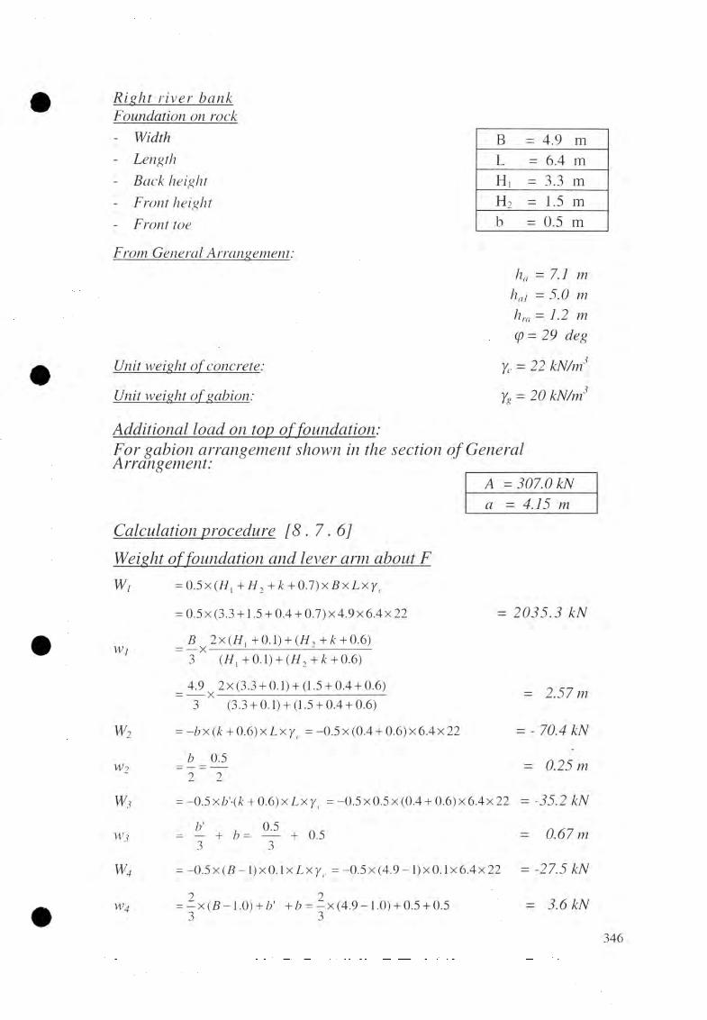
Right l i v e r bankFoundation on rock- Width- Length- Back height- Front height- Front toe
From General Arrangement:
Unit weight of concrete:
Unit weight
B = 4.9 mL = 6.4 mH, = 3.3 mh 2 = 1.5 mb = 0.5 m
ha = 7.1 m ha\ =5.0 m
hra = 1.2 m (p= 29 deg
Yc = 22
yg = 20 kN/tn
Additional load on tojl o f f o u n d a t i o n :
For gabion arrangement shown the section o f General Arrangement: ________
Aa 4.15 m
CakuJation procedure [ 8 . 7 . 6]
Weight offoundation Od d ¡ever 01111 about FW,
W]
W2
w2
W3
w 3
W4
w4
= 0.5x(//, + H 2 + k + 0 .7)x B x L x y , .
= 0.5 x (3.3 +1.5 + 0.4 + 0.7) x 4.9 x 6.4 x 22
_ B 2x(//, +0,1)+ ( / / ,+ it+ 0.6)” 3 (H x + 0.1) + (//2 +¿ + 0.6)
_ 4.9 2 x (3.3+ 0.1)+ (1.5+ 0.4+ 0.6)3 (3.3+ 0.1)+ (1.5+ 0.4+ 0.6)
= - b x ( k + 0.6) x L xy, = “ °-5 x (°-4 + °-6)x 6-4 x 22
_ b _ 05 _ 2 _ 2
= 2035.3 kN
= 2.57 m
= - 70.4 kN
= 0.25 m
= -0.5 x b 'ik + 0 .6 ) x L x y r = -0.5 x 0.5 x (0.4 + 0 .6 ) x 6.4 x 22 = -35 .2 kN
= — + /?= — + 0.5 = 0.67 m3 3
= -0 .5 x ( f l- l) x 0 .1 x L x y , . = -0 .5x (4 .9 - l ) x 0 .1x6.4x22 = -27.5 k N
= - x ( B - l .Q ) + b' + b = —x (4.9-1.0) + 0.5 + 0.5 =3 3
346
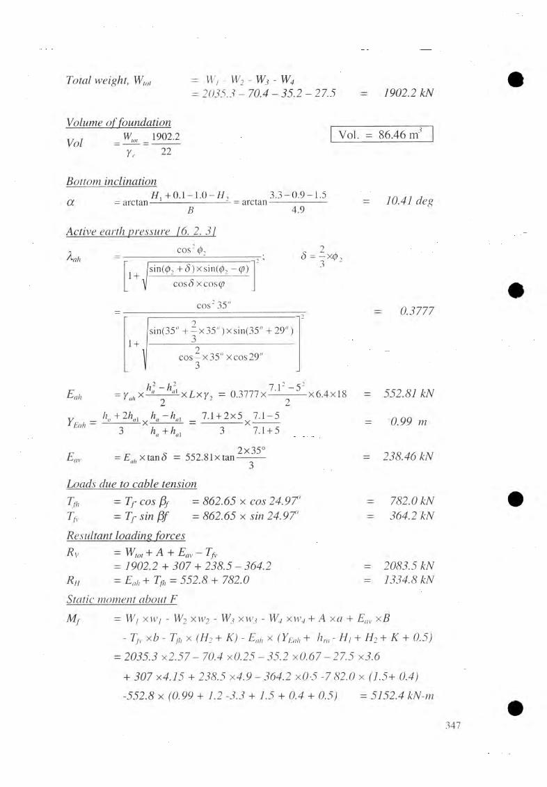
1902.2Total weight, = W , - W 2 - W 3 -
= 2035.3- 70.4 35.2 - 27.5
Volume of foundation
Vol WM _ 1902.2 Vol. = 86.46 mYc
Bottom inclination
Ot = arctan
22
H, + 0 4 - 1 .0 - H , 3 .3 -0 .9 -1 .5B
— = arctan •4.9
= 10.41 deg
Active earth pressure [6. 2. 3 1
l *ahCOS2 0,
[sin(</>2 + <5)xsin(02 -(f))1 +COS <5 xcos
cos235'
<5 = — X0, 3
= 0.3777
1 +sin(35" + - x 35" ) x sin(35" + 29" )
3
cos^x35" xcos29" 3
ah
Ye* =
= X-
h + 2
h : - h \
-x-2
h.
x L x y 2 = 0.3777X7.12 - 5 2
x 6 .4 x l8 =
al _ 74 + 2x5 7 .1-5h. + h., ~ 3 X 7.1 + 5
2x35°■Jav = Eahxvm8 = 552.81xtan
552.81 kN
0.99 m
238.46 kN
= 782.0 kN= 364.2 kN
= 2083.5= 1334.8 kN
Loads due to cable tension Tfh = Tf cos fa = 862.65 x cos 24.97'Tfr = Tf sin Pf = 862.65 x sin 24.97’
Resultant hading forcesRv = W,ot + A + Eav - T f
= 1902.2 + 307 + 238.5 - 364.2 Rh = Eah + T = 552.8 + 782.0
Static moment about EM f — W/ xvv/ - W2 x w 2 - W3x w j - W4 x w 4 + Em, x B
- T f x b - Tfx (H i + K) - Ex (YEah + hm - H / + H 2 + K + 0.5) = 2035.3 x2.57 -70.4 xO.25-35.2
+ 307 x4.15+ 238.5 x4.9 -364.2 xO-5 - 7 82.0 x (1.5+ 0.4)-552.8 x (0.99 + 1.2 -3.3 + 1.5 + 0.4 + = 5152.4
347

ljic lina tion o f
SrRh= arctan—— = arctan-R
1334.82083.5
Location of resultant
B * M~2 Rv( 1 + tan or x tan<5R)
3689.02083.5 x (1 + tan 10.41" x tan 32.65")
Check for B */2 B *~2
B 4 9= 2.18 m > - = —6 6
= 32.65 deg
B- = 2.18 m
ok!
Safety, factor against to llin g M + 7673.22
FM - 2520.79
= 3.04 > 1.5 ok!
Calculation of_gwund bearing pressure
R'v
B ’
B *~ T
= Rvx cos oc + Rh xsin a= 2083.46 x coslO.410 + 1334.81 x = 2290.31 kN= B x sec oc = 4.9 x sec 10.41 °
= — x sec a = 2.1x sec 10.412
?
_ RVB’L
x
B*'2
1 ±B'
4.98 2.22
2290.31 , 4.98x6.4'
1 ±6x0.27
4.98
B '= 4.98 mB*'— = 2.22 m2
e' = 0.27 m
Gmnx - 95.2 kN/rrrGmin =48.5 kN/rrf
„ . B B * BSince — > — > —2 2 3
no anchorage rods are required for main cable foundation.
R'h = Rh xcos a - R vx sin a= 1334.81 x cos 10.41° + 2083.46 x R ’„ =936.47 kN
Safety factor, againsl sliding
Fsitan (psl x Rv _ tan 38" x 2290.31
R, 936.47Fd = 1.91
Check for.Fsi
Fsi = 1 .9 1 > ok!348

Additional anchorage [6
From fina] geotechnical recoil
Rock type Weathering Rock quality
Augen gneiss with quartz band ModerateHighly fractured with open joints
Weakness planes/lmes
Slope ~bedding 320755s (direction/amounof dip)
Azimuth of br axis
Intersection 1Intersection 2Intersection line 3
370743s360739s225708s318s
Provision of anchorage rods
The bedding plane 320755s is nearly parallel to the bridge axis, i.e .3 1 8 s, anchorage rods to stabilize this plane are provide in direction 120745s i.e. perpendicular to 320745s.
Since the intersection lines 1 and 2 are more or less the same direction, anchorage rods perpendicular to their average direction i.e365/41s. , are provided, i.e. in a direction of 165759s.
As the bridge axis is oblique to the intersection lines 1 and 2, anchorage rods in direction 65759s are also symmetrically provided.
Intersection line 3 is too lateral to the bridge axis and flat, no anchorage rod is provided to stabilize this line.
Number of anchorage rods
NlxickB x L _4.9 x 6.4
2x1.5 ” 2x1.5- 1 1 nos
Nfront. B x L . 4.9x6.42x------- = 2x---------
2x1.5 2x1.5= 27 nos
— 19back + Nfront - 1 1 + 21=32 ((|)25mm) nos
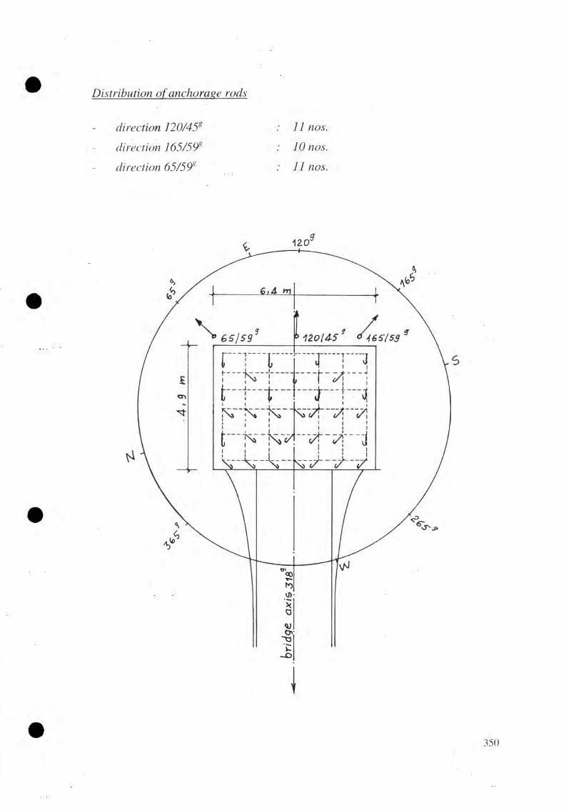
D is tr ib u tio n o fja n ç h o ra g e ro d s
direction
direction 9s
direction ^
11 nos.
10 nos.
11 nos.
350

C o m p ila t io n Of F in a l D ata [ 8 . 7 . 7 ] ; R/B, Main Cable Foundation
Bridge No. & Name: Design example 2 Date: April 2004 checked by N. L. Joshi
A) And B) Initial Data (refer to 8 .7 .5 )
C) Main Calculation
1) Load on top of foundation- Total load A = 307 m
- Front to C.G. distance a - 4.15 m
2)Soil/rock heights - Active pressure height ha 7.1 m
ha1 = 5.0 m- Rock height at back hra = 1.2 m- Embedded depth t = 1.5 m- Depth of additional soil (if on soil) t’ = - m
3) Soil parameters- Front slope of soil
(top of dry stone pitching) £1 . 27 deg
- Slope of soil baseline £b = - deg
- Length of influence L*inf|. - _ m
- Back slope of soil ¥ = 29 deg
4) Foundation dimensions- Back height H1 = 3.3 m
- Front height H2 — 1.5 m
- Width B = 4.9 m
- Length L - 6.4 m
- Base inclination a — 10.41 m
- Distance to resultant force B72 - 2.18 m
and L72 = 3.20 m
5) Safety factors - Sliding F sl 1.91 /
- Bearing capacity F bc = - /
- Toppling F t - 3.04 /
- Slope stability Fs - - /
6) Anchorage rods Nos. as per calculation
D) Additional Anchorage Rods(from geological report) : 32 /

Left rive_r bank
Foundation on soil i 8 . 7. /
FQundgtiondimensions (by trial)- Width
- Length- Back height- Front height- Front toe
From foundation layout:
K = 0.4 m b = 0.5 m
Calculation procedure [8 . 7. 6]Weight ofJowjQoOon and lever arm about F.Wi = 0.5 x ( / / , + H 2+
= 0.5 x (3.3 +1.5 + 0.4 + 0.7) x 4.9 x 6.4 x 22
B 2x(H . + 0.1) + ( / / , + £ + 0.6)Wj = —x -------------------------- =--------------
3 ( ff,+ 0 .1 ) + ( t f 2+ * + 0.6)
_ 4.9 2 x (3.3+ 0.1)+ (1.5+ 0.4+ 0.6)~ ~ (3.3+ 0.1)+ (1.5+ 0.4+ 0.6)
B = 4.9 mL
Tt"II mH, = 3.3 mh 2 = 1.5 mb = 0.5 m
ha - 4.5 m hai = 1.2 mhp = 1.5 m hra = 0 mhw = 0 m\f/ = 30 deg£/ = 33 deg
= 2035.3 kN
2.57 m
w2 = -b x (k + 0 .6 ) x L x y c
= -0.5 x (0.4+0.6) x6.4x 22 = -70.4 kN
w2_ b _ 0.5 _ 2 _ 2
= 0.25 m
w3 = -0.5 x bYik + 0.6) x L y t.
= -0.5 x 0.5 x (0.4 + 0 .6 ) x 6.4 x 22 = -35.2 kN
w3 b' u 0 5 n ^— ----h b —-------- h 0.5
3 3= 0.67m
W4 = -0.5 x (B - 1.0) x 0.1 x L xYr
=-0.5 x (4.9-1 .0 )x 0.1x6.4x22 = -27.46 kN
W4 = — x (B - 1.0 ) + b'+b 3
= —x (4.9 -1 .0) + 0.5 + 0.5 = 3.6 kN
352

1902.1Wwr =w,-w2- w3 - W4
= 2035.3 - 70.4 - 35.2 - 27.5
Additional load on Foundation Load of wall (Dry Stone Masonary):A = 0.5x 6.4 x 1.2 x 2076.8 kNLever a r m = 4.9 - 0.5x0.5 = 4.65 m
Yolume offoimdation
Vol wim _1902.1
Yr 22
Base inclination
a =arctan -H, + 0.1 -1 .0 -
= arctan-
B3.3 + 0 .1 -1 .0 -1 .5
4.9
Active earth pressure 16 . 3j
cos2 6 2A,'ah|sin(</>2 +5 )xs in (0 , -y /)1 +
cos<5 xcosy/
cos2 35°
1 +
1 cos — x 35" x cos 30" 3
Vol. = 86.46 m2
= 10.41 deg
* - ! * ■
sin(35" + —x35")xsin(35" -3 0 " )
= 0.J95S
Eah - 0.5 x y ah x (/j2 - / i; i )x L x 7 , = 0.3938x 0.5x (4.52 - 1.22)x 6.4x 18 = 426.7 kN
Vertical distance “YEah” from base (backside) of foundation block to the resultan force Eah;
h + 2 h .1 £n/i
/ r - h. 4.5+ 2x1.2 4.5-1.2_ y a_____<<1 — ________________ y ____________
h + h .,~~ 3 4.5+ 1.21.33 m
2Eav = Eah x tan 5 = 426.7 x tan — x 35"
Loads due to cable tensionTfl, = Tf xcos(3f =862.65 x 24.97’Tfr = TfX s in fif =862.65 x s in
Résultant loadingforces Rv = Wlo, + A + Eav -
= 1902.1 +76.8 + 184.1-364.2B h = Eah + Tfj,
= 426.7 + 782.0
= 184.1 kN
= 782.0 kN = 364.2 kN
= 1798.8 kN
= 1208.7 kN %353
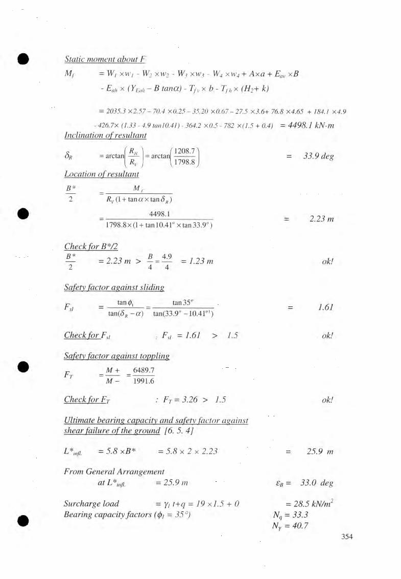
Static moment about F
Mf = W/ xw’i - W2 xw2 - W2 xWj - Axa + Eav xB
- Eah x (YEah - B tana) - x b - Tfh x k)
= 2035.3 X 2.57 - 70.4x0.25 - 35.20 xO.67 - 27.5 X 3.6+ 76.8 X 4.65 + 184.1 X 4.9
- 426.7X (1.33 - 4.9 tanlO.41)- 364.2 x 0 .5 - 782 + 0.4) = 4498.1 kN-m Indirmtion ofresuEtant
Sr =arctanf r> AKhv R V ,V
Location ofresultcmt
= arctan1208.7 1798.8
B *~2
M ,Rv (1 + tan a xtan SR )
4498.11798.8 x (1 + tan 10.41° x tan 33.9" )
= 33.9 deg
2.23 m
Check for B */2 B *~2
= 2.23 m > - = — = 1.23 m ok!
Safety factor against sliding
sitan bt tan 35°
tan(<5f i - a ) tan(33.9°-10.41"*)1.61
Check for Fsi Fst = 1.61 > 1.5 ok!
S a fe ty factor, agam s t to p p lin g
F _M +_ _ 6489.7T ~ M - ~ 1991.6
Check for F T :F T = 3.26 > 1.5 ok!
Ultimate beating capacity and safety, factor against shear failure ofthe ground [6. 5. 4]
L*infl. = 5.8 xB* = 5.8 x 2 x 2.23
From General Arrangement at L*inf] =
Surcharge load = Yi = 19 + 0Bearing capacity factors ((pi = 35 °)
= 25 m
£b = 33.0 deg
= 28.5 kN/m Nq = 33.3 Ny = 40.7

Correction factors
Shape (— = 0.70 and 0/ = 35") L *
Depth ( — = 0.35 and 0/ = 35°) B *
Inclination of resultant (8R = 33.9" 10.41")
Inclination of foundation base & (¡)i=35°)
Inclination of base line (eB = 33.0°)
Shear resistance ofthe ground
P* =B*xL*x[(Yl xt + q)xNilxS ilxd{lx iq x bq x gq
+ ^ x Yi x B * x N yx S y x d yxiy xby x g y j
= 2 x 2.23 x 6.4x [28.5 x 33.3 x 1.49 x 1.08 x 0.29 x 0.77
+ —x l9 .0 x 2 x 2.23 x 40.7 x 0.72 x 1 x 0.18 x 0.71] x 0.41 2_ P * _ 5605.9
BC ~ I f ~ 1798.8
Ground bearing pressure [6. 2. 7]
Rv Rv xcos a + Rh xs in a
= 1798.8xcosl0.41° +1208.7 x sin 10.41"
B 'B _ 4.9
cos a cos 10.41"B*’ _ B *1 2 2.23
cos a coslO.41"
e I f 5* 'T ~ i
Since B' B*B'— > -------- > —2 2 3
a maxRyB L
-x 1 +6 x^ '
B'
1987.6 4.96x6.40
-x 1 +6x0.18
4.96
Check for o„,ny
omax = 76.2 kN/m2 < openn = 300 kN/nr
sq = 1-49
sY = 0.72
dq = 1.08
d y — 1.0iq 0.29 iy= 0.18
b 'q = 0
b 'y = 0
gq = 8 y= 0A1
= 5605.9 kN
= 3.11
= 1987.6 kN
= 4.96 m
= 2.27 m
= 0.18 m
= 76.2 kN/m2
ok!

C o m p ila t io n o f F in a l Data [ 8 . 7 . 7 ] ; L/B , Main Cable Foundation
Bridge No. & Name: Design example 2 Date: April 2004 Checked By N. L. Joshi A) And B) Initial Data (refer to 8. 7. 5)C) Main Calculation
1) Load on top of foundation
- Total load A = 76.8 kN
- Front to C.g. distance a - 4.65 m
Soil/rock heights
- Active pressure height ha - 4.5 m
ha1 - 1.2Rock height at back hra = - m
- Embedded depth t = 1.5 m
- Depth of additional soil (if on soil) t ' - 0 m
Soil parameters
- Front slope of soil(top of dry stone pitching) £1 33 deg
- Slope of soil baseline £b= 33 deg
- Length of influence I- inf I. = 25.9 m
- Back slope of soil ¥ - 30 deg
Foundation dimensions
- Back height H t - 3.3 m
- Front height h 2 — 1.5 m
- Width B — 4.9 m
- Length L — 6.4 m
- Base inclination a - 10.41 deg
- Distance to resultant force B72 - 2.23 m
and L72 - 3.2 m
Safety factors
- Sliding F SL = 1.61 /
- Bearing capacity F bc - 3.11 /
- Toppling F t - 3.26 /
- Slope stability Fs - - /
5) Anchorage rods
Not provided
356
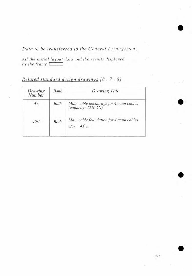
Data to be tj^ajufejred_ to A jj^ a n ^ jn e n j
All the initial layout data and the results displayed by the frame I I
Related ytamdard design draw ings . 8 ]
DrawingNumber
Bank Drawing Title
49 Both Main cable anchorage for 4 main cables(capacity: 1220 kN)
49/1 Both Main cable foundation for 4 main cablesc/cj = 4.0m

D E T E R M IN A T IO N OF SU SP E N D E R L E N G T H [ 8 . 8]In it ia l la yo ud data [8. 8. 4 ]- Design span 1= 141.40 m- Dead load sag f d= 15.65 m- Dead load camber Main Calculation Formula
c/cn _ 4 x (/d +Cd^xx * +1.3c-
C(i = 3.54 m
With = 1.2 x (n - 1)
With n - 1 at mid-span to nmax continuously
Umax1 -4 .6 , 141.4-4.6 ,
2.4 2.4= 58 nos
L = c/cn - 542
In( - 3^0
= INTEGER n1650
It = ln - 1650 xjnIre = lr + 180 for 0 12 mm suspenders
- = /, + 240 for 0 16mm suspendersw nl 2 = 1.625 xjn + 0.888 xlO'3 Ire for 12(f) mm suspenders
Sn12 = 0.069 xjn + 0.0377 xl O3 xlrc suspendersWnl6 = 3.286 xjn + 1.58 xlO'3 xlrc 16 0 m m suspenders
8nl6 = 0.104 xjn + 0.05 xlO'3 xlrc 16 (f)mm suspenders
Tabular caladationn xn
(m)Dia
(mm)c/c n
(mm)In
(mm)J¡i
(nos)lr
(mm)Ire
(mm)w„
(kg)Sn
(m2)i 0 16 1300 758 0 758 998 1.6 0.032 1.2 16 1306 764 0 764 1004 1 .6 0.033 2.4 16 1322 780 0 780 1020 1.6 0.044 3.6 16 1350 808 0 808 1048 1 .7 0.04
21 24.0 16 3511 2969 1 1319 1559 5.7 0.1822 25.2 12 3738 3196 1 1546 1726 3.2 0.13
55 64.8 12 17421 16879 10 379 559 16.7 0.7156 66.0 12 18023 17481 10 981 1161 17.3 0.7457 67.2 12 18637 18095 10 1595 1775 17.8 0.7658 68.4 12 19262 18720 11 570 750 18.5 0.79

ÇaJxidajjxm data
- Total number of suspenders
Ar £-3.40 141.4-3.4yv = ---------- = ----------------
0.60 0.6
Number of (p 16 mm suspenders from mid span,
lnm = Int
= I
7.2+ 1
141.47.2
+ 1
= Int (19.64) + 1=20+ 1 =21
Total suspenders weight
W58
= 2xWx+ 4 x ^ W n
N = 230 nos
W = 1681.08 kg
Total surface of suspender rods
58
S = 2x5, + 4 x ^ 5 , ,n=2
S = 66.39 m
Data to be transferred to Standard Design Drawing [ 8. 8 . 5 ]
( 1 )
(2)
To the suspender list for each suspenderAll the results except Xn from Tabular calculation.
To the steel part list:W= 1681.08 h
S = 68.72
Related standard design draw ings [8 .8 .6 ]
Drawing Number Drawing Title
32 Suspenders for 4 main cables
359

DESIGN OF STABILIZING MEASURES [ 8 . 9 ]Stabilizing cables [ 8 . 9 . 1 ]
fix first stabilizing cables at 8.90 m (d/= 8.90 either tower saddle.Fix second stabilizing cables at 17.3 m (d2=17.3 - 8.9 = 8.4 m)from either tower saddle
Length o f Stabilizing cables
At dj = 8.9 m
Main cable height = 1.05 +3.54+ - ^ x V 2f <• ^-d ,
■
= 4.59 + 15.6570.702
'±11-8 .9 V
Length of first stabilizing cables, f = V8.92 +16.552
At d2 = 17.3 m
fMain cable height = 1.05 + 3.54 + ^ - x
J
4.59 + 15.65 ( 141.4 \ 2
70.702 2-17.3
Length of 2nd stabilizing cables, l 2 = Vl7.32 +13.522
= 16.55 m
= 18.79 m
= 13.52 m
= 21.96 m
Check for cable inclination, a
OL = arctan - - ' ^ = 38° > 35° and <45° =17.30
Data to be transferred to General Arrangement [ 8 . 9 . 3 ]
Distances : = m8.4 m
Cable lengths :1? = 4x21.96 m
Into cable listTotal length = 4x 18.79+ 4x 21.96 + x 0.4 = 170 m
Related standard design draw ings [8 . 9 . 4 ]
Drawing Number Drawing Title
22 Stabilizing cable clamp for 4 main cables

DESIGN OF WINDGUY CABLE STRUCTURES [9.4]
In itia l layout data [ 9 . 4 . 6 ]
Span, l 1 = 141.40 mElevation, Hi = 84.0 0.25 H ,= 83.75 mCamber, Cd = 3.54 mr = 1/2 = 141.4/2 r = 70.70 m
suspension bridge; d = 4.8 m735 m
Topographical and geological conditionCheck concave slope contours upstream of bridge axis on right bank. Slope is gentle and no geomorphological instability exists.(survey reort).
Cakulation procedureDetenninatwn o f theoretical parabola in plan
P M l 4Vertex, V - L l
2 2
Windguy cable sag at mid-span:
Bw — fw
H w
Tr = Tl
141.49 9
w x t 2 0 .5x l41.428 x 6 ,.. 8x17.65
— H w x. +' 2 x / ^
70.8x .1 +
V = 70.7 m
fw — bw= 17.65 m
Hw=
2x17.65^2
Tr = 71=79.1 kNv 70.70 y
Number and diameter o cable Number of windguy cable Diameer of windguy cablePermissible tension
Safety factor, F = —— =79.1
nw = 1 <pw = 26 mmTperm = 129 kN
ok!
Windguy cables shall be provided symmetrically both upstream and downstream.361
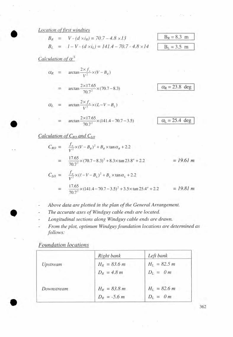
Location of first windties
Br = V - (d x iR) = 70-4.8x13Bl = l - V - ( d x i L) = 141.4-70.7
Br = 8.3 m
Bi = 3.5 m
CalcuMtwn of a 'S
2 x fCCR = arctan 2 x
2x17.65 ,_n _ „= arctan-------- -—x (70.7-8.3)
lO . l 2a R = 23.8 deg
2 xOLi = arctan — * x(L
= a r c ta n ^ ^ x ( 1 4 1 .4 - 7 0 .7 - 3 .5 )10.1 -
a L = 25.4 deg
Calculation of Cro and Cm
Cro = ^ x ( V - B R) 2 + B Rx tanaR+2.2
17.6570.72
^-x(70.7-8 .3)2 +8.3xtan 23.8° +2.2
Clo = ^ - x ( i - V - f i J 2 + f iL x ta n a L + 2.2
17.65
= 19.61 m
10.1- x (141.4-70.7-3 .5 )2 + 3.5x tan 25.4° + 2.2 = 79.87 m
Above data are plotted in the plan of the General Arrangement.The accurate axes ofWindguy cable ends are located.Longitudinal sections along Windguy cable ends are drawn.From the plot, optimum Windguy foundation locations are determined as follows:
Foundcdion locations
Right bank Left bank
Upstream Hr = 83.6 m HL = 82.5 m
Dr = 4.8 m DL = 0 m
Downstream Hr = 83.8 m Hl = 82.6 m
Dr = -5.6 m DL = 0 m
362

Check far freeboard
In the section of the General Arrangement, freeboard line at elevation 79.0+5.0=84.0 m and the Windguy cable alignments both upstream and downstream are drawn.
From the plot, it is found that the Windguy cable on left bank passes slightly below ( ~20cm) freeboard line.
Therefore, the Windguy cable on left bank requires to be raised slightly.
Revised foundation locations
Right bank Left bank
Upstream Hr = 83.6 m Hl = 83.20 m
Dr = 4.8 m Dl = 1.5m
Downstream Hr = 83.8 m Hl = 83.3 mDr =-5.6 m Dr = 1.5m
By trial, the windguy cable alignment clears off the freeboard line.
Calculation of Cr and Cr_
For upstream windguy cable
CR= y X (V - B R) 2 + tar\aR(BR + DR) + 2.2
1 7= — x (70 .7- 8.3) 2 + tan 23.8" (8.3 + 4.8) + 2.2 70.72
CL = - B l ) 2 + t m a L(BL + D l ) + 2 . 2
1 7= — —t x (141.4-70 .7-3 .5)2 +tan25.4" x (3.5+ 1.5)+ 2.2
10.12
CR = 21.73 m
CL = 20.52 m
Calculation ofwindtie lengths [9 .5 . 7] For upstream windguy arrangement
(1) Peteij2nnatipnof parabola 4
Cl 4 — L v 2
17.6570.72
a4 = 0.003531
c4 = 1.465 mc4 = 2 .2 - k =363

(2) Calculation of
AhLP
} ’lp
tan
= y LP X tan y
= a4x (r - V) +C4
= 0 .00353lx(70.7-70.7)2 + 1.465 = 1.465 m( / / , - H r - cd) x ( ( + P R + P L) - ( P R + r ) x ( H L ~ H r )
(Cr - k ) x ( t + D r + D l ) - ( D r
L + Dr + Dl = 141.4 + 4.8
DR + r = 4.8+70.7(83.75 - 83.6 + 3.54) x 147.7 - 75.5 x (83.2 - 83.6)Tan y
AhLP
(21.73 - 0.735) x 147.7 - 75.5 x (21.73 - 20.52)
= 1.465x 0.191
(3) Detejjjnnationof parabolas (1), (2} and(3)
Parabola (1) a¡ = - c A -3 .5470.72
C, = AhLP
Parabola (2) a2 = ( c < i) ) & 1 1 l p H t
(r + £>«)2
_ 83.6-3.54+ 0.28-83.75 (70.7+ 4.8) 2
C2 = 0
Parabola (3) a, = Hl + (~c¿) + A/(l - r - D LŸ
83.2-3.54 + 0.28-83.75(141.4- 70.7 + 1.5) 2
c, = 0
(4) Calculation ofwindtie
C/Ci = jAhf + yf
Dwi — -------- X "X(í/ + 2xi)~ + 1cos ß ,
Where in -x, = V-Bp-(i-l)xd = 70.7- 8.3 - 4.8 x
X, = Xj
i - B g - B . , 141.4-8.3-3.5 ,I m n r = ----------------- ~ + l = --------------------------- + 1
4.8
= 147.7 m
= 75.5 m
= 0.191
= 0.28 m
= - 0.000708
= 0.28 m
= - 0.000598
= - 0.000731
= 62.4-4.8 (i-1)
28
y> = a 4 x x,2 + c 4 =0.003531 x x 2 + 1.456 = +1.465

forx,-’ > 0
2 2Ah; - a.]x x ’i -AhLP - a 2x x
= - 0.000708x x ’i + 0.28 + 0 .0 0 0 5 9 8 x x ’,2
(5j = arc tan (2x a ? x x ’,) = arctan ( -0 .0 0 0 5 9 8 ) x x ’,7
forxf< 0
2 2Ah, = a] x x ’i + AhLP - a? x x ’,
= -0 .0 0 0 7 0 8 x x,2+ 0.28 + 0 .0 0 0 7 3 1 x x,2
P i = arc /an (2 x a3 x x ’,) = arc tan {2 x (- 0 .0 0 0 7 3 1 ) x x , ’j
Starting from right side (i=l), the windtie data are calculated continuously upto imax on left side as shown below:
Tabular calculation
i Xi = X (m)
1 62.42 57.63 52.84 48.05 43.26 38.47 33.68 28.89 '24.0
10 19.211 14.412 9.613 4.814 0.015 -4.816 -9.617 -14.418 -19.219 -24.020 -28.821 -33.622 -38.423 -43.224 -48.025 -52.826 -57.627 -62.428 -67.2
Ah, / tanpi
—z-----------
Take values for Xi > 0
Take values for Xi < 0
C/Ci(mm)
Dwj(m)
15.2113.18 5.2311.31 5.16
9.60 5.108.06 5.056.67 5.005.45 4.964.40 4.923.51 4.882.78 4.862.21 4.83
1.81 4.821.57 4.811.49 4.801.57 4.80
1.81 4812.,21 4.822.78 4.843.51 4.864.40 4.895.46 4.926.68 4.968.06 5.009.60 5.05
11.31 5.1113.18 5.1715.22 5.2917.41 5.30
190.45 134.18
365

(5) Calcidationof an
Pr
Pl
= arc tan [2 x a2 x (Br
= arc tan [2 x (- 0.000598) x (5.5 -
= arc tan [2 x a? x ( r - l +
Pr = AW_ deg
Pl = 5.61 deg
= arc tan [2 x (- 0.000731) x (70.7 - 747.4 + 3.5)]
(6) Calculation of En andEi
■p _ ■*" 7 «B r ---------------------cosaR xcos
_ 8.3+ 4.8cos 23.8° x 054.72°
Er = 14.36 m
P_LcosaL xcos(3L
El = 5.56 m3.5+ 1.5 1------ -----------------
cos25.4° xcos5.61°
(7) Calculation of total lengths ofcables
L w(tot) = Z Dwi + E r + El + Overlapping length
= 134.18 + 14.36 + 5.56 + 2 x1.70 = 157.50 m
Lftot) = Z (c/ci + 0.60)
= 190.45 + 28 x0.60 = 207.25 m
PownM reajn Wmd_guy_ cable gjj^aji^ejjven4
Similar to the upstream Windguycable arrangement manual calculation for downstream Windguy cable arrangement is also to be made.
366

C o m p ila t io n o f F in a l D ata [ 9 . 4 . 8 ] ; U/S W .G .C a b le S tructures
Bridge No. & Name: Design example 2 Date: April 2004 Checked By N. L. Joshi A) Initial Data (refer to 9. 4. 6 and GA)
Bridge type (suspended or suspension) ? Suspension /
Design span t = 141.6 m
Horizontal distance r = 70.7 m
Windguy cable nw = 1 /
<|>w = 26 mm
Aw = 292 _ 2 mm
Tw, break — 386 kN
E-Module = 1 1 0 KN/mm2
Cable anchorage elevation:Left bank Windguy cable, upstream 83.20 m
Windguy cable, downstream = 83.30 m
Right bank Windguy cable, upstream = 83.60 m
H, = 83.75 m
Windguy cable, downstream = 83.80 m
Freeboard Windguy cables = 5.00 m
Loads: - Wind load W = 0.5 KN/m
B) Data from Main Calculations
Theoretical parabola hw =Upstream
0Downstream
m
bw = 17.65 m
fw = 17.65 m
T r 79.10 kN
T l 79.10 kNSafety factor = 4.80 /
Layout aL 25.40 degOr = 23.80 deg
C|_o = 19.81 m
CLo = 19.61 m
CL 20.52 m
C r = 21.73 mD l 1.50 mD r 1.50 m
H l 83.20 mH r 83.30 m
367

Data to be tran_sfexjre_d to the General4 ) L r to ^ la n
All the initial layout data and the results displayed by the frame [ —|
5 ) h t t p I j r n g h w d f j i a l section
Separate longitudinal section of all fo u r cable ends Freeboard
W i n d g u y c a b l e e l e v a t i o n ( H / S ), i n c l i n a t i o n ( / 3/ S ) a n d t e n s i o n a s g i v e n in th e f o l l o w i n g t a b l e :
Location H(m)
P(deg)
Tm
Right bank:upstream 83.6 4.27 158.3downstream 83.8 158.3
Left bank:upstream 83.2 5.61 158.3downstream 83.3 158.3
6 ) Into cable listWindguy cable: Upstream:
- number- diameter
n w — 1
(¡)w = 26 mm
Total cutting lengthy____ = 7-59
Downstream:- number =- diameter 4>w= 26 mm
Total cutting lengthy Lw- = ......m
Windties: - diameter = 13 mm
Total lengthy______LT(tot.)
R ela ted^ s t a n d a r d d r a w i n g [ 9 . 5 . 9 ]
Drawing number Drawing title10 Windtie for windguy cable 26 mm 0

DESIGN OF WINDGUY CABLE FOUNDATION [9 . 6]J j ü t i a l logout data [ 9 . 6 . 5 ]
Foundation CharacteristicsRiver bank Right LeftSide upstream upstreamFoundation on Rock soil
W.G. cable structure characteristics
Number ofwindguy cable n\v — 1 1
Windguy cable tension Tw = 79.1 kN 79.1 kN
Cable inclination ß 4.27° 5.61°
Front slope £i - - 17°
Soil parametersSub-soil at depth = - 4.65 mFriction angle of sub-soil 4\ i= 35°Unit weight of sub-soil Yi = - 19 kN/Friction angle of backfilling soil; 02 = - 350Unit weight of backfilling soil; Ï2 = - 18 kN/Ground water at depth h\v = - -
Ground bearing pressure Gperm - 300 kNRock parameters
Rock at depth = 0.20 m -
Sliding friction angle 0s/ ~ 4or -
Rock quality coefficient k = 1.75 -Ground bearing pressure Gperm 400 kN -
Minimum embedded depth 0.5 m 1.0 m
Design parameters for l_no_^26 mm cable [9J53J.
Foundation on Rock SoilFoundationdimensions
maximum minimum maximum minimum
Width B = 2 . 4
3 . 0
2 . 0
1.70 2 . 4 2 . 0
Length L = 1.2 3 . 5 1.5-For- [3 = <6° >6° - <6° >6°Front height hT = 0.4 0.6 2 . 0 0.4 0.6Front height H 2 = h j + 0.4 - h J + 0.4C.G. distance s = 0 . 7 5 -
369

Cadcjdafion procedure . 6 ]
— Determine the trial foundation dimensions with due consideration of economical design.
— Draw the cross-section at each Windguy cable anchorage end.
— Determine the topographical parameters.
— Calculate additional load on top of foundation, if applicable.
— Calculate active earth pressure, if required.
— Calculate the loading forces and static moments.
— Check the foundation fo r safety parameters.
— Compile the final data, data to be transferred to the General Arrangement and the Related Standard Design Drawings fo r all four foundations.
Detailed calculation procedure shown fo r windguy cable foundation, Suspended Bridge [page 316] can be followed fo r Suspension Bridge too.
I f the foundation has to be designed on rock and the final geotechnical report suggests the provision of additional anchorage rods, the design procedure fo r additional anchorage rods as shown fo r right bank Main Cable Foundation, Suspension Bridge [page 351] has to be followed.

DESIGN EXAMPLE OF DEADMAN ANCHORAGE FOUNDATION [10. 4]Initial layout d a ta [10 . 4. 5]
Foundation characteristics - River bank
- Foundation onUnit Left
Soil
Main cable characteristics- Number of main cables nM — nos. 4- Main cable tension Tiuf = kN 862.65- Main cable inclination Pf = deg 24.97- Tower leg centre distance c/c1= m 4.0
Soil parameters- Sub-soil at depth = m 4.0- Friction angle of sub-soil 0 / = deg 30- Unit weight of sub-soil Yi = KN/rn 18- Friction angle of backfilling soil = deg 30- Unit weight of backfilling soil y2 = KN/rn 17- Ground water at depth m -
- Ground bearing pressure Gperm KN/rn 300
From General ArrangementBack slope angle, iff = 10.0 deg
Front slope angle, £ = 10 .0 deg
Active earth pressure [ 6 . 2 . 3 1
(j)2
sin(02 +<5)xsin(02 - y/) cos<5 xcosty/-
cos230°
1 +sin(30" + - x 30° ) x sin(30" -10° )
cos —x 30" x cos 10" 3
0.32
371

Passive earth pressure
X,C O S '
'phsin(0i - <5) x sin(0i +
cos <5 X C O S £
S = - - >2
cos2 30°
sin(30" + — x30°)xsin(30" -10")
cos — x30" xcoslO" 2
= 3.05
Earth pressure at rest
Xo= 1 - sin (pi = 0.50
Design parameters [Drawings 49/2]
Foundation dimensions (m) Formula Values, m
- Anchorage Length A = 4.125 + 0.71 n 10.52- B = A cos ¡3 - 0.5 sin [3 9.32- Height H = A sin (3 + 0.5cos [3 + 0.3 5.19- height hi = 1.41 + 1.59 tan (p - 26.56°) 1.37
- height h2 = Correct value is found by iteration
3.0
- Ah = 0.45
- height h3 « H - h 2- 0.50 + Ah 1.24
- active height ha = h2 + h3 + 1.8 tan 4° 4.37
- passive height hp h2 + h3 4.24
Eah = Yah X y X L x y , = 0.32x 4 372 x 6.0x172
= 311.67 kN
Eap = YphX~fXLXY' = 3.05 x 4.242x6.0xl82
=2960.91 kN
372

302.21
2Eol = ^ A0 y, hp3 tan )
= 0.33x 0.5 x!8 x4.24 3 30°x (-V3.05 + Vo.32) =
Hult = Eph - Eah + 2 Eql = 2960.91- 311.67 + 302.27 = 2957.45 flV
Loads due to cable tension
Tfh =TfXcos(3f x cos 24.97°Tfi, = TfXsinpf =862.65 x sin 24.9T
Weight ofFoundation Block (refer Drawing}
WF = Bf x L x h2x Yc = 1-8 x 6.0 x 3.0 x 22
Weight ofEarth over Foundation Block
WF = Bf x L x h3 x Y2 = E 8 x 6.0 x 1.24 x 17
Safety, factor against sliding r _ H « + t y F +WE - T J>) tan0 ,r si - -------------------------- ------------------------- -
1 fh
2951.45 + (712.8 + 227.66 - 364.2)tan 30° 782.0
Check for.Fsi =4.2 > 3.5
= 782.0 kN= 364.2 kN
= 712.80 kN
= 227.66 kN
= 4.2
ok!
Data to be txg juferred. to the
All the initial layout data and the results displayed by the frame I ..J
Related stamdard. design
DrawingNumber
Bank Drawing Title
49/2 Left Main cable deadman anchorage foundationcapacity: 1220 kN, c/c\ = 4.0 m 4 main cables (related drawing 49)

Volume A Long Span Trail Bridge Standard
0 12.5 Cost Estimate Norms/Formats
279 Chapter 12: Appendix

H is M a je s ty ’s G o v e rn m e n tM in is try o t L o ca l D e v e lo p m e n t
COST ESTIMATE CONSTRUCTION : SUMMARY
Bridge Number Bridge Name
Span, m River
Walkway width, cm District
Type of Bridge Region
Mode of Execution
Description COST %
200 Materials (Wire Ropes) _
300 Steel Parts
400 Transportation
500 Construction
600 Miscellaneous
Total
C O N T R I B U T I O N Cost %
Total
Cost per meter span
1

LS TB C o s t E s tim a te
DETAILS OF CONTRIBUTION DDC
Cost % Cost %
200 Materials (Wire Ropes)
300 Steel Parts
400 Transportation
500 Construction
600 Miscellaneous
Total
COST FOR TENDER COMPARISON COST %
300 Steel Parts
400 Transportation
500 Construction
600 Miscellaneous
Total
Name Signature Date
Estimated By
Checked By
Accepted By
Approved By
Name Signature Date
Recorded in DBR
2

His Majesty’s GovernmentMinistry of Local Development
COST ESTIMATE CONSTRUCTION: ABSTRACT
2 0 0 M A T E R I A L S
Description Unit Quantity Rate Cost210 Wire Ropes 211 0 13mm m
212 0 26mm m213 0 32mm m214 0 36mm m215 0 40mm mTotal 210 Wire Ropes
220 Blasting Materials 221 Gelatin kg222 Detonator pc223 Fuse Wire mTotal 220 Blasting Materials
230 Miscellaneous 231232233234235Total 230 MiscellaneousSubtotal 210-2305% ContingenciesTotal 200 Materials
3 0 0 S T E E L P A R T S 1
Description Unit Quantity Rate Cost
310 Supply & Fabrication 311 Structural Steel kg312 Reinforcement Steel kg
320 Supply of Thimbles 321 0 13mm pc322 0 26mm pc323 0 32mm pc324 0 36mm pc325 0 40mm pc
330 Supply of Bulldog Grips 331 0 13mm pc332 0 26mm pc333 0 32mm pc334 0 36mm pc335 0 40mm pc
340 Miscellaneous Supply
350 Rust Prevention
341 Wiremesh Netting m2342 Sign Board pc343 Bolts, Nut and Washers kg344 10 SWIG Gl Binding wire kg351 Hot Dip Galvanization kgSubtotal 310-3505% ContingenciesTotal on 300 Steel Parts
1 No need of rate analysis for these items.Unit rates of these items are available at TBS' website: www.neplatrailbridges.org.
3
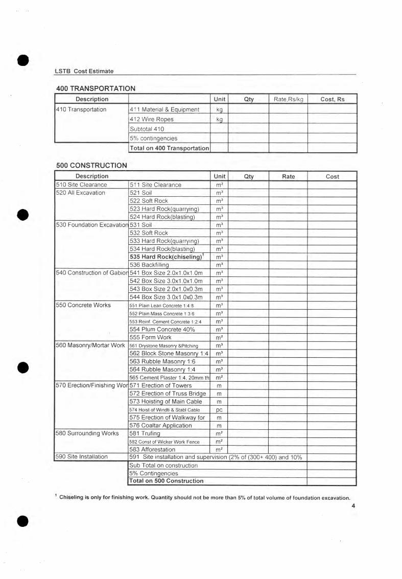
LSTB C os t E stim ate
4 0 0 T R A N S P O R T A T I O N
Description Unit Qty Rate,Rs/kg Cost, Rs410 Transportation 411 Material & Equipment kg
412 Wire Ropes kgSubtotal 4105% contingenciesTotal on 400 Transportation
5 0 0 C O N S T R U C T I O N
Description Unit Qty Rate Cost510 Site Clearance 511 Site Clearance m2520 All Excavation 521 Soil m3
522 Soft Rock m3523 Hard Rock(quarrying) m3524 Hard Rock(blasting) m3
530 Foundation Excavation 531 Soil m3532 Soft Rock m3533 Hard Rock(quarrying) m3534 Hard Rock(blasting) m3535 Hard Rock(chiseling)1 m3536 Backfilling m3
540 Construction of Gabion 541 Box Size 2.0x1.0x1.0m m3542 Box Size 3.0x1.0x1.0m m3543 Box Size 2.0x1.0x0.3m m3544 Box Size 3.0x1.0x0.3m m3
550 Concrete Works 551 P la in Lean C on cre te 1:4:8 m3552 P la in M ass C oncre te 1:3:6 m3553 R ein f. C e m e n t C on cre te 1:2:4 m3554 Plum Concrete 40% m3555 Form Work m2
560 Masonry/Mortar Work 561 D rys tone M ason ry & P itch ing m3562 Block Stone Masonry 1:4 m3563 Rubble Masonry 1:6 m3564 Rubble Masonry 1:4 m3565 Cement Plaster 1:4, 20mm th m2
570 Erection/Finishing Wor 571 Erection of Towers m572 Erection of Truss Bridge m573 Hoisting of Main Cable m574 H o is t o f W in d ti & S tab l C ab le pc575 Erection of Walkway for m576 Coaltar Application m
580 Surrounding Works 581 Trufing m2582 C o n s t o f W ic k e r W o rk Fence m2583 Afforestation m2
590 Site Installation 591 Site installation and supervision (2% of (300+ 400) and 10%Sub Total on construction5% ContingenciesTotal on 500 Construction
1 Chiseling is only for finishing work. Quantity should not be more than 5% of total volume of foundation excavation.4

LSTB C ost E stim ate
600 Miscellaneous WorksDescription Unit Quantity Rate Cost
610 Gabion Works 611 Dismantling of Gabion Bo> m3
620 Concret & Masonry Wo 621 Dismantling of Masonry St m3
622 Dismantling of Concrete S m3
630 Pretensioning/Hoisting 631 Main,handrail, fixation & w m
of Wire Ropes 632 Windtie and stabilizing cat pc
640 Walkway Adjustment 641 Replacing of Suspenders m
642 Adjusting of Suspenders m
643 Replacing of Crossbeams m
644 Adjusting of Crossbeams m
645 Dismantling of Walkway m
646 Refixing of Walkway m
647 Dismantling of Wiremesh l m
648 Replacing of Wiremesh Ne m
650 Finishing Works 651 Retightening of BD Grips,T m
652 Coltar Application m
653 Repainting of Steel Parts m2
660 Miscellaneous 661 Dismantling of Existing Bri- m
Subtotal 610-660
5% Contingencies
Total on 600 Miscellaneous Works
5

H is M a je s ty 's G o v e rn m e n tM in is try o f L o ca l D e v e lo p m e n t
COST ESTIMATE CONSTRUCTION : LIST OF MATERIALS
Bridge No Bridge Name
Span, meters District
Type of Bridge Region
Tower Height River
210 Wire RopesType Pcs No Single
Length,m 0 mm
Length per Type per 0
013mm 026mm 032mm 036mm 040mmMainWindguy UpstreamWindguy DownstreamSpanningHandrailFixationWindtieSidestayStabilizingDiagonal StabilizingWindguy strut fixation
Total Length in metersWeight of cables per m length 0.67 2.57 3.90 4.93 6.09Total weight of cable per 0 in kgTotal WeightPOS CE 211 212 213 214 215
220 Blasting MaterialsDescription Unit Qty POS CEGelatin( 0.25 kg/m3) kgDetonator( 2 pc/m3) pcFuse Wire(2m/m3) m
NAME DESIGNATION SIGNATURE DATE
Verified by
Approved by6
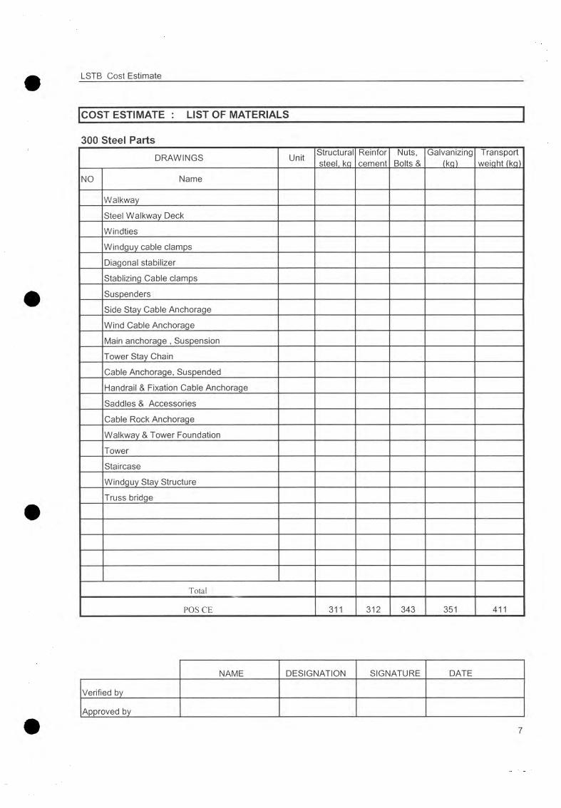
LSTB Cost Estimate
COST ESTIMATE : LIST OF MATERIALS ~ |
300 Steel PartsDRAWINGS Unit Structural
steel, kqReinforcement
Nuts, Bolts &
Galvanizing(kq)
Transport weight (kq)
NO Name
WalkwaySteel Walkway DeckWindtiesWindguy cable clampsDiagonal stabilizerStablizing Cable clampsSuspendersSide Stay Cable AnchorageWind Cable AnchorageMain anchorage , SuspensionTower Stay ChainCable Anchorage, SuspendedHandrail & Fixation Cable AnchorageSaddles & AccessoriesCable Rock AnchorageWalkway & Tower FoundationTowerStaircaseWindguy Stay StructureTruss bridge
Total
POS C E 311 312 343 351 411
NAME DESIGNATION SIGNATURE DATE
Verified by
Approved by
7

LSTB Cost Estimate
|COST ESTIMATE : LIST OF MATERIALS
500 Construction
Item Unit QuantityRequire
mentmentperUnit
Requirement of
Cement(bags)
Sand(m3)
Gravel(m3)
Rubble/ bldr (m3)
Block stone (m3)
540 Construction of Gabions m3 1.10551 Plain Mass Concrete 1:4:8 m3 3.40
0.470.89
552 Plain Mass Concrete 1:3:6 m3 4.400.470.89
553 Rent. Cement Concrete1:2:4 m3 6.400.450.85
554 Plum Concrete 40% m3 2.640.280.540.50
561 Dry Stone Masonry/Pitching m3 1.10562 Block Stone Masonry(1:4) m3 2.28
0.421.10
563 Rubble Masonry(1:6) m3 1.500.471.10
564 Rubble Masonry( 1:4) m3 2.280.451.10
565 Cement Plaster(1:4) m2 0.180.02
TOTAL
540 Gabion wiresMesh Wire 10SWG Selvedge Wire 7i Binding Wire 12SWG
Box Size(m) Volumem3
Require, per m3
Weightkg
Require, per m3
Weightkg
Require, per m3
Weightkg
2.0 x 1.0 x 1.0 12.08 1.58 0.483.0 x 1.0 x 1.0 11.70 1.37 0.432.0 x 1.0 x 0.3 22.33 3.75 1.083.0 x 1.0 x 0.3 21.94 3.33 1.00
TOTALTotal Weight of Gabion Wire (kg)
NAME DESIGNATION SIGNATURE DATE
Verified by
Approved by
8

His Majesty's GovernmentMinistry of Local Development
COST ESTIMATE CONSTRUCTION : SCHEDULE OF WORKS
300 STEEL PARTSDescription Unit Quantity
310 Supply & Fabrication 311 Structural Steel kg312 Reinforcement Steel kg
320 Thimbles 321 0 13mm pc322 0 26mm pc323 0 32mm pc324 0 36mm pc325 0 40mm pc
330 Bulldog Grip 331 0 13mm pc332 0 26mm pc333 0 32mm pc334 0 36mm pc335 0 40mm pc
340 Miscellaneous Supply 341 Wiremesh Netting m2342 Sign Board pc343 Bolts, Nuts, Washers kg344 10 SWG Gl Binding wire kg
350 Rust Prevention 351 Hot Dip Galvanization kg
400 TRANSPORTATIONDescription Unit Quantity
410 Transportation 411 Material and Equipment kg412 Wire Ropes kg
500 CONSTRUCTIONDescription Unit Quantity
510 Site Clearance 511 Site Clearance m2520 All Excavation 521 Soil m3
522 Soft Rock m3523 Hard Rock (quarrying) m3524 Hard Rock (blasting) m3
530 Foundation Excavation 531 Soil m3532 Soft Rock m3533 Hard Rock(quarrying) m3534 Hard Rock(blasting) m3535 Hard Rock(chiseling) m3536 Backfilling m3
9

LSTB Cost Estimate
500 CONSTRUCTIONDescription Unit Quantity
540 Construction of Gabions 541 Box Size 2.0x1.0x1.0 m3542 Box Size 3.0x1.0x1.0 m3543 Box Size 2.0x1.0x0.3 m3544 Box Size 3.0x1.0x0.3 m3
550 Concrete Works 551 Plain Lean Concrete 1:4:8 m3552 Plain Mass Concrete 1:3:6 m3553 Reinf Cement Concrete 1:2:4 m3554 Plum Concrete 40% m3555 Form Work m2
560 Masonry & Mortar Works 561 Dry Stone Masonry & Pitching m3562 Block Stone Masonry 1:4 m3563 Rubble Masonry 1:6 m3564 Rubble Masonry 1:4 m3565 1:4 Cement Plaster 20mm thick m2
570 Erection & Finishing Works 571 Erection of Towers m572 Erection of Truss Bridge m573 Hoisting of Main Cable m574 Hoisting of Windties & Stablizing Cable pc575 Erection of Walkway m576 Coaltar Application m
580 Surrounding Works 581 Turfing m2582 Construction of Wicker Work Fence m2583 Afforestation m2
590 Site Installation Charge 591 Site Installation and Supervision Unit|Total 500 Construction
600 MISCELLANEOUS WORKSDescription Unit Quantity610 Gabion Works 611 Dismantling of Gabion Boxes m3620 Concrete Masonry Works 621 Dismantling of Masonry Structures m3
622 Dismantling of Concrete Structures m3630 Pretensioning/ Hoisting of
Wire Ropes631 Main Cables m632 Windties and Stabilizng Cables pc
640 Walkway Adjustments 641 Replacing of Suspenders pc642 Adjusting of Suspenders m643 Replacing of Cross Beams m644 Adjusting of Cross Beams m645 Dismantling of Walkway m646 Refixing of Walkway m647 Dismantling of Wiremesh Net m648 Replacing of Wiremens Net m
650 Finishing Works 651 Retightening of BD Grips, Nuts etc. m652 Coaltar Application m653 Repainting of Steel parts m2
660 Miscellaneous 661 Dismantling of Existing Bridge m662663664665Total 600 Miscellaneous Work
10

His Majesty’s GovernmentMinistry of Local Development
COST ESTIMATE CONSTRUCTION : RATE ANALYSIS
Description Unit UnitQuantity
Rate UnitCost
Description Dist. Wt Rate Unit Cost
411 Material and Equipment
Transportation by TruckFrom : To:
Metalled Road, km 1.00N on M e ta lle d R o a d , km 1.00
Transportation by Porter (Rate=Daily wage/38) 1,000.00Transportation by AirSubtotalTotal per kg = Subtotal/1000Cost per kg with 15 % overhead and 10 % VAT412 Wire Ropes
Transportation by truckFrom :To:Transportation by Porter
Metalled Road, km 1.00N on M e ta lle d R o a d , km 1.00Rate=Daily W age/15 1,000.00
Transportation by AirSubtotalTotal per kg = Subtotal/1000Cost per kg with 15 % overhead and 10% VAT511 Site Clearance
Labour Unskilled Md. 0.06Cost per sq.m with 15 % overhead & 10% VAT521 All Excavation in Soil
Labour Unskilled Md. 0.80Cost per cu.m with 15 % overhead & 10% VAT522 All Excavation in Soft Rock
Labour Unskilled Md. 1.40Cost per m3 with 15 % overhead & 10% VAT523 All Excavation in Hard Rock by Quarrying
Material Fuel Lt. 2.20Labour Unskilled Md 1.65SubtotalCost per m3 with 15 % overhead & 10% VAT
11

LSTB Cost Estimate
DescriptionUnit Unit
QuantityRate Unit
Cost
524 All Excavation in Hard Rock by BlastingMaterial Fuel Lt 2.20Labour Skilled Md 0.04
Unskilled Md 1.65SubtotalCost per m3 with 15 % overhead & 10% VAT531 Foundation Excavation in SoilLabour Unskilled Md 1.69Cost per m3 with 15 % overhead & 10% VAT532 Foundation Excavation in Soft RockLabour Unskilled Md 2.50Cost per m3 with 15 % overhead & 10% VAT533 Foundation Excavation in Hard Rock by QuarryingMaterial Fuel Lt 4.00Labour Unskilled Md 5.50SubtotalCost per m3 with 15 % overhead & 10% VAT534 Foundation Excavation in Hard Rock by BlastingMaterial Fuel Lt 2.20Labour Skilled Md 0.04
Unskilled Md 4.40SubtotalCost per m3 with 15 % overhead & 10% VAT535 Foundation Excavation in Hard Rock by ChiselingLabour Unskilled Md 25.20Cost per m3 with 15 % overhead & 10% VAT536 Back fillingLabour Unskilled Md 0.85Cost per m3 with 15 % overhead & 10% VAT541 Gabion Box Size 2.0mx1.0mx1.0mMaterial Mesh Wire 10SWG kg 12.08
Selvage Wire 7 SWG kg 1.58Binding Wire 12SWC kg 0.48Rubble m3 1.10
LabourFabrication of Gabions Skilled Md 0.23
Unskilled Md 0.10Construction of Gabions Unskilled Md 0.20SubtotalCost per m3 with 15 % overhead & 10% VAT
12
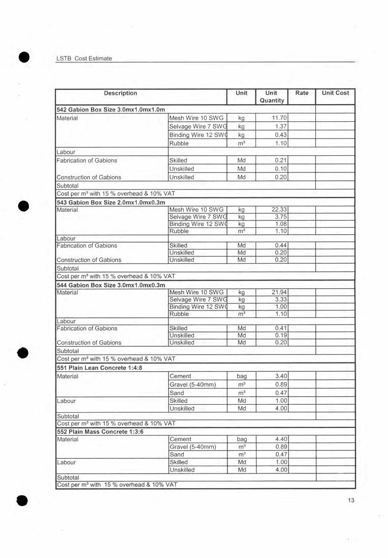
LSTB Cost Estimate
Description Unit UnitQuantity
Rate Unit Cost
542 Gabion Box Size 3.0mx1.0mx1.0mMaterial Mesh Wire 10SWG kg 11.70
Selvage Wire 7 SWG kg 1.37Binding Wire 12SW( kg 0.43Rubble m3 1.10
LabourFabrication of Gabions
Construction of Gabions
Skilled Md 0.21Unskilled Md 0.10Unskilled Md 0.20
SubtotalCost per m3 with 15 % overhead & 10% VAT543 Gabion Box Size 2.0mx1.0mx0.3mMaterial Mesh Wire 10 SWG kg 22.33
Selvage Wire 7 SWG kg 3.75Binding Wire 12SW( kg 1.08Rubble m3 1.10
LabourFabrication of Gabions
Construction of Gabions
Skilled Md 0.44Unskilled Md 0.20Unskilled Md 0.20
SubtotalCost per m3 with 15 % overhead & 10% VAT544 Gabion Box Size 3.0mx1.0mx0.3mMaterial Mesh Wire 10 SWG kg 21.94
Selvage Wire 7 SWG kg 3.33Binding Wire 12 SW( kg 1.00Rubble m3 1.10
LabourFabrication of Gabions
Construction of Gabions
Skilled Md 0.41Unskilled Md 0.19Unskilled Md 0.20
SubtotalCost per m3 with 15 % overhead & 10% VAT551 Plain Lean Concrete 1:4:8Material Cement bag 3.40
Gravel (5-40mm) m3 0.89Sand m3 0.47
Labour Skilled Md 1.00Unskilled Md 4.00
SubtotalCost per m3 with 15 % overhead & 10% VAT552 Plain Mass Concrete 1:3:6Material Cement bag 4.40
Gravel (5-40mm) m3 0.89Sand m3 0.47
Labour Skilled Md 1.00Unskilled Md 4.00
SubtotalCost per m3 with 15 % overhead & 10% VAT
13

LSTB Cost Estimate
Description Unit UnitQuantity
Rate Unit Cost
553 Reinforced Cement Concrete 1:2:4Material Cement bag 6.40
Gravel (5-40mm) m3 0.85Sand m3 0.45
Labour Skilled Md 1.00Unskilled Md 4.00
SubtotalCost per m3 with 15 % overhead & 10% VAT554 Plum Concrete 40%Material Cement bag 2.64
Gravel (5-40mm) m3 0.54Sand m3 0.28Boulders(225 mm) m3 0.50
Labour Skilled Md 0.50Unskilled Md 4.00
SubtotalCost per m3 with 15 % overhead & 10% VAT555 Form WorkMaterial Wood m3 0.01
Nails kg 0.03Labour Skilled Md 0.78
Unskilled Md 0.62SubtotalCost per mA2 with 15 % overhead & 10% VAT561 Dry Stone Masonry or PitchingMaterial Rubble m3 1.10Labour Skilled Md 1.00
Unskilled Md 2.00SubtotalCost per m3 with 15 % overhead & 10% VAT562 Block Stone Masonry 1:4Material Cement bag 2.28
Sand m3 0.42Dressed/Stratified Blc m3 1.10
Labour Skilled Md 1.50Unskilled Md 3.00
SubtotalCost per m3 with 15 % overhead & 10% VAT563 Rubble Masonry 1:6Material Cement bag 1.50
Sand m3 0.47Rubble m3 1.10
Labour Skilled Md 1.50Unskilled Md 5.00
SubtotalCost per m3 with 15 % overhead & 10% VAT
14
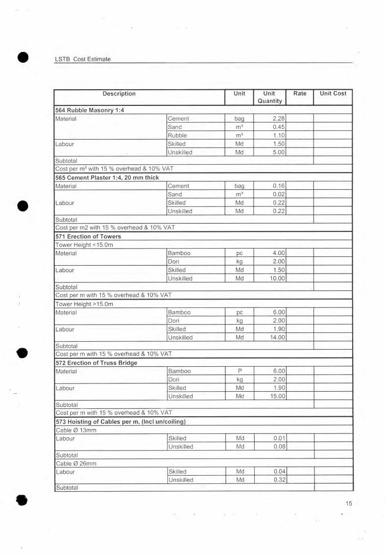
LSTB Cost Estimate
Description Unit UnitQuantity
Rate Unit Cost
564 Rubble Masonry 1:4Material Cement bag 2.28
Sand m3 0.45Rubble m3 1.10
Labour Skilled Md 1.50Unskilled Md 5.00
SubtotalCost per m3 with 15 % overhead & 10% VAT565 Cement Plaster 1:4, 20 mm thickMaterial Cement bag 0.16
LabourSand m3 0.02Skilled Md 0.22Unskilled Md 0.22
SubtotalCost per m2 with 15 % overhead & 10% VAT571 Erection of TowersTower Height <15.0mMaterial Bamboo pc 4.00
Dori kg 2.00Labour Skilled Md 1.50
Unskilled Md 10.00SubtotalCost per m with 15 % overhead & 10% VATTower Height >15.0mMaterial Bamboo pc 6.00
Dori kg 2.00Labour Skilled Md 1.90
Unskilled Md 14.00SubtotalCost per m with 15 % overhead & 10% VAT572 Erection of Truss BridgeMaterial Bamboo P 6.00
Dori kg 2.00Labour Skilled Md 1.90
Unskilled Md 15.00SubtotalCost per m with 15 % overhead & 10% VAT573 Hoisting of Cables per m, (Incl un/coiling)Cable 0 13mmLabour Skilled Md 0.01
Unskilled Md 0.08SubtotalCable 0 26mmLabour Skilled Md 0.04
Unskilled Md 0.32Subtotal
15
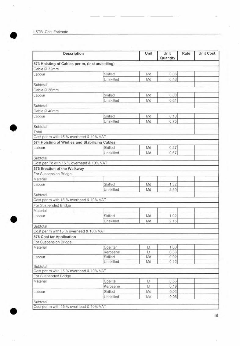
LSTB Cost Estimate
Description Unit UnitQuantity
Rate Unit Cost
573 Hoisting of Cables per m, (Incl un/coiling)Cable 0 32mmLabour Skilled Md 0.06
Unskilled Md 0.48SubtotalCable 0 36mmLabour Skilled Md 0.08
Unskilled Md 0.61SubtotalCable 0 40mmLabour Skilled Md 0.10
Unskilled Md 0.75SubtotalTotalCost per m with 15 % overhead & 10% VAT574 Hoisting of Winties and Stabilizing CablesLabour Skilled Md 0.27
Unskilled Md 0.67SubtotalCost per Pc with 15 % overhead & 10% VAT575 Erection of the WalkwayFor Suspension BridgeMaterialLabour Skilled Md 1.32
Unskilled Md 2.50SubtotalCost per m with 15 % overhead & 10% VATFor Suspended BridgeMaterialLabour Skilled Md 1.02
Unskilled Md 2.15SubtotalCost per m with 15 % overhead & 10% VAT576 Coal tar ApplicationFor Suspension BridgeMaterial Coal tar Lt 1.00
Kerosene Lt 0.33Labour Skilled Md 0.02
Unskilled Md 0.12SubtotalCost per m with 15 % overhead & 10% VATFor Suspended BridgeMaterial Coal ta Lt 0.56
Kerosene Lt 0.19Labour Skilled Md 0.03
Unskilled Md 0.06SubtotalCost per m with 15 % overhead & 10% VAT
16

LSTB Cost Estimate
Description Unit UnitQuantity
Rate Unit Cost
581 TurfingMaterial Fertilizer kg 0.07Labour Unskilled Md 0.20SubtotalCost per m2 with 15 % overhead & 10% VAT582 Construction of Wicker Work FenceWith BrushwoodLabour Unskilled Md 0.20Cost per m with 15 % overhead & 10% VAT583 AfforstationMaterial Saplings P 0.30
Barbed Wire and Pol Md 1.00Labour Unskilled Md 0.02SubtotalCost per m with 15 % overhead & 10% VAT611 Dismantling of Gabion BoxesLabour Unskilled Md 3.00Cost per m3 with 15 % overhead & 10% VAT621 Dismantling of Masonry StructuresLabour Unskilled Md 2.20Cost per m3 with 15 % overhead & 10% VAT622 Dismantling of Concrete StructuresMaterial Fuel Lt 4.00Labour Unskilled Md 26.00SubtotalCost per m3 with 15 % overhead & 10% VAT631 Pretensioning / Hoisting of Windguy, Spanning, Handrail & Fixation CablesCable 13 mmLabour Pretensioning Skilled Md 0.01
Unskilled Md 0.01SubtotalCost per m with 15 % overhead & 10% VATCable 26-40 mmLabour Loosening Skilled Md 0.01
Unskilled Md 0.02Labour Pretensioning Skilled Md 0.01
Unskilled Md 0.05SubtotalCost per m with 15 % overhead & 10% VAT
17
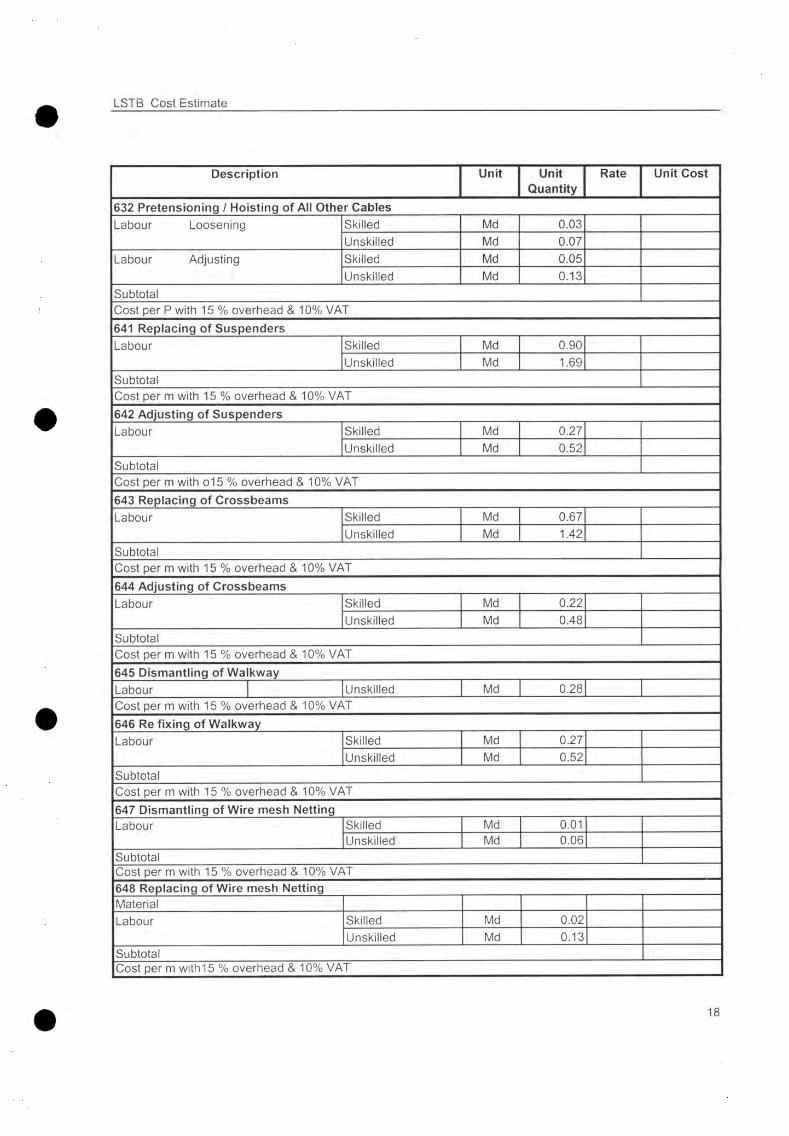
LSTB Cost Estimate
Description Unit UnitQuantity
Rate Unit Cost
632 Pretensioning / Hoisting of All Other CablesLabour Loosening Skilled Md 0.03
Unskilled Md 0.07Labour Adjusting Skilled Md 0.05
Unskilled Md 0.13SubtotalCost per P with 15 % overhead & 10% VAT641 Replacing of SuspendersLabour Skilled Md 0.90
Unskilled Md 1.69SubtotalCost per m with 15 % overhead & 10% VAT642 Adjusting of SuspendersLabour Skilled Md 0.27
Unskilled Md 0.52SubtotalCost per m with o15 % overhead & 10% VAT643 Replacing of CrossbeamsLabour Skilled Md 0.67
Unskilled Md 1.42SubtotalCost per m with 15 % overhead & 10% VAT644 Adjusting of CrossbeamsLabour Skilled Md 0.22
Unskilled Md 0.48SubtotalCost per m with 15 % overhead & 10% VAT645 Dismantling of WalkwayLabour Unskilled Md 0.28Cost per m with 15 % overhead & 10% VAT646 Re fixing of WalkwayLabour Skilled Md 0.27
Unskilled Md 0.52SubtotalCost per m with 15 % overhead & 10% VAT647 Dismantling of Wire mesh NettingLabour Skilled Md 0.01
Unskilled Md 0.06SubtotalCost per m with 15 % overhead & 10% VAT648 Replacing of Wire mesh NettingMaterialLabour Skilled Md 0.02
Unskilled Md 0.13SubtotalCost per m with 15 % overhead & 10% VAT
18

LSTB Cost Estimate
Description Unit UnitQuantity
Rate Unit Cost
651 Retightening of Bulldog Grips, Nuts, etc.Labour Unskilled Md 0.10Cost per m with overhead and contract tax652 Coaltar ApplicationMaterial Coal tar Lt 0.59
Kerosene Lt 0.20Labour Skilled Md 0.02
Unskilled Md 0.07SubtotalCost per m with 15 % overhead & 10% VAT653 Repainting of Steel PartsLabourPreparation of Surface
Skilled Md 0.01Unskilled Md 0.16
Material 1 Base Coat Labour
Red Oxide Zinc Chro Lt 0.13Skilled Md 0.08Unskilled Md 0.07
Material Finishing Coat Polythene Enamel Lt 0.10Labour Skilled Md 0.09
Unskilled Md 0.10Subtotal
550/560 SandLabour Collection of Sand Unskilled Md 1.49Washing of Sand Additional Haulage, m
Unskilled MdUnskilled Md 0.01
Cost per m3540-560 Rubble, BoulderLabour [Collection of Rubble Boulder Additional Haulage,m
Unskilled Md 0.77Unskilled Md 0.02
Cost per m3550 GravelLabounCollection of natural Gravel Breaking of Gravel, %Additional Haulage, m
Unskilled Md 4.00Unskilled Md 14.60Unskilled Md 0.01
Cost per m3560 Block StoneLabour Collection & Dressing Additional Haulage
Unskilled Md 5.63Unskilled Md 0.02
Cost per m3
19
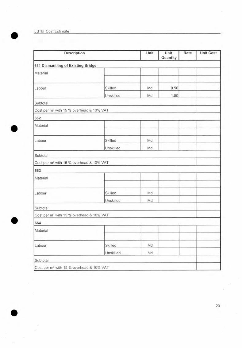
LSTB Cost Estimate
Description Unit UnitQuantity
Rate Unit Cost
661 Dismantling of Existing Bridge
Material
Labour Skilled Md 0.50
Unskilled Md 1.50
Subtotal
Cost per m3 with 15 % overhead & 10% VAT
662
Material
Labour Skilled Md
Unskilled Md
Subtotal
Cost per m3 with 15 % overhead & 10% VAT
663
Material
Labour Skilled Md
Unskilled Md
Subtotal
Cost per m3 with 15 % overhead & 10% VAT
664
Material
Labour Skilled Md
Unskilled Md
Subtotal
Cost per m3 with 15 % overhead & 10% VAT
20
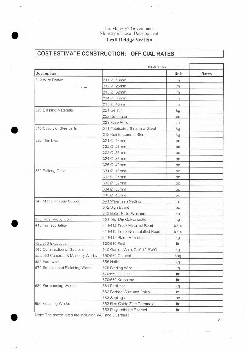
His Majesty’s Government Ministry o f Local Development
Trail Bridge Section
COST ESTIMATE CONSTRUCTION: OFFICIAL RATES
FISCAL YEAR
Description Unit Rates210 Wire Ropes 211 0 13mm m
212 0 26mm m
213 0 32mm m
214 0 36mm m
215 0 40mm m
220 Blasting Materials 221 Gelatin kg
222 Detonator pc223 Fuse Wire m
310 Supply of Steelparts 311 Fabricated Structural Steel kg312 Reinforcement Steel kg
320 Thimbles 321 0 13mm pc322 0 26mm pc323 0 32mm pc324 0 36mm pc325 0 40mm PC
330 Bulldog Grips 331 0 13mm PC
332 0 26mm pc
333 0 32mm pc334 0 36mm PC
335 0 40mm PC
340 Miscellaneous Supply 341 Wiremesh Netting m 2
342 Sign Board PC343 Bolts, Nuts, Washers kg
350 Rust Prevention 351 Hot Dip Galvanization kg410 Transportation 411/412 Truck Metalled Road txkm
411/412 Truck Nonmetalled Road txkm411/412 Plane/Helicopter kg
520/530 Excavation 520/530 Fuel Itr540 Construction of Gabions 540 Gabion Wire, 7,10,12 SWG kg550/560 Concrete & Masonry Works 550/560 Cement bag555 Formwork 555 Nails kg
570 Erection and Finishing Works 575 Binding Wire kg
570/650 Coaltar Itr570/650 Kerosene Itr
580 Surrounding Works 581 Fertilizer kg
582 Barbed Wire and Poles m
583 Saplings PC
650 Finishing Works 653 Red Oxide Zinc Chromate Itr653 Polyurethane Enamel Itr
Note: The above rates are including VAT and Overhead21

Volume A Long Span Trail Bridge Standard
12.6 Survey Form and Checklist
Chapter 12: Appendix

His Majesty’s GovernmentMinistry o f Local Development
Department o f Local Infrastructure D evelopm ent and Agricultural RoadsTrail Bridge Section
S U R V E Y F O R M and C H E C K L I S T
ForDetail Survey of Long Span Trail (LSTB) Bridge
Bridge Number
Bridge Name
District
River
Surveyed by
Date
Kim. July 2004/G R

His Majesty’s GovernmentMinistry o f Local Development
Department o f Local Infrastructure D evelopm ent and Agricultural RoadsTrail Bridge Section
SURVEY FORM
Bridge Number : Name :
Span* & Type : River :
Coordinates
N : E :
Map N o. : A ltitude :
Left Bank Right Bank
V illage : V illage :
District : District :
Region : R egion :
N am e Signature Date
Surveyed by:
Checked by:
Approved by:
* approximate span and type o f bridge

LSTB Survey Form TBS/DoLIDAR
Table of Content
1. Introduction..................................................................................................................... 3
2. Socio-Economic Data......................................................................................................4
2.1 Traffic Counting/Expected Tim e S av in g ............................................................................42.2 Poverty O rientation......................................................................................................................6
3. Feasibility Survey........................................................................................................... 7
3.1 Site S e lec tio n ................................................................................................................................. 73.2 Local Support o f the Project.................................................................................................... 73.3 Type o f R iver................................................................................................................................. 73.4 Existence o f Local Bridge or C rossin g .............................................................................. 83.5 A vailability and Cost o f Construction M aterials............................................................ 83.6 Labor District R ates.....................................................................................................................83.7 A ccessib ility , D istan ces............................................................................................................. 8
4. Geological and Geotechnical survey...........................................................................9
4.1 Rocky Bank and S lo p e .............................................................................................................. 94.2 Soil Bank and S lo p e ................................................................................................................... 94.3 Soil Test Pit D im en sion .............................................................................................................94 .4 Sam pling.......................................................................................................................................... 9
5. Topographical Survey..................................................................................................10
5.1 Description o f Pegs and B ench-M arks............................................................................. 105.2 Triangulation and Elevation o f Pegs and B ench-M arks............................................ 115.3 Tacheom etric Survey ................................................................................................................11
6. Preliminary Design....................................................................................................... 11
6.1 High Flood L ev e l........................................................................................................................116.2 Sketch o f the bridge and the bridge s i t e .........................................................................116.3 Preliminary D esign Data..........................................................................................................12
7. Photographs................................................................................................................... 12
8. Compilation of Data and Reporting.........................................................................13
8.1 Feasibility and site se lec tion .................................................................................................. 138.2 G eological Survey and Determ ination o f D esign Param eters.................................138.3 Topographical Survey, preliminary design and photographs.................................. 13

TBS/DoLIDAR LSTB Survey Form
1. Introduction
This Survey Check List is prepared for experienced consultants and T B S /S B D engineers. The surveyor should be very fam iliar w ith the standard design, “Survey, D esign and Construction o f Trail Suspension Bridges for Rem ote Areas” developed by Trail Bridge Section /Suspension Bridge D iv ision and H elvetas. In addition, the surveyor must have the basic know ledge in the art o f engineering geology. He must be able to judge whether a site is feasib le or geo log ica lly risky. In the latter case, an Engineer G eologist is necessary to carry out a detailed geological study. In such exceptional cases, the Engineer G eologist o f T B S /S B D w ill provide the additional required information.
Prior to v isiting the site, the “Preliminary Survey Report” prepared by the Engineer G eologist, T B S /S B D has to be studied. W ithout such report, no survey should be carried and the works w ill also not be accepted by the Trail Bridge Section/Suspension Bridge D ivision .
The fo llow ing M anuals and Check-Lists are required for executing a survey according to the requirements o f T B S/SB D :
Survey and D esign and Construction o f Trail Suspension Bridges for Rem ote Areas: V olum e A: D esign , revised version
Survey and D esign and Construction o f Trail Suspension Bridges for Rem ote Areas: V olum e B: Survey
Check-List N o. 1
Check-List N o. 2
Check-List N o. 3
Check-List N o. 4
Check-List N o. 5
Check-List N o. 6
Check-List N o. 7
Check-List N o. 8
Check-List N o. 9
Preliminary Study For Alternative Sites
Slope study & Site Selection
Rock Investigation
G eological Plane Investigation (GPI)
Transit C ross-Profile
Soil Investigation
Triangulation
Summary O f Triangulation And Elevations
T acheom etry
Check-List No. 10 Design Parameters
The surveyor is requested to fo llow the instructions very precisely. In case o f an incom plete or w rong survey, refer in particularly to Chapter 7 below , The office w ill strictly not accept and approve such submitted jobs.

LSTB Survey Form TBS/DoLIDAR
2. Socio-E conomic Data
2.1 Traffic Counting/Expected Time SavingTraffic counting has to be conducted at the traditional crossing point/s for at least three consecutive days. If, in case the proposed crossing site is not being used by the traffic due to unavailability or risky river crossing facility (bridge, ferry, cable car, temporary bridge) the traffic study has to be conducted at the nearest crossing site at the upstream or downstream o f the river. The average daily traffic o f the proposed crossing site should be interpreted based on the origin and destination survey with proper justification.
Expected tim e saving after bridge construction should be estim ated on the basis o f detouration o f the crossing point at present.
Date and day o f traffic su rvey:____________________ tim e (F r o m .................... T o ................. )
Human Traffic
s.N.
Traffic category (numbers)Origin Destination Remarks
Expected time saving after bridge construction
Porters Travellers
Male Female
1.
2.
3.
4.
5.
6.
7.
8.
9.
10.
11.
12.
13.
14.
Total
4

TBS/DoLIDAR LSTB Survey Form
Animal Traffic
s .N.
Traffic category (numbers)Origin Destination Remarks
Expected time saving after
bridge construction
Porters Animals
1.
2.
3.
4.
5.
6.
7.
8.
9.
10.
11.
12.
13.
14.
Total
Note: Cattle, mules, buffaloes, horses: 1 unitGoats, sheep: '/a unit
5

LSTB Survey Form TBS/DoLIDAR
2.2 Poverty OrientationIdentify number o f people and households w ho are below the poverty line (those w ho have daily per capita incom e less than U S $ 1) w ithin the influence area o f the proposed bridge. Investigate the p ossib le positive or negative impact on these people due to the construction o f the proposed bridge. R ecom m end measure to m in im ize negative impact on the poor.
H ousehold with daily per capita incom e less than U S $ 1 =
H ousehold with daily per capita incom e > U S $ 1 =
Total household
P ossib le Negative im pacts on the poor:
Possible Positive impacts on the poor:
Recom m end Measures to m inim ize negative impacts on the poor:
6

TBS/DoLIDAR LSTB Survey Form
3. Feasibility Survey
3.1 Site SelectionCarry out feasib ility studies o f at least three alternative sites in concordance w ith the “Preliminary Survey Report”.For all three sites do the follow ing:
• Fill in Check List No. 1: Preliminary Study for Alternative Sites• Draw a sketch and a cross section o f each alternative site, include the trail system
and trails to be build in future, existing and planned roads, present and future river crossings, distribution o f population, etc.
• Take photographs i.e. an overall v iew and both banks
Select the best site by considering criteria like trail system , span, type o f bridge, bank and slope conditions, structure o f rocks, etc.
D ecide whether a detailed geologica l investigation is required. I f not, continue w ith the detailed survey. I f yes, an Engineer G eologist is necessary to carry out the detailed geological and topographical survey.
3.2 Local Support of the ProjectD o the local people agree with the selected site? Interview at least three beneficiaries, V D C and D D C m em bers, etc.
N o N am e Address Function Remarks
1
2
3
4
5
6
7In addition, get a letter o f confirm ation regarding the site selection from the D D C Chairman.
3.3 Type of RiverReport the nature o f the river at the crossing point based on the fo llow ing sim ple classification:□
□□
Major
Medium
Minor
=> Unfordable throughout the year
=> Fordable at som e places during dry season with d ifficu lties or with temporary, bridges
=> Easily fordable during dry season
7

LSTB Survey Form TBS/DoLIDAR
3.4 Existence of Local Bridge or CrossingD escribe the existing bridge or crossing ( i f any):
Bridge Type : _________________________ Span (m ) : ___________
Year o f Construction : _________________________ Free-Board (m ) : ___________
Actual condition o f Bridge : ________________________________________
Constructed by : ________________________________________
Organization responsible for m aintenance : ________________________________________
Replacem ent : □ N ecessary □ N ot necessary
Attach a sketch, m ake photographs (overall v iew , relevant details).
3.5 Availability and Cost of Construction MaterialsCost Item Description Rates Haulage RemarksEstimate DistancePos. No. NC Unit meter550/60 Sand540/50/60 Rubble, Boulders555 Wood for Form
workm3
571/72 Bamboo pc571/72 Dori kg
3.6 Labor District RatesCost Estimate Pos. No.
Item Description RatesRemarks
NC Unit500/600 Skilled Labor md500/600 Unskilled Labor md410 Porter md
3.7 Accessibility, DistancesExisting distances:
Nearest NameDistances
Miles Porterdays
Roadhead(Trucks)Roadhead (Tractors)Airport
From w hich source are this information ?
8

TBS/DoLIDAR LSTB Survey Form
W ill in future a new road be build or planned? If yes, g ive the fo llow in g information:
Nearest NameDistances
Miles Porterdays
Roadhead (Trucks)Roadhead (Tractors)
Planned date o f co m p letio n :____________From w hich source are this information?
4. Geological and G eotechnical survey
Study carefully and fill in the respective Check-Lists as indicated in the “Preliminary Survey Report”.
4.1
4.2
4.3
Rocky Bank and Slope• Check List No. 2:• Check List No. 3:• Check List No. 4:
• Cheek List No. 5:• Check List No. 6:
Slope Study & Site Selection, for each bank Rock Investigation, for each rock sam ple Geological Plane Investigation,for exposed rock around the anchorage b locks and banks Transit Cross Profile, for geologica l d ifficult banks Soil Investigation,for open test pits, i f the rock is covered by soil
Soil Bank and Slope• Check List No. 2: Slope Study & Site Selection, for each bank• Check List No. 6: Soil Investigation,
for each main anchorage b lock and tower foundation
Soil Test Pit DimensionThe m inim um length and breadth o f the pit should be 0 .80 x 1.50 meter.
The depth for soil anchorages must be at least 2 .00 meter for tower foundations and main anchorages and 1.50 meter for w indguy anchorages or at least up to the estim ated foundation base or below to the rock face. For h ighly weathered and fractured rock surfaces, the depth must be up to the fresh rock.
4.4 SamplingIn order to be able to determine the soil and rock parameters the fo llow in g sam ples are essential and must therefore be transported back to the head office:
Rock : One fresh sam ple from each anchorage and bank for each different type o frock. And, one sam ple for different grade o f weathering.
Soil : One m ixed sam ple1 from top to bottom and, one sam ple1 from the bottomlayer o f the pit for each pit.
1 Take at least 1.5 kg per sample for visual classification and at least 2.5 kg for laboratory test i.e. sieve analysis, atterberg limits and shear test. Fill soil sample tag for each sample and bind it to the sample bag.
9

LSTB Survey Form TBS/DoLIDAR
5. Topographical Survey
5.1 Description of Pegs and Bench-MarksDraw a sketch and describe the pegs by indicating type o f peg, distances, angles and azimuths.
R i g h t B a n kPoint Marking Elevation
Le f t B a n kPoint Marking Elevation
Indicate distances, azim uths, angles, north direction and flow o f river.
10

TBS/DoLlDAR LSTB Survey Form
5.2 Triangulation and Elevation of Pegs and Bench-MarksRefer to Check-List Nos. 7 and 8.
• The base distance “d” must be at least 20 % o f the distance D• The distance “d” must be accurately measured horizontally. M easure it several
tim es and take the mean• The triangulation has to be made tw ice, i f the difference o f D is m ote than 0.25% ,
repeat it• If D < 150 meter: The triangulation can be made in one section• If D > 150 meter: The distance d has to be divided into two sections. Ref. V olum e
B: Survey, page 189• M ake all the calculation before continuing with the tacheom etric survey
5.3 Tacheometric SurveyRefer to Check-List No. 9.
• Based on the preliminary design, refer to paragraph 5 below , the area to be covered by the detailed survey can be determined
• The sta ff must be kept in a vertical position. A slight inclination from the vertical w ill result in a large error in the distance
• Special attention has to be paid to the area near the proposed anchorage blocks, at breaking points o f the terrain, paddy fields, existing local crossings, drainage, trails, houses, big boulders, etc.
• Tacheom etric reading has to be made for triangulation points, reference points and bench marks for cross checking purpose
• The location and elevation o f the soil test pits and rock outcrops have to be measured
• Set up the theodolite on permanent pegs only
6. Pr e l im in a r y D e sig n
Refer to LSTB Technical Manual,Volume B : Survey, chapter 6.5 for detailed information.
6.1 High Flood LevelSince in remote areas hydrological data are norm ally not available, the design flood level has to be based on the highest ascertainable historic flood level by inquiry am ong local inhabitants and com m ented by observations at the site by flood marks on the river banks, presence o f forests, etc.
6.2 Sketch of the bridge and the bridge siteMeasure a profile in the axis line A -B by using the tacheometric method. Draw a sketch o f the site in scale 1:500 in plan and cross section with all important information.

LSTB Survey Form TBS/DoLIDAR
6.3 Preliminary Design DataSuspended Bridge: Span range
Span intervals Dead load sag
Suspension Bridge: Span range Span intervals Camber Dead load sag
20 - 350 meter span = 1.2 i fd = span/23
30 - 280 meter span = 2 .40 i + 2 .20 cd = 3 % o f span fd = 12 % o f span
Anchorages/Foundations: The approxim ate position must be determined.
Wind bracings:
Free-Board:
The approxim ate layout including the location o f the anchorages m ust be detennined for spans exceed ing 50 meters.
D eterm ine the elevation o f the bridge including the wind bracings in such a w ay that the m inim um freeboard o f five meter is maintained.
Special Design: In special topographic conditions, m odifications o f thestandard bridges m ay be required. There are different possib ilities o f adopting the design to the specific site conditions like tunnel anchorages, suspension bridges with one tower, etc. For further details refer to LSTB Technical M anual, V olum e A: Design.
7. P h o t o g r a p h s
For the Bridge Record o f the District and the internal checking propose good photographs are very essential. Therefore, a survey without sufficient and good photos w ill not be accepted by the office.
The fo llow in g photographs have to be taken:
• Overall v iew , anchorages, walkway, etc. o f the existing crossing, i f any• Overall v iew o f the bridge site from downstream and upstream• Overall v iew o f the right and left bank• Position all foundations and anchorages• Soil test pits and locations where rock sam ples are taken. Do not forget to put the
staff or a scale in v isib le position for references
If one picture does not cover the necessary area, take several pictures from the sam e spot with sufficient overlapping.
12

TBS/DoLlDAR LSTB Survey Form
8. C o m p il a t io n o f D a t a a n d R e p o r t in g
The survey report has to be in concordance with the fo llow in g structure and it mustcontain the fo llow ing information:
8.1 Feasibility and site selection1) C om plete Check List N o. 1: Preliminary Study for Alternative S ites for all sites2) Draw a sketch and a cross section o f each alternative site, include the trail
system and trails to be build in future, existing and planned roads, present and future river crossings, distribution o f population, etc.
3) D escribe each alternative site separately and com pile the photographs4) G ive a detailed justification , pros and cons, o f the selected site5) D escribe the existing trail system and compare it with the situation after the new
bridge w ill be built6) Make your ow n firm judgm ent with regard to the feasib ility o f the proposed
bridge site in terms o f socio -econ om ic as w ell as technical as aspects.
8.2 Geological Survey and Determination of Design Parameters7) C om plete Check List N o. 28) C om plete Check List N o. 39) C om plete Check List N o . 4
10) C om plete Check List N o. 5:
S lope Study & Site Selection, for each bank Rock Investigation, for each rock sam ple G eological Plane Investigation, for exposed rock around the anchorage b locks and banks; Transit Cross Profile, for geologica l d ifficult banks
11) C om plete Check List N o. 6: Soil Investigation, for each open test pit12) For rocky banks carry out a stability analysis according to V olum e B: Survey,
chapter 5.4113) Submit all soil and rock sam ple, ref. Chapter 3.4 above. G ive reference numbers
where geologica l data and/or sam ples were collected14) Fill in Check List N o. 10: D esign Parameters15) M ake a report with com m ents on the detailed geological survey with em phasis
on the geological lim its and possib le failures o f the slopes and banks
8.3 Topographical Survey, preliminary design and photographs16) Com plete Check List N o. 7: Triangulation17) C om plete Check List N o. 8: Summary o f Triangulation and Elevations18) C om plete Check List N o. 9: Tacheom etry19) Com plete the preliminary bridge design and g ive recom m endation for the design20) Plot the contour line map and a section along the bridge axis in scale 1: 200 on a
white paper with 0 .60 meter width. Indicate permanents pegs, bench-marks, location o f soil test pit, existing crossings, trails, etc
21) Com pile all photographs. G ive a com m ent, indicating all the features o f the picture
13

TBS/DoLIDAR LSTB Survey Check List
GEOLOGICAL AND SURVEY CHECK LISTS
FORLSTB BRIDGE
C h e c k L i s t N o . 1 : P p r e l i m i n a r y S t u d y f o r A l t e r n a t i v e
C h e c k L i s t N o .2
S i t e s
: S l o p e S t u d y & S i t e S e l e c t i o n
C h e c k L i s t N o .3 : R o c k In v e s t i g a t i o n
C h e c k L i s t N o .4 : G e o l o g i c a l P l a n e In v e s t i g a t i o n
(G PI)
C h e c k L i s t N o .5 : T r a n s i t C r o s s P r o f i l e
C h e c k L i s t N o .6 : S o i l In v e s t i g a t i o n
C h e c k L i s t N o .7 : T r i a n g u l a t i o n
C h e c k L i s t N o .8 : S u m m a r y o f T r i a n g u l a t i o n a n d
E l e v a t i o n s
C h e c k L i s t N o .9 : T a c h e o m e t r y
C h e c k L is t N o . 10 : D esign Param eters

TBS/DoLIDAR LSTB Survey Check List
CHECK LIST NO. 1: PRELIMINARY STUDY FORALTERNATIVE SITES
Bridge Num ber : N am e :
Alternative Site N o. : Approx. Span :
Approx, distance from the traditional existing crossing point :
S.N Description Comment R/B L/B Comment R/B L/B1. River Bank Erosion Present Absent
2. River Current Striking Bank Straight
3. Vegetation Heavy Light
4. Landslides Present Absent
5. Slope Type Soil Rock
6. Steepness: Soil < 35° > 35°
7. Steepness: Rock < 50° > 50°
8. Seepage Present Absent
9. Springs Present Absent
10. Swampy Area Present Absent
11.. Erosions Present Absent
12. Inclined Trees Present Absent
13. Rivulets Present Absent
14. Cliff/s (Soil/Rock) Present Absent
15. Others (Specify)
16.
17.
M ake your ow n judgem ent, evaluate the bridge site :
Right bank is : Good Fair Q uestionable
Left bank is : Good Fair Q uestionable
15

TBS/DoLIDAR LSTB Survey Check List
CHECK LIST NO. 1: PRELIMINARY STUDY FORALTERNATIVE SITES
Bridge Num ber : N am e :
Alternative Site N o. : Approx. Span :
Approx, distance from the traditional existing crossing point :
S.N Description Comment R/B L/B Comment R/B L/B
1. River Bank Erosion Present Absent
2. River Current Striking Bank Straight
3. Vegetation Heavy Light
4. Landslides Present Absent
5. Slope Type Soil Rock
6. Steepness: Soil < 35° > 3 5 °
7. Steepness: Rock < 50° > 5 0 °
8. Seepage Present Absent
9. Springs Present Absent
10. Swampy Area Present Absent
11.. Erosions Present Absent
12. Inclined Trees Present Absent
13. Rivulets Present Absent
14. Cliff/s (Soil/Rock) Present Absent
15. Others (Specify)
16.
17.
M ake your ow n judgem ent, evaluate the bridge site :
Right bank is : Good Fair Q uestionable
Left bank is : Good Fair Q uestionable
16

TBS/DoLIDAR LSTB Survey Check List
CHECK LIST NO. 1: PRELIMINARY STUDY FORALTERNATIVE SITES
Bridge Num ber : N am e :
Alternative Site N o. : Approx. Span :
Approx, distance from the traditional existing crossing point :
S.N Description Comment R/B L/B Comment R/B L/B
1. River Bank Erosion Present Absent
2. River Current Striking Bank Straight
3. Vegetation Heavy Light
4. Landslides Present Absent
5. Slope Type Soil Rock
6. Steepness: Soil <35° >35°7. Steepness: Rock <50° >50°8. Seepage Present Absent
9. Springs Present Absent
10. Swampy Area Present Absent
11.. Erosions Present Absent
12. Inclined Trees Present Absent
13. Rivulets Present Absent
14. Cliff/s (Soil/Rock) Present Absent
15. Others (Specify)
16.
17.
M ake your ow n judgem ent, evaluate the bridge site :
Right bank is : Good Fair Q uestionable
Left bank is : Good Fair Q uestionable
17

TBS/DoLIDAR LSTB Survey Check List
CHECK LIST NO. 2: SLOPE STUDY & SITE SELECTION
Bridge Num ber : N am e :
Bank : Approx, span :
Azim uth o f bridge axis : Azim uth o f river flow :
S lope type :
Approx, distance from the traditional existing crossing point :
This Check List has to be filled in after selecting the best site by using Check List N o. 1.
A) SLOPE AND RIVER BANK DESCRIPTION
General aspect of the slope: Sm ooth
Cut-out
Partially cut-out
Strongly cut-out
Average inclination and dimensions of:
River bank : __________ 0 S lope : ________ 0
Height o f bank : m Length o f slope : m
Breadth o f slope : m
General slope profile :
¿Ha ¿3 aShape of transverse section of the slope :
□ a a □ □ D □
General river bank profile :
18

TBS/DoLIDAR LSTB Survey Check List
Rock out crops or scarps on slope and bank:
Slope : Sparse Moderate Num erous
Bank : Sparse M oderate Num erous
Vegetation cover on the slope: H eavyM oderate
FewN one
Deforestation: H eavyM oderate
LightN one
Paddy field: Location : PresentAbsent
Irrigation channel: Location : PresentAbsent
B )
C)
RIVER
Flow type:
Fordability:
Erosiveness:
INSTABILITY FEATURES
Bank erosion :
Gully erosion:
Sheet erosion:
Water run off on the slope :
Perennial CalmN on perennial
FordableNon-fordable
H ighly erosive
T urbulent
Fordable in dry season
N onerosiveM oderately erosive Filling up
H eavy LightM oderate N one
H eavy LightM oderate N one
H eavy FewM oderate N on e
Num ber o f rivulets :
G ive approx. D im ension o f each rivulet, average breadth x depth
1. x 2. x 3. x 4. ____ x
Dry W et Seasonal
19

TBS/DoLIDAR LSTB Survey Check List
Presence of impermeable layers :
Azim uth
Absent
Present
Absent
Presence of swampy area:
Seepage: Absent
Springs: Absent
Presence of inclined trees :
D istance
Absent
Permanent
Permanent
Absent
from A or B ,
Present
Seasonal
Seasonal
Present
Bulges or depression :
Present
Absent
Azim uth D istance
Transverse open cracks:
Longitudinal open cracks:
Traces of dissolution on slope & bank:
Fallen blocks or rock-fall on slope and bank:
Absent
Present
Present
Few
Angular
M ax. diameter m
Landslides : Absent
Few
M edium Angular
Location
from A or B,
A bsent
Absent
Num erous
Num erous
Rounded
Dormant Absent
Failure mechanism (if present):
Erosion Plane Translat.
Rotational Flow'
Wedsje Fall
2 0

TBS/DoLIDAR LSTB Survey Check List
Landslides or fallen debris :
Present
Absent
A zim uth D ista n ce___________ from A or B,
Old slided wedge:
Density of geologic planes:
Opening of geologic planes :
Absent LowHigh Num erous
Low M oderateHigh N ot v isib le
C losed OpenVery open N ot
applicable
Dip of bedding plane :
Parallel to the slope Sub parallel O pposite
Weathering of rock : Sound Fair H igh
Judgement of Bank Action to be takenG ood Proceed with further investigation
A cceptable Proceed with further investigation
Propose protective m easures
Q uestionable Proceed with further investigation
Propose protective m easures
Consult Engineer G eologist
Unstable C hoose a new site
21
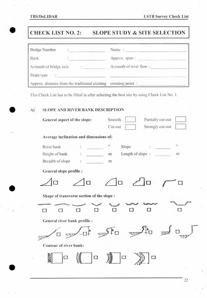
TBS/DoLIDAR LSTB Survey Check List
CHECK LIST NO. 2: SLOPE STUDY & SITE SELECTION
Bridge Num ber : N am e :
Bank : Approx, span :
Azim uth o f bridge axis : Azim uth o f river flow :
S lope type :
Approx, distance from the traditional existing crossing point :
This Check List has to be filled in after selecting the best site by using Check List N o. 1.
A) SLOPE AND RIVER BANK DESCRIPTION
General aspect of the slope: Sm ooth Partially cut-out
Cut-out Strongly cut-out
Average inclination and dimensions of:
River bank : 0 S lope : ________
Height o f bank : m Length o f slope : m
Breadth o f slope : m
General slope profile :
z f ln / ' " ! □ ¿f ]a f ^ aShape of transverse section of the slope :
>11»» I M TTT
o □ w□ D □ □General river bank profile :
2 2

TBS/DoLIDAR LSTB Survey Check List
Rock out crops or scarps on slope and bank:
Slope : Sparse M oderate Num erous
Bank : Sparse M oderate Num erous
Vegetation cover on the slope: H eavyM oderate
FewN one
Deforestation: H eavyM oderate
LightN one
Paddy field: Location : PresentAbsent
Irrigation channel: Location : PresentAbsent
B) RIVER
Flow type:
Fordability:
Erosiveness:
Perennial CalmN on perennial Turbulent
Fordable Fordable inNon-fordable dry season
H ighly erosive N onerosiveM oderately erosive Filling up
C) INSTABILITY FEATURES
Bank erosion :
Gully erosion:
Sheet erosion:
Water run off on the slope :
H eavy LightM oderate N one
H eavy LightM oderate N one
H eavv FewM oderate N one
Num ber o f rivulets :
G ive approx. D im ension o f each rivulet, average breadth x depth
1 . x 2. x 3. ____ x _______ 4 . ______ x
Dry W et Seasonal
23

TBS/DoLIDAR LSTB Survey Check List
Presence of impermeable layers :
Azim uth
Absent
Present
Absent
Presence of swampy area:
Seepage: Absent
Springs : Absent
Presence of inclined trees :
D istance
A bsent
Permanent
Permanent
A bsent
from A or B,
Present
Seasonal
Seasonal
Present
Bulges or depression :
Present
Absent
Azim uth D istance
Transverse open cracks:
Longitudinal open cracks:
Traces of dissolution on slope & bank:
Fallen blocks or rock-fall on slope and bank:
Present
Present
F ew
Absent
Angular
Max. diameter
Landslides :
m
Absent
Few
M edium Angular
Location
from A or B,
Absent
Absent
Num erous
Num erous
Rounded
D onnant Absent
Failure mechanism (if present):
Erosion Plane Translat.
Rotational Flow
W ed ye Fall
24

TBS/DoLIDAR LSTB Survey Check List
Landslides or fallen debris :
Present
Absent
Azim uth D ista n ce___________ from A or B,
Old slided wedge: Absent LowHigh Num erous
Density of geologic planes: Low M oderateHigh Not visib le
Opening of geologic planes : C losed OpenVery open Not
applicable
Dip of bedding plane :
Parallel to the slope Sub parallel O pposite
Weathering of rock : Sound Fair High
Judgement of Bank Action to be takenGood Proceed with further investigation
A cceptable Proceed with further investigation
Propose protective m easures
Q uestionable Proceed with further investigation
Propose protective m easures
Consult Engineer G eologist
Unstable C hoose a new site
25

TBS/DoLIDAR LSTB Survey Check List
CHECK LIST NO. 3: ROCK INVESTIGATION
Bridge Num ber : N am e :
Location : Bank :
S.
N. DescriptionSample Number
i 2 3 4
1. General Informationl.a Location
l.b Bank
l.c Sample depth
l.d Photo No.
l.e GPI No.
2. Identification Procedure2.a Layers
2.b Hammer sound test (hardness)
2.c Bounding o f grains/layers
2.d Quartz test (scratch hammer)
2.e Calcit test (Hcl reaction)
2 .f Texture (grain size & shape)
2-g Colour
2.h Fracture pattern
2.1 Bedding (with thickness)
2 j Special characters
3. Rock Type4. Weathering Grade5. Photograph No.
Remarks : l .a1. e2 . a 2.b 2 .c 2.d 2 .e 2.f 2.h 2 .i 4.
tower (TA) m ainanchorage (M A);GPI = G eological Plane Investigation (Check List N o .4 )no/yes, lam inated/foliated/banded;brittle/dull;w ell/not w ell;no/fine/strong;no/yes, slight/strong/very strong, at jo in t or at rock mass; coarse/m edium /fm e/very fine, angular/rounded; planer/curve, regular/irregular; clear/not so clear/not clear;sound (I), fairly weathered (II), h igh ly weathered (III)
26

TBS/DoLIDAR LSTB Survey Check List
CHECK LIST NO. 3: ROCK INVESTIGATION
Bridge Num ber : N am e :
Location : Bank :
S.
N. Description
Sample 1Number
1 2 3 4
1. General Information
l.a Location
l.b Bank
l.c Sample depth
l.d Photo No.
l.e GPI No.
2. Identification Procedure
2.a Layers
2.b Hammer sound test (hardness)
2.c Bounding o f grains/layers
2.d Quartz test (scratch hammer)
2.e Calcit test (Hcl reaction)
2 .f Texture (grain size & shape)
2-g Colour
2.h Fracture pattern
2.1 Bedding (with thickness)
2.J Special characters
3. Rock Type
4. Weathering Grade
5. Photograph No.
Remarks : l.a1. e2 . a 2.b 2.c 2.d 2.e 2 .f 2.h 2.i 4.
tower (T A ) m ainanchorage (M A);GPI = G eologica l Plane Investigation (Check List N o.4)no/yes, lam inated/foliated/banded;brittle/dull;w ell/not w ell;no/flne/strong;no/yes, slight/strong/very strong, at jo in t or at rock mass; coarse/m edium /fine/very fine, angular/rounded; planer/curve, regular/irregular; clear/not so clear/not clear;sound (I), fairly weathered (II), h ighly weathered (III)
27

TBS/DoLIDAR LSTB Survey Check List
CHECK LIST NO. 4: GEOLOGICAL PLANEINVESTIGATION (GPI)
Bridge Num ber : N am e :
Location : Bank :
Type o f Rock : Sam ple N o. :
W eathering grade : GPI N o :
Typeo f
plane 1)
g )
Dip o f rock or plane
Number per m length
or spacing
Two dimens, extent in
%(2)
Surfacetexture
(3)
Openingin
mm
Fillingor
coating
(4)
Remarks
(5)
Remarks :
1) such as fracture, shear, seam , major or minor fault, bedding, slope2) 100% for continuous plane3) sm ooth, slightly sm ooth, rough, very rough4) clay, calcite, silt, sand etc.5) use coding like “w atch out”, “forget”, etc.
28

TBS/DoLIDAR LSTB Survey Check List
CHECK LIST NO. 4: GEOLOGICAL PLANEINVESTIGATION (GPI)
Bridge Num ber :
Location
Type o f Rock :
W eathering grade :
N am e :
Bank :
Sam ple No. :
GPI N o :
Typeof
plane 1)
(1)
Dip o f rock or plane
Number per m length
or spacing
Two dimens, extent in
%(2)
Surfacetexture
(3)
Openingin
mm
Fillingor
coating
(4)
Remarks
(5)
Remarks :
1) such as fracture, shear, seam , major or m inor fault, bedding, slope2) 100% for continuous plane3) sm ooth, slightly sm ooth, rough, very rough4) clay, calcite, silt, sand etc.5) use coding like “watch out”, “forget”, etc.
29
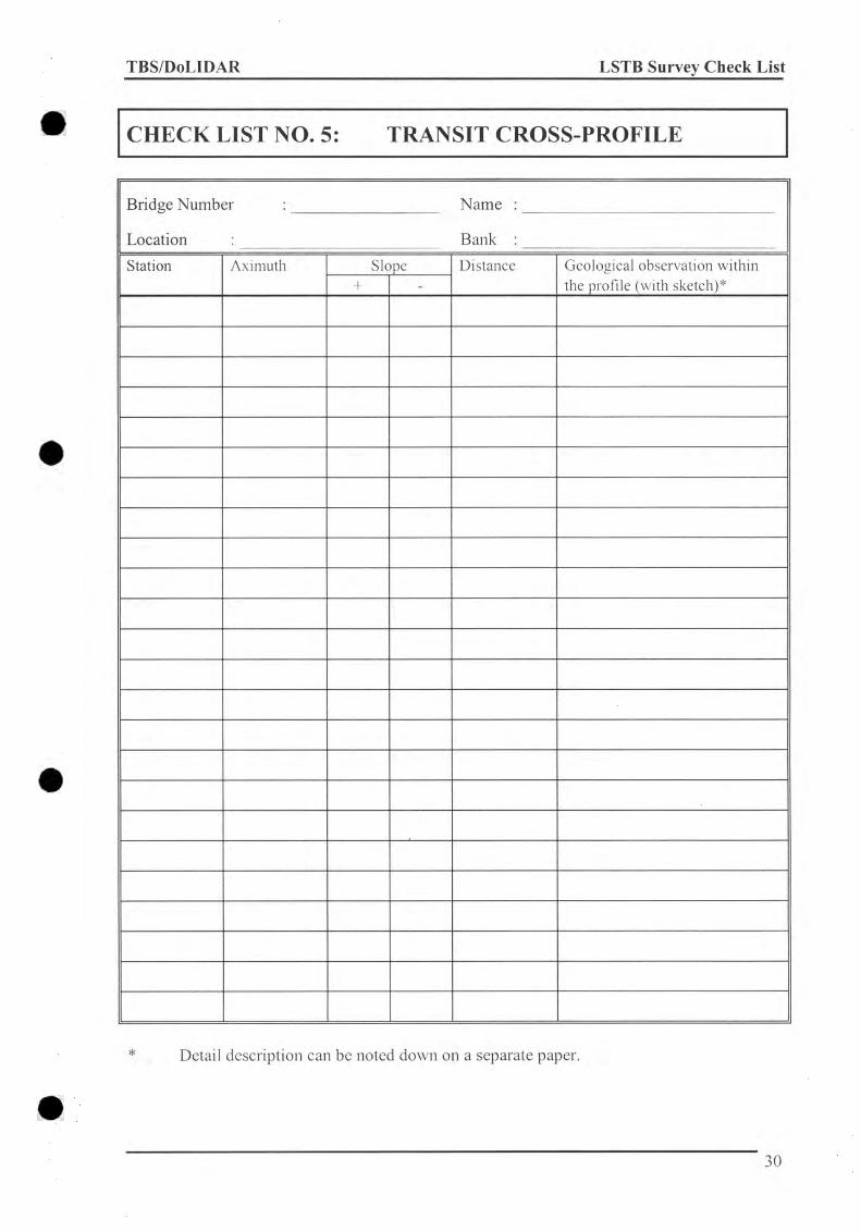
TBS/DoLIDAR LSTB Survey Check List
CHECK LIST NO. 5: TRANSIT CROSS-PROFILE
Bridge Numb<
Location
er : N am e :
: Bank :
Station Aximuth Slope Distance Geological observation within the profile (with sketch)*+ -
Detail description can be noted down on a separate paper.
30

TBS/DoLIDAR LSTB Survey Check List
CHECK LIST NO. 6: SOIL INVESTIGATION
Bridge Number : Name : Pit No : Film No.
Location : Bank : Sample No : Photo No. :
Descriptionof
eachStratum
Grading
1)
Depth
0.00
Sample
No.
Compactness
o fStratum
2)
usesClassification.
Color o f each Stratum
Boulders > 60 mmMax.sizemm
% o fvolume
3)
Grainshape
4)
Wetness
5)
Dip o f imperme
able level
(for rock)
Premea-bility
6)
Geological
denomination
7)
I) Well (W) Medium (M) Poor(P)
2) High (H)Medium (M) Low (L)
3) By Circle Method
4) Angular (A)Sub. Angular (SA) Sub. Rounded (SR) Rounded (R)
5) Very Wet (VW) Wet (W)Dry (D)
6) Very Previous (VP) Previous (P)Semi Previous (SP) Impervious (IP|)
7) Top Soil (TP) Alluvial (AL) Allogenic (AO) Colluvial (CO)
31
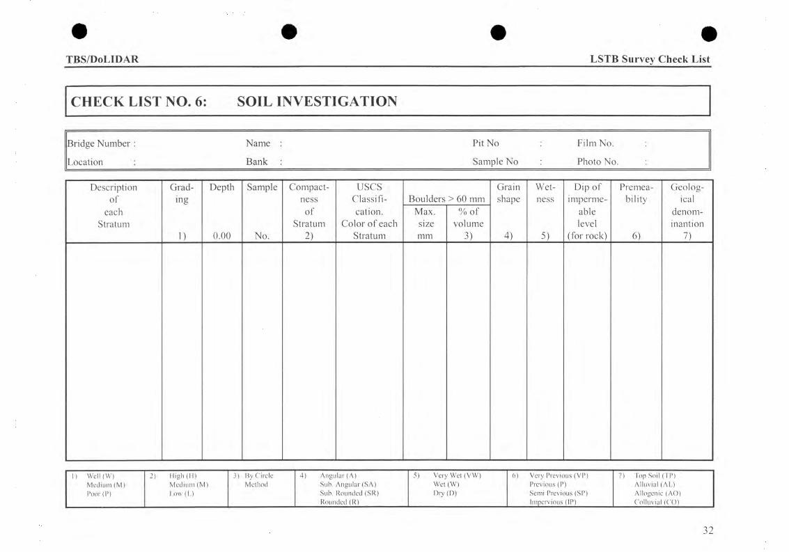
TBS/DoLIDAR LSTB Survey Check List
CHECK LIST NO. 6: SOIL INVESTIGATION
Bridge Number : Name : Pit No : Film No. :
Location : Bank : Sample No : Photo No.
Descriptionof
eachStratum
Grading
1)
Depth
0.00
Sample
No.
Compactness
o fStratum
2)
usesClassification.
Color o f each Stratum
Boulders > 60 mmMax.sizemm
% o f volume
3)
Grainshape
4)
Wetness
5)
Dip o f imperme
able level
(for rock)
Premea-bility
6)
Geological
denom-inantion
7)
1) Well (W) Medium (M) Poor(P)
2) High (H)Medium (M) Low (L)
3) By Circle Method
4) Angular (A)Sub. Angular (SA) Sub. Rounded (SR) Rounded (R)
5) Very Wet (VW) Wet (W)Dry (D)
6) Very Previous (VP) Previous (P)Semi Previous (SP) Impervious (IP)
7) I'op Soil (TP) Alluvial (AL) Allogenic (AO) Colluvial (CO)
32

TBS/DoLIDAR LSTB Survey Check List
CHECK LIST NO. 6: SOIL INVESTIGATION
Bridge Number : Name : Pit No : Film No. :
Location : Bank : Sample No : Photo No. :
Descriptionof
eachStratum
Grading
1)
Depth
0.00
Sample
No.
Compactness
o fStratum
2)
usesClassification.
Color o f each Stratum
Boulders > 60 mmMax.sizemm
% o fvolume
3)
Grainshape
4)
Wetness
5)
Dip o f imperme
able level
(for rock)
Premea-bility
6)
Geological
denomination
n
1) Well (W) Medium (M) Poor(P)
2) High (H)Medium (M) Low (L)
3) By Circle Method
4) Angular (A)Sub. Angular (SA) Sub. Rounded (SR) Roufldcil (R)
5) Very Wet (VW) Wet (W)Dry (D)
6) Very Previous (VP) Previous (P)Semi Previous (SP) Impervious (IP)
7) Top Soil (TP) Alluvial (AL) Allogenic (AO) Colluvial (CO)
33

TBS/DoLIDAR ____ _________________________________________________ LSTB Survey Check List
CHECK LIST NO. 6: SOIL INVESTIGATION
Bridge Number : Name : Pit No : Film No. :
Location : Bank : Sample No : Photo No. :
Descriptionof
eachStratum
Grad- Depth Sample Compact- u s e s Grain Wet Dip o f Premea- Geologing ness Classifi- Boulders > 60 mm shape ness imperme bility ical
o f cation. Max. % o f able denom-Stratum Color o f each size volume level inantion
o 0.00 No. 2) Stratum mm 3) 4) 5) (for rock) 6) 7)
1) Well (W) 2) High (H) 3) By Circle 4) Angular (A) 5) Very Wet (VW) 6) Very Previous (VP) 7) Top Soil (TP)Medium (M) Medium (M) Method Sub. Angular (SA) Wet (W) Previous (P) Alluvial (AL)Poor(P) Low (L) Sub. Rounded (SR)
Rounded (R)Dry (D) Semi Previous (SP)
Impervious (IP^Allogenic (AO) Colluvial (CO)
34
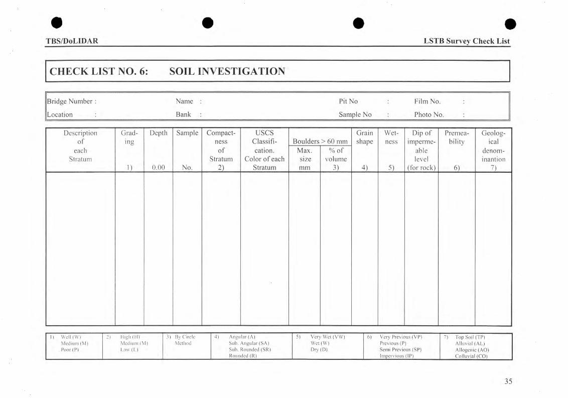
TBS/DoLIDAR LSTB Survey Check List
CHECK LIST NO. 6: SOIL INVESTIGATION
Bridge Number : Name : Pit No : Film No. :
Location : Bank : Sample No : Photo No. :
Descriptionof
eachStratum
Grading
1)
Depth
0.00
Sample
No.
Compactness
o fStratum
____2)____
usesClassification.
Color o f each Stratum
Boulders > 60 mmMax.sizemm
% o fvolume
3)
Grainshape
4)
Wetness
H
Dip o f imperme
able level
(for rock)
Premea-bility
i l
Geological
denomination
7)
1) Well (W) Medium (M) Poor(P)
2) High (H)Medium (M) Low (L)
3) By Circle Method
4) Angular (A)Sub. Angular (SA) Sub. Rounded (SR) Rounded (R)
5) Very Wet (VW) Wet (W)Dry (D)
6) Very Previous (VP) Previous (P)Semi Previous (SP) Impervious (IP)
7) Top Soil (TP) Alluvial (AL) Allogenic (AO) Colluvial (CO)
35

TBS/DoLIDAR ___________________________________________________ LSTB Survey Check List
CHECK LIST NO. 6: SOIL INVESTIGATION
Bridge Number : Name : Pit No : Film No. :
Location : Bank : Sample No : Photo No. :
Descriptionof
eachStratum
Grading
1)
Depth
0.00
Sample
No.
Compactness
o fStratum
2)
usesClassification.
Color o f each Stratum
Boulders > 60 mmMax.sizemm
% o fvolume
3)
Grainshape
4)
Wetness
5)
Dip o f imperme
able level
(for rock)
Premea-bility
6)
Geological
denom-inantion
7)
1) Well (W) 2) High (H) 3) By Circle 4) Angular (A) 5) Very Wet (VW) 6) Very Previous (VP) 7) Top Soil (TP)Medium (M) Medium (M) Method Sub. Angular (SA) Wet (W) Previous (P) Alluvial (AL)Poor(P) Low (L) Sub. Rounded (SR)
Rounded (R|)Dry (D) Semi Previous (SP)
Impervious (IP)Allogenic (AO) Colluvial (CO)
36
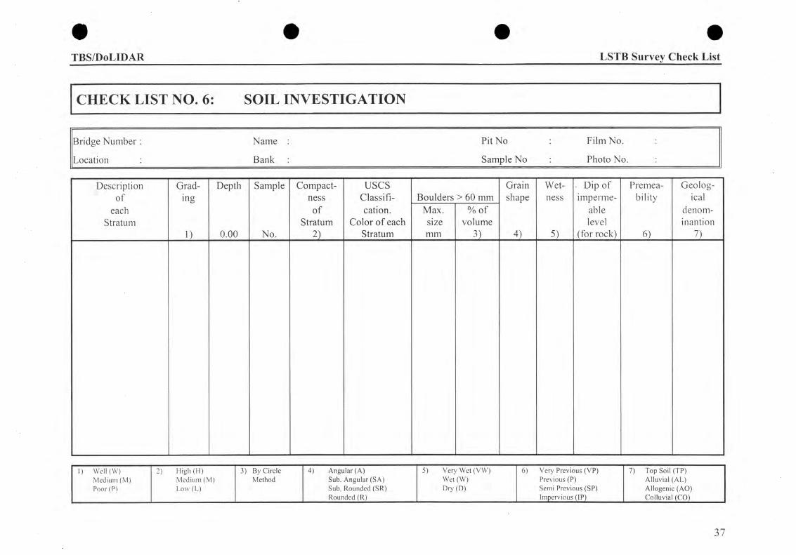
• • • •TBS/DoLIDAR LSTB Survey Check List
CHECK LIST NO. 6: SOIL INVESTIGATION
Bridge Number : Name : Pit No : Film No. :
Location : Bank : Sample No : Photo No. :
Descriptionof
eachStratum
Grading
i)
Depth
0.00
Sample
No.
Compactness
o fStratum
2)
usesClassification.
Color o f each Stratum
Boulders > 60 mmMax.sizemm
% o fvolume
3)
Grainshape
4)
Wetness
5)
. Dip o f imperme
able level
(for rock)
Premea-bility
i l
Geological
denomination
7 >
1) Well (W) Medium (M) Poor(P)
2) High (H)Medium (M) Low (L)
3) By Circle Method
4) Angular (A)Sub. Angular (SA) Sub. Rounded (SR) Rounded (R)
5) Very Wet (VW) Wet (W)Dry (D)
6) Very Previous (VP) Previous (P)Semi Previous (SP) Impervious (IP)
7) Top Soil (TP) Alluvial (AL) Allogenic (AO) Colluvial (COj)
37

TBS/DoLIDAR LSTB Survey Check List
CHECK LIST NO. 6: SOIL INVESTIGATION
Pit No : Film No.
Sample No : Photo No.
Bridge Number : Name
Location : Bank
Description Grad- Depth Sample Compact- uses Grain Wet Dip o f Premea- Geologof ing ness Classifi- Boulders > 60 mm shape ness imperme bility ical
each o f cation. Max. % o f able denom-Stratum Stratum Color o f each size volume level inantion
i) 0.00 No. 2) Stratum mm 3) 4) 5) (for rock) 6) 7)
1) Well (W) 2) High (H) 3) By Circle 4) Angular (A) 5) Very Wet (VW) 6) Very Previous (VP) 7) Top Soil (TP)Medium (M) Medium (M) Method Sub. Angular (SA) Wet (W) Previous (P) Alluvial (AL)Poor(P) Low (L) Sub. Rounded (SR) Dry (D) Semi Previous (SP) Allogenic (AO)
Rounded (R) Impervious (IP) Colluvial (CO)
38

TBS/DoLIDAR LSTB Survey Check List
CHECK LIST NO.7: TRIANGULATION
Bridge No. : Name : Surveyed by : Date :
1. Triangulation 2. Triangulation
d =
a = a G + A/3
Y = y„ + A/3
c = sn + A/3
NO
ILV1S
1N3IAK HITS Nil
O—C_
HORIZONTAL CIRCLE ANGLE
FACE RIGHT FACE LEFT FACE RIGHT FACE LEFT MEAN
A B
C
B A
C
A
13
A = (200ë) + 8 = 5 = e0 + y0 + a 0 =
= Yo
= So
d =
z _W Z 2 2 d ^cd < H H00 00 Z
B
HORIZONTAL CIRCLE
FACE RIGHT FACE LEFT
A = ( 2 0 0 s) + 5 =
a = a 0 + A /3 =
Y - Yo + A /3
8 — £ n + A /3
ANGLE
FACE RIGHT FACE LEFT
5 - 8o + Yo + a o -
MEAN
= Yo
I f 5 > ± 0.02g repeat the triangulation 39

• • • •TBS/DoLIDAR LSTB Survey Check List
CHECK LIST NO.8: SUMMARY OF TRIANGULATION AND ELEVATIONS
Bridge No. :____________________________________Name :________________________ Surveyed by :_________________________Date :
1. Summary of Triangulation
1. T r ia n g u la t io n D,
2. T r ia n g u la t io n d 2
D if fe r e n c e A d
M e a n D is t a n c e L mean
A |) /D mcan —
It A |) /D mean > U.Ü025 r e p e a t th e t r ia n g u la t io n
2. Elevation
INS
TR
UM
EN
T
ST
AT
ION
ST
AF
F
ST
AT
ION
INS
TR
UM
EN
T
HE
IGH
T I
MID
DL
E
HA
IR z
HO
RIZ
ON
TA
l
DIS
TA
NC
E
t^m
ean
V E R T I C A L A N G L E ß
VE
RT
ICA
L
DIS
TA
NC
E
V
D I F F E R E N C E IN
E L E V A T I O N
F A C E R I G H T M E A N A II M E A N
in c m m c m m c m F A C E L E F T m c m m 1 c m m 1 c m
A B
B A
A B M I
B M I A
B B M I I
B M I B
REDUCED LEVELS : BMIBMII
AB
40

# #
TBS/DoLIDAR LSTB Survey Check List
CHECK LIST NO. 9: TACHEOMETRY Page No.
Bridge No. Name : Surveyed by : Date :
STATIONINSTR.
HEIGHT ISTAFF
STATION
HORIZONTALCIRCLE
a
VERTICALCIRCLE
ß
TOPHAIR
MIDDLEHAIR
Z
BOTTOMHAIR
STAFFINTER.
HORIZONT.DISTANCE
D
VERTICAL DISTANCE
+/- V
DIFF. IN ELEVATION
+/- AH
REDUCEDLEVEL
HREMARKS
41
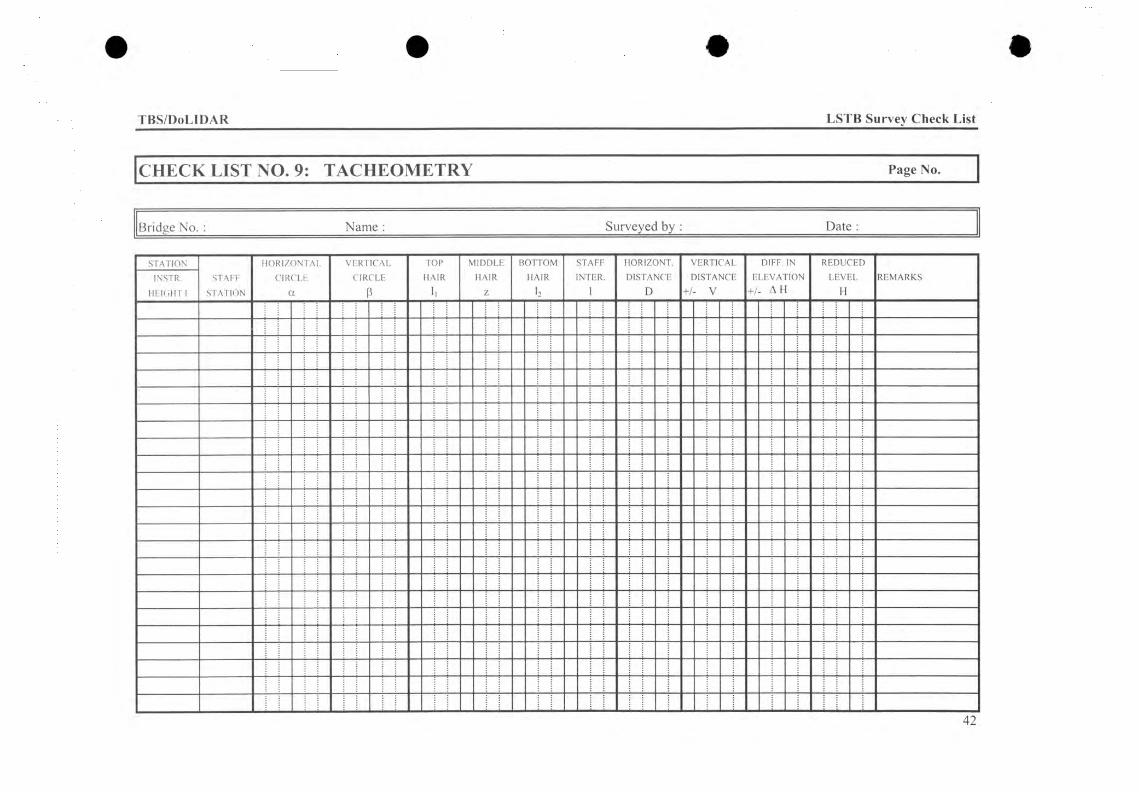
TBS/DoLIDAR LSTB Survey Check List
CHECK LIST NO. 9: TACHEOMETRY Page No.
Bridge No. : Name : Surveyed by : Date
STATIONSTAFF
STATION
HORIZONTALCIRCLE
a
VERTICALCIRCLE
ß
TOPHAIR
ll
MIDDLEHAIR
Z
BOTTOMHAIR
12
STAFFINTER.
1
HORIZONT.DISTANCE
D
VERTICAL DIFF. IN RErLI
)UCEDREMARKSINSTR.
HEIGHT IDISTA1
+/- VMCE E
+/■LEVA . A t
riONI
2VÏH
ÏL

TBS/DoLIDAR LSTB Survey Check List
CHECK LIST NO. 9: TACHEOMETRY Page No.
Bridge No. : Name : Surveyed by : Date :
STATIONSTAFF
STATION
HORIZONTALCIRCLE
a
VERTICAL TOPHAIR
1.
MIDDLEHAIR
Z
BOTTOMHAIR
b
STAFFINTER.
1
HORIZONT.DISTANCE
D
VERTICAL DISTANCE
+/- V
DIFF. IN ELEVATION
+/- A H
REDUCEDLEVEL
HREMARKSINSTR.
HEIGHT ICIRCLE
3
'

TBS/DoLIDAR LSTB Survey Check List
CHECK LIST NO. 9: TACHEOMETRY Page No.
Bridge No. : Name : Surveyed by : Date :
STATIONSTAFF
STATION
HORIZONTALCIRCLE
a
VERTICALCIRCLE
P
TOPHAIR
1.
MIDDLEHAIR
Z
BOTTOMHAIR
b
STAFFINTER.
1
HORIZONT.DISTANCE
D
VERTICAL DISTANCE
+/- V
DIFF. IN ELEVATION
+/- A H
REDUCEDLEVEL
HREMARKSINSTR.
HEIGHT I
44

TBS/DoLIDAR LSTB Survey Check List
CHECK LIST NO. 9: TACHEOMETRY Page No.
Bridge No. : Name : Surveyed by : Date :
STATIONSTAFF
STATION
HORIZONTALCIRCLE
a
VERTICAL TOPHAIR
1,
MIDDLEHAIR
Z
BOTTOMHAIR
12
STAFFINTER.
1
HORIZONT.DISTANCE
D
VERTICAL DISTANCE
+/- V
DIFF. IN ELEVATION
+/- A H
REDUCEDLEVEL
HREMARKSINSTR.
HEIGHT ICTRCLE
3
45

TBS/DoLIDAR LSTB Survey Check List
CHECK LIST NO. 9: TACHEOMETRY Page No.
Bridge No. :______________________Name :___________________________________Surveyed by :______________________ Date :
STATIONSTAFF
STATION
HORIZONTALCIRCLE
a
VERTICAL TOPHAIR
1.
MIDDLEHR
BOTTOM STAFF HÖRDIS'
LIZONT. VERTICAL DIFF. IN REDUCEDREMARKSINSTR.
HEIGHT ICIRCLE
3H A HAIR
12
:INTER.1
TAID
NCE [+/■
)ISTA1 - V
NCE E+/■
LEVA' . A f
riONT
LEVIH
iL
46
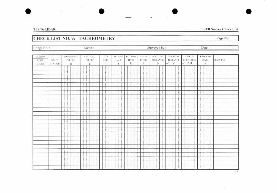
TBS/DoLIDAR LSTB Survey Check List
CHECK LIST NO. 9: TACHEOMETRY Page No.
Bridge No. : Name : Surveyed by : Date :
STATION INSTR.
HEIGHT ISTAFF
STATION
HORIZONTAFCIRCFE
ot
VERTICAFCIRCLE
ß
TOPHAIR
MIDDLEHAIR
Z
BOTTOMHAIR
12
STAFFINTER.
HORIZONT.DISTANCE
D
VERTICAL DISTANCE
+/- V
DIFF. IN ELEVATION
+/- AH
REDUCEDLEVEL
HREMARKS
47
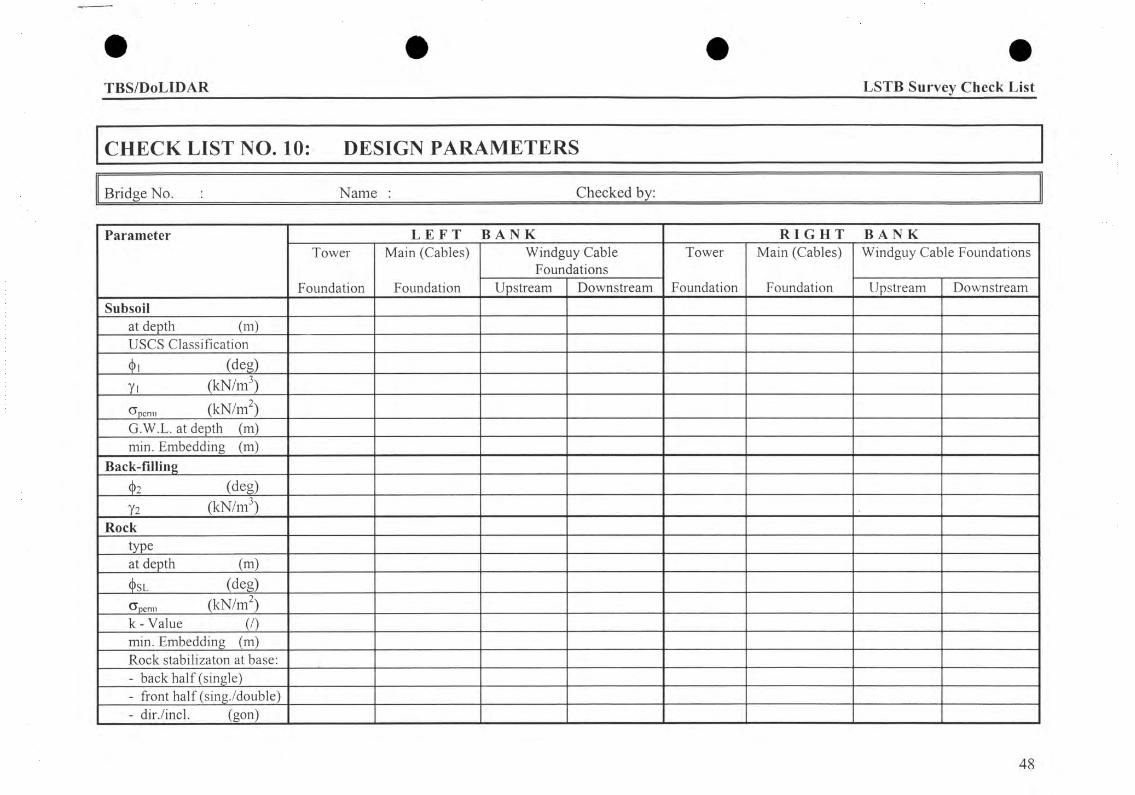
TBS/DoLIDAR LSTB Survey Check List
CHECK LIST NO. 10: DESIGN PARAMETERS
Bridge No. : Name : Checked by:
Parameter L E F T B A N K R I G H T B A N KTower
Foundation
Main (Cables)
Foundation
Windguy Cable Foundations
Tower
Foundation
Main (Cables)
Foundation
Windguy Cable Foundations
Upstream Downstream Upstream DownstreamSubsoil
at depth (m)USCS Classification(l>i (deg)yi (kN /m 3)
cTpcnn (k N /m )G.W.L. at depth (m)min. Embedding (m)
Back-filling(t>2 (deg)
Y2 (kN /m 3)Rock
typeat depth (m)(I>sl (deg)
Cpcmi (kN/m )k -V a lu e (/)min. Embedding (m)Rock stabilizaton at base:- back half (single)- front half (sing./double)- dir./incl. (gon)
48
Related Documents