TM 11-6625-2632-14 TECHNICAL MANUAL OPERATOR'S, ORGANIZATIONAL, DIRECT SUPPORT, AND GENERAL SUPPORT MAINTENANCE MANUAL INCLUDING REPAIR PARTS AND SPECIAL TOOLS LIST (INCLUDING DEPOT MAINTENANCE REPAIR PARTS AND SPECIAL TOOLS) RADIO TEST SET AN/PRM-32 HEADQUARTERS, DEPARTMENT OF THE ARMY DECEMBER 1973

Welcome message from author
This document is posted to help you gain knowledge. Please leave a comment to let me know what you think about it! Share it to your friends and learn new things together.
Transcript

TM 11-6625-2632-14
TECHNICAL MANUAL
OPERATOR'S, ORGANIZATIONAL, DIRECT SUPPORT, ANDGENERAL SUPPORT MAINTENANCE MANUAL
INCLUDING REPAIR PARTS AND SPECIAL TOOLS LIST(INCLUDING DEPOT MAINTENANCE REPAIR PARTS AND SPECIAL TOOLS)
RADIO
TEST SET
AN/PRM-32
HEADQUARTERS, DEPARTMENT OF THE ARMY
DECEMBER 1973
WARNING
The fumes of trichloroethane are toxic. Provide thorough ventilation wheneverused. DO NOT USE NEAR AN OPEN FLAME. Trichloroethane is not flammable,but exposure of the fumes to an open flame or hot metal surface forms highly toxicphosgene gas
TM 11-6625-2632-14
TECHNICAL MANUAL HEADQUARTERSDEPARTMENT OF THE ARMY
No. 11-6625-2632-14 WASHINGTON, DC, 11 December 1973
Operator's, Organizational, Direct Support, and General SupportMaintenance Manual Including Repair Parts and Special Tools List
(Including Depot Maintenance Repair Parts and Special Tools)
RADIO TEST SET AN/PRM-32
Current as of 10 September 1973_________________
Paragraph PageCHAPTER 1. INTRODUCTIONSection I. General
Scope ---------------------------------------------------------------------------------------------------------- 1-1 1-1Forms and Records --------------------------------------------------------------------------------------- 1-2 1-1Destruction of Army Material to prevent enemy use ----------------------------------------- 1-3 1-2Administrative storage ----------------------------------------------------------------------------------- 1-4 1-2Calibration ---------------------------------------------------------------------------------------------------- 1-6 1-2Reporting of equipment publication improvements ------------------------------------------ 1-6 1-2
II. Description and dataPurpose and use ------------------------------------------------------------------------------------------- 1-7 1-2Description --------------------------------------------------------------------------------------------------- 1-8 1-3Technical characteristics -------------------------------------------------------------------------------- 1-9 1-3Items comprising an operable Radio Test Set AN/PRM-32 ------------------------------ 1-10 1-3Additional equipment required ------------------------------------------------------------------------ 1-11 1-3
CHAPTER 2. OPERATING INSTRUCTIONSSection I. Service upon receipt of equipment
General -------------------------------------------------------------------------------------------------------- 2-1 2-1Checking unpacked equipment ---------------------------------------------------------------------- 2-2 2-1Installation instructions ---------------------------------------------------------------------------------- 2-3 2-1
II. Controls and instrumentsGeneral -------------------------------------------------------------------------------------------------------- 2-4 2-1Operator's controls ---------------------------------------------------------------------------------------- 2-5 2-1
III. Operation under usual conditionsIntroduction -------------------------------------------------------------------------------------------------- 2-6 2-1Test setup ---------------------------------------------------------------------------------------------------- 2-7 2-2Beacon battery and transmitter check ------------------------------------------------------------ 2-8 2-2Beacon monitor check ----------------------------------------------------------------------------------- 2-9 2-2MCW transmitter check --------------------------------------------------------------------------------- 2-10 2-2243.0 MHz voice transmitter check ----------------------------------------------------------------- 2-11 2-3282.8 MHz voice transmitter check ----------------------------------------------------------------- 2-12 2-3243.0 MHz receiver check ----------------------------------------------------------------------------- 2-13 2-4282.8 MHz receiver check ----------------------------------------------------------------------------- 2-14 2-5Earphone check -------------------------------------------------------------------------------------------- 2-15 2-5Completion of tests --------------------------------------------------------------------------------------- 2-16 2-5
IV. Operation under unusual conditionsIntroduction -------------------------------------------------------------------------------------------------- 2-17 2-6Procedure after testing ---------------------------------------------------------------------------------- 2-18 2-6Lubrication after testing --------------------------------------------------------------------------------- 2-19 2-6
CHAPTER 3. ORGANIZATIONAL MAINTENANCESection I. General
Scope of organizational maintenance ------------------------------------------------------------- 3-1 3-1Tools, materials, and test equipment required for organizational maintenance -- 3-2 3-1
II Organizational preventive maintenancePreventive maintenance -------------------------------------------------------------------------------- 3-3 3-1Preventive maintenance checks and service---------------------------------------------------- 3-4 3-1Cleaning ------------------------------------------------------------------------------------------------------- 3-5 3-2Touchup painting instructions ------------------------------------------------------------------------ 3-6 3-2Organizational troubleshooting ----------------------------------------------------------------------- 3-7 3-3
i

TM 11-66-25-2632-14
Paragraph PageCHAPTER 4. FUNCTIONING OF EQUIPMENT
Introduction -------------------------------------------------------------------------------------------------- 4-1 4-1Theory of operation --------------------------------------------------------------------------------------- 4-2 4-1
5. GENERAL SUPPORT MAINTENANCESection I. General
Scope ---------------------------------------------------------------------------------------------------------- 5-1 5-1Tools and test equipment ------------------------------------------------------------------------------ 5-2 5-1Physical inspection --------------------------------------------------------------------------------------- 5-3 5-1
II. TroubleshootingGeneral -------------------------------------------------------------------------------------------------------- 5-4 5-1Checkout procedures ------------------------------------------------------------------------------------ 5-5 5-1Troubleshooting procedures -------------------------------------------------------------------------- 5-6 5-3
III. Adjustment, alignment, repair, removal, and replacementGeneral -------------------------------------------------------------------------------------------------------- 5-7 5-3Panel assembly removal -------------------------------------------------------------------------------- 5-8 5-4Detector housing assembly removal --------------------------------------------------------------- 5-9 5-6Component board assembly removal ------------------------------------------------------------- 5-10 5-6Component replacement ------------------------------------------------------------------------------- 5-11 5-6Repair procedures ---------------------------------------------------------------------------------------- 5-12 5-6Fabrication of replacement parts -------------------------------------------------------------------- 5-13 5-7Component board assembly installation --------------------------------------------------------- 5-14 5-7Detector housing assembly installation ----------------------------------------------------------- 5-15 5-8Panel assembly installation ---------------------------------------------------------------------------- 5-16 5-8
IV. Testing and calibrationTesting --------------------------------------------------------------------------------------------------------- 5-17 5-8Calibration ---------------------------------------------------------------------------------------------------- 5-18 5-8
APPENDIX A REFERENCES --------------------------------------------------------------------------------------------------------- A-1B. MAINTENANCE ALLOCATION
Section I. IntroductionGeneral -------------------------------------------------------------------------------------------------------- B-1 B-1Maintenance functions ---------------------------------------------------------------------------------- B-2 B-1Explanation of format for maintenance allocation chart ------------------------------------ B-3 B-2Explanation of format for tool and test equipment requirements ----------------------- B-4 B-2
II. Maintenance allocation chart ------------------------------------------------------------------------------------- B-3Table I. Tool and test equipment requirements ------------------------------------------------------------------------ B-4APPENDIX C. ORGANIZATIONAL, DIRECT SUPPORT, AND GENERAL SUPPORT MAINTE-
NANCE REPAIR PARTS AND SPECIAL TOOLS LIST (INCLUDING DEPOTMAINTENANCE REPAIR PARTS AND SPECIAL TOOLS)
Section I. Introduction -------------------------------------------------------------------------------------------------------------- C-1II. Repair parts list -------------------------------------------------------------------------------------------------------- C-6
Group 02. Cables --------------------------------------------------------------------------------------------------------------------- C-6Section III. Special tools list -------------------------------------------------------------------------------------------------------- C-7
IV. Repair parts list -------------------------------------------------------------------------------------------------------- C-8Group 01. Case ------------------------------------------------------------------------------------------------------------------------ C-8
02. Cables --------------------------------------------------------------------------------------------------------------------- C-803. Meter ----------------------------------------------------------------------------------------------------------------------- C-1004. Detector assembly ---------------------------------------------------------------------------------------------------- C-1005. Potentiometer ----------------------------------------------------------------------------------------------------------- C-1206. Receiver section ------------------------------------------------------------------------------------------------------- C-1307. Bulk material ------------------------------------------------------------------------------------------------------------- C-13
ii

TM 11-6625-2632-14
LIST OF ILLUSTRATIONS
Number Title Page1-1 Radio Test Set AN/PRM-32 with cover closed ------------------------------------------------------------------------- 1-11-2 Radio Test Set AN/PRM-32 with cover open --------------------------------------------------------------------------- 1-22-1 Antenna removal from Radio Set AN/PRC-90 ------------------------------------------------------------------------- 2-22-2 Connection of test set to radios under test ------------------------------------------------------------------------------ 2-32-3 Radio Set AN/PRC-90, controls and indicators ------------------------------------------------------------------------ 2-44-1 Radio Test Set AN/PRM-32 schematic diagram ---------------------------------------------------------------------- 4-15-1 Radio Test Set AN/PRM-32 component identification -------------------------------------------------------------- 5-35-2 Radio Test Set AN/PRM-32 panel assembly --------------------------------------------------------------------------- 5-45-3 Radio Test Set AN/PRM-32 detector housing assembly ---------------------------------------------------------- 5-55-4 Neoprene gasket fabrication detail ----------------------------------------------------------------------------------------- 5-65-5 Cable assembly fabrication details ----------------------------------------------------------------------------------------- 5-65-6 Receiver wire fabrication details --------------------------------------------------------------------------------------------- 5-75-7 Wrench fabrication details ----------------------------------------------------------------------------------------------------- 5-7
1 Case group --------------------------------------------------------------------------------------------------------------------------- C-92 Detector assembly, cables, meter, potentiometer and receiver section ------------------------------------- C-113 Radio Set AN/PRC-90 ----------------------------------------------------------------------------------------------------------- C-15
LIST OF TABLES
Table No. Title Page
1-1 Radio Test Set AN/PRM-2 Characteristics ------------------------------------------------------------------------------ 1-31-2 Items Comprising an Operable Radio Test Set AN/PRM-32 ----------------------------------------------------- 1-32-1 Radio Test Set AN/PRM-32 Controls and Indicators ---------------------------------------------------------------- 2-13-1 Organizational Preventive Maintenance Checks and Services ------------------------------------------------- 3-25-1 Physical Inspection --------------------------------------------------------------------------------------------------------------- 5-15-2 Operational Check ---------------------------------------------------------------------------------------------------------------- 5-25-3 Troubleshooting Procedure ---------------------------------------------------------------------------------------------------- 5-2
iii
TM 11-6625-2632-14
CHAPTER 1
INTRODUCTION
Section I. GENERAL
1-1. Scope
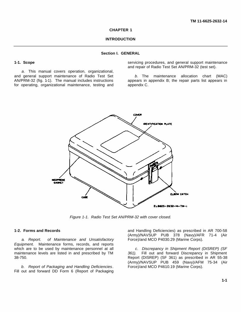
a. This manual covers operation, organizational,and general support maintenance of Radio Test SetAN/PRM-32 (fig. 1-1). The manual includes instructionsfor operating, organizational maintenance, testing and
servicing procedures, and general support maintenanceand repair of Radio Test Set AN/PRM-32 (test set).
b. The maintenance allocation chart (MAC)appears in appendix B; the repair parts list appears inappendix C.
Figure 1-1. Radio Test Set AN/PRM-32 with cover closed.
1-2. Forms and Records
a. Report. of Maintenance and UnsatisfactoryEquipment. Maintenance forms, records, and reportswhich are to be used by maintenance personnel at allmaintenance levels are listed in and prescribed by TM38-750.
b. Report of Packaging and Handling Deficiencies.Fill out and forward DD Form 6 (Report of Packaging
and Handling Deficiencies) as prescribed in AR 700-58(Army)/NAVSUP PUB 378 (Navy)/AFR 71-4 (AirForce)/and MCO P4030.29 (Marine Corps).
c. Discrepancy in Shipment Report (DISREP) (SF361). Fill out and forward Discrepancy in ShipmentReport (DISREP) (SF 361) as prescribed in AR 55-38(Army)/NAVSUP PUB 459 (Navy)/AFM 75-34 (AirForce)/and MCO P4610.19 (Marine Corps).
1-1

TM 11-4662S-2632-14
1-3. Destruction of Army Materiel to Prevent EnemyUse
Requirements for destruction will be those prescribed inTM 750-244-2.
1-4. Administrative Storage
Requirements and procedures for administrative storagewill be those prescribed in TM 740-90-1.
1-5. Calibration
Radio Test Set AN/PRM-32 is simple to use but must beproperly calibrated. Calibration is performed at generalsupport maintenance, as prescribed in TB 750-236.
1-6. Reporting of Equipment PublicationImprovements
The reporting of errors, omissions, andrecommendations for improving this publication by theindividual user is encouraged. Reports should besubmitted on DA Form 2028 (Recommended Changesto Publications) and forwarded direct to Commander,U.S. Army Electronics Command, ATTN: AMSEL-MA-AC, Fort Monmouth, NJ 07703.
Section II. DESCRIPTION AND DATA
1-7. Purpose and UseRadio Test Set AN/PRM-32 is the primary piece of testequipment used to check out Radio Set AN/PRC-90 atorganizational maintenance. Two cable assemblies(transmitter cable and receiver cable) (fig. 1-2) areprovided for attachment of the test set to the radio setsbeing tested. One radio set under test serves as a
transmitter and the other as a receiver. The test setserves as a fully-shielded test path between the tworadios. There is no interference with operating channelsduring testing. Indications on the meter of the test setshow the operating condition of the radio sets under test.
Figure 1-2. Radio Test Set AN/PRM-32 with cover open
1-2

TM 11-6625-2632-14
1-8. Description(fig. 1-1 and 1-2)
Radio Test Set AN/PRM-32 is built into a case (fig. 1-2)which also contains two connector adapters and twoaccessories, a wrench used to remove antennas fromradio sets under test, and an instruction book. The caseis equipped with a cover (fig. 1-1), an elbow catch, and aneoprene gasket to protect it from moisture and dirtwhen it is not being used. The test set is self-containedand requires no batteries or other power source. It ismade ready for use at any time by releasing the elbowcatch and opening the hinged cover.
1-9. Technical Characteristics
Technical characteristics for Radio Test Set AN/PRM-32are given in table 1-1.
1-10. Items Comprising an Operable Radio Test SetAN/PRM-32(fig. 1-2)
The items in the table below make up an operable RadioTest Set AN/PRM-32. One copy of this manual ispacked with each AN/PRM-32.
Table 1-1. Radio Test Set AN/PRM-32 Characteristics
Operating range:Temperature.......................+5oC. to +40oC.Altitude...............................Sea level to 12,000 feetHumidity.............................95% maximum
Dimensions:Height ................................2.95 inchesLength................................5.40 inchesWidth.................................3.50 inches
Weight, complete......................1-1/2 poundsOperating frequencies ...............243.0 and 282.8 MHzPower required .........................None
Table 1-2. Radio Test Set AN/PRM-32
FSN Item Quantity Common name
6625-803-3399 Radio Test Set AN/PRM-32 ..............................1............................................ Test Setconsisting of:
Wrench, Spanner.................................1............................................ Spanner wrenchBook, Instruction ..................................1............................................ Instruction bookCable Assembly, Transmitter ................1............................................ Transmitter cableCable Assembly, Receiver....................1............................................ Receiver cable
5820-478-7054 Adapter, Test MX-8802/PRC-90........................2............................................ Connector adapter
1-11. Additional Equipment Required
No additional equipment is required when the AN/PRM-32 is used with the equipment it is intended to test.
Information concerning operation of the equipment undertest, Radio Set AN/PRC-90, is contained in TM 11-5820-800-12.
1-3

TM 11-6625-2632-14
CHAPTER 2
OPERATING INSTRUCTIONS
Section I. SERVICE UPON RECEIPT OF EQUIPMENT
2-1. General
Radio Test Set AN/PRM-32 is packaged for shipment ina standard moisture-proof container. It requires nospecial treatment upon receipt except removal by theoperator from the package. There are no special sitingor shelter requirements to be considered. It is availablefor use at any time. It should be used in a location asfree from moisture, mud, dirt, and snow as possible, butcan be used under such conditions if necessary.
2-2. Checking Unpacked Equipment
a. Inspect the equipment for damage incurredduring shipment. If the equipment has been damaged,report the damage in accordance with instructions in TM38-750.
b. Check the equipment against the componentlisting in the operator's manual and the packing slip to
see if the shipment is complete. Report alldiscrepancies in accordance with the instructions of TM38-750. The equipment should be placed in serviceeven though a minor assembly or part that does notaffect proper functioning is missing.
c. Check to see whether the equipment has beenmodified. (Equipment which has been modified will havethe MWO number on the identification plate on the top ofthe cover.) Check also to see whether all currentlyapplicable MWO's have been applied. (Current MWO’sapplicable to the equipment are listed in DA Pam 310-7.)
2-3. Installation Instructions
There are no installation requirements for Radio Test SetAN/PRM-32. No preliminary adjustments, externalconnections, or circuit alignment are required.
Section II. CONTROLS AND INSTRUMENTS
2-4. General
There are no control settings on Radio Test SetAN/PRM-32. It serves as a link in testing.
2-5. Operator’s Controls
Operator's controls and indicators on Radio Test SetAN/PRM-32 are identified in table 2-1 and shown infigure 1-2. Refer to TM 11-5820-800-12 for a descriptionof the Radio Set AN/PRC-90 controls and indicators.
Table 2-1. Radio Test Set AN/PRM-32Controls and Indicators
Control orIndicator Function
Transmitter cable ..........Connects test set to antennajack of transmitting radiounder test.
Receiver cable..............Connects test set to antennajack of receiving radio undertest.
Meter ...........................Indicates power level oftransmitted radio signal.
Section III. OPERATION UNDER USUAL CONDITIONS
2-6. Introduction
Radio Test Set AN/PRM-32 was designed specifically totest Radio Set AN/PRC-90. It can test a single set fortransmission, or test one set for receiving the transmitted
signal from a second set. The usual procedure fortesting is to connect two radio sets to the test set andtest them both as transmitters and receivers in one set oftest procedures. In this procedure the
2-1
TM 11-6625-2632-14
radio set to be used as a transmitter must be tested first.The receiving set is then tested against this transmitter,which is known to be operating properly. The two setsare then reversed and the test procedure is run throughagain.
2-7. Test Setupa. Select a test area which is as free of moisture,
dust, salt spray, snow, or other contaminants aspossible. Testing can be performed in the presence of
such contaminants, but it is best to avoid theseconditions.
b. Check to be sure both Radio Sets AN/PRC-90 tobe tested contain batteries in good condition.
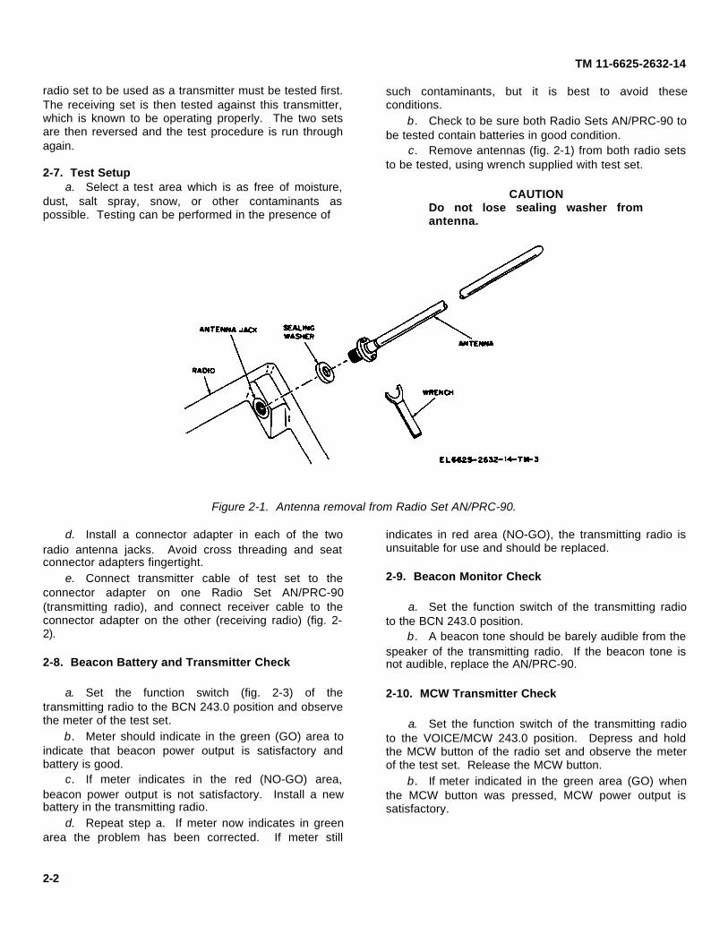
c. Remove antennas (fig. 2-1) from both radio setsto be tested, using wrench supplied with test set.
CAUTIONDo not lose sealing washer fromantenna.
Figure 2-1. Antenna removal from Radio Set AN/PRC-90.
d. Install a connector adapter in each of the tworadio antenna jacks. Avoid cross threading and seatconnector adapters fingertight.
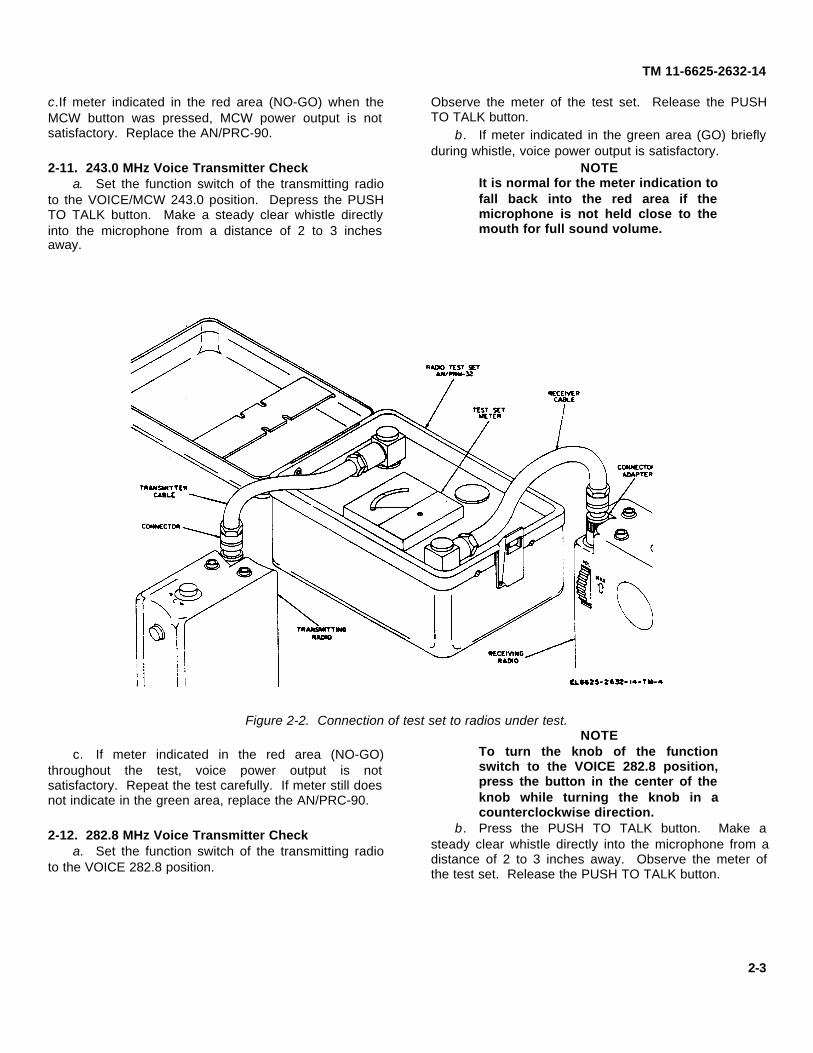
e. Connect transmitter cable of test set to theconnector adapter on one Radio Set AN/PRC-90(transmitting radio), and connect receiver cable to theconnector adapter on the other (receiving radio) (fig. 2-2).
2-8. Beacon Battery and Transmitter Check
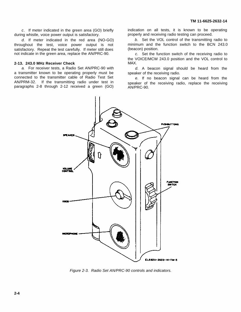
a. Set the function switch (fig. 2-3) of thetransmitting radio to the BCN 243.0 position and observethe meter of the test set.
b. Meter should indicate in the green (GO) area toindicate that beacon power output is satisfactory andbattery is good.
c. If meter indicates in the red (NO-GO) area,beacon power output is not satisfactory. Install a newbattery in the transmitting radio.
d. Repeat step a. If meter now indicates in greenarea the problem has been corrected. If meter still
indicates in red area (NO-GO), the transmitting radio isunsuitable for use and should be replaced.
2-9. Beacon Monitor Check
a. Set the function switch of the transmitting radioto the BCN 243.0 position.
b. A beacon tone should be barely audible from thespeaker of the transmitting radio. If the beacon tone isnot audible, replace the AN/PRC-90.
2-10. MCW Transmitter Check
a. Set the function switch of the transmitting radioto the VOICE/MCW 243.0 position. Depress and holdthe MCW button of the radio set and observe the meterof the test set. Release the MCW button.
b. If meter indicated in the green area (GO) whenthe MCW button was pressed, MCW power output issatisfactory.
2-2
TM 11-6625-2632-14
c.If meter indicated in the red area (NO-GO) when theMCW button was pressed, MCW power output is notsatisfactory. Replace the AN/PRC-90.
2-11. 243.0 MHz Voice Transmitter Checka. Set the function switch of the transmitting radio
to the VOICE/MCW 243.0 position. Depress the PUSHTO TALK button. Make a steady clear whistle directlyinto the microphone from a distance of 2 to 3 inchesaway.
Observe the meter of the test set. Release the PUSHTO TALK button.
b. If meter indicated in the green area (GO) brieflyduring whistle, voice power output is satisfactory.
NOTEIt is normal for the meter indication tofall back into the red area if themicrophone is not held close to themouth for full sound volume.
Figure 2-2. Connection of test set to radios under test.
c. If meter indicated in the red area (NO-GO)throughout the test, voice power output is notsatisfactory. Repeat the test carefully. If meter still doesnot indicate in the green area, replace the AN/PRC-90.
2-12. 282.8 MHz Voice Transmitter Checka. Set the function switch of the transmitting radio
to the VOICE 282.8 position.
NOTETo turn the knob of the functionswitch to the VOICE 282.8 position,press the button in the center of theknob while turning the knob in acounterclockwise direction.
b. Press the PUSH TO TALK button. Make asteady clear whistle directly into the microphone from adistance of 2 to 3 inches away. Observe the meter ofthe test set. Release the PUSH TO TALK button.
2-3
TM 11-6625-2632-14
c. If meter indicated in the green area (GO) brieflyduring whistle, voice power output is satisfactory.
d. If meter indicated in the red area (NO-GO)throughout the test, voice power output is notsatisfactory. Repeat the test carefully. If meter still doesnot indicate in the green area, replace the AN/PRC-90.
2-13. 243.0 MHz Receiver Checka. For receiver tests, a Radio Set AN/PRC-90 with
a transmitter known to be operating properly must beconnected to the transmitter cable of Radio Test SetAN/PRM-32. If the transmitting radio under test inparagraphs 2-8 through 2-12 received a green (GO)
indication on all tests, it is known to be operatingproperly and receiving radio testing can proceed.
b. Set the VOL control of the transmitting radio tominimum and the function switch to the BCN 243.0(beacon) position.
c. Set the function switch of the receiving radio tothe VOICE/MCW 243.0 position and the VOL control toMAX.
d. A beacon signal should be heard from thespeaker of the receiving radio.
e. If no beacon signal can be heard from thespeaker of the receiving radio, replace the receivingAN/PRC-90.
Figure 2-3. Radio Set AN/PRC-90 controls and indicators.
2-4
TM 11-6625-2632-14
NOTEThe presence of an audibleinterfering signal from the speakercaused by a nearby 243.0 MHztransmitter generally will be a GOcondition. This may not be a trueindication if the interferingtransmitter is of unusually higherpower or its antenna is located within100 feet.
2-14. 282.8 MHz Receiver Checka. Using a transmitting radio known to be operating
properly, set its function switch to the VOICE 282.8position and its VOL control at minimum. Set thefunction switch of the receiving radio to the VOICE 282.8position and its VOL control at MAX.
NOTETo turn the knob of the functionswitch to the VOICE 282.8 position,press the button in the center of theknob while turning the knob in acounterclockwise direction.
b. Press the PUSH TO TALK button on thetransmitting radio. A reduction in noise level from thespeaker of the receiving radio indicates a satisfactory282.8 MHz receiver.
c. Complete lack of noise, or no change in noiselevel indicates a NO-GO condition. Replace thereceiving AN/PRC-90.
NOTEThe presence of an audibleinterfering signal from the speakercaused by a nearby 282.8 MHztransmitter generally will be a GOcondition. This may not be a trueindication if the interferingtransmitter is of unusually highpower or its antenna is located within100 feet.
2-15. Earphone Checka. Using a transmitting radio known to be operating
properly, set its function switch to the VOICE 282.8position and its VOL control at minimum. Set thefunction switch of the receiving radio to the VOICE 282.8position and its VOL control at MAX.
NOTETo turn the knob of the functionswitch to the VOICE 282.8 position,press the button in the center of theknob while turning the knob in acounterclockwise direction.
b. Observe the noise level from the speaker of thereceiving radio.
c. Plug the earphone connector into theEARPHONE JACK of the receiving radio. The speakerof the receiving radio should now be silent and thereceiver noise should be heard clearly in the earphone.
d. If the earphone does not operate properly (cabove), check the earphone connection for cleancontacts. If this does not correct the problem, replacethe earphone and cord assembly. If operation is stillimproper, replace the receiving AN/PRC-90.
2-16. Completion of Testsa. Completion of the testing in paragraphs 2-8
through 2-15 with all GO indications assume that thetransmitting radio set is operating properly as atransmitter, and the receiving radio set is operatingproperly as a receiver. Disconnect the transmitter cableand receiver cable and reconnect them with the radiosets reversed.
b. Repeat the test procedures in paragraphs 2-8through 2-15. If the testing is completed with all GOindications, both radio sets are operating properly astransmitters and as receivers.
c. Disconnect the transmitter cable and receivercable from the radio sets. Be sure the threads of theantennas and antenna jacks are free of moisture, dirt, orother contaminants. Install the antennas and antennasealing washers. Avoid cross threading of the antennas.Use the wrench (fig. 2-1) to tighten each antenna to itscase with just enough torque to compress the washerslightly.
CAUTIONDo not overtighten or the plasticthreads on the antenna will bedamaged.
d. Place the wrench and instruction manual in thecover (fig. 1-2) of the test set. Disconnect the twoconnector adapters and place them in the test set. Stowthe cables and close the cover.
2-5
TM 11-6625-2632-14
Section IV. OPERATION UNDER UNUSUAL CONDITIONS
2-17. Introduction
Radio Test Set AN/PRM-32 is designed to be resistantto damage from moisture, cold, heat, dust, sand, andsnow. Consequently Radio Test Set AN/PRM-32 can beused for testing Radio Set AN/PRC-90 under severefield conditions. However, screw threads, switches, andknobs may be damaged from excessive contamination.Always select a test area which is as free of moisture,salt spray, dust, sand, snow, mud or other contaminantsas possible. Under severe conditions, provide someform of shelter for the test area. If no other shelter isavailable, a poncho held over the units under test willreduce the amount of contamination from foreign matter.
2-18. Procedure After Testing
After testing is completed under severe conditions, wipethe screw threads on the antenna and radio, and thesealing washer, carefully with a clean, dry cloth toreduce the contamination before reassembling theantennas on the radio sets. Wipe off the connectors andconnector adapters before closing the cover on the testset. After the cover is closed on the test set it is notlikely to be damaged by contaminants.
2-19. Lubrication After Testing
No lubrication of Radio Test Set AN/PRM-32 is required.Under extreme conditions, such as the presence of saltspray, dust, sand, snow, or mud, wipe a very light oilover the surfaces of the two connectors to preventdamage to them.
2-6

TM 11-6625-2632-14
CHAPTER 3ORGANIZATIONAL MAINTENANCE
NOTEThe operator will perform organizational maintenance. All test set repairs will bereferred to general support category.
Section I. GENERAL
3-1. Scope of Organizational Maintenance
This chapter provides instructions for organizationalmaintenance of the AN/PRM-32. Maintenance at theorganizational category, beyond visual inspection andexterior cleaning and painting, is not authorized. Thefollowing instructions list the actions to be taken at theorganizational maintenance category and the tools andmaterials required.
a. Preventive Maintenance Checks and Services(para 3-4).
b. Cleaning (para 3-5).c. Painting Instructions (para 3-6).d. Troubleshooting (para 3-7).
3-2. Tools, Materials, and Test Equipment Requiredfor Organizational Maintenance
a. Tools. Tool Kit, Electronic Equipment TK-101/G.b. Materials.
(1) Trichloroethane (cleaning compound)(FSN 6810-664-0273).
(2) Lint free cloth (FSN 8305-170-5062).(3) Sandpaper, fine (FSN 5350-264-3485).(4) Camel's-hair brush (FSN 8020-24-9625).
c. Equipment. The only test equipment requiredare two each Radio Sets AN/PRC-90.
Section II. ORGANIZATIONAL PREVENTIVE MAINTENANCE
3-3. Preventive Maintenance
Preventive maintenance is the systematic care andinspection of equipment to detect and prevent possibletrouble, to reduce out-of-service time, and to maintainequipment serviceability. The AN/PRM-32 requires nolubrication.
3-4. Preventive Maintenance Checks and Services
To insure that Radio Test Set AN/PRM-32 is alwaysready for operation, .it must be inspected systematicallyso that defects may be discovered and corrected beforethey result in serious damage or failure. Theorganizational preventive maintenance checks andservices to be performed are listed and described intable 3-1. The item numbers indicate the sequence ofand minimum time for inspection required. Perform the
preventive maintenance functions listed in the preventivemaintenance chart once each month. A month isdefined as approximately 30 calendar days of 8-hour-per-day operation. If the equipment is operated 16hours a day, the monthly preventive maintenancechecks should be performed at 15-day intervals.Adjustments of the maintenance interval must be madeto compensate for any unusual operating conditions.Equipment maintained in a standby (ready for immediateoperation) condition must have monthly preventivemaintenance checks. Equipment in limited storage(requires service before operation) does not requiremonthly preventive maintenance. At the organizationalcategory, monthly preventive maintenance consists ofvisual inspection, cleaning, operation and painting of theAN/PRM-32 as listed in table 3-1. Other correctiveaction will be taken at general support category.
3-1
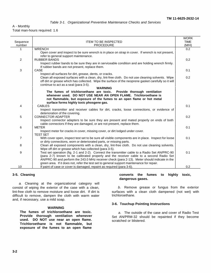
TM 11-6625-2632-14Table 3-1. Organizational Preventive Maintenance Checks and Services
A - MonthlyTotal man-hours required: 1.6
Sequencenumber
ITEM TO BE INSPECTEDPROCEDURE
WORKTIME(M/H)
1 WRENCH 0.2Open cover and inspect to be sure wrench is in place on strap in cover. If wrench is not present,refer to general support maintenance.
2 RUBBER BANDS 0.2Inspect rubber bands to be sure they are in serviceable condition and are holding wrench firmly.If rubber bands are not present, replace them.
3 CASE 0.1Inspect all surfaces for dirt, grease, dents, or cracks.Clean all exposed surfaces with a clean, dry, lint-free cloth. Do not use cleaning solvents. Wipeoff dirt or grease which has collected. Wipe the surface of the neoprene gasket carefully so it willcontinue to act as a seal (para 3-5).
0.2
WARNINGThe fumes of trichloroethane are toxic. Provide thorough ventilationwhenever used. DO NOT USE NEAR AN OPEN FLAME. Trichloroethane isnot flammable, but exposure of the fumes to an open flame or hot metalsurface forms highly toxic phosgene gas.
4 CABLES 0.1Inspect transmitter and receiver cables for dirt, cracks, loose connections, or evidence ofdeterioration of the covering.
5 CONNECTOR ADAPTER 0.2Inspect connector adapters to be sure they are present and mated properly on ends of bothcable connectors If they are damaged, or are not present, replace them.
6 METER 0.1Inspect meter for cracks in cover, missing cover, or dirt lodged under cover.
TEST SET7 With cover open, inspect test set to be sure all visible components are in place. Inspect for loose
or dirty connections, worn or deteriorated parts, or missing parts.0.1
8 Clean all exposed components with a clean, dry, lint-free cloth. Do not use cleaning solvents.Wipe off dirt or grease which has collected (para 3-5).
9 Test set operation (fig. 2-1 and 2-2). Connect the transmitter cable to a Radio Set AN/PRC-90(para 2-7) known to be calibrated properly and the receiver cable to a second Radio SetAN/PRC-90 and perform the 243.0 MHz receiver check (para 2-13). Meter should indicate in thegreen area. If it does not, refer the test set to general support maintenance for repair.
0.1
10 If paint of case or cover is damaged, repaint as required (para 3-6). 0.2
3-5. Cleaning
a. Cleaning at the organizational category willconsist of wiping the exterior of the case with a clean,lint-free cloth to remove moisture and loose dirt. If dirt isdifficult to remove, dampen the cloth with warm waterand, if necessary, use a mild soap.
WARNINGThe fumes of trichloroethane are toxic.Provide thorough ventilation wheneverused. DO NOT use near an open flame.Trichloroethane is not flammable, butexposure of the fumes to an open flame
converts the fumes to highly toxic,dangerous gases.
b. Remove grease or fungus from the exteriorsurfaces with a clean cloth dampened (not wet) withtrichloroethane.
3-6. Touchup Pointing Instructions
a. The outside of the case and cover of Radio TestSet AN/PRM-32 should be repainted if they becomescratched or blistered.
3-2
TM 11-6625-2632-14CAUTION
Do not apply any paint or finish to theneoprene gasket, elbow catch or anysurfaces inside the case.
b. Remove rust and corrosion from metal surfacesby sanding them lightly with fine sandpaper. Brush twothin coats of paint on the bare metal to protect it fromfurther corrosion. Refer to the applicable cleaning andrefinishing practices specified in TB 746-10.
3-7. Organizational Troubleshooting
Troubleshooting at the organizational category isconfined to a visual indication of possible or actualtrouble and is based on the monthly preventivemaintenance checks and equipment performance duringuse. Any malfunction that is beyond the scope oforganizational maintenance to correct shall be referredto general support category maintenance personnel.
3-3

TM 11-6625-2632-14CHAPTER 4
FUNCTIONING OF EQUIPMENT
4-1. IntroductionIn use Radio Test Set AN/PRM-32 is connected betweentwo Radio Sets AN/PRC-90. One radio set transmitsand the other receives the transmitted signal through thetest set. The test set performs two functions. Itattenuates the signal level from the transmitting radio setso that only a weak signal is applied to the antenna ofthe receiving radio set. This permits more sensitivetesting than would otherwise be possible. It alsoprovides a meter indication of signal strength as visibleevidence that a signal is being transmitted.
4-2. Theory of Operation(fig. 4-1)
a. The signal from the transmitting radio set isreceived by the test set at connector J1 and passedthrough an antenna coupler to J2 as an output to the
receiving radio set's antenna (fig. 4-1). The antennacoupler consists of two parts, one of which is afeedthrough terminal which acts as an internaltransmitting antenna. The signal from this terminal ispicked up approximately 2 inches away by an internalreceiving antenna, a wire connected to output connectorJ2. Transmission of the signal across this air gapprovides the necessary attenuation.
b. The signal from connector J1 is also passesthrough a detector circuit, which is a half-way rectifyingcircuit, to potentiometer R6 and test set meter M1. Testset meter M1 is a 50-microampere dc ammeter.Potentiometer R6 adjusted during calibration so that testset meter M1 registers in the green portion of its dialmarking when the signal passed through the antennacoupler is at an acceptable level.
Figure 4-1. Radio Test Set AN/PRM-32 schematic diagram.
4-1

TM 11-6625-2632-14CHAPTER 5
GENERAL SUPPORT MAINTENANCE
Section I. GENERAL
5-1. Scope
General support maintenance includes requirements forperforming physical inspection, operational check,troubleshooting, repair, removal and replacement, andtesting of Radio Test Set AN/PRM-32. Theserequirements are expanded, when necessary, to includethose maintenance functions assigned to organizationalmaintenance category.
5-2. Tools and Test Equipmenta. Tools. Tool Kit, Electronic Equipment TK-100/G.b. Test Equipment. Multimeter AN/USM-223.
5-3. Physical Inspection
The purpose of visual inspection is to locate faultswithout testing of components. Many faults may bedetected by sight, touch, or smell. All visual signsshould be analyzed to help localize the fault to aparticular part. Inspect the test set carefully for obviousdefects. Inspection procedures are shown in table 5-1.Partial disassembly (panel assembly removal, para 5-8)will be required so that the electronic components on theback of the panel can be examined. After correction ofany defects found by inspection, reassemble the test setand per form the checkout procedures.
Table 5-1. Physical Inspection
Step No. Test procedure Performance standard
1 Inspect all controls and mechanicalassemblies for loose or missing screws,bolts, and nuts.
Screws, bolts, and nuts must be tight, withnone missing
2 Inspect all metal parts and wiring for dirt, rust,and corrosion.
Metal parts and wiring must be clean and freeof rust and corrosion
3 Inspect for loose or missing parts, andcracked or broken parts.
All parts must be intact, without cracks, withno loose connections, and no partsmissing.
4 Inspect for frayed or broken insulation, brokenwires, and bare wires or burned insulation.
All wires must be securely soldered, with nobreaks. There must be no bare wires, orburned or broken insulation.
5 Inspect for shorted wires, or wires in contactwith metal parts of panel
There must be no shorted wires, and no wiresin contact with metal parts of case.
Section II. TROUBLESHOOTING
5-4. General
Troubleshooting at general support maintenancecategory consists of verifying and localizing troubles indefective equipment. It also includes a checkout of newequipment for proper operation before use.Troubleshooting by general support maintenancepersonnel is performed using the operational checkspecified in table 5-2. Refer to troubleshooting
procedures (para 5-6) for corrective measures. Replacedefective components.
5-5. Checkout Procedures
Checkout procedures are intended to localize themalfunction or determine that no malfunction exists.Perform the checkout steps shown in table 5-2. If thetest set gives weak or
5-1
TM 11-6625-2632-14
normal indications in this procedure, proceed to testingand calibration (sec IV). If an abnormal indicationappears, record the step at which a malfunction occurredand proceed to the corresponding step in thetroubleshooting procedure. After repair, perform the
complete checkout procedure to be sure the test set isfunctioning properly. After completion of checkoutprocedure, refer to the calibration requirements shown insection IV.
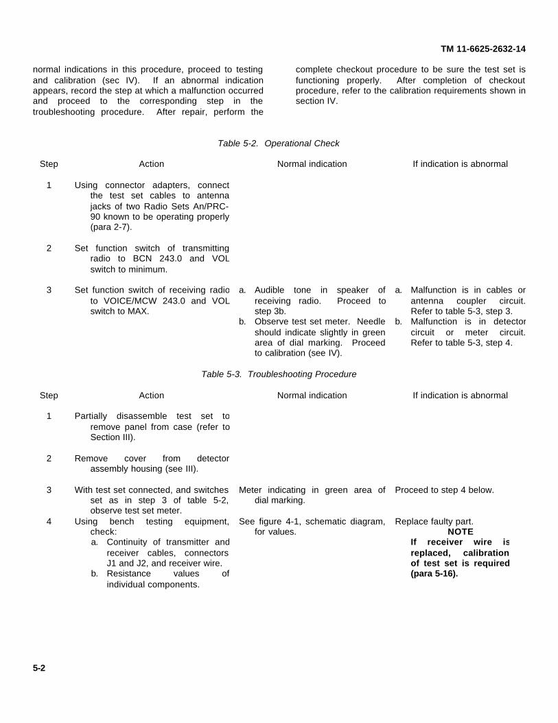
Table 5-2. Operational Check
Step Action Normal indication If indication is abnormal
1 Using connector adapters, connectthe test set cables to antennajacks of two Radio Sets An/PRC-90 known to be operating properly(para 2-7).
2 Set function switch of transmittingradio to BCN 243.0 and VOLswitch to minimum.
3 Set function switch of receiving radioto VOICE/MCW 243.0 and VOLswitch to MAX.
a. Audible tone in speaker ofreceiving radio. Proceed tostep 3b.
a. Malfunction is in cables orantenna coupler circuit.Refer to table 5-3, step 3.
b. Observe test set meter. Needleshould indicate slightly in greenarea of dial marking. Proceedto calibration (see IV).
b. Malfunction is in detectorcircuit or meter circuit.Refer to table 5-3, step 4.
Table 5-3. Troubleshooting Procedure
Step Action Normal indication If indication is abnormal
1 Partially disassemble test set toremove panel from case (refer toSection III).
2 Remove cover from detectorassembly housing (see III).
3 With test set connected, and switchesset as in step 3 of table 5-2,observe test set meter.
Meter indicating in green area ofdial marking.
Proceed to step 4 below.
4 Using bench testing equipment,check:a. Continuity of transmitter and
receiver cables, connectorsJ1 and J2, and receiver wire.
b. Resistance values ofindividual components.
See figure 4-1, schematic diagram,for values.
Replace faulty part.NOTE
If receiver wire isreplaced, calibrationof test set is required(para 5-16).
5-2
TM 11-6625-2632-14
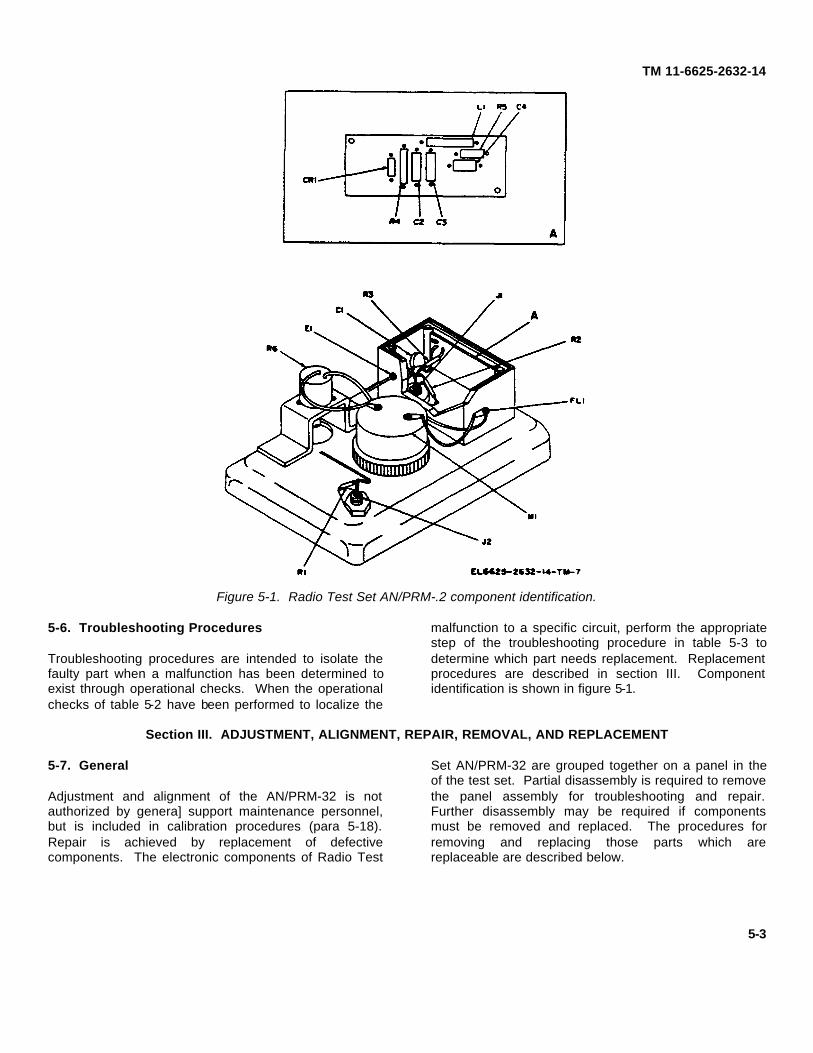
Figure 5-1. Radio Test Set AN/PRM-.2 component identification.
5-6. Troubleshooting Procedures
Troubleshooting procedures are intended to isolate thefaulty part when a malfunction has been determined toexist through operational checks. When the operationalchecks of table 5-2 have been performed to localize the
malfunction to a specific circuit, perform the appropriatestep of the troubleshooting procedure in table 5-3 todetermine which part needs replacement. Replacementprocedures are described in section III. Componentidentification is shown in figure 5-1.
Section III. ADJUSTMENT, ALIGNMENT, REPAIR, REMOVAL, AND REPLACEMENT
5-7. General
Adjustment and alignment of the AN/PRM-32 is notauthorized by genera] support maintenance personnel,but is included in calibration procedures (para 5-18).Repair is achieved by replacement of defectivecomponents. The electronic components of Radio Test
Set AN/PRM-32 are grouped together on a panel in theof the test set. Partial disassembly is required to removethe panel assembly for troubleshooting and repair.Further disassembly may be required if componentsmust be removed and replaced. The procedures forremoving and replacing those parts which arereplaceable are described below.
5-3

TM 11-6625-2632-14
5-8. Panel Assembly Removal(fig. 5-2)
1. Elbow catch2. Screws3. Screws4. Cover Assembly5. Neoprene gasket6. Case7. Panel assembly8. Hinge9. Strike plate10. Rivets
Figure 5-2. Radio Test Set AN/PRM-32 panel assembly.
5-4

TM 11-6625-2632-14
a. Open the elbow catch (1) and remove twoscrews (2).
b. Remove two screws (3) and lift off coverassembly (4)
c. Pull neoprene gasket (5) off case (6) carefullyand lift panel assembly (7) out of case.
CAUTIONAvoid damage to the neoprene gasketwhich could prevent its functioning as aproper seal.
5-9. Detector Housing Assembly Removal(fig. 5-3)
a. Remove panel assembly from case (para 5-7).b. Remove four screws (1) and lift cover (2) off
detector housing assembly (3).
1. Screw 16. Mounting ring2. Cover 9. Screw 17. Test set meter M13. Detector housing assembly 10. Panel 18. Nonrotating lugs4. Connector J1 11. Screw 19. Hex nut5. Hex nut 12. Lockwasher 20. Connector J26. Terminal lug and resistor R2 13. Flat washer 21. Terminal lug and resistor R17. Terminal lug 14. Stepped spacer 21. Terminal lug and resistor R18. Filter capacitor FL1 15. Component board assembly 22. Receiver wire
Figure 5-3. Radio Test Set AN/PRM-32 detector housing assembly.5-5
TM 11-6625-2632-14
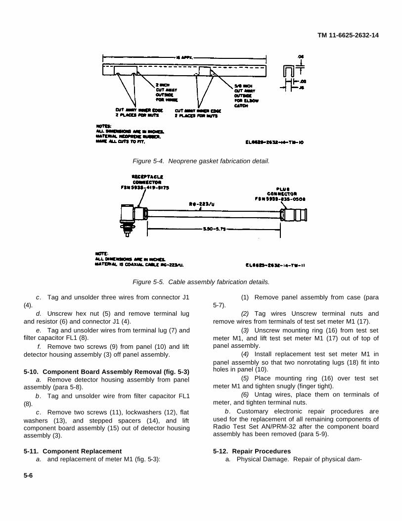
Figure 5-4. Neoprene gasket fabrication detail.
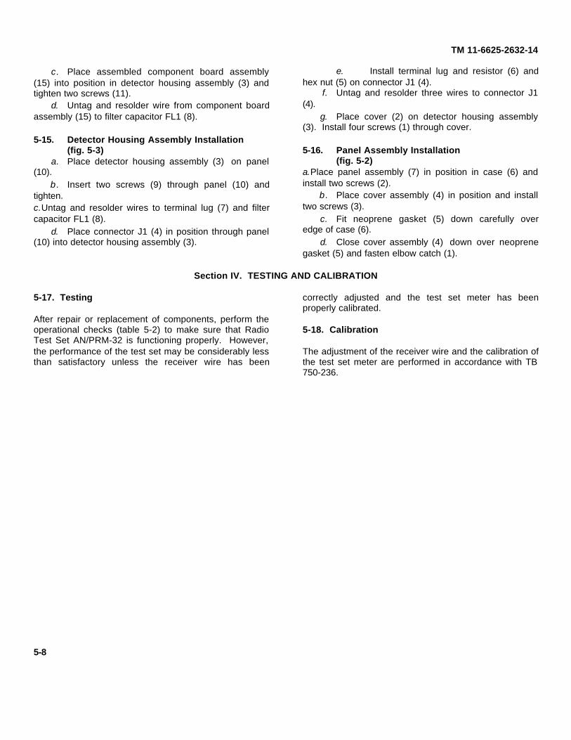
Figure 5-5. Cable assembly fabrication details.
c. Tag and unsolder three wires from connector J1(4).
d. Unscrew hex nut (5) and remove terminal lugand resistor (6) and connector J1 (4).
e. Tag and unsolder wires from terminal lug (7) andfilter capacitor FL1 (8).
f. Remove two screws (9) from panel (10) and liftdetector housing assembly (3) off panel assembly.
5-10. Component Board Assembly Removal (fig. 5-3)a. Remove detector housing assembly from panel
assembly (para 5-8).b. Tag and unsolder wire from filter capacitor FL1
(8).c. Remove two screws (11), lockwashers (12), flat
washers (13), and stepped spacers (14), and liftcomponent board assembly (15) out of detector housingassembly (3).
5-11. Component Replacementa. and replacement of meter M1 (fig. 5-3):
(1) Remove panel assembly from case (para5-7).
(2) Tag wires Unscrew terminal nuts andremove wires from terminals of test set meter M1 (17).
(3) Unscrew mounting ring (16) from test setmeter M1, and lift test set meter M1 (17) out of top ofpanel assembly.
(4) Install replacement test set meter M1 inpanel assembly so that two nonrotating lugs (18) fit intoholes in panel (10).
(5) Place mounting ring (16) over test setmeter M1 and tighten snugly (finger tight).
(6) Untag wires, place them on terminals ofmeter, and tighten terminal nuts.
b. Customary electronic repair procedures areused for the replacement of all remaining components ofRadio Test Set AN/PRM-32 after the component boardassembly has been removed (para 5-9).
5-12. Repair Proceduresa. Physical Damage. Repair of physical dam-
5-6

TM 11-6625-2632-14
Figure 5-6. Receiver wire fabrication details.
Figure 5-7. Wrench fabrication details.
age to the case, cover assembly, or panel of Radio TestSet AN/PRM-32 should be performed if required. Suchrepair consists of straightening out dents, and repainting.
b. Cover Assembly (fig. 5-2). The hinge (8) andstrike plate (9) are each fastened to the cover assembly(4) with two rivets (10). Remove the rivets and replacethe hinge or strike plate by riveting the replacement partin position.
c. Case (fig. 5-2). The elbow catch (1) is fastenedto the case (6) with two rivets (10). Remove the rivetsand replace the elbow catch by riveting the replacementpart in position.
5-13. Fabrication of Replacement Parts
The following parts may be fabricated by the generalsupport repairman:
a. Neoprene Gasket . Using the data in figure 5-4,a replacement neoprene gasket can be made locally.
b. Cable Assembly. A replacement cableassembly can be made locally from repair parts asshown in figure 5-5.
c. Receiver Wire. Using the data in figure 5-6, areplacement receiver wire can be made locally.
NOTEWhenever the receiver wire is replaced,calibration of the test set is required; referto section IV.
d. Wrench. Using the data in figure 5-7, areplacement spanner wrench can be made locally.
5-14. Component Board Assembly Installation(fig. 5-2)
a. Place two screws (11) through lockwashers (12)and flat washers (13) and into detector housingassembly (3).
b. Place stepped spacer (14) over each screw (11).
5-7
TM 11-6625-2632-14
c. Place assembled component board assembly(15) into position in detector housing assembly (3) andtighten two screws (11).
d. Untag and resolder wire from component boardassembly (15) to filter capacitor FL1 (8).
5-15. Detector Housing Assembly Installation(fig. 5-3)
a. Place detector housing assembly (3) on panel(10).
b. Insert two screws (9) through panel (10) andtighten.c.Untag and resolder wires to terminal lug (7) and filtercapacitor FL1 (8).
d. Place connector J1 (4) in position through panel(10) into detector housing assembly (3).
e. Install terminal lug and resistor (6) andhex nut (5) on connector J1 (4).
f. Untag and resolder three wires to connector J1(4).
g. Place cover (2) on detector housing assembly(3). Install four screws (1) through cover.
5-16. Panel Assembly Installation(fig. 5-2)
a.Place panel assembly (7) in position in case (6) andinstall two screws (2).
b. Place cover assembly (4) in position and installtwo screws (3).
c. Fit neoprene gasket (5) down carefully overedge of case (6).
d. Close cover assembly (4) down over neoprenegasket (5) and fasten elbow catch (1).
Section IV. TESTING AND CALIBRATION
5-17. Testing
After repair or replacement of components, perform theoperational checks (table 5-2) to make sure that RadioTest Set AN/PRM-32 is functioning properly. However,the performance of the test set may be considerably lessthan satisfactory unless the receiver wire has been
correctly adjusted and the test set meter has beenproperly calibrated.
5-18. Calibration
The adjustment of the receiver wire and the calibration ofthe test set meter are performed in accordance with TB750-236.
5-8
TM 11-6625-2632-14
APPENDIX A
REFERENCES
The following publications contain information applicable to the maintenance of Radio Set AN/PRM-32.
AR 746-5 Color, Marking, and Preparation of Equipment for Shipment of Army Materiel.DA Pam 310-4 Index of Technical Manuals, Technical Bulletins, Supply Manuals (types 7, 8, and 9),
Supply Bulletins, and Lubrication Orders.DA Pam 310-7 US Army Equipment Index of Modification Work Orders.SB 11-573 Painting and Preservation Supplies Available for Field Use for Electronics Command
Equipment.SB 38-100 Preservation, Packaging, Packing and Marking Materials, Supplies, and Equipment Used
by the Army.SC 5180-91-CL-R13 Sets, Kits, and Outfits Components List: Tool Kit, Electronic Equipment TK-101/G.SC 5180-91-CL-S21 Sets, Kits, and Outfits Components List: Tool Kit, Electronic Equipment TK-100/G.TB 746-10 Field Instructions for Painting and Preserving Electronics Command Equipment.TB 750-236 Calibration Requirements for the Maintenance of Army MaterielTM 38-750 The Army Maintenance Management System (TAMMS).TM 740-90-1 Administrative Storage of Equipment.TM 750-244-2 Procedures for Destruction of Electronic Materiel to Prevent Enemy U
(Electronics Command).
A-1

TM 11-6625-2632-14
APPENDIX B
MAINTENANCE ALLOCATION
Section I. INTRODUCTION
B-1. GeneralThis appendix provides a summary of the maintenanceoperations covered in the equipment literature for RadioTest Set AN/PRM-32. It authorizes categories ofmaintenance for specific maintenance functions onrepairable items and components and the tools andequipment required to perform each function. Thisappendix may be used as an aid in planningmaintenance operations.
B-2. Maintenance FunctionsMaintenance functions shall be limited to and defined asfollows:
a. Adjust. Maintain within prescribed limits bybringing into proper or exact position, or by setting theoperating characteristics to the specified parameters.
b. Align. To adjust specified variable elements ofan item to bring about optimum or desired performance.
c. Calibrate. To determine and cause correctionsto be made or to be adjusted on instruments or testmeasuring and diagnostic equipment used in precisionmeasurement. Consists of comparisons of twoinstruments, one of which is a certified standard ofknown accuracy, to detect and adjust any discrepancy inthe accuracy of the instrument being compared.
d. inspect. To determine the serviceability of anitem by comparing its physical, mechanical and/orelectrical characteristics with established standardsthrough examination.
e. Install The act of emplacing, seating, or fixinginto position an item, part, module (component orassembly) in a manner to allow the proper functioning ofthe equipment/system.
f. Overhaul. That maintenance effort (service/action) necessary to restore an item to a completelyserviceable/operational condition as prescribed bymaintenance standards (e.g., DMWR) in pertinent
technical publications. Overhaul is normally the highestdegree of maintenance performed by the Army.Overhaul does not normally return an item to like newcondition.
g. Rebuild. Consists of those services/actionsnecessary for the restoration of unserviceable equipmentto a like-new condition in accordance with originalmanufacturing standard Rebuild is the highest degree ofmateriel maintenance applied to Army equipment. Thebuild operation includes the act of returning zero thoseage measurements (hours, mil etc.) considered inclassifying Army equipment components.
h. Repair. The application of maintenanceservices (inspect, test, service, adjust, align calibrate,replace) or other maintenance corrections (welding,grinding, riveting, straightening, facing, remachining, orresurfacing) to store serviceability to an item bycorrecting specific damage, fault, malfunction, or failurein a part, subassembly, module/component/assembly,end item or system.
i. Replace. The act of substituting a serviceablelike-type part, subassembly, module (component orassembly) in a manner to allow the proper functioning ofan equipment/system.
j. Service. Operations required periodically tokeep an item in proper operating condition; i.e., to clean,preserve, drain, paint, or to replenishfuel/lubricants/hydraulic fluids or compressed airsupplies.
k. Test. To verify serviceability and to detectincipient failure by measuring the mechanical orelectrical characteristics of an item and comparing thosecharacteristics with prescribed standards.
i. Symbols. The uppercase letter placed in theappropriate column indicates the lowest level at whichthat particular maintenance function is to be performed.
B-1
TM 11-6625-2632-14
B-3. Explanation of Format for MaintenanceAllocation ChartPurpose and use of the format are as follows:
a. Column 1. Group Number. Column 1 listsgroup numbers, the purpose of which is to matchcomponents, assemblies, subassemblies and moduleswith the next higher assembly.
b. Column 2. Functional Group. Column 2 lists thenext higher assembly group and the item names ofcomponents, assemblies, subassemblies and moduleswithin the group for which maintenance is authorized.
c. Column 3. Maintenance Function. Column 3lists the twelve maintenance functions defined inparagraph B-2. Each maintenance function required foran item shall be specified by the symbol among thoselisted in d below which indicates the level responsible forthe required maintenance. Under this symbol there shallbe listed an appropriate work measurement time valuedetermined as indicated in e below.
d. Use of Symbols. The following symbols shall beused to prescribe work function responsibility:
C-Operator/CrewO-OrganizationF-Direct SupportH-General SupportD-Depote. Work Measurement Time. The active repair
time required to perform the maintenance function isincluded directly below the symbol identifying thecategory of maintenance. The manpower figures aredeveloped under conditions (real or simulated)corresponding to those that are considered normal forTOE units operating in the field. The skill levels used to
obtain the measurement times approximate those foundin typical TOE units. Active repair time is the averageaggregate time required to restore an item(subassembly, assembly, component, module, end itemor system) to a serviceable condition under typical fieldoperating conditions. This time includes preparationtime, fault isolation/diagnostic time, and QA/QC time inaddition to the time required to perform specificmaintenance functions identified for the tasks authorizedin the maintenance allocation chart. This time isexpressed in man-hours and carried to one decimalplace (tenths of hours).
f. Column 4, Tools and Equipment. This columnspecifies, by code, those tools and test equipmentsrequired to perform the designated function.
g. Column 5, Remarks. Self-explanatory.
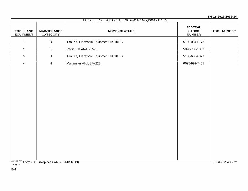
B-4. Explanation of Format for Tool and TestEquipment Requirements
a. Tools and Equipment. The numbers used in thetools and equipment column of the maintenanceallocation chart indicate the applicable tool for themaintenance function.
b. Maintenance Category. The codes in thiscolumn indicate the maintenance category normallyallocated the facility.
c. Nomenclature. This column lists tools, test andmaintenance equipment required to perform themaintenance functions.
d. Federal Stock Number. This column lists theFederal stock number of the specific tool or testequipment.
e. Tool Number. Not used.
(Next printed page is B-3)
B-2

SECTION II. MAINTENANCE ALLOCATION CHART
(3)MAINTENANCE FUNCTIONS
(1)GROUP
NUMBER
(2)FUNCTIONAL GROUP
COMPONENT ASSEMBLYNOMENCLATURE
INS
PE
CT
TES
T
SE
RV
ICE
AD
JUS
T
ALI
GN
CA
LIB
RA
TE
INS
TALL
RE
PL
AC
E
RE
PA
IR
OV
ER
HA
UL
RE
BU
ILD
(4)TOOLS ANDEQUIPMENT
(5)REMARKS
TM 11-6625-2632-14
01 Group, Radio Test Set 0 0 0 0 1,2 Replace MX-8802/PRC-90.AN/PRM-32 0.1 0.1 0.2 0.1
H 3,40.4
*
101 Case 0 0 10.1 0.2
H 3 Replace hinge and0.5 latch.
0102 Cable assembly 0 10.1
H H 3, 4 Replace cable and0.1 0.3 connector.
0103 Connector, Adapter 0 0 1 Non-repairable.MX-8802/PRC-90 0.1 0.1
104 Meter 0 10.1
H H 3, 4 Non-repairable.0.5 0.3
*
0105 Detector H H 3, 4 Piece part replacement.0.3 1.0
106 Potentiometer H H 3, 40.3 0.3
107 Receiver section H H 3, 40.3 0.3
** For calibration refer to TB 760-236.
AMSEL-MA Form 6031 (Edition of 1 Feb 72 is obsolete)1 Aug 72
B-3
TM 11-6625-2632-14TABLE I. TOOL AND TEST EQUIPMENT REQUIREMENTS
TOOLS ANDEQUIPMENT
MAINTENANCECATEGORY
NOMENCLATUREFEDERAL
STOCKNUMBER
TOOL NUMBER
1 O Tool Kit, Electronic Equipment TK-101/G 5180-064-5178
2 0 Radio Set AN/PRC-90 5820-782-5308
3 H Tool Kit, Electronic Equipment TK-100/G 5180-605-0079
4 H Multimeter AN/USM-223 6625-999-7465
AMSEL-MA Form 6031 (Replaces AMSEL-MR 6013) HISA-FM 436-721 Aug 72
B-4

TM 11-6625S-2632-14
APPENDIX C
ORGANIZATIONAL, DIRECT SUPPORT, AND GENERAL SUPPORT
MAINTENANCE REPAIR PARTS AND SPECIAL TOOLS LIST
(INCLUDING DEPOT MAINTENANCE REPAIR PARTS AND SPECIAL TOOLS)
Section I. INTRODUCTION
C-1. ScopeThis appendix lists repair parts and special tools requiredfor the performance of organizational, general support,and depot maintenance of AN/PRM-32.
C-2. GeneralThis Repair Parts and Special Tools List is divided intothe following sections:
a. Repair Parts List-Section II. A list of repair partsauthorized at the organizational level for the performanceof maintenance. The list also includes parts which mustbe removed for replacement of the authorized parts.Parts lists are composed of functional groups inascending numerical sequence, with the parts in eachgroup listed in figure and item number sequence.
b. Special Tools List-Section III. A list of specialtools, test, and support equipment authorized for theperformance of maintenance at the organizational level.
c. Repair Parts List-Section IV. A list of repairparts authorized at the general support and depot levelsfor the performance of maintenance. The list alsoincludes parts which must be removed for thereplacement of the authorized parts. Parts lists arecomposed of functional groups in ascending numericalsequence, with parts in each group listed in figure anditem number sequence.
d. Special Tools List-Section V. A list of specialtools, test, and support equipment authorized for theperformance of maintenance at the general support anddepot levels.
e. Federal Stock Number and Reference NumberIndex-Section VI. A list, in ascending numericalsequence, of all Federal stock numbers appearing in thelistings, followed by a list, in alphanumeric sequence, ofall reference numbers
appearing in the listings. Federal stock numbers andreference numbers are cross-referenced to eachillustration figure and item number appearance.
C-3. Explanation of Columns.
The following provides an explanation of columns foundin the tabular listings:
a. Source, Maintenance, and Recoverability Codes(SMR).
(1) Source code. Source codes are assign tosupport items to indicate the manner acquiring supportitems for maintenance, pair, or overhaul of end items.Source codes a entered in the first and second positionsof t Uniform SMR Code Format as follows:
Code DefinitionPA -Item procured and stocked for anticipated or
known usagePB -Item procured and stocked for insurance
purposes because essentiality dictates that aminimum quantity be available in the supplysystems.
PC -Item procured and stocked and which other-wise would be coded PA except that it isdeteriorative in nature
PD -Support item, excluding support equipment,procured for initial issue or outfitting andstocked only for subsequent or additional initialissues or outfittings. Not subject to automaticreplenishment
PE -Support equipment procured and stocked forinitial issue or outfitting to specifiedmaintenance repair activities.
C-1
TM 11-6625-2632-14
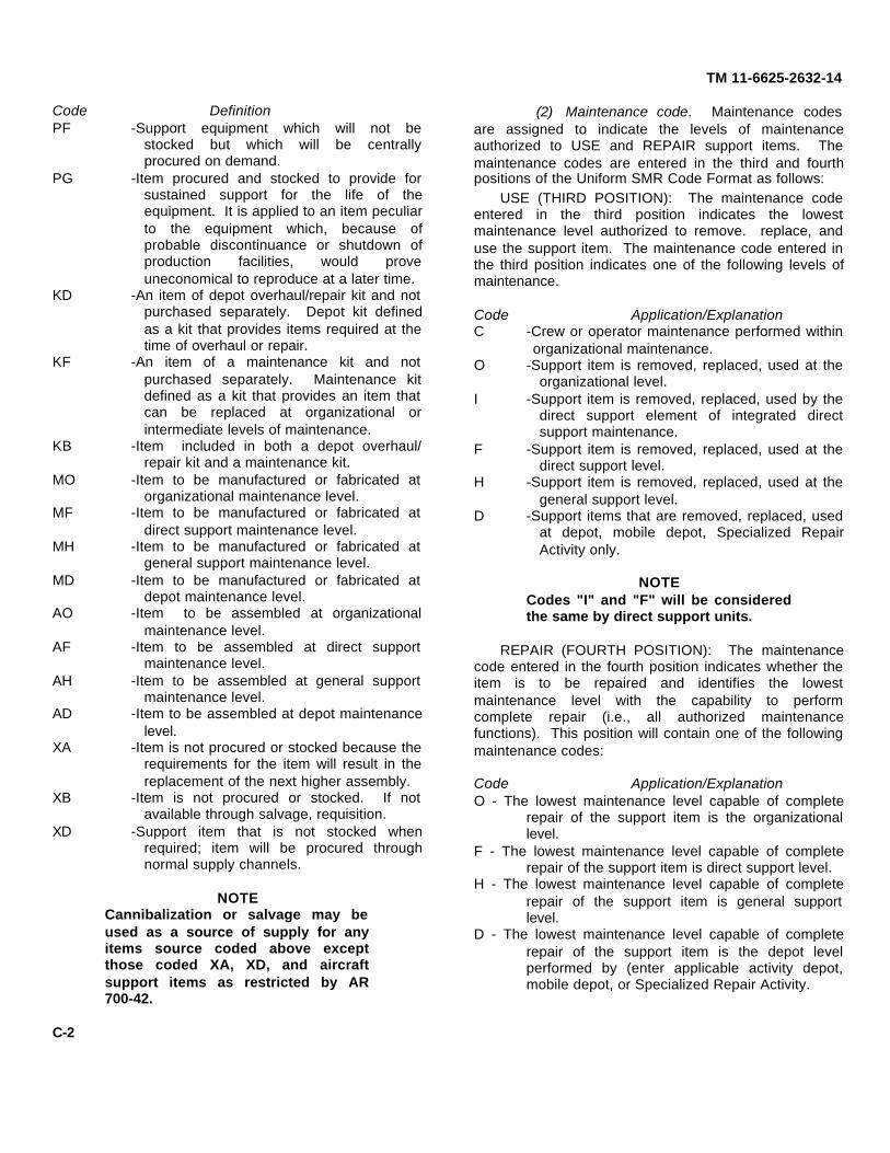
Code DefinitionPF -Support equipment which will not be
stocked but which will be centrallyprocured on demand.
PG -Item procured and stocked to provide forsustained support for the life of theequipment. It is applied to an item peculiarto the equipment which, because ofprobable discontinuance or shutdown ofproduction facilities, would proveuneconomical to reproduce at a later time.
KD -An item of depot overhaul/repair kit and notpurchased separately. Depot kit definedas a kit that provides items required at thetime of overhaul or repair.
KF -An item of a maintenance kit and notpurchased separately. Maintenance kitdefined as a kit that provides an item thatcan be replaced at organizational orintermediate levels of maintenance.
KB -Item included in both a depot overhaul/repair kit and a maintenance kit.
MO -Item to be manufactured or fabricated atorganizational maintenance level.
MF -Item to be manufactured or fabricated atdirect support maintenance level.
MH -Item to be manufactured or fabricated atgeneral support maintenance level.
MD -Item to be manufactured or fabricated atdepot maintenance level.
AO -Item to be assembled at organizationalmaintenance level.
AF -Item to be assembled at direct supportmaintenance level.
AH -Item to be assembled at general supportmaintenance level.
AD -Item to be assembled at depot maintenancelevel.
XA -Item is not procured or stocked because therequirements for the item will result in thereplacement of the next higher assembly.
XB -Item is not procured or stocked. If notavailable through salvage, requisition.
XD -Support item that is not stocked whenrequired; item will be procured throughnormal supply channels.
NOTECannibalization or salvage may beused as a source of supply for anyitems source coded above exceptthose coded XA, XD, and aircraftsupport items as restricted by AR700-42.
(2) Maintenance code. Maintenance codesare assigned to indicate the levels of maintenanceauthorized to USE and REPAIR support items. Themaintenance codes are entered in the third and fourthpositions of the Uniform SMR Code Format as follows:
USE (THIRD POSITION): The maintenance codeentered in the third position indicates the lowestmaintenance level authorized to remove. replace, anduse the support item. The maintenance code entered inthe third position indicates one of the following levels ofmaintenance.
Code Application/ExplanationC -Crew or operator maintenance performed within
organizational maintenance.O -Support item is removed, replaced, used at the
organizational level.I -Support item is removed, replaced, used by the
direct support element of integrated directsupport maintenance.
F -Support item is removed, replaced, used at thedirect support level.
H -Support item is removed, replaced, used at thegeneral support level.
D -Support items that are removed, replaced, usedat depot, mobile depot, Specialized RepairActivity only.
NOTECodes "I" and "F" will be consideredthe same by direct support units.
REPAIR (FOURTH POSITION): The maintenancecode entered in the fourth position indicates whether theitem is to be repaired and identifies the lowestmaintenance level with the capability to performcomplete repair (i.e., all authorized maintenancefunctions). This position will contain one of the followingmaintenance codes:
Code Application/ExplanationO - The lowest maintenance level capable of complete
repair of the support item is the organizationallevel.
F - The lowest maintenance level capable of completerepair of the support item is direct support level.
H - The lowest maintenance level capable of completerepair of the support item is general supportlevel.
D - The lowest maintenance level capable of completerepair of the support item is the depot levelperformed by (enter applicable activity depot,mobile depot, or Specialized Repair Activity.
C-2

TM 11-6625-2632-14
Code Application/Explanation
L -Repair. restricted to designated SpecializedRepair Activity.
Z -Nonrepairable. No repair is authorized.B -No repair is authorized. The item may be
reconditioned by adjusting, lubricating, etc., atthe user level. No parts or special tools areprocured for the maintenance of this item.
(3) Recoverability code. Recoverability codesare assigned to support items to indicate the dispositionaction on unserviceable items. The recoverability codeis entered in the fifth position of the Uniform SMR CodeFormat as follows:
Code DefinitionZ -Nonrepairable item. When unserviceable,
condemn and dispose at the level indicated inposition three.
O -Repairable item. When uneconomicallyrepairable, condemn and dispose atorganizational level.
F -Repairable item. When uneconomicallyrepairable, condemn and dispose at the directsupport level.
H -Repairable item. When uneconomicallyrepairable, condemn and dispose at the generalsupport level.
D -Repairable item. When beyond lower level repaircapability, return to depot. Condemnation anddisposal not authorized below depot level.
L -Repairable item. Repair, condemnation, anddisposal not authorized below depot/SpecializedRepair Activity level.
A -Item requires special handling or condemnationprocedures because of specific reasons (i.e.,precious metal content, high dollar value, criticalmaterial or hazardous material). Refer toappropriate manual/directive for specificinstructions.
b. Federal Stock Number. Indicates the Federalstock number assigned to the item and will be used forrequisitioning purposes.
c. Description. Indicates the Federal item nameand a minimum description required to identify the item.The last line indicates the reference number followed bythe applicable Federal Supply Code for Manufacturer(FSCM) in parentheses. The FSCM is used as anelement in item identification to designate manufactureror distributor or Government agency, etc., and isidentified in SB 708-42.
d.Unit of Measure (U/M). Indicates the standard or basicquantity by which the listed item is used in performingthe actual maintenance function. This measure isexpressed by a two-character alphabetical abbreviation;e.g., ea, in, pr, etc., and is the basis used to indicatequantities and allowances in subsequent columns.When the unit of measure differs from the unit of issue,the lowest unit of issue that will satisfy the required unitsof measure will be requisitioned.
e. Quantity Incorporated in Unit. Indicates thequantity of the item used in the breakout shown on theillustration figure, which is prepared for a functionalgroup, subfunctional group, or an assembly.
f. 15-Day Organizational Maintenance Allowances.(1) The repair parts indicated by an asterisk in
the allowance columns represent those authorized foruse at the organizational category and will berequisitioned on an "as required" basis until stockage isbased on demand in accordance with AR 710-2.
(2) Major Army commanders are authorized toapprove reduction in range of support items authorizedfor use in units within the commands.Recommendations for increase range of itemsauthorized for use will be forwarded to Commander, USArmy Electronic Command, ATTN: AMSEL-MA-A, FortMonmouth, NJ 07703. Any changes approved willreflected in a revision to the RPSTL.
(3) Allowance quantities are indicated theSpecial Tools List section for special too TMDE, andother support equipment.
g. 30-Day GS Maintenance Allowances.(1) The repair parts indicated by asterisk
entries in separate allowance columns for GS representthose authorized for use at that category of maintenanceto be requisitioned on an "as required" basis.
(2) Allowance quantities are indicated in theSpecial Tools List section for special tools, TMDE, andother support equipment.
h. 1-Year Allowances Per 100 Equipments/Contingency Planning Purposes . Column intentionallyleft blank.
i. Depot Maintenance Allowance Per 100Equipments. This column indicates that the itemsidentified with an asterisk are authorized to berequisitioned as required.
j. Illustration. This column is divided as follows:(1) Figure number. Indicates the figure
number of the illustration on which the item is shown.
C-3
TM 11-6625-2632-14
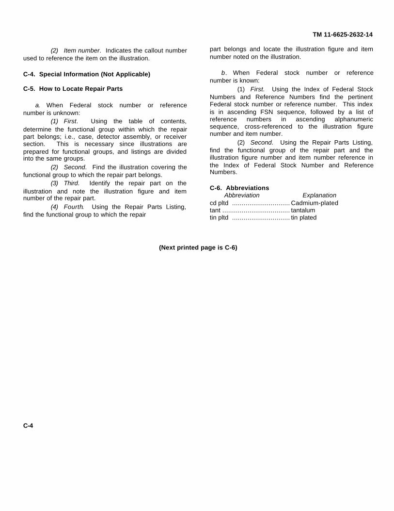
(2) Item number. Indicates the callout numberused to reference the item on the illustration.
C-4. Special Information (Not Applicable)
C-5. How to Locate Repair Parts
a. When Federal stock number or referencenumber is unknown:
(1) First. Using the table of contents,determine the functional group within which the repairpart belongs; i.e., case, detector assembly, or receiversection. This is necessary since illustrations areprepared for functional groups, and listings are dividedinto the same groups.
(2) Second. Find the illustration covering thefunctional group to which the repair part belongs.
(3) Third. Identify the repair part on theillustration and note the illustration figure and itemnumber of the repair part.
(4) Fourth. Using the Repair Parts Listing,find the functional group to which the repair
part belongs and locate the illustration figure and itemnumber noted on the illustration.
b. When Federal stock number or referencenumber is known:
(1) First. Using the Index of Federal StockNumbers and Reference Numbers find the pertinentFederal stock number or reference number. This indexis in ascending FSN sequence, followed by a list ofreference numbers in ascending alphanumericsequence, cross-referenced to the illustration figurenumber and item number.
(2) Second. Using the Repair Parts Listing,find the functional group of the repair part and theillustration figure number and item number reference inthe Index of Federal Stock Number and ReferenceNumbers.
C-6. AbbreviationsAbbreviation Explanation
cd pltd .............................. Cadmium-platedtant ................................... tantalumtin pltd .............................. tin plated
(Next printed page is C-6)
C-4

(1) (2) (3) (4) (5) (6) (7)SMR FEDERAL DESCRIPTION UNIT QTY 15-DAY ORGANIZATIONAL ILLUSTRATIONCODE STOCK OF INC MAINTENANCE ALW (a) (b)
NUMBER MEAS IN (a) (b) (c) (d) FIGURE ITEMReference Number & Mfr Code Usable on Code UNIT 1-5 6-20 21-150 51-100 NO. NO.
TM 11-6625-2632-14Section II. REPAIR PARTS LIST
GROUP 02, CABLES
PAOZZ 5820-478-7054 ADAPTER, TEST EA 2 * * * * 2 4MX8902PRC90 (80052)
C-6
(1) (2) (3) (4) (5) (6) (7)SMR FEDERAL DESCRIPTION UNIT QTY 15-DAY ORGANIZATIONAL ILLUSTRATIONCODE STOCK OF INC MAINTENANCE ALW (a) (b)
NUMBER MEAS IN (a) (b) (c) (d) FIGURE ITEMReference Number & Mfr Code Usable on Code UNIT 1-5 6-20 21-150 51-100 NO. NO.
TM 11-6625-2632-14
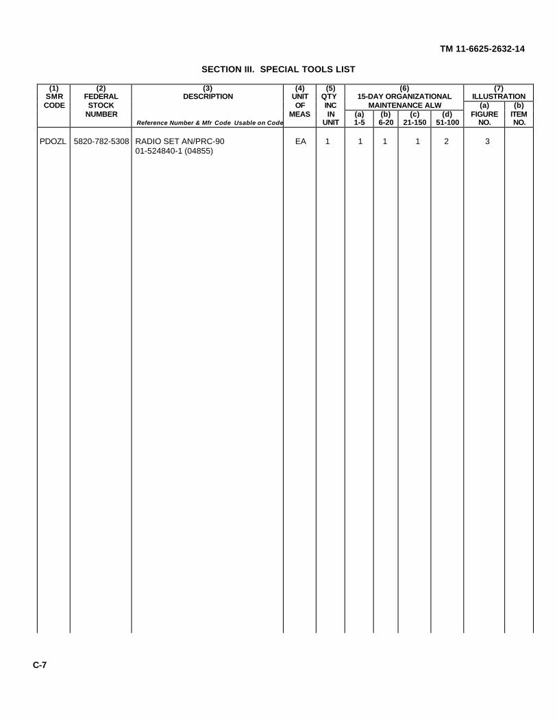
SECTION III. SPECIAL TOOLS LIST
PDOZL 5820-782-5308 RADIO SET AN/PRC-90 EA 1 1 1 1 2 301-524840-1 (04855)
C-7
(1) (2) (3) (4) (5) (6) (7) (8)1-YR
(9)DEPOT
(10)
SMR FEDERAL DESCRIPTION UNIT QTY 30-DAY DS MAINT 30-DAY GS MAINT ALWPER MAINT ILLUSTRATIONCODE STOCK OF INC ALLOWANCE ALLOWANCE 100 ALWPER (a) (b)
NUMBER Reference Number Usable On& Mfr Code
MEAS INUNIT
(a)1-20
(b)21-50
(c)51-100
(a)1-20
(b)21-50
(c)51-100
EQUIPCNTGCY
100EQUIP
FIGURENO.
ITEMNO.
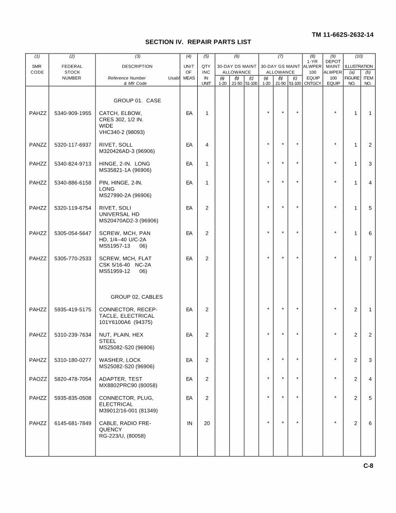
TM 11-662S-2632-14SECTION IV. REPAIR PARTS LIST
GROUP 01. CASE
PAHZZ 5340-909-1955 CATCH, ELBOW, EA 1 * * * * 1 1CRES 302, 1/2 IN.WIDEVHC340-2 (98093)
PANZZ 5320-117-6937 RIVET, SOLL EA 4 * * * * 1 2M320426AD-3 (96906)
PAHZZ 5340-824-9713 HINGE, 2-IN. LONG EA 1 * * * * 1 3MS35821-1A (96906)
PAHZZ 5340-886-6158 PIN, HINGE, 2-lN. EA 1 * * * * 1 4LONGMS27990-2A (96906)
PAHZZ 5320-119-6754 RIVET, SOLI EA 2 * * * * 1 5UNIVERSAL HDMS20470AD2-3 (96906)
PAHZZ 5305-054-5647 SCREW, MCH, PAN EA 2 * * * * 1 6HD, 1/4--40 U/C-2AMS51957-13 06)
PAHZZ 5305-770-2533 SCREW, MCH, FLAT EA 2 * * * * 1 7CSK 5/16-40 NC-2AMS51959-12 06)
GROUP 02, CABLES
PAHZZ 5935-419-5175 CONNECTOR, RECEP- EA 2 * * * * 2 1TACLE, ELECTRICAL101Y6100A6 (94375)
PAHZZ 5310-239-7634 NUT, PLAIN, HEX EA 2 * * * * 2 2STEELMS25082-S20 (96906)
PAHZZ 5310-180-0277 WASHER, LOCK EA 2 * * * * 2 3MS25082-S20 (96906)
PAOZZ 5820-478-7054 ADAPTER, TEST EA 2 * * * * 2 4MX8802PRC90 (80058)
PAHZZ 5935-835-0508 CONNECTOR, PLUG, EA 2 * * * * 2 5ELECTRICALM39012/16-001 (81349)
PAHZZ 6145-681-7849 CABLE, RADIO FRE- IN 20 * * * * 2 6QUENCYRG-223/U, (80058)
C-8

TM 11-6625-2632-14
Figure 1. Case group
C-9
(1) (2) (3) (4) (5) (6) (7) (8)1-YR
(9)DEPOT
(10)
SMR FEDERAL DESCRIPTION UNIT QTY 30-DAY DS MAINT 30-DAY GS MAINT ALWPER MAINT ILLUSTRATIONCODE STOCK OF INC ALLOWANCE ALLOWANCE 100 ALWPER (a) (b)
NUMBER Reference Number Usable On& Mfr Code
MEAS INUNIT
(a)1-20
(b)21-50
(c)51-100
(a)1-20
(b)21-50
(c)51-100
EQUIPCNTGCY
100EQUIP
FIGURENO.
ITEMNO.
TM 11-6625-2632-14SECTION IV. REPAIR PARTS LIST (cont)
GROUP 03. METER
PAHZZ 6625-459-5258 METER, 0-50 UA DC, EA 1 * * * * 2 7SPECIAL SCALE,INC, RING, MOUNT-ING, KNURLED,PHENOLIC25-520493-3 (04655)
PAHZZ 5406-00-0124 TERMINAL LUG, EA 2 * * * * 2 8BRASS, TIN PLTD1497 (83330)
GROUP 04, DETECTORASSEMBLY
PAHZZ 5530-064-5647 SCREW, MCH, PAN EA 2 * * * * 2 9HD, 1/4--40 UNC-2AMS51957-13 (96906)
PAHZZ 5910-S0-983 CAPACITOR, FIXED, EA 1 * * * * 2 10CERAMIC, 160 INDLA. .310 IN LONG,22 UUFCK60BX220K (81349)
PAHZZ 5905-433-2240 RESISTOR, FIXED, EA 1 * * * * 2 1156 OHM ± 5% .25WATTRC07GF221J (81349)
PAHZZ 5905-279-1897 RESISTOR, FIXED EA 1 * * * * 2 1256 OHM ± 5% .5 WATTRC20GF560J (81349)
PAHZZ 5310-934-9759 NUT, PLAN, HEX EA 1 * * * * 2 13STEELMS35649-284S (96906)
PAHZZ 5940-502-7452 TERMINAL LUG, EA 1 * * * * 2 14BRONZE, TIN PLTD2103-06-00 (78189)
PAHZZ 5915-917-9424 CAPACITOR, FIXED EA 1 * * * * 2 15CERAMIC, 1500PF1250-005 (15450)
PAHZZ 5305-054-5637 SCREW, MCH, PAN EA 2 * * * * 2 16HD, 1/4-56 UNC-2AMS51957-3 (96906)
C-10
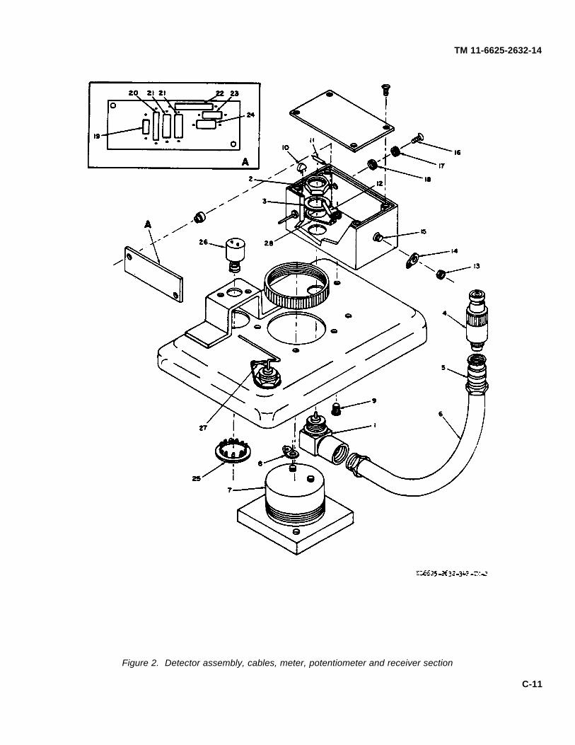
TM 11-6625-2632-14
Figure 2. Detector assembly, cables, meter, potentiometer and receiver section
C-11

(1) (2) (3) (4) (5) (6) (7) (8)1-YR
(9)DEPOT
(10)
SMR FEDERAL DESCRIPTION UNIT QTY 30-DAY DS MAINT 30-DAY GS MAINT ALWPER MAINT ILLUSTRATIONCODE STOCK OF INC ALLOWANCE ALLOWANCE 100 ALWPER (a) (b)
NUMBER Reference Number Usable On& Mfr Code
MEAS INUNIT
(a)1-20
(b)21-50
(c)51-100
(a)1-20
(b)21-50
(c)51-100
EQUIPCNTGCY
100EQUIP
FIGURENO.
ITEMNO.
TM 11-6625-2632-14SECTION IV. REPAIR PARTS LIST (cont)
PAHZZ 5310-928-2690 WASHER, LOCK EA 2 * * * * 2 17SPRING, HELICALMS35338-134 (96906)
PAHZZ 5310-595-6761 WASHER, FLAT, EA 2 * * * * 2 18ROUND, GENL.PURPOSEMS15795-802 (96906)
PAHZZ 5961-938-1135 SEMICONDUCTOR EA 1 * * * * 2 19DEVICE, DIODE,SILICONIN4148 (81349)
PAHZZ 5905-683-2240 RESISTOR, FIXED, EA 1 * * * * 2 20220 OHM ± 5% .25WATTRC07GF221J (81349)
PAHZZ 5910-837-2577 CAPACITOR, FIXED, EA 2 * * * * 2 21CERAMIC, .160 INDIA. .310 IN. LONG,1500 UUFCK60AW152M (81349)
PAHZZ 5950-724-6214 COIL, RF, MOLDED, EA 1 * * * * 2 22TYPE LT4K089,4.70 UH ± 10%MS18130-16 (96906)
PAHZZ 5905-726-4413 RESISTOR, FIXED, EA 1 * * * * 2 2312000 OHM ± 5% .25WATTRC07GF123J (81349)
PAHZZ 5830-11.2-305S CAPACITOR, FIXED, EA 1 * * * * 2 24ELECTROLYTIC,TART, 15 UF ± 20%RADIAL LEADSL15GR (17554)
GROUP 05, POTENTI-OMETER
PAHZZ 5340-685-0765 BUTTON, PLUG, EA 1 * * * * 2 25BRASS, CD PLTD 1/16IN. THICK, 23/32 IN.DIA. 7/32 IN.PRONGSBS48172 (83058)
PAHZZ 5905-577-0434 POTENTIOMETER, EA 1 * * * * 2 26250000 OHM ± 10%0.5 WATTRV6LAYSA254A (81349)
C-12
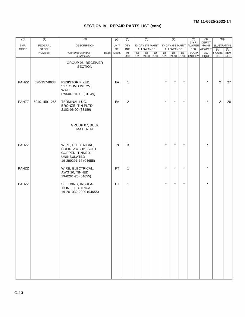
(1) (2) (3) (4) (5) (6) (7) (8)1-YR
(9)DEPOT
(10)
SMR FEDERAL DESCRIPTION UNIT QTY 30-DAY DS MAINT 30-DAY GS MAINT ALWPER MAINT ILLUSTRATIONCODE STOCK OF INC ALLOWANCE ALLOWANCE 100 ALWPER (a) (b)
NUMBER Reference Number Usable On& Mfr Code
MEAS INUNIT
(a)1-20
(b)21-50
(c)51-100
(a)1-20
(b)21-50
(c)51-100
EQUIPCNTGCY
100EQUIP
FIGURENO.
ITEMNO.
TM 11-6625-2632-14SECTION IV. REPAIR PARTS LIST (cont)
GROUP 06, RECEIVERSECTION
PAHZZ 590-957-8633 RESISTOR FIXED, EA 1 * * * * 2 2751.1 OHM ±1% .25WATTRN60D51R1F (81349)
PAHZZ 5940-159-1265 TERMINAL LUG, EA 2 * * * * 2 28BRONZE, TIN PLTD2103-06-00 (78189)
GROUP 07, BULKMATERIAL
PAHZZ WIRE, ELECTRICAL, IN 3 * * * *SOLID, AWG16, SOFTCOPPER, TINNED,UNINSULATED19-290291-16 (04655)
PAHZZ WIRE, ELECTRICAL, FT 1 * * * *AWG 20, TINNED19-0291-20 (04655)
PAHZZ SLEEVING, INSULA- FT 1 * * * *TION, ELECTRICAL19-201032-2009 (04655)
C-13

(1) (2) (3) (4) (5) (6) (7) (8)1-YR
(9)DEPOT
(10)
SMR FEDERAL DESCRIPTION UNIT QTY 30-DAY DS MAINT 30-DAY GS MAINT ALWPER MAINT ILLUSTRATIONCODE STOCK OF INC ALLOWANCE ALLOWANCE 100 ALWPER (a) (b)
NUMBER Reference Number Usable On& Mfr Code
MEAS INUNIT
(a)1-20
(b)21-50
(c)51-100
(a)1-20
(b)21-50
(c)51-100
EQUIPCNTGCY
100EQUIP
FIGURENO.
ITEMNO.
TM 11-6625-2632-14SECTION V. SPECIAL TOOLS LIST (cont)
PDOZL 5820-782-5308 RADIO SET EA 1 1 1 1 1 3AN/PRC-9001-524860-1 (04655)
C-14

TM 11-6625-2632-14
EL6625-2632-34P-TM-3
Figure 3. Radio set AN/PRC-90
C-15
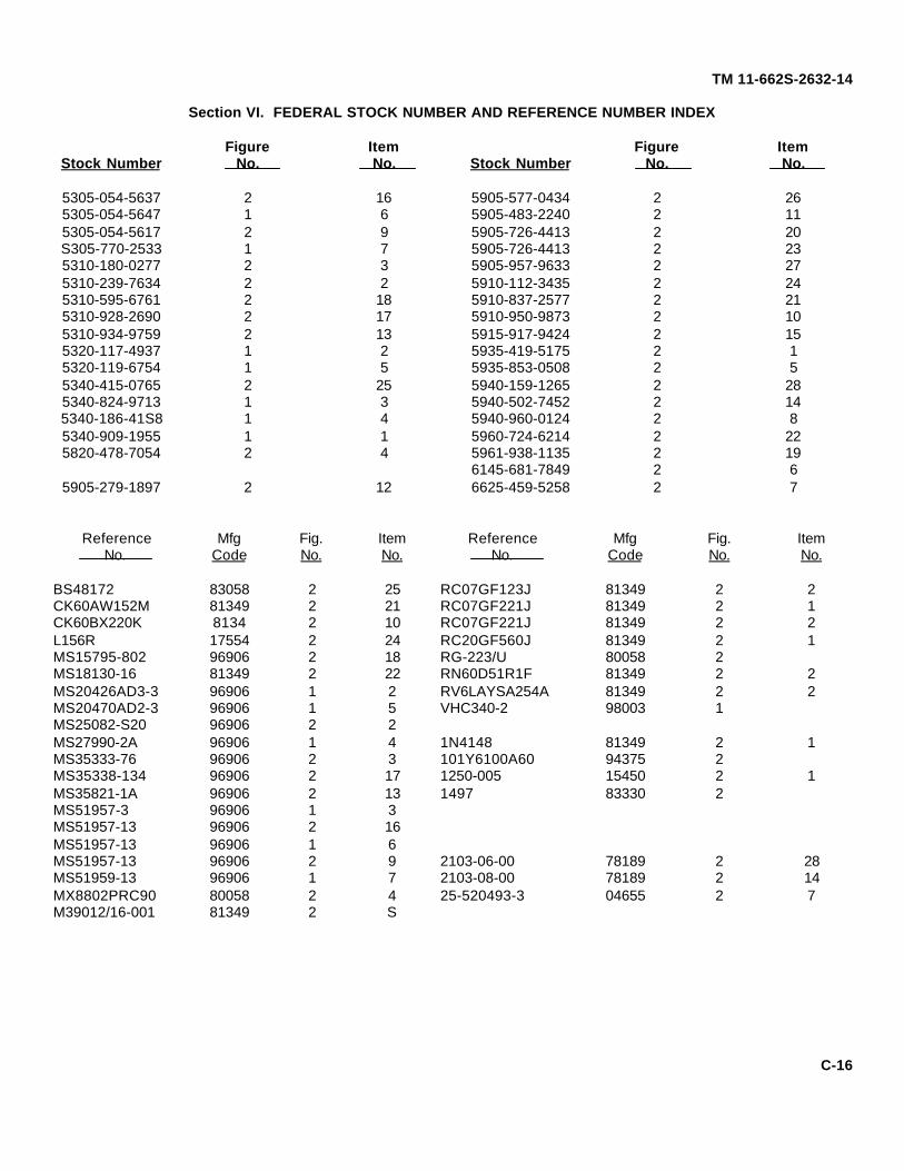
TM 11-662S-2632-14
Section VI. FEDERAL STOCK NUMBER AND REFERENCE NUMBER INDEX
Figure Item Figure ItemStock Number No. No. Stock Number No. No.
5305-054-5637 2 16 5905-577-0434 2 265305-054-5647 1 6 5905-483-2240 2 115305-054-5617 2 9 5905-726-4413 2 20S305-770-2533 1 7 5905-726-4413 2 235310-180-0277 2 3 5905-957-9633 2 275310-239-7634 2 2 5910-112-3435 2 245310-595-6761 2 18 5910-837-2577 2 215310-928-2690 2 17 5910-950-9873 2 105310-934-9759 2 13 5915-917-9424 2 155320-117-4937 1 2 5935-419-5175 2 15320-119-6754 1 5 5935-853-0508 2 55340-415-0765 2 25 5940-159-1265 2 285340-824-9713 1 3 5940-502-7452 2 145340-186-41S8 1 4 5940-960-0124 2 85340-909-1955 1 1 5960-724-6214 2 225820-478-7054 2 4 5961-938-1135 2 19
6145-681-7849 2 65905-279-1897 2 12 6625-459-5258 2 7
Reference Mfg Fig. Item Reference Mfg Fig. ItemNo. Code No. No. No. Code No. No.
BS48172 83058 2 25 RC07GF123J 81349 2 2CK60AW152M 81349 2 21 RC07GF221J 81349 2 1CK60BX220K 8134 2 10 RC07GF221J 81349 2 2L156R 17554 2 24 RC20GF560J 81349 2 1MS15795-802 96906 2 18 RG-223/U 80058 2MS18130-16 81349 2 22 RN60D51R1F 81349 2 2MS20426AD3-3 96906 1 2 RV6LAYSA254A 81349 2 2MS20470AD2-3 96906 1 5 VHC340-2 98003 1MS25082-S20 96906 2 2MS27990-2A 96906 1 4 1N4148 81349 2 1MS35333-76 96906 2 3 101Y6100A60 94375 2MS35338-134 96906 2 17 1250-005 15450 2 1MS35821-1A 96906 2 13 1497 83330 2MS51957-3 96906 1 3MS51957-13 96906 2 16MS51957-13 96906 1 6MS51957-13 96906 2 9 2103-06-00 78189 2 28MS51959-13 96906 1 7 2103-08-00 78189 2 14MX8802PRC90 80058 2 4 25-520493-3 04655 2 7M39012/16-001 81349 2 S
C-16

TM 11-6625-2632-14By Order of the Secretary of the Army
CREIGHTON W. ABRAMSGeneral, United States Army
Official: Chief of Staff
VERNE L. BOWERSMajor General, United States ArmyThe Adjutant General
Distribution:To be distributed in accordance with DA Form 1231 (qty rqr block No. 392) organizational maintenance requirements forall Fixed and Rotor Wing Aircraft.
IU.S. GOVERNMENT PRINTING OFFICE: 1997 - 418-292/65051

PIN : 016133-000

This fine document...
Was brought to you by me:
Liberated Manuals -- free army and government manuals
Why do I do it? I am tired of sleazy CD-ROM sellers, who take publicly available information, slap “watermarks” and other junk on it, and sell it. Those masters of search engine manipulation make sure that their sites that sell free information, come up first in search engines. They did not create it... They did not even scan it... Why should they get your money? Why are not letting you give those free manuals to your friends?
I am setting this document FREE. This document was made by the US Government and is NOT protected by Copyright. Feel free to share, republish, sell and so on.
I am not asking you for donations, fees or handouts. If you can, please provide a link to liberatedmanuals.com, so that free manuals come up first in search engines:
<A HREF=http://www.liberatedmanuals.com/>Free Military and Government Manuals</A>
– SincerelyIgor Chudovhttp://igor.chudov.com/
– Chicago Machinery Movers
Related Documents


