WE CREATE MOTION Technical Manual MCS 3242 BX4 MCS 3268 BX4 MCS 3274 BP4 EN

Welcome message from author
This document is posted to help you gain knowledge. Please leave a comment to let me know what you think about it! Share it to your friends and learn new things together.
Transcript
WE CREATE MOTION
Technical Manual
MCS 3242 BX4
MCS 3268 BX4
MCS 3274 BP4
EN

Imprint
2
Version: 3rd edition, 6-11-2017
Copyrightby Dr. Fritz Faulhaber GmbH & Co. KGDaimlerstr. 23 / 25 · 71101 Schönaich
All rights reserved, including those to the translation.No part of this description may be duplicated, reproduced,stored in an information system or processed or transferred in any other form without prior express writtenpermission of Dr. Fritz Faulhaber GmbH & Co. KG.
This document has been prepared with care.Dr. Fritz Faulhaber GmbH & Co. KG cannot accept any liability for any errors in this document or for theconsequences of such errors. Equally, no liability can beaccepted for direct or consequential damages resultingfrom improper use of the equipment.
The relevant regulations regarding safety engineeringand interference suppression as well as the requirementsspecified in this document are to be noted and followedwhen using the software.
Subject to change without notice.
The respective current version of this technical manual isavailable on FAULHABER's internet site:www.faulhaber.com
3rd edition, 6-11-2017 7000.05058, 3rd edition, 6-11-20177000.05058
3rd edition, 6-11-2017 7000.05058, 3rd edition, 6-11-20177000.05058
Content
3
1 About this document ....................................................................................................... 4
1.1 Validity of this document ...................................................................................... 4
1.2 Associated documents ............................................................................................ 4
1.3 Using this document .............................................................................................. 4
1.4 List of abbreviations ............................................................................................... 5
1.5 Symbols and markers ............................................................................................. 6
2 Safety ................................................................................................................................ 7
2.1 Use for the intended purpose ............................................................................... 7
2.2 Safety instructions .................................................................................................. 7
2.3 Environmental conditions ...................................................................................... 8
2.4 EC directives on product safety ............................................................................. 8
3 Product description .......................................................................................................... 9
3.1 General product description .................................................................................. 9
3.2 Product information ............................................................................................. 10
3.3 Product variants .................................................................................................... 11
3.4 Cable exits for the Motion Control system ......................................................... 12
3.4.1 Axial cable exit (standard).................................................................... 123.4.2 Radial cable exit (option 5451) ............................................................ 123.4.3 Gearbox combination ........................................................................... 13
3.5 Connector overview ............................................................................................. 14
4 Installation ...................................................................................................................... 15
4.1 Mounting .............................................................................................................. 15
4.1.1 Mounting instructions .......................................................................... 154.1.2 Installation at the faceplate ................................................................. 164.1.3 Installation with a baseplate................................................................ 18
4.2 Electrical connection ............................................................................................ 19
4.2.1 Instructions for the electrical connection............................................ 194.2.2 Connecting the Motion Control system............................................... 21
4.2.2.1 Power supply.......................................................................... 214.2.3 Connector pin assignment.................................................................... 214.2.4 I/O circuit diagrams ............................................................................... 244.2.5 External circuit diagrams ...................................................................... 25
5 Maintenance and diagnostics ........................................................................................ 29
5.1 Maintenance instructions .................................................................................... 29
5.2 Maintenance activities ......................................................................................... 29
5.3 Diagnostics ............................................................................................................ 30
5.4 Troubleshooting ................................................................................................... 30
6 Accessories ...................................................................................................................... 31
7 Warranty ......................................................................................................................... 32

About this document
1 About this document
1.1 Validity of this documentThis document describes the installation and use of the following series:
MCS 3242 BX4
MCS 3268 BX4
MCS 3274 BP4
This document is intended for use by trained experts authorised to perform installation and electrical connection of the product.
All data in this document relate to the standard versions of the series listed above. Changes relating to customer-specific versions can be found in the data sheet.
1.2 Associated documentsFor certain actions during commissioning and operation of FAULHABER products additional information from the following manuals is useful:
These manuals can be downloaded in pdf format from the web page www.faulhaber.com/manuals.
1.3 Using this document Read the document carefully before undertaking configuration, in particular chapter
"Safety".
Retain the document throughout the entire working life of the product.
Keep the document accessible to the operating and, if necessary, maintenance person-nel at all times.
Pass the document on to any subsequent owner or user of the product.
Manual Description
Motion Manager 6 Operating instructions for FAULHABER Motion Manager PC software
Quick start guide Description of the first steps for commissioning and operation of FAULHABER Motion Controllers
Drive functions Description of the operating modes and functions of the drive
Accessories manual Description of the accessories
3rd edition, 6-11-2017 7000.05058, 3rd edition, 6-11-20177000.050584

About this document
1.4 List of abbreviations
Abbreviation Meaning
AC Alternating Current
AnIn Analogue Input
AGND Analogue Ground
CAN Controller Area Network
CAN_L CAN-Low
CAN_H CAN-High
CS Command Specifier
DC Direct Current
DigIn Digital input
DigOut Digital output
EGND Enclosure ground
EMC Electromagnetic compatibility
ESD Electrostatic discharge
ET EtherCAT (Ethernet for Control Automation Technology)
GND Ground
I/O Input/Output
PLC Programmable Logic Controller
PWM Pulse Width Modulation
RxD Receive data
TTL Transistor Transistor Logic
TxD Transmit data
3rd edition, 6-11-2017 7000.05058, 3rd edition, 6-11-20177000.050585
About this document
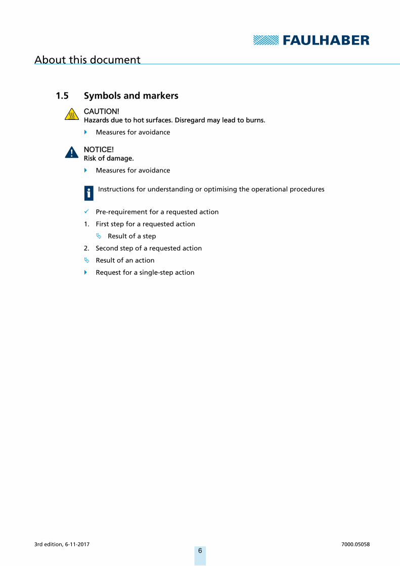
1.5 Symbols and markers
CAUTION!Hazards due to hot surfaces. Disregard may lead to burns.
Measures for avoidance
NOTICE!Risk of damage.
Measures for avoidance
Pre-requirement for a requested action
1. First step for a requested action
Result of a step
2. Second step of a requested action
Result of an action
Request for a single-step action
Instructions for understanding or optimising the operational procedures
3rd edition, 6-11-2017 7000.05058, 3rd edition, 6-11-20177000.050586

Safety
2 Safety
2.1 Use for the intended purposeThe Motion Control systems described here consist of a combination of a basic motor and an integral Motion Controller within a common housing with standard protection class IP 54.
The Motion Control systems are intended for use as slaves, and are particularly suitable for positioning tasks in the following application fields:
Robotics
Toolbuilding
Automation technology
Industrial equipment and special machine building
Medical technology
Laboratory technology
When using the Motion Control systems the following aspects should be recognised:
Motion Control systems contain electronic components and should be handled in accordance with the ESD regulations.
Do not install Motion Control systems in environments where they will come into con-tact with chemicals, nor in explosion hazard areas.
Motion Control systems should be operated only within the limits specified in the data sheet.
Please ask the manufacturer for information about use under individual special environmental conditions.
2.2 Safety instructions
NOTICE!Electrostatic discharges can damage the electronics.
Wear conductive work clothes.
Wear an earthed wristband.
NOTICE!Penetration of foreign objects can damage the electronics.
Do not open the housing.
NOTICE!Inserting and withdrawing connectors whilst supply voltage is applied at the device can damage the electronics.
Do not insert or withdraw connectors whilst supply voltage is applied at the device.
3rd edition, 6-11-2017 7000.05058, 3rd edition, 6-11-20177000.050587

Safety
2.3 Environmental conditions Select the installation location so that clean dry air is available for cooling the Motion
Control system.
When installed within an enclosure, take particular care to ensure adequate cooling of the Motion Control system.
Select a power supply that is within the defined tolerance range.
Protect the Motion Control system against chemical pollutants.
Motion Control systems satisfy protection class IP54 to DIN EN 60259.
2.4 EC directives on product safety The following EC directives on product safety must be observed.
If the Motion Controller is being used outside the EU, international, national and regional directives must be also observed.
Machinery Directive (2006/42/EC)Because of their small size, no serious threats to life or physical condition can normally be expected from electric miniature drives. Therefore the Machinery Directive does not apply to our products. The products described here are not "incomplete machines". Therefore installation instructions are not normally issued by FAULHABER.
Low Voltage Directive (2014/35/EU)The Low Voltage Directive applies for all electrical equipment with a nominal voltage of 75 to 1500 V DC and 50 to 1000 V AC. The products described in this technical manual do not fall within the scope of this directive, since they are intended for lower voltages.
EMC Directive (2014/30/EU)The directive concerning electromagnetic compatibility (EMC) applies to all electrical and electronic devices, installations and systems sold to an end user. In addition, CE marking can be undertaken for built-in components according to the EMC Directive. Conformity with the directive is documented in the Declaration of Conformity.
Depending on the application, additional shaft seals may optionally be installed in the base drive, which have to be maintained at regular intervals.
When combined with attachments (e.g. gearboxes) or for enhanced motor protection an additional seal (O-ring) to enhance the protection class is optionally available (see chap. 3.4.3, p. 13, chap. 4.1.2, p. 16 and chap. 5.2, p. 29).
3rd edition, 6-11-2017 7000.05058, 3rd edition, 6-11-20177000.050588

Product description
3 Product description
3.1 General product descriptionThe FAULHABER Motion Control systems described here are intended for controlled opera-tion of various basic motors incorporated as sub-systems. The offer various different func-tions and operating modes, allowing complex drive duties to be performed. Thanks to their compact design and flexible connection options, the units can be used in a wide variety of applications and require only basic wiring.
The Motion Control system can offer the following communications interfaces:
RS232
CANopen
RS232 and EtherCAT
Connections are also available for common or separate power supplies between motor and controller, and also for a wide variety of inputs and outputs. Configuration of the Motion Control system is performed using the FAULHABER Motion Manager V6.
The drives can be incorporated into the network by means of the CANopen or EtherCAT field bus interfaces. In smaller installations networking can be performed using the RS232 interface. Within the network the Motion Control system operates principally as a slave. Master functionality for controlling other axes is not provided. Alternatively after initial commissioning by the Motion Manager the Motion Control system can also be operated without any communications interface.
Motion Control systems are normally secured using the tapped holes in the faceplate. Where cabling is connected axially, optionally the drive can be secured from below on a flat baseplate (see chap. 4.1, p. 15).
Analogue Hall sensors are used as feedback components.
Motion Control systems with RS232, CANopen or EtherCAT interfaces can also be oper-ated independently of the communications interface if a pre-programmed function or operating program has been programmed without digital command controls.
3rd edition, 6-11-2017 7000.05058, 3rd edition, 6-11-20177000.050589

Product description
3.2 Product information
Fig. 1: Designation key
RS: Serial Interface RS 232CO: Interface CANopen® ET: Interface EtherCAT®
BX4: Motor family (BL, 4 pole technology)
BP4: Motor family (BL, 4 pole technology)
G: Shaft diameter 5 mm
42: Motor length 42 mm68: Motor length 68 mm74: Motor length 74 mm
32: Motor diameter 32 mm
MCS: Motion Control System
024: Motor nominal voltage 24 V
G ... MCS 32 ... ... ...
3rd edition, 6-11-2017 7000.05058, 3rd edition, 6-11-20177000.0505810
Product description
3.3 Product variantsThe following product variants are available:
Motion Control system with axial cable exit
Motion Control System with radial cable exit
As well as the cable exit, the following communications interfaces can be selected:
RS232
CANopen
RS232 and EtherCAT
The following motors are available for selection for each product variant:
3242 BX4
3268 BX4
3274 BP4
Depending on the motor, interface and cable exit selection, the installed length and/or height of the MCS will vary. Details can be found on the respective product datasheet or the relevant dimensional drawing.
Depending on the application, additional shaft seals may optionally be installed in the base drive, which have to be maintained at regular intervals.
When combined with attachments (e.g. gearboxes) or for enhanced motor protection an additional seal (O-ring) to enhance the protection class is optionally available (see chap. 3.4.3, p. 13, chap. 4.1.2, p. 16 and chap. 5.2, p. 29).
3rd edition, 6-11-2017 7000.05058, 3rd edition, 6-11-20177000.0505811

Product description
3.4 Cable exits for the Motion Control system
3.4.1 Axial cable exit (standard)
Fig. 2: Isometric view (left) and connector view (right) for axial cable exit
3.4.2 Radial cable exit (option 5451)
Fig. 3: Isometric view (left) and connector view (right) for radial cable exit
3rd edition, 6-11-2017 7000.05058, 3rd edition, 6-11-20177000.0505812
Product description
3.4.3 Gearbox combination
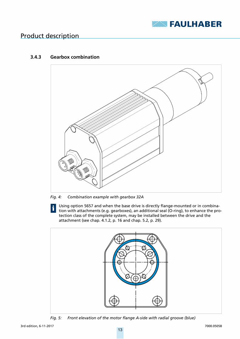
Fig. 4: Combination example with gearbox 32A
Fig. 5: Front elevation of the motor flange A-side with radial groove (blue)
Using option 5657 and when the base drive is directly flange-mounted or in combina-tion with attachments (e.g. gearboxes), an additional seal (O-ring), to enhance the pro-tection class of the complete system, may be installed between the drive and the attachment (see chap. 4.1.2, p. 16 and chap. 5.2, p. 29).
3rd edition, 6-11-2017 7000.05058, 3rd edition, 6-11-20177000.0505813

Product description
3.5 Connector overview
Tab. 1: Connector overview of the Motion Control system
Tab. 2: LED overview
Designation Function
IN/OUT Connection of the EtherCAT communication
X1 (supply) Power supply of the Motion Control system
X2 (I/O) Interface connection RS232/CAN and inputs or outputs for external circuits
Designation Interface Function
Status LED all Green (continuous): Device active. Green (flashing): Device active. However the state machine has not yet reached
the Operation Enabled state. Red (continuously flashing): The drive has switched to a fault state. The output
stage will be switched off or has already been switched off. Red (Error code): Boot procedure failed. Please contact FAULHABER Support.
RUN LED EtherCAT Green (continuous): Connection available. Device is ready for operation. Green (flashing): Device is in the Pre-Operational state. Green (single flash): Device is in the Safe-Operational state. Off: Device is in the Initialisation state.
ERR LED EtherCAT Red (flashing): Defective configuration. Red (single flash): Local error. Red (double flash): Watchdog timeout. Off: No connection error
LA LED EtherCAT Green (continuous): No data transfer. Connection to another participant has been established.
Green (flashing): Data transfer active. Off: No data transfer. No connection to another participant.
3rd edition, 6-11-2017 7000.05058, 3rd edition, 6-11-20177000.0505814
Installation
4 Installation
4.1 MountingOnly trained specialists and instructed persons with knowledge of the following fields may install and operate the Motion Control system:
Automation technology
Standards and regulations (such as the EMC Directive)
Low Voltage Directive
Machinery Directive
VDE regulations (DIN VDE 0100)
Accident prevention regulations
This description must be carefully read and observed before commissioning.
Also comply with the supplementary instructions for installation (see chap. 2.3, p. 8).
4.1.1 Mounting instructions
CAUTION!When in operation the Motion Control system can become very hot.
Place a guard against contact and warning notice in the immediate proximity to the Motion Control system.
NOTICE!Improper installation or installation using unsuitable attachment materials can lead to the Motion Control system becoming damaged.
Comply with the installation instructions.
NOTICE!Installation and connection of the Motion Control system when the power supply is live can lead to the device becoming damaged.
During all aspects of installation and connection work on the Motion Control system, switch off the power supply.
NOTICE!Installation of the Motion Control system on a surface that is not flat and connection on it can lead to the Motion Control system becoming damaged.
Install the Motion Control system on a flat surface.
3rd edition, 6-11-2017 7000.05058, 3rd edition, 6-11-20177000.0505815

Installation
4.1.2 Installation at the faceplate
Fig. 6: V3 installation
NOTICE!If the Motion Control system is installed with the shaft end facing upwards, liquids can accumulate on the upward-facing surface and damage the unit.
If the system is installed to V3 format (see Fig. 6), make sure that no liquids can pene-trate into the bearings.
Optionally: Use a Motion Control system with an additional shaft seal. Fitting an addi-tional shaft seal will lead to a reduction in motor performance (see chap. 4.1, p. 15)
Secure the Motion Control system (1) with screws (2) using the tapped holes on the cover plate as shown in Fig. 7.
The tightening torque of the screws is 130 Ncm.
The maximum screw-in depth is 4 mm.
Fig. 7: Installation at the faceplate
Using option 5657 and when the base drive is directly flange-mounted or in combina-tion with attachments (e.g. gearboxes), an additional seal (O-ring), to enhance the pro-tection class of the complete system, may be installed between the drive and the attachment (see chap. 4.1.2, p. 16 and chap. 5.2, p. 29).
1 2
3rd edition, 6-11-2017 7000.05058, 3rd edition, 6-11-20177000.0505816

Installation
Fig. 8: Front elevation of the motor flange A-side with radial groove (blue)
3rd edition, 6-11-2017 7000.05058, 3rd edition, 6-11-20177000.0505817

Installation
4.1.3 Installation with a baseplate
1. Secure the Motion Control system (1) with screws (3) to the baseplate (2).
Screw type ST 2.2
The tightening torque of the countersunk screws is 50 Ncm.
The maximum screw-in depth of the countersunk screws is 5 mm
Fig. 9: Installation with a baseplate
Screws and baseplate are not part of the FAULHABER product portfolio, they must be provided by the user.
Screw distances 3274 BP4 RS/CO/ET 3268 BX4 RS/CO/ET 3242 BX4 RS/CO/ET
X 29 mm 29 mm 29 mm
Y 103 mm 94 mm 68 mm
1
2
3
XY
3rd edition, 6-11-2017 7000.05058, 3rd edition, 6-11-20177000.0505818

Installation
4.2 Electrical connection
4.2.1 Instructions for the electrical connection
NOTICE!Electrostatic discharges to the Motion Control system connections can damage the elec-tronic components.
Comply with the ESD protective measures.
NOTICE!Incorrect connection of the wires can damage the electronic components.
Connect the wires as shown in the connection assignment.
NOTICE!A short-term voltage peak during braking can damage the power supply or other con-nected devices.
For applications with high load inertia, the FAULHABER Braking Chopper of the BC 5004 series can be used to limit overvoltages and thereby protect the power supply. For more detailed information see the data sheet for the Braking Chopper.
The Motion Control system contains a PWM output stage for controlling the motors. Power losses arising during operation and alternating electrical fields arising due to the pulsed control of the motors, must be dissipated and damped by appropriate installation.
Connect the Motion Control system to an earthing system. This should be done prefera-bly by mounting on an earthed baseplate, or by mounting on an earthed flange. Alter-natively the earthing can be achieved by connecting the screen of the connecting cables to the connection sockets.
Make sure that potential equalisation is present between all coupled parts of the sys-tem.
If several electrical devices or controllers are networked by means of RS232 or CAN, make sure that the potential difference between the earth potentials of the various parts of the system is less than 2 V.
The EGND connection, and if necessary the screen around the power supply connection cable, are available for potential equalisation.
3rd edition, 6-11-2017 7000.05058, 3rd edition, 6-11-20177000.0505819
Installation
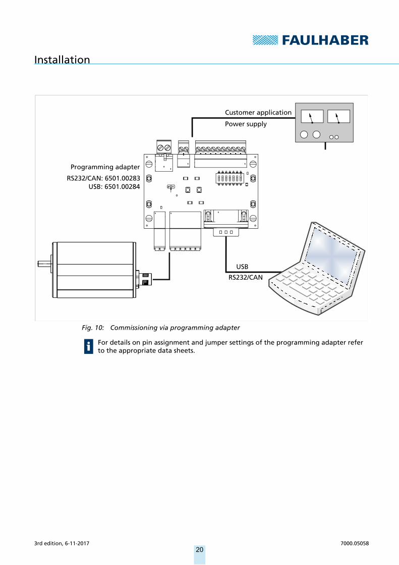
Fig. 10: Commissioning via programming adapter
USB
RS232/CAN
Programming adapter
RS232/CAN: 6501.00283USB: 6501.00284
Customer application
Power supply
For details on pin assignment and jumper settings of the programming adapter refer to the appropriate data sheets.
3rd edition, 6-11-2017 7000.05058, 3rd edition, 6-11-20177000.0505820
Installation
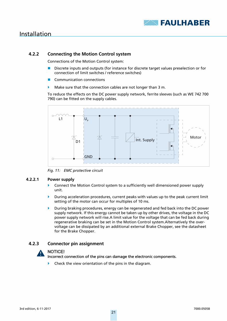
4.2.2 Connecting the Motion Control system
Connections of the Motion Control system:
Discrete inputs and outputs (for instance for discrete target values preselection or for connection of limit switches / reference switches)
Communication connections
Make sure that the connection cables are not longer than 3 m.
To reduce the effects on the DC power supply network, ferrite sleeves (such as WE 742 700 790) can be fitted on the supply cables.
Fig. 11: EMC protective circuit
4.2.2.1 Power supply Connect the Motion Control system to a sufficiently well dimensioned power supply
unit.
During acceleration procedures, current peaks with values up to the peak current limit setting of the motor can occur for multiples of 10 ms.
During braking procedures, energy can be regenerated and fed back into the DC power supply network. If this energy cannot be taken up by other drives, the voltage in the DC power supply network will rise.A limit value for the voltage that can be fed back during regenerative braking can be set in the Motion Control system.Alternatively the over-voltage can be dissipated by an additional external Brake Chopper, see the datasheet for the Brake Chopper.
4.2.3 Connector pin assignment
NOTICE!Incorrect connection of the pins can damage the electronic components.
Check the view orientation of the pins in the diagram.
L1
D1
GND
MotorInt. Supply
UP
3rd edition, 6-11-2017 7000.05058, 3rd edition, 6-11-20177000.0505821

Installation
EtherCAT interface connection (IN/OUT)
Tab. 3: Pin assignment for the EtherCAT M8 connector, 4–pin, A-coded, socket side view
Supply connection (X1)
Tab. 4: Pin assignment for the M12 connector, 4-pin, A-coded, viewed from the pin side
Tab. 5: Electrical data for the supply connection (X1)
Pin Designation Meaning
1 Rx/Tx + Rx/Tx positive connection port
2 Tx/Rx + Tx/Rx positive connection port
3 Tx/Rx – Tx/Rx negative connection port
4 Rx/Tx – Rx/Tx negative connection port
Pin Designation Meaning
1 GND Ground
2 Up Supply connection to the electronics
3 Umot Supply connection to the motor
4 EGND Enclosure ground connection
Designation Value
Power supply for the electronics 12–50 V
Reference potential to GND
< 100 mA (without external consumer load)
Power supply for motor <50 V
Reference potential to GND
24
3 1
2
3 1
4
3rd edition, 6-11-2017 7000.05058, 3rd edition, 6-11-20177000.0505822

Installation
I/O port (X2)
Tab. 6: Pin assignment for the M12 connector, 12-pin, A-coded, viewed from the pin side
Tab. 7: Electrical data for the I/O port (X2)
Pin Designation Meaning
1 GND Ground
2 CAN_L /RxD CAN-Low interface
3 CAN_H /TxD CAN-High interface
4 UDD Supply voltage for external con-sumer load
5 DigOut 1 Digital output
6 DigOut 2 Digital output
7 DigIn 1 Digital input
8 DigIn 2 Digital input
9 DigIn 3 Digital input
10 AnIn 1 Analogue input
11 AGND Analogue ground
12 AnIn 2 Analogue input
Screen EGND Enclosure ground connection
Pin Value
External power supply 5 V
Current Source < 100 mA
DigOut Low = GND
High = high resistance
Integrated pull-up resistor = 33 kΩCurrent sink < 0.7 A
TTL level: low < 0.5 V, high > 3.5 V
PLC level: low < 7 V, high > 11.5 V
DigIn <50 V
Input resistance > 10 kΩFrequency < 1 MHz
Reference potential = GND
AnIn Input voltage = ±10 V
Input resistance > 27 kΩAGND
23
411
51
10
912
876
3rd edition, 6-11-2017 7000.05058, 3rd edition, 6-11-20177000.0505823
Installation
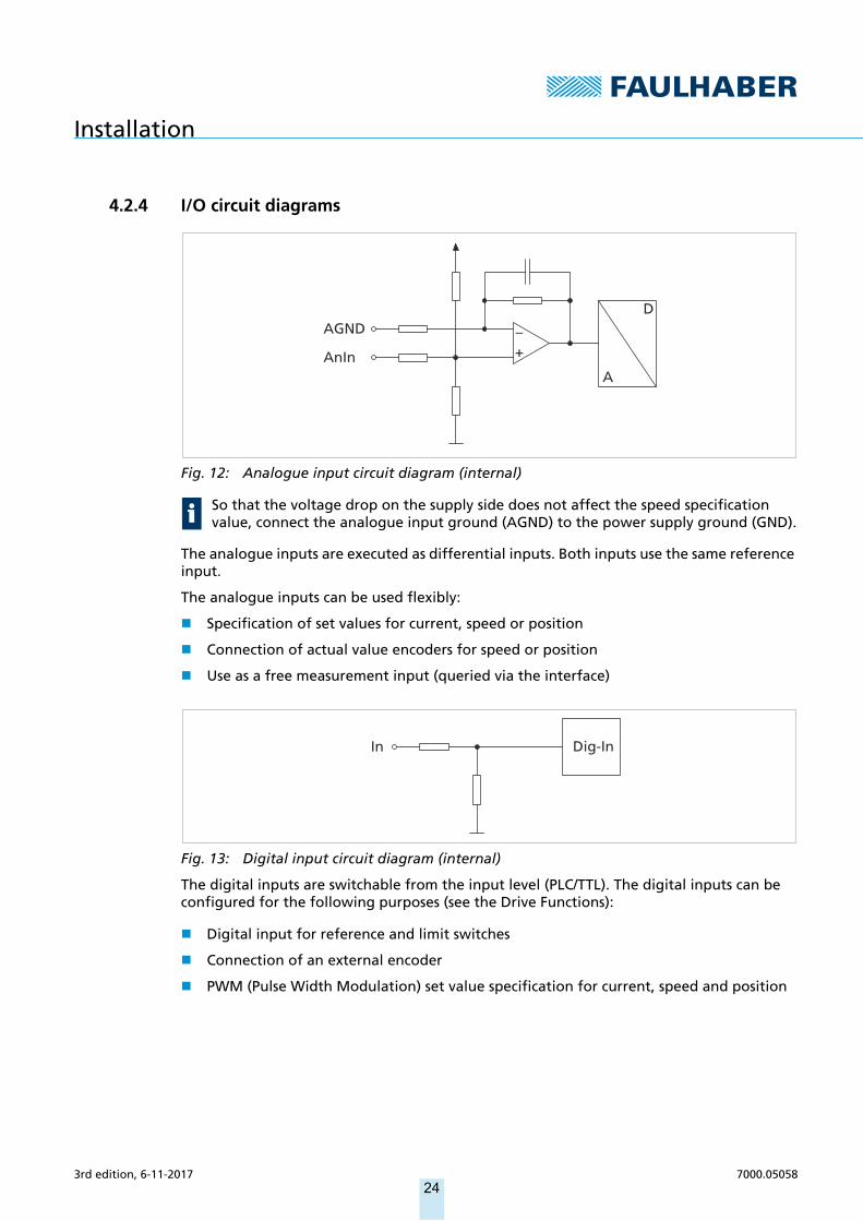
4.2.4 I/O circuit diagrams
Fig. 12: Analogue input circuit diagram (internal)
The analogue inputs are executed as differential inputs. Both inputs use the same reference input.
The analogue inputs can be used flexibly:
Specification of set values for current, speed or position
Connection of actual value encoders for speed or position
Use as a free measurement input (queried via the interface)
Fig. 13: Digital input circuit diagram (internal)
The digital inputs are switchable from the input level (PLC/TTL). The digital inputs can be configured for the following purposes (see the Drive Functions):
Digital input for reference and limit switches
Connection of an external encoder
PWM (Pulse Width Modulation) set value specification for current, speed and position
So that the voltage drop on the supply side does not affect the speed specification value, connect the analogue input ground (AGND) to the power supply ground (GND).
AnIn
AGND –+
A
D
In Dig-In
3rd edition, 6-11-2017 7000.05058, 3rd edition, 6-11-20177000.0505824

Installation
Fig. 14: Digital output circuit diagram (internal)
The digital output has the following properties:
Open collector switch to ground
Monitored output current (switch opens in the event of an error)
The digital output can be configured for the following purposes:
Fault output
Actuation of an externally installed brake
Digital output (freely programmable)
4.2.5 External circuit diagrams
Bipolar analogue set value specification via potentiometer
Fig. 15: Bipolar analogue set value specification via potentiometer
DigOut
33k
UP
DigOut
–+
20 V
10k
4,7k
1k
Motion Controller
AnIn
AGND
Interface
Ref
UP
GND
GND
UP
10 V
3rd edition, 6-11-2017 7000.05058, 3rd edition, 6-11-20177000.0505825

Installation
Analogue set value specification via potentiometer with internally set offset and scaling
Fig. 16: Analogue set value specification via potentiometer with internally set offset and scaling
Connection of reference and limit switches
Fig. 17: Connection of reference and limit switches
Depending on the type of switch it may be necessary to use additional pull-up resistors. No internal pull-up resistors are incorporated in the Motion Controller.
–+10k
Motion Controller
AnIn
AGND
Interface
Ref
UP
GND
GND
UP
UDD
1k 1k
InterfaceLimit Switch
Motion Controller
DigIn X
DigIn Y
GND
GND
GND
UP
UP
3rd edition, 6-11-2017 7000.05058, 3rd edition, 6-11-20177000.0505826
Installation
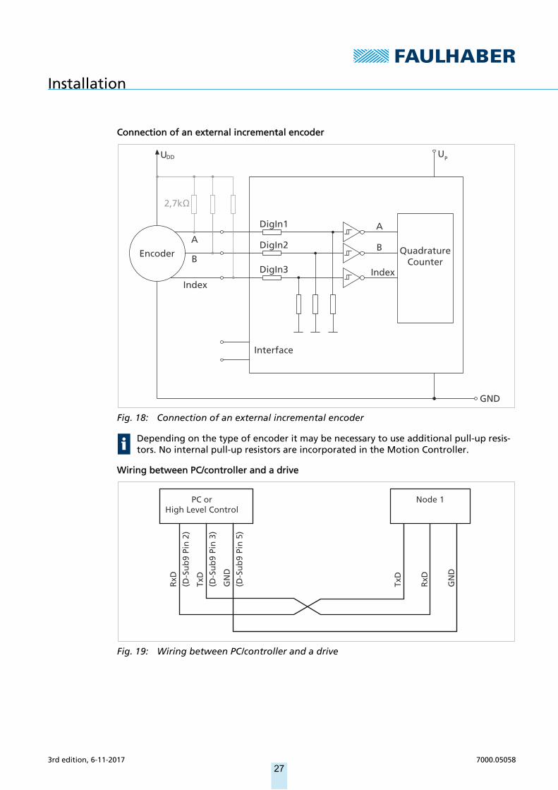
Connection of an external incremental encoder
Fig. 18: Connection of an external incremental encoder
Wiring between PC/controller and a drive
Fig. 19: Wiring between PC/controller and a drive
Depending on the type of encoder it may be necessary to use additional pull-up resis-tors. No internal pull-up resistors are incorporated in the Motion Controller.
2,7k
Interface
QuadratureCounter
AA
B
IndexB
Index
DigIn2
DigIn3
Encoder
UDD
GND
UP
DigIn1
PC orHigh Level Control
Node 1
TxD
RxD
RxD
TxD
GN
D
GN
D
(D-S
ub
9 Pi
n 2
)
(D-S
ub
9 Pi
n 3
)
(D-S
ub
9 Pi
n 5
)
3rd edition, 6-11-2017 7000.05058, 3rd edition, 6-11-20177000.0505827
Installation
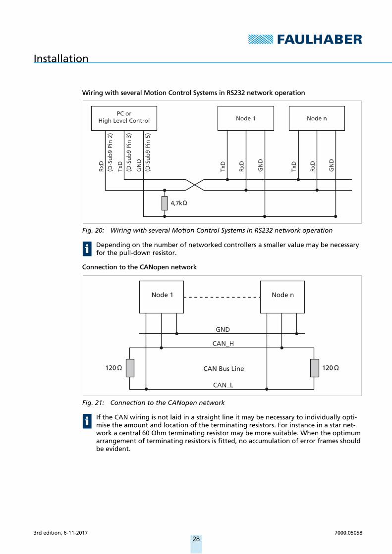
Wiring with several Motion Control Systems in RS232 network operation
Fig. 20: Wiring with several Motion Control Systems in RS232 network operation
Connection to the CANopen network
Fig. 21: Connection to the CANopen network
Depending on the number of networked controllers a smaller value may be necessary for the pull-down resistor.
If the CAN wiring is not laid in a straight line it may be necessary to individually opti-mise the amount and location of the terminating resistors. For instance in a star net-work a central 60 Ohm terminating resistor may be more suitable. When the optimum arrangement of terminating resistors is fitted, no accumulation of error frames should be evident.
PC orHigh Level Control
4,7k
Node 1 Node n
TxD
TxD
RxD
RxD
RxD
TxD
GN
D
GN
D
GN
D
(D-S
ub
9 Pi
n 2
)
(D-S
ub
9 Pi
n 3
)
(D-S
ub
9 Pi
n 5
)
Node 1
CAN Bus Line
Node n
GND
CAN_H
CAN_L
120 120
3rd edition, 6-11-2017 7000.05058, 3rd edition, 6-11-20177000.0505828
Maintenance and diagnostics
5 Maintenance and diagnostics
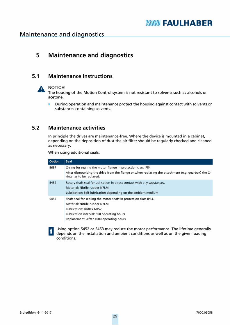
5.1 Maintenance instructions
NOTICE!The housing of the Motion Control system is not resistant to solvents such as alcohols or acetone.
During operation and maintenance protect the housing against contact with solvents or substances containing solvents.
5.2 Maintenance activitiesIn principle the drives are maintenance-free. Where the device is mounted in a cabinet, depending on the deposition of dust the air filter should be regularly checked and cleaned as necessary.
When using additional seals:
Option Seal
5657 O-ring for sealing the motor flange in protection class IP54.
After dismounting the drive from the flange or when replacing the attachment (e.g. gearbox) the O-ring has to be replaced.
5452 Rotary shaft seal for utilisation in direct contact with oily substances.
Material: Nitrile rubber N7LM
Lubrication: Self-lubrication depending on the ambient medium
5453 Shaft seal for sealing the motor shaft in protection class IP54.
Material: Nitrile rubber N7LM
Lubrication: Isoflex NB52
Lubrication interval: 500 operating hours
Replacement: After 1000 operating hours
Using option 5452 or 5453 may reduce the motor performance. The lifetime generally depends on the installation and ambient conditions as well as on the given loading conditions.
3rd edition, 6-11-2017 7000.05058, 3rd edition, 6-11-20177000.0505829
Maintenance and diagnostics
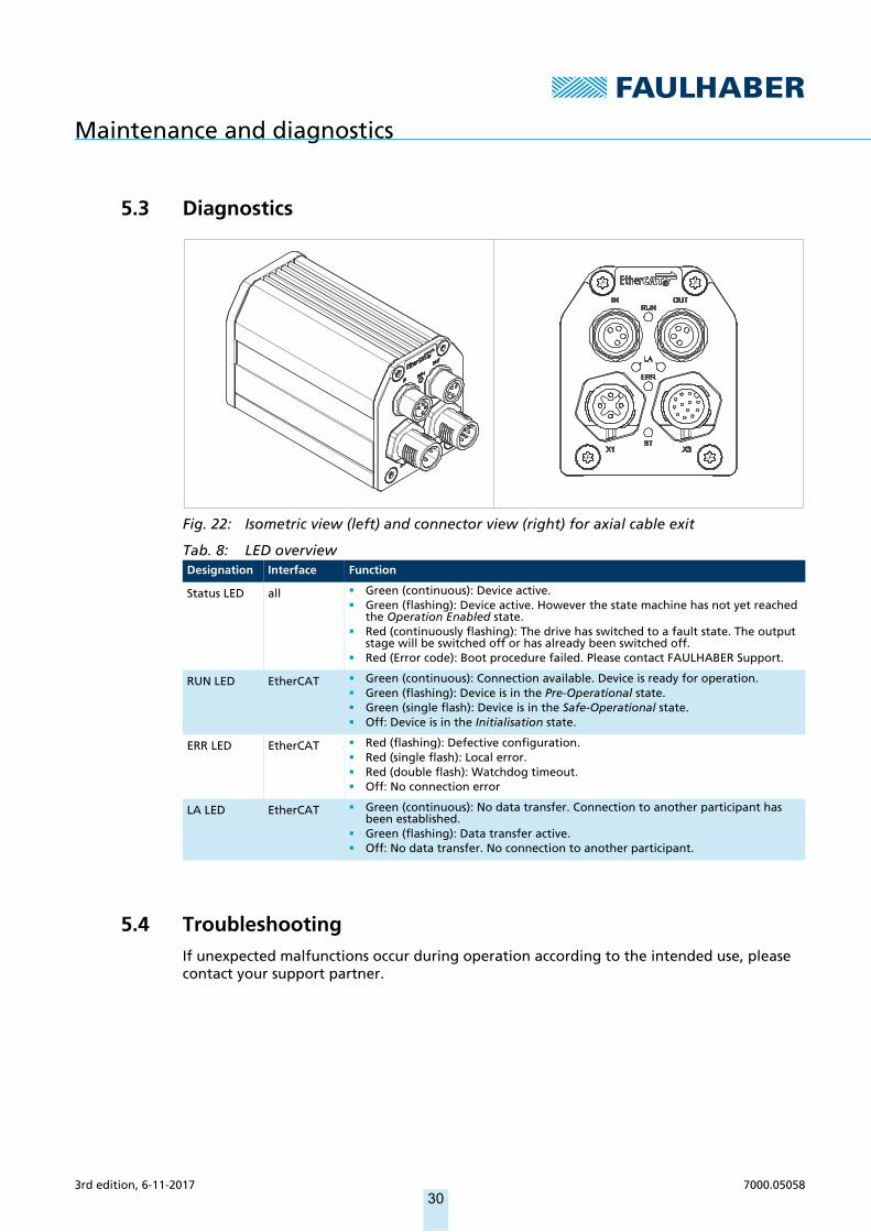
5.3 Diagnostics
Fig. 22: Isometric view (left) and connector view (right) for axial cable exit
Tab. 8: LED overview
5.4 TroubleshootingIf unexpected malfunctions occur during operation according to the intended use, please contact your support partner.
Designation Interface Function
Status LED all Green (continuous): Device active. Green (flashing): Device active. However the state machine has not yet reached
the Operation Enabled state. Red (continuously flashing): The drive has switched to a fault state. The output
stage will be switched off or has already been switched off. Red (Error code): Boot procedure failed. Please contact FAULHABER Support.
RUN LED EtherCAT Green (continuous): Connection available. Device is ready for operation. Green (flashing): Device is in the Pre-Operational state. Green (single flash): Device is in the Safe-Operational state. Off: Device is in the Initialisation state.
ERR LED EtherCAT Red (flashing): Defective configuration. Red (single flash): Local error. Red (double flash): Watchdog timeout. Off: No connection error
LA LED EtherCAT Green (continuous): No data transfer. Connection to another participant has been established.
Green (flashing): Data transfer active. Off: No data transfer. No connection to another participant.
3rd edition, 6-11-2017 7000.05058, 3rd edition, 6-11-20177000.0505830

3rd edition, 6-11-2017 7000.05058, 3rd edition, 6-11-20177000.05058
Accessories
31
6 AccessoriesDetails of the following accessory parts can be found in the Accessories Manual:
Connection cables
Connectors
Installation materials
Additional equipment
Programming adapter
3rd edition, 6-11-2017 7000.05058, 3rd edition, 6-11-20177000.05058
Warranty
32
7 WarrantyProducts of the company Dr. Fritz Faulhaber GmbH & Co. KG are produced using the most modern production methods and are subject to strict quality inspections. All sales and deliv-eries are performed exclusively on the basis of our General Conditions of Sale and Delivery which can be viewed on the FAULHABER home page www.faulhaber.com/gtc and down-loaded from it.

7000.05058, 3rd edition, 6-11-2017© Dr. Fritz Faulhaber GmbH & Co. KG
DR. FRITZ FAULHABER GMBH & CO. KGAntriebssysteme
Daimlerstraße 23 / 2571101 Schönaich • GermanyTel. +49(0)7031/638-0Fax +49(0)7031/[email protected]
Related Documents