MARINE CORPS TECHNICAL MANUAL ARMY TECHNICAL MANUAL TM 05926B/06509B-34/3 TM 5-6115-615-34 NAVY PUBLICATION NAVFAC P-8-646-34 AIR FORCE TECHNICAL ORDER TO 35C2-3-386-32 TECHNICAL MANUAL INTERMEDIATE (FIELD) (DIRECT AND GENERAL SUPPORT) MAINTENANCE MANUAL GENERATOR SET, DIESEL ENGINE DRIVEN, TACTICAL, SKID MOUNTED, 3 KW, 3 PHASE 120/208 AND SINGLE PHASE 120/240 VOLTS AC AND 28 VOLTS DC DOD MODEL CLASS MODE NSN MEP-016B UTILITY 60 HZ 6115-01-150-4140 MEP-021B UTILITY 400 HZ 6115-01-151-8126 MEP-026B UTILITY 28 VDC 6115-01-150-0367 THIS PUBLICATION IS REQUIRED FOR OFFICIAL USE FOR ADMINISTRATIVE OR OPERATIONAL PURPOSES ONLY. DISTRIBUTION IS LIMITED TO U.S. GOVERNMENT AGENCIES. OTHER REQUESTS FOR THIS DOCUMENT MUST BE REFERRED TO: COMMANDANT OF THE MARINE CORPS (HQSP-2), WASHINGTON, D.C. 20380-0001. DESTRUCTION NOTICE: FOR UNCLASSIFIED, LIMITED DOCUMENTS, DESTROY BY ANY METHOD THAT WILL PREVENT DISCLOSURE OF CONTENTS OR RECONSTRUCTION OF THE DOCUMENT. PUBLISHED UNDER THE AUTHORITY OF HEADQUARTERS U.S. MARINE CORPS, THE DEPARTMENTS OF THE ARMY, AIR FORCE, AND NAVY JULY 1987 PCN 184 059270 00

Welcome message from author
This document is posted to help you gain knowledge. Please leave a comment to let me know what you think about it! Share it to your friends and learn new things together.
Transcript

MARINE CORPS TECHNICAL MANUAL ARMY TECHNICAL MANUAL
TM 05926B/06509B-34/3TM 5-6115-615-34
NAVY PUBLICATION NAVFAC P-8-646-34AIR FORCE TECHNICAL ORDER TO 35C2-3-386-32
T E C H N I C A L M A N U A L
I N T E R M E D I A T E ( F I E L D ) ( D I R E C T A N D G E N E R A L S U P P O R T )
M A I N T E N A N C E M A N U A L
G E N E R A T O R S E T , D I E S E L E N G I N E D R I V E N , T A C T I C A L ,
S K I D M O U N T E D , 3 K W , 3 P H A S E 1 2 0 / 2 0 8 A N D
S I N G L E P H A S E 1 2 0 / 2 4 0 V O L T S A C A N D 2 8 V O L T S D C
D O D M O D E L C L A S S M O D E N S N
M E P - 0 1 6 B U T I L I T Y 6 0 H Z 6 1 1 5 - 0 1 - 1 5 0 - 4 1 4 0
M E P - 0 2 1 B U T I L I T Y 4 0 0 H Z 6 1 1 5 - 0 1 - 1 5 1 - 8 1 2 6
M E P - 0 2 6 B U T I L I T Y 2 8 V D C 6 1 1 5 - 0 1 - 1 5 0 - 0 3 6 7
THIS PUBLICATION IS REQUIRED FOR OFFICIAL USE FOR ADMINISTRATIVE OR OPERATIONALPURPOSES ONLY. DISTRIBUTION IS LIMITED TO U.S. GOVERNMENT AGENCIES. OTHER REQUESTSFOR THIS DOCUMENT MUST BE REFERRED TO: COMMANDANT OF THE MARINE CORPS (HQSP-2),WASHINGTON, D.C. 20380-0001.
DESTRUCTION NOTICE: FOR UNCLASSIFIED, LIMITED DOCUMENTS, DESTROY BY ANY METHOD THATWILL PREVENT DISCLOSURE OF CONTENTS OR RECONSTRUCTION OF THE DOCUMENT.
PUBLISHED UNDER THE AUTHORITY OF HEADQUARTERS U.S. MARINE CORPS,THE DEPARTMENTS OF THE ARMY, AIR FORCE, AND NAVY
JULY 1987
P C N 1 8 4 0 5 9 2 7 0 0 0


MARINE CORPS TECHNICAL MANUAL TM 05926B/06509B-34/3DEPARTMENT OF THE ARMY TECHNICAL MANUAL TM 5-6115-615-34DEPARTMENT OF THE NAVY PUBLICATION NAVFAC P-8-646-34DEPARTMENT OF THE AIR FORCE TECHNICAL ORDER TO 35C2-3-386-32
H E A D Q U A R T E R S U . S . M A R I N E C O R P S ,
D E P A R T M E N T S O F T H E A R M Y , N A V Y , A N D A I R F O R C EW A S H I N G T O N , D . C . ( J u l y 1 9 8 7 )
I N T E R M E D I A T E ( F I E L D ) ( D I R E C T A N D G E N E R A L S U P P O R T )
M A I N T E N A N C E M A N U A L
G E N E R A T O R S E T , D I E S E L E N G I N E D R I V E N , T A C T I C A L ,
S K I D M O U N T E D , 3 K W , 3 P H A S E 1 2 0 / 2 0 8 A N D
S I N G L E P H A S E 1 2 0 / 2 4 0 V O L T S A C A N D 2 8 V O L T S D C
D O D M O D E L C L A S S M O D E N S N
M E P - 0 1 6 B U T I L I T Y 6 0 H Z 6 1 1 5 - 0 1 - 1 5 0 - 4 1 4 0M E P - 0 2 1 B U T I L I T Y 4 0 0 H Z 6 1 1 5 - 0 1 - 1 5 1 - 8 1 2 6M E P - 0 2 6 B U T I L I T Y 2 8 V D C 6 1 1 5 - 0 1 - 1 5 0 - 0 3 6 7


J. G. O'NEILL
Marine Corps TM 05926B/06509B-34/3 Army TM 5-6115-615-34 Navy NAVFAC P-8-646-34
Air Force TO 35C2-3-386-32
DEPARTMENT OF THE NAVYHeadquarters, U.S. Marine Corps
Washington, D.C. 20380-0001
31 July 1987
1 . This Manual is effective upon receipt and contains intermediate(Field) (Direct and General Support) maintenance instructions forGenerator Set, Engine Driven, Tactical, Skid Mounted, 3 KW, DODModels MEP-016B, 60 HZ, NSN 6115-01-150-4140, MEP-021B, 400 HZ,NSN 6115-01-151-8126, MEP-026B, 28 VDC, NSN 6115-01-150-0367.
2. Notice of discrepancies or suggested changes: refer to paragraph1-4 titled, Reporting of Errors, of this Manual for applicableServices' form number and forwarding address.
BY DIRECTION OF THE COMMANDANT OF THE MARINE CORPS
OFFICIAL:
J. G. O’NEILLHead, Materiel Acquisition Support BranchMateriel DivisionInstallations and Logistics Department
R. L. DILWORTHBrigadier General, United States ArmyThe Adjutant General
ALFRED G. HANSEN, General, USAFCommander, Air Force Logistics Command
DISTRIBUTION: AGB/L77/L82
Copy to: 7000161(2)
CARL E. VUONOGeneral, United States ArmyChief of Staff
B. F. MONTOYA, RADM, CECUSN
LARRY D. WELSH, GeneralUSAF, Chief of Staff
1/(2blank)


MARINE CORPS TM 05926B/06509B-34ARMY TM 5-6115-615-34NAVY NAVFAC P-8-646-34AIR FORCE TO 35C2-3-386-32
LIST OF EFFECTIVE PAGESINSERT LATEST CHANGED PAGES. DESTROY SUPERSEDED PAGES.
NOTE: The portion of the text affected by the changes iS indicated by a vertical linein the outer margins of the page. Changes to Illustrations are indicated byminiature pointing hands. Changes to wiring diagrams are indicated byshaded areas.
Date of issue for original and changed pages are:Original . . . 0 . . . July 1987
TOTAL NUMBER OF PAGES IN THIS PUBLICATION IS 198 CONSISTING OF THE FOLLOWING:
PageNo.
Cover . . . . . . . . . . . . . . . . . . . . .Blank . . . . . . . . . . . . . . . . . . . . .Title Block . . . . . . . . . . . . . . . . .Blank . . . . . . . . . . . . . . . . . . . . .A .. . . . . . . . . . . . . . . . . . . . .. .Blank. . . . . . . . . . . . . . . . . . . . . . .i thru x . . . . . . . . . . . . . . . . . . . .1-1 thru 1-18 . . . . . . . . . . . . . . .2-1 thru 2-29 . . . . . . . . . . . . . .Blank . . . . . . . . . . . . . . . . . . . . .3-1 thru 3-10 . . . . . . . . . . . . . . .4-1 and 4-2 . . . . . . . . . . . . . . . . .5-1 thru 5-33 . . . . . . . . . . . . . . .Blank . . . . . . . . . . . . . . . . . . . . .6-1 thru 6-12 . . . . . . . . . . . . . . .7-1 thru 7-60 . . . . . . . . . . . . . . .8-1 . . . . . . . . . . . . . . . . . . . . . . .Blank . . . . . . . . . . . . . . . . . . . . .9-1 thru 9-3 . . . . . . . . . . . . . . . .Blank . . . . . . . . . . . . . . . . . . . . .10-1 thru 10-4 . . . . . . . . . . . . . .A-1 . . . . . . . . . . . . . . . . . . . . . . .Blank . . . . . . . . . . . . . . . . . . . . .Index-1 thru Index-3 . . . . . . . . .Blank . . . . . . . . . . . . . . . . . . . . .
ChangeNo.
0000000000000000000000000
Zero in this column indicates an original page.
USMC A/(B blank)


MARINE CORPS TM 05926B/06509B-34ARMY TM 5-6115-615-34NAVY NAVFAC P-8-646-34AIR FORCE TO 35C2-3-386-32
Chapter/Section/Paragraph
TABLE OF CONTENTS
CHAPTER 1.Section I.
1-1.1-2.1-3.1-4.1-5.1-6.1-7.1-8.1-9.
1-10.Section II.
1-11.1-12.1-13.
CHAPTER 2.Section I.
2-1.2-2.2-3.
Section II.2-4.2-5.
Section III.
2-6.2-7.
Section IV.2-8.2-9.
2-10.
CHAPTER 3.3-1.3-2.3-3.
CHAPTER 4.
4-1.4-2.
CHAPTER 5.
5-1.5-2.
Page
INTRODUCTION . . . . . . . . . . . . . . . . . . . . . . . . . . . . . . . . . . . . . . . . . . . . . . . 1-1General . . . . . . . . . . . . . . . . . . . . . . . . . . . . . . . . . . . . . . . . . . . . . . . . . . 1-1Scope . . . . . . . . . . . . . . . . . . . . . . . . . . . . . . . . . . . . . . . . . . . . . . . . . . . . . . 1-1Limited Applicability . . . . . . . . . . . . . . . . . . . . . . . . . . . . . . . . . . . . . . 1-1Maintenance Forms and Records . . . . . . . . . . . . . . . . . . . . . . . . . . . . . . . . 1-1Reporting of Errors . . . . . . . . . . . . . . . . . . . . . . . . . . . . . . . . . . . . . . . . 1-1Levels of Maintenance Accomplishment . . . . . . . . . . . . . . . . . . . . . . . 1-2Destruction of Army Materiel to Prevent Enemy Use . . . . . . . . . . 1-2Administrative Storage . . . . . . . . . . . . . . . . . . . . . . . . . . . . . . . . . . . . . 1-2Preparation for Shipment and Storage . . . . . . . . . . . . . . . . . . . . . . . 1-2Reporting Equipment Improvement Recommendations, MC . . . . . . . . 1-2Reporting Equipment Improvement Recommendations, A . . . . . . . . . 1-2Description and Tabulated Data . . . . . . . . . . . . . . . . . . . . . . 1-3Description . . . . . . . . . . . . . . . . . . . . . . . . . . . . . . . . . . . . . . . . . . . . . 1-3
Tabulated Data . . . . . . . . . . . . . . . . . . . . . . . . . . 1-3Differences Between Models . . . . . . . . . . . . . . . . . . . . . . . . . . . . . . . . 1-18
GENERAL MAINTENANCE INSTRUCTIONS . . . . . . . . . . . . . . . . . . . . . . . . . . . . 2-1Repair Parts, Special Tools, Test, Measurement, and
Diagnostic Equipment (TMDE), and Support Equipment . . . . . . . 2-1Repair Parts . . . . . . . . . . . . . . . . . . . . . . . . . . . . . . . . . . . . . 2-1Tools and Equipment . . . . . . . . . . . . . . . . . . . . . . . . . . . . . . . . . . 2-1Fabricated Tools And Equipment . . . . . . . . . . . . . . . . . . . . . . . . . . . . . 2-3Troubleshooting .. . . . . . . . . . . . . . . . . . . . . . . . . . . . . . . . . . 2-6General . . . . . . . . . . . . . . . . . . . . . . . . . . . . . . . . . . . . . . . . 2-6Malfunctions Not Corrected By Use of
Troubleshooting Table . . . . . . . . . . . . . . . . . . . . . . . . . . . . . 2-6General Maintenance .. . . . . . . . . . . . . . . . . . . . . . . . . . . . . 2-14General Maintenance .. . . . . . . . . . . . . . . . . . . . . . . . . . 2-14General Maintenance Requirements . . . . . . . . . . . . . . . . . 2-14Removal and Installation of Major Components . . . . . 2-16Control Box .. . . . . . . . . . . . . . . . . . . . . . . . . . . . . . . . . . . . 2-16Engine . . . . . . . . . . . . . . . . . . . . . . . . . . . . . . . . . . . 2-21Generator . . . . . . . . . . . . . . . . . . . . . . . . . . . . . . . . . . . 2-25
MAINTENANCE OF THE FRAME . . . . . . . . . . . . . . . . . . . . . . . . . . . . . . . . . . . 3-1General . . . . . . . . . . . . . . . . . . . . . . . . . . . . . . . . . . . . . . . . 3-1Frame . . . . . . . . . . . . . . . . . . . . . . . . . . . . . . . . . . . . . . . . 3-1Skid Base . . . . . . . . . . . . . . . . . . . . . . . . . . . . . . . . . . . . 3-8
MAINTENANCE OF THE DC ELECTRICALAND CONTROL SYSTEM . . . . . . . . . . . . . . . . . . . . . . . . . . . . . 4-1General . . . . . . . . . . . . . . . . . . . . . . . . . . . . . . . . . . . . . . 4-1Battery Repair . . . . . . . . . . . . . . . . . . . . . . . . . . . . . . . . . . . 4-1
MAINTENANCE OF THE ELECTRICAL POWERGENERATION AND CONTROL SYSTEM . . . . . . . . . . . . . . . . . . . . . . . . . . . . . . 5-1General . . . . . .. . . . . . . . . . . . . . . . . . . . . . . . . . . . . . . . . . . 5-1Generator Assembly . . . . . . . . . . . . . . . . . . . . . . . . . . . . . . . . . . . . . . . . . 5-1
i

MARINE CORPS TM 05926B/06509B-34ARMY TM 5-6115-615-34NAVY NAVFAC P-8-646-34AIR FORCE TO 35C2-3-386-32
TABLE OF CONTENTS - continued
Chapter/Section/Paragraph Page
5-3.5-4.5-5.5-6.5-7.5-8.5-9.
5-10.
CHAPTER 6.6-1.6-2.6-3.6-4.
CHAPTER 7.7-1.7-2.7-3.7-4.7-5.7-6.7-7.7-8.7-9.
7-10.7-11.7-12.7-13.7-14.7-15.7-16.7-17.7-18.7-19.7-20.
CHAPTER 8.8-1.8-2.
Generator Fan . . . . . . . . . . . . . . . . . . . . . . . . . . . . . . . . . 5-6Rotor . ....... . . . . . ... ● . . . . . . . . . . . . . . . . . . . . . . ..... ....... 5-7Rotating Rectifiers (Diodes) . ....... . . . . . . . . . . . . . . . . . 5-12Stator Testing . . . . . . . . . . . . . . . . . . . . . . . . . . . . . . . . . . . . .. 5-13Excitor Stator Testing . . . . . . . . . . . . . . . . . . . . . . . . . . . . . . . . . . . . 5-16Generator Bearing 5-17Voltage Regulator . . . . . . . . . . . . . . . . . . . . . . . . . . . . . . 5-18Current Transformer MEP-D16B/MEP021B (60/400 Hz)
Sets Only . . . . . . . ● . . . . . . . . . . . . . . . . . . . . . . . . . . . . . . . ● . 5-32
MAINTENANCE OF THE FUEL SYSTEM . . . . . . . . . . . . . . . . . ● . . . . . . . . ● . . 6-1General . . . . . . . . . . . . . . . . . . . . . . . . . . . . . . . . . . . . . . . . . 6-1Fuel Tank . . . . . . . . . . . . . . . . . . . . . . . . . . . . . . . . . . . . . . . . . . . . . . . . . . 6-1Fuel Injection Pump . . . . . . . . . . . . . . . . . . . . . . . . . . . . . . . . . . . ● ● . . . 6-3Fuel Injector 6-7
MAINTENANCE OF THE ENGINE ● . . . . . . . . . . . . . ● ● . . . . ● . . . . . . . ● . . . . ● 7-1General . . . . . . . . . . . . . . . . . . . . . . . . . . . . . . . . . ● . . . . . . . . . . . . . . ● . ● . 7-1Engine Assembly . . . . . . . . . . ● ● . ● . . . . . . . . . . . . . . . . . . . . . . . . . . . . . 7-1Oil Pan . . . . . . . . . . . . . . . . . . . . . . . . . . . . . . . . . . . . . . . 7-8Starter Assembly . . . . . . . . . . . . ● . . . . . . . . . . . . . . . . . . . . ● . . . . . . . . 7-10Starter Solenoid . . . . . . . . . . . . . . . . . . . . . . . . . . . . . 7-19Cylinder Head . . . . . . . . . . . . ● . . . . . . . . . . . . . . . . . . . . . . ● . . . . . . . . 7-20Valves . . . . . . . . . . . . . . . . . . . . . . . . . . . . . . . . . . 7-25Rocker Arms and Push Rods 7-27Lifters and Push Rod Tubes . . . . . . . . . . . . . . . . . . . . . . . . . . . . . . . . 7-30Flywheel and Engine Fan . . . . . . . . . . . . . . . . . . . . . . . . . . 7-32Battery Charger Stator and Air Scroll Back Plate . . . . . . . . . . 7-35Gear Cover and Seal . . . . . . . . . . . . . . . . . . . . . . . . . . . . . . . . . . . . .. 7-38Cylinder and Piston . . . . . . . . . . . . . . . . . . . . . . . . . . . . . . . . . . . . . . . 7-40Oil Pump 7-44Connecting Rod . . . . . . . . . . . . . . . . . . . . . . . . . . . . . . . . . . . . . . . . ● ● 7-45Camshaft . . . . . . . . . . . . ● . . . . . . . ● . . . . . . . . . . . . . . . . . . . . . . . . ● . ● . ● 7-47Crankshaft and Flywheel Housing 7-49Oil Filter Adapter . . . . . . . . . . . . . . . . . . . . . . . . . . . . . . 7-53Crankcase . . . . . . . . . . . . . . . . . . . . . . . . . . . . . . . . . . . . . 7-55Oil Cooler . . . . . . . . . . . . . . . . . . . . . . . . . . . . . . . . . . . . . 7-59
MAINTENANCE OF THE ENGINE CONTROLS AND INSTRUMENTS . . . . . . . . . 8-1General . . . . . . . . . . . . . . . . . . . . . . . . . . . . . . . . . . . . . . . . . 8-1Engine Control Circuit Board 8-1
ii

MARINE CORPS TM 05926B/06509B-34ARMY TM 5-6115-615-34NAVY NAVFAC P-8-646-34AIR FORCE TO 35C2-3-386-32
TABLE OF CONTENTS - continued
Chapter/Section/Paragraph Page
CHAPTER 9.9-1.9-2.9-3.9-4.
CHAPTER 10.
Section I.10-1.
Section II.10-2.10-3.10-4.
Section III.10-5.
MAINTENANCE OF GENERATOR CONTROLS AND INSTRUMENTS . . . . . . . . . . . . . 9-1General . . . . . . . . . . . . . . . . . . . . . . . . . . . . . . . . . . . . . . . . 9-1Control Box Assembly . . . . . . . . . . . . . . . . . . . . . . . . . . . . . . . . . . . . . . . 9-1Frequency Meter . . . . . . . . . . . . . . . . . . . . . . . . . . . . . . . . . . . . . 9-1Frequency Transducer . . . . . . . . . . . . . . . . . . . . . . . . . . . . . . . . . . . . . . . 9-1
GENERATOR SET TEST AND INSPECTIONAFTER REPAIR OR OVERHAUL . . . . . . . . . . . . . . . . . . . . . . . . . . . . . . . . 10-1
General Requirements . . . . . . . . . . . . . . . . . . . . . . . . . . . . . . . . . . . . . . 10-1General . . . . . . . . . . . . . . . . . . . . . . . . . . . . . . . . . . . . . . . . . . . 10-1Inspection . . . . . . . . . . . . . . . . . . . . . . . . . . . . . . . . . . . 10-1Generator Set . . . . . . . . . . . . . . . . . . . . . . . . . . . . . . . . . . . . . . . . . 10-1Engine . . . . . . . . . . . . . . . . . . . . . . . . . . . . . . . . . . . . . . . . . . . . . . . . . . . . 10-1Wiring Harnesses . . . . . . . . . . . . . . . . . . . . . . . . . .. . . . . . 10-1Operational Test . . . . . . . . . . . . . . . . . . . . . . . . . . . . . . . . . . . . . . . . . . 10-1Operational Tests . . . . . . . . . . . . . . . . . . . . . . . . . . . . . . . . . . . . . 10-1
APPENDIX A REFERENCES . . . . . . . . . . . . . . . . . . . . . . . . . . . . . . . . . . . . . . . . . . . . . . . . . . . . A-1
INDEX . . . . . . . . . . . . . . . . . . . . . . . . . . . . . . . . . . . . . . . . . . . . . . . . . . . . . . . . . . . . . . . Index-1
iii

MARINE CORPSA R M YN A V YAIR FORCE
TM 05926B/06509B-34T M 5 - 6 1 1 5 - 6 1 5 - 3 4NAVFAC P-8-646-34T O 3 5 C 2 - 3 - 3 8 6 - 3 2
LIST OF ILLUSTRATIONS
Figure
1-1
2-12-22-32-42-52-6
3-13-2
5-15-25-35-45-55-65-75-85-9
5-105-115-125-135-145-155-165-175-185-195-205-21
6-16-26-36-46-56-6
7-17-27-37-47-57-6
Title Page
Cylinder Head Torquing Sequence . . . . . . . . . . . . . . . . . . . . . . . . . . . . . . . 1-18
Control Box Removal and Installation . . . . . . . . . . . . . . . . . . . . . . . . . . 2-17Generator Wiring MEP-026B . . . . . . . . . . . . . . . . . . . . . . . . . . . . . . . . . . . . . 2-18Generator Wiring MEP-016B and MEP-021B . . . . . . . . . . . . . . . . . . . . . . . . 2-19Control Box Harness . . . . . . . . . . . . . . . . . . . . . . . . . . . . . . . . . . . . . . . . . . . 2-20Engine Removal . . . . . . . . . . . . . . . . . . . . . . . . . . . . . . . . . . . . . . . . . . . . . . . . 2-21Generator Removal and Installation . . . . . . . . . . . . . . . . . . . . . . . . . . . . 2-26
Frame Removal . . . . . . . . . . . . . . . . . . . . . . . . . . . . . . . . . . . . . . . . . . . . . . . . . . 3-2Skid Base
GeneratorGeneratorGeneratorGenerator
. . . . . . . . . . . . . . . . . . . . . . . . . . . . . . . . . . . . . . . . . . . . . . . . . . . . . . 3-9
Testing - MEP-016B and MEP-021B . . . . . . . . . . . . . . . . . . . . . . 5-2Testing - MEP-026B . . . . . . . . . . . . . . . . . . . . . . . . . . . . . . . . . . . 5-3Disassembly and Assembly . . . . . . . . . . . . . . . . . . . . . . . . . . . . . 5-5Fan . . . . . . . . . . . . . . . . . . . . . . . . . . . . . . . . . . . . . . . . . . . . . . . . . . 5-7
Rotor . . . . . . . . . . . . . . . . . . . . . . . . . . . . . . . . . . . . . . . . . . . . . . . . . . . . . . . . . . 5-7Rotor Insulation Test . . . . . . . . . . . . . . . . . . . . . . . . . . . . . . . . . . . . . . . . . . 5-9Main Rotor Winding Resistance Check . . . . . . . . . . . . . . . . . . . . . . . . . . 5-10Exciter Rotor Winding Resistance Check . . . . . . . . . . . . . . . . . . . . . . . . 5-11Rotating Rectifiers . . . . . . . . . . . . . . . . . . . . . . . . . . . . . . . . . . . . . . . . . . . 5-12Stator Winding Insulation Test . . . . . . . . . . . . . . . . . . . . . . . . . . . . . . . 5-14Generator Wiring Schematics . . . . . . . . . . . . . . . . . . . . . . . . . . . . . . . . . . . 5-16Generator Bearing . . . . . . . . . . . . . . . . . . . . . . . . . . . . . . . . . . . . . . . . . . . . . 5-17Voltage Regulator Testing . . . . . . . . ● . . . . . . . ... . . . . . . ... . . . ... . . . . 5-18Q1 and Q2 Transistor Pin Out Locations . . . . . . . . . . . . . . . . . . . . . . . . 5-19Voltage Regulator Schematic . . . . . . . . . . . . . . . . . . . . . . . . . . . . . . . . . . . 5-23Voltage Regulator Adjustment Schematic . . . . . . . . . . . . . . . . . . . . . . . 5-26Waveforms . . . . . . . . . . . . . . . . . . . . . . . . . . . . . . . . . . . 5-26Voltage Regulator MEP-016B and MEP-021B (60/400 Hz Sets) ..... 5-29Voltage Regulator MEP-026B (28VDC Set) . . . . . . . . . . . . . . . . . . . . . . . . 5-30Standard Voltage Regulator Jumper Wire Placement . . . . . . . . . . . . . . 5-33Current Transformer . . . . . . . . . . . . . . . . . . . . . . . . . . . . . . 5-34
Fuel Tank . . . . . . . . . . . . . . . . . . . . . . . . . . . . . . . . . . . . . . . . . . . . . . . . . . . 6-2Fuel Injection Pump . . . . . . . . . . . . . . . . . . . . . . . . . . . . . . . . . . . . . . . . . . . . 6-4External Governor Linkage . . . . . . . . . . . . . . . . . . . . . . . . . . . . . . . . . . . . . . 6-7Fuel Injector Removal and Installation . . . . . . . . . . . . . . . . . . . . . . . . . 6-8Fuel Injector Testing . . . . . . . . . . . . . . . . . . . . . . . . . . . . . . . . . . . . . . . . . . 6-9Fuel Injector . . . . . . . . . . . . . . . . . . . . . . . . . . . . . . . . . . . . . . . . . . . . . . . . . 6-11
Low Fuel Shutdown Solenoid Adjustment . . . . . . . . . . . . . . . . . . . . . . . . . . 7-5Governor Linkage Adjustment 7-6Governor Adjustment . . . . . . . . . . . . . . . . . . . . . . . . . . . . . . . . . . . . . . . . . . . . 7-7Oil Pan . . . . . . . . . . . . . . . . . . . . . . . . . . . ● . . . . . . . . . . . . . . . . . . . . . . . . . . . . 7-9Starter Disassembly/Assembly . . . . . . . . . . . . . . . . . . . . . . . . . . . . . . . . . . 7-11Testing Armature For Grounds or Shorts . . . . . . . . . . . . . . . . . . . . . . . . 7-12
i v

MARINE CORPS TM 05926B/06509B-34A R M Y TM 5-6115-615-34NAVY NAVFAC P-8-646-34AIR FORCE TO 35C2-3-386-32
Figure
7-77-87-9
7-107-117-127-137-147-157-167-177-187-197-207-217-227-237-247-257-267-277-287-297-307-317-327-337-347-35
9-1
LIST OF ILLUSTRATIONS - continued.
Title Page
Testing Armature For Open Circuits . . . . . . . . . . . . . . . . . . . . . . . . . . . . 7-13Solenoid Testing . . . . . . . . . . . . . . . . . . . . . . . . . . . . . . . . . . . . . . . . . . . . . . 7-14Brush Wear Limit . . . . . . . . . . . . . . . . . . . . . . . . . . . . . . . . . . . . . . . . . . . . . . 7-15Overrunning Clutch . . . . . . . . . . . . . . . . . . . . . . . . . . . . . . . . . . . . . . . . . . . . 7-16Pinion Gear Installation . . . . . . . . . . . . . . . . . . . . . . . . . . . . . . . . . . . . . . 7-17Adjusting Pinion Shaft End Play 7-17Lever Installation . . . . . . . . . . . . . . . . . . . . . . . . . . . . . . . . . . . . . . . . . . . . 7-18Pinion Gap Adjustment . . . . . . . . . . . . . . . . . . . . . . . . . . . . . . . . . . . . . . . 7-19Starter Solenoid . . . . . . . . . . . . . . . . . . . . . . . . . . . . . . . . . . . . . . . . . . . . . . 7-20Cylinder Head 7-21Valves . . . . . . . . . . . . . . . . . . . . . . . . . . . . . . . . . . . . . . . . . . . . . . . . . . . 7-25Rocker Arms and Push Rods 7-28Piston at Top Dead Center to Set Engine Timing . . . . . . . . . . . . . . . . . 7-29Adjusting Valve Clearance . . . . . . . . . . . . . . . . . . . . . . . . . . . . . . . . . . . . . 7-30Push Rod Tubes and Lifters . . . . . . . . . . . . . . . . . . . . . . . . . . . . . . . . . . . . 7-31Flywheel and Engine Fan . . . . . . . . . . . . . . . . . . . . . . . . . . . . . . . . . 7-33Fan and Drive Adapter Alinement Tabs . . . ● . . . . . . . . . . . . . . . . . . . . . 7-34Battery Charger Stator Testing . . . . . . . . . . . . . . . . . . . . . . . . . . . . . . . . 7-35Battery Charger Stator . . . . . . . . . . . . . . . . . . . . . . . . . . . . . . . . . . . . . . . . 7-36Gear Cover and Seal . . . .. . . . . . . . ● . . . . . . . . . . . . . . . . . . . . . . . . . . . . . . 7-39Cylinder and Piston .. . . . . . . . . . . . . . . . . . . . . . . . . . . . 7-41Piston Ring Positioning 7-43Oil Pump . . . . . . . . . . . . . . . . . . . . . . . . . . . . . . . . . . . . . . . . . . . . . . . . . . . . . . 7-44Connecting Rod . . . . . . . . . . . . . . . . . . . . . . . . . . . . . . . . . . . . . . . . . . . . . . 7-46Camshaft 7-48Crankshaft and Generator Adapter . . . . . . . . . . . . . . . . . . . . . . . . . . . . . . 7-50Oil Filter Adapter 7-54Crankcase . . . . . . . . . . . . . . . . . . . . . . . . . . . . . . . . . . . . . 7-56Engine Oil Cooler . .. . . . . . . . . . . . . . . . . . . . . . . . . . . . . . 7-59
Frequency Transducer Testing . . . . . . . . . . . . . . . . . . . . . . . . . . . . . . . . . . . 9-2
v
MARINE CORPS TM 05926B/06509B-34ARMY TM 5-6115-615-34NAVY NAVFAC P-8-646-34AIR FORCE TO 35C2-3-386-32
LIST OF TABLES
Table
1-11 - 2
1 - 3
2-12-22-3
5-15-25-3
7-1
10-110-210-3
Title Page
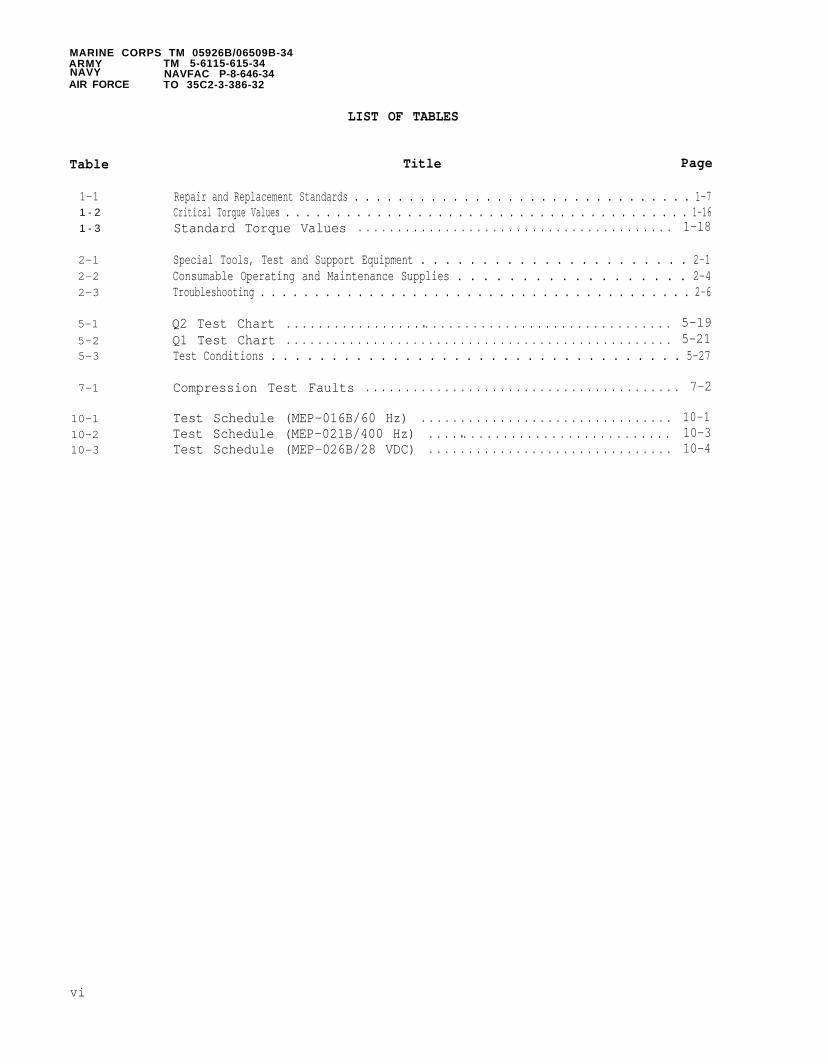
Repair and Replacement Standards . . . . . . . . . . . . . . . . . . . . . . . . . . . . . . . 1-7Critical Torque Values . . . . . . . . . . . . . . . . . . . . . . . . . . . . . . . . . . . . . . . . 1-16Standard Torque Values . . . . . . . . . . . . . . . . . . . . . . . . . . . . . . . . . . . . . . . . 1-18
Special Tools, Test and Support Equipment . . . . . . . . . . . . . . . . . . . . . . 2-1Consumable Operating and Maintenance Supplies . . . . . . . . . . . . . . . . . . 2-4Troubleshooting . . . . . . . . . . . . . . . . . . . . . . . . . . . . . . . . . . . . . . . . 2-6
Q2 Test Chart . . . . . . . . . . . . . . . . . ● . . . . . . . . . . . . . . . . . . . . . . . . . . . . . . . 5-19Q1 Test Chart . . . . . . . . . . . . . . . . . . . . . . . . . . . . . . . . . . . . . . . . . . . . . . . . . 5-21Test Conditions . . . . . . . . . . . . . . . . . . . . . . . . . . . . . . . . . . 5-27
Compression Test Faults . . . . . . . . . . . . . . . . . . . . . . . . . . . . . . . . . . . . . . . . 7-2
Test Schedule (MEP-016B/60 Hz) . . . . . . . . . . . . . . . . . . . . . . . . . . . . . . . . 10-1Test Schedule (MEP-021B/400 Hz) . . . . ● . . . . . . . . . . . . . . . . . . . . . . . . . . 10-3Test Schedule (MEP-026B/28 VDC) . . . . . . . . . . . . . . . . . . . . . . . . . . . . . . . 10-4
vi

MARINE CORPS TM 05926B/06509B-34ARMY TM 5-6115-615-34NAVY NAVFAC P-8-646-34AIR FORCE TO 35C2-3-386-32
SAFETY SUMMARY
The following are general safety precautions that are not related to any specificprocedures and therefore do not appear elsewhere in this publication. These arerecommended precautions that personnel must understand and apply during many phasesof operation and maintenance.
KEEP AWAY FROM LIVE CIRCUITSOperating personnel must at all times observe allsafety regulations. DO not replace components or makeadjustments to this equipment with the high voltagesupply turned on. Under certain conditions, dangerouspotentials may exist when the power control is in theoff position, due to charges retained by capacitors.To avoid casualties, always remove power and dischargeand ground a circuit before touching it, and alwaysremove rings, watches and other jewelry beforeservicing this equipment.
DO NOT SERVICE OR ADJUST ALONEUnder no circumstances should any person reach intothis equipment for the purpose of servicing oradjusting this equipment except in the presence ofsomeone who is capable of rendering aid.
RESUSCITATIONPersonnel working with or near high voltages should befamiliar with modern methods of resuscitation. Suchinformation may be obtained from the Bureau of Medicineand Surgery.
SECURE LOOSE CLOTHINGPersonnel working on this equipment should secure allloose fitting clothing to prevent clothing fromcatching in moving parts.
KEEP COMPRESSED AIR AWAY FROM SKINPersonnel using compressed air should not exceed 15 psinozzle pressure when drying parts, and should notdirect compressed air toward skin. Personal injurycould result.
OPERATE EQUIPMENT IN A WELL VENTILATED AREAExhaust discharge contains noxious and deadly fumes.DO not operate this equipment in an enclosed areaunless exhaust discharge is properly vented to theoutside. When using cleaning solvents, clean parts ina well ventilated area and avoid inhalation of solventfumes.
vii

MARINE CORPS TM 05926B/06509B-34ARMY TM 5-6115-615-34NAVY NAVFAC P-8-646-34AIR FORCE TO 35C2-3-386-32
The following
WEAR EAR PROTECTIONThe noise level of this generator set can cause hearingdamage. To avoid hearing damage, always wear earprotectors, as recommend by the medical or safetyofficer, when operating near this equipment.
USE CAUTION WHEN WORKING AROUND FLAMMABLESDo not smoke, use open flame or use excessive heat inthe vicinity of this equipment when refueling, workingaround the battery or working with flammable cleaningsolvents. Doing so could causecould result in severe personal
warnings appear in the text and
an explosion whichinjury or death.
are repeated here for emphasis.
DRY CLEANING SOLVENT, P-D-680 or P-S-681, is used toclean parts and is potentially dangerous to personneland property. Avoid repeated and prolonged skincontact. DO NOT use near open flame or excessive heat.Flash point of solvent is 100° to 138°F (38° to 60°C).Paragraph 2-7.
Connect battery cables last when installing frame. Thehigh current output of the DC electrical system cancause arcing and/or burns if a short circuit occurs.Paragraph 3-2.
Disconnect battery cables before removing frame. Thehigh current output of the DC electrical system cancause arcing and/or burns if a short circuit occurs.Paragraph 3-2.
viii

MARINE CORPS TM 05926B/06509B-34ARMY TM 5-6115-615-34NAVY NAVFAC P-8-646-34AIR FORCE TO 35C2-3-386-32
Observe safety regulations. The voltages used in thistest are dangerous to human life. Contact with theleads or windings under test can cause severe,possibly fatal, shock. Arrange the high voltage leadsso that they are not in a position to be accidentallytouched. Keep clear of all energized parts. Alwaysreduce the test voltage to zero and ground the windingunder test before making any mechanical or electricaladjustments on the equipment. When grounding outwindings which have been tested, always connect theconnection wire to ground first and then to thewinding. Never perform this test without at least oneother person assisting. Generator frame shall besecurely grounded. Paragraphs 5-4 and 5-6.
Turn off 115 VAC power source before attempting anyinspection or repair. Paragraph 5-9.
Wear protective clothing and face shield when openingfuel injection line. Fuel under high pressure may betrapped in the fuel injection line. Opening fuelinjection line can cause a high pressure stream of fuelto be released which can cause severe personal injury.Paragraphs 6-4 and 6-7.
Do not allow nozzle to spray against skin. Fuel undernozzle pressure can penetrate fleshinfection. Paragraph 6-4.
Be sure to turn growler off betweenwill be produced. Paragraph 7-4.
and cause a serious
intervals or voltage
Do not use a punch, prybar, or chisel to remove valveseat. Seat is made of a hardened material which mayshatter and cause personal injury. Paragraph 7-6.
ix

MARINE CORPS TM 05926B/06509B-34ARMY TM 5-6115-615-34NAVY NAVFAC P-8-646-34AIR FORCE TO 35C2-3-386-32
Wear protective gloves when handling dry ice and cooledvalve seat. Personal injury may result if the seat orice comes in contact with unprotected skin. Paragraph7-6.
Hot oil and heated crankshaft drive gear can severelyburn exposed areas of skin. Wear insulated gloves andprotective clothing to protect against burns.Paragraph 7-17.
Before repairing battery posts, place battery on a workbench under an exhaust hood to protect personnel fromlead and /or acid fumes. Paragraph 4-2.
Always wear safety goggles and gloves when repairingbattery posts. Paragraph 4-2.
x
MARINE CORPS TM 05926B/06509B-34ARMY TM 5-6115-615-34NAVY NAVFAC P-8-646-34AIR FORCE TO 35C2-3-386-32
CHAPTER 1
INTRODUCTION
Section I. GENERAL
1-1. SCOPE. This manual is for your use in maintaining the 3KW DED Generator Set,Type I (Tactical), Class 2 (Utility), skid mounted Models MEP-016B, MEP-021B andMEP-026B.
1-1.1. Contents. This manual covers Intermediate (Field) (Direct and GeneralSupport Maintenance). It contains sections for general maintenance,troubleshooting, removal and replacement of components, and maintenance ofindividual components of the unit.
1-1.2. Appendices. Appendix A contains a list of reference publications applicableto this manual.
1-2. LIMITED APPLICABILITY.
Some portions of this publication are not applicable to all services. Theseportions are prefixed to indicate the services to which they pertain: (A) for Army,(AF) for Air Force, (N) for Navy and (MC) for Marine Corps. Portions not prefixedare applicable to all services.
1-3. MAINTENANCE FORMS AND RECORDS.
1-3.1. (MC) Maintenance forms and records used by Marine Corps personnel areprescribed in TM 4700-15/1.
1-3.2. (A) Maintenance forms and records used by ArmyPAM 738-750.
1-3.3. (AF) Maintenance forms and records used by Airin AFM-66-1 and the applicable 00-20 Series Technical
personnel are prescribed in DA
Force personnel are prescribedOrders.
1-3.4. (N) Navy users shouldapplicable maintenance forms
1-4. REPORTING OF ERRORS.
Report of errors, omissions,
refer to their service peculiar directives to determineand records to be used.
and recommendations for improvement of this publicationby the individual user is encouraged. Reports should be submitted as follows:
1-4.1. (MC) By NAVMC Form 10772 directly to: Commanding General, Marine CorpsLogistic Base (Code 850), Albany, GA 31704-5000.
1-4.2. (A) DA Form 2028 directly to: Commander, US Army Troop Support Command,ATTN: AMSTR-MCTS Goodfellow Boulevard, St. Louis, MO 63120-1798.
1-1

MARINE CORPS TM 05926B/06509B-34ARMY TM 5-6115-615-34NAVY NAVFAC P-8-646-34AIR FORCE TO 35C2-3-386-32
1-4.3. (AF) AFTO Form 22 directly to: Commander, Sacramento Air Logistics Center,ATTN: MMEDT, McClellan Air Force Base, CA 95652 in accordance with TO-00-5-l.
1-4.4. (N) By letter directly to: Commanding Officer, U.S. Navy, Ships PartsControl Center, ATTN: Code 783, Mechanicsburg, PA 17055.
1-5. LEVELS OF MAINTENANCE ACCOMPLISHMENT.
1-5.1. (MC) Marine Corps users shall refer to the Repair Parts List.
1-5.2. (A) Army users shall refer to the Maintenance Allocation Chart (MAC) fortasks and levels of maintenance to be performed.
1-5.3. (AF) Air Force users shall accomplish maintenance at the user level consistentwith their capability in accordance with policies established in accordance with AFM66-1.
1-5.4. (N) Navy users shall determine their maintenance levels in accordance withtheir service directives.
1-6. (MC, A) DESTRUCTION OF ARMY MATERIEL TO PREVENT ENEMY USE. Demolition ofmateriel to prevent enemy use shall be in accordance with the requirement of TM-750-244-3 (Procedures for Destruction of Equipment to Prevent Enemy Use for U.S. Army).
1-7. ADMINISTRATIVE STORAGE.
1-7.1. (MC, N) Refer to individual service directives for
1-7.2. (A) Refer to TM 740-90-1 (Administrative Storage).
1-7.3. (AF) Refer to TO 35-1-4 (Processing and InspectionEquipment).
1-8. PREPARATION FOR SHIPMENT AND STORAGE.
1-8.1. (MC Refer to MCO P4450.7.
1-8.2. (A) Refer to TB 740-97-2 and TM 740-90-1.
requirements.
of Aerospace Ground
1-8.3. (AF) Refer to TO 35-1-4 for end item generator sets and TO 38-1-5 forinstalled engine.
1-8.4. (N) Refer to individual service directives for requirements.
1-9. (MC) REPORTING EQUIPMENT IMPROVEMENT RECOMMENDATIONS (EIR). Submit QualityAssurance Report on standard form 368 in accordance with MCO 4855.10.
1-10. (A) REPORTING EQUIPMENT IMPROVEMENT RECOMMENDATIONS (EIR). EIR will beprepared using DA form 2407, Maintenanceare provided in DA PAM 738-750, The Armyshould be mailed directly to: U.S. Army4300 Goodfellow Boulevard, St. Louis, MOdirectly to you.
Request. Instructions for preparing EIR'sMaintenance Management System. EIR’sTroop Support Command, ATTN: AMSTR-QX,63120-1798. A reply will be furnished
1-2

MARINE CORPS TM 05926B/06509B-34ARMY TM 5-6115-615-34NAVY NAVFAC P-8-646-34AIR FORCE TO 35C2-3-386-32
Section II. DESCRIPTION and TABULATED DATA
1-11. DESCRIPTION.
A general description of the diesel engine generator sets and information pertainingto the identification plates are contained in the Operator/Crew and OrganizationalMaintenance Manual for this unit. Detailed descriptions of the components of thediesel engine generator sets areof this manual.
1-12. TABULATED DATA.
1-12.1. General. This paragraphIntermediate (Field) (Direct and
a. Engine, Generator Sets.Manual.
b. Main Generator. Exciter
(1)
(2)
provided in the applicable maintenance paragraphs
contains all maintenance data pertinent toGeneral Support).
Refer to Operator and Organizational Maintenance
field voltage and current versus load as follows:
Model MEP-016B: 0.38 amp. max. at no load, 0.90 amp. max. at rated load
Model MEP-021B: 0.60 amp. max. at no load, 0.96 amp. max. at rated load
(3) Model MEP-026B: 0.25 amp. max. at no load, 0.77 amp. max. at rated load
c. Generator Stator.
(1)
(2)
Model MEP-016B:
DOD Drawing Number . . . . . . . . . . . . . . . . . . . . . . . . . . . . . . 13213E4079 (Rev. P)Number of Slots . . . . . . . . . . . . . . . . . . . . . . . . . . . . . . . . 27Pitch of Coil . . . . . . . . . . . . . . . . . . . . . . . . . . . . . . . . . . . . . . . . . . . . . . . 1-10Coil Grouping . . . . . . . . . . . . . . . . . . . . . . . . . . . . . . . . 5-4-5/4-5-4Coil Sides Per Slot 2Turns Per Coil Group . . . . . . . . . . . . . . . . . . . . . . . . . . . . . . . . . . . 9Conductor . . . . . . . . . . . . . . . . . . . . . . 2 AWG No. 16Resistance Between Lead Pairs at 25°C (77°F) . . 337 ohms ± 10 percent
Model MEP-021B:
DOD Drawing Number . . . . . . . . . . . . . . . . . . . . . . . . . . . . . 13213E4148 (Rev. P)Number of Slots . . . . . . . . . . . . . . . . . . . . . . . . . . . . . . . . . . . . . . . . . . . . . . . . . . 60Pitch of Coil . . . . ● . . . . . . . . . . . . . . . . . . . . . . . . . . . . . . . . . . . . . . . . . . . . . 1-4Coil Group . . . . . . . . . . . . . . . . . . . . . . . . . . . . . . 212/121/121/212/112/121/211Coils Per Group . . . . . . . . . . . . . . . . . . . . . . . . . . . . . . . . . . . . . 2Turns Per Coil Group . . . . . . . . . . . . . . . . . . . . . . . . . . . . . . . . . . . . . . . . . . . . . . 7Conductor. . . . . . . . . . . . . . . . . . AWG No. 12 MS 25471-12Resistance Between Lead Pairs at 25°C(77°F) 0.165 ohms ± 10 percent
1-3

MARINE CORPS TM 05926B/06509B-34ARMY TM 5-6115-615-34NAVY NAVFAC P-8-646-34AIR FORCE TO 35C2-3-386-32
(3) Model MEP-026B:
DOD Drawing Number . . . . . . . . . . . . . . . . . . . . . . . . . . . . . . 13213E4108 (Rev. K)Number of Slots .. . . . . . . . . . . . . . . . . . . . . . . . . . . . . . . . . . . . . 27Pitch of Coil . . . . . . . . . . . . . . . . . . . . . . . . . . . . . . . . . . . . . 1-10Coil Groups .. . . . . . . . . . . . . . . . . . . . . . . . . . . . . . . . . 5-4-3/4-5-4Coils Per Group . . . . . . . . . . . . . . . . . . . . . . . . . . . . . . . . . . . 2Turns Per Coil Group . . . . . . . . . . . . . . . . . . . . . . . . . . 3/2/3/2/3/2/3/2/3 (3)Conductor .. . . . . . . . . . . . . . . . . . . . . . . . . . . . . . . . . . . . 6- No. 16 AWGResistance Between Lead Pairs at 25°C(77°F) . . . . . . . . . . . . . . . . . . . . . . . . . . . . . . . . . . . . . . . 0.02 ohms ± 10 percent
d. Generator Rotor.
(1)
(2)
(3)
Model MEP-016B:
DOD Drawing Number . . . . . . . . . . . . . . . . . . . . . . . 13213E4222Number of Poles . . . . . . . . . . . . . . . . . . . . . . . . . . . . . . . . . . . 2Turns Per Pole . . . . . . . . . . . . . . . . . . . . . . . . . . . . . . . . . . 1,140Conductor . . . . . . . . . . . . . . . . . . . . . . . . . . . . . . . . . . . . 18.5 AWGConnection . . . . . . . . . . . . . . . . . . . . . . . . . . . . . . . . . . SeriesResistance of Connected Poles at 25°C(77°F) . . . . . . . . . . . . . . ● . . . . . . . . . . . . . . . . . . . . . . . . 10.6 ohms ± 10 percent
Model MEP-021B
DOD Drawing Number . . . . . . . . . . . . . . . . . . . . . . 13213E4170Number of Poles . . . . . . . . . . . . . . . . . . . . . . ● ● . . . . ● . . . . . . . . . . . . . . . . . . . . . 14Turns Per Pole . . . . . . . . . . . . . . . . . . . . . . . . . . . . . . . . . . . . 95Conductor . . .. . . . . . . . . . . . . . . . . . . . . . . . . . . . . 3 AWG No. 21Connection . . . . . . . . . . . . . . . . . . . . . . . . . . . . . . . . . . . . . . . . . . . . . . . . . . . SeriesResistance of Connected Poles at 25°C(77°F) . . . . . . . . . . . . . . . . . . . . . . . . . . . . . . . . . . . . . . . . 6.1 ohms ± 10 percent
Model MEP-026B
DOD Drawing Number . . . . . . . . . . . . . . . . . . . . . . . . 13213E4222Number of Poles . . . . . . . . . . . . . . . . . . . . . . . . . . . . . . . . . 2Turns per Pole . . . . . . . . . . . . . . . . . . . . . . . . . . . . . . . . . 1,140Conductor . . . . . . . . . . . . . . . . . . . . . . . . . . . . . . . . . . . . 18.5 AWGConnection . . . . . . . . . . . . . . . . . . . . . . . . . . . . . . . . SeriesResistance of Connected Poles at 25°C(77°F) . . . . . . . . . . . . . . . . . . . . . . . . . . . . . . . . . . . . . . . 10.6 ohms ± 10 percent
1-4

MARINE CORPS TM 05926B/06509B-34ARMY TM 5-6115-615-34NAVY NAVFAC P-8-646-34AIR FORCE TO 35C2-3-386-32
e . Exciter Stator.
(1) Model MEP-016B:
DOD Drawing Number . . . . . . . . . . . . . . . . . . . . . . . . . . . . . . . . . . . . . . D13213E4080Number of Poles . . . . . . . . . . . . . . . . . . . . . . . . . . . . . . . . . . . . . . . . 6Turns Per Coil . . . . . . . . . . . . . . . . . . . . . . . . . . . . . . . . . . . . . 385Conductor . . . . . . . . . . . . . . . . . . . . . . . . . . . . . . . No. 23 AWGConnection . . . . . . . . . . . . . . . . . . . . . . . . . . . . SeriesResistance at 25°C (77°F) . . . . . . . . . . . . . . . . . . . . 22.6 ohms ± 10 percent
(2) Model MEP-021B:
DOD Drawing Number . . . . . . . . . . . . . . . . . . . . . . . . . . . . . . . . . . . . . . D13213E4080Number of Poles . . . . . . . . . . . . . . . . . . . . . . . . . . . . 6Turns Per Coil . . .. . . . . . . . . . . . . . . . . . . . . . . . . . . . . . . . . 385Conductor . . . . . . . . . . . . . . . . . . . . . . . . . . . . . . . No. 23 AWGConnection . . . . . . . . . . . . . . . . . . . . . . . . . . . . . . . SeriesResistance at 25°C (77°F) . . . . . . . . . . . . . . . . . . . . 22.6 ohms ± 10 percent
(3) Model MEP-026B:
DOD Drawing Number . . . . . . . . . . . . . . . . . . . . . . . . . . . . . . . . . . . . . D13213E4080Number of Poles . . . . . . . . . . . . . . . . . . . . . . . . . . . . . . . . . 6Turns Per Coil . .. . . . . . . . . . . . . . . . . . . . . . . . . . . . . . . . . 385Conductor. . . . . . . . . . . . . . . . . . . . . . . . . . . . . . . . . No. 23 AWGConnection . . . . . . . . . . . . . . . . . . . . . . . . . . . . . . . . . . SeriesResistance at 25°C (77°F) . . . . . . . . . . . . . . . . . . . . 22.6 ohms ± 10 percent
f. Exciter Rotor.
(1) Model MEP-016B:
1-5
DOD Drawing Number . . . . . . . . . . . . . . . . . . . . . . . . . . 13213E4074Number of Slots . . . . . . . . . . . . . . . . . . . . . . . . . . . . . . . . . . . . . . . . . . . . . . . . . . 45Pitch of Coil . . . . . . . . . . . . . . . . . . . . . . . . . . . . . . . . . . . . . . . . . . . . . . . . . . . 1-7Coil Groups . . . . . . . . . . . . . . . . . . . . . . . . . . . . . . . . . . . . . . . . . . . . . 2-3-2/3-2-3Coils Per Group . . . . . . . . . . . . . . . . . . . . . . . . . . . . . . . 2Turns Per Coil . . . . . . . . . . . . . . . . . . . . . . . . . . . . . . . 11Conductor . . . . . . . . . . . . . . . . . . . . . . . . . . . . . AWG NO. 21Resistance Between Leads at 25°C (77°F) . . . . . . . 2.4 ohms ± 10 percent
(2) Model MEP-021B:
DOD Drawing Number . . . . . . . . . . . . . . . . . . . . . . . . . . 13213E4074Number of Slots . . . . . . . . . . . . . . . . . . . . . . . . . . . . . . . . . . . . . . . . . 45Pitch of Coil . . . . . . . . . . . . . . . . . . . . . . . . . . . . . . . . . . . . . . . . . . . . . . . 1-7Coil Grouping . . . . . . . . . . . . . . . . . . . . . . . . . . . . . . . . . . . . . . . . 2-3-2/3-2-3Coils Sides Per Slot . . . . . . . . . . . . . . . . . . . . . . . . . . . . . . . . . . . . . . . . . . . . . . 2Turns Per Coil . . . . . . . . . . . . . . . . . . . . . . . . . . . . . . . . . . . . . . . . . . . . . . . . . . . 11Conductor . . . . . . . . . . . . . . . . . . . . . . . . . . . . . . . . . . . . . . . . . . . . . . AWG No. 21Resistance Between Leads at 25°C (77°F) . . . . . . . 2.4 ohms ± 10 percent

MARINE CORPS TM 05926B/06509B-34ARMY TM 5-6115-615-34NAVY NAVFAC P-8-646-34AIR FORCE TO 35C2-3-386-32
(3) Model MEP-026B:
DOD Drawing Number . . . . . . . . . . . . . . . . . . . . . . . . . . . . . . . . . 13213E4074Number of Slots . . . . . . . . . . . . . . . . . . . . . . . . . . . . . . . . . . 45Pitch of Coil . . . . . . . . . . . . ..... . . . . . . . . . . . . . . . . . . . . . . . . . . .1-7Coil Groups . .. . . . . . . . . . . . . . . . . . . . . . . . . . 2-3-2/3-2-3Coils Per Group . . . . . . . . . . . . . . . . . . . . . . . . . . . . . . . 2Turns Per Coil . . . . . . . . . . . . . . . . . . . . . . . . . . . . . . . . . . . . . . . . . . . . . . . 11Conductor . . . . . . . . . . . . . . . . . . . . . . . . . . . . . . AWG No. 21Resistance Between Leads at 25°C (77°F) . . . . . . 2.4 ohms ± 10 percent
g. Circuit Breaker .
(1) Model MEP-016B:
DOD Drawing Number . . . . . . . . . . . . . . . . . . . . . . . . . . . . . . . . . . 13208E5838Type AM333M66Voltage . . . . . . . . . . . . . . . . . . . . . . . . . . . . . . . . . . . . . . . . . . . . . . . 250 ACFrequency 400 or 60 HzInterrupting Capacity . . . . . . . . . . . . . . . . . . . . . . . . . . . . . . . . . 1000 AMPSRelay Coil 60 Hz
Trip Poles 1 & 2, 54 to 70 AMPSTrip . . . . . . . . . . . . . . . . . . . . . . . . . . . . . . . . . Pole 3, 45 to 54 AMPS
Relay Coil 400 HzTrip . . . . . . . . . . . . . . . . . . . . . . Poles 1 & 2, 70 to 90 AMPSTrip Pole 3, 42 to 54 AMPS
Temperature Range . . . . . . . . . . . . . . . . . . . . . -65 to 175 degrees Fahrenheit
h. Repair and Replacement Standards. Refer to Table 1-1 for repair andreplacement standards.
1-6

MARINE CORPS TM 05926B/06509B-34ARMY TM 5-6115-615-34NAVY NAVFAC P-8-646-34AIR FORCE TO 35C2-3-386-32
Table 1-1. Repair and Replacement Standards.
Manufacturer Dimensionsand Tolerances
Minimum Maximum Maximum AllowableComponent Inches (mm) Wear Limit
CRANKCASE
Main bearing bore (without bearing) 3.1845 3.1854 3.1854(80.886) (80.910) (80.910)
Main bearing bore (bearing installed) 2.9947 2.9967 Refer to main(76.067) (76.117) journal bearing
clearance
NOTE
Main bearings are available in four undersizes: 0.01(0.25 mm), 0.02 (0.5 mm), 0.03 (0.75 mm) and 0.04 (1.00
mm) .
Camshaft bearing(without bearing
Camshaft bearing(without bearing)
bore - front 1.9354(49.158
bore - rear 1.1079(28.142)
Camshaft bearing bore - front(bearing installed)
Camshaft bearing bore - rear(bearing installed)
Valve tappet bore
Rear bearing housingmain bearing bore(without bearing)
Rear bearing housingmain bearing bore(bearing installed)
1.8129(46.049)
0.9858(25.040)
0.986(25.044)
3.1837(80.866)
2.9943(76.055)
1.9363(49.182)
1.1089(28.166)
1.8149(46.099)
0.9878(25.090)
0.9872(25.074)
3.1846(80.890)
2.9962(76.104)
1.9363(49.182)
1.1089(28.166)
Refer to camshaftbearing clearance
Refer to camshaftbearing clearance
Refer to valvetappet clearancein bore
3.1846(80.890)
Refer to mainbearing journalclearance
1-7

MARINE CORPS TM 05926B/06509B-34ARMY TM 5-6115-615-34NAVY NAVFAC P-8-646-34AIR FORCE TO 35C2-3-386-32
Table 1-1. Repair and Replacement Standards - continued.
Manufacturer Dimensionsand Tolerances
Minimum Maximum Maximum AllowableComponent Inches (mm) Wear Limit
Governor actuator bushing 0.311 0.312 0.317bore (reamed in place) (7.900) (7.925) (8.052)
Governor actuator shaft 0.3093 0.3103 0.3083(7.856) (7.882) (7.831)
CRANKSHAFT
Main bearing journal diameter
Main bearing journal out of round
Main bearing journal taper
Connecting
Crankshaft(Front)
Crankshaft(Rear)
Crankshaft
Crankshaft
rod journal diameter
main bearing clearance
main bearing clearance
thrust clearance
thrust washer thickness
2.9917(75.990)
2.361(59.99)
0.0022(0.057)
0.0017(0.045)
0.008(0.20)
0.157(4.000)
Seal surface diameter (front) 1.967(49.98)
2.9925(76.010)
0.0003(0.007)
0.0002(0.005)
2.362(60.01)
Refer to mainbearing journalclearance
0.0004(0.010)
0.0003(0.007)
Refer to connectingrod to crankshaftclearance
0.0050(0.127)
0.0045(0.114)
0.014(0.35)
0.159(4.050)
1.969(50.01)
(0.006)(0.15)
0.0055(0.14)
0.016(0.4)
0.157(4.00)
1-8

MARINE CORPS TM 05926B/06509B-34ARMY TM 5-6115-615-34NAVY NAVFAC P-8-646-34AIR FORCE TO 35C2-3-386-32
Table 1-1. Repair and Replacement Standards - continued.
Manufacturer Dimensionsand Tolerances
Minimum Maximum Maximum AllowableComponent Inches (mm) Wear Limit
CONNECTING ROD
Side clearance 0.004 0.016 0.016(0.1) (0.4) (0.4)
Length (center to center) 6.1407 6.1427 6.1427(155.975) (156.025) (156.025)
Bearing bore (less bearing and rod 2.5141 2.5147 2.5147nuts tightened to the proper torque) (63.860) (63.875) (63.875)
NOTE
Connecting rod bearings are available in fourundersizes: 0.01 (0.25 mm), 0.02 (0.5 mm), 0.03 (0.75mm) and 0.04 (1.00 mm).
Bearing bore (bearing installed and 2.3637 2.3650rod nuts tightened to the proper (60.040) (60.071)torque)
Bearing to crankshaft clearance 0.0012 0.0032(0.030) (0.081)
Piston pin bushing bore (less 1.306 1.307bushing) (33.19) (33.22)
Piston pin bushing bore (bushing 1.1820 1.1824
Refer to bearingto crankshaftclearance
0.006(0.15)
1.3078(33.22)
Refer to connectinginstalled) (30.025) (30.035) rod bushing
clearance
CAMSHAFT
Bearing journal diameter - front 1.8110 1.8115 Refer to camshaft(46.000) (46.014) bearing clearance
Bearing journal diameter - rear 0.9842 0.9848(25.000) (25.014)
Camshaft bearing clearance - front 0.0013 0.0039(0.035) (0.099)
Refer to camshaftbearing clearance
0.006(0.15)
1-9

MARINE CORPS TM 05926B/06509B-34ARMY TM 5-6115-615-34NAVY NAVFAC P-8-646-34AIR FORCE TO 35C2-3-386-32
Table 1-1. Repair and Replacement Standards - continued.
Manufacturer Dimensionsand Tolerances
Minimum Maximum Maximum AllowableComponent Inches (mm) Wear Limit
Camshaft bearing clearance - rear 0.0010(0.026)
End play 0.0027(0.07)
Intake lobe - base to tip 1.481
Exhaust lobe -
Injection lobe
(37.63)
base to tip 1.447(36.76)
- base to tip 1.493( 3 7 . 9 1 )
Transfer pump cam diameter 1.377(34.98)
Transfer pump push rod length 1.856(47.15)
0.0035(0.090)
0.041(1.05)
1.491(37.87)
1.457(37.00)
1.539
0.006(0.15)
0.041(1.05)
1.476(37.5)
1.443(36.65)
1.488(38.09) (37.8)
1.382 1.358(35.11) (34.5)
1.860 1.840(47.25) (46.75)
CYLINDER BARREL
Cylinder bore
Cylinder bore
Cylinder bore
honed diameter 3.740 3.741 3.743(95.000) (95.025) (95.075)
out of round 0.002(0.05)
taper 0.003(0.075)
PISTON
NOTE
Oversize pistons available+0.0197 in. (0.500 mm)
Clearance in cylinder (measured 0.0102 0.0119 0.015090° from piston pin, 1.752 in. (0.261) (0.304) (0.380)(44.5 mm) above bottom of skirt)
1-10

MARINE CORPS TM 05926B/06509B-34ARMY TM 5-6115-616-34NAVY NAVFAC P-8-646-34AIR FORCE TO 35C2-3-386-32
Table 1-1. Repair and Replacement Standards - continued.
Manufacturer Dimensionsand Tolerances
Minimum Maximum Maximum AllowableComponent Inches (mm) Wear Limit
Piston pin bore 1.1812 1.1814 Refer to(30.003) (30.009) piston pin
clearance in piston
Width of ring groove (top 0.1212 0.1220 0.1240compression) (3.08) (3.10) (3.15)
Width of ring groove (2nd 0.100 0.1008 0.1027compression) (2.54) (2.56) (2.61)
Width of ring groove (oil control) 0.1590 0.1598 0.1618(4.04) (4.06) (4.11)
PISTON PIN
Diameter 1.1809 1.1811 Refer to connecting(29.995) (30.000) rod bushing
clearance
Clearance in piston 0.0001 0.0005 0.001(0.003) (0.014) (0.025)
Clearance, connecting rod bushing 0.0009 0.0015 0.0019(0.025) (0.040) (0.050)
PISTON RING
NOTE
Oversize piston rings available+0.0197 in . (0.500 mm)
Gap (top compression) 0.015 0.025 0.039(0.40) (0.65) (1.00)
Gap (2nd compression) 0.015 0.025 0.039(0.40) (0.65) (1.00)
Gap (oil control) 0.011 0.023 0.039(0.30) (0.60) (1.00)
1-11

MARINE CORPS TM 05926B/06509B-34ARMY TM 5-6115-615-34NAVY NAVFAC P-8-646-34AIR FORCE TO 35C2-3-386-32
Table 1-1. Repair and Replacement Standards - continued.
Manufacturer Dimensionsand Tolerances
Minimum Maximum Maximum AllowableComponent Inches (mm) Wear Limit
VALVE, INTAKE
Side clearance, top ring
Side clearance, 2nd ring
Side clearance, oil ring
Stem diameter (plated)
Stem to guide clearance
0.0035(0.09)
0.0055(0.14)
0.0078(0.20)
0.0019(0.05)
0.0039(0.10)
0.0059(0.15)
0.0019(0.05)
0.0039(0.10)
0.0059(0.15)
0.352(8.95)
0.353(8.97)
Refer to stemto guide clearance
0.0012(0.030)
0.0029(0.074)
With valve open0.29 in. (7.6 mm),side to sidemovement of valvehead not to exceed0.01 in. (0.25 mm)
30°V a l v e s e a t a n g l e
29° 30' ± 15'Valve face angle
Top of valve head extension aboveand retraction below cylinder headdeck
+0.009 -0.009+(0.23) -(0.23)
-0.048-(1.23)
0.002 Regrind to within(0.05) specification
Valve seat to guide run out
VALVE, EXHAUST
Stem diameter (plated) 0.351 0.352(8.93) (8.95)
Refer to stem toguide clearance
Stem to guide clearance 0.002 0.0037(0.050) (0.094)
With valve open0.29 in. (7.6 mm),side to sidemovement of valvehead not to exceed0.014 in. (0.35 mm)
1-12

MARINE CORPS TM 05926B/06509B-34ARMY TM 5-6115-615-34NAVY NAVFAC P-8-646-34AIR FORCE TO 35C2-3-386-32
Table 1-1. Repair and Replacement Standards - continued.
Manufacturer Dimensionsand Tolerances
Minimum Maximum Maximum AllowableComponent Inches (mm) Wear Limit
Valve seat angle 45°
Valve face angle 44° 30' ± 15'
Top of valve head extension above +0.009 -0.009 -0.048and retraction below cylinder head +(0.23) -(0.23) -(1.23)deck
Valve seat to guide run-out 0.002 Regrind to within(0.05) specification
VALVE GUIDES - INTAKE AND EXHAUST
Length
Outside diameter
2.24(57.1)
0.5535(14.060)
Inside diameter (after reaming) 0.354(9.000)
Height above valve spring 0.697counter bore (17.7)
2.28(57.9)
0.5540(14.074)
0.0355 Refer to stem to(9.024) guide clearance
0.705(17.9)
VALVE LIFTER
Body diameter 0.9832 0.9837 Refer to valve(24.973) (24.986) lifter clearance in
bore
Overall length 1.838 1.862(46.7) (47.3)
Clearance in bore 0.0023 0.0040 0.006(0.058) (0.101) (0.150)
1-13

MARINE CORPS TM 05926B/06509B-34ARMY TM 5-6115-615-34NAVY NAVFAC P-8-646-34AIR FORCE TO 35C2-3-386-32
T a b l e 1 - 1 . R e p a i r a n d R e p l a c e m e n t S t a n d a r d s - c o n t i n u e d .
Manufacturer Dimensionsand Tolerances
Minimum Maximum Maximum AllowableComponent Inches (mm) Wear Limit
VALVE SPRINGS - INTAKE AND EXHAUST
Free length (approximately) 2.25(57.2)
Valve spring length - valve open 1.366(34.7)
Valve spring length - valve closed 1.732(44.0)
Spring load @ 1.732 in. (44.0 mm) - 73.1 lb 78.9 lb 65.8 lbvalve closed (325 N) (351 N) (292.5 N)
Spring load @ 1.366 in. (34.7 mm) - 123.7 lb 135.3 lb 112.4 lbvalve open (550 N) (602 N) (500 N)
OIL PUMP BODY
Shaft bore diameter (drive) 0.4744 0.4750 Refer to drive(12.050) (12.065) shaft clearance in
Shaft bore diameter (idler) 0.4687(11.905)
Pump gear bore diameter 1.697(43.11)
Pump gear bore depth 0.450(11.44)
0.4693(11.920)
1.699(43.15)
0.452(11.49)
body
Refer to oil pumpgear radialclearance inbody bore
Refer to oil pumpgear end clearanceto body
1-14

MARINE CORPS TM 05926B/06509B-34ARMY TM 5-6115-615-34NAVY NAVFAC P-8-646-34AIR FORCE TO 35C2-3-386-32
Table 1-1. Repair and Replacement Standards - continued.
Manufacturer Dimensionsand Tolerances
Minimum Maximum Maximum AllowableComponent Inches (mm) Wear Limit
OIL PUMP SHAFTS
Length (drive) 2.165 2.205(55.0) (56.0)
Diameter (drive) 0.4732 0.4734 Refer to drive(12.020) (12.025) shaft clearance in
body
Length (idler) 1.634 1.673(41.5) (42.5)
Diameter (idler) 0.4707 0.4713 Refer to idler(11.955) (11.970) shaft clearance in
gear
Drive shaft clearance in body 0.0010 0.0018 0.0030(0.025) (0.045) (0.076)
Idler shaft clearance in gear 0.0006 0.0018 0.0024(0.015) (0.045) (0.060)
OIL PUMP GEARS
Outside diameter (both) 1.6919 1.6929(42.975) (43.000)
Length (both) 0.445 0.446 Refer to end(11.30) (11.33) clearance to
body
Radial clearance in body bore 0.0043 0.0069 0.0087(0.110) (0.175) (0.220)
Inside diameter (both) 0.4719 0.4724 Refer to idler shaft(11.985) (12.00) clearance in gear
Gear end clearance to body 0.0043 0.0075 0.0087(0.110) (0.190) (0.220)
1-15

MARINE CORPS TM 05926B/06509B-34ARMY TM 5-6115-615-34NAVY NAVFAC P-8-646-34AIR FORCE TO 35C2-3-386-32
Table 1-1. Repair and Replacement Standards - continued.
Manufacturer Dimensionsand Tolerances
Minimum Maximum Maximum AllowableComponent Inches (mm) Wear Limit
GEAR BACKLASH
Crankshaft to camshaft 0.0024 0.010 0.0156(0.061) (0.267) (0.396)
Oil pump to crankshaft 0.0024(0.061)
Oil pump element gears 0.0067(0.170)
Governor drive to camshaft 0.0024
0.0131 0.0187(0.333) (0.475)
0.0168 0.0188(0.428) (0.480)
0.026 0.031(0.061) (0.661) (0.795)
FUEL INJECTOR
Injector nozzle opening pressure 3117.5 psi 3262.5 psi Re-shim to(215 bar) (225 bar) specifications
i. Torque Values. Refer to Table 1-2. for critical torque values and allengine torque values. All other items are tightened to standard torques, refer toTable 1-3.
Table 1-2. Critical Torque Values.
Location Fastener Size/Class lb ft (N.m)
Flywheel M10x1.5/12.9 57-58 (77-79)Pushrod shield adapter M6x1.0/8.8 7-8 (10-11)Oil pan M6x1.0/8.8 7-8 (10-11)Oil pan drain plug M18X1.5 31-32 (41-43)Rocker arm studs ### M10x1.5/10.9 28-30 (38-40)Injector clamp stud ### M8x1.25/10.9 5-6 (7-8)Injector clamp nut ## M8x1.25/10.9 7-8 (9-11)Cylinder head nuts ##, *** MJ10x1.5/10.9 33 (45)Cylinder head studs ### MJ10x1.5/12.9 Refer to
installationprocedures
1-16

MARINE CORPS TM 05926B/06509B-34ARMY TM 5-6115-615-34NAVY NAVFAC P-8-646-34AIR FORCE TO 35C2-3-386-32
Table 1-2. Critical Torque Values - continued.
Location Fastener Size/Class lb ft (N.m)
Valve coverBreather coverMounting feetIntake manifoldExhaust manifold stud ##, *Exhaust manifold nuts ##Sound shield & scroll mounting ##Sheet metalLifting eye nutLifting eye studFuel injection pumpFuel transfer pump #Injection line fittings #Fuel line banjo bolts ##Generator adapterConnecting rod nuts ##, **Oil pump cover plateOil pump mountingCamshaft retainerGear coverAlternatorGovernor drive gearGovernorFan mountingFlexplate mountingGlow plugStarter to starter mountStarter to support bracketStarter mount to crankcseOil pump bypass plugOil filter adapter ###Injection pump actuator shaftSolenoid mounting bracketSolenoid mountingGovernor cable mounting clip
M8x1.25/8.8M6x1.0/10.9M8x1.25/8.8M8x1.25/8.8M8x1.25/9.8M8x1.25/8.8M6x1.0/8.8M6x1.0/8.8M8x1.25/8.8M8x1.25/9.8M8x1.25/10.9M6x1.0/8.8M12x1.5M12x1.5M10x1.5/8.8M10x12.5/12.9M6x1.0/8.8M6x1.0/8.8M6x1.0/8.8M6x1.0/8.8M4x0.7/8.8M4x0.7/12.9M6x1.0/12.9M6x1.0/8.8M6x1.0/8.8M10x1.0M12x1.75/10.9M6x1.0/8.8M8x1.25/8.8M14x1.5M16x1.5M6X1.0.M6x1.0/8.8M6x1.0/8.8M6x1.0/8.8
12-137-816-1816-185-616-184-55-616-185-624-267-816-1818-2030-3260-666-77-87-87-81-22-37-85-67-812-1360-627-816-1820-2520-254-57-87-87-8
(16-18)(10-11)(21-24)(21-24)(7-8)(21-24)(6-7)(7-8)(21-24)(7-8)(32-35)(10-11)(21-24)(24-27)(41-43)(81-89)(8-9)(10-11)(10-11)(10-11)(2-3)(3-4)(10-11)(7-8)(10-11)(16-18)(82-84)(10-11)(21-24)(27-34)(27-34)(6-7)(10-11)(10-11)(10-11)
NOTES: Use sealing compound (Table 2-2, item 7) on all fasteners except asindicated below.
Recommended torque. Torquing not required.
Do not use sealing compound. Use may be detrimental.
Use sealing compound (Table 2-2, item 5).
Use sealing compound (Table 2-2, item 6) on cylinder head end only.
1 - 1 7

ARMYN A V Y
MARINE CORPS TM 05926B/06509B-34TM 5-6115-615-34NAVFAC P-8-646-34
AIR FORCE TO 35C2-3-386-32
* * Before torquing, apply lube oil tobearing faces on nut and rod cap.
*** Before torquing, apply lube oil toand finally 45 N.m. (15, 26, 33 ft3-4. See Figure 1-1.
bolt and nut threads and to adjacent load
stud and nut threads. Torque nuts to 20, 35,lb) using the sequence 1-2-3-4-4-3-2-1-1-2-
Figure 1-1. Cylinder Head Torquing Sequence.
Table 1-3. Standard Torque Values.
Approximate Screw Size Torquein. (mm) ft lbs (N.m)
1/4 (6) 3-5 (4-7)5/16 (8) 7-11 (10-15)3/8 (10) 14-18 (19-24)7/16 (11) 23-28 (31-38)1/2 (13) 32-37 (44-50)
1-13. DIFFERENCES BETWEEN MODELS. This manual covers DOD Models MEP-016B, MEP-021B,and MEP-026B. The differences that exist between these models are discussed in theappropriate areas in this manual. The basic difference between models is MEP-016Bdelivers 60 hertz Alternating Current (AC), MEP-021B delivers 400 hertz (AC), andthe MEP-026B delivers 28 volts Direct Current (DC).
1-18
MARINE TM 05926B/06509B-34ARMY TM 5 -6115 -615 -34NAVY NAVFAC P-8-646-34AIR FORCE TO 35C2-3-386-32
C H A P T E R 2
GENERAL MAINTENANCE INSTRUCTIONS
Sec t i on I . REPAIR PARTS, SPECIAL TOOLS, TEST,MEASUREMENT, AND DIAGNOSTIC EQUIPMENT (TMDE), AND SUPPORT EQUIPMENT
2-1. REPAIR PARTS. Repair parts are listed and illustrated in TM 05926B/06509B-24P/TM 5-6115-615-24P/TO 35C2-3-386-24P/NAVFAC P-8-646-24P parts manual for the 3kwGenerator Set.
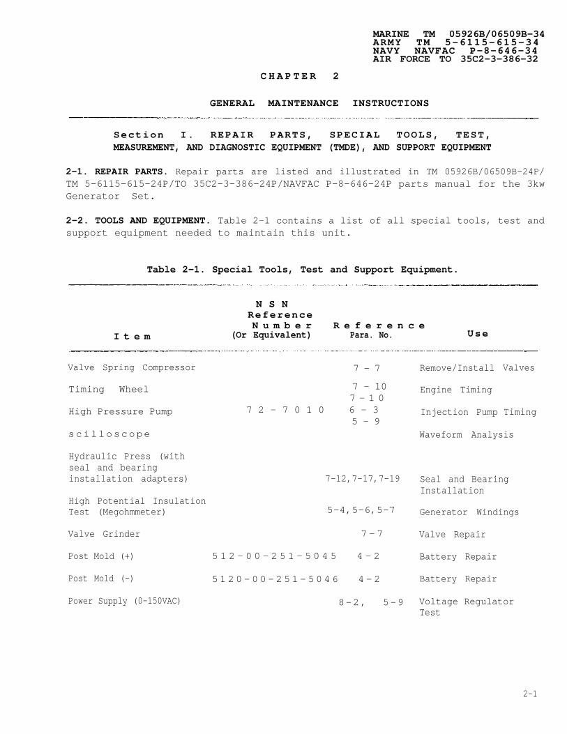
2-2. TOOLS AND EQUIPMENT. Table 2-1 contains a list of all special tools, test andsupport equipment needed to maintain this unit.
Table 2-1. Special Tools, Test and Support Equipment.
N S N Re fe renceN u m b e r R e f e r e n c e
I t e m (Or Equivalent) Para. No. Use
Valve Spring Compressor 7 - 7
Timing Wheel
High Pressure Pump
s c i l l o s c o p e
7 - 107 - 1 0
7 2 - 7 0 1 0 6 - 35 - 9
Hydraulic Press (withseal and bearinginstallation adapters) 7-12,7-17,7-19
High Potential InsulationTest (Megohmmeter) 5-4,5-6,5-7
Valve Grinder 7 - 7
Post Mold (+)
Post Mold (-)
Power Supply (0-150VAC)
Remove/Install
Engine Timing
Injection Pump
Valves
Timing
Waveform Analysis
Seal and BearingInstallation
Generator Windings
Valve Repair
Battery Repair
Battery Repair
Voltage RegulatorTest
5 1 2 - 0 0 - 2 5 1 - 5 0 4 5 4 - 2
5 1 2 0 - 0 0 - 2 5 1 - 5 0 4 6 4 - 2
8 -2 , 5 -9
2-1

MARINE CORPS TM 05926B/06509B-34ARMY TM 5-6115-615-34NAVY NAVFAC P-8-646-34AIR FORCE TO 35C2-3-386-32
Table 2-1. Special Tools, Test and Support Equipment - Continued
NSNReferenceNumber Reference
Item (Or Equivalent) Para. No. Use
Power Supply (Variable DC) 9-3 Frequency Meter
Epoxy Kit
Multimeters (3)
Signal Generator
Rheostat 750 ohm, 2 Watt
Resistor 30 ohm, 120 Watt
Potentiometer 500 ohm
Voltmeter (AC)
Voltmeter (DC)
Cylinder Hone
Nozzle CleaningKit
Nozzle Tester
Rocker Arm Socket
Ring Expander
Crankshaft Gear:PullerSocket
Test
8010-00-959-4661 4-2 Battery Repair
5-2, 5-4, Circuit Testing5-5 5-6, 5-7, and 8-2
KDEP-1043
0-681-143-014
420-0517
PS87-104-1PS87-104-2-2
8-2
5-9
5-9
5-9
5-9
5-9
7-13
6-4
6-4
7-8
7-13
7-177-17
Circuit Testing
Voltage RegulatorTesting/Adjustment
Voltage RegulatorTesting/Adjustment
Voltage RegulatorAdjustment
Voltage RegulatorAdjustment
Voltage RegulatorAdjustment
Remove CylinderGlaze
Injection SprayHole Cleaning
Injector Testing,Setting NozzleOpening Pressure
Remove/InstallRocker Arm Nuts
Remove/Install Rings
Remove CrankGear
2-2

MARINE CORPS TM 05926B/06509B-34ARMY TM 5-6115-615-34NAVY NAVFAC P-8-646-34AIR FORCE TO 35C2-3-386-32
Table 2-1. Special Tools, Test and Support Equipment - Continued
NSNReferenceNumber Reference
Item (Or Equivalent) Para. No. Use
Load Bank 7-2 Governor Adjustment
Bar Stock 420-0518 7-11 Setting TimingPointer
2-3. FABRICATED TOOLSfor the maintenance of
ANDthe
EQUIPMENT. No fabricated tools or equipment are necessary3kw Generator Sets.
2-3

MARINE CORPS TM 05926B/06509B-34ARMY TM 5-6115-615-34NAVY NAVFAC P-8-646-34AIR FORCE TO 35C2-3-386-32
Table 2-2. Consumable Operating and Maintenance Supplies.
Qty QtyNational Required Required
Item Component Stock For Initial 8 HoursNo. Application Number Description Operation Operation Notes
1
2
3
4
5
6
7
8
9
10
11
12
Battery
Battery
Starter
Lifter
Misc.
Misc.
Misc.
Misc.
Misc.
Misc.
Misc.
Misc.
8010-00-959-4661 Epoxy Kit As req’d
9650-00-264-5050 Pig Lead As req’d
Grease As req’dMultitempPS No. 2
Lifter, Pre-lube As req’dType, sealedpower LL-S
8030-00-148-9833 Loctite 271 As req’dMIL-S-46163-AType I, Grade K
Never-Seeze(Onan P/N524-0076)
Loctite 242MIL-S-46163AType II, Grade
As req’d
As req’d
N
Sealing Compound As req’dMIL-S-46163-AType III,Grade RRemovable
Sealing Compound, As req’dRTV SiliconeMIL-A-46106-A
Loctite Ultra As req’dBlue SiliconeSealant
Sealing Compound As req’dMIL-R-46082Type I
Dry Cleaning As req’dSolvent, P-D-680
2-4

MARINE CORPS TM 05926B/06509B-34ARMY TM 5-6115-615-34NAVY NAVFAC P-8-646-34AIR FORCE TO 35C2-3-386-32
Table 2-2. Consumable Operating and Maintenance Supplies - Continued.
QtyNational Required
Item Component Stock For InitialNo. Application Number Description Operation
— — ————————------------------------------------
13 Misc. Sealing compound As req'dMIL-S-22473-EGrade HVV
14 Misc. P/N 13217E3704, Heat SinkFSCM 97403 Compound
- - - - - - - - - - - - - - - - - - - - - - - - - - - - - - - - - - - - - - - - - - - - - - - - - - - - - -
As req'd
QtyRequired8 Hours
Operation Motes
--------------------
2-5

MARINE CORPS TM 05926B/06509B-34ARMY TM 5-6115-615-34NAVY NAVFAC P-8-646-34AIR FORCE TO 35C2-3-386-32
Section II. TROUBLESHOOTING
2-4. GENERAL. This section contains troubleshooting information for locating andcorrecting operating troubles which may develop in the Generator Set. Eachmalfunction for an individual component, unit or system is followed by a list oftests or inspections which will help you determine probable causes and correctiveactions to take. You should perform the tests/inspections and corrective actions inthe order listed.
2-5. MALFUNCTIONS NOT CORRECTED BY USE OF THE TROUBLESHOOTING TABLE. This manualcannot list all malfunctions that may occur, nor all tests or inspections andcorrective actions. If a malfunction is not listed or cannot be corrected by thelisted corrective actions, notify your supervisor.
Table 2-3. Troubleshooting.
MalfunctionTest or Inspection
Corrective Action
1. STARTER MOTOR DOES NOT TURN - HIGH CURRENT DRAW.
Step 1. CheckRefer
Step 2. CheckRefer
Step 3. CheckRefer
Step 4. Check
starter for grounded solenoid.to paragraph 7-4.c. and 7-5.a.
Replace any grounded component.
starter for grounded terminals.to paragraph 7-4.c.
Replace any grounded component.
starter for grounded field stator.to paragraph 7-4.c.
Replace any grounded component.
for frozen armature shaft. Refer to paragraph 7-4.d.e.
Replace armature bushing and, if necessary, armature.
2. STARTER DOES NOT TURN - NO CURRENT DRAW.
Step 1. Check for open
Replace
Step 2. Check for open
Replace
armature windings. Refer to paragraph 7-4.b.c.
armature if necessary.
starter field windings. Refer to paragraph 7-4.c.
field windings if necessary.
2-6

MARINE CORPS TM 05926B/06509B-34ARMY TM 5-6115-615-34NAVY NAVFAC P-8-646-34AIR FORCE TO 35C2-3-386-32
Table 2-3. Troubleshooting - Continued.
MalfunctionTest or Inspection
Corrective Action
Step 3. Check
Step 4. Check
3. SLOW STARTER SPEED.
Step 1.
Step 2.
Step 3.
Step 4.
Step 5.
Check
Check
Check
Check
for broken or weak brush springs. Refer to paragraph 7-4.d.
Replace brush springs if necessary.
for worn commutator (high mica). Refer to paragraph 7-4.d.
Refinish commutator or replace armature (includingcommutator).
for dirty commutator. Refer to paragraph 7-4.d.
Clean or refinish commutator.
for worn armature shaft bushings. Refer to paragraph 7-4.d.
Replace bushings and, if necessary, armature.
for burned solenoid contacts. Refer to paragraph 7-4.d.
Replace solenoid.
for open or shorted starter field windings. Refer to
4. STARTER WILL NOT
paragraph 7-4.c.
Replace windings, if necessary.
Check for worn generator end bearing. Refer to paragraph 5-8.a.
Replace bearing if necessary.
ENGAGE FLYWHEEL.
Step 1. Check
Step 2. Check
Step 3. Check
starter free running clutch. Refer to paragraph 7-4.d.
Replace clutch if necessary.
starter pinion gear. Refer to paragraph 7-4.d.
Replace pinion if necessary.
for damaged flywheel ring gear. Refer to paragraph 7-1.b.
Replace flywheel if necessary.
2-7

MARINE CORPS TM 05926B/06509B-34ARMY TM 5-6115-615-34NAVY NAVFAC P-8-646-34AIR FORCE TO 35C2-3-386-32
Table 2-3. Troubleshooting - Continued.
MalfunctionTest or Inspection
Corrective Action
5. ENGINE WILL NOT START WHEN CRANKED.
Step 1. Check glow plug operation. Refer to TM 05926B/06509B-12/TM 5-6115-615-12/NAVFAC P-8-646-12/TO 35C2-3-386-31 manual, paragraph 4-50.a.
Replace a defective glow plug or wiring.
Step 2. Check for faulty injection caused by dirty fuel. Refer toparagraph 6-4.c.
Replace with clean fuel. Service fuel filters, refer toTM 05926B/06509B-12/TM 5-6115-615-12/NAVFAC P-8-646-12/TO35C2-3-386-31 manual, paragraph 4-50. Clean and, ifnecessary, repair or replace fuel injection nozzle. Referto paragraph 6-4.e.f.g.
Step 3. Check for poor compression. Refer to paragraph 7-2.a.
See malfunction 12.
Step 4. Incorrect fuel injection pump
Retime pump. Refer to
6. ENGINE MISFIRES.
timing. Refer to paragraph 6-2.e.
paragraph 6-2.e.
Step 1. Check for poor compression. Refer to paragraph 7-2.a.
See malfunction 12.
Step 2. Check for defective or dirty injection6-4.c.
Clean or replace nozzle. Refer
Step 3. Check for broken valve springs. Refer
nozzle. Refer to paragraph
to paragraph 6-4.e.f.g.
to paragraph 7-7.a.
Replace broken springs. Refer to paragraph 7-7.c.
Step 4. Check cylinder head assembly for build-up of carbon. Refer toparagraph 7-6.c.
Clean carbon from cylinder head assembly. Refer toparagraph 7-6.c.
2-8

MARINE CORPS TM 05926B/06509B-34ARMY TM 5-6115-615-34NAVY NAVFAC P-8-646-34AIR FORCE TO 35C2-3-386-32
T a b l e 2 - 3 . Troubleshooting - Continued.
MalfunctionTest or Inspection
Corrective Action
7. LOW ENGINE POWER.
Step 1. Check
Step 2. Check6-4.c
Step 3. Check6-2.e.
for poor compression. Refer to paragraph 7-2.a.
See malfunction 12.
for dirty or defective injection nozzle. Refer to paragraph
Clean or replace injection nozzle. Refer to paragraph 6-4.e.f.g.
for incorrect fuel injection pump timing. Refer to paragraph
Adjust6-2.e.
8. EXCESSIVE OIL CONSUMPTION.
Step 1. Check
Step 2. Check13.b.
9. BLACK SMOKEY EXHAUST
Step 1. Check
injection timing if necessary. Refer to paragraph
for worn valve guides. Refer to paragraph 7-6.c.
Replace guides, valves and seals. Refer to paragraph 7-6.dfor guide replacement and paragraph 7-7.b for valve and sealreplacement.
for worn or sticking piston rings. Refer to paragraph 7-
Replace rings if necessary. Refer to paragraph 7-13.c.d.
AND EXCESSIVE FUEL CONSUMPTION
for incorrect fuel injection pump timing. Refer to paragraph6-2.e.
Adjust injection timing if necessary. Refer to paragraph6-2.e.
Step 2. Check for faulty injection pump. Refer to paragraph 6-2.e.
Replace pump as necessary.
Step 3. Check for faulty fuel injection nozzle. Refer to paragraph 6-4.c.
Repair or replace nozzle. See paragraph 6-4.e.f.g.
2-9

MARINE CORPS TM 05926B/06509B-34ARMY TM 5-6115-615-34NAVY NAVFAC P-8-646-34AIR FORCE TO 35C2-3-386-32
Table 2-3. Troubleshooting - Continued.
MalfunctionTest or Inspection
Corrective Action
S t e p 4 . Check valve condition. Refer to paragraph 7-7.a.
Repair or replace worn valves.
10. TAPPING OR CLICKING SOUND FROM CYLINDER HEAD.
Step 1. Check for excessive valve clearance.
Adjust clearance.
Step 2. Check for broken valve spring. Refer
Replace broken springs. Refer
Refer to paragraph 7-7.b.c.
Refer to paragraph 7-8.e.
to paragraph 7-7.a.
to paragraph 7-7.c.
11. METALLIC KNOCKING, CLICKING, OR POUNDING FROM CRANKCASE OR CYLINDER BLOCK.
Step 1.
Step 2.
Step 3.
Step 4.
Check for dirty or defective injection nozzle. Refer to paragraph6-4.c.
Clean or replace injection nozzle. Refer to paragraph6-4.e.f.g.
Check for worn or loose connecting rod bearings. Refer toparagraph 7-15.c.
Replace bearings if necessary.
Check for loose piston assembly. Refer to paragraph 7-13.c.
Repair or replace piston. Refer to paragraph 7-13.d.e.
Check for loose connecting rod assembly. Refer to paragraph7-15.C.
Replace connecting rod bearings.
12. LOW ENGINE COMPRESSION.
N O T E
Normal cylinder pressure is between 325 and 375 psidepending upon engine condition. Maintenance should beconsidered if pressure is below 325 psi.
2-10

MARINE CORPS TM 05926B/06509B-34ARMY TM 5-6115-615-34NAVY NAVFAC P-8-646-34AIR FORCE TO 35C2-3-386-32
Table 2-3. Troubleshooting - Continued.
MalfunctionTest or Inspection
Corrective Action
Step 1. Check
Step 2. Check
Step 3. Check
Step 4. Check
for loose cylinder head.
Properly tighten head.
for broken valve spring.
Replace broken spring.
Refer to paragraph 7-6.f.
Refer to paragraph 7-7.a.
Refer to paragraph 7-7.c.
for worn or sticking valves. Refer to paragraph 7-7.b.
See malfunction 13 below.
for worn valve seats. Refer to paragraph 7-6.c.
Clean and, if necessary, regrind valve seats. Refer toparagraph 7-6.d.
Step 5. Check for worn or sticking piston rings. Refer to paragraph7-13.C.
Replace rings if necessary. Check condition of cylinderwalls and piston grooves.
Step 6. Check for worn cylinder walls and pistons. Refer to paragraph7-13.C.
Refinish cylinder walls. Replace pistons.
13. STICKING VALVES.
Step 1. Check for dirty, scored, or gummy valve stems or guides. Refer toparagraph 7-6.c.
Clean stems and guides. Replace guides if necessary.Refer to paragraph 7-6.c.d.
Step 2. Check for weak or broken springs. Refer to paragraph 7-7.a.
Replace springs. Refer to paragraph 7-7.c.
14. ENGINE RUNS NORMALLY, BUT GENERATOR HAS NO OUTPUT.
Step 1. Check voltage regulator. Refer to paragraph 5-9.a.
Repair or replace regulator. Refer to paragraph 5-9.d.e.
2-11

MARINE CORPS TM 05926B/06509B-34ARMY TM 5-6115-615-34NAVY NAVFAC P-8-646-34AIR FORCE TO 35C2-3-386-32
Table 2-3. Troubleshooting - Continued.
MalfunctionTest or Inspection
Corrective Action
Step 2. Check exciter field (stator) for open or shorted windings. Referto paragraph 5-7.
Step 3. Check
Step 4. Check
Replace stator if necessary. Refer to paragraph 5-2.e.f.
Check diodes on exciter rotor. Refer to paragraph 5-5.a.
Replace diodes if necessary. Refer to paragraph 5-5.b.c.
generator field (rotor) for open or shorted windings. Referto paragraph 5-4.b.
Step 5. CheckRefer
Step 6. Check
Replace rotor if necessary. Refer to paragraph 5-4.c.
generator stator for open, shorted, or grounded windingsto paragraph 5-6.a.
Replace stator, if necessary. Refer to Paragraph 5-2.f.
exciter rotor for open, shorted, or gorunded windings. Referto paragraph 5-4.b.
Replace exciter rotor if necessary. Refer to paragraph5-2.f.
Step 7. Check bridge assembly (MEP-026B Only) for defective diodes. Referto TM 05926B/06509B-12/TM 5-6115-615-12/NAVFAC P-8-646-12/TO 35C2-3-386-31 manual, paragraph 69.c.
Replace defective diodes. Refer to TM 05926B/06509B-12/TM5-6115-615-12/NAVFAC P-8-646-012/TO 35C2-3-386-31 manual,paragraph 4-69.d.
15. ENGINE RUNS NORMALLY, BUT GENERATOR HAS LOW OUTPUT.
Step 1. Check voltage regulator. Refer to paragraph 5-9.a.
Adjust, repair, or replace regulator. Refer to paragraph5-9.d.e.
Check voltage adjust rheostat. Refer to TM 05926B/06509B-12/TM 5-6115-615-1/NAVFAC P-8-646-12/TO 35C2-3-386-31manual, paragraph 4-65.a.
Replace rheostat if necessary. Refer to TM 05926B/06509B-12/TM 5-6115-615-12/NAVFAC P-8-646-12TO 35C2-3-386-31manual, paragraph 4-65.b.c.
Step 2.
2-12

MARINE CORPS TM 05926B/06509B-34ARMY TM 5-6115-615-34NAVY NAVFAC P-8-646-34AIR FORCE TO 35C2-3-386-32
Table 2-3. Troubleshooting - Continued.
MalfunctionTest or Inspection
Corrective Action
Step 3. Check generator stator for open or shortedparagraph 5-6.a.
Replace stator.
Step 4. Check exciter rotor for5-4.b.
Refer to paragraph
shorted windings.
windings. Refer to
5-2.f.
Refer to paragraph
Replace rotor. Refer to paragraph 5-2.f.
Step 5. Check diodes on exciter rotor. Refer to paragraph 5-5.a.
Replace diodes as necessary. Refer to paragraph 5-5.c.
16. HIGH GENERATOR OUTPUT VOLTAGE (NO LOAD).
Step 1.
Step 2.
Check for voltage regulator failure. Refer to paragraph 5-9.a.
Repair or replace defective regulator. Refer to paragraph5-9.d.e.
Check voltage adjust rheostat. Refer to TM 05926B/06509B-12/TM 5-6115-615-12/NAVFAC P-8-646-12/TO 35C2-3-386-31 manual, paragraph4-65.a.
Replace rheostat if necessary. Refer to TM 05926B/06509B-12/TM 5-6115-615-12/NAVFAC P-8-646-12/TO 35C2-3-386-31manual, paragraph 4-65.b.c.
17. FREQUENCY METER FAILS TO REGISTER.
Step 1. Test frequency meter. Refer to paragraph 9-3.a.
Replace defective frequency meter. Refer to TM05926B/06509B-12/TM 5-6115-615-12/NAVFAC P-8-646-12/TO35C2-3-386-31 manual, paragraph 4-66.a.b.
Step 2. Test frequency transducer. Refer to paragraph 9-4.a.
Replace defective frequency transducer. Refer to TM05926B/06509B-12/TM 5-6115-615-12/NAVFAC P-8-646-12/TO35C2-3-386-31 manual, paragraph 4-68.b.c.
2-13

Table 2-3. Troubleshooting - Continued.
MalfunctionTest or Inspection
Corrective Action
18. BATTERIES DO NOT CHARGE.
Step 1.
Step 2.
Step 3.
Check battery charging alternator stator. Refer to paragraph7-11.a.
Replace defective stator. Refer to paragraph 7-11.b.f.
Check flywheel magnets. Refer to paragraph 7-10.b.
Replace flywheel. Refer to paragraph 7-10.c.
Check battery charging voltage regulator. Refer to TM05926B/06509B-12/TM 5-6115-615-12/NAVFAC P-8-646-12/TO 35C2-3-386-31 manual, paragraph 4-25.b.
Replace defective battery charging voltage regulator. Referto TM 05926B/06509B-12/TM 5-6115-615-12/NAVFAC P-8-646-12/TO 35C2-3-386-31 manual, paragraph 4-25.c.d.
MARINE CORPS TM 05926B/06509B-34ARMY TM 5-6115-615-34NAVY NAVFAC P-8-646-34AIR FORCE TO 35C2-3-386-32
Section III. GENERAL MAINTENANCE
2-6. GENERAL MAINTENANCE. This section contains general maintenance instructionswhich are the responsibility of intermediate direct support and general supportmaintenance personnel. You will find that these instructions apply to severalcomponents or assemblies.chapter.
2-7. GENERAL MAITENANCE
They would otherwise have to be repeated throughout the
REQUIREMENTS.
2-7.1. Work Guidelines.
a. Make sure the workengine.
b. Make sure that the
area is clean before you disassemble
materials needed for the task are atinclude cleaning solvents, lubricants, buckets or other
the generator or
hand. These maycontainers for
2-14

cleaning parts orall of the proper
DRY CLEANING
keepingtools.
MARINE CORPS TM 05926B/06509B-34ARMY TM 5-6115-615-34NAVY NAVFAC P-8-646-34AIR FORCE TO 35C2-3-386-32
components separated, clean wiping cloths, and
SOLVENT, (Table 2-2, item 12), used toclean parts is potentially dangerous to personnel andproperty. Avoid repeated and prolonged skin contact.DO NOT use near open flame or excessive heat. Flashpoint of solvent is 100 to 138 degrees Fahrenheit (38to 60 degrees Centigrade).
c. Clean the exterior of the engine and generator before disassembly to keepforeign matter from contaminating bearings, gears and other componentswhich may be damaged by these foreign materials. Use a clean clothdampened with cleaning solvent (Table 2-2, item 12).
d. If compressed air is used to clean parts, make sure it is free of dirt andother contaminants. Never exceed 15 psi nozzle pressure.
e. Protect disassembled parts from dust, blowing sand, and moisture which cancause rapid wear and deterioration of bearings,parts.
2-7.2. Seals and Gaskets. Replace seals and gaskets ofcomponents. This will greatly reduce the possibility of
gears and other machined
all disassembledleaking after reassembly,
and will help prevent the entry of dust and dirt.
2-7.3. Care of Bearings.
a. Clean ball and roller bearings by placing them in a wire basket andimmersing them in a container of fresh cleaning solvent. Agitate thebearings in the solvent to remove all traces of old lubricant.
b. Dip the cleaned bearings in clean engine oil and immediately wrap them inlint-free paper to protect them from dust and other foreign matter.
2-7.4. Replacing Electronic Components.
a. Tag wires with identification before removal to ensure properreconnection.
b. When soldering, use a heat sink between the soldering pencil and theelectronic component to prevent damage to the component.
c. Do not use excessive heat when soldering on printed circuit boards. Damageto the board may result.
2-7.5. Fuel System Maintenance. The fuel injectors and fuel pump are manufacturedto extremely tight tolerances. Even small amounts of dust or water in the fuelsystem can damage these components. It is of great importance that dirt be kept outof the fuel lines and fittings during disassembly and assembly. All openings shouldbe taped, capped or plugged immediately after disassembly. If dirt doesaccidentally enter a component, it should be flushed with clean diesel fuel beforereassembly.
2-15

MARINE CORPS TM 05926B/06509B-34ARMY TM 5-6115-615-34NAVY NAVFAC P-8-646-34AIR FORCE TO 35C2-3-386-32
2-7.6.
a.
b.
c.
2-7.7.
Welding.
Aluminum welding. Repair of aluminum components by welding is accomplishedin accordance with MIL-W-45205, Class B.
Steel welding. Repair of steel components by welding is accomplished inaccordance with MIL-W-8611.
Resistance welding. Resistance welding is accomplished in accordance withMIL-W-12332.
Painting. Components which require painting are treated and painted inaccordance with MIL-T-704, Type F or G, NATO Green 383.
Section IV. REMOVAL AND INSTALLATION OF MAJOR COMPONENTS.
2-8. CONTROL BOX.
a. Removal.
(1)
(2)
(3)
(4)
Disconnect negative (-) battery cable from battery.
NOTE
Figure 2-1 shows the Model MEP-016B Control box.Models MEP-026B and MEP-021B (28VDC and 400 Hz) aresimilar.
Remove screws (1, Figure 2-1) and nuts (2). Remove speed control mountingbracket from bottom of control box.
Remove nut (3), ground strap (4), and screw (5).
Disconnect five generator leads (MEP-026B) and eight generator leads (MEP-016B and MEP-021B).
(a) MEP-026B (28VDC).
1 Tag and disconnect two exciter stator leads from terminals #1 and#5 of terminal board A3-TB1 (see Figure 2-2).
2 Tag and disconnect three main stator leads T1, T2, and T3. T1 isconnected to terminal #4 of terminal board A3-TB1.Lead T2 is connected to terminal #2 of A3-TB1 and lead T3 isconnected to terminal #3 of A2-TB2.
(b) MEP-016B and MEP-021B (60 and 400 Hz).
1 Tag and disconnect exciter stator leads F1 and F2 at terminals #1and #2 of terminal block A1-TB2 (see Figure 2-3).
2-16

MARINE CORPS TM 05926B/06509B-34ARMY TM 5-6115-615-34NAVY NAVFAC P-8-646-34AIR FORCE TO 35C2-3-386-32
F i g u r e 2 - 1 . C o n t r o l B o x R e m o v a l a n d I n s t a l l a t i o n .2-17

MARINE CORPS TM 05926B/06509B-34ARMY TM 5-6115-615-34NAVY NAVFAC P-8-646-34AIR FORCE TO 35C2-3-386-32
2 Tag and disconnect six main stator leads T1, T2, T3, T4, T5, andT6. Lead T1 is connected to terminal #1 of terminal block A1-TB1,lead T2 is connected to terminal #2 of A1-TB1, lead T3 is connectedto terminal #3 of A1-TB1, lead T4 is connected to terminal #4 ofA1-TB1, lead T5 is connected to terminal #5 of A1-TB1, and lead T6is connected to terminal #6 of A1-TB1.
(5) Remove four screws (6, Figure 2-l), lockwashers (7), and washers (8).
Figure 2-2. Generator Wiring MEP-026B.
2-18

MARINE CORPS TM 05926B/06509B-34ARMY TM 5-6115-615-34NAVY NAVFAC P-8-646-34AIR FORCE TO 35C2-3-386-32
Figure 2-3. Generator Wiring MEP-016B and MEP-021B.
(6)
(7)
(8)
Loosen clamp and disconnect control box harness (Figure 2-4).
Thread generator wiring (five leads MEP-026B, eight leads MEP-016B and MEP-021B) through opening in bottom of control box.
Remove control box and cover generator opening to prevent entry of dirt.
b. Installation.
(1) Remove cover from generator.
(2) Place control box in position on frame. Thread generator wiring (fiveleads MEP-026B, eight leads MEP-016B and MEP-021B) through opening inbottom of control box.
2-19

MARINE CORPSARMYN A V YA I R F O R C E
(3)
(4)
(5)
(6)
(7)
TM 05926B/06509B-34TM 5-6115-615-34NAVFAC P-8-646-34TO 35C2-3-386-32
Secure control box to frameand screws (6).
Connect generator wiring toidentification.
with washers (8, Figure 2-l), lockwashers (7),
control box terminal boards using tags as lead
Secure ground strap (4) with screw (5)
Connect(1) and
Connect(Figure
speed control mounting bracketnuts (2).
control box harness to back of2-4).
and nut (3).
to bottom of control box with screws
control box and tighten clamp
Figure 2-4. Control Box Harness.
2 -20

MARINE CORPS TM 05926B/06509B-34ARMY TM 5-6115-615-34NAVY NAVFAC P-8-646-34AIR FORCE TO 35C2-3-386-32
2-9. ENGINE.
a . Removal.
(1) Drain fuel from fuel tank.
Do not, apply air pressure to the engine crankcase tospeed the oil drain process. Air pressure can forcethe oil seals out of the crankcase.
NOTE
To expedite the oil draining process, raise end ofset opposite the drain valve.
(2) Open drain valve (1, Figure 2-5), drain the engine oil. Disconnect oildrain line (2) from the drain valve and plug the oil line.
Figure 2-5. Engine Removal (Sheet 1 of 3).
2-21

MARINE CORPS TM 05926B/06509B-34ARMY TM 5-6115-615-34NAVY NAVFAC P-8-646-34AIR FORCE TO 35C2-3-386-32
Figure 2-5. Engine Removal (Sheet 2 of 3).
2-22

MARINE CORPS TM 05926B/06509B-34ARMY TM 5-6115-615-34NAVY NAVFAC P-8-646-34AIR FORCE TO 35C2-3-386-32
Figure 2-5. E n g i n e R e m o v a l ( S h e e t 3 o f 3 ) .
2 - 2 3

MARINE CORPS TM 05926B/06509B-34A R M Y T M 5 - 6 1 1 5 - 6 1 5 - 3 4N A V Y N A V F A C P - 8 - 6 4 6 - 3 4A I R F O R C E T O 3 5 C 2 - 3 - 3 8 6 - 3 2
( 3 )
( 4 )
( 5 )
( 6 )
( 7 )
( 8 )
( 9 )
( 1 0 )
(11)
(12)
(13)
(14)
(15)
(16)
(17)
(18)
(19)
Remove battery, refer to TM 05926B/06509B-12/TM 5-6115-615 -12/NAVFAC P-8-646-12/TO 35C2-3-386-31 manual paragraph 4-19.
Remove frame, refer to paragraph 3-2.
Remove rear starter bracket, refer to TM 05926B/06509B-12/TM 5-6115-615-12/NAVFAC P-8-646-12/TO 35C2-3-386-31 manual, paragraph 4-48.
Remove engine oil filter, refer to TM 05926B/06509B-12/TM 5-6115-615-12/NAVFAC P-8-646-12/TO 35C2-3-386-31 manual, paragraph 4-46.
Remove screws (3) and sound shield (4).
Remove oil cooler, refer to paragraph 7-20.
Disconnect throttle cable from governor, refer6115-615-12/NAVFAC P-8-646-12/TO 35C2-3-386-31
Remove generator, refer to paragraph 2-10.
Disconnect electrical connector from auxiliary
to TM 05926B/06509B-12/TM 5-manual, paragraph 4-56.
fuel pump, refer to TM05926B/06509B-12/TM 5-6115-615-12/NAVFAC P-8-646-12/TO 35C2-3-386-31manual, paragraph 4-35.
Attach a chain hoist to the engine lifting eyes. Remove slack from chains,but do not lift engine.
Remove engine wiring harness, refer to TM 05926B/06509B-12/TM 5-6115-615-12/NAVFAC P-8-646-12/TO 35C2-3-386-31 manual, paragraph 4-72.
Remove air intake hose, refer to TM 05926B/06509B-12/TM 5-6115-615-12/NAVFAC P-8-646-12/TO 35C2-3-386-31 manual, paragraph 4-49.
Remove fuel lines, refer to TM 05926B/06509B-12/TM 5-6115-615-12/NAVFAC P-8-646-12/TO 35C2-3-386-31 manual, paragraph 4-39.
Restore engine support leg (24, Figure 2-6) to original position.
Remove screws (5), lockwashers (6), washer (7), washers (8, 9 and 10),lockwasher (11) and nut (12). Keep washers in correct sequence forinstallation.
Lift and remove engine with chain hoist.
Remove generator fan, refer to paragraph 5-3.
b. Installation.
(1)
( 2 )
( 3 )
Secure generator fan to engine, refer to paragraph 5-3.
Place engine in position.
Install screws (5, Figure 2-5), lockwashers (6), washer (7), washers (8,9, and 10), lockwasher (11), and nut (12).
2-24

(4)
(5)
(6)
(7)
(8)
(9)
( 1 0 )
(11)
(12)
(13)
(14)
(15)
(16)
(17)
MARINE CORPSARMYNAVYAIR FORCE
TM 05926B/06509B-34TM 5-6115-615-34NAVFAC P-8-646-34TO 35C2-3-386-32
Install fuel lines, refer to TM 05926B/06509B-12/TM 5-6115-615-12/NAVFAC P-8-646-12/TO 35C2-3-386-31 manual, paragraph 4-39.
Install air intake hose, refer to TM 05926B/06509B-12/TM 5-6115-615-12/NAVFAC P-8-646-12/TO 35C2-3-386-31 manual, paragraph 4-49.
Install engine wiring harness, refer to TM 05926B/06509B-12/TM 5-6115-615-12/NAVFAC P-8-646-12/TO 35C2-3-386-31manual, paragraph 4-72.
Connect electrical connector to auxiliary fuel pump, refer to TM05926B/06509B-12/TM 5-6115-615-12/NAVFAC P-8-646-12/TO 35C2-3-386-31 manual,paragraph 4-35.
Install generator, refer to paragraph 2-10.
Connect throttle cable to governor, refer to TM 05926B/06509B-12/TM 5-6115-615-12/NAVFAC P-8-646-12/TO 35C2-3-386-31 manual, paragraph 4-56.
Install oil cooler, refer to paragraph 7-20.
Position sound shield (4) in frame and secure with screws (3).
Install engine oil filter, refer to TM 05926B/06509B-12/TM 5-6115-615-12/NAVFAC P-8-646-12/TO 35C2-3-386-31 manual, paragraph 4-46.
Install rear starter bracket, refer to TM 05926B/06509B-12/TM 5-6115-615-12/NAVFAC P-8-646-12/TO 35C2-3-386-31 manual, paragraph 4-48.
Install frame, refer to paragraph 3-2.
Remove lifting hoist.
Connect oil drain lineengine with the properTM 05926B/06509B-12/TMmanual, paragraph 3-2.
Install battery, refer
(2) to oil pan, close drain valve (1), and fillamount and type of engine oil. Refer to5-6115-615-12/NAVFAC P-8-646-12/TO 35C2-3-386-31
to TM 05926B/06509B-12/TM 5-6115-615-12/NAVFAC P-8-646-12/TO 35C2-3-386-31 manual, paragraph 4-22.
N O T E
Generator cannot be removed as an assembly; somedisassembly is required.
2-10. GENERATOR.
a. Removal.
(1) Remove frame, refer to paragraph 3-2.
(2) Remove rear starter bracket, refer to TM 05926B/06509B-12/TM 5-6115-615-12/NAVFAC P-8-646-12/TO 35C2-3-386-31 manual, paragraph 4-48.
2-25

MARINE CORPS TM 05926B/06509B-34ARMY TM 5-6115-615-34NAVY NAVFAC P-8-646-34AIR FORCE TO 35C2-3-386-32
2-26
Figure 2-6. Generator Removal and Installation (Sheet 1 of 2).

MARINE CORPS TM 05926B/06509B-34ARMY TM 5-6115-615-34NAVY NAVFAC P-8-646-34AIR FORCE TO 35C2-3-386-32
Figure 2-6. Generator Removal and Installation (Sheet 2 of 2).
2-27

MARINE CORPS TM 05926B/06509B-34ARMY TM 5-6115-615-34NAVY NAVFAC P-8-646-34AIR FORCE TO 35C2-3-386-32
(3)
(4)
(5)
(6)
(7)
(8)
(9)
(10)
(11)
(12)
(13)
(14)
(15)
(16)
(17)
b.
(1)
(2)
(3)
Remove control box, refer to paragraph 2-8.
Attach a hoist to the generator. Remove slack from hoist chains but do notlift generator.
Remove auxiliary fuel hose (1, Figure 2-6) and ground cable (2) from skidbase.
Remove bolt (3), washer (4), and nut (5) securing ground strap (6) to skidbase.
Remove screws (7), washers (8), lockwashers (9), and nuts (10) that securegenerator to cross brace (11).
Remove bolts (12), lockwashers (13), and end cover (14) of generator.
Remove screws (15), lockwashers (16), washers (17), washers (18),lockwashers (19), and nuts (20). Keep washers in correct sequence forinstallation.
Remove screws (21),
Turn engine supportsupport engine when
Install and tighten
lockwashers (22), washers (23) and engine support (24).
(24) so leg of support is facing down. Leg willgenerator is removed.
engine support (24) to engine with screws (21),lockwashers (22) and washers (23).
Remove bolts (25), lockwashers (26), and washers (27) securing generator toengine housings.
Use a gear puller to remove generator housing and stator assembly (28).
Remove screws (29) and lockwashers (30) securing drive adapter (31) androtor (32) to fan (33).
To remove rotor (32) and drivelightly with a rubber mallet.
Remove bolts (34), lockwashers(31) from rotor (32).
Installation.
adapter (31) from fan (33), tap end of rotorBe careful not to tap rotor windings.
(35), washer plate (36), and drive adapter
Install screws (7), washers (8), lockwashers (9) and nuts (10) that securegenerator to cross brace (11).
Install drive adapter (31, Figure 2-6), to rotor (32) with washer plate(36), lockwashers (35), and bolts (34).
Put rotor (32) and drive adapter (31) in position on fan (33) and installbolts (29), and lockwashers (30). Tighten bolts (29) to 7 to 8 ft lbs (10to 11 N.m).
2-28

MARINE CORPS TM 05926B/06509B-34A R M Y T M 5 - 6 1 1 5 - 6 1 5 - 3 4N A V Y N A V F A C P - 8 - 6 4 6 - 3 4A I R F O R C E T O 3 5 C 2 - 3 - 3 8 6 - 3 2
(4)
(5)
(6)
( 7 )
( 8 )
(9 )
(10)
(11)
(12)
Use extreme care when installing stator housing.Misalignment and/or forced assembly may damage the rotoror stator.
Position stator housing (28) over rotor (32).
Secure generator stator assembly (28) to engine housing with bolts (25),lockwashers (26), and washers (27). Install two long bolts in holes aboveand below starter motor.
Remove screws (21), lockwashers (22), washers (23) and engine support (24).
Turn engine support (24) so leg of support is facing up.
Install and tighten engine support (24) to engine with screws (21),lockwashers (22) and washers (23).
Install resilient mount screws (15), lockwashers (16), washers (17),washers (18), lockwashers (19) and nuts (20).
Install end cover (14) with bolts (12) and lockwashers (13).
Connect ground strap (6) to cross brace (11) with screw (7), washer (8),and nut (10).
Install frame, refer to paragraph 3-2.
2-29/(2-30 blank)


MARINE CORPS TM 05926B/06509B-34ARMY TM 5-6115-615-34NAVY NAVFAC P-8-646-34AIR FORCE TO 35C2-3-386-32
CHAPTER 3
MAINTENANCE OF THE FRAME
3-1. GENERAL. The frame provides the generator set a point for lifting, protectionagainst physical damage, and a mounting surface for some components, and it issecured to the skid base. The skid base provides a mounting surface for theengine/generator assembly. A battery frame securely holds the battery in an uprightposition.
3-2. FRAME.
a. Removal.
(1)
(2)
(3)
(4)
(5)
(6)
(7)
(8)
Disconnect battery cables before removing frame. Thehigh current output of the DC electrical system cancause arcing and/or burns if a short circuit occurs.
Remove control box assembly. Refer to paragraph 2-8.
Disconnect two battery cables and slave receptacle cables from battery,remove nuts (1, Figure 3-1) and disconnect negative (2) cable first thendisconnect positive cable (3).
Remove negative slave cable (6) and positive slave cable (7).
NOTE
Screws (4) are captive and cannot be removed from soundsuppression panel (5).
Loosen two screwssound suppression
Remove screw (8),assemblies (12).
(4) that secure sound suppression panel (5). Removepanel (5).
lockwasher (9), washer (10), clamp (11), and ground rod
Remove nut (13), screw (14), and clips (15) that secure wiring harness tothe muffler heat shield at three locations.
Remove nuts (16), screws (17), and muffler heat shield panel (18) from theframe.
Tag and disconnect three fuel lines (19) from top of fuel tank (20). Plughose ends and fittings to prevent the entry of contaminants.
3-1

MARINE CORPS TM 05926B/06509B-34ARMY TM 5-6115-615-34NAVY NAVFAC P-8-646-34AIR FORCE TO 35C2-3-386-32
F i g u r e 3 - 1 . F r a m e R e m o v a l ( S h e e t 1 o f 5 ) .
3 - 2

MARINE CORPS TM 05926B/06509B-34A R M Y T M 5 - 6 1 1 5 - 6 1 5 - 3 4N A V Y N A V F A C P - 8 - 6 4 6 - 3 4A I R F O R C E T O 3 5 C 2 - 3 - 3 8 6 - 3 2
Figure 3-1. Frame Removal (Sheet 2 of 5).
3-3

MARINE CORPS TM 05926B/06509B-34ARMY TM 5-6115-615-34NAVYAIR FORCE
( 9 )
( 1 0 )
( 1 1 )
(12)
(13)
(14)
(15)
(16)
NAVFAC P-8-646-34TO 35C2-3-386-32
Unscrew wire connector (21) from top of fuel tank.
Loosen fuel filter vent plug (22) on fuel filter (23) and drain fuel fromfilter drain (24) into a suitable container.
Tag and disconnect two hoses (25 and 26) from fuel filter (23) and plughose ends and fittings to prevent the entry of contaminants.
Loosen clamp (27). Remove four screws (28) lockwashers (29), and washers(30) and remove air cleaner (31).
Remove nuts (32), lockwashers (33), washers (34), bolts (35), and washers(36) that secure frame to skid base (6 locations).
Remove screw (37) that secures bracket (38) to frame.
Remove cap from fuel tank drain.
Carefully lift frame from skid base, and remove fuel tank (39).
b. Repair. Repair of the frame is limited to simple bending or aluminumwelding. Refer to paragraph 2-7.6.
c. Installation.
(1)
(2)
(3)
(4)
(5)
(6)
(7)
(8)
(9)
Install oil cooler, refer to paragraph 7-20.
Place fuel tank (39) in position on skid base and replace cap from fueltank drain.
Carefully place frame in position on skid base.
Secure fuel tank (39) to frame.
Secure bracket (38) to frame with screw (37).
Secure frame to skid base with washers (36), bolts (35), washers (34),lockwashers (33), and nuts (32).
NOTE
If control box was removed, push generator wiresthrough grommets in bottom of box.pad completely surrounds opening inafter installation.
Install control box. Refer to paragraph
Install air cleaner (31)(29), and washers (30).
Remove plugs and connect
and secure with
Make sure rubbertop of generator
2-8.
four screws (28), lockwashersTighten clamp (27).
two fuel lines (25 and 26) to fuel filter (23).
3-4
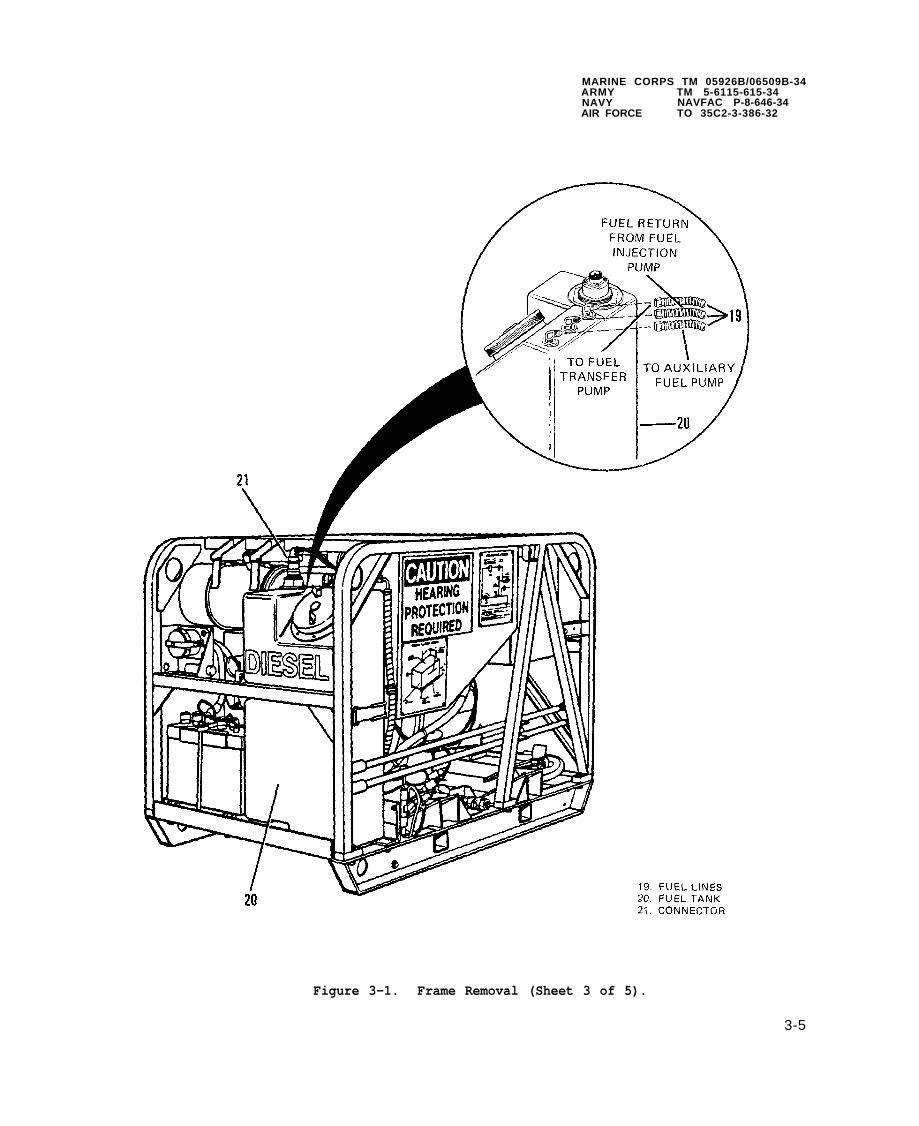
MARINE CORPS TM 05926B/06509B-34ARMY TM 5-6115-615-34NAVY NAVFAC P-8-646-34AIR FORCE TO 35C2-3-386-32
Figure 3-1. Frame Removal (Sheet 3 of 5).
3-5

MARINE CORPS TM 05926B/06509B-34ARMY TM 5-6115-615-34NAVY NAVFAC P-8-646-34AIR FORCE TO 35C2-3-386-32
Figure 3-1. Frame Removal (Sheet 4 of 5).
3-6

MARINE CORPS TM 05926B/06509B-34ARMY TM 5-6115-615-34NAVY NAVFAC P-8-646-34AIR FORCE TO 35C2-3-386-32
3-7
Figure 3-1. Frame Removal (Sheet 5 of 5).

MARINE CORPS TM 05926B/06509B-34ARMYNAVYAIR FORCE
(10)
(11)
(12)
(13)
(14)
(15)
(16)
(17)
(18)
(19)
TM 5-6115-615-34NAVFAC P-8-646-34TO 35C2-3-386-32
Check that vent plug (22) on fuel filter (23) is closed.
Connect wire connector (21) to top of fuel tank (20).
Remove plugs from ends of fuel lines (19) and connect to fuel tank (20).
Place cable clip (15) inside heat shield panel (18).
Secure heat shield panel (18) to frame with screws (17) and nuts (16).
Secure wiring harness and auxiliary fuel line with clips (15), screw (14),and nut (13). Clip (15) on outside of heat shield panel secures theauxiliary fuel line and clip (15) inside the heat shield panel secures thewiring harness.
Secure ground rod assemblies (12) with clamp (11), washer (10), lockwasher(9), and screw (8).
Place sound suppression panel (5) on generator set and tighten screws (4).
Install battery. Refer to TM 05926B/06509B-12/TM 5-6115-615-12/NAVFAC P-8-646-12/TO 35C2-3-386-31 manual, paragraph 3-15.
Connect battery cables last when installing frame. Thehigh current output of the DC electrical system cancause arcing and/or burns if a short circuit occurs.
Connect positive battery cable (3) and positive slave cable (7) first andthen negative battery cable (2) and negative slave cable (6) to battery.Secure cables by tightening nuts (1).
3-3. SKIDBASE.
a. Removal.
(1) Remove frame, refer to paragraph 3-2.
(2) Remove generator, refer to paragraph 2-10.
(3) Remove engine, refer to paragraph 2-9.
b. Disassembly.
(1) Remove nuts (1, Figure 3-2), lockwashers (2), washers (3), bolts (4) andmounts (5).
(2) Remove nut (6), lockwasher (7), ground strap (8), and bolt (9).
3-8
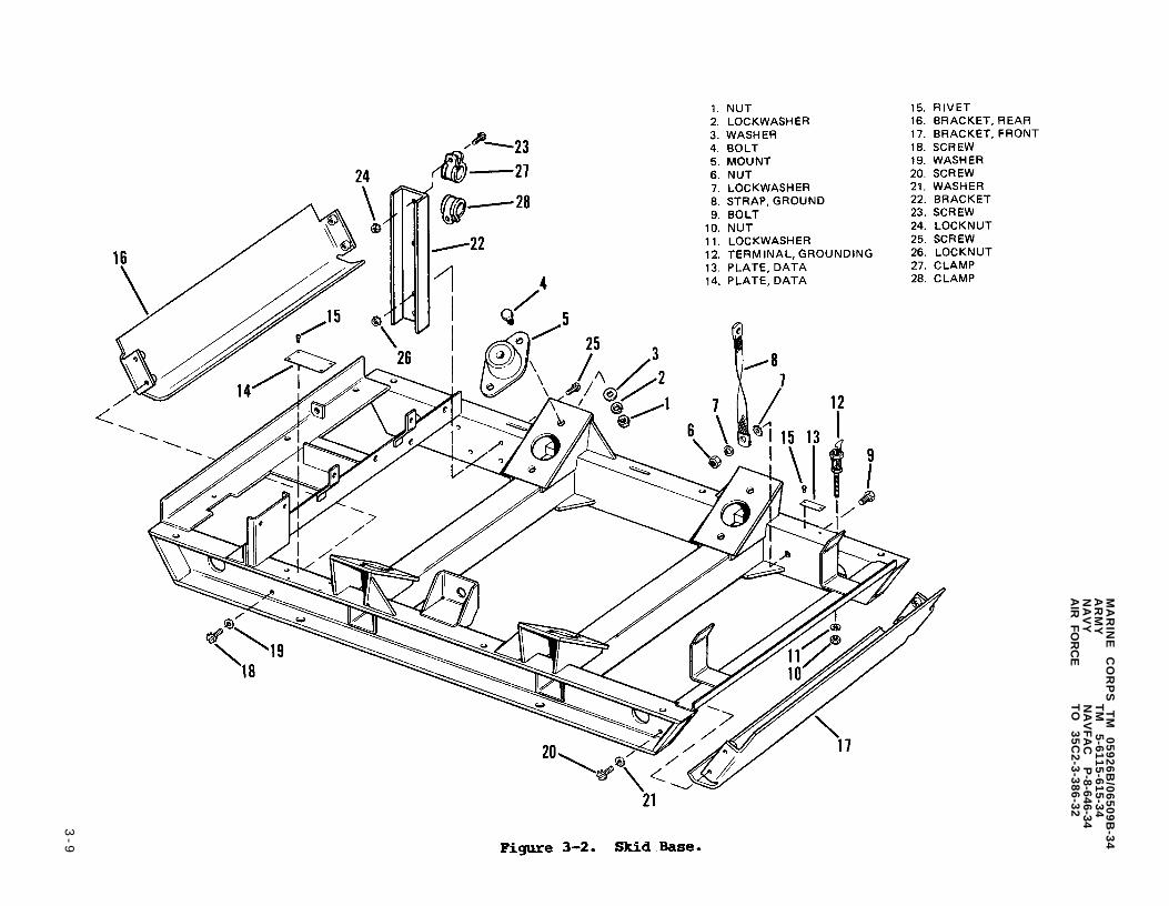
Figure 3-2.
MA
RIN
E
CO
RP
S
TM
0
59
26
B/0
65
09
B-3
4A
RM
YT
M
5-6
11
5-6
15
-34
NA
VY
NA
VF
AC
P
-8-646-34A
IR F
OR
CE
TO
3
5C
2-3
-38
6-3
2
3-9

MARINE CORPS TM 05926B/06509B-34A R M YN A V YA I R F O R C E
(3)
(4)
(5)
(6)
(7)
(8)
TM 5-6115-615-34NAVFAC P-8-646-34TO 35C2-3-386-32
Remove nut (10), lockwasher (11), and grounding terminal (12).
If necessary, remove auxiliary fuel pump, battery tray, and oil drainassembly. Refer to TM 05926B/06509B-12/TM 5-6115-615-12/NAVFAC P-8-646-12/TO 35C2-3-386-31 manual, paragraphs 4-35, 4-19 and 4-51.
Data plates (13 and 14) are not removed unless visibly damaged. Platesmay be removed by removing rivets (15).
Remove screws
Remove screws
Remove screws
(18), washers (19), and bracket (16).
(20), washers (21) and bracket (17).
(23 and 25), locknuts (24 and 26), clamps (27 and 28) andbracket (22).
c . Cleaning and Inspection.
(1) Wipe all parts with a clean lint free cloth.
(2) Inspect skid base and other parts for damaged threads, cracks, distortion,or other visible damage.
d. R e p a i r . R e p a i r o f t h e s k i d b a s e m a y b e a c c o m p l i s h e d b y e i t h e r b e n d i n g o r
aluminum welding, refer to paragraph 2-7.6.
e . Assembly.
(1) Install bracket (22) with screws (23 and 25), locknuts (24 and 26) and
(2)
(3)
(4)
(5)
(6)
(7)
clamps (22 and 28).
Install bracket (17) with screws (20) and washers (21).
Install bracket (16) with screws (18) and washers (19).
If removed, data plates (13 and 14) may be secured to skid base withrivets (15).
If necessary, install oil drain assembly, battery tray, and auxiliary fuelpump. Refer to TM 05926B/06509B-12/TM 5-6115-615-12/NAVFAC P-8-646-12/TO 35C2-3-386-31 manual, paragraphs 4-35, 4-19 and 4-51.
Secure grounding terminal (12) to skid base with lockwasher (11) and nut(10).
Secure ground strap (8) to frame with bolt (9), lockwashers (7) and nut(6).
Install mounts (5), bolts (4), washers (3), lockwashers (2), and nuts (1).(8)
f. Installation.
(1) Install engine, refer to paragraph 2-9.
(2) Install generator, refer to paragraph 2-10.
(3) Install frame, refer to paragraph 3-2.
3-10

MARINE CORPS TM 05926B/06509B-34ARMY TM 5-6115-615-34NAVY NAVFAC P-8-646-34AIR FORCE TO 35C2-3-386-32
CHAPTER 4
MAINTENANCE OF THE DC ELETRICAL AND CONTROL SYSTEM
4-1. GENERAL. A battery charging voltage regulator provides a stable DC currentthat is used to charge the battery after starting. The battery charging voltageregulator is a sealed unit and cannot be repaired or adjusted.
4-2. BATTERY REPAIR.
a. Battery Case.
(1) Cracks on the top of the battery case can be repaired. Cracks on theor bottom of the battery cannot be repaired and the battery should bediscarded in accordance with local policy and procedure.
sides
(2) Cracks in the battery top may be repaired by using epoxy kit (Table 2-2,item 1). Reference instructions are furnished with each kit.
b. Battery Posts.
(1) Battery posts which are worn or broken may be rebuilt by using pig lead andsteel battery post molds. Pig lead is available in five pound bars (Table2-2, item 2). Post molds are supplied in two sizes: positive (+) post,NSN 5120-00-251-5045 and negative (-) post, NSN 5120-00-251-5046. Positivepost mold has a larger inside diameter than the negative post mold.
Before repairing battery posts, place battery onbench under an exhaust hood to protect personnellead and/or acid fumes.
a workfrom
Always wear safety goggles and gloves when repairingbattery posts.
Follow procedures (2) through (5) carefully to avoiddanger of explosion.
(2) Remove all filler caps from the battery.
4-1

MARINE CORPS TM 05926B/06509B-34ARMY TM 5-6115-615-34NAVY NAVFAC P-8-646-34AIR FORCE TO 35C2-3-386-32
(3)
(4)
(5)
(6)
(7)
(8)
(9)
(10)
(11)
(12)
(13)
Make sure that electrolyte level is up to ledge in filler openings. Adddistilled water as necessary. A low electrolyte level creates a potentialfor hydrogen gas to be trapped in the plate area. Hydrogen gas whensubjected to flame or sparks can explode.
Let the battery stand for five minutes to permit explosive hydrogendissipate.
Using a low flame from a torch, flash the area above the open cellsremove excess fumes. There may be a small flash of flame when thisdone, so stand clear of the immediate area over the battery.
Clean the battery post. Dress down post to remove all burrs, roughand corrosion.
Place the battery post mold securely around the post to be repaired.
gas to
tois
edges,
Seatpost mold to prevent molten lead from running out from under the mold.
With steel post mold securely in place, apply heat to the top of thedamaged post. Use a torch that produces a narrow pencil shaped flame sothat heat can be applied to battery post without overheating the post mold.An overheated post mold will cause the lead to become too hot and lead willrun out of mold base.
Once the
When theover theinto the
lead starts to melt, do not jar and unseat the mold.
top of lead post is molten, hold one end of the lead stick closemold, heat the end of the lead stick, and feed the molten leadalready molten metal of the battery post.
NOTE
To prevent separation of old and new lead, do not jarthe battery while the lead is solidifying.
When lead has hardened and cooled, the mold can be removed by working offthe newly formed post, slowly, with a pair of pliers.
Test the newly formed post by gripping top of post with a pliers andtwisting. If top breaks off, the lead was not fully molten to effect acomplete bonding of the old and new lead,repeated.
If the post was properly rebuilt, it willroughness. Dress and clean the post with
and the repair procedure must be
have a smooth exterior, or minora file.
4-2

MARINE CORPS TM 05926B/06509B-34ARMY TM 5-6115-615-34NAVY NAVFAC P-8-646-34AIR FORCE TO 35C2-3-386-32
CHAPTER 5
MAINTENANCE OF THE ELECTRICAL POWER GENERATION AND CONTROL SYSTEM
5-1. GENERAL. Repair of the generator is limited to the replacement of defectiveparts. The generators on each of the models covered by this manual are nearlyidentical in appearance. Testing procedures are similar but may yield differentresults depending on the generator model.
5-2. GENERATOR ASSEMBLY.
a. Testing.
NOTE
Before testing power generator make sure that thevoltmeter on control panel is operating properly, referto procedures contained in operator/organizationalmanual. Also make sure that the output voltage
(1)
(2)
(3)
(4)
regulator is functioning properly, refer5-9.
Start generator set and allow it to warm up.
Observe the voltmeter on the front of controlregulator, or stator is defective; there willreading on the set voltmeter.
to paragraph
box. If exciter, rotor,be no or a low voltage
Perform the following preliminary generator tests to determine whichcomponent of the power generator is faulty. If these tests do not indicatea faulty component, disassembly and testing of individual components isrequired.
Test exciter stator windings.
(a) Disconnect
1 ModelsstatorA1-TB2
the two exciter stator windings at the control box.
MEP-016B and MEP-021B (60 and 400Hz) disconnect exciterleads F1 and F2 at terminals #1 and #2 of terminal block(see Figure 5-l).
5-1

MARINE CORPS TM 05926B/06509B-34ARMY TM 5-6115-615-34NAVY NAVFAC P-8-646-34AIR FORCE TO 35C2-3-386-32
Figure 5-1. Generator Testing-MEP-016B and MEP-021B.
(b)
(c)
(d)
(e)
2 Model MEP-026B (28 VDC) disconnect exciter stator leads at—terminals #1 and #2 of terminal board A3-TB1 (see Figure 5-2).
Connect a multimeter (set to read ohms) across the two exciter windingleads (leads F1 and F2 for models MEP-016B and MEP-021B).
A reading of approximately 22 ohms indicates that the exciter statorwindings are functional.
A low reading of less than 20 ohms indicates shorted windings, andexciter stator should be replaced.
A reading higher than 25 ohms indicates poor connections or openwindings, and exciter stator should be replaced.
5-2

MARINE CORPS TM 05926B/06509B-34ARMY TM 5-6115-615-34NAVY NAVFAC P-8-646-34AIR FORCE TO 35C2-3-386-32
Figure 5-2. Generator Testing-MEP-026B.
(a) Tag and disconnect the main1 for MEP-016B and MEP-021B
(5) Test main stator windings.
stator windings at the control box refer tosets and refer to 2 for MEP-026B set.
1
2
MEP-016B and MEP-021B (60 and 400 Hz) sets disconnect the sixstator leads (T1, T2, T3, T4, T5, and T6) from the control box.Lead T1 is connected to terminal #1 of terminal block A1-TB1 (seeFigure 5-1). Lead T2 is connected to terminal #2 of A1-TB1, leadT3 is connected to terminal #3 of A1-TB1, lead T4 is connected toterminal #4 of A1-TB1, lead T5 is connected to terminal #5 of A1-TB1, and lead T6 is connected to terminal #6 of A1-TB1.
MEP-026B (28 VDC) set disconnect the three stator leads (T1, T2,
and T3) from the control box. Lead T1 is connected to terminal #4of terminal block A3-TB1 (see, Figure 5-2). Lead T2 is connectedto terminal #2 of A3-TB1 and lead T3 is connected to terminal #3 ofA3-TB1.
(b) Use a multimeter (set to read ohms) to check the resistance betweenstator 1ead pairs. Refer to 1 for MEP-016B and MEP-021B sets and referto 2 for MEP-026B set.
5-3

MARINE CORPS TM 05926B/06509B-34ARMY TM 5-6115-615-34NAVY NAVFAC P-8-646-34AIR FORCE TO 35C2-3-386-32
(c)
1 MEP-016B and MEP-021B (60 and 400 Hz) sets check the resistancebetween leads (T3 and T6), (T1 and T4), and (T2 and T5).
2 MEP-026B set check the resistance between lead pairs (T1 and T2),(T2 and T3), and (T1 and T3).
The stator resistance values should be within the following ranges. Ifresistance is less than stated; stator has a short and should bereplaced. If resistance is greater than stated; stator has poorconnections or open windings and should be replaced.
1 MEP-016B set- theshould be between
2 MEP-021B set- theshould be between
3 MEP-026B set- theshould be between
(3) Generator rotor (main and
main stator winding resistance between lead pairs0.304 and 0.370 ohms.
main stator winding resistance between lead pairs0.149 and 0.181 ohms.
main stator winding resistance between leads0.018 and 0.022 ohms.
exciter) windings cannot be tested unless rotoris removed from the generator housing, refer to paragraph 5-4.
b. Removal. For removal procedures, refer to paragraph 2-10.
c. Disassembly.
NOTE
Figure 5-3 illustrates the MEP-016B and MEP-026B (60Hzand 28VDC) sets. Model MEP-021B (400 Hz) set issimilar, but has a slightly different rotor. Procedureswhich follow can be used for all three models.
(1)
(2)
(3)
(4)
(5)
(6)
Remove four screws (1,drive adapter (4) from
Remove circlip (5) and
Figure 5-3), lockwashers (2), washer plate (3), androtor assembly.
use a puller to remove bearing (6).
Exciter rotor (7) is permanently attached to main rotor (8) shaft andcannot be removed without damaging rotor.
Remove four screws (9), lockwashers (10) and cover (11). Remove smallgrommet (12) and large grommet (13).
Remove screw (14), lockwasher (15), and two
Data plate (17) is not removed unless it isretained by rivets (18).
bearing retainers (16).
being replaced. Data plate is
5-4

MARINE CORPS TM 05926B/06509B-34ARMY TM 5-6115-615-34NAVY NAVFAC P-8-646-34AIR FORCE TO 35C2-3-386-32
Figure 5-3. Generator Disassembly and Assembly.
d. Cleaning and Inspection.
(1 )
(2)
(3)
Clean non-electrical parts in solvent and dry with compressed air.
Wipe all electrical components with a clean, dry cloth. Clean rotor andstator windings with compressed air.
Inspect rotor and stator windings for signs of burning or damagedinsulation.
5-5

MARINE CORPS TM 05926B/06509B-34ARMY TM 5-6115-615-34NAVY NAVFAC P-8-646-34AIR FORCE TO 35C2-3-386-32
(4) Inspect rotor and stators for scoring or other indications that stators androtor have been rubbing together.
(5) Inspect stator leads for damaged or missing insulation.
e. Repair. Repair of generator is accomplished by replacement of defectivecomponents.
f. Assembly.
(1 )
(2)
(3)
(4)
(5)
(6)
(7)
If removed, install data plate (17, Figure 5-3) with rivets (18).
Secure bearing retainers (16) to housing with screw (14) and lockwasher( 1 5 ) .
P l a c e
Placeleadslarge
large grommet (13) and small grommet (12) into holes in cover (11).
two exciter stator leads through small grommet and six main stator(MEP-016B and MEP-021B) or three main stator leads (MEP-026B) throughgrommet.
Secure cover (11) with four screws (9) and lockwashers (10).
Press bearing (6) onto rotor shaft and install circlip (5).
Install drive adapter (4) and secure with washer plate (3), lockwashers(2), and screws (1). Make sure that radius on washer plate (3) faces driveadapter (4). Tighten screws (1) to 25 to 29 ft lbs (34 to 39 N.m).
Installation.g. For installation procedures, refer to paragraph 2-10.
5-3. GENERATOR FAN.
a . Removal .
(1) Remove generator, refer to paragraph 2-10.
(2) Remove screws (1, Figure 5-4), lockwashers (2) and washer (3).
(3) Remove fan (4) from engine crankshaft.
b. Cleaning and Inspection.
(1)
(2 )
(3)
Wipe fan with a clean lint-free cloth that has been slightlysolvent.
Inspect fan for cracks, distortion, or other visible damage.
If fan is cracked or damaged, fan should be replaced.
moistened with
c . Installation.
(1) Secure fan (4) to engine crankshaft with washers (3), lockwashers (2) andscrews (1). Tighten screws (1) to 51 to 55 ft lbs (69 to 75 N.m).
5-6
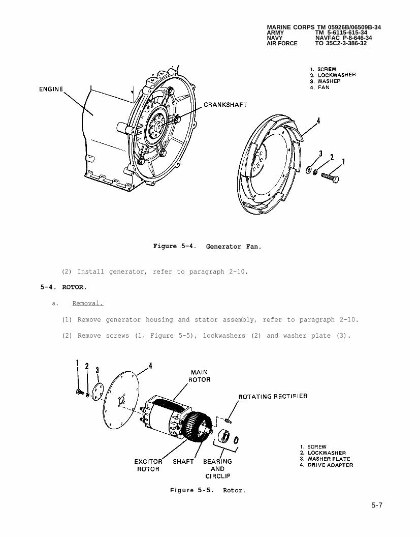
MARINE CORPS TM 05926B/06509B-34ARMY TM 5-6115-615-34NAVY NAVFAC P-8-646-34AIR FORCE TO 35C2-3-386-32
Figure 5-4. Generator Fan.
(2) Install generator, refer to paragraph 2-10.
5-4. ROTOR.
a. Removal.
(1) Remove generator housing and stator assembly, refer to paragraph 2-10.
(2) Remove screws (1, Figure 5-5), lockwashers (2) and washer plate (3).
F i g u r e 5 - 5 . Rotor.
5-7

MARINE CORPS TM 05926B/06509B-34ARMY TM 5-6115-615-34NAVY NAVFAC P-8-646-34AIR FORCE TO 35C2-3-386-32
(3) Remove drive adapter (4).
(4) Remove rotating rectifiers, refer to paragraph 5-5.
DO not remove exciter rotor from rotor shaft.
(5) Remove bearing and circlip from rotor shaft, refer to paragraph 5-8.
b. Testing.
NOTE
Before testing, remove rotating rectifiers (refer toparagraph 5-5) and disconnect main rotor winding lead(2, Figure 5-8) from exciter core.
(1) Perform high potential test on rotors (exciter and generator).
(a )
(b )
Observe safety regulations. The voltages used in thistest are dangerous to human life. Contact with theleads or the windings under test may cause severe and,possibly, fatal shock. Arrange the high voltage leadsso that they are not in a position to be accidentallytouched. Keep clear of all energized parts. Alwaysreduce the test voltage to zero and ground the windingunder test before making any mechanical or electricaladjustments on the equipment. When grounding outwindings which have been tested, always connect theconnection wire to ground first, and then to thewinding. Never perform this test without at least oneother person assisting. Generator frame shall besecurely grounded.
General. The high potential test is performed to determine whether ornot the insulation of the equipment under test is defective. It iscustomary to determine whether electrical equipment will withstandnormal voltage stresses by means of a test in which higher voltagesthan normal are applied for a definite period of time. The appliedvoltage must not be so high (above 1,500 V) as to damage the insulationunless the insulation was initially defective.
Test Equipment. Use acceptable high potential test equipment inaccordance with instructions accompanying the equipment. Refer toTable 2-1 or Appendix B, Section III of TM 05926B/06509B-12/TM 5-6115-615-12/NAVFAC P-8-646-12/TO 35C2-3-386-31 manual.
5-8

MARINE CORPS TM 05926B/06509B-34ARMY TM 5-6115-615-34NAVY NAVFAC P-8-646-34AIR FORCE TO 35C2-3-386-32
(c) Procedure.
1 Adequately ground high potential test equipment (1, Figure 5-6) toa water pipe or similar electrical ground in accordance withinstructions accompanying the test equipment.
(d )
Figure 5-6. Rotor Insulation Test.
Make sure that the rotating rectifiers have beenremoved from the rotor prior to testing (refer toparagraph 5-5). Damage to rotating rectifiers mayresult if high voltage is applied.
2 Disconnect ground lead to exciter core (see Figure 5-7).
3 Connect the high voltage lead (2, Figure 5-6) of the test equipmentto the winding (3) under test.
4 Connect the ground lead (4) (or grounding bed) to the rotor shaft(5).
Test.
1 Turn on test equipment in accordance with manufacturer’sinstructions after making sure that the initially applied voltagewill be not greater than 600 volts.
5 -9

MARINE CORPS TM 05926B/06509B-34ARMY NAVYAIR FORCE
(2)
TM 5-6115-615-34NAVFAC P-8-646-34TO 35C2-3-386-32
2
3
4
5
The test voltage then shall be raised uniformly to themaximum (1,500 Volts RMS, 60 Hz). This increase shallaccomplished in not less than 10 seconds nor more than
Apply the maximum voltage for 1 minute.
After 1 minute of applied maximum voltage, the voltage
requiredbe30 seconds.
then shallbe reduced gradually to the voltage initially supplied. Thisreduction shall not be accomplished in less than 5 seconds.
Turn off test equipment.
Ground the high voltage lead of themake sure that no charge remains onhave been under test.
6 Remove the high-voltage lead (2)
test equipment tothe windings which
from the winding (3) and proceedwith the tests of the remaining circuits to be tested. Make surethat all circuits not under test are securely grounded.
(e) Results. Any evidence of insulation breakdown is cause for replacementof the equipment under test.
Test winding resistance.
(a )
(b )
Perform winding resistance test using a multimeter (set for ohms).
Check the main rotor windings by connecting the multimeter across mainrotor leads (1 and 2, Figure 5-7). Use sharp multimeter probes topenetrate wire insulating material.
Figure 5-7. Main Rotor Winding Resistance Check.
5-10

(d)
(e )
(f)
Resistance forranges:
MEP-016Bwindings
MEP-021B
the
and
MARINE CORPS TM 05926B/06509B-34ARMY TM 5-6115-615-34NAVY NAVFAC P-8-646-34AIR FORCE TO 35C2-3-386-32
main rotor windings should be within the following
MEP-026B (60 Hz and 28VDC) sets: Resistance of rotorat 77°F (25°C) should be between 9.6 and 11.6 ohms.
(400 Hz) set: Resistance of rotor windings at 77°F (25°C)should be between 5.5 and 6.7 ohms.
Check the exciter windings by connecting the multimeter across theexciter rotor lead pairs (1, Figure 5-8), and (2).
Figure 5-8. Exciter Rotor Winding Resistance Check.
Resistance between lead pairs at 77°F (25°C) should be between 2.2 and2.6 ohms.
c. Installation.
(1) Install rotor bearing, refer to paragraph 5-8.
(2) Install rotating rectifier on rotor, refer to paragraph 5-5.
(3) Install generator, refer to paragraph 2-10.
5-11

MARINE CORPS TM 05926B/06509B-34ARMY TM 5-6115-615-34NAVY NAVFAC P-8-646-34AIR FORCE TO 35C2-3-386-32
5-5. ROTATING RECTIFIERS (DIODES).
Do not attemptshaft. Damageis attempted.
toto
remove exciter rotor from main rotorthe windings will result if removal
a. Testing. A shorted or open diode can cause poor generator operation. Thisis evident by failure of the generator terminal voltage to build up torated value or a terminal voltage that is too low.
(1) Remove diodes (1, Figure 5-9) from exciter rotor, refer to b, Removal.
Figure 5-9. Rotating Rectifiers.
(2) Use a multimeter (set to read ohms) to measure the resistance between theterminal end and the threaded base (heat sink) end of the diode. Reversemultimeter leads and repeat the resistance measurement. A diode in goodcondition will have a very high resistance for one measurement and aresistance near zero when multimeter probes are reversed. Failure toobtain these two extremes in resistance measurement indicates a defectivediode that should be replaced.
NOTE
Be sure points of multimeter probes are sufficiently longand sharp to penetrate any insulating varnish on diodeterminals.
5-12

MARINE CORPS TM 05926B/06509B-34ARMY TM 5-6115-615-34NAVY NAVFAC P-8-646-34AIR FORCE TO 35C2-3-386-32
b. Removal.
(1) Remove rotor, refer to paragraph 5-4.
To protect diode from damage, hold diode with needlenose pliers or other suitable heat sink. Use a lowmelting point solder. Diode can be damaged if allowedto overheat during soldering.
(2) Hold diode (1) lead with a heat sink (needle nose pliers, alligator clip,etc.) to prevent the transfer of heat to the diode as it is beingunsoldered.
(3) Unsolder leadremove diodes
c. Installation.
wire from diode with a 25 to 40 watt soldering iron, and(1) from exciter rotor (2).
(1)
(2)
(3)
Install diodes (1) into exciter rotor, tighten diodes to 12 to 15 in lbs(0.27 to 0.34 N.m).
Using a 25 to 40 watt soldering iron, solder lead wires to terminal ofdiode. To protect diode from damage due to heat caused by soldering, holddiode terminal with needle nose pliers as a heat sink and use a low meltingpoint solder.
Install rotor, refer to paragraph 5-4.
5-6. STATOR TESTING.
Observe safety regulations. The voltages used in thistest are dangerous to human life. Contact with theleads or the windings under test may cause severe and,possibly, fatal shock. Arrange the high voltage leadsso that they are not in a position to be accidentallytouched. Keep clear of all energized parts. Alwaysreduce the test voltage to zero and ground the windingunder test before making any mechanical or electricaladjustments on the equipment. When grounding outwindings which have been tested, always connect theconnection wire to ground first, and then to thewinding. Never performother person assisting.securely grounded.
a. Perform high potential test on
this test without at least oneGenerator frame shall be
stator. Do not perform high potential test ofexciter stator.
5-13
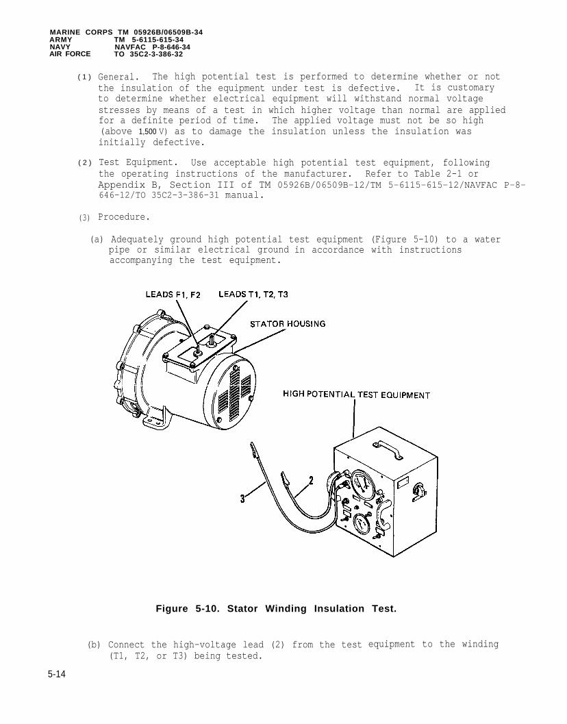
MARINE CORPS TM 05926B/06509B-34ARMYNAVYAIR FORCE
( 1 )
( 2 )
(3)
TM 5-6115-615-34NAVFAC P-8-646-34TO 35C2-3-386-32
General. The high potential test is performed to determine whether or notthe insulation of the equipment under test is defective. It is customaryto determine whether electrical equipment will withstand normal voltagestresses by means of a test in which higher voltage than normal are appliedfor a definite period of time. The applied voltage must not be so high(above 1,500 V) as to damage the insulation unless the insulation wasinitially defective.
Test Equipment. Use acceptable high potential test equipment, followingthe operating instructions of the manufacturer. Refer to Table 2-1 orAppendix B, Section III of TM 05926B/06509B-12/TM 5-6115-615-12/NAVFAC P-8- 646-12/TO 35C2-3-386-31 manual.
Procedure.
(a) Adequately ground high potential test equipment (Figure 5-10) to a waterpipe or similar electrical groundaccompanying the test equipment.
in accordance with instructions
Figure 5-10. Stator Winding Insulation Test.
(b) Connect the high-voltage lead (2) from the test(T1, T2, or T3) being tested.
equipment to the winding
5-14

MARINE CORPS TM 05926B/06509B-34ARMY TM 5-6115-615-34NAVY NAVFAC P-8-646-34AIR FORCE TO 35C2-3-386-32
NOTE
On stator for sets MEP-016B and MEP-021B (60 and 400Hz)sets there are six stator leads (T1, T2, T3, T4, T5,
and T6). The stator for the MEP-026B generator set hasthree leads (T1, T2, and T3). The insulation testconnections will only involve leads (T1, T2, and T3)all three sets.
on
(c) Connect the ground lead (3) (or place stator on grounding bed) to thestator frame. Make sure ground lead has a good, clean connection.
(4) Test.
(a)
(b)
(c)
(d )
(e)
(f)
Turn on test equipment in accordance with manufacturer’s instructionsafter making sure that the initially applied voltage will be not greaterthan 600 volts.
The test voltage then shall be raised uniformly to the required maximum(1,500 Volts RMS, 60 Hz). This increase shall be accomplished in notless than 10 seconds nor more than 30 seconds.
Apply the maximum voltage for 1 minute.
After 1 minute of applied maximum voltage, the voltage then shall bereduced gradually to the voltage initially applied. This reduction shallnot be accomplished in less than 5 seconds.
Turn off test equipment.
Ground the high voltage lead of the test equipment tomake sure that no charge remains on the windings whichhave been under test.
Remove the high-voltage lead (2) from the winding and proceed with thetests of the remaining circuits to be tested. Make sure that allcircuits not under test are securely grounded.
(5) Results. Any evidence of insulation breakdown is cause for replacement ofthe stator under tests.
b. Perform winding resistance test. Refer to Figure 5-11.
(1) Perform winding resistance test using a multimeter (set to read ohms).
(a )
(b)
On MEP-026B (28 VDC) set measureand T1-T3.
On MEP-016B/MEP-021B (60/400 Hz)
resistance between leads T1-T2, T2-T3,
sets measure between leads T3-T6, T1-T4,and T5-T2.
5 - 1 5

ARMYNAVY
MARINE CORPS TM 05926B/06509B-34TM 5-6115-615-34NAVFAC P-8-646-34
AIR FORCE TO 35C2-3-386-32
Figure 5-11. Generator Wiring Schematics.
(2) Winding resistance should
(a) MEP-016B set - the mainshould be between O.304
(b) MEP-021B set - the mainshould be between 0.149
(c) MEP-026B set - the mainbetween 0.018 and 0.022
be as follows:
stator winding resistance between lead pairsand 0.370 ohms.
stator winding resistance between lead pairsand 0.181 ohms.
stator winding resistance between leads should beohms.
(3) A winding resistance above or below the resistance values given indicates adefective stator and stator should be replaced.
5-7. EXCITER STATOR TESTING.
N O T E
Testing, removal, and installation of the exciter rotoris described in paragraph 5-4. The exciter rotor is notremoved from the rotor shaft. The following procedurecovers the exciter stator only.
5 - 1 6

MARINE CORPS TM 05926B/06509B-34ARMY TM 5-6115-615-34NAVY NAVFAC P-8-646-34AIR FORCE TO 35C2-3-386-32
Do not perform high potential insulation test onexciter stator.
a. Separate the stator leads F1 and F2
b. Use a multimeter (set to read ohms)windings.
c. Exciter stator windings should haveohms.
5-8. GENERATOR
a. Removal
(1) Remove
(2) Remove
BEARING.
rotor, refer to paragraph 5-4.
circlip (1, Figure 5-12).
from the other leads.
to measure the resistance of the
a resistance between 20.34 and 24.86
Figure 5-12. Generator Bearing.
(3) Remove bearing (2) from rotor shaft (3) with a puller.
b. Installation
(1) Apply a light coating of grease to bearing.
Press bearing on inner race only.
5-17

MARINE CORPS TM 05926B/06509B-34
NAVYARMY
AIR FORCE
(2)
(3)
(4)
TM 5-6115-615-34NAVFAC P-8-646-34TO 35C2-3-386-32
Press bearing (2) on to rotor shaft (3) until bearing contacts shoulder.
Install circlip (1).
Install rotor, refer to paragraph 5-4.
5-9. VOLTAGE REGULATOR.
a. Testing.
(1) Remove voltage regulator, refer to step c, Removal.
(2) Test power transistor Q2.
(a) Locate power transistor Q2 (1, Figure 5-13) on the back of the voltageregulator housing.
Figure 5-13. Voltage Regulator Testing.
5 - 1 8

MARINE CORPS TM 05926B/06509B-34ARMY TM 5-6115-615-34NAVY NAVFAC P-8-646-34AIR FORCE TO 35C2-3-386-32
(b)
(c)
(d)
Remove screws (2) and washers (3) securing Q2 to housing.
Pull transistor (1) straight from housing, being careful not to damagethe mica insulator under the transistor.
Do not remove the white heat sink paste from the micainsulator, transistor, or regulator housing. If thiscompound is removed transistor Q2 will overheat andbecome damaged.
Test transistor with a multimeter (set to read ohms). Refer to Figure5-14 and Table 5-1. Multimeter (+) and (-) refer to the multimetertest leads.
Figure 5-14. Q1 and Q2 Transistor Pin Out Locations.
Table 5-1. Q2 Test Chart.
Multimeter (+) Multimeter (-) Meter Reading
Collector Emitter Infinite Collector Base Infinite Emitter Collector Infinite Base Collector 1 to 50 ohmsBase Emitter 1 to 50 ohmsEmitter Base Infinite
(e) Readings other than those listed in Table 5-1 indicate either an openor shorted junction within Q2 and Q2 should be replaced.
5 - 1 9

MARINE CORPS TM 05926B/06509B-34ARMY TM 5-6115-615-34NAVY NAVFAC P-8-646-34AIR FORCE TO 35C2-3-386-32
NOTE
Do not install transistor Q2 at this time. With Q2removed, transistor Q1 can be tested without removal ofthe transistor from the printed circuit board.
(3) Remove terminal strip
(a) Remove two screws
VR1.
(4, Figure 5-13
(b) Gently pull terminal strip VR1 (5)upward.
(4) Test diode CR5.
that secure terminal strip VR1 (5).
along with the printed circuit board
(a) Locate diode CR5 located on circuit board.
(b) Test diode CR5 with a multimeter (set to read ohms). Measureresistance across CR5, reverse test leads, and measure resistanceagain.
(c) Resistance should be low (1 to 50 ohms) one way and infinite resistance the other way.
(d) If low or high resistance is measured in both directions diode CR5should be replaced.
(5) Test current regulating diode CR6.
(a) Locate diode CR6 located on circuit board.
(b) Unsolder and lift one end of diode CR6 from the printed circuit board.
(c) Test diode CR6 with a multimeter (set to read ohms). Measureresistance across CR6, reverse test leads, and measure resistanceagain.
(d) Resistance should be low (1 to 50 ohms) one way and greater than 500ohms resistance the other way.
(e) If low or high resistance is measured in both directions diode CR6should be replaced.
NOTE
Do not install diode CR6 lead to printed circuit boarduntil transistor Q1 has been tested.
(6) Test diode CR7.
(a) Locate diode CR7 on circuit board.
5-20

(b)
( c )
(d)
MARINE CORPSARMYNAVYAIR FORCE
TM 05926B/06509B-34TM 5-6115-615-34NAVFAC P-8-646-34TO 35C2-3-386-32
Test diode CR7 with a multimeter (set to read ohms). Measureresistance across CR7, reverse test leads, and measure resistanceagain.
Resistance should be low (1 to 50 ohms) one way and infinite resistance the other way.
If low or high resistance is measured in both directions, diode CR7
should be replaced.
(7) Test transistor Q1.
(a) Make sure that transistor Q2 is still removed and that one lead ofdiode CR6 is unattached to the printed circuit board.
(b) Locate power transistor Q1 on the printed circuit board.
(c) Test transistor with a multimeter (set to read ohms). Refer to Figure5-14 and Table 5-2. Multimeter (+) and (-) refer to the multimetertest leads.
Table 5-2. Q1 Test Chart.
Multimeter (+) Multimeter (-) Meter Reading
Collector Emitter Infinite Collector Base Infinite Emitter Collector Infinite Base Collector 1 to 50 OhmsBase Emitter 1 to 50 OhmsEmitter Base Infinite
(8)
(9)
(10)
(11)
(d) Resistance measurements other than those listed in Table 5-2 indicatean open or shorted junction within Q1, Q1 should be replaced.
Solder lead of diode CR6 to printed circuit board (6, Figure 5-13).
Install transistor Q2 (1, Figure 5-13) with mica insulator between Q2 andregulator housing.
If necessary, apply a small amount of heat sink compound (Table 2-2, item14) (P/N 13217E3704, FSCM 97403) to transistor Q2 and housing. Securetransistor Q2 with screws (2) and washers (3).
Make test connections.
(a) Connect a 30 ohm 120 watt resistor to terminals #21 and #20 of terminalstrip VR1 (5).
(b) Obtain a 750 ohm 2 watt rheostat.
5-21

MARINE CORPS TM 05926B/06509B-34ARMY TM 5-6115-615-34NAVY NAVFAC P-8-646-34AIR FORCE TO 35C2-3-386-32
(c)
(d)
(e)
Position rheostat so that control shaft is facing you and the threeterminal lugs are facing up. Connect a 12-18 AWG insulated wire to themiddle terminal lug and another wire to the left hand terminal lug ofthe rheostat.
Attach the two rheostat leads to terminals #26 and #28 of terminalstrip VR1 (5). Turn the rheostat clockwise to its maximum rotation.
Connect a 0-150 VAC, 60 HZ power supply (refer to Table 2-1) toterminals #24 and #27 of terminal strip VR1 (5).
(12) Perform tests.
(a )
(b )
( c )
(d )
(e)
(f)
( g )
(h)
Turn on the power supply and set for 115 VAC.
Set a multimeter to read a 0-50 VDC range.
Check for 30-35 VDC between terminals #20 and #21 of terminal stripVR1 (5). Terminal #20 is positive and terminal #21 is negative.
Rotate the shaft of the test rheostat counterclockwise to approximatelyeighty percent of its maximum rotation. The voltage between terminals#20 and #21 of VR1 (5) should now be zero.
Rotate the shaft of the test rheostat clockwise while observing thevoltage at terminals #20 and #21 of VR1 (5).
Voltage at terminals #20 and #21 should be between 30 and 35 volts whentest rheostat is turned to approximately eighty percent of itsclockwise rotation. If no voltage is present, refer to step (i).
If there is a delay of two seconds or more between decreases andincreases of the voltage at terminals #20 and #21 or if voltage changesdo not occur at the eighty percent of maximum rotation points, adjust R6. Refer to (h) for adjustment procedure. If no delay is present andvoltage changes occur at the eighty percent rotation points, testingprocedure is completed. If no voltage change occurs, regardless of theposition of the test rheostat, refer to step (i).
Locate R6 on the printed circuit board (6). Turning the adjustmentscrew of R6 clockwise will turn the voltage at terminals #20 and #21of VR1 (5) on for a given setting of the test rheostat. Turningadjustment screw counterclockwise turns the voltage at terminals #20and #21 off. Adjust screw as required to achieve voltage cutoff andturn on for eighty percent of maximum rotation as described in steps(d), (e), and (f). Troubleshooting is complete after adjustment ismade.
NOTE
Adjustment of R6 does not cause the voltage atterminals #20 and #21 of VR1 (5) to vary. Either voltagewill be on or voltage will be off.
5-22

MARINE CORPS TM 05926B/06509B-34ARMY TM 5-6115-615-34NAVY NAVFAC P-8-646-34AIR FORCE TO 35C2-3-386-32
(i)
(j)
Turn off 115 VAC power source before attempting anyinspection or repair.
Inspect circuit board for burned or broken printed circuit boardpaths. If burned or broken paths are present, circuit board should bereplaced.
Locate components R1 and R2. Refer to Figure 5-15 for a wiringschematic. Apply 115 VAC to terminals #24 and #27 of terminal stripVR1 (5, Figure 5-13).
F i g u r e 5 - 1 5 . Voltage Regulator Schematic.
5-23

MARINE CORPSARMYNAVYAIR FORCE
( k )
(1)
(m)
(n)
(o)
(p)
(q)
(r)
(s)
(t)
TM 05926B/06509B-34TM 5-6115-615-34NAVFAC P-8-646-34TO 35C2-3-386-32
Connect a multimeter (set to read 0-50 VDC) across points "A" and "B"as indicated on wiring schematic. Connect red lead to point "A" andblack lead to point.
A DC voltage of 28-32 volts should be indicated. If voltage is notwithin this range, check the voltagediode VR1 and VR2 on circuit board.
across voltage regulating (zener)
If either zener diode VR1 and VR2 is removed, do notapply the 115 VAC source to the regulator until areplacement is connected into the circuit. Failure ofthe voltage regulator will occur if this caution is notobserved.
The voltage across VR1 and VR2 should be approximately 14 VDC. Replacezener diodes that do not have a voltage drop of approximately 14 VDC.
After replacing zener diodes VR1 and/or VR2 and no voltage is indicatedacross either or both zener diodes VR1 and VR2, check the voltageacross terminal lugs #7 and #8 of the T1 power transformer (6).
Change setting on
A voltage of 25-35 VAC
NOTE
multimeter to 0-50
should be present.
VAC range.
If voltage is not present,check that 115 VAC power source is connected properly and all wiringconnections to T1 (6) are tight. If power is properly connected and T1(6) connections are tight transformer T1 (6) should be replaced.
After verifying that 25-35 VAC is present across T1 (6) terminals #7and #8, locate diodes CR8 and CR9 on circuit board (6).
Turn off power and unsolder one end of diode CR8 and CR9. Check theresistance of each diode in one direction and then reverse leads andtest in the other direction.and high in the other.
Replace diodes CR8 or CR9 if
Locate capacitors C1 (7) andcircuit board. Unsolder oneboard.
Resistance should be low in one direction
they do not pass resistance check.
C2 (8) on the reverse side of the printedend of each capacitor from the circuit
Test capacitors C1 (7) and C2 (8) with a multimeter (set to read ohms)across the capacitor being tested and then reverse leads acrosscapacitor.
5-24

MARINE CORPS TM 05926B/06509B-34ARMY TM 5-6115-615-34NAVY NAVFAC P-8-646-34AIR FORCE TO 35C2-3-386-32
(u)
( v )
(w)
( x )
( y )
( z )
(aa)
(bb)
Connection of the multimeter (set for ohms) across the capacitor shouldimmediately result in the movement of the meter pointer from theinfinity side of the scale to the low ohms side of the scale andthen slowly return to the infinity side of the scale.
If the capacitor is shorted or leaky, the pointer will remain on thelow ohms side of the scale. If the capacitor is open, there will be nomovement of the meter pointer. Replace open, shorted, or leakycapacitors as required.
Locate zener diode VR3 on circuit board and apply 115 VAC to terminals#24 and #27 of the terminal strip VR1 (5, Figure 5-13).
Check the voltage across zener diode VR3. Voltage across VR3 should beapproximately 4.7 VDC.
If voltage across VR3 is greater than 4.7 VDC, replace VR3. If novoltage is indicated across VR3, locate R3 a 1K ohm resistor located oncircuit board.
Disconnect the 115 VAC power source from the regulator, unsolder oneend of R3 from the circuit board. Measure the resistance of R3,resistance should be between 900 and 1100 ohms. If resistor is withinthis range, reconnect lead. Replace resistor if not within tolerances.
Apply the 115 VAC power to terminals #24 and #27 of the terminal stripVR1 (5). Recheck the voltage drop across zener diode VR2, there shouldbe a voltage drop of 14 VDC present. If 14 VDC is present and there isno voltage drop across zener diode VR3, VR3 should be replaced.
If none of the tests or recommended repairs correct the operation ofthe voltage regulator, entire voltage regulator should be replaced.
b. Adjustment.
(1)
(2)
(3)
(4)
The following components and equipment are needed for the adjustmentprocedures on the voltage regulator.
DC Voltmeter ± 0.5 percent,AC Voltmeter ± 0.5 percent,Oscilloscope (M3)Voltage source 0-150 VAC 60
0-100 VDC (M1 and M4)0-150 VAC (M2)
Hz, Regulation±0.25 percent, from 0-2 Amps (PS1)Resistor 30 ohms, 120 watts (R1)Resistor, 750 ohms ± 5 percent 2 watts (R2)Potentiometer, 500 ohms (R6)
Connect voltage regulator, equipment, and components as shown in Figure5-16.
Set potentiometer R6 to 250 ohms (halfway).
Turn AC power supply (PS1) on.
5-25

MARINE CORPS TM 05926B/06509B-34ARMY TM 5-6115-615-34NAVY NAVFAC P-8-646-34AIR FORCE TO 35C2-3-386-32
(5)
( 6 )
Figure 5-16. Voltage Regulator Adjustment Schematic.
Slowly increase AC voltage (0 to 30 VAC) while monitoring DC voltmeter (M1)and oscilloscope (M3). DC voltage reading on DC voltmeter (M1) shallincrease proportionally with the increasing AC voltage and the voltage waveform trace of oscilloscope (M3) shall move toward a positive voltage level.A voltage shall also be indicated on meter DC voltmeter (M4). The waveformtrace of oscilloscope (M3) swinging below the zero axis (negative) duringthis (0-30 VAC) test shall be indicative of an unusable/defectiveoperational amplifier.
Increase AC voltage for a "maximum reading" on meter (M1) (35 VDC minimum)or until oscilloscope (M3) wave form is just starting to come off the"maximum level" refer to curve 1 of Figure 5-17.
Figure 5-17. Waveforms.
5 -26

MARINE CORPS TM 05926B/06509B-34ARMY TM 5-6115-615-34NAVY NAVFAC P-8-646-34AIR FORCE TO 35C2-3-386-32
(a) If the AC voltmeter (M2) indicates 136 VAC or greater, proceed withstep (7).
(b) If the AC voltmeter (M2) indicates less than 136 VAC, proceed with step(8).
(7) Perform the following adjustment procedures:
(a)
(b)
( c )
Adjust AC supply (M2) to 136 VAC.
Slowly adjust R6 clockwise until oscilloscope (M3) wave form begins todecrease from "maximum level". DC voltmeter (M1) reading shall go tozero when wave form passes through zero. Refer to curve 2 on Figure5-17.
Adjust AC input voltage AC voltmeter (M2) to 133 VAC. The oscilloscope(M3) waveform shall return to maximum level and DC voltmeter (M1) shallread maximum (35 VDC minimum).
(8) Perform the following adjustment procedures.
(a)
(b)
(c)
Adjust AC supply (PS1) to adjust (M2) to 133 VAC.
Slowly adjust R6 counterclockwise until oscilloscope (M3) wave formbegins to go up from "minimum level" (curve 3, Figure 5-17). Mlreading shall go to "maximum level" (35 VDC minimum) when wave formpasses through zero.
Adjust AC supply (PS1) to adjust (M2) to 136 WAC. The oscilloscope
(9)
(M3) wave form shall return to "minimum level" and Ml shall read zerovolts.
Without further adjustment of R6, repeat the above procedure for theremaining three conditions tabulated in Table 5-3. In all cases, similarperformance should be achieved.
NOTE
Test condition one in Table 5-3 has already beenaccomplished in the previous procedures. Proceduresare repeated for the remaining three conditions.
Table 5-3. Test Conditions.
Condition White Lead Black Lead Red Lead M3+ Lead
1234
C2C2C1C1
C5C5C4C6
C4 C5C3 C3C3 C4C4 C6
5 - 2 7

MARINE CORPS TM 05926B/06509B-34ARMY TM 5-6115-615-34NAVY NAVFAC P-8-646-34AIR FORCE TO 35C2-3-386-32
Failure ofindicative
NOTE
the unit to meet adjustment requirements isof a defective regulator.
(10) After all adjustments have been made,item 13) between the adjustment screwscrew head.
c. Removal.
apply a locking compound (Table 2-2,head and housing surfaces adjacent to
NOTE
Both the MEP-016B/MEP-021B (60/400) Hz sets and theMEP-026B (28 VDC) set have similar procedures forremoving and installing the voltage regulator. Referto Figure 5-18 for MEP-016B/MEP-021B (60/400 Hz) setsand Figure 5-19 for MEP-026B (28 VDC) sets.
(1) Tag and disconnect wiring from voltage regulator (3, Figure 5-18 or 5-19).
(2) Remove nuts (1), screws (2) and regulator (3).
d. Cleaning, Inspection, and Repair.
(1) Clean voltage regulator with compressed air and a soft bristle brush.
(2) Inspect voltage regulator for cracks, damaged terminals, or other visibledamage.
(3) For testing, refer to step a, Testing.
(4) Repair of components identified by testing as faulty is by componentreplacement.
Solder joints and/or component leads (exceptpotentiometer leads) should not project more than 0.125in. beyond the surface of the board.
(a) Transistor replacement.
1 Make sure that replacement transistor has same identificationnumber as the original transistor.
2 Apply heat sinks to the circuit board runs connected to thetransistor being replaced.
5-28

MARINE CORPS TM 05926B/06509B-34ARMY TM 5-6115-615-34NAVY NAVFAC P-8-646-34AIR FORCE TO 35C2-3-386-32
Figure 5-18. Voltage Regulator. MEP-016B and MEP-021B (60/400 Hz Sets).
5 - 2 9

MARINE CORPS TM 05926B/06509B-34ARMY TM 5-6115-615-34NAVY NAVFAC P-8-646-34AIR FORCE TO 35C2-3-386-32
Figure 5-19. Voltage Regulator MEP-026B (28VDC Set).
3 Note and record position of transistor leads and tab on transistorcase in relation to the printed circuit board.
4 Unsolder transistor from circuit board and remove.
5 Place new transistor on circuit board. Make sure emmiter,collector, and base leads are positioned as noted during removal.
Solder transistor in accordance with MIL-STD-454 Requirement 5.6Trim transistor leads.
5-30

MARINE CORPSARMYNAVYAIR FORCE
TM 05926B/06509B-34TM 5-6115-615-34NAVFAC P-8-646-34TO 35C2-3-386-32
e. I n s t a l l a t i o n .
(1) Check that red, black,the generator output.
and white jumper wires are properly positioned forRefer to Figure 5-20.
F i g u r e 5 - 2 0 . Standard Voltage Regulator
(a )
(b)
(c)
Jumper Wire Placement.
MEP-026B (28 VDC)-Red jumper wire is connected to terminal C4, Blackjumper wire is connected to terminal C6, and the White jumper wire isconnected to terminal C1.
MEP-021B (400 Hz)-Red jumper is connected to terminal C4, Black jumperwire is connected to terminal C6, and white jumper wire is connected toterminal C1.
MEP-016B (60 HZ)-Red jumper wire is connected to terminal C3, Blackjumper wire is connected to C4, and white jumper wire is connected toterminal C1.
5 - 3 1

MARINE CORPSTM 05926B/06509B-34A R M YNAVYAIR FORCE
(2)
(3)
TM 5-6115-615-34NAVFAC P-8-646-34TO 35C2-3-386-32
Place voltage regulator (3, Figure 5-18 or 5-19) in control box and securewith screws (2) and nuts (1).
Use tags for identification to connect leads to voltage regulator.
5-10. CURRENT TRANSFORMER MEP-016B/MEP-021B (60/400 Hz) SETS ONLY.
a. Testing
(1) Tag and disconnect wires and resistors from transformer (3, Figure 5-21)terminals.
Figure 5-21. Current Transformer.
5-32

(2)
(3)
MARINE CORPS TM 05926B/06509B-34ARMY TM 5-6115-615-34NAVY NAVFAC P-8-646-34AIR FORCE TO 35C2-3-386-32
Use a multimeter (set to read ohms) to check the transformer windings.Check resistance across terminals A-1 and A-2, B-1 and B-2, C-1 and C-2.
Multimeter should indicate an equal resistance between each terminal pair.Resistance should be between 12 and 18 ohms.
b. Removal.
(1)
(2)
(3)
Tag and disconnect wires and resistors from transformer (3, Figure 5-21)terminals.
Tag and disconnect leads that pass through current transformer from thecircuit breaker.
Remove nuts (1), screws (2), and transformer (3).
c. Installation.
(1)
(2)
(3)
Secure transformer (3) with screws (2) and nuts (1).
Thread leads through transformer and attach to circuit breaker. Use tagsas identification.
Connect wires and resistors to transformer using tags as leadidentification.
5-33/(5-34 blank)


MARINE CORPS TM 05926B/06509B-34ARMY TM 5-6115-615-34NAVY NAVFAC P-8-646-34AIR FORCE TO 35C2-3-386-32
CHAPTER 6
MAINTENANCE OF THE FUEL SYSTEM
6 - 1 . GENERAL. The engine fuel system consists of two pressure systems (a lowpressure system and a high pressure system). In the low pressure system fuel ispumped from the main fuel tank through a fuel/water separator to the injection pumpby a mechanical fuel transfer pump mounted on the engine. If an auxiliary fuelsource is selected, fuel is pumped by an electric fue1 pump from the auxiliary fuelsource to the main fuel tank. The electric fuel pump is controlled by a fuelhigh/low level switch on the main fuel tank. The high pressure fuel system consistsof the fuel injection pump, injection line, and fuel injector.
6 - 2 . FUEL TANK.
a. Removal.
(1) Drain the fuel tank.
(2) Remove frame, refer to paragraph 3-2.
(3) Remove nut (1, Figure 6-1), lockwashers (2), and washer (3).
(4) Remove strap (4), gasket (5).
(5) Remove screw (17) that secures bracket (18) to frame. Remove tank (6).
b. Disassembly.
(1) Remove filler cap (7) and fittings (8, 9 and 10).
(2) Remove drain valve (11) and fitting (12).
(3) Remove level switch (13).
(4) If necessary, remove nut (14), screw (15)assembly (16).
and valve cap and retainer
(5) Remove screws (19), flange (20) and gasket (21).
c. Cleaning Inspection and Repair.
(1) Wipe all unpainted metal parts with a clean lint-free cloth that has beenslightly moistened with solvent.
(2) Inspect all parts for cracks, distortion, damaged threads or other visibledamage.
(3) Repair of cracked nylon fuel tank cannot be accomplished. Repair offuel tank assembly is by the replacement of defective components.
d. Assembly
(1) If removed, attach valve cap and retainer assembly (16) to frame with screw(15) and nut (14).
6-1

MARINE CORPS TM 05926B/06509B-34ARMY TM 5-6115-615-34NAVY NAVFAC P-8-646-34AIR FORCE TO 35C2-3-386-32
Figure 6 -1 . Fuel Tank.
6-2

(2)
(3)
(4)
(5)
(6)
MARINE CORPS TM 05926B/06509B-34ARMY TM 5-6115-615-34NAVY NAVFAC P-8-646-34AIR FORCE TO 35C2-3-386-32
Apply teflon tape to threads of level switch (13). Install level switch(13) into fuel tank.
Apply teflon tape to drain valve (11) and fitting (12) threads. Installdrain valve (11) with fitting (12).
Apply teflon tape to fittings (8, 9 and 10). Install fittings (8, 9 and10) on fuel tank.
Place gasket (21) in position and install flange (20) with screws (19).
Install filler cap (7).
e. Testing
(1)
(2)
(3)
(4)
Plug all but one of the fuel line openings on fuel tank.
Submerge fuel tank in water and pressurize to 3 psig with air through theremaining fuel line fitting.
Hold pressurized tank under water for 3 minutes, no leakage of air shouldbe visible.
Repair any visible leaks that appear at fittings by removing fitting,applying new teflon tape, and reinstalling fitting.
f. Installation
(1) Place tank (6) in position with strap (4) and gasket (5).
(2) Secure strap (4) with washer (3), lockwashers (2), and nut (1).
(3) Secure bracket (18) to frame with screw (17).
(4) Install frame, refer to paragraph 3-2.
6-3. FUEL INJECTION PUMP.
a. Removal.
Wear protective clothing and face shield when openingfuel injection line. Fuel under high pressure may betrapped in the fuel injection line. Opening fuelinjection line can cause a high pressure stream of fuelto be released which can cause severe personal injury.
Plug all fuel lines and connections when a fuel line isremoved to prevent the entry of contaminants.
6-3

MARINE CORPS TM 05926B/06509B-34A R M Y T M 5 - 6 1 1 5 - 6 1 5 - 3 4N A V Y N A V F A C P - 8 - 6 4 6 - 3 4A I R F O R C E T O 3 5 C 2 - 3 - 3 8 6 - 3 2
( 1 ) Remove screw (1, Figure 6-2), washer (2) and clamp (3) securing injectionline (4) to push rod tube adapter (5).
Figure 6-2. Fuel Injection Pump.
6-4

(2)
(3)
(4)
(5)
(6)
NOTE
(7)
(8)
Remove tie wrap (6) and injection line (4).
Remove supply line (7).
Remove clamps (8) and return line (9).
Remove clamp (10) and hose (11).
MARINE CORPS TM 05926B/06509B-34ARMY TM 5-6115-615-34NAVY NAVFAC P-8-646-34AIR FORCE TO 35C2-3-386-32
If pump is pushed upwards as screws (12) are removed, rotatecrankshaft approximately 90° to rotate camshaft to lowpoint of cam lobe.
Remove three screws (12) and washers (13).
Position external arm of governor linkage (1, Figure 6-3) to midpoint oftravel and remove injection pump (14, Figure 6-2) and shims (15).
Do not remove actuator or fork unless damaged, refer to TM 05926B/06509B-12/TM 5-6115-615-12/NAVFAC P-8-646-12/TO 35C2-3-386-31 manual, paragraph 4-44.
c. Cleaning and Repair.
(1)
(2 )
(3)
(4)
Wipe all parts with a clean lint-free cloth that has been slightlymoistened with solvent.
Inspect all threaded parts for damaged threads.
Inspect fuel lines for obstructions or kinks.
Inspect all parts for cracks, deformation, or other visible damage.
d. Installation.
(1 )
(2 )
(3)
(4)
(5)
Position external arm of governor linkage (1, Figure 6-3) to midpoint oftravel and place injection pump (14, Figure 6-2) and shim (15) on engine.
Check that injection pump rack is caught between fork on governor linkageby holding fuel injection pump and rotating governor linkage fullycounterclockwise. Rotate fuel pump and feel for engagement in bothdirections. Repeat with governor linkage rotated fully clockwise.
Install and tighten three capscrews (12) with washers (13).
Set injection pump timing, refer to step e, Adjustment.
Apply sealing compound (Table 2-2, item 5) to capscrews (12) and tightensecurely.
(6 ) Recheck injection pump timing, refer to step e, Adjustment.
6-5

MARINE CORPS TM 05926B/06509B-34ARMYNAVYAIR FORCE
(7)
(8)
(9)
(10)
(11)
(12)
(13)
TM 5-6115-615-34NAVFAC P-8-646-34TO 35C2-3-386-32
Apply sealing compoundto seal.
Install fuel injection
Secure injection line (4) to adapter (5) with screw (1), washer (2) andclamp (3).
Install supply line (7).
Install new return line (9) and secure with new tie wraps (6) and clamps(8).
Install hose (11) with clamp (10).
Prime the fuel lines.
( a )
(b)
( c )
Disconnect fuel injection line (4) at the fuel injector.
Manually turn engine until fuel appears at the open end of the fuelinjection line.
Connect
e. Adjustment.
(1)
(2)
(3)
(4)
(5)
(6)
(7)
(Table 2-2, item 8) to edges of injection pump (14)
line (4).
Timing
fuel injection line (4) to fuel injector.
NOTE
of injection pump requires that engine timingmarks be used.
Connect a high pressure timing pump (refer to Table 2-1) to the injectionpump. High pressure pump outlet is connected to injection pump supply andinjection pump return line is connected to return tank on pump.
Start timing pump and rotate external linkage (1, Figure 6-3) to the fuelinjection pump to the fuel off positioncounterclockwise (4-5 mm). Fuel should
Rotate engine slowly (clockwise, viewedobserving the flow from the fuel return
(fully clockwise). Rotate linkagebe flowing from the return line.
from front flywheel) whileline.
When fuel stops flowing from return line (there will be several drops ofleakage), stop rotating the engine.
Rotate the engine back (counterclockwise, viewed from front flywheel) untilfuel is flowing from the return line.
Very slowly rotate the engine (clockwise, viewed from front flywheel) andobserve fuel return line.
Stop rotating engine when fuel stops flowing from the return line.
6 - 6

(8)
(9)
(10)
(11)
MARINE CORPS TM 05926B/06509B-34ARMY TM 5-6115-615-34NAVY NAVFAC P-8-646-34AIR FORCE TO 35C2-3-386-32
Figure 6-3. External Governor Linkage.
Note the number of degrees the engine is at before TDC.
Injection pump timing should be at 22 degrees before TDC.
Timing is retarded by adding shims (15, Figure 6-2). Timing is advanced byremoving shims (15).
Shim 0.0045 in. (0.1143 mm) = 1 degree of timing
Add or subtract shims (15) as required. Thickness of shims is determinedby the number of small indented holes on the shim surface.
No holes: 0.0150 to 0.0165 in. (0.38 to 0.42 mm)One hole: 0.0035 to 0.0043 in. (0.09 to 0.11 mm)Two holes: 0.0055 to 0.0063 in. (0.14 to 0.16 mm)Three holes: 0.0070 to 0.0087 in. (0.18 to 0.22mm)
6-4. FUEL INJECTOR.
a. Removal.
Wear protective clothing and face shield when openingfuel injection line. Fuel under high pressure may betrapped in the fuel injection line. Opening fuelinjection line can cause a high pressure stream of fuelto be released which can cause severe personal injury.
(1) Disconnect fuel supply and return lines at the injector (see Figure 6-4).Plug openings in injector and lines to prevent the entry of dirt.
6-7
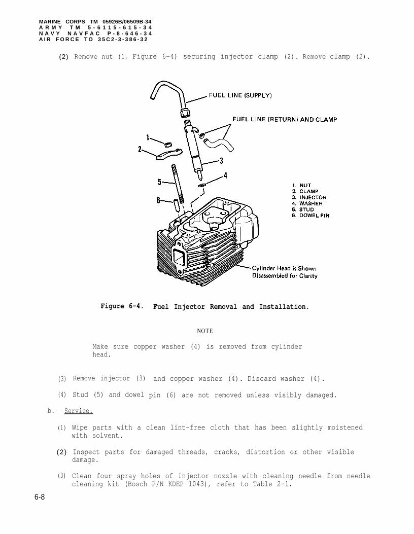
MARINE CORPS TM 05926B/06509B-34A R M Y T M 5 - 6 1 1 5 - 6 1 5 - 3 4N A V Y N A V F A C P - 8 - 6 4 6 - 3 4A I R F O R C E T O 3 5 C 2 - 3 - 3 8 6 - 3 2
(2)
(3)
(4)
Remove nut (1, Figure 6-4) securing injector clamp (2). Remove clamp (2).
Figure 6-4. Fuel Injector Removal and Installation.
NOTE
Make sure copper washer (4) is removed from cylinderhead.
Remove injector (3)
Stud (5) and dowel
b. Service.
(1)
(2 )
(3)
and copper washer (4). Discard washer (4).
pin (6) are not removed unless visibly damaged.
Wipe parts with a clean lint-free cloth that has been slightly moistenedwith solvent.
Inspect parts for damaged threads, cracks, distortion or other visibledamage.
Clean four spray holes of injector nozzle with cleaning needle from needlecleaning kit (Bosch P/N KDEP 1043), refer to Table 2-1.
6-8

MARINE CORPS TM 05926B/06509B-34ARMY TM 5-6115-615-34NAVY NAVFAC P-8-646-34AIR FORCE TO 35C2-3-386-32
c . Testing.
Do not allow nozzle to spray against skin. Fuel undernozzle pressure can penetrate flesh and cause a seriousinfection.
(1) Connect fuel injector to nozzle tester (1, Figure 6-5), (Bosch P/N 0 681143 014), refer to Table 2-1.
Figure 6-5. Fuel Injector Testing.
(2) Close the tester pressure gauge valve (2). Depress the tester pump lever(3) rapidly (6-8 strokes to bleed the system).
(3) Test opening pressure as follows:
(a) Open the tester pressure gauge valve (2). Slowly depress the pumplever (3) of the nozzle tester.
6-9

MARINE CORPS TM 05926B/06509B-34ARMY TM 5-6115-615-34NAVY NAVFAC P-8-646-34AIR FORCE TO 35C2-3-386-32
(b)
(c)
(d)
Read the opening pressure (the pressure when the nozzle opens and thespray starts).
If the pressure gaugevalve (2) may be open
NOTE
reads erratically, the gaugetoo much.
Opening pressure should be between 3120 and 3260 psi (215 to 225 kPa).
Opening pressure can be adjusted by adding or removing shims, (8,Figure 6-6). Adding shims increases opening pressure, removing shimsdecreases the opening pressure. Refer steps d. and e. for Disassemblyand Assembly procedures.
(4) Test for leakage as follows:
(a )
(b)
( c )
With the pressure gauge still open, depress the pump lever until thepressure is 50 psi (344 kPa) below the opening pressure. Maintainpressure with pump lever.
If no drops fall from the nozzle tip within 10 seconds, the nozzle isgood.
If a drop falls from the nozzle within 10 seconds, the nozzle leaks andshould be cleaned and retested. If nozzle continues to drip, it shouldbe replaced.
d. Disassembly.
Disassembly and assembly of fuel injector requires ahigh standard of cleanliness. Small amounts of dirtcan damage the injector.
Hold the needle valve (4) by the stem only. Skin oilswill corrode the finely lapped surfaces of the needleva lve .
The needle valve (4) and nozzle (3) are a matched set.Nozzle parts from one fuel injector cannot beinterchanged with nozzle parts from another fuelinjector.
6-10

(1)
MARINE CORPS TM 05926B/06509B-34ARMY TM 5-6115-615-34N A V Y NAVFAC P-8-646-34AIR FORCE TO 35C2-3-386-32
If nozzle (3) turns when nozzle nut (2) is turned, soakthe fuel injector in diesel fuel. Nozzle (3) haslocating pins which may be sheared off if nozzle (3)turns with nozzle nut (2).
Clamp the nozzle holder (1, Figure 6-6) in a vise. Use a wrench to removenozzle nut (2) approximately 1/4 of a turn.
(2)
(3)
(4)
(5)
Figure 6-6. Fuel Injector.
Apply downward pressure on nozzle to prevent spring (7)pressure from damaging the nozzle nut (2) threads whichcould contaminate the nozzle holder (1) with chips.
Apply downward pressure against nozzle (3) and spring (7). Remove nozzlenut (2).
Remove
Remove
Remove
nozzle (3) and nozzle needle (4) as an assembly.
intermediate piece (6).
plunger (5), spring (7) and shims (8).
6-11

MARINE CORPS TM 05926B/06509B-34ARMY TM 5-6115-615-34NAVY NAVFAC P-8-646-34AIR FORCE TO 35C2-3-386-32
e . Cleaning, Inspection, and Repair.
(1)
(2)
(4)
(5)
Check nozzle needle (4, Figure 6-6) and nozzle (3) by lifting nozzle needle (4) halfway out of nozzle (3) and allowing it to drop. Needle must slideslowly and smoothly into nozzle under its own weight without sticking. Ifneedle sticks, clean needle and nozzle in diesel fuel and repeat test.Replace both nozzle and needle if needle continues to stick.
Remove any carbon residue from nozzle (3) tip and nozzle nut (2).
Never use emery paper or any metal scraper to cleannozzle. Only use the hardwood scrapers provided aspart of the nozzle cleaning kit.
Clean and polish the nozzle needle seating surface of the nozzle (3) withthe hardwood scraper. Scraper is part of needle cleaning kit (Bosch P/NKDEP 1043), refer to Table 2-1.
Thoroughlywet.
f. Assembly.
(1)
(2)
(3)
(4)
(5)
clean all components in diesel fuel before assembly. Assemble
Place
Place
Place
nozzle (3, Figure 6-6) with nozzle needle (4) into nut (2).
shims (8) into nozzle holder (1).
intermediate piece (6) onto nozzle (3). Make sure that pins inintermediate piece (6) fit into holes in nozzle (3).
Install plunger (5) and spring (7).
Screw nozzle nut (2) onto nozzle holder (l). Tighten nut (2) to 30 ft lbs(40 N.m).
Installation.g.
(1) If removed, apply sealing compound (Table 2-2, item 5) to stud (5, Figure6-4) and install. If removed, install dowel pin (6).
(2) Seat new copper washer (4) in injector bore.
(3) Install injector (3) into bore.
(4) Secure injector with clamp (2)7 to 8 ft lbs (9 to 11 N.m).
(5) Connect fuel supply and return
6-12
and nut (1). Tighten nut (1) to a torque of
lines to injector.

MARINE CORPS TM 05926B/06509B-34ARMY TM 5-6115-615-34NAVY NAVFAC P-8-646-34AIR FORCE TO 35C2-3-386-32
CHAPTER 7
MAINTENANCE OF THE ENGINE
7 - 1 . G E N E R A L . This chapter contains all the procedures necessary to remove,disassemble, clean and inspect, assemble, and install the engine or individualcomponents.
7-2. ENGINE ASSEMBLY.
a. Test.
(1) Perform engine compression test.
NOTE
The compression pressure given for the compression testis based upon a normal engine starting speed. A weakbattery or faulty starter may result in a lowercompression reading. Make sure that the startingsystem is functioning normally before checkingcompression pressure.
(a )
(b)
( c )
(d )
(e)
(f)
Remove fuel injector, (refer to paragraph 6-4), and remove electricalconnector to shutdown solenoid.
Assemble compression gage (refer to Table 2-1) and fitting (refer toTable 2-1) with sealing washer into fuel injector port.
Do not run starter any longer than 30 seconds. Allowstarter to cool a minimum of two minutes after eachengagement.
Crank engine overRecord reading.
until compression gage indicator stops moving.
Remove compression gage, squirt a small amount of engine oil into theinjector port, and use starter rotor to crank engine for a few seconds.Reinstall compression gage.
Crank engine over until compression gage indicator stops moving.Record reading.
Remove compression gage and install fuel injector, refer to paragraph6-4 for fuel injector installation.
7-1

MARINE CORPS TM 05926B/06509B-34ARMYNAVYAIR FORCE
(g)
TM 5-6115-615-34NAVFAC P-8-646-34TO 35C2-3-386-32
Compression pressure should be between 325 and 375 psi (2,413 and 3,100kPa) for both the dry and wet (oil squirted on piston) test. Refer toTable 7-1 for an analysis of the compression tests.
Table 7-1. Compression Test Faults.
Indication Probable Fault/Corrective Action
Compression pressure for both Valves, valve seats, piston, and piston ringswet and dry test normal are OK./no corrective action is needed.
Low compression pressure for Burned valves or seats, valves not adjustedboth wet and dry test properly. adjust valves. if compression
pressure is still low, repair cylinder head.
Low compression pressure for Piston, piston rings, or cylinder sleeve isdry test and normal or near worn beyond acceptable limits/replace wornnormal pressure for wet test. components.
(2) Perform fuel transfer pump output test.
(a) Test fuel transfer pump with procedures given in TM 05926B/06509B-12/TM 5-6115-615-12/NAVFAC P-8-646-12/TO 35C2-3-386-31 manual, paragraph 4-34.
(b) Failure of the fuel transfer pump to achieve an output pressure of 4 to7 psi (27 to 48 kPa) indicates that the fuel transfer pump should bereplaced.
b. Removal. Refer to paragraph 2-9.
c. Disassembly.
(1)
(2)
(3)
(4)
(5)
(6)
(7)
Remove engine, refer to paragraph 2-9.
Remove fuel cutoff solenoid, refer to TM 05926B/06509B-12/TM 5-6115-615-12/NAVFAC P-8-646-12/TO 35C2-3-386-31 manual, paragraph 4-37.
Remove sound shield and air scroll as an assembly, refer to paragraph 7-10.
Remove air flow exit duct and intake manifold, refer to TM 05926B/06509B-12/TM 5-6115-615-12/NAVFAC P-8-646-12/TO 35C2-3-386-31 manual, paragraph 4-49.
Remove starter assembly, refer to TM 05926B/06509B-12/TM 5-6115-615-12/NAVFAP-8-646-12/TO 35C2-3-386-31 manual, paragraph 4-48.
Remove governor, refer to TM 05926B/06509B-12/TM 5-6115-615-12/NAVFAC P-8-646-12/TO 35C2-3-386-31 manual, paragraph 4-44.
Remove fuel transfer pump, refer to TM 05926B/06509B-12/TM 5-6115-615-12/NAVFAC P-8-646-12/TO 35C2-3-386-31 manual, paragraph 4-34.
7-2

(8)
(9)
(10)
(11)
(12)
(13)
(14)
(15)
(16)
(17)
(18)
(19)
(20)
(21)
(22)
(23)
(24)
(25)
(26)
(27)
Remove
Remove
Remove
MARINE CORPS TM 05926B/06509B-34ARMY TM 5-6115-615-34NAVY NAVFAC P-8-646-34AIR FORCE TO 35C2-3-386-32
front and rear cylinder head wrappers, refer to paragraph 7-6.
fuel injection pump, refer to paragraph 6-3.
glow plug, refer to TM 05926B/06509B-12/TM 5-6115-615-12/NAVFAC P-8-646-12/TO 35C2-3-386-31 manual, paragraph 4-50.
Remove
Remove
Remove
Remove
Remove
Remove
Remove
Remove
Remove
Remove
Remove
Remove
Remove
Remove
Remove
Remove
Remove
d. Assembly.
(1)
(2)
(3)
Install
Install
Install
(4) Install
(5) Install
(6) Install
fuel injector, refer to paragraph 6-4.
cylinder head, refer to paragraph 7-6.
rocker arms and push rods, refer to paragraph 7-8.
lifters and push rod tubes, refer to paragraph 7-9.
flywheel and engine fan, refer to paragraph 7-10.
stator, refer to paragraph 7-11.
gear cover and seal, refer to paragraph 7-12.
oil pump, refer to paragraph 7-14.
camshaft, refer to paragraph 7-16.
crankshaft drive gear, refer to paragraph 7-17.
flywheel cover and gear cover back plate, refer to paragraph 7-12.
cylinder and piston, refer to paragraph 7-13.
oil pan, refer to paragraph 7-3.
connecting rod, refer to paragraph 7-15.
crankshaft, refer to paragraph 7-17.
oil filter adapter, refer to paragraph 7-18.
crankshaft main seal from flywheel housing, refer to paragraph 7-17.
crankshaft
oil filter
crankshaft
connecting
main seal on flywheel housing, refer to paragraph 7-17.
adapter, refer to paragraph 7-18.
(without crankshaft drive gear), refer to paragraph 7-17.
rod, refer to paragraph 7-15.
oil pan, refer to paragraph 7-3.
cylinder and piston, refer to paragraph 7-13.
7-3

MARINE CORPS TM 05926B/06509B-34ARMY TM 5-6115-615-34NAVY NAVFAC P-8-646-34AIR FORCE TO 35C2-3-386-32
(7)
(8)
(9)
(10)
(11)
(12)
(13)
(14)
(15)
(16)
(17)
(18)
(19)
(20)
(21)
(22)
(23)
(24)
(25)
(26)
Install
Install
Install
Install
Install
Install
Install
Install
Install
Install
Install
Install
gear cover back plate and flywheel cover, refer to paragraph 7-12.
crankshaft drive gear, refer to paragraph 7-17.
camshaft, refer to paragraph 7-16.
oil pump, refer to paragraph 7-14.
gear cover and seal, refer to paragraph 7-12.
stator, refer to paragraph 7-11.
flywheel and engine fan, refer to paragraph 7-10.
lifters and push rod tubes, refer to paragraph 7-9.
rocker arms and push rods, refer to paragraph 7-8.
cylinder head, refer to paragraph 7-6.
fuel injector, refer to paragraph 6-4.
glow plug, refer to TM 05926B/06509B-12/TM 5-6115-615-12/NAVFAC P-8-646-12/TO 35C2-3-386-31 manual, paragraph 4-50.
Install fuel injection pump, refer to paragraph 6-3.
Install front and rear cylinder head wrappers, refer to paragraph 7-6.
Install fuel transfer pump, refer TM 05926B/06509B-12/TM 5-6115-615-12/NAVFACP-8-646-12/TO 35C2-3-386-31 manual, paragraph 4-34.
Install governor, refer to TM 05926B/06509B-12/TM 5-6115-615-12/NAVFAC P-8-646-12/TO 35C2-3-386-31 manual, paragraph 4-44.
Install starter assembly, refer to TM 05926B/06509B-12/TM 5-6115-615-12/NAVFAC P-8-646-12/TO 35C2-3-386-31 manual, paragraph 4-48.
Install air flow exit duct and intake manifold, refer to TM 05926B/06509B-12/TM 5-6115-615-12/NAVFAC P-8-646-12/TO 35C2-3-386-31 manual, paragraph 4-49.
Install sound shield and air scroll as an assembly, refer to paragraph 7-10.
Install fuel cutoff solenoid, refer to TM 05926B/06509B-12/TM 5-6115-615-12/NAVFAC P-8-646-12/TO 35C2-3-386-31 manual, paragraph 4-37.
e. Installation. Refer to paragraph 2-9.
f. Adjust.
(1) Adjust fuel injection pump timing.
(a) Adjust fuel injection pump timing, refer to paragraph 6-3.
7-4

MARINE CORPS TM 05926B/06509B-34ARMY TM 5-6115-615-34NAVY NAVFAC P-8-646-34AIR FORCE TO 35C2-3-386-32
(b) Fuel injection pump should be set for 22 degrees Before Top Dead Center(BTDC).
(2) Adjust
(3) Adjust
(a)
(b)
(c)
(d)
(e)
Fuelwhen
valve clearance, refer to paragraph 7-8.
fuel cutoff solenoid.
cutoff solenoid should be adjusted so solenoid stops fuel injectionin the de-energized position.
Disconnect governor linkage (1, Figure 7-1).
(f)
Figure 7-1. Fuel Cutoff Solenoid Adjustment.
Make sure solenoid (2) is energized.
Rotate external arm (4) fully counterclockwise.
Loosen locknut (5) and adjust plunger screw (6) for a 0.01 to 0.02 in.(0.25 to 0.51 mm) clearance between plunger screw (6) and stop pin (7)on the external linkage (4).
Tighten locknut (5) to lock plunger screw (6) position.
7-5

MARINE CORPS TM 05926B/06509B-34ARMY TM 5-6115-615-34NAVY NAVFAC P-8-646-34AIR FORCE TO 35C2-3-386-32
(4) Adjust governor linkage.
(a) Remove nuts (1, Figure 7-2) and governor linkage (2).
(b)
( c )
(d )
(e)
Figure 7-2. Governor Linkage Adjustment.
Rotate external arm (3) of fuel injection pump counterclockwise towardsthe governor (4).
Governor linkage (2) should fit easily into hole (5) in external link(3) and governor link hole (6).
Adjust length of governor linkage (2) by loosening locknuts (7),turning ends in or out, and retightening locknuts (7).
Secure governor linkage (2) with nuts (1).
7 - 6

MARINE CORPS TM 05926B/06509B-34ARMY TM 5-6115-615-34NAVY NAVFAC P-8-646-34AIR FORCE TO 35C2-3-386-32
(5) Adjust governor.
(a)
(b)
1
2
Adjust governor droop, refer to TM 05926B/06509B-12/TM 5-6115-615-12/NAVFACP-8-646-12/TO 35C2-3-386-31 manual, paragraph 4-45.
Adjust governor maximum fuel screw.
Connect generator set to a three kilowatt (3 kw) load bank (refer toTable 2-1).
Back out high idle stop screw (1, Figure 7-3).
Figure 7-3. Maximum Fuel Screw Adjustment.
3 Start generator set and operate until unit reaches operating temperature.
4 Apply three kilowatt load. Adjust unit to rated speed.
NOTE
Use two wrench method when adjusting maximum fuel screw(2). Use a one-half inch wrench to support maximumfuel screw boss when loosening or tightening locknut(3).
5 Loosen maximum fuel screw locknut (3) and back out maximum fuel screw(2) counterclockwise until engine speed drops by 100 rpm (or equivalentHz) and tighten locknut.
7-7

MARINE CORPS TM 05926B/06509B-34ARMYNAVYAIR FORCE
6—
7—
8—
9—
10
11
12
TM 5-6115-615-34NAVFAC P-8-646-34TO 35C2-3-386-32
Increase speed to rated rpm (or equivalent Hz) using manual speedcontrol.
Repeat steps 4 and 5 until rated rpm is no longer obtainable.
Loosen maximum fuel screw locknut (3) and slowly turn maximum fuel screw(2) in clockwise until rated speed is obtained and tighten locknut (3).
Use manual speed control to reduce engine speed to 3400 rpm (orequivalent Hz) and switch of load.
Shut down unit.
Loosen maximum fuel screw locknut (3) and back in maximum fuel screw (2)clockwise seven-eighths of a turn and tighten locknut.
Restart unit and check and adjust no load high idle speed to 3850-3900rpm (or
7-3. OIL PAN.
equivalent Hz).
a. Removal.
Do not apply air pressure to the engine crankcase tospeed the oil drain process. Air pressure can forcethe oil seals out of the crankcase.
NOTE
To expedite oil draining, block unit opposite drainvalve.
(1) Drain engine oil into a suitable container by opening oil drain valve (1,Figure 7-4).
(2) Remove oil drain hose (2) from oil pan.
(3) Remove screws (3) and washers (4).
(4) Remove oil pan (5).
b. Cleaning, Inspection, and Repair.
(1)
(2)
(3)
(4)
Scrape all traces of gasket material from both engine crankcase and oilpan.
Clean oil pan in solvent and dry.
Inspect oil pan for cracks, distortion, or other visible damage.
Repair cracked oil pan by steel welding, refer to paragraph 2-7.6.
7-8

MARINE CORPS TM 05926B/06509B-34ARMY TM 5-6115-615-34NAVY NAVFAC P-8-646-34AIR FORCE TO 35C2-3-386-32
Figure 7-4. Oil Pan.
7-9

MARINE CORPS TM 05926B/06509B-34ARMY NAVYAIR FORCE
c.
(1)
(2)
(3)
(4)
(5)
(6)
(7)
TM 5-6115-615-34NAVFAC P-8-646-34TO 35C2-3-386-32
Installation.
Apply blue sealing compound (Table 2-2, item 9) to oil pan. Sealingcompound should be applied in a continuous 1/16 in. (1.5 mm) bead aroundinside of pan mounting holes.
NOTE
Drain hole on oil pan (5) should face starter side ofengine.
Immediately place oil pan (5) on crankcase and align bolt holes in oil panand crankcase.
Loosely install screws (3) and washers (4).
Tighten screws (3) in a crisscross pattern to a torque of 7 to 8 ft lbs(10 to 11 N.m).
After assembly, allow 30 minutes minimum cure time before adding oil orrunning engine.
NOTE
Sealing surface must be clean and dry before applyingbead.
Reinstall drain hose (2) and close oil drain valve.
Fill crankcase with the required amount and type of oil, refer toTM 05926B/06509B-12/TM 5-6115-615-12/NAVFAC P-8-646-12/TO 35C2-3-386-31manual, paragraph 5-3.
7-4.
a.
b.
STARTER ASSEMSLY.
Removal. Refer to TM35C2-3-386-31 manual,
Disassembly.
05926B/06509B-12/TM 5-6115-615-12/NAVFAC P-8-646-12/TOparagraph 4-8.
NOTE
Removal of solenoid mounting screws (1) may bedifficult and require the use of an impact type driver.
(1) Disconnect wire from solenoid.
(2) Remove two solenoid mounting screws (1, Figure 7-5) and remove fiberwashers (2) and solenoid (3).
7-10

MARINE CORPS TM 05926B/06509B-34ARMY TM 5-6115-615-34NAVY NAVFAC P-8-646-34AIR FORCE TO 35C2-3-386-32
Figure 7-5. Starter Disassembly/Assembly.
(3)
(4)
(5)
(6)
(7)
(8)
Remove through bolts (4). Note Location of long bolt before removal.
(9)
Remove brush holder retaining screws (5).
Remove rear bracket (6).
Remove brush holder assembly (7) and frame assembly
Use a screwdriver to pull brushes upward and removeframe (8).
Remove armature (9) with bearing (10).
Remove screws (11) and cover (12).
( 8 ) .
brush holder (7) from
Remove snap ring (13), washer (14) and gasket (15) from pinion shaft.
7 -11

MARINE CORPS TM 05926B/06509B-34ARMY TM 5-6115-615-34NAVYAIR FORCE
( 1 0 )
( 1 1 )
(12)
(13)
(14)
NAVFAC P-8-646-34TO 35C2-3-386-32
NOTE
There is a spring force behind screw (16).
Remove screw (16) that secures center bracket (17) to front bracket (18).
Count and
Note
remove washers (19) that are used to adjust shaft end play.
NOTE
the direction in which lever assembly (23) isinstalled before removal.
Remove gear (20), spring set (21), packing (22) and lever assembly (23)from front bracket (18).
Push pinion gear (24) and stopper (25) down and remove retaining ring (26).Remove pinion gear (24), stopper (25), and spring (27).
Remove overrunning clutch assembly (28).
c. Testing.
(1) Test armature for grounds.
(a) Refer to Figure 7-6. Use a multimeter (set to read ohms) to check fora grounded armature.
Figure 7-6. Testing Armature for Grounds or Shorts.
7-12

MARINE CORPS TM 05926B/06509B-34ARMY TM 5-6115-615-34NAVY NAVFAC P-8-646-34AIR FORCE TO 35C2-3-386-32
(b) Touch armature shaft and each commutator bar with the multimeter leads.
(c) If ohmmeter indicates a low reading (approximately 0 ohms), armature isgrounded and should be replaced.
(2) Test armature for short circuits.
(a) Use a growler (refer to Table 2-1) to locate shorts in the armature.
(b)
(c)
Be sure to turnvoltage will be
growler off betweenproduced.
intervals or
Refer to Figure 7-6. Place armature in growler and hold a thin steelblade (e.g. hacksaw blade) parallel and just above the armature corewhile rotating armature at one-quarter turn intervals in the growler.Turn off the growler between intervals.
A shorted armature will cause the blade to vibrate and bethe core. If armature is shorted, it should be replaced.
(3) Test armature for an open circuit.
(a )
(b)
Refer to Figure 7-7. Use a multimeter (set to read ohms)continuity between commutator segments.
attracted to
to check for
If there is discontinuity (infinite resistance oo)the segments areopen and the armature must be replaced.
Figure 7-7. Tesing Armature for Open Circuits.
7-13

MARINE CORPS TM 05926B/06509B-34ARMY TM 5-6115-615-34NAVY NAVFAC P-8-646-34AIR FORCE TO 35C2-3-386-32
( 4 ) T e s t f i e l d c o i l .
(a)
(b)
( c )
(d)
Use a multimeterbetween brushes.
If there is no continuity between brushes, the field coil is open andmust be replaced.
Check for continuity between field coil frame and brushes.
If continuity exists between field coil frame and brushes, there is a ground in the field coil and field coil should be replaced.
(5) Test solenoid.
(a)
(set to read ohms) to check for continuity (0 ohms)
Check for continuity between solenoid terminals "M" and "B" with amultimeter (set to read ohms). Refer to Figure 7-8.
Figure 7-8. Solenoid Testing.
(b) Discontinuity should be indicated when solenoid is in its normal (out)position.
(c) Push solenoid plunger in and note resistance. Multimeter shouldindicate continuity (0 ohms). If there is no continuity, replacesolenoid.
7-14

MARINE CORPS TM 05926B/06509B-34ARMY TM 5-6115-615-34NAVY NAVFAC P-8-646-34AIR FORCE TO 35C2-3-386-32
d. Cleaning, Inspection, and Repair.
Do not clean overrunning clutch in solvent or othercleaning solution. Washing clutch will remove greasewhich may result in premature failure of the clutch.
(1)
(2)
(3)
(4)
Wipe all metallic parts with a clean lint-free cloth that has been slightlydampened with solvent.
Inspect all parts for damaged threads, cracks, distortion, or other visibledamage.
Inspect armature commutator. If commutator is dirty or discolored, cleanwith number 00 or 000 sandpaper. Use compressed air to blow sand out frombetween commutator segments.
Clean around brushes and holders by wiping off all brush dust and dirt.Refer to Figure 7-9. If brushes are shorter than 0.453 in (11.5 mm) theyshould be replaced.
(5)
(6)
Figure 7-9. Brush Wear Limit.
Check for the free movement of brushes. Brushes should move freely whenplaced in brush holders. Replace brush springs if weak or worn.
NOTE
If pinion gear is worn or damaged, inspect flywheelring gear also.
Inspect armature shaft gear, bushings, reduction gear, and pinion gear forwear or damage. Replace any part that is damaged.
7-15

MARINE CORPS TM 05926B/06509B-34ARMY TM 5-6115-615-34NAVY NAVFAC P-8-646-34AIR FORCE TO 35C2-3-386-32
(7) When pinion gear is placed upon the overrunning clutch, the pinion gearshould turn freely in one direction and lock when turned in the oppositedirection. Refer to Figure 7-10.
Figure 7 -10 . Over runn ing C lu tch .
e. Assembly.
(1) Apply a light coating of grease (Table 2-2, item 3) to the following startercomponents before assembling.
Armature (9) Shaft GearReduction Gear (20)Ball Bearing (10)Stopper on Pinion Shaft (25)Sleeve Bearing in Front Bracket (18)Pinion Gear (24)Lever (23) (sliding portion)
(2) Position overrunning clutch assembly (28, Figure 7-5) into front bracket(18).
(3) Install spring (27) and gear (24) on pinion shaft.
(4) Refer to Figure 7-11 and slide stopper onto pinion shaft and installretaining ring (26, Figure 7-5) in groove. Stopper (25) must fully engageretaining ring when installed.
7-16

MARINE CORPS TM 05926B/06509B-34ARMY TM 5-6115-615-34NAVY NAVFAC P-8-646-34AIR FORCE TO 35C2-3-386-32
Figure 7-11. Pinion Gear Installation.
(5) Install lever assembly (23), spring set (21),Figure 7-13.
(6) Adjust pinion shaft end play as follows:
(a)
(b)
(c)
Place reduction gear (20) on pinion shaft.
Install center bracket (17) and secure with
and packing (22), refer to
screw (16).
Refer to Figure 7-12 and measure pinion shaft end play with a feelergage between the center bracket and the washer.
F i g u r e 7 - 1 2 . Adjusting Pinion Shaft End Play.
7-17

MARINE CORPS TM 05926B/06509B-34ARMY TM 5-6115-615-34NAVY NAVFAC P-8-646-34AIR FORCE TO 35C2-3-386-32
(d) Adjust end play to between 0.0039 to 0.0315 in (0.1 to 0.8 mm) withadjustment washers (19).
Figure 7-13. Lever Installation.
(7)
(8)
(9)
( 1 0 )
(11)
(12)
(13)
Install gasket (15, Figure 7-5), washer (14) and snap ring (13).
Install cover (12) with screws (11).
Install armature (9) on center bracket (17).
Install brush holder (7) in frame assembly (8) and position frame assemblyon center bracket (17). Tab on frame assembly (8) must fit in notch incenter bracket (17)
Pull brushes upward
Secure rear bracket
at assembly.
and install armature assembly (9) with bearing (10).
(6) with screws (5) and bolts (4).
NOTE
Be sure that rectangular hole in solenoid plunger shaftengages lever in housing.
Apply sealing compound (Table 2-2, item 7) to mountingscrews before assembly.
Install solenoid (3), fiber washers (2), secure with mounting screws (1).
7-18

MARINE CORPS TM 05926B/06509B-34ARMY TM 5-6115-615-34NAVY NAVFAC P-8-646-34AIR FORCE TO 35C2-3-386-32
(14) Reconnect wire to solenoid.
(15) Check pinion gap adjustment.
(a) Connect a 24 VDC power source as follows:
1 Positive (+) connection to "S" terminal on solenoid (see Figure 7-8).
2 Negative (-) connection to starter body.
(b)
(c)
Figure 7-14. Pinion Gap Adjustment.
(d)
(e)
With power applied to solenoid, starter pinion gear will shift.
Gently push the pinion shaft towards the solenoid and measure theamount of travel. Refer to Figure 7-14.
The pinion gap should be 0.0118 to 0.787 in. (0.3 to 2.0 mm).
Adjust the gap by increasing or decreasing the number of fiber washers(Figure 7-12). Increasing number of washers decreases the clearanceand decreasing the number of washers increases the clearance.
f. Installation. Refer to TM 05926B/06509B-12/TM 5-6115-615-12/NAVFAC P-8-646-12/TO 35C2-3-386-31 manual, paragraph 4-48 for starter installationinstructions.
7-5. STARTER SOLENOID.
a. Removal.
(1) Tag and disconnect all wires connected to the solenoid.
7-19

MARINE CORPS TM 05926B/06509B-34ARMY TM 5-6115-615-34NAVY NAVFAC P-8-646-34AIR FORCE TO 35C2-3-386-32
(2) Remove screws (1 , Figure 7-15) that hold the solenoid (2) to the startermotor. Remove solenoid and remove gaskets (3).
Figure 7-15. Starter Solenoid.
b. Installation.
(1) Put gaskets (3) and solenoid (2) in position on the starter motor andinstall screws (1).
(2) Using tags as identification, connect all wires to the solenoid.
7-6. CYLINDER HEAD.
a. Removal.
(1)
(2)
(3)
Remove intake manifold, refer to TM 05926B/06509B-12/TM 5-6115-615-12/NAVFACP-8-646-12/TO 35C2-3-386-31 manual, paragraph 4-49.
Remove muffler, refer to TM 05926B/06509B-12/TM 5-6115-615-12/NAVFAC P-8-646-12/TO 35C2-3-386-31 manual, paragraph 4-54.
Remove lifting eyes and wrappers.
(a) Remove screw (1, Figure 7-16), washer (2) and lifting eye (3).
(b) Remove nut (4), washer (5), lifting eye (6), stud (7) and upper mufflerbracket (27).
7-20

MARINE CORPS TM 05926B/06509B-34ARMY TM 5-6115-615-34NAVY NAVFAC P-8-646-34AIR FORCE TO 35C2-3-386-32
7-21
Figure 7-16. Clinder Head.
MARINE CORPS TM 05926B/06509B-34ARMYNAVYAIR FORCE
( c )
( d )
( e )
( f )
TM 5-6115-615-34NAVFAC P-8-646-34TO 35C2-3-386-32
Remove screws (8) washers (9), clamp (10) and exit duct (11).
Remove screws (12), washers (13) and rear wrapper (14).
Remove nuts (15), washers (16), exhaust stub (17) and gasket (18), andfront wrapper (28).
Remove intake manifold, refer to TM 05926B/06509B-12/TM12/NAVFAC P-8-646-12/TO 35C2-3-386-31 manual, paragraph
5-6115-615-4-48.
(3)
(4)
(5)
(6)
(7)
Remove rocker arms and push rods, refer to paragraph 7-8.
Remove fuel injector, refer to paragraph 6-4.
Remove glow plug (24), refer to TM 05926B/06509B-12/TM 5-6115-615-12/NAVFACP-8-646-12/TO 35C2-3-386-31 manual, paragraph 4-50.
Remove four nuts (19, Figure 7-16) and washers (20).
Remove cylinder head (21).
b. Disassembly.
(1) Remove valves, refer to paragraph 7-7.
(2) Valve guides (22) and seats (23) are not removed unlessindicates that they cannot be reused. Refer to step c,Cleaning and Inspection. For removal, refer to step d,
c. Cleaning and Inspection.
inspection
Repair.
(1)
(2)
(3)
(4)
(5)
(6)
(7)
Wipe parts with a clean lint-free cloth that has been moistenedsolvent.
with
Remove carbon deposits with a hardwood chisel or steel brush, being carefulnot to scratch the valve or cylinder seating surfaces.
Measure valve guide (22) to valve clearance. For maximum allowableclearance, see Table 1-1.
If proper clearances cannot be obtained by replacing valves, replace valveguides refer to step d, Repair.
Measure valve seat (23) width (refer to Table 1-1). If seat width cannotbe narrowed by grinding, replace valve seat, refer to step d, Repair.
Inspect valve seats for signs of pitting, seats may be reground. Refer tostep d, Repair.
Inspect all parts for cracks, distortion, or other visible damage.
7-22

MARINE CORPS TM 05926B/06509B-34ARMY TM 5-6115-615-34NAVY NAVFAC P-8-646-34AIR FORCE TO 35C2-3-386-32
d. Repair.
(1) Replace valve seats.
(a)
(b)
(c)
(d)
(e)
Do not use a punch, prybar, or chisel to remove valveseat. Seat is made of a hardened material which mayshatter and cause personal injury.
Remove valve seats (23) without damaging head.
Check the valve seat bore for burrs, cracks or rough edges. If burrsor rough edges are present, they should be removed.
Place the new insert into a container of dry ice. Insert must becooled to approximately -70°F (-57°C).
Wear protective gloves when handling dry ice and cooledvalve seat. Personal injury may result if the seat orice comes in contact with unprotected skin.
Heat the cylinder head to 350° F (177° C).
Quickly remove the valve seat from the dry ice and press into thecylinder head.
(2) Grind valve seats.
(a)
(b)
Only remove enough material to produce a smooth seatsurface.
Make sure that the valve guide is clean and apply a light coating ofengine oil to the valve seat.
With a seat grinder (refer to Table 2-1), lightly grind the valve seatsurface to produce a smooth seat surface. Intake valve seat andexhaust valve seat dimensions are listed in Table 1-1.
(3) Replace valve guides.
(a) Press old valve guide (22) out from the underside of the cyinder head.
7-23

MARINE CORPS TM 05926B/06509B-34ARMYNAVYAIR FORCE
(b)
(c)
(d)
(e)
TM 5-6115-615-34NAVFAC P-8-646-34TO 35C2-3-386-32
After valve guide has been removed, check the bore for burrs, cracks, orrough edges. If burrs or rough edges are present, they should beremoved.
Wear protective gloves when handling dry ice and cooledvalve seat. Personal injury may result if the seat orice comes in contact with unprotected skin.
Place the new valve guide into a container of dry ice. Guide must becooled to approximately -70°F (-57° C).
Heat the cylinder head to 350° F (177° C).
Use a mandrel to press the valve guide to between 0.681 and 0.697 in.(17.3 to 17.7 mm) above the valve spring seat surface.
e. Assembly. Install valves, refer to paragraph 7-7.
f. Installation.
(1) Place cylinder
(2) Make sure push
head (21) onto cylinder
rod tubes are correctly
head studs.
positioned in cylinder head.
(3) Apply engine oil to cylinderensure proper torque. Placestuds and tighten lightly bysquarely on cylinder barrel.
head studs, washers (20), and nuts (19) towashers (20) and nuts (19) on cylinder headhand. Ensure that cylinder head is seated
(4) Tighten cylinder head nuts (19) in a crisscross pattern. Torque in threesteps; 15, 26, and 33 ft lbs (20, 35, and 45 N.m). Refer to Figure 1-1.
(5) Install injector, refer to paragraph 6-4.
(6) Install rocker arms and push rods, refer to paragraph 7-8.
(7) Install glow plug (24). Refer to TM 05926B/06509B-12/TM 5-6115-615-12/NAVFACP-8-646-12/TO 35C2-3-386-31 manual, paragraph 4-50.
(8) Install lifting eyes and wrappers.
(a) Apply sealing compound (Table 2-2, item 7) to all screws.
NOTE
Do not tighten screws until all have been started.
(b) Place front wrapper (28) in position and secure with screws (12) andwashers (13).
7-24

MARINE CORPS TM 05926B/06509B-34ARMY TM 5-6115-615-34NAVY NAVFAC P-8-646-34AIR FORCE TO 35C2-3-386-32
(c) Place gasket (18) and exhaust stub (17) in position on cylinder headand install washers (16) and nuts (15). Tighten nuts to a torque of16-18 ft lbs (21-23 N.m).
(d) Place rear wrapper (14) in position and secure with screws (12) andwashers (13).
(e) Install exit duct (11) and secure withy screws (8) and washers (9), andclamp (10).
(f) Secure lifting eyes (6) and bracket (27) with washer (5), stud (7) andnut (4).
(g) Secure lifting eye (3) with screw (1) and washer (2).
(9) Install muffler, refer to TM 05926B/06509B-12/TM 5-6115-615-12/NAVFAC P-8-646-12/TO 35C2-3-386-31 manual, paragraph 4-54.
(10) Install intake manifold, refer to TM 05926B/06509B-12/TM 5-6115-615-12/NAVFACP-8-646-12/TO 35C2-3-386-3 manual, paragraph 4-50.
7-7. VALVES.
a. Removal.
(1) Remove cylinder head, efer to paragraph 7-6.
(2) Compress valve springs (1, Figure 7-17) with a valve spring compressor(refer to Table 2-1).
Figure 7-17. Valves.
7 - 2 5

MARINE CORPS TM 05926B/06509B-34ARMYNAVYAIR FORCE
(3)
(4)
(5)
(6)
TM 5-6115-615-34NAVFAC P-8-646-34TO 35C2-3-386-32
Remove valve keepers (2).
Release valve spring compressor slowly.
Remove valves (3), spring retainers (4) and valve springs (1).
Remove valve stem seals (5) and spring seats (6).
b. Repair.
(1)
(2)
(3)
(4)
(5)
(6)
(7)
Intake valve is slightly larger than the exhaust valve.Do not interchange valves.
Install valve into valve grinding tool (refer to Table 2-1).
Make sure that grinding wheel of grinding tool is well dressed beforegrinding valve.
Adjust the valve chuck angle to the desired degree. Make sure that valvehead is close as possible to chuck to prevent vibration or bending.
Check the valve runout; if runout is greater than 0.002 in. (0.050 mm),relocate the valve in the chuck and try again.
Lightly cut across the valve face. This will reveal warpage of the valvehead which may not have been apparent earlier.
To avoid overheating, make only light and slow cuts.
Grind valves to within acceptable limits, refer to Table 1-1.
c . Installation.
(1)
(2)
(3)
(4)
(5)
(6)
(7)
(8)
Install spring seats (6) over valve guides (7) into recess in cylinder head.
Press stem seals (5) into place.
Lubricate valve (3) stems and insert valves.
Install valve springs (1) and retainers (4).
Compress valve springs with a valve spring compressor.
Install keepers (2) and slowly release valve spring compressor.
Check that keepers (2)
Install cylinder head,
are seated properly.
refer to paragraph 7-6.
7-26

MARINE CORPS TM 05926B/06509B-34ARMY TM 5-6115-615-34NAVY NAVFAC P-8-646-34AIR FORCE TO 35C2-3-386-32
7-8. ROCKER ARMS AND PUSH RODS.
NOTE
Exhaust rocker arm is longer than the intake rockerarm.
a. Removal.
(1) Remove rocker arm cover:
(a) Move clamps (1, Figure 7-18) so that breather hose (2) can be removed.
(b) Remove breather hose (2) from connector on crankcase and breather tubeon rocker arm cover (5).
(c) Remove two screws (3), washers (4), rocker arm cover (5), and gasket(6).
(2) Remove
(3) Remove
(4) Remove
(5) Remove
Discard gasket (6).
rocker arm nuts (7).
special washers (8), rocker arm balls (9), and rocker arms (10).
rocker arm studs (11) and push rod plate (12).
push rods (13).
b. Cleaning and Inspection.
(1 )
(2)
(3)
Wipe all parts with a clean lint-free cloth that has been slightlymoistened with solvent.
Inspect parts for damageddamage.
Inspect rocker arm thrust
threads, cracks, distortion, or other visible
pads and rocker arm balls for scoring, flatspots, or other visible wear.
c. Repair. Deep score marks or excessively worn rocker arm or rocker ballscannot be repaired and should be replaced.
d. Installation.
(1) Place push rods (13) into
(2) Place push rod plate (12)
push rod tubes.
on cylinder head.
(3) Apply sealing compound (Table 2-2,studs (11).
(4) Place rocker arms (10), balls (9),studs.
item 5) to and install rocker arm
and special washers (8) on rocker arm
7-27

MARINE CORPS TM 05926B/06509B-34ARMY TM 5-6115-615-34NAVY NAVFAC P-8-646-34AIR FORCE TO 35C2-3-386-32
F i g u r e 7 - 1 8 . Rocker Arms and Push Rods.
7 - 2 8

(5)
(7)
MARINE CORPS TM 05926B/06509B-34ARMY TM 5-6115-615-34NAVY NAVFAC P-8-646-34AIR FORCE TO 35C2-3-386-32
Install self-locking nuts (7). Adjust valve clearance, refer to step e,Adjustment.
Lubricate rocker arms and balls liberally with engine oil.
e. Adjustment.
(1)
(2)
Remove inspection plug from flywheel housing to expose timing pointer andtiming marks on flywheel. The inspection plug is located on the flywheelhousing between the starter motor and the engine crankcase (see Figure 7-19).
Rotate engine clockwise (viewed from flywheel) until piston is at top deadcenter (TDC) of compression stroke (both valves closed) as indicated by theflywheel timing marks and pointer. See Figure 7-19.
Figure 7-19. Piston at Top Dead Center to Set Engine Timing.
7-29

MARINE CORPS TM 05926B/06509B-34TM 5-6115-615-34ARMY
NAVYAIR FORCE
(3)
Figure 7-20. Adjusting Valve Clearance.
(4)
(5)
(6)
NAVFAC P-8-646-34TO 35C2-3-386-32
Loosen the rocker arm retaining nuts (7, Figure 7-18) until the rocker armsmove freely. Now tighten the rocker arm retaining nuts until there is0.001 in. (0.25 mm) clearance between the valve stem and rocker arm. Use afeeler gage to measure clearance (see Figure 7-20).
Tighten rocker arm retaining nuts (7, Figure 7-18) an additional 1-1/2turns.
Allow approximately 5 minutes for lifters to leak down (drain of oil)before starting engine.
Never start engineValves may contact
immediately after adjustment.piston causing engine damage.
Using a new rocker arm cover gasket (6, Figure 7-18), install rocker armcover (5) with screws (3) and washers (4). Be sure that breather hole inrocker cover is aligned with hole in rocker cover gasket.
7-9. LIFTERS AND PUSH ROD TUBES.
a. Removal.
(1) Remove cylinder head, refer to paragraph 7-6.
7 - 3 0

(2)
MARINE CORPS TM 05926B/06509B-34ARMY TM 5-6115-615-34NAVY NAVFAC P-8-646-34AIR FORCE TO 35C2-3-386-32
Remove lifter tube assembly (1, Figure 7-21).
Figure 7-21. Push Rod Tubes and Lifters.
(3)
(4)
(5)
Remove capscrews (2) washers (3), and two-piece clamp (4).
Remove push rod plate (5) and gasket (6).
Use a magnetic pickup tool to remove lifter (7) from bore.
b. Disassembly.
(1) Remove rubber seals (8).
(2) Remove washer (9) and spring (10) from push rod tube (11).
7-31

MARINE CORPS TM 05926B/06509B-34ARMY TM 5-6115-615-34NAVY NAVFAC P-8-646-34AIR FORCE TO 35C2-3-386-32
c . Cleaning and Inspection.
(1) Wipe parts with a clean lint-free cloth that has been slightly moistenedwith solvent.
(2) Inspect all parts for cracks, distortion, or other visible damage.
d. Assembly.
(1) Place spring (10) and washer (9) on push rod tube (11).
e . Installation.
(1) Apply liftersurfaces.
(2) Place lifter
(3) Install pushrod plate is
(2) Lubricate and install seals (8) on both sides of
pre-lube (Table 2-2, item 4)
into its bore in crankcase.
rod plate (5) and gasket (6)facing cylinder head.
to the
Make
tube.
lifter (7) wearing
sure angled edge on push
(4) Apply sealing compound (Table 2-2, item 7) to and install screw (2),washer (3) and two-piece clamp (4). Torque screw to 7-8 ft lbs (9.5 to 10.8N.m).
(5) Place push rod tubes in position.
(6) Install cylinder head, refer to paragraph 7-6.
7-10. FLYWHEEL AND ENGINE FAN.
a. Removal.
(1)
(2)
(3)
Remove frame, refer to paragraph 3-2.
Remove lifting eye and wrappers, refer to paragraph 7-6.a (1), Removal.
Remove sound shield (1, Figure 7-22) and air scroll (2) as an assembly.Remove screws (3) inserts (4), screw (5) and washer (6) through access holein sound shield.
7-32

MARINE CORPS TM 05926B/06509B-34ARMY TM 5-6115-615-34NAVY NAVFAC P-8-646-34AIR FORCE TO 35C2-3-386-32
Figure 7-22. Flywheel and Engine Fan.
NOTE
It is not necessary to separate air scroll from soundshield unless parts are damaged. Loose or removed foamsegments should be reattached with foam adhesive andpush nuts.
Do not hold fan on flywheel to prevent engine fromturning. Doing so can damage fan.
(4) Remove flywheel
(a) Remove screws
(b) If necessary,
and fan.
(10), washer plate (11), and flywheel assembly (12).
remove screws (7), inserts (8), and fan (9).
7-33

MARINE CORPS TM 05926B/06509B-34ARMY TM 5-6115-615-34NAVY NAVFAC P-8-646-34AIR FORCE TO 35C2-3-386-32
b. Cleaning and Inspection.
(1 )
(2)
(3)
(4)
Clean all metallic parts in solvent and dry with compressed air.
Inspect ring gear on flywheel for cracked, worn, or otherwise damagedteeth.
Inspect fan for cracks, wear, or other damage.
Check that flywheel magnets (13) are secure on inside drive adapter (14).If magnets are loose or damaged, flywheel assembly (12) must be replaced.
c. Installation.
(1)
(2)
(3)
(4)
Apply sealing compound (Table 2-2, item 7) to all screws.
Do not hold fan on flywheel to prevent engine fromturning. Doing so can damage fan.
Place flywheel assembly (12) on engine crankshaft. Be sure that hole inflywheel engages dowel on crankshaft.
Secure flywheel assembly with screws (10) and washer plate (11). Torquescrews to 57-58 ft lbs (77-79 N.m).
Position fan (9) on flywheel assembly (12). Make sure that flat side onone of the fan slots aligns with the one tab with a flat on the driveadapter. Refer to Figure 7-23.
Figure 7-23. Fan and Drive Adapter Alignment Tabs.
7-34

MARINE CORPS TM 05926B/06509B-34ARMY TM 5-6115-615-34NAVY NAVFAC P-8-646-34AIR FORCE TO 35C2-3-386-32
(5) Install inserts (8, Figure 7-22) and screws (7) to secure fan. Tightenscrews (7) to a torque of 5-6 ft lbs (7-8 N.m).
(6) Install air scroll (2) and sound shield (1) as an assembly.
(a) Place air scroll (2) and sound shield (1) as an assembly on engine.
NOTE
Do not apply sealing compound to air scroll mountingscrews.
(b) Install screw (5) and washer (6).
(c) Install screws (3) with inserts (4).
( 7 )
( 8 )
Install lifting eye and wrappers, refer to paragraph 7-6.f (8),Installation.
Install frame, refer to paragraph 3-2.
7-11. BATTERY CHARGER STATOR AND AIR SCROLL BACK PLATE.
a. Testing.
(1)
(2)
Use a multimeter (set to read ohms) to check the stator windings.
Disconnect the stator windings at the wiring plug (1, Figure 7-24).
Figure 7-24. Battery Charger Stator Testing.
7-35

paragraph 7-10
Figure 7-25
MARINE CORPS TM 05926B/06509B-34ARMY TM 5-6115-615-34NAVY NAVFAC P-8-646-34AIR FORCE T0 35C2-3-386-32
P l a c e t h e m u l t i m e t e r l e a d s a c r o s s t h e s t a t o r w i n d i n g c o n n e c t i o n s a c r o s sp l u g s ( 1 ) .
Figure 7-25. Battery Charger Stator.
7 - 3 6

MARINE CORPS TM 05926B/06509B-34ARMY TM 5-6115-615-34NAVY NAVFAC P-8-646-34AIR FORCE TO 35C2-3-386-32
(3) Remove screws (2) and washers (3).
(4) Disconnect stator (4) wiring at connector (9).
(5) Remove stator (4) and air scroll back plate (5).
b. Disassembly. Screws (6) and timing pointer (7) are not removed unlessvisibly damaged. Dust plug (8) may be removed if necessary.
c. Cleaning and Inspection.
(1) Wipe all parts with a clean lint-free cloth that has been slightlymoistened with solvent.
(2) Inspect all parts for cracks, distortion, or other visible damage.
(3) Inspect inside of stator core for scoring or other indications of weardue to contact with drive adapter.
d. Assembly. If removed, loosely install timing pointer (7) and secure withscrews (6).
e. Installation.
(1)
(2)
(3)
(4)
(5)
(6)
NOTE
Setting of timing pointer requires that a timing wheelbe installed on the crankshaft. Timing pointer shouldbe adjusted whenever air scroll back plate is loosenedor removed.
Apply sealing compound (Table 2-2, item 7) to all screws.
Place air scroll back plate (5) in position and loosely install screws (2)and washers (3).
Thread stator wiring past air scroll back plate.
Place stator (4) in position and secure with screws (1).
Tighten screws (2) securely.
Set timing pointer as follows:
(a)
(b)
(c)
Install flywheel, refer to paragraph 7-10.
Remove cylinder head, refer to paragraph 7-6.
Use 0.5 in. (12.5 mm) bar stock (two holes drilled to fit, over cylinderretaining studs), refer to Table 2-1 to retain cylinder in crankcase.Tighten bar stock lightly in a crisscross pattern.
7-37

MARINE CORPS TM 05926B/06509B-34ARMY TM 5-6115-615-34NAVY NAVFAC P-8-646-34AIR FORCE TO 35C2-3-386-32
(d) Mount a dial indicator to read off of
(e) Use dial indicator to locate top dead
top of piston over wrist pin.
center of piston travel.
(f) Rotate engine to bring piston up to 0.039 in. (1 mm) before top deadcenter (TDC) as indicated on dial indicator. Make a mark on theflywheel in line with the timing pointer.
(g) Bring piston up to TDC and then go to 0.039 in. (1 mm) past TDC asindicated on the dial indicator. Make a second mark on the flywheel inline with the timing pointer.
(h) Carefully measure the distance between the first and second marks anddetermine the halfway point between them. Make a third mark on theflywheel at this halfway point.
(i) Rotate the engine to put this third mark in line with the timingpointer. This is top dead center. If necessary, adjust the locationof the timing pointer so that it is directly over the TDC mark stampedon the flywheel, and tighten screws securely.
(j) Install dust plug (8)
(7) Install lifters and push rod tubes, refer to paragraph 7-9.
7-12. GEAR COVER AND SEAL.
a. Removal.
(1)
(2)
(3)
(4)
(5)
(6)
(7 )
Remove governor, refer to TM 05926B/06509B-12/TM 5-6115-615-12/NAVFAC P-8-646-12/TO 35C2-3-386-31 manual, paragraph 4-44.
Remove lifting eyes and wrappers, refer to paragraph 7-6 a, Removal.
Remove air scroll, sound shield, and flywheel, refer to paragraph 7-10.
Remove stator and air scroll back plate, refer to paragraph 7-11.
Remove screws (1, Figure 7-26), washers (2), cover (3) and gasket (4).
Removal of gear cover back plate (5) and gasket (6) requires removalof camshaft (refer to paragraph 7-16), and the oil pump (refer to paragraph7-14).
Remove screw (7), washer (8), cover back plate (5) and gasket (6).
b. D i s a s s e m b l y . Front oil seal (9) is not removed unless there is evidence ofthe leakage of oil.
c . Cleaning and Inspection.
(1) Wipe parts with a clean lint-free cloth that has been slightly moistenedwith solvent.
(2) Inspect all parts for cracks, distortion, or other visible damage.
7-38

MARINE CORPS TM 05926B/06509B-34ARMY TM 5-6115-615-34NAVY NAVFAC P-8-646-34AIR FORCE TO 35C2-3-386-32
d.
Figure 7-26. Gear Cover and Seal.
Assembly.
(1)
(2)
If removed, oil seal (9) can be pressed into cover (3) with a press andinstallation tool (refer to Table 2-1).
Seal (9) should be pressed in 0.12 to 0.17 in. (3 to 3.8 mm) from the coverface. Be sure that oil seal lip does not run in previous oil seal lipgroove.
e . Installation.
NOTE
Apply a bead of sealing compound (Table 2-2, item 10)in area shown in Figure 7-26 to both sides of gasket(6) before installation.
(1) Install cover back plate (5) with gasket (6) and secure with screw (7) andwasher (8).
(2) Install camshaft, refer to paragraph 7-16.
(4) Install oil pump, refer to paragraph 7-14.
7-39

MARINE CORPS TM 05926B/06509B-34ARMYNAVYAIR FORCE
(4)
(5)
(6)
(7)
(8)
(9)
(10)
(11)
(12)
TM 5-6115-615-34NAVFAC P-8-646-34TO 35C2-3-386-32
Lubricate oil seal (9) with lubricating oil.
Apply sealing compound (Table 2-2, item 7) to screws (1).
Place gasket (4) and cover (3) in position.
Install screws (1) and washers (2) in recessed bosses on cover. Bossesthat are not recessed are used to mount other covers.
Tighten screws in a crisscross pattern in two steps to 6.6 to 7.4 ft lbs(9-10 N.m).
Install stator and air scroll back plate, refer
Install air scroll, sound shield, and flywheel,
to paragraph 7-11.
refer to paragraph 7-10.
Install lifting eyes and front and rear wrappers, refer to paragraph 7-6.f,step (9).
Install governor, refer to TM 05926B/06509B-12/TM 5-6115-615-12/NAVFAC P-8-646-12/TO 35C2-3-386-31 manual, paragraph 4-44.
7-13. CYLINDER AND PISTON.
a. Removal.
(1)
(2)
(3)
(4)
Remove cylinder head, refer to paragraph 7-6.
Remove push rod tubes and lifters, refer to paragraph 7-9.
NOTE
Do not remove cylinder head
Remove cylinder (1, Figure 7-27)
studs (10) unless damaged.
from piston assembly (2).
Remove two circlips (3) and wrist pin (4). Remove piston (5) fromconnecting rod.
b. Disassembly.
(1) Remove rings (6 and 7) from piston with a ring expander.
(2) Remove oil ring (8) from piston.
(3) Remove shims (9) from cylinder.
c. Cleaning, Inspection and Repair.
(1) Wipe all parts with a clean lint-free cloth that has beenmoistened with solvent.
slightly
(2) Ring grooves may be cleaned with a groove cleaner (refer to Table 2-1).
7-40

MARINE CORPS TM 05926B/06509B-34ARMY TM 5-6115-615-34NAVY NAVFAC P-8-646-34AIR FORCE TO 35C2-3-386-32
Figure 7-27. Cylinder and Piston.
(3) Inspect piston and cylinder for signs of burning, scoring, or other visibledamage.
(4) Check that piston and cylinder dimensions are within specifications, referto Table 1-1.
(5) Inspect all parts for cracks, distortion, or other visible damage.
(6) Place piston rings in cylinder. Square rings in cylinder with piston andcheck that ring gaps are within specifications, refer to Table 1-1.
7-41

MARINE CORPS TM 05926B/06509B-34ARMY TM 5-6115-615-34NAVY NAVFAC P-8-646-34AIR FORCE TO 35C2-3-386-32
(7) Hone cylinder sleeve.
(a)
(b)
(c)
Do not place cylinder sleeve in a vise for honing.Cylinder sleeve will be made out of round if pressureis applied to cylinder sleeve.
Place the cylinder sleeve into a holding fixture (old crankcase orequivalent).
Use a cylinder hone (refer to Table 2-1) and hone cylinder sleeve toachieve a 40 to 50 degree cross pattern.
Clean cylinder sleeve with soap and water and apply a coat of cleanengine oil.
d. Assembly.
(1)
(2)
(3)
Install oil ring (8) spring in piston groove and then install oil ring.Make sure spring is seated inside oil ring.
Using a ring expander, install rings (6 and 7). Markings on rings shouldface up.
Install one circlip (3) on piston. Make sure sharp edge on circlip facesout and round edge of circlip is facing piston.
e. Installation.
(1)
(2)
(3)
(4)
(5)
(6)
(7)
(8)
If removed, apply sealing compound (Table 2-2, item 5) to and installcylinder studs (10). End of studs should be 5.55 to 5.63 in. (141 to 143mm) from crankcase face.
Position ring end gaps so they are approximately 120 degrees apart. Referto Figure 7-28.
Position shims (9, Figure 7-27) on cylinder (1).
Lubricate rings, piston, ring compressor and cylinder with lubricating oil.
Using a ringcylinder.
Allow bottomcylinder.
compressor (refer to Table 2-1), install piston (5) into
of piston to extend from cylinder, but keep rings retained in
Move connecting rod to its highest point of travel.
Position cylinder/piston assembly on connecting rod. Flat sides ofcylinder should face front and back of engine. Markings on top of pistonshould face the front of engine (gear end).
7 - 4 2

MARINE CORPS TM 05926B/06509B-34ARMY TM 5-6115-615-34NAVY NAVFAC P-8-646-34AIR FORCE TO 35C2-3-386-32
Figure 7-28. Piston Ring Positioning.
(9) Install wrist
(10) Push cylinder
pin (4) and circlip (3).
down into crankcase.
(11) Check bump clearance (piston to cylinder head clearance) as follows:
(a)
(b)
(c)
(d)
(e)
(f)
(g)
(h)
(i)
Bring piston up near to top dead center (TDC).
Cut two pieces of 1/16 in. solid core solder approximately 0.39 to 0.49in. (10-12 mm) length.
Curve me end of solder to prevent rolling.
Place the two pieces of solder on piston.
Solder should beback of piston.
Install cylinder
positioned over wrist pin of piston at the front and
head and secure with cylinder head washers and nuts.
Lubricate cylinder studs with lubricating oil to ensure proper torque.
Snug cylinder head nuts down. Tighten nuts in a crisscross pattern in three steps 15, 26, 33 ft lbs (20, 35, 45 N.m).
Rotate engine over to compress solder.
7-43

MARINE CORPS TM 05926B/06509B-34ARMY TM 5-6115-615-34NAVYAIR FORCE
(j)
( k )
(l)
(m)
1—
2—
3—
NAVFAC P-8-646-34TO 35C2-3-386-32
Remove cylinder head.
Remove and measure the thickness of the pieces of solder. Add themeasurements together and divide by two to find average.
Correct bump clearance should be 0.033 to 0.037 in. (0.85 to 0.95 mm).
Add or remove shims (9) as required to bring bump clearance withinspecifications. Thickness of shims may be determined by the number ofindented holes in the shim surface.
No holes = 0.0016 to 0.0024 in. (0.04 to 0.06 mm).
One hole = 0.0055 to 0.0063 in. (0.14 to 0.16 mm).
Two holes = 0.0130 to 0.0146 in. (0.33 to 0.37 mm).
(12) Recheck bump clearance, repeat step 11.
(13) Install push rod tubes and lifters, refer to paragraph 7-9.
(14) Install cylinder head, refer to paragraph 7-6.
7-14. OIL PUMP.
a. Removal.
(1) Remove gear cover, refer to paragraph 7-12.
(2) Remove two screws (1, Figure 7-29) and washers (2).
Figure 7-29. Oil Pump.
7 - 4 4

MARINE CORPS TM 05926B/06509B-34ARMY TM 5-6115-615-34NAVY NAVFAC P-8-646-34AIR FORCE TO 35C2-3-386-32
(3) Remove oil pump assembly (3) from crankcase. If tight, thread two M6 x 1.0screws into tapped holes for attachment of puller.
b. Installation.
(1)
(2)
(3)
Lubricate outside surface of pump with lubricating oil.
Position pump (3) in crankcase. Pump may need to be lightly tapped intoplace with a rawhide mallet.
Apply sealing compound (Table 2-2, item 7) to screws (1) and install
(4)
screws (1) and washers (2). Tighten screws to a torque of 8 ft lbs(11 N.m).
Install gear cover, refer to paragraph 7-12.
7-15. CONNECTING ROD.
a. Removal.
(1)
(2)
(3)
(4)
(5)
(6)
Remove oil pan, refer to paragraph 7-3.
Remove cylinder and piston, refer to paragraph 7-13.
Remove nuts (1, Figure 7-30).
Remove connecting rod cap (2) with bearing shell (3).
Care should be taken to ensure that exposed rod boltsdo not contact and damage crankshaft.
Remove connecting rod (4) with bearing shell (5).
Bolts (6) are pressed into place and are not removed unless visiblydamaged.
b. Disassembly.
(1) Remove bearing shells (3 and 5).
(2) Bearing (7) is not removed unless visibly damaged or worn beyondspecifications. Refer to Table 1-1 for bearing specifications.
c. Cleaning and Inspection.
(1)
(2)
Wipe all parts with a clean lint-freemoistened with solvent.
Inspect bearing shells for scoring or
cloth that has been slightly
obvious signs of wear.
7-45

TO 35C2-3-386-32
MARINE CORPS TM 05926B/06509B-34ARMY TM 5-6115-615-34NAVY NAVFAC P-8-646-34AIR FORCE
( 3 )
(4)
(5)
(6)
(7)
(8)
Lubricate bearing shells with lubricating oil.
Push bearing shells (3 and 5) in connecting rod (4) and cap (2). Makesure tab on bearing shell fits into groove on connecting rod and cap.
Position connecting rod cap (2) on connecting rod (4). Make sure numberprinted on cap (2) is on same side as number on connecting rod (4).
Lightly retain connecting rod in a soft jaw vise. Install and tighten nuts(1) to a torque of 56-63 ft lbs (76-85 N.m) in three steps 22, 37, 56 ftlbs (30, 50, 85 N.m).
Measure the diameter of bearing shells (3 and 5). If diameter is notwithin the limits specified in Table 1-1, replace bearing shells (3 and 5)and recheck dimensions. If dimensions are still not within specifications,the connecting rod must be replaced.
Disassemble connecting rod.
(a) Remove nuts (1) and cap (2).
(b) Bearing shells (3 and 5) do not need to be removed from cap (2) orconnecting rod (4).
Figure 7-30. Connecting Rod.
7-46

d.
(1)
(2)
(3)
(4)
(5)
(6)
(7)
(8)
MARINE CORPS TM 05926B/06509B-34A R M Y TM 5-6115-615-34N A V Y NAVFAC P-8-646-34AIR FORCE TO 35C2-3-386-32
Installation.
Apply a light coating of oil to bearing shells.
If removed, install bearing (7). Make sure oil holes are aligned and pressbearing into place with a press and bearing installation tool.
Carefully install connecting rod (4) over crankshaft journal. Make surethe numbered side of connecting
Install connecting rod cap (2).
rod is facing the camshaft side of engine.
Make sure numbered side aligns withnumbered side on connecting rod
Install nuts (1) and tighten to37, 56 ft lbs (30, 50, 85 N.m).
Check that connecting rod moves
(4).
a torque of 56-63 ft lbs in three steps
freely on crankshaft journal.
Install cylinder and piston, refer to paragraph 7-13.
Install oil pan, refer to paragraph 7-3.
22,
7-16. CAMSHAFT.
a. Removal.
(1)
(2)
(3)
(4)
(5)
(6)
(7)
(8)
b. Disassembly.
(1) Camshaft drive gear (3) and governor drive gear (4) are not removed unlessgears are visibly damaged or worn.
Remove gear cover, refer to paragraph 7-12.
Remove cylinder head, refer to paragraph 7-6.
Remove push rod tubes and lifters, refer to paragraph 7-9.
Remove fuel transfer pump, refer to TM 05926B/06509B-12/TM 5-6115-615-12/NAVFAC P-8-646-12/TO 35C2-3-386-31 manual, paragraph 4-34.
Remove fuel injection pump, refer to paragraph 6-3.
Remove oil pump, refer to paragraph 7-14.
Remove screws (1, Figure 7-31) and washers (2).
Do not nick or damage camshaft or camshaft bearingswhen removing or installing camshaft.
Remove camshaft assembly from crankcase.
7-47

MARINE CORPSARMYNAVYAIR FORCE
( 2 )
( 3 )
TM 05926B/06509B-34TM 5-6115-615-34NAVFAC P-8-646-34TO 35C2-3-386-32
( 4 )
(5)
c. C l e a n i n g and Inspection.
(1)
(2)
(3)
(4)
F i g u r e 7 - 3 1 . Camshaft.
If necessary, press gear (3) from camshaft (5).
Separate governor drive gear (4) from camshaft gear (3) by removing threescrews (6).
Retainer plate (7) can be removed after drive gears are removed.
Key (8) is not removed unless key is visibly damaged.
Wipe all parts with a clean lint-free cloth that has been slightlymoistened with solvent.
Inspect gears for missing, worn, or otherwise damaged teeth.
Inspect camshaft for excessive wear or scoring. Refer to Table 1-1 forwear limits.
Inspect all parts for cracks, distortion, or other visible damage.
7-48

MARINE CORPS TM 05926B/06509B-34ARMY TM 5-6115-615-34NAVY NAVFAC P-8-646-34AIR FORCE TO 35C2-3-386-32
d. Assembly,
(1)
(2)
(3)
(4)
(5)
Attach governor drive gear (4) to camshaft drive gear (3). Apply sealingcompound (Table 2-2, item 7) to screws (6) and tighten to 3.0 ft lbs(4 N.m).
If removed install key (8).
Position retainer plate (7) on camshaft.
Press camshaft (5) into camshaft drive gear (3). Make sure retainer plateis on camshaft shoulder.
Check that retainer plate (7) moves freely on camshaft shoulder.
e . Installation.
(1)
(2)
(3)
(4)
(5)
(6)
(7)
(8)
(9)
Apply engine oil to crankcase bearing and camshaft bearing surfaces, placecamshaft in crankcase, making sure camshaft does not scratch bearingsurfaces.
Align timing mark (punch hole on gear tooth face) on camshaft with timingmark on crankshaft gear.
Apply sealing compound (Table 2-2, item 7) to screws (1) and installscrews (1) and washers to a torque of 7-8 ft lbs (9.5-10.8 N.m).
Install
Install
Install
oil pump, refer to paragraph 7-14.
fuel injection pump, refer to paragraph 6-4.
fuel transfer pump, refer to TM 05926B/06509B-12/TM 5-6115-615-12/NAVFAC P-8-646-12/TO 35C2-3-386-31 manual, paragraph 4-34.
Install push rod tubes and lifters, refer to paragraph 7-9.
Install cylinder head, refer to paragraph 7-6.
Install gear
7-17. CRANKSHAFT AND GENERATOR ADAPTER.
cover, refer to paragraph 7-12.
a. Removal.
(1) Remove
(2) Remove
(3) Remove
connecting rod,
camshaft, refer
oil pump, refer
refer to paragraph 7-15.
to paragraph 7-16.
to paragraph 7-14.
7-49

MARINE CORPS TM 05926B/06509B-34A R M Y T M 5 - 6 1 1 5 - 6 1 5 - 3 4N A V Y N A V F A C P - 8 - 6 4 6 - 3 4AIR FORCE TO 35C2-3-386-32
(4)
(5)
(6)
NOTE
Use holding bar to hold crankshaftcrankshaft drive gear (4).
stable when removing
Using crankshaft gear puller (refer to Table 2-1), remove crankshaftgear (4).
Remove screws (1, Figure 7-32) and washers (2) that secure generatoradapter (3) to crankcase.
Remove crankshaft (5).
drive
Figure 7-32. Crankshaft and Generator Adapter.
7-50

MARINE CORPS TM 05926B/06509B-34A R M Y TM 5-6115-615-34NAVY NAVFAC P-8-646-34AIR FORCE TO 35C2-3-386-32
b. Disassembly.
(1) Disassemble generator adapter.
(a)
(b)
(c)
(d)
(e)
Remove thrust bearing (11) and shims (12).
Remove seal (7) from generator adapter.
Oil seal (8) is not removed unless visibly damaged, worn, or leakingoil. Seal is pressed in and must be discarded if removed. Removal ofseal is accomplished with a seal puller.
Engine bearing (9) is not removed unless visibly damaged or worn beyondspecifications (refer to Table 1-1). Bearing is removed with a puller.
Thrust bearing locating pins (10) are not removed unless visiblydamaged. Pins (10) are pressed into generator adapter.
(2) Disassemble crankshaft. Oil plug (13), woodruff key (14) and locating pin(15) are not removed unless they are visibly damaged, or thorough cleaningis required.
c. Cleaning and Inspection.
(1)
(2)
(3)
(4)
Wipe all parts with a clean lint-free cloth that has been slightlymoistened with solvent.
Inspect crankshaft gear for missing, worn, or otherwise damaged teeth.
Inspect all parts for cracks, distortion, or other visible damage.
Check for correct crankshaft journal tolerances with a micrometer. Referto Table 1-1 for specifications.
d. Assembly.
(1) Assemble generator adapter.
(a) If removed, install engine bearing (9).
1 Lubricate bearing inside and out with grease.
2 Position bearing so that oil hole in bearing is alined with generator—adapter oil feed hole and oil groove in bearing is in top half ofbearing.
3 Support housing around bearing bore. Press bearing (9) into place usinga press and bearing installation tool (refer to Table 2-l).
—4 Bearing should be flush to or 0.02 in. (0.5 mm) below face of generatoradapter.
(c) Support flywheel housing and press oil seal (8) into generator adapterwith a press and installation tool.
(d) Place seal (7) on generator adapter.
7-51

NAVY
MARINE CORPS TM 05926B/06509B-34ARMY TM 5-6115-615-34
NAVFAC P-8-646-34AIR FORCE TO 35C2-3-386-32
(2) Assemble crankshaft.
(a) Apply sealing compound (Table 2-2, item 5) to oil plug (13).
(b) Install oil plug (13) to a torque of 6.0 ft lbs (8 N.m).
(c) If removed, tap woodruff key (14) and locating pin (15) into place witha hammer.
e. Adjust End Play.
(1)
(2)
(3)
(4)
(5)
(6)
(7)
(8)
(9)
( 1 0 )
( 1 1 )
Apply a light coat of grease to thrust bearing (6) and lightly oilcrankshaft journals.
Place thrust bearing (6) on locating pins inside crankcase. Grooved sideof thrust bearing must face towards crankshaft journal surface.
Slide crankshaft (5) into crankcase. Be careful that journals and bearingsare not nicked or scratched. Check that thrust bearing (6) is in place.
Apply a light coating of grease to thrust bearing (11).
Place thrust bearing (11) on generator adapter (3). Grooved side ofbearing should face crankshaft journal.
Be sure that seal (7) is in place and install generator adapter tocrankcase. Light tapping of generator adapter with a rawhide malletnecessary. Generator adapter should rotate freely when installed.
Tighten screws (1) in a crisscross pattern to 33 ft lbs (45 N.m).
Attach a dial indicator to crankshaft end.
Move crankshaft back and forth to measure end play. Record end play.
End play should be 0.008 to 0.014 in. (0.20 to 0.35 mm).
Place the required amount of shims (12) behind thrust bearing (11) on
thrust
may be
generator adapter to bring end play to 0.008 to 0.014 in. (0.20 to 0.35 mm).
Thickness of shims is determined by number of small indented holes on the shimsurface.
No holes: 0.0035 to 0.0043 in. (0.09 to 0.11 mm)One hole: 0.0070 to 0.0087 in. (0.18 to 0.22 mm)
f. Installation.
(1) Slide crankshaft (5) into crankcase. Be careful that journals and bearingsare not nicked or scratched. Check that thrust bearing (11) is in place.
7-52

(2)
(3)
(4)
(5)
(6)
(7)
(8)
(9)
(10)
MARINE CORPS TM 05926B/06509B-34ARMY TM 5-6115-615-34NAVY NAVFAC P-8-646-34AIR FORCE TO 35C2-3-386-32
Be sure that seal (7) is in place and install generator adapter withthrust bearing (11) to crankcase. Light tapping of the generator adapterwith a rawhide mallet may be necessary. Generator adapter should rotatefreely when installed.
Apply sealing compound tighten screws (1) withcrisscross pattern.
Recheck end play, refer
Hot oil and heatedburn exposed areas
(Table 2-2, item 7) to screws (1), install andwashers (2) to a torque of 33 ft lbs (45 N.m) in a
to step e (8 through 10).
crankshaft drive gear can severelyof skin. Wear insulated gloves and
protective clothing to protect against burns.
Heat crankshaft drive gear (4) in a hot oil tank to 350°F (166°C)(approximately twenty minutes).
When assembling gear (4) on crankshaft (5) make suretapped holes are facing up.
While crankshaft drive gear (4) is still hot, place gear on crankshaft andtap into place. If drive gear does not slide freely onto crankshaft, repeatstep 6.
Allow crankshaft drive gear to cool for several minutes.
Install oil pump, refer to paragraph 7-14.
Install camshaft, refer to paragraph 7-16.
Install connecting rod, refer to paragraph 7-15.
7-18. OIL FILTER ADAPTER.
a. Removal.
Do not apply air pressure to theoil drain process. Air pressureseals out of the crankcase.
(1) Drain the engine of engine oil, refer12/NAVFAC P-8-646-12/TO 35C2-3-386-31
crankcase to speed thecan force the oil
to TM 05926B/06509B-12/TM 5-6115-615-manual, paragraph 4-7.
7-53

MARINE CORPS TM 05926B/06509B-34ARMY TM 5-6115-615-34NAVY NAVFAC P-8-646-34AIR FORCE TO 35C2-3-386-32
(2) Remove oil filter (1, Figure 7-33).
Figure 7-33. Oil Filter Adapter.
(3) Disconnect oil cooler lines from elbows (2).
(4) Unscrew threaded adapter (3) from crankcase.
(5) Remove filter base (4) and O-ring (5). Discard O-ring (5).
b. Cleaning and Inspection.
(1)
(2)
7-54
Wipe parts with a clean lint-free cloth that has been slightly moistenedwith solvent.
Inspect threaded adapter and oil filter base for damaged threads, cracks,or other visible damage.

MARINE CORPS TM 05926B/06509B-34ARMY TM 5-6115-615-34NAVY NAVFAC P-8-646-34AIR FORCE TO 35C2-3-386-32
c. I ns ta l l a t i on .
(1)
( 2 )
(3)
Apply Loctite (Table 2-2,(3) before installation.
Secure oil filter base (4) and
NOTE
item 5) to threaded adapter
new O-ring (5) to crankcase with threadedadapter (3). Fittings should be installed at 6 o-clock position (see Table1-2 for torque values).
Reconnect oil cooler lines to elbows (2).
Lightly coat the sealing gasket of oil filter (1) with oil. Install oilfilter (1).
7-19. CRANKCASE.
a. Removal.
(1) Remove crankshaft, refer to paragraph 7-17.
(2) Remove oil filter and adapter, refer to paragraph 7-18.
(3) Oil fill tube (1, Figure 7-34) is pressed into crankcaseunless it is visibly damaged.
and is not removed
(a) To remove damaged oil fill tube, use a hammer and chisel to bend tube inwhere it enters the crankcase.
(b) Remove and discard oil fill tube.
b. Disassembly.
(1) Bearings are not removed unless visibly damaged or worn beyondspecifications.
(a) Front main engine bearing (2).
(b) Front camshaft bearing (3).
(c) Governor actuator bearing (4) and seal (5).
(d) Rear camshaft bearing (6); requires the removal of welch plug (7).
(2) Oil transfer tube (8) is not removed unless visibly damaged. Removalrequires that cap plugs (9) be removed.
(3) If the crankcase oil galleries are to be cleaned, the removal of all capplugs and pipe plugs is required. Note and record locations forreassembly.
7-55

MARINE CORPS TM 05926B/06509B-34A R M Y T M 5 - 6 1 1 5 - 6 1 5 - 3 4N A V Y N A V F A C P - 8 - 6 4 6 - 3 4A I R F O R C E T O 3 5 C 2 - 3 - 3 8 6 - 3 2
(4)
(5)
(6)
(7)
Locating pins (10) are not removed unless visibly damaged.
Remove screws (11) lockwashers (12), washers (13) and feet (14).
Remove cup plugs (15) and pipe plugs (16).
Rear starter mounting bracket (19) is not removed unless visibly damaged.
Figure 7-34. Crankcase.
7-56

MARINE CORPS TM 05926B/06509B-34ARMY TM 5-6115-615-34NAVY NAVFAC P-8-646-34AIR FORCE TO 35C2-3-386-32
c. Cleaning and Inspection.
(1)
(2)
(3)
(4)
General cleaning of the crankcase may be accomplished by wiping surfaceswith a clean lint-free cloth.
NOTE
Do not remove governor actuator shaft bearing unlessworn. Refer to Table 1-1.
Cleaning of oil galleries requires the crankcase to be hot tanked in acleaning solvent. Hot tanking the crankcase requires the removal of allbearings, cup plugs, and pipe plugs.
Examine bearings for excessive wear or scoring. Check that bearingdimensions are within specifications.
Test the crankcase for cracks by dye penetration testing or magneticparticle inspection.
d. Assembly.
(1) Install main engine bearing (2).
(a) Lubricate bearing (2) inside and out with grease.
(b) Aline oil holes in bearing with oil holes in crankcase, oil groove up.
(c) Press bearing into place with a press and bearing installation tool.
(2) Install rear camshaft bearing (6).
(a)
(b)
(c)
Lubricate bearing (6) inside and out with grease.
Bearing (6) is installed from the inside of crankcase. Inside borehas a lead in chamfer for bearing installation.
Aline oil hole in bearing with oil hole in bottom of crankcase bore.Seam on bearing should be on the oil filter side of crankcase.
(3) Install front camshaft bearing (3).
(a) Lubricate bearing (3) inside and out with grease.
(b) Position bearing (3) so that oil holes are alined and that bearing seamis in the 11 o’clock position on crankcase front.
(c) Press bearing into crankcase with a press and bearing installationtool.
7-57

MARINE CORPS TM 05926B/06509B-34ARMY TM 5-6115-615-34NAVY NAVFAC P-8-646-34AIR FORCE TO 35C2-3-386-32
(4) Install governor actuator bearing (4) and oil seal (5).
(a) Lubricate bearing (4) and oil seal (5) inside and out with lubricatingoil.
(b) Press bearing (4) in crankcase to a depth of 0.18 to 0.19 in. (4.50 to4.75 mm) below crankcase surface.
(c) Finish ream bearing (4) inside diameter to 0.311 - 0.312 in. (7.900 -7.925 mm).
(d) Press seal (5) into crankcase to a depth of 0.01 to 0.02 in. (0.25 to0.50 mm) below crankcase surface.
(5) Install welch plug (7).
(a)
(b)
(c)
Apply a small amount of sealing compound (Table 2-2, item 11) to welchplug.
Position welch plug on crankcase and flatten plug with a large rounddrift and a hammer.
Make sure welch plug is below the crankcase surface.
(6)
(7)
(8)
(9)
( 1 0 )
( 1 1 )
e .
( 1 )
(2)
Install cup plugs (15). There are four 12 mm plugs and one 9 mm cup plug.All cup plugs are coated with a small amount of sealing compound (Table2-2, item 11) and installed to a depth of 0.11 to 0.12 in. (2.7 to 3.2 mm)below surface of crankcase.
Install four 1/8 in. pipe plugs (16). Pipe plugs are coated with teflonsealing compound (Table 2-2, item 11) and installed to a torque of 4.4ft lbs. (6 N.m).
If removed, install locating pins (10) and pin (17).
Apply sealing compound (Table 2-2, item 7) to six screws (11).
Install two feet (14) and secure with six screws (11), lockwashers(12), and washers (13).
If removed, apply Loctite (Table 2-2, item 11) and install screws (20),washers (21) and bracket (19).
Installation.
Install oil filter and
Install crankshaft and
base, refer to paragraph 7-18.
generator adapter, refer to paragraph 7-17.
7-58

MARINE CORPSARMYNAVYAIR FORCE
7-20. OIL COOLER.
a. Removal.
Do not apply air pressure to the crankcase to speed
(1)
(3)
(3)
(4)
(5)
(6)
TM 05926B/06509B-34TM 5-6115-615-34NAVFAC P-8-646-34TO 35C2-3-386-32
the oil drain process. Air pressure can force the oilseals out of the crankcase.
NOTE
To expedite the oil draining process, block unitopposite drain valve.
Drain engine oil, refer to TM 05926B/06509B-12/TM 5-6115-615-12/NAVFAC P-8-646-12/TO 35C2-3-386-31 manual, paragraph 3-30.
Remove battery, refer to TM 05926B/06509B-12/TM 5-6115-615-12/NAVFAC P-8-646-12/TO 35C2-3-386-31 manual, paragraph 4-22.
Disconnect hoses (1 and 2, Figure 7-35) from oil filter adapter elbows.
Remove screw (4) and clamp (5).
Remove screw (6), clamp (7), and remove oil cooler (8) from cover (9).
Remove hoses (1 and 2) and sleeves (3) from oil cooler (8), taking care notto damage the oil cooler.
Figure 7-35. Engine Oil Cooler.
7-59

MARINE CORPS TM 05926B/06509B-34ARMY TM 5-6115-615-34NAVY NAVFAC P-8-646-34AIR FORCE TO 35C2-3-386-32
b. Repair. Bent cooling fins may be repaired by carefully bending fins.
c. Installation.
(1)
(2)
(3)
(4)
(5)
(6)
7-60
NOTE
Be sure that the short hose is installed on top fittingof oil cooler.
Carefully install hoses (1 and 2, Figure 7-35) and sleeves (3) onto oilcooler (8).
Secure oil cooler (8) to cover (9) with clamp (7) and screw (6).
Install clamp (5) and screw (4).
Connect hoses (1 and 2) to oil filter adapter elbows.
Install battery, refer to TM 05926B/06509B-12/TM 5-6115-615-12/NAVFAC P-8-646-12/TO 35C2-3-386-31 manual, paragraph 4-22.
Fill engine with the proper amount and type of engine oil. Refer toTM 05926B/06509B-12/TM 5-6115-615-12/NAVFAC P-8-646-12/TO 35C2-3-386-31manual, paragraph 3-30.

MAINTENANCE OF THE
MARINE CORPSARMYNAVYAIR FORCE
CHAPTER 8
TM 05926B/06509B-34TM 5-6115-615-34NAVFAC P-8-646-34TO 35C2-3-386-32
ENGINE CONTROLS AND INSTRUMENTS
8 - 1 . GENERAL. The engine control circuit board contains five separate circuits andthe ammeter sealing resistors.
a . Field Flashing Circuit. The field flashing circuit provides a generatorflashing current during engine starting. The flashing circuit removes the flashingcurrent once the engine is at its normal operating speed. Flashing of the generatorfield windings ensures that the generator output will buildup properly.
b. Glow Plug Circuit. The glow plug circuit provides current to the engine glowplug during engine starting. The circuit disconnects the glow plug current when theengine reaches its normal operating speed.
c . Start Disconnect Circuit. The start disconnect circuit senses the batterycharging stator output. When the stator output reaches a "breakover" value thefield flashing and glow plug circuits are disconnected.
d. Fuel Pump Circuit. The fuel pump circuit is switched on and off by the fuellevel switch in the fuel tank. When the fuel level falls below a certain point, thefuel pump circuit activates the fuel pump. When the fuel level rises to a certainpoint, the fuel pump circuit switches off the fuel pump.
e . Low Fuel Cutoff Circuit. When the fuel level in the fuel tank falls belowa certain point, the low fuel cutoff circuit will de-energize the fuel shutdownsolenoid. When the fuel shutdown solenoid is de-energized, the fuel supply iscutoff to the fuel injection pumps.
f. Circuit Protection. The circuit board uses diodes to protect against damagecaused by the reversal of battery cables and voltage spikes.
8-2. ENGINE CONTROL CIRCUIT BOARD.
a.
b.
c .
d.
e .
f.
Repair of the engine control circuit board is limited to the replacement ofdefective relays K1, K2, K3, or K4. If replacement of relays does notcorrect the circuit board defect, the engine control circuit board must bereplaced.
Using a multimeter and an appropriate power source, locate the defectiverelay on the printed circuit board.
Remove screws securing relay.
Remove the defective relay from
Replace new relay and screws.
Test circuit board, refer to TM646-12/TO 35C2-3-386-31 manual,
the relay socket.
05926B/0650913-12/TM 5-6115-615-12/NAVFAC P-8-paragraph 4-73.
8 - 1 / ( 8 - 2 b l a n k )

CHAPTER 9
MAINTENANCE OF GENERATOR CONTROLS AND INSTRUMENTS.
MARINE CORPS TM 05926B/06509B-34ARMY TM 5-6115-615-34NAVY NAVFAC P-8-646-34AIR FORCE TO 35C2-3-386-32
9-1. GENERAL. This chapter covers the testing and maintenance of the frequencytransducer, frequency meter (60/400 Hz Sets), and control box assembly. Thefrequency converter on the 28 VDC generator set is used as a sensing unit for thetachometer which indicates the revolutions per minute (rpm) of the generator set.The frequency transducer on the 60 and 400 Hz generators is used as afor the frequency meter.
9-2. CONTROL BOX ASSEMBLY.
a. Removal. Refer to TM 05926B/06509B-12/TM 5-6115-615-12/NAVFAC35C2-3-386-31 manual, paragraph 4-58.
b. Repair. Repair of the control box assembly is accomplished by
sensing unit
P-8-646-12/TO
thereplacement of defective components. Refer to individual components in thismanual and in the operator/organizational manual for procedures describingtheir removal. Repair of the voltage regulator is described in paragraph 5-9and repair of the engine printed circuit board is described in paragraph 8-2.
9-3. FREQUENCY METER. MEP-016B/MEP-021B (60/400 Hz) Sets Only.
a. Testing.
(1)
(2)
(3)
(4)
Connect a frequency meter which is known to be good across the frequencymeter connections. Connections must be in parallel with meter beingtested.
Start and run generator set.
Both frequency meters should indicate the same frequency.being tested as required.
If adjustment does not bring frequency meter to frequency
Adjust meter
on test meter,replace frequency meter.
b. Replacement. If meter is defective, follow replacement procedures given inthe TM 05926B/06509B-12/TM 5-6115-615-12/NAVFAC P-8-646-12/TO 35C2-3-386-31manual, paragraph 4-66.
9-4. FREQUENCY TRANSDUCER.
a. Testing (On generator set).
(1) Stop the generator set.
When testing frequency transducer (Figure 9-1), aload resistance of 1100 ± 27 ohms or a frequency metermust be connected across terminals - and +.
9 - 1

MARINE CORPS TM 05926B/06509B-34ARMY TM 5-6115-615-34NAVYAIR FORCE
NAVFAC P-8-646-34TO 35C2-3-386-32
Figure 9-1. Frequency Transducer Testing.
( 2 ) Start the generator set and measure input voltage across terminals L-L witha multimeter. This voltage will normally be 120 volts AC for 60 Hz and 400Hz sets and 24 volts AC for the 28 volt DC sets.
( 3 ) Observing polarity, measure DC microampere current output on + and -terminalsbe within
of the frequency converter. This DC microamperea 0 to 200 microampere range.
b. Testing (on test bench).
current should
(1)
(2)
(3)
(4)
Connect a waveform (signal) generator across terminals L-Ltransducer.
Connect a resistance providing a total load of 1100 ± 27.5
on the frequency
ohms acrossterminals + and - on the frequency transducer or connect transducer tofrequency meter.
Observing polarity, measure DC microampere current output on + and -terminal of the frequency transducer.
Test frequency transducer as follows:
(a) 400 Hz frequency transducer.
1 Apply an AC input voltage between 114 and 126 volts to L1 and L2.
2 With an input frequency of 360 Hz output current should be 0.0 to10 microamperes.
3 With an input frequency of 420 Hz output current should be 190-210microamperes.
9 - 2

MARINE CORPS TM 05926B/06509B-34A R M Y T M 5 - 6 1 1 5 - 6 1 5 - 3 4N A V Y N A V F A C P - 8 - 6 4 6 - 3 4A I R F O R C E T O 3 5 C 2 - 3 - 3 8 6 - 3 2
4
(b) 60
Output current should vary linearlywith an input frequency between 360
Hz frequency transducer.
between 0 andand 420 Hz.
1
2
3
4
(c) 28
1
2
3
4
210 microamperes
Apply an AC input voltage between 114 and 126 volts to L1 and L2.
With an input frequency of 55 Hz output current should be 0.0 to 10microamperes.
With a input frequency of 65 Hz output current should be 190-210microampere.
Output current should vary linearly between 0 and 210 microampereswith an input frequency between 55 and 65 Hz.
VDC frequency transducer.
Apply an AC input voltage between 19 and 28 volts.
With an input frequency of 55 Hz output current should be 0-10microamperes.
With an input frequency of 85 Hz output current should be 190 to210 microamperes.
Output current should vary linearly between 0 and 210 microampereswith an input frequency between 55 and 85 Hz.
c . Calibration.
(1)
(2 )
(3)
(4)
If the frequency transducer does not meet the testing requirements,recalibration of the transducer may be required.
Remove access cover.
The calibration screw offers the following adjustment ranges:
400 Hz Converter - 100 ± 20 microamperes (± 4 Hz) with 120 volt400 Hz input.
60 Hz Converter - 100 ± 20 microamperes (± 1 Hz) with 120 volt 60Hz input.
28 VDC Converter - 100 ± 20 microamperes (± 1 Hz) with 24 volt 60Hz input.
Secure access cover.
d. Replacement. If meter is defective, follow replacement procedures given inoperator/organizational manual.
9-3/(9-4 blank)


MARINE CORPS TM 05926B/06509B-34ARMY TM 5-6115-615-34NAVY NAVFAC P-8-646-34AIR FORCE TO 35C2-3-386-32
CHAPTER 10
GENERATOR SET TEST AND INSPECTION AFTER REPAIR OR OVERHAUL
Section I. GENERAL REQUIREMENTS
1 0 - 1 . G E N E R A L . The activity performing the repair or overhaul is responsible forthe performance of all applicable tests and inspections specified herein.Activities performing maintenance on any portion of the generator set must performthose tests and inspections required by the applicable component or system repairinstructions.
Section II. INSPECTION
10-2.
a.
b.
c.
10-3.
10-4.
GENERATOR SET.
Inspect entire set for loose, missing, or damaged parts.
Check that each part is properly painted.
Check that auxiliary fuel line and grounding rods are properly secured.
ENGINE. Inspect that proper lubricating oil is at the required level.
WIRING HARNESSES. Inspect that all wiring harnesses are properly connectedand that all connectors are tight. Check that all wires are secured away frommoving parts which might damage wires.
Section III. OPERATIONAL TEST
1 0 - 5 . OPERATIONAL TESTS. Refer to Table 10-1 for operational testing of MEP-016B(60 Hz) generator set. Refer to Table 10-2 for operational testing of the MEP-021B(400 Hz) generator set. Refer to Table 10-3 for operational test of MEP-026B(28 VDC) generator set.
Table 10-1. Test Schedule (MEP-016B/60Hz).
Test MethodTest (MIL-STD-705) Requirements
Open circuit saturation 410.1 Maximum 0.25 ampere at ratedcurve (one point at voltage and speed.rated voltage)
10-1

MARINE CORPS TM 05926B/06509B-34ARMY TM 5-6115-615-34NAVY NAVFAC P-8-646-34AIR FORCE TO 35C2-3-386-32
Table 10-1. Test Schedule (MEP-016B/60Hz) - continued.
Test MethodTest MIL-STD-705) Requirements
Rated load currentsaturation curve (onepoint at rated voltage)
413.1 Maximum 0.77 ampere at ratedvoltage and speed.
Power input
Overspeed
Voltage waveform(harmonic analysis)
Short circuit
Heat run (temperaturerise)
Humidity
415.1 Minimum efficiency of 70percent when measured after 1hour stabilization at ratedvoltage, speed and load (0.8pf) and 80 percent at 1.0pf.
Efficiency = Load (kw) X 100Input Power (kw)
505.3
601.4
625.1
680.1
711.1
Perform at 110 percent ofrated speed for 10 Minutes.
Individual harmonic 3percent maximum with allharmonics above 0.1 percentrecorded at no load andrated load for 3 phase andsingle phase.
200 percent of rated currentfor 10 seconds.
Maximum temperature rise forstator windings 75°C(135°F), at rated load at125°F ambient.
Perform 614.1 in lieu of608.1. The voltageregulation from no load torated load and from ratedload to no load shall notexceed 4 percent of ratedvoltage. There shall be nodeterioration that affectsperformance of the generatorassembly or insulationresistance less than 1megohm.
10-2

MARINE CORPS TM 05926B/06509B-34ARMY TM 5-6115-615-34NAVY NAVFAC P-8-646-34AIR FORCE TO 35C2-3-386-32
Table 10-2. Test Schedule (MEP-021B/400Hz).
625.1
680.1
415.1
505.3
601.4
Test MethodTest (MIL-STD-705) Requirements
Open circuit saturation 410.1 Maximum 0.50 ampere at ratedcurve (one point at voltage and speed.rated voltage)
Rated load current 413.1 Maximum 0.96 ampere at ratedsaturation curve (one voltage and speed.point at rated voltage)
Power input Minimum efficiency of 75percent when measured after1 Hour stabilization atrated voltage, speed andload (0.8 pf) and 80 percentat 1.0 pf.
Efficiency = Load (kw) X 100Input Power (kw)
Overspeed Perform at 110 percent of ratedspeed for 10 minutes
Voltage waveform Individual harmonic 3(harmonic analysis) percent maximum with all
harmonics above 0.1 percentRecorded at no load andrated load for 3 Phase andsingle phase.
Short circuit 200 percent of rated currentfor 10 seconds.
Heat run (temperature Maximum temperature rise forrise) stator windings 75°C
(135°F). At rated load, at125°F ambient.
Humidity Perform 614.1 in lieu of608.1. The voltageregulation from no load torated load and from ratedload to no load shall notexceed 4 percent of ratedvoltage. There shall be nodeterioration that affectsperformance of the generator
711.1
assembly or insulationresistance less than 1megohm.
10-3

MARINE CORPS TM 05926B/06509B-34ARMY T M 5 - 6 1 1 5 - 6 1 5 - 3 4NAVY NAVFAC P-8-646-34AIR FORCE TO 35C2-3-386-32
Table 10-3. Test Schedule (MEP-026B/28VDC).
Test MethodTest (MIL-STD-705) Requirements
Open circuit saturation 410.1curve (one point atrated voltage)
Maximum 0.25 ampere at ratedvoltage and speed.
Rated load currentsaturation curve (onepoint at rated voltage)
Power input
4 1 3 . 1
4 1 5 . 1
Overspeed
Short circuit
505.3
625.1
Maximum 0.77 ampere at ratedvoltage and speed.
Minimum efficiency of 72percent when measured after1 Hour stabilization atrated voltage, speed andload.
Efficiency = Load (kw) X 100Input Power (kw)
Perform at 110 percent ofrated speed for 10 minutes
200 percent of rated currentfor 10 seconds.
Heat run (temperaturerise)
Humidity
680.1
7 1 1 . 1
Maximum temperature rise forstator windings 75°C(135°F). At rated load, at125°F ambient.
Perform 614.1 in lieu of608.1. The voltageregulation from no load torated load and from ratedload to no load shall notexceed 4 percent of ratedvoltage. mere shall be nodeterioration that affectsperformance of the generatorassembly or insulationresistance less than 1megohm.
10-4

MARINE CORPS TM 05926B/06509B-34ARMY TM 5-6115-615-34NAVY NAVFAC P-8-646-34AIR FORCE TO 35C2-3-386-32
1.
2.
3.
4.
5.
6.
PAINTING:
T.O.35-1-3
RADIO SUPPRESSION
MIL-STD-461
MAINTENANANCE
T.O.1-1-1T.O.1-1-2
T.O.35-1-11
T.O.35-1-12
T.O.35-1-26
T.O.35-1-524
TM 05926B/06509B-12/1TM 5-764TM 5-766TM 5-6115-615-24P (A)SL-4-05926B/
06509B-24P/2 (MC)SHIPMENT AND STORAGE:
T.O.35-1-4
T.O.38-1-5
DESTRUCTION OF MATERIAL
TM 750-244-3
APPENDIX A
REFERENCES
Painting and marking of USAF Aerospace GroundEquipment.
Radio Interference Suppression.
Cleaning of Aerospace Equipment.Corrosion Control and Treatment for AerospaceEquipment.Organization, Intermediate and Depot LevelMaintenance for FSC 6115 Equipment.Components and Procedures for Clening AerospaceGround Equipment.Repair/Replacement Criteria for FSC 6115 AerospaceGround Equipment.USAF Equipment Registration Number Sytem Applicableto FSC 6115 Equipment.Operator and organizational Maintenance ManualElectric Motor and Generator Repair. Electric Power Generation in the Field.Organizational, Intermediate (field) Direct Supportand General Support and Depot Maintenance RepairParts Lists.
Processing and Inspection of Aerospace GroundEquipment for Storage and Shipment.Processing and Inspection of Non-Mounted, Non-Aircraft Gasoline and Diesel Engines for Storage andShipment.
Procedures for Destruction of Equipment to PreventEnemy Use.
MAINTENANCE FORMS AND RECORDS:
DA PAM 738-750 The Army Maintenance Management System.DA PAM 310-1 Consolidated Index of Army Forms and Publications.SL-1-2 Marine Corps Index of Authorized Publications for
Equipment Support. AFM 66-1 Air Force Maintenance Forms and Records.TM 4700.15/1 Marine Corps Forms and Records Procedure.NAVMC Form 10772 Recommendations for Changes and Improvements for
Technical Publication.AFTO Form 22 Recommendations for Changes and Improvements for
Technical Publications.DA Form 2028 Recommendations for Changes and Improvements for
Technical Publications.
A-1/(A-2 blank)


MARINE CORPS TM 05926B/06509B-34ARMY TM 5-6115-615-34N A V Y NAVFAC P-8-646-34AIR FORCE TO 35C2-3-386-32
INDEX
Subject Paragraph,TableNumber
BatteryBattery
B
Charger Stator and Air Scroll Back Plate .. . . . . . . . . . . . . . . . . . 7-11Repair 4-2
C
Camshaft 7-16Compression Test Faults . . . . . . . . . . . . . . . . . . . . . . . . . . . . . . . T7-1Connecting Rod 7-15Consumable Operating and Maintenance Supplies . . . . . . . . . . . . . . . . . T2-2Control Box 2-8Control Box Assembly 9-2Crankcase . . . . . . . . . . . . . . . . . . . . . . . . . . . . . . . . . . . . . . . 7-19Crankshaft and Generator Adapter . . . . . . . . . . . . . . . . . . . . . . . . . . . 7-17Critical Torque Values. . . . . . . . . . . . . . . . . . . . . . . . . . . . . . . . . T1-2Current Transformer MEP-016B/MEP-021B (60/400 Hz) . . . . . . . . . . . . . . . . . 5-10Cylinder and Piston . . . . . . . . . . . . . . . . . . . . . . . . . . . . . . . . . . . . 7-13Cylinder Head 7-6
D
Description . . . . . . . . . . . . . . . . . . . . . . . . . . . . . . . . . . . . . . . . . . . . . . . . 1-6Differences Between Models . . . . . . . . . . . . . . . . . . . . . . . . . . . . . . . . . . . . . . . 1-8
EngineEngineEngineEngine
E
Assembly 7-2Control Circuit Board .. . . . . . . . . . . . . . . . . . . . . . . . . . . . . . . . . . . 8-2Inspection . . . . . . . . . . . . . . . . . . . . . . . . . . . . . . . . . . . . . . . 10-3Remove and Install 2-9
Exciter Stator Testing . . . . . . . . . . . . . . . . . . . . . . . . . . . . . . . . . . . . . . . . . 5-7
F
Fabricated Tools and Equipment . . . . . . . . . . . . . . . . . . . . . . . . . . . . . . . 2-3Flywheel and Engine Fan . . . . . . . . . . . . . . . . . . . . . . . . . . . . . . . . . . . . . . . . 7-10Frame, Removal, Repair, and Installation .. . . . . . . . . . . . . . . . . . . . 3-2Frequency Meter 9-3Frequency Transducer .. . . . . . . . . . . . . . . . . . . . . . . . . . . . . . . . . . . . 9-4Fuel Injection Pump 6-3Fuel Injector . . . . . . . . . . . . . . . . . . . . . . . . . . . . . . . . . . . . . . . 6-4Fuel Tank 6-2
Index 1

Gear Cover and SealGeneral MaintenanceGeneral Maintenance
Paragraph,TableNumber
G
7-122-6
Requirements 2-7GeneratorGeneratorGeneratorGeneratorGenerator
2-10Assembly 5-2Bearing 5-8Fan . . . . . . . . . . . . . . . . . . . . . . . . . . . . . . . . . . . . . . . . . . . . . . . . . . . . . . . . . 5-3Set 10-2
Levels of
L
Maintenance Accomplishment . . . . . . . . . . . . . . . . . . . . . . . . . . . . . . . . . .Lifters and Push Rod Tubes . . . . . . . . . . . . . . . . . . . . . .Limited Applicability
M
Maintenance Forms and Records . . . . . . . . . . . . . . . . . . . . . . . . . . .Malfunctions Not Corrected by Use of the Troubleshooting Table . . . . . . . . . . . . .
O
MARINE CORPS TM 05926B/06509B-34ARMY TM 5-6115-615-34NAVY NAVFAC P-8-646-34AIR FORCE TO 35C2-3-386-32
Subject
1-57-91-2
1-32-5
Oil Cooler . . . . . . . . . . . . . . . . . . . . . . . . . . . . . . . . . . . . . . . . . . . . .7-20Oil Filter Adapter . . . . . . . . . . . . . . . . . . . . . . . . . . . . . . . . . . . . . .7-18Oil Pan . . . . . . . . . . . . . . . . . . . . . . . . . . . . . . . . . . . . . . . . . . . . . . . . . . . . . . . . . . . . . . . . . 7-3Oil Pump 7-14Operational Tests . . . . . . . . . . . . . . . . . . . . . . . . . . . . . . . . . . . . . . . . . . 10-5
Q
Q1 Test Chart . . . . . . . . . . . . . . . . . . . . . . . . . . . . . . . . . . . . . . . . . . . . . . . . . . T5-19Q2 Test Chart T5-2
R
Repair and Replacement Standards T1-1Repair Parts . . . . . . . . . . . . . . . . . . . . . . . . . . . . . . . . . . . . . 2-1Reporting of Errors . . . . . . . . . . . . . . . . . . . . . . . . . . . . . . . . 1-4Rocker Arms and Push Rods 7-8Rotating Rectifiers (Diodes) 5-5Rotor, Removal, Testing, and Installation 5-4
Index 2

Subject
S
MARINE CORPS TM 05926B/06509B-34ARMY TM 5-6115-615-34NAVY NAVFAC P-8-646-34AIR FORCE TO 35C2-3-386-32
Paragraph,TableNumber
Scope 1-1Skid Base. . . . . . . . . . . . . . . . . . . . . . . . . . . . . . . . . . . . . . . . . . . . . . . 3-3Special Tools, Test and Support Equipment T2-1Standard Torque Values . . . . . . . . . . . . . . . . . . . . . . . . . . . . . . . . . . . . . T1-3
7-47-55-6
Starter Assembly . . . . . . . . . . . . . . . . . . . . . . . . . . . . . . . . . . . . . . . . . . . . . . . . . . . . . . . .Starter SolenoidStator Testing . . . . . . . . . . . . . . . . . . . . . . . . . . . . . . . . . . . . . . . .
T
Tabulated Data . . . . . . . . . . . . . . . . . . . . . . . . . . . . . . . . . . . . . . . . . . . . . . . . . 1-7Test Conditions . . . . . . . . . . . . . . . . . . . . . . . . . . . . . . . . . . . . . . . . . T5-3Test Schedule . . . . . . . . . . . . . . . . . . . . . . . . . . . . . . . . . . . . . . . . . .T10-1Tools & Equipment . . . . . . . . . . . . . . . . . . . . . . . . . . . . . . . 2-2Troubleshooting. . . . . . . . . . . . . . . . . . . . . . . T2-3
V
Voltage Regulator . . . . . . . . . . . . . . . . . . . . . . . . . . . . . .Valves
Wiring Harness
W
5-97-7
10-4
U.S. GOVERNMENT PRINTING OFFICE: 1988-541-91/60216
Index 3/ (Index 4 blank)


Related Documents
![Civic Reception House Nagoya EntranceTechnical Tour2 Technical Tour3 Technical Tour4 Technical Tour5 [12] Technical Tour6 Technical Tour7 Technical Tour8 Technical Tour9 Technical](https://static.cupdf.com/doc/110x72/60511276b5492f765a3fd03c/civic-reception-house-nagoya-entrance-technical-tour2-technical-tour3-technical.jpg)