Hydraulic Excavator PART NO. TT1V7-E-00 330-3 class 330-3 • 330LC-3 350H-3 • 350LCH-3 350LCK-3 350LC-3 • 350LCN-3 Technical Manual Troubleshooting Service Manual consists of the following separate Part No; Technical Manual (Operational Principle) : Vol. No.TO1V7-E Technical Manual (Troubleshooting) : Vol. No.TT1V7-E Workshop Manual : Vol. No.W1V7-E

Welcome message from author
This document is posted to help you gain knowledge. Please leave a comment to let me know what you think about it! Share it to your friends and learn new things together.
Transcript
PRINTED IN JAPAN (E) 2006, 01
ZA
XIS
330-3 class H
YD
RA
ULIC
EX
CA
VA
TO
R T
EC
HN
ICA
L MA
NU
AL T
RO
UB
LES
HO
OT
ING
Hydraulic Excavator
PART NO. TT1V7-E-00
330-3 class330-3•330LC-3
350H-3•350LCH-3
350LCK-3
350LC-3•350LCN-3
Technical ManualTroubleshooting
Service Manual consists of the following separate Part No;Technical Manual (Operational Principle) : Vol. No.TO1V7-ETechnical Manual (Troubleshooting) : Vol. No.TT1V7-EWorkshop Manual : Vol. No.W1V7-E
URL:http://www.hitachi-c-m.com
TM_E(TT) 2006.1.26, 19:48Page 1 Adobe PageMaker 7.0J/PPC

INTRODUCTION
IN-01
TO THE READER • This manual is written for an experienced technician
to provide technical information needed to maintain and repair this machine.
• Be sure to thoroughly read this manual for correct
product information and service procedures.
• If you have any questions or comments, at if you found any errors regarding the contents of this manual, please contact using “Service Manual Revision Request Form” at the end of this manual. (Note: Do not tear off the form. Copy it for us-age.):
Publications Marketing & Product Support Hitachi Construction Machinery Co. Ltd. TEL: 81-298-32-7173 FAX: 81-298-31-1162
ADDITIONAL REFERENCES • Please refer to the materials listed below in addition
to this manual.
• The Operator’s Manual • The Parts Catalog
• Operation Manual of the Engine • Parts Catalog of the Engine • Hitachi Training Material
MANUAL COMPOSITION • This manual consists of three portions: the Techni-
cal Manual (Operational Principle), the Technical Manual (Troubleshooting) and the Workshop Man-ual.
• Information included in the Technical Manual
(Operational Principle): technical information needed for redelivery and delivery, operation and activation of all devices and systems.
• Information included in the Technical Manual (Troubleshooting): technical information needed for operational per-formance tests, and troubleshooting procedures.
• Information included in the Workshop Manual:
technical information needed for maintenance and repair of the machine, tools and devices needed for maintenance and repair, maintenance standards, and removal/installation and assem-ble/disassemble procedures.
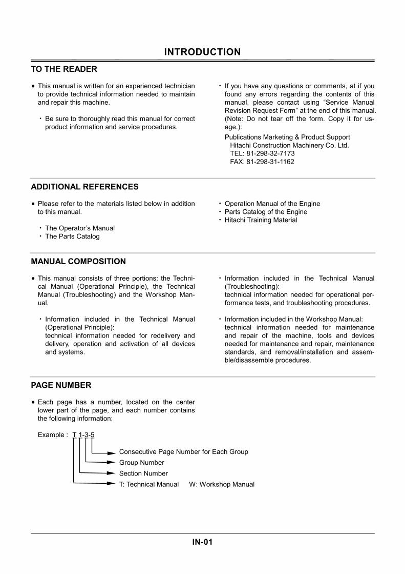
PAGE NUMBER • Each page has a number, located on the center
lower part of the page, and each number contains the following information: Example : T 1-3-5
Consecutive Page Number for Each Group Group Number Section Number T: Technical Manual W: Workshop Manual
INTRODUCTION
IN-02
SAFETY ALERT SYMBOL AND HEADLINE NOTATIONS In this manual, the following safety alert symbol and signal words are used to alert the reader to the potential for personal injury of machine damage.
This is the safety alert symbol. When you see this symbol, be alert to the potential for personal injury. Never fail to follow the safety instructions prescribed along with the safety alert symbol. The safety alert symbol is also used to draw attention to component/part weights. To avoid injury and damage, be sure to use appropri-ate lifting techniques and equipment when lifting heavy parts.
• CAUTION:
Indicated potentially hazardous situation which could, if not avoided, result in personal injury or death.
• IMPORTANT:
Indicates a situation which, if not conformed to the instructions, could result in damage to the machine.
• NOTE: Indicates supplementary technical information or know-how.
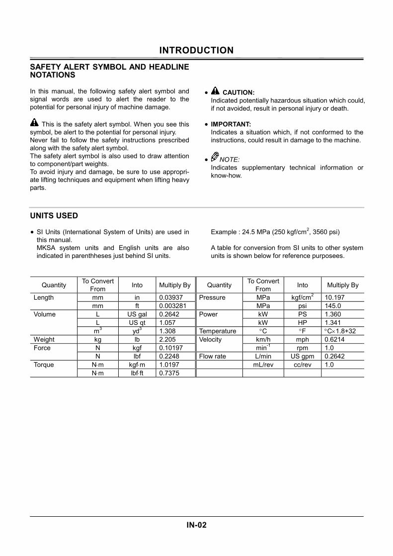
UNITS USED • SI Units (International System of Units) are used in
this manual. MKSA system units and English units are also indicated in parenthheses just behind SI units.
Example : 24.5 MPa (250 kgf/cm2, 3560 psi) A table for conversion from SI units to other system units is shown below for reference purposees.
Quantity To Convert From Into Multiply By
MPa kgf/cm2 10.197 Pressure MPa psi 145.0 kW PS 1.360 Power kW HP 1.341
Temperature °C °F °C×1.8+32 km/h mph 0.6214 Velocity min-1 rpm 1.0
Flow rate L/min US gpm 0.2642 mL/rev cc/rev 1.0
Quantity To Convert From Into Multiply By
mm in 0.03937 Length mm ft 0.003281
L US gal 0.2642 L US qt 1.057
Volume
m3 yd3 1.308 Weight kg lb 2.205
N kgf 0.10197 Force N lbf 0.2248
N⋅m kgf⋅m 1.0197 Torque N⋅m lbf⋅ft 0.7375
SAFETY
SA-1
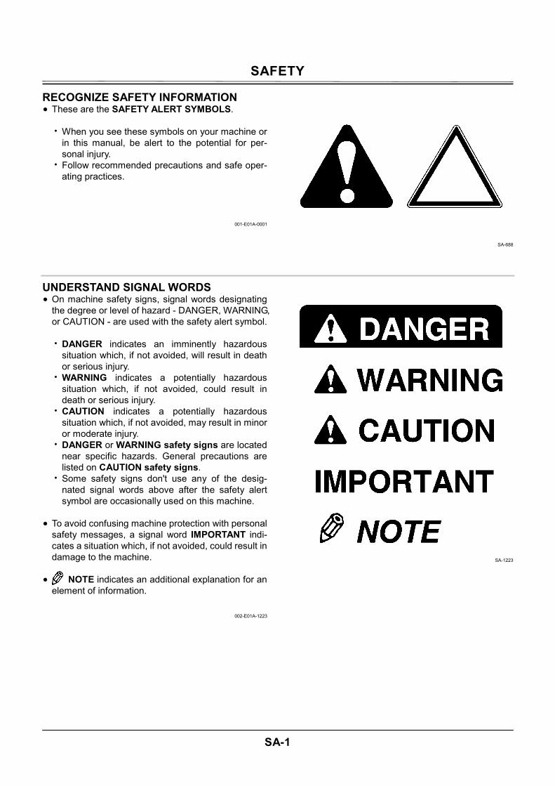
RECOGNIZE SAFETY INFORMATION • These are the SAFETY ALERT SYMBOLS.
• When you see these symbols on your machine or in this manual, be alert to the potential for per-sonal injury.
• Follow recommended precautions and safe oper-ating practices.
001-E01A-0001
SA-688
UNDERSTAND SIGNAL WORDS • On machine safety signs, signal words designating
the degree or level of hazard - DANGER, WARNING, or CAUTION - are used with the safety alert symbol.
• DANGER indicates an imminently hazardous
situation which, if not avoided, will result in death or serious injury.
• WARNING indicates a potentially hazardous situation which, if not avoided, could result in death or serious injury.
• CAUTION indicates a potentially hazardous situation which, if not avoided, may result in minor or moderate injury.
• DANGER or WARNING safety signs are located near specific hazards. General precautions are listed on CAUTION safety signs.
• Some safety signs don't use any of the desig-nated signal words above after the safety alert symbol are occasionally used on this machine.
• To avoid confusing machine protection with personal
safety messages, a signal word IMPORTANT indi-cates a situation which, if not avoided, could result in damage to the machine.
• NOTE indicates an additional explanation for an
element of information.
002-E01A-1223
SA-1223
SAFETY
SA-2
FOLLOW SAFETY INSTRUCTIONS • Carefully read and follow all safety signs on the
machine and all safety messages in this manual. • Safety signs should be installed, maintained and
replaced when necessary.
• If a safety sign or this manual is damaged or missing, order a replacement from your author-ized dealer in the same way you order other re-placement parts (be sure to state machine model and serial number when ordering).
• Learn how to operate the machine and its controls correctly and safely.
• Allow only trained, qualified, authorized personnel to operate the machine.
• Keep your machine in proper working condition.
• Unauthorized modifications of the machine may impair its function and/or safety and affect ma-chine life.
• Do not modify any machine parts without au-thorization. Failure to do so may deteriorate the part safety, function, and/or service life. In addi-tion, personal accident, machine trouble, and/or damage to material caused by unauthorized modifications will void Hitachi Warranty Policy.
• Do not use attachments and/or optional parts or equipment not authorized by Hitachi. Failure to do so may deteriorate the safety, function, and/or service life of the machine. In addition, personal accident, machine trouble, and/or damage to material caused by using unauthorized attach-ments and/or optional parts or equipment will void Hitachi Warranty Policy.
• The safety messages in this SAFETY chapter are intended to illustrate basic safety procedures of machines. However it is impossible for these safety messages to cover every hazardous situation you may encounter. If you have any questions, you should first consult your supervisor and/or your au-thorized dealer before operating or performing maintenance work on the machine.
003-E01B-0003
SA-003
SAFETY
SA-3
PREPARE FOR EMERGENCIES • Be prepared if a fire starts or if an accident occurs.
• Keep a first aid kit and fire extinguisher on hand. • Thoroughly read and understand the label at-
tached on the fire extinguisher to use it properly. • To ensure that a fire-extinguisher can be always
used when necessary, check and service the fire-extinguisher at the recommended intervals as specified in the fire-extinguisher manual.
• Establish emergency procedure guidelines to cope with fires and accidents.
• Keep emergency numbers for doctors, ambu-lance service, hospital, and fire department posted near your telephone.
004-E01A-0437
SA-437
WEAR PROTECTIVE CLOTHING • Wear close fitting clothing and safety equipment
appropriate to the job.
You may need: A hard hat Safety shoes Safety glasses, goggles, or face shield Heavy gloves Hearing protection Reflective clothing Wet weather gear Respirator or filter mask.
Be sure to wear the correct equipment and clothing for the job. Do not take any chances.
• Avoid wearing loose clothing, jewelry, or other
items that can catch on control levers or other parts of the machine.
• Operating equipment safely requires the full atten-tion of the operator. Do not wear radio or music headphones while operating the machine.
005-E01A-0438
SA-428
SAFETY
SA-4
PROTECT AGAINST NOISE • Prolonged exposure to loud noise can cause im-
pairment or loss of hearing.
• Wear a suitable hearing protective device such as earmuffs or earplugs to protect against objec-tionable or uncomfortably loud noises.
006-E01A-0434
SA-434
INSPECT MACHINE • Inspect your machine carefully each day or shift by
walking around it before you start it to avoid per-sonal injury.
• In the walk-around inspection be sure to cover all
points described in the "RE-START INSPEC-TION" chapter in the operator's manual.
007-E01A-0435
SA-435
SAFETY
SA-5
GENERAL PRECAUTIONS FOR CAB • Before entering the cab, thoroughly remove all dirt
and/or oil from the soles of your work boots. If any controls such as a pedal is operated while with dirt and/or oil on the soles of the operator's work boots the operator's foot may slip off the pedal, possibly resulting in a personal accident.
• Do not leave parts and/or tools lying around the operator's seat. Store them in their specified loca-tions.
• Avoid storing transparent bottles in the cab. Do not attach any transparent type window decora-tions on the windowpanes as they may focus sunlight, possibly starting a fire.
• Refrain from listening to the radio, or using music headphones or mobile telephones in the cab while operating the machine.
• Keep all flammable objects and/or explosives away from the machine.
• After using the ashtray, always cover it to extin-guish the match and/or tobacco.
• Do not leave cigarette lighters in the cab. When the temperature in the cab increases, the lighter may explode.
524-E01A-0000
SAFETY
SA-6
USE HANDHOLDS AND STEPS • Falling is one of the major causes of personal injury.
• When you get on and off the machine, always face the machine and maintain a three-point contact with the steps and handrails.
• Do not use any controls as hand-holds. • Never jump on or off the machine. Never mount or
dismount a moving machine. • Be careful of slippery conditions on platforms,
steps, and handrails when leaving the machine.
008-E01A-0439
SA-439
ADJUST THE OPERATOR'S SEAT • A poorly adjusted seat for either the operator or for
the work at hand may quickly fatigue the operator leading to mis-operations.
• The seat should be adjusted whenever changing
the operator for the machine. • The operator should be able to fully depress the
pedals and to correctly operate the control levers with his back against the seat back.
• If not, move the seat forward or backward, and check again.
• Adjust the rear view mirror position so that the best rear visibility is obtained from the operator's seat. If the mirror is broken, immediately replace it with a new one.
009-E01A-0462
SA-462
SAFETY
SA-7
ENSURE SAFETY BEFORE RISING FROM OR LEAVING OPERATOR'S SEAT • Before rising from the operator's seat to open/close
either side window or to adjust the seat position, be sure to first lower the front attachment to the ground and then move the pilot control shut-off lever to the LOCK position. Failure to do so may allow the ma-chine to unexpectedly move when a body part un-intentionally comes in contact with a control lever, possibly resulting in serious personal injury or death.
• Before leaving the machine, be sure to first lower
the front attachment to the ground and then move the pilot control shut-off lever to the LOCK posi-tion. Turn the key switch OFF to stop the engine.
• Before leaving the machine, close all windows, doors, and access covers and lock them up.
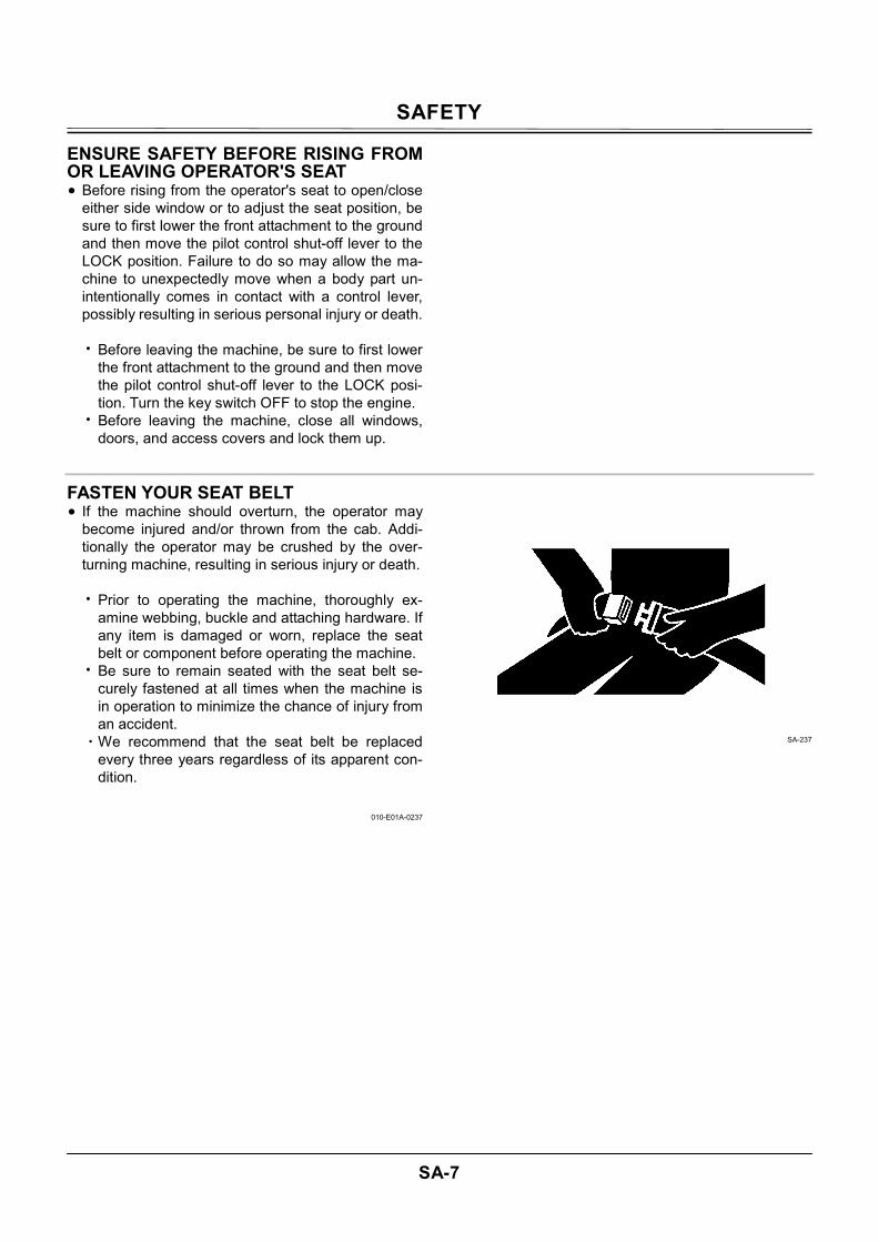
FASTEN YOUR SEAT BELT • If the machine should overturn, the operator may
become injured and/or thrown from the cab. Addi-tionally the operator may be crushed by the over-turning machine, resulting in serious injury or death.
• Prior to operating the machine, thoroughly ex-
amine webbing, buckle and attaching hardware. If any item is damaged or worn, replace the seat belt or component before operating the machine.
• Be sure to remain seated with the seat belt se-curely fastened at all times when the machine is in operation to minimize the chance of injury from an accident.
・We recommend that the seat belt be replaced every three years regardless of its apparent con-dition.
010-E01A-0237
SA-237
SAFETY
SA-8
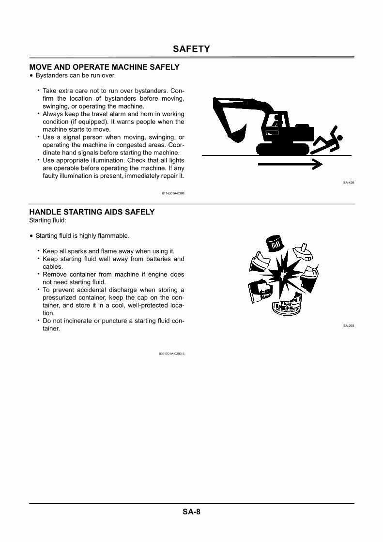
MOVE AND OPERATE MACHINE SAFELY • Bystanders can be run over.
• Take extra care not to run over bystanders. Con-firm the location of bystanders before moving, swinging, or operating the machine.
• Always keep the travel alarm and horn in working condition (if equipped). It warns people when the machine starts to move.
• Use a signal person when moving, swinging, or operating the machine in congested areas. Coor-dinate hand signals before starting the machine.
• Use appropriate illumination. Check that all lights are operable before operating the machine. If any faulty illumination is present, immediately repair it.
011-E01A-0398
SA-426
HANDLE STARTING AIDS SAFELY Starting fluid: • Starting fluid is highly flammable.
• Keep all sparks and flame away when using it. • Keep starting fluid well away from batteries and
cables. • Remove container from machine if engine does
not need starting fluid. • To prevent accidental discharge when storing a
pressurized container, keep the cap on the con-tainer, and store it in a cool, well-protected loca-tion.
• Do not incinerate or puncture a starting fluid con-tainer.
036-E01A-0293-3
SA-293
SAFETY
SA-9
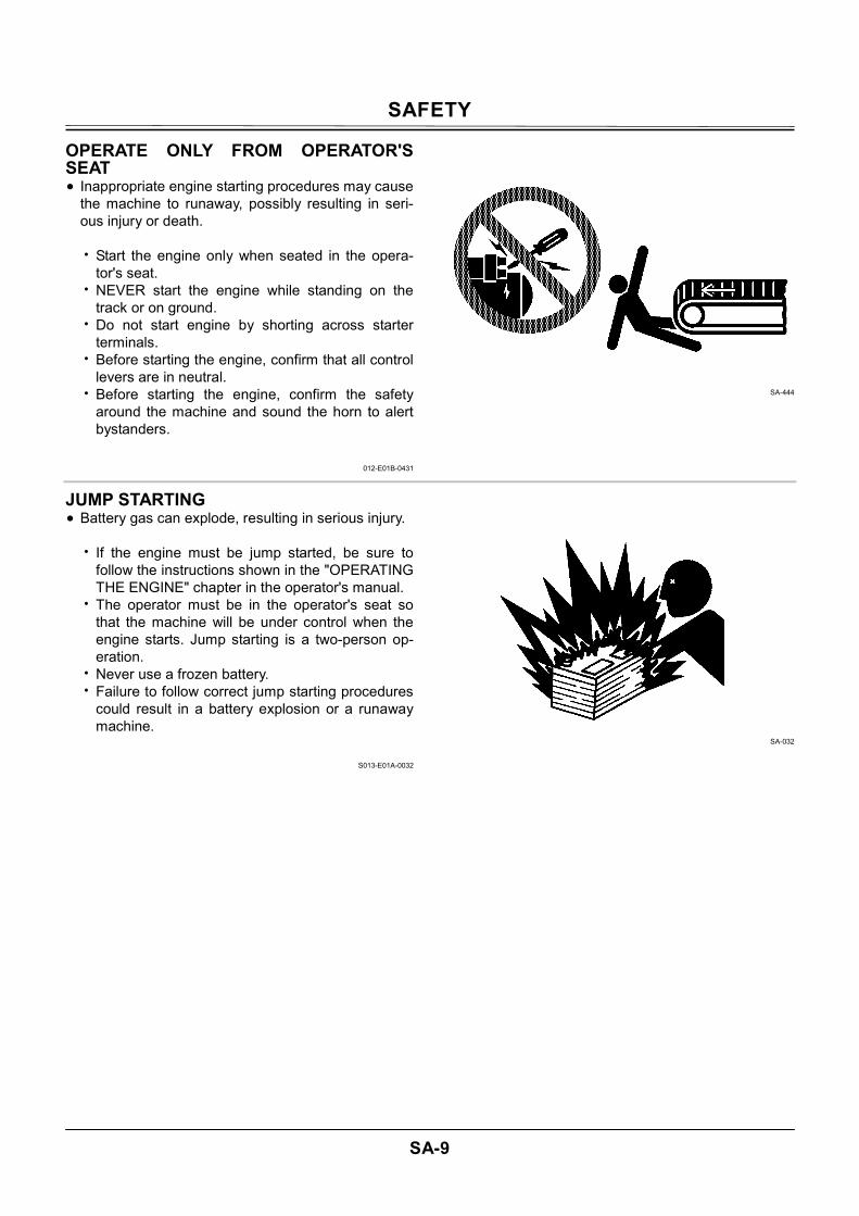
OPERATE ONLY FROM OPERATOR'S SEAT • Inappropriate engine starting procedures may cause
the machine to runaway, possibly resulting in seri-ous injury or death.
• Start the engine only when seated in the opera-
tor's seat. • NEVER start the engine while standing on the
track or on ground. • Do not start engine by shorting across starter
terminals. • Before starting the engine, confirm that all control
levers are in neutral. • Before starting the engine, confirm the safety
around the machine and sound the horn to alert bystanders.
012-E01B-0431
SA-444
JUMP STARTING • Battery gas can explode, resulting in serious injury.
• If the engine must be jump started, be sure to follow the instructions shown in the "OPERATING THE ENGINE" chapter in the operator's manual.
• The operator must be in the operator's seat so that the machine will be under control when the engine starts. Jump starting is a two-person op-eration.
• Never use a frozen battery. • Failure to follow correct jump starting procedures
could result in a battery explosion or a runaway machine.
S013-E01A-0032
SA-032
SAFETY
SA-10
KEEP RIDERS OFF MACHINE • Riders on machine are subject to injury such as be-
ing struck by foreign objects and being thrown off the machine.
• Only the operator should be on the machine.
Keep riders off. • Riders also obstruct the operator's view, resulting
in the machine being operated in an unsafe manner.
014-E01B-0427
SA-379
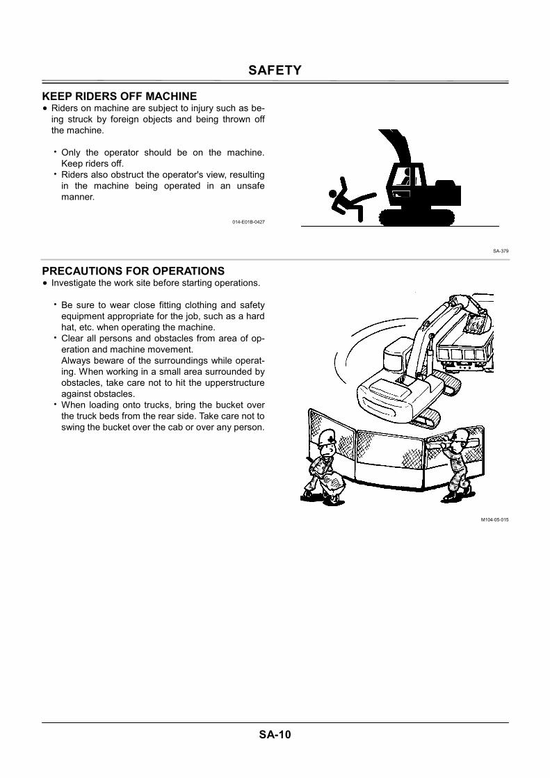
PRECAUTIONS FOR OPERATIONS • Investigate the work site before starting operations.
• Be sure to wear close fitting clothing and safety equipment appropriate for the job, such as a hard hat, etc. when operating the machine.
• Clear all persons and obstacles from area of op-eration and machine movement. Always beware of the surroundings while operat-ing. When working in a small area surrounded by obstacles, take care not to hit the upperstructure against obstacles.
• When loading onto trucks, bring the bucket over the truck beds from the rear side. Take care not to swing the bucket over the cab or over any person.
M104-05-015
SAFETY
SA-11
INVESTIGATE JOB SITE BEFOREHAND • When working at the edge of an excavation or on a
road shoulder, the machine could tip over, possibly resulting in serious injury or death. • Investigate the configuration and ground condi-
tions of the job site beforehand to prevent the machine from falling and to prevent the ground, stockpiles, or banks from collapsing.
• Make a work plan. Use machines appropriate to the work and job site.
• Reinforce ground, edges, and road shoulders as necessary. Keep the machine well back from the edges of excavations and road shoulders.
• When working on an incline or on a road shoulder, employ a signal person as required.
• Confirm that your machine is equipped a FOPS cab before working in areas where the possibility of falling stones or debris exist.
• When the footing is weak, reinforce the ground before starting work.
• When working on frozen ground, be extremely alert. As ambient temperatures rise, footing be-comes loose and slippery.
• Beware the possibility of fire when operating the machine near flammable objects such as dry grass.
• Make sure the worksite has sufficient strength to firmly support the machine. When working close to an excavation or at road shoulders, operate the machine with the tracks po-sitioned perpendicular to the cliff face with travel motors at the rear, so that the machine can more easily evacuate if the cliff face collapses.
• If working on the bottom of a cliff or a high bank is required, be sure to investigate the area first and confirm that no danger of the cliff or bank collapsing exists. If any possibility of cliff or bank collapsing exists, do not work on the area.
• Soft ground may collapse when operating the ma-chine on it, possibly causing the machine to tip over. When working on a soft ground is required, be sure to reinforce the ground first using large pieces of steel plates strong and firm enough to easily support the machine.
• Note that there is always a possibility of machine tipping over when working on rough terrain or on slopes. Prevent machine tipping over from occurring. When operating on rough terrain or on slopes: • Reduce the engine speed. • Select slow travel speed mode. • Operate the machine slowly and be cautious with
machine movements.
SA-380
SAFETY
SA-12
EQUIPMENT OF HEAD GUARD, ROPS, FOPS In case the machine is operated in areas where the possibility of falling stones or debris exist, equip a head guard, ROPS, or FOPS according to the poten-tial hazardous conditions. (The standard cab for this machine corresponds to ROPS and FOPS.)
ROPS: Roll-Over Protective Structure FOPS: Falling Object Protective Structure
SA-490
PROVIDE SIGNALS FOR JOBS INVOLV-ING MULTIPLE NUMBERS OF MACHINES • For jobs involving multiple numbers of machines,
provide signals commonly known by all personnel involved. Also, appoint a signal person to coordinate the job site. Make sure that all personnel obey the signal person's directions.
018-E01A-0481
SA-481
CONFIRM DIRECTION OF MACHINE TO BE DRIVEN • Incorrect travel pedal/lever operation may result in
serious injury death.
• Before driving the machine, confirm the position of the undercarriage in relation to the operator's position. If the travel motors are located in front of the cab, the machine will move in reverse when travel pedals/levers are operated to the front.
017-E01A-0491
SA-491
SAFETY
SA-13
DRIVE MACHINE SAFELY • Before driving the machine, always confirm that the
travel levers/pedals direction corresponds to the di-rection you wish to drive.
• Be sure to detour around any obstructions. • Avoid traveling over obstructions. Soil, fragments
of rocks, and/or metal pieces may scatter around the machine. Don't allow personnel to stay around the machine while traveling.
• Driving on a slope may cause the machine to slip or
overturn, possibly resulting in serious injury or death.
• Never attempt to ascend or descend 35 degrees
or steeper slopes. • Be sure to fasten the seat belt. • When driving up or down a slope, keep the bucket
facing the direction of travel, approximately 0.5 to 1.0 m (A) above the ground.
• If the machine starts to skid or becomes unstable, immediately lower the bucket to the ground and stop.
SA-657
SA-658
SA-441
SA-442
SAFETY
SA-14
DRIVE MACHINE SAFELY • Driving across the face of a slope or steering on a
slope may cause the machine to skid or turnover. If the direction must be changed, move the ma-chine to level ground, then, change the direction to ensure safe operation.
• Avoid swinging the upperstructure on slopes. Never attempt to swing the upperstructure down-hill. The machine may tip over. If swinging uphill is unavoidable, carefully operate the upperstructure and boom at slow speed.
• If the engine stalls on a slope, immediately lower the bucket to the ground. Return the control lev-ers to neutral. Then, restart the engine.
• Be sure to thoroughly warm up the machine be-fore ascending steep slopes. If hydraulic oil has not warmed up sufficiently, sufficient performance may not be obtained.
• Use a signal person when moving, swinging or operating the machine in congested areas. Coor-dinate hand signals before starting the machine.
• Before moving machine, determine which way to move travel pedals/levers for the direction you want to go. When the travel motors are in the rear, pushing down on the front of the travel pedals or pushing the levers forward moves the machine forward, towards the idlers. An arrow-mark seal is stuck on the inside surface of the side frame to indicate the machine front direction.
• Select a travel route that is as flat as possible. Steer the machine as straight as possible, making small gradual changes in direction.
• Before traveling on them, check the strengths of bridges and road shoulders, and reinforce if nec-essary.
M104-05-008
M178-03-001
Travel Motor
Arrow-Mark
SAFETY
SA-15
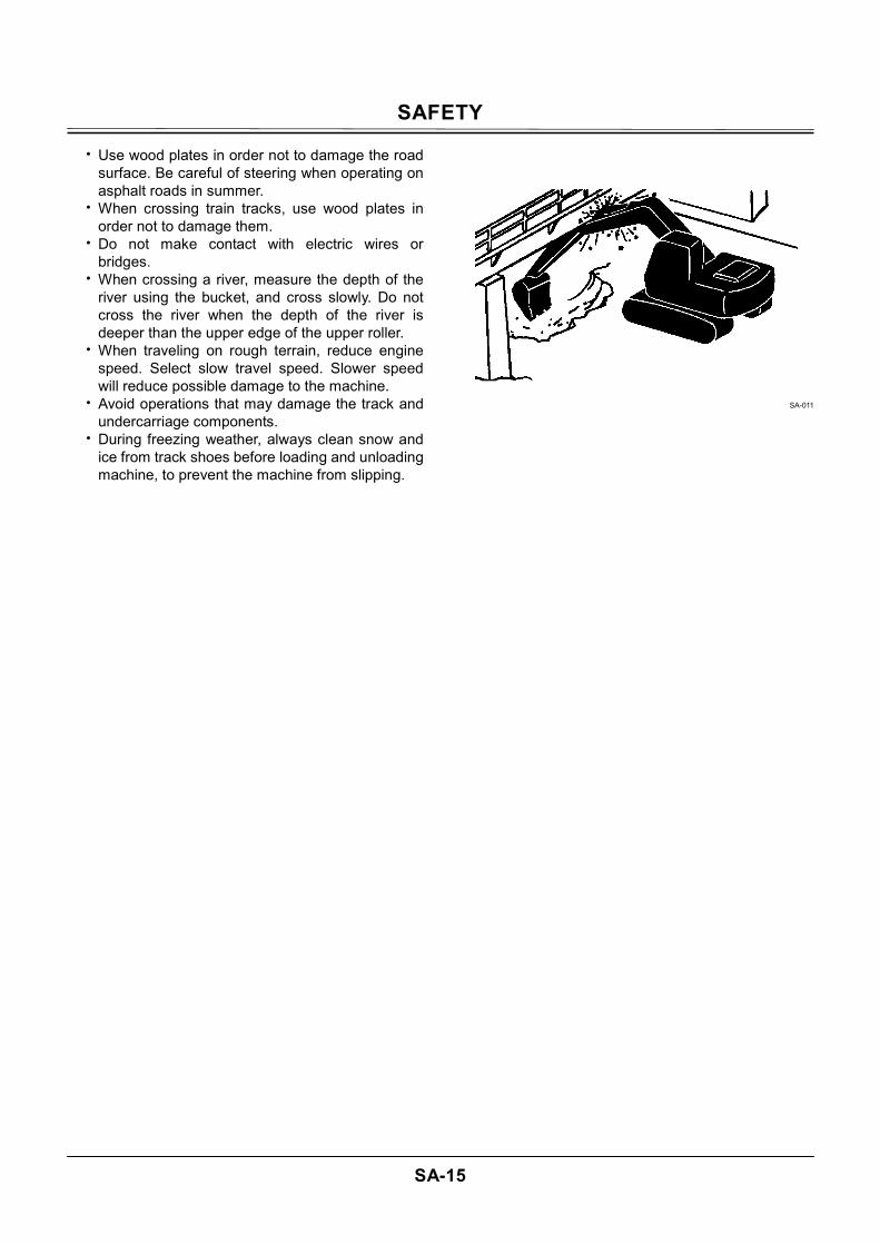
• Use wood plates in order not to damage the road surface. Be careful of steering when operating on asphalt roads in summer.
• When crossing train tracks, use wood plates in order not to damage them.
• Do not make contact with electric wires or bridges.
• When crossing a river, measure the depth of the river using the bucket, and cross slowly. Do not cross the river when the depth of the river is deeper than the upper edge of the upper roller.
• When traveling on rough terrain, reduce engine speed. Select slow travel speed. Slower speed will reduce possible damage to the machine.
• Avoid operations that may damage the track and undercarriage components.
• During freezing weather, always clean snow and ice from track shoes before loading and unloading machine, to prevent the machine from slipping.
SA-011
SAFETY
SA-16
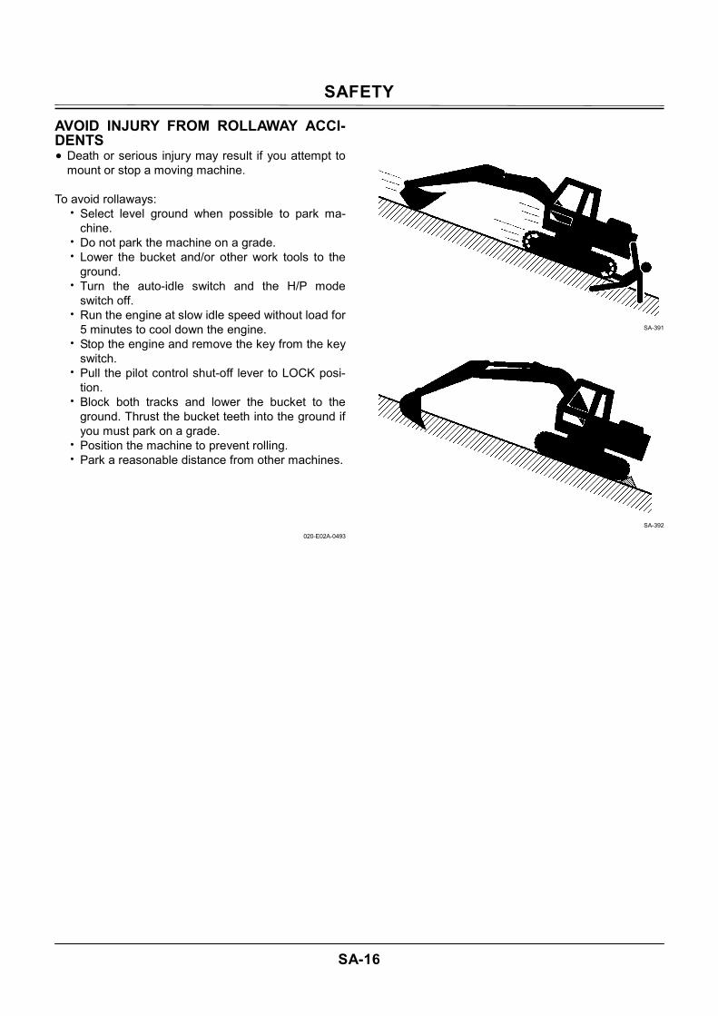
AVOID INJURY FROM ROLLAWAY ACCI-DENTS • Death or serious injury may result if you attempt to
mount or stop a moving machine. To avoid rollaways:
• Select level ground when possible to park ma-chine.
• Do not park the machine on a grade. • Lower the bucket and/or other work tools to the
ground. • Turn the auto-idle switch and the H/P mode
switch off. • Run the engine at slow idle speed without load for
5 minutes to cool down the engine. • Stop the engine and remove the key from the key
switch. • Pull the pilot control shut-off lever to LOCK posi-
tion. • Block both tracks and lower the bucket to the
ground. Thrust the bucket teeth into the ground if you must park on a grade.
• Position the machine to prevent rolling. • Park a reasonable distance from other machines.
020-E02A-0493
SA-391
SA-392
SAFETY
SA-17
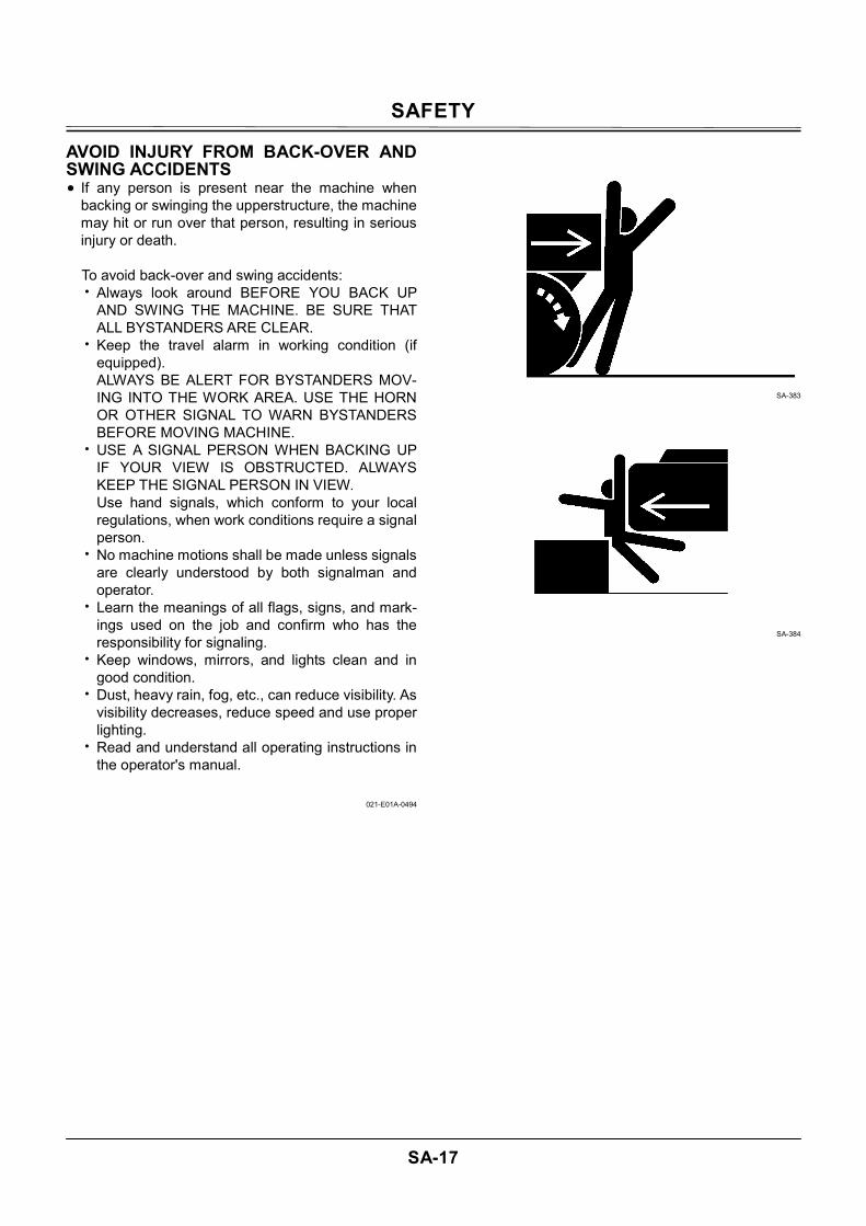
AVOID INJURY FROM BACK-OVER AND SWING ACCIDENTS • If any person is present near the machine when
backing or swinging the upperstructure, the machine may hit or run over that person, resulting in serious injury or death.
To avoid back-over and swing accidents: • Always look around BEFORE YOU BACK UP
AND SWING THE MACHINE. BE SURE THAT ALL BYSTANDERS ARE CLEAR.
• Keep the travel alarm in working condition (if equipped). ALWAYS BE ALERT FOR BYSTANDERS MOV-ING INTO THE WORK AREA. USE THE HORN OR OTHER SIGNAL TO WARN BYSTANDERS BEFORE MOVING MACHINE.
• USE A SIGNAL PERSON WHEN BACKING UP IF YOUR VIEW IS OBSTRUCTED. ALWAYS KEEP THE SIGNAL PERSON IN VIEW. Use hand signals, which conform to your local regulations, when work conditions require a signal person.
• No machine motions shall be made unless signals are clearly understood by both signalman and operator.
• Learn the meanings of all flags, signs, and mark-ings used on the job and confirm who has the responsibility for signaling.
• Keep windows, mirrors, and lights clean and in good condition.
• Dust, heavy rain, fog, etc., can reduce visibility. As visibility decreases, reduce speed and use proper lighting.
• Read and understand all operating instructions in the operator's manual.
021-E01A-0494
SA-383
SA-384
SAFETY
SA-18
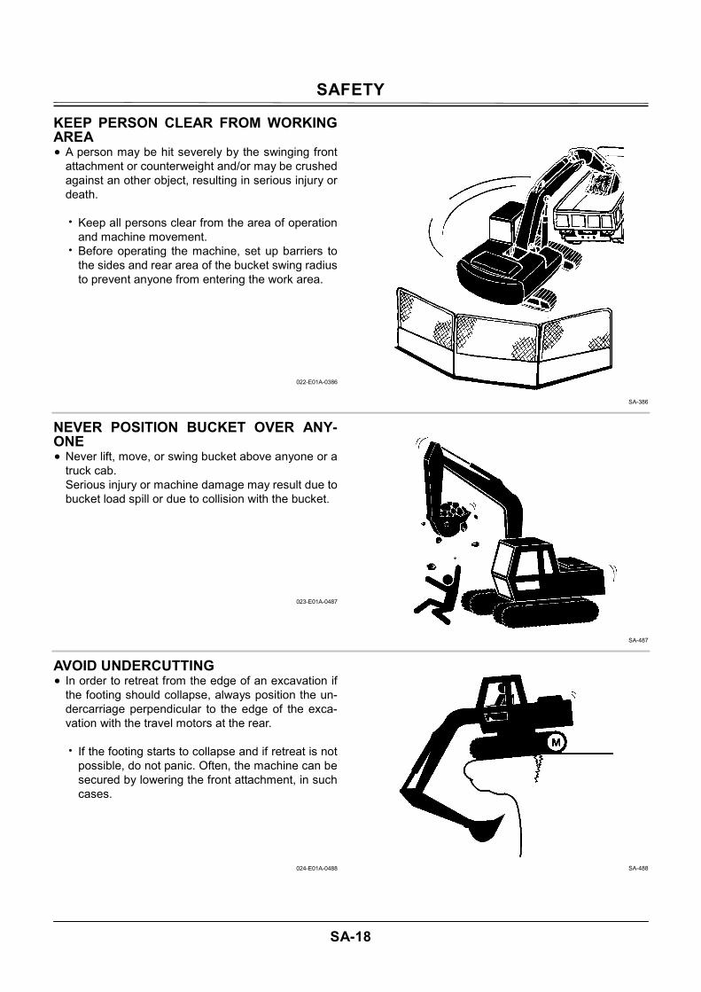
KEEP PERSON CLEAR FROM WORKING AREA • A person may be hit severely by the swinging front
attachment or counterweight and/or may be crushed against an other object, resulting in serious injury or death.
• Keep all persons clear from the area of operation
and machine movement. • Before operating the machine, set up barriers to
the sides and rear area of the bucket swing radius to prevent anyone from entering the work area.
022-E01A-0386
SA-386
NEVER POSITION BUCKET OVER ANY-ONE • Never lift, move, or swing bucket above anyone or a
truck cab. Serious injury or machine damage may result due to bucket load spill or due to collision with the bucket.
023-E01A-0487
SA-487
AVOID UNDERCUTTING • In order to retreat from the edge of an excavation if
the footing should collapse, always position the un-dercarriage perpendicular to the edge of the exca-vation with the travel motors at the rear.
• If the footing starts to collapse and if retreat is not
possible, do not panic. Often, the machine can be secured by lowering the front attachment, in such cases.
024-E01A-0488
SA-488
SAFETY
SA-19
AVOID TIPPING DO NOT ATTEMPT TO JUMP CLEAR OF TIPPING MACHINE---SERIOUS OR FATAL CRUSHING IN-JURIES WILL RESULT MACHINE WILL TIP OVER FASTER THAN YOU CAN JUMP FREE FASTEN YOUR SEAT BELT
• The danger of tipping is always present when oper-ating on a grade, possibly resulting in serious injury or death.
To avoid tipping:
• Be extra careful before operating on a grade.
• Prepare machine operating area flat. • Keep the bucket low to the ground and close to
the machine. • Reduce operating speeds to avoid tipping or slip-
ping. • Avoid changing direction when traveling on
grades. • NEVER attempt to travel across a grade steeper
than 15 degrees if crossing the grade is un-avoidable.
• Reduce swing speed as necessary when swing-ing loads.
• Be careful when working on frozen ground.
• Temperature increases will cause the ground to become soft and make ground travel unstable.
025-E03B-0463
SA-012
SA-440
NEVER UNDERCUT A HIGH BANK • The edges could collapse or a land slide could occur
causing serious injury or death.
026-E01A-0519
SA-489
SAFETY
SA-20
DIG WITH CAUTION • Accidental severing of underground cables or gas
lines may cause an explosion and/or fire, possibly resulting in serious injury or death.
• Before digging check the location of cables, gas
lines, and water lines. • Keep the minimum distance required, by law, from
cables, gas lines, and water lines. • If a fiber optic cable should be accidentally sev-
ered, do not look into the end. Doing so may re-sult in serious eye injury.
• Contact your local "diggers hot line" if available in your area, and/or the utility companies directly. Have them mark all underground utilities.
027-E01A-0382
SA-382
OPERATE WITH CAUTION • If the front attachment or any other part of the ma-
chine hits against an overhead obstacle, such as a bridge, both the machine and the overhead obstacle will be damaged, and personal injury may result as well.
• Take care to avoid hitting overhead obstacles with
the boom or arm.
028-E01A-0389
SA-389
SAFETY
SA-21
AVOID POWER LINES • Serious injury or death can result if the machine or
front attachments are not kept a safe distance from electric lines.
• When operating near an electric line, NEVER
move any part of the machine or load closer than 3 m plus twice the line insulator length.
• Check and comply with any local regulations that may apply.
• Wet ground will expand the area that could cause any person on it to be affected by electric shock. Keep all bystanders or co-workers away from the site.
029-E01A-0381
SA-381
PRECAUTIONS FOR LIGHTENING • The machine is vulnerable to lighting strikes.
• In the event of an electrical storm, immediately stop operation, and lower the bucket to the ground. Evacuate to a safe place far away from the machine.
• After the electrical storm has passed, check all of the machine safety devices for any failure. If any failed safety devices are found, operate the ma-chine only after repairing them.
SA-1088
OBJECT HANDLING • If a lifted load should fall, any person nearby may be
struck by the falling load or may be crushed under-neath it, resulting in serious injury or death.
• When using the machine for craning operations,
be sure to comply with all local regulations. • Do not use damaged chains or frayed cables,
sables, slings, or ropes. • Before craning, position the upperstructure with
the travel motors at the rear. • Move the load slowly and carefully. Never move it
suddenly. • Keep all persons well away from the load. • Never move a load over a person's head. • Do not allow anyone to approach the load until it
is safely and securely situated on supporting blocks or on the ground.
• Never attach a sling or chain to the bucket teeth. They may come off, causing the load to fall.
032-E01A-0132
SA-014
SAFETY
SA-22
PROTECT AGAINST FLYING DEBRIS • If flying debris hit eyes or any other part of the body,
serious injury may result.
• Guard against injury from flying pieces of metal or debris; wear goggles or safety glasses.
• Keep bystanders away from the working area before striking any object.
031-E01A-0432
SA-432
PARK MACHINE SAFELY
To avoid accidents: • Park machine on a firm, level surface. • Lower bucket to the ground. • Turn auto-idle switch and H/P mode switch OFF. • Run engine at slow idle speed without load for 5
minutes. • Turn key switch to OFF to stop engine. • Remove the key from the key switch. • Pull the pilot control shut-off lever to the LOCK
position. • Close windows, roof vent, and cab door. • Lock all access doors and compartments.
SA-390
HANDLE FLUIDS SAFELY-AVOID FIRES • Handle fuel with care; it is highly flammable. If fuel
ignites, an explosion and/or a fire may occur, possi-bly resulting in serious injury or death.
• Do not refuel the machine while smoking or when
near open flame or sparks. • Always stop the engine before refueling the ma-
chine. • Fill the fuel tank outdoors.
• All fuels, most lubricants, and some coolants are
flammable.
• Store flammable fluids well away from fire haz-ards.
• Do not incinerate or puncture pressurized con-tainers.
• Do not store oily rags; they can ignite and burn spontaneously.
• Securely tighten the fuel and oil filler cap. 034-E01A-0496
SA-018
SA-019
SAFETY
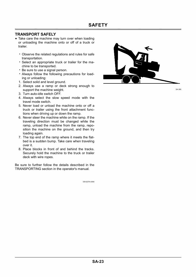
SA-23
TRANSPORT SAFELY • Take care the machine may turn over when loading
or unloading the machine onto or off of a truck or trailer.
• Observe the related regulations and rules for safe
transportation. • Select an appropriate truck or trailer for the ma-
chine to be transported. • Be sure to use a signal person. • Always follow the following precautions for load-
ing or unloading: 1. Select solid and level ground. 2. Always use a ramp or deck strong enough to
support the machine weight. 3. Turn auto-idle switch OFF. 4. Always select the slow speed mode with the
travel mode switch. 5. Never load or unload the machine onto or off a
truck or trailer using the front attachment func-tions when driving up or down the ramp.
6. Never steer the machine while on the ramp. If the traveling direction must be changed while the ramp, unload the machine from the ramp, repo-sition the machine on the ground, and then try loading again.
7. The top end of the ramp where it meets the flat-bed is a sudden bump. Take care when traveling over it.
8. Place blocks in front of and behind the tracks. Securely hold the machine to the truck or trailer deck with wire ropes.
Be sure to further follow the details described in the TRANSPORTING section in the operator's manual.
035-E07A-0454
SA-395
SAFETY
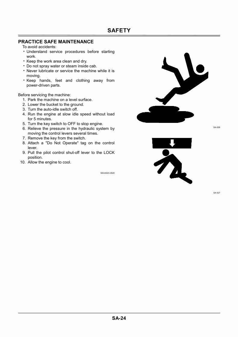
SA-24
PRACTICE SAFE MAINTENANCE To avoid accidents: • Understand service procedures before starting
work. • Keep the work area clean and dry. • Do not spray water or steam inside cab. • Never lubricate or service the machine while it is
moving. • Keep hands, feet and clothing away from
power-driven parts. Before servicing the machine:
1. Park the machine on a level surface. 2. Lower the bucket to the ground. 3. Turn the auto-idle switch off. 4. Run the engine at slow idle speed without load
for 5 minutes. 5. Turn the key switch to OFF to stop engine. 6. Relieve the pressure in the hydraulic system by
moving the control levers several times. 7. Remove the key from the switch. 8. Attach a "Do Not Operate" tag on the control
lever. 9. Pull the pilot control shut-off lever to the LOCK
position. 10. Allow the engine to cool.
500-E02C-0520
SA-028
SA-527
SAFETY
SA-25
• If a maintenance procedure must be performed with the engine running, do not leave machine unattended.
• If the machine must be raised, maintain a 90 to 100° angle between the boom and arm. Securely support any machine elements that must be raised for service work.
• Inspect certain parts periodically and repair or re-place as necessary. Refer to the section discuss-ing that part in the "MAINTENANCE" chapter of this manual.
• Keep all parts in good condition and properly in-stalled.
• Fix damage immediately. Replace worn or broken parts. Remove any buildup of grease, oil, or de-bris.
• When cleaning parts, always use nonflammable detergent oil. Never use highly flammable oil such as fuel oil and gasoline to clean parts or surfaces.
• Disconnect battery ground cable (-) before mak-ing adjustments to electrical systems or before performing welding on the machine.
• Sufficiently illuminate the work site. Use a main-tenance work light when working under or inside the machine.
• Always use a work light protected with a guard. In case the light bulb is broken, spilled fuel, oil, anti-freeze fluid, or window washer fluid may catch fire.
SA-037
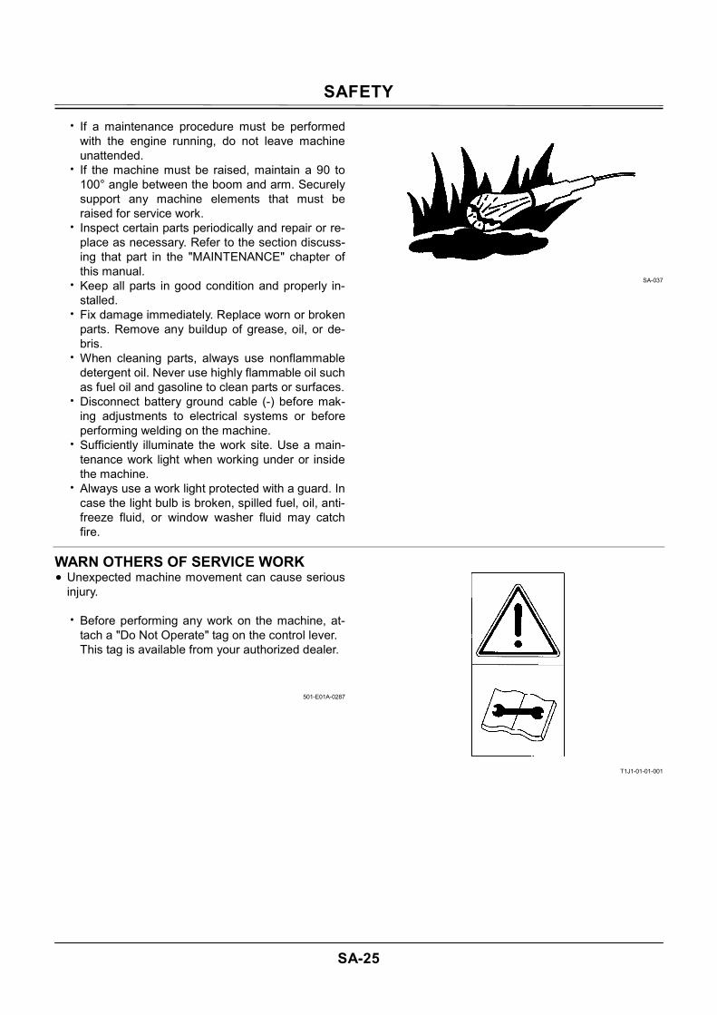
WARN OTHERS OF SERVICE WORK • Unexpected machine movement can cause serious
injury.
• Before performing any work on the machine, at-tach a "Do Not Operate" tag on the control lever. This tag is available from your authorized dealer.
501-E01A-0287
T1J1-01-01-001
SAFETY
SA-26
SUPPORT MACHINE PROPERLY • Never attempt to work on the machine without se-
curing the machine first.
• Always lower the attachment to the ground before you work on the machine.
• If you must work on a lifted machine or attach-ment, securely support the machine or attach-ment. Do not support the machine on cinder blocks, hollow tires, or props that may crumble under continuous load. Do not work under a ma-chine that is supported solely by a jack.
519-E01A-0527
SA-527
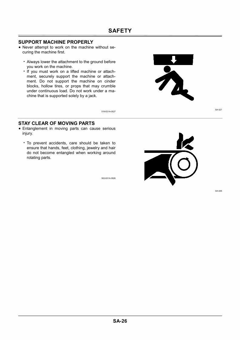
STAY CLEAR OF MOVING PARTS • Entanglement in moving parts can cause serious
injury.
• To prevent accidents, care should be taken to ensure that hands, feet, clothing, jewelry and hair do not become entangled when working around rotating parts.
502-E01A-0026
SA-026
SAFETY
SA-27
PREVENT PARTS FROM FLYING • Grease in the track adjuster is under high pressure.
Failure to follow the precautions below may result in serious injury, blindness, or death.
• Do not attempt to remove GREASE FITTING or
VALVE ASSEMBLY. • As pieces may fly off, be sure to keep body and
face away from valve. • Never attempt to disassemble the track adjuster.
Inadvertent disassembling of the track adjuster may cause the parts such as a spring to fly off, possibly resulting in severe personal injury or death.
• Travel reduction gears are under pressure.
• As pieces may fly off, be sure to keep body and face away from AIR RELEASE PLUG to avoid injury.
• GEAR OIL is hot. Wait for GEAR OIL to cool, and then gradually loosen AIR RELEASE PLUG to release pressure.
503-E01B-0344
SA-344
STORE ATTACHMENTS SAFELY • Stored attachments such as buckets, hydraulic
hammers, and blades can fall and cause serious injury or death.
• Securely store attachments and implements to
prevent falling. Keep children and bystanders away from storage areas.
504-E01A-0034
SA-034
SAFETY
SA-28
PREVENT BURNS Hot spraying fluids: • After operation, engine coolant is hot and under
pressure. Hot water or steam is contained in the engine, radiator and heater lines. Skin contact with escaping hot water or steam can cause severe burns.
• To avoid possible injury from hot spraying water.
DO NOT remove the radiator cap until the engine is cool. When opening, turn the cap slowly to the stop. Allow all pressure to be released before removing the cap.
• The hydraulic oil tank is pressurized. Again, be sure to release all pressure before removing the cap.
Hot fluids and surfaces: • Engine oil, gear oil and hydraulic oil also become
hot during operation. The engine, hoses, lines and other parts become hot as well.
• Wait for the oil and components to cool before
starting any maintenance or inspection work.
505-E01B-0498
SA-039
SA-225
REPLACE RUBBER HOSES PERIODI-CALLY • Rubber hoses that contain flammable fluids under
pressure may break due to aging, fatigue, and abrasion. It is very difficult to gauge the extent of deterioration due to aging, fatigue, and abrasion of rubber hoses by inspection alone.
• Periodically replace the rubber hoses. (See the
page of "Periodic replacement of parts" in the operator's manual.)
• Failure to periodically replace rubber hoses may
cause a fire, fluid injection into skin, or the front attachment to fall on a person nearby, which may result in severe burns, gangrene, or otherwise serious injury or death.
S506-E01A-0019
SA-019
SAFETY
SA-29
AVOID HIGH-PRESSURE FLUIDS • Fluids such as diesel fuel or hydraulic oil under
pressure can penetrate the skin or eyes causing se-rious injury, blindness or death. • Avoid this hazard by relieving pressure before
disconnecting hydraulic or other lines. • Tighten all connections before applying pressure. • Search for leaks with a piece of cardboard; take
care to protect hands and body from high-pressure fluids. Wear a face shield or gog-gles for eye protection.
• If an accident occurs, see a doctor familiar with this type of injury immediately. Any fluid injected into the skin must be surgically removed within a few hours or gangrene may result.
507-E03A-0499
SA-031
SA-292
SA-044
SAFETY
SA-30
PREVENT FIRES Check for Oil Leaks: • Fuel, hydraulic oil and lubricant leaks can lead to
fires. • Check for oil leaks due to missing or loose clamps,
kinked hoses, lines or hoses that rub against each other, damage to the oil-cooler, and loose oil-cooler flange bolts.
• Tighten, repair or replace any missing, loose or damaged clamps, lines, hoses, oil-cooler and oil-cooler flange bolts.
• Do not bend or strike high-pressure lines. • Never install bent or damaged lines, pipes, or
hoses. Check for Shorts: • Short circuits can cause fires.
• Clean and tighten all electrical connections. • Check before each shift or after eight(8) to ten(10)
hours operation for loose, kinked, hardened or frayed electrical cables and wires.
• Check before each shift or after eight(8) to ten(10) hours operation for missing or damaged terminal caps.
• DO NOT OPERATE MACHINE if cable or wires are loose, kinked, etc..
Clean up Flammables: • Spilled fuel and oil, and trash, grease, debris, ac-
cumulated coal dust, and other flammables may cause fires. • Prevent fires by inspecting and cleaning the ma-
chine daily and by removing spilled or accumu-lated flammables immediately.
Check Key Switch: • If a fire breaks out, failure to stop the engine will
escalate the fire, hampering fire fighting. Always check key switch function before operating the machine every day: 1. Start the engine and run it at slow idle. 2. Turn the key switch to the OFF position to con-
firm that the engine stops. • If any abnormalities are found, be sure to repair
them before operating the machine. 508-E02B-0019
Check Heat Shields: • Damaged or missing heat shields may lead to fires.
• Damaged or missing heat shields must be re-paired or replaced before operating the machine.
508-E02A-0393
SA-019
SAFETY
SA-31
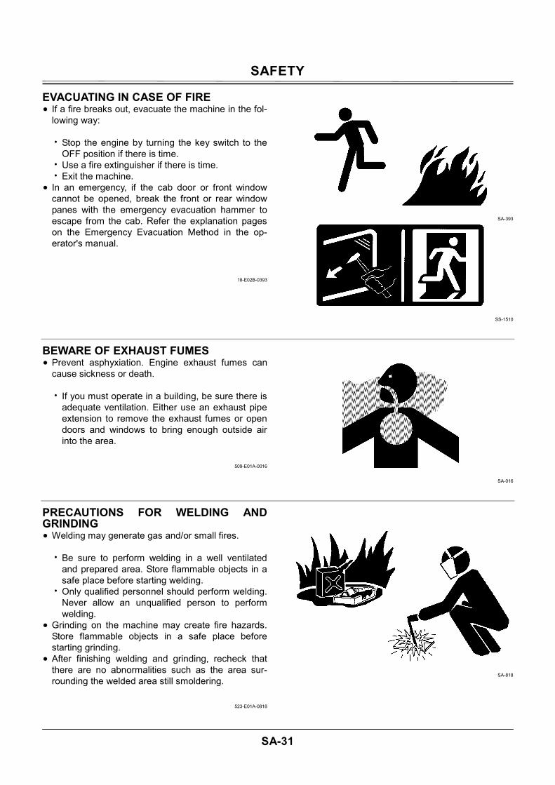
EVACUATING IN CASE OF FIRE • If a fire breaks out, evacuate the machine in the fol-
lowing way: • Stop the engine by turning the key switch to the
OFF position if there is time. • Use a fire extinguisher if there is time. • Exit the machine.
• In an emergency, if the cab door or front window cannot be opened, break the front or rear window panes with the emergency evacuation hammer to escape from the cab. Refer the explanation pages on the Emergency Evacuation Method in the op-erator's manual.
18-E02B-0393
SA-393
SS-1510
BEWARE OF EXHAUST FUMES • Prevent asphyxiation. Engine exhaust fumes can
cause sickness or death.
• If you must operate in a building, be sure there is adequate ventilation. Either use an exhaust pipe extension to remove the exhaust fumes or open doors and windows to bring enough outside air into the area.
509-E01A-0016
SA-016
PRECAUTIONS FOR WELDING AND GRINDING • Welding may generate gas and/or small fires.
• Be sure to perform welding in a well ventilated and prepared area. Store flammable objects in a safe place before starting welding.
• Only qualified personnel should perform welding. Never allow an unqualified person to perform welding.
• Grinding on the machine may create fire hazards. Store flammable objects in a safe place before starting grinding.
• After finishing welding and grinding, recheck that there are no abnormalities such as the area sur-rounding the welded area still smoldering.
523-E01A-0818
SA-818
SAFETY
SA-32
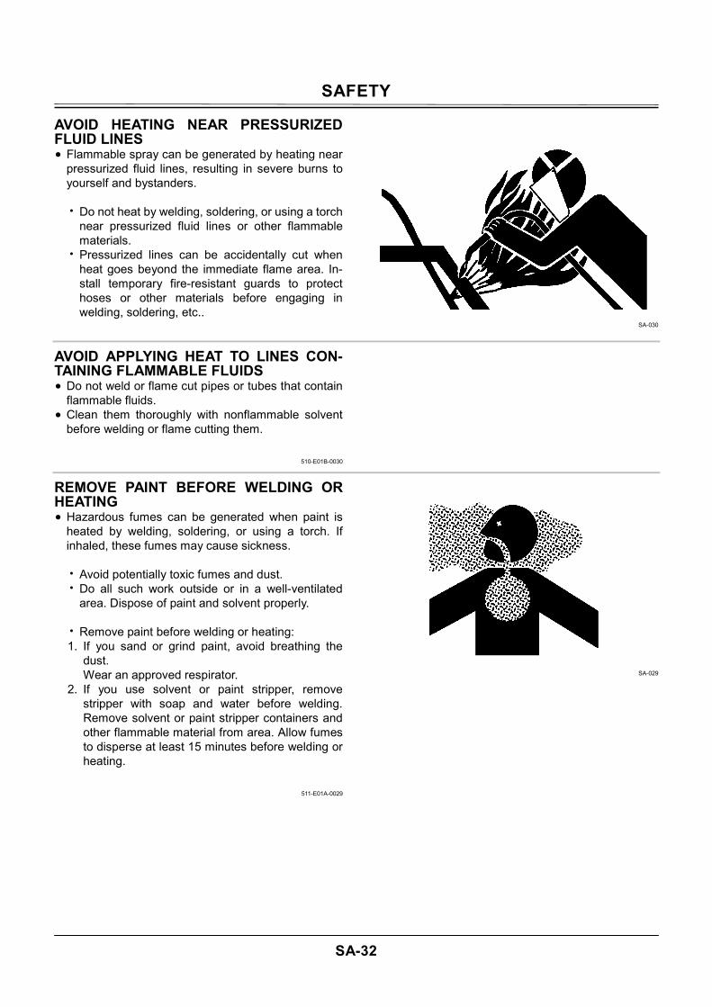
AVOID HEATING NEAR PRESSURIZED FLUID LINES • Flammable spray can be generated by heating near
pressurized fluid lines, resulting in severe burns to yourself and bystanders.
• Do not heat by welding, soldering, or using a torch
near pressurized fluid lines or other flammable materials.
• Pressurized lines can be accidentally cut when heat goes beyond the immediate flame area. In-stall temporary fire-resistant guards to protect hoses or other materials before engaging in welding, soldering, etc..
SA-030
AVOID APPLYING HEAT TO LINES CON-TAINING FLAMMABLE FLUIDS • Do not weld or flame cut pipes or tubes that contain
flammable fluids. • Clean them thoroughly with nonflammable solvent
before welding or flame cutting them.
510-E01B-0030
REMOVE PAINT BEFORE WELDING OR HEATING • Hazardous fumes can be generated when paint is
heated by welding, soldering, or using a torch. If inhaled, these fumes may cause sickness.
• Avoid potentially toxic fumes and dust. • Do all such work outside or in a well-ventilated
area. Dispose of paint and solvent properly.
• Remove paint before welding or heating: 1. If you sand or grind paint, avoid breathing the
dust. Wear an approved respirator.
2. If you use solvent or paint stripper, remove stripper with soap and water before welding. Remove solvent or paint stripper containers and other flammable material from area. Allow fumes to disperse at least 15 minutes before welding or heating.
511-E01A-0029
SA-029
SAFETY
SA-33
BEWARE OF ASBESTOS DUST • Take care not to inhale dust produced in the work
site. Inhalation of asbestos fibers may be the cause of lung cancer.
• Depending on the wok site conditions, the risk of
inhaling asbestos fiber may exist. Spray water to prevent asbestos from becoming airborne. Don't use compressed air.
• When operating the machine in a work site where asbestos might be present, be sure to operate the machine from the upwind side and wear a mask rated to prevent the inhalation of asbestos.
• Keep bystanders out of the work site during op-eration.
• Asbestos might be present in imitation parts. Use only genuine Hitachi Parts.
SA-029
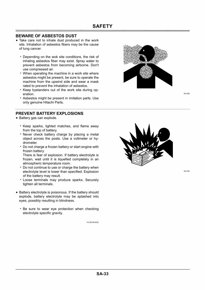
PREVENT BATTERY EXPLOSIONS • Battery gas can explode.
• Keep sparks, lighted matches, and flame away from the top of battery.
• Never check battery charge by placing a metal object across the posts. Use a voltmeter or hy-drometer.
• Do not charge a frozen battery or start engine with frozen battery. There is fear of explosion. If battery electrolyte is frozen, wait until it is liquefied completely in an atmospheric temperature room.
• Do not continue to use or charge the battery when electrolyte level is lower than specified. Explosion of the battery may result.
• Loose terminals may produce sparks. Securely tighten all terminals.
• Battery electrolyte is poisonous. If the battery should
explode, battery electrolyte may be splashed into eyes, possibly resulting in blindness.
• Be sure to wear eye protection when checking
electrolyte specific gravity.
512-E01B-0032
SA-032
SAFETY
SA-34
SERVICE AIR CONDITIONING SYSTEM SAFELY • If spilled onto skin, refrigerant may cause a cold
contact burn.
• Refer to the instructions described on the con-tainer for proper use when handling the refriger-ant.
• Use a recovery and recycling system to avoid leaking refrigerant into the atmosphere.
• Never touch the refrigerant.
513-E01A-0405
SA-405
HANDLE CHEMICAL PRODUCTS SAFELY • Direct exposure to hazardous chemicals can cause
serious injury. Potentially hazardous chemicals used with your machine include such items as lubricants, coolants, paints, and adhesives.
• A Material Safety Data Sheet (MSDS) provides
specific details on chemical products: physical and health hazards, safety procedures, and emergency response techniques.
• Check the MSDS before you start any job using a hazardous chemical. That way you will know ex-actly what the risks are and how to do the job safely. Then follow procedures and use recom-mended equipment.
• See your authorized dealer for MSDS's (available only in English) on chemical products used with your machine.
515-E01A-0309
SA-309
SAFETY
SA-35
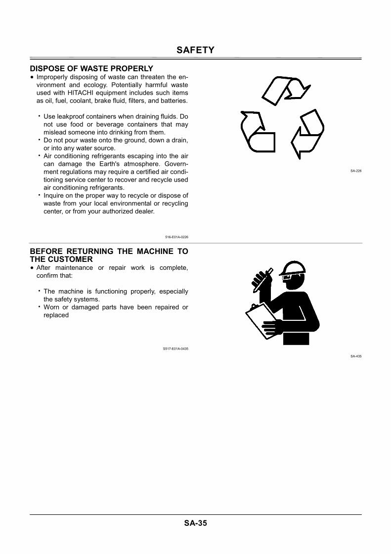
DISPOSE OF WASTE PROPERLY • Improperly disposing of waste can threaten the en-
vironment and ecology. Potentially harmful waste used with HITACHI equipment includes such items as oil, fuel, coolant, brake fluid, filters, and batteries.
• Use leakproof containers when draining fluids. Do
not use food or beverage containers that may mislead someone into drinking from them.
• Do not pour waste onto the ground, down a drain, or into any water source.
• Air conditioning refrigerants escaping into the air can damage the Earth's atmosphere. Govern-ment regulations may require a certified air condi-tioning service center to recover and recycle used air conditioning refrigerants.
• Inquire on the proper way to recycle or dispose of waste from your local environmental or recycling center, or from your authorized dealer.
516-E01A-0226
SA-226
BEFORE RETURNING THE MACHINE TO THE CUSTOMER • After maintenance or repair work is complete,
confirm that:
• The machine is functioning properly, especially the safety systems.
• Worn or damaged parts have been repaired or replaced
S517-E01A-0435
SA-435

SAFETY
SA-36
(Blank)
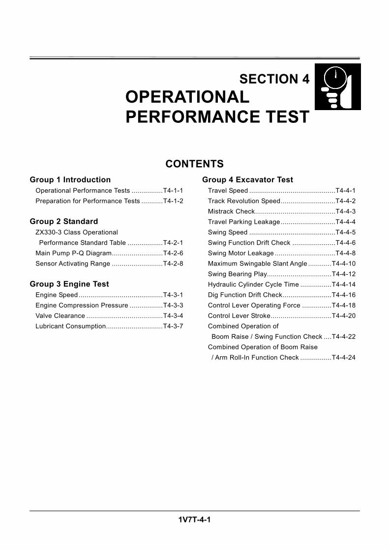
SECTION AND GROUP CONTENTS
TECHNICAL MANUAL
(Troubleshooting)
All information, illustrations and speci-fications in this manual are based on the latest product information available at the time of publication. The right is reserved to make changes at any time without notice.
COPYRIGHT(C)2006
Hitachi Construction Machinery Co., Ltd. Tokyo, Japan
All rights reserved
SECTION 4 OPERATIONAL PER- FORMANCE TEST
Group 1 Introduction
Group 2 Standard Group 3 Engine Test Group 4 Excavator Test Group 5 Component Test
SECTION 5 TROUBLESHOOTING
Group 1 Diagnosing Procedure Group 2 Monitor Unit Group 3 Dr. ZX Group 4 e-Shovel Group 5 Component Layout Group 6 Troubleshooting A Group 7 Troubleshooting B Group 8 Electrical System Inspection
TECHNICAL MANUAL (Operational Principle) SECTION 1 GENERAL Group 1 Specifications Group 2 Component Layout Group 3 Component Specifications
SECTION 2 SYSTEM Group 1 Controller Group 2 Control System Group 3 ECM System Group 4 Hydraulic System Group 5 Electrical System
SECTION 3 COMPONENT OPERATION Group 1 Pump Device Group 2 Swing Device Group 3 Control Valve Group 4 Pilot Valve Group 5 Travel Device Group 6 Signal Control Valve Group 7 Others (Upperstructure) Group 8 Others (Undercarriage)
WORKSHOP MANUAL SECTION 1 GENERAL INFORMA-
TION Group 1 Precautions for Disassem- bling and Assembling Group 2 Tightening Torque Group 3 Painting Group 4 Bleeding Air from Hydrau- lic Oil Tank
SECTION 2 UPPERSTRUCTURE Group 1 Cab Group 2 Counterweight Group 3 Main Frame Group 4 Pump Device Group 5 Control Valve Group 6 Swing Device Group 7 Pilot Valve Group 8 Pilot Shut-Off Valve Group 9 Signal Control Valve Group 10 Solenoid Valve
SECTION 3 UNDERCARRIAGE Group 1 Swing Bearing Group 2 Travel Device Group 3 Center Joint Group 4 Track Adjuster Group 5 Front Idler Group 6 Upper and Lower Roller Group 7 Track
SECTION 4 FRONT ATTACHMENT Group 1 Front Attachment Group 2 Cylinder

1V7T-4-1
SECTION 4
OPERATIONAL PERFORMANCE TEST
CONTENTSGroup 1 Introduction
Operational Performance Tests ................T4-1-1 Preparation for Performance Tests ...........T4-1-2
Group 2 Standard ZX330-3 Class Operational Performance Standard Table ..................T4-2-1 Main Pump P-Q Diagram..........................T4-2-6 Sensor Activating Range ..........................T4-2-8
Group 3 Engine Test Engine Speed...........................................T4-3-1 Engine Compression Pressure .................T4-3-3 Valve Clearance .......................................T4-3-4 Lubricant Consumption.............................T4-3-7
Group 4 Excavator Test Travel Speed ............................................T4-4-1 Track Revolution Speed............................T4-4-2 Mistrack Check.........................................T4-4-3 Travel Parking Leakage............................T4-4-4 Swing Speed ............................................T4-4-5 Swing Function Drift Check ......................T4-4-6 Swing Motor Leakage ...............................T4-4-8 Maximum Swingable Slant Angle ............T4-4-10 Swing Bearing Play.................................T4-4-12 Hydraulic Cylinder Cycle Time ................T4-4-14 Dig Function Drift Check.........................T4-4-16 Control Lever Operating Force ...............T4-4-18 Control Lever Stroke...............................T4-4-20 Combined Operation of Boom Raise / Swing Function Check ....T4-4-22 Combined Operation of Boom Raise / Arm Roll-In Function Check ................T4-4-24
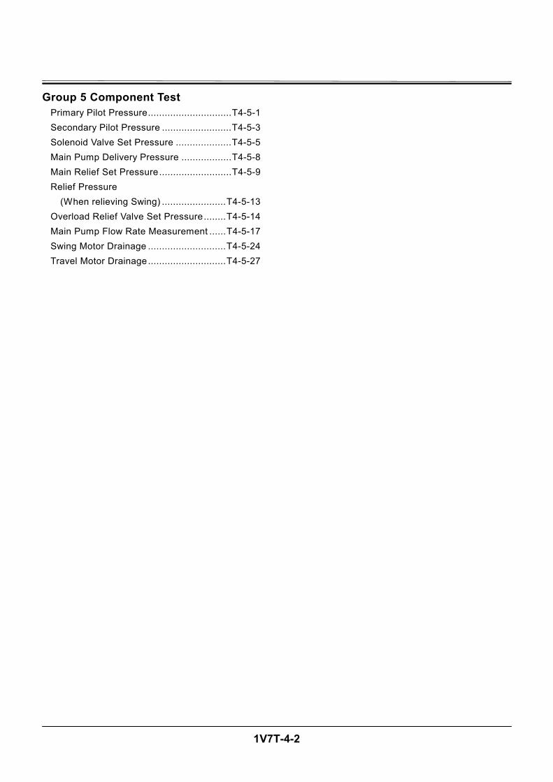
1V7T-4-2
Group 5 Component Test Primary Pilot Pressure..............................T4-5-1 Secondary Pilot Pressure .........................T4-5-3 Solenoid Valve Set Pressure ....................T4-5-5 Main Pump Delivery Pressure ..................T4-5-8 Main Relief Set Pressure..........................T4-5-9 Relief Pressure
(When relieving Swing) .......................T4-5-13 Overload Relief Valve Set Pressure........T4-5-14 Main Pump Flow Rate Measurement ......T4-5-17 Swing Motor Drainage ............................T4-5-24 Travel Motor Drainage............................T4-5-27
OPERATIONAL PERFORMANCE TEST / Introduction
T4-1-1
OPERATIONAL PERFORMANCE TESTS Use operational performance test procedure to quan-titatively check all system and functions on the ma-chine.
Purpose of Performance Tests 1. To comprehensively evaluate each operational
function by comparing the performance test data with the standard values.
2. According to the evaluation results, repair, adjust, or replace parts or components as necessary to restore the machine’s performance to the desired standard.
3. To economically operate the machine under op-timal conditions.
Kinds of Tests 1. Base machine performance test is to check the
operational performance of each system such as engine, travel, swing, and hydraulic cylinders.
2. Hydraulic component unit test is to check the op-erational performance of each component such as hydraulic pump, motor, and various kinds of valves.
Performance Standards “Performance Standard” is shown in tables to evalu-ate the performance test data.
Precautions for Evaluation of Test Data 1. To evaluate not only that the test data are correct,
but also in what range the test data are. 2. Be sure to evaluate the test data based on the
machine operation hours, kinds and state of work loads, and machine maintenance conditions.
The machine performance does not always deteriorate as the working hours increase. However, the machine performance is normally considered to reduce in pro-portion to the increase of the operation hours. Accord-ingly, restoring the machine performance by repair, adjustment, or replacement shall consider the number of the machine’s working hours.
Definition of “Performance Standard” 1. Operation speed values and dimensions of the
new machine. 2. Operational performance of new components
adjusted to specifications. Allowable errors will be indicated as necessary.
OPERATIONAL PERFORMANCE TEST / Introduction
T4-1-2
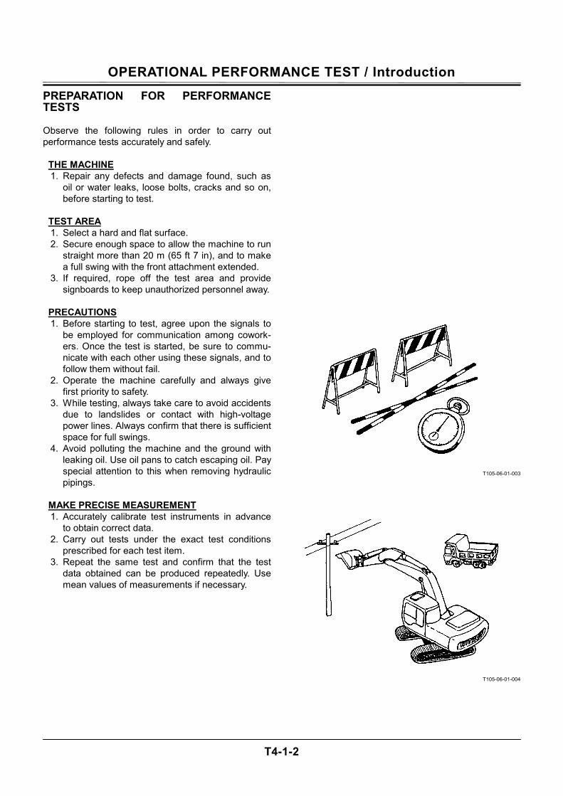
PREPARATION FOR PERFORMANCE TESTS Observe the following rules in order to carry out performance tests accurately and safely.
THE MACHINE 1. Repair any defects and damage found, such as
oil or water leaks, loose bolts, cracks and so on, before starting to test.
TEST AREA 1. Select a hard and flat surface. 2. Secure enough space to allow the machine to run
straight more than 20 m (65 ft 7 in), and to make a full swing with the front attachment extended.
3. If required, rope off the test area and provide signboards to keep unauthorized personnel away.
PRECAUTIONS 1. Before starting to test, agree upon the signals to
be employed for communication among cowork-ers. Once the test is started, be sure to commu-nicate with each other using these signals, and to follow them without fail.
2. Operate the machine carefully and always give first priority to safety.
3. While testing, always take care to avoid accidents due to landslides or contact with high-voltage power lines. Always confirm that there is sufficient space for full swings.
4. Avoid polluting the machine and the ground with leaking oil. Use oil pans to catch escaping oil. Pay special attention to this when removing hydraulic pipings.
MAKE PRECISE MEASUREMENT 1. Accurately calibrate test instruments in advance
to obtain correct data. 2. Carry out tests under the exact test conditions
prescribed for each test item. 3. Repeat the same test and confirm that the test
data obtained can be produced repeatedly. Use mean values of measurements if necessary.
T105-06-01-003
T105-06-01-004
OPERATIONAL PERFORMANCE TEST / Standard
T4-2-1
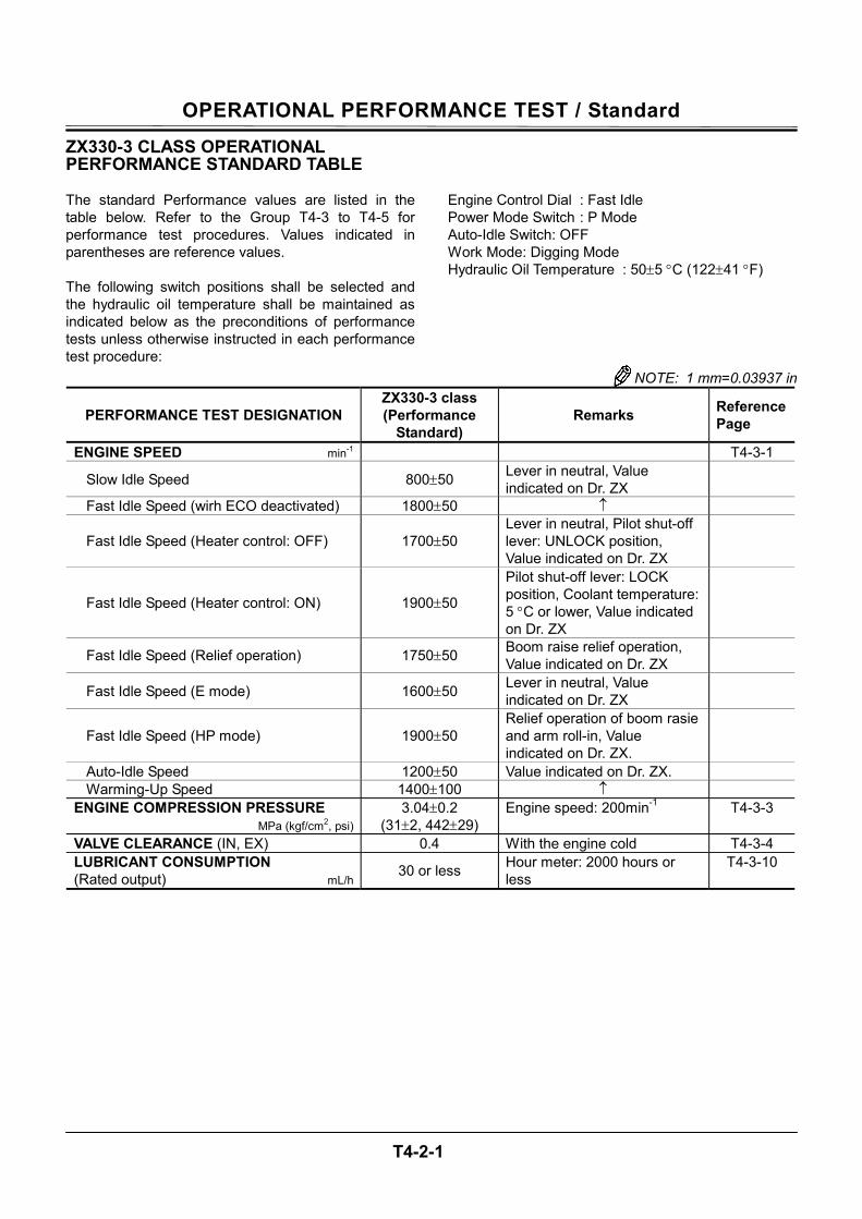
ZX330-3 CLASS OPERATIONAL PERFORMANCE STANDARD TABLE The standard Performance values are listed in the table below. Refer to the Group T4-3 to T4-5 for performance test procedures. Values indicated in parentheses are reference values. The following switch positions shall be selected and the hydraulic oil temperature shall be maintained as indicated below as the preconditions of performance tests unless otherwise instructed in each performance test procedure:
Engine Control Dial : Fast Idle Power Mode Switch : P Mode Auto-Idle Switch: OFF Work Mode: Digging Mode Hydraulic Oil Temperature : 50±5 °C (122±41 °F)
NOTE: 1 mm=0.03937 in
PERFORMANCE TEST DESIGNATION ZX330-3 class (Performance
Standard) Remarks Reference
Page
ENGINE SPEED min-1 T4-3-1
Slow Idle Speed 800±50 Lever in neutral, Value indicated on Dr. ZX
Fast Idle Speed (wirh ECO deactivated) 1800±50 ↑
Fast Idle Speed (Heater control: OFF) 1700±50 Lever in neutral, Pilot shut-off lever: UNLOCK position, Value indicated on Dr. ZX
Fast Idle Speed (Heater control: ON) 1900±50
Pilot shut-off lever: LOCK position, Coolant temperature: 5 °C or lower, Value indicated on Dr. ZX
Fast Idle Speed (Relief operation) 1750±50 Boom raise relief operation, Value indicated on Dr. ZX
Fast Idle Speed (E mode) 1600±50 Lever in neutral, Value indicated on Dr. ZX
Fast Idle Speed (HP mode) 1900±50 Relief operation of boom rasie and arm roll-in, Value indicated on Dr. ZX.
Auto-Idle Speed 1200±50 Value indicated on Dr. ZX. Warming-Up Speed 1400±100 ↑
ENGINE COMPRESSION PRESSURE MPa (kgf/cm2, psi)
3.04±0.2 (31±2, 442±29)
Engine speed: 200min-1 T4-3-3
VALVE CLEARANCE (IN, EX) 0.4 With the engine cold T4-3-4 LUBRICANT CONSUMPTION (Rated output) mL/h 30 or less Hour meter: 2000 hours or
less T4-3-10
OPERATIONAL PERFORMANCE TEST / Standard
T4-2-2
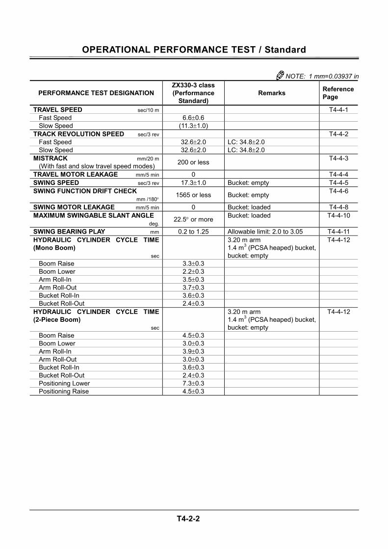
NOTE: 1 mm=0.03937 in
PERFORMANCE TEST DESIGNATION ZX330-3 class (Performance
Standard) Remarks Reference
Page
TRAVEL SPEED sec/10 m T4-4-1 Fast Speed 6.6±0.6 Slow Speed (11.3±1.0)
TRACK REVOLUTION SPEED sec/3 rev T4-4-2 Fast Speed 32.6±2.0 LC: 34.8±2.0 Slow Speed 32.6±2.0 LC: 34.8±2.0
MISTRACK mm/20 m (With fast and slow travel speed modes) 200 or less T4-4-3
TRAVEL MOTOR LEAKAGE mm/5 min 0 T4-4-4 SWING SPEED sec/3 rev 17.3±1.0 Bucket: empty T4-4-5 SWING FUNCTION DRIFT CHECK mm /180° 1565 or less Bucket: empty T4-4-6
SWING MOTOR LEAKAGE mm/5 min 0 Bucket: loaded T4-4-8 MAXIMUM SWINGABLE SLANT ANGLE deg. 22.5° or more Bucket: loaded T4-4-10
SWING BEARING PLAY mm 0.2 to 1.25 Allowable limit: 2.0 to 3.05 T4-4-11 HYDRAULIC CYLINDER CYCLE TIME (Mono Boom) sec
3.20 m arm 1.4 m3 (PCSA heaped) bucket, bucket: empty
T4-4-12
Boom Raise 3.3±0.3 Boom Lower 2.2±0.3 Arm Roll-In 3.5±0.3 Arm Roll-Out 3.7±0.3 Bucket Roll-In 3.6±0.3 Bucket Roll-Out 2.4±0.3
HYDRAULIC CYLINDER CYCLE TIME (2-Piece Boom) sec
3.20 m arm 1.4 m3 (PCSA heaped) bucket, bucket: empty
T4-4-12
Boom Raise 4.5±0.3 Boom Lower 3.0±0.3 Arm Roll-In 3.9±0.3 Arm Roll-Out 3.0±0.3 Bucket Roll-In 3.6±0.3 Bucket Roll-Out 2.4±0.3 Positioning Lower 7.3±0.3 Positioning Raise 4.5±0.3
OPERATIONAL PERFORMANCE TEST / Standard
T4-2-3
PERFORMANCE TEST DESIGNATION ZX330-3 class (Performance
Standard) Remarks Reference
Page
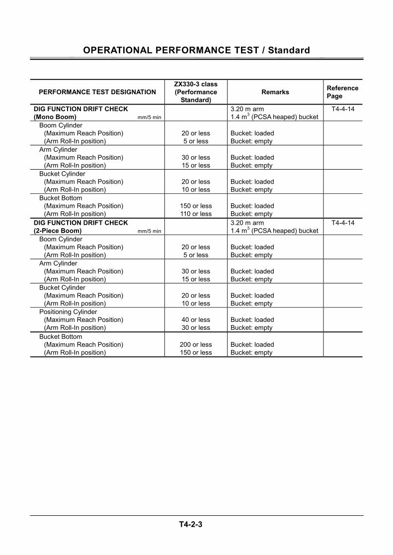
DIG FUNCTION DRIFT CHECK (Mono Boom) mm/5 min
3.20 m arm 1.4 m3 (PCSA heaped) bucket
T4-4-14
Boom Cylinder (Maximum Reach Position) (Arm Roll-In position)
20 or less 5 or less
Bucket: loaded Bucket: empty
Arm Cylinder (Maximum Reach Position) (Arm Roll-In position)
30 or less 15 or less
Bucket: loaded Bucket: empty
Bucket Cylinder (Maximum Reach Position) (Arm Roll-In position)
20 or less 10 or less
Bucket: loaded Bucket: empty
Bucket Bottom (Maximum Reach Position) (Arm Roll-In position)
150 or less 110 or less
Bucket: loaded Bucket: empty
DIG FUNCTION DRIFT CHECK (2-Piece Boom) mm/5 min
3.20 m arm 1.4 m3 (PCSA heaped) bucket
T4-4-14
Boom Cylinder (Maximum Reach Position) (Arm Roll-In position)
20 or less 5 or less
Bucket: loaded Bucket: empty
Arm Cylinder (Maximum Reach Position) (Arm Roll-In position)
30 or less 15 or less
Bucket: loaded Bucket: empty
Bucket Cylinder (Maximum Reach Position) (Arm Roll-In position)
20 or less 10 or less
Bucket: loaded Bucket: empty
Positioning Cylinder (Maximum Reach Position) (Arm Roll-In position)
40 or less 30 or less
Bucket: loaded Bucket: empty
Bucket Bottom (Maximum Reach Position) (Arm Roll-In position)
200 or less 150 or less
Bucket: loaded Bucket: empty
OPERATIONAL PERFORMANCE TEST / Standard
T4-2-4
NOTE: 1 mm=0.03937 in
PERFORMANCE TEST DESIGNATION ZX330-3 class (Performance
Standard) Remarks Reference
Page
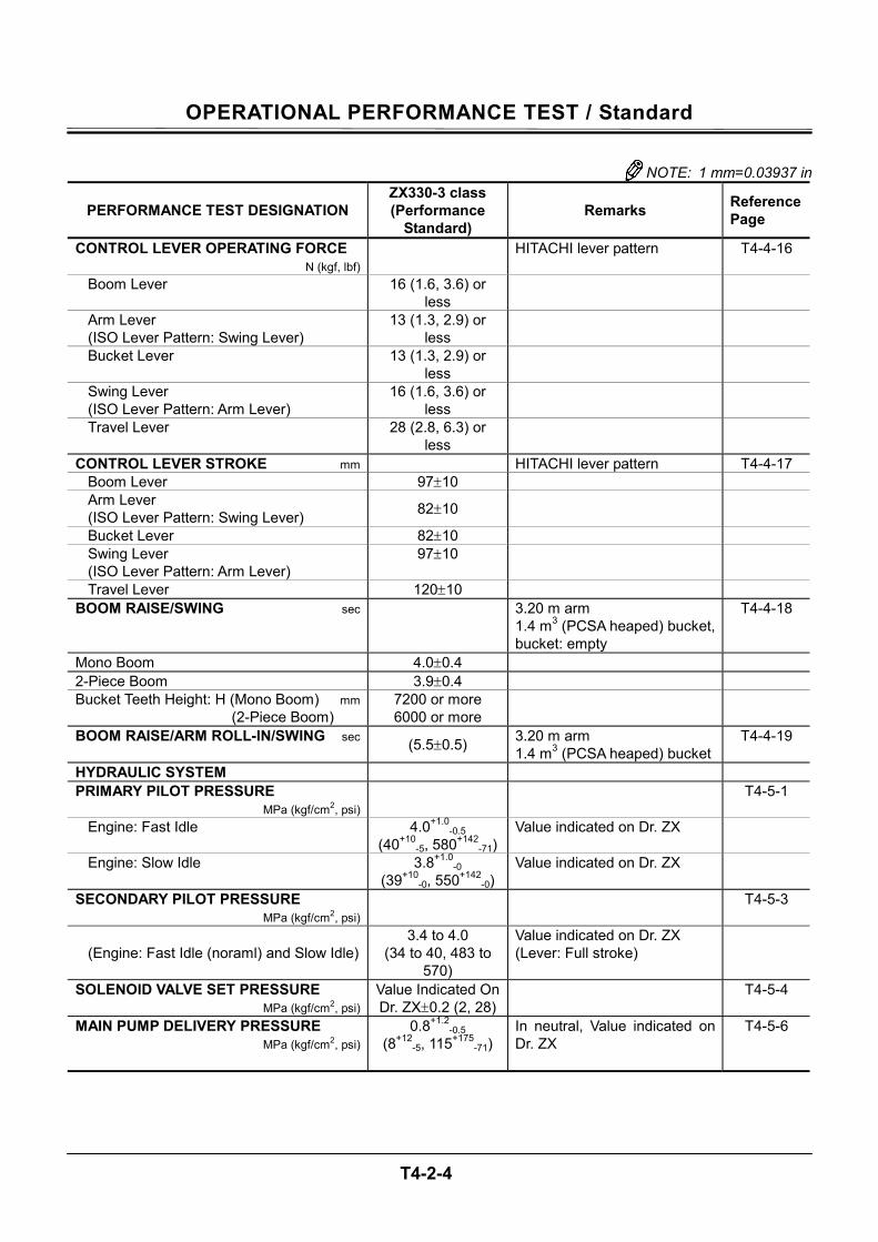
CONTROL LEVER OPERATING FORCE N (kgf, lbf)
HITACHI lever pattern T4-4-16
Boom Lever 16 (1.6, 3.6) or less
Arm Lever (ISO Lever Pattern: Swing Lever)
13 (1.3, 2.9) or less
Bucket Lever 13 (1.3, 2.9) or less
Swing Lever (ISO Lever Pattern: Arm Lever)
16 (1.6, 3.6) or less
Travel Lever 28 (2.8, 6.3) or less
CONTROL LEVER STROKE mm HITACHI lever pattern T4-4-17 Boom Lever 97±10 Arm Lever (ISO Lever Pattern: Swing Lever) 82±10
Bucket Lever 82±10 Swing Lever (ISO Lever Pattern: Arm Lever)
97±10
Travel Lever 120±10 BOOM RAISE/SWING sec
3.20 m arm 1.4 m3 (PCSA heaped) bucket, bucket: empty
T4-4-18
Mono Boom 4.0±0.4 2-Piece Boom 3.9±0.4 Bucket Teeth Height: H (Mono Boom) mm (2-Piece Boom)
7200 or more 6000 or more
BOOM RAISE/ARM ROLL-IN/SWING sec (5.5±0.5) 3.20 m arm
1.4 m3 (PCSA heaped) bucket T4-4-19
HYDRAULIC SYSTEM PRIMARY PILOT PRESSURE MPa (kgf/cm2, psi) T4-5-1
Engine: Fast Idle 4.0+1.0-0.5
(40+10-5, 580+142
-71)Value indicated on Dr. ZX
Engine: Slow Idle 3.8+1.0-0
(39+10-0, 550+142
-0)Value indicated on Dr. ZX
SECONDARY PILOT PRESSURE MPa (kgf/cm2, psi) T4-5-3
(Engine: Fast Idle (noraml) and Slow Idle)
3.4 to 4.0 (34 to 40, 483 to
570)
Value indicated on Dr. ZX (Lever: Full stroke)
SOLENOID VALVE SET PRESSURE MPa (kgf/cm2, psi)
Value Indicated On Dr. ZX±0.2 (2, 28)
T4-5-4
MAIN PUMP DELIVERY PRESSURE MPa (kgf/cm2, psi)
0.8+1.2-0.5
(8+12-5, 115+175
-71) In neutral, Value indicated on Dr. ZX
T4-5-6
OPERATIONAL PERFORMANCE TEST / Standard
T4-2-5
NOTE: 1 mm=0.03937 in
PERFORMANCE TEST DESIGNATION ZX330-3 class (Performance
Standard) Remarks
Reference Page
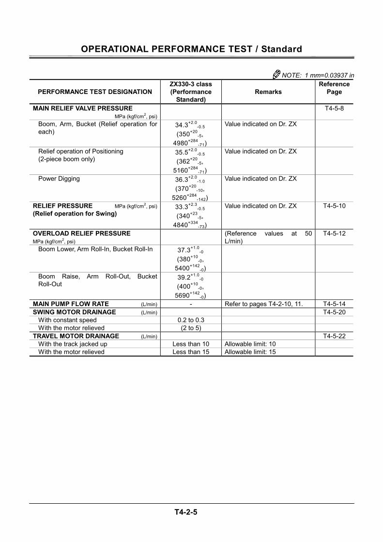
MAIN RELIEF VALVE PRESSURE MPa (kgf/cm2, psi)
T4-5-8
Boom, Arm, Bucket (Relief operation for each)
34.3+2.0-0.5
(350+20-5,
4980+284-71)
Value indicated on Dr. ZX
Relief operation of Positioning (2-piece boom only)
35.5+2.0-0.5
(362+20-5,
5160+284-71)
Value indicated on Dr. ZX
Power Digging 36.3+2.0-1.0
(370+20-10,
5260+284-142)
Value indicated on Dr. ZX
RELIEF PRESSURE MPa (kgf/cm2, psi) (Relief operation for Swing)
33.3+2.3-0.5
(340+23-5,
4840+334-73)
Value indicated on Dr. ZX T4-5-10
OVERLOAD RELIEF PRESSURE MPa (kgf/cm2, psi)
(Reference values at 50 L/min)
T4-5-12
Boom Lower, Arm Roll-In, Bucket Roll-In 37.3+1.0-0
(380+10-0,
5400+142-0)
Boom Raise, Arm Roll-Out, Bucket Roll-Out
39.2+1.0-0
(400+10-0,
5690+142-0)
MAIN PUMP FLOW RATE (L/min) - Refer to pages T4-2-10, 11. T4-5-14 SWING MOTOR DRAINAGE (L/min) T4-5-20
With constant speed 0.2 to 0.3 With the motor relieved (2 to 5)
TRAVEL MOTOR DRAINAGE (L/min) T4-5-22 With the track jacked up Less than 10 Allowable limit: 10 With the motor relieved Less than 15 Allowable limit: 15
OPERATIONAL PERFORMANCE TEST / Standard
T4-2-6
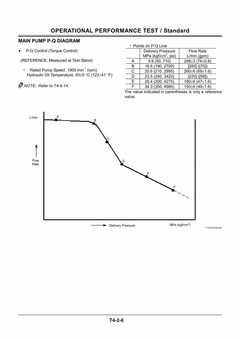
MAIN PUMP P-Q DIAGRAM • P-Q Control (Torque Control)
(REFERENCE: Measured at Test Stand)
• Rated Pump Speed: 1900 min-1 (rpm) Hydraulic Oil Temperature: 50±5 °C (122±41 °F)
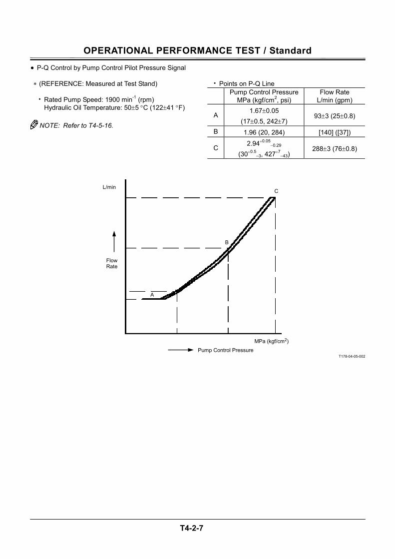
NOTE: Refer to T4-5-14.
• Points on P-Q Line
Delivery Pressure
MPa (kgf/cm2, psi) Flow Rate
L/min (gpm) A 4.9 (50, 710) 288±3 (76±0.8) B 18.6 (190, 2700) [285] ([75]) C 20.6 (210, 2995) 260±6 (69±1.6) D 23.5 (240, 3420) [220] ([58]) E 29.4 (300, 4275) 180±6 (47±1.6) F 34.3 (350, 4980) 150±6 (40±1.6)
The value indicated in parentheses is only a reference value.
T178-04-05-001
MPa (kgf/cm2)
L/min
Flow Rate
Delivery Pressure
A B
C
D
E
F
OPERATIONAL PERFORMANCE TEST / Standard
T4-2-7
• P-Q Control by Pump Control Pilot Pressure Signal
∗ (REFERENCE: Measured at Test Stand)
• Rated Pump Speed: 1900 min-1 (rpm) Hydraulic Oil Temperature: 50±5 °C (122±41 °F)
NOTE: Refer to T4-5-16.
• Points on P-Q Line Pump Control Pressure
MPa (kgf/cm2, psi) Flow Rate
L/min (gpm)
A1.67±0.05
(17±0.5, 242±7) 93±3 (25±0.8)
B 1.96 (20, 284) [140] ([37])
C2.94+0.05
−0.29 (30+0.5
−3, 427+7−43)
288±3 (76±0.8)
T178-04-05-002
MPa (kgf/cm2)
L/min
Pump Control Pressure
A
B
C
Flow Rate
OPERATIONAL PERFORMANCE TEST / Standard
T4-2-8
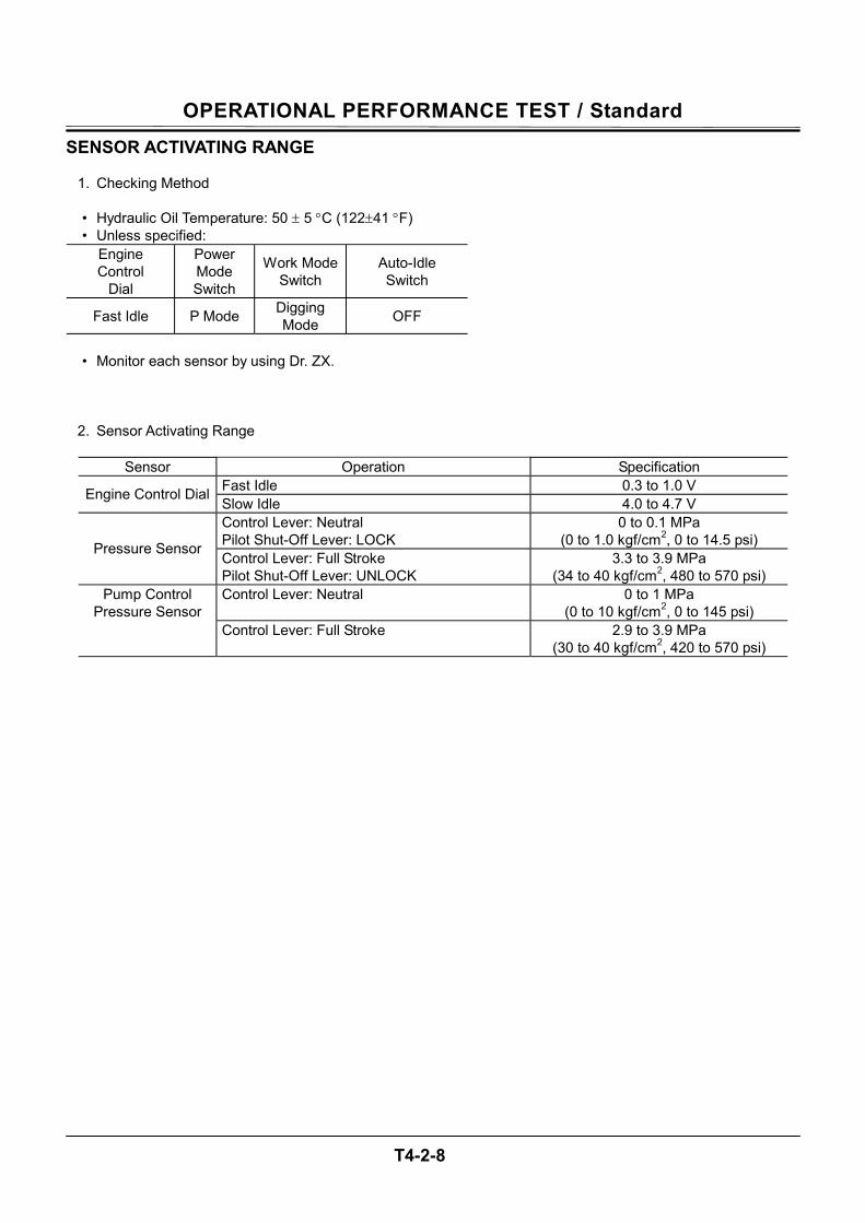
SENSOR ACTIVATING RANGE
1. Checking Method
• Hydraulic Oil Temperature: 50 ± 5 °C (122±41 °F) • Unless specified:
Engine Control
Dial
Power Mode Switch
Work Mode Switch
Auto-Idle Switch
Fast Idle P Mode Digging Mode OFF
• Monitor each sensor by using Dr. ZX.
2. Sensor Activating Range
Sensor Operation Specification
Fast Idle 0.3 to 1.0 V Engine Control Dial Slow Idle 4.0 to 4.7 V Control Lever: Neutral Pilot Shut-Off Lever: LOCK
0 to 0.1 MPa (0 to 1.0 kgf/cm2, 0 to 14.5 psi) Pressure Sensor
Control Lever: Full Stroke Pilot Shut-Off Lever: UNLOCK
3.3 to 3.9 MPa (34 to 40 kgf/cm2, 480 to 570 psi)
Control Lever: Neutral 0 to 1 MPa (0 to 10 kgf/cm2, 0 to 145 psi)
Pump Control Pressure Sensor
Control Lever: Full Stroke 2.9 to 3.9 MPa (30 to 40 kgf/cm2, 420 to 570 psi)
OPERATIONAL PERFORMANCE TEST / Engine Test
T4-3-1
ENGINE SPEED
Summary 1. Measure the engine speed by using the monitor
unit or Dr. ZX.) 2. Measure the engine speeds in each mode.
NOTE: If the engine speed is not adjusted correctly,
all other performance data will be unreli-able. Consequently, measure the engine speed before performing all other tests in order to check that the engine speed meets specification.
Preparation: 1. Select the service menu of monitor (In case of Dr.
ZX, install Dr. ZX first). 2. Warm up the machine until coolant temperature
reaches 50 °C (122 °F) or more, and hydraulic oil temperature is 50±5 °C (122±41 °F).
OPERATIONAL PERFORMANCE TEST / Engine Test
T4-3-2
Measurement: 1. Measure the items as shown in the table below. 2. When measuring, set the switch and test condi-
tion as shown in the table below in response to the engine speed to be measured.
Evaluation: Refer to Operational Performance Standard in Group T4-2.
Remedy: Refer to Troubleshooting B in Group T5-4.
NOTE: ECO stands for the auto engine speed re-
duction system by 100 min-1.
Item Engine Control Dial
Power Mode Switch
Auto-Idle Switch Work Mode Test Conditions
Slow Idle Min. Speed P OFF Digging Mode
Fast Idle (With ECO deac-tivated) Max. Speed P OFF Digging
Mode
Check in the Dr. ZX special functions with ECO deacti-vated. Measure engine speed with the lever in neutral.
Fast Idle (Heater control: OFF) Max. Speed P OFF Digging
Mode
Move the pilot shut-off lever to the UNLOCK position. Meas-ure engine speed with the lever in neutral.
Fast Idle (Heater control: ON) Max. Speed P OFF Digging
Mode
Move the pilot shut-off lever to the LOCK position. Engine speed can be measured only when coolant temperature is 5°C (41 °F) or lower.
Fast Idle (Relief operation) Max. Speed P OFF Digging
Mode Measure engine speed while relieving the boom raise circuit.
Fast Idle (E mode) Max. Speed E Mode OFF Digging
Mode
Fast Idle (HP mode) Max. Speed HP Mode OFF Digging
Mode Measure engine speed while relieving the boom raise circuit.
Auto-Idle Max. Speed P ON Digging Mode
Check engine speed 4 sec-onds after returning all control levers to neutral.
Warming Up Min. Speed P OFF Digging Mode
Engine speed can be meas-ured only when oil temperature is 0 °C (32 °F) or lower.
Switch Panel:
T1V1-04-03-001
Monitor Unit:
T1V1-05-01-007
Engine Control Dial
Auto-Idle Switch
Power Mode Switch
Digging Mode
OPERATIONAL PERFORMANCE TEST / Engine Test
T4-3-3
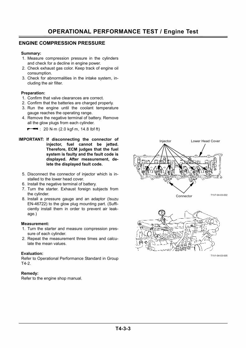
ENGINE COMPRESSION PRESSURE
Summary: 1. Measure compression pressure in the cylinders
and check for a decline in engine power. 2. Check exhaust gas color. Keep track of engine oil
consumption. 3. Check for abnormalities in the intake system, in-
cluding the air filter.
Preparation: 1. Confirm that valve clearances are correct. 2. Confirm that the batteries are charged properly. 3. Run the engine until the coolant temperature
gauge reaches the operating range. 4. Remove the negative terminal of battery. Remove
all the glow plugs from each cylinder. : 20 N⋅m (2.0 kgf⋅m, 14.8 lbf⋅ft)
IMPORTANT: If disconnecting the connector of
injector, fuel cannot be jetted. Therefore, ECM judges that the fuel system is faulty and the fault code is displayed. After measurement, de-lete the displayed fault code.
5. Disconnect the connector of injector which is in-
stalled to the lower head cover. 6. Install the negative terminal of battery. 7. Turn the starter. Exhaust foreign subjects from
the cylinder. 8. Install a pressure gauge and an adaptor (Isuzu
EN-46722) to the glow plug mounting part. (Suffi-ciently install them in order to prevent air leak-age.)
Measurement: 1. Turn the starter and measure compression pres-
sure of each cylinder. 2. Repeat the measurement three times and calcu-
late the mean values.
Evaluation: Refer to Operational Performance Standard in Group T4-2.
Remedy: Refer to the engine shop manual.
T1V7-04-03-002
T1V1-04-03-005
Connector
Injector Lower Head Cover
OPERATIONAL PERFORMANCE TEST / Engine Test
T4-3-4
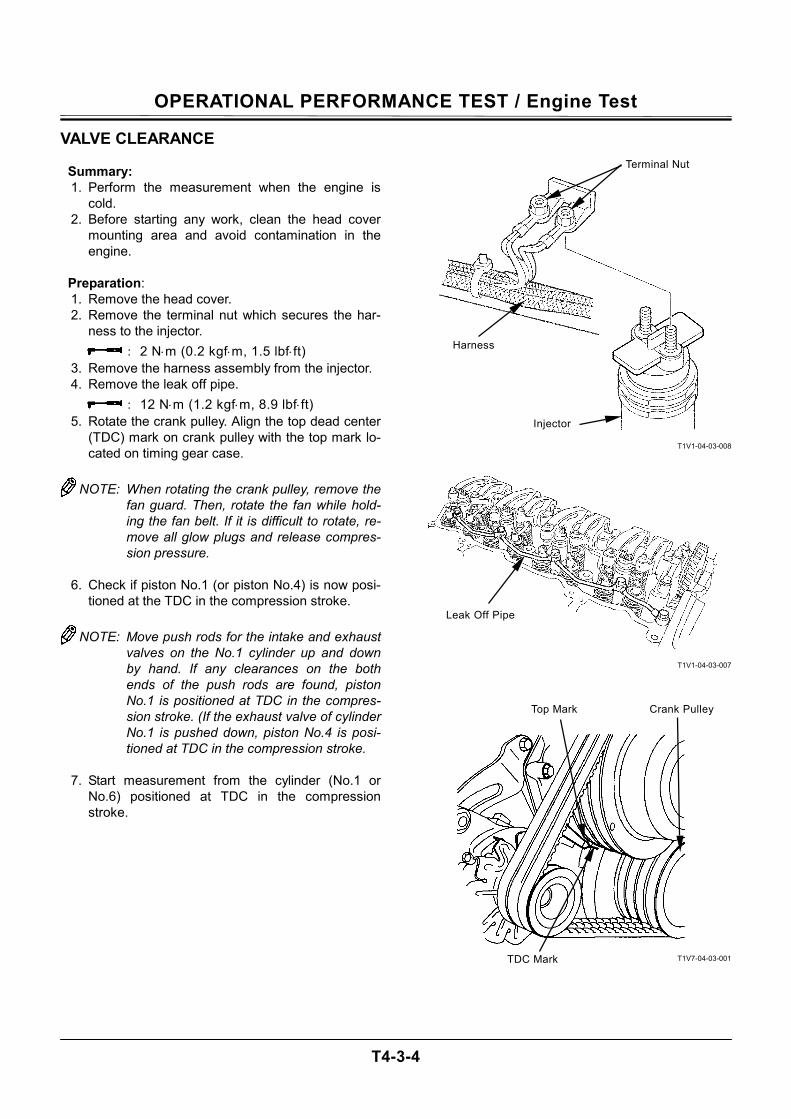
VALVE CLEARANCE
Summary: 1. Perform the measurement when the engine is
cold. 2. Before starting any work, clean the head cover
mounting area and avoid contamination in the engine.
Preparation: 1. Remove the head cover. 2. Remove the terminal nut which secures the har-
ness to the injector. : 2 N⋅m (0.2 kgf⋅m, 1.5 lbf⋅ft)
3. Remove the harness assembly from the injector. 4. Remove the leak off pipe.
: 12 N⋅m (1.2 kgf⋅m, 8.9 lbf⋅ft) 5. Rotate the crank pulley. Align the top dead center
(TDC) mark on crank pulley with the top mark lo-cated on timing gear case.
NOTE: When rotating the crank pulley, remove the
fan guard. Then, rotate the fan while hold-ing the fan belt. If it is difficult to rotate, re-move all glow plugs and release compres-sion pressure.
6. Check if piston No.1 (or piston No.4) is now posi-
tioned at the TDC in the compression stroke.
NOTE: Move push rods for the intake and exhaust valves on the No.1 cylinder up and down by hand. If any clearances on the both ends of the push rods are found, piston No.1 is positioned at TDC in the compres-sion stroke. (If the exhaust valve of cylinder No.1 is pushed down, piston No.4 is posi-tioned at TDC in the compression stroke.
7. Start measurement from the cylinder (No.1 or
No.6) positioned at TDC in the compression stroke.
T1V1-04-03-008
T1V1-04-03-007
T1V7-04-03-001
Harness
Terminal Nut
Injector
Leak Off Pipe
Top Mark Crank Pulley
TDC Mark
OPERATIONAL PERFORMANCE TEST / Engine Test
T4-3-5
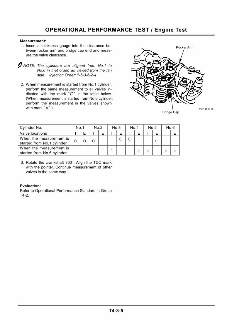
Measurement: 1. Insert a thickness gauge into the clearance be-
tween rocker arm and bridge cap end and meas-ure the valve clearance.
NOTE: The cylinders are aligned from No.1 to
No.6 in that order, as viewed from the fan side. Injection Order: 1-5-3-6-2-4
2. When measurement is started from No.1 cylinder,
perform the same measurement to all valves in-dicated with the mark “” in the table below. (When measurement is started from No.6 cylinder, perform the measurement in the valves shown with mark “×”.)
T17P-04-03-001
Cylinder No. No.1 No.2 No.3 No.4 No.5 No.6 Valve locations I E I E I E I E I E I E When the measurement is started from No.1 cylinder
When the measurement is started from No.6 cylinder × × × × × ×
3. Rotate the crankshaft 360°. Align the TDC mark
with the pointer. Continue measurement of other valves in the same way.
Evaluation: Refer to Operational Performance Standard in Group T4-2.
Rocker Arm
Bridge Cap
OPERATIONAL PERFORMANCE TEST / Engine Test
T4-3-6
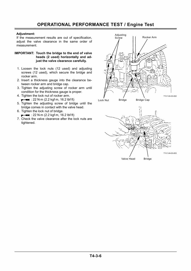
Adjustment: If the measurement results are out of specification, adjust the valve clearance in the same order of measurement.
IMPORTANT: Touch the bridge to the end of valve
heads (2 used) horizontally and ad-just the valve clearance carefully.
1. Loosen the lock nuts (12 used) and adjusting
screws (12 used), which secure the bridge and rocker arm.
2. Insert a thickness gauge into the clearance be-tween rocker arm and bridge cap.
3. Tighten the adjusting screw of rocker arm until condition for the thickness gauge is proper.
4. Tighten the lock nut of rocker arm. : 22 N⋅m (2.2 kgf⋅m, 16.2 lbf⋅ft)
5. Tighten the adjusting screw of bridge until the bridge comes in contact with the valve head.
6. Tighten the lock nut of bridge. : 22 N⋅m (2.2 kgf⋅m, 16.2 lbf⋅ft)
7. Check the valve clearance after the lock nuts are tightened.
T1V1-04-03-002
T1V1-04-03-003
Valve Head Bridge
Rocker Arm
Bridge Bridge Cap
Adjusting Screw
Lock Nut
OPERATIONAL PERFORMANCE TEST / Engine Test
T4-3-7
LUBRICANT CONSUMPTION
Measuring Method 1. Place the machine on level firm ground and leave
the machine for at least one hour in order to let the lubricant lower to the oil pan when the engine stops. At this time, confirm that the machine is level by using a leveler.
2. Record read-out A (unit: hour) of the hour meter. 3. Replenish the lubricant up to the high-level
gauge. 4. Operate the machine for at least 100 hours or un-
til the oil level lowers to the low-level gauge. IMPORTANT: Keep the machine-leaving time in
Step 1 above. 5. Place the machine on level firm ground and leave
the machine for at least one hour in order to let the lubricant lower to the oil pan when the engine stops. At this time, confirm that the machine is level by using a leveler.
6. Record read-out B (unit: hour) of the hour meter. 7. Replenish the lubricant up to the high-level gauge
while measuring the oil-replenishing volume C. NOTE: When measuring, use a high-precision
measuring cylinder or the like.
8. Determine lubricant consumption from the fol-lowing equation:
Oil replenishing volume (C) [mL] / Operating hours (B-A) [hr]
Evaluation: Refer to Operational Performance Standard in Group T4-2.

OPERATIONAL PERFORMANCE TEST / Engine Test
T4-3-8
(Blank)
OPERATIONAL PERFORMANCE TEST / Excavator Test
T4-4-1
TRAVEL SPEED
Summary: Measure the time required for the excavator to travel a 20 m (65.6 ft) test track and check the performance of travel device systems (from main pump to travel motor).
Preparation: 1. Adjust the track sag on both tracks equally. 2. Prepare a flat and solid test track 10 m (33 ft) in
length with extra length of 3 to 5 m (9.8 to 16 ft) on both ends for machine acceleration and de-celeration.
3. With the arm and bucket fully extended, hold the bucket 0.3 to 0.5 m (12 to 20 in) above the ground.
4. Maintain hydraulic oil temperature at 50±5 °C (122±41 °F).
T105-06-03-001
Measurement: 1. Measure both slow and fast speeds of the
machine. 2. Select the following switch positions: Travel Mode Switch
Engine Control
Dial
Power Mode Switch
Auto-Idle Switch
Work Mode
Slow Mode Fast Idle P Mode OFF Digging
Mode Fast Mode Fast Idle P Mode OFF Digging
Mode
3. Start traveling the machine in the acceleration zone with the travel levers to full stroke.
4. Measure the time required to travel 10 m (33 ft). 5. After measuring the forward travel speed, turn the
upperstructure 180° and measure the reverse travel speed.
6. Repeat the measurement three times in each di-rection and calculate the average values.
Evaluation: Refer to the Operational Performance Standard in Group T4-2. Remedy: Refer to the Troubleshooting B in Group T5-4.
DecelerationZone 3 to 5 m
Arm Rolled-In, Bucket Rolled-In
Bucket Height: 0.3 to 0.5 m End
Start 10 m
Acceleration Zone 3 to 5 m
OPERATIONAL PERFORMANCE TEST / Excavator Test
T4-4-2
TRACK REVOLUTION SPEED
Summary: Measure the track revolution cycle time with the track raised off ground and check the performance of travel device systems (from main pump to travel motor).
Preparation: 1. Adjust the track sag of both side tracks equally. 2. On the track to be measured, put the mark on
one shoe by using a piece of chalk or cloth. 3. Jack up the track to be measured as illustrated.
M104-07-067
CAUTION: Securely support the raised machine by using the blocks.
4. Maintain the hydraulic oil temperature at 50±5 °C
(122±41 °F).
Measurement: 1. Measure both slow and fast travel speeds of the
machine. 2. Select the following switch positions: Travel Mode Switch
Engine Control
Dial
Power Mode Switch
Auto-Idle Switch
Work Mode
Slow Mode Fast Idle P Mode OFF Digging
Mode Fast Mode Fast Idle P Mode OFF Digging
Mode 3. Operate the travel control lever of the track to be
measured to full stroke. 4. Measure the time required for 3 revolutions in
both directions after a constant track revolution speed is obtained.
5. Repeat the measurement three times and calculate the average values.
Evaluation: Refer to the Operational Performance Standard in Group T4-2.
NOTE: The measurement data obtained through
the raised track revolution test may have wide variations. Therefore, the evaluation based on the results obtained from the 10 m travel speed check described before is more recommendable.
Remedy: Refer to the Troubleshooting B in Group T5-4.
90 to 110°
OPERATIONAL PERFORMANCE TEST / Excavator Test
T4-4-3
MISTRACK CHECK
Summary: 1. Allow the machine to travel 20 m (65.6 ft).
Measure the maximum tread deviation from the tread chord line drawn between the travel start and end points and check the performance of travel device systems (from main pump to travel motor).
2. If measured on a concrete surface, the tread deviation has a trend to decrease.
Preparation: 1. Adjust the track sag of both tracks equally. 2. Provide a flat, solid test yard 20 m (65.6 ft) in
length, with extra length of 3 to 5 m (9.8 to 16 ft) on both ends for machine acceleration and deceleration.
T105-06-03-022
3. With the arm and bucket fully extended, hold the
bucket 0.3 to 0.5 m (12 to 20 in) above the ground.
4. Maintain the hydraulic oil temperature at 50±5 °C (122±41 °F).
Measurement: 1. Measure both slow and fast travel speeds of the
machine. 2. Select the following switch positions: Travel Mode Switch
Engine Control
Dial
Power Mode Switch
Auto-Idle Switch
Work Mode
Slow Mode Fast Idle P Mode OFF Digging
Mode Fast Mode Fast Idle P Mode OFF Digging
Mode
3. Start traveling the machine in the acceleration zone with the travel levers at full stroke.
4. Measure the maximum distance between a straight 20 m (65.6 ft) tread chord line and the tread made by the machine.
5. After measuring the tracking in forward travel, turn the upperstructure 180° and measure in reverse travel.
6. Repeat the measurement three times and calculate the average values.
Evaluation: Refer to the Operational Performance Standard in Group T4-2.
Remedy: Refer to the Troubleshooting B in Group T5-4.
Maximum Distance
20 m
AccelerationZone: 3 to 5 m
OPERATIONAL PERFORMANCE TEST / Excavator Test
T4-4-4
TRAVEL PARKING LEAKAGE
Summary: Measure the parking brake function on a specified slope.
Preparation: 1. The surface of test slope shall be even with a
gradient of 20 % (11.31°). 2. With the arm and bucket fully extended, hold the
bucket 0.2 to 0.3 m (8 to 12 in) above the ground. 3. Maintain the hydraulic oil temperature at 50±5 °C
(122±41 °F).
Measurement: 1. Measure the travel parking brake slip amount
while parked. 2. Climb the slope and place the travel levers in
neutral. 3. Stop the engine. 4. After the machine stops, put the matching marks
on a track link or shoe, and the track side frame. 5. After 5 minutes, measure the distance between
marks on the track link or shoe and the track frame.
Evaluation: Refer to the Operational Performance Standard in Group T4-2.
T105-06-03-004
T105-06-03-006
0.2 to 0.3 m
The matching marks on track frame and shoe when the ma-chine comes to a stop.
Displacement measured after 5 minutes.
OPERATIONAL PERFORMANCE TEST / Excavator Test
T4-4-5
SWING SPEED
Summary: Measure the time required to swing three complete turns and check the performance of swing device systems (from main pump to swing motor).
Preparation: 1. Check lubrication of the swing gear and swing
bearing. 2. Place the machine on flat, solid ground with
ample space for swinging. Do not conduct this test on slopes.
3. With the arm fully retracted and the bucket fully extended, hold the bucket so that the height of the bucket pin is the same as the boom foot pin. The bucket must be empty.
T105-06-03-013
NOTE: In case a sufficient space for the meas-
urement is difficult to find, carry out the measurement with the boom fully raised and the arm fully rolled-in.
T178-04-03-001
4. Maintain the hydraulic oil temperature at 50±5 °C
(122±41 °F).
CAUTION: Prevent personal injury. Always make sure that the area is clear and that co-workers are out of the swing area before starting the measurement.
Measurement: 1. Select the following switch positions:
Engine Con-trol Dial
Power Mode Switch
Auto-Idle Switch Work Mode
Fast Idle P Mode OFF Digging Mode
2. Operate the swing control lever fully. 3. Measure the time required to swing 3 turns in one
direction. 4. Operate swing control lever fully in the opposite
direction and measure the time required for 3 turns.
5. Repeat the measurement three times and calculate the average values.
Evaluation: Refer to the Operational Performance Standard in Group T4-2.
Remedy: Refer to the Troubleshooting B in Group T5-4.
The same height as the boom foot pin height
OPERATIONAL PERFORMANCE TEST / Excavator Test
T4-4-6
SWING FUNCTION DRIFT CHECK
Summary: 1. Measure the swing drift on swing bearing outer
circumference when stopping after a 180° full-speed swing and check the performance of swing brake valve.
2. The mechanical brake for seing parking brake is equipped for the swing motor.
Preparation: 1. Check lubrication of the swing gear and swing
bearing. 2. Place the machine on flat, solid ground with
ample space for swinging. Do not conduct this test on a slope.
3. With the arm fully retracted and the bucket fully extended, hold the bucket so that the height of the bucket pin is the same as the boom foot pin. The bucket must be empty.
4. Put the matching marks on the swing bearing outer circumference (upperstructure side) and the track frame.
5. Swing the upperstructure 180°. 6. Maintain the hydraulic oil temperature at 50±5 °C
(122±41 °F).
CAUTION: Prevent personal injury. Always make sure that the area is clear and that co-workers are out of the swing area before starting the measurement.
T105-06-03-008
T105-06-03-009
Put the matching marks on swing bearing outer circumfer-ence and track frame.
Before start the measurement, swing the upperstructure 180°
OPERATIONAL PERFORMANCE TEST / Excavator Test
T4-4-7
Measurement: 1. Select the following switch positions:
Engine Con-trol Dial
Power Mode Switch
Auto-Idle Switch Work Mode
Fast Idle P Mode OFF Digging Mode
2. Operate the swing control lever fully and return it
to the neutral position when the mark on upperstructure aligns with that on track frame after swinging 180° .
3. Measure the distance between the two marks. 4. Align the marks again and swing 180°. Then test
in the opposite direction. 5. Repeat the measurement three times each and
calculate the average values.
Evaluation: Refer to the Operational Performance Standard in Group T4-2. Remedy: Refer to the Troubleshooting B in Group T5-4.
T105-06-03-010
Mark on Swing Bearing
Mark on Track Frame
Measure Difference Between Marks
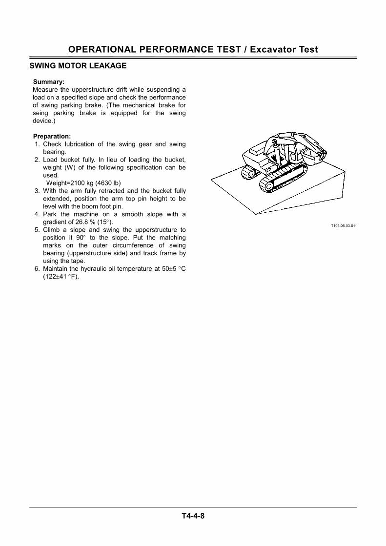
OPERATIONAL PERFORMANCE TEST / Excavator Test
T4-4-8
SWING MOTOR LEAKAGE
Summary: Measure the upperstructure drift while suspending a load on a specified slope and check the performance of swing parking brake. (The mechanical brake for seing parking brake is equipped for the swing device.)
Preparation: 1. Check lubrication of the swing gear and swing
bearing. 2. Load bucket fully. In lieu of loading the bucket,
weight (W) of the following specification can be used. Weight=2100 kg (4630 lb)
3. With the arm fully retracted and the bucket fully extended, position the arm top pin height to be level with the boom foot pin.
4. Park the machine on a smooth slope with a gradient of 26.8 % (15°).
5. Climb a slope and swing the upperstructure to position it 90° to the slope. Put the matching marks on the outer circumference of swing bearing (upperstructure side) and track frame by using the tape.
6. Maintain the hydraulic oil temperature at 50±5 °C (122±41 °F).
T105-06-03-011
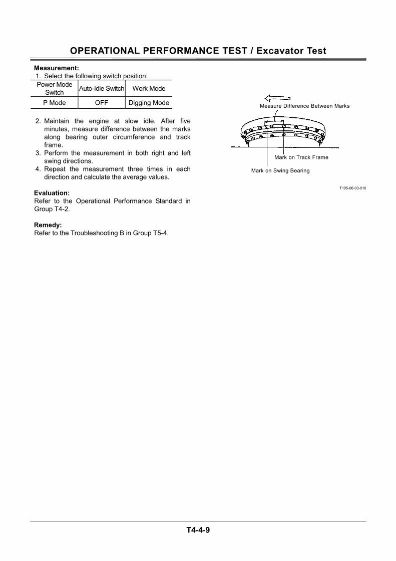
OPERATIONAL PERFORMANCE TEST / Excavator Test
T4-4-9
Measurement: 1. Select the following switch position: Power Mode
Switch Auto-Idle Switch Work Mode
P Mode OFF Digging Mode
2. Maintain the engine at slow idle. After five minutes, measure difference between the marks along bearing outer circumference and track frame.
3. Perform the measurement in both right and left swing directions.
4. Repeat the measurement three times in each direction and calculate the average values.
Evaluation: Refer to the Operational Performance Standard in Group T4-2.
Remedy: Refer to the Troubleshooting B in Group T5-4.
T105-06-03-010
Mark on Swing Bearing
Mark on Track Frame
Measure Difference Between Marks
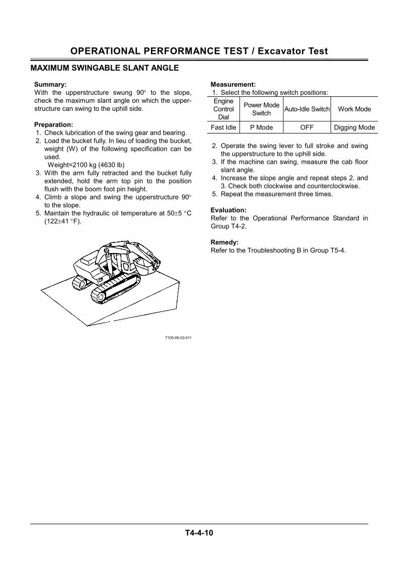
OPERATIONAL PERFORMANCE TEST / Excavator Test
T4-4-10
MAXIMUM SWINGABLE SLANT ANGLE
Summary: With the upperstructure swung 90° to the slope, check the maximum slant angle on which the upper-structure can swing to the uphill side.
Preparation: 1. Check lubrication of the swing gear and bearing. 2. Load the bucket fully. In lieu of loading the bucket,
weight (W) of the following specification can be used. Weight=2100 kg (4630 lb)
3. With the arm fully retracted and the bucket fully extended, hold the arm top pin to the position flush with the boom foot pin height.
4. Climb a slope and swing the upperstructure 90° to the slope.
5. Maintain the hydraulic oil temperature at 50±5 °C (122±41 °F).
T105-06-03-011
Measurement: 1. Select the following switch positions: Engine Control
Dial
Power Mode Switch Auto-Idle Switch Work Mode
Fast Idle P Mode OFF Digging Mode
2. Operate the swing lever to full stroke and swing the upperstructure to the uphill side.
3. If the machine can swing, measure the cab floor slant angle.
4. Increase the slope angle and repeat steps 2. and 3. Check both clockwise and counterclockwise.
5. Repeat the measurement three times.
Evaluation: Refer to the Operational Performance Standard in Group T4-2. Remedy: Refer to the Troubleshooting B in Group T5-4.

OPERATIONAL PERFORMANCE TEST / Excavator Test
T4-4-11
(Blank)
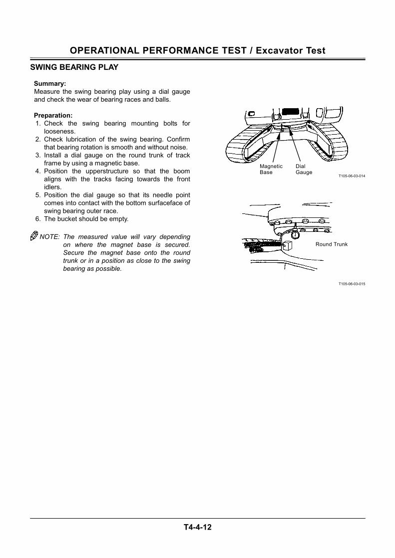
OPERATIONAL PERFORMANCE TEST / Excavator Test
T4-4-12
SWING BEARING PLAY
Summary: Measure the swing bearing play using a dial gauge and check the wear of bearing races and balls.
Preparation: 1. Check the swing bearing mounting bolts for
looseness. 2. Check lubrication of the swing bearing. Confirm
that bearing rotation is smooth and without noise. 3. Install a dial gauge on the round trunk of track
frame by using a magnetic base. 4. Position the upperstructure so that the boom
aligns with the tracks facing towards the front idlers.
5. Position the dial gauge so that its needle point comes into contact with the bottom surfaceface of swing bearing outer race.
6. The bucket should be empty.
NOTE: The measured value will vary depending on where the magnet base is secured. Secure the magnet base onto the round trunk or in a position as close to the swing bearing as possible.
T105-06-03-014
T105-06-03-015
Dial Gauge
Magnetic Base
Round Trunk
OPERATIONAL PERFORMANCE TEST / Excavator Test
T4-4-13
Measurement: 1. With the arm fully retracted and the bucket fully
extended, hold the bucket 100 mm above the ground. Record dial gauge reading (h1).
2. Lower the bucket to the ground and raise the front idler 0.5 m (20 in) by using the front attachment. Record dial gauge reading (h2).
3. Calculate bearing play (H) from this data (h1 and h2) as follows: H=h2-h1
Evaluation: Refer to the Operational Performance Standard in Group T4-2.
T105-06-03-007
T105-06-03-017
Measurement: (h2)
Measurement: (h1)
100 mm
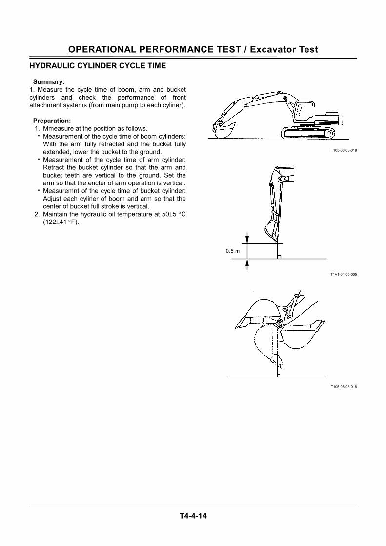
OPERATIONAL PERFORMANCE TEST / Excavator Test
T4-4-14
HYDRAULIC CYLINDER CYCLE TIME
Summary: 1. Measure the cycle time of boom, arm and bucket cylinders and check the performance of front attachment systems (from main pump to each cyliner).
Preparation: 1. Mmeasure at the position as follows. • Measurement of the cycle time of boom cylinders:
With the arm fully retracted and the bucket fully extended, lower the bucket to the ground.
• Measurement of the cycle time of arm cylinder: Retract the bucket cylinder so that the arm and bucket teeth are vertical to the ground. Set the arm so that the encter of arm operation is vertical.
• Measuremnt of the cycle time of bucket cylinder: Adjust each cyliner of boom and arm so that the center of bucket full stroke is vertical.
2. Maintain the hydraulic oil temperature at 50±5 °C (122±41 °F).
T105-06-03-018
T1V1-04-05-005
T105-06-03-018
0.5 m
OPERATIONAL PERFORMANCE TEST / Excavator Test
T4-4-15
Measurement: 1. Select the following switch positions: Engine Control
Dial
Power Mode Switch Auto-Idle Switch Work Mode
Fast Idle P Mode OFF Digging Mode
2. Measure the cylinder cycle times as follows: (Cylinder full stroke includes cylinder cushioning zone.)
• Boom cylinder: Operate the boom control lever to full stroke. Measure the time to raise and lower the boom.
• Arm cylinder: Operate the arm control lever to full stroke. Measure the time to roll in and roll out the arm.
• Bucket cylinder: Operate the bucket control lever to full stroke. Measure the time to roll in and roll out the bucket.
3. Repeat each measurement three times and
calculate the average values.
Evaluation: Refer to the Operational Performance Standard in Group T4-2. Remedy: Refer to the Troubleshooting B in Group T5-4.
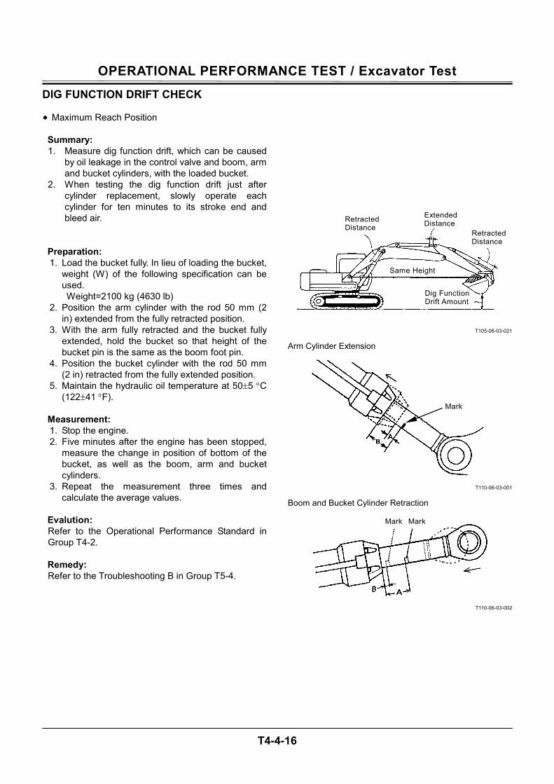
OPERATIONAL PERFORMANCE TEST / Excavator Test
T4-4-16
DIG FUNCTION DRIFT CHECK • Maximum Reach Position Summary: 1. Measure dig function drift, which can be caused
by oil leakage in the control valve and boom, arm and bucket cylinders, with the loaded bucket.
2. When testing the dig function drift just after cylinder replacement, slowly operate each cylinder for ten minutes to its stroke end and bleed air.
Preparation: 1. Load the bucket fully. In lieu of loading the bucket,
weight (W) of the following specification can be used. Weight=2100 kg (4630 lb)
2. Position the arm cylinder with the rod 50 mm (2 in) extended from the fully retracted position.
3. With the arm fully retracted and the bucket fully extended, hold the bucket so that height of the bucket pin is the same as the boom foot pin.
4. Position the bucket cylinder with the rod 50 mm (2 in) retracted from the fully extended position.
5. Maintain the hydraulic oil temperature at 50±5 °C (122±41 °F).
Measurement: 1. Stop the engine. 2. Five minutes after the engine has been stopped,
measure the change in position of bottom of the bucket, as well as the boom, arm and bucket cylinders.
3. Repeat the measurement three times and calculate the average values.
Evalution: Refer to the Operational Performance Standard in Group T4-2. Remedy: Refer to the Troubleshooting B in Group T5-4.
T105-06-03-021
T110-06-03-001
T110-06-03-002
Extended Distance
Retracted Distance
Dig Function Drift Amount
Same Height
Retracted Distance
Arm Cylinder Extension
Mark
Boom and Bucket Cylinder Retraction
Mark Mark
OPERATIONAL PERFORMANCE TEST / Excavator Test
T4-4-17
• Arm Roll-In Position Summary: 1. Measure dig function drift, which can be caused
by oil leakage in the control valve and boom, arm and bucket cylinders.
2. When testing the dig function drift just after cylinder replacement, slowly operate each cylinder for ten minutes to its stroke end and bleed air.
Preparation: 1. The bucket must be empty. 2. With the arm fully extended and the bucket fully
extended, lower the boom until the arm tip is 1 m (40 in) above the ground.
3. position the bucket cylinder with the rod 50 mm (2 in) retracted from the fully extended position.
4. Maintain the hydraulic oil temperature at 50±5 °C (122±41 °F).
Measurement: 1. Stop the engine. 2. Five minutes after the engine has been stopped,
measure the change in position of bottom of the arm tip, as well as the boom, arm and bucket cylinders.
3. Repeat the measuemrent three times and calculate the average values.
Evalution: Refer to the Operational Performance Standard in Group T4-2. Remedy: Refer to the Troubleshooting B in Group T5-4.
T173-04-03-001
T110-06-03-002
1 m
Cylinder Retraction
Mark Mark
OPERATIONAL PERFORMANCE TEST / Excavator Test
T4-4-18
CONTROL LEVER OPERATING FORCE
Summary: 1. Measure a play and operating condition of each
control lever. 2. Measure the maximum operating force of front
attachment control lever. 3. Measure the operating force at the grip center of
each control lever.
Preparation: Maintain the hydraulic oil temperature at 50±5 °C (122±41 °F).
CAUTION: Prevent personal injury. Always make sure that the area is clear and that co-workers are out of the swing area before starting the measurement.
T107-06-03-003
T107-06-03-004
OPERATIONAL PERFORMANCE TEST / Excavator Test
T4-4-19
Measurement: 1. Measure each control lever. 2. Select the following switch positions: Engine Control
Dial
Power Mode Switch Auto-Idle Switch Work Mode
Fast Idle P Mode OFF Digging Mode
3. In case of boom (raise), arm and bucket lever, measure the maximum operating force for each with each actuator relieved.
4. In case of boom (lower) lever, measure the maximum operating force with the boom (lower) relieved by jacking up the machine in a safe area.
5. In case of swing lever, measure the maximum operating force with swing relieved after securing the front attachment to prevent swinging.
6. In case of travel lever, raise the track to be measured. Measure the maximum operating force required.
7. Repeat the measurement three times and calcu-late the average values.
Evalution: Refer to the Orerational Performance Standard in Group T4-2.
OPERATIONAL PERFORMANCE TEST / Excavator Test
T4-4-20
CONTROL LEVER STROKE
Summary: 1. Measure a play and operating condition of each
control lever. 2. Measure the lever stroke at the grip center of
each control lever. 3. In case lever stroke play is present in the neutral
position, add half (1/2) the play present to both side lever strokes.
Preparation: Maintain the hydraulic oil temperature at 50±5 °C (122±41 °F).
Measurement: 1. Stop the engine. 2. Measure each lever stroke from neutral to the
stroke end of each control lever of boom, arm, bucket, swing and travel.
3. Repeat the measuement three times and calculate the average values.
Evalution: Refer to the Orerational Performance Standard in Group T4-2.
T107-06-03-005

OPERATIONAL PERFORMANCE TEST / Excavator Test
T4-4-21
(Blank)
OPERATIONAL PERFORMANCE TEST / Excavator Test
T4-4-22
COMBINED OPERATION OF BOOM RAISE / SWING FUNCTION CHECK
Summary: 1. Check boom raise and swing movement and
speeds while operating both functions simultaneously.
2. Make sure that the cylinders do not hesitate while operating the cylinder with the engine running at fast idle.
Preparation: 1. With the arm fully retracted and the bucket fully
extended, lower the bucket onto the ground. The bucket must be empty.
2. Maintain the hydraulic oil temperature at 50±5 °C (122±41 °F).
CAUTION: Prevent personal injury. Always make sure that the area is clear and that co-workers are out of the swing area before starting the measurement.
T107-06-03-009
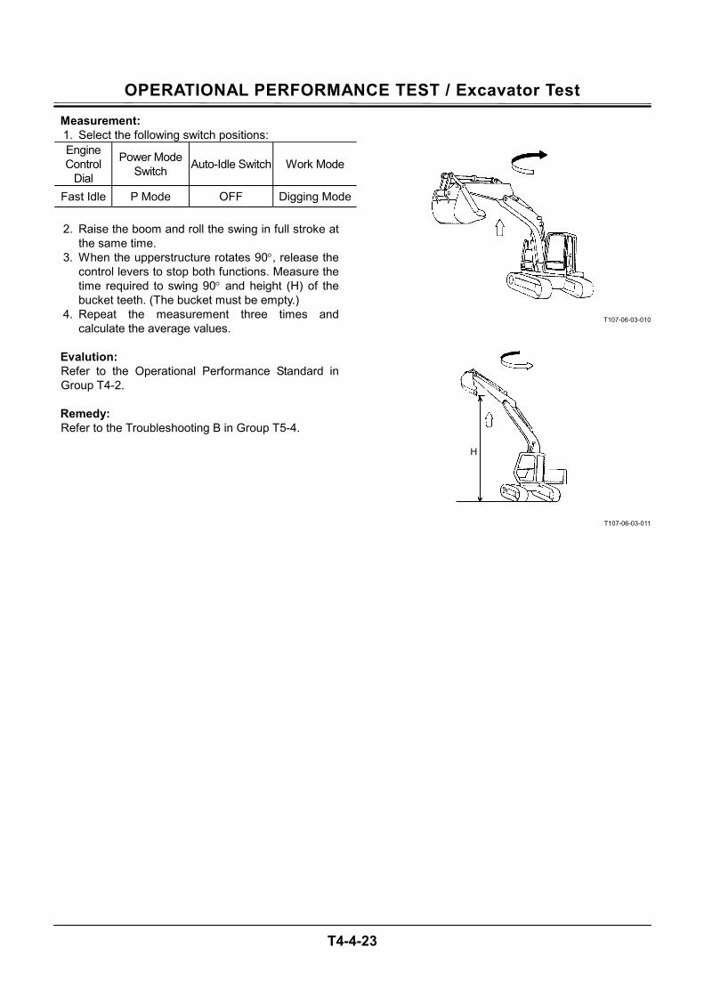
OPERATIONAL PERFORMANCE TEST / Excavator Test
T4-4-23
Measurement: 1. Select the following switch positions: Engine Control
Dial
Power Mode Switch Auto-Idle Switch Work Mode
Fast Idle P Mode OFF Digging Mode
2. Raise the boom and roll the swing in full stroke at the same time.
3. When the upperstructure rotates 90°, release the control levers to stop both functions. Measure the time required to swing 90° and height (H) of the bucket teeth. (The bucket must be empty.)
4. Repeat the measurement three times and calculate the average values.
Evalution: Refer to the Operational Performance Standard in Group T4-2. Remedy: Refer to the Troubleshooting B in Group T5-4.
T107-06-03-010
T107-06-03-011
H
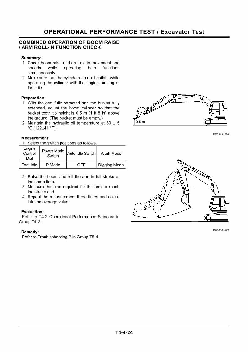
OPERATIONAL PERFORMANCE TEST / Excavator Test
T4-4-24
COMBINED OPERATION OF BOOM RAISE / ARM ROLL-IN FUNCTION CHECK
Summary: 1. Check boom raise and arm roll-in movement and
speeds while operating both functions simultaneously.
2. Make sure that the cylinders do not hesitate while operating the cylinder with the engine running at fast idle.
Preparation: 1. With the arm fully retracted and the bucket fully
extended, adjust the boom cylinder so that the bucket tooth tip height is 0.5 m (1 ft 8 in) above the ground. (The bucket must be empty.)
2. Maintain the hydraulic oil temperature at 50 ± 5 °C (122±41 °F).
Measurement: 1. Select the switch positions as follows. Engine Control
Dial
Power Mode Switch Auto-Idle Switch Work Mode
Fast Idle P Mode OFF Digging Mode
2. Raise the boom and roll the arm in full stroke at the same time.
3. Measure the time required for the arm to reach the stroke end.
4. Repeat the measurement three times and calcu-late the average value.
Evaluation: Refer to T4-2 Operational Performance Standard in
Group T4-2.
Remedy: Refer to Troubleshooting B in Group T5-4.
T107-06-03-006
T107-06-03-008
0.5 m
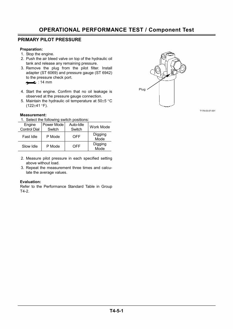
OPERATIONAL PERFORMANCE TEST / Component Test
T4-5-1
PRIMARY PILOT PRESSURE
Preparation: 1. Stop the engine. 2. Push the air bleed valve on top of the hydraulic oil
tank and release any remaining pressure. 3. Remove the plug from the pilot filter. Install
adapter (ST 6069) and pressure gauge (ST 6942) to the pressure check port.
: 14 mm
4. Start the engine. Confirm that no oil leakage is observed at the pressure gauge connection.
5. Maintain the hydraulic oil temperature at 50±5 °C (122±41 °F).
Measurement: 1. Select the following switch positions:
Engine Control Dial
Power Mode Switch
Auto-Idle Switch Work Mode
Fast Idle P Mode OFF Digging Mode
Slow Idle P Mode OFF Digging Mode
2. Measure pilot pressure in each specified setting
above without load. 3. Repeat the measurement three times and calcu-
late the average values.
Evaluation: Refer to the Performance Standard Table in Group T4-2.
T178-03-07-001
Plug
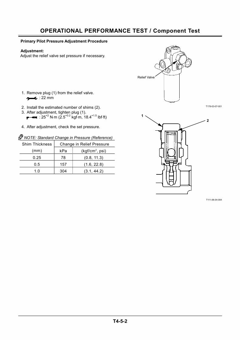
OPERATIONAL PERFORMANCE TEST / Component Test
T4-5-2
Primary Pilot Pressure Adjustment Procedure
Adjustment: Adjust the relief valve set pressure if necessary.
1. Remove plug (1) from the relief valve. : 22 mm
2. Install the estimated number of shims (2). 3. After adjustment, tighten plug (1).
: 25+2 N⋅m (2.5+0.2 kgf⋅m, 18.4+1.5 lbf⋅ft)
4. After adjustment, check the set pressure.
NOTE: Standard Change in Pressure (Reference) Change in Relief Pressure Shim Thickness
(mm) kPa (kgf/cm2, psi)
0.25 78 (0.8, 11.3)
0.5 157 (1.6, 22.8)
1.0 304 (3.1, 44.2)
T178-03-07-001
T111-06-04-004
Relief Valve
21
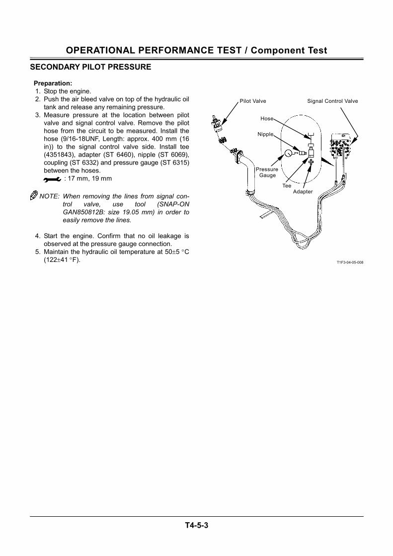
OPERATIONAL PERFORMANCE TEST / Component Test
T4-5-3
SECONDARY PILOT PRESSURE
Preparation: 1. Stop the engine. 2. Push the air bleed valve on top of the hydraulic oil
tank and release any remaining pressure. 3. Measure pressure at the location between pilot
valve and signal control valve. Remove the pilot hose from the circuit to be measured. Install the hose (9/16-18UNF, Length: approx. 400 mm (16 in)) to the signal control valve side. Install tee (4351843), adapter (ST 6460), nipple (ST 6069), coupling (ST 6332) and pressure gauge (ST 6315) between the hoses.
: 17 mm, 19 mm
NOTE: When removing the lines from signal con-trol valve, use tool (SNAP-ON GAN850812B: size 19.05 mm) in order to easily remove the lines.
4. Start the engine. Confirm that no oil leakage is
observed at the pressure gauge connection. 5. Maintain the hydraulic oil temperature at 50±5 °C
(122±41 °F).
T1F3-04-05-008
Pilot Valve Signal Control Valve
Hose
Nipple
Pressure Gauge
Tee Adapter
OPERATIONAL PERFORMANCE TEST / Component Test
T4-5-4
Measurement: 1. Select the following switch positions:
Engine Control Dial
Power Mode Switch
Auto-Idle Switch Work Mode
Fast Idle P Mode OFF Digging Mode
Slow Idle P Mode OFF Digging Mode
2. Measure pilot pressure by using a pressure gauge with the corresponding control lever oper-ated to full stroke.
3. Repeat the measurement three times and calcu-late the average values.
Evaluation: Refer to the Performance Standard Table in Group T4-2.
Remedy: Refer to the Troubleshooting B in Group T5-4.
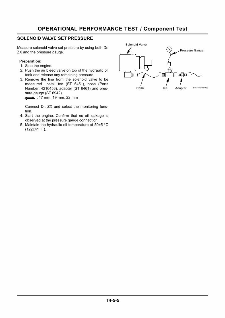
OPERATIONAL PERFORMANCE TEST / Component Test
T4-5-5
SOLENOID VALVE SET PRESSURE Measure solenoid valve set pressure by using both Dr. ZX and the pressure gauge.
Preparation: 1. Stop the engine. 2. Push the air bleed valve on top of the hydraulic oil
tank and release any remaining pressure. 3. Remove the line from the solenoid valve to be
measured. Install tee (ST 6451), hose (Parts Number: 4216453), adapter (ST 6461) and pres-sure gauge (ST 6942).
: 17 mm, 19 mm, 22 mm
Connect Dr. ZX and select the monitoring func-tion.
4. Start the engine. Confirm that no oil leakage is observed at the pressure gauge connection.
5. Maintain the hydraulic oil temperature at 50±5 °C (122±41 °F).
T157-05-04-002
Hose AdapterTee
Pressure Gauge
Solenoid Valve
OPERATIONAL PERFORMANCE TEST / Component Test
T4-5-6
Measurement: 1. Select the following switch positions:
Engine Control Dial
Power Mode Switch
Auto-Idle Switch Work Mode
Fast Idle P Mode OFF Digging Mode
Slow Idle P Mode OFF Digging Mode
2. Operate as instructed below for each measuring
solenoid valve: Solenoid Valve SG: Turn the power digging switch ON and OFF. Solenoid Valve SI: Travel: Stop Solenoid Valve SF: Relief combined operation of boom raise and arm roll-in. Solenoid Valve SC: Combined operation of swing and arm roll-in.
3. Read the values on both Dr. ZX and the pressure
gauge. 4. Repeat the measurement three times and calcu-
late the average values.
Evaluation: Refer to the performance Standard Table in Group T4-2.
T1V1-03-07-007
SC SF SI SG
OPERATIONAL PERFORMANCE TEST / Component Test
T4-5-7
Solenoid Valve Adjustment Procedure IMPORTANT: As O-ring is damaged and oil leak-
age may cause, do not loosen ad-justing screw (8) excessively. Do not loosen adjusting screw (8) more than 2 turns.
1. Loosen lock nut (7). Turn adjusting screw (8) and adjust the set pressure.
2. After adjustment, tighten lock nut (7). : 10 mm : 3 mm : 3 N⋅m (0.3 kgf⋅m, 2.2 lbf⋅ft)
3. After adjustment, check the set pressure. NOTE: Standard Change in Pressure (Reference)
Screw Turns 1/4 1/2 3/4 1 kPa 69 137 206 275(kgf/cm2) (0.7) (1.4) (2.1) (2.8)Change in
Pressure (psi) (10) (20) (30) (40)
T1V1-04-05-004
T1V1-04-05-003
W107-02-05-129
Pressure Increase
Pressure Decrease
8 7
2.0 mm (0.079 in) or less from end of Lock Nut
7
8
O-Ring
8
7
OPERATIONAL PERFORMANCE TEST / Component Test
T4-5-8
MAIN PUMP DELIVERY PRESSURE The main pump delivery pressure can also be meas-ured by using Dr. ZX.
Preparation: 1. Stop the engine. 2. Push the air bleed valve on top of the hydraulic oil
tank and release any remaining pressure. 3. Remove the plug of pressure check port from the
main pump delivery port. Install adapter (ST 6069), hose (ST 6943) and pressure gauge (ST 6941).
: 6 mm
Connect Dr. ZX and select the monitoring func-tion.
4. Start the engine. Confirm that no oil leakage is observed at the pressure gauge connection.
5. Maintain the hydraulic oil temperature at 50±5 °C (122±41 °F).
Measurement: 1. Select the following switch positions:
Engine Control Dial
Power Mode Switch
Auto-Idle Switch Work Mode
Fast Idle P Mode OFF Digging Mode
2. Measure pressure with the control levers in neu-
tral without load. 3. Repeat the measurement three times and calcu-
late the average values.
Evaluation: Refer to the Performance Standard Table in Group T4-2.
Remedy: Refer to the Troubleshooting B in Group T5-4.
T1V7-04-05-001
Plug
OPERATIONAL PERFORMANCE TEST / Component Test
T4-5-9
MAIN RELIEF SET PRESSURE Summary:
Measure the main relief valve set pressure at the de-livery port in main pump. (The main relief set pressure can also be measured by using Dr. ZX.)
Preparation: 1. Stop the engine. 2. Push the air bleed valve on top of the hydraulic oil
tank and release any remaining pressure. 3. Remove the plug of pressure check port from the
main pump delivery port. Install adapter (ST 6069), hose (ST 6943) and pressure gauge (ST 6941).
: 6 mm
Connect Dr. ZX and select the monitoring func-tion.
4. Start the engine. Confirm that no oil leakage is observed at the pressure gauge connection.
5. Maintain the hydraulic oil temperature at 50±5 °C (122±41 °F).
T1V7-04-05-001
Plug
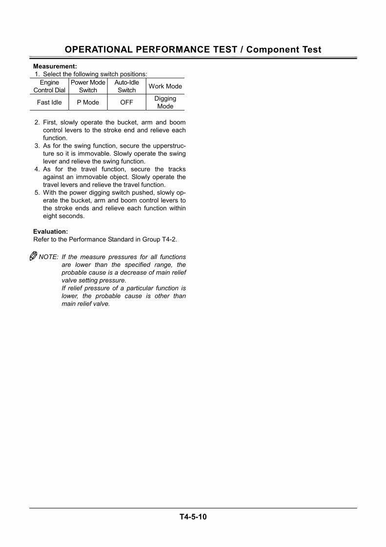
OPERATIONAL PERFORMANCE TEST / Component Test
T4-5-10
Measurement: 1. Select the following switch positions:
Engine Control Dial
Power Mode Switch
Auto-Idle Switch Work Mode
Fast Idle P Mode OFF Digging Mode
2. First, slowly operate the bucket, arm and boom
control levers to the stroke end and relieve each function.
3. As for the swing function, secure the upperstruc-ture so it is immovable. Slowly operate the swing lever and relieve the swing function.
4. As for the travel function, secure the tracks against an immovable object. Slowly operate the travel levers and relieve the travel function.
5. With the power digging switch pushed, slowly op-erate the bucket, arm and boom control levers to the stroke ends and relieve each function within eight seconds.
Evaluation: Refer to the Performance Standard in Group T4-2.
NOTE: If the measure pressures for all functions are lower than the specified range, the probable cause is a decrease of main relief valve setting pressure. If relief pressure of a particular function is lower, the probable cause is other than main relief valve.
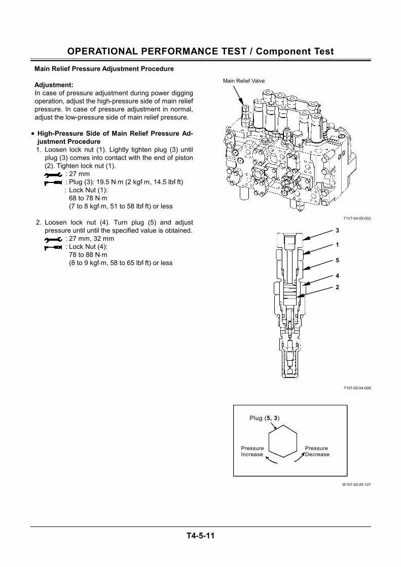
OPERATIONAL PERFORMANCE TEST / Component Test
T4-5-11
Main Relief Pressure Adjustment Procedure
Adjustment: In case of pressure adjustment during power digging operation, adjust the high-pressure side of main relief pressure. In case of pressure adjustment in normal, adjust the low-pressure side of main relief pressure.
• High-Pressure Side of Main Relief Pressure Ad-
justment Procedure 1. Loosen lock nut (1). Lightly tighten plug (3) until
plug (3) comes into contact with the end of piston (2). Tighten lock nut (1).
: 27 mm : Plug (3): 19.5 N⋅m (2 kgf⋅m, 14.5 lbf⋅ft)
: Lock Nut (1): 68 to 78 N⋅m (7 to 8 kgf⋅m, 51 to 58 lbf⋅ft) or less
2. Loosen lock nut (4). Turn plug (5) and adjust
pressure until until the specified value is obtained. : 27 mm, 32 mm : Lock Nut (4):
78 to 88 N⋅m (8 to 9 kgf⋅m, 58 to 65 lbf⋅ft) or less
T1V7-04-05-002
T157-05-04-009
W107-02-05-127
Main Relief Valve
3
1
5
4
2
Pressure Decrease
Pressure Increase
Plug (5, 3)
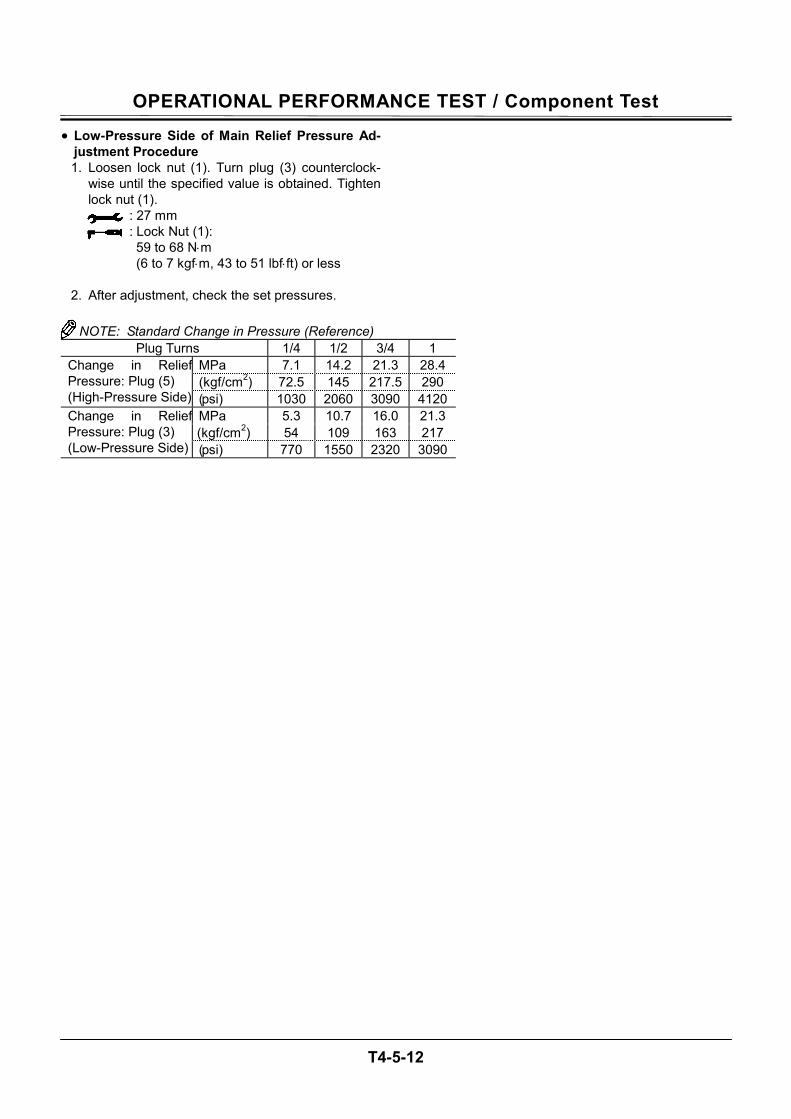
OPERATIONAL PERFORMANCE TEST / Component Test
T4-5-12
• Low-Pressure Side of Main Relief Pressure Ad-justment Procedure 1. Loosen lock nut (1). Turn plug (3) counterclock-
wise until the specified value is obtained. Tighten lock nut (1).
: 27 mm : Lock Nut (1):
59 to 68 N⋅m (6 to 7 kgf⋅m, 43 to 51 lbf⋅ft) or less
2. After adjustment, check the set pressures.
NOTE: Standard Change in Pressure (Reference)
Plug Turns 1/4 1/2 3/4 1 MPa 7.1 14.2 21.3 28.4(kgf/cm2) 72.5 145 217.5 290
Change in ReliefPressure: Plug (5) (High-Pressure Side) (psi) 1030 2060 3090 4120
MPa 5.3 10.7 16.0 21.3(kgf/cm2) 54 109 163 217
Change in ReliefPressure: Plug (3) (Low-Pressure Side) (psi) 770 1550 2320 3090
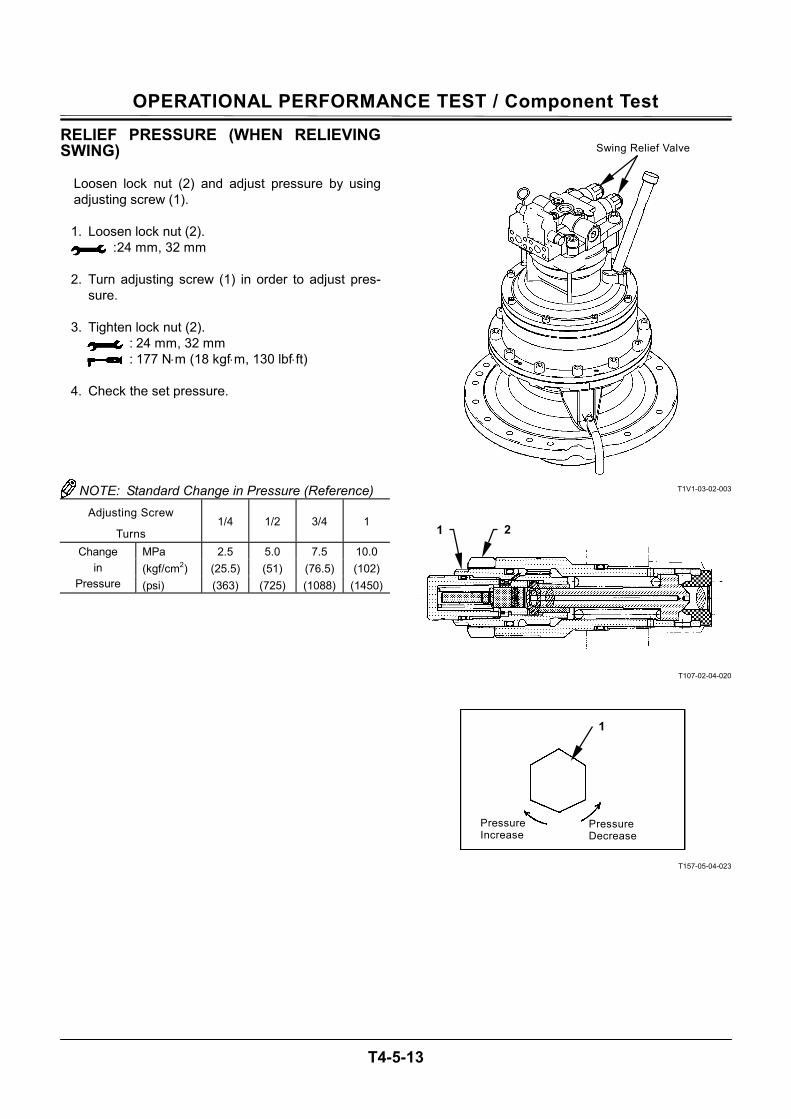
OPERATIONAL PERFORMANCE TEST / Component Test
T4-5-13
RELIEF PRESSURE (WHEN RELIEVING SWING)
Loosen lock nut (2) and adjust pressure by using adjusting screw (1).
1. Loosen lock nut (2).
: 24 mm, 32 mm 2. Turn adjusting screw (1) in order to adjust pres-
sure. 3. Tighten lock nut (2).
: 24 mm, 32 mm : 177 N⋅m (18 kgf⋅m, 130 lbf⋅ft)
4. Check the set pressure.
NOTE: Standard Change in Pressure (Reference) Adjusting Screw
Turns 1/4 1/2 3/4 1
MPa 2.5 5.0 7.5 10.0 (kgf/cm2) (25.5) (51) (76.5) (102)
Change in
Pressure (psi) (363) (725) (1088) (1450)
T1V1-03-02-003
T107-02-04-020
T157-05-04-023
Swing Relief Valve
1
Pressure Increase
Pressure Decrease
21
OPERATIONAL PERFORMANCE TEST / Component Test
T4-5-14
OVERLOAD RELIEF VALVE SET PRES-SURE
Summary: 1. The circuit pressure must be increased by apply-
ing an external force while blocking the return cir-cuit from the control valve. This measuring method is hazardous and the results obtained with this method are unreliable.
2. The oil flow rate used to set the overload relief pressure is far less than that used to set the main relief pressure. Therefore, measuring the over-load pressure in the main circuit by increasing the main relief set pressure more than the overload valve set-pressure is not a proper method. In ad-dition, in case a main relief valve designed to leak a small quantity of oil before reliving is used, its pre-leaking start pressure must be increased more than the overload relief valve set pressure. However, the pre-leaking start pressure is not al-ways increased more than the overload relief valve set-pressure as the adjustable upper limit of the main relief valve set-pressure is provided. Accordingly, the overload relief valve assembly should be removed from the machine and checked on a specified test stand at a correct oil flow rate. Some overload relief valves come in contact with the control valve body to block the oil passage. When this type of overload relief valve is checked, the control valve body must be pre-cisely finished as the test unit. Provide one con-trol valve other than that on the machine as a test kit.
3. If the overload relief valve performance must be
checked on the machine, however, measure the main relief pressure while releasing each front function respective to the measuring overload re-lief valve. And, assume that the overload relief valve is functioning correctly if the obtained main relief pressure is within the specified value range. Measure the main pressure of the front functions as follows:
T1V7-04-05-001
Preparation: 1. Stop the engine. 2. Push the air bleed valve on top of the hydraulic oil
tank and release any remaining pressure. 3. Remove the plug from pressure check port of
main pump delivery port. Install adapter (ST 6069), hose (ST 6943) and pressure gauge (ST 6941).
: 6 mm
4. Connect Dr. ZX and select the monitoring function. Start the engine. Confirm that no oil leakage is observed at the pressure gauge connection.
5. Maintain the hydraulic oil temperature at 50±5 °C
(122±41 °F).
Plug
OPERATIONAL PERFORMANCE TEST / Component Test
T4-5-15
Measurement: 1. Select the following switch positions:
Engine Control Dial
Power Mode Switch
Auto-Idle Switch Work Mode
Fast Idle P Mode OFF Digging Mode
2. Slowly operate the bucket, arm and boom control
levers to the stroke ends and relieve each func-tion.
3. Read pressures on the pressure gauge at this time.
4. Perform the measurement for the bucket, arm and boom in that order.
5. Repeat the measurement three times and calcu-late the average value for each.
Evaluation: 1. Performance of the overload relief valves are
normal if the measured main relief pressures are within the specified value range. Refer to the Performance Standard in Group T4-2.

OPERATIONAL PERFORMANCE TEST / Component Test
T4-5-16
Overload Relief Valve Pressure Adjustment Pro-cedure
NOTE: In principle, adjust the overload relief valve pressure on a test stand.
Loosen lock nut (1) and adjust pressure by using ad-justing screw (2).
1. Loosen lock nut (1).
: 17 mm 2. Turn adjusting screw (2) in order to adjust pres-
sure. : 6 mm
3. Tighten lock nut (1).
: 17 mm : 29.5 N⋅m (3.0 kgf⋅m, 22 lbf⋅ft)
4. Check the set pressure. NOTE: Standard Change in Pressure (Reference)
Screw Turns 1/4 1/2 3/4 1 MPa 5.2 10.6 15.9 21.1 (kgf/cm2) (54) (108) (162) (216) Change in
Pressure (psi) (770) (1540) (2300) (3070)
W107-02-05-128
W107-02-05-129
1
2
Pressure Decrease
Pressure Increase
2
OPERATIONAL PERFORMANCE TEST / Component Test
T4-5-17
MAIN PUMP FLOW RATE MEASUREMENT • P-Q Control (Torque Control) Summary: Main pump performance is checked by measuring the pump flow rate by using a hydraulic tester in-stalled at the main pump delivery port (one side) to be measured. Use Dr. ZX and a pressure gauge at the same time.
IMPORTANT: This measurement procedure is a simple method. The measured data will be lower by approx. 5 % than the accurately measured value. In order to measure accurately, disconnect the return circuit from the control valve and connect it to the hydraulic oil tank.
Preparation: 1. Stop the engine. Push the air bleed valve and
bleed air. Connect a vacuum pump to the oil filler port.
NOTE: Operate the vacuum pump while connect-ing the pump flow rate test line.
2. Disconnect the delivery hose from main pump (one side) to be measured. Connect pipe (1 or 2) by using the split flanges and bolts which were used for the disconnected delivery hose.
: 41 mm : 10 mm
3. Connect hose (1 or 2) to hydraulic tester (5) by using test hose (3) and adapter (4). Install adapter (6), joint (7), test hose (8) and flange (9) to hydraulic tester (5).
: 41 mm : 10 mm
4. Connect the delivery hose to flange (9) with split flanges (10) and bolt (11).
: 10 mm
5. Install a pressure gauge to the main pump to be measured. (Refer to “Main Relief Set Pressure”.)
: 6 mm 6. Disconnect pipe (14) from the regulator. Connect
hose (ST 6339) (13) to the disconnected pipe (14) hole on regulator to be measured. Install plug (ST 6212) to the disconnected pipe (14) hole on regulator not to be measured.
: 17 mm 7. Remove the vacuum pump. Loosen plug (12) on
top of the pump casing. Bleed air from the casing until oil only comes out.
8. Fully open the loading valve of the hydraulic tester.
9. Start the engine. Check the pressure gauge con-nection for any oil leaks. Install Dr. ZX and select the monitor function.
Measurement: 1. Maintain the hydraulic oil temperature at 50±5 °C
(122±41 °F). 2. Measure the maximum flow rate. 3. Select each switch position as follows:
Engine Control Dial
Power Mode Switch
Auto-Idle Switch Work Mode
Fast Idle P Mode OFF Digging Mode
4. Adjust the relief set pressure of main relief valve
in control valve to each pressure point specified along the main pump P-Q curve. (Refer to T4-2-6) Slowly restrict the loading valve of hy-draulic tester while relieving pressure in the arm roll-in circuit. Measure the flow rates and engine speeds at each pressure point specified in the P-Q curve.
5. Repeat each measurement three times and cal-culate the average values.
OPERATIONAL PERFORMANCE TEST / Component Test
T4-5-18
Evaluation: 1. Convert the measured flow rates to those at the
specified pump speed by using the following for-mulas:
Qc = (Ns × Q) ⁄ Ne Qc : Converted Flow Rate Q : Measured Flow Rate Ns : Specified Engine Speed: 1900 min-1 Ne : Measured Engine Speed: Values indicated on Dr. ZX
2. Standard Flow Rate
Refer to Operational Performance Standard in Group T4-2.
NOTE: When actually measuring, install pipe (1 or 2) only to the pump to be measured.
T173-04-04-002
T1V7-04-05-003
1 - Pipe E (ST 6144) 5 - Hydraulic Tester (ST 6299) 9 - Flange (ST 6118) 12 - Plug 2 - Pipe B (ST 6143) 6 - Adapter PF1 × UNF1-7/8
(ST 6146) 10 - Split Flange (ST 6130) 13 - Hose (ST 6339)
3 - Test Hose (ST 6145) 7 - Joint (ST 6330) 11 - Bolt (ST 6409) (4 used) 14 - Pipe (2 Used) 4 - Adapter PF1 × UNF1-7/8
(ST 6146) 8 - Test Hose (ST 6320)
1, 2 3 4 5 6 8 9 7 10 11
Delivery Hose (To Control Valve)
12
13
14
OPERATIONAL PERFORMANCE TEST / Component Test
T4-5-19
• Pilot Characteristics
Summary: Main pump performance is checked by measuring the pump flow rate by using a hydraulic tester in-stalled at the main pump delivery port (one side) to be measured. Use Dr. ZX and a pressure gauge at the same time.
IMPORTANT: This measurement procedure is a simple method. The measured data will be lower by approx. 5 % than the accurately measured value. In order to measure accurately, disconnect the return circuit from the control valve and connect it to the hydraulic oil tank.
Preparation: 1. While referring to steps 1 to 4 on page T4-5-18,
connect a hydraulic tester to the main pump to be measured.
2. Disconnect the hose from regulator port Pi of the pump to be measured. Connect plug (ST 6213) to the disconnected hose.
: 6 mm, 19 mm 3. Install adapters (15) (3 used) to reducing valve
(16). Remove plug M from the pilot filter. Install adapter (13) and hose (14) to the pilot filter. Con-nect hose (14) to regulator port P1 on reducing valve (16).
: 19 mm 4. Install tee (17) to port P2 of reducing valve (16).
Connect pressure gauge (18) and hose (14) to tee (17). Connect hose (14) to the regulator.
: 19 mm
5. Connect hose (19) and adapter (20) to port T of reducing valve (16). Remove plug L from the re-turn pipe. Connect hose (19).
: 19 mm, 22 mm 6. Disconnect the vacuum pump. Loosen plug (12)
from top of the pump casing. Bleed air from the pump casing until oil only comes out.
7. Fully open the loading valve of hydraulic tester. 8. Start the engine. Check the line connections for
any oil leaks.
OPERATIONAL PERFORMANCE TEST / Component Test
T4-5-20
T173-04-04-002
T1V7-04-05-001
T178-03-07-001
T178-04-04-004
1 - Pipe E (ST 6144) 7 - Joint (ST6330) 12 - Plug M 17 - Tee UNF7/16 × UNF7/16×
PF1/4 (ST 6451)
2 - Pipe B (ST 6143) 8 - Test Hose (ST 6320) 13 - Adapter UNF7/16 × PF1/4(ST 6069)
18 - Pressure Gauge (ST 6931)
3 - Test Hose (ST 6145) 9 - Flange (ST 6118) 14 - Hose UNF7/16 × UNF7/16 (4334309)
19 - Hose UNF7/16 × UNF7/16 (4334309)
4 - Adapter PF1 × UNF1-7/8 (ST 6146)
10 - Split Flange (ST 6130) 15 - Adapter PF3/8 × UNF7/16 (4200465)
20 - Adapter PF3/8 × UNF7/16 (4200465)
5 - Hydraulic Tester (ST 6299) 11 - Bolt (ST 6409) (4 used) 16 - Reducing Valve (4325439) 6 - Adapter PF1 × UNF1-7/8
(ST 6146)
1, 2 3 4 5 6 8 9 7
Plug M
17
10
15
11
16
Delivery Hose (To Control Valve)
15 14 13
Reducing Valve Port Position Reducing Valve Return Pipe
To Regulator Port Pi
To Pilot Filter
18
15
19
20
L
P1 P2
T
14
12
Port Pi
OPERATIONAL PERFORMANCE TEST / Component Test
T4-5-21
Measurement: 1. Maintain the hydraulic oil temperature at 50±5 °C
(122±41 °F) 2. Measure pump flow rate in response to the ex-
ternal command pilot pressure. 3. Select each switch position as follows:
Engine Control Dial
Power Mode Switch
Auto-Idle Switch Work Mode
Fast Idle P Mode OFF Digging Mode
4. Adjust the reducing valve set pressure to each pressure point specified along the main pump P-Q curve. (Pilot Characteristics) (Refer to T4-2-7.) Measure the flow rates and engine speeds at the pressure points specified in the P-Q curve.
5. Repeat each measurement three times and cal-culate the average values.
Evaluation: 1. Convert the measured flow rates to those at the
specified pump speed by using the following formulas:
Qc = (Ns × Q) ⁄ Ne Qc : Converted Flow Rate Q : Measured Flow Rate Ns : Specified Engine Speed: 1900 min-1 Ne : Measured Engine Speed Values indicated on Dr. ZX
2. Standard Flow Rate
Refer to Operational Performance Standard in Group T4-2.
NOTE: When actually measuring, install pipe (1 or 2) only to the pump to be measured.
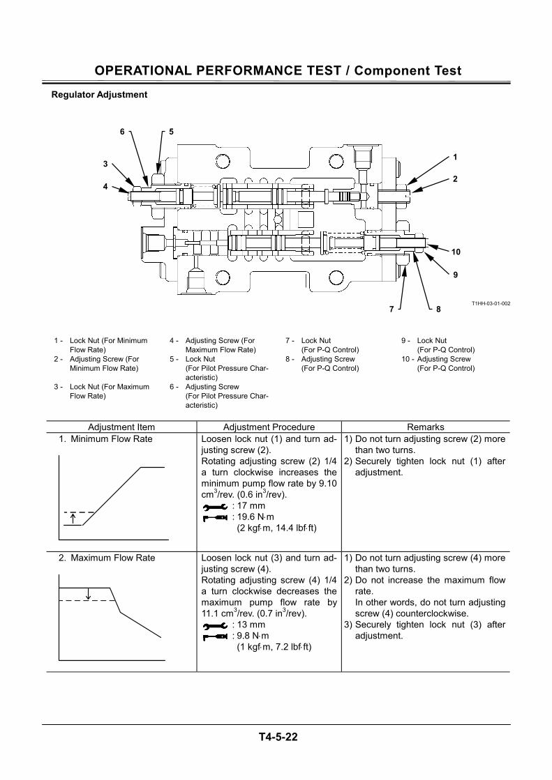
OPERATIONAL PERFORMANCE TEST / Component Test
T4-5-22
Regulator Adjustment
T1HH-03-01-002
1 - Lock Nut (For Minimum
Flow Rate) 4 - Adjusting Screw (For
Maximum Flow Rate) 7 - Lock Nut
(For P-Q Control) 9 - Lock Nut
(For P-Q Control) 2 - Adjusting Screw (For
Minimum Flow Rate) 5 - Lock Nut
(For Pilot Pressure Char-acteristic)
8 - Adjusting Screw (For P-Q Control)
10 - Adjusting Screw (For P-Q Control)
3 - Lock Nut (For Maximum Flow Rate)
6 - Adjusting Screw (For Pilot Pressure Char-acteristic)
Adjustment Item Adjustment Procedure Remarks
1. Minimum Flow Rate
Loosen lock nut (1) and turn ad-justing screw (2). Rotating adjusting screw (2) 1/4 a turn clockwise increases the minimum pump flow rate by 9.10 cm3/rev. (0.6 in3/rev).
: 17 mm : 19.6 N⋅m
(2 kgf⋅m, 14.4 lbf⋅ft)
1) Do not turn adjusting screw (2) more than two turns.
2) Securely tighten lock nut (1) after adjustment.
2. Maximum Flow Rate
Loosen lock nut (3) and turn ad-justing screw (4). Rotating adjusting screw (4) 1/4 a turn clockwise decreases the maximum pump flow rate by 11.1 cm3/rev. (0.7 in3/rev).
: 13 mm : 9.8 N⋅m
(1 kgf⋅m, 7.2 lbf⋅ft)
1) Do not turn adjusting screw (4) more than two turns.
2) Do not increase the maximum flow rate. In other words, do not turn adjusting screw (4) counterclockwise.
3) Securely tighten lock nut (3) after adjustment.
1
2
9
10
8 7
3
4
6 5
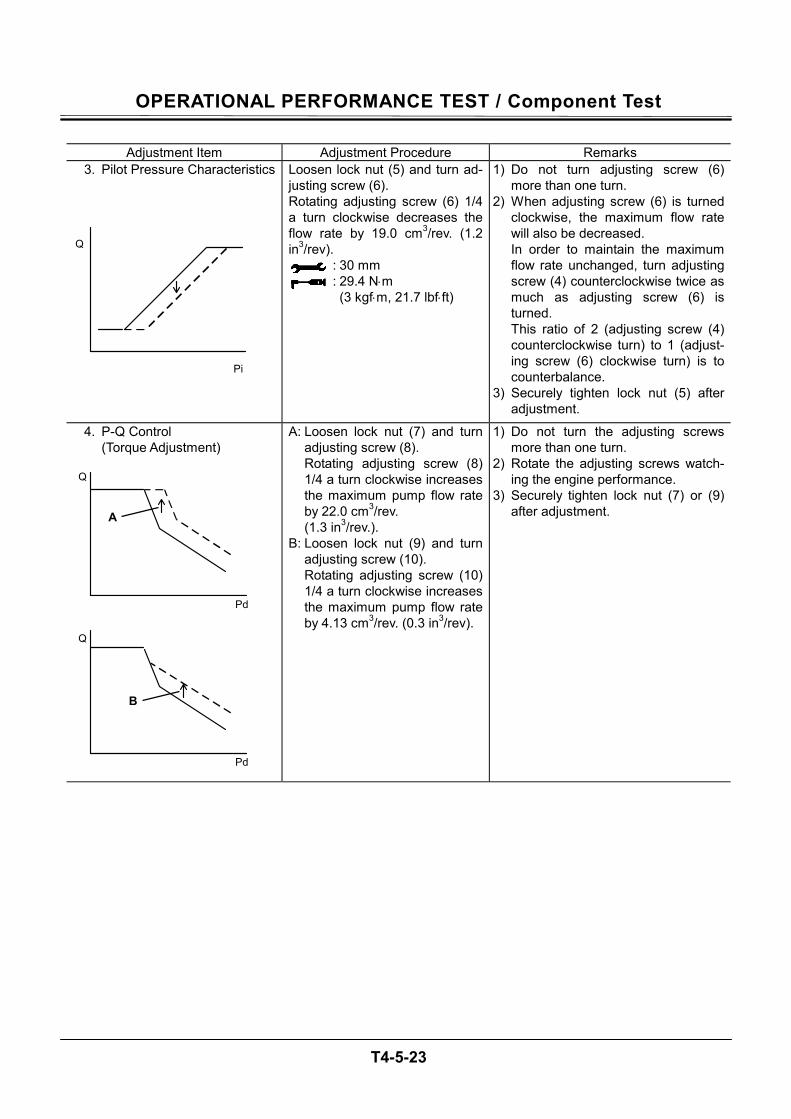
OPERATIONAL PERFORMANCE TEST / Component Test
T4-5-23
Adjustment Item Adjustment Procedure Remarks
3. Pilot Pressure Characteristics
Loosen lock nut (5) and turn ad-justing screw (6). Rotating adjusting screw (6) 1/4 a turn clockwise decreases the flow rate by 19.0 cm3/rev. (1.2 in3/rev).
: 30 mm : 29.4 N⋅m
(3 kgf⋅m, 21.7 lbf⋅ft)
1) Do not turn adjusting screw (6) more than one turn.
2) When adjusting screw (6) is turned clockwise, the maximum flow rate will also be decreased. In order to maintain the maximum flow rate unchanged, turn adjusting screw (4) counterclockwise twice as much as adjusting screw (6) is turned. This ratio of 2 (adjusting screw (4) counterclockwise turn) to 1 (adjust-ing screw (6) clockwise turn) is to counterbalance.
3) Securely tighten lock nut (5) after adjustment.
4. P-Q Control (Torque Adjustment)
A: Loosen lock nut (7) and turn adjusting screw (8). Rotating adjusting screw (8) 1/4 a turn clockwise increases the maximum pump flow rate by 22.0 cm3/rev. (1.3 in3/rev.).
B: Loosen lock nut (9) and turn adjusting screw (10). Rotating adjusting screw (10) 1/4 a turn clockwise increases the maximum pump flow rate by 4.13 cm3/rev. (0.3 in3/rev).
1) Do not turn the adjusting screws more than one turn.
2) Rotate the adjusting screws watch-ing the engine performance.
3) Securely tighten lock nut (7) or (9) after adjustment.
Pd
Q
A
B
Pd
Q
Pi
Q
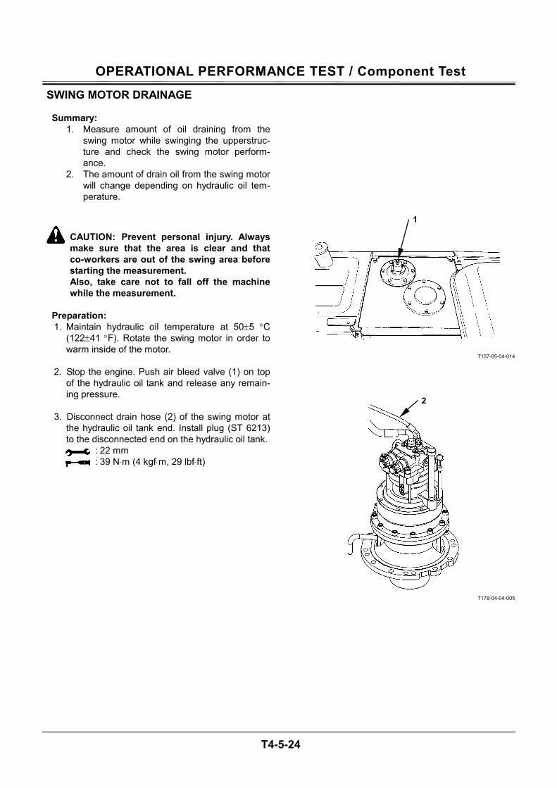
OPERATIONAL PERFORMANCE TEST / Component Test
T4-5-24
SWING MOTOR DRAINAGE
Summary: 1. Measure amount of oil draining from the
swing motor while swinging the upperstruc-ture and check the swing motor perform-ance.
2. The amount of drain oil from the swing motor will change depending on hydraulic oil tem-perature.
CAUTION: Prevent personal injury. Always make sure that the area is clear and that co-workers are out of the swing area before starting the measurement. Also, take care not to fall off the machine while the measurement.
Preparation: 1. Maintain hydraulic oil temperature at 50±5 °C
(122±41 °F). Rotate the swing motor in order to warm inside of the motor.
2. Stop the engine. Push air bleed valve (1) on top
of the hydraulic oil tank and release any remain-ing pressure.
3. Disconnect drain hose (2) of the swing motor at
the hydraulic oil tank end. Install plug (ST 6213) to the disconnected end on the hydraulic oil tank.
: 22 mm : 39 N⋅m (4 kgf⋅m, 29 lbf⋅ft)
T157-05-04-014
T178-04-04-005
1
2
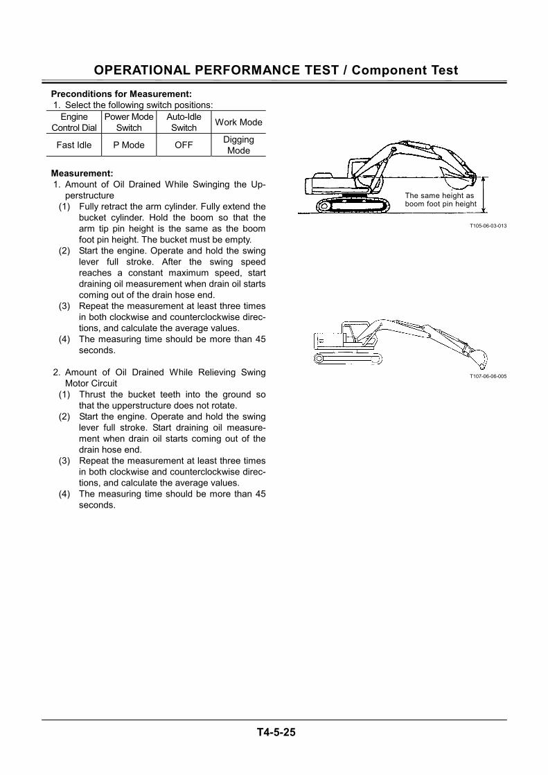
OPERATIONAL PERFORMANCE TEST / Component Test
T4-5-25
Preconditions for Measurement: 1. Select the following switch positions:
Engine Control Dial
Power Mode Switch
Auto-Idle Switch Work Mode
Fast Idle P Mode OFF Digging Mode
Measurement: 1. Amount of Oil Drained While Swinging the Up-
perstructure (1) Fully retract the arm cylinder. Fully extend the
bucket cylinder. Hold the boom so that the arm tip pin height is the same as the boom foot pin height. The bucket must be empty.
(2) Start the engine. Operate and hold the swing lever full stroke. After the swing speed reaches a constant maximum speed, start draining oil measurement when drain oil starts coming out of the drain hose end.
(3) Repeat the measurement at least three times in both clockwise and counterclockwise direc-tions, and calculate the average values.
(4) The measuring time should be more than 45 seconds.
2. Amount of Oil Drained While Relieving Swing
Motor Circuit (1) Thrust the bucket teeth into the ground so
that the upperstructure does not rotate. (2) Start the engine. Operate and hold the swing
lever full stroke. Start draining oil measure-ment when drain oil starts coming out of the drain hose end.
(3) Repeat the measurement at least three times in both clockwise and counterclockwise direc-tions, and calculate the average values.
(4) The measuring time should be more than 45 seconds.
T105-06-03-013
T107-06-06-005
The same height as boom foot pin height
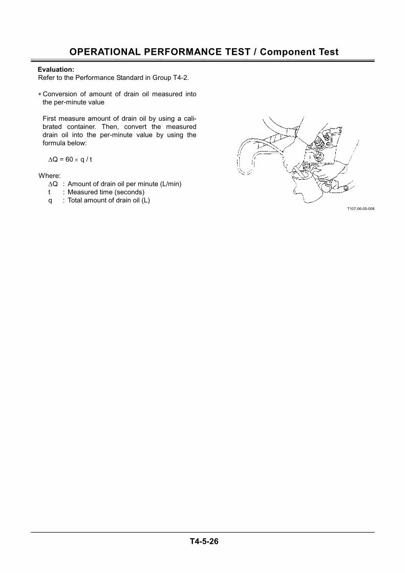
OPERATIONAL PERFORMANCE TEST / Component Test
T4-5-26
Evaluation: Refer to the Performance Standard in Group T4-2.
∗ Conversion of amount of drain oil measured into
the per-minute value First measure amount of drain oil by using a cali-brated container. Then, convert the measured drain oil into the per-minute value by using the formula below:
∆Q = 60 × q / t
Where: ∆Q : Amount of drain oil per minute (L/min) t : Measured time (seconds) q : Total amount of drain oil (L)
T107-06-05-008
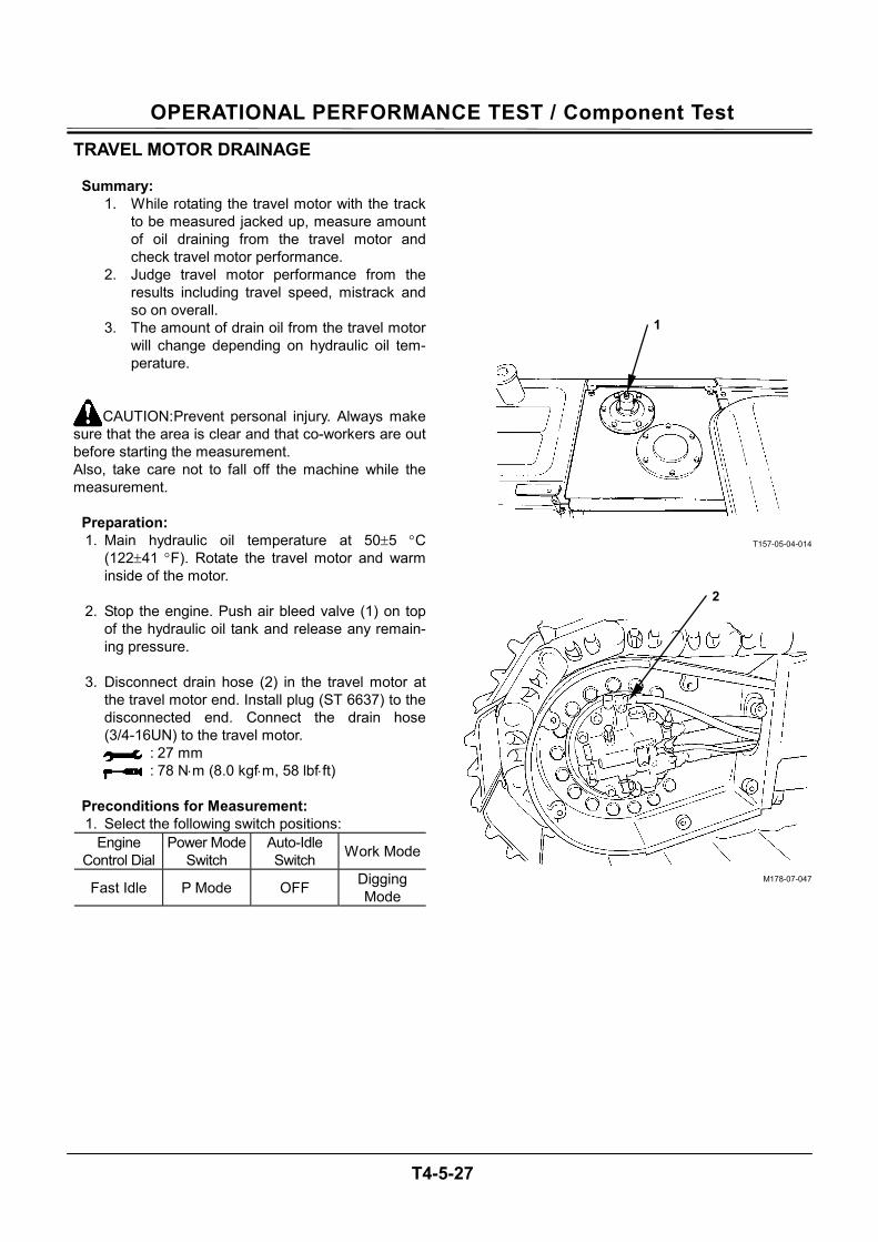
OPERATIONAL PERFORMANCE TEST / Component Test
T4-5-27
TRAVEL MOTOR DRAINAGE
Summary: 1. While rotating the travel motor with the track
to be measured jacked up, measure amount of oil draining from the travel motor and check travel motor performance.
2. Judge travel motor performance from the results including travel speed, mistrack and so on overall.
3. The amount of drain oil from the travel motor will change depending on hydraulic oil tem-perature.
CAUTION: Prevent personal injury. Always make sure that the area is clear and that co-workers are out before starting the measurement. Also, take care not to fall off the machine while the measurement.
Preparation: 1. Main hydraulic oil temperature at 50±5 °C
(122±41 °F). Rotate the travel motor and warm inside of the motor.
2. Stop the engine. Push air bleed valve (1) on top
of the hydraulic oil tank and release any remain-ing pressure.
3. Disconnect drain hose (2) in the travel motor at
the travel motor end. Install plug (ST 6637) to the disconnected end. Connect the drain hose (3/4-16UN) to the travel motor.
: 27 mm : 78 N⋅m (8.0 kgf⋅m, 58 lbf⋅ft)
Preconditions for Measurement: 1. Select the following switch positions:
Engine Control Dial
Power Mode Switch
Auto-Idle Switch Work Mode
Fast Idle P Mode OFF Digging Mode
T157-05-04-014
M178-07-047
1
2
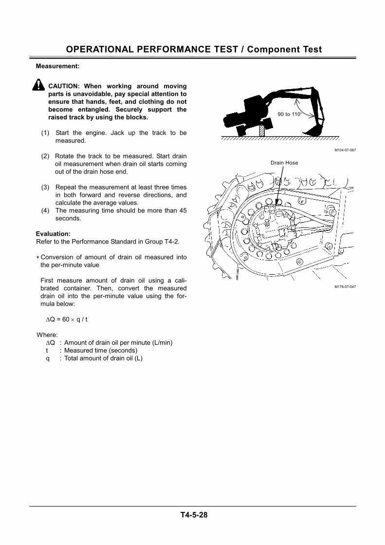
OPERATIONAL PERFORMANCE TEST / Component Test
T4-5-28
Measurement:
CAUTION: When working around moving parts is unavoidable, pay special attention to ensure that hands, feet, and clothing do not become entangled. Securely support the raised track by using the blocks.
(1) Start the engine. Jack up the track to be
measured.
(2) Rotate the track to be measured. Start drain oil measurement when drain oil starts coming out of the drain hose end.
(3) Repeat the measurement at least three times
in both forward and reverse directions, and calculate the average values.
(4) The measuring time should be more than 45 seconds.
Evaluation: Refer to the Performance Standard in Group T4-2.
∗ Conversion of amount of drain oil measured into
the per-minute value First measure amount of drain oil using a cali-brated container. Then, convert the measured drain oil into the per-minute value using the for-mula below:
∆Q = 60 × q / t
Where: ∆Q : Amount of drain oil per minute (L/min) t : Measured time (seconds) q : Total amount of drain oil (L)
M104-07-067
M178-07-047
90 to 110°
Drain Hose

M E M O
....................................................................................................................................................................
....................................................................................................................................................................
....................................................................................................................................................................
....................................................................................................................................................................
....................................................................................................................................................................
....................................................................................................................................................................
....................................................................................................................................................................
....................................................................................................................................................................
....................................................................................................................................................................
....................................................................................................................................................................
....................................................................................................................................................................
....................................................................................................................................................................
....................................................................................................................................................................
....................................................................................................................................................................
....................................................................................................................................................................
....................................................................................................................................................................
....................................................................................................................................................................
....................................................................................................................................................................
....................................................................................................................................................................
....................................................................................................................................................................
....................................................................................................................................................................
....................................................................................................................................................................
....................................................................................................................................................................
....................................................................................................................................................................
....................................................................................................................................................................
....................................................................................................................................................................
....................................................................................................................................................................
....................................................................................................................................................................
....................................................................................................................................................................
....................................................................................................................................................................
1V7T-5-1
SECTION 5
TROUBLESHOOTING
CONTENTSGroup 1 Diagnosing Procedure
Introduction ..............................................T5-1-1 Diagnosing Procedure ..............................T5-1-2
Group 2 Monitor Unit
Outline .....................................................T5-2-1 How to Use Screens............................... T5-2-11 Primary Screen ......................................T5-2-21 Screen Display When An Alarm is Issued......................T5-2-22 Contents of Alarms .................................T5-2-24 Troubleshooting......................................T5-2-26 Controller Version...................................T5-2-28 Monitoring ..............................................T5-2-30 Displaying Operating Conditions.............T5-2-33 Pump 2 Flow Rate Adjustment (Only Machines Equipped with Optional Parts) ..............................T5-2-34 Attachment Selection (Only Machines Equipped with Optional Parts) ..............................T5-2-36 Time Set.................................................T5-2-40 Fuel Rate Display/No Display .................T5-2-42 Back Monitor Settings ............................T5-2-46 Maintenance Settings .............................T5-2-54 Language Settings .................................T5-2-60 Mail (Optional)........................................T5-2-62
Group 3 Dr. ZX Outline .....................................................T5-3-1 Select Controller.......................................T5-3-6 Main Controller .........................................T5-3-7 Main Menu Monitor Display.......................T5-3-8 Special Function .....................................T5-3-14 Setting....................................................T5-3-16 Adjustment Data List ..............................T5-3-20 Attachment Adjustment Data List ............T5-3-24 Attachment Setting .................................T5-3-44 Engine Controller....................................T5-3-50 Main Menu Monitor Display.....................T5-3-51 Record Data Display...............................T5-3-54 Password Change ..................................T5-3-55 ICF Controller .........................................T5-3-56 Main Menu Information C/U Various Setup..............T5-3-57 Information C/U: Initialize .......................T5-3-58 Enter Model and Serial No......................T5-3-59 Enter Date and Time ..............................T5-3-60 Control Data: Initialize ............................T5-3-61 Satellite Terminal: Initialize .....................T5-3-62 Satellite Terminal No. Confirmation.........T5-3-63 Communicating State Check...................T5-3-64 Enter Satellite Comm. Start / Stop ..........T5-3-65 Date Download .......................................T5-3-67 Save Data Check....................................T5-3-68 Password Change ..................................T5-3-69 Monitor Controller ...................................T5-3-70 Monitoring ..............................................T5-3-71 Various Settings .....................................T5-3-74 Optional Function Allocation ...................T5-3-76
1V7T-5-2
Overload Alarm Enable / Disable Selection ....................T5-3-84 Back Monitor Setting ..............................T5-3-86 Operating Condition Enable / Disable Selection ....................T5-3-90 Time Setting Function Enable / Disable Selection ....................T5-3-92 Maintenance Setting Maintenance Operation Allow / Not Allow Selection....................T5-3-94 Notification Function Enable / Disable Selection ....................T5-3-96 Maintenance Display Item On/Off Selection ...................................T5-3-98 Internal Hour Meter Synchronization.....T5-3-102 Fuel Consumption Gauge Display Enable / Disable Selection ..................T5-3-103 Password Change ................................T5-3-105
Group 4 e-Shovel
Outline .....................................................T5-4-1 List of Daily Report Data...........................T5-4-2 List of Frequency Distribution Data ...........T5-4-5 List of Total Operating Hours ....................T5-4-6 How to Download and Upload Data of ICF..........T5-4-8 Various Setup of ICF and Satellite Communication Terminal by Using Dr. ZX .................................... T5-4-11 List of Fault Code ...................................T5-4-23 Satellite Communication System ............T5-4-24
Group 5 Component Layout Main Components ....................................T5-5-1 Electrical System (Overview) ....................T5-5-3 Engine......................................................T5-5-8 Pump Device ............................................T5-5-9 Swing Device............................................T5-5-9 Control Valve ..........................................T5-5-10 Signal Control Valve ...............................T5-5-10 Solenoid Valve Unit ................................T5-5-11 Travel Device .........................................T5-5-11 Pilot Port (Signal Control Valve)..............T5-5-28
Group 6 Troubleshooting A
Troubleshooting A Procedure....................T5-6-1 Fault Code List .........................................T5-6-2 ECM .......................................................T5-6-20 ICF .........................................................T5-6-44 Controller Hardware Failure MC Fault Code 11000 to 11002.............T5-6-50 MC Fault Code 11003.............................T5-6-51 MC Fault Code 11004.............................T5-6-52 CAN Harness Check ..............................T5-6-54 Engine Failure MC Fault Code 11100 ...........................T5-6-74 MC Fault Code 11101 .............................T5-6-75 Pump Failure MC Fault Code 11200 ...........................T5-6-76 MC Fault Code 11202.............................T5-6-77 MC Fault Code 11206.............................T5-6-78 MC Fault Code 11208.............................T5-6-79 Pilot Failure MC Fault Code 11301 ...........................T5-6-80 MC Fault Code 11302.............................T5-6-81 MC Fault Code 11303.............................T5-6-82 MC Fault Code 11304.............................T5-6-83 MC Fault Code 11307.............................T5-6-84 Proportional Solenoid Valve Failure MC Fault Code 11400 ...........................T5-6-85 MC Fault Code 11401.............................T5-6-86 MC Fault Code 11402.............................T5-6-87 MC Fault Code 11403.............................T5-6-88 MC Fault Code 11404.............................T5-6-89 MC Fault Code 11405.............................T5-6-90
1V7T-5-3
MC Fault Code 11410.............................T5-6-91 CAN Data Reception Failure MC Fault Code 11910 ...........................T5-6-92 CAN Harness Check MC Fault Code 11910 ...........................T5-6-94 MC Fault Code 11918.............................T5-6-97 CAN Harness Check MC Fault Code 11918 ...........................T5-6-98 MC Fault Code 11911 ...........................T5-6-101 CAN Harness Check MC Fault Code 11911 .........................T5-6-102 MC Fault Code 11920...........................T5-6-105 CAN Harness Check MC Fault Code 11920 .........................T5-6-106 MC Fault Code 11914...........................T5-6-109 CAN Harness Check MC Fault Code 11914 ......................... T5-6-110 Other Failures MC Fault Code 11901........................... T5-6-113 ECM, Sensor System ECM Fault Codes 100, 102, 105, 108, 110, 157, 172.............................. T5-6-114 ECM Fault Codes 174, 636, 723, 10001.......................... T5-6-115 ECM, External Device System ECM Fault Codes 651, 652, 653, 654, 655, 656, 1347, 10002 ................ T5-6-116 ECM, Fuel System ECM Fault Codes 157, 633, 1239, 1240.......................... T5-6-117 ECM, Engine Protection ECM Fault Codes 110, 190 ................. T5-6-118 ECM, Engine Protection ECM Fault Codes 987, 1485............... T5-6-119 ECM, Internal Circuit System ECM Fault Codes 628, 1077, 1079, 1080, 10003, 10004, 10005 ................T5-6-120 ECM Fault Codes 10006, 10007, 10008, 10009, 10010, 10011, 10013 ..............T5-6-121
ECM, Communication System ECM Fault Codes 639.........................T5-6-122 ICF, Satellite Terminal Fault Codes 14000 to 14003...................................T5-6-123 ICF, Satellite Terminal Fault Codes 14006, 14008, 14100 to 14106 ...........T5-6-127 Monitor Unit Fault Code 13303 .............T5-6-129 Monitor Unit Fault Code 13304 .............T5-6-130 Monitor Unit Fault Code 13306, 13308..T5-6-131 Monitor Unit Fault Code 13310 .............T5-6-132 Monitor Unit Fault Code 13311 .............T5-6-133 Pilot Shut Off Lever Alarm ....................T5-6-134
Group 7 Troubleshooting B
Troubleshooting B Procedure ...................T5-7-1 Relationship between Machine Trouble Symptoms and Related Parts .................T5-7-2 Correlation between Trouble Symptoms and Part Failures.................T5-7-18 Engine System Troubleshooting .............T5-7-32 All Actuator System Troubleshooting ......T5-7-58 Front Attachment System Troubleshooting....................................T5-7-70 Swing System Troubleshooting...............T5-7-84 Travel System Troubleshooting...............T5-7-88 Other System Troubleshooting ...............T5-7-96 Exchange Inspection ............................ T5-7-116 Emergency Boom Lowering Procedure........................................... T5-7-119 One Part of Data, Daily Report Data, Distribution Data and Total Operating hours in not Recorded ..................................T5-7-120
1V7T-5-4
Group 8 Electrical System Inspection Precautions for Inspection and Maintenance...........................................T5-8-1 Instructions for Disconnecting Connectors.............................................T5-8-3 Fuse Inspection........................................T5-8-4 Fusible Link Inspection.............................T5-8-5 Battery Voltage Check ..............................T5-8-6 Alternator Check ......................................T5-8-7 Continuity Check ......................................T5-8-8 Voltage and Current Measurement .........T5-8-10 Check by False Signal ............................T5-8-17 Test Harness ..........................................T5-8-18
TROUBLESHOOTING / Diagnosing Procedure
T5-1-1
INTRODUCTION Refer to the inspection and troubleshooting proce-dures after any machine trouble has occurred. The inspection and troubleshooting procedures are pre-sented in an orderly fashion in this section to quickly find the cause of the machine trouble and solution. The troubleshooting section in this manual consists of 8 groups; Diagnosing Procedure, monitor unit, Dr. ZX, e-Shovel, Component Layout, Troubleshooting A (base machine diagnosis by using fault codes), Trouble-shooting B (base machine diagnosis starting with in-spection of abnormal operational status) and Electrical System Inspection.
• Monitor Unit Refer to this group as for the display screen and
operating procedures of monitor unit. • Dr. ZX
This group contains the operating procedures for Dr. ZX.
• e-Shovel
This group contains as follows. Download data from ICF and Upload Procedures when starting satellite communication, when installing the satellite communication con-troller and when replacing ICF Explanation for the satellite communication sys-tem
• Component Layout
• Troubleshooting A (base machine diagnosis by using fault codes) Refer to these procedures if any fault codes are displayed when each controller (MC, ECM, ICF and monitor unit) is diagnosed by using Dr. ZX (or the service menu of monitor unit).
IMPORTANT: ICF receives and retains a record of the electrical signal system mal-function of each controller in the form of fault codes by using CAN communication. In addition, ICF self-diagnosing function records the electrical signal system malfunction in the form of fault codes
Ex.) Fault Code 11004-2: Failure of CAN Com-munication
• Troubleshooting B (base machine diagnosis start-ing with inspection of abnormal operational status) Refer to these procedures when no fault codes are displayed after diagnosing the machine with Dr. ZX (or the service menu of monitor unit). Ex.) Although the engine control dial is turned, engine speed does not change.
• Electrical System Inspection
Refer to this group when required to obtain pre-cautions and/or information for the electrical sys-tem inspection. Ex.) Fuse Check
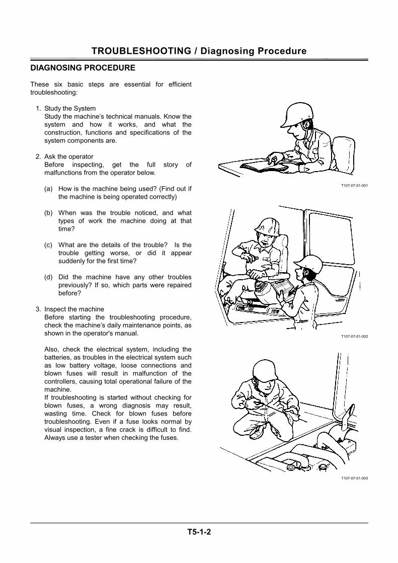
TROUBLESHOOTING / Diagnosing Procedure
T5-1-2
DIAGNOSING PROCEDURE These six basic steps are essential for efficient troubleshooting:
1. Study the System Study the machine’s technical manuals. Know the system and how it works, and what the construction, functions and specifications of the system components are.
2. Ask the operator
Before inspecting, get the full story of malfunctions from the operator below.
(a) How is the machine being used? (Find out if
the machine is being operated correctly)
(b) When was the trouble noticed, and what types of work the machine doing at that time?
(c) What are the details of the trouble? Is the
trouble getting worse, or did it appear suddenly for the first time?
(d) Did the machine have any other troubles
previously? If so, which parts were repaired before?
3. Inspect the machine
Before starting the troubleshooting procedure, check the machine’s daily maintenance points, as shown in the operator's manual. Also, check the electrical system, including the batteries, as troubles in the electrical system such as low battery voltage, loose connections and blown fuses will result in malfunction of the controllers, causing total operational failure of the machine. If troubleshooting is started without checking for blown fuses, a wrong diagnosis may result, wasting time. Check for blown fuses before troubleshooting. Even if a fuse looks normal by visual inspection, a fine crack is difficult to find. Always use a tester when checking the fuses.
T107-07-01-001
T107-07-01-002
T107-07-01-003
TROUBLESHOOTING / Diagnosing Procedure
T5-1-3
4. Operate the machine yourself
Try to identify the trouble by operating the machine yourself. If the trouble cannot be confirmed, stop the engine and obtain further details of the malfunction from the operator. Also, check for any incomplete connections of the wire harnesses correponding to the trouble.
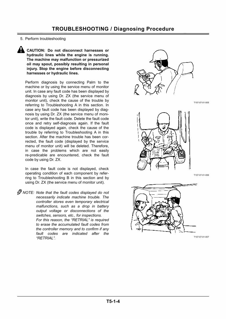
TROUBLESHOOTING / Diagnosing Procedure
T5-1-4
5. Perform troubleshooting
CAUTION: Do not disconnect harnesses or hydraulic lines while the engine is running. The machine may malfunction or pressurized oil may spout, possibly resulting in personal injury. Stop the engine before disconnecting harnesses or hydraulic lines.
Perform diagnosis by connecting Palm to the machine or by using the service menu of monitor unit. In case any fault code has been displayed by diagnosis by using Dr. ZX (the service menu of monitor unit), check the cause of the trouble by referring to Troubleshooting A in this section. In case any fault code has been displayed by diag-nosis by using Dr. ZX (the service menu of moni-tor unit), write the fault code. Delete the fault code once and retry self-diagnosis again. If the fault code is displayed again, check the cause of the trouble by referring to Troubleshooting A in this section. After the machine trouble has been cor-rected, the fault code (displayed by the service menu of monitor unit) will be deleted. Therefore, in case the problems which are not easily re-predicable are encountered, check the fault code by using Dr. ZX. In case the fault code is not displayed, check operating condition of each component by refer-ring to Troubleshooting B in this section and by using Dr. ZX (the service menu of monitor unit).
NOTE: Note that the fault codes displayed do not
necessarily indicate machine trouble. The controller stores even temporary electrical malfunctions, such as a drop in battery output voltage or disconnections of the switches, sensors, etc., for inspections. For this reason, the “RETRIAL” is required to erase the accumulated fault codes from the controller memory and to confirm if any fault codes are indicated after the “RETRIAL”.
T107-07-01-005
T107-07-01-006
T107-07-01-007
TROUBLESHOOTING / Diagnosing Procedure
T5-1-5
6. Trace possible causes
Before reaching a conclusion, check the most likely causes again. Try to identify the actual cause of the trouble. Based on your conclusion, make a plan for appropriate repairs to avoid consequent malfunctions.

TROUBLESHOOTING / Diagnosing Procedure
T5-1-6
(Blank)
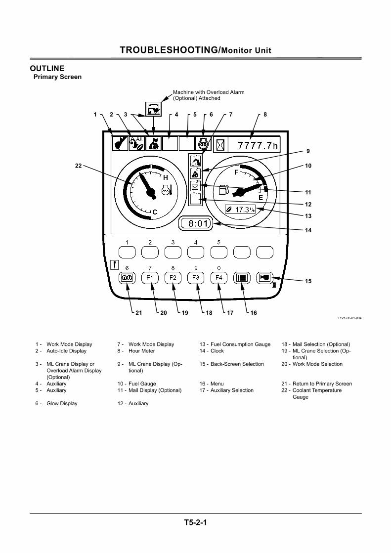
TROUBLESHOOTING/Monitor Unit
T5-2-1
OUTLINE Primary Screen
T1V1-05-01-094
1 - Work Mode Display 7 - Work Mode Display 13 - Fuel Consumption Gauge 18 - Mail Selection (Optional) 2 - Auto-Idle Display 8 - Hour Meter 14 - Clock 19 - ML Crane Selection (Op-
tional) 3 - ML Crane Display or
Overload Alarm Display (Optional)
9 - ML Crane Display (Op-tional)
15 - Back-Screen Selection 20 - Work Mode Selection
4 - Auxiliary 10 - Fuel Gauge 16 - Menu 21 - Return to Primary Screen 5 - Auxiliary 11 - Mail Display (Optional) 17 - Auxiliary Selection 22 - Coolant Temperature
Gauge 6 - Glow Display 12 - Auxiliary
2 1 3
9
4 5 6 7 8
10
11
12
14
15
161718192021
22
13
Machine with Overload Alarm(Optional) Attached
TROUBLESHOOTING/Monitor Unit
T5-2-2
• Display of Meters Data to be displayed on each meter are received from other controllers (MC, ICF and ECM) by using CAN, and are displayed on the monitor unit.
Items to be displayed 1. Coolant Temperature Gauge 2. Hour Meter 3. Fuel Consumption Gauge 4. Clock
• Work Mode Display The attachments being used are displayed accord-ing to the signals received from MC by using CAN.
Digging Mode
T1V1-05-01-108
Attachment Mode Breaker
T1V1-05-01-104
Pulverizer
T1V1-05-01-105
Crusher
T1V1-05-01-106
Vibrating Hammer
T1V1-05-01-107
Others
T1V1-05-02-003
NOTE: The items on monitor unit and HITACHI pattern are same.
Monitor Unit HITACHI pattern Breaker1 Hydraulic Breaker1 Breaker2 Hydraulic Breaker2 Pulverizer1 Secondary Crusher1 Crusher1 Primary Crusher1
T1V1-05-01-008
3
Work Mode
4
1
2
TROUBLESHOOTING/Monitor Unit
T5-2-3
• Auto-Idle Display(1) When selecting auto-idle from the switch panel, the data according to the signals received from MC by using CAN is displayed. When the key is turned ON, the data blinks for 10 seconds.
• ML Crane or Overload Alarm Display (2) (optional) ML Crane
T1V1-05-02-001
When ML crane mode switch or travel suspended load mode switch is turned ON on the ML crane display, the data will be displayed. Overload Alarm Display
T1V1-05-02-002
The system measures the load of suspended load from the bottom pressure of boom cylinder. When overload is detected, an alarm is displayed. (Refer to T5-2-10.)
• Glow Display (3) While ECM is supplying current to the glow plug, the date is displayed according to the signal from ECM.
• Fuel Consumption Gauge Display (4) Fuel consumption is displayed according to the sig-nal from ECM, which is received through MC by us-ing CAN.
T1V1-05-01-008
T1V1-05-01-128
21 3
4
2
TROUBLESHOOTING/Monitor Unit
T5-2-4
• Fuel Sensor Error Display When the fuel sensor is faulty or if the harness be-tween fuel sensor and monitor unit is broken, the data is displayed on the fuel gauge.
• Coolant Temperature Sensor Error Display When the coolant temperature sensor is faulty or if the harness between coolant temperature sensor and monitor unit is broken, the data is displayed on the coolant temperature gauge.
• Alarm and Remedy Displays against Alarm Alarm marks are displayed on the lower part of screen according to the alarm signals received from each controller by using CAN. The remedy for each alarm is displayed by key operation.
T1V1-05-02-005
T1V1-05-01-096
T1V5-05-01-013
Remedy Display against Alarm
Alarm Display
Coolant Temperature Sensor Error Display
Fuel Sensor Error Display
TROUBLESHOOTING/Monitor Unit
T5-2-5
• Troubleshooting This screen displays fault codes according to the signals received from ICF by using CAN.
• Controller Version
This screen displays the version of controller.
• Monitoring This screen displays temperature and pressure data received from each controller by using CAN. By key operation, the displayed data is hold.
• Operating Conditions This screen displays machine hour, fuel usage, and fuel consumption rate registered by the monitor unit.
T1V5-05-01-097
T1V5-05-01-122
T1V5-05-01-087
T1V5-05-01-025
Fault Code Display
Controller Version Display
Monitoring Screen
Operating Conditions Screen
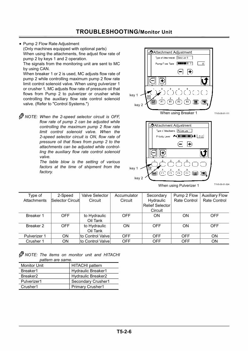
TROUBLESHOOTING/Monitor Unit
T5-2-6
• Pump 2 Flow Rate Adjustment (Only machines equipped with optional parts) When using the attachments, fine adjust flow rate of pump 2 by keys 1 and 2 operation. The signals from the monitoring unit are sent to MC by using CAN. When breaker 1 or 2 is used, MC adjusts flow rate of pump 2 while controlling maximum pump 2 flow rate limit control solenoid valve. When using pulverizer 1 or crusher 1, MC adjusts flow rate of pressure oil that flows from Pump 2 to pulverizer or crusher while controlling the auxiliary flow rate control solenoid valve. (Refer to "Control Systems.")
NOTE: When the 2-speed selector circuit is OFF, flow rate of pump 2 can be adjusted while controlling the maximum pump 2 flow rate limit control solenoid valve. When the 2-speed selector circuit is ON, flow rate of pressure oil that flows from pump 2 to the attachments can be adjusted while control-ling the auxiliary flow rate control solenoid valve. The table blow is the setting of various factors at the time of shipment from the factory.
T1V5-05-01-111
T1V5-05-01-024
Type of Attachments
2-Speed Selector Circuit
Valve Selector Circuit
Accumulator Circuit
Secondary Hydraulic
Relief Selector Circuit
Pump 2 Flow Rate Control
Auxiliary Flow Rate Control
Breaker 1 OFF to Hydraulic Oil Tank
OFF ON ON OFF
Breaker 2 OFF to Hydraulic Oil Tank
ON OFF ON OFF
Pulverizer 1 ON to Control Valve OFF OFF OFF ON Crusher 1 ON to Control Valve OFF OFF OFF ON
NOTE: The items on monitor unit and HITACHI pattern are same.
Monitor Unit HITACHI pattern Breaker1 Hydraulic Breaker1 Breaker2 Hydraulic Breaker2 Pulverizer1 Secondary Crusher1 Crusher1 Primary Crusher1
When using Breaker 1
When using Pulverizer 1
key 1
key 2
key 1
key 2
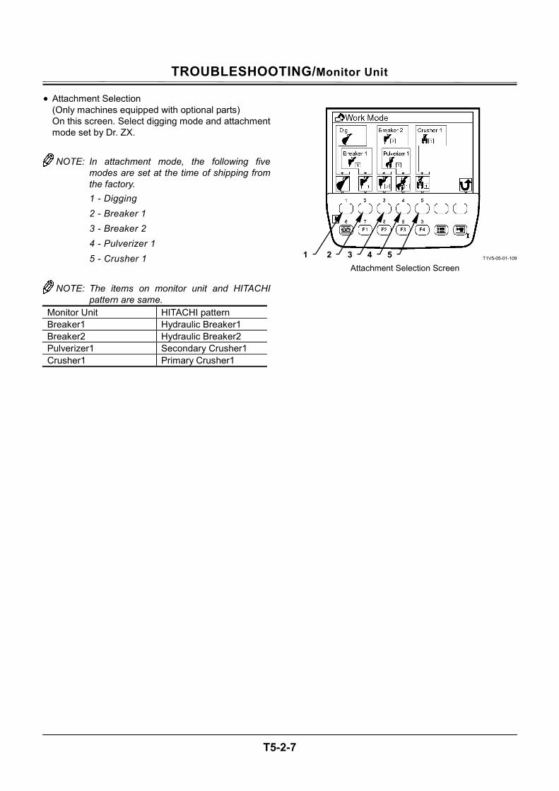
TROUBLESHOOTING/Monitor Unit
T5-2-7
• Attachment Selection (Only machines equipped with optional parts) On this screen. Select digging mode and attachment mode set by Dr. ZX.
NOTE: In attachment mode, the following five
modes are set at the time of shipping from the factory. 1 - Digging 2 - Breaker 1 3 - Breaker 2 4 - Pulverizer 1 5 - Crusher 1
NOTE: The items on monitor unit and HITACHI
pattern are same. Monitor Unit HITACHI pattern Breaker1 Hydraulic Breaker1 Breaker2 Hydraulic Breaker2 Pulverizer1 Secondary Crusher1 Crusher1 Primary Crusher1
T1V5-05-01-109
Attachment Selection Screen 1 2 3 4 5
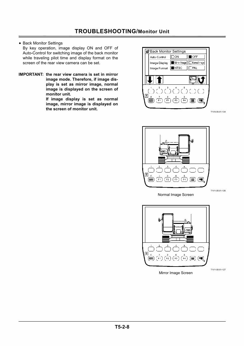
TROUBLESHOOTING/Monitor Unit
T5-2-8
• Back Monitor Settings By key operation, image display ON and OFF of Auto-Control for switching image of the back monitor while traveling pilot time and display format on the screen of the rear view camera can be set.
IMPORTANT: the rear view camera is set in mirror
image mode. Therefore, if image dis-play is set as mirror image, normal image is displayed on the screen of monitor unit. If image display is set as normal image, mirror image is displayed on the screen of monitor unit.
T1V5-05-01-134
T1V1-05-01-126
T1V1-05-01-127
Normal Image Screen
Mirror Image Screen
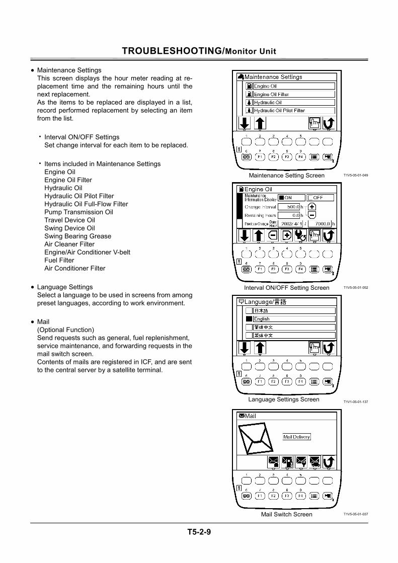
TROUBLESHOOTING/Monitor Unit
T5-2-9
• Maintenance Settings This screen displays the hour meter reading at re-placement time and the remaining hours until the next replacement. As the items to be replaced are displayed in a list, record performed replacement by selecting an item from the list.
• Interval ON/OFF Settings
Set change interval for each item to be replaced.
• Items included in Maintenance Settings Engine Oil Engine Oil Filter Hydraulic Oil Hydraulic Oil Pilot Filter Hydraulic Oil Full-Flow Filter Pump Transmission Oil Travel Device Oil Swing Device Oil Swing Bearing Grease Air Cleaner Filter Engine/Air Conditioner V-belt Fuel Filter Air Conditioner Filter
• Language Settings
Select a language to be used in screens from among preset languages, according to work environment.
(Optional Function) Send requests such as general, fuel replenishment, service maintenance, and forwarding requests in the mail switch screen. Contents of mails are registered in ICF, and are sent to the central server by a satellite terminal.
T1V5-05-01-049
T1V5-05-01-052
T1V1-05-01-137
T1V5-05-01-037
Maintenance Setting Screen
Interval ON/OFF Setting Screen
Mail Switch Screen
Language Settings Screen
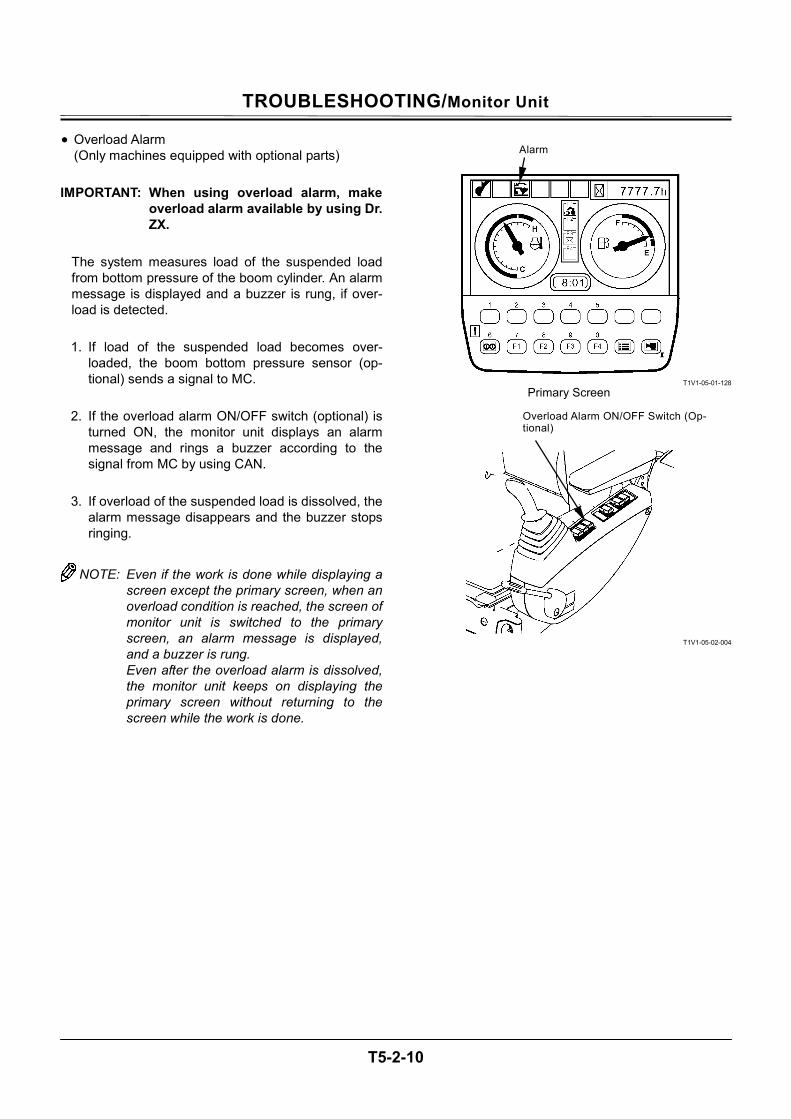
TROUBLESHOOTING/Monitor Unit
T5-2-10
• Overload Alarm (Only machines equipped with optional parts)
IMPORTANT: When using overload alarm, make
overload alarm available by using Dr. ZX.
The system measures load of the suspended load from bottom pressure of the boom cylinder. An alarm message is displayed and a buzzer is rung, if over-load is detected.
1. If load of the suspended load becomes over-
loaded, the boom bottom pressure sensor (op-tional) sends a signal to MC.
2. If the overload alarm ON/OFF switch (optional) is
turned ON, the monitor unit displays an alarm message and rings a buzzer according to the signal from MC by using CAN.
3. If overload of the suspended load is dissolved, the
alarm message disappears and the buzzer stops ringing.
NOTE: Even if the work is done while displaying a
screen except the primary screen, when an overload condition is reached, the screen of monitor unit is switched to the primary screen, an alarm message is displayed, and a buzzer is rung. Even after the overload alarm is dissolved, the monitor unit keeps on displaying the primary screen without returning to the screen while the work is done.
T1V1-05-01-128
T1V1-05-02-004
Alarm
Primary Screen
Overload Alarm ON/OFF Switch (Op-tional)
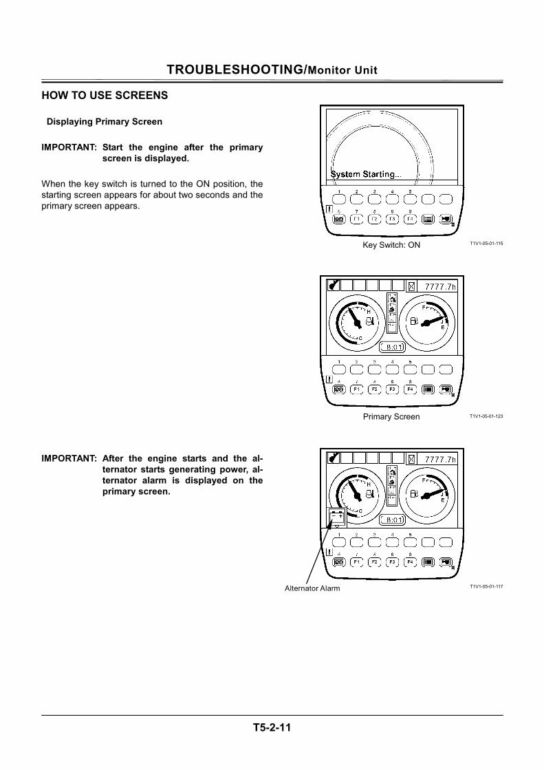
TROUBLESHOOTING/Monitor Unit
T5-2-11
HOW TO USE SCREENS
Displaying Primary Screen IMPORTANT: Start the engine after the primary
screen is displayed. When the key switch is turned to the ON position, the starting screen appears for about two seconds and the primary screen appears. IMPORTANT: After the engine starts and the al-
ternator starts generating power, al-ternator alarm is displayed on the primary screen.
T1V1-05-01-115
T1V1-05-01-123
T1V1-05-01-117
Key Switch: ON
Primary Screen
Alternator Alarm
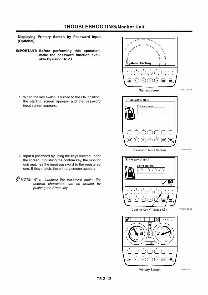
TROUBLESHOOTING/Monitor Unit
T5-2-12
Displaying Primary Screen by Password Input (Optional)
IMPORTANT: Before performing this operation,
make the password function avail-able by using Dr. ZX.
1. When the key switch is turned to the ON position, the starting screen appears and the password input screen appears.
2. Input a password by using the keys located under the screen. If pushing the confirm key, the monitor unit matches the input password to the registered one. If they match, the primary screen appears.
NOTE: When inputting the password again, the
entered characters can be erased by pushing the Erase key.
T1V1-05-01-115
T1V5-05-01-093
T1V5-05-01-002
T1V1-05-01-123
Starting Screen
Password Input Screen
Confirm Key Erase Key
Primary Screen

TROUBLESHOOTING/Monitor Unit
T5-2-13
(Blank)
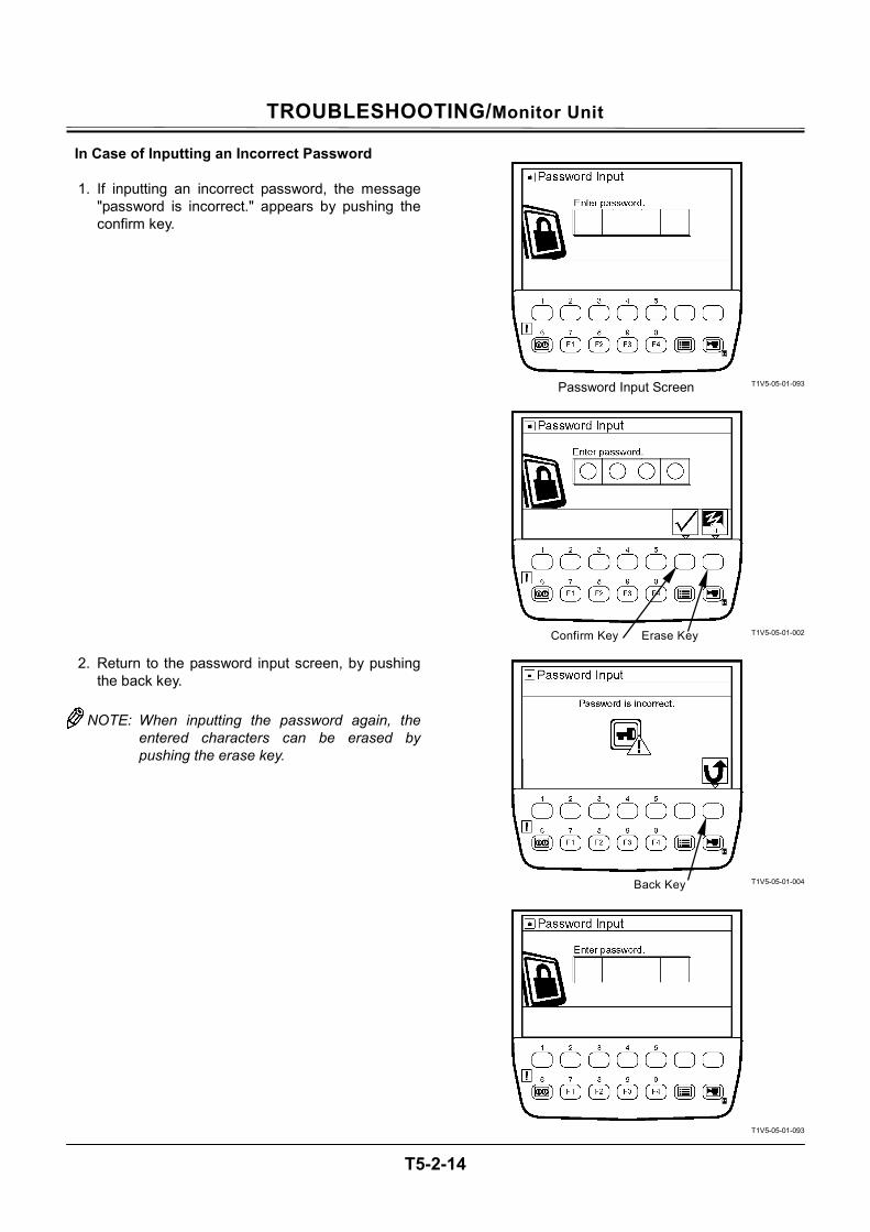
TROUBLESHOOTING/Monitor Unit
T5-2-14
In Case of Inputting an Incorrect Password
1. If inputting an incorrect password, the message "password is incorrect." appears by pushing the confirm key.
2. Return to the password input screen, by pushing the back key.
NOTE: When inputting the password again, the
entered characters can be erased by pushing the erase key.
T1V5-05-01-093
T1V5-05-01-002
T1V5-05-01-004
T1V5-05-01-093
Password Input Screen
Confirm Key Erase Key
Back Key
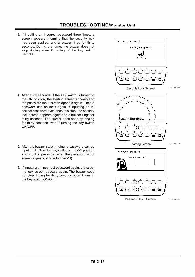
TROUBLESHOOTING/Monitor Unit
T5-2-15
3. If inputting an incorrect password three times, a screen appears informing that the security lock has been applied, and a buzzer rings for thirty seconds. During that time, the buzzer does not stop ringing even if turning of the key switch ON/OFF.
4. After thirty seconds, if the key switch is turned to the ON position, the starting screen appears and the password input screen appears again. Then a password can be input again. If inputting an in-correct password even once this time, the security lock screen appears again and a buzzer rings for thirty seconds. The buzzer does not stop ringing for thirty seconds even if turning the key switch ON/OFF.
5. After the buzzer stops ringing, a password can be input again. Turn the key switch to the ON position and input a password after the password input screen appears. (Refer to T5-2-11).
6. If inputting an incorrect password again, the secu-
rity lock screen appears again. The buzzer does not stop ringing for thirty seconds even if turning the key switch ON/OFF.
T1V5-05-01-005
T1V1-05-01-115
T1V5-05-01-093
Security Lock Screen
Starting Screen
Password Input Screen
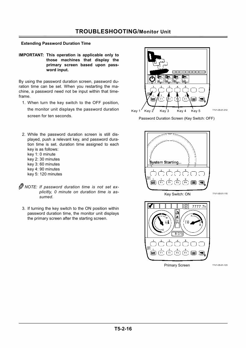
TROUBLESHOOTING/Monitor Unit
T5-2-16
Extending Password Duration Time IMPORTANT: This operation is applicable only to
those machines that display the primary screen based upon pass-word input.
By using the password duration screen, password du-ration time can be set. When you restarting the ma-chine, a password need not be input within that time-frame.
1. When turn the key switch to the OFF position, the monitor unit displays the password duration screen for ten seconds.
2. While the password duration screen is still dis-played, push a relevant key, and password dura-tion time is set. duration time assigned to each key is as follows: key 1: 0 minute key 2: 30 minutes key 3: 60 minutes key 4: 90 minutes key 5: 120 minutes
NOTE: If password duration time is not set ex-
plicitly, 0 minute on duration time is as-sumed.
3. If turning the key switch to the ON position within
password duration time, the monitor unit displays the primary screen after the starting screen.
T1V1-05-01-012
T1V1-05-01-115
T1V1-05-01-123
Key Switch: ON
Primary Screen
Key 1 Key 2
Password Duration Screen (Key Switch: OFF)
Key 3 Key 4 Key 5

TROUBLESHOOTING/Monitor Unit
T5-2-17
(Blank)
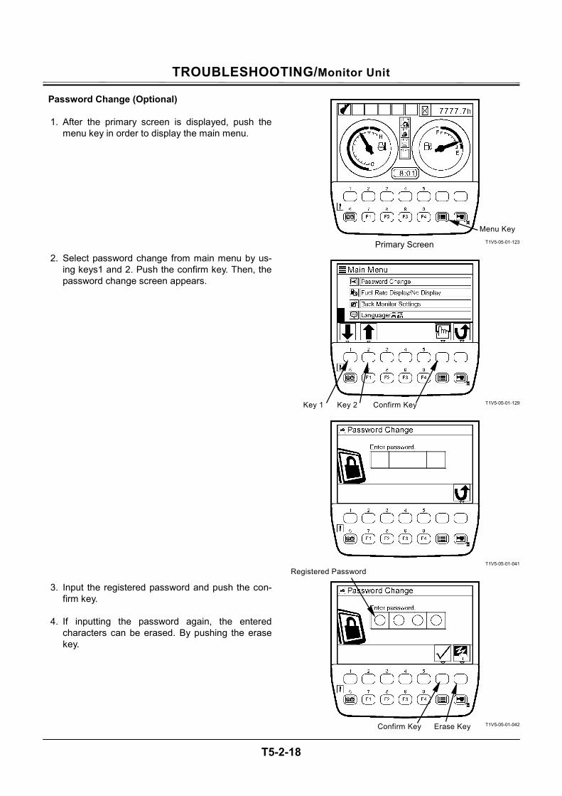
TROUBLESHOOTING/Monitor Unit
T5-2-18
Password Change (Optional)
1. After the primary screen is displayed, push the menu key in order to display the main menu.
2. Select password change from main menu by us-ing keys1 and 2. Push the confirm key. Then, the password change screen appears.
3. Input the registered password and push the con-firm key.
4. If inputting the password again, the entered
characters can be erased. By pushing the erase key.
T1V5-05-01-123
T1V5-05-01-129
T1V5-05-01-041
T1V5-05-01-042
Menu Key
Primary Screen
Confirm Key Key 1 Key 2
Erase Key
Registered Password
Confirm Key
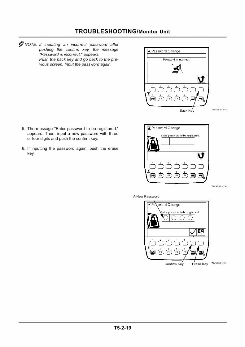
TROUBLESHOOTING/Monitor Unit
T5-2-19
NOTE: If inputting an incorrect password after pushing the confirm key, the message "Password is incorrect." appears. Push the back key and go back to the pre-vious screen, Input the password again.
5. The message "Enter password to be registered." appears. Then, input a new password with three or four digits and push the confirm key.
6. If inputting the password again, push the erase
key.
T1V5-05-01-044
T1V5-05-01-130
T1V5-05-01-131
Back Key
Erase Key
A New Password
Confirm Key
TROUBLESHOOTING/Monitor Unit
T5-2-20
7. The message "Re-enter password." appears. Then, input a new password again and push the confirm key.
8. If inputting the password again, push the erase
key in order to erase the entered characters.
9. The message "New password has been regis-tered." appears. This completes the password change process.
10. Push key 6 and the primary screen appears.
T1V5-05-01-132
T1V5-05-01-133
T1V5-05-01-043
T1V1-05-01-123
Erase KeyConfirm Key
Key 6
Primary Screen
TROUBLESHOOTING/Monitor Unit
T5-2-21
PRIMARY SCREEN
T1V1-05-01-094
1 - Work Mode Display 7 - Work Mode Display 13 - Fuel Consumption Gauge 18 - Mail Selection (Optional) 2 - Auto-Idle Display 8 - Hour Meter 14 - Clock 19 - ML Crane Selection (Op-
tional) 3 - ML Crane Display or
Overload Alarm Display (Optional)
9 - ML Crane Display (Op-tional)
15 - Screen Selection 20 - Work Mode Selection
4 - Auxiliary 10 - Fuel Gauge 16 - Menu 21 - Return to Primary Screen 5 - Auxiliary 11 - Mail Display (Optional) 17 - Auxiliary Selection 22 - Coolant Temperature
Gauge 6 - Glow Display 12 - Auxiliary
2 1 3
9
4 5 6 7 8
10
11
12
14
15
161718192021
22
13
Machine with Overload Alarm (Optional) Attached
TROUBLESHOOTING/Monitor Unit
T5-2-22
SCREEN DISPLAY WHEN AN ALARM IS ISSUED When an alarm is issued, the alarm marks are dis-played at the bottom of screen. • When the number of alarms is two or less • When the number of alarms is three or more
T1V1-05-01-095
T1V1-05-01-096
TROUBLESHOOTING/Monitor Unit
T5-2-23
When an alarm is issued, if the key under a relevant alarm mark is pushed, the remedy against the alarm is displayed.
T1V1-05-01-095
T1V5-05-01-013
Push a Relevant Key
TROUBLESHOOTING/Monitor Unit
T5-2-24
CONTENTS OF ALARMS
Display Contents of Alarms Remedy
M178-01-036
Overheat Alarm Temperature of engine coolant is going up abnormally higher. Stop the work and turn the engine into low idle in order to lower the coolant temperature.
M183-01-080
Engine Warning Alarm Failure of the engine or its related parts. Please contact our authorized distributor or dealer.
M178-01-037
Engine Oil Pressure Alarm Pressure of engine lubricant oil is decreasing. Stop the engine immediately and inspect the hydraulic system and oil volume of the engine.
M183-01-071
Alternator Alarm Fault in the electroinic system. Inspect the alternator and battery system.
M178-01-034
Remaining Fuel Alarm Volume of remaining oil is becoming less. Refuel oil earlier.
M1CC-01-039
Hydraulic Oil Filter Alarm The hydraulic oil filter is clogged. Clean or replace the hydraulic oil filter.
M183-01-067
Air Filter Clogged Alarm The air filter is clogged. Clean or replace the air filter.
T1V1-05-01-102
Work Mode Alarm Fault in the network system. Please contact our authorized distributor or dealer.
T1V1-05-01-103
Pilot Shut-Off Lever Alarm Fault in the pilot shut-off lever system. Please contact our authorized distributor or dealer.

TROUBLESHOOTING/Monitor Unit
T5-2-25
(Blank)
TROUBLESHOOTING/Monitor Unit
T5-2-26
TROUBLESHOOTING
1. Displaying service menu Turn the key switch to the ON position while pushing the key at upper right corner of the monitor unit. Therefore, service menu is added to main menu.
2. When the primary screen appears, push the menu key and display main menu.
3. Select service menu from main menu by using keys 1 and 2. Push the confirm key. Then, the service menu screen appears.
NOTE: When pushing the back key, return to the
previous screen.
T1V1-05-01-115
T1V1-05-01-123
T1V5-05-01-114
T1V5-05-01-083
Turn key switch ON while pushing the key
Menu Key
Confirm Key Key 1 Key 2
Primary Screen
Back Key
Back Key
TROUBLESHOOTING/Monitor Unit
T5-2-27
4. Select troubleshooting by using keys 1 and 2. Push the confirm key. Then, the troubleshooting screen appears.
5. Results of trouble analyses for each controller are
displayed on the screen.
6. Select abnormal of a faulty controller by using keys 1 and 2. Push the confirm key. Then, failure code screen appears. For details of trouble analyses, refer to "Trouble-shooting A."
IMPORTANT: Up to twenty failure codes can be
displayed. But, one screen can con-tain only ten failure codes maximum. If the screen is fully filled with ten items, push key 1 and check other failure codes on the next page. When returning to the previous page, push key 2.
NOTE: When pushing the back key, return to the
previous screen.
7. Push key 6, and the primary screen appears.
T1V5-05-01-083
T1V5-05-01-085
T1V5-05-01-097
T1V1-05-01-123
Confirm Key Back KeyKey 1 Key 2
A figure enclosed in ( ) indicates the number of failure codes.
Primary Screen
Confirm Key Key 1 Key 2 Back Key
Back Key Key 1 Key 2Key 6
TROUBLESHOOTING/Monitor Unit
T5-2-28
CONTROLLER VERSION
1. Displaying Service Menu Turn the key switch to the ON position while pushing the key at upper right of the monitor unit. Therefore, service menu is added to main menu.
2. When primary screen appeared, push menu key to display main menu.
3. Select service menu from main menu by using keys 1 and 2. Push the confirm key. Then, the service menu screen appears.
NOTE: When pushing the back key, return back to
the previous screen.
T1V1-05-01-115
T1V1-05-01-123
T1V5-05-01-114
T1V5-05-01-083
Turn the key switch ON while pushing the key
Confirm Key Key 1 Key 2
Menu Key
Primary Screen
Back Key
Back Key
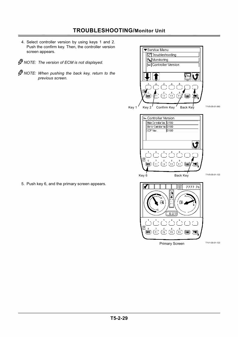
TROUBLESHOOTING/Monitor Unit
T5-2-29
4. Select controller version by using keys 1 and 2. Push the confirm key. Then, the controller version screen appears.
NOTE: The version of ECM is not displayed.
NOTE: When pushing the back key, return to the
previous screen.
5. Push key 6, and the primary screen appears.
T1V5-05-01-083
T1V5-05-01-122
T1V1-05-01-123
Confirm Key Back Key Key 1 Key 2
Back Key Key 6
Primary Screen
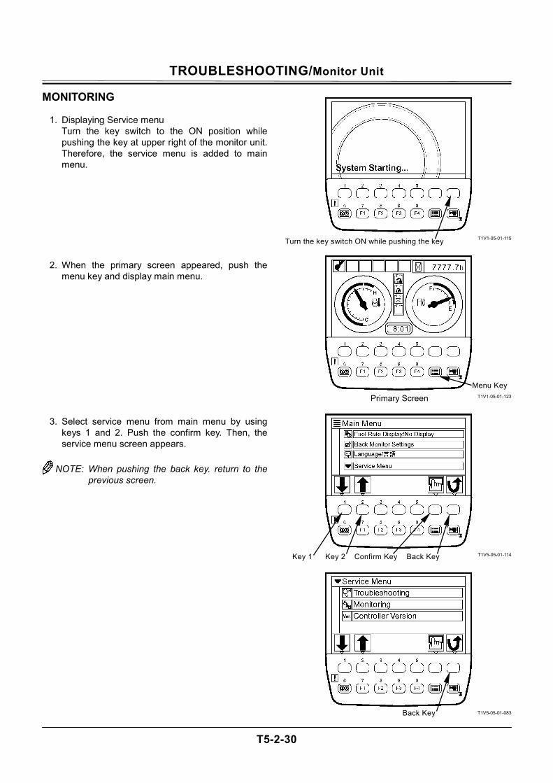
TROUBLESHOOTING/Monitor Unit
T5-2-30
MONITORING
1. Displaying Service menu Turn the key switch to the ON position while pushing the key at upper right of the monitor unit. Therefore, the service menu is added to main menu.
2. When the primary screen appeared, push the menu key and display main menu.
3. Select service menu from main menu by using keys 1 and 2. Push the confirm key. Then, the service menu screen appears.
NOTE: When pushing the back key. return to the
previous screen.
T1V1-05-01-115
T1V1-05-01-123
T1V5-05-01-114
T1V5-05-01-083
Turn the key switch ON while pushing the key
Menu Key
Primary Screen
Confirm Key Key 1 Key 2 Back Key
Back Key
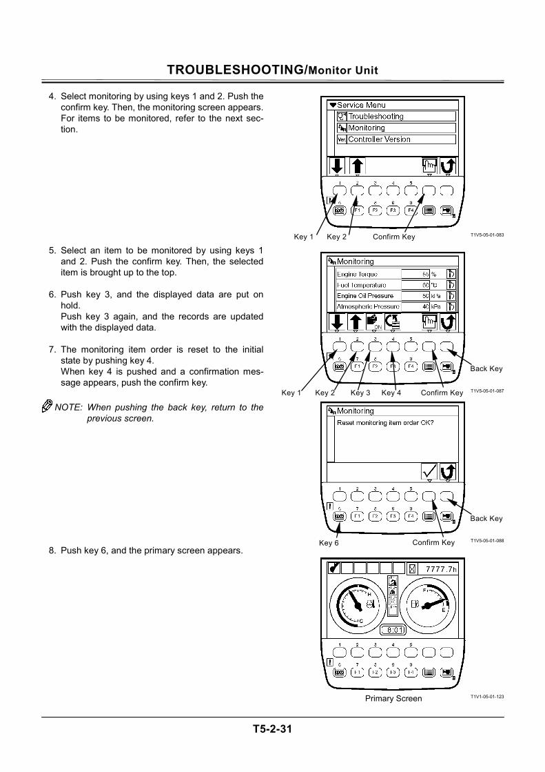
TROUBLESHOOTING/Monitor Unit
T5-2-31
4. Select monitoring by using keys 1 and 2. Push the confirm key. Then, the monitoring screen appears. For items to be monitored, refer to the next sec-tion.
5. Select an item to be monitored by using keys 1 and 2. Push the confirm key. Then, the selected item is brought up to the top.
6. Push key 3, and the displayed data are put on
hold. Push key 3 again, and the records are updated with the displayed data.
7. The monitoring item order is reset to the initial
state by pushing key 4. When key 4 is pushed and a confirmation mes-sage appears, push the confirm key.
NOTE: When pushing the back key, return to the
previous screen.
8. Push key 6, and the primary screen appears.
T1V5-05-01-083
T1V5-05-01-087
T1V5-05-01-088
T1V1-05-01-123
Confirm Key
Back Key
Key 6
Primary Screen
Confirm Key
Back Key
Key 1 Key 2 Key 3 Key 4
Confirm Key Key 1 Key 2
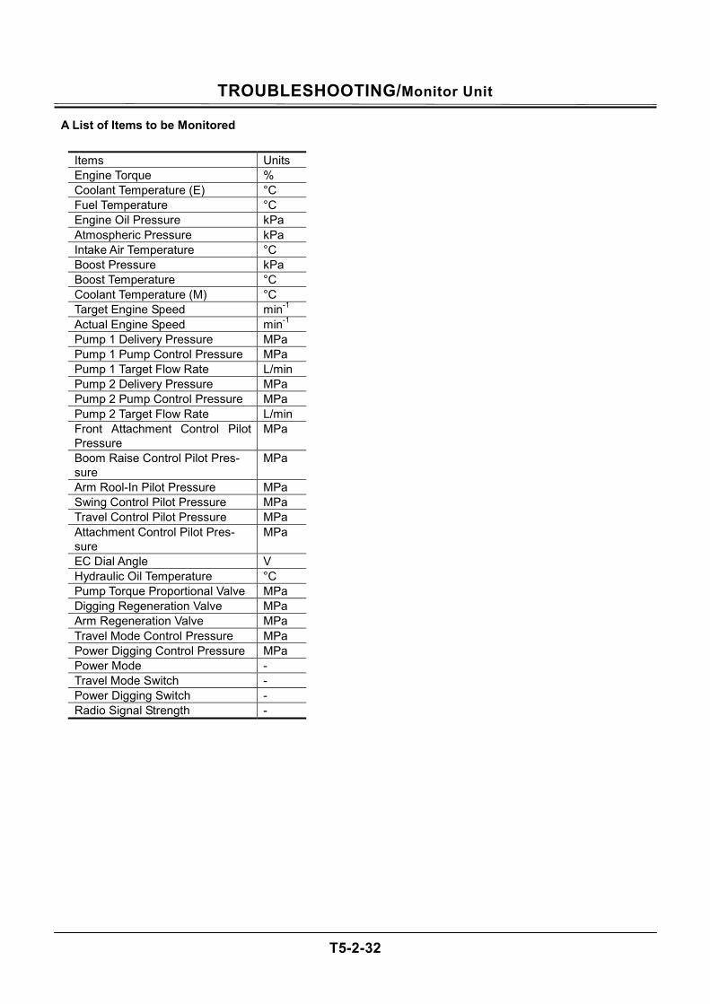
TROUBLESHOOTING/Monitor Unit
T5-2-32
A List of Items to be Monitored
Items Units Engine Torque % Coolant Temperature (E) °C Fuel Temperature °C Engine Oil Pressure kPa Atmospheric Pressure kPa Intake Air Temperature °C Boost Pressure kPa Boost Temperature °C Coolant Temperature (M) °C Target Engine Speed min-1 Actual Engine Speed min-1 Pump 1 Delivery Pressure MPa Pump 1 Pump Control Pressure MPa Pump 1 Target Flow Rate L/min Pump 2 Delivery Pressure MPa Pump 2 Pump Control Pressure MPa Pump 2 Target Flow Rate L/min Front Attachment Control Pilot Pressure
MPa
Boom Raise Control Pilot Pres-sure
MPa
Arm Rool-In Pilot Pressure MPa Swing Control Pilot Pressure MPa Travel Control Pilot Pressure MPa Attachment Control Pilot Pres-sure
MPa
EC Dial Angle V Hydraulic Oil Temperature °C Pump Torque Proportional Valve MPa Digging Regeneration Valve MPa Arm Regeneration Valve MPa Travel Mode Control Pressure MPa Power Digging Control Pressure MPa Power Mode - Travel Mode Switch - Power Digging Switch - Radio Signal Strength -
TROUBLESHOOTING/Monitor Unit
T5-2-33
DISPLAYING OPERATING CONDITIONS
1. When the primary screen appeared, push the menu key and display main menu.
2. Select operating conditions from main menu by
using keys 1 and 2. Push the confirm key. Then, the operating conditions screen appears.
3. Push the reset key, and a screen appears to con-
firm if it's OK to reset data. If it’s OK to reset data, push the confirm key.
NOTE: When pushing the back key, return to the
previous screen. IMPORTANT: Total fuel consumption and fuel
consumption rate depend on the operating environment and the op-eration method of machine. The values shown on the screen are just for reference. There could arise ± 20% of differ-ences between actual fuel consump-tion and fuel consumption which is displayed by the monitor unit.
4. Push key 6, and the primary screen appears.
T1V1-05-01-123
T1V5-05-01-019
T1V5-05-01-025
T1V5-05-01-026
Menu Key
Primary Screen
Confirm Key Key 1 Key 2
Confirm Key
Back Key
Key 6
Reset Key Back Key
TROUBLESHOOTING/Monitor Unit
T5-2-34
PUMP 2 FLOW RATE ADJUSTMENT (Only Machines Equipped with Optional Parts) IMPORTANT: This operation is effective when at-
tachments are used.
1. When the primary screen appears, push the menu key and display main menu.
2. Select attachment adjustment from main menu by
using keys 1 and 2. Push confirm key. Then, the attachment adjustment screen appears.
3. Push key 2. Then, the attachment adjustment
screen for currently installed attachments ap-pears.
4. Adjust flow rate of pump 2 by using keys 1 and 2. When using breaker 1 or breaker 2, pushing key 1 will decrease flow rate of pump 2 and pushing key 2 will increase respectively. When using the pulverizer or crusher, pushing key 1 will increase flow rate of boom raise, arm roll-out, swing or travel circuit sides. Pushing key 2 will increase flow rate of attach-ment side.
NOTE: When pushing the back key, return to the
previous screen.
5. Push key 6, and the primary screen appears.
T1V1-05-01-123
T1V5-05-01-019
T1V5-05-01-111
T1V5-05-01-024
Menu Key
Primary Screen
Confirm Key Key 1 Key 2
Back Key Key 1 Key 2
Back Key Key 1 Key 2
Key 6

TROUBLESHOOTING/Monitor Unit
T5-2-35
(Blank)
TROUBLESHOOTING/Monitor Unit
T5-2-36
ATTACHMENT SELECTION (Only Machines Equipped with Optional Parts) IMPORTANT: Select the attachments from the
work mode screen. In order to display the work mode screen, push key F1 after primary screen appears, or select from main menu.
Selecting an Attachment by Using Key F1
1. When the primary screen appears, push key F1
and display the work mode screen.
2. Push a relevant key under an attachment mark to be used in order to select the attachment. (In the right example, Crusher 1 is selected.)
NOTE: When selecting Digging, return to the pri-
mary screen.
3. On the attachment specification screen, confirm if specification of the installed attachment agrees with that displayed on the screen.
NOTE: When pushing the back key, return to the
previous screen.
4. Push confirm the key, and the primary screen appears.
T1V1-05-01-123
T1V5-05-01-109
T1V5-05-01-028
Key F1 Primary Screen
Back Key
Attachment Specification Screen
Confirm Key
Select Crusher 1 Work Mode Screen
Digging
Back Key
TROUBLESHOOTING/Monitor Unit
T5-2-37
Selecting an Attachment from Main Menu
1. When the primary screen appears, push the menu key and display main menu.
2. Select work mode from main menu by using keys
1 and 2. Push confirm key. Then, the work mode screen appears.
3. Push the relevant key under an attachment mark
to be used in order to select the attachment. (In the right example, Crusher 1 is selected.)
NOTE: When selecting digging, return to main
menu.
4. On the attachment specification screen, confirm if specification of the installed attachment agrees with that displayed on the screen. If they do not match, perform the setting of at-tachment by using Dr. ZX. For details of the attachment specification screen, refer to T5-2-38 and 39.
NOTE: When pushing the back key, return to the
previous screen.
5. Push the confirm key, and the primary screen appears.
T1V1-05-01-123
T1V5-05-01-019
T1V5-05-01-109
T1V5-05-01-028
Menu Key
Primary Screen
Confirm Key Key 1 Key 2
Back Key
Attachment Specification Screen
Confirm Key
Back Key
Select Crusher 1 Work Mode Screen
Digging
Back Key
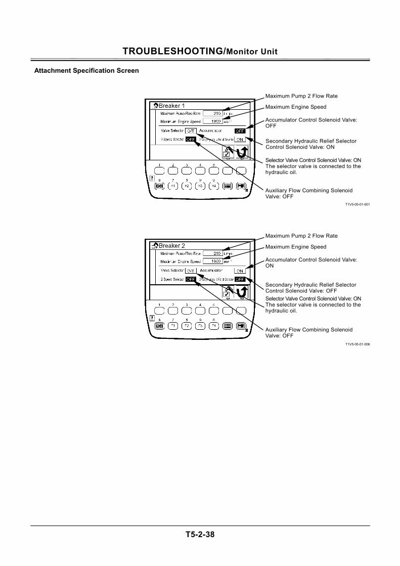
TROUBLESHOOTING/Monitor Unit
T5-2-38
Attachment Specification Screen
T1V5-05-01-001
T1V5-05-01-006
Maximum Pump 2 Flow Rate
Maximum Engine Speed
Accumulator Control Solenoid Valve: OFF
Secondary Hydraulic Relief Selector Control Solenoid Valve: ON
Selector Valve Control Solenoid Valve: ON The selector valve is connected to the hydraulic oil.
Auxiliary Flow Combining Solenoid Valve: OFF
Maximum Pump 2 Flow Rate
Maximum Engine Speed
Accumulator Control Solenoid Valve: ON
Secondary Hydraulic Relief Selector Control Solenoid Valve: OFF Selector Valve Control Solenoid Valve: ON The selector valve is connected to the hydraulic oil.
Auxiliary Flow Combining Solenoid Valve: OFF
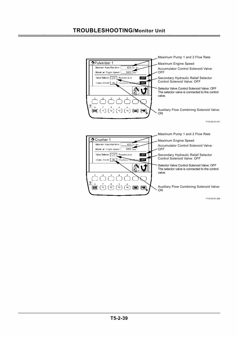
TROUBLESHOOTING/Monitor Unit
T5-2-39
T1V5-05-01-011
T1V5-05-01-028
Maximum Pump 1 and 2 Flow Rate
Maximum Engine Speed Accumulator Control Solenoid Valve: OFF
Secondary Hydraulic Relief Selector Control Solenoid Valve: OFF
Selector Valve Control Solenoid Valve: OFFThe selector valve is connected to the control valve.
Auxiliary Flow Combining Solenoid Valve: ON
Maximum Pump 1 and 2 Flow Rate
Maximum Engine Speed Accumulator Control Solenoid Valve: OFF
Secondary Hydraulic Relief Selector Control Solenoid Valve: OFF
Selector Valve Control Solenoid Valve: OFFThe selector valve is connected to the control valve.
Auxiliary Flow Combining Solenoid Valve: ON
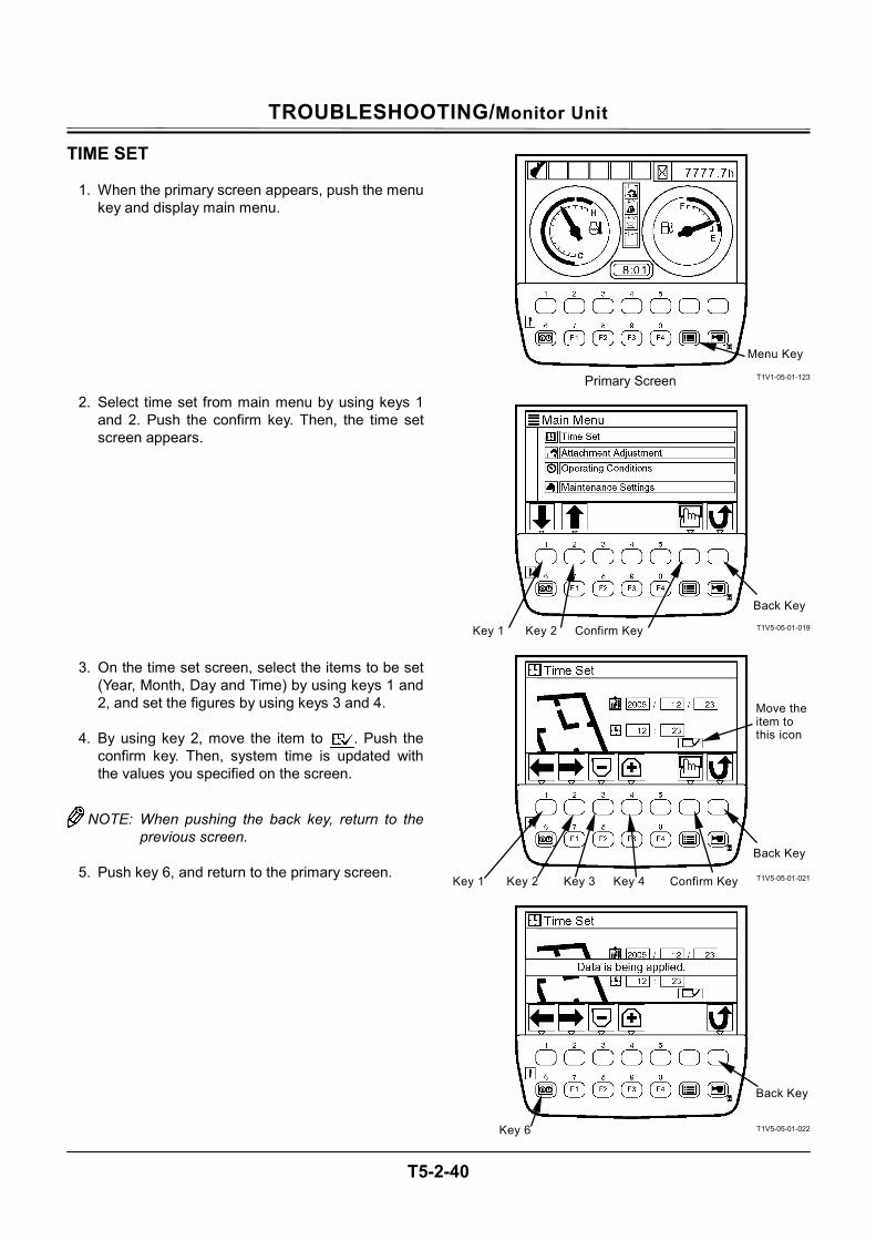
TROUBLESHOOTING/Monitor Unit
T5-2-40
TIME SET
1. When the primary screen appears, push the menu key and display main menu.
2. Select time set from main menu by using keys 1 and 2. Push the confirm key. Then, the time set screen appears.
3. On the time set screen, select the items to be set (Year, Month, Day and Time) by using keys 1 and 2, and set the figures by using keys 3 and 4.
4. By using key 2, move the item to . Push the
confirm key. Then, system time is updated with the values you specified on the screen.
NOTE: When pushing the back key, return to the previous screen.
5. Push key 6, and return to the primary screen.
T1V1-05-01-123
T1V5-05-01-019
T1V5-05-01-021
T1V5-05-01-022
Menu Key
Primary Screen
Back Key
Confirm Key
Move the item to this icon
Key 1 Key 2 Key 3 Key 4
Key 6
Back Key
Confirm Key Key 1 Key 2
Back Key

TROUBLESHOOTING/Monitor Unit
T5-2-41
(Blank)
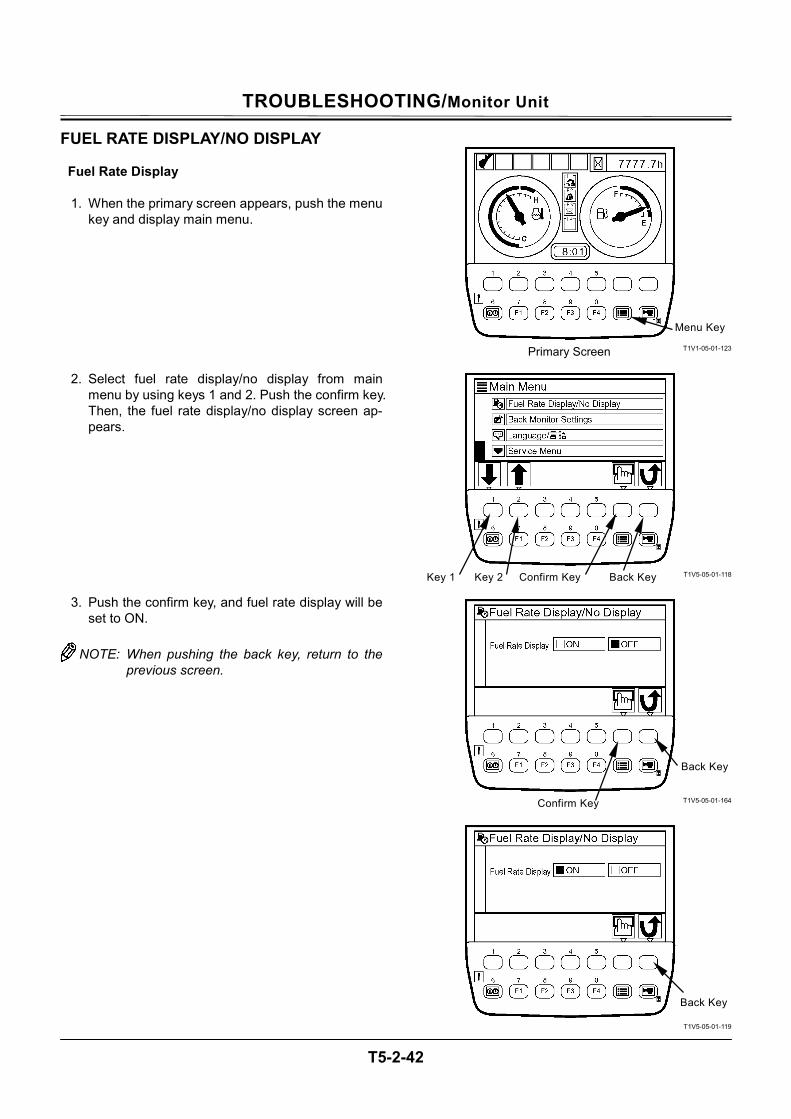
TROUBLESHOOTING/Monitor Unit
T5-2-42
FUEL RATE DISPLAY/NO DISPLAY
Fuel Rate Display
1. When the primary screen appears, push the menu key and display main menu.
2. Select fuel rate display/no display from main menu by using keys 1 and 2. Push the confirm key. Then, the fuel rate display/no display screen ap-pears.
3. Push the confirm key, and fuel rate display will be set to ON.
NOTE: When pushing the back key, return to the
previous screen.
T1V1-05-01-123
T1V5-05-01-118
T1V5-05-01-164
T1V5-05-01-119
Menu Key
Primary Screen
Confirm Key Key 1 Key 2
Confirm Key
Back Key
Back Key
Back Key
TROUBLESHOOTING/Monitor Unit
T5-2-43
4. Push key 6, and the fuel gauge will be added to primary screen.
T1V5-05-01-119
T1V1-05-01-007
Key 6
Fuel Gauge
TROUBLESHOOTING/Monitor Unit
T5-2-44
Fuel Rate No Display
1. When the primary screen appears, push the menu key and display main menu.
2. Select fuel rate display/no display from main menu by using keys 1 and 2. Push the confirm key. Then, the fuel rate display/no display screen ap-pears.
3. Push the confirm key, and fuel rate display will be set to OFF.
NOTE: When pushing the back key, return to the
previous screen.
T1V1-05-01-007
T1V5-05-01-118
T1V5-05-01-119
T1V5-05-01-164
Menu Key
Primary Screen
Fuel Gauge
Back Key
Confirm Key Key 1 Key 2 Back Key
Confirm Key
Back Key
TROUBLESHOOTING/Monitor Unit
T5-2-45
4. Push key 6, and return to the primary screen.
T1V5-05-01-164
T1V1-05-01-123
Primary Screen
Key 6
TROUBLESHOOTING/Monitor Unit
T5-2-46
BACK MONITOR SETTINGS IMPORTANT: Image displayed on the back monitor
is of auxiliary nature at best. When the machine is operated pay thor-ough attention to surrounding situa-tion.
Auto-Control: ON
Image on the monitor unit when traveling is automati-cally switched to that of the back monitor.
1. When the primary screen appears, push the menu key and display main menu.
2. Select back monitor settings from main menu by
using keys 1 and 2. Push the confirm key. Then, the back monitor settings screen appears.
3. Select auto-control by using keys 1 and 2. push the confirm key. then, auto-control is set to ON.
NOTE: When pushing the back key, return to the
primary screen.
4. Push key 6, and return to the primary screen.
5. If travel operation is done, backward image is displayed on the screen of monitor unit.
T1V1-05-01-123
T1V5-05-01-114
T1V5-05-01-134
T1V5-05-01-120
Key 6
Menu Key
Primary Screen
Back Key
Confirm Key Key 1 Key 2
Back Key
Key 1 Key 2 Confirm Key
Back Key
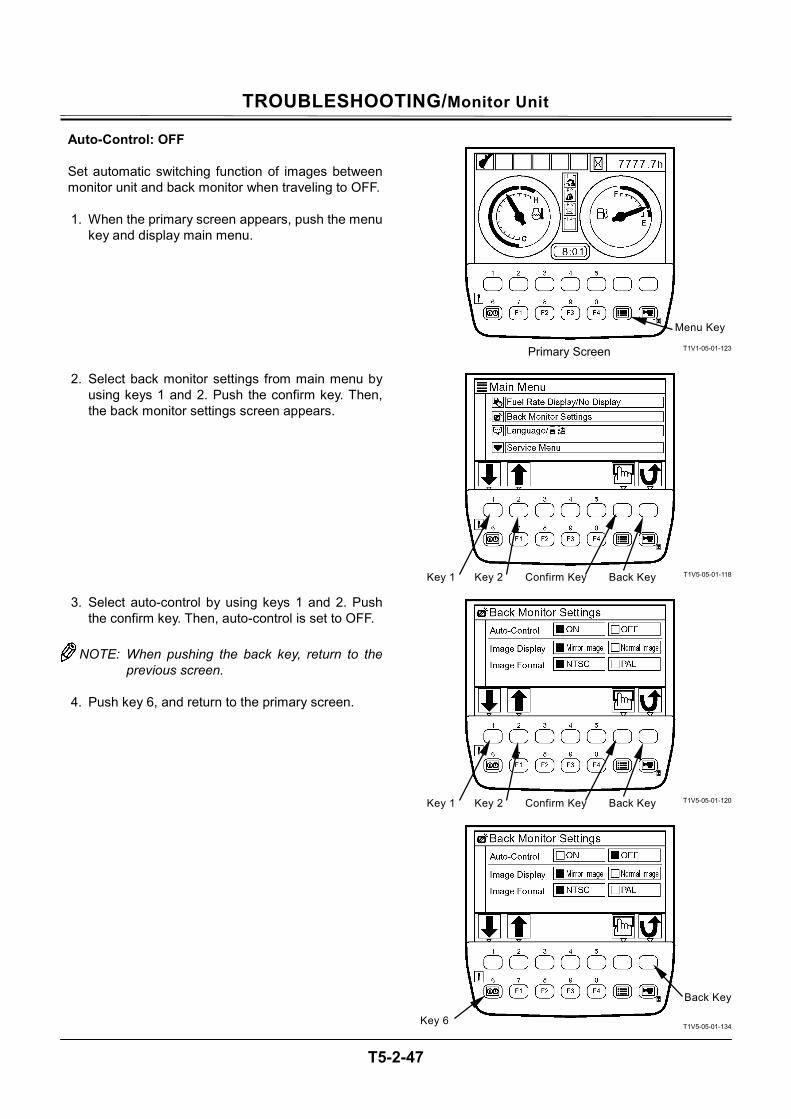
TROUBLESHOOTING/Monitor Unit
T5-2-47
Auto-Control: OFF
Set automatic switching function of images between monitor unit and back monitor when traveling to OFF.
1. When the primary screen appears, push the menu
key and display main menu.
2. Select back monitor settings from main menu by using keys 1 and 2. Push the confirm key. Then, the back monitor settings screen appears.
3. Select auto-control by using keys 1 and 2. Push the confirm key. Then, auto-control is set to OFF.
NOTE: When pushing the back key, return to the
previous screen.
4. Push key 6, and return to the primary screen.
T1V1-05-01-123
T1V5-05-01-118
T1V5-05-01-120
T1V5-05-01-134
Confirm Key Key 1 Key 2
Menu Key
Primary Screen
Back Key
Confirm Key Key 1 Key 2 Back Key
Back Key
Key 6
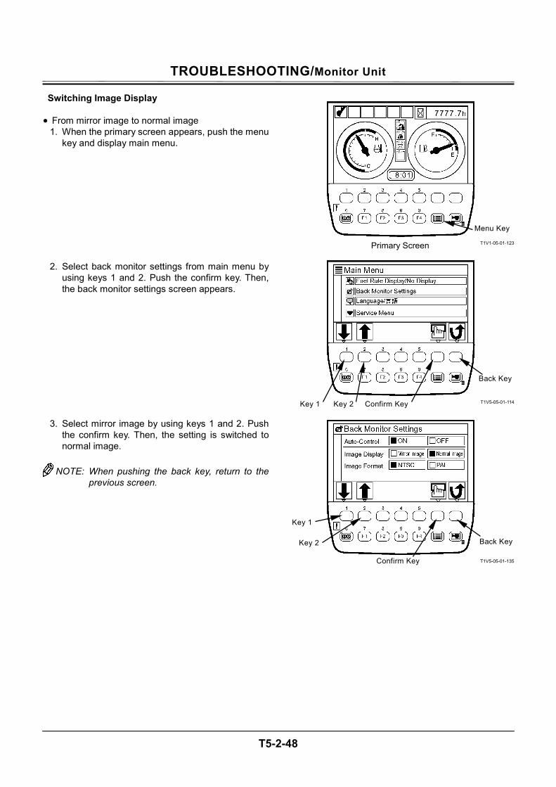
TROUBLESHOOTING/Monitor Unit
T5-2-48
Switching Image Display • From mirror image to normal image
1. When the primary screen appears, push the menu key and display main menu.
2. Select back monitor settings from main menu by using keys 1 and 2. Push the confirm key. Then, the back monitor settings screen appears.
3. Select mirror image by using keys 1 and 2. Push the confirm key. Then, the setting is switched to normal image.
NOTE: When pushing the back key, return to the
previous screen.
T1V1-05-01-123
T1V5-05-01-114
T1V5-05-01-135
Menu Key
Primary Screen
Key 1
Key 2 Back Key
Confirm Key
Confirm Key Key 1 Key 2
Back Key
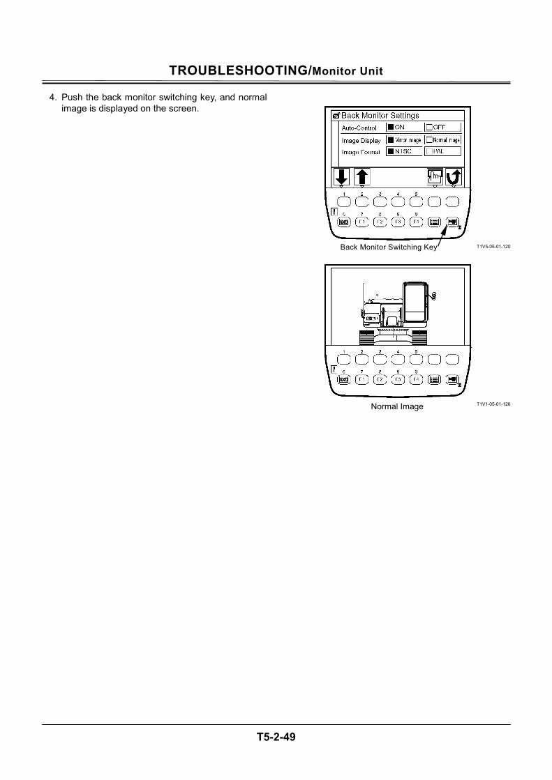
TROUBLESHOOTING/Monitor Unit
T5-2-49
4. Push the back monitor switching key, and normal image is displayed on the screen.
T1V5-05-01-120
T1V1-05-01-126 Normal Image
Back Monitor Switching Key
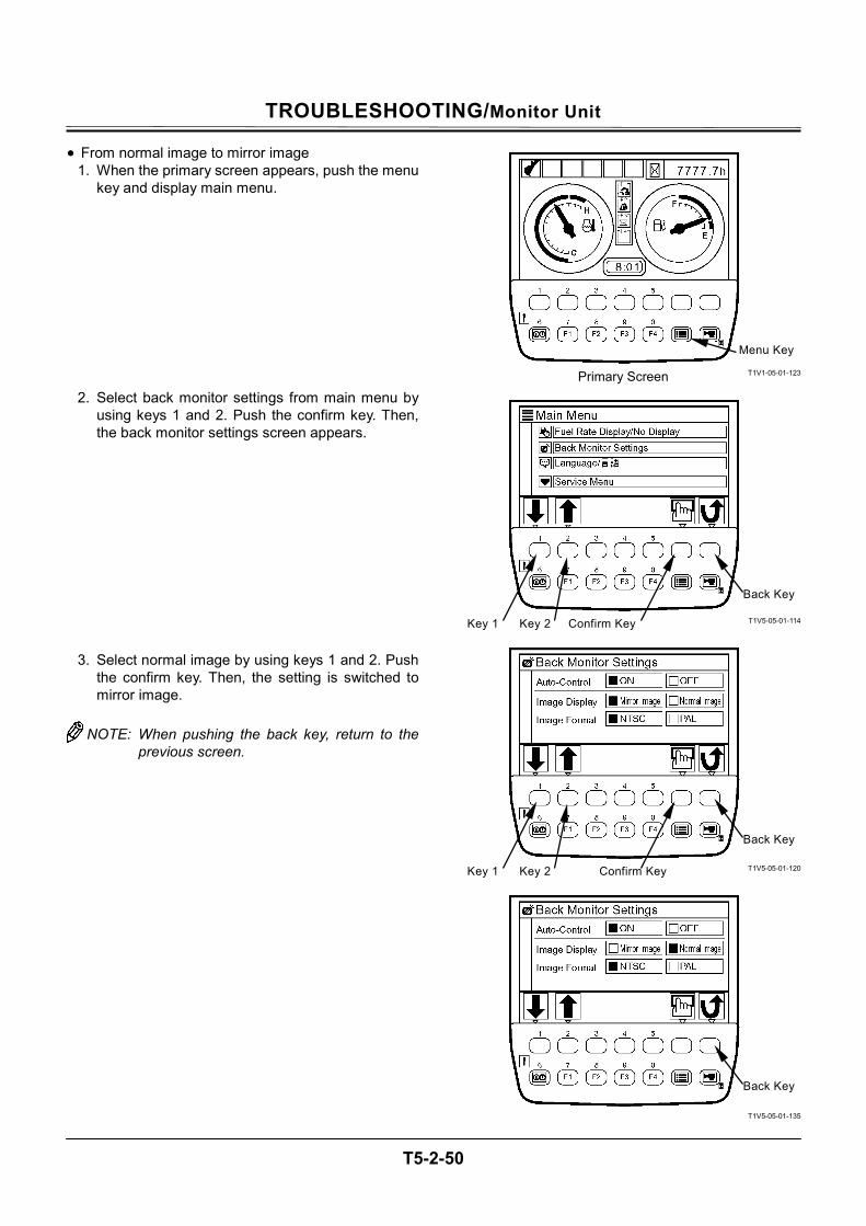
TROUBLESHOOTING/Monitor Unit
T5-2-50
• From normal image to mirror image 1. When the primary screen appears, push the menu
key and display main menu.
2. Select back monitor settings from main menu by using keys 1 and 2. Push the confirm key. Then, the back monitor settings screen appears.
3. Select normal image by using keys 1 and 2. Push the confirm key. Then, the setting is switched to mirror image.
NOTE: When pushing the back key, return to the
previous screen.
T1V1-05-01-123
T1V5-05-01-114
T1V5-05-01-120
T1V5-05-01-135
Menu Key
Primary Screen
Confirm Key Key 1 Key 2
Confirm Key Key 1 Key 2
Back Key
Back Key
Back Key
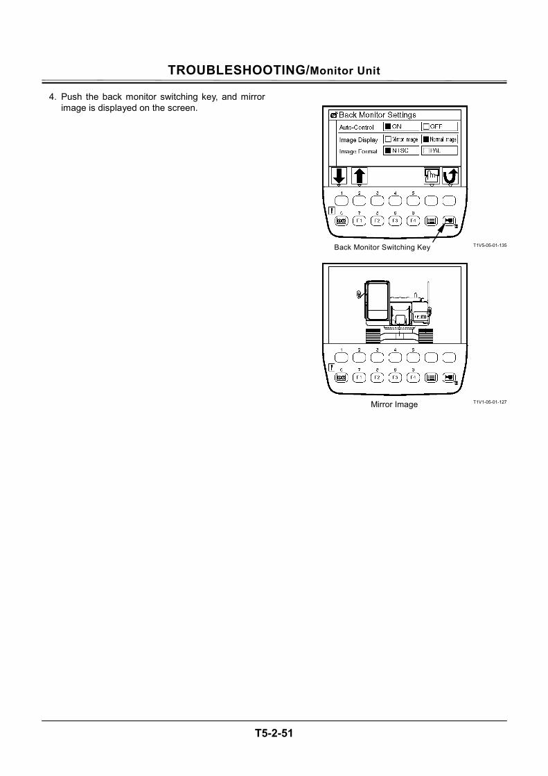
TROUBLESHOOTING/Monitor Unit
T5-2-51
4. Push the back monitor switching key, and mirror image is displayed on the screen.
T1V5-05-01-135
T1V1-05-01-127 Mirror Image
Back Monitor Switching Key
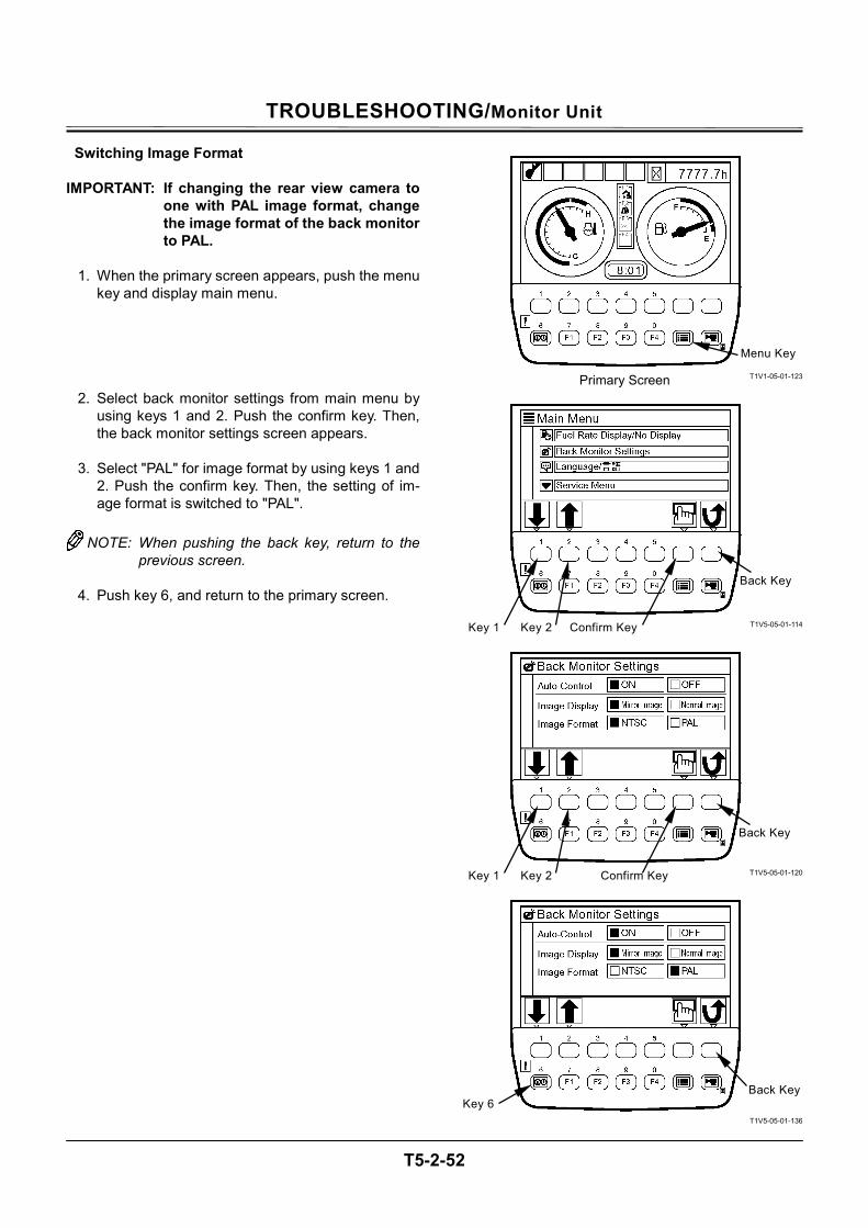
TROUBLESHOOTING/Monitor Unit
T5-2-52
Switching Image Format IMPORTANT: If changing the rear view camera to
one with PAL image format, change the image format of the back monitor to PAL.
1. When the primary screen appears, push the menu
key and display main menu.
2. Select back monitor settings from main menu by using keys 1 and 2. Push the confirm key. Then, the back monitor settings screen appears.
3. Select "PAL" for image format by using keys 1 and
2. Push the confirm key. Then, the setting of im-age format is switched to "PAL".
NOTE: When pushing the back key, return to the
previous screen.
4. Push key 6, and return to the primary screen.
T1V1-05-01-123
T1V5-05-01-114
T1V5-05-01-120
T1V5-05-01-136
Menu Key
Primary Screen
Back KeyKey 6
Confirm Key Key 1 Key 2
Confirm Key Key 1 Key 2
Back Key
Back Key

TROUBLESHOOTING/Monitor Unit
T5-2-53
(Blank)
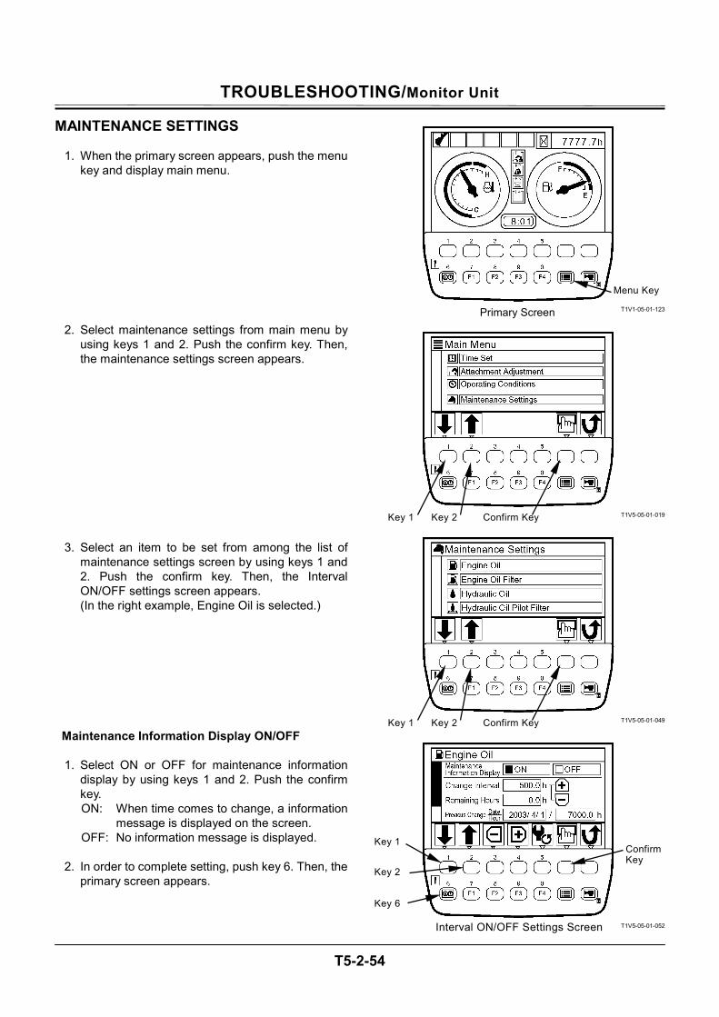
TROUBLESHOOTING/Monitor Unit
T5-2-54
MAINTENANCE SETTINGS
1. When the primary screen appears, push the menu key and display main menu.
2. Select maintenance settings from main menu by using keys 1 and 2. Push the confirm key. Then, the maintenance settings screen appears.
3. Select an item to be set from among the list of maintenance settings screen by using keys 1 and 2. Push the confirm key. Then, the Interval ON/OFF settings screen appears. (In the right example, Engine Oil is selected.)
Maintenance Information Display ON/OFF
1. Select ON or OFF for maintenance information display by using keys 1 and 2. Push the confirm key. ON: When time comes to change, a information
message is displayed on the screen. OFF: No information message is displayed.
2. In order to complete setting, push key 6. Then, the
primary screen appears.
T1V1-05-01-123
T1V5-05-01-019
T1V5-05-01-049
T1V5-05-01-052
Menu Key
Primary Screen
Confirm Key Key 1 Key 2
Confirm Key Key 1 Key 2
Confirm Key
Interval ON/OFF Settings Screen
Key 6
Key 1
Key 2
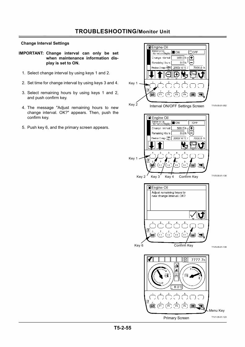
TROUBLESHOOTING/Monitor Unit
T5-2-55
Change Interval Settings IMPORTANT: Change interval can only be set
when maintenance information dis-play is set to ON.
1. Select change interval by using keys 1 and 2.
2. Set time for change interval by using keys 3 and 4.
3. Select remaining hours by using keys 1 and 2,
and push confirm key.
4. The message "Adjust remaining hours to new change interval. OK?" appears. Then, push the confirm key.
5. Push key 6, and the primary screen appears.
T1V5-05-01-052
T1V5-05-01-138
T1V5-05-01-139
T1V1-05-01-123
Key 1
Key 2 Key 3 Confirm Key
Key 6 Confirm Key
Menu Key
Primary Screen
Key 4
Interval ON/OFF Settings Screen
Key 1
Key 2
TROUBLESHOOTING/Monitor Unit
T5-2-56
Resetting Data
If data is reset, push key 5 on the Interval ON/OFF settings screen. The message "Reset Data. OK?" appears. Then, push the confirm key. The value of remaining hours is reset to that of change interval. Previous change date/hour is up-dated with current date and time.
T1V5-05-01-052
T1V5-05-01-140
Confirm Key
Interval ON/OFF Settings Screen
Key 5

TROUBLESHOOTING/Monitor Unit
T5-2-57
(Blank)
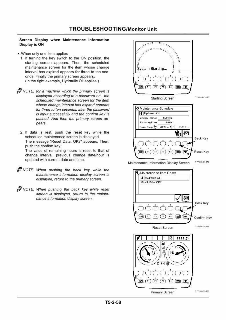
TROUBLESHOOTING/Monitor Unit
T5-2-58
Screen Display when Maintenance Information Display is ON
• When only one item applies
1. If turning the key switch to the ON position, the starting screen appears. Then, the scheduled maintenance screen for the item whose change interval has expired appears for three to ten sec-onds. Finally the primary screen appears. (In the right example, Hydraulic Oil applies.)
NOTE: for a machine which the primary screen is
displayed according to a password on , the scheduled maintenance screen for the item whose change interval has expired appears for three to ten seconds, after the password is input successfully and the confirm key is pushed. And then the primary screen ap-pears.
2. If data is rest, push the reset key while the
scheduled maintenance screen is displayed. The message "Reset Data. OK?" appears. Then, push the confirm key. The value of remaining hours is reset to that of change interval. previous change date/hour is updated with current date and time.
NOTE: When pushing the back key while the
maintenance information display screen is displayed, return to the primary screen.
NOTE: When pushing the back key while reset
screen is displayed, return to the mainte-nance information display screen.
T1V1-05-01-115
T1V5-05-01-170
T1V5-05-01-171
T1V1-05-01-123
Starting Screen
Primary Screen
Reset Key
Back Key
Maintenance Information Display Screen
Confirm Key
Back Key
Reset Screen
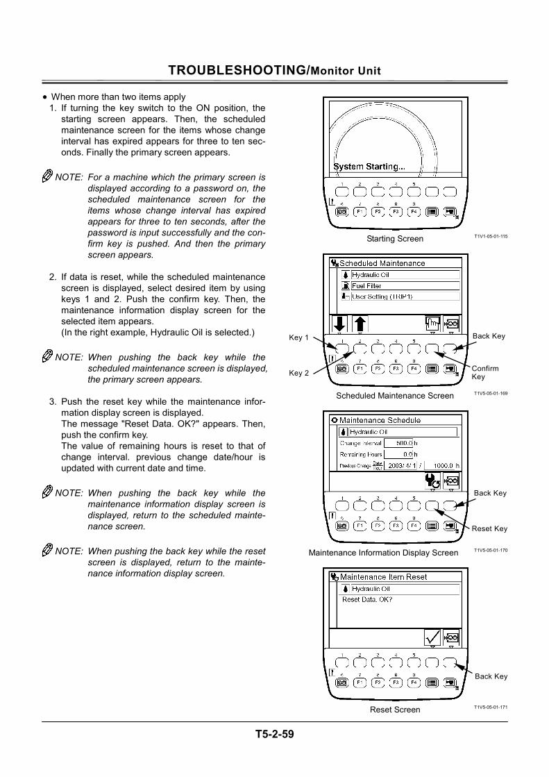
TROUBLESHOOTING/Monitor Unit
T5-2-59
• When more than two items apply 1. If turning the key switch to the ON position, the
starting screen appears. Then, the scheduled maintenance screen for the items whose change interval has expired appears for three to ten sec-onds. Finally the primary screen appears.
NOTE: For a machine which the primary screen is
displayed according to a password on, the scheduled maintenance screen for the items whose change interval has expired appears for three to ten seconds, after the password is input successfully and the con-firm key is pushed. And then the primary screen appears.
2. If data is reset, while the scheduled maintenance
screen is displayed, select desired item by using keys 1 and 2. Push the confirm key. Then, the maintenance information display screen for the selected item appears. (In the right example, Hydraulic Oil is selected.)
NOTE: When pushing the back key while the
scheduled maintenance screen is displayed, the primary screen appears.
3. Push the reset key while the maintenance infor-
mation display screen is displayed. The message "Reset Data. OK?" appears. Then, push the confirm key. The value of remaining hours is reset to that of change interval. previous change date/hour is updated with current date and time.
NOTE: When pushing the back key while the
maintenance information display screen is displayed, return to the scheduled mainte-nance screen.
NOTE: When pushing the back key while the reset
screen is displayed, return to the mainte-nance information display screen.
T1V1-05-01-115
T1V5-05-01-169
T1V5-05-01-170
T1V5-05-01-171
Starting Screen
Confirm Key
Back Key
Scheduled Maintenance Screen
Key 1
Key 2
Reset Screen
Reset Key
Back Key
Maintenance Information Display Screen
Back Key
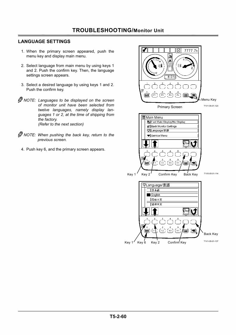
TROUBLESHOOTING/Monitor Unit
T5-2-60
LANGUAGE SETTINGS
1. When the primary screen appeared, push the menu key and display main menu.
2. Select language from main menu by using keys 1
and 2. Push the confirm key. Then, the language settings screen appears.
3. Select a desired language by using keys 1 and 2.
Push the confirm key.
NOTE: Languages to be displayed on the screen of monitor unit have been selected from twelve languages, namely display lan-guages 1 or 2, at the time of shipping from the factory. (Refer to the next section)
NOTE: When pushing the back key, return to the
previous screen.
4. Push key 6, and the primary screen appears.
T1V1-05-01-123
T1V5-05-01-114
T1V1-05-01-137
Menu Key
Primary Screen
Confirm Key Key 1 Key 2
Confirm Key Key 1 Key 2Key 6
Back Key
Back Key
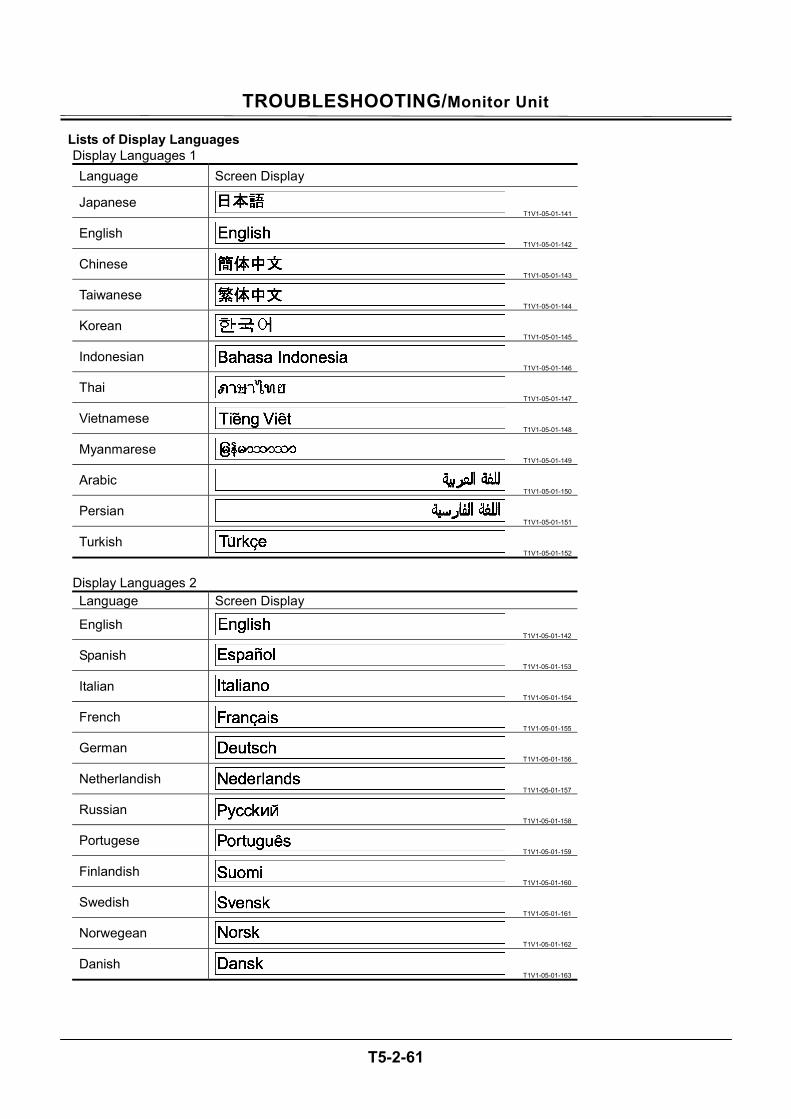
TROUBLESHOOTING/Monitor Unit
T5-2-61
Lists of Display LanguagesDisplay Languages 1 Language Screen Display
Japanese T1V1-05-01-141
English T1V1-05-01-142
Chinese T1V1-05-01-143
Taiwanese T1V1-05-01-144
Korean T1V1-05-01-145
Indonesian T1V1-05-01-146
Thai T1V1-05-01-147
Vietnamese T1V1-05-01-148
Myanmarese T1V1-05-01-149
Arabic T1V1-05-01-150
Persian T1V1-05-01-151
Turkish T1V1-05-01-152
Display Languages 2 Language Screen Display
English T1V1-05-01-142
Spanish T1V1-05-01-153
Italian T1V1-05-01-154
French T1V1-05-01-155
German T1V1-05-01-156
Netherlandish T1V1-05-01-157
Russian T1V1-05-01-158
Portugese T1V1-05-01-159
Finlandish T1V1-05-01-160
Swedish T1V1-05-01-161
Norwegean T1V1-05-01-162
Danish T1V1-05-01-163
TROUBLESHOOTING/Monitor Unit
T5-2-62
MAIL (Optional) IMPORTANT: This function is available only to a
machine equipped with a satellite terminal. When using the mail function, make the mail function avaiable by using Dr. ZX.
1. When the primary screen appears, push key F3
and display mail screen.
2. If pushing a relevant request key, mail information is sent to ICF. 1 - General Request 2 - Fuel Replenishment Request 3 - Service Maintenance Request 4 - Forwarding Request
3. While mail information is sent to ICF, the message
"Mail is being delivered." is displayed on the screen.
4. When ICF completes receives mail information,
the message "Mail delivery successful." is dis-played on the screen. When pushing the back key, return to the mail screen.
5. Then, a mail is sent from the satellite terminal to
the central server via the satellite.
NOTE: Depending on machine's operating envi-ronment or position of the satellite on its orbit, the mail may not be sent.
T1V1-05-01-123
T1V5-05-01-037
T1V5-05-01-038
T1V5-05-01-039
Key F3 Primary Screen
Back Key
Mail Screen 1 2 3 4
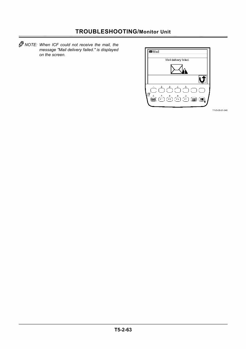
TROUBLESHOOTING/Monitor Unit
T5-2-63
NOTE: When ICF could not receive the mail, the message "Mail delivery failed." is displayed on the screen.
T1V5-05-01-040

TROUBLESHOOTING/Monitor Unit
T5-2-64
(Blank)
TROUBLESHOOTING / Dr. ZX
T5-3-1
OUTLINE Dr. ZX is used for diagnosis of electrical system including MC, EMC, ICF and monitor unit. Dr. ZX is connected to ICF and failure of each controller and each sensor is displayed as a fault code. (Self-Fiagnostic Result) Dr. ZX displays the input status of sensors and switches connected to each controller and the output status to actuator including solenoid valve from controller with the machine operated in real time. (Controller Diagnosis)
TROUBLESHOOTING / Dr. ZX
T5-3-2
Operation 1. Connect Palm (Dr. ZX) to the diagnosing
connector in the cab by using the Hot Sync cable and connecting harness.
2. Turn the key switch ON or start the engine. 3. When turning Palm ON, the following screen is
displayed on the display of Palm. 3-1. Initial Screen
Select Dr. ZX icon. 3-2. Password Setup Screen (When the
password has unset) Set the password. 3-3. Service Software Selection Screen
Select ZX-3 Mid. 3-4. Function Selection Screen
Self-Diagnostic Result Select Controller
4. Select Self-Diagnostic Result and operate according to the instruction under display screen.
T1V1-05-07-001
T1V1-05-07-002
Palm (Dr. ZX)
Hot Sync Cable
Connecting Harness
+
+
Dr. ZX Connector
+
TROUBLESHOOTING / Dr. ZX
T5-3-3
T1V7-05-03-165
•Check Communication Hraness •Check Harness
Communication Error
Initial Screen
Start
RecordSelf-Diagnostic Result of EachController
Self-Diagnostic Result Function
Select Controller
Select Controller Select Function
Main Menu • Monitor Display• Special Function• Setup Disp. Record Password ChangeOp. Manual.
Service Software Selection Screen
Main Menu • Monitor DisplayDisp. Record Password Change
Main Menu • Information C/U
Various Setup • Data Download • Save Data Check Password Change
Main Menu • Monitoring • Various Setup Password Change
Self-Diagnostic Result
Retry B
Main Controller Engine Controller
ICF Controller
Monitor Controller
When the password has unset
•Input Password Input the former password (6 characters or more). Next time, input the same password in order to check and push OK.
When the password has unset
Password Setup Screen
Select ZX-3 Mid
TROUBLESHOOTING / Dr. ZX
T5-3-4
Self-Diagnostic Result The self-diagnostic result of each controller is displayed. After starting Dr. ZX, push Self-Diagnostic Result.
T1V7-05-03-001
T1V7-05-03-008
T1V7-05-03-002
NOTE: Main C/U: MC
Engine C/U: ECM Monitor Unit: Monitor Unit Information C/U: ICF
NOTE: Self-diagnosis of ICF controller is done on
the next page.
Function Selection Screen Controller Self- Diagnosis Screen
TROUBLESHOOTING / Dr. ZX
T5-3-5
Self-Diagnosis
T1V7-05-03-001
T1V7-05-03-003
T1V7-05-03-008
T1V7-05-03-005
T1V7-05-03-002
T1V7-05-03-002
T1V7-05-03-007
Controller Self- Diagnosis Screen
Push Fault of ICF Controller. Incase of no faulty, No Fault isdisplayed.
After starting Dr. ZX, pushSelf-Diagnostic Result.
Function Selection Screen Controller Self- Diagnosis Screen
To the lower
If the message of Details islong, push the arrow andchange the screen.
By changing the page, the forward and backward fault code is displayed.
Retry B
ESC
ESC
Retry B
Push ESC and Retry B Screen isdisplayed.
Push Retry B and return toController Self-Diagnosis Screenafter executing Retry B. Push ESC and return to ControllerSelf-Diagnosis Screen directly.
Retry B Screen
ESC
Trouble
Push Details, and Details of thefault code and Corrective Actionare displayed. Push ESC and Retry B isdisplayed.
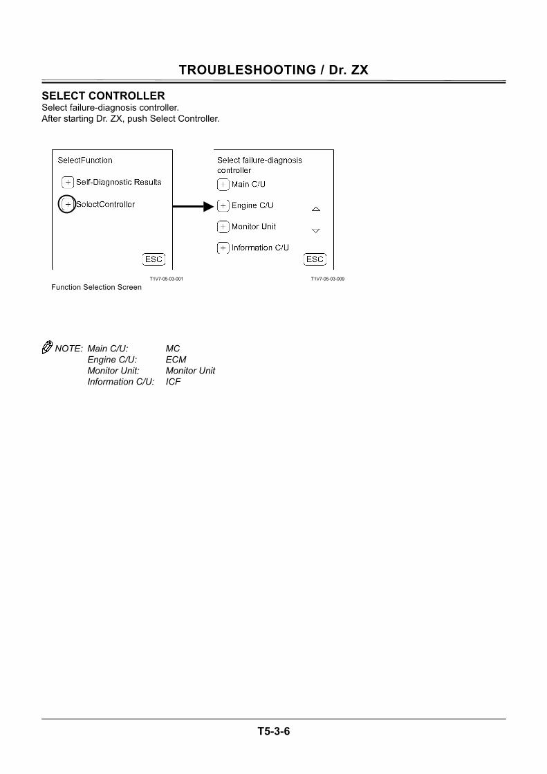
TROUBLESHOOTING / Dr. ZX
T5-3-6
SELECT CONTROLLER Select failure-diagnosis controller. After starting Dr. ZX, push Select Controller.
T1V7-05-03-001
T1V7-05-03-009
NOTE: Main C/U: MC
Engine C/U: ECM Monitor Unit: Monitor Unit Information C/U: ICF
Function Selection Screen
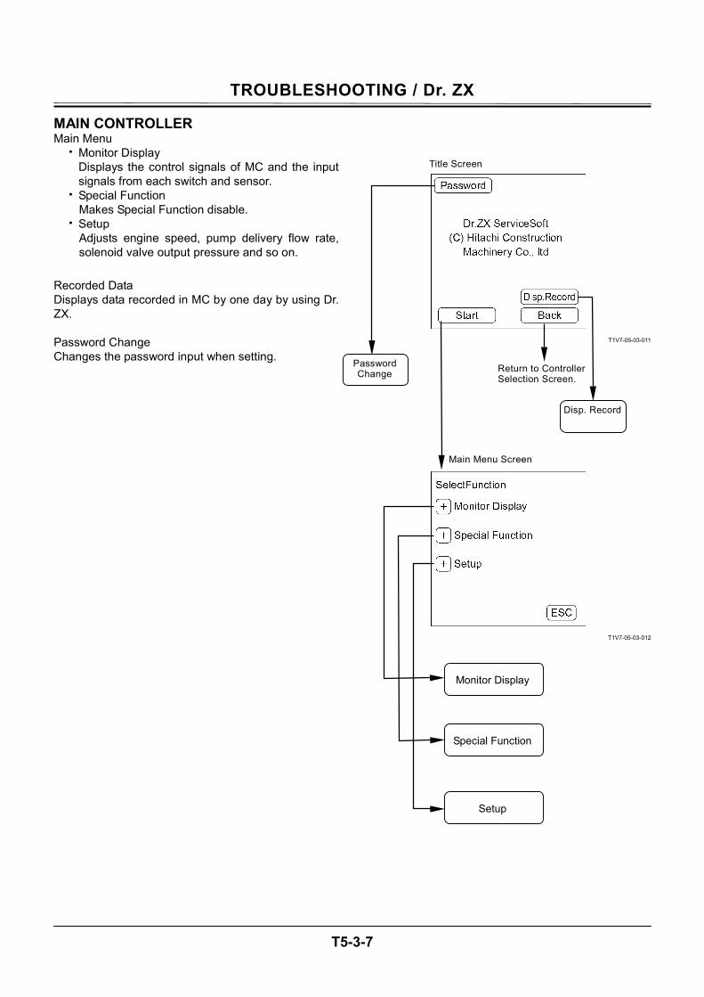
TROUBLESHOOTING / Dr. ZX
T5-3-7
MAIN CONTROLLER Main Menu
• Monitor Display Displays the control signals of MC and the input signals from each switch and sensor.
• Special Function Makes Special Function disable.
• Setup Adjusts engine speed, pump delivery flow rate, solenoid valve output pressure and so on.
Recorded Data Displays data recorded in MC by one day by using Dr. ZX. Password Change Changes the password input when setting.
T1V7-05-03-011
T1V7-05-03-012
Password Change
Disp. Record
Return to Controller Selection Screen.
Monitor Display
Special Function
Setup
Title Screen
Main Menu Screen
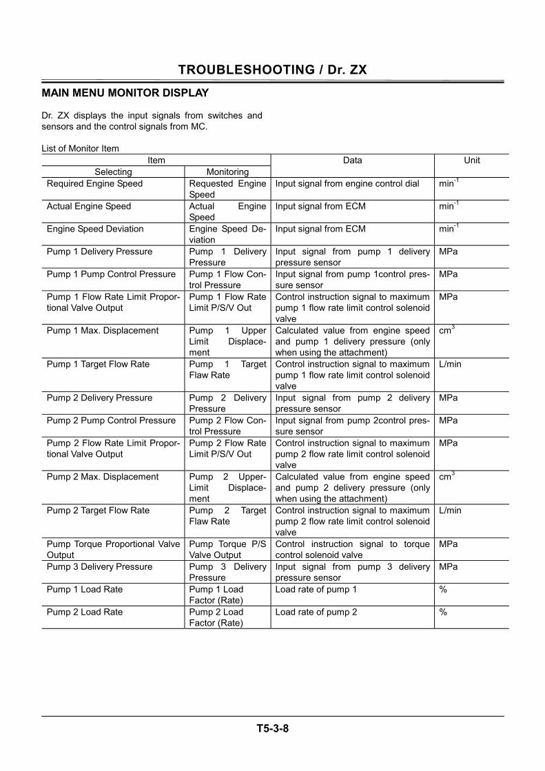
TROUBLESHOOTING / Dr. ZX
T5-3-8
MAIN MENU MONITOR DISPLAY Dr. ZX displays the input signals from switches and sensors and the control signals from MC. List of Monitor Item
Item Selecting Monitoring
Data Unit
Required Engine Speed Requested Engine Speed
Input signal from engine control dial min-1
Actual Engine Speed Actual Engine Speed
Input signal from ECM min-1
Engine Speed Deviation Engine Speed De-viation
Input signal from ECM min-1
Pump 1 Delivery Pressure Pump 1 Delivery Pressure
Input signal from pump 1 delivery pressure sensor
MPa
Pump 1 Pump Control Pressure Pump 1 Flow Con-trol Pressure
Input signal from pump 1control pres-sure sensor
MPa
Pump 1 Flow Rate Limit Propor-tional Valve Output
Pump 1 Flow Rate Limit P/S/V Out
Control instruction signal to maximum pump 1 flow rate limit control solenoid valve
MPa
Pump 1 Max. Displacement Pump 1 Upper Limit Displace-ment
Calculated value from engine speed and pump 1 delivery pressure (only when using the attachment)
cm3
Pump 1 Target Flow Rate Pump 1 Target Flaw Rate
Control instruction signal to maximum pump 1 flow rate limit control solenoid valve
L/min
Pump 2 Delivery Pressure Pump 2 Delivery Pressure
Input signal from pump 2 delivery pressure sensor
MPa
Pump 2 Pump Control Pressure Pump 2 Flow Con-trol Pressure
Input signal from pump 2control pres-sure sensor
MPa
Pump 2 Flow Rate Limit Propor-tional Valve Output
Pump 2 Flow Rate Limit P/S/V Out
Control instruction signal to maximum pump 2 flow rate limit control solenoid valve
MPa
Pump 2 Max. Displacement Pump 2 Upper-Limit Displace-ment
Calculated value from engine speed and pump 2 delivery pressure (only when using the attachment)
cm3
Pump 2 Target Flow Rate Pump 2 Target Flaw Rate
Control instruction signal to maximum pump 2 flow rate limit control solenoid valve
L/min
Pump Torque Proportional Valve Output
Pump Torque P/S Valve Output
Control instruction signal to torque control solenoid valve
MPa
Pump 3 Delivery Pressure Pump 3 Delivery Pressure
Input signal from pump 3 delivery pressure sensor
MPa
Pump 1 Load Rate Pump 1 Load Factor (Rate)
Load rate of pump 1 %
Pump 2 Load Rate Pump 2 Load Factor (Rate)
Load rate of pump 2 %
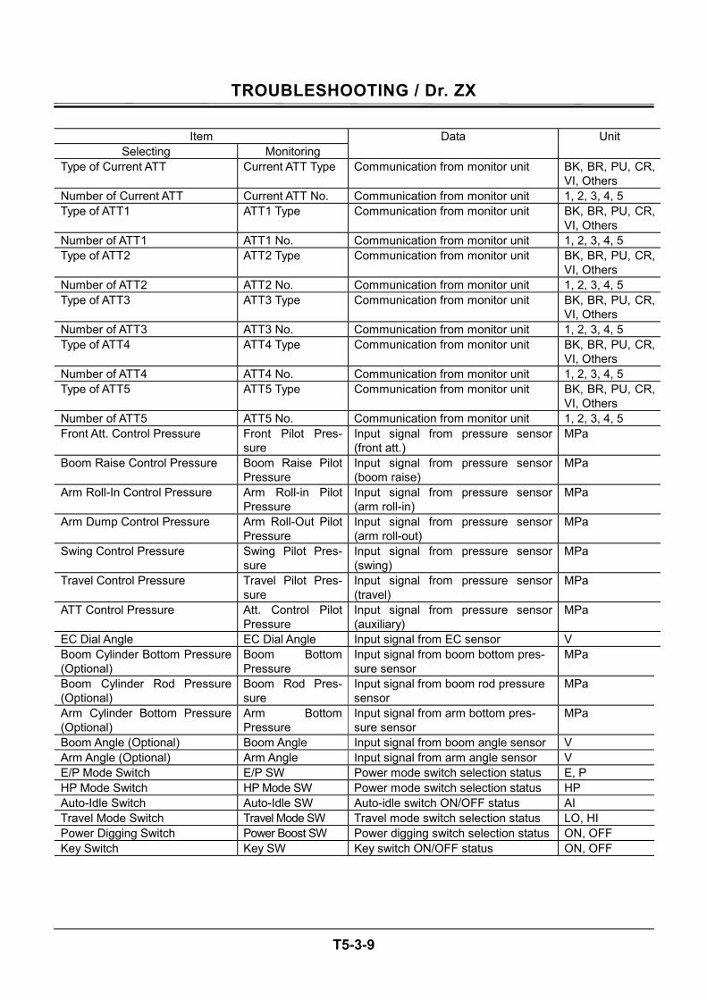
TROUBLESHOOTING / Dr. ZX
T5-3-9
Item
Selecting Monitoring Data Unit
Type of Current ATT Current ATT Type Communication from monitor unit BK, BR, PU, CR, VI, Others
Number of Current ATT Current ATT No. Communication from monitor unit 1, 2, 3, 4, 5 Type of ATT1 ATT1 Type Communication from monitor unit BK, BR, PU, CR,
VI, Others Number of ATT1 ATT1 No. Communication from monitor unit 1, 2, 3, 4, 5 Type of ATT2 ATT2 Type Communication from monitor unit BK, BR, PU, CR,
VI, Others Number of ATT2 ATT2 No. Communication from monitor unit 1, 2, 3, 4, 5 Type of ATT3 ATT3 Type Communication from monitor unit BK, BR, PU, CR,
VI, Others Number of ATT3 ATT3 No. Communication from monitor unit 1, 2, 3, 4, 5 Type of ATT4 ATT4 Type Communication from monitor unit BK, BR, PU, CR,
VI, Others Number of ATT4 ATT4 No. Communication from monitor unit 1, 2, 3, 4, 5 Type of ATT5 ATT5 Type Communication from monitor unit BK, BR, PU, CR,
VI, Others Number of ATT5 ATT5 No. Communication from monitor unit 1, 2, 3, 4, 5 Front Att. Control Pressure Front Pilot Pres-
sure Input signal from pressure sensor (front att.)
MPa
Boom Raise Control Pressure Boom Raise Pilot Pressure
Input signal from pressure sensor (boom raise)
MPa
Arm Roll-In Control Pressure Arm Roll-in Pilot Pressure
Input signal from pressure sensor (arm roll-in)
MPa
Arm Dump Control Pressure Arm Roll-Out Pilot Pressure
Input signal from pressure sensor (arm roll-out)
MPa
Swing Control Pressure Swing Pilot Pres-sure
Input signal from pressure sensor (swing)
MPa
Travel Control Pressure Travel Pilot Pres-sure
Input signal from pressure sensor (travel)
MPa
ATT Control Pressure Att. Control Pilot Pressure
Input signal from pressure sensor (auxiliary)
MPa
EC Dial Angle EC Dial Angle Input signal from EC sensor V Boom Cylinder Bottom Pressure (Optional)
Boom Bottom Pressure
Input signal from boom bottom pres-sure sensor
MPa
Boom Cylinder Rod Pressure (Optional)
Boom Rod Pres-sure
Input signal from boom rod pressure sensor
MPa
Arm Cylinder Bottom Pressure (Optional)
Arm Bottom Pressure
Input signal from arm bottom pres-sure sensor
MPa
Boom Angle (Optional) Boom Angle Input signal from boom angle sensor V Arm Angle (Optional) Arm Angle Input signal from arm angle sensor V E/P Mode Switch E/P SW Power mode switch selection status E, P HP Mode Switch HP Mode SW Power mode switch selection status HP Auto-Idle Switch Auto-Idle SW Auto-idle switch ON/OFF status AI Travel Mode Switch Travel Mode SW Travel mode switch selection status LO, HI Power Digging Switch Power Boost SW Power digging switch selection status ON, OFF Key Switch Key SW Key switch ON/OFF status ON, OFF
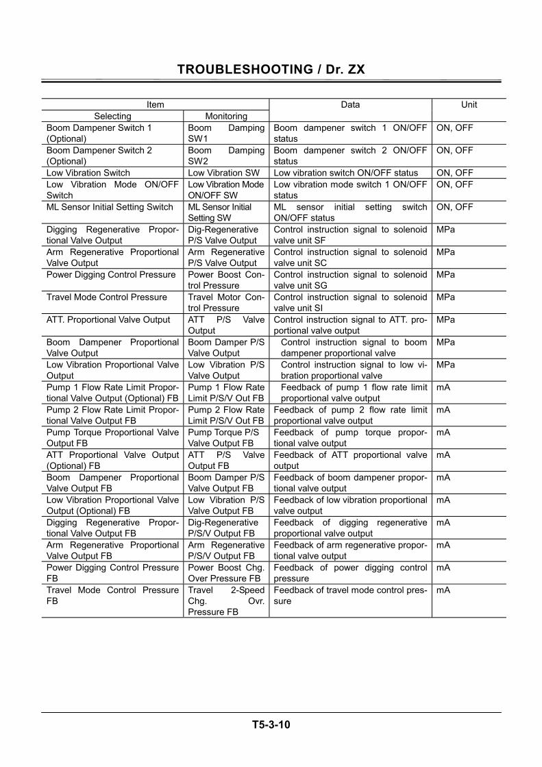
TROUBLESHOOTING / Dr. ZX
T5-3-10
Item
Selecting Monitoring Data Unit
Boom Dampener Switch 1 (Optional)
Boom Damping SW1
Boom dampener switch 1 ON/OFF status
ON, OFF
Boom Dampener Switch 2 (Optional)
Boom Damping SW2
Boom dampener switch 2 ON/OFF status
ON, OFF
Low Vibration Switch Low Vibration SW Low vibration switch ON/OFF status ON, OFF Low Vibration Mode ON/OFF Switch
Low Vibration Mode ON/OFF SW
Low vibration mode switch 1 ON/OFF status
ON, OFF
ML Sensor Initial Setting Switch ML Sensor Initial Setting SW
ML sensor initial setting switch ON/OFF status
ON, OFF
Digging Regenerative Propor-tional Valve Output
Dig-Regenerative P/S Valve Output
Control instruction signal to solenoid valve unit SF
MPa
Arm Regenerative Proportional Valve Output
Arm Regenerative P/S Valve Output
Control instruction signal to solenoid valve unit SC
MPa
Power Digging Control Pressure Power Boost Con-trol Pressure
Control instruction signal to solenoid valve unit SG
MPa
Travel Mode Control Pressure Travel Motor Con-trol Pressure
Control instruction signal to solenoid valve unit SI
MPa
ATT. Proportional Valve Output ATT P/S Valve Output
Control instruction signal to ATT. pro-portional valve output
MPa
Boom Dampener Proportional Valve Output
Boom Damper P/S Valve Output
Control instruction signal to boom dampener proportional valve
MPa
Low Vibration Proportional Valve Output
Low Vibration P/S Valve Output
Control instruction signal to low vi-bration proportional valve
MPa
Pump 1 Flow Rate Limit Propor-tional Valve Output (Optional) FB
Pump 1 Flow Rate Limit P/S/V Out FB
Feedback of pump 1 flow rate limit proportional valve output
mA
Pump 2 Flow Rate Limit Propor-tional Valve Output FB
Pump 2 Flow Rate Limit P/S/V Out FB
Feedback of pump 2 flow rate limit proportional valve output
mA
Pump Torque Proportional Valve Output FB
Pump Torque P/S Valve Output FB
Feedback of pump torque propor-tional valve output
mA
ATT Proportional Valve Output (Optional) FB
ATT P/S Valve Output FB
Feedback of ATT proportional valve output
mA
Boom Dampener Proportional Valve Output FB
Boom Damper P/S Valve Output FB
Feedback of boom dampener propor-tional valve output
mA
Low Vibration Proportional Valve Output (Optional) FB
Low Vibration P/S Valve Output FB
Feedback of low vibration proportional valve output
mA
Digging Regenerative Propor-tional Valve Output FB
Dig-Regenerative P/S/V Output FB
Feedback of digging regenerative proportional valve output
mA
Arm Regenerative Proportional Valve Output FB
Arm Regenerative P/S/V Output FB
Feedback of arm regenerative propor-tional valve output
mA
Power Digging Control Pressure FB
Power Boost Chg. Over Pressure FB
Feedback of power digging control pressure
mA
Travel Mode Control Pressure FB
Travel 2-Speed Chg. Ovr. Pressure FB
Feedback of travel mode control pres-sure
mA
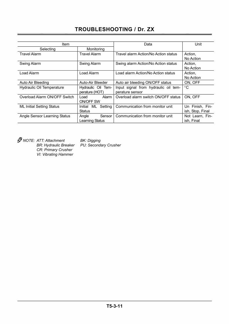
TROUBLESHOOTING / Dr. ZX
T5-3-11
Item
Selecting Monitoring Data Unit
Travel Alarm Travel Alarm Travel alarm Action/No Action status Action, No Action
Swing Alarm Swing Alarm Swing alarm Action/No Action status Action, No Action
Load Alarm Load Alarm Load alarm Action/No Action status Action, No Action
Auto Air Bleeding Auto-Air Bleeder Auto air bleeding ON/OFF status ON, OFF Hydraulic Oil Temperature Hydraulic Oil Tem-
perature (HOT) Input signal from hydraulic oil tem-perature sensor
°C
Overload Alarm ON/OFF Switch Load Alarm ON/OFF SW
Overload alarm switch ON/OFF status ON, OFF
ML Initial Setting Status Initial ML Setting Status
Communication from monitor unit Un Finish, Fin-ish, Stop, Final
Angle Sensor Learning Status Angle Sensor Learning Status
Communication from monitor unit Not Learn, Fin-ish, Final
NOTE: ATT: Attachment BK: Digging BR: Hydraulic Breaker PU: Secondary Crusher CR: Primary Crusher VI: Vibrating Hammer
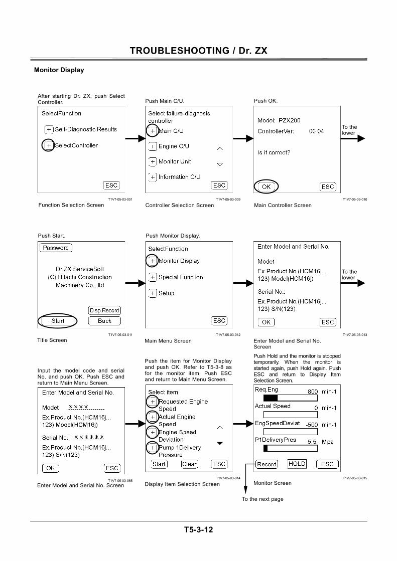
TROUBLESHOOTING / Dr. ZX
T5-3-12
Monitor Display
T1V7-05-03-001
T1V7-05-03-011
T1V7-05-03-065
T1V7-05-03-009
T1V7-05-03-012
T1V7-05-03-014
T1V7-05-03-010
T1V7-05-03-013
T1V7-05-03-015
After starting Dr. ZX, push SelectController. Push Main C/U. Push OK.
Function Selection Screen Controller Selection Screen Main Controller Screen
Push Start. Push Monitor Display.
Main Menu Screen Enter Model and Serial No. Screen
Title Screen
Push the item for Monitor Displayand push OK. Refer to T5-3-8 asfor the monitor item. Push ESCand return to Main Menu Screen.
Push Hold and the monitor is stoppedtemporarily. When the monitor isstarted again, push Hold again. PushESC and return to Display ItemSelection Screen.
Input the model code and serialNo. and push OK. Push ESC andreturn to Main Menu Screen.
Monitor Screen Enter Model and Serial No. Screen Display Item Selection Screen
To the next page
To the lower
To the lower
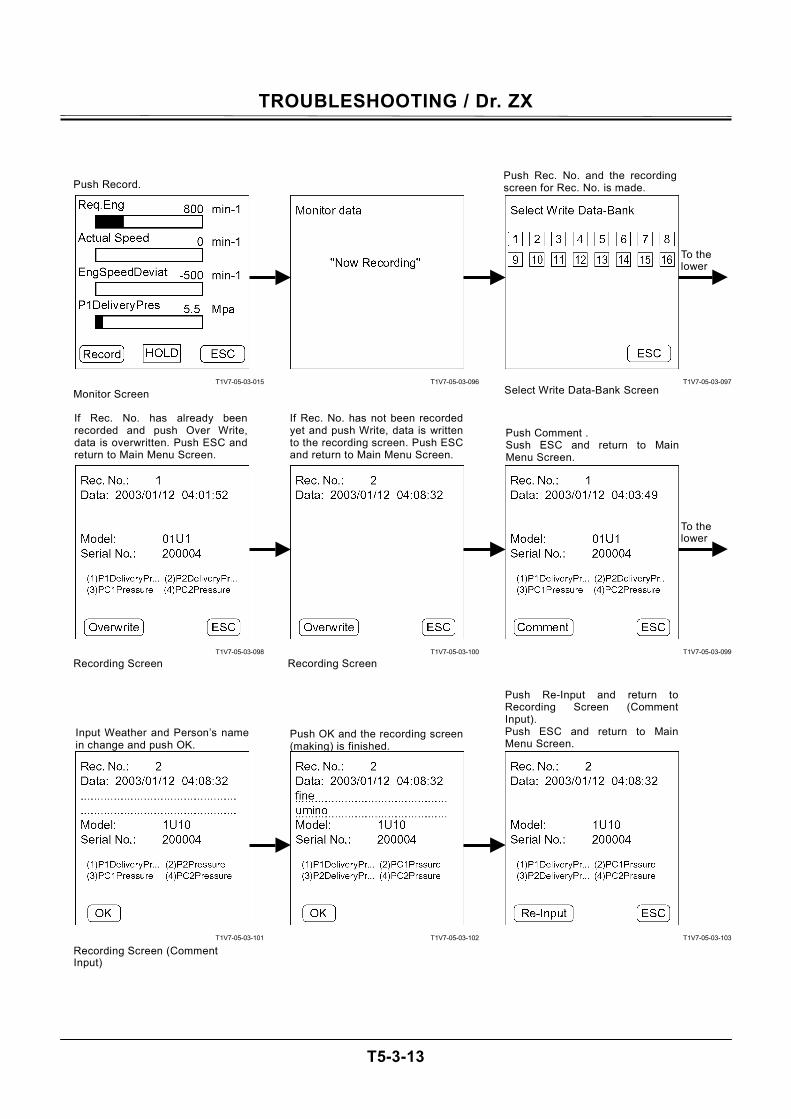
TROUBLESHOOTING / Dr. ZX
T5-3-13
T1V7-05-03-015
T1V7-05-03-098
T1V7-05-03-101
T1V7-05-03-096
T1V7-05-03-100
T1V7-05-03-102
T1V7-05-03-097
T1V7-05-03-099
T1V7-05-03-103
Push Record.
Monitor Screen
Push Rec. No. and the recording screen for Rec. No. is made.
Select Write Data-Bank Screen
Recording Screen Recording Screen
Recording Screen (Comment Input)
Push Comment . Sush ESC and return to MainMenu Screen.
If Rec. No. has already beenrecorded and push Over Write,data is overwritten. Push ESC andreturn to Main Menu Screen.
If Rec. No. has not been recordedyet and push Write, data is writtento the recording screen. Push ESCand return to Main Menu Screen.
Input Weather and Person’s name in change and push OK.
Push OK and the recording screen(making) is finished.
Push Re-Input and return toRecording Screen (CommentInput). Push ESC and return to MainMenu Screen.
To the lower
To the lower
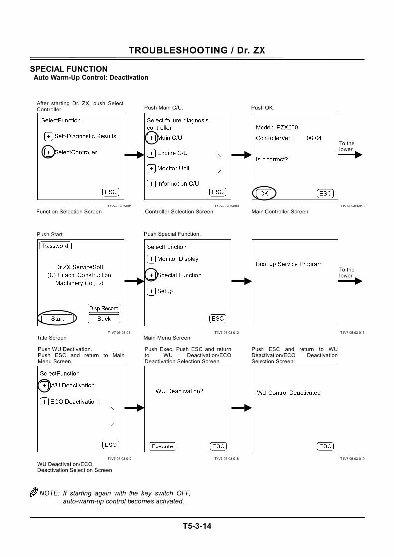
TROUBLESHOOTING / Dr. ZX
T5-3-14
SPECIAL FUNCTION Auto Warm-Up Control: Deactivation
T1V7-05-03-001
T1V7-05-03-011
T1V7-05-03-017
T1V7-05-03-009
T1V7-05-03-012
T1V7-05-03-018
T1V7-05-03-010
T1V7-05-03-016
T1V7-05-03-019
NOTE: If starting again with the key switch OFF, auto-warm-up control becomes activated.
After starting Dr. ZX, push SelectController. Push Main C/U. Push OK.
Function Selection Screen Controller Selection Screen Main Controller Screen
Push Start. Push Special Function.
Main Menu Screen Title Screen
Push Exec. Push ESC and returnto WU Deactivation/ECODeactivation Selection Screen.
Push ESC and return to WUDeactivation/ECO DeactivationSelection Screen.
Push WU Dectivation. Push ESC and return to MainMenu Screen.
WU Deactivation/ECO Deactivation Selection Screen
To the lower
To the lower
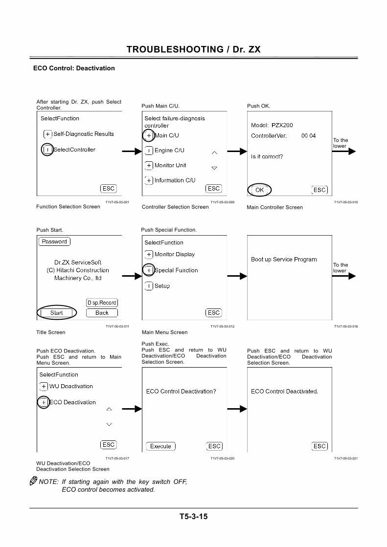
TROUBLESHOOTING / Dr. ZX
T5-3-15
ECO Control: Deactivation
T1V7-05-03-001
T1V7-05-03-011
T1V7-05-03-017
T1V7-05-03-009
T1V7-05-03-012
T1V7-05-03-020
T1V7-05-03-010
T1V7-05-03-016
T1V7-05-03-021
NOTE: If starting again with the key switch OFF, ECO control becomes activated.
After starting Dr. ZX, push SelectController. Push Main C/U. Push OK.
Function Selection Screen Controller Selection Screen Main Controller Screen
Push Start. Push Special Function.
Main Menu Screen Title Screen
Push Exec. Push ESC and return to WUDeactivation/ECO DeactivationSelection Screen.
Push ESC and return to WU Deactivation/ECO Deactivation Selection Screen.
Push ECO Deactivation. Push ESC and return to MainMenu Screen.
WU Deactivation/ECO Deactivation Selection Screen
To the lower
To the lower
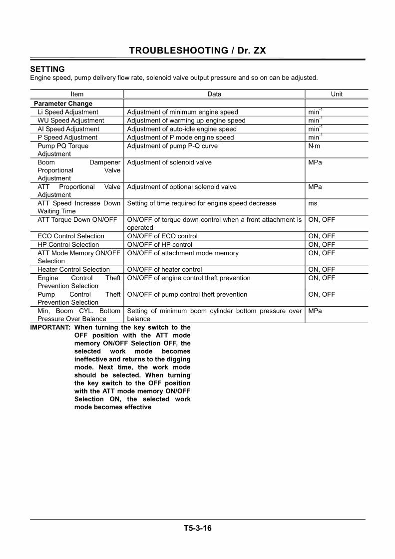
TROUBLESHOOTING / Dr. ZX
T5-3-16
SETTING Engine speed, pump delivery flow rate, solenoid valve output pressure and so on can be adjusted.
Item Data Unit Parameter Change
Li Speed Adjustment Adjustment of minimum engine speed min-1 WU Speed Adjustment Adjustment of warming up engine speed min-1 AI Speed Adjustment Adjustment of auto-idle engine speed min-1 P Speed Adjustment Adjustment of P mode engine speed min-1 Pump PQ Torque Adjustment
Adjustment of pump P-Q curve N⋅m
Boom Dampener Proportional Valve Adjustment
Adjustment of solenoid valve MPa
ATT Proportional Valve Adjustment
Adjustment of optional solenoid valve MPa
ATT Speed Increase Down Waiting Time
Setting of time required for engine speed decrease ms
ATT Torque Down ON/OFF ON/OFF of torque down control when a front attachment is operated
ON, OFF
ECO Control Selection ON/OFF of ECO control ON, OFF HP Control Selection ON/OFF of HP control ON, OFF ATT Mode Memory ON/OFF Selection
ON/OFF of attachment mode memory ON, OFF
Heater Control Selection ON/OFF of heater control ON, OFF Engine Control Theft Prevention Selection
ON/OFF of engine control theft prevention ON, OFF
Pump Control Theft Prevention Selection
ON/OFF of pump control theft prevention ON, OFF
Min, Boom CYL. Bottom Pressure Over Balance
Setting of minimum boom cylinder bottom pressure over balance
MPa
IMPORTANT: When turning the key switch to the OFF position with the ATT mode memory ON/OFF Selection OFF, the selected work mode becomes ineffective and returns to the digging mode. Next time, the work mode should be selected. When turning the key switch to the OFF position with the ATT mode memory ON/OFF Selection ON, the selected work mode becomes effective
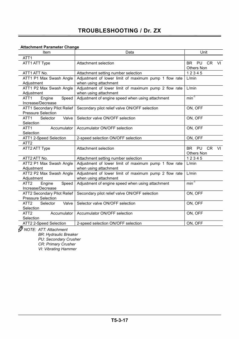
TROUBLESHOOTING / Dr. ZX
T5-3-17
Attachment Parameter Change
Item Data Unit ATT1 ATT1 ATT Type Attachment selection BR PU CR VI
Others Non ATT1 ATT No. Attachment setting number selection 1 2 3 4 5 ATT1 P1 Max Swash Angle Adjustment
Adjustment of lower limit of maximum pump 1 flow rate when using attachment
L/min
ATT1 P2 Max Swash Angle Adjustment
Adjustment of lower limit of maximum pump 2 flow rate when using attachment
L/min
ATT1 Engine Speed Increase/Decrease
Adjustment of engine speed when using attachment min-1
ATT1 Secondary Pilot Relief Pressure Selection
Secondary pilot relief valve ON/OFF selection ON, OFF
ATT1 Selector Valve Selection
Selector valve ON/OFF selection ON, OFF
ATT1 Accumulator Selection
Accumulator ON/OFF selection ON, OFF
ATT1 2-Speed Selection 2-speed selection ON/OFF selection ON, OFF ATT2 ATT2 ATT Type Attachment selection BR PU CR VI
Others Non ATT2 ATT No. Attachment setting number selection 1 2 3 4 5 ATT2 P1 Max Swash Angle Adjustment
Adjustment of lower limit of maximum pump 1 flow rate when using attachment
L/min
ATT2 P2 Max Swash Angle Adjustment
Adjustment of lower limit of maximum pump 2 flow rate when using attachment
L/min
ATT2 Engine Speed Increase/Decrease
Adjustment of engine speed when using attachment min-1
ATT2 Secondary Pilot Relief Pressure Selection
Secondary pilot relief valve ON/OFF selection ON, OFF
ATT2 Selector Valve Selection
Selector valve ON/OFF selection ON, OFF
ATT2 Accumulator Selection
Accumulator ON/OFF selection ON, OFF
ATT2 2-Speed Selection 2-speed selection ON/OFF selection ON, OFF NOTE: ATT: Attachment
BR: Hydraulic Breaker PU: Secondary Crusher CR: Primary Crusher VI: Vibrating Hammer
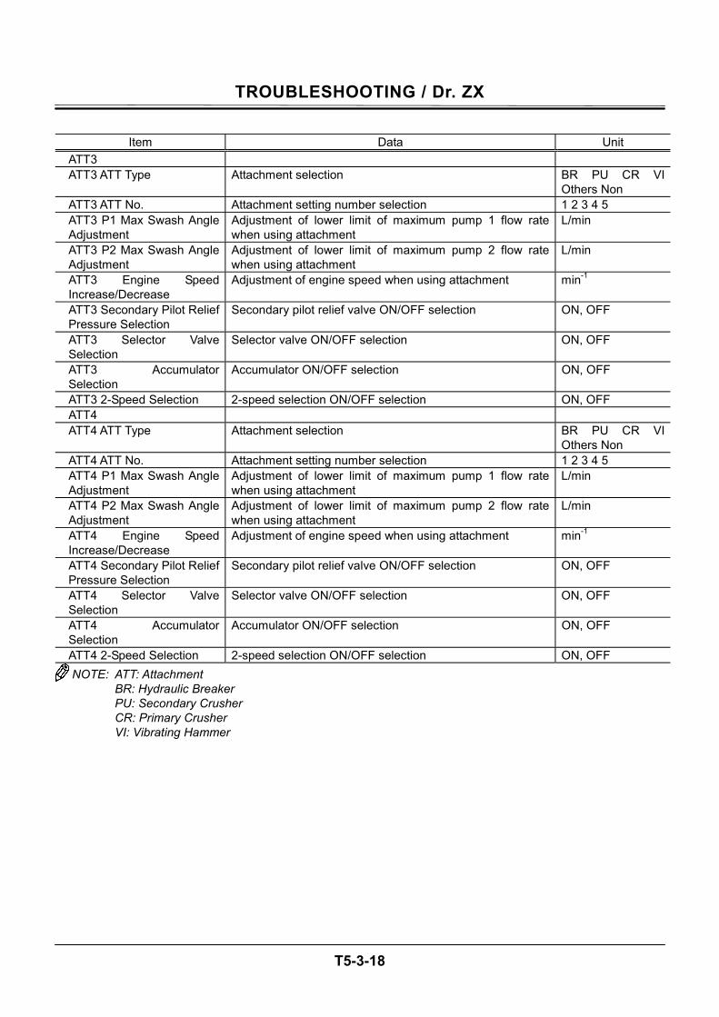
TROUBLESHOOTING / Dr. ZX
T5-3-18
Item Data Unit
ATT3 ATT3 ATT Type Attachment selection BR PU CR VI
Others Non ATT3 ATT No. Attachment setting number selection 1 2 3 4 5 ATT3 P1 Max Swash Angle Adjustment
Adjustment of lower limit of maximum pump 1 flow rate when using attachment
L/min
ATT3 P2 Max Swash Angle Adjustment
Adjustment of lower limit of maximum pump 2 flow rate when using attachment
L/min
ATT3 Engine Speed Increase/Decrease
Adjustment of engine speed when using attachment min-1
ATT3 Secondary Pilot Relief Pressure Selection
Secondary pilot relief valve ON/OFF selection ON, OFF
ATT3 Selector Valve Selection
Selector valve ON/OFF selection ON, OFF
ATT3 Accumulator Selection
Accumulator ON/OFF selection ON, OFF
ATT3 2-Speed Selection 2-speed selection ON/OFF selection ON, OFF ATT4 ATT4 ATT Type Attachment selection BR PU CR VI
Others Non ATT4 ATT No. Attachment setting number selection 1 2 3 4 5 ATT4 P1 Max Swash Angle Adjustment
Adjustment of lower limit of maximum pump 1 flow rate when using attachment
L/min
ATT4 P2 Max Swash Angle Adjustment
Adjustment of lower limit of maximum pump 2 flow rate when using attachment
L/min
ATT4 Engine Speed Increase/Decrease
Adjustment of engine speed when using attachment min-1
ATT4 Secondary Pilot Relief Pressure Selection
Secondary pilot relief valve ON/OFF selection ON, OFF
ATT4 Selector Valve Selection
Selector valve ON/OFF selection ON, OFF
ATT4 Accumulator Selection
Accumulator ON/OFF selection ON, OFF
ATT4 2-Speed Selection 2-speed selection ON/OFF selection ON, OFF NOTE: ATT: Attachment
BR: Hydraulic Breaker PU: Secondary Crusher CR: Primary Crusher VI: Vibrating Hammer
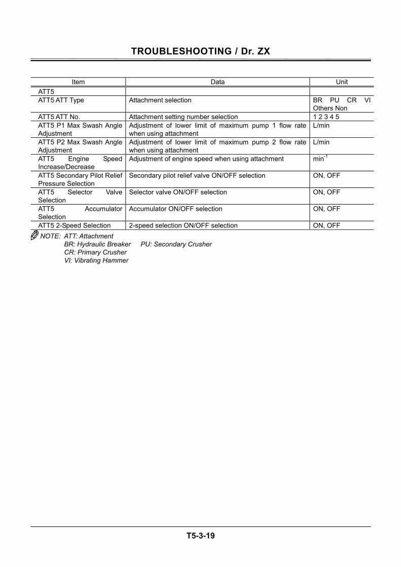
TROUBLESHOOTING / Dr. ZX
T5-3-19
Item Data Unit
ATT5 ATT5 ATT Type Attachment selection BR PU CR VI
Others Non ATT5 ATT No. Attachment setting number selection 1 2 3 4 5 ATT5 P1 Max Swash Angle Adjustment
Adjustment of lower limit of maximum pump 1 flow rate when using attachment
L/min
ATT5 P2 Max Swash Angle Adjustment
Adjustment of lower limit of maximum pump 2 flow rate when using attachment
L/min
ATT5 Engine Speed Increase/Decrease
Adjustment of engine speed when using attachment min-1
ATT5 Secondary Pilot Relief Pressure Selection
Secondary pilot relief valve ON/OFF selection ON, OFF
ATT5 Selector Valve Selection
Selector valve ON/OFF selection ON, OFF
ATT5 Accumulator Selection
Accumulator ON/OFF selection ON, OFF
ATT5 2-Speed Selection 2-speed selection ON/OFF selection ON, OFF NOTE: ATT: Attachment
BR: Hydraulic Breaker PU: Secondary Crusher CR: Primary Crusher VI: Vibrating Hammer
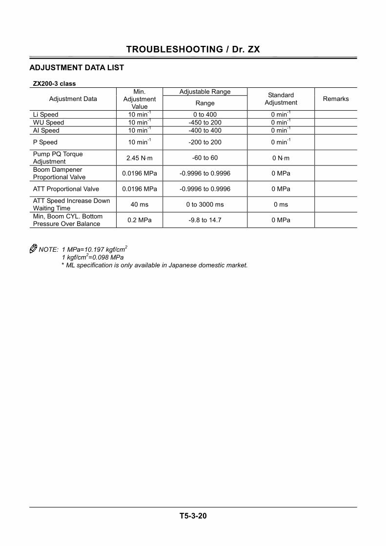
TROUBLESHOOTING / Dr. ZX
T5-3-20
ADJUSTMENT DATA LIST ZX200-3 class
Adjustable Range Adjustment Data
Min. Adjustment
Value Range Standard
Adjustment Remarks
Li Speed 10 min-1 0 to 400 0 min-1 WU Speed 10 min-1 -450 to 200 0 min-1 AI Speed 10 min-1 -400 to 400 0 min-1
P Speed 10 min-1 -200 to 200 0 min-1
Pump PQ Torque Adjustment 2.45 N⋅m -60 to 60 0 N⋅m
Boom Dampener Proportional Valve 0.0196 MPa -0.9996 to 0.9996 0 MPa
ATT Proportional Valve 0.0196 MPa -0.9996 to 0.9996 0 MPa
ATT Speed Increase Down Waiting Time 40 ms 0 to 3000 ms 0 ms
Min, Boom CYL. Bottom Pressure Over Balance 0.2 MPa -9.8 to 14.7 0 MPa
NOTE: 1 MPa=10.197 kgf/cm2 1 kgf/cm2=0.098 MPa * ML specification is only available in Japanese domestic market.
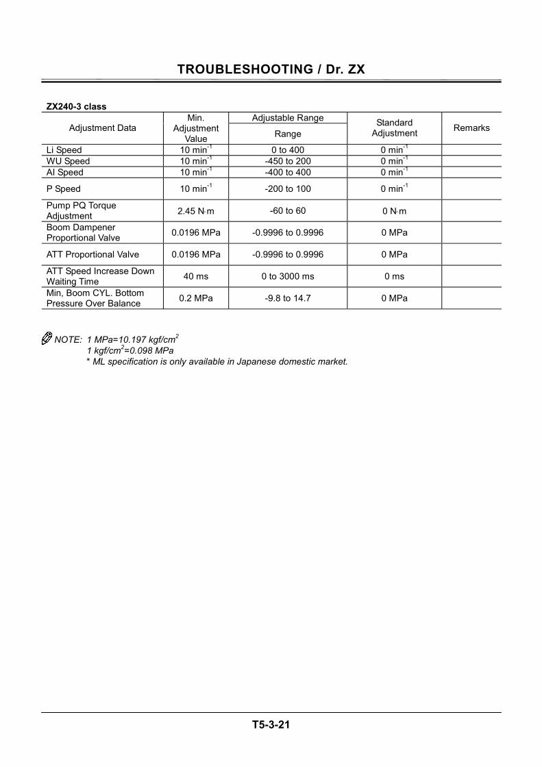
TROUBLESHOOTING / Dr. ZX
T5-3-21
ZX240-3 class
Adjustable Range Adjustment Data
Min. Adjustment
Value Range Standard
Adjustment Remarks
Li Speed 10 min-1 0 to 400 0 min-1 WU Speed 10 min-1 -450 to 200 0 min-1 AI Speed 10 min-1 -400 to 400 0 min-1
P Speed 10 min-1 -200 to 100 0 min-1
Pump PQ Torque Adjustment 2.45 N⋅m -60 to 60 0 N⋅m
Boom Dampener Proportional Valve 0.0196 MPa -0.9996 to 0.9996 0 MPa
ATT Proportional Valve 0.0196 MPa -0.9996 to 0.9996 0 MPa
ATT Speed Increase Down Waiting Time 40 ms 0 to 3000 ms 0 ms
Min, Boom CYL. Bottom Pressure Over Balance 0.2 MPa -9.8 to 14.7 0 MPa
NOTE: 1 MPa=10.197 kgf/cm2 1 kgf/cm2=0.098 MPa * ML specification is only available in Japanese domestic market.
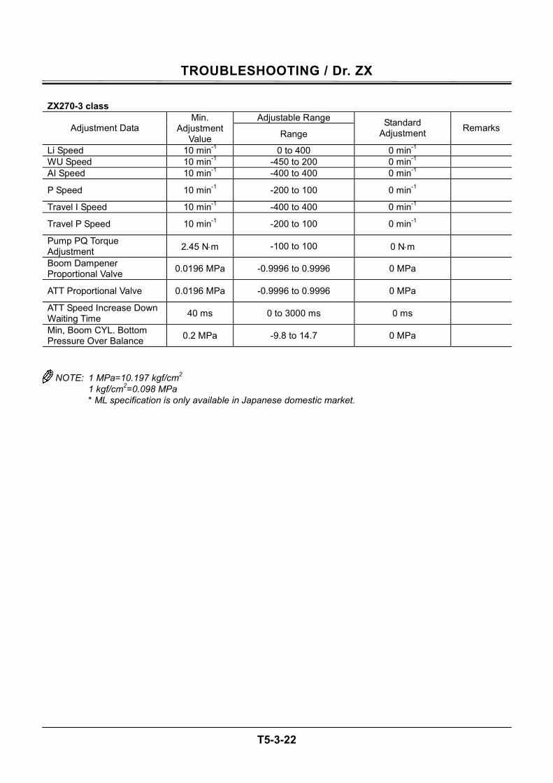
TROUBLESHOOTING / Dr. ZX
T5-3-22
ZX270-3 class
Adjustable Range Adjustment Data
Min. Adjustment
Value Range Standard
Adjustment Remarks
Li Speed 10 min-1 0 to 400 0 min-1 WU Speed 10 min-1 -450 to 200 0 min-1 AI Speed 10 min-1 -400 to 400 0 min-1
P Speed 10 min-1 -200 to 100 0 min-1
Travel I Speed 10 min-1 -400 to 400 0 min-1
Travel P Speed 10 min-1 -200 to 100 0 min-1
Pump PQ Torque Adjustment 2.45 N⋅m -100 to 100 0 N⋅m
Boom Dampener Proportional Valve 0.0196 MPa -0.9996 to 0.9996 0 MPa
ATT Proportional Valve 0.0196 MPa -0.9996 to 0.9996 0 MPa
ATT Speed Increase Down Waiting Time 40 ms 0 to 3000 ms 0 ms
Min, Boom CYL. Bottom Pressure Over Balance 0.2 MPa -9.8 to 14.7 0 MPa
NOTE: 1 MPa=10.197 kgf/cm2 1 kgf/cm2=0.098 MPa * ML specification is only available in Japanese domestic market.

TROUBLESHOOTING / Dr. ZX
T5-3-23
(Blank)
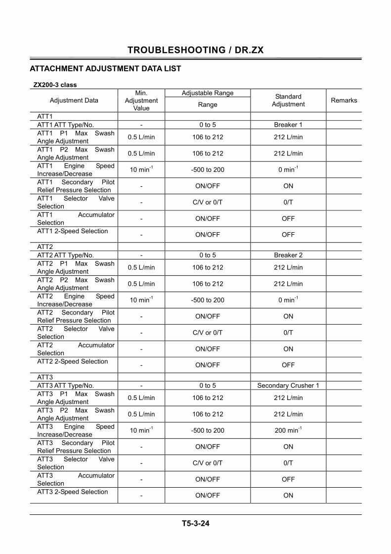
TROUBLESHOOTING / DR.ZX
T5-3-24
ATTACHMENT ADJUSTMENT DATA LIST ZX200-3 class
Adjustable Range Adjustment Data
Min. Adjustment
Value Range Standard
Adjustment Remarks
ATT1 ATT1 ATT Type/No. - 0 to 5 Breaker 1 ATT1 P1 Max Swash Angle Adjustment 0.5 L/min 106 to 212 212 L/min
ATT1 P2 Max Swash Angle Adjustment 0.5 L/min 106 to 212 212 L/min
ATT1 Engine Speed Increase/Decrease 10 min-1 -500 to 200 0 min-1
ATT1 Secondary Pilot Relief Pressure Selection - ON/OFF ON
ATT1 Selector Valve Selection - C/V or 0/T 0/T
ATT1 Accumulator Selection - ON/OFF OFF
ATT1 2-Speed Selection - ON/OFF OFF
ATT2 ATT2 ATT Type/No. - 0 to 5 Breaker 2 ATT2 P1 Max Swash Angle Adjustment 0.5 L/min 106 to 212 212 L/min
ATT2 P2 Max Swash Angle Adjustment 0.5 L/min 106 to 212 212 L/min
ATT2 Engine Speed Increase/Decrease 10 min-1 -500 to 200 0 min-1
ATT2 Secondary Pilot Relief Pressure Selection - ON/OFF ON
ATT2 Selector Valve Selection - C/V or 0/T 0/T
ATT2 Accumulator Selection - ON/OFF ON
ATT2 2-Speed Selection - ON/OFF OFF
ATT3 ATT3 ATT Type/No. - 0 to 5 Secondary Crusher 1 ATT3 P1 Max Swash Angle Adjustment 0.5 L/min 106 to 212 212 L/min
ATT3 P2 Max Swash Angle Adjustment 0.5 L/min 106 to 212 212 L/min
ATT3 Engine Speed Increase/Decrease 10 min-1 -500 to 200 200 min-1
ATT3 Secondary Pilot Relief Pressure Selection - ON/OFF ON
ATT3 Selector Valve Selection - C/V or 0/T 0/T
ATT3 Accumulator Selection - ON/OFF OFF
ATT3 2-Speed Selection - ON/OFF ON
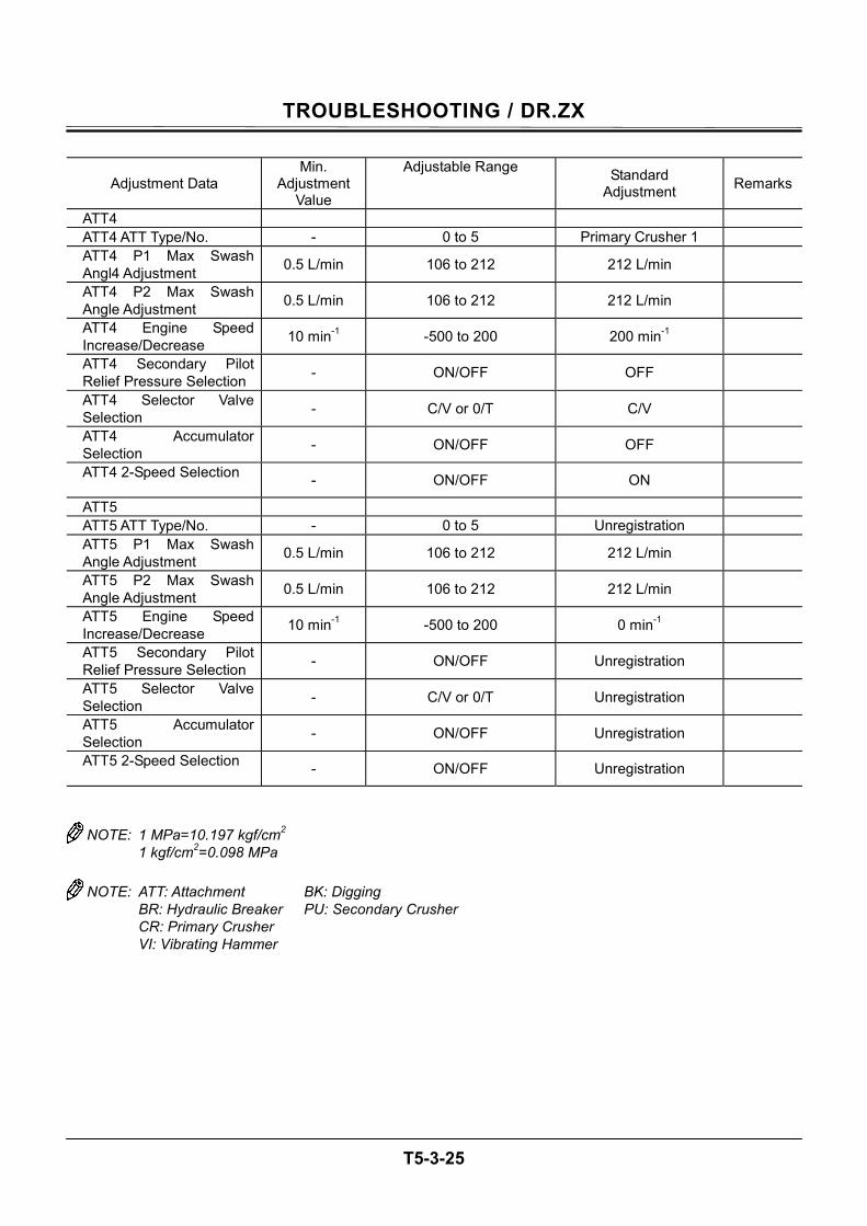
TROUBLESHOOTING / DR.ZX
T5-3-25
Adjustment Data Min.
Adjustment Value
Adjustable Range Standard Adjustment Remarks
ATT4 ATT4 ATT Type/No. - 0 to 5 Primary Crusher 1 ATT4 P1 Max Swash Angl4 Adjustment 0.5 L/min 106 to 212 212 L/min
ATT4 P2 Max Swash Angle Adjustment 0.5 L/min 106 to 212 212 L/min
ATT4 Engine Speed Increase/Decrease 10 min-1 -500 to 200 200 min-1
ATT4 Secondary Pilot Relief Pressure Selection - ON/OFF OFF
ATT4 Selector Valve Selection - C/V or 0/T C/V
ATT4 Accumulator Selection - ON/OFF OFF
ATT4 2-Speed Selection - ON/OFF ON
ATT5 ATT5 ATT Type/No. - 0 to 5 Unregistration ATT5 P1 Max Swash Angle Adjustment 0.5 L/min 106 to 212 212 L/min
ATT5 P2 Max Swash Angle Adjustment 0.5 L/min 106 to 212 212 L/min
ATT5 Engine Speed Increase/Decrease 10 min-1 -500 to 200 0 min-1
ATT5 Secondary Pilot Relief Pressure Selection - ON/OFF Unregistration
ATT5 Selector Valve Selection - C/V or 0/T Unregistration
ATT5 Accumulator Selection - ON/OFF Unregistration
ATT5 2-Speed Selection - ON/OFF Unregistration
NOTE: 1 MPa=10.197 kgf/cm2 1 kgf/cm2=0.098 MPa
NOTE: ATT: Attachment BK: Digging BR: Hydraulic Breaker PU: Secondary Crusher CR: Primary Crusher VI: Vibrating Hammer

TROUBLESHOOTING / DR.ZX
T5-3-26
ZX240-3 class
Adjustable Range Adjustment Data
Min. Adjustment
Value Range Standard
Adjustment Remarks
ATT1 ATT1 ATT Type/No. - 0 to 5 Breaker 1 ATT1 P1 Max Swash Angle Adjustment 0.5 L/min 112 to 224 224 L/min
ATT1 P2 Max Swash Angle Adjustment 0.5 L/min 112 to 224 224 L/min
ATT1 Engine Speed Increase/Decrease 10 min-1 -500 to 100 0 min-1
ATT1 Secondary Pilot Relief Pressure Selection - ON/OFF ON
ATT1 Selector Valve Selection - C/V or 0/T 0/T
ATT1 Accumulator Selection - ON/OFF OFF
ATT1 2-Speed Selection - ON/OFF OFF
ATT2 ATT2 ATT Type/No. - 0 to 5 Breaker 2 ATT2 P1 Max Swash Angle Adjustment 0.5 L/min 112 to 224 224 L/min
ATT2 P2 Max Swash Angle Adjustment 0.5 L/min 112 to 224 224/min
ATT2 Engine Speed Increase/Decrease 10 min-1 -500 to 200 0 min-1
ATT2 Secondary Pilot Relief Pressure Selection - ON/OFF ON
ATT2 Selector Valve Selection - C/V or 0/T 0/T
ATT2 Accumulator Selection - ON/OFF ON
ATT2 2-Speed Selection - ON/OFF OFF
ATT3 ATT3 ATT Type/No. - 0 to 5 Secondary Crusher 1 ATT3 P1 Max Swash Angle Adjustment 0.5 L/min 112 to 224 224 L/min
ATT3 P2 Max Swash Angle Adjustment 0.5 L/min 112 to 224 224 L/min
ATT3 Engine Speed Increase/Decrease 10 min-1 -500 to 100 100 min-1
ATT3 Secondary Pilot Relief Pressure Selection - ON/OFF ON
ATT3 Selector Valve Selection - C/V or 0/T C/V
ATT3 Accumulator Selection - ON/OFF OFF
ATT3 2-Speed Selection - ON/OFF ON

TROUBLESHOOTING / DR.ZX
T5-3-27
Adjustment Data Min.
Adjustment Value
Adjustable Range Standard Adjustment Remarks
ATT4 ATT4 ATT Type/No. - 0 to 5 Primary Crusher 1 ATT4 P1 Max Swash Angl4 Adjustment 0.5 L/min 112 to 224 224 L/min
ATT4 P2 Max Swash Angle Adjustment 0.5 L/min 112 to 224 224 L/min
ATT4 Engine Speed Increase/Decrease 10 min-1 -500 to 100 100 min-1
ATT4 Secondary Pilot Relief Pressure Selection - ON/OFF OFF
ATT4 Selector Valve Selection - C/V or 0/T C/V
ATT4 Accumulator Selection - ON/OFF OFF
ATT4 2-Speed Selection - ON/OFF ON
ATT5 ATT5 ATT Type/No. - 0 to 5 Unregistration ATT5 P1 Max Swash Angle Adjustment 0.5 L/min 112 to 224 224 L/min
ATT5 P2 Max Swash Angle Adjustment 0.5 L/min 112 to 224 224 L/min
ATT5 Engine Speed Increase/Decrease 10 min-1 -500 to 100 0 min-1
ATT5 Secondary Pilot Relief Pressure Selection - ON/OFF Unregistration
ATT5 Selector Valve Selection - C/V or 0/T Unregistration
ATT5 Accumulator Selection - ON/OFF Unregistration
ATT5 2-Speed Selection - ON/OFF Unregistration
NOTE: 1 MPa=10.197 kgf/cm2 1 kgf/cm2=0.098 MPa
NOTE: ATT: Attachment BK: Digging BR: Hydraulic Breaker PU: Secondary Crusher CR: Primary Crusher VI: Vibrating Hammer
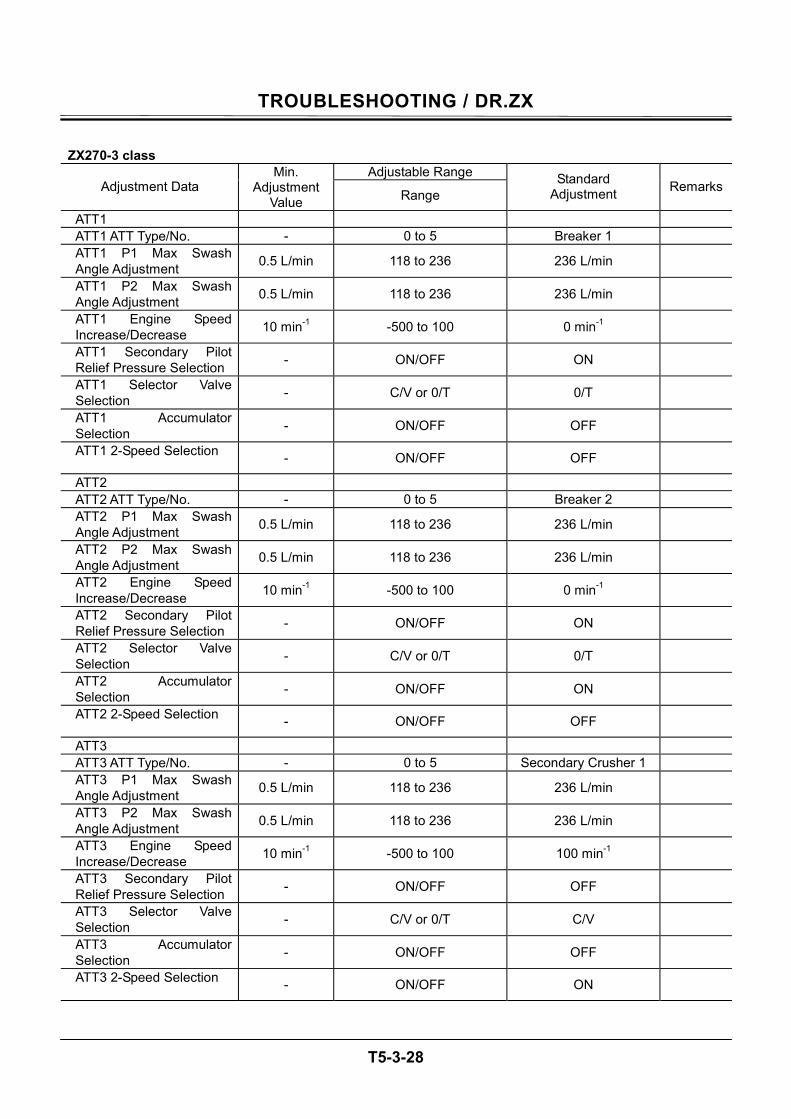
TROUBLESHOOTING / DR.ZX
T5-3-28
ZX270-3 class
Adjustable Range Adjustment Data
Min. Adjustment
Value Range Standard
Adjustment Remarks
ATT1 ATT1 ATT Type/No. - 0 to 5 Breaker 1 ATT1 P1 Max Swash Angle Adjustment 0.5 L/min 118 to 236 236 L/min
ATT1 P2 Max Swash Angle Adjustment 0.5 L/min 118 to 236 236 L/min
ATT1 Engine Speed Increase/Decrease 10 min-1 -500 to 100 0 min-1
ATT1 Secondary Pilot Relief Pressure Selection - ON/OFF ON
ATT1 Selector Valve Selection - C/V or 0/T 0/T
ATT1 Accumulator Selection - ON/OFF OFF
ATT1 2-Speed Selection - ON/OFF OFF
ATT2 ATT2 ATT Type/No. - 0 to 5 Breaker 2 ATT2 P1 Max Swash Angle Adjustment 0.5 L/min 118 to 236 236 L/min
ATT2 P2 Max Swash Angle Adjustment 0.5 L/min 118 to 236 236 L/min
ATT2 Engine Speed Increase/Decrease 10 min-1 -500 to 100 0 min-1
ATT2 Secondary Pilot Relief Pressure Selection - ON/OFF ON
ATT2 Selector Valve Selection - C/V or 0/T 0/T
ATT2 Accumulator Selection - ON/OFF ON
ATT2 2-Speed Selection - ON/OFF OFF
ATT3 ATT3 ATT Type/No. - 0 to 5 Secondary Crusher 1 ATT3 P1 Max Swash Angle Adjustment 0.5 L/min 118 to 236 236 L/min
ATT3 P2 Max Swash Angle Adjustment 0.5 L/min 118 to 236 236 L/min
ATT3 Engine Speed Increase/Decrease 10 min-1 -500 to 100 100 min-1
ATT3 Secondary Pilot Relief Pressure Selection - ON/OFF OFF
ATT3 Selector Valve Selection - C/V or 0/T C/V
ATT3 Accumulator Selection - ON/OFF OFF
ATT3 2-Speed Selection - ON/OFF ON
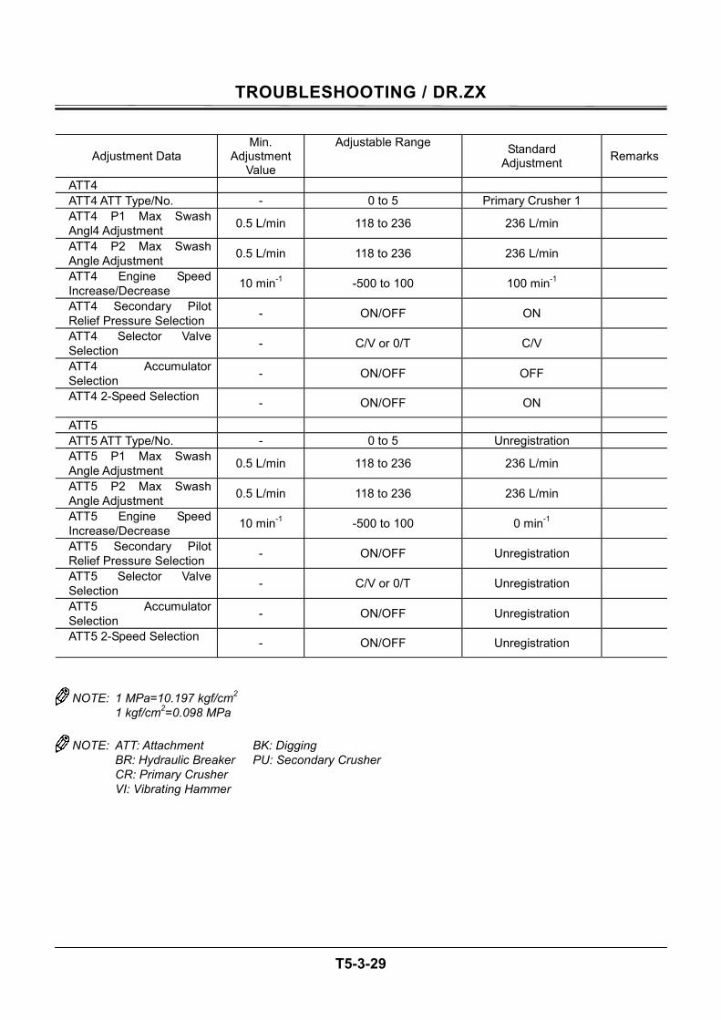
TROUBLESHOOTING / DR.ZX
T5-3-29
Adjustment Data Min.
Adjustment Value
Adjustable Range Standard Adjustment Remarks
ATT4 ATT4 ATT Type/No. - 0 to 5 Primary Crusher 1 ATT4 P1 Max Swash Angl4 Adjustment 0.5 L/min 118 to 236 236 L/min
ATT4 P2 Max Swash Angle Adjustment 0.5 L/min 118 to 236 236 L/min
ATT4 Engine Speed Increase/Decrease 10 min-1 -500 to 100 100 min-1
ATT4 Secondary Pilot Relief Pressure Selection - ON/OFF ON
ATT4 Selector Valve Selection - C/V or 0/T C/V
ATT4 Accumulator Selection - ON/OFF OFF
ATT4 2-Speed Selection - ON/OFF ON
ATT5 ATT5 ATT Type/No. - 0 to 5 Unregistration ATT5 P1 Max Swash Angle Adjustment 0.5 L/min 118 to 236 236 L/min
ATT5 P2 Max Swash Angle Adjustment 0.5 L/min 118 to 236 236 L/min
ATT5 Engine Speed Increase/Decrease 10 min-1 -500 to 100 0 min-1
ATT5 Secondary Pilot Relief Pressure Selection - ON/OFF Unregistration
ATT5 Selector Valve Selection - C/V or 0/T Unregistration
ATT5 Accumulator Selection - ON/OFF Unregistration
ATT5 2-Speed Selection - ON/OFF Unregistration
NOTE: 1 MPa=10.197 kgf/cm2 1 kgf/cm2=0.098 MPa
NOTE: ATT: Attachment BK: Digging BR: Hydraulic Breaker PU: Secondary Crusher CR: Primary Crusher VI: Vibrating Hammer
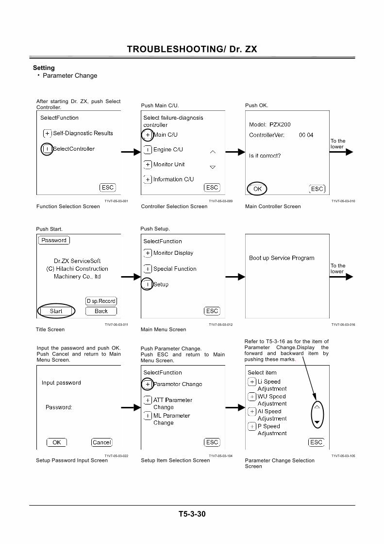
TROUBLESHOOTING/ Dr. ZX
T5-3-30
Setting • Parameter Change
T1V7-05-03-001
T1V7-05-03-011
T1V7-05-03-022
T1V7-05-03-009
T1V7-05-03-012
T1V7-05-03-104
T1V7-05-03-010
T1V7-05-03-016
T1V7-05-03-105
To the lower
To the lower
After starting Dr. ZX, push SelectController. Push Main C/U. Push OK.
Function Selection Screen Controller Selection Screen Main Controller Screen
Push Start. Push Setup.
Main Menu Screen Title Screen
Push Parameter Change. Push ESC and return to MainMenu Screen.
Refer to T5-3-16 as for the item of Parameter Change.Display the forward and backward item by pushing these marks.
Input the password and push OK.Push Cancel and return to MainMenu Screen.
Parameter Change Selection Screen
Setup Password Input Screen Setup Item Selection Screen
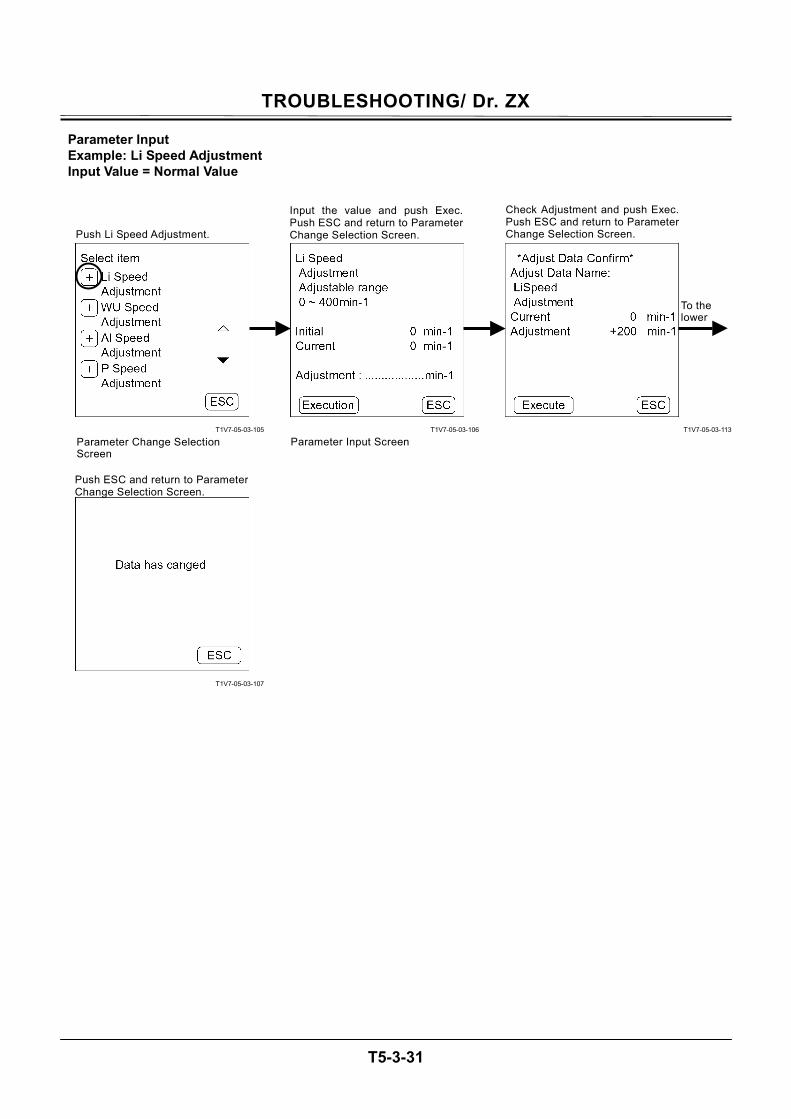
TROUBLESHOOTING/ Dr. ZX
T5-3-31
Parameter Input Example: Li Speed Adjustment Input Value = Normal Value
T1V7-05-03-105
T1V7-05-03-107
T1V7-05-03-106
T1V7-05-03-113
To the lower
Push Li Speed Adjustment.
Parameter Change Selection Screen
Input the value and push Exec.Push ESC and return to Parameter Change Selection Screen.
Parameter Input Screen
Check Adjustment and push Exec.Push ESC and return to ParameterChange Selection Screen.
Push ESC and return to ParameterChange Selection Screen.
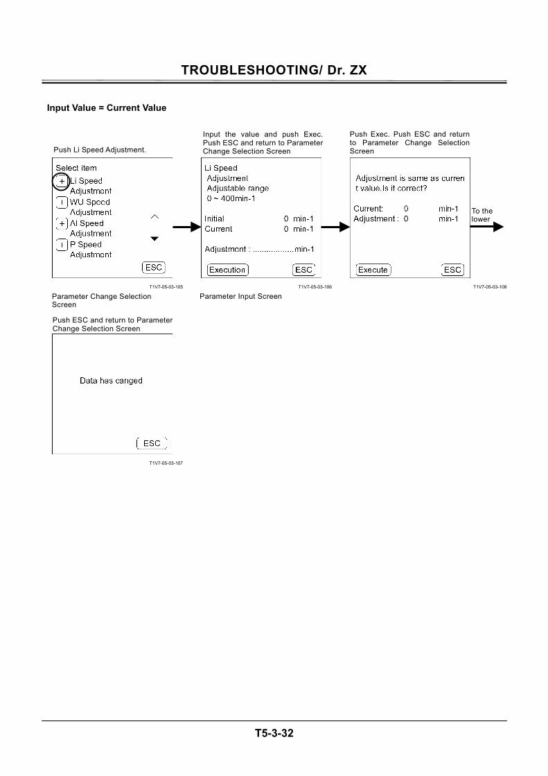
TROUBLESHOOTING/ Dr. ZX
T5-3-32
Input Value = Current Value
T1V7-05-03-105
T1V7-05-03-107
T1V7-05-03-106
T1V7-05-03-108
To the lower
Push Li Speed Adjustment.
Parameter Change Selection Screen
Input the value and push Exec.Push ESC and return to ParameterChange Selection Screen
Parameter Input Screen
Push Exec. Push ESC and returnto Parameter Change SelectionScreen
Push ESC and return to ParameterChange Selection Screen
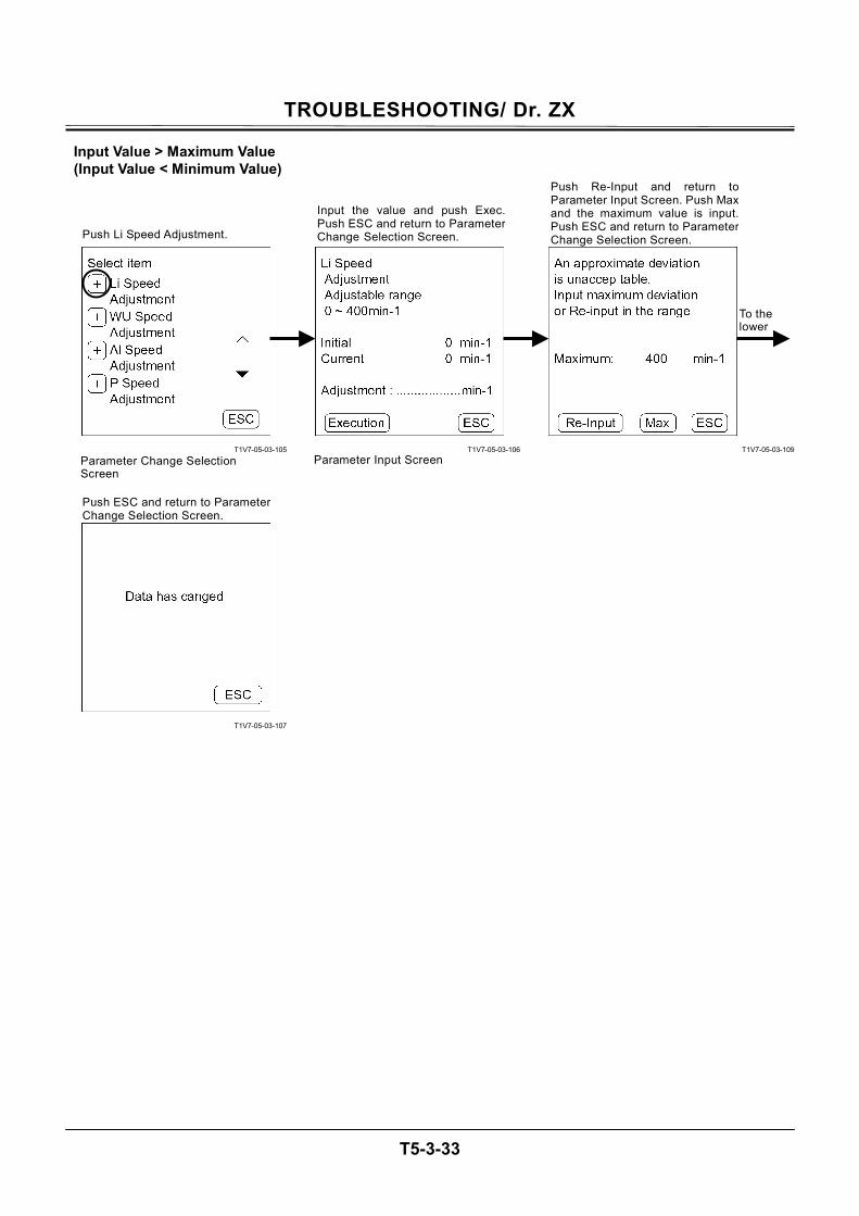
TROUBLESHOOTING/ Dr. ZX
T5-3-33
Input Value > Maximum Value (Input Value < Minimum Value)
T1V7-05-03-105
T1V7-05-03-107
T1V7-05-03-106
T1V7-05-03-109
Push Li Speed Adjustment.
Parameter Change Selection Screen
Input the value and push Exec.Push ESC and return to ParameterChange Selection Screen.
Parameter Input Screen
Push Re-Input and return toParameter Input Screen. Push Maxand the maximum value is input.Push ESC and return to ParameterChange Selection Screen.
Push ESC and return to ParameterChange Selection Screen.
To the lower
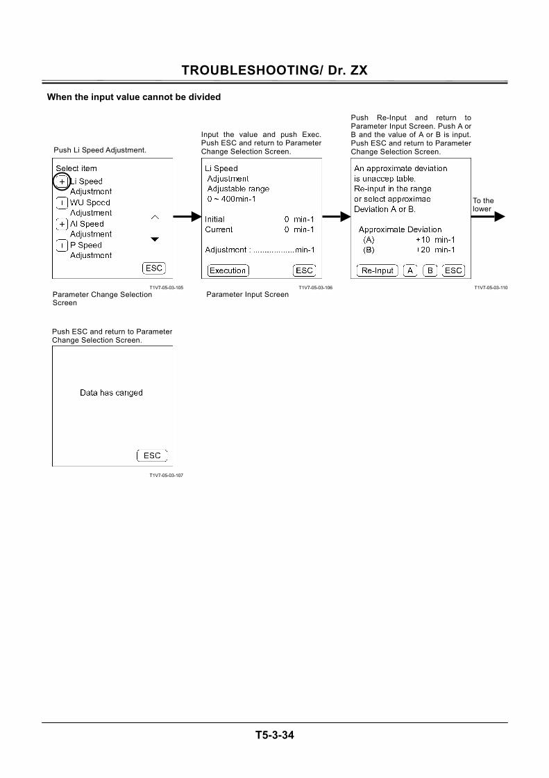
TROUBLESHOOTING/ Dr. ZX
T5-3-34
When the input value cannot be divided
T1V7-05-03-105
T1V7-05-03-107
T1V7-05-03-106
T1V7-05-03-110
Push Li Speed Adjustment.
Parameter Change Selection Screen
Input the value and push Exec.Push ESC and return to ParameterChange Selection Screen.
Parameter Input Screen
Push Re-Input and return toParameter Input Screen. Push A orB and the value of A or B is input.Push ESC and return to ParameterChange Selection Screen.
Push ESC and return to ParameterChange Selection Screen.
To the lower
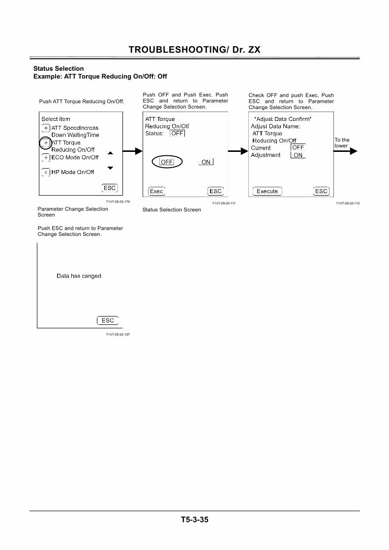
TROUBLESHOOTING/ Dr. ZX
T5-3-35
Status Selection Example: ATT Torque Reducing On/Off: Off
T1V7-05-03-179
T1V7-05-03-107
T1V7-05-03-111
T1V7-05-03-112
Push ATT Torque Reducing On/Off.
Parameter Change Selection Screen
Push OFF and Push Exec. Push ESC and return to ParameterChange Selection Screen.
Status Selection Screen
Check OFF and push Exec. PushESC and return to ParameterChange Selection Screen.
Push ESC and return to ParameterChange Selection Screen.
To the lower
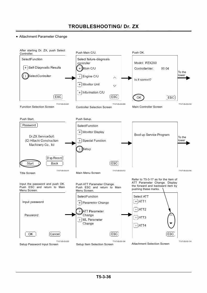
TROUBLESHOOTING/ Dr. ZX
T5-3-36
• Attachment Parameter Change
T1V7-05-03-001
T1V7-05-03-011
T1V7-05-03-022
T1V7-05-03-009
T1V7-05-03-012
T1V7-05-03-104
T1V7-05-03-010
T1V7-05-03-016
T1V7-05-03-114
After starting Dr. ZX, push SelectController.
Function Selection Screen
Push Main C/U.
Controller Selection Screen
Push OK.
Main Controller Screen
Push Start. Push Setup.
Main Menu Screen Title Screen
Push ATT Parameter Change. Push ESC and return to MainMenu Screen.
Refer to T5-3-17 as for the item of ATT Parameter Change. Display the forward and backward item by pushing these marks.
Attachment Selection Screen
Input the password and push OK.Push ESC and return to MainMenu Screen.
Setup Password Input Screen Setup Item Selection Screen
To the lower
To the lower
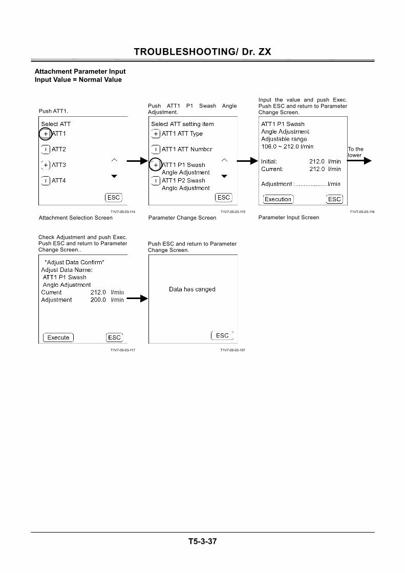
TROUBLESHOOTING/ Dr. ZX
T5-3-37
Attachment Parameter Input Input Value = Normal Value
T1V7-05-03-114
T1V7-05-03-117
T1V7-05-03-115
T1V7-05-03-107
T1V7-05-03-116
Push ATT1.
Attachment Selection Screen
Push ATT1 P1 Swash AngleAdjustment.
Parameter Change Screen
Input the value and push Exec.Push ESC and return to ParameterChange Screen.
Parameter Input Screen
Check Adjustment and push Exec.Push ESC and return to ParameterChange Screen..
Push ESC and return to ParameterChange Screen.
To the lower
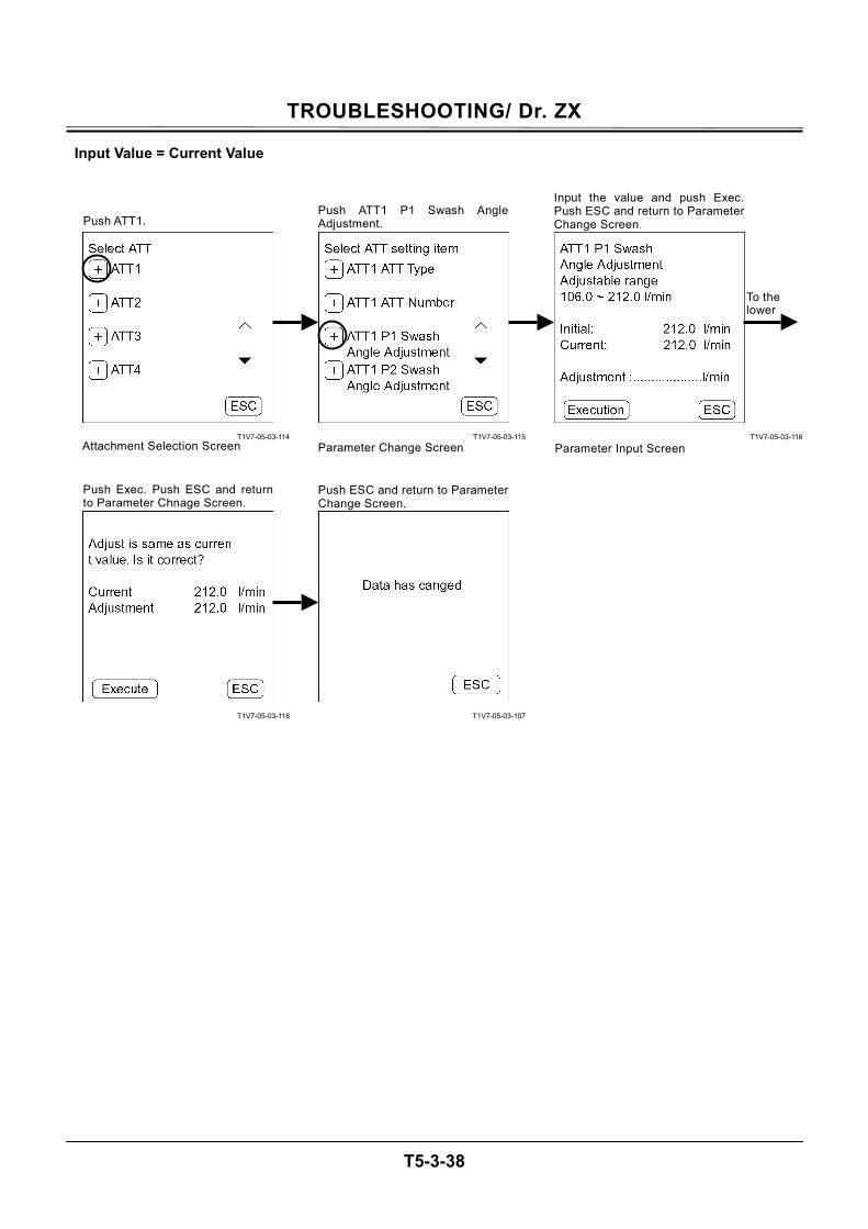
TROUBLESHOOTING/ Dr. ZX
T5-3-38
Input Value = Current Value
T1V7-05-03-114
T1V7-05-03-118
T1V7-05-03-115
T1V7-05-03-107
T1V7-05-03-116
Push ATT1.
Attachment Selection Screen
Push ATT1 P1 Swash AngleAdjustment.
Parameter Change Screen
Input the value and push Exec.Push ESC and return to ParameterChange Screen.
Parameter Input Screen
Push Exec. Push ESC and returnto Parameter Chnage Screen.
Push ESC and return to ParameterChange Screen.
To the lower
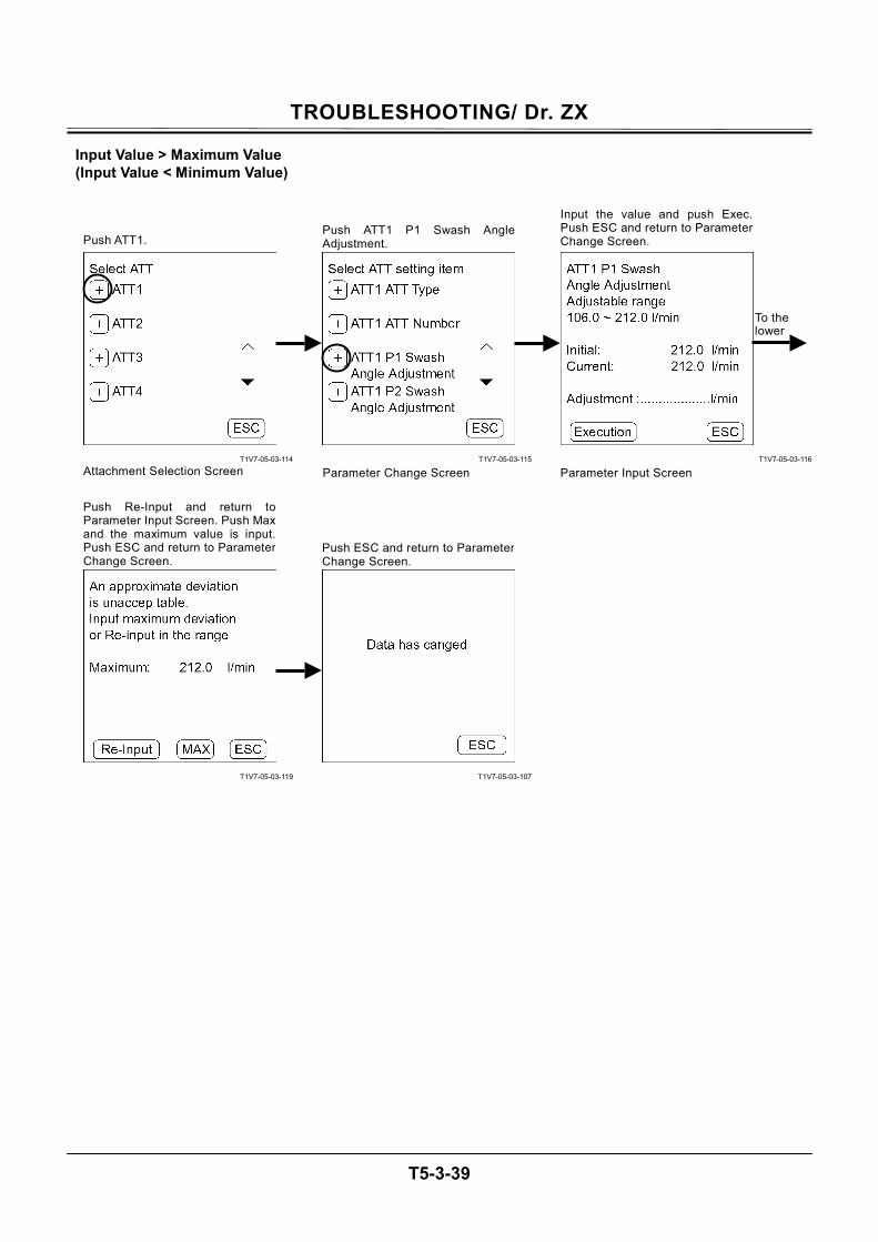
TROUBLESHOOTING/ Dr. ZX
T5-3-39
Input Value > Maximum Value (Input Value < Minimum Value)
T1V7-05-03-114
T1V7-05-03-119
T1V7-05-03-115
T1V7-05-03-107
T1V7-05-03-116
Push ATT1.
Attachment Selection Screen
Push ATT1 P1 Swash AngleAdjustment.
Parameter Change Screen
Input the value and push Exec.Push ESC and return to ParameterChange Screen.
Parameter Input Screen
Push Re-Input and return toParameter Input Screen. Push Max and the maximum value is input.Push ESC and return to ParameterChange Screen.
Push ESC and return to ParameterChange Screen.
To the lower
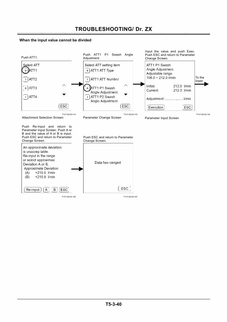
TROUBLESHOOTING/ Dr. ZX
T5-3-40
When the input value cannot be divided
T1V7-05-03-114
T1V7-05-03-120
T1V7-05-03-115
T1V7-05-03-107
T1V7-05-03-116
Push ATT1.
Attachment Selection Screen
Push ATT1 P1 Swash Angle Adjustment.
Parameter Change Screen
Input the value and push Exec.Push ESC and return to ParameterChange Screen.
Parameter Input Screen
Push Re-Input and return toParameter Input Screen. Push A orB and the value of A or B is input.Push ESC and return to ParameterChange Screen.
Push ESC and return to ParameterChange Screen.
To the lower
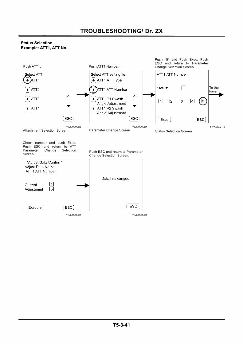
TROUBLESHOOTING/ Dr. ZX
T5-3-41
Status Selection Example: ATT1, ATT No.
T1V7-05-03-114
T1V7-05-03-168
T1V7-05-03-115
T1V7-05-03-107
T1V7-05-03-123
Push ATT1.
Attachment Selection Screen
Push ATT1 Number.
Parameter Change Screen
Push “5” and Push Exec. PushESC and return to ParameterChange Selection Screen.
Status Selection Screen
Check number and push Exec.Push ESC and return to ATTParameter Change SelectionScreen.
Push ESC and return to ParameterChange Selection Screen.
To the lower
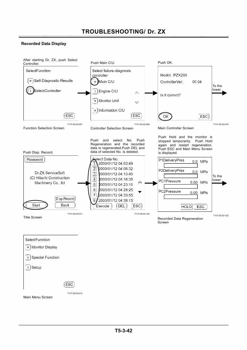
TROUBLESHOOTING/ Dr. ZX
T5-3-42
Recorded Data Display
T1V7-05-03-001
T1V7-05-03-011
T1V7-05-03-012
T1V7-05-03-009
T1V7-05-03-124
T1V7-05-03-010
T1V7-05-03-125
After starting Dr. ZX, push SelectController.
Function Selection Screen
Push Main C/U.
Controller Selection Screen
Push OK.
Main Controller Screen
Push and select No. PushRegeneration and the recordeddata is regenerated.Push DEL and data of selected No. is deleted.
Recorded Data Regeneration Screen
Push Disp. Record.
Title Screen
Push Hold and the monitor is stopped temporarily. Push Hold again and restart regeneration.Push ESC and Main Menu Screenis displayed.
Main Menu Screen
To the lower
To the lower
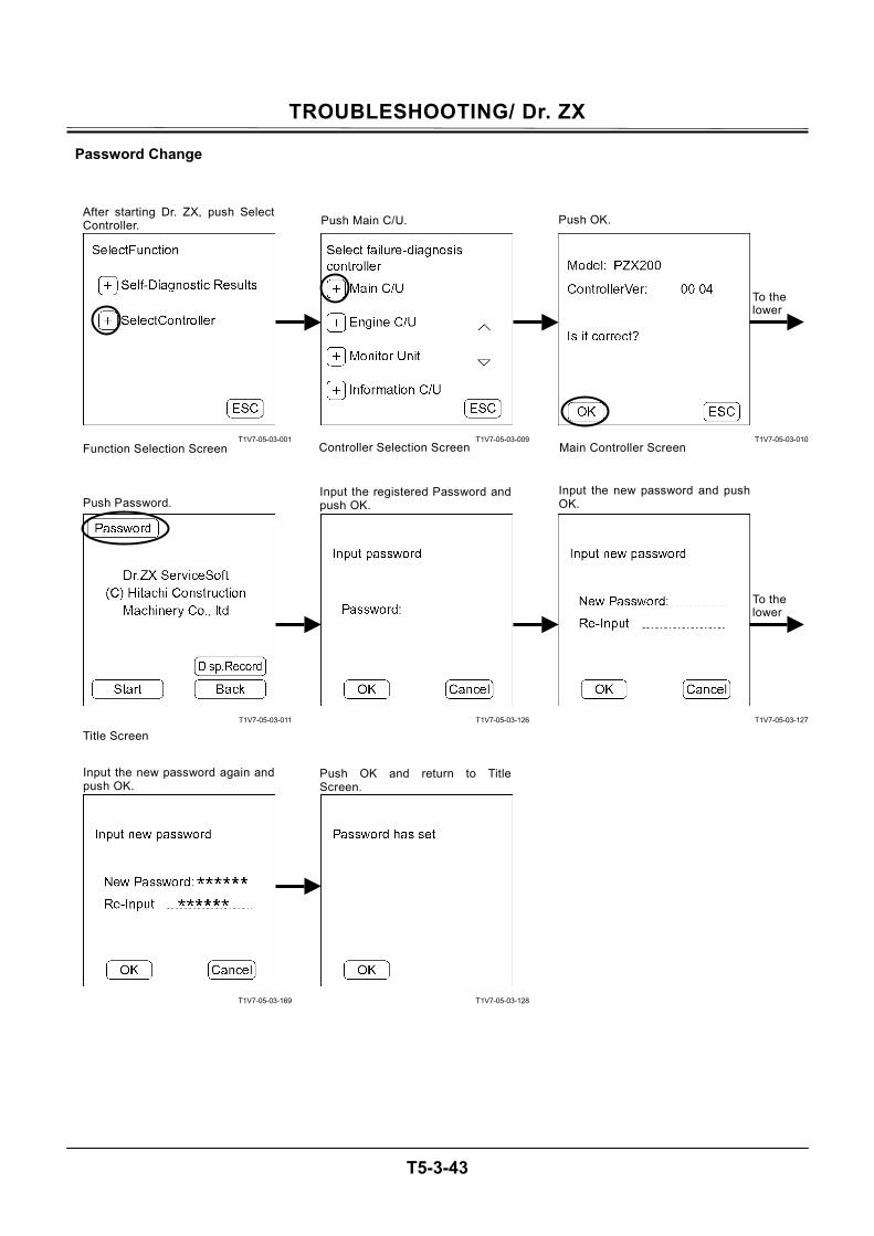
TROUBLESHOOTING/ Dr. ZX
T5-3-43
Password Change
T1V7-05-03-001
T1V7-05-03-011
T1V7-05-03-169
T1V7-05-03-009
T1V7-05-03-126
T1V7-05-03-128
T1V7-05-03-010
T1V7-05-03-127
After starting Dr. ZX, push SelectController.
Function Selection Screen
Push Main C/U.
Controller Selection Screen
Push OK.
Main Controller Screen
Push Password. Input the registered Password andpush OK.
Push OK and return to TitleScreen.
Title Screen
Input the new password again andpush OK.
Input the new password and pushOK.
To the lower
To the lower
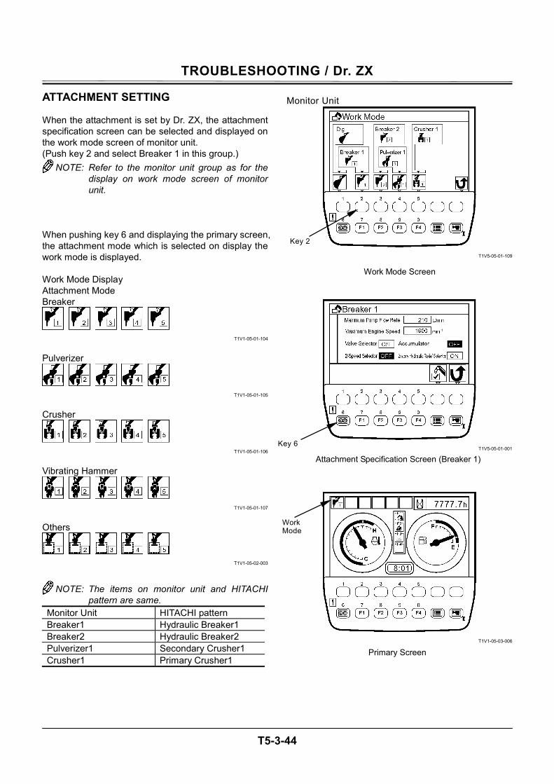
TROUBLESHOOTING / Dr. ZX
T5-3-44
ATTACHMENT SETTING When the attachment is set by Dr. ZX, the attachment specification screen can be selected and displayed on the work mode screen of monitor unit. (Push key 2 and select Breaker 1 in this group.)
NOTE: Refer to the monitor unit group as for the display on work mode screen of monitor unit.
When pushing key 6 and displaying the primary screen, the attachment mode which is selected on display the work mode is displayed. Work Mode Display Attachment Mode Breaker
T1V1-05-01-104
Pulverizer
T1V1-05-01-105
Crusher
T1V1-05-01-106
Vibrating Hammer
T1V1-05-01-107
Others
T1V1-05-02-003
NOTE: The items on monitor unit and HITACHI pattern are same.
Monitor Unit HITACHI pattern Breaker1 Hydraulic Breaker1 Breaker2 Hydraulic Breaker2 Pulverizer1 Secondary Crusher1 Crusher1 Primary Crusher1
Monitor Unit
T1V5-05-01-109
T1V5-05-01-001
T1V1-05-03-006
Work Mode Screen
Key 2
Key 6
Attachment Specification Screen (Breaker 1)
Work Mode
Primary Screen
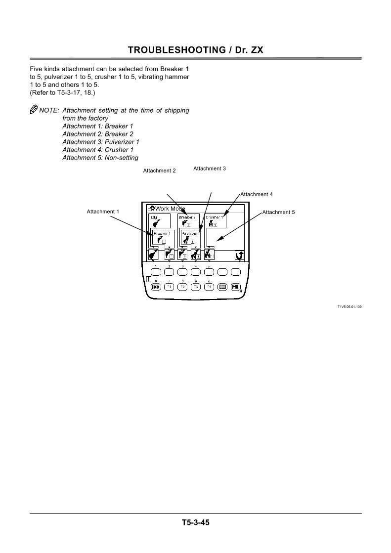
TROUBLESHOOTING / Dr. ZX
T5-3-45
Five kinds attachment can be selected from Breaker 1 to 5, pulverizer 1 to 5, crusher 1 to 5, vibrating hammer 1 to 5 and others 1 to 5. (Refer to T5-3-17, 18.)
NOTE: Attachment setting at the time of shipping from the factory Attachment 1: Breaker 1 Attachment 2: Breaker 2 Attachment 3: Pulverizer 1 Attachment 4: Crusher 1 Attachment 5: Non-setting
T1V5-05-01-109
Attachment 5
Attachment 4
Attachment 3Attachment 2
Attachment 1
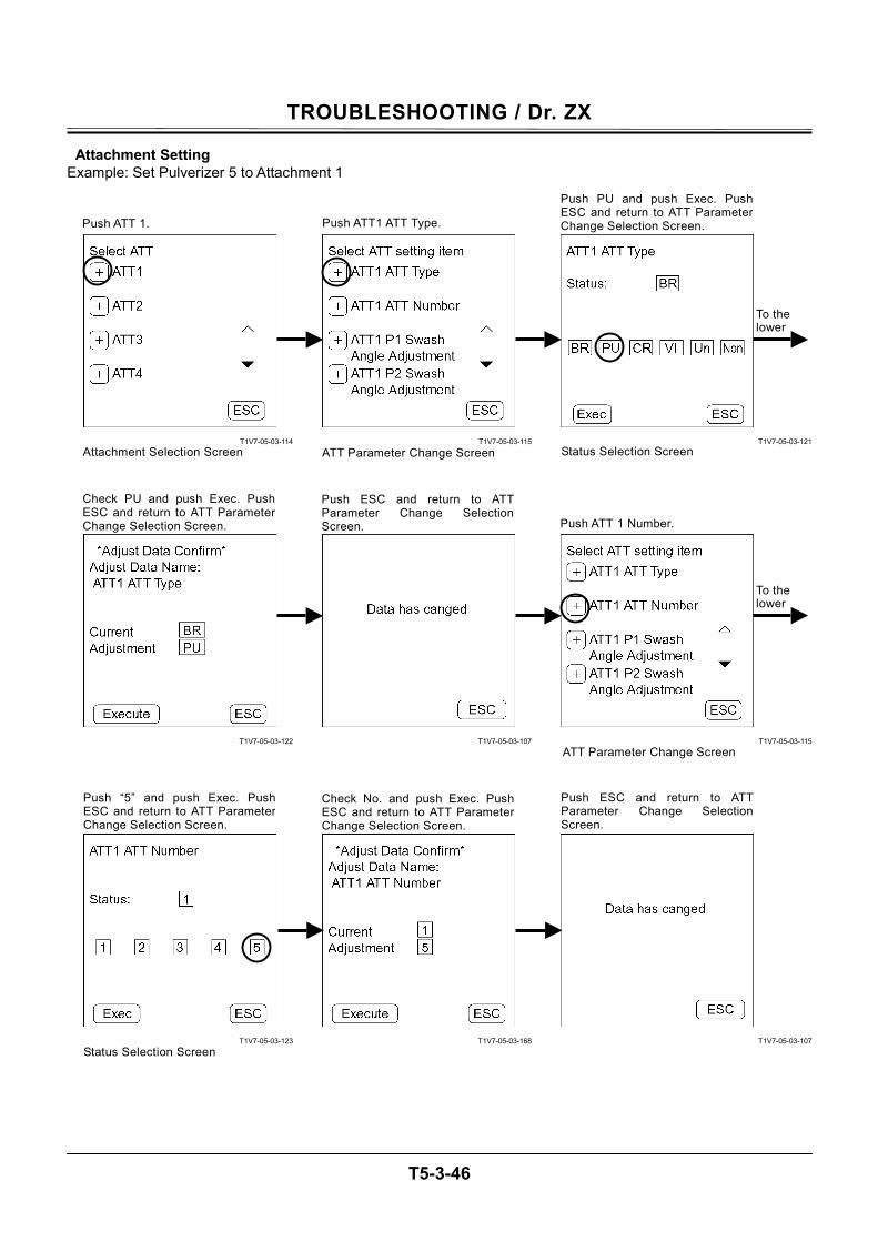
TROUBLESHOOTING / Dr. ZX
T5-3-46
Attachment Setting Example: Set Pulverizer 5 to Attachment 1
T1V7-05-03-114
T1V7-05-03-122
T1V7-05-03-123
T1V7-05-03-115
T1V7-05-03-107
T1V7-05-03-168
T1V7-05-03-121
T1V7-05-03-115
T1V7-05-03-107
Status Selection Screen
Push ATT 1.
Attachment Selection Screen
Push ATT1 ATT Type.
ATT Parameter Change Screen
Push PU and push Exec. PushESC and return to ATT ParameterChange Selection Screen.
Status Selection Screen
Push ESC and return to ATTParameter Change SelectionScreen. Push ATT 1 Number.
ATT Parameter Change Screen
Push “5” and push Exec. PushESC and return to ATT ParameterChange Selection Screen.
Check No. and push Exec. PushESC and return to ATT ParameterChange Selection Screen.
Check PU and push Exec. PushESC and return to ATT ParameterChange Selection Screen.
Push ESC and return to ATTParameter Change SelectionScreen.
To the lower
To the lower
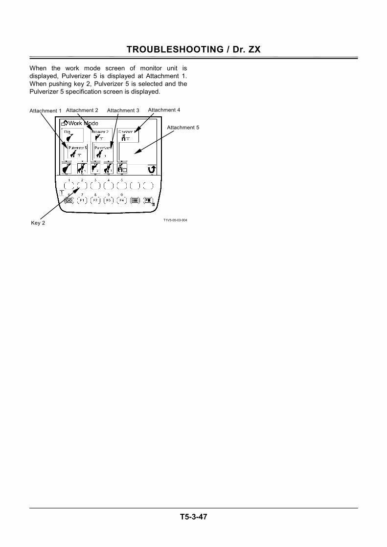
TROUBLESHOOTING / Dr. ZX
T5-3-47
When the work mode screen of monitor unit is displayed, Pulverizer 5 is displayed at Attachment 1. When pushing key 2, Pulverizer 5 is selected and the Pulverizer 5 specification screen is displayed.
T1V5-05-03-004
Attachment 1 Attachment 2 Attachment 3 Attachment 4
Attachment 5
Key 2
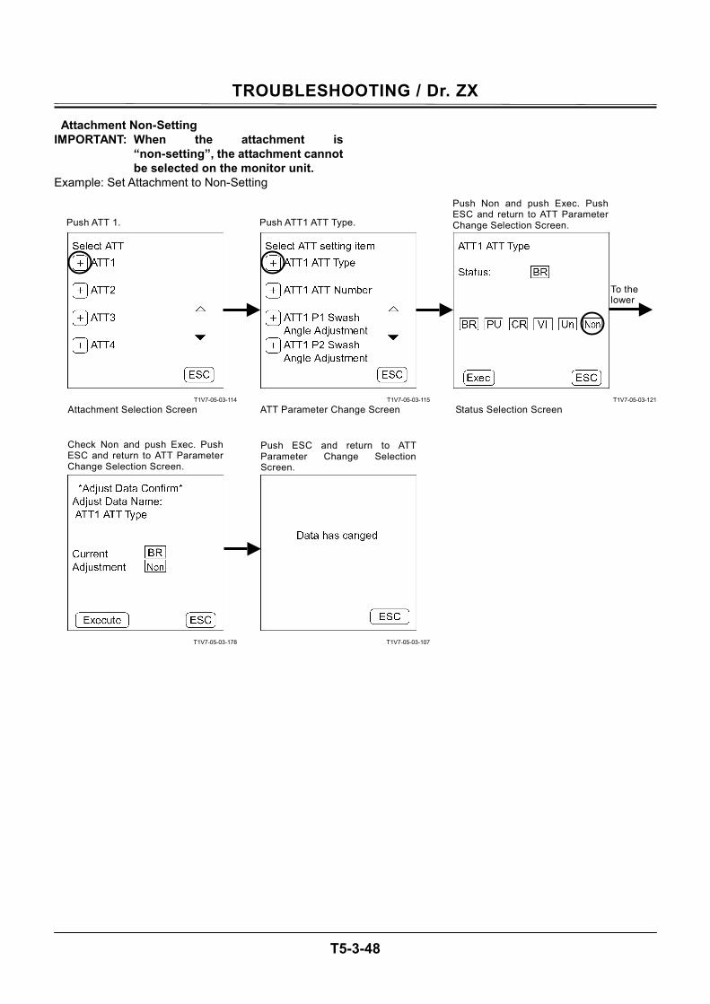
TROUBLESHOOTING / Dr. ZX
T5-3-48
Attachment Non-Setting IMPORTANT: When the attachment is
“non-setting”, the attachment cannot be selected on the monitor unit.
Example: Set Attachment to Non-Setting
T1V7-05-03-114
T1V7-05-03-178
T1V7-05-03-115
T1V7-05-03-107
T1V7-05-03-121
Push ATT 1.
Attachment Selection Screen
Push ATT1 ATT Type.
ATT Parameter Change Screen
Push Non and push Exec. Push ESC and return to ATT Parameter Change Selection Screen.
Status Selection Screen
Check Non and push Exec. PushESC and return to ATT ParameterChange Selection Screen.
Push ESC and return to ATTParameter Change SelectionScreen.
To the lower
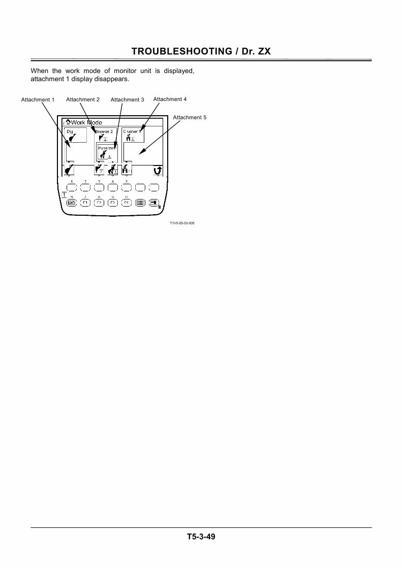
TROUBLESHOOTING / Dr. ZX
T5-3-49
When the work mode of monitor unit is displayed, attachment 1 display disappears.
T1V5-05-03-005
Attachment 1 Attachment 2 Attachment 3 Attachment 4
Attachment 5
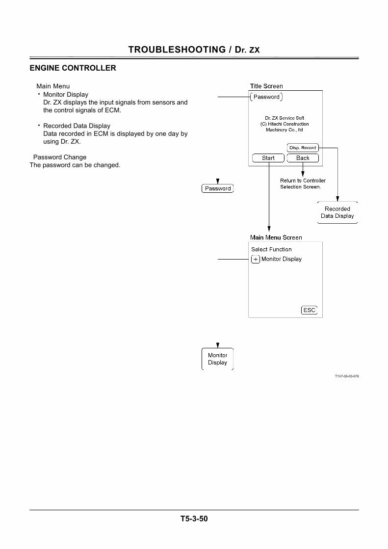
TROUBLESHOOTING / Dr. ZX
T5-3-50
ENGINE CONTROLLER
Main Menu • Monitor Display
Dr. ZX displays the input signals from sensors and the control signals of ECM.
• Recorded Data Display
Data recorded in ECM is displayed by one day by using Dr. ZX.
Password Change
The password can be changed.
T1V7-05-03-079
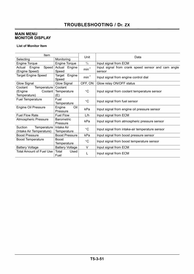
TROUBLESHOOTING / Dr. ZX
T5-3-51
MAIN MENU MONITOR DISPLAY
List of Monitor Item
Item Selecting Monitoring Unit Data
Engine Torque Engine Torque % Input signal from ECM Actual Engine Speed (Engine Speed)
Actual Engine Speed min-1 Input signal from crank speed sensor and cam angle
sensor Target Engine Speed Target Engine
Speed min-1 Input signal from engine control dial
Glow Signal Glow Signal OFF, ON Glow relay ON/OFF status Coolant Temperature (Engine Coolant Temperature)
Coolant Temperature (E)
°C Input signal from coolant temperature sensor
Fuel Temperature Fuel Temperature °C Input signal from fuel sensor
Engine Oil Pressure Engine Oil Pressure kPa Input signal from engine oil pressure sensor
Fuel Flow Rate Fuel Flow L/h Input signal from ECM Atmospheric Pressure Barometric
Pressure kPa Input signal from atmospheric pressure sensor
Suction Temperature (Intake Air Temperature)
Intake Air Temperature °C Input signal from intake-air temperature sensor
Boost Pressure Boost Pressure kPa Input signal from boost pressure sensor Boost Temperature Boost
Temperature °C Input signal from boost temperature sensor
Battery Voltage Battery Voltage V Input signal from ECM Total Amount of Fuel Use Total Used
Fuel L Input signal from ECM
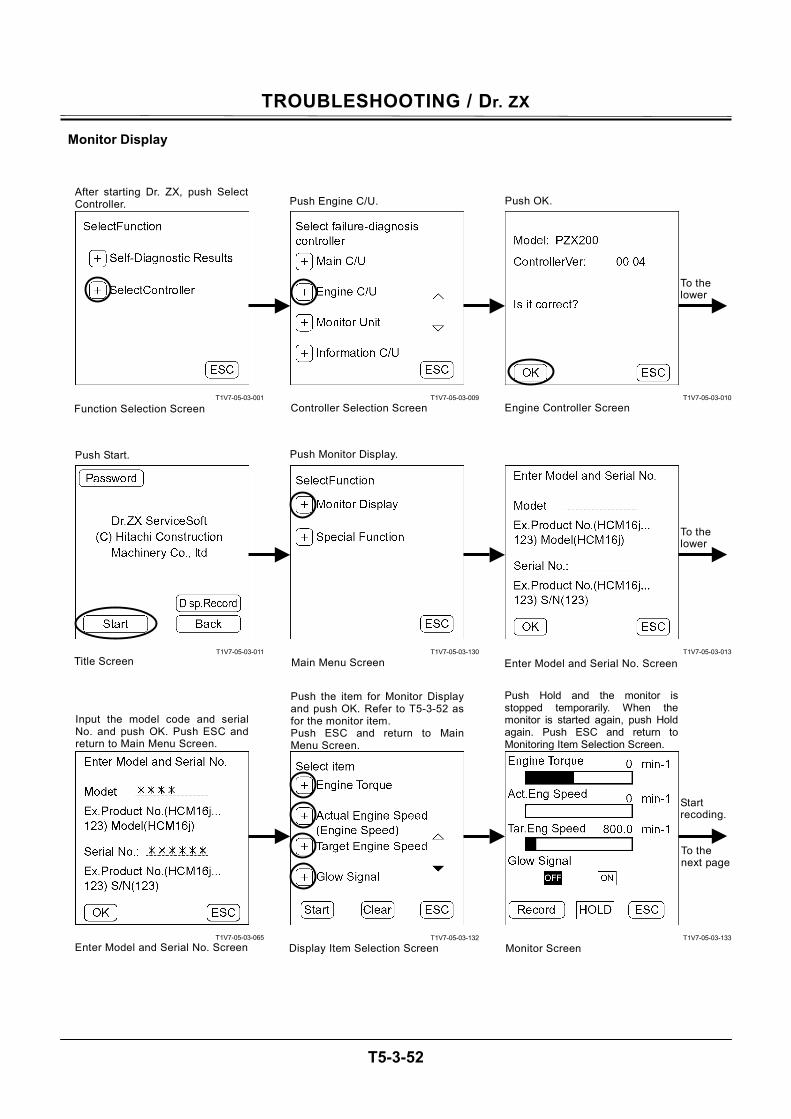
TROUBLESHOOTING / Dr. ZX
T5-3-52
Monitor Display
T1V7-05-03-001
T1V7-05-03-011
T1V7-05-03-065
T1V7-05-03-009
T1V7-05-03-130
T1V7-05-03-132
T1V7-05-03-010
T1V7-05-03-013
T1V7-05-03-133
Push Hold and the monitor isstopped temporarily. When themonitor is started again, push Holdagain. Push ESC and return toMonitoring Item Selection Screen.
Monitor Screen
After starting Dr. ZX, push SelectController.
Function Selection Screen
Push Engine C/U.
Controller Selection Screen
Push OK.
Engine Controller Screen
Push Start. Push Monitor Display.
Main Menu Screen
Push the item for Monitor Displayand push OK. Refer to T5-3-52 as for the monitor item. Push ESC and return to MainMenu Screen.
Display Item Selection Screen
Title Screen
Start recoding.
To the next page
Enter Model and Serial No. Screen
Input the model code and serial No. and push OK. Push ESC and return to Main Menu Screen.
Enter Model and Serial No. Screen
To the lower
To the lower
TROUBLESHOOTING / Dr. ZX
T5-3-53
T1V7-05-03-133
T1V7-05-03-170
T1V7-05-03-138
T1V7-05-03-134
T1V7-05-03-136
T1V7-05-03-171
T1V7-05-03-135
T1V7-05-03-137
T1V7-05-03-139
Push Record. Push Rec. No. and the recording screen for Rec. No. is made.
Monitor Screen Select Write Data-Bank Screen
If Rec. No. has already beenrecorded and push Over Write,data is overwritten. Push ESC and return to MainMenu Screen.
Recording Screen
Push Comment. Push ESC and return to MainMenu Screen.
Recording Screen
If Rec. No. has not been recordedyet and push Write, data is writtento the recording screen. Push ESC and return to MainMenu Screen.
Push Re-Input and return toRecording Screen (CommentInput). Push ESC and return to MainMenu Screen.
Input weather and person’s namein change and push OK.
Recording Screen (Comment Input)
Push OK and the recording screen(making) is finished.
To the lower
To the lower
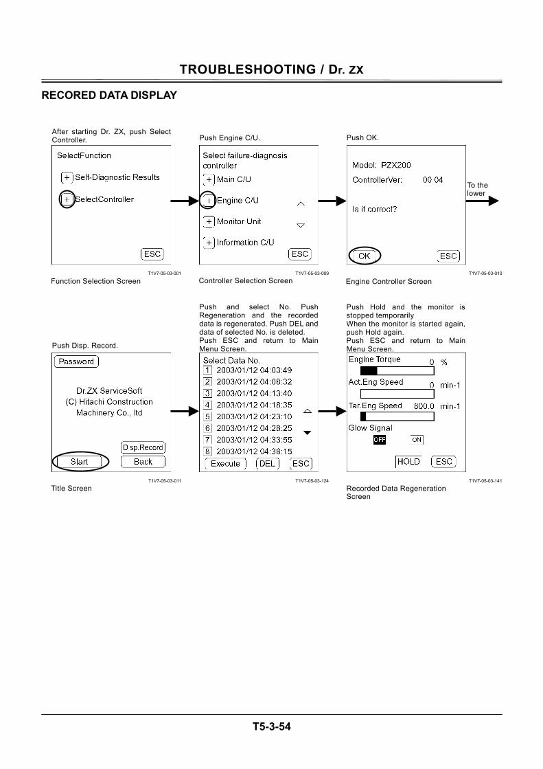
TROUBLESHOOTING / Dr. ZX
T5-3-54
RECORED DATA DISPLAY
T1V7-05-03-001
T1V7-05-03-011
T1V7-05-03-009
T1V7-05-03-124
T1V7-05-03-010
T1V7-05-03-141
To the lower
After starting Dr. ZX, push SelectController.
Function Selection Screen
Push Engine C/U.
Controller Selection Screen
Push OK.
Engine Controller Screen
Push Disp. Record.
Title Screen
Push and select No. PushRegeneration and the recordeddata is regenerated. Push DEL anddata of selected No. is deleted. Push ESC and return to MainMenu Screen.
Push Hold and the monitor isstopped temporarily When the monitor is started again,push Hold again. Push ESC and return to MainMenu Screen.
Recorded Data Regeneration Screen
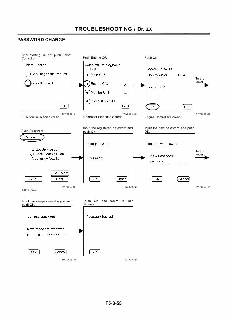
TROUBLESHOOTING / Dr. ZX
T5-3-55
PASSWORD CHANGE
T1V7-05-03-001
T1V7-05-03-011
T1V7-05-03-169
T1V7-05-03-009
T1V7-05-03-126
T1V7-05-03-128
T1V7-05-03-010
T1V7-05-03-127
After starting Dr. ZX, push SelectController.
Function Selection Screen
Push Engine C/U.
Controller Selection Screen
Push OK.
Engine Controller Screen
Push Password.
Title Screen
Input the newpassword again andpush OK.
Push OK and return to TitleScreen.
Input the registered password and push OK.
Input the new password and push OK.
To the lower
To the lower
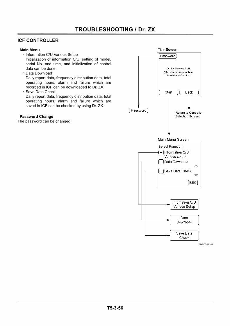
TROUBLESHOOTING / Dr. ZX
T5-3-56
ICF CONTROLLER
Main Menu • Information C/U Various Setup
Initialization of information C/U, setting of model, serial No. and time, and initialization of control data can be done.
• Data Download Daily report data, frequency distribution data, total operating hours, alarm and failure which are recorded in ICF can be downloaded to Dr. ZX.
• Save Data Check Daily report data, frequency distribution data, total operating hours, alarm and failure which are saved in ICF can be checked by using Dr. ZX.
Password Change
The password can be changed.
T1V7-05-03-166
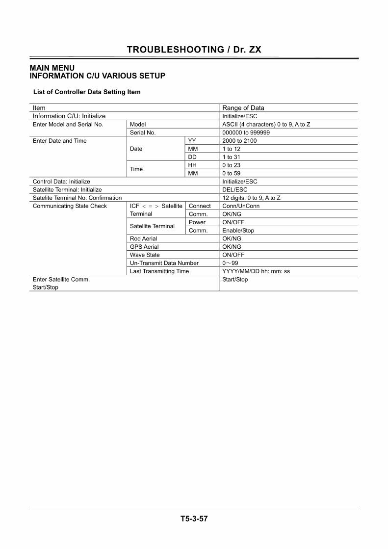
TROUBLESHOOTING / Dr. ZX
T5-3-57
MAIN MENU INFORMATION C/U VARIOUS SETUP
List of Controller Data Setting Item Item Range of Data Information C/U: Initialize Initialize/ESC
Model ASCII (4 characters) 0 to 9, A to Z Enter Model and Serial No. Serial No. 000000 to 999999
YY 2000 to 2100 MM 1 to 12 Date DD 1 to 31 HH 0 to 23
Enter Date and Time
Time MM 0 to 59
Control Data: Initialize Initialize/ESC Satellite Terminal: Initialize DEL/ESC Satelite Terminal No. Confirmation 12 digits: 0 to 9, A to Z
Connect Conn/UnConn ICF < = > Satellite Terminal Comm. OK/NG
Power ON/OFF Satellite Terminal
Comm. Enable/Stop Rod Aerial OK/NG GPS Aerial OK/NG Wave State ON/OFF Un-Transmit Data Number 0~99
Communicating State Check
Last Transmitting Time YYYY/MM/DD hh: mm: ss Enter Satellite Comm. Start/Stop
Start/Stop
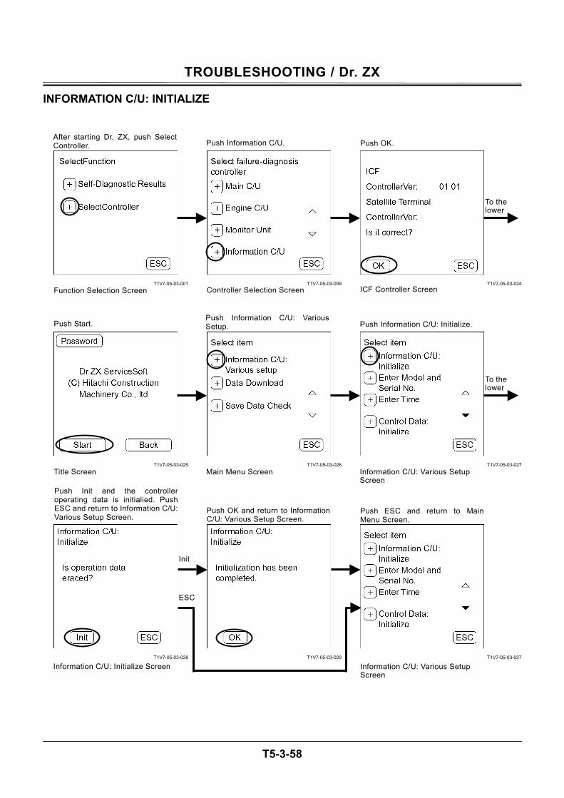
TROUBLESHOOTING / Dr. ZX
T5-3-58
INFORMATION C/U: INITIALIZE
T1V7-05-03-001
T1V7-05-03-025
T1V7-05-03-028
T1V7-05-03-009
T1V7-05-03-026
T1V7-05-03-029
T1V7-05-03-024
T1V7-05-03-027
T1V7-05-03-027
After starting Dr. ZX, push SelectController.
Function Selection Screen
Push Information C/U.
Controller Selection Screen
Push OK.
Push Start.
Main Menu Screen Title Screen
ICF Controller Screen
Push Information C/U: VariousSetup.
Information C/U: Various Setup Screen
Push Information C/U: Initialize.
Push Init and the controlleroperating data is initialied. PushESC and return to Information C/U:Various Setup Screen.
Push OK and return to InformationC/U: Various Setup Screen.
Push ESC and return to MainMenu Screen.
Information C/U: Various Setup Screen
Information C/U: Initialize Screen
To the lower
To the lower
ESC
Init
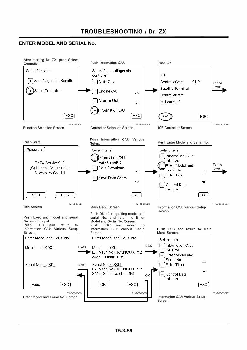
TROUBLESHOOTING / Dr. ZX
T5-3-59
ENTER MODEL AND SERIAL No.
T1V7-05-03-001
T1V7-05-03-025
T1V7-05-03-030
T1V7-05-03-009
T1V7-05-03-026
T1V7-05-03-031
T1V7-05-03-024
T1V7-05-03-027
T1V7-05-03-027
After starting Dr. ZX, push SelectController.
Function Selection Screen
Push Information C/U.
Controller Selection Screen
Push OK.
Push Start.
Main Menu Screen Title Screen
ICF Controller Screen
Push Information C/U: VariousSetup.
Information C/U: Various Setup Screen
Push Enter Model and Serial No.
Push ESC and return to Main Menu Screen.
Information C/U: Various Setup Screen
Push Exec and model and serialNo. can be input. Push ESC and return toInformation C/U: Various SetupScreen.
Enter Model and Serial No. Screen
Push OK after inputting model and serial No. and return to EnterModel and Serial No. Screen. Push ESC and return toInformation C/U: Various SetupScreen.
ESC
Exes ESC
OK
To the lower
To the lower
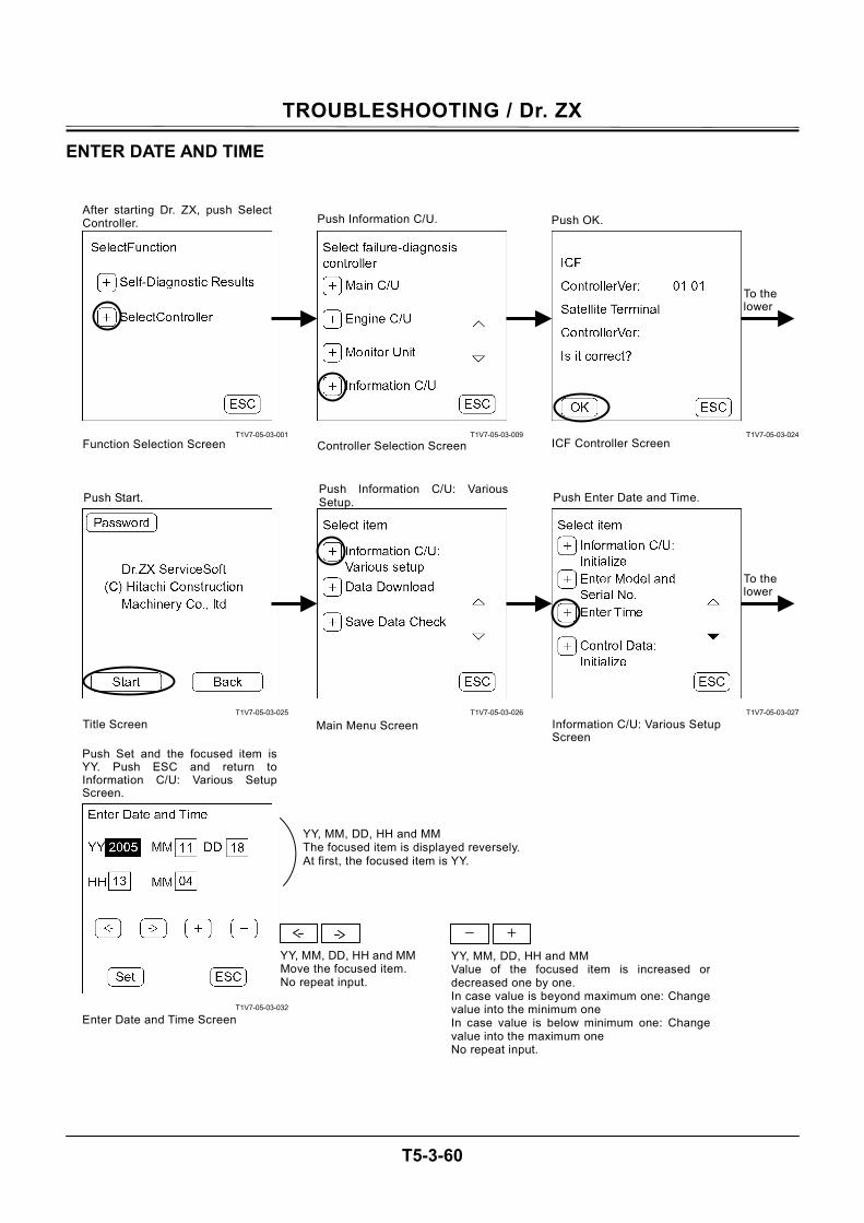
TROUBLESHOOTING / Dr. ZX
T5-3-60
ENTER DATE AND TIME
T1V7-05-03-001
T1V7-05-03-025
T1V7-05-03-032
T1V7-05-03-009
T1V7-05-03-026
T1V7-05-03-024
T1V7-05-03-027
After starting Dr. ZX, push SelectController.
Function Selection Screen
Push Information C/U.
Controller Selection Screen
Push OK.
Push Start.
Main Menu Screen Title Screen
ICF Controller Screen
Push Information C/U: VariousSetup.
Information C/U: Various Setup Screen
Push Enter Date and Time.
Push Set and the focused item isYY. Push ESC and return toInformation C/U: Various SetupScreen.
Enter Date and Time Screen
YY, MM, DD, HH and MM The focused item is displayed reversely. At first, the focused item is YY.
YY, MM, DD, HH and MMMove the focused item.No repeat input.
- +
YY, MM, DD, HH and MM Value of the focused item is increased or decreased one by one. In case value is beyond maximum one: Change value into the minimum one In case value is below minimum one: Change value into the maximum one No repeat input.
To the lower
To the lower
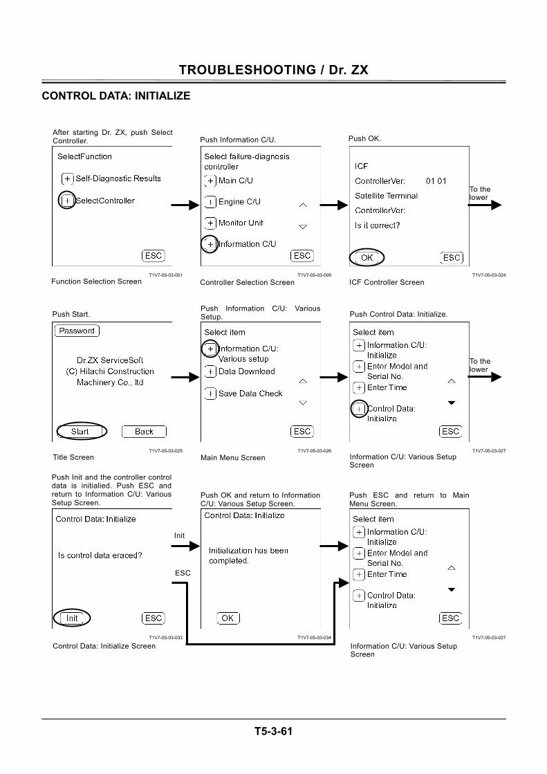
TROUBLESHOOTING / Dr. ZX
T5-3-61
CONTROL DATA: INITIALIZE
T1V7-05-03-001
T1V7-05-03-025
T1V7-05-03-033
T1V7-05-03-009
T1V7-05-03-026
T1V7-05-03-034
T1V7-05-03-024
T1V7-05-03-027
T1V7-05-03-027
After starting Dr. ZX, push SelectController.
Function Selection Screen
Push Information C/U.
Controller Selection Screen
Push OK.
Push Start.
Main Menu Screen Title Screen
ICF Controller Screen
Push Information C/U: VariousSetup.
Information C/U: Various Setup Screen
Push Control Data: Initialize.
Push OK and return to InformationC/U: Various Setup Screen.
Push ESC and return to MainMenu Screen.
Information C/U: Various Setup Screen
Push Init and the controller controldata is initialied. Push ESC andreturn to Information C/U: VariousSetup Screen.
Control Data: Initialize Screen
To the lower
To the lower
ESC
Init
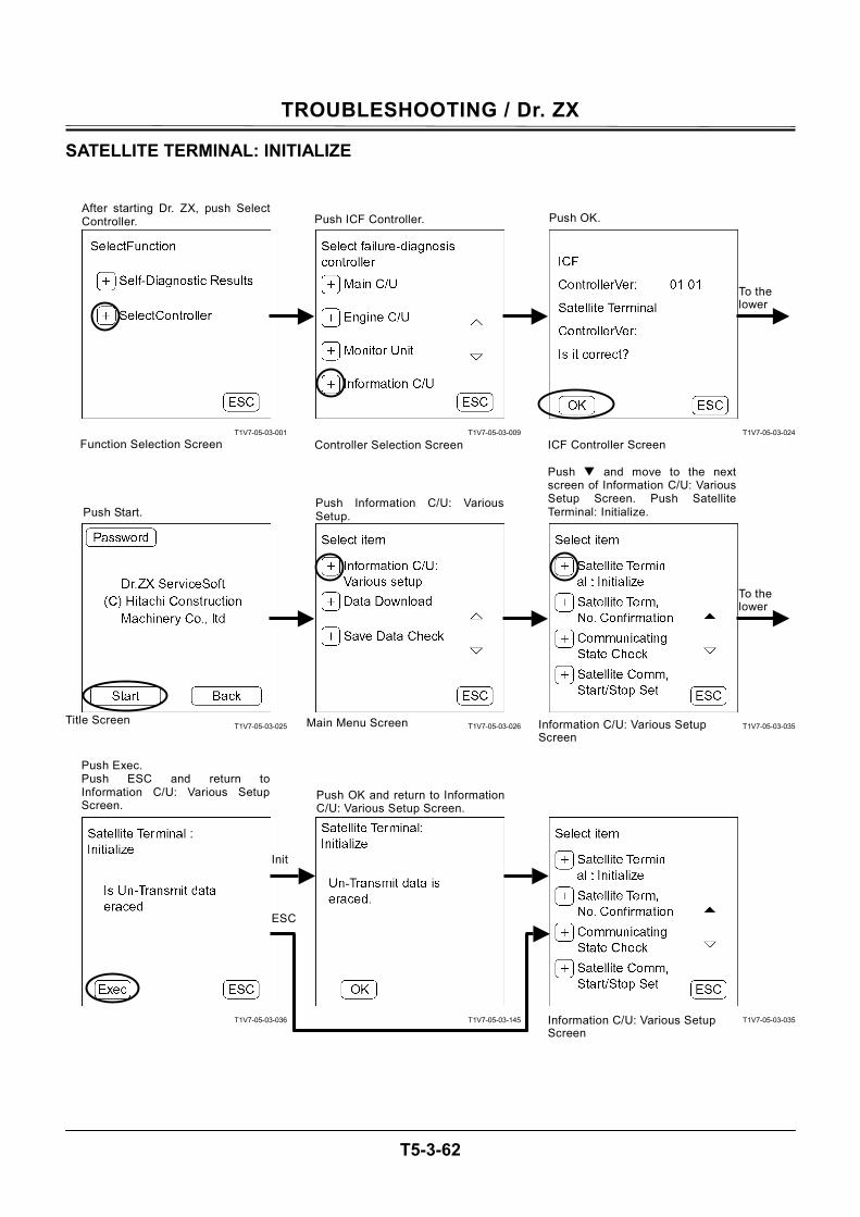
TROUBLESHOOTING / Dr. ZX
T5-3-62
SATELLITE TERMINAL: INITIALIZE
T1V7-05-03-001
T1V7-05-03-025
T1V7-05-03-036
T1V7-05-03-009
T1V7-05-03-026
T1V7-05-03-145
T1V7-05-03-024
T1V7-05-03-035
T1V7-05-03-035
After starting Dr. ZX, push SelectController.
Function Selection Screen
Push ICF Controller.
Controller Selection Screen
Push OK.
Push Start.
Main Menu Screen Title Screen
ICF Controller Screen
Push Information C/U: VariousSetup.
Information C/U: Various Setup Screen
Push and move to the next screen of Information C/U: Various Setup Screen. Push Satellite Terminal: Initialize.
Push Exec. Push ESC and return toInformation C/U: Various SetupScreen.
Push OK and return to InformationC/U: Various Setup Screen.
Information C/U: Various Setup Screen
To the lower
To the lower
ESC
Init
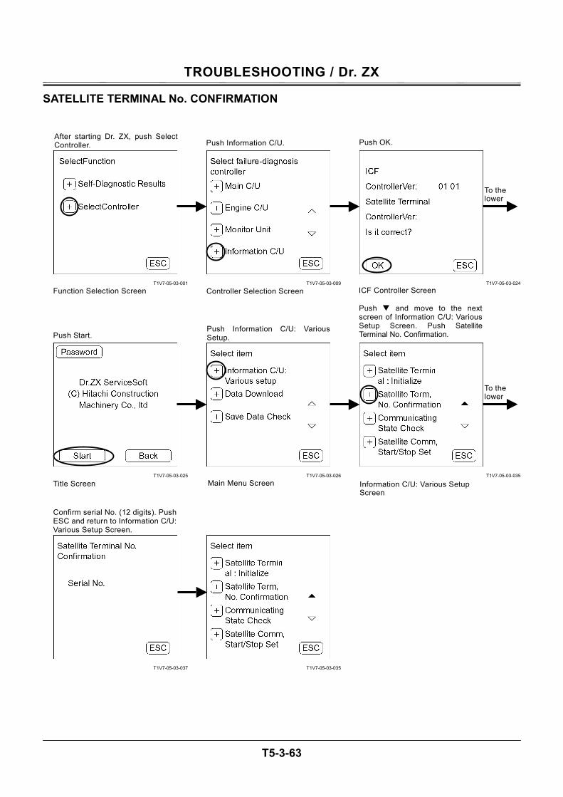
TROUBLESHOOTING / Dr. ZX
T5-3-63
SATELLITE TERMINAL No. CONFIRMATION
T1V7-05-03-001
T1V7-05-03-025
T1V7-05-03-037
T1V7-05-03-009
T1V7-05-03-026
T1V7-05-03-035
T1V7-05-03-024
T1V7-05-03-035
After starting Dr. ZX, push SelectController.
Function Selection Screen
Push Information C/U.
Controller Selection Screen
Push OK.
Push Start.
Main Menu Screen Title Screen
ICF Controller Screen
Push Information C/U: VariousSetup.
Information C/U: Various Setup Screen
Push and move to the nextscreen of Information C/U: VariousSetup Screen. Push SatelliteTerminal No. Confirmation.
Confirm serial No. (12 digits). PushESC and return to Information C/U:Various Setup Screen.
To the lower
To the lower
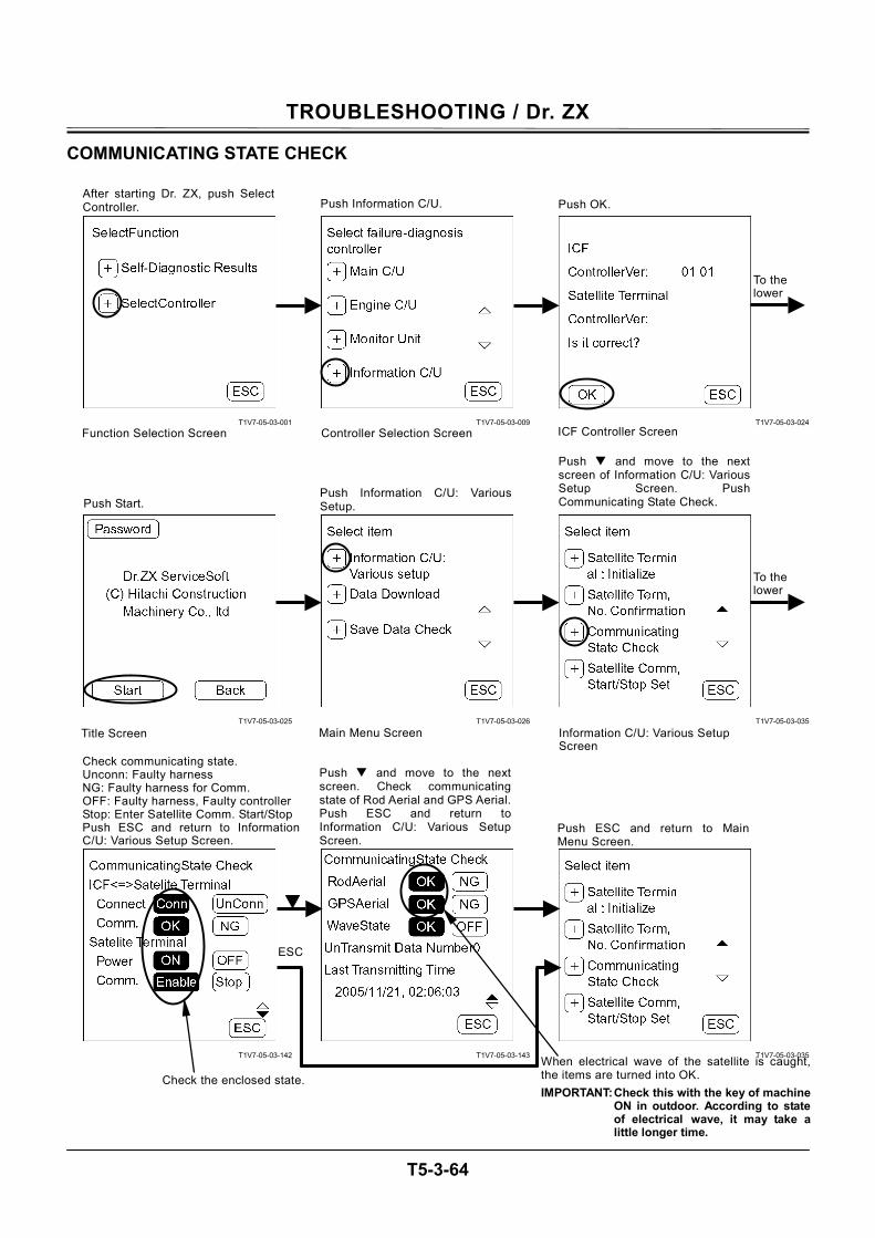
TROUBLESHOOTING / Dr. ZX
T5-3-64
COMMUNICATING STATE CHECK
T1V7-05-03-001
T1V7-05-03-025
T1V7-05-03-142
T1V7-05-03-009
T1V7-05-03-026
T1V7-05-03-143
T1V7-05-03-024
T1V7-05-03-035
T1V7-05-03-035
After starting Dr. ZX, push SelectController.
Function Selection Screen
Push Information C/U.
Controller Selection Screen
Push OK.
Push Start.
Main Menu Screen Title Screen
ICF Controller Screen
Push Information C/U: VariousSetup.
Information C/U: Various Setup Screen
Push and move to the next screen of Information C/U: Various Setup Screen. Push Communicating State Check.
Check communicating state. Unconn: Faulty harness NG: Faulty harness for Comm. OFF: Faulty harness, Faulty controller Stop: Enter Satellite Comm. Start/Stop Push ESC and return to InformationC/U: Various Setup Screen.
Push ESC and return to MainMenu Screen.
Push and move to the nextscreen. Check communicatingstate of Rod Aerial and GPS Aerial.Push ESC and return toInformation C/U: Various SetupScreen.
Check the enclosed state. When electrical wave of the satellite is caught,the items are turned into OK. IMPORTANT: Check this with the key of machine
ON in outdoor. According to stateof electrical wave, it may take alittle longer time.
To the lower
To the lower
ESC
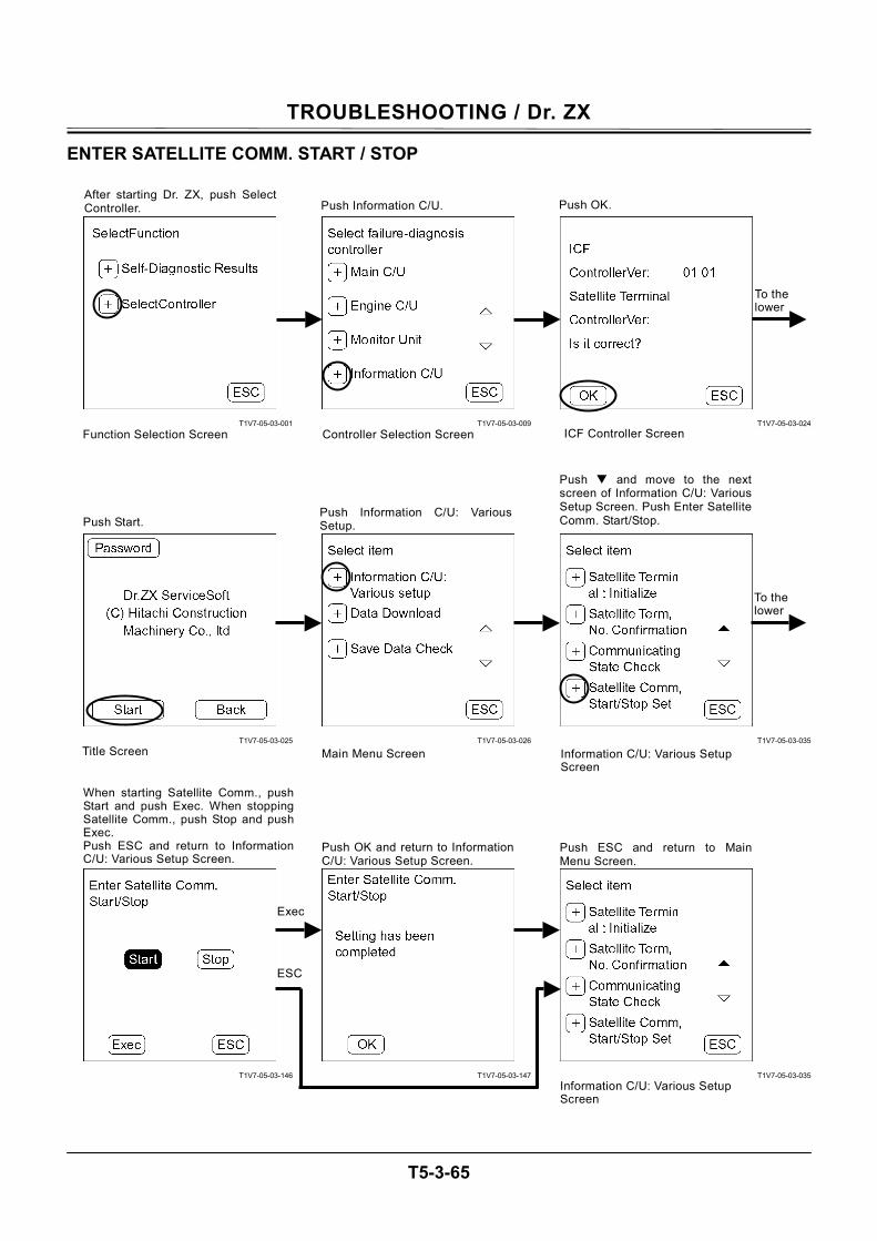
TROUBLESHOOTING / Dr. ZX
T5-3-65
ENTER SATELLITE COMM. START / STOP
T1V7-05-03-001
T1V7-05-03-025
T1V7-05-03-146
T1V7-05-03-009
T1V7-05-03-026
T1V7-05-03-147
T1V7-05-03-024
T1V7-05-03-035
T1V7-05-03-035
After starting Dr. ZX, push SelectController.
Function Selection Screen
Push Information C/U.
Controller Selection Screen
Push OK.
Push Start.
Main Menu Screen Title Screen
ICF Controller Screen
Push Information C/U: VariousSetup.
Push and move to the nextscreen of Information C/U: VariousSetup Screen. Push Enter SatelliteComm. Start/Stop.
Push ESC and return to MainMenu Screen.
When starting Satellite Comm., pushStart and push Exec. When stoppingSatellite Comm., push Stop and pushExec. Push ESC and return to InformationC/U: Various Setup Screen.
Push OK and return to InformationC/U: Various Setup Screen.
Information C/U: Various Setup Screen
To the lower
To the lower
ESC
Exec
Information C/U: Various Setup Screen

TROUBLESHOOTING / Dr. ZX
T5-3-66
(Blank)
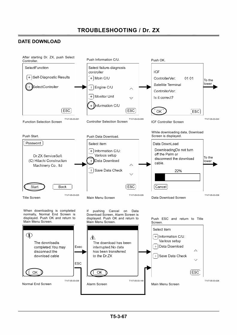
TROUBLESHOOTING / Dr. ZX
T5-3-67
DATE DOWNLOAD
T1V7-05-03-001
T1V7-05-03-025
T1V7-05-03-039
T1V7-05-03-009
T1V7-05-03-026
T1V7-05-03-148
T1V7-05-03-024
T1V7-05-03-038
T1V7-05-03-026
After starting Dr. ZX, push SelectController.
Function Selection Screen
Push Information C/U.
Controller Selection Screen
Push OK.
Push Start.
Main Menu Screen Title Screen
ICF Controller Screen
Push Data Download. While downloading data, DownloadScreen is displayed.
Data Download Screen
When downloading is completednormally, Normal End Screen isdisplayed. Push OK and return toMain Menu Screen.
Normal End Screen
If pushing Cancel on DataDownload Screen, Alarm Screen isdisplayed. Push OK and return toMain Menu Screen.
Main Menu Screen Alarm Screen
To the lower
To the lower
ESC
Exec
Push ESC and return to TitleScreen.
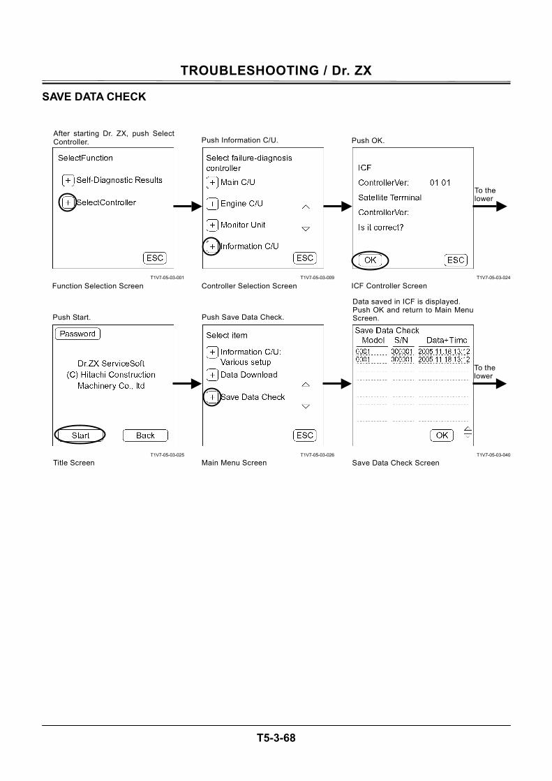
TROUBLESHOOTING / Dr. ZX
T5-3-68
SAVE DATA CHECK
T1V7-05-03-001
T1V7-05-03-025
T1V7-05-03-009
T1V7-05-03-026
T1V7-05-03-024
T1V7-05-03-040
After starting Dr. ZX, push SelectController.
Function Selection Screen
Push Information C/U.
Controller Selection Screen
Push OK.
Push Start.
Main Menu Screen Title Screen
ICF Controller Screen
Push Save Data Check.
Data saved in ICF is displayed. Push OK and return to Main MenuScreen.
Save Data Check Screen
To the lower
To the lower
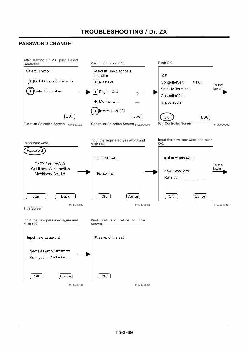
TROUBLESHOOTING / Dr. ZX
T5-3-69
PASSWORD CHANGE
T1V7-05-03-001
T1V7-05-03-025
T1V7-05-03-169
T1V7-05-03-009
T1V7-05-03-126
T1V7-05-03-128
T1V7-05-03-024
T1V7-05-03-127
After starting Dr. ZX, push SelectController.
Function Selection Screen
Push Information C/U.
Controller Selection Screen
Push OK.
ICF Controller Screen
Push Password.
Title Screen
Input the new password again andpush OK.
Push OK and return to TitleScreen.
Input the registered password and push OK.
Input the new password and pushOK.
To the lower
To the lower
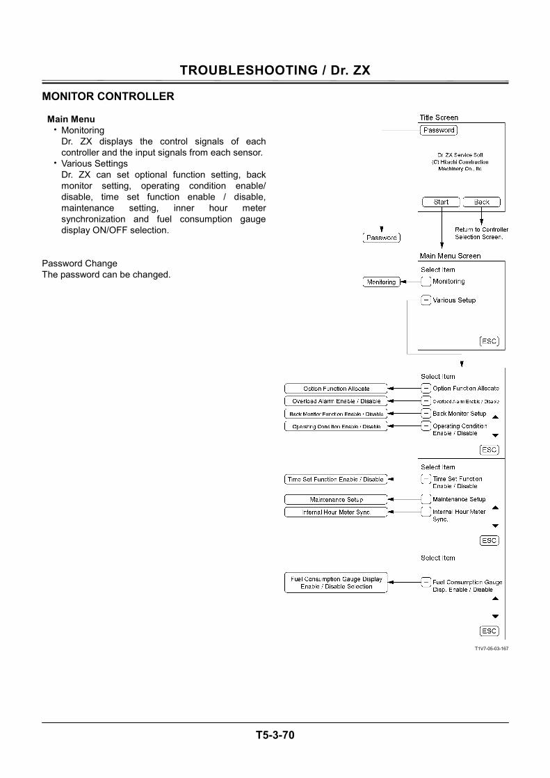
TROUBLESHOOTING / Dr. ZX
T5-3-70
MONITOR CONTROLLER
Main Menu • Monitoring
Dr. ZX displays the control signals of each controller and the input signals from each sensor.
• Various Settings Dr. ZX can set optional function setting, back monitor setting, operating condition enable/ disable, time set function enable / disable, maintenance setting, inner hour meter synchronization and fuel consumption gauge display ON/OFF selection.
Password Change The password can be changed.
T1V7-05-03-167
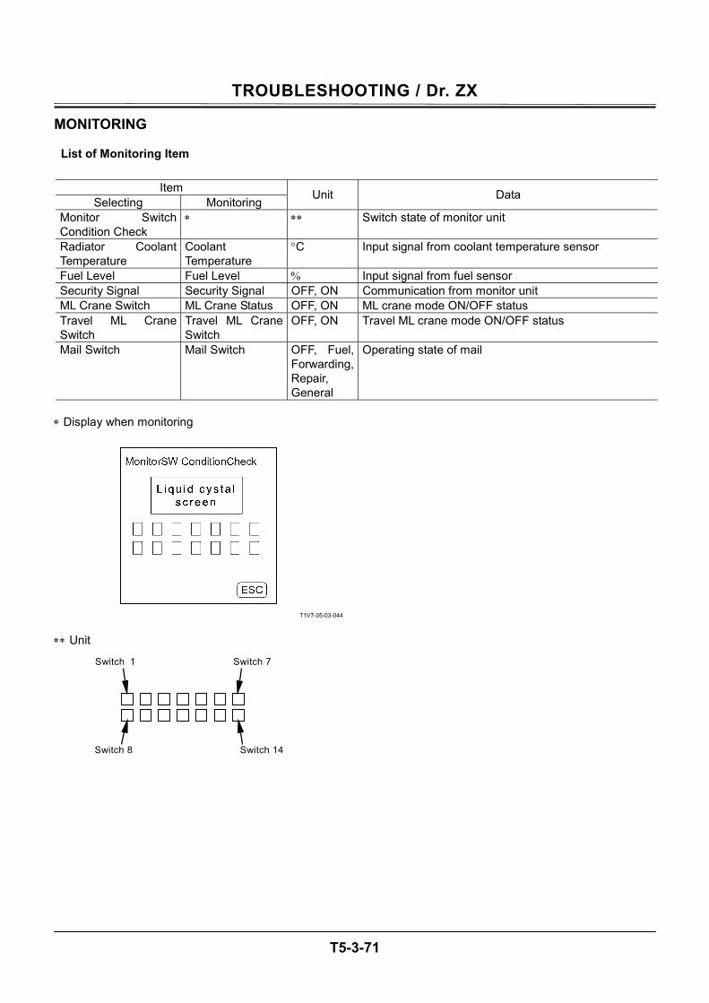
TROUBLESHOOTING / Dr. ZX
T5-3-71
MONITORING
List of Monitoring Item
Item Selecting Monitoring Unit Data
Monitor Switch Condition Check
∗ ∗∗ Switch state of monitor unit
Radiator Coolant Temperature
Coolant Temperature
°C Input signal from coolant temperature sensor
Fuel Level Fuel Level % Input signal from fuel sensor Security Signal Security Signal OFF, ON Communication from monitor unit ML Crane Switch ML Crane Status OFF, ON ML crane mode ON/OFF status Travel ML Crane Switch
Travel ML Crane Switch
OFF, ON Travel ML crane mode ON/OFF status
Mail Switch Mail Switch OFF, Fuel, Forwarding, Repair, General
Operating state of mail
∗ Display when monitoring
T1V7-05-03-044
∗∗ Unit
Switch 1 Switch 7
Switch 14 Switch 8
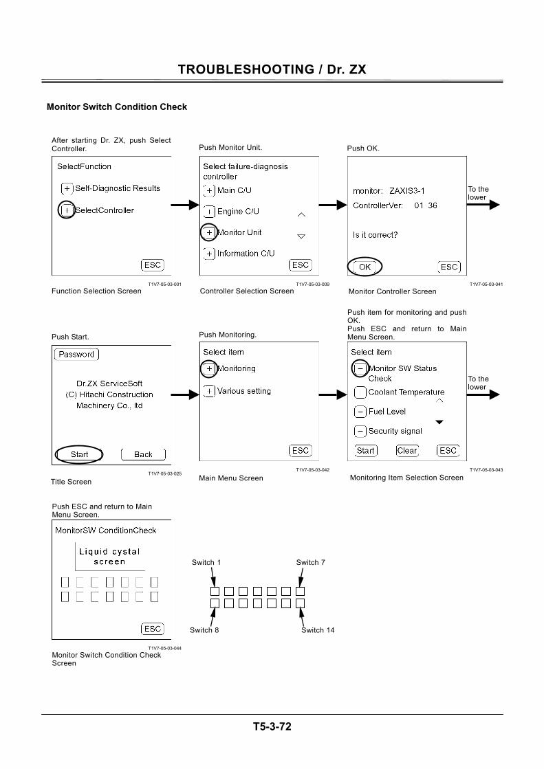
TROUBLESHOOTING / Dr. ZX
T5-3-72
Monitor Switch Condition Check
T1V7-05-03-001
T1V7-05-03-025
T1V7-05-03-044
T1V7-05-03-009
T1V7-05-03-042
T1V7-05-03-041
T1V7-05-03-043
After starting Dr. ZX, push SelectController.
Function Selection Screen
Push Monitor Unit.
Controller Selection Screen
Push OK.
Monitor Controller Screen
Push Start. Push Monitoring.
Main Menu Screen
Push item for monitoring and push OK. Push ESC and return to Main Menu Screen.
Monitoring Item Selection ScreenTitle Screen
Push ESC and return to Main Menu Screen.
Monitor Switch Condition Check Screen
Switch 1 Switch 7
Switch 14Switch 8
To the lower
To the lower
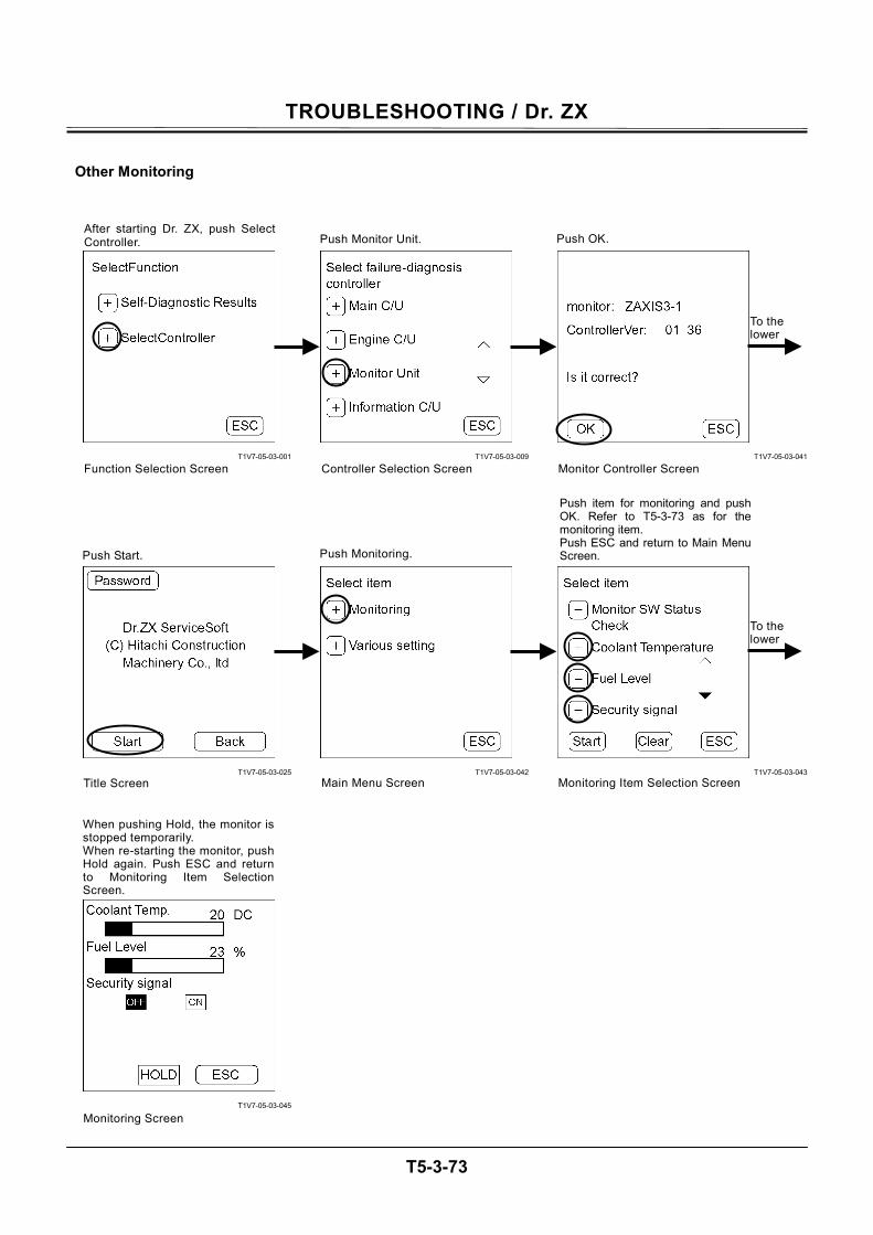
TROUBLESHOOTING / Dr. ZX
T5-3-73
Other Monitoring
T1V7-05-03-001
T1V7-05-03-025
T1V7-05-03-045
T1V7-05-03-009
T1V7-05-03-042
T1V7-05-03-041
T1V7-05-03-043
After starting Dr. ZX, push SelectController.
Function Selection Screen
Push Monitor Unit.
Controller Selection Screen
Push OK.
Monitor Controller Screen
Push Start. Push Monitoring.
Main Menu Screen Monitoring Item Selection ScreenTitle Screen
Push item for monitoring and pushOK. Refer to T5-3-73 as for themonitoring item. Push ESC and return to Main MenuScreen.
When pushing Hold, the monitor isstopped temporarily. When re-starting the monitor, pushHold again. Push ESC and return to Monitoring Item Selection Screen.
Monitoring Screen
To the lower
To the lower
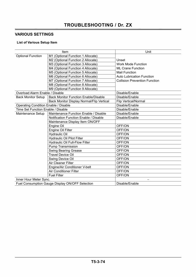
TROUBLESHOOTING / Dr. ZX
T5-3-74
VARIOUS SETTINGS
List of Various Setup Item
Item Unit M1 (Optional Function 1 Allocate) M2 (Optional Function 2 Allocate) Unset M3 (Optional Function 3 Allocate) Work Mode Function M4 (Optional Function 4 Allocate) ML Crane Function M5 (Optional Function 5 Allocate) Mail Function M6 (Optional Function 6 Allocate) Auto Lubrication Function M7 (Optional Function 7 Allocate) Collision Prevention Function M8 (Optional Function 8 Allocate)
Optional Function
M9 (Optional Function 9 Allocate) Overload Alarm Enable / Disable Disable/Enable
Back Monitor Function Enable/Disable Disable/Enable Back Monitor Setup Back Monitor Display Normal/Flip Vertical Flip Vertical/Normal
Operating Condition Enable / Disable Disable/Enable Time Set Function Enable / Disable Disable/Enable
Maintenance Function Enable / Disable Disable/Enable Notification Function Enable / Disable Disable/Enable Maintenance Display Item ON/OFF Engine Oil OFF/ON Engine Oil Filter OFF/ON Hydraulic Oil OFF/ON Hydraulic Oil Pilot Filter OFF/ON Hydraulic Oil Full-Flow Filter OFF/ON Pump Transmission OFF/ON Swing Bearing Grease OFF/ON Travel Device Oil OFF/ON Swing Device Oil OFF/ON Air Cleaner Filter OFF/ON Engine/Air Conditioner V-belt OFF/ON Air Conditioner Filter OFF/ON
Maintenance Setup
Fuel Filter OFF/ON Inner Hour Meter Sync. − Fuel Consumption Gauge Display ON/OFF Selection Disable/Enable

TROUBLESHOOTING / Dr. ZX
T5-3-75
(Blank)
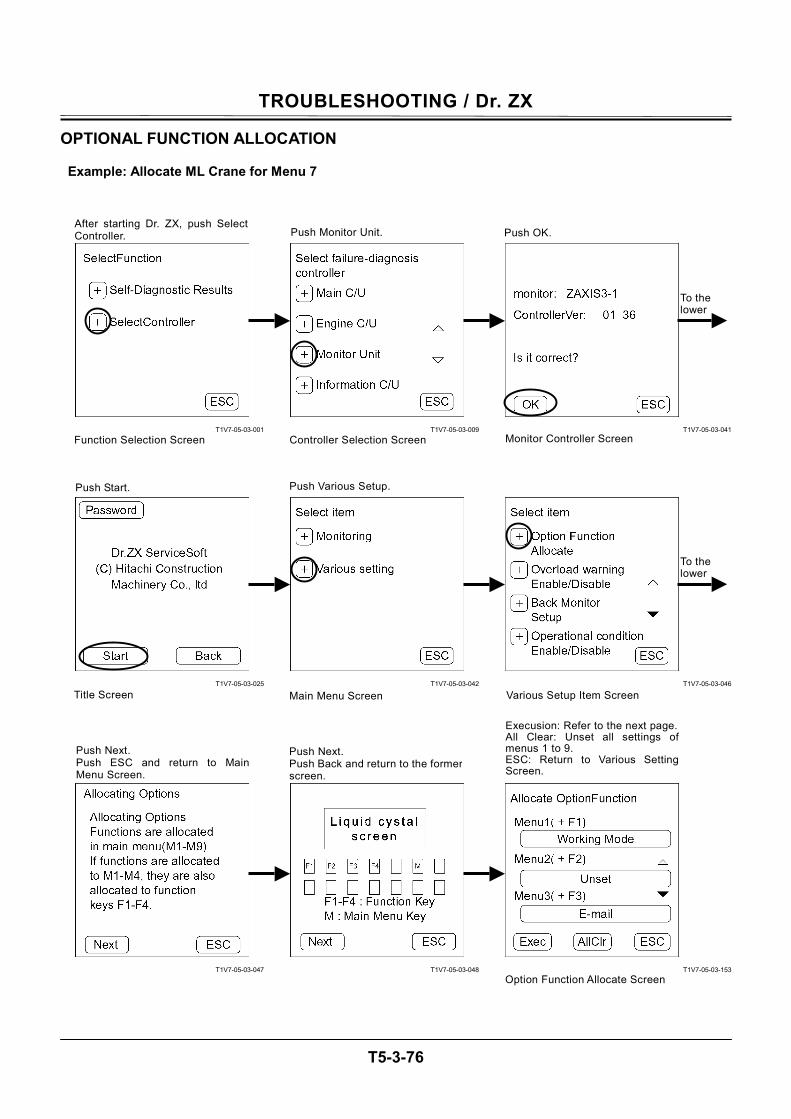
TROUBLESHOOTING / Dr. ZX
T5-3-76
OPTIONAL FUNCTION ALLOCATION
Example: Allocate ML Crane for Menu 7
T1V7-05-03-001
T1V7-05-03-025
T1V7-05-03-047
T1V7-05-03-009
T1V7-05-03-042
T1V7-05-03-048
T1V7-05-03-041
T1V7-05-03-046
T1V7-05-03-153
Push Next. Push Back and return to the formerscreen.
After starting Dr. ZX, push SelectController.
Function Selection Screen
Push Monitor Unit.
Controller Selection Screen
Push OK.
Monitor Controller Screen
Push Start. Push Various Setup.
Main Menu ScreenTitle Screen
Push Next. Push ESC and return to MainMenu Screen.
Execusion: Refer to the next page.All Clear: Unset all settings ofmenus 1 to 9. ESC: Return to Various SettingScreen.
Option Function Allocate Screen
To the lower
To the lower
Various Setup Item Screen
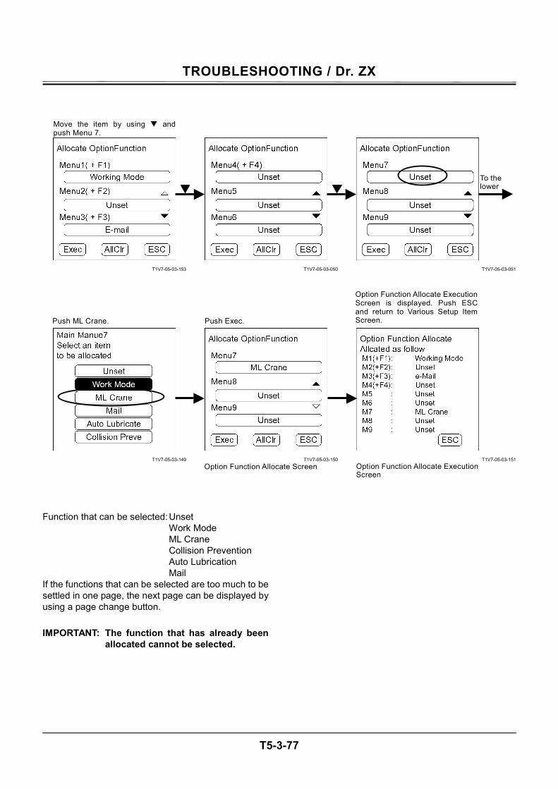
TROUBLESHOOTING / Dr. ZX
T5-3-77
T1V7-05-03-153
T1V7-05-03-149
T1V7-05-03-050
T1V7-05-03-150
T1V7-05-03-051
T1V7-05-03-151
Function that can be selected: Unset
Work Mode ML Crane Collision Prevention Auto Lubrication Mail
If the functions that can be selected are too much to be settled in one page, the next page can be displayed by using a page change button. IMPORTANT: The function that has already been
allocated cannot be selected.
Move the item by using andpush Menu 7.
Push ML Crane. Push Exec.
Option Function Allocate Screen Option Function Allocate Execution Screen
Option Function Allocate ExecutionScreen is displayed. Push ESCand return to Various Setup ItemScreen.
To the lower
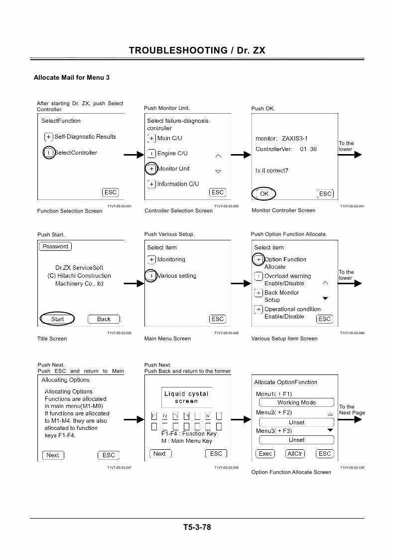
TROUBLESHOOTING / Dr. ZX
T5-3-78
Allocate Mail for Menu 3
T1V7-05-03-001
T1V7-05-03-025
T1V7-05-03-047
T1V7-05-03-009
T1V7-05-03-042
T1V7-05-03-048
T1V7-05-03-041
T1V7-05-03-046
T1V7-05-03-155
To the lower
To the lower
To the Next Page
Push Next. Push Back and return to the former
After starting Dr. ZX, push SelectController.
Function Selection Screen
Push Monitor Unit.
Controller Selection Screen
Push OK.
Monitor Controller Screen
Push Start. Push Various Setup.
Main Menu ScreenTitle Screen
Push Next. Push ESC and return to Main
Option Function Allocate Screen
Push Option Function Allocate.
Various Setup Item Screen
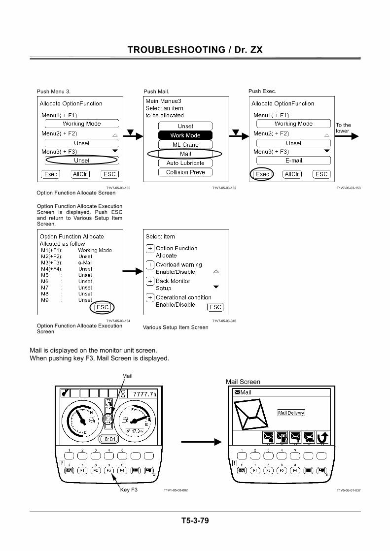
TROUBLESHOOTING / Dr. ZX
T5-3-79
T1V7-05-03-155
T1V7-05-03-154
T1V7-05-03-152
T1V7-05-03-046
T1V7-05-03-153
Mail is displayed on the monitor unit screen. When pushing key F3, Mail Screen is displayed.
T1V1-05-03-002
Mail Screen
T1V5-05-01-037
To the lower
Various Setup Item Screen
Option Function Allocate ExecutionScreen is displayed. Push ESCand return to Various Setup ItemScreen.
Option Function Allocate Screen
Push Menu 3. Push Mail. Push Exec.
Option Function Allocate ExecutionScreen
Key F3
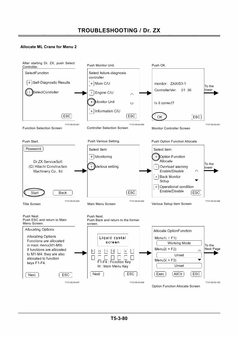
TROUBLESHOOTING / Dr. ZX
T5-3-80
Allocate ML Crane for Menu 2
T1V7-05-03-001
T1V7-05-03-025
T1V7-05-03-047
T1V7-05-03-009
T1V7-05-03-042
T1V7-05-03-048
T1V7-05-03-041
T1V7-05-03-046
T1V7-05-03-155
To the lower
To the lower
To the Next Page
Push Next. Push Back and return to the formerscreen.
After starting Dr. ZX, push SelectController.
Function Selection Screen
Push Monitor Unit.
Controller Selection Screen
Push OK.
Monitor Controller Screen
Push Start. Push Various Setting.
Main Menu ScreenTitle Screen
Push Next. Push ESC and return to Main Menu Screen.
Various Setup Item Screen
Option Function Allocate Screen
Push Option Function Allocate.
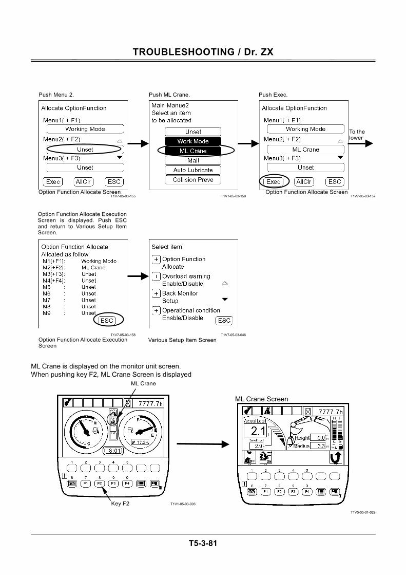
TROUBLESHOOTING / Dr. ZX
T5-3-81
T1V7-05-03-155
T1V7-05-03-158
T1V7-05-03-159
T1V7-05-03-046
T1V7-05-03-157
ML Crane is displayed on the monitor unit screen. When pushing key F2, ML Crane Screen is displayed
T1V1-05-03-003
ML Crane Screen
T1V5-05-01-029
To the lower
Various Setup Item Screen
Option Function Allocate ExecutionScreen is displayed. Push ESCand return to Various Setup ItemScreen.
Option Function Allocate Screen Option Function Allocate Screen
Push Menu 2. Push ML Crane. Push Exec.
Option Function Allocate ExecutionScreen
ML Crane
Key F2

TROUBLESHOOTING / Dr. ZX
T5-3-82
Make ML Crane for Menu 2 Disable
T1V7-05-03-001
T1V7-05-03-025
T1V7-05-03-047
T1V7-05-03-009
T1V7-05-03-042
T1V7-05-03-048
T1V7-05-03-041
T1V7-05-03-046
T1V7-05-03-157
To the lower
To the lower
To the Next Page
Push Next. Push Back and return to the formerscreen.
After starting Dr. ZX, push SelectController. Push Monitor Unit. Push OK.
Push Start. Push Various Setting.
Main Menu ScreenTitle Screen
Push Next. Push ESC and return to MainMenu Screen.
Option Function Allocate Screen
Push Option Function Allocate.
Function Selection Screen Controller Selection Screen Monitor Controller Screen
Various Setup Item Screen
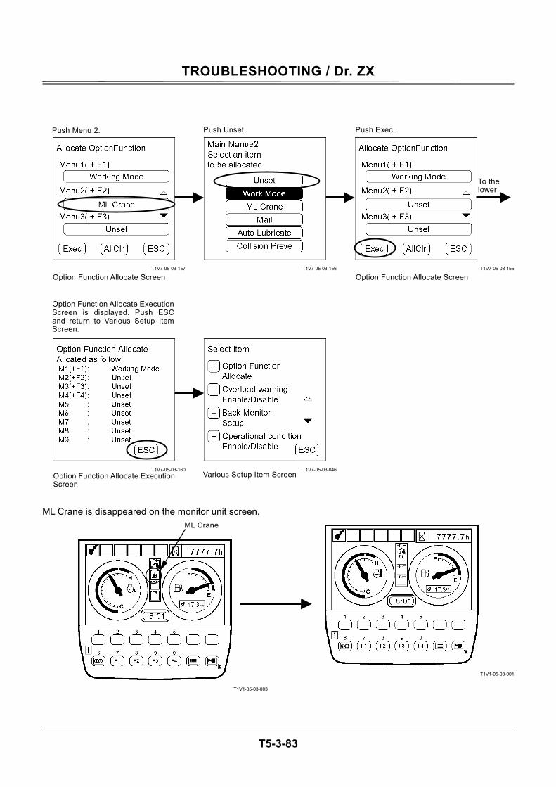
TROUBLESHOOTING / Dr. ZX
T5-3-83
T1V7-05-03-157
T1V7-05-03-160
T1V7-05-03-156
T1V7-05-03-046
T1V7-05-03-155
ML Crane is disappeared on the monitor unit screen.
T1V1-05-03-003
T1V1-05-03-001
ML Crane
To the lower
Various Setup Item Screen
Option Function Allocate Execution Screen is displayed. Push ESCand return to Various Setup Item Screen.
Option Function Allocate Screen Option Function Allocate Screen
Push Menu 2. Push Unset. Push Exec.
Option Function Allocate ExecutionScreen
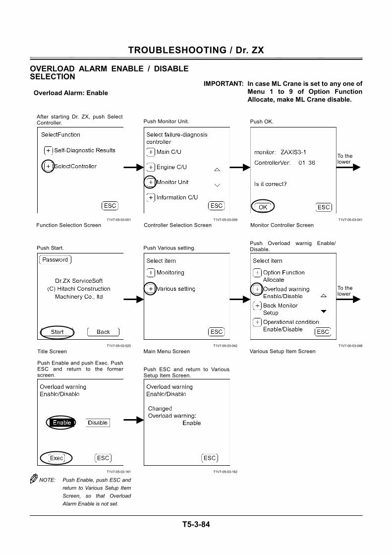
TROUBLESHOOTING / Dr. ZX
T5-3-84
OVERLOAD ALARM ENABLE / DISABLE SELECTION
Overload Alarm: Enable
IMPORTANT: In case ML Crane is set to any one of Menu 1 to 9 of Option Function Allocate, make ML Crane disable.
T1V7-05-03-001
T1V7-05-03-025
T1V7-05-03-161
NOTE: Push Enable, push ESC and return to Various Setup Item Screen, so that Overload Alarm Enable is not set.
T1V7-05-03-009
T1V7-05-03-042
T1V7-05-03-162
T1V7-05-03-041
T1V7-05-03-046
To the lower
To the lower
After starting Dr. ZX, push SelectController.
Function Selection Screen
Push Monitor Unit.
Controller Selection Screen
Push OK.
Monitor Controller Screen
Main Menu ScreenTitle Screen Various Setup Item Screen
Push Enable and push Exec. PushESC and return to the formerscreen.
Push ESC and return to VariousSetup Item Screen.
Push Various setting. Push Overload warnig Enable/Disable.Push Start.
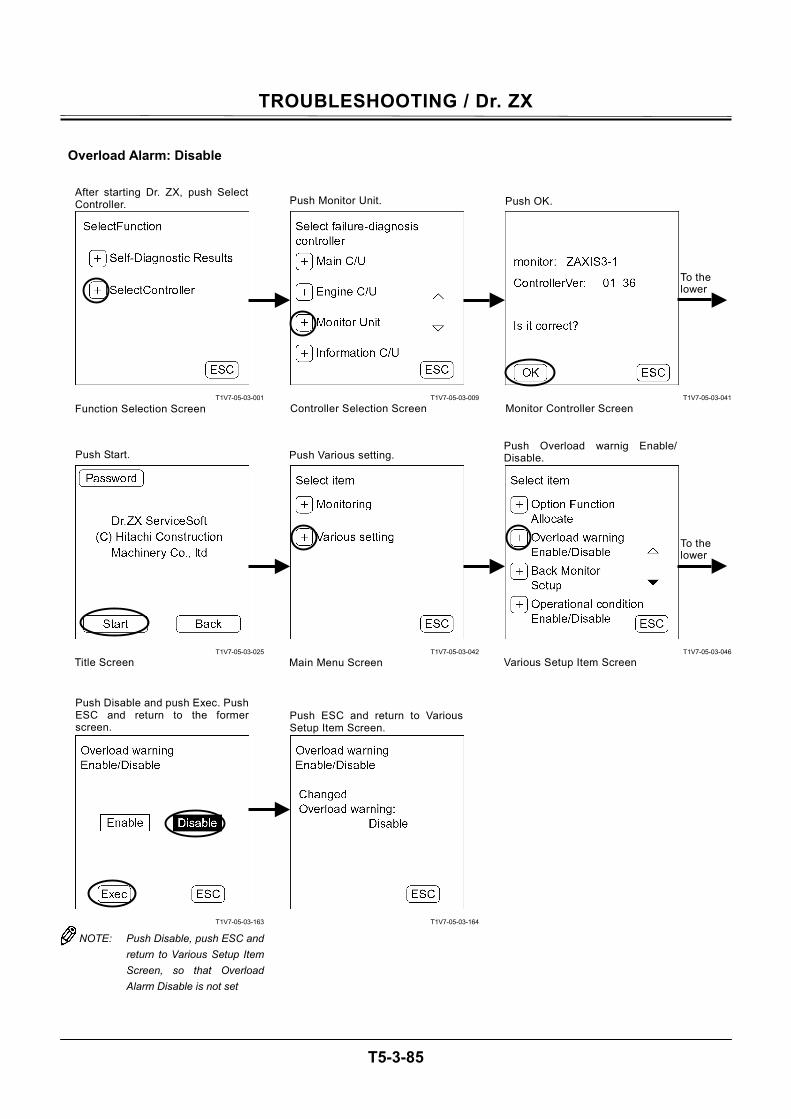
TROUBLESHOOTING / Dr. ZX
T5-3-85
Overload Alarm: Disable
T1V7-05-03-001
T1V7-05-03-025
T1V7-05-03-163
NOTE: Push Disable, push ESC and return to Various Setup Item Screen, so that Overload Alarm Disable is not set
T1V7-05-03-009
T1V7-05-03-042
T1V7-05-03-164
T1V7-05-03-041
T1V7-05-03-046
To the lower
To the lower
After starting Dr. ZX, push SelectController.
Function Selection Screen
Push Monitor Unit.
Controller Selection Screen
Push OK.
Monitor Controller Screen
Push Start. Push Various setting.
Main Menu ScreenTitle Screen Various Setup Item Screen
Push Overload warnig Enable/Disable.
Push Disable and push Exec. PushESC and return to the formerscreen.
Push ESC and return to VariousSetup Item Screen.
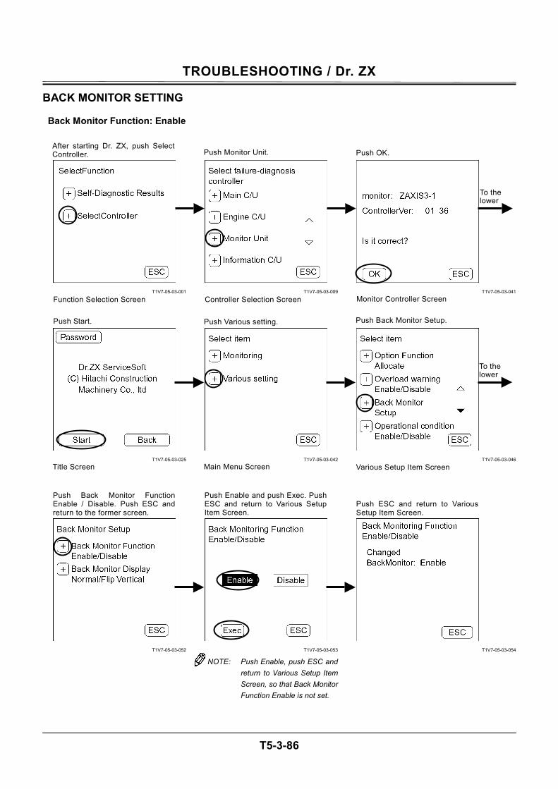
TROUBLESHOOTING / Dr. ZX
T5-3-86
BACK MONITOR SETTING
Back Monitor Function: Enable
T1V7-05-03-001
T1V7-05-03-025
T1V7-05-03-052
T1V7-05-03-009
T1V7-05-03-042
T1V7-05-03-053
NOTE: Push Enable, push ESC and return to Various Setup Item Screen, so that Back Monitor Function Enable is not set.
T1V7-05-03-041
T1V7-05-03-046
T1V7-05-03-054
After starting Dr. ZX, push SelectController.
Function Selection Screen
Push Monitor Unit.
Controller Selection Screen
Push OK.
Monitor Controller Screen
Push Start. Push Various setting.
Main Menu ScreenTitle Screen Various Setup Item Screen
Push Back Monitor Setup.
Push Enable and push Exec. PushESC and return to Various SetupItem Screen.
Push ESC and return to VariousSetup Item Screen.
Push Back Monitor FunctionEnable / Disable. Push ESC andreturn to the former screen.
To the lower
To the lower
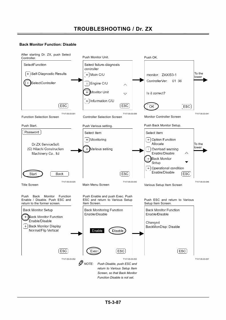
TROUBLESHOOTING / Dr. ZX
T5-3-87
Back Monitor Function: Disable
T1V7-05-03-001
T1V7-05-03-025
T1V7-05-03-052
T1V7-05-03-009
T1V7-05-03-042
T1V7-05-03-053
NOTE: Push Disable, push ESC and return to Various Setup Item Screen, so that Back Monitor Function Disable is not set.
T1V7-05-03-041
T1V7-05-03-046
T1V7-05-03-057
After starting Dr. ZX, push SelectController.
Function Selection Screen
Push Monitor Unit.
Controller Selection Screen
Push OK.
Monitor Controller Screen
Push Start. Push Various setting.
Main Menu ScreenTitle Screen Various Setup Item Screen
Push Back Monitor Setup.
Push Enable and push Exec. PushESC and return to Various SetupItem Screen.
Push ESC and return to VariousSetup Item Screen.
Push Back Monitor FunctionEnable / Disable. Push ESC andreturn to the former screen.
To the lower
To the lower
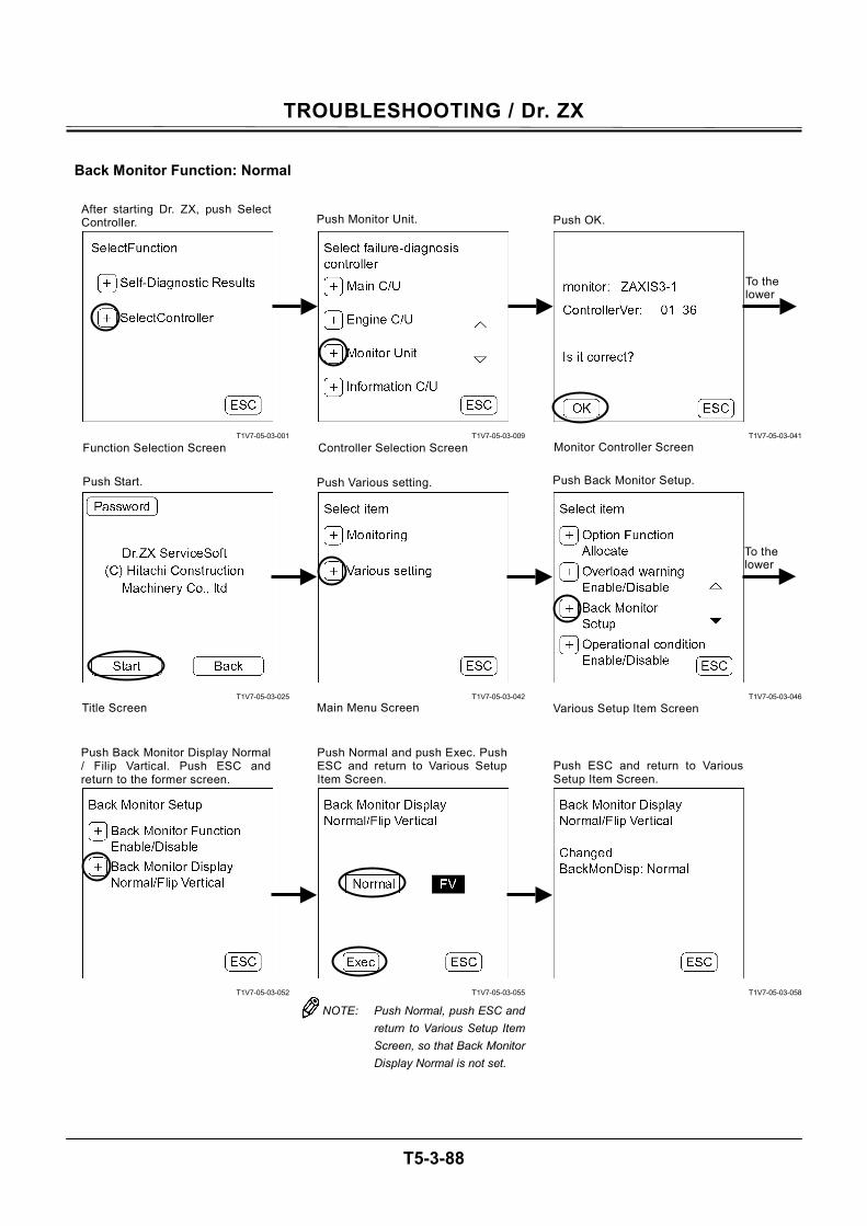
TROUBLESHOOTING / Dr. ZX
T5-3-88
Back Monitor Function: Normal
T1V7-05-03-001
T1V7-05-03-025
T1V7-05-03-052
T1V7-05-03-009
T1V7-05-03-042
T1V7-05-03-055
NOTE: Push Normal, push ESC and return to Various Setup Item Screen, so that Back Monitor Display Normal is not set.
T1V7-05-03-041
T1V7-05-03-046
T1V7-05-03-058
After starting Dr. ZX, push SelectController.
Function Selection Screen
Push Monitor Unit.
Controller Selection Screen
Push OK.
Monitor Controller Screen
Push Start. Push Various setting.
Main Menu ScreenTitle Screen Various Setup Item Screen
Push Back Monitor Setup.
Push ESC and return to VariousSetup Item Screen.
To the lower
To the lower
Push Normal and push Exec. PushESC and return to Various SetupItem Screen.
Push Back Monitor Display Normal / Filip Vartical. Push ESC andreturn to the former screen.
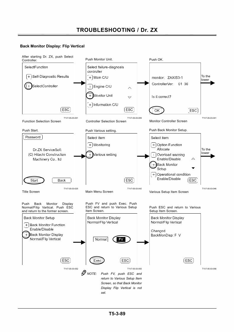
TROUBLESHOOTING / Dr. ZX
T5-3-89
Back Monitor Display: Flip Vertical
T1V7-05-03-001
T1V7-05-03-025
T1V7-05-03-052
T1V7-05-03-009
T1V7-05-03-042
T1V7-05-03-055
NOTE: Push FV, push ESC and return to Various Setup Item Screen, so that Back Monitor Display Flip Vertical is not set.
T1V7-05-03-041
T1V7-05-03-046
T1V7-05-03-056
After starting Dr. ZX, push SelectController.
Function Selection Screen
Push Monitor Unit.
Controller Selection Screen
Push OK.
Monitor Controller Screen
Push Start. Push Various setting.
Main Menu ScreenTitle Screen Various Setup Item Screen
Push Back Monitor Setup.
Push ESC and return to VariousSetup Item Screen.
To the lower
To the lower
Push Back Monitor Display Normal/Filip Vartical. Push ESC and return to the former screen.
Push FV and push Exec. PushESC and return to Various SetupItem Screen.

TROUBLESHOOTING / Dr. ZX
T5-3-90
OPERATING CONDITION ENABLE / DISABLE SELECTION
Operating Condition: Enable
T1V7-05-03-001
T1V7-05-03-025
T1V7-05-03-059
NOTE: Push Enable, push ESC and return to Various Setup Item Screen, so that Operating Condition Enable is not set.
T1V7-05-03-009
T1V7-05-03-042
T1V7-05-03-060
T1V7-05-03-041
T1V7-05-03-046
To the lower
To the lower
After starting Dr. ZX, push SelectController.
Function Selection Screen
Push Monitor Unit.
Controller Selection Screen
Push OK.
Monitor Controller Screen
Main Menu ScreenTitle Screen Various Setup Item Screen
Push Enable and push Exec. PushESC and return to the formerscreen.
Push ESC and return to VariousSetup Item Screen.
Push Various setting. Push Overload warnig Enable/Disable. Push Start.
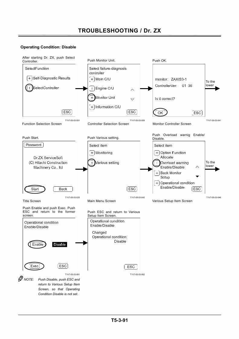
TROUBLESHOOTING / Dr. ZX
T5-3-91
Operating Condition: Disable
T1V7-05-03-001
T1V7-05-03-025
T1V7-05-03-061
NOTE: Push Disable, push ESC and return to Various Setup Item Screen, so that Operating Condition Disable is not set.
T1V7-05-03-009
T1V7-05-03-042
T1V7-05-03-062
T1V7-05-03-041
T1V7-05-03-046
To the lower
To the lower
After starting Dr. ZX, push SelectController.
Function Selection Screen
Push Monitor Unit.
Controller Selection Screen
Push OK.
Monitor Controller Screen
Main Menu ScreenTitle Screen Various Setup Item Screen
Push Enable and push Exec. PushESC and return to the formerscreen.
Push ESC and return to Various Setup Item Screen.
Push Various setting. Push Overload warnig Enable/Disable. Push Start.
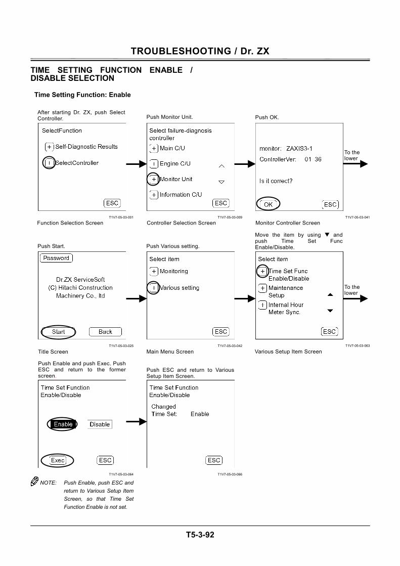
TROUBLESHOOTING / Dr. ZX
T5-3-92
TIME SETTING FUNCTION ENABLE / DISABLE SELECTION
Time Setting Function: Enable
T1V7-05-03-001
T1V7-05-03-025
T1V7-05-03-064
NOTE: Push Enable, push ESC and return to Various Setup Item Screen, so that Time Set Function Enable is not set.
T1V7-05-03-009
T1V7-05-03-042
T1V7-05-03-066
T1V7-05-03-041
T1V7-05-03-063
To the lower
To the lower
After starting Dr. ZX, push SelectController.
Function Selection Screen
Push Monitor Unit.
Controller Selection Screen
Push OK.
Monitor Controller Screen
Main Menu ScreenTitle Screen Various Setup Item Screen
Push Enable and push Exec. Push ESC and return to the formerscreen.
Push ESC and return to VariousSetup Item Screen.
Push Various setting.
Move the item by using andpush Time Set FuncEnable/Disable. Push Start.
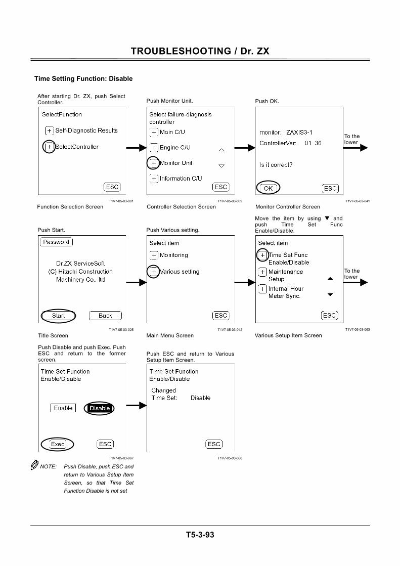
TROUBLESHOOTING / Dr. ZX
T5-3-93
Time Setting Function: Disable
T1V7-05-03-001
T1V7-05-03-025
T1V7-05-03-067
NOTE: Push Disable, push ESC and return to Various Setup Item Screen, so that Time Set Function Disable is not set
T1V7-05-03-009
T1V7-05-03-042
T1V7-05-03-068
T1V7-05-03-041
T1V7-05-03-063
To the lower
To the lower
After starting Dr. ZX, push SelectController.
Function Selection Screen
Push Monitor Unit.
Controller Selection Screen
Push OK.
Monitor Controller Screen
Main Menu ScreenTitle Screen Various Setup Item Screen
Push Disable and push Exec. PushESC and return to the formerscreen.
Push ESC and return to VariousSetup Item Screen.
Push Various setting.
Move the item by using andpush Time Set FuncEnable/Disable. Push Start.

TROUBLESHOOTING / Dr. ZX
T5-3-94
MAINTENANCE SETTING MAINTENANCE OPERATION ALLOW / NOT ALLOW SELECTION
Maintenance Operation: Allow
T1V7-05-03-001
T1V7-05-03-025
T1V7-05-03-069
T1V7-05-03-009
T1V7-05-03-042
T1V7-05-03-070
NOTE: Push Allow, push ESC and return to Maintenance Set Item Screen, so that Maintenance Operation Allow is not set.
T1V7-05-03-041
T1V7-05-03-063
T1V7-05-03-071
To the lower
To the lower
After starting Dr. ZX, push SelectController.
Function Selection Screen
Push Monitor Unit.
Controller Selection Screen
Push OK.
Monitor Controller Screen
Main Menu ScreenTitle Screen Various Setup Item Screen
Push Maintenance operationAllow/Not Allow.
Push Allow and push Exec. PushESC and return to the formerscreen.
Push Various setting. Move the item by using andpush Maintenance Setup. Push Start.
Maintenance Set Item Screen
Push ESC and return to Various Maintenance set Item Screen.
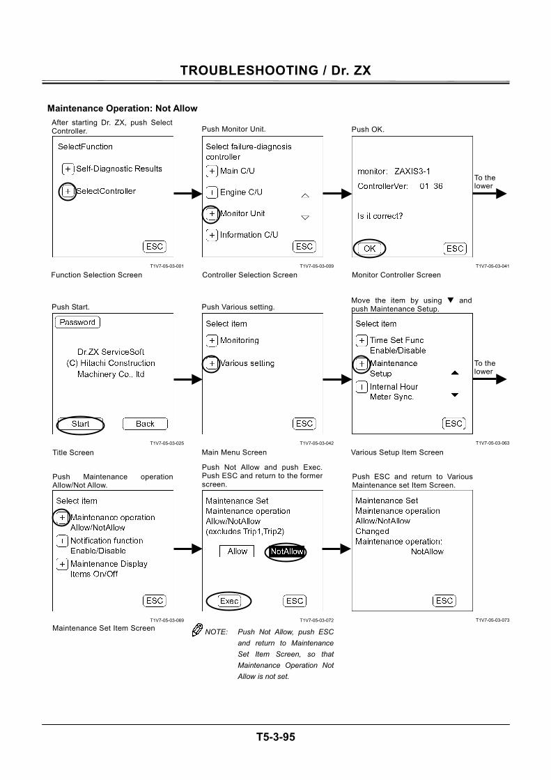
TROUBLESHOOTING / Dr. ZX
T5-3-95
Maintenance Operation: Not Allow
T1V7-05-03-001
T1V7-05-03-025
T1V7-05-03-069
T1V7-05-03-009
T1V7-05-03-042
T1V7-05-03-072
NOTE: Push Not Allow, push ESC and return to Maintenance Set Item Screen, so that Maintenance Operation Not Allow is not set.
T1V7-05-03-041
T1V7-05-03-063
T1V7-05-03-073
To the lower
To the lower
After starting Dr. ZX, push SelectController.
Function Selection Screen
Push Monitor Unit.
Controller Selection Screen
Push OK.
Monitor Controller Screen
Main Menu ScreenTitle Screen Various Setup Item Screen
Push Maintenance operationAllow/Not Allow.
Push Not Allow and push Exec.Push ESC and return to the former screen.
Push Various setting. Move the item by using andpush Maintenance Setup. Push Start.
Maintenance Set Item Screen
Push ESC and return to VariousMaintenance set Item Screen.
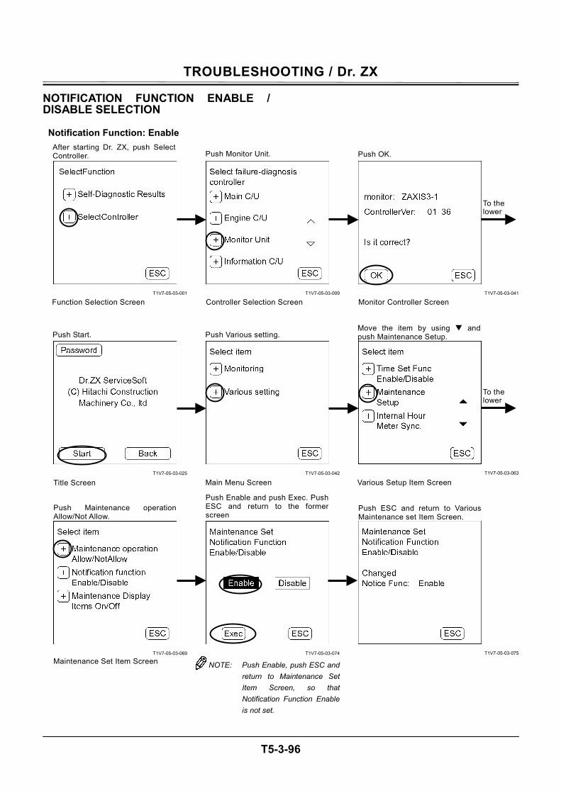
TROUBLESHOOTING / Dr. ZX
T5-3-96
NOTIFICATION FUNCTION ENABLE / DISABLE SELECTION
Notification Function: Enable
T1V7-05-03-001
T1V7-05-03-025
T1V7-05-03-069
T1V7-05-03-009
T1V7-05-03-042
T1V7-05-03-074
NOTE: Push Enable, push ESC and return to Maintenance Set Item Screen, so that Notification Function Enable is not set.
T1V7-05-03-041
T1V7-05-03-063
T1V7-05-03-075
To the lower
To the lower
After starting Dr. ZX, push Select Controller.
Function Selection Screen
Push Monitor Unit.
Controller Selection Screen
Push OK.
Monitor Controller Screen
Main Menu ScreenTitle Screen Various Setup Item Screen
Push Maintenance operationAllow/Not Allow.
Push Enable and push Exec. Push ESC and return to the formerscreen
Push Various setting. Move the item by using andpush Maintenance Setup. Push Start.
Maintenance Set Item Screen
Push ESC and return to Various Maintenance set Item Screen.
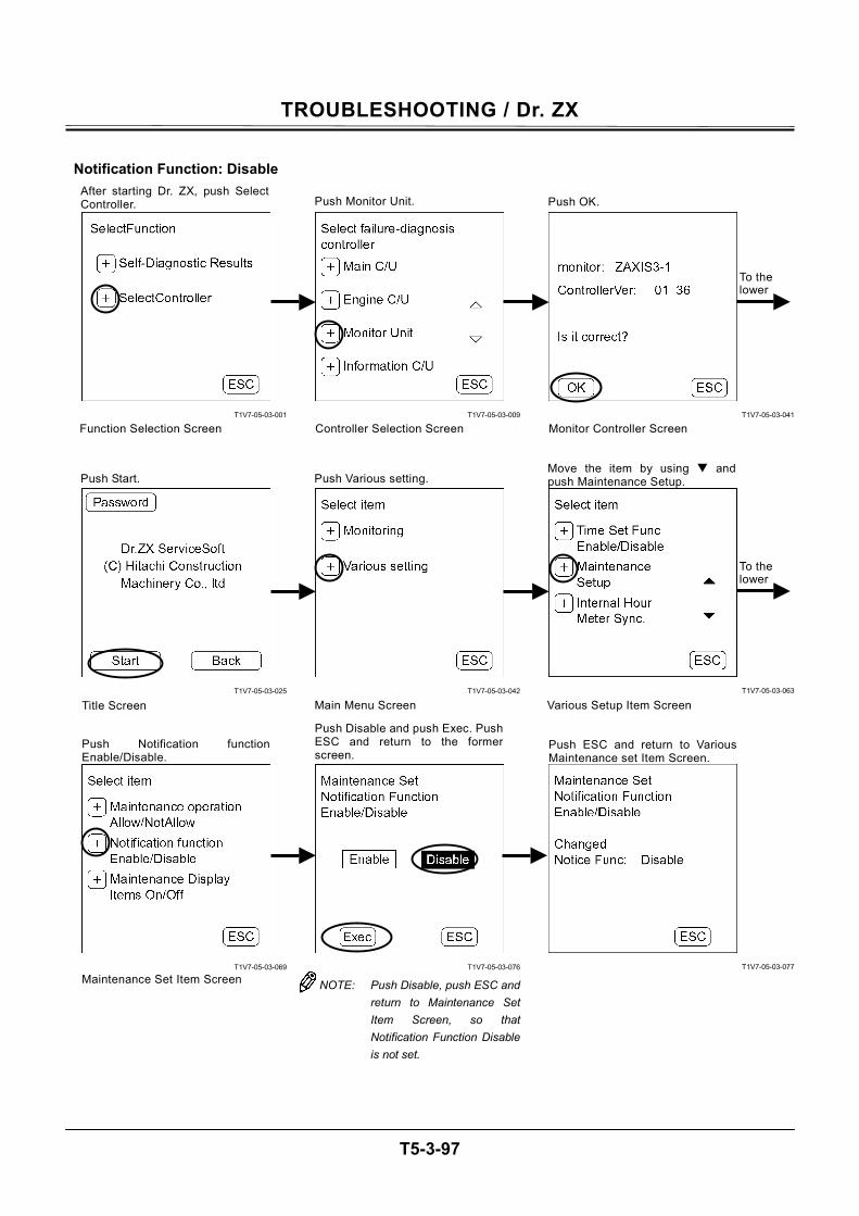
TROUBLESHOOTING / Dr. ZX
T5-3-97
Notification Function: Disable
T1V7-05-03-001
T1V7-05-03-025
T1V7-05-03-069
T1V7-05-03-009
T1V7-05-03-042
T1V7-05-03-076
NOTE: Push Disable, push ESC and return to Maintenance Set Item Screen, so that Notification Function Disable is not set.
T1V7-05-03-041
T1V7-05-03-063
T1V7-05-03-077
To the lower
To the lower
After starting Dr. ZX, push SelectController.
Function Selection Screen
Push Monitor Unit.
Controller Selection Screen
Push OK.
Monitor Controller Screen
Main Menu ScreenTitle Screen Various Setup Item Screen
Push Notification functionEnable/Disable.
Push Disable and push Exec. PushESC and return to the formerscreen.
Push Various setting. Move the item by using andpush Maintenance Setup. Push Start.
Maintenance Set Item Screen
Push ESC and return to Various Maintenance set Item Screen.
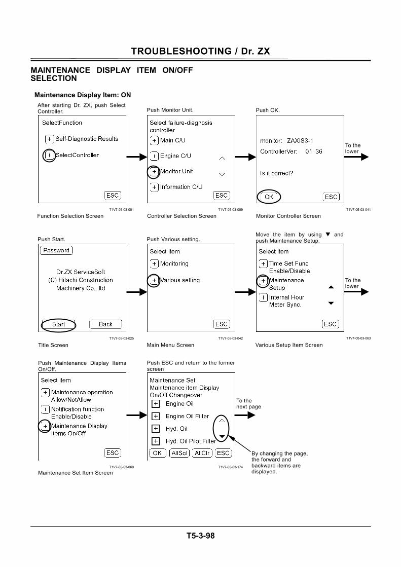
TROUBLESHOOTING / Dr. ZX
T5-3-98
MAINTENANCE DISPLAY ITEM ON/OFF SELECTION
Maintenance Display Item: ON
T1V7-05-03-001
T1V7-05-03-025
T1V7-05-03-069
T1V7-05-03-009
T1V7-05-03-042
T1V7-05-03-174
T1V7-05-03-041
T1V7-05-03-063
To the lower
To the lower
After starting Dr. ZX, push SelectController.
Function Selection Screen
Push Monitor Unit.
Controller Selection Screen
Push OK.
Monitor Controller Screen
Main Menu ScreenTitle Screen Various Setup Item Screen
Push Maintenance Display ItemsOn/Off.
Push ESC and return to the formerscreen
Push Various setting. Move the item by using andpush Maintenance Setup. Push Start.
Maintenance Set Item Screen
To the next page
By changing the page, the forward and backward items are displayed.
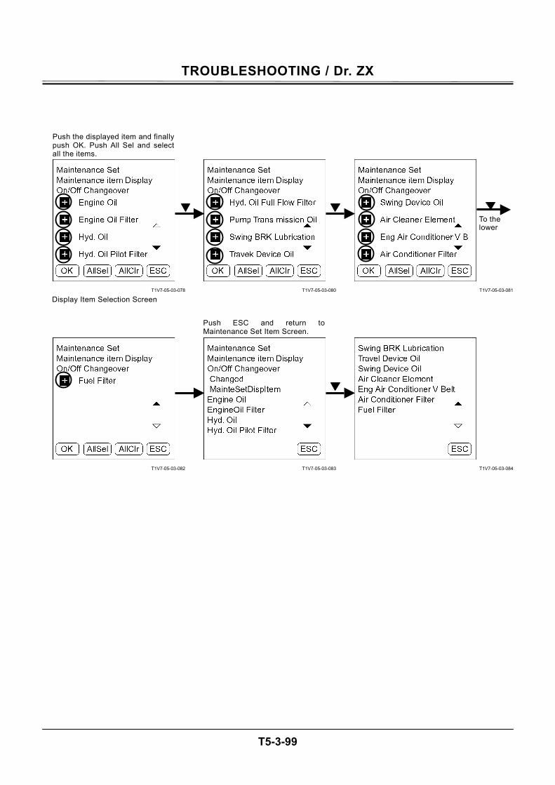
TROUBLESHOOTING / Dr. ZX
T5-3-99
T1V7-05-03-078
T1V7-05-03-082
T1V7-05-03-080
T1V7-05-03-083
T1V7-05-03-081
T1V7-05-03-084
Push the displayed item and finallypush OK. Push All Sel and selectall the items.
Display Item Selection Screen
Push ESC and return toMaintenance Set Item Screen.
To the lower
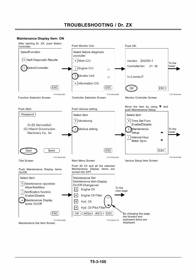
TROUBLESHOOTING / Dr. ZX
T5-3-100
Maintenance Display Item: ON
T1V7-05-03-001
T1V7-05-03-025
T1V7-05-03-069
T1V7-05-03-009
T1V7-05-03-042
T1V7-05-03-174
T1V7-05-03-041
T1V7-05-03-063
To the lower
To the lower
After starting Dr. ZX, push SelectController.
Function Selection Screen
Push Monitor Unit.
Controller Selection Screen
Push OK.
Monitor Controller Screen
Main Menu ScreenTitle Screen Various Setup Item Screen
Push Maintenance Display ItemsOn/Off.
Push All Clr and all the selected Maintenance Display Items areturned into OFF.
Push Various setting. Move the item by using andpush Maintenance Setup. Push Start.
Maintenance Set Item Screen
To the next page
By changing the page, the forward and backward items are displayed.
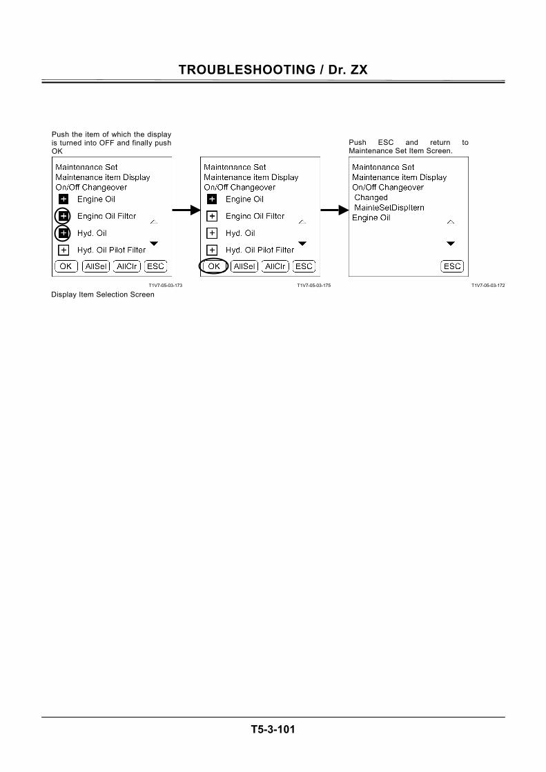
TROUBLESHOOTING / Dr. ZX
T5-3-101
T1V7-05-03-173
T1V7-05-03-175
T1V7-05-03-172
Push the item of which the displayis turned into OFF and finally pushOK
Display Item Selection Screen
Push ESC and return toMaintenance Set Item Screen.
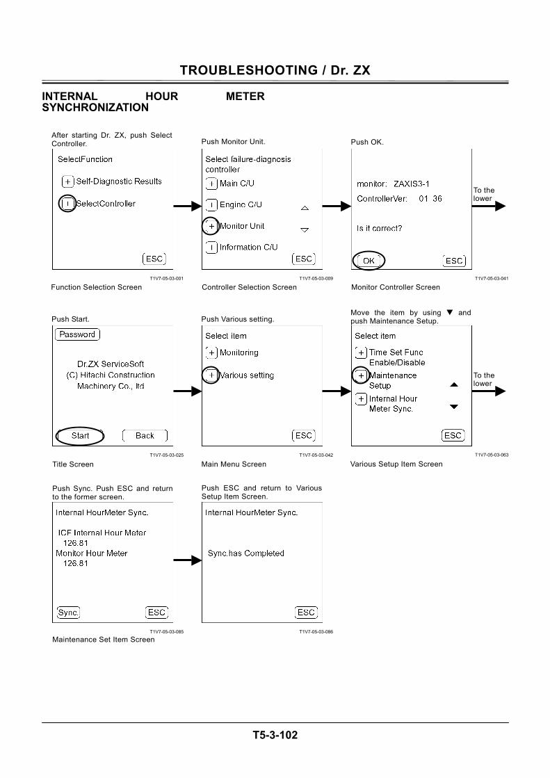
TROUBLESHOOTING / Dr. ZX
T5-3-102
INTERNAL HOUR METER SYNCHRONIZATION
T1V7-05-03-001
T1V7-05-03-025
T1V7-05-03-085
T1V7-05-03-009
T1V7-05-03-042
T1V7-05-03-086
T1V7-05-03-041
T1V7-05-03-063
To the lower
To the lower
After starting Dr. ZX, push SelectController.
Function Selection Screen
Push Monitor Unit.
Controller Selection Screen
Push OK.
Monitor Controller Screen
Main Menu ScreenTitle Screen Various Setup Item Screen
Push Sync. Push ESC and returnto the former screen.
Push ESC and return to VariousSetup Item Screen.
Push Various setting. Move the item by using andpush Maintenance Setup. Push Start.
Maintenance Set Item Screen
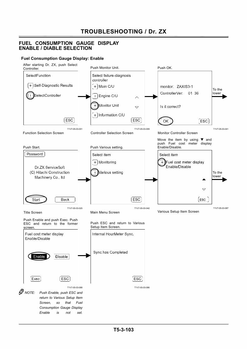
TROUBLESHOOTING / Dr. ZX
T5-3-103
FUEL CONSUMPTION GAUGE DISPLAY ENABLE / DIABLE SELECTION
Fuel Consumption Gauge Display: Enable
T1V7-05-03-001
T1V7-05-03-025
T1V7-05-03-088
NOTE: Push Enable, push ESC and return to Various Setup Item Screen, so that Fuel Consumption Gauge Display Enable is not set.
T1V7-05-03-009
T1V7-05-03-042
T1V7-05-03-086
T1V7-05-03-041
T1V7-05-03-087
To the lower
To the lower
After starting Dr. ZX, push SelectController.
Function Selection Screen
Push Monitor Unit.
Controller Selection Screen
Push OK.
Monitor Controller Screen
Main Menu ScreenTitle Screen Various Setup Item Screen
Push Enable and push Exec. PushESC and return to the formerscreen.
Push ESC and return to VariousSetup Item Screen.
Push Various setting.
Move the item by using and push Fuel cost meter display Enable/Disable. Push Start.
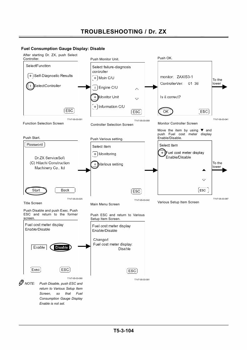
TROUBLESHOOTING / Dr. ZX
T5-3-104
Fuel Consumption Gauge Display: Disable
T1V7-05-03-001
T1V7-05-03-025
T1V7-05-03-090
NOTE: Push Disable, push ESC and return to Various Setup Item Screen, so that Fuel Consumption Gauge Display Enable is not set.
T1V7-05-03-009
T1V7-05-03-042
T1V7-05-03-091
T1V7-05-03-041
T1V7-05-03-087
To the lower
To the lower
After starting Dr. ZX, push SelectController.
Function Selection Screen
Push Monitor Unit.
Controller Selection Screen
Push OK.
Monitor Controller Screen
Main Menu ScreenTitle Screen Various Setup Item Screen
Push Disable and push Exec. PushESC and return to the formerscreen.
Push ESC and return to VariousSetup Item Screen.
Push Various setting.
Move the item by using and push Fuel cost meter display Enable/Disable. Push Start.
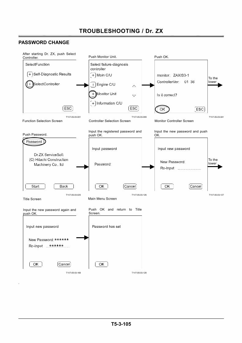
TROUBLESHOOTING / Dr. ZX
T5-3-105
PASSWORD CHANGE
T1V7-05-03-001
T1V7-05-03-025
T1V7-05-03-169
.
T1V7-05-03-009
T1V7-05-03-126
T1V7-05-03-128
T1V7-05-03-041
T1V7-05-03-127
To the lower
To the lower
After starting Dr. ZX, push SelectController.
Function Selection Screen
Push Monitor Unit.
Controller Selection Screen
Push OK.
Monitor Controller Screen
Main Menu ScreenTitle Screen
Input the new password again andpush OK.
Push OK and return to TitleScreen.
Input the registered password andpush OK.
Input the new password and pushOK. Push Password.

TROUBLESHOOTING / Dr. ZX
T5-3-106
(Blank)
TROUBLESHOOTING / e-Shovel
T5-4-1
OUTLINE ICF (Information Controller) saves the input signals from various sensors and switches of the machine as data. Various input signals are recorded as “list of daily report data”, “list of frequency distribution data”, “list of total operating hours”, “list of alarm” and “list of failure” in ICF. The recorded data is downloaded to the personal computer and is uploaded to the center server via LAN, so that the data can be used as “e-Service”. The machine equipped with the optional satellite communication terminal sends the data to center server by using satellite communication. (As for the satellite communication system, refer to T5-4-24.
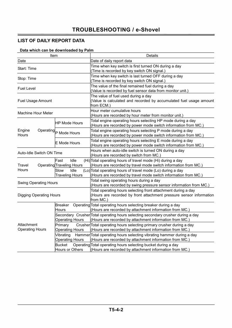
TROUBLESHOOTING / e-Shovel
T5-4-2
LIST OF DAILY REPORT DATA Data which can be downloaded by Palm
Item Details Date Date of daily report data
Start: Time Time when key switch is first turned ON during a day (Time is recorded by key switch ON signal.)
Stop: Time Time when key switch is last turned OFF during a day (Time is recorded by key switch ON signal.)
Fuel Level The value of the final remained fuel during a day (Value is recorded by fuel sensor data from monitor unit.)
Fuel Usage Amount The value of fuel used during a day (Value is calculated and recorded by accumulated fuel usage amount from ECM.)
Machine Hour Meter Hour meter cumulative hours (Hours are recorded by hour meter from monitor unit.)
HP Mode Hours Total engine operating hours selecting HP mode during a day (Hours are recorded by power mode switch information from MC.)
P Mode Hours Total engine operating hours selecting P mode during a day (Hours are recorded by power mode switch information from MC.)
Engine Operating Hours
E Mode Hours Total engine operating hours selecting E mode during a day (Hours are recorded by power mode switch information from MC.)
Auto-Idle Switch ON Time Hours when auto-idle switch is turned ON during a day (Hours are recorded by switch from MC.)
Fast Idle (Hi) Traveling Hours
Total operating hours of travel mode (Hi) during a day (Hours are recorded by travel mode switch information from MC.) Travel Operating
Hours Slow Idle (Lo) Traveling Hours
Total operating hours of travel mode (Lo) during a day (Hours are recorded by travel mode switch information from MC.)
Swing Operating Hours Total swing operating hours during a day (Hours are recorded by swing pressure sensor information from MC.)
Digging Operating Hours Total operating hours selecting front attachment during a day (Hours are recorded by front attachment pressure sensor information from MC.)
Breaker Operating Hours
Total operating hours selecting breaker during a day (Hours are recorded by attachment information from MC.)
Secondary Crusher Operating Hours
Total operating hours selecting secondary crusher during a day (Hours are recorded by attachment information from MC.)
Primary Crusher Operating Hours
Total operating hours selecting primary crusher during a day (Hours are recorded by attachment information from MC.)
Vibrating Hammer Operating Hours
Total operating hours selecting vibrating hammer during a day (Hours are recorded by attachment information from MC.)
Attachment Operating Hours
Bucket Operating Hours or Others
Total operating hours selecting bucket during a day (Hours are recorded by attachment information from MC.)
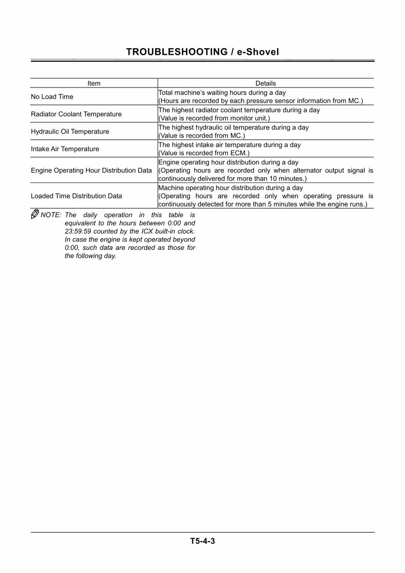
TROUBLESHOOTING / e-Shovel
T5-4-3
Item Details
No Load Time Total machine’s waiting hours during a day (Hours are recorded by each pressure sensor information from MC.)
Radiator Coolant Temperature The highest radiator coolant temperature during a day (Value is recorded from monitor unit.)
Hydraulic Oil Temperature The highest hydraulic oil temperature during a day (Value is recorded from MC.)
Intake Air Temperature The highest intake air temperature during a day (Value is recorded from ECM.)
Engine Operating Hour Distribution Data Engine operating hour distribution during a day (Operating hours are recorded only when alternator output signal is continuously delivered for more than 10 minutes.)
Loaded Time Distribution Data Machine operating hour distribution during a day (Operating hours are recorded only when operating pressure is continuously detected for more than 5 minutes while the engine runs.)
NOTE: The daily operation in this table is equivalent to the hours between 0:00 and 23:59:59 counted by the ICX built-in clock. In case the engine is kept operated beyond 0:00, such data are recorded as those for the following day.
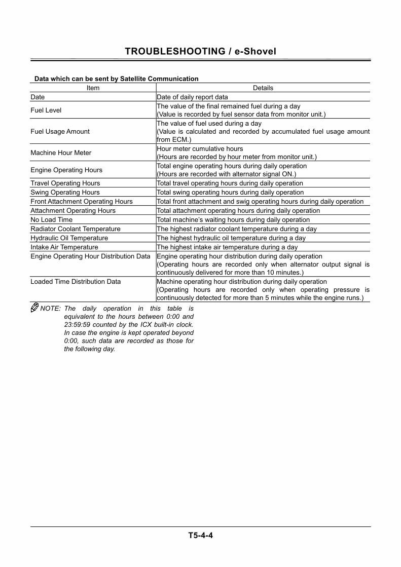
TROUBLESHOOTING / e-Shovel
T5-4-4
Data which can be sent by Satellite Communication
Item Details Date Date of daily report data
Fuel Level The value of the final remained fuel during a day (Value is recorded by fuel sensor data from monitor unit.)
Fuel Usage Amount The value of fuel used during a day (Value is calculated and recorded by accumulated fuel usage amount from ECM.)
Machine Hour Meter Hour meter cumulative hours (Hours are recorded by hour meter from monitor unit.)
Engine Operating Hours Total engine operating hours during daily operation (Hours are recorded with alternator signal ON.)
Travel Operating Hours Total travel operating hours during daily operation Swing Operating Hours Total swing operating hours during daily operation Front Attachment Operating Hours Total front attachment and swig operating hours during daily operation Attachment Operating Hours Total attachment operating hours during daily operation No Load Time Total machine’s waiting hours during daily operation Radiator Coolant Temperature The highest radiator coolant temperature during a day Hydraulic Oil Temperature The highest hydraulic oil temperature during a day Intake Air Temperature The highest intake air temperature during a day Engine Operating Hour Distribution Data Engine operating hour distribution during daily operation
(Operating hours are recorded only when alternator output signal is continuously delivered for more than 10 minutes.)
Loaded Time Distribution Data Machine operating hour distribution during daily operation (Operating hours are recorded only when operating pressure is continuously detected for more than 5 minutes while the engine runs.)
NOTE: The daily operation in this table is equivalent to the hours between 0:00 and 23:59:59 counted by the ICX built-in clock. In case the engine is kept operated beyond 0:00, such data are recorded as those for the following day.
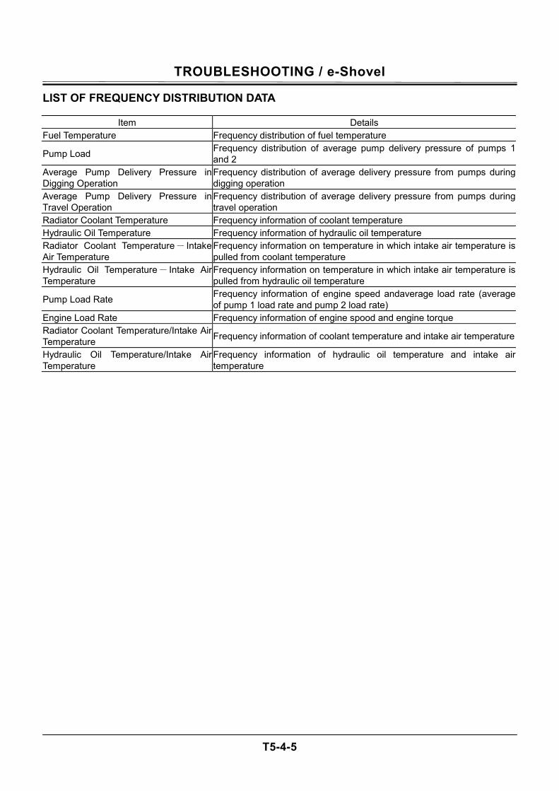
TROUBLESHOOTING / e-Shovel
T5-4-5
LIST OF FREQUENCY DISTRIBUTION DATA
Item Details Fuel Temperature Frequency distribution of fuel temperature
Pump Load Frequency distribution of average pump delivery pressure of pumps 1 and 2
Average Pump Delivery Pressure in Digging Operation
Frequency distribution of average delivery pressure from pumps during digging operation
Average Pump Delivery Pressure in Travel Operation
Frequency distribution of average delivery pressure from pumps during travel operation
Radiator Coolant Temperature Frequency information of coolant temperature Hydraulic Oil Temperature Frequency information of hydraulic oil temperature Radiator Coolant Temperature- Intake Air Temperature
Frequency information on temperature in which intake air temperature is pulled from coolant temperature
Hydraulic Oil Temperature- Intake Air Temperature
Frequency information on temperature in which intake air temperature is pulled from hydraulic oil temperature
Pump Load Rate Frequency information of engine speed andaverage load rate (average of pump 1 load rate and pump 2 load rate)
Engine Load Rate Frequency information of engine spood and engine torque Radiator Coolant Temperature/Intake Air Temperature Frequency information of coolant temperature and intake air temperature
Hydraulic Oil Temperature/Intake Air Temperature
Frequency information of hydraulic oil temperature and intake air temperature
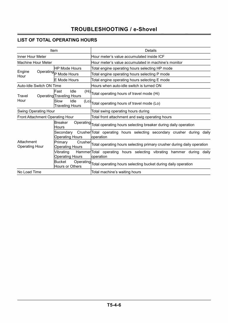
TROUBLESHOOTING / e-Shovel
T5-4-6
LIST OF TOTAL OPERATING HOURS
Item Details Inner Hour Meter Hour meter’s value accumulated inside ICF Machine Hour Meter Hour meter’s value accumulated in machine’s monitor
HP Mode Hours Total engine operating hours selecting HP mode P Mode Hours Total engine operating hours selecting P mode
Engine Operating Hour
E Mode Hours Total engine operating hours selecting E mode Auto-Idle Switch ON Time Hours when auto-idle switch is turned ON
Fast Idle (Hi) Traveling Hours Total operating hours of travel mode (Hi) Travel Operating
Hour Slow Idle (Lo) Traveling Hours Total operating hours of travel mode (Lo)
Swing Operating Hour Total swing operating hours during Front Attachment Operating Hour Total front attachment and swig operating hours
Breaker Operating Hours Total operating hours selecting breaker during daily operation
Secondary Crusher Operating Hours
Total operating hours selecting secondary crusher during daily operation
Primary Crusher Operating Hours Total operating hours selecting primary crusher during daily operation
Vibrating Hammer Operating Hours
Total operating hours selecting vibrating hammer during daily operation
Attachment Operating Hour
Bucket Operating Hours or Others Total operating hours selecting bucket during daily operation
No Load Time Total machine’s waiting hours

TROUBLESHOOTING / e-Shovel
T5-4-7
(Blank)
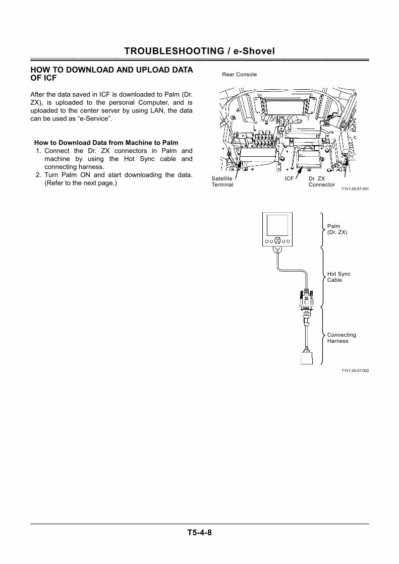
TROUBLESHOOTING / e-Shovel
T5-4-8
HOW TO DOWNLOAD AND UPLOAD DATA OF ICF After the data saved in ICF is downloaded to Palm (Dr. ZX), is uploaded to the personal Computer, and is uploaded to the center server by using LAN, the data can be used as “e-Service”.
How to Download Data from Machine to Palm 1. Connect the Dr. ZX connectors in Palm and
machine by using the Hot Sync cable and connecting harness.
2. Turn Palm ON and start downloading the data. (Refer to the next page.)
T1V1-05-07-001
T1V1-05-07-002
Dr. ZX Connector
Rear Console
ICF Satellite Terminal
Palm (Dr. ZX)
Hot Sync Cable
Connecting Harness
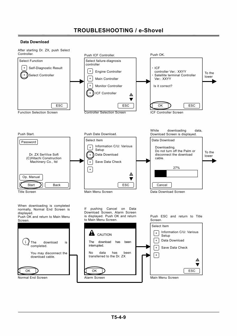
TROUBLESHOOTING / e-Shovel
T5-4-9
Data Download
Select Function
Self-Diagnostic Result Select Controller
After starting Dr. ZX, push SelectController.
Function Selection Screen
Select failure-diagnosis controller
Engine Controller Main Controller Monitor Controller ICF Controller
Push ICF Controller.
Controller Selection Screen
・ ICF
controller Ver.: XXYY ・ Satellite terminal Controller
Ver.: XXYY Is it correct?
Push OK.
ICF Controller Screen
To the lower
ESC
+
+ +
+
+
+
ESC ESC OK
Dr. ZX SerVice Soft (C)Hitachi Construction
Machinery Co., ltd
Push Start.
Select Item
Information C/U: Various Setup
Data Download Save Data Check
Push Date Download.
Main Menu Screen
Data Download
Downloading. Do not turn off the Palm or disconnect the download cable.
While downloading data, Download Screen is displayed.
Data Download Screen
To the lower
Back Start
+
+
+
+
ESC Cancel
Op. Manual
Password
When downloading is completednormally, Normal End Screen isdisplayed. Push OK and return to Main Menu Screen.
Normal End Screen
Initialization has been completed.
If pushing Cancel on Data Download Screen, Alarm Screenis displayed. Push OK and returnto Main Menu Screen.
Select Item
Information C/U: Various Setup
Data Download Save Data Check
Push ESC and return to Title Screen.
Main Menu Screen
ESC
CAUTION
The download has been interrupted. No data has been transferred to the Dr. ZX
OK
+
+
+
+
Title Screen
27%
Initialization has been completed.
The download is completed. You may disconnect the download cable.
OK
i
Alarm Screen
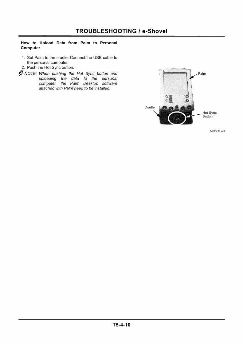
TROUBLESHOOTING / e-Shovel
T5-4-10
How to Upload Data from Palm to Personal Computer
1. Set Palm to the cradle. Connect the USB cable to
the personal computer. 2. Push the Hot Sync button. NOTE: When pushing the Hot Sync button and
uploading the data to the personal computer, the Palm Desktop software attached with Palm need to be installed.
T178-05-07-033
Palm
Hot Sync Button
Cradle
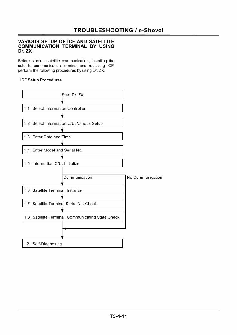
TROUBLESHOOTING / e-Shovel
T5-4-11
VARIOUS SETUP OF ICF AND SATELLITE COMMUNICATION TERMINAL BY USING Dr. ZX Before starting satellite communication, installing the satellite communication terminal and replacing ICF, perform the following procedures by using Dr. ZX.
ICF Setup Procedures
1.2 Select Information C/U: Various Setup
1.3 Enter Date and Time
1.4 Enter Model and Serial No.
1.5 Information C/U: Initialize
1.6 Satellite Terminal: Initialize
1.7 Satellite Terminal Serial No. Check
1.8 Satellite Terminal, Communicating State Check
2. Self-Diagnosing
Communication No Communication
Start Dr. ZX
1.1 Select Information Controller
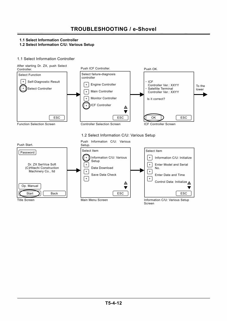
TROUBLESHOOTING / e-Shovel
T5-4-12
1.1 Select Information Controller 1.2 Select Information C/U: Various Setup
Select Function
Self-Diagnostic Result Select Controller
After starting Dr. ZX, push SelectController.
Function Selection Screen
Select failure-diagnosis controller
Engine Controller Main Controller Monitor Controller ICF Controller
Push ICF Controller.
Controller Selection Screen
・ ICF
Controller Ver.: XXYY ・ Satellite Terminal
Controller Ver.: XXYY Is it correct?
Push OK.
ICF Controller Screen
To the lower
ESC
+
+ +
+
+
+
ESC ESC OK
Dr. ZX SerVice Soft (C)Hitachi Construction
Machinery Co., ltd
Push Start.
Select Item
Information C/U: Various Setup Data Download Save Data Check
Push Information C/U: VariousSetup.
Main Menu Screen
Select Item
Information C/U: Initialize Enter Model and Serial No. Enter Date and Time Control Data: Initialize
Information C/U: Various Setup Screen
Back Start
+
+
+
+
ESC ESC
Op. Manual
Password
+
+
+
+
Title Screen
1.1 Select Information Controller
1.2 Select Information C/U: Various Setup
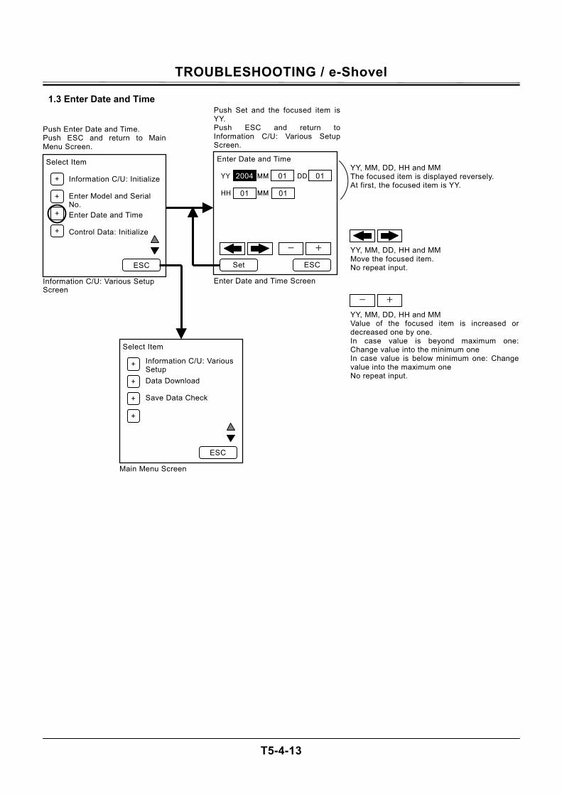
TROUBLESHOOTING / e-Shovel
T5-4-13
1.3 Enter Date and Time
Enter Date and Time YY MM DD HH MM
Push Set and the focused item is YY. Push ESC and return to Information C/U: Various Setup Screen.
Enter Date and Time Screen
ESC
Select Item
Information C/U: Various Setup
Data Download Save Data Check
Main Menu Screen
+
+
+
+
ESC
Select Item
Information C/U: Initialize Enter Model and Serial No. Enter Date and Time Control Data: Initialize
Push Enter Date and Time. Push ESC and return to Main Menu Screen.
Information C/U: Various Setup Screen
ESC
+
+
+
+
Set
- +
2004 01 01
01 01
YY, MM, DD, HH and MM The focused item is displayed reversely. At first, the focused item is YY.
YY, MM, DD, HH and MM Move the focused item. No repeat input.
- +
YY, MM, DD, HH and MM Value of the focused item is increased or decreased one by one. In case value is beyond maximum one: Change value into the minimum one In case value is below minimum one: Change value into the maximum one No repeat input.
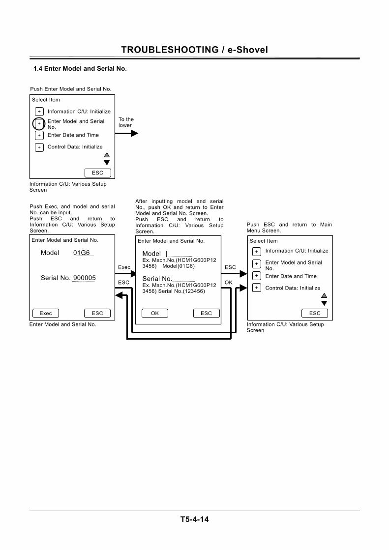
TROUBLESHOOTING / e-Shovel
T5-4-14
1.4 Enter Model and Serial No. Select Item
Information C/U: Initialize
Enter Model and Serial No. Enter Date and Time Control Data: Initialize
Push Enter Model and Serial No.
Information C/U: Various Setup Screen
To the lower
ESC
+
+
+
+
Enter Model and Serial No.
Model 01G6
Serial No. 900005
Push Exec, and model and serialNo. can be input. Push ESC and return toInformation C/U: Various SetupScreen.
Enter Model and Serial No.
Enter Model and Serial No.
Model | Ex. Mach.No.(HCM1G600P123456) Model(01G6)
Serial No. Ex. Mach.No.(HCM1G600P123456) Serial No.(123456)
After inputting model and serial No., push OK and return to EnterModel and Serial No. Screen. Push ESC and return toInformation C/U: Various SetupScreen.
Select Item
Information C/U: Initialize Enter Model and Serial No. Enter Date and Time Control Data: Initialize
Push ESC and return to Main Menu Screen.
Information C/U: Various Setup Screen
ESC Exec ESC
Exec
ESC
OK
+
+
+
+
ESC
OK
ESC
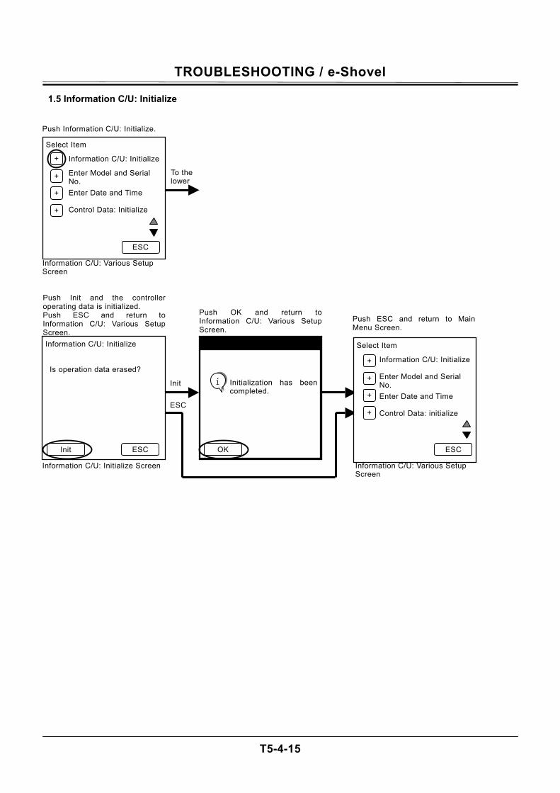
TROUBLESHOOTING / e-Shovel
T5-4-15
1.5 Information C/U: Initialize Select Item
Information C/U: Initialize
Enter Model and Serial No. Enter Date and Time Control Data: Initialize
Push Information C/U: Initialize.
Information C/U: Various Setup Screen
To the lower
ESC
+
+
+
+
Information C/U: Initialize Is operation data erased?
Push Init and the controlleroperating data is initialized. Push ESC and return toInformation C/U: Various SetupScreen.
Information C/U: Initialize Screen
Initialization has been completed.
Push OK and return toInformation C/U: Various Setup Screen.
Select Item
Information C/U: Initialize Enter Model and Serial No. Enter Date and Time Control Data: initialize
Push ESC and return to Main Menu Screen.
Information C/U: Various Setup Screen
ESC Init ESC
Init
ESC
Initialization has beencompleted.
OK
i
+
+
+
+
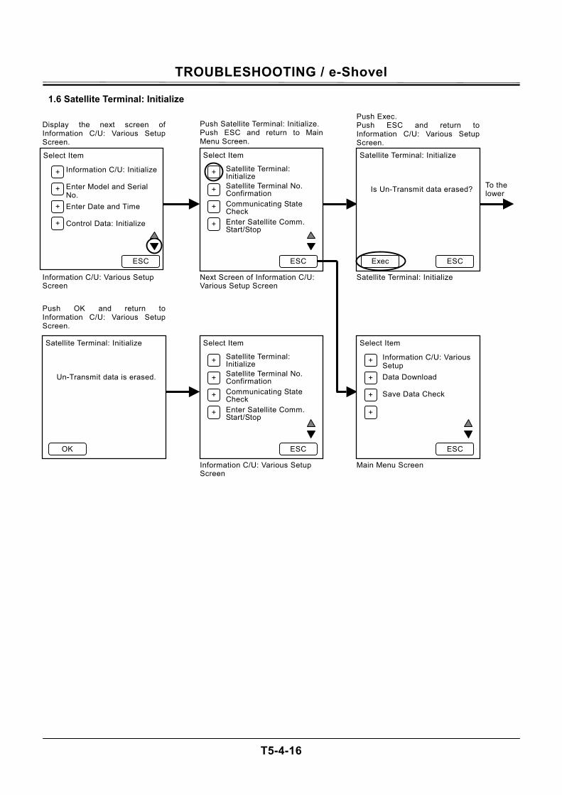
TROUBLESHOOTING / e-Shovel
T5-4-16
1.6 Satellite Terminal: Initialize
Select Item
Information C/U: Initialize Enter Model and Serial No. Enter Date and Time Control Data: Initialize
Display the next screen ofInformation C/U: Various Setup Screen.
Information C/U: Various Setup Screen
Select Item
Satellite Terminal: Initialize
Satellite Terminal No. Confirmation
Communicating State Check
Enter Satellite Comm. Start/Stop
Push Satellite Terminal: Initialize.Push ESC and return to Main Menu Screen.
Next Screen of Information C/U: Various Setup Screen
Satellite Terminal: Initialize
Is Un-Transmit data erased?
Push Exec. Push ESC and return to Information C/U: Various Setup Screen.
Satellite Terminal: Initialize
To the lower
ESC
+
+
+
+
+
+
ESC ESC Exec
Satellite Terminal: Initialize
Un-Transmit data is erased.
Push OK and return toInformation C/U: Various SetupScreen.
Select Item
Satellite Terminal: Initialize
Satellite Terminal No. Confirmation
Communicating State Check
Enter Satellite Comm. Start/Stop
Information C/U: Various Setup Screen
Select Item
Information C/U: Various Setup
Data Download Save Data Check
Main Menu Screen
OK
+
+
+
+
ESC ESC
+
+
+
+
+
+
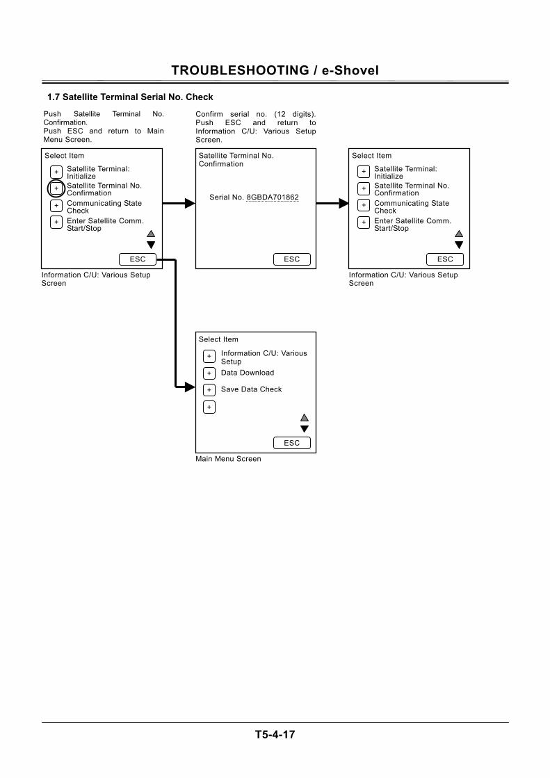
TROUBLESHOOTING / e-Shovel
T5-4-17
1.7 Satellite Terminal Serial No. Check Select Item
Satellite Terminal: Initialize
Satellite Terminal No. Confirmation
Communicating State Check
Enter Satellite Comm. Start/Stop
Push Satellite Terminal No.Confirmation. Push ESC and return to MainMenu Screen.
Information C/U: Various Setup Screen
Satellite Terminal No. Confirmation
Serial No. 8GBDA701862
Confirm serial no. (12 digits).Push ESC and return to Information C/U: Various SetupScreen.
Select Item
Satellite Terminal: Initialize
Satellite Terminal No. Confirmation
Communicating State Check
Enter Satellite Comm. Start/Stop
Information C/U: Various Setup Screen
ESC
+
+
+
+
+
+
ESC ESC
Select Item
Information C/U: Various Setup
Data Download Save Data Check
Main Menu Screen
+
+
+
+
ESC
+
+
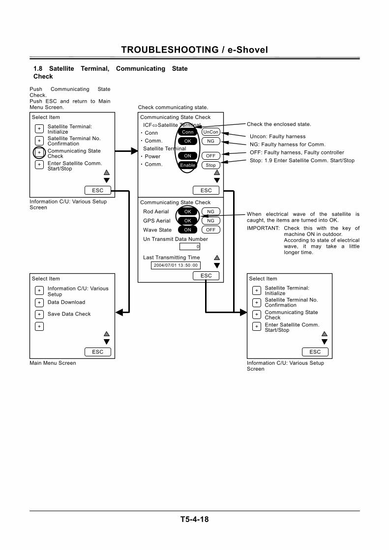
TROUBLESHOOTING / e-Shovel
T5-4-18
1.8 Satellite Terminal, Communicating State Check
Select Item
Satellite Terminal: Initialize
Satellite Terminal No. Confirmation
Communicating State Check
Enter Satellite Comm. Start/Stop
Push Communicating State Check. Push ESC and return to Main Menu Screen.
Information C/U: Various Setup Screen
Communicating State Check
ICF⇔Satellite Terminal ・ Conn
・ Comm. Satellite Terminal ・ Power ・ Comm.
Check communicating state.
+
+
+
+
ESC ESC
Select Item
Information C/U: Various Setup
Data Download Save Data Check
Main Menu Screen
Select Item
Satellite Terminal: Initialize
Satellite Terminal No. Confirmation
Communicating State Check
Enter Satellite Comm. Start/Stop
Check the enclosed state. Uncon: Faulty harness NG: Faulty harness for Comm. OFF: Faulty harness, Faulty controller Stop: 1.9 Enter Satellite Comm. Start/Stop
Information C/U: Various Setup Screen
+
+
+
+
ESC ESC
+
+
+
+
UnConConn
NGOK
OFFON
StopEnable
Communicating State Check
Rod Aerial
GPS Aerial
Wave State
Un Transmit Data Number
Last Transmitting Time
ESC
NGOK
NGOK
OFFON
0
2004/07/01 13:50:00
When electrical wave of the satellite is caught, the items are turned into OK. IMPORTANT: Check this with the key of
machine ON in outdoor. According to state of electrical wave, it may take a little longer time.
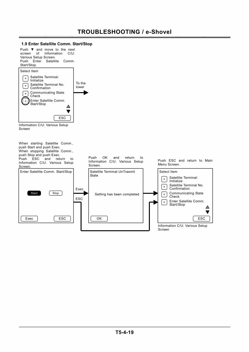
TROUBLESHOOTING / e-Shovel
T5-4-19
1.9 Enter Satellite Comm. Start/Stop
Enter Satellite Comm. Start/Stop
When starting Satellite Comm.,push Start and push Exec. When stopping Satellite Comm.,push Stop and push Exec. Push ESC and return toInformation C/U: Various SetupScreen.
Satellite Terminal UnTrasmit State
Setting has been completed
Push OK and return toInformation C/U: Various SetupScreen.
Select Item
Satellite Terminal: Initialize
Satellite Terminal No. Confirmation
Communicating State Check
Enter Satellite Comm. Start/Stop
Push ESC and return to Main Menu Screen.
Information C/U: Various Setup Screen
ESC Exec ESC
Exec
ESC
OK
+
+
+
+
Select Item
Satellite Terminal: Initialize
Satellite Terminal No. Confirmation
Communicating State Check
Enter Satellite Comm. Start/Stop
Push and move to the nextscreen of Information C/U:Various Setup Screen. Push Enter Satellite Comm.Start/Stop.
Information C/U: Various Setup Screen
ESC
+
+
+
+
To the lower
Stop Start
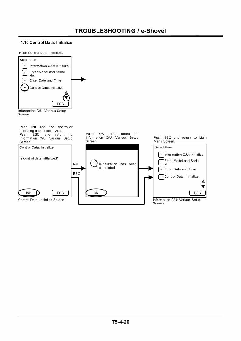
TROUBLESHOOTING / e-Shovel
T5-4-20
1.10 Control Data: Initialize
Control Data: Initialize Is control data initialized?
Push Init and the controlleroperating data is initialized. Push ESC and return toInformation C/U: Various SetupScreen.
Control Data: Initialize Screen
Initialization has been completed.
Push OK and return toInformation C/U: Various SetupScreen.
Select Item
Information C/U: Initialize
Enter Model and Serial No. Enter Date and Time Control Data: Initialize
Push ESC and return to Main Menu Screen.
Information C/U: Various Setup Screen
ESC Init ESC
Init
ESC
Initialization has beencompleted.
OK
i
+
+
+
+
Select Item
Information C/U: Initialize
Enter Model and Serial No. Enter Date and Time Control Data: Initialize
Push Control Data: Initialize.
Information C/U: Various Setup Screen
ESC
+
+
+
+

TROUBLESHOOTING / e-Shovel
T5-4-21
(Blank)
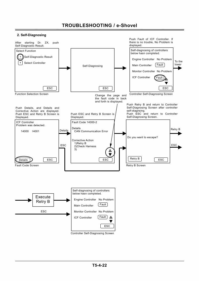
TROUBLESHOOTING / e-Shovel
T5-4-22
2. Self-Diagnosing
Select Function
Self-Diagnostic Result Select Controller
After starting Dr. ZX, pushSelf-Diagnostic Result.
Function Selection Screen
Self-Diagnosing
Self-diagnosing of controllers below hasn completed. Engine Controller No Problem Main Controller Monitor Controller No Problem ICF Controller
Push Fault of ICF Controller. If there is no trouble, No Problem is displayed.
Controller Self-Diagnosing Screen
To the lower
ESC
+
+
ESC ESC
ICF Controller Problem was detected.
14000 14001
Push Details, and Details and Corrective Action are displayed.Push ESC and Retry B Screen isDisplayed.
Fault Code 14000-2 Details
CAN Communication Error Corrective Action
1)Retry B 2)Check Harness 3)
Push ESC and Retry B Screen isDisplayed.
Do you want to escape?
Push Retry B and return to Controller Self-Diagnosing Screen after controller self-diagnsing. Push ESC and return to Controller Self-Diagnosing Screen.
Retry B Screen
ESC ESC
ESC
Fault
Fault
ESC ESC
Change the page and the fault code in back and forth is displayed.
ESC Details
Details Retry B
Retry B
Execute Retry B
Self-diagnosing of controllers below hasn completed. Engine Controller No Problem Main Controller Monitor Controller No Problem ICF Controller
Controller Self-Diagnosing Screen
ESC
Fault
Fault
Fault Code Screen
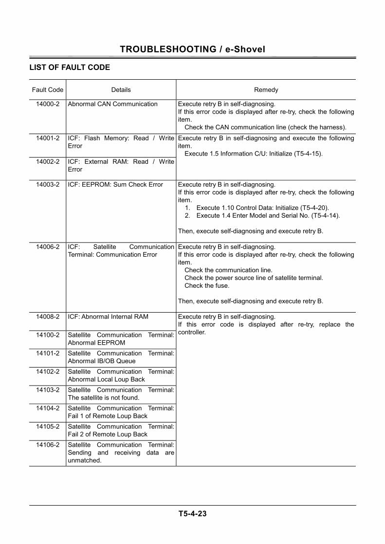
TROUBLESHOOTING / e-Shovel
T5-4-23
LIST OF FAULT CODE
Fault Code Details Remedy
14000-2 Abnormal CAN Communication Execute retry B in self-diagnosing. If this error code is displayed after re-try, check the following item. Check the CAN communication line (check the harness).
14001-2 ICF: Flash Memory: Read / Write Error
14002-2 ICF: External RAM: Read / Write Error
Execute retry B in self-diagnosing and execute the following item. Execute 1.5 Information C/U: Initialize (T5-4-15).
14003-2 ICF: EEPROM: Sum Check Error Execute retry B in self-diagnosing. If this error code is displayed after re-try, check the following item.
1. Execute 1.10 Control Data: Initialize (T5-4-20). 2. Execute 1.4 Enter Model and Serial No. (T5-4-14).
Then, execute self-diagnosing and execute retry B.
14006-2 ICF: Satellite Communication Terminal: Communication Error
Execute retry B in self-diagnosing. If this error code is displayed after re-try, check the following item. Check the communication line. Check the power source line of satellite terminal. Check the fuse. Then, execute self-diagnosing and execute retry B.
14008-2 ICF: Abnormal Internal RAM
14100-2 Satellite Communication Terminal: Abnormal EEPROM
14101-2 Satellite Communication Terminal: Abnormal IB/OB Queue
14102-2 Satellite Communication Terminal: Abnormal Local Loup Back
14103-2 Satellite Communication Terminal: The satellite is not found.
14104-2 Satellite Communication Terminal: Fail 1 of Remote Loup Back
14105-2 Satellite Communication Terminal: Fail 2 of Remote Loup Back
14106-2 Satellite Communication Terminal: Sending and receiving data are unmatched.
Execute retry B in self-diagnosing. If this error code is displayed after re-try, replace the controller.
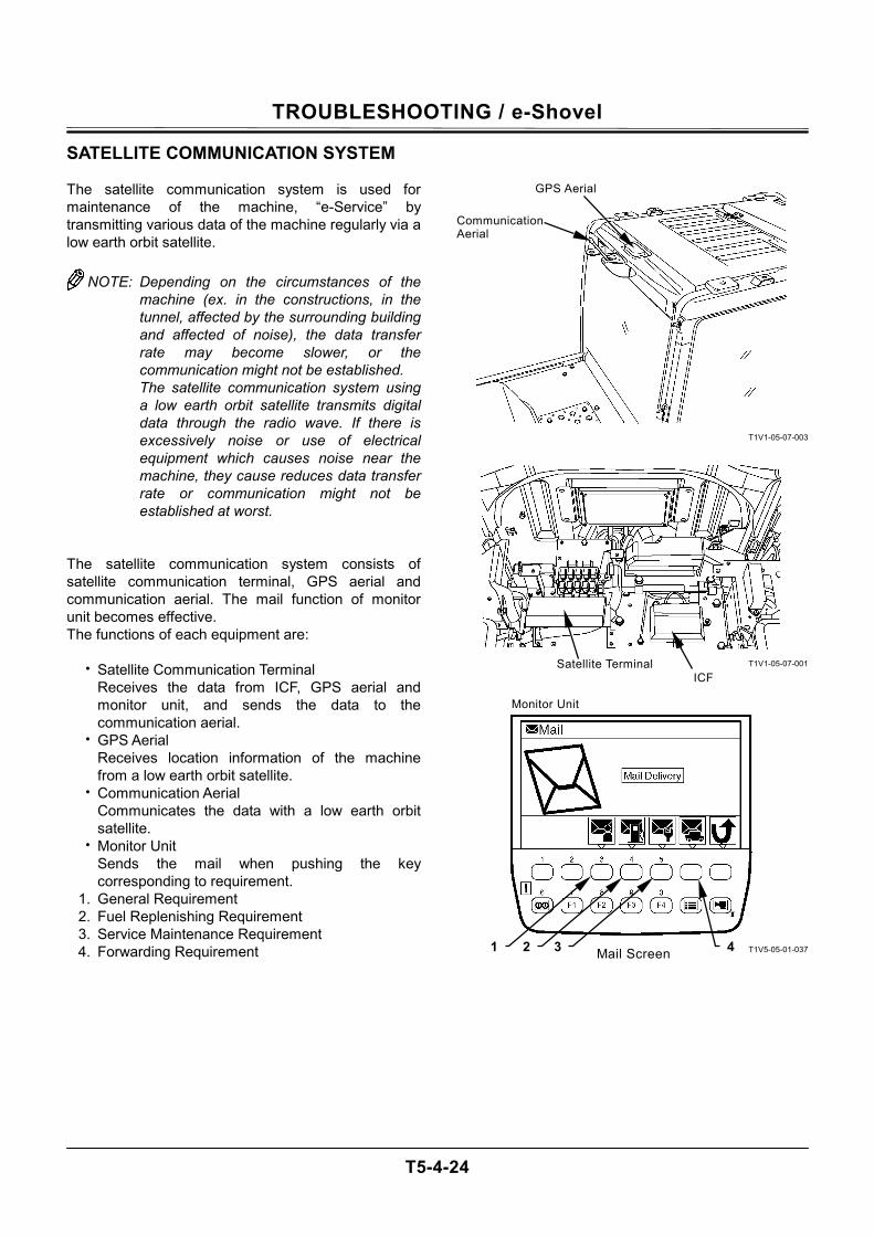
TROUBLESHOOTING / e-Shovel
T5-4-24
SATELLITE COMMUNICATION SYSTEM The satellite communication system is used for maintenance of the machine, “e-Service” by transmitting various data of the machine regularly via a low earth orbit satellite.
NOTE: Depending on the circumstances of the machine (ex. in the constructions, in the tunnel, affected by the surrounding building and affected of noise), the data transfer rate may become slower, or the communication might not be established. The satellite communication system using a low earth orbit satellite transmits digital data through the radio wave. If there is excessively noise or use of electrical equipment which causes noise near the machine, they cause reduces data transfer rate or communication might not be established at worst.
The satellite communication system consists of satellite communication terminal, GPS aerial and communication aerial. The mail function of monitor unit becomes effective. The functions of each equipment are:
• Satellite Communication Terminal Receives the data from ICF, GPS aerial and monitor unit, and sends the data to the communication aerial.
• GPS Aerial Receives location information of the machine from a low earth orbit satellite.
• Communication Aerial Communicates the data with a low earth orbit satellite.
• Monitor Unit Sends the mail when pushing the key corresponding to requirement.
1. General Requirement 2. Fuel Replenishing Requirement 3. Service Maintenance Requirement 4. Forwarding Requirement
T1V1-05-07-003
T1V1-05-07-001
T1V5-05-01-037
GPS Aerial
Communication Aerial
Monitor Unit
Satellite Terminal
Mail Screen 4321
ICF
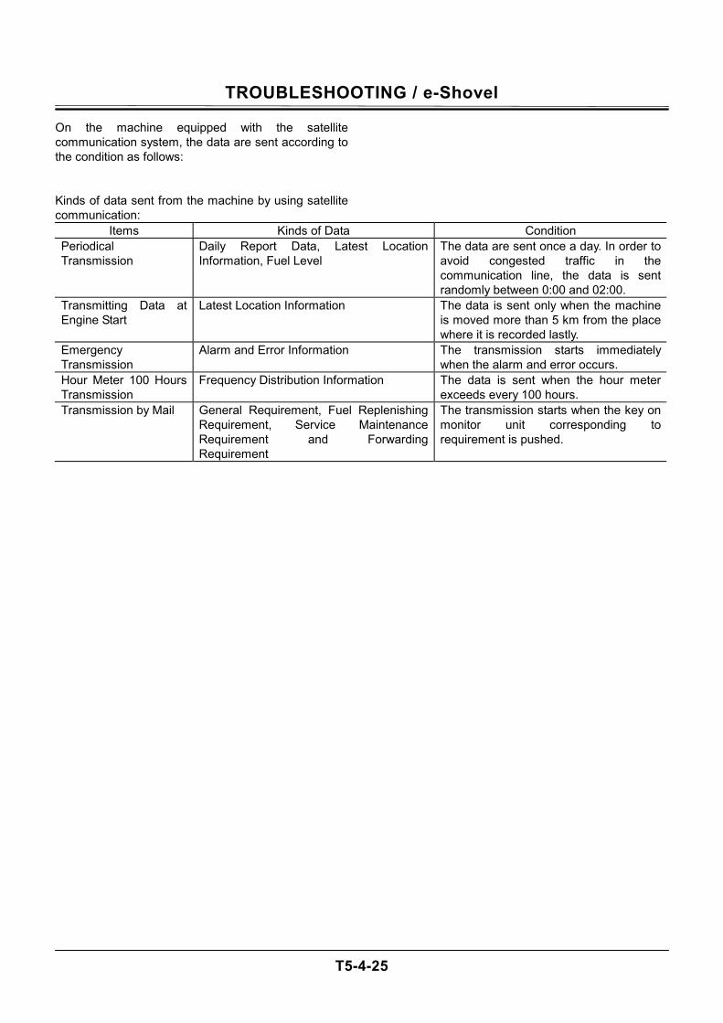
TROUBLESHOOTING / e-Shovel
T5-4-25
On the machine equipped with the satellite communication system, the data are sent according to the condition as follows: Kinds of data sent from the machine by using satellite communication:
Items Kinds of Data Condition Periodical Transmission
Daily Report Data, Latest Location Information, Fuel Level
The data are sent once a day. In order to avoid congested traffic in the communication line, the data is sent randomly between 0:00 and 02:00.
Transmitting Data at Engine Start
Latest Location Information The data is sent only when the machine is moved more than 5 km from the place where it is recorded lastly.
Emergency Transmission
Alarm and Error Information The transmission starts immediately when the alarm and error occurs.
Hour Meter 100 Hours Transmission
Frequency Distribution Information The data is sent when the hour meter exceeds every 100 hours.
Transmission by Mail General Requirement, Fuel Replenishing Requirement, Service Maintenance Requirement and Forwarding Requirement
The transmission starts when the key on monitor unit corresponding to requirement is pushed.

TROUBLESHOOTING / e-Shovel
T5-4-26
(Blank)
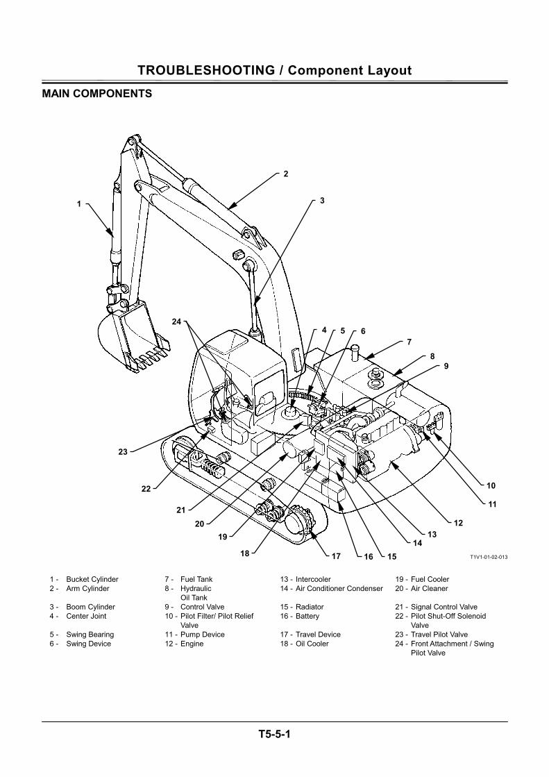
TROUBLESHOOTING / Component Layout
T5-5-1
MAIN COMPONENTS
T1V1-01-02-013
1 - Bucket Cylinder 7 - Fuel Tank 13 - Intercooler 19 - Fuel Cooler 2 - Arm Cylinder 8 - Hydraulic
Oil Tank 14 - Air Conditioner Condenser 20 - Air Cleaner
3 - Boom Cylinder 9 - Control Valve 15 - Radiator 21 - Signal Control Valve 4 - Center Joint 10 - Pilot Filter/ Pilot Relief
Valve 16 - Battery 22 - Pilot Shut-Off Solenoid
Valve 5 - Swing Bearing 11 - Pump Device 17 - Travel Device 23 - Travel Pilot Valve 6 - Swing Device 12 - Engine 18 - Oil Cooler 24 - Front Attachment / Swing
Pilot Valve
2
23
22
21 20
19
18 17 15 14
13 12
11
10
9 8
7 654
31
24
16
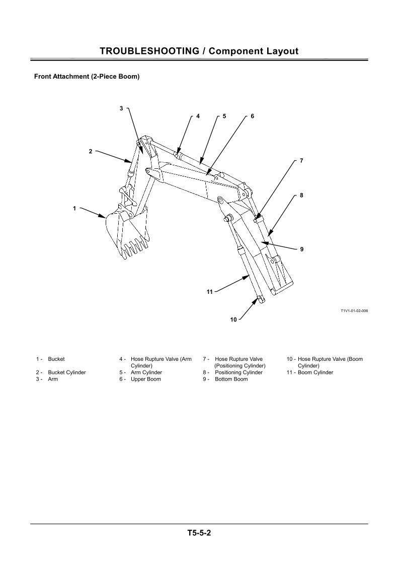
TROUBLESHOOTING / Component Layout
T5-5-2
Front Attachment (2-Piece Boom)
T1V1-01-02-006
1 - Bucket 4 - Hose Rupture Valve (Arm Cylinder)
7 - Hose Rupture Valve (Positioning Cylinder)
10 - Hose Rupture Valve (Boom Cylinder)
2 - Bucket Cylinder 5 - Arm Cylinder 8 - Positioning Cylinder 11 - Boom Cylinder 3 - Arm 6 - Upper Boom 9 - Bottom Boom
34 5 6
7
8
9
10
11
2
1
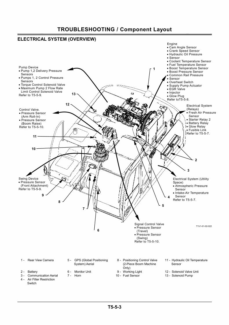
TROUBLESHOOTING / Component Layout
T5-5-3
ELECTRICAL SYSTEM (OVERVIEW)
T1V1-01-02-022
1 - Rear View Camera 5 - GPS (Global Positioning System) Aerial
8 - Positioning Control Valve (2-Piece Boom Machine Only)
11 - Hydraulic Oil Temperature Sensor
2 - Battery 6 - Monitor Unit 9 - Working Light 12 - Solenoid Valve Unit 3 - Communication Aerial 7 - Horn 10 - Fuel Sensor 13 - Solenoid Pump 4 - Air Filter Restriction
Switch
Signal Control Valve • Pressure Sensor
(Travel) • Pressure Sensor
(Swing) Refer to T5-5-10.
Pump Device • Pump 1,2 Delivery Pressure
Sensors • Pumps 1, 2 Control Pressure
Sensors • Torque Control Solenoid Valve • Maximum Pump 2 Flow Rate
Limit Control Solenoid Valve Refer to T5-5-9.
Control Valve. • Pressure Sensor
(Arm Roll-In) • Pressure Sensor
(Boom Raise) Refer to T5-5-10.
Swing Device • Pressure Sensor
(Front Attachment) Refer to T5-5-9.
Electrical System (Utility Space) • Atmospheric Pressure
Sensor • Intake-Air Temperature
Sensor Refer to T5-5-7.
Electrical System (Relays) • Fresh Air Pressure
Sensor • Starter Relay 2 • Battery Relay • Glow Relay • Fusible Link Refer to T5-5-7.
Engine • Cam Angle Sensor • Crank Speed Sensor • Hydraulic Oil Pressure • Sensor • Coolant Temperature Sensor• Fuel Temperature Sensor • Boost Temperature Sensor • Boost Pressure Sensor • Common Rail Pressure • Sensor • Overheat Switch • Supply Pump Actuator • EGR Valve • Injector • Glow Plug Refer toT5-5-8.
13
12
11
10
9
7
6
5
4
3
2
1
8
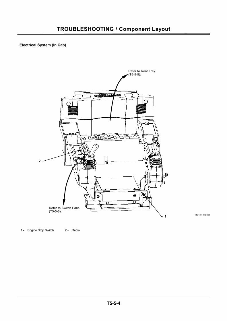
TROUBLESHOOTING / Component Layout
T5-5-4
Electrical System (In Cab)
T1V1-01-02-011
1 - Engine Stop Switch 2 - Radio
Refer to Switch Panel (T5-5-6).
Refer to Rear Tray(T5-5-5).
2
1
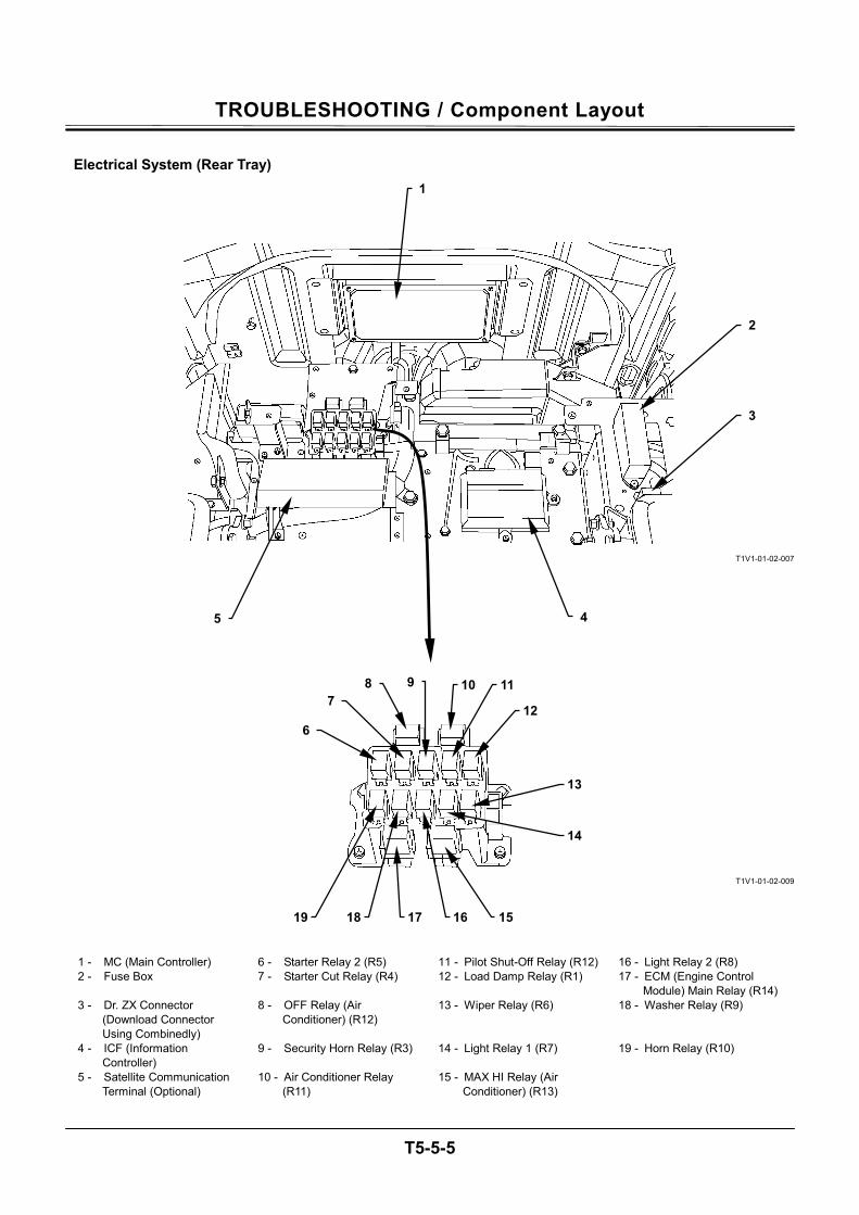
TROUBLESHOOTING / Component Layout
T5-5-5
Electrical System (Rear Tray)
T1V1-01-02-007
T1V1-01-02-009
1 - MC (Main Controller) 6 - Starter Relay 2 (R5) 11 - Pilot Shut-Off Relay (R12) 16 - Light Relay 2 (R8) 2 - Fuse Box 7 - Starter Cut Relay (R4) 12 - Load Damp Relay (R1) 17 - ECM (Engine Control
Module) Main Relay (R14) 3 - Dr. ZX Connector
(Download Connector Using Combinedly)
8 - OFF Relay (Air Conditioner) (R12)
13 - Wiper Relay (R6) 18 - Washer Relay (R9)
4 - ICF (Information Controller)
9 - Security Horn Relay (R3) 14 - Light Relay 1 (R7) 19 - Horn Relay (R10)
5 - Satellite Communication Terminal (Optional)
10 - Air Conditioner Relay (R11)
15 - MAX HI Relay (Air Conditioner) (R13)
1
2
3
45
6
7 8 9 10 11
12
13
14
17 161819 15
TROUBLESHOOTING / Component Layout
T5-5-6
Electrical System (Switch Panel)
T1V1-04-02-001
1 - Wiper / Washer Switch 3 - Engine Control Dial 5 - Power Mode Switch 6 - Travel Mode Switch 2 - Working Light Switch 4 - Auto-Idle Switch
3
4
5
6
2
1
TROUBLESHOOTING / Component Layout
T5-5-7
Electrical System (Utility Space)
T1V1-01-02-012
Electrical System (Relays)
T1V1-01-02-018
1 - Atmospheric Pressure
Sensor 3 - Fresh Air Pressure Sensor 5 - Battery Relay 7 - Fusible Link
2 - Intake-Air Temperature Sensor
4 - Starter Relay 2 6 - Glow Relay
2
1 Air Cleaner
Front
3 4
5
6
7
TROUBLESHOOTING / Component Layout
T5-5-8
ENGINE
T1V1-01-02-016
T1V1-01-02-015
T1V1-01-02-017
1 - Cam Angle Sensor 5 - Fuel Temperature Sensor 8 - Hydraulic Oil Pressure
Sensor 11 - Boost Temperature Sensor
2 - Overheat Switch 6 - Crank Speed Sensor 9 - Injector 12 - Boost Pressure Sensor 3 - Coolant temperature
sensor 7 - Supply Pump Actuator 10 - EGR (Exhaust Gas
Recirculation) Valve 13 - Glow Plug
4 - Common Rail Pressure Sensor
1
2
3 4 5
6
8
10
7
12 9
13
11 9
TROUBLESHOOTING / Component Layout
T5-5-9
PUMP DEVICE
T178-03-01-003
SWING DEVICE
ZX200-3 class, ZX240-3 class
T1V1-01-02-005
T178-03-01-001
ZX270-3 class
T1V1-01-02-004
1 - Pilot Pump 4 - Pump 1 Delivery Pressure Sensor
7 - Maximum Pump 2 Flow Rate Limit Control Solenoid Valve
10 - Swing Relief Valve
2 - Pump 2 5 - Pump 2 Delivery Pressure Sensor
8 - Pump 2 Control Pressure Sensor
11 - Pressure Sensor (Front Attachment)
3 - Pump 1 6 - Torque Control Solenoid Valve
9 - Pump 1 Control Pressure Sensor
3 2 1 8
76
9
4 5
10
11
Front
11
TROUBLESHOOTING / Component Layout
T5-5-10
CONTROL VALVE
T1V1-03-03-073
SIGNAL CONTROL VALVE
T1V1-01-02-014
1 - Pressure Sensor (Arm
Roll-In) 2 - Pressure Sensor (Boom
Raise) 3 - Pressure Sensor (Swing) 4 - Pressure Sensor (Travel)
2
1
Main Relief Valve
3
4
TROUBLESHOOTING / Component Layout
T5-5-11
SOLENOID VALVE UNIT
T1V1-03-07-007
TRAVEL DEVICE
ZX200-3 class, ZX240-3 class
T1HD-01-02-001
ZX270-3 class
T178-01-02-014
1 - Solenoid Valve Unit SC 3 - Solenoid Valve Unit SI 5 - Counterbalance Valve 6 - Travel Relief Valve 2 - Solenoid Valve Unit SF 4 - Solenoid Valve Unit SG
6
1 2 3 4
5
6
5
55
TROUBLESHOOTING / Component Layout
T5-5-12
Layout of Control Valve
T1V1-03-03-021
1 2 3 4 5 6 7 8 9 10 11
12
13
14
15
16
17
18
19
20
21
22
23
24
25 26272829 3031
32
33
34
35
36 37
38
39
40
41
42
Machine Lower Machine Upper Machine Lower Machine Upper
TROUBLESHOOTING / Component Layout
T5-5-13
4-Spool Section
T1V1-03-03-073
1 - Load Check Valve (Left Travel Parallel Circuit)
12 - Bucket Regenerative Valve 23 - Arm 2 Flow Rate Control Valve (Switch Valve)
34 - Arm Anti-Drift Valve (Switch Valve)
2 - Check Valve (Main Relief Circuit)
13 - Overload Relief Valve (Bucket: Rod Side)
24 - Load Check Valve (Arm 2 Tandem Circuit)
35 - Overload Relief Valve (Arm: Bottom Side)
3 - Main Relief Valve 14 - Overload Relief Valve (Bucket: Bottom Side)
25 - Bypass Shut-Out Valve 36 - Arm Anti-Drift Valve (Check Valve)
4 - Check Valve (Auxiliary Combining Valve Circuit)
15 - Boom Flow Control Valve (Poppet Valve)
26 - Arm 2 Flow Rate Control Valve (Poppet Valve)
37 - Overload Relief Valve (Arm: Rod Side)
5 - Auxiliary Flow Combiner Valve
16 - Boom Lower Meter-In Cut Valve
27 - Arm Regenerative Valve 38 - Check Valve (Digging Regenerative Circuit)
6 - Check Valve (Flow Combiner Valve Circuit)
17 - Boom Flow Rate Control Valve (Switch Valve)
28 - Digging Regenerative Valve
39 - Load Check Valve (Boom 2 Parallel Circuit)
7 - Flow Combiner Valve 18 - Overload Relief Valve (Boom: Bottom Side)
29 - Load Check Valve (Digging Regenerative Circuit)
40 - Auxiliary Flow Rate Control Valve (Poppet Valve)
8 - Load Check Valve (Orifice) (Bucket)
19 - Boom Anti-Drift Valve (Check Valve)
30 - Arm 1 Flow Rate Control Valve (Poppet Valve)
41 - Auxiliary Flow Rate Control Valve (Switch Valve)
9 - Check Valve (Main Relief Circuit)
20 - Overload Relief Valve (Boom: Rod Side)
31 - Load Check Valve (Swing Circuit)
42 - Load Check Valve (Left Travel Tandem Circuit)
10 - Bucket Flow Rate Control Valve (Poppet Valve)
21 - Boom Regenerative Valve 32 - Arm 1 Flow Rate Control Valve (Switch Valve)
11 - Bucket Flow Rate Control Valve (Switch Valve)
22 - Boom Anti-Drift Valve (Switch Valve)
33 - Load Check Valve (Arm Regenerative Circuit)
Boom Raise Pressure Sensor
18 19, 22 13
10, 11
16
20 14
7
Arm Roll-In Pressure Sensor
15, 17 23

TROUBLESHOOTING / Component Layout
T5-5-14
T1V1-03-03-021
1 2 3 4 5 6 7 8 9 10 11
12
13
14
15
16
17
18
19
20
21
22
23
24
25 26272829 3031
32
33
34
35
36 37
38
39
40
41
42
Machine Lower Machine Upper Machine Lower Machine Upper
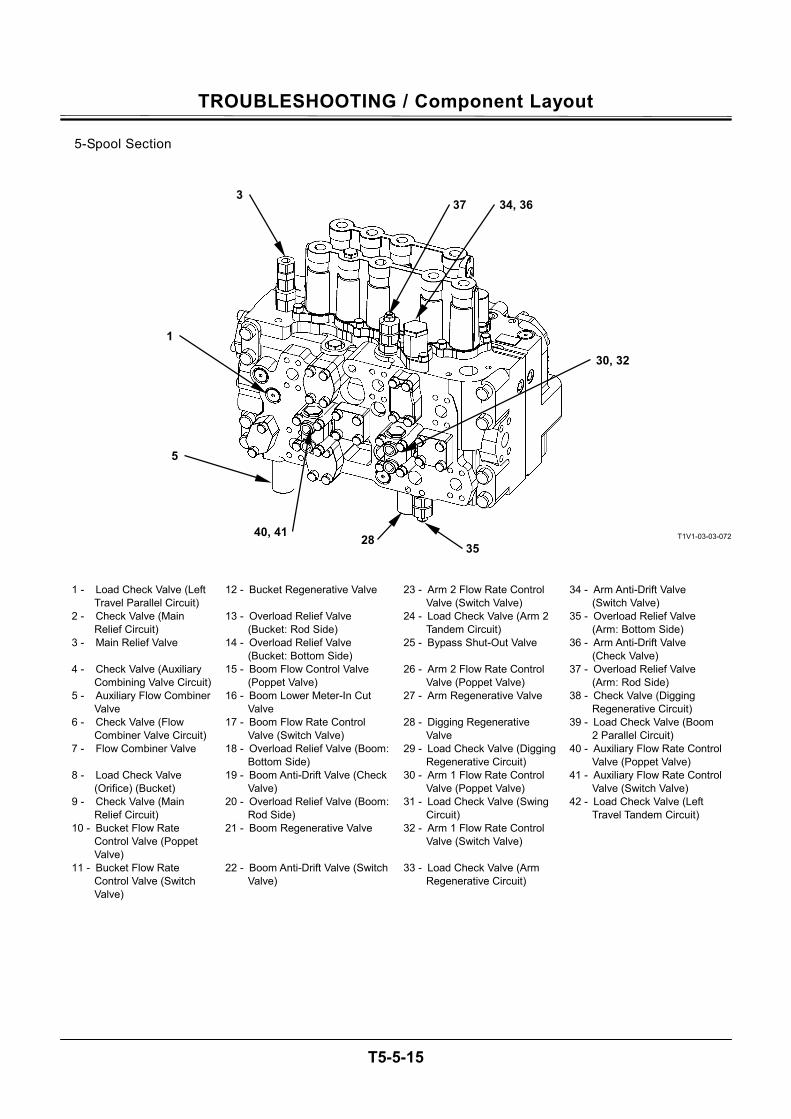
TROUBLESHOOTING / Component Layout
T5-5-15
5-Spool Section
T1V1-03-03-072
1 - Load Check Valve (Left Travel Parallel Circuit)
12 - Bucket Regenerative Valve 23 - Arm 2 Flow Rate Control Valve (Switch Valve)
34 - Arm Anti-Drift Valve (Switch Valve)
2 - Check Valve (Main Relief Circuit)
13 - Overload Relief Valve (Bucket: Rod Side)
24 - Load Check Valve (Arm 2 Tandem Circuit)
35 - Overload Relief Valve (Arm: Bottom Side)
3 - Main Relief Valve 14 - Overload Relief Valve (Bucket: Bottom Side)
25 - Bypass Shut-Out Valve 36 - Arm Anti-Drift Valve (Check Valve)
4 - Check Valve (Auxiliary Combining Valve Circuit)
15 - Boom Flow Control Valve (Poppet Valve)
26 - Arm 2 Flow Rate Control Valve (Poppet Valve)
37 - Overload Relief Valve (Arm: Rod Side)
5 - Auxiliary Flow Combiner Valve
16 - Boom Lower Meter-In Cut Valve
27 - Arm Regenerative Valve 38 - Check Valve (Digging Regenerative Circuit)
6 - Check Valve (Flow Combiner Valve Circuit)
17 - Boom Flow Rate Control Valve (Switch Valve)
28 - Digging Regenerative Valve
39 - Load Check Valve (Boom 2 Parallel Circuit)
7 - Flow Combiner Valve 18 - Overload Relief Valve (Boom: Bottom Side)
29 - Load Check Valve (Digging Regenerative Circuit)
40 - Auxiliary Flow Rate Control Valve (Poppet Valve)
8 - Load Check Valve (Orifice) (Bucket)
19 - Boom Anti-Drift Valve (Check Valve)
30 - Arm 1 Flow Rate Control Valve (Poppet Valve)
41 - Auxiliary Flow Rate Control Valve (Switch Valve)
9 - Check Valve (Main Relief Circuit)
20 - Overload Relief Valve (Boom: Rod Side)
31 - Load Check Valve (Swing Circuit)
42 - Load Check Valve (Left Travel Tandem Circuit)
10 - Bucket Flow Rate Control Valve (Poppet Valve)
21 - Boom Regenerative Valve 32 - Arm 1 Flow Rate Control Valve (Switch Valve)
11 - Bucket Flow Rate Control Valve (Switch Valve)
22 - Boom Anti-Drift Valve (Switch Valve)
33 - Load Check Valve (Arm Regenerative Circuit)
34, 36373
1
5
40, 41 2835
30, 32

TROUBLESHOOTING / Component Layout
T5-5-16
T1V1-03-03-021
1 2 3 4 5 6 7 8 9 10 11
12
13
14
15
16
17
18
19
20
21
22
23
24
25 26272829 3031
32
33
34
35
36 37
38
39
40
41
42
Machine Lower Machine Upper Machine Lower Machine Upper
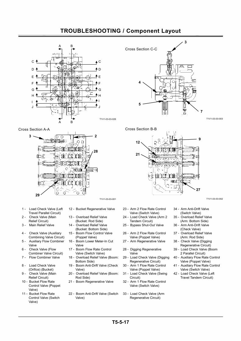
TROUBLESHOOTING / Component Layout
T5-5-17
T1V1-03-03-026
Cross Section A-A
T1V1-03-03-001
Cross Section C-C
T1V1-03-03-003
Cross Section B-B
T1V1-03-03-002
1 - Load Check Valve (Left
Travel Parallel Circuit) 12 - Bucket Regenerative Valve 23 - Arm 2 Flow Rate Control
Valve (Switch Valve) 34 - Arm Anti-Drift Valve
(Switch Valve) 2 - Check Valve (Main
Relief Circuit) 13 - Overload Relief Valve
(Bucket: Rod Side) 24 - Load Check Valve (Arm 2
Tandem Circuit) 35 - Overload Relief Valve
(Arm: Bottom Side) 3 - Main Relief Valve 14 - Overload Relief Valve
(Bucket: Bottom Side) 25 - Bypass Shut-Out Valve 36 - Arm Anti-Drift Valve
(Check Valve) 4 - Check Valve (Auxiliary
Combining Valve Circuit) 15 - Boom Flow Control Valve
(Poppet Valve) 26 - Arm 2 Flow Rate Control
Valve (Poppet Valve) 37 - Overload Relief Valve
(Arm: Rod Side) 5 - Auxiliary Flow Combiner
Valve 16 - Boom Lower Meter-In Cut
Valve 27 - Arm Regenerative Valve 38 - Check Valve (Digging
Regenerative Circuit) 6 - Check Valve (Flow
Combiner Valve Circuit) 17 - Boom Flow Rate Control
Valve (Switch Valve) 28 - Digging Regenerative
Valve 39 - Load Check Valve (Boom
2 Parallel Circuit) 7 - Flow Combiner Valve 18 - Overload Relief Valve (Boom:
Bottom Side) 29 - Load Check Valve (Digging
Regenerative Circuit) 40 - Auxiliary Flow Rate Control
Valve (Poppet Valve) 8 - Load Check Valve
(Orifice) (Bucket) 19 - Boom Anti-Drift Valve (Check
Valve) 30 - Arm 1 Flow Rate Control
Valve (Poppet Valve) 41 - Auxiliary Flow Rate Control
Valve (Switch Valve) 9 - Check Valve (Main
Relief Circuit) 20 - Overload Relief Valve (Boom:
Rod Side) 31 - Load Check Valve (Swing
Circuit) 42 - Load Check Valve (Left
Travel Tandem Circuit) 10 - Bucket Flow Rate
Control Valve (Poppet Valve)
21 - Boom Regenerative Valve 32 - Arm 1 Flow Rate Control Valve (Switch Valve)
11 - Bucket Flow Rate Control Valve (Switch Valve)
22 - Boom Anti-Drift Valve (Switch Valve)
33 - Load Check Valve (Arm Regenerative Circuit)
3
7
4
5
3 2
28
29
912
21
27
A B
A B
C
D
E
F
G
H
I J
C
D
E
F
G
HI
J

TROUBLESHOOTING / Component Layout
T5-5-18
T1V1-03-03-021
1 2 3 4 5 6 7 8 9 10 11
12
13
14
15
16
17
18
19
20
21
22
23
24
25 26272829 3031
32
33
34
35
36 37
38
39
40
41
42
Machine Lower Machine Upper Machine Lower Machine Upper
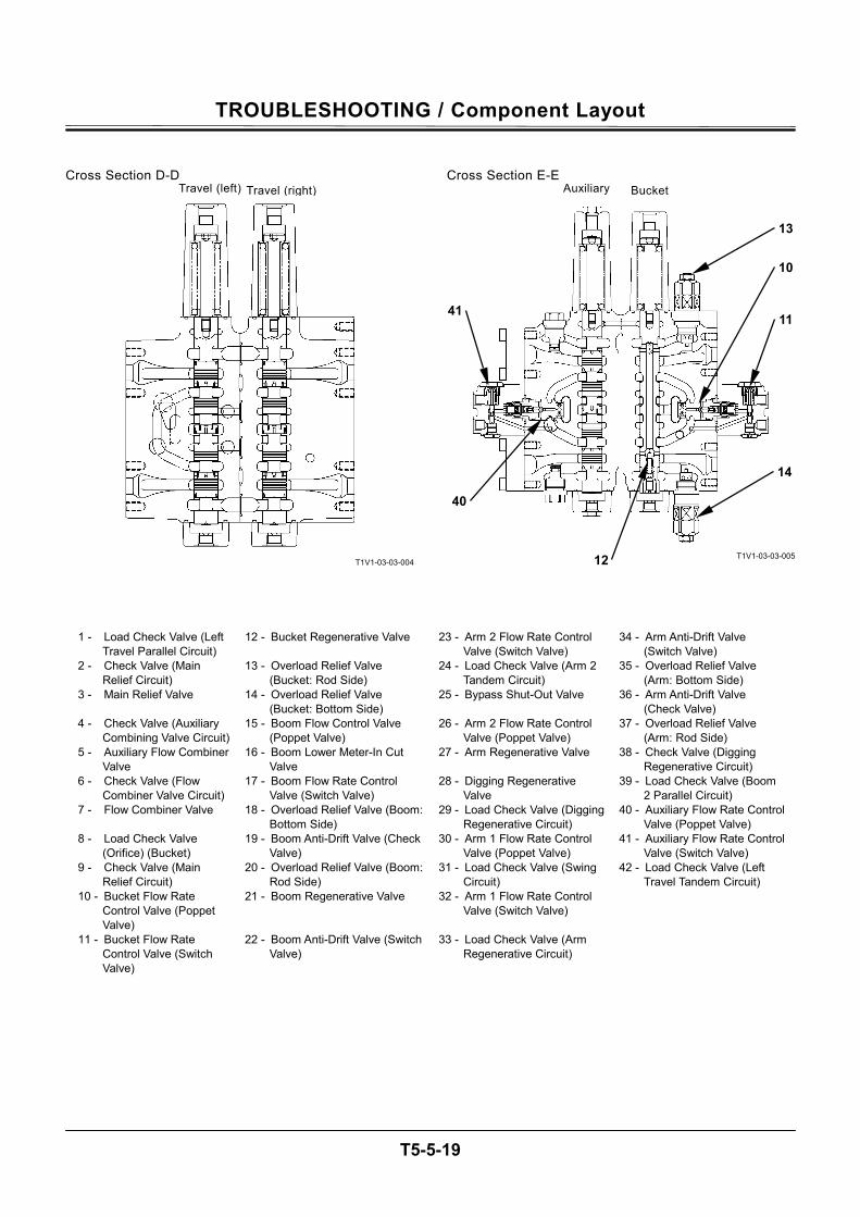
TROUBLESHOOTING / Component Layout
T5-5-19
Cross Section D-D
T1V1-03-03-004
Cross Section E-E
T1V1-03-03-005
1 - Load Check Valve (Left Travel Parallel Circuit)
12 - Bucket Regenerative Valve 23 - Arm 2 Flow Rate Control Valve (Switch Valve)
34 - Arm Anti-Drift Valve (Switch Valve)
2 - Check Valve (Main Relief Circuit)
13 - Overload Relief Valve (Bucket: Rod Side)
24 - Load Check Valve (Arm 2 Tandem Circuit)
35 - Overload Relief Valve (Arm: Bottom Side)
3 - Main Relief Valve 14 - Overload Relief Valve (Bucket: Bottom Side)
25 - Bypass Shut-Out Valve 36 - Arm Anti-Drift Valve (Check Valve)
4 - Check Valve (Auxiliary Combining Valve Circuit)
15 - Boom Flow Control Valve (Poppet Valve)
26 - Arm 2 Flow Rate Control Valve (Poppet Valve)
37 - Overload Relief Valve (Arm: Rod Side)
5 - Auxiliary Flow Combiner Valve
16 - Boom Lower Meter-In Cut Valve
27 - Arm Regenerative Valve 38 - Check Valve (Digging Regenerative Circuit)
6 - Check Valve (Flow Combiner Valve Circuit)
17 - Boom Flow Rate Control Valve (Switch Valve)
28 - Digging Regenerative Valve
39 - Load Check Valve (Boom 2 Parallel Circuit)
7 - Flow Combiner Valve 18 - Overload Relief Valve (Boom: Bottom Side)
29 - Load Check Valve (Digging Regenerative Circuit)
40 - Auxiliary Flow Rate Control Valve (Poppet Valve)
8 - Load Check Valve (Orifice) (Bucket)
19 - Boom Anti-Drift Valve (Check Valve)
30 - Arm 1 Flow Rate Control Valve (Poppet Valve)
41 - Auxiliary Flow Rate Control Valve (Switch Valve)
9 - Check Valve (Main Relief Circuit)
20 - Overload Relief Valve (Boom: Rod Side)
31 - Load Check Valve (Swing Circuit)
42 - Load Check Valve (Left Travel Tandem Circuit)
10 - Bucket Flow Rate Control Valve (Poppet Valve)
21 - Boom Regenerative Valve 32 - Arm 1 Flow Rate Control Valve (Switch Valve)
11 - Bucket Flow Rate Control Valve (Switch Valve)
22 - Boom Anti-Drift Valve (Switch Valve)
33 - Load Check Valve (Arm Regenerative Circuit)
Travel (left) Travel (right) Auxiliary Bucket
41
13
10
11
40
14
12

TROUBLESHOOTING / Component Layout
T5-5-20
T1V1-03-03-021
1 2 3 4 5 6 7 8 9 10 11
12
13
14
15
16
17
18
19
20
21
22
23
24
25 26272829 3031
32
33
34
35
36 37
38
39
40
41
42
Machine Lower Machine Upper Machine Lower Machine Upper
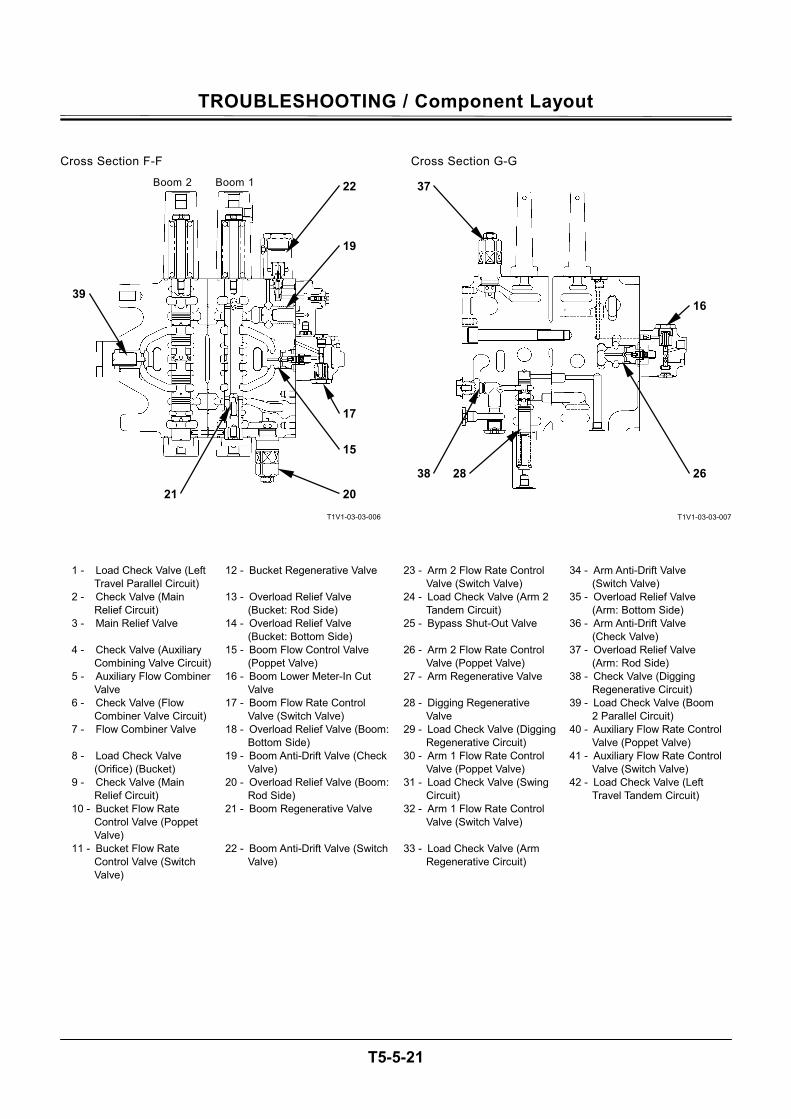
TROUBLESHOOTING / Component Layout
T5-5-21
Cross Section F-F
T1V1-03-03-006
Cross Section G-G
T1V1-03-03-007
1 - Load Check Valve (Left Travel Parallel Circuit)
12 - Bucket Regenerative Valve 23 - Arm 2 Flow Rate Control Valve (Switch Valve)
34 - Arm Anti-Drift Valve (Switch Valve)
2 - Check Valve (Main Relief Circuit)
13 - Overload Relief Valve (Bucket: Rod Side)
24 - Load Check Valve (Arm 2 Tandem Circuit)
35 - Overload Relief Valve (Arm: Bottom Side)
3 - Main Relief Valve 14 - Overload Relief Valve (Bucket: Bottom Side)
25 - Bypass Shut-Out Valve 36 - Arm Anti-Drift Valve (Check Valve)
4 - Check Valve (Auxiliary Combining Valve Circuit)
15 - Boom Flow Control Valve (Poppet Valve)
26 - Arm 2 Flow Rate Control Valve (Poppet Valve)
37 - Overload Relief Valve (Arm: Rod Side)
5 - Auxiliary Flow Combiner Valve
16 - Boom Lower Meter-In Cut Valve
27 - Arm Regenerative Valve 38 - Check Valve (Digging Regenerative Circuit)
6 - Check Valve (Flow Combiner Valve Circuit)
17 - Boom Flow Rate Control Valve (Switch Valve)
28 - Digging Regenerative Valve
39 - Load Check Valve (Boom 2 Parallel Circuit)
7 - Flow Combiner Valve 18 - Overload Relief Valve (Boom: Bottom Side)
29 - Load Check Valve (Digging Regenerative Circuit)
40 - Auxiliary Flow Rate Control Valve (Poppet Valve)
8 - Load Check Valve (Orifice) (Bucket)
19 - Boom Anti-Drift Valve (Check Valve)
30 - Arm 1 Flow Rate Control Valve (Poppet Valve)
41 - Auxiliary Flow Rate Control Valve (Switch Valve)
9 - Check Valve (Main Relief Circuit)
20 - Overload Relief Valve (Boom: Rod Side)
31 - Load Check Valve (Swing Circuit)
42 - Load Check Valve (Left Travel Tandem Circuit)
10 - Bucket Flow Rate Control Valve (Poppet Valve)
21 - Boom Regenerative Valve 32 - Arm 1 Flow Rate Control Valve (Switch Valve)
11 - Bucket Flow Rate Control Valve (Switch Valve)
22 - Boom Anti-Drift Valve (Switch Valve)
33 - Load Check Valve (Arm Regenerative Circuit)
Boom 2 Boom 1 22
19
17
15
2021
39
37
38 28 26
16

TROUBLESHOOTING / Component Layout
T5-5-22
T1V1-03-03-021
1 2 3 4 5 6 7 8 9 10 11
12
13
14
15
16
17
18
19
20
21
22
23
24
25 26272829 3031
32
33
34
35
36 37
38
39
40
41
42
Machine Lower Machine Upper Machine Lower Machine Upper
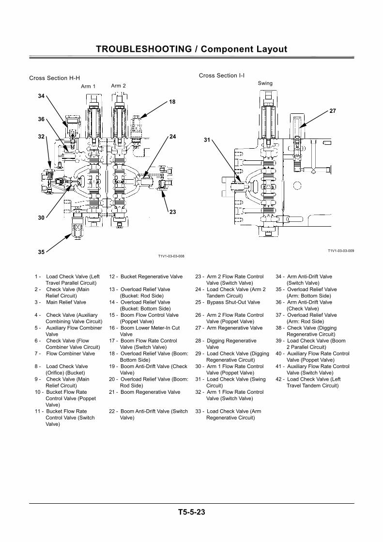
TROUBLESHOOTING / Component Layout
T5-5-23
Cross Section H-H
T1V1-03-03-008
Cross Section I-I
T1V1-03-03-009
1 - Load Check Valve (Left
Travel Parallel Circuit) 12 - Bucket Regenerative Valve 23 - Arm 2 Flow Rate Control
Valve (Switch Valve) 34 - Arm Anti-Drift Valve
(Switch Valve) 2 - Check Valve (Main
Relief Circuit) 13 - Overload Relief Valve
(Bucket: Rod Side) 24 - Load Check Valve (Arm 2
Tandem Circuit) 35 - Overload Relief Valve
(Arm: Bottom Side) 3 - Main Relief Valve 14 - Overload Relief Valve
(Bucket: Bottom Side) 25 - Bypass Shut-Out Valve 36 - Arm Anti-Drift Valve
(Check Valve) 4 - Check Valve (Auxiliary
Combining Valve Circuit) 15 - Boom Flow Control Valve
(Poppet Valve) 26 - Arm 2 Flow Rate Control
Valve (Poppet Valve) 37 - Overload Relief Valve
(Arm: Rod Side) 5 - Auxiliary Flow Combiner
Valve 16 - Boom Lower Meter-In Cut
Valve 27 - Arm Regenerative Valve 38 - Check Valve (Digging
Regenerative Circuit) 6 - Check Valve (Flow
Combiner Valve Circuit) 17 - Boom Flow Rate Control
Valve (Switch Valve) 28 - Digging Regenerative
Valve 39 - Load Check Valve (Boom
2 Parallel Circuit) 7 - Flow Combiner Valve 18 - Overload Relief Valve (Boom:
Bottom Side) 29 - Load Check Valve (Digging
Regenerative Circuit) 40 - Auxiliary Flow Rate Control
Valve (Poppet Valve) 8 - Load Check Valve
(Orifice) (Bucket) 19 - Boom Anti-Drift Valve (Check
Valve) 30 - Arm 1 Flow Rate Control
Valve (Poppet Valve) 41 - Auxiliary Flow Rate Control
Valve (Switch Valve) 9 - Check Valve (Main
Relief Circuit) 20 - Overload Relief Valve (Boom:
Rod Side) 31 - Load Check Valve (Swing
Circuit) 42 - Load Check Valve (Left
Travel Tandem Circuit) 10 - Bucket Flow Rate
Control Valve (Poppet Valve)
21 - Boom Regenerative Valve 32 - Arm 1 Flow Rate Control Valve (Switch Valve)
11 - Bucket Flow Rate Control Valve (Switch Valve)
22 - Boom Anti-Drift Valve (Switch Valve)
33 - Load Check Valve (Arm Regenerative Circuit)
Arm 1 Arm 2
18
24
23
34
36
32
30
35
31
27
Swing
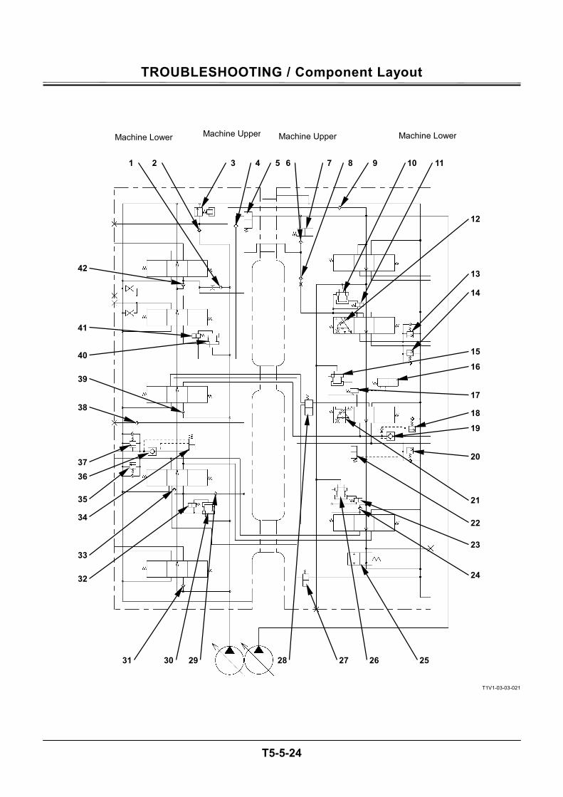
TROUBLESHOOTING / Component Layout
T5-5-24
T1V1-03-03-021
1 2 3 4 5 6 7 8 9 10 11
12
13
14
15
16
17
18
19
20
21
22
23
24
25 26272829 3031
32
33
34
35
36 37
38
39
40
41
42
Machine Lower Machine Upper Machine Lower Machine Upper
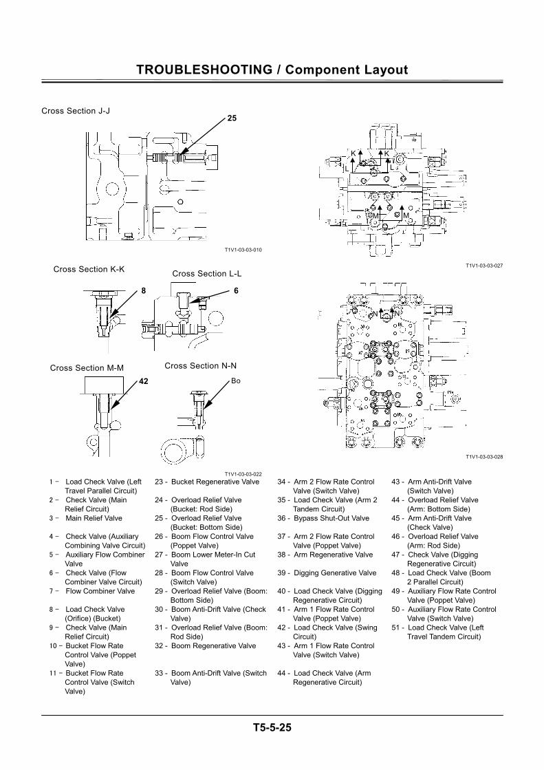
TROUBLESHOOTING / Component Layout
T5-5-25
Cross Section J-J
T1V1-03-03-010
T1V1-03-03-022
T1V1-03-03-027
T1V1-03-03-028
1 - Load Check Valve (Left
Travel Parallel Circuit) 23 - Bucket Regenerative Valve 34 - Arm 2 Flow Rate Control
Valve (Switch Valve) 43 - Arm Anti-Drift Valve
(Switch Valve) 2 - Check Valve (Main
Relief Circuit) 24 - Overload Relief Valve
(Bucket: Rod Side) 35 - Load Check Valve (Arm 2
Tandem Circuit) 44 - Overload Relief Valve
(Arm: Bottom Side) 3 - Main Relief Valve 25 - Overload Relief Valve
(Bucket: Bottom Side) 36 - Bypass Shut-Out Valve 45 - Arm Anti-Drift Valve
(Check Valve) 4 - Check Valve (Auxiliary
Combining Valve Circuit) 26 - Boom Flow Control Valve
(Poppet Valve) 37 - Arm 2 Flow Rate Control
Valve (Poppet Valve) 46 - Overload Relief Valve
(Arm: Rod Side) 5 - Auxiliary Flow Combiner
Valve 27 - Boom Lower Meter-In Cut
Valve 38 - Arm Regenerative Valve 47 - Check Valve (Digging
Regenerative Circuit) 6 - Check Valve (Flow
Combiner Valve Circuit) 28 - Boom Flow Control Valve
(Switch Valve) 39 - Digging Generative Valve 48 - Load Check Valve (Boom
2 Parallel Circuit) 7 - Flow Combiner Valve 29 - Overload Relief Valve (Boom:
Bottom Side) 40 - Load Check Valve (Digging
Regenerative Circuit) 49 - Auxiliary Flow Rate Control
Valve (Poppet Valve) 8 - Load Check Valve
(Orifice) (Bucket) 30 - Boom Anti-Drift Valve (Check
Valve) 41 - Arm 1 Flow Rate Control
Valve (Poppet Valve) 50 - Auxiliary Flow Rate Control
Valve (Switch Valve) 9 - Check Valve (Main
Relief Circuit) 31 - Overload Relief Valve (Boom:
Rod Side) 42 - Load Check Valve (Swing
Circuit) 51 - Load Check Valve (Left
Travel Tandem Circuit) 10 - Bucket Flow Rate
Control Valve (Poppet Valve)
32 - Boom Regenerative Valve 43 - Arm 1 Flow Rate Control Valve (Switch Valve)
11 - Bucket Flow Rate Control Valve (Switch Valve)
33 - Boom Anti-Drift Valve (Switch Valve)
44 - Load Check Valve (Arm Regenerative Circuit)
K K
L L
MM
25
Cross Section K-K Cross Section L-L
Cross Section M-M Cross Section N-N
8
42
6
Bo
N N
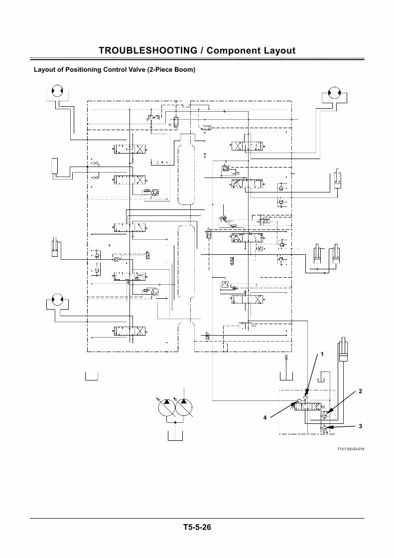
TROUBLESHOOTING / Component Layout
T5-5-26
Layout of Positioning Control Valve (2-Piece Boom)
T1V1-03-03-019
1
4
2
3
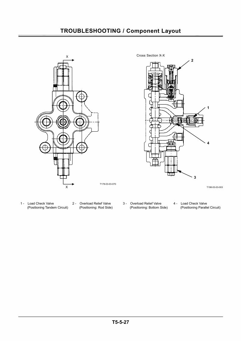
TROUBLESHOOTING / Component Layout
T5-5-27
T178-03-03-070
T198-03-03-003
1 - Load Check Valve (Positioning Tandem Circuit)
2 - Overload Relief Valve (Positioning: Rod Side)
3 - Overload Relief Valve (Positioning: Bottom Side)
4 - Load Check Valve (Positioning Parallel Circuit)
X
X
2
1
4
3
Cross Section X-X
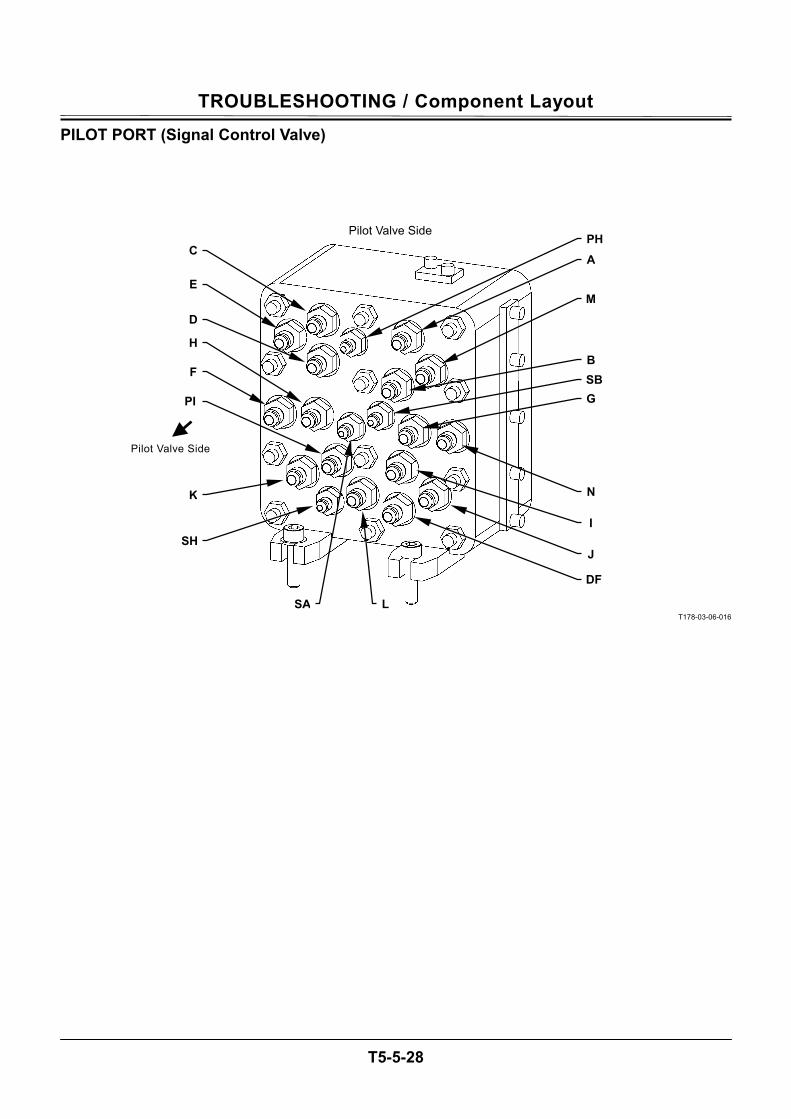
TROUBLESHOOTING / Component Layout
T5-5-28
PILOT PORT (Signal Control Valve)
T178-03-06-016
Pilot Valve Side
E
F
K
C
D
H
PI
SH
A PH
M
J
I
N
B SB
SA L
DF
G
Pilot Valve Side
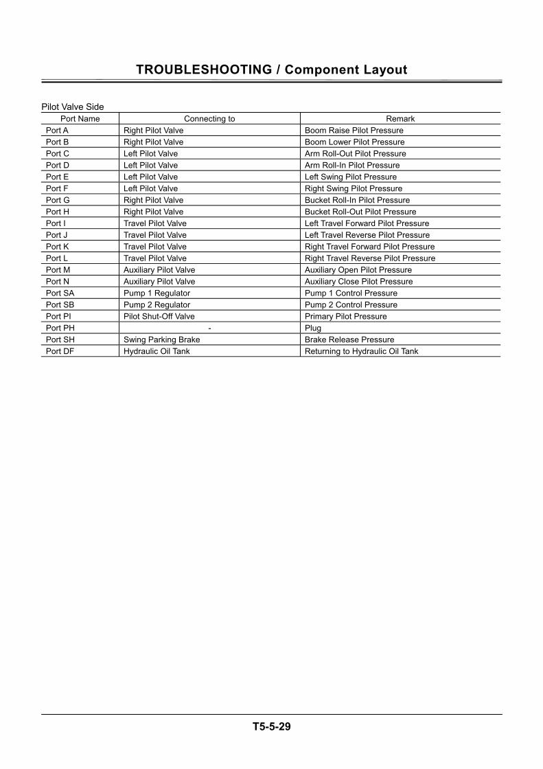
TROUBLESHOOTING / Component Layout
T5-5-29
Pilot Valve Side
Port Name Connecting to Remark Port A Right Pilot Valve Boom Raise Pilot Pressure Port B Right Pilot Valve Boom Lower Pilot Pressure Port C Left Pilot Valve Arm Roll-Out Pilot Pressure Port D Left Pilot Valve Arm Roll-In Pilot Pressure Port E Left Pilot Valve Left Swing Pilot Pressure Port F Left Pilot Valve Right Swing Pilot Pressure Port G Right Pilot Valve Bucket Roll-In Pilot Pressure Port H Right Pilot Valve Bucket Roll-Out Pilot Pressure Port I Travel Pilot Valve Left Travel Forward Pilot Pressure Port J Travel Pilot Valve Left Travel Reverse Pilot Pressure Port K Travel Pilot Valve Right Travel Forward Pilot Pressure Port L Travel Pilot Valve Right Travel Reverse Pilot Pressure Port M Auxiliary Pilot Valve Auxiliary Open Pilot Pressure Port N Auxiliary Pilot Valve Auxiliary Close Pilot Pressure Port SA Pump 1 Regulator Pump 1 Control Pressure Port SB Pump 2 Regulator Pump 2 Control Pressure Port PI Pilot Shut-Off Valve Primary Pilot Pressure Port PH - Plug Port SH Swing Parking Brake Brake Release Pressure Port DF Hydraulic Oil Tank Returning to Hydraulic Oil Tank
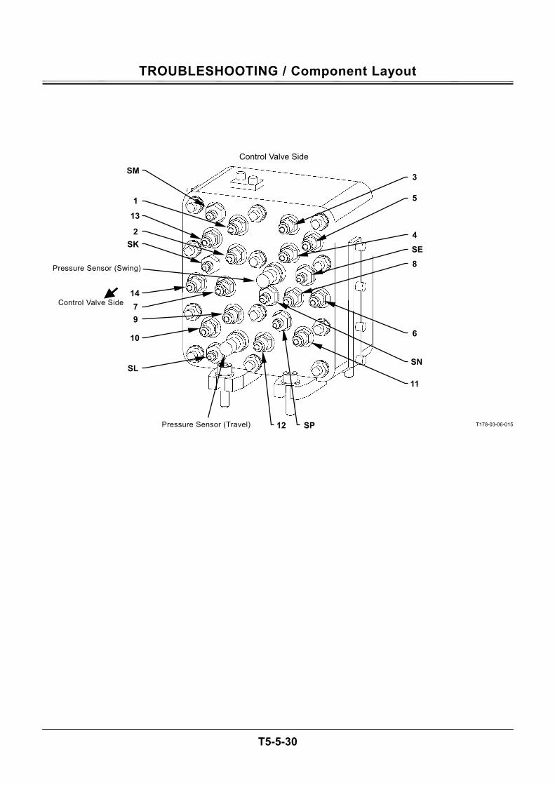
TROUBLESHOOTING / Component Layout
T5-5-30
T178-03-06-015
Control Valve Side
1
SK
14
SM
13
2
7
3
5
11
SN
6
4 SE
12
9
10
SL
8
SP
Pressure Sensor (Swing)
Pressure Sensor (Travel)
Control Valve Side
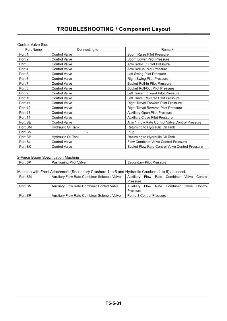
TROUBLESHOOTING / Component Layout
T5-5-31
Control Valve Side
Port Name Connecting to Remark Port 1 Control Valve Boom Raise Pilot Pressure Port 2 Control Valve Boom Lower Pilot Pressure Port 3 Control Valve Arm Roll-Out Pilot Pressure Port 4 Control Valve Arm Roll-In Pilot Pressure Port 5 Control Valve Left Swing Pilot Pressure Port 6 Control Valve Right Swing Pilot Pressure Port 7 Control Valve Bucket Roll-In Pilot Pressure Port 8 Control Valve Bucket Roll-Out Pilot Pressure Port 9 Control Valve Left Travel Forward Pilot Pressure Port 10 Control Valve Left Travel Reverse Pilot Pressure Port 11 Control Valve Right Travel Forward Pilot Pressure Port 12 Control Valve Right Travel Reverse Pilot Pressure Port 13 Control Valve Auxiliary Open Pilot Pressure Port 14 Control Valve Auxiliary Close Pilot Pressure Port SE Control Valve Arm 1 Flow Rate Control Valve Control Pressure Port SM Hydraulic Oil Tank Returning to Hydraulic Oil Tank Port SN - Plug Port SP Hydraulic Oil Tank Returning to Hydraulic Oil Tank Port SL Control Valve Flow Combiner Valve Control Pressure Port SK Control Valve Bucket Flow Rate Control Valve Control Pressure
2-Piece Boom Specification Machine Port SP Positioning Pilot Valve Secondary Pilot Pressure
Machine with Front Attachment (Secondary Crushers 1 to 5 and Hydraulic Crushers 1 to 5) attached. Port SM Auxiliary Flow Rate Combiner Solenoid Valve Auxiliary Flow Rate Combiner Valve Control
Pressure Port SN Auxiliary Flow Rate Combiner Control Valve Auxiliary Flow Rate Combiner Valve Control
Pressure Port SP Auxiliary Flow Rate Combiner Solenoid Valve Pump 1 Control Pressure

TROUBLESHOOTING / Component Layout
T5-5-32
(Blank)
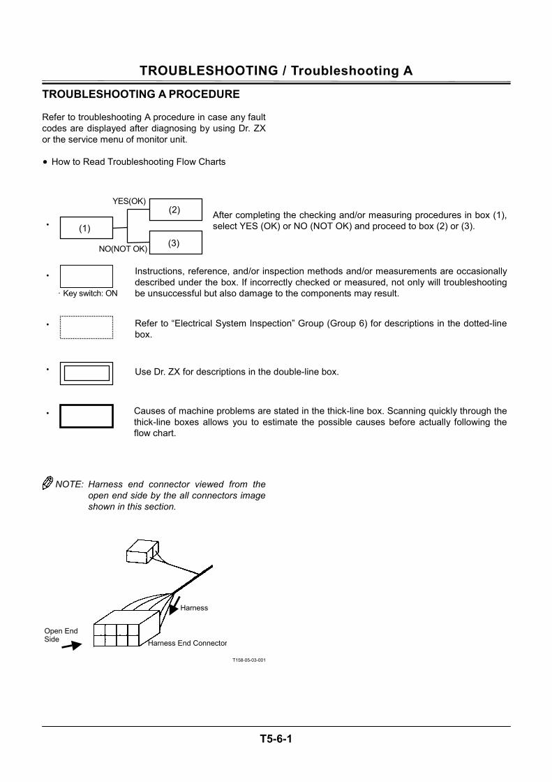
TROUBLESHOOTING / Troubleshooting A
T5-6-1
TROUBLESHOOTING A PROCEDURE Refer to troubleshooting A procedure in case any fault codes are displayed after diagnosing by using Dr. ZX or the service menu of monitor unit. • How to Read Troubleshooting Flow Charts
NOTE: Harness end connector viewed from the open end side by the all connectors image shown in this section.
T158-05-03-001
· Key switch: ON
・
・
NO(NOT OK)
YES(OK)
After completing the checking and/or measuring procedures in box (1),select YES (OK) or NO (NOT OK) and proceed to box (2) or (3).
Instructions, reference, and/or inspection methods and/or measurements are occasionallydescribed under the box. If incorrectly checked or measured, not only will troubleshootingbe unsuccessful but also damage to the components may result.
・
・
Use Dr. ZX for descriptions in the double-line box.
Causes of machine problems are stated in the thick-line box. Scanning quickly through the thick-line boxes allows you to estimate the possible causes before actually following theflow chart.
・ Refer to “Electrical System Inspection” Group (Group 6) for descriptions in the dotted-line box.
Open End Side
Harness
Harness End Connector
(1)
(2)
(3)
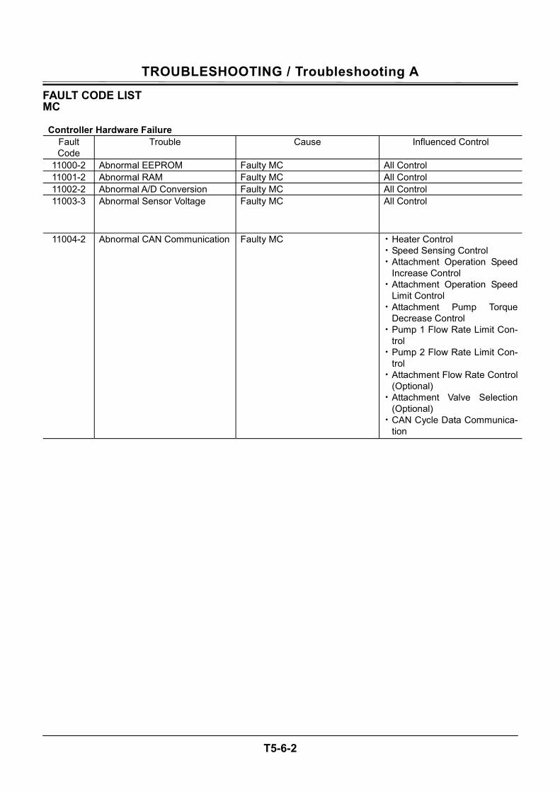
TROUBLESHOOTING / Troubleshooting A
T5-6-2
FAULT CODE LIST MC
Controller Hardware Failure Fault Code
Trouble Cause Influenced Control
11000-2 Abnormal EEPROM Faulty MC All Control 11001-2 Abnormal RAM Faulty MC All Control 11002-2 Abnormal A/D Conversion Faulty MC All Control 11003-3 Abnormal Sensor Voltage Faulty MC All Control
11004-2 Abnormal CAN Communication Faulty MC • Heater Control • Speed Sensing Control • Attachment Operation Speed
Increase Control • Attachment Operation Speed
Limit Control • Attachment Pump Torque
Decrease Control • Pump 1 Flow Rate Limit Con-
trol • Pump 2 Flow Rate Limit Con-
trol • Attachment Flow Rate Control
(Optional) • Attachment Valve Selection
(Optional) • CAN Cycle Data Communica-
tion
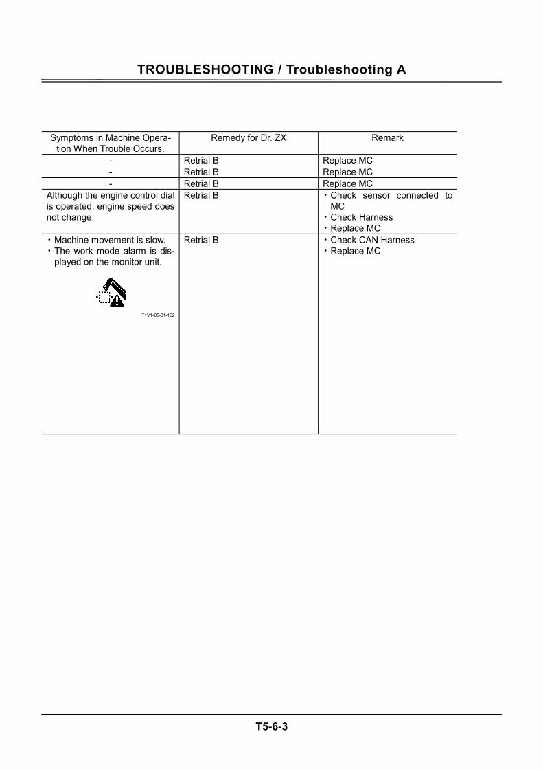
TROUBLESHOOTING / Troubleshooting A
T5-6-3
Symptoms in Machine Opera-
tion When Trouble Occurs. Remedy for Dr. ZX Remark
- Retrial B Replace MC - Retrial B Replace MC - Retrial B Replace MC
Although the engine control dial is operated, engine speed does not change.
Retrial B • Check sensor connected to MC
• Check Harness • Replace MC
• Machine movement is slow. • The work mode alarm is dis-
played on the monitor unit.
T1V1-05-01-102
Retrial B • Check CAN Harness • Replace MC
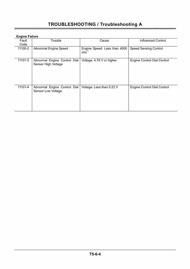
TROUBLESHOOTING / Troubleshooting A
T5-6-4
Engine Failure
Fault Code
Trouble Cause Influenced Control
11100-2
Abnormal Engine Speed Engine Speed: Less than 4000 min-1
Speed Sensing Control
11101-3 Abnormal Engine Control Dial Sensor High Voltage
Voltage: 4.78 V or higher Engine Control Dial Control
11101-4 Abnormal Engine Control Dial Sensor Low Voltage
Voltage: Less than 0.22 V Engine Control Dial Control
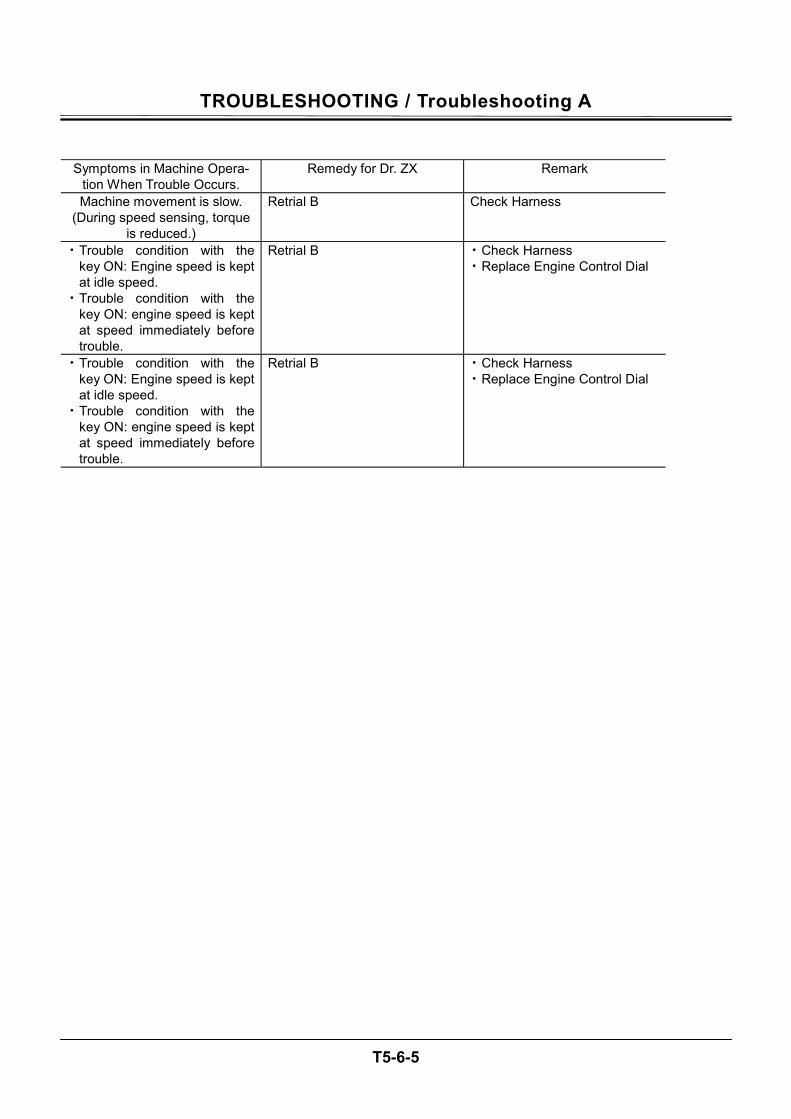
TROUBLESHOOTING / Troubleshooting A
T5-6-5
Symptoms in Machine Opera-tion When Trouble Occurs.
Remedy for Dr. ZX Remark
Machine movement is slow. (During speed sensing, torque
is reduced.)
Retrial B Check Harness
• Trouble condition with the key ON: Engine speed is kept at idle speed.
• Trouble condition with the key ON: engine speed is kept at speed immediately before trouble.
Retrial B • Check Harness • Replace Engine Control Dial
• Trouble condition with the key ON: Engine speed is kept at idle speed.
• Trouble condition with the key ON: engine speed is kept at speed immediately before trouble.
Retrial B • Check Harness • Replace Engine Control Dial
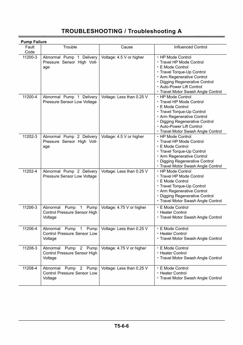
TROUBLESHOOTING / Troubleshooting A
T5-6-6
Pump Failure Fault Code
Trouble Cause Influenced Control
11200-3 Abnormal Pump 1 Delivery Pressure Sensor High Volt-age
Voltage: 4.5 V or higher • HP Mode Control • Travel HP Mode Control • E Mode Control • Travel Torque-Up Control • Arm Regenerative Control • Digging Regenerative Control • Auto-Power Lift Control • Travel Motor Swash Angle Control
11200-4 Abnormal Pump 1 Delivery Pressure Sensor Low Voltage
Voltage: Less than 0.25 V • HP Mode Control • Travel HP Mode Control • E Mode Control • Travel Torque-Up Control • Arm Regenerative Control • Digging Regenerative Control • Auto-Power Lift Control • Travel Motor Swash Angle Control
11202-3 Abnormal Pump 2 Delivery Pressure Sensor High Volt-age
Voltage: 4.5 V or higher • HP Mode Control • Travel HP Mode Control • E Mode Control • Travel Torque-Up Control • Arm Regenerative Control • Digging Regenerative Control • Travel Motor Swash Angle Control
11202-4 Abnormal Pump 2 Delivery Pressure Sensor Low Voltage
Voltage: Less than 0.25 V • HP Mode Control • Travel HP Mode Control • E Mode Control • Travel Torque-Up Control • Arm Regenerative Control • Digging Regenerative Control • Travel Motor Swash Angle Control
11206-3 Abnormal Pump 1 Pump Control Pressure Sensor High Voltage
Voltage: 4.75 V or higher • E Mode Control • Heater Control • Travel Motor Swash Angle Control
11206-4 Abnormal Pump 1 Pump Control Pressure Sensor Low Voltage
Voltage: Less than 0.25 V • E Mode Control • Heater Control • Travel Motor Swash Angle Control
11208-3 Abnormal Pump 2 Pump Control Pressure Sensor High Voltage
Voltage: 4.75 V or higher • E Mode Control • Heater Control • Travel Motor Swash Angle Control
11208-4 Abnormal Pump 2 Pump Control Pressure Sensor Low Voltage
Voltage: Less than 0.25 V • E Mode Control • Heater Control • Travel Motor Swash Angle Control
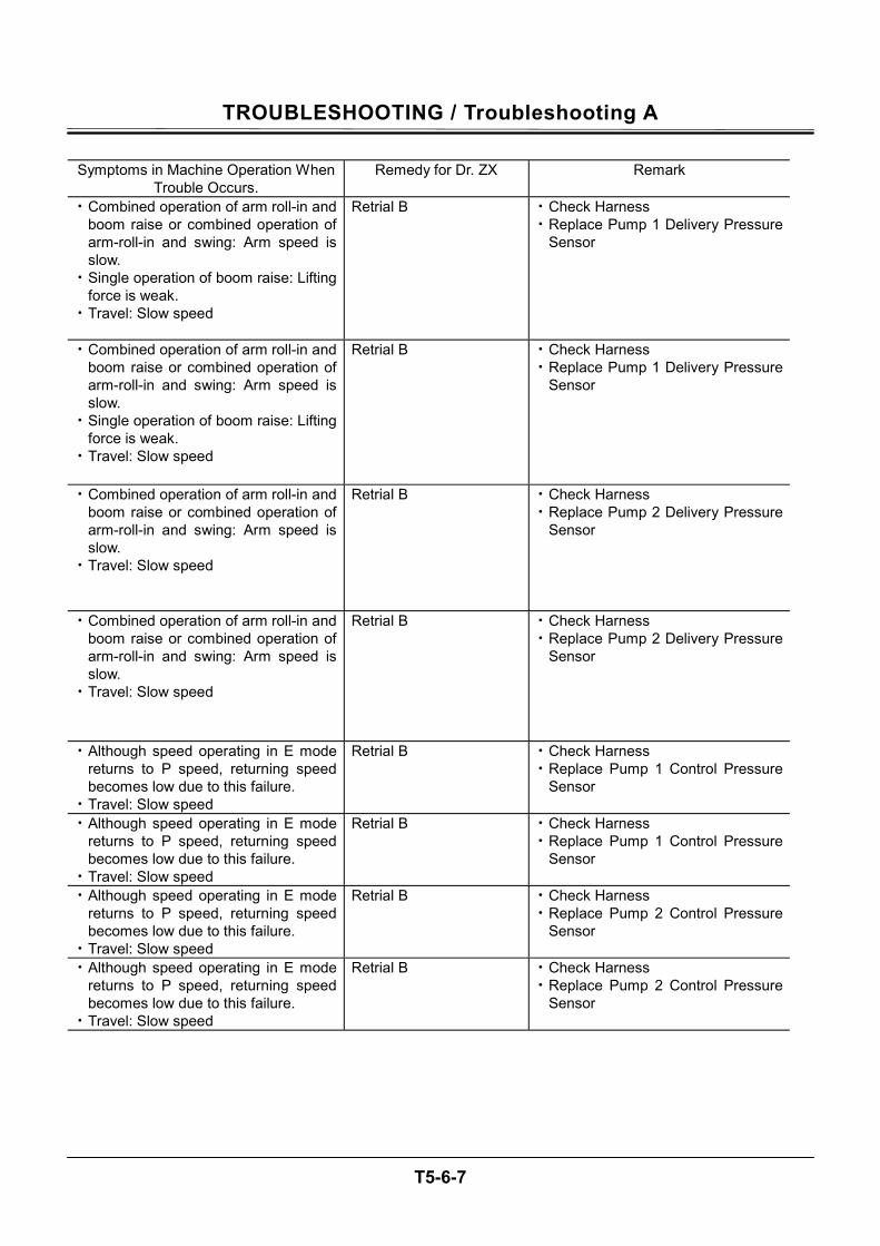
TROUBLESHOOTING / Troubleshooting A
T5-6-7
Symptoms in Machine Operation When
Trouble Occurs. Remedy for Dr. ZX Remark
• Combined operation of arm roll-in and boom raise or combined operation of arm-roll-in and swing: Arm speed is slow.
• Single operation of boom raise: Lifting force is weak.
• Travel: Slow speed
Retrial B • Check Harness • Replace Pump 1 Delivery Pressure
Sensor
• Combined operation of arm roll-in and boom raise or combined operation of arm-roll-in and swing: Arm speed is slow.
• Single operation of boom raise: Lifting force is weak.
• Travel: Slow speed
Retrial B • Check Harness • Replace Pump 1 Delivery Pressure
Sensor
• Combined operation of arm roll-in and boom raise or combined operation of arm-roll-in and swing: Arm speed is slow.
• Travel: Slow speed
Retrial B • Check Harness • Replace Pump 2 Delivery Pressure
Sensor
• Combined operation of arm roll-in and boom raise or combined operation of arm-roll-in and swing: Arm speed is slow.
• Travel: Slow speed
Retrial B • Check Harness • Replace Pump 2 Delivery Pressure
Sensor
• Although speed operating in E mode returns to P speed, returning speed becomes low due to this failure.
• Travel: Slow speed
Retrial B • Check Harness • Replace Pump 1 Control Pressure
Sensor
• Although speed operating in E mode returns to P speed, returning speed becomes low due to this failure.
• Travel: Slow speed
Retrial B • Check Harness • Replace Pump 1 Control Pressure
Sensor
• Although speed operating in E mode returns to P speed, returning speed becomes low due to this failure.
• Travel: Slow speed
Retrial B • Check Harness • Replace Pump 2 Control Pressure
Sensor
• Although speed operating in E mode returns to P speed, returning speed becomes low due to this failure.
• Travel: Slow speed
Retrial B • Check Harness • Replace Pump 2 Control Pressure
Sensor
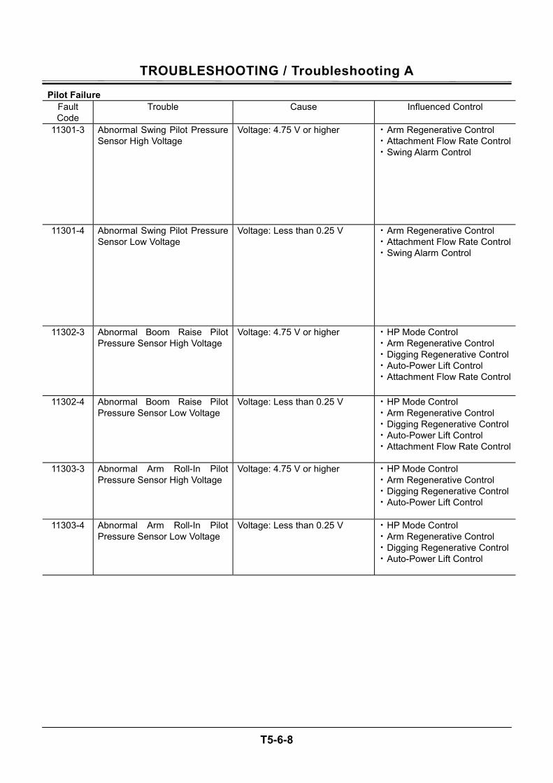
TROUBLESHOOTING / Troubleshooting A
T5-6-8
Pilot Failure Fault Code
Trouble Cause Influenced Control
11301-3 Abnormal Swing Pilot Pressure Sensor High Voltage
Voltage: 4.75 V or higher • Arm Regenerative Control • Attachment Flow Rate Control• Swing Alarm Control
11301-4 Abnormal Swing Pilot Pressure Sensor Low Voltage
Voltage: Less than 0.25 V • Arm Regenerative Control • Attachment Flow Rate Control• Swing Alarm Control
11302-3 Abnormal Boom Raise Pilot Pressure Sensor High Voltage
Voltage: 4.75 V or higher • HP Mode Control • Arm Regenerative Control • Digging Regenerative Control• Auto-Power Lift Control • Attachment Flow Rate Control
11302-4 Abnormal Boom Raise Pilot Pressure Sensor Low Voltage
Voltage: Less than 0.25 V • HP Mode Control • Arm Regenerative Control • Digging Regenerative Control• Auto-Power Lift Control • Attachment Flow Rate Control
11303-3 Abnormal Arm Roll-In Pilot Pressure Sensor High Voltage
Voltage: 4.75 V or higher • HP Mode Control • Arm Regenerative Control • Digging Regenerative Control• Auto-Power Lift Control
11303-4 Abnormal Arm Roll-In Pilot Pressure Sensor Low Voltage
Voltage: Less than 0.25 V • HP Mode Control • Arm Regenerative Control • Digging Regenerative Control• Auto-Power Lift Control
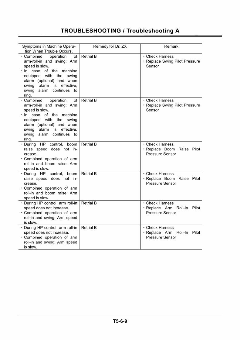
TROUBLESHOOTING / Troubleshooting A
T5-6-9
Symptoms in Machine Opera-
tion When Trouble Occurs. Remedy for Dr. ZX Remark
• Combined operation of arm-roll-in and swing: Arm speed is slow.
• In case of the machine equipped with the swing alarm (optional) and when swing alarm is effective, swing alarm continues to ring.
Retrial B • Check Harness • Replace Swing Pilot Pressure
Sensor
• Combined operation of arm-roll-in and swing: Arm speed is slow.
• In case of the machine equipped with the swing alarm (optional) and when swing alarm is effective, swing alarm continues to ring.
Retrial B • Check Harness • Replace Swing Pilot Pressure
Sensor
• During HP control, boom raise speed does not in-crease.
• Combined operation of arm roll-in and boom raise: Arm speed is slow.
Retrial B • Check Harness • Replace Boom Raise Pilot
Pressure Sensor
• During HP control, boom raise speed does not in-crease.
• Combined operation of arm roll-in and boom raise: Arm speed is slow.
Retrial B • Check Harness • Replace Boom Raise Pilot
Pressure Sensor
• During HP control, arm roll-in speed does not increase.
• Combined operation of arm roll-in and swing: Arm speed is slow.
Retrial B • Check Harness • Replace Arm Roll-In Pilot
Pressure Sensor
• During HP control, arm roll-in speed does not increase.
• Combined operation of arm roll-in and swing: Arm speed is slow.
Retrial B • Check Harness • Replace Arm Roll-In Pilot
Pressure Sensor
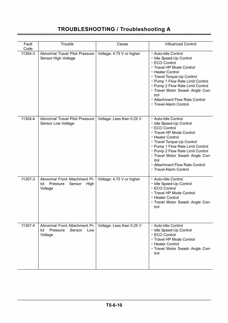
TROUBLESHOOTING / Troubleshooting A
T5-6-10
Fault Code
Trouble Cause Influenced Control
11304-3 Abnormal Travel Pilot Pressure Sensor High Voltage
Voltage: 4.75 V or higher • Auto-Idle Control • Idle Speed-Up Control • ECO Control • Travel HP Mode Control • Heater Control • Travel Torque-Up Control • Pump 1 Flow Rate Limit Control • Pump 2 Flow Rate Limit Control • Travel Motor Swash Angle Con-
trol • Attachment Flow Rate Control • Travel Alarm Control
11304-4 Abnormal Travel Pilot Pressure Sensor Low Voltage
Voltage: Less than 0.25 V • Auto-Idle Control • Idle Speed-Up Control • ECO Control • Travel HP Mode Control • Heater Control • Travel Torque-Up Control • Pump 1 Flow Rate Limit Control • Pump 2 Flow Rate Limit Control • Travel Motor Swash Angle Con-
trol • Attachment Flow Rate Control • Travel Alarm Control
11307-3 Abnormal Front Attachment Pi-lot Pressure Sensor High Voltage
Voltage: 4.75 V or higher • Auto-Idle Control • Idle Speed-Up Control • ECO Control • Travel HP Mode Control • Heater Control • Travel Motor Swash Angle Con-
trol
11307-4 Abnormal Front Attachment Pi-lot Pressure Sensor Low Voltage
Voltage: Less than 0.25 V • Auto-Idle Control • Idle Speed-Up Control • ECO Control • Travel HP Mode Control • Heater Control • Travel Motor Swash Angle Con-
trol
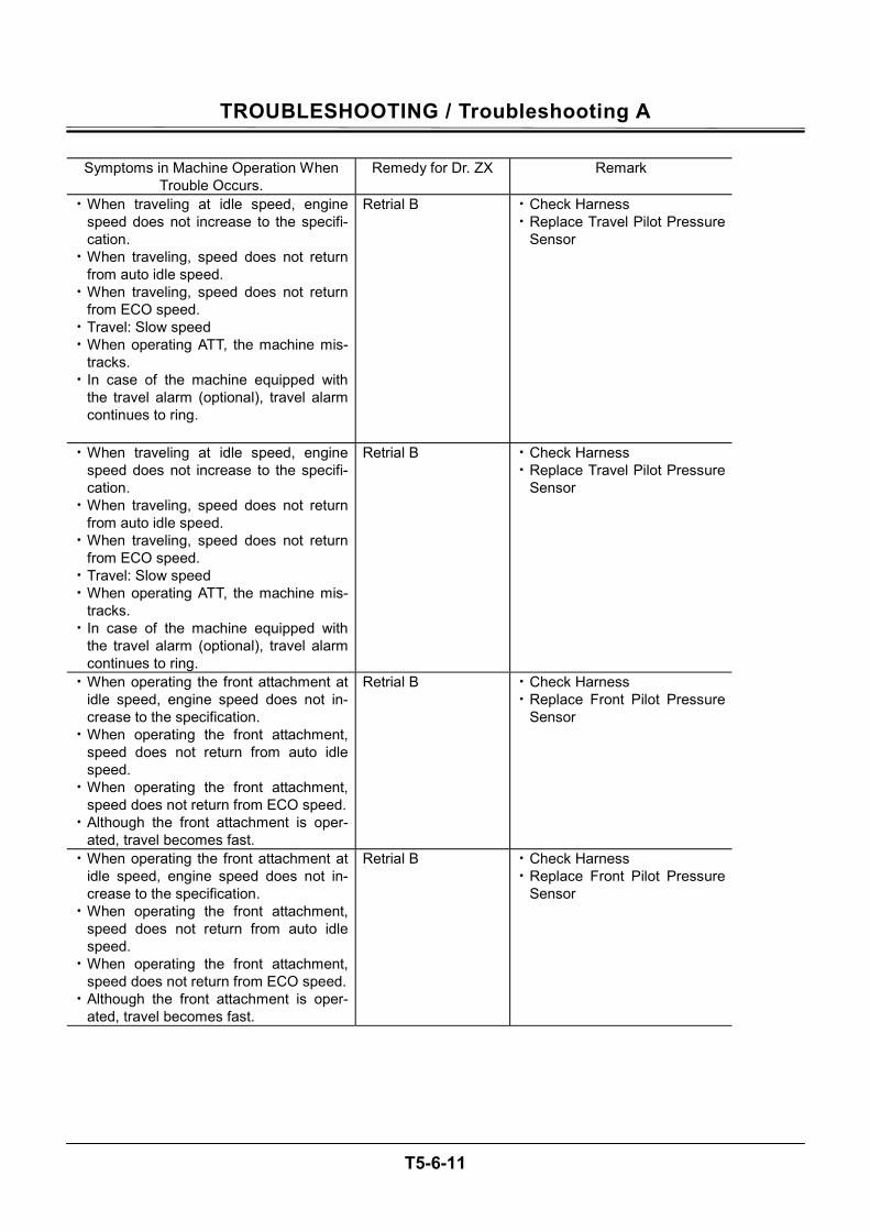
TROUBLESHOOTING / Troubleshooting A
T5-6-11
Symptoms in Machine Operation When
Trouble Occurs. Remedy for Dr. ZX Remark
• When traveling at idle speed, engine speed does not increase to the specifi-cation.
• When traveling, speed does not return from auto idle speed.
• When traveling, speed does not return from ECO speed.
• Travel: Slow speed • When operating ATT, the machine mis-
tracks. • In case of the machine equipped with
the travel alarm (optional), travel alarm continues to ring.
Retrial B • Check Harness • Replace Travel Pilot Pressure
Sensor
• When operating the front attachment at idle speed, engine speed does not in-crease to the specification.
• When operating the front attachment, speed does not return from auto idle speed.
• When operating the front attachment, speed does not return from ECO speed.
• Although the front attachment is oper-ated, travel becomes fast.
Retrial B • Check Harness • Replace Front Pilot Pressure
Sensor
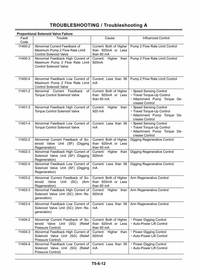
TROUBLESHOOTING / Troubleshooting A
T5-6-12
Proportional Solenoid Valve Failure Fault Code
Trouble Cause Influenced Control
11400-2 Abnormal Current Feedback of Maximum Pump 2 Flow Rate Limit Control Solenoid Valve
Current: Both of Higher than 920mA or Less than 60 mA
Pump 2 Flow Rate Limit Control
11400-3 Abnormal Feedback High Current of Maximum Pump 2 Flow Rate Limit Control Solenoid Valve
Current: Higher than 920mA
Pump 2 Flow Rate Limit Control
11400-4 Abnormal Feedback Low Current of Maximum Pump 2 Flow Rate Limit Control Solenoid Valve
Current: Less than 56 mA
Pump 2 Flow Rate Limit Control
11401-2 Abnormal Current Feedback of Torque Control Solenoid Valve
Current: Both of Higher than 920mA or Less than 60 mA
• Speed Sensing Control • Travel Torque-Up Control • Attachment Pump Torque De-
crease Control 11401-3 Abnormal Feedback High Current of
Torque Control Solenoid Valve Current: Higher than 920 mA
• Speed Sensing Control • Travel Torque-Up Control • Attachment Pump Torque De-
crease Control 11401-4 Abnormal Feedback Low Current of
Torque Control Solenoid Valve Current: Less than 56 mA
• Speed Sensing Control • Travel Torque-Up Control • Attachment Pump Torque De-
crease Control 11402-2 Abnormal Current Feedback of So-
lenoid Valve Unit (SF) (Digging Regeneration)
Current: Both of Higher than 920mA or Less than 60 mA
Digging Regenerative Control
11402-3 Abnormal Feedback High Current of Solenoid Valve Unit (SF) (Digging Regeneration)
Current: Higher than 920mA
Digging Regenerative Control
11402-4 Abnormal Feedback Low Current of Solenoid Valve Unit (SF) (Digging Regeneration)
Current: Less than 56 mA
Digging Regenerative Control
11403-2 Abnormal Current Feedback of So-lenoid Valve Unit (SC) (Arm Regeneration)
Current: Both of Higher than 920mA or Less than 60 mA
Arm Regenerative Control
11403-3 Abnormal Feedback High Current of Solenoid Valve Unit (SC) (Arm Re-generation)
Current: Higher than 920mA
Arm Regenerative Control
11403-4 Abnormal Feedback Low Current of Solenoid Valve Unit (SC) (Arm Re-generation)
Current: Less than 56 mA
Arm Regenerative Control
11404-2 Abnormal Current Feedback of So-lenoid Valve Unit (SG) (Relief Pressure Control)
Current: Both of Higher than 920mA or Less than 60 mA
• Power Digging Control • Auto-Power Lift Control
11404-3 Abnormal Feedback High Current of Solenoid Valve Unit (SG) (Relief Pressure Control)
Current: Higher than 920mA
• Power Digging Control • Auto-Power Lift Control
11404-4 Abnormal Feedback Low Current of Solenoid Valve Unit (SG) (Relief Pressure Control)
Current: Less than 56 mA
• Power Digging Control • Auto-Power Lift Control
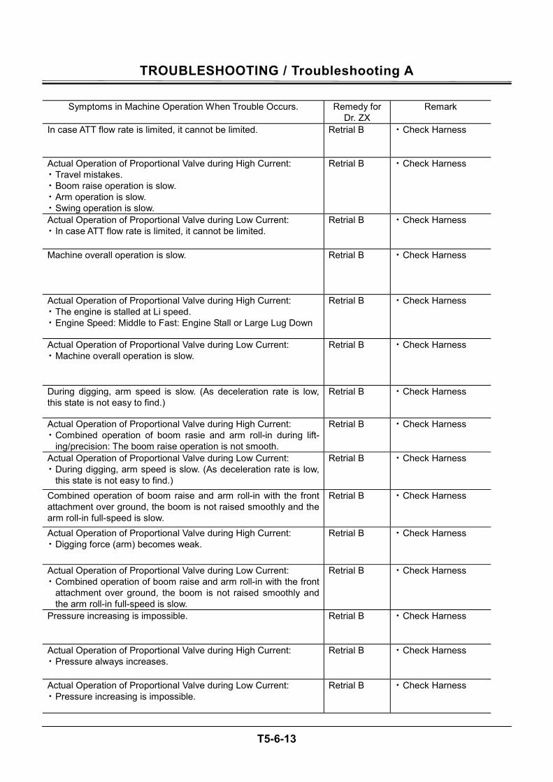
TROUBLESHOOTING / Troubleshooting A
T5-6-13
Symptoms in Machine Operation When Trouble Occurs. Remedy for
Dr. ZX Remark
In case ATT flow rate is limited, it cannot be limited. Retrial B • Check Harness
Actual Operation of Proportional Valve during High Current: • Travel mistakes. • Boom raise operation is slow. • Arm operation is slow. • Swing operation is slow.
Retrial B • Check Harness
Actual Operation of Proportional Valve during Low Current: • In case ATT flow rate is limited, it cannot be limited.
Retrial B • Check Harness
Machine overall operation is slow. Retrial B • Check Harness
Actual Operation of Proportional Valve during High Current: • The engine is stalled at Li speed. • Engine Speed: Middle to Fast: Engine Stall or Large Lug Down
Retrial B • Check Harness
Actual Operation of Proportional Valve during Low Current: • Machine overall operation is slow.
Retrial B • Check Harness
During digging, arm speed is slow. (As deceleration rate is low, this state is not easy to find.)
Retrial B • Check Harness
Actual Operation of Proportional Valve during High Current: • Combined operation of boom rasie and arm roll-in during lift-
ing/precision: The boom raise operation is not smooth.
Retrial B • Check Harness
Actual Operation of Proportional Valve during Low Current: • During digging, arm speed is slow. (As deceleration rate is low,
this state is not easy to find.)
Retrial B • Check Harness
Combined operation of boom raise and arm roll-in with the front attachment over ground, the boom is not raised smoothly and the arm roll-in full-speed is slow.
Retrial B • Check Harness
Actual Operation of Proportional Valve during High Current: • Digging force (arm) becomes weak.
Retrial B • Check Harness
Actual Operation of Proportional Valve during Low Current: • Combined operation of boom raise and arm roll-in with the front
attachment over ground, the boom is not raised smoothly and the arm roll-in full-speed is slow.
Retrial B • Check Harness
Pressure increasing is impossible. Retrial B • Check Harness
Actual Operation of Proportional Valve during High Current: • Pressure always increases.
Retrial B • Check Harness
Actual Operation of Proportional Valve during Low Current: • Pressure increasing is impossible.
Retrial B • Check Harness
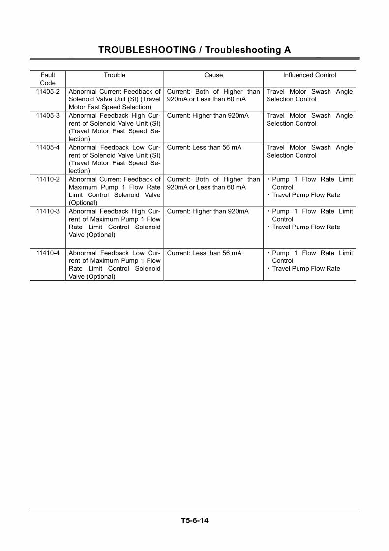
TROUBLESHOOTING / Troubleshooting A
T5-6-14
Fault Code
Trouble Cause Influenced Control
11405-2 Abnormal Current Feedback of Solenoid Valve Unit (SI) (Travel Motor Fast Speed Selection)
Current: Both of Higher than 920mA or Less than 60 mA
Travel Motor Swash Angle Selection Control
11405-3 Abnormal Feedback High Cur-rent of Solenoid Valve Unit (SI) (Travel Motor Fast Speed Se-lection)
Current: Higher than 920mA Travel Motor Swash Angle Selection Control
11405-4 Abnormal Feedback Low Cur-rent of Solenoid Valve Unit (SI) (Travel Motor Fast Speed Se-lection)
Current: Less than 56 mA Travel Motor Swash Angle Selection Control
11410-2 Abnormal Current Feedback of Maximum Pump 1 Flow Rate Limit Control Solenoid Valve (Optional)
Current: Both of Higher than 920mA or Less than 60 mA
• Pump 1 Flow Rate Limit Control
• Travel Pump Flow Rate
11410-3 Abnormal Feedback High Cur-rent of Maximum Pump 1 Flow Rate Limit Control Solenoid Valve (Optional)
Current: Higher than 920mA • Pump 1 Flow Rate Limit Control
• Travel Pump Flow Rate
11410-4 Abnormal Feedback Low Cur-rent of Maximum Pump 1 Flow Rate Limit Control Solenoid Valve (Optional)
Current: Less than 56 mA • Pump 1 Flow Rate Limit Control
• Travel Pump Flow Rate
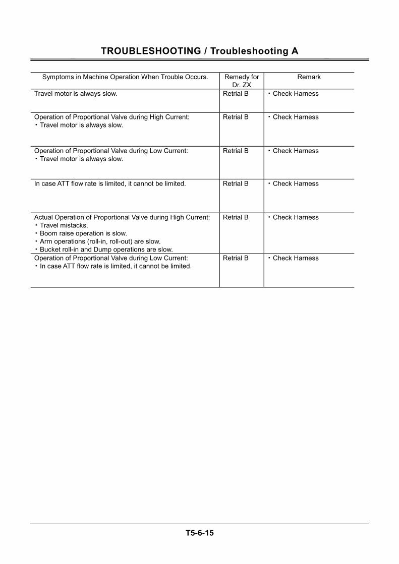
TROUBLESHOOTING / Troubleshooting A
T5-6-15
Symptoms in Machine Operation When Trouble Occurs. Remedy for
Dr. ZX Remark
Travel motor is always slow. Retrial B • Check Harness
Operation of Proportional Valve during High Current: • Travel motor is always slow.
Retrial B • Check Harness
Operation of Proportional Valve during Low Current: • Travel motor is always slow.
Retrial B • Check Harness
In case ATT flow rate is limited, it cannot be limited. Retrial B • Check Harness
Actual Operation of Proportional Valve during High Current: • Travel mistacks. • Boom raise operation is slow. • Arm operations (roll-in, roll-out) are slow. • Bucket roll-in and Dump operations are slow.
Retrial B • Check Harness
Operation of Proportional Valve during Low Current: • In case ATT flow rate is limited, it cannot be limited.
Retrial B • Check Harness
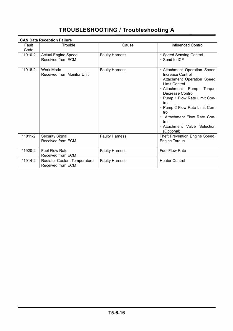
TROUBLESHOOTING / Troubleshooting A
T5-6-16
CAN Data Reception Failure Fault Code
Trouble Cause Influenced Control
11910-2 Actual Engine Speed Received from ECM
Faulty Harness • Speed Sensing Control • Send to ICF
11918-2 Work Mode Received from Monitor Unit
Faulty Harness • Attachment Operation Speed Increase Control
• Attachment Operation Speed Limit Control
• Attachment Pump Torque Decrease Control
• Pump 1 Flow Rate Limit Con-trol
• Pump 2 Flow Rate Limit Con-trol
• Attachment Flow Rate Con-trol
• Attachment Valve Selection (Optional)
11911-2 Security Signal Received from ECM
Faulty Harness Theft Prevention Engine Speed, Engine Torque
11920-2 Fuel Flow Rate Received from ECM
Faulty Harness Fuel Flow Rate
11914-2 Radiator Coolant Temperature Received from ECM
Faulty Harness Heater Control
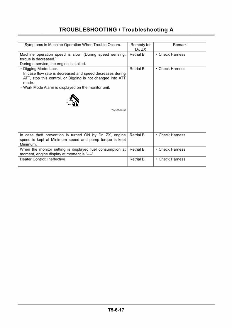
TROUBLESHOOTING / Troubleshooting A
T5-6-17
Symptoms in Machine Operation When Trouble Occurs. Remedy for
Dr. ZX Remark
Machine operation speed is slow. (During speed sensing, torque is decreased.) During e-service, the engine is stalled.
Retrial B • Check Harness
• Digging Mode: Lock In case flow rate is decreased and speed decreases during ATT, stop this control, or Digging is not changed into ATT mode.
• Work Mode Alarm is displayed on the monitor unit.
T1V1-05-01-102
Retrial B • Check Harness
In case theft prevention is turned ON by Dr. ZX, engine speed is kept at Minimum speed and pump torque is kept Minimum.
Retrial B • Check Harness
When the monitor setting is displayed fuel consumption at moment, engine display at moment is “----“.
Retrial B • Check Harness
Heater Control: Ineffective Retrial B • Check Harness
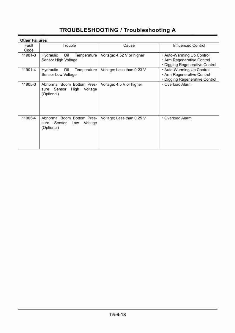
TROUBLESHOOTING / Troubleshooting A
T5-6-18
Other Failures Fault Code
Trouble Cause Influenced Control
11901-3 Hydraulic Oil Temperature Sensor High Voltage
Voltage: 4.52 V or higher • Auto-Warming Up Control • Arm Regenerative Control • Digging Regenerative Control
11901-4 Hydraulic Oil Temperature Sensor Low Voltage
Voltage: Less than 0.23 V • Auto-Warming Up Control • Arm Regenerative Control • Digging Regenerative Control
11905-3 Abnormal Boom Bottom Pres-sure Sensor High Voltage (Optional)
Voltage: 4.5 V or higher • Overload Alarm
11905-4 Abnormal Boom Bottom Pres-sure Sensor Low Voltage (Optional)
Voltage: Less than 0.25 V • Overload Alarm
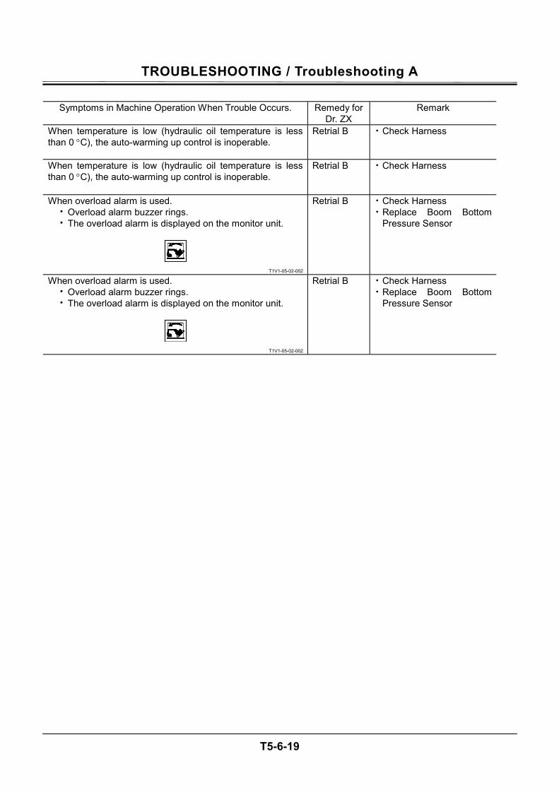
TROUBLESHOOTING / Troubleshooting A
T5-6-19
Symptoms in Machine Operation When Trouble Occurs. Remedy for
Dr. ZX Remark
When temperature is low (hydraulic oil temperature is less than 0 °C), the auto-warming up control is inoperable.
Retrial B • Check Harness
When temperature is low (hydraulic oil temperature is less than 0 °C), the auto-warming up control is inoperable.
Retrial B • Check Harness
When overload alarm is used. • Overload alarm buzzer rings. • The overload alarm is displayed on the monitor unit.
T1V1-05-02-002
Retrial B • Check Harness • Replace Boom Bottom
Pressure Sensor
When overload alarm is used. • Overload alarm buzzer rings. • The overload alarm is displayed on the monitor unit.
T1V1-05-02-002
Retrial B • Check Harness • Replace Boom Bottom
Pressure Sensor
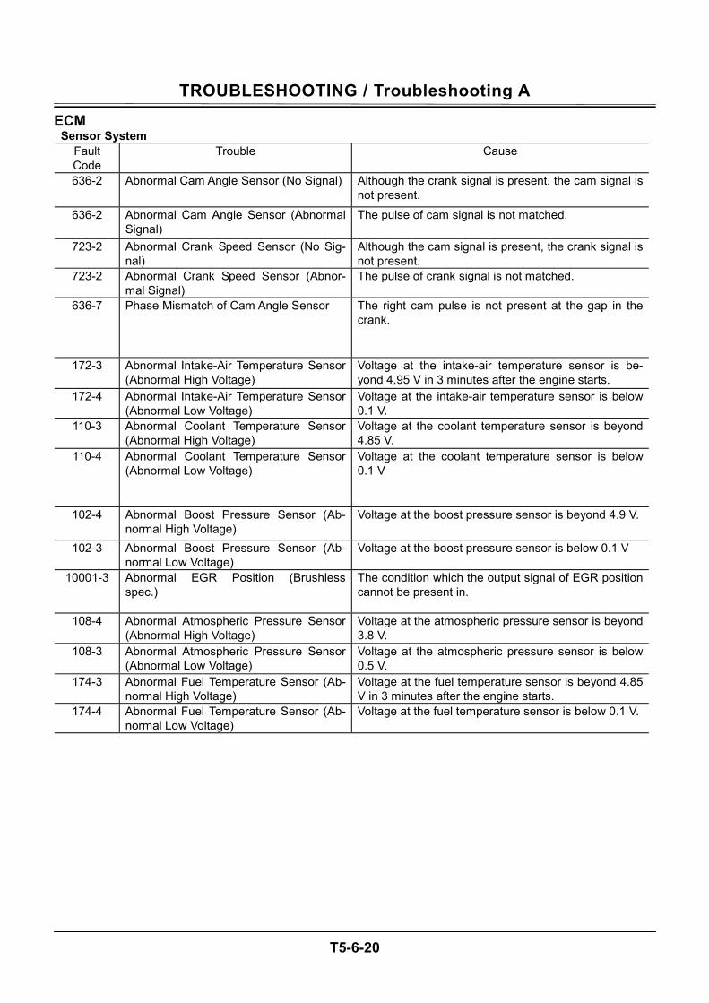
TROUBLESHOOTING / Troubleshooting A
T5-6-20
ECM Sensor System
Fault Code
Trouble Cause
636-2 Abnormal Cam Angle Sensor (No Signal) Although the crank signal is present, the cam signal is not present.
636-2 Abnormal Cam Angle Sensor (Abnormal Signal)
The pulse of cam signal is not matched.
723-2 Abnormal Crank Speed Sensor (No Sig-nal)
Although the cam signal is present, the crank signal is not present.
723-2 Abnormal Crank Speed Sensor (Abnor-mal Signal)
The pulse of crank signal is not matched.
636-7 Phase Mismatch of Cam Angle Sensor The right cam pulse is not present at the gap in the crank.
172-3 Abnormal Intake-Air Temperature Sensor (Abnormal High Voltage)
Voltage at the intake-air temperature sensor is be-yond 4.95 V in 3 minutes after the engine starts.
172-4 Abnormal Intake-Air Temperature Sensor (Abnormal Low Voltage)
Voltage at the intake-air temperature sensor is below 0.1 V.
110-3 Abnormal Coolant Temperature Sensor (Abnormal High Voltage)
Voltage at the coolant temperature sensor is beyond 4.85 V.
110-4 Abnormal Coolant Temperature Sensor (Abnormal Low Voltage)
Voltage at the coolant temperature sensor is below 0.1 V
102-4 Abnormal Boost Pressure Sensor (Ab-normal High Voltage)
Voltage at the boost pressure sensor is beyond 4.9 V.
102-3 Abnormal Boost Pressure Sensor (Ab-normal Low Voltage)
Voltage at the boost pressure sensor is below 0.1 V
10001-3 Abnormal EGR Position (Brushless spec.)
The condition which the output signal of EGR position cannot be present in.
108-4 Abnormal Atmospheric Pressure Sensor (Abnormal High Voltage)
Voltage at the atmospheric pressure sensor is beyond 3.8 V.
108-3 Abnormal Atmospheric Pressure Sensor (Abnormal Low Voltage)
Voltage at the atmospheric pressure sensor is below 0.5 V.
174-3 Abnormal Fuel Temperature Sensor (Ab-normal High Voltage)
Voltage at the fuel temperature sensor is beyond 4.85 V in 3 minutes after the engine starts.
174-4 Abnormal Fuel Temperature Sensor (Ab-normal Low Voltage)
Voltage at the fuel temperature sensor is below 0.1 V.
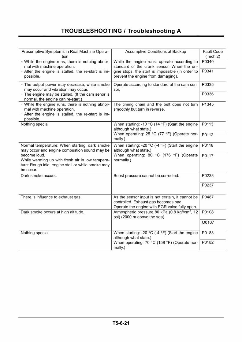
TROUBLESHOOTING / Troubleshooting A
T5-6-21
Presumptive Symptoms in Real Machine Opera-tion
Assumptive Conditions at Backup Fault Code (Tech 2)
P0340 • While the engine runs, there is nothing abnor-mal with machine operation.
• After the engine is stalled, the re-start is im-possible.
While the engine runs, operate according to standard of the crank sensor. When the en-gine stops, the start is impossible (in order to prevent the engine from damaging).
P0341
P0335 • The output power may decrease, white smoke may occur and vibration may occur.
• The engine may be stalled. (If the cam senor is normal, the engine can re-start.)
Operate according to standard of the cam sen-sor.
P0336
• While the engine runs, there is nothing abnor-mal with machine operation.
• After the engine is stalled, the re-start is im-possible.
The timing chain and the belt does not turn smoothly but turn in reverse.
P1345
P0113 Nothing special When starting: -10 °C (14 °F) (Start the engine although what state.) When operating: 25 °C (77 °F) (Operate nor-mally.)
P0112
P0118 Normal temperature: When starting, dark smoke may occur and engine combustion sound may be become loud. While warming up with fresh air in low tempera-ture: Rough idle, engine stall or while smoke may be occur.
When starting: -20 °C (-4 °F) (Start the engine although what state.) When operating: 80 °C (176 °F) (Operate normally.)
P0117
P0238 Dark smoke occurs. Boost pressure cannot be corrected.
P0237
There is influence to exhaust gas. As the sensor input is not certain, it cannot be controlled. Exhaust gas becomes bad. Operate the engine with EGR valve fully open.
P0487
P0108 Dark smoke occurs at high altitude. Atmospheric pressure 80 kPa (0.8 kgf/cm2, 12 psi) (2000 m above the sea)
O0107
P0183 Nothing special When starting: -20 °C (-4 °F) (Start the engine although what state.) When operating: 70 °C (158 °F) (Operate nor-mally.)
P0182
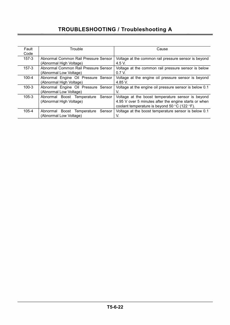
TROUBLESHOOTING / Troubleshooting A
T5-6-22
Fault Code
Trouble Cause
157-3 Abnormal Common Rail Pressure Sensor (Abnormal High Voltage)
Voltage at the common rail pressure sensor is beyond 4.5 V.
157-3 Abnormal Common Rail Pressure Sensor (Abnormal Low Voltage)
Voltage at the common rail pressure sensor is below 0.7 V.
100-4 Abnormal Engine Oil Pressure Sensor (Abnormal High Voltage)
Voltage at the engine oil pressure sensor is beyond 4.85 V.
100-3 Abnormal Engine Oil Pressure Sensor (Abnormal Low Voltage)
Voltage at the engine oil pressure sensor is below 0.1 V.
105-3 Abnormal Boost Temperature Sensor (Abnormal High Voltage)
Voltage at the boost temperature sensor is beyond 4.95 V over 5 minutes after the engine starts or when coolant temperature is beyond 50 °C (122 °F).
105-4 Abnormal Boost Temperature Sensor (Abnormal Low Voltage)
Voltage at the boost temperature sensor is below 0.1 V.
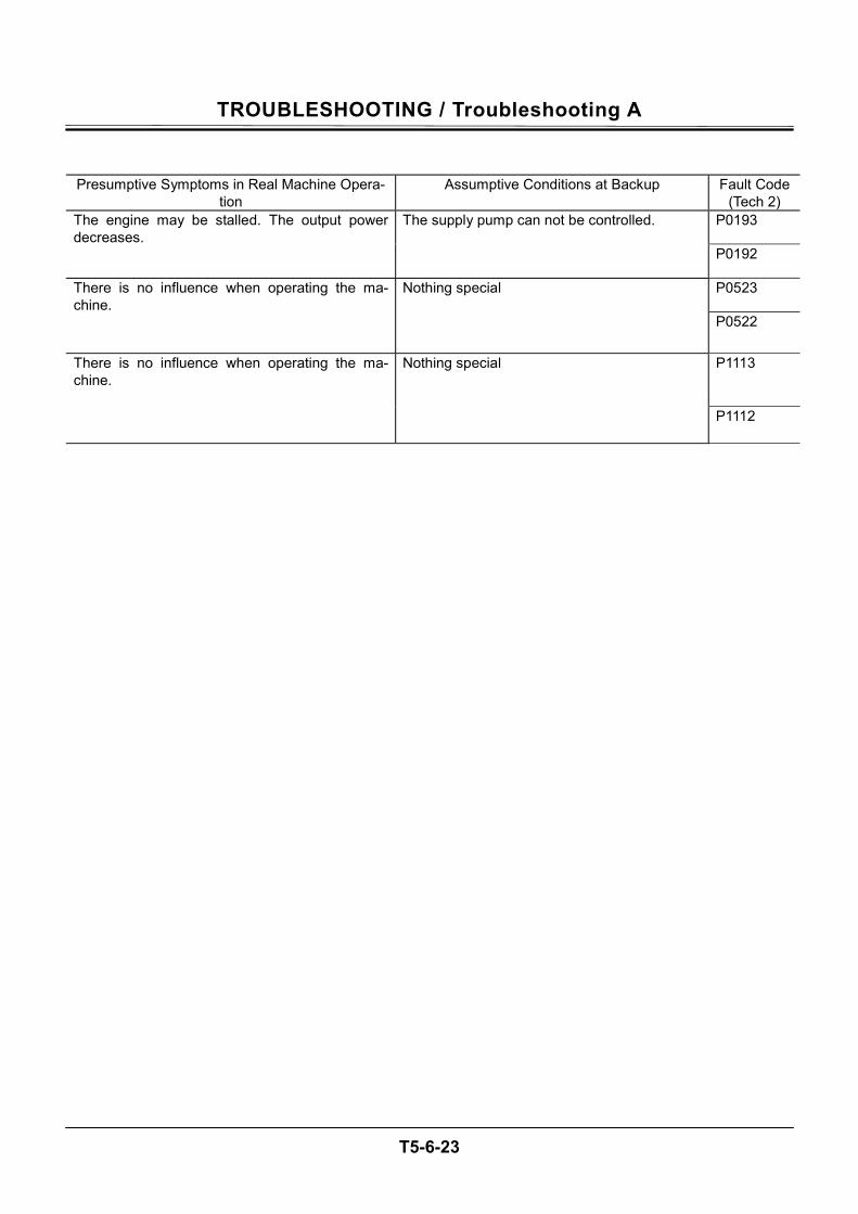
TROUBLESHOOTING / Troubleshooting A
T5-6-23
Presumptive Symptoms in Real Machine Opera-tion
Assumptive Conditions at Backup Fault Code (Tech 2)
P0193 The engine may be stalled. The output power decreases.
The supply pump can not be controlled.
P0192
P0523 There is no influence when operating the ma-chine.
Nothing special
P0522
P1113 There is no influence when operating the ma-chine.
Nothing special
P1112
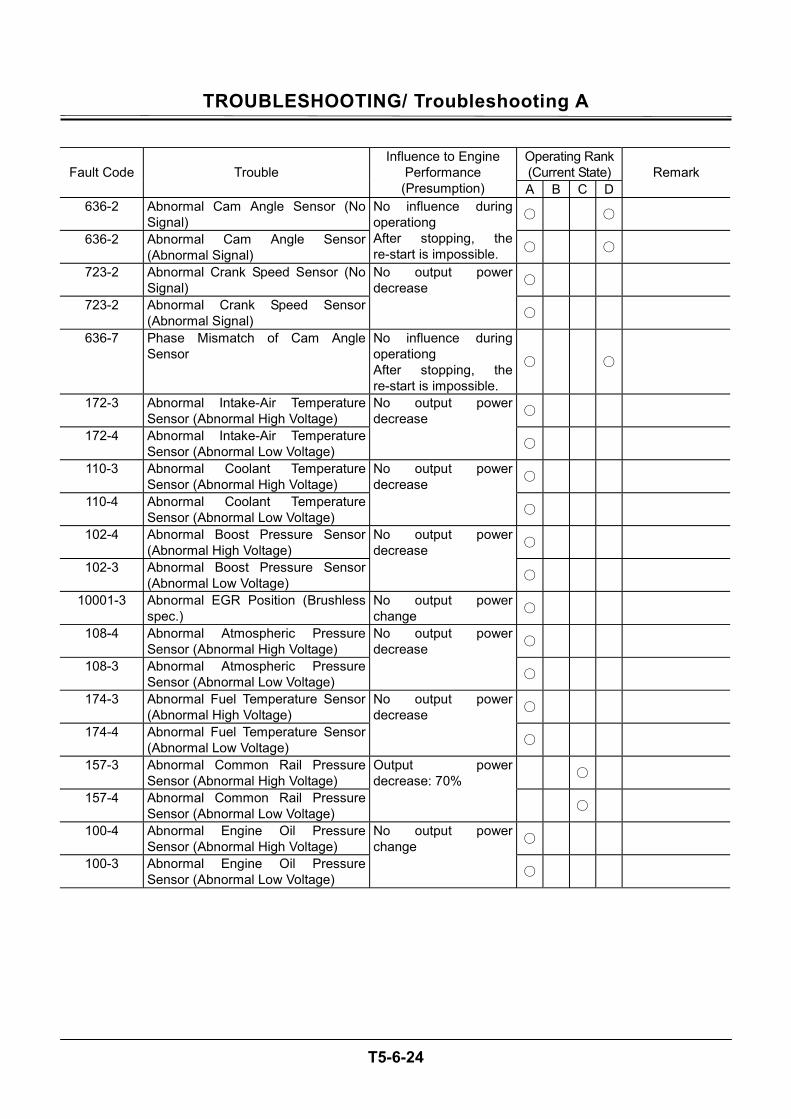
TROUBLESHOOTING/ Troubleshooting A
T5-6-24
Operating Rank (Current State) Fault Code Trouble
Influence to Engine Performance (Presumption) A B C D
Remark
636-2 Abnormal Cam Angle Sensor (No Signal)
636-2 Abnormal Cam Angle Sensor (Abnormal Signal)
No influence during operationg After stopping, the re-start is impossible.
723-2 Abnormal Crank Speed Sensor (No Signal)
723-2 Abnormal Crank Speed Sensor (Abnormal Signal)
No output power decrease
636-7 Phase Mismatch of Cam Angle Sensor
No influence during operationg After stopping, the re-start is impossible.
172-3 Abnormal Intake-Air Temperature Sensor (Abnormal High Voltage)
172-4 Abnormal Intake-Air Temperature Sensor (Abnormal Low Voltage)
No output power decrease
110-3 Abnormal Coolant Temperature Sensor (Abnormal High Voltage)
110-4 Abnormal Coolant Temperature Sensor (Abnormal Low Voltage)
No output power decrease
102-4 Abnormal Boost Pressure Sensor (Abnormal High Voltage)
102-3 Abnormal Boost Pressure Sensor (Abnormal Low Voltage)
No output power decrease
10001-3 Abnormal EGR Position (Brushless spec.)
No output power change
108-4 Abnormal Atmospheric Pressure Sensor (Abnormal High Voltage)
108-3 Abnormal Atmospheric Pressure Sensor (Abnormal Low Voltage)
No output power decrease
174-3 Abnormal Fuel Temperature Sensor (Abnormal High Voltage)
174-4 Abnormal Fuel Temperature Sensor (Abnormal Low Voltage)
No output power decrease
157-3 Abnormal Common Rail Pressure Sensor (Abnormal High Voltage)
157-4 Abnormal Common Rail Pressure Sensor (Abnormal Low Voltage)
Output power decrease: 70%
100-4 Abnormal Engine Oil Pressure Sensor (Abnormal High Voltage)
100-3 Abnormal Engine Oil Pressure Sensor (Abnormal Low Voltage)
No output power change
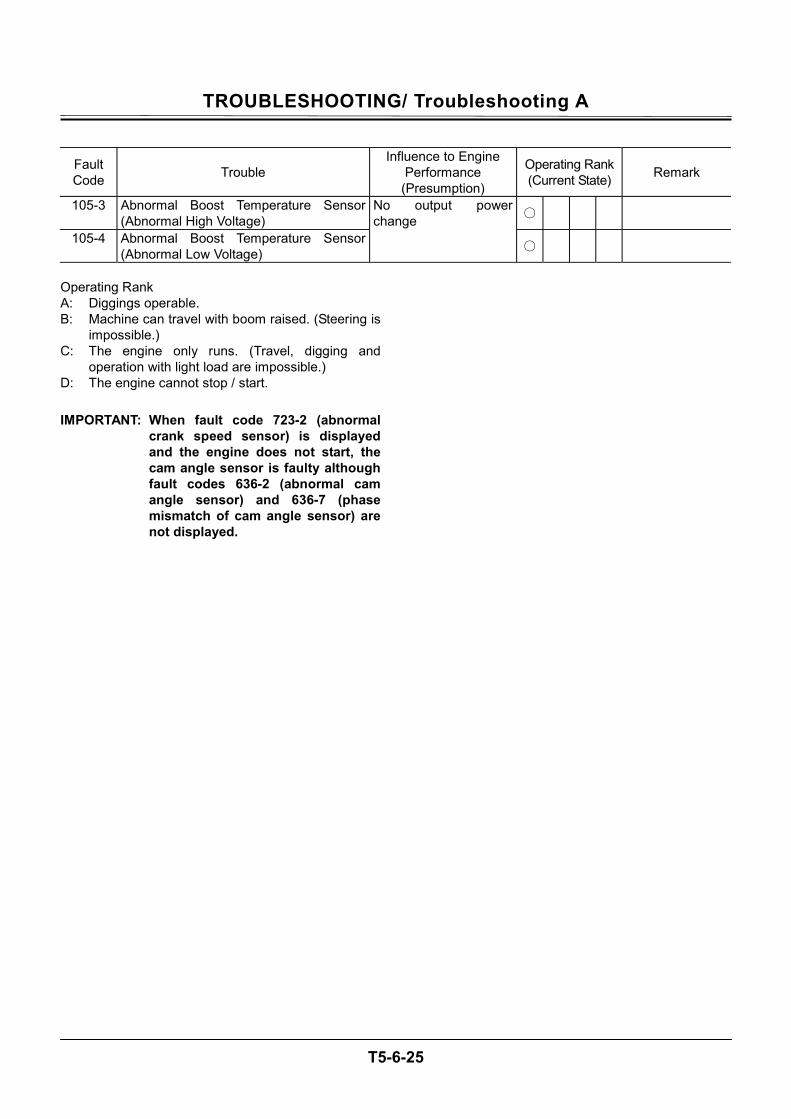
TROUBLESHOOTING/ Troubleshooting A
T5-6-25
Fault Code Trouble
Influence to Engine Performance (Presumption)
Operating Rank (Current State) Remark
105-3 Abnormal Boost Temperature Sensor (Abnormal High Voltage)
105-4 Abnormal Boost Temperature Sensor (Abnormal Low Voltage)
No output power change
Operating Rank A: Diggings operable. B: Machine can travel with boom raised. (Steering is
impossible.) C: The engine only runs. (Travel, digging and
operation with light load are impossible.) D: The engine cannot stop / start. IMPORTANT: When fault code 723-2 (abnormal
crank speed sensor) is displayed and the engine does not start, the cam angle sensor is faulty although fault codes 636-2 (abnormal cam angle sensor) and 636-7 (phase mismatch of cam angle sensor) are not displayed.
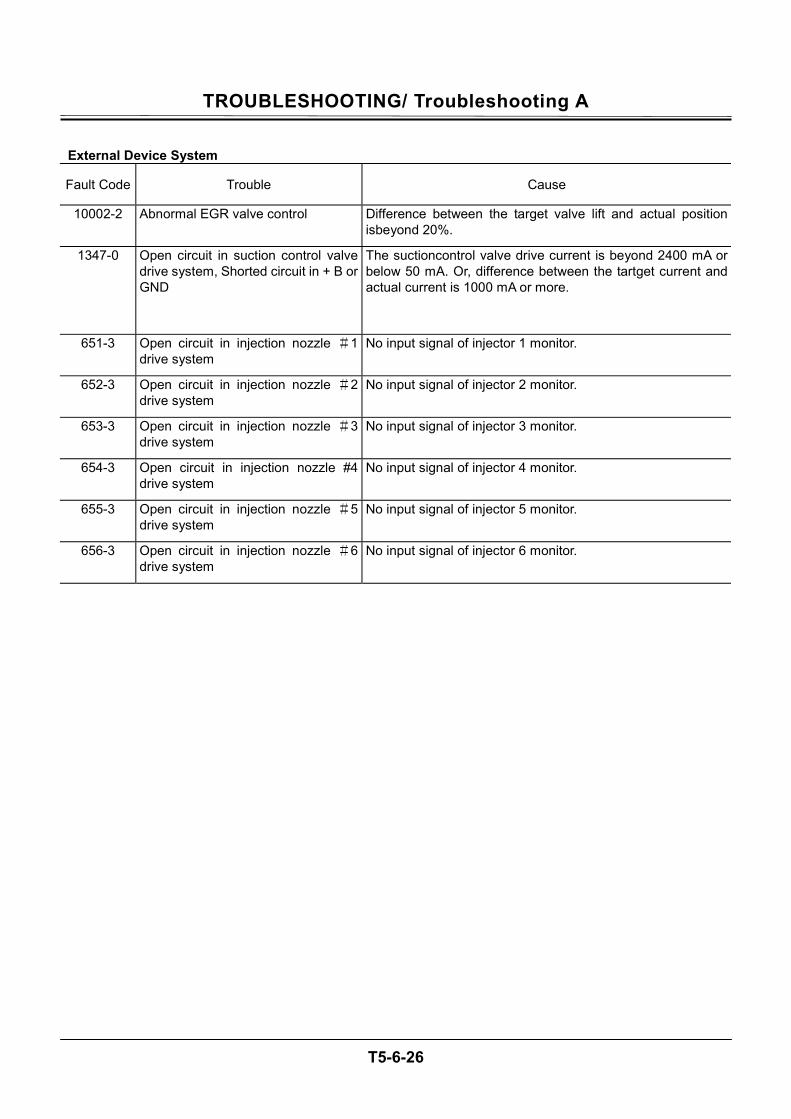
TROUBLESHOOTING/ Troubleshooting A
T5-6-26
External Device System
Fault Code Trouble Cause
10002-2 Abnormal EGR valve control Difference between the target valve lift and actual position isbeyond 20%.
1347-0 Open circuit in suction control valve drive system, Shorted circuit in + B or GND
The suctioncontrol valve drive current is beyond 2400 mA or below 50 mA. Or, difference between the tartget current and actual current is 1000 mA or more.
651-3 Open circuit in injection nozzle #1 drive system
No input signal of injector 1 monitor.
652-3 Open circuit in injection nozzle #2 drive system
No input signal of injector 2 monitor.
653-3 Open circuit in injection nozzle #3 drive system
No input signal of injector 3 monitor.
654-3 Open circuit in injection nozzle #4 drive system
No input signal of injector 4 monitor.
655-3 Open circuit in injection nozzle #5 drive system
No input signal of injector 5 monitor.
656-3 Open circuit in injection nozzle #6 drive system
No input signal of injector 6 monitor.
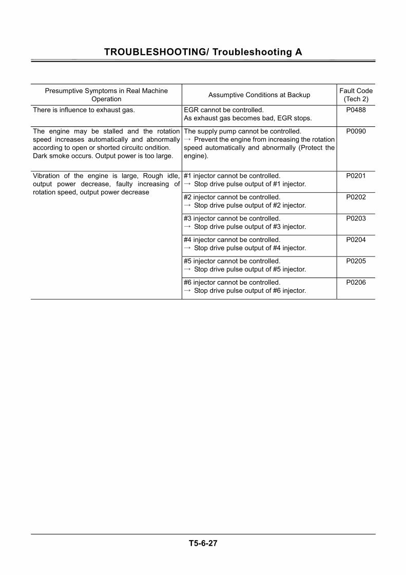
TROUBLESHOOTING/ Troubleshooting A
T5-6-27
Presumptive Symptoms in Real Machine Operation Assumptive Conditions at Backup Fault Code
(Tech 2) There is influence to exhaust gas. EGR cannot be controlled.
As exhaust gas becomes bad, EGR stops. P0488
The engine may be stalled and the rotation speed increases automatically and abnormally according to open or shorted circuitc ondition. Dark smoke occurs. Output power is too large.
The supply pump cannot be controlled. → Prevent the engine from increasing the rotation speed automatically and abnormally (Protect the engine).
P0090
#1 injector cannot be controlled. → Stop drive pulse output of #1 injector.
P0201
#2 injector cannot be controlled. → Stop drive pulse output of #2 injector.
P0202
#3 injector cannot be controlled. → Stop drive pulse output of #3 injector.
P0203
#4 injector cannot be controlled. → Stop drive pulse output of #4 injector.
P0204
#5 injector cannot be controlled. → Stop drive pulse output of #5 injector.
P0205
Vibration of the engine is large, Rough idle, output power decrease, faulty increasing of rotation speed, output power decrease
#6 injector cannot be controlled. → Stop drive pulse output of #6 injector.
P0206
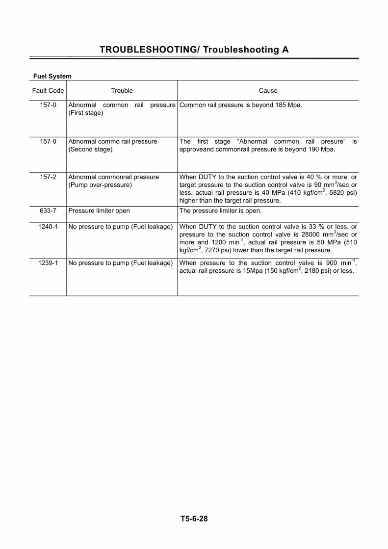
TROUBLESHOOTING/ Troubleshooting A
T5-6-28
Fuel System
Fault Code Trouble Cause
157-0 Abnormal common rail pressure (First stage)
Common rail pressure is beyond 185 Mpa.
157-0 Abnormal commo rail pressure (Second stage)
The first stage “Abnormal common rail presure” is approveand commonrail pressure is beyond 190 Mpa.
157-2 Abnormal commonrail pressure (Pump over-pressure)
When DUTY to the suction control valve is 40 % or more, or target pressure to the suction control valve is 90 mm3/sec or less, actual rail pressure is 40 MPa (410 kgf/cm2, 5820 psi) higher than the target rail pressure.
633-7 Pressure limiter open The pressure limiter is open.
1240-1 No pressure to pump (Fuel leakage) When DUTY to the suction control valve is 33 % or less, or pressure to the suction control valve is 28000 mm3/sec or more and 1200 min-1, actual rail pressure is 50 MPa (510 kgf/cm2, 7270 psi) lower than the target rail pressure.
1239-1 No pressure to pump (Fuel leakage) When pressure to the suction control valve is 900 min-1, actual rail pressure is 15Mpa (150 kgf/cm2, 2180 psi) or less.
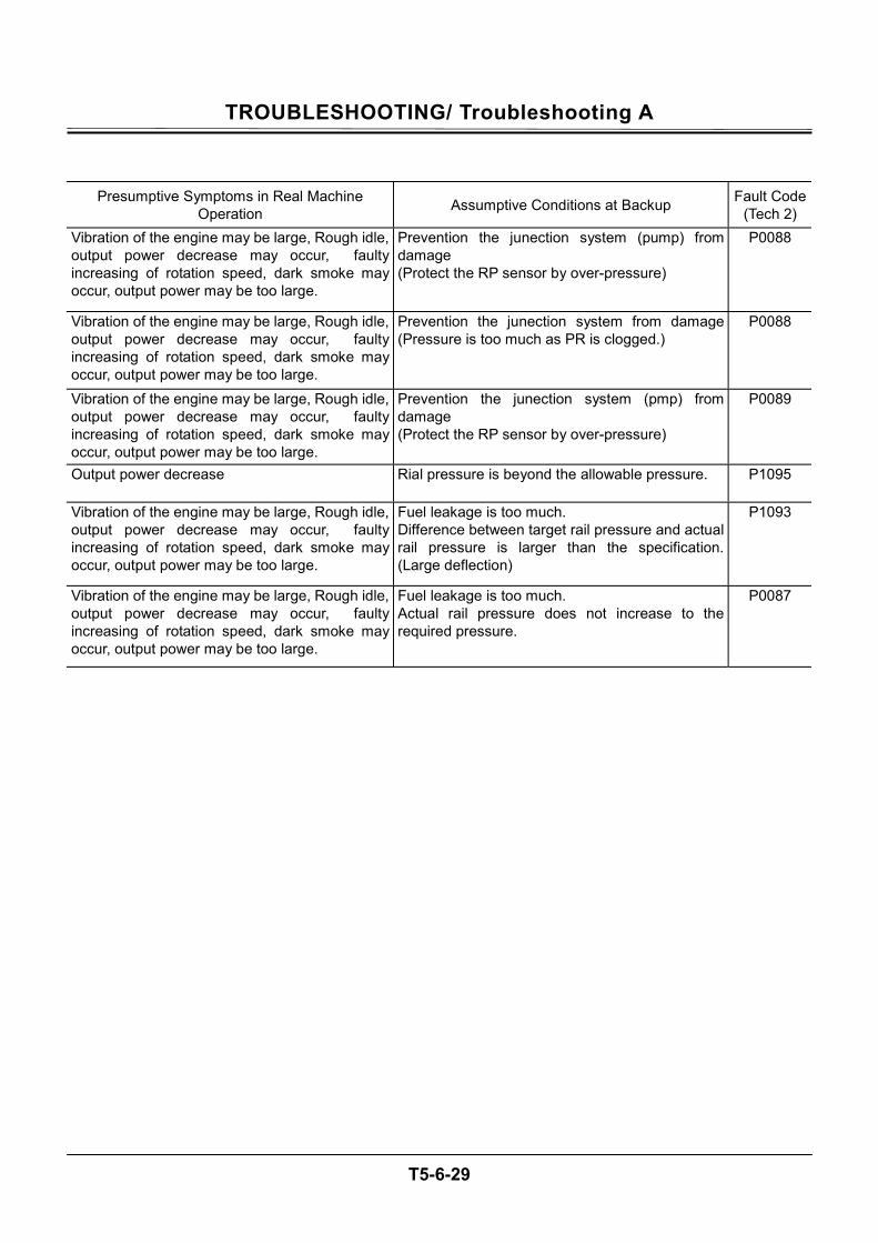
TROUBLESHOOTING/ Troubleshooting A
T5-6-29
Presumptive Symptoms in Real Machine Operation Assumptive Conditions at Backup Fault Code
(Tech 2) Vibration of the engine may be large, Rough idle, output power decrease may occur, faulty increasing of rotation speed, dark smoke may occur, output power may be too large.
Prevention the junection system (pump) from damage (Protect the RP sensor by over-pressure)
P0088
Vibration of the engine may be large, Rough idle, output power decrease may occur, faulty increasing of rotation speed, dark smoke may occur, output power may be too large.
Prevention the junection system from damage (Pressure is too much as PR is clogged.)
P0088
Vibration of the engine may be large, Rough idle, output power decrease may occur, faulty increasing of rotation speed, dark smoke may occur, output power may be too large.
Prevention the junection system (pmp) from damage (Protect the RP sensor by over-pressure)
P0089
Output power decrease Rial pressure is beyond the allowable pressure. P1095
Vibration of the engine may be large, Rough idle, output power decrease may occur, faulty increasing of rotation speed, dark smoke may occur, output power may be too large.
Fuel leakage is too much. Difference between target rail pressure and actual rail pressure is larger than the specification. (Large deflection)
P1093
Vibration of the engine may be large, Rough idle, output power decrease may occur, faulty increasing of rotation speed, dark smoke may occur, output power may be too large.
Fuel leakage is too much. Actual rail pressure does not increase to the required pressure.
P0087
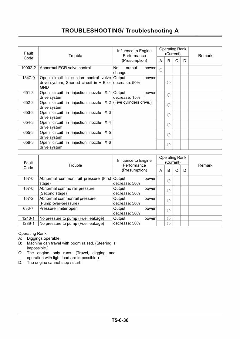
TROUBLESHOOTING/ Troubleshooting A
T5-6-30
Operating Rank
(Current) Fault Code Trouble
Influence to Engine Performance (Presumption) A B C D
Remark
10002-2 Abnormal EGR valve control No output power change
1347-0 Open circuit in suction control valve drive system, Shorted circuit in + B or GND
Output power decrease: 50%
651-3 Open circuit in injection nozzle # 1 drive system
652-3 Open circuit in injection nozzle # 2 drive system
653-3 Open circuit in injection nozzle # 3 drive system
654-3 Open circuit in injection nozzle # 4 drive system
655-3 Open circuit in injection nozzle # 5 drive system
656-3 Open circuit in injection nozzle # 6 drive system
Output power decrease: 15% (Five cylinders drive.)
Operating Rank
(Current) Fault Code Trouble
Influence to Engine Performance (Presumption) A B C D
Remark
157-0 Abnormal common rail pressure (First stage)
Output power decrease: 50%
157-0 Abnormal commo rail pressure (Second stage)
Output power decrease: 50%
157-2 Abnormal commonrail pressure (Pump over-pressure)
Output power decrease: 50%
633-7 Pressure limiter open Output power decrease: 50%
1240-1 No pressure to pump (Fuel leakage) 1239-1 No pressure to pump (Fuel leakage)
Output power decrease: 50%
Operating Rank A: Diggings operable. B: Machine can travel with boom raised. (Steering is
impossible.) C: The engine only runs. (Travel, digging and
operation with light load are impossible.) D: The engine cannot stop / start.

TROUBLESHOOTING/ Troubleshooting A
T5-6-31
(Blank)
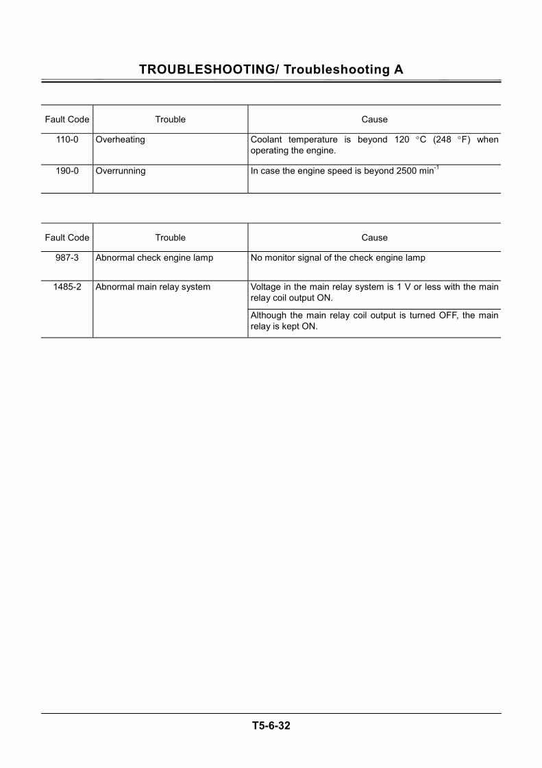
TROUBLESHOOTING/ Troubleshooting A
T5-6-32
Fault Code Trouble Cause
110-0 Overheating Coolant temperature is beyond 120 °C (248 °F) when operating the engine.
190-0 Overrunning In case the engine speed is beyond 2500 min-1
Fault Code Trouble Cause
987-3 Abnormal check engine lamp No monitor signal of the check engine lamp
Voltage in the main relay system is 1 V or less with the main relay coil output ON.
1485-2 Abnormal main relay system
Although the main relay coil output is turned OFF, the main relay is kept ON.
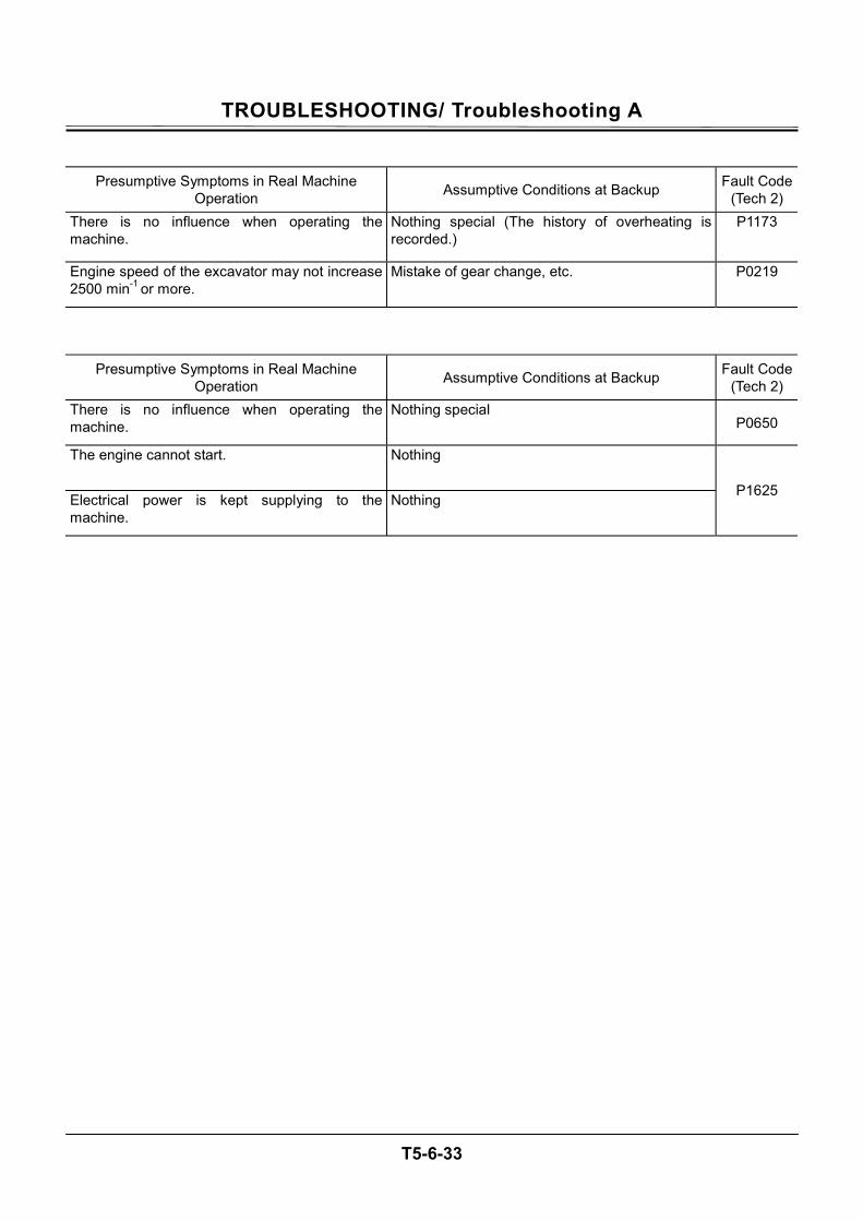
TROUBLESHOOTING/ Troubleshooting A
T5-6-33
Presumptive Symptoms in Real Machine Operation Assumptive Conditions at Backup Fault Code
(Tech 2) There is no influence when operating the machine.
Nothing special (The history of overheating is recorded.)
P1173
Engine speed of the excavator may not increase 2500 min-1 or more.
Mistake of gear change, etc. P0219
Presumptive Symptoms in Real Machine Operation Assumptive Conditions at Backup Fault Code
(Tech 2) There is no influence when operating the machine.
Nothing special P0650
The engine cannot start. Nothing
Electrical power is kept supplying to the machine.
Nothing P1625
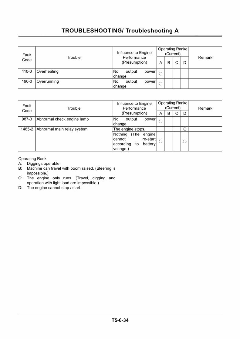
TROUBLESHOOTING/ Troubleshooting A
T5-6-34
Operating Ranke
(Current) Fault Code Trouble
Influence to Engine Performance (Presumption) A B C D
Remark
110-0 Overheating No output power change
190-0 Overrunning No output power change
Operating Ranke (Current) Fault
Code Trouble Influence to Engine
Performance (Presumption) A B C D
Remark
987-3 Abnormal check engine lamp No output power change
The engine stops. 1485-2 Abnormal main relay system Nothing (The engine cannot re-start according to battery voltage.)
Operating Rank A: Diggings operable. B: Machine can travel with boom raised. (Steering is
impossible.) C: The engine only runs. (Travel, digging and
operation with light load are impossible.) D: The engine cannot stop / start.

TROUBLESHOOTING/ Troubleshooting A
T5-6-35
(Blank)
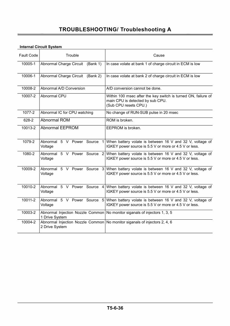
TROUBLESHOOTING/ Troubleshooting A
T5-6-36
Internal Circuit System
Fault Code Trouble Cause
10005-1 Abnormal Charge Circuit (Bank 1) In case volate at bank 1 of charge circuit in ECM is low
10006-1 Abnormal Charge Circuit (Bank 2) In case volate at bank 2 of charge circuit in ECM is low
10008-2 Abnormal A/D Conversion A/D conversion cannot be done.
10007-2 Abnormal CPU Within 100 msec after the key switch is turned ON, failure of main CPU is detected by sub CPU. (Sub CPU resets CPU.)
1077-2 Abnormal IC for CPU watching No change of RUN-SUB pulse in 20 msec
628-2 Abnormal ROM ROM is broken.
10013-2 Abnormal EEPROM EEPROM is broken.
1079-2 Abnormal 5 V Power Source 1Voltage
When battery volate is between 16 V and 32 V, voltage of IGKEY power source is 5.5 V or more or 4.5 V or less.
1080-2 Abnormal 5 V Power Source 2 Voltage
When battery volate is between 16 V and 32 V, voltage of IGKEY power source is 5.5 V or more or 4.5 V or less.
10009-2 Abnormal 5 V Power Source 3 Voltage
When battery volate is between 16 V and 32 V, voltage of IGKEY power source is 5.5 V or more or 4.5 V or less.
10010-2 Abnormal 5 V Power Source 4 Voltage
When battery volate is between 16 V and 32 V, voltage of IGKEY power source is 5.5 V or more or 4.5 V or less.
10011-2 Abnormal 5 V Power Source 5 Voltage
When battery volate is between 16 V and 32 V, voltage of IGKEY power source is 5.5 V or more or 4.5 V or less.
10003-2 Abnormal Injection Nozzle Common 1 Drive System
No monitor siganals of injectors 1, 3, 5
10004-2 Abnormal Injection Nozzle Common 2 Drive System
No monitor siganals of injectors 2, 4, 6
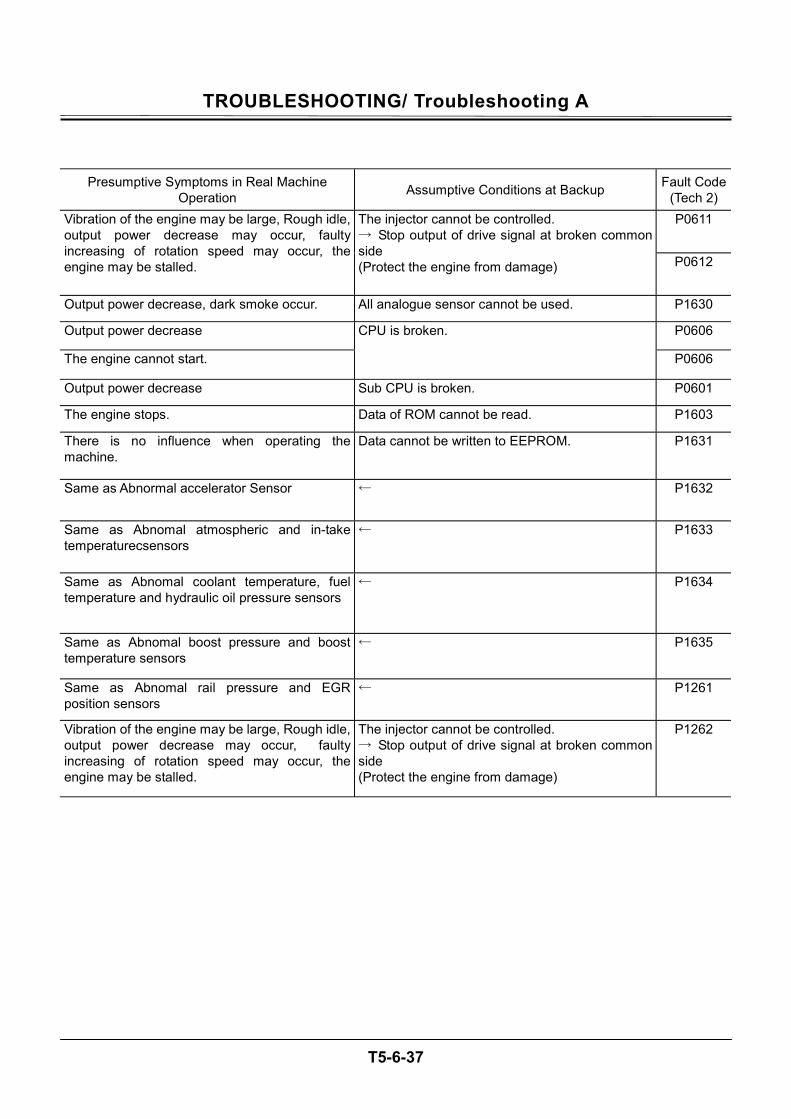
TROUBLESHOOTING/ Troubleshooting A
T5-6-37
Presumptive Symptoms in Real Machine Operation Assumptive Conditions at Backup Fault Code
(Tech 2) P0611 Vibration of the engine may be large, Rough idle,
output power decrease may occur, faulty increasing of rotation speed may occur, the engine may be stalled.
The injector cannot be controlled. → Stop output of drive signal at broken common side (Protect the engine from damage) P0612
Output power decrease, dark smoke occur. All analogue sensor cannot be used. P1630
Output power decrease P0606
The engine cannot start.
CPU is broken.
P0606
Output power decrease Sub CPU is broken. P0601
The engine stops. Data of ROM cannot be read. P1603
There is no influence when operating the machine.
Data cannot be written to EEPROM. P1631
Same as Abnormal accelerator Sensor ← P1632
Same as Abnomal atmospheric and in-take temperaturecsensors
← P1633
Same as Abnomal coolant temperature, fuel temperature and hydraulic oil pressure sensors
← P1634
Same as Abnomal boost pressure and boost temperature sensors
← P1635
Same as Abnomal rail pressure and EGR position sensors
← P1261
Vibration of the engine may be large, Rough idle, output power decrease may occur, faulty increasing of rotation speed may occur, the engine may be stalled.
The injector cannot be controlled. → Stop output of drive signal at broken common side (Protect the engine from damage)
P1262
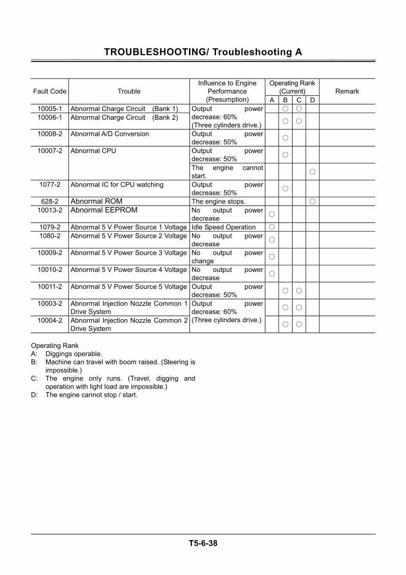
TROUBLESHOOTING/ Troubleshooting A
T5-6-38
Operating Rank
(Current) Fault Code Trouble Influence to Engine
Performance (Presumption) A B C D
Remark
10005-1 Abnormal Charge Circuit (Bank 1) 10006-1 Abnormal Charge Circuit (Bank 2)
Output power decrease: 60% (Three cylinders drive.)
10008-2 Abnormal A/D Conversion Output power decrease: 50%
Output power decrease: 50% 10007-2 Abnormal CPU
The engine cannot start.
1077-2 Abnormal IC for CPU watching Output power decrease: 50%
628-2 Abnormal ROM The engine stops. 10013-2 Abnormal EEPROM No output power
decrease
1079-2 Abnormal 5 V Power Source 1 Voltage Idle Speed Operation 1080-2 Abnormal 5 V Power Source 2 Voltage No output power
decrease
10009-2 Abnormal 5 V Power Source 3 Voltage No output power change
10010-2 Abnormal 5 V Power Source 4 Voltage No output power decrease
10011-2 Abnormal 5 V Power Source 5 Voltage Output power decrease: 50%
10003-2 Abnormal Injection Nozzle Common 1 Drive System
10004-2 Abnormal Injection Nozzle Common 2 Drive System
Output power decrease: 60% (Three cylinders drive.)
Operating Rank A: Diggings operable. B: Machine can travel with boom raised. (Steering is
impossible.) C: The engine only runs. (Travel, digging and
operation with light load are impossible.) D: The engine cannot stop / start.

TROUBLESHOOTING/ Troubleshooting A
T5-6-39
(Blank)

TROUBLESHOOTING/ Troubleshooting A
T5-6-40
Communication System
Fault Code Trouble Cause
639-2 Abnormal CAN Bus Line Detect the bus line off.
639-3 Abnormal CAN Time Out In case the CAN data reception is not approved in prescribedtime

TROUBLESHOOTING/ Troubleshooting A
T5-6-41
Presumptive Symptoms in Real Machine Operation Assumptive Conditions at Backup Fault Code
(Tech 2) U2104 Speed is turnd into idle speed. CAN communication is operable.
U2106

TROUBLESHOOTING/ Troubleshooting A
T5-6-42
Operating Rank
(Current) Fault Code Trouble
Influence to Engine Performance (Presumption) A B C D
Remark
639-2 Abnormal CAN Bus Line 639-3 Abnormal CAN Time Out
Idle speed

TROUBLESHOOTING/ Troubleshooting A
T5-6-43
(Blank)
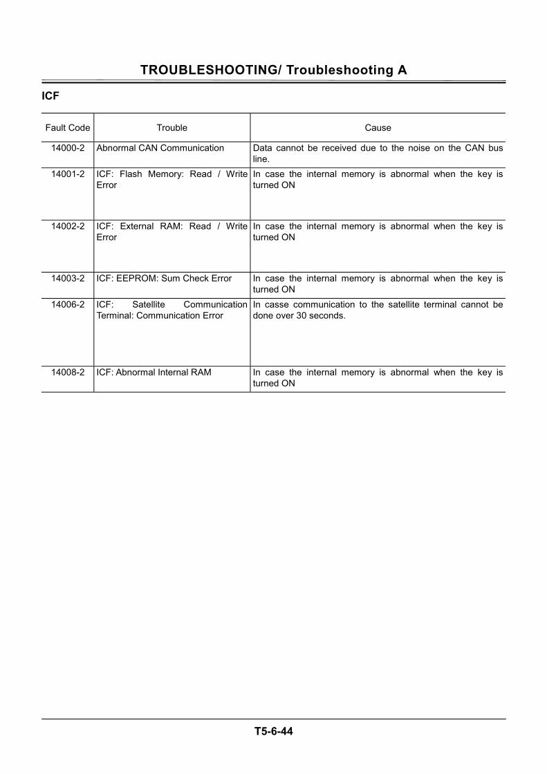
TROUBLESHOOTING/ Troubleshooting A
T5-6-44
ICF
Fault Code Trouble Cause
14000-2 Abnormal CAN Communication Data cannot be received due to the noise on the CAN bus line.
14001-2 ICF: Flash Memory: Read / Write Error
In case the internal memory is abnormal when the key is turned ON
14002-2 ICF: External RAM: Read / Write Error
In case the internal memory is abnormal when the key is turned ON
14003-2 ICF: EEPROM: Sum Check Error In case the internal memory is abnormal when the key is turned ON
14006-2 ICF: Satellite Communication Terminal: Communication Error
In casse communication to the satellite terminal cannot be done over 30 seconds.
14008-2 ICF: Abnormal Internal RAM In case the internal memory is abnormal when the key is turned ON
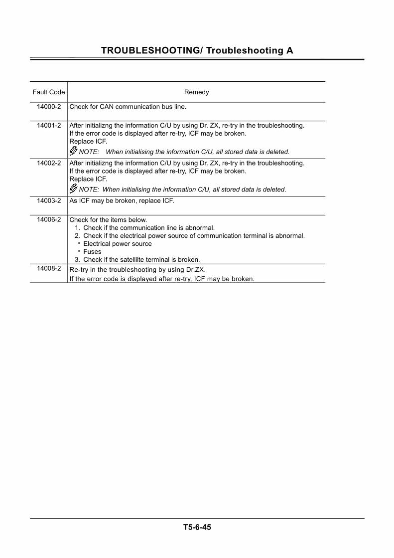
TROUBLESHOOTING/ Troubleshooting A
T5-6-45
Fault Code Remedy
14000-2 Check for CAN communication bus line.
14001-2 After initializng the information C/U by using Dr. ZX, re-try in the troubleshooting. If the error code is displayed after re-try, ICF may be broken. Replace ICF.
NOTE: When initialising the information C/U, all stored data is deleted.
14002-2 After initializng the information C/U by using Dr. ZX, re-try in the troubleshooting. If the error code is displayed after re-try, ICF may be broken. Replace ICF.
NOTE: When initialising the information C/U, all stored data is deleted. 14003-2 As ICF may be broken, replace ICF.
14006-2 Check for the items below. 1. Check if the communication line is abnormal. 2. Check if the electrical power source of communication terminal is abnormal. • Electrical power source • Fuses
3. Check if the satellilte terminal is broken. 14008-2 Re-try in the troubleshooting by using Dr.ZX.
If the error code is displayed after re-try, ICF may be broken.
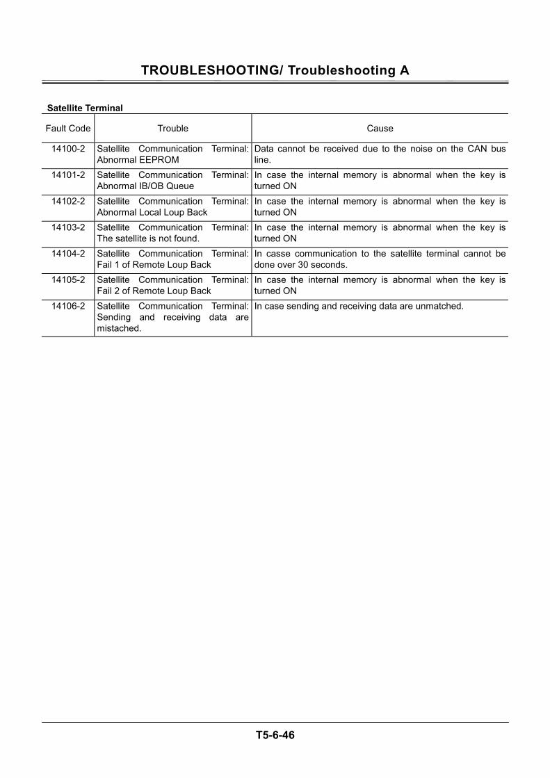
TROUBLESHOOTING/ Troubleshooting A
T5-6-46
Satellite Terminal
Fault Code Trouble Cause
14100-2 Satellite Communication Terminal: Abnormal EEPROM
Data cannot be received due to the noise on the CAN bus line.
14101-2 Satellite Communication Terminal: Abnormal IB/OB Queue
In case the internal memory is abnormal when the key is turned ON
14102-2 Satellite Communication Terminal: Abnormal Local Loup Back
In case the internal memory is abnormal when the key is turned ON
14103-2 Satellite Communication Terminal: The satellite is not found.
In case the internal memory is abnormal when the key is turned ON
14104-2 Satellite Communication Terminal: Fail 1 of Remote Loup Back
In casse communication to the satellite terminal cannot be done over 30 seconds.
14105-2 Satellite Communication Terminal: Fail 2 of Remote Loup Back
In case the internal memory is abnormal when the key is turned ON
14106-2 Satellite Communication Terminal: Sending and receiving data are mistached.
In case sending and receiving data are unmatched.
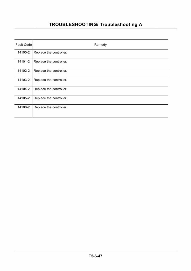
TROUBLESHOOTING/ Troubleshooting A
T5-6-47
Fault Code Remedy
14100-2 Replace the controller.
14101-2 Replace the controller.
14102-2 Replace the controller.
14103-2 Replace the controller.
14104-2 Replace the controller.
14105-2 Replace the controller.
14106-2 Replace the controller.
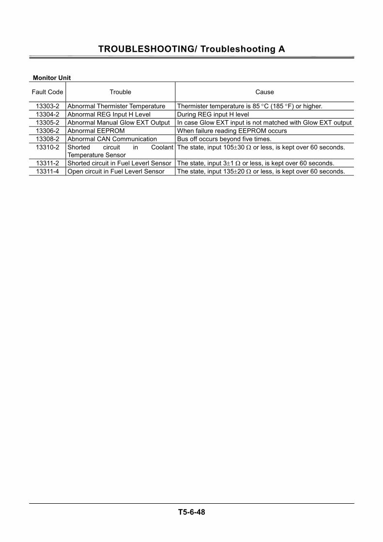
TROUBLESHOOTING/ Troubleshooting A
T5-6-48
Monitor Unit
Fault Code Trouble Cause
13303-2 Abnormal Thermister Temperature Thermister temperature is 85 °C (185 °F) or higher. 13304-2 Abnormal REG Input H Level During REG input H level 13305-2 Abnormal Manual Glow EXT Output In case Glow EXT input is not matched with Glow EXT output13306-2 Abnormal EEPROM When failure reading EEPROM occurs 13308-2 Abnormal CAN Communication Bus off occurs beyond five times. 13310-2 Shorted circuit in Coolant
Temperature Sensor The state, input 105±30 Ω or less, is kept over 60 seconds.
13311-2 Shorted circuit in Fuel Leverl Sensor The state, input 3±1 Ω or less, is kept over 60 seconds. 13311-4 Open circuit in Fuel Leverl Sensor The state, input 135±20 Ω or less, is kept over 60 seconds.
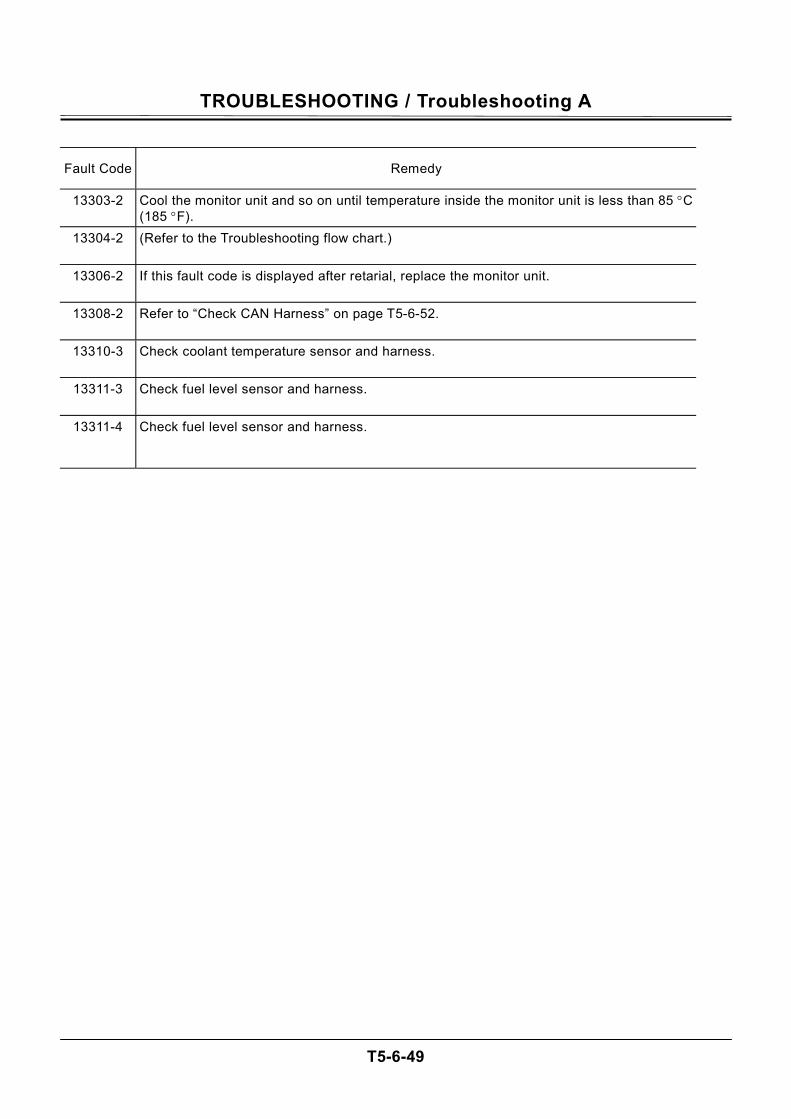
TROUBLESHOOTING / Troubleshooting A
T5-6-49
Fault Code Remedy
13303-2 Cool the monitor unit and so on until temperature inside the monitor unit is less than 85 °C (185 °F).
13304-2 (Refer to the Troubleshooting flow chart.)
13306-2 If this fault code is displayed after retarial, replace the monitor unit.
13308-2 Refer to “Check CAN Harness” on page T5-6-52.
13310-3 Check coolant temperature sensor and harness.
13311-3 Check fuel level sensor and harness.
13311-4 Check fuel level sensor and harness.
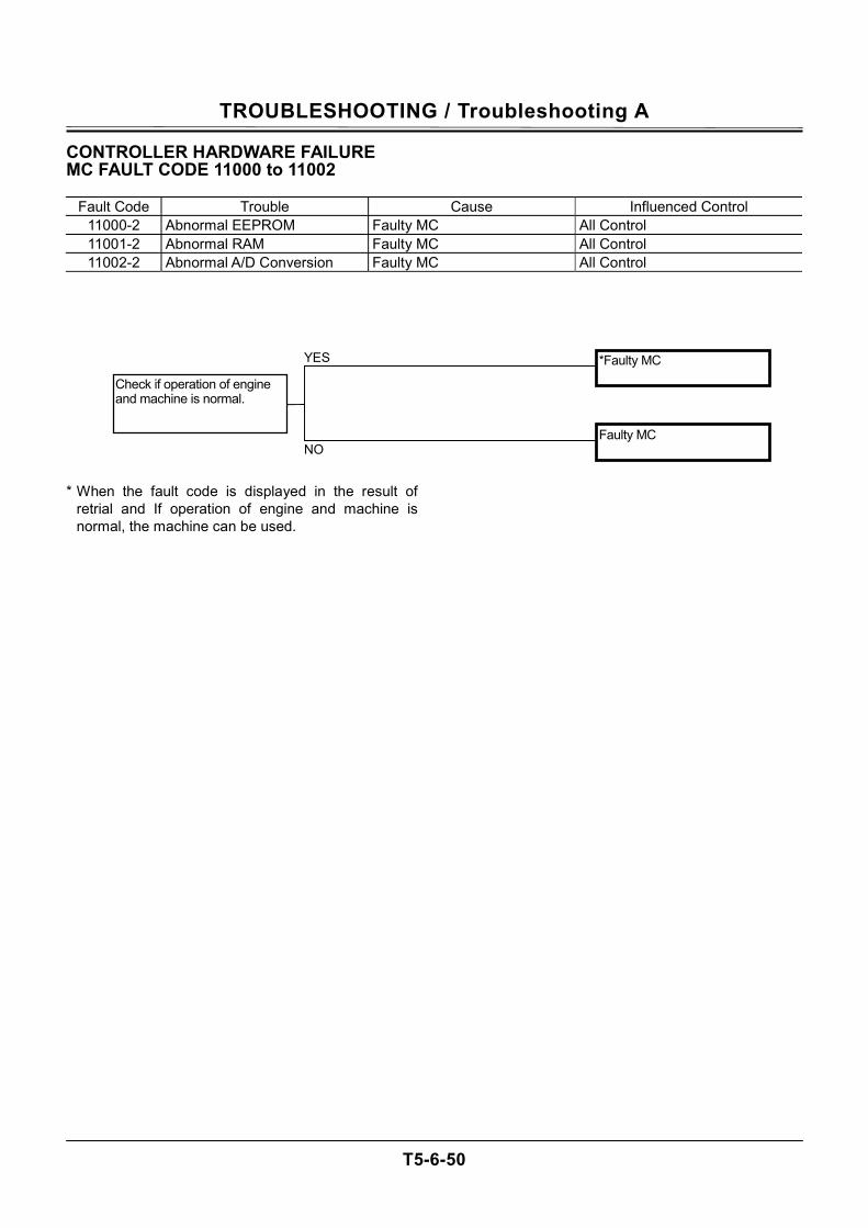
TROUBLESHOOTING / Troubleshooting A
T5-6-50
CONTROLLER HARDWARE FAILURE MC FAULT CODE 11000 to 11002
Fault Code Trouble Cause Influenced Control 11000-2 Abnormal EEPROM Faulty MC All Control 11001-2 Abnormal RAM Faulty MC All Control 11002-2 Abnormal A/D Conversion Faulty MC All Control
* When the fault code is displayed in the result of
retrial and If operation of engine and machine is normal, the machine can be used.
*Faulty MC
Faulty MC NO
YES
Check if operation of engine and machine is normal.
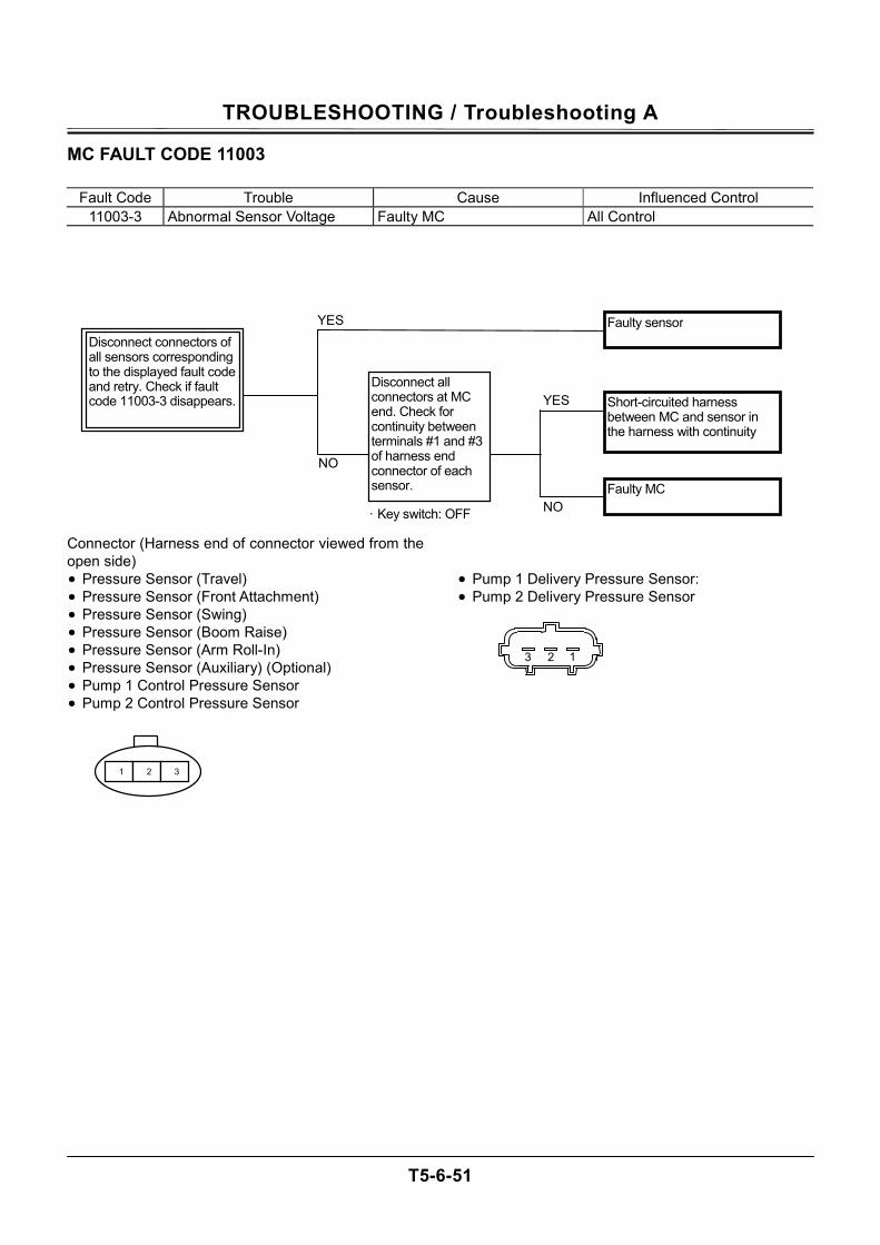
TROUBLESHOOTING / Troubleshooting A
T5-6-51
MC FAULT CODE 11003
Fault Code Trouble Cause Influenced Control 11003-3 Abnormal Sensor Voltage Faulty MC All Control
Connector (Harness end of connector viewed from the open side) • Pressure Sensor (Travel) • Pressure Sensor (Front Attachment) • Pressure Sensor (Swing) • Pressure Sensor (Boom Raise) • Pressure Sensor (Arm Roll-In) • Pressure Sensor (Auxiliary) (Optional) • Pump 1 Control Pressure Sensor • Pump 2 Control Pressure Sensor
• Pump 1 Delivery Pressure Sensor: • Pump 2 Delivery Pressure Sensor
YES
Disconnect connectors of all sensors corresponding to the displayed fault code and retry. Check if fault code 11003-3 disappears.
Faulty sensor
YES
NOFaulty MC
Disconnect all connectors at MC end. Check for continuity between terminals #1 and #3 of harness end connector of each sensor.
Short-circuited harness between MC and sensor in the harness with continuity
· Key switch: OFF
NO
1 2 3
123
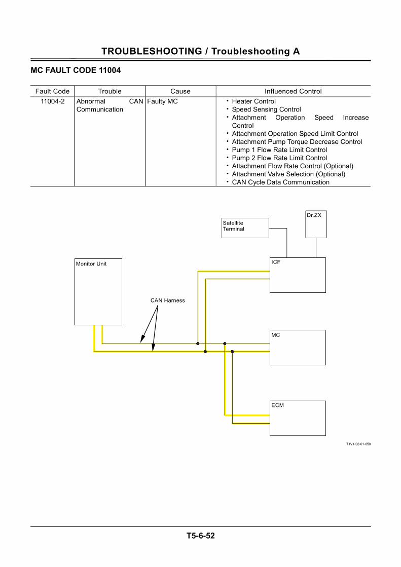
TROUBLESHOOTING / Troubleshooting A
T5-6-52
MC FAULT CODE 11004
Fault Code Trouble Cause Influenced Control 11004-2 Abnormal CAN
Communication Faulty MC • Heater Control
• Speed Sensing Control • Attachment Operation Speed Increase
Control • Attachment Operation Speed Limit Control • Attachment Pump Torque Decrease Control • Pump 1 Flow Rate Limit Control • Pump 2 Flow Rate Limit Control • Attachment Flow Rate Control (Optional) • Attachment Valve Selection (Optional) • CAN Cycle Data Communication
T1V1-02-01-050
Monitor Unit
CAN Harness
Satellite Terminal
ICF
Dr.ZX
MC
ECM

TROUBLESHOOTING / Troubleshooting A
T5-6-53
(Blank)
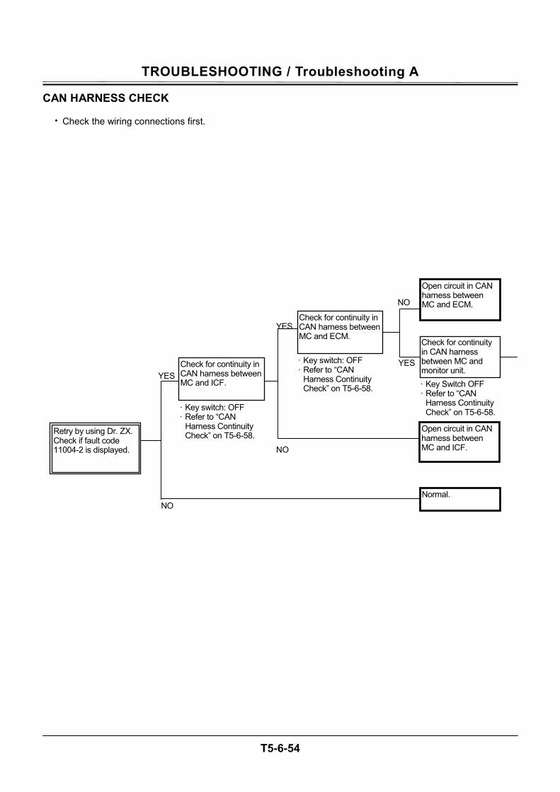
TROUBLESHOOTING / Troubleshooting A
T5-6-54
CAN HARNESS CHECK
• Check the wiring connections first.
YES YES
NO
NO
YES
NO
· Key switch: OFF · Refer to “CAN
Harness Continuity Check” on T5-6-58.
· Key switch: OFF · Refer to “CAN
Harness Continuity Check” on T5-6-58.Retry by using Dr. ZX.
Check if fault code 11004-2 is displayed.
Check for continuity in CAN harness between MC and ICF.
Check for continuity in CAN harness between MC and ECM.
Open circuit in CAN harness between MC and ICF.
Normal.
Open circuit in CAN harness between MC and ECM.
Check for continuity in CAN harness between MC and monitor unit. · Key Switch OFF · Refer to “CAN
Harness Continuity Check” on T5-6-58.
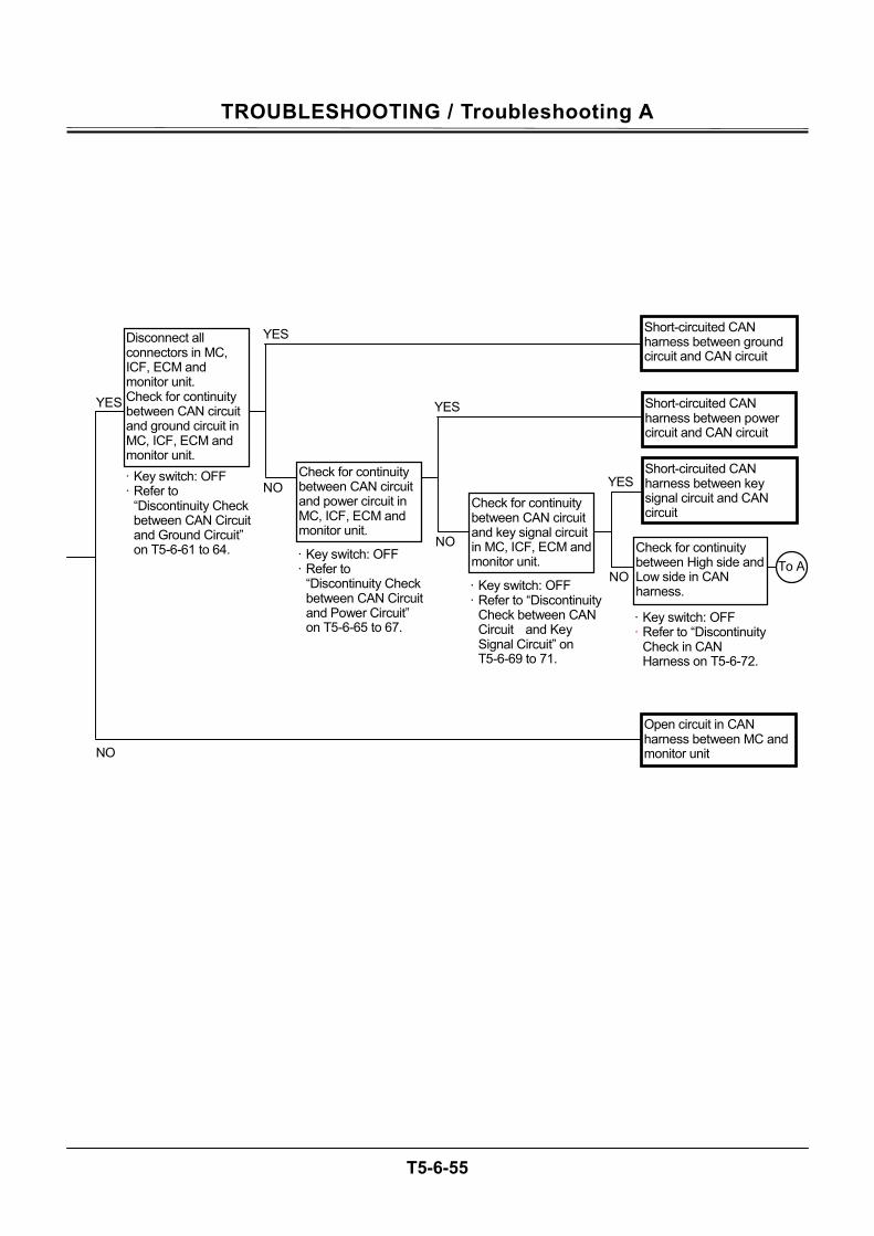
TROUBLESHOOTING / Troubleshooting A
T5-6-55
NO
YES
NO
YES
YES
NO
NO
YES
· Key switch: OFF · Refer to
“Discontinuity Check between CAN Circuit and Power Circuit” on T5-6-65 to 67.
· Key switch: OFF · Refer to
“Discontinuity Check between CAN Circuit and Ground Circuit” on T5-6-61 to 64.
Disconnect all connectors in MC, ICF, ECM and monitor unit. Check for continuity between CAN circuit and ground circuit in MC, ICF, ECM and monitor unit.
Check for continuity between CAN circuit and power circuit in MC, ICF, ECM and monitor unit.
Short-circuited CAN harness between key signal circuit and CAN circuit
Open circuit in CAN harness between MC and monitor unit
Short-circuited CAN harness between power circuit and CAN circuit
Check for continuity between High side and Low side in CAN harness.
· Key switch: OFF · Refer to “Discontinuity
Check in CAN Harness on T5-6-72.
Check for continuity between CAN circuit and key signal circuit in MC, ICF, ECM and monitor unit.
· Key switch: OFF · Refer to “Discontinuity
Check between CAN Circuit and Key Signal Circuit” on T5-6-69 to 71.
Short-circuited CAN harness between ground circuit and CAN circuit
To A
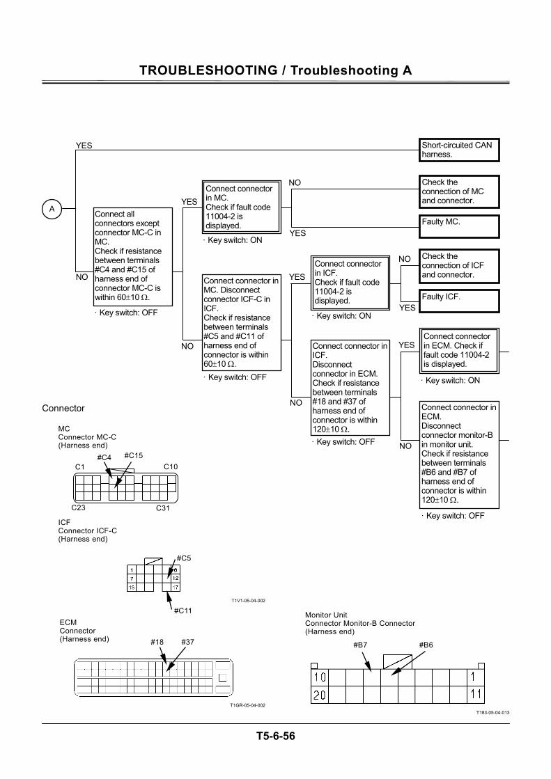
TROUBLESHOOTING / Troubleshooting A
T5-6-56
Connector
T1V1-05-04-002
T1GR-05-04-002
T183-05-04-013
#18 #37 #B7 #B6
#C5
#C11
· Key switch: OFF
· Key switch: OFF
NO
YES
NO
YESNO
NO
YES
· Key switch: OFF
· Key switch: OFF
Connect all connectors except connector MC-C in MC. Check if resistance between terminals #C4 and #C15 of harness end of connector MC-C is within 60±10 Ω.
Connect connector in MC. Disconnect connector ICF-C in ICF. Check if resistance between terminals #C5 and #C11 of harness end of connector is within 60±10 Ω.
Connect connector in ECM. Disconnect connector monitor-B in monitor unit. Check if resistance between terminals #B6 and #B7 of harness end of connector is within 120±10 Ω.
Connect connector in ICF. Disconnect connector in ECM. Check if resistance between terminals #18 and #37 of harness end of connector is within 120±10 Ω.
A
Connect connector in ICF. Check if fault code 11004-2 is displayed.
· Key switch: ON
YES
· Key switch: ON
Connect connector in MC. Check if fault code 11004-2 is displayed.
YES
NO
Connect connector in ECM. Check if fault code 11004-2 is displayed.
Short-circuited CAN harness.
Check the connection of MC and connector.
Faulty MC.
YES
NO Check the connection of ICF and connector.
Faulty ICF.
· Key switch: ON
C31
C10
C23
C1
#C15 #C4
MC Connector MC-C (Harness end)
ICF Connector ICF-C (Harness end)
ECM Connector (Harness end)
Monitor Unit Connector Monitor-B Connector (Harness end)
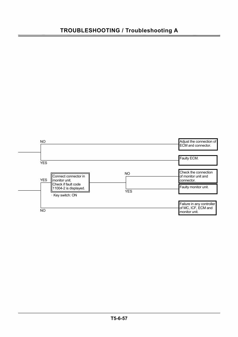
TROUBLESHOOTING / Troubleshooting A
T5-6-57
NO
YES
· Key switch: ON
Connect connector in monitor unit. Check if fault code 11004-2 is displayed.
YES
NO
Adjust the connection of ECM and connector.
Check the connection of monitor unit and connector.
Faulty monitor unit.
Failure in any controller of MC, ICF, ECM and monitor unit.
Faulty ECM. YES
NO
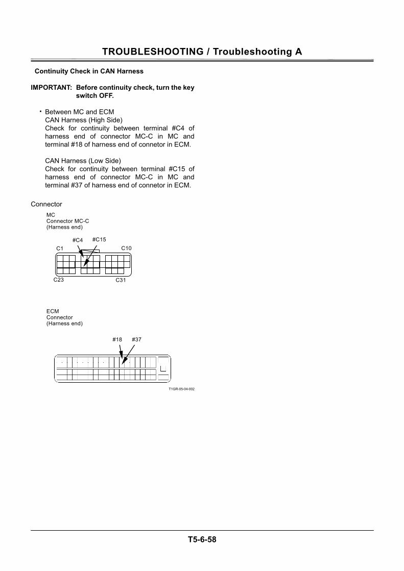
TROUBLESHOOTING / Troubleshooting A
T5-6-58
Continuity Check in CAN Harness IMPORTANT: Before continuity check, turn the key
switch OFF.
• Between MC and ECM CAN Harness (High Side) Check for continuity between terminal #C4 of harness end of connector MC-C in MC and terminal #18 of harness end of connetor in ECM. CAN Harness (Low Side) Check for continuity between terminal #C15 of harness end of connector MC-C in MC and terminal #37 of harness end of connetor in ECM.
Connector
T1GR-05-04-002
#18 #37
C31
C10
C23
C1
#C15 #C4
MC Connector MC-C (Harness end)
ECM Connector (Harness end)
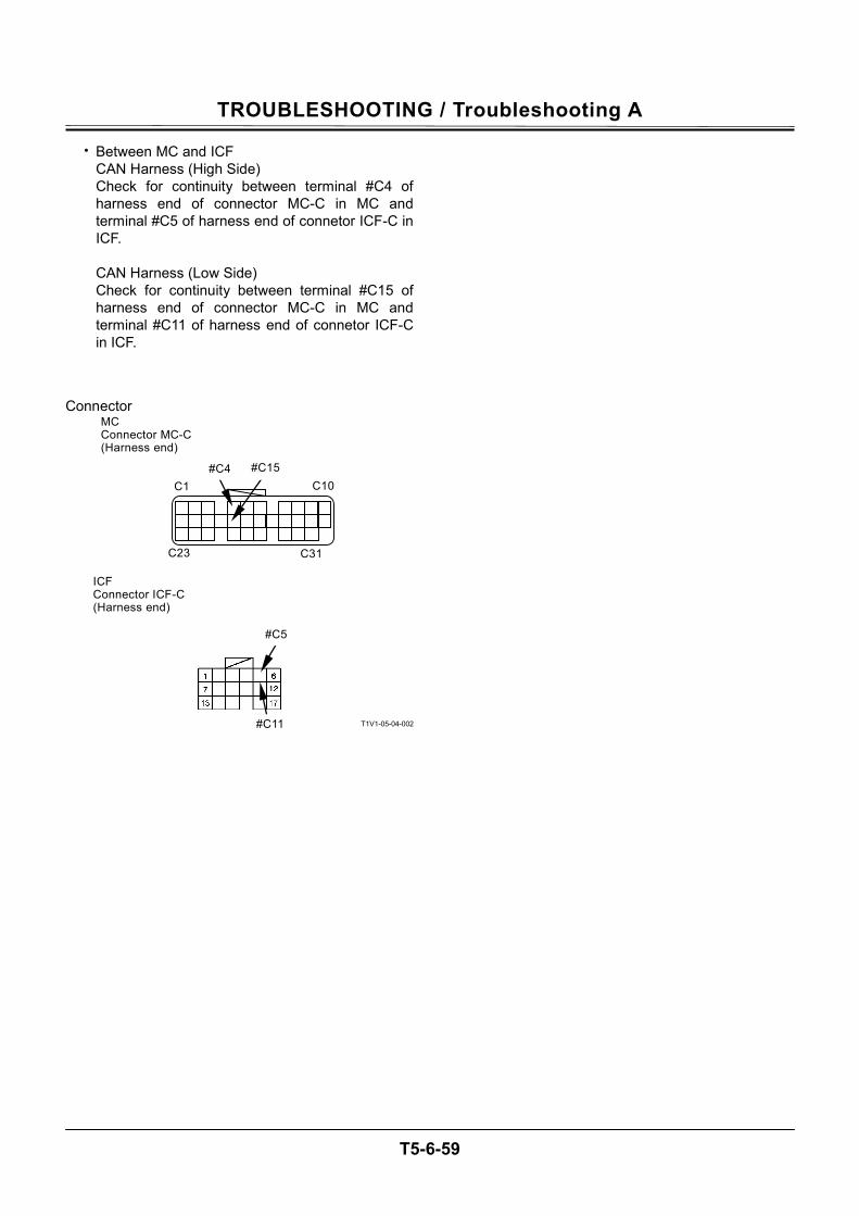
TROUBLESHOOTING / Troubleshooting A
T5-6-59
• Between MC and ICF CAN Harness (High Side) Check for continuity between terminal #C4 of harness end of connector MC-C in MC and terminal #C5 of harness end of connetor ICF-C in ICF. CAN Harness (Low Side) Check for continuity between terminal #C15 of harness end of connector MC-C in MC and terminal #C11 of harness end of connetor ICF-C in ICF.
Connector
T1V1-05-04-002
#C5
#C11
C31
C10
C23
C1
#C15 #C4
MC Connector MC-C (Harness end)
ICF Connector ICF-C (Harness end)
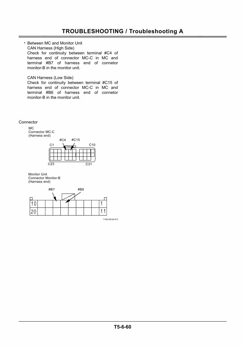
TROUBLESHOOTING / Troubleshooting A
T5-6-60
• Between MC and Monitor Unit CAN Harness (High Side) Check for continuity between terminal #C4 of harness end of connector MC-C in MC and terminal #B7 of harness end of connetor monitor-B in the monitor unit. CAN Harness (Low Side) Check for continuity between terminal #C15 of harness end of connector MC-C in MC and terminal #B6 of harness end of connetor monitor-B in the monitor unit.
Connector
T183-05-04-013
#B7 #B6
C31
C10
C23
C1
#C15 #C4
MC Connector MC-C (Harness end)
Monitor Unit Connector Monitor-B (Harness end)
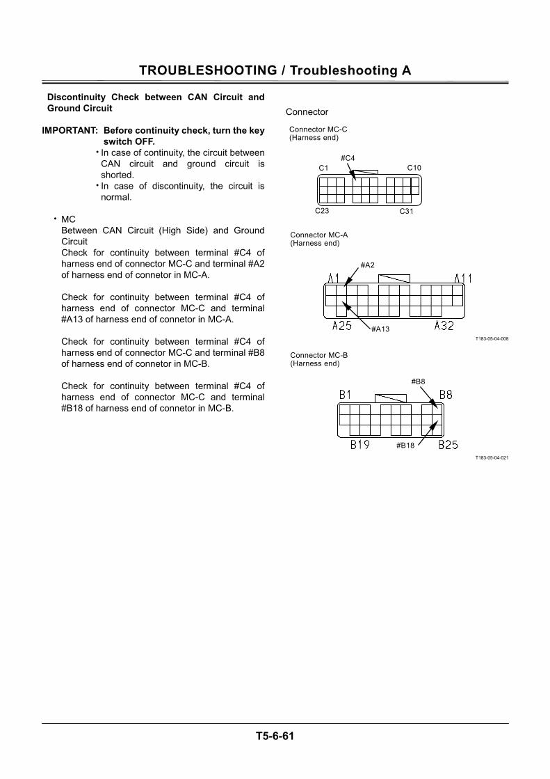
TROUBLESHOOTING / Troubleshooting A
T5-6-61
Discontinuity Check between CAN Circuit and Ground Circuit
IMPORTANT: Before continuity check, turn the key
switch OFF. • In case of continuity, the circuit between
CAN circuit and ground circuit is shorted.
• In case of discontinuity, the circuit is normal.
• MC
Between CAN Circuit (High Side) and Ground Circuit Check for continuity between terminal #C4 of harness end of connector MC-C and terminal #A2 of harness end of connetor in MC-A. Check for continuity between terminal #C4 of harness end of connector MC-C and terminal #A13 of harness end of connetor in MC-A. Check for continuity between terminal #C4 of harness end of connector MC-C and terminal #B8 of harness end of connetor in MC-B. Check for continuity between terminal #C4 of harness end of connector MC-C and terminal #B18 of harness end of connetor in MC-B.
Connector
T183-05-04-008
T183-05-04-021
C31
C10
C23
C1
#C4
#A2
#A13
#B8
#B18
Connector MC-C (Harness end)
Connector MC-A (Harness end)
Connector MC-B (Harness end)
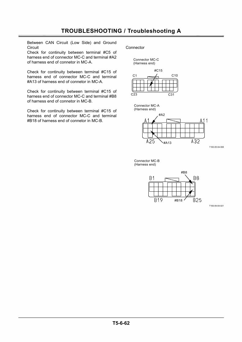
TROUBLESHOOTING / Troubleshooting A
T5-6-62
Between CAN Circuit (Low Side) and Ground Circuit Check for continuity between terminal #C5 of harness end of connector MC-C and terminal #A2 of harness end of connetor in MC-A. Check for continuity between terminal #C15 of harness end of connector MC-C and terminal #A13 of harness end of connetor in MC-A. Check for continuity between terminal #C15 of harness end of connector MC-C and terminal #B8 of harness end of connetor in MC-B. Check for continuity between terminal #C15 of harness end of connector MC-C and terminal #B18 of harness end of connetor in MC-B.
Connector
T183-05-04-008
T183-05-04-021
C31
C10
C23
C1
#C15
#A2
#A13
#B8
#B18
Connector MC-C (Harness end)
Connector MC-A (Harness end)
Connector MC-B (Harness end)
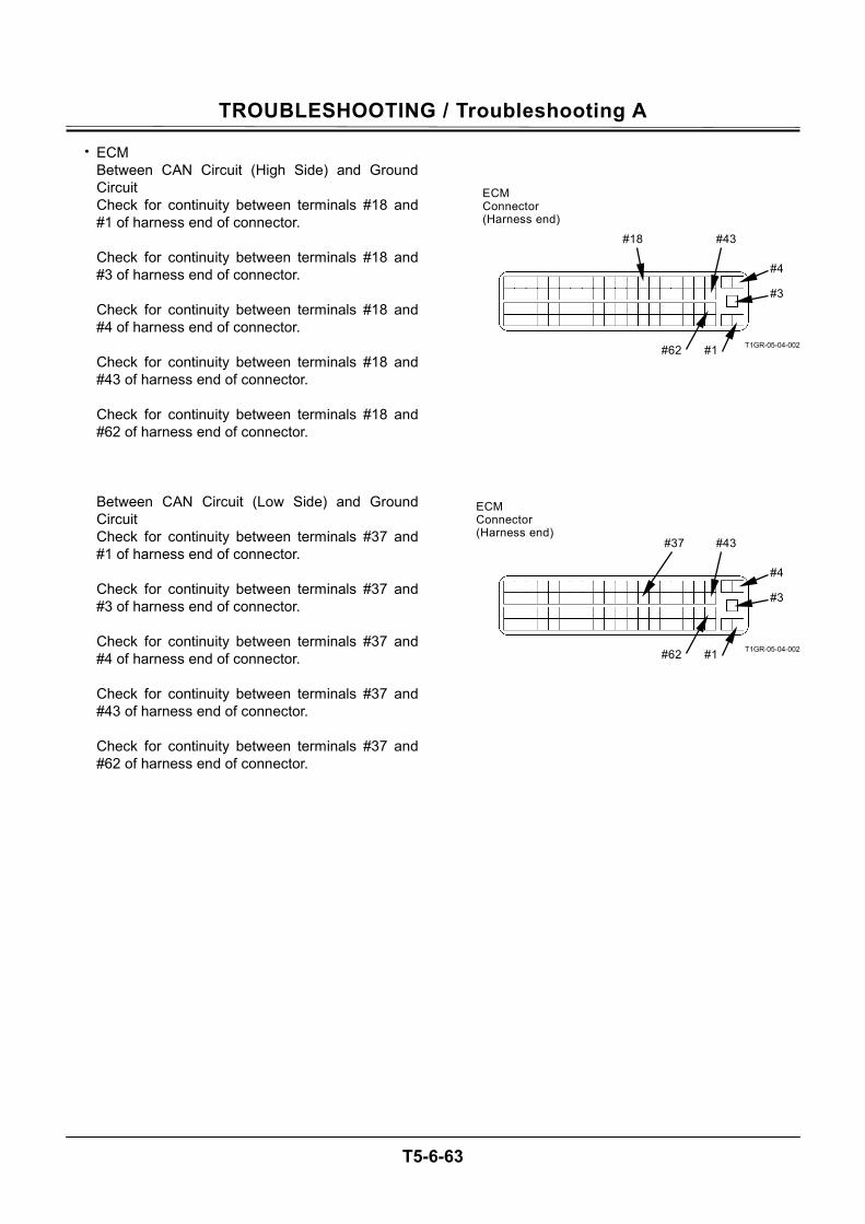
TROUBLESHOOTING / Troubleshooting A
T5-6-63
• ECM Between CAN Circuit (High Side) and Ground Circuit Check for continuity between terminals #18 and #1 of harness end of connector. Check for continuity between terminals #18 and #3 of harness end of connector. Check for continuity between terminals #18 and #4 of harness end of connector. Check for continuity between terminals #18 and #43 of harness end of connector. Check for continuity between terminals #18 and #62 of harness end of connector. Between CAN Circuit (Low Side) and Ground Circuit Check for continuity between terminals #37 and #1 of harness end of connector. Check for continuity between terminals #37 and #3 of harness end of connector. Check for continuity between terminals #37 and #4 of harness end of connector. Check for continuity between terminals #37 and #43 of harness end of connector. Check for continuity between terminals #37 and #62 of harness end of connector.
T1GR-05-04-002
T1GR-05-04-002
#18 #43
#4
#3
#62 #1
#37 #43
#4
#3
#62 #1
ECM Connector (Harness end)
ECM Connector (Harness end)
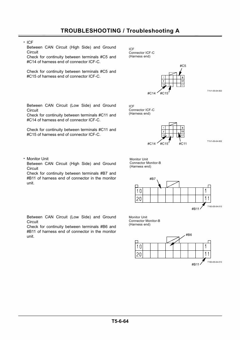
TROUBLESHOOTING / Troubleshooting A
T5-6-64
• ICF Between CAN Circuit (High Side) and Ground Circuit Check for continuity between terminals #C5 and #C14 of harness end of connector ICF-C. Check for continuity between terminals #C5 and #C15 of harness end of connector ICF-C. Between CAN Circuit (Low Side) and Ground Circuit Check for continuity between terminals #C11 and #C14 of harness end of connector ICF-C. Check for continuity between terminals #C11 and #C15 of harness end of connector ICF-C.
• Monitor Unit Between CAN Circuit (High Side) and Ground Circuit Check for continuity between terminals #B7 and #B11 of harness end of connector in the monitor unit. Between CAN Circuit (Low Side) and Ground Circuit Check for continuity between terminals #B6 and #B11 of harness end of connector in the monitor unit.
T1V1-05-04-002
T1V1-05-04-002
T183-05-04-013
T183-05-04-013
#C5
#C15#C14
#C11 #C15#C14
#B7
#B11
#B6
#B11
ICF Connector ICF-C (Harness end)
ICF Connector ICF-C (Harness end)
Monitor Unit Connector Monitor-B(Harness end)
Monitor Unit Connector Monitor-B(Harness end)
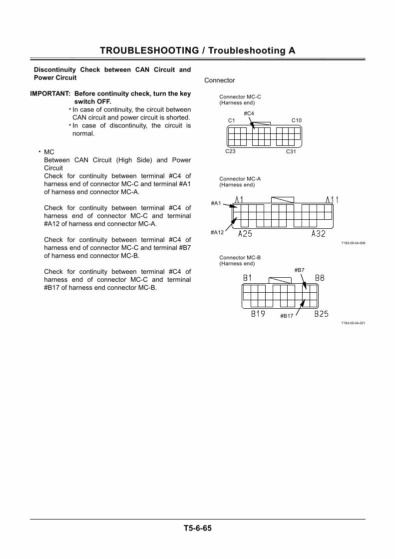
TROUBLESHOOTING / Troubleshooting A
T5-6-65
Discontinuity Check between CAN Circuit and Power Circuit
IMPORTANT: Before continuity check, turn the key
switch OFF. • In case of continuity, the circuit between
CAN circuit and power circuit is shorted. • In case of discontinuity, the circuit is
normal.
• MC Between CAN Circuit (High Side) and Power Circuit Check for continuity between terminal #C4 of harness end of connector MC-C and terminal #A1 of harness end connector MC-A. Check for continuity between terminal #C4 of harness end of connector MC-C and terminal #A12 of harness end connector MC-A. Check for continuity between terminal #C4 of harness end of connector MC-C and terminal #B7 of harness end connector MC-B. Check for continuity between terminal #C4 of harness end of connector MC-C and terminal #B17 of harness end connector MC-B.
Connector
T183-05-04-008
T183-05-04-021
C31
C10
C23
C1
#C4
#A1
#A12
#B7
#B17
Connector MC-C (Harness end)
Connector MC-A (Harness end)
Connector MC-B (Harness end)
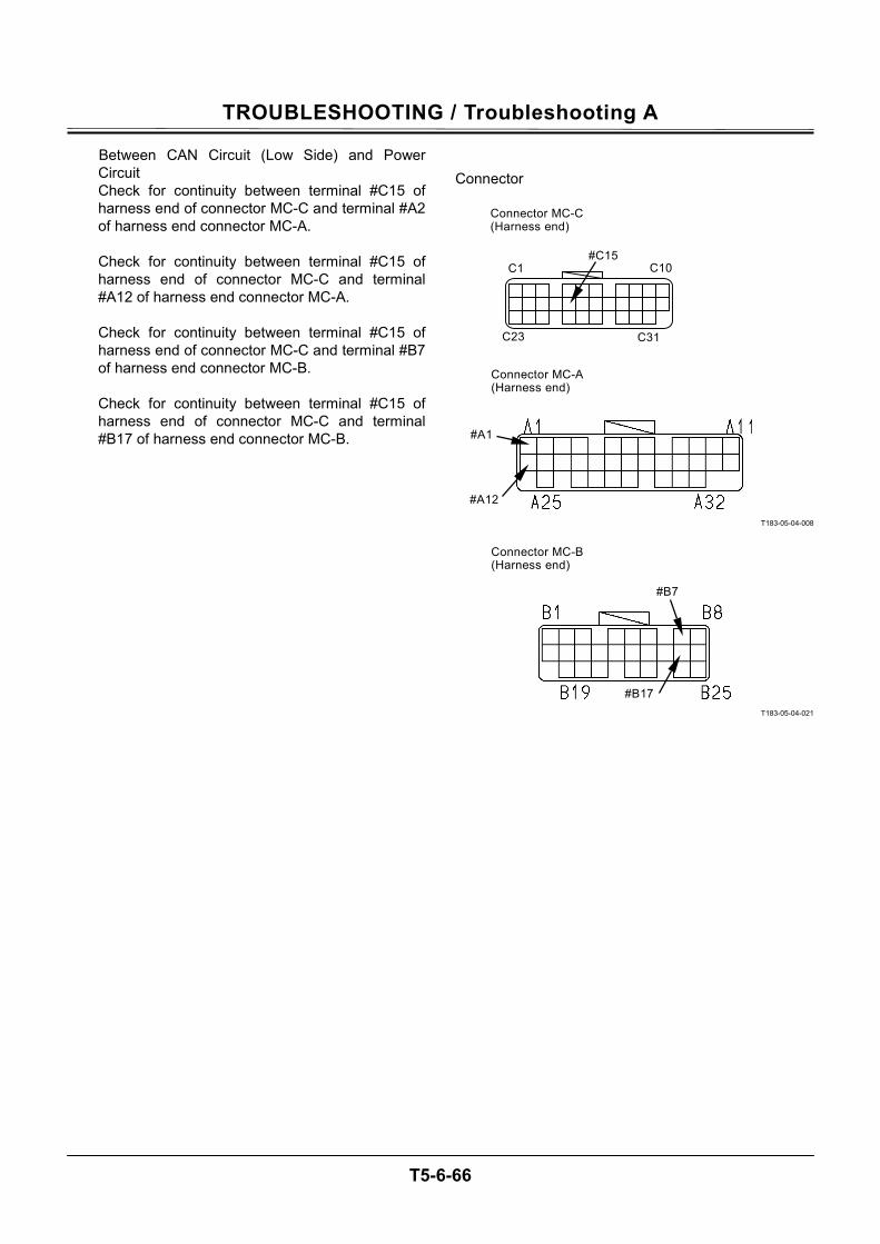
TROUBLESHOOTING / Troubleshooting A
T5-6-66
Between CAN Circuit (Low Side) and Power Circuit Check for continuity between terminal #C15 of harness end of connector MC-C and terminal #A2 of harness end connector MC-A. Check for continuity between terminal #C15 of harness end of connector MC-C and terminal #A12 of harness end connector MC-A. Check for continuity between terminal #C15 of harness end of connector MC-C and terminal #B7 of harness end connector MC-B. Check for continuity between terminal #C15 of harness end of connector MC-C and terminal #B17 of harness end connector MC-B.
Connector
T183-05-04-008
T183-05-04-021
C31
C10
C23
C1
#C15
#A1
#A12
#B7
#B17
Connector MC-C (Harness end)
Connector MC-A (Harness end)
Connector MC-B (Harness end)
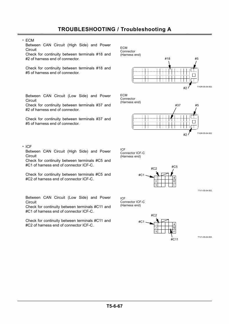
TROUBLESHOOTING / Troubleshooting A
T5-6-67
• ECM Between CAN Circuit (High Side) and Power Circuit Check for continuity between terminals #18 and #2 of harness end of connector. Check for continuity between terminals #18 and #5 of harness end of connector. Between CAN Circuit (Low Side) and Power Circuit Check for continuity between terminals #37 and #2 of harness end of connector. Check for continuity between terminals #37 and #5 of harness end of connector.
• ICF Between CAN Circuit (High Side) and Power Circuit Check for continuity between terminals #C5 and #C1 of harness end of connector ICF-C. Check for continuity between terminals #C5 and #C2 of harness end of connector ICF-C. Between CAN Circuit (Low Side) and Power Circuit Check for continuity between terminals #C11 and #C1 of harness end of connector ICF-C. Check for continuity between terminals #C11 and #C2 of harness end of connector ICF-C.
T1GR-05-04-002
T1GR-05-04-002
T1V1-05-04-002
T1V1-05-04-002
#18 #5
#2
#37 #5
#2
#C5
#C11
#C2
#C1
#C2
#C1
ECM Connector (Harness end)
ECM Connector (Harness end)
ICF Connector ICF-C (Harness end)
ICF Connector ICF-C (Harness end)
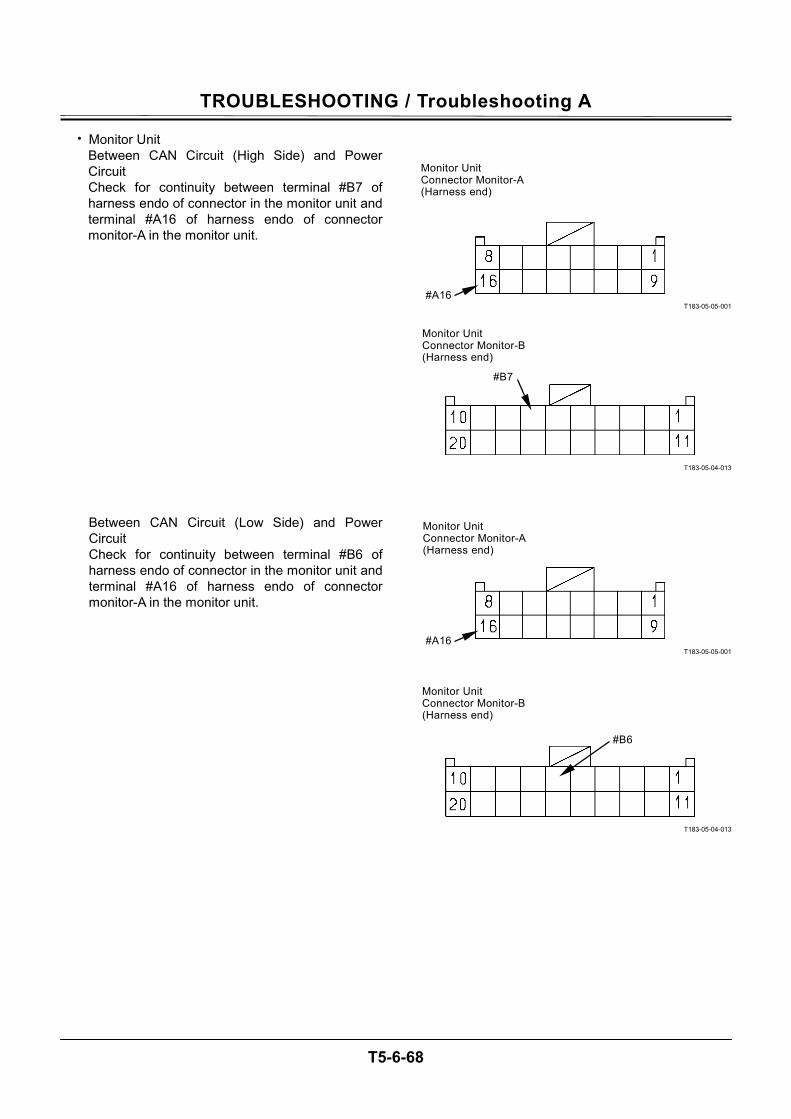
TROUBLESHOOTING / Troubleshooting A
T5-6-68
• Monitor Unit Between CAN Circuit (High Side) and Power Circuit Check for continuity between terminal #B7 of harness endo of connector in the monitor unit and terminal #A16 of harness endo of connector monitor-A in the monitor unit.
Between CAN Circuit (Low Side) and Power Circuit Check for continuity between terminal #B6 of harness endo of connector in the monitor unit and terminal #A16 of harness endo of connector monitor-A in the monitor unit.
T183-05-05-001
T183-05-04-013
T183-05-05-001
T183-05-04-013
#B7
#B6
#A16
#A16
Monitor Unit Connector Monitor-A (Harness end)
Monitor Unit Connector Monitor-B(Harness end)
Monitor Unit Connector Monitor-A (Harness end)
Monitor Unit Connector Monitor-B(Harness end)
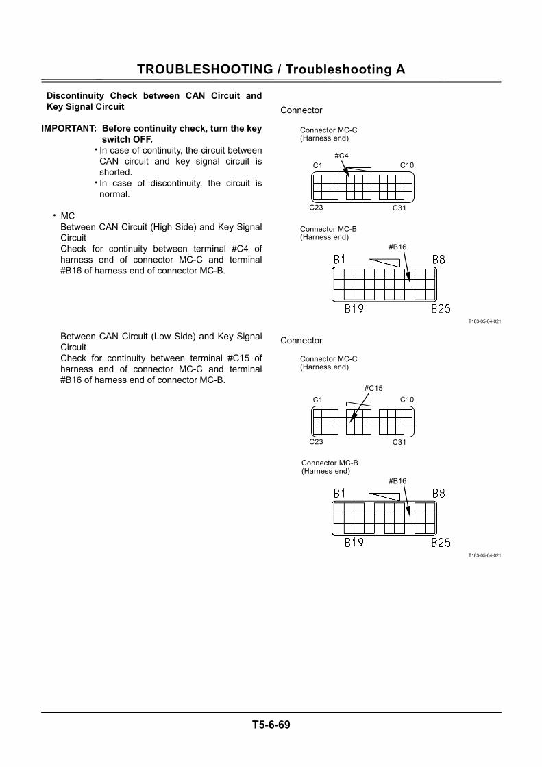
TROUBLESHOOTING / Troubleshooting A
T5-6-69
Discontinuity Check between CAN Circuit and Key Signal Circuit
IMPORTANT: Before continuity check, turn the key
switch OFF. • In case of continuity, the circuit between
CAN circuit and key signal circuit is shorted.
• In case of discontinuity, the circuit is normal.
• MC
Between CAN Circuit (High Side) and Key Signal Circuit Check for continuity between terminal #C4 of harness end of connector MC-C and terminal #B16 of harness end of connector MC-B. Between CAN Circuit (Low Side) and Key Signal Circuit Check for continuity between terminal #C15 of harness end of connector MC-C and terminal #B16 of harness end of connector MC-B.
Connector
T183-05-04-021
Connector
T183-05-04-021
C31
C10
C23
C1
#C4
#B16
C31
C10
C23
C1
#C15
#B16
Connector MC-C (Harness end)
Connector MC-B (Harness end)
Connector MC-C (Harness end)
Connector MC-B (Harness end)
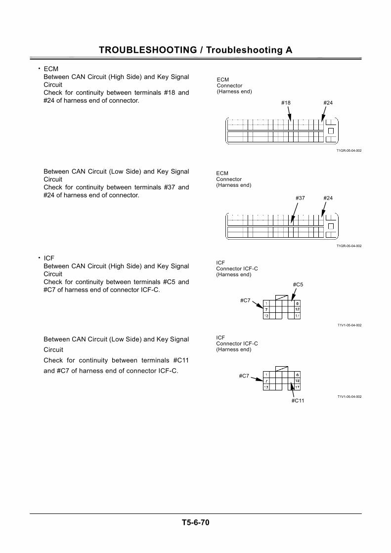
TROUBLESHOOTING / Troubleshooting A
T5-6-70
• ECM Between CAN Circuit (High Side) and Key Signal Circuit Check for continuity between terminals #18 and #24 of harness end of connector. Between CAN Circuit (Low Side) and Key Signal Circuit Check for continuity between terminals #37 and #24 of harness end of connector.
• ICF Between CAN Circuit (High Side) and Key Signal Circuit Check for continuity between terminals #C5 and #C7 of harness end of connector ICF-C. Between CAN Circuit (Low Side) and Key Signal Circuit Check for continuity between terminals #C11 and #C7 of harness end of connector ICF-C.
T1GR-05-04-002
T1GR-05-04-002
T1V1-05-04-002
T1V1-05-04-002
#18 #24
#37 #24
#C5
#C11
#C7
#C7
ECM Connector (Harness end)
ECM Connector (Harness end)
ICF Connector ICF-C (Harness end)
ICF Connector ICF-C (Harness end)
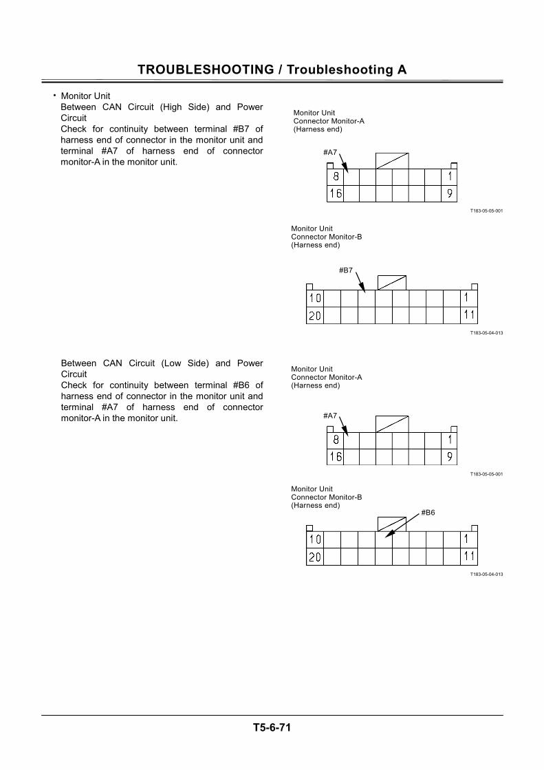
TROUBLESHOOTING / Troubleshooting A
T5-6-71
• Monitor Unit Between CAN Circuit (High Side) and Power Circuit Check for continuity between terminal #B7 of harness end of connector in the monitor unit and terminal #A7 of harness end of connector monitor-A in the monitor unit.
Between CAN Circuit (Low Side) and Power Circuit Check for continuity between terminal #B6 of harness end of connector in the monitor unit and terminal #A7 of harness end of connector monitor-A in the monitor unit.
T183-05-05-001
T183-05-04-013
T183-05-05-001
T183-05-04-013
#B7
#B6
#A7
#A7
Monitor Unit Connector Monitor-A(Harness end)
Monitor Unit Connector Monitor-B(Harness end)
Monitor Unit Connector Monitor-A(Harness end)
Monitor Unit Connector Monitor-B(Harness end)
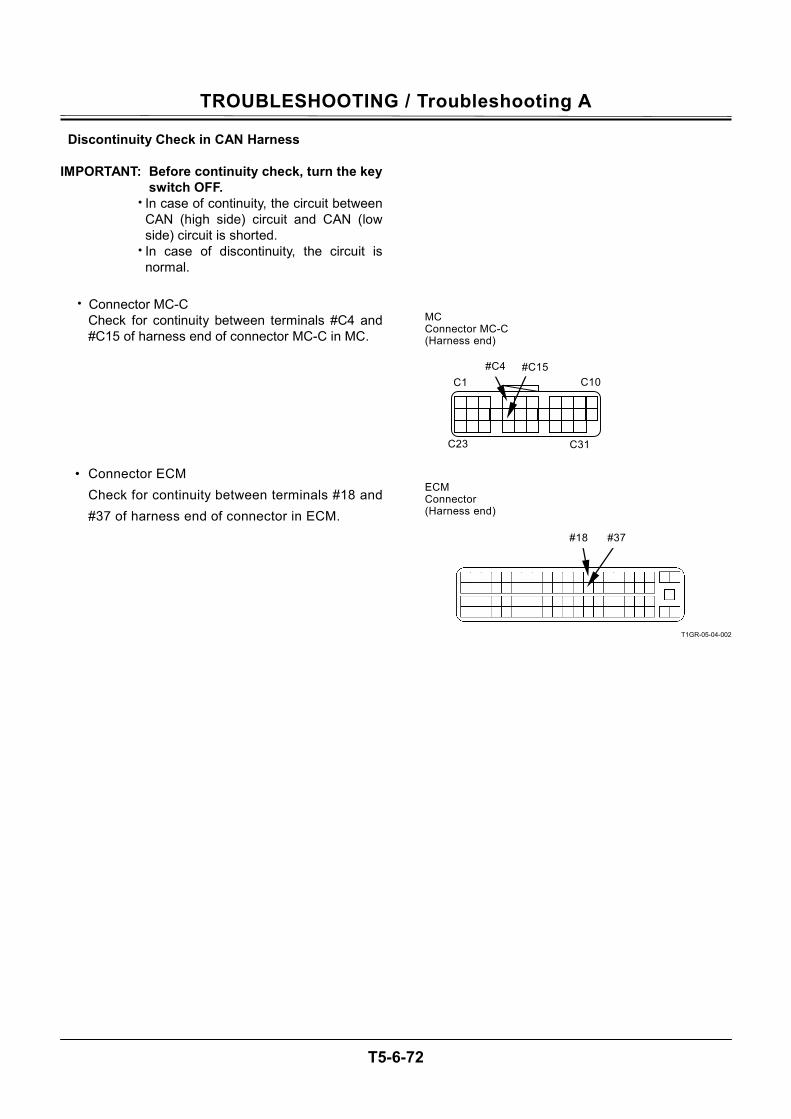
TROUBLESHOOTING / Troubleshooting A
T5-6-72
Discontinuity Check in CAN Harness IMPORTANT: Before continuity check, turn the key
switch OFF. • In case of continuity, the circuit between
CAN (high side) circuit and CAN (low side) circuit is shorted.
• In case of discontinuity, the circuit is normal.
• Connector MC-C
Check for continuity between terminals #C4 and #C15 of harness end of connector MC-C in MC.
• Connector ECM Check for continuity between terminals #18 and #37 of harness end of connector in ECM.
T1GR-05-04-002
C31
C10
C23
C1
#C15#C4
MC Connector MC-C (Harness end)
ECM Connector (Harness end)
#18 #37
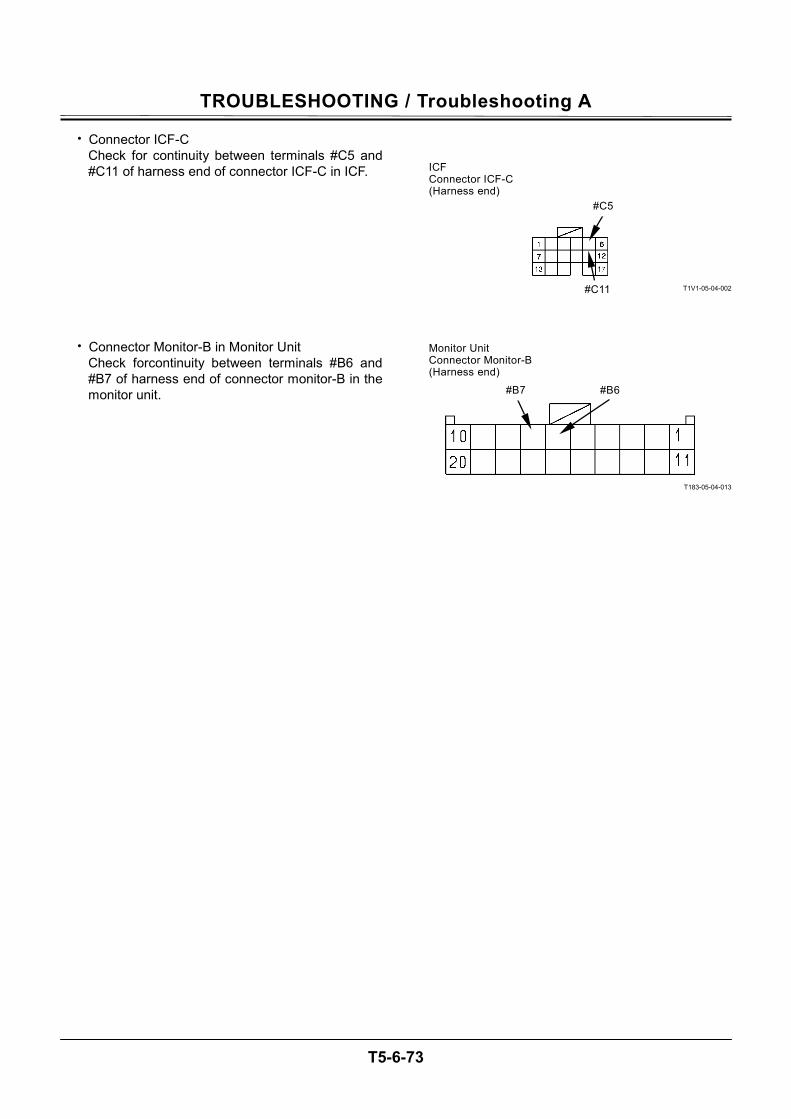
TROUBLESHOOTING / Troubleshooting A
T5-6-73
• Connector ICF-C Check for continuity between terminals #C5 and #C11 of harness end of connector ICF-C in ICF.
• Connector Monitor-B in Monitor Unit Check forcontinuity between terminals #B6 and #B7 of harness end of connector monitor-B in the monitor unit.
T1V1-05-04-002
T183-05-04-013
#C5
#C11
ICF Connector ICF-C (Harness end)
#B7 #B6
Monitor Unit Connector Monitor-B(Harness end)

TROUBLESHOOTING / Troubleshooting A
T5-6-74
ENGINE FAILURE MC FAULT CODE 11100 Fault Code Trouble Cause Influenced Control
11100-2 Abnormal Engine Speed Engine Speed: 4000 min-1 or faster Speed Sensing Control
• ECM sends by using CAN bus line. The actual engine speed is abnormal. Perform self-diagnosis of ECM.
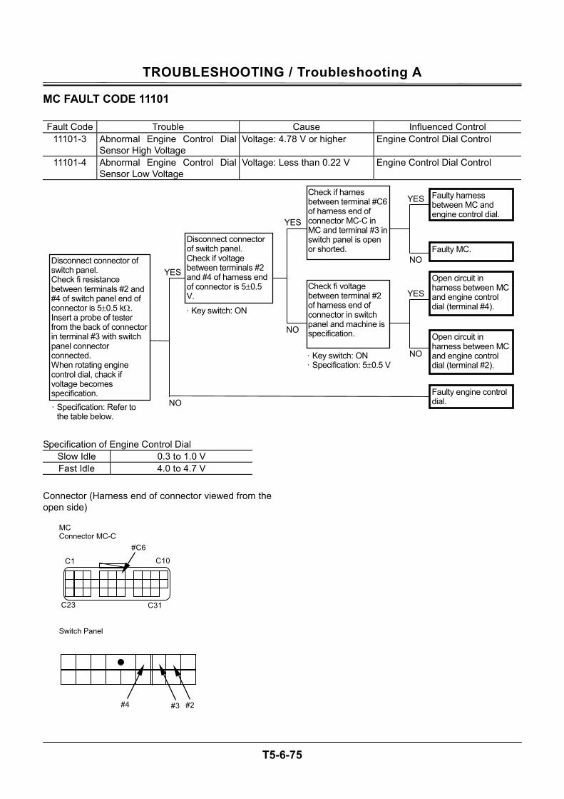
TROUBLESHOOTING / Troubleshooting A
T5-6-75
MC FAULT CODE 11101 Fault Code Trouble Cause Influenced Control
11101-3 Abnormal Engine Control Dial Sensor High Voltage
Voltage: 4.78 V or higher Engine Control Dial Control
11101-4 Abnormal Engine Control Dial Sensor Low Voltage
Voltage: Less than 0.22 V Engine Control Dial Control
Specification of Engine Control Dial
Slow Idle 0.3 to 1.0 V Fast Idle 4.0 to 4.7 V
Connector (Harness end of connector viewed from the open side)
MC Connector MC-C
C31
C10
C23
C1
#C6
#2 #4
#3
NO
NO
NO
NO
YES
YES
YES
YES
Disconnect connector of switch panel. Check if voltage between terminals #2 and #4 of harness end of connector is 5±0.5 V.
· Key switch: ON
· Key switch: ON · Specification: 5±0.5 V
· Specification: Refer to the table below.
Open circuit in harness between MC and engine control dial (terminal #4).
Disconnect connector of switch panel. Check fi resistance between terminals #2 and #4 of switch panel end of connector is 5±0.5 kΩ. Insert a probe of tester from the back of connector in terminal #3 with switch panel connector connected. When rotating engine control dial, chack if voltage becomes specification.
Open circuit in harness between MC and engine control dial (terminal #2).
Faulty engine control dial.
Faulty harness between MC and engine control dial.
Check if harnes between terminal #C6 of harness end of connector MC-C in MC and terminal #3 in switch panel is open or shorted. Faulty MC.
Check fi voltage between terminal #2 of harness end of connector in switch panel and machine is specification.
Switch Panel
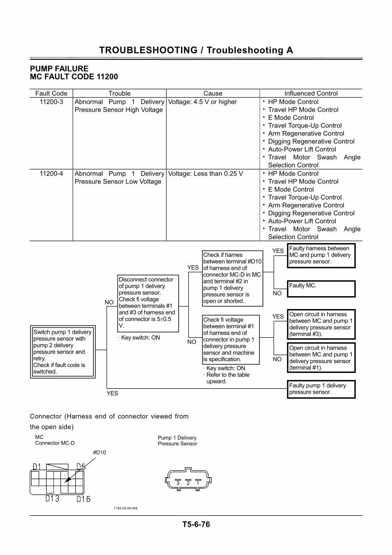
TROUBLESHOOTING / Troubleshooting A
T5-6-76
PUMP FAILURE MC FAULT CODE 11200
Fault Code Trouble Cause Influenced Control 11200-3 Abnormal Pump 1 Delivery
Pressure Sensor High VoltageVoltage: 4.5 V or higher • HP Mode Control
• Travel HP Mode Control • E Mode Control • Travel Torque-Up Control • Arm Regenerative Control • Digging Regenerative Control • Auto-Power Lift Control • Travel Motor Swash Angle
Selection Control 11200-4 Abnormal Pump 1 Delivery
Pressure Sensor Low Voltage Voltage: Less than 0.25 V • HP Mode Control
• Travel HP Mode Control • E Mode Control • Travel Torque-Up Control • Arm Regenerative Control • Digging Regenerative Control • Auto-Power Lift Control • Travel Motor Swash Angle
Selection Control Connector (Harness end of connector viewed from the open side)
T183-05-04-009
Pump 1 Delivery Pressure Sensor
123
MC Connector MC-D
#D10
Switch pump 1 delivery pressure sensor with pump 2 delivery pressure sensor and retry. Check if fault code is switched.
NO NO
NO
NO
YES
YES
YES
YES
Disconnect connector of pump 1 delivery pressure sensor. Check fi voltage between terminals #1 and #3 of harness end of connector is 5±0.5 V.
Open circuit in harness between MC and pump 1 delivery pressure sensor (terminal #3).
Open circuit in harness between MC and pump 1 delivery pressure sensor (terminal #1).
Faulty pump 1 delivery pressure sensor.
Faulty harness between MC and pump 1 delivery pressure sensor.
Check if harnes between terminal #D10 of harness end of connector MC-D in MC and terminal #2 in pump 1 delivery pressure sensor is open or shorted.
Faulty MC.
Check fi voltage between terminal #1 of harness end of connector in pump 1 delivery pressure sensor and machine is specification. · Key switch: ON · Refer to the table
upward.
· Key switch: ON
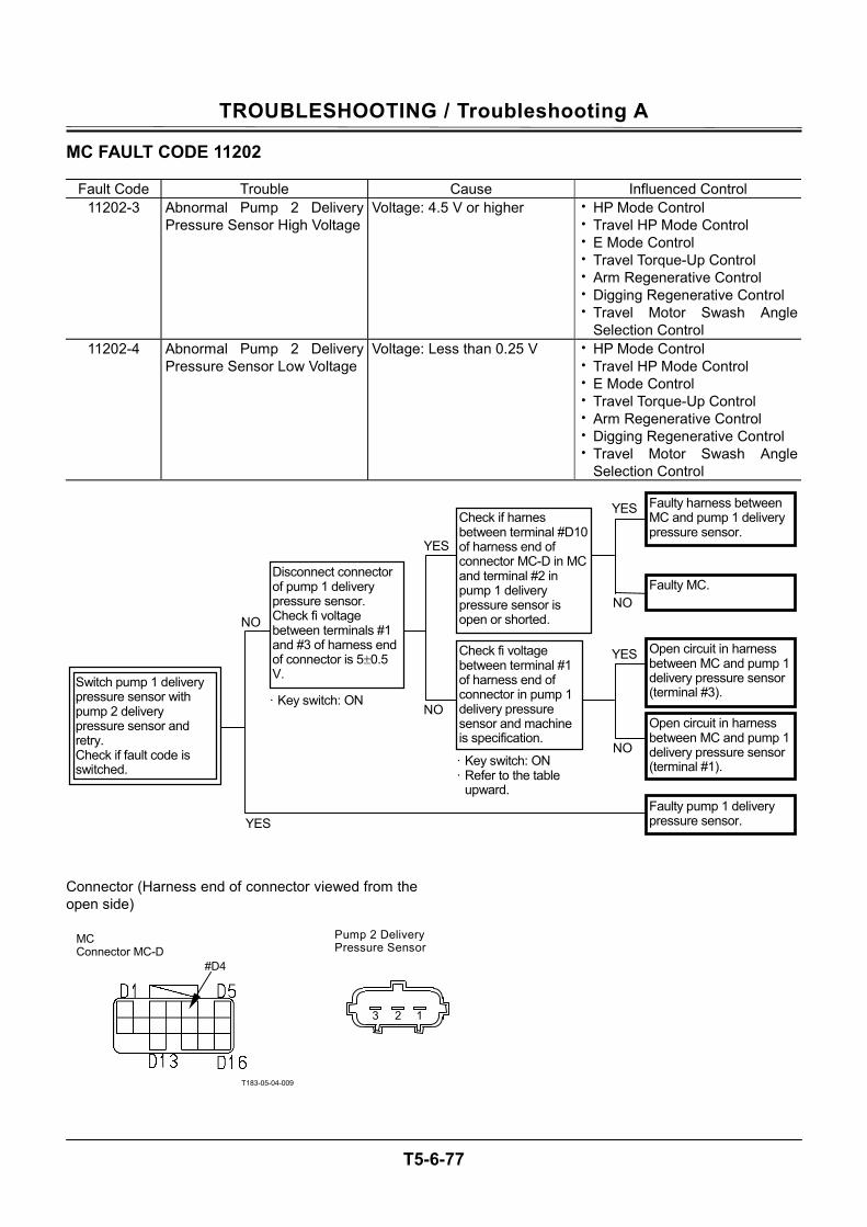
TROUBLESHOOTING / Troubleshooting A
T5-6-77
MC FAULT CODE 11202
Fault Code Trouble Cause Influenced Control 11202-3 Abnormal Pump 2 Delivery
Pressure Sensor High VoltageVoltage: 4.5 V or higher • HP Mode Control
• Travel HP Mode Control • E Mode Control • Travel Torque-Up Control • Arm Regenerative Control • Digging Regenerative Control • Travel Motor Swash Angle
Selection Control 11202-4 Abnormal Pump 2 Delivery
Pressure Sensor Low Voltage Voltage: Less than 0.25 V • HP Mode Control
• Travel HP Mode Control • E Mode Control • Travel Torque-Up Control • Arm Regenerative Control • Digging Regenerative Control • Travel Motor Swash Angle
Selection Control Connector (Harness end of connector viewed from the open side)
T183-05-04-009
Pump 2 Delivery Pressure Sensor
123
MC Connector MC-D
#D4
Switch pump 1 delivery pressure sensor with pump 2 delivery pressure sensor and retry. Check if fault code is switched.
NO NO
NO
NO
YES
YES
YES
YES
Disconnect connector of pump 1 delivery pressure sensor. Check fi voltage between terminals #1 and #3 of harness end of connector is 5±0.5 V.
Open circuit in harness between MC and pump 1 delivery pressure sensor (terminal #3).
Open circuit in harness between MC and pump 1 delivery pressure sensor (terminal #1).
Faulty pump 1 delivery pressure sensor.
Faulty harness between MC and pump 1 delivery pressure sensor.
Check if harnes between terminal #D10 of harness end of connector MC-D in MC and terminal #2 in pump 1 delivery pressure sensor is open or shorted.
Faulty MC.
Check fi voltage between terminal #1 of harness end of connector in pump 1 delivery pressure sensor and machine is specification.
· Key switch: ON · Refer to the table
upward.
· Key switch: ON
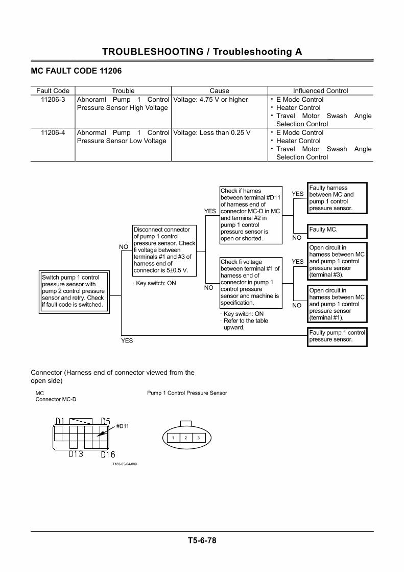
TROUBLESHOOTING / Troubleshooting A
T5-6-78
MC FAULT CODE 11206
Fault Code Trouble Cause Influenced Control 11206-3 Abnoraml Pump 1 Control
Pressure Sensor High VoltageVoltage: 4.75 V or higher • E Mode Control
• Heater Control • Travel Motor Swash Angle
Selection Control 11206-4 Abnormal Pump 1 Control
Pressure Sensor Low Voltage Voltage: Less than 0.25 V • E Mode Control
• Heater Control • Travel Motor Swash Angle
Selection Control Connector (Harness end of connector viewed from the open side)
T183-05-04-009
Switch pump 1 control pressure sensor with pump 2 control pressure sensor and retry. Check if fault code is switched.
NO NO
NO
NO
YES
YES
YES
YES
Disconnect connector of pump 1 control pressure sensor. Check fi voltage between terminals #1 and #3 of harness end of connector is 5±0.5 V.
Open circuit in harness between MC and pump 1 control pressure sensor (terminal #3).
Open circuit in harness between MC and pump 1 control pressure sensor (terminal #1).
Faulty pump 1 control pressure sensor.
Faulty harness between MC and pump 1 control pressure sensor.
Check if harnes between terminal #D11 of harness end of connector MC-D in MC and terminal #2 in pump 1 control pressure sensor is open or shorted.
Faulty MC.
Check fi voltage between terminal #1 of harness end of connector in pump 1 control pressure sensor and machine is specification.
· Key switch: ON · Refer to the table
upward.
· Key switch: ON
MC Connector MC-D
#D11
Pump 1 Control Pressure Sensor
1 2 3
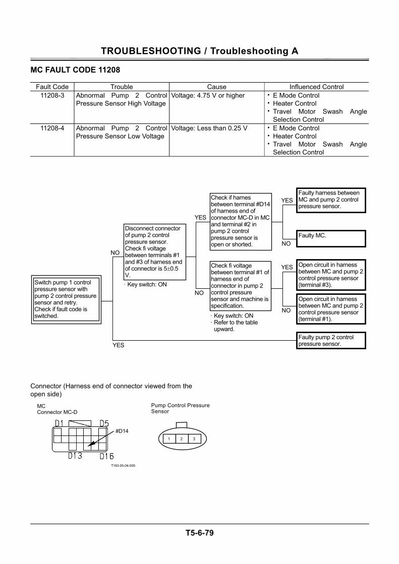
TROUBLESHOOTING / Troubleshooting A
T5-6-79
MC FAULT CODE 11208
Fault Code Trouble Cause Influenced Control 11208-3 Abnormal Pump 2 Control
Pressure Sensor High VoltageVoltage: 4.75 V or higher • E Mode Control
• Heater Control • Travel Motor Swash Angle
Selection Control 11208-4 Abnormal Pump 2 Control
Pressure Sensor Low Voltage Voltage: Less than 0.25 V • E Mode Control
• Heater Control • Travel Motor Swash Angle
Selection Control Connector (Harness end of connector viewed from the open side)
T183-05-04-009
Switch pump 1 control pressure sensor with pump 2 control pressure sensor and retry. Check if fault code is switched.
NO NO
NO
NO
YES
YES
YES
YES
Disconnect connector of pump 2 control pressure sensor. Check fi voltage between terminals #1 and #3 of harness end of connector is 5±0.5 V.
Open circuit in harness between MC and pump 2 control pressure sensor (terminal #3).
Open circuit in harness between MC and pump 2 control pressure sensor (terminal #1).
Faulty pump 2 control pressure sensor.
Faulty harness between MC and pump 2 control pressure sensor.
Check if harnes between terminal #D14 of harness end of connector MC-D in MC and terminal #2 in pump 2 control pressure sensor is open or shorted.
Faulty MC.
Check fi voltage between terminal #1 of harness end of connector in pump 2 control pressure sensor and machine is specification. · Key switch: ON · Refer to the table
upward.
· Key switch: ON
Pump Control Pressure Sensor
1 2 3
MC Connector MC-D
#D14
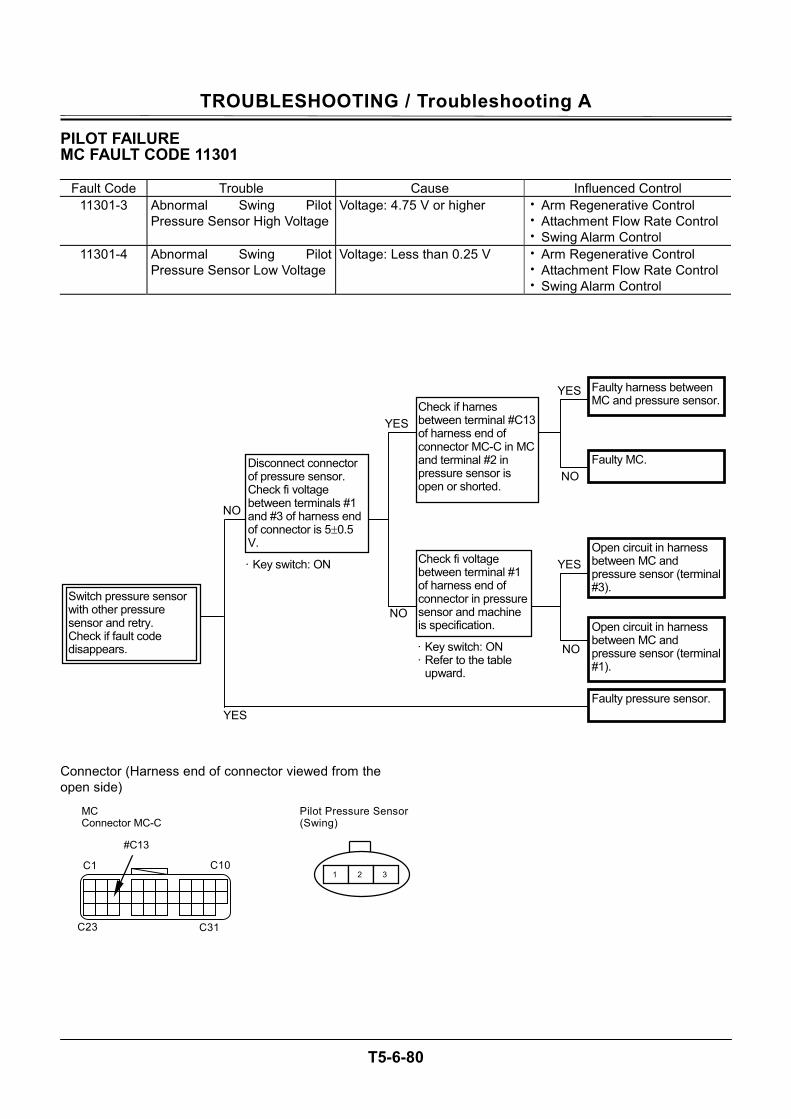
TROUBLESHOOTING / Troubleshooting A
T5-6-80
PILOT FAILURE MC FAULT CODE 11301
Fault Code Trouble Cause Influenced Control 11301-3 Abnormal Swing Pilot
Pressure Sensor High VoltageVoltage: 4.75 V or higher • Arm Regenerative Control
• Attachment Flow Rate Control • Swing Alarm Control
11301-4 Abnormal Swing Pilot Pressure Sensor Low Voltage
Voltage: Less than 0.25 V • Arm Regenerative Control • Attachment Flow Rate Control • Swing Alarm Control
Connector (Harness end of connector viewed from the open side)
MC Connector MC-C
C31
C10
C23
C1
#C13
Pilot Pressure Sensor (Swing)
1 2 3
NO
NO
NO
NO
YES
YES
YES
YES
Disconnect connector of pressure sensor. Check fi voltage between terminals #1 and #3 of harness end of connector is 5±0.5 V. Open circuit in harness
between MC and pressure sensor (terminal #3).
Switch pressure sensor with other pressure sensor and retry. Check if fault code disappears.
Open circuit in harness between MC and pressure sensor (terminal #1).
Faulty pressure sensor.
Faulty harness between MC and pressure sensor.Check if harnes
between terminal #C13 of harness end of connector MC-C in MC and terminal #2 in pressure sensor is open or shorted.
Faulty MC.
Check fi voltage between terminal #1 of harness end of connector in pressure sensor and machine is specification.
· Key switch: ON · Refer to the table
upward.
· Key switch: ON
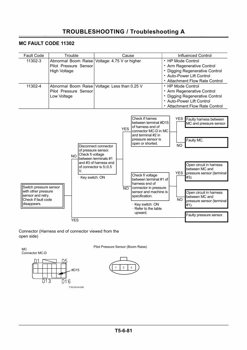
TROUBLESHOOTING / Troubleshooting A
T5-6-81
MC FAULT CODE 11302
Fault Code Trouble Cause Influenced Control 11302-3 Abnormal Boom Raise
Pilot Pressure Sensor High Voltage
Voltage: 4.75 V or higher • HP Mode Control • Arm Regenerative Control • Digging Regenerative Control • Auto-Power Lift Control • Attachment Flow Rate Control
11302-4 Abnormal Boom Raise Pilot Pressure Sensor Low Voltage
Voltage: Less than 0.25 V • HP Mode Control • Arm Regenerative Control • Digging Regenerative Control • Auto-Power Lift Control • Attachment Flow Rate Control
Connector (Harness end of connector viewed from the open side)
T183-05-04-009
Pilot Pressure Sensor (Boom Raise)
1 2 3
MC Connector MC-D
#D15
NO
NO
NO
NO
YES
YES
YES
YES
Disconnect connector of pressure sensor. Check fi voltage between terminals #1 and #3 of harness end of connector is 5±0.5 V.
Open circuit in harness between MC and pressure sensor (terminal #3).
Switch pressure sensor with other pressure sensor and retry. Check if fault code disappears.
Open circuit in harness between MC and pressure sensor (terminal #1).
Faulty pressure sensor.
Faulty harness between MC and pressure sensor.
Check if harnes between terminal #D15 of harness end of connector MC-D in MC and terminal #2 in pressure sensor is open or shorted.
Faulty MC.
Check fi voltage between terminal #1 of harness end of connector in pressure sensor and machine is specification.
· Key switch: ON · Refer to the table
upward.
· Key switch: ON
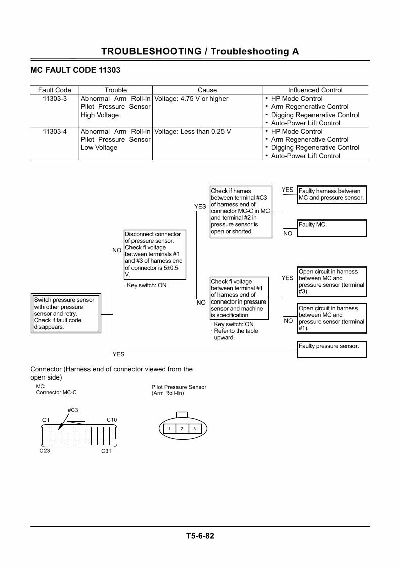
TROUBLESHOOTING / Troubleshooting A
T5-6-82
MC FAULT CODE 11303
Fault Code Trouble Cause Influenced Control 11303-3 Abnormal Arm Roll-In
Pilot Pressure Sensor High Voltage
Voltage: 4.75 V or higher • HP Mode Control • Arm Regenerative Control • Digging Regenerative Control • Auto-Power Lift Control
11303-4 Abnormal Arm Roll-In Pilot Pressure Sensor Low Voltage
Voltage: Less than 0.25 V • HP Mode Control • Arm Regenerative Control • Digging Regenerative Control • Auto-Power Lift Control
Connector (Harness end of connector viewed from the open side)
Pilot Pressure Sensor (Arm Roll-In)
1 2 3
MC Connector MC-C
C31
C10
C23
C1
#C3
NO
NO
NO
NO
YES
YES
YES
YES
Disconnect connector of pressure sensor. Check fi voltage between terminals #1 and #3 of harness end of connector is 5±0.5 V. Open circuit in harness
between MC and pressure sensor (terminal #3).
Switch pressure sensor with other pressure sensor and retry. Check if fault code disappears.
Open circuit in harness between MC and pressure sensor (terminal #1).
Faulty pressure sensor.
Faulty harness between MC and pressure sensor.
Check if harnes between terminal #C3 of harness end of connector MC-C in MC and terminal #2 in pressure sensor is open or shorted.
Faulty MC.
Check fi voltage between terminal #1 of harness end of connector in pressure sensor and machine is specification. · Key switch: ON · Refer to the table
upward.
· Key switch: ON
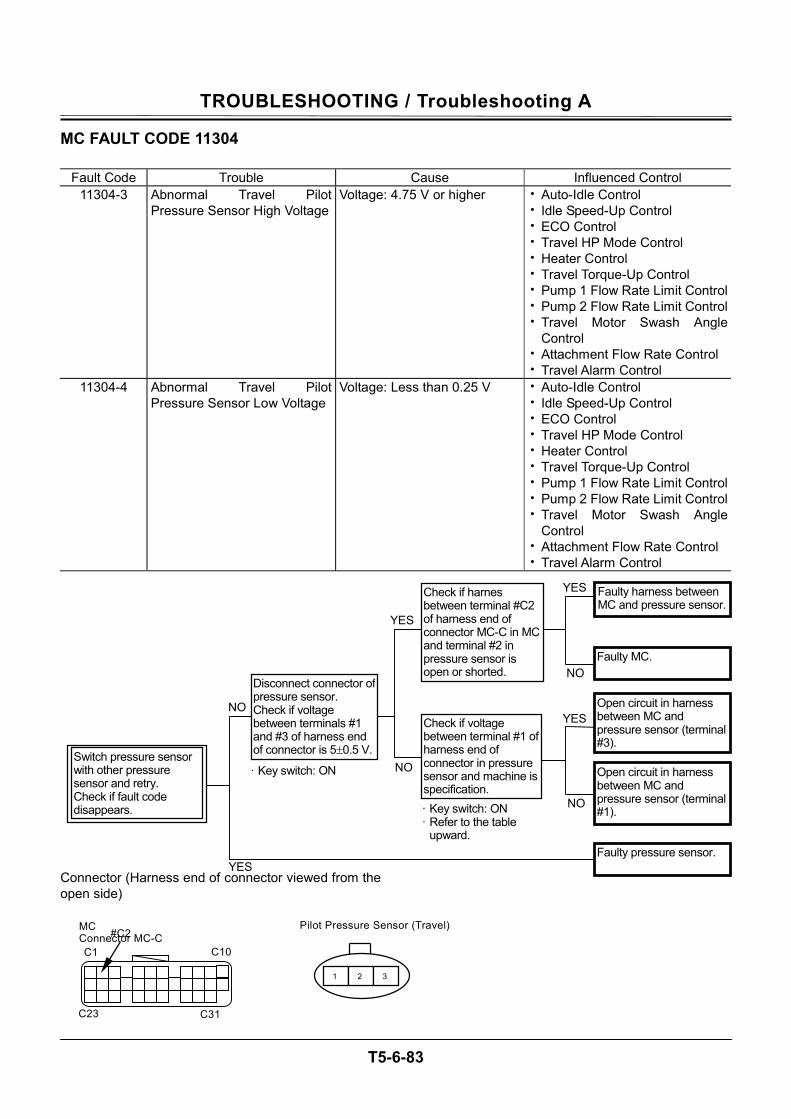
TROUBLESHOOTING / Troubleshooting A
T5-6-83
MC FAULT CODE 11304
Fault Code Trouble Cause Influenced Control 11304-3 Abnormal Travel Pilot
Pressure Sensor High VoltageVoltage: 4.75 V or higher • Auto-Idle Control
• Idle Speed-Up Control • ECO Control • Travel HP Mode Control • Heater Control • Travel Torque-Up Control • Pump 1 Flow Rate Limit Control• Pump 2 Flow Rate Limit Control• Travel Motor Swash Angle
Control • Attachment Flow Rate Control • Travel Alarm Control
11304-4 Abnormal Travel Pilot Pressure Sensor Low Voltage
Voltage: Less than 0.25 V • Auto-Idle Control • Idle Speed-Up Control • ECO Control • Travel HP Mode Control • Heater Control • Travel Torque-Up Control • Pump 1 Flow Rate Limit Control• Pump 2 Flow Rate Limit Control• Travel Motor Swash Angle
Control • Attachment Flow Rate Control • Travel Alarm Control
Connector (Harness end of connector viewed from the open side)
NO
NO
NO
NO
YES
YES
YES
YES
Disconnect connector of pressure sensor. Check if voltage between terminals #1 and #3 of harness end of connector is 5±0.5 V.
Open circuit in harness between MC and pressure sensor (terminal #3).
Switch pressure sensor with other pressure sensor and retry. Check if fault code disappears.
Open circuit in harness between MC and pressure sensor (terminal #1).
Faulty pressure sensor.
Faulty harness between MC and pressure sensor.
Check if harnes between terminal #C2 of harness end of connector MC-C in MC and terminal #2 in pressure sensor is open or shorted.
Faulty MC.
Check if voltage between terminal #1 of harness end of connector in pressure sensor and machine is specification. · Key switch: ON · Refer to the table
upward.
· Key switch: ON
Pilot Pressure Sensor (Travel)
1 2 3
C31
C10
C23
C1
#C2 MC Connector MC-C
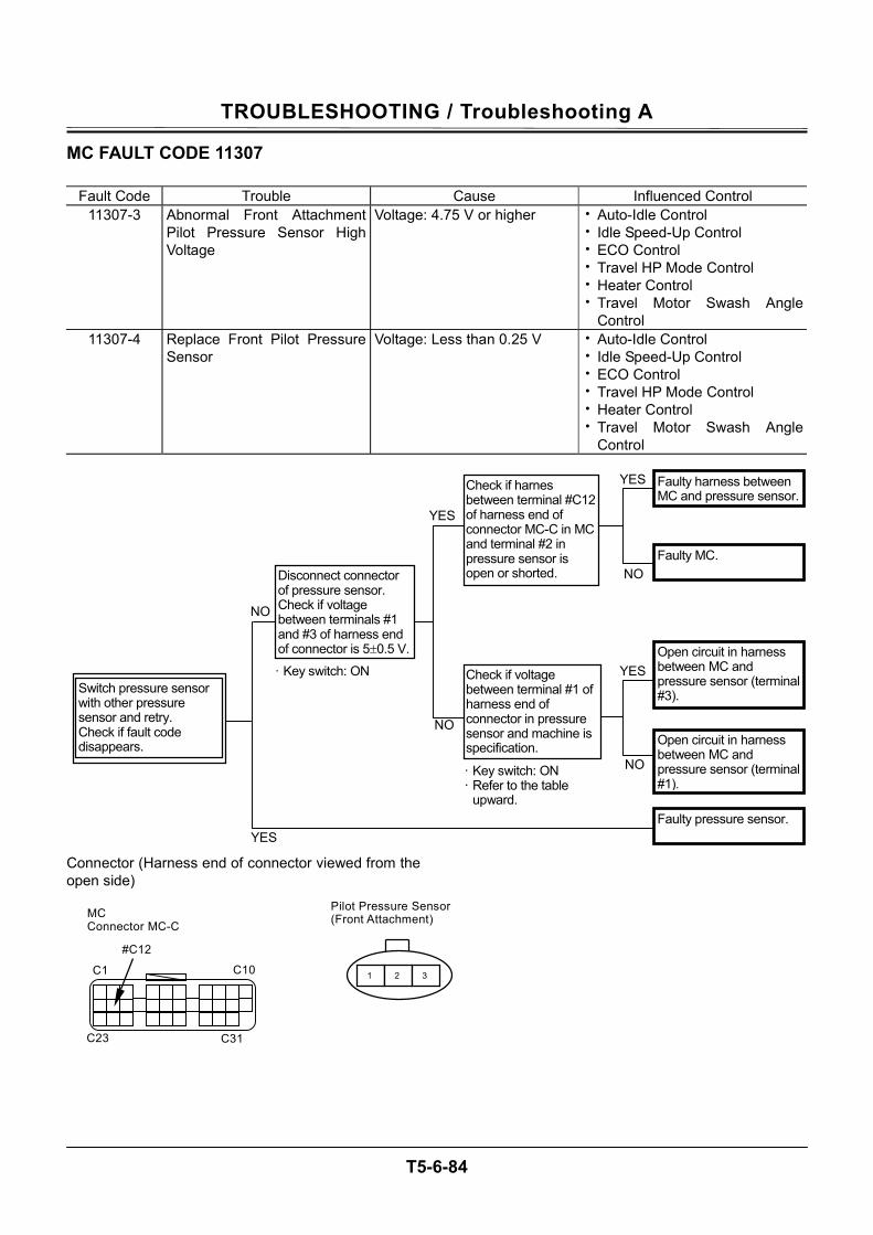
TROUBLESHOOTING / Troubleshooting A
T5-6-84
MC FAULT CODE 11307
Fault Code Trouble Cause Influenced Control 11307-3 Abnormal Front Attachment
Pilot Pressure Sensor High Voltage
Voltage: 4.75 V or higher • Auto-Idle Control • Idle Speed-Up Control • ECO Control • Travel HP Mode Control • Heater Control • Travel Motor Swash Angle
Control 11307-4 Replace Front Pilot Pressure
Sensor Voltage: Less than 0.25 V • Auto-Idle Control
• Idle Speed-Up Control • ECO Control • Travel HP Mode Control • Heater Control • Travel Motor Swash Angle
Control Connector (Harness end of connector viewed from the open side)
NO
NO
NO
NO
YES
YES
YES
YES
Disconnect connector of pressure sensor. Check if voltage between terminals #1 and #3 of harness end of connector is 5±0.5 V. Open circuit in harness
between MC and pressure sensor (terminal #3). Switch pressure sensor
with other pressure sensor and retry. Check if fault code disappears. Open circuit in harness
between MC and pressure sensor (terminal #1).
Faulty pressure sensor.
Faulty harness between MC and pressure sensor.
Check if harnes between terminal #C12 of harness end of connector MC-C in MC and terminal #2 in pressure sensor is open or shorted.
Faulty MC.
Check if voltage between terminal #1 of harness end of connector in pressure sensor and machine is specification.
· Key switch: ON · Refer to the table
upward.
· Key switch: ON
Pilot Pressure Sensor (Front Attachment)
1 2 3
C31
C10
C23
C1
#C12
MC Connector MC-C
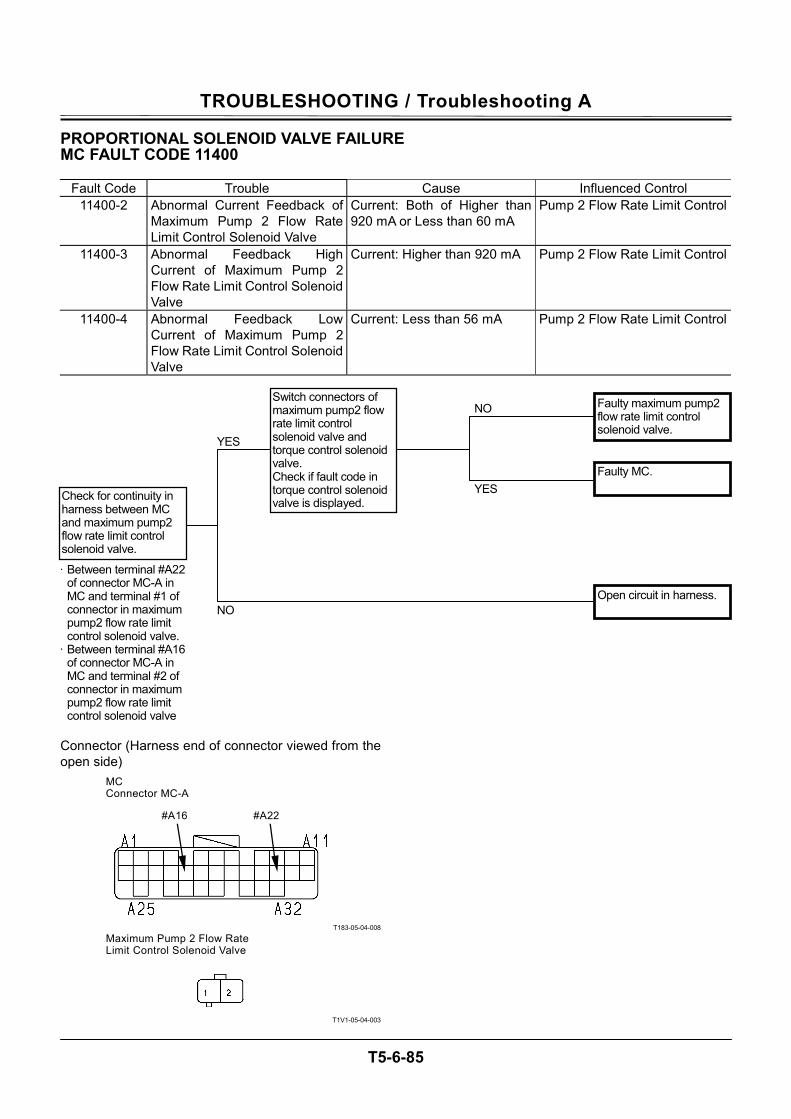
TROUBLESHOOTING / Troubleshooting A
T5-6-85
PROPORTIONAL SOLENOID VALVE FAILURE MC FAULT CODE 11400
Fault Code Trouble Cause Influenced Control 11400-2 Abnormal Current Feedback of
Maximum Pump 2 Flow Rate Limit Control Solenoid Valve
Current: Both of Higher than 920 mA or Less than 60 mA
Pump 2 Flow Rate Limit Control
11400-3 Abnormal Feedback High Current of Maximum Pump 2 Flow Rate Limit Control Solenoid Valve
Current: Higher than 920 mA Pump 2 Flow Rate Limit Control
11400-4 Abnormal Feedback Low Current of Maximum Pump 2 Flow Rate Limit Control Solenoid Valve
Current: Less than 56 mA Pump 2 Flow Rate Limit Control
Connector (Harness end of connector viewed from the open side)
T183-05-04-008
T1V1-05-04-003
YES
Check for continuity in harness between MC and maximum pump2 flow rate limit control solenoid valve.
Faulty MC.
Faulty maximum pump2 flow rate limit control solenoid valve.
· Between terminal #A22 of connector MC-A in MC and terminal #1 of connector in maximum pump2 flow rate limit control solenoid valve.
· Between terminal #A16 of connector MC-A in MC and terminal #2 of connector in maximum pump2 flow rate limit control solenoid valve
NO
YES
Switch connectors of maximum pump2 flow rate limit control solenoid valve and torque control solenoid valve. Check if fault code in torque control solenoid valve is displayed.
NO Open circuit in harness.
#A16 #A22
MC Connector MC-A
Maximum Pump 2 Flow Rate Limit Control Solenoid Valve
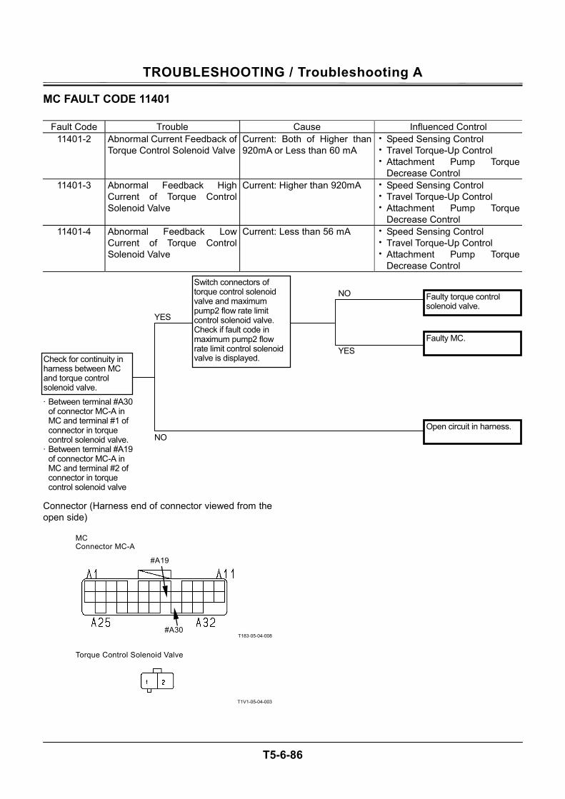
TROUBLESHOOTING / Troubleshooting A
T5-6-86
MC FAULT CODE 11401
Fault Code Trouble Cause Influenced Control 11401-2 Abnormal Current Feedback of
Torque Control Solenoid ValveCurrent: Both of Higher than 920mA or Less than 60 mA
• Speed Sensing Control • Travel Torque-Up Control • Attachment Pump Torque
Decrease Control 11401-3 Abnormal Feedback High
Current of Torque Control Solenoid Valve
Current: Higher than 920mA • Speed Sensing Control • Travel Torque-Up Control • Attachment Pump Torque
Decrease Control 11401-4 Abnormal Feedback Low
Current of Torque Control Solenoid Valve
Current: Less than 56 mA • Speed Sensing Control • Travel Torque-Up Control • Attachment Pump Torque
Decrease Control Connector (Harness end of connector viewed from the open side)
T183-05-04-008
T1V1-05-04-003
YES
Check for continuity in harness between MC and torque control solenoid valve.
Faulty MC.
Faulty torque control solenoid valve.
· Between terminal #A30 of connector MC-A in MC and terminal #1 of connector in torque control solenoid valve.
· Between terminal #A19 of connector MC-A in MC and terminal #2 of connector in torque control solenoid valve
NO
YES
Switch connectors of torque control solenoid valve and maximum pump2 flow rate limit control solenoid valve. Check if fault code in maximum pump2 flow rate limit control solenoid valve is displayed.
NO Open circuit in harness.
#A19
#A30
MC Connector MC-A
Torque Control Solenoid Valve
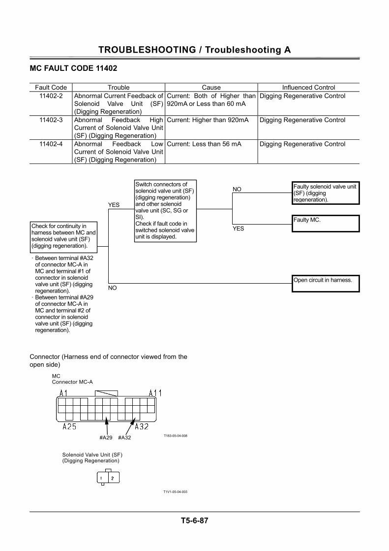
TROUBLESHOOTING / Troubleshooting A
T5-6-87
MC FAULT CODE 11402
Fault Code Trouble Cause Influenced Control 11402-2 Abnormal Current Feedback of
Solenoid Valve Unit (SF) (Digging Regeneration)
Current: Both of Higher than 920mA or Less than 60 mA
Digging Regenerative Control
11402-3 Abnormal Feedback High Current of Solenoid Valve Unit (SF) (Digging Regeneration)
Current: Higher than 920mA Digging Regenerative Control
11402-4 Abnormal Feedback Low Current of Solenoid Valve Unit (SF) (Digging Regeneration)
Current: Less than 56 mA Digging Regenerative Control
Connector (Harness end of connector viewed from the open side)
T183-05-04-008
T1V1-05-04-003
Faulty MC.
Faulty solenoid valve unit (SF) (digging regeneration).
NO
YES
YES
Check for continuity in harness between MC and solenoid valve unit (SF) (digging regeneration).
· Between terminal #A32 of connector MC-A in MC and terminal #1 of connector in solenoid valve unit (SF) (digging regeneration).
· Between terminal #A29 of connector MC-A in MC and terminal #2 of connector in solenoid valve unit (SF) (digging regeneration).
Switch connectors of solenoid valve unit (SF) (digging regeneration) and other solenoid valve unit (SC, SG or SI). Check if fault code in switched solenoid valve unit is displayed.
NO Open circuit in harness.
#A29
MC Connector MC-A
#A32
Solenoid Valve Unit (SF) (Digging Regeneration)
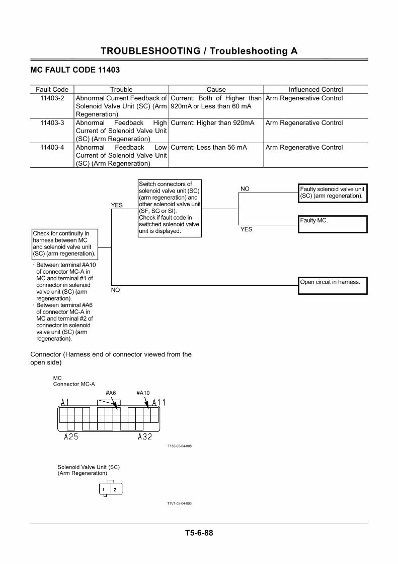
TROUBLESHOOTING / Troubleshooting A
T5-6-88
MC FAULT CODE 11403
Fault Code Trouble Cause Influenced Control 11403-2 Abnormal Current Feedback of
Solenoid Valve Unit (SC) (Arm Regeneration)
Current: Both of Higher than 920mA or Less than 60 mA
Arm Regenerative Control
11403-3 Abnormal Feedback High Current of Solenoid Valve Unit (SC) (Arm Regeneration)
Current: Higher than 920mA Arm Regenerative Control
11403-4 Abnormal Feedback Low Current of Solenoid Valve Unit (SC) (Arm Regeneration)
Current: Less than 56 mA Arm Regenerative Control
Connector (Harness end of connector viewed from the open side)
T183-05-04-008
T1V1-05-04-003
YES
Check for continuity in harness between MC and solenoid valve unit (SC) (arm regeneration).
Faulty MC.
Faulty solenoid valve unit (SC) (arm regeneration).
· Between terminal #A10 of connector MC-A in MC and terminal #1 of connector in solenoid valve unit (SC) (arm regeneration).
· Between terminal #A6 of connector MC-A in MC and terminal #2 of connector in solenoid valve unit (SC) (arm regeneration).
NO
YES
Switch connectors of solenoid valve unit (SC) (arm regeneration) and other solenoid valve unit (SF, SG or SI). Check if fault code in switched solenoid valve unit is displayed.
NOOpen circuit in harness.
#A6
MC Connector MC-A
#A10
Solenoid Valve Unit (SC) (Arm Regeneration)
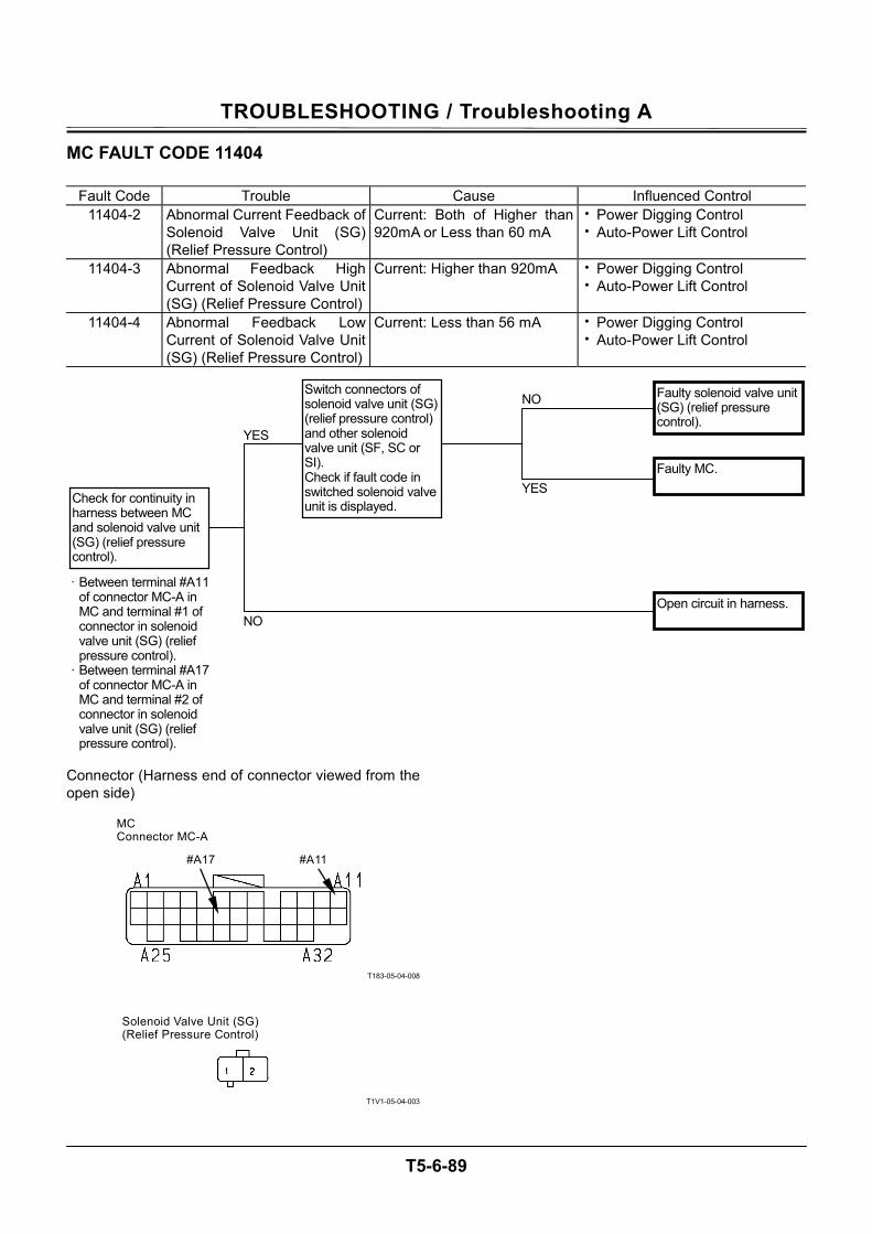
TROUBLESHOOTING / Troubleshooting A
T5-6-89
MC FAULT CODE 11404
Fault Code Trouble Cause Influenced Control 11404-2 Abnormal Current Feedback of
Solenoid Valve Unit (SG) (Relief Pressure Control)
Current: Both of Higher than 920mA or Less than 60 mA
• Power Digging Control • Auto-Power Lift Control
11404-3 Abnormal Feedback High Current of Solenoid Valve Unit (SG) (Relief Pressure Control)
Current: Higher than 920mA • Power Digging Control • Auto-Power Lift Control
11404-4 Abnormal Feedback Low Current of Solenoid Valve Unit (SG) (Relief Pressure Control)
Current: Less than 56 mA • Power Digging Control • Auto-Power Lift Control
Connector (Harness end of connector viewed from the open side)
T183-05-04-008
T1V1-05-04-003
YES
Check for continuity in harness between MC and solenoid valve unit (SG) (relief pressure control).
Faulty MC.
Faulty solenoid valve unit (SG) (relief pressure control).
· Between terminal #A11 of connector MC-A in MC and terminal #1 of connector in solenoid valve unit (SG) (relief pressure control).
· Between terminal #A17 of connector MC-A in MC and terminal #2 of connector in solenoid valve unit (SG) (relief pressure control).
NO
YES
Switch connectors of solenoid valve unit (SG) (relief pressure control) and other solenoid valve unit (SF, SC or SI). Check if fault code in switched solenoid valve unit is displayed.
NO
Open circuit in harness.
#A17
MC Connector MC-A
#A11
Solenoid Valve Unit (SG) (Relief Pressure Control)
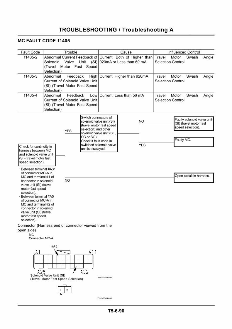
TROUBLESHOOTING / Troubleshooting A
T5-6-90
MC FAULT CODE 11405
Fault Code Trouble Cause Influenced Control 11405-2 Abnormal Current Feedback of
Solenoid Valve Unit (SI) (Travel Motor Fast Speed Selection)
Current: Both of Higher than 920mA or Less than 60 mA
Travel Motor Swash Angle Selection Control
11405-3 Abnormal Feedback High Current of Solenoid Valve Unit (SI) (Travel Motor Fast Speed Selection)
Current: Higher than 920mA Travel Motor Swash Angle Selection Control
11405-4 Abnormal Feedback Low Current of Solenoid Valve Unit (SI) (Travel Motor Fast Speed Selection)
Current: Less than 56 mA Travel Motor Swash Angle Selection Control
Connector (Harness end of connector viewed from the open side)
T183-05-04-008
T1V1-05-04-003
YES
Check for continuity in harness between MC and solenoid valve unit (SI) (travel motor fast speed selection).
Faulty MC.
Faulty solenoid valve unit (SI) (travel motor fast speed selection).
· Between terminal #A31 of connector MC-A in MC and terminal #1 of connector in solenoid valve unit (SI) (travel motor fast speed selection).
· Between terminal #A5 of connector MC-A in MC and terminal #2 of connector in solenoid valve unit (SI) (travel motor fast speed selection).
NO
YES
Switch connectors of solenoid valve unit (SI) (travel motor fast speed selection) and other solenoid valve unit (SF, SC or SG). Check if fault code in switched solenoid valve unit is displayed.
NO
Open circuit in harness.
#A5
MC Connector MC-A
#A31 Solenoid Valve Unit (SI) (Travel Motor Fast Speed Selection)
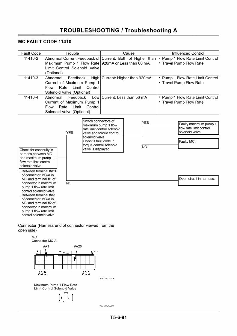
TROUBLESHOOTING / Troubleshooting A
T5-6-91
MC FAULT CODE 11410
Fault Code Trouble Cause Influenced Control 11410-2 Abnormal Current Feedback of
Maximum Pump 1 Flow Rate Limit Control Solenoid Valve (Optional)
Current: Both of Higher than 920mA or Less than 60 mA
• Pump 1 Flow Rate Limit Control• Travel Pump Flow Rate
11410-3 Abnormal Feedback High Current of Maximum Pump 1 Flow Rate Limit Control Solenoid Valve (Optional)
Current: Higher than 920mA • Pump 1 Flow Rate Limit Control• Travel Pump Flow Rate
11410-4 Abnormal Feedback LowCurrent of Maximum Pump 1 Flow Rate Limit Control Solenoid Valve (Optional)
Current: Less than 56 mA • Pump 1 Flow Rate Limit Control• Travel Pump Flow Rate
Connector (Harness end of connector viewed from the open side)
T183-05-04-008
T1V1-05-04-003
YES
Check for continuity in harness between MC and maximum pump 1 flow rate limit control solenoid valve.
Faulty MC.
Faulty maximum pump 1 flow rate limit control solenoid valve.
· Between terminal #A20 of connector MC-A in MC and terminal #1 of connector in maximum pump 1 flow rate limit control solenoid valve.
· Between terminal #A3 of connector MC-A in MC and terminal #2 of connector in maximum pump 1 flow rate limit control solenoid valve.
YES
NO
Switch connectors of maximum pump 1 flow rate limit control solenoid valve and torque control solenoid valve. Check if fault code in torque control solenoid valve is displayed.
NO
Open circuit in harness.
#A3
MC Connector MC-A
#A20
Maximum Pump 1 Flow Rate Limit Control Solenoid Valve
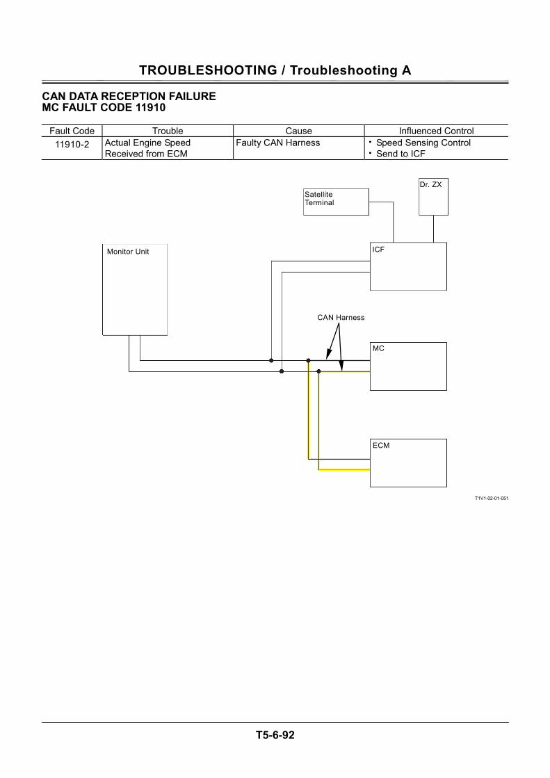
TROUBLESHOOTING / Troubleshooting A
T5-6-92
CAN DATA RECEPTION FAILURE MC FAULT CODE 11910
Fault Code Trouble Cause Influenced Control 11910-2 Actual Engine Speed
Received from ECM Faulty CAN Harness • Speed Sensing Control
• Send to ICF
T1V1-02-01-051
Monitor Unit
Satellite Terminal
Dr. ZX
ICF
MC
ECM
CAN Harness

TROUBLESHOOTING / Troubleshooting A
T5-6-93
(Blank)

TROUBLESHOOTING / Troubleshooting A
T5-6-94
CAN HARNESS CHECK MC FAULT CODE 11910
• Check the wiring connections first.
NO YES
NO
YES
YES
NO
· Key switch: OFF · Refer to “Continuity
Check in CAN Harness”.
Retry by using Dr. ZX. Check if fault code 11004-2 is displayed.
Check for continuity in CAN harness betweenMC and ECM.
Open circuit in CAN harness between MC and ECM.
Normal.
Shorted circuit in CAN harness between ground circuit and CAN circuit.
· Key switch: OFF · Refer to
“Discontinuity Check between CAN Circuit and Ground Circuit”.
Disconnect all connectors of MC, ICF,ECM and monitor unit. Check for continuity between ground circuit (MC, ICF, ECM, monitor unit) and CAN circuit.
· Key switch: OFF · Refer to “Discontinuity
Check between CAN Circuit and Power Circuit”.
Check for continuity between power circuit (MC, ICF, ECM, monitor unit) and CAN circuit.

TROUBLESHOOTING / Troubleshooting A
T5-6-95
Connector
T1GR-05-04-002
NO
YES
NO
YES
YES
NO
NO
YES
Shorted circuit in CAN harness.
Disconnect connector in MC. Connect connector of harness end. Check if resistance between terminals #18 and #37 of connector in ECM is within 120±10 Ω.
To A
Check for continuity between key signal circuit (MC, ICF, ECM, monitor unit) and CAN circuit. · Key switch: OFF · Refer to
“Discontinuity Check between CAN Circuit and Key Signal Circuit”.
Check for continuity between High side and Low side in CAN harness. · Key switch: OFF · Refer to
“Discontinuity Check in CAN Harness”.
· Key switch: OFF
Connect all connectors except connector MC-C in MC. Check if resistance between terminals #C4and #C15 of harness end of connector MC-C is within 60±10 Ω.
· Key switch: OFF
To B
Shorted circuit in CAN harness between key signal circuit and CAN circuit.
Shorted circuit in CAN harness between power circuit and CAN circuit.
#18 #37
C31
C10
C23
C1
#C15 #C4
MC Connector MC-C (Harness end)
ECM Connector (Harness end)
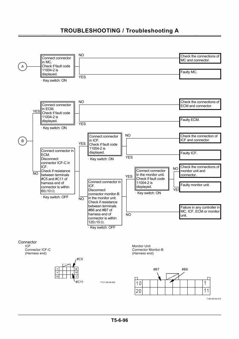
TROUBLESHOOTING / Troubleshooting A
T5-6-96
Connector
T1V1-05-04-002
T183-05-04-013
A
· Key switch: ON
Connect connector in MC. Check if fault code 11004-2 is displayed.
YES
NO Check the connections of MC and connector.
Faulty MC.
#B7 #B6
#C5
#C11
ICF Connector ICF-C (Harness end)
Monitor Unit Connector Monitor-B (Harness end)
NO
YES
NO
YESNO
· Key switch: OFF
· Key switch: OFF
Connect connector in ECM. Disconnect connector ICF-C in ICF. Check if resistance between terminals #C5 and #C11 of harness end of connector is within 60±10 Ω.
Connect connector in ICF. Disconnect connector monitor-B in the monitor unit. Check if resistance between terminals #B6 and #B7 of harness end of connector is within 120±10 Ω.
B
Connect connector in the monitor unit. Check if fault code 11004-2 is displayed.
· Key switch: ON
YES
· Key switch: ON
Connect connector in ICF. Check if fault code 11004-2 is displayed.
YES
NO Check the connection of ICF and connector.
YES
NO
Faulty ICF.
Check the connections of monitor unit and connector.
· Key switch: ON
Connect connector in ECM. Check if fault code 11004-2 is displayed.
YES
NO
Faulty monitor unit.
Failure in any controller in MC, ICF, ECM or monitor unit.
Check the connections of ECM and connector.
Faulty ECM.
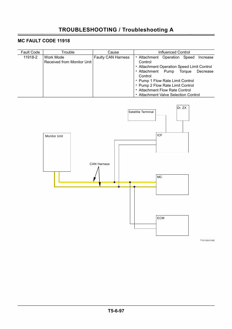
TROUBLESHOOTING / Troubleshooting A
T5-6-97
MC FAULT CODE 11918
Fault Code Trouble Cause Influenced Control 11918-2 Work Mode
Received from Monitor Unit Faulty CAN Harness • Attachment Operation Speed Increase
Control • Attachment Operation Speed Limit Control• Attachment Pump Torque Decrease
Control • Pump 1 Flow Rate Limit Control • Pump 2 Flow Rate Limit Control • Attachment Flow Rate Control • Attachment Valve Selection Control
T1V1-02-01-052
Monitor Unit
Satellite TerminalDr. ZX
ICF
MC
ECM
CAN Harness
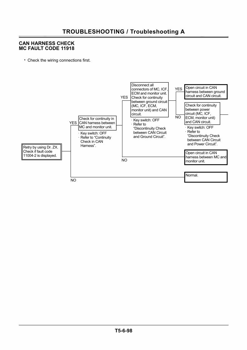
TROUBLESHOOTING / Troubleshooting A
T5-6-98
CAN HARNESS CHECK MC FAULT CODE 11918
• Check the wiring connections first.
NO YES
NO
YES
YES
NO
· Key switch: OFF · Refer to
“Discontinuity Check between CAN Circuit and Ground Circuit”.
· Key switch: OFF · Refer to “Continuity
Check in CAN Harness”. Retry by using Dr. ZX.
Check if fault code 11004-2 is displayed.
Check for continuity in CAN harness betweenMC and monitor unit.
Disconnect all connectors of MC, ICF,ECM and monitor unit. Check for continuity between ground circuit (MC, ICF, ECM, monitor unit) and CAN circuit.
Open circuit in CAN harness between MC and monitor unit.
Normal.
Open circuit in CAN harness between ground circuit and CAN circuit.
Check for continuity between power circuit (MC, ICF, ECM, monitor unit) and CAN circuit. · Key switch: OFF · Refer to
“Discontinuity Check between CAN Circuit and Power Circuit”.
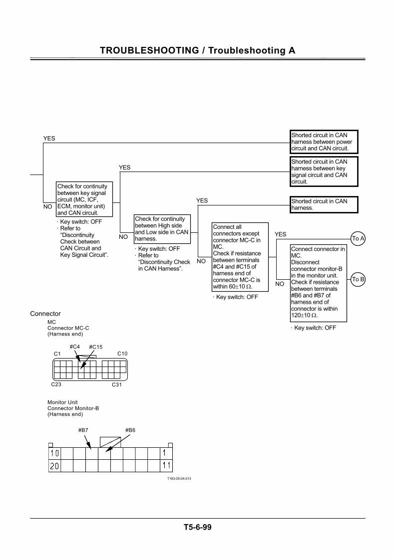
TROUBLESHOOTING / Troubleshooting A
T5-6-99
Connector
T183-05-04-013
NO
YES
NO
YES
YES
NO
NO
YES
Shorted circuit in CAN harness.
Connect connector in MC. Disconnect connector monitor-B in the monitor unit. Check if resistance between terminals #B6 and #B7 of harness end of connector is within 120±10 Ω.
To A
Check for continuity between key signal circuit (MC, ICF, ECM, monitor unit) and CAN circuit. · Key switch: OFF · Refer to
“Discontinuity Check between CAN Circuit and Key Signal Circuit”.
Check for continuity between High side and Low side in CAN harness.
· Key switch: OFF · Refer to
“Discontinuity Check in CAN Harness”.
· Key switch: OFF
Connect all connectors except connector MC-C in MC. Check if resistance between terminals #C4 and #C15 of harness end of connector MC-C is within 60±10 Ω.
· Key switch: OFF
To B
Shorted circuit in CAN harness between key signal circuit and CAN circuit.
Shorted circuit in CAN harness between power circuit and CAN circuit.
C31
C10
C23
C1
#C15 #C4
#B7 #B6
MC Connector MC-C (Harness end)
Monitor Unit Connector Monitor-B (Harness end)

TROUBLESHOOTING / Troubleshooting A
T5-6-100
Connector
T1GR-05-04-002
T1V1-05-04-002
NO
YES
NO
YESNO
· Key witch: OFF
· Key witch: OFF
Connect connector in the monitor unit. Disconnect connector ECM. Check if resistance between terminals #18 and #37 of harness end of connector is within 120±10 Ω.
Connect connector in ECM. Disconnect connector ICF-C in ICF. Check if resistance between terminals #C5 and #C11 of harness end of connector is within 60±10 Ω.
B
Connect connector in ICF. Check if fault code 11004-2 is displayed.
· Key witch: ON
YES
· Key witch: ON
Connect connector in ECM. Check if fault code 11004-2 is displayed.
YES
NO
YES
NO
A
· Key witch: ON
Connect connector in MC. Check if fault code 11004-2 is displayed.
YES
NO
· Key witch: ON
Connect connector in the monitor unit. Check if fault code 11004-2 is displayed.
YES
NO
#C5
#C11
#18 #37
Check the connections of monitor unit and connector.
Faulty monitor unit.
Check the connections of ICF and connector.
Faulty ICF.
Check the connections of ICF and connector.
Check the connections of MC and connector.
Faulty MC.
Faulty ICF.
Failure in any controller in MC, ICF, ECM or monitor unit.
ECM Connector (Harness end)
ICF Connector ICF-C (Harness end)
TROUBLESHOOTING / Troubleshooting A
T5-6-101
MC FAULT CODE 11911
Fault Code Trouble Cause Influenced Control 11911-2 Security Signal
Received from Monitor Unit Faulty CAN Harness Theft Prevention Engine Speed,
Engine Torque
T1V1-02-01-052
Monitor Unit
Satellite TerminalDr. ZX
ICF
MC
ECM
CAN Harness
TROUBLESHOOTING / Troubleshooting A
T5-6-102
CAN HARNESS CHECK MC FAULT CODE 11911
• Check the wiring connections first.
NO YES
NO
YES
YES
NO
· Key switch: OFF · Refer to “Discontinuity
Check between CAN Circuit and Ground Circuit”. · Key switch: OFF
· Refer to “Continuity Check in CAN Harness”.
Retry by using Dr. ZX. Check if fault code 11004-2 is displayed.
Check for continuity in CAN harness betweenMC and monitor unit.
Disconnect all connectors of MC, ICF,ECM and monitor unit. Check for continuity between ground circuit (MC, ICF, ECM, monitor unit) and CAN circuit.
Open circuit in CAN harness between MC and monitor unit.
Normal.
Open circuit in CAN harness between ground circuit and CAN circuit.
Check for continuity between power circuit (MC, ICF, ECM, monitor unit) and CAN circuit. · Key switch: OFF · Refer to “Discontinuity
Check between CAN Circuit and Power Circuit”.
TROUBLESHOOTING / Troubleshooting A
T5-6-103
Connector
T183-05-04-013
C31
C10
C23
C1
#C15 #C4
#B7 #B6
NO
YES
NO
YES
YES
NO
NO
YES
Shorted circuit in CAN harness.
Connect connector in MC. Disconnect connector monitor-B in the monitor unit. Check if resistance between terminals #6 and #B7 of harness end of connector is within 120±10 Ω.
To A
Check for continuity between key signal circuit (MC, ICF, ECM, monitor unit) and CAN circuit.
· Key switch: OFF · Refer to
“Discontinuity Check between CAN Circuit and Key Signal Circuit”.
Check for continuity between High side and Low side in CAN harness. · Key switch: OFF · Refer to
“Discontinuity Check in CAN Harness”.
· Key switch: OFF
Connect all connectors except connector MC-C in MC. Check if resistance between terminals #C4 and #C15 of harness end of connector MC-C is within 60±10 Ω.
· Key switch: OFF
To B
Shorted circuit in CAN harness between key signal circuit and CAN circuit.
Shorted circuit in CAN harness between power circuit and CAN circuit.
MC Connector MC-C (Harness end)
Monitor Unit Connector Monitor-B (Harness end)
TROUBLESHOOTING / Troubleshooting A
T5-6-104
Connector
T1GR-05-04-002
T1V1-05-04-002
NO
YES
NO
YESNO
· Key switch: OFF
· Key switch: OFF
Connect connector in the monitor unit. Disconnect connector ECM. Check if resistance between terminals #18 and #37 of harness end of connector is within 120±10 Ω.
Connect connector in ECM. Disconnect connector ICF-C in ICF. Check if resistance between terminals #C5 and #C11 of harness end of connector is within 60±10 Ω
B
Connect connector in ICF. Check if fault code 11004-2 is displayed.
· Key switch: ON
YES
· Key switch: ON
Connect connector in ECM. Check if fault code 11004-2 is displayed.
YES
NO
YES
NO Check the connections of ICF and connector.
A
· Key switch: ON
Connect connector in MC. Check if fault code 11004-2 is displayed.
YES
NO
· Key switch: ON
Connect connector in the monitor unit. Check if fault code 11004-2 is displayed.
YES
NO
Faulty ICF.
Failure in any controller in MC, ICF, ECM or monitor unit.
#C5
#C11
#18 #37
Check the connections of monitor unit and connector.
Faulty Monitor Unit.
Check the connection of ICF and connector.
Faulty ICF.
Check the connections of MC and connector.
Faulty MC.
ECM Connector (Harness end)
ICF Connector ICF-C (Harness end)
TROUBLESHOOTING / Troubleshooting A
T5-6-105
MC FAULT CODE 11920
Fault Code Trouble Cause Influenced Control 11920-2 Fuel Flow Rate Received from
ECM Faulty CAN Harness Fuel Flow Rate
T1V1-02-01-051
Monitor Unit
Satellite TerminalDr. ZX
ICF
MC
ECM
CAN Harness
TROUBLESHOOTING / Troubleshooting A
T5-6-106
CAN HARNESS CHECK MC FAULT CODE 11920
• Check the wiring connections first.
NO YES
NO
YES
YES
NO
· Key switch: OFF · Refer to “Continuity
Check in CAN Harness”.
Retry by using Dr. ZX. Check if fault code 11004-2 is displayed.
Check for continuity in CAN harness betweenMC and ECM.
Open circuit in CAN harness between MC and ECM.
Normal.
Shorted circuit in CAN harness between ground circuit and CAN circuit.
· Key switch: OFF · Refer to
“Discontinuity Check between CAN Circuit and Ground Circuit”.
Disconnect all connectors of MC, ICF,ECM and monitor unit. Check for continuity between ground circuit (MC, ICF, ECM, monitor unit) and CAN circuit.
· Key switch: OFF · Refer to “Discontinuity
Check between CAN Circuit and Power Circuit”.
Check for continuity between power circuit (MC, ICF, ECM, monitor unit) and CAN circuit.
TROUBLESHOOTING / Troubleshooting A
T5-6-107
Connector
T1GR-05-04-002
NO
YES
NO
YES
YES
NO
NO
YES
Shorted circuit in CAN harness.
Disconnect connector in MC. Connect connector of harness end. Check if resistance between terminals #18 and #37 of connector in ECM is within 120±10 Ω.
To A
Check for continuity between key signal circuit (MC, ICF, ECM, monitor unit) and CAN circuit. · Key switch: OFF · Refer to
“Discontinuity Check between CAN Circuit and Key Signal Circuit”.
Check for continuity between High side and Low side in CAN harness. · Key switch: OFF · Refer to
“Discontinuity Check in CAN Harness”.
· Key switch: OFF
Connect all connectors except connector MC-C in MC. Check if resistance between terminals #C4 and #C15 of harness end of connector MC-C is within 60±10 Ω.
· Key switch: OFF
To B
Shorted circuit in CAN harness between key signal circuit and CAN circuit.
Shorted circuit in CAN harness between power circuit and CAN circuit.
#18 #37
C31
C10
C23
C1
#C15 #C4
MC Connector MC-C (Harness end)
ECM Connector (Harness end)
TROUBLESHOOTING / Troubleshooting A
T5-6-108
Connector
T1V1-05-04-002
T183-05-04-013
NO
YES
NO
YESNO
· Key switch: OFF
· Key switch: OFF
Connect connector in ECM. Disconnect connector ICF-C in ICF. Check if resistance between terminals #C5 and #C11 of harness end of connector is within 60±10 Ω.
Connect connector in ICF. Disconnect connector monitor-B in the monitor unit. Check if resistance between terminals #B6 and #B7 of harness end of connector is within 120±10 Ω.
B
Connect connector in the monitor unit. Check if fault code 11004-2 is displayed.
· Key switch: ON
YES
· Key switch: ON
Connect connector in ICF. Check if fault code 11004-2 is displayed.
YES
NO Check the connection of ICF and connector.
YES
NO
Faulty ICF.
Check the connections of monitor unit and connector.
A
· Key switch: ON
Connect connector in MC. Check if fault code 11004-2 is displayed.
YES
NO Check the connections of MC and connector.
Faulty MC.
· Key switch: ON
Connect connector in ECM. Check if fault code 11004-2 is displayed. YES
NO
Faulty monitor unit.
Failure in any controller in MC, ICF, ECM or monitor unit.
#B7 #B6 #C5
#C11
Check the connections of ECM and connector.
Faulty ECM.
ICF Connector ICF-C (Harness end)
Monitor Unit Connector Monitor-B(Harness end)
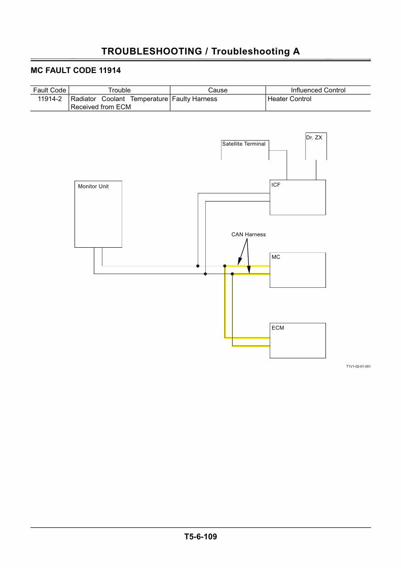
TROUBLESHOOTING / Troubleshooting A
T5-6-109
MC FAULT CODE 11914
Fault Code Trouble Cause Influenced Control 11914-2 Radiator Coolant Temperature
Received from ECM Faulty Harness Heater Control
T1V1-02-01-051
Monitor Unit
Satellite TerminalDr. ZX
ICF
MC
ECM
CAN Harness

TROUBLESHOOTING / Troubleshooting A
T5-6-110
CAN HARNESS CHECK MC FAULT CODE 11914
• Check the wiring connections first.
NO YES
NO
YES
YES
NO
· Key switch: OFF · Refer to “Continuity
Check in CAN Harness”. Retry by using Dr. ZX.
Check if fault code 11004-2 is displayed.
Check for continuity in CAN harness betweenMC and ECM.
Open circuit in CAN harness between MC and ECM.
Normal.
Shorted circuit in CAN harness between ground circuit and CAN circuit.
· Key switch: OFF · Refer to
“Discontinuity Check between CAN Circuit and Ground Circuit”.
Disconnect all connectors of MC, ICF,ECM and monitor unit. Check for continuity between ground circuit (MC, ICF, ECM, monitor unit) and CAN circuit.
· Key switch: OFF · Refer to
“Discontinuity Check between CAN Circuit and Power Circuit”.
Check for continuity between power circuit (MC, ICF, ECM, monitor unit) and CAN circuit.
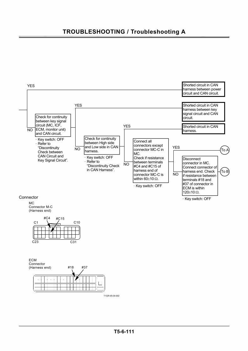
TROUBLESHOOTING / Troubleshooting A
T5-6-111
Connector
T1GR-05-04-002
NO
YES
NO
YES
YES
NO
NO
YES
Shorted circuit in CAN harness.
Disconnect connector in MC. Connect connector of harness end. Check if resistance between terminals #18 and #37 of connector in ECM is within 120±10 Ω.
To A
Check for continuity between key signal circuit (MC, ICF, ECM, monitor unit) and CAN circuit. · Key switch: OFF · Refer to
“Discontinuity Check between CAN Circuit and Key Signal Circuit”.
Check for continuity between High side and Low side in CAN harness.
· Key switch: OFF · Refer to
“Discontinuity Check in CAN Harness”.
· Key switch: OFF
Connect all connectors except connector MC-C in MC. Check if resistance between terminals #C4 and #C15 of harness end of connector MC-C is within 60±10 Ω.
· Key switch: OFF
To B
Shorted circuit in CAN harness between key signal circuit and CAN circuit.
Shorted circuit in CAN harness between power circuit and CAN circuit.
#18 #37
C31
C10
C23
C1
#C15 #C4
MC Connector M-C (Harness end)
ECM Connector (Harness end)
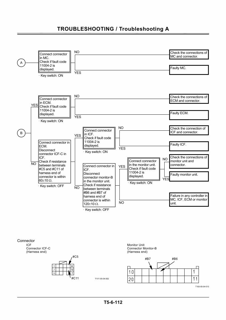
TROUBLESHOOTING / Troubleshooting A
T5-6-112
Connector
T1V1-05-04-002
T183-05-04-013
NO
YES
NO
YESNO
· Key switch: OFF
· Key switch: OFF
Connect connector in ECM. Disconnect connector ICF-C in ICF. Check if resistance between terminals #C5 and #C11 of harness end of connector is within 60±10 Ω.
Connect connector in ICF. Disconnect connector monitor-B in the monitor unit. Check if resistance between terminals #B6 and #B7 of harness end of connector is within 120±10 Ω.
B
Connect connector in the monitor unit. Check if fault code 11004-2 is displayed.
· Key switch: ON
YES
· Key switch: ON
Connect connector in ICF. Check if fault code 11004-2 is displayed.
YES
NO
YES
NO
A
· Key switch: ON
Connect connector in MC. Check if fault code 11004-2 is displayed.
YES
NO
· Key switch: ON
Connect connector in ECM. Check if fault code 11004-2 is displayed.
YES
NO
#B7 #B6 #C5
#C11
Check the connections of ECM and connector.
Faulty ECM.
Check the connection of ICF and connector.
Faulty ICF.
Check the connections of monitor unit and connector.
Check the connections of MC and connector.
Faulty MC.
Faulty monitor unit.
Failure in any controller in MC, ICF, ECM or monitor unit.
ICF Connector ICF-C (Harness end)
Monitor Unit Connector Monitor-B(Harness end)
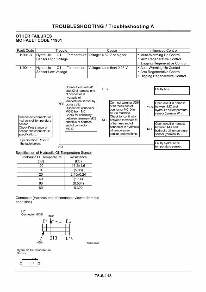
TROUBLESHOOTING / Troubleshooting A
T5-6-113
OTHER FAILURES MC FAULT CODE 11901
Fault Code Trouble Cause Influenced Control 11901-3 Hydraulic Oil Temperature
Sensor High Voltage Voltage: 4.52 V or higher • Auto-Warming Up Control
• Arm Regenerative Control • Digging Regenerative Control
11901-4 Hydraulic Oil Temperature Sensor Low Voltage
Voltage: Less than 0.23 V • Auto-Warming Up Control • Arm Regenerative Control • Digging Regenerative Control
Specification of Hydraulic Oil Temperature Sensor Hydraulic Oil Temperature
(°C) Resistance
(kΩ) -20 16.2±1.6 0 (5.88) 20 2.45±0.24 40 (1.14) 60 (0.534) 80 0.322
Connector (Harness end of connector viewed from the open side)
T183-05-04-009
NO
NO
NO
YES
YES YES
Connect terminals #1 and #2 of harness end of connector in hydraulic oil temperature sensor by using a clip. Disconnect connector MC-D from MC. Check for continuity between terminals #D2 and #D6 of harness end of connector MC-D.
Open circuit in harness between MC and hydraulic oil temperature sensor (terminal #1).
Disconnect connector of hydraulic oil temperature sensor. Check if resistance at sensor end connector is specification.
Open circuit in harness between MC and hydraulic oil temperature sensor (terminal #2).
Faulty hydraulic oil temperature sensor.
Connect terminal #D6 of harness end of connector MC-D in MC to machine. Check for continuity between terminals #2 of harness end of connector in hydraulic oil temperature sensor and machine.
Faulty MC.
· Specification: Refer to the table below.
2 1
#D2
#D6
MC Connector MC-D
Hydraulic Oil Temperature Sensor
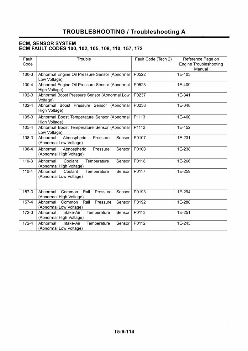
TROUBLESHOOTING / Troubleshooting A
T5-6-114
ECM, SENSOR SYSTEM ECM FAULT CODES 100, 102, 105, 108, 110, 157, 172
Fault Code
Trouble Fault Code (Tech 2) Reference Page on Engine Troubleshooting
Manual 100-3 Abnormal Engine Oil Pressure Sensor (Abnormal
Low Voltage) P0522 1E-403
100-4 Abnormal Engine Oil Pressure Sensor (Abnormal High Voltage)
P0523 1E-409
102-3 Abnormal Boost Pressure Sensor (Abnormal Low Voltage)
P0237 1E-341
102-4 Abnormal Boost Pressure Sensor (Abnormal High Voltage)
P0238 1E-348
105-3 Abnormal Boost Temperature Sensor (Abnormal High Voltage)
P1113 1E-460
105-4 Abnormal Boost Temperature Sensor (Abnormal Low Voltage)
P1112 1E-452
108-3 Abnormal Atmospheric Pressure Sensor (Abnormal Low Voltage)
P0107 1E-231
108-4 Abnormal Atmospheric Pressure Sensor (Abnormal High Voltage)
P0108 1E-238
110-3 Abnormal Coolant Temperature Sensor (Abnormal High Voltage)
P0118 1E-266
110-4 Abnormal Coolant Temperature Sensor (Abnormal Low Voltage)
P0117 1E-259
157-3 Abnormal Common Rail Pressure Sensor (Abnormal High Voltage)
P0193 1E-294
157-4 Abnormal Common Rail Pressure Sensor (Abnormal Low Voltage)
P0192 1E-288
172-3 Abnormal Intake-Air Temperature Sensor (Abnormal High Voltage)
P0113 1E-251
172-4 Abnormal Intake-Air Temperature Sensor (Abnormal Low Voltage)
P0112 1E-245
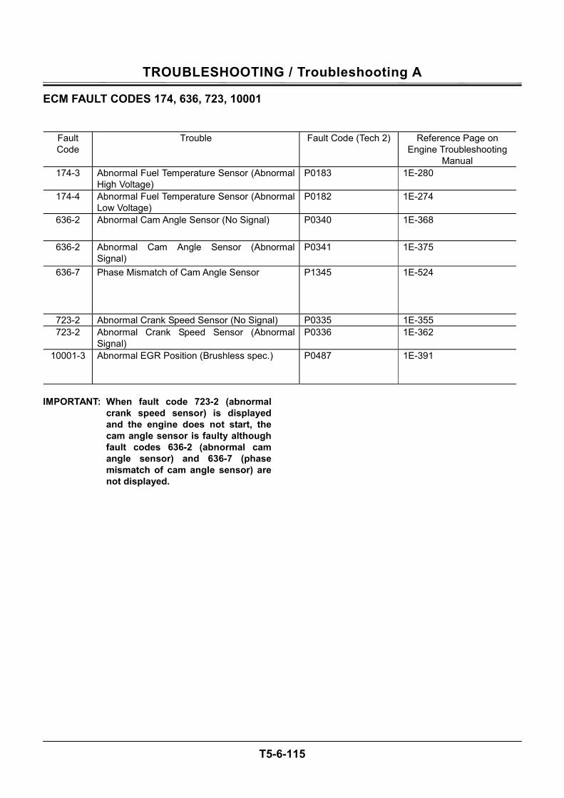
TROUBLESHOOTING / Troubleshooting A
T5-6-115
ECM FAULT CODES 174, 636, 723, 10001
Fault Code
Trouble Fault Code (Tech 2) Reference Page on Engine Troubleshooting
Manual 174-3 Abnormal Fuel Temperature Sensor (Abnormal
High Voltage) P0183 1E-280
174-4 Abnormal Fuel Temperature Sensor (Abnormal Low Voltage)
P0182 1E-274
636-2 Abnormal Cam Angle Sensor (No Signal) P0340 1E-368
636-2 Abnormal Cam Angle Sensor (Abnormal Signal)
P0341 1E-375
636-7 Phase Mismatch of Cam Angle Sensor P1345 1E-524
723-2 Abnormal Crank Speed Sensor (No Signal) P0335 1E-355 723-2 Abnormal Crank Speed Sensor (Abnormal
Signal) P0336 1E-362
10001-3 Abnormal EGR Position (Brushless spec.) P0487 1E-391
IMPORTANT: When fault code 723-2 (abnormal
crank speed sensor) is displayed and the engine does not start, the cam angle sensor is faulty although fault codes 636-2 (abnormal cam angle sensor) and 636-7 (phase mismatch of cam angle sensor) are not displayed.
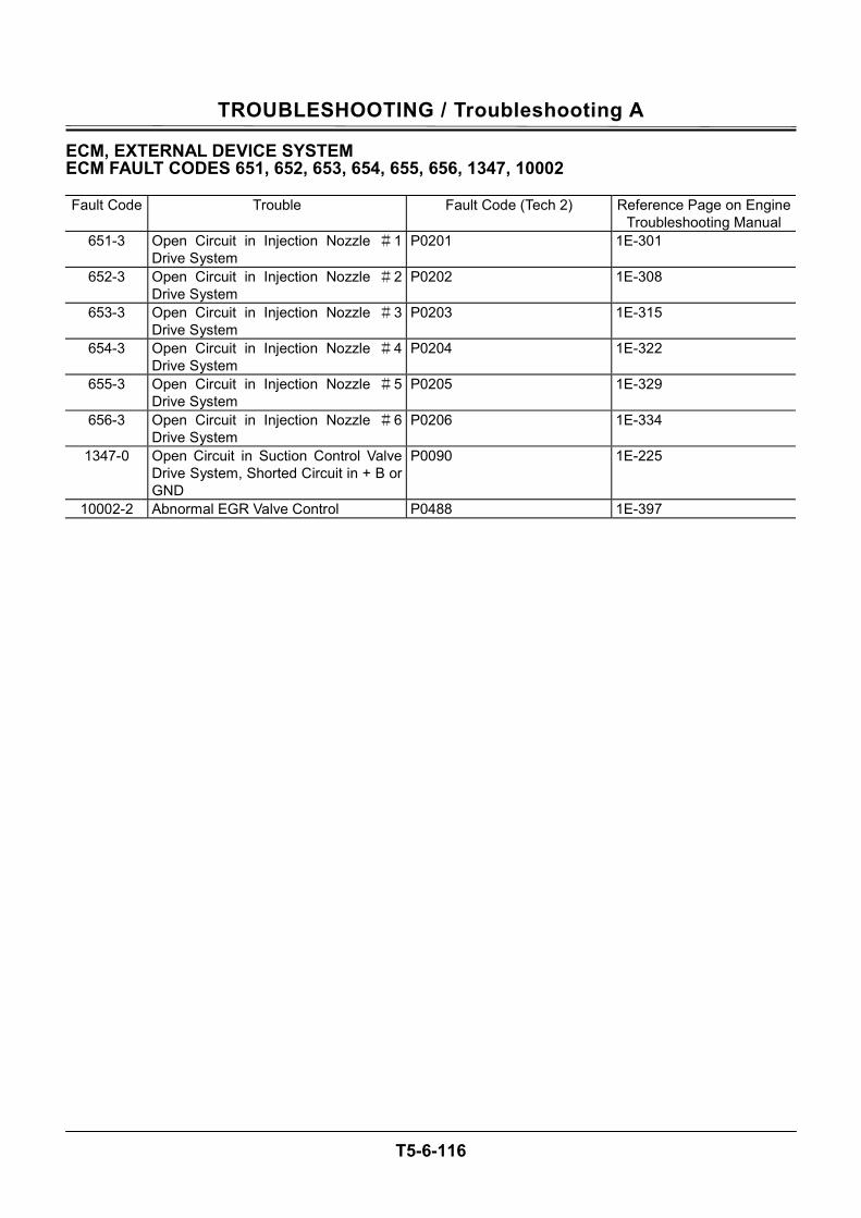
TROUBLESHOOTING / Troubleshooting A
T5-6-116
ECM, EXTERNAL DEVICE SYSTEM ECM FAULT CODES 651, 652, 653, 654, 655, 656, 1347, 10002 Fault Code Trouble Fault Code (Tech 2) Reference Page on Engine
Troubleshooting Manual 651-3 Open Circuit in Injection Nozzle #1
Drive System P0201 1E-301
652-3 Open Circuit in Injection Nozzle #2 Drive System
P0202 1E-308
653-3 Open Circuit in Injection Nozzle #3 Drive System
P0203 1E-315
654-3 Open Circuit in Injection Nozzle #4 Drive System
P0204 1E-322
655-3 Open Circuit in Injection Nozzle #5 Drive System
P0205 1E-329
656-3 Open Circuit in Injection Nozzle #6 Drive System
P0206 1E-334
1347-0 Open Circuit in Suction Control Valve Drive System, Shorted Circuit in + B or GND
P0090 1E-225
10002-2 Abnormal EGR Valve Control P0488 1E-397
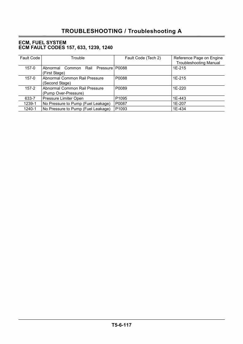
TROUBLESHOOTING / Troubleshooting A
T5-6-117
ECM, FUEL SYSTEM ECM FAULT CODES 157, 633, 1239, 1240 Fault Code Trouble Fault Code (Tech 2) Reference Page on Engine
Troubleshooting Manual 157-0 Abnormal Common Rail Pressure
(First Stage) P0088 1E-215
157-0 Abnormal Common Rail Pressure (Second Stage)
P0088 1E-215
157-2 Abnormal Common Rail Pressure (Pump Over-Pressure)
P0089 1E-220
633-7 Pressure Limiter Open P1095 1E-443 1239-1 No Pressure to Pump (Fuel Leakage) P0087 1E-207 1240-1 No Pressure to Pump (Fuel Leakage) P1093 1E-434

TROUBLESHOOTING / Troubleshooting A
T5-6-118
ECM, ENGINE PROTECTION ECM FAULT CODES 110, 190 Fault Code Trouble Fault Code (Tech 2) Reference Page on Engine
Troubleshooting Manual 110-0 Overheating P1173 1E-466 190-0 Overrunning P0219 1E-339

TROUBLESHOOTING / Troubleshooting A
T5-6-119
ECM, ENGINE PROTECTION ECM FAULT CODES 987, 1485 Fault Code Trouble Fault Code (Tech 2) Reference Page on Engine
Troubleshooting Manual 987-3 Abnormal Check Engine Lamp P0650 1E-429
1485-2 Abnormal Main Relay System (None) P1625 1E-529
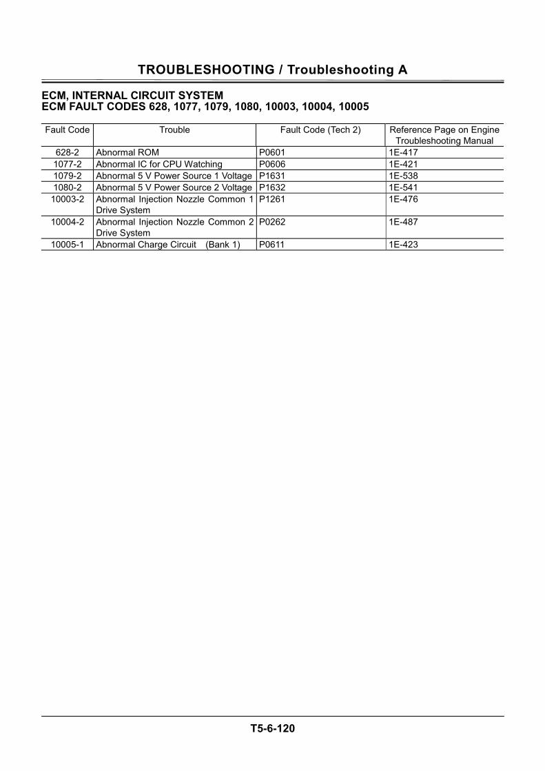
TROUBLESHOOTING / Troubleshooting A
T5-6-120
ECM, INTERNAL CIRCUIT SYSTEM ECM FAULT CODES 628, 1077, 1079, 1080, 10003, 10004, 10005 Fault Code Trouble Fault Code (Tech 2) Reference Page on Engine
Troubleshooting Manual 628-2 Abnormal ROM P0601 1E-417 1077-2 Abnormal IC for CPU Watching P0606 1E-421 1079-2 Abnormal 5 V Power Source 1 Voltage P1631 1E-538 1080-2 Abnormal 5 V Power Source 2 Voltage P1632 1E-541 10003-2 Abnormal Injection Nozzle Common 1
Drive System P1261 1E-476
10004-2 Abnormal Injection Nozzle Common 2 Drive System
P0262 1E-487
10005-1 Abnormal Charge Circuit (Bank 1) P0611 1E-423
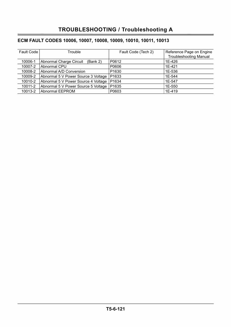
TROUBLESHOOTING / Troubleshooting A
T5-6-121
ECM FAULT CODES 10006, 10007, 10008, 10009, 10010, 10011, 10013 Fault Code Trouble Fault Code (Tech 2) Reference Page on Engine
Troubleshooting Manual 10006-1 Abnormal Charge Circuit (Bank 2) P0612 1E-426 10007-2 Abnormal CPU P0606 1E-421 10008-2 Abnormal A/D Conversion P1630 1E-536 10009-2 Abnormal 5 V Power Source 3 Voltage P1633 1E-544 10010-2 Abnormal 5 V Power Source 4 Voltage P1634 1E-547 10011-2 Abnormal 5 V Power Source 5 Voltage P1635 1E-550 10013-2 Abnormal EEPROM P0603 1E-419
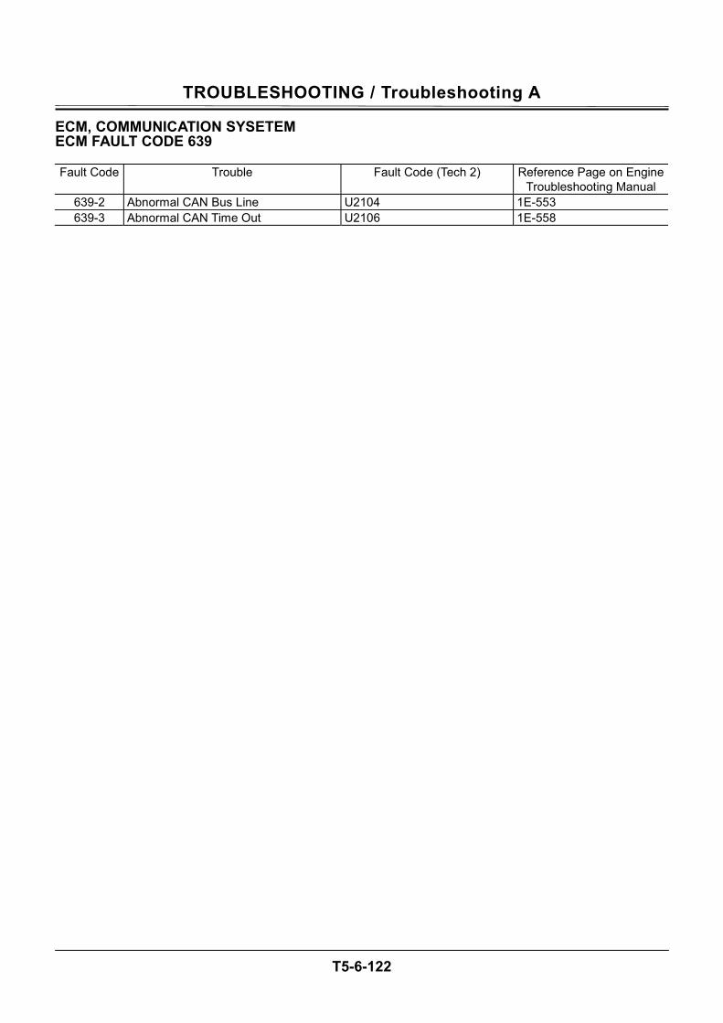
TROUBLESHOOTING / Troubleshooting A
T5-6-122
ECM, COMMUNICATION SYSETEM ECM FAULT CODE 639 Fault Code Trouble Fault Code (Tech 2) Reference Page on Engine
Troubleshooting Manual 639-2 Abnormal CAN Bus Line U2104 1E-553 639-3 Abnormal CAN Time Out U2106 1E-558
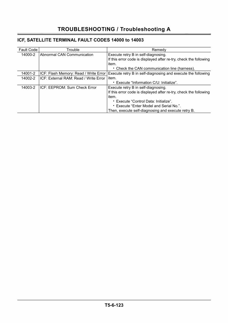
TROUBLESHOOTING / Troubleshooting A
T5-6-123
ICF, SATELLITE TERMINAL FAULT CODES 14000 to 14003 Fault Code Trouble Remedy
14000-2 Abnormal CAN Communication Execute retry B in self-diagnosing. If this error code is displayed after re-try, check the following item.
• Check the CAN communication line (harness). 14001-2 ICF: Flash Memory: Read / Write Error14002-2 ICF: External RAM: Read / Write Error
Execute retry B in self-diagnosing and execute the following item.
• Execute “Information C/U: Initialize”. 14003-2 ICF: EEPROM: Sum Check Error Execute retry B in self-diagnosing.
If this error code is displayed after re-try, check the following item.
• Execute “Control Data: Initialize”. • Execute “Enter Model and Serial No.”.
Then, execute self-diagnosing and execute retry B.
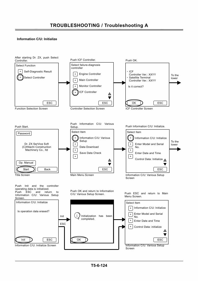
TROUBLESHOOTING / Troubleshooting A
T5-6-124
Information C/U: Initialize
Select Function
Self-Diagnostic Result Select Controller
After starting Dr. ZX, push SelectController.
Function Selection Screen
Select failure-diagnosis controller
Engine Controller Main Controller Monitor Controller ICF Controller
Push ICF Controller.
Controller Selection Screen
・ ICF
Controller Ver.: XXYY ・ Satellite Terminal
Controller Ver.: XXYY Is it correct?
Push OK.
ICF Controller Screen
To the lower
ESC
+
+ +
+
+
+
ESC ESC OK
Dr. ZX SerVice Soft (C)Hitachi Construction
Machinery Co., ltd
Push Start.
Select Item
Information C/U: Various Setup Data Download Save Data Check
Push Information C/U: VariousSetup.
Main Menu Screen
Select Item
Information C/U: Initialize Enter Model and Serial No. Enter Date and Time Control Data: Initialize
Information C/U: Various Setup Screen
Back Start
+
+
+
+
ESC ESC
Op. Manual
Password
+
+
+
+
Title Screen
Push Information C/U: Initialize.
To the lower
Information C/U: Initialize Is operation data erased?
Push Init and the controlleroperating data is initialized. Push ESC and return toInformation C/U: Various SetupScreen.
Information C/U: Initialize Screen
Initialization has beencompleted.
Push OK and return to InformationC/U: Various Setup Screen.
Select Item
Information C/U: Initialize Enter Model and Serial No. Enter Date and Time Control Data: initialize
Push ESC and return to MainMenu Screen.
Information C/U: Various Setup Screen
ESC Init ESC
Init
ESC
Initialization has beencompleted.
OK
i
+
+
+
+
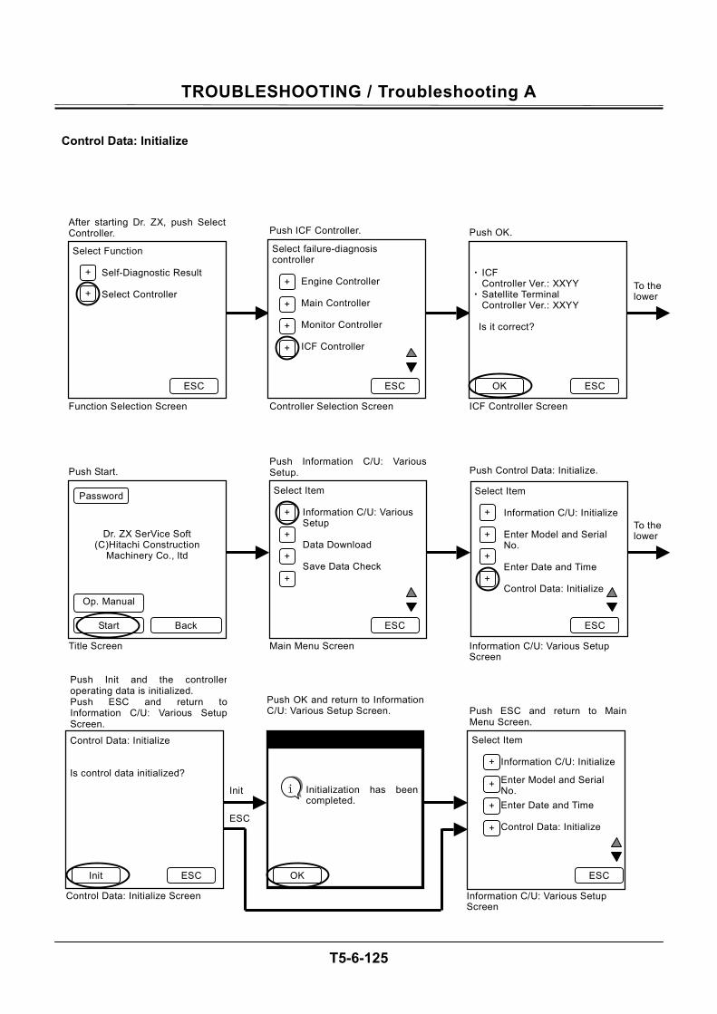
TROUBLESHOOTING / Troubleshooting A
T5-6-125
Control Data: Initialize
Select Function
Self-Diagnostic Result Select Controller
After starting Dr. ZX, push SelectController.
Function Selection Screen
Select failure-diagnosis controller
Engine Controller Main Controller Monitor Controller ICF Controller
Push ICF Controller.
Controller Selection Screen
・ ICF
Controller Ver.: XXYY ・ Satellite Terminal
Controller Ver.: XXYY Is it correct?
Push OK.
ICF Controller Screen
ESC
+
+ +
+
+
+
ESC ESC OK
Dr. ZX SerVice Soft (C)Hitachi Construction
Machinery Co., ltd
Push Start.
Select Item
Information C/U: Various Setup Data Download Save Data Check
Push Information C/U: VariousSetup.
Main Menu Screen
Select Item
Information C/U: Initialize Enter Model and Serial No. Enter Date and Time Control Data: Initialize
Information C/U: Various Setup Screen
Back Start
+
+
+
+
ESC ESC
Op. Manual
Password
+
+
+
+
Title Screen
Push Control Data: Initialize.
To the lower
To the lower
Control Data: Initialize Is control data initialized?
Push Init and the controlleroperating data is initialized. Push ESC and return toInformation C/U: Various SetupScreen.
Control Data: Initialize Screen
Initialization has been completed.
Push OK and return to InformationC/U: Various Setup Screen.
Select Item
Information C/U: Initialize
Enter Model and Serial No. Enter Date and Time Control Data: Initialize
Push ESC and return to MainMenu Screen.
Information C/U: Various Setup Screen
ESC Init ESC
Init
ESC
Initialization has beencompleted.
OK
i
+
+
+
+
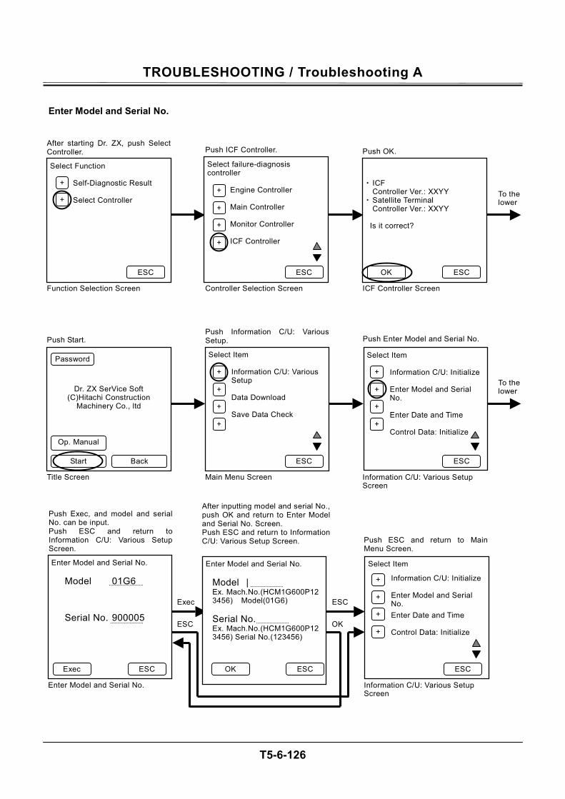
TROUBLESHOOTING / Troubleshooting A
T5-6-126
Enter Model and Serial No.
Select Function
Self-Diagnostic Result Select Controller
After starting Dr. ZX, push SelectController.
Function Selection Screen
Select failure-diagnosis controller
Engine Controller Main Controller Monitor Controller ICF Controller
Push ICF Controller.
Controller Selection Screen
・ ICF
Controller Ver.: XXYY ・ Satellite Terminal
Controller Ver.: XXYY Is it correct?
Push OK.
ICF Controller Screen
ESC
+
+ +
+
+
+
ESC ESC OK
Dr. ZX SerVice Soft (C)Hitachi Construction
Machinery Co., ltd
Push Start.
Select Item
Information C/U: Various Setup Data Download Save Data Check
Push Information C/U: VariousSetup.
Main Menu Screen
Select Item
Information C/U: Initialize Enter Model and Serial No. Enter Date and Time Control Data: Initialize
Information C/U: Various Setup Screen
Back Start
+
+
+
+
ESC ESC
Op. Manual
Password
+
+
+
+
Title Screen
Push Enter Model and Serial No.
To the lower
To the lower
Enter Model and Serial No.
Model 01G6
Serial No. 900005
Push Exec, and model and serialNo. can be input. Push ESC and return toInformation C/U: Various SetupScreen.
Enter Model and Serial No.
Enter Model and Serial No.
Model | Ex. Mach.No.(HCM1G600P123456) Model(01G6)
Serial No. Ex. Mach.No.(HCM1G600P123456) Serial No.(123456)
After inputting model and serial No.,push OK and return to Enter Model and Serial No. Screen. Push ESC and return to InformationC/U: Various Setup Screen.
Select Item
Information C/U: Initialize Enter Model and Serial No. Enter Date and Time Control Data: Initialize
Push ESC and return to MainMenu Screen.
Information C/U: Various Setup Screen
ESC Exec ESC
Exec
ESC
OK
+
+
+
+
ESC
OK
ESC
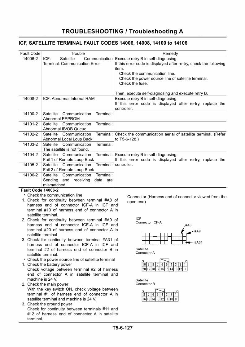
TROUBLESHOOTING / Troubleshooting A
T5-6-127
ICF, SATELLITE TERMINAL FAULT CODES 14006, 14008, 14100 to 14106 Fault Code Trouble Remedy
14006-2 ICF: Satellite Communication Terminal: Communication Error
Execute retry B in self-diagnosing. If this error code is displayed after re-try, check the following item. Check the communication line. Check the power source line of satellite terminal. Check the fuse. Then, execute self-diagnosing and execute retry B.
14008-2 ICF: Abnormal Internal RAM Execute retry B in self-diagnosing. If this error code is displayed after re-try, replace the controller.
14100-2 Satellite Communication Terminal: Abnormal EEPROM
14101-2 Satellite Communication Terminal: Abnormal IB/OB Queue
14102-2 Satellite Communication Terminal: Abnormal Local Loup Back
14103-2 Satellite Communication Terminal: The satellite is not found.
Check the communication aerial of satellite terminal. (Refer to T5-6-128.)
14104-2 Satellite Communication Terminal: Fail 1 of Remote Loup Back
14105-2 Satellite Communication Terminal: Fail 2 of Remote Loup Back
14106-2 Satellite Communication Terminal: Sending and receiving data are mismatched.
Execute retry B in self-diagnosing. If this error code is displayed after re-try, replace the controller.
Fault Code 14006-2 • Check the communication line
1. Check for continuity between terminal #A8 of harness end of connector ICF-A in ICF and terminal #10 of harness end of connector A in satellite terminal.
2. Check for continuity between terminal #A9 of harness end of connector ICF-A in ICF and terminal #20 of harness end of connector A in satellite terminal.
3. Check for continuity between terminal #A31 of harness end of connector ICF-A in ICF and terminal #2 of harness end of connector B in satellite terminal.
• Check the power source line of satellite terminal 1. Check the battery power
Check voltage between terminal #2 of harness end of connector A in satellite terminal and machine is 24 V.
2. Check the main power With the key switch ON, check voltage between terminal #1 of harness end of connector A in satellite terminal and machine is 24 V.
3. Check the ground power Check for continuity between terminals #11 and #12 of harness end of connector A in satellite terminal.
Connector (Harness end of connector viewed from the open end)
#A9
#A8
#A31
6
14 1213
458
16 15
7
1011
23 1 9
7
17 1516
5610
20 1819
89
13 14
3 4 1 2 11 12
ICF Connector ICF-A
Satellite Connector A
Satellite Connector B
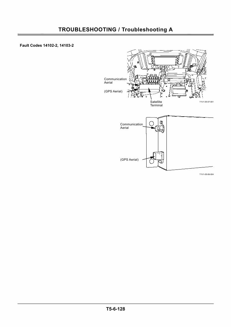
TROUBLESHOOTING / Troubleshooting A
T5-6-128
Fault Codes 14102-2, 14103-2
T1V1-05-07-001
T1V1-05-06-004
Satellite Terminal
Communication Aerial
(GPS Aerial)
Communication Aerial
(GPS Aerial)
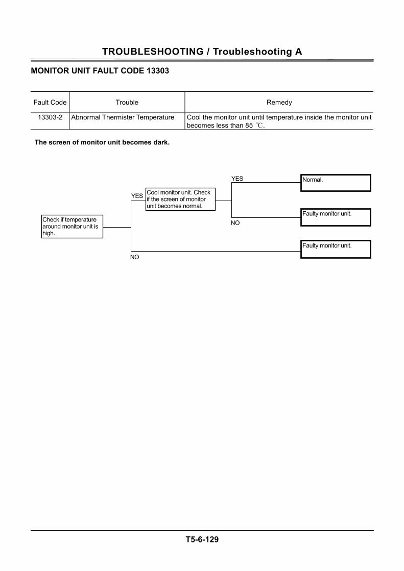
TROUBLESHOOTING / Troubleshooting A
T5-6-129
MONITOR UNIT FAULT CODE 13303
Fault Code Trouble Remedy
13303-2 Abnormal Thermister Temperature Cool the monitor unit until temperature inside the monitor unit becomes less than 85 .
The screen of monitor unit becomes dark.
Cool monitor unit. Check if the screen of monitor unit becomes normal.
Check if temperature around monitor unit is high.
Faulty monitor unit.
Faulty monitor unit.
Normal.
NO
YES
NO
YES
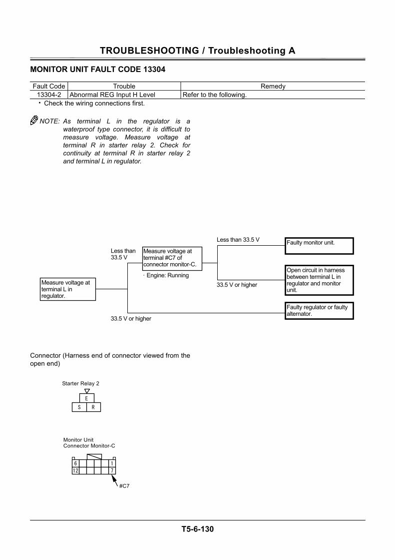
TROUBLESHOOTING / Troubleshooting A
T5-6-130
MONITOR UNIT FAULT CODE 13304 Fault Code Trouble Remedy
13304-2 Abnormal REG Input H Level Refer to the following. • Check the wiring connections first.
NOTE: As terminal L in the regulator is a
waterproof type connector, it is difficult to measure voltage. Measure voltage at terminal R in starter relay 2. Check for continuity at terminal R in starter relay 2 and terminal L in regulator.
Connector (Harness end of connector viewed from the open end)
E
R S
Starter Relay 2
Monitor Unit Connector Monitor-C
6 12
1 7
#C7
Measure voltage at terminal #C7 of connector monitor-C.
Measure voltage at terminal L in regulator.
33.5 V or higher
Less than 33.5 V
· Engine: RunningOpen circuit in harness between terminal L in regulator and monitor unit.
Faulty regulator or faulty alternator.
Faulty monitor unit. Less than 33.5 V
33.5 V or higher

TROUBLESHOOTING / Troubleshooting A
T5-6-131
MONITOR UNIT FAULT CODES 13306, 13308
Fault Code Trouble Remedy
13306-2 Abnormal EEPROM If this error code is displayed after re-try, replace the monitor unit.
13308-2 Abnormal CAN Communication Refer to “Check CAN Harness” (T5-6-54).
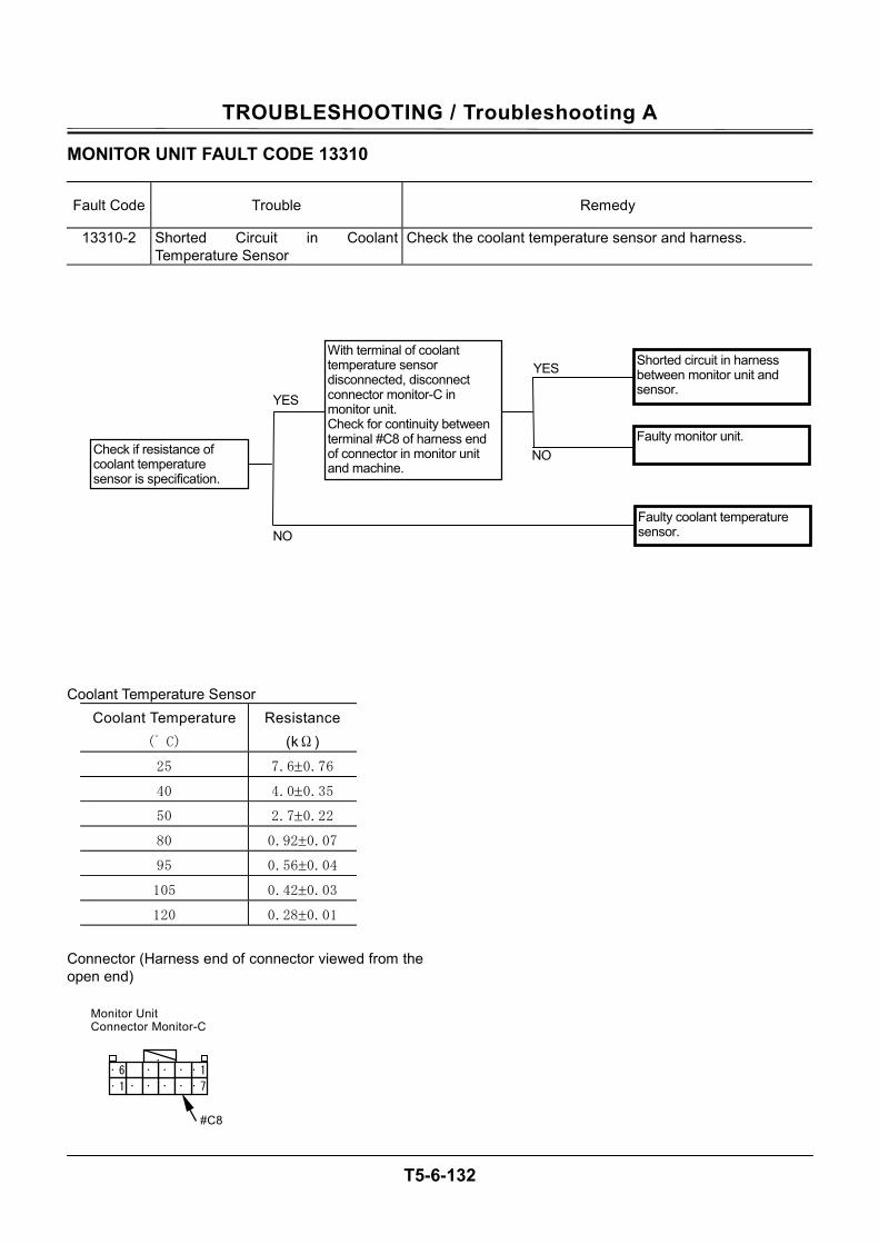
TROUBLESHOOTING / Troubleshooting A
T5-6-132
MONITOR UNIT FAULT CODE 13310
Fault Code Trouble Remedy
13310-2 Shorted Circuit in Coolant Temperature Sensor
Check the coolant temperature sensor and harness.
Coolant Temperature Sensor Coolant Temperature
(゚ C)
Resistance (kΩ)
25 7.6±0.76
40 4.0±0.35
50 2.7±0.22
80 0.92±0.07
95 0.56±0.04
105 0.42±0.03
120 0.28±0.01
Connector (Harness end of connector viewed from the open end)
NO
YES
With terminal of coolant temperature sensor disconnected, disconnect connector monitor-C in monitor unit. Check for continuity between terminal #C8 of harness end of connector in monitor unit and machine.
Check if resistance of coolant temperature sensor is specification.
NO
YES Shorted circuit in harness between monitor unit and sensor.
Faulty monitor unit.
Faulty coolant temperature sensor.
Monitor Unit Connector Monitor-C
·· 6
· · 1 · · · · · 1 ·
· 7 ·
#C8
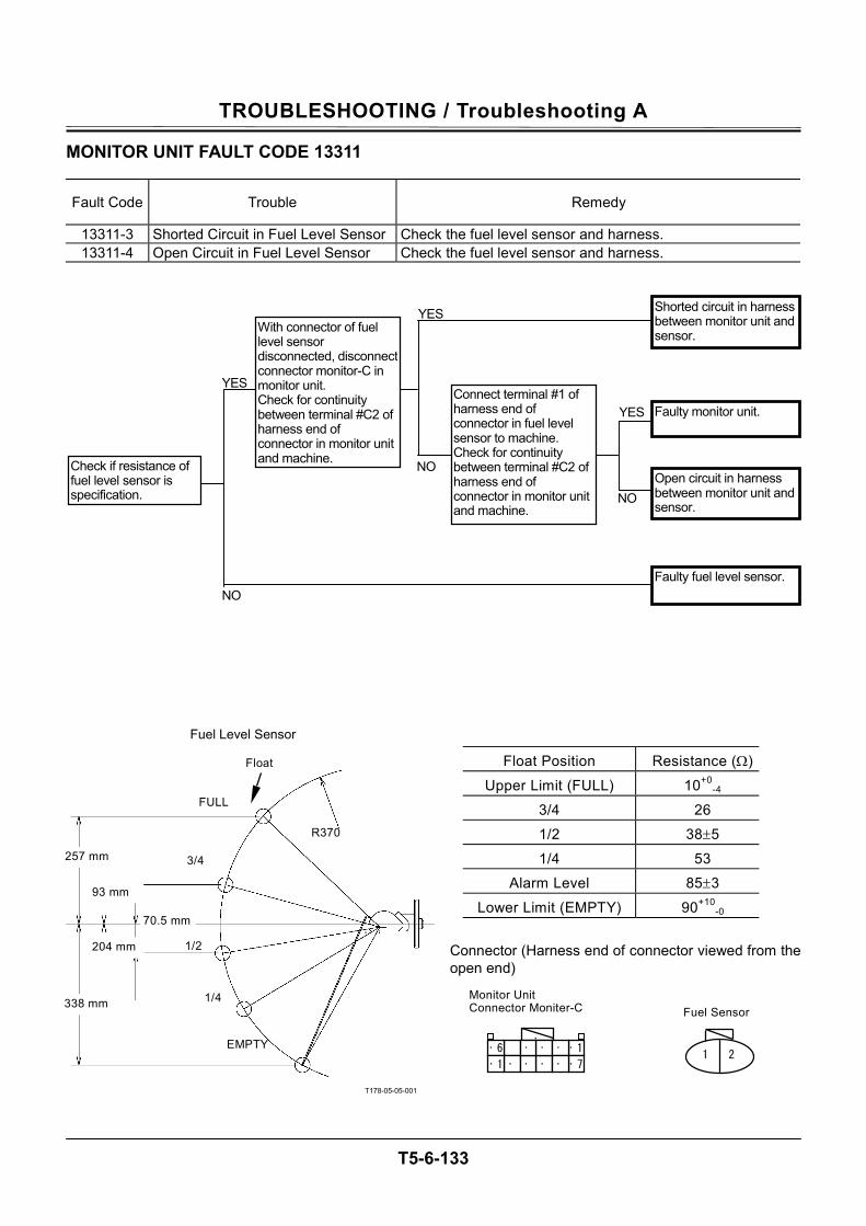
TROUBLESHOOTING / Troubleshooting A
T5-6-133
MONITOR UNIT FAULT CODE 13311
Fault Code Trouble Remedy
13311-3 Shorted Circuit in Fuel Level Sensor Check the fuel level sensor and harness. 13311-4 Open Circuit in Fuel Level Sensor Check the fuel level sensor and harness.
T178-05-05-001
Float Position Resistance (Ω)
Upper Limit (FULL) 10+0-4
3/4 26
1/2 38±5
1/4 53
Alarm Level 85±3
Lower Limit (EMPTY) 90+10-0
Connector (Harness end of connector viewed from the open end)
NO
YES
Check if resistance of fuel level sensor is specification. NO
YES
NO
YESWith connector of fuel level sensor disconnected, disconnectconnector monitor-C in monitor unit. Check for continuity between terminal #C2 of harness end of connector in monitor unit and machine.
Shorted circuit in harness between monitor unit and sensor.
Open circuit in harness between monitor unit and sensor.
Faulty monitor unit.
Faulty fuel level sensor.
Connect terminal #1 of harness end of connector in fuel level sensor to machine. Check for continuity between terminal #C2 of harness end of connector in monitor unit and machine.
Float
1/4
1/2
R370
70.5 mm
338 mm
204 mm
93 mm
257 mm 3/4
EMPTY
FULL
Monitor Unit Connector Moniter-C
·· 6
· · 1 · · ·· · 1·
· 7· 21
Fuel Sensor
Fuel Level Sensor
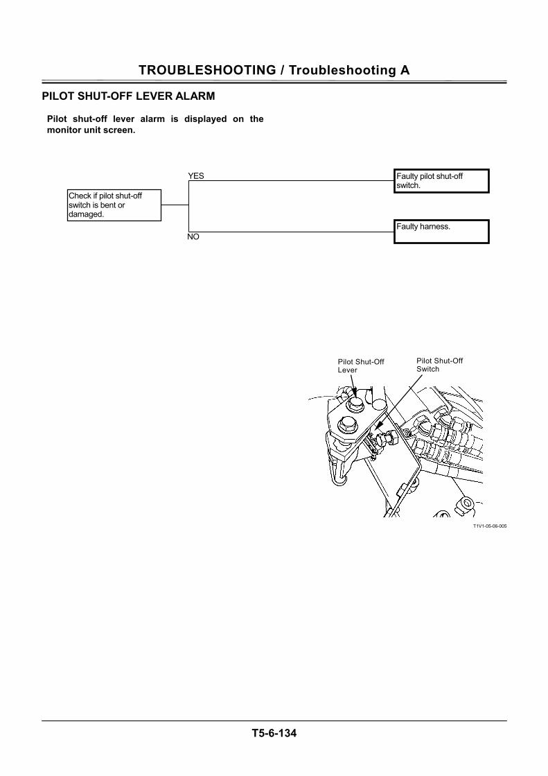
TROUBLESHOOTING / Troubleshooting A
T5-6-134
PILOT SHUT-OFF LEVER ALARM
Pilot shut-off lever alarm is displayed on the monitor unit screen.
T1V1-05-06-005
Check if pilot shut-off switch is bent or damaged.
Faulty pilot shut-off switch.
Faulty harness. NO
YES
Pilot Shut-Off Lever
Pilot Shut-Off Switch
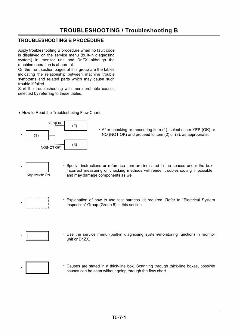
TROUBLESHOOTING / Troubleshooting B
T5-7-1
TROUBLESHOOTING B PROCEDURE Apply troubleshooting B procedure when no fault code is displayed on the service menu (built-in diagnosing system) in monitor unit and Dr.ZX although the machine operation is abnormal. On the front section pages of this group are the tables indicating the relationship between machine trouble symptoms and related parts which may cause such trouble if failed. Start the troubleshooting with more probable causes selected by referring to these tables. • How to Read the Troubleshoting Flow Charts
・
NO(NOT OK)
YES(OK)
(1) • After checking or measuring item (1), select either YES (OK) or
NO (NOT OK) and proceed to item (2) or (3), as appropriate.
(2)
(3)
・ • Special instructions or reference item are indicated in the spaces under the box. Incorrect measuring or checking methods will render troubleshooting impossible, and may damage components as well.
・ • Causes are stated in a thick-line box. Scanning through thick-line boxes, possible causes can be seen without going through the flow chart.
・ • Use the service menu (built-in diagnosing system/monitoring function) in monitor unit or Dr.ZX.
· Key switch: ON
・• Explanation of how to use test harness kit required. Refer to “Electrical System
Inspection” Group (Group 8) in this section.
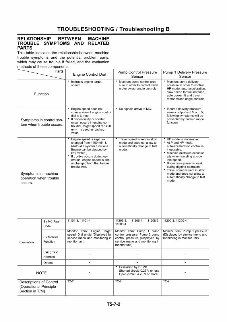
TROUBLESHOOTING / Troubleshooting B
T5-7-2
RELATIONSHIP BETWEEN MACHINE TROUBLE SYMPTOMS AND RELATED PARTS This table indicates the relationship between machine trouble symptoms and the potential problem parts, which may cause trouble if failed, and the evaluation methods of these components.
Parts Engine Control Dial Pump Control Pressure
Sensor Pump 1 Delivery Pressure
Sensor
Function
• Instructs engine target speed.
• Monitors pump control pres-sure in order to control travel motor swash angle controls.
• Monitors pump delivery pressure in order to control HP mode, auto-acceleration, slow speed torque increase, auto power lift and travel motor swash angle controls.
Symptoms in control sys-tem when trouble occurs.
• Engine speed does not change even if engine control dial is turned.
• If discontinuity or shorted circuit occurs in engine con-trol dial, target speed of 1400 min-1 is used as backup value.
• No signals arrive to MC. • If pump delivery pressure sensor output is 0 V or 5 V, following symptoms will be presented by backup mode function.
Symptoms in machine operation when trouble occurs.
• Engine speed is kept un-changed from 1400 min-1. (Auto-idle system functions. Engine can be stopped by key switch.)
• If trouble occurs during op-eration, engine speed is kept unchanged from that before breakdown.
• Travel speed is kept in slow mode and does not allow to automatically change to fast mode.
• HP mode is inoperable. • At P and HP mode,
auto-acceleration control is inoperable.
• Machine mistakes occasion-ally when traveling at slow idle speed.
• Boom raise power is weak during digging operation.
• Travel speed is kept in slow mode and does not allow to automatically change to fast mode.
By MC Fault Code
11101-3, 11101-4 11206-3, 11206-4, 11208-3, 11208-4
11200-3, 11200-4
By Monitor Function
Monitor Item: Engine target speed, Dial angle (Displayed by service menu and monitoring in monitor unit)
Monitor Item: Pump 1 pump control pressure, Pump 2 pump control pressure (Displayed by service menu and monitoring in monitor unit)
Monitor Item: Pump 1 pressure (Displayed by service menu and monitoring in monitor unit)
Using Test Harness
- - -
Evaluation
Others - - -
NOTE - • Evaluation by Dr. ZX
Shorted circuit: 0.25 V or lessOpen circuit: 4.75 V or more -
Descriptions of Control (Operational Principle Section in T/M)
T2-2 T2-2 T2-2
TROUBLESHOOTING / Troubleshooting B
T5-7-3
Pump 2 Delivery Pressure Sensor Pump 3 Delivery Pressure Sensor (Optional) Pressure Sensor (Travel)
• Monitors pump delivery pressure in order to control HP mode, auto-acceleration, slow speed torque increase, arm flow rate, arm regeneration and travel motor swash angle controls.
• Monitors pump delivery pressure in order to control pump 3 torque decrease con-trols.
• Monitors travel pilot pressure in order to control auto-idle, auto-acceleration, idle speed-up, engine speed automatic in-crease at travel (ZX270-3 class only), slow speed torque increase and travel motor swash angle controls.
• If pump delivery pressure sensor output is 0 V or 5 V, following symptoms will be presented by backup mode function.
• Engine stalls if pump torque is increased. • No signals arrive to MC.
• HP mode is inoperable. • At P and HP mode, auto-acceleration
control is inoperable. • Machine mistakes occasionally when
traveling at slow idle speed. • Swing power is weak during a combined
operation. • During shorted circuit, swing is given pri-
ority. • Arm is slow when combined operation of
arm roll-in and swing is made. • Travel speed is kept in slow mode and
does not allow to change to fast mode
• Engine stalls if pump torque is increased. • Engine speed does not increase even if auto-idle switch is turned ON.
• Engine speed does not increase even if auto-acceleration switch is turned ON.
• Occasionally, engine speed hunts while traveling at slow idle.
• If there is a difference in delivery flow rate between pumps 1 and 2, machine may mistake when traveling at minimum speed. (Not remarkable)
• Fast travel mode cannot be selected even if travel mode switch is turned to the FAST position.
• ZX270-3 class only: Travel speed is not increased. (Not remarkable)
11202-3, 11202-4 -
11304-3, 11304-4
Monitor Item: Pump 2 pressure (Displayed by service menu and monitoring in monitor unit) -
Monitor Item: Travel control pressure (Dis-played by service menu and monitoring in monitor unit) Monitor pressure change while traveling machine.
- - -
- - -
- - • Judge if pressure sensor is faulty or port
is clogged by switching pressure sensor with other pressure sensor.
T2-2
T2-2 T2-2
TROUBLESHOOTING / Troubleshooting B
T5-7-4
Parts Pressure Sensor (Front Attachment) Pressure Sensor (Swing) Pressure Sensor
(Boom Raise)
Function
• Monitors front attachment pilot pressure in order to con-trol auto-idle, and idle speed-up, and engine speed automatic increase at travel (ZX270-3 class only) controls.
• Monitors swing pilot pressure in order to control arm flow rate and arm regeneration controls.
• Monitors boom raise pilot pressure in order to control HP mode, auto-acceleration, arm regeneration and auto-power lift controls.
Symptoms in control system when trouble occurs.
• No signals arrive to MC. • No signals arrive to MC. • No signals arrive to MC.
Symptoms in machine operation when trouble occurs.
• Engine speed does not in-crease even if any front at-tachment is operated with auto-idle switch ON.
• Occasionally, engine speed hunts while operating front attachment at slow idle.
• ZX270 class only: Travel speed is not in-creased. (Not remarkable)
• As arm regenerative function is inoperable during com-bined operation of swing/arm roll-in, initial arm moving speed is slow. (Not remark-able)
• During arm level crowding operation, arm speed is slightly slow.
• Even if boom is raised with HP mode switch ON, engine speed does not increase.
• Even if boom is raised with auto-acceleration switch ON, engine speed does not in-crease.
• As arm regenerative system does not work, arm roll-in speed becomes slightly slower than normal during combined operation of boom raise and arm roll-in. (Not remarkable)
• Arm roll-in and boom raise speeds become slightly slower at the beginning stage of arm level crowd operation.
• Boom raise power is weak. (Not remarkable)
By MC Fault Code
11307-3, 11307-4 11301-3, 11301-4 11302-3, 11302-4
By Monitor Function
Monitor Item: Front attachment operation (Displayed by service menu and monitoring in monitor unit) Monitor pressure change while operating front attachment.
Monitor Item: Swing control pressure (Displayed by service menu and monitoring in monitor unit) Monitor pressure change while swinging upperstructure.
Monitor Item: Boom raise pilot pressure (Displayed by service menu and monitoring in monitor unit) Monitor pressure change while raising boom.
Using Test Harness
- - -
Evaluation
Others - - -
NOTE
• Judge if pressure sensor is faulty or port is clogged by switching pressure sensor with other pressure sensor.
• Judge if pressure sensor is faulty or port is clogged by switching pressure sensor with other pressure sensor.
• Judge if pressure sensor is faulty or port is clogged by switching pressure sensor with other pressure sensor.
Descriptions of Control (Operational Principle Section in T/M)
T2-2 T2-2 T2-2
TROUBLESHOOTING / Troubleshooting B
T5-7-5
Pressure Sensor (Arm Roll-In)
Pressure Sensor (Auxiliary) (Optional) Torque Control Solenoid Valve
• Monitors arm roll-in pilot pressure in or-der to control HP mode, auto-acceleration, arm flow rate, and arm regeneration controls.
• Monitors attachment pilot pressure when attachment is installed in order to control attachment operation speed increase, pump 1 flow rate limit, pump 2 flow rate limit and auxiliary flow rate controls.
• Supplies control pressure to pumps 1 and 2 in order to control speed sensing and slow speed torque increase controls.
• No signals arrive to MC. • No signals arrive to MC. • If torque control solenoid valve is not ac-tivated, output pressure from solenoid valve is 0 MPa (0 kgf/cm2).
• Even if arm is rolled-in with HP mode switch ON, engine speed does not in-crease.
• Even if arm is rolled-in with auto-acceleration switch ON, engine speed does not increase.
• As arm flow rate control does not work, swing speed becomes slightly slower during combined operation of swing and arm roll-in. (Not remarkable)
• Arm speed is slow during arm level crowd operation.
• Engine speed does not increase when attachment is operated.
• Operation speed increases when at-tachment is operated.
• Even if speed sensing system does not work, upper limit power is restricted so that machine is operable.
• Machine may occasionally mistake when traveling at slow idle speed.
11303-3, 11303-4 -
11401-2, 11401-3, 11401-4
Monitor Item: Arm roll-In pilot pressure (Displayed by service menu and monitoring in monitor unit) Monitor pressure change while rolling arm in.
Monitor Item: ATT control pressure (Dis-played by service menu and monitoring in monitor unit) Monitor pressure change while operating attachment.
Monitor Item: Pump torque proportional so-lenoid valve output
- - -
- - - • Judge if pressure sensor is faulty or port
is clogged by switching pressure sensor with other pressure sensor.
• Judge if pressure sensor is faulty or port is clogged by switching pressure sensor with other pressure sensor. -
T2-2 T2-2 T2-2
TROUBLESHOOTING / Troubleshooting B
T5-7-6
Parts Solenoid Valve Unit (SG) Solenoid Valve Unit (SF) Solenoid Valve Unit (SC)
Function
• Temporarily increases main relief valve pressure when operating machine either in power digging and auto-power lift control.
• Routes return oil from boom cylinder rod side to arm cyl-inder bottom side during dig-ging operation and increases arm speed.
• Routes return oil from arm cylinder rod side to bottom side when rolling arm in and increases arm speed.
Symptoms in control sys-tem when trouble occurs.
• If solenoid valve unit (SG) is not activated, pressure at port SG becomes 0 MPa (0 kgf/cm2).
• If solenoid valve unit (SF) is not activated, pressure at port SF becomes 0 MPa (0 kgf/cm2).
• If solenoid valve unit (SC) is not activated, pressure at port SC becomes 0 MPa (0 kgf/cm2). Arm regenerative valve will not operate at this time.
Symptoms in machine operation when trouble occurs.
Solenoid valve unit (SG) is closed: • Relief pressure stays at
normal 34 MPa (350 kfg/cm2). Even if power dig-ging switch is pushed, relief pressure does not increase. Power does not increase.
Solenoid valve unit (SG) is open: • Pressure always increases.
Every operation makes the force increase.
Solenoid valve unit (SF) is closed: • Arm roll-in speed becomes
slow during digging opera-tion.
Solenoid valve unit (SF) is open: • Arm speed becomes fast
during combined operation of boom raise and arm.
Solenoid valve unit (SC) is closed: • Arm speed becomes slow
during arm level crowd op-eration.
Solenoid valve unit (SC) is open: • Arm speed becomes fast as
arm regeneration is operated.
Evaluation By MC Fault Code
11404-2, 11404-3, 11404-4 11404-2, 11404-3, 11404-4 11404-2, 11404-3, 11404-4
By Monitor Function
Monitor Item: Power digging control pressure
Monitor Item: Digging regen-erative valve
Monitor Item: Arm regenerative proportional solenoid valve output
Using Test Harness
• Install lamp harness (ST 7226). Check output signals from MC and harness condi-tion.
• Install lamp harness (ST 7226). Check output signals from MC and harness condi-tion.
• Install lamp harness (ST 7226). Check output signals from MC and harness condi-tion.
Others - - -
NOTE
• Proportional solenoid valve is used as an ON/OFF valve. When power digging switch is pushed or released and lamp comes ON, harness is normal. If lamp goes OFF, it may be due to open harness.
- -
Descriptions of Control (Operational Principle Section in T/M)
T2-2 T2-2 T2-2
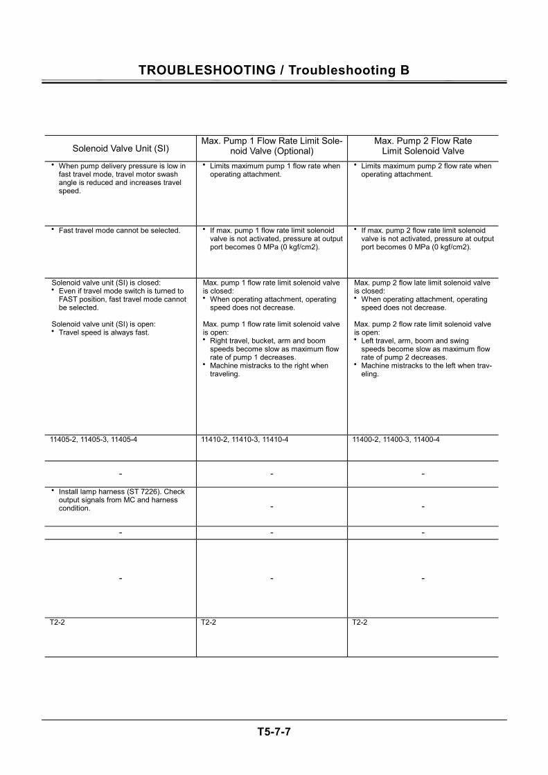
TROUBLESHOOTING / Troubleshooting B
T5-7-7
Solenoid Valve Unit (SI) Max. Pump 1 Flow Rate Limit Sole-
noid Valve (Optional) Max. Pump 2 Flow Rate
Limit Solenoid Valve • When pump delivery pressure is low in
fast travel mode, travel motor swash angle is reduced and increases travel speed.
• Limits maximum pump 1 flow rate when operating attachment.
• Limits maximum pump 2 flow rate when operating attachment.
• Fast travel mode cannot be selected. • If max. pump 1 flow rate limit solenoid valve is not activated, pressure at output port becomes 0 MPa (0 kgf/cm2).
• If max. pump 2 flow rate limit solenoid valve is not activated, pressure at output port becomes 0 MPa (0 kgf/cm2).
Solenoid valve unit (SI) is closed: • Even if travel mode switch is turned to
FAST position, fast travel mode cannot be selected.
Solenoid valve unit (SI) is open: • Travel speed is always fast.
Max. pump 1 flow rate limit solenoid valve is closed: • When operating attachment, operating
speed does not decrease.
Max. pump 1 flow rate limit solenoid valve is open: • Right travel, bucket, arm and boom
speeds become slow as maximum flow rate of pump 1 decreases.
• Machine mistracks to the right when traveling.
Max. pump 2 flow late limit solenoid valve is closed: • When operating attachment, operating
speed does not decrease.
Max. pump 2 flow rate limit solenoid valve is open: • Left travel, arm, boom and swing
speeds become slow as maximum flow rate of pump 2 decreases.
• Machine mistracks to the left when trav-eling.
11405-2, 11405-3, 11405-4 11410-2, 11410-3, 11410-4 11400-2, 11400-3, 11400-4
- - -
• Install lamp harness (ST 7226). Check output signals from MC and harness condition. - -
- - -
- - -
T2-2 T2-2 T2-2
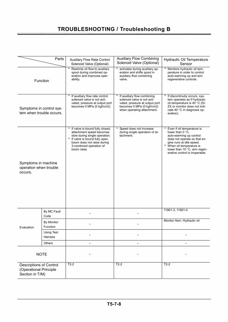
TROUBLESHOOTING / Troubleshooting B
T5-7-8
Parts Auxiliary Flow Rate Control Solenoid Valve (Optional)
Auxiliary Flow Combining Solenoid Valve (Optional)
Hydraulic Oil Temperature Sensor
Function
• Restricts oil flow to auxiliary spool during combined op-eration and improves oper-ability.
• activates during auxiliary op-eration and shifts spool in auxiliary flow combining valve.
• Monitors hydraulic oil tem-perature in order to control auto-warming up and arm regenerative controls.
Symptoms in control sys-tem when trouble occurs.
• If auxiliary flow rate control solenoid valve is not acti-vated, pressure at output port becomes 0 MPa (0 kgf/cm2).
• If auxiliary flow combining solenoid valve is not acti-vated, pressure at output port becomes 0 MPa (0 kgf/cm2) when operating attachment.
• If discontinuity occurs, sys-tem operates as if hydraulic oil temperature is 40 °C (Dr. ZX or monitor does not indi-cate 40 °C in diagnosis op-eration).
Symptoms in machine operation when trouble occurs.
• If valve is bound fully closed, attachment speed becomes slow during single operation.
• If valve is bound fully open, boom does not raise during 3-combined operation of boom raise.
• Speed does not increase during single operation of at-tachment.
• Even if oil temperature is lower than 0 °C, auto-warming up control does not operate so that en-gine runs at idle speed.
• When oil temperature is lower than 10 °C, arm regen-erative control is inoperable.
By MC Fault Code
- - 11901-3, 11901-4
By Monitor Function
- - Monitor Item: Hydraulic oil
Using Test Harness - - -
Evaluation
Others - - -
NOTE - - -
Descriptions of Control (Operational Principle Section in T/M)
T2-2 T2-2 T2-2
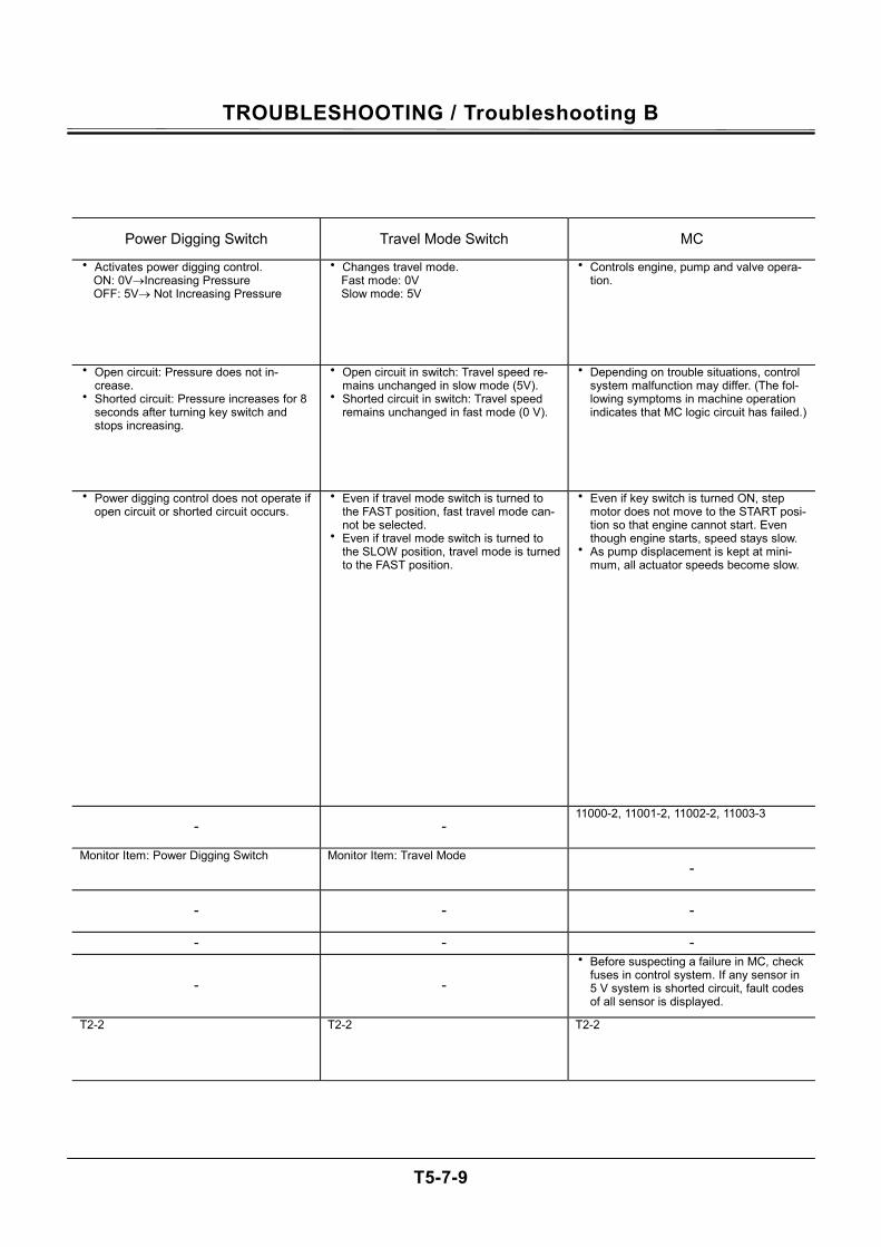
TROUBLESHOOTING / Troubleshooting B
T5-7-9
Power Digging Switch Travel Mode Switch MC
• Activates power digging control. ON: 0V→Increasing Pressure OFF: 5V→ Not Increasing Pressure
• Changes travel mode. Fast mode: 0V Slow mode: 5V
• Controls engine, pump and valve opera-tion.
• Open circuit: Pressure does not in-crease.
• Shorted circuit: Pressure increases for 8 seconds after turning key switch and stops increasing.
• Open circuit in switch: Travel speed re-mains unchanged in slow mode (5V).
• Shorted circuit in switch: Travel speed remains unchanged in fast mode (0 V).
• Depending on trouble situations, control system malfunction may differ. (The fol-lowing symptoms in machine operation indicates that MC logic circuit has failed.)
• Power digging control does not operate if open circuit or shorted circuit occurs.
• Even if travel mode switch is turned to the FAST position, fast travel mode can-not be selected.
• Even if travel mode switch is turned to the SLOW position, travel mode is turned to the FAST position.
• Even if key switch is turned ON, step motor does not move to the START posi-tion so that engine cannot start. Even though engine starts, speed stays slow.
• As pump displacement is kept at mini-mum, all actuator speeds become slow.
- - 11000-2, 11001-2, 11002-2, 11003-3
Monitor Item: Power Digging Switch Monitor Item: Travel Mode -
- - -
- - -
- - • Before suspecting a failure in MC, check
fuses in control system. If any sensor in 5 V system is shorted circuit, fault codes of all sensor is displayed.
T2-2 T2-2 T2-2
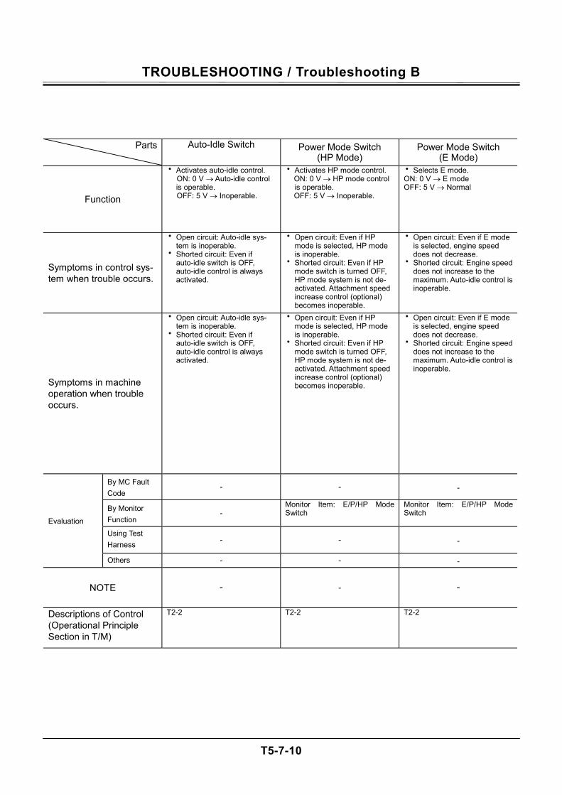
TROUBLESHOOTING / Troubleshooting B
T5-7-10
Parts Auto-Idle Switch Power Mode Switch (HP Mode)
Power Mode Switch (E Mode)
Function
• Activates auto-idle control. ON: 0 V → Auto-idle control is operable. OFF: 5 V → Inoperable.
• Activates HP mode control. ON: 0 V → HP mode control is operable. OFF: 5 V → Inoperable.
• Selects E mode. ON: 0 V → E mode OFF: 5 V → Normal
Symptoms in control sys-tem when trouble occurs.
• Open circuit: Auto-idle sys-tem is inoperable.
• Shorted circuit: Even if auto-idle switch is OFF, auto-idle control is always activated.
• Open circuit: Even if HP mode is selected, HP mode is inoperable.
• Shorted circuit: Even if HP mode switch is turned OFF, HP mode system is not de-activated. Attachment speed increase control (optional) becomes inoperable.
• Open circuit: Even if E mode is selected, engine speed does not decrease.
• Shorted circuit: Engine speed does not increase to the maximum. Auto-idle control is inoperable.
Symptoms in machine operation when trouble occurs.
• Open circuit: Auto-idle sys-tem is inoperable.
• Shorted circuit: Even if auto-idle switch is OFF, auto-idle control is always activated.
• Open circuit: Even if HP mode is selected, HP mode is inoperable.
• Shorted circuit: Even if HP mode switch is turned OFF, HP mode system is not de-activated. Attachment speed increase control (optional) becomes inoperable.
• Open circuit: Even if E mode is selected, engine speed does not decrease.
• Shorted circuit: Engine speed does not increase to the maximum. Auto-idle control is inoperable.
By MC Fault Code
- - -
By Monitor Function
- Monitor Item: E/P/HP Mode Switch
Monitor Item: E/P/HP Mode Switch
Using Test Harness - - -
Evaluation
Others - - -
NOTE - - -
Descriptions of Control (Operational Principle Section in T/M)
T2-2 T2-2 T2-2
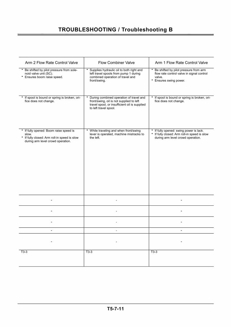
TROUBLESHOOTING / Troubleshooting B
T5-7-11
Arm 2 Flow Rate Control Valve Flow Combiner Valve Arm 1 Flow Rate Control Valve
• Be shifted by pilot pressure from sole-noid valve unit (SC).
• Ensures boom raise speed.
• Supplies hydraulic oil to both right and left travel spools from pump 1 during combined operation of travel and front/swing.
• Be shifted by pilot pressure from arm flow rate control valve in signal control valve.
• Ensures swing power.
• If spool is bound or spring is broken, ori-fice does not change.
• During combined operation of travel and front/swing, oil is not supplied to left travel spool, or insufficient oil is supplied to left travel spool.
• If spool is bound or spring is broken, ori-fice does not change.
• If fully opened: Boom raise speed is slow.
• If fully closed: Arm roll-in speed is slow during arm level crowd operation.
• While traveling and when front/swing lever is operated, machine mistracks to the left.
• If fully opened: swing power is lack. • If fully closed: Arm roll-in speed is slow
during arm level crowd operation.
- - -
- - -
- - -
- - -
- - -
T3-3 T3-3 T3-3
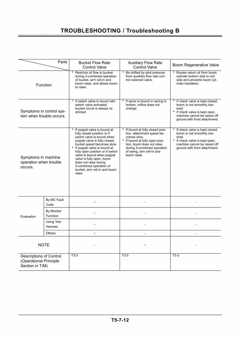
TROUBLESHOOTING / Troubleshooting B
T5-7-12
Parts Bucket Flow Rate Control Valve
Auxiliary Flow Rate Control Valve Boom Regenerative Valve
Function
• Restricts oil flow to bucket during 3-combined operation of bucket, arm roll-in and boom raise, and allows boom to raise.
• Be shifted by pilot pressure from auxiliary flow rate con-trol solenoid valve.
• Routes return oil from boom cylinder bottom side to rod side and prevents boom cyl-inder hesitation.
Symptoms in control sys-tem when trouble occurs.
• If switch valve is bound with switch valve activated, bucket circuit is always re-stricted.
• If spool is bound or spring is broken, orifice does not change.
• If check valve is kept closed, boom is not smoothly low-ered.
• If check valve is kept open, machine cannot be raised off ground with front attachment.
Symptoms in machine operation when trouble occurs.
• If poppet valve is bound at fully closed position or if switch valve is bound when poppet valve is fully closed, bucket speed becomes slow.
• If poppet valve is bound at fully open position or if switch valve is bound when poppet valve is fully open, boom does not raise during 3-combined operation of bucket, arm roll-in and boom raise.
• If bound at fully closed posi-tion, attachment speed be-comes slow.
• If bound at fully open posi-tion, boom does not raise during 3-combined operation of swing, arm roll-in and boom raise.
• If check valve is kept closed, boom is not smoothly low-ered.
• If check valve is kept open, machine cannot be raised off ground with front attachment.
By MC Fault Code
- - -
By Monitor Function
- - -
Using Test Harness - - -
Evaluation
Others - - -
NOTE - - -
Descriptions of Control (Operational Principle Section in T/M)
T3-3 T3-3 T3-3
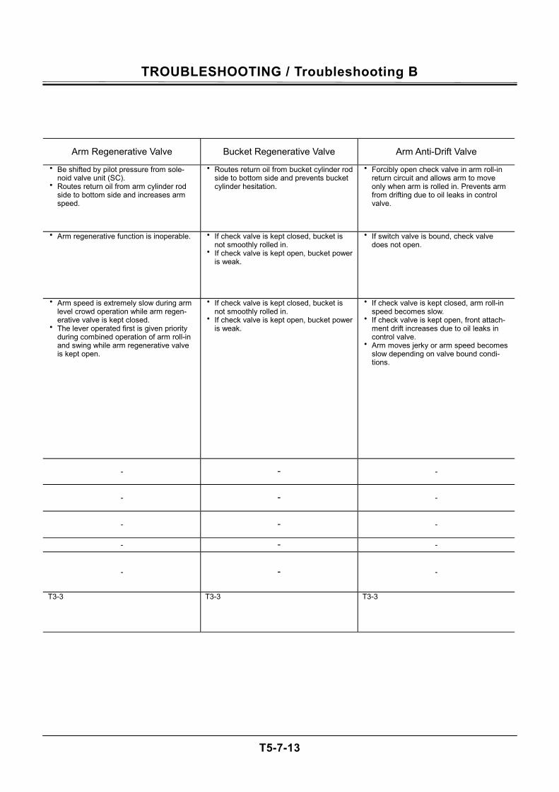
TROUBLESHOOTING / Troubleshooting B
T5-7-13
Arm Regenerative Valve Bucket Regenerative Valve Arm Anti-Drift Valve
• Be shifted by pilot pressure from sole-noid valve unit (SC).
• Routes return oil from arm cylinder rod side to bottom side and increases arm speed.
• Routes return oil from bucket cylinder rod side to bottom side and prevents bucket cylinder hesitation.
• Forcibly open check valve in arm roll-in return circuit and allows arm to move only when arm is rolled in. Prevents arm from drifting due to oil leaks in control valve.
• Arm regenerative function is inoperable. • If check valve is kept closed, bucket is not smoothly rolled in.
• If check valve is kept open, bucket power is weak.
• If switch valve is bound, check valve does not open.
• Arm speed is extremely slow during arm level crowd operation while arm regen-erative valve is kept closed.
• The lever operated first is given priority during combined operation of arm roll-in and swing while arm regenerative valve is kept open.
• If check valve is kept closed, bucket is not smoothly rolled in.
• If check valve is kept open, bucket power is weak.
• If check valve is kept closed, arm roll-in speed becomes slow.
• If check valve is kept open, front attach-ment drift increases due to oil leaks in control valve.
• Arm moves jerky or arm speed becomes slow depending on valve bound condi-tions.
- - -
- - -
- - -
- - -
- - -
T3-3 T3-3 T3-3
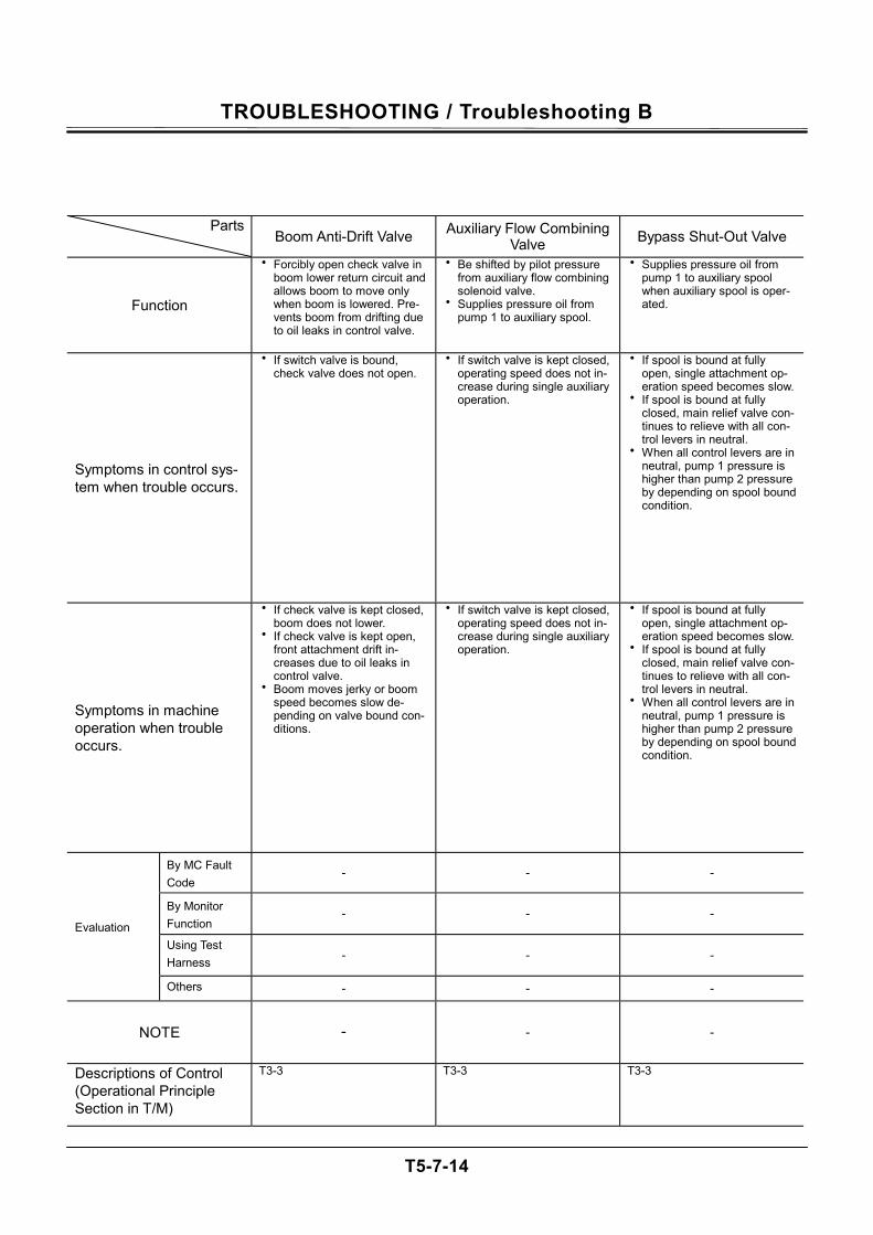
TROUBLESHOOTING / Troubleshooting B
T5-7-14
Parts Boom Anti-Drift Valve Auxiliary Flow Combining
Valve Bypass Shut-Out Valve
Function
• Forcibly open check valve in boom lower return circuit and allows boom to move only when boom is lowered. Pre-vents boom from drifting due to oil leaks in control valve.
• Be shifted by pilot pressure from auxiliary flow combining solenoid valve.
• Supplies pressure oil from pump 1 to auxiliary spool.
• Supplies pressure oil from pump 1 to auxiliary spool when auxiliary spool is oper-ated.
Symptoms in control sys-tem when trouble occurs.
• If switch valve is bound, check valve does not open.
• If switch valve is kept closed, operating speed does not in-crease during single auxiliary operation.
• If spool is bound at fully open, single attachment op-eration speed becomes slow.
• If spool is bound at fully closed, main relief valve con-tinues to relieve with all con-trol levers in neutral.
• When all control levers are in neutral, pump 1 pressure is higher than pump 2 pressure by depending on spool bound condition.
Symptoms in machine operation when trouble occurs.
• If check valve is kept closed, boom does not lower.
• If check valve is kept open, front attachment drift in-creases due to oil leaks in control valve.
• Boom moves jerky or boom speed becomes slow de-pending on valve bound con-ditions.
• If switch valve is kept closed, operating speed does not in-crease during single auxiliary operation.
• If spool is bound at fully open, single attachment op-eration speed becomes slow.
• If spool is bound at fully closed, main relief valve con-tinues to relieve with all con-trol levers in neutral.
• When all control levers are in neutral, pump 1 pressure is higher than pump 2 pressure by depending on spool bound condition.
By MC Fault Code
- - -
By Monitor Function
- - -
Using Test Harness - - -
Evaluation
Others - - -
NOTE - - -
Descriptions of Control (Operational Principle Section in T/M)
T3-3 T3-3 T3-3
TROUBLESHOOTING / Troubleshooting B
T5-7-15
Pump 1 Flow Rate Control Valve Pump 2 Flow Rate Control Valve Flow Combiner Valve Control Spool
• Supplies flow rate control pressure Pi to pump 1 regulator in response to lever stroke when boom (raise/lower), arm (roll-out/in), bucket (roll-out/in), right travel or auxiliary is operated.
• Supplies flow rate control pressure Pi to pump 2 regulator in response to lever stroke when boom (raise/lower), arm (roll-out/in), swing (right/left), left travel or auxiliary is operated.
• Be shifted by right travel pilot pres-sure and supplies control pressure to flow combiner valve in control valve.
• If spool is bound at fully open, even if con-trol lever is in neutral, pump 1 swash angle is tilted to maximum. (When traveling with travel levers held in half stroke, machine mistracks to the left.)
• If spool is bound at fully open, pump 1 control pressure sensor monitors the maximum pressure.
• If spool is bound at fully closed, even if control lever is operated, pump 1 swash angle is tilted to minimum. (Right travel is inoperable during single travel operation. Bucket speed becomes very slow.)
• If spool is bound at fully open, pump 1 control pressure sensor cannot monitor the pump control pressure. (Right travel does not run fast with right track jacked-up.)
• If spool is bound at fully open, even if con-trol lever is in neutral, pump 2 swash angle is tilted to maximum. (When traveling with travel levers held in half stroke, machine mistracks to the right.)
• If spool is bound at fully open, pump 2 con-trol pressure sensor monitors the maxi-mum pressure.
• If spool is bound at fully closed, even if control lever is operated, pump 2 swash angle is tilted to minimum. (Left travel is inoperable during single travel operation. Swing speed becomes very slow.)
• If spool is bound at fully open, pump 2 con-trol pressure sensor cannot monitor the pump control pressure. (Left travel does not run fast with left track jacked-up.)
• If spool is bound at fully open, when boom, arm, bucket or swing is oper-ated, flow combiner valve is shifted.
• If spool is bound at fully closed, when combined operation of travel and front/swing is made, machine mistracks to the left. (Left travel speed becomes slow.)
• spool is bound at fully open, even if control lever is in neutral, pump 1 swash angle is tilted to maximum. (When traveling with travel levers held in half stroke, machine mistracks to the left.)
• If spool is bound at fully open, pump 1 control pressure sensor monitors the maximum pressure.
• If spool is bound at fully closed, even if control lever is operated, pump 1 swash angle is tilted to minimum. (Right travel is inoperable during single travel operation. Bucket speed becomes very slow.)
• If spool is bound at fully open, pump 1 control pressure sensor cannot monitor the pump control pressure. (Right travel does not run fast with right track jacked-up.)
• If spool is bound at fully open, even if con-trol lever is in neutral, pump 2 swash angle is tilted to maximum. (When traveling with travel levers held in half stroke, machine mistracks to the right.)
• If spool is bound at fully open, pump 2 con-trol pressure sensor monitors the maxi-mum pressure.
• If spool is bound at fully closed, even if control lever is operated, pump 2 swash angle is tilted to minimum. (Left travel is inoperable during single travel operation. Swing speed becomes very slow.)
• If spool is bound at fully open, pump 2 con-trol pressure sensor cannot monitor the pump control pressure. (Left travel does not run fast with left track jacked-up.)
• If spool is bound at fully open, when boom, arm, bucket or swing is oper-ated, flow combiner valve is shifted.
• If spool is bound at fully closed, when combined operation of travel and front/swing is made, machine mistracks to the left. (Left travel speed becomes slow.)
- - -
- - -
- - -
- - -
- - -
T3-6 T3-6 T3-6
TROUBLESHOOTING / Troubleshooting B
T5-7-16
Parts Swing Parking Brake Release Spool
Bucket Flow Rate Control Valve Control Spool
Function
• Be shifted by boom, arm, bucket or swing pilot pressure and supplies swing parking brake release pressure.
• Be shifted by arm roll-in pilot pressure and supplies boom raise pilot pressure to bucket flow rate control valve as control pressure.
Symptoms in control sys-tem when trouble occurs.
• If spool is bound at fully open, swing parking brake is kept released. (Machine vibrates while traveling.)
• If spool is bound at fully open, pressure sen-sor (front attachment) is always turned into ON. Thus, engine speed does not decrease when control lever is in neutral during auto-idle/acceleration control.
• If spool is bound at fully closed, swing parking brake is kept applied. (Dragging is felt.)
• If spool is bound at fully closed, pressure sensor (front attachment) is always turned into OFF. Thus, engine speed does not increase when control lever is operated during auto-idle/acceleration control.
• If spool is bound at fully open, bucket speed becomes slow during combined operation of boom raise and bucket. (Bucket flow rate con-trol is inoperable.)
• If spool is bound at fully closed, boom does not raise during 3-combined operation of bucket, arm roll-in and boom raise.
Symptoms in machine op-eration when trouble oc-curs.
• If spool is bound at fully open, swing parking brake is kept released. (Machine vibrates while traveling.)
• If spool is bound at fully open, pressure sen-sor (front attachment) is always turned into ON. Thus, engine speed does not decrease when control lever is in neutral during auto-idle/acceleration control.
• If spool is bound at fully closed, swing parking brake is kept applied. (Dragging is felt.)
• If spool is bound at fully closed, pressure sensor (front attachment) is always turned into OFF. Thus, engine speed does not increase when control lever is operated during auto-idle/acceleration control.
• If spool is bound at fully open, bucket speed becomes slow during combined operation of boom raise and bucket. (Bucket flow rate con-trol is inoperable.)
• If spool is bound at fully closed, boom does not raise during 3-combined operation of bucket, arm roll-in and boom raise.
By MC Fault Code
- -
By Monitor Function
- -
Using Test Harness - -
Evaluation
Others - -
NOTE - -
Descriptions of Control (Operational Principle Sec-tion in T/M)
T3-3 T3-6
TROUBLESHOOTING / Troubleshooting B
T5-7-17
Arm Flow Rate Control
Valve Control Spool Digging Regenerative
Valve Boom Flow Rate Control
Valve Boom Lower Meter-In Cut
Valve • Be shifted by arm roll-in pilot
pressure and supplies to arm flow rate control valve 1 on 5-spool side in control valve as control pressure.
• Be shifted by pilot pressure from solenoid valve unit (SF).
• Routes return oil from boom cylinder rod side to arm cyl-inder bottom side and in-creases arm speed.
• Be shifted by pilot pressure from boom lower meter-in cut valve.
• Controls flow rate to boom 1 spool during combined op-eration and improves com-bined operation.
• Be shifted by return oil from boom cylinder bottom side.
• Shifts boom flow rate control valve by boom lower pilot pressure.
• If spool is bound at fully open, arm speed decreases during single arm operation. (Arm flow rate control is al-ways operable.)
• If spool is bound at fully closed, swing power be-comes insufficient during combined operation of swing and arm roll-in. (Arm flow rate control is inoperable.)
• If valve is kept closed, arm roll-in speed does not in-crease during digging opera-tion.
• If valve is kept open, arm speed becomes fast during combined operation of boom raise and arm.
• If valve is at fully open, boom lower speed becomes fast during combined operation.
• If valve is at fully closed, machine cannot be raised off ground with front attachment.
• If valve is kept closed, as boom flow rate control valve is not shifted, boom lower speed becomes fast during combined operation.
• If valve is kept open, as boom flow rate control valve is shifted, pressure oil from pump 1 does not flow to boom 1 spool. Therefore, machine cannot be raised off ground with front attachment.
- - - -
- - - -
- - - -
- - - -
- - - -
T3-6 T3-3 T3-3 T3-3
TROUBLESHOOTING / Troubleshooting B
T5-7-18
CORRELATION BETWEEN TROUBLE SYMPTOMS AND PART FAILURES This table indicates the relationship between machine troubles and parts contributing to the cause of the trouble if failed.
: Related, required to check : Related. However, in case this component fails, other trouble
symptom will be more noticeable so that this component will not be the direct cause of the trouble concerned.
Engine System Troubleshooting
E-1 E-2 E-3 Trouble Symptom
Parts
Starter does not rotate Even if starter rotates, engine does not start.
When engine control dial is fully rotated, engine stalls. When engine control dial is fully rotated, engine speed becomes slow.
MC
ECM
ICF
Monitor Unit
Pump 1 Delivery Pressure Sensor
Pump 2 Delivery Pressure Sensor
Pump 1 Control Pressure Sensor
Pump 2 Control Pressure Sensor
Pressure Sensor (Travel)
Pressure Sensor (Front Attachment)
Pressure Sensor (Swing)
Pressure Sensor (Boom Raise)
Pressure Sensor (Arm Roll-In)
Pressure Sensor (Auxiliary)
N Sensor
Hyd. Oil Temperature Sensor
Coolant Temperature Sensor
Key Switch
Engine Control Dial
Auto-Idle Switch
Power Mode Switch
Travel Mode Switch
Torque Control Solenoid Valve
Starter Cut Relay
ECM Main Relay
Battery Relay
Glow Relay
Engine Electrical Equipment
Engine Unit
Pump Regulator
Swing Parking Brake Release Spool (Signal Control Valve)
Remarks
Check batteries.
TROUBLESHOOTING / Troubleshooting B
T5-7-19
NOTE: The trouble symptoms in this table are de-scribed provided that each trouble occurs independently.
In case more than one trouble occurs at the same time, find out all faulty compo-nents while checking all suspected com-ponents in each trouble symptom.
E-4 E-5 E-6 E-7 Even if engine control dial is rotated, engine speed remains unchanged.
Engine speed does not increase when engine starts.
Faulty HP mode. Faulty Travel HP mode.
TROUBLESHOOTING / Troubleshooting B
T5-7-20
: Related, required to check : Related. However, in case this component fails, other trouble
symptom will be more noticeable so that this component will not be the direct cause of the trouble concerned.
E-8 E-9 E-10 Trouble Symptom
Parts
Even if key switch is turned OFF, engine does not stop.
Faulty auto-idle system. Faulty E mode.
MC
ECM
ICF
Monitor Unit Pump 1 Delivery Pressure Sensor
Pump 2 Delivery Pressure Sensor
Pump 1 Control Pressure Sensor
Pump 2 Control Pressure Sensor
Pressure Sensor (Travel) Pressure Sensor (Front At-tachment)
Pressure Sensor (Swing)
Pressure Sensor (Boom Raise)
Pressure Sensor (Arm Roll-In)
Pressure Sensor (Auxiliary)
Hyd. Oil Temperature Sensor
Coolant Temperature Sensor
Key Switch
Engine Control Dial
Auto-Idle Switch
Power Mode Switch
Travel Mode Switch
Torque Control Solenoid Valve
Starter Cut Relay
ECM Main Relay
Battery Relay
Glow Relay
Engine Electrical Equipment
Engine Unit
Pump Regulator
Swing Parking Brake Release Spool (Signal Control Valve)
Remarks
TROUBLESHOOTING / Troubleshooting B
T5-7-21
NOTE: The trouble symptoms in this table are de-scribed provided that each trouble occurs independently.
In case more than one trouble occurs at the same time, find out all faulty compo-nents while checking all suspected com-ponents in each trouble symptom.
E-11 E-12 E-13 E-14
When traveling or operating front attachment with engine running at slow idle, engine hunts.
Engine speed does not increase even if attachment is operated in attachment mode.
When attachment mode is se-lected, engine speed does not decrease.
Engine stops within several seconds after engine has started.
TROUBLESHOOTING / Troubleshooting B
T5-7-22
E-15 E-16 Trouble Symptom
Parts
Engine stalls during operation under adverse condition such as at high altitude.
Engine is difficult to start at low temperature.
MC
ECM
ICF
Monitor Unit Pump 1 Delivery Pressure Sensor
Pump 2 Delivery Pressure Sensor
Pump 1 Control Pressure Sensor
Pump 2 Control Pressure Sensor
Pressure Sensor (Travel) Pressure Sensor (Front Attachment)
Pressure Sensor (Swing)
Pressure Sensor (Boom Raise)
Pressure Sensor (Arm Roll-In)
Pressure Sensor (Auxiliary)
Hyd. Oil Temperature Sensor
Coolant Temperature Sensor
Key Switch
Engine Control Dial
Auto-Idle Switch
Power Mode Switch
Travel Mode Switch
Torque Control Solenoid Valve
Starter Cut Relay
ECM Main Relay
Battery Relay
Glow Relay
Engine Electrical Equipment
Engine Unit
Pump Regulator Swing Parking Brake Release Spool (Signal Control Valve)
Remarks
Check batteries.

TROUBLESHOOTING / Troubleshooting B
T5-7-23
(Blank)
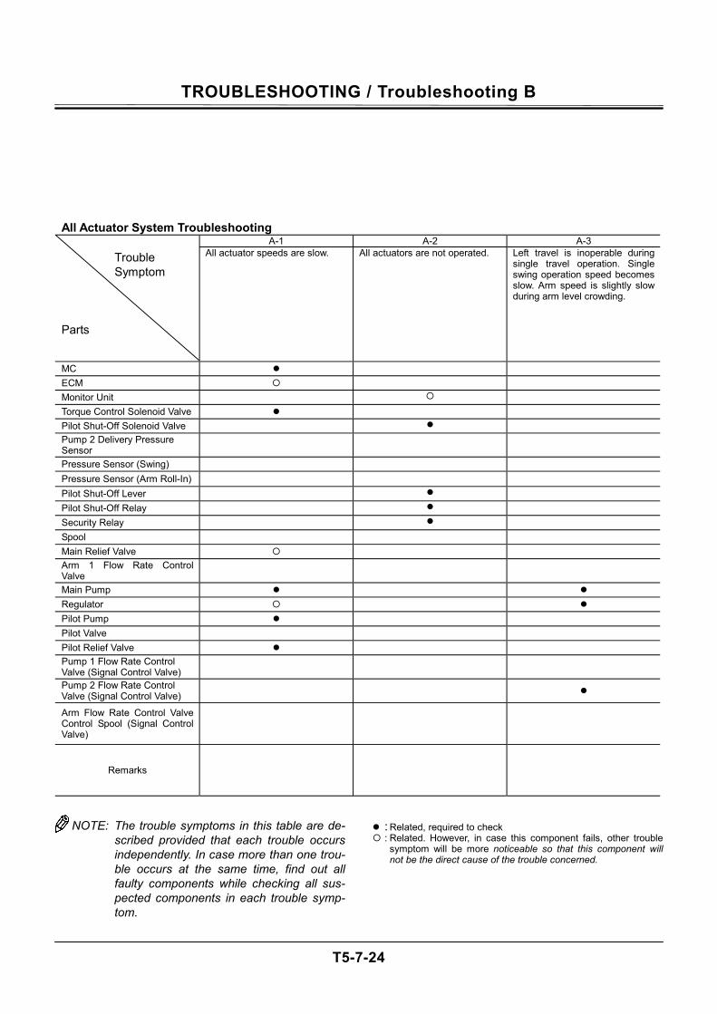
TROUBLESHOOTING / Troubleshooting B
T5-7-24
All Actuator System Troubleshooting A-1 A-2 A-3
Trouble Symptom
Parts
All actuator speeds are slow. All actuators are not operated. Left travel is inoperable during single travel operation. Single swing operation speed becomes slow. Arm speed is slightly slow during arm level crowding.
MC ECM Monitor Unit Torque Control Solenoid Valve Pilot Shut-Off Solenoid Valve Pump 2 Delivery Pressure Sensor
Pressure Sensor (Swing) Pressure Sensor (Arm Roll-In) Pilot Shut-Off Lever Pilot Shut-Off Relay Security Relay Spool Main Relief Valve Arm 1 Flow Rate Control Valve
Main Pump Regulator Pilot Pump Pilot Valve Pilot Relief Valve Pump 1 Flow Rate Control Valve (Signal Control Valve)
Pump 2 Flow Rate Control Valve (Signal Control Valve)
Arm Flow Rate Control Valve Control Spool (Signal Control Valve)
Remarks
NOTE: The trouble symptoms in this table are de-
scribed provided that each trouble occurs independently. In case more than one trou-ble occurs at the same time, find out all faulty components while checking all sus-pected components in each trouble symp-tom.
: Related, required to check : Related. However, in case this component fails, other trouble
symptom will be more noticeable so that this component will not be the direct cause of the trouble concerned.
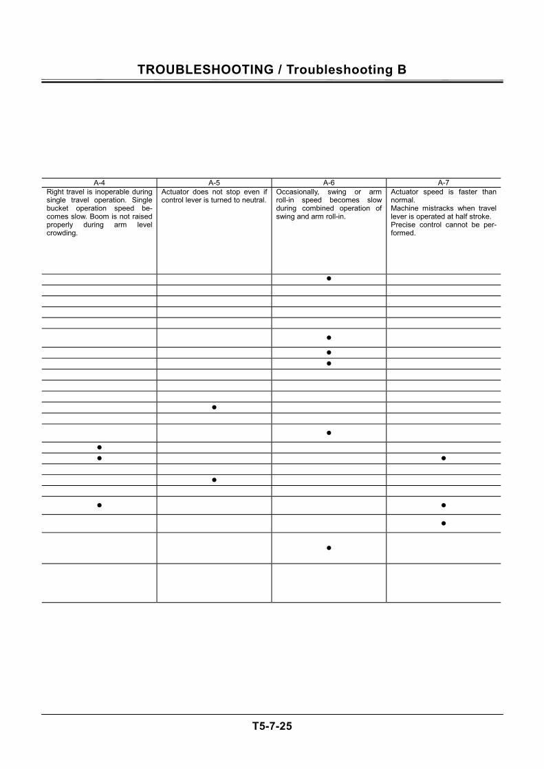
TROUBLESHOOTING / Troubleshooting B
T5-7-25
A-4 A-5 A-6 A-7 Right travel is inoperable during single travel operation. Single bucket operation speed be-comes slow. Boom is not raised properly during arm level crowding.
Actuator does not stop even if control lever is turned to neutral.
Occasionally, swing or arm roll-in speed becomes slow during combined operation of swing and arm roll-in.
Actuator speed is faster than normal. Machine mistracks when travel lever is operated at half stroke. Precise control cannot be per-formed.
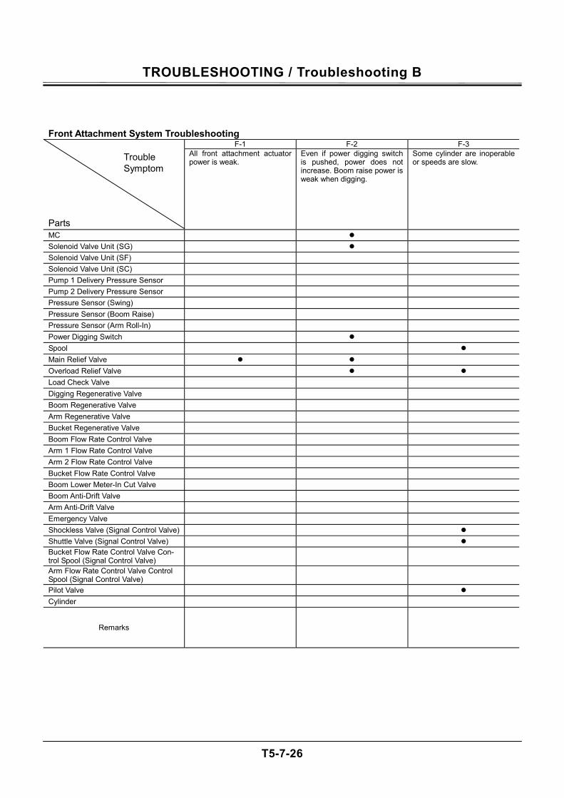
TROUBLESHOOTING / Troubleshooting B
T5-7-26
Front Attachment System Troubleshooting F-1 F-2 F-3
Trouble Symptom
Parts
All front attachment actuator power is weak.
Even if power digging switch is pushed, power does not increase. Boom raise power is weak when digging.
Some cylinder are inoperable or speeds are slow.
MC
Solenoid Valve Unit (SG)
Solenoid Valve Unit (SF)
Solenoid Valve Unit (SC)
Pump 1 Delivery Pressure Sensor
Pump 2 Delivery Pressure Sensor
Pressure Sensor (Swing)
Pressure Sensor (Boom Raise)
Pressure Sensor (Arm Roll-In)
Power Digging Switch
Spool
Main Relief Valve
Overload Relief Valve
Load Check Valve
Digging Regenerative Valve
Boom Regenerative Valve
Arm Regenerative Valve
Bucket Regenerative Valve
Boom Flow Rate Control Valve
Arm 1 Flow Rate Control Valve
Arm 2 Flow Rate Control Valve
Bucket Flow Rate Control Valve
Boom Lower Meter-In Cut Valve
Boom Anti-Drift Valve
Arm Anti-Drift Valve
Emergency Valve
Shockless Valve (Signal Control Valve)
Shuttle Valve (Signal Control Valve) Bucket Flow Rate Control Valve Con-trol Spool (Signal Control Valve)
Arm Flow Rate Control Valve Control Spool (Signal Control Valve)
Pilot Valve
Cylinder
Remarks
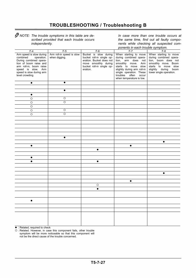
TROUBLESHOOTING / Troubleshooting B
T5-7-27
NOTE: The trouble symptoms in this table are de-scribed provided that each trouble occurs independently.
In case more than one trouble occurs at the same time, find out all faulty compo-nents while checking all suspected com-ponents in each trouble symptom.
F-4 F-5 F-6 F-7 F-8 Arm speed is slow during combined operation. During combined opera-tion of boom raise and arm roll-in, boom raise speed is slow. Arm speed is slow during arm level crowding.
Arm roll-in speed is slow when digging.
Bucket is slow during bucket roll-in single op-eration. Bucket does not move smoothly during bucket roll-in single op-eration.
When starting to move during combined opera-tion, arm does not smoothly move. Arm starts to move slow slightly during arm roll-in single operation. These troubles often occur when temperature is low.
When starting to move during combined opera-tion, boom does not smoothly move. Boom starts to move slow slightly during boom lower single operation.
: Related, required to check : Related. However, in case this component fails, other trouble
symptom will be more noticeable so that this component will not be the direct cause of the trouble concerned.
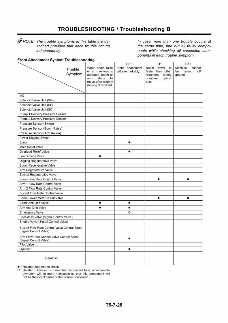
TROUBLESHOOTING / Troubleshooting B
T5-7-28
NOTE: The trouble symptoms in this table are de-scribed provided that each trouble occurs independently.
In case more than one trouble occurs at the same time, find out all faulty compo-nents while checking all suspected com-ponents in each trouble symptom.
Front Attachment System Troubleshooting F-9 F-10 F-11 F-12
Trouble Symptom
When boom raise or arm roll-out is operated, boom or arm starts to move after slightly moving downward.
Front attachment drifts remarkably.
Boom lower is faster than other actuators during combined opera-tion.
Machine cannot be raised off ground.
MC
Solenoid Valve Unit (SG)
Solenoid Valve Unit (SF)
Solenoid Valve Unit (SC)
Pump 1 Delivery Pressure Sensor
Pump 2 Delivery Pressure Sensor
Pressure Sensor (Swing)
Pressure Sensor (Boom Raise)
Pressure Sensor (Arm Roll-In)
Power Digging Switch
Spool
Main Relief Valve
Overload Relief Valve
Load Check Valve
Digging Regenerative Valve
Boom Regenerative Valve
Arm Regenerative Valve
Bucket Regenerative Valve
Boom Flow Rate Control Valve
Arm 1 Flow Rate Control Valve
Arm 2 Flow Rate Control Valve
Bucket Flow Rate Control Valve
Boom Lower Meter-In Cut Valve
Boom Anti-Drift Valve
Arm Anti-Drift Valve
Emergency Valve
Shockless Valve (Signal Control Valve)
Shuttle Valve (Signal Control Valve)
Bucket Flow Rate Control Valve Control Spool (Signal Control Valve)
Arm Flow Rate Control Valve Control Spool (Signal Control Valve)
Pilot Valve
Cylinder
Remarks
: Related, required to check : Related. However, in case this component fails, other trouble
symptom will be more noticeable so that this component will not be the direct cause of the trouble concerned.

TROUBLESHOOTING / Troubleshooting B
T5-7-29
(Blank)
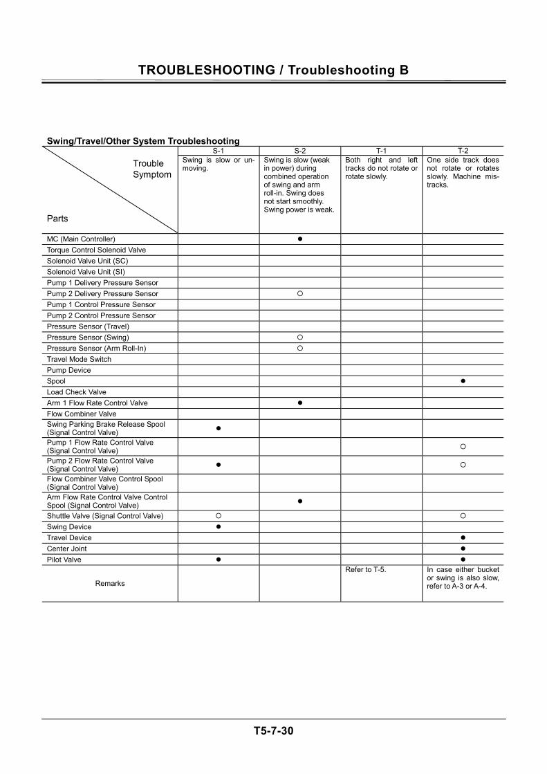
TROUBLESHOOTING / Troubleshooting B
T5-7-30
Swing/Travel/Other System Troubleshooting S-1 S-2 T-1 T-2
Trouble Symptom
Parts
Swing is slow or un-moving.
Swing is slow (weak in power) during combined operation of swing and arm roll-in. Swing does not start smoothly. Swing power is weak.
Both right and left tracks do not rotate or rotate slowly.
One side track does not rotate or rotates slowly. Machine mis-tracks.
MC (Main Controller)
Torque Control Solenoid Valve
Solenoid Valve Unit (SC)
Solenoid Valve Unit (SI)
Pump 1 Delivery Pressure Sensor
Pump 2 Delivery Pressure Sensor
Pump 1 Control Pressure Sensor
Pump 2 Control Pressure Sensor
Pressure Sensor (Travel)
Pressure Sensor (Swing)
Pressure Sensor (Arm Roll-In)
Travel Mode Switch
Pump Device
Spool
Load Check Valve
Arm 1 Flow Rate Control Valve
Flow Combiner Valve Swing Parking Brake Release Spool (Signal Control Valve)
Pump 1 Flow Rate Control Valve (Signal Control Valve)
Pump 2 Flow Rate Control Valve (Signal Control Valve)
Flow Combiner Valve Control Spool (Signal Control Valve)
Arm Flow Rate Control Valve Control Spool (Signal Control Valve)
Shuttle Valve (Signal Control Valve)
Swing Device
Travel Device
Center Joint
Pilot Valve
Remarks
Refer to T-5. In case either bucket or swing is also slow, refer to A-3 or A-4.
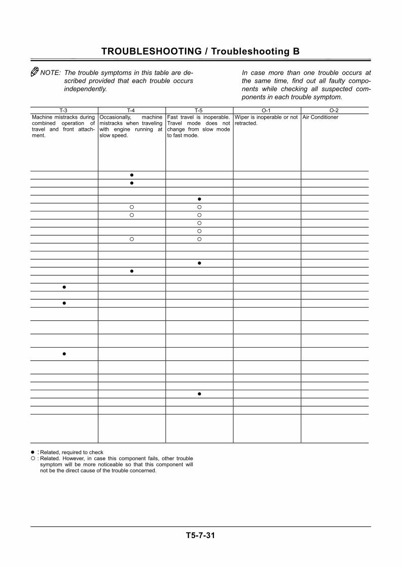
TROUBLESHOOTING / Troubleshooting B
T5-7-31
NOTE: The trouble symptoms in this table are de-scribed provided that each trouble occurs independently.
In case more than one trouble occurs at the same time, find out all faulty compo-nents while checking all suspected com-ponents in each trouble symptom.
T-3 T-4 T-5 O-1 O-2
Machine mistracks during combined operation of travel and front attach-ment.
Occasionally, machine mistracks when traveling with engine running at slow speed.
Fast travel is inoperable. Travel mode does not change from slow mode to fast mode.
Wiper is inoperable or not retracted.
Air Conditioner
: Related, required to check : Related. However, in case this component fails, other trouble
symptom will be more noticeable so that this component will not be the direct cause of the trouble concerned.
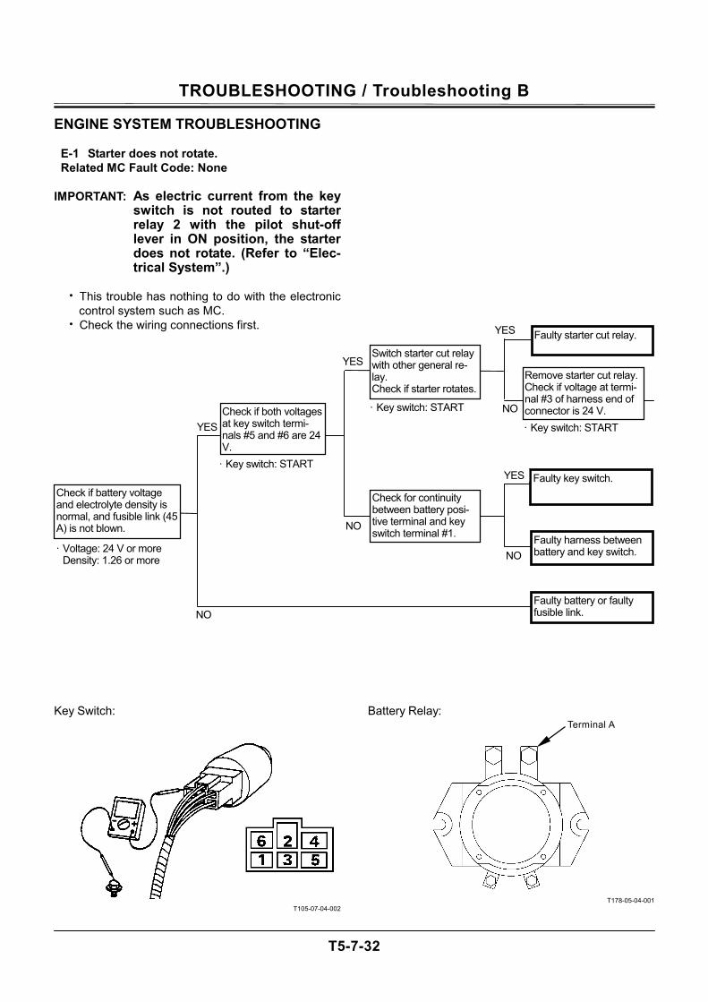
TROUBLESHOOTING / Troubleshooting B
T5-7-32
ENGINE SYSTEM TROUBLESHOOTING
E-1 Starter does not rotate. Related MC Fault Code: None
IMPORTANT: As electric current from the key
switch is not routed to starter relay 2 with the pilot shut-off lever in ON position, the starter does not rotate. (Refer to “Elec-trical System”.)
• This trouble has nothing to do with the electronic
control system such as MC. • Check the wiring connections first.
Key Switch:
T105-07-04-002
Battery Relay:
T178-05-04-001
Terminal A
Faulty starter cut relay.
Remove starter cut relay. Check if voltage at termi-nal #3 of harness end of connector is 24 V.
Check if battery voltage and electrolyte density is normal, and fusible link (45 A) is not blown.
Faulty battery or faulty fusible link.
Switch starter cut relay with other general re-lay. Check if starter rotates.
YES
NO
YES
NO
YES
NO
· Key switch: START
· Voltage: 24 V or more Density: 1.26 or more
Faulty key switch.
Faulty harness between battery and key switch.
Check for continuity between battery posi-tive terminal and key switch terminal #1.
YES
NO
· Key switch: START Check if both voltages at key switch termi-nals #5 and #6 are 24 V.
· Key switch: START
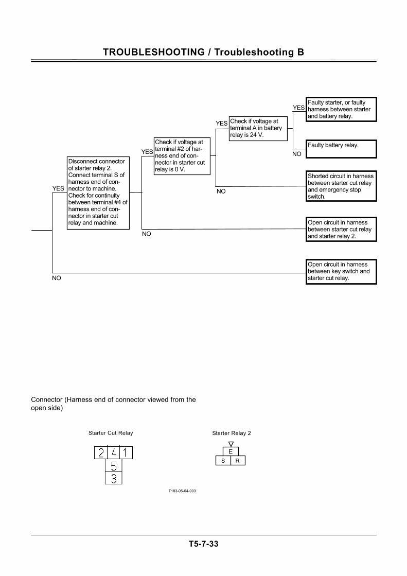
TROUBLESHOOTING / Troubleshooting B
T5-7-33
Connector (Harness end of connector viewed from the open side)
T183-05-04-003
ERS
Starter Relay 2Starter Cut Relay
YES
NO
YES
YES
NO
YES
NO
Open circuit in harness between key switch and starter cut relay.
NO Disconnect connector of starter relay 2. Connect terminal S of harness end of con-nector to machine. Check for continuity between terminal #4 of harness end of con-nector in starter cut relay and machine.
Check if voltage at terminal A in battery relay is 24 V.
Check if voltage at terminal #2 of har-ness end of con-nector in starter cut relay is 0 V.
Shorted circuit in harness between starter cut relay and emergency stop switch.
Open circuit in harness between starter cut relay and starter relay 2.
Faulty starter, or faulty harness between starter and battery relay.
Faulty battery relay.
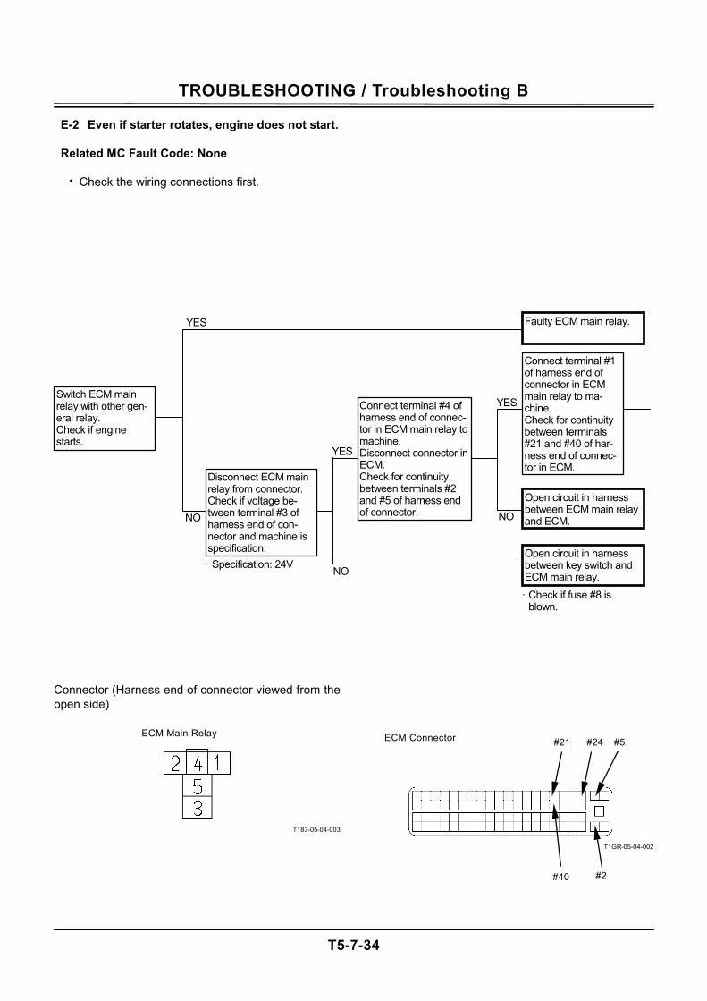
TROUBLESHOOTING / Troubleshooting B
T5-7-34
E-2 Even if starter rotates, engine does not start.
Related MC Fault Code: None
• Check the wiring connections first.
Connector (Harness end of connector viewed from the open side)
T183-05-04-003
T1GR-05-04-002
ECM Main Relay ECM Connector #21 #24 #5
#40 #2
YES Switch ECM main relay with other gen-eral relay. Check if engine starts.
YES
NO
Open circuit in harness between ECM main relay and ECM.
Open circuit in harness between key switch and ECM main relay.
YES
NO
Faulty ECM main relay.
· Specification: 24V
Connect terminal #4 of harness end of connec-tor in ECM main relay to machine. Disconnect connector in ECM. Check for continuity between terminals #2 and #5 of harness end of connector.
· Check if fuse #8 is blown.
NO
Connect terminal #1 of harness end of connector in ECM main relay to ma-chine. Check for continuity between terminals #21 and #40 of har-ness end of connec-tor in ECM.
Disconnect ECM main relay from connector. Check if voltage be-tween terminal #3 of harness end of con-nector and machine is specification.
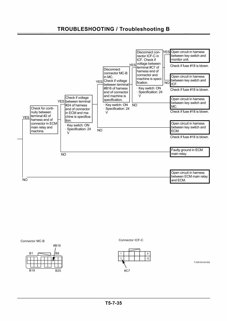
TROUBLESHOOTING / Troubleshooting B
T5-7-35
T1GR-05-04-002
YES
YES
NO
Open circuit in harness between key switch and monitor unit.
NO
YES
NO
Check if fuse #18 is blown.
NO
YES
YES
NO
Open circuit in harness between key switch and ICF.
· Key switch: ON · Specification: 24
V
Connector MC-B
B25 B19
#B16
B1 B8
#C7
Connector ICF-C
6
12
1
7
Check for conti-nuity between terminal #2 of harness end of connector in ECM main relay and machine.
Check if voltage between terminal #24 of harness end of connector in ECM and ma-chine is specifica-tion.
Disconnect con-nector ICF-C in ICF. Check if voltage between terminal #C7 of harness end of connector and machine is speci-fication.
Disconnect connector MC-B in MC. Check if voltage between terminal #B16 of harness end of connector and machine is specification. Open circuit in harness
between key switch and MC.
Open circuit in harness between key switch and ECM.
Faulty ground in ECM main relay.
Open circuit in harness between ECM main relay and ECM.
· Key switch: ON· Specification: 24
V
· Key switch: ON · Specification: 24
V
Check if fuse #18 is blown.
Check if fuse #18 is blown.
Check if fuse #18 is blown.
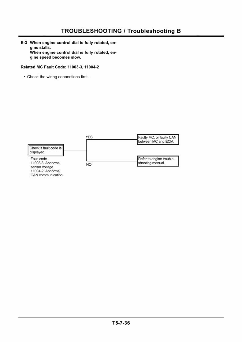
TROUBLESHOOTING / Troubleshooting B
T5-7-36
E-3 When engine control dial is fully rotated, en-gine stalls. When engine control dial is fully rotated, en-gine speed becomes slow.
Related MC Fault Code: 11003-3, 11004-2
• Check the wiring connections first.
Faulty MC, or faulty CAN between MC and ECM.
Refer to engine trouble-shooting manual.
YES
NO · Fault code
11003-3: Abnormal sensor voltage 11004-2: Abnormal CAN communication
Check if fault code is displayed.
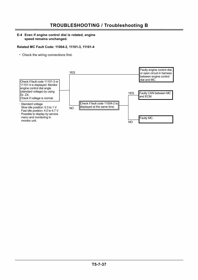
TROUBLESHOOTING / Troubleshooting B
T5-7-37
E-4 Even if engine control dial is rotated, engine speed remains unchanged.
Related MC Fault Code: 11004-2, 11101-3, 11101-4
• Check the wiring connections first.
Faulty CAN between MC and ECM.
Faulty MC.
Faulty engine control dial,or open circuit in harness between engine control dial and MC. Check if fault code 11101-3 or
11101-4 is displayed. Monitor engine control dial angle (standard voltage) by using Dr. ZX. Check if voltage is normal.
NO
YES
NO
YES
Check if fault code 11004-2 is displayed at the same time.
· Standard voltage Slow idle position: 0.3 to 1 V Fast idle position: 4.0 to 4.7 V
· Possible to display by service menu and monitoring in monitor unit.
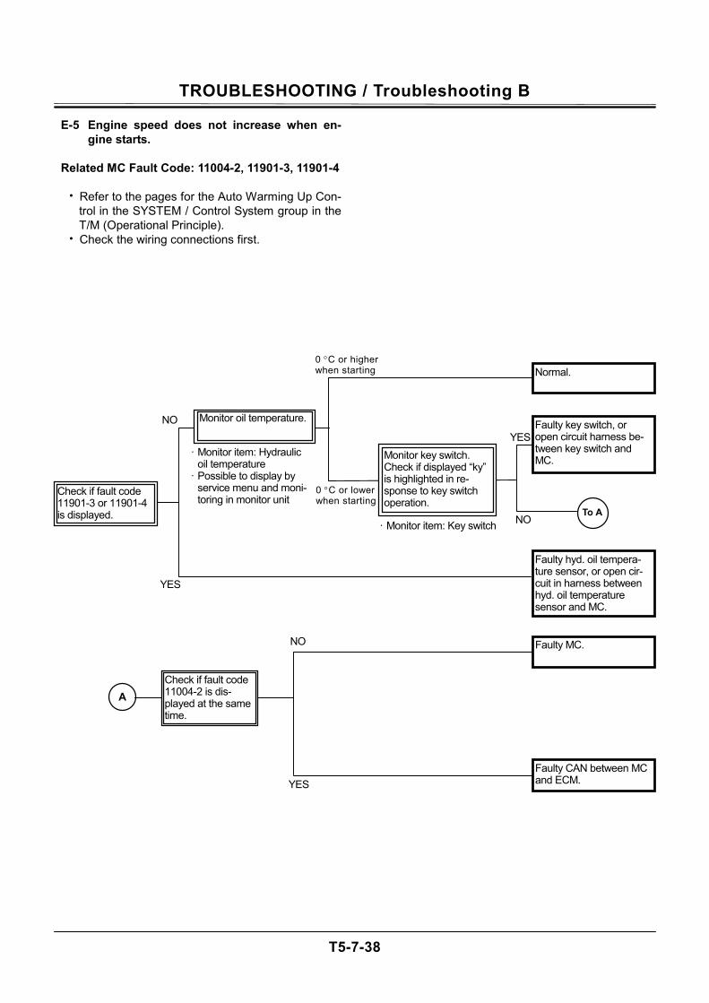
TROUBLESHOOTING / Troubleshooting B
T5-7-38
E-5 Engine speed does not increase when en-gine starts.
Related MC Fault Code: 11004-2, 11901-3, 11901-4
• Refer to the pages for the Auto Warming Up Con-
trol in the SYSTEM / Control System group in the T/M (Operational Principle).
• Check the wiring connections first.
YES
Faulty hyd. oil tempera-ture sensor, or open cir-cuit in harness between hyd. oil temperature sensor and MC.
Monitor oil temperature.
Normal.
NO
YES
NO
· Monitor item: Hydraulic oil temperature
· Possible to display by service menu and moni-toring in monitor unit
· Monitor item: Key switchTo A
A
YES
NO
Check if fault code 11004-2 is dis-played at the same time.
0 °C or higher when starting
Check if fault code 11901-3 or 11901-4 is displayed.
0 °C or lower when starting
Monitor key switch. Check if displayed “ky” is highlighted in re-sponse to key switch operation.
Faulty key switch, or open circuit harness be-tween key switch and MC.
Faulty CAN between MC and ECM.
Faulty MC.

TROUBLESHOOTING / Troubleshooting B
T5-7-39
(Blank)
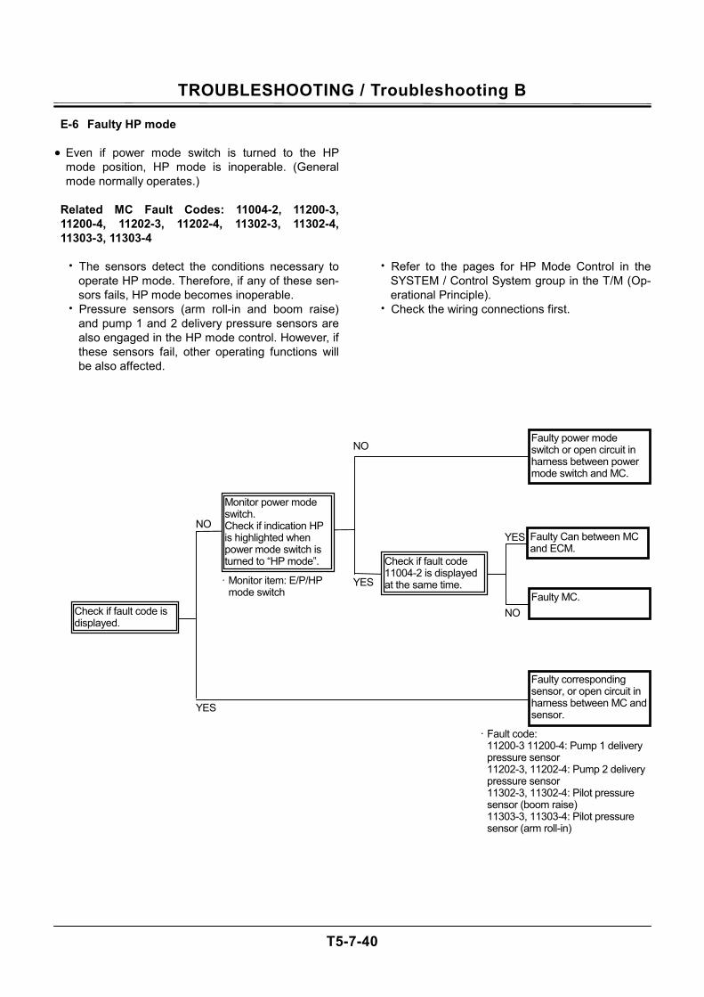
TROUBLESHOOTING / Troubleshooting B
T5-7-40
E-6 Faulty HP mode • Even if power mode switch is turned to the HP
mode position, HP mode is inoperable. (General mode normally operates.)
Related MC Fault Codes: 11004-2, 11200-3, 11200-4, 11202-3, 11202-4, 11302-3, 11302-4, 11303-3, 11303-4
• The sensors detect the conditions necessary to
operate HP mode. Therefore, if any of these sen-sors fails, HP mode becomes inoperable.
• Pressure sensors (arm roll-in and boom raise) and pump 1 and 2 delivery pressure sensors are also engaged in the HP mode control. However, if these sensors fail, other operating functions will be also affected.
• Refer to the pages for HP Mode Control in the SYSTEM / Control System group in the T/M (Op-erational Principle).
• Check the wiring connections first.
· Fault code: 11200-3 11200-4: Pump 1 delivery pressure sensor 11202-3, 11202-4: Pump 2 delivery pressure sensor 11302-3, 11302-4: Pilot pressure sensor (boom raise) 11303-3, 11303-4: Pilot pressure sensor (arm roll-in)
NO
YES
NO
NO
YES
YESFaulty MC.
· Monitor item: E/P/HP mode switch
Check if fault code 11004-2 is displayed at the same time.
Faulty corresponding sensor, or open circuit in harness between MC and sensor.
Faulty Can between MC and ECM.
Faulty power mode switch or open circuit in harness between power mode switch and MC.
Check if fault code is displayed.
Monitor power mode switch. Check if indication HP is highlighted when power mode switch is turned to “HP mode”.
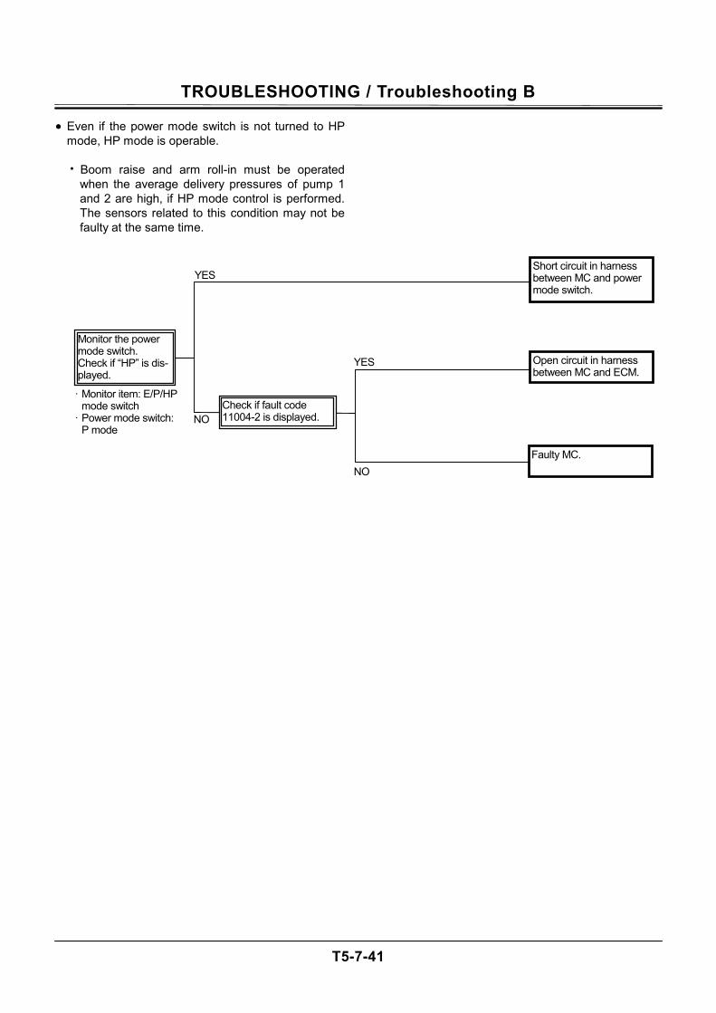
TROUBLESHOOTING / Troubleshooting B
T5-7-41
• Even if the power mode switch is not turned to HP mode, HP mode is operable.
• Boom raise and arm roll-in must be operated
when the average delivery pressures of pump 1 and 2 are high, if HP mode control is performed. The sensors related to this condition may not be faulty at the same time.
· Monitor item: E/P/HP mode switch
· Power mode switch: P mode
NO
YES
NO
YES Open circuit in harness between MC and ECM.
Monitor the power mode switch. Check if “HP” is dis-played.
Short circuit in harness between MC and power mode switch.
Faulty MC.
Check if fault code 11004-2 is displayed.
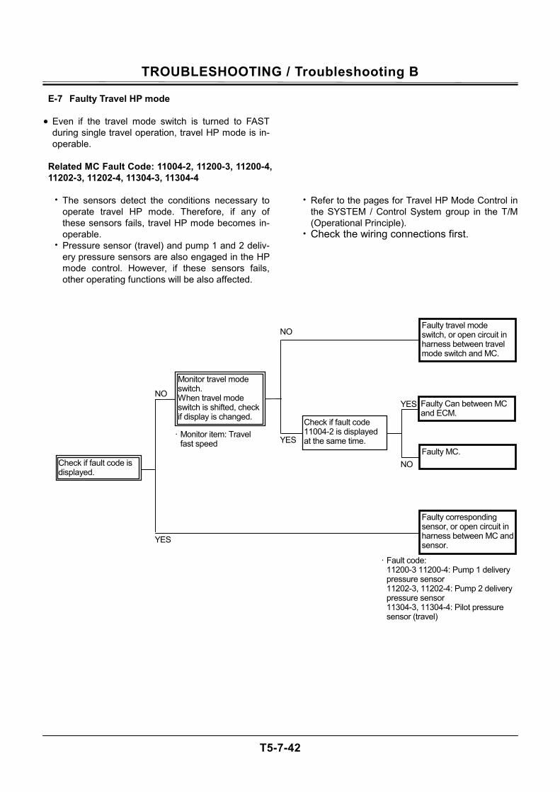
TROUBLESHOOTING / Troubleshooting B
T5-7-42
E-7 Faulty Travel HP mode • Even if the travel mode switch is turned to FAST
during single travel operation, travel HP mode is in-operable.
Related MC Fault Code: 11004-2, 11200-3, 11200-4, 11202-3, 11202-4, 11304-3, 11304-4
• The sensors detect the conditions necessary to
operate travel HP mode. Therefore, if any of these sensors fails, travel HP mode becomes in-operable.
• Pressure sensor (travel) and pump 1 and 2 deliv-ery pressure sensors are also engaged in the HP mode control. However, if these sensors fails, other operating functions will be also affected.
• Refer to the pages for Travel HP Mode Control in the SYSTEM / Control System group in the T/M (Operational Principle).
• Check the wiring connections first.
· Fault code: 11200-3 11200-4: Pump 1 delivery pressure sensor 11202-3, 11202-4: Pump 2 delivery pressure sensor 11304-3, 11304-4: Pilot pressure sensor (travel)
NO
YES
NO
NO
YES
YESFaulty MC.
· Monitor item: Travel fast speed
Check if fault code 11004-2 is displayed at the same time.
Faulty corresponding sensor, or open circuit in harness between MC and sensor.
Faulty Can between MC and ECM.
Faulty travel mode switch, or open circuit in harness between travel mode switch and MC.
Check if fault code is displayed.
Monitor travel mode switch. When travel mode switch is shifted, check if display is changed.
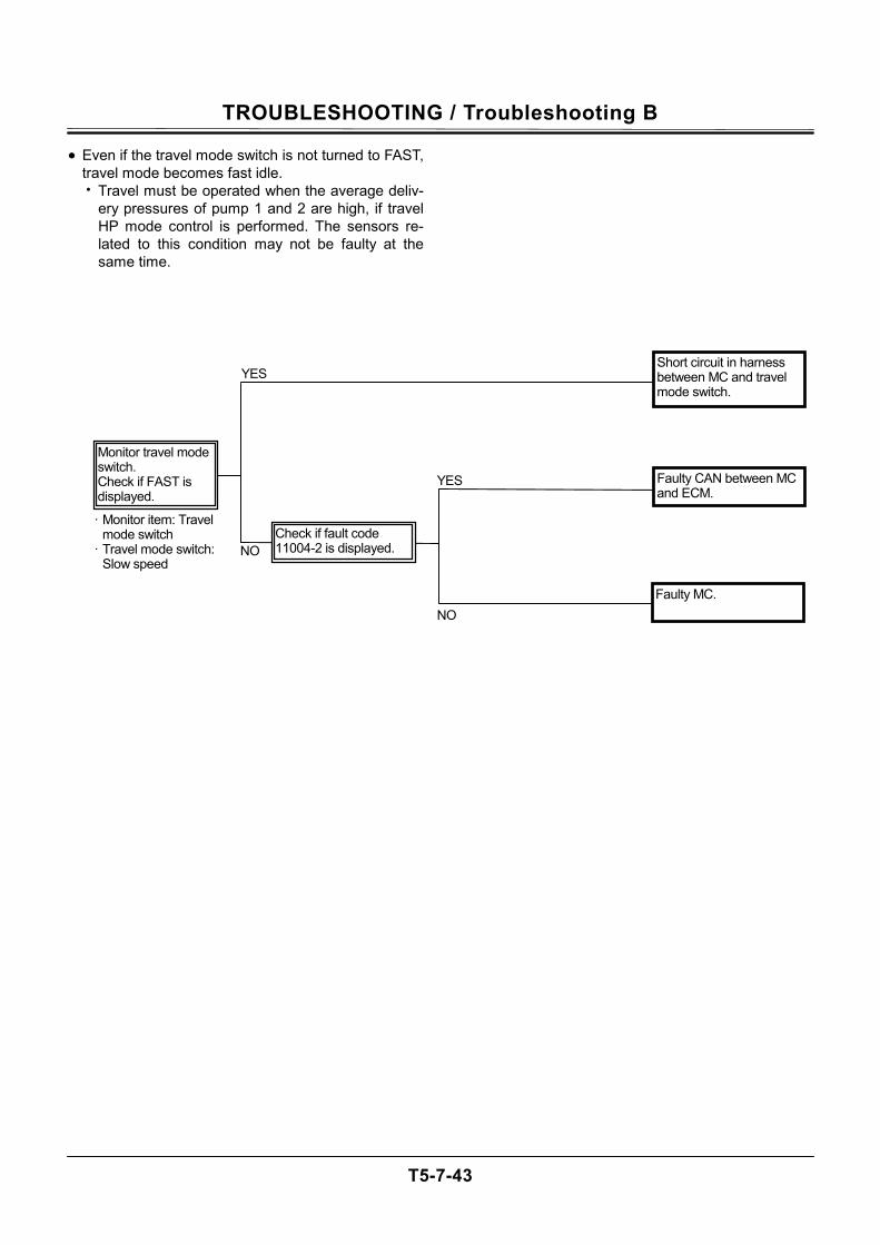
TROUBLESHOOTING / Troubleshooting B
T5-7-43
• Even if the travel mode switch is not turned to FAST, travel mode becomes fast idle. • Travel must be operated when the average deliv-
ery pressures of pump 1 and 2 are high, if travel HP mode control is performed. The sensors re-lated to this condition may not be faulty at the same time.
· Monitor item: Travel mode switch
· Travel mode switch: Slow speed
NO
YES
NO
YES Faulty CAN between MC and ECM.
Monitor travel mode switch. Check if FAST is displayed.
Short circuit in harness between MC and travel mode switch.
Faulty MC.
Check if fault code 11004-2 is displayed.
TROUBLESHOOTING / Troubleshooting B
T5-7-44
E-8 Even if key switch is turned OFF, engine does not stop. (In case engine does not stop, stop engine by pulling engine stop handle located under seat stand. Then, begin in-spection.)
Related MC Fault Codes: 11101-3, 11101-4
• Probably the symptoms such as “Engine speed is
slower than specification in all operating ranges” or “Even if engine control dial is rotated, engine speed remains unchanged” may come up. Per-form troubleshooting for these symptoms.

TROUBLESHOOTING / Troubleshooting B
T5-7-45
(Blank)
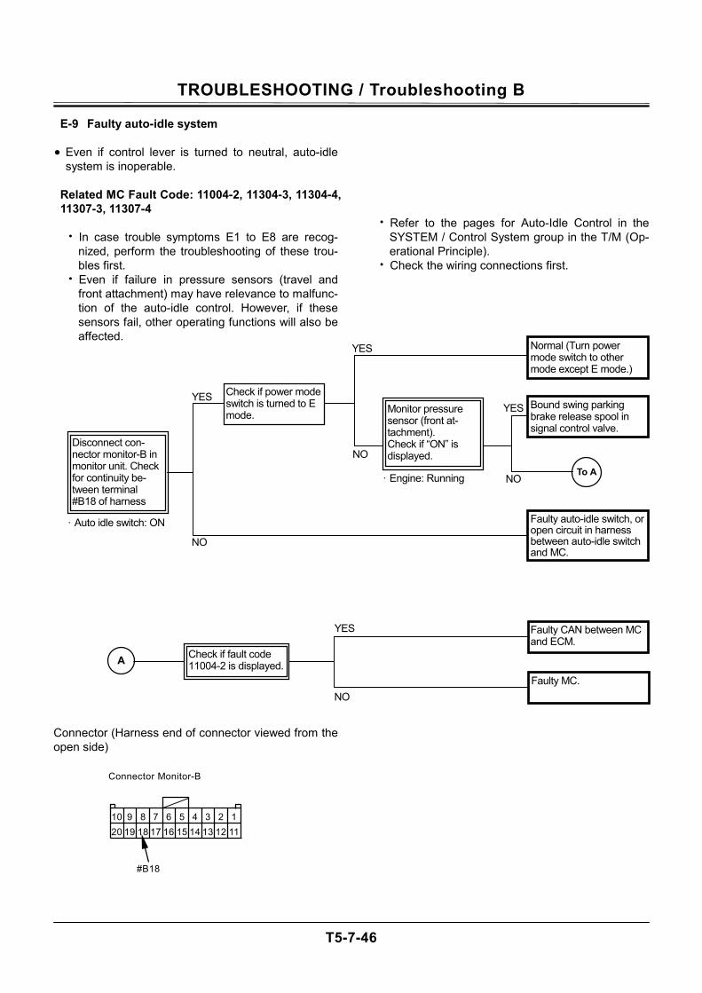
TROUBLESHOOTING / Troubleshooting B
T5-7-46
E-9 Faulty auto-idle system • Even if control lever is turned to neutral, auto-idle
system is inoperable.
Related MC Fault Code: 11004-2, 11304-3, 11304-4, 11307-3, 11307-4
• In case trouble symptoms E1 to E8 are recog-
nized, perform the troubleshooting of these trou-bles first.
• Even if failure in pressure sensors (travel and front attachment) may have relevance to malfunc-tion of the auto-idle control. However, if these sensors fail, other operating functions will also be affected.
Connector (Harness end of connector viewed from the open side)
• Refer to the pages for Auto-Idle Control in the SYSTEM / Control System group in the T/M (Op-erational Principle).
• Check the wiring connections first.
NO
YES
NO
YES
· Engine: Running
Disconnect con-nector monitor-B in monitor unit. Check for continuity be-tween terminal #B18 of harness
f
To A
Monitor pressure sensor (front at-tachment). Check if “ON” is displayed.
· Auto idle switch: ON
Check if power mode switch is turned to E mode.
YES
NO
A
YES
NO
Check if fault code 11004-2 is displayed.
10 9 8 7 6 5 4 3 2 1 20 19 18 17 16 15 14 13 12 11
Connector Monitor-B
#B18
Faulty auto-idle switch, or open circuit in harness between auto-idle switch and MC.
Normal (Turn power mode switch to other mode except E mode.)
Bound swing parking brake release spool in signal control valve.
Faulty MC.
Faulty CAN between MC and ECM.
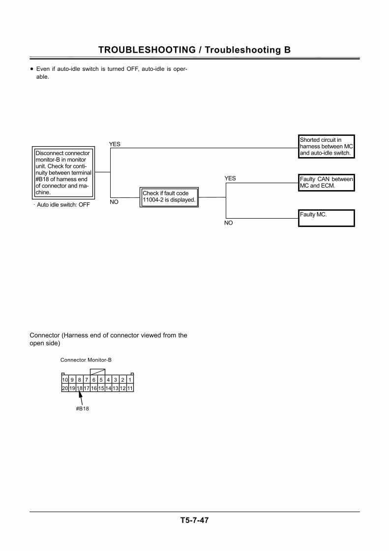
TROUBLESHOOTING / Troubleshooting B
T5-7-47
• Even if auto-idle switch is turned OFF, auto-idle is oper-able.
Connector (Harness end of connector viewed from the open side)
· Auto idle switch: OFF
YES
NO
Faulty CAN between MC and ECM.
Shorted circuit in harness between MC and auto-idle switch.Disconnect connector
monitor-B in monitor unit. Check for conti-nuity between terminal #B18 of harness end of connector and ma-chine.
YES
NO
Check if fault code 11004-2 is displayed.
Faulty MC.
10 9 8 7 6 5 4 3 2 1 20 19 18 17 16 15 14 13 12 11
Connector Monitor-B
#B18
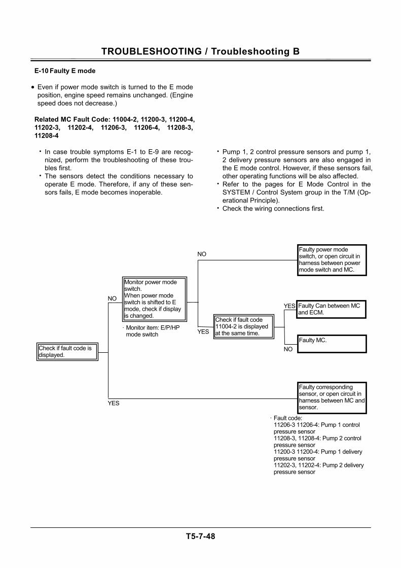
TROUBLESHOOTING / Troubleshooting B
T5-7-48
E-10 Faulty E mode
• Even if power mode switch is turned to the E mode position, engine speed remains unchanged. (Engine speed does not decrease.)
Related MC Fault Code: 11004-2, 11200-3, 11200-4, 11202-3, 11202-4, 11206-3, 11206-4, 11208-3, 11208-4
• In case trouble symptoms E-1 to E-9 are recog-
nized, perform the troubleshooting of these trou-bles first.
• The sensors detect the conditions necessary to operate E mode. Therefore, if any of these sen-sors fails, E mode becomes inoperable.
• Pump 1, 2 control pressure sensors and pump 1, 2 delivery pressure sensors are also engaged in the E mode control. However, if these sensors fail, other operating functions will be also affected.
• Refer to the pages for E Mode Control in the SYSTEM / Control System group in the T/M (Op-erational Principle).
• Check the wiring connections first.
· Fault code: 11206-3 11206-4: Pump 1 control pressure sensor 11208-3, 11208-4: Pump 2 control pressure sensor 11200-3 11200-4: Pump 1 delivery pressure sensor 11202-3, 11202-4: Pump 2 delivery pressure sensor
NO
YES
NO
NO
YES
YESFaulty MC.
· Monitor item: E/P/HP mode switch
Check if fault code 11004-2 is displayed at the same time.
Faulty corresponding sensor, or open circuit in harness between MC and sensor.
Faulty Can between MC and ECM.
Faulty power mode switch, or open circuit in harness between power mode switch and MC.
Check if fault code is displayed.
Monitor power mode switch. When power mode switch is shifted to E mode, check if display is changed.
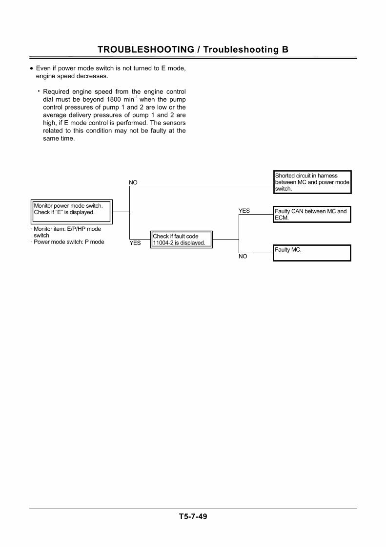
TROUBLESHOOTING / Troubleshooting B
T5-7-49
• Even if power mode switch is not turned to E mode, engine speed decreases.
• Required engine speed from the engine control
dial must be beyond 1800 min-1 when the pump control pressures of pump 1 and 2 are low or the average delivery pressures of pump 1 and 2 are high, if E mode control is performed. The sensors related to this condition may not be faulty at the same time.
Faulty CAN between MC and ECM.
Monitor power mode switch. Check if “E” is displayed.
NO
YES
· Monitor item: E/P/HP mode switch
· Power mode switch: P mode
Shorted circuit in harness between MC and power mode switch.
YES
NO
Check if fault code 11004-2 is displayed.
Faulty MC.
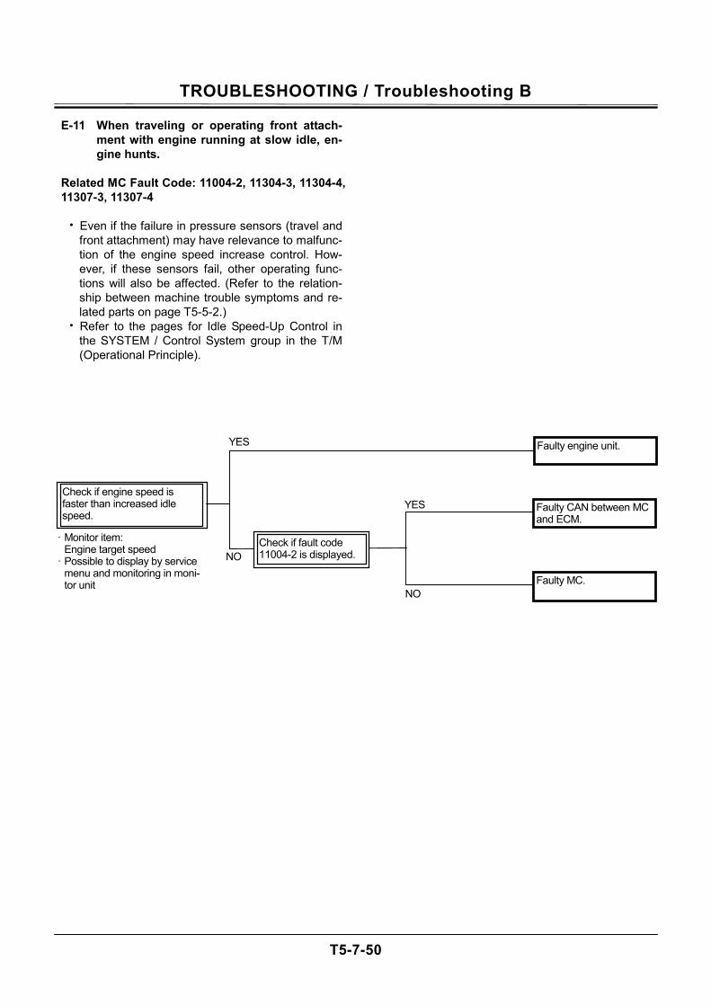
TROUBLESHOOTING / Troubleshooting B
T5-7-50
E-11 When traveling or operating front attach-ment with engine running at slow idle, en-gine hunts.
Related MC Fault Code: 11004-2, 11304-3, 11304-4, 11307-3, 11307-4
• Even if the failure in pressure sensors (travel and
front attachment) may have relevance to malfunc-tion of the engine speed increase control. How-ever, if these sensors fail, other operating func-tions will also be affected. (Refer to the relation-ship between machine trouble symptoms and re-lated parts on page T5-5-2.)
• Refer to the pages for Idle Speed-Up Control in the SYSTEM / Control System group in the T/M (Operational Principle).
Check if engine speed is faster than increased idle speed.
· Monitor item: Engine target speed
· Possible to display by service menu and monitoring in moni-tor unit
NO
Faulty engine unit.
Faulty CAN between MC and ECM.
Faulty MC.
YES
YES
NO
Check if fault code 11004-2 is displayed.
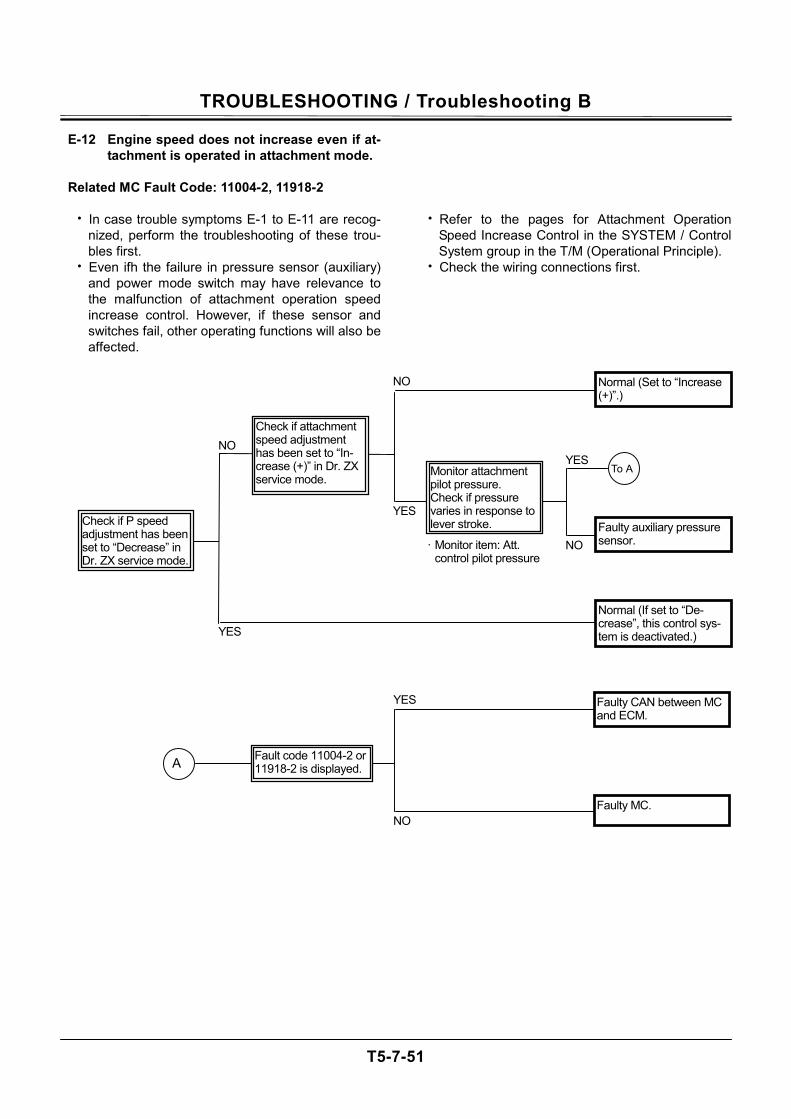
TROUBLESHOOTING / Troubleshooting B
T5-7-51
E-12 Engine speed does not increase even if at-tachment is operated in attachment mode.
Related MC Fault Code: 11004-2, 11918-2
• In case trouble symptoms E-1 to E-11 are recog-
nized, perform the troubleshooting of these trou-bles first.
• Even ifh the failure in pressure sensor (auxiliary) and power mode switch may have relevance to the malfunction of attachment operation speed increase control. However, if these sensor and switches fail, other operating functions will also be affected.
• Refer to the pages for Attachment Operation
Speed Increase Control in the SYSTEM / Control System group in the T/M (Operational Principle).
• Check the wiring connections first.
NO
NO
YES
YES
YES
NO
YES
NO
Faulty auxiliary pressure sensor.
Check if P speed adjustment has been set to “Decrease” in Dr. ZX service mode.
Normal (If set to “De-crease”, this control sys-tem is deactivated.)
Faulty MC.
Faulty CAN between MC and ECM.
· Monitor item: Att. control pilot pressure
To A
A
Normal (Set to “Increase (+)”.)
Check if attachment speed adjustment has been set to “In-crease (+)” in Dr. ZX service mode.
Fault code 11004-2 or 11918-2 is displayed.
Monitor attachment pilot pressure. Check if pressure varies in response to lever stroke.
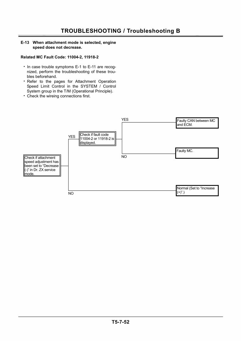
TROUBLESHOOTING / Troubleshooting B
T5-7-52
E-13 When attachment mode is selected, engine speed does not decrease.
Related MC Fault Code: 11004-2, 11918-2
• In case trouble symptoms E-1 to E-11 are recog-
nized, perform the troubleshooting of these trou-bles beforehand.
• Refer to the pages for Attachment Operation Speed Limit Control in the SYSTEM / Control System group in the T/M (Operational Principle).
• Check the wireing connections first.
YES
NO
YES
NO
Normal (Set to “Increase (+)”.)
Faulty MC.
Faulty CAN between MC and ECM.
Check if attachment speed adjustment has been set to “Decrease (-)” in Dr. ZX service mode.
Check if fault code 11004-2 or 11918-2 is displayed.
TROUBLESHOOTING / Troubleshooting B
T5-7-53
E-14 Engine stalls within several seconds after engine has started.
Related MC Fault Code: None
• Refer to the Engine Troubleshooting Manual.
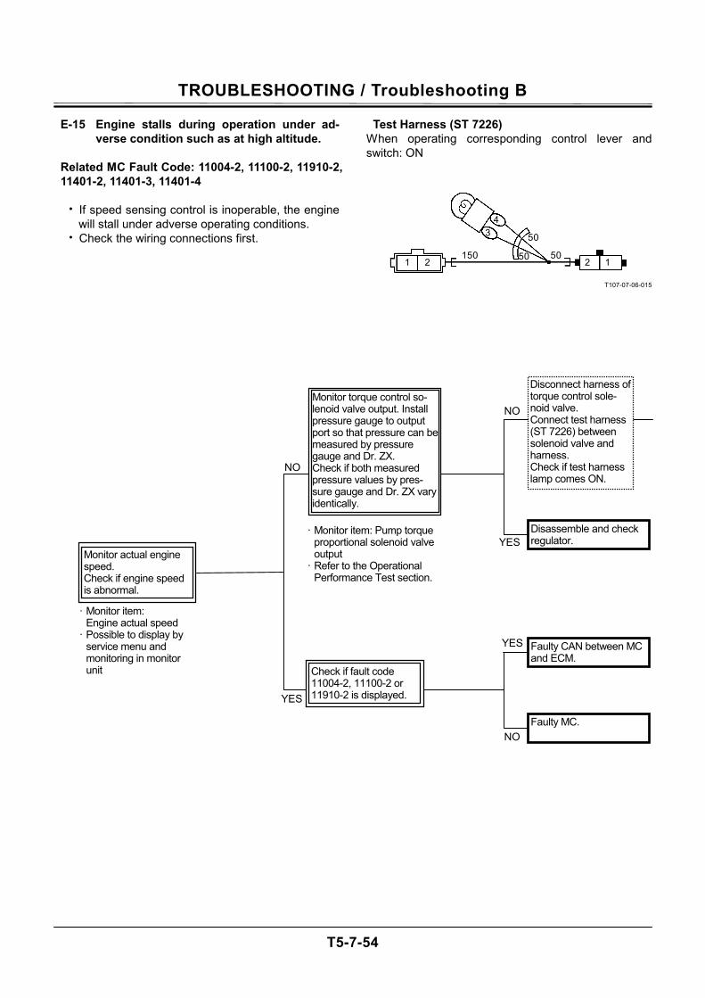
TROUBLESHOOTING / Troubleshooting B
T5-7-54
E-15 Engine stalls during operation under ad-verse condition such as at high altitude.
Related MC Fault Code: 11004-2, 11100-2, 11910-2, 11401-2, 11401-3, 11401-4
• If speed sensing control is inoperable, the engine
will stall under adverse operating conditions. • Check the wiring connections first.
Test Harness (ST 7226) When operating corresponding control lever and switch: ON
T107-07-06-015
50
50
50 15022
4 3
11
Monitor actual engine speed. Check if engine speed is abnormal.
Disconnect harness of torque control sole-noid valve. Connect test harness (ST 7226) between solenoid valve and harness. Check if test harness lamp comes ON.
Disassemble and check regulator.
· Monitor item: Pump torque proportional solenoid valve output
· Refer to the Operational Performance Test section.
· Monitor item: Engine actual speed
· Possible to display by service menu and monitoring in monitor unit
NO
NO
YES
YES
Monitor torque control so-lenoid valve output. Install pressure gauge to output port so that pressure can be measured by pressure gauge and Dr. ZX. Check if both measured pressure values by pres-sure gauge and Dr. ZX vary identically.
Faulty MC.
YES
NO
Check if fault code 11004-2, 11100-2 or 11910-2 is displayed.
Faulty CAN between MC and ECM.
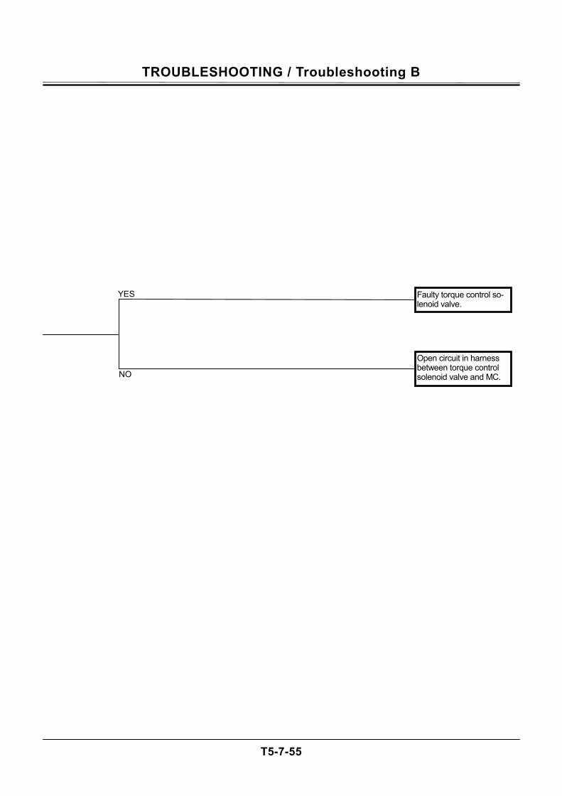
TROUBLESHOOTING / Troubleshooting B
T5-7-55
Faulty torque control so-lenoid valve.
Open circuit in harness between torque control solenoid valve and MC. NO
YES
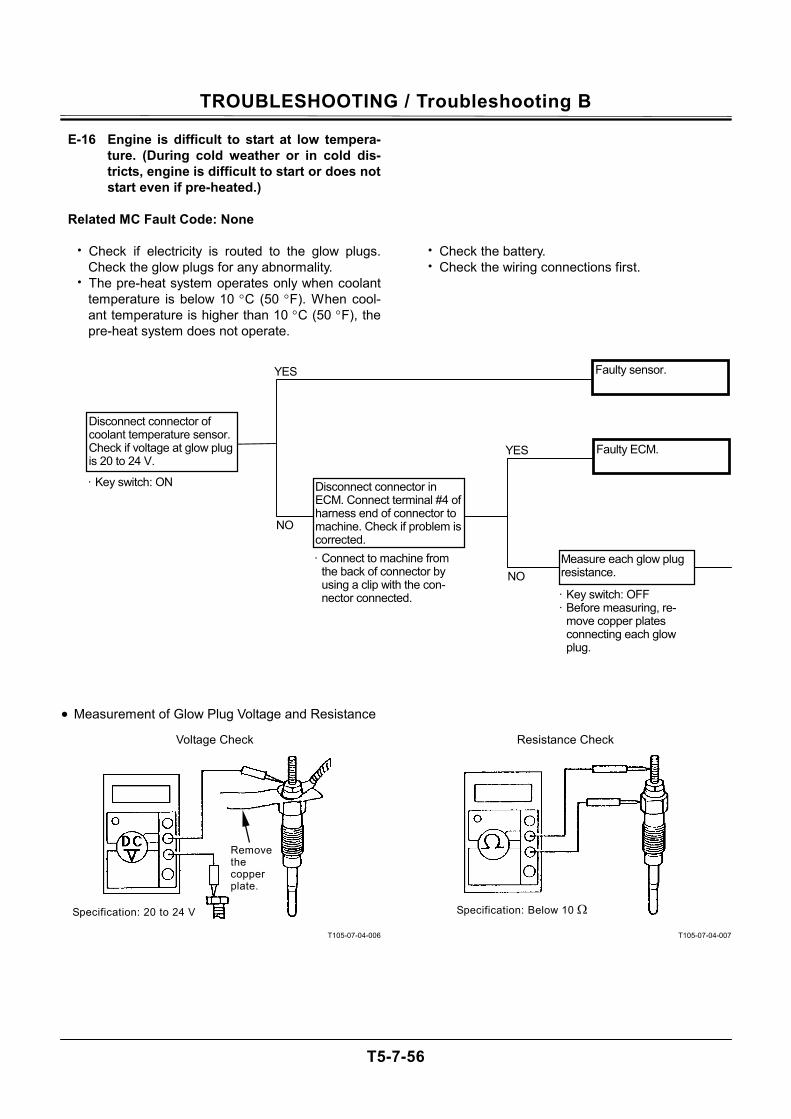
TROUBLESHOOTING / Troubleshooting B
T5-7-56
E-16 Engine is difficult to start at low tempera-ture. (During cold weather or in cold dis-tricts, engine is difficult to start or does not start even if pre-heated.)
Related MC Fault Code: None
• Check if electricity is routed to the glow plugs.
Check the glow plugs for any abnormality. • The pre-heat system operates only when coolant
temperature is below 10 °C (50 °F). When cool-ant temperature is higher than 10 °C (50 °F), the pre-heat system does not operate.
• Measurement of Glow Plug Voltage and Resistance
T105-07-04-006
• Check the battery. • Check the wiring connections first.
T105-07-04-007
NO
NO
YES
YES
· Key switch: OFF · Before measuring, re-
move copper plates connecting each glow plug.
· Connect to machine from the back of connector by using a clip with the con-nector connected.
· Key switch: ON
Measure each glow plug resistance.
Disconnect connector in ECM. Connect terminal #4 of harness end of connector to machine. Check if problem is corrected.
Disconnect connector of coolant temperature sensor. Check if voltage at glow plug is 20 to 24 V.
Faulty sensor.
Faulty ECM.
Specification: 20 to 24 V
Remove the copper plate.
Voltage Check
Specification: Below 10 Ω
Resistance Check
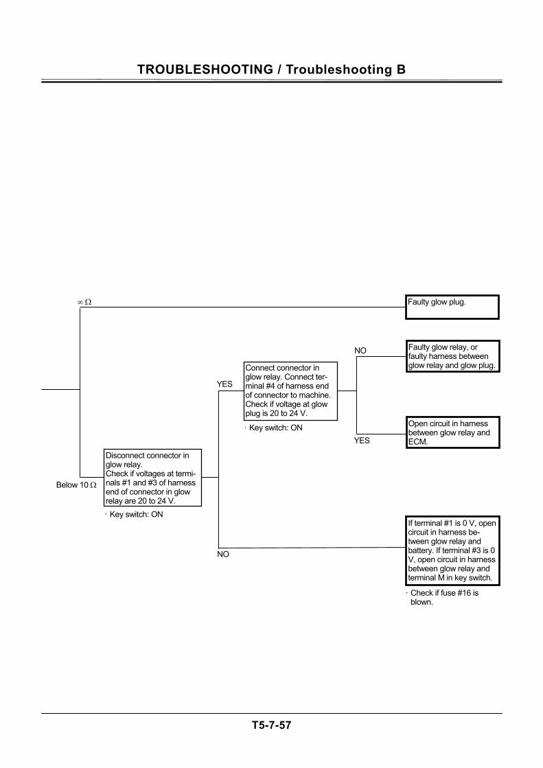
TROUBLESHOOTING / Troubleshooting B
T5-7-57
Below 10 Ω
∞ Ω
· Check if fuse #16 is blown.
· Key switch: ON
NO
YES
Disconnect connector in glow relay. Check if voltages at termi-nals #1 and #3 of harness end of connector in glow relay are 20 to 24 V.
Faulty glow plug.
If terminal #1 is 0 V, open circuit in harness be-tween glow relay and battery. If terminal #3 is 0 V, open circuit in harness between glow relay and terminal M in key switch.
· Key switch: ON
Connect connector in glow relay. Connect ter-minal #4 of harness end of connector to machine. Check if voltage at glow plug is 20 to 24 V.
YES
NO
Open circuit in harness between glow relay and ECM.
Faulty glow relay, or faulty harness between glow relay and glow plug.
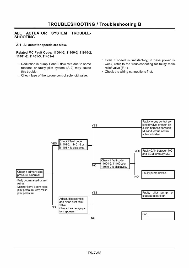
TROUBLESHOOTING / Troubleshooting B
T5-7-58
ALL ACTUATOR SYSTEM TROUBLE-SHOOTING
A-1 All actuator speeds are slow.
Related MC Fault Code: 11004-2, 11100-2, 11910-2, 11401-2, 11401-3, 11401-4
• Reduction in pump 1 and 2 flow rate due to some
reasons or faulty pilot system (A-2) may cause this trouble.
• Check fuse of the torque control solenoid valve.
• Even if speed is satisfactory, in case power is weak, refer to the troubleshooting for faulty main relief valve (F-1).
• Check the wiring connections first. NO
· Fully boom raised or arm roll-in
· Monitor item: Boom raise pilot pressure, Arm roll-in pilot pressure
NO
YES
Check if fault code 11004-2, 11100-2 or 11910-2 is displayed.
NO
YES
YES
NO
YES
Adjust, disassemble and clean pilot relief valve. Check if same symp-tom appears.
Check if primary pilot pressure is normal.
Check if fault code 11401-2, 11401-3 or 11401-4 is displayed.
Faulty pump device.
Faulty pilot pump, or clogged pilot filter.
End.
Faulty torque control so-lenoid valve, or open cir-cuit in harness between MC and torque control solenoid valve.
Faulty CAN between MC and ECM, or faulty MC.

TROUBLESHOOTING / Troubleshooting B
T5-7-59
(Blank)
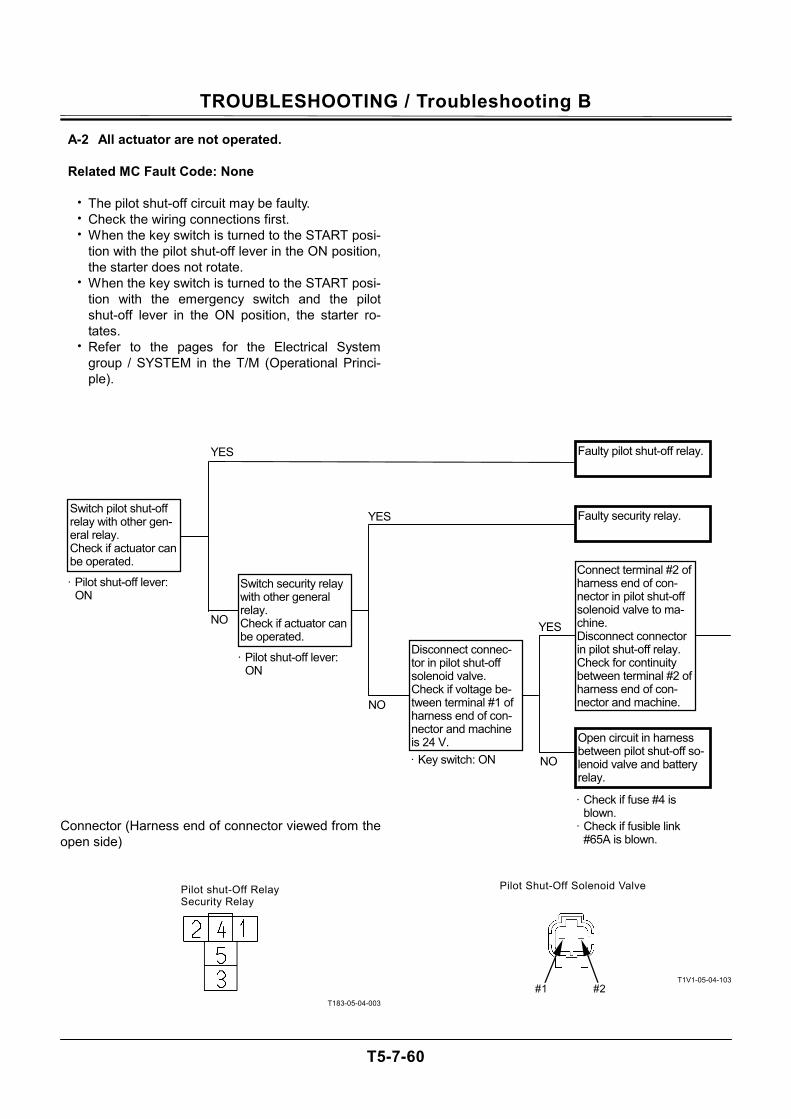
TROUBLESHOOTING / Troubleshooting B
T5-7-60
A-2 All actuator are not operated.
Related MC Fault Code: None
• The pilot shut-off circuit may be faulty. • Check the wiring connections first. • When the key switch is turned to the START posi-
tion with the pilot shut-off lever in the ON position, the starter does not rotate.
• When the key switch is turned to the START posi-tion with the emergency switch and the pilot shut-off lever in the ON position, the starter ro-tates.
• Refer to the pages for the Electrical System group / SYSTEM in the T/M (Operational Princi-ple).
Connector (Harness end of connector viewed from the open side)
T183-05-04-003
T1V1-05-04-103
NO
YES
· Pilot shut-off lever: ON
Switch pilot shut-off relay with other gen-eral relay. Check if actuator can be operated.
Faulty pilot shut-off relay.
Switch security relay with other general relay. Check if actuator can be operated.
Open circuit in harness between pilot shut-off so-lenoid valve and battery relay.
· Check if fuse #4 is blown.
· Check if fusible link #65A is blown.
Disconnect connec-tor in pilot shut-off solenoid valve. Check if voltage be-tween terminal #1 of harness end of con-nector and machine is 24 V.
Connect terminal #2 of harness end of con-nector in pilot shut-off solenoid valve to ma-chine. Disconnect connector in pilot shut-off relay. Check for continuity between terminal #2 of harness end of con-nector and machine.
YES
NO
NO
YES
· Pilot shut-off lever: ON
· Key switch: ON
Faulty security relay.
Pilot shut-Off Relay Security Relay
Pilot Shut-Off Solenoid Valve
#1 #2
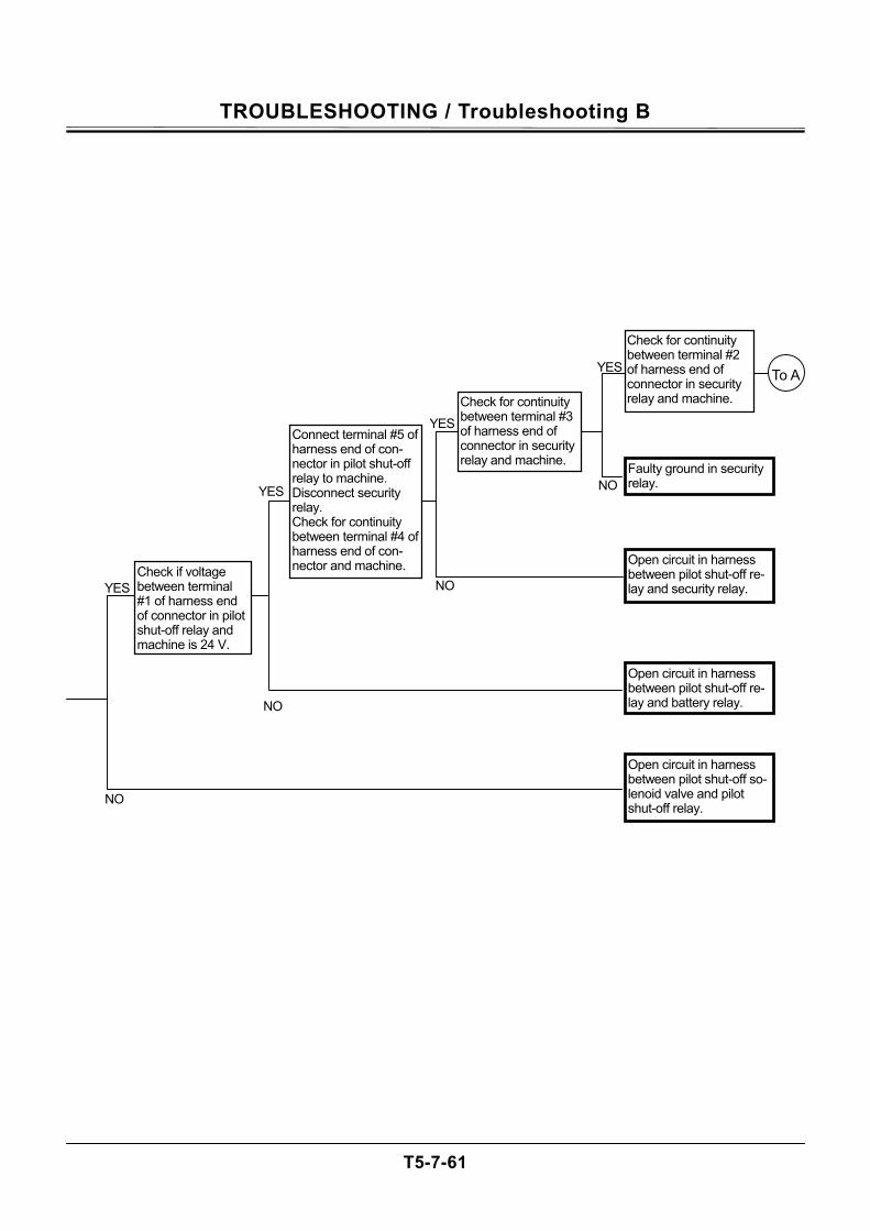
TROUBLESHOOTING / Troubleshooting B
T5-7-61
YES
YES NO
NO
YES
Faulty ground in security relay.
YES
Open circuit in harness between pilot shut-off re-lay and security relay.
Open circuit in harness between pilot shut-off re-lay and battery relay.
Open circuit in harness between pilot shut-off so-lenoid valve and pilot shut-off relay.
To A
Check if voltage between terminal #1 of harness end of connector in pilot shut-off relay and machine is 24 V.
Check for continuity between terminal #2 of harness end of connector in security relay and machine.
Connect terminal #5 of harness end of con-nector in pilot shut-off relay to machine. Disconnect security relay. Check for continuity between terminal #4 of harness end of con-nector and machine.
Check for continuity between terminal #3 of harness end of connector in security relay and machine.
NO
NO
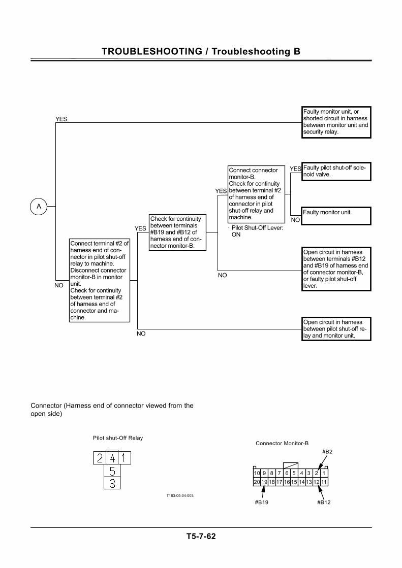
TROUBLESHOOTING / Troubleshooting B
T5-7-62
Connector (Harness end of connector viewed from the open side)
T183-05-04-003
Pilot shut-Off Relay Connector Monitor-B
#B19
10 9 8 7 6 5 4 3 2 1 20 19 18 17 16 15 14 13 12 11
#B12
#B2
NO
YES
YES
YES
NO
Check for continuity between terminals #B19 and #B12 of harness end of con-nector monitor-B. Connect terminal #2 of
harness end of con-nector in pilot shut-off relay to machine. Disconnect connector monitor-B in monitor unit. Check for continuity between terminal #2 of harness end of connector and ma-chine.
· Pilot Shut-Off Lever: ON
NO
NO
YES
NO
A
Faulty monitor unit, or shorted circuit in harness between monitor unit and security relay.
Faulty pilot shut-off sole-noid valve.
Faulty monitor unit.
Open circuit in harness between terminals #B12 and #B19 of harness end of connector monitor-B, or faulty pilot shut-off lever.
Open circuit in harness between pilot shut-off re-lay and monitor unit.
Connect connector monitor-B. Check for continuity between terminal #2 of harness end of connector in pilot shut-off relay and machine.

TROUBLESHOOTING / Troubleshooting B
T5-7-63
(Blank)
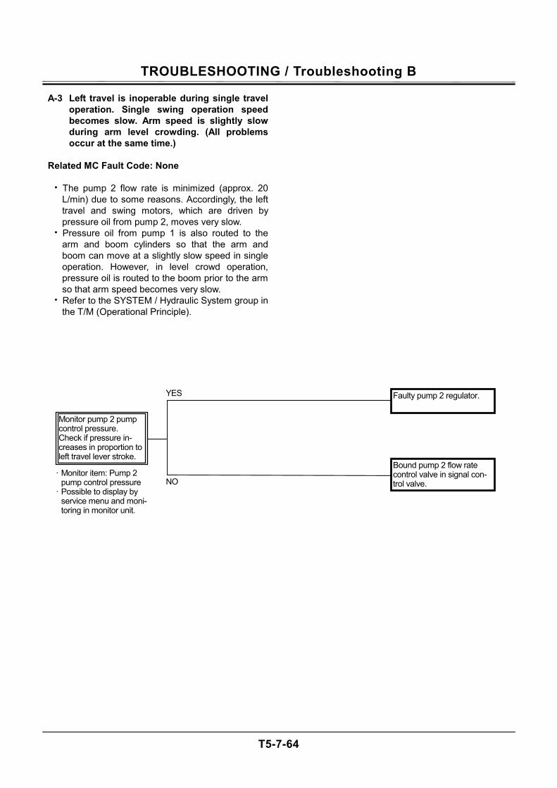
TROUBLESHOOTING / Troubleshooting B
T5-7-64
A-3 Left travel is inoperable during single travel operation. Single swing operation speed becomes slow. Arm speed is slightly slow during arm level crowding. (All problems occur at the same time.)
Related MC Fault Code: None
• The pump 2 flow rate is minimized (approx. 20
L/min) due to some reasons. Accordingly, the left travel and swing motors, which are driven by pressure oil from pump 2, moves very slow.
• Pressure oil from pump 1 is also routed to the arm and boom cylinders so that the arm and boom can move at a slightly slow speed in single operation. However, in level crowd operation, pressure oil is routed to the boom prior to the arm so that arm speed becomes very slow.
• Refer to the SYSTEM / Hydraulic System group in the T/M (Operational Principle).
NO
YES
· Monitor item: Pump 2 pump control pressure
· Possible to display by service menu and moni-toring in monitor unit.
Monitor pump 2 pump control pressure. Check if pressure in-creases in proportion to left travel lever stroke.
Faulty pump 2 regulator.
Bound pump 2 flow rate control valve in signal con-trol valve.
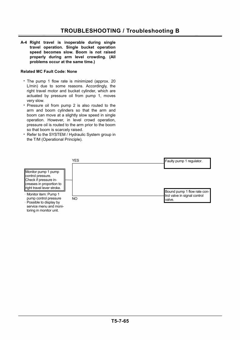
TROUBLESHOOTING / Troubleshooting B
T5-7-65
A-4 Right travel is inoperable during single travel operation. Single bucket operation speed becomes slow. Boom is not raised properly during arm level crowding. (All problems occur at the same time.)
Related MC Fault Code: None
• The pump 1 flow rate is minimized (approx. 20
L/min) due to some reasons. Accordingly, the right travel motor and bucket cylinder, which are actuated by pressure oil from pump 1, moves very slow.
• Pressure oil from pump 2 is also routed to the arm and boom cylinders so that the arm and boom can move at a slightly slow speed in single operation. However, in level crowd operation, pressure oil is routed to the arm prior to the boom so that boom is scarcely raised.
• Refer to the SYSTEM / Hydraulic System group in the T/M (Operational Principle).
NO
YES
· Monitor item: Pump 1 pump control pressure
· Possible to display by service menu and moni-toring in monitor unit.
Faulty pump 1 regulator.
Bound pump 1 flow rate con-trol valve in signal control valve.
Monitor pump 1 pump control pressure. Check if pressure in-creases in proportion to right travel lever stroke.
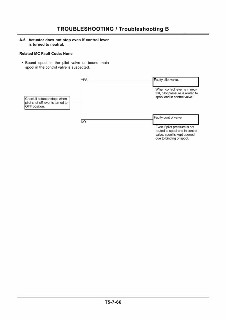
TROUBLESHOOTING / Troubleshooting B
T5-7-66
A-5 Actuator does not stop even if control lever is turned to neutral.
Related MC Fault Code: None
• Bound spool in the pilot valve or bound main
spool in the control valve is suspected.
Faulty pilot valve.
Faulty control valve.
Check if actuator stops when pilot shut-off lever is turned to OFF position.
NO
YES
· When control lever is in neu-tral, pilot pressure is routed to spool end in control valve.
· Even if pilot pressure is not routed to spool end in control valve, spool is kept opened due to binding of spool.
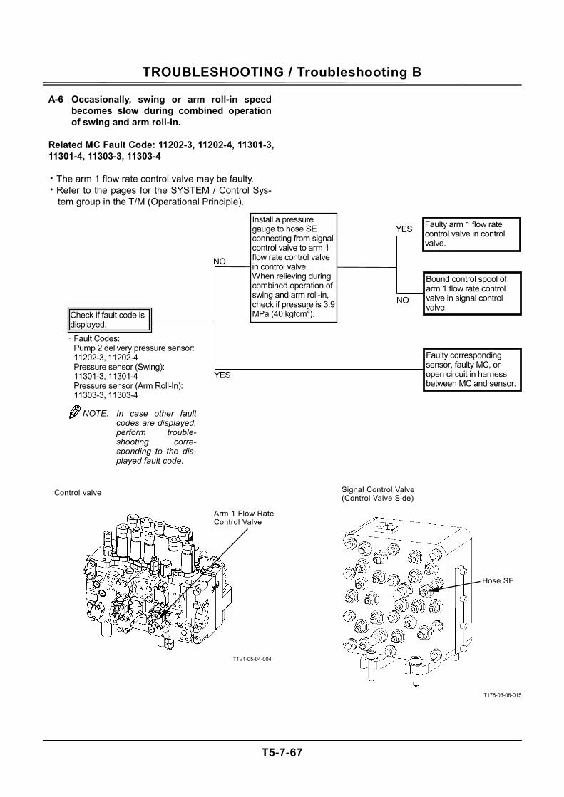
TROUBLESHOOTING / Troubleshooting B
T5-7-67
A-6 Occasionally, swing or arm roll-in speed becomes slow during combined operation of swing and arm roll-in.
Related MC Fault Code: 11202-3, 11202-4, 11301-3, 11301-4, 11303-3, 11303-4
• The arm 1 flow rate control valve may be faulty. • Refer to the pages for the SYSTEM / Control Sys-
tem group in the T/M (Operational Principle).
T1V1-05-04-004
T178-03-06-015
Arm 1 Flow Rate Control Valve
Control valve
Hose SE
Signal Control Valve (Control Valve Side)
NO
NO
YES
YES
Faulty arm 1 flow rate control valve in control valve.
Bound control spool of arm 1 flow rate control valve in signal control valve.
Faulty corresponding sensor, faulty MC, or open circuit in harness between MC and sensor.
Install a pressure gauge to hose SE connecting from signal control valve to arm 1 flow rate control valve in control valve. When relieving during combined operation of swing and arm roll-in, check if pressure is 3.9 MPa (40 kgfcm2).
· Fault Codes: Pump 2 delivery pressure sensor: 11202-3, 11202-4 Pressure sensor (Swing): 11301-3, 11301-4 Pressure sensor (Arm Roll-In): 11303-3, 11303-4
Check if fault code is displayed.
NOTE: In case other faultcodes are displayed,perform trouble-shooting corre-sponding to the dis-played fault code.
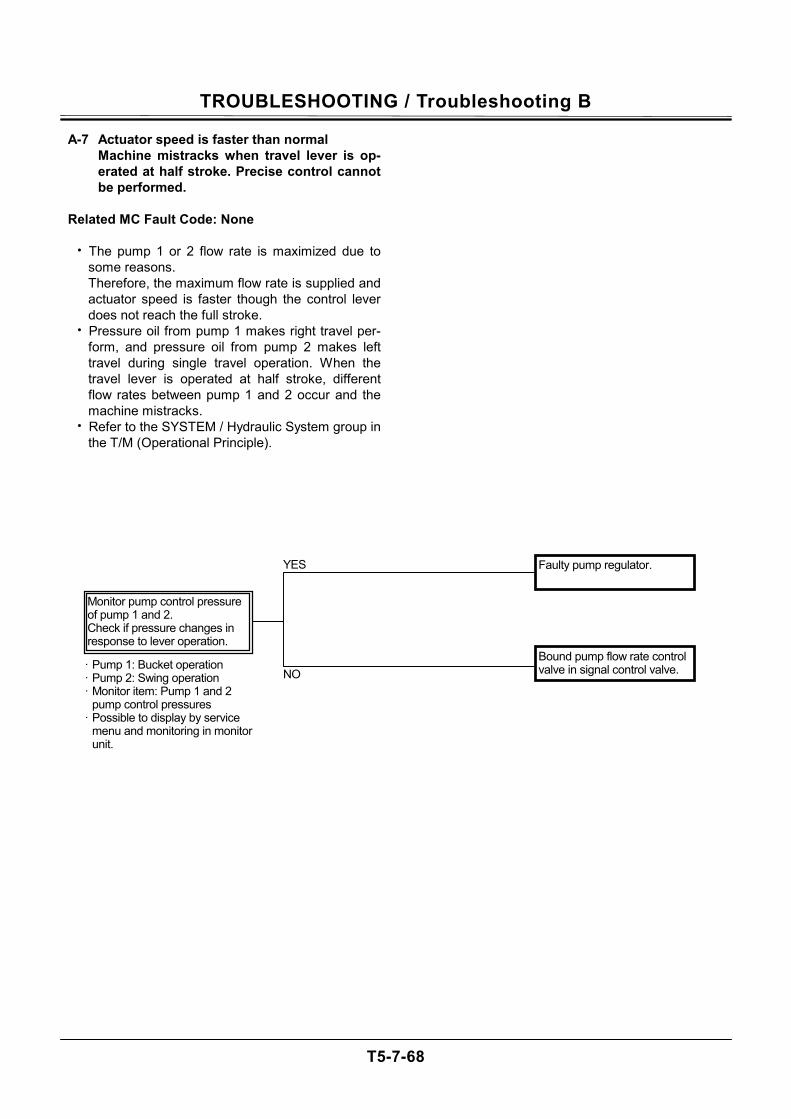
TROUBLESHOOTING / Troubleshooting B
T5-7-68
A-7 Actuator speed is faster than normal Machine mistracks when travel lever is op-erated at half stroke. Precise control cannot be performed.
Related MC Fault Code: None
• The pump 1 or 2 flow rate is maximized due to
some reasons. Therefore, the maximum flow rate is supplied and actuator speed is faster though the control lever does not reach the full stroke.
• Pressure oil from pump 1 makes right travel per-form, and pressure oil from pump 2 makes left travel during single travel operation. When the travel lever is operated at half stroke, different flow rates between pump 1 and 2 occur and the machine mistracks.
• Refer to the SYSTEM / Hydraulic System group in the T/M (Operational Principle).
Faulty pump regulator.
Bound pump flow rate control valve in signal control valve. NO
YES
· Pump 1: Bucket operation · Pump 2: Swing operation · Monitor item: Pump 1 and 2
pump control pressures · Possible to display by service
menu and monitoring in monitor unit.
Monitor pump control pressure of pump 1 and 2. Check if pressure changes in response to lever operation.

TROUBLESHOOTING / Troubleshooting B
T5-7-69
(Blank)
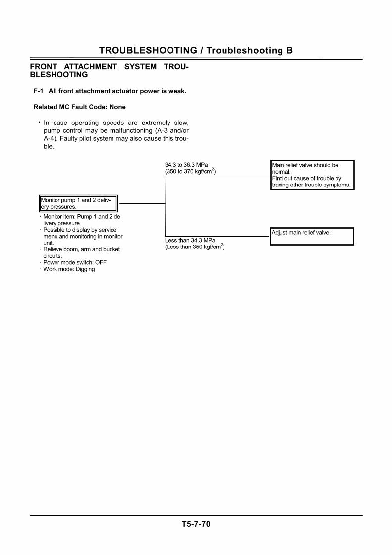
TROUBLESHOOTING / Troubleshooting B
T5-7-70
FRONT ATTACHMENT SYSTEM TROU-BLESHOOTING
F-1 All front attachment actuator power is weak.
Related MC Fault Code: None
• In case operating speeds are extremely slow, pump control may be malfunctioning (A-3 and/or A-4). Faulty pilot system may also cause this trou-ble.
Main relief valve should be normal. Find out cause of trouble by tracing other trouble symptoms.
Adjust main relief valve. Less than 34.3 MPa (Less than 350 kgf/cm2)
34.3 to 36.3 MPa (350 to 370 kgf/cm2)
· Monitor item: Pump 1 and 2 de-livery pressure
· Possible to display by service menu and monitoring in monitor unit.
· Relieve boom, arm and bucket circuits.
· Power mode switch: OFF · Work mode: Digging
Monitor pump 1 and 2 deliv-ery pressures.
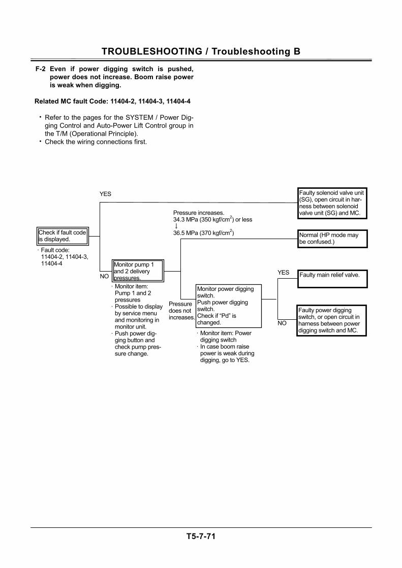
TROUBLESHOOTING / Troubleshooting B
T5-7-71
F-2 Even if power digging switch is pushed, power does not increase. Boom raise power is weak when digging.
Related MC fault Code: 11404-2, 11404-3, 11404-4
• Refer to the pages for the SYSTEM / Power Dig-
ging Control and Auto-Power Lift Control group in the T/M (Operational Principle).
• Check the wiring connections first.
· Fault code: 11404-2, 11404-3, 11404-4
Check if fault code is displayed.
NO
NO YES
YES Faulty solenoid valve unit (SG), open circuit in har-ness between solenoid valve unit (SG) and MC.
Faulty power digging switch, or open circuit in harness between power digging switch and MC.
Monitor power digging switch. Push power digging switch. Check if “Pd” is changed.
· Monitor item: Pump 1 and 2 pressures
· Possible to display by service menu and monitoring in monitor unit.
· Push power dig-ging button and check pump pres-sure change.
Faulty main relief valve.
Normal (HP mode may be confused.)
· Monitor item: Power digging switch
· In case boom raise power is weak during digging, go to YES.
Pressure does not increases.
Pressure increases. 34.3 MPa (350 kgf/cm2) or less↓ 36.5 MPa (370 kgf/cm2)
Monitor pump 1 and 2 delivery pressures.
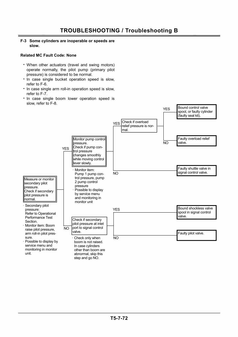
TROUBLESHOOTING / Troubleshooting B
T5-7-72
F-3 Some cylinders are inoperable or speeds are slow.
Related MC Fault Code: None
• When other actuators (travel and swing motors)
operate normally, the pilot pump (primary pilot pressure) is considered to be normal.
• In case single bucket operation speed is slow, refer to F-6.
• In case single arm roll-in operation speed is slow, refer to F-7.
• In case single boom lower operation speed is slow, refer to F-8.
NO
YES NO
NO
YES
YES
· Check only when boom is not raised. In case cylinders other than boom are abnormal, skip this step and go NO.
· Secondary pilot pressure:
Refer to Operational Performance Test Section.
· Monitor item: Boom raise pilot pressure, arm roll-in pilot pres-sure.
· Possible to display by service menu and monitoring in monitor unit.
· Monitor item: Pump 1 pump con-
trol pressure, pump 2 pump control pressure
· Possible to display by service menu and monitoring in monitor unit
Bound control valve spool, or faulty cylinder (faulty seal kit).
Faulty overload relief valve.
Faulty shuttle valve in signal control valve.
NO
YES Bound shockless valve spool in signal control valve.
Faulty pilot valve.
Check if overload relief pressure is nor-mal.
Check if secondary pilot pressure at inlet port to signal control valve.
Monitor pump control pressure. Check if pump con-trol pressure changes smoothly while moving control lever slowly.
Measure or monitor secondary pilot pressure. Check if secondary pilot pressure is normal.

TROUBLESHOOTING / Troubleshooting B
T5-7-73
(Blank)
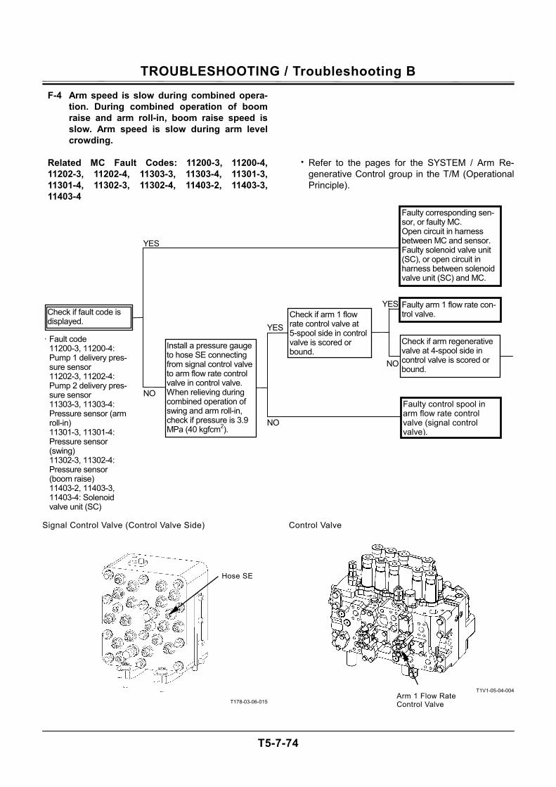
TROUBLESHOOTING / Troubleshooting B
T5-7-74
F-4 Arm speed is slow during combined opera-tion. During combined operation of boom raise and arm roll-in, boom raise speed is slow. Arm speed is slow during arm level crowding.
Related MC Fault Codes: 11200-3, 11200-4, 11202-3, 11202-4, 11303-3, 11303-4, 11301-3, 11301-4, 11302-3, 11302-4, 11403-2, 11403-3, 11403-4
• Refer to the pages for the SYSTEM / Arm Re-generative Control group in the T/M (Operational Principle).
Signal Control Valve (Control Valve Side)
T178-03-06-015
Control Valve
T1V1-05-04-004
NO
YES
NO
NO
YES
YES· Fault code
11200-3, 11200-4: Pump 1 delivery pres-sure sensor 11202-3, 11202-4: Pump 2 delivery pres-sure sensor 11303-3, 11303-4: Pressure sensor (arm roll-in) 11301-3, 11301-4: Pressure sensor (swing) 11302-3, 11302-4: Pressure sensor (boom raise) 11403-2, 11403-3, 11403-4: Solenoid valve unit (SC)
Faulty control spool in arm flow rate control valve (signal control valve).
Check if fault code is displayed.
Install a pressure gauge to hose SE connecting from signal control valve to arm flow rate control valve in control valve. When relieving during combined operation of swing and arm roll-in, check if pressure is 3.9 MPa (40 kgfcm2).
Faulty arm 1 flow rate con-trol valve.
Check if arm regenerative valve at 4-spool side in control valve is scored or bound.
Check if arm 1 flow rate control valve at 5-spool side in control valve is scored or bound.
Faulty corresponding sen-sor, or faulty MC. Open circuit in harness between MC and sensor. Faulty solenoid valve unit (SC), or open circuit in harness between solenoid valve unit (SC) and MC.
Hose SE
Arm 1 Flow Rate Control Valve
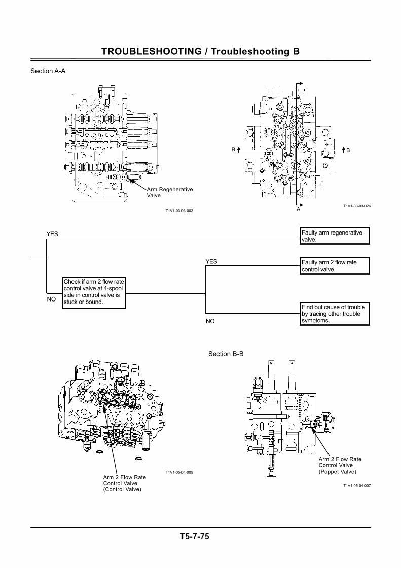
TROUBLESHOOTING / Troubleshooting B
T5-7-75
Section A-A
T1V1-03-03-002
T1V1-05-04-005
T1V1-03-03-026
Section B-B
T1V1-05-04-007
NO
YES Faulty arm 2 flow rate control valve.
Faulty arm regenerative valve.
YES
Check if arm 2 flow rate control valve at 4-spool side in control valve is stuck or bound.
Find out cause of trouble by tracing other trouble symptoms. NO
Arm Regenerative Valve
A
A
BB
Arm 2 Flow Rate Control Valve (Control Valve)
Arm 2 Flow Rate Control Valve (Poppet Valve)
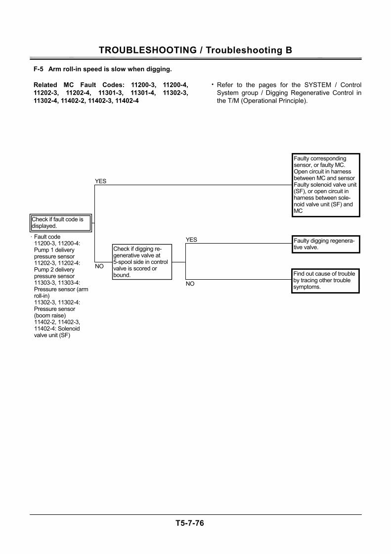
TROUBLESHOOTING / Troubleshooting B
T5-7-76
F-5 Arm roll-in speed is slow when digging.
Related MC Fault Codes: 11200-3, 11200-4, 11202-3, 11202-4, 11301-3, 11301-4, 11302-3, 11302-4, 11402-2, 11402-3, 11402-4
• Refer to the pages for the SYSTEM / Control System group / Digging Regenerative Control in the T/M (Operational Principle).
YES
· Fault code 11200-3, 11200-4: Pump 1 delivery pressure sensor 11202-3, 11202-4: Pump 2 delivery pressure sensor 11303-3, 11303-4: Pressure sensor (arm roll-in) 11302-3, 11302-4: Pressure sensor (boom raise) 11402-2, 11402-3, 11402-4: Solenoid valve unit (SF)
Faulty corresponding sensor, or faulty MC. Open circuit in harness between MC and sensor Faulty solenoid valve unit (SF), or open circuit in harness between sole-noid valve unit (SF) and MC
Check if digging re-generative valve at 5-spool side in control valve is scored or bound.
Faulty digging regenera-tive valve.
Find out cause of trouble by tracing other trouble symptoms.
YES
NO
NO
Check if fault code is displayed.
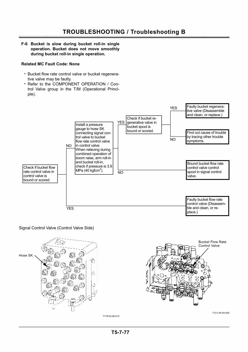
TROUBLESHOOTING / Troubleshooting B
T5-7-77
F-6 Bucket is slow during bucket roll-in single operation. Bucket does not move smoothly during bucket roll-in single operation.
Related MC Fault Code: None
• Bucket flow rate control valve or bucket regenera-
tive valve may be faulty. • Refer to the COMPONENT OPERATION / Con-
trol Valve group in the T/M (Operational Princi-ple).
Signal Control Valve (Control Valve Side)
T178-03-06-015
T1V1-05-04-005
NO
YES
NO
YES
YES
NO
Faulty bucket regenera-tive valve (Disassemble and clean, or replace.)
Find out cause of trouble by tracing other trouble symptoms.
Bound bucket flow rate control valve control spool in signal control valve.
Faulty bucket flow rate control valve (Disassem-ble and clean, or re-place.)
Check if bucket re-generative valve in bucket spool is bound or scored.
Check if bucket flow rate control valve in control valve is bound or scored.
Install a pressure gauge to hose SK connecting signal con-trol valve to bucket flow rate control valve in control valve. When relieving during combined operation of boom raise, arm roll-in and bucket roll-in, check if pressure is 3.9 MPa (40 kgfcm2).
Hose SK
Bucket Flow Rate Control Valve
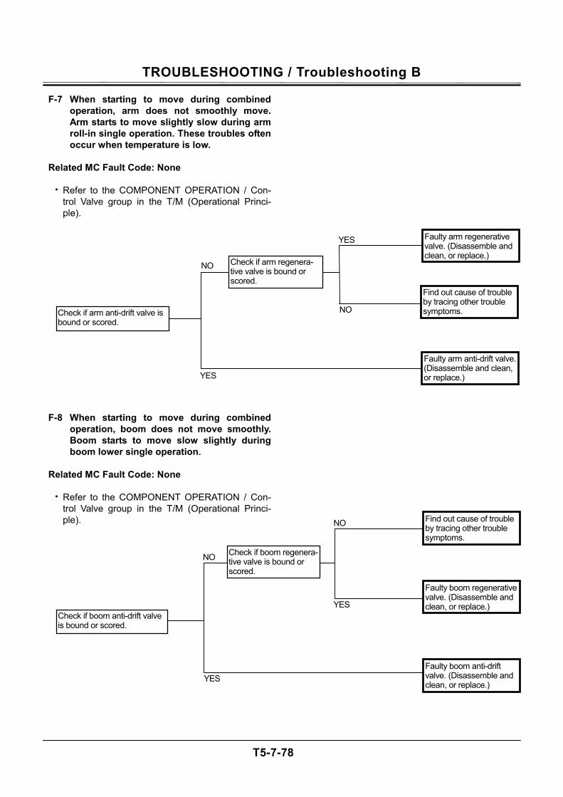
TROUBLESHOOTING / Troubleshooting B
T5-7-78
F-7 When starting to move during combined operation, arm does not smoothly move. Arm starts to move slightly slow during arm roll-in single operation. These troubles often occur when temperature is low.
Related MC Fault Code: None
• Refer to the COMPONENT OPERATION / Con-
trol Valve group in the T/M (Operational Princi-ple).
F-8 When starting to move during combined operation, boom does not move smoothly. Boom starts to move slow slightly during boom lower single operation.
Related MC Fault Code: None
• Refer to the COMPONENT OPERATION / Con-
trol Valve group in the T/M (Operational Princi-ple).
NO
NO
YES
YES
Find out cause of trouble by tracing other trouble symptoms.
Check if boom regenera-tive valve is bound or scored.
Faulty boom anti-drift valve. (Disassemble and clean, or replace.)
Faulty boom regenerative valve. (Disassemble and clean, or replace.)
Check if boom anti-drift valve is bound or scored.
NO
YES
Check if arm regenera-tive valve is bound or scored.
Check if arm anti-drift valve is bound or scored.
NO
YES
Faulty arm anti-drift valve. (Disassemble and clean, or replace.)
Faulty arm regenerative valve. (Disassemble and clean, or replace.)
Find out cause of trouble by tracing other trouble symptoms.
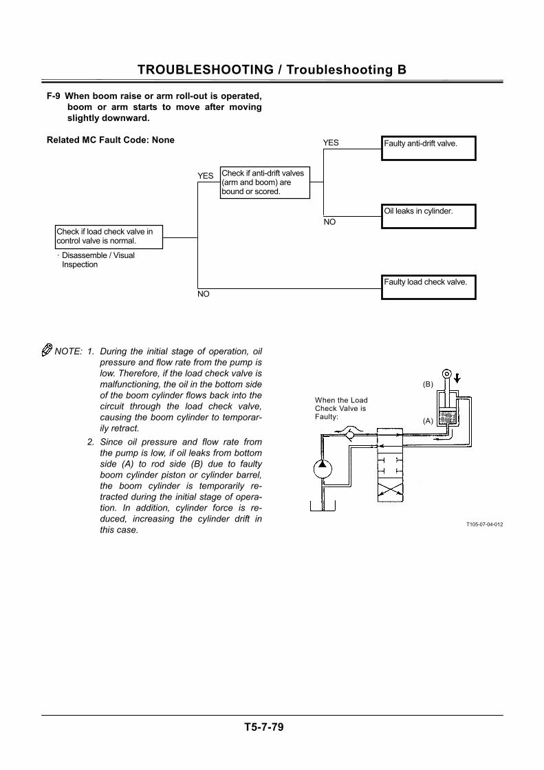
TROUBLESHOOTING / Troubleshooting B
T5-7-79
F-9 When boom raise or arm roll-out is operated, boom or arm starts to move after moving slightly downward.
Related MC Fault Code: None
NOTE: 1. During the initial stage of operation, oil pressure and flow rate from the pump is low. Therefore, if the load check valve is malfunctioning, the oil in the bottom side of the boom cylinder flows back into the circuit through the load check valve, causing the boom cylinder to temporar-ily retract.
2. Since oil pressure and flow rate from the pump is low, if oil leaks from bottom side (A) to rod side (B) due to faulty boom cylinder piston or cylinder barrel, the boom cylinder is temporarily re-tracted during the initial stage of opera-tion. In addition, cylinder force is re-duced, increasing the cylinder drift in this case.
T105-07-04-012
When the Load Check Valve is Faulty: (A)
(B)
· Disassemble / Visual Inspection
NO
NO
YES
YES
Faulty anti-drift valve.
Check if anti-drift valves (arm and boom) are bound or scored.
Faulty load check valve.
Oil leaks in cylinder.
Check if load check valve in control valve is normal.
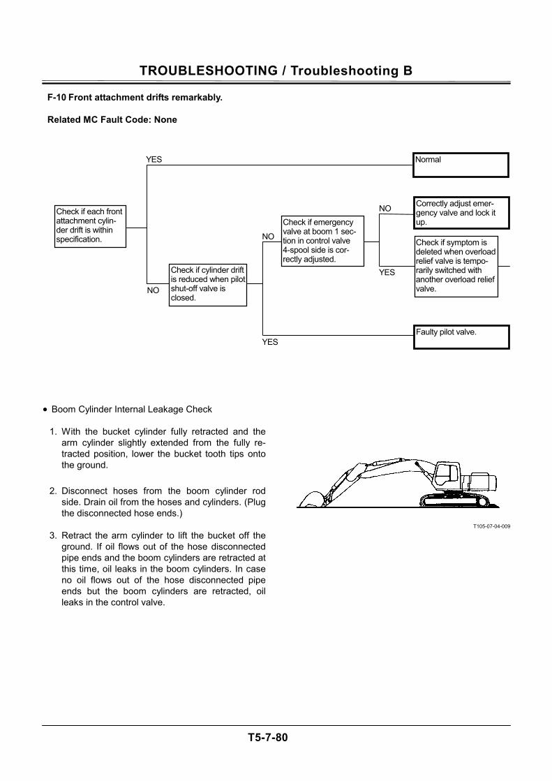
TROUBLESHOOTING / Troubleshooting B
T5-7-80
F-10 Front attachment drifts remarkably.
Related MC Fault Code: None • Boom Cylinder Internal Leakage Check
1. With the bucket cylinder fully retracted and the arm cylinder slightly extended from the fully re-tracted position, lower the bucket tooth tips onto the ground.
2. Disconnect hoses from the boom cylinder rod side. Drain oil from the hoses and cylinders. (Plug the disconnected hose ends.)
3. Retract the arm cylinder to lift the bucket off the
ground. If oil flows out of the hose disconnected pipe ends and the boom cylinders are retracted at this time, oil leaks in the boom cylinders. In case no oil flows out of the hose disconnected pipe ends but the boom cylinders are retracted, oil leaks in the control valve.
T105-07-04-009
YES
NO
NO
NO
YES
YES
Check if each front attachment cylin-der drift is within specification.
Correctly adjust emer-gency valve and lock it up.
Check if symptom is deleted when overload relief valve is tempo-rarily switched with another overload relief valve.
Faulty pilot valve.
Normal
Check if cylinder drift is reduced when pilot shut-off valve is closed.
Check if emergency valve at boom 1 sec-tion in control valve 4-spool side is cor-rectly adjusted.
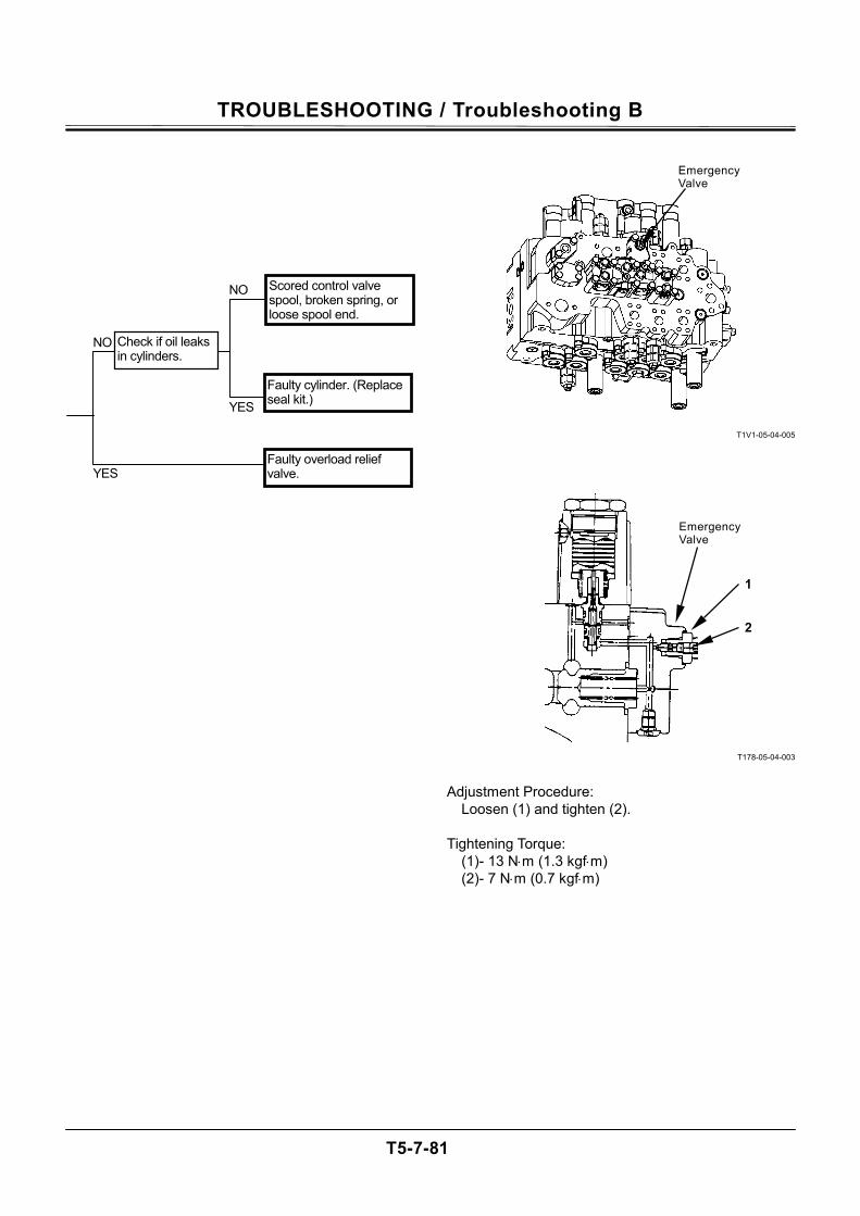
TROUBLESHOOTING / Troubleshooting B
T5-7-81
T1V1-05-04-005
T178-05-04-003
Adjustment Procedure: Loosen (1) and tighten (2). Tightening Torque: (1)- 13 N⋅m (1.3 kgf⋅m) (2)- 7 N⋅m (0.7 kgf⋅m)
NO
NO
YES
YES
Scored control valve spool, broken spring, or loose spool end.
Check if oil leaks in cylinders.
Faulty overload relief valve.
Faulty cylinder. (Replace seal kit.)
1
Emergency Valve
2
Emergency Valve
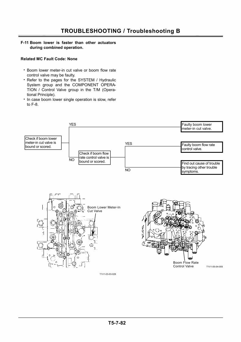
TROUBLESHOOTING / Troubleshooting B
T5-7-82
F-11 Boom lower is faster than other actuators during combined operation.
Related MC Fault Code: None
• Boom lower meter-in cut valve or boom flow rate control valve may be faulty.
• Refer to the pages for the SYSTEM / Hydraulic System group and the COMPONENT OPERA-TION / Control Valve group in the T/M (Opera-tional Principle).
• In case boom lower single operation is slow, refer to F-8.
T1V1-03-03-026
T1V1-05-04-005
NO
NO
YES
YES Faulty boom lower meter-in cut valve.
Check if boom flow rate control valve is bound or scored. Find out cause of trouble
by tracing other trouble symptoms.
Faulty boom flow rate control valve.
Check if boom lower meter-in cut valve is bound or scored.
Boom Lower Meter-In Cut Valve
Boom Flow Rate Control Valve
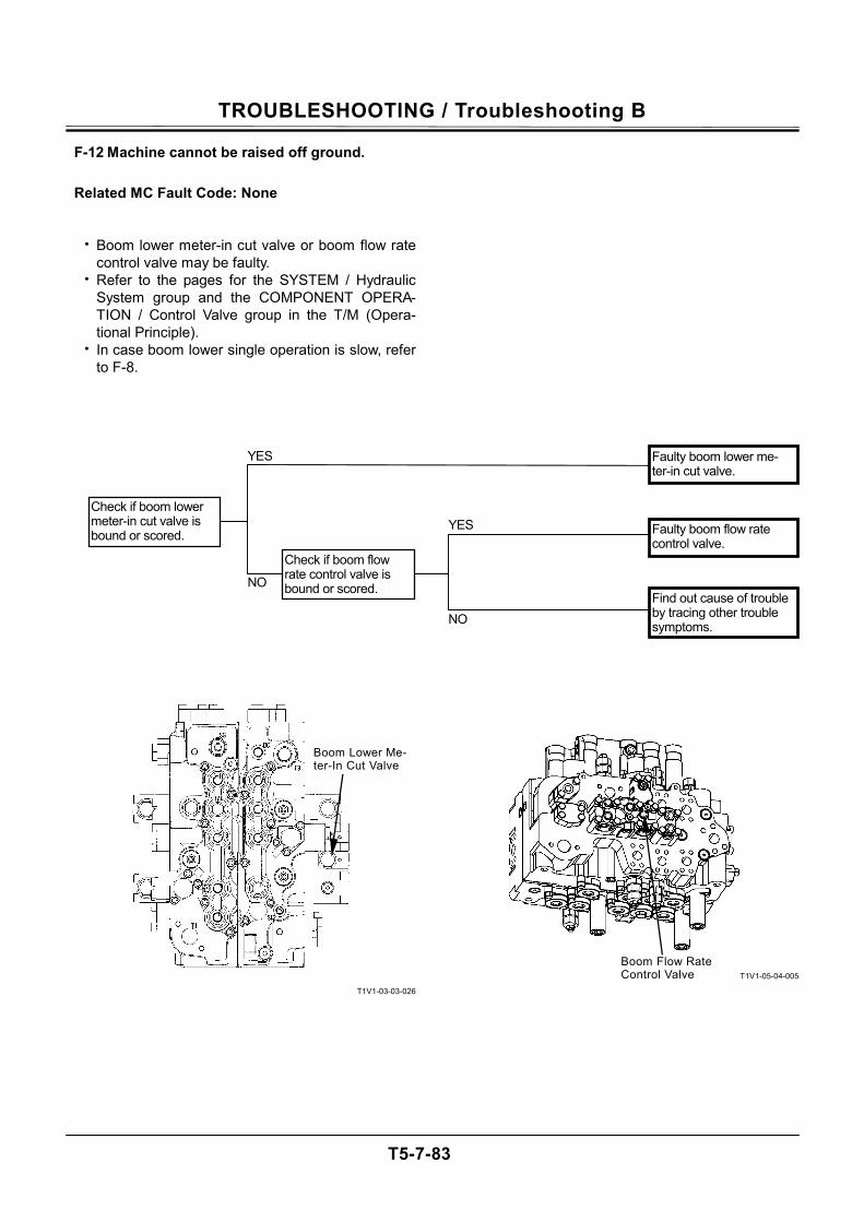
TROUBLESHOOTING / Troubleshooting B
T5-7-83
F-12 Machine cannot be raised off ground.
Related MC Fault Code: None
• Boom lower meter-in cut valve or boom flow rate control valve may be faulty.
• Refer to the pages for the SYSTEM / Hydraulic System group and the COMPONENT OPERA-TION / Control Valve group in the T/M (Opera-tional Principle).
• In case boom lower single operation is slow, refer to F-8.
T1V1-03-03-026
T1V1-05-04-005
NO
NO
YES
YES Faulty boom lower me-ter-in cut valve.
Check if boom flow rate control valve is bound or scored.
Find out cause of trouble by tracing other trouble symptoms.
Faulty boom flow rate control valve.
Check if boom lower meter-in cut valve is bound or scored.
Boom Lower Me-ter-In Cut Valve
Boom Flow Rate Control Valve
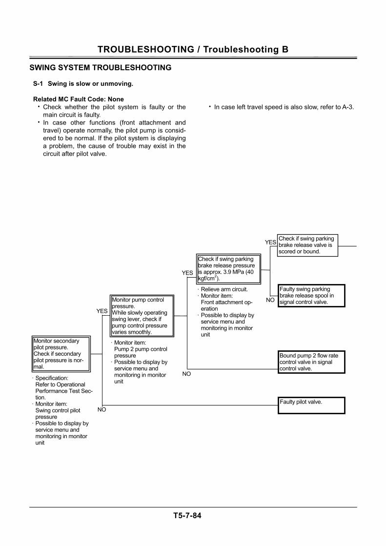
TROUBLESHOOTING / Troubleshooting B
T5-7-84
SWING SYSTEM TROUBLESHOOTING
S-1 Swing is slow or unmoving.
Related MC Fault Code: None • Check whether the pilot system is faulty or the
main circuit is faulty. • In case other functions (front attachment and
travel) operate normally, the pilot pump is consid-ered to be normal. If the pilot system is displaying a problem, the cause of trouble may exist in the circuit after pilot valve.
• In case left travel speed is also slow, refer to A-3.
NO
YES
NO
NO
YES
YES
· Relieve arm circuit. · Monitor item:
Front attachment op-eration
· Possible to display by service menu and monitoring in monitor unit
· Monitor item: Pump 2 pump control pressure
· Possible to display by service menu and monitoring in monitor unit · Specification:
Refer to Operational Performance Test Sec-tion.
· Monitor item: Swing control pilot pressure
· Possible to display by service menu and monitoring in monitor unit
Bound pump 2 flow rate control valve in signal control valve.
Faulty swing parking brake release spool in signal control valve.
Monitor secondary pilot pressure. Check if secondary pilot pressure is nor-mal.
Check if swing parking brake release valve is scored or bound.
Faulty pilot valve.
Check if swing parking brake release pressure is approx. 3.9 MPa (40 kgf/cm2).
Monitor pump control pressure. While slowly operating swing lever, check if pump control pressure varies smoothly.
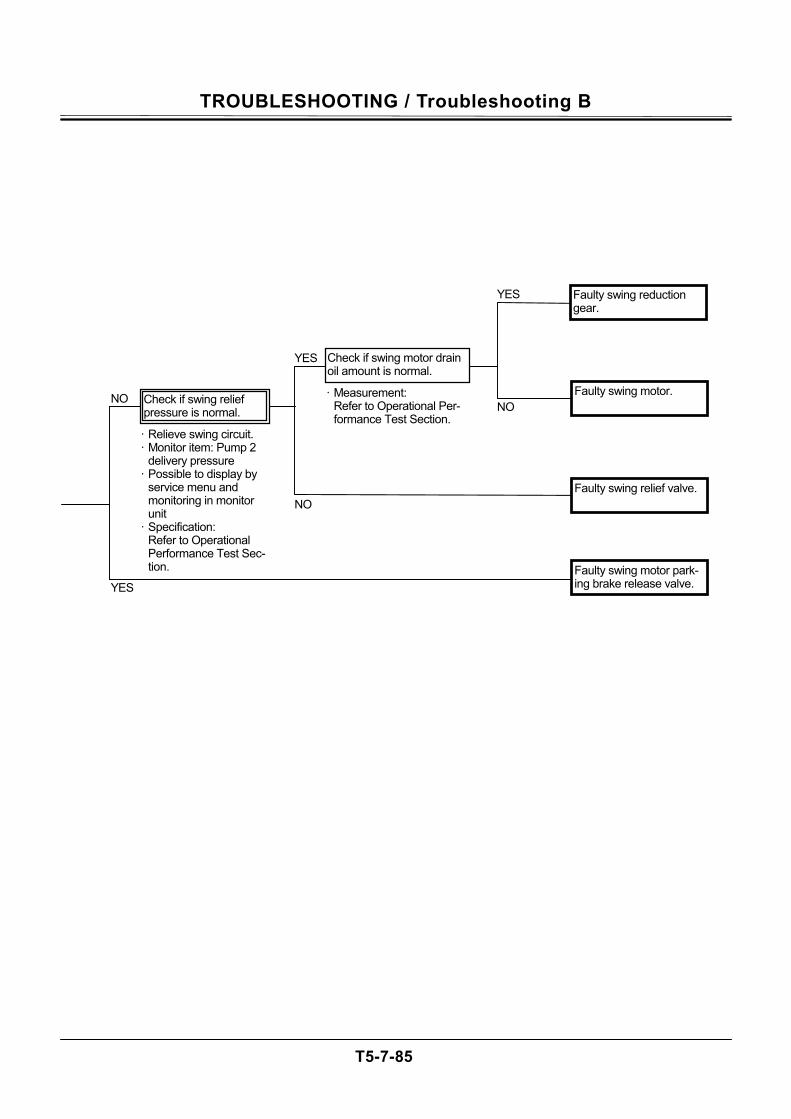
TROUBLESHOOTING / Troubleshooting B
T5-7-85
NO
YES
YES
YES
NONO
Faulty swing reduction gear.
Faulty swing motor.
Faulty swing relief valve.
Faulty swing motor park-ing brake release valve.
· Measurement: Refer to Operational Per-formance Test Section.
Check if swing motor drain oil amount is normal.
· Relieve swing circuit. · Monitor item: Pump 2
delivery pressure · Possible to display by
service menu and monitoring in monitor unit
· Specification: Refer to Operational Performance Test Sec-tion.
Check if swing relief pressure is normal.
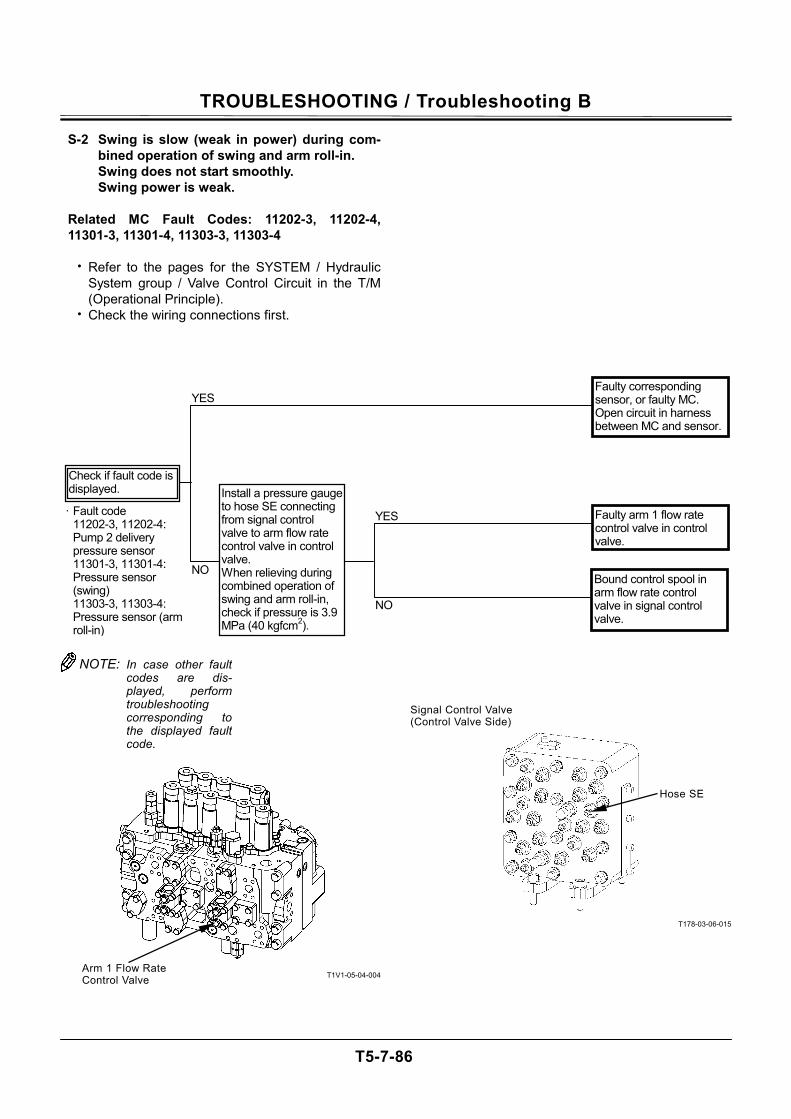
TROUBLESHOOTING / Troubleshooting B
T5-7-86
S-2 Swing is slow (weak in power) during com-bined operation of swing and arm roll-in. Swing does not start smoothly. Swing power is weak.
Related MC Fault Codes: 11202-3, 11202-4, 11301-3, 11301-4, 11303-3, 11303-4
• Refer to the pages for the SYSTEM / Hydraulic
System group / Valve Control Circuit in the T/M (Operational Principle).
• Check the wiring connections first.
T1V1-05-04-004
T178-03-06-015
Arm 1 Flow Rate Control Valve
Hose SE
Signal Control Valve (Control Valve Side)
YES
· Fault code 11202-3, 11202-4: Pump 2 delivery pressure sensor 11301-3, 11301-4: Pressure sensor (swing) 11303-3, 11303-4: Pressure sensor (arm roll-in)
Check if fault code is displayed.
Faulty corresponding sensor, or faulty MC. Open circuit in harness between MC and sensor.
Install a pressure gauge to hose SE connecting from signal control valve to arm flow rate control valve in control valve. When relieving during combined operation of swing and arm roll-in, check if pressure is 3.9 MPa (40 kgfcm2).
Faulty arm 1 flow rate control valve in control valve.
Bound control spool in arm flow rate control valve in signal control valve.
YES
NO
NO
NOTE: In case other faultcodes are dis-played, performtroubleshooting corresponding tothe displayed faultcode.

TROUBLESHOOTING / Troubleshooting B
T5-7-87
(Blank)
TROUBLESHOOTING / Troubleshooting B
T5-7-88
TRAVEL SYSTEM TROUBLESHOOTING
T-1 Both right and left tracks do not rotate or rotate slowly.
Related MC Fault Code: None
• Both right and left pilot valves, travel motors,
and/or control valve spools are unlikely to be faulty at the same time.
• In case both travel systems do not operate, the pilot system, which is applied to both side travel motors, may be faulty. If primary pilot pressure is lower than specification, front attachment operat-ing speed becomes slow as well. Refer to A-1.
• In case the fast travel mode cannot be selected, refer to T-5.

TROUBLESHOOTING / Troubleshooting B
T5-7-89
(Blank)
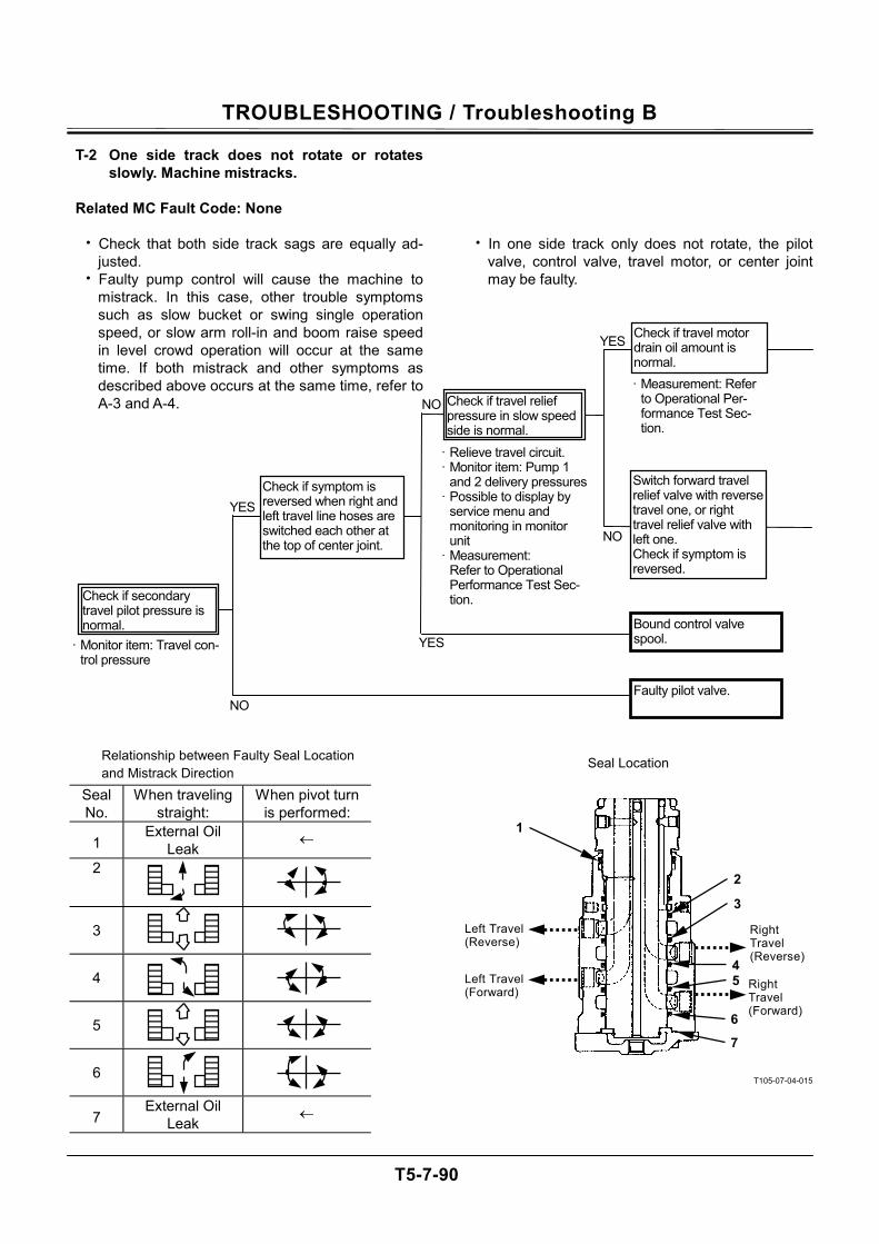
TROUBLESHOOTING / Troubleshooting B
T5-7-90
T-2 One side track does not rotate or rotates slowly. Machine mistracks.
Related MC Fault Code: None
• Check that both side track sags are equally ad-
justed. • Faulty pump control will cause the machine to
mistrack. In this case, other trouble symptoms such as slow bucket or swing single operation speed, or slow arm roll-in and boom raise speed in level crowd operation will occur at the same time. If both mistrack and other symptoms as described above occurs at the same time, refer to A-3 and A-4.
Seal No.
When traveling straight:
When pivot turn is performed:
1 External Oil
Leak ←
2
3
4
5
6
7 External Oil
Leak ←
• In one side track only does not rotate, the pilot
valve, control valve, travel motor, or center joint may be faulty.
T105-07-04-015
NO
NO
NO
YES
YES
YES
· Measurement: Refer to Operational Per-formance Test Sec-tion.
· Relieve travel circuit. · Monitor item: Pump 1
and 2 delivery pressures· Possible to display by
service menu and monitoring in monitor unit
· Measurement: Refer to Operational
Performance Test Sec-tion.
· Monitor item: Travel con-trol pressure
Bound control valve spool.
Switch forward travel relief valve with reverse travel one, or right travel relief valve with left one. Check if symptom is reversed.
Check if secondary travel pilot pressure is normal.
Check if travel relief pressure in slow speed side is normal.
Check if symptom is reversed when right and left travel line hoses are switched each other at the top of center joint.
Faulty pilot valve.
Check if travel motor drain oil amount is normal.
Relationship between Faulty Seal Location and Mistrack Direction
Seal Location
1
2
3
Left Travel(Reverse)
Left Travel (Forward)
Right Travel (Reverse)
Right Travel (Forward)
45
6
7
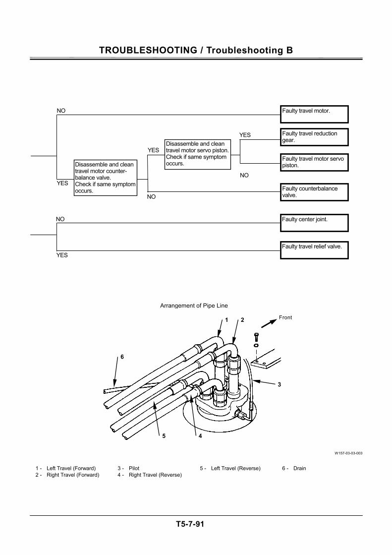
TROUBLESHOOTING / Troubleshooting B
T5-7-91
W157-03-03-003
1 - Left Travel (Forward) 3 - Pilot 5 - Left Travel (Reverse) 6 - Drain 2 - Right Travel (Forward) 4 - Right Travel (Reverse)
Arrangement of Pipe Line
1 2
3
45
6
Front
YES
YES NO
NO
NO
YES
Faulty travel motor.
Disassemble and clean travel motor counter-balance valve. Check if same symptom occurs.
Disassemble and clean travel motor servo piston. Check if same symptom occurs.
Faulty travel motor servo piston.
Faulty counterbalance valve.
Faulty travel reduction gear.
NO
YES Faulty travel relief valve.
Faulty center joint.
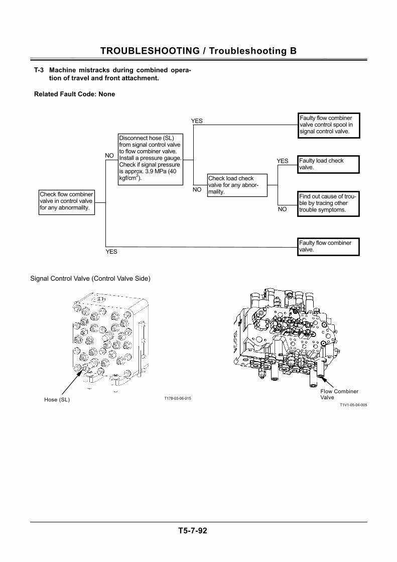
TROUBLESHOOTING / Troubleshooting B
T5-7-92
T-3 Machine mistracks during combined opera-tion of travel and front attachment.
Related Fault Code: None
Signal Control Valve (Control Valve Side)
T178-03-06-015
T1V1-05-04-005
NO
NO YES
YES
Faulty flow combiner valve control spool in signal control valve.
Faulty load check valve.
Disconnect hose (SL) from signal control valve to flow combiner valve.Install a pressure gauge. Check if signal pressure is approx. 3.9 MPa (40 kgf/cm2).
Faulty flow combiner valve.
Find out cause of trou-ble by tracing other trouble symptoms.
Check flow combiner valve in control valve for any abnormality.
YES
NO
Check load check valve for any abnor-mality.
Flow Combiner Valve Hose (SL)
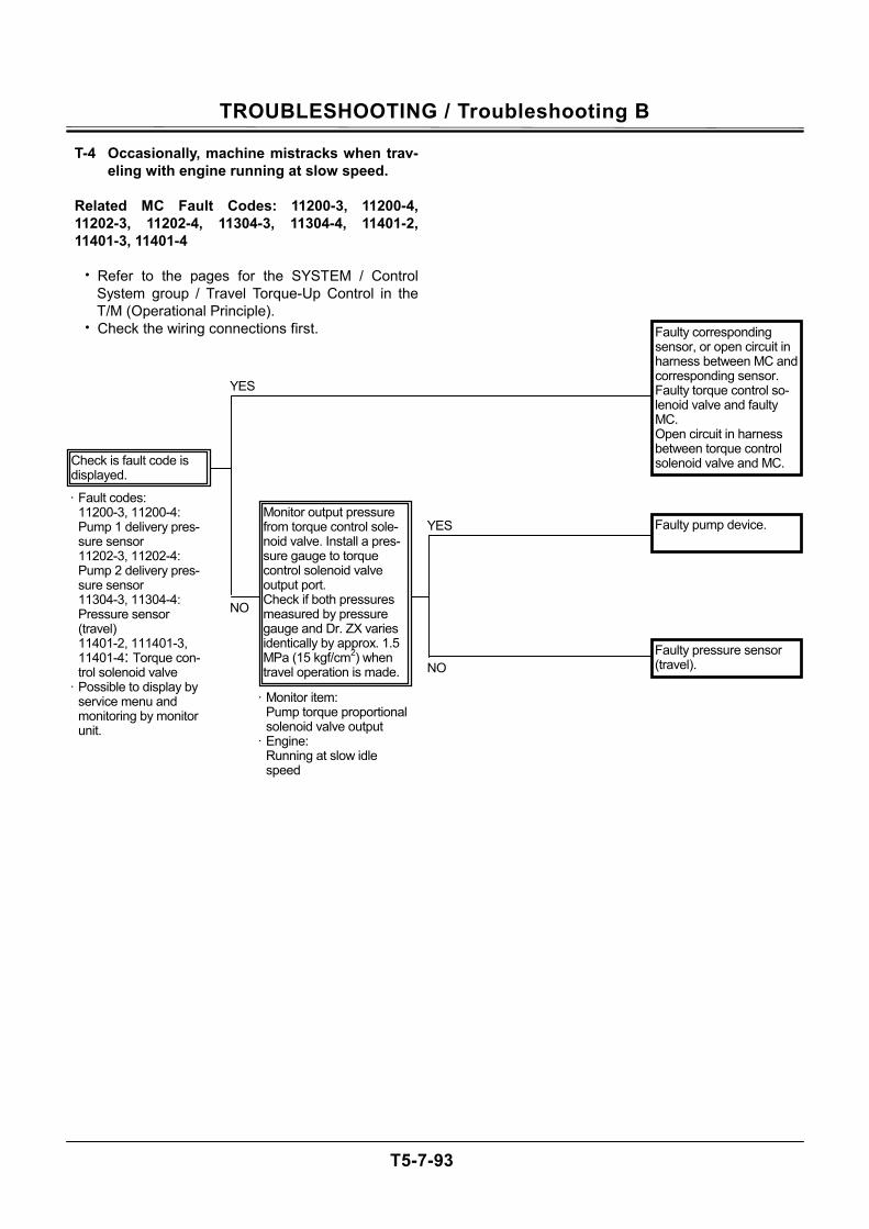
TROUBLESHOOTING / Troubleshooting B
T5-7-93
T-4 Occasionally, machine mistracks when trav-eling with engine running at slow speed.
Related MC Fault Codes: 11200-3, 11200-4, 11202-3, 11202-4, 11304-3, 11304-4, 11401-2, 11401-3, 11401-4
• Refer to the pages for the SYSTEM / Control
System group / Travel Torque-Up Control in the T/M (Operational Principle).
• Check the wiring connections first.
YES
NO
Faulty corresponding sensor, or open circuit in harness between MC and corresponding sensor. Faulty torque control so-lenoid valve and faulty MC. Open circuit in harness between torque control solenoid valve and MC.
Faulty pump device. Monitor output pressure from torque control sole-noid valve. Install a pres-sure gauge to torque control solenoid valve output port. Check if both pressures measured by pressure gauge and Dr. ZX varies identically by approx. 1.5 MPa (15 kgf/cm2) when travel operation is made.
YES
NO
Check is fault code is displayed.
· Fault codes: 11200-3, 11200-4: Pump 1 delivery pres-sure sensor 11202-3, 11202-4: Pump 2 delivery pres-sure sensor 11304-3, 11304-4: Pressure sensor (travel) 11401-2, 111401-3, 11401-4: Torque con-trol solenoid valve
· Possible to display by service menu and monitoring by monitor unit.
· Monitor item: Pump torque proportional solenoid valve output
· Engine: Running at slow idle speed
Faulty pressure sensor (travel).
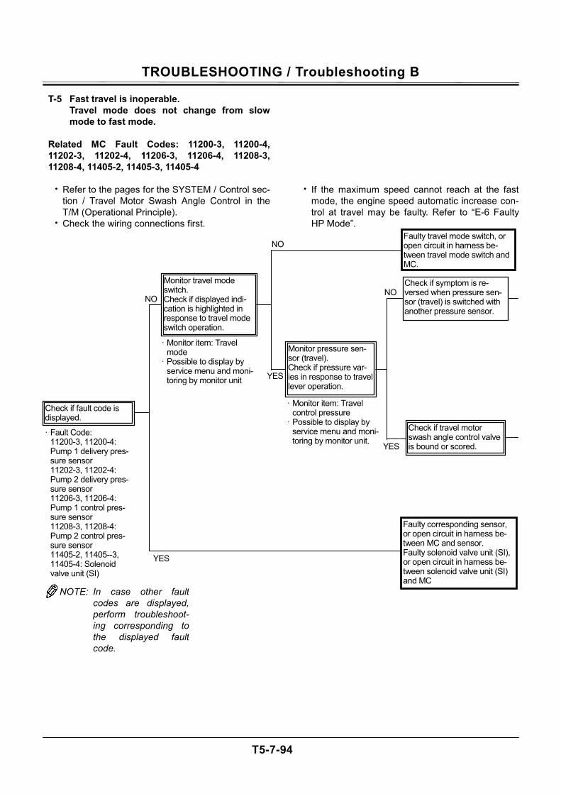
TROUBLESHOOTING / Troubleshooting B
T5-7-94
T-5 Fast travel is inoperable. Travel mode does not change from slow mode to fast mode.
Related MC Fault Codes: 11200-3, 11200-4, 11202-3, 11202-4, 11206-3, 11206-4, 11208-3, 11208-4, 11405-2, 11405-3, 11405-4
• Refer to the pages for the SYSTEM / Control sec-
tion / Travel Motor Swash Angle Control in the T/M (Operational Principle).
• Check the wiring connections first.
• If the maximum speed cannot reach at the fast mode, the engine speed automatic increase con-trol at travel may be faulty. Refer to “E-6 Faulty HP Mode”.
· Monitor item: Travel mode
· Possible to display by service menu and moni-toring by monitor unit
· Monitor item: Travel control pressure
· Possible to display by service menu and moni-toring by monitor unit.
· Fault Code: 11200-3, 11200-4: Pump 1 delivery pres-sure sensor 11202-3, 11202-4: Pump 2 delivery pres-sure sensor 11206-3, 11206-4: Pump 1 control pres-sure sensor 11208-3, 11208-4: Pump 2 control pres-sure sensor 11405-2, 11405--3, 11405-4: Solenoid valve unit (SI)
YES
NO
NO
NO
YES
YES
Faulty corresponding sensor, or open circuit in harness be-tween MC and sensor. Faulty solenoid valve unit (SI), or open circuit in harness be-tween solenoid valve unit (SI) and MC
Faulty travel mode switch, or open circuit in harness be-tween travel mode switch and MC.
Check if fault code is displayed.
Monitor travel mode switch. Check if displayed indi-cation is highlighted in response to travel mode switch operation.
Check if travel motor swash angle control valve is bound or scored.
Monitor pressure sen-sor (travel). Check if pressure var-ies in response to travel lever operation.
NOTE: In case other faultcodes are displayed,perform troubleshoot-ing corresponding tothe displayed faultcode.
Check if symptom is re-versed when pressure sen-sor (travel) is switched with another pressure sensor.
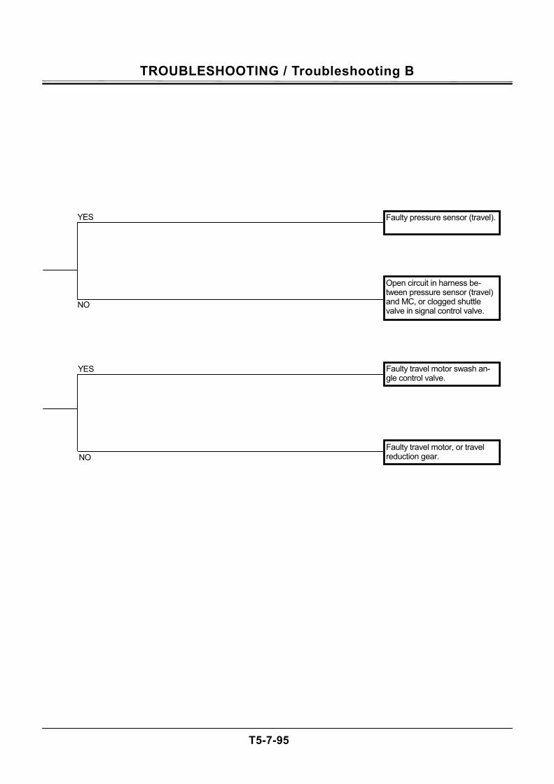
TROUBLESHOOTING / Troubleshooting B
T5-7-95
Faulty travel motor swash an-gle control valve.
Faulty travel motor, or travel reduction gear. NO
YES
YES
NO
Faulty pressure sensor (travel).
Open circuit in harness be-tween pressure sensor (travel) and MC, or clogged shuttle valve in signal control valve.
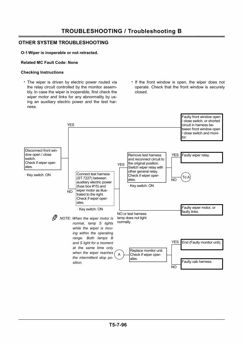
TROUBLESHOOTING / Troubleshooting B
T5-7-96
OTHER SYSTEM TROUBLESHOOTING
O-1 Wiper is inoperable or not retracted.
Related MC Fault Code: None
Checking Instructions
• The wiper is driven by electric power routed via the relay circuit controlled by the monitor assem-bly. In case the wiper is inoperable, first check the wiper motor and links for any abnormality by us-ing an auxiliary electric power and the test har-ness.
• If the front window is open, the wiper does not operate. Check that the front window is securely closed.
· Key switch: ON
Disconnect front win-dow open / close switch. Check if wiper oper-ates.
NO or test harness lamp does not light normally.
YES
Faulty wiper relay.
YES
NO· Key switch: ON
Remove test harness and reconnect circuit to the original position. Switch wiper relay with other general relay. Check if wiper oper-ates.
Faulty wiper motor, or faulty links.
Faulty front window open / close switch, or shorted circuit in harness be-tween front window open / close switch and moni-tor.
NOTE: When the wiper motor isnormal, lamp S lightswhile the wiper is mov-ing within the operatingrange. Both lamps Band S light for a momentat the same time onlywhen the wiper reachesthe intermittent stop po-sition.
NO
YES
Faulty cab harness.
End (Faulty monitor unit).
Replace monitor unit.Check if wiper oper-ates.
NO
YES
· Key switch: ON
Connect test harness (ST 7227) between auxiliary electric power (fuse box #15) and wiper motor as illus-trated to the right. Check if wiper oper-ates.
To A
A
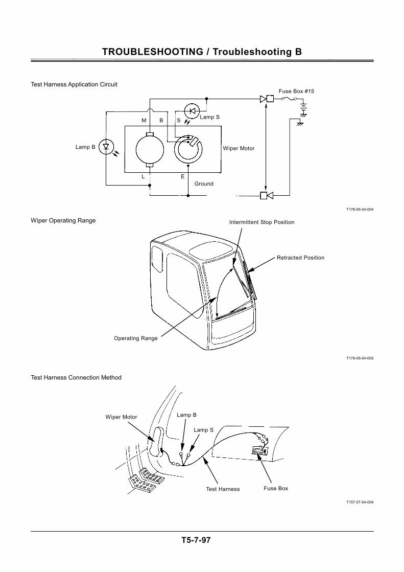
TROUBLESHOOTING / Troubleshooting B
T5-7-97
T178-05-04-004
T178-05-04-005
T157-07-04-004
Test Harness Application Circuit
Wiper Operating Range
Test Harness Connection Method
Wiper Motor
Ground
Lamp B
Fuse Box #15
Lamp S
Operating Range
Retracted Position
Intermittent Stop Position
Fuse Box
Lamp S
Test Harness
Lamp B Wiper Motor
SB
EL
M
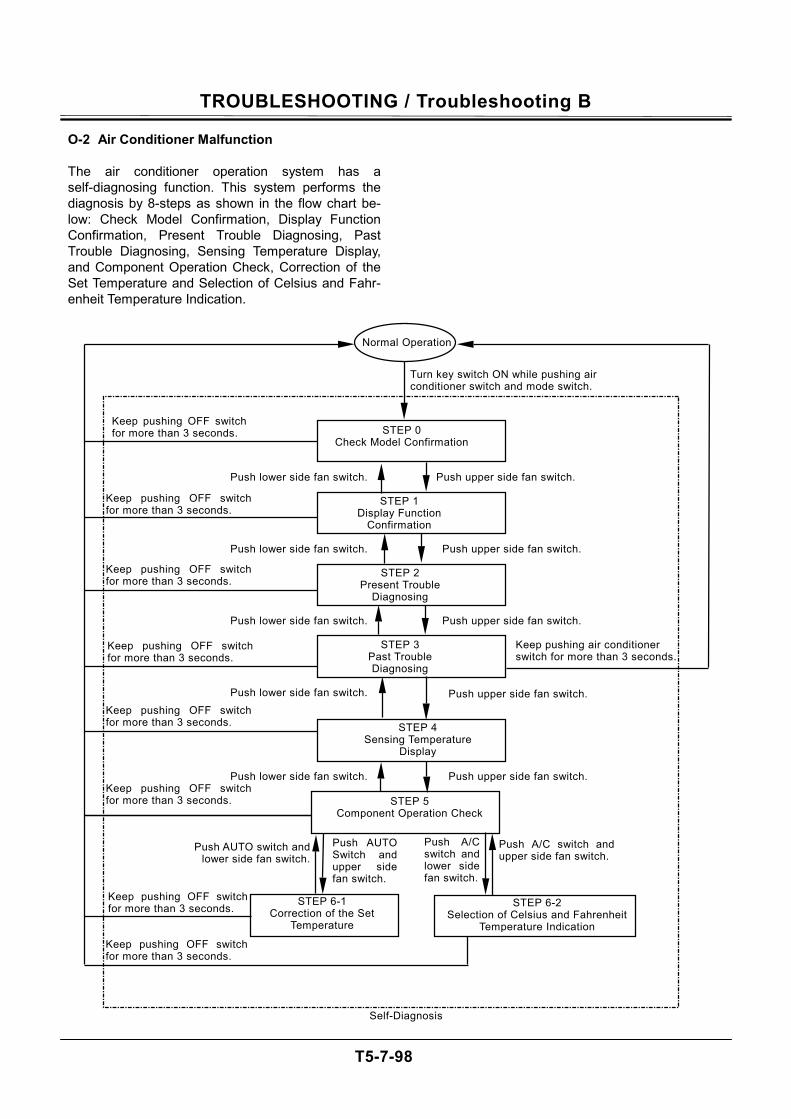
TROUBLESHOOTING / Troubleshooting B
T5-7-98
O-2 Air Conditioner Malfunction
The air conditioner operation system has a self-diagnosing function. This system performs the diagnosis by 8-steps as shown in the flow chart be-low: Check Model Confirmation, Display Function Confirmation, Present Trouble Diagnosing, Past Trouble Diagnosing, Sensing Temperature Display, and Component Operation Check, Correction of the Set Temperature and Selection of Celsius and Fahr-enheit Temperature Indication.
STEP 2 Present Trouble
Diagnosing
STEP 3 Past Trouble Diagnosing
Normal Operation
STEP 0 Check Model Confirmation
STEP 1 Display Function
Confirmation
STEP 4 Sensing Temperature
Display
STEP 5 Component Operation Check
Self-Diagnosis
Push lower side fan switch.
Turn key switch ON while pushing air conditioner switch and mode switch.
Push upper side fan switch.
Keep pushing OFF switch for more than 3 seconds.
Keep pushing OFF switch for more than 3 seconds.
Keep pushing air conditioner switch for more than 3 seconds.
Keep pushing OFF switch for more than 3 seconds.
Keep pushing OFF switch for more than 3 seconds.
Keep pushing OFF switch for more than 3 seconds.
Keep pushing OFF switch for more than 3 seconds.
Push lower side fan switch. Push upper side fan switch.
Push lower side fan switch. Push upper side fan switch.
Push lower side fan switch. Push upper side fan switch.
Push lower side fan switch. Push upper side fan switch.
STEP 6-1 Correction of the Set
Temperature
STEP 6-2 Selection of Celsius and Fahrenheit
Temperature Indication
Keep pushing OFF switch for more than 3 seconds.
Keep pushing OFF switch for more than 3 seconds.
Push AUTO switch and lower side fan switch.
Push A/C switch and upper side fan switch.
Push A/C switch and lower side fan switch.
Push AUTO Switch and upper side fan switch.
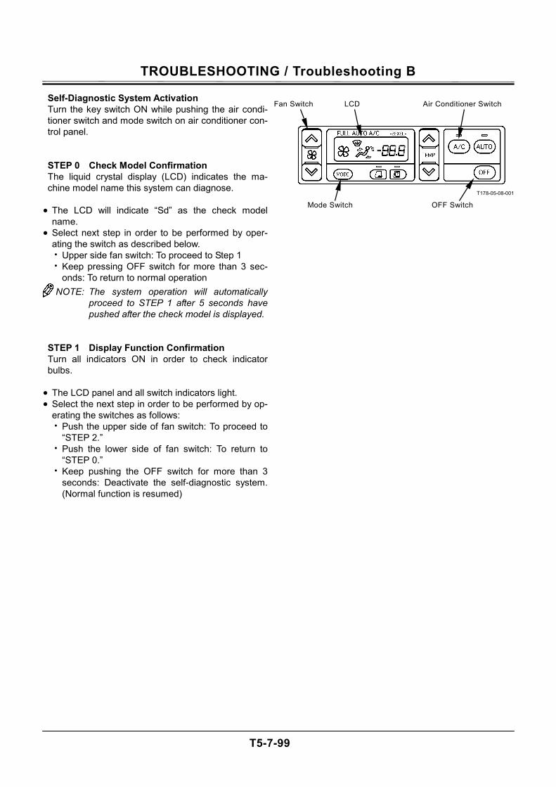
TROUBLESHOOTING / Troubleshooting B
T5-7-99
Self-Diagnostic System Activation Turn the key switch ON while pushing the air condi-tioner switch and mode switch on air conditioner con-trol panel. STEP 0 Check Model Confirmation The liquid crystal display (LCD) indicates the ma-chine model name this system can diagnose.
• The LCD will indicate “Sd” as the check model
name. • Select next step in order to be performed by oper-
ating the switch as described below. • Upper side fan switch: To proceed to Step 1 • Keep pressing OFF switch for more than 3 sec-
onds: To return to normal operation NOTE: The system operation will automatically
proceed to STEP 1 after 5 seconds have pushed after the check model is displayed.
STEP 1 Display Function Confirmation Turn all indicators ON in order to check indicator bulbs.
• The LCD panel and all switch indicators light. • Select the next step in order to be performed by op-
erating the switches as follows: • Push the upper side of fan switch: To proceed to
“STEP 2.” • Push the lower side of fan switch: To return to
“STEP 0.” • Keep pushing the OFF switch for more than 3
seconds: Deactivate the self-diagnostic system. (Normal function is resumed)
T178-05-08-001
Mode Switch
Air Conditioner SwitchLCD
OFF Switch
Fan Switch
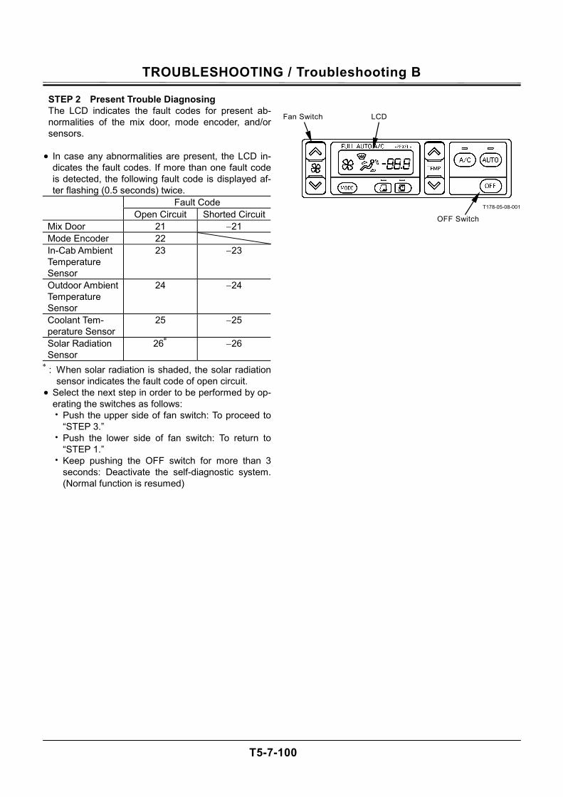
TROUBLESHOOTING / Troubleshooting B
T5-7-100
STEP 2 Present Trouble Diagnosing The LCD indicates the fault codes for present ab-normalities of the mix door, mode encoder, and/or sensors.
• In case any abnormalities are present, the LCD in-
dicates the fault codes. If more than one fault code is detected, the following fault code is displayed af-ter flashing (0.5 seconds) twice.
Fault Code Open Circuit Shorted Circuit
Mix Door 21 −21 Mode Encoder 22 In-Cab Ambient Temperature Sensor
23 −23
Outdoor Ambient Temperature Sensor
24 −24
Coolant Tem-perature Sensor
25 −25
Solar Radiation Sensor
26∗ −26 ∗ : When solar radiation is shaded, the solar radiation
sensor indicates the fault code of open circuit. • Select the next step in order to be performed by op-
erating the switches as follows: • Push the upper side of fan switch: To proceed to
“STEP 3.” • Push the lower side of fan switch: To return to
“STEP 1.” • Keep pushing the OFF switch for more than 3
seconds: Deactivate the self-diagnostic system. (Normal function is resumed)
T178-05-08-001
LCD
OFF Switch
Fan Switch
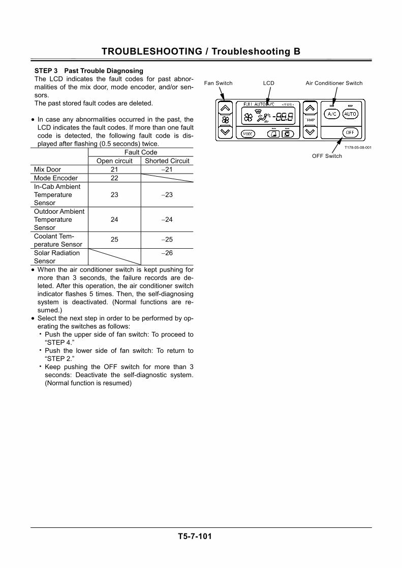
TROUBLESHOOTING / Troubleshooting B
T5-7-101
STEP 3 Past Trouble Diagnosing The LCD indicates the fault codes for past abnor-malities of the mix door, mode encoder, and/or sen-sors. The past stored fault codes are deleted.
• In case any abnormalities occurred in the past, the
LCD indicates the fault codes. If more than one fault code is detected, the following fault code is dis-played after flashing (0.5 seconds) twice.
Fault Code Open circuit Shorted Circuit
Mix Door 21 −21 Mode Encoder 22 In-Cab Ambient Temperature Sensor
23
−23
Outdoor Ambient Temperature Sensor
24
−24
Coolant Tem-perature Sensor
25 −25
Solar Radiation Sensor
−26
• When the air conditioner switch is kept pushing for more than 3 seconds, the failure records are de-leted. After this operation, the air conditioner switch indicator flashes 5 times. Then, the self-diagnosing system is deactivated. (Normal functions are re-sumed.)
• Select the next step in order to be performed by op-erating the switches as follows: • Push the upper side of fan switch: To proceed to
“STEP 4.” • Push the lower side of fan switch: To return to
“STEP 2.” • Keep pushing the OFF switch for more than 3
seconds: Deactivate the self-diagnostic system. (Normal function is resumed)
T178-05-08-001
LCD
OFF Switch
Fan Switch Air Conditioner Switch
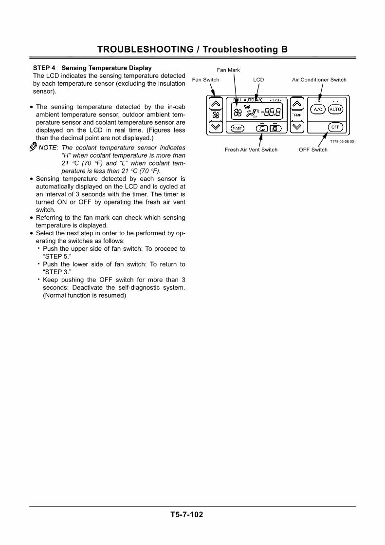
TROUBLESHOOTING / Troubleshooting B
T5-7-102
STEP 4 Sensing Temperature Display The LCD indicates the sensing temperature detected by each temperature sensor (excluding the insulation sensor).
• The sensing temperature detected by the in-cab
ambient temperature sensor, outdoor ambient tem-perature sensor and coolant temperature sensor are displayed on the LCD in real time. (Figures less than the decimal point are not displayed.) NOTE: The coolant temperature sensor indicates
“H” when coolant temperature is more than 21 °C (70 °F) and “L” when coolant tem-perature is less than 21 °C (70 °F).
• Sensing temperature detected by each sensor is automatically displayed on the LCD and is cycled at an interval of 3 seconds with the timer. The timer is turned ON or OFF by operating the fresh air vent switch.
• Referring to the fan mark can check which sensing temperature is displayed.
• Select the next step in order to be performed by op-erating the switches as follows: • Push the upper side of fan switch: To proceed to
“STEP 5.” • Push the lower side of fan switch: To return to
“STEP 3.” • Keep pushing the OFF switch for more than 3
seconds: Deactivate the self-diagnostic system. (Normal function is resumed)
T178-05-08-001
LCD
OFF Switch
Fan Switch Air Conditioner Switch
Fresh Air Vent Switch
Fan Mark
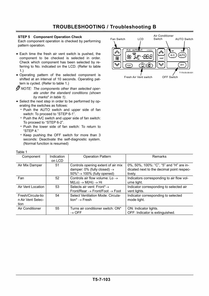
TROUBLESHOOTING / Troubleshooting B
T5-7-103
STEP 5 Component Operation Check Each component operation is checked by performing pattern operation.
• Each time the fresh air vent switch is pushed, the
component to be checked is selected in order. Check which component has been selected by re-ferring to No. indicated on the LCD. (Refer to table 1.)
• Operating pattern of the selected component is shifted at an interval of 10 seconds. Operating pat-tern is cycled. (Refer to table 1.) NOTE: The components other than selected oper-
ate under the standard conditions (shown by marks* in table 1).
• Select the next step in order to be performed by op-erating the switches as follows: • Push the AUTO switch and upper side of fan
switch: To proceed to “STEP 6-1”. • Push the A/C switch and upper side of fan switch:
To proceed to “STEP 6-2”. • Push the lower side of fan switch: To return to
“STEP 4.” • Keep pushing the OFF switch for more than 3
seconds: Deactivate the self-diagnostic system. (Normal function is resumed)
T178-05-08-001
Table 1 Component Indication
on LCD Operation Pattern Remarks
Air Mix Damper 51 Controls opening extent of air mix damper: 0% (fully closed) → 50%*→ 100% (fully opened)
0%, 50%, 100%: “C”, “5” and “H” are in-dicated next to the decimal point respec-tively.
Fan 52 Controls air flow volume: Lo → M(Lo) → M(Hi) → Hi
Indicators corresponding to air flow vol-ume light.
Air Vent Location 53 Selects air vent: Front*→ Front/Rear → Front/Foot → Foot
Indicator corresponding to selected air vent lights.
Fresh/Circula-tion Air Vent Selec-tion
54 Select Ventilation Mode: Circula-tion* → Fresh
Indicator corresponding to selected mode light.
Air Conditioner 55 Turns air conditioner switch: ON* → OFF
ON: Indicator lights. OFF: Indicator is extinguished.
LCD
OFF Switch
Fan Switch
Fresh Air Vent switch
Air Conditioner Switch AUTO Switch
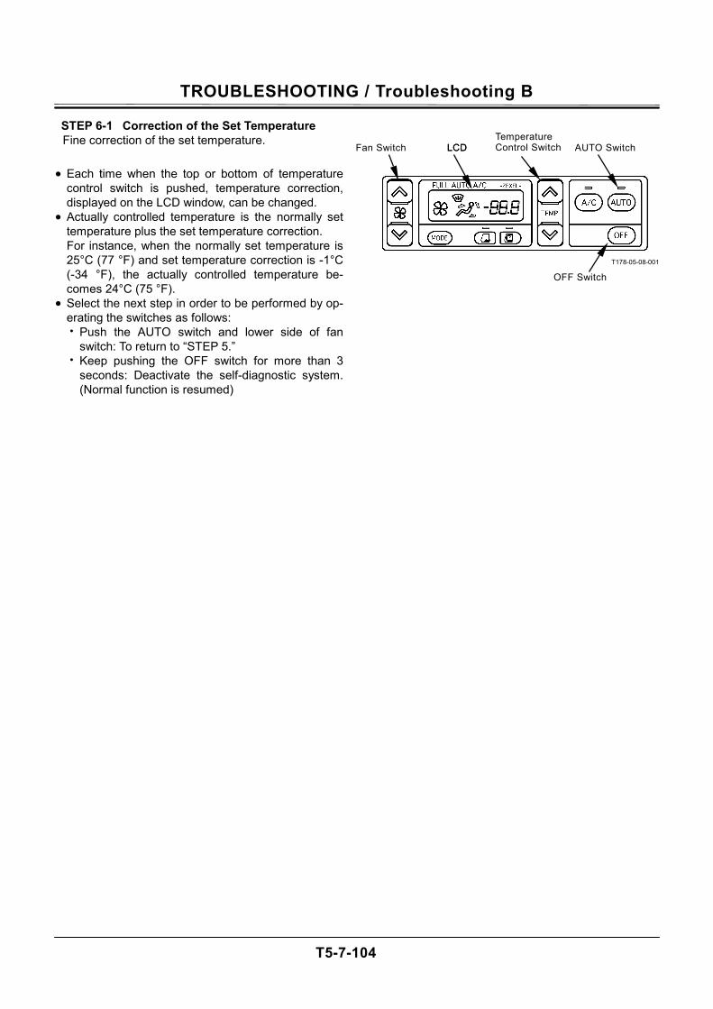
TROUBLESHOOTING / Troubleshooting B
T5-7-104
STEP 6-1 Correction of the Set Temperature Fine correction of the set temperature.
• Each time when the top or bottom of temperature control switch is pushed, temperature correction, displayed on the LCD window, can be changed.
• Actually controlled temperature is the normally set temperature plus the set temperature correction. For instance, when the normally set temperature is 25°C (77 °F) and set temperature correction is -1°C (-34 °F), the actually controlled temperature be-comes 24°C (75 °F).
• Select the next step in order to be performed by op-erating the switches as follows: • Push the AUTO switch and lower side of fan
switch: To return to “STEP 5.” • Keep pushing the OFF switch for more than 3
seconds: Deactivate the self-diagnostic system. (Normal function is resumed)
T178-05-08-001
LCD
OFF Switch
Fan Switch AUTO Switch LCD Temperature Control Switch
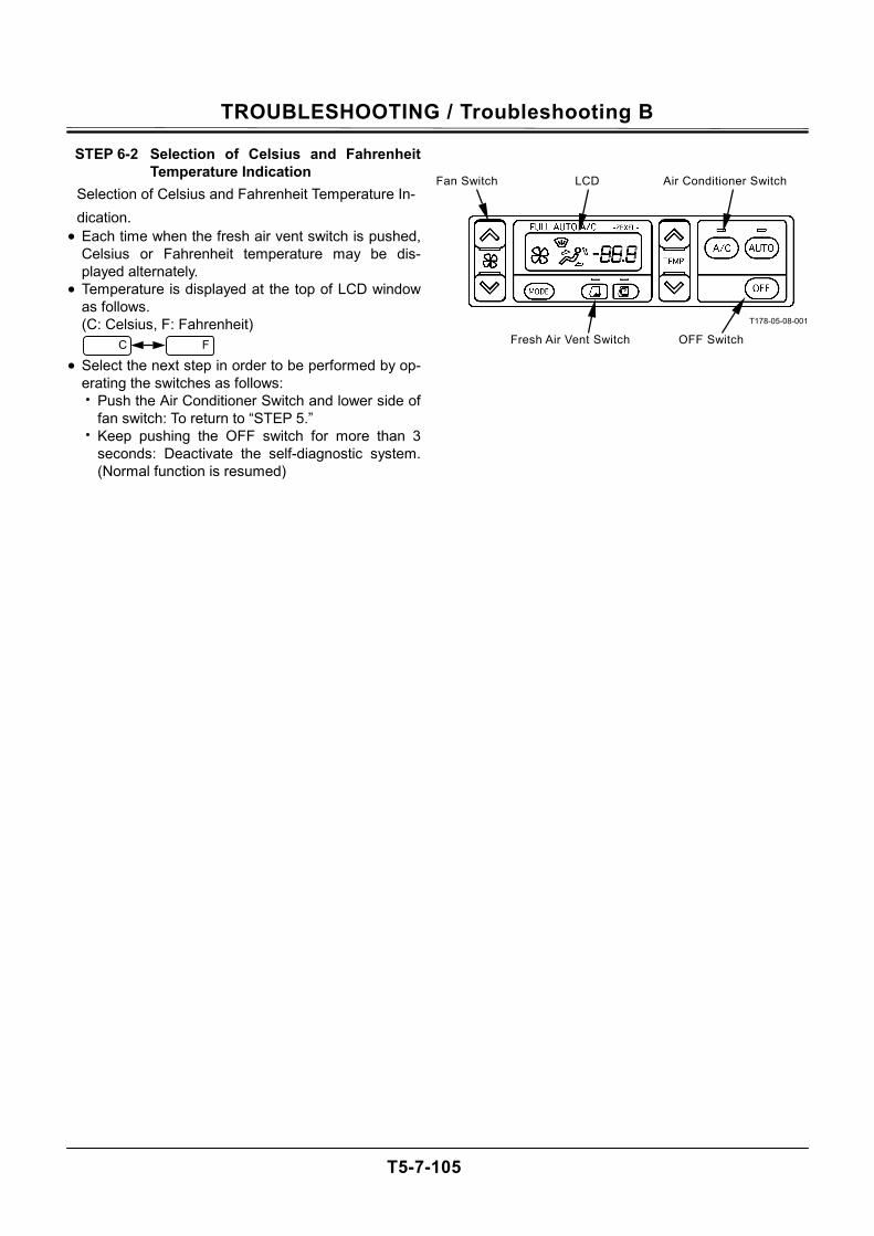
TROUBLESHOOTING / Troubleshooting B
T5-7-105
STEP 6-2 Selection of Celsius and Fahrenheit Temperature Indication
Selection of Celsius and Fahrenheit Temperature In-dication.
• Each time when the fresh air vent switch is pushed, Celsius or Fahrenheit temperature may be dis-played alternately.
• Temperature is displayed at the top of LCD window as follows. (C: Celsius, F: Fahrenheit)
• Select the next step in order to be performed by op-
erating the switches as follows: • Push the Air Conditioner Switch and lower side of
fan switch: To return to “STEP 5.” • Keep pushing the OFF switch for more than 3
seconds: Deactivate the self-diagnostic system. (Normal function is resumed)
T178-05-08-001
LCD
OFF Switch
Fan Switch Air Conditioner Switch
Fresh Air Vent Switch C F
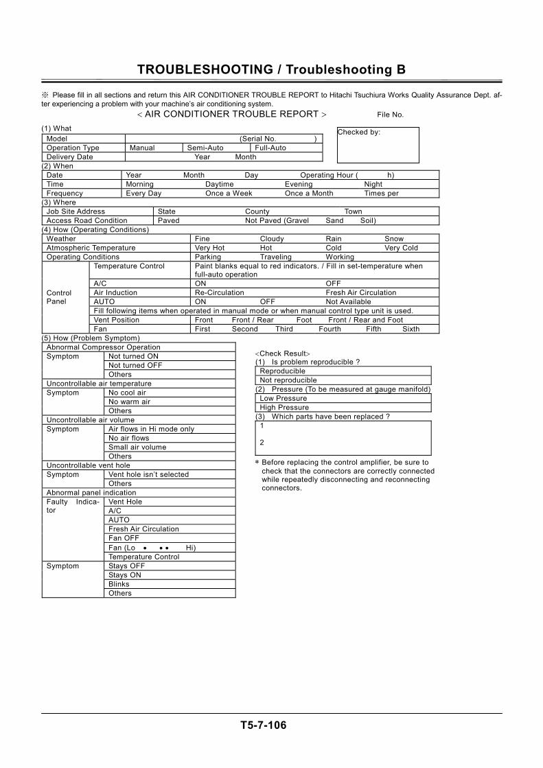
TROUBLESHOOTING / Troubleshooting B
T5-7-106
※ Please fill in all sections and return this AIR CONDITIONER TROUBLE REPORT to Hitachi Tsuchiura Works Quality Assurance Dept. af-ter experiencing a problem with your machine’s air conditioning system.
< AIR CONDITIONER TROUBLE REPORT > File No.
(1) What Model (Serial No. )Operation Type Manual Semi-Auto Full-Auto Delivery Date Year Month
(2) When Date Year Month Day Operating Hour ( h) Time Morning Daytime Evening Night Frequency Every Day Once a Week Once a Month Times per
(3) Where Job Site Address State County Town Access Road Condition Paved Not Paved (Gravel Sand Soil)
(4) How (Operating Conditions) Weather Fine Cloudy Rain Snow Atmospheric Temperature Very Hot Hot Cold Very Cold Operating Conditions Parking Traveling Working
Temperature Control Paint blanks equal to red indicators. / Fill in set-temperature when full-auto operation
A/C ON OFF Air Induction Re-Circulation Fresh Air Circulation AUTO ON OFF Not Available Fill following items when operated in manual mode or when manual control type unit is used. Vent Position Front Front / Rear Foot Front / Rear and Foot
Control Panel
Fan First Second Third Fourth Fifth Sixth (5) How (Problem Symptom)
Abnormal Compressor Operation Not turned ON Not turned OFF
Symptom
Others Uncontrollable air temperature
No cool air No warm air
Symptom
Others Uncontrollable air volume
Air flows in Hi mode only No air flows Small air volume
Symptom
Others Uncontrollable vent hole
Vent hole isn’t selected Symptom Others
Abnormal panel indication Vent Hole A/C AUTO Fresh Air Circulation Fan OFF Fan (Lo • • • Hi)
Faulty Indica-tor
Temperature Control Stays OFF Stays ON Blinks
Symptom
Others
Checked by:
<Check Result> (1) Is problem reproducible ?
Reproducible Not reproducible
(2) Pressure (To be measured at gauge manifold) Low Pressure High Pressure
(3) Which parts have been replaced ? 1 2
∗ Before replacing the control amplifier, be sure to check that the connectors are correctly connected while repeatedly disconnecting and reconnecting connectors.

TROUBLESHOOTING / Troubleshooting B
T5-7-107
Refrigerant Quantity....................... 850±50 g Compressor Oil Quantity................ 210 cm3
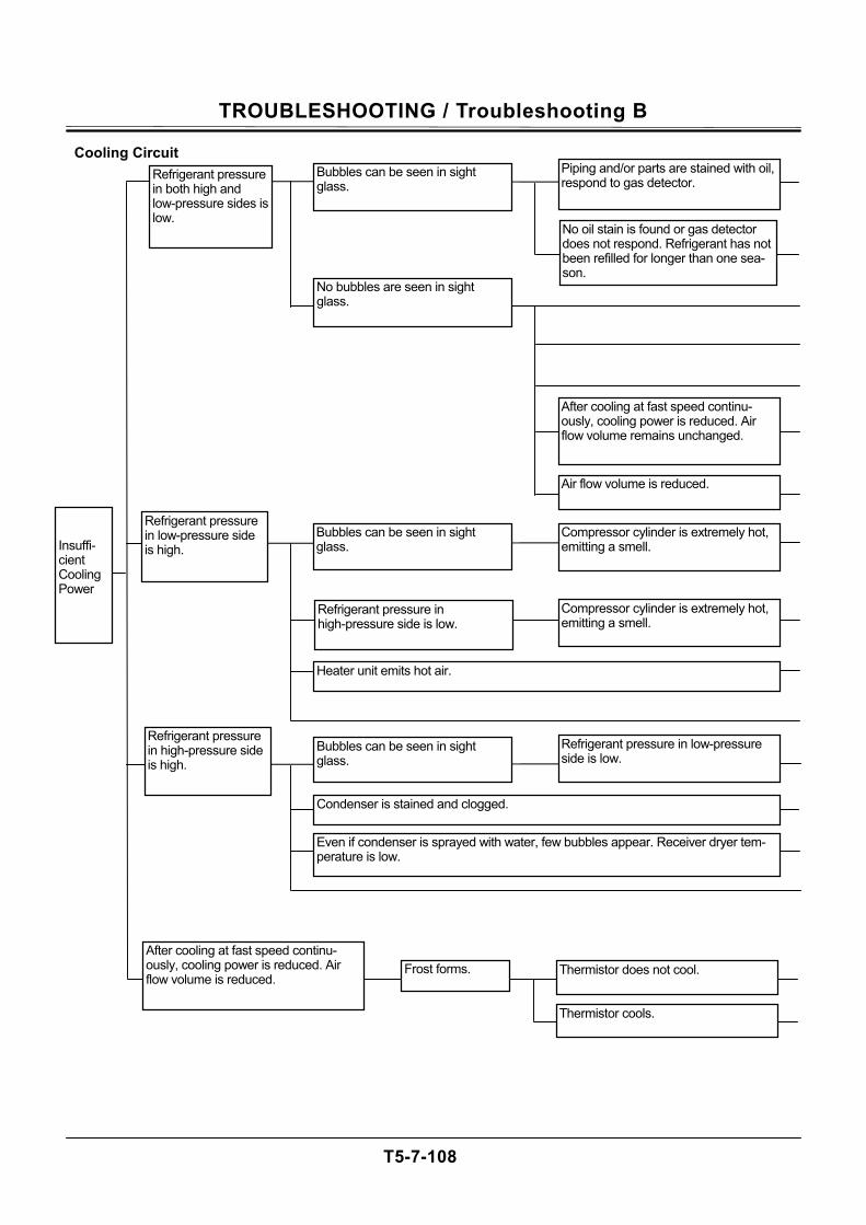
TROUBLESHOOTING / Troubleshooting B
T5-7-108
Cooling Circuit
Insuffi-cient Cooling Power
Refrigerant pressure in both high and low-pressure sides is low.
Bubbles can be seen in sight glass.
Piping and/or parts are stained with oil, respond to gas detector.
No oil stain is found or gas detector does not respond. Refrigerant has not been refilled for longer than one sea-son.
No bubbles are seen in sight glass.
After cooling at fast speed continu-ously, cooling power is reduced. Air flow volume remains unchanged.
Air flow volume is reduced.
Refrigerant pressure in low-pressure side is high.
Bubbles can be seen in sight glass.
Refrigerant pressure in high-pressure side is low.
Compressor cylinder is extremely hot, emitting a smell.
Compressor cylinder is extremely hot, emitting a smell.
Heater unit emits hot air.
Refrigerant pressure in high-pressure side is high.
Bubbles can be seen in sight glass.
Refrigerant pressure in low-pressure side is low.
Condenser is stained and clogged.
Even if condenser is sprayed with water, few bubbles appear. Receiver dryer tem-perature is low.
Thermistor does not cool.
Thermistor cools.
Frost forms. After cooling at fast speed continu-ously, cooling power is reduced. Air flow volume is reduced.
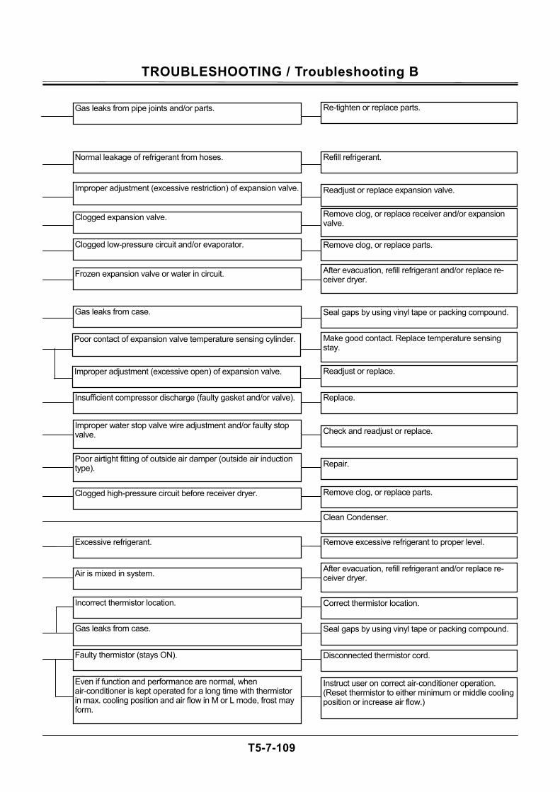
TROUBLESHOOTING / Troubleshooting B
T5-7-109
Gas leaks from pipe joints and/or parts. Re-tighten or replace parts.
Normal leakage of refrigerant from hoses. Refill refrigerant.
Readjust or replace expansion valve.
Clogged expansion valve.
Clogged low-pressure circuit and/or evaporator. Remove clog, or replace parts.
Frozen expansion valve or water in circuit.
Gas leaks from case.
Remove clog, or replace receiver and/or expansion valve.
After evacuation, refill refrigerant and/or replace re-ceiver dryer.
Seal gaps by using vinyl tape or packing compound.
Poor contact of expansion valve temperature sensing cylinder. Make good contact. Replace temperature sensing stay.
Readjust or replace.
Insufficient compressor discharge (faulty gasket and/or valve). Replace.
Improper water stop valve wire adjustment and/or faulty stop valve. Check and readjust or replace.
Poor airtight fitting of outside air damper (outside air induction type). Repair.
Clogged high-pressure circuit before receiver dryer. Remove clog, or replace parts.
Clean Condenser.
Excessive refrigerant. Remove excessive refrigerant to proper level.
Air is mixed in system. After evacuation, refill refrigerant and/or replace re-ceiver dryer.
Incorrect thermistor location. Correct thermistor location.
Gas leaks from case. Seal gaps by using vinyl tape or packing compound.
Faulty thermistor (stays ON). Disconnected thermistor cord.
Even if function and performance are normal, when air-conditioner is kept operated for a long time with thermistor in max. cooling position and air flow in M or L mode, frost may form.
Instruct user on correct air-conditioner operation. (Reset thermistor to either minimum or middle cooling position or increase air flow.)
Improper adjustment (excessive open) of expansion valve.
Improper adjustment (excessive restriction) of expansion valve.
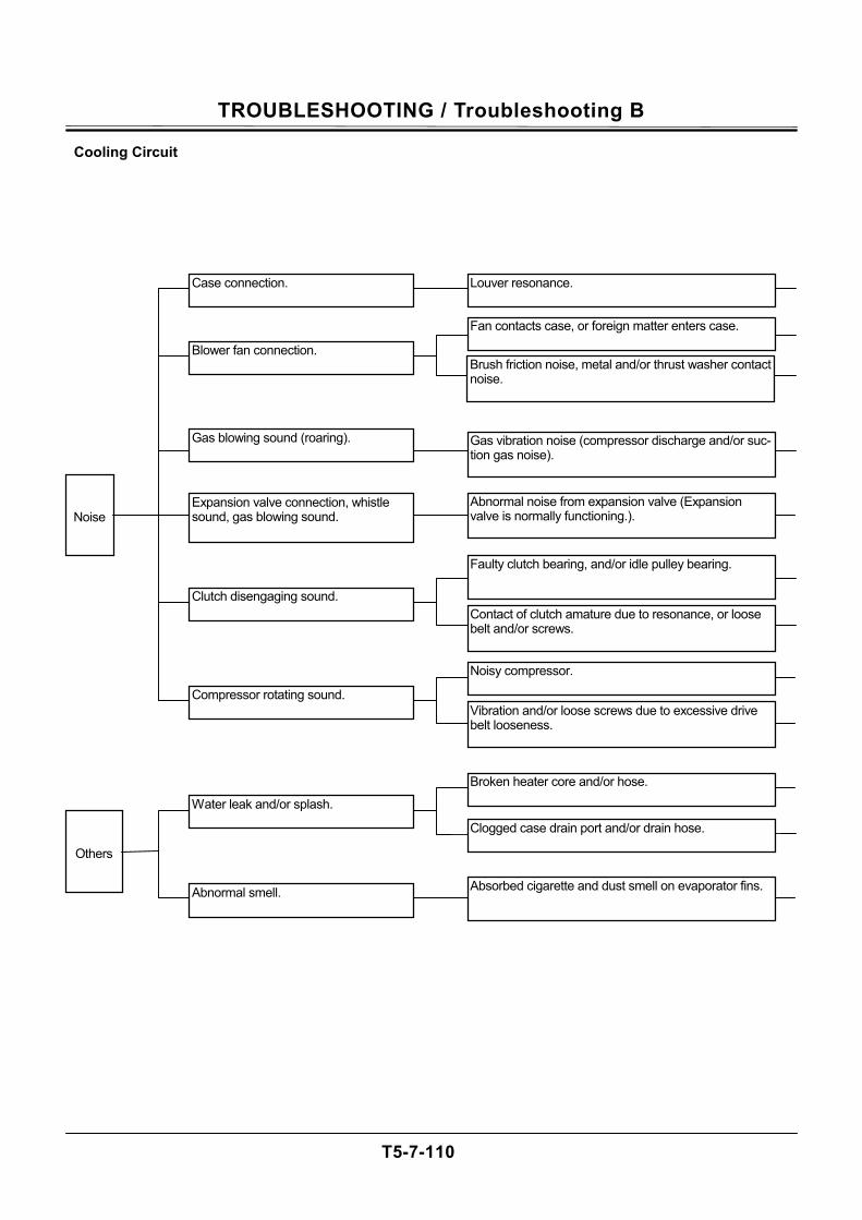
TROUBLESHOOTING / Troubleshooting B
T5-7-110
Cooling Circuit
Noise Expansion valve connection, whistle sound, gas blowing sound.
Gas blowing sound (roaring).
Clutch disengaging sound.
Compressor rotating sound.
Others
Louver resonance.
Fan contacts case, or foreign matter enters case.
Brush friction noise, metal and/or thrust washer contact noise.
Gas vibration noise (compressor discharge and/or suc-tion gas noise).
Abnormal noise from expansion valve (Expansion valve is normally functioning.).
Faulty clutch bearing, and/or idle pulley bearing.
Contact of clutch amature due to resonance, or loose belt and/or screws.
Noisy compressor.
Vibration and/or loose screws due to excessive drive belt looseness.
Broken heater core and/or hose.
Clogged case drain port and/or drain hose.
Absorbed cigarette and dust smell on evaporator fins.
Case connection.
Blower fan connection.
Water leak and/or splash.
Abnormal smell.
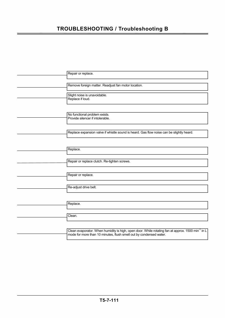
TROUBLESHOOTING / Troubleshooting B
T5-7-111
Repair or replace.
Remove foreign matter. Readjust fan motor location.
Slight noise is unavoidable. Replace if loud.
No functional problem exists. Provide silencer if intolerable.
Replace expansion valve if whistle sound is heard. Gas flow noise can be slightly heard.
Replace.
Repair or replace clutch. Re-tighten screws.
Repair or replace.
Re-adjust drive belt.
Replace.
Clean.
Clean evaporator. When humidity is high, open door. While rotating fan at approx. 1500 min-1 in L mode for more than 10 minutes, flush smell out by condensed water.
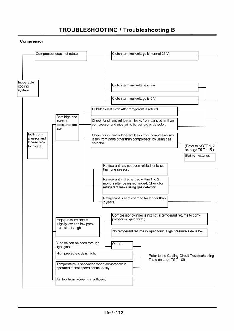
TROUBLESHOOTING / Troubleshooting B
T5-7-112
Compressor
Inoperable cooling system.
Clutch terminal voltage is low.
Both com-pressor and blower mo-tor rotate.
Stain on exterior.
Bubbles can be seen through sight glass.
Compressor cylinder is not hot. (Refrigerant returns to com-pressor in liquid form.)
No refrigerant returns in liquid form. High pressure side is low.
Refer to the Cooling Circuit Troubleshooting Table on page T5-7-106.
High pressure side is slightly low and low pres-sure side is high.
Both high and low side pressures are low.
Compressor does not rotate. Clutch terminal voltage is normal 24 V.
Clutch terminal voltage is 0 V.
Bubbles exist even after refrigerant is refilled.
Check for oil and refrigerant leaks from parts other than compressor and pipe joints by using gas detector.
Check for oil and refrigerant leaks from compressor (no leaks from parts other than compressor) by using gas detector.
Refrigerant is discharged within 1 to 2 months after being recharged. Check for refrigerant leaks using gas detector.
Refrigerant is kept charged for longer than 2 years.
Refrigerant has not been refilled for longer than one season.
Air flow from blower is insufficient.
Others
Temperature is not cooled when compressor is operated at fast speed continuously.
High pressure side is high.
(Refer to NOTE 1, 2 on page T5-7-115.)
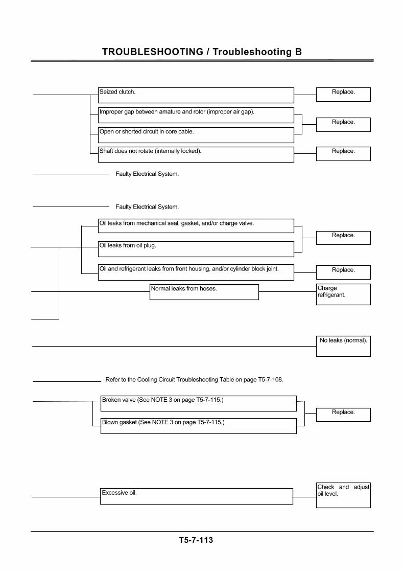
TROUBLESHOOTING / Troubleshooting B
T5-7-113
Faulty Electrical System.
Replace.
Seized clutch.
Improper gap between amature and rotor (improper air gap).
Open or shorted circuit in core cable.
Shaft does not rotate (internally locked).
Replace.
Replace.
Faulty Electrical System.
Oil leaks from oil plug.
Oil leaks from mechanical seal, gasket, and/or charge valve.
Oil and refrigerant leaks from front housing, and/or cylinder block joint.
Replace.
Replace.
Normal leaks from hoses. Charge refrigerant.
Refer to the Cooling Circuit Troubleshooting Table on page T5-7-108.
Blown gasket (See NOTE 3 on page T5-7-115.)
Broken valve (See NOTE 3 on page T5-7-115.)
Replace.
No leaks (normal).
Excessive oil. Check and adjust oil level.
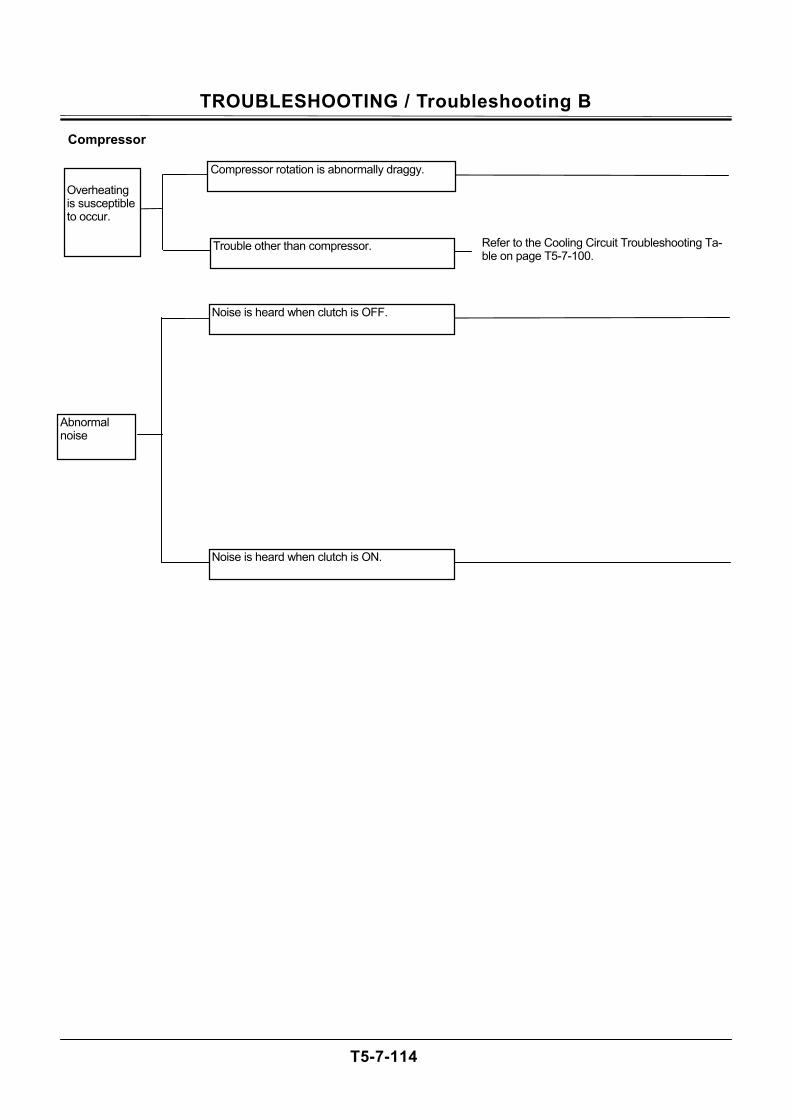
TROUBLESHOOTING / Troubleshooting B
T5-7-114
Compressor
Abnormal noise
Noise is heard when clutch is OFF.
Noise is heard when clutch is ON.
Refer to the Cooling Circuit Troubleshooting Ta-ble on page T5-7-100.
Compressor rotation is abnormally draggy. Overheating is susceptible to occur.
Trouble other than compressor.
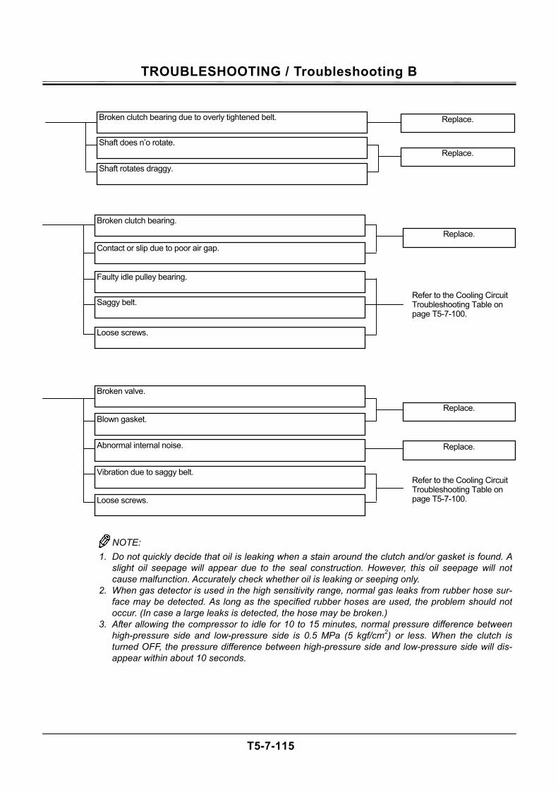
TROUBLESHOOTING / Troubleshooting B
T5-7-115
Replace. Broken clutch bearing.
Contact or slip due to poor air gap.
Faulty idle pulley bearing.
Saggy belt.
Refer to the Cooling Circuit Troubleshooting Table on page T5-7-100.
Refer to the Cooling Circuit Troubleshooting Table on page T5-7-100.
Loose screws.
Replace.
Broken valve.
Blown gasket.
Abnormal internal noise.
Vibration due to saggy belt.
Loose screws.
Replace.
NOTE: 1. Do not quickly decide that oil is leaking when a stain around the clutch and/or gasket is found. A
slight oil seepage will appear due to the seal construction. However, this oil seepage will notcause malfunction. Accurately check whether oil is leaking or seeping only.
2. When gas detector is used in the high sensitivity range, normal gas leaks from rubber hose sur-face may be detected. As long as the specified rubber hoses are used, the problem should notoccur. (In case a large leaks is detected, the hose may be broken.)
3. After allowing the compressor to idle for 10 to 15 minutes, normal pressure difference betweenhigh-pressure side and low-pressure side is 0.5 MPa (5 kgf/cm2) or less. When the clutch isturned OFF, the pressure difference between high-pressure side and low-pressure side will dis-appear within about 10 seconds.
Broken clutch bearing due to overly tightened belt.
Replace.
Replace.
Shaft does n’o rotate.
Shaft rotates draggy.
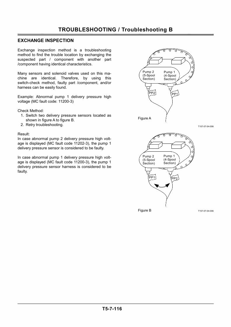
TROUBLESHOOTING / Troubleshooting B
T5-7-116
EXCHANGE INSPECTION Exchange inspection method is a troubleshooting method to find the trouble location by exchanging the suspected part / component with another part /component having identical characteristics. Many sensors and solenoid valves used on this ma-chine are identical. Therefore, by using this switch-check method, faulty part /component, and/or harness can be easily found. Example: Abnormal pump 1 delivery pressure high voltage (MC fault code: 11200-3) Check Method:
1. Switch two delivery pressure sensors located as shown in figure A to figure B.
2. Retry troubleshooting. Result: In case abnormal pump 2 delivery pressure high volt-age is displayed (MC fault code 11202-3), the pump 1 delivery pressure sensor is considered to be faulty. In case abnormal pump 1 delivery pressure high volt-age is displayed (MC fault code 11200-3), the pump 1 delivery pressure sensor harness is considered to be faulty.
T157-07-04-006
T157-07-04-006
Figure B
Figure A
PP1 PP2
Pump 2 (5-Spool Section)
Pump 1 (4-Spool Section)
PP2 PP1
Pump 2 (5-Spool Section)
Pump 1 (4-Spool Section)
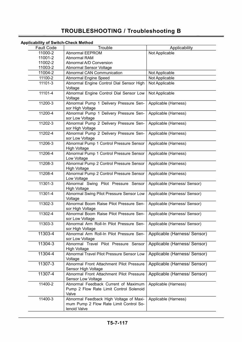
TROUBLESHOOTING / Troubleshooting B
T5-7-117
Applicability of Switch-Check Method Fault Code Trouble Applicability
11000-2 11001-2 11002-2 11003-2
Abnormal EEPROM Abnormal RAM Abnormal A/D Conversion Abnormal Sensor Voltage
Not Applicable
11004-2 Abnormal CAN Communication Not Applicable 11100-2 Abnormal Engine Speed Not Applicable 11101-3 Abnormal Engine Control Dial Sensor High
Voltage Not Applicable
11101-4 Abnormal Engine Control Dial Sensor Low Voltage
Not Applicable
11200-3 Abnormal Pump 1 Delivery Pressure Sen-sor High Voltage
Applicable (Harness)
11200-4 Abnormal Pump 1 Delivery Pressure Sen-sor Low Voltage
Applicable (Harness)
11202-3 Abnormal Pump 2 Delivery Pressure Sen-sor High Voltage
Applicable (Harness)
11202-4 Abnormal Pump 2 Delivery Pressure Sen-sor Low Voltage
Applicable (Harness)
11206-3 Abnormal Pump 1 Control Pressure Sensor High Voltage
Applicable (Harness)
11206-4 Abnormal Pump 1 Control Pressure Sensor Low Voltage
Applicable (Harness)
11208-3 Abnormal Pump 2 Control Pressure Sensor High Voltage
Applicable (Harness)
11208-4 Abnormal Pump 2 Control Pressure Sensor Low Voltage
Applicable (Harness)
11301-3 Abnormal Swing Pilot Pressure Sensor High Voltage
Applicable (Harness/ Sensor)
11301-4 Abnormal Swing Pilot Pressure Sensor Low Voltage
Applicable (Harness/ Sensor)
11302-3 Abnormal Boom Raise Pilot Pressure Sen-sor High Voltage
Applicable (Harness/ Sensor)
11302-4 Abnormal Boom Raise Pilot Pressure Sen-sor Low Voltage
Applicable (Harness/ Sensor)
11303-3 Abnormal Arm Roll-In Pilot Pressure Sen-sor High Voltage
Applicable (Harness/ Sensor)
11303-4 Abnormal Arm Roll-In Pilot Pressure Sen-sor Low Voltage
Applicable (Harness/ Sensor)
11304-3 Abnormal Travel Pilot Pressure Sensor High Voltage
Applicable (Harness/ Sensor)
11304-4 Abnormal Travel Pilot Pressure Sensor Low Voltage
Applicable (Harness/ Sensor)
11307-3 Abnormal Front Attachment Pilot Pressure Sensor High Voltage
Applicable (Harness/ Sensor)
11307-4 Abnormal Front Attachment Pilot Pressure Sensor Low Voltage
Applicable (Harness/ Sensor)
11400-2 Abnormal Feedback Current of Maximum Pump 2 Flow Rate Limit Control Solenoid Valve
Applicable (Harness)
11400-3 Abnormal Feedback High Voltage of Maxi-mum Pump 2 Flow Rate Limit Control So-lenoid Valve
Applicable (Harness)
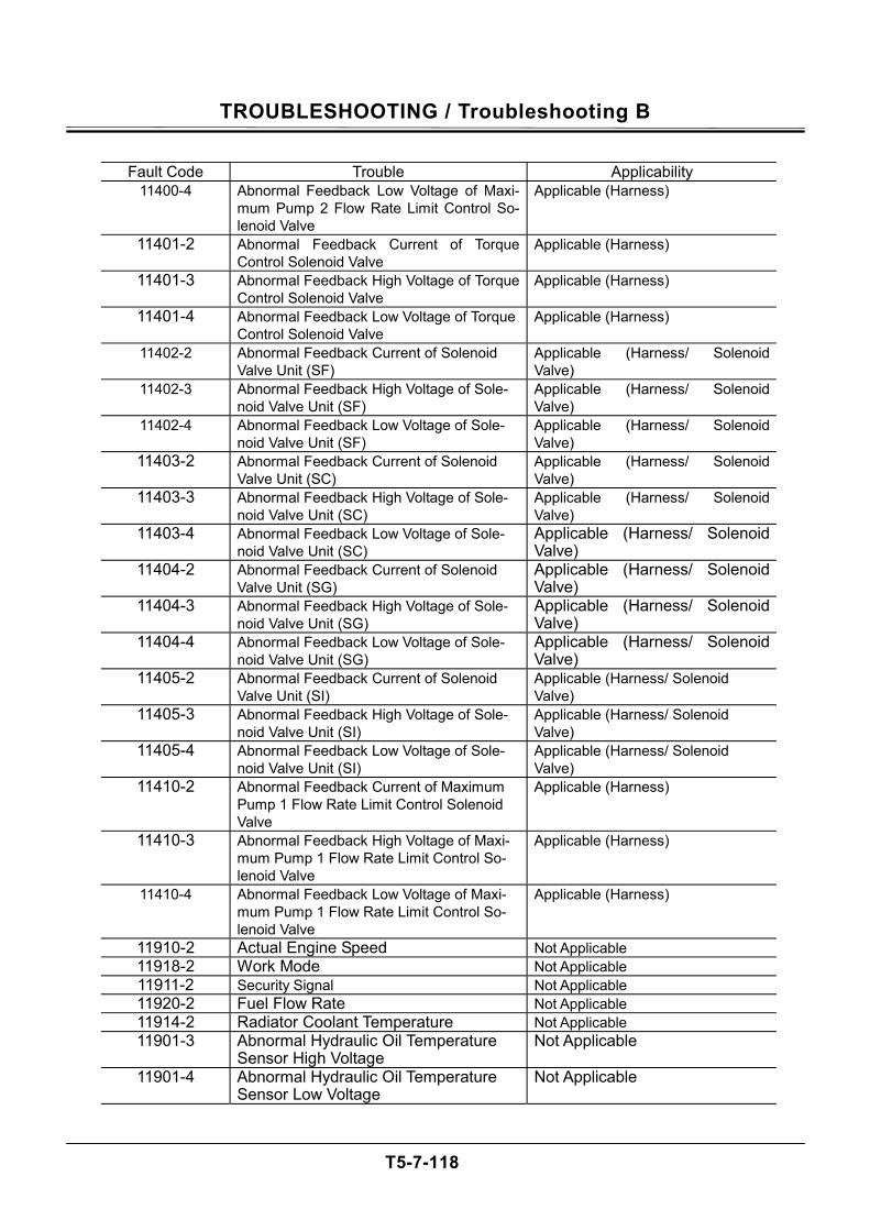
TROUBLESHOOTING / Troubleshooting B
T5-7-118
Fault Code Trouble Applicability
11400-4 Abnormal Feedback Low Voltage of Maxi-mum Pump 2 Flow Rate Limit Control So-lenoid Valve
Applicable (Harness)
11401-2 Abnormal Feedback Current of Torque Control Solenoid Valve
Applicable (Harness)
11401-3 Abnormal Feedback High Voltage of Torque Control Solenoid Valve
Applicable (Harness)
11401-4 Abnormal Feedback Low Voltage of Torque Control Solenoid Valve
Applicable (Harness)
11402-2 Abnormal Feedback Current of Solenoid Valve Unit (SF)
Applicable (Harness/ Solenoid Valve)
11402-3 Abnormal Feedback High Voltage of Sole-noid Valve Unit (SF)
Applicable (Harness/ Solenoid Valve)
11402-4 Abnormal Feedback Low Voltage of Sole-noid Valve Unit (SF)
Applicable (Harness/ Solenoid Valve)
11403-2 Abnormal Feedback Current of Solenoid Valve Unit (SC)
Applicable (Harness/ Solenoid Valve)
11403-3 Abnormal Feedback High Voltage of Sole-noid Valve Unit (SC)
Applicable (Harness/ Solenoid Valve)
11403-4 Abnormal Feedback Low Voltage of Sole-noid Valve Unit (SC)
Applicable (Harness/ Solenoid Valve)
11404-2 Abnormal Feedback Current of Solenoid Valve Unit (SG)
Applicable (Harness/ Solenoid Valve)
11404-3 Abnormal Feedback High Voltage of Sole-noid Valve Unit (SG)
Applicable (Harness/ Solenoid Valve)
11404-4 Abnormal Feedback Low Voltage of Sole-noid Valve Unit (SG)
Applicable (Harness/ Solenoid Valve)
11405-2 Abnormal Feedback Current of Solenoid Valve Unit (SI)
Applicable (Harness/ Solenoid Valve)
11405-3 Abnormal Feedback High Voltage of Sole-noid Valve Unit (SI)
Applicable (Harness/ Solenoid Valve)
11405-4 Abnormal Feedback Low Voltage of Sole-noid Valve Unit (SI)
Applicable (Harness/ Solenoid Valve)
11410-2 Abnormal Feedback Current of Maximum Pump 1 Flow Rate Limit Control Solenoid Valve
Applicable (Harness)
11410-3 Abnormal Feedback High Voltage of Maxi-mum Pump 1 Flow Rate Limit Control So-lenoid Valve
Applicable (Harness)
11410-4 Abnormal Feedback Low Voltage of Maxi-mum Pump 1 Flow Rate Limit Control So-lenoid Valve
Applicable (Harness)
11910-2 Actual Engine Speed Not Applicable 11918-2 Work Mode Not Applicable 11911-2 Security Signal Not Applicable 11920-2 Fuel Flow Rate Not Applicable 11914-2 Radiator Coolant Temperature Not Applicable 11901-3 Abnormal Hydraulic Oil Temperature
Sensor High Voltage Not Applicable
11901-4 Abnormal Hydraulic Oil Temperature Sensor Low Voltage
Not Applicable
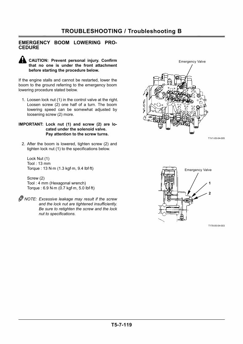
TROUBLESHOOTING / Troubleshooting B
T5-7-119
EMERGENCY BOOM LOWERING PRO-CEDURE
CAUTION: Prevent personal injury. Confirm that no one is under the front attachment before starting the procedure below.
If the engine stalls and cannot be restarted, lower the boom to the ground referring to the emergency boom lowering procedure stated below.
1. Loosen lock nut (1) in the control valve at the right. Loosen screw (2) one half of a turn. The boom lowering speed can be somewhat adjusted by loosening screw (2) more.
IMPORTANT: Lock nut (1) and screw (2) are lo-
cated under the solenoid valve. Pay attention to the screw turns.
2. After the boom is lowered, tighten screw (2) and
tighten lock nut (1) to the specifications below. Lock Nut (1) Tool : 13 mm Torque : 13 N⋅m (1.3 kgf⋅m, 9.4 lbf⋅ft) Screw (2) Tool : 4 mm (Hexagonal wrench) Torque : 6.9 N⋅m (0.7 kgf⋅m, 5.0 lbf⋅ft) NOTE: Excessive leakage may result if the screw
and the lock nut are tightened insufficiently. Be sure to retighten the screw and the lock nut to specifications.
T1V1-05-04-005
T178-05-04-003
1
2
Emergency Valve
Emergency Valve
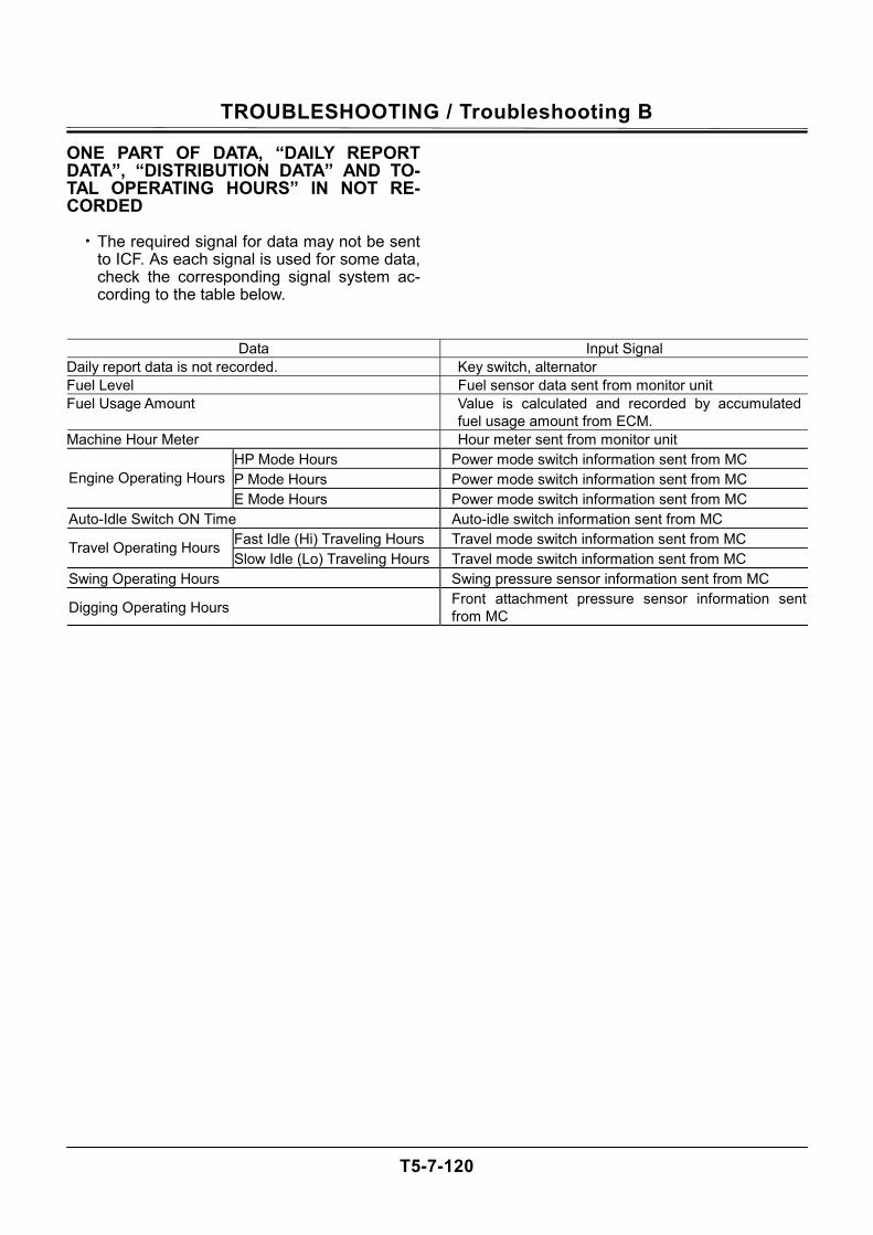
TROUBLESHOOTING / Troubleshooting B
T5-7-120
ONE PART OF DATA, “DAILY REPORT DATA”, “DISTRIBUTION DATA” AND TO-TAL OPERATING HOURS” IN NOT RE-CORDED
• The required signal for data may not be sent to ICF. As each signal is used for some data, check the corresponding signal system ac-cording to the table below.
Data Input Signal Daily report data is not recorded. Key switch, alternator Fuel Level Fuel sensor data sent from monitor unit Fuel Usage Amount Value is calculated and recorded by accumulated
fuel usage amount from ECM. Machine Hour Meter Hour meter sent from monitor unit
HP Mode Hours Power mode switch information sent from MC
P Mode Hours Power mode switch information sent from MC Engine Operating Hours E Mode Hours Power mode switch information sent from MC
Auto-Idle Switch ON Time Auto-idle switch information sent from MC
Fast Idle (Hi) Traveling Hours Travel mode switch information sent from MC Travel Operating Hours Slow Idle (Lo) Traveling Hours Travel mode switch information sent from MC
Swing Operating Hours Swing pressure sensor information sent from MC
Digging Operating Hours Front attachment pressure sensor information sent from MC
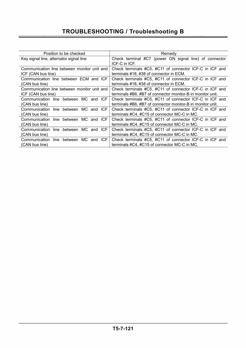
TROUBLESHOOTING / Troubleshooting B
T5-7-121
Position to be checked Remedy Key signal line, alternator signal line Check terminal #C7 (power ON signal line) of connector
ICF-C in ICF. Communication line between monitor unit and ICF (CAN bus line)
Check terminals #C5, #C11 of connector ICF-C in ICF and terminals #18, #38 of connector in ECM.
Communication line between ECM and ICF (CAN bus line)
Check terminals #C5, #C11 of connector ICF-C in ICF and terminals #18, #38 of connector in ECM.
Communication line between monitor unit and ICF (CAN bus line)
Check terminals #C5, #C11 of connector ICF-C in ICF and terminals #B6, #B7 of connector monitor-B in monitor unit.
Communication line between MC and ICF (CAN bus line)
Check terminals #C5, #C11 of connector ICF-C in ICF and terminals #B6, #B7 of connector monitor-B in monitor unit.
Communication line between MC and ICF (CAN bus line)
Check terminals #C5, #C11 of connector ICF-C in ICF and terminals #C4, #C15 of connector MC-C in MC.
Communication line between MC and ICF (CAN bus line)
Check terminals #C5, #C11 of connector ICF-C in ICF and terminals #C4, #C15 of connector MC-C in MC.
Communication line between MC and ICF (CAN bus line)
Check terminals #C5, #C11 of connector ICF-C in ICF and terminals #C4, #C15 of connector MC-C in MC.
Communication line between MC and ICF (CAN bus line)
Check terminals #C5, #C11 of connector ICF-C in ICF and terminals #C4, #C15 of connector MC-C in MC.
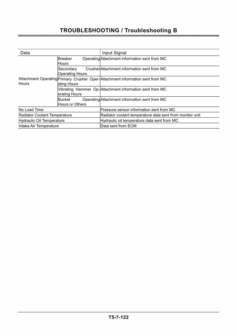
TROUBLESHOOTING / Troubleshooting B
T5-7-122
Data Input Signal Breaker Operating Hours
Attachment information sent from MC
Secondary Crusher Operating Hours
Attachment information sent from MC
Primary Crusher Oper-ating Hours
Attachment information sent from MC
Vibrating Hammer Op-erating Hours
Attachment information sent from MC
Attachment Operating Hours
Bucket Operating Hours or Others
Attachment information sent from MC
No Load Time Pressure sensor information sent from MC
Radiator Coolant Temperature Radiator coolant temperature data sent from monitor unit Hydraulic Oil Temperature Hydraulic oil temperature data sent from MC
Intake Air Temperature Data sent from ECM
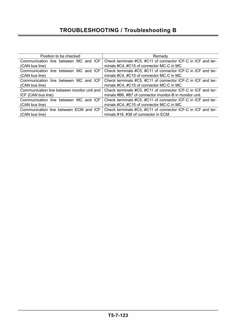
TROUBLESHOOTING / Troubleshooting B
T5-7-123
Position to be checked Remedy Communication line between MC and ICF (CAN bus line)
Check terminals #C5, #C11 of connector ICF-C in ICF and ter-minals #C4, #C15 of connector MC-C in MC.
Communication line between MC and ICF (CAN bus line)
Check terminals #C5, #C11 of connector ICF-C in ICF and ter-minals #C4, #C15 of connector MC-C in MC.
Communication line between MC and ICF (CAN bus line)
Check terminals #C5, #C11 of connector ICF-C in ICF and ter-minals #C4, #C15 of connector MC-C in MC.
Communication line between monitor unit and ICF (CAN bus line)
Check terminals #C5, #C11 of connector ICF-C in ICF and ter-minals #B6, #B7 of connector monitor-B in monitor unit.
Communication line between MC and ICF (CAN bus line)
Check terminals #C5, #C11 of connector ICF-C in ICF and ter-minals #C4, #C15 of connector MC-C in MC.
Communication line between ECM and ICF (CAN bus line)
Check terminals #C5, #C11 of connector ICF-C in ICF and ter-minals #18, #38 of connector in ECM.

TROUBLESHOOTING / Troubleshooting B
T5-7-124
(Blank)
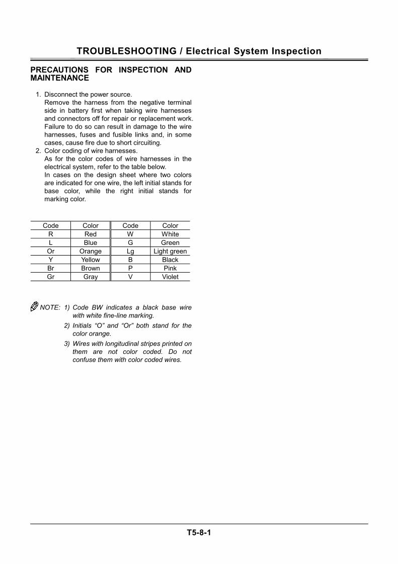
TROUBLESHOOTING / Electrical System Inspection
T5-8-1
PRECAUTIONS FOR INSPECTION AND MAINTENANCE
1. Disconnect the power source. Remove the harness from the negative terminal side in battery first when taking wire harnesses and connectors off for repair or replacement work. Failure to do so can result in damage to the wire harnesses, fuses and fusible links and, in some cases, cause fire due to short circuiting.
2. Color coding of wire harnesses. As for the color codes of wire harnesses in the electrical system, refer to the table below. In cases on the design sheet where two colors are indicated for one wire, the left initial stands for base color, while the right initial stands for marking color.
Code Color Code Color
R Red W White L Blue G Green
Or Orange Lg Light greenY Yellow B Black Br Brown P Pink Gr Gray V Violet
NOTE: 1) Code BW indicates a black base wire with white fine-line marking.
2) Initials “O” and “Or” both stand for the color orange.
3) Wires with longitudinal stripes printed on them are not color coded. Do not confuse them with color coded wires.
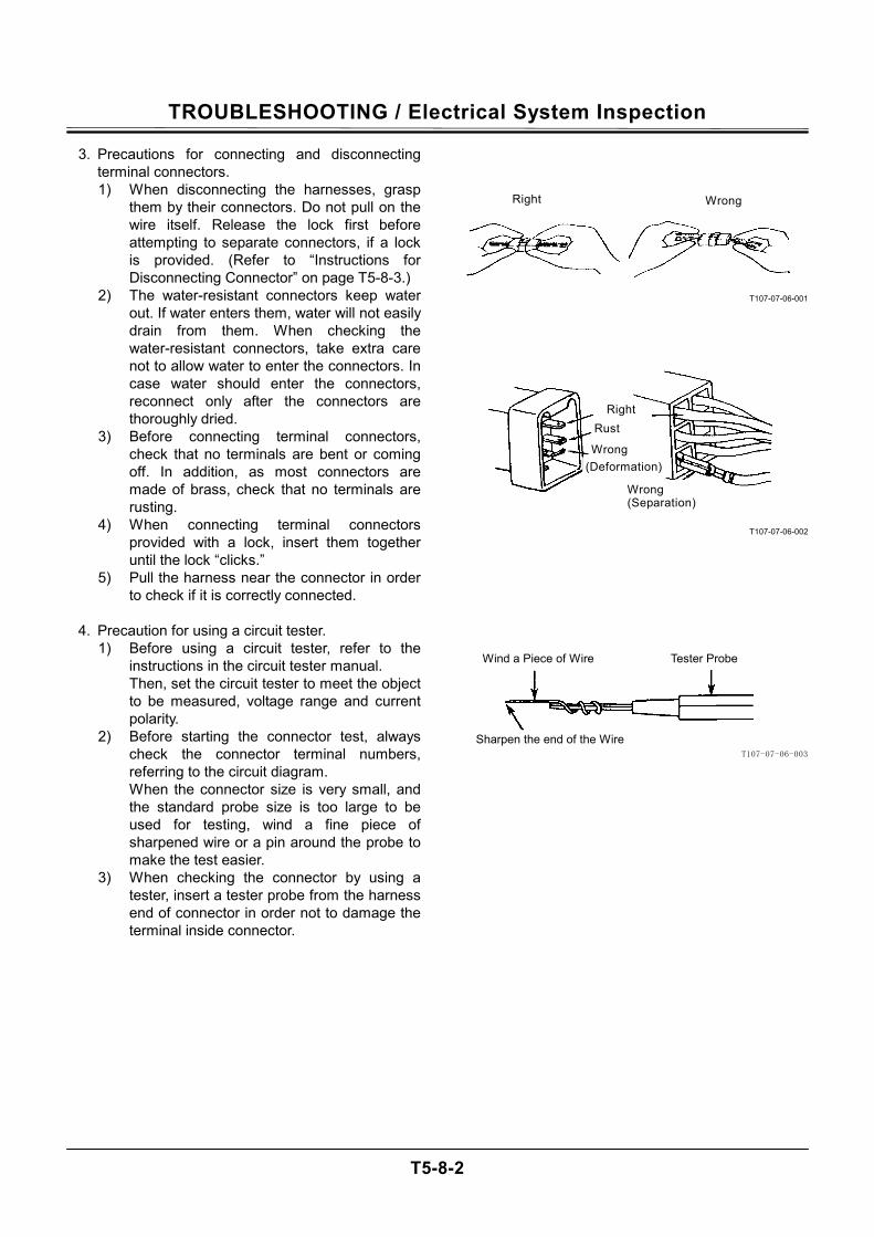
TROUBLESHOOTING / Electrical System Inspection
T5-8-2
3. Precautions for connecting and disconnecting terminal connectors. 1) When disconnecting the harnesses, grasp
them by their connectors. Do not pull on the wire itself. Release the lock first before attempting to separate connectors, if a lock is provided. (Refer to “Instructions for Disconnecting Connector” on page T5-8-3.)
2) The water-resistant connectors keep water out. If water enters them, water will not easily drain from them. When checking the water-resistant connectors, take extra care not to allow water to enter the connectors. In case water should enter the connectors, reconnect only after the connectors are thoroughly dried.
3) Before connecting terminal connectors, check that no terminals are bent or coming off. In addition, as most connectors are made of brass, check that no terminals are rusting.
4) When connecting terminal connectors provided with a lock, insert them together until the lock “clicks.”
5) Pull the harness near the connector in order to check if it is correctly connected.
4. Precaution for using a circuit tester.
1) Before using a circuit tester, refer to the instructions in the circuit tester manual. Then, set the circuit tester to meet the object to be measured, voltage range and current polarity.
2) Before starting the connector test, always check the connector terminal numbers, referring to the circuit diagram. When the connector size is very small, and the standard probe size is too large to be used for testing, wind a fine piece of sharpened wire or a pin around the probe to make the test easier.
3) When checking the connector by using a tester, insert a tester probe from the harness end of connector in order not to damage the terminal inside connector.
T107-07-06-001
T107-07-06-002
T107-07-06-003
Wind a Piece of Wire
Sharpen the end of the Wire
Tester Probe
Wrong
Right
Right
Wrong
Rust
Wrong (Separation)
(Deformation)
TROUBLESHOOTING / Electrical System Inspection
T5-8-3
INSTRUCTIONS FOR DISCONNECTING CONNECTORS • Push, Unlock and Separate Type
NOTE: 1. Connectors will not be easily separated even if the lock is pushed while being pulled. Push the lock first before pulling the connectors.
2. The lock is located on female side con-nector (harness end side).
T107-04-05-002
Locations of This Type Connector
Fuel Gauge Pump Delivery Pressure Sensor Radio Hydraulic Oil Level Switch General Relay Speaker Horn Solenoid Valve Wiper Cab Harness Diode Monitor Unit Pressure Sensor Key Switch ECM Washer Engine Control Dial ICF
• Raise Lock, Pull and Separate Type Locations of This Type Connector
Starter Relay 2
• Pull and Separate Type IMPORTANT: Before pulling and separating, re-
lease the lock of connector in the solenoid valve by using a pair of pincers.
Locations of This Type Connector
Hydraulic Oil Temperature Sensor
Dr. ZX
T107-04-05-003
T107-04-05-004
TROUBLESHOOTING / Electrical System Inspection
T5-8-4
FUSE INSPECTION Cracks in a fuse are so fine that it is very difficult or impossible to find by visual inspection. Use a tester in order to correctly inspect fuse continuity by following the instructions described below.
1. Turn the key switch ON. When the key switch is turned ON, current from key switch terminal M activates the battery relay so that electric power is supplied to all circuits except the glow plug relay circuit. (Refer to the circuit diagram.)
2. Remove the fuse box cover. Set the tester. (Measurement Range: 0 to 30 V)
3. Ground the negative probe of tester to the vehicle frame. Touch the terminals located away from center of the fuse box with the positive probe of tester one at a time. When normal continuity of a fuse is intact, the tester will indicate 20 to 25 V (battery voltage).
NOTE: All terminals located along the lengthwise centerline of the fuse box are connected to the power source, while terminals located away from center of the fuse box are con-nected to loads (accessories). Therefore, test all fuses in the same method except for the glow relay circuit fuse. Check the glow relay circuit fuse with the key switch turned to the ON position and follow the procedure in step 3.
M178-07-034
Fuse No. Capacity Connected to Fuse
No. Capacity Connected to
1 20 A Work Light Relays 1 and 2 11 10 A Horn Relay 2 10 A Wiper Relay, Wiper Motor,
Washer Relay 12 5 A Radio, Cab Light
3 20 A Heater (Air Conditioner Unit) 13 10 A Cigarette Lighter 4 10 A MC (Solenoid Valve Power) 14 5 A Fuel Pump 5 5 A Optional 1 15 10 A Auxiliary 6 10 A Optional 2 16 5 A Glow Relay 7 10 A Empty 17 5 A Air Conditioner Unit 8 30 A ECM Main Relay 18 5 A MC, ECM, ICF, Monitor Unit
(Power ON Signal) 9 10 A Security Horn, Security Horn
Relay (Power), Radio (Backup)19 5 A Monitor Unit (Main Power)
10 5 A MC, ICF (Main Power) 20 5 A Optional 3
20
19
18 17
16
15 14 13
12
11
10
9
87
6
543
2
1
TROUBLESHOOTING / Electrical System Inspection
T5-8-5
FUSIBLE LINK INSPECTION
Inspection
1. Remove the negative cable from the battery. 2. Loosen bolt M8 holding the cable routed in front
of the fusible link box. Slide the cable out of the way of the front cover.
3. Open the front cover of fusible link box and visu-ally inspect the fusible link.
Replacement
1. Check that the negative cable is removed from the battery.
2. Remove bolt M8. Remove the fusible link from the battery relay.
3. Open the upper and bottom side covers of fusible link box. Remove screws M6 (2 used).
4. Pull out the fusible link. Replace the fusible link. 5. Install screws M6 (2 used). 6. Install the fusible link box and the cable to the
battery relay. 7. Connect the negative cable to the battery.
M178-07-049
T178-05-06-002
T107-04-05-008
Fusible Link Cover
Battery Relay
Screw M6Cable
Bolt M8
Battery Relay
Fusible Link
TROUBLESHOOTING / Electrical System Inspection
T5-8-6
BATTERY VOLTAGE CHECK
1. Turn the key switch OFF. Check voltage between the battery positive terminal and the vehicle frame. Normal Voltage: 24 V
NOTE: If voltage is abnormal, recharge or replace
the battery.
2. Start the engine. Check voltage between the battery positive terminal and the vehicle frame. Normal Voltage: 26 to 28 V
NOTE: If voltage is abnormal, check the charging
system.
T157-07-06-007
V
TROUBLESHOOTING / Electrical System Inspection
T5-8-7
ALTERNATOR CHECK In general, the alternator indicator remains off when the alternator is generating power. If the alternator indicator comes on while the engine is running, the alternator might be defective.
How to check the circuit 1. Turn the key switch to the ON position. Confirm
that the alternator alarm is displayed.
2. Measure voltage between teminals B and E of the alternator. If the measured voltage is around 24 V, the alternator circuit can be considered normal. If the measured voltage is low, a shortage in battery capacity or looseness of the wire connectors of alternator circuit might be cause of the malfunction. When voltage is 0 V, the wiring between fuse box and alternator might be loose or disconnected. Also, the alternator cannot generate electricity if the ground line is disconnected.
3. Next, start the engine. Measure voltage
generated while as the alternator rotates. As described above, measure voltage between terminals B and E on the alternator side. If voltage is around 28 V, the alternator is operating normally. If the rated voltage is not being generated, there is some trouble with the alternator or the regula-tor.
T1V1-05-01-117
T157-07-06-003
E
B
Monitor Unit Alternator Alarm
TROUBLESHOOTING / Electrical System Inspection
T5-8-8
CONTINUITY CHECK
Single-line continuity check Disconnect both end connectors of the harness and check continuity between both ends: If the ohm-meter reading is: 0 Ω = Continuity ∞ Ω = Discontinuity
NOTE: When the one end connector is far apart
from the other, connect one end of connector (A) to the machine chassis using a clip. Then, check continuity of the harness through the vehicle frame as illustrated.
If the ohm-meter reading is: 0 Ω = Continuity ∞ Ω = Discontinuity
Single-line short-circuit check Disconnect both end connectors of the harness and check continuity between one end connector of the harness and the vehicle frame: If the ohm-meter reading is: 0 Ω = Short circuit is present. ∞ Ω = No short circuit is present.
T107-07-05-003
A a
A a
A a
Short-circuit between the harness and the vehicle frame.
Connect to the vehicle frame.
Connect to the vehicle frame.
×
Ω
Ω
Ω
Harness
TROUBLESHOOTING / Electrical System Inspection
T5-8-9
Multi-line continuity check Disconnect both end connectors of the harness, and short-circuit two terminals, (A) and (B), at one end connector, as illustrated. Then, check continuity between terminals (a) and (b) at the other connector. If the ohm-meter reading is ∞ Ω, either line (A) - (a), or (B) - (b) is in discontinuity. To find out which line is discontinued, conduct the single line continuity check on both lines individually, or, after changing the short-circuit terminals from (A) - (B) to (A) - (C), check continuity once more between terminals (a) and (c).
NOTE: By conducting the multi-line continuity
check twice, it is possible to find out which line is discontinued. With terminals (A) and (C) short-circuited, check continuity between terminals (a) and (c).
If the ohm-meter reading is: 0 Ω = Line (B) - (b) has discontinuity. ∞ Ω = Line (A) - (a) has discontinuity.
Multi-line short-circuit check Disconnect both end connectors of the harness, and check continuity between terminals (A) and (B) or (C). If the ohm-meter reading is: 0 Ω = Short-circuit exists between the lines. ∞ Ω = No short-circuit exists between the lines.
T107-07-05-004
T107-07-05-005
ABC
abc
Ω
Ω
× ABC
abc
Second short-circuit
First short-circuit
Short-circuit between harnesses.
TROUBLESHOOTING / Electrical System Inspection
T5-8-10
VOLTAGE AND CURRENT MEASURE-MENT Turn key switch ON so that the specified voltage (cur-rent) is supplied to the location to be measured. Judge if the circuit is normal by evaluating whether the measured voltage (current) matches the specification.
24-Volt Circuit Start checking the circuit in order up to the loca-tion to be measured from either power source or actuator side. Thereby, the faulty location in the circuit will be found. Black Probe (Negative) of Tester:
To ground to the vehicle frame Red Probe (Positive) of Tester:
To touch the location to be measured
Engine Key Switch Location to be Measured SpecificationPower Source Circuit Stopped Stopped Stopped Stopped Stopped Stopped
OFF OFF OFF OFF OFF OFF
Between (2) and (1): One Battery Between (3) and (2): One Battery Between (3) and (1): Two Batteries Between (4) and Ground: Battery Power Between (5) and Ground: Fusible Link Between (1) and Ground: Backup Current*
10 to 12.5 V 10 to 12.5 V 20 to 25 V 20 to 25 V 20 to 25 V 6 mA
Preheat Circuit Stopped Stopped
ON or START ON or START
Between (6) and Ground: Key Switch Between (7) and Ground: Glow Plug
20 to 25 V 20 to 25 V
Charging Circuit Fast Speed Fast Speed Fast Speed Fast Speed Fast Speed
ON ON ON ON ON
Between (8) and Ground: Alternator (B) / Generating
Voltage Between (9) and Ground: Battery Relay / Generating
Voltage Between (10) and Ground: Fuse Box / Starter Relay 2 (R)
/ Generating Voltage Between (11) and Ground: Generating Voltage Between (12) and Ground: Monitor Unit (C7)
26 to 30 V 26 to 30 V 26 to 30 V 13 to 30 V 13 to 30 V
Surge Voltage Prevention Circuit Idle Speed Idle Speed Idle Speed Idle Speed
ON ON ON ON
Between (8) and Ground: Alternator (B) Between (11) and Ground: Starter Relay 2 (R) Between (13) and Ground: Load Damp Relay Between (9) and Ground: Battery Relay
26 to 30 V 13 to 30 V 26 to 30 V 26 to 30 V
Accessory Circuit Stopped Stopped Stopped Stopped
ON ON ON ON
Between (14) and Ground: Auxiliary Between (15) and Ground: Cigarette Lighter Between (16) and Ground: Radio, Cab Light Between (17) and Ground: Battery Relay
20 to 25 V 20 to 25 V 20 to 25 V 20 to 25 V
NOTE: *Before measurement, disconnect the
negative cable from the battery.
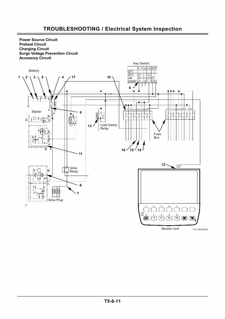
TROUBLESHOOTING / Electrical System Inspection
T5-8-11
Power Source Circuit Preheat Circuit Charging Circuit Surge Voltage Prevention Circuit Accessory Circuit
T1V1-05-06-001
Key Switch
Glow Plug
Starter
Battery
C7
Fuse Box
Glow Relay
Load Damp Relay
9
7
11
1 2 3 5 4 17 10
6
8
16 15 14
12
13
Monitor Unit
B C
B S E
R
B
L
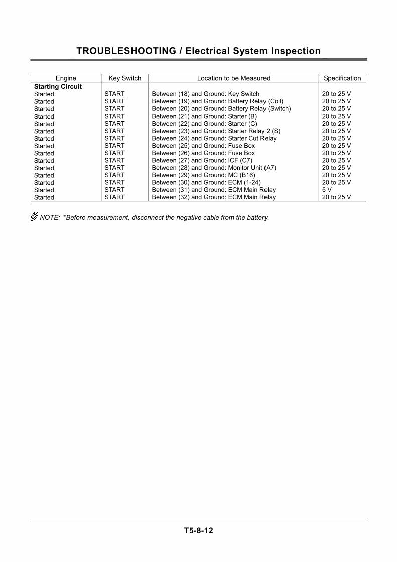
TROUBLESHOOTING / Electrical System Inspection
T5-8-12
Engine Key Switch Location to be Measured Specification
Starting Circuit Started Started Started Started Started Started Started Started Started Started Started Started Started Started Started
START START START START START START START START START START START START START START START
Between (18) and Ground: Key Switch Between (19) and Ground: Battery Relay (Coil) Between (20) and Ground: Battery Relay (Switch) Between (21) and Ground: Starter (B) Between (22) and Ground: Starter (C) Between (23) and Ground: Starter Relay 2 (S) Between (24) and Ground: Starter Cut Relay Between (25) and Ground: Fuse Box Between (26) and Ground: Fuse Box Between (27) and Ground: ICF (C7) Between (28) and Ground: Monitor Unit (A7) Between (29) and Ground: MC (B16) Between (30) and Ground: ECM (1-24) Between (31) and Ground: ECM Main Relay Between (32) and Ground: ECM Main Relay
20 to 25 V 20 to 25 V 20 to 25 V 20 to 25 V 20 to 25 V 20 to 25 V 20 to 25 V 20 to 25 V 20 to 25 V 20 to 25 V 20 to 25 V 20 to 25 V 20 to 25 V 5 V 20 to 25 V
NOTE: *Before measurement, disconnect the negative cable from the battery.
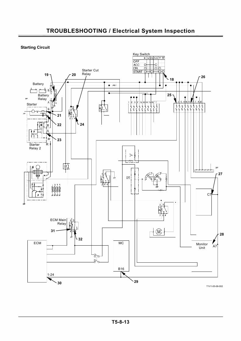
TROUBLESHOOTING / Electrical System Inspection
T5-8-13
Starting Circuit
T1V1-05-06-002
Monitor Unit
19 Starter Cut Relay 20
21
22
23 R Starter
Relay 2
Battery
Battery Relay
Starter
24
18
25
Key Switch
26
27
C7
A7
28
MC
B16
29
1-24
30
31
ECM
ECM Main Relay
32
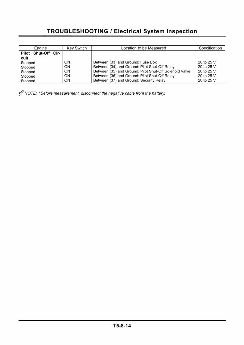
TROUBLESHOOTING / Electrical System Inspection
T5-8-14
Engine Key Switch Location to be Measured Specification
Pilot Shut-Off Cir-cuit Stopped Stopped Stopped Stopped Stopped
ON ON ON ON ON
Between (33) and Ground: Fuse Box Between (34) and Ground: Pilot Shut-Off Relay Between (35) and Ground: Pilot Shut-Off Solenoid Valve Between (36) and Ground: Pilot Shut-Off Relay Between (37) and Ground: Security Relay
20 to 25 V 20 to 25 V 20 to 25 V 20 to 25 V 20 to 25 V
NOTE: *Before measurement, disconnect the negative cable from the battery.
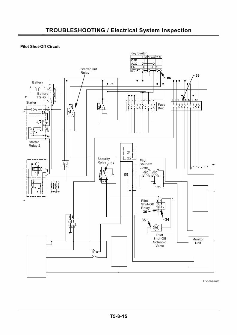
TROUBLESHOOTING / Electrical System Inspection
T5-8-15
Pilot Shut-Off Circuit
T1V1-05-06-003
Starter Cut Relay
Starter Relay 2
Battery
Battery Relay
Starter
#6
37
Key Switch
33
Fuse Box
Security Relay Pilot
Shut-Off Lever
Pilot Shut-Off Relay 36
34 35
Monitor Unit
Pilot Shut-Off Solenoid
Valve
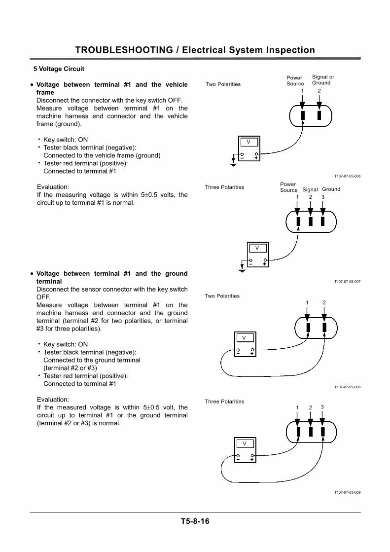
TROUBLESHOOTING / Electrical System Inspection
T5-8-16
5 Voltage Circuit • Voltage between terminal #1 and the vehicle
frame Disconnect the connector with the key switch OFF. Measure voltage between terminal #1 on the machine harness end connector and the vehicle frame (ground).
• Key switch: ON • Tester black terminal (negative):
Connected to the vehicle frame (ground) • Tester red terminal (positive):
Connected to terminal #1
Evaluation: If the measuring voltage is within 5±0.5 volts, the circuit up to terminal #1 is normal.
• Voltage between terminal #1 and the ground
terminal Disconnect the sensor connector with the key switch OFF. Measure voltage between terminal #1 on the machine harness end connector and the ground terminal (terminal #2 for two polarities, or terminal #3 for three polarities).
• Key switch: ON • Tester black terminal (negative):
Connected to the ground terminal (terminal #2 or #3)
• Tester red terminal (positive): Connected to terminal #1
Evaluation: If the measured voltage is within 5±0.5 volt, the circuit up to terminal #1 or the ground terminal (terminal #2 or #3) is normal.
T107-07-05-006
T107-07-05-007
T107-07-05-008
T107-07-05-009
V
V
1 2
1 2 3
V
V
1 2 3
1 2
Two PolaritiesPower Source
Signal or Ground
Three Polarities Power Source Signal Ground
Two Polarities
Three Polarities
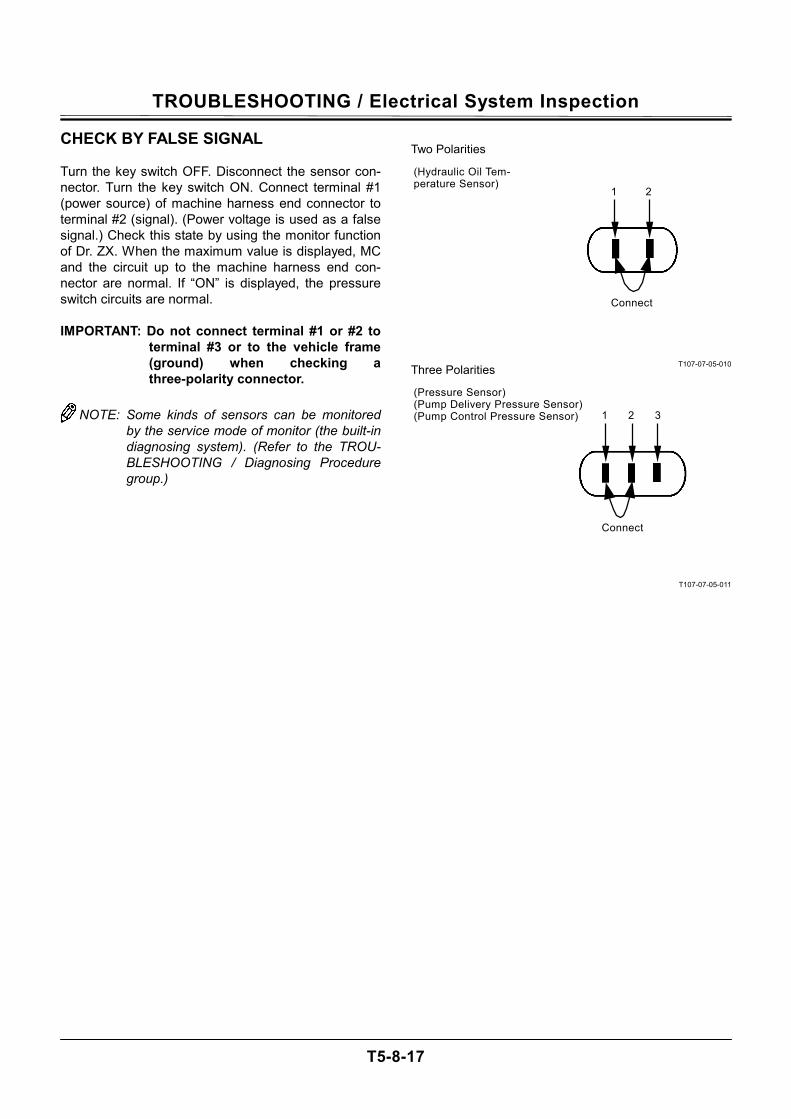
TROUBLESHOOTING / Electrical System Inspection
T5-8-17
Three Polarities
CHECK BY FALSE SIGNAL Turn the key switch OFF. Disconnect the sensor con-nector. Turn the key switch ON. Connect terminal #1 (power source) of machine harness end connector to terminal #2 (signal). (Power voltage is used as a false signal.) Check this state by using the monitor function of Dr. ZX. When the maximum value is displayed, MC and the circuit up to the machine harness end con-nector are normal. If “ON” is displayed, the pressure switch circuits are normal. IMPORTANT: Do not connect terminal #1 or #2 to
terminal #3 or to the vehicle frame (ground) when checking a three-polarity connector.
NOTE: Some kinds of sensors can be monitored
by the service mode of monitor (the built-in diagnosing system). (Refer to the TROU-BLESHOOTING / Diagnosing Procedure group.)
T107-07-05-010
T107-07-05-011
(Pressure Sensor) (Pump Delivery Pressure Sensor) (Pump Control Pressure Sensor)
Two Polarities
(Hydraulic Oil Tem-perature Sensor)
2 1
32
Connect
1
Connect
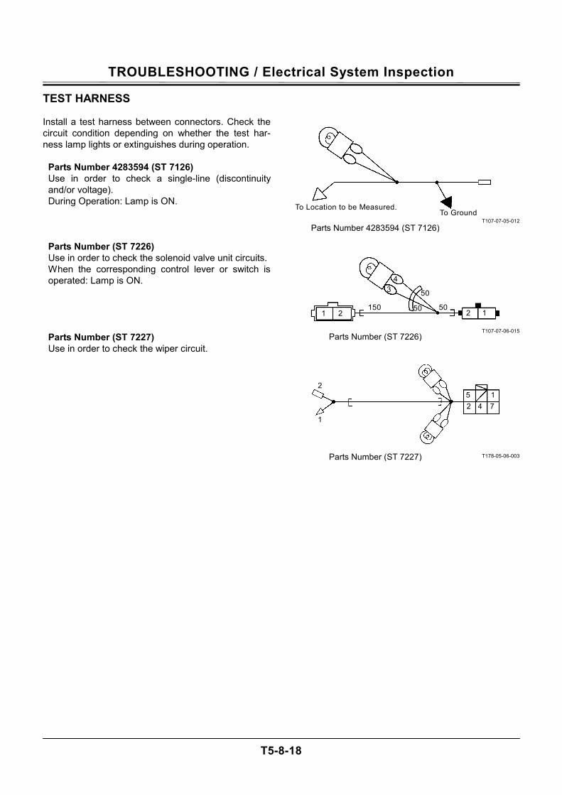
TROUBLESHOOTING / Electrical System Inspection
T5-8-18
TEST HARNESS Install a test harness between connectors. Check the circuit condition depending on whether the test har-ness lamp lights or extinguishes during operation.
Parts Number 4283594 (ST 7126) Use in order to check a single-line (discontinuity and/or voltage). During Operation: Lamp is ON.
Parts Number (ST 7226) Use in order to check the solenoid valve unit circuits. When the corresponding control lever or switch is operated: Lamp is ON.
Parts Number (ST 7227) Use in order to check the wiper circuit.
T107-07-05-012
T107-07-06-015
T178-05-06-003
Parts Number 4283594 (ST 7126)
To Location to be Measured. To Ground
50
50
50 15022
4 3
11
Parts Number (ST 7226)
5 1742
2
1
Parts Number (ST 7227)

M E M O
....................................................................................................................................................................
....................................................................................................................................................................
....................................................................................................................................................................
....................................................................................................................................................................
....................................................................................................................................................................
....................................................................................................................................................................
....................................................................................................................................................................
....................................................................................................................................................................
....................................................................................................................................................................
....................................................................................................................................................................
....................................................................................................................................................................
....................................................................................................................................................................
....................................................................................................................................................................
....................................................................................................................................................................
....................................................................................................................................................................
....................................................................................................................................................................
....................................................................................................................................................................
....................................................................................................................................................................
....................................................................................................................................................................
....................................................................................................................................................................
....................................................................................................................................................................
....................................................................................................................................................................
....................................................................................................................................................................
....................................................................................................................................................................
....................................................................................................................................................................
....................................................................................................................................................................
....................................................................................................................................................................
....................................................................................................................................................................
....................................................................................................................................................................
....................................................................................................................................................................
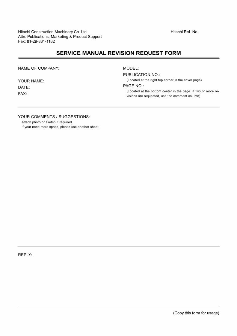
Hitachi Construction Machinery Co. Ltd Hitachi Ref. No. Attn: Publications, Marketing & Product Support Fax: 81-29-831-1162
SERVICE MANUAL REVISION REQUEST FORM
(Copy this form for usage)
NAME OF COMPANY: YOUR NAME: DATE: FAX:
MODEL: PUBLICATION NO.:
(Located at the right top corner in the cover page) PAGE NO.:
(Located at the bottom center in the page. If two or more re-visions are requested, use the comment column)
YOUR COMMENTS / SUGGESTIONS:
Attach photo or sketch if required. If your need more space, please use another sheet.
REPLY:
THE ATTACHED DIAGRAM LIST
(The following diagrams are attached to this manual.)
1. ZAXIS200-3 CLASS/240-3 CLASS/270-3 CLASS/330-3 CLASS ELECTRICAL CIRCUIT DIAGRAM 2. ZAXIS200-3 CLASS/240-3 CLASS/270-3 CLASS/330-3 CLASS CONNECTORS
3. ZAXIS330-3 CLASS ENGINE HARNESS 1
4. ZAXIS200-3 CLASS/240-3 CLASS/270-3 CLASS/330-3 CLASS ENGINE HARNESS 2
ZAXIS200-3 CLASS/240-3 CLASS/270-3 CLASS/330-3 CLASS MONITOR UNIT HARNESS 5. ZAXIS200-3 CLASS/240-3 CLASS/270-3 CLASS/330-3 CLASS CAB HARNESS 6. ZAXIS330-3 CLASS HYDRAULIC CIRCUIT DIAGRAM
(BASE MACHINE) ZAXIS330-3 CLASS HYDRAULIC CIRCUIT DIAGRAM (2-PIECE BOOM, BOOM HOSE RUPTURE VALVE, ARM HOSE RUPTURE VALVE, POSITIONING HOSE RUPTURE VALVE)) ZAXIS330-3 CLASS HYDRAULIC CIRCUIT DIAGRAM (BREAKER AND CRUSHER PIPING, 2-SPEED FLOW COMBINING PIPING)
Related Documents