Technical Information TI 061D/06/en 50102807 Coriolis Mass Flow Measuring System PROline promass 80/83 E Mass flow measuring system offering “Low Cost of Ownership” as an alternative to conventional volumetric flowmeters Features and benefits x Multifunctional: Simultaneous measurement of flow (mass flow, volume flow), density and temperature. x Balanced dual-tube system x Nominal diameters DN 8...50 x Measurement is independent of fluid properties x Compact design x “Fit and forget” installation x Low cost of ownership x Robust field housing (aluminium), IP 67 protection x Quick Setup menus for straightforward commissioning in the field x Programming via HART protocol or local operation x Guaranteed product quality, suitable for CIP/SIP cleaning x Hygienic design in accordance with the latest requirements: 3A authorization x Ex approvals: ATEX, FM, CSA x Performance characteristics: – Mass flow (liquids): Promass 80: ±0.35% o.r. Promass 83: ±0.30% o.r. – Mass flow (gases): ±0.75% o.r. Application For mass or volume flow measurement. Application examples: x Deionized water x Fuel oils x Edible oils x Solvents x Gases

Welcome message from author
This document is posted to help you gain knowledge. Please leave a comment to let me know what you think about it! Share it to your friends and learn new things together.
Transcript

Technical InformationTI 061D/06/en50102807
Coriolis Mass Flow Measuring SystemPROline promass 80/83 E
Mass flow measuring system offering “Low Cost of Ownership” as an alternative to conventional volumetric flowmeters
Features and benefits� Multifunctional: Simultaneous
measurement of flow (mass flow, volume flow), density and temperature.
� Balanced dual-tube system� Nominal diameters DN 8...50� Measurement is independent of fluid
properties� Compact design� “Fit and forget” installation� Low cost of ownership� Robust field housing (aluminium),
IP 67 protection� Quick Setup menus for straightforward
commissioning in the field� Programming via HART protocol or
local operation� Guaranteed product quality, suitable
for CIP/SIP cleaning� Hygienic design in accordance with
the latest requirements: 3A authorization
� Ex approvals: ATEX, FM, CSA� Performance characteristics:
– Mass flow (liquids):Promass 80: ±0.35% o.r.Promass 83: ±0.30% o.r.
– Mass flow (gases):±0.75% o.r.
ApplicationFor mass or volume flow measurement.
Application examples:� Deionized water� Fuel oils� Edible oils� Solvents� Gases

PROline Promass 80/83 E
2 Endress+Hauser
Function and system design
Measuring principle The measuring principle is based on the controlled generation of Coriolis forces. These forces are always present when both translational and rotational movements are superimposed.
C = 2 · �m ( )
C = Coriolis force �m = moved mass
= angular velocity= radial velocity in the rotating or oscillating system
The amplitude of the Coriolis force depends on the moving mass �m, its velocity in the system and thus on the mass flow. Instead of a constant angular velocity the Promass sensor uses oscillation. In the sensor, two parallel measuring tubes containing flowing fluid oscillate in antiphase, acting like a tuning fork. The Coriolis forces produced at the measuring tubes cause a phase shift in the tube oscillations (see illustration):� At zero flow, in other words when the fluid is at a standstill, the two tubes oscillate in phase (1).� Mass flow causes deceleration of the oscillation at the inlet of the tubes (2) and acceleration at
the outlet (3).
The phase difference (A-B) increases with increasing mass flow. Electrodynamic sensors register the tube oscillations at the inlet and outlet.
System balance is ensured by the antiphase oscillation of the two measuring tubes.The measuring principle operates independently of temperature, pressure, viscosity, conductivity and flow profile.
Volume measurementThe measuring tubes are continuously excited at their resonance frequency. A change in the mass and thus the density of the oscillating system (comprising measuring tubes and fluid) results in a corresponding, automatic adjustment in the oscillation frequency. Resonance frequency is thus a function of fluid density. The density value obtained in this way can be used in conjunction with the measured mass flow to calculate the volume flow.The temperature of the measuring tubes is also determined in order to calculate the compensation factor due to temperature effects.
F v ��
F
�
v
v�
F06-xxxxxxxx-15-xx-xx-xx-004
PROline Promass 80/83 E
Endress+Hauser 3
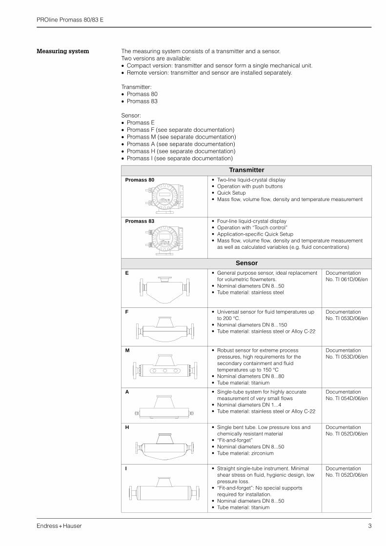
Measuring system The measuring system consists of a transmitter and a sensor.Two versions are available:� Compact version: transmitter and sensor form a single mechanical unit.� Remote version: transmitter and sensor are installed separately.
Transmitter:� Promass 80� Promass 83
Sensor:� Promass E� Promass F (see separate documentation)� Promass M (see separate documentation)� Promass A (see separate documentation)� Promass H (see separate documentation)� Promass I (see separate documentation)
TransmitterPromass 80 • Two-line liquid-crystal display
• Operation with push buttons• Quick Setup• Mass flow, volume flow, density and temperature measurement
Promass 83 • Four-line liquid-crystal display• Operation with “Touch control”• Application-specific Quick Setup• Mass flow, volume flow, density and temperature measurement
as well as calculated variables (e.g. fluid concentrations)
SensorE • General purpose sensor, ideal replacement
for volumetric flowmeters.• Nominal diameters DN 8...50• Tube material: stainless steel
DocumentationNo. TI 061D/06/en
F • Universal sensor for fluid temperatures up to 200 °C.
• Nominal diameters DN 8...150• Tube material: stainless steel or Alloy C-22
DocumentationNo. TI 053D/06/en
M • Robust sensor for extreme process pressures, high requirements for the secondary containment and fluid temperatures up to 150 °C
• Nominal diameters DN 8...80• Tube material: titanium
DocumentationNo. TI 053D/06/en
A • Single-tube system for highly accurate measurement of very small flows
• Nominal diameters DN 1...4• Tube material: stainless steel or Alloy C-22
DocumentationNo. TI 054D/06/en
H • Single bent tube. Low pressure loss and chemically resistant material
• “Fit-and-forget”• Nominal diameters DN 8...50• Tube material: zirconium
DocumentationNo. TI 052D/06/en
I • Straight single-tube instrument. Minimal shear stress on fluid, hygienic design, low pressure loss.
• “Fit-and-forget”: No special supports required for installation.
• Nominal diameters DN 8...50• Tube material: titanium
DocumentationNo. TI 052D/06/en
PROline Promass 80/83 E
4 Endress+Hauser
Input
Measured variable � Mass flow (proportional to the phase difference between two sensors mounted on the measuring tubes to register a phase shift in the oscillation)
� Fluid density (proportional to resonance frequency of the measuring tubes)� Fluid temperature (measured with temperature sensors)
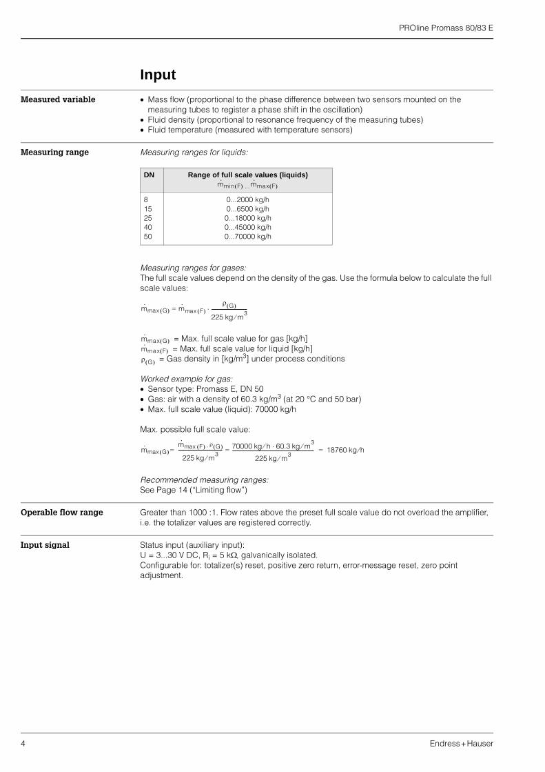
Measuring range Measuring ranges for liquids:
Measuring ranges for gases:The full scale values depend on the density of the gas. Use the formula below to calculate the full scale values:
= Max. full scale value for gas [kg/h] = Max. full scale value for liquid [kg/h]
= Gas density in [kg/m3] under process conditions
Worked example for gas:� Sensor type: Promass E, DN 50� Gas: air with a density of 60.3 kg/m3 (at 20 °C and 50 bar)� Max. full scale value (liquid): 70000 kg/h
Max. possible full scale value:
Recommended measuring ranges:See Page 14 (“Limiting flow”)
Operable flow range Greater than 1000 :1. Flow rates above the preset full scale value do not overload the amplifier, i.e. the totalizer values are registered correctly.
Input signal Status input (auxiliary input):U = 3...30 V DC, Ri = 5 k�, galvanically isolated.Configurable for: totalizer(s) reset, positive zero return, error-message reset, zero point adjustment.
DN Range of full scale values (liquids)
...
815254050
0...2000 kg/h0...6500 kg/h0...18000 kg/h0...45000 kg/h0...70000 kg/h
m· min F� � m· max F� �
m· max G� � m·= max F� �
� G� �
225 kg m3�
-----------------------------�
m· max G� �
m· max F� �
� G� �
m· max G� �
m· max F� � � G� ��
225 kg m3�
------------------------------------ 70000 kg h 60.3� kg m3��
225 kg m3�
------------------------------------------------------------------- 18760 kg h�===

PROline Promass 80/83 E
Endress+Hauser 5
Output
Output signal Promass 80Current output:Active/passive selectable, galvanically isolated, time constant selectable (0.05...100 s), full scale value selectable, temperature coefficient: typically 0.005% o.r./°C; resolution: 0.5 �A� Active: 0/4...20 mA, RL < 700 � (for HART: RL � 250 �)� Passive: 4...20 mA, max. 30 V DC, Ri � 150 �
Pulse/frequency output:Passive, open collector, 30 V DC, 250 mA, galvanically isolated.� Frequency output: full scale frequency 2...1000 Hz (fmax = 1250 Hz), on/off ratio 1:1,
pulse width max. 2 sPulse output: pulse value and pulse polarity selectable, pulse width adjustable (0.5... 2000 ms)
Promass 83Current output:Active/passive selectable, galvanically isolated, time constant selectable (0.05...100 s), full scale value selectable, temperature coefficient: typically 0.005% o.r./°C; resolution: 0.5 �A� Active: 0/4...20 mA, RL < 700 � (for HART: RL � 250 �)� Passive: 4...20 mA, max. 30 V DC, Ri � 150 �
Pulse/frequency output:active/passive selectable, galvanically isolated� Active: 24 V DC, 25 mA (max. 250 mA during 20 ms), RL > 100 �� Passive: open collector, 30 V DC, 250 mA
� Frequency output: full scale frequency 2...10000 Hz (fmax = 12500 Hz), on/off ratio 1:1, pulse width max. 2 s
� Pulse output: pulse value and pulse polarity selectable,pulse width adjustable (0.05 ... 2000 ms)
Signal on alarm � Current output � �failsafe mode selectable (according to recommendation NAMUR NE 43)� Pulse/frequency output �� failsafe mode selectable� Status output �� “non-conductive” by fault or power supply failure
Load see “Output signal”
Switching output Open collector, max. 30 V DC / 250 mA, galvanically isolated.Configurable for: error messages, Empty Pipe Detection (EPD), flow direction, limit values.
Low flow cut off Switch points for low flow cut off are selectable.
Galvanic isolation All circuits for inputs, outputs, and power supply are galvanically isolated from each other.

PROline Promass 80/83 E
6 Endress+Hauser
Power supply
Electrical connection Measuring unit
A = View A (field housing)B = View B (wall-mount housing)
a Cable for power supply: 85...260 V AC, 20...55 V AC, 16...62 V DCTerminal No. 1: L1 for AC, L+ for DCTerminal No. 2: N for AC, L– for DC
b Signal cable: Terminals Nos. 20–27 � see table belowc Ground terminal for protective conductord Ground terminal for signal-cable shield
Terminal assignment Promass 80
Terminal Nos. (inputs/outputs)
Order variant 20 � 21 22 � 23 24 � 25 26 � 27
80***-***********A � � Frequency outputCurrent output
HART
80***-***********D Status input Status output Frequency outputCurrent output
HART
80***-***********H – – –PROFIBUS-PA
80***-***********S – –Frequency output
Ex i, passiveCurrent output Ex i
active, HART
80***-***********T – –Frequency output
Ex i, passiveCurrent output Ex i
passive, HART
80***-***********8 Status input Frequency output Current output 2 Current output 1
A
B
B1 2
c da
b
c
d
a
b
+22
–23
+20
–21
+24
–25
+26
–27
A– 27
– 25
– 23
– 21
21
+ 26
+ 24
+ 22
+ 20
L1 (L+)N (L-)
L1 (L+)N (L-)
F06-
xxxx
xxxx
-04-
06-x
x-xx
-000
PROline Promass 80/83 E
Endress+Hauser 7
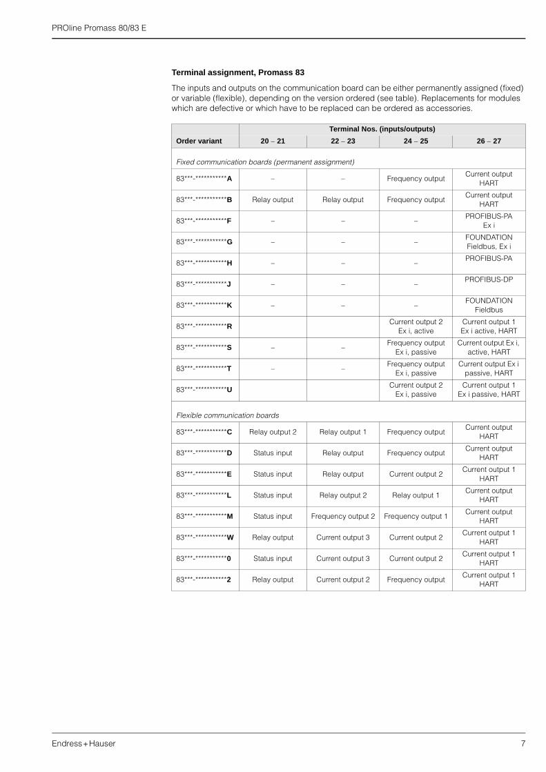
Terminal assignment, Promass 83
The inputs and outputs on the communication board can be either permanently assigned (fixed) or variable (flexible), depending on the version ordered (see table). Replacements for modules which are defective or which have to be replaced can be ordered as accessories.
Terminal Nos. (inputs/outputs)
Order variant 20 � 21 22 � 23 24 � 25 26 � 27
Fixed communication boards (permanent assignment)
83***-***********A � � Frequency outputCurrent output
HART
83***-***********B Relay output Relay output Frequency outputCurrent output
HART
83***-***********F – – –PROFIBUS-PA
Ex i
83***-***********G – – –FOUNDATION Fieldbus, Ex i
83***-***********H – – –PROFIBUS-PA
83***-***********J – – –PROFIBUS-DP
83***-***********K � � �FOUNDATION
Fieldbus
83***-***********RCurrent output 2
Ex i, activeCurrent output 1Ex i active, HART
83***-***********S – –Frequency output
Ex i, passiveCurrent output Ex i,
active, HART
83***-***********T – –Frequency output
Ex i, passiveCurrent output Ex i
passive, HART
83***-***********UCurrent output 2
Ex i, passiveCurrent output 1
Ex i passive, HART
Flexible communication boards
83***-***********C Relay output 2 Relay output 1 Frequency outputCurrent output
HART
83***-***********D Status input Relay output Frequency outputCurrent output
HART
83***-***********E Status input Relay output Current output 2Current output 1
HART
83***-***********L Status input Relay output 2 Relay output 1Current output
HART
83***-***********M Status input Frequency output 2 Frequency output 1Current output
HART
83***-***********W Relay output Current output 3 Current output 2Current output 1
HART
83***-***********0 Status input Current output 3 Current output 2Current output 1
HART
83***-***********2 Relay output Current output 2 Frequency outputCurrent output 1
HART
PROline Promass 80/83 E
8 Endress+Hauser
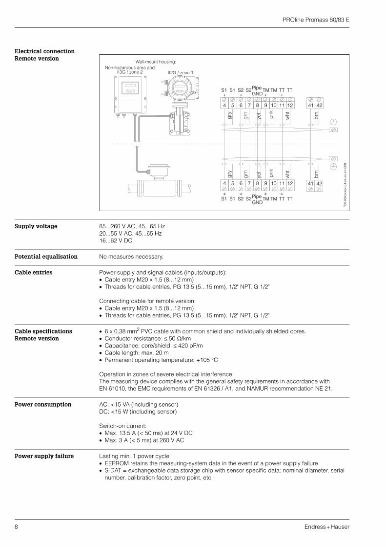
Electrical connection Remote version
Supply voltage 85...260 V AC, 45...65 Hz20...55 V AC, 45...65 Hz16...62 V DC
Potential equalisation No measures necessary.
Cable entries Power-supply and signal cables (inputs/outputs):� Cable entry M20 x 1.5 (8...12 mm)� Threads for cable entries, PG 13.5 (5...15 mm), 1/2" NPT, G 1/2"
Connecting cable for remote version:� Cable entry M20 x 1.5 (8...12 mm)� Threads for cable entries, PG 13.5 (5...15 mm), 1/2" NPT, G 1/2"
Cable specifications Remote version
� 6 x 0.38 mm2 PVC cable with common shield and individually shielded cores.� Conductor resistance: � 50 �/km� Capacitance: core/shield: � 420 pF/m� Cable length: max. 20 m� Permanent operating temperature: +105 °C
Operation in zones of severe electrical interference:The measuring device complies with the general safety requirements in accordance with EN 61010, the EMC requirements of EN 61326 / A1, and NAMUR recommendation NE 21.
Power consumption AC: <15 VA (including sensor)DC: <15 W (including sensor)
Switch-on current:� Max. 13.5 A (< 50 ms) at 24 V DC� Max. 3 A (< 5 ms) at 260 V AC
Power supply failure Lasting min. 1 power cycle� EEPROM retains the measuring-system data in the event of a power supply failure� S-DAT = exchangeable data storage chip with sensor specific data: nominal diameter, serial
number, calibration factor, zero point, etc.
6
6
4
4
7
7
5
5
8
8
9
9
10
10
11
11
12
12
41
41
42
42
S1+ + + +
S1 S2 S2 TM TM TT TTGNDPipe
S1+ + + +
S1 S2 S2 TM TM TT TTGNDPipe
brn
brn
wht
wht
grn
grn
gry
gry
yel
yel
pnk
pnk
Wall-mount housing:
II2G / zone 1Non-hazardous area and
II3G / zone 2
F06-
83xx
xxxx
-04-
xx-x
x-en
-000
PROline Promass 80/83 E
Endress+Hauser 9
Performance characteristics
Reference operating conditions
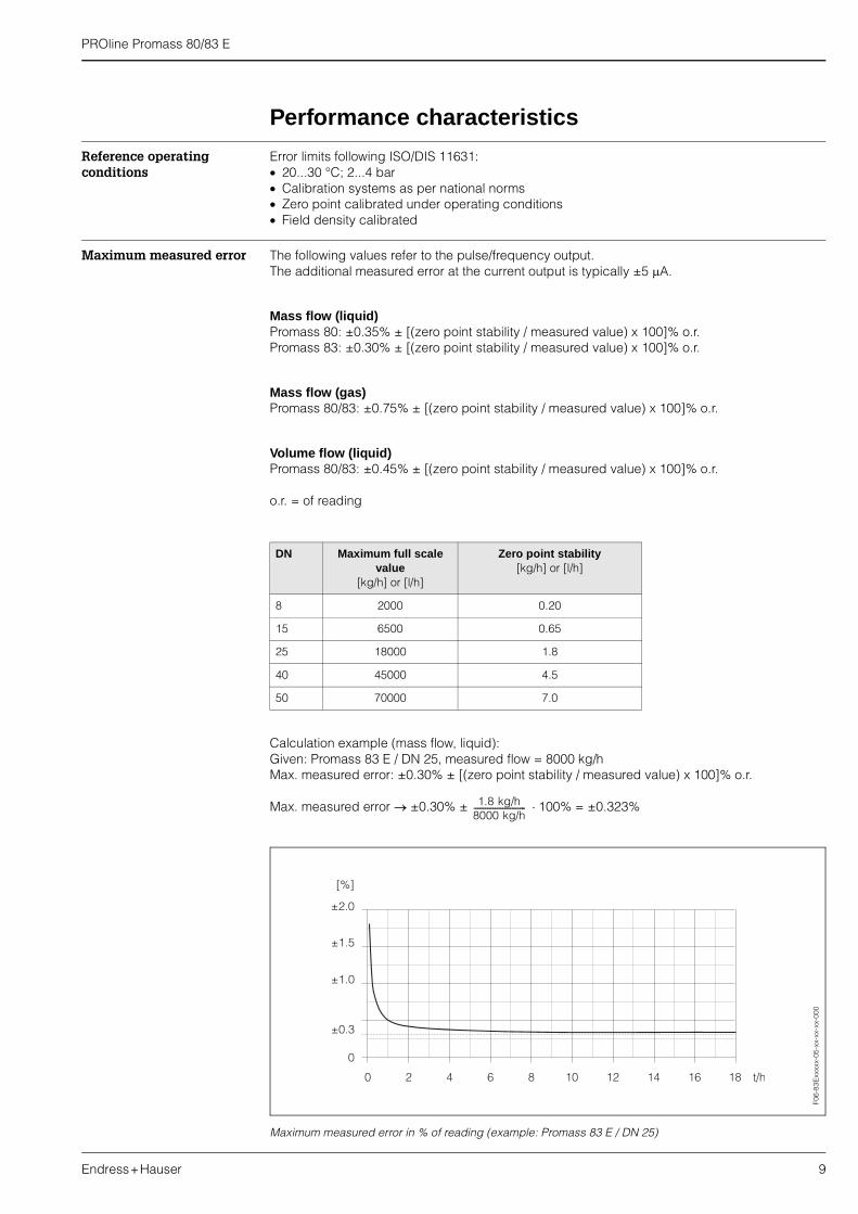
Error limits following ISO/DIS 11631:� 20...30 °C; 2...4 bar� Calibration systems as per national norms� Zero point calibrated under operating conditions� Field density calibrated
Maximum measured error The following values refer to the pulse/frequency output.The additional measured error at the current output is typically ±5 �A.
Mass flow (liquid)Promass 80: ±0.35% ± [(zero point stability / measured value) x 100]% o.r.Promass 83: ±0.30% ± [(zero point stability / measured value) x 100]% o.r.
Mass flow (gas)Promass 80/83: ±0.75% ± [(zero point stability / measured value) x 100]% o.r.
Volume flow (liquid)Promass 80/83: ±0.45% ± [(zero point stability / measured value) x 100]% o.r.
o.r. = of reading
Calculation example (mass flow, liquid):Given: Promass 83 E / DN 25, measured flow = 8000 kg/hMax. measured error: ±0.30% ± [(zero point stability / measured value) x 100]% o.r.
Max. measured error � ±0.30% ± �100% = ±0.323%
Maximum measured error in % of reading (example: Promass 83 E / DN 25)
DN Maximum full scale value
[kg/h] or [l/h]
Zero point stability[kg/h] or [l/h]
8 2000 0.20
15 6500 0.65
25 18000 1.8
40 45000 4.5
50 70000 7.0
1.8 kg/h8000 kg/h---------------------------
0
±1.0
±1.5
±2.0
[%]
0 2 4 6 8 10 12 14 16 18 t/h
±0.3
F06-
83E
xxxx
x-05
-xx-
xx-x
x-00
0

PROline Promass 80/83 E
10 Endress+Hauser
Density (liquid)Standard calibration: ±0.02 g/cc (1 g/cc = 1 kg/l)
After field density calibration or under reference conditions: ±0.001 g/cc
Temperature±0.5 °C ±0.005 x T (T = fluid temperature in °C)
Repeatability Flow measurementPromass 80/83 E:� Mass flow (liquid): ±0.15% ± [1/2 x (zero point stability / measured value) x 100]% o.r.� Mass flow (gas): ±0.35% ± [1/2 x (zero point stability / measured value) x 100]% o.r.� Volume flow (liquid): ±0.20% ± [1/2 x (zero point stability / measured value) x 100]% o.r.
o.r. = of readingZero point stability: see “Max. measured error”
Calculation example (mass flow, liquid):Given: Promass 80 E / DN 25, measured flow = 8000 kg/hRepeatability: ±0.15% ± [1/2 x (zero point stability / measured value) x 100]% o.r.
Repeatability � ±0.15% ± 1/2 � �100% = ±0.161%
Density measurement (liquid)±0.0005 g/cc (1 g/cc = 1 kg/l)
Temperature measurement±0.25 °C ±0.0025 x T (T = fluid temperature in °C)
Influence of medium temperature
When there is a difference between the temperature for zero point adjustment and the process temperature, the typical measured error of Promass E is ±0.0002% of the full scale value / °C.
Influence of medium pressure
With nominal diameters DN 8...40, the effect on accuracy of mass flow due to a difference between calibration pressure and process pressure can be neglected.
With DN 50 the influence is –0.009% o.r. / bar (o.r. = of reading)
1.8 kg/h8000 kg/h---------------------------
PROline Promass 80/83 E
Endress+Hauser 11
Operating conditions (installation)
Installation instructions Note the following points:� No special measures such as supports are necessary. External forces are absorbed by the
construction of the instrument, for example the secondary containment.� The high oscillation frequency of the measuring tubes ensures that the correct operation of the
measuring system is not influenced by pipe vibrations.� No special precautions need to be taken for fittings which create turbulence (valves, elbows,
T-pieces, etc.), as long as no cavitation occurs.
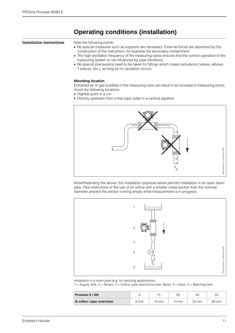
Mounting locationEntrained air or gas bubbles in the measuring tube can result in an increase in measuring errors. Avoid the following locations:� Highest point in a run.� Directly upstream from a free pipe outlet in a vertical pipeline.
Notwithstanding the above, the installation proposal below permits installation in an open down pipe. Pipe restrictions or the use of an orifice with a smaller cross-section than the nominal diameter prevent the sensor running empty while measurement is in progress.
Installation in a down pipe (e.g. for batching applications)1 = Supply tank, 2 = Sensor, 3 = Orifice, pipe restrictions (see Table), 4 = Valve, 5 = Batching tank
Promass E / DN 8 15 25 40 50
Ø orifice / pipe restriction 6 mm 10 mm 14 mm 22 mm 28 mm
F06-
xxxx
xxxx
-11-
00-0
0-xx
-004
F06-
xxxx
xxxx
-11-
00-0
0-xx
-002

PROline Promass 80/83 E
12 Endress+Hauser
Orientation
VerticalRecommended orientation with upward direction of flow (View 1). Entrained solids sink down. Gases rise away from the measuring tube when fluid is not flowing. The measuring tubes can be completely drained and protected against solids build-up.
HorizontalThe measuring tubes of Promass E must be in the same horizontal plane. When installation is correct the transmitter housing is above or below the pipe (Views 2, 3). Always avoid having the transmitter housing in the same horizontal plane as the pipe.
Orientation
Caution:The measuring tubes of Promass E are slightly curved. The position of the sensor, therefore, has to be matched to the fluid properties when the sensor is installed horizontally (see illustration below).
1 Not suitable for fluids with entrained solids. Risk of solids accumulating!2 Not suitable for outgassing fluids. Risk of air accumulating!
Fluid temperature / orientationIn order to ensure that the permissible ambient temperature for the transmitter (–20...+60 °C, optional –40...+60 °C) is not exceeded, we recommend the following orientations:
High fluid temperatureVertical piping: installation in accordance with Fig. “Orientation” / View 1Horizontal piping: installation in accordance with Fig. “Orientation” / View 3
Low fluid temperatureVertical piping: installation in accordance with Fig. “Orientation” / View 1Horizontal piping: installation in accordance with Fig. “Orientation” / View 2
F06-
xxxx
xxxx
-11-
00-0
0-xx
-000

PROline Promass 80/83 E
Endress+Hauser 13
Zero point adjustmentPromass generally does not require zero point adjustment!
Zero point adjustment is only required in special cases:� To achieve highest measuring accuracy also with very small flow rates� Under extreme process or operating conditions (e.g. very high process pressure or very high
viscosity of the fluid).
Zero point adjustment is performed with the measuring tubes completely filled and “zero flow”. This can be achieved, for example, with shut-off valves upstream and/or downstream of the sensor or by using existing valves and gates:� Normal operation � valves 1 and 2 open� Zero point adjustment with pump pressure � valve 1 open / valve 2 closed� Zero point adjustment without pump pressure � valve 1 closed / valve 2 open
Tracing, thermal insulationSome fluids require suitable measures to avoid heat transfer at the sensor. A wide range of materials can be used to provide the required thermal insulation. Heating can be electric, e.g. with heating elements, or by means of hot-water or steam pipes made of copper.
Caution:Risk of electronics overheating!Make sure that the connector between sensor and transmitter as well as the connection housing of the remote version always remain free of insulating material.Note that a certain orientation might be required, depending on the fluid temperature (see Page 12).
Inlet and outlet runs There are no installation requirements regarding inlet and outlet runs.
Length of connecting cable Max. 20 meters (remote version)
System pressure It is important to ensure that cavitation does not occur, because it would influence the oscillation of the measuring tubes. No special measures need to be taken for fluids which have properties similar to water under normal conditions.In the case of liquids with a low boiling point (hydrocarbons, solvents, liquefied gases) or in suction lines, it is important to ensure that pressure does not drop below the vapour pressure and that the liquid does not start to boil. It is also important to ensure that the gases that occur naturally in many liquids do not outgas. Such effects can be prevented when system pressure is sufficiently high.
Consequently, it is generally best to install the sensor:� Downstream from pumps (no risk of partial vacuum)� At the lowest point in a vertical pipe
1
2
F06-
xxxx
xxxx
-11-
00-0
0-xx
-001
PROline Promass 80/83 E
14 Endress+Hauser
Operating conditions (environment)
Ambient temperature range
20...+60 °C (sensor, transmitter)Optionally: 40...+60 °C
Install the device at a shady location. Avoid direct sunlight, particularly in warm climatic regions.
Note!At ambient temperatures below 20 °C the readability of the display may be impaired.
Storage temperature –40...+80 °C (preferably +20 °C)
Degree of protection Standard: IP 67 (NEMA 4X) for transmitter and sensor
Shock resistance According to IEC 68-2-31
Vibration resistance Acceleration up to 1 g, 10...150 Hz, following IEC 68-2-6
Electromagnetic compatibility (EMC)
According to EN 61326 / A1
Operating conditions (process)
Medium temperature range
Sensor:40...+125 °C
Seals:no internal seals
Limiting medium pressure range (nominal pressure)
Flanges: DIN PN 40...100 / ANSI Cl 150, Cl 300, Cl 600 / JIS 10K, 20K, 40K, 63KThe sensor Promass E has no secondary containment.
Limiting flow See Page 4 (“Measuring range”).
Select nominal diameter by optimising between required flow range and permissible pressure loss. See Page 4 for a list of max. possible full scale values.� The minimum recommended full scale value is approx. 1/20 of the max. full scale value.� In most applications, 20...50% of the maximum full scale value can be considered ideal.� Select a lower full scale value for abrasive substances such as fluids with entrained solids
(flow velocity <1 m/s). � For gas measurement the following rules apply:
– Flow velocity in the measuring tubes should not be more than half the sonic velocity (0.5 Mach).
– The maximum mass flow depends on the density of the gas (see formula on Page 4)

PROline Promass 80/83 E
Endress+Hauser 15
Pressure loss Pressure loss depends on the fluid properties and on the flow rate.The following formula can be used to approximately calculate the pressure loss.
Pressure loss coefficient for Promass E
Pressure loss diagram for water
Reynolds number
Re ��2300 1)
Re < 2300
�p = pressure loss [mbar]� = kinematic viscosity [m2/s]
= mass flow [kg/s]
� = fluid density [kg/m3]d = inside diameter of measuring tubes [m]K...K2 = constants (depending on nominal diameter)
1) To compute the pressure loss for gases, always use the formula for Re ��2300.
DN d [m] K K1 K2
8 5.35 ��10–3 5.70 ��107 7.91 ��107 2.10 ��107
15 8.30 ��10–3 7.62 ��106 1.73 ��107 2.13 ��106
25 12.00 ��10–3 1.89 ��106 4.66 ��106 6.11 ��105
40 17.60 ��10–3 4.42 ��105 1.35 ��106 1.38 ��105
50 26.00 ��10–3 8.54 ��104 4.02 ��105 2.31 ��104
Re 2 m�� d � �� � �---------------------------=
�p K �0.25 m·
1.85�
0.86–� � �=
�p K1 � m· K2 ��0.25 m·
2�
�-------------------------------------+� �=
m·
F06-
4xE
xxxx
x-05
-xx-
xx-x
x-00
9
PROline Promass 80/83 E
16 Endress+Hauser
Mechanical construction
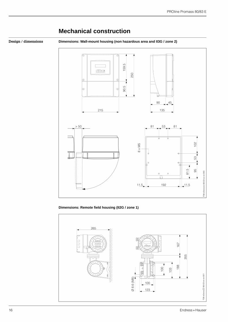
Design / dimensions Dimensions: Wall-mount housing (non hazardous area and II3G / zone 2)
Dimensions: Remote field housing (II2G / zone 1)F0
6-x0
xxxx
xx-0
6-03
-xx-
xx-0
00
Nicht unter Spannungöffnen
Kee
pc
ove
rtig
htw
hile
circ
uits
are
alive
Nepasouvrirl’appareil soustension
Kee
pc
ove
rtig
htw
hile
circ
uits
are
aliv
e
Ø 8
.6 (
M8)
100
123
100
133 18
8
355
167
Esc
E- +
265
Nicht-eigensichereStromkreise durch
IP40-Abdeckung geschützt
Non-intrinsically safecircuits Ip40 protected
Boucles de courantsans sécurité intrinsèque
protégées par Ip40
Nicht-eigensichereStromkreise durch
IP40-Abdeckung geschützt
Non-intrinsically safecircuits Ip40 protected
Boucles de courantsans sécurité intrinsèque
protégées par Ip40
F06-
x0xx
xxZ
Z-0
6-03
-xx-
xx-0
01
PROline Promass 80/83 E
Endress+Hauser 17
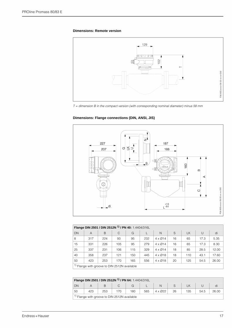
Dimensions: Remote version
T = dimension B in the compact version (with corresponding nominal diameter) minus 58 mm
Dimensions: Flange connections (DIN, ANSI, JIS)
Flange DIN 2501 / DIN 2512N 1) / PN 40: 1.4404/316L
DN A B C G L N S LK U di
8 317 224 93 95 232 4 x Ø14 16 65 17.3 5.35
15 331 226 105 95 279 4 x Ø14 16 65 17.3 8.30
25 337 231 106 115 329 4 x Ø14 18 85 28.5 12.00
40 358 237 121 150 445 4 x Ø18 18 110 43.1 17.60
50 423 253 170 165 556 4 x Ø18 20 125 54.5 26.001) Flange with groove to DIN 2512N available
Flange DIN 2501 / DIN 2512N 1) / PN 64: 1.4404/316L
DN A B C G L N S LK U di
50 423 253 170 180 565 4 x Ø22 26 135 54.5 26.001) Flange with groove to DIN 2512N available
T
129
102
F06-
80E
xxxx
x-06
-05-
xx-x
x-00
0F0
6-80
Exx
xxx-
06-0
0-xx
-xx-
000
PROline Promass 80/83 E
18 Endress+Hauser
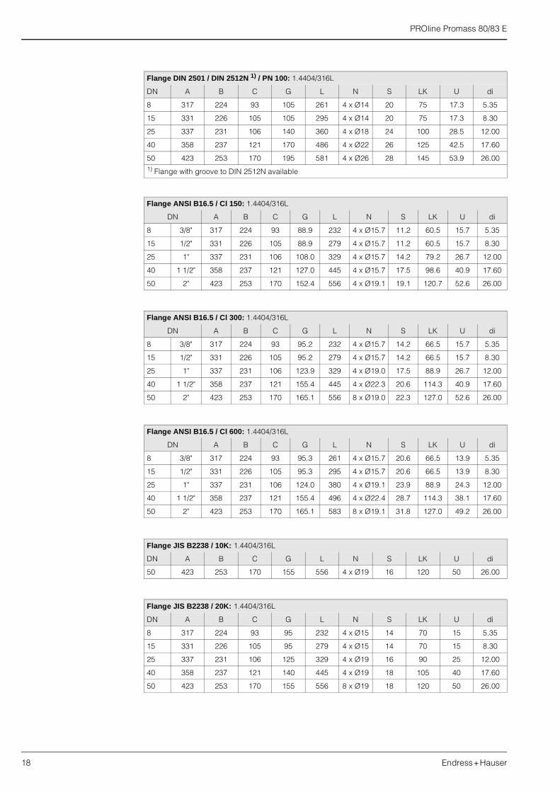
Flange DIN 2501 / DIN 2512N 1) / PN 100: 1.4404/316L
DN A B C G L N S LK U di
8 317 224 93 105 261 4 x Ø14 20 75 17.3 5.35
15 331 226 105 105 295 4 x Ø14 20 75 17.3 8.30
25 337 231 106 140 360 4 x Ø18 24 100 28.5 12.00
40 358 237 121 170 486 4 x Ø22 26 125 42.5 17.60
50 423 253 170 195 581 4 x Ø26 28 145 53.9 26.001) Flange with groove to DIN 2512N available
Flange ANSI B16.5 / Cl 150: 1.4404/316L
DN A B C G L N S LK U di
8 3/8" 317 224 93 88.9 232 4 x Ø15.7 11.2 60.5 15.7 5.35
15 1/2" 331 226 105 88.9 279 4 x Ø15.7 11.2 60.5 15.7 8.30
25 1" 337 231 106 108.0 329 4 x Ø15.7 14.2 79.2 26.7 12.00
40 1 1/2" 358 237 121 127.0 445 4 x Ø15.7 17.5 98.6 40.9 17.60
50 2" 423 253 170 152.4 556 4 x Ø19.1 19.1 120.7 52.6 26.00
Flange ANSI B16.5 / Cl 300: 1.4404/316L
DN A B C G L N S LK U di
8 3/8" 317 224 93 95.2 232 4 x Ø15.7 14.2 66.5 15.7 5.35
15 1/2" 331 226 105 95.2 279 4 x Ø15.7 14.2 66.5 15.7 8.30
25 1" 337 231 106 123.9 329 4 x Ø19.0 17.5 88.9 26.7 12.00
40 1 1/2" 358 237 121 155.4 445 4 x Ø22.3 20.6 114.3 40.9 17.60
50 2" 423 253 170 165.1 556 8 x Ø19.0 22.3 127.0 52.6 26.00
Flange ANSI B16.5 / Cl 600: 1.4404/316L
DN A B C G L N S LK U di
8 3/8" 317 224 93 95.3 261 4 x Ø15.7 20.6 66.5 13.9 5.35
15 1/2" 331 226 105 95.3 295 4 x Ø15.7 20.6 66.5 13.9 8.30
25 1" 337 231 106 124.0 380 4 x Ø19.1 23.9 88.9 24.3 12.00
40 1 1/2" 358 237 121 155.4 496 4 x Ø22.4 28.7 114.3 38.1 17.60
50 2" 423 253 170 165.1 583 8 x Ø19.1 31.8 127.0 49.2 26.00
Flange JIS B2238 / 10K: 1.4404/316L
DN A B C G L N S LK U di
50 423 253 170 155 556 4 x Ø19 16 120 50 26.00
Flange JIS B2238 / 20K: 1.4404/316L
DN A B C G L N S LK U di
8 317 224 93 95 232 4 x Ø15 14 70 15 5.35
15 331 226 105 95 279 4 x Ø15 14 70 15 8.30
25 337 231 106 125 329 4 x Ø19 16 90 25 12.00
40 358 237 121 140 445 4 x Ø19 18 105 40 17.60
50 423 253 170 155 556 8 x Ø19 18 120 50 26.00

PROline Promass 80/83 E
Endress+Hauser 19
Dimensions: VCO connections
Flange JIS B2238 / 40K: 1.4404/316L
DN A B C G L N S LK U di
8 317 224 93 115 261 4 x Ø19 20 80 15 5.35
15 331 226 105 115 300 4 x Ø19 20 80 15 8.30
25 337 231 106 130 375 4 x Ø19 22 95 25 12.00
40 358 237 121 160 496 4 x Ø23 24 120 38 17.60
50 423 253 170 165 601 8 x Ø19 26 130 50 26.00
Flange JIS B2238 / 63K: 1.4404/316L
DN A B C G L N S LK U di
8 317 224 93 120 282 4 x Ø19 23 85 12 5.35
15 331 226 105 120 315 4 x Ø19 23 85 12 8.30
25 337 231 106 140 383 4 x Ø23 27 100 22 12.00
40 358 237 121 175 515 4 x Ø25 32 130 35 17.60
50 423 253 170 185 616 8 x Ø23 34 145 48 26.00
8-VCO-4 (1/2"): 1.4404/316L
DN A B C G L U di
8 317 224 93 a/f 1" 252 10.2 5.35
12-VCO-4 (3/4"): 1.4404/316L
DN A B C G L U di
15 331 226 105 a/f 1 1/2" 305 15.7 8.30
F06-
80E
xxxx
x-06
-00-
xx-x
x-00
7

PROline Promass 80/83 E
20 Endress+Hauser
Dimensions: Tri-Clamp connections
Tri-Clamp: 1.4404/316L
DN Clamp A B C G L U di
8 1" 317 224 93 50.4 229 22.1 5.35
15 1" 331 226 105 50.4 273 22.1 8.30
25 1" 337 231 106 50.4 324 22.1 12.00
40 1 1/2" 358 237 121 50.4 456 34.8 17.60
50 2" 423 253 170 63.9 562 47.5 26.00
3A version also available (Ra ��0.8 m/150 grit)
1/2" Tri-Clamp: 1.4404/316L
DN Clamp A B C G L U di
8 1/2" 317 224 93 25.0 229 9.5 5.35
15 1/2" 331 226 105 25.0 273 9.5 8.30
3A version also available (Ra ��0.8 m/150 grit)
F06-
80E
xxxx
x-06
-00-
xx-x
x-00
3
PROline Promass 80/83 E
Endress+Hauser 21
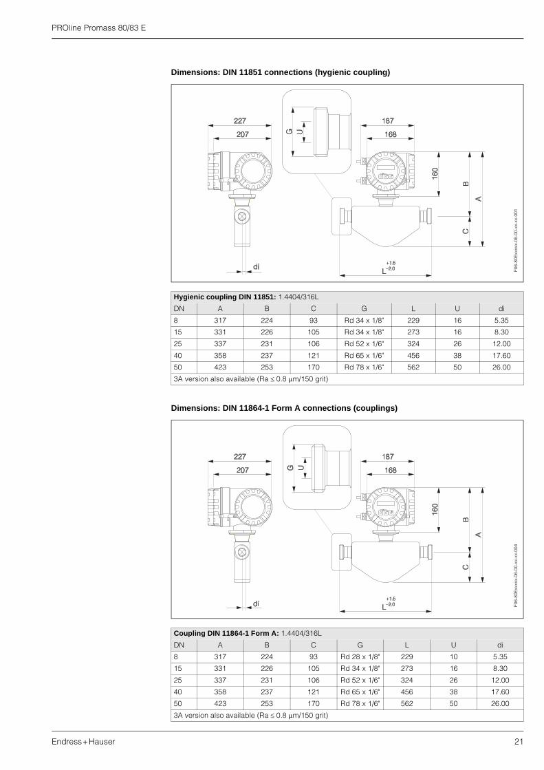
Dimensions: DIN 11851 connections (hygienic coupling)
Dimensions: DIN 11864-1 Form A connections (couplings)
Hygienic coupling DIN 11851: 1.4404/316L
DN A B C G L U di
8 317 224 93 Rd 34 x 1/8" 229 16 5.35
15 331 226 105 Rd 34 x 1/8" 273 16 8.30
25 337 231 106 Rd 52 x 1/6" 324 26 12.00
40 358 237 121 Rd 65 x 1/6" 456 38 17.60
50 423 253 170 Rd 78 x 1/6" 562 50 26.00
3A version also available (Ra ��0.8 m/150 grit)
Coupling DIN 11864-1 Form A: 1.4404/316L
DN A B C G L U di
8 317 224 93 Rd 28 x 1/8" 229 10 5.35
15 331 226 105 Rd 34 x 1/8" 273 16 8.30
25 337 231 106 Rd 52 x 1/6" 324 26 12.00
40 358 237 121 Rd 65 x 1/6" 456 38 17.60
50 423 253 170 Rd 78 x 1/6" 562 50 26.00
3A version also available (Ra ��0.8 m/150 grit)
F06-
80E
xxxx
x-06
-00-
xx-x
x-00
1F0
6-80
Exx
xxx-
06-0
0-xx
-xx-
004

PROline Promass 80/83 E
22 Endress+Hauser
Dimensions: flange connections DIN 11864-2 Form A (BF)
Dimensions: ISO 2853 connections (couplings)
Flange DIN 11864-2 Form A (BF): 1.4404/316L
DN A B C G L N S LK U di
8 317 224 93 54 249 4 x Ø9 10 37 10 5.35
15 331 226 105 59 293 4 x Ø9 10 42 16 8.30
25 337 231 106 70 344 4 x Ø9 10 53 26 12.00
40 358 237 121 82 456 4 x Ø9 10 65 38 17.60
50 423 253 170 94 562 4 x Ø9 10 77 50 26.00
3A version also available (Ra ��0.8 m/150 grit)
Coupling ISO 2853: 1.4404/316L
DN A B C G 1) L U di
8 317 224 93 37.13 229 22.6 5.35
15 331 226 105 37.13 273 22.6 8.30
25 337 231 106 37.13 324 22.6 12.00
40 358 237 121 52.68 456 35.6 17.60
50 423 253 170 64.16 562 48.6 26.001) Max. thread diameter to ISO 2853 Annex A, 3A version also available (Ra ��0.8 m/150 grit)
F06-
80E
xxxx
x-06
-00-
xx-x
x-00
5F0
6-80
Exx
xxx-
06-0
0-xx
-xx-
006

PROline Promass 80/83 E
Endress+Hauser 23
Dimensions: SMS 1145 connections (hygienic coupling)
Weight � Compact version: see table below� Remote version
– Sensor: weight of compact version minus 2 kg
Materials Transmitter housing:� Powder coated die-cast aluminium
Sensor housing:� Acid and alkali resistant outer surface; stainless steel 1.4301/304
Process connections and manifolds:� Flanges DIN / ANSI / JIS � Stainless steel 1.4404/316L� Flange DIN 11864-2 � Stainless steel 1.4404/316L � VCO connection � Stainless steel 1.4404/316L� Hygienic coupling DIN 11851 / SMS 1145 � Stainless steel 1.4404/316L� Couplings ISO 2853 / DIN 11864-1 � Stainless steel 1.4404/316L� Tri-Clamp � Stainless steel 1.4404/316L
Hygienic coupling SMS 1145: 1.4404/316L
DN A B C G L U di
8 317 224 93 Rd 40 x 1/6" 229 22.5 5.35
15 331 226 105 Rd 40 x 1/6" 273 22.5 8.30
25 337 231 106 Rd 40 x 1/6" 324 22.5 12.00
40 358 237 121 Rd 60 x 1/6" 456 35.5 17.60
50 423 253 170 Rd 70 x 1/6" 562 48.5 26.00
3A version also available (Ra ��0.8 m/150 grit)
F06-
80E
xxxx
x-06
-00-
xx-x
x-00
2
Promass E / DN 8 15 25 40 50
Weight in [kg] 8 8 10 15 22
PROline Promass 80/83 E
24 Endress+Hauser
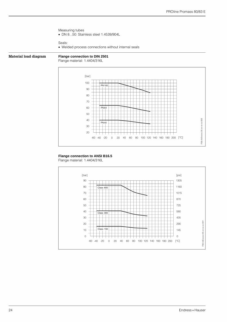
Measuring tubes� DN 8...50: Stainless steel 1.4539/904L
Seals:� Welded process connections without internal seals
Material load diagram Flange connection to DIN 2501Flange material: 1.4404/316L
Flange connection to ANSI B16.5Flange material: 1.4404/316L
F06-
4xE
xxxx
x-05
-xx-
xx-x
x-00
0F0
6-4x
Exx
xxx-
05-x
x-xx
-xx-
001
PROline Promass 80/83 E
Endress+Hauser 25
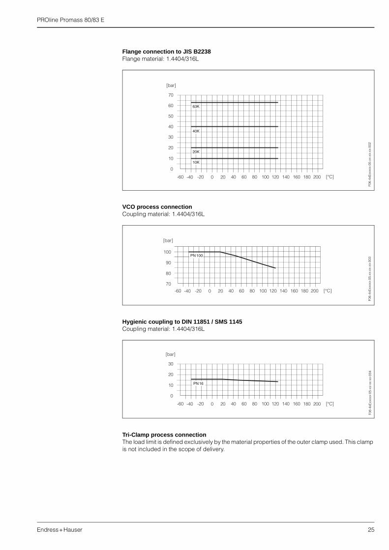
Flange connection to JIS B2238Flange material: 1.4404/316L
VCO process connectionCoupling material: 1.4404/316L
Hygienic coupling to DIN 11851 / SMS 1145Coupling material: 1.4404/316L
Tri-Clamp process connectionThe load limit is defined exclusively by the material properties of the outer clamp used. This clamp is not included in the scope of delivery.
F06-
4xE
xxxx
x-05
-xx-
xx-x
x-00
2F0
6-4x
Exx
xxx-
05-x
x-xx
-xx-
003
F06-
4xE
xxxx
x-05
-xx-
xx-x
x-00
4

PROline Promass 80/83 E
26 Endress+Hauser
Coupling to DIN 11864-1Coupling material: 1.4404/316L
Flange connection to DIN 11864-2Flange material: 1.4404/316L
Coupling to ISO 2853Coupling material: 1.4404/316L
Process connection Welded process connections:� VCO coupling, flanges (DIN 2501, ANSI B16.5, JIS B2238)� Sanitary connections: Tri-Clamp, couplings (DIN 11851, SMS 1145, ISO 2853, DIN 11864-1),
flange to DIN 11864-2
F06-
4xE
xxxx
x-05
-xx-
xx-x
x-00
5F0
6-4x
Exx
xxx-
05-x
x-xx
-xx-
006
F06-
4xE
xxxx
x-05
-xx-
xx-x
x-00
7

PROline Promass 80/83 E
Endress+Hauser 27
Human interface
Display elements � Liquid-crystal display: backlit, two lines (Promass 80) or four lines (Promass 83) with 16 characters per line
� Selectable display of different measured values and status variables
Operating elements Unified control concept for both types of transmitter:
Promass 80 E:� Local operation with three keys (–, +, E)� Quick Setup menus for straightforward commissioning
Promass 83 E:� Local operation with three optical sensors (–, +, E)� Application specific Quick Setup menus for straightforward commissioning
Remote operation Promass 80 E:Remote operation via HART, PROFIBUS-PA
Promass 83 E:Remote operation via HART, PROFIBUS-PA/-DP, FOUNDATION Fieldbus
Certificates and approvals
Ex approval Information about currently available Ex versions (ATEX, FM, CSA) can be supplied by your E+H Sales Centre on request. All explosion protection data are given in a separate documentation which is available upon request.
Sanitary compatibility 3A authorization
CE mark The measuring system is in conformity with the statutory requirements of the EC Directives. Endress+Hauser confirms successful testing of the device by affixing to it the CE mark.
Other standards, guidelines
EN 60529:Degrees of protection by housing (IP code)
EN 61326 / A1 (IEC 1326):Electromagnetic compatibility (EMC requirements)
NAMUR NE 21:Electromagnetic compatibility (EMC) of imdustrial process and laboratory control equipment.
NAMUR NE 43:Standardisation of the signal level for the breakdown information of digital transmitters with analogue output signal.
Ordering information
The E+H service organisation can provide detailed ordering information and information on the order codes on request.

Endress+Hauser GmbH+Co.Instruments InternationalP.O. Box 2222D-79574 Weil am RheinGermany
Tel. (07621) 975-02Tx 773926Fax (07621) 975 345e-mail: [email protected]
Internet:http://www.endress.com
11.01
Subject to modification
Accessories
Various accessories, which can be ordered separately from Endress+Hauser, are available for the transmitter. The E+H service organisation can provide detailed information on request.
Supplementary documentation
❑ Operating Instructions Promass 80 (BA 057D/06/en)❑ Operating Instructions Promass 83 (BA 059D/06/en)❑ Description of Device Functions Promass 80 (BA 058D/06/en)❑ Description of Device Functions Promass 83 (BA 060D/06/en)❑ Supplementary documentation on Ex-ratings: ATEX, FM, CSA
TRI-CLAMP®
Registered trademark of Ladish & Co., Inc., Kenosha, USA
HART®
Registered trademark of HART Communication Foundation, Austin, USA
S-DAT™, T-DAT™, F-CHIP™Registered or registration-pending trademark of Endress+Hauser Flowtec AG, Reinach, CH
TI 061D/06/en/01.0350102807FM+SGML 6.0
Related Documents