TECHNICAL HANDBOOK PIPING SYSTEMS Non-Metallic Expansion Joints 7.3EDITION

Welcome message from author
This document is posted to help you gain knowledge. Please leave a comment to let me know what you think about it! Share it to your friends and learn new things together.
Transcript
TECHNICAL HANDBOOK
PIPING SYSTEMS Non-Metallic Expansion Joints 7.3EDITION
NON-METALLIC EXPANSION JOINT DIVISION
FLUID SEALING ASSOCIATION Telephone: (610) 971-4850
994 Old Eagle School Road, Suite 1019, Wayne, PA 19087 Facsimile: (610) 971-4859
Copyright 1970, 1995, 2008, 2013 by FLUID SEALING ASSOCIATION®. Printed In United States of America. All rights reserved. this handbook
or parts thereof may not be reproduced in any form without permission of the copyright owner.
Edition 7.3 2013
For current Members and Associate Members, please go to the Piping Division
section of the Fluid Sealing Association website:
www.fluidsealing.com
Acknowledgements The FSA is pleased to recognize the cooperation of Member Companies of the Non-Metallic Piping Expansion Joint Division in the preparation of this document. Without their support, this document would not have been possible. Technical Committee members who have made a particularly significant contribution to this publication include: Jim Richter The Metraflex Company Bruce Stratton Garlock Sealing Technologies Hans Vemb Hansen KE-Burgmann Ed Marchese Proco Products Rick DiGiovanni General Rubber Corp. Ted White Unaflex
Table of Contents
Members of the Division Regular Members .............................................................. 1 Associate Members ........................................................... 1
Foreword ................................................................................. 3 Chapter I - Product Description of Rubber
Expansion Joints A. Definitions ................................................................. 4 B. Functions .................................................................... 4 C. Advantages ................................................................ 4 D. Construction Details ................................................... 5
Chapter II - Types of Rubber Expansion Joints
and Connectors A. “Arch” Type ................................................................ 6 B. Reducer Type: “Taper” .............................................. 7 C. Custom Type ............................................................. 7 D. Sleeve Type .............................................................. 7 E. Special Flange Type .................................................. 7 F. Designs for Reduction of Turbulence
And Abrasion ............................................................. 8 G. Rectangular with Arch Type ...................................... 8 H. “U” Type .................................................................... 8 I. Belt “Dogbone” Type ................................................. 9 J. Spherical Molded Type .............................................. 9 K. Rubber Flanged Pipe, Fittings, Pipe Elbows ............. 10 L. Unions ....................................................................... 10 M. Fan Connectors ......................................................... 10 N. Retaining Rings and Control Units ............................ 10 O. Expansion Joint Protective
Shields and Covers ................................................... 10
Chapter III - Definition of Performance Characteristics
A. Expansion Joint Motions ........................................... 11 B. Sound Limiting Characteristics .................................. 11 C. Pressure Characteristics ........................................... 11 D. Resistance to Fluids .................................................. 11 E. Force Pounds and Spring Rates ............................... 12 F. Hydrostatic Testing .................................................... 12 G. Seismic Testing ......................................................... 12 H. Cycle Life ................................................................... 12
Chapter IV - Installation and Maintenance
A. Anchoring and Guiding the Piping System ................ 15 B. Control Units .............................................................. 15 C. Other Installations ..................................................... 16 D. Installation Instructions for Non-Metallic
Expansion Joints ....................................................... 17 E. Inspection Procedure for Expansion
Joints in Service ........................................................ 18 Chapter V - Flexible Rubber Pipe Connectors
Foreword ................................................................... 19 A. Definition ................................................................... 19 B. Performance Characteristic ....................................... 19 C. Construction Details .................................................. 19 D. Types of Pipe Connectors ......................................... 19 E. Anchoring and Control Units ..................................... 19 F. Installation and Maintenance..................................... 20
Chapter VI - All Fluoroplastic Couplings, Expansion Joints, Bellows
Foreword ................................................................... 21 A. Construction Details .................................................. 21 B. Performance Characteristics .................................... 21 C. Construction Detail ................................................... 21 D. Dimensions ............................................................... 21 E. Types of Connectors ................................................. 21 F. Anchoring .................................................................. 22 G. Installation and Maintenance .................................... 22
Tables I. Maximum Temperature Ratings ............................... 4 II. List of Elastomers Used in Expansion
Joints and Rubber Pipes ........................................... 5 III. Comparison of Acoustical Impedances .................... 11 IV. Pressure Characteristics of Rubber
Expansion Joints ....................................................... 11 V. Typical Narrow Arch Expansion Joint Movement/
Spring Rate Capabilities ........................................... 13 VI. Typical Wide Arch Movement/Spring
Rate Capabilities ....................................................... 14 VII. Rubber Pipe Connectors .......................................... 20 VIII. Coupling, 2 Convolution ........................................... 22 IX. Expansion Joint, 3 Convolution ................................ 22 X. Bellows, 5 Convolution ............................................. 22
Figures
1. Cross Section View of Standard Expansion Joint ........................................................ 3
2. 2A to 2T, Types of Expansion Joints ........................ 6-10 3. 3A to 3F, Types of Movements ................................. 11 4. Thrust Formula ......................................................... 14 5. 5A to 5F, Piping Layout with Use of
Expansion Joints ....................................................... 14-16 6. Assembly of Control Rods ........................................ 15 7. 7A to 7C, Types of Rubber Pipe
Connectors ............................................................... 18 8. Cross Section View of Rubber
Pipe Connectors ....................................................... 19 9. 9A to 9C, Types of Fluoroplastic
Connectors ............................................................... 20 10. Fluoroplastic Expansion Joint Flange ....................... 21
Appendixes
A. Dimension Inspection Procedure .............................. 20 B. Common Flange Dimensions/Drilling Chart .............. 23 C. Control Unit Dimensions and Ratings ....................... 24 D. Mating Flange Thickness .......................................... 24 E. Glossary of Terms .................................................... 25 F. Noise and Vibration Transmitted Through
the Hydraulic Media Reduced with the Installation of Expansion Joints ................................ 28
G. Mechanical Vibration in a Steel Piping System Reduced with the Installation of Pipe Connectors or Expansion Joints ................... 29
H. Pressure Terminology ............................................... 30 I. List of Specifications ................................................. 30 J. Bibliography of Rubber Expansion Joint
Articles ...................................................................... 30 K. Would a Rubber or Metal Expansion Joint
Better Suite my Application ....................................... 31
FOREWORD:
†Rubber expansion joints have been specified and used for many years by consulting engineers, mechanical contractors, pressure
vessel designers, plant engineers and turn-key construction firms. They are installed to accommodate movement in piping runs,
protect piping from expansion and contraction and insure efficient and economical on-stream operations.
Rubber expansion joints provide time-tested ways to accommodate pressure loads, relieve movement stresses, reduce noise, isolate
vibration, compensate for misalignment after plants go on stream and prolong the life of motive equipment. Rubber expansion
joints, designed by engineers and fabricated by skilled craftsmen, are used in all systems conveying fluids under pressure and/or
vacuum at various temperatures:
Air Conditioning, heating and ventilating systems* in commercial and institutional buildings, schools,
apartments, stores, hospitals, motels, hotels and aboard ships
Central and ancillary power-generating stations in communities, factories, buildings and aboard
ships.
Sewage disposal and water-treatment plants.
Process piping in paper and pulp, chemical, primary metal and petroleum refining plants.
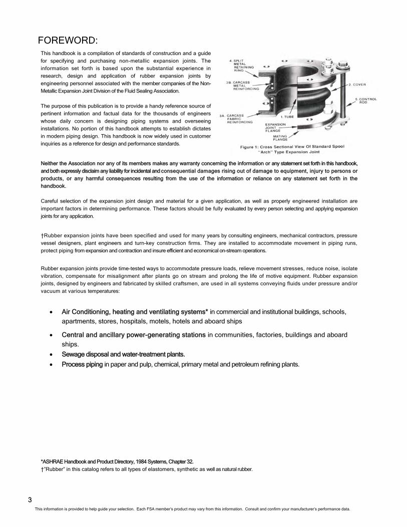
This handbook is a compilation of standards of construction and a guide
for specifying and purchasing non-metallic expansion joints. The
information set forth is based upon the substantial experience in
research, design and application of rubber expansion joints by
engineering personnel associated with the member companies of the Non-
Metallic Expansion Joint Division of the Fluid Sealing Association.
The purpose of this publication is to provide a handy reference source of
pertinent information and factual data for the thousands of engineers
whose daily concern is designing piping systems and overseeing
installations. No portion of this handbook attempts to establish dictates
in modern piping design. This handbook is now widely used in customer
inquiries as a reference for design and performance standards.
3
*ASHRAE Handbook and Product Directory, 1984 Systems, Chapter 32.
†”Rubber” in this catalog refers to all types of elastomers, synthetic as well as natural rubber.
Neither the Association nor any of its members makes any warranty concerning the information or any statement set forth in this handbook,
and both expressly disclaim any liability for incidental and consequential damages rising out of damage to equipment, injury to persons or
products, or any harmful consequences resulting from the use of the information or reliance on any statement set forth in the
handbook.
Careful selection of the expansion joint design and material for a given application, as well as properly engineered installation are
important factors in determining performance. These factors should be fully evaluated by every person selecting and applying expansion
joints for any application.
This information is provided to help guide your selection. Each FSA member’s product may vary from this information. Consult and confirm your manufacturer’s performance data.
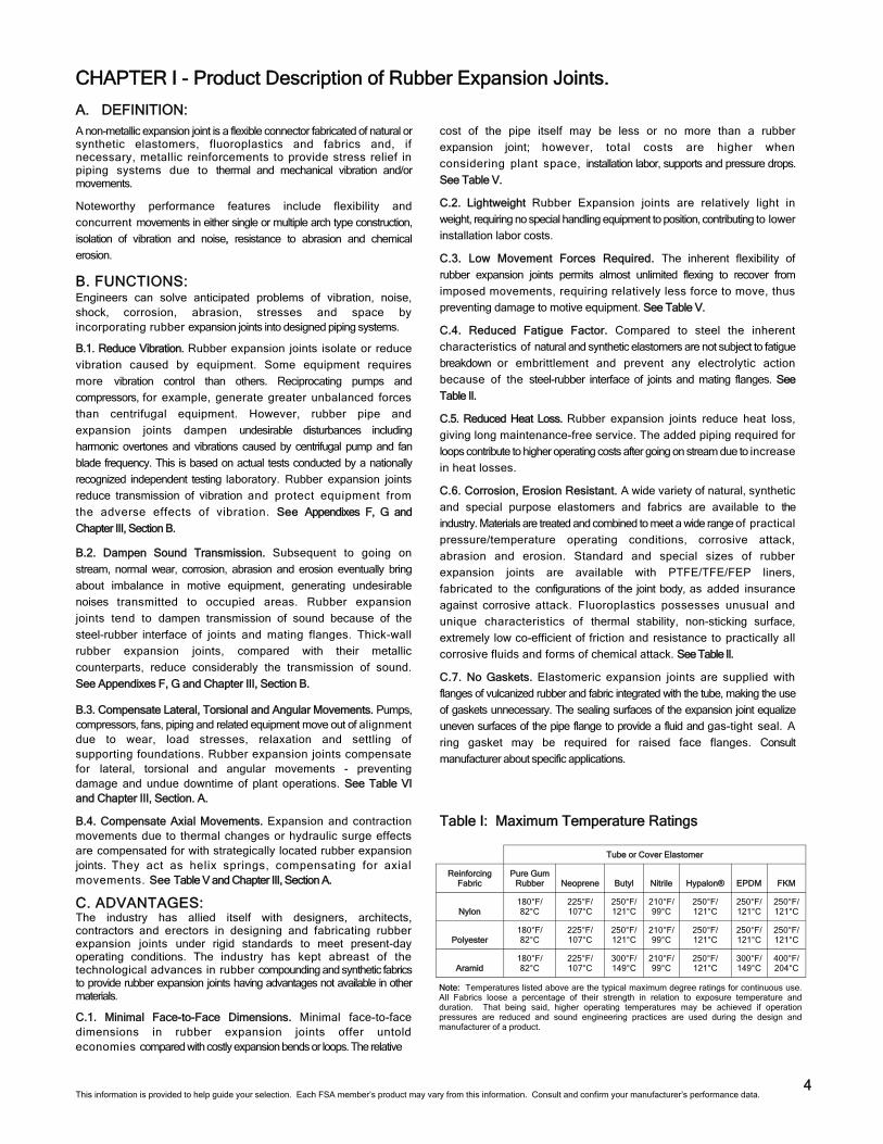
Note: Temperatures listed above are the typical maximum degree ratings for continuous use. All Fabrics loose a percentage of their strength in relation to exposure temperature and duration. That being said, higher operating temperatures may be achieved if operation pressures are reduced and sound engineering practices are used during the design and manufacturer of a product.
CHAPTER I - Product Description of Rubber Expansion Joints.
A. DEFINITION:
A non-metallic expansion joint is a flexible connector fabricated of natural or synthetic elastomers, fluoroplastics and fabrics and, if necessary, metallic reinforcements to provide stress relief in piping systems due to thermal and mechanical vibration and/or movements.
Noteworthy performance features include flexibility and
concurrent movements in either single or multiple arch type construction,
isolation of vibration and noise, resistance to abrasion and chemical
erosion.
B. FUNCTIONS: Engineers can solve anticipated problems of vibration, noise, shock, corrosion, abrasion, stresses and space by incorporating rubber expansion joints into designed piping systems.
B.1. Reduce Vibration. Rubber expansion joints isolate or reduce
vibration caused by equipment. Some equipment requires
more vibration control than others. Reciprocating pumps and
compressors, for example, generate greater unbalanced forces
than centrifugal equipment. However, rubber pipe and
expansion joints dampen undesirable disturbances including
harmonic overtones and vibrations caused by centrifugal pump and fan
blade frequency. This is based on actual tests conducted by a nationally
recognized independent testing laboratory. Rubber expansion joints
reduce transmission of vibration and protect equipment from
the adverse effects of vibration. See Appendixes F, G and
Chapter III, Section B.
B.2. Dampen Sound Transmission. Subsequent to going on
stream, normal wear, corrosion, abrasion and erosion eventually bring
about imbalance in motive equipment, generating undesirable
noises transmitted to occupied areas. Rubber expansion
joints tend to dampen transmission of sound because of the
steel-rubber interface of joints and mating flanges. Thick-wall
rubber expansion joints, compared with their metallic
counterparts, reduce considerably the transmission of sound.
See Appendixes F, G and Chapter III, Section B.
B.3. Compensate Lateral, Torsional and Angular Movements. Pumps, compressors, fans, piping and related equipment move out of alignment due to wear, load stresses, relaxation and settling of supporting foundations. Rubber expansion joints compensate for lateral, torsional and angular movements - preventing damage and undue downtime of plant operations. See Table VI and Chapter III, Section. A.
B.4. Compensate Axial Movements. Expansion and contraction movements due to thermal changes or hydraulic surge effects are compensated for with strategically located rubber expansion joints. They act as helix springs, compensating for axial movements. See Table V and Chapter III, Section A.
C. ADVANTAGES: The industry has allied itself with designers, architects, contractors and erectors in designing and fabricating rubber expansion joints under rigid standards to meet present-day operating conditions. The industry has kept abreast of the technological advances in rubber compounding and synthetic fabrics to provide rubber expansion joints having advantages not available in other materials.
C.1. Minimal Face-to-Face Dimensions. Minimal face-to-face dimensions in rubber expansion joints offer untold economies compared with costly expansion bends or loops. The relative
cost of the pipe itself may be less or no more than a rubber
expansion joint; however, total costs are higher when
considering plant space, installation labor, supports and pressure drops.
See Table V.
C.2. Lightweight Rubber Expansion joints are relatively light in
weight, requiring no special handling equipment to position, contributing to lower
installation labor costs.
C.3. Low Movement Forces Required. The inherent flexibility of
rubber expansion joints permits almost unlimited flexing to recover from
imposed movements, requiring relatively less force to move, thus
preventing damage to motive equipment. See Table V.
C.4. Reduced Fatigue Factor. Compared to steel the inherent
characteristics of natural and synthetic elastomers are not subject to fatigue
breakdown or embrittlement and prevent any electrolytic action
because of the steel-rubber interface of joints and mating flanges. See
Table II.
C.5. Reduced Heat Loss. Rubber expansion joints reduce heat loss,
giving long maintenance-free service. The added piping required for
loops contribute to higher operating costs after going on stream due to increase
in heat losses.
C.6. Corrosion, Erosion Resistant. A wide variety of natural, synthetic
and special purpose elastomers and fabrics are available to the
industry. Materials are treated and combined to meet a wide range of practical
pressure/temperature operating conditions, corrosive attack,
abrasion and erosion. Standard and special sizes of rubber
expansion joints are available with PTFE/TFE/FEP liners,
fabricated to the configurations of the joint body, as added insurance
against corrosive attack. Fluoroplastics possesses unusual and
unique characteristics of thermal stability, non-sticking surface,
extremely low co-efficient of friction and resistance to practically all
corrosive fluids and forms of chemical attack. See Table II.
C.7. No Gaskets. Elastomeric expansion joints are supplied with
flanges of vulcanized rubber and fabric integrated with the tube, making the use
of gaskets unnecessary. The sealing surfaces of the expansion joint equalize
uneven surfaces of the pipe flange to provide a fluid and gas-tight seal. A
ring gasket may be required for raised face flanges. Consult
manufacturer about specific applications.
4
Table I: Maximum Temperature Ratings
Tube or Cover Elastomer
Reinforcing Fabric
Pure Gum Rubber Neoprene Butyl Nitrile Hypalon® EPDM FKM
Nylon 180°F/ 82°C
225°F/ 107°C
250°F/ 121°C
210°F/ 99°C
250°F/ 121°C
250°F/ 121°C
250°F/ 121°C
Polyester 180°F/ 82°C
225°F/ 107°C
250°F/ 121°C
210°F/ 99°C
250°F/ 121°C
250°F/ 121°C
250°F/ 121°C
Aramid 180°F/ 82°C
225°F/ 107°C
300°F/ 149°C
210°F/ 99°C
250°F/ 121°C
300°F/ 149°C
400°F/ 204°C
This information is provided to help guide your selection. Each FSA member’s product may vary from this information. Consult and confirm your manufacturer’s performance data.
C.8. Acoustical Impedance. Elastomeric expansion joints
significantly reduce noise transmission in piping systems
because the elastomeric composition of the joint acts as a
dampener that absorbs the greatest percentage of noise and
vibration. See Appendix F.
C.9. Greater Shock Resistance. The elastomeric type expansion joints
provide good resistance against shock stress from excessive hydraulic
surge, water hammer or pump cavitation.
D. CONSTRUCTION DETAILS: D.1. Tube. A protective, leakproof lining made of synthetic or
natural rubber as the service dictates. This is a seamless tube
that extends through the bore to the outside edges of the
flanges. Its purpose is to eliminate the possibility of the materials
being handled penetrating the carcass and weakening the fabric.
These tubes can be designed to cover service conditions for
chemical petroleum, sewage, gaseous and abrasive materials.
See Tables I and II, and Figure 1.
D.2. Cover. The exterior surface of the joint is formed from natural or synthetic rubber, depending on service requirements.
The prime function of the cover is to protect the carcass from outside
damage or abuse. Special polymers can be supplied to resist
chemicals, oils, sunlight, acid fumes and ozone. Also, a protective
coating may be applied to the exterior of the joint for additional
protection. See Tables I and II, and Figure 1.
D.3. Carcass. The carcass or body of the expansion joint consists of fabric
and, when necessary, metal reinforcement.
D.3.A. Fabric Reinforcement. The carcass fabric reinforcement is the
flexible and supporting member between the tube and cover.
Standard constructions normally utilize high quality synthetic
fabric. Natural fabrics can also be used at some pressures
and temperatures. All fabric plies are impregnated with rubber or
synthetic compounds to permit flexibility between the fabric plies.
See Figure 1-3A. and Table 1.
D.3.B. Metal Reinforcement. Wire or solid steel rings imbedded in the
carcass are frequently used as strengthening members of the joint. The
use of metal sometimes raises the rated working pressure and
can supply rigidity to the joint for vacuum service. See Table IV
and Figure 1-3B.
5
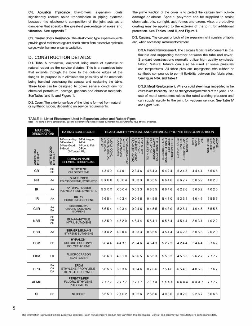
7-Outstanding 3-Fair to good 6-Excellent 2-Fair 5-Very Good 1-Poor to Fair 4-Good 0-Poor X-Contact Mfg.
MATERIAL DESIGNATION:
SI
NBR
SBR
CSM
FKM
EPR
AFMU
NR
IR
IIR
CIIR
CR
GE
BE BK CH
AA
CE
HK
BA CA DA
AA
AA
AA
AA BA
BC BE
BUNA-N/NITRILE NITRIL-BUTADIENE
EPDM ETHYLENE-PROPYLENE-
DIENE-TERPOLYMER
GUM RUBBER POLYISOPRENE, SYNTHETIC
5 5 5 0
4 3 5 0
5 3 X 2
5 6 4 4
5 6 6 0
5 6 5 6
7 7 7 7
5 3 X X
5 3 X X
5 6 5 4
5 6 5 4
4 3 4 0
6 6 6 6 4 0 3 6 2 5 6 6 0 0 2 6 2 X 0 2 2 2 6 7 6 0 2 0
4 0 2 2 0 5 5 4 5 5 4 1 4 6 4 4 4 5 2 0 3 0 3 4 4 5 4 4
2 0 2 0 4 5 4 4 0 6 5 5 0 0 3 3 4 0 0 4 3 0 5 3 4 4 2 5
6 7 6 7 5 2 2 2 4 5 4 3 2 3 4 6 4 4 3 1 3 4 4 4 4 2 4 4
7 7 7 7 5 5 6 2 6 5 5 3 6 6 6 5 4 6 1 0 2 6 2 7 4 5 5 5
6 7 6 7 7 5 4 6 0 7 6 6 0 0 4 6 6 0 3 6 4 0 5 6 6 5 4 5
7 7 7 7 X X X X 7 3 7 X 7 7 7 7 7 7 7 7 X X X 7 X X X 4
4 0 2 0 6 6 4 6 0 6 5 5 0 0 3 3 X 0 0 4 5 0 5 2 6 6 2 7
4 0 2 0 6 6 4 6 0 6 5 5 0 0 3 3 X 0 0 4 5 0 5 2 6 2 2 6
6 5 5 6 5 4 3 0 0 4 5 5 0 0 4 6 4 0 3 4 4 0 4 5 5 2 6 4
6 5 5 6 5 4 3 0 0 4 5 5 0 0 4 6 4 0 3 4 4 0 4 5 5 2 6 4
5 5 6 5 5 4 2 4 4 5 4 3 2 3 4 6 4 4 0 1 4 4 4 4 5 2 4 5
RATING SCALE CODE: ELASTOMER PHYSICAL AND CHEMICAL PROPERTIES COMPARISON
ALK
ALI, C
ON
C.
AN
IMA
L VE
G. O
IL C
HE
MIC
AL
WA
TE
R
AC
ID D
ILUT
E
AC
ID, C
ON
C.
ALP
HA
TIC
HY
DR
O
AR
OM
AT
IC H
YD
RO
HE
AT
C
OLD
F
LAM
E
TE
AR
OZ
ON
E
WE
AT
HE
R
SU
NLIG
HT
O
XID
AT
ION
OX
YG
EN
AT
ED
HY
DR
O.
LAC
QU
ER
S
OIL &
GA
SO
LINE
A
LKA
LI, DILU
TE
BUTYL ISOBUTENE-ISOPRENE
NATURAL RUBBER POLYISOPRENE, SYNTHETIC
CHLOROBUTYL CHLORO-ISOBUTENE-
ISOPRENE
HYPALON* CHLORO-SULFONYL-
POLYETHYLENE
SBR/GRS/BUNA-S STYRENE-BUTADIENE
FLUOROCARBON ELASTOMER
PTFE/TFE/FEP FLUORO-ETHYLENE-
POLYYMERS
SILICONE
AN
SI/A
ST
M
D14
18-7
7
COMMON NAME CHEMICAL GROUP NAME
NEOPRENE CHLOROPRENE
AS
TM
-D-2
000
D14
18-7
7
RE
BO
UN
D-C
OLD
C
OM
P. S
ET
T
EN
SILE
ST
RE
NG
TH
D
IELE
CT
RIC
ST
R.
ELE
. INS
ULA
TIO
N
WA
TE
R A
BS
OR
P
RA
DIA
TIO
N
SW
ELLIN
G IN
OIL
AB
RA
SIO
N
IMP
ER
ME
AB
ILITY
D
YN
AM
IC
RE
BO
UN
D-H
OT
TABLE II: List of Elastomers Used in Expansion Joints and Rubber Pipes Note: This listing is only a general guide. Specific elastomer compounds produced by member manufacturers may have different properties.
This information is provided to help guide your selection. Each FSA member’s product may vary from this information. Consult and confirm your manufacturer’s performance data.
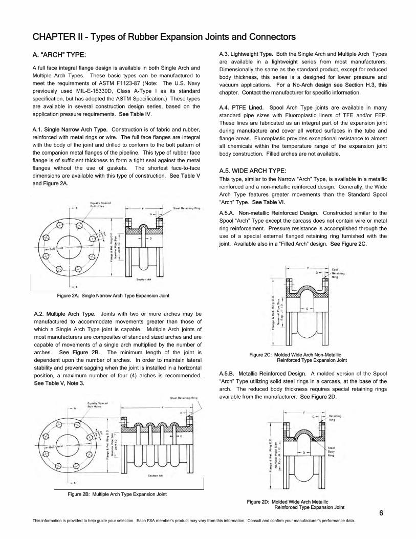
Figure 2B: Multiple Arch Type Expansion Joint
6
CHAPTER II - Types of Rubber Expansion Joints and Connectors
A. “ARCH” TYPE: A full face integral flange design is available in both Single Arch and
Multiple Arch Types. These basic types can be manufactured to
meet the requirements of ASTM F1123-87 (Note: The U.S. Navy
previously used MIL-E-15330D, Class A-Type I as its standard
specification, but has adopted the ASTM Specification.) These types
are available in several construction design series, based on the
application pressure requirements. See Table IV.
A.1. Single Narrow Arch Type. Construction is of fabric and rubber,
reinforced with metal rings or wire. The full face flanges are integral
with the body of the joint and drilled to conform to the bolt pattern of
the companion metal flanges of the pipeline. This type of rubber face
flange is of sufficient thickness to form a tight seal against the metal
flanges without the use of gaskets. The shortest face-to-face
dimensions are available with this type of construction. See Table V
and Figure 2A.
Figure 2A: Single Narrow Arch Type Expansion Joint
A.3. Lightweight Type. Both the Single Arch and Multiple Arch Types
are available in a lightweight series from most manufacturers.
Dimensionally the same as the standard product, except for reduced
body thickness, this series is a designed for lower pressure and
vacuum applications. For a No-Arch design see Section H.3, this
chapter. Contact the manufacturer for specific information.
A.2. Multiple Arch Type. Joints with two or more arches may be
manufactured to accommodate movements greater than those of
which a Single Arch Type joint is capable. Multiple Arch joints of
most manufacturers are composites of standard sized arches and are
capable of movements of a single arch multiplied by the number of
arches. See Figure 2B. The minimum length of the joint is
dependent upon the number of arches. In order to maintain lateral
stability and prevent sagging when the joint is installed in a horizontal
position, a maximum number of four (4) arches is recommended.
See Table V, Note 3.
A.4. PTFE Lined. Spool Arch Type joints are available in many
standard pipe sizes with Fluoroplastic liners of TFE and/or FEP.
These lines are fabricated as an integral part of the expansion joint
during manufacture and cover all wetted surfaces in the tube and
flange areas. Fluoroplastic provides exceptional resistance to almost
all chemicals within the temperature range of the expansion joint
body construction. Filled arches are not available.
A.5.B. Metallic Reinforced Design. A molded version of the Spool
“Arch” Type utilizing solid steel rings in a carcass, at the base of the
arch. The reduced body thickness requires special retaining rings
available from the manufacturer. See Figure 2D.
Figure 2D: Molded Wide Arch Metallic Reinforced Type Expansion Joint
A.5. WIDE ARCH TYPE: This type, similar to the Narrow “Arch” Type, is available in a metallic
reinforced and a non-metallic reinforced design. Generally, the Wide
Arch Type features greater movements than the Standard Spool
“Arch” Type. See Table VI.
A.5.A. Non-metallic Reinforced Design. Constructed similar to the
Spool “Arch” Type except the carcass does not contain wire or metal
ring reinforcement. Pressure resistance is accomplished through the
use of a special external flanged retaining ring furnished with the
joint. Available also in a “Filled Arch” design. See Figure 2C.
Figure 2C: Molded Wide Arch Non-Metallic Reinforced Type Expansion Joint
This information is provided to help guide your selection. Each FSA member’s product may vary from this information. Consult and confirm your manufacturer’s performance data.
7
D.2. Lightweight Type. Dimensionally the same as the sleeve
"Spool Type", except for reduced body thickness. This
series is designed for very low pressure and vacuum
applications. Joints are available in single and multiple arch types.
Consult the manufacturer for the types of clamps available for
sealing. This type generally offers greater flexibility than the spool
type.
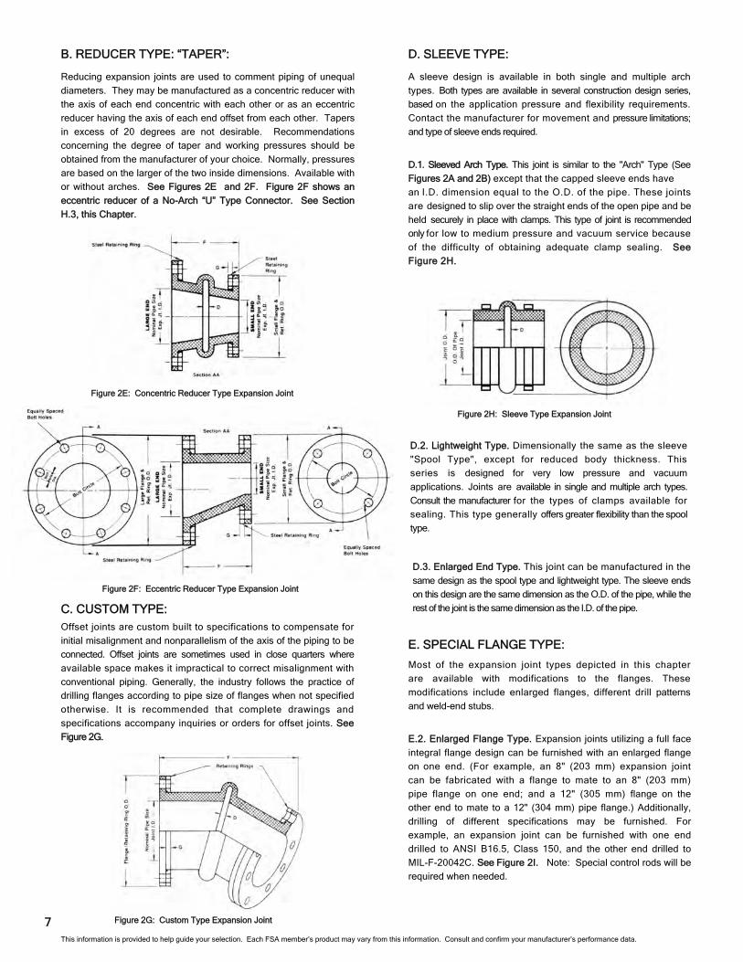
D.3. Enlarged End Type. This joint can be manufactured in the
same design as the spool type and lightweight type. The sleeve ends
on this design are the same dimension as the O.D. of the pipe, while the
rest of the joint is the same dimension as the I.D. of the pipe.
E. SPECIAL FLANGE TYPE:
Most of the expansion joint types depicted in this chapter
are available with modifications to the flanges. These
modifications include enlarged flanges, different drill patterns
and weld-end stubs.
E.2. Enlarged Flange Type. Expansion joints utilizing a full face
integral flange design can be furnished with an enlarged flange
on one end. (For example, an 8" (203 mm) expansion joint
can be fabricated with a flange to mate to an 8" (203 mm)
pipe flange on one end; and a 12" (305 mm) flange on the
other end to mate to a 12" (304 mm) pipe flange.) Additionally,
drilling of different specifications may be furnished. For
example, an expansion joint can be furnished with one end
drilled to ANSI B16.5, Class 150, and the other end drilled to
MIL-F-20042C. See Figure 2I. Note: Special control rods will be
required when needed.
C. CUSTOM TYPE:
Offset joints are custom built to specifications to compensate for
initial misalignment and nonparallelism of the axis of the piping to be
connected. Offset joints are sometimes used in close quarters where
available space makes it impractical to correct misalignment with
conventional piping. Generally, the industry follows the practice of
drilling flanges according to pipe size of flanges when not specified
otherwise. It is recommended that complete drawings and
specifications accompany inquiries or orders for offset joints. See
Figure 2G.
D. SLEEVE TYPE:
A sleeve design is available in both single and multiple arch
types. Both types are available in several construction design series,
based on the application pressure and flexibility requirements.
Contact the manufacturer for movement and pressure limitations;
and type of sleeve ends required.
Figure 2G: Custom Type Expansion Joint
B. REDUCER TYPE: “TAPER”:
Reducing expansion joints are used to comment piping of unequal
diameters. They may be manufactured as a concentric reducer with
the axis of each end concentric with each other or as an eccentric
reducer having the axis of each end offset from each other. Tapers
in excess of 20 degrees are not desirable. Recommendations
concerning the degree of taper and working pressures should be
obtained from the manufacturer of your choice. Normally, pressures
are based on the larger of the two inside dimensions. Available with
or without arches. See Figures 2E and 2F. Figure 2F shows an
eccentric reducer of a No-Arch “U” Type Connector. See Section
H.3, this Chapter.
D.1. Sleeved Arch Type. This joint is similar to the "Arch" Type (See
Figures 2A and 2B) except that the capped sleeve ends have
an I.D. dimension equal to the O.D. of the pipe. These joints
are designed to slip over the straight ends of the open pipe and be
held securely in place with clamps. This type of joint is recommended
only for low to medium pressure and vacuum service because
of the difficulty of obtaining adequate clamp sealing. See
Figure 2H.
Figure 2E: Concentric Reducer Type Expansion Joint
Figure 2F: Eccentric Reducer Type Expansion Joint
Figure 2H: Sleeve Type Expansion Joint
This information is provided to help guide your selection. Each FSA member’s product may vary from this information. Consult and confirm your manufacturer’s performance data.
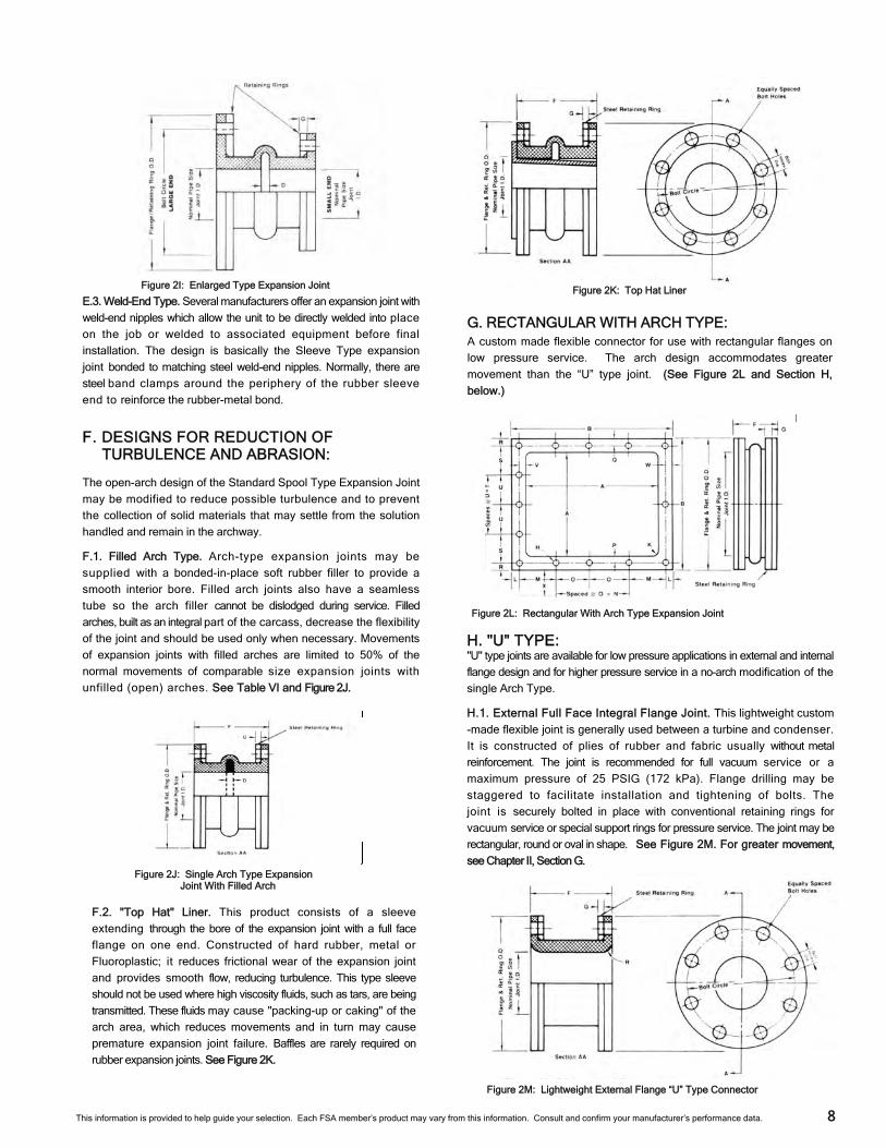
F. DESIGNS FOR REDUCTION OF TURBULENCE AND ABRASION:
The open-arch design of the Standard Spool Type Expansion Joint
may be modified to reduce possible turbulence and to prevent
the collection of solid materials that may settle from the solution
handled and remain in the archway.
F.1. Filled Arch Type. Arch-type expansion joints may be
supplied with a bonded-in-place soft rubber filler to provide a
smooth interior bore. Filled arch joints also have a seamless
tube so the arch filler cannot be dislodged during service. Filled
arches, built as an integral part of the carcass, decrease the flexibility
of the joint and should be used only when necessary. Movements
of expansion joints with filled arches are limited to 50% of the
normal movements of comparable size expansion joints with
unfilled (open) arches. See Table VI and Figure 2J.
F.2. "Top Hat" Liner. This product consists of a sleeve
extending through the bore of the expansion joint with a full face
flange on one end. Constructed of hard rubber, metal or
Fluoroplastic; it reduces frictional wear of the expansion joint
and provides smooth flow, reducing turbulence. This type sleeve
should not be used where high viscosity fluids, such as tars, are being
transmitted. These fluids may cause "packing-up or caking" of the
arch area, which reduces movements and in turn may cause
premature expansion joint failure. Baffles are rarely required on
rubber expansion joints. See Figure 2K.
8
E.3. Weld-End Type. Several manufacturers offer an expansion joint with
weld-end nipples which allow the unit to be directly welded into place
on the job or welded to associated equipment before final
installation. The design is basically the Sleeve Type expansion
joint bonded to matching steel weld-end nipples. Normally, there are
steel band clamps around the periphery of the rubber sleeve
end to reinforce the rubber-metal bond.
Figure 2I: Enlarged Type Expansion Joint
Figure 2J: Single Arch Type Expansion Joint With Filled Arch
Figure 2K: Top Hat Liner
G. RECTANGULAR WITH ARCH TYPE: A custom made flexible connector for use with rectangular flanges on
low pressure service. The arch design accommodates greater
movement than the “U” type joint. (See Figure 2L and Section H,
below.)
H. "U" TYPE: "U" type joints are available for low pressure applications in external and internal
flange design and for higher pressure service in a no-arch modification of the
single Arch Type.
H.1. External Full Face Integral Flange Joint. This lightweight custom
-made flexible joint is generally used between a turbine and condenser.
It is constructed of plies of rubber and fabric usually without metal
reinforcement. The joint is recommended for full vacuum service or a
maximum pressure of 25 PSIG (172 kPa). Flange drilling may be
staggered to facilitate installation and tightening of bolts. The
joint is securely bolted in place with conventional retaining rings for
vacuum service or special support rings for pressure service. The joint may be
rectangular, round or oval in shape. See Figure 2M. For greater movement,
see Chapter II, Section G.
Figure 2L: Rectangular With Arch Type Expansion Joint
Figure 2M: Lightweight External Flange “U” Type Connector
This information is provided to help guide your selection. Each FSA member’s product may vary from this information. Consult and confirm your manufacturer’s performance data.
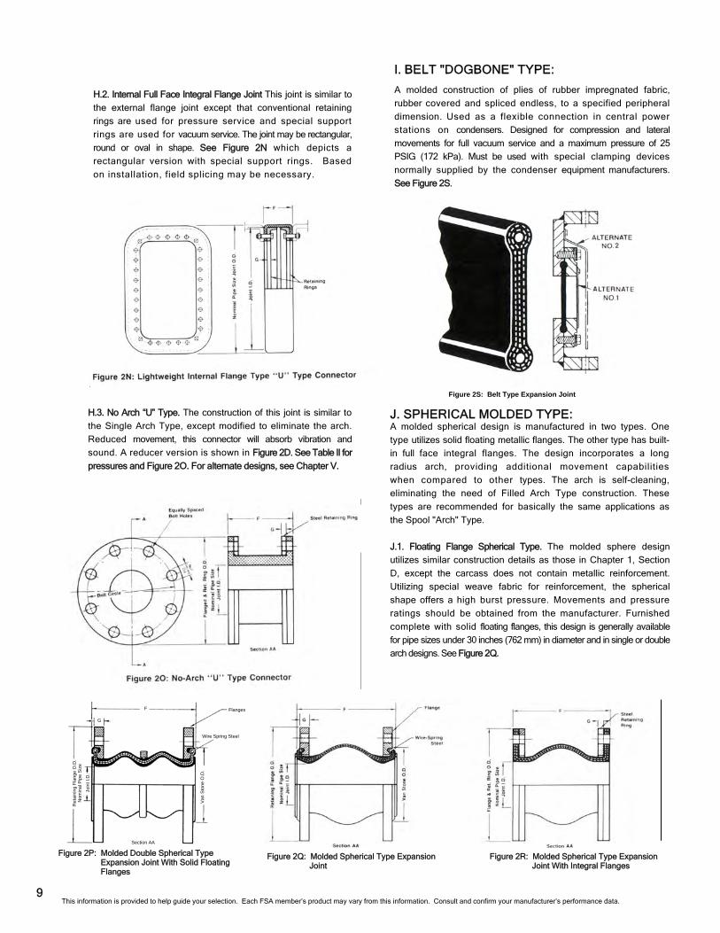
H.2. Internal Full Face Integral Flange Joint This joint is similar to
the external flange joint except that conventional retaining
rings are used for pressure service and special support
rings are used for vacuum service. The joint may be rectangular,
round or oval in shape. See Figure 2N which depicts a
rectangular version with special support rings. Based
on installation, field splicing may be necessary.
I. BELT "DOGBONE" TYPE:
A molded construction of plies of rubber impregnated fabric,
rubber covered and spliced endless, to a specified peripheral
dimension. Used as a flexible connection in central power
stations on condensers. Designed for compression and lateral
movements for full vacuum service and a maximum pressure of 25
PSIG (172 kPa). Must be used with special clamping devices
normally supplied by the condenser equipment manufacturers.
See Figure 2S.
H.3. No Arch “U” Type. The construction of this joint is similar to
the Single Arch Type, except modified to eliminate the arch.
Reduced movement, this connector will absorb vibration and
sound. A reducer version is shown in Figure 2D. See Table Il for
pressures and Figure 2O. For alternate designs, see Chapter V.
J. SPHERICAL MOLDED TYPE: A molded spherical design is manufactured in two types. One
type utilizes solid floating metallic flanges. The other type has built-
in full face integral flanges. The design incorporates a long
radius arch, providing additional movement capabilities
when compared to other types. The arch is self-cleaning,
eliminating the need of Filled Arch Type construction. These
types are recommended for basically the same applications as
the Spool "Arch" Type.
J.1. Floating Flange Spherical Type. The molded sphere design
utilizes similar construction details as those in Chapter 1, Section
D, except the carcass does not contain metallic reinforcement.
Utilizing special weave fabric for reinforcement, the spherical
shape offers a high burst pressure. Movements and pressure
ratings should be obtained from the manufacturer. Furnished
complete with solid floating flanges, this design is generally available
for pipe sizes under 30 inches (762 mm) in diameter and in single or double
arch designs. See Figure 2Q.
9 This information is provided to help guide your selection. Each FSA member’s product may vary from this information. Consult and confirm your manufacturer’s performance data.
Figure 2P: Molded Double Spherical Type Expansion Joint With Solid Floating Flanges
Figure 2Q: Molded Spherical Type Expansion Joint
Figure 2R: Molded Spherical Type Expansion Joint With Integral Flanges
Figure 2S: Belt Type Expansion Joint
Wire Spring Steel
Van
Sto
ne O
.D.
Flanges
Join
t I.D
.
Ret
aini
ng F
lang
e O
.D.
Nom
inal
Pip
e S
ize
F
G
Section AA
K. RUBBER FLANGED PIPE, FITTINGS, PIPE ELBOWS:
Elastomeric elbows and fittings are frequently used in place of metal
fittings where high abrasion and chemical resistance is required
and/or where vibration and stress relief is desirable. 45°, 900 short
radius and 90° long radius elbows as well as Y's, T's, laterals and
crosses can be furnished to ANSI B-16.1 dimensions.
L. UNIONS: Unions are small double arch rubber connectors with female
threaded (usually ANSI NPT) ends. These connectors are for use
with small diameter pipe and where clearance space for flanges is
not available. Usually available for standard pipe sizes from 3/4 inch (19
mm) to 3 inch (76 mm) diameter and a wide variety of elastomers. Normally,
unions are found in Heating, Ventilating and Air-Conditioning
(HVAC) applications.
M. FAN CONNECTORS: Industrial fans and their related ducting frequently require a
flexible connector to absorb vibration reduce noise and provide
an easy access to fans when overhaul or cleaning is required.
Elastomeric fan connectors have a lighter body and flanges
designed to match the specific fan design. Usually their pressure
and vacuum ratings are approximately ± 2 PSIG (14 kPa) to
match the service. Face-to-face dimension as short as 2-1/2" (63
mm) face-to-face are available. Slip over fan connectors are also
frequently specified.
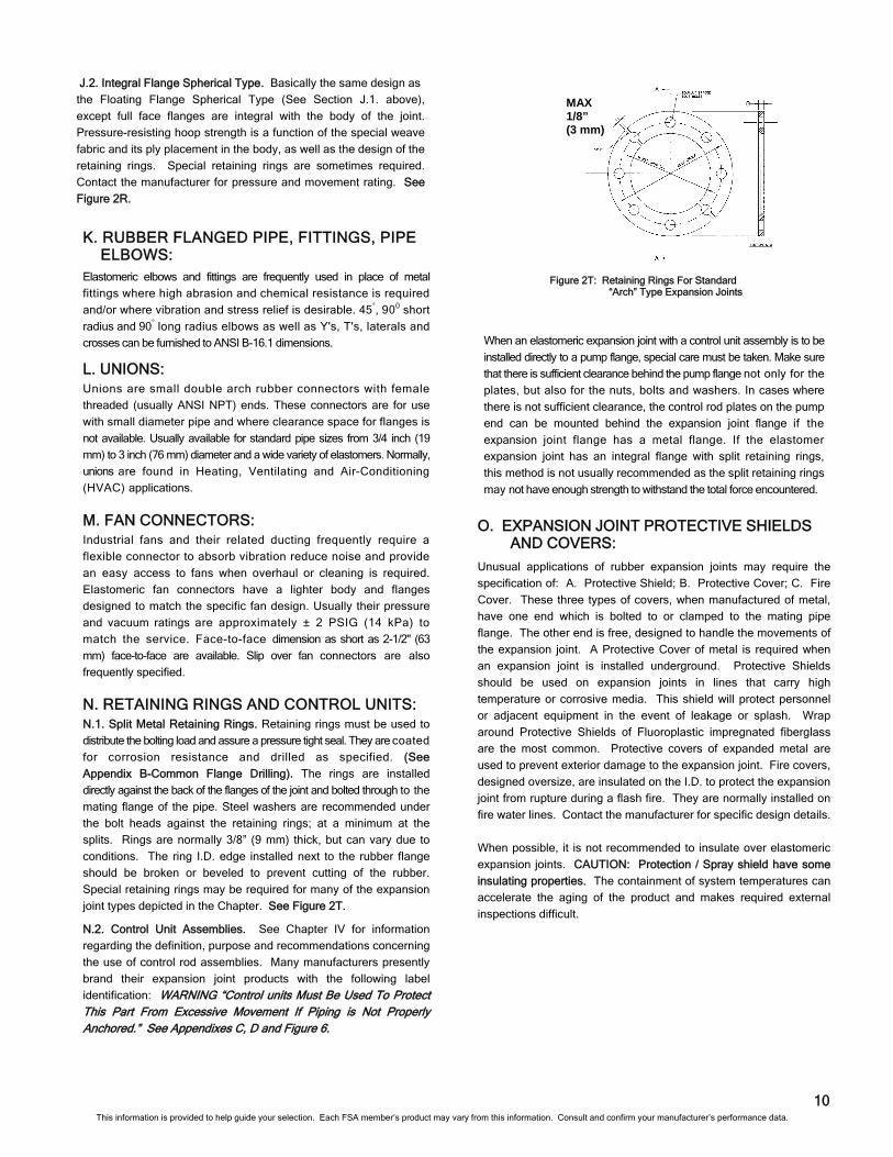
N. RETAINING RINGS AND CONTROL UNITS: N.1. Split Metal Retaining Rings. Retaining rings must be used to
distribute the bolting load and assure a pressure tight seal. They are coated
for corrosion resistance and drilled as specified. (See
Appendix B-Common Flange Drilling). The rings are installed
directly against the back of the flanges of the joint and bolted through to the
mating flange of the pipe. Steel washers are recommended under
the bolt heads against the retaining rings; at a minimum at the
splits. Rings are normally 3/8” (9 mm) thick, but can vary due to
conditions. The ring I.D. edge installed next to the rubber flange
should be broken or beveled to prevent cutting of the rubber.
Special retaining rings may be required for many of the expansion
joint types depicted in the Chapter. See Figure 2T.
N.2. Control Unit Assemblies. See Chapter IV for information
regarding the definition, purpose and recommendations concerning
the use of control rod assemblies. Many manufacturers presently
brand their expansion joint products with the following label
identification: WARNING “Control units Must Be Used To Protect This Part From Excessive Movement If Piping is Not Properly Anchored.” See Appendixes C, D and Figure 6.
When an elastomeric expansion joint with a control unit assembly is to be
installed directly to a pump flange, special care must be taken. Make sure
that there is sufficient clearance behind the pump flange not only for the
plates, but also for the nuts, bolts and washers. In cases where
there is not sufficient clearance, the control rod plates on the pump
end can be mounted behind the expansion joint flange if the
expansion joint flange has a metal flange. If the elastomer
expansion joint has an integral flange with split retaining rings,
this method is not usually recommended as the split retaining rings
may not have enough strength to withstand the total force encountered.
O. EXPANSION JOINT PROTECTIVE SHIELDS AND COVERS:
Unusual applications of rubber expansion joints may require the
specification of: A. Protective Shield; B. Protective Cover; C. Fire
Cover. These three types of covers, when manufactured of metal,
have one end which is bolted to or clamped to the mating pipe
flange. The other end is free, designed to handle the movements of
the expansion joint. A Protective Cover of metal is required when
an expansion joint is installed underground. Protective Shields
should be used on expansion joints in lines that carry high
temperature or corrosive media. This shield will protect personnel
or adjacent equipment in the event of leakage or splash. Wrap
around Protective Shields of Fluoroplastic impregnated fiberglass
are the most common. Protective covers of expanded metal are
used to prevent exterior damage to the expansion joint. Fire covers,
designed oversize, are insulated on the I.D. to protect the expansion
joint from rupture during a flash fire. They are normally installed on
fire water lines. Contact the manufacturer for specific design details.
When possible, it is not recommended to insulate over elastomeric
expansion joints. CAUTION: Protection / Spray shield have some
insulating properties. The containment of system temperatures can
accelerate the aging of the product and makes required external
inspections difficult.
10
the Floating Flange Spherical Type (See Section J.1. above),
except full face flanges are integral with the body of the joint.
Pressure-resisting hoop strength is a function of the special weave
fabric and its ply placement in the body, as well as the design of the
retaining rings. Special retaining rings are sometimes required.
Contact the manufacturer for pressure and movement rating. See
Figure 2R.
J.2. Integral Flange Spherical Type. Basically the same design as
MAX 1/8” (3 mm)
Figure 2T: Retaining Rings For Standard “Arch” Type Expansion Joints
This information is provided to help guide your selection. Each FSA member’s product may vary from this information. Consult and confirm your manufacturer’s performance data.
A. EXPANSION JOINT MOTIONS
A.1. Axial Compression. The dimensional reduction or shortening in the face-
to-face parallel length of the joint measured along the longitudinal
axis. See Figure 3A and Table V.
A.2. Axial Elongation. The dimensional increase or lengthening of face-to-face
parallel length of the joint measured along the longitudinal axis. See
Figure 3B and Table V.
A.3. Lateral or Transverse Movement The movement or relating
displacement of the two ends of the joint perpendicular to its
longitudinal axis. See Figure 3C and Table V.
A.4. Vibration. The ability of a flexible connector to absorb
mechanical oscillations in the system, usually high frequency. See
Figure 3D and Appendixes F and G.
A.5. Angular Movement. The angular displacement of the
longitudinal axis of the expansion joint from its initial straight line
position, measured in degrees. This is a combination of axial
elongation and axial compression. See Figure 3E and Table V.
A.6. Torsional Movement. The twisting of one end of an expansion joint
with respect to the other end about its longitudinal axis. Such
movement is measured in degrees. See Figure 3F and Table V.
A.7. Concurrent Movement. The combination of two or more of the above
expansion joint movements. This value is expressed as the Resultant
Movement. To calculate concurrent movement use the following
formula:
The concurrent movement formula is the sum of the individual movements except for Angular (because angular movement is covered by compression and elongation when looking at concurrent movements). Therefore the sum of the following: Compression, Elongation, Lateral, and Torsional still need to be less than one or the joint is operating outside the design intent and needs to be evaluated.
Formula: 1 ≥ ΔC + ΔE + ΔL + ΔT RC RE RL RT
Sample Calculation: 1 ≥ 2” + 0” + .75” + 0° 4” 2” 1” 5°
1 ≥ .5 + .75 + 0
1 ≥ 1.25 Joint is operating outside its design movements and needs to be evaluated.
ΔC = Change in compression RC = Rated Compression ΔE = Change in Elongation RE = Rated Elongation ΔL = Change in Lateral RL = Rated Lateral ΔT = Change in Torsional RT = Rated Torsional
CHAPTER III - Definition of Performance Characteristics
11
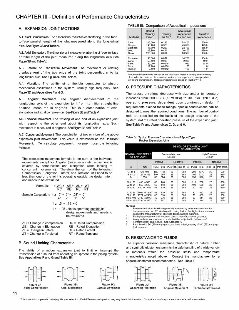
NOTES: 1. Pressure limitations listed are generally accepted by most manufacturers for
temperatures up to 180° yielding a 3:1 safety factor. For higher termperatures, consult the manufacturer for alternate designs and/or materials.
2. For higher pressure than inducated, contact manufacturer for guidance. 3. Always advise manufacturer if product will be subjected to “full vacuum” 4. For terminalogy on pressure. See Appnedix H. 5. Parts listed at 26” (660 mm) Hg vacuum have a design rating of 30” (762 mm) Hg
(full vacuum).
D. RESISTANCE TO FLUIDS: The superior corrosion resistance characteristic of natural rubber
and synthetic elastomers permits the safe handling of a wide variety
of materials within the pressure limits and temperature
characteristics noted above. Contact the manufacturer for a
specific elastomer recommendation. See Table II.
The pressure ratings decrease with size and/or temperature
increases from 200 PSIG (1379 kPa) to 30 PSIG (207 kPa)
operating pressure, dependent upon construction design. If
requirements exceed these ratings, special constructions can be
designed to meet the required conditions. The number of control
rods are specified on the basis of the design pressure of the
system, not the rated operating pressure of the expansion joint.
See Table IV and Appendixes C, D, and H.
Table IV: Typical Pressure Characteristics of Spool Type Rubber Expansion Joints.
B. Sound Limiting Characteristic: The ability of a rubber expansion joint to limit or interrupt the transmission of a sound from operating equipment to the piping system. See Appendixes F and G and Table III.
NOMINAL PIPE SIZE I.D. OF EXP. JOINT
DESIGN OF EXPANSION JOINT CONSTRUCTION
Pressure/Vacuum Design
High Pressure Design
in.
Positive Negative Positive Negative
PSIG kPa in. of Hg. mm of Hg. PSIG kPa in. of Hg. mm of Hg.
1/4 to 4 5 to 12
14
6 to 102 127 to 305
356
165 140 85
1138 965 586
26 26 26
660 660 660
200 190 130
1379 1310 896
26 26 26
660 660 660
16 to 20 22 to 24 26 to 40
406 to 508 559 to 610
660 to 1,016
65 65 55
448 448 379
26 26 26
660 660 660
110 100 90
758 689 621
26 26 26
660 660 660
42 to 66 68 to 96
98 to 108 110 to 155
1067 to 1676 1727 to 2438 2489 to 2743 2794 to 3937
55 45 40 30
379 310 276 207
26 26 26 26
660 660 660 660
80 70 60 50
552 483 414 374
26 26 26 26
660 660 660 660
mm
Material
Sound Velocity In/sec.
Density lbs./In.3
Acoustical Impedance lbs./In.2 sec
Relative Impedance
Steel Copper Cast Iron Lead Glass
206,500 140,400 148,800
49,800 216,000
0.283 0.320 0.260 0.411 0.094
58,400 45,000 38,700 20,400 20,300
500.0 425.0 365.0 190.0 190.0
Concrete Water Pine Cork Rubber
198,000 56,400
132,000 19,200
2,400
0.072 0.036 0.0145 0.0086 0.0442
14,200 2,030 1,910
165 106
134.0 19.0 18.0
1.6 1.0
TABLE III: Comparison of Acoustical Impedances
Acoustical impedance is defined as the product of material density times velocity of sound in the material. In acoustical systems, low impedance corresponds to low sound transmission. Relative impedance is based on Rubber = 1.0
C. PRESSURE CHARACTERISTICS
This information is provided to help guide your selection. Each FSA member’s product may vary from this information. Consult and confirm your manufacturer’s performance data.
E.2.A. Filled Arch. The spring rate for a Filled Arch Type
expansion joint is approximately 4 times that of a Standard Single
Arch Type. This rate will vary with manufacturers and is dependent upon
the material used in the filled arch section of the expansion joint.
E.2.B. Multi-Arch. The spring rate for a Mufti-Arch Type expansion joint
is equal to the spring rate for a Single Arch Type product divided by the
number of arches.
F. HYDROSTATIC TESTING: If required, joints can be hydrostatic tested up to 1.5 times the Maximum
Allowable Working Pressure of the product, for a minimum of 10
minutes without leaks. See Appendix C - Terminology and Table II.
G. SEISMIC TESTING: Association Position. It is the position of the Non-Metallic Expansion Joint
Division that, although seismic testing may apply to rigid
components of a piping system, it does not apply to an individual non-
metallic expansion joint due to its inherent flexibility. The problem is
further complicated by the absence of any definitive specification.
The industry is unable to quote on seismic testing unless specific
information on test procedures and results required becomes available.
H. CYCLE LIFE:
One full movement cycle is defined as the sum of the total movements incurred
when an expansion joint fully compresses from the neutral position
then moves to the position of maximum allowed elongation and finally returns to
neutral. Cycle life depends not only on the amount of movement, but
also on the frequency of cycles or cycle rate. Cycle life can also be
affected by installation practices, temperature and type of media being
handled.
Testing can involve full movement cycling of an expansion joint at the rate of 10
cycles per minute at rated maximum temperatures and pressures to various
duration, without failure. Much longer cycle life occurs with reduced
movement.
12
E. FORCE POUNDS AND SPRING RATES:
E.1. Force Pounds. The force to deflect an expansion joint is defined
as, the total load required to deflect the expansion joint a distance
equal to the maximum rated movement of the product. This force
figure is expressed in pounds for compression, elongation and lateral
movements. The force figure is expressed in foot-pounds for angular
deflection.
E.2. Spring Rate. The spring rate is defined as the force in pounds
required to deflect an expansion joint one inch in compression and
elongation or in a lateral direction. For angular movement the spring
rate is the force needed in foot-pounds to deflect the expansion joint
one degree. See Table V & VI.
This information is provided to help guide your selection. Each FSA member’s product may vary from this information. Consult and confirm your manufacturer’s performance data.
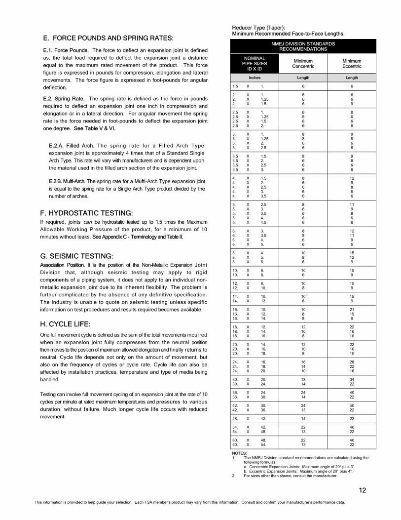
NOMINAL PIPE SIZES
ID X ID
Minimum Concentric
Minimum Eccentric
Inches Length Length
1.5 X 1. 6 6
2. X 1. 2. X 1.25 2. X 1.5
6 6 6
6 6 9
2.5 X 1. 2.5 X 1.25 2.5 X 1.5 2.5 X 2.
6 6 6 6
8 6 6 6
3. X 1. 3. X 1.25 3. X 2. 3. X 2.5
8 8 6 6
9 8 6 6
3.5 X 1.5 3.5 X 2. 3.5 X 2.5 3.5 X 3.
8 6 6 6
9 8 6 6
4. X 1.5 4. X 2. 4. X 2.5 4. X 3. 4. X 3.5
8 6 6 6 6
12 9 8 6 6
5. X 2.5 5. X 3. 5. X 3.5 5. X 4. 5. X 4.5
8 6 6 6 6
11 9 8 6 6
6. X 3. 6. X 3.5 6. X 4. 6. X 5.
8 8 6 6
12 11 9 6
8. X 4. 8. X 5. 8. X 6.
10 8 6
15 12 9
10. X 6. 10. X 8.
10 6
15 9
12. X 8. 12. X 10.
10 8
15 9
14. X 10. 14. X 12.
10 8
15 9
16. X 10. 16. X 12. 16. X 14.
10 8 8
21 15 9
18. X 12. 18. X 14. 18. X 16.
12 10 8
22 16 10
20. X 14. 20. X 16. 20. X 18.
12 10 8
22 16 10
24. X 16. 24. X 18. 24. X 20.
16 14 10
28 22 16
30. X 20. 30. X 24.
18 14
34 22
36. X 24. 36. X 30.
24 14
40 22
42. X 30. 42. X 36.
24 13
40 22
48. X 42. 14 22
54. X 42. 54. X 48.
22 13
40 22
60. X 48. 60. X 54.
22 13
40 22
NMEJ DIVISION STANDARDS RECOMMENDATIONS
NOTES: 1. The NMEJ Division standard recommendations are calculated using the
following formulas: a. Concentric Expansion Joints: Maximum angle of 20° plus 3”. b. Eccentric Expansion Joints: Maximum angle of 20° plus 4”.
2. For sizes other than shown, consult the manufacturer.
Reducer Type (Taper): Minimum Recommended Face-to-Face Lengths.
13
in mm in mm in mm in mm in mm lbs/in N/mm lbs/in N/mm lbs/in N/mm ft-lbs/deg Nm/deg
1* 1-1/4* 1-1/2*
2 2-1/2
3
25 32 40 50 65 75
6 6 6 6 6 6
150 150 150 150 150 150
7/16 7/16 7/16 7/16 7/16 7/16
11 11 11 11 11 11
1/4 1/4 1/4 1/4 1/4 1/4
6 6 6 6 6 6
1/2 1/2 1/2 1/2 1/2 1/2
13 13 13 13 13 13
27.5 22.5 18.5 14.5 11.5 10.0
3 3 3 3 3 3
3-1/2 4 5 6 8
88 100 125 150 200
6 6 6 6 6
150 150 150 150 150
7/16 7/16 7/16 7/16
11/16
11 11 11 11 18
1/4 1/4 1/4 1/4 3/8
6 6 6 6
10
1/2 1/2 1/2 1/2 1/2
13 13 13 13 13
8.3 7.5 6.0 5.0 5.5
3 3 3 3 3
10 12 14 16 18
250 300 350 400 450
8 8 8 8 8
200 200 200 200 200
11/16 11/16 11/16 11/16 11/16
18 18 18 18 18
3/8 3/8 3/8 3/8 3/8
10 10 10 10 10
1/2 1/2 1/2 1/2 1/2
13 13 13 13 13
4.5 3.75 3.25 2.75 2.5
3 3 2 2 1
20 22 24 26 28
500 550 600 650 700
8 10 10 10 10
200 250 250 250 250
13/16 13/16 13/16 15/16 15/16
21 21 21 24 24
7/16 7/16 7/16 1/2 1/2
11 11 11 13 13
1/2 1/2 1/2 1/2 1/2
13 13 13 13 13
2.5 2.25 2.0 2.3 2.0
1 1 1 1 1
30 32 34 36 38
750 800 850 900 950
10 10 10 10 10
250 250 250 250 250
15/16 15/16 15/16 15/16 15/16
24 24 24 24 24
1/2 1/2 1/2 1/2 1/2
13 13 13 13 13
1/2 1/2 1/2 1/2 1/2
13 13 13 13 13
2.0 1.8
1.75 1.5 1.5
1 1 1 1 1
40 42 44 46 48
1000 1050 1100 1150 1200
10 12 12 12 12
250 300 300 300 300
15/16 1-1/16 1-1/16 1-1/16 1-1/16
24 27 27 27 27
1/2 9/16 9/16 9/16 9/16
13 14 14 14 14
1/2 1/2 1/2 1/2 1/2
13 13 13 13 13
1.5 1.5 1.5 1.3
1.25
1 1 1 1 1
50 52 54 56 58
1250 1300 1350 1400 1450
12 12 12 12 12
300 300 300 300 300
1-1/16 1-1/16 1-1/16 1-1/16 1-1/16
27 27 27 27 27
9/16 9/16 9/16 9/16 9/16
14 14 14 14 14
1/2 1/2 1/2 1/2 1/2
13 13 13 13 13
1.25 1.25 1.25 1.25 1.0
1 1 1 1 1
60 66 72 78 84
1500 1650 1800 1950 2100
12 12 12 12 12
300 300 300 300 300
1-1/16 1-1/16 1-1/16 1-1/16 1-1/16
27 27 27 27 27
9/16 9/16 9/16 9/16 9/16
14 14 14 14 14
1/2 1/2 1/2 1/2 1/2
13 13 13 13 13
1.0 1.0 0.9 0.9 0.8
.5
.5
.5
.5
.5
96 102 108 120 132 144
2400 2550 2700 3000 3300 3600
12 12 12 12 12 12
300 300 300 300 300 300
1-1/16 1-1/16 1-1/16 1-1/16 1-1/16 1-1/16
27 27 27 27 27 27
9/16 9/16 9/16 9/16 9/16 9/16
14 14 14 14 14 14
1/2 1/2 1/2 1/2 1/2 1/2
13 13 13 13 13 13
0.70 0.66 0.62 0.56 0.51 0.47
.5
.5
.5
.5
.5
.5
235 294 353 423 530 635
41 51 62 74 93
111
304 383 459 552 689 828
53 67 80 97
121 145
350 438 524 700 762 824
61 77 92
123 133 144
.04
.10
.15
.30
.50
.80
.05
.13
.20
.41
.68 1.10
742 848
1058 1271 1412
130 148 185 223 247
965 1104 1376 1652 1837
169 193 241 289 322
888 952
1092 1234 1506
155 167 191 216 264
1.3 1.9 3.7 6.4
12.7
1.8 2.6 5.0 8.7
17.2
1766 2118 1853 2118 2382
309 371 325 371 417
2296 2755 2411 2755 3101
402 482 422 482 543
1618 1896 2234 2572 2840
283 332 391 450 497
24.2 42.1 19.2 76
106
32.8 57.1 80.3 103 144
2649 2913 3178 3060 3296
464 510 557 536 577
3440 3785 4130 3980 4286
602 663 723 697 751
3176 3296 3412 3658 3904
556 577 597 641 684
152 205 274 292 382
206 278 371 396 518
3532 3769 4002 4238 4475
619 660 701 742 784
4594 4899 5602 5512 5818
804 858 981 965
1019
4150 4876 5602 6328 6502
727 854 981
1108 1139
437 555 645 844 943
592 752 874
1144 1278
4708 4452 4664 4870 5087
824 780 817 853 891
6124 5783 6057 6339 6608
1072 1013 1061 1110 1157
6676 6846 7142 7436 7732
1169 1199 1251 1302 1354
1042 1163 1270 1680 1825
1413 1577 1722 2278 2474
5300 5512 5724 5936 6148
928 965
1002 1039 1076
6884 7166 7435 7717 7992
1206 1255 1302 1351 1400
8024 8314 8606 8896 9184
1405 1456 1507 1558 1608
1968 2138 2308 2464 3310
2668 2899 3129 3341 4488
6360 6996 7632 8268 8904
1114 1225 1337 1448 1559
8268 9095 9922
10748 11575
1448 1593 1738 1882 2027
9472 10216 10954 11902 12850
1659 1789 1918 2084 2250
3537 4288 5681 7022 8641
4795 5813 7702 9520
11715
10176 10812 11448 12720 13992 15264
1782 1893 2005 2228 2450 2673
13228 14056 14883 16537 18190 19843
2317 2462 2606 2896 3185 3475
14750 15700 16652 18550 20288 22026
2538 2749 2916 3249 3553 2857
13441 16967 21855 29871 33547 42902
18223 23003 29630 40498 45481 58164
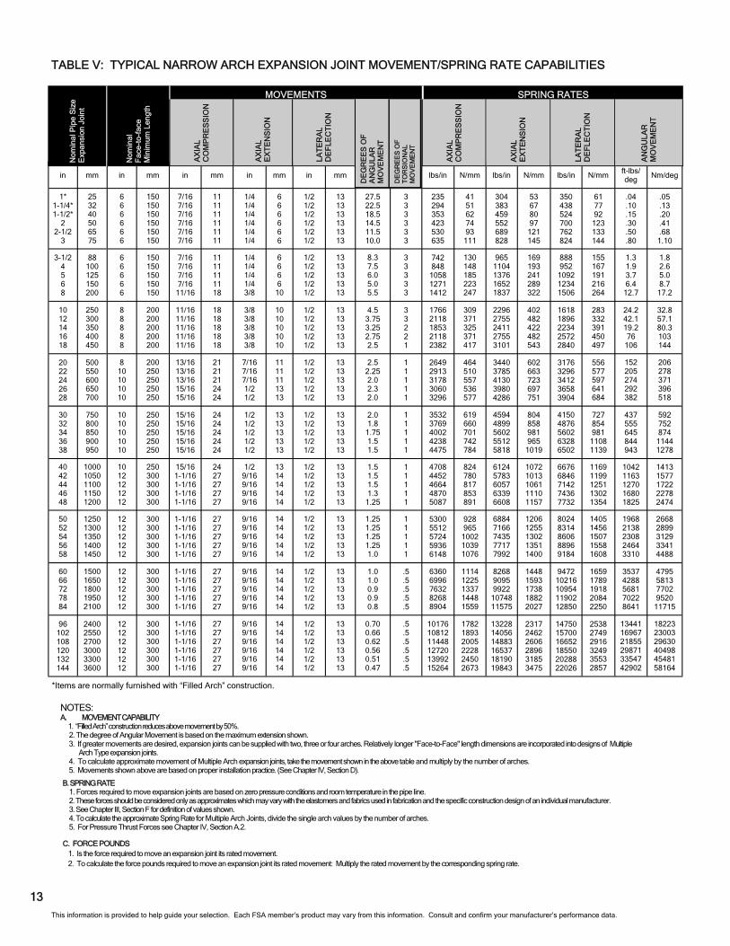
TABLE V: TYPICAL NARROW ARCH EXPANSION JOINT MOVEMENT/SPRING RATE CAPABILITIES
NOTES: A. MOVEMENT CAPABILITY
1. “Filled Arch” construction reduces above movement by 50%. 2. The degree of Angular Movement is based on the maximum extension shown. 3. If greater movements are desired, expansion joints can be supplied with two, three or four arches. Relatively longer "Face-to-Face" length dimensions are incorporated into designs of Multiple
Arch Type expansion joints. 4. To calculate approximate movement of Multiple Arch expansion joints, take the movement shown in the above table and multiply by the number of arches. 5. Movements shown above are based on proper installation practice. (See Chapter IV, Section D).
B. SPRING RATE 1. Forces required to move expansion joints are based on zero pressure conditions and room temperature in the pipe line. 2. These forces should be considered only as approximates which may vary with the elastomers and fabrics used in fabrication and the specific construction design of an individual manufacturer. 3. See Chapter III, Section F for definition of values shown. 4. To calculate the approximate Spring Rate for Multiple Arch Joints, divide the single arch values by the number of arches. 5. For Pressure Thrust Forces see Chapter IV, Section A.2.
C. FORCE POUNDS 1. Is the force required to move an expansion joint its rated movement. 2. To calculate the force pounds required to move an expansion joint its rated movement: Multiply the rated movement by the corresponding spring rate.
DE
GR
EE
S O
F
T
OR
SIO
NA
L
MO
VE
ME
NT
AX
IAL
CO
MP
RE
SS
ION
AX
IAL
EX
TE
NS
ION
LAT
ER
AL
D
EF
LEC
TIO
N
AN
GU
LAR
M
OV
EM
EN
T
SPRING RATES
LAT
ER
AL
D
EF
LEC
TIO
N
AX
IAL
E
XT
EN
SIO
N
AX
IAL
C
OM
PR
ES
SIO
N
Nom
inal
F
ace-
to-f
ace
M
inim
um L
engt
h
Nom
ina
l Pip
e S
ize
Exp
ansi
on J
oin
t
MOVEMENTS
DE
GR
EE
S O
F
A
NG
ULA
R
MO
VE
ME
NT
This information is provided to help guide your selection. Each FSA member’s product may vary from this information. Consult and confirm your manufacturer’s performance data.
*Items are normally furnished with “Filled Arch” construction.
AN
GU
LAR
M
OV
EM
EN
T
LAT
ER
AL
D
EF
LEC
TIO
N
AX
IAL
E
XT
EN
SIO
N
AX
IAL
C
OM
PR
ES
SIO
N
in mm in mm in mm in mm in mm lbs/in N/mm lbs/in N/mm lbs/in N/mm ft-lbs/deg
Nm/deg
1* 1-1/4* 1-1/2
2 2-1/2
3
25 32 40 50 65 75
6 6 6 6 6 6
150 150 150 150 150 150
3/4 3/4 3/4 3/4 3/4 3/4
19 19 19 19 19 19
7/16 7/16 7/16 7/16 7/16 7/16
11 11 11 11 11 11
5/8 5/8 5/8 5/8 5/8 5/8
16 16 16 16 16 16
34.4 28.1 23.1 18.1 14.4 12.5
3 3 3 3 3 3
3-1/2 4 5 6 8
88 100 125 150 200
6 6 6 6 6
150 150 150 150 150
3/4 3/4 3/4 3/4
1-3/16
19 19 19 19 30
7/16 7/16 7/16 7/16
11/16
11 11 11 11 17
5/8 5/8 5/8 5/8 5/8
16 16 16 16 16
10.4 9.4 7.5 6.2 6.9
3 3 3 3 3
10 12 14 16 18
250 300 350 400 450
8 8 8 8 8
200 200 200 200 200
1-3/16 1-3/16 1-3/16 1-3/16 1-3/16
30 30 30 30 30
11/16 11/16 11/16 11/16 11/16
17 17 17 17 17
3/4 3/4 3/4 3/4 3/4
19 19 19 19 19
5.6 4.7 4.1 3.4 3.1
3 3 2 2 1
20 22 24 26 28
500 550 600 650 700
8 10 10 10 10
200 250 250 250 250
1-7/16 1-7/16 1-7/16 1-5/8 1-5/8
37 37 37 41 41
3/4 3/4 3/4 1 1
19 19 19 25 25
3/4 3/4 3/4 3/4 3/4
19 19 19 19 19
3.1 2.8 2.5 2.9 2.5
1 1 1 1 1
30 32 34 36 38
750 800 850 900 950
10 10 10 10 10
250 250 250 250 250
1-5/8 1-5/8 1-5/8 1-5/8 1-5/8
41 41 41 41 41
1 1 1 1 1
25 25 25 25 25
3/4 3/4 3/4 3/4 3/4
19 19 19 19 19
2.5 2.2 2.2 1.9 1.9
1 1 1 1 1
40 42 44 46 48
1000 1050 1100 1150 1200
10 12 12 12 12
250 300 300 300 300
1-5/8 1-7/8 1-7/8 1-7/8 1-7/8
41 48 48 48 48
1 1 1 1 1
25 25 25 25 25
3/4 3/4 3/4 3/4 3/4
19 19 19 19 19
1.9 1.9 1.9 1.6 1.6
1 1 1 1 1
50 52 54 56 58
1250 1300 1350 1400 1450
12 12 12 12 12
300 300 300 300 300
1-7/8 1-7/8 1-7/8 1-7/8 1-7/8
48 48 48 48 48
1 1 1 1 1
25 25 25 25 25
3/4 3/4 3/4 3/4 3/4
19 19 19 19 19
1.6 1.6 1.6 1.6 1.2
1 1 1 1 1
60 66 72 78 84
1500 1650 1800 1950 2100
12 12 12 12 12
300 300 300 300 300
1-7/8 1-7/8 1-7/8 1-7/8 1-7/8
48 48 48 48 48
1 1 1 1 1
25 25 25 25 25
3/4 3/4 3/4 3/4 3/4
19 19 19 19 19
1.2 1.2 1.1 1.1 1.0
1 1 .5 .5 .5
96 102 108 120 132 144
2400 2550 2700 3000 3300 3600
12 12 12 12 12 12
300 300 300 300 300 300
1-7/8 1-7/8 1-7/8 1-7/8 1-7/8 1-7/8
48 48 48 48 48 48
1 1 1 1 1 1
25 25 25 25 25 25
3/4 3/4 3/4 3/4 3/4 3/4
19 19 19 19 19 19
.87
.82
.77
.70
.64
.59
.5
.5
.5
.5
.5
.5
176 220 265 317 397 476
31 38 46 55 69 83
228 287 344 414 517 621
39 50 60 72 90
109
262 328 393 525 571 618
46 57 69 92
100 108
.03 .075 .11 .22
.375 .60
.04
.10
.15
.30
.51
.81
556 636 793 953
1059
97 111 139 167 185
724 828
1032 1239 1378
127 145 181 217 241
666 714 819 925
1129
117 125 143 162 198
.975 1.425
3 5
10
1.32 1.93
4 7
13
1324 1588 1390 1588 1786
232 278 243 278 313
1722 2066 1808 2066 2326
302 362 317 362 407
1213 1422 1675 1929 2130
212 249 293 338 373
18 32 14 57 80
24 43 19 77
108
1987 2185 2383 2295 2472
348 383 417 402 433
2580 2839 3097 2985 3214
452 497 542 523 563
2382 2472 2559 2743 2928
417 433 448 480 513
114 154 205 219 286
155 209 278 297 388
2649 2827 3001 3178 3356
464 495 525 556 588
3445 3674 4201 4134 4363
603 643 736 724 764
3112 3657 4201 4746 4876
545 640 736 831 854
328 416 484 633 707
445 564 656 926 959
3531 3339 3498 3652 3815
618 585 613 640 668
4593 4337 4543 4754 4956
804 759 796 832 868
5007 5134 5356 5577 5799
877 899 938 977
1016
781 872 952
1260 1369
1059 1182 1291 1708 1856
3975 4134 4293 4452 4611
696 724 752 780 807
5163 5374 5576 5787 5994
904 941 976
1013 1050
6018 6235 6454 6672 6888
1054 1092 1130 1168 1206
1476 1603 1731 1848 2482
2001 2173 2347 2505 3365
4770 5247 5724 6201 6678
835 919
1002 1086 1169
6201 6821 7441 8061 8681
1086 1194 1303 1412 1520
7104 7662 8215 8926 9637
1244 1342 1439 1563 1688
2653 3216 4261 5266 6481
3597 4360 5777 7140 8787
7632 8109 8586 9540
10494 11448
1337 1420 1503 1670 1838 2005
9921 10542 11162 12403 13642 14882
1737 1846 1955 2172 2389 2606
11062 11775 12489 13912 15216 16519
1937 2062 2187 2436 2665 2893
10081 12725 16391 22403 25160 32176
13668 17253 22223 30374 34112 43625
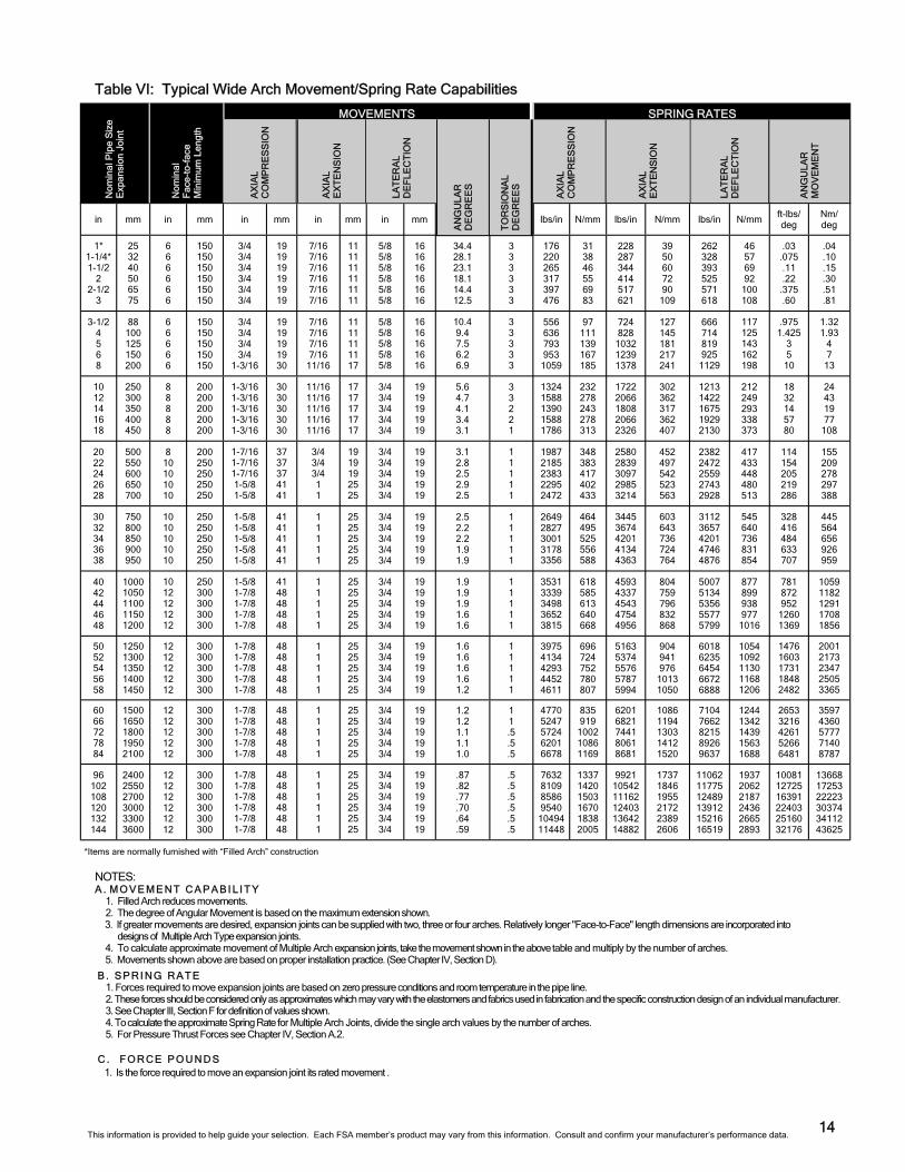
NOTES: A . M O V E M E N T C A P A B I L I T Y
1. Filled Arch reduces movements. 2. The degree of Angular Movement is based on the maximum extension shown. 3. If greater movements are desired, expansion joints can be supplied with two, three or four arches. Relatively longer "Face-to-Face" length dimensions are incorporated into
designs of Multiple Arch Type expansion joints. 4. To calculate approximate movement of Multiple Arch expansion joints, take the movement shown in the above table and multiply by the number of arches. 5. Movements shown above are based on proper installation practice. (See Chapter IV, Section D).
B . S P R I N G R A T E 1. Forces required to move expansion joints are based on zero pressure conditions and room temperature in the pipe line. 2. These forces should be considered only as approximates which may vary with the elastomers and fabrics used in fabrication and the specific construction design of an individual manufacturer. 3. See Chapter III, Section F for definition of values shown. 4. To calculate the approximate Spring Rate for Multiple Arch Joints, divide the single arch values by the number of arches. 5. For Pressure Thrust Forces see Chapter IV, Section A.2.
C . FO R CE P O U N D S
1. Is the force required to move an expansion joint its rated movement .
Nom
inal
F
ace-
to-f
ace
M
inim
um L
engt
h
Table VI: Typical Wide Arch Movement/Spring Rate Capabilities
14
Nom
ina
l Pip
e S
ize
E
xpan
sion
Jo
int
SPRING RATES MOVEMENTS
AX
IAL
C
OM
PR
ES
SIO
N
AX
IAL
E
XT
EN
SIO
N
LAT
ER
AL
DE
FLE
CT
ION
This information is provided to help guide your selection. Each FSA member’s product may vary from this information. Consult and confirm your manufacturer’s performance data.
AN
GU
LAR
D
EG
RE
ES
TO
RS
ION
AL
D
EG
RE
ES
*Items are normally furnished with “Filled Arch” construction
15
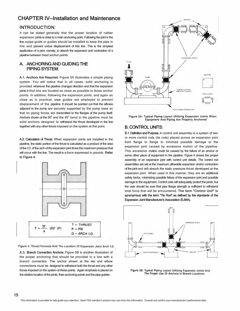
A.3. Branch Connection Anchors. Figure 5B is another illustration of
the proper anchoring that should be provided in a line with a
branch connection. The anchor shown at the tee and elbow
connections must be designed to withstand both the thrust and any other
forces imposed on the system at these points. Again emphasis is placed on
the relative location of the joints, their anchoring points and the pipe guides.
INTRODUCTION: It can be stated generally that the proper location of rubber
expansion joints is close to a main anchoring point. Following the joint in the
line, a pipe guide or guides should be installed to keep the pipe in
line and prevent undue displacement of this line. This is the simplest
application of a joint, namely, to absorb the expansion and contraction of a
pipeline between fixed anchor points.
A.1. Anchors Are Required. Figure 5A illustrates a simple piping
system. You will notice that in all cases, solid anchoring is
provided wherever the pipeline changes direction and that the expansion
joints in that line are located as close as possible to those anchor
points. In addition, following the expansion joints, and again as
close as is practical, pipe guides are employed to prevent
displacement of the pipeline. It should be pointed out that the elbows
adjacent to the pump are securely supported by the pump base so
that no piping forces are transmitted to the flanges of the pump itself.
Anchors shown at the 900 and the 450 bend in the pipeline must be
solid anchors designed to withstand the thrust developed in the line
together with any other forces imposed on the system at this point.
A.2. Calculation of Thrust. When expansion joints are installed in the
pipeline, the static portion of the thrust is calculated as a product of the area
of the I.D. of the arch of the expansion joint times the maximum pressure that
will occur with the line. The result is a force expressed in pounds. Refer
to Figure 4.
A. ANCHORING AND GUIDING THE PIPING SYSTEM:
B. CONTROL UNITS: B.1. Definition and Purpose. A control unit assembly is a system of two
or more control rods (tie rods) placed across an expansion joint
from flange to flange to minimize possible damage to the
expansion joint caused by excessive motion of the pipeline.
This excessive motion could be caused by the failure of an anchor or
some other piece of equipment in the pipeline. Figure 6 shows the proper
assembly of an expansion joint with control unit details. The control rod
assemblies are set at the maximum allowable expansion and/or contraction
of the joint and will absorb the static pressure thrust developed at the
expansion joint. When used in this manner, they are an additional
safety factor, minimizing possible failure of the expansion joint and possible
damage to the equipment. Control units will adequately protect the joints, but
the user should be sure that pipe flange strength is sufficient to withstand
total force that will be encountered. The term "Control Unit" Is
synonymous with the term "Tie Rod" as defined by the standards of the
Expansion Joint Manufacturer's Association (EJMA).
CHAPTER IV—Installation and Maintenance
This information is provided to help guide your selection. Each FSA member’s product may vary from this information. Consult and confirm your manufacturer’s performance data.
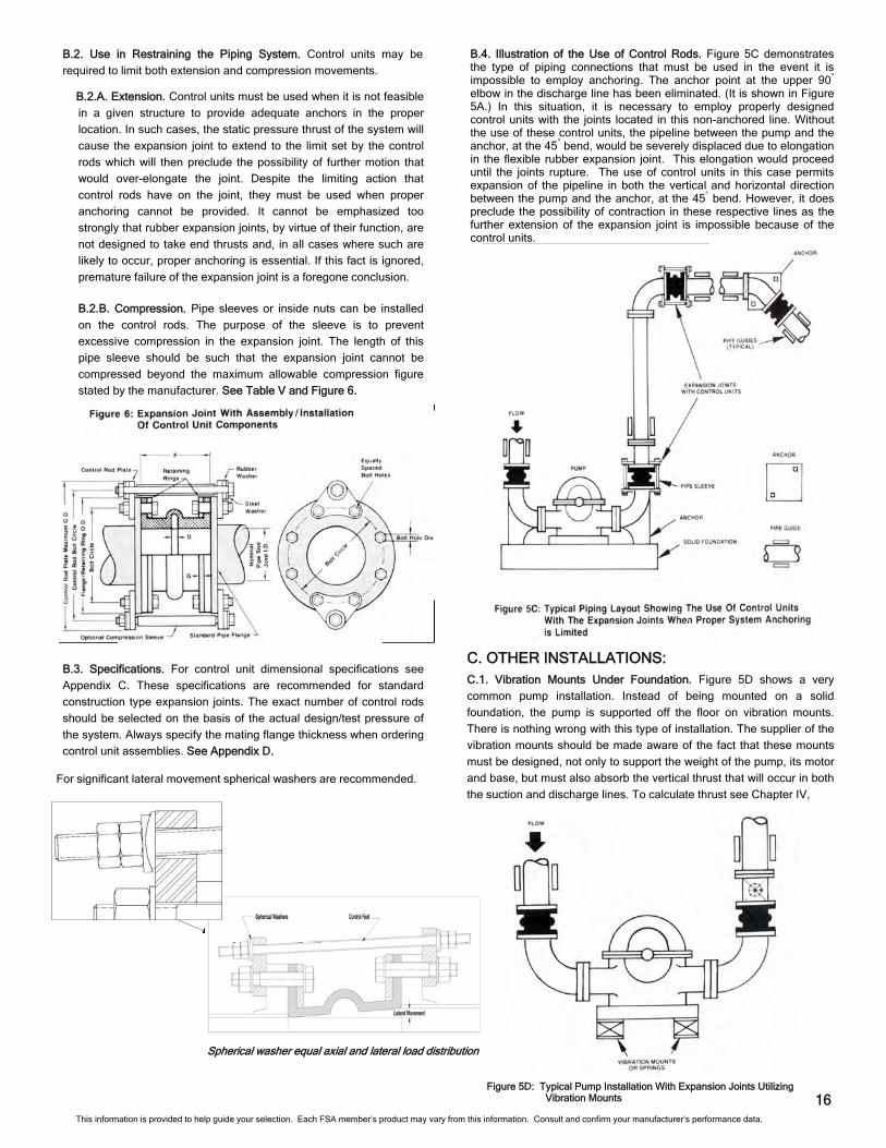
C. OTHER INSTALLATIONS: C.1. Vibration Mounts Under Foundation. Figure 5D shows a very
common pump installation. Instead of being mounted on a solid
foundation, the pump is supported off the floor on vibration mounts.
There is nothing wrong with this type of installation. The supplier of the
vibration mounts should be made aware of the fact that these mounts
must be designed, not only to support the weight of the pump, its motor
and base, but must also absorb the vertical thrust that will occur in both
the suction and discharge lines. To calculate thrust see Chapter IV,
B.2.A. Extension. Control units must be used when it is not feasible
in a given structure to provide adequate anchors in the proper
location. In such cases, the static pressure thrust of the system will
cause the expansion joint to extend to the limit set by the control
rods which will then preclude the possibility of further motion that
would over-elongate the joint. Despite the limiting action that
control rods have on the joint, they must be used when proper
anchoring cannot be provided. It cannot be emphasized too
strongly that rubber expansion joints, by virtue of their function, are
not designed to take end thrusts and, in all cases where such are
likely to occur, proper anchoring is essential. If this fact is ignored,
premature failure of the expansion joint is a foregone conclusion.
B.2.B. Compression. Pipe sleeves or inside nuts can be installed
on the control rods. The purpose of the sleeve is to prevent
excessive compression in the expansion joint. The length of this
pipe sleeve should be such that the expansion joint cannot be
compressed beyond the maximum allowable compression figure
stated by the manufacturer. See Table V and Figure 6.
B.3. Specifications. For control unit dimensional specifications see
Appendix C. These specifications are recommended for standard
construction type expansion joints. The exact number of control rods
should be selected on the basis of the actual design/test pressure of
the system. Always specify the mating flange thickness when ordering
control unit assemblies. See Appendix D.
B.4. Illustration of the Use of Control Rods. Figure 5C demonstrates the type of piping connections that must be used in the event it is impossible to employ anchoring. The anchor point at the upper 90° elbow in the discharge line has been eliminated. (It is shown in Figure 5A.) In this situation, it is necessary to employ properly designed control units with the joints located in this non-anchored line. Without the use of these control units, the pipeline between the pump and the anchor, at the 45° bend, would be severely displaced due to elongation in the flexible rubber expansion joint. This elongation would proceed until the joints rupture. The use of control units in this case permits expansion of the pipeline in both the vertical and horizontal direction between the pump and the anchor, at the 45° bend. However, it does preclude the possibility of contraction in these respective lines as the further extension of the expansion joint is impossible because of the control units.
16
For significant lateral movement spherical washers are recommended.
B.2. Use in Restraining the Piping System. Control units may be
required to limit both extension and compression movements.
Figure 5D: Typical Pump Installation With Expansion Joints Utilizing Vibration Mounts
Spherical washer equal axial and lateral load distribution
This information is provided to help guide your selection. Each FSA member’s product may vary from this information. Consult and confirm your manufacturer’s performance data.
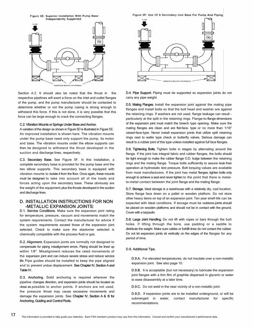
17
C.2. Vibration Mounts or Springs Under Base and Anchor.
A variation of the design as shown in Figure 5D is illustrated in Figure 5E.
An improved installation is shown here. The vibration mounts
under the pump base need only support the pump, its motor
and base. The vibration mounts under the elbow supports can
then be designed to withstand the thrust developed in the
suction and discharge lines, respectively.
C.3. Secondary Base. See Figure 5F. In this installation, a
complete secondary base is provided for the pump base and the
two elbow supports. This secondary base is equipped with
vibration mounts to isolate it from the floor. Once again, these mounts
must be designed to take into account all of the loads and
forces acting upon the secondary base. These obviously are
the weight of the equipment plus the thrusts developed in the suction
and discharge lines.
D. INSTALLATION INSTRUCTIONS FOR NON-METALLIC EXPANSION JOINTS:
D.1. Service Conditions. Make sure the expansion joint rating
for temperature, pressure, vacuum and movements match the
system requirements. Contact the manufacturer for advice if
the system requirements exceed those of the expansion joint
selected. Check to make sure the elastomer selected is
chemically compatible with the process fluid or gas.
D.2. Alignment. Expansion joints are normally not designed to
compensate for piping misalignment errors. Piping should be lined up
within 1/8". Misalignment reduces the rated movements of
the expansion joint and can induce severe stress and reduce service
life. Pipe guides should be installed to keep the pipe aligned
and to prevent undue displacement. See Chapter IV, Section A and
Table IV.
D.3. Anchoring. Solid anchoring is required wherever the
pipeline changes direction, and expansion joints should be located as
close as possible to anchor points. If anchors are not used,
the pressure thrust may cause excessive movements and
damage the expansion joints. See Chapter IV, Section A & B for
Anchoring, Guiding and Control Rods.
D.4. Pipe Support. Piping must be supported so expansion joints do not
carry any pipe weight.
D.5. Mating Flanges. Install the expansion joint against the mating pipe
flanges and install bolts so that the bolt head and washer are against
the retaining rings. If washers are not used, flange leakage can result -
particularly at the split in the retaining rings. Flange-to-flange dimensions
of the expansion joint must match the breech type opening. Make sure the
mating flanges are clean and are flat-face- type or no more than 1/16"
raised-face-type. Never install expansion joints that utilize split retaining
rings next to wafer type check or butterfly valves. Serious damage can
result to a rubber joint of this type unless installed against full face flanges.
D.6. Tightening Bolts. Tighten bolts in stages by alternating around the
flange. If the joint has integral fabric and rubber flanges, the bolts should
be tight enough to make the rubber flange O.D. bulge between the retaining
rings and the mating flange. Torque bolts sufficiently to assure leak-free
operation at hydrostatic test pressure. Bolt torquing values are available
from most manufacturers. If the joint has metal flanges, tighten bolts only
enough to achieve a seal and never tighten to the point that there is metal-
to-metal contact between the joint flange and the mating flange.
D.7. Storage. Ideal storage is a warehouse with a relatively dry, cool location.
Store flange face down on a pallet or wooden platform. Do not store
other heavy items on top of an expansion joint. Ten year shelf-life can be
expected with ideal conditions. If storage must be outdoors joints should
be placed on wooden platforms and should not be in contact with the ground.
Cover with a tarpaulin.
D.8. Large Joint Handling. Do not lift with ropes or bars through the bolt
holes. If lifting through the bore, use padding or a saddle to
distribute the weight. Make sure cables or forklift tines do not contact the rubber.
Do not let expansion joints sit vertically on the edges of the flanges for any
period of time.
D.9. Additional Tips.
D.9.A. For elevated temperatures, do not insulate over a non-metallic
expansion joint. See also page 10.
D.9.B. It is acceptable (but not necessary) to lubricate the expansion
joint flanges with a thin film of graphite dispersed in glycerin or water
to ease disassembly at a later time.
D.9.C. Do not weld in the near vicinity of a non-metallic joint.
D.9.D. If expansion joints are to be installed underground, or will be
submerged in water, contact manufacturer for specific
recommendations.
Section A.2. It should also be noted that the thrust in the
respective pipelines will exert a force on the inlet and outlet flanges
of the pump, and the pump manufacturer should be contacted to
determine whether or not the pump casing is strong enough to
withstand this force. If this is not done, it is very possible that this
force can be large enough to crack the connecting flanges.
This information is provided to help guide your selection. Each FSA member’s product may vary from this information. Consult and confirm your manufacturer’s performance data.
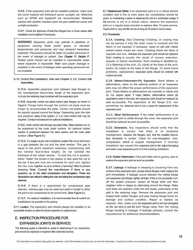
D.9.E. If the expansion joint will be installed outdoors, make sure
the cover material will withstand ozone, sunlight, etc. Materials
such as EPDM and Hypalon® are recommended. Materials
painted with weather resistant paint will give additional ozone and
sunlight protection.
D.9.F. Check the tightness of leak-free flanges two or three weeks after
installation and re-tighten if necessary.
WARNING: Expansion joints may operate in pipelines or equipment carrying fluids and/or gases at elevated temperatures and pressures and may transport hazardous materials. Precautions should be taken to protect personnel in the event of leakage or splash. See Chapter 11, Section P. Rubber joints should not be installed in inaccessible areas where inspection is impossible. Make sure proper drainage is available in the event of leakage when operating personnel are not available.
D.11. Location. The expansion joint should always be installed in an
accessible location to allow for future inspection or replacement.
D.10. Control Rod Installation. Also see Chapter II, 0.2. Control Unit
Assemblies.
E. INSPECTION PROCEDURE FOR
EXPANSION JOINTS IN SERVICE: The following guide is intended to assist in determining if an expansion
joint should be replaced or repaired after extended service.
E.1. Replacement Criteria. If an expansion joint is in a critical service
condition and is five or more years old, consideration should be
given to maintaining a spare or replacing the unit at a scheduled outage. If
the service is not of a critical nature, observe the expansion
joint on a regular basis and plan to replace after 10 years service.
Applications vary and life can be as long as 30 years in some cases.
E.2. Procedures.
E.2.A. Cracking. (Sun Checking) Cracking, or crazing may
not be serious if only the outer cover is involved and the
fabric is not exposed. If necessary, repair on site with rubber
cement where cracks are minor. Cracking where the fabric is
exposed and torn, indicates the expansion joint should be replaced.
Such cracking is usually the result of excess extension,
angular or lateral movements. Such cracking is identified by:
(1) a flattening of the arch, (2) cracks at the base of the arch,
and/or (3) cracks at the base of the flange. To avoid future
problems, replacement expansion joints should be ordered with
control rod units.
E.2.B. Blisters-Deformation-Ply Separation. Some blisters or
deformations, when on the external portions of an expansion
joint, may not affect the proper performance of the expansion
joint. These blisters or deformations are cosmetic in nature and
do not require repair. If major blisters, deformations and/or ply
separations exist in the tube, the expansion joint should be replaced as
soon as possible. Ply separation at the flange O.D. can
sometimes be observed and is not a cause for replacement of the
expansion joint.
E.2.C. Metal Reinforcement. If the metal reinforcement of an
expansion joint is visible through the cover, the expansion joint
should be replaced as soon as possible.
E.2.D. Dimensions. Any inspections should verify that the
installation is correct; that there is no excessive
misalignment between the flanges; and, that the installed face-to-
face dimension is correct. Check for over-elongation, over-
compression, lateral or angular misalignment. If incorrect
installation has caused the expansion joint to fail, adjust the piping
and order a new expansion joint to fit the existing installation.
E.2.E. Rubber Deterioration. If the joint feels soft or gummy, plan to
replace the expansion joint as soon as possible.
E.2.F. Leakage. If leakage or weeping is occurring from any
surface of the expansion joint, except where flanges meet, replace the
joint immediately. If leakage occurs between the mating flange
and expansion joint flange, tighten all bolts. If this is not successful, turn
off the system pressure, loosen all flange bolts and then
retighten bolts in stages by alternating around the flange. Make
sure there are washers under the bolt heads, particularly at the
split in the retaining rings. Remove the expansion joint and
inspect both rubber flanges and pipe mating flange faces for
damage and surface condition. Repair or replace as
required. Also, make sure the expansion joint is not over elongated
as this can tend to pull the joint flange away from the mating
flange resulting in leakage. If leakage persists, consult the
manufacturer for additional recommendations.
18
D.10.A. Assemble expansion joint between pipe flanges to
the manufactured face-to-face length of the expansion joint.
Include the retaining rings furnished with the expansion joint.
D.10.B. Assemble control rod plates behind pipe flanges as shown in
Figure 6. Flange bolts through the control rod plate must be
longer to accommodate the plate. Control rod plates should
be equally spaced around the flange. Depending upon the size
and pressure rating of the system, 2, 3 or more control rods may be
required. Contact manufacturer for optional installations.
D.10.C. Insert control rods through top plate holes. Steel washers are to
be positioned at the outer plate surface. An optional rubber
washer is positioned between the steel washer and the outer plate
surface. (See Figure 6.)
D.10.D. If a single nut per unit is furnished, position this nut so that there
is a gap between the nut and the steel washer. This gap is
equal to the joint's maximum extension (commencing with
the nominal face-to-face length). Do not consider the
thickness of the rubber washer. To lock this nut in position,
either "stake" the thread in two places or tack weld the nut to
the rod. If two jam nuts are furnished for each unit, tighten
the two nuts together, so as to achieve a "jamming" effect to prevent
loosening. Note: Consult the manufacturer if there is any
question as to the rated compression and elongation. These two
dimensions are critical in setting the nuts and sizing the compression pipe
sleeves.
D.10.E. If there is a requirement for compression pipe
sleeves, ordinary pipe may be used and sized in length to allow
the joint to be compressed to its normal limit. (See Figure 6.)
D.10.F. For reducer installations, it is recommended that all control rod
installations be parallel to the piping.
This information is provided to help guide your selection. Each FSA member’s product may vary from this information. Consult and confirm your manufacturer’s performance data.
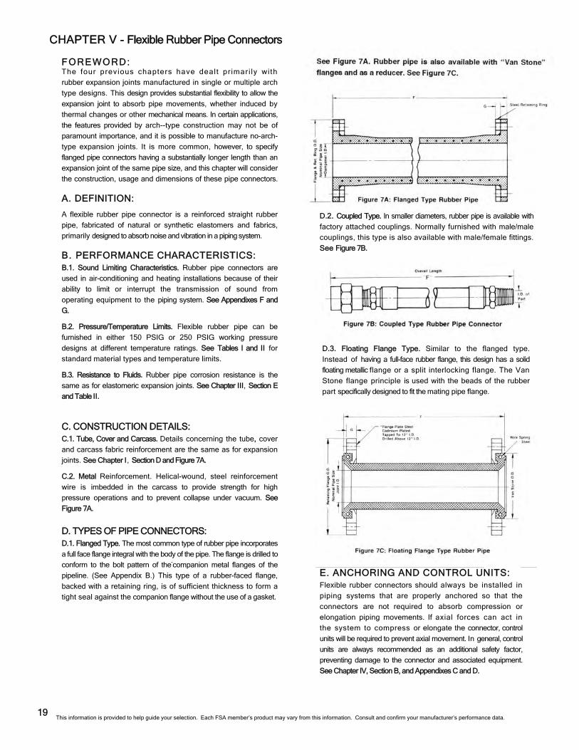
CHAPTER V - Flexible Rubber Pipe Connectors
E. ANCHORING AND CONTROL UNITS: Flexible rubber connectors should always be installed in
piping systems that are properly anchored so that the
connectors are not required to absorb compression or
elongation piping movements. If axial forces can act in
the system to compress or elongate the connector, control
units will be required to prevent axial movement. In general, control
units are always recommended as an additional safety factor,
preventing damage to the connector and associated equipment.
See Chapter IV, Section B, and Appendixes C and D.
D.3. Floating Flange Type. Similar to the flanged type.
Instead of having a full-face rubber flange, this design has a solid
floating metallic flange or a split interlocking flange. The Van
Stone flange principle is used with the beads of the rubber
part specifically designed to fit the mating pipe flange.
D.2. Coupled Type. In smaller diameters, rubber pipe is available with
factory attached couplings. Normally furnished with male/male
couplings, this type is also available with male/female fittings.
See Figure 7B.
FOREWORD: The four previous chapters have dealt primari ly with
rubber expansion joints manufactured in single or multiple arch
type designs. This design provides substantial flexibility to allow the
expansion joint to absorb pipe movements, whether induced by
thermal changes or other mechanical means. In certain applications,
the features provided by arch--type construction may not be of
paramount importance, and it is possible to manufacture no-arch-
type expansion joints. It is more common, however, to specify
flanged pipe connectors having a substantially longer length than an
expansion joint of the same pipe size, and this chapter will consider
the construction, usage and dimensions of these pipe connectors.
A. DEFINITION:
A flexible rubber pipe connector is a reinforced straight rubber
pipe, fabricated of natural or synthetic elastomers and fabrics,
primarily designed to absorb noise and vibration in a piping system.
B. PERFORMANCE CHARACTERISTICS: B.1. Sound Limiting Characteristics. Rubber pipe connectors are
used in air-conditioning and heating installations because of their
ability to limit or interrupt the transmission of sound from
operating equipment to the piping system. See Appendixes F and
G.
B.2. Pressure/Temperature Limits. Flexible rubber pipe can be
furnished in either 150 PSIG or 250 PSIG working pressure
designs at different temperature ratings. See Tables I and II for
standard material types and temperature limits.
B.3. Resistance to Fluids. Rubber pipe corrosion resistance is the
same as for elastomeric expansion joints. See Chapter III, Section E
and Table II.
C. CONSTRUCTION DETAILS:
C.1. Tube, Cover and Carcass. Details concerning the tube, cover
and carcass fabric reinforcement are the same as for expansion
joints. See Chapter I, Section D and Figure 7A.
C.2. Metal Reinforcement. Helical-wound, steel reinforcement
wire is imbedded in the carcass to provide strength for high
pressure operations and to prevent collapse under vacuum. See
Figure 7A.
D. TYPES OF PIPE CONNECTORS: D.1. Flanged Type. The most common type of rubber pipe incorporates
a full face flange integral with the body of the pipe. The flange is drilled to
conform to the bolt pattern of the-companion metal flanges of the
pipeline. (See Appendix B.) This type of a rubber-faced flange,
backed with a retaining ring, is of sufficient thickness to form a
tight seal against the companion flange without the use of a gasket.
19 This information is provided to help guide your selection. Each FSA member’s product may vary from this information. Consult and confirm your manufacturer’s performance data.
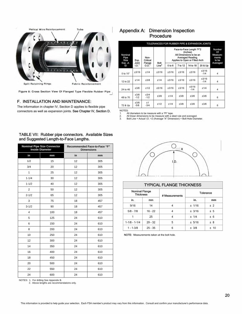
F. INSTALLATION AND MAINTENANCE: The information in chapter IV, Section D applies to flexible pipe
connectors as well as expansion joints. See Chapter IV, Section D.
20
TYPICAL FLANGE THICKNESS
Nominal Flange Thickness # Measurements
in. mm in. mm
9/16 14 4 ± 1/16 ± 2
5/8 - 7/8 16 - 22 4 ± 3/16 ± 5
1 25 4 ± 1/4 ± 6
1-1/8 - 1-1/4 29 - 32 5 ± 5/16 ± 8
1 - 1-3/8 25 - 35 6 ± 3/8 ± 10
Tolerance
NOTE: Measurements taken at the bolt hole.
TABLE VII: Rubber pipe connectors. Available Sizes and Suggested Length-to-Face Lengths.
This information is provided to help guide your selection. Each FSA member’s product may vary from this information. Consult and confirm your manufacturer’s performance data.
Nominal Pipe Size Connector Inside Diameter
in mm in mm
1/2 15 12 305
3/4 20 12 305
1 25 12 305
1-1/4 30 12 305
1-1/2 40 12 305
2 50 12 305
2-1/2 65 12 305
3 75 18 457
3-1/2 90 18 457
4 100 18 457
5 125 24 610
6 150 24 610
8 200 24 610
10 250 24 610
12 300 24 610
14 350 24 610
16 400 24 610
18 450 24 610
20 500 24 610
22 550 24 610
Recommended Face-to-Face “F” Dimensions
24 600 24 610
NOTES: 1. For drilling See Appendix B. 2. Above lengths are recommendations only.
Appendix A: Dimension Inspection Procedure
NOTES: 1. All diameters to be measure with a “Pi” tape. 2. All linear dimensions to be measure with a steel rule and averaged. 3. Bolt Line = Actual I.D. +2 (Average “X” Dimension) + Bolt Hole Diameter.
Nominal Pipe Size
Exp. Jt. ID
Exp. Joint I.D.1
Non- Critical Flange O.D.1
Bolt Line3
Face-to-Face Length “F”2 (Inches)
All Dimensions to be an Averaged Reading.
Applies to Open or Filled Arch
Number Of
Measure- ments to be
Averaged 0 to 6 7 to 12 14 to 18 20 & Up
0 to 10” ±3/16 ±1/4 ±3/16 ±3/16 ±3/16 ±3/16 ±3/16
-1/4 4
12 to 22 ±1/4 ±3/8 ±1/4 ±3/16 ±3/16 ±3/16 ±3/16
-1/4 4
24 to 46 ±3/8 ±1/2 ±5/16 ±3/16 ±3/16 ±3/16
-1/4 ±1/4
4
48 to 70 ±3/8 -1/2
±3/4 -1/2
±3/8 ±1/4 ±3/8 ±3/8 ±3/8 6
72 & Up ±3/8 -5/8
±1 -3/4
±1/2 ±1/4 ±3/8 ±3/8 ±3/8 6
TOLERANCES FOR RUBBER PIPE & EXPANSION JOINTS
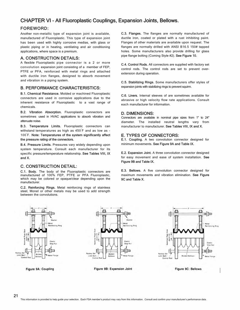
CHAPTER VI - All Fluoroplastic Couplings, Expansion Joints, Bellows.
C.3. Flanges. The flanges are normally manufactured of
ductile iron, coated or plated with a rust inhibiting paint.
Flanges of other materials are available upon request. The
flanges are normally drilled with ANSI B16.5 150# tapped
holes. Some manufacturers also provide drilling for glass
pipe flange bolting (Coming Style #2). See Figure 10.
C.4. Control Rods. All connectors are supplied with factory set
control rods. The control rods are set to prevent over-
extension during operation.
C.5. Stabilizing Rings. Some manufacturers offer styles of
expansion joints with stabilizing rings to prevent squirm.
C.6. Liners. Internal sleeves of are sometimes available for
abrasive or high velocity flow rate applications. Consult
each manufacturer for information.
D. DIMENSIONS: Connectors are available in nominal pipe sizes from 1" to 24"
diameter. The installed neutral lengths vary from
manufacturer to manufacturer. See Tables VIII, IX and X.
E. TYPES OF CONNECTORS: E.1. Coupling. A two convolution connector designed for
minimum movements. See Figure 9A and Table IX.
E.2. Expansion Joint. A three convolution connector designed
for easy movement and ease of system installation. See
Figure 9B and Table IX.
E.3. Bellows. A five convolution connector designed for
maximum movements and vibration elimination. See Figure
9C and Table X.
FOREWORD: Another non-metallic type of expansion joint is available,
manufactured of Fluoroplastic. This type of expansion joint
has been used with highly corrosive medias, with glass or
plastic piping or in heating, ventilating and air conditioning
applications, where space is a premium.
A. CONSTRUCTION DETAILS: A flexible Fluoroplastic pipe connector is a 2 or more
convolut ion expansion joint consisting of a member of FEP,
PTFE or PFA, reinforced with metal rings and attached
with ductile iron flanges, designed to absorb movement
and vibration in a piping system.
B. PERFORMANCE CHARACTERISTICS: B.1. Chemical Resistance. Molded or machined Fluoroplastic
connectors are used in corrosive applications due to the
inherent resistance of Fluoroplastic to a vast range of
chemicals.
B.2. Vibration Absorption. Fluoroplastic connectors are
sometimes used in HVAC applications to absorb vibration and
attenuate noise.
B.3. Temperature Limits. Fluoroplastic connectors can
withstand temperatures as high as 450°F and as low as -
100°F. Note: Temperatures of the system significantly affect
the pressure rating of the connectors.
B.4. Pressure Limits. Pressures vary widely depending upon
system temperature. Consult each manufacturer for its
specific pressure/temperature relationship. See Tables VIII, IX
and X.
C. CONSTRUCTION DETAIL: C.1. Body. The body of the Fluoroplastic connectors are manufactured of 100% FEP, PTFE or PFA Fluoroplastic, which may be colored or opaque/clear depending upon the manufacturer.
C.2. Reinforcing Rings. Metal reinforcing rings of stainless steel, Monel or other metals may be used to add strength between the convolutions.
21 This information is provided to help guide your selection. Each FSA member’s product may vary from this information. Consult and confirm your manufacturer’s performance data.
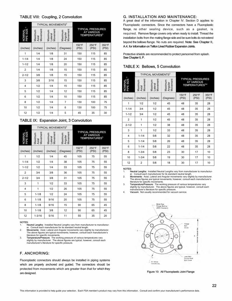
F. ANCHORING:
Fluoroplastic connectors should always be installed in piping systems
which are properly anchored and guided. The connectors should be
protected from movements which are greater than that for which they
are designed.
G. INSTALLATION AND MAINTENANCE: A great deal of the information in Chapter IV. Section D applies to
Fluoroplastic connectors. Since the connectors have a Fluoroplastic
flange, no other sealing device, such as a gasket, is
required. Remove flange covers only when ready to install. Thread the
installation bolts from the mating flange side and be sure bolts do not extend
beyond the bellows flange. No nuts are required. Note: See Chapter II,
A.4. for information on Teflon Lined Rubber Expansion Joints.
Protective shields are recommended to protect personnel from splash. See Chapter II, P.
22
Figure 10: All Fluoroplastic Joint Flange
TABLE X: Bellows, 5 Convolution
TABLE VIII: Coupling, 2 Convolution
TABLE IX: Expansion Joint, 3 Convolution
NO
MIN
AL
PIP
E S
IZE
1
TYPICAL MOVEMENTS2
(inches) (inches) (inches) (Degrees) 150°F (PSI)
250°F (PSI)
350°F (PSI)
1 1/2 1/2 45 48 35 28
1-1/4 3/4 1/2 45 48 35 28
1-1/2 3/4 1/2 45 48 35 28
2 1 1/2 45 48 35 28
2-1/2 1 1/2 38 48 35 28
3 1 1/2 33 48 35 28
4 1-1/4 5/8 32 48 35 28
5 1-1/4 5/8 26 48 35 28
6 1-1/4 5/8 22 48 35 28
8 1-3/4 5/8 23 30 17 10
10 1-3/4 5/8 19 30 17 10
12 2 5/8 18 30 17 10
TYPICAL PRESSURES AT VARIOUS
TEMPERATURES3.4
Max
imum
A
xial
M
ovem
ent
Max
imum
La
tera
l M
ovem
ent
Max
imum
A
ngul
ar
Mov
emen
t NOTES: 1. Neutral Lengths: Installed Neutral Lengths vary from manufacturer to manufactur-
er. Consult each manufacturer for its standard neutral length. 2. Movements: Axial, Lateral and Angular movements vary slightly by manufacturer.
The above figures are typical movements; however, consult each manufacturer’s literature for specific movements.
3. Temperature/Pressure: The working pressure of various temperatures vary slightly by manufacturer. The above figures are typical, however, consult each manufacturer’s literature for specific pressure.
4. Vacuum: Not usually recommended for vacuum service.
TYPICAL MOVEMENTS2
(inches) (inches) (inches) (Degrees) 150°F (PSI)
250°F (PSI)
350°F (PSI)
1 1/2 1/4 45 105 75 55
1-1/4 1/2 1/4 38 105 75 55
1-1/2 1/2 1/4 33 105 75 55
2 3/4 3/8 36 105 75 55
2-1/2 3/4 3/8 31 105 75 55
3 1 1/2 33 105 75 55
4 1 1/2 26 105 75 55
5 1-1/8 1/2 24 105 75 55
6 1-1/8 9/16 20 105 75 55
8 1-1/8 9/16 15 90 65 45
10 1-1/8 3/8 12 90 65 45
12 1-3/16 5/16 11 55 35 20
TYPICAL PRESSURES AT VARIOUS
TEMPERATURES3
Max
imum
A
xial
M
ovem
ent
Max
imum
La
tera
l M
ovem
ent
Max
imum
A
ngul
ar
Mov
emen
t
NO
MIN
AL
PIP
E S
IZE
1
NOTES: 1. Neutral Lengths: Installed Neutral Lengths vary from manufacturer to manufactur-
er. Consult each manufacturer for its standard neutral length. 2. Movements: Axial, Lateral and Angular movements vary slightly by manufacturer.
The above figures are typical movements; however, consult each manufacturer’s literature for specific movements.
3. Temperature/Pressure: The working pressure of various temperatures vary slightly by manufacturer. The above figures are typical, however, consult each manufacturer’s literature for specific pressure.
TYPICAL MOVEMENTS2
(inches) (inches) (inches) (Degrees) 150°F (PSI)
250°F (PSI)
350°F (PSI)
1 1/4 1/8 31 150 115 85
1-1/4 1/4 1/8 24 150 115 85
1-1/2 1/4 1/8 20 150 115 85
2 1/4 1/8 15 150 115 85
2-1/2 3/8 1/8 15 150 115 85
3 3/8 3/16 15 150 115 85
4 1/2 1/4 15 150 115 85
5 1/2 1/4 12 150 115 85
6 1/2 1/4 10 150 115 85
8 1/2 1/4 7 130 100 75
10 1/2 1/4 6 130 100 75
12 1/2 1/4 5 45 35 30
TYPICAL PRESSURES AT VARIOUS
TEMPERATURES3 M
axim
um
Axi
al
Mov
emen
t
Max
imum
La
tera
l M
ovem
ent
Max
imum
A
ngul
ar
Mov
emen
t
NO
MIN
AL
PIP
E S
IZE
1
This information is provided to help guide your selection. Each FSA member’s product may vary from this information. Consult and confirm your manufacturer’s performance data.
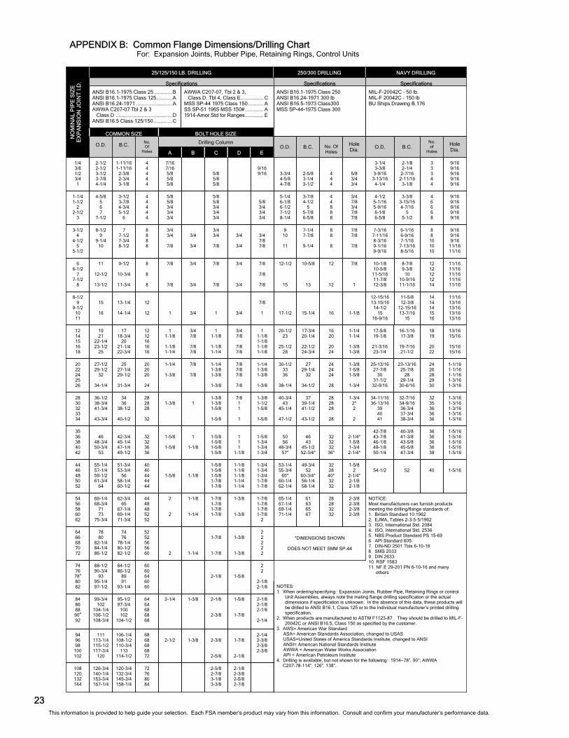
APPENDIX B: Common Flange Dimensions/Drilling Chart For: Expansion Joints, Rubber Pipe, Retaining Rings, Control Units
This information is provided to help guide your selection. Each FSA member’s product may vary from this information. Consult and confirm your manufacturer’s performance data.
23
3-3/4 4-5/8 4-7/8
9 10
11
20-1/2 23
25-1/2
28
30-1/2 33 36
38-1/4
17-1/2
53-1/4 55-3/4
65* 60-1/4 62-1/4
50 56
48-3/4 57*
5-1/4 6-1/8 6-1/2 7-1/2 8-1/4
65-1/4 67-1/4 69-1/4 71-1/4
40-3/4 43
45-1/4
47-1/2
12-1/2
15
2-5/8 3-1/4 3-1/2
7-1/4 7-7/8
9-1/4
17-3/4 20-1/4
22-1/2 24-3/4
27 29-1/4
32
34-1/2
15-1/4
49-3/4 52
60-3/4* 56-1/4 58-1/4
46 43
45-1/2 52-3/4*
3-7/8 4-1/2
5 5-7/8 6-5/8
61 63 65 67
37 39-1/4 41-1/2
43-1/2
10-5/8
13
4 4 4
8 8
8
16 20
20 24
24 24 24
28
16
32 28 40* 32 32
32 32 32 36*
4 4 8 8 8
28 28 32 32
28 28 28
28
12
12
5/8 3/4 3/4
7/8 7/8
7/8
1-1/4 1-1/4
1-3/8 1-3/8
1-3/8 1-5/8 1-5/8
1-3/4
1-1/8
1-5/8 2
2-1/4* 2-1/8 2-1/8
2-1/4* 1-5/8 1-3/4 2-1/4*
3/4 7/8 3/4 7/8 7/8
2-3/8 2-3/8 2-3/8 2-3/8
1-3/4 2* 2
2
7/8
1
1/4 3/8 1/2 3/4 1
3-1/2 4
4-1/2 5
5-1/2
12 14 15 16 18
20 22 24 25 26
8-1/2 9
9-1/2 10 11
74 76 784 80 82
44 46 48 50 52
35 36 38 40 42
1-1/4 1-1/2
2 2-1/2
3
54 56 58 60 62
28 30 32 33 34
6 6-1/2
7 7-1/2
8
64 66 68 70 72
84 86 88 904 92
94 96 98
100 102
108 120 132 144
2-1/2 2-1/2 3-1/2 3-7/8 4-1/4
8-1/2 9
9-1/4 10
19 21
22-1/4 23-1/2
25
27-1/2 29-1/2
32
34-1/4
15
16
88-1/2 90-3/4
93 95-1/4 97-1/2
55-1/4 57-1/4 59-1/2 61-3/4
64
46
48-3/4 50-3/4
53
4-5/8 5 6 7
7-1/2
66-1/4 68-3/4
71 73
75-3/4
36-1/2 38-3/4 41-3/4
43-3/4
11
12-1/2
13-1/2
78 80
82-1/4 84-1/4 86-1/2
99-3/4 102
104-1/4 106-1/2 108-3/4
111 113-1/4 115-1/2 117-3/4
120
126-3/4 140-1/4 153-3/4 167-1/4
1-11/16 1-11/16
2-3/8 2-3/4 3-1/8
7 7-1/2 7-3/4 8-1/2
17 18-3/4
20 21-1/4 22-3/4
25 27-1/4 29-1/2
31-3/4
13-1/4
14-1/4
84-1/2 86-1/2
89 91
93-1/4
51-3/4 53-3/4
56 58-1/4 60-1/2
42-3/4 45-1/4 47-1/4 49-1/2
3-1/2 3-7/8 4-3/4 5-1/2
6
62-3/4 65
67-1/4 69-1/4 71-3/4
34 36
38-1/2
40-1/2
9-1/2
10-3/4
11-3/4
74 76
78-1/4 80-1/2 82-1/2
95-1/2 97-3/4
100 102
104-1/2
106-1/4 108-1/2 110-3/4
113 114-1/2
120-3/4 132-3/4 145-3/4 158-1/4
4 4 4 4 4
8 8 8 8
12 12 16 16 16
20 20 20
24
12
12
60 60 64 60 60
40 40 44 44 44
32 32 36 36
4 4 4 4 4
44 48 48 52 52
28 28 28
32
8
8
8
52 52 56 56 60
64 64 68 68 68
68 68 68 68 72
72 76 80 84
7/16 7/16 5/8 5/8 5/8
3/4 3/4
7/8
1 1-1/8
1-1/8 1-1/4
1-1/4
1-3/8
1
1-5/8
1-5/8
1-5/8
5/8 5/8 3/4 3/4 3/4
2
2
1-3/8
7/8
7/8
2
2-1/4
2-1/2
3/4
3/4
3/4 7/8
7/8 7/8
7/8
7/8
3/4
1-1/8
1
1-1/8
1-1/8
1-1/4
1
3/4
3/4
1-1/4
1-3/8
1-3/8
5/8 5/8 5/8
3/4 3/4
7/8
1 1-1/8
1-1/8 1-1/4
1-1/4 1-3/8 1-3/8
1-3/8
1
2-1/8
1-5/8 1-5/8 1-5/8 1-7/8 1-7/8
1-5/8 1-5/8 1-5/8 1-5/8
5/8 5/8 3/4 3/4 3/4
1-7/8 1-7/8 1-7/8 1-7/8
1-3/8 1-3/8 1-5/8
1-5/8
7/8
7/8
1-7/8
1-7/8
2-1/8
2-3/8
2-3/8
2-5/8
2-5/8 2-7/8 3-1/8 3-3/8
9/16 9/16
3/4 7/8 7/8
1 1-1/8 1-1/8 1-1/8 1-1/8
1-1/4 1-3/8 1-3/8
1-3/8
7/8
1
2 2
2-1/8 2-1/8
1-3/4 1-3/4 1-3/4 1-7/8 1-7/8
1-5/8 1-3/4 1-3/4 1-3/4
5/8 3/4 3/4 3/4
1-7/8 1-7/8 1-7/8 1-7/8
2
1-3/8 1-1/2 1-5/8
1-5/8
7/8
7/8
7/8
2 2 2 2 2
2-1/8 2-1/8 2-1/8
2-1/4
2-1/4 2-3/8 2-3/8 2-3/8
3/4
3/4
3/4 7/8
7/8 7/8
7/8 7/8 7/8
7/8
3/4
1-5/8
1-1/8 1-1/8 1-1/8 1-1/4 1-1/4
1 1 1
1-1/8
1-3/8
1-3/8
7/8 1 1
1
3/4
3/4
1-3/8
1-3/8
1-5/8
1-7/8
1-7/8
2-1/8
2-1/8 2-3/8 2-5/8 2-7/8
NO
MIN
AL
PIP
E S
IZE
E
XP
AN
SIO
N J
OIN
T I.
D.
B C D E
BOLT HOLE SIZE
O.D. B.C. O.D. B.C. No. Of Holes
2-1/8 2-1/4
2-7/16 2-11/16
3-1/8
6-1/16 6-9/16 7-1/16
7-13/16 8-5/16
16-1/16 17-3/8
19-7/16 21-1/2
23-13/16 25-7/8
28 29-1/4
30-6/16
11-5/8 12-3/8
12-15/16 13-7/16
15
52
40-3/8 41-3/8 43-5/8 45-5/8 47-3/4
3-3/8 3-15/16 4-7/16
5 5-1/2
32-7/16 34-9/16 36-3/4 37-3/4 38-3/4
8-7/8 9-3/8
10 10-9/16 11-1/16
B.C.
3 3 3 4 4
8 8
10 10 10
18 19
20 22
24 26 28 29 30
14 14 14 15 16
40
36 36 36 36 38
4 6 6 6 8
32 35 36 36 36
12 12 12 12 14
No. of
Holes
Hole Dia.
9/16 9/16 9/16 9/16 9/16
9/16 9/16 9/16
11/16 11/16
13/16 15/16
15/16 15/16
1-1/16 1-1/16 1-1/16 1-3/16 1-3/16
11/16 13/16 13/16 13/16 13/16
1-5/16
1-5/16 1-5/16 1-5/16 1-5/16 1-5/16
9/16 9/16 9/16 9/16 9/16
1-3/16 1-3/16 1-3/16 1-3/16 1-3/16
11/16 11/16 11/16 11/16 11/16
Hole Dia.
ANSI B16.1-1975 Class 25 ............. B ANSI B16.1-1975 Class 125 ........... A ANSI B16.24-1971 ......................... A AWWA C207-07 Tbl 2 & 3 Class D ....................................... D ANSI B16.5 Class 125/150 ............. C
Specifications
25/125/150 LB. DRILLING
No. Of
Holes
7-3/16 7-11/16 8-3/16 9-1/16 9-9/16
17-5/8 19-1/8
21-3/16 23-1/4
25-13/16 27-7/8
30 31-1/2
32-9/16
12-15/16 13-15/16
14-1/2 15
16-9/16
54-1/2
42-7/8 43-7/8 46-1/8 48-1/8 50-1/4
10-1/8 10-5/8
11-5/16 11-7/8 12-3/8
3-1/4 3-3/8
3-9/16 3-13/16
4-1/4
4-1/2 5-1/16 5-9/16 6-1/8 6-5/8
O.D.
34-11/16 36-13/16
39 40 41
COMMON SIZE
A
Drilling Column
ANSI B16.1-1975 Class 250 ANSI B16.24-1971 300 lb ANSI B16.5-1973 Class300 MSS SP-44-1975 Class 300
MIL-F-20042C - 50 lb. MIL-F 20042C - 150 lb BU Ships Drawing B.176
AWWA C207-07, Tbl 2 & 3, Class D. Tbl 4, Class E................ C MSS SP-44 1975 Class 150 ........... A SS SP-51 1965 MSS 150# ............. A 1914-Amor Std for Ranges ............. E
Specifications Specifications
250/300 DRILLING NAVY DRILLING
*DIMENSIONS SHOWN
DOES NOT MEET SMM SP-44
NOTICE: Most manufacturers can furnish products meeting the drilling/flange standards of: 1. British Standard 10:1962 2. EJMA, Tables 2-3-5-5/1962 3. ISO, International Std. 2084 4. ISO, International Std. 2536 5. NBS Product Standard PS 15-69 6. API Standard 605 7. DIN-ND 2501 Tbls 6-10-16 8. SMS 2033 9. DIN 2633 10. RSF 1583 11. NF.E 29-201 PN 6-10-16 and many others
NOTES: 1. When ordering/specifying: Expansion Joints, Rubber Pipe, Retaining Rings or control
Unit Assemblies, always note the mating flange drilling specification or the actual dimensions if specification is unknown. In the absence of this data, these products will be drilled to ANSI B16.1, Class 125 or to the individual manufacturer’s printed drilling specification.
2. When products are manufactured to ASTM F1123-87 . They should be drilled to MIL-F-20042C or ANSI B16.5, Class 150 as specified by the customer.
3. AWS= American War Standard ASA= American Standards Association, changed to USAS USAS=United States of America Standards Institute, changed to ANSI ANSI= American National Standards Institute AWWA = American Water Works Association API = American Petroleum Institute
4. Drilling is available, but not shown for the following: 1914—78”, 90”; AWWA C207-78-114”, 126”, 138”.
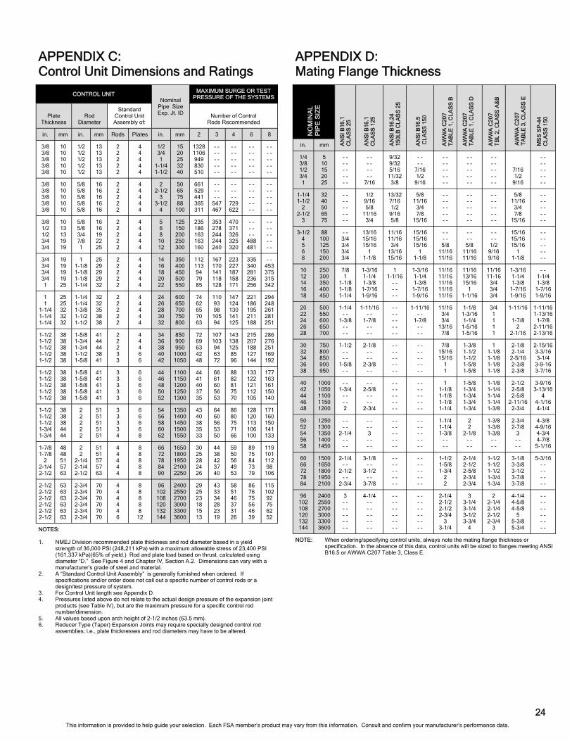
24
APPENDIX C: Control Unit Dimensions and Ratings
APPENDIX D: Mating Flange Thickness
in. mm
1/4 3/8 1/2 3/4 1
5 10 15 20 25
- - - - - - - - - -
- - - - - - - -
7/16
9/32 9/32 5/16
11/32 3/8
- - - -
7/16 1/2
9/16
- - - - - - - - - -
- - - - - - - - - -
- - - - - - - - - -
7/16 1/2
9/16
- - - - - - - - - -
1-1/4 1-1/2
2 2-1/2
3
32 40 50 65 75
- - - - - - - - - -
1/2 9/16 5/8
11/16 3/4
13/32 7/16 1/2
9/16 5/8
5/8 11/16
3/4 7/8
15/16
- - - - - - - - - -
- - - - - - - - - -
- - - - - - - - - -
5/8 11/16
3/4 7/8
15/16
- - - - - - - - - -
3-1/2 4 5 6 8
88 100 125 150 200
- - 3/4 3/4 3/4 3/4
13/16 15/16 15/16
1 1-1/8
11/16 11/16
3/4 13/16 15/16
15/16 15/16 15/16
1 1-1/8
- - - - 5/8
11/16 11/16
- - - - 5/8
11/16 11/16
- - - - 1/2
9/16 9/16
15/16 15/16 15/16
1 1-1/8
- - - - - - - - - -
10 12 14 16 18
250 300 350 400 450
7/8 1
1-1/8 1-1/8 1-1/4
1-3/16 1-1/4 1-3/8
1-7/16 1-9/16
1 1-1/16
- - - - - -
1-3/16 1-1/4 1-3/8
1-7/16 1-9/16
11/16 11/16 11/16 11/16 11/16
11/16 13/16 15/16
1 1-1/16
11/16 11-16
3/4 3/4 3/4
1-3/16 1-1/4 1-3/8
1-7/16 1-9/16
- - 1-1/4 1-3/8
1-7/16 1-9/16
20 22 24 26 28
500 550 600 650 700
1-1/4 - -
1-3/8 - - - -
1-11/16 - -
1-7/8 - - - -
- - - - - - - - - -
1-11/16 - -
1-7/8 - - - -
11/16 3/4 3/4
13/16 7/8
1-1/8 1-3/16 1-1/4
1-5/16 1-5/16
3/4 1 1 1 1
1-11/16
1-7/8 2
2-1/16
1-11/16 1-13/16
1-7/8 2-11/16 2-13/16
30 32 34 36 38
750 800 850 900 950
1-1/2 - - - -
1-5/8 - -
2-1/8 - - - -
2-3/8 - -
- - - - - - - - - -
- - - - - - - - - -
7/8 15/16 15/16
1 1
1-3/8 1-1/2 1-1/2 1-5/8 1-5/8
1 1-1/8 1-1/8 1-1/8 1-1/8
2-1/8 2-1/4
2-5/16 2-3/8 2-3/8
2-15/16 3-3/16 3-1/4
3-9-16 3-7/16
40 42 44 46 48
1000 1050 1100 1150 1200
- - 1-3/4
- - - - 2
- - 2-5/8
- - - -
2-3/4
- - - - - - - - - -
- - - - - - - - - -
1 1-1/8 1-1/8 1-1/8 1-1/4
1-5/8 1-3/4 1-3/4 1-3/4 1-3/4
1-1/8 1-1/4 1-1/4 1-1/4 1-3/8
2-1/2 2-5/8 2-5/8
2-11/16 2-3/4
3-9/16 3-13/16
4 4-1/16 4-1/4
50 52 54 56 58
1250 1300 1350 1400 1450
- - - -
2-1/4 - - - -
- - - - 3 - - - -
- - - - - - - - - -
- - - - - - - - - -
1-1/4 1-1/4 1-3/8
- - - -
2 2
2-1/8 - - - -
1-3/8 1-3/8 1-3/8
- - - -
2-3/4 2-7/8
3 - - - -
4-3/8 4-9/16 4-3/4 4-7/8
5-1/16
60 66 72 78 84
1500 1650 1800 1950 2100
2-1/4 - -
2-1/2 - -
2-3/4
3-1/8 - -
3-1/2 - -
3-7/8
- - - - - - - - - -
- - - - - - - - - -
1-1/2 1-5/8 1-3/4
2 2
2-1/4 2-1/2 2-5/8 2-3/4 2-3/4
1-1/2 1-1/2 1-1/2 1-3/4 1-3/4
3-1/8 3-3/8 3-1/2 3-7/8 3-7/8
5-3/16 - - - - - - - -
96 102 108 120 132 144
2400 2550 2700 3000 3300 3600
3 - - - - - - - - - -
4-1/4 - - - - - - - - - -
- - - - - - - - - - - -
- - - - - - - - - - - -
2-1/4 2-1/2 2-1/2 2-3/4
3 3-1/4
3 3-1/4 3-1/4 3-1/2 3-3/4
4
2 2-1/4 2-1/4 2-1/2 2-3/4
3
4-1/4 4-5/8 4-5/8
5 5-3/8 5-3/4
- - - - - - - - - - - -
NO
MIN
AL
P
IPE
SIZ
E
AW
WA
C20
7 T
AB
LE 1
, CLA
SS
D
AN
SI B
16.1
C
LAS
S 2
5
AN
SI B
16.1
C
LAS
S 1
25
AN
SI B
16.2
4 15
0LB
CLA
SS
25
AN
SI B
16.5
C
LAS
S 1
50
AW
WA
C20
7 T
AB
LE 1
, CLA
SS
B
AW
WA
C20
7 T
BL
2, C
LAS
S A
&B
AW
WA
C20
7 T
AB
LE 3
, CLA
SS
E
MS
S S
P-4
4 C
LAS
S 1
50
NOTE: When ordering/specifying control units, always note the mating flange thickness or specification. In the absence of this data, control units will be sized to flanges meeting ANSI B16.5 or AWWA C207 Table 3, Class E.
NOTES: 1. NMEJ Division recommended plate thickness and rod diameter based in a yield
strength of 36,000 PSI (248,211 kPa) with a maximum allowable stress of 23,400 PSI (161,337 kPa)(65% of yield.) Rod and plate load based on thrust, calculated using diameter “D.” See Figure 4 and Chapter IV, Section A.2. Dimensions can vary with a manufacturer’s grade of steel and material.
2. A “Standard Control Unit Assembly” is generally furnished when ordered. If specifications and/or order does not call out a specific number of control rods or a design/test pressure of system.
3. For Control Unit length see Appendix D. 4. Pressures listed above do not relate to the actual design pressure of the expansion joint
products (see Table IV), but are the maximum pressure for a specific control rod number/dimension.
5. All values based upon arch height of 2-1/2 inches (63.5 mm). 6. Reducer Type (Taper) Expansion Joints may require specially designed control rod
assemblies; i.e., plate thicknesses and rod diameters may have to be altered.
CONTROL UNIT MAXIMUM SURGE OR TEST
PRESSURE OF THE SYSTEMS
Plate Thickness
Rod Diameter
Standard Control Unit Assembly of:
Number of Control Rods Recommended
in. mm in. mm Rods Plates in. mm 2 3 4 6 8
3/8 3/8 3/8 3/8 3/8
10 10 10 10 10
1/2 1/2 1/2 1/2 1/2
13 13 13 13 13
2 2 2 2 2
4 4 4 4 4
1/2 3/4 1
1-1/4 1-1/2
15 20 25 32 40
1328 1106 949 830 510
- - - - - - - - - -
- - - - - - - - - -
- - - - - - - - - -
- - - - - - - - - -
3/8 3/8 3/8 3/8 3/8
10 10 10 10 10
5/8 5/8 5/8 5/8 5/8
16 16 16 16 16
2 2 2 2 2
4 4 4 4 4
2 2-1/2
3 3-1/2
4
50 65 75 88
100
661 529 441 365 311
- - - - - -
547 467
- - - - - -
729 622
- - - - - - - - - -
- - - - - - - - - -
3/8 1/2 1/2 3/4 3/4
10 13 13 19 19
5/8 5/8 3/4 7/8 1
16 16 19 22 25
2 2 2 2 2
4 4 4 4 4
5 6 8
10 12
125 150 200 250 300
235 186 163 163 160
353 278 244 244 240
470 371 326 325 320
- - - - - -
488 481
- - - - - - - - - -
3/4 3/4 3/4 3/4 1
19 19 19 19 25
1 1-1/8 1-1/8 1-1/8 1-1/4
25 29 29 29 32
2 2 2 2 2
4 4 4 4 4
14 16 18 20 22
350 400 450 500 550
112 113 94 79 85
167 170 141 118 128
223 227 187 158 171
335 340 281 236 256
- - 453 375 315 342
1 1
1-1/4 1-1/4 1-1/4
25 25 32 32 32
1-1/4 1-1/4 1-3/8 1-1/2 1-1/2
32 32 35 38 38
2 2 2 2 2
4 4 4 4 4
24 26 28 30 32
600 650 700 750 800
74 62 65 70 63
110 93 98
105 94
147 124 130 141 125
221 186 195 211 188
294 248 261 281 251
1-1/2 1-1/2 1-1/2 1-1/2 1-1/2
38 38 38 38 38
1-5/8 1-3/4 1-3/4 1-1/2 1-5/8
41 44 44 38 41
2 2 2 3 3
4 4 4 6 6
34 36 38 40 42
850 900 950
1000 1050
72 69 63 42 48
107 103 94 63 72
143 138 125 85 96
215 207 188 127 144
286 276 251 169 192
1-1/2 1-1/2 1-1/2 1-1/2 1-1/2
38 38 38 38 38
1-5/8 1-5/8 1-5/8 1-5/8 1-5/8
41 41 41 41 41
3 3 3 3 3
6 6 6 6 6
44 46 48 50 52
1100 1150 1200 1250 1300
44 41 40 37 35
66 61 60 56 53
88 82 81 75 70
133 122 121 112 105
177 163 161 150 140
1-1/2 1-1/2 1-1/2 1-3/4 1-3/4
38 38 38 44 44
2 2 2 2 2
51 51 51 51 51
3 3 3 3 4
6 6 6 6 8
54 56 58 60 62
1350 1400 1450 1500 1550
43 40 38 35 33
64 60 56 53 50
86 80 75 71 66
128 120 113 106 100
171 160 150 141 133
1-7/8 1-7/8
2 2-1/4 2-1/2
48 48 51 57 63
2 2
2-1/4 2-1/4 2-1/2
51 51 57 57 63
4 4 4 4 4
8 8 8 8 8
66 72 78 84 90
1650 1800 1950 2100 2250
30 25 28 24 26
44 38 42 37 40
59 50 56 49 53
89 75 84 73 79
119 101 112 98
106
2-1/2 2-1/2 2-1/2 2-1/2 2-1/2 2-1/2
63 63 63 63 63 63
2-3/4 2-3/4 2-3/4 2-3/4 2-3/4 2-3/4
70 70 70 70 70 70
4 4 4 4 4 6
8 8 8 8 8
12
96 102 108 120 132 144
2400 2550 2700 3000 3300 3600
29 25 23 18 15 13
43 33 34 28 23 19
58 51 46 37 31 26
86 76 75 56 46 39
115 102 92 75 62 52
Nominal Pipe Size Exp. Jt. ID
This information is provided to help guide your selection. Each FSA member’s product may vary from this information. Consult and confirm your manufacturer’s performance data.
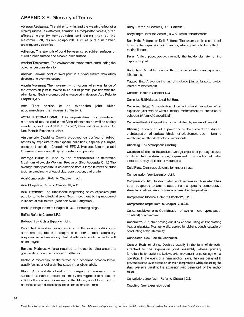
APPENDIX E: Glossary of Terms
Abrasion Resistance: The ability to withstand the wearing effect of a
rubbing surface. In elastomers, abrasion is a complicated process, often
affected more by compounding and curing than by the
elastomer. Soft, resilient compounds, such as pure gum rubber,
are frequently specified.
Adhesion: The strength of bond between cured rubber surfaces or
cured rubber surface and a non-rubber surface.
Ambient Temperature: The environment temperature surrounding the
object under consideration.
Anchor: Terminal point or fixed point in a piping system from which
directional movement occurs.
Angular Movement: The movement which occurs when one flange of
the expansion joint is moved to an out of parallel position with the
other flange. Such movement being measured in degrees. Also Refer to
Chapter III, A.5.
Arch: That portion of an expansion joint which
accommodates the movement of the joint.
ASTM INTERNATIONAL: This organization has developed
methods of testing and classifying elastomers as well as setting
standards, such as ASTM F 1123-87, Standard Specification for
Non-Metallic Expansion Joints.
Atmospheric Cracking: Cracks produced on surface of rubber
articles by exposure to atmospheric conditions, especially sunlight,
ozone and pollution. Chlorobutyl, EPDM, Hypalon, Neoprene and
Fluoroelastomers are all highly resistant compounds.
Average Burst: Is used by the manufacturer to determine
Maximum Allowable Working Pressure. (See Appendix C, 4.) The
average burst pressure is determined from a large number of burst
tests on specimens of equal size, construction, and grade.
Axial Compression: Refer to Chapter III, A.1.
Axial Elongation: Refer to Chapter III, A.2.
Axial Extension: The dimensional lengthening of an expansion joint
parallel to its longitudinal axis. Such movement being measured
in inches or millimeters. (Also see Axial Elongation.)
Back-up Rings: Refer to Chapter II, O.1., Retaining Rings.
Baffle: Refer to Chapter Il, F.2.
Bellows: See Arch or Expansion Joint.
Bench Test: A modified service test in which the service conditions are
approximated, but the equipment is conventional laboratory
equipment and not necessarily identical with that in which the product will
be employed.
Bending Modulus: A force required to induce bending around a
given radius; hence a measure of stiffness.
Blister: A raised spot on the surface or a separation between layers,
usually forming a void or air-filled space in the rubber article.
Bloom: A natural discoloration or change in appearance of the
surface of a rubber product caused by the migration of a liquid or
solid to the surface. Examples: sulfur bloom, wax bloom. Not to
be confused with dust on the surface from external sources.
Body: Refer to Chapter 1, D.3., Carcass.
Body Rings: Refer to Chapter I, D.3.B., Metal Reinforcement.
Bolt Hole Pattern or Drill Pattern: The systematic location of bolt
holes in the expansion joint flanges, where joint is to be bolted to
mating flanges.
Bore: A fluid passageway, normally the inside diameter of the
expansion joint.
Burst Test: A test to measure the pressure at which an expansion
joint bursts.
Capped End: A seal on the end of a sleeve joint or flange to protect
internal reinforcement.
Carcass: Refer to Chapter I, D.3.
Cemented Bolt Hole: see Lined Bolt Hole.
Cemented Edge: An application of cement around the edges of an
expansion joint with or without internal reinforcement for protection or
adhesion. (A form of Capped End.)
Cemented End: A Capped End accomplished by means of cement.
Chalking: Formation of a powdery surface condition due to
disintegration of surface binder or elastomer, due in turn to
weathering or other destructive environments.
Checking: See Atmospheric Cracking.
Coefficient of Thermal Expansion: Average expansion per degree over
a stated temperature range, expressed in a fraction of initial
dimension. May be linear or volumetric.
Cold Flow: Continued deformation under stress.
Compensator: See Expansion Joint.
Compression Set: The deformation which remains in rubber after it has
been subjected to and released from a specific compressive
stress for a definite period of time, at a prescribed temperature.
Compression Sleeves: Refer to Chapter IV, B.2.B.
Compression Stops: Refer to Chapter IV, B.2.B.
Concurrent Movements: Combination of two or more types (axial
or lateral) of movement.
Conductive: A rubber having qualities of conducting or transmitting
heat or electricity. Most generally, applied to rubber products capable of
conducting static electricity.
Connector: See Flexible Connector.
Control Rods or Units: Devices usually in the form of tie rods,
attached to the expansion joint assembly whose primary
function is to restrict the bellows axial movement range during normal
operation. In the event of a main anchor failure, they are designed to
prevent bellows over-extension or over-compression while absorbing the
static pressure thrust at the expansion joint, generated by the anchor
failure.
Convolution: See Arch. Refer to Chapter I, D.2.
Coupling: See Expansion Joint.
25
This information is provided to help guide your selection. Each FSA member’s product may vary from this information. Consult and confirm your manufacturer’s performance data.
Fatigue: The weakening or deterioration of a material caused by a
repetition of stress or strain.
Filled Arch: Refer to Chapter II, F.1.
Flange: See Integrally Flanged Type Expansion Joint.
Flanged End: Turned up or raised end made so that it can be bolted to an
adjacent flange.
Flexible Connector: See Expansion Joint.
Flex Cracking: A surface cracking induced by repeated bending or flexing.
Flex Life: See Cycle Life.
Floating Flange: Metal flange which is grooved to contain the bead on each end
of an expansion joint. The flange floats until lined up with mating bolt holes
and bolted in place, and is used on spherical expansion joints.
Fluoroelastomers: highly resistant compounds.
Free Length: The linear measurement before being subjected to a load
or force.
Friction: A rubber compound applied to and impregnating a fabric,
usually by means of a calender with rolls running at different surface
speed; hence the name "friction". The process is called "frictioning".
Frictioned Fabric: A fabric with a surface treatment which will bond two
surfaces together when interposed between the surfaces. Also may be
used to adhere to only one surface.
Gusset Plates: Refer to Chapter IV, B.1., Control Units.
Hardness: Property or extent of being hard. Measured by extent of
failure of the indentor point of any one of a number of standard
hardness testing instruments to penetrate the product. (Also see
Durometer.)
Heat Resistance: The ability of rubber articles to resist the
deteriorating effects of elevated temperatures.
Helix: Shape formed by spiraling a wire or other reinforcement
around the cylindrical body of a rubber pipe.
Hydraulic Pressure: A force exerted through fluids.
Hydrostatic Test: Refer to Chapter III, F.
Installed Length: See Face-To-Face.
Integrally Flanged Type Expansion Joint: An expansion joint in which the
joint flanges are made of the same rubber and fabric as the body of the joint.
Internal Sleeve: Refer to Chapter II, F.2.
Lateral Deflection or Lateral Movement: Refer to Chapter III, A.3.
Lateral Offset: Refer to Chapter III, A.3.
Limit Rods: Refer to Chapter IV, B.1., Control Units.
Lined Bolt Hole: A method of sealing exposed fabric in a bolt
hole.
Liner: Refer to Chapter II, F.2.
Main Anchor: A main anchor is one which must withstand all of the thrust due to
pressure, flow, and spring forces of the system.
Mandrel: A form used for sizing and to support the expansion joint during
fabrication and/or vulcanization. It may be rigid or flexible.
Mandrel Built: An expansion joint fabricated and/or vulcanized on a mandrel.
APPENDIX E: Continued
Cover: Refer to Chapter I, D.2.
Cracking: See (1) Atmospheric Cracking; (2) Flex Cracking
Crazing: See Atmospheric Cracking.
Cuff End: Refer to Chapter II, D., Sleeve Type.
Cycle Life: See Chapter III, H.
Design Pressure: The maximum high temperature that the
expansion joint is designed to handle during normal
operating conditions. Not to be confused with excursion
temperature.
Design Temperature: The maximum high or low temperature
that the expansion joint is designed to handle during normal
operating conditions. Not to be confused with excursion
temperature.
Diameter, Inside: The length of a straight line though the geometric
center and terminating at the inner periphery of an expansion joint.
Directional Anchor: A directional or sliding anchor is one which is
designed to absorb loading in one direction while permitting motion in
another. It may be either a main or intermediate anchor,
depending upon the application involved. When designed for
the purpose, a directional anchor may also function as a pipe
alignment guide.
Drill Pattern: The systematic location of bolt holes on the
mating flange to which the expansion joint will be attached. Usually
meets a specific specification.
Duck: A durable, closely woven fabric.
Durometer: A measurement of the hardness of rubber. (Also
see Hardness.)
Ears: Refer to Chapter IV, B., Control Units.
Eccentricity: A condition in which the inside and outside of
two diameters deviate from a common center.
EJMA: Expansion Joint Manufacturers Association (Metal
Expansion Joints). See NMEJ.
Elasticity: The ability to return to the original shape after removal of
load without regard to the rate of return.
Electrical Resistivity: The resistance between opposite parallel
faces of material having a unit length and unit cross section. Typically
measured in Ohms/cm.
Elongation: Increase in length expressed numerically as a
fraction or a percentage of initial length.
Enlarged End: An end with inside diameter greater than that of the
main body of an expansion joint.
Excursion Temperature: The temperature the system could reach
during an equipment failure. Excursion temperature should
be defined by maximum temperature and time duration of excursion.
Expansion Joint: Refer to Chapter 1.A., Definition.
Face-to-Face (F/F): Dimension between the pipe flange faces
to which the expansion joint will be bolted. This is also the length of the
expansion joint when the system is in the cold position. Also see (1) Pre
-Compression and (2) Pre-Set.
26 This information is provided to help guide your selection. Each FSA member’s product may vary from this information. Consult and confirm your manufacturer’s performance data.
Maximum Burst: Is the theoretical (predetermined) burst
pressure of an expansion joint.
Metal Reinforcement: Refer to Chapter I, D.3.B
Misalignment: The out of line condition that exists
between the adjacent faces of the flanges.
Movements: The dimensional changes which the expansion
joint is designed to absorb, such as those resulting from thermal
expansion or contraction. See (1) Angular Movement, (2)
Concurrent Movement (3) Resultant Movement, (4)
Lateral Movement, (5) Torsional Movement, (6) Thermal
Movement, (7) Transverse Movement.
NMEJ: Non-Metallic Expansion Joint Division, Fluid
Sealing Association.
O-A-L: Alternative term for the “face to face” dimension of
the overall length of an expansion joint.
Oil Resistant: The ability to withstand the deteriorating effects
of oil (generally refers to petroleum) on the physical
properties.
Oil Swell: The change in volume of rubber due to absorption of oil.
Open Arch: See Figure 2.A.1. Refer to Chapter II, A.1.
Operating Pressure/Vacuum: Refer to Appendix C,1.
Operating Temperature: The temperature at which the
system will generally operate during normal conditions.
Permeability: The ability of a fluid or gas to pass through an
elastomer.
Permanent Set: Permanent set is the deformation
remaining after a specimen has been stressed in tension or
compression a prescribed amount for a definite period and
released for a definite period.
Pipe Alignment Guide: A pipe alignment guide is framework
fastened to some rigid part of the installation which permits the
pipeline to move freely in only one direction along the axis of
the pipe. Pipe alignment guides are designed primarily for
use in applications to prevent lateral deflection and
angular rotation.
Pipe Sleeve: See Compression Sleeves.
Plain Ends: See Straight Ends.
Ply: One concentric layer or ring of material, such as fabric
plies in an expansion joint.
Pre-Compression: Compressing the expansion joint
(shortening the F/F) so that in the cold position the joint
has a given amount of compression set into the joint. The
purpose of pre-compression is to allow for unexpected or
additional axial extension. This is performed at the jobsite.
Pre-Set: Dimension that joints are deflected to insure that
desired movements will take place. See Lateral.
Proof Pressure Test: See Hydrostatic Test.
Pump Connector: See Expansion Joint.
Reducers: Refer to Chapter II, B., Reducers.
Reinforcement: Refer to Chapter I, D.3., Carcass
Resultant Movement: The net effect of concurrent movement.
Retaining Rings: Refer to Chapter II, L.1.
RMA: The Rubber Manufacturers Association, Inc.
SAE: The Society of Automotive Engineers. This organization has
developed methods of testing and classifying elastomers.
Service Test: A test in which the expansion joint is operated under service
conditions in the actual equipment.
Soft Cuffs: Refer to Chapter II, D., Sleeve Type.
Soft End: An end in which the rigid reinforcement of the body, usually wire,
is omitted.
Specific Gravity: The ratio of the weight of a given substance to the weight
of an equal volume of water at a specified temperature.
Spool "Arch" Type: Refer to Chapter II, A.
Static Wire: A wire incorporated in an expansion joint for conducting or
transmitting static electricity.
Straight End: An end with inside diameter the same as that of the main body.
Stretcher Bolts: Refer to Chapter IV, B.1., Control Units.
Sun Checking: See Atmospheric Cracking. See Chapter 4E, 2A
Tapers: Refer to Chapter III, A.6., Reducers.
Temperature: See (1) Ambient Temperature, (2) Design Temperature,
(3) Excursion Temperature, (4) Operating Temperature.
Tensile Strength: The force required to rupture a specimen.
"Dumbbell" specimens are cut from flat stock by a die of specified
shape. Large elongations require special considerations in holding
specimens and measuring the test results.
Testing: See (1) Bench Test, (2) Burst Test, (3) Hydrostatic Test, (4)
Service Test.
Thermal Movements: Movements created within the piping system by thermal
expansion. Can be axial, lateral or torsional.
Top Hat Liner: See Chapter II, F.3.
Torsional Movement: Refer to Chapter III, A.6.
Transverse Movement: See Lateral Movement.
Tube: Refer to Chapter I, D.1.
Under Gauge: Thinner than the thickness specified.
Vacuum: See Table II.
Wide Arch: Refer to Chapter II, K.
Wire Reinforced: A product containing metal wire to give added
strength, increased dimensional stability or crush resistance. See
Reinforcement.
Wrap Marks: Impressions left on the cover surface by the material used to
wrap the expansion joint during vulcanization. Usually shows
characteristics of a woven pattern and wrapper width edge marks.
Van Stone Flange: A loose, rotating type flange, sometimes called a lap-
joint flange.
27 This information is provided to help guide your selection. Each FSA member’s product may vary from this information. Consult and confirm your manufacturer’s performance data.
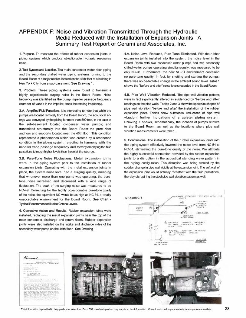
APPENDIX F: Noise and Vibration Transmitted Through the Hydraulic Media Reduced with the Installation of Expansion Joints A Summary Test Report of Cerami and Associates, Inc.
28
1. Purpose. To measure the effects of rubber expansion joints in
piping systems which produce objectionable hydraulic resonance
noise.
2. Test System and Location. The main condenser water riser piping
and the secondary chilled water piping systems running to the
Board Room of a major retailer, located on the 46th floor of a building in
New York City from a sub-basement. See Drawing 1.
3. Problem. These piping systems were found to transmit a
highly objectionable surging noise in the Board Room. Noise
frequency was identified as the pump impeller passage frequency
(number of vanes in the impeller, times the rotating frequency).
3.A. Amplified Fluid Pulsations. It is interesting to note that while the
pumps are located remotely from the Board Room, the acoustical en-
ergy was conveyed by the piping for more than 500 feet, in the case of
the sub-basement located condenser water pumps; and
transmitted structurally into the Board Room via pure riser
anchors and supports located near the 46th floor. This condition
represented a phenomenon which was created by a resonance
condition in the piping system, re-acting in harmony with the
impeller vane passage frequency and thereby amplifying the fluid
pulsations to much higher levels than those at the source.
3.B. Pure-Tone Noise Fluctuations. Metal expansion joints
were in the piping system prior to the installation of rubber
expansion joints. Operating with the metal expansion joints in
place, the system noise level had a surging quality, meaning
that whenever more than one pump was operating, the pure-
tone noise increased and decreased with a wide range of
fluctuation. The peak of the surging noise was measured to be
NC-49. Correcting for the highly objectionable pure-tone quality
of the noise, the equivalent NC would be as high as NC-54, a totally
unacceptable environment for the Board Room. See Chart -
Typical Recommended Noise Criteria Levels.
4. Corrective Action and Results. Rubber expansion joints were
installed, replacing the metal expansion joints near the top of the
main condenser discharge and return risers. Rubber expansion
joints were also installed on the intake and discharge sides of the
secondary water pump on the 46th floor. See Drawing 1.
4.A. Noise Level Reduced, Pure-Tone Eliminated. With the rubber
expansion joints installed into the system, the noise level in the
Board Room with two condenser water pumps and two secondary
chilled wa-ter pumps operating simultaneously, was measured to be
only NC-31. Furthermore, the new NC-31 environment contained
no pure-tone quality. In fact, by shutting and starting the pumps,
there was no de-tectable change in the ambient sound level. Table 1
shows the "before and after" noise levels recorded in the Board Room.
4.B. Pipe Wall Vibration Reduced. The pipe wall vibration patterns
were in fact significantly altered as evidenced by "before and after'
readings on the pipe walls. Tables 2 and 3 show the spectrum shapes of
pipe wall vibration "before and after' the installation of the rubber
expansion joints. Tables show substantial reductions of pipe wall
vibration, further indications of a quieter piping system.
Drawing 1 shows, schematically, the location of pumps relative
to the Board Room, as well as the locations where pipe wall
vibration measurements were taken.
5. Conclusions. The installation of the rubber expansion joints into
the piping system effectively lowered the noise level from NC-54 to
NC-31, eliminating the pure-tone quality of the noise. We attribute
the highly successful attenuation provided by the rubber expansion
joints to a disruption in the acoustical standing wave pattern in
the piping configuration. This disruption was being created by the
sudden change in pipe wall rigidity at the expansion joint. The soft wall of
the expansion joint would actually "breathe" with the fluid pulsations,
thereby disrupt-ing the steel pipe wall vibration pattern as well.
This information is provided to help guide your selection. Each FSA member’s product may vary from this information. Consult and confirm your manufacturer’s performance data.
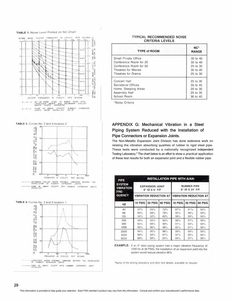
APPENDIX G: Mechanical Vibration in a Steel
Piping System Reduced with the Installation of Pipe Connectors or Expansion Joints. The Non-Metallic Expansion Joint Division has done extensive work on
relating the vibration absorbing qualities of rubber to rigid steel pipe.
These tests were conducted by a nationally recognized independent
Testing Laboratory." The chart below is an effort to show a practical application
of these test results for both an expansion joint and a flexible rubber pipe.
29 This information is provided to help guide your selection. Each FSA member’s product may vary from this information. Consult and confirm your manufacturer’s performance data.
APPENDIX H: Pressure Terminology APPENDIX J: Bibliography of
Rubber Expansion Joint Articles Rubber Expansion Joint Articles
In 1971, the Non-Metallic Expansion Joint Division of the
Fluid Sealing Association sent out a terminology survey to
some of the leading engineering firms in the country asking their
help in defining certain terms that are continually used in our industry. The
purpose of the survey was to arrive at a standard definition of these
terms. Our Division Membership has made a very careful study of
the answers received and, after consolidating and refining the
answers, has been able to reduce the terms in question to the following:
A. ASHRAE Handbook & Product Directory, 1984 Systems
Chapter 32, "Flexible Pipe Connectors."
B. Building Construction, June, 1967: "A Guide to
Expansion Joints in Modern Piping Systems", by D. Bruce Keep.
C. Chemical Engineering, December 29, 1980" "Elastomeric
Expansion Joints", by Joseph H. Bedson.
D. Elastomerics, January, 1980: "Elastomers in Flexible
Pipe Joints", by R. R. O'Toole.
E. Elastomers Notebook, August, 1976: "Hot Gas Exposure",
by Gene Johnson.
F. Elastomers Notebook, June, 1978: "Flangless Flexibility",
by General Rubber Corporation.
G. Engineering Appliances, Ltd., January, 1979: "Noise
Absorption by Bellows", by Stenflex GMBH.
H. Heating/Piping/Air Conditioning, December, 1961: 'When
and How Flexible Rubber Connectors Can Help Reduce
System Noise, Vibration", by Robert L. Swenson.
I . Heating/Piping/Air Conditioning, November, 1979:
"Refrigeration for 1980 Winter Olympics", by D. Bruce Keep.
J. Heating/Piping/Air Conditioning, January, 1985: "Noise
Control in Plumbing Systems", by Lyle F. Yerges.
K. Mechanical Contractor, February, 1966: "Rubber
Expansion and Vibration Joints, Selection/Installation/
Maintenance", by Ray Michael.
L. Pipeline & Gas Journal, March, 1988: "Rubber Expansion
Joints", by Ray Magner.
M. Plant Engineering, May 17, 1978: "Fabric-Reinforced
Rubber Expansion Joints", by Ed Holland.
N. Plant Engineering, July 26, 1979: "Methods of
Handling Thermally Induced Pipe Movement', by Ernest R.
Cunningham.
O. Plant Services, April, 1990: "Pump Alignment: When to do
it", By Igor J. Karassik.
P. Power, August, 1986: "Expansion Joints for Ductwork
and Piping", by William O'Keefe.
Q. Pump and Systems Magazine. December, 1993: "Ask the
Experts - Expansion Joints and Air Chambers", by Bob Stover.
R. Water/Engineering & Management. November, 1986:
"Cushioning Stress and Strain in Pipe Systems", by
Ray Magner.
30
1. Operating Pressure. The actual pressure at which the system
works under normal conditions. This pressure may be positive
or negative (vacuum.)
2. System Design Pressure. The highest or most severe pressure
expected during operation. Sometimes used as the calculated
operating pressure plus an allowance for safety margin.
4. Surge Pressure. Operating pressure plus the increment above
operating pressure that the expansion joint will be subjected. For
a very short time duration due to pump starts, valve closings, etc.
5. Maximum Allowable Pressure. This term is used by the
expansion joint manufacturer to define the maximum operating
pressure recommended for a specific expansion joint. See Table II.
6. Hydrostatic Test Pressure. The hydrostatic test pressure is used
to demonstrate system or expansion joint capability. The
standard test is 1-1/2 times the Maximum Allowable Pressure, held for 10
minutes, without leaks.
3. Expansion Joint Design Pressure. The highest most severe
pressure the expansion joint will handle.
APPENDIX I: List of Specifications
A: ASTM Designation: F1123-87, “Standard Specification for Non-
Metallic Expansion Joints.” Approved December 31, 1987.
American Society for Testing and Material, 1916 Race Street,
Philadelphia, PA 19103 USA.
B: MIL-E-15330D(SH): “Military Specification Expansion Joint, Pipe,
Non-Metallic, Fire-Retardant”, revised October 14, 1977. U.S.
Government Printing Office Form 1977-7103-122-6336. The
section on class A, Type 1, Arched, Spool-Type Expansion Joint
is replaced by ASTM F 1123-87, effective August 10, 1993.
C: COAST GUARD: Code of Federal Regulations (C.F.R.46) Parts
56.35-10 and 56.60-1 (B). Revised 10/1/91. Office of the
Federal Register, National Archives and Records Service,
General Services Administration. ASTM F 1123-87 is the
governing specification.
D: Fan Connector Spec: MIL-R-6855-D: Military Specification,
“General specification for rubber synthetic; sheets, strips, molded
or extruded shapes.” Class 2 is specified for Navy fan
connectors.
This information is provided to help guide your selection. Each FSA member’s product may vary from this information. Consult and confirm your manufacturer’s performance data.
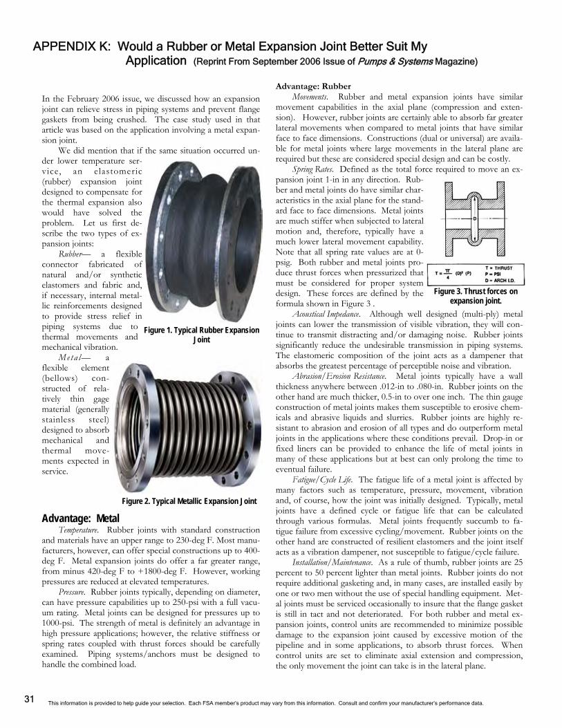
APPENDIX K: Would a Rubber or Metal Expansion Joint Better Suit My Application (Reprint From September 2006 Issue of Pumps & Systems Magazine)
31
In the February 2006 issue, we discussed how an expansion joint can relieve stress in piping systems and prevent flange gaskets from being crushed. The case study used in that article was based on the application involving a metal expan-sion joint.
We did mention that if the same situation occurred un-der lower temperature ser-vice, an elastomeric (rubber) expansion joint designed to compensate for the thermal expansion also would have solved the problem. Let us first de-scribe the two types of ex-pansion joints:
Rubber— a flexible connector fabricated of natural and/or synthetic elastomers and fabric and, if necessary, internal metal-lic reinforcements designed to provide stress relief in piping systems due to thermal movements and mechanical vibration.
Meta l— a flexible element (bellows) con-structed of rela-tively thin gage material (generally stainless steel) designed to absorb mechanical and thermal move-ments expected in service. Advantage: Metal
Temperature. Rubber joints with standard construction and materials have an upper range to 230-deg F. Most manu-facturers, however, can offer special constructions up to 400-deg F. Metal expansion joints do offer a far greater range, from minus 420-deg F to +1800-deg F. However, working pressures are reduced at elevated temperatures.
Pressure. Rubber joints typically, depending on diameter, can have pressure capabilities up to 250-psi with a full vacu-um rating. Metal joints can be designed for pressures up to 1000-psi. The strength of metal is definitely an advantage in high pressure applications; however, the relative stiffness or spring rates coupled with thrust forces should be carefully examined. Piping systems/anchors must be designed to handle the combined load.
Figure 1. Typical Rubber Expansion Joint
Figure 2. Typical Metallic Expansion Joint
Advantage: Rubber Movements. Rubber and metal expansion joints have similar
movement capabilities in the axial plane (compression and exten-sion). However, rubber joints are certainly able to absorb far greater lateral movements when compared to metal joints that have similar face to face dimensions. Constructions (dual or universal) are availa-ble for metal joints where large movements in the lateral plane are required but these are considered special design and can be costly.
Spring Rates. Defined as the total force required to move an ex-pansion joint 1-in in any direction. Rub-ber and metal joints do have similar char-acteristics in the axial plane for the stand-ard face to face dimensions. Metal joints are much stiffer when subjected to lateral motion and, therefore, typically have a much lower lateral movement capability. Note that all spring rate values are at 0-psig. Both rubber and metal joints pro-duce thrust forces when pressurized that must be considered for proper system design. These forces are defined by the formula shown in Figure 3 .
Acoustical Impedance. Although well designed (multi-ply) metal joints can lower the transmission of visible vibration, they will con-tinue to transmit distracting and/or damaging noise. Rubber joints significantly reduce the undesirable transmission in piping systems. The elastomeric composition of the joint acts as a dampener that absorbs the greatest percentage of perceptible noise and vibration.
Abrasion/Erosion Resistance. Metal joints typically have a wall thickness anywhere between .012-in to .080-in. Rubber joints on the other hand are much thicker, 0.5-in to over one inch. The thin gauge construction of metal joints makes them susceptible to erosive chem-icals and abrasive liquids and slurries. Rubber joints are highly re-sistant to abrasion and erosion of all types and do outperform metal joints in the applications where these conditions prevail. Drop-in or fixed liners can be provided to enhance the life of metal joints in many of these applications but at best can only prolong the time to eventual failure.
Fatigue/Cycle Life. The fatigue life of a metal joint is affected by many factors such as temperature, pressure, movement, vibration and, of course, how the joint was initially designed. Typically, metal joints have a defined cycle or fatigue life that can be calculated through various formulas. Metal joints frequently succumb to fa-tigue failure from excessive cycling/movement. Rubber joints on the other hand are constructed of resilient elastomers and the joint itself acts as a vibration dampener, not susceptible to fatigue/cycle failure.
Installation/Maintenance. As a rule of thumb, rubber joints are 25 percent to 50 percent lighter than metal joints. Rubber joints do not require additional gasketing and, in many cases, are installed easily by one or two men without the use of special handling equipment. Met-al joints must be serviced occasionally to insure that the flange gasket is still in tact and not deteriorated. For both rubber and metal ex-pansion joints, control units are recommended to minimize possible damage to the expansion joint caused by excessive motion of the pipeline and in some applications, to absorb thrust forces. When control units are set to eliminate axial extension and compression, the only movement the joint can take is in the lateral plane.
Figure 3. Thrust forces on expansion joint.
This information is provided to help guide your selection. Each FSA member’s product may vary from this information. Consult and confirm your manufacturer’s performance data.
Summary Metal expansion joints are applied more frequently
than rubber primarily because application conditions, e.g. temperatures and pressures, favor their use. Some experts in this industry estimate the metal expansion joint market to be 4X larger than the rubber expansion joint market. The writer of this article has been in the manufacturing business of both rubber and metal joints for over 35 years and would venture to say that is a good estimate.
It may appear that the above comparison is slanted toward the rubber expansion joints. The fact is, rubber can’t replace metal in all applications, but it is a better choice for many applications involving high vibration and sound dampening within the guidelines mentioned above. Consultation with a reputable manufacturer for your specific application is always recommended.
This information is provided to help guide your selection. Each FSA member’s product may vary from this information. Consult and confirm your manufacturer’s performance data. 32
Revisions 7.1 Edition Added Spring Rate values to Tables V and VI, page 13— 14. Added the Filled Arch notes to the Notes section, page 13. Corrected references to ANSI and AWWA on page 23. Added Revisions page, page 33. Updated the cover page. Made the last page an electronic worksheet for web-site.
7.2 Edition Updated Table VI with changes to Compression, Extension and Lateral Movements, page 14. Updated the cover page and inside cover. 7.3 Edition Corrected Movement/Spring Rate Capabilities in Table VI, page 14. Corrected form of trademark on front, inside, and back covers. Corrected phone and fax numbers on inside cover. Updated Revisions, page 33.
This information is provided to help guide your selection. Each FSA member’s product may vary from this information. Consult and confirm your manufacturer’s performance data. 33
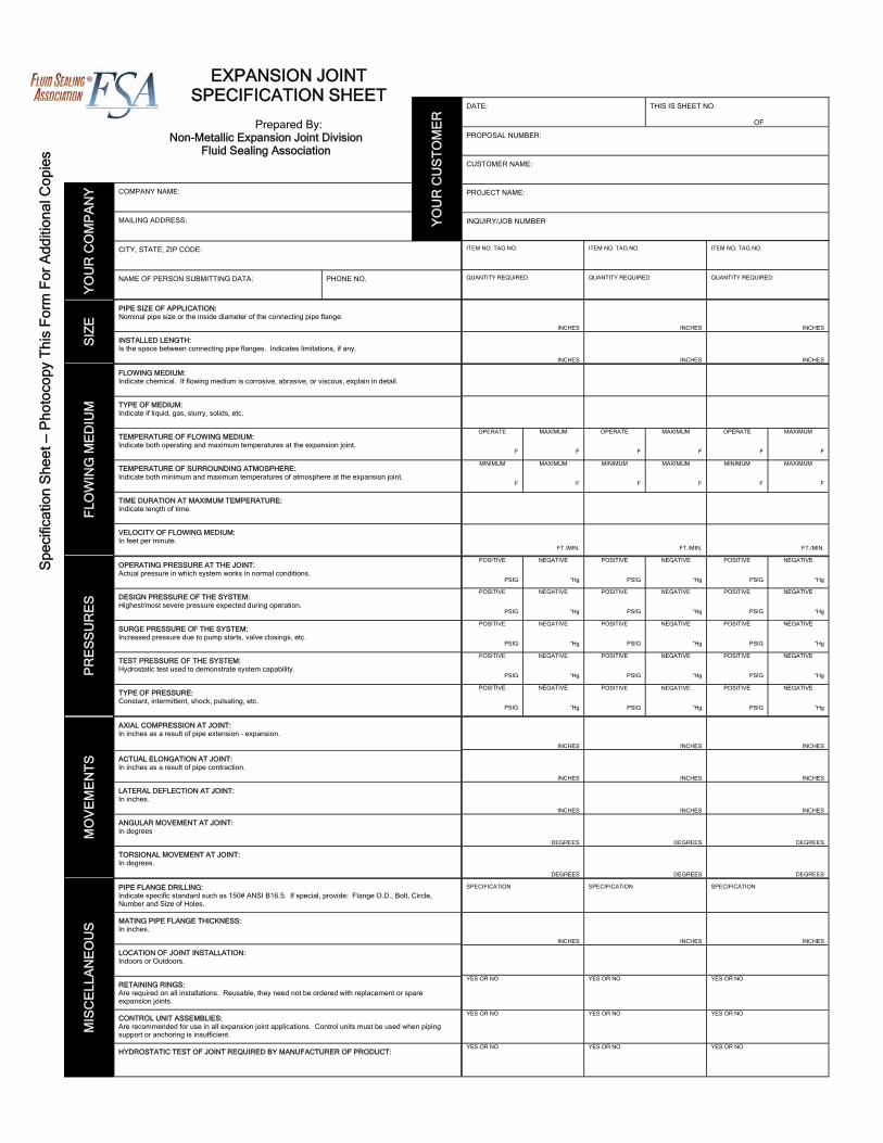
COMPANY NAME:
MAILING ADDRESS:
CITY, STATE, ZIP CODE:
NAME OF PERSON SUBMITTING DATA: PHONE NO.
DATE: THIS IS SHEET NO. OF
PROPOSAL NUMBER:
CUSTOMER NAME:
PROJECT NAME:
INQUIRY/JOB NUMBER
PIPE SIZE OF APPLICATION: Nominal pipe size or the inside diameter of the connecting pipe flange.
INSTALLED LENGTH: Is the space between connecting pipe flanges. Indicates limitations, if any.
FLOWING MEDIUM: Indicate chemical. If flowing medium is corrosive, abrasive, or viscous, explain in detail.
TYPE OF MEDIUM: Indicate if liquid, gas, slurry, solids, etc.
TEMPERATURE OF FLOWING MEDIUM: Indicate both operating and maximum temperatures at the expansion joint.
TEMPERATURE OF SURROUNDING ATMOSPHERE: Indicate both minimum and maximum temperatures of atmosphere at the expansion joint.
TIME DURATION AT MAXIMUM TEMPERATURE: Indicate length of time.
VELOCITY OF FLOWING MEDIUM: In feet per minute.
OPERATING PRESSURE AT THE JOINT: Actual pressure in which system works in normal conditions.
DESIGN PRESSURE OF THE SYSTEM: Highest/most severe pressure expected during operation.
SURGE PRESSURE OF THE SYSTEM: Increased pressure due to pump starts, valve closings, etc.
TEST PRESSURE OF THE SYSTEM: Hydrostatic test used to demonstrate system capability.
TYPE OF PRESSURE: Constant, intermittent, shock, pulsating, etc.
AXIAL COMPRESSION AT JOINT: In inches as a result of pipe extension - expansion.
ACTUAL ELONGATION AT JOINT: In inches as a result of pipe contraction.
LATERAL DEFLECTION AT JOINT: In inches.
ANGULAR MOVEMENT AT JOINT: In degrees
TORSIONAL MOVEMENT AT JOINT: In degrees.
PIPE FLANGE DRILLING: Indicate specific standard such as 150# ANSI B16.5. If special, provide: Flange O.D., Bolt, Circle, Number and Size of Holes.
MATING PIPE FLANGE THICKNESS: In inches.
LOCATION OF JOINT INSTALLATION: Indoors or Outdoors.
RETAINING RINGS: Are required on all installations. Reusable, they need not be ordered with replacement or spare expansion joints.
CONTROL UNIT ASSEMBLIES: Are recommended for use in all expansion joint applications. Control units must be used when piping support or anchoring is insufficient.
HYDROSTATIC TEST OF JOINT REQUIRED BY MANUFACTURER OF PRODUCT:
INCHES
INCHES
INCHES
INCHES
INCHES
INCHES
OPERATE
F
MAXIMUM
F
OPERATE
F
MAXIMUM
F
OPERATE
F
MAXIMUM
F
MINIMUM
F
MAXIMUM
F
MINIMUM
F
MAXIMUM
F
MINIMUM
F
MAXIMUM
F
FT./MIN.
FT./MIN.
FT./MIN.
POSITIVE
PSIG
NEGATIVE
“Hg
POSITIVE
PSIG
NEGATIVE
“Hg
POSITIVE
PSIG
NEGATIVE
“Hg
POSITIVE
PSIG
NEGATIVE
“Hg
POSITIVE
PSIG
NEGATIVE
“Hg
POSITIVE
PSIG
NEGATIVE
“Hg
POSITIVE
PSIG
NEGATIVE
“Hg
POSITIVE
PSIG
NEGATIVE
“Hg
POSITIVE
PSIG
NEGATIVE
“Hg
POSITIVE
PSIG
NEGATIVE
“Hg
POSITIVE
PSIG
NEGATIVE
“Hg
POSITIVE
PSIG
NEGATIVE
“Hg
POSITIVE
PSIG
NEGATIVE
“Hg
POSITIVE
PSIG
NEGATIVE
“Hg
POSITIVE
PSIG
NEGATIVE
“Hg
INCHES
INCHES
INCHES
INCHES
INCHES
INCHES
INCHES
INCHES
INCHES
DEGREES
DEGREES
DEGREES
DEGREES
DEGREES
DEGREES
SPECIFICATION SPECIFICATION SPECIFICATION
INCHES
INCHES
INCHES
YES OR NO YES OR NO
YES OR NO
YES OR NO
YES OR NO YES OR NO
YES OR NO
YES OR NO YES OR NO
ITEM NO. TAG NO. ITEM NO. TAG NO. ITEM NO. TAG NO.
QUANTITY REQUIRED: QUANTITY REQUIRED: QUANTITY REQUIRED:
YO
UR
CO
MP
AN
Y
SIZ
E
FLO
WIN
G M
ED
IUM
P
RE
SS
UR
ES
M
OV
EM
EN
TS
M
ISC
ELL
AN
EO
US
YO
UR
CU
ST
OM
ER
Spe
cific
atio
n S
heet
— P
hoto
copy
Thi
s F
orm
For
Add
ition
al C
opie
s
EXPANSION JOINT SPECIFICATION SHEET
Prepared By:
Non-Metallic Expansion Joint Division Fluid Sealing Association
Related Documents