Technical Guidelines for Power Generating Units Part 7: Operation and maintenance of power plants for renewable energy Category D3: "Global Service Protocol (GSP)" Standardised data format for the electronic exchange of data in the maintenance process Revision 0 01.01.2014 Published by: FGW e.V. - Fördergesellschaft Windenergie und andere Erneuerbare Energien

Welcome message from author
This document is posted to help you gain knowledge. Please leave a comment to let me know what you think about it! Share it to your friends and learn new things together.
Transcript

Technical Guidelines for Power Generating Units
Part 7:
Operation and maintenance of
power plants
for renewable energy
Category D3:
"Global Service Protocol (GSP)"
Standardised data format for the
electronic exchange of data in the maintenance process
Revision 0 01.01.2014
Published by:
FGW e.V. -
Fördergesellschaft Windenergie
und andere Erneuerbare Energien
Operation and maintenance
of power plants for renewable energy
Category D3:
Global Service Protocol (GSP)
Revision 0
01.01.2014
Published by:
FGW e.V. - Fördergesellschaft Windenergie und andere Erneuerbare Energien Oranienburger Straße 45 10117 Berlin, Germany
Tel.: +49 (0)30 30101505 0 Fax: +49 (0)30 30101505 1 [email protected] www.wind-fgw.de
The focus of the FGW Technical Guidelines for Wind Turbines part 7 (TG7) "Maintenance of renewable
energy power plants" lies in the description of the processes and the necessary documents and data. Fur-
thermore, a clear and standardised identification of components, standard description of states and
events and classification of malfunctions are required for all participants to enable later evaluation and
analysis.
The present Part 7 of the Technical Guidelines (TG7) was compiled jointly by operative management -
companies, service providers, manufacturers, research institutes, specialist companies, certification bod-
ies and insurance companies.
The objective of the Global Service Protocol (GSP) is the provision of a standardised electronic data format
that facilitates communication between different parties involved in the maintenance of renewable wind
turbines.
Part 1: Determination of Noise Emission Values
Part 2: Determination of Power Curves and Standardised Energy Yields
Part 3: Determination of Electrical Characteristics of Power Generating Units connected to
MV, HV and EHV Grids
Part 4: Requirements for Modelling and Validating Simulation Models of Electrical Characteris-
tics of Power Generating Units and Systems (starting from Rev. 3)
Part 5: Determination and Application of Reference Yield
Part 6: Determination of Wind Potential and Energy Yields
Part 7: Operation and maintenance of power plants for renewable energy
Category A: Miscellaneous section
Category B3: Specialist application notes for monitoring and testing foundations
and supporting structures for wind turbines
Category D2: State-Event-Cause code
Category D3: Global Service Protocol (GSP)
Part 8: Certification of the Electrical Characteristics of Power Generating Units and Systems in
the Medium-, High- and Highest-voltage Grids
Part 9: Electromagnetic Compatibility
Notes on TG7 category D3:
Existing energy industry standards were combined with experience from the renewable energy sector to produce these guidelines.
Additional categories in TG7 are in preparation at the time of publication of Category D3 in TG7. References to other as yet unpublished categories are therefore provisional and purely for infor-mation.
In revision 0 of these guidelines this particularly relates to
FGW TG 7 category C documentation
FGW TG 7 category D1
Additional information and recommendations on practical implementation will in future include an application guide on the GSP for specific applications.
Materials available from FGW e.V. on the GSP standard:
- Guidelines as a free download (PDF) in German and English
- Application package TG 7 category D3 (available for token fee; free of charge for FGW members)
o Guidelines incl. Attachment A (schema documentation) as a print version in German
o XSD schema file
Contents
1 INTRODUCTION .............................................................................................................9
1.1 Global Service Protocol (GSP) ............................................................................................................... 10
2 GENERAL INFORMATION ............................................................................................. 11
2.1 Scope .................................................................................................................................................... 11
2.2 Legal regulations................................................................................................................................... 11
2.3 Normative references ........................................................................................................................... 11
2.4 Reference to guidelines and requirements ........................................................................................... 12
3 GENERAL SPECIFICATIONS ........................................................................................... 13
3.1 Definitions ............................................................................................................................................ 13
3.2 Abbreviations ....................................................................................................................................... 15
3.3 Definition of the contents of the guidelines .......................................................................................... 15
3.4 Functions of the GSP ............................................................................................................................. 18
3.5 Roles of the parties involved ................................................................................................................ 19
3.6 Applications .......................................................................................................................................... 21
3.7 References between system components ............................................................................................. 22
3.8 Example process ................................................................................................................................... 24
3.9 IT process workflow .............................................................................................................................. 29
4 INFORMATION STRUCTURE IN THE GSP ....................................................................... 31
4.1 Overview .............................................................................................................................................. 31
4.2 GSP info data block (gspInfo) ................................................................................................................ 33
4.3 powerPlant data block .......................................................................................................................... 33
4.4 energySystem data block ...................................................................................................................... 35
4.5 workOrder data block ........................................................................................................................... 37
4.6 workReport data block ......................................................................................................................... 42
4.7 Additional notes on the information structure ..................................................................................... 47
5 GSP APPLICATION RULES ............................................................................................. 59
5.1 Conformity rules ................................................................................................................................... 59
5.2 Time reference ..................................................................................................................................... 60
5.3 Reference to the energy system ........................................................................................................... 61
5.4 Object reference ................................................................................................................................... 61
5.5 Order reference .................................................................................................................................... 63
5.6 Item reference ...................................................................................................................................... 63
5.7 Condition assessment ........................................................................................................................... 63
5.8 Staff and time recording ....................................................................................................................... 64
5.9 Scope and completeness of the data to be transferred ......................................................................... 64
5.10 Missing information in mandatory information units ........................................................................... 65
5.11 Uniformity of designations in the master data ..................................................................................... 65
5.12 Units of measurement to be used in GSP data ...................................................................................... 65
5.13 Language of the Maintenance documentation in the GSP .................................................................... 65
5.14 Person responsible for a system ........................................................................................................... 66
5.15 Use of comments .................................................................................................................................. 66
6 STANDARDISED CATEGORIES TO BE USED.................................................................... 67
6.1 Structure of a standardised GSP category code .................................................................................... 67
6.2 Classification of the energy system according to the type of energy used ............................................ 68
6.3 Categories to be used for work orders .................................................................................................. 68
6.4 Categories to be used for the processing status of work orders and items ........................................... 69
6.5 Categories for the status of activities .................................................................................................... 69
6.6 Condition assessment in accordance with TG7 category D2 (ZEUS) ...................................................... 69
6.7 Categories to be used for the status of a ZEUS condition assessment ................................................... 70
6.8 Classification of the M measures according to their complexity (maintenance level) ........................... 70
6.9 Description of file types in the attachment ........................................................................................... 70
6.10 Units and unit symbols ......................................................................................................................... 70
6.11 Recommendation for the assignment of order priorities ...................................................................... 71
6.12 Time types in the time recording .......................................................................................................... 71
6.13 Remuneration surcharges ..................................................................................................................... 71
6.14 Gender and salutation .......................................................................................................................... 72
6.15 Traffic routes ........................................................................................................................................ 72
6.16 Transport modes .................................................................................................................................. 72
6.17 Description of the level of cloud cover .................................................................................................. 72
6.18 Description of the language of free texts in the GSP ............................................................................. 72
6.19 Reference to countries.......................................................................................................................... 72
6.20 Information on the type of maintenance contract ................................................................................ 73
6.21 Loading type for transport operations .................................................................................................. 73
7 ADDITIONAL IMPLEMENTATION NOTES AND DEFINITIONS .......................................... 74
7.1 Required set up of system structure ..................................................................................................... 74
7.2 Assignment of the system elements involved in the M process ............................................................ 74
7.3 Application of the ZEUS code ................................................................................................................ 74
7.4 Documentation of M on equipment parts when removed .................................................................... 75
7.5 Temporary regulations ......................................................................................................................... 75
7.6 Graphical display of the XML schema ................................................................................................... 76
8 SPECIFICATION OF THE GSP DOCUMENT FORMAT ....................................................... 79
8.1 Basics .................................................................................................................................................... 79
8.2 Structure of a GSP document file .......................................................................................................... 79
8.3 Manifest ............................................................................................................................................... 79
8.4 File references in the .gsp document format ........................................................................................ 81
9 XML SCHEMA DOCUMENTATION ................................................................................ 82
9.1 Specification of the GSP document format schema definition .............................................................. 82
9.2 XML schema documentation ................................................................................................................ 82

OPERATION AND MAINTENANCE
of power plants for renewable energy
Category D3: "Global Service Protocol (GSP)"
Revision 0, as at 01.01.2014
The focus of the FGW Technical Guidelines for Wind Turbines part 7 (TG7) "Maintenance of renewable
energy power plants" lies in the description of the processes and the necessary documents and data.
Furthermore, a clear and standardised identification of components, standard description of states and
events and classification of malfunctions are required for all participants to enable later evaluation and
analysis.
The present Part 7 of the Technical Guidelines (TG7) was compiled jointly by operative management -
companies, service providers, manufacturers, research institutes, specialist companies, certification
bodies and insurance companies. The aim is to define terms, describe necessary processes and
documentation in the area of the maintenance of renewable energy power plants including the
associated infrastructures as well as creating standardised communication interfaces for the exchange
of maintenance-related data.
Introduction 9
Reprints, reproduction, or similar processes only with written permission of the publisher
1 Introduction
In accordance with Section 6 of the Energy Industry Act (Energiewirtschaftsgesetz, EnWG), "Security
and reliability of the energy supply", Para. 49 Requirements for Energy Plants, the following applies:
“Energy systems must be set up and operated in such a way as to ensure the technical safety is
guaranteed. Generally recognised rules of technology are to be taken into account subject to other
relevant legal provisions.”
In accordance with DIN EN 13306 and DIN 31051, the term maintenance comprises all technical and
administrative measures, as well as the management of measures, required to establish the actual
state, to maintain a functional state, to return to this state and to increase functional reliability
during the life cycle of a unit. A proper approach to maintenance aims to secure the value of the
invested capital and the required availability as well as protecting public safety.
Every operator of a system is responsible for its safe and economical operation. The operator is liable
for any harm to the environment or to persons caused directly by the energy systems operated by
him or the associated infrastructure. It is therefore necessary to seamlessly and adequately
document operations for the authorities, insurance companies and banks, not only for economic
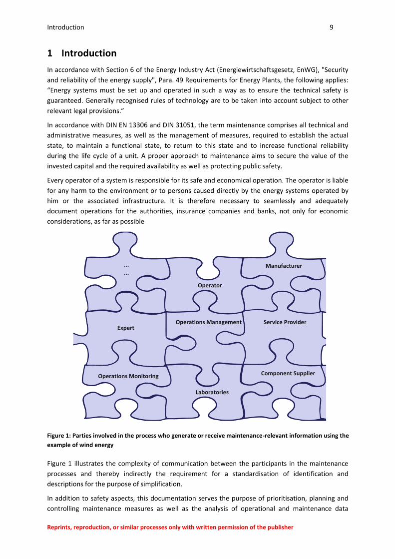
considerations, as far as possible
Figure 1: Parties involved in the process who generate or receive maintenance-relevant information using the
example of wind energy
Figure 1 illustrates the complexity of communication between the participants in the maintenance
processes and thereby indirectly the requirement for a standardisation of identification and
descriptions for the purpose of simplification.
In addition to safety aspects, this documentation serves the purpose of prioritisation, planning and
controlling maintenance measures as well as the analysis of operational and maintenance data
Manufacturer
Operator
Operations Management
...
...
Service Provider
Operations Monitoring Component Supplier
Laboratories
Expert
Introduction 10
Reprints, reproduction, or similar processes only with written permission of the publisher
relating to the updating of ongoing maintenance planning, the optimisation of the named processes
as well as improving the systems. The operator also needs all the required technical documents in
accordance with DIN EN 13460. A standardised design of documentation and data interfaces
facilitates co-operation of all the parties involved in the process.
1.1 Global Service Protocol (GSP)
In the maintenance of systems for the production of renewable energy, the provision of work order
data and the provision of data from the work report is currently still often generated using printed
paper templates. Although there are systems for the electronic recording and transmission of data in
use, these systems use different data formats. This means that they are not compatible with one
another or are only compatible to a limited extent.
The aim of the Global Service Protocol (GSP) is therefore to provide a standardised electronic data
and document format that facilitates communication between different parties involved in the
maintenance of renewable energy systems.
The definition of a standard format and unique identifiers ensures compatibility of the data from the
various parties involved. This permits the exchange of relevant maintenance data, forming the basis
for complete documentation (maintenance history file) of all maintenance activities.
When the IT systems of the individual parties involved support data exchange in accordance with the
GSP document format, exchange with all other systems supporting the GSP is possible without
further adaptation work. The complex conversion of files or the manual updating of maintenance
information is therefore no longer required.
In the definition of the protocol contents, the GSP is based on FGW guideline TG7 as well as other
standards and guidelines. In addition to the predefined protocol content, the parties involved can
specify and exchange additional content via defined user-specific data fields.
General information 11
Reprints, reproduction, or similar processes only with written permission of the publisher
2 General information
The application of the TG7 is available to everyone and is only binding when it is part of a contract or
other publication.
2.1 Scope
The scope of the guidelines for power plants part 7 category A section 2.1.
In addition, users are also free to transfer data in GSP document and data format outside the scope of
these guidelines.
In addition to the scope of the standard, the GSP described in these guidelines may also be suitable for
the transfer of maintenance data for other systems which use a code system based on basic standards
EN 81346 / IEC 81346 or ISO/TS ISO/TS 16952-1, such as RDS-PP®.
2.2 Legal regulations
Legal regulations of the respective country of the place of fulfilment take priority over these guide-
lines.
2.3 Normative references
The normative references given in the guidelines for power plants part 7 category A in section 2.3.
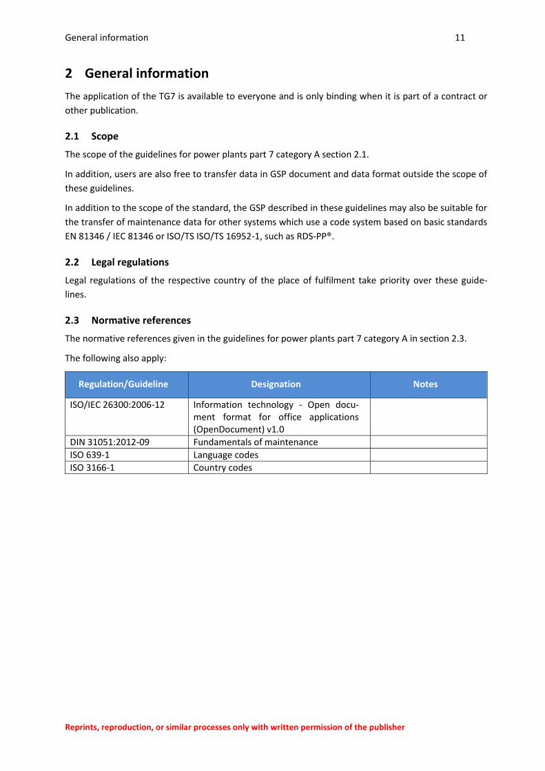
The following also apply:
Regulation/Guideline Designation Notes
ISO/IEC 26300:2006-12 Information technology - Open docu-ment format for office applications (OpenDocument) v1.0
DIN 31051:2012-09 Fundamentals of maintenance
ISO 639-1 Language codes
ISO 3166-1 Country codes
General information 12
Reprints, reproduction, or similar processes only with written permission of the publisher
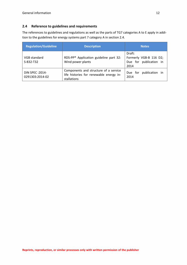
2.4 Reference to guidelines and requirements
The references to guidelines and regulations as well as the parts of TG7 categories A to E apply in addi-
tion to the guidelines for energy systems part 7 category A in section 2.4.
Regulation/Guideline Description Notes
VGB standard S-832-T32
RDS-PP® Application guideline part 32: Wind power plants
Draft: Formerly VGB-B 116 D2; Due for publication in 2014
DIN SPEC :2014-0291303:2014-02
Components and structure of a service life histories for renewable energy in-stallations
Due for publication in 2014
General specifications 13
Reprints, reproduction, or similar processes only with written permission of the publisher
3 General specifications
3.1 Definitions
As definitions from general case law and standards and guidelines given in the TG7 are not always
harmonised, misunderstandings can occur. Separate specifications apply based on the TG7 in these
cases. The application of the TG7 therefore also simplifies the contractual definition of terms.
To achieve a standardised terminology for the various bodies involved in the maintenance of wind
power plants, the definition of terms and versions given in the guidelines for power plants part 7 cate-
gory A applies.
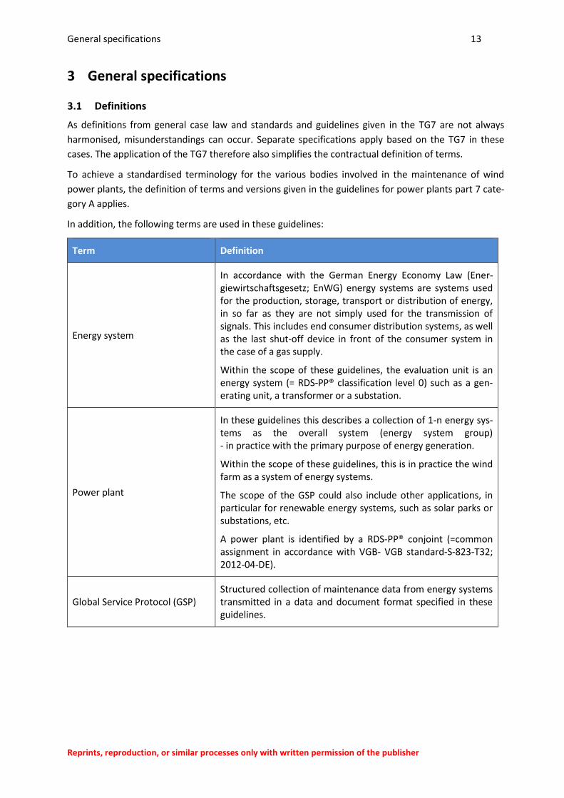
In addition, the following terms are used in these guidelines:
Term Definition
Energy system
In accordance with the German Energy Economy Law (Ener-giewirtschaftsgesetz; EnWG) energy systems are systems used for the production, storage, transport or distribution of energy, in so far as they are not simply used for the transmission of signals. This includes end consumer distribution systems, as well as the last shut-off device in front of the consumer system in the case of a gas supply.
Within the scope of these guidelines, the evaluation unit is an energy system (= RDS-PP® classification level 0) such as a gen-erating unit, a transformer or a substation.
Power plant
In these guidelines this describes a collection of 1-n energy sys-tems as the overall system (energy system group) - in practice with the primary purpose of energy generation.
Within the scope of these guidelines, this is in practice the wind farm as a system of energy systems.
The scope of the GSP could also include other applications, in particular for renewable energy systems, such as solar parks or substations, etc.
A power plant is identified by a RDS-PP® conjoint (=common assignment in accordance with VGB- VGB standard-S-823-T32; 2012-04-DE).
Global Service Protocol (GSP) Structured collection of maintenance data from energy systems transmitted in a data and document format specified in these guidelines.
General specifications 14
Reprints, reproduction, or similar processes only with written permission of the publisher
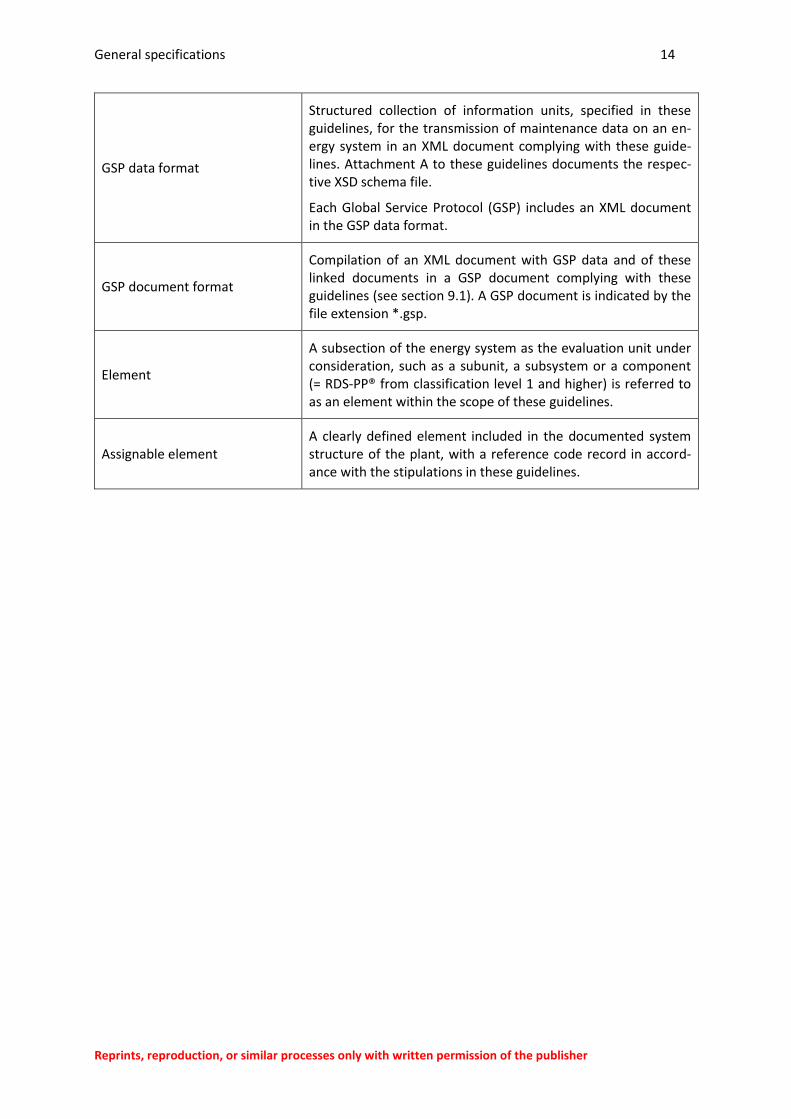
GSP data format
Structured collection of information units, specified in these guidelines, for the transmission of maintenance data on an en-ergy system in an XML document complying with these guide-lines. Attachment A to these guidelines documents the respec-tive XSD schema file.
Each Global Service Protocol (GSP) includes an XML document in the GSP data format.
GSP document format
Compilation of an XML document with GSP data and of these linked documents in a GSP document complying with these guidelines (see section 9.1). A GSP document is indicated by the file extension *.gsp.
Element
A subsection of the energy system as the evaluation unit under consideration, such as a subunit, a subsystem or a component (= RDS-PP® from classification level 1 and higher) is referred to as an element within the scope of these guidelines.
Assignable element A clearly defined element included in the documented system structure of the plant, with a reference code record in accord-ance with the stipulations in these guidelines.
General specifications 15
Reprints, reproduction, or similar processes only with written permission of the publisher
3.2 Abbreviations
Abbreviation Description
.gsp File extension for files in GSP document format
CT Customer (ordering party)
CN Contractor (implementing party)
DIN German Institute for Standardisation
Docu Documentation
EN European norm
GSP Global Service Protocol
M Maintenance
ISO International Organisation for Standardisation
IT Information technology
M Mandatory – required element (compulsory field)
O Optional – permissible element (optional)
RDS-PP® Reference code system for power plants RDS-PP®
Rel. Relevance (application of the class or attribute recommended or compulsory).
Rev. Revision (also version)
VDI Verein Deutscher Ingenieure (Association of German Engineers)
W3C World Wide Web Consortium
WT Wind turbine
XML Extensible Markup Language
XSD XML Schema Definition
ZEUS Zustands-Ereignis-Ursachen-Schlüssel (status/event/cause code) in accordance with TG 7 category D2
3.3 Definition of the contents of the guidelines
The subject of this current guideline revision, and thus the position of the GSP, is defined as follows:
These guidelines specify a document format summarising maintenance data and associated attachments for transmission. (GSP document format)
General specifications 16
Reprints, reproduction, or similar processes only with written permission of the publisher
These guidelines describe a data format for the electronic documentation of maintenance data. (GSP data format)
These guidelines also define which data for the applications specified in section 3.6 are to be transmitted.
These guidelines also specify how individually agreed data is to be incorporated between the parties.
These guidelines regulate the assignments to be generated in the data gathering process to convert the data into the data format and to be able to compare the data later on in line with standardised criteria.
For certain data, these guidelines regulate which categories are to be used for subsequent comparison and onward processing of the data recorded.
Figure 2: GSP data format and GSP interoperable data storage
General specifications 17
Reprints, reproduction, or similar processes only with written permission of the publisher
Figure 3: GSP data processing in the maintenance documentation
The following topics are involved in the implementation of the data exchange or data acquisition and
are not therefore covered by these guidelines.
Data acquisition process for individual applications.
Backup and verification of data quality
Conversion of existing data into GSP data format
Specifications for software for the input, processing, compilation and analysis of the data
transmitted in the GSP data format
Documentation of the maintenance and format of the documents to be prepared for
maintenance and the maintenance history file (covered in TG7 category C)
To achieve this, however, the provisions of other parts of TG 7 and the guidelines and standards
given in the TG7 category may have overriding priority.
Higher priority documents, which may be compiled in accordance with the specifications from TG7
category C on the basis data transferred in the GSP data format, are given as follows:
Work order (TG7 category A section 3.2.6)
Work report (TG7 category A section 3.2.7)
Maintenance report (M history)
Documents for inspection (TG7 category A section 3.4.3.)
Maintenance-related parts of the maintenance history files of WTs (DIN SPEC 91303)
To speed up the application of a standardised data format, this revision of the guidelines also
contains provisional stipulations from the standards provided in the draft revisions of TG7 category
D1 and TG7 category C.
General specifications 18
Reprints, reproduction, or similar processes only with written permission of the publisher
This applies in particular to:
The recommendation for the use of the ZEUS code in accordance with TG 7 category D2 as
part of the maintenance documentation (to be covered in future by TG7 category C).
The application of the VGB standard VGB-S823 T32 (RDS-PP® application guidelines part 32:
wind energy) for the identification of assignable elements in the system structure (covered
by TG7 category D1).
3.4 Functions of the GSP
The data format defined in these guidelines as the Global Service Protocol (GSP) fulfils the following
functions:
Exchange of data on maintenance measures between the parties as a prerequisite for the transmission and compilation of the maintenance documents given above
Assignment of the information units on individual maintenance activities integrated in the GSP data format (orders)
Assignment of the information units on relevant systems and system components integrated into the GSP data format
Assurance of comparability for individual maintenance situations via the implementation of a standard data format and standardised assignment logic.
Documentation option for the fault-finding process, i.e. the route from suspected fault to fault location.
The standardised assignment logic is achieved via:
integration of the ZEUS code defined in TG7 category D2 for the standardised description of status conditions, events and causes.
integration of a standardised code system within a function-oriented structure according to an industry-standard system (RDS-PP Reference Designation System for Power Plants according to the guidelines of the VGB).
integration option of an object type definition into the GSP data format.
In some cases, the requirements for standardised categories for the content of the information units, where this simplifies considerably the standardised processing and evaluation of the data. The specification of standardised categories is carried out if possible on the basis of existing guidelines and standards, see section 6.
With the acquisition and transmission of the information units defined in these guidelines, the user
ensures the following:
that the requirements of TG7 category A section 4.6 documentation of the maintenance measures can be fulfilled and
in this respect, the information units specified in DIN EN 13460 on the work order can be transmitted.
General specifications 19
Reprints, reproduction, or similar processes only with written permission of the publisher
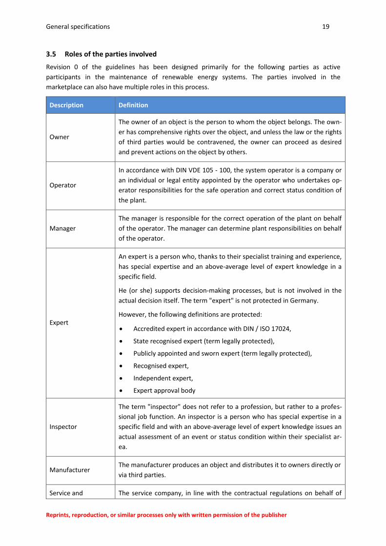
3.5 Roles of the parties involved
Revision 0 of the guidelines has been designed primarily for the following parties as active
participants in the maintenance of renewable energy systems. The parties involved in the
marketplace can also have multiple roles in this process.
Description Definition
Owner
The owner of an object is the person to whom the object belongs. The own-
er has comprehensive rights over the object, and unless the law or the rights
of third parties would be contravened, the owner can proceed as desired
and prevent actions on the object by others.
Operator
In accordance with DIN VDE 105 - 100, the system operator is a company or
an individual or legal entity appointed by the operator who undertakes op-
erator responsibilities for the safe operation and correct status condition of
the plant.
Manager
The manager is responsible for the correct operation of the plant on behalf
of the operator. The manager can determine plant responsibilities on behalf
of the operator.
Expert
An expert is a person who, thanks to their specialist training and experience,
has special expertise and an above-average level of expert knowledge in a
specific field.
He (or she) supports decision-making processes, but is not involved in the
actual decision itself. The term "expert" is not protected in Germany.
However, the following definitions are protected:
Accredited expert in accordance with DIN / ISO 17024,
State recognised expert (term legally protected),
Publicly appointed and sworn expert (term legally protected),
Recognised expert,
Independent expert,
Expert approval body
Inspector
The term "inspector" does not refer to a profession, but rather to a profes-
sional job function. An inspector is a person who has special expertise in a
specific field and with an above-average level of expert knowledge issues an
actual assessment of an event or status condition within their specialist ar-
ea.
Manufacturer The manufacturer produces an object and distributes it to owners directly or
via third parties.
Service and The service company, in line with the contractual regulations on behalf of
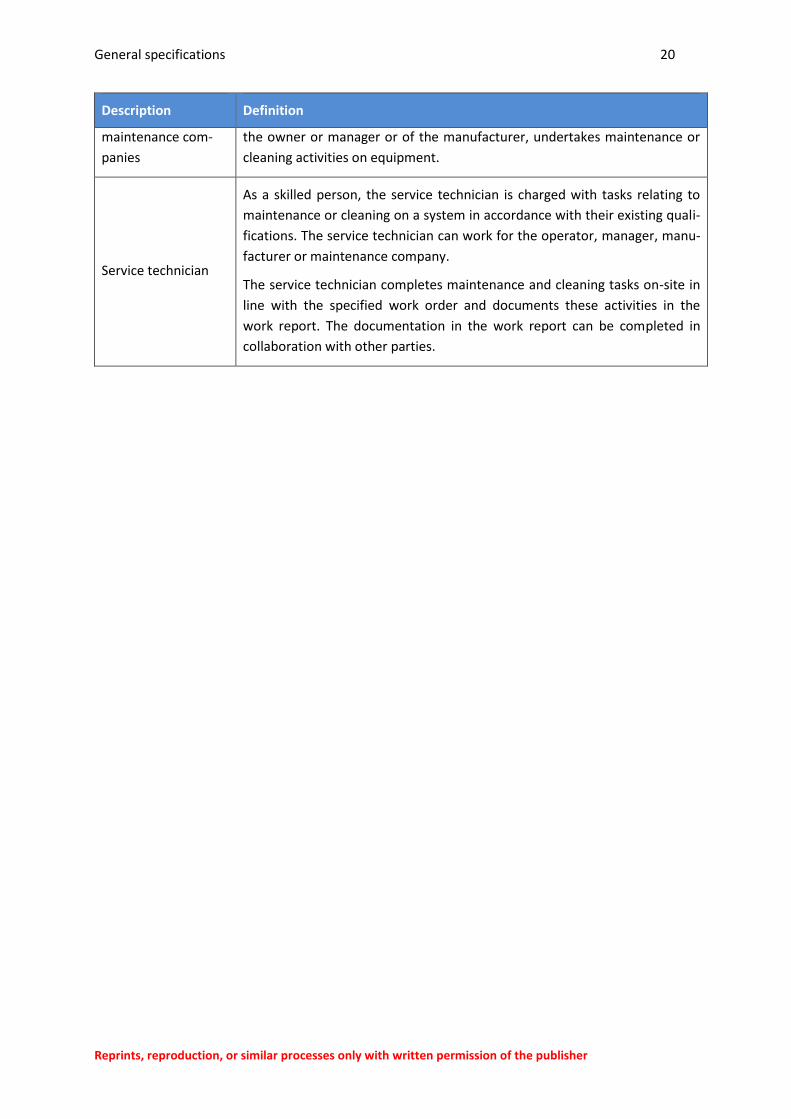
General specifications 20
Reprints, reproduction, or similar processes only with written permission of the publisher
Description Definition
maintenance com-
panies
the owner or manager or of the manufacturer, undertakes maintenance or
cleaning activities on equipment.
Service technician
As a skilled person, the service technician is charged with tasks relating to
maintenance or cleaning on a system in accordance with their existing quali-
fications. The service technician can work for the operator, manager, manu-
facturer or maintenance company.
The service technician completes maintenance and cleaning tasks on-site in
line with the specified work order and documents these activities in the
work report. The documentation in the work report can be completed in
collaboration with other parties.
General specifications 21
Reprints, reproduction, or similar processes only with written permission of the publisher
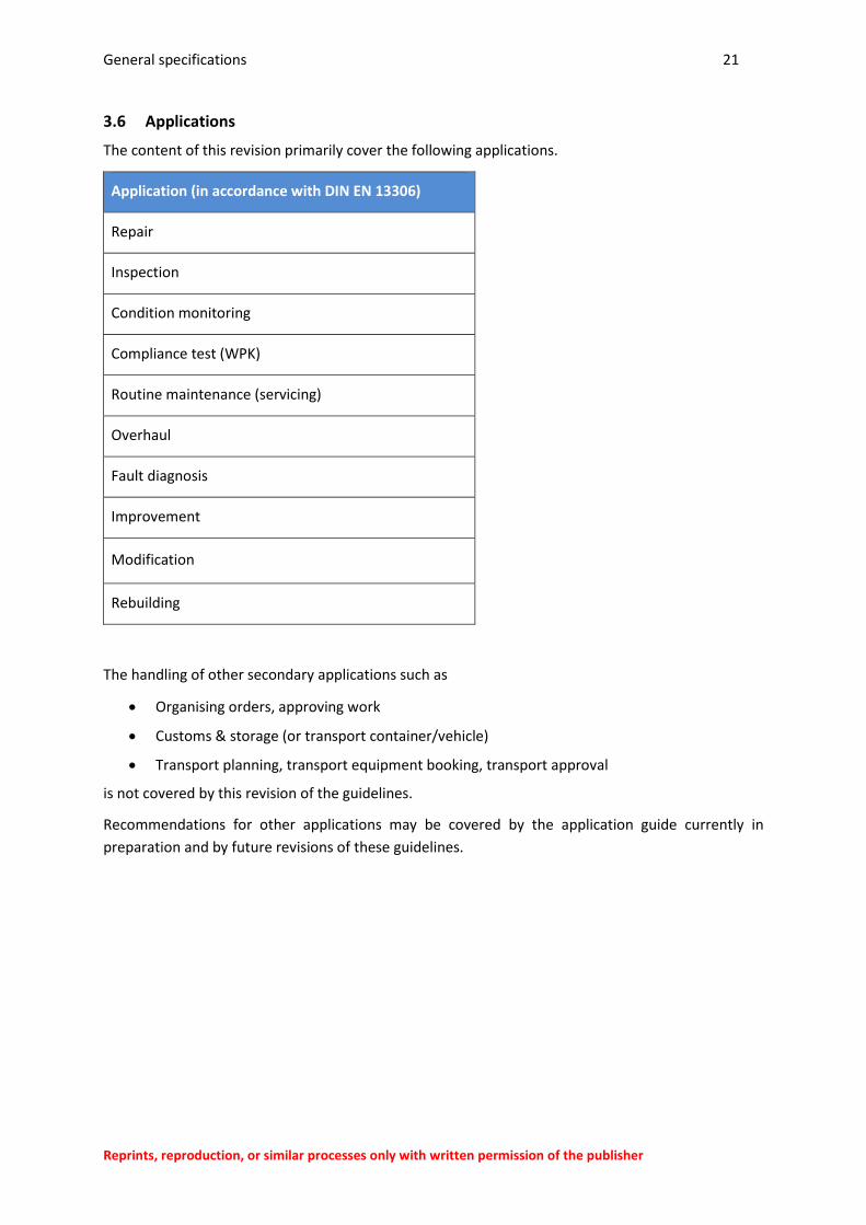
3.6 Applications
The content of this revision primarily cover the following applications.
Application (in accordance with DIN EN 13306)
Repair
Inspection
Condition monitoring
Compliance test (WPK)
Routine maintenance (servicing)
Overhaul
Fault diagnosis
Improvement
Modification
Rebuilding
The handling of other secondary applications such as
Organising orders, approving work
Customs & storage (or transport container/vehicle)
Transport planning, transport equipment booking, transport approval
is not covered by this revision of the guidelines.
Recommendations for other applications may be covered by the application guide currently in
preparation and by future revisions of these guidelines.
General specifications 22
Reprints, reproduction, or similar processes only with written permission of the publisher
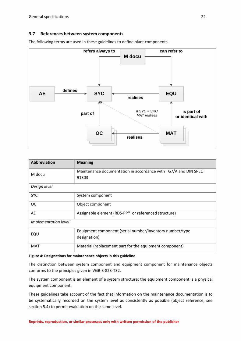
3.7 References between system components
The following terms are used in these guidelines to define plant components.
Abbreviation Meaning
M docu Maintenance documentation in accordance with TG7/A and DIN SPEC
91303
Design level
SYC System component
OC Object component
AE Assignable element (RDS-PP® or referenced structure)
Implementation level
EQU Equipment component (serial number/inventory number/type
designation)
MAT Material (replacement part for the equipment component)
Figure 4: Designations for maintenance objects in this guideline
The distinction between system component and equipment component for maintenance objects
conforms to the principles given in VGB-S-823-T32.
The system component is an element of a system structure; the equipment component is a physical
equipment component.
These guidelines take account of the fact that information on the maintenance documentation is to
be systematically recorded on the system level as consistently as possible (object reference, see
section 5.4) to permit evaluation on the same level.
OTOTOTOT
M docu
SYC EQU
MATOC
refers always to
part of
AEdefines
is part of
or identical with
realises
realises
can refer to
If SYC = SRU
MAT realises
General specifications 23
Reprints, reproduction, or similar processes only with written permission of the publisher
This also corresponds to the basic principles for the documentation of service history records
for renewable energy systems in accordance with DIN SPEC 91303:2014-2
The system components that have been clearly defined in the system structure are therefore
referred to as assignable elements because they can be assigned to a specific element of the system
structure in advance. Components not defined in the system structure (below the defined system
components) are referred to as object components.
An assignable element can be part of the system structure in RDS-PP® or a defined object with
reference to RDS-PP® (user-specific system structure referenced on the same or a higher level of
RDS-PP®).
Material used as a replacement part as part of the maintenance is then always identical to a system
component if the system structure has been set up in accordance with the smallest logical
replaceable elements. These elements are referred to in the guidelines as the smallest replaceable
units (SRU).
In all other cases, the replacement part used is identical to an object component as part of a system
component defined as an assignable element outside the system structure.
It should be noted that information on an equipment component does not always have to be
transferred and documented, i.e. an equipment component stored in the inventory under inventory
numbers or serial numbers is not always known for every plant component in practice.
General specifications 24
Reprints, reproduction, or similar processes only with written permission of the publisher
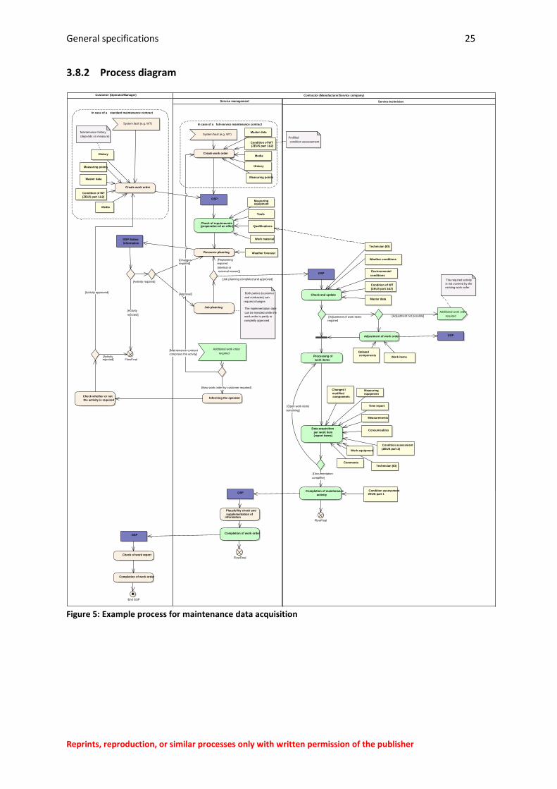
3.8 Example process
3.8.1 Introduction
The definition and description of maintenance processes incl. the associated data acquisition and
processing stages is not covered by these guidelines and is the responsibility of the parties at the
company responsible for maintenance work. The maintenance contracts should be drafted
accordingly to ensure a company-wide approach.
The GSP has been developed for the applications listed in section 3.6 of these guidelines. To
determine the requirements relating to the content to transmitted to the parties given in section 3.5,
an example process has been developed as a model in the working group.
This generic model process is intended to explain the basic usage options of the GSP and
demonstrate the general workflow of maintenance and repair activities, inspections, regular tests,
etc. that the GSP was primarily designed for. The process given does demonstrate the specific
workflow of a maintenance/repair activity, but the workflows in an inspection or regular test can be
formed from a subset of the process stages shown.
The stages shown in the process do not necessarily have to be implemented in all cases when using
the GSP. The informational contents of the GSP given are information categories that are further
differentiated in the GSP guideline. The contents of the information categories shown are also
optional in some cases.
General specifications 25
Reprints, reproduction, or similar processes only with written permission of the publisher
3.8.2 Process diagram
Figure 5: Example process for maintenance data acquisition
Service technician
Plausibility check and
supplementation of information
GSP
Customer (Operator/Manager) Contractor (Manufacturer/Service company)
GSP
Check of requirements(preperation of an offer)
Service management
Adjustment of work order GSP
Additional work order
required
End GSP
FlowFinal
FlowFinal
GSP
Check and update
Processing of
work items
Data acquisition
per work item(report items)
Completion of maintenance
activity
In case of a full-service maintenance contract
In case of a standard maintenance contract
Create work order
System fault (e.g. WT)
GSP
Completion of work order
Master data
Relatedcomponents
Work items
Measuringequipment
Qualifications
Tools
Master data
Condition of WT
(ZEUS part 1&2)
Media
Changed /
modifiedcomponents
Time report
Measurements
Work equipment
Check of work report
Job planning
Environmental
conditions
Weather conditions
Comments
Condition assessment
(ZEUS part 2)
Consumeables
Condition assessmentZEUS part 1
GSP Status
Information
Master data
Condition of WT (ZEUS part 1&2)
MediaHistory
History
Maintenance history
(depends on measure)
Informing the operatorCheck whether or not
the activity is required
FlowFinal
The required activity
is not covered by the
existing work order
Prefilled
condition assessement
Measuring points
Weather forecastResource planning
Both parties (customer
and contractor) can
request changes
The implementation date
can be rejected while the
work order is partly or
completly approved
Measuring points
Work material
Technician (ID)
Technician (ID)
[Open work items
remaining]
[Adjustment not possible][Adjustment of work items
required
[New work order by customer required]
[Activity approved]
[Maintenance contract
comprises the actvity]
[Documentation
complete]
[Replanning
required
(internal or
external reason)]
[Activity
rejected]
[Activity rejected]
[Changesrequired]
[Approval]
[Job planning completed and approved][Avtivity required]
System fault (e.g. WT)
Create work order
Condition of WT
(ZEUS part 1&2)
Additional work order
required
Measuringequipment
Completion of work order
General specifications 26
Reprints, reproduction, or similar processes only with written permission of the publisher
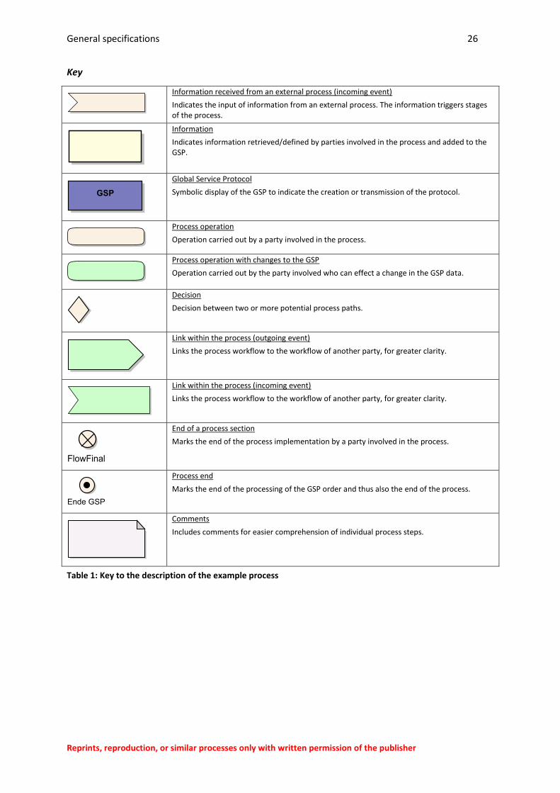
Key
Information received from an external process (incoming event)
Indicates the input of information from an external process. The information triggers stages of the process.
Information
Indicates information retrieved/defined by parties involved in the process and added to the GSP.
Global Service Protocol
Symbolic display of the GSP to indicate the creation or transmission of the protocol.
Process operation
Operation carried out by a party involved in the process.
Process operation with changes to the GSP
Operation carried out by the party involved who can effect a change in the GSP data.
Decision
Decision between two or more potential process paths.
Link within the process (outgoing event)
Links the process workflow to the workflow of another party, for greater clarity.
Link within the process (incoming event)
Links the process workflow to the workflow of another party, for greater clarity.
End of a process section
Marks the end of the process implementation by a party involved in the process.
Process end
Marks the end of the processing of the GSP order and thus also the end of the process.
Comments
Includes comments for easier comprehension of individual process steps.
Table 1: Key to the description of the example process
General specifications 27
Reprints, reproduction, or similar processes only with written permission of the publisher
3.8.3 Parties involved in the process
The parties described below are involved in this process. Depending on the configuration, the parties
may belong to one or more companies.
Operator/manager (according to FGW TG 7)
The operator or manager is always the direct or indirect customer of every maintenance activity.
Either a service company is appointed by the operator/manager directly with a specific
maintenance/repair order, or a longer term maintenance contract is concluded (e.g. full-service
maintenance contract). In the case of a direct appointment, details of the order can themselves be
transmitted as a GSP order.
Various organisational units may be involved in the process implementation.
Work planning
Transport planning
Engineering
Manufacturer/ISP service management (according to FGW TG 7 category A)
The service management receives the order from the operator/manager, plans the staff deployments
and evaluates these afterwards. Depending on the maintenance contract, the service management
can also initiate internal orders. The implementation is also to be agreed with the operator/manager
in this case. The service management prepares a corresponding GSP order for the service technician
and adds to the order following processing. Depending on the contractual regulation, a report can be
provided to the operator/manager via GSP protocol.
Manufacturer/ISP service technician
The service technician receives a GSP order from his service management, processes it and
documents his work in the GSP protocol.
Other parties not shown in the process are
independent technical experts and
inspectors of the operator/manager.
General specifications 28
Reprints, reproduction, or similar processes only with written permission of the publisher
3.8.4 Process workflow
1. Creation of the GSP order (operator/manager or service company)
The creation of the GSP order is carried out either by the operator/manger or internally by the
service company depending on the situation (e.g. standard maintenance contract or full-service
maintenance contract). The GSP is equipped with the basic information such as master data, required
maintenance history and current condition assessment. This information is intended to be used as a
decision-making aid in staff deployment planning as well as on-site. On creation by the
operator/manager, the order is passed to the service company.
2. Order planning (service company)
The created order at the contractor (service company) enters into the order planning process,
additional information is added such as the measuring equipment, tools, qualifications, etc. required
and then scheduled in the resource planning process. The customer (operator/manager) is then
informed for approval of the planned deployment, work content and the scheduled time slot and
approves the planned activity.
If approval (see figure 5) is given on behalf of the customer and no changes are required, the staff
deployment planning is carried out and the order is passed to the assigned service technicians
following internal approval. If the customer requests changes to the planned order, the order is
returned to order planning for alteration.
3. Order approval (operator/manager)
On the basis of the information on the work order, the operator/manager decides whether or not
the planned activity is required and if any changes to the content or time slot of the order are
required. The contractor receives the corresponding notification. The function of the GSP is
particularly useful in the case of a full-service maintenance contract so that the customer is informed
of all current activities and can coordinate the forthcoming activities with other system deadlines.
If the planned activity is not deemed necessary by the customer, the order is rejected and the
process is ended.
4. Order processing (service technician)
After the service technician has received the GSP including the relevant information (master data,
condition, work materials, etc.), he/she checks the data on-site, adds to the data if necessary, and
begins the processing of work items. If other work items are required that are not covered by the
order and that cannot be created by the service technician on his/her own account, the service
management is informed and another work order is generated if necessary. Depending on the
contract situation, this is created directly by the service management or by the customer once
appropriately informed.
After/during the processing of each work item, this is documented specifying all necessary
information (components, times, measurements, condition assessment, etc.). Following completion
of all work items, the service technician can submit a condition assessment of the energy system if
required.
General specifications 29
Reprints, reproduction, or similar processes only with written permission of the publisher
5. Order completion (operator/manager & service company)
The GSP order completed by the service technician is checked by the service management and can
then be passed to the customer with the contents agreed between the parties.
The GSP data format does not contain any specific fields for order settlement. The transfer of
data for order settlement can be carried out by users via user-specific content.
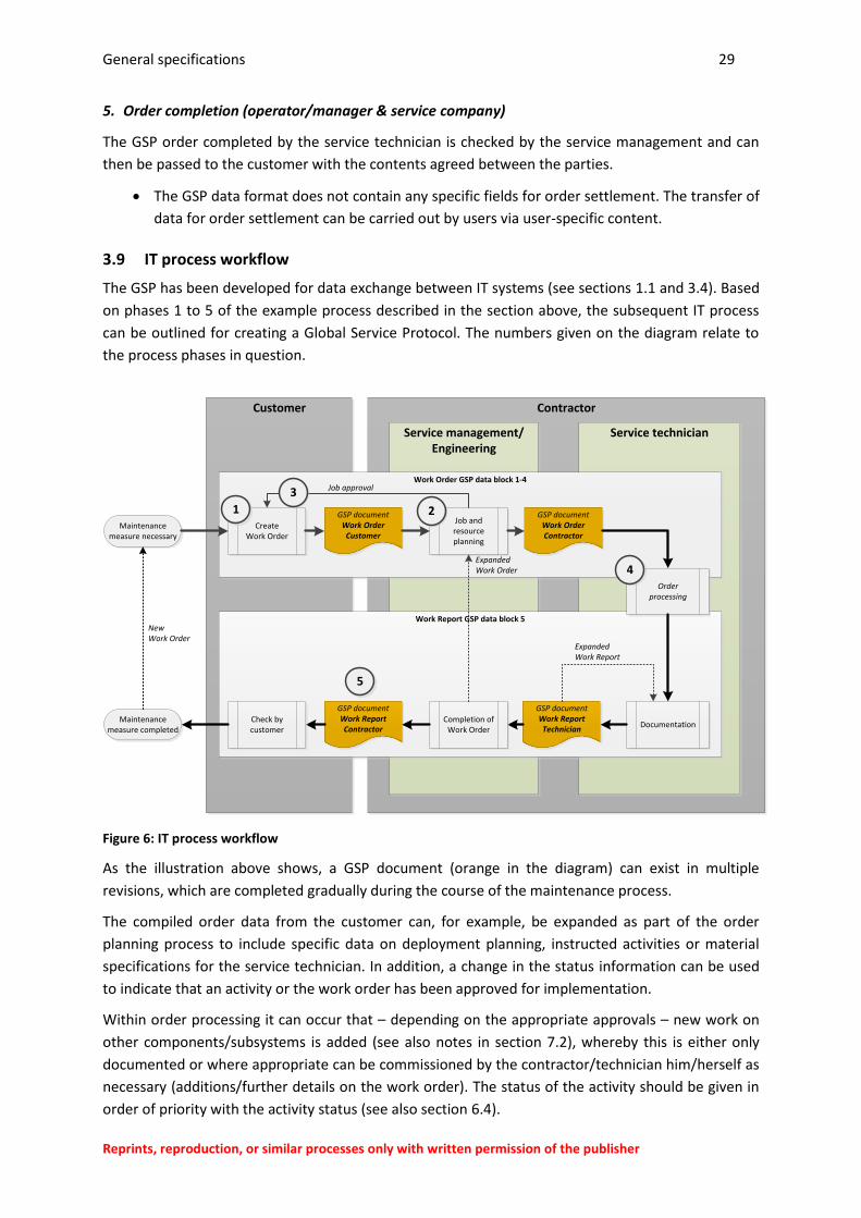
3.9 IT process workflow
The GSP has been developed for data exchange between IT systems (see sections 1.1 and 3.4). Based
on phases 1 to 5 of the example process described in the section above, the subsequent IT process
can be outlined for creating a Global Service Protocol. The numbers given on the diagram relate to
the process phases in question.
Figure 6: IT process workflow
As the illustration above shows, a GSP document (orange in the diagram) can exist in multiple
revisions, which are completed gradually during the course of the maintenance process.
The compiled order data from the customer can, for example, be expanded as part of the order
planning process to include specific data on deployment planning, instructed activities or material
specifications for the service technician. In addition, a change in the status information can be used
to indicate that an activity or the work order has been approved for implementation.
Within order processing it can occur that – depending on the appropriate approvals – new work on
other components/subsystems is added (see also notes in section 7.2), whereby this is either only
documented or where appropriate can be commissioned by the contractor/technician him/herself as
necessary (additions/further details on the work order). The status of the activity should be given in
order of priority with the activity status (see also section 6.4).
Contractor
Service management/Engineering
Customer
Service technician
Work Report GSP data block 5
Work Order GSP data block 1-4
Maintenance measure necessary
CreateWork Order
Job and resource planning
GSP documentWork Order
Customer
GSP documentWork OrderContractor
Documentation
NewWork Order
GSP documentWork ReportTechnician
GSP documentWork ReportContractor
Completion of Work Order
Maintenance measure completed
ExpandedWork Order
Check by customer
ExpandedWork Report
Job approval
Order processing
1 2
3
4
5
General specifications 30
Reprints, reproduction, or similar processes only with written permission of the publisher
The GSP data format allows status information to be stored for every order and report item, as well
as for the order and order processing and for activities.
Who can assign which status and when is covered by the agreements between the users, however.
As these guidelines specify a data format, but not IT and maintenance processes, this naturally does
not exclude data being compiled for a GSP in other ways. More complex IT processes, through to
parallel transmission of multiple GSP documents with partial content are also possible (see also
section 5.9).
The information structure of the GSP has been developed based on the IT process and the example
process given here,which is described in summary in the following part of the guidelines.
Information structure in the GSP 31
Reprints, reproduction, or similar processes only with written permission of the publisher
4 Information structure in the GSP
This section provides an overview of the structure of the information to be given in the GSP. More in-
depth information and detailed descriptions of the individual information units can be found in
sections 8 and 9 as well as Attachment A of these guidelines.
4.1 Overview
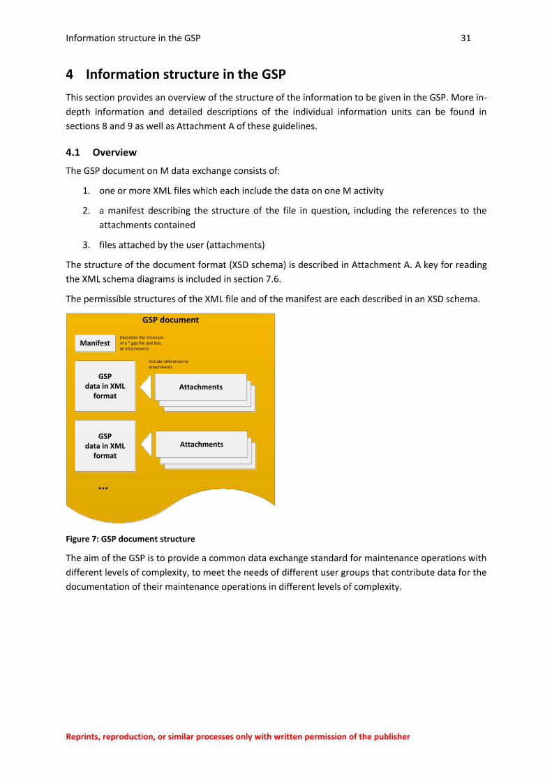
The GSP document on M data exchange consists of:
1. one or more XML files which each include the data on one M activity
2. a manifest describing the structure of the file in question, including the references to the
attachments contained
3. files attached by the user (attachments)
The structure of the document format (XSD schema) is described in Attachment A. A key for reading
the XML schema diagrams is included in section 7.6.
The permissible structures of the XML file and of the manifest are each described in an XSD schema.
Figure 7: GSP document structure
The aim of the GSP is to provide a common data exchange standard for maintenance operations with
different levels of complexity, to meet the needs of different user groups that contribute data for the
documentation of their maintenance operations in different levels of complexity.
GSP document
GSPdata in XML
format
Manifest
GSPdata in XML
format 0XML-Datei
Attachments
Include references to attachments
Describes the structure of a *.gsp file and lists all attachments
0XML-Datei
Attachments
...
Information structure in the GSP 32
Reprints, reproduction, or similar processes only with written permission of the publisher
To ensure standardised legibility and the proper onward processing of documents, the GSP
document specifications include the following contents:
compulsory information units,
that need to be used by all participants
permissible (optional) information units,
which are (can) be added depending on the application in question
a permissible structure for user-specific extensions,
which can be specified on the basis of mutual agreements between the users
The actual scope and size of a GSP document can therefore be very different depending on the
requirements of the users and of the M situations being handled.
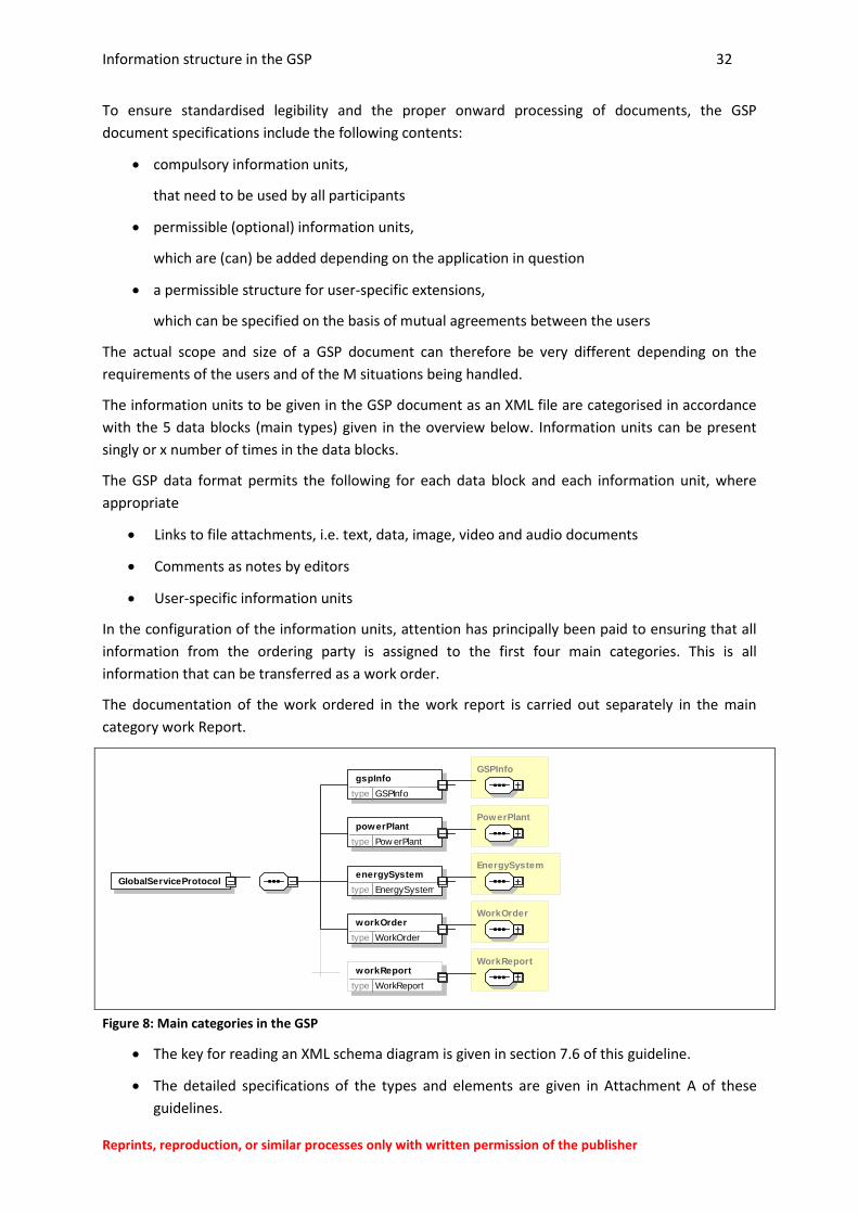
The information units to be given in the GSP document as an XML file are categorised in accordance
with the 5 data blocks (main types) given in the overview below. Information units can be present
singly or x number of times in the data blocks.
The GSP data format permits the following for each data block and each information unit, where
appropriate
Links to file attachments, i.e. text, data, image, video and audio documents
Comments as notes by editors
User-specific information units
In the configuration of the information units, attention has principally been paid to ensuring that all
information from the ordering party is assigned to the first four main categories. This is all
information that can be transferred as a work order.
The documentation of the work ordered in the work report is carried out separately in the main
category work Report.
Figure 8: Main categories in the GSP
The key for reading an XML schema diagram is given in section 7.6 of this guideline.
The detailed specifications of the types and elements are given in Attachment A of these
guidelines.
GlobalServiceProtocol
GSPInfo gspInfo
type GSPInfo
PowerPlant powerPlant
type Pow erPlant
EnergySystem energySystem
type EnergySystem
WorkOrder workOrder
type WorkOrder
WorkReport workReport
type WorkReport
Information structure in the GSP 33
Reprints, reproduction, or similar processes only with written permission of the publisher
This means that in the GSP, separate documentation of content of the order and of the work
implementation can be given. This creates a strict separation between order information (required)
and report information (actual), see also section 5.5.
The ordering party can be both a customer (manager, owner) as well as a service manager in
the service company or in exceptional cases the technician him/herself (see example process
in section 3.8).
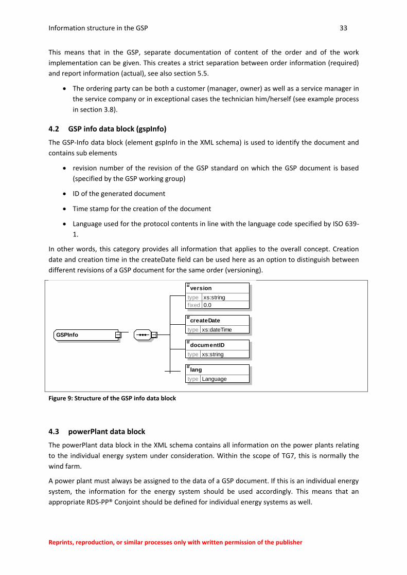
4.2 GSP info data block (gspInfo)
The GSP-Info data block (element gspInfo in the XML schema) is used to identify the document and
contains sub elements
revision number of the revision of the GSP standard on which the GSP document is based
(specified by the GSP working group)
ID of the generated document
Time stamp for the creation of the document
Language used for the protocol contents in line with the language code specified by ISO 639-
1.
In other words, this category provides all information that applies to the overall concept. Creation
date and creation time in the createDate field can be used here as an option to distinguish between
different revisions of a GSP document for the same order (versioning).
Figure 9: Structure of the GSP info data block
4.3 powerPlant data block
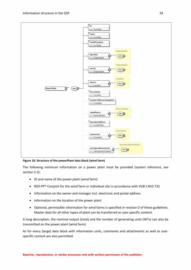
The powerPlant data block in the XML schema contains all information on the power plants relating
to the individual energy system under consideration. Within the scope of TG7, this is normally the
wind farm.
A power plant must always be assigned to the data of a GSP document. If this is an individual energy
system, the information for the energy system should be used accordingly. This means that an
appropriate RDS-PP® Conjoint should be defined for individual energy systems as well.
GSPInfo
version
type xs:string
f ixed 0.0
createDate
type xs:dateTime
documentID
type xs:string
lang
type Language
Information structure in the GSP 34
Reprints, reproduction, or similar processes only with written permission of the publisher
Figure 10: Structure of the powerPlant data block (wind farm)
The following minimum information on a power plant must be provided (system reference, see
section 5.3):
ID and name of the power plant (wind farm)
RDS-PP® Conjoint for the wind farm or individual site in accordance with VGB S 832-T32
Information on the owner and manager incl. electronic and postal address
Information on the location of the power plant
Optional, permissible information for wind farms is specified in revision 0 of these guidelines.
Master data for all other types of plant can be transferred as user-specific content.
A long description, the nominal output (total) and the number of generating units (WTs) can also be
transmitted on the power plant (wind farm).
As for every (large) data block with information units, comments and attachments as well as user-
specific content are also permitted.
PowerPlant
id
type xs:string
name
type xs:string
rdsPPConjoint
type xs:string
Organisation
operator
type Organisation
Organisation
owner
type Organisation
Location
adress
type Location
description
type xs:string
numberOfGeneratingUnits
type xs:integer
GeneralValue
ratedPower
type GeneralValue
operationalSince
type xs:dateTime
Comments
comments
type Comments
UserSpecificContents
userSpecificContents
type UserSpecif icContents
Information structure in the GSP 35
Reprints, reproduction, or similar processes only with written permission of the publisher
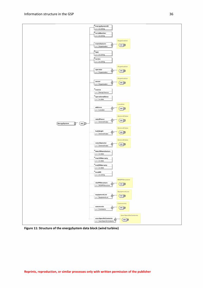
4.4 energySystem data block
The energySystem data block in the XML schema contains all information on the energy system (e.g.
wind turbine) the GSP in question relates to. It has been designed primarily for wind turbines, but
can also be used for other types of energy system.
A minimum of the following information must be provided on an energy system:
ID of the energy system
Information on the manufacturer, type, series and serial number
Information on the owner and manager
In addition, the person responsible for the system appointed to the energy system in question for
system operation can be stored using the contact data for the manager (see also section 5.14).
The following are also permitted as information on the energy system:
Primary energy used (wind, biogas, water…)
Commissioning date/date of manufacture
Address of the WT (normally identical to the address of the wind farm)
WT-NIS code of the system
Selected technical values that may be relevant to the work planning process (hub height,
rotor diameter, rated power…)
End and, where applicable, the start of a warranty period in line with legal or individual
contractual regulations
List of equipment parts (directory of components) as well as RDS-PP system structure for the
relevant energy system (see section 4.7.3).
Additional data on the energy system can be transferred as a user-specific parameter set or as
attachments.
The optional, permissible information for wind turbines is specified in revision 0 of these
guidelines. Master data for all other types of system can be transferred as a user-specific
parameter set.
Information structure in the GSP 36
Reprints, reproduction, or similar processes only with written permission of the publisher
Figure 11: Structure of the energySystem data block (wind turbine)
EnergySystem
energySystemID
type xs:string
serialNumber
type xs:string
Organisation
manufacturer
type Organisation
type
type xs:string
series
type xs:string
Organisation
operator
type Organisation
Organisation
owner
type Organisation
source
type EnergySource
operationalSince
type xs:date
Location
address
type Location
GeneralValue
ratedPower
type GeneralValue
GeneralValue
hubHeight
type GeneralValue
GeneralValue
rotorDiameter
type GeneralValue
dateOfManufacture
type xs:date
startOfWarranty
type xs:date
endOfWarranty
type xs:date
weaNIS
type xs:string
RDSPPStructure
rdsPPStructure
type RDSPPStructure
EquipmentList
equipmentList
type EquipmentList
Comments
comments
type Comments
UserSpecificContents
userSpecificContents
type UserSpecif icContents
Information structure in the GSP 37
Reprints, reproduction, or similar processes only with written permission of the publisher
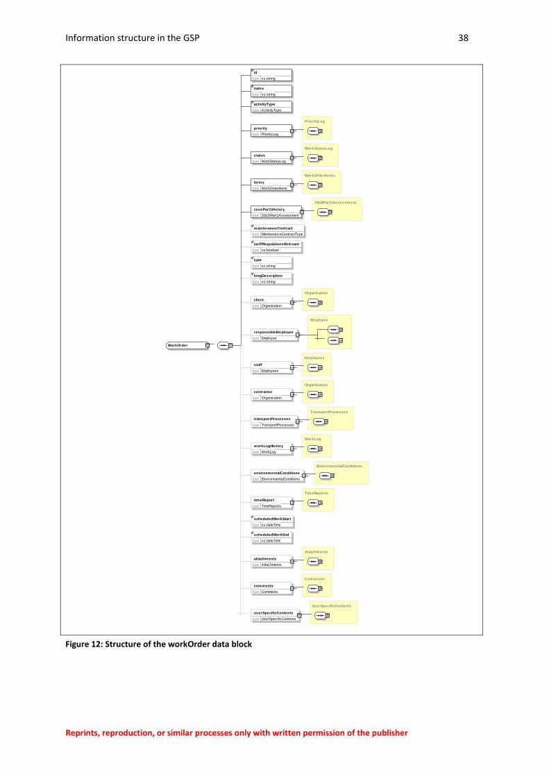
4.5 workOrder data block
The workOrder data block in the XML schema contains all information on the work order and
contains at least one order item. A work order relates to contracted work on various parts of an
energy system which can be processed accordingly by a contractor as part of an activity type in line
with DIN EN 13306. (see order reference usage rules, item and object reference and reference to the
energy system, section 4.7.5).
The work order therefore defines the required work, materials, times, etc.
The data in a work order is initially compiled by the customer, and added to if required during the
order planning stage, e.g. by the service management (see sections 3.8 and 3.9).
Who is permitted to change which data in the order planning stage is not covered by these
guidelines but is to be agreed between the users.
4.5.1 Contents of the work order
A work order contains a minimum of the following information for the contractor:
Order ID and name
Activity type in accordance with DIN EN 13306 Section 8
Order priority and order status (log of the status changes)
A minimum of data for an order item in accordance with section 4.5.2
ZEUS condition assessment block 1 in accordance with TG 7 category D2 for the relevant
energy system (history of the changes in condition at the time of order transmission)
Information structure in the GSP 38
Reprints, reproduction, or similar processes only with written permission of the publisher
Figure 12: Structure of the workOrder data block
WorkOrder
id
type xs:string
name
type xs:string
activityType
type ActivityType
PriorityLog
priority
type PriorityLog
WorkStatusLog
status
type WorkStatusLog
WorkOrderItems
items
type WorkOrderItems
ZEUSPart1Assessment
zeusPart1History
type ZEUSPart1Assessment
maintenanceContract
type MaintenanceContractType
tariffRegulationsRelevant
type xs:boolean
type
type xs:string
longDescription
type xs:string
Organisation
client
type Organisation
Employee
responsibleEmployee
type Employee
Employees
staff
type Employees
Organisation
contractor
type Organisation
TransportProcesses
transportProcesses
type TransportProcesses
WorkLog
workLogHistory
type WorkLog
EnvironmentalConditions
environmentalConditions
type EnvironmentalConditions
TimeReports
timeReport
type TimeReports
scheduledWorkStart
type xs:dateTime
scheduledWorkEnd
type xs:dateTime
Attachments
attachments
type Attachments
Comments
comments
type Comments
UserSpecificContents
userSpecificContents
type UserSpecif icContents
Information structure in the GSP 39
Reprints, reproduction, or similar processes only with written permission of the publisher
In addition, the following information is permitted as part of the order planning process by the
customer or the contractor:
Customer and contractor
Person responsible for all work in the order
User-specific order type
Description of the order content (long text)
Type of maintenance contract
Requirement for customs processing (yes/no)
Planned start of work/planned end of work
Personnel requirements (qualifications and staff) from the order planning
Planned transport processes (see section 4.7.5)
History of the work completed on the energy system (WorkLogHistory)
Environmental conditions
Time-based specifications for the order
As well as comments, additional data on the work order can be transferred as a user-specific
parameter set or as attachments.
4.5.2 Data on the order items
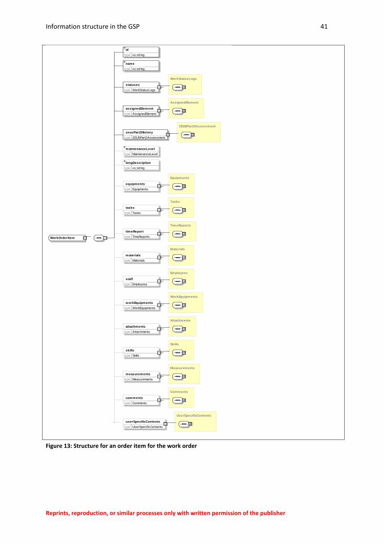
As well as the general specifications on the work order, it should be specified which maintenance
activity (activities) is (are) to be carried out on which part(s) of the energy system.
The corresponding work for a system part (element in the system structure) should be recorded
using order items, whereby every order item relates to an element of the system structure set up for
the system (see object reference, section 5.4).
The previous set up of a system structure and the delimitation of the systems parts to be considered
is required to this end to be able to assign the required maintenance activities (preventative and
corrective maintenance) to the individual components (see also section 7.1).
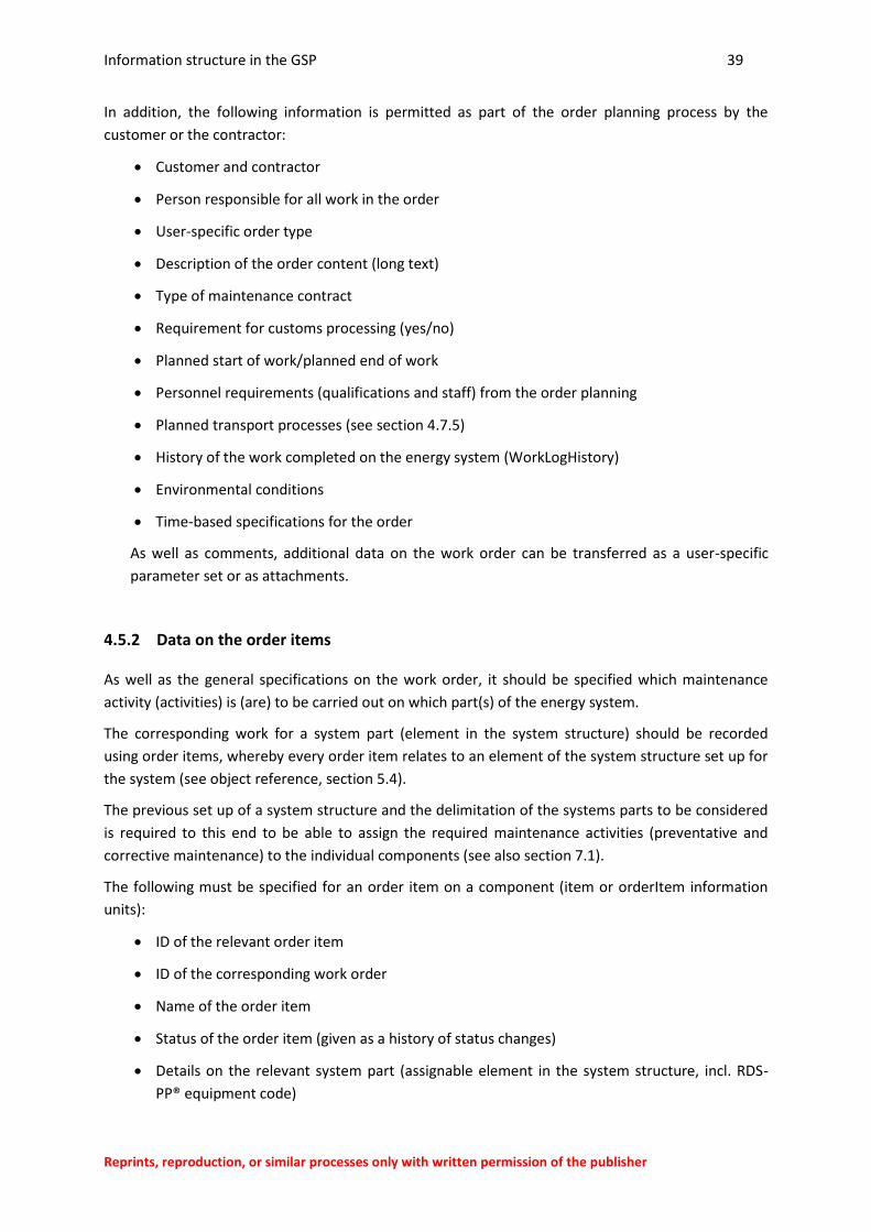
The following must be specified for an order item on a component (item or orderItem information
units):
ID of the relevant order item
ID of the corresponding work order
Name of the order item
Status of the order item (given as a history of status changes)
Details on the relevant system part (assignable element in the system structure, incl. RDS-
PP® equipment code)

Information structure in the GSP 40
Reprints, reproduction, or similar processes only with written permission of the publisher
ZEUS condition assessment in accordance with TG 7 category D2 for the relevant part of the
system (assignable element)
In addition, the following information is permitted in the GSP data format, which are typically
compiled as part of the order planning process by the customer or by the contractor:
Description of the work to be carried out and other information in long text
Level (degree of complexity) of the maintenance task in accordance with DIN EN 13306
Information on the equipment part representing the assignable element (removed, physical
component)
Details on the work to be carried out
Qualifications required to carry out the activity
Details on the equipment to be used (or scheduled)
Staff (option for personnel planning)
Measurements/measurement series
Comments as processing notes
User-specific content
Additional data on the work order can be transferred as user-specific contents or as attachments.
Information structure in the GSP 41
Reprints, reproduction, or similar processes only with written permission of the publisher
Figure 13: Structure for an order item for the work order
WorkOrderItem
id
type xs:string
name
type xs:string
WorkStatusLogs
statuses
type WorkStatusLogs
AssignedElement
assignedElement
type AssignedElement
ZEUSPart2Assessment
zeusPart2History
type ZEUSPart2Assessment
maintenanceLevel
type MaintenanceLevel
longDescription
type xs:string
Equipments
equipments
type Equipments
Tasks
tasks
type Tasks
TimeReports
timeReport
type TimeReports
Materials
materials
type Materials
Employees
staff
type Employees
WorkEquipments
workEquipments
type WorkEquipments
Attachments
attachments
type Attachments
Skills
skills
type Skills
Measurements
measurements
type Measurements
Comments
comments
type Comments
UserSpecificContents
userSpecificContents
type UserSpecif icContents
Information structure in the GSP 42
Reprints, reproduction, or similar processes only with written permission of the publisher
4.6 workReport data block
Data on the work report and data on the work order are compiled in a document. The information
units contained in the workReport data block cover all data compiled by the service
technician/assessor, etc. as part of the order processing on-site, primarily to document his/her work.
The workReport data block in the XML schema contains all permitted information on the work report
that relates to that work order (data blocks given above). At the time of commissioning (in other
words, before starting work), this data block is not filled with content and is therefore an optional
element.
This does not preclude the subsequent preparation and testing of the data recorded by the
technician in a follow-on process (see section 3.9).
4.6.1 Contents of the work report
The workReport data block covers a minimum of the following information:
Report ID and report name
Work status (overall status of the order processing)
At least one report item
A minimum of the data for an associated report item (see section 4.6.2.)
ZEUS condition assessment on-site for the energy system in accordance with TG 7 category
D2
The specification of the following optional information is permitted:
Long text to document the works carried out
Staff involved (responsible employee as responsibleEmployee, involved staff as staff)
Transport processes required for the work order (transportProcesses)
Condition assessment in accordance with ZEUS Block 1
Environmental conditions (e.g. weather on the day work is carried out)
Work time recording for the entire order (timeReport - see also section 5.8)
Attachments (e.g. appraisals, images, invoices and admin documents, measurement logs)
Comments as processing notes
User-specific content
Information structure in the GSP 43
Reprints, reproduction, or similar processes only with written permission of the publisher
Figure 14: Structure of the workReport data block
As information recording takes place in different levels of detail in practice, individual pieces of
information are permitted on the work report level and on the report item level, e.g. data on the
working times.
WorkReport
id
type xs:string
name
type xs:string
WorkStatusLogs
statuses
type WorkStatusLogs
WorkReportItems
items
type WorkReportItems
ZEUSPart1Assessment
zeusPart1Assessment
type ZEUSPart1Assessment
longDescription
type xs:string
Employee
responsibleEmployee
type Employee
Employees
staff
type Employees
TransportProcesses
transportProcesses
type TransportProcesses
EnvironmentalConditions
environmentalConditions
type EnvironmentalConditions
TimeReports
timeReport
type TimeReports
Attachments
attachments
type Attachments
Comments
comments
type Comments
UserSpecificContents
userSpecificContents
type UserSpecif icContents
Information structure in the GSP 44
Reprints, reproduction, or similar processes only with written permission of the publisher
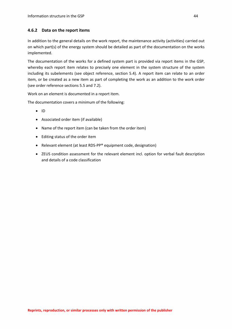
4.6.2 Data on the report items
In addition to the general details on the work report, the maintenance activity (activities) carried out
on which part(s) of the energy system should be detailed as part of the documentation on the works
implemented.
The documentation of the works for a defined system part is provided via report items in the GSP,
whereby each report item relates to precisely one element in the system structure of the system
including its subelements (see object reference, section 5.4). A report item can relate to an order
item, or be created as a new item as part of completing the work as an addition to the work order
(see order reference sections 5.5 and 7.2).
Work on an element is documented in a report item.
The documentation covers a minimum of the following:
ID
Associated order item (if available)
Name of the report item (can be taken from the order item)
Editing status of the order item
Relevant element (at least RDS-PP® equipment code, designation)
ZEUS condition assessment for the relevant element incl. option for verbal fault description
and details of a code classification
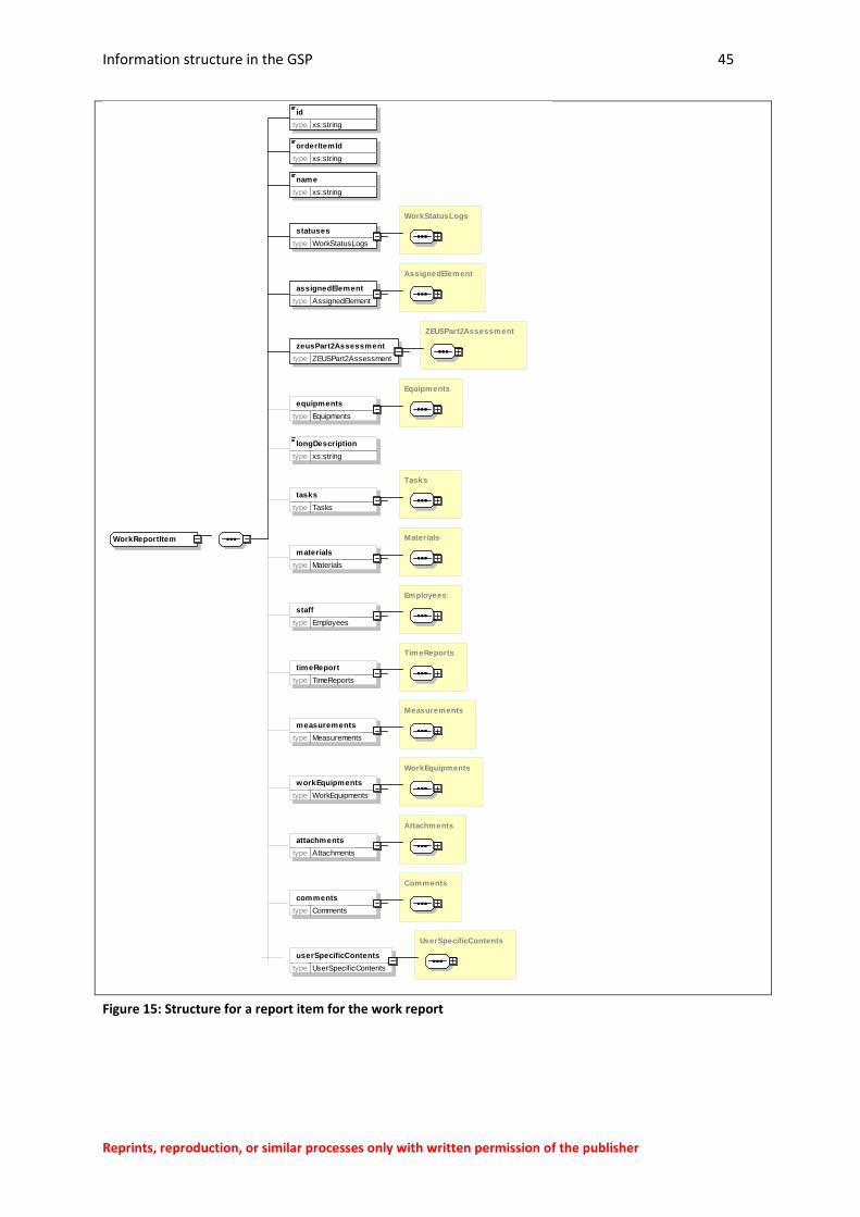
Information structure in the GSP 45
Reprints, reproduction, or similar processes only with written permission of the publisher
Figure 15: Structure for a report item for the work report
WorkReportItem
id
type xs:string
orderItemId
type xs:string
name
type xs:string
WorkStatusLogs
statuses
type WorkStatusLogs
AssignedElement
assignedElement
type AssignedElement
ZEUSPart2Assessment
zeusPart2Assessment
type ZEUSPart2Assessment
Equipments
equipments
type Equipments
longDescription
type xs:string
Tasks
tasks
type Tasks
Materials
materials
type Materials
Employees
staff
type Employees
TimeReports
timeReport
type TimeReports
Measurements
measurements
type Measurements
WorkEquipments
workEquipments
type WorkEquipments
Attachments
attachments
type Attachments
Comments
comments
type Comments
UserSpecificContents
userSpecificContents
type UserSpecif icContents
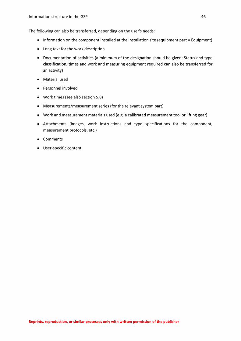
Information structure in the GSP 46
Reprints, reproduction, or similar processes only with written permission of the publisher
The following can also be transferred, depending on the user's needs:
Information on the component installed at the installation site (equipment part = Equipment)
Long text for the work description
Documentation of activities (a minimum of the designation should be given: Status and type
classification, times and work and measuring equipment required can also be transferred for
an activity)
Material used
Personnel involved
Work times (see also section 5.8)
Measurements/measurement series (for the relevant system part)
Work and measurement materials used (e.g. a calibrated measurement tool or lifting gear)
Attachments (images, work instructions and type specifications for the component,
measurement protocols, etc.)
Comments
User-specific content

Information structure in the GSP 47
Reprints, reproduction, or similar processes only with written permission of the publisher
4.7 Additional notes on the information structure
4.7.1 Formation of the system structure / RDS-PP®
The information units included in the GSP data format are structured so that a reference of all
information to a standardised classification level can be produced in the defined structure of an
energy system.
For this reason, the information on maintenance procedures should also relate to a system element
defined in the system structure. As this element should be defined in advance, it is referred to in this
guideline as what is known as an assignable element.
In accordance with the application rules on the object reference (see section 5.4), this means
establishing a system structure with a reference code system standardised for the sector (RDS-PP®).
The structure should ideally be defined down to the smallest logical unit for maintenance
(smallest replaceable units (SRU)).
As this requirement will not always be met in practice, the specification of information on
object parts under the system structure is also possible and considered to a certain extent.
An order or report item contains exactly one system structure specification and relates to precisely
one equipment part (removed and installed part where necessary).
The transfer of data to the system structure is carried out in the GSP data format in the
assignedElement data block for the order and report item (see sections 4.5.2 and 4.6.2).
For details on removed components (equipment parts), see notes in section 7.4.
The information on system parts is included in the elements
assignedElement
Equipment.
If required, it is also possible to transfer entire system structures in the GSP data format (see section
4.7.3).
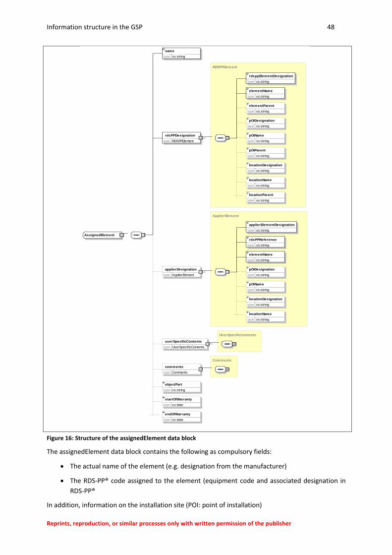
Information structure in the GSP 48
Reprints, reproduction, or similar processes only with written permission of the publisher
Figure 16: Structure of the assignedElement data block
The assignedElement data block contains the following as compulsory fields:
The actual name of the element (e.g. designation from the manufacturer)
The RDS-PP® code assigned to the element (equipment code and associated designation in
RDS-PP®
In addition, information on the installation site (POI: point of installation)
AssignedElement
name
type xs:string
RDSPPElement
rdsPPDesignation
type RDSPPElement
rdsppElementDesignation
type xs:string
elementName
type xs:string
elementParent
type xs:string
pOIDesignation
type xs:string
pOIName
type xs:string
pOIParent
type xs:string
locationDesignation
type xs:string
locationName
type xs:string
locationParent
type xs:string
ApplierElement
applierDesignation
type ApplierElement
applierElementDesignation
type xs:string
rdsPPReference
type xs:string
elementName
type xs:string
pOIDesignation
type xs:string
pOIName
type xs:string
locationDesignation
type xs:string
locationName
type xs:string
UserSpecificContents
userSpecificContents
type UserSpecif icContents
Comments
comments
type Comments
objectPart
type xs:string
startOfWarranty
type xs:date
endOfWarranty
type xs:date
Information structure in the GSP 49
Reprints, reproduction, or similar processes only with written permission of the publisher
Name
Installation site code
and on the location
Name
Site code
are permissible.
Where the system structure is not described in full in RDS-PP®, a user-specific system structure can
be created referenced on the same level or a higher level RDS-PP® (applierDesignation).
The information units are identical to those of RDS-PP® here, but a reference to an RDS-PP® element
should be given.
It is also possible to restrict all relevant information to a lower level object part (objectPart) which
has not been defined in the system structure (for the relationships, see section 3.7).
4.7.2 Object types and object information in the GSP
Certain types of object are defined in the GSP data format.
These can be fixed (in other words permanently linked or inventoried) or mobile (brought across for
the work order). For the designations of parts of the energy system, see section 3.7.
A distinction is drawn between the following:
1. The energy system itself as an evaluation unit.
2. Elements that have been defined in the system structure as system components of an energy
system (assignable elements; e.g. motor, pitch gears)
3. Physically fitted components representing the defined system structure 1 to 1 (equipment
parts/equipment with a type designation/serial number and installation date where
applicable, e.g. specific motor for the pitch gears from a manufacturer).
4. On an element of the system structure as part of the material used as part of the
maintenance work
5. Work and measuring equipment, i.e. the tools and equipment used to process an order (e.g.
floating crane, calibrated measuring equipment)
6. Transport equipment used for order processing (e.g. service vehicle, helicopter)
Often a inventory may only be carried out for important/valuable equipment parts of an energy
system. It should therefore be noted that the physical object (specific component) for the
maintenance does not always have to be defined in more detail in the GSP assuming there is a
unique reference to a specific element in the system structure.
Specific data required in the maintenance work is defined for objects as separate fields.
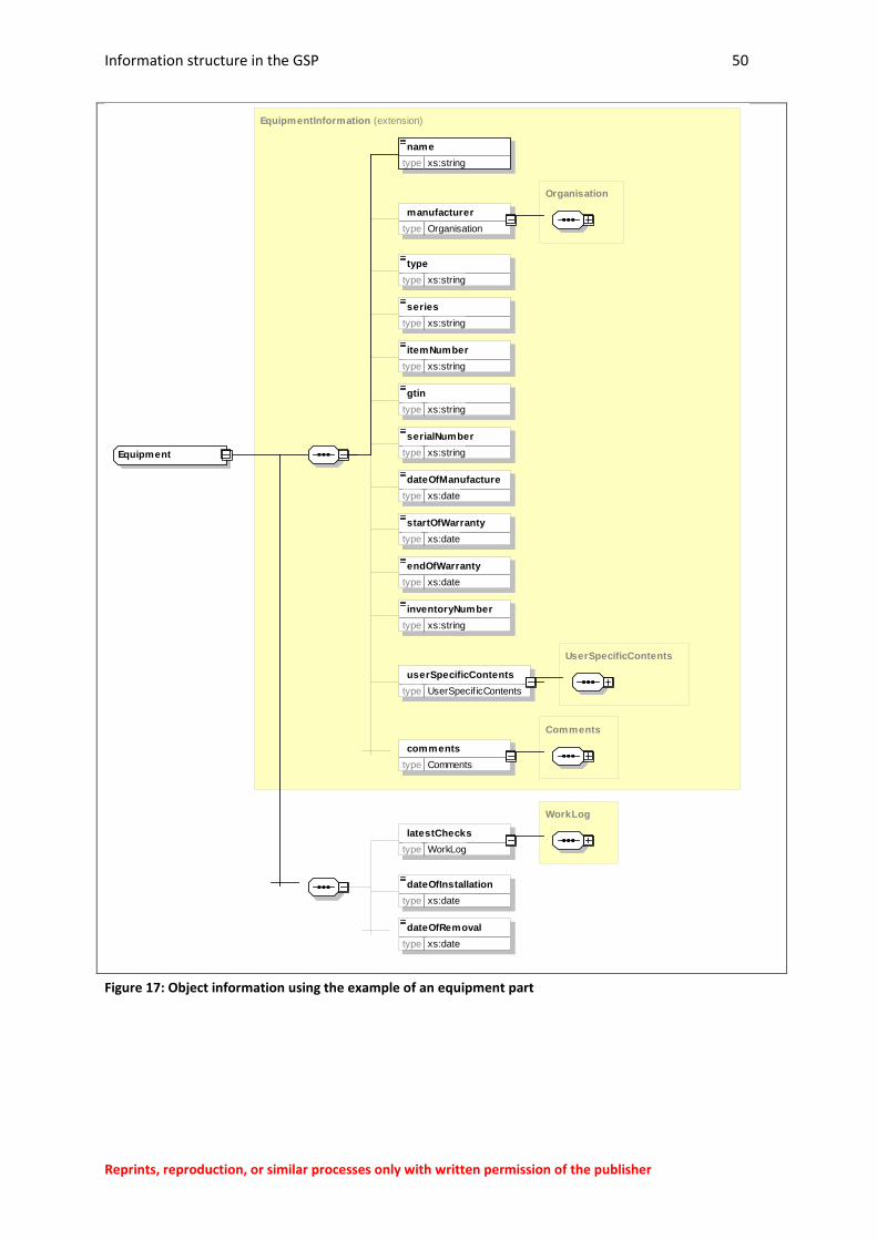
Information structure in the GSP 50
Reprints, reproduction, or similar processes only with written permission of the publisher
Figure 17: Object information using the example of an equipment part
EquipmentInformation
Equipment
(extension)
name
type xs:string
Organisation
manufacturer
type Organisation
type
type xs:string
series
type xs:string
itemNumber
type xs:string
gtin
type xs:string
serialNumber
type xs:string
dateOfManufacture
type xs:date
startOfWarranty
type xs:date
endOfWarranty
type xs:date
inventoryNumber
type xs:string
UserSpecificContents
userSpecificContents
type UserSpecif icContents
Comments
comments
type Comments
WorkLog
latestChecks
type WorkLog
dateOfInstallation
type xs:date
dateOfRemoval
type xs:date
Information structure in the GSP 51
Reprints, reproduction, or similar processes only with written permission of the publisher
The details of data on objects covers the specification of the object designation (compulsory field) and
the following, depending on the needs of the user:
for equipment parts, installation and expansion date, as well as
History of the work carried out
For all of the object types given above:
Manufacturer
Type
Series
Inventory number
Serial number
Global Trade item number
Production date
Start and end of the warranty period
It is also possible to transfer the last work and inspections carried out (log of the maintenance
activities/workLog).
If these details are not sufficient, the transfer of object parameters obtained from the IT systems is
also possible via user-specific content.
In addition, files supplied are permissible for every object.
Examples of information assigned to an object as user-specific parameters or attachments include:
Manuals, specifications (or links)
Text modules from specifications and manuals
Spare parts lists
Work and safety instructions
Technical data
Hit list of faults, e.g. from ZEUS or typical patterns of damage obtained
Lists with error codes from the software
Hit list of spare parts replaced
Lists with object parts (underneath/outside the system structure)
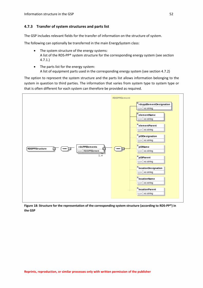
Information structure in the GSP 52
Reprints, reproduction, or similar processes only with written permission of the publisher
4.7.3 Transfer of system structures and parts list
The GSP includes relevant fields for the transfer of information on the structure of system.
The following can optionally be transferred in the main EnergySystem class:
The system structure of the energy systems: A list of the RDS-PP® system structure for the corresponding energy system (see section 4.7.1.)
The parts list for the energy system: A list of equipment parts used in the corresponding energy system (see section 4.7.2)
The option to represent the system structure and the parts list allows information belonging to the
system in question to third parties. The information that varies from system type to system type or
that is often different for each system can therefore be provided as required.
Figure 18: Structure for the representation of the corresponding system structure (according to RDS-PP®) in
the GSP
RDSPPStructure
RDSPPElement
rdsPPElements
1 ¥..
type RDSPPElement
rdsppElementDesignation
type xs:string
elementName
type xs:string
elementParent
type xs:string
pOIDesignation
type xs:string
pOIName
type xs:string
pOIParent
type xs:string
locationDesignation
type xs:string
locationName
type xs:string
locationParent
type xs:string
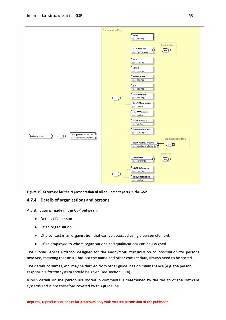
Information structure in the GSP 53
Reprints, reproduction, or similar processes only with written permission of the publisher
Figure 19: Structure for the representation of all equipment parts in the GSP
4.7.4 Details of organisations and persons
A distinction is made in the GSP between:
Details of a person
Of an organisation
Of a contact in an organisation that can be accessed using a person element.
Of an employee to whom organisations and qualifications can be assigned.
The Global Service Protocol designed for the anonymous transmission of information for persons
involved, meaning that an ID, but not the name and other contact data, always need to be stored.
The details of names, etc. may be derived from other guidelines on maintenance (e.g. the person
responsible for the system should be given, see section 5.14).
Which details on the person are stored in comments is determined by the design of the software
systems and is not therefore covered by this guideline.
EquipmentList
EquipmentListEntry
equipmentListEntries
type EquipmentListEntry
name
type xs:string
Organisation
manufacturer
type Organisation
type
type xs:string
series
type xs:string
itemNumber
type xs:string
gtin
type xs:string
serialNumber
type xs:string
dateOfManufacture
type xs:date
startOfWarranty
type xs:date
endOfWarranty
type xs:date
inventoryNumber
type xs:string
UserSpecificContents
userSpecificContents
type UserSpecif icContents
Comments
comments
type Comments
rdsPPReference
type xs:string
dateOfInstallation
type xs:date
Information structure in the GSP 54
Reprints, reproduction, or similar processes only with written permission of the publisher
4.7.5 Details of transport processes
For settlement and documentation, data on the transport processes required can also be
documented in GSP format. The recording of transport processes is integrated into the GSP and
collected for a work order or a work report, whereby the necessary transport times can also be
assigned as special activities (inward/outward journey) to a report item (and thus to a sub-order).
Planned transport operations (e.g. booked ship passages or material transports to the system) can be
documented in the work order as required. The actual transport operations required are contained in
the workReport data block.
Transport processes can be recorded in the GSP for the entire order, whereby the following must be
stored:
ID (consecutive number or journey/booking/transport order number…)
Transport route (air, land, water)
Carrier (transport company)
The other permissible information is based on the needs of the user.
Carrier (transport company)
Distance (incl. calculation method for the route)
Type and description of the transport method (e.g. service vehicle 815)
Shipping company (who is carrying out the operation)
Parameters on the vehicle (e.g. load capacity, loading dimensions…)
Type of transported goods (freight only or personnel, personnel and freight)
Booked/paid transport capacity (weight, number of persons)
Duration and/or start and end time of the transport process
Start and end location of the transport process
Comments
Both electronic travel documentation (log book) and transport order planning (e.g. booking with the
transport company/shipper) can be documented in the GSP data format using these details.
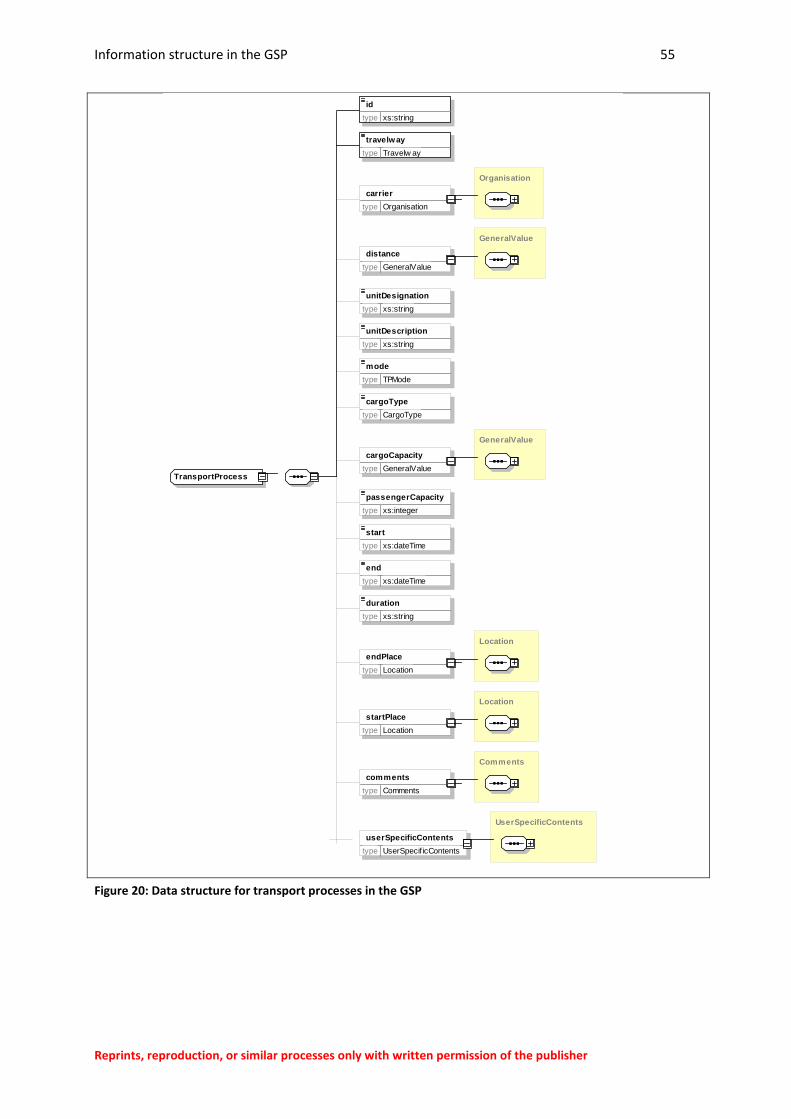
Information structure in the GSP 55
Reprints, reproduction, or similar processes only with written permission of the publisher
Figure 20: Data structure for transport processes in the GSP
TransportProcess
id
type xs:string
travelway
type Travelw ay
Organisation
carrier
type Organisation
GeneralValue
distance
type GeneralValue
unitDesignation
type xs:string
unitDescription
type xs:string
mode
type TPMode
cargoType
type CargoType
GeneralValue
cargoCapacity
type GeneralValue
passengerCapacity
type xs:integer
start
type xs:dateTime
end
type xs:dateTime
duration
type xs:string
Location
endPlace
type Location
Location
startPlace
type Location
Comments
comments
type Comments
UserSpecificContents
userSpecificContents
type UserSpecif icContents
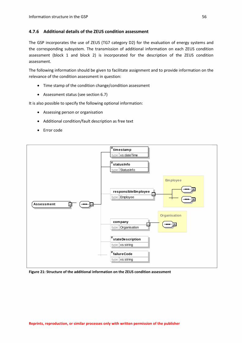
Information structure in the GSP 56
Reprints, reproduction, or similar processes only with written permission of the publisher
4.7.6 Additional details of the ZEUS condition assessment
The GSP incorporates the use of ZEUS (TG7 category D2) for the evaluation of energy systems and
the corresponding subsystem. The transmission of additional information on each ZEUS condition
assessment (block 1 and block 2) is incorporated for the description of the ZEUS condition
assessment.
The following information should be given to facilitate assignment and to provide information on the
relevance of the condition assessment in question:
Time stamp of the condition change/condition assessment
Assessment status (see section 6.7)
It is also possible to specify the following optional information:
Assessing person or organisation
Additional condition/fault description as free text
Error code
Figure 21: Structure of the additional information on the ZEUS condition assessment
Assessment
timestamp
type xs:dateTime
statusInfo
type StatusInfo
Employee
responsibleEmployee
type Employee
Organisation
company
type Organisation
stateDescription
type xs:string
failureCode
type xs:string
Information structure in the GSP 57
Reprints, reproduction, or similar processes only with written permission of the publisher
4.7.7 User-specific content
User-specific content is used to provide
the persons involved in the maintenance work for decisions and planning in the maintenance
process
with the software tools used for the structured preparation of information
to transfer additional information.
As the breadth of the usage options is significant, the possible user-specific content is not
conclusively defined in these guidelines. These should therefore be agreed between the parties
involved.
Potential examples for the use of user-specific information include:
Object parameters (see section 4.7.2)
Information on invoicing (e.g. prices and costs)
User-specific criteria definitions (see section 6.1).
Additional information for processing with specific software systems (e.g. SAP)
In addition, the GSP working group intends to submit recommendations for the format of parameters
sets in future for specific areas of application to minimise the amount of modification required of
software tools for typical applications.
The application guide for these guidelines may contain more detailed specifications.
The recommendation is intended to be able to process the recommended parameter sets of all IT
systems assuming this is appropriate for the application/user in question.
The following information can be provided for the software if required for processing user-specific
content:
ID of the parameter set (compulsory field)
Category of the parameter (to be able to represent data content with multiple dimensions,
e.g. table columns in value tables)
Time stamp of the entry of a user-specific parameter
Reference to a responsible employee
Multiple data types are permitted for parameters transmitted as user-specific content. In addition,
links to files (attachments) can also be included in user-specific content.
Information structure in the GSP 58
Reprints, reproduction, or similar processes only with written permission of the publisher
User-specific content is structured as follows in the GSP data format:
Figure 22: Structure of the user-specific content
UserSpecificParameterSet
id
type xs:string
Parameter
userSpecificParameters
1 ¥..
type Parameter
name
type xs:string
ParameterValue
value
type ParameterValue
stringParameterValue
type xs:string
integerParameterValue
type xs:integer
decimalParameterValue
type xs:decimal
dateParameterValue
type xs:date
timeParameterValue
type xs:time
dateTimeParameterValue
type xs:dateTime
durationParameterValue
type xs:duration
valueParameterType
type GeneralValue
documentParameterType
type File
longDescription
type xs:string
category
type xs:string
timestamp
type xs:dateTime
Employee
responsibleEmployee
type Employee
Comments comments
type Comments
name
type xs:string
longDescription
type xs:string
Comments comments
type Comments
GSP application rules 59
Reprints, reproduction, or similar processes only with written permission of the publisher
5 GSP application rules
When maintenance data is transferred between different parties in a standardised format,
agreement is required on the relevant usage rules.
This is the only way to ensure the following across the entire data processing chain:
The information is recorded, compiled, assigned and interpreted in accordance with standardised aspects
The information recorded and transferred in the GSP data format can be compiled effectively to create useful and consistent documents on the maintenance process
Assessments are possible using the maintenance data transferred that apply to all situations, e.g. the assessment of the reliability of system components and system types.
5.1 Conformity rules
To ensure conformity of the data transferred in a GSP document, the following general rules for use
must be observed.
All information units in the data blocks of the GSP data format must conform to the specifications
of these guidelines (Attachment A).
Data in the GSP data format should be transferred in the GSP document format (see section 8).
The data transferred by the users must contain a minimum of the information units and contents
identified as compulsory.
Recommended information units and recommended content should be used in a standardised way
if appropriate for the use in question.
Specifications for the essential information units to be provided are defined in section 4.
The structure of the permissible information units (XML schema) is documented in
Attachment A.
User-specific information units should only be defined and used where this has been (contractually)
agreed between all users involved or if recommended by the GSP working group.
In line with the structure specified for the purpose, the users can agree the inclusion of additional
information units in the data format as user-specific content (see section 4.7.2).
For user-specific content, the GSP/FAIH working group at FGW e.V. can specify
recommendations for specific applications.
The GSP working group is pleased to accept suggestions and experiences from users of the
guideline.
GSP application rules 60
Reprints, reproduction, or similar processes only with written permission of the publisher
The requirement for the transfer of data in the GSP format is interoperable data acquisition and data
management.
Data acquisition and data management of an IT system interoperable with GSP must follow the
rules specified in sections 5.1.2 - 5.1.8.
A database on an IT system is GSP-interoperable when it is possible to create a GSP from the
database. This is the case when at least all information units (types, elements) in these
guidelines that are identified as compulsory can be generated from the available data.
The use of a separate assignment logic is permitted in this respect if it is possible to clearly
reference the assignment logic required in these guidelines.
An interface compatible with the GSP data format between two IT systems interoperable with GSP
must be able to process and generate the data in accordance with the data format defined in
section 4 and the document format specified in section 8.
The data exchange between two IT systems interoperable with GSP can also be ensured in
ways other than data transmission in the defined format, such as via a direct database access
with or without data synchronisation.
In this case, the conformity rules given above apply for data acquisition and data
management.
5.2 Time reference
The individual GSP documents must be comparable in terms of the processing status, and must
permit conclusions to be drawn when status changes are implemented.
All information units containing a time stamp should be updated on each update of the associated
element by the software.
Example: Time stamp for status change, time stamp for comment editing, time stamp for a
ZEUS condition assessment.
The creation date of a GSP (createDate) should be updated by the software on each document save
operation.
Document saving is referred to as the saving, exporting, creation, update/synchronisation
time of the updated element.
GSP application rules 61
Reprints, reproduction, or similar processes only with written permission of the publisher
5.3 Reference to the energy system
The maintenance data recorded must be assignable to the relevant evaluation unit. The following
usage rules must therefore be observed.
Every work order must relate to precisely one energy system.
Every energy system must be assigned a power plant as a higher level system cluster.
The GSP data recorded structured in XML format in accordance with section 7.6.1 relates to
precisely one work order with the corresponding order items in the scope of these guidelines.
The energy system (generating unit) is normally referred to as the evaluation unit in the
scope of the guideline (see also TG7 category A, section 3.5.).
In the field of wind energy, the energy system or generating unit is normally the individual
wind turbine.
The documentation of the maintenance in the form of work orders relating to multiple
energy systems or multiple power plants is not permitted when using these guidelines.
In the field of wind energy, the power plant is the wind farm as a relevant cluster of energy
systems.
That a GSP data record relates to one work order takes into account the fact that most work
on energy systems is carried out without consultation from the management. This means
that a work order should be created for every activity on a system, including inspection, fault
diagnosis, etc.
The use of the GSP document format described in these guidelines for other types of energy system
(e.g. substation platforms, internal park cabling, etc.) is possible and is actively recommended.
The GSP document format can be used primarily for maintenance operations on energy systems that
have a reference code system for the system structure comparable to the RDS-PP® ("object
reference").
5.4 Object reference
The processing of maintenance orders is documented in the GSP principally for an assignable
element that can be clearly identified and defined by a reference code in the system structure incl.
any sub-elements it may have.
The implementation of the data transfer in accordance with the GSP data format therefore
requires the use of an adequately detailed system structure, see section 7.1.
Every order item should be assigned to exactly one assignable element in the system structure.
Every associated report item must relate to one order item and thus to the same or a different
assignable element in the system structure.
Assignable element refers to the following, with reference to TG7 category A section 3.5:
The assignment to a maintenance object in accordance with standardised criteria can only be
carried out for the elements included in the system structure.
GSP application rules 62
Reprints, reproduction, or similar processes only with written permission of the publisher
The assignment can only be carried out in accordance with the information available at the
time the documentation is produced (suspected damage or automatic error message
triggered by the system monitoring).
For more details, see section 7.2.
For the assignment of order and report items, the order reference applies with the
applications defined in section 5.5.
In the scope of the TG 7 category D3, a service protocol includes at least one report item.
Every report item should be assigned to exactly one assignable element in the system structure.
The reference of multiple report items to one order item is permitted.
For more information, see section 7.2.
In the scope of these guidelines, the RDS-PP® reference code set should be used for the
maintenance documentation in accordance with the requirements of the VGB-Standard-S-823-T32
usage guidelines for the wind energy sector.
The guidelines are currently in draft form and are expected to be released during 2014.
The reference code set to be used when setting up the system structure must include the equipment
code.
It is also recommended to specify the reference code for the installation site:
for the equipment code with function and product aspects, see VGB-Standard-S-823-T32;
2012-04 DE section 5.5.
for the installation site, see VGB-Standard-S-823-T32; 2012-04 DE section 5.6.
for the identification of energy systems, see VGB-Standard-S-823-T32; 2012-04 DE section
7.2.
It is also recommended to identify the installation site.
The regulations of the guidelines TG7 category D1 should be observed here as necessary
once published.
The additional use of an individual, user-specific reference code system is permissible assuming the
logical item-based assignment to an RDS-PP® equipment code is guaranteed.
The user-specific system structure can be more detailed than the classification according to
the RDS-PP® system structure, assuming the assignment is created uniquely for every system
element.
It should be ensured that all users of the GSP data format can carry out a logical, item-based
assignment to one and the same system structure.
This means that the IT systems must be able to access a standardised system structure for
the relevant system.
The GSP permits the transfer of the system structure belonging to the relevant energy
system.
GSP application rules 63
Reprints, reproduction, or similar processes only with written permission of the publisher
5.5 Order reference
For the continuous, traceable documentation and itemised processing of the maintenance activities,
the maintenance data logged during the creation of the work report must be linked to the actual
order data. The following therefore applies:
A maintenance activity is only logged within the protocol data block. The planned values of the
order data block are retained permanently.
The maintenance documentation is completed by the addition of information in the protocol data
block, whereby status entries in the order data block can be changed.
This requirement relates to the data-based separation of the documentation for the work
order and work report. Users are free to incorporate the dynamic modification of work order
data, even during the processing of assigned order items.
A report item should relate to precisely one order item.
For a new report item to be created without a reference to an existing work order (expansion
of the work order), the user in question will need to have the relevant authorisations.
In addition, the contractor completing the works will need to be recorded for an accurate order
reference and the work order will need to include the information units given in DIN EN 13460.
See information units in the work order in accordance with DIN EN 13460.
5.6 Item reference
For the continuous, traceable documentation and itemised processing of the maintenance activities,
items must be separated by activity type in the maintenance documentation.
The following therefore applies:
The maintenance documentation must be implemented separately for all maintenance activities in
accordance with DIN EN 13306. Several activities of the same type are permitted to be combined in
one work order. The relevant maintenance type should also be documented in line with DIN EN
13306.
A work order, and thus a service protocol data record transmitted in the GSP data format, is
therefore only permitted to contain data for one activity type.
Activity types for maintenance are defined in DIN EN 13306, section 8 (part B).
Maintenance types are defined in DIN EN 13306, section 7.
When using an operator-specific code to describe status conditions, events and event causes,
proceed as appropriate in line with these instructions.
The relevant ZEUS codes for the categorisation of the maintenance are given in TG 7 category
D2 revision 1 02-08-xx and 02-09-xx.
5.7 Condition assessment
If required, the condition assessment for each assignable object (element in the system structure)
should be carried out consecutively for the entire monitoring period. In the context of the
GSP application rules 64
Reprints, reproduction, or similar processes only with written permission of the publisher
maintenance documentation this should be implemented via a condition assessment criteria in
accordance with criteria used in a standardised way.
In the scope of this guideline, a condition assessment and description should be carried out in
accordance with the standardised status/event/cause code (ZEUS) according to TG 7 category D2.
The application of the ZEUS code is a requirement of TG7 category A, see section 3.5.2 .
The observation period should begin at the time of system acceptance.
The responsibility for the ZEUS assessment (e.g. service technician, engineering, service
management, etc.) is not covered by these guidelines.
The condition assessment can be carried out directly in the process of data acquisition or on
the basis of the data submitted downstream with the GSP.
Other points are regulated in TG 7 category C.
5.8 Staff and time recording
Whether and how staff and working hours are to be transferred is based on the agreements of the
individual parties involved in addition to the legal provisions.
For this reason, the GSP includes multiple options for staff and time recording including the
specification of required qualifications. However, which level and what information is transmitted for
staff and time recording is not covered by these guidelines.
To ensure the GSP interoperability of the IT systems and to meet the documentation requirements
according to DIN EN 13460, at least the transmission in the GSP and the processing of the following
information units is recommended on the level of the work report (WorkReport):
1. List of the staff involved (if necessary, with anonymous ID only)
2. working hours hours spent for the entire work order (incl. an indication of the working type time
and the activity category).
Corresponding provisions of the DIN EN 13460 and (when published) of the TG 7 category C
must be observed.
The transfer of the required activities of the staff involved may also be required (see also DIN
EN 13460).
5.9 Scope and completeness of the data to be transferred
For data storage interoperable with the GSP, it is advisable to store all information units of a GSP
data record included in the data format centrally in one place.
In addition, depending on the specific application to be implemented, the transmission of partial data
is permitted if the assignment to a service protocol data record can be ensured on the IT side and the
structure of the data format is observed for the parts transferred (valid GSP document).
The extent to which operator-specific parts in the transferred service protocol data record are
displayed and processed is covered by the arrangements of the parties involved.
The onward IT-based processing and testing and the adjustment of the service protocol data
in the GSP data format are not covered by these guidelines.
GSP application rules 65
Reprints, reproduction, or similar processes only with written permission of the publisher
5.10 Missing information in mandatory information units
In accordance with application rules defined in section 5.1, a GSP document must include details on
all mandatory (compulsory) information units.
If a mandatory information unit in the special application is not required in exceptional cases, or if
there is no data for it in an exceptional situation, the following applies to users of these guidelines:
A mandatory information unit for which there is no content, should be included in the GSP with all
mandatory elements, but the content should be left blank.
If content is specified for the information units, in this case the specified categories should be used
for unspecified or missing data.
Specified content is defined in the XML schema for the GSP data format in accordance with
section 7.6.1 of these guidelines using enumerations or specified content (fixed="…").
for enumerations, see section 6
5.11 Uniformity of designations in the master data
To improve the interpretability of data, all parties involved in the maintenance should agree and use
uniform descriptions.
A designation should be specified in the scope of these guidelines in a standardised way for all
users of the GSP by the party to whom they primarily relate.
Example: A WT type should be specified by the manufacturer.
Example: A company name should be specified by the relevant company.
5.12 Units of measurement to be used in GSP data
In a GSP document, it is only permitted to use units corresponding to the international system SI of
units for recording measurements and descriptions, in accordance with DIN 1301. The depiction of
the units in the GSP corresponds to the CIM procedure (Common Information Model) and is carried
out using a separate unit multiplier.
Individual deviations for the information units (elements) affected are identified in the element
description. In these cases, the unit specified in the element description should be used.
For the element description, see section 7.6.1 of these guidelines.
Rev. 0 of the guidelines does not include any details on payments, and therefore does not
cover units of currency.
5.13 Language of the Maintenance documentation in the GSP
The maintenance documentation (M documentation) should be given in a common language for the
work order and work report in the scope of these guidelines.
The document language should therefore be stored in the protocol. The language codes according
to ISO 639-1 should be used for the identification of the document language.
The language for the documentation of the GSP is to be recorded in the GSP info data block in the
GSP data format (see section 6.18).
GSP application rules 66
Reprints, reproduction, or similar processes only with written permission of the publisher
The language of other content linked in the GSP such as product and material specifications,
manufacturer specifications, etc. may be different from the M documentation language in some
circumstances.
Which procedure is correct here and whether or not links to language-specific documents or object
parameters are to be included in the GSP, is not the subject of these guidelines.
5.14 Person responsible for a system
If a person responsible for a system is specified for the energy system in the current version of DIN
VDE 0105-100, it must be noted in the GSP in the order data.
To do this, a corresponding contact should be transferred into the work order data in the operator
information unit.
5.15 Use of comments
Comments are all the information which are used primarily as processing notes for the internal
communication between the parties involved. The comment fields (comments) are intended for this
purpose. In particular, it might not always be useful for the written M documentation to include all
comments in the maintenance documents.
The following principle should be followed so that the use of comments in the GSP does not involve
any information becoming lost or not clearly displayed.
Information to be included in the continuously archived M documentation is not permitted to be
noted as comments.
The scope of the M documentation is regulated by local work instructions and the regulations
governing the M documentation, e.g. TG 7 category C.
Long text fields or special fields are intended for all supplementary information in the
protocol.
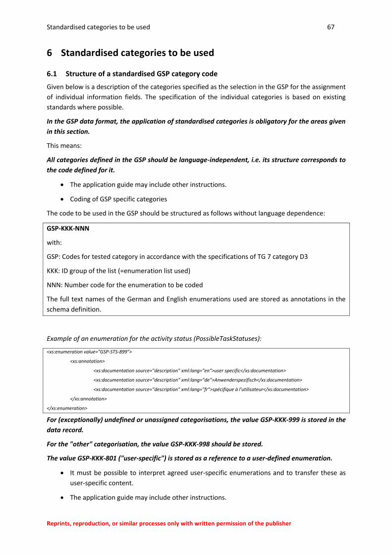
Standardised categories to be used 67
Reprints, reproduction, or similar processes only with written permission of the publisher
6 Standardised categories to be used
6.1 Structure of a standardised GSP category code
Given below is a description of the categories specified as the selection in the GSP for the assignment
of individual information fields. The specification of the individual categories is based on existing
standards where possible.
In the GSP data format, the application of standardised categories is obligatory for the areas given
in this section.
This means:
All categories defined in the GSP should be language-independent, i.e. its structure corresponds to
the code defined for it.
The application guide may include other instructions.
Coding of GSP specific categories
The code to be used in the GSP should be structured as follows without language dependence:
GSP-KKK-NNN
with:
GSP: Codes for tested category in accordance with the specifications of TG 7 category D3
KKK: ID group of the list (=enumeration list used)
NNN: Number code for the enumeration to be coded
The full text names of the German and English enumerations used are stored as annotations in the
schema definition.
Example of an enumeration for the activity status (PossibleTaskStatuses):
<xs:enumeration value="GSP-STS-899">
<xs:annotation>
<xs:documentation source="description" xml:lang="en">user specific</xs:documentation>
<xs:documentation source="description" xml:lang="de">Anwenderspezifisch</xs:documentation>
<xs:documentation source="description" xml:lang="fr">spécifique à l'utilisateur</xs:documentation>
</xs:annotation>
</xs:enumeration>
For (exceptionally) undefined or unassigned categorisations, the value GSP-KKK-999 is stored in the
data record.
For the "other" categorisation, the value GSP-KKK-998 should be stored.
The value GSP-KKK-801 ("user-specific") is stored as a reference to a user-defined enumeration.
It must be possible to interpret agreed user-specific enumerations and to transfer these as
user-specific content.
The application guide may include other instructions.
Standardised categories to be used 68
Reprints, reproduction, or similar processes only with written permission of the publisher
6.1.1 Codes for ZEUS categories
For the codes for ZEUS categories, the ZEUS code is used directly in line with TG 7 category D2
without a code letter. Details on the ZEUS categories can be found in section 6.6.
Example:
01-02-97
= ZEUS block 1 - Functional condition status - undefined functional state
6.1.2 Codes for the document languages
For the codes for the document language, the language code is used directly in accordance with ISO
639-1. Details on the language codes can be found in section 6.18.
6.2 Classification of the energy system according to the type of energy used
The classification of the energy systems according to the energy type used is carried out in line with
the categories defined in the Common Information Model (CIM).
The possible energy types are defined as an enumeration in SimpleType EnergySource.
6.3 Categories to be used for work orders
Typically, the input and processing routines are adjusted in IT systems for order processing via order
types.
For this reason, specified order types should be used uniformly in GSP-interoperable IT systems.
The possible order types are defined in the SimpleType ActivityType as an enumeration.
The possible order types are based on DIN EN 13306:2010-12, section 8 (part B).
User-specific order types should be transferred as user-specific content, see section 4.7.7.
Standardised categories to be used 69
Reprints, reproduction, or similar processes only with written permission of the publisher
6.4 Categories to be used for the processing status of work orders and items
The processing status of maintenance (M) measures should be documented in the application area of
the guideline with a schema compatible with the TG 7 category D2. This permits the assignment of
the ZEUS code 02-11 to be linked automatically to the status of the order or of the protocol and its
positions as part of processing M measures.
The possible status messages are specified in the SimpleType WorkStatus as an enumeration.
The corresponding provisions of the TG 7 category C should be observed accordingly
following publication.
6.5 Categories for the status of activities
In cases where the user processes stipulate the documentation of the status of individually
documented activities, an assessment should be carried out based on TG 7 category D2 but
simplified.
As the "work" level in the work report documents consecutive activities or activities processed in
parallel when processing a commissioned M measure on one and the same component (assignable
element, see section 5.4), no reference to the ZEUS code is not permitted or required here.
The possible status messages are specified in the SimpleType TaskStatus as an enumeration.
6.6 Condition assessment in accordance with TG7 category D2 (ZEUS)
The application of the ZEUS code for the status description in accordance with TG7 category D2 is
compulsory in the scope of these guidelines, see section 5.7.
The correct use of the ZEUS code is checked against the SimpleTypes ZEUS0101-ZEUS0212,
ZEUSKA01-ZEUSKA05 as well as ZEUSKE01- ZEUSKE0103 via enumerations.
Standardised categories to be used 70
Reprints, reproduction, or similar processes only with written permission of the publisher
6.7 Categories to be used for the status of a ZEUS condition assessment
In the event of a division of tasks in the condition assessment - for example, between Service, Service
Management, Operations Management and Engineering - it can be useful to make a preliminary
condition assessment based on the information transferred in the GSP data format then evaluated
after the work completed by the service engineer.
The status of the condition assessment is specified in accordance with the enumeration
specified in the SimpleType StatusInfo.
6.8 Classification of the M measures according to their complexity (maintenance level)
A classification of the M measures of a corresponding order or report position can be carried out
based on DIN EN 13306:2010-12, section 7.13, depending on its complexity.
The possible maintenance levels are specified as an enumeration in SimpleType
MaintenanceLevel.
6.9 Description of file types in the attachment
For simplified assignment and processing, file attachments to the GSP protocol can be categorised in
accordance with the upper level categories of the MIME types according to RFC 2045.
The possible MIME types are stored as an enumeration in the SimpleType MIMEMediaType.
6.10 Units and unit symbols
In the specification of numerical values (e.g. measurements), an SI unit and the corresponding unit
symbol must be specified in a standardised way to ensure comprehension.
6.10.1 Units
For the standardised designation of values, SI units should be used (in accordance with DIN 1301).
The SI units are stored as enumerations in the SimpleType UnitSymbol.
6.10.2 Unit symbols
The unit symbols (SI prefixes) can be used to map the corresponding size to the values described, in
accordance with DIN 1301.
The possible unit symbols are stored in the SimpleType UnitMultiplier as an enumeration.
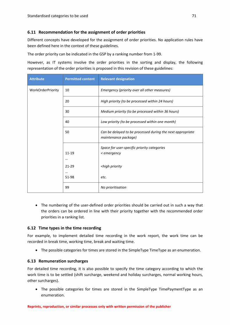
Standardised categories to be used 71
Reprints, reproduction, or similar processes only with written permission of the publisher
6.11 Recommendation for the assignment of order priorities
Different concepts have developed for the assignment of order priorities. No application rules have
been defined here in the context of these guidelines.
The order priority can be indicated in the GSP by a ranking number from 1-99.
However, as IT systems involve the order priorities in the sorting and display, the following
representation of the order priorities is proposed in this revision of these guidelines:
Attribute Permitted content Relevant designation
WorkOrderPriority
10 Emergency (priority over all other measures)
20 High priority (to be processed within 24 hours)
30 Medium priority (to be processed within 36 hours)
40 Low priority (to be processed within one month)
50 Can be delayed to be processed during the next appropriate
maintenance package)
11-19
…
21-29
…
51-98
Space for user-specific priority categories
< emergency
<high priority
etc.
99 No prioritisation
The numbering of the user-defined order priorities should be carried out in such a way that
the orders can be ordered in line with their priority together with the recommended order
priorities in a ranking list.
6.12 Time types in the time recording
For example, to implement detailed time recording in the work report, the work time can be
recorded in break time, working time, break and waiting time.
The possible categories for times are stored in the SimpleType TimeType as an enumeration.
6.13 Remuneration surcharges
For detailed time recording, it is also possible to specify the time category according to which the
work time is to be settled (shift surcharge, weekend and holiday surcharges, normal working hours,
other surcharges).
The possible categories for times are stored in the SimpleType TimePaymentType as an
enumeration.
Standardised categories to be used 72
Reprints, reproduction, or similar processes only with written permission of the publisher
For the time recording, calculation of the time types and remuneration categories are not
specified in these guidelines. If necessary, a parameter record should be agreed as user-
specific content, containing additional payment-related parameters.
6.14 Gender and salutation
In addition to the staff ID, the gender of a person should also always be given.
The categories for genders are specified in the SimpleType Gender.
6.15 Traffic routes
With transport processes, the type of traffic route can be categorised.
The possible categories for traffic routes are specified in the SimpleType Travelway as an
enumeration.
6.16 Transport modes
To simplify the documentation of the transport processes (common recording of onward and inward
journeys), defined categories can be stored for the type of the transport process.
To process the distances stored for the transport processes, the category description also specifies
how the distance specification in question is to be calculated.
The possible categories for traffic processes are specified in the SimpleType TPMode as an
enumeration.
6.17 Description of the level of cloud cover
A description of the degree of cloud cover can also be included in the description of the
environmental conditions (weather conditions). This is based on the standardised Okta unit used
internationally.
The categories for the description of the cloud cover are stored in the SimpleType
CloudCover.
6.18 Description of the language of free texts in the GSP
The language information given in the GSP-Info data block includes an enumeration of the Language
Codes in accordance with ISO 639-1.
The possible categories of language codes are specified in the SimpleType Language as an
enumeration.
6.19 Reference to countries
The possible reference to countries in addresses, for example, is carried out using the country codes
according to ISO 3166-1.
The possible categories of country codes are specified in the SimpleType Country as an
enumeration.
Standardised categories to be used 73
Reprints, reproduction, or similar processes only with written permission of the publisher
6.20 Information on the type of maintenance contract
The possible storing of information on the type of maintenance contract in the workOrder under
which the order has been granted, is carried out using standardised categories.
The possible categories of maintenance types are specified in the SimpleType
MaintenanceContract as an enumeration.
6.21 Loading type for transport operations
The general type of loading with a transport operation is distinguished at a high level as follows:
Passenger, Cargo, Passenger + Cargo
The possible categories of loading types are specified in the SimpleType
MaintenanceContract as an enumeration.
Additional implementation notes and definitions 74
Reprints, reproduction, or similar processes only with written permission of the publisher
7 Additional implementation notes and definitions
7.1 Required set up of system structure
As the energy system is normally the unit considered in the context of TG 7 section A paragraph 3.5,
a system structure must be set up for the application of these guidelines for every energy system
(wind turbine); this structure is maintained on an ongoing basis.
In practice, the system structure can change, e.g. due to conversions, and equally when completing
maintenance work it may become clear that a redefinition of the system structure with new
specifications or new assignments of elements in the system structure would be appropriate. The
updating of the system structure is especially relevant for system types for which no complete
system structure has been provided by the manufacturer.
The smallest object identifiable by a reference code and which is thus assignable should in the scope
of these guidelines be the smallest replaceable unit (SRU) or the smallest unit regarded as relevant in
the context of the M in practical terms.
The smallest assignable element (=SRU) thus also defines the lowest level of the system structure of
the unit being considered (see DIN 60300-3-1).
7.2 Assignment of the system elements involved in the M process
The selection of assignable objects for which information on a report item is carried out in the
context of the known information (e.g. suspected damage), so that in the course of a M process to be
documented in the GSP it can be necessary to specify in more detail the documentation via the
assignment of information to other assignable elements (recording of the actual work completed for
another assignable element).
In other words to "extend" the condition assessment as part of the M to the specific "fault location".
This means that the M documentation is restricted to the smallest or a smaller assignable element or
"extended" to another element as part of the fault diagnosis process.
Example:
The fault diagnosis process showed that an adjacent unit has caused the fault. Only the fault
diagnosis for the unit with suspected damage is logged in the service protocol initially. The
fault diagnosis and repair for the faulty unit is then documented in a new report item. The
condition assessments are then modified both for the object with suspected damage, and
for the actual damage.
7.3 Application of the ZEUS code
The application of the ZEUS code for the status description in line with TG7 section D2 is specified in
the application of these guidelines, see section 5.7. Accordingly, the transfer of all ZEUS codes is
prescribed in the GSP data format. However, which ZEUS code is actually used and transferred in the
respective application does not form part of these guidelines and should be specified by the user.
Stipulations on this may be covered by other guidelines and standards such as TG7 section C
or TG 7 section D2.
Additional implementation notes and definitions 75
Reprints, reproduction, or similar processes only with written permission of the publisher
The assessment can also be designed as a provisional assessment by the M personnel with
downstream submission of a complete assessment according to ZEUS criteria catalogue.
7.4 Documentation of M on equipment parts when removed
For equipment parts in the removed status, the reference to the energy plant (see section 5.3)
cannot always be produced. The special case where work is carried out on components in the
removed status which are to be documented for the M history of the component can be given in the
GSP, if the information units on the wind park or the energy system are modified accordingly in
terms of content and also recorded as appropriate for the storage locations as well.
At points where equipment parts are also monitored in the removed status, the continuous M
documentation can be ensured by the reference to the component details (equipment information),
e.g. with a reference to the serial number and type.
The RDS-PP® equipment code can be retained as these are normally large components which
are not installed onto every subsystem
For the location, a separate RDS-PP® conjoint or spare conjoint with site information would
need to be defined in line with the power plant
Further information on the warehouse and location can be recorded using the user-specific
system structure, for example (applierDesignation).
For smaller components where only the work is documented, the use of a standardised
equipment code is not absolutely necessary as no M history is tracked here.
It is recommended that the codes of warehouse locations are implemented in a standardised
way for the user (standardised specification by the ordering instance).
Even with an object code deviating from RDS-PP®, the GSP document is still valid as no
stipulations on the format are made in the schema file.
The component installation and removal (inward/outward from warehouse) can be removed
via the information units dateOfInstallation and dateOfRemoval.
7.5 Temporary regulations
7.5.1 Sector-standard reference code system
Instead of a sector-standard reference code system, the use of a suitable user-specific code system is
permitted for inventory systems.
Newly set up system structures must use a sector-standard reference code system (RDS-PP®) in line
with the usage regulations in section 5.4 from the date of publication of these draft regulations in
VGB-Standard-S-823-T32.
The regulations in TG7 section D1 should be observed in this respect following publication.
7.5.2 Order types and editing status
The documentation of the editing status of orders, order items and activities takes priority over the
processing and display of order data in IT systems interoperable with the GSP standard.
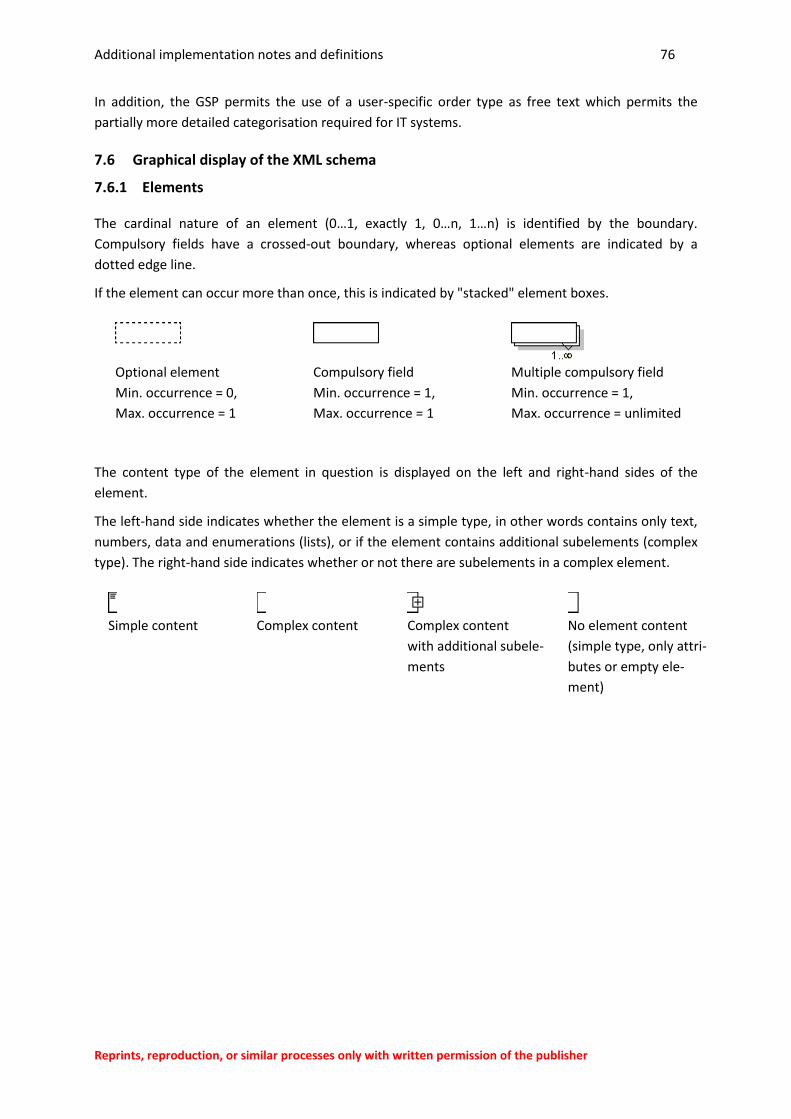
Additional implementation notes and definitions 76
Reprints, reproduction, or similar processes only with written permission of the publisher
In addition, the GSP permits the use of a user-specific order type as free text which permits the
partially more detailed categorisation required for IT systems.
7.6 Graphical display of the XML schema
7.6.1 Elements
The cardinal nature of an element (0…1, exactly 1, 0…n, 1…n) is identified by the boundary.
Compulsory fields have a crossed-out boundary, whereas optional elements are indicated by a
dotted edge line.
If the element can occur more than once, this is indicated by "stacked" element boxes.
Optional element
Min. occurrence = 0,
Max. occurrence = 1
Compulsory field
Min. occurrence = 1,
Max. occurrence = 1
Multiple compulsory field
Min. occurrence = 1,
Max. occurrence = unlimited
The content type of the element in question is displayed on the left and right-hand sides of the
element.
The left-hand side indicates whether the element is a simple type, in other words contains only text,
numbers, data and enumerations (lists), or if the element contains additional subelements (complex
type). The right-hand side indicates whether or not there are subelements in a complex element.
Simple content
Complex content
Complex content
with additional subele-
ments
No element content
(simple type, only attri-
butes or empty ele-
ment)
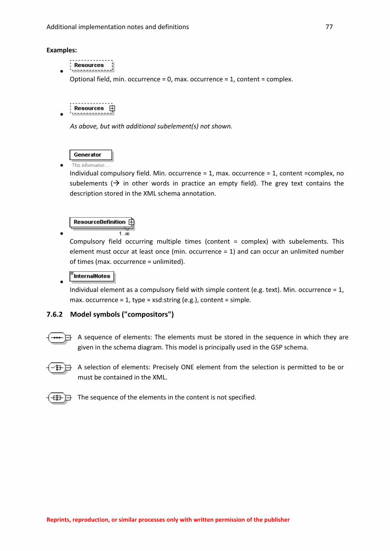
Additional implementation notes and definitions 77
Reprints, reproduction, or similar processes only with written permission of the publisher
Examples:
Optional field, min. occurrence = 0, max. occurrence = 1, content = complex.
As above, but with additional subelement(s) not shown.
Individual compulsory field. Min. occurrence = 1, max. occurrence = 1, content =complex, no
subelements ( in other words in practice an empty field). The grey text contains the
description stored in the XML schema annotation.
Compulsory field occurring multiple times (content = complex) with subelements. This
element must occur at least once (min. occurrence = 1) and can occur an unlimited number
of times (max. occurrence = unlimited).
Individual element as a compulsory field with simple content (e.g. text). Min. occurrence = 1,
max. occurrence = 1, type = xsd:string (e.g.), content = simple.
7.6.2 Model symbols ("compositors")
A sequence of elements: The elements must be stored in the sequence in which they are
given in the schema diagram. This model is principally used in the GSP schema.
A selection of elements: Precisely ONE element from the selection is permitted to be or
must be contained in the XML.
The sequence of the elements in the content is not specified.
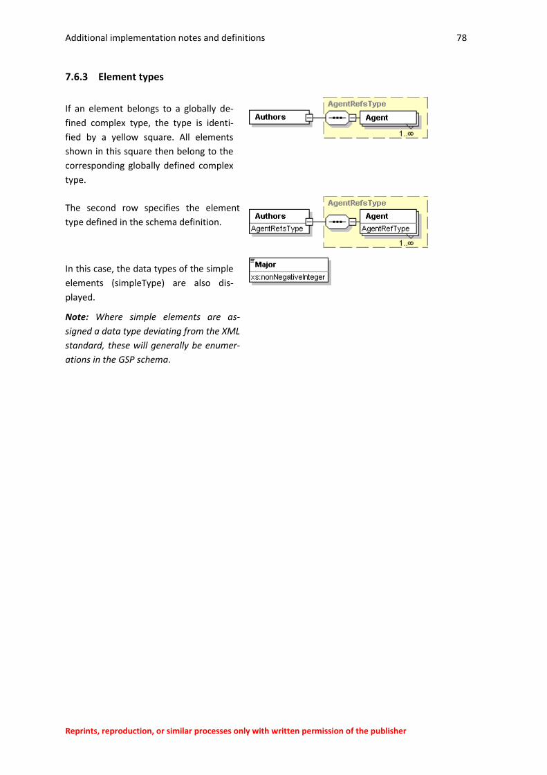
Additional implementation notes and definitions 78
Reprints, reproduction, or similar processes only with written permission of the publisher
7.6.3 Element types
If an element belongs to a globally de-
fined complex type, the type is identi-
fied by a yellow square. All elements
shown in this square then belong to the
corresponding globally defined complex
type.
The second row specifies the element
type defined in the schema definition.
In this case, the data types of the simple
elements (simpleType) are also dis-
played.
Note: Where simple elements are as-
signed a data type deviating from the XML
standard, these will generally be enumer-
ations in the GSP schema.
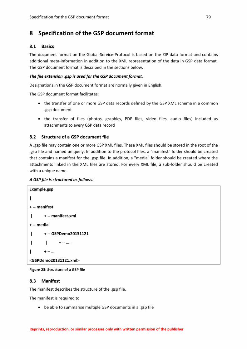
Specification for the GSP document format 79
Reprints, reproduction, or similar processes only with written permission of the publisher
8 Specification of the GSP document format
8.1 Basics
The document format on the Global-Service-Protocol is based on the ZIP data format and contains
additional meta-information in addition to the XML representation of the data in GSP data format.
The GSP document format is described in the sections below.
The file extension .gsp is used for the GSP document format.
Designations in the GSP document format are normally given in English.
The GSP document format facilitates:
the transfer of one or more GSP data records defined by the GSP XML schema in a common
.gsp document
the transfer of files (photos, graphics, PDF files, video files, audio files) included as
attachments to every GSP data record
8.2 Structure of a GSP document file
A .gsp file may contain one or more GSP XML files. These XML files should be stored in the root of the
.gsp file and named uniquely. In addition to the protocol files, a "manifest" folder should be created
that contains a manifest for the .gsp file. In addition, a "media" folder should be created where the
attachments linked in the XML files are stored. For every XML file, a sub-folder should be created
with a unique name.
A GSP file is structured as follows:
Example.gsp
|
+ -- manifest
| + -- manifest.xml
+ -- media
| + -- GSPDemo20131121
| | + -- ….
| + -- …
<GSPDemo20131121.xml>
Figure 23: Structure of a GSP file
8.3 Manifest
The manifest describes the structure of the .gsp file.
The manifest is required to
be able to summarise multiple GSP documents in a .gsp file
Specification for the GSP document format 80
Reprints, reproduction, or similar processes only with written permission of the publisher
because certain meta-information on the documents is not to be included in the actual GSP
XML.
The manifest should be defined in line with the following XML schema:
<?xml version="1.0" encoding="UTF-8"?>
<xs:schema xmlns:xs="http://www.w3.org/2001/XMLSchema"
attributeFormDefault="unqualified" elementFormDefault="qualified">
<!-- Manifest root element -->
<xs:element name="gspManifest">
<xs:complexType>
<xs:sequence>
<xs:element name="documents" type="Documents"/>
</xs:sequence>
</xs:complexType>
</xs:element>
<!-- A List of Global Service Protocol documents within in .gsp File -->
<xs:complexType name="Documents">
<xs:sequence>
<xs:element name="document" type="Document" minOccurs="1"
maxOccurs="unbounded" />
</xs:sequence>
</xs:complexType>
<!-- A Global Service Protocol document -->
<xs:complexType name="Document">
<xs:sequence>
<xs:element name="mediaFile" type="MediaFile" minOccurs="0
" maxOccurs="unbounded" />
</xs:sequence>
<xs:attribute name="name" type="xs:string" use="required" />
<!-- Empty path is valid if no attachments are defined -->
<xs:attribute name="path" type="xs:string" use="optional"/>
</xs:complexType>
<!-- A digital attachment / media file -->
<xs:complexType name="MediaFile">
<xs:attribute name="name" type="xs:string" use="required"/>
<xs:attribute name="mimeType" type="xs:string" use="required"/>
</xs:complexType>
</xs:schema>
The manifest file can be created when the .gsp file is created by all file entries being evaluated.
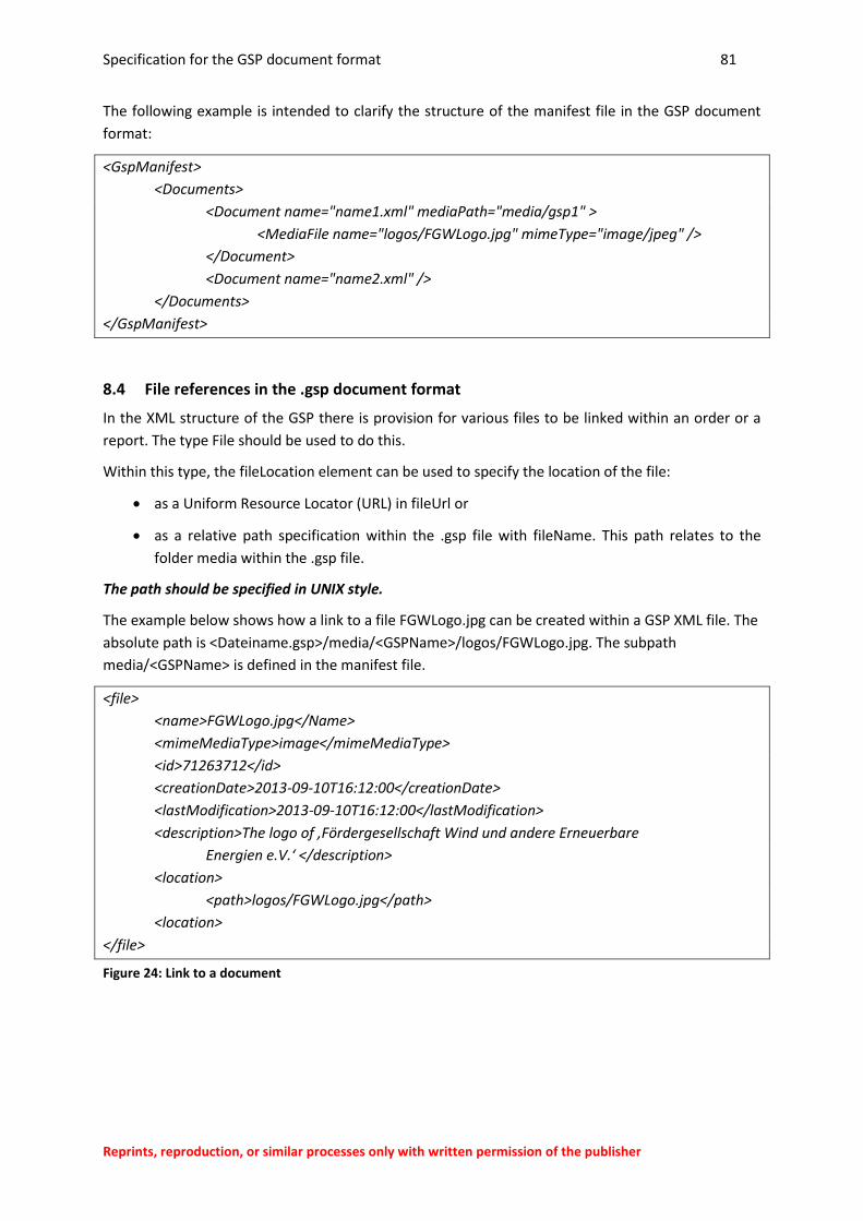
Specification for the GSP document format 81
Reprints, reproduction, or similar processes only with written permission of the publisher
The following example is intended to clarify the structure of the manifest file in the GSP document
format:
<GspManifest>
<Documents>
<Document name="name1.xml" mediaPath="media/gsp1" >
<MediaFile name="logos/FGWLogo.jpg" mimeType="image/jpeg" />
</Document>
<Document name="name2.xml" />
</Documents>
</GspManifest>
8.4 File references in the .gsp document format
In the XML structure of the GSP there is provision for various files to be linked within an order or a
report. The type File should be used to do this.
Within this type, the fileLocation element can be used to specify the location of the file:
as a Uniform Resource Locator (URL) in fileUrl or
as a relative path specification within the .gsp file with fileName. This path relates to the
folder media within the .gsp file.
The path should be specified in UNIX style.
The example below shows how a link to a file FGWLogo.jpg can be created within a GSP XML file. The
absolute path is <Dateiname.gsp>/media/<GSPName>/logos/FGWLogo.jpg. The subpath
media/<GSPName> is defined in the manifest file.
<file>
<name>FGWLogo.jpg</Name>
<mimeMediaType>image</mimeMediaType>
<id>71263712</id>
<creationDate>2013-09-10T16:12:00</creationDate>
<lastModification>2013-09-10T16:12:00</lastModification>
<description>The logo of ‚Fördergesellschaft Wind und andere Erneuerbare
Energien e.V.‘ </description>
<location>
<path>logos/FGWLogo.jpg</path>
<location>
</file>
Figure 24: Link to a document
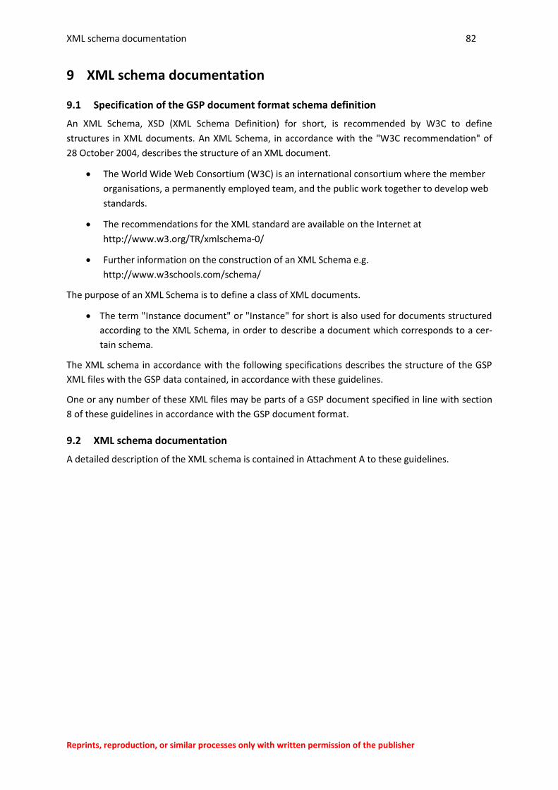
XML schema documentation 82
Reprints, reproduction, or similar processes only with written permission of the publisher
9 XML schema documentation
9.1 Specification of the GSP document format schema definition
An XML Schema, XSD (XML Schema Definition) for short, is recommended by W3C to define
structures in XML documents. An XML Schema, in accordance with the "W3C recommendation" of
28 October 2004, describes the structure of an XML document.
The World Wide Web Consortium (W3C) is an international consortium where the member
organisations, a permanently employed team, and the public work together to develop web
standards.
The recommendations for the XML standard are available on the Internet at
http://www.w3.org/TR/xmlschema-0/
Further information on the construction of an XML Schema e.g.
http://www.w3schools.com/schema/
The purpose of an XML Schema is to define a class of XML documents.
The term "Instance document" or "Instance" for short is also used for documents structured
according to the XML Schema, in order to describe a document which corresponds to a cer-
tain schema.
The XML schema in accordance with the following specifications describes the structure of the GSP
XML files with the GSP data contained, in accordance with these guidelines.
One or any number of these XML files may be parts of a GSP document specified in line with section
8 of these guidelines in accordance with the GSP document format.
9.2 XML schema documentation
A detailed description of the XML schema is contained in Attachment A to these guidelines.
Related Documents