Technical Evaluation Report TER 1703-04 Starborn® Structural H19 and F23 Screws: Cladding Attachment through Foam Sheathing Starborn Industries, Inc. Product: Starborn Structural H19 Screws and Starborn Structural F23 Screws Issue Date: October 3, 2019 Revision Date: October 3, 2019 Subject to Renewal: January 1, 2021

Welcome message from author
This document is posted to help you gain knowledge. Please leave a comment to let me know what you think about it! Share it to your friends and learn new things together.
Transcript
Technical Evaluation Report
TER 1703-04
Starborn® Structural H19 and F23
Screws: Cladding Attachment through
Foam Sheathing
Starborn Industries, Inc.
Product:
Starborn Structural H19 Screws
and Starborn Structural F23
Screws
Issue Date:
October 3, 2019
Revision Date:
October 3, 2019
Subject to Renewal:
January 1, 2021
TER 1703-04: STARBORN® STRUCTURAL H19 AND F23 SCREWS: CLADDING ATTACHMENT THROUGH FOAM
SHEATHING
© 2019 DRJ ENGINEERING, LLC PAGE 2 OF 14
COMPANY
INFORMATION:
Starborn Industries, Inc.
45 Mayfield Ave Edison, NJ 08837-3820
P: 800-596-7747
F: 732-381-9830
starbornindustries.com
DIVISION: 06 00 00 - WOOD, PLASTICS AND COMPOSITES
SECTION: 06 05 23 - Wood, Plastic, and Composite Fastenings
1 PRODUCT EVALUATED1
1.1 Starborn Structural H19 Screws
1.2 Starborn Structural F23 Screws
2 APPLICABLE CODES AND STANDARDS2,3
2.1 Codes
2.1.1 IBC—12, 15, 18: International Building Code®
2.1.2 IRC—12, 15, 18: International Residential Code®
2.2 Standards and Referenced Documents
2.2.1 ANSI/AWC NDS: National Design Specification (NDS) for Wood Construction
2.2.2 ASCE/SEI 7: Minimum Design Loads and Associated Criteria for Buildings and Other Structures
2.2.3 ASTM A153: Standard Specification for Zinc Coating (Hot-Dip) on Iron and Steel Hardware
2.2.4 ASTM A510: Standard Specification for General Requirements for Wire Rods and Coarse Round Wire,
Carbon Steel, and Alloy Steel
2.2.5 ASTM D1761: Standard Test Methods for Mechanical Fasteners in Wood
1 Building codes require data from valid research reports be obtained from approved sources. An approved agency, which is an approved source, is defined as “an established and
recognized agency that is regularly engaged in…furnishing product certification where such agency has been approved…” Being approved, defined as “acceptable to the building official,” is accomplished via accreditation using ISO/IEC 17065 evaluation procedures meeting code requirements of independence, adequate equipment, and experienced personnel. DrJ is an ISO/IEC 17065 ANSI-Accredited Product Certification Body – Accreditation #1131.
Through ANSI accreditation, DrJ certification can be used to obtain product approval in any country that is an IAF MLA Signatory and covered by an IAF MLA Evaluation per the Purpose of the MLA – “certified once, accepted everywhere.” Manufacturers can go to jurisdictions in any IAF MLA Signatory Country and have their products readily approved by authorities having jurisdiction using DrJ’s ANSI accreditation.
For more information on any of these topics or our mission, product evaluation policies, product approval process, and engineering law, see drjcertification.org.
2 Unless otherwise noted, all references in this TER are from the 2018 version of the codes and the standards referenced therein (e.g., ASCE 7, NDS, ASTM). This material, design, or
method of construction also complies with the 2000-2015 versions of the referenced codes and the standards referenced therein. As required by code, where this TER is not approved, the building official shall respond in writing stating the reasons this TER was not approved. For any variations in state and local codes, see Section 8.
3 All terms defined in the applicable building codes are italicized.
TER 1703-04: STARBORN® STRUCTURAL H19 AND F23 SCREWS: CLADDING ATTACHMENT THROUGH FOAM
SHEATHING
© 2019 DRJ ENGINEERING, LLC PAGE 3 OF 14
2.2.6 ASTM F1575: Standard Test Method for Determining Bending Yield Moment of Nails
2.2.7 AWC TR 12: General Dowel Equations for Calculating Lateral Connection Values
3 PERFORMANCE EVALUATION
3.1 Starborn Structural H19 and F23 screws were evaluated for their ability to support the gravity and transverse
loads in the application of cladding attachment over foam sheathing in wood-frame construction.
3.2 Use of fasteners in locations exposed to saltwater or saltwater spray is outside the scope of this evaluation report.
3.3 Any code compliance issues not specifically addressed in this section are outside the scope of this TER.
3.4 Any engineering evaluation conducted for this TER was performed on the dates provided in this TER and within
DrJ’s professional scope of work.
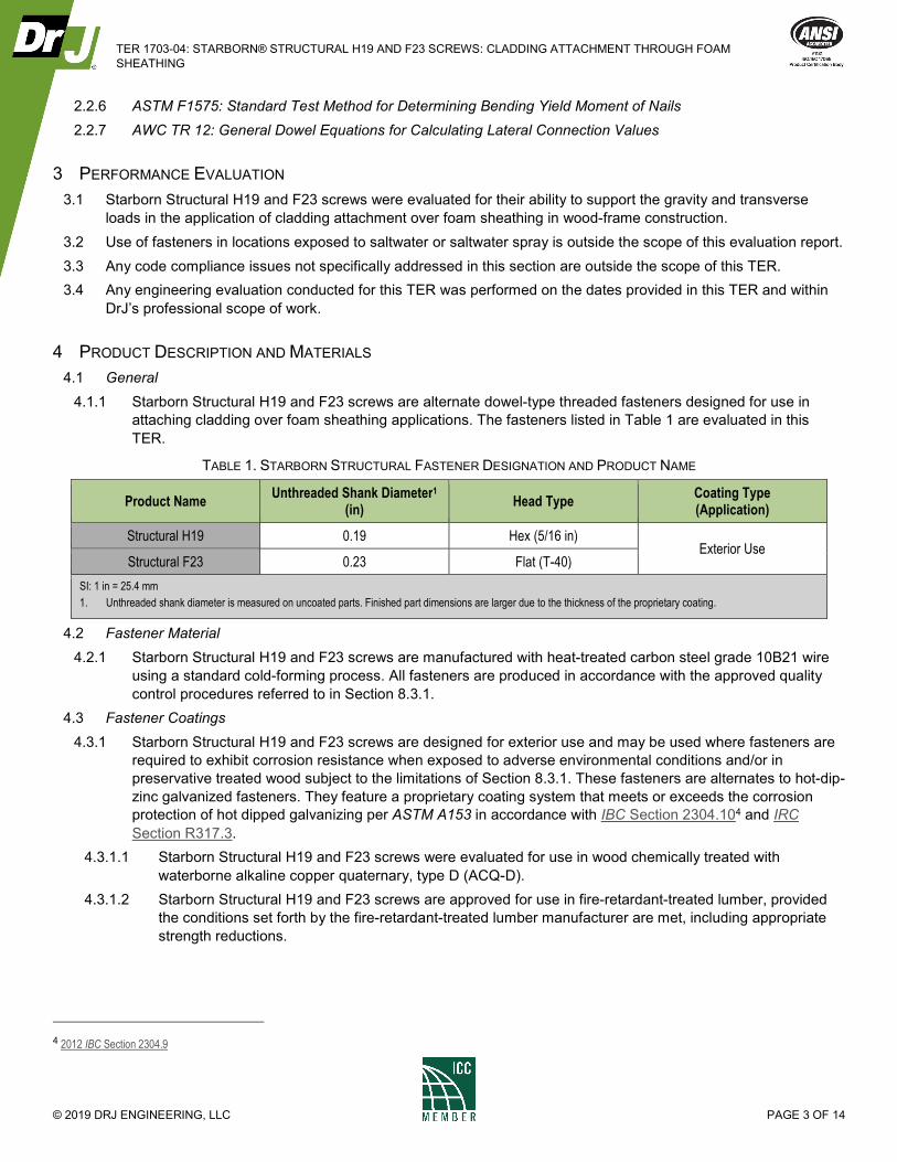
4 PRODUCT DESCRIPTION AND MATERIALS
4.1 General
4.1.1 Starborn Structural H19 and F23 screws are alternate dowel-type threaded fasteners designed for use in
attaching cladding over foam sheathing applications. The fasteners listed in Table 1 are evaluated in this
TER.
TABLE 1. STARBORN STRUCTURAL FASTENER DESIGNATION AND PRODUCT NAME
Product Name Unthreaded Shank Diameter1
(in) Head Type
Coating Type (Application)
Structural H19 0.19 Hex (5/16 in) Exterior Use
Structural F23 0.23 Flat (T-40)
SI: 1 in = 25.4 mm
1. Unthreaded shank diameter is measured on uncoated parts. Finished part dimensions are larger due to the thickness of the proprietary coating.
4.2 Fastener Material
4.2.1 Starborn Structural H19 and F23 screws are manufactured with heat-treated carbon steel grade 10B21 wire
using a standard cold-forming process. All fasteners are produced in accordance with the approved quality
control procedures referred to in Section 8.3.1.
4.3 Fastener Coatings
4.3.1 Starborn Structural H19 and F23 screws are designed for exterior use and may be used where fasteners are
required to exhibit corrosion resistance when exposed to adverse environmental conditions and/or in
preservative treated wood subject to the limitations of Section 8.3.1. These fasteners are alternates to hot-dip-
zinc galvanized fasteners. They feature a proprietary coating system that meets or exceeds the corrosion
protection of hot dipped galvanizing per ASTM A153 in accordance with IBC Section 2304.104 and IRC
Section R317.3.
4.3.1.1 Starborn Structural H19 and F23 screws were evaluated for use in wood chemically treated with
waterborne alkaline copper quaternary, type D (ACQ-D).
4.3.1.2 Starborn Structural H19 and F23 screws are approved for use in fire-retardant-treated lumber, provided
the conditions set forth by the fire-retardant-treated lumber manufacturer are met, including appropriate
strength reductions.
4 2012 IBC Section 2304.9
TER 1703-04: STARBORN® STRUCTURAL H19 AND F23 SCREWS: CLADDING ATTACHMENT THROUGH FOAM
SHEATHING
© 2019 DRJ ENGINEERING, LLC PAGE 4 OF 14
4.4 Wood Members
4.4.1 Solid sawn wood members connected with Starborn Structural H19 and F23 screws shall consist of lumber
species or species combinations having a specific gravity of 0.42 to 0.55.
4.4.2 Structural composite lumber (e.g., LVL, LSL, PSL, etc.) connected with Starborn Structural H19 and F23
screws shall be recognized in evaluation reports having published equivalent specific gravities for lateral and
withdrawal resistance. Equivalent specific gravities for structural composite lumber may be used in the design
of connections using the specific gravities of the sawn lumber shown in Table 3 and Table 4.
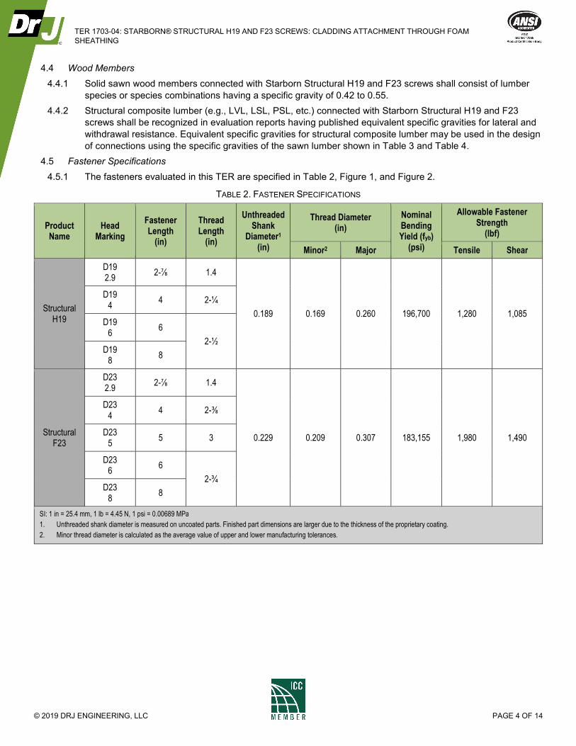
4.5 Fastener Specifications
4.5.1 The fasteners evaluated in this TER are specified in Table 2, Figure 1, and Figure 2.
TABLE 2. FASTENER SPECIFICATIONS
Product Name
Head Marking
Fastener Length
(in)
Thread Length
(in)
Unthreaded Shank
Diameter1 (in)
Thread Diameter (in)
Nominal Bending Yield (fyb)
(psi)
Allowable Fastener Strength
(lbf)
Minor2 Major Tensile Shear
Structural H19
D19 2.9
2-⅞ 1.4
0.189 0.169 0.260 196,700 1,280 1,085
D19 4
4 2-¼
D19 6
6
2-½ D19
8 8
Structural F23
D23 2.9
2-⅞ 1.4
0.229 0.209 0.307 183,155 1,980 1,490
D23 4
4 2-⅜
D23 5
5 3
D23 6
6
2-¾ D23
8 8
SI: 1 in = 25.4 mm, 1 lb = 4.45 N, 1 psi = 0.00689 MPa
1. Unthreaded shank diameter is measured on uncoated parts. Finished part dimensions are larger due to the thickness of the proprietary coating.
2. Minor thread diameter is calculated as the average value of upper and lower manufacturing tolerances.
TER 1703-04: STARBORN® STRUCTURAL H19 AND F23 SCREWS: CLADDING ATTACHMENT THROUGH FOAM
SHEATHING
© 2019 DRJ ENGINEERING, LLC PAGE 5 OF 14
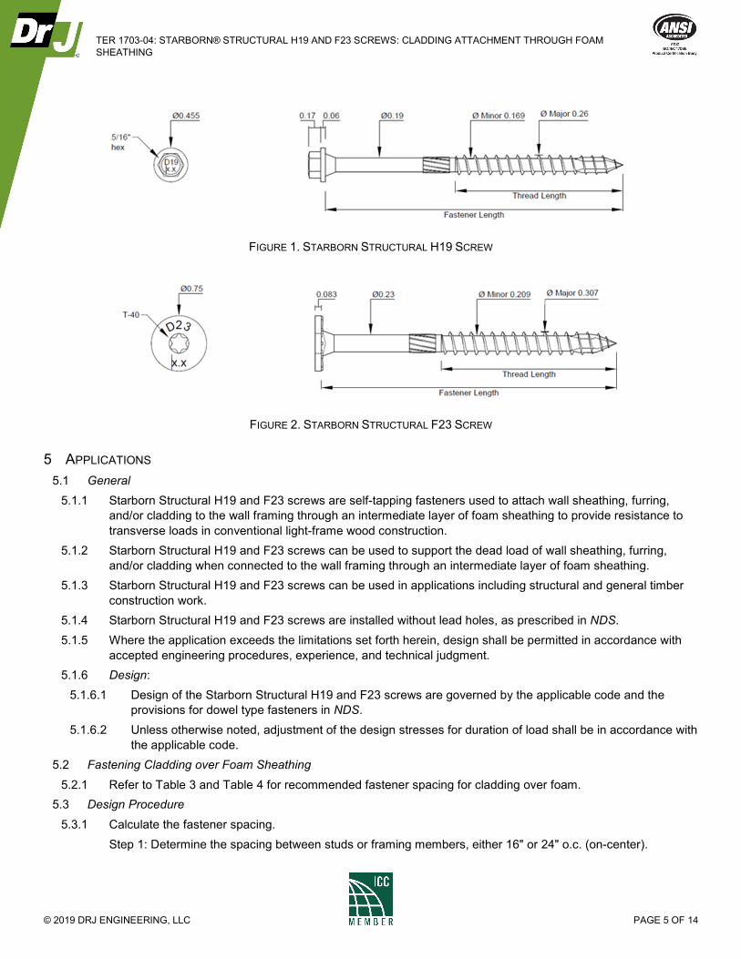
FIGURE 1. STARBORN STRUCTURAL H19 SCREW
FIGURE 2. STARBORN STRUCTURAL F23 SCREW
5 APPLICATIONS
5.1 General
5.1.1 Starborn Structural H19 and F23 screws are self-tapping fasteners used to attach wall sheathing, furring,
and/or cladding to the wall framing through an intermediate layer of foam sheathing to provide resistance to
transverse loads in conventional light-frame wood construction.
5.1.2 Starborn Structural H19 and F23 screws can be used to support the dead load of wall sheathing, furring,
and/or cladding when connected to the wall framing through an intermediate layer of foam sheathing.
5.1.3 Starborn Structural H19 and F23 screws can be used in applications including structural and general timber
construction work.
5.1.4 Starborn Structural H19 and F23 screws are installed without lead holes, as prescribed in NDS.
5.1.5 Where the application exceeds the limitations set forth herein, design shall be permitted in accordance with
accepted engineering procedures, experience, and technical judgment.
5.1.6 Design:
5.1.6.1 Design of the Starborn Structural H19 and F23 screws are governed by the applicable code and the
provisions for dowel type fasteners in NDS.
5.1.6.2 Unless otherwise noted, adjustment of the design stresses for duration of load shall be in accordance with
the applicable code.
5.2 Fastening Cladding over Foam Sheathing
5.2.1 Refer to Table 3 and Table 4 for recommended fastener spacing for cladding over foam.
5.3 Design Procedure
5.3.1 Calculate the fastener spacing.
Step 1: Determine the spacing between studs or framing members, either 16" or 24" o.c. (on-center).
TER 1703-04: STARBORN® STRUCTURAL H19 AND F23 SCREWS: CLADDING ATTACHMENT THROUGH FOAM
SHEATHING
© 2019 DRJ ENGINEERING, LLC PAGE 6 OF 14
Step 2: Calculate the correct thickness of rigid foam, up to 4", needed to obtain the required insulation effect
or R-value.
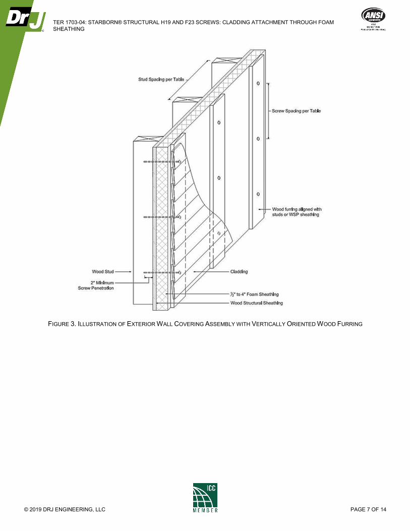
Step 3: Choose the furring or sheathing (substrate) material to which the cladding will be affixed:
1. Minimum ¾" x 3½" wood furring
2. Minimum ⅜" or Wood Structural Panel (WSP) sheathing
Ensure that the substrate allows for cladding connections that are compliant with the cladding
manufacturer’s installation and connection instructions and meet the applicable building code. See Figure
3 for an illustration of the wall assembly.
Step 4: Determine the actual weight for the cladding materials being installed, per square foot, as given by the
cladding manufacturer’s specifications.
Note:
1. Typical cladding weights are 1.3 psf for vinyl siding, 2.5 psf for cement board siding, 11 psf for
Portland cement stucco and 25 psf for adhered masonry veneer; use actual weights for materials
installed.
2. Wood furring may add up to 1 psf of additional weight; wood sheathing may add up to 1.5 psf,
depending on thickness.
Step 5: Using these four values together, find the proper fastening pattern of between 6" and 24" o.c. using
Table 3 for Structural H19 and Table 4 for Structural F23 screws.
TER 1703-04: STARBORN® STRUCTURAL H19 AND F23 SCREWS: CLADDING ATTACHMENT THROUGH FOAM
SHEATHING
© 2019 DRJ ENGINEERING, LLC PAGE 7 OF 14
FIGURE 3. ILLUSTRATION OF EXTERIOR WALL COVERING ASSEMBLY WITH VERTICALLY ORIENTED WOOD FURRING
TER 1703-04: STARBORN® STRUCTURAL H19 AND F23 SCREWS: CLADDING ATTACHMENT THROUGH FOAM
SHEATHING
© 2019 DRJ ENGINEERING, LLC PAGE 8 OF 14
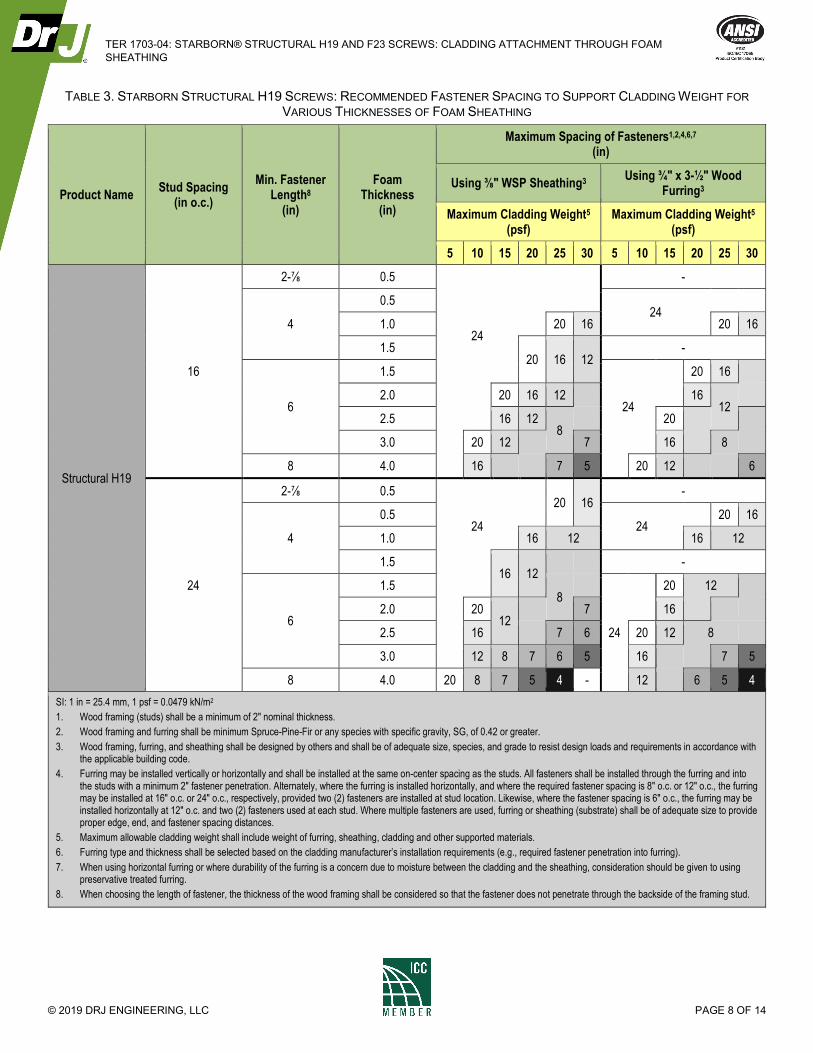
TABLE 3. STARBORN STRUCTURAL H19 SCREWS: RECOMMENDED FASTENER SPACING TO SUPPORT CLADDING WEIGHT FOR
VARIOUS THICKNESSES OF FOAM SHEATHING
Product Name Stud Spacing
(in o.c.)
Min. Fastener Length8
(in)
Foam Thickness
(in)
Maximum Spacing of Fasteners1,2,4,6,7 (in)
Using ⅜" WSP Sheathing3 Using ¾" x 3-½" Wood
Furring3
Maximum Cladding Weight5 (psf)
Maximum Cladding Weight5 (psf)
5 10 15 20 25 30 5 10 15 20 25 30
Structural H19
16
2-⅞ 0.5 -
4
0.5 24
1.0 24
20 16 20 16
1.5 20 16 12
-
6
1.5
24
20 16
2.0 20 16 12 16 12
2.5 16 12 8
20
3.0 20 12 7 16 8
8 4.0 16 7 5 20 12 6
24
2-⅞ 0.5 20 16
-
4
0.5 24
24
20 16
1.0 16 12 16 12
1.5 16 12
-
6
1.5 8
24
20 12
2.0 20 12
7 16
2.5 16 7 6 20 12 8
3.0 12 8 7 6 5 16 7 5
8 4.0 20 8 7 5 4 - 12 6 5 4
SI: 1 in = 25.4 mm, 1 psf = 0.0479 kN/m2
1. Wood framing (studs) shall be a minimum of 2" nominal thickness.
2. Wood framing and furring shall be minimum Spruce-Pine-Fir or any species with specific gravity, SG, of 0.42 or greater.
3. Wood framing, furring, and sheathing shall be designed by others and shall be of adequate size, species, and grade to resist design loads and requirements in accordance with the applicable building code.
4. Furring may be installed vertically or horizontally and shall be installed at the same on-center spacing as the studs. All fasteners shall be installed through the furring and into the studs with a minimum 2" fastener penetration. Alternately, where the furring is installed horizontally, and where the required fastener spacing is 8" o.c. or 12" o.c., the furring may be installed at 16" o.c. or 24" o.c., respectively, provided two (2) fasteners are installed at stud location. Likewise, where the fastener spacing is 6" o.c., the furring may be installed horizontally at 12" o.c. and two (2) fasteners used at each stud. Where multiple fasteners are used, furring or sheathing (substrate) shall be of adequate size to provide proper edge, end, and fastener spacing distances.
5. Maximum allowable cladding weight shall include weight of furring, sheathing, cladding and other supported materials.
6. Furring type and thickness shall be selected based on the cladding manufacturer’s installation requirements (e.g., required fastener penetration into furring).
7. When using horizontal furring or where durability of the furring is a concern due to moisture between the cladding and the sheathing, consideration should be given to using preservative treated furring.
8. When choosing the length of fastener, the thickness of the wood framing shall be considered so that the fastener does not penetrate through the backside of the framing stud.
TER 1703-04: STARBORN® STRUCTURAL H19 AND F23 SCREWS: CLADDING ATTACHMENT THROUGH FOAM
SHEATHING
© 2019 DRJ ENGINEERING, LLC PAGE 9 OF 14
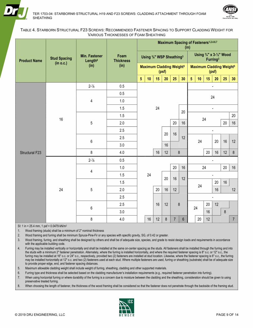
TABLE 4. STARBORN STRUCTURAL F23 SCREWS: RECOMMENDED FASTENER SPACING TO SUPPORT CLADDING WEIGHT FOR
VARIOUS THICKNESSES OF FOAM SHEATHING
Product Name Stud Spacing
(in o.c.)
Min. Fastener Length8
(in)
Foam Thickness
(in)
Maximum Spacing of Fasteners1,2,4,6,7 (in)
Using ⅜" WSP Sheathing3 Using ¾" x 3-½" Wood
Furring3
Maximum Cladding Weight5 (psf)
Maximum Cladding Weight5 (psf)
5 10 15 20 25 30 5 10 15 20 25 30
Structural F23
16
2-⅞ 0.5 -
4
0.5 24
1.0
1.5 24 20
-
5
1.5 24
20
2.0 20 16 20 16
2.5 20 16
12
-
6 2.5
24 20 16 12 3.0 16
8 4.0 16 12 8 20 16 12 8
24
2-⅞ 0.5 -
4 1.0 20 16 24 20 16
1.5 24 20 16 12
-
5
1.5 24
20 16
2.0 20 16 12 16 12
2.5
16 12 8
-
6 2.5
24 20 12
3.0 16 8
8 4.0 16 12 8 7 6 20 12 7
SI: 1 in = 25.4 mm, 1 psf = 0.0479 kN/m2
1. Wood framing (studs) shall be a minimum of 2" nominal thickness
2. Wood framing and furring shall be minimum Spruce-Pine-Fir or any species with specific gravity, SG, of 0.42 or greater.
3. Wood framing, furring, and sheathing shall be designed by others and shall be of adequate size, species, and grade to resist design loads and requirements in accordance with the applicable building code.
4. Furring may be installed vertically or horizontally and shall be installed at the same on-center spacing as the studs. All fasteners shall be installed through the furring and into the studs with a minimum 2" fastener penetration. Alternately, where the furring is installed horizontally, and where the required fastener spacing is 8" o.c. or 12" o.c., the furring may be installed at 16" o.c. or 24" o.c., respectively, provided two (2) fasteners are installed at stud location. Likewise, where the fastener spacing is 6" o.c., the furring may be installed horizontally at 12" o.c. and two (2) fasteners used at each stud. Where multiple fasteners are used, furring or sheathing (substrate) shall be of adequate size to provide proper edge, end, and fastener spacing distances.
5. Maximum allowable cladding weight shall include weight of furring, sheathing, cladding and other supported materials.
6. Furring type and thickness shall be selected based on the cladding manufacturer’s installation requirements (e.g., required fastener penetration into furring).
7. When using horizontal furring or where durability of the furring is a concern due to moisture between the cladding and the sheathing, consideration should be given to using preservative treated furring.
8. When choosing the length of fastener, the thickness of the wood framing shall be considered so that the fastener does not penetrate through the backside of the framing stud.
TER 1703-04: STARBORN® STRUCTURAL H19 AND F23 SCREWS: CLADDING ATTACHMENT THROUGH FOAM
SHEATHING
© 2019 DRJ ENGINEERING, LLC PAGE 10 OF 14
6 INSTALLATION
6.1 Installation shall comply with the manufacturer’s installation instructions and this TER. In the event of a conflict
between the manufacturer’s installation instructions and this TER, the more restrictive shall govern.
6.2 Installation Procedure
6.2.1 Starborn Structural H19 and F23 screws shall be installed using a high-torque low speed drill in accordance
with the manufacturer’s installation instructions, applicable code, the approved construction documents, this
TER, NDS, and standard framing practice as applied to wood fasteners.
6.2.2 The fasteners must be installed using a 5/16" hex or Torx® T-40 star drive bit. Pre-drilling of pilot holes is not
required but may be used where lumber is prone to splitting.
6.2.3 Fasteners should be aligned perpendicular to the face of the wall stud so that the point engages the center of
the wall stud and at a minimum distance of 3" from the end of the stud or furring material.
6.2.4 Fasteners must be installed in a manner to avoid over-driving yet snug enough to remove any gaps between
the layers of materials being fastened.
6.2.5 For applications outside the scope of this TER, an engineered design is required.
All fastener spacing, edge distance, and end distance shall be as determined in Table 5,
TER 1703-04: STARBORN® STRUCTURAL H19 AND F23 SCREWS: CLADDING ATTACHMENT THROUGH FOAM
SHEATHING
© 2019 DRJ ENGINEERING, LLC PAGE 11 OF 14
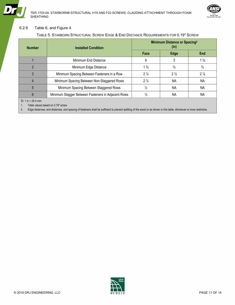
6.2.6 Table 6, and Figure 4.
TABLE 5. STARBORN STRUCTURAL SCREW EDGE & END DISTANCE REQUIREMENTS FOR 0.19" SCREW
Number Installed Condition
Minimum Distance or Spacing2 (in)
Face Edge End
1 Minimum End Distance 6 3 1 ¾
2 Minimum Edge Distance 1 ¾ ¾ ¾
3 Minimum Spacing Between Fasteners in a Row 2 ⅞ 2 ⅞ 2 ⅞
4 Minimum Spacing Between Non-Staggered Rows 2 ⅞ NA NA
5 Minimum Spacing Between Staggered Rows ½ NA NA
6 Minimum Stagger Between Fasteners in Adjacent Rows ½ NA NA
SI: 1 in = 25.4 mm
1. Table values based on 0.19" screw
2. Edge distances, end distances, and spacing of fasteners shall be sufficient to prevent splitting of the wood or as shown in this table, whichever is more restrictive.
TER 1703-04: STARBORN® STRUCTURAL H19 AND F23 SCREWS: CLADDING ATTACHMENT THROUGH FOAM
SHEATHING
© 2019 DRJ ENGINEERING, LLC PAGE 12 OF 14
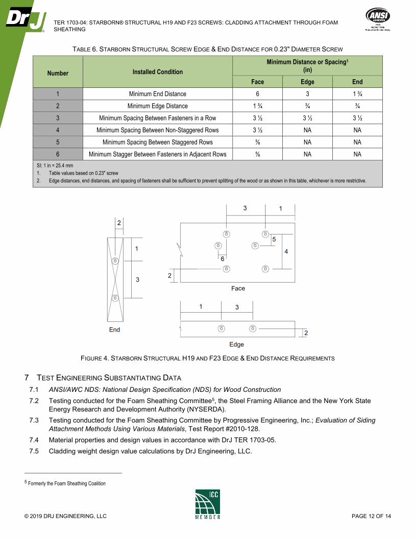
TABLE 6. STARBORN STRUCTURAL SCREW EDGE & END DISTANCE FOR 0.23" DIAMETER SCREW
Number Installed Condition
Minimum Distance or Spacing1 (in)
Face Edge End
1 Minimum End Distance 6 3 1 ¾
2 Minimum Edge Distance 1 ¾ ¾ ¾
3 Minimum Spacing Between Fasteners in a Row 3 ½ 3 ½ 3 ½
4 Minimum Spacing Between Non-Staggered Rows 3 ½ NA NA
5 Minimum Spacing Between Staggered Rows ⅝ NA NA
6 Minimum Stagger Between Fasteners in Adjacent Rows ⅝ NA NA
SI: 1 in = 25.4 mm
1. Table values based on 0.23" screw
2. Edge distances, end distances, and spacing of fasteners shall be sufficient to prevent splitting of the wood or as shown in this table, whichever is more restrictive.
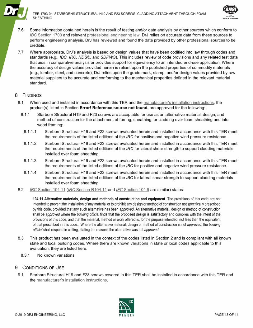
FIGURE 4. STARBORN STRUCTURAL H19 AND F23 EDGE & END DISTANCE REQUIREMENTS
7 TEST ENGINEERING SUBSTANTIATING DATA
7.1 ANSI/AWC NDS: National Design Specification (NDS) for Wood Construction
7.2 Testing conducted for the Foam Sheathing Committee5, the Steel Framing Alliance and the New York State
Energy Research and Development Authority (NYSERDA).
7.3 Testing conducted for the Foam Sheathing Committee by Progressive Engineering, Inc.; Evaluation of Siding
Attachment Methods Using Various Materials, Test Report #2010-128.
7.4 Material properties and design values in accordance with DrJ TER 1703-05.
7.5 Cladding weight design value calculations by DrJ Engineering, LLC.
5 Formerly the Foam Sheathing Coalition
TER 1703-04: STARBORN® STRUCTURAL H19 AND F23 SCREWS: CLADDING ATTACHMENT THROUGH FOAM
SHEATHING
© 2019 DRJ ENGINEERING, LLC PAGE 13 OF 14
7.6 Some information contained herein is the result of testing and/or data analysis by other sources which conform to
IBC Section 1703 and relevant professional engineering law. DrJ relies on accurate data from these sources to
perform engineering analysis. DrJ has reviewed and found the data provided by other professional sources to be
credible.
7.7 Where appropriate, DrJ’s analysis is based on design values that have been codified into law through codes and
standards (e.g., IBC, IRC, NDS®, and SDPWS). This includes review of code provisions and any related test data
that aids in comparative analysis or provides support for equivalency to an intended end-use application. Where
the accuracy of design values provided herein is reliant upon the published properties of commodity materials
(e.g., lumber, steel, and concrete), DrJ relies upon the grade mark, stamp, and/or design values provided by raw
material suppliers to be accurate and conforming to the mechanical properties defined in the relevant material
standard.
8 FINDINGS
8.1 When used and installed in accordance with this TER and the manufacturer’s installation instructions, the
product(s) listed in Section Error! Reference source not found. are approved for the following:
8.1.1 Starborn Structural H19 and F23 screws are acceptable for use as an alternative material, design, and
method of construction for the attachment of furring, sheathing, or cladding over foam sheathing and into
wood framing:
8.1.1.1 Starborn Structural H19 and F23 screws evaluated herein and installed in accordance with this TER meet
the requirements of the listed editions of the IRC for positive and negative wind pressure resistance.
8.1.1.2 Starborn Structural H19 and F23 screws evaluated herein and installed in accordance with this TER meet
the requirements of the listed editions of the IRC for lateral shear strength to support cladding materials
installed over foam sheathing.
8.1.1.3 Starborn Structural H19 and F23 screws evaluated herein and installed in accordance with this TER meet
the requirements of the listed editions of the IBC for positive and negative wind pressure resistance.
8.1.1.4 Starborn Structural H19 and F23 screws evaluated herein and installed in accordance with this TER meet
the requirements of the listed editions of the IBC for lateral shear strength to support cladding materials
installed over foam sheathing.
8.2 IBC Section 104.11 (IRC Section R104.11 and IFC Section 104.9 are similar) states:
104.11 Alternative materials, design and methods of construction and equipment. The provisions of this code are not
intended to prevent the installation of any material or to prohibit any design or method of construction not specifically prescribed
by this code, provided that any such alternative has been approved. An alternative material, design or method of construction
shall be approved where the building official finds that the proposed design is satisfactory and complies with the intent of the
provisions of this code, and that the material, method or work offered is, for the purpose intended, not less than the equivalent
of that prescribed in this code…Where the alternative material, design or method of construction is not approved, the building
official shall respond in writing, stating the reasons the alternative was not approved.
8.3 This product has been evaluated in the context of the codes listed in Section 2 and is compliant with all known
state and local building codes. Where there are known variations in state or local codes applicable to this
evaluation, they are listed here.
8.3.1 No known variations
9 CONDITIONS OF USE
9.1 Starborn Structural H19 and F23 screws covered in this TER shall be installed in accordance with this TER and
the manufacturer’s installation instructions.
TER 1703-04: STARBORN® STRUCTURAL H19 AND F23 SCREWS: CLADDING ATTACHMENT THROUGH FOAM
SHEATHING
© 2019 DRJ ENGINEERING, LLC PAGE 14 OF 14
9.2 For conditions not covered in this TER, connections shall be designed in accordance with generally accepted
engineering practice. When the capacity of a connection is controlled by fastener metal strength rather than wood
strength, the metal strength must not be multiplied by the adjustment factors specified in the NDS.
9.3 Use of fasteners in locations exposed to saltwater or saltwater spray is outside the scope of this evaluation report.
9.4 Starborn Structural H19 and F23 screws are produced by Starborn Industries, Inc. at its facilities located in
Edison, NJ.
9.5 Starborn Structural H19 and F23 screws are produced under a quality control program subject to periodic
inspections performed by an approved agency in accordance with IBC Section 1703.5.2.
9.6 Install fasteners prior to utility installations in exterior walls to avoid accidental penetration of utilities (e.g.
electrical wiring, plumbing, etc.).
9.7 Foam sheathing shall be minimum Type II (expanded polystyrene) or Type X (extruded polystyrene) per ASTM
C578 or Type 1 (polyiso) per ASTM C1289.
9.7.1 Types with greater compressive strength are acceptable.
9.8 Ensure furring or sheathing material provides adequate substrate and thickness for the application of the siding
fastener per the code requirements for siding application and the siding manufacturer’s installation instructions.
9.8.1 For example, if the siding manufacturer requires the fastener for the siding to penetrate more than ¾" into the
furring, a 1" x 4" furring strip (actual dimension of ¾" x 3 ½") would not be adequate, and a thicker furring
strip, such as a 2" x 4", would be required.
9.9 Where required by the building official, also known as the authority having jurisdiction (AHJ) in which the project is
to be constructed, this TER and the installation instructions shall be submitted at the time of permit application.
9.10 Any generally accepted engineering calculations needed to show compliance with this TER shall be submitted to
the AHJ for review and approval.
9.11 Design loads shall be determined in accordance with the building code adopted by the jurisdiction in which the
project is to be constructed and/or by the Building Designer (e.g., owner or registered design professional).
9.12 At a minimum, this product shall be installed per Section 0 of this TER.
9.13 This product is manufactured under a third-party quality control program in accordance with IBC Section 104.4
and 110.4 and IRC Section R104.4 and R109.2.
9.14 The actual design, suitability, and use of this TER, for any particular building, is the responsibility of the owner or
the owner's authorized agent. Therefore, the TER shall be reviewed for code compliance by the building official
for acceptance.
9.15 The use of this TER is dependent on the manufacturer’s in-plant QC, the ISO/IEC 17020 third-party quality
assurance program and procedures, proper installation per the manufacturer’s instructions, the building official’s
inspection, and any other code requirements that may apply to demonstrate and verify compliance with the
applicable building code.
10 IDENTIFICATION
10.1 The product(s) listed in Section 1.1 are identified by a label on the board or packaging material bearing the
manufacturer’s name, product name, TER number, and other information to confirm code compliance.
10.2 Individual fasteners are marked with a head stamp indicating fastener diameter and length as shown in Table 2.
10.3 Additional technical information can be found at starbornindustries.com.
11 REVIEW SCHEDULE
11.1 This TER is subject to periodic review and revision. For the most recent version of this TER, visit
drjcertification.org.
11.2 For information on the current status of this TER, contact DrJ Certification.
Related Documents