Tools of Technical Drawing 1

Technical drawing (by: Sherief Elmetwali)
Jul 15, 2015
Welcome message from author
This document is posted to help you gain knowledge. Please leave a comment to let me know what you think about it! Share it to your friends and learn new things together.
Transcript

Tools of Technical Drawing
1

Definition of Technical Drawing
Technical drawing describes the process of producing a
pictorial representation of a designer or engineer's vision into
a physical form. Technical drawings serve as a guide or plan to
the construction of whatever is represented in the drawing.
Technical drawings use graphics to show details. In
other words, they convert ideas into physical form. Also
known as drafting, technical drawing is done using a
two-dimensional or three-dimensional depiction.
2

The Purpose for Technical Drawings
The purpose of a technical drawing is to clarify an
idea and to translate that idea into a common
graphical language.
Technical drawings fulfill the purpose of idea
translation through the application of a variety of
methods and visual conventions.
3

History
• Since the 18th century, specific disciplines of technical
drawing have developed, and during the 20th century,
these became aided by the use of computers.
Types• Technical drawing can be divided into four main
disciplines or types: construction, cutaway, exploded
view and patent
4

Tools Used for Technical Drawings1. Drafting Tables
2. Rulers and Squares
3. Curve Templates and Compasses
4. Lettering Guides
5. Drawing Pencils
6. Inking Pens
7. Drafting Machines
8. CAD: Computer Aided Design
5

Drafting Tables
Draftsmen create technical
drawings using a tilting table.
Parallel rulers on each side of
the drawing surface align the
drawing paper and provide
horizontal and vertical guides
for drawing.
6

Rulers and Squares
7
Using a T-square and clear plastic triangle, draftsmen create lines. Common triangles they use are an eight inch triangle with forty five and ninety degree sides and a ten inch triangle with 30- and 60-degree sides. Draftsmen measure dimensions with triangular shaped rulers that have different scales on each of three surfaces.

Curve Templates and Compasses
8
• Draftsmen create curves using
irregular curve templates made
of clear rigid plastic. They draw
circles and portions of circles
called arcs with an adjustable
compass and calculate angles
from 1 degree to 180 degrees
with clear plastic protractors

Lettering Guides
9
•Lettering templates guide the
draftsman in the execution of
uniform lettering throughout the
drawing. As a matter of common
practice most creators of technical
drawings hand letter in personally
developed styles that identify their
work as clearly as fingerprints.

Drawing Pencils
•Most draftsmen use sharp 2H and
4H pencils for drawing. Pencils may
be wooden or mechanical pencils
with replaceable leads. They utilize
erasing shields and soft gum or
nylon erasers to make corrections.
10

Inking Pens
11
Technical drawings created in
pencil are usually over-traced with
ink to render durable final
drawings. Early inking pens
consisted of a mechanical device
with an adjustable nib. Modern
disposable inking pens have built
in ink reservoirs and are available
in many point widths.

Drafting Machines
12
• Early drafting machines date back to Italy in 1913. Modern drafting machines combine horizontal and vertical rulers or scales and a protractor head that allows adjustment of the rulers to required angles for drawing. The device is permanently attached to the drawing board and uses a pair of connected arms to move freely around the drawing surface.

CAD: Computer Aided Design
13
• Drawings and designs using computer software drastically reduce hand and machine drafting, especially in the professional sectors. Lower drawing cost and greater degrees of accuracy dictate increasing use of CAD as a primary tool for creating technical drawings. Large computer screens for creating designs and plotters for printing large technical drawings are replacing traditional technical drawing tools. Colleges and trade schools offer CAD training to a growing number of specializing technicians who are replacing conventional draftsmen in the drafting room.
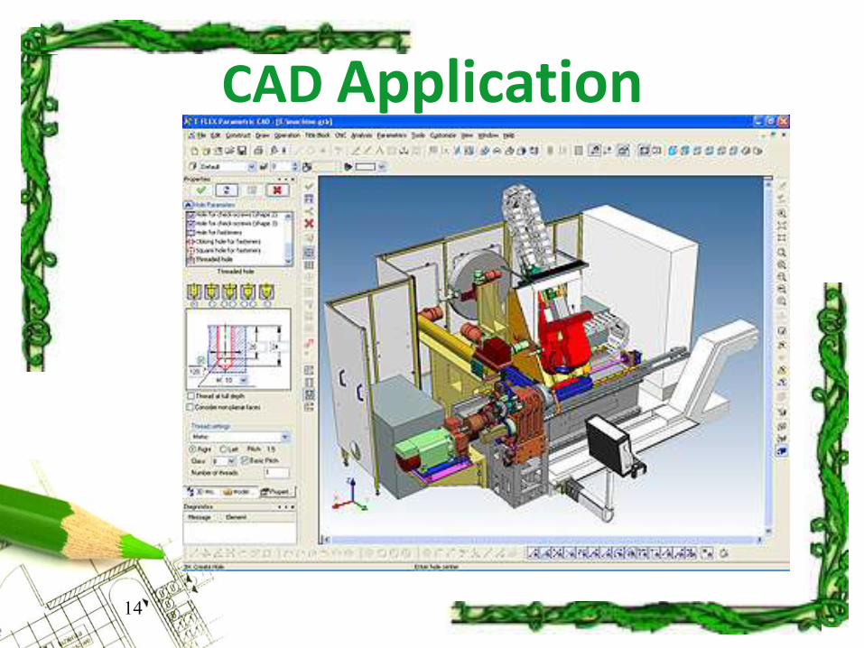
CAD Application
14

Uses of Technical Drawings• Construction drawings are made for defining engineering
items and are made with standardized conventions for layout and appearance reasons.
• Technical illustrations use illustrations to communicate visually technical information, for a nontechnical audience.
• Cutaway drawings are technical illustrations where surface items of three-dimensional model are removed selectively to make internal features
• An exploded view drawing shows how parts fit together in an assembly. Patent drawings are technical renderings of patent inventions, showing the nature of the invention. It shows all the invention's features .
15

Technical drawing methods
• a quickly executed freehand drawing that is not
intended as a finished work. In general, a sketch is a
quick way to record an idea for later use. Architect's
sketches primarily serve as a way to try out different
ideas and establish a composition before
undertaking a more finished work, especially when
the finished work is expensive and time consuming.
16
1- Sketching

Technical drawing methods
• The basic drafting procedure is to place a piece of
paper on a smooth surface with right-angle corners as
a drawing board. A sliding straightedge known as a T-
square is then placed on one of the sides, allowing it
to be slid across the side of the table, and over the
surface of the paper. the drafter uses several tools to
draw curves and circles.
17
2- Manual using instrument

Technical drawing methods
18
2- Manual using instrument

Technical drawing methods
• Today, the mechanics of the drafting task have largely been
automated and accelerated through the use of computer-
aided design systems (CAD).
• There are two types of computer-aided design systems used
for the production of technical drawings" two dimensions
("2D") and three dimensions ("3D").
• Both 2D and 3D CAD systems can be used to produce
technical drawings for any discipline.
19
3- Computer aided design

Applications for technical drawing
• The art and design that goes into making buildings is
known as architecture. To communicate all aspects of
the design, detailed drawings are used. In this field,
the term plan is often used when referring to the full
section view of these drawings. Architectural drawings
describe and document an architect's design.
20

Applications for technical drawing
• The art and design that goes into making buildings
is known as architecture. To communicate all
aspects of the design, detailed drawings are used.
In this field, Architectural drawings describe and
document an architect's design.
21
1- Architecture

Applications for technical drawing
22
2- Engineering
• Engineering drawings generally deal with mechanical
engineered items, such as manufactured parts and
equipment.
• The end goal of an engineering drawing is to convey
all the required information that will allow a
manufacturer to produce that component.

Summery
Importance of Technical Drawing• Technical drawing allows efficient communication
among engineers and can be kept as a record of the
planning process. Since a picture is worth a thousand
words, a technical drawing is a much more effective
tool for engineers than a written plan.
23
Related Documents