Technical Details Components for Discharge Lamps Components for discharge lamps 379–421 Electronic ballasts 379 Assembly instructions for mounting and installing 380–385 Circuit diagrams 385 Electromagnetic ballasts 386 Power reduction 386–387 Assembly instructions for mounting and installing 392–394 Electromagnetic control gear units 388 Assembly instructions for mounting and installing 388–391 Circuit diagrams – Electromagnetic ballasts 395–398 Lampholders for high-pressure sodium lamps 399 Ignitors 400–403 Assembly instructions for mounting and installing 404–406 Power switches 407–408 Lamp table 409–420 Energy efficiency classification 421 General technical details 530–538 Glossary 539–545 378 Technical Details – Components for Discharge Lamps

Welcome message from author
This document is posted to help you gain knowledge. Please leave a comment to let me know what you think about it! Share it to your friends and learn new things together.
Transcript

Technical DetailsComponents for Discharge Lamps
Components for discharge lamps 379–421
Electronic ballasts 379Assembly instructions for mounting and installing 380–385Circuit diagrams 385
Electromagnetic ballasts 386Power reduction 386–387Assembly instructions for mounting and installing 392–394
Electromagnetic control gear units 388Assembly instructions for mounting and installing 388–391
Circuit diagrams – Electromagnetic ballasts 395–398
Lampholders for high-pressure sodium lamps 399
Ignitors 400–403Assembly instructions for mounting and installing 404–406
Power switches 407–408
Lamp table 409–420
Energy efficiency classification 421
General technical details 530–538
Glossary 539–545
378 Technical Details – Components for Discharge Lamps

Components for Discharge LampsIf the electrical current through a discharge lamp is increased, a discharge channel with very highluminous efficiency is created in the discharge chamber. Luminous flux and light output increasesubstantially. The internal pressure of the discharge chamber rises and attains between 1 and 10 bar– these are so-called high-pressure discharge lamps or simply discharge lamps. The light output andcolour rendition of high-pressure lamps vary considerably depending on the lamp family.
Discharge lamps can only be operated with ballasts. Ignitors are additionally required for sodiumlamps and metal halide lamps. Furthermore, to compensate blind current when using magneticballasts, compensation capacitors must be fitted. The lampholders enable the lamp to be fixed in theluminaire and ensure simple exchange of lamps at the end of their service life.
As well as stabilising the lamp's operating point, ballasts also influence the lamp's output andluminous flux, the system's light output, the service life of the lamps as well as the colour temperatureof the light.
The following chapters provide technical information regarding VS components for
• High-pressure sodium lamps (HS lamps)• Metal halide lamps (HI lamps)• Metal halide lamps with a ceramic discharge tube (C-HI lamps)• Mercury vapour lamps (HM lamps)• Low-pressure sodium lamps (LS lamps)
Electromagnetic or electronic ballasts can be used for high-pressure discharge lamps. Unlike withfluorescent lamps, lamp efficiency is not decisively altered by the use of electronic ballasts. Incontrast, electronic ballasts lead to a reduction of the inherent losses and thus to an increase insystem efficiency. In addition, electronic ballasts ensure gentle lamp operation, which increases thelamp's service life.
Independent electronic and electromagnetic ballasts have also been developed, which in the formof control gear units then provide special advantages during application.
Electronic Ballasts for HI and C-HI Lamps
Electronic ballasts are fitted with all the components required to operate discharge lamps.Furthermore, they safely shut down lamps at the end of their service life to prevent high temperaturesfrom being generated within the luminaires that could influence the service life of the luminaires andcomponents.
By adding a strain-relief module, VS electronic built-in ballasts turn into independent operatingdevices that can, for instance, be used as a power unit and can also be installed in intermediateceilings in this form.
Technical Details – Components for Discharge Lamps 379

Components for Discharge LampsAssembly Instructions for Mounting and InstallingElectronic Ballasts for High-pressure Discharge Lamps
Mandatory Regulations
DIN VDE 0100 Erection of low voltage installations
EN 60598-1 Luminaires – part 1: general requirements and tests
EN 61347-1 Operating devices for lamps – part 1: general and safety requirements
EN 61347-2-12 Control gear for lamps; part 2-12: Particular requirements for d.c. or a.c.supplied electronic ballasts for discharge lamps (excluding fluorescent lamps)
EN 55015 Limits and methods of measurement of radio disturbance characteristicsof electrical lighting and similar equipment
EN 61000-3-2 Electromagnetic Compatibility (EMC) – part 3:maximum values – main section part 2: maximum values for mains harmonics(device input current up to and including 16 A per conductor)
EN 61547 Installations for general lighting purposes – EMC immunity requirements
Descriptions of VS EBs for Discharge Lamps
The type designations for VS HID ballasts all follow the same pattern, as follows:
EHXc 70 .326Electronic ballasts for HID lamps Wattage Serial number
Mechanical Mounting
Surface Firm, flat surface required to ensure good heat transfer.Avoid mounting on protruding surfaces.
Mounting location Electronic ballasts must be protected against moisture and heat. Installationin outdoor luminaires: water protection rate of > 4 (e.g. IP54 required).
Fastening Using M4 screws in the designated holes
Heat transfer If the ballast is destined for installation in a luminaire, sufficient heat transfer mustbe ensured between the electronic ballast and the luminaire casing.Electronic ballasts should be mounted with the greatest possible clearance to heatsources or lamps. During operation, the temperature measured at the ballast's tcpoint must not exceed the specified maximum value.
380 Technical Details – Components for Discharge Lamps

Supplement for independent electronic ballasts
Mounting position Any
Clearance Min. of 0.10 m from walls, ceilings and insulationMin. of 0.10 m from further electronic ballastsMin. of 0.25 m from sources of heat (lamp)
Surface Solid; EB must not be allowed to sink into insulation materials
Technical Specifications
Type Operating voltage Leak Mean service Power Temperature Possible no. of VS devices/automatic cut-out typerange current life3 factor protection1 B (10A) B (16A) C (10A) C (16A)AC: 220V...240V mA hrs. λ
EHXc 20.323 +6 –10% � 0.5 50,000 > 0.57 No 11 18 18 30EHXc 22.324 +6 –10% � 0.5 50,000 > 0.57 No 11 18 18 30EHXc 20G.329 +6 –10% � 0.5 50,000 (tc 80 °C) > 0.9 Yes 11 18 18 30EHXc 35.325 ±10% � 0.5 32,000 (tc 85 °C) � 0.95 Yes² 7 12 12 20(188537; 40,000 (tc 80 °C)188538) 50,000 (tc 75 °C)EHXc 35.325 ±10% � 0.5 32,000 (tc 80 °C) � 0.95 Yes 7 12 12 20(188546) 40,000 (tc 75 °C)
50,000 (tc 70 °C)EHXc 35G.327 +6 –10% � 0.5 50,000 > 0.9 Yes 7 12 12 20EHXc 35G.328 +6 –10% � 0.5 50,000 > 0.9 Yes 7 12 12 20EHXc 35.339 ±10% � 0.5 50,000 (tc 70 °C) � 0.95 Yes 7 12 12 20EHXc 235.316 +6 –10% � 0.5 50,000 > 0.98 Yes 7 12 12 20EHXc 70.326 ±10% � 0.5 32,000 (tc 80 °C) � 0.95 Yes² 7 12 12 20(188539; 40,000 (tc 75 °C)188540) 50,000 (tc 70 °C)EHXc 70.326 ±10% � 0.5 26,000 (tc 75 °C) � 0.95 Yes 7 12 12 20(188545) 40,000 (tc 65 °C)
50,000 (tc 60 °C)EHXc 70.340 ±10% � 0.5 50,000 (tc 70 °C) > 0.95 Yes 7 12 12 20EHXc 270.317 +6 –10% � 0.5 50,000 > 0.98 Yes 5 8 8 14EHXc 150G.334 +6 –10% � 0.5 50,000 > 0.98 Yes 5 8 8 14EHXd 250.344 ±10% � 0.75 40,000 (tc 80 °C) � 0.95 Yes 2 3 3 5
1 The devices are fitted with a temperature switch to protect against impermissible overheating.Once the device has cooled down, it is switched on again. It may prove necessary to briefly dis- and then reconnect the device to the mains voltage.
2 The temperature protection inside the luminaire must be checked when using devices without a cap.3 To achieve the mean service life, the max. temperature (tc max.) at the tc point must not be exceeded; failure rate = 0.2% per 1000 hours.
Product Features
Overvoltage protectionAC: up to 48 hours at UNAC = 320 Vand up to 2 hours at UNAC = 350 VDC: no disorders occur with input voltages of up to UNDC 285 V.UNDC voltages in excess of 288 V destroy the ballast.A maximum voltage of 275 V is permitted for the following ballasts:EHXc 35.325, EHXc 35.339, EHXc 70.326, EHXc 70.340
Technical Details – Components for Discharge Lamps 381

Components for Discharge LampsUndervoltage For DC and AC: UNDC, UNAC = 176 V – 2 hours
Shutdown of defective lampsIn the event of a lamp failing to ignite or of a lamp with an increased operatingvoltage (end of the lamp's service life), the electronic ballast will switch off after adefined period of time (< 20 minutes). The ballast will also shut down if the lampfails to attain its specified rated output. The ballast can be reset by disconnectingand then reconnecting the mains voltage.The ballast must always be disconnected from the mains prior to changing alamp.
EOL Effect In high-pressure discharge lamps, the EOL effect manifests itself in a change ofthe lamp's voltage. These changes can, for instance, occur due to unsealed partsof the burner or the rectifier effect. An automatic EOL cut-out prevents safety risksat the end of the service life of high-pressure discharge lamps. EOL tests are con-ducted to check the behaviour of electronic ballasts at the end of a lamp's servicelife. The EOL cut-out stops the lamp base overheating at the end of a lamp'sservice life.
Short-circuit resistanceThe ballast outputs (to the lamp) are short-circuit-proof. Short-circuits between thelamp connection and the casing (earth conductor) will destroy the ballast.
Temperature protectionTo prevent excess temperatures, some ballasts are fitted with temperatureprotection. A ballast will restart after it has cooled down. It might be necessaryto briefly interrupt the supply voltage. The table on page 381 contains a list oftemperature-protected devices.
Transient mains peak protectionValues are in compliance with EN 61547 (interference immunity).
Electrical Installation
Wiring • The wiring between the mains, electronic ballast and lamp must comply withthe respective circuit diagram. Note: the luminaire casing (metal) must beconnected to the earth conductor.
• The electronic ballast must be earthed using a toothed washer or similar(protection class I, compliance with RFI/BCI standards).
• To ensure compliance with RFI suppression limits, mains conductors should notbe wired parallel to lamp conductors and maximum clearance should beensured.
• After the installation of electronic ballasts, luminaires must be tested to ensurecompliance with maximum values laid down in EN 55015.
It is permissible to connect the protective conductor of the ballast by attaching theballast to metal conductors that are connected to the protective conductor. Indoing so, care must be taken to ensure the protective conductor is contacted inaccordance with EN 60598. If, however, a ballast is fitted with a connectionterminal for a protective conductor without through-wiring and if this is to be usedto connect the protective conductor, this connection terminal may only be usedfor the ballast itself.
382 Technical Details – Components for Discharge Lamps

Push-in terminals The used terminals can be connected using rigid or flexible conductors witha section of 0.75–2.5 mm² (K33/K35 ballasts: 0.5–1.5 mm²).The stripped conductor length is 10–11 mm (K33/K35 ballasts: 8.5–9.5 mm)for terminal grid 3.5 mm. Conductors must not be tin-plated.
Error current Impulse-resistant leak-current protection must be installed. Distribute the luminairesto phases L1, L2 and L3; install tri-phase FI switches. If permissible, install FIswitches with 30 mA leak current; connect no more than 15 luminaires as FIswitches can be triggered at half the leak current value.
Tri-phase connection of luminaires with EB• Prior to operating newly installed lighting systems: check the mains voltage is
appropriate to the electronic ballast's mains voltage range (AC, DC).• The N-type conductor must be properly connected to all luminaires or ballasts.• Conductors can only be connected or disconnected if the ballast is
disconnected from the mains. Attention: N-type conductors must never bedisconnected individually or as the first element.
• Insulation resistance test: from L to PE (L and N must not be connected)• The neutral conductor must be reconnected after completion of the test.
Electromagnetic Compatibility (EMC)Vossloh-Schwabe's electronic ballast range was developed in accordance withvalid EMC standards (interference, interference immunity and mains harmonics)and specially designed to ensure safe compliance with the limiting values. It isassumed that that any remarks regarding conductor wiring and conductor lengthin the instructions for installing electronic ballasts in luminaires or for independentballasts will be observed.
Compensation Luminaires with electronic ballasts do not need compensation(power factor � 0.95).
Selection of Automatic Cut-outs
Dimensioning automatic cut-outsHigh transient currents occur when an EB is switched on because the capacitorshave to load. Lamp ignition occurs almost simultaneously.This also causes a simul-taneous high demand for power. These high currents when the system is switchedon put a strain on the automatic conductor cut-outs, which must be selected anddimensioned to suit.
Release reaction The release reaction of the automatic conductor cut-outs comply withVDE 0641, part 11, for B, C characteristics.
No. of electronic ballasts (see table on page 381)The maximum number of VS ballasts applies to cases where the devices areswitched on simultaneously. Specifications apply to single-pole fuses. The numberof permissible ballasts must be reduced by 20% for multi-pole fuses. The con-sidered circuit impedance equals 400 m (approx. 20 m [2.5 mm²] of conduc-tor from the power supply to the distributor and a further 15 m to the luminaire).Doubling circuit impedance to 800 m increases the possible number ofballasts by 10%.
Technical Details – Components for Discharge Lamps 383
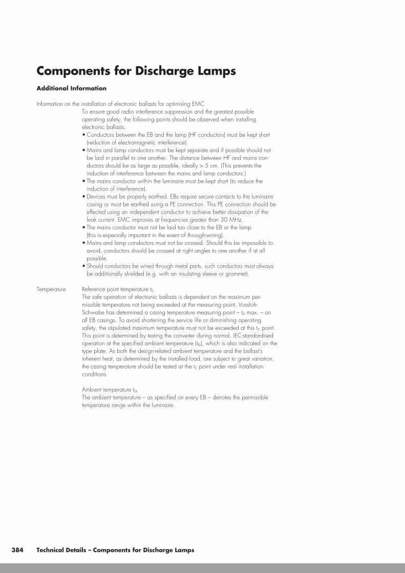
Components for Discharge LampsAdditional Information
Information on the installation of electronic ballasts for optimising EMCTo ensure good radio interference suppression and the greatest possibleoperating safety, the following points should be observed when installingelectronic ballasts:• Conductors between the EB and the lamp (HF conductors) must be kept short
(reduction of electromagnetic interference).• Mains and lamp conductors must be kept separate and if possible should not
be laid in parallel to one another. The distance between HF and mains con-ductors should be as large as possible, ideally > 5 cm. (This prevents theinduction of interference between the mains and lamp conductors.)
• The mains conductor within the luminaire must be kept short (to reduce theinduction of interference).
• Devices must be properly earthed. EBs require secure contacts to the luminairecasing or must be earthed using a PE connection. This PE connection should beeffected using an independent conductor to achieve better dissipation of theleak current. EMC improves at frequencies greater than 30 MHz.
• The mains conductor must not be laid too close to the EB or the lamp(this is especially important in the event of through-wiring).
• Mains and lamp conductors must not be crossed. Should this be impossible toavoid, conductors should be crossed at right angles to one another if at allpossible.
• Should conductors be wired through metal parts, such conductors must alwaysbe additionally shielded (e.g. with an insulating sleeve or grommet).
Temperature Reference point temperature tcThe safe operation of electronic ballasts is dependent on the maximum per-missible temperature not being exceeded at the measuring point. Vossloh-Schwabe has determined a casing temperature measuring point – tc max. – onall EB casings. To avoid shortening the service life or diminishing operatingsafety, the stipulated maximum temperature must not be exceeded at this tc point.This point is determined by testing the converter during normal, IEC-standardisedoperation at the specified ambient temperature (ta), which is also indicated on thetype plate. As both the design-related ambient temperature and the ballast'sinherent heat, as determined by the installed load, are subject to great variation,the casing temperature should be tested at the tc point under real installationconditions.
Ambient temperature taThe ambient temperature – as specified on every EB – denotes the permissibletemperature range within the luminaire.
384 Technical Details – Components for Discharge Lamps

Reliability and Service LifeIf the max. temperature at the tc reference point (as specified on the type plateand the technical documentation of the ballast) is not exceeded, the definedservice life can be expected to be achieved, assuming a switching cycle of165 minutes on and 15 minutes off.See table on page 381 for service life details.
Circuit diagrams for metal halide lamps (HI) with electronic ballasts (EB)
Technical Details – Components for Discharge Lamps 385
EHXc�
�
PE
EHXd
EHXc
�
�PE
235.336, 270.317
250.344
20.323, 22.324
�
EHXc
PE
20G.329, 35G.327, 35G.328, 35.325,70.326, 150G.334
�
EHXc
35.339, 70.340
PEPE
DC1...10V
–+

Components for Discharge LampsElectromagnetic Ballasts for HI and HS Lamps
As the lamp manufacturer's reference values regarding lamp current and voltage are generallyidentical for metal halide (HI) and high-pressure sodium lamps (HS) of the same lamp wattage andthe impedance values required for the ballast are also identical, the same ballasts can frequently beused for both lamp types. It should be remembered that HI lamps react sensitively to impedancedeviations from the rated value with appreciable colour changes. Vossloh-Schwabe ballasts thereforecomply with the lamp's narrower tolerances. Moreover, ballasts remain below the maximum peakDC value for HI lamps. This value is not specified for HS lamps; instead, the maximum stated start-upcurrent must not be exceeded.
In order to keep the temperature of the luminaires and the electrical values of the lamps withintolerable limits, the impedance of the ballasts must remain constant over the entire service life.A so-called service life test (test of thermal durability) provides proof of this requirement havingbeen met.
HI and HS lamps constitute a special case in terms of thermal testing. In rare cases, a safety risk canoccur at the end of the service life of lamps fitted with external bulbs. The safety risk is caused by theso-called lamp rectifier effect, which can lead to overheating of ballasts, ignitors, lampholders andconductors and can therefore destroy the luminaire. Against this background, the luminaire standardEN 60598-1 "luminaires; part 1: general requirements and tests" has been supplemented by testsconcerning this safety risk. As a result, since 1 September 2002, it has been illegal to marketluminaires that do not comply with the new regulations. This means luminaires need to be fittedwith thermal protection that prevents a luminaire from overheating in the event of this malfunction.
In this respect, it is recommended to use VS ballasts with temperatureswitches that have already been tested using this circuit.
Electromagnetic Ballasts for HM Lamps
Even in the event of major mains fluctuations (92–106% of the rated voltage), the ballast must notfall short of the no-load voltage specified by the lamp manufacturer nor exceed a fixed short-circuitcurrent. The start-up current must be high enough to ensure that at least 90% of the lamp's operatingvoltage is achieved within 15 minutes.
Power Reduction with HS and HM Lamps
The lamp wattage can be reduced by operating the ballast at a higher impedance value, higherthan the rated value. The lamp manufacturer's specifications must be observed in doing so to avoidshortening the lamp's service life. The lamps should be started at the ballast's rated impedance andonly switched down to reduced operation after a period of at least five minutes.
The impedance value can be altered by using an additional ballast (high-effort option) or by usinga switchable ballast (low-cost option). These ballast models can be switched using either a modern,time-controlled electronic power reduction switch, which is equipped with an additional controlconductor (230 V), or a power reduction switch with a constant incentive rate setting (no controlconductor).
386 Technical Details – Components for Discharge Lamps
DUT
UND
DUT Device under TestD Diode, 100A, 600VR Resistor, 0...200
(1/2 lamp output)U 110% of rated
supply voltageN
R
Test circuit for thermallyprotected ballasts
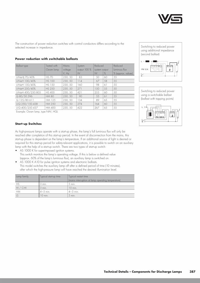
The construction of power reduction switches with control conductors differs according to theselected increase in impedance.
Power reduction with switchable ballasts
Ballast type Tested with Mains System Reduced ReducedOsram lamp voltage output 100 % system output luminous flux
V, Hz W W % % (approx. values)U-NaHJ 70/40% HS 70 230, 50 83 50 60 55U-NaH 100/40% HS 100 230, 50 114 67 58 55U-NaH 150/40% HS 150 230, 50 160 98 61 55U-NaH 250/40% HS 250 230, 50 271 150 55 50U-NaH 400/250.805 HS 400 230, 50 421 253 60 50Q 80/50.596 HM 80 230, 50 90 55 61 55Q 125/80.611 HM 125 230, 50 134 89 65 55U-Q 250/150.438 HM 250 230, 50 274 164 60 55U-Q 400/250.437 HM 400 230, 50 422 267 65 55Example: Osram lamp, type NAV, HQL
Start-up Switches
As high-pressure lamps operate with a start-up phase, the lamp's full luminous flux will only bereached after completion of this start-up period. In the event of disconnection from the mains, thisstart-up phase is dependent on the lamp's temperature. If an additional source of light is desired orrequired for this start-up period for safety-relevant applications, it is possible to switch on an auxiliarylamp with the help of a start-up switch. There are two types of start-up switch:• AS 1000 K for superimposed ignition systems.
This switch monitors the lamp's operating voltage. If this is below a defined value(approx. 60% of the lamp's luminous flux), an auxiliary lamp is switched on.
• AS 1000 K A10 for pulse ignition systems and electronic ballasts.This model switches the auxiliary lamp off after a defined period of time (10 minutes),after which the high-pressure lamp will have reached the desired illumination level.
Lamp family Typical start-up time Typical restart time(mains interruption at lamp operating temperature)
HS 3 min. 5 min.HI / C-HI 3 min. 10 min.HM 4–5 min. 4–5 min.LS 10 min. 5 min.
Technical Details – Components for Discharge Lamps 387
3 BN LpLST N
PW 12 K
L
N
1 2
LST
Z
Switching to reduced powerusing additional impedance(second ballast)
213
PU 120 KZ
B Lp NN STL
Pmin
Pmax
L
NLST
L
Switching to reduced powerusing a switchable ballast(ballast with tapping points)

Components for Discharge LampsControl Gear Units (with Electromagnetic Ballasts)for High-pressure Discharge Lamps
Control gear units with electromagnetic ballasts for high-pressure sodium lamps (HS), metal halidelamps (HI) and metal halide lamps with a ceramic discharge tube (C-HI) are fitted with all thecomponents needed to ensure safe normal operation. Apart from a ballast, control gear units alsocontain a digital timer ignitor with IPP++ technology (Intelligent-Pulse-Pause-Mode), a compensationcapacitor and a temperature switch with automatic reset. As all these components form a matchedsystem, they create optimum operating conditions for lamps and small models. These compact con-trol gear units remove the need for separate installation and wiring of individual components, thusconsiderably reducing assembly time.
Mandatory Regulations
DIN VDE 0100 Erection of low voltage installations
EN 60598-1 Luminaires – part 1: general requirements and tests
EN 61347-1 Operating devices for lamps – part 1: general and safety requirements
EN 61347-2-1 Control gear for lamps; part 2-1: special requirements for ignitors(other than glow starters)
EN 61347-2-9 Control gear for lamps; part 2-9: special requirements for ballastsfor discharge lamps (except fluorescent lamps)
EN 60923 Ballasts for discharge lamps – performance requirements
EN 60927 Operating devices for lamps; ignitors (glow starters); performance requirements
EN 61048 Operating devices for lamps – capacitors for fluorescent lamp circuits andother discharge lamp circuits; general and safety requirements
EN 61049 Operating devices for lamps – capacitors for fluorescent lamp circuits andother discharge lamp circuits; performance requirements
EN 55015 Limits and methods of measurement of radio disturbance characteristicsof electrical lighting and similar equipment
EN 61000-3-2 Electromagnetic Compatibility (EMC) – part 3:maximum values – main section part 2: maximum values for mains harmonics(device input current up to and including 16 A per conductor)
EN 61547 Installations for general lighting purposes – EMC immunity requirements
Technical Specifications
Operating voltage rangeControl gear units can be operated at the specified mains voltage withina tolerance range of ±10% for HS/HI lamps and ±3% for C-HI lamps.
388 Technical Details – Components for Discharge Lamps

Leak current � 0.1 mA
Compensation/power factorParallel-compensated control gear units with a power factor of λ < 0.9(λ < 0.85 for 100 W)
Degree of protectionIP40, IP65IP54 for aluminium casing
Protection class Independent, protection class II control gear units (plastic casing)Independent, protection class I control gear units (aluminium casing)
Max. ambient temperatureSee ta value on the type plate of the control gear unit
Lead length to lampMax. 10 m
F designation Suitable for mounting on surfaces of normal flammability
Mechanical Mounting
Mounting position Any position using the mounting tabs
Clearance Min. of 0.20 m from walls, ceilings and insulationMin. of 0.20 m from further control gear unitsMin. of 0.25 m from sources of heat (lamp)
Surface Solid; control gear unit must not be allowed to sink into insulation materials
Electromagnetic Compatibility (EMC)
Interference Interference voltage measurements only have to be taken at the connectionterminals for luminaires with electromagnetic control gear units as these systemsoperate with lamp voltages of under 100 Hz. These low-frequency interferencevoltages are generally not critical with high-pressure discharge lamps withelectromagnetic control gear units.
Interference immunityThanks to the robust design and choice of materials, electromagnetic controlgear units provide a high degree of interference immunity and are not impairedby normal mains power interference.
Mains Harmonics After every zero crossing of the lamp current, discharge lamps experience are-ignition peak as the lamps go out for a brief (imperceptible) moment. Thesere-ignition peaks of discharge lamps generate mains harmonics that are smoothedby the ballast's impedance. VS electromagnetic control gear units all comply withthe stipulated maximum values.
Technical Details – Components for Discharge Lamps 389

Components for Discharge LampsSelection of Automatic Cut-outs for VS Control Gear Units
Dimensioning automatic cut-outsWhen a control gear unit is switched on, high transient current peaks occurdue to the smoothing capacitor having to load. The lamps are ignited almostsimultaneously, which also causes energy consumption peaks. These high systemswitch-on currents put a strain on the automatic conductor cut-outs, which must beselected and dimensioned to suit.
Release reaction The release reaction of the automatic conductor cut-outs comply withVDE 0641, part 11, for B and C characteristics.
No. of control gear unitsThe following values are meant as guidelines only and may vary depending onthe respective lighting system. The specified maximum number applies to thenumber of devices that can be switched on simultaneously. Specifications applyto single-pole fuses; using multi-pole fuses reduces the maximum number by 20%.The considered circuit impedance equals 400 m (approx. 20 m [2.5 mm²] ofconductor from the power supply to the distributor and a further 15 m to theluminaire). Doubling circuit impedance to 800 m increases the possiblenumber of control gear units by 10%.
Type of control gear unit Type of automatic cut-outB (10 A) B (16 A) C (10 A) C (16 A)
VNaHJ 35PZT 7 12 12 20VNaHJ 70PZT 7 12 12 20VNaHJ 100PZT 6 10 10 16VNaHJ 150PZT 5 8 8 14VNaHJ 250PZT 3 5 5 7VNaHJ 400PZT 2 4 3 5
Safety Functions
Shutdown of defective lampsIn the event of a lamp failing to ignite the control gear unit will automaticallyshut down after a preset safety period. The programmed switch off time preventsflickering at the end of the lamp's service life. The control gear unit can be resetafter shut down and lamp changing by disconnecting and then reconnecting themains voltage.
Temperature protectionTo protect against impermissible excess temperatures, the devices are fitted with atemperature fuse.
390 Technical Details – Components for Discharge Lamps

Protection against installation and wiring errorsThe integrated IPP++ function will prevent the power unit from making any attemptto start the lamp in the event of an installation or wiring error and also if theneutral conductor is dislodged within the existing mains voltage network(three-phase supply network). Should the nominal supply voltage be connected,the power unit will begin starting the lamp immediately.
Reliability and Service Life
The control gear units can be expected to provide a service life of 50,000 operating hours providedthat the assembly instructions are observed and the maximum tw value of the ballast is not exceeded.Failure rate: < 0.1%/1,000 hours.
Electrical Installation
Connection terminalsTerminals can be contacted with rigid or flexible conductors• rigid conductors: max. 2,5 mm2
• flexible conductors: max. 2,5 mm2
• stripped lead length: 10–11 mm• conductors must not be tin-plated
Connection leads Admissible Ø 7–9 mmThe suitability of luminaire conductors and cables for use within luminaires withignition devices must be checked in accordance with luminaire standardEN 60598-1 10.2.2. In general, all silicone and standard PVC cables meetthese requirements.
Wiring The wiring between the supply mains, control gear unit and lamp must be inaccordance with the circuit diagram shown on the type plate. Note: luminairecasing (metal) must be connected to the protective earth conductor.
Technical Details – Components for Discharge Lamps 391

Components for Discharge LampsAssembly Instructions for Mounting and InstallingElectromagnetic Ballasts for High-pressure Discharge Lamps
Mandatory Regulations
DIN VDE 0100 Erection of low voltage installations
EN 60598-1 Luminaires – part 1: general requirements and tests
EN 61347-1 Operating devices for lamps – part 1: general and safety requirements
EN 61347-2-9 Operating devices for lamps; part 2-9: special requirements for ballasts fordischarge lamps (except fluorescent lamps)
EN 60923 Ballasts for discharge lamps – performance requirements
EN 55015 Maximum values and methods of measurement for RFI suppression inelectrical lighting installations and similar electrical appliances
EN 61000-3-2 Electromagnetic Compatibility (EMC) – part 3:maximum values – main section part 2: maximum values for mains harmonics(device input current up to and including 16 A per conductor)
EN 61547 Installations for general lighting purposes – EMC immunity requirements
Technical Specifications
Operating voltage rangeThe ballasts can be operated at the specified mains voltage withina tolerance range of ±10% for HS/HI lamps and ±3% for C-HI lamps.
Leak current � 0.1 mA
Compensation/power factorInductive ballasts: λ � 0.5Parallel-compensated ballasts: λ � 0.85
Mechanical Mounting
Mounting position Any
Mounting location Ballasts are designed for installation in luminaires or comparable devices.Independent ballasts do not need to be installed in a casing.
Fastening Preferably using M4 to M6 screws, depending on the size of the ballast.Encapsulated ballasts may only be used with flat-headed screws (M5), underlaidwith a washer (DIN 9021). (Tightening torque � 2 Nm)
392 Technical Details – Components for Discharge Lamps

Temperature The winding temperature tw must be checked during operation and must not exceed the specified maximum value. It mustbe tested by using the standardised method of measuring resistance. The Δt marking on the type plate is a measure of theballast's inherent heating and thus of its power loss. The lower this value is the lower the power loss of the ballast.This value is determined using standardised measuring regulations and constitutes a benchmark for comparing ballasts ofthe same design for selection purposes.
Electromagnetic Compatibility (EMC)
Interference Interference voltage measurements have to be taken at the connection terminals for luminaires with electromagneticballasts as these are systems that operate with lamp voltages of under 100 Hz. These low-frequency interference voltagesare generally not critical with high-pressure discharge lamps with electromagnetic ballasts.
Interference immunityThanks to the robust design and choice of materials, electromagnetic ballasts provide a high degree of interferenceimmunity and are not impaired by normal mains power interference.
Mains Harmonics After every zero crossing of the lamp current, discharge lamps experience a re-ignition peak as the lamps go out for abrief (imperceptible) moment. These re-ignition peaks of discharge lamps generate mains harmonics that are smoothed bythe ballast's impedance. VS electromagnetic ballasts all comply with the stipulated maximum values.
Selection of Automatic Cut-outs for VS Electromagnetic Ballasts
Dimensioning automatic cut-outsWhen a ballast is switched on, high transient current peaks occur due to parasite capacitances that can accumulatewith the number of luminaires. These high system switch-on currents put a strain on the automatic conductor cut-outs.For this reason, only surge-current-proof automatic cut-outs should be used for lighting systems.
Release reaction The release reaction of the automatic conductor cut-outs comply with VDE 0641, part 11, for B and C characteristics.
No. of ballasts The following values are meant as guidelines only and may vary depending on the respective lighting system.The maximum number of VS ballasts applies to cases where the devices are switched on simultaneously. Specificationsapply to single-pole fuses. The number of permissible ballasts must be reduced by 20% for multi-pole fuses. The consideredcircuit impedance equals 400 m (approx. 20 m of [2.5 m²] conductor from the power supply to the distributor and afurther 15 m to the luminaire). Doubling circuit impedance to 800 m increases the possible number of ballasts by 10%.The values quoted in the following tables are guidelines and can be affected by system-specific factors.
Possible number of ballasts connected to automatic cut-outs with or without compensation
Lamp data CP Max. number of ballasts connected to automatic cut-outs – without compensation / with compensation
C10 C13 C16 C20 C25 B10 B13 B16 B20 B25
W V μF without with without with without with without with without with without with without with without with without with without with
Mercury vapour lamps (HM)50 230 7 10 19 13 25 15 31 18 39 23 49 8 10 11 12 13 15 16 18 20 23
80 230 8 6 12 7 15 9 19 11 24 14 30 6 6 8 7 10 9 12 11 15 14
125 230 10 4 7 5 9 7 12 7 15 9 19 4 4 5 5 7 6 9 7 10 9
250 230 18 2 4 3 5 3 6 3 7 4 9 2 2 3 2 3 3 4 3 5 4
400 230 25 1 2 1 3 2 4 2 5 2 6 1 1 1 1 2 22 3 2 3 2
700 230 40 — 1 — 1 1 2 1 2 1 3 1 — 1 — 1 1 1 1 2 1
1000 230 60 — 1 — 1 — 1 1 2 1 2 — — — — 1 — 1 1 1 1
Technical Details – Components for Discharge Lamps 393

Components for Discharge LampsLamp data CP Max. number of ballasts connected to automatic cut-outs – without compensation / with compensation
C10 C13 C16 C20 C25 B10 B13 B16 B20 B25
W V μF without with without with without with without with without with without with without with without with without with without with
Metal halide lamps (HI)35 230 6 11 22 14 29 18 36 23 45 29 50 9 11 12 14 15 18 18 23 23 27
70 230 12 7 12 9 15 11 18 14 23 17 29 5 8 6 10 8 13 9 16 12 20
150 230 20 4 7 5 9 6 11 7 14 9 17 2 5 3 6 4 8 5 10 6 12
250 230 32 2 5 2 6 3 7 4 9 5 11 1 3 1 4 2 5 3 6 4 8
400 230 35 2 3 2 4 3 5 4 7 5 8 1 2 1 3 2 4 2 5 3 6
1000 230 85 — 1 — 1 1 1 1 3 1 3 — — — — — 1 1 1 1 2
2000 380 60 — 1 — 1 — 2 — 2 — 3 — — — — — 1 — 1 — 2
2000 380 37 — — — — — 1 — 1 — 2 — — — — — — — 1 — 1
3500 380 100 — — — — — — — — — — — — — — — — — — — —
High pressure sodium vapour lamps (HS)50 230 10 9 16 11 20 14 24 18 31 22 38 6 11 8 14 10 17 13 22 16 27
70 230 12 7 12 9 15 11 18 14 23 17 29 5 8 6 10 8 13 10 16 12 20
100 230 12 6 10 7 13 9 16 11 20 14 25 4 7 5 9 6 11 8 14 10 17
150 230 20 4 7 5 9 6 11 7 14 9 17 2 5 3 6 4 8 5 10 7 12
250 230 36 2 5 2 6 3 7 4 9 5 11 1 3 1 4 2 5 3 6 4 8
400 230 45 1 3 1 3 2 4 3 5 4 7 1 2 1 2 1 3 2 4 2 5
600 230 60 1 2 1 2 1 2 2 3 2 4 — 1 — 1 1 2 2 2 2 3
1000 230 100 1 1 1 1 1 1 1 2 2 3 — — — — — 1 1 1 1 2
Safety Functions
The VS range includes ballasts with an integrated temperature switch that safely disconnects the lamp from the power supply if the lampshould develop the rectifier effect towards the end of its service life. The cut-out behaviour of the temperature switch is influenced by theluminaire construction. The luminaire manufacturer is responsible for checking the factory settings of the temperature switch in accordancewith EN 60598-1 Section 12.5. VS can adjust the temperature switch to the appropriate cut-out temperature to suit requirements.
Reliability and Service Life
Provided the maximum winding temperature is not exceeded, the ballasts can be expected to yield a service life of 100,000 operatinghours. Failure rate < 0.025%/1,000 hrs.
Electrical Installation
Push-in terminals Terminals can be contacted with rigid conductors up to a maximum of 1.5 mm².
Screw terminals • Terminals can be contacted with rigid or flexible conductors with ferrules on bare end of core• Conductor cross-sections are determined by the terminals and can
vary according to type 0.5–1.5 mm² / 0.75–2.5 mm² / 1.5–2.5 mm²• Stripped lead length: 8–9 mm• Conductors must not be tin-plated
Wiring The wiring between the power supply, ballast and lamp must be in accordance with the respective circuit diagram(see pages 395–396).
Components High-pressure discharge lamps must only be fitted with components that are rated to withstand the respectiveignition voltage.
394 Technical Details – Components for Discharge Lamps
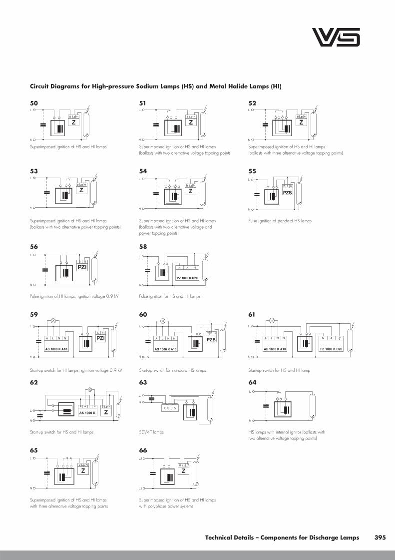
Circuit Diagrams for High-pressure Sodium Lamps (HS) and Metal Halide Lamps (HI)
Technical Details – Components for Discharge Lamps 395
63
SDW-T lamps
64
HS lamps with internal ignitor (ballasts withtwo alternative voltage tapping points)
65
Superimposed ignition of HS and HI lampswith three alternative voltage tapping points
66
Superimposed ignition of HS and HI lampswith polyphase power systems
A L N N
59
Start-up switch for HI lamps, ignition voltage 0.9 kV
A L
L
N N
60
Start-up switch for standard HS lamps
A L N N N A
AS 1000 K A10 PZ 1000 K D20
61
Start-up switch for HS and HI lamp
AS 1000 K
62
Start-up switch for HS and HI lamps
56
Pulse ignition of HI lamps, ignition voltage 0.9 kV
N A
PZ 1000 K D20
58
Pulse ignition for HS and HI lamps
PZS
55
Pulse ignition of standard HS lamps
54
Superimposed ignition of HS and HI lamps(ballasts with two alternative voltage andpower tapping points)
53
Superimposed ignition of HS and HI lamps(ballasts with two alternative power tapping points)
50
Superimposed ignition of HS and HI lamps
51
Superimposed ignition of HS and HI lamps(ballasts with two alternative voltage tapping points)
52
Superimposed ignition of HS and HI lamps(ballasts with three alternative voltage tapping points)

Components for Discharge LampsCircuit Diagrams for Mercury Vapour Lamps (HM)
Circuit Diagrams for Low-Pressure Sodium Lamps (LS)
396 Technical Details – Components for Discharge Lamps
72
LS lamps 35 to 180 W (without ignitor)
67
HM lamps
68
HM lamps (ballasts withtwo alternative voltage tapping points)
69
HM lamps (ballasts withtwo alternative power tapping points)
70
HM lamps (ballasts with two alternative voltageand power tapping points apiece)
71
Start-up switch for HM lamps with auxiliary lamp

Power Reduction of High-pressure Sodium Lamps (HS lamps) – Superimposed Ignition SystemLST connectable to L1, L2 or L3
Technical Details – Components for Discharge Lamps 397
Pmax
Pmin
LSTN NLpB
ZPU 121 K
3 1 2
STL
L
N
81
Connected control phase (LST = 230 V)with ballasts with two tapping points
213
PU 120 K
L
N
Z
B Lp NN STL
STL
Pmin
Pmax
L
80
Disconnected control phase (LST = 0 V)with ballasts with two tapping point
Pmax
LSTN NLpB
ZPU 12 K
3 1 2
L
NSTL
82
Disconnected control phase (LST = 0 V)with ballasts with two tapping points
213
PR 12 K LC
L
N
Z
B Lp NN STL
Pmax
85
Electronic power reduction without control phase
ST
213
PU 120 K Z
B Lp NN STL
Pmax
L
L
N
L
84
Disconnected control phase (LST = 0 V)with main ballast and additional inductance
213
PU 12 K Z
B Lp NN STL
Pmax
L
STL
N
83
Connected control phase (LST = 230 V)with ballasts with two tapping points
STL
86
Ballast with two tapping points and twovoltage tapping points (LST = 0 V or LST > 0 V)
21
ZPU
N STP LL
L
STL
N
87
Disconnected control phase (LST = 0 V)with ballasts with two tapping points
21
ZPU
N STP LL
L
STL
N
88
Connected control phase (LST = 230 V)with ballasts with two tapping points
2 NN
ZPU...D20
1 ST PLL L
L
STL
N
89
Disconnected control phase (LST = 0 V)with ballasts with two tapping points

Components for Discharge LampsPower Reduction of Mercury Vapour Lamps (HM lamps)LST connectable to L1, L2 and L3
398 Technical Details – Components for Discharge Lamps
213
PU 121 K
L
N
N STL
STL
Pmin
Pmax
93
Connected control phase (LST = 230 V)with ballasts with two tapping points
L
Pmax
Pmin
LST
LSTN
N
L
PU 120 K
3 1 2
92
Disconnected control phase (LST = 0 V)with ballasts with two tapping points
213
PU 12 K
L
N
N STL
STL
Pmax
94
Disconnected control phase (LST = 0 V)with ballasts with two tapping points
Pmax
LSTN
N
L
PR 12 K LC
3 1 2
97
Electronic power reduction without control phase
LST
N
213
PU 120 K
N STL
Pmax
L
L
96
Disconnected control phase (LST = 0 V)with two ballasts connected in parallel
Pmax
LST
LSTN
N
L
PU 12 K
3 1 2
95
Connected control phase (LST = 230 V)with ballasts with two tapping points
PU
98
Ballasts with two tapping points andtwo voltage tapping points (LST = 0 V or LST > 0 V)

Lampholders for High-pressure Discharge Lamps
Metal halide and high-pressure sodium lamps feature extremely different bases, which include RX7s,Fc2, G8.5, GX8.5, GX10, G12, GX12, PG12, PGJ5, GU6.5, E27 and E40, depending onwhether the lamp is single- or double-ended. All lampholders are subject to the same typical condi-tions found with discharge lamps: high ignition voltages and temperatures. The high start-up currentsdeserve particular attention in lampholder design. This is also reflected by the insulation materials,which are usually solid ceramics or heat-resistant plastic (e.g. PPS – polyphenylene sulphide).Depending on the lamp's requirements (voltage, current, temperature, etc.), silver, nickel and copperalloys with thick nickel coatings are used as conductors. The luminaire regulation EN 60598-1 (VDE0711 part 1), defines the safety requirements with regard to ignition voltages in connection withcreepage and air clearance distances. Special care must be taken to ensure that lampholders areapproved for discharge lamps when using high-pressure lamps with E27 and E40 Edison bases.Lampholders that are suitable for this purpose are marked with a maximum value of "5 kV" andcomply with the increased creepage and air clearance distances specified by the lampholderrequirements in EN 60238 (VDE 0616 part 1). The lampholder regulations governing special lamp-holders, EN 60838-1 (VDE 0616 part 5), apply analogously to all other base systems. The highignition voltage pulses also place special demands on the conductors. In practice, silicone-insulatedconductors with an outer diameter of 3.6 mm have proved to be suitable for discharge lamps.Silicone-insulated conductors with a glass-silk lining with a diameter of 7 mm should be used forlamps with an instant hot restart (20 kV) function.
Bases for the Most Commonly Used HI and HS Lamps
Bases for the Most Commonly Used HM Lamps
Edison bases are predominantly used for mercury vapour lamps (HM)
Technical Details – Components for Discharge Lamps 399
G8.5
Fc2RX7s E27 E40/45 E40/80x50E40/41
G12 PG12-1 PG12-2GX10GX8.5 GX12 PGJ5GY9.5 GU6.5
VS lampholders forthe UL market and ULapproved leads areavailable for allcommon lamp types.
Further informationcan be found atwww.unvlt.com.
E27 E40/41 E40/45 E40/80x50

Components for Discharge LampsIgnition Voltages for High-pressure Sodium Lamps (HS)and Metal Halide Lamps (HI)
The ignition voltage of HS and HI lamps is determined by the respective lamp technology as wellas the creepage and air clearance distances of the base-lampholder system. High-pressure sodiumlamps of 35, 50 and 70 W with an E27 base are ignited with a voltage of between 1.8 and2.3 kV. All other high-pressure lamps of the sodium and metal halide families require an ignitionvoltage of between 4 and 5 kV (except for special lamps and lamps with base PGJ5).
Superimposed Ignitors
Superimposed ignitors work independently of ballasts and generate defined ignition pulses withinthe voltage ranges of 220–240 V ±10% and 380–415 V ±10%. As the mains frequency onlyplays a minor role, these systems work equally well at 50 Hz and 60 Hz. In accordance with thelamp manufacturer's specifications, pulses or clusters of pulses of defined width and height aregenerated in every half wave. Although lamp current flows through superimposed ignitors, they onlycause low losses in relation to the system's power consumption. The maximum ambient temperaturecan be calculated by subtracting the ignitor's self-heating, which is caused by the inherent losses,from the specified maximum casing temperature (tc).
Superimposed ignitors should be mounted near the lampholder. The clearance needed between theignitor and the lamp is determined by the respective maximum load capacitance, which is specifiedfor each ignitor in the technical specifications. The capacitive load of the cable is dependent on itsphysical properties and wiring layout; this value usually ranges between 70 pF and 100 pF permetre. The casing temperature must not fall below –30°C and must not exceed the maximum valuespecified on the device.
Pulse Ignitors
Pulse ignitors use the winding of an inductive ballast to generate the pulse voltage needed to ignitehigh-pressure discharge lamps. For that reason, ballasts must be designed to withstand these highignition voltages. In this respect, special attention is paid to the insulation as well as the creepageand air clearance distances. As pulse ignition systems generate high-energy pulses, they are alsosuitable in the event of longer conductor distances between ignitor and lamp. State-of-the-art ignitorsfeature electronic circuitry. Depending on their design and the technical requirements, the simplestsolution is to connect pulse ignitors in parallel with the lamp. Further models make partial use of thewinding of a ballast, which will either feature multiple tapping points for voltage selection or specialtapping points for pulse operation.
400 Technical Details – Components for Discharge Lamps
L1
N
VG
Circuit principle ofa superimposed ignitor
L
N
VG
Circuit principle ofa pulse ignitor

VS ignitors provide the following advantages:
• fully electronic construction• compact design• large nominal voltage range• large output range• low self-heating• minimal power loss• low noise• long service life• high electrical safety due to high-quality
components (e.g. approved capacitors)
• highly heat-resistant (max. permissible casingtemperature tc: 105°C for superimposed ignitorsand 95°C for pulse ignitors)
• highly fire-resistant potting compound(certified according to EN 60926 and UL 94-V0)
• environmentally compatible potting compound(waste key No. 57110)
Product Range
Vossloh-Schwabe's product range covers superimposed and pulse ignitors in standard models andwith automatic cut-outs. Superimposed ignitors with automatic cut-outs are available with variouscut-out times and ignition voltage pulse mechanisms (A and D). In this respect, D-series ignitorsfeaturing the intelligent pulse-pause mode (IPP) are the best solution in terms of ignition reliability andswitching off defective lamps.
Electronic ignitors with integrated cut-outs capture data on ignition behaviour during the ignitionprocess. These data, e.g. regarding ignition frequency or failure, serve to identify ageing lamps andto ensure the ignition process is reliably switched off after a defined period of time at the end of thelamp's service life or in the event of defective lamps. This reduces the negative consequencesassociated with defective lamps.
Technical Details – Components for Discharge Lamps 401

Components for Discharge LampsSuperimposed and Pulse Ignitors with Automatic Cut-out
Ignitors with Automatic Cut-out – A Series
After connection to mains voltage, A series ignitors supply a continuous stream of ignition voltagepulses until the lamp has ignited or the predefined cut-out time (sum of all ignition periods) has beenreached if the lamp fails to ignite.
Z ... A20 for HS, HI and C-HI lampsprogrammed cut-out time: 1,310 seconds
Ignitors with IPP Technology and Extended Cut-out – D Series
After connection to mains voltage, D series ignitors generate ignition voltage pulses that arecontrolled and if necessary switched off by the ignitor in accordance with the lamp's operating state,lamp recognition and the safe burning time. If the safe burning time is not attained after three con-secutive ignition attempts, pulse generation will cease. Appropriately programmed microprocessorsenable these performance features of ignitors with IPP technology (Intelligent Pulse-Pause Mode) andextended cut-outs.
Z ... D20/PZ ... D20 for HS, HI and C-HI lamps
programmed cut-out time: 1,216 seconds
Ignitors with IPP technology and extended cut-outs are available up to an output of 1,000 W.
Programmed Cut-out Function of VS Ignitors
402 Technical Details – Components for Discharge Lamps
Time
D20
A20

Pulse Ignition Systems – Overview of Technical Specifications
For HS, HI and C-HI lamps – PZ 1000 K D20for high-pressure sodium lamps (HS) 50–1000 W,,metal halide lamps (HI) 35–1000 W andfor ceramic discharge tube lamps (C-HI) 35–400 WIgnition voltage: 1.8–2.3 kV or 4–5 kVNo. of pulses: 2 per mains periodLoad capacitance: 20–1000 pF
For HS lamps – PZS 1000 Kfor standard high-pressure sodium lamps (HS) 50–1000 WNot suitable for discharge lamp models SUPER, PLUS, XL, etc.Ignition voltage: approx. 4 kVNo. of pulses: 1 per secondLoad capacitance: 20–4000 pFSuitable ballast types:NaH ... P with winding tapping point(20 V voltage difference)
For HI lamps – PZI 1000/1 Kfor metal halide lamps (HI)with an ignition voltage up to 0.9 kVNo. of pulses: 1 per mains periodLoad capacitance: max. 10,000 pFSuitable ballast models: Q...
Technical Details – Components for Discharge Lamps 403
L
N
N32
(220
V)
(240
V)
PZS 1000 K
C
A
L
N
N
PZ 1000 K D20
C
L
N
NB
PZI 1000/1 KC

Components for Discharge LampsAssembly Instructions for Mounting and Installing Ignitors
Mandatory Regulations
DIN VDE 0100 Erection of low voltage installations
EN 60598-1 Luminaires – part 1: general requirements and tests
EN 61347-1 Operating devices for lamps – part 1: general and safety requirements
EN 61347-2-1 Control gear for lamps; part 2-1: special requirements for ignitors(other than glow starters)
EN 60927 Control gear for lamps; ignitors (other than glow starters);performance requirements
EN 55015 Maximum values and methods of measurement for RFI suppressionin electrical lighting installations and similar electrical appliances
EN 61000-3-2 Electromagnetic Compatibility (EMC) – part 3:maximum values – main section part 2: maximum values for mains harmonics(device input current up to and including 16 A per conductor)
EN 61547 Installations for general lighting purposes – EMC immunity requirements
Technical Specifications
Operating voltage rangeIgnitors can be operated at the specified mains voltage withina tolerance range of ±10%.
Max. casing temperature tcA maximum casing temperature tc of 105°C or 95°C is specified for super-imposed ignitors and pulse ignitors, respectively. Tests carried out duringoperation must ensure this maximum value is not exceeded. Selecting an ignitorfor higher lamp currents can reduce self-heating and thus also the temperatureat the tc measuring point. Details regarding self-heating can be found in thefollowing table. The temperature structure in the luminaires is negatively influencedby ageing lamps.
Minimum ambient temperature taThe minimum ambient temperature ta for all superimposed and pulse ignitors is–30 °C. Ignitors for use in applications with special requirements to the ambienttemperature (for example –40 °C) are available on request.
404 Technical Details – Components for Discharge Lamps

Superimposed Ignitors – Technical Specifications
Voltage Type Max.lampcurrent
Powerloss
Inherentheating
Ignitionvoltage
Max.loadcapacity
Max.conductorlength betweenignitor andlamp*
Connection terminals(mm2)
Casingmaterial
Dimensions(Dia. x L orL x W x H)length withoutthreaded stud
V/Hz A W K kV pF m Screw Push-in mm
220–240/50–60
Z 70 S 2 < 0.6 < 5 1.8–2.3 200 2 0.75–4 — Al Ø35 x 76
Z 70 K 2 < 0.6 < 5 1.8–2.3 200 20.75–4 —
PC78 x 34 x 27
— 0.5–2.5 81 x 34 x 27
Z 70 K D20 2 < 0.6 < 5 1.8–2.3 200 20.75–4 —
PC80 x 34 x 30
— 0.5–2.5 83 x 34 x 30
Z 250 S 3.5 < 1.8 < 20 4.0–5.0 100 1 0.75–4 — Al Ø35 x 76
Z 250 K 3.5 < 1.8 < 20 4.0–5.0 100 10.75–4 —
PC78 x 34 x 27
— 0.5–2.5 81 x 34 x 27
Z 250 K D20 3.5 < 1.8 < 20 4.0–5.0 100 10.75–4 —
PC80 x 34 x 30
— 0.5–2.5 83 x 34 x 30
Z 400 S 5 < 3.0 < 25 4.0–5.0 100 1 0.75–4 — Al Ø45 x 76
Z 400 MZ 400 M VS-PowerZ 400 M S
5 < 3.0 < 35 4.0–5.0 50 0.5 0.75–4 — Al Ø35 x 76
Z 400 M K 5 < 3,0 < 35 4,0–5,0 50 0,50,75–4 —
PC78 x 34 x 27
— 0.5–2.5 81 x 34 x 27
Z 400 M K VS-Power 5 < 3,0 < 35 4,0–5,0 50 0,50,75–4 —
PC78 x 34 x 27
— 0.5–2.5 81 x 34 x 27
Z 400 S D20 5 < 3.0 < 25 4.0–5.0 100 1 0.75–4 — Al Ø45 x 90
Z 400 M K D20 5 < 3.0 < 35 4.0–5.0 50 0.50.75–4 —
PC80 x 34 x 30
— 0.5–2.5 83 x 34 x 30
Z 750 S 8 < 3.0 < 20 4.0–5.0 100 1 0.75–2.5 — Al Ø50 x 90
Z 1000 SZ 1000 TOP
12 < 6.0 < 35 4.0–5.0 100 1 0.75–2.5 — AlØ50 x 7885 x 85 x 60
Z 1000 S D20 12 < 6.0 < 35 4.0–5.0 100 1 0.75–2.5 — Al Ø50 x 84
Z 1000 L 12 < 6.0 < 35 4.0–5.0 2000 20 0.75–2.5 — Al Ø50 x 97
Z 1200/2,5 15 < 7.5 < 40 2.0–2.5 200 2 0.75–2.5 — Al Ø50 x 84
Z 1200/9 15 < 10.0 < 40 7.0–8.0 50 0.5 0.75–2.5 — Al Ø50 x 133
Z 2000 S 20 < 6.0 < 30 4.0–5.0 100 1 0.75–2.5 — Al Ø65 x 96
380–420/50–60
Z 1000 S/400V 6 < 3.3 < 28 4.0–5.0 2000 20 0.75–2.5 — Al Ø45 x 97
Z 2000 S/400V 12 < 5.0 < 32 4.0–5.0 2000 20 0.75–2.5 — Al Ø50 x 98
Z 3500 S/400V 20 < 7.0 < 35 4.0–5.0 100 1 0.75–2.5 — Al Ø65 x 96
* with a conductor of, for instance, 100 pF per m (3x2.5 mm2)
Pulse Ignitors – Technical Specifications
Type Nominal voltage/frequency
Casingtemperaturetc
Ignitionvoltage
Max.loadcapacity
Max. conductorlength betweenignitor and lamp*
Connectionscrewterminals
Casingmaterial
Dimensions(Dia. x L or L x W x H)length without threaded stud
V/Hz °C kV pF m mm2 mm
PZS 1000 K 220–240/50–60 95 approx. 4 4000 40 0.5–1.5 PC 50 x 28 x 27
PZ 1000 K D20 220–240/50–60 95 1.8–2.3/4.0–5.0
1000 10 0.75–2.5 PC 74 x 34 x 27
PZ 1000/400 V A5 380–420/50–60 95 4.0–5.0 800 8 0.75–2.5 Al Ø40 x 80
PZI 1000/1 K 220–240/50–60 95 0.7–0.9 10000 100 0.5–2.5 PC 57 x 28 x 27
*with a conductor of, for instance, 100 pF per m (3x2.5 mm2) – wiring must be taken into consideration
Technical Details – Components for Discharge Lamps 405

Components for Discharge LampsMechanical Mounting
Mounting position Any
Mounting location Ignitors are designed for installation in luminaires or comparable constructions. Ignitors must be protectedagainst radiation of direct lamp heat by appropriate installation.
Clearance from lampThe clearance needed between ignitor and lamp is determined by the load capacitance of the conductors and by thetype of ignitor pulses. The table on page 405 gives details of the clearance needed for a typical 3-phase lead with across-section of 2.5 mm² per conductor.
Casing materials Unmarked in the type description: aluminium; Marked "K": polycarbonate
Fastening Via threaded stud M8x10 (Z 2000 S, Z 3500 S/400 V: M12x12)
Dimensions The table on page 405 provides details of ignitor dimensions.
Electromagnetic Compatibility (EMC)
Interference Ignitors only generate interference due to the high ignition voltages during lamp ignition. This is classified as clickinterference and is not evaluated in lighting technology. However, as this interference occurs continuously in the eventof old lamps that fail to ignite, operators of lighting systems are legally obliged to exchange such lamps.
Interference immunityOwing to their design and the materials used, VS ignitors are characterised by high interference immunity and complywith the specified maximum values.
Mains harmonics Are not observed during lamp ignition. VS ignitors meet the requirements.
Reliability and Service Life
The service life of an ignitor is dependent on strict compliance with the casing temperature tc during operation. As the ignitors are onlysubjected to loads during high-voltage lamp ignition, a service life of 10 years can be expected provided the tc values are not exceeded.Failure rate: < 0.04%/1,000 hours.
Electrical Installation
Connection terminalsIgnitors feature screw or push-in terminals. For screw terminals a maximum torque value of 0.8 Nm must not be exceededwhen connecting the conductor. Push-in terminals are for rigid conductors with a cross section of 0.5–2.5 mm2 orrespective flexible conductors with ferrule bare end of cores. Stripped lead ends of 8–9 mm are required. Tinned leadends are not permitted. The permissible conductor cross-sections can be seen in the table on page 405.
Wiring The ignitors must be wired between ballast and lamp in accordance with the circuit diagrams on pages 395–396.The load capacitances of the wiring must also be taken into account. Distances to lamps should be kept as short aspossible.
406 Technical Details – Components for Discharge Lamps

Power Switches for Street Lighting
In view of the drive to cut public spending on energy and also in the light of environmental policies to protect resources, reducing thepower consumption of high-pressure discharge lamps is becoming increasingly important.Power reduction is possible on high-pressure sodium vapour and mercury vapour lamps and is realised with the aid of electronic actuatorsor by switching the inductance in the luminaire itself with the aid of power switches.Provided that the lamp still emits an acceptable minimum of light output and uniformity, these lamps can be used to reduce the lighting levelof outdoor lighting systems during off-peak traffic periods (e.g. in accordance with DIN 5044 for street lighting).In conjunction with the appropriate ballasts, the VS power switches constitute a perfect all-round solution for power switching purposes.This VS system has been approved by leading lamp manufacturers.
Power Switch PR 12 K LC – Power Reduction without Control Line
The new VS PR 12 K LC power switch is capable of setting the period of power-reduced operation based on the measured burning timeof a lighting system. This eliminates the time-consuming task of continually adjusting the times of power-reduced operation to suit constantlychanging day-night cycles; it also removes the need for making adjustments due to daylight-saving times and is thus suitable for useworldwide (regionally independent).
Function
The intelligent PR 12 K LC power switch does not require a control line to reduce lamp output; it uses the tapping of the ballast.Thanks to an integrated microprocessor, the PR 12 K LC power switch can measure the burning time of the luminaire.This value is then compared to data stored on the chip and used to set the time at which the luminaire will switch over to power-reducedoperation.The luminaire will be operated at reduced power for a minimum of six hours (reduced by approx. 40% of the lamp's nominal rating at 50%of luminous flux). This period of power reduction can be extended to a maximum of 10 hours.
Setting Periods of Power-Reduced Operation
The power switch is delivered in its default setting – i.e. the dial is set to 'Test (Code 0)'.After the luminaire has been installed, the desired power reduction time must be set using the dial on the power switch.The power-reduction period can be set to a minimum of six hours and can be extended by up to two hours in both directions(i.e. earlier or later). This results in a maximum power-reduction period of 10 hours.
The dial enables the following settings:
Dial Settings t1 Basic power t2 Total powerPosition Timings Hours reduction period (hrs.) Hours reduction time (hrs.)
0 Test Factory setting: 5 seconds on full load, followed by power reduction1 0/0 0 6 0 62 0/1 0 6 1 73 0/2 0 6 2 84 0.5/0 0.5 6 0 6.55 0.5/1 0.5 6 1 7.56 0.5/2 0.5 6 2 8.57 1/0 1 6 0 78 1/1 1 6 1 89 1/2 1 6 2 9A 1.5/0 1.5 6 0 7.5B 1.5/1 1.5 6 1 8.5C 1.5/2 1.5 6 2 9.5D 2/0 2 6 0 8E 2/1 2 6 1 9F 2/2 2 6 2 10
Technical Details – Components for Discharge Lamps 407
09/09
1/01/00,5/20,5/2
0,5/10,5/1
0,5/00,5/0
0/20/2
0/10/10/00/02/22/2
2/12/1
2/02/0
1,5/21,5/2
1,5/11,5/1
1,5/01,5/01/21/2
TestTest
t1t1 t2t2
1/11/1
t /t1 2t /t1 2
6h6h
PR 12 K LCPR 12 K LCPowerswitchPowerswitch
80 °C80 °C
33 22 NN11 LL
Lamp (Ign.)Lamp (Ign.)
ttcc
LL
NN
Made in GermanyMade in Germany
1 N3 2 L1 N3 2 L
Ref. No. 142170220- 230V/50Hz or220V/ 60HzPL max. 600WTa 70°C
Ref. No. 142170220- 230V/50Hz or220V/ 60HzPL max. 600WTa 70°C
00 11
33EE
DD
FF
99
22
BB
77665544CC
88AA
1/01/00,5/20,5/2
0,5/10,5/1
0,5/00,5/0
0/20/2
0/10/10/00/02/22/2
2/12/1
2/02/0
1,5/21,5/2
1,5/11,5/1
1,5/01,5/01/21/2
TestTest
1/11/1
00 11
33EE
DD
FF
99
22
BB
77665544CC
88AA
1/01/00,5/20,5/2
0,5/10,5/1
0,5/00,5/0
0/20/2
0/10/10/00/02/22/2
2/12/1
2/02/0
1,5/21,5/2
1,5/11,5/1
1,5/01,5/01/21/2
TestTest
1/11/1
00 11
33EE
DD
FF
99
22
BB
77665544CC
88AA

Components for Discharge LampsDetermining Operating/Power Reduction Periods
• The dial is set to the desired period of power reduction, e.g. to position 1 (0/0), which corresponds to a power-reduction periodof six hours.
• In the first night, the luminaire is activated by the twilight switch (e.g. at 20:30 hours) and will operate at its nominal rating.After four hours (default setting), the luminaire will be switched down by 40% of the lamp output by the power switchand will then remain in power-reduced operation until the twilight switch turns the system off (e.g. at 06:30 hours).
• During this time, the power switch will measure the entire burning time of the lamp (10 hours in our example).• The power switch then compares the measured burning period with values stored on the microprocessor.
The integrated comparative values of the power switch form the basis for the starting point of power-reduced operation for the followingnight. The "new" starting time will then be stored by the power switch until the following night.
• In the second night, the lighting system – controlled by the twilight switch and thus dependent on the day/night cycle of the respectiveregion and the time of year – will be activated (and deactivated) at a slightly different time as compared to the first night (either earlier orlater, depending on the season).
• With the dial set to position 1, the power switch will thus activate the six-hour period of power-reduced operation after two hours, as perour example, and will then revert to nominal operation before the twilight switch finally sends the signal to switch the lighting system off.
• During the night, the power switch will again measure the entire burning time, compare this value with the stored values and then resetthe starting time for power-reduced operation.
• The period of power-reduced operation can be adjusted by changing the dial setting. This period can be extended in both directions(i.e. earlier or later) as detailed in the table on page 407.
• If the dial is, for instance, set to 9 (1/2) this will produce a total period of power-reduced operation of 9 hours (1+6+2).As a result, power-reduced operation will begin one hour earlier than the value determined the night before would ordinarily prescribeand will then extend the minimum period of power-reduced operation by two hours.
• If, in very rare cases, the total burning period of the lighting system should remain under six hours per night, the power switch willactivate power-reduced operation after 15 minutes of nominal operation and stay in power-reduced mode until the lighting system isswitched off.
Switching Diagram for Power Reduced Operation
Luminaire Testing
The 'Test (Code 0)' dial setting on the power switch is used for luminaire testing during production as well as for direct function tests for"subsequent" installation in the lighting system. After the luminaire is switched on, the lamp is first operated at its nominal rating.After only five seconds, the system will be switched over to power-reduced operation, which will produce a visible change even thoughthe lamp will not yet have attained its full output.
Maintenance Work on the Lighting System
Maintenance work that requires the lighting system to be switched on for a period of less than two hours will not influence the settingsof power switch PR 12 K LC.Should the lighting system need to be switched on for more than two hours during maintenance work, the PR 12 K LC power switchwill activate power-reduced operation after 15 minutes of nominal operation in the following night and will then start to re-measure the totalburning time of the lighting system. To determine the starting time of power-reduced operation for subsequent nights, the power switchwill again use the stored comparative values.
408 Technical Details – Components for Discharge Lamps
Pmax.
Pmin.
0 V
Reduced Power(Basic time 6 hrs.)
Expandable Power Reduction ( + 6 hrs. + t )2t1
t1
ON OFF
t2

High-pressure Sodium Lamps (HS lamps)
Manufac- Designation Base Lamp Superimposed ignition system Pulse ignition system Instant restrike ignition system Control EB
turer current Ignitor Ballast Ignitor Ballast Ignitor Ballast gear unit
Lamp output 35 W
Philips SDW-T PG12-1 0.48 Ignitor/stabiliser
NaH 35II — — — — — —
Sylvania SHP-S...CO/E E27 0.53 Z 70… NaHJ 35 PZ 1000KD20 NaHJ35PZT — — — —
Lamp output 50 W
GE LU… E27 0.76 Z 70… NaH 50 PZ 1000KD20 — — — — —
GE LU...XO E27 0.76 Z 70… NaH 50 PZ 1000KD20 — — — — —
GE LU...SBY E27 0.76 Z 70… NaH 50 PZ 1000KD20 — — — — —
Iwasaki NH.../HV/… E27 0.76 Z 70… NaH 50 PZ 1000KD20 — — — — —
Narva NA E27 0.76 Z 70… NaH 50 PZ 1000KD20 — — — — —
Narva NA…-D E27 0.76 Z 70… NaH 50 PZ 1000KD20 — — — — —
Osram NAV-E .../E E27 0.76 Z 70… NaH 50 PZ 1000KD20 — — — — —
Osram NAV-E...4Y E27 0.76 Z 70… NaH 50 PZ 1000KD20 — — — — —
Osram NAV-T...Super 4Y E27 0.76 Z 70… NaH 50 PZ 1000KD20 — — — — —
Philips SDW-T PG12-1 0.78 Ignitor/stabiliser
NaH 50II — — — — — —
Philips SON...Hg free E27 0.76 Z 70… NaH 50 PZ 1000KD20 — — — — —
Philips SON...Pro E27 0.76 Z 70… NaH 50 PZ 1000KD20 — — — — —
Philips SON-T...Plus E27 0.76 Z 70… NaH 50 PZ 1000KD20 — — — — —
Radium RNP E27 0.76 Z 70… NaH 50 PZ 1000KD20 — — — — —
Sylvania SHP-S E27 0.76 Z 70… NaH 50 PZ 1000KD20 — — — — —
Sylvania SHP-TS E27 0.76 Z 70… NaH 50 PZ 1000KD20 — — — — —
Lamp output 70 W
BLV HST-SE E27 0.98 Z 70… NaHJ 70 PZ 1000KD20 NaHJ 70PZT — — VNaHJ 70 —
GE LU E27 0.98 Z 70… NaHJ 70 PZ 1000KD20 NaHJ 70PZT — — VNaHJ 70 —
GE LU...RFL E27 0.98 Z 70… NaHJ 70 PZ 1000KD20 NaHJ 70PZT — — VNaHJ 70 —
GE LU...SBY E27 0.98 Z 70… NaHJ 70 PZ 1000KD20 NaHJ 70PZT — — VNaHJ 70 —
GE LU...XO E27 0.98 Z 70… NaHJ 70 PZ 1000KD20 NaHJ 70PZT — — VNaHJ 70 —
Iwasaki NH.../HV/… E27 0.98 Z 70… NaHJ 70 PZ 1000KD20 NaHJ 70PZT — — VNaHJ 70 —
Narva NA. E27 0.98 Z 70… NaHJ 70 PZ 1000KD20 NaHJ 70PZT — — VNaHJ 70 —
Narva NA...-D E27 0.98 Z 70… NaHJ 70 PZ 1000KD20 NaHJ 70PZT — — VNaHJ 70 —
Osram NAV-E.../E E27 0.98 Z 70… NaHJ 70 PZ 1000KD20 NaHJ 70PZT — — VNaHJ 70 —
Osram NAV-E...4Y E27 0.98 Z 70… NaHJ 70 PZ 1000KD20 NaHJ 70PZT — — VNaHJ 70 —
Osram NAV-T E27 0.98 Z 70… NaHJ 70 PZ 1000KD20 NaHJ 70PZT — — VNaHJ 70 —
Osram NAV-T...4Y E27 0.98 Z 70… NaHJ 70 PZ 1000KD20 NaHJ 70PZT — — VNaHJ 70 —
Osram NAV-T...Super 4Y E27 0.98 Z 70… NaHJ 70 PZ 1000KD20 NaHJ 70PZT — — VNaHJ 70 —
Osram NAV-TS...Super 4Y RX7s 0.98 Z 400… NaHJ 70 PZ 1000KD20 NaHJ 70PZT HZ 600K NaHJ 70 VNaHJ 70 —
Philips SON...Hg free E27 0.98 Z 70… NaHJ 70 PZ 1000KD20 NaHJ 70PZT — — VNaHJ 70 —
Philips SON...Pro E27 0.98 Z 70… NaHJ 70 PZ 1000KD20 NaHJ 70PZT — — VNaHJ 70 —
Philips SON-T...Plus E27 0.98 Z 70… NaHJ 70 PZ 1000KD20 NaHJ 70PZT — — VNaHJ 70 —
Philips SON-T...Pro E27 0.98 Z 70… NaHJ 70 PZ 1000KD20 NaHJ 70PZT — — VNaHJ 70 —
Radium RNP-E E27 0.98 Z 70… NaHJ 70 PZ 1000KD20 NaHJ 70PZT — — VNaHJ 70 —
Radium RNP-T E27 0.98 Z 70… NaHJ 70 PZ 1000KD20 NaHJ 70PZT — — VNaHJ 70 —
Radium RNP-TS RX7s 0.98 Z 400… NaHJ 70 PZ 1000KD20 NaHJ 70PZT HZ 600K NaHJ 70 VNaHJ 70 —
Sylvania SHP E27 0.98 Z 70… NaHJ 70 PZ 1000KD20 NaHJ 70PZT — — VNaHJ 70 —
Sylvania SHP-T E27 0.98 Z 70… NaHJ 70 PZ 1000KD20 NaHJ 70PZT — — VNaHJ 70 —
Sylvania SHP-TS E27 0.98 Z 70… NaHJ 70 PZ 1000KD20 NaHJ 70PZT — — VNaHJ 70 —
Sylvania SHP.../CO-E E27 0.98 Z 70… NaHJ 70 PZ 1000KD20 NaHJ 70PZT — — VNaHJ 70 —
Sylvania SHP-S E27 0.98 Z 70… NaHJ 70 PZ 1000KD20 NaHJ 70PZT — — VNaHJ 70 —
Lamp output 100 W
BLV HST-SE E40 1.20 Z 250…, Z 400… NaHJ 100 PZ 1000KD20 NaHJ 100PZT — — VNaHJ 100 —
GE LU E40 1.20 Z 250…, Z 400… NaHJ 100 PZ 1000KD20 NaHJ 100PZT — — VNaHJ 100 —
GE LU...SBY E40 1.20 Z 250…, Z 400… NaHJ 100 PZ 1000KD20 NaHJ 100PZT — — VNaHJ 100 —
GE LU...XO E40 1.20 Z 250…, Z 400… NaHJ 100 PZ 1000KD20 NaHJ 100PZT — — VNaHJ 100 —
Iwasaki NH...F E40 1.20 Z 250…, Z 400… NaHJ 100 PZ 1000KD20 NaHJ 100PZT — — VNaHJ 100 —
Iwasaki NHT...F E40 1.20 Z 250…, Z 400… NaHJ 100 PZ 1000KD20 NaHJ 100PZT — — VNaHJ 100 —
Narva NA. E40 1.20 Z 250…, Z 400… NaHJ 100 PZ 1000KD20 NaHJ 100PZT — — VNaHJ 100 —
Narva NA…-D E40 1.20 Z 250…, Z 400… NaHJ 100 PZ 1000KD20 NaHJ 100PZT — — VNaHJ 100 —
Technical Details – Components for Discharge Lamps 409
Lamp Table – Discharge Lamps

High-pressure Sodium Lamps (HS lamps)
Manufac- Designation Base Lamp Superimposed ignition system Pulse ignition system Instant restrike ignition system Control EB
turer current Ignitor Ballast Ignitor Ballast Ignitor Ballast gear unit
Lamp output 100 W
Osram NAV-E E40 1.20 Z 250…, Z 400… NaHJ 100 PZ 1000KD20 NaHJ 100PZT — — VNaHJ 100 —
Osram NAV-E...Super 4Y E40 1.20 Z 250…, Z 400… NaHJ 100 PZ 1000KD20 NaHJ 100PZT — — VNaHJ 100 —
Osram NAV-T E40 1.20 Z 250…, Z 400… NaHJ 100 PZ 1000KD20 NaHJ 100PZT — — VNaHJ 100 —
Osram NAV-T...Super 4Y E40 1.20 Z 250…, Z 400… NaHJ 100 PZ 1000KD20 NaHJ 100PZT — — VNaHJ 100 —
Philips SDW-T PG12-1 1.30 Ignitor/stabiliser
NaH 100II — — — — — —
Philips SON...Plus E40 1.20 Z 250…, Z 400… NaHJ 100 PZ 1000KD20 NaHJ 100PZT — — VNaHJ 100 —
Philips SON...Pro E40 1.20 Z 250…, Z 400… NaHJ 100 PZ 1000KD20 NaHJ 100PZT — — VNaHJ 100 —
Philips SON-T...Hg free E40 1.20 Z 250…, Z 400… NaHJ 100 PZ 1000KD20 NaHJ 100PZT — — VNaHJ 100 —
Philips SON-T...Plus E40 1.20 Z 250…, Z 400… NaHJ 100 PZ 1000KD20 NaHJ 100PZT — — VNaHJ 100 —
Philips SON-T...Pro E40 1.20 Z 250…, Z 400… NaHJ 100 PZ 1000KD20 NaHJ 100PZT — — VNaHJ 100 —
Radium RNP-E E40 1.20 Z 250…, Z 400… NaHJ 100 PZ 1000KD20 NaHJ 100PZT — — VNaHJ 100 —
Radium RNP-T E40 1.20 Z 250…, Z 400… NaHJ 100 PZ 1000KD20 NaHJ 100PZT — — VNaHJ 100 —
Sylvania SHP-S E40 1.20 Z 250…, Z 400… NaHJ 100 PZ 1000KD20 NaHJ 100PZT — — VNaHJ 100 —
Sylvania SHP-T E40 1.20 Z 250…, Z 400… NaHJ 100 PZ 1000KD20 NaHJ 100PZT — — VNaHJ 100 —
Sylvania SHP-TS E40 1.20 Z 250…, Z 400… NaHJ 100 PZ 1000KD20 NaHJ 100PZT — — VNaHJ 100 —
Lamp output 150 W
BLV HST-DE Fc2 1.80 Z 250…, Z 400… NaHJ 150 PZ 1000KD20 NaHJ 150PZT HZ 600K NaHJ 150 VNaHJ 150 —
BLV HST-DE RX7s 1.80 Z 250…, Z 400… NaHJ 150 PZ 1000KD20 NaHJ 150PZT HZ 600K NaHJ 150 VNaHJ 150 —
BLV HST-SE E40 1.80 Z 250…, Z 400… NaHJ 150 PZ 1000KD20 NaHJ 150PZT — — VNaHJ 150 —
GE LU E40 1.80 Z 250…, Z 400… NaHJ 150 PZ 1000KD20 NaHJ 150PZT — — VNaHJ 150 —
GE LU...SBY E40 1.80 Z 250…, Z 400… NaHJ 150 PZ 1000KD20 NaHJ 150PZT — — VNaHJ 150 —
GE LU...XO E40 1.80 Z 250…, Z 400… NaHJ 150 PZ 1000KD20 NaHJ 150PZT — — VNaHJ 150 —
Iwasaki NH E40 1.80 Z 250…, Z 400… NaHJ 150 PZ 1000KD20 NaHJ 150PZT — — VNaHJ 150 —
Iwasaki NHT E40 1.80 Z 250…, Z 400… NaHJ 150 PZ 1000KD20 NaHJ 150PZT — — VNaHJ 150 —
Narva NA E40 1.80 Z 250…, Z 400… NaHJ 150 PZ 1000KD20 NaHJ 150PZT — — VNaHJ 150 —
Narva NA…-D E40 1.80 Z 250…, Z 400… NaHJ 150 PZ 1000KD20 NaHJ 150PZT — — VNaHJ 150 —
Osram NAV-E E40 1.80 Z 250…, Z 400… NaHJ 150 PZ 1000KD20 NaHJ 150PZT — — VNaHJ 150 —
Osram NAV-E...4Y E40 1.80 Z 250…, Z 400… NaHJ 150 PZ 1000KD20 NaHJ 150PZT — — VNaHJ 150 —
Osram NAV-E...Super 4Y E40 1.80 Z 250…, Z 400… NaHJ 150 PZ 1000KD20 NaHJ 150PZT — — VNaHJ 150 —
Osram NAV-T E40 1.80 Z 250…, Z 400… NaHJ 150 PZ 1000KD20 NaHJ 150PZT — — VNaHJ 150 —
Osram NAV-T...4Y E40 1.80 Z 250…, Z 400… NaHJ 150 PZ 1000KD20 NaHJ 150PZT — — VNaHJ 150 —
Osram NAV-T...Super 4Y E40 1.80 Z 250…, Z 400… NaHJ 150 PZ 1000KD20 NaHJ 150PZT — — VNaHJ 150 —
Osram NAV-TS...Super 4Y RX7s 1.80 Z 250…, Z 400… NaHJ 150 PZ 1000KD20 NaHJ 150PZT HZ 600K NaHJ 150 VNaHJ 150 —
Philips SON...Hg free E40 1.80 Z 250…, Z 400… NaHJ 150 PZ 1000KD20 NaHJ 150PZT — — VNaHJ 150 —
Philips SON...Plus E40 1.80 Z 250…, Z 400… NaHJ 150 PZ 1000KD20 NaHJ 150PZT — — VNaHJ 150 —
Philips SON...Pro E40 1.80 Z 250…, Z 400… NaHJ 150 PZ 1000KD20 NaHJ 150PZT — — VNaHJ 150 —
Philips SON...Comfort Pro E40 1.82 Z 250…, Z 400… NaHJ 150 PZ 1000KD20 NaHJ 150PZT — — VNaHJ 150 —
Philips SON-T...Hg free E40 1.80 Z 250…, Z 400… NaHJ 150 PZ 1000KD20 NaHJ 150PZT — — VNaHJ 150 —
Philips SON-T...Plus E40 1.80 Z 250…, Z 400… NaHJ 150 PZ 1000KD20 NaHJ 150PZT — — VNaHJ 150 —
Philips SON-T...Pro E40 1.80 Z 250…, Z 400… NaHJ 150 PZ 1000KD20 NaHJ 150PZT — — VNaHJ 150 —
Philips SON-T...Comfort Pro E40 1.80 Z 250…, Z 400… NaHJ 150 PZ 1000KD20 NaHJ 150PZT — — VNaHJ 150 —
Radium RNP-E E40 1.80 Z 250…, Z 400… NaHJ 150 PZ 1000KD20 NaHJ 150PZT — — VNaHJ 150 —
Radium RNP-T E40 1.80 Z 250…, Z 400… NaHJ 150 PZ 1000KD20 NaHJ 150PZT — — VNaHJ 150 —
Radium RNP-TS RX7s 1.80 Z 250…, Z 400… NaHJ 150 PZ 1000KD20 NaHJ 150PZT HZ 600K NaHJ 150 VNaHJ 150 —
Sylvania SHP-S E40 1.80 Z 250…, Z 400… NaHJ 150 PZ 1000KD20 NaHJ 150PZT — — VNaHJ 150 —
Sylvania SHP-T E40 1.80 Z 250…, Z 400… NaHJ 150 PZ 1000KD20 NaHJ 150PZT — — VNaHJ 150 —
Sylvania SHP-TS E40 1.80 Z 250…, Z 400… NaHJ 150 PZ 1000KD20 NaHJ 150PZT — — VNaHJ 150 —
Lamp output 250 W
BLV HST-DE RX7s 3.00 Z 250…, Z 400… NaHJ 250 PZ 1000KD20 NaHJ 250PZT HZ 600K NaHJ 250 VNaHJ 250 —
BLV HST-SE E40 3.00 Z 250…, Z 400… NaHJ 250 PZ 1000KD20 NaHJ 250PZT — — VNaHJ 250 EHXd 250
GE LU E40 3.00 Z 250…, Z 400… NaHJ 250 PZ 1000KD20 NaHJ 250PZT — — VNaHJ 250 EHXd 250
GE LU...SBY E40 3.00 Z 250…, Z 400… NaHJ 250 PZ 1000KD20 NaHJ 250PZT — — VNaHJ 250 EHXd 250
GE LU...TD RX7s 2.95 Z 250…, Z 400… NaHJ 250 PZ 1000KD20 NaHJ 250PZT HZ 600K NaHJ 250 VNaHJ 250 —
GE LU...XO E40 2.95 Z 250…, Z 400… NaHJ 250 PZ 1000KD20 NaHJ 250PZT — — VNaHJ 250 EHXd 250
Iwasaki NH E40 3.00 Z 250…, Z 400… NaHJ 250 PZ 1000KD20 NaHJ 250PZT — — VNaHJ 250 EHXd 250
Iwasaki NHT E40 3.00 Z 250…, Z 400… NaHJ 250 PZ 1000KD20 NaHJ 250PZT — — VNaHJ 250 EHXd 250
410 Technical Details – Components for Discharge Lamps
Lamp Table – Discharge Lamps

High-pressure Sodium Lamps (HS lamps)
Manufac- Designation Base Lamp Superimposed ignition system Pulse ignition system Instant restrike ignition system Control EB
turer current Ignitor Ballast Ignitor Ballast Ignitor Ballast gear unit
Lamp output 250 W
Narva NA E40 3.00 Z 250…, Z 400… NaHJ 250 PZ 1000KD20 NaHJ 250PZT — — VNaHJ 250 EHXd 250
Narva NA…-D E40 3.00 Z 250…, Z 400… NaHJ 250 PZ 1000KD20 NaHJ 250PZT — — VNaHJ 250 EHXd 250
Osram NAV-E E40 3.00 Z 250…, Z 400… NaHJ 250 PZ 1000KD20 NaHJ 250PZT — — VNaHJ 250 EHXd 250
Osram NAV-E...4Y E40 3.00 Z 250…, Z 400… NaHJ 250 PZ 1000KD20 NaHJ 250PZT — — VNaHJ 250 EHXd 250
Osram NAV-E...Super 4Y E40 3.00 Z 250…, Z 400… NaHJ 250 PZ 1000KD20 NaHJ 250PZT — — VNaHJ 250 EHXd 250
Osram NAV-T E40 3.00 Z 250…, Z 400… NaHJ 250 PZ 1000KD20 NaHJ 250PZT — — VNaHJ 250 EHXd 250
Osram NAV-T...4Y E40 3.00 Z 250…, Z 400… NaHJ 250 PZ 1000KD20 NaHJ 250PZT — — VNaHJ 250 EHXd 250
Osram NAV-T...Super 4Y E40 3.00 Z 250…, Z 400… NaHJ 250 PZ 1000KD20 NaHJ 250PZT — — VNaHJ 250 EHXd 250
Osram NAV-TS RX7s 3.00 Z 250…, Z 400… NaHJ 250 PZ 1000KD20 NaHJ 250PZT HZ 600K NaHJ 250 VNaHJ 250 —
Philips SON...Hg free E40 3.00 Z 250…, Z 400… NaHJ 250 PZ 1000KD20 NaHJ 250PZT — — VNaHJ 250 EHXd 250
Philips SON...Plus E40 3.00 Z 250…, Z 400… NaHJ 250 PZ 1000KD20 NaHJ 250PZT — — VNaHJ 250 EHXd 250
Philips SON...Pro E40 3.00 Z 250…, Z 400… NaHJ 250 PZ 1000KD20 NaHJ 250PZT — — VNaHJ 250 EHXd 250
Philips SON...Comfort Pro E40 3.00 Z 250…, Z 400… NaHJ 250 PZ 1000KD20 NaHJ 250PZT — — VNaHJ 250 EHXd 250
Philips SON-T...Hg free E40 3.00 Z 250…, Z 400… NaHJ 250 PZ 1000KD20 NaHJ 250PZT — — VNaHJ 250 EHXd 250
Philips SON-T...Plus E40 3.00 Z 250…, Z 400… NaHJ 250 PZ 1000KD20 NaHJ 250PZT — — VNaHJ 250 EHXd 250
Philips SON-T...Pro E40 3.00 Z 250…, Z 400… NaHJ 250 PZ 1000KD20 NaHJ 250PZT — — VNaHJ 250 EHXd 250
Philips SON-T...Comfort Pro E40 3.00 Z 250…, Z 400… NaHJ 250 PZ 1000KD20 NaHJ 250PZT — — VNaHJ 250 EHXd 250
Radium RNP-E E40 3.00 Z 250…, Z 400… NaHJ 250 PZ 1000KD20 NaHJ 250PZT — — VNaHJ 250 EHXd 250
Radium RNP-T E40 3.00 Z 250…, Z 400… NaHJ 250 PZ 1000KD20 NaHJ 250PZT — — VNaHJ 250 EHXd 250
Sylvania SHP E40 3.00 Z 250…, Z 400… NaHJ 250 PZ 1000KD20 NaHJ 250PZT — — VNaHJ 250 EHXd 250
Sylvania SHP-T E40 3.00 Z 250…, Z 400… NaHJ 250 PZ 1000KD20 NaHJ 250PZT — — VNaHJ 250 EHXd 250
Sylvania SHP-S E40 2.95 Z 250…, Z 400… NaHJ 250 PZ 1000KD20 NaHJ 250PZT — — VNaHJ 250 EHXd 250
Sylvania SHP-TS E40 2.95 Z 250…, Z 400… NaHJ 250 PZ 1000KD20 NaHJ 250PZT — — VNaHJ 250 EHXd 250
Lamp output 400 W
BLV HST-DE RX7s 4.40 Z 400…, Z 1000… NaHJ 400 PZ 1000KD20 NaHJ 400PZT HZ 600K NaHJ 400 VNaHJ 400 —
BLV HST-SE E40 4.40 Z 400…, Z 1000… NaHJ 400 PZ 1000KD20 NaHJ 400PZT — — VNaHJ 400 —
GE LU E40 4.60 Z 400…, Z 1000… NaHJ 400 PZ 1000KD20 NaHJ 400PZT — — VNaHJ 400 —
GE LU...PSL E40 4.30 Z 400…, Z 1000… NaHJ 400 PZ 1000KD20 NaHJ 400PZT — — VNaHJ 400 —
GE LU...SBY E40 4.45 Z 400…, Z 1000… NaHJ 400 PZ 1000KD20 NaHJ 400PZT — — VNaHJ 400 —
GE LU...TD RX7s 4.40 Z 400…, Z 1000… NaHJ 400 PZ 1000KD20 NaHJ 400PZT HZ 600K NaHJ 400 VNaHJ 400 —
GE LU...XO E40 4.50 Z 400…, Z 1000… NaHJ 400 PZ 1000KD20 NaHJ 400PZT — — VNaHJ 400 —
Iwasaki NH E40 4.60 Z 400…, Z 1000… NaHJ 400 PZ 1000KD20 NaHJ 400PZT — — VNaHJ 400 —
Iwasaki NHT E40 4.60 Z 400…, Z 1000… NaHJ 400 PZ 1000KD20 NaHJ 400PZT — — VNaHJ 400 —
Narva NA E40 4.45 Z 400…, Z 1000… NaHJ 400 PZ 1000KD20 NaHJ 400PZT — — VNaHJ 400 —
Narva NA…-D E40 4.45 Z 400…, Z 1000… NaHJ 400 PZ 1000KD20 NaHJ 400PZT — — VNaHJ 400 —
Narva NA…-S E40 4.45 Z 400…, Z 1000… NaHJ 400 PZ 1000KD20 NaHJ 400PZT — — VNaHJ 400 —
Osram NAV-E E40 4.45 Z 400…, Z 1000… NaHJ 400 PZ 1000KD20 NaHJ 400PZT — — VNaHJ 400 —
Osram NAV-E...4Y E40 4.45 Z 400…, Z 1000… NaHJ 400 PZ 1000KD20 NaHJ 400PZT — — VNaHJ 400 —
Osram NAV-E...Super 4Y E40 4.40 Z 400…, Z 1000… NaHJ 400 PZ 1000KD20 NaHJ 400PZT — — VNaHJ 400 —
Osram NAV-T E40 4.40 Z 400…, Z 1000… NaHJ 400 PZ 1000KD20 NaHJ 400PZT — — VNaHJ 400 —
Osram NAV-T...4Y E40 4.40 Z 400…, Z 1000… NaHJ 400 PZ 1000KD20 NaHJ 400PZT — — VNaHJ 400 —
Osram NAV-T...Super 4Y E40 4.40 Z 400…, Z 1000… NaHJ 400 PZ 1000KD20 NaHJ 400PZT — — VNaHJ 400 —
Osram NAV-TS RX7s 4.40 Z 400…, Z 1000… NaHJ 400 PZ 1000KD20 NaHJ 400PZT HZ 600K NaHJ 400 VNaHJ 400 —
Osram Plantastar E40 4.40 Z 400…, Z 1000… NaHJ 400 PZ 1000KD20 NaHJ 400PZT — — VNaHJ 400 —
Philips SON...Hg free E40 4.50 Z 400…, Z 1000… NaHJ 400 PZ 1000KD20 NaHJ 400PZT — — VNaHJ 400 —
Philips SON...Plus E40 4.50 Z 400…, Z 1000… NaHJ 400 PZ 1000KD20 NaHJ 400PZT — — VNaHJ 400 —
Philips SON...Pro E40 4.45 Z 400…, Z 1000… NaHJ 400 PZ 1000KD20 NaHJ 400PZT — — VNaHJ 400 —
Philips SON...Comfort Pro E40 4.60 Z 400…, Z 1000… NaHJ 400 PZ 1000KD20 NaHJ 400PZT — — VNaHJ 400 —
Philips SON-T...Agro E40 4.13 Z 400…, Z 1000… NaHJ 400 PZ 1000KD20 NaHJ 400PZT — — VNaHJ 400 —
Philips SON-T...Green Power
E40 4.23 Z 400…, Z 1000… NaHJ 400 PZ 1000KD20 NaHJ 400PZT — — VNaHJ 400 —
Philips SON-T...Hg free E40 4.60 Z 400…, Z 1000… NaHJ 400 PZ 1000KD20 NaHJ 400PZT — — VNaHJ 400 —
Philips SON-T...Plus E40 4.50 Z 400…, Z 1000… NaHJ 400 PZ 1000KD20 NaHJ 400PZT — — VNaHJ 400 —
Philips SON-T...Pro E40 4.60 Z 400…, Z 1000… NaHJ 400 PZ 1000KD20 NaHJ 400PZT — — VNaHJ 400 —
Philips SON-T...Comfort Pro E40 4.45 Z 400…, Z 1000… NaHJ 400 PZ 1000KD20 NaHJ 400PZT — — VNaHJ 400 —
Radium RNP-E E40 4.60 Z 400…, Z 1000… NaHJ 400 PZ 1000KD20 NaHJ 400PZT — — VNaHJ 400 —
Radium RNP-T E40 4.60 Z 400…, Z 1000… NaHJ 400 PZ 1000KD20 NaHJ 400PZT — — VNaHJ 400 —
Technical Details – Components for Discharge Lamps 411
Lamp Table – Discharge Lamps

High-pressure Sodium Lamps (HS lamps)
Manufac- Designation Base Lamp Superimposed ignition system Pulse ignition system Instant restrike ignition system Control EB
turer current Ignitor Ballast Ignitor Ballast Ignitor Ballast gear unit
Lamp output 400 W
Sylvania SHP E40 4.60 Z 400…, Z 1000… NaHJ 400 PZ 1000KD20 NaHJ 400PZT — — VNaHJ 400 —
Sylvania SHP-S E40 4.50 Z 400…, Z 1000… NaHJ 400 PZ 1000KD20 NaHJ 400PZT — — VNaHJ 400 —
Sylvania SHP-TS E40 4.50 Z 400…, Z 1000… NaHJ 400 PZ 1000KD20 NaHJ 400PZT — — VNaHJ 400 —
Sylvania SHP-TS...Gro-Lux E40 4.00 Z 400…, Z 1000… NaHJ 400 PZ 1000KD20 NaHJ 400PZT — — VNaHJ 400 —
Lamp output 600 W
GE LU...PSL E40 6.00 Z 750… NaH 600 PZ 1000KD20 NaH 600PZT — — VNaH 600 —
GE LU...XO E40 6.00 Z 750… NaH 600 PZ 1000KD20 NaH 600PZT — — VNaH 600 —
GE LU 400V/600W PSL
E40 3.60 Z 1000/400V NaH 600/400V PZ 1000/400V A5 NaH 600PZT/400V
— — — —
Narva NA E40 6.20 Z 750… NaH 600 PZ 1000KD20 NaH 600PZT — — VNaH 600 —
Narva NA…-S E40 6.20 Z 750… NaH 600 PZ 1000KD20 NaH 600PZT — — VNaH 600 —
Osram NAV-T….Super 4Y E40 6.20 Z 750… NaH 600 PZ 1000KD20 NaH 600PZT — — VNaH 600 —
Osram Plantastar 600 E40 6.20 Z 750… NaH 600 PZ 1000KD20 NaH 600PZT — — VNaH 600 —
Philips SON-T...Plus E40 5.80 Z 750… NaH 600 PZ 1000KD20 NaH 600PZT — — VNaH 600 —
Philips SON-T...Green Power
E40 6.30 Z 750… NaH 600 PZ 1000KD20 NaH 600PZT — — VNaH 600 —
Philips SON-T 600W/400VGreen Power
E40 3.62 Z 1000/400V NaH 600/400V PZ 1000/400V A5 NaH 600PZT/400V
— — — —
Philips SON-T 600WEL 400VGreen Power1)
E40 2.93–2.24 — — — — — — — —
Radium RNP-T E40 6.20 Z 750… NaH 600 PZ 1000KD20 NaH 600PZT — — VNaH 600 —
Sylvania SHP-TS E40 5.90 Z 750… NaH 600 PZ 1000KD20 NaH 600PZT — — VNaH 600 —
Sylvania SHP-TS...Gro-Lux E40 5.50 Z 750… NaH 600 PZ 1000KD20 NaH 600PZT — — VNaH 600 —
Lamp output 750 W
GE LU...PSL E40 7.00 Z 750… NaH 750 PZ 1000KD20 NAH 750/600PZT
— — — —
GE LU 400V/750W PSL E40 4.40 Z 1000/400V NaH 750/400V PZ 1000/400V A5 NaHJ 750PZT — — — —
Lamp output 1000 W
GE LU...T E40 10.60 Z 1000… NaH 1000,NaHJD 1000
PZ 1000KD20 — — — — —
GE LU...D E40 10.30 Z 1000… NaH 1000,NaHJD 1000
PZ 1000KD20 — — — — —
GE LU...TD RX7s 10.30 Z 1000… NaH 1000,NaHJD 1000
PZ 1000KD20 — — — — —
Iwasaki NH E40 10.30 Z 1000… NaH 1000,NaHJD 1000
PZ 1000KD20 — — — — —
Iwasaki NHT E40 10.30 Z 1000… NaH 1000,NaHJD 1000
PZ 1000KD20 — — — — —
Narva NA E40 10.60 Z 1000… NaH 1000,NaHJD 1000
PZ 1000KD20 — — — — —
Narva NA…-D E40 10.60 Z 1000… NaH 1000,NaHJD 1000
PZ 1000KD20 — — — — —
Narva NAT-VEG1000/400V
E40 5.70 Z 1000/400V,Z 2000/400V
— PZ 1000/400V A5 — — — — —
Osram NAV-E E40 10.30 Z 1000… NaH 1000,NaHJD 1000
PZ 1000KD20 — — — — —
Osram NAV-T E40 10.30 Z 1000… NaH 1000,NaHJD 1000
PZ 1000KD20 — — — — —
Philips SON...Pro E40 10.30 Z 1000… NaH 1000,NaHJD 1000
PZ 1000KD20 — — — — —
Philips SON-T...Pro E40 10.60 Z 1000… NaH 1000,NaHJD 1000
PZ 1000KD20 — — — — —
Philips SON-T 1000WEL 400VGreen Power2)
Wire 4–3.17 — — — — — — — —
Radium RNP-E E40 10.30 Z 1000… NaH 1000,NaHJD 1000
PZ 1000KD20 — — — — —
Radium RNP-T E40 10.30 Z 1000… NaH 1000,NaHJD 1000
PZ 1000KD20 — — — — —
Sylvania SHP-T E40 10.60 Z 1000… NaH 1000,NaHJD 1000
PZ 1000KD20 — — — — —
Sylvania SHP-T...SBY E40 10.60 Z 1000… NaH 1000,NaHJD 1000
PZ 1000KD20 — — — — —
1) Voltage range 210–275 V 2) Voltage range 250–315 V
412 Technical Details – Components for Discharge Lamps
Lamp Table – Discharge Lamps

Metal Halide Lamps (HI lamps)
Manufac- Designation Base Lamp Superimposed ignition system Pulse ignition system Instant restrike ignition system Control EB
turer current Ignitor Ballast Ignitor Ballast Ignitor Ballast gear unit
Lamp output 70 W
BLV HIE E27 0.90 Z 250…, Z 400… NaHJ 70 PZ 1000KD20 NaHJ 70PZT — — VNaHJ 70 EHXc 70
BLV HIE-P E27 0.90 Z 250…, Z 400… NaHJ 70 PZ 1000KD20 NaHJ 70PZT — — VNaHJ 70 EHXc 70
BLV HIT G12 0.90 Z 250…, Z 400… NaHJ 70 PZ 1000KD20 NaHJ 70PZT — — VNaHJ 70 EHXc 70
BLV HIT-DE RX7s 0.90 Z 250…, Z 400… NaHJ 70 PZ 1000KD20 NaHJ 70PZT — — VNaHJ 70 EHXc 70
GE ARC G12 0.95 Z 250…, Z 400… NaHJ 70 PZ 1000KD20 NaHJ 70PZT — — VNaHJ 70 EHXc 70
GE ARC Rx7s 0.95 Z 250…, Z 400… NaHJ 70 PZ 1000KD20 NaHJ 70PZT HZ 600K NaHJ 70 VNaHJ 70 EHXc 70
Iwasaki M E27 1.00 Z 250…, Z 400… NaHJ 70 PZ 1000KD20 NaHJ 70PZT — — VNaHJ 70 EHXc 70
Iwasaki MT E27 1.00 Z 70… NaHJ 70 PZ 1000KD20 NaHJ 70PZT — — VNaHJ 70 EHXc 70
Iwasaki MT G8.5 1.00 Z 250…, Z 400… NaHJ 70 PZ 1000KD20 NaHJ 70PZT — — VNaHJ 70 EHXc 70
Iwasaki MT G12 1.00 Z 250…, Z 400… NaHJ 70 PZ 1000KD20 NaHJ 70PZT — — VNaHJ 70 EHXc 70
Narva NC… E27; G12 0.90 Z 250…, Z 400… NaHJ 70 PZ 1000KD20 NaHJ 70PZT — — VNaHJ 70 EHXc 70
Narva NC… Rx7s 0.90 Z 250…, Z 400… NaHJ 70 PZ 1000KD20 NaHJ 70PZT HZ 600K NaHJ 70 VNaHJ 70 EHXc 70
Osram HQI-E E27 0.95–1.00 Z 250…, Z 400… NaHJ 70 PZ 1000KD20 NaHJ 70PZT — — VNaHJ 70 EHXc 70
Osram HQI-T G12 1.00 Z 250…, Z 400… NaHJ 70 PZ 1000KD20 NaHJ 70PZT — — VNaHJ 70 EHXc 70
Osram HQI-TS RX7s 1.00 Z 250…, Z 400… NaHJ 70 PZ 1000KD20 NaHJ 70PZT HZ 600K NaHJ 70 VNaHJ 70 EHXc 70
Philips MHN-TD RX7s 1.00 Z 250…, Z 400… NaHJ 70 PZ 1000KD20 NaHJ 70PZT HZ 600K NaHJ 70 VNaHJ 70 EHXc 70
Philips MHW-TD RX7s 1.00 Z 250…, Z 400… NaHJ 70 PZ 1000KD20 NaHJ 70PZT HZ 600K NaHJ 70 VNaHJ 70 EHXc 70
Radium HRI-E E27 0.95 Z 250…, Z 400… NaHJ 70 PZ 1000KD20 NaHJ 70PZT — — VNaHJ 70 EHXc 70
Radium HRI-T G12 1.00 Z 250…, Z 400… NaHJ 70 PZ 1000KD20 NaHJ 70PZT — — VNaHJ 70 EHXc 70
Radium HRI-TS RX7s 1.00 Z 250…, Z 400… NaHJ 70 PZ 1000KD20 NaHJ 70PZT HZ 600K NaHJ 70 VNaHJ 70 EHXc 70
Sylvania HSI-MP E27 1.00 Z 250…, Z 400… NaHJ 70 PZ 1000KD20 NaHJ 70PZT — — VNaHJ 70 EHXc 70
Sylvania HSI-T G12 0.95 Z 250…, Z 400… NaHJ 70 PZ 1000KD20 NaHJ 70PZT — — VNaHJ 70 EHXc 70
Sylvania HSI-TD RX7s 0.98 Z 250…, Z 400… NaHJ 70 PZ 1000KD20 NaHJ 70PZT HZ 600K NaHJ 70 VNaHJ 70 EHXc 70
Venture HIE E27 0.90 Z 250…, Z 400… NaHJ 70 PZ 1000KD20 NaHJ 70PZT — — VNaHJ 70 EHXc 70
Venture HIPE E27 0.90 Z 250…, Z 400… NaHJ 70 PZ 1000KD20 NaHJ 70PZT — — VNaHJ 70 EHXc 70
Venture HIT E27 0.90 Z 250…, Z 400… NaHJ 70 PZ 1000KD20 NaHJ 70PZT — — VNaHJ 70 EHXc 70
Venture HIT G12 0.90 Z 250…, Z 400… NaHJ 70 PZ 1000KD20 NaHJ 70PZT — — VNaHJ 70 EHXc 70
Venture MH-DE Rx7s 1.00 Z 250…, Z 400… NaHJ 70 PZ 1000KD20 NaHJ 70PZT — — VNaHJ 70 EHXc 70
Lamp output 100 W
BLV HIE E27 1.20 Z 250…, Z 400… NaHJ 100 PZ 1000KD20 NaHJ 100PZT — — VNaHJ 100 —
BLV HIE-P E27 1.20 Z 250…, Z 400… NaHJ 100 PZ 1000KD20 NaHJ 100PZT — — VNaHJ 100 —
Narva NC… E27; E40 1.10 Z 250…, Z 400… NaHJ 100 PZ 1000KD20 NaHJ 100PZT — — VNaHJ 100 —
Osram HQI-E E27 1.10 Z 250…, Z 400… NaHJ 100 PZ 1000KD20 NaHJ 100PZT — — VNaHJ 100 —
Radium HRI-E E27 1.10 Z 250…, Z 400… NaHJ 100 PZ 1000KD20 NaHJ 100PZT — — VNaHJ 100 —
Sylvania HSI-MP E27 1.15 Z 250…, Z 400… NaHJ 100 PZ 1000KD20 NaHJ 100PZT — — VNaHJ 100 —
Venture HIE E27 1.10 Z 250…, Z 400… NaHJ 100 PZ 1000KD20 NaHJ 100PZT — — VNaHJ 100 —
Venture HIPE E27; E40 1.10 Z 250…, Z 400… NaHJ 100 PZ 1000KD20 NaHJ 100PZT — — VNaHJ 100 —
Venture HIT E27; E40 1.10 Z 250…, Z 400… NaHJ 100 PZ 1000KD20 NaHJ 100PZT — — VNaHJ 100 —
Lamp output 150 W
BLV HIE E27 1.80 Z 250…, Z 400… NaHJ 150 PZ 1000KD20 NaHJ 150PZT — — VNaHJ 150 EHXc 150
BLV HIE-P E27 1.80 Z 250…, Z 400… NaHJ 150 PZ 1000KD20 NaHJ 150PZT — — VNaHJ 150 EHXc 150
BLV HIT G12; E27;E40
1.80 Z 250…, Z 400… NaHJ 150 PZ 1000KD20 NaHJ 150PZT — — VNaHJ 150 EHXc 150
BLV HIT-DE RX7s-24 1.80 Z 250…, Z 400… NaHJ 150 PZ 1000KD20 NaHJ 150PZT HZ 1000K NaHJ 150 VNaHJ 150 EHXc 150
GE ARC G12 1.80 Z 250…, Z 400… NaHJ 150 PZ 1000KD20 NaHJ 150PZT — — VNaHJ 150 EHXc 150
GE ARC Rx7s-24 1.80 Z 250…, Z 400… NaHJ 150 PZ 1000KD20 NaHJ 150PZT HZ 1000K NaHJ 150 VNaHJ 150 EHXc 150
Iwasaki M E27 1.90 Z 250…, Z 400… NaHJ 150 PZ 1000KD20 NaHJ 150PZT — — VNaHJ 150 EHXc 150
Iwasaki MT E27 1.90 Z 250…, Z 400… NaHJ 150 PZ 1000KD20 NaHJ 150PZT — — VNaHJ 150 EHXc 150
Iwasaki MT G12 1.90 Z 250…, Z 400… NaHJ 150 PZ 1000KD20 NaHJ 150PZT — — VNaHJ 150 EHXc 150
Iwasaki MTD RX7s 1.90 Z 250…, Z 400… NaHJ 150 PZ 1000KD20 NaHJ 150PZT HZ 1000K NaHJ 150 VNaHJ 150 EHXc 150
Narva NC… E27; E40;G12
1.80 Z 250…, Z 400… NaHJ 150 PZ 1000KD20 NaHJ 150PZT — — VNaHJ 150 EHXc 150
Narva NC… Rx7s 1.80 Z 250…, Z 400… NaHJ 150 PZ 1000KD20 NaHJ 150PZT HZ 1000K NaHJ 150 VNaHJ 150 EHXc 150
Osram HQI-E E27 1.80 Z 250…, Z 400… NaHJ 150 PZ 1000KD20 NaHJ 150PZT — — VNaHJ 150 EHXc 150
Osram HQI-R Connector 1.80 Z 250…, Z 400… NaHJ 150 PZ 1000KD20 NaHJ 150PZT — — VNaHJ 150 —
Osram HQI-T G12 1.80 Z 250…, Z 400… NaHJ 150 PZ 1000KD20 NaHJ 150PZT — — VNaHJ 150 EHXc 150
Osram HQI-TS RX7s-24 1.80 Z 250…, Z 400… NaHJ 150 PZ 1000KD20 NaHJ 150PZT HZ 1000K NaHJ 150 VNaHJ 150 EHXc 150
Technical Details – Components for Discharge Lamps 413
Lamp Table – Discharge Lamps

Metal Halide Lamps (HI lamps)
Manufac- Designation Base Lamp Superimposed ignition system Pulse ignition system Instant restrike ignition system Control EB
turer current Ignitor Ballast Ignitor Ballast Ignitor Ballast gear unit
Lamp output 150 W
Philips MHN-TD RX7s 1.80 Z 250…, Z 400… NaHJ 150 PZ 1000KD20 NaHJ 150PZT HZ 1000K NaHJ 150 VNaHJ 150 EHXc 150
Philips MHW-TD RX7s 1.80 Z 250…, Z 400… NaHJ 150 PZ 1000KD20 NaHJ 150PZT HZ 1000K NaHJ 150 VNaHJ 150 EHXc 150
Radium HRI-E E27 1.80 Z 250…, Z 400… NaHJ 150 PZ 1000KD20 NaHJ 150PZT — — VNaHJ 150 EHXc 150
Radium HRI-T G12 1.80 Z 250…, Z 400… NaHJ 150 PZ 1000KD20 NaHJ 150PZT — — VNaHJ 150 EHXc 150
Radium HRI-TS RX7s 1.80 Z 250…, Z 400… NaHJ 150 PZ 1000KD20 NaHJ 150PZT HZ 1000K NaHJ 150 VNaHJ 150 EHXc 150
Sylvania HSI-MP E27 1.80 Z 250…, Z 400… NaHJ 150 PZ 1000KD20 NaHJ 150PZT — — VNaHJ 150 EHXc 150
Sylvania HSI-T G12 1.80 Z 250…, Z 400… NaHJ 150 PZ 1000KD20 NaHJ 150PZT — — VNaHJ 150 EHXc 150
Sylvania HSI-TD RX7s 1.80 Z 250…, Z 400… NaHJ 150 PZ 1000KD20 NaHJ 150PZT HZ 1000K NaHJ 150 VNaHJ 150 EHXc 150
Venture HIE E27 1.80 Z 250…, Z 400… NaHJ 150 PZ 1000KD20 NaHJ 150PZT — — VNaHJ 150 EHXc 150
Venture HIPE E27; E40 1.80 Z 250…, Z 400… NaHJ 150 PZ 1000KD20 NaHJ 150PZT — — VNaHJ 150 EHXc 150
Venture HIT E27; E40 1.80 Z 250…, Z 400… NaHJ 150 PZ 1000KD20 NaHJ 150PZT — — VNaHJ 150 EHXc 150
Venture HIT G12 1.80 Z 250…, Z 400… NaHJ 150 PZ 1000KD20 NaHJ 150PZT — — VNaHJ 150 EHXc 150
Venture MH-DE RX7s 1.80 Z 250…, Z 400… NaHJ 150 PZ 1000KD20 NaHJ 150PZT HZ 1000K NaHJ 150 VNaHJ 150 EHXc 150
Lamp output 250 W
BLV HIE E40 3.00 Z 250…, Z 400… NaHJ 250 PZ 1000KD20 NaHJ 250PZT — — VNaHJ 250 —
BLV HIT E40 3.00 Z 250…, Z 400… NaHJ 250 PZ 1000KD20 NaHJ 250PZT — — VNaHJ 250 —
BLV HIT-DE Fc2 3.00 Z 250…, Z 400… NaHJ 250 PZ 1000KD20 NaHJ 250PZT HZ 1000K NaHJ 250 VNaHJ 250 —
GE ARC250/T E40 2.75 Z 250…, Z 400… NaHJ 250 PZ 1000KD20 NaHJ 250PZT — — VNaHJ 250 —
GE ARC250/TD Fc2 3.00 Z 250…, Z 400… NaHJ 250 PZ 1000KD20 NaHJ 250PZT HZ 1000K NaHJ 250 VNaHJ 250 —
Narva NC… E40 2.15 Z 250…, Z 400… NaHJ 250 PZ 1000KD20 NaHJ 250PZT — — VNaHJ 250 —
Narva NC…-P E40 2.15 — — PZI 1000/1 Q 250 — — — —
Osram HQI-E E40 3.00 Z 250…, Z 400… NaHJ 250 PZ 1000KD20 NaHJ 250PZT — — VNaHJ 250 —
Osram HQI-E/P E40 3.00 Z 250…, Z 400… NaHJ 250 PZ 1000KD20 NaHJ 250PZT — — VNaHJ 250 —
Osram HQI-T E40 3.00 Z 250…, Z 400… NaHJ 250 PZ 1000KD20 NaHJ 250PZT — — VNaHJ 250 —
Osram HQI-TS Fc2 3.00 Z 250…, Z 400… NaHJ 250 PZ 1000KD20 NaHJ 250PZT HZ 1000K NaHJ 250 VNaHJ 250 —
Philips HPI Plus E40 2.20 — — PZI 1000/1 Q 250 — — — —
Philips HPI-T E40 2.15 — — PZI 1000/1 Q 250 — — — —
Philips MHN-TD Fc2 3.00 Z 250…, Z 400… NaHJ 250 PZ 1000KD20 NaHJ 250PZT — — VNaHJ 250 —
Radium HRI-E E40 3.00 Z 250…, Z 400… NaHJ 250 PZ 1000KD20 NaHJ 250PZT — — VNaHJ 250 —
Radium HRI-T E40 3.00 Z 250…, Z 400… NaHJ 250 PZ 1000KD20 NaHJ 250PZT — — VNaHJ 250 —
Radium HRI-TS Fc2 3.00 Z 250…, Z 400… NaHJ 250 PZ 1000KD20 NaHJ 250PZT HZ 1000K NaHJ 250 VNaHJ 250 —
Sylvania HSI-HX E40 2.10 — — PZI 1000/1 Q 250 — — — —
Sylvania HSI-T E40 3.00 Z 250…, Z 400… NaHJ 250 PZ 1000KD20 NaHJ 250PZT — — VNaHJ 250 —
Sylvania HSI-TD Fc2 3.00 Z 250…, Z 400… NaHJ 250 PZ 1000KD20 NaHJ 250PZT HZ 1000K NaHJ 250 VNaHJ 250 —
Sylvania HSI-THX E40 2.10 — — PZI 1000/1 Q 250 — — — —
Sylvania HSI-TSX E40 2.90 Z 250…, Z 400… NaHJ 250 PZ 1000KD20 NaHJ 250PZT — — VNaHJ 250 —
Sylvania HSI-SX E40 2.90 Z 250…, Z 400… NaHJ 250 PZ 1000KD20 NaHJ 250PZT — — VNaHJ 250 —
Venture HIE E40 3.10 Z 250…, Z 400… NaHJ 250 PZ 1000KD20 NaHJ 250PZT — — VNaHJ 250 —
Venture HIPE E40 3.10 Z 250…, Z 400… NaHJ 250 PZ 1000KD20 NaHJ 250PZT — — VNaHJ 250 —
Venture HIT E40 3.10 Z 250…, Z 400… NaHJ 250 PZ 1000KD20 NaHJ 250PZT — — VNaHJ 250 —
Venture HIT…EURO E40 2.10 — — PZI 1000/1 Q 250 — — — —
Venture MH-DE Fc2 3.10 Z 250…, Z 400… NaHJ 250 PZ 1000KD20 NaHJ 250PZT HZ 1000K NaHJ 250 VNaHJ 250 —
Lamp output 400 W
BLV HIE E40 4.00 Z 400…, Z 1000… NaHJ 400 PZ 1000KD20 NaHJ 400PZT — — VNaHJ 400 —
BLV HIT E40 4.00 Z 400…, Z 1000… NaHJ 400 PZ 1000KD20 NaHJ 400PZT — — VNaHJ 400 —
GE ARC400/T E40 4.35 Z 400…, Z 1000… NaHJ 400 PZ 1000KD20 NaHJ 400PZT — — VNaHJ 400 —
Narva NC… E40 3.25 Z 400…, Z 1000… NaHJ 400 PZ 1000KD20 NaHJ 400PZT — — VNaHJ 400 —
Narva NC…-P E40 3.25 — — PZI 1000/1 Q 400 — — — —
Osram HQI-E E40 3.50 Z 400…, Z 1000… NaHJ 400 PZ 1000KD20 NaHJ 400PZT — — VNaHJ 400 —
Osram HQI-E/P E40 3.50 Z 400…, Z 1000… NaHJ 400 PZ 1000KD20 NaHJ 400PZT — — VNaHJ 400 —
Osram HQI-T E40 3.60 Z 400…, Z 1000… NaHJ 400 PZ 1000KD20 NaHJ 400PZT — — VNaHJ 400 —
Osram HQI-TS Fc2 3.60 Z 400…, Z 1000… NaHJ 400 PZ 1000KD20 NaHJ 400PZT HZ 1000K NaHJ 400 VNaHJ 400 —
Philips HPI-T E40 3.40 — — PZI 1000/1 Q 400 — — — —
Philips MH-T E40 3.40 Z 400…, Z 1000… NaHJ 400 PZ 1000KD20 NaHJ 400PZT — — VNaHJ 400 —
Radium HRI-BT E40 4.00 Z 400…, Z 1000… NaHJ 400 PZ 1000KD20 NaHJ 400PZT — — VNaHJ 400 —
Radium HRI-E E40 4.60 Z 400…, Z 1000… NaHJ 400 PZ 1000KD20 NaHJ 400PZT — — VNaHJ 400 —
414 Technical Details – Components for Discharge Lamps
Lamp Table – Discharge Lamps

Metal Halide Lamps (HI lamps)
Manufac- Designation Base Lamp Superimposed ignition system Pulse ignition system Instant restrike ignition system Control EB
turer current Ignitor Ballast Ignitor Ballast Ignitor Ballast gear unit
Lamp output 400 W
Radium HRI-T E40 4.60 Z 400…, Z 1000… NaHJ 400 PZ 1000KD20 NaHJ 400PZT — — VNaHJ 400 —
Radium HRI-TS Fc2 4.10 Z 400…, Z 1000… NaHJ 400 PZ 1000KD20 NaHJ 400PZT HZ 1000K NaHJ 400 VNaHJ 400 —
Sylvania HSI-HX E40 3.40 — — PZI 1000/1 Q 400 — — — —
Sylvania HSI-T E40 4.00 Z 400…, Z 1000… NaHJ 400 PZ 1000KD20 NaHJ 400PZT — — VNaHJ 400 —
Sylvania HSI-THX E40 3.40 — — PZI 1000/1 Q 400 — — — —
Sylvania HSI-TSX E40 4.40 Z 400…, Z 1000… NaHJ 400 PZ 1000KD20 NaHJ 400PZT — — VNaHJ 400 —
Sylvania HSI-SX E40 4.40 Z 400…, Z 1000… NaHJ 400 PZ 1000KD20 NaHJ 400PZT — — VNaHJ 400 —
Venture HIE E40 3.20 Z 400…, Z 1000… NaHJ 400 PZ 1000KD20 NaHJ 400PZT — — VNaHJ 400 —
Venture HIPE E40 3.20 Z 400…, Z 1000… NaHJ 400 PZ 1000KD20 NaHJ 400PZT — — VNaHJ 400 —
Venture HIT E40 3.20 Z 400…, Z 1000… NaHJ 400 PZ 1000KD20 NaHJ 400PZT — — VNaHJ 400 —
Venture HIT …EURO E40 3.20 — — PZI 1000/1 Q 400 — — — —
Lamp output 1000 W
BLV HIT E40 9.50 Z 1000…, Z 2000 NaHJ 1000 PZ 1000KD20 — — — — —
GE SPL 1000 E40 9.50 Z 1000…, Z 2000 NaHJ 1000 PZ 1000KD20 — — — — —
Narva NC… E40 8.25 Z 1000…, Z 2000 NaHJ 1000 PZ 1000KD20 — — — — —
Narva NC…-P E40 8.25 — — PZI 1000/1 Q 1000 — — — —
Narva NCT…/400V E40 4.80 Z 1000/400V;Z 2000/400V
NaHJ 1000 — — — — — —
Osram HQI-E E40 9.50 Z 1000…, Z 2000 NaHJ 1000 PZ 1000KD20 — — — — —
Osram HQI-T E40 9.50 Z 1000…, Z 2000 NaHJ 1000 PZ 1000KD20 — — — — —
Osram HQI-TS Cables 9.60 Z 1000…, Z 2000 NaHJ 1000 PZ 1000KD20 — HZ 1000K NaHJ 1000 — —
Philips HPI-T E40 8.25 — — PZI 1000/1 Q 1000 — — — —
Philips MHN-LA Cables 9.30 Z 1000…, Z 2000 NaHJ 1000 PZ 1000KD20 — HZ 1000K NaHJ 1000 — —
Radium HRI-T E40 9.50 Z 1000…, Z 2000 NaHJ 1000 PZ 1000KD20 — — — — —
Radium HRI-TS Cables 9.60 Z 1000…, Z 2000 NaHJ 1000 PZ 1000KD20 — HZ 1000K NaHJ 1000 — —
Sylvania HSI-THX E40 8.25 — — PZI 1000/1 Q 1000 — — — —
Venture HIE E40 4.10 — — PZI 2000/400V — — — — —
Venture HIT E40 9.15 Z 1000…, Z 2000 NaHJ1000 PZ 1000KD20 — — — — —
Venture MBIL Rx7s 4.40 Z 2000/400V — — — HZ 2000K/400V
— — —
Lamp output 2000 W
GE SPL 2000/T E40 10.30 Z 2000/400V JD 2000 — — — — — —
Osram HQI-T E40 10.30 Z 2000/400V JD 2000 — — — — — —
Osram HQI-T…SN E40 8.80 — — PZI 2000/400V QJ 2000 — — — —
Osram HQI-TS Cables 11.30 Z 2000/400V JD 2000 — — HZ 2000K/400V
JD 2000 — —
Philips HPI-T 220V E40 16.50 — — PZI 1000/1 JD 2000 — — — —
Philips HPI-T 380V E40 9.10 — PZI 2000/400V QJ 2000 — — — —
Philips MHN-LA Cables 9.6–10.3 Z 2000/400V JD 2000 — — HZ 2000K/400V
JD 2000 — —
Philips MHN-SA X830R 11.30 Z 2000/400V JD 2000 — — HZ 2000K/400V
JD 2000 — —
Philips MHN-SB 400V Cables 11.30 Z 2000/400V JD 2000 — — — — — —
Radium HRI-T E40 16.50 — — PZI 1000/1 JD 2000 — — — —
Radium HRI-TS E40 10.30 Z 2000/400V JD 2000 — — — — — —
Radium HRI-TS Cables 11.30 Z 2000/400V JD 2000 — — HZ 2000K/400V*
JD 2000 — —
Sylvania HSI-T E40 9.00 Z 2000/400V JD 2000 — — — — — —
Sylvania HSI-TD Cables 11.30 Z 2000/400V JD 2000 — — HZ 2000K/400V
JD 2000 — —
Venture MH Cables 10.30 Z 2000 JD 2000 — — — — — —
Venture MBIL Rx7s 10.30 Z 2000 JD 2000 — — — — — —
Lamp output 3500 W
Radium HRI-T E40 18.00 Z 3500/400V JD 3500 — — — — — —
Radium HRI-TS Cables 18.00 Z 3500/400V JD 3500 — — — — — —
* not suitable HRI-TS 2000W/N/L
Technical Details – Components for Discharge Lamps 415
Lamp Table – Discharge Lamps

Ceramic Discharge Tube Lamps (C-HI)
Manufac- Designation Base Lamp Superimposed ignition system Pulse ignition system Instant restrike ignition system Control EB
turer current Ignitor* Ballast Ignitor Ballast Ignitor Ballast gear unit
Lamp output 20 W
GE CMH20MR16 GX10 0.21 — — — — — — — EHXc 20
GE CMH20PAR E27 0.23 — — — — — — — EHXc 20
GE CMH20T G12 0.23 — — — — — — — EHXc 20
GE CMH20T GU6.5 0.21 — — — — — — — EHXc 20
GE CMH20TC G8.5 0.23 — — — — — — — EHXc 20
GE CMH20TC G12 0.23 — — — — — — — EHXc 20
Osram HCI-PAR E27 0.22 — — — — — — — EHXc 20
Osram HCI-R111 GX8.5 0.22 — — — — — — — EHXc 20
Osram HCI-TF GU6.5 0.22 — — — — — — — EHXc 20.323EHXc 20G.329
Osram HCI-TC G8.5 0.22 — — — — — — — EHXc 20.323EHXc 20G.329
Philips CDM-TM PGJ5 0.22 — — — — — — — EHXc 22.324
Philips CDM-R GX10 0.22 — — — — — — — —
Radium RCC-TC G8.5 0.22 — — — — — — — EHXc 20.323EHXc 20G.329
Lamp output 35 W
BLV C-HIT G12 0.50 Z 250…, Z 400… NaHJ 35 PZ 1000KD20 NaHJ 35PZT — — VNaHJ 35 EHXc 35
GE CMH35PAR E27 0.50 Z 250…, Z 400… NaHJ 35 PZ 1000KD20 NaHJ 35PZT — — VNaHJ 35 EHXc 35
GE CMH35T G12 0.50 Z 250…, Z 400… NaHJ 35 PZ 1000KD20 NaHJ 35PZT — — VNaHJ 35 EHXc 35
GE CMH35TC G8.5 0.50 Z 250…, Z 400… NaHJ 35 PZ 1000KD20 NaHJ 35PZT — — VNaHJ 35 EHXc 35
Osram HCI-E/P E27 0.50 Z 250…, Z 400… NaHJ 35 PZ 1000KD20 NaHJ 35PZT — — VNaHJ 35 EHXc 35
Osram HCI-PAR E27 0.50 Z 250…, Z 400… NaHJ 35 PZ 1000KD20 NaHJ 35PZT — — VNaHJ 35 EHXc 35
Osram HCI-R111 GX8.5 0.50 Z 250…, Z 400… NaHJ 35 PZ 1000KD20 NaHJ 35PZT — — VNaHJ 35 EHXc 35
Osram HCI-T G12 0.50 Z 250…, Z 400… NaHJ 35 PZ 1000KD20 NaHJ 35PZT — — VNaHJ 35 EHXc 35
Osram HCI-TC G8.5 0.50 Z 250…, Z 400… NaHJ 35 PZ 1000KD20 NaHJ 35PZT — — VNaHJ 35 EHXc 35
Osram HCI-TF GU6.5 0.50 Z 250…, Z 400… NaHJ 35 PZ 1000KD20 NaHJ 35PZT — — VNaHJ 35 EHXc 35
Philips CDM-R E27 0.53 Z 250…, Z 400… NaHJ 35 PZ 1000KD20 NaHJ 35PZT — — VNaHJ 35 EHXc 35
Philips CDM-R111 GX8.5 0.53 Z 250…, Z 400… NaHJ 35 PZ 1000KD20 NaHJ 35PZT — — VNaHJ 35 EHXc 35
Philips CDM-T G12 0.53 Z 250…, Z 400… NaHJ 35 PZ 1000KD20 NaHJ 35PZT — — VNaHJ 35 EHXc 35
Philips CDM-TC G8.5 0.53 Z 250…, Z 400… NaHJ 35 PZ 1000KD20 NaHJ 35PZT — — VNaHJ 35 EHXc 35
Philips CDM-R GX10 0,53 Z 250…, Z 400… NaHJ 35 PZ 1000KD20 NaHJ 35PZT — — — EHXc 35G.328
Radium RCC-PAR E27 0.50 Z 250…, Z 400… NaHJ 35 PZ 1000KD20 NaHJ 35PZT — — VNaHJ 35 EHXc 35
Radium RCC-T G12 0.50 Z 250…, Z 400… NaHJ 35 PZ 1000KD20 NaHJ 35PZT — — VNaHJ 35 EHXc 35
Radium RCC-TC G8.5 0.50 Z 250…, Z 400… NaHJ 35 PZ 1000KD20 NaHJ 35PZT — — VNaHJ 35 EHXc 35
Sylvania CMI-T G12 0.53 Z 250…, Z 400… NaHJ 35 PZ 1000KD20 NaHJ 35PZT — — VNaHJ 35 EHXc 35
Sylvania CMI-TC G8.5 0.53 Z 250…, Z 400… NaHJ 35 PZ 1000KD20 NaHJ 35PZT — — VNaHJ 35 EHXc 35
Venture CMH35/T G12 0.50 Z 250…, Z 400… NaHJ 35 PZ 1000KD20 NaHJ 35PZT — — VNaHJ 35 EHXc 35
Venture CMH35/TC G8.5 0.50 Z 250…, Z 400… NaHJ 35 PZ 1000KD20 NaHJ 35PZT — — VNaHJ 35 EHXc 35
Lamp output 70 W
BLV C-HIT G12 0.98 Z 250…, Z 400… NaHJ 70 PZ 1000KD20 NaHJ 70PZT — — VNaHJ 70 EHXc 70
BLV C-HIT-DE RX7s 0.90 Z 250…, Z 400… NaHJ 70 PZ 1000KD20 NaHJ 70PZT — — VNaHJ 70 EHXc 70
GE CMH70E E27 0.98 Z 250…, Z 400… NaHJ 70 PZ 1000KD20 NaHJ 70PZT — — VNaHJ 70 EHXc 70
GE CMH70PAR E27 0.98 Z 250…, Z 400… NaHJ 70 PZ 1000KD20 NaHJ 70PZT — — VNaHJ 70 EHXc 70
GE CMH70T G12 0.98 Z 250…, Z 400… NaHJ 70 PZ 1000KD20 NaHJ 70PZT — — VNaHJ 70 EHXc 70
GE CMH70TC G8.5 0.98 Z 250…, Z 400… NaHJ 70 PZ 1000KD20 NaHJ 70PZT — — VNaHJ 70 EHXc 70
GE CMH70TD Rx7s 0.98 Z 250…, Z 400… NaHJ 70 PZ 1000KD20 NaHJ 70PZT — — VNaHJ 70 EHXc 70
GE CMH70TT E27 0.98 Z 70… NaHJ 70 PZ 1000KD20 NaHJ 70PZT — — VNaHJ 70 EHXc 70
Osram HCI-E/P E27 0.98 Z 250…, Z 400… NaHJ 70 PZ 1000KD20 NaHJ 70PZT — — VNaHJ 70 EHXc 70
Osram HCI-PAR E27 0.97 Z 250…, Z 400… NaHJ 70 PZ 1000KD20 NaHJ 70PZT — — VNaHJ 70 EHXc 70
Osram HCI-R111 GX8.5 0.98 Z 250…, Z 400… NaHJ 70 PZ 1000KD20 NaHJ 70PZT — — VNaHJ 70 EHXc 70
Osram HCI-T G12 0.96 Z 250…, Z 400… NaHJ 70 PZ 1000KD20 NaHJ 70PZT — — VNaHJ 70 EHXc 70
Osram HCI-T/P E27 0.98 Z 250…, Z 400… NaHJ 70 PZ 1000KD20 NaHJ 70PZT — — VNaHJ 70 EHXc 70
Osram HCI-TC G8.5 0.96 Z 250…, Z 400… NaHJ 70 PZ 1000KD20 NaHJ 70PZT — — VNaHJ 70 EHXc 70
Osram HCI-TS RX7s 0.95 Z 250…, Z 400… NaHJ 70 PZ 1000KD20 NaHJ 70PZT HZ 600K NaHJ 70 VNaHJ 70 EHXc 70
Osram HCI-TT E27 0.92 Z 70… NaHJ 70 PZ 1000KD20 NaHJ 70PZT — — VNaHJ 70 EHXc 70
Philips CDO-ET E27 0.98 Z 70… NaHJ 70 PZ 1000KD20 NaHJ 70PZT — — VNaHJ 70 EHXc 70
416 Technical Details – Components for Discharge Lamps
Lamp Table – Discharge Lamps

Ceramic Discharge Tube Lamps (C-HI)
Manufac- Designation Base Lamp Superimposed ignition system Pulse ignition system Instant restrike ignition system Control EB
turer current Ignitor* Ballast Ignitor Ballast Ignitor Ballast gear unit
Lamp output 70 W
Philips CDO-TT E27 1.00 Z 70… NaHJ 70 PZ 1000KD20 NaHJ 70PZT — — VNaHJ 70 EHXc 70
Philips CDM-R E27 0.97 Z 250…, Z 400… NaHJ 70 PZ 1000KD20 NaHJ 70PZT — — VNaHJ 70 EHXc 70
Philips CDM-R111 GX8.5 0.97 Z 250…, Z 400… NaHJ 70 PZ 1000KD20 NaHJ 70PZT — — VNaHJ 70 EHXc 70
Philips CDM-T G12 0.98 Z 250…, Z 400… NaHJ 70 PZ 1000KD20 NaHJ 70PZT — — VNaHJ 70 EHXc 70
Philips CDM-TC G8.5 0.98 Z 250…, Z 400… NaHJ 70 PZ 1000KD20 NaHJ 70PZT — — VNaHJ 70 EHXc 70
Philips CDM-TD RX7s 0.97 Z 250…, Z 400… NaHJ 70 PZ 1000KD20 NaHJ 70PZT HZ 600K NaHJ 70 VNaHJ 70 EHXc 70
Philips CDM-TP PG12-2 0.98 Z 250…, Z 400… NaHJ 70 PZ 1000KD20 NaHJ 70PZT — — VNaHJ 70 —
Radium RCC-PAR E27 0.98 Z 250…, Z 400… NaHJ 70 PZ 1000KD20 NaHJ 70PZT — — VNaHJ 70 EHXc 70
Radium RCC-T G12 0.96 Z 250…, Z 400… NaHJ 70 PZ 1000KD20 NaHJ 70PZT — — VNaHJ 70 EHXc 70
Radium RCC-TC G8.5 0.96 Z 250…, Z 400… NaHJ 70 PZ 1000KD20 NaHJ 70PZT — — VNaHJ 70 EHXc 70
Radium RCC-TS RX7s 0.98 Z 250…, Z 400… NaHJ 70 PZ 1000KD20 NaHJ 70PZT HZ 600K NaHJ 70 VNaHJ 70 EHXc 70
Sylvania CMI-T G12 0.98 Z 250…, Z 400… NaHJ 70 PZ 1000KD20 NaHJ 70PZT — — VNaHJ 70 EHXc 70
Sylvania CMI-TC G8.5 0.98 Z 250…, Z 400… NaHJ 70 PZ 1000KD20 NaHJ 70PZT — — VNaHJ 70 EHXc 70
Sylvania CMI-TD RX7s 0.98 Z 250…, Z 400… NaHJ 70 PZ 1000KD20 NaHJ 70PZT — — VNaHJ 70 EHXc 70
Venture CMH70/T G12 0.98 Z 250…, Z 400… NaHJ 70 PZ 1000KD20 NaHJ 70PZT — — VNaHJ 70 EHXc 70
Venture CMH70/TC G8.5 0.98 Z 250…, Z 400… NaHJ 70 PZ 1000KD20 NaHJ 70PZT — — VNaHJ 70 EHXc 70
Venture CMH70/TD RX7s 0.98 Z 250…, Z 400… NaHJ 70 PZ 1000KD20 NaHJ 70PZT — — VNaHJ 70 EHXc 70
Venture CMH70/TT E27 0.98 Z 70… NaHJ 70 PZ 1000KD20 NaHJ 70PZT — — VNaHJ 70 EHXc 70
Lamp output 100 W
GE CMH100PAR E26 1.10 Z 250…, Z 400… NaHJ 100 PZ 1000KD20 NaHJ 100PZT — — VNaHJ 100 —
Osram HCI-E/P E27 1.20 Z 250…, Z 400… NaHJ 100 PZ 1000KD20 NaHJ 100PZT — — VNaHJ 100 —
Osram HCI-T/P E27 1.20 Z 250…, Z 400… NaHJ 100 PZ 1000KD20 NaHJ 100PZT — — VNaHJ 100 —
Osram HCI-T G12 1.10 Z 250…, Z 400… NaHJ 100 PZ 1000KD20 NaHJ 100PZT — — VNaHJ 100 —
Philips CDO-ET E40 1.20 Z 250…, Z 400… NaHJ 100 PZ 1000KD20 NaHJ 100PZT — — VNaHJ 100 —
Philips CDO-TT E40 1.20 Z 250…, Z 400… NaHJ 100 PZ 1000KD20 NaHJ 100PZT — — VNaHJ 100 —
Lamp output 150 W
BLV C-HIT G12 1.85 Z 250…, Z 400… NaHJ 150 PZ 1000KD20 NaHJ 150PZT — — VNaHJ 150 EHXc 150
BLV C-HIT-DE RX7s-24 1.80 Z 250…, Z 400… NaHJ 150 PZ 1000KD20 NaHJ 150PZT — — VNaHJ 150 —
GE CMH150T G12 1.85 Z 250…, Z 400… NaHJ 150 PZ 1000KD20 NaHJ 150PZT — — VNaHJ 150 EHXc 150
GE CMH150TD RX7s 1.80 Z 250…, Z 400… NaHJ 150 PZ 1000KD20 NaHJ 150PZT — — VNaHJ 150 EHXc 150
Osram HCI-E/P E27 1.80 Z 250…, Z 400… NaHJ 150 PZ 1000KD20 NaHJ 150PZT — — VNaHJ 150 EHXc 150
Osram HCI-T G12 1.80 Z 250…, Z 400… NaHJ 150 PZ 1000KD20 NaHJ 150PZT — — VNaHJ 150 EHXc 150
Osram HCI-T/P E27 1.80 Z 250…, Z 400… NaHJ 150 PZ 1000KD20 NaHJ 150PZT — — VNaHJ 150 EHXc 150
Osram HCI-TS RX7s-24 1.80 Z 250…, Z 400… NaHJ 150 PZ 1000KD20 NaHJ 150PZT HZ 1000K NaHJ 150 VNaHJ 150 —
Osram HCI-TT E40 1.80 Z 250…, Z 400… NaHJ 150 PZ 1000KD20 NaHJ 150PZT — — VNaHJ 150 EHXc 150
Philips CDO-ET E40 1.80 Z 250…, Z 400… NaHJ 150 PZ 1000KD20 NaHJ 150PZT — — VNaHJ 150 EHXc 150
Philips CDO-TT E40 1.80 Z 250…, Z 400… NaHJ 150 PZ 1000KD20 NaHJ 150PZT — — VNaHJ 150 EHXc 150
Philips CDM-T G12 1.80–1.90 Z 250…, Z 400… NaHJ 150 PZ 1000KD20 NaHJ 150PZT — — VNaHJ 150 EHXc 150
Philips CDM-TD RX7s 1.80 Z 250…, Z 400… NaHJ 150 PZ 1000KD20 NaHJ 150PZT HZ 1000K NaHJ 150 VNaHJ 150 EHXc 150
Philips CDM-TP PGX12-2 1.80 Z 250…, Z 400… NaHJ 150 PZ 1000KD20 NaHJ 150PZT — — VNaHJ 150 EHXc 150
Radium RCC-T G12 1.80 Z 250…, Z 400… NaHJ 150 PZ 1000KD20 NaHJ 150PZT HZ 1000K NaHJ 150 VNaHJ 150 EHXc 150
Radium RCC-TS RX7s 1.80 Z 250…, Z 400… NaHJ 150 PZ 1000KD20 NaHJ 150PZT — — VNaHJ 150 EHXc 150
Sylvania CMI-T G12 1.82 Z 250…, Z 400… NaHJ 150 PZ 1000KD20 NaHJ 150PZT — — VNaHJ 150 EHXc 150
Sylvania CMI-TD RX7s-24 1.82 Z 250…, Z 400… NaHJ 150 PZ 1000KD20 NaHJ 150PZT — — VNaHJ 150 —
Venture CMH150/T G12 1.85 Z 250…, Z 400… NaHJ 150 PZ 1000KD20 NaHJ 150PZT — — VNaHJ 150 EHXc 150
Venture CMH150/TD RX7s 1.80 Z 250…, Z 400… NaHJ 150 PZ 1000KD20 NaHJ 150PZT — — VNaHJ 150 EHXc 150
GE CMH250E E40 2.70 Z 250…, Z 400… NaHJ 250 PZ 1000KD20 NaHJ 250PZT — — VNaHJ 250 —
GE CMH250P E40 2.70 Z 250…, Z 400… NaHJ 250 PZ 1000KD20 NaHJ 250PZT — — VNaHJ 250 —
GE CMH-TT E40 2.90 Z 250…, Z 400… NaHJ 250 PZ 1000KD20 NaHJ 250PZT — — VNaHJ 250 —
Osram HCI-E E40 2.90 Z 250…, Z 400… NaHJ 250 PZ 1000KD20 NaHJ 250PZT — — VNaHJ 250 —
Osram HCI-TC E40 2.90 Z 250…, Z 400… NaHJ 250 PZ 1000KD20 NaHJ 250PZT — — VNaHJ 250 —
Osram HCI-TM G22 2.90 Z 250…, Z 400… NaHJ 250 PZ 1000KD20 NaHJ 250PZT HZ 1000K NaHJ 250 VNaHJ 250 —
Osram HCI-TS E40; Fc2 3.00 Z 250…, Z 400… NaHJ 250 PZ 1000KD20 NaHJ 250PZT HZ 1000K NaHJ 250 VNaHJ 250 —
Philips CDO-TT E40 3.00 Z 250…, Z 400… NaHJ 250 PZ 1000KD20 NaHJ 250PZT — — VNaHJ 250 —
Philips CDM-T G12 3.00 Z 250…, Z 400… NaHJ 250 PZ 1000KD20 NaHJ 250PZT — — VNaHJ 250 —
Radium RCC-E E40 2.90 Z 250…, Z 400… NaHJ 250 PZ 1000KD20 NaHJ 250PZT — — VNaHJ 250 —
Technical Details – Components for Discharge Lamps 417
Lamp Table – Discharge Lamps

Ceramic Discharge Tube Lamps (C-HI)
Manufac- Designation Base Lamp Superimposed ignition system Pulse ignition system Instant restrike ignition system Control EB
turer current Ignitor* Ballast Ignitor Ballast Ignitor Ballast gear unit
Lamp output 250 W
Radium RCC-T E40 2.80 Z 250…, Z 400… NaHJ 250 PZ 1000KD20 NaHJ 250PZT — — VNaHJ 250 EHXd 250.344
Radium RCC-TM G22 2.90 Z 250…, Z 400… NaHJ 250 PZ 1000KD20 NaHJ 250PZT HZ 1000K NaHJ 250 VNaHJ 250 —
Radium RCC-TS Fc2 3.00 Z 250…, Z 400… NaHJ 250 PZ 1000KD20 NaHJ 250PZT HZ 1000K NaHJ 250 VNaHJ 250 EHXd 250.344
Lamp output 400 W
GE CMHTT E40 4.60 Z 400M…, Z 400… NaHJ 400 PZ 1000KD20 NaHJ 400PZT — — VNaHJ 400 —
Osram HCI-TM G22 4.45 Z 400M…, Z 400… NaHJ 400 PZ 1000KD20 NaHJ 400PZT — — VNaHJ 400 —
* Z 400 M VS-Power ignitor is not suitable for C-HI lamps
418 Technical Details – Components for Discharge Lamps
Lamp Table – Discharge Lamps

Mercury Vapour Lamps (HM lamps)
Manufacturer Designation Base Current Operating devices CapacitorBallasts (ignitor not required) at 50 Hz
Lamp output 50 WGE H 50 E27, B22d 0.62 Q 50, Q 80/50 7 μFIwasaki HF 50 PD E27 0.62 Q 50, Q 80/50 7 μFNarva NF 50 E27 0.62 Q 50, Q 80/50 7 μFOsram HQL 50 E27 0.62 Q 50, Q 80/50 7 μFPhilips HPL 50 E27 0.62 Q 50, Q 80/50 7 μFRadium HRL 50 E27 0.62 Q 50, Q 80/50 7 μFSylvania HSL 50 E27 0.62 Q 50, Q 80/50 7 μFLamp output 80 WGE H 80 E27, B22d-3* 0.80 Q 80, Q 80/50, Q 125/80 8 μFIwasaki HF 80 PD E27 0.80 Q 80, Q 80/50, Q 125/80 8 μFNarva NF 80 E27 0.80 Q 80, Q 80/50, Q 125/80 8 μFOsram HQL 80 E27 0.80 Q 80, Q 80/50, Q 125/80 8 μFPhilips HPL 80 E27 0.80 Q 80, Q 80/50, Q 125/80 8 μFRadium HRL 80 E27 0.80 Q 80, Q 80/50, Q 125/80 8 μFSylvania HSL 80 E27 0.80 Q 80, Q 80/50, Q 125/80 8 μFLamp output 125 WGE H 125 E27, B22d-3* 1.15 Q 125, Q 125/80 10 μFIwasaki HF 125 PD E27 1.15 Q 125, Q 125/80 10 μFNarva NF 125 E27 1.15 Q 125, Q 125/80 10 μFOsram HQL 125 E27, E40 1.15 Q 125, Q 125/80 10 μFPhilips HPL 125 E27 1.15 Q 125, Q 125/80 10 μFRadium HRL 125 E27 1.15 Q 125, Q 125/80 10 μFSylvania HSL 125 E27, B22d-3* 1.15 Q 125, Q 125/80 10 μFLamp output 250 WGE H 250 E40 2.15 Q 250, U-Q 250/150 18 μFIwasaki HF 250 PD E40 2.15 Q 250, U-Q 250/150 18 μFNarva NF 250 E40 2.15 Q 250, U-Q 250/150 18 μFOsram HQL 250 E40 2.15 Q 250, U-Q 250/150 18 μFPhilips HPL 250 E40 2.15 Q 250, U-Q 250/150 18 μFRadium HRL 250 E40 2.15 Q 250, U-Q 250/150 18 μFSylvania HSL 250 E40 2.15 Q 250, U-Q 250/150 18 μFLamp output 400 WGE H 400 E40 3.25 Q 400, U-Q 400/250 25 μFIwasaki HF 400 PD E40 3.25 Q 400, U-Q 400/250 25 μFNarva NF 400 E40 3.25 Q 400, U-Q 400/250 25 μFOsram HQL 400 E40 3.25 Q 400, U-Q 400/250 25 μFPhilips HPL 400 E40 3.25 Q 400, U-Q 400/250 25 μFRadium HRL 400 E40 3.25 Q 400, U-Q 400/250 25 μFSylvania HSL 400 E40 3.25 Q 400, U-Q 400/250 25 μFLamp output 700 WGE H 700 E40 5.45 Q 700 40 μFIwasaki HF 700 PD E40 5.40 Q 700 40 μFNarva NF 700 E40 5.40 Q 700 40 μFOsram HQL 700 E40 5.40 Q 700 40 μFPhilips HPL 700 E40 5.40 Q 700 40 μFRadium HRL 700 E40 5.40 Q 700 40 μFSylvania HSL 700 E40 5.40 Q 700 40 μFLamp output 1000 WGE H 1000 E40 7.50 Q 1000 60 μFIwasaki HF 1000 PD E40 7.50 Q 1000 60 μFNarva NF 1000 E40 7.50 Q 1000 60 μFOsram HQL 1000 E40 7.50 Q 1000 60 μFPhilips HPL 1000 E40 7.50 Q 1000 60 μFRadium HRL 1000 E40 7.50 Q 1000 60 μFSylvania HSL 1000 E40 7.50 Q 1000 60 μF
* the VS range does not include a lampholder for base B22d-3
Technical Details – Components for Discharge Lamps 419
Lamp Table – Discharge Lamps

Low-pressure Sodium Lamps (LS lamps)
Manufacturer Designation Base Current Operating devices CapacitorBallasts (ignitor not required) at 50 Hz
Lamp output 35 WGE SOX 35 BY22d 0.60 Na 85G 20 μFOsram SOX 35 BY22d 0.60 Na 85G 20 μFPhilips SOX 35 BY22d 0.62 Na 85G 20 μFRadium RNA/SOX 35 BY22d 0.60 Na 85G 20 μFSylvania SLP 35 BY22d 0.60 Na 85G 20 μFLamp output 55 WGE SOX 55 BY22d 0.60 Na 85G 20 μFOsram SOX 55 BY22d 0.59 Na 85G 20 μFPhilips SOX 55 BY22d 0.59 Na 85G 20 μFRadium RNA/SOX 55 BY22d 0.59 Na 85G 20 μFSylvania SLP 55 BY22d 0.59 Na 85G 20 μFLamp output 90 WGE SOX 90 BY22d 0.90 Na 140G 26 μFOsram SOX 90 BY22d 0.94 Na 140G 26 μFPhilips SOX 90 BY22d 0.90 Na 140G 26 μFRadium RNA/SOX 90 BY22d 0.94 Na 140G 26 μFSylvania SLP 90 BY22d 0.94 Na 140G 26 μFLamp output 135 WGE SOX 135 BY22d 0.90 Na 200G 40 μFOsram SOX 135 BY22d 0.95 Na 200G 40 μFPhilips SOX 135 BY22d 0.90 Na 200G 40 μFRadium RNA/SOX 135 BY22d 0.95 Na 200G 40 μFSylvania SLP 135 BY22d 0.95 Na 200G 40 μFLamp output 180 WGE SOX 180 BY22d 0.90 Na 200G 40 μFOsram SOX 180 BY22d 0.90 Na 200G 40 μFPhilips SOX 180 BY22d 0.90 Na 200G 40 μFRadium RNA/SOX 180 BY22d 0.90 Na 200G 40 μFSylvania SLP 180 BY22d 0.91 Na 200G 40 μF
* the VS range does not include a lampholder for base BY22d
420 Technical Details – Components for Discharge Lamps
Lamp Table – Discharge Lamps

Components for Discharge LampsEnergy efficiency classification
THE COMMISSION's REGULATION (EC) No. 245/2009 dated 18 March 2009 implementingDirective 2005/32/EC of the European Parliament and of the Council with regard to defining eco-design requirements for fluorescent lamps without integrated ballast, high-pressure discharge lampsand for ballasts and luminaires needed for their operation, and repealing Directive 2000/55/ECof the European Parliament and of the Council (official title), has created a legal framework in the EUthat defines fundamental requirements for operating efficient lighting technology products.
Although the Regulation predominantly applies to general lighting, it is also product-orientated andthus independent of any specific application. The efficiency and performance requirements (specifi-cations governing performance features) apply to fluorescent lamps without integrated ballast,high-pressure discharge lamps as well as ballasts and luminaires needed to operate these lamps.A brief overview of the requirements governing high-pressure discharge lamps is provided in thefollowing table (excerpt from the CELMA guide).
Technical Details – Components for Discharge Lamps 421
Stage Requirements governing113.04.2010 Ballasts • No special requirements
Interim Stage13.09.2010 Luminaires
• After 18 months: technical information must be made available, both online and in luminaire documentation(for luminaires > 2,000 Lumens)
213.04.2012
Ballasts
• Introduction of minimum energy-efficiency index values for HID ballasts and their labelling:P < 30 W – η � 65 %
30 < P < 75 W – η � 75 %75 < P < 105 W – η � 80 %
105 < P < 405 W – η � 85 %P > 405 W – η � 90 %
• HID ballasts to be labelled: EEI=A3Luminaires • Luminaire designs must permit the integration of 3rd-stage ballasts. Exception: luminaires > IP4X
at the latest by13.04.2014
Revision of the RegulationTechnological progress as well as the sum of the experience gained during the implementation of the Regulationwill be taken into consideration during the revision process.
313.04.2017
Ballasts
• Minimum energy-efficiency index values will be raised:P < 30 W – η � 78 %
30 < P < 75 W – η � 85 %75 < P < 105 W – η � 87 %
105 < P < 405 W – η � 90 %P > 405 W – η � 92 %
• HID ballasts to be labelled: A2Luminaires • All luminaire designs must permit the integration of 3rd-stage ballasts.
Related Documents