Technical Data Manual for use by engineers and heating contractors 5443 109 - 02 04/2015 Pyrot with its patented rotating combustion chamber design, features the industry’s most advanced combustion technology. An in-feed auger continuously moves the wood fuel onto a moving grate where gasification takes place. The combustible gases blend with precisely controlled secondary air, resulting in a complete combustion with ultra low emissions. Max. output: 150 to 540 kW (512 to 1843 MBH) Min. output: 45 to 140 kW (154 to 478 MBH) Pyrot r Product may not be exactly as shown Wood-fired Boiler KRT 150 to KRT 540 Series H

Welcome message from author
This document is posted to help you gain knowledge. Please leave a comment to let me know what you think about it! Share it to your friends and learn new things together.
Transcript
Technical Data Manualfor use by engineers and heating contractors
5443 109 - 02 04/2015
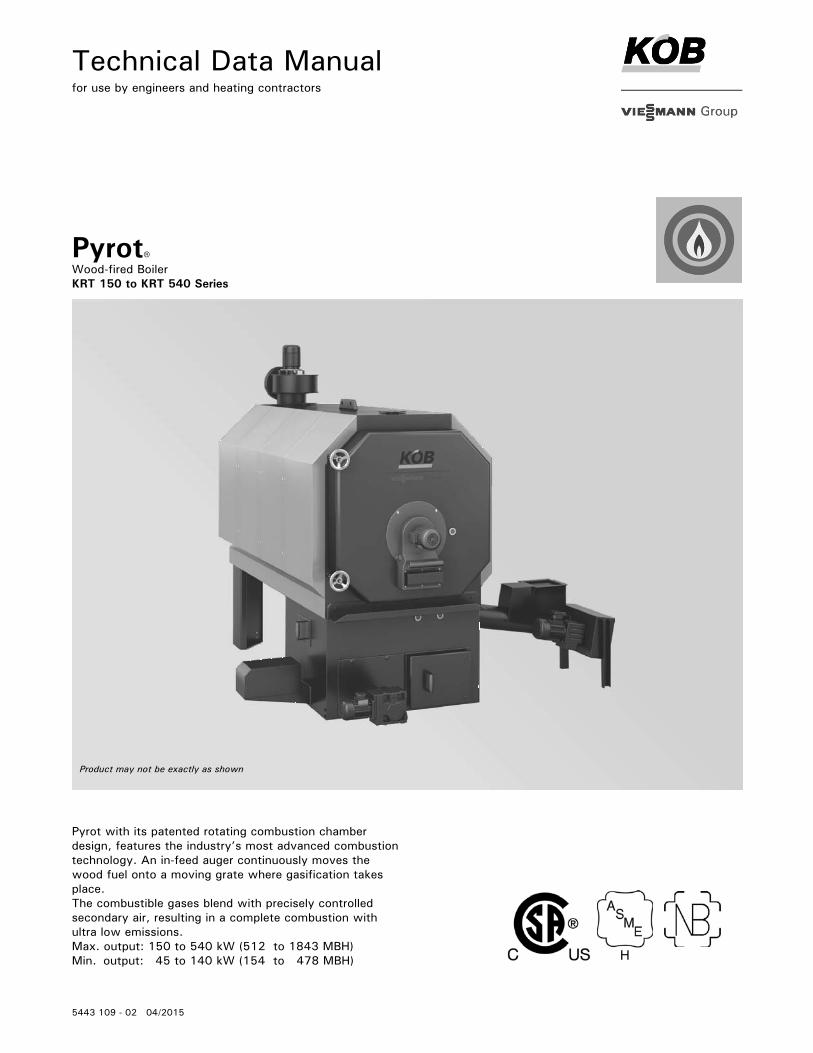
Pyrot with its patented rotating combustion chamber design, features the industry’s most advanced combustion technology. An in-feed auger continuously moves the wood fuel onto a moving grate where gasification takes place.The combustible gases blend with precisely controlled secondary air, resulting in a complete combustion with ultra low emissions.Max. output: 150 to 540 kW (512 to 1843 MBH)Min. output: 45 to 140 kW (154 to 478 MBH)
Pyrotr
Product may not be exactly as shown
Wood-fired Boiler KRT 150 to KRT 540 Series
H
2
5443 1
09 -
02
Pyrot Technical Data
PyrotProduct Information
CodesCSA B366.1-M91Solid Fuel Fired Central Heating Appliances
CSA C.22.2#3-M88 (R2004)Electrical Features of Fuel Burning Equipment
UL2523Solid Fuel-Fired Hydronic Heating Appliances, Water Heaters and Boilers
CSA B365-10Installation Code for Solid Fuel Burning Appliances and Equipment
WARNINGExposing the boiler to pressures and temperatures in excess of those listed will result in damages and will render the warranty null and void.
Maximum allowable working pressure (water)...30 or 60 psi
Maximum water temperature…..250°F (120°C) (closed loop)
Maximum boiler temperature………210°F (99°C) (open loop)
This boiler does not require a flow switch.
Steel wood-fired hot water heating boiler. For operation primarily with modulating boiler water temperatures in closed loop forced circulation hot water heating systems. Under certain conditions, open loop systems may also be considered. Contact Viessmann for details.
Specifications Fully-automatic rotating combustion wood-fired boiler
5 models from 512 to 1843 MBH
For dry wood fuels with max. water content of 35%
Efficiency: 85%
Available for 30 or 60 psi max. operating pressure
Benefits at a glance High efficiency with advanced combustion technology,
triple-pass heat exchanger and modulating output control (turndown ratio 4:1)
Maximum heat transfer with triple-pass heat exchanger design.
High efficiency and ultra-low emissions with precisely controlled primary and secondary air.
Igniter device limits idling and saves fuel.
Low maintenance with fully-automatic de-ashing, optional pneumatic cleaning system and flue gas cyclone.
Advanced safety equipment ensures safe and reliable operation.
Custom design of your system by our team of experts.
Available as convenient portable boiler enclosure.
3
5443 1
09 -
02
Pyrot Technical Data
Boiler Description
DescriptionThe PYROT Rotating Combustion System (patent no: EP 0 905 442 B1) was developed for automatic combustion of all dry to moist wood fuels (remnant wood, pellets and forest wood chips to max. W35-40, see section “Wood Fuel Requirements”. The PYROT Rotating Combustion System is characterized by high efficiencies and perfect combustion at all load levels. The PYROT Boiler Plant has been built to ASME Sec. IV and has CRN for Canada. It is tested and approved to the applicable CSA / UL safety standards.
Function:- The in-feed auger conveys the wood fuel diagonally from below into the combustion chamber. The holding devices for the back-burn sensor and the thermal extinguishing valve are situated on the in-feed auger. Above the in-feed auger, there is a metering container with a light barrier to ascertain the level of the fuel insulating layer required.- The wood fuel is ignited automatically by an igniter, at the time of the boiler start. The gasification of the fuel is carried out on a feed grate moved by a worm-geared motor. The ash falls in an ash bin below. An automatic de-ashing assembly with ash is optional. The combustion chamber is heavily insulated and lined with fire clay refractory elements.- The combustion gases rising from the combustion chamber are swept up by the rotary secondary airflow brought to bear from the rotation blower and burned out completely in the round combustion chamber. The thermal energy from the combustion gases is transmitted to the boiler water in horizontal heat exchanger tubes. The combustion chamber is heavily insulated and provided with excellent access through the boiler door in the front.- A flue gas re-circulation system reduces the temperature in the combustion chamber while maintaining the highest possible degree of efficiency. This increases the service life of the un-cooled refractory elements in the gasification zone. With the basic setting, the ratio of re-circulated gas to fresh air is precisely adjusted according to the amount of wood fuel that is burned. A mechanical adjustable damper provides a constant ratio of the quantity of re-circulated gas to fresh air over the entire output range.- The flue gas exhaust blower is specially designed for wood heating operation and is very quiet. The motor has a solid, heat resistant design with a heat dissipation hub and is spring supported. The blower casing has a round intake port and a round blowout nozzle Installation is possible on the top, side or rear of the flue gas collector within 360° rotation.
General Information
Boiler Description
Supplied with:- Boiler with rotary heat exchanger including supply and return temperature sensors- combustion chamber with moving grate and light barriers for ember monitoring- Igniter- In-feed auger including insulating layer, safety end switch for maintenance lid, back-burn temperature sensor, extinguisher water container with mounting bracket- Set of displacement rods- Flue gas re-circulation system- Flue gas exhaust blower including flue gas temperature sensor and oxygen sensor- Draft damper for installation in the flue gas pipe- Boiler cleaning tools for the combustion chamber and heat exchanger- Installation fittings including pressure relief valve, drain valve, low water cut off, fixed high limiter, temperature and pressure gauge
Customer supplied:- Counter flanges for the boiler supply and return- Piping to the 3-way mixing valve, boiler pump and thermal storage tank- Piping for the safety heat exchanger- Wiring to the control panel
Accessories for PYROT Rotating Combustion System:- Flue gas cyclone 24 USG (90 L)- Metal mesh filter- Automatic de-ashing in bin, 63 USG (240 L)- Automatic de-ashing in bin, 211 USG (800 L)- Automatic de-ashing in base container- Pneumatic cleaning system- Operating pressure 30 or 60 psi- Two-stage in-feed auger- Insulation for flue gas re-circulation line- Thermal safety flush valve- Slide valve / Rotary valve- Boiler pump and boiler 3-way mixing valve- Ecotronic control system options: - 3 sensor storage tank management system - External control module for field supplied extraction system - Output module / Input module - Input module 0-10V - ModBus - BacNet gateway - Visualization
CBER
Highlight

4
5443 1
09 -
02
Pyrot Technical Data
Precautions must be taken to avoid accidents and injury during the transportation of the boiler.Only hoist the boiler when it is entirely empty of water, fuel and ash.
LiftingA number of lifting lugs will be provided on each boiler and heat exchanger where lifting gear may be attached. A tie bar is required to lift the boiler by the boiler supply and boiler return flanges.
Minimum clearances to walls for installation and maintenance work must be observed. Anti-vibration boiler supports may be used if anti-vibration measures are required.
Pyrot 150 - 300:Hoist by the lifting lug.
Pyrot 400 - 540:Hoist by boiler supply and boiler return flanges using a lifting lug.
IMPORTANT
WARNINGFollow instructions for proper installation.For wood-fired installations:This wood-fired boiler must be installed in accordance with local codes if any; if not, follow B365-10, Installation Code for Solid-Fuel Burning Appliances and Equipment.
General Information
Transport and Installation
A Lifting lugs
5
5443 1
09 -
02
Pyrot Technical Data
Standard delivery conditionThe standard delivery condition of the Pyrot boiler includes pre-assembled components as well as components that need to be assembled by the contractor in the field.
Components that are attached to the boiler at time of delivery:- The heat exchanger is mounted to the combustion chamber- Boiler is fully bricked- Boiler door is mounted to the heat exchanger including secondary air rotary blower- Primary air vents are attached to the combustion chamber- Flue gas collector is attached to the heat exchanger- Pneumatic cleaning system (optional) is attached to the flue gas collector
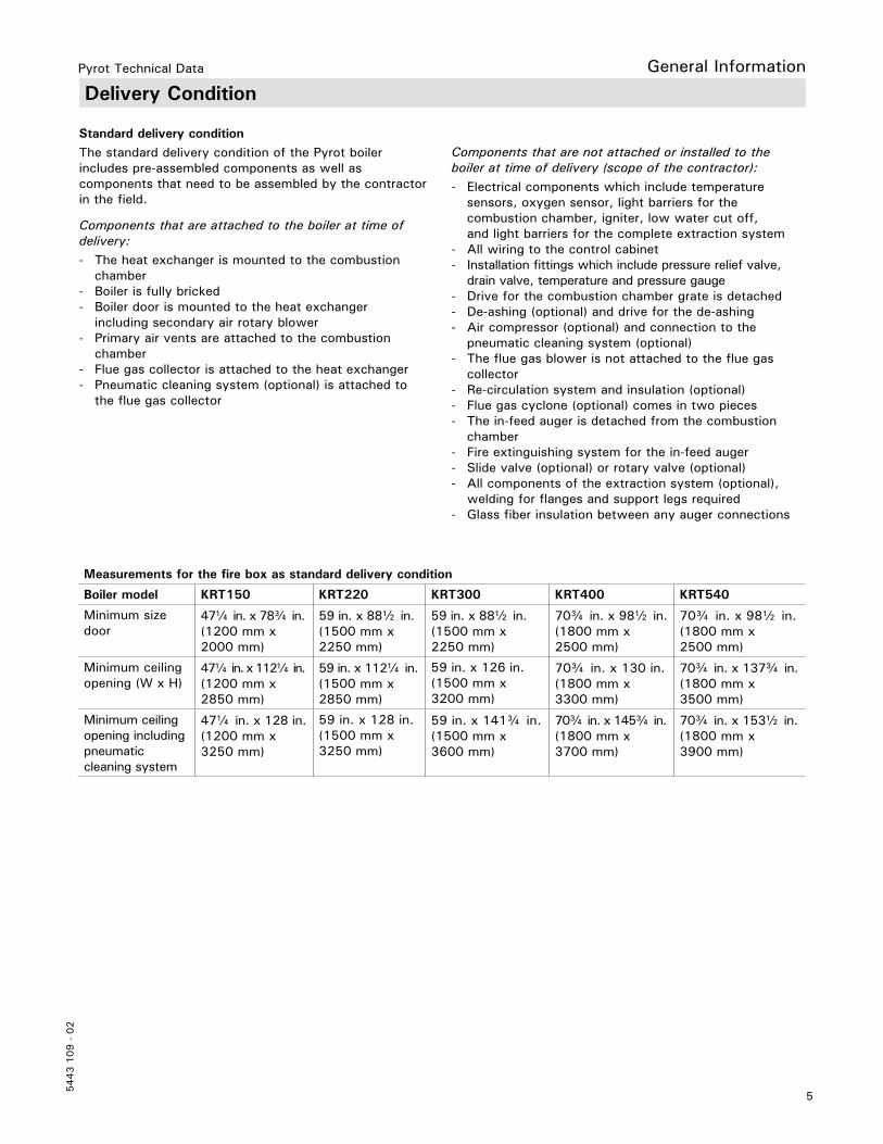
Measurements for the fire box as standard delivery condition
Boiler model KRT150 KRT220 KRT300 KRT400 KRT540
Minimum size door
47a in. x 78c in. (1200 mm x 2000 mm)
59 in. x 88b in. (1500 mm x 2250 mm)
59 in. x 88b in. (1500 mm x 2250 mm)
70c in. x 98b in. (1800 mm x 2500 mm)
70c in. x 98b in. (1800 mm x 2500 mm)
Minimum ceiling opening (W x H)
47a in. x 112a in. (1200 mm x 2850 mm)
59 in. x 112a in. (1500 mm x 2850 mm)
59 in. x 126 in. (1500 mm x 3200 mm)
70c in. x 130 in. (1800 mm x 3300 mm)
70c in. x 137c in. (1800 mm x 3500 mm)
Minimum ceiling opening including pneumatic cleaning system
47a in. x 128 in. (1200 mm x 3250 mm)
59 in. x 128 in. (1500 mm x 3250 mm)
59 in. x 141c in. (1500 mm x 3600 mm)
70c in. x 145c in. (1800 mm x 3700 mm)
70c in. x 153b in. (1800 mm x 3900 mm)
Delivery ConditionGeneral Information
Components that are not attached or installed to the boiler at time of delivery (scope of the contractor):- Electrical components which include temperature sensors, oxygen sensor, light barriers for the combustion chamber, igniter, low water cut off, and light barriers for the complete extraction system- All wiring to the control cabinet- Installation fittings which include pressure relief valve, drain valve, temperature and pressure gauge- Drive for the combustion chamber grate is detached- De-ashing (optional) and drive for the de-ashing - Air compressor (optional) and connection to the pneumatic cleaning system (optional)- The flue gas blower is not attached to the flue gas collector- Re-circulation system and insulation (optional)- Flue gas cyclone (optional) comes in two pieces- The in-feed auger is detached from the combustion chamber- Fire extinguishing system for the in-feed auger- Slide valve (optional) or rotary valve (optional)- All components of the extraction system (optional), welding for flanges and support legs required- Glass fiber insulation between any auger connections
6
5443 1
09 -
02
Pyrot Technical Data
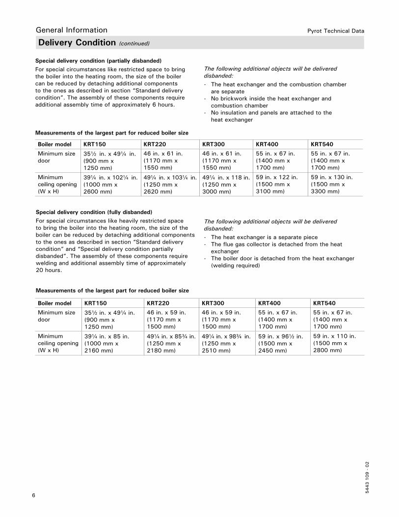
Boiler model KRT150 KRT220 KRT300 KRT400 KRT540
Minimum size door
35b in. x 49a in. (900 mm x 1250 mm)
46 in. x 61 in. (1170 mm x 1550 mm)
46 in. x 61 in. (1170 mm x 1550 mm)
55 in. x 67 in. (1400 mm x 1700 mm)
55 in. x 67 in. (1400 mm x 1700 mm)
Minimum ceiling opening (W x H)
39a in. x 102a in. (1000 mm x 2600 mm)
49a in. x 103a in. (1250 mm x 2620 mm)
49a in. x 118 in. (1250 mm x 3000 mm)
59 in. x 122 in. (1500 mm x 3100 mm)
59 in. x 130 in. (1500 mm x 3300 mm)
Special delivery condition (partially disbanded)For special circumstances like restricted space to bring the boiler into the heating room, the size of the boiler can be reduced by detaching additional components to the ones as described in section “Standard delivery condition”. The assembly of these components require additional assembly time of approximately 6 hours.
Measurements of the largest part for reduced boiler size
Special delivery condition (fully disbanded)For special circumstances like heavily restricted space to bring the boiler into the heating room, the size of the boiler can be reduced by detaching additional components to the ones as described in section “Standard delivery condition” and “Special delivery condition partially disbanded”. The assembly of these components require welding and additional assembly time of approximately 20 hours.
Measurements of the largest part for reduced boiler size
Boiler model KRT150 KRT220 KRT300 KRT400 KRT540
Minimum size door
35b in. x 49a in. (900 mm x 1250 mm)
46 in. x 59 in. (1170 mm x 1500 mm)
46 in. x 59 in. (1170 mm x 1500 mm)
55 in. x 67 in. (1400 mm x 1700 mm)
55 in. x 67 in. (1400 mm x 1700 mm)
Minimum ceiling opening (W x H)
39a in. x 85 in. (1000 mm x 2160 mm)
49a in. x 85c in. (1250 mm x 2180 mm)
49a in. x 98c in. (1250 mm x 2510 mm)
59 in. x 96b in. (1500 mm x 2450 mm)
59 in. x 110 in. (1500 mm x 2800 mm)
Delivery Condition (continued)
General Information
The following additional objects will be delivered disbanded:- The heat exchanger and the combustion chamber are separate- No brickwork inside the heat exchanger and combustion chamber- No insulation and panels are attached to the heat exchanger
The following additional objects will be delivered disbanded:- The heat exchanger is a separate piece- The flue gas collector is detached from the heat exchanger- The boiler door is detached from the heat exchanger (welding required)
7
5443 1
09 -
02
Pyrot Technical Data
Wood Fuel Requirements
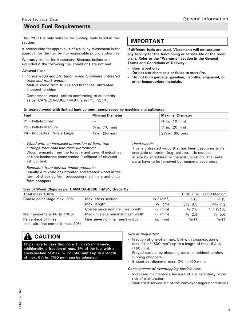
Allowed fuels- Forest wood and plantation wood (complete untreated trees and trunk wood): Mature wood from trunks and branches, untreated, chopped to chips
- Compressed wood, pellets conforming to standards, as per CAN/CSA-B366.1-M91, size P1, P2, P4.
Untreated wood with limited bark content, compressed by machine and calibrated
Fuel Minimal Diameter Maximal Diameter
P1 - Pellets Small --- e in. (10 mm)
P2 - Pellets Medium e in. (10 mm) c in. (20 mm)
P4 - Briquettes (Pellets Large) c in. (20 mm) 2b in. (60 mm)
Consequence of overstepping particle size:- Increased maintenance because of a substantially higher risk of malfunction- Shortened service life of the conveyor augers and drives
CAUTIONChips have to pass through a 1 in. (25 mm) sieve, additionally, a fraction of max. 5% of the fuel with a cross-section of max. c in² (500 mm²) up to a length of max. 6a in. (160 mm) can be tolerated.
- Wood with an increased proportion of bark, tree cuttings from roadside trees (untreated): Wood remnants from the forestry and sawmill industries or from landscape conservation (likelihood of elevated ash content).
- Remnants from derived timber products: Usually a mixture of untreated and treated wood in the form of shavings from processing machinery and chips from choppers.
If different fuels are used, Viessmann will not assume any liability for the functioning or service life of the boiler plant. Refer to the “Warranty” section in the General Terms and Conditions of Delivery.- Burn wood only- Do not use chemicals or fluids to start fire.- Do not burn garbage, gasoline, naphtha, engine oil, or other inappropriate materials.
IMPORTANT
General Information
The PYROT is only suitable for burning fuels listed in this section.
A prerequisite for approval is of a fuel by Viessmann is the approval for the fuel by the responsible public authorities.
Warranty claims for Viessmann Biomass boilers are excluded if the following fuel conditions are not met.
Size of briquettes:- Fraction of one-offs. max. 5% with cross-section of max. c in2 (500 mm2) up to a length of max. 6a in. (160 mm).- Frayed surface by chopping tools (shredders) or slow- running choppers.- Briquettes, diameter max. 2e in. (60 mm).
- Used wood: This is untreated wood that has been used prior to its energetic utilization (e.g. pallets). It is reduced in size by shredders for thermal utilization. The metal parts have to be removed by magnetic separators.
Size of Wood Chips as per CAN/CSA-B366.1-M91, Grade C7Total mass 100% G 30 Fine G 50 MediumCoarse percentage max. 20% Max. cross-section in.2 (cm2) b (3) c (5)
Max. length in. (cm) 3g (8.5) 4c (12)Coarse sieve nominal mesh width in. (mm) f (16) 1a (31.5)
Main percentage 60 to 100% Medium sieve nominal mesh width in. (mm) d (2.8) a (5.6)Percentage of fines (incl. ultrafine content) max. 20%
Fine sieve nominal mesh width in. (mm) 1/25 (1) 1/25 (1)
8
5443 1
09 -
02
Pyrot Technical Data
Wood Fuel Requirements (continued)
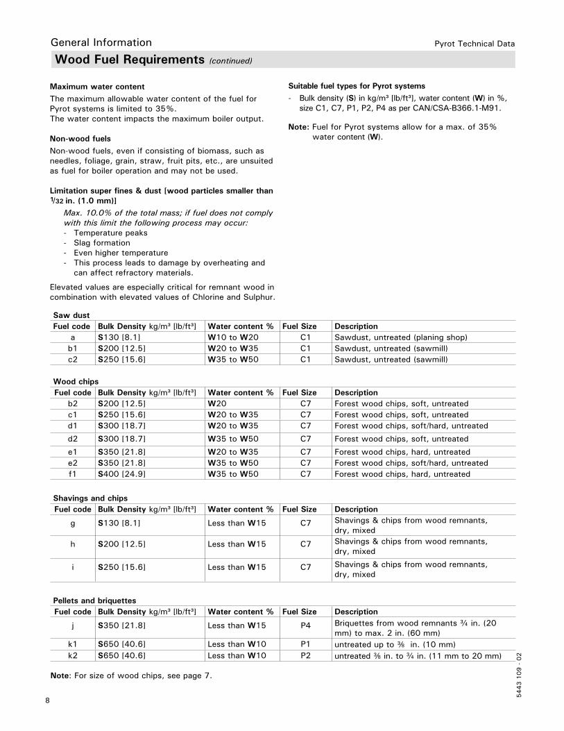
Maximum water contentThe maximum allowable water content of the fuel for Pyrot systems is limited to 35%. The water content impacts the maximum boiler output.
Non-wood fuelsNon-wood fuels, even if consisting of biomass, such as needles, foliage, grain, straw, fruit pits, etc., are unsuited as fuel for boiler operation and may not be used.
Limitation super fines & dust [wood particles smaller than 1/32 in. (1.0 mm)] Max. 10.0% of the total mass; if fuel does not comply with this limit the following process may occur: - Temperature peaks - Slag formation - Even higher temperature - This process leads to damage by overheating and can affect refractory materials.
Elevated values are especially critical for remnant wood in combination with elevated values of Chlorine and Sulphur.
General Information
Suitable fuel types for Pyrot systems- Bulk density (S) in kg/m³ [lb/ft³], water content (W) in %, size C1, C7, P1, P2, P4 as per CAN/CSA-B366.1-M91.
Note: Fuel for Pyrot systems allow for a max. of 35% water content (W).
Saw dustFuel code Bulk Density kg/m³ [lb/ft³] Water content % Fuel Size Description
a S130 [8.1] W10 to W20 C1 Sawdust, untreated (planing shop)b1 S200 [12.5] W20 to W35 C1 Sawdust, untreated (sawmill)c2 S250 [15.6] W35 to W50 C1 Sawdust, untreated (sawmill)
Wood chipsFuel code Bulk Density kg/m³ [lb/ft³] Water content % Fuel Size Description
b2 S200 [12.5] W20 C7 Forest wood chips, soft, untreatedc1 S250 [15.6] W20 to W35 C7 Forest wood chips, soft, untreatedd1 S300 [18.7] W20 to W35 C7 Forest wood chips, soft/hard, untreated
d2 S300 [18.7] W35 to W50 C7 Forest wood chips, soft, untreated
e1 S350 [21.8] W20 to W35 C7 Forest wood chips, hard, untreatede2 S350 [21.8] W35 to W50 C7 Forest wood chips, soft/hard, untreatedf1 S400 [24.9] W35 to W50 C7 Forest wood chips, hard, untreated
Shavings and chipsFuel code Bulk Density kg/m³ [lb/ft³] Water content % Fuel Size Description
g S130 [8.1] Less than W15 C7 Shavings & chips from wood remnants, dry, mixed
h S200 [12.5] Less than W15 C7 Shavings & chips from wood remnants, dry, mixed
i S250 [15.6] Less than W15 C7 Shavings & chips from wood remnants, dry, mixed
Pellets and briquettesFuel code Bulk Density kg/m³ [lb/ft³] Water content % Fuel Size Description
j S350 [21.8] Less than W15 P4 Briquettes from wood remnants c in. (20 mm) to max. 2 in. (60 mm)
k1 S650 [40.6] Less than W10 P1 untreated up to e in. (10 mm)k2 S650 [40.6] Less than W10 P2 untreated e in. to c in. (11 mm to 20 mm)
Note: For size of wood chips, see page 7.
9
5443 1
09 -
02
Pyrot Technical Data
Wood Fuel Requirements (continued)
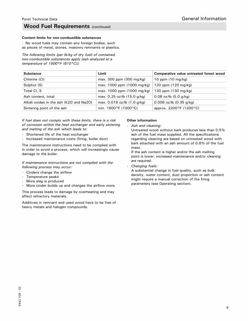
If fuel does not comply with these limits, there is a risk of corrosion within the heat exchanger and early sintering and melting of the ash which leads to:- Shortened life of the heat exchanger- Increased maintenance costs (firing, boiler door)
The maintenance instructions need to be complied with in order to avoid a process, which will increasingly cause damage to the boiler. If maintenance instructions are not complied with the following process may occur:- Cinders change the airflow- Temperature peaks- More slag is produced- More cinder builds up and changes the airflow more
This process leads to damage by overheating and may affect refractory materials.
Additives in remnant and used wood have to be free of heavy metals and halogen compounds.
Content limits for non-combustible substances- No wood fuels may contain any foreign bodies, such as pieces of metal, stones, masonry remnants or plastics.
The following limits (per lb/kg of dry fuel) of contained non-combustible substances apply [ash analyzed at atemperature of 1500°F (815°C)]:
Substance Limit Comparative value untreated forest wood
Chlorine (Cl) max. 300 ppm (300 mg/kg) 10 ppm (10 mg/kg)
Sulphur (S) max. 1000 ppm (1000 mg/kg) 120 ppm (120 mg/kg)
Total Cl, S max. 1000 ppm (1000 mg/kg) 130 ppm (130 mg/kg)
Ash content, total max. 0.25 oz/lb (15.0 g/kg) 0.08 oz/lb (5.0 g/kg)
Alkali oxides in the ash (K2O and Na2O) max. 0.016 oz/lb (1.0 g/kg) 0.006 oz/lb (0.35 g/kg)
Sintering point of the ash min. 1800°F (1000°C) approx. 2200°F (1200°C)
General Information
Other information- Ash and cleaning: Untreated wood without bark produces less than 0.5% ash of the fuel mass supplied. All the specifications regarding cleaning are based on untreated wood with bark attached with an ash amount of 0.8% of the fuel mass. If the ash content is higher and/or the ash melting point is lower, increased maintenance and/or cleaning are required.- Changing fuels: A substantial change in fuel quality, such as bulk density, water content, dust proportion or ash content might require a manual correction of the firing parameters (see Operating section).

10
5443 1
09 -
02
Pyrot Technical Data
The PYROT Rotating Combustion system is equipped with a flue gas exhaust blower.
This boiler must be properly vented. Use a vent material certified for use with solid-fuel fired equipment.
This boiler shall be connected to:a) a masonry chimney conforming to local regulations or, in the absence of such regulations, to the requirements of the National Building Code.b) a certified factory-built chimney (refer to the NFPA 211 standard).
A flue pipe serving this boiler shall be constructed of steel or other suitable material with a melting point of not less than 2000°F (1100°C).
Do not use galvanized steel.
IMPORTANT
Customers must ensure that there is a supply of water independent of the electrical supply. This design ensures that in case of a power failure, the boiler will be reliably cooled by the thermal safety flush valve.
Power Failure ProvisionSafety
Venting Requirements
For installations in Canada:The boiler venting system must be tested and listed by a Nationally Recognized Testing Lab such as ULC/CSAfor solid fuel burning appliances.
The PYROT rotating combustion system is output-controlled within a range from 30%-100% of the rated boiler output. This produces flue gas temperatures from min. 212°F (100°C) to max. 482°F (250°C).
An insulated chimney should be provided to prevent sooting.
The distance from the flue gas exhaust blower to the chimney should be as short as possible. 90° elbows should be avoided if possible. Flue gas pipes of more than 3 ft. (1 m) in length must be insulated.
The connection to the chimney should be made such that it rises at an angle of 30°- 45° (to prevent excess ash accumulating in the lateral section of the vent pipe).
The flue gas line, including the lead-in into the chimney, must be gas-tight.
11
5443 1
09 -
02
Pyrot Technical Data
The minimum distance to the walls and ceiling required according to the table of dimensions for proper cleaning and maintenance of the boiler must be complied with.
A sufficient supply of fresh air must be provided directly from outdoors into the heating room. Induced ventilation is necessary for heating rooms that are confined or enclosed.
Safety
Mechanical Room
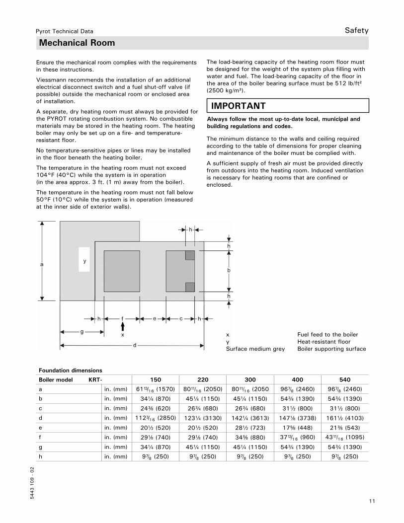
Foundation dimensions
Boiler model KRT- 150 220 300 400 540
a in. (mm) 6113/16 (1570) 8011/16 (2050) 8011/16 (2050 967/8 (2460) 967/8 (2460)
b in. (mm) 34a (870) 45a (1150) 45a (1150) 54c (1390) 54c (1390)
c in. (mm) 24e (620) 26c (680) 26c (680) 31b (800) 31b (800)
d in. (mm) 1123/16 (2850) 123a (3130) 142a (3613) 147d (3738) 161b (4103)
e in. (mm) 20b (520) 20b (520) 28b (723) 17f (448) 21e (543)
f in. (mm) 29d (740) 29d (740) 34f (880) 3713/16 (960) 4311/16 (1095)
g in. (mm) 34a (870) 45a (1150) 45a (1150) 54c (1390) 54c (1390)
h in. (mm) 97/8 (250) 97/8 (250) 97/8 (250) 97/8 (250) 97/8 (250)
The load-bearing capacity of the heating room floor must be designed for the weight of the system plus filling with water and fuel. The load-bearing capacity of the floor in the area of the boiler bearing surface must be 512 lb/ft² (2500 kg/m²).
IMPORTANTAlways follow the most up-to-date local, municipal and building regulations and codes.
x Fuel feed to the boilery Heat-resistant floorSurface medium grey Boiler supporting surface
Ensure the mechanical room complies with the requirements in these instructions.
Viessmann recommends the installation of an additional electrical disconnect switch and a fuel shut-off valve (if possible) outside the mechanical room or enclosed area of installation.
A separate, dry heating room must always be provided for the PYROT rotating combustion system. No combustible materials may be stored in the heating room. The heating boiler may only be set up on a fire- and temperature-resistant floor.
No temperature-sensitive pipes or lines may be installed in the floor beneath the heating boiler.
The temperature in the heating room must not exceed 104°F (40°C) while the system is in operation (in the area approx. 3 ft. (1 m) away from the boiler).
The temperature in the heating room must not fall below 50°F (10°C) while the system is in operation (measured at the inner side of exterior walls).
12
5443 1
09 -
02
Pyrot Technical Data
Combustion Air SupplySafety
WARNINGFailure to provide an adequate supply of fresh combustion air can cause poisonous flue gases to enter living space. Flue gases entering living space can cause carbon monoxide poisoning which can result in severe personal injury or loss of life.
WARNINGNever cover the boiler or store debris or other materials near the boiler, or in any way block the flow of adequate fresh air to the boiler. Never cover the combustion air opening. Advise system operator / ultimate owner accordingly.
GeneralThis equipment requires fresh air for safe operation and must be installed ensuring provisions for adequate combustion and ventilation air exist.
Whenever possible, install boiler near an outside wall so that it is easy to duct fresh air directly to the boiler area.
The boiler location must never be under negative pressure. Exhaust blowers, attic blowers, or dryer blowers may cause air to be exhausted at a rate higher than air can enter the structure for safe combustion.
The heating contractor shall ensure all of the following requirements are met:- An adequate supply of combustion air must be available to ensure proper combustion.
- Ambient air temperatures must be maintained within safe operating limits.
- When a damper is provided in any opening intended to admit combustion air into the room within which the appliance is installed, the damper shall be interlocked to prevent any burner from starting before the damper is fully open.
- Each duct used to convey air from the outdoors shall have: 1. a cross-sectional area throughout its length at least equal to the free area of the inlet and outlet openings which it connects,
2. making a provision for outside combustion air, the intake shall not be less than 1 ft. (0.3 m) above the anticipated snow level for the location.
- The heating contractor must check with local authorities (municipal building department) for combustion air requirements particular to the area.
CodesProvision for combustion and ventilation air must be made in accordance with applicable local codes.In the absence of local codes, use:CSA B365-10, Installation Code for Solid Fuel Burning Appliances and Equipment.Always use latest edition codes.
Confined spacesWhen a furnace or boiler is enclosed in a space that has a volume less than 20% of that to be heated by the appliance, the space shall:a) have a permanent opening or openings for natural air circulation with a minimum net free area of 1.5 in² / 1000 Btu/h (3300 mm² / kW) input, and
b) connect to another space or spaces such that the total volume of air available for natural air circulation is at least 30% of the total volume to be heated by the appliance.
The minimum dimension of any opening specified in item (a) shall be no less than 1 in. (25 mm) The lower edge of at least one opening shall be located within 1.5 ft. (0.5 m) of the floor of the enclosed space, and the upper edge of at least one opening shall be located within 1.5 ft. (0.5 m) of the ceiling of the enclosed space.
Note: The intent of this Clause is to allow either one long vertical opening or two shorter horizontal openings, one high and the other low, to allow for air circulation to prevent overheating of the appliance.
Unconfined spacesWhere the boiler is located in an unconfined space in a building having insufficient infiltration, additional air for combustion and ventilation shall be obtained from outdoors or from spaces freely communicating with the outdoors. Under these conditions, permanent opening(s) shall be provided so that the total air received through these openings will be at least as much as would be admitted by openings having a total free area of 1 in² / 5,000 Btu/h or (450 mm² / kWh) of the total input rating of all wood-fired appliances.
Louvers and grillesIn calculating free area as specified, consideration shall be given to the blocking effect of louvers, grilles, or screens that protect openings. Screens shall be no smaller than ¼ in. (6 mm) mesh and shall be readily accessible for cleaning. If the free area through a design of louver or grilles is known, it shall be used in calculating the size of opening required to provide the free area specified. If the design and free area are not known, it shall be assumed that wood louvers have 20 - 25% free area and metal louvers and grilles have 60 - 75% free area.

13
5443 1
09 -
02
Pyrot Technical Data
Technical Data
Boiler model KRT- 150 220 300 400 540
Maximum output MBH (kW) 512 (150) 751 (220) 1024 (300) 1365 (400) 1843 (540)
Minimum output1 MBH (kW) 154 (45) 205 (60) 273 (80) 341 (100) 478 (140)
Efficiency 85%
Fuel moisture content2 % W 40
Size of wood chips3 G 30 / G 50 as per CAN/CSA-B366. 1-M91
Flue gas figuresConnection flue gas pipe 7 AMass flow rate; W5; O2 6% Volume flow; W5; O2 6%; 150ºC (302º F)Mass flow rate; W35; O2 8%;Volume flow;W35; O2 8%; 150°C (302º F)Average flue gas temperature at full load4
Average flue gas temperature at partial load4
Chimney draft required
in. (mm) lb/s (g/s)
ft³/s (m³/s)lb/s (g/s)
ft³/s (m³/s)°F (°C)°F (°C)
Pa
97/8 (250)0.18 (80.4)3.1 (0.09)
0.24 (106.9)4.2 (0.12)
97/8 (250)0.26 (117.9)4.9 (0.14)
0.35 (156.9)6.7 (0.19)
117/8 (300)0.35 (160.8)6.7 (0.19)
0.47 (213.9)8.8 (0.25)
137/8 (350)0.47 (214.4)8.8 (0.25)
0.63 (285.2)12.0 (0.34)
137/8 (350)0.64 (289.44)12.4 (0.35)0.85 (385.1)16.2 (0.46)
320 (160)266 (130)
±0
Electrical connectionsElectrical connections, totalIgniterFlue gas exhaust blower Rotary blowerIn-feed augerGrate drive unit Electric power consumption at full loadElectric power consumption at partial load
kWkWkWkWkWkWkWkW
2.671.60.550.120.370.031.0320.355
2.851.60.550.120.550.031.1080.369
3.61.60.750.121.10.031.5210.434
3.981.61.10.121.10.061.8680.480
3.631.61.10.120.750.061.7530.460
HeatingWater side resistance (diff. 27°F/15 K)Boiler water volume Heating surface Volume on heating gas side Volume of ash container for grate ash
Volume of ash container for flue gas cycloneTest pressure5
Maximum allowable working pressure (water)5 Maximum water temperatureMinimum return temperature
“wc (mbar)USG (L)ft² (m²)USG (L)USG (L)
USG (L)psi (bar)psi (bar)°F (°C)°F (°C)
13 (38)114 (430)
116.3 (10.8)99 (374)8 (32)
30 (76)209 (790)
172.3 (16.0)197 (744)12 (45)
16 (42)238 (900)
222.9 (20.7)233 (883)15 (55)
11 (29)350 (1330)
310.1 (28.8)354 (1340)
20 (75)
22 (56)399 (1510)
424.1 (39.4)426 (1613)
24 (91)
24 (90)60 or 90 (4 or 6)30 or 60 (2 or 4)
250 (120)149 (65)
WeightWeight of combustion chamberWeight of pressure vessel (30 psi) 6 Weight of pressure vessel (60 psi) 6 Weight of displacement rodsWeight of flue gas exhaust blowerWeight of in-feed augerTotal weight without water (30 psi) 7 Total weight without water (60 psi) 7Total weight with water (30 psi) 7 Total weight with water (60 psi) 7
lb. (kg)lb. (kg)lb. (kg)lb. (kg)lb. (kg)lb. (kg)lb. (kg)lb. (kg)lb. (kg)lb. (kg)
1049 (477)4885 (2216)4974 (2256)
191 (87)88 (40)
315 (143)6532 (2963)6620 (3003)7485 (3395)7573 (3435)
1278 (581)6535 (2964)6667 (3024)310 (141)88 (40)
315 (143)8530 (3869)8662 (3929)10280 (4663)10412 (4723)
1410 (641)7408 (3360)7452 (3380)359 (163)99 (45)
315 (143)9595 (4352)9639 (4372)11585 (5255)11629 (5275)
1712 (778)9764 (4429)9875 (4479)484 (220)136 (62)315 (143)
12416 (563212527 (5682)15340 (6958)15450 (7008)
2061 (937)11233 (5095)11453 (5195)
636 (289)136 (62)328 (149)
14401 (6532)14621 (6632)17730 (8042)17950 (8142)
1 Minimum load: Operation with modulated control (Infinitely variable power control) Low load with ON Qmin / OFF (Stop-and-go mode)2 Moist fuels: >W35 further limitations regarding output, degree of efficiency and control behavior3 Specification: See section on Wood Fuel Requirements 4 Flue gas temperature: An increase is possible by removing the displacement rods [Full load 86°F (30°C); Partial load 50°F (10°C)]5 Pressure: Per ASME Sec. IV 6 Weight: Includes door and refractory concrete lining7 Overall weight: Includes displacement rodsOther influences: Fuel, water content, ash content, pneumatic cleaning system yes/no; track time (number of operating hours without cleaning). Specifications for the start of the track time [toward the end of the track time there is an increase in the flue gas temperature by approx. 68°F (20°C)]
Mechanical
CBER
Highlight

14
5443 1
09 -
02
Pyrot Technical Data
Dimensions
Boiler Model KRT- 150 220 300 400 540
a in. (mm) 157/16 (392) 16 (406) 16 (406) 18e (466) 18e (466)b in. (mm) 60f (1541) 60 (1525) 7313/16 (1875) 707/8 (1800) 7915/16 (2030)
c in. (mm) 141/16 (358) 141/16 (358) 137/8 (352) 14c (375) 14c (375)d in. (mm) 75d (1908) 85e (2168) 86d (2182) 96c (2457) 99b (2527)e in. (mm) 1115/16 (303) 127/16 (316) 127/16 (316) 129/16 (319) 129/16 (319)f in. (mm) 43 (1093) 467/16 (1179) 467/16 (1179) 48 (1219) 50e (1279)g in. (mm) 3 (DN 80) 3 (DN 80) 5 (DN 125) 5 (DN 125) 5 (DN 125)h in. (mm) 12213/16 (3120) 13413/16 (3424) 14813/16 (3780) 157f (4004) 1665/8 (4232)
k in. (mm) 149/16 (370) 149/16 (370) 175/16 (440) 175/16 (440) 249/16 (548)l in. (mm) 34a (870) 45a (1150) 45a (1150) 54c (1390) 54c (1390)m in. (mm) 69b (1765) 7911/16 (2024) 7911/16 (2024) 891/16 (2262) 9113/16 (2332)
n in. (mm) 717/8 (1825) 821/16 (2084) 821/16 (2084) 95e (2422)*1 98d (2492)*1
o in. (mm) 279/16 (700) 279/16 (700) 279/16 (700) 279/16 (700) 293/16 (742)
p in. (mm) 34a (870) 45a (1150) 45a (1150) 54c (1390) 54c (1390)q in. (mm) 26b (673) 26b (673) 26b (673) 26b (673) 29b (750)
r in. (mm) 41e (1050) 52e (1330) 52e (1330) 617/8 (1570) 617/8 (1570)
Boiler DimensionsMechanical
*1 For Pyrot 400/540 - Suspension gear is detachable.
BR BS
BR Boiler ReturnBS Boiler Supply
15
5443 1
09 -
02
Pyrot Technical Data
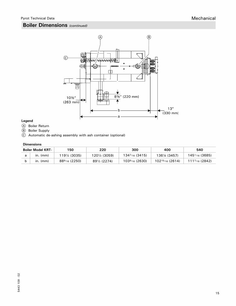
Boiler Dimensions (continued)
Mechanical
Dimensions
Boiler Model KRT- 150 220 300 400 540
a in. (mm) 119b (3035) 120b (3059) 1347/16 (3415) 136d (3457) 1451/16 (3685)
b in. (mm) 889/16 (2250) 89b (2274) 1039/16 (2630) 10215/16 (2614) 1117/16 (2842)
LegendA Boiler ReturnB Boiler SupplyC Automatic de-ashing assembly with ash container (optional)

16
5443 1
09 -
02
Pyrot Technical Data
Boiler ComponentsMechanical
LegendA Flue gas exhaust blowerB Boiler door with rotary blowerC Extinguishing water connection c in.D In-feed augerE Grate motorF Ash doors of the grate ash container (2 units)G Motor for automatic de-ashing assemblyH Combustion chamberI Incline auger for automatic de-ashing assemblyJ Light barrier for in-feed augerK Limit switch for maintenance coverL Temperature sensor for in-feed augerM Light barrier for ember monitoring (2 locations)N Light barrier for automatic de-ashing assembly
LegendA Pneumatic cleaning system (optional)B Cleaning cover, flue gas collector, alternate port for the flue gas exhaust blowerC Cover with sight glassD Recirculation gas line, line routing variableE IgniterF Rotary blowerG Flue gas temperature sensorH Oxygen sensorBS Boiler SupplyBR Boiler Return
17
5443 1
09 -
02
Pyrot Technical Data Mechanical
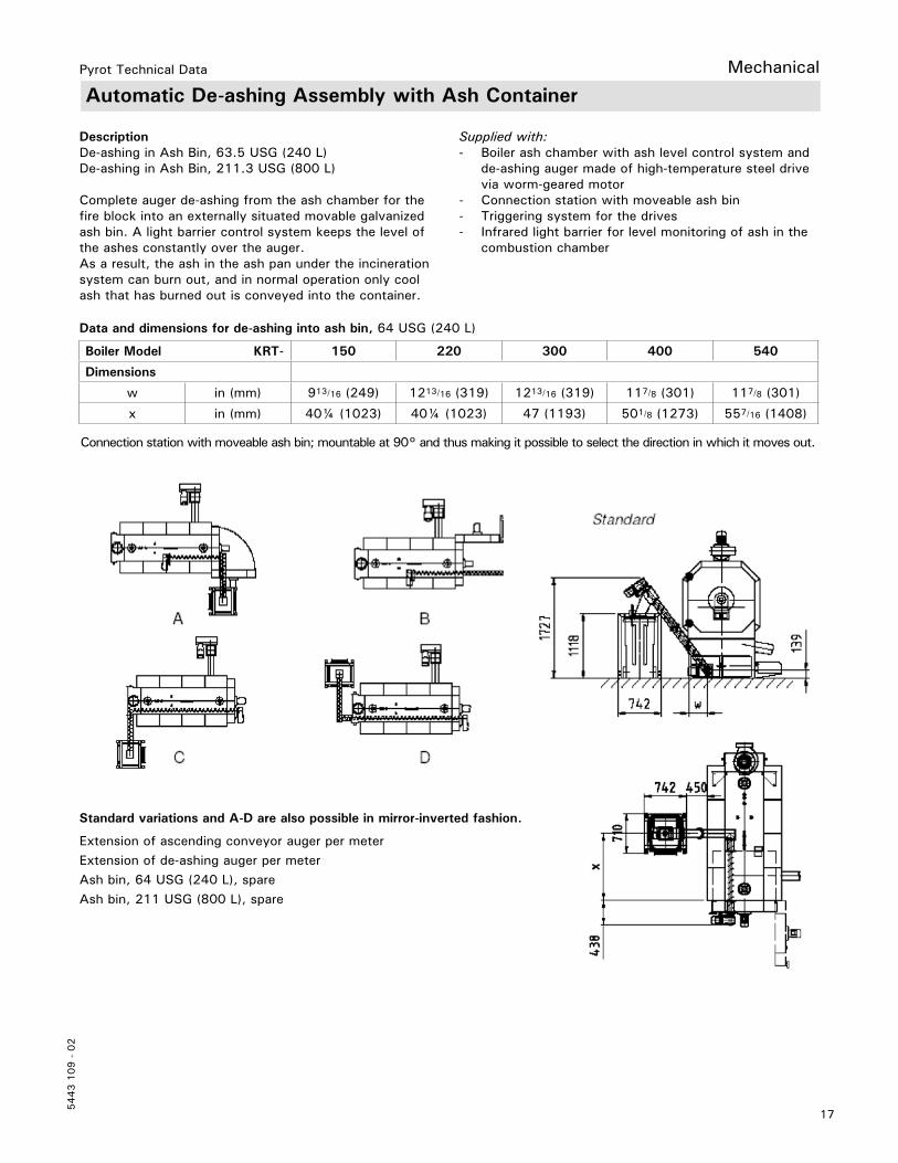
Automatic De-ashing Assembly with Ash Container
DescriptionDe-ashing in Ash Bin, 63.5 USG (240 L) De-ashing in Ash Bin, 211.3 USG (800 L)
Complete auger de-ashing from the ash chamber for the fire block into an externally situated movable galvanized ash bin. A light barrier control system keeps the level of the ashes constantly over the auger. As a result, the ash in the ash pan under the incineration system can burn out, and in normal operation only cool ash that has burned out is conveyed into the container.
Boiler Model KRT- 150 220 300 400 540
Dimensions
w in (mm) 913/16 (249) 1213/16 (319) 1213/16 (319) 117/8 (301) 117/8 (301)
x in (mm) 40¼ (1023) 40¼ (1023) 47 (1193) 501/8 (1273) 557/16 (1408)
Connection station with moveable ash bin; mountable at 90° and thus making it possible to select the direction in which it moves out.
Standard variations and A-D are also possible in mirror-inverted fashion.
Extension of ascending conveyor auger per meter Extension of de-ashing auger per meter Ash bin, 64 USG (240 L), spare Ash bin, 211 USG (800 L), spare
Supplied with:- Boiler ash chamber with ash level control system and de-ashing auger made of high-temperature steel drive via worm-geared motor- Connection station with moveable ash bin- Triggering system for the drives- Infrared light barrier for level monitoring of ash in the combustion chamber
Data and dimensions for de-ashing into ash bin, 64 USG (240 L)
18
5443 1
09 -
02
Pyrot Technical DataMechanical
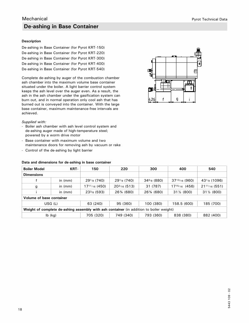
De-ashing in Base Container
Description
De-ashing in Base Container (for Pyrot KRT-150)
De-ashing in Base Container (for Pyrot KRT-220)
De-ashing in Base Container (for Pyrot KRT-300)De-ashing in Base Container (for Pyrot KRT-400)De-ashing in Base Container (for Pyrot KRT-540)
Complete de-ashing by auger of the combustion chamber ash chamber into the maximum volume base container situated under the boiler. A light barrier control system keeps the ash level over the auger even. As a result, the ash in the ash chamber under the gasification system can burn out, and in normal operation only cool ash that has burned out is conveyed into the container. With the large base container, maximum maintenance-free intervals are achieved.
Supplied with:- Boiler ash chamber with ash level control system and de-ashing auger made of high-temperature steel; powered by a worm drive motor- Base container with maximum volume and two maintenance doors for removing ash by vacuum or rake- Control of the de-ashing by light barrier
Boiler Model KRT- 150 220 300 400 540
Dimensions
f in (mm) 291/8 (740) 291/8 (740) 345/8 (880) 3713/16 (960) 431/8 (1096)
g in (mm) 1711/16 (450) 203/16 (513) 31 (787) 1715/16 (456) 2111/16 (551)
i in (mm) 233/8 (593) 26¾ (680) 26¾ (680) 31½ (800) 31½ (800)
Volume of base container
USG (L) 63 (240) 95 (360) 100 (380) 158.5 (600) 185 (700)
Weight of complete de-ashing assembly with ash container (in addition to boiler weight)
lb (kg) 705 (320) 749 (340) 793 (360) 838 (380) 882 (400)
Data and dimensions for de-ashing in base container
19
5443 1
09 -
02
Pyrot Technical Data Mechanical
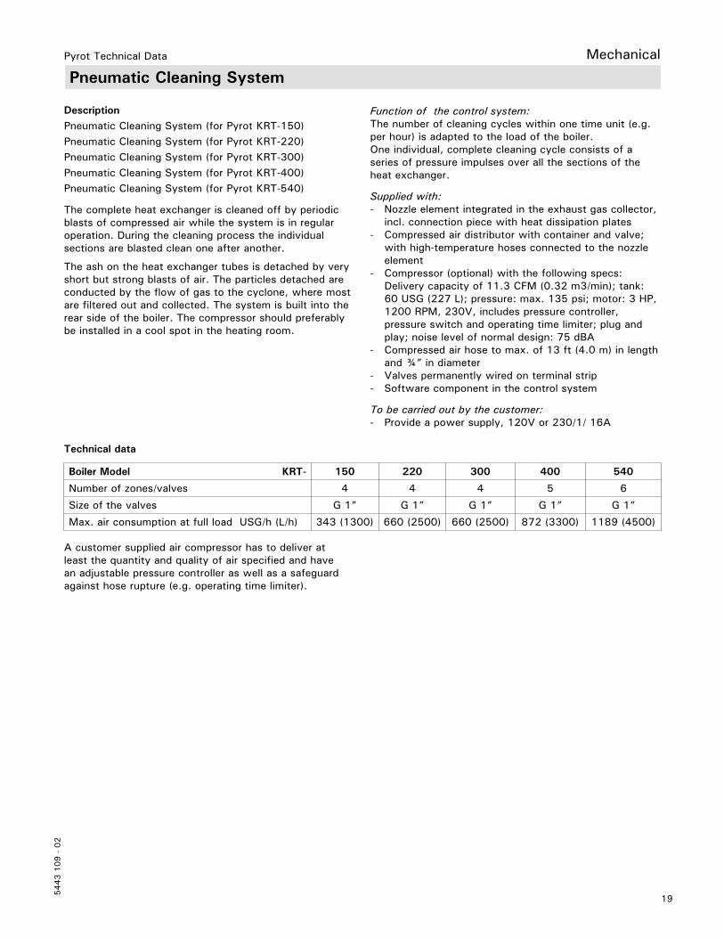
Pneumatic Cleaning System
DescriptionPneumatic Cleaning System (for Pyrot KRT-150)Pneumatic Cleaning System (for Pyrot KRT-220)Pneumatic Cleaning System (for Pyrot KRT-300)Pneumatic Cleaning System (for Pyrot KRT-400)Pneumatic Cleaning System (for Pyrot KRT-540)
The complete heat exchanger is cleaned off by periodic blasts of compressed air while the system is in regularoperation. During the cleaning process the individual sections are blasted clean one after another.
The ash on the heat exchanger tubes is detached by very short but strong blasts of air. The particles detached are conducted by the flow of gas to the cyclone, where most are filtered out and collected. The system is built into the rear side of the boiler. The compressor should preferably be installed in a cool spot in the heating room.
Boiler Model KRT- 150 220 300 400 540
Number of zones/valves 4 4 4 5 6
Size of the valves G 1” G 1” G 1” G 1” G 1”
Max. air consumption at full load USG/h (L/h) 343 (1300) 660 (2500) 660 (2500) 872 (3300) 1189 (4500)
A customer supplied air compressor has to deliver at least the quantity and quality of air specified and have an adjustable pressure controller as well as a safeguard against hose rupture (e.g. operating time limiter).
Function of the control system:The number of cleaning cycles within one time unit (e.g. per hour) is adapted to the load of the boiler. One individual, complete cleaning cycle consists of a series of pressure impulses over all the sections of the heat exchanger.
Supplied with:- Nozzle element integrated in the exhaust gas collector, incl. connection piece with heat dissipation plates- Compressed air distributor with container and valve; with high-temperature hoses connected to the nozzle element- Compressor (optional) with the following specs: Delivery capacity of 11.3 CFM (0.32 m3/min); tank: 60 USG (227 L); pressure: max. 135 psi; motor: 3 HP, 1200 RPM, 230V, includes pressure controller, pressure switch and operating time limiter; plug and play; noise level of normal design: 75 dBA- Compressed air hose to max. of 13 ft (4.0 m) in length and ¾” in diameter- Valves permanently wired on terminal strip- Software component in the control system
To be carried out by the customer:- Provide a power supply, 120V or 230/1/ 16A
Technical data

20
5443 1
09 -
02
Pyrot Technical Data
DimensionsBoiler Model KRT- 150 220 300 400 540a in. (mm) 11b (292) 11b (292) 1211/16 (323) 1211/16 (323) 17e (442)b in. (mm) 97/8 (250) 97/8 (250) 117/8 (300) 137/8 (350) 137/8 (350)c in. (mm) 9d (232) 10d (257) 107/8 (277) 14 (355) 14 (355)d in. (mm) 141/16 (358) 141/16 (358) 137/16 (352) 14c (375) 14c (375)e in. (mm) 97/8 250 97/8 (250) 11c (300) 13c (350) 13c (350)f in. (mm) 47/8 (125) 47/8 (125) 57/8 (150) 67/8 (175) 67/8 (175)
It is recommended to install a draft damper in the chimney 1. The draft damper is field supplied.
Optional, the Viessmann supplied draft damper can be installed in the flue gas pipe of the biomass boiler 2. The draft damper should be installed in the flue gas pipe (not included) as close as possible to the chimney not closer than 39e In. (1000 mm) to the outlet of the flue gas exhaust blower. The final position has to be arranged with the chimney supplier. The draft damper must be installed in the heating room together with the biomass boiler.
Chimney ConnectionMechanical
recirculated flue gas draft damper
21
5443 1
09 -
02
Pyrot Technical Data Mechanical
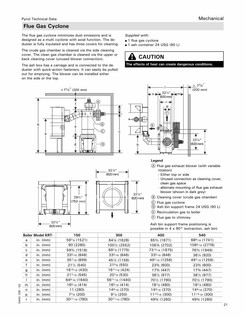
Flue Gas Cyclone
Boiler Model KRT- 150 300 400 540a in. (mm) 597/8 (1521) 64d (1628) 65c (1671) 689/16 (1741)b in. (mm) 90 (2285) 100b (2552) 106e (2702) 1095/16 (2776)c in. (mm) 59c (1518) 697/8 (1775) 7313/16 (1875) 76c (1949)d in. (mm) 335/16 (846) 335/16 (846) 335/16 (846) 36a (920)e in. (mm) 357/16 (899) 45b (1156) 497/16 (1256) 497/16 (1256)f in. (mm) 21a (540) 215/8 (550) 23f (600) 23f (600)g in. (mm) 1615/16 (430) 1611/16 (424) 17f (447) 17f (447)h in. (mm) 217/16 (545) 207/8 (530) 38b (977) 38b (977)l in. (mm) 649/16 (1640) 5611/16 (1440) 70b (1790) 70b (1790)m in. (mm) 165/16 (414) 165/16 (414) 187/8 (480) 187/8 (480)n in. (mm) 11 (280) 149/16 (370) 149/16 (370) 149/16 (370)p in. (mm) 77/8 (200) 97/8 (250) 1113/16 (300) 1113/16 (300)r in. (mm) 3011/16 (780) 3011/16 (780) 49f (1260) 49f (1260)
LegendA Flue gas exhaust blower (with variable rotation) - Either top or side - Unused connection as cleaning cover, clean gas space - alternate mounting of flue gas exhaust blower (shown in dark grey)B Cleaning cover (crude gas chamber)C Flue gas cyclone D Ash bin support frame 24 USG (90 L)E Recirculation gas to boilerF Flue gas to chimney
Ash bin support frame positioning is possible in 4 x 90° (extraction, ash bin)
The flue gas cyclone minimizes dust emissions and is designed as a multi cyclone with axial function. The de-duster is fully insulated and has three covers for cleaning.
The crude gas chamber is cleaned via the side cleaning cover. The clean gas chamber is cleaned via the upper or back cleaning cover (unused blower connection).
The ash box has a carriage and is connected to the de-duster with quick-action fasteners. It can easily be pulled out for emptying. The blower can be installed either on the side or the top.
Supplied with:■ 1 flue gas cyclone■ 1 ash container 24 USG (90 L)
CAUTIONThe effects of heat can create dangerous conditions.

22
5443 1
09 -
02
Pyrot Technical Data
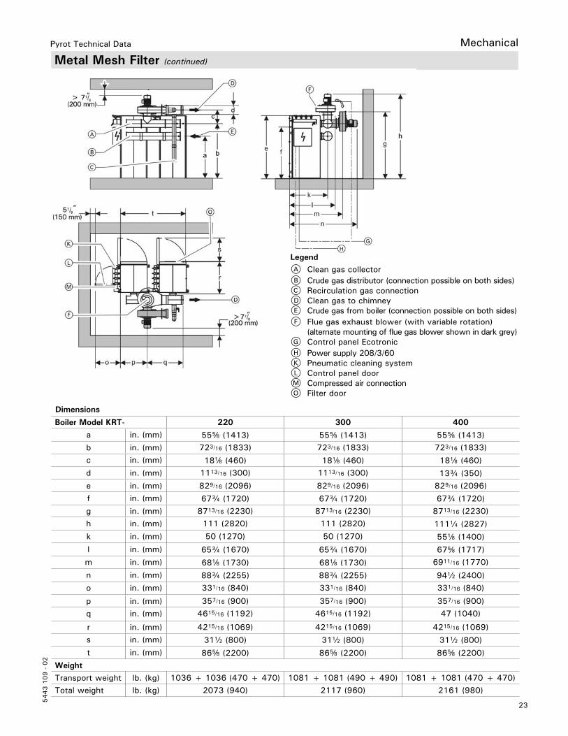
Metal Mesh Filter
The metal mesh filter removes dust and fine dust from the flue gas. It is characterized by a particularly high degree of separation. This ensures a fine dust content of less than 20 mg/Nm3 in the clean gas. The flue gas cyclone is not required when using the metal mesh filter.
The metal mesh filter compresses two block shaped units joined together. The compact design enables it to also be used in low level boiler rooms. The filter cartridges are robust and resistant to a shower of sparks.
Function:The filter is operated under negative pressure. With the cylindrical filter cartridges, the flow is from outside in. The filter cartridges are protected against condensation by means of a heating system and are therefore protected against corrosion.
In the case of boiler demand, the filter cartridges are preheated. If the set filter temperature is reached, boiler start-up operation is enabled. If the temperature falls below the filter temperature set point, the filter heating system starts in heating mode.
The filters are cleaned automatically in the counter current. This means that the dust layer on the mesh is regularly discarded into the ash box.
Filter operation is controlled via the boiler control unit. Operation is carried out via the control unit programming module.
Supplied with:- Two-part, insulated filter casing with: - Hinged doors, lockable by means of a quick-action fastener and lock - Maintenance cover for clean gas space - Filter cartridges - Ash box- Electric heater- Pneumatic cleaning- Flue gas exhaust blower for boiler and filter- Control panel fully wired.
On-site tasks:Provision of a compressor or a connection to a compressed air line system [adjustable pressure level 4-6 bar (60-90 psi)] and a power supply of 208/3/60.
Mechanical
23
5443 1
09 -
02
Pyrot Technical Data Mechanical
Dimensions
Boiler Model KRT- 220 300 400
a in. (mm) 55f (1413) 55f (1413) 55f (1413)b in. (mm) 723/16 (1833) 723/16 (1833) 723/16 (1833)c in. (mm) 18d (460) 18d (460) 18d (460)d in. (mm) 1113/16 (300) 1113/16 (300) 13c (350)e in. (mm) 829/16 (2096) 829/16 (2096) 829/16 (2096)f in. (mm) 67c (1720) 67c (1720) 67c (1720)g in. (mm) 8713/16 (2230) 8713/16 (2230) 8713/16 (2230)h in. (mm) 111 (2820) 111 (2820) 111a (2827)k in. (mm) 50 (1270) 50 (1270) 55d (1400)l in. (mm) 65c (1670) 65c (1670) 67f (1717)m in. (mm) 68d (1730) 68d (1730) 6911/16 (1770)
n in. (mm) 88c (2255) 88c (2255) 94b (2400)o in. (mm) 331/16 (840) 331/16 (840) 331/16 (840)
p in. (mm) 357/16 (900) 357/16 (900) 357/16 (900)q in. (mm) 4615/16 (1192) 4615/16 (1192) 47 (1040)
r in. (mm) 4215/16 (1069) 4215/16 (1069) 4215/16 (1069)s in. (mm) 31b (800) 31b (800) 31b (800)t in. (mm) 86f (2200) 86f (2200) 86f (2200)
Weight
Transport weight lb. (kg) 1036 + 1036 (470 + 470) 1081 + 1081 (490 + 490) 1081 + 1081 (470 + 470)Total weight lb. (kg) 2073 (940) 2117 (960) 2161 (980)
Metal Mesh Filter (continued)
LegendA Clean gas collector B Crude gas distributor (connection possible on both sides)C Recirculation gas connectionD Clean gas to chimneyE Crude gas from boiler (connection possible on both sides)F Flue gas exhaust blower (with variable rotation) (alternate mounting of flue gas blower shown in dark grey)G Control panel EcotronicH Power supply 208/3/60K Pneumatic cleaning systemL Control panel doorM Compressed air connection O Filter door
24
5443 1
09 -
02
Pyrot Technical Data
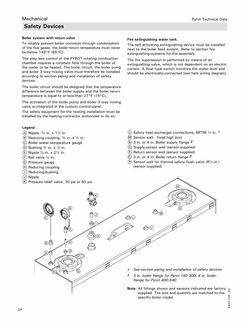
Safety Devices
Boiler system with return valveTo reliably prevent boiler corrosion through condensation of the flue gases, the boiler return temperature must never be below 149°F (65°C).
The step less control of the PYROT rotating combustion chamber requires a constant flow through the boiler of the water to be heated. The boiler circuit, the boiler pump and boiler 3-way mixing valve must therefore be installed according to section piping and installation of safety devices.
The boiler circuit should be designed that the temperature difference between the boiler supply and the boiler return temperature is equal to or less than 27°F (15°C).
The activation of the boiler pump and boiler 3-way mixing valve is integrated in the custom control panel.
L Safety heat exchanger connections, NPTM b in. 1
M Sensor well - fixed high limit N 3 in. or 4 in. Boiler supply flange 2
O Supply sensor well (sensor supplied)P Return sensor well (sensor supplied)Q 3 in. or 4 in. Boiler return flange 2
R Sensor well for thermal safety flush valve (Rb in.) (sensor supplied)
B
C
D
F
G
H
J
K
LM
N
O
P
E
I
A
R
L
Q
The safety equipment for the heating installation must be installed by the heating contractor authorized to do so.
Mechanical
Fire extinguishing water tankThe self-activating extinguishing device must be installed next to the boiler feed system. Refer to section fire extinguishing systems for the assembly.
The fire suppression is performed by means of an extinguishing valve, which is not dependent on an electric current. A float-type switch monitors the water level and should be electrically connected (see field wiring diagram).
1 See section piping and installation of safety devices2 3 in. boiler flange for Pyrot 150-300, 4 in. boiler flange for Pyrot 400-540
Note: All fittings shown and sensors indicated are factory supplied. The size and quantity are matched to the specific boiler model.
LegendA Nipple, c in. x 1b in. B Reducing coupling, c in. x b in. C Boiler water temperature gaugeD Bushing c in. x a in.E Nipple a in. x 2b in. F Ball valve a in.G Pressure gaugeH Reducing couplingI Reducing bushingJ NippleK Pressure relief valve, 30 psi or 60 psi
25
5443 1
09 -
02
Pyrot Technical Data
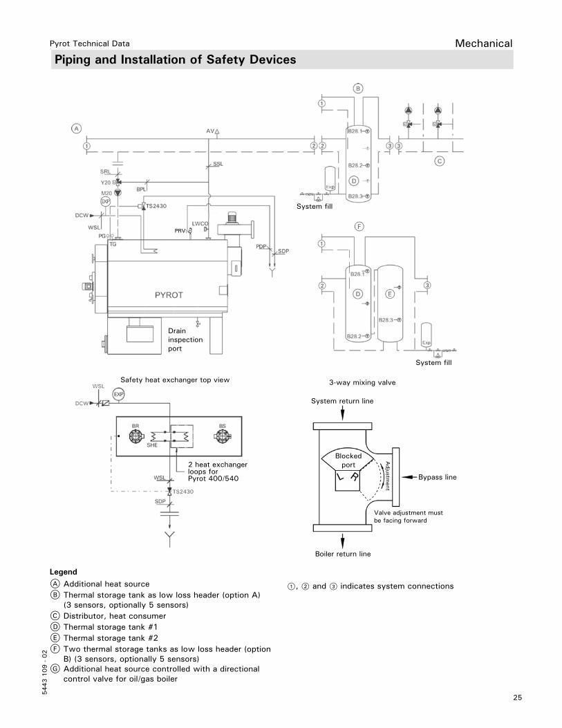
3-way mixing valve
System return line
Bypass line
Boiler return line
Blocked port
Valve adjustment must be facing forward
Adjustm
ent
2 heat exchanger loops for Pyrot 400/540
Safety heat exchanger top view
Drain inspection port
System fill
System fill
PRV
Piping and Installation of Safety Devices
1, 2 and 3 indicates system connections
LegendA Additional heat sourceB Thermal storage tank as low loss header (option A) (3 sensors, optionally 5 sensors)C Distributor, heat consumerD Thermal storage tank #1E Thermal storage tank #2F Two thermal storage tanks as low loss header (option B) (3 sensors, optionally 5 sensors)G Additional heat source controlled with a directional control valve for oil/gas boiler
Mechanical
26
5443 1
09 -
02
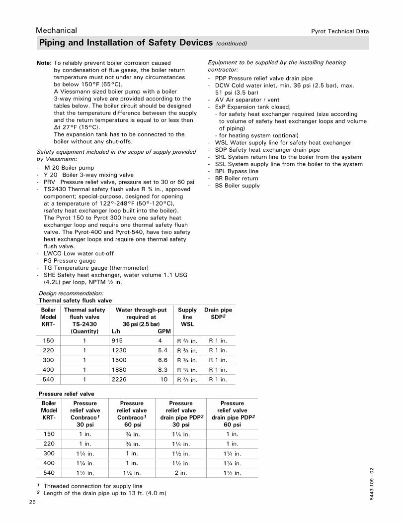
Pyrot Technical Data
Equipment to be supplied by the installing heating contractor:- PDP Pressure relief valve drain pipe- DCW Cold water inlet, min. 36 psi (2.5 bar), max. 51 psi (3.5 bar)- AV Air separator / vent- ExP Expansion tank closed; - for safety heat exchanger required (size according to volume of safety heat exchanger loops and volume of piping) - for heating system (optional)- WSL Water supply line for safety heat exchanger- SDP Safety heat exchanger drain pipe- SRL System return line to the boiler from the system- SSL System supply line from the boiler to the system- BPL Bypass line- BR Boiler return- BS Boiler supply
Piping and Installation of Safety Devices (continued)
Note: To reliably prevent boiler corrosion caused by condensation of flue gases, the boiler return temperature must not under any circumstances be below 150°F (65°C). A Viessmann sized boiler pump with a boiler 3-way mixing valve are provided according to the tables below. The boiler circuit should be designed that the temperature difference between the supply and the return temperature is equal to or less than ∆t 27°F (15°C). The expansion tank has to be connected to the boiler without any shut-offs.
Safety equipment included in the scope of supply provided by Viessmann:- M 20 Boiler pump- Y 20 Boiler 3-way mixing valve- PRV Pressure relief valve, pressure set to 30 or 60 psi- TS2430 Thermal safety flush valve R ¾ in., approved component; special-purpose, designed for opening at a temperature of 122°-248°F (50°-120°C), (safety heat exchanger loop built into the boiler). The Pyrot 150 to Pyrot 300 have one safety heat exchanger loop and require one thermal safety flush valve. The Pyrot-400 and Pyrot-540, have two safety heat exchanger loops and require one thermal safety flush valve.- LWCO Low water cut-off- PG Pressure gauge- TG Temperature gauge (thermometer)- SHE Safety heat exchanger, water volume 1.1 USG (4.2L) per loop, NPTM b in.
Design recommendation:Thermal safety flush valve
Boiler Model KRT-
Thermal safety flush valve TS-2430 (Quantity)
Water through-put required at
36 psi (2.5 bar)L/h GPM
Supply line WSL
Drain pipe SDP2
150 1 915 4 R c in. R 1 in.
220 1 1230 5.4 R c in. R 1 in.
300 1 1500 6.6 R c in. R 1 in.
400 1 1880 8.3 R c in. R 1 in.
540 1 2226 10 R c in. R 1 in.
1 Threaded connection for supply line2 Length of the drain pipe up to 13 ft. (4.0 m)
Pressure relief valve
Boiler Model KRT-
Pressure relief valve Conbraco1
30 psi
Pressure relief valve Conbraco1
60 psi
Pressure relief valve
drain pipe PDP2
30 psi
Pressure relief valve
drain pipe PDP2
60 psi
150 1 in. c in. 1a in. 1 in.
220 1 in. c in. 1a in. 1 in.
300 1a in. 1 in. 1b in. 1a in.
400 1a in. 1 in. 1b in. 1a in.
540 1b in. 1a in. 2 in. 1b in.
Mechanical

27
5443 1
09 -
02
Pyrot Technical Data Mechanical
3-way mixing valve
Viessmann ASME recommended tank sizes (U-stamped)
Boiler model KRT- Nominal pipe size
Valve
150 2b in. 3-way mixing valve220 2b in. 3-way mixing valve300 3 in. 3-way mixing valve400 3 in. 3-way mixing valve540 4 in. 3-way mixing valve
Boiler model KPT- Tank size L USG
150 1514 400220 2006 530300 2650 700400 3785 1000540 5678 1500
Piping and Installation of Safety Devices (continued)
Fire Protection
Follow local regulations for wood-fired heating systems.
Power failure provisionThe customer must ensure that there is a supply of water independent of the electrical supply. This design ensures that in case of a power failure, the boiler will be reliably cooled by the thermal safety flush valve.
Protection against back-burn for the boiler plantThe following safeguards are part of the scope of supply for the PYROT Rotating Combustion System:- Preventing overfilling of the combustion chamber A level monitor must be installed to prevent overfilling of the combustion chamber. The PYROT Rotating Combustion System has a light barrier to monitor the embers.
- Preventing back-burn With a temperature sensor directly on the in-feed auger, any danger of back-burn initiation will be detected and quickly counteracted at an early stage by increasing the fuel conveyance speed into the combustion chamber.
- Back flash safeguard The PYROT Rotating Combustion System is operated with continuous negative pressure and is equipped with a back flash prevention device. This device prevents back flashes caused by flying embers or combustible gases that may ignite the fuel system.
- Automatic In-feed auger extinguishing system The supplied fire extinguishing system is necessary on the in-feed auger. This system should reliably prevent back- burn in case of a malfunction (such as a power failure). For safety reasons and to prevent damage by flooding, connecting the extinguishing system directly to the water network is not advisable.
This extinguishing system must be equipped with a 6.6 USG (25 L) extinguishing water tank with a float- type switch and an adjustable Danfoss extinguisher valve. The tank for the extinguishing system must be equipped with a level monitoring system.
If there is a shortage of water, the PYROT Rotating Combustion System will switch off automatically. In case of excess temperature, the in-feed auger will be flooded reliably but in a limited fashion.
The heating contractor must perform the installation of the fire extinguishing system as specified in section fire extinguishing systems.
IMPORTANT
Design recommendation (continued):Boiler pump
Boiler model KRT- Pump Freq. Voltage and phase Speed
150 UPS 32-80 F 60 Hz 3 x 208-230 V 3
220 UPS 40-80/4 F 60 Hz 3 x 208-230 V 1
300 UPS 50-80/4 F 60 Hz 3 x 208-230 V 2
400 UPS 80-80/4 F 60 Hz 3 x 208-230 V 2
540 UPS 80-80/4 F 60 Hz 3 x 208-230 V 3

28
5443 1
09 -
02
Pyrot Technical Data
Back-burn safeguard for the fuel supply systemThe fire extinguishing system for the conveyor auger and the down pipe depends on specific requirements (location, size of the fuel storage site, material, pressure conditions and regulations), these being accessories to the scope of delivery ordered from Viessmann according to their descriptions.
Automatic triggering system for the fuel supply system Approved in part as a variation to the shut-off valve in pressure-less fuel storage units.
Slide valveThe slide valve is approved in pressure-less fuel storage units and is a suitable safeguard against back-burn.
The slide valve is optional and closes in case of standstill, danger of back-burn, or power failure, with the help of a spring return motor.
We recommend installing a rotary valve for the PYROT Rotating Combustion System. In addition to being a safeguard against back-burn, this will also prevent any penetration by air leaking in via the in-feed auger.
Rotary valveThe Rotary valve is optional and used if remnant wood is moved into fuel storage spaces with blowers, then, in order to reduce pressure applied, at least one rotary valve is necessary to reduce pressure between the fuel storage unit and the boiler. The rotary valve is suited to reduce pressure and at the same time is considered a suitable safeguard against back-burn.
Max. overpressure allowed in fuel storage unit: +500 Pa / +2.00”wc.Max. negative pressure allowed in fuel storage unit: +0 Pa / +0”wc.
Fire Protection (continued)
IMPORTANT
IMPORTANT
IMPORTANT
Double rotary valve with pressure compensation systemIf, due to special circumstances, any mechanically produced negative pressures or extraordinarily high overpressures are expected in the fuel storage unit, then two rotary valves must be installed in the material transport route according to the respective project plan with a pressure compensation line to the outdoors.
Max. overpressure allowed in fuel storage unit:+3000 Pa /+12”wc.Max. negative pressure allowed in fuel storage unit:-3000 Pa / –12”wc.
The supplier of the silo must confirm the maximum weight that is to be expected on the rotary valve.
The rotary valve below the silo extraction system can become leaky due to wear of the sealing elements or through large pieces of wood that cannot be conveyed. This leakage can make it possible for low-temperature gases to flow back from the boiler into the silo.
A smoke alarm must be installed between the rotary valve and the silo extraction system, which, when triggered, will disconnect the system and create negative pressure in the silo.
Down pipeA vertical drop-off section interrupts the connected line of burning material.
Fire protection for fuel storage spaceViessmann does not provide fire protection for the fuel storage space.
The local building codes and regulations must be followed by the heating contractor.
Mechanical
29
5443 1
09 -
02
Pyrot Technical Data Mechanical
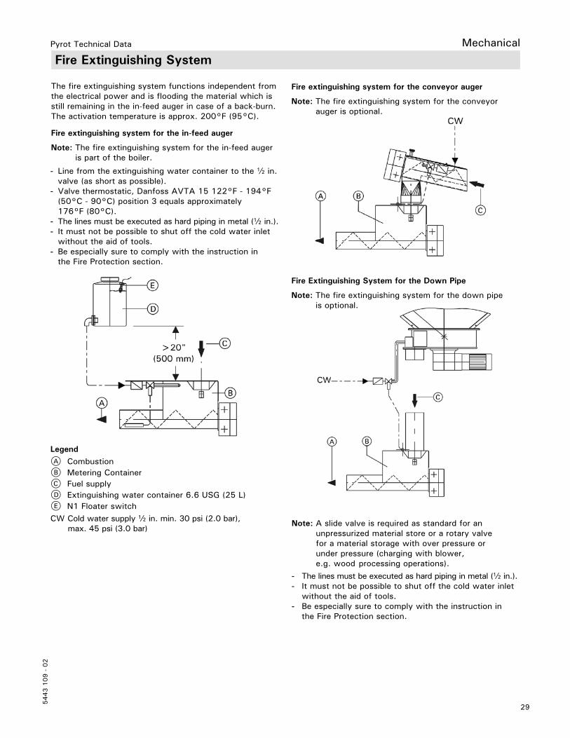
Fire Extinguishing System
LegendA CombustionB Metering ContainerC Fuel supplyD Extinguishing water container 6.6 USG (25 L)E N1 Floater switchCW Cold water supply b in. min. 30 psi (2.0 bar), max. 45 psi (3.0 bar)
Note: A slide valve is required as standard for an unpressurized material store or a rotary valve for a material storage with over pressure or under pressure (charging with blower, e.g. wood processing operations).
Fire extinguishing system for the in-feed auger
Note: The fire extinguishing system for the in-feed auger is part of the boiler.
- Line from the extinguishing water container to the b in. valve (as short as possible).- Valve thermostatic, Danfoss AVTA 15 122°F - 194°F (50°C - 90°C) position 3 equals approximately 176°F (80°C).- The lines must be executed as hard piping in metal (b in.).- It must not be possible to shut off the cold water inlet without the aid of tools.- Be especially sure to comply with the instruction in the Fire Protection section.
- The lines must be executed as hard piping in metal (b in.).- It must not be possible to shut off the cold water inlet without the aid of tools.- Be especially sure to comply with the instruction in the Fire Protection section.
Fire extinguishing system for the conveyor auger
Note: The fire extinguishing system for the conveyor auger is optional.
Fire Extinguishing System for the Down Pipe
Note: The fire extinguishing system for the down pipe is optional.
The fire extinguishing system functions independent from the electrical power and is flooding the material which is still remaining in the in-feed auger in case of a back-burn. The activation temperature is approx. 200°F (95°C).
30
5443 1
09 -
02
Pyrot Technical DataElectrical
Mounting of the control panel
The control panel should be in an area where the heat radiation (front side of boiler, rear side of boiler with flue gas deduster and flue gas exhaust blower as well as recirculation line) and the exposure to dust during cleaning is at a minimum.
The ambient temperature for the control panel (approx. 4 in. (100 mm) away from the control cabinet) should not exceed 104°F (40°C) while the system is in operation. The minimum temperature must not be less than 50°F (10°C). In case of doubt, preference should be given to placing the control panel outside the mechanical room near the heating room door.
Electrical connection- Install the control panel according to the field wiring diagram. The field wiring diagram is supplied with the control panel.- In the area of hot parts (flue gas exhaust blower, flue gas pipe), the lines should be installed in steel pipes at an appropriate distance so as to be protected from excessive temperatures. See section “Boiler Wiring”.- The cable bushings to the motors and equipment must be dust-tight and provided with a strain relief.
Vitocontrol
A microprocessor control system for the complete PYROT Boiler Plant, including control of the fuel loading systems required for the separately listed items. The heat output of the boiler adjusts to the heat consumption in modulatingfashion. A regulating circuit for the combustion optimizing system is superimposed on the output control circuit with an oxygen sensor. Maximum quality criteria are met in terms of fire protection and personal protection.
Functions:- Automatic ignition- Output and control circuits with modulating output operation (25%-100%)- Air-conducted by means of a speed-regulated exhaust fan, depending on the boiler supply temperature- Precise re supplying of fuel by the in-feed auger from the metering container with an insulating layer- Refilling of the metering container with the use of a level monitoring system- Limitation and distribution of the mass burning in the combustion chamber by means of a level monitoring system in the combustion chamber along with movement of the feed grate- Emissions-optimized control circuit: Optimized air supply through motor-operated air vents for the best possible combustion using an oxygen sensor. Upholding the return temperature with the boiler mixing value provides for a long service life of the boiler.- Safety functions for: Excess temperature, burn-back, opening of a lid in the loading system and forced heat dissipation- Floating output (malfunction combustion system)
Operation: Operation is carried out by means of a control panel with a membrane keyboard and plain language display. All the operational data can be read on the display. The set points for all the important parameters can be entered simply using the keyboard. Malfunctions are displayed in plain language and indicated in the order of their occurrence.
Supplied with:- A microprocessor control system (control panel with back-lit plain language display), CSA-tested, battery- backed real-time clock, RS 232 serial interface for connection to PC.- Control cabinet (uninstalled), surface powder-coated with RAL 7035 (gray) textured, executed according to CSA C.22, ready-wired on series terminals, Power supply: 208V/3/60Hz; control voltage: 120/240V/1/60 Hz or 24V- Adapted, updateable software- Soft starter for all the drives for the loader system (208V/3/60 Hz) according to the items priced separately- Overload protection for boiler pump- Outputs for stepping motors - Variable frequency drive (EMC-Operation Class 3) for exhaust fan - Main disconnect- Documentation, including bound circuit diagram, terminal connection diagram with cable designation, service and maintenance instructions, installation and operating instructions in document pocket- Sensors and switches for the in-feed auger- Infrared light barrier level monitoring system, insulating layer for in-feed auger- Safety limit switch on the maintenance lid for the in-feed auger- PT-100 temperature sensor for the in-feed auger- Sensors and switches on the combustion chamber for firing and in the exhaust gas nozzle (installation on site)- Infrared light barriers for level monitoring of fuel in the combustion chamber- Oxygen sensor with instrument reading converter- PT-100 exhaust gas sensor- Sensors and switches mounted on top of the boiler
- KTY boiler sensor in the connecting piece, supply- KTY boiler return sensor in the connecting piece, return- Fixed high limit- Sensor, uninstalled- One KTY sensor with sensor shell, 1/2 “ x 280 mm
31
5443 1
09 -
02
Pyrot Technical Data Electrical
Vitocontrol Accessories
Triggering System for external drive
Function:Starttec, motor soft start for optimized connection of an external conveyor drive or rotary valve without reversal. A CAN bus is used to directly connect the motors to the gentle start-up system via the Ecotronic. Temperature-monitored and protected against overloading. Its electronic circuit breakers are wear-free, even at high switching frequencies.
Supplied with:- Starttec completely integrated in the control cabinet- Parameter assignment for the drive function- Input in the control cabinet for safety end switch on the maintenance cover- Output in the control cabinet for external conveyor drive
Customer supplied:- Delivery and/or installation of safety end switch for the external conveyor drive
Note: Only for PYROT. Starttec is built into the control cabinet for the boiler plant. Only possible with defined, limited material feed facility (upstream conveyor auger)
Triggering System for external drive with light barrier
Function:Starttec motor starter for optimized connection of an external conveyor drive without reversal. A CAN bus is used to directly connect the motors to the gentle start-up system via the Ecotronic. Temperature-monitored andprotected against overloading. Its electronic circuit breakersare wear-free, even at high switching frequencies. Additional protection of the external drive through level-monitoring system of the further feed system by means of a light barrier. The light barrier connects directly to the Starttec for the continuing feed system, affecting the extraction system.
Supplied with:- Starttec completely integrated in control cabinet- Parameter assignment for the drive function- Input in the control cabinet for safety end switch on the maintenance cover- Output in the control cabinet for external conveyor drive- Infrared light barrier, level-monitoring system for fuel
Customer supplied:- Delivery and/or installation of safety end switch for the external conveyor drive
Note: Only for PYROT. Starttec is built into the control cabinet for the boiler plant.
Note: The control system components below are reserved for the PYROT Single-unit System. With the PYROT Double-unit System, these functions are included in the Mastercontrol.
Thermal Storage Tank Management System 3 Sensors
Function:Using a heat accumulator improves the modulating output operation of the PYROT grate firing system. In addition,sudden heat requirement peaks are covered. The accumulator’s load of heat is detected by the temperature sensors. The firing power is adapted to the accumulator’s degree of loading.
Supplied with:- Two additional KTY sensors with sensor well, 1/2“ x 280 mm
External Request ON/OFF
Input for switching the system on and off automatically by an external potential-free N.O. contact.
Operational Message
Function:System status “Operating Load” indication; from operation of the boiler pump to higher-level control.
Supplied with:- Floating output (operational message)
Output signals 0 - 10 V
Function:The system includes output of the boiler in the form of a voltage signal and preparation for connection to receive a maximum limitation of the boiler output.
Supplied with:- Output of the boiler, 0 - 10 V- Reception and processing of an external output limitation
0.1 - 3 V..... Standby 3.1 - 10 V... 30% to 100% output operation
Note: Installation of “Output signals 0 - 10 V” is possible according to “QM for Wood Heating Systems” irrespective of any additional control system components to be used.
32
5443 1
09 -
02
Pyrot Technical Data
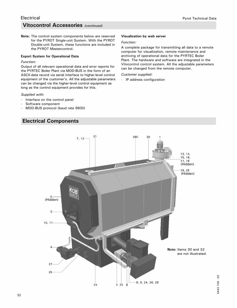
Electrical Components
Electrical
Vitocontrol Accessories (continued)
Note: The control system components below are reserved for the PYROT Single-unit System. With the PYROT Double-unit System, these functions are included in the PYROT Mastercontrol.
Export System for Operational Data
Function:Output of all relevant operational data and error reports for the PYRTEC Boiler Plant via MOD-BUS in the form of an ASCII-data record via serial interface to higher-level control equipment of the customer’s. All the adjustable parameters can be changed via the higher-level control equipment as long as the control equipment provides for this.
Supplied with:- Interface on the control panel- Software component- MOD-BUS protocol (baud rate 9600)
Visualization by web server
Function:A complete package for transmitting all data to a remote computer for visualization, remote maintenance and archiving of operational data for the PYRTEC Boiler Plant. The hardware and software are integrated in the Vitocontrol control system. All the adjustable parameters can be changed from the remote computer.
Customer supplied:- IP address configuration
(Hidden)
(Hidden)
(Hidden)
Note: Items 30 and 32 are not illustrated.
10, 11
8, 9, 24, 26, 28
7 7
6
33
5443 1
09 -
02
Pyrot Technical Data
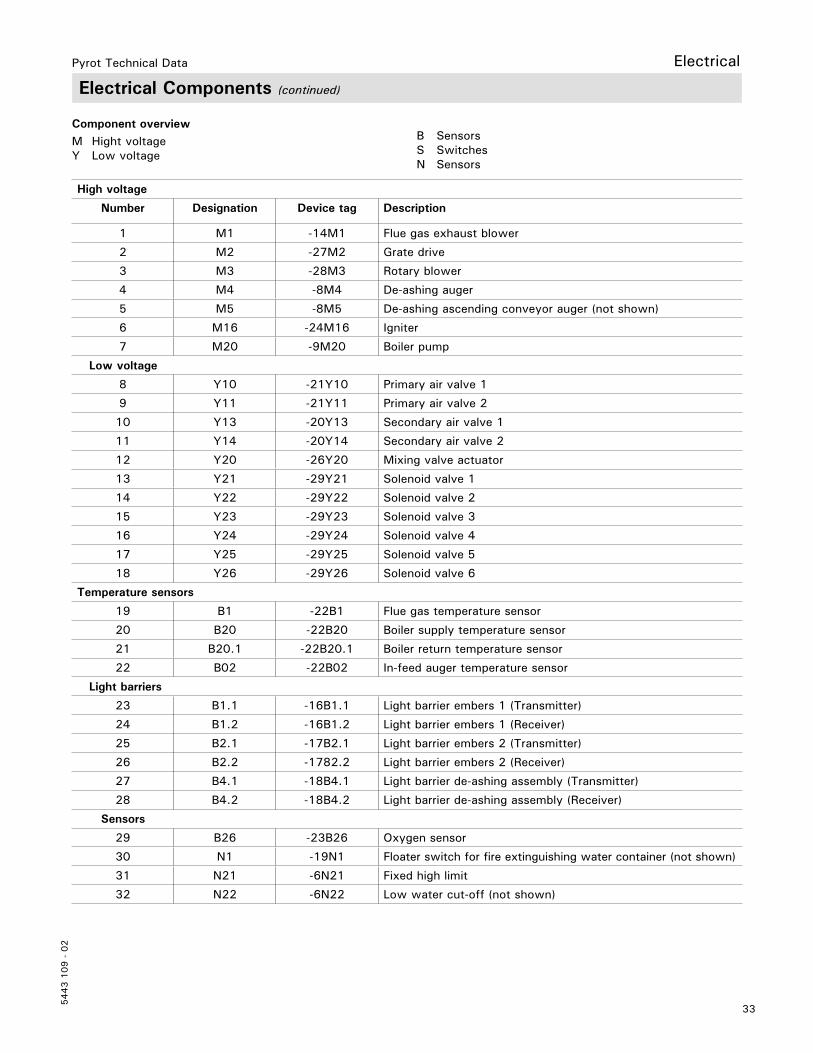
Electrical Components (continued)
High voltage
Number Designation Device tag Description
1 M1 -14M1 Flue gas exhaust blower
2 M2 -27M2 Grate drive
3 M3 -28M3 Rotary blower
4 M4 -8M4 De-ashing auger
5 M5 -8M5 De-ashing ascending conveyor auger (not shown)
6 M16 -24M16 Igniter
7 M20 -9M20 Boiler pump
Low voltage
8 Y10 -21Y10 Primary air valve 1
9 Y11 -21Y11 Primary air valve 2
10 Y13 -20Y13 Secondary air valve 1
11 Y14 -20Y14 Secondary air valve 2
12 Y20 -26Y20 Mixing valve actuator
13 Y21 -29Y21 Solenoid valve 1
14 Y22 -29Y22 Solenoid valve 2
15 Y23 -29Y23 Solenoid valve 3
16 Y24 -29Y24 Solenoid valve 4
17 Y25 -29Y25 Solenoid valve 5
18 Y26 -29Y26 Solenoid valve 6
Temperature sensors
19 B1 -22B1 Flue gas temperature sensor
20 B20 -22B20 Boiler supply temperature sensor
21 B20.1 -22B20.1 Boiler return temperature sensor
22 B02 -22B02 In-feed auger temperature sensor
Light barriers
23 B1.1 -16B1.1 Light barrier embers 1 (Transmitter)
24 B1.2 -16B1.2 Light barrier embers 1 (Receiver)
25 B2.1 -17B2.1 Light barrier embers 2 (Transmitter)
26 B2.2 -1782.2 Light barrier embers 2 (Receiver)
27 B4.1 -18B4.1 Light barrier de-ashing assembly (Transmitter)
28 B4.2 -18B4.2 Light barrier de-ashing assembly (Receiver)
Sensors
29 B26 -23B26 Oxygen sensor
30 N1 -19N1 Floater switch for fire extinguishing water container (not shown)
31 N21 -6N21 Fixed high limit
32 N22 -6N22 Low water cut-off (not shown)
Component overview M Hight voltage Y Low voltage
B Sensors S Switches N Sensors
Electrical
34
5443 1
09 -
02
Pyrot Technical DataElectrical
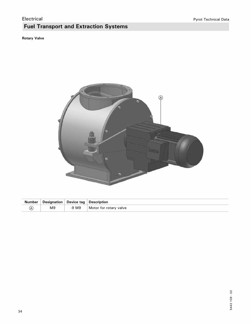
Number Designation Device tag Description
A M9 -9 M9 Motor for rotary valve
Rotary Valve
Fuel Transport and Extraction Systems

35
5443 1
09 -
02
Pyrot Technical Data
Fuel Transport and Extraction Systems
In-feed auger
Number Designation Device tag Description
34 M31 -11M31 Motor for in-feed auger
35 S31.1 11S31.1 Limit switch for maintenance lid
36 B31.1 -11B31.1 Light barrier metering container (Transmitter)
37 B31.2 -11B31.2 Light barrier metering container (Receiver)
38 Y30.1 -23Y30.1 Slide valve T30
39 Y30.2 -23Y30.2 Slide valve T30
Pipe/trough conveyor auger
Number Designation Device tag Description
40 M32 -12M32 Motor for pipe/trough conveyor auger
41 S32.1 -12S32.1 Limit switch for maintenance lid
42 B32.1 -12B32.1 Light barrier conveyor auger (Transmitter)
43 B32.2 -12B32.2 Light barrier conveyor auger (Receiver)
Note: For details on designation, see field wiring diagram.
Electrical
Note: For details on designation, see field wiring diagram.
36
5443 1
09 -
02
Pyrot Technical Data
Fuel Transport and Extraction Systems (continued)
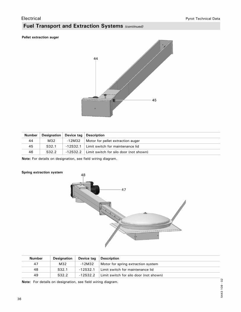
Pellet extraction auger
Number Designation Device tag Description
44 M32 -12M32 Motor for pellet extraction auger
45 S32.1 -12S32.1 Limit switch for maintenance lid
46 S32.2 -12S32.2 Limit switch for silo door (not shown)
Note: For details on designation, see field wiring diagram.
Number Designation Device tag Description
47 M32 -12M32 Motor for spring extraction system
48 S32.1 -12S32.1 Limit switch for maintenance lid
49 S32.2 -12S32.2 Limit switch for silo door (not shown)
Note: For details on designation, see field wiring diagram.
Spring extraction system
Electrical

37
5443 1
09 -
02
Pyrot Technical Data Electrical
Fuel Transport and Extraction Systems (continued)
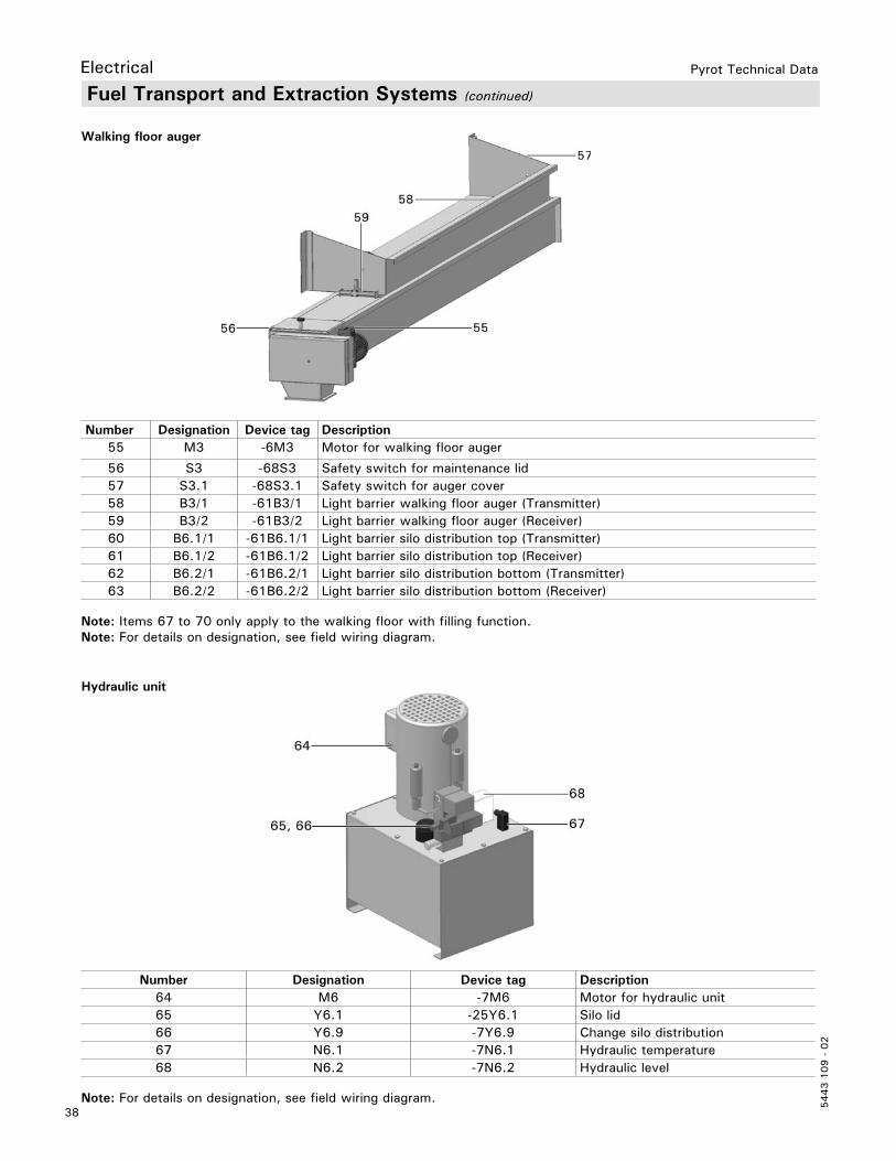
Horizontal extraction system
Number Device tag Device tag Description
50 M32 -12M32 Motor for extraction auger
51 M33 -12M33 Motor for agitator
52 B32 -12B32 Light barrier for extraction auger
53 S32.1 -12S32.1 Safety switch for maintenance lid
54 S32.2 -12S32.2 Safety switch for silo door (not shown)
Note: For details on designation, see field wiring diagram.
38
5443 1
09 -
02
Pyrot Technical Data
Hydraulic unit
Number Designation Device tag Description64 M6 -7M6 Motor for hydraulic unit65 Y6.1 -25Y6.1 Silo lid66 Y6.9 -7Y6.9 Change silo distribution67 N6.1 -7N6.1 Hydraulic temperature68 N6.2 -7N6.2 Hydraulic level
Note: For details on designation, see field wiring diagram.
Fuel Transport and Extraction Systems (continued)
Walking floor auger
Number Designation Device tag Description55 M3 -6M3 Motor for walking floor auger
56 S3 -68S3 Safety switch for maintenance lid57 S3.1 -68S3.1 Safety switch for auger cover58 B3/1 -61B3/1 Light barrier walking floor auger (Transmitter)59 B3/2 -61B3/2 Light barrier walking floor auger (Receiver)60 B6.1/1 -61B6.1/1 Light barrier silo distribution top (Transmitter)61 B6.1/2 -61B6.1/2 Light barrier silo distribution top (Receiver)62 B6.2/1 -61B6.2/1 Light barrier silo distribution bottom (Transmitter)63 B6.2/2 -61B6.2/2 Light barrier silo distribution bottom (Receiver)
Note: Items 67 to 70 only apply to the walking floor with filling function.Note: For details on designation, see field wiring diagram.
Electrical
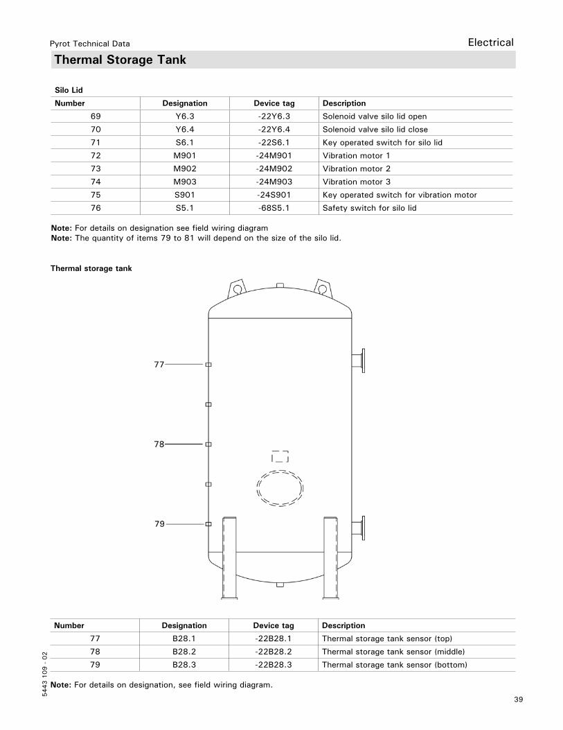
39
5443 1
09 -
02
Pyrot Technical Data Electrical
Thermal Storage Tank
Thermal storage tank
Number Designation Device tag Description
77 B28.1 -22B28.1 Thermal storage tank sensor (top)
78 B28.2 -22B28.2 Thermal storage tank sensor (middle)
79 B28.3 -22B28.3 Thermal storage tank sensor (bottom)
Note: For details on designation, see field wiring diagram.
Silo Lid
Number Designation Device tag Description
69 Y6.3 -22Y6.3 Solenoid valve silo lid open
70 Y6.4 -22Y6.4 Solenoid valve silo lid close
71 S6.1 -22S6.1 Key operated switch for silo lid
72 M901 -24M901 Vibration motor 1
73 M902 -24M902 Vibration motor 2
74 M903 -24M903 Vibration motor 3
75 S901 -24S901 Key operated switch for vibration motor
76 S5.1 -68S5.1 Safety switch for silo lid
Note: For details on designation see field wiring diagramNote: The quantity of items 79 to 81 will depend on the size of the silo lid.
Commissioning
Fuel for the commissioningFor the commissioning, sufficient dry fuel (max. W 20%) should be stored for approx. 10-24 full operating hours:
PYROT 150 approx. 2640 lb.PYROT 220 approx. 3300 lb.PYROT 300 approx. 4400 lb.PYROT 400 approx. 5500 lb.PYROT 500 approx. 6600 lb.
Since the boiler plant will be cold, and residual moisture will be drawn from the refractory concrete during the initial operation, the material to be burned for the initial operation has to be at least air dry. For the first three hours, the heating-up process should be carried out at low output.
To ensure that the silo extraction system is functioning properly, only place a minimal amount of fuel in the silo in case there is a problem. This enables the extraction system to be cleaned out quickly and the problem to be identified and corrected.
5443 1
09 -
02
Tec
hnic
al in
form
atio
n su
bjec
t to
cha
nge
witho
ut n
otic
e.Pr
inte
d on
env
ironm
enta
lly f
riend
ly
(rec
ycle
d an
d re
cycl
able
) pa
per.
Pyrot Technical Data
Related Documents