1 5439 --- 0205 --- N9 138 HYLAB 5 Link-Belt Cranes Technical Dat a Specifications & Angle Boom Capacities Crawler Crane 80 Ton (72.6 metric ton) CAUTION: This material is supplied for reference use only. Operator must refer to in---cab Crane Rating Manual and Operator’s Manual to determine allowable crane lifting capacities and assembly and operating procedures.

Welcome message from author
This document is posted to help you gain knowledge. Please leave a comment to let me know what you think about it! Share it to your friends and learn new things together.
Transcript
15439---0205---N9
138 HYLAB 5Link-Belt Cranes
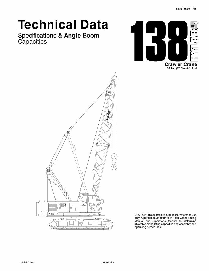
Technical DataSpecifications & Angle BoomCapacities
Crawler Crane80 Ton (72.6 metric ton)
CAUTION: Thismaterial is supplied for referenceuseonly. Operator must refer to in---cab Crane RatingManual and Operator’s Manual to determineallowable crane lifting capacities and assembly andoperating procedures.

5439---0205---N9
138 HYLAB 5 Link-Belt Cranes

15439---0205---N9
138 HYLAB 5Link-Belt Cranes
Table Of ContentsPages
Specifications 1--12Angle Boom Capacities 1--12Angle Boom + Jib Capacities 1--20

5439---0205---N9
138 HYLAB 5 Link-Belt Cranes
This page intentionally left blank

1
Specifications
Crawler Crane80 Ton (72.6 metric ton)
CAUTION: Thismaterial is supplied for referenceuseonly. Operator must refer to in---cab Crane RatingManual and Operator’s Manual to determineallowable crane lifting capacities and assembly andoperating procedures.

1
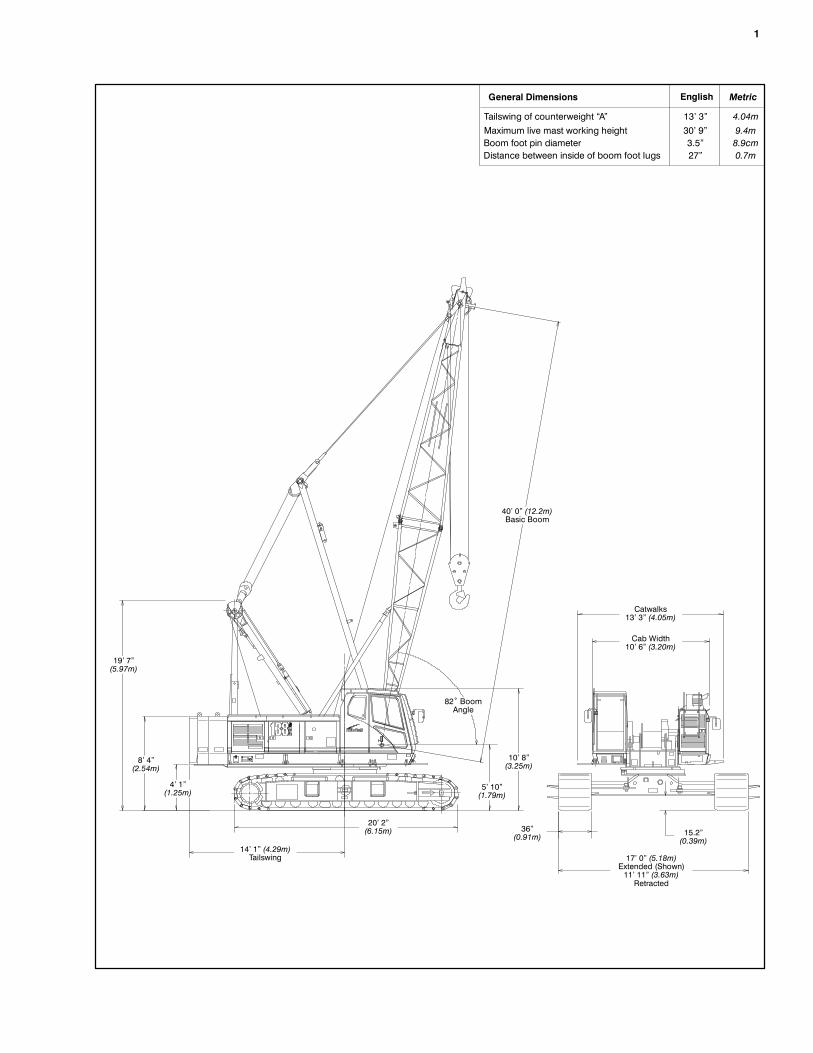
General Dimensions
Tailswing of counterweight “A”
English Metric
13’ 3” 4.04mMaximum live mast working height 30’ 9” 9.4mBoom foot pin diameter 3.5” 8.9cmDistance between inside of boom foot lugs 27” 0.7m
40’ 0” (12.2m)Basic Boom
19’ 7”(5.97m)
8’ 4”(2.54m)
4’ 1”(1.25m)
14’ 1” (4.29m)Tailswing
20’ 2”(6.15m)
5’ 10”(1.79m)
10’ 8”(3.25m)
82˚ BoomAngle
36”(0.91m)
Catwalks13’ 3” (4.05m)
Cab Width10’ 6” (3.20m)
15.2”(0.39m)
17’ 0” (5.18m)Extended (Shown)11’ 11” (3.63m)Retracted
2
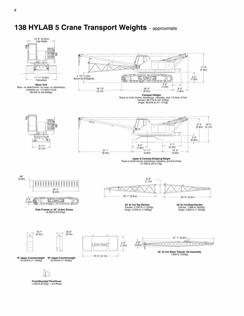
138 HYLAB 5 Crane Transport Weights -- approximate
10’ 6” (3.20m)Cab Width
11’ 11” (3.6m)Retracted
3’ 10” (1.2m)Boom@0Degrees
16’ 10”(5.1m)
20’ 2”(6.2m)
6’ 0”(1.8m)
3’ 5”(1.0m)
4’ 0”(1.2m)
11’ 6”(3.5m)
21’ 1”(6.4m)
11’ 11”(3.6m)
6’ 0”(1.8m)
7’ 7”(2.3m)10’ 0”(3.0m)
2’ 9”(0.8m)
10’ 2”(3.1m)
20’ 2”(6.2m)
3’ 3”(1.0m)
36”(0.9m) 3’ 8”
(1.1m)
22’ 7” (6.9m) 20’ 6” (6.3m)
19.7”(0.5m)
20.3”(0.5m)
4’ 3”(1.3m)
10’ 2” (3.1m)
2’ 6”(0.8m)
31’ 1” (9.5m)
9’ 4”(2.9m)
Transport WeightRope on both drums, backstops, catwalks, and 1/3 tank of fuel
Tubular: 89,778 lb (40 723kg)Angle: 90,678 lb (41 131kg)
Upper&CarbodyShippingWeightRopeonbothdrums, backstops, catwalks, and full of fuel
51,392 lb (23 311kg)
Side Frames w/ 36” (0.9m) Shoes18,380 lb (8 337kg)
20’ (6.1m) TopSectionTubular: 2,700 lb (1 225kg)Angle: 3,500 lb (1 588kg)
20’ (6.1m) BaseSectionTubular: 1,988 lb (902kg)Angle: 2,853 lb (1 294kg)
“A” Upper Counterweight25,250 lb (11 450kg)
“B” UpperCounterweight25,250 lb (11 450kg)
30’ (9.1m) Basic Tubular Jib Assembly1,683 lb (763kg)
6’ 11”(2.1m)
FrontMounted ThirdDrum1,345 lb (610kg) --- w/o Rope
Basic UnitBare, no attachment, no rope, no backstops,
catwalks on, 1/4 tank of fuel80,840 lb (36 668kg)
3
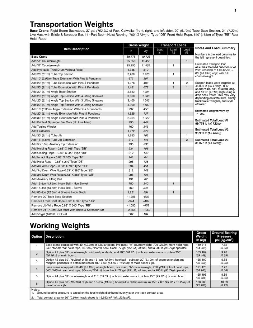
Transportation WeightsBase Crane: Rigid Boom Backstops, 27 gal (102.2L) of Fuel, Catwalks (front, right, and left side), 20’ (6.10m) Tube Base Section, 24’ (7.32m)Live Mast with Bridle & Spreader Bar, 14---Part Boom Hoist Reeving, 700’ (213m) of Type “DB” Front Hoist Rope, 540’ (165m) of Type “RB” RearHoist Rope.
Gross Weight Transport LoadsNotes and Load SummaryItem Description
lb kg Load#1
Load#2
Load#3
Notes and Load Summary
Numbers in the load columns toBase Crane 89,778 40 723 1
Numbers in the load columns tothe left represent quantities.
Add “A” Counterweight 25,250 11 453 1the left represent quantities.
E ti t d t t l dAdd “B” Counterweight 25,250 11 453 1 Estimated transport loadassumes the load out consist of
Add Hydraulic Third Drum Without Rope 1,345 610assumes the load out consist of200’ (60.96m) of tube boom +60’ (18 29 ) f jib i h f llAdd 20’ (6.1m) Tube Top Section 2,700 1 225 1200 (60.96m) of tube boom +60’ (18.29m) of jib with fullcounterweight
Add 10’ (3.05m) Tube Extension With Pins & Pendants 677 307 1counterweight.
Add 20’ (6.1m) Tube Extension With Pins & Pendants 1,076 488 1 2 Support loads were targeted at45 000 lb (20 412k ) 8’ 6”Add 30’ (9.1m) Tube Extension With Pins & Pendants 1,481 672 2 1
pp g45,000 lb (20 412kg), 8’ 6”(2.6m) wide, 48’ (14.63m) long,
Add 20’ (6.1m) Angle Base Section 2,853 1 294(2.6m) wide, 48’ (14.63m) long,and 13’ 6” (4.11m) high using ad d k t il ThiAdd 20’ (6.1m) Angle Top Section With 4 Lifting Sheaves 3,500 1 588and 13 6 (4.11m) high using adrop deck trailer. This may varydepending on state laws empty
Add 20’ (6.1m) Angle Top Section With 3 Lifting Sheaves 3,400 1 542depending on state laws, emptytruck/trailer weights, and style
Add 20’ (6.1m) Angle Top Section With 2 Lifting Sheaves 3,300 1 497truck/trailer weights, and styleof trailer.
Add 10’ (3.05m) Angle Extension With Pins & Pendants 992 450 Estimated weights vary byAdd 20’ (6.1m) Angle Extension With Pins & Pendants 1,625 737
Estimated weights vary by+/-- 2%.
Add 30’ (9.1m) Angle Extension With Pins & Pendants 2,264 1 027+/ 2%.
Estimated Total Load #1Add Bridle & Spreader Bar Only (No Live Mast) 990 449
Estimated Total Load #189,778 lb (40 723kg).
Add Tagline Winder 760 34589,778 lb (40 723kg).
Estimated Total Load #2Add Fairleader 1,272 577 Estimated Total Load #233 959 lb (15 404kg)
Add 30’ (9.1m) Tube Jib 1,683 763 133,959 lb (15 404kg).
Add 15’ (4.6m) Tube Jib Extension 317 144 2 Estimated Total Load #331 877 lb (14 459k )Add 5’ (1.5m) Auxiliary Tip Extension 735 333st ated ota oad #3
31,877 lb (14 459kg).
Add Holding Rope -- 0.88” X 165’ Type “DB” 234 106
Add Closing Rope -- 0.88” X 220’ Type “DB” 312 142
Add Inhaul Rope -- 0.88” X 105’ Type “M” 141 64
Add Hoist Rope -- 0.88” x 210’ Type “DB” 298 135
Add Jib Wire Rope -- 0.88” X 700’ Type “DB” 994 451
Add 3rd Drum Wire Rope 0.63” X 385’ Type “ZB” 312 142
Add 3rd Drum Wire Rope 0.63” X 385’ Type “WB” 296 134
Add Auxiliary Lifting Bail 191 87
Add 15--ton (13.6mt) Hook Ball -- Non Swivel 750 340 1
Add 15--ton (13.6mt) Hook Ball -- Swivel 760 345
Add 80--ton (72.6mt) 4 Sheave Hook Block 1,221 554 1
Remove 20’ Tube Base Section --1,988 --902
Remove Front Hoist Rope 0.88” X 700’ Type “DB” --944 --428
Remove Jib Wire Rope 0.88” X 540’ Type “RB” --1,050 --476
Remove 24’ (7.3m) Live Mast With Bridle & Spreader Bar --2,356 --1 069
Add 50 gal (189.3L) Of Fuel 362 164
Working WeightsOption Description
GrossWeightlb (kg)
Ground BearingPressure
psi (kg/cm2)
1 Base crane equipped with 40’ (12.2m) of tubular boom, live mast, “A” counterweight, 700’ (213m) front hoist rope,540’ (165m) rear hoist rope, 80--ton (72.6mt) hook block, 77 gal (291.5L) of fuel, and a 200 lb (90.7kg) operator.
119,511(54 209)
7.62(0.53)
2 Option #1 plus “B” counterweight, midpoint pendants, and 160’ (48.77m) of boom extensions to obtain 200’(60.96m) of main boom.
153,109(69 449)
9.76(0.69)
3 Option #2 plus 60’ (18.29m) of jib and 15--ton (13.6mt) hookball -- subtract 20’ (6.10m) of boom extension andmidpoint pendants to obtain maximum 180’ + 60’ (54.86 + 18.29m) of main boom + jib.
155,100(70 352)
9.88(0.70)
4 Base crane equipped with 40’ (12.20m) of angle boom, live mast, “A” counterweight, 700’ (213m) front hoist rope,540’ (165m) rear hoist rope, 80--ton (72.6mt) hook block, 77 gal (291.5L) of fuel, and a 200 lb (90.7kg) operator.
121,176(54 965)
7.72(0.54)
5 Option #4 plus “B” counterweight and 110’ (33.53m) of boom extensions to obtain 150’ (45.72m) of main boom. 155,196(70 396)
9.89(0.70)
6 Option #5 plus 60’ (18.29m) of jib and 15--ton (13.6mt) hookball to obtain maximum 150’ + 60’ (45.72 + 18.29m) ofmain boom + jib.
158,263(71 786)
10.09(0.71)
Notes:1. Ground bearing pressure is based on the total weight distributed evenly over the track contact area.
2. Total contact area for 36” (0.91m) track shoes is 15,692 in2 (101,239cm2).
4
Attachment Options
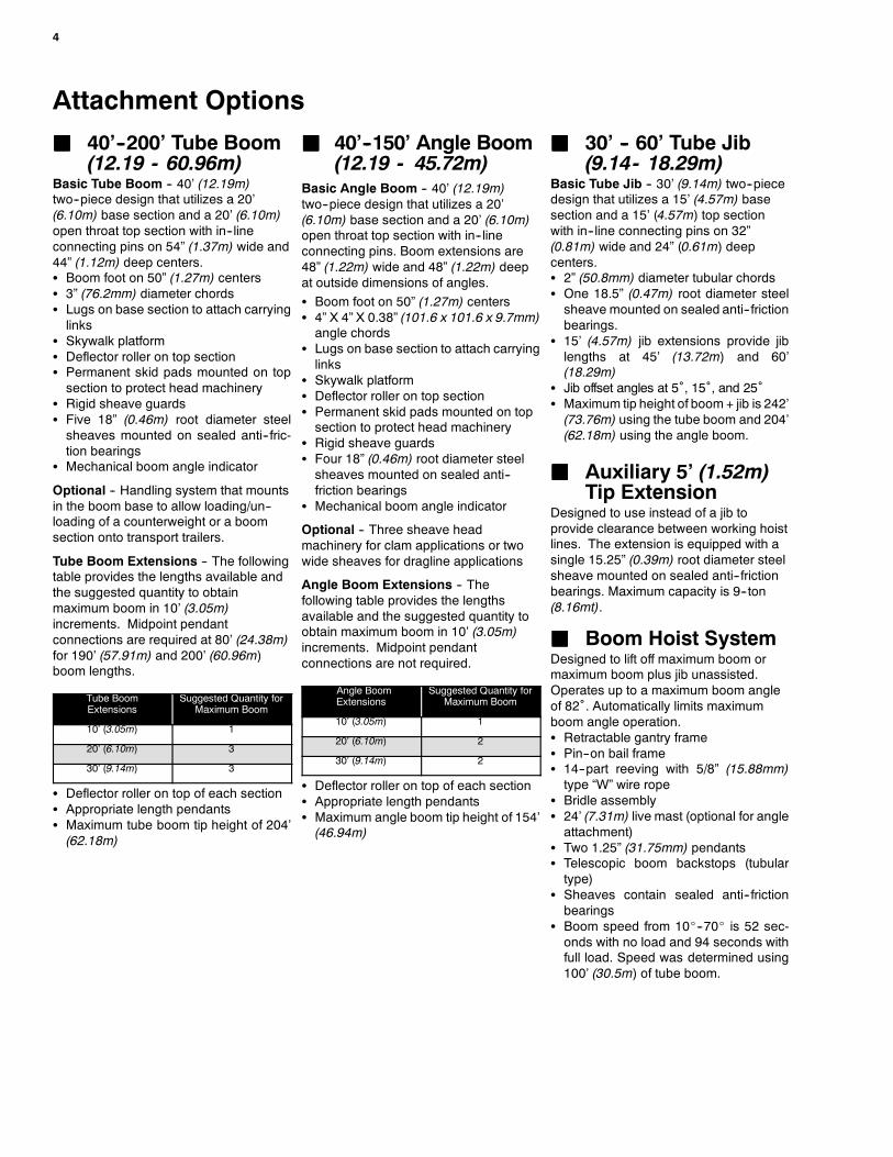
JJJJ 40’--200’ Tube Boom(12.19 - 60.96m)
Basic Tube Boom -- 40’ (12.19m)two--piece design that utilizes a 20’(6.10m) base section and a 20’ (6.10m)open throat top section with in--lineconnecting pins on 54” (1.37m) wide and44” (1.12m) deep centers.S Boom foot on 50” (1.27m) centersS 3” (76.2mm) diameter chordsS Lugs on base section to attach carryinglinks
S Skywalk platformS Deflector roller on top sectionS Permanent skid pads mounted on topsection to protect head machinery
S Rigid sheave guardsS Five 18” (0.46m) root diameter steelsheaves mounted on sealed anti--fric-tion bearings
S Mechanical boom angle indicator
Optional -- Handling system that mountsin the boom base to allow loading/un--loading of a counterweight or a boomsection onto transport trailers.
Tube Boom Extensions -- The followingtable provides the lengths available andthe suggested quantity to obtainmaximum boom in 10’ (3.05m)increments. Midpoint pendantconnections are required at 80’ (24.38m)for 190’ (57.91m) and 200’ (60.96m)boom lengths.
Tube BoomExtensions
Suggested Quantity forMaximum Boom
10’ (3.05m) 1
20’ (6.10m) 3
30’ (9.14m) 3
S Deflector roller on top of each sectionS Appropriate length pendantsS Maximum tube boom tip height of 204’(62.18m)
JJJJ 40’--150’ Angle Boom(12.19 - 45.72m)
Basic Angle Boom -- 40’ (12.19m)two--piece design that utilizes a 20’(6.10m) base section and a 20’ (6.10m)open throat top section with in--lineconnecting pins. Boom extensions are48” (1.22m) wide and 48” (1.22m) deepat outside dimensions of angles.S Boom foot on 50” (1.27m) centersS 4” X 4” X 0.38” (101.6 x 101.6 x 9.7mm)angle chords
S Lugs on base section to attach carryinglinks
S Skywalk platformS Deflector roller on top sectionS Permanent skid pads mounted on topsection to protect head machinery
S Rigid sheave guardsS Four 18” (0.46m) root diameter steelsheaves mounted on sealed anti--friction bearings
S Mechanical boom angle indicator
Optional -- Three sheave headmachinery for clam applications or twowide sheaves for dragline applications
Angle Boom Extensions -- Thefollowing table provides the lengthsavailable and the suggested quantity toobtain maximum boom in 10’ (3.05m)increments. Midpoint pendantconnections are not required.
Angle BoomExtensions
Suggested Quantity forMaximum Boom
10’ (3.05m) 1
20’ (6.10m) 2
30’ (9.14m) 2
S Deflector roller on top of each sectionS Appropriate length pendantsS Maximum angle boom tip height of 154’(46.94m)
JJJJ 30’ -- 60’ Tube Jib(9.14- 18.29m)
Basic Tube Jib -- 30’ (9.14m) two--piecedesign that utilizes a 15’ (4.57m) basesection and a 15’ (4.57m) top sectionwith in--line connecting pins on 32”(0.81m) wide and 24” (0.61m) deepcenters.S 2” (50.8mm) diameter tubular chordsS One 18.5” (0.47m) root diameter steelsheave mounted on sealed anti--frictionbearings.
S 15’ (4.57m) jib extensions provide jiblengths at 45’ (13.72m) and 60’(18.29m)
S Jib offset angles at 5˚, 15˚, and 25˚S Maximum tip height of boom + jib is 242’(73.76m) using the tube boom and 204’(62.18m) using the angle boom.
JJJJ Auxiliary 5’ (1.52m)Tip Extension
Designed to use instead of a jib toprovide clearance between working hoistlines. The extension is equipped with asingle 15.25” (0.39m) root diameter steelsheave mounted on sealed anti--frictionbearings. Maximum capacity is 9--ton(8.16mt).
JJJJ Boom Hoist SystemDesigned to lift off maximum boom ormaximum boom plus jib unassisted.Operates up to a maximum boom angleof 82˚. Automatically limits maximumboom angle operation.S Retractable gantry frameS Pin--on bail frameS 14--part reeving with 5/8” (15.88mm)type “W” wire rope
S Bridle assemblyS 24’ (7.31m) live mast (optional for angleattachment)
S Two 1.25” (31.75mm) pendantsS Telescopic boom backstops (tubulartype)
S Sheaves contain sealed anti--frictionbearings
S Boom speed from 10_--70_ is 52 sec-onds with no load and 94 seconds withfull load. Speed was determined using100’ (30.5m) of tube boom.

5
Revolving UpperstructureJJJJ FrameAll welded steel frame with precisionmachined surfaces for mating parts.
JJJJ EngineMitsubishi 6D16--TLE2A with oil filter, oil cooler,air cleaner, fuel filter, water separator, hour meter,tachometer, and electrical shutdown.
Number of cylinders 6
Bore and stroke -- in(mm)
4.65 x 4.53(118 x 115)
Piston displacement -- in3 (cm3) 460 (7 538)
Engine rpm at full load speed 2,000
Hi--idle rpm 2,200
Gross horsepower (kw) 182 (135)
Peak torque -- ft lb (joule) 535 (726)
Peak torque -- rpm 1,600
Electrical system 24 volt
Batteries 2--12 volt
Approximate fuel consumption gal/hr (L/hr)
100% hp 9.17 (34.71)
50% hp 4.58 (17.34)
25% hp 2.29 (8.67)
15% hp 1.38 (5.22)
JJJJ Hydraulic SystemHydraulic Pumps -- The pumparrangement is designed to provideprecise control with independent orsimultaneous operation of all cranefunctions.S Pump P1 -- Variable displacement,semi--closed loop, piston pumpoperating at 4,480 psi (315kg/cm2) and64 gpm (242Lpm). Supplies power forthe front drum, rear drum, boom hoistdrum, and travel.
S Pump P2 -- Variable displacement,semi--closed loop, piston pumpoperating at 4,480 psi (315kg/cm2) and64 gpm (242Lpm). Supplies power forthe front drum, rear drum, travel, andoptional 4th drum.
S Pump P3 -- Fixed displacement, openloop, gear pump operating at 3,556 psi(250kg/cm2) and 33 gpm (125Lpm).Supplies power for swing and sideframe retract cylinders.
S Pump P4 -- Fixed displacement, openloop, gear pump operating at 1,422 psi(100kg/cm2) and 12.7 gpm (48Lpm).Supplies power for remote mountedhydraulic oil cooler fan.
S Pump P5 -- Fixed displacement, openloop, gear pump operating at 2,987 psi(210kg/cm2) and 8.6 gpm (33Lpm).Supplies power for hydraulic remotecontrol system and hydrauliccounterweight self--assembly system.
S Pump P6 (Optional) -- Fixeddisplacement, open loop, gear pumpoperating at 1,422 psi (100kg/cm2) and6.3 gpm (24Lpm). Supplies power foroptional hydraulic tagline.
Pump Control (“Fine Inching”) modeSpecial pump setting, selectable fromoperator’s cab, that allows very slowmovements of load hoist drums, boomhoist drum, and travel for precision work.
Hydraulic Reservoir -- 53 gal (200.6L),equipped with sight level gauge.Diffusers built in for deaeriation.
Filtration -- One 10 micron, full flow linefilter in the control circuit. All oil is filteredprior to entering the reservoir.
Counterbalance Valves -- All hoistmotors are equipped withcounterbalance valves to providepositive load lowering and preventaccidental load drop if the hydraulicpressure is suddenly lost.
JJJJ Load Hoist DrumsEach drum contains a pilot controlled,bi--directional, axial piston motor and aplanetary gear reduction unit to providepositive control under all load conditions.S Power up/down & free--fall operationmodes
S Automatic brake mode (spring applied,hydraulically released, band typebrake)
S 0.88” (22.35mm) grooved laggingS Drum pawl controlled manuallyS Electronic drum rotation indicatorsS Mounted on anti--friction bearingsS 17.64” (0.45m) root diameterS 29.92” (0.76m) flange diameterS 19.84” (0.50m) width
Note: The freefall operation mode isdesigned to prevent load lowering even ifthe freefall switch is accidentallyactivated. The automatic brake modemeets all OSHA requirements forpersonnel handling.
Drum Clutches -- Power hydraulic twoshoe clutch design that uses a 20”(0.51mm) diameter x 5” (0.13mm) wideshoe that internally expands to provideload control. Swept area is 314 in2
(2 026 cm2).
JJJJ Optional FrontMounted Third HoistDrum
The hydraulic winch is pinned to the frontof the upper frame and is used inconjunction with a fleeting sheave and3--sheave idler assembly to run the wirerope over the boom top section.S Free--spooling capability for piledriving applications
S 10.63” (0.27m) root diameterS 20” (0.51m) outside flange diameterS 13.5” (0.34m) widthS Mounted on anti--friction bearings
JJJJ Boom Hoist DrumContains a pilot controlled, bi--directional,axial piston motor and a planetary gearreduction unit to provide positive controlunder all load conditions.S Spring applied, hydraulically released,disc type automatically controlled brake
S 5/8” (15.88mm) grooved laggingS Drum pawl controlled manuallyS Mounted on anti--friction bearingsS 12.60” (0.32m) root diameterS 24.41” (0.62m) flange diameterS 9.57” (0.24m) width
JJJJ Swing SystemMechanical linkage controls thebi--directional axial piston motor and theplanetary gear reduction unit to providepositive control under all load conditions.S Spring applied, hydraulically released,360 degree multi--plate brake
S Free swing mode when lever is in neu-tral position
S Two position positive house lockS Audio/Visual swing alarmS Maximum swing speed is 3.0 rpm
JJJJ Upper CounterweightConsist of a two piece design that canbe easily lowered to the ground usingthe gantry.S 25,250 lb (11 453kg) “A” uppercounterweight
S 25,250 lb (11 453kg) “B” uppercounterweight can be added tomaximize capacities
6
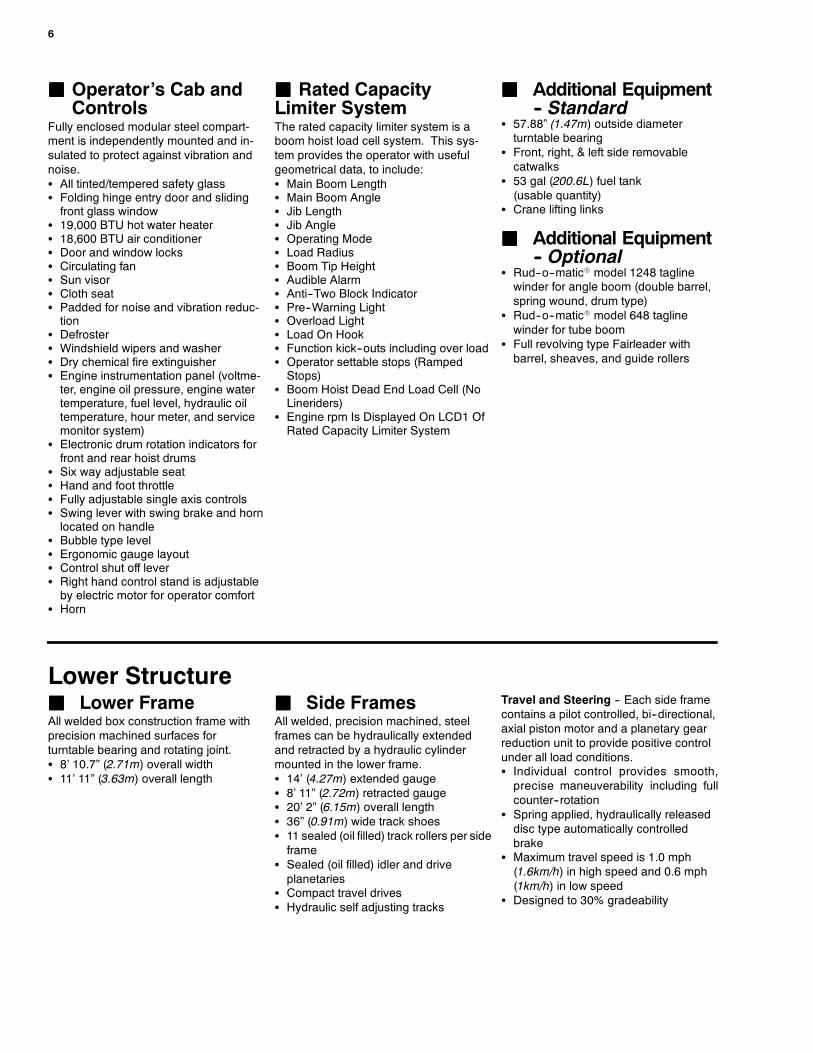
JJJJ Operator’s Cab andControls
Fully enclosed modular steel compart-ment is independently mounted and in-sulated to protect against vibration andnoise.S All tinted/tempered safety glassS Folding hinge entry door and slidingfront glass window
S 19,000 BTU hot water heaterS 18,600 BTU air conditionerS Door and window locksS Circulating fanS Sun visorS Cloth seatS Padded for noise and vibration reduc-tion
S DefrosterS Windshield wipers and washerS Dry chemical fire extinguisherS Engine instrumentation panel (voltme-ter, engine oil pressure, engine watertemperature, fuel level, hydraulic oiltemperature, hour meter, and servicemonitor system)
S Electronic drum rotation indicators forfront and rear hoist drums
S Six way adjustable seatS Hand and foot throttleS Fully adjustable single axis controlsS Swing lever with swing brake and hornlocated on handle
S Bubble type levelS Ergonomic gauge layoutS Control shut off leverS Right hand control stand is adjustableby electric motor for operator comfort
S Horn
JJJJ Rated CapacityLimiter SystemThe rated capacity limiter system is aboom hoist load cell system. This sys-tem provides the operator with usefulgeometrical data, to include:S Main Boom LengthS Main Boom AngleS Jib LengthS Jib AngleS Operating ModeS Load RadiusS Boom Tip HeightS Audible AlarmS Anti--Two Block IndicatorS Pre--Warning LightS Overload LightS Load On HookS Function kick--outs including over loadS Operator settable stops (RampedStops)
S Boom Hoist Dead End Load Cell (NoLineriders)
S Engine rpm Is Displayed On LCD1 OfRated Capacity Limiter System
JJJJ Additional Equipment-- Standard
S 57.88” (1.47m) outside diameterturntable bearing
S Front, right, & left side removablecatwalks
S 53 gal (200.6L) fuel tank(usable quantity)
S Crane lifting links
JJJJ Additional Equipment-- Optional
S Rud--o--maticR model 1248 taglinewinder for angle boom (double barrel,spring wound, drum type)
S Rud--o--maticR model 648 taglinewinder for tube boom
S Full revolving type Fairleader withbarrel, sheaves, and guide rollers
Lower StructureJJJJ Lower FrameAll welded box construction frame withprecision machined surfaces forturntable bearing and rotating joint.S 8’ 10.7” (2.71m) overall widthS 11’ 11” (3.63m) overall length
JJJJ Side FramesAll welded, precision machined, steelframes can be hydraulically extendedand retracted by a hydraulic cylindermounted in the lower frame.S 14’ (4.27m) extended gaugeS 8’ 11” (2.72m) retracted gaugeS 20’ 2” (6.15m) overall lengthS 36” (0.91m) wide track shoesS 11 sealed (oil filled) track rollers per sideframe
S Sealed (oil filled) idler and driveplanetaries
S Compact travel drivesS Hydraulic self adjusting tracks
Travel and Steering -- Each side framecontains a pilot controlled, bi--directional,axial piston motor and a planetary gearreduction unit to provide positive controlunder all load conditions.S Individual control provides smooth,precise maneuverability including fullcounter--rotation
S Spring applied, hydraulically releaseddisc type automatically controlledbrake
S Maximum travel speed is 1.0 mph(1.6km/h) in high speed and 0.6 mph(1km/h) in low speed
S Designed to 30% gradeability

7
Load Hoisting Performance
Front Or Rear Drum --- 7/8” (22.22mm) Wire Rope
Rope Maximum Line Pull No Load Line Speed Full Load Line Speed Pitch Diameter Layer TotalRopeLayer lb kg ft/min m/min ft/min m/min in mm ft m ft m
1 32,377 14 686 300 91 91 28 18.5 470 100 30 100 30
2 29,581 13 418 329 100 100 30 20.3 516 109 33 209 64
3 27,229 12 351 357 109 109 33 22.0 559 119 36 327 100
4 25,224 11 441 386 118 117 36 23.8 605 128 39 455 139
5 23,493 10 657 414 126 126 38 25.5 648 137 42 593 181
6 21,985 9 972 442 135 134 41 27.3 693 147 45 740 225
Boom Hoist Drum --- 5/8” (15.88mm) Wire Rope
Rope Maximum Line Pull No Load Line Speed Full Load Line Speed Pitch Diameter Layer TotalRopeLayer lb kg ft/min m/min ft/min m/min in mm ft m ft m
1 17,856 8 099 186 57 177 54 13.2 336 48 15 48 15
2 16,313 7 400 203 62 193 59 14.5 368 52 16 100 31
3 15,017 6 812 221 67 210 64 15.7 400 57 17 157 48
4 13,911 6 310 238 73 227 69 17.0 432 61 19 218 67
5 12,956 5 877 256 78 243 74 18.3 464 66 20 284 87
6 12,125 5 500 274 84 260 79 19.5 496 70 21 355 108
7 11,393 5 168 291 89 277 84 20.8 528 75 23 430 131
Optional Third Drum --- 5/8” (15.88mm) Wire Rope
Rope Maximum Line Pull No Load Line Speed Full Load Line Speed Pitch Diameter Layer TotalRopeLayer lb kg ft/min m/min ft/min m/min in mm ft m ft m
1 15,041 6 822 157 48 143 44 11.25 286 57 17 57 17
2 13,537 6 140 175 53 159 48 12.50 318 64 20 121 37
3 12,307 5 582 192 59 175 53 13.75 349 71 22 192 59
4 11,282 5 117 210 64 191 58 15.00 381 77 23 269 82
5 10,414 4 724 228 69 207 63 16.25 413 83 25 352 107
6 9,671 4 387 245 75 223 68 17.50 445 90 27 442 135
Wire Rope Applications
Wire Rope ApplicationDiameter Length
TypeMaximum Permissible Load
Wire Rope Applicationin mm ft m
Typelb kg
Boom Hoist 5/8 15.88 610 186 W 11,770 5 339
Front Hoist 7/8 22.22 700 213 DB 22,740 10 315
Rear Hoist (Optional) 7/8 22.22 540 165 RB 17,520 7 947
Rear Hoist (Optional) 7/8 22.22 700 213 DB 22,740 10 315
Third Drum (Optional) 5/8 15.88 385 117 ZB 11,080 5 026
Third Drum (Optional) 5/8 15.88 385 117 WB 13,650 6 192
RopeType Description
DB 6 x 26 (6 X 19 Class) --- Warrington Seal --- Extra Improved Plow Steel --- Preformed --- Right Lay --- Regular Lay --- I.W.R.C.
RB 19 x 19 Rotation Resistant --- Extra Improved Plow Steel --- Preformed --- Right Lay --- Regular Lay --- Swaged
ZB 36 x 7 --- Non---rotating --- Extra Improved Plow Steel --- Right Lay --- Regular Lay
WB 8 Strand --- Regular Lay
W 6 x 26 (6 X 19 Class) --- Extra Improved Plow Steel --- Preformed --- Right Lay --- Alternate Lay --- I.W.R.C.

8
This Page Left BlankIntentionally

9
This Page Left BlankIntentionally

Link--Belt Construction Equipment Company Lexington, Kentucky www.linkbelt.comRLink--Belt is a registered trademark. Copyright 2005. We are constantly improving our products and therefore reserve the right to change designs and specifications.

�������������� Lattice Boom Crawler Crane
138 HYLAB 5 80–ton (72.6 metric ton)
Angle Boom Capacities40’ – 150’ (12.19 – 45.72m)24’ (7.31m) Live Mast� Extended/Retracted Side Frames
5’ (1.52m) Tip Extension
Duty Cycle Capacities� 40’ – 70’ (12.19 – 21.34m) Angle Boom� Extended Side Frames� “A” Counterweight
Angle Boom Capacities � 40’ – 150’ (12.19 – 45.72m) Angle Boom� 48” (1.22m) Wide x 48” (1.22m) Deep Boom� 20’ (6.10m) Open Throat Top Section� ���������������������������������� �
� Extended / Retracted Side Frames� Over End Blocked Capacities� “AB”, “A”, or “0” Counterweight Options� 20’ 2” (6.15m) Crawler Length
CAUTION: This material is supplied for reference use only. Operator must refer toin–cab Crane Rating Manual to determine allowable crane lifting capacities andoperating procedures.

–2–138 HYLAB 5
����������� ��� ��������� � � ���������� ��� ������ ������ ��� � �
������������������������ ������������������������ ����������������� �� �������������� ��������������������������
���������
LIFTING NOTESGENERAL:
1. Rated lifting capacities in pounds as shown on liftcharts pertain to this crane as originally manufacturedand normally equipped. Modifications to the crane oruse of optional equipment other than that specifiedcan result in a reduction of capacity.
2. Construction equipment can be dangerous ifimproperly operated or maintained. Operation andmaintenance of this crane must be in compliance withthe information in the Operator’s, Parts, and SafetyManuals supplied with this crane. If these manualsare missing, order replacements through thedistributor.
3. The operator and other personnel associated with thiscrane shall read and fully understand the latestapplicable American National Standards Institute(ANSI) safety standards for cranes.
4. All capacities listed in this book are in compliance withASME/ANSI B30.5c at date of manufacture.
LIFT CRANE OPERATION:1. Capacities shown are in pounds and are not more
than 75% of the tipping loads with the crane standinglevel on firm supporting surface. A deduction must bemade from these capacities for weight of hook block,hook ball, sling, grapple, load weighing device (otherthan those supplied with the crane), etc. When usingmain hook while jib is attached, reduce capacities byvalues shown on Capacity Deductions For Lifting OffMain Boom Hook With Jib Installed. When using mainhook while 5’ tip extension is attached, reducecapacities by values shown on Capacity DeductionsFor Lifting Off Main Boom Hook With 5’Tip Extension Installed. See Operator’s Manual for alllimitations when raising or lowering attachment.
2. The crane capacities in the shaded areas are basedon structural strength. The crane capacities in thenon–shaded areas are based on stability.
3. For recommended reeving, parts of line, wire ropetype, and wire rope inspection, see Wire RopeCapacity chart, Operator’s Manual, and PartsManual.
4. Load ratings in the Crane Rating Manual are based onfreely suspended loads and make no allowances forsuch factors as the effect of the wind, groundconditions, and operating speeds. The operator shalltherefore reduce load ratings in order to take theseconditions into account.
5. Rated lifting capacities do not account for the effectsof wind on a suspended load or boom. Liftingcapacities should be considered acceptable for windspeeds less than 20 mph and appropriately reducedfor wind speeds greater than 20 mph. Extremecaution should be used when lifting heavy loads orloads with large wind sail area under high windconditions (over 20 mph).
6. The capacities listed in the Crane Rating Manual arefor the crane with or without live mast, with the gantryin the raised position.
7. The least stable rated condition is over the side.8. Booms must be erected and lowered over the end for
maximum stability.9. Do not operate at radii and boom lengths where the
Crane Rating Manual lists no capacity. Do not uselonger booms or jibs than those listed in the CraneRating Manual. Any of the above can cause a tippingcondition or boom and jib failure.
10. These capacities apply only to the crane as originallymanufactured and normally equipped by Link–BeltConstruction Equipment Company.
FOR OVER END CAPACITIES ONLY1. These capacities can be lifted over either end with the
crane standing level on a firm supporting surface withadequate blocking placed under the side framesprockets/idlers, to prevent rocking.
2. Do not travel with a load.

–3– 138 HYLAB 5
WIRE ROPE CAPACITYParts 7/8” 5/8”
ofLine Type “DB” Type “RB” Type “ZB” Type “WB” Notes
1 22,700 17,520 * 11,000 ** 13,650 *
2 45,400 35,040 22,000 27,310Capacities
3 68,100 52,560 33,000 40,970shown are inpounds andworking loads
4 90,800 70,080 44,000 54,620
working loadsmust not ex-ceed the ratingson the capacity
5 113,500 87,600 55,000 68,280on the capacitycharts in theCrane Rating
6 136,200 105,120 66,000 81,940Manual. StudyOperator ’sManual for wire
7 158,900 122,640 77,000 95,600rope inspectionprocedures andsingle part of
8 181,600 140,160 88,000 109,250
single part ofline applica-tions.
LBCEType
Description
DB 6 x 26 (6 x 19 Class) – Warrington Seale – Extra Improved Plow Steel – Pre-formed – Right Lay – Regular Lay – I.W.R.C.
RB 19 x 19 Rotation Resistant– Extra Extra Improved Plow Steel – Preformed –Right Lay – Regular Lay. Swaged
ZB 36 x 7 Class – Non–Rotating – Extra Improved Plow Steel – Right Lay – Regu-lar Lay
WB 8 Strand – Regular Lay
M 6 X 19 Class – Extra Improved Plow Steel – Lang Lay
WORKING AREAS
Boom
Ove
r Id
ler
End
Ove
r D
rive
End
Center OfRotation
Drive Sprocket
Of Crawler
Longitudinal
See Note
See Note
Idler Sprocket
360�
Over Side
Note: These Lines Determine The Limiting Position Of Any LoadFor Operation Within Working Areas Indicated.
Over Side
AB
LIFTOFF CAPABILITIES
��������� !"�
�)����$*�)��� $�#�%���+���% '�$��' � ��(
��������� !"�#� $���%&�'( �%, &�&���& �%, &�&���&./ 0# ( �%, &�&���&
#-�(
�%, &�&���&./ 0
#-�(
��
���������� !" �#�
��
��$������ %"" �#�
�
���������� %�" �#�
�
��$������ %�" �#�
�
��$������ &���������
%'" �#�
�(
��$������ %'"
%�"�)�*"
%'"�)�+"
��������� !"�
�)����$*�)��� $�#�%���+��������$��' � ��(
��������� !"�#� $���%&�'( �%, &�&���& �%, &�&���&./ 0# ( �%, &�&���&
#-�(
�%, &�&���&./ 0
#-�(
��
���������� !" �#�
��
��$������ ," �#�
�
���������� ," �#�
�
��$������ ," �#�
�(
��$������ ,"
*"�)�*"
-"�)��'
NOTES:1. For maximum stability, booms must be erected or lowered
over the end with no load – hook block on ground.2. Crane on firm and level surface.3. gantry pins must be installed when the gantry is in the
lowered position.4. For 150’ boom (side frames extended) with A counterweight
only – Adequate blocking must be placed under both sideframe sprockets (or idler rollers) at the end that the boom isto be lifted off to prevent rocking. The ramps supplied withthe crane are considered to be adequate blocking.
–4–138 HYLAB 5
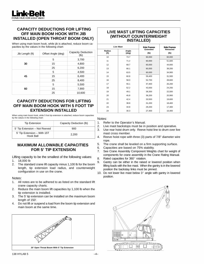
CAPACITY DEDUCTIONS FOR LIFTINGOFF MAIN BOOM HOOK WITH JIB
INSTALLED (OPEN THROAT BOOM ONLY)When using main boom hook, while jib is attached, reduce boom ca-pacities by the values in the following chart:
Jib Length (ft) Offset Angle (deg) Capacity Deduction(lb)
5 3,700
30 15 4,80030
25 6,200
5 4,500
45 15 6,40045
25 8,400
5 5,500
60 15 7,90060
25 10,600
CAPACITY DEDUCTIONS FOR LIFTINGOFF MAIN BOOM HOOK WITH 5 FOOT TIP
EXTENSION INSTALLEDWhen using main boom hook, while 5 foot tip extension is attached, reduce boom capacitiesby the values in the following chart:
Tip Extension Capacity Deduction (lb)
5’ Tip Extension – Not Reeved 900
5’ Tip Extension – With 15THook Ball 2,200
MAXIMUM ALLOWABLE CAPACITIES FOR 5’ TIP EXTENSION
Lifting capacity to be the smallest of the following values:1. 18,000 lb2. The standard crane lift capacity minus 1,100 lb for the boom
length, tip extension load radius, and counterweightconfiguration in use on the crane.
Notes:1. All notes are to be adhered to as listed on the standard lift
crane capacity charts.2. Reduce the main boom lift capacities by 1,100 lb when the
tip extension is installed.3. The 5’ tip extension can be installed on the maximum boom
length of 150’.4. Do not lift or suspend a load from the boom tip extension and
main boom at the same time.
20’ Open Throat Boom With 5’ Tip Extension
LIVE MAST LIFTING CAPACITIES(WITHOUT COUNTERWEIGHT
INSTALLED)Live Mast Side Frames Side Frames
Radius(ft)
Angle(deg)
Side FramesExtended
(lb)
Side FramesRetracted
(lb)
10 73.7 60,000 60,000
11 71.2 60,000 51,600
12 68.7 60,000 44,600
13 66.1 60,000 39,200
14 63.5 60,000 34,900
15 60.8 59,400 31,500
16 58.0 52,700 28,600
17 55.1 47,400 26,200
18 52.2 43,000 24,200
19 49.1 39,300 22,500
20 45.8 36,200 20,900
21 42.4 33,500 19,600
22 38.8 31,200 18,400
23 34.8 29,200 17,300
24 30.3 27,400 16,400
Notes:1. Refer to the Operator’s Manual.2. Live mast backstops must be in position and operative.3. Use rear hoist drum only. Reeve hoist line to drum over live
mast cross member.4. Reeve hoist rope with three (3) parts of 7/8” diameter wire
rope.5. The crane shall be leveled on a firm supporting surface.6. Capacities are based on 75% stability.7. See Crane Assembly Component Weights chart for weight of
components for crane assembly in the Crane Rating Manual.8. Rated capacities for 360� rotation.9. Gantry can be either in the raised or lowered position when
lifting loads with the live mast. When the gantry is in the loweredposition the backstay links must be pinned.
10. Do not lower live mast below 3� angle with gantry in loweredposition.

–5– 138 HYLAB 5
DUTY CYCLE NOTES FOR ANGLE BOOM1. The capacities included in the “Duty Cycle Capacities –
Angle Boom” chart are the maximum allowable, and arebased on crane standing level on firm supporting surfaceunder ideal job conditions.
2. Capacities are based on 75% of minimum tipping loads fordragline; 67.5% for clamshell.
3. Weight of bucket plus load, must not exceed thesecapacities.
4. Dragline operation is not recommended with boom anglesless than 35�.
5. Boom length for dragline/clamshell attachment operationshould not exceed 70’.
6. Retractable high gantry must be fixed in raised position for allcapacities on the “Duty Cycle Capacities – Angle Boom”chart.
7. These capacities apply to the crane as originallymanufactured and normally equipped by Link–BeltConstruction Equipment Company.
8. Capacities are maximum recommended by PCSA Standard#4. Operator must make allowances for soft or unevensupporting surfaces, rapid cycle operations, bucket suction,or other unfavorable conditions which may require smallerbuckets for most efficient operation.
DUTY CYCLE CAPACITIES – ANGLE BOOMSide Frames Extended – “A” Counter-
BoomLength
LoadRadius
BoomAngle
weight Only (All capacities listed arein pounds)
Length(ft)
Radius(ft)
Angle(deg)
Dragline Clamshell/Mag-net
40 9 81.8 – – – 22,700
40 10 80.3 – – – 22,700
40 11 78.9 – – – 22,700
40 12 77.4 – – – 22,700
40 13 75.9 – – – 22,700
40 14 74.5 – – – 22,700
40 15 73.0 – – – 22,700
40 16 71.5 – – – 22,700
40 17 69.9 – – – 22,700
40 18 68.4 – – – 22,700
40 19 66.9 – – – 22,700
40 20 65.3 – – – 22,700
40 25 57.1 22,700 22,700
40 30 48.1 22,700 22,700
40 35 37.5 22,700 22,700
40 40 23.4 – – – 20,160
50 11 81.1 – – – 22,700
50 12 80.0 – – – 22,700
50 13 78.8 – – – 22,700
50 14 77.6 – – – 22,700
50 15 76.4 – – – 22,700
50 16 75.3 – – – 22,700
50 17 74.1 – – – 22,700
50 18 72.9 – – – 22,700
50 19 71.7 – – – 22,700
50 20 70.5 – – – 22,700
50 25 64.3 – – – 22,700
50 30 57.7 22,700 22,700
50 35 50.6 22,700 22,700
50 40 42.7 22,500 20,250
50 50 20.9 – – – 14,670
60 12 81.6 – – – 22,700
60 13 80.7 – – – 22,700
60 14 79.7 – – – 22,700
60 15 78.7 – – – 22,700
60 16 77.8 – – – 22,700
60 17 76.8 – – – 22,700
60 18 75.8 – – – 22,700
Side Frames Extended –“A” Counterweight Only
BoomLength
LoadRadius
BoomAngle
“A” Counterweight Only(All capacities listed are in
pounds)Length(ft)
Radius(ft)
Angle(deg)
Dragline Clamshell/Magnet
60 19 74.8 – – – 22,700
60 20 73.8 – – – 22,700
60 25 68.8 – – – 22,700
60 30 63.6 – – – 22,700
60 35 58.1 22,700 22,700
60 40 52.3 22,400 20,160
60 50 38.9 16,300 14,670
60 60 19.0 – – – 11,160
70 14 81.2 – – – 22,700
70 15 80.4 – – – 22,700
70 16 79.5 – – – 22,700
70 17 78.7 – – – 22,700
70 18 77.9 – – – 22,700
70 19 77.0 – – – 22,700
70 20 76.2 – – – 22,700
70 25 71.9 – – – 22,700
70 30 67.6 – – – 22,700
70 35 63.1 – – – 22,700
70 40 58.4 22,200 19,980
70 50 48.1 16,200 14,580
70 60 35.9 12,400 11,160
70 70 17.6 – – – 8,730
80 15 81.6 – – – 22,700
80 16 80.9 – – – 22,700
80 17 80.1 – – – 22,700
80 18 79.4 – – – 22,700
80 19 78.7 – – – 22,700
80 20 77.9 – – – 22,700
80 25 74.2 – – – 22,700
80 30 70.5 – – – 22,700
80 35 66.6 – – – 22,700
80 40 62.7 – – – 19,800
80 50 54.3 16,000 14,400
80 60 44.8 12,200 10,980
80 70 33.5 9,600 8,640
80 80 16.5 – – – 6,840

–6–138 HYLAB 5
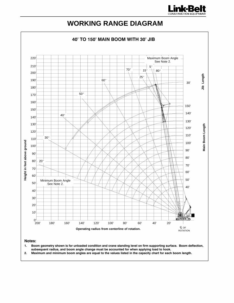
WORKING RANGE DIAGRAM
12���342������ ��������
����'5
1. Boom geometry shown is for unloaded condition and crane standing level on firm supporting surface. Boomdeflection, subsequent radius, and boom angle change must be accounted for when applying load to hook.
2. Maximum and minimum boom angles are equal to the values listed in the capacity chart for each boomlength.
Operating radius from centerline of rotation in feet
Maximum Boom AngleSee Note 2.
Mai
n B
oo
m L
eng
th
Hei
gh
t in
fee
t ab
ove
gro
un
d
140’ 120’ 100’ 80’ 60’ 40’ 20’
50’
60’
70’
80’
90’
100’
110’
120’
130’
140’
150’
50’
60’
70’
80’
90’
100’
110’
120’
130’
140’
150’
20’
30’
40’
0’
10’
Minimum Boom AngleSee Note 2.
40’
80°
70°
60°
50°
40°
30°
10°
20°
160’
160’
OFCLROTATION

–7– 138 HYLAB 5
AB
MAIN BOOM CAPACITIES – 40 FT OPEN THROAT ANGLE BOOM
Over 360� Rotation
Load Boom
OverEnd
BlockedSide Frames
ExtendedSide Frames
RetractedRadius
(ft)Angle(deg) AB
CTWT(lb)
ABCTWT
(lb)
ACTWT
(lb)
0CTWT
(lb)
ACTWT
(lb)
0CTWT
(lb)
8.9 82.0 160,000 160,000 160,000 160,000 145,600 77,200
9 81.8 160,000 160,000 160,000 160,000 140,700 74,600
10 80.3 160,000 160,000 160,000 152,300 114,800 60,600
11 78.9 160,000 160,000 156,700 119,900 96,800 50,900
12 77.4 160,000 160,000 144,600 95,700 83,600 43,800
13 75.9 151,200 151,200 134,100 79,500 73,500 38,300
14 74.5 140,900 140,900 116,900 67,800 65,500 34,000
15 73.0 132,000 132,000 102,000 59,100 59,000 30,500
16 71.5 124,000 124,000 90,500 52,200 53,600 27,600
17 69.9 117,000 117,000 81,200 46,800 49,100 25,200
18 68.4 110,600 107,700 73,600 42,300 45,300 23,100
19 66.9 104,900 98,600 67,300 38,600 42,000 21,300
20 65.3 99,800 90,800 61,900 35,400 39,100 19,800
25 57.1 79,600 64,900 44,000 24,800 28,900 14,300
30 48.1 60,500 50,200 33,800 18,800 22,500 10,700
35 37.5 48,500 40,600 27,100 14,800 18,200 8,300
40 23.4 35,500 33,800 22,400 11,900 15,000 6,600
MAIN BOOM CAPACITIES – 50 FT OPEN THROAT ANGLE BOOM
Over 360� Rotation
Load Boom
OverEnd
BlockedSide Frames
ExtendedSide Frames
RetractedRadius
(ft)Angle(deg) AB
CTWT(lb)
ABCTWT
(lb)
ACTWT
(lb)
0CTWT
(lb)
ACTWT
(lb)
0CTWT
(lb)
10.3 82.0 149,300 149,300 149,300 148,400 109,900 58,000
11 81.1 146,200 146,200 146,200 120,200 96,800 50,900
12 80.0 142,300 142,300 142,300 95,900 83,600 43,800
13 78.8 138,700 138,700 133,700 79,600 73,400 38,300
14 77.6 134,000 134,000 117,000 67,900 65,400 34,000
15 76.4 130,800 130,800 102,100 59,100 58,900 30,500
16 75.3 123,800 123,800 90,500 52,300 53,500 27,500
17 74.1 116,800 116,800 81,200 46,800 49,000 25,100
18 72.9 110,500 107,700 73,600 42,300 45,200 23,000
19 71.7 104,800 98,500 67,300 38,500 41,900 21,200
20 70.5 99,600 90,800 61,900 35,300 39,000 19,700
25 64.3 79,600 64,800 43,900 24,700 28,700 14,100
30 57.7 60,400 50,100 33,700 18,700 22,500 10,700
35 50.6 48,500 40,600 27,100 14,800 18,200 8,400
40 42.7 40,300 33,900 22,500 12,000 15,100 6,700
50 20.9 27,100 25,100 16,300 8,300 10,900 4,300
MAIN BOOM CAPACITIES – 60 FT OPEN THROAT ANGLE BOOM
Over 360� Rotation
Load Boom
OverEnd
BlockedSide Frames
ExtendedSide Frames
RetractedRadius
(ft)Angle(deg) AB
CTWT(lb)
ABCTWT
(lb)
ACTWT
(lb)
0CTWT
(lb)
ACTWT
(lb)
0CTWT
(lb)
11.7 82.0 130,200 130,200 130,200 103,800 87,900 46,100
12 81.6 129,000 129,000 129,000 96,100 83,500 43,700
13 80.7 125,900 125,900 125,900 79,700 73,300 38,200
14 79.7 122,800 122,800 117,000 68,000 65,300 33,800
15 78.7 120,000 120,000 102,100 59,100 58,800 30,300
16 77.8 117,300 117,300 90,500 52,300 53,400 27,400
17 76.8 114,700 114,700 81,200 46,700 48,900 25,000
18 75.8 110,100 107,700 73,600 42,200 45,000 22,900
19 74.8 104,500 98,500 67,200 38,500 41,700 21,100
20 73.8 99,400 90,700 61,800 35,300 38,800 19,500
25 68.8 79,500 64,700 43,800 24,600 28,500 13,900
30 63.6 60,300 49,900 33,600 18,500 22,300 10,500
35 58.1 48,300 40,400 27,000 14,600 18,100 8,300
40 52.3 40,100 33,800 22,400 11,900 15,100 6,600
50 38.9 29,700 25,100 16,300 8,300 10,900 4,300
60 19.0 21,900 19,600 12,400 5,900 8,100 2,700
MAIN BOOM CAPACITIES – 70 FT OPEN THROAT ANGLE BOOM
Over 360� Rotation
Load Boom
OverEnd
BlockedSide Frames
ExtendedSide Frames
RetractedRadius
(ft)Angle(deg) AB
CTWT(lb)
ABCTWT
(lb)
ACTWT
(lb)
0CTWT
(lb)
ACTWT
(lb)
0CTWT
(lb)
13.1 82.0 114,400 114,400 114,400 79,400 73,000 37,900
14 81.2 110,700 110,700 110,700 68,000 65,100 33,700
15 80.4 108,200 108,200 102,100 59,100 58,600 30,200
16 79.5 105,900 105,900 90,500 52,200 53,200 27,200
17 78.7 103,700 103,700 81,100 46,700 48,700 24,800
18 77.9 101,500 101,500 73,500 42,100 44,800 22,700
19 77.0 99,500 98,400 67,100 38,400 41,500 20,900
20 76.2 97,500 90,600 61,700 35,100 38,600 19,300
25 71.9 79,300 64,500 43,600 24,400 28,300 13,700
30 67.6 60,200 49,800 33,400 18,400 22,100 10,300
35 63.1 48,200 40,200 26,800 14,400 17,900 8,000
40 58.4 40,000 33,600 22,200 11,700 14,800 6,400
50 48.1 29,500 24,900 16,200 8,100 10,700 4,200
60 35.9 23,000 19,500 12,400 5,800 8,000 2,600
70 17.6 17,500 15,700 9,700 4,200 6,100 1,500

–8–138 HYLAB 5
AB
MAIN BOOM CAPACITIES – 80 FT OPEN THROAT ANGLE BOOM
Over 360� Rotation
Load Boom
OverEnd
BlockedSide Frames
ExtendedSide Frames
RetractedRadius
(ft)Angle(deg) AB
CTWT(lb)
ABCTWT
(lb)
ACTWT
(lb)
0CTWT
(lb)
ACTWT
(lb)
0CTWT
(lb)
14.5 82.0 101,100 101,100 101,100 64,000 62,100 32,000
15 81.6 99,800 99,800 99,800 59,100 58,500 30,000
16 80.9 97,800 97,800 90,400 52,100 53,100 27,100
17 80.1 95,800 95,800 81,000 46,600 48,500 24,600
18 79.4 93,900 93,900 73,400 42,000 44,700 22,500
19 78.7 92,100 92,100 67000 38,200 41,300 20,700
20 77.9 89,200 89,200 61,500 35,000 38,400 19,100
25 74.2 78,900 64,400 43,500 24,300 28,100 13,500
30 70.5 60,000 49,600 33,200 18,200 21,900 10,100
35 66.6 48,000 40,000 26,600 14,200 17,600 7,800
40 62.7 39,800 33,400 22,000 11,500 14,600 6,200
50 54.3 29,300 24,700 16,000 7,900 10,500 3,900
60 44.8 22,800 19,300 12,200 5,700 7,900 2,500
70 33.5 18,400 15,600 9,600 4,100 6,000 –––
80 16.5 14,200 12,800 7,600 2,900 4,500 –––
MAIN BOOM CAPACITIES – 90 FT OPEN THROAT ANGLE BOOM
Over360� Rotation
LoadRadius
BoomAngle
OverEnd
Blocked Side FramesExtended
Side FramesRetracted
Radius(ft)
Angle(deg) AB
CTWT(lb)
ABCTWT
(lb)
ACTWT
(lb)
0CTWT
(lb)
ACTWT
(lb)
0CTWT
(lb)
15.9 82.0 89,500 89,500 89500 53,300 53,800
16 81.9 89,200 89,200 89200 52,100 52,900
17 81.2 87,500 87,500 80,900 46,500 48,300
18 80.6 85,900 85,900 73,200 41,900 44,400
19 79.9 84,300 84,300 66,800 38,100 41,100
20 79.3 82,800 82,800 61,400 34,900 38,200
25 76.0 76,000 64,200 43,300 24,100 27,900 TE
D
30 72.7 59,800 49,400 33,000 18,000 21,600 IBIT
35 69.4 47,800 39,800 26,400 14,000 17,400 OH
I
40 65.9 39,600 33,200 21,800 11,300 14,400 PR
50 58.7 29,000 24,500 15,700 7,700 10,300
60 50.9 22,600 19,100 12,000 5,400 7,700
70 42.2 18,200 15,400 9,400 3,900 5,800
80 31.5 15,100 12,600 7,500 2,700 4,400
90 15.5 11,600 10,500 6,000 1,800 3,300
MAIN BOOM CAPACITIES – 100 FT OPEN THROAT ANGLE BOOM
Over 360� Rotation
LoadRadius
BoomAngle
OverEnd
BlockedSide Frames
ExtendedSide Frames
RetractedRadius(ft)
Angle(deg) AB
CTWT(lb)
ABCTWT
(lb)
ACTWT
(lb)
0CTWT
(lb)
ACTWT
(lb)
0CTWT
(lb)
17.2 82.0 80,700 80,700 79,200 45,400 47,300
18 81.5 79,600 79,600 73,100 41,800 44,200
19 81.0 78,200 78,200 66,700 38,000 40,900
20 80.4 76,900 76,900 61,300 34,700 38,000
25 77.5 70,800 64,000 43,100 23,900 27,700
30 74.5 59,600 49,200 32,800 17,800 21,400 D
35 71.5 47,600 39,600 26,200 13,800 17,100 ITE
D
40 68.5 39,400 32,900 21,500 11,000 14,100 HIB
50 62.1 28,800 24,300 15,500 7,400 10,000 PR
O
60 55.4 22,400 18,800 11,700 5,200 7,400
P
70 48.2 18,000 15,100 9,100 3,600 5,600
80 39.9 14,800 12,400 7,300 2,500 4,200
90 29.9 12,400 10,300 5,800 1,600 3,100
100 14.7 9,400 8,600 4,600 ––– 2,200
MAIN BOOM CAPACITIES – 110 FT OPEN THROAT ANGLE BOOM
Over 360� Rotation
Load Boom
OverEnd
BlockedSide Frames
ExtendedSide Frames
RetractedRadius
(ft)Angle(deg) AB
CTWT(lb)
ABCTWT
(lb)
ACTWT
(lb)
0CTWT
(lb)
ACTWT
(lb)
0CTWT
(lb)
18.6 82.0 73,000 73,000 69,000 42,000
19 81.8 72,500 72,500 66,600 40,700
20 81.3 71,300 71,300 61,100 37,800
25 78.6 64,900 63,800 42,900 27,400
30 75.9 59,500 48,900 32,600 21,100
35 73.2 47,400 39,400 25,900 D 16,900 D
40 70.5 39,100 32,700 21,300 ITE
D
13,900 ITE
D50 64.9 28,600 24,000 15,200 H
IB
9,800 HIB
60 59.0 22,100 18,600 11,500 PR
O
7,100 PR
O
70 52.7 17,700 14,900 8,900
P
5,300
P
80 45.8 14,600 12,200 7,000 4,000
90 38.0 12,200 10,100 5,600 2,900
100 28.4 10,300 8,500 4,400 2,000
110 14.0 7,500 7,100 3,400 –––
–9– 138 HYLAB 5
AB
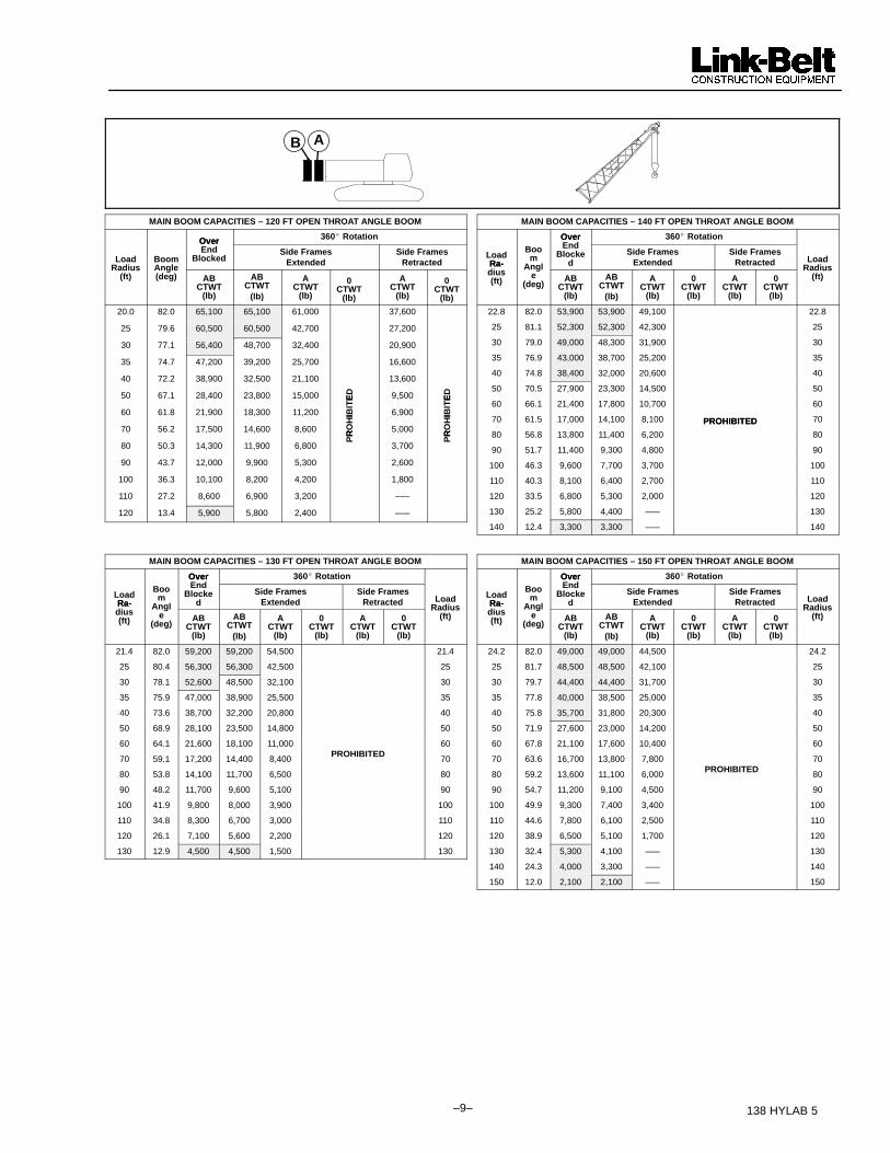
MAIN BOOM CAPACITIES – 120 FT OPEN THROAT ANGLE BOOM
Over 360� Rotation
Load Boom
OverEnd
BlockedSide Frames
ExtendedSide Frames
RetractedRadius
(ft)Angle(deg) AB
CTWT(lb)
ABCTWT
(lb)
ACTWT
(lb)
0CTWT
(lb)
ACTWT
(lb)
0CTWT
(lb)
20.0 82.0 65,100 65,100 61,000 37,600
25 79.6 60,500 60,500 42,700 27,200
30 77.1 56,400 48,700 32,400 20,900
35 74.7 47,200 39,200 25,700 16,600
40 72.2 38,900 32,500 21,100 13,600
50 67.1 28,400 23,800 15,000 ED 9,500 ED
60 61.8 21,900 18,300 11,200 IBIT
E
6,900 IBIT
E
70 56.2 17,500 14,600 8,600 RO
HI
5,000 RO
HI
80 50.3 14,300 11,900 6,800
PR
3,700P
R
90 43.7 12,000 9,900 5,300 2,600
100 36.3 10,100 8,200 4,200 1,800
110 27.2 8,600 6,900 3,200 –––
120 13.4 5,900 5,800 2,400 –––
MAIN BOOM CAPACITIES – 130 FT OPEN THROAT ANGLE BOOM
Over 360� Rotation
LoadRa-
Boom
OverEnd
Blocked
Side FramesExtended
Side FramesRetracted LoadRa-
dius(ft)
Angle
(deg)AB
CTWT(lb)
ABCTWT
(lb)
ACTWT
(lb)
0CTWT
(lb)
ACTWT
(lb)
0CTWT
(lb)
Radius(ft)
21.4 82.0 59,200 59,200 54,500 21.4
25 80.4 56,300 56,300 42,500 25
30 78.1 52,600 48,500 32,100 30
35 75.9 47,000 38,900 25,500 35
40 73.6 38,700 32,200 20,800 40
50 68.9 28,100 23,500 14,800 50
60 64.1 21,600 18,100 11,000 60
70 59.1 17,200 14,400 8,400PROHIBITED
70
80 53.8 14,100 11,700 6,500 80
90 48.2 11,700 9,600 5,100 90
100 41.9 9,800 8,000 3,900 100
110 34.8 8,300 6,700 3,000 110
120 26.1 7,100 5,600 2,200 120
130 12.9 4,500 4,500 1,500 130
MAIN BOOM CAPACITIES – 140 FT OPEN THROAT ANGLE BOOM
Over 360� Rotation
LoadRa-
Boom
OverEnd
Blocked
Side FramesExtended
Side FramesRetracted LoadRa-
dius(ft)
Angle
(deg)AB
CTWT(lb)
ABCTWT
(lb)
ACTWT
(lb)
0CTWT
(lb)
ACTWT
(lb)
0CTWT
(lb)
Radius(ft)
22.8 82.0 53,900 53,900 49,100 22.8
25 81.1 52,300 52,300 42,300 25
30 79.0 49,000 48,300 31,900 30
35 76.9 43,000 38,700 25,200 35
40 74.8 38,400 32,000 20,600 40
50 70.5 27,900 23,300 14,500 50
60 66.1 21,400 17,800 10,700 60
70 61.5 17,000 14,100 8,100 PROHIBITED 70
80 56.8 13,800 11,400 6,200
PROHIBITED
80
90 51.7 11,400 9,300 4,800 90
100 46.3 9,600 7,700 3,700 100
110 40.3 8,100 6,400 2,700 110
120 33.5 6,800 5,300 2,000 120
130 25.2 5,800 4,400 ––– 130
140 12.4 3,300 3,300 ––– 140
MAIN BOOM CAPACITIES – 150 FT OPEN THROAT ANGLE BOOM
Over 360� Rotation
LoadRa-
Boom
OverEnd
Blocked
Side FramesExtended
Side FramesRetracted LoadRa-
dius(ft)
Angle
(deg)AB
CTWT(lb)
ABCTWT
(lb)
ACTWT
(lb)
0CTWT
(lb)
ACTWT
(lb)
0CTWT
(lb)
Radius(ft)
24.2 82.0 49,000 49,000 44,500 24.2
25 81.7 48,500 48,500 42,100 25
30 79.7 44,400 44,400 31,700 30
35 77.8 40,000 38,500 25,000 35
40 75.8 35,700 31,800 20,300 40
50 71.9 27,600 23,000 14,200 50
60 67.8 21,100 17,600 10,400 60
70 63.6 16,700 13,800 7,800 70
80 59.2 13,600 11,100 6,000PROHIBITED
80
90 54.7 11,200 9,100 4,500 90
100 49.9 9,300 7,400 3,400 100
110 44.6 7,800 6,100 2,500 110
120 38.9 6,500 5,100 1,700 120
130 32.4 5,300 4,100 ––– 130
140 24.3 4,000 3,300 ––– 140
150 12.0 2,100 2,100 ––– 150

–10–138 HYLAB 5
This page intentionallyleft blank

–11– 138 HYLAB 5
This page intentionallyleft blank

–12–138 HYLAB 5
� �67��8����'���9� ���:� ;&�����&;%�+ ��.������/�0�����12 33345��16�5�4��7� Link–Belt is a registered trademark. Copyright 2005. All rights reserved. We are constantly improving our products and therefore reserve the right to change designs and specifications.

Jib CapacitiesLattice Boom Crawler Crane
138 HYLAB 5 80–ton (72.6 metric ton) Angle Boom + Jib� 40’–140’ (12.19 – 42.7m) Angle Boom with
30’ – 60’ (9.14 – 18.28m) of Jib
� 40’ – 150’ (12.19 – 45.72m) Angle Boom with30’ (9.14m) of Jib
� 20’ (6.10m) Open Throat Top Section with 32” (0.81m) Wide x 24” (0.61m) Deep Jib
� ���������������������������� ������
� Extended / Retracted Side Frames� Over End Blocked Capacities� 360� Capacities� “AB” Counterweight Options� 20’ 2” (6.15m) Crawler Length
CAUTION: This material is supplied for reference use only. Operator must refer toin–cab Crane Rating Manual to determine allowable crane lifting capacities andoperating procedures.

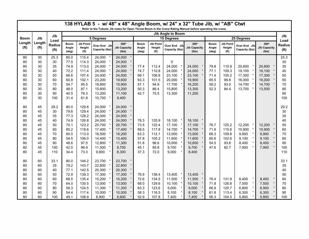
TUBULAR JIB NOTES FOR OPEN THROAT BOOM
1. Capacities are for a 138 HYLAB crawler crane with AB (50,500 lb) counterweight.
2. Separate capacity charts are listed for 360� and for over end blocked crawler working areas. Verify operatingconditions as described on the Working Area Chart found in the general information section of the Crane RatingManual. Apply the appropriate lift capacity chart based on the working area and the specific operatingconditions.
3. Over end blocked capacities can be lifted over either end with the crane standing level on a firm supportingsurface. Adequate blocking must be placed under both side frame sprockets (or idler rollers) at the end that theload is to be lifted to prevent rocking. The ramps supplied with the crane are considered to be adequateblocking.
4. Capacities are for side frames in the extended position only and are based on the crane standing level on a firmsupporting surface.
5. Capacities are limited to a LBCE 48” x 48” angle boom with an open throat and a LBCE 12 ton, 24” x 32”cross section jib with a 11’6” high jib mast properly assembled.
6. Two parts of 7/8” Diameter Type “DB” or Type “RB” wire rope are required for maximum lift.
7. Capacities are for 30’, 45’, and 60’ jib lengths only.
8. Maximum boom plus jib combination is 140’ + 60’ or 150’ + 30’. The only jib length available on the 150’ openthroat boom length is 30’.
9. The least stable condition is over the side.
10. All capacities are listed in pounds and are not more than 75% of the tipping loads. Those capacities followed byan asterisk (*) are governed by factors other than those that would cause a tipping condition.
11. A deduction must be made from the jib capacities for the weight of the following: Main boom hook block or hookball, jib hook block or hook ball, slings, grapple, load weighing devices (other than those supplied with thecrane), etc.
������������������������������
AB
������������������������� ������
5�
15�25�

WORKING RANGE DIAGRAM
�������� �������� ������������� ������������������������� ������������������������ ������ ������� ���������������������
����������� ����������������������������������������������� ����������������������������
�� �!������������������������ ������������������������������������������������ ���� �����������������
"#$�%&��"#$� '(��&& �)(%*�+#$�%&�,#$�-(
Mai
n B
oo
m L
eng
th
Hei
gh
t in
fee
t ab
ove
gro
un
d
Maximum Boom AngleSee Note 2.
60’
45’
30’
Jib
Len
gth
140’
130’
120’
110’
100’
90’
80’
70’
60’
50’
40’
20’40’60’80’100’120’140’160’180’200’0’
10’
20’
30’
40’
50’
60’
70’
80’
90’
100’
110’
120’
130’
140’
150’
160’
170’
180’
190’
200’
210’
220’
Operating radius from centerline of rotation.
5�15�
25�80�
70�
60�
50�
40�
30�
20�
Minimum Boom AngleSee Note 2.
OFCLROTATION
WORKING RANGE DIAGRAM
�������� �������� ������������� ������������������������� ������������������������ ������ ������� ���������������������
����������� ����������������������������������������������� ����������������������������
�� �!������������������������ ������������������������������������������������ ���� �����������������
"#$�%&��.#$� '(��&& �)(%*�+#$�-(
Mai
n B
oo
m L
eng
th
Hei
gh
t in
fee
t ab
ove
gro
un
d
30’
Jib
Len
gth
140’
130’
120’
110’
100’
90’
80’
70’
60’
50’
40’
0’10’
20’40’60’80’100’120’140’160’180’0’
10’
20’
30’
40’
50’
60’
70’
80’
90’
100’
110’
120’
130’
140’
150’
160’
170’
180’
190’
200’
210’
220’
Operating radius from centerline of rotation.
150’
200’
Minimum Boom AngleSee Note 2.
Maximum Boom AngleSee Note 2.
20�
30�
40�
50�
60�
70� 80�5�
15�
25�
OFCLROTATION
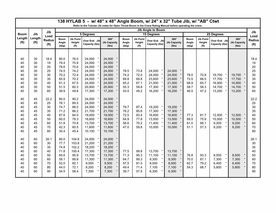
40 30 18.4 80.0 76.0 24,000 * 24,000 * 18.440 30 19 79.4 75.9 24,000 * 24,000 * 1940 30 20 78.6 75.6 24,000 * 24,000 * 2040 30 25 74.5 74.2 24,000 * 24,000 * 78.5 73.8 24,000 * 24,000 * 2540 30 30 70.2 72.4 24,000 * 24,000 * 74.2 72.0 24,000 * 24,000 * 78.0 70.8 19,700 * 19,700 * 3040 30 35 65.9 70.2 24,000 * 24,000 * 69.8 69.8 23,600 * 23,600 * 73.5 68.5 17,700 * 17,700 * 3540 30 40 61.3 67.5 24,000 * 24,000 * 65.2 67.1 21,000 * 21,000 * 68.9 65.7 16,900 * 16,900 * 4040 30 50 51.5 60.3 20,900 * 20,900 * 55.3 59.8 17,300 * 17,300 * 58.7 58.3 14,700 * 14,700 * 5040 30 60 39.9 49.8 17,300 * 17,300 * 43.5 49.2 16,200 * 16,200 * 46.5 47.2 13,200 * 13,200 * 60
40 45 22.2 80.0 90.2 24,000 * 24,000 * 22.240 45 25 78.1 89.5 24,000 * 24,000 * 2540 45 30 74.7 88.0 24,000 * 24,000 * 79.7 87.4 19,200 * 19,200 * 3040 45 35 71.2 86.2 21,700 * 21,700 * 76.2 85.6 17,300 * 17,300 * 3540 45 40 67.6 84.0 19,000 * 19,000 * 72.5 83.4 16,600 * 16,600 * 77.3 81.7 12,500 * 12,500 * 4040 45 50 60.0 78.3 16,600 * 16,600 * 64.9 77.8 13,500 * 13,500 * 69.5 75.9 10,500 * 10,500 * 5040 45 60 51.8 70.8 13,700 * 13,700 * 56.6 70.2 11,400 * 11,400 * 61.0 68.1 9,200 * 9,200 * 6040 45 70 42.3 60.5 11,600 * 11,600 * 47.0 59.8 10,000 * 10,000 * 51.1 57.3 8,200 * 8,200 * 7040 45 80 30.4 45.4 10,100 * 10,100 * 80
40 60 26.1 80.0 104.8 24,000 * 24,000 * 26.140 60 30 77.7 103.8 21,200 * 21,200 * 3040 60 35 74.8 102.2 18,200 * 18,200 * 3540 60 40 71.8 100.4 17,300 * 17,300 * 77.5 99.8 13,700 * 13,700 * 4040 60 50 65.6 95.9 13,700 * 13,700 * 71.3 95.3 11,100 * 11,100 * 76.8 93.3 8,500 * 8,500 * 5040 60 60 59.1 89.9 11,300 * 11,300 * 64.7 89.3 9,300 * 9,300 * 70.0 87.1 7,300 * 7,300 * 6040 60 70 52.0 82.1 9,500 * 9,500 * 57.5 81.5 8,000 * 8,000 * 62.7 79.2 6,400 * 6,400 * 7040 60 80 44.0 72.1 8,200 * 8,200 * 49.4 71.4 7,100 * 7,100 * 54.3 68.7 5,800 * 5,800 * 8040 60 90 34.5 58.4 7,300 * 7,300 * 39.7 57.5 6,300 * 6,300 * 90
Boom Length
(ft)
Jib Load
Radius (ft)
138 HYLAB 5 - w/ 48" x 48" Angle Boom, w/ 24" x 32" Tube Jib, w/ "AB" CtwtRefer to the Tubular Jib notes for Open Throat Boom in the Crane Rating Manual before operating the crane.
Jib Length
(ft)
Jib Angle to Boom Jib Load
Radius (ft)
5 Degrees 15 Degrees 25 DegreesBoom Angle (deg)
Jib Point Height
(ft)
Over End Jib Capacity (lbs)
360° Jib Capacity
(lbs)
Boom Angle (deg)
Jib Point Height
(ft)
Over End Jib Capacity (lbs)
360° Jib Capacity
(lbs)
Boom Angle (deg)
Jib Point Height
(ft)
Over End Jib Capacity (lbs)
360° Jib Capacity
(lbs)
Boom Length
(ft)
Jib Load
Radius (ft)
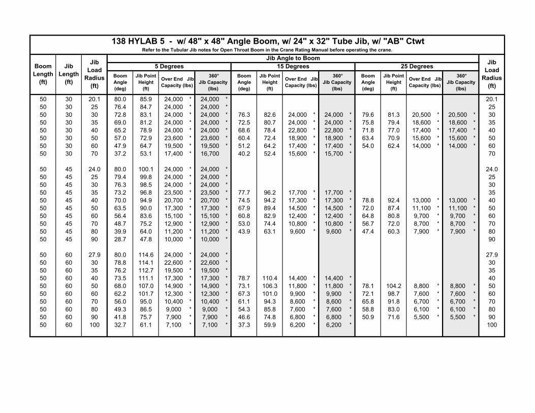
138 HYLAB 5 - w/ 48" x 48" Angle Boom, w/ 24" x 32" Tube Jib, w/ "AB" CtwtRefer to the Tubular Jib notes for Open Throat Boom in the Crane Rating Manual before operating the crane.
Jib Length
(ft)
Jib Angle to Boom Jib Load
Radius (ft)
5 Degrees 15 Degrees 25 DegreesBoom Angle (deg)
Jib Point Height
(ft)
Over End Jib Capacity (lbs)
360° Jib Capacity
(lbs)
Boom Angle (deg)
Jib Point Height
(ft)
Over End Jib Capacity (lbs)
360° Jib Capacity
(lbs)
Boom Angle (deg)
Jib Point Height
(ft)
Over End Jib Capacity (lbs)
360° Jib Capacity
(lbs)
50 30 20.1 80.0 85.9 24,000 * 24,000 * 20.150 30 25 76.4 84.7 24,000 * 24,000 * 2550 30 30 72.8 83.1 24,000 * 24,000 * 76.3 82.6 24,000 * 24,000 * 79.6 81.3 20,500 * 20,500 * 3050 30 35 69.0 81.2 24,000 * 24,000 * 72.5 80.7 24,000 * 24,000 * 75.8 79.4 18,600 * 18,600 * 3550 30 40 65.2 78.9 24,000 * 24,000 * 68.6 78.4 22,800 * 22,800 * 71.8 77.0 17,400 * 17,400 * 4050 30 50 57.0 72.9 23,600 * 23,600 * 60.4 72.4 18,900 * 18,900 * 63.4 70.9 15,600 * 15,600 * 5050 30 60 47.9 64.7 19,500 * 19,500 * 51.2 64.2 17,400 * 17,400 * 54.0 62.4 14,000 * 14,000 * 6050 30 70 37.2 53.1 17,400 * 16,700 40.2 52.4 15,600 * 15,700 * 70
50 45 24.0 80.0 100.1 24,000 * 24,000 * 24.050 45 25 79.4 99.8 24,000 * 24,000 * 2550 45 30 76.3 98.5 24,000 * 24,000 * 3050 45 35 73.2 96.8 23,500 * 23,500 * 77.7 96.2 17,700 * 17,700 * 3550 45 40 70.0 94.9 20,700 * 20,700 * 74.5 94.2 17,300 * 17,300 * 78.8 92.4 13,000 * 13,000 * 4050 45 50 63.5 90.0 17,300 * 17,300 * 67.9 89.4 14,500 * 14,500 * 72.0 87.4 11,100 * 11,100 * 5050 45 60 56.4 83.6 15,100 * 15,100 * 60.8 82.9 12,400 * 12,400 * 64.8 80.8 9,700 * 9,700 * 6050 45 70 48.7 75.2 12,900 * 12,900 * 53.0 74.4 10,800 * 10,800 * 56.7 72.0 8,700 * 8,700 * 7050 45 80 39.9 64.0 11,200 * 11,200 * 43.9 63.1 9,600 * 9,600 * 47.4 60.3 7,900 * 7,900 * 8050 45 90 28.7 47.8 10,000 * 10,000 * 90
50 60 27.9 80.0 114.6 24,000 * 24,000 * 27.950 60 30 78.8 114.1 22,600 * 22,600 * 3050 60 35 76.2 112.7 19,500 * 19,500 * 3550 60 40 73.5 111.1 17,300 * 17,300 * 78.7 110.4 14,400 * 14,400 * 4050 60 50 68.0 107.0 14,900 * 14,900 * 73.1 106.3 11,800 * 11,800 * 78.1 104.2 8,800 * 8,800 * 5050 60 60 62.2 101.7 12,300 * 12,300 * 67.3 101.0 9,900 * 9,900 * 72.1 98.7 7,600 * 7,600 * 6050 60 70 56.0 95.0 10,400 * 10,400 * 61.1 94.3 8,600 * 8,600 * 65.8 91.8 6,700 * 6,700 * 7050 60 80 49.3 86.5 9,000 * 9,000 * 54.3 85.8 7,600 * 7,600 * 58.8 83.0 6,100 * 6,100 * 8050 60 90 41.8 75.7 7,900 * 7,900 * 46.6 74.8 6,800 * 6,800 * 50.9 71.6 5,500 * 5,500 * 9050 60 100 32.7 61.1 7,100 * 7,100 * 37.3 59.9 6,200 * 6,200 * 100

Boom Length
(ft)
Jib Load
Radius (ft)
138 HYLAB 5 - w/ 48" x 48" Angle Boom, w/ 24" x 32" Tube Jib, w/ "AB" CtwtRefer to the Tubular Jib notes for Open Throat Boom in the Crane Rating Manual before operating the crane.
Jib Length
(ft)
Jib Angle to Boom Jib Load
Radius (ft)
5 Degrees 15 Degrees 25 DegreesBoom Angle (deg)
Jib Point Height
(ft)
Over End Jib Capacity (lbs)
360° Jib Capacity
(lbs)
Boom Angle (deg)
Jib Point Height
(ft)
Over End Jib Capacity (lbs)
360° Jib Capacity
(lbs)
Boom Angle (deg)
Jib Point Height
(ft)
Over End Jib Capacity (lbs)
360° Jib Capacity
(lbs)
60 30 21.8 80.0 95.7 24,000 * 24,000 * 21.860 30 25 77.9 95.0 24,000 * 24,000 * 2560 30 30 74.7 93.6 24,000 * 24,000 * 77.8 93.1 24,000 * 24,000 * 3060 30 35 71.4 91.9 24,000 * 24,000 * 74.5 91.4 24,000 * 24,000 * 77.5 90.0 19,400 * 19,400 * 3560 30 40 68.1 89.9 24,000 * 24,000 * 71.1 89.4 24,000 * 24,000 * 74.0 88.0 17,900 * 17,900 * 4060 30 50 61.0 84.8 24,000 * 24,000 * 64.1 84.3 20,400 * 20,400 * 66.8 82.7 16,300 * 16,300 * 5060 30 60 53.5 78.0 21,700 * 20,100 56.4 77.4 17,600 * 17,600 * 59.0 75.7 14,700 * 14,700 * 6060 30 70 45.0 68.8 18,600 * 16,400 47.8 68.2 17,100 * 16,600 50.2 66.2 13,500 * 13,500 * 7060 30 80 34.9 56.2 16,000 * 13,700 37.6 55.3 15,300 * 13,800 80
60 45 25.7 80.0 109.9 24,000 * 24,000 * 25.760 45 30 77.6 108.9 24,000 * 24,000 * 3060 45 35 74.8 107.4 24,000 * 24,000 * 78.9 106.7 18,500 * 18,500 * 3560 45 40 72.0 105.7 22,400 * 22,400 * 76.0 104.9 17,300 * 17,300 * 79.9 103.0 13,300 * 13,300 * 4060 45 50 66.2 101.3 18,000 * 18,000 * 70.2 100.6 15,400 * 15,400 * 73.9 98.5 11,500 * 11,500 * 5060 45 60 60.0 95.7 16,600 * 16,600 * 63.9 94.9 13,200 * 13,200 * 67.6 92.8 10,100 * 10,100 * 6060 45 70 53.4 88.5 14,100 * 14,100 * 57.3 87.7 11,600 * 11,600 * 60.8 85.3 9,100 * 9,100 * 7060 45 80 46.2 79.3 12,300 * 12,300 * 49.9 78.4 10,300 * 10,300 * 53.2 75.8 8,300 * 8,300 * 8060 45 90 37.8 67.2 10,900 * 10,900 * 41.4 66.2 9,400 * 9,400 * 9060 45 100 27.2 50.1 9,900 * 9,900 * 100
60 60 29.6 80.0 124.5 24,000 * 24,000 * 29.660 60 30 79.8 124.4 23,900 * 23,900 * 3060 60 35 77.4 123.1 20,700 * 20,700 * 3560 60 40 74.9 121.6 18,200 * 18,200 * 79.7 120.8 14,900 * 14,900 * 4060 60 50 69.9 117.9 16,100 * 16,100 * 74.6 117.1 12,300 * 12,300 * 79.2 114.9 9,100 * 9,100 * 5060 60 60 64.7 113.2 13,300 * 13,300 * 69.4 112.4 10,500 * 10,500 * 73.8 110.0 7,900 * 7,900 * 6060 60 70 59.2 107.2 11,300 * 11,300 * 63.9 106.4 9,100 * 9,100 * 68.2 103.9 7,000 * 7,000 * 7060 60 80 53.4 99.8 9,800 * 9,800 * 58.0 99.0 8,100 * 8,100 * 62.2 96.2 6,300 * 6,300 * 8060 60 90 47.0 90.7 8,600 * 8,600 * 51.5 89.8 7,200 * 7,200 * 55.5 86.7 5,800 * 5,800 * 9060 60 100 39.9 79.1 7,700 * 7,700 * 44.2 78.1 6,600 * 6,600 * 47.9 74.5 5,400 * 5,400 * 10060 60 110 31.2 63.7 7,000 * 7,000 * 35.3 62.3 6,100 * 6,100 * 110
Boom Length
(ft)
Jib Load
Radius (ft)
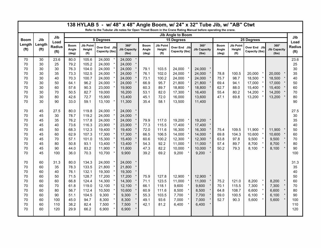
138 HYLAB 5 - w/ 48" x 48" Angle Boom, w/ 24" x 32" Tube Jib, w/ "AB" CtwtRefer to the Tubular Jib notes for Open Throat Boom in the Crane Rating Manual before operating the crane.
Jib Length
(ft)
Jib Angle to Boom Jib Load
Radius (ft)
5 Degrees 15 Degrees 25 DegreesBoom Angle (deg)
Jib Point Height
(ft)
Over End Jib Capacity (lbs)
360° Jib Capacity
(lbs)
Boom Angle (deg)
Jib Point Height
(ft)
Over End Jib Capacity (lbs)
360° Jib Capacity
(lbs)
Boom Angle (deg)
Jib Point Height
(ft)
Over End Jib Capacity (lbs)
360° Jib Capacity
(lbs)
70 30 23.6 80.0 105.6 24,000 * 24,000 * 23.670 30 25 79.2 105.2 24,000 * 24,000 * 2570 30 30 76.3 104.0 24,000 * 24,000 * 79.1 103.5 24,000 * 24,000 * 3070 30 35 73.3 102.5 24,000 * 24,000 * 76.1 102.0 24,000 * 24,000 * 78.8 100.5 20,000 * 20,000 * 3570 30 40 70.3 100.7 24,000 * 24,000 * 73.1 100.2 24,000 * 24,000 * 75.7 98.7 18,500 * 18,500 * 4070 30 50 64.1 96.2 24,000 * 24,000 * 66.9 95.7 21,800 * 21,800 * 69.4 94.1 17,000 * 17,000 * 5070 30 60 57.6 90.3 23,000 * 19,900 60.3 89.7 18,800 * 18,800 * 62.7 88.0 15,400 * 15,400 * 6070 30 70 50.5 82.7 19,000 16,200 53.1 82.0 17,300 * 16,400 55.4 80.2 14,200 * 14,200 * 7070 30 80 42.6 72.7 15,900 13,400 45.1 72.0 16,000 13,600 47.1 69.8 13,200 * 13,200 * 8070 30 90 33.0 59.1 13,100 * 11,300 35.4 58.1 13,500 11,400 90
70 45 27.5 80.0 119.8 24,000 * 24,000 * 27.570 45 30 78.7 119.2 24,000 * 24,000 * 3070 45 35 76.2 117.8 24,000 * 24,000 * 79.9 117.0 19,200 * 19,200 * 3570 45 40 73.6 116.3 23,900 * 23,900 * 77.3 115.5 17,400 * 17,400 * 4070 45 50 68.3 112.3 19,400 * 19,400 * 72.0 111.6 16,300 * 16,300 * 75.4 109.5 11,900 * 11,900 * 5070 45 60 62.9 107.3 17,300 * 17,300 * 66.5 106.5 14,000 * 14,000 * 69.8 104.3 10,600 * 10,600 * 6070 45 70 57.1 101.0 15,300 * 15,400 * 60.6 100.2 12,300 * 12,300 * 63.8 97.8 9,500 * 9,500 * 7070 45 80 50.8 93.1 13,400 * 13,400 * 54.3 92.2 11,000 * 11,000 * 57.4 89.7 8,700 * 8,700 * 8070 45 90 44.0 83.2 11,900 * 11,600 47.3 82.2 10,000 * 10,000 * 50.2 79.3 8,100 * 8,100 * 9070 45 100 36.0 70.3 10,700 * 9,900 39.2 69.2 9,200 * 9,200 * 100
70 60 31.3 80.0 134.3 24,000 * 24,000 * 31.370 60 35 78.3 133.5 21,800 * 21,800 * 3570 60 40 76.1 132.1 19,300 * 19,300 * 4070 60 50 71.5 128.7 17,200 * 17,200 * 75.9 127.8 12,900 * 12,900 * 5070 60 60 66.8 124.4 14,300 * 14,300 * 71.1 123.5 11,000 * 11,000 * 75.2 121.0 8,200 * 8,200 * 6070 60 70 61.8 119.0 12,100 * 12,100 * 66.1 118.1 9,600 * 9,600 * 70.1 115.5 7,300 * 7,300 * 7070 60 80 56.7 112.4 10,500 * 10,600 * 60.9 111.6 8,500 * 8,500 * 64.8 108.7 6,600 * 6,600 * 8070 60 90 51.1 104.5 9,300 * 9,300 * 55.3 103.5 7,700 * 7,700 * 59.0 100.5 6,100 * 6,100 * 9070 60 100 45.0 94.7 8,300 * 8,300 * 49.1 93.6 7,000 * 7,000 * 52.7 90.3 5,600 * 5,600 * 10070 60 110 38.2 82.4 7,500 * 7,500 * 42.1 81.2 6,400 * 6,400 * 11070 60 120 29.9 66.2 6,900 * 6,900 * 120
Boom Length
(ft)
Jib Load
Radius (ft)
138 HYLAB 5 - w/ 48" x 48" Angle Boom, w/ 24" x 32" Tube Jib, w/ "AB" CtwtRefer to the Tubular Jib notes for Open Throat Boom in the Crane Rating Manual before operating the crane.
Jib Length
(ft)
Jib Angle to Boom Jib Load
Radius (ft)
5 Degrees 15 Degrees 25 DegreesBoom Angle (deg)
Jib Point Height
(ft)
Over End Jib Capacity (lbs)
360° Jib Capacity
(lbs)
Boom Angle (deg)
Jib Point Height
(ft)
Over End Jib Capacity (lbs)
360° Jib Capacity
(lbs)
Boom Angle (deg)
Jib Point Height
(ft)
Over End Jib Capacity (lbs)
360° Jib Capacity
(lbs)
80 30 25.3 80.0 115.4 24,000 * 24,000 * 25.380 30 30 77.5 114.3 24,000 * 24,000 * 0 3080 30 35 74.9 113.0 24,000 * 24,000 * 77.4 112.4 24,000 * 24,000 * 79.8 110.9 20,600 * 20,600 * 3580 30 40 72.2 111.4 24,000 * 24,000 * 74.7 110.8 24,000 * 24,000 * 77.1 109.3 19,100 * 19,100 * 4080 30 50 66.6 107.4 24,000 * 24,000 * 69.1 106.8 23,100 * 23,100 * 71.4 105.2 17,300 * 17,300 * 5080 30 60 60.8 102.1 23,200 19,600 63.3 101.5 20,000 * 19,900 65.5 99.8 16,000 * 16,000 * 6080 30 70 54.7 95.5 18,800 15,900 57.1 94.9 17,700 * 16,200 59.2 93.0 14,700 * 14,700 * 7080 30 80 48.0 87.1 15,600 13,200 50.3 86.4 15,800 13,300 52.3 84.4 13,700 * 13,500 8080 30 90 40.5 76.3 13,200 11,100 42.7 75.5 13,300 11,200 9080 30 100 31.4 61.8 10,700 * 9,400 100
80 45 29.2 80.0 129.6 24,000 * 24,000 * 29.280 45 30 79.6 129.4 24,000 * 24,000 * 3080 45 35 77.3 128.2 24,000 * 24,000 * 3580 45 40 74.9 126.8 24,000 * 24,000 * 78.3 125.9 18,100 * 18,100 * 4080 45 50 70.1 123.2 20,700 * 20,700 * 73.5 122.4 17,100 * 17,100 * 76.7 120.2 12,200 * 12,200 * 5080 45 60 65.2 118.6 17,400 * 17,400 * 68.5 117.8 14,700 * 14,700 * 71.6 115.6 10,900 * 10,900 * 6080 45 70 60.0 113.0 16,500 * 16,200 63.3 112.1 13,000 * 13,000 * 66.3 109.8 9,900 * 9,900 * 7080 45 80 54.5 106.0 14,400 * 13,400 57.8 105.2 11,600 * 11,600 * 60.6 102.6 9,100 * 9,100 * 8080 45 90 48.6 97.5 12,800 * 11,300 51.8 96.6 10,600 * 10,600 * 54.5 93.8 8,400 * 8,400 * 9080 45 100 42.0 86.9 11,500 * 9,700 45.1 85.8 9,700 * 9,700 * 47.6 82.7 7,900 * 7,900 * 10080 45 110 34.4 73.3 9,800 * 8,300 37.3 72.0 9,000 * 8,400 110
80 60 33.1 80.0 144.2 23,700 * 23,700 * 33.180 60 35 79.2 143.7 22,800 * 22,800 * 3580 60 40 77.1 142.5 20,300 * 20,300 * 4080 60 50 72.9 139.3 17,300 * 17,300 * 76.9 138.4 13,400 * 13,400 * 5080 60 60 68.5 135.4 15,200 * 15,200 * 72.6 134.5 11,500 * 11,500 * 76.4 131.9 8,400 * 8,400 * 6080 60 70 64.0 130.5 13,000 * 13,000 * 68.0 129.6 10,100 * 10,100 * 71.8 126.8 7,500 * 7,500 * 7080 60 80 59.3 124.5 11,300 * 11,300 * 63.3 123.6 9,000 * 9,000 * 66.9 120.7 6,800 * 6,900 * 8080 60 90 54.4 117.4 10,000 * 10,000 * 58.3 116.5 8,100 * 8,100 * 61.8 113.4 6,300 * 6,300 * 9080 60 100 49.1 108.9 8,900 * 8,900 * 52.9 107.8 7,400 * 7,400 * 56.3 104.5 5,800 * 5,800 * 100

Boom Length
(ft)
Jib Load
Radius (ft)
138 HYLAB 5 - w/ 48" x 48" Angle Boom, w/ 24" x 32" Tube Jib, w/ "AB" CtwtRefer to the Tubular Jib notes for Open Throat Boom in the Crane Rating Manual before operating the crane.
Jib Length
(ft)
Jib Angle to Boom Jib Load
Radius (ft)
5 Degrees 15 Degrees 25 DegreesBoom Angle (deg)
Jib Point Height
(ft)
Over End Jib Capacity (lbs)
360° Jib Capacity
(lbs)
Boom Angle (deg)
Jib Point Height
(ft)
Over End Jib Capacity (lbs)
360° Jib Capacity
(lbs)
Boom Angle (deg)
Jib Point Height
(ft)
Over End Jib Capacity (lbs)
360° Jib Capacity
(lbs)
80 60 110 43.3 98.5 8,100 * 8,100 * 47.0 97.3 6,800 * 6,800 * 50.2 93.6 5,500 * 5,500 * 11080 60 120 36.7 85.6 7,400 * 7,400 * 40.3 84.2 6,300 * 6,300 * 12080 60 130 28.7 68.6 6,800 * 6,400 130
90 30 27.0 80.0 125.3 24,000 * 24,000 * 27.090 30 30 78.6 124.6 24,000 * 24,000 * 3090 30 35 76.1 123.4 24,000 * 24,000 * 78.5 122.8 24,000 * 24,000 * 3590 30 40 73.7 121.9 24,000 * 24,000 * 76.0 121.3 24,000 * 24,000 * 78.2 119.8 19,700 * 19,700 * 4090 30 50 68.7 118.3 24,000 * 24,000 * 71.0 117.7 23,900 * 23,800 * 73.1 116.1 17,400 * 17,400 * 5090 30 60 63.5 113.6 23,000 19,400 65.7 113.0 21,100 * 19,700 67.8 111.3 16,500 * 16,500 * 6090 30 70 58.0 107.7 18,500 15,700 60.2 107.1 18,700 15,900 62.2 105.3 15,300 * 15,300 * 7090 30 80 52.2 100.4 15,400 12,900 54.4 99.7 15,600 13,100 56.2 97.8 14,200 * 13,300 8090 30 90 45.8 91.3 12,900 10,800 47.9 90.6 13,100 11,000 49.7 88.4 13,200 11,100 9090 30 100 38.6 79.8 11,000 9,200 40.7 78.9 11,100 9,300 10090 30 110 30.0 64.5 8,700 * 7,800 110
90 45 30.9 80.0 139.5 24,000 * 24,000 * 30.990 45 35 78.2 138.5 24,000 * 24,000 * 3590 45 40 76.1 137.2 24,000 * 24,000 * 79.2 136.3 18,700 * 18,700 * 4090 45 50 71.7 133.9 21,000 * 21,000 * 74.8 133.1 17,300 * 17,300 * 77.8 130.8 12,600 * 12,600 * 5090 45 60 67.1 129.8 18,300 * 18,300 * 70.2 128.9 15,400 * 15,400 * 73.1 126.6 11,300 * 11,300 * 6090 45 70 62.4 124.6 16,800 * 16,000 65.5 123.7 13,600 * 13,600 * 68.3 121.3 10,200 * 10,200 * 7090 45 80 57.5 118.4 15,000 * 13,200 60.5 117.5 12,200 * 12,200 * 63.2 114.9 9,400 * 9,400 * 8090 45 90 52.3 110.8 13,200 11,100 55.2 109.9 11,100 * 11,100 * 57.8 107.2 8,700 * 8,700 * 9090 45 100 46.6 101.7 11,300 9,400 49.5 100.7 10,200 * 9,600 52.0 97.7 8,200 * 8,200 * 10090 45 110 40.3 90.5 9,700 8,000 43.1 89.3 9,500 * 8,200 11090 45 120 33.0 76.2 8,000 * 6,900 120
90 60 34.8 80.0 154.0 22,800 * 22,800 * 34.890 60 35 79.9 154.0 22,700 * 22,700 * 3590 60 40 78.0 152.8 20,800 * 20,800 * 4090 60 50 74.0 149.9 17,400 * 17,400 * 77.8 148.9 13,800 * 13,800 * 5090 60 60 70.0 146.2 16,100 * 16,000 * 73.8 145.3 11,900 * 12,000 * 77.4 142.6 8,600 * 8,600 * 60

Boom Length
(ft)
Jib Load
Radius (ft)
138 HYLAB 5 - w/ 48" x 48" Angle Boom, w/ 24" x 32" Tube Jib, w/ "AB" CtwtRefer to the Tubular Jib notes for Open Throat Boom in the Crane Rating Manual before operating the crane.
Jib Length
(ft)
Jib Angle to Boom Jib Load
Radius (ft)
5 Degrees 15 Degrees 25 DegreesBoom Angle (deg)
Jib Point Height
(ft)
Over End Jib Capacity (lbs)
360° Jib Capacity
(lbs)
Boom Angle (deg)
Jib Point Height
(ft)
Over End Jib Capacity (lbs)
360° Jib Capacity
(lbs)
Boom Angle (deg)
Jib Point Height
(ft)
Over End Jib Capacity (lbs)
360° Jib Capacity
(lbs)
90 60 70 65.9 141.7 13,800 * 13,800 * 69.6 140.7 10,500 * 10,500 * 73.1 138.0 7,700 * 7,700 * 7090 60 80 61.6 136.3 12,000 * 12,000 * 65.3 135.3 9,400 * 9,400 * 68.7 132.4 7,100 * 7,100 * 8090 60 90 57.1 129.9 10,600 * 10,600 * 60.8 128.8 8,500 * 8,500 * 64.1 125.8 6,500 * 6,500 * 9090 60 100 52.4 122.2 9,500 * 9,500 * 56.0 121.1 7,700 * 7,700 * 59.2 117.9 6,000 * 6,000 * 10090 60 110 47.3 113.1 8,600 * 8,200 50.8 112.0 7,100 * 7,100 * 53.9 108.4 5,700 * 5,700 * 11090 60 120 41.7 102.2 7,900 * 7,100 45.1 100.9 6,600 * 6,600 * 48.0 96.9 5,400 * 5,400 * 12090 60 130 35.3 88.6 7,300 * 6,200 38.6 87.1 6,200 * 6,200 * 13090 60 140 27.7 70.9 5,600 * 5,400 140
100 30 28.8 80.0 135.1 24,000 * 24,000 * 28.8100 30 30 79.4 134.8 24,000 * 24,000 * 30100 30 35 77.2 133.7 24,000 * 24,000 * 79.4 133.1 24,000 * 24,000 * 35100 30 40 75.0 132.4 24,000 * 24,000 * 77.1 131.8 24,000 * 24,000 * 79.2 130.2 20,100 * 20,100 * 40100 30 50 70.4 129.0 24,000 * 24,000 * 72.5 128.4 23,800 * 23,800 * 74.5 126.8 17,900 * 17,900 * 50100 30 60 65.6 124.8 22,700 19,100 67.8 124.1 21,100 * 19,500 69.7 122.5 17,000 * 17,000 * 60100 30 70 60.7 119.4 18,200 15,400 62.8 118.8 18,500 15,700 64.6 117.0 15,800 * 15,800 * 70100 30 80 55.5 112.9 15,100 12,700 57.6 112.3 15,300 12,900 59.3 110.4 14,700 * 13,100 80100 30 90 50.0 105.0 12,700 10,500 52.0 104.3 12,800 10,700 53.6 102.3 13,000 10,900 90100 30 100 43.9 95.3 10,700 8,900 45.8 94.5 10,900 9,000 47.4 92.2 11,000 9,100 100100 30 110 37.1 83.1 9,200 * 7,500 38.9 82.2 9,300 7,600 110100 30 120 28.8 67.0 7,000 * 6,400 120
100 45 32.7 80.0 149.3 24,000 * 24,000 * 32.7100 45 35 79.0 148.8 24,000 * 24,000 * 35100 45 40 77.0 147.6 24,000 * 24,000 * 40100 45 50 73.0 144.5 21,100 * 21,100 * 75.9 143.6 17,300 * 17,300 * 78.7 141.4 12,800 * 12,800 * 50100 45 60 68.8 140.7 18,300 * 18,400 * 71.7 139.8 16,100 * 16,100 * 74.4 137.5 11,600 * 11,600 * 60100 45 70 64.5 136.0 16,900 * 15,700 67.3 135.1 14,300 * 14,300 * 70.0 132.7 10,500 * 10,500 * 70100 45 80 60.0 130.3 15,200 * 12,900 62.8 129.4 12,800 * 12,800 * 65.4 126.8 9,700 * 9,700 * 80100 45 90 55.3 123.5 12,900 10,800 58.1 122.6 11,700 * 11,100 60.5 119.9 9,000 * 9,000 * 90100 45 100 50.3 115.4 11,000 9,100 53.0 114.4 10,700 * 9,300 55.4 111.6 8,500 * 8,500 * 100100 45 110 44.9 105.7 9,400 7,800 47.5 104.6 9,600 8,000 49.7 101.5 8,000 * 8,000 * 110100 45 120 38.8 93.9 8,200 6,700 41.4 92.6 8,300 6,800 120100 45 130 31.8 78.9 6,500 * 5,700 130
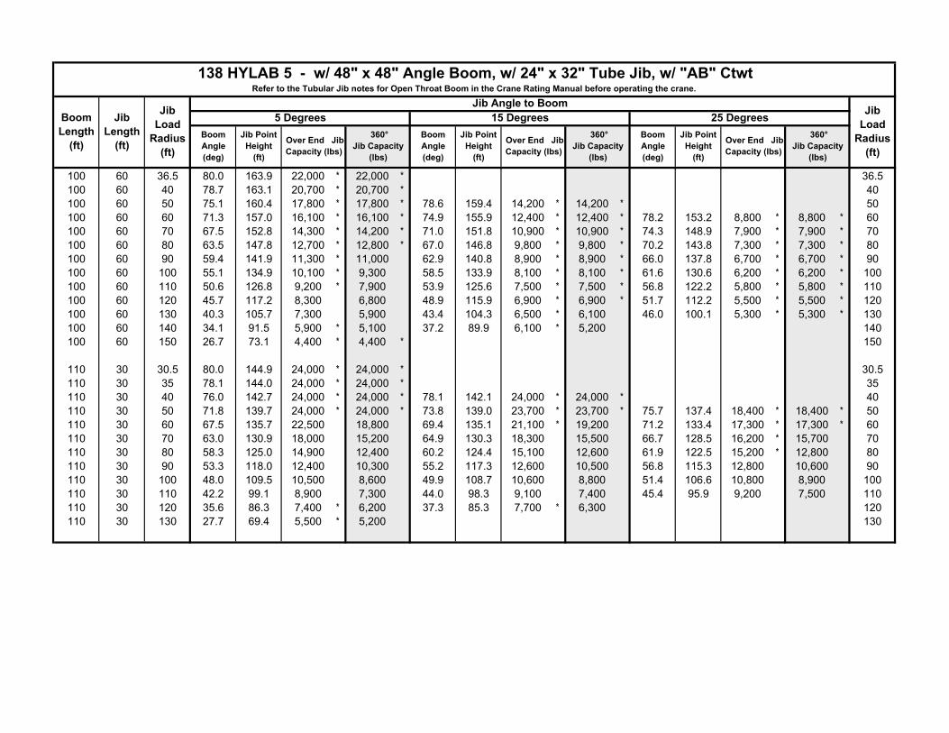
Boom Length
(ft)
Jib Load
Radius (ft)
138 HYLAB 5 - w/ 48" x 48" Angle Boom, w/ 24" x 32" Tube Jib, w/ "AB" CtwtRefer to the Tubular Jib notes for Open Throat Boom in the Crane Rating Manual before operating the crane.
Jib Length
(ft)
Jib Angle to Boom Jib Load
Radius (ft)
5 Degrees 15 Degrees 25 DegreesBoom Angle (deg)
Jib Point Height
(ft)
Over End Jib Capacity (lbs)
360° Jib Capacity
(lbs)
Boom Angle (deg)
Jib Point Height
(ft)
Over End Jib Capacity (lbs)
360° Jib Capacity
(lbs)
Boom Angle (deg)
Jib Point Height
(ft)
Over End Jib Capacity (lbs)
360° Jib Capacity
(lbs)
100 60 36.5 80.0 163.9 22,000 * 22,000 * 36.5100 60 40 78.7 163.1 20,700 * 20,700 * 40100 60 50 75.1 160.4 17,800 * 17,800 * 78.6 159.4 14,200 * 14,200 * 50100 60 60 71.3 157.0 16,100 * 16,100 * 74.9 155.9 12,400 * 12,400 * 78.2 153.2 8,800 * 8,800 * 60100 60 70 67.5 152.8 14,300 * 14,200 * 71.0 151.8 10,900 * 10,900 * 74.3 148.9 7,900 * 7,900 * 70100 60 80 63.5 147.8 12,700 * 12,800 * 67.0 146.8 9,800 * 9,800 * 70.2 143.8 7,300 * 7,300 * 80100 60 90 59.4 141.9 11,300 * 11,000 62.9 140.8 8,900 * 8,900 * 66.0 137.8 6,700 * 6,700 * 90100 60 100 55.1 134.9 10,100 * 9,300 58.5 133.9 8,100 * 8,100 * 61.6 130.6 6,200 * 6,200 * 100100 60 110 50.6 126.8 9,200 * 7,900 53.9 125.6 7,500 * 7,500 * 56.8 122.2 5,800 * 5,800 * 110100 60 120 45.7 117.2 8,300 6,800 48.9 115.9 6,900 * 6,900 * 51.7 112.2 5,500 * 5,500 * 120100 60 130 40.3 105.7 7,300 5,900 43.4 104.3 6,500 * 6,100 46.0 100.1 5,300 * 5,300 * 130100 60 140 34.1 91.5 5,900 * 5,100 37.2 89.9 6,100 * 5,200 140100 60 150 26.7 73.1 4,400 * 4,400 * 150
110 30 30.5 80.0 144.9 24,000 * 24,000 * 30.5110 30 35 78.1 144.0 24,000 * 24,000 * 35110 30 40 76.0 142.7 24,000 * 24,000 * 78.1 142.1 24,000 * 24,000 * 40110 30 50 71.8 139.7 24,000 * 24,000 * 73.8 139.0 23,700 * 23,700 * 75.7 137.4 18,400 * 18,400 * 50110 30 60 67.5 135.7 22,500 18,800 69.4 135.1 21,100 * 19,200 71.2 133.4 17,300 * 17,300 * 60110 30 70 63.0 130.9 18,000 15,200 64.9 130.3 18,300 15,500 66.7 128.5 16,200 * 15,700 70110 30 80 58.3 125.0 14,900 12,400 60.2 124.4 15,100 12,600 61.9 122.5 15,200 * 12,800 80110 30 90 53.3 118.0 12,400 10,300 55.2 117.3 12,600 10,500 56.8 115.3 12,800 10,600 90110 30 100 48.0 109.5 10,500 8,600 49.9 108.7 10,600 8,800 51.4 106.6 10,800 8,900 100110 30 110 42.2 99.1 8,900 7,300 44.0 98.3 9,100 7,400 45.4 95.9 9,200 7,500 110110 30 120 35.6 86.3 7,400 * 6,200 37.3 85.3 7,700 * 6,300 120110 30 130 27.7 69.4 5,500 * 5,200 130

Boom Length
(ft)
Jib Load
Radius (ft)
138 HYLAB 5 - w/ 48" x 48" Angle Boom, w/ 24" x 32" Tube Jib, w/ "AB" CtwtRefer to the Tubular Jib notes for Open Throat Boom in the Crane Rating Manual before operating the crane.
Jib Length
(ft)
Jib Angle to Boom Jib Load
Radius (ft)
5 Degrees 15 Degrees 25 DegreesBoom Angle (deg)
Jib Point Height
(ft)
Over End Jib Capacity (lbs)
360° Jib Capacity
(lbs)
Boom Angle (deg)
Jib Point Height
(ft)
Over End Jib Capacity (lbs)
360° Jib Capacity
(lbs)
Boom Angle (deg)
Jib Point Height
(ft)
Over End Jib Capacity (lbs)
360° Jib Capacity
(lbs)
110 45 34.4 80.0 159.2 24,000 * 24,000 * 34.4110 45 35 79.8 159.0 24,000 * 24,000 * 35110 45 40 77.9 157.9 24,000 * 24,000 * 40110 45 50 74.1 155.1 21,100 * 21,100 * 76.8 154.1 17,100 * 17,000 * 79.4 151.8 13,100 * 13,100 * 50110 45 60 70.2 151.5 18,400 * 18,400 * 72.9 150.6 16,700 * 16,700 * 75.5 148.2 11,800 * 11,800 * 60110 45 70 66.2 147.1 17,000 * 15,400 68.9 146.2 14,900 * 14,900 * 71.4 143.8 10,800 * 10,800 * 70110 45 80 62.1 141.9 15,100 12,600 64.8 141.0 13,400 * 13,000 67.2 138.4 10,000 * 10,000 * 80110 45 90 57.8 135.8 12,700 10,500 60.5 134.8 12,200 * 10,800 62.8 132.1 9,300 * 9,300 * 90110 45 100 53.3 128.5 10,700 8,800 55.9 127.5 11,000 9,100 58.1 124.6 8,700 * 8,700 * 100110 45 110 48.5 119.9 9,200 7,500 51.0 118.8 9,400 7,700 53.2 115.8 8,300 * 7,900 110110 45 120 43.3 109.6 7,900 6,400 45.8 108.4 8,100 6,600 47.7 105.1 7,900 * 6,700 120110 45 130 37.5 97.2 6,700 * 5,500 39.8 95.9 7,000 * 5,600 130110 45 140 30.7 81.5 5,100 * 4,700 140
110 60 38.3 80.0 173.7 21,300 * 21,300 * 38.3110 60 40 79.4 173.3 20,600 * 20,700 * 40110 60 50 76.0 170.8 17,700 * 17,700 * 79.3 169.7 14,600 * 14,600 * 50110 60 60 72.5 167.6 16,200 * 16,200 * 75.8 166.5 12,800 * 12,800 * 79.0 163.7 8,900 * 8,900 * 60110 60 70 68.9 163.7 14,300 * 14,300 * 72.2 162.6 11,300 * 11,300 * 75.3 159.8 8,100 * 8,100 * 70110 60 80 65.2 159.1 12,900 * 12,800 * 68.5 158.0 10,200 * 10,200 * 71.5 155.0 7,400 * 7,500 * 80110 60 90 61.4 153.6 11,600 * 10,700 64.7 152.5 9,200 * 9,200 * 67.6 149.4 6,900 * 6,900 * 90110 60 100 57.5 147.2 10,600 * 9,000 60.7 146.1 8,400 * 8,400 * 63.6 142.9 6,400 * 6,400 * 100110 60 110 53.3 139.8 9,300 7,700 56.5 138.7 7,800 * 7,800 * 59.3 135.3 6,000 * 6,000 * 110110 60 120 48.9 131.2 8,100 6,500 52.0 130.0 7,200 * 6,800 54.7 126.3 5,700 * 5,700 * 120110 60 130 44.2 121.1 7,000 5,600 47.2 119.8 6,800 * 5,800 49.8 115.8 5,400 * 5,400 * 130110 60 140 39.0 109.1 6,000 * 4,800 41.9 107.6 6,300 5,000 140110 60 150 33.0 94.4 4,700 * 4,100 35.9 92.6 5,100 * 4,300 150110 60 160 25.9 75.3 3,300 * 3,300 * 160
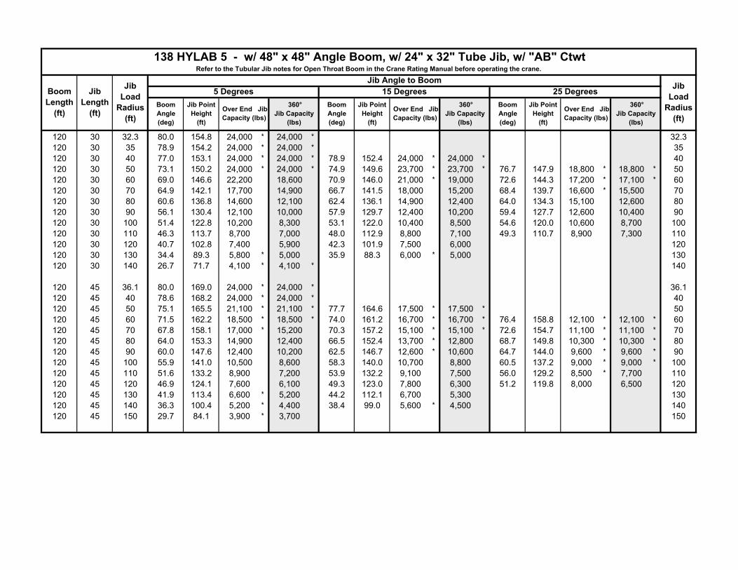
Boom Length
(ft)
Jib Load
Radius (ft)
138 HYLAB 5 - w/ 48" x 48" Angle Boom, w/ 24" x 32" Tube Jib, w/ "AB" CtwtRefer to the Tubular Jib notes for Open Throat Boom in the Crane Rating Manual before operating the crane.
Jib Length
(ft)
Jib Angle to Boom Jib Load
Radius (ft)
5 Degrees 15 Degrees 25 DegreesBoom Angle (deg)
Jib Point Height
(ft)
Over End Jib Capacity (lbs)
360° Jib Capacity
(lbs)
Boom Angle (deg)
Jib Point Height
(ft)
Over End Jib Capacity (lbs)
360° Jib Capacity
(lbs)
Boom Angle (deg)
Jib Point Height
(ft)
Over End Jib Capacity (lbs)
360° Jib Capacity
(lbs)
120 30 32.3 80.0 154.8 24,000 * 24,000 * 32.3120 30 35 78.9 154.2 24,000 * 24,000 * 35120 30 40 77.0 153.1 24,000 * 24,000 * 78.9 152.4 24,000 * 24,000 * 40120 30 50 73.1 150.2 24,000 * 24,000 * 74.9 149.6 23,700 * 23,700 * 76.7 147.9 18,800 * 18,800 * 50120 30 60 69.0 146.6 22,200 18,600 70.9 146.0 21,000 * 19,000 72.6 144.3 17,200 * 17,100 * 60120 30 70 64.9 142.1 17,700 14,900 66.7 141.5 18,000 15,200 68.4 139.7 16,600 * 15,500 70120 30 80 60.6 136.8 14,600 12,100 62.4 136.1 14,900 12,400 64.0 134.3 15,100 12,600 80120 30 90 56.1 130.4 12,100 10,000 57.9 129.7 12,400 10,200 59.4 127.7 12,600 10,400 90120 30 100 51.4 122.8 10,200 8,300 53.1 122.0 10,400 8,500 54.6 120.0 10,600 8,700 100120 30 110 46.3 113.7 8,700 7,000 48.0 112.9 8,800 7,100 49.3 110.7 8,900 7,300 110120 30 120 40.7 102.8 7,400 5,900 42.3 101.9 7,500 6,000 120120 30 130 34.4 89.3 5,800 * 5,000 35.9 88.3 6,000 * 5,000 130120 30 140 26.7 71.7 4,100 * 4,100 * 140
120 45 36.1 80.0 169.0 24,000 * 24,000 * 36.1120 45 40 78.6 168.2 24,000 * 24,000 * 40120 45 50 75.1 165.5 21,100 * 21,100 * 77.7 164.6 17,500 * 17,500 * 50120 45 60 71.5 162.2 18,500 * 18,500 * 74.0 161.2 16,700 * 16,700 * 76.4 158.8 12,100 * 12,100 * 60120 45 70 67.8 158.1 17,000 * 15,200 70.3 157.2 15,100 * 15,100 * 72.6 154.7 11,100 * 11,100 * 70120 45 80 64.0 153.3 14,900 12,400 66.5 152.4 13,700 * 12,800 68.7 149.8 10,300 * 10,300 * 80120 45 90 60.0 147.6 12,400 10,200 62.5 146.7 12,600 * 10,600 64.7 144.0 9,600 * 9,600 * 90120 45 100 55.9 141.0 10,500 8,600 58.3 140.0 10,700 8,800 60.5 137.2 9,000 * 9,000 * 100120 45 110 51.6 133.2 8,900 7,200 53.9 132.2 9,100 7,500 56.0 129.2 8,500 * 7,700 110120 45 120 46.9 124.1 7,600 6,100 49.3 123.0 7,800 6,300 51.2 119.8 8,000 6,500 120120 45 130 41.9 113.4 6,600 * 5,200 44.2 112.1 6,700 5,300 130120 45 140 36.3 100.4 5,200 * 4,400 38.4 99.0 5,600 * 4,500 140120 45 150 29.7 84.1 3,900 * 3,700 150
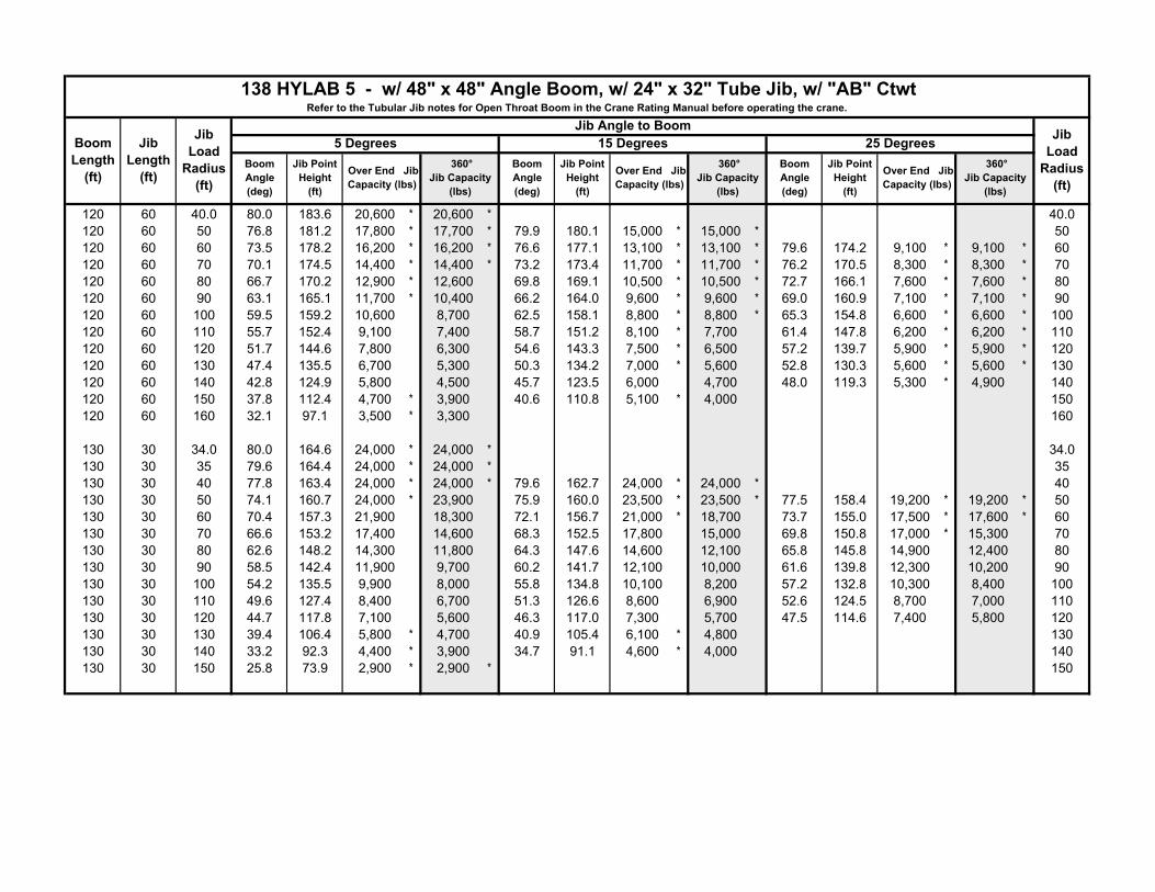
Boom Length
(ft)
Jib Load
Radius (ft)
138 HYLAB 5 - w/ 48" x 48" Angle Boom, w/ 24" x 32" Tube Jib, w/ "AB" CtwtRefer to the Tubular Jib notes for Open Throat Boom in the Crane Rating Manual before operating the crane.
Jib Length
(ft)
Jib Angle to Boom Jib Load
Radius (ft)
5 Degrees 15 Degrees 25 DegreesBoom Angle (deg)
Jib Point Height
(ft)
Over End Jib Capacity (lbs)
360° Jib Capacity
(lbs)
Boom Angle (deg)
Jib Point Height
(ft)
Over End Jib Capacity (lbs)
360° Jib Capacity
(lbs)
Boom Angle (deg)
Jib Point Height
(ft)
Over End Jib Capacity (lbs)
360° Jib Capacity
(lbs)
120 60 40.0 80.0 183.6 20,600 * 20,600 * 40.0120 60 50 76.8 181.2 17,800 * 17,700 * 79.9 180.1 15,000 * 15,000 * 50120 60 60 73.5 178.2 16,200 * 16,200 * 76.6 177.1 13,100 * 13,100 * 79.6 174.2 9,100 * 9,100 * 60120 60 70 70.1 174.5 14,400 * 14,400 * 73.2 173.4 11,700 * 11,700 * 76.2 170.5 8,300 * 8,300 * 70120 60 80 66.7 170.2 12,900 * 12,600 69.8 169.1 10,500 * 10,500 * 72.7 166.1 7,600 * 7,600 * 80120 60 90 63.1 165.1 11,700 * 10,400 66.2 164.0 9,600 * 9,600 * 69.0 160.9 7,100 * 7,100 * 90120 60 100 59.5 159.2 10,600 8,700 62.5 158.1 8,800 * 8,800 * 65.3 154.8 6,600 * 6,600 * 100120 60 110 55.7 152.4 9,100 7,400 58.7 151.2 8,100 * 7,700 61.4 147.8 6,200 * 6,200 * 110120 60 120 51.7 144.6 7,800 6,300 54.6 143.3 7,500 * 6,500 57.2 139.7 5,900 * 5,900 * 120120 60 130 47.4 135.5 6,700 5,300 50.3 134.2 7,000 * 5,600 52.8 130.3 5,600 * 5,600 * 130120 60 140 42.8 124.9 5,800 4,500 45.7 123.5 6,000 4,700 48.0 119.3 5,300 * 4,900 140120 60 150 37.8 112.4 4,700 * 3,900 40.6 110.8 5,100 * 4,000 150120 60 160 32.1 97.1 3,500 * 3,300 160
130 30 34.0 80.0 164.6 24,000 * 24,000 * 34.0130 30 35 79.6 164.4 24,000 * 24,000 * 35130 30 40 77.8 163.4 24,000 * 24,000 * 79.6 162.7 24,000 * 24,000 * 40130 30 50 74.1 160.7 24,000 * 23,900 75.9 160.0 23,500 * 23,500 * 77.5 158.4 19,200 * 19,200 * 50130 30 60 70.4 157.3 21,900 18,300 72.1 156.7 21,000 * 18,700 73.7 155.0 17,500 * 17,600 * 60130 30 70 66.6 153.2 17,400 14,600 68.3 152.5 17,800 15,000 69.8 150.8 17,000 * 15,300 70130 30 80 62.6 148.2 14,300 11,800 64.3 147.6 14,600 12,100 65.8 145.8 14,900 12,400 80130 30 90 58.5 142.4 11,900 9,700 60.2 141.7 12,100 10,000 61.6 139.8 12,300 10,200 90130 30 100 54.2 135.5 9,900 8,000 55.8 134.8 10,100 8,200 57.2 132.8 10,300 8,400 100130 30 110 49.6 127.4 8,400 6,700 51.3 126.6 8,600 6,900 52.6 124.5 8,700 7,000 110130 30 120 44.7 117.8 7,100 5,600 46.3 117.0 7,300 5,700 47.5 114.6 7,400 5,800 120130 30 130 39.4 106.4 5,800 * 4,700 40.9 105.4 6,100 * 4,800 130130 30 140 33.2 92.3 4,400 * 3,900 34.7 91.1 4,600 * 4,000 140130 30 150 25.8 73.9 2,900 * 2,900 * 150

Boom Length
(ft)
Jib Load
Radius (ft)
138 HYLAB 5 - w/ 48" x 48" Angle Boom, w/ 24" x 32" Tube Jib, w/ "AB" CtwtRefer to the Tubular Jib notes for Open Throat Boom in the Crane Rating Manual before operating the crane.
Jib Length
(ft)
Jib Angle to Boom Jib Load
Radius (ft)
5 Degrees 15 Degrees 25 DegreesBoom Angle (deg)
Jib Point Height
(ft)
Over End Jib Capacity (lbs)
360° Jib Capacity
(lbs)
Boom Angle (deg)
Jib Point Height
(ft)
Over End Jib Capacity (lbs)
360° Jib Capacity
(lbs)
Boom Angle (deg)
Jib Point Height
(ft)
Over End Jib Capacity (lbs)
360° Jib Capacity
(lbs)
130 45 37.9 80.0 178.9 24,000 * 24,000 * 37.9130 45 40 79.3 178.4 24,000 * 24,000 * 40130 45 50 75.9 175.9 21,100 * 21,100 * 78.4 174.9 17,800 * 17,800 * 50130 45 60 72.6 172.8 18,500 * 18,500 * 75.0 171.8 16,600 * 16,600 * 77.2 169.4 12,300 * 12,300 * 60130 45 70 69.1 169.0 17,100 * 14,900 71.5 168.0 15,000 * 15,000 * 73.7 165.6 11,300 * 11,300 * 70130 45 80 65.5 164.5 14,600 12,100 67.9 163.5 13,700 * 12,500 70.1 161.0 10,500 * 10,500 * 80130 45 90 61.9 159.2 12,100 10,000 64.2 158.2 12,500 10,300 66.3 155.6 9,800 * 9,800 * 90130 45 100 58.1 153.1 10,200 8,300 60.4 152.1 10,500 8,600 62.4 149.3 9,200 * 8,900 100130 45 110 54.1 146.0 8,600 6,900 56.4 145.0 8,900 7,200 58.4 142.1 8,700 * 7,400 110130 45 120 49.9 137.8 7,300 5,800 52.2 136.7 7,600 6,000 54.1 133.6 7,800 6,200 120130 45 130 45.5 128.2 6,300 4,900 47.6 127.0 6,500 5,100 49.4 123.7 6,600 5,200 130130 45 140 40.6 117.0 5,200 * 4,100 42.7 115.7 5,500 * 4,300 140130 45 150 35.2 103.5 3,900 * 3,400 37.2 102.0 4,200 * 3,500 150130 45 160 28.8 86.6 2,700 * 2,700 * 160
130 60 41.8 80.0 193.4 20,000 * 20,000 * 41.8130 60 50 77.5 191.5 17,700 * 17,700 * 50130 60 60 74.4 188.7 16,300 * 16,300 * 77.4 187.5 13,500 * 13,500 * 60130 60 70 71.2 185.2 14,400 * 14,400 * 74.2 184.1 12,000 * 12,000 * 77.0 181.1 8,400 * 8,400 * 70130 60 80 68.0 181.2 13,000 * 12,300 70.9 180.0 10,900 * 10,900 * 73.7 177.0 7,800 * 7,800 * 80130 60 90 64.7 176.4 11,700 * 10,100 67.6 175.3 9,900 * 9,900 * 70.3 172.1 7,200 * 7,200 * 90130 60 100 61.3 170.9 10,400 8,500 64.2 169.8 9,100 * 8,900 66.8 166.5 6,800 * 6,800 * 100130 60 110 57.7 164.6 8,800 7,100 60.6 163.4 8,400 * 7,500 63.2 160.0 6,400 * 6,400 * 110130 60 120 54.1 157.4 7,500 6,000 56.9 156.2 7,800 * 6,300 59.4 152.6 6,000 * 6,000 * 120130 60 130 50.2 149.1 6,400 5,100 53.0 147.8 6,700 5,300 55.4 144.1 5,700 * 5,600 130130 60 140 46.1 139.6 5,500 4,300 48.8 138.3 5,800 4,500 51.1 134.2 5,500 * 4,700 140130 60 150 41.6 128.6 4,500 * 3,600 44.3 127.1 4,900 * 3,800 46.4 122.7 5,100 3,900 150130 60 160 36.7 115.6 3,500 * 3,000 39.3 113.9 3,800 * 3,100 160130 60 170 31.1 99.8 2,500 * 2,500 * 170
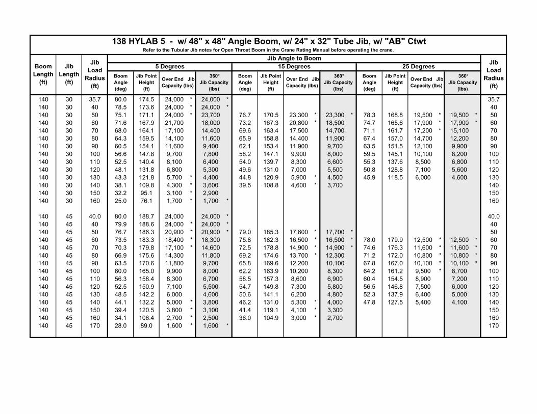
Boom Length
(ft)
Jib Load
Radius (ft)
138 HYLAB 5 - w/ 48" x 48" Angle Boom, w/ 24" x 32" Tube Jib, w/ "AB" CtwtRefer to the Tubular Jib notes for Open Throat Boom in the Crane Rating Manual before operating the crane.
Jib Length
(ft)
Jib Angle to Boom Jib Load
Radius (ft)
5 Degrees 15 Degrees 25 DegreesBoom Angle (deg)
Jib Point Height
(ft)
Over End Jib Capacity (lbs)
360° Jib Capacity
(lbs)
Boom Angle (deg)
Jib Point Height
(ft)
Over End Jib Capacity (lbs)
360° Jib Capacity
(lbs)
Boom Angle (deg)
Jib Point Height
(ft)
Over End Jib Capacity (lbs)
360° Jib Capacity
(lbs)
140 30 35.7 80.0 174.5 24,000 * 24,000 * 35.7140 30 40 78.5 173.6 24,000 * 24,000 * 40140 30 50 75.1 171.1 24,000 * 23,700 76.7 170.5 23,300 * 23,300 * 78.3 168.8 19,500 * 19,500 * 50140 30 60 71.6 167.9 21,700 18,000 73.2 167.3 20,800 * 18,500 74.7 165.6 17,900 * 17,900 * 60140 30 70 68.0 164.1 17,100 14,400 69.6 163.4 17,500 14,700 71.1 161.7 17,200 * 15,100 70140 30 80 64.3 159.5 14,100 11,600 65.9 158.8 14,400 11,900 67.4 157.0 14,700 12,200 80140 30 90 60.5 154.1 11,600 9,400 62.1 153.4 11,900 9,700 63.5 151.5 12,100 9,900 90140 30 100 56.6 147.8 9,700 7,800 58.2 147.1 9,900 8,000 59.5 145.1 10,100 8,200 100140 30 110 52.5 140.4 8,100 6,400 54.0 139.7 8,300 6,600 55.3 137.6 8,500 6,800 110140 30 120 48.1 131.8 6,800 5,300 49.6 131.0 7,000 5,500 50.8 128.8 7,100 5,600 120140 30 130 43.3 121.8 5,700 * 4,400 44.8 120.9 5,900 * 4,500 45.9 118.5 6,000 4,600 130140 30 140 38.1 109.8 4,300 * 3,600 39.5 108.8 4,600 * 3,700 140140 30 150 32.2 95.1 3,100 * 2,900 150140 30 160 25.0 76.1 1,700 * 1,700 * 160
140 45 40.0 80.0 188.7 24,000 24,000 * 40.0140 45 40 79.9 188.6 24,000 * 24,000 * 40140 45 50 76.7 186.3 20,900 * 20,900 * 79.0 185.3 17,600 * 17,700 * 50140 45 60 73.5 183.3 18,400 * 18,300 75.8 182.3 16,500 * 16,500 * 78.0 179.9 12,500 * 12,500 * 60140 45 70 70.3 179.8 17,100 * 14,600 72.5 178.8 14,900 * 14,900 * 74.6 176.3 11,600 * 11,600 * 70140 45 80 66.9 175.6 14,300 11,800 69.2 174.6 13,700 * 12,300 71.2 172.0 10,800 * 10,800 * 80140 45 90 63.5 170.6 11,800 9,700 65.8 169.6 12,200 10,100 67.8 167.0 10,100 * 10,100 * 90140 45 100 60.0 165.0 9,900 8,000 62.2 163.9 10,200 8,300 64.2 161.2 9,500 * 8,700 100140 45 110 56.3 158.4 8,300 6,700 58.5 157.3 8,600 6,900 60.4 154.5 8,900 7,200 110140 45 120 52.5 150.9 7,100 5,500 54.7 149.8 7,300 5,800 56.5 146.8 7,500 6,000 120140 45 130 48.5 142.2 6,000 4,600 50.6 141.1 6,200 4,800 52.3 137.9 6,400 5,000 130140 45 140 44.1 132.2 5,000 * 3,800 46.2 131.0 5,300 * 4,000 47.8 127.5 5,400 4,100 140140 45 150 39.4 120.5 3,800 * 3,100 41.4 119.1 4,100 * 3,300 150140 45 160 34.1 106.4 2,700 * 2,500 36.0 104.9 3,000 * 2,700 160140 45 170 28.0 89.0 1,600 * 1,600 * 170

Boom Length
(ft)
Jib Load
Radius (ft)
138 HYLAB 5 - w/ 48" x 48" Angle Boom, w/ 24" x 32" Tube Jib, w/ "AB" CtwtRefer to the Tubular Jib notes for Open Throat Boom in the Crane Rating Manual before operating the crane.
Jib Length
(ft)
Jib Angle to Boom Jib Load
Radius (ft)
5 Degrees 15 Degrees 25 DegreesBoom Angle (deg)
Jib Point Height
(ft)
Over End Jib Capacity (lbs)
360° Jib Capacity
(lbs)
Boom Angle (deg)
Jib Point Height
(ft)
Over End Jib Capacity (lbs)
360° Jib Capacity
(lbs)
Boom Angle (deg)
Jib Point Height
(ft)
Over End Jib Capacity (lbs)
360° Jib Capacity
(lbs)
140 60 43.5 80.0 203.3 19,300 * 19,300 * 43.5140 60 50 78.1 201.8 17,600 * 17,600 * 50140 60 60 75.2 199.1 16,200 * 16,200 * 78.0 198.0 13,700 * 13,700 * 60140 60 70 72.2 195.9 14,400 * 14,400 * 75.0 194.7 12,400 * 12,300 * 77.7 191.7 8,600 * 8,600 * 70140 60 80 69.1 192.0 13,000 * 12,000 71.9 190.9 11,200 * 11,200 * 74.5 187.8 7,900 * 7,900 * 80140 60 90 66.0 187.6 11,800 * 9,900 68.8 186.4 10,200 * 10,200 * 71.4 183.2 7,400 * 7,400 * 90140 60 100 62.8 182.4 10,100 8,200 65.6 181.2 9,400 * 8,600 68.1 178.0 6,900 * 6,900 * 100140 60 110 59.5 176.5 8,500 6,800 62.3 175.3 8,700 * 7,200 64.7 172.0 6,500 * 6,500 * 110140 60 120 56.1 169.8 7,200 5,700 58.8 168.6 7,600 6,000 61.2 165.1 6,200 * 6,200 * 120140 60 130 52.6 162.2 6,200 4,800 55.2 161.0 6,500 5,100 57.5 157.3 5,900 * 5,300 130140 60 140 48.8 153.6 5,300 * 4,000 51.4 152.2 5,500 4,200 53.7 148.3 5,600 * 4,500 140140 60 150 44.8 143.6 4,300 * 3,300 47.4 142.2 4,700 * 3,500 49.5 138.0 4,900 3,700 150140 60 160 40.5 132.2 3,300 * 2,700 43.0 130.6 3,700 * 2,900 160140 60 170 35.7 118.7 2,400 * 2,200 38.2 116.9 2,700 * 2,300 170140 60 180 30.3 102.4 1,500 * 1,500 * 180
150 30 37.5 80.0 184.3 24,000 * 24,000 * 37.5150 30 40 79.2 183.8 24,000 * 24,000 * 40150 30 50 75.9 181.5 24,000 * 23,400 77.5 180.8 23,000 * 23,000 * 79.0 179.2 19,800 19,800 * 50150 30 60 72.6 178.5 21,400 17,700 74.2 177.8 20,600 * 18,200 75.6 176.1 18,000 18,000 * 60150 30 70 69.3 174.9 17,100 14,100 70.8 174.2 17,300 14,500 72.2 172.5 17,000 14,900 70150 30 80 65.9 170.6 13,800 11,300 67.4 169.9 14,100 11,600 68.7 168.1 14,400 11,900 80150 30 90 62.3 165.6 11,300 9,100 63.8 164.9 11,600 9,400 65.2 163.0 11,900 9,700 90150 30 100 58.7 159.7 9,400 7,500 60.2 159.0 9,600 7,700 61.4 157.1 9,800 7,900 100150 30 110 54.9 152.9 7,800 6,100 56.3 152.2 8,000 6,300 57.6 150.2 8,200 6,500 110150 30 120 50.9 145.1 6,500 5,000 52.3 144.4 6,700 5,200 53.5 142.2 6,900 5,300 120150 30 130 46.6 136.1 5,400 * 4,100 48.0 135.3 5,600 4,200 49.1 133.0 5,800 4,400 130150 30 140 42.0 125.6 4,200 * 3,300 43.4 124.7 4,400 * 3,400 140150 30 150 37.0 113.1 3,000 * 2,600 38.3 112.1 3,200 * 2,700 150150 30 160 31.3 97.9 1,900 * 1,900 * 160

This page intentionallyleft blank

5439---0205---N9
Link--Belt Construction Equipment Company Lexington, Kentucky www.linkbelt.comRLink--Belt is a registered trademark. Copyright 2005. We are constantly improving our products and therefore reserve the right to change designs and specifications.
Related Documents