14 15 20 25 32 40 50 65 80 100 125 150 200 250 300 350 400 450 500 550 600 650 700 750 800 850 900 I. PIPING ABOVE GROUND DERIVED OPERATING TIME STANDARD FOR TABLES FACTOR OF BASIC ASSEMBLY POSITION CHAPTER X, ACCORDING TO FORMS ON PAGE 142 ÷ 146 Productivity efficiency percentage (PEP) = 80% FOR PREFABRICATION : 8% 1. PIPES (ANSI B 36.10) FOR INSTALLATION : 92% 1.1 PIPE INSTALLATION ON PROCESS PLANT [ CARBON STEEL - NONWRAPPED - ABOVE GROUND STAINLESS STEEL Dn-mm 0-Inch 1/2” 3/4” 1” 1 1/4” 1 1/2” 2” 2 1/2” 3” 4” 5” 6” 8” 10” 12” 14” 16” 18” 20” 22” 24” 26” 28” 30” 32” 34” 36” Man hour included next activities : - handling - erection - on-site transport - welding - prefabrication - pressure testing

Welcome message from author
This document is posted to help you gain knowledge. Please leave a comment to let me know what you think about it! Share it to your friends and learn new things together.
Transcript
14
15
20
25
32
40
50
65
80
100
125
150
200
250
300
350
400
450
500
550
600
650
700
750
800
850
900
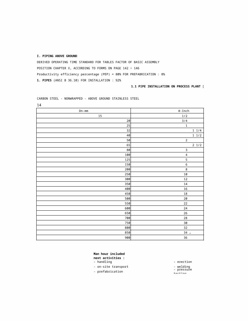
I. PIPING ABOVE GROUND
DERIVED OPERATING TIME STANDARD FOR TABLES FACTOR OF BASIC ASSEMBLY
POSITION CHAPTER X, ACCORDING TO FORMS ON PAGE 142 ÷ 146
Productivity efficiency percentage (PEP) = 80% FOR PREFABRICATION : 8%
1. PIPES (ANSI B 36.10) FOR INSTALLATION : 92%
1.1 PIPE INSTALLATION ON PROCESS PLANT [Mhr/m]
CARBON STEEL - NONWRAPPED - ABOVE GROUND STAINLESS STEEL
Dn-mm 0-Inch
1/2”
3/4”
1”
1 1/4”
1 1/2”
2”
2 1/2”
3”
4”
5”
6”
8”
10”
12”
14”
16”
18”
20”
22”
24”
26”
28”
30”
32”
34”
36”
Man hour included next activities :
- handling - erection
- on-site transport - welding
- prefabrication - pressure testing

Mhr/m x 0,3048 = Mhr/ft

73
273
457
508
559
610
660
711
762
813
864
914
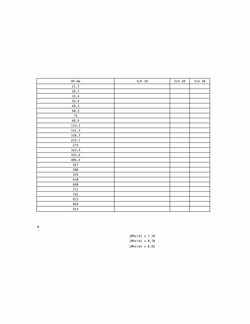
1.1 PIPE INSTALLATION ON PROCESS PLANT [Mhr/m]
OD-mm Sch 10 Sch 20
21,3
26,7
33,4
42,2
48,3
60,3
88,9
114,3
141,3
168,3
219,1
323,9
355,6
406,4
Materials: k
- alloy steel [Mhr/m] x 1,10
- prewrapped [Mhr/m] x 1,15 (underground install.)
- galvanized [Mhr/m] x 0,70
- aluminium alloy [Mhr/m] x 0,85

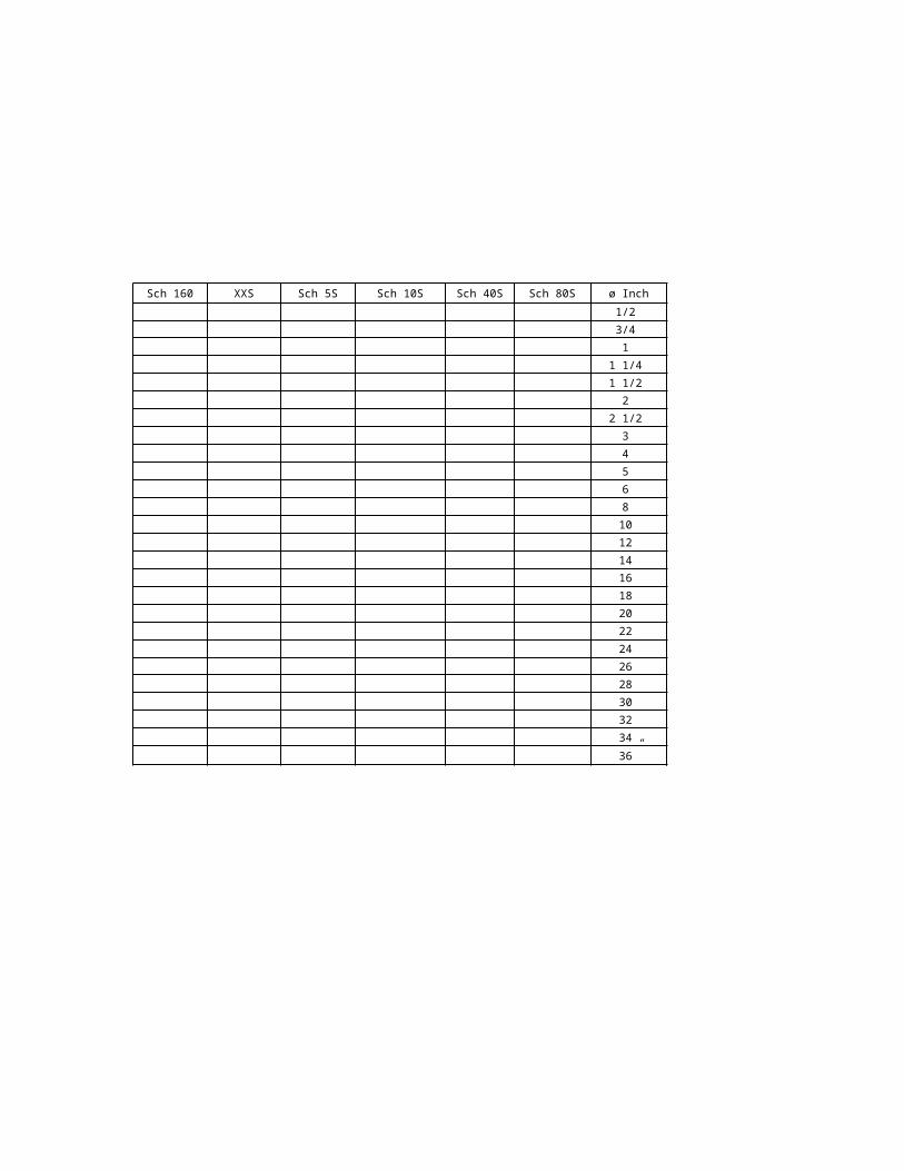
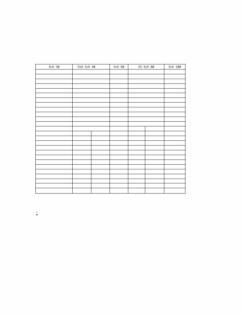
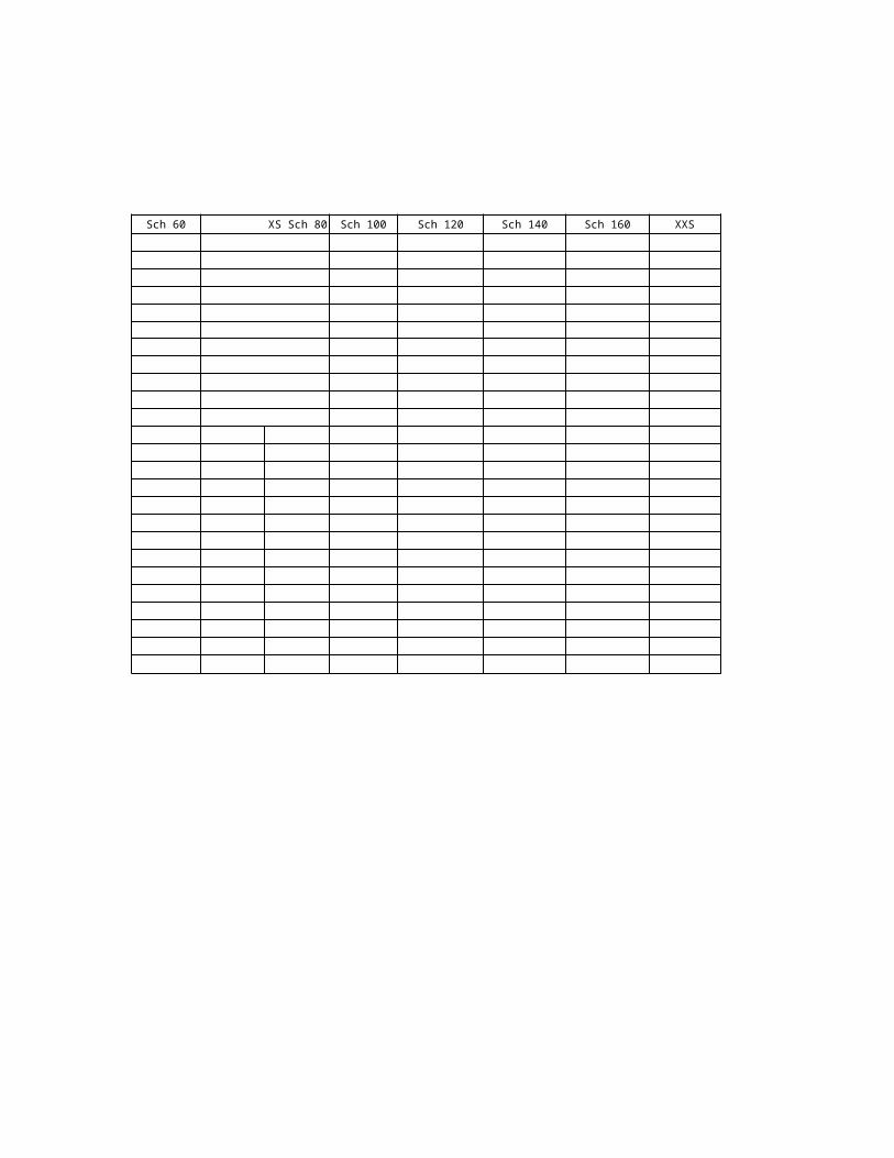
Sch 30 Std Sch 40 Sch 60 XS Sch 80 Sch 100 Sch 120 Sch 140 Sch 160

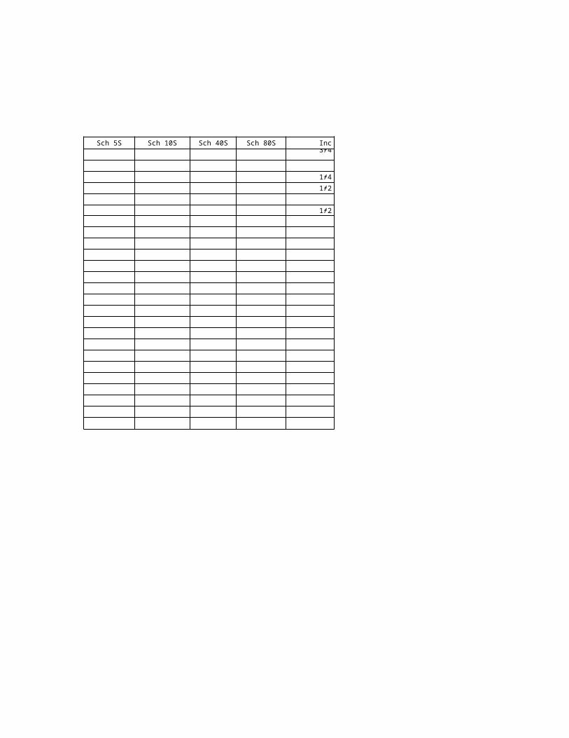
XXS Sch 5S Sch 10S Sch 40S Sch 80S 0 -Inch
1/2”
3/4”
1”
1 1/4”
1 1/2”
2”
2 1/2”
3”
4”
5”
6”
8”
10”
12”
14”
16”
18”
20”
22”
24”
26”
28”
30”
32”
34”
36”

15
15
20
25
32
40
50
65
80
100
125
150
200
250
300
350
400
450
500
550
600
650
700
750
800
850
900
1. PIPES (ANSI B. 36.10) FOR PREFABRICATION : 8%
1.2 INSTALLATION ON PIPE RACK OR SLEEPER WAY [Mhr/m] FOR INSTALLATION : 92%
CARBON STEEL NONWRAPPED
-
STAINLESS STEEL
Dn-mm ø Inch
1/2”
3/4”
1”
1 1/4”
1 1/2”
2”
2 1/2”
3”
4”
5”
6”
8”
10”
12”
14”
16”
18”
20”
22”
24”
26”
28”
30”
32”
34”
36”
Man hour include the next activities:
- handling - erection
- on-site transport - welding
- prefabrication - pressure testing
Mhr/m x 0,3048 = Mhr/ft

Std
73
273
457
508
559
610
660
711
762
813
864
914
[Mhr/m] FOR INSTALLATION : 92%
OD-mm Sch 10 Sch 20 Sch 30
21,3
26,7
33,4
42,4
48,3
60,3
88,9
114,3
141,3
168,3
219,1
323,9
355,6
406,4
Materials: k
- alloy steel [Mhr/m] x 1,10
- galvanized [Mhr/m] x 0,70
- aluminium alloy [Mhr/m] x 0,85
Sch 40 Sch 60 XS Sch 80 Sch 100 Sch 120 Sch 140 Sch 160 XXS

Sch 5S Sch 10S Sch 40S Sch 80S ø Inch
1/2”
3/4”
1”
1 1/4”
1 1/2”
2”
2 1/2”
3”
4”
5”
6”
8”
10”
12”
14”
16”
18”
20”
22”
24”
26”
28”
30”
32”
34”
36”
16
15
20
25
32
40
50
65 73
80
100
125
150
200
250 273
300
350
400
450 457
500 508
550 559
600 610
650 660
700 711
750 762
800 813
850 864
900 914
2. FITTINGS (ANSI 36.10) FOR PREFABRICATION : 85%
2.1 ELBOWS [Mhr/ea] FOR INSTALLATION: 15%
CARBON STEEL STAINLESS STEEL
DN-mm 0 -Inch OD-mm Sch 10
1/2” 21,3
3/4” 26,7
1” 33,4
1 1/4” 42,2
1 1/2” 48,3
2” 60,3
2 1/2”
3” 88,9
4” 114,3
5” 141,3
6” 168,3
8” 219,1
10”
12” 323,9
14” 355,6
16” 406,4
18”
20”
22”
24”
26”
28”
30”
32”
34”
36”
2.2 CAPS [Mhr/ea] x Materials:
f
- Cr-Mo alloy steel
1,40 ÷1,
60- High temp. alloy steel
- Copper alloy
1,20 - Alloy steel Ni- Killed C.S.
1,00 ÷1,
25- Aluminium alloy

Sch 20 Sch 30 Std Sch 40 Sch 60 XS Sch 80 Sch 100 Sch 120
f
1,00 ÷
1,80
1,60
1,50

Sch 140 Sch 160 XXS Sch 5S Sch 10S Sch 40S Sch 80S 0-Inch
1/2”
3/4”
1”
1 1/4”
1 1/2”
2”
2 1/2”
3”
4”
5”
6”
8”
10”
12”
14”
16”
18”
20”
22”
24”
26”
28”
30”
32”
34”
36”

17
15
20
25
32
40
50
65
80
100
125
150
200
250
300
350
400
450
500
550
600
650
700
750
800
850
900
2. FITTINGS (ANSI B.36.10) FOR PREFABRICATION : 85%
2.3 TEES FOR INSTALLATION : 15%
2.3.1 STRAIGHT TEE [Mhr/ea]
CARBON STEEL STAINLESS STEEL
Dn-mm
2.3.2 REDUCED TEE [Mhr/ea] x Materials:- Cr-Mo alloy steel
- Copper alloy
- Killed C.S.

73
273
457
508
559
610
660
711
762
813
864
914
0 -Inch OD-mm Sch 10 Sch 20 Sch 30 Std Sch 40
1/2” 21,3
3/4” 26,7
1” 33,4
1 1/4” 42,4
1 1/2” 48,3
2” 60,3
2 1/2”
3” 88,9
4” 114,3
5” 141,3
6” 168,3
8” 219,1
10”
12” 323,9
14” 355,6
16” 406,4
18”
20”
22”
24”
26”
28”
30”
32”
34”
36”
f f
1,40 ÷1,60
- High temp. alloy steel
1,00 ÷
1,801,20 - Alloy steel Ni 1,60
1,00 ÷1,25
- Auminium alloy 1,50

Std Sch 40 Sch 60 XS Sch 80 Sch 100 Sch 120 Sch 140 Sch 160 XXS

Sch 5S Sch 10S Sch 40S Sch 80S 0-Inch
1/2”
3/4”
1”
1 1/4”
1 1/2”
2”
2 1/2”
3”
4”
5”
6”
8”
10”
12”
14”
16”
18”
20”
22”
24”
26”
28”
30”
32”
34”
36”
18
20
25
32
40
50
65
80
100
125
150
200
250
300
350
400
450
500
550
600
650
700
750
800
850
900
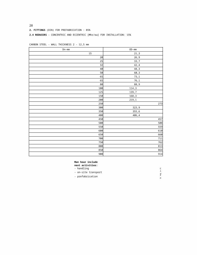
2. FITTINGS (ANSI) FOR PREFABRICATION : 85%
2.4 REDUCERS - CONCENTRIC AND ECCENTRIC [Mhr/ea] FOR INSTALLATION: 15%
CARBON STEEL STAINLESS STEEL
Dn-mm 0 -Inch
3/4”
1”
1 1/4”
1 1/2”
2”
2 1/2”
3”
4”
5”
6”
8”
10”
12”
14”
16”
18”
20”
22”
24”
26”
28”
30”
32”
34”
36”
Man hour include next activities:
- handling - erection
- on-site transport - welding
- prefabrication - pressure testing

73
273
457
508
559
610
660
711
762
813
864
914
OD-mm Sch 10 Sch 20
26,7
33,4
42,2
48,3
60,3
88,9
114,3
141,3
168,3
219,1
323,9
355,6
406,4
Materials: f
- Cr-Mo alloy steel 1,40 ÷ 1,60 - High temp. alloy steel
- Copper alloy 1,20 - Alloy steel Ni
- Killed C.S 1,00 ÷ 1,25 - Aluminium alloy

Sch 30 Std Sch 40 Sch 60 XS Sch 80 Sch 100
f
1,00 ÷ 1,80
1,60
1,50

Sch 120 Sch 140 Sch 160 XXS Sch 5S Sch 10S Sch 40S Sch 80S 0 -Inch
3/4”
1”
1 1/4”
1 1/2”
2”
2 1/2”
3”
4”
5”
6”
8”
10”
12”
14”
16”
18”
20”
22”
24”
26”
28”
30”
32”
34”
36”

19
15
20
25
32
40
50
65
65
80
100
125
150
200
250 273
300
350
400
450 457
500 508
550 559
600 610
650 660
700 711
750 762
800 813
850 864
900 914
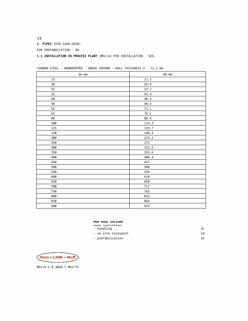
1. PIPES (DIN 2448/2458)
FOR PREFABRICATION : 8%
1.1 INSTALLATION IN PROCESS PLANT [Mhr/m] FOR INSTALLATION : 92%
CARBON STEEL - NONWRAPPED - ABOVE GROUND - WALL THICKNESS 2 - 12,5 mm
Dn-mm OD-mm
21,3
26,9
33,7
42,4
48,3
60,3
73,1
76,1
88,9
114,3
139,7
168,3
219,1
323,9
355,6
406,4
Man hour include next activities:
- handling - erection
- on-site transport - welding
- prefabrication - pressure testing
Mhr/m x 0,3048 = Mhr/ft

2
8
8
10
t - Std|Ext 2,3
2\2
2\2,3
2\2,6
2\2,6
2,3\2,6
2,3\2,9
2,6\2,9
2,6\2,9
2,9\3,2
3,2\3,6
3,6\4
4\4,5
4,5\6,3
5\6,3
5,6\7,1
5,6\8
6,3\8,8
6,3\10
6,3\11
6,3\12,5
6,3\12,5
7,1\14,2
7,1
8,8
Materials: k
- Stainless steel [Mhr/m] x 1,10- High temp. alloy steel
[Mhr/m] x 1,10
- Prewrapped [Mhr/m] x 1,15 (underground install.)
- Galvanized [Mhr/m] x 0,70
- Aluminium alloy [Mhr/m] x 0,85
4 52,6 2,9 3,2 3,6 4,5 5,6 6,3 7,1
8 10 11
273
457
508
559
610
660
711
762
813
864
914
8,8 12,5 OD-mm
21,3
26,9
33,7
42,4
48,3
60,3
73,1
76,1
88,9
114,3
139,7
168,3
219,1
323,9
355,6
406,4
20
15
20
25
32
40
50
65
65
80
100
125
150
200
250 273
300
350
400
450 457
500 508
550 559
600 610
650 660
700 711
750 762
800 813
850 864
900 914
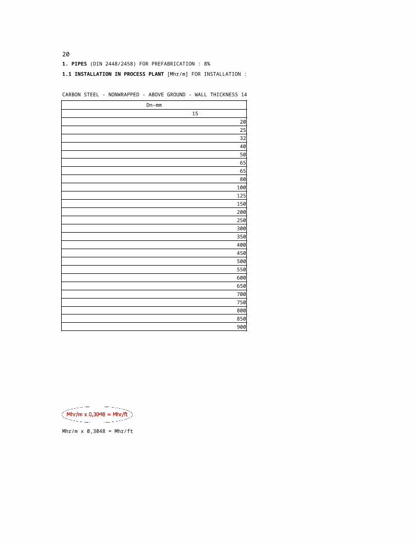
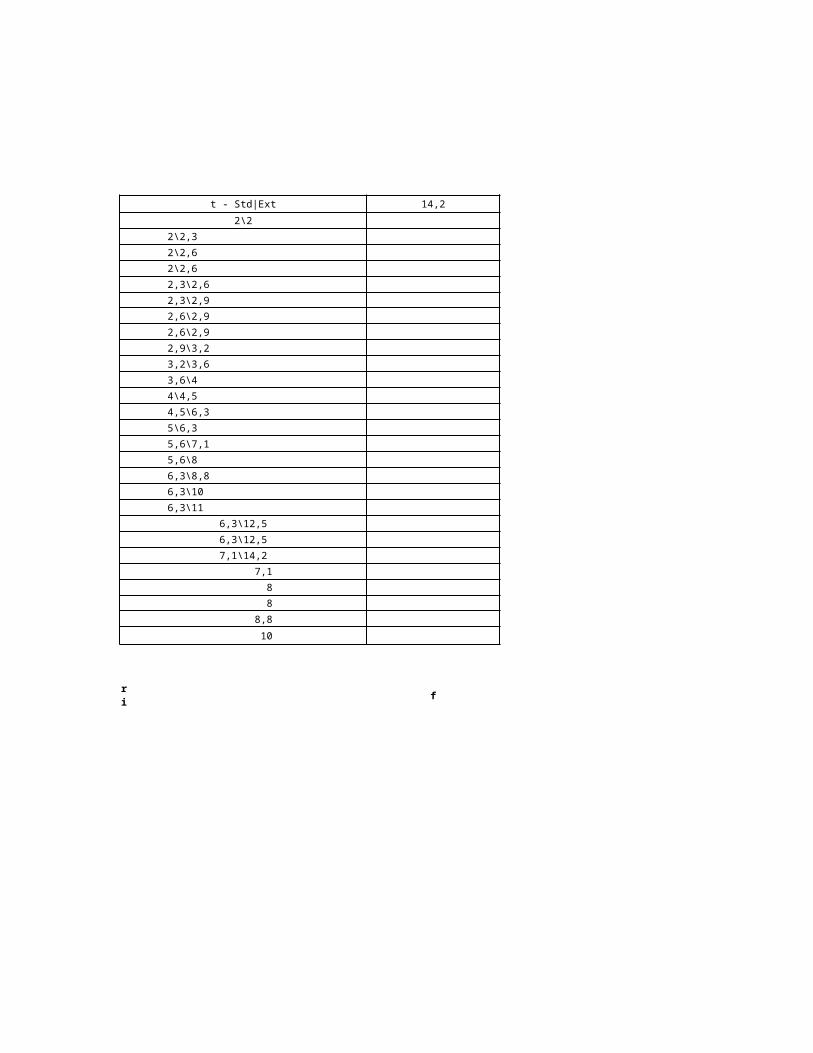
1. PIPES (DIN 2448/2458) FOR PREFABRICATION : 8%
1.1 INSTALLATION IN PROCESS PLANT [Mhr/m] FOR INSTALLATION : 92%
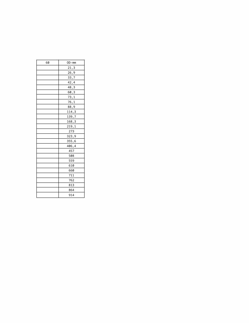
CARBON STEEL - NONWRAPPED - ABOVE GROUND - WALL THICKNESS 14,2 - 60 mm
Dn-mm OD-mm
21,3
26,9
33,7
42,4
48,3
60,3
73,1
76,1
88,9
114,3
139,7
168,3
219,1
323,9
355,6
406,4
Man hour include next activities:
- handling - erection
- on-site transport - welding
- prefabrication - pressure testing
Mhr/m x 0,3048 = Mhr/ft

16
8
8
10
t - Std|Ext 14,2 17,5
2\2
2\2,3
2\2,6
2\2,6
2,3\2,6
2,3\2,9
2,6\2,9
2,6\2,9
2,9\3,2
3,2\3,6
3,6\4
4\4,5
4,5\6,3
5\6,3
5,6\7,1
5,6\8
6,3\8,8
6,3\10
6,3\11
6,3\12,5
6,3\12,5
7,1\14,2
7,1
8,8
Materials: k
- Stainless steel [Mhr/m] x 1,10
- High temp. alloy steel [Mhr/m] x 1,10
- Prewrapped [Mhr/m] x 1,15
- Galvanized [Mhr/m] x 0,70
- Aluminium alloy [Mhr/m] x 0,85

20 25 28 30 32 36 40 4522,2

50 55 60 65 70
273
457
508
559
610
660
711
762
813
864
914
OD-mm
21,3
26,9
33,7
42,4
48,3
60,3
73,1
76,1
88,9
114,3
139,7
168,3
219,1
323,9
355,6
406,4

21
15
20
25
32
40
50
65
65
80
100
125
150
200
250 273
300
350
400 406
450 457
500 508
550 559
600 610
650 660
700 711
750 762
800 813
850 864
900 914
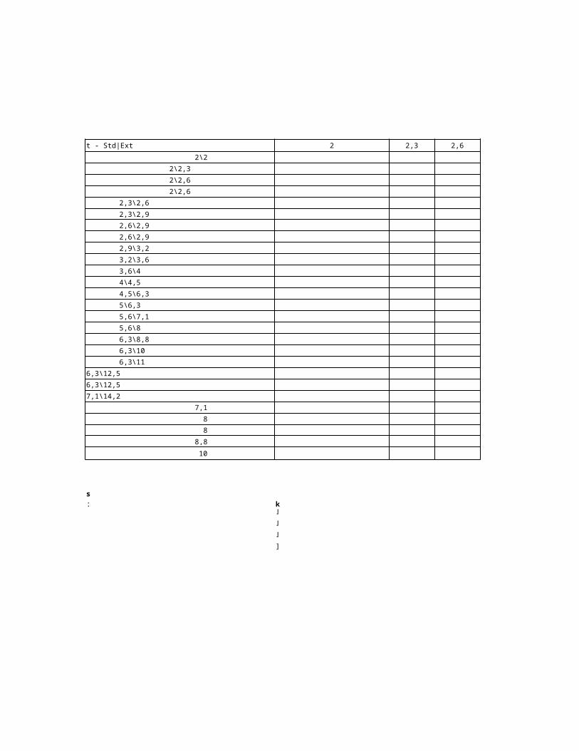
1. PIPES (DIN 2448/2458) FOR PREFABRICATION : 8%
1.2 INSTALLATION ON PIPE RACK OR SLEEPER WAY [Mhr/m] FOR INSTALLATION : 92%
CARBON STEEL - NONINSULATED - WALL THICKNESS - 2 mm - 12,5 mm
Dn-mm OD-mm
21,3
26,9
33,7
42,4
48,3
60,3
73,1
76,1
88,9
114,3
139,7
168,3
219,1
323,9
355,6
Man hour include next activities:
- handling - erection
- on-site transport - welding
- prefabrication - pressure testing
Mhr/m x 0,3048 = Mhr/ft
2
8
8
10
t - Std|Ext 2,3 2,6 2,9
2\2
2\2,3
2\2,6
2\2,6
2,3\2,6
2,3\2,9
2,6\2,9
2,6\2,9
2,9\3,2
3,2\3,6
3,6\4
4\4,5
4,5\6,3
5\6,3
5,6\7,1
5,6\8
6,3\8,8
6,3\10
6,3\11
6,3\12,5
6,3\12,5
7,1\14,2
7,1
8,8
Materials: k
- Stainless steel [Mhr/m] x 1,10- High temp. alloy steel
[Mhr/m] x 1,10
- Prewraped [Mhr/m] x 0,70
- Aluminium alloy [Mhr/m] x 0,85

4 5 83,2 3,6 4,5 5,6 6,3 7,1

10 11
273
457
508
559
610
660
711
762
813
864
914
8,8 12,5 OD-mm
21,3
26,9
33,7
42,4
48,3
60,3
73,1
76,1
88,9
114,3
139,7
168,3
219,1
323,9
355,6
406,4

22
16 20 25
15
20
25
32
40
50
65
65
80
100
125
150
200
250 273
300
350
400
450 457
500 508
550 559
600 610
650 660
700 711
750 762 8
800 813 8
850 864
900 914 10
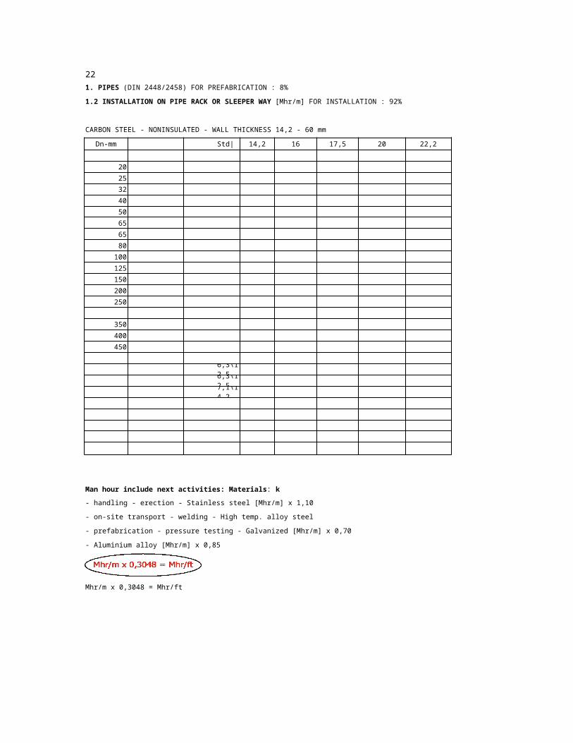
1. PIPES (DIN 2448/2458) FOR PREFABRICATION : 8%
1.2 INSTALLATION ON PIPE RACK OR SLEEPER WAY [Mhr/m] FOR INSTALLATION : 92%
CARBON STEEL - NONINSULATED - WALL THICKNESS 14,2 - 60 mm
Dn-mm OD-mm t - Std|Ext 14,2 17,5 22,2
21,3 2\2
26,9 2\2,3
33,7 2\2,6
42,4 2\2,6
48,3 2,3\2,6
60,3 2,3\2,9
73,1 2,6\2,9
76,1 2,6\2,9
88,9 2,9\3,2
114,3 3,2\3,6
139,7 3,6\4
168,3 4\4,5
219,1 4,5\6,3
5\6,3
323,9 5,6\7,1
355,6 5,6\8
406,4 6,3\8,8
6,3\10
6,3\11
6,3\12,5
6,3\12,5
7,1\14,2
7,1
8,8
Man hour include next activities: Materials: k
- handling - erection - Stainless steel [Mhr/m] x 1,10
- on-site transport - welding - High temp. alloy steel
- prefabrication - pressure testing - Galvanized [Mhr/m] x 0,70
- Aluminium alloy [Mhr/m] x 0,85
Mhr/m x 0,3048 = Mhr/ft

28 30 32 36 40 45 50 55 60

273
457
508
559
610
660
711
762
813
864
914
OD-mm
21,3
26,9
33,7
42,4
48,3
60,3
73,1
76,1
88,9
114,3
139,7
168,3
219,1
323,9
355,6
406,4
15
20
25
32
40
50
65
80
1
1
2
3
4
2
15
20
25
32
40
50
65 73
65
80
23
10 22
12 25
14 28
15 30
16 35
18 38
20 42
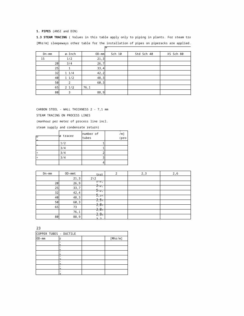
1. PIPES (ANSI and DIN)
1.3 STEAM TRACING ( Values in this table apply only to piping in plants. For steam tracing of pipe lines on piperacks or
[Mhr/m] sleepeways other table for the installation of pipes on piperacks are applied.)
CARBON STEEL
Dn-mm ø-Inch OD-mm Sch 10 Std Sch 40 XS Sch 80 Sch 160
1/2” 21,3
3/4” 26,7
1” 33,4
1 1/4” 42,2
1 1/2” 48,3
2” 60,3
2 1/2” 76,1
3” 88,9
CARBON STEEL - WALL THICKNESS 2 - 7,1 mm
STEAM TRACING ON PROCESS LINES
(manhour per meter of process line incl.
steam supply and condensate return)
ø tracernumber of tubes
[Mhr/m] (proc.)D
n to
3" 1/2”4” ÷ 8”
3/4”10” ÷
16”3/4”
18” ÷ 36”
3/4”above 36 ”
3/4”
Dn-mm OD-mmt -Std|Ext 2,3 2,6 2,9
21,3 2\2
26,9 2\2,3
33,7 2\2,6
42,4 2\2,6
48,3 2,3\2,6
60,3 2,3\2,9
2,6\2,9
76,1 2,6\2,9
88,9 2,9\3,2
COPPER TUBES - DUCTILE
OD-mm Mhr/m OD-mm [Mhr/m]
0,12
0,14
0,18
0,20
0,21
0,24
0,27
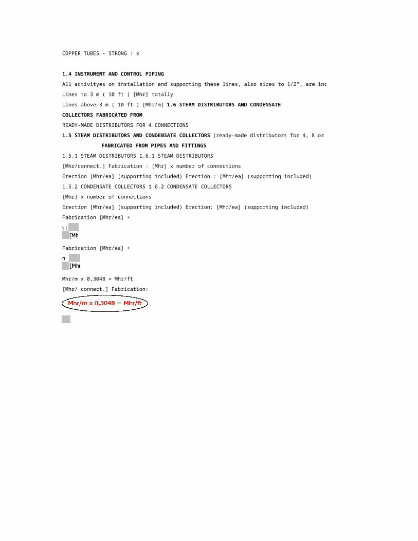
COPPER TUBES - STRONG : x
1.4 INSTRUMENT AND CONTROL PIPING

All activityes on installation and supporting these lines, also sizes to 1/2", are included.
Lines to 3 m ( 10 ft ) [Mhr] totally
Lines above 3 m ( 10 ft ) [Mhr/m] 1.6 STEAM DISTRIBUTORS AND CONDENSATE
COLLECTORS FABRICATED FROM
READY-MADE DISTRIBUTORS FOR 4 CONNECTIONS
1.5 STEAM DISTRIBUTORS AND CONDENSATE COLLECTORS (ready-made distributors for 4, 8 or 12 connections)
FABRICATED FROM PIPES AND FITTINGS
1.5.1 STEAM DISTRIBUTORS 1.6.1 STEAM DISTRIBUTORS
[Mhr/connect.] Fabrication : [Mhr] x number of connections
Erection [Mhr/ea] (supporting included) Erection : [Mhr/ea] (supporting included)
1.5.2 CONDENSATE COLLECTORS 1.6.2 CONDENSATE COLLECTORS
[Mhr] x number of connections
Erection [Mhr/ea] (supporting included) Erection: [Mhr/ea] (supporting included)
Fabrication [Mhr/ea] +
Fabrication [Mhr/ea] +
Mhr/m x 0,3048 = Mhr/ft
[Mhr/ connect.] Fabrication:

4 5
( Values in this table apply only to piping in plants. For steam tracing of pipe lines on piperacks or
CARBON STEEL STAINLESS STEEL
XXS Sch 5S Sch 10S Sch 40S Sch 80S
3,2 3,6 4,5 5,6 6,3 7,1
(ready-made distributors for 4, 8 or 12 connections)

24
15
20
25
32
40
50
65
65
80
100
125
150
200
250
300
350
400
450
500
550
600
650
700
750
800
850
900
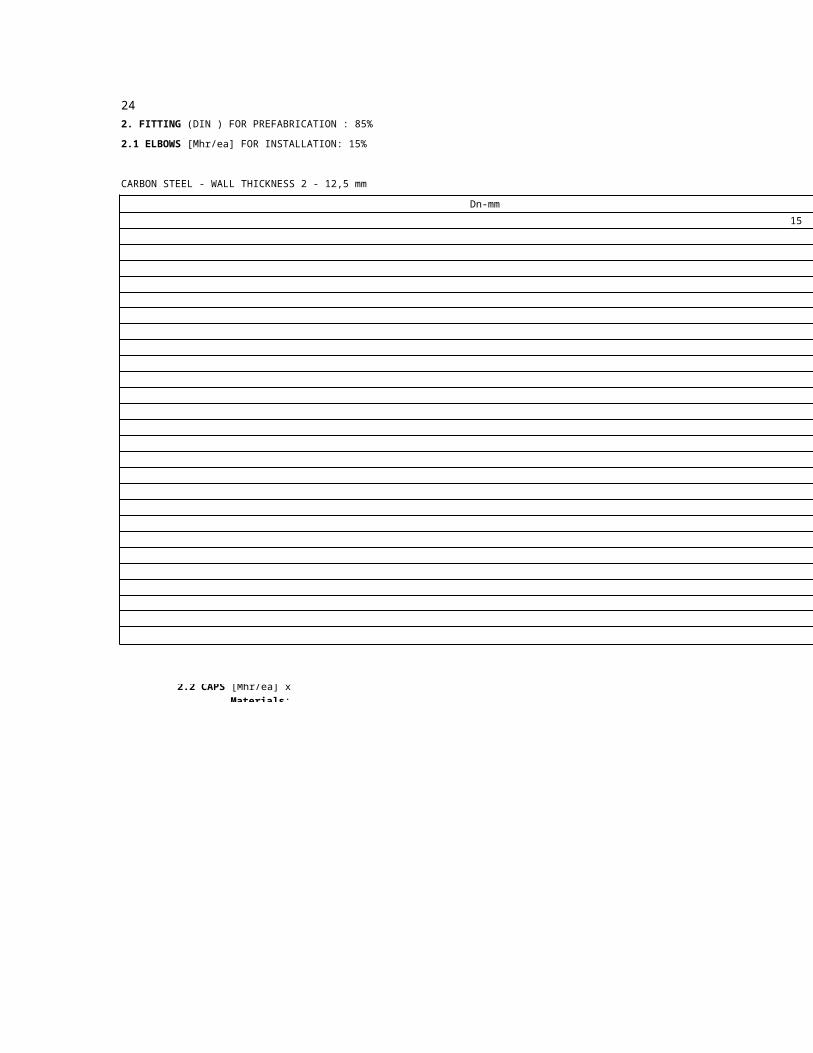
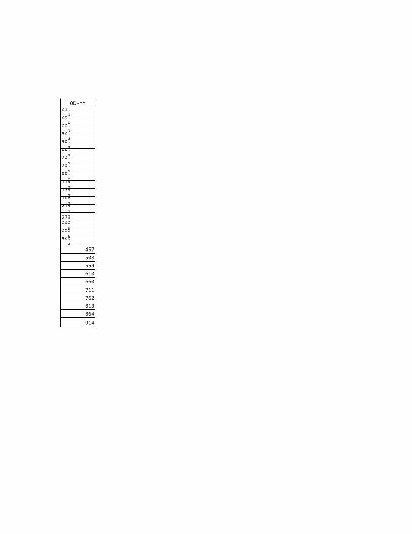
2. FITTING (DIN ) FOR PREFABRICATION : 85%
2.1 ELBOWS [Mhr/ea] FOR INSTALLATION: 15%
CARBON STEEL - WALL THICKNESS 2 - 12,5 mm
Dn-mm
2.2 CAPS [Mhr/ea] x Materials:
- Cr-Mo alloy steel
- Copper alloy
- Killed C.S

2
273
457
508
559
610
660
711
762 8
813 8
864
914 10
OD-mm ?Std|Ext 2,3
21,3 2\2
26,9 2\2,3
33,7 2\2,6
42,4 2\2,6
48,3 2,3\2,6
60,3 2,3\2,9
73,1 2,6\2,9
76,1 2,6\2,9
88,9 2,9\3,2
114,3 3,2\3,6
139,7 3,6\4
168,3 4\4,5
219,1 4,5\6,3
5\6,3
323,9 5,6\7,1
355,6 5,6\8
406,4 6,3\8,8
6,3\10
6,3\11
6,3\12,5
6,3\12,5
7,1\14,2
7,1
8,8
f
1,40÷1,60 - High temp. alloy steel 1,00 ÷ 1,80
1,20 - Alloy steel Ni 1,60
1,00÷1,25 - Aluminium alloy 1,50
4 52,6 2,9 3,2 3,6 4,5 5,6 6,3
8 10 11
273
457
508
559
610
660
711
762
813
864
914
7,1 8,8 12,5 OD-mm
21,3
26,9
33,7
42,4
48,3
60,3
73,1
76,1
88,9
114,3
139,7
168,3
219,1
323,9
355,6
406,4

25
15
20
25
32
40
50
65
65
80
100
125
150
200
250
300
350
400
450
500
550
600
650
700
750
800
850
900
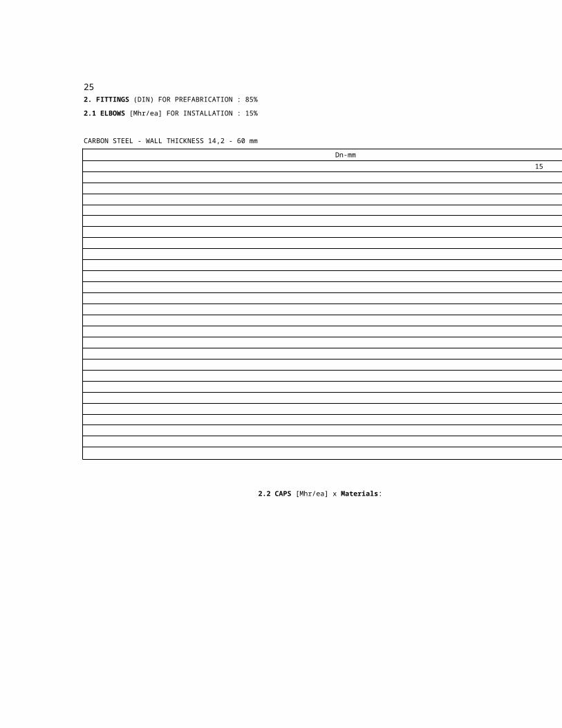
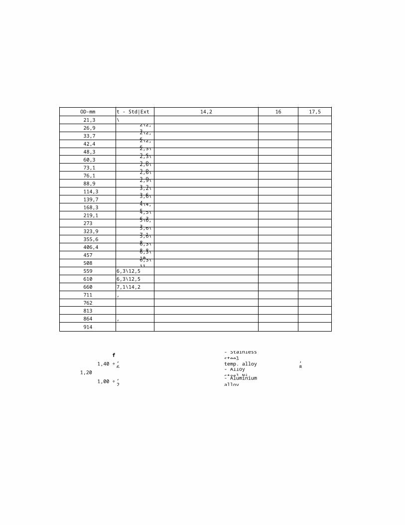
2. FITTINGS (DIN) FOR PREFABRICATION : 85%
2.1 ELBOWS [Mhr/ea] FOR INSTALLATION : 15%
CARBON STEEL - WALL THICKNESS 14,2 - 60 mm
Dn-mm
2.2 CAPS [Mhr/ea] x Materials:
- Cr-Mo alloy steel
- Copper alloy
Killed C.S

16 20
273
457
508
559
610
660
711
762 8
813 8
864
914 10
OD-mm t - Std|Ext 14,2 17,5
21,3 2\2
26,9 2\2,3
33,7 2\2,6
42,4 2\2,6
48,3 2,3\2,6
60,3 2,3\2,9
73,1 2,6\2,9
76,1 2,6\2,9
88,9 2,9\3,2
114,3 3,2\3,6
139,7 3,6\4
168,3 4\4,5
219,1 4,5\6,3
5\6,3
323,9 5,6\7,1
355,6 5,6\8
406,4 6,3\8,8
6,3\10
6,3\11
6,3\12,5
6,3\12,5
7,1\14,2
7,1
8,8
f Stainless steel 1,25
1,40 ÷ 1,60 High temp. alloy steel1,00 ÷
1,80
1,20 Alloy steel Ni 1,60
1,00 ÷ 1,25 Aluminium alloy 1,50
25 28 30 32 36 40 45 5022,2

55 60
273
457
508
559
610
660
711
762
813
864
914
OD-mm
21,3
26,9
33,7
42,4
48,3
60,3
73,1
76,1
88,9
114,3
139,7
168,3
219,1
323,9
355,6
406,4

26
15
20
25
32
40
50
65
65
80
100
125
150
200
250
300
350
400
450
500
550
600
650
700
750
800
850
900
2. FITTINGS (DIN) FOR PREFABRICATION : 85%
2.3 TEES [Mhr/ea] FOR INSTALLATION: 15%
2.3.1 STRAIGHT TEE
CARBON STEEL - WALL THICKNESS 2 mm - 12,5 mm
Dn-mm
2.3.2 REDUCED TEE [Mhr/ea] x Materials:
- Cr-Mo alloy steel
- Copper alloy
- Killed C.S

2
273
457
508
559
610
660
711
762 8
813 8
864
914 10
OD-mm t - Std|Ext 2,3 2,6 2,9
21,3 2\2
26,9 2\2,3
33,7 2\2,6
42,4 2\2,6
48,3 2,3\2,6
60,3 2,3\2,9
73,1 2,6\2,9
76,1 2,6\2,9
88,9 2,9\3,2
114,3 3,2\3,6
139,7 3,6\4
168,3 4\4,5
219,1 4,5\6,3
5\6,3
323,9 5,6\7,1
355,6 5,6\8
406,4 6,3\8,8
6,3\10
6,3\11
6,3\12,5
6,3\12,5
7,1\14,2
7,1
8,8
f - Stainless steel 1,25
1,40 ÷ 1,60 - High temp. alloy steel1,00 ÷
1,801,20 - Alloy steel Ni 1,60
1,00 ÷ 1,25 - Aluminium alloy 1,50
4 5 83,2 3,6 4,5 5,6 6,3 7,1 8,8
10 11
273
457
508
559
610
660
711
762
813
864
914
12,5 OD-mm
21,3
26,9
33,7
42,4
48,3
60,3
73,1
76,1
88,9
114,3
139,7
168,3
219,1
323,9
355,6
406,4

27
15
20
25
32
40
50
65
65
80
100
125
150
200
250
300
350
400
450
500
550
600
650
700
750
800
850
900
2.3 TEES FOR PREFABRICATION : 85%
2.3.1 STRAIGHT TEE [Mhr/ea] FOR INSTALLATION : 15%
CARBON STEEL - WALL THICKNESS 14,2 - 60 mm
Dn-mm
2.3.2 REDUCED TEE [Mhr/ea] x Materials:
- Cr-Mo alloy steel
- Copper alloy
- Killed C.S

16 20
273
457
508
559
610
660
711
762 8
813 8
864
914 10
OD-mm t - Std|Ext 14,2 17,5
21,3 2\2
26,9 2\2,3
33,7 2\2,6
42,4 2\2,6
48,3 2,3\2,6
60,3 2,3\2,9
73,1 2,6\2,9
76,1 2,6\2,9
88,9 2,9\3,2
114,3 3,2\3,6
139,7 3,6\4
168,3 4\4,5
219,1 4,5\6,3
5\6,3
323,9 5,6\7,1
355,6 5,6\8
406,4 6,3\8,8
6,3\10
6,3\11
6,3\12,5
6,3\12,5
7,1\14,2
7,1
8,8
f - Stainless steel 1,25
1,40 ÷ 1,60 - High temp. alloy steel 1,00 ÷ 1,80
1,20 - Alloy steel Ni 1,60
1,00 ÷ 1,25 - Aluminium alloy 1,50

25 28 30 32 36 40 45 5022,2

55 60
273
457
508
559
610
660
711
762
813
864
914
OD-mm
21,3
26,9
33,7
42,4
48,3
60,3
73,1
76,1
88,9
114,3
139,7
168,3
219,1
323,9
355,6
406,4

28
15
20
25
32
40
50
65
65
80
100
125
150
200
250 273
300
350
400
450 457
500 508
550 559
600 610
650 660
700 711
750 762
800 813
850 864
900 914
2. FITTINGS (DIN) FOR PREFABRICATION : 85%
2.4 REDUCERS - CONCENTRIC AND ECCENTRIC [Mhr/ea] FOR INSTALLATION: 15%
CARBON STEEL - WALL THICKNESS 2 - 12,5 mm
Dn-mm OD-mm
21,3
26,9
33,7
42,4
48,3
60,3
73,1
76,1
88,9
114,3
139,7
168,3
219,1
323,9
355,6
406,4
Man hour include next activities:
- handling - erection
- on-site transport - welding
- prefabrication - pressure testing

2
8
8
10
t - Std|Ext 2,3
2\2
2\2,3
2\2,6
2\2,6
2,3\2,6
2,3\2,9
2,6\2,9
2,6\2,9
2,9\3,2
3,2\3,6
3,6\4
4\4,5
4,5\6,3
5\6,3
5,6\7,1
5,6\8
6,3\8,8
6,3\10
6,3\11
6,3\12,5
6,3\12,5
7,1\14,2
7,1
8,8
Materials: f - Stainless steel
- Cr Mo alloy steel 1,40 ÷ 1,60 - High temp. alloy steel
- Copper alloy 1,20 - Alloy steel Ni
- Killed C.S. 1,00 ÷ 1,25 - Aluminium alloy

4 52,6 2,9 3,2 3,6 4,5 5,6
1,25
1,00 ÷ 1,80
1,60
1,50

8 10 11
273
457
508
559
610
660
711
762
813
864
914
6,3 7,1 8,8 12,5 OD-mm
21,3
26,9
33,7
42,4
48,3
60,3
73,1
76,1
88,9
114,3
139,7
168,3
219,1
323,9
355,6
406,4
29
15
20
25
32
40
50
65
65
80
100
125
150
200
250 273
300
350
400
450 457
500 508
550 559
600 610
650 660
700 711
750 762
800 813
850 864
900 914
2. FITTINGS (DIN) FOR PREFABRICATION : 85%
2.4 REDUCERS - CONCENTRIC AND ECCENTRIC [Mhr/ea] FOR INSTALLATION : 15%
CARBON STEEL - WALL THICKNESS 14,2 -60 mm
Dn-mm OD-mm
21,3
26,9
33,7
42,4
48,3
60,3
73,1
76,1
88,9
114,3
139,7
168,3
219,1
323,9
355,6
406,4
Man hour include next activities:
- handling - erection
- on-site transport - welding
- prefabrication - pressure testing

16
8
8
10
t - Std|Ext 14,2
2\2
2\2,3
2\2,6
2\2,6
2,3\2,6
2,3\2,9
2,6\2,9
2,6\2,9
2,9\3,2
3,2\3,6
3,6\4
4\4,5
4,5\6,3
5\6,3
5,6\7,1
5,6\8
6,3\8,8
6,3\10
6,3\11
6,3\12,5
6,3\12,5
7,1\14,2
7,1
8,8
Materials: f - Stainless steel
- Cr Mo alloy steel 1,40 ÷ 1,60 - High temp. alloy steel
- Copper alloy 1,20 - Alloy steel Ni
- Killed C.S. 1,00 ÷ 1,25 - Aluminium alloy

20 25 28 30 32 3617,5 22,2
1,25
1,00 ÷ 1,80
1,60
1,50
40 45 50 55 60
273
457
508
559
610
660
711
762
813
864
914
OD-mm
21,3
26,9
33,7
42,4
48,3
60,3
73,1
76,1
88,9
114,3
139,7
168,3
219,1
323,9
355,6
406,4

30
15
20
25
32
40
50
65
80
100
125
150
200
250
300
350
400
450
500
550
600
650
700
750
800
850
900
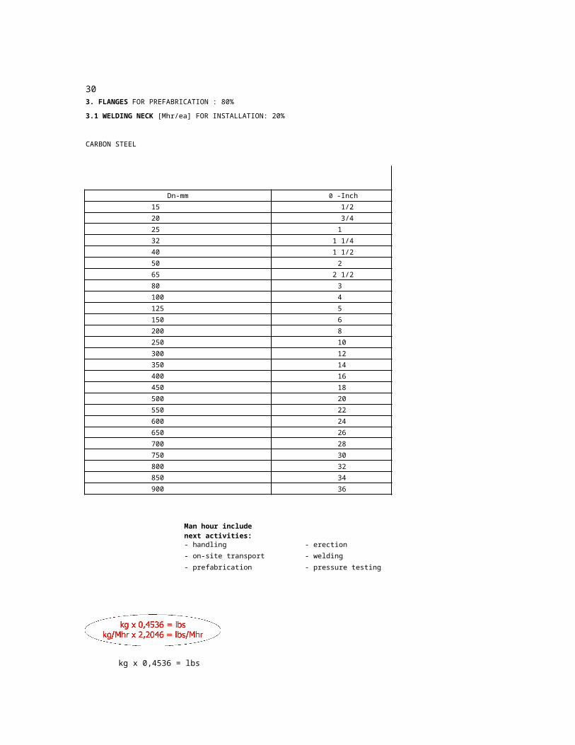
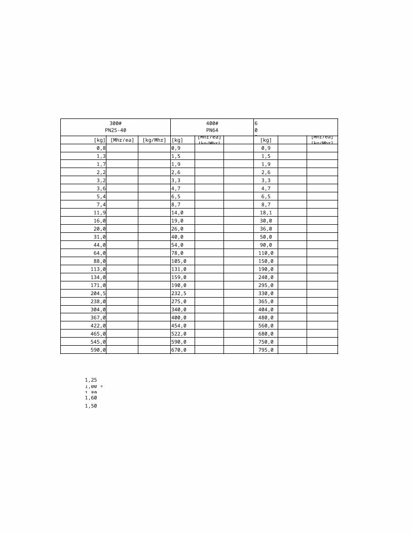
3. FLANGES FOR PREFABRICATION : 80%
3.1 WELDING NECK [Mhr/ea] FOR INSTALLATION: 20%
CARBON STEEL
150#PN6-16
Dn-mm 0 -Inch [kg]
1/2” 0,5
3/4” 0,7
1” 1,1
1 1/4” 1,5
1 1/2” 1,8
2” 2,7
2 1/2” 4,4
3” 5,2
4” 7,5
5” 9,2
6” 1,0
8” 18,3
10” 25,0
12” 39,0
14” 51,0
16” 60,0
18” 71,0
20” 88,0
22” 103,5
24” 119,0
26” 136,0
28” 143,0
30” 168,0
32” 197,0
34” 211,0
36” 236,0
Man hour include next activities: Materials:
- handling - erection - Cr Mo alloy steel
- on-site transport - welding - Copper alloy
- prefabrication - pressure testing - Killed C.S.
kg x 0,4536 = lbs
kg/Mhr x 2,2046 = lbs/Mhr

150#PN6-16
300#PN25-40
400#PN64
[Mhr/ea] [kg/Mhr] [kg] [Mhr/ea] [kg/Mhr] [kg] [Mhr/ea][kg/Mhr]
0,8 0,9
1,3 1,5
1,7 1,9
2,2 2,6
3,2 3,3
3,6 4,7
5,4 6,5
7,4 8,7
11,9 14,0
16,0 19,0
20,0 26,0
31,0 40,0
44,0 54,0
64,0 78,0
88,0 105,0
113,0 131,0
134,0 159,0
171,0 190,0
204,5 232,5
238,0 275,0
304,0 340,0
367,0 400,0
422,0 454,0
465,0 522,0
545,0 590,0
590,0 670,0
f - Stainless steel 1,25
1,40 ÷ 1,60 - High temp. alloy steel 1,00 ÷ 1,80
1,20 - Alloy steel Ni 1,60
1,00 ÷ 1,25 - Aluminium alloy 1,50

400#PN64
600#PN100
900#PN160
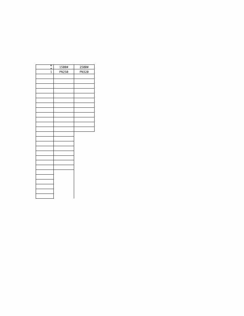
1500#PN250
2500#PN320
[kg] [Mhr/ea][kg/Mhr] [kg] [Mhr/ea] [kg/Mhr] [kg] [Mhr/ea] [kg/Mhr] [kg]
0,9 1,9 1,9 3,6
1,5 2,6 2,6 4,0
1,9 3,8 3,8 6,0
2,6 4,4 4,4 9,0
3,3 6,1 6,1 13,0
4,7 11,1 11,1 19,0
6,5 15,5 15,5 24,0
8,7 14,0 20,5 43,0
18,1 23,0 30,5 66,0
30,0 37,0 58,0 111,0
36,0 49,0 70,0 172,0
50,0 84,0 119,0 261,0
90,0 123,0 204,0 485,0
110,0 168,0 303,0 730,0
150,0 186,0 400,0 14”
190,0 224,0 510,0 16”
240,0 300,0 18”
Notice: Unit weights in this refer to welding to ANSI B 16-5.1977.for to 24”and BS-3293-1960for26”
295,0 373,0 20”
330,0 526,5 22”
365,0 680,0 24”
404,0 715,0 26”
480,0 840,0 28”
560,0 975,0 30”
680,0 1170,0 32”
750,0 1375,0 34”
795,0 1565,0 36”

2500#PN320
[Mhr/ea] [kg/Mhr] 0-Inch
1/2”
3/4”
1”
1 1/4”
1 1/2”
2”
2 1/2”
3”
4”
5”
6”
8”
10”
12”
tableneck flanges acc.
(1)÷ 36”

31
15
20
25
32
40
50
65
80
100
125
150
200
250
300
350
400
450
500
550
600
650
700
750
800
850
900
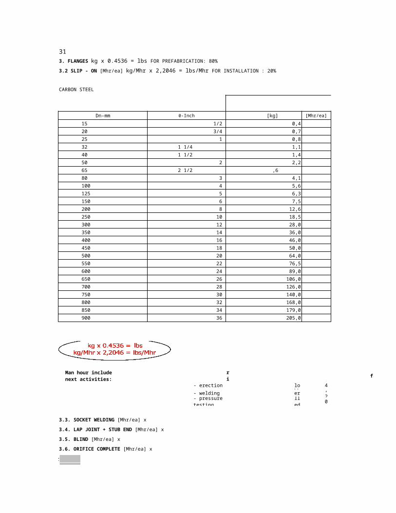
3. FLANGES kg x 0.4536 = lbs FOR PREFABRICATION: 80%
3.2 SLIP - ON [Mhr/ea] kg/Mhr x 2,2046 = lbs/Mhr FOR INSTALLATION : 20%
CARBON STEEL
150# PN6-16
Dn-mm 0-Inch [kg] [Mhr/ea] [kg/Mhr]
1/2” 0,4
3/4” 0,7
1” 0,8
1 1/4” 1,1
1 1/2” 1,4
2” 2,2
2 1/2” ,6
3” 4,1
4” 5,6
5” 6,3
6” 7,5
8” 12,6
10” 18,5
12” 28,0
14” 36,0
16” 46,0
18” 50,0
20” 64,0
22” 76,5
24” 89,0
26” 106,0
28” 126,0
30” 140,0
32” 168,0
34” 179,0
36” 205,0
Man hour include next activities: Materials: f
- handling - erection - Cr Mo alloy steel 1,40 ÷ 1,60
- on-site transport - welding - Copper alloy 1,20
- prefabrication - pressure testing - Killed C.S. 1,00 ÷ 1,25
3.3. SOCKET WELDING [Mhr/ea] x
3.4. LAP JOINT + STUB END [Mhr/ea] x
3.5. BLIND [Mhr/ea] x
3.6. ORIFICE COMPLETE [Mhr/ea] x
300# PN25-40 400#PN64
600#PN100
[kg] [Mhr/ea] [kg/Mhr] [kg] [Mhr/ea] [kg/Mhr] [kg [Mhr/ea]
0,7 0,8 0,8
1,1 1,4 1,4
1,4 1,6 1,6
1,8 2,1 2,1
2,6 3,1 3,1
3,4 3,7 3,7
4,4 5,4 5,4
6,1 7,3 7,3
10,1 11,5 15,8
12,5 14,5 24,5
14,1 19,0 29,5
24,8 29,0 43,0
37,1 39,5 70,0
50,0 58,0 86,0
70,0 82,0 100,0
97,0 105,0 142,0
123,0 126,0 175,0
133,0 152,0 221,0
170,5 185,0 268,0
208,0 218,0 315,0
255,0 295,0 425,0
321,0 354,0 470,0
362,0 408,0 533,0
398,0 465,0 624,0
480,0 522,0 681,0
540,0 601,0 726,0
- Stainless steel 1,25
- High temp. alloy steel 1,00 ÷ 1,80
- Alloy steel Ni 1,60
- Aluminium alloy 1,50

600#PN100
900#PN160
1500#PN250
2500#PN320
[kg/Mhr] [kg] [Mhr/ea] [kg/Mhr] [kg] [Mhr/ea] [kg/Mhr] [kg] [Mhr/ea] [kg/Mhr] 0 -Inch
1,7 1,7 3,0 1/2”
2,3 2,3 4,0 3/4”
3,4 3,4 5,0 1”
3,9 3,9 8,0 1 1/4”
5,4 5,4 11,0 1 1/2”
9,8 9,8 17,0 2”
13,7 13,7 24,0 2 1/2”
11,6 18,0 36,0 3”
19,8 27,8 55,0 4”
32,0 52,0 93,0 5”
41,2 61,0 142,0 6”
71,0 104,0 214,0 8”
100,0 175,0 407,0 10”
133,0 264,0 573,0 12”
152,0 308,0 14” in this table refer
1977.24”
÷ 36”
184,0 352,0 16”
258,0 18”
Notice: Unit weights to slip on flanges acc. toANSI B 16-5.for toand BS-3293-1960for 26”
317,0 20”
462,5 22”
608,0 24”
692,0 26”
817,0 28”
942,0 30”
1135,0 32”
1339,0 34”
1521,0 36”

15
20
25
32
40
50
65
80
100
125
150
200
250
300
350
400
450
500
550
600
650
700
750
15
20
25
32
40
50
65
80
100
15
20
25
32
40
50
65
80
100
4. SMALL FITTINGS [Mhr/ea]
4.1 WELDOLETS, SOCKOLETS, NIPOLETS, etc. 4.2 HALF COUPLINGS FOR WELDING FOR PREFABRICATION : 85%
FOR INSTALLATION: 15%
Dn-mm 0 -Inch
1/2”
3/4”
1”
1 1/4”
1 1/2”
2”
2 1/2”
3”
4”
5”
6”
8”
10”
12”
14”
16”
18”
20”
22”
24”
26”
28”
30”
CARBON STEEL
3000# 6000#
Dn-mm 0 -Inch
1/2”
3/4”
1”
1 1/4”
1 1/2”
2”
2 1/2”
3”
4”
CARBON STEEL
WITH ONE END
Dn-mm 0 -Inch
1/2”
3/4”
1”
1 1/4”
1 1/2”
2”
2 1/2”
3”
4”
32
15
20
25
32
40
50
65
80
100
4.3 FITTINGS WITH SOCKET ENDS 4.4 THREADED FITTINGS
4.4.1 CARBON STEEL
WITH ONE END
Dn-mm 0 -Inch
1/2”
3/4”
1”
1 1/4”
1 1/2”
2”
2 1/2”
3”
4”
WITH 2 ENDS x 2
WITH 3 ENDS x 3
Man hour include next activities:
- handling - erection
- on-site transport - welding
- prefabrication - pressure testing
73
273
457
508
559
610
660
711
762
73
73
4.2 HALF COUPLINGS FOR WELDING FOR PREFABRICATION : 85%
CARBON STEEL
1500#
OD-mm Std
21,3
26,7
33,4
42,2
48,3
60,3
88,9
114,3
141,3
168,3
219,1
323,9
355,6
406,4
OD-mm XS
21,3
26,7
33,4
42,2
48,3
60,3
88,9
114,3
CARBON STEEL
WITH ONE END
OD-mm [Mhr/ea]
21,3
26,7
33,4
42,2
48,3
60,3
88,9
114,3

73
WITH ONE END
OD-mm [Mhr/ea]
21,3
26,7
33,4
42,2
48,3
60,3
88,9
114,3
Materials:(FOR WELDED FITTINGS ONLY)
f
- Stainless steel 1,25
- Cr Mo alloy steel 1,40 ÷ 1,60
- High temp. alloy steel 1,00 ÷ 1,80
- Copper alloy 1,20
- Alloy steel Ni 1,60
- Killed C.S. 1,00 ÷ 1,25
- Aluminium alloy 1,50

CARBON STEEL
3000# 6000#
XS XXS
XXS
4.4.2 NON-FERROUS METALS
VALUES FOR
CARBON STEEL x
4.4.3 "HERMETO" COUPLINGS
VALUES IN
TABLE 4.4.1 x

15
20
25
32
40
50
65
80
100
125
150
200
250
300
350
400
450
500
550
600
650
700
750
800
850
900
16
40
5. VALVES
5.1 VALVES WITH FLANGED ENDS
5.1.1 GATE, GLOBE, CHECK, SWING CHECK, BONNET, VF - Factor for installation of flanged valves
BALL, BUTTERFLY, FILTER, etc [Mhr/ea]
150# 300# 400#
Dn-mm ø -Inch PN6-16 25-40 PN64
1/2”
3/4”
1”
1 1/4”
1 1/2”
2”
2 1/2”
3”
4”
5”
6”
8”
10”
12”
14”
16”
18”
20”
22”
24”
26”
28”
30”
32”
34”
36”
for flanged valves Dn to 100 ø to 4”
Dn 125 ÷ 200ø 5” ÷ 8”
PN 6 ÷ 150#
PN 25 ÷ 300#
PN 64 400#
PN 100 600#
PN 160 900#
PN 250 1500#
PN 320 2500#
(included in table)

5/1/10
33
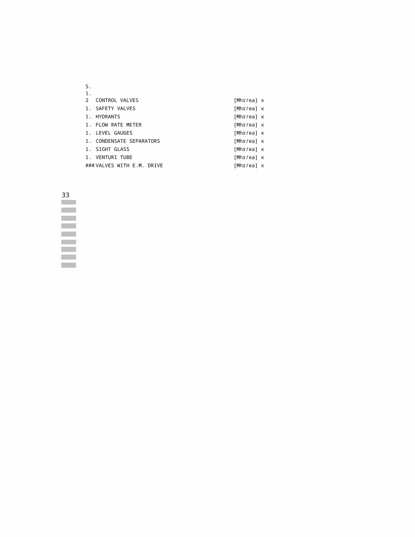
5.1.2 CONTROL VALVES [Mhr/ea] x
5.1.3 SAFETY VALVES [Mhr/ea] x
5.1.4 HYDRANTS [Mhr/ea] x
5.1.5 FLOW RATE METER [Mhr/ea] x
5.1.6 LEVEL GAUGES [Mhr/ea] x
5.1.7 CONDENSATE SEPARATORS [Mhr/ea] x
5.1.8 SIGHT GLASS [Mhr/ea] x
5.1.9 VENTURI TUBE [Mhr/ea] x
VALVES WITH E.M. DRIVE [Mhr/ea] x
600# 900# 1500# 2500#
PN100 PN160 PN250 PN320
Dn above 250ø above 10”

34
15
20
25
32
40
50
65 73
80
100
125
150
200
250 273
300
350
400
450 457
500 508
550 559
600 610
650 660
700 711
750 762
800 813
850 864
900 914
15
20
25
32
40
50
65 73
80
100
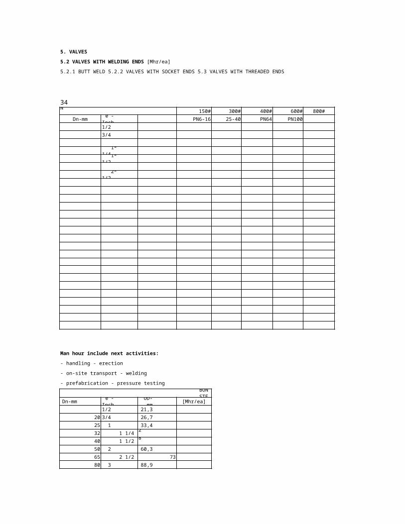
5. VALVES
5.2 VALVES WITH WELDING ENDS [Mhr/ea]
5.2.1 BUTT WELD 5.2.2 VALVES WITH SOCKET ENDS 5.3 VALVES WITH THREADED ENDS
CARBON STEEL 150# 300# 400# 600# 800# 900#
Dn-mm 0 -Inch OD-mm PN6-16 25-40 PN64 PN100 PN160
1/2” 21,3
3/4” 26,7
1” 33,4
1 1/4” 42,2
1 1/2” 48,3
2” 60,3
2 1/2”
3” 88,9
4” 114,3
5” 141,3
6” 168,3
8” 219,1
10”
12” 323,9
14” 355,6
16” 406,4
18”
20”
22”
24”
26”
28”
30”
32”
34”
36”
Man hour include next activities:
- handling - erection
- on-site transport - welding
- prefabrication - pressure testing
CARBON STEEL
Dn-mm 0 -Inch OD-mm [Mhr/ea]
1/2” 21,3
3/4” 26,7
1” 33,4
1 1/4” 42,2
1 1/2” 48,3
2” 60,3
2 1/2”
3” 88,9
4” 114,3

1
1
2 73
5.4 PRESSURE GAUGES [Mhr/ea]
5.5 THERMOMETERS [Mhr/ea]
Materials: f- Cr Mo
alloy steel
1,40 ÷ 1,60- Copper alloy
1,20- Killed C.S.
1,00 ÷ 1,25- Stainless steel
1,25- High temp. alloy steel
1,00 ÷ 1,80- Alloy steel Ni
1,60- Aluminium alloy
1,50
0 -Inch OD-mm [Mhr/ea]
1/2" 21,3
3/4” 26,7
1” 33,4
1/4” 42,2
1/2” 48,3
2” 60,3
1/2”
3” 88,9
4” 114,3

1500# 2500#
PN250 PN320

35
25 417
32 359
40 330
50 286
65 246
80 209
100 165
125 135
150 111
200
250
300
350
400
500
600
1000
RATES FOR TENDER CALCULATIONS
1. MANHOUR ESTIMATE FOR INSTALLATION OF PIPING
BASED ON DIAMETERS AND WEIGHTS (FOR CARBON STEEL ONLY)
(Origin: Technical Journal "3R International" of April 4, 1985)
Productivity Efficiency Percentage (PEP) = 75%
TypeAS TypeAF Type BS TypeBF
Dn-mm ø -Inch [Mhr/ton] [kg/Mhr] [Mhr/ton] [kg/Mhr] [Mhr/ton] [kg/Mhr] [Mhr/ton]
1”
1 1/4”
1 1/2”
2”
2 1/2”
3”
4”
5”
6”
8” 93,6
10” 75,9
12” 63,2
14” 59,5
16” 50,6
20” 43,8
24” 38,9
40” 20,8
Type AS Piping in the plant with prefabricated weld joints
Type AF Piping in the plant with prefabricated
flanged joints
Type BS Piping outside the plant (pipe racks, sleeper ways, etc.)
with prefabricated weld joints
Type BF Piping outside the plant (pipe racks, sleeper ways etc.)
with prefabricated flanged joints
kg/Mhr x 2,2046 = lbs/Mhr
Above standards do not include: Time allowance for
- storing and store handling (calculate separately) - space obstruction to %
) - connection to the existing lines to %
÷
- decrease effect of due to bad weather (add ÷ ) - erection at higher elevations
site grading and facilities (add
%

%
÷
%
- scaffolding (calculate separately) (above 4 m)
- radiographic inspection (calculate separately)
- performance tests (calculate separately)

TypeBF
[kg/Mhr]

36
15
20
25
32
40
50
65
80
100
125
150
200
250 273
300
350
400
450 457
500 508
550 559
600 610
650 660
700 711
750 762
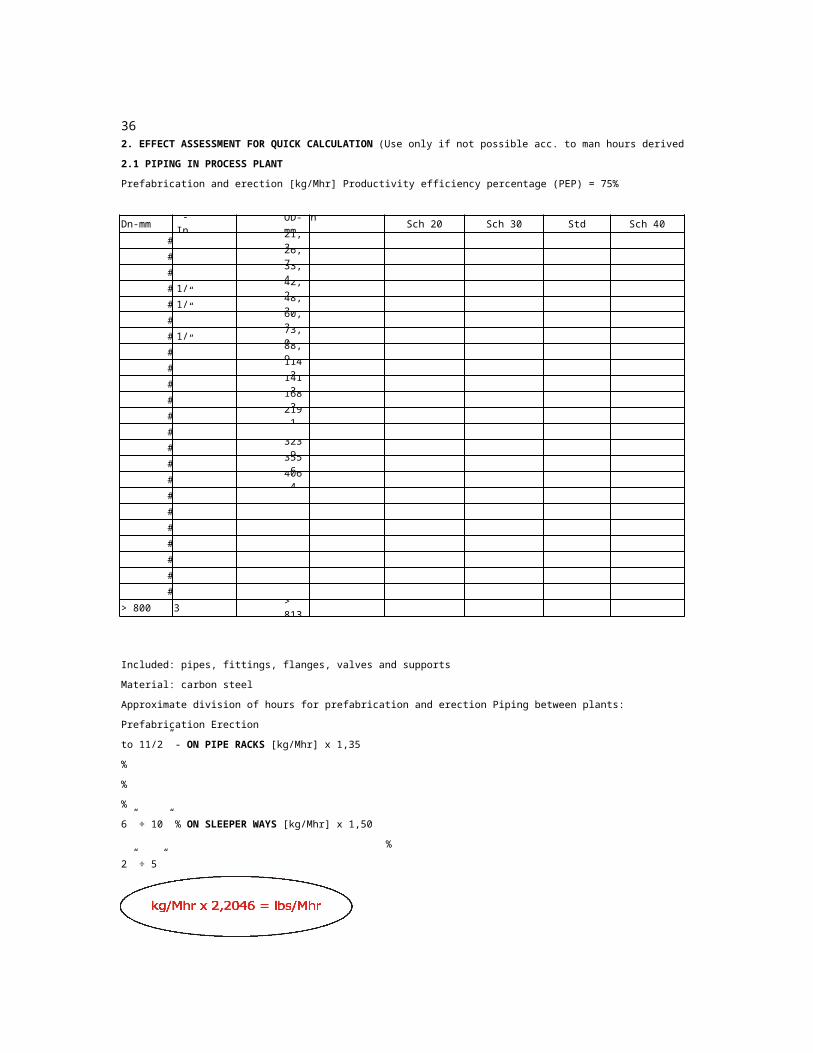
2. EFFECT ASSESSMENT FOR QUICK CALCULATION (Use only if not possible acc. to man hours derived from basic estimate points)
2.1 PIPING IN PROCESS PLANT
Prefabrication and erection [kg/Mhr] Productivity efficiency percentage (PEP) = 75%
Dn-mm 0 -Inch OD-mmSch 10
Sch 20 Sch 30 Std Sch 40 Sch 60
1/2” 21,3
3/4” 26,7
1” 33,4
1 1/4” 42,2
1 1/2” 48,3
2” 60,3
2 1/2” 73,0
3” 88,9
4” 114,3
5” 141,3
6” 168,3
8” 219,1
10”
12” 323,9
14” 355,6
16” 406,4
18”
20”
22”
24”
26”
28”
30”
> 800 > 32” > 813
Included: pipes, fittings, flanges, valves and supports
Material: carbon steel
Approximate division of hours for prefabrication and erection Piping between plants:
Prefabrication Erection
to 11/2” - ON PIPE RACKS [kg/Mhr] x 1,35
%
%
%
6” ÷ 10” % ON SLEEPER WAYS [kg/Mhr] x 1,50
%
2” ÷ 5”
kg/Mhr x 2,2046 = lbs/Mhr

(Use only if not possible acc. to man hours derived from basic estimate points)
XS Sch 80 Sch 100 Sch 120 Sch 140 Sch 160 XXS 0 -Inch
1/2”
3/4”
1”
1 1/4”
1 1/2”
2”
2 1/2”
3”
4”
5”
6”
8”
10”
12”
14”
16”
18”
20”
22”
24”
26”
28”
30”
above 32”

37
15
20
25
32
40
50
65 73
80
100
125
150
200
250 273
300
350
400
450 457
500 508
550 559
600 610
650 660
700 711
750 762
800 813
850 864
900 914
950 38 966
1000 1016
1050 1066
1100 1118
1150 1168
1200 1219
2. RATES FOR QUICK CALCULATION (Used only when such data provided in tendering documents )
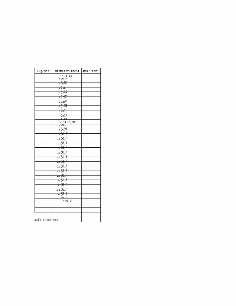
2.2 PIPES (CARBON STEEL - NOT INSULATED) [Mhr/m] [ kg/Mhr]
MEAN VALUE Productivity Efficiency Percentage (PEP) = 75%
FOR " TECHNIP" COMP.
Sch 10 Sch 20 Std Sch 40 XS Sch 80 Sch 120 Sch 160 Average
Dn-mm ø -Inch OD-mm[Mhr/m][kg/Mhr]
[Mhr/m] [kg/Mhr] [Mhr/m] [kg/Mhr] [Mhr/m] [kg/Mhr]
1/2" 21,3
3/4" 26,7
1" 33,4
1 1/4” 42,2
1 1/2” 48,3
2” 60,3
2 1/2”
3" 88,9
4" 114,3
5" 141,3
6" 168,3
8" 219,1
10"
12" 323,9
14" 355,6
16" 406,4
18"
20"
22"
24"
26"
28"
30"
32"
34"
36"
40"
42"
44"
46"
48"
Mhr/m x 0,3048 = Mhr/ft
kg/Mhr x 2,2046 = lbs/Mhr

[Mhr/m] [kg/Mhr] [Mhr/m] [kg/Mhr] [Mhr/m] [kg/Mhr] [Mhr/m] [kg/Mhr] diameter[inch] Mhr/ ton*
< 0,66
0,67-0,87
0,88-1,12
1,13-1,37
1,38-1,75
1,76-2,25
2,26-2,75
2,76-3,50
3,51-4,50
4,51-5,50
5,51-7,00
7,01-9,00
9,01-11,0
11,01-13,0
13,01-15,0
15,01-17,0
17,01-19,0
19,01-21,0
21,01-23,0
23,01-25,0
25,01-27,0
27,01-29,0
29,01-31,0
31,01-33,0
33,01-35,0
35,01-37,0
37,01-39,0
>39,0
*Mhr/ton for one millimetre of average wall thickness

38
"SOCKET"
Sch 160
Sch 120
Sch 80
XXS
Materials: f
Stainless steel 1,25
High temp. alloy steel 1,00 ÷1,8
0Killed C.S 1,00 ÷
1,25
Cr Mo alloy steel 1,40 ÷1,6
0Alloy steel Ni 1,60
Copper alloy 1,20
Aluminium alloy 1,50
2. EFFECT ASSESSMENT FOR QUICK CALCULATION (Used only if such data provided in tendering documents)
Productivity efficiency percentage (PEP) 75%
2.3 FITTINGS (CARBON STEEL) - MEAN VALUE [kg/Mhr]
All types of fittings included.
Note:
Generally, socket fittings to Ø 1 1/2"
are used in petrochemical plants.
*[Mhr/ton] for one millimetre of average wall thickness
FOR "TECHNIP" COMP.
Averagediameter [inch]
[Mhr/ton]*
< 0,66
0,67-0,87
0,88-1,12
1,13-1,37
1,38-1,75
1 ,76-2,2 5
2,26-2,75
2,76-3,50
3,51-4,50
4,51-5,50
5,51-7 ,00
7,01-9,00
9,01-11,0
11,01-13,0
13,01-15,0
15,01-17,0
17,01-19,0
19,01-21,0
21,01-23,0
23,01-25,0
1000
1050
25,01-27,0
27,01-29,0
29,01-31,0
31,01-33,0
33,01-35,0
35,01-37,0
37,01-39,0
39,01-41,0
41,01-43,0
43,01-45,0
45,01-47,0
>47,0
Dn-mm
ø -Inch
OD-mm
Sch 10
Sch 20
Std
Sch 40
XS

1100
1150
1200
400
450
700
750
850
200
250
300
350
600
650
800
900
950
500
550
100
125
150
40
20
25
32
65
80
50
15
1 1/4”
1 1/2”
3/4”
1/2”
2 1/2”
40”
42”
44”
46”
48”
30”
32”
34”
36”
38”
20”
1016
1066
1118
1168
1219
457
273
610
660
711
762
813
864
914
966
508
22”
24”
26”
28”
16”
18”
10”
12”
14”
4”
3”
5”
6”
8”
2”
1”
219,1
114,3
141,3
168,3
406,4
42,2
48,3
21,3
26,7
33,4
60,3
88,9
323,9
355,6

559
73
kg/Mhr x 2,2046 =lbs/Mhr
(Used only if such data provided in tendering documents)

39
15
20
25
32
40
50
65 2
80
100
150
200
250
300
350
400
450
500
550
600
2.4 VALVES MEAN VALUE
(ALL KINDS OF VALVES INCLUDED)
Productivity Efficiency Percentage (PEP) = 75%
2.4.1. WITH FLANGED ENDS [Mhr/kg]
150# 300# 600#
Dn-mm ø -Inch NP6-16 NP25 NP40
1/2”
3/4”
1”
1 1/4”
1 1/2”
2”
1/2”
3”
4”
6”
8”
10”
12”
14”
16”
18”
20”
22”
24”
2.4.2. WITH WELDING ENDS
2.4.2.1. BUTT WELDING: [Mhr/kg] x
2.4.2.2. SOCKET WELDING: [Mhr/kg] x
2.5 PIPE SUPPORTS
Productivity Efficiency Percentage (PEP) = 80%
2.5.1. PARTICIPATION IN THE PIPING QUANTITY
to be estimated with %
2.5.2. FABRICATION AND INSTALLATION
2.5.2.1 DIVISION BASED ON THE UNIT WEIGHT OF SUPPORT
Unitweight
Fabrication
Installation Fabrication+installation
[kg/pc][kg/Mhr]
[kg/Mhr] [kg/Mhr]
to 5
5 ÷ 20
20 ÷ 50
50 ÷ 75
75 ÷100
100÷150
above 150Spring
supports

2.5.2.2 DIVISION BASED ON THE PIPING DIAMETER
Fabrication Installation Fabrication+installation
DN [kg/Mhr] [kg/Mhr] [kg/Mhr]
15 ÷ 50 1/2” ÷2”
65 ÷ 100 2 1/2” ÷4”
125÷150 5”÷6”
200÷350 8”÷14”
above 350 above 14”
2.5.2.3 EFFECT OF SUPPORT FABRICATION AND INSTALLATION WITH ALREADY
KNOWN AVERAGE DIAMETER OF PIPING
The effect of the fabrication and installation [kg/Mhr] is to
the average diameter in inches.
Mhr/kg x 0,4536 = Mhr/lbs
kg/Mhr x 2,2046 = lbs/Mhr
2.6 AVERAGE DIAMETER - Manner of Calculation
Average diameter of all pipings in the plant or on the project shall be
calculated in the following way:
Sum of the multiplication product of the diameter and length of each pipe
shall be divided by the sum of all pipe lengths.
(Dn 1x l) 1+ (Dn x 2l) + 2 (Dn x l) 3+ ... 3
l 1+ l 2+ l +3 ...

900# 1500#
NP64 100-160
40
16
20
25
32
40
50
63
75
90
110
140
160
180
200
225
250
280
315
355
20 25 32 40 50
40
63
90
110
125
160
180
200
225
3. RATES FOR INSTALLATION OF POLYETHYLENE PIPING
Productivity Efficiency Percentage (PEP) = 80%
3.1 PE Pipes DIN 8074
PIPES
PN 6 PN 10 Straight pipes
Dn-mm t [mm] [kg/m] t [mm] [kg/m] [Mhr/m]
2,0 0,12
2,0 0,15 2,3 0,17
2,0 0,17 2,9 0,27
2,3 0,29 3,6 0,42
2,8 0,43 4,5 0,65
3,6 0,68 5,7 1,03
4,3 0,97 6,8 1,47
5,1 1,38 8,2 2,11
6,2 2,04 10,0 3,14
7,9 3,60 12,7 5,07
9,1 4,33 14,6 6,66
10,2 5,45 16,4 8,41
11,4 6,77 18,2 10,40
12,8 8,55 20,5 13,10
14,2 10,50 22,8 16,20
15,9 13,20 25,5 20,30
17,9 16,70 28,7 25,70
20,1 21,10 32,3 32,60
3.2 Rates for installation of PE reinforcement pads for branch connection [Mhr/ea]
PIPE BRANCH
Dn-mm
mm x 0,03937 = inch
kg/m x 0,672 = lbs/ft
Mhr/m x 0,3048 = Mhr/ft

63
PIPES FITTINGS AND VALVES
Coils Bends Tees Reducers Caps Flanges
[Mhr/m] [Mhr/ea] [Mhr/ea] [Mhr/ea] [Mhr/ea] [Mhr/ea]
BRANCH

FITTINGS AND VALVES
Valves
[Mhr/ea]

41
150
200
250
300
350
400
500
600
700
800
900
1000
1100
1200
15
20
25
30
40
50
65
80
100
150
200
250
300
350
400
450
500
550
600
650
4. RATES FOR ERECTION OF PVC & FRP PIPING 5. CARBON STEEL PIPING (SCH 40)
CEMENT LINED INSIDE
Productivity Efficiency Percentage (PEP) 80%
Productivity Efficiency Percentage (PEP) 80%
Pipeshandling
Pipe cutting Butt weld
Sleeve jointwith two
fillet welds
Nozzle at 90°
Repair of concrete lining on joints
Dn-mm ø-Inch [Mhr/m] [Mhr/cut.] [Mhr/ea] [Mhr/joint] [Mhr/ea] [Mhr/joint]
6”
8”
10”
12”
14”
16”
20”
24”
28”
32”
36”
40”
44”
48”
Pipes handling
Socket joint
Nozzle at 90° and reinforce ment
ValvesPVC
housing(handling)
Dn-mm ø-I nch [Mhr/m] [Mhr/ea] [Mhr/ea] [Mhr/ea]
1/2”
3/4”
1”
1 1/4”
1 1/2”
2”
2 1/2”
3”
4”
6”
8”
10”
12”
14”
16”
18”
20”
22”
24”
26”

700
750
800
850
900
950
1000
28”
30”
32”
34”
36”
38”
40”
SYNTHETIC MATERIALS
ABBREVIATIONS &
INTERPRETATION
FRP - FIBREGLASS RESIN
POLYESTER
PE - POLYETHYLENE
PVDF -POL YVINYLDENFLUORIDE
PVC - POLYVINYLCHLORIDE,
HARD
PP - POLYPROPYLENE
FPM - (VITON A ®)
FLUOR INDIAN RUBBER (KAUTSCHUK)
EPDM -(APTK)
ETHYLENE PROPYLENE-
INDIAN RUBBER
CR - (NEOPRENE ®)
CHLOROPRENE INDIAN RUBBER
PTFE - (TEFLON ®)
POLYTETRAFLUORETHYLENE
PVC-C -POL YVINYLCHLORIDE,
ADDITIONALLY CHLORINATED Note:
PB - POLYBUTENE 1. Piping of synthetic materials
POM - POLYXYMETHYLENE to be calculated acc. to the tables for
NBR - NITRIL INDIAN RUBBER PE or PVC piping
IIR BUTYL INDIAN RUBBER 2. For diameters larger than 40” (1000 mm),
CSM - (HYPALON ®) to be calculated proportionally
CHLORSULFONYLPOLYETHYLENE to 40”
PEHD -POL YETHYLENE HIGH DENSITY
PRFV -POL YESTER RESIN FIBREGLASS REINFORCED,
INTERNAL CORE OF PVC
Mhr/m x 0,3048 = Mhr/ft

42
80 5
100 5
125 5
150 5
200 5
250 5
300 5
350 5
400 5
450 5
500 5
600
700 6
800 6
80
100
125
150
200
250
300
350
400
450
500
6. PIPING MADE OF STEEL AND GREY CAST-IRON 6.2 FITTINGS
I made an exception and included steel and grey cast piping in (DIN: A, E, F, FF, K, FFK, Q, MQ,
the Chapter Piping Above Ground although they are in most cases laid underground. MMQ, MMK, FFR, T, TT, U, MMA, MMB, MMR, X, N)
According to these man hour rates only the pipes are determined according to the unit When calculating man hours for each fitting each
of length whereas the man hour rates for all other fittings end is calculated according to its type, except for the
should be calculated acc. to the type and number of joints. For example, straight end.
Tpiece with a flange at one end and a socket at two ends should be calculated as
* Note:
According to John S. Page's manual
each joint between the pipes is also
added man hour for the socket joint.
I do not agree with that. This could
apply only if the fittings are
not calculated separately. Just to
mention that his man hour for a socket
joint is 1/3 lower than the man hour
in this table.
Mhr/m x 0,3048 = Mhr/ft
DN [m] [Mhr/m] *
(3”) 3; 4;
(4”) 3; 4;
(5”) 3; 4;
(6”) 3; 4;
(8”)(10”
)(12”)(14”)(16”)(18”)(20”)(24”)
5;6(28”
)(32”)
Nominaldiameter
Socketend
Flanged end
DN [Mhr/ea] [Mhr/ea]
(3”)
(4”)
(5”)
(6”)
(8”)
(10”)
(12”)
(14”)
(16”)
(18”)
(20”)
600
700
800
(24”)
(28”)
(32”)
6.3 VALVES
Valves to be estimated by considering the
handling as for the piping above ground and by adding
2 x Mhr/ea for a flanged end.
1 x flanged end and 2 x socket end.
Productivity efficiency percentage (PEP) = 80%
6.1 CAST IRON PIPES
Nominal
diameter Pipe length

the Chapter Piping Above Ground although they are in most cases laid underground. MMQ, MMK, FFR, T, TT, U, MMA, MMB, MMR, X, N)
According to these man hour rates only the pipes are determined according to the unit When calculating man hours for each fitting each
of length whereas the man hour rates for all other fittings end is calculated according to its type, except for the
Related Documents