Min Gao Li Structural Option Faculty Advisor: Dr. Thomas E. Boothby September 17, 2012 Technical Assignment 1 Piez Hall Extension Oswego, NY

Welcome message from author
This document is posted to help you gain knowledge. Please leave a comment to let me know what you think about it! Share it to your friends and learn new things together.
Transcript
Min Gao Li
Structural Option
Faculty Advisor: Dr. Thomas E. Boothby
September 17, 2012
Technical Assignment 1
Piez Hall Extension Oswego, NY
1
Tec
hnic
al A
ssig
nmen
t 1
|
O
sweg
o, N
Y
TABLE OF CONTENTS EXECUTIVE SUMMARY ....................................................................................................................... 2
BUILDING INTRODUCTION ................................................................................................................ 3
STRUCTURAL OVERVIEW ................................................................................................................... 4
FOUNDATION ................................................................................................................................. 4
FLOOR SYSTEM ............................................................................................................................... 5
FRAMING SYSTEM ........................................................................................................................... 6
LATERAL SYSTEM ........................................................................................................................... 7
ROOF SYSTEM ................................................................................................................................. 9
DESIGN CODES ............................................................................................................................... 9
MATERIALS USED ......................................................................................................................... 10
GRAVITY LOADS ............................................................................................................................... 11
DEAD AND LIVE LOADS ............................................................................................................... 11
SNOW LOADS ............................................................................................................................... 12
COLUMN GRAVITY CHECK .......................................................................................................... 13
BEAM GRAVITY CHECK ............................................................................................................... 13
SLAB GRAVITY CHECK ................................................................................................................. 14
LATERAL LOADS ............................................................................................................................... 15
WIND LOADS ................................................................................................................................ 15
SEISMIC LOADS ............................................................................................................................. 17
CONCLUSION .................................................................................................................................... 19
APPENDICES ...................................................................................................................................... 20
APPENDIX A: GRAVITY LOAD CALCULATION ............................................................................ 21
APPENDIX B: WIND LOAD CALCULATION ................................................................................. 28
APPENDIX C: SEISMIC LOAD CALCULATION .............................................................................. 34
APPENDIX D: TYPICAL FLOOR PLANS ........................................................................................ 37

2
Tec
hnic
al A
ssig
nmen
t 1
|
O
sweg
o, N
Y
Executive Summary
The goal of technical assignment one was to gain a better understand of the structural system of
Piez hall extension. This was accomplished through careful examination of the foundation, floor,
framing, lateral, and roof system of the building. Also, research and spot check calculations of Piez
Hall were included in this technical report. Gravity loads were analyzed in order to perform spot
checks on typical column, beam and floor slab. A typical interior column labeled D-6 on the
structural drawing was checked for its compressive load carrying capacity. A typical beam labeled
CB2 and a typical 31.5’x31.5’ bay of the floor system were checked against deflection, shear and
flexural requirements. All members were found to be adequately designed for gravity loads.
However, these structural members were not checked for their lateral loads carrying capacity due
to the time permitted in this technical report. A thorough check on these members for both their
gravity and lateral loads carrying capacity will be performed in technical report 3.
Also, the overall weight of the building was obtained in order to calculate seismic loads. The
author followed the procedure from ASCE 7-10 to obtain the wind and seismic loads of Piez Hall.
Many simplifications were made throughout the process in order to reach the conclusion of this
report. For instance, the geometric shape of Piez hall was modified in order to simplify the use of
equivalent lateral force procedure as defined by ASCE 7-10. For the seismic loads calculation, it
was found that the base shear of the building was 1067kips, which was less than 3% difference from
the 1040kips listed in the structural drawings. This minor difference was probably due to the error
in obtaining the area of the floor plan. In conclusion, it was determined that seismic forces control
over wind forces in all directions. Although wind loads effect on component and cladding of the
facade must be taken into consideration, this was not included in this technical report because of
the limited amount of time. Component and cladding of the façade will be investigated in the
future.
In addition, appendices that contains all hand calculations, diagrams, charts and typical structural
plans were included in this technical report.

3
Tec
hnic
al A
ssig
nmen
t 1
|
O
sweg
o, N
Y
Building Introduction
The new Piez hall extension at Oswego University located in New York will provide high quality
classrooms, teaching and research laboratories, as well as interaction spaces for all kinds of
engineering departments. Inside the new facility, there will be a planetarium, meteorology
observatory and a greenhouse.
The Piez hall addition will add an expansion of approximately 155,000 square feet to the existing
Piez hall. Snygg hall, which is next to the Piez hall, will be demolished as a result of the new
addition. In the back of the U shaped Piez hall, there will be a walkway connecting Wilbur hall and
the new addition. The construction of Piez hall extension began as early as April 2011. It is
anticipated to be complete by April 2013 with an estimated cost of $110 million dollars. The
building has 6 stories and it stands 64 feet high. The new 210,000 square feet concrete framed
extension was designed by Cannon Design. The building is designed so that its exterior enclosure
looks somewhat similar to the existing Piez hall (see Figure 3). The building is decorated with a
skin of curtain wall. Brick is used in the south side facade. The second and third levels have spaces
cantilevered slightly out to the west.
The Piez hall extension has numerous sustainability features to attain LEED Gold Certification.
The building energy efficient curtain wall with a high R value will reduce heat loss. The mechanical
system includes a large geothermal heat
pump with a design capacity of 800 tons will
be implanted to cool and heat the building.
Occupied spaces have access to daylight.
The roof has photovoltaic array, skylight and
wind turbines. These features together will
reduce the total energy use of the building to
47% and save 21% of the energy cost each
year.
FIGURE 2: AERIAL MAP FROM BING.COM SHOWING THE
LOCATION OF THE SITE FIGURE 1: SITE MAP SHOWING EXISTING PIEZ HALL AND
THE NEW EXTENSION (SHADED AREA)
FIGURE 3: EXTERIOR RENDERING SHOWING THE BUILDING
ENCLOSURE

4
Tec
hnic
al A
ssig
nmen
t 1
|
O
sweg
o, N
Y
Structural Overview
Foundation
According to the soil report for Oswego County, the proposed site will be suitable for supporting
the renovation and addition with a shallow spread foundation system. The maximum net
allowable pressure on soil is 6,000psf for very dense till layers and 4,000 psf for medium dense
clay and sand layers. All grade beams, foundation walls and piers will have a concrete strength of
4000psi while all other footings and slabs-on-grade will have a concrete strength of 3000psi.It is
estimated that all foundations will undergo a total settlement less than 1 inch. Differential
settlement is estimated to be less than 0.5 inch. Details of typical footings are given in Figure 4.
Basement non-yielding walls have granular backfill with drains at locations where surcharge effect
from any adjacent live loads may cause problems. These non-yielding walls are designed to resist
lateral soil pressure of 65pcf where foundation drains are placed above groundwater level. Any
cantilever earth retaining walls are designed based on 45pcf active earth pressure. All retaining wall
are designed for a factor of safety equal to or greater than 1.5 against sliding and overturning. The
frictional resistance can be estimated by multiplying the normal force acting at the base of the
footing by a coefficient of friction of 0.32.
FIGURE 4: TYPICAL COLUMN FOOTING SHOWING REINFORCEMENT
PLACEMENT
5
Tec
hnic
al A
ssig
nmen
t 1
|
O
sweg
o, N
Y
Floor System
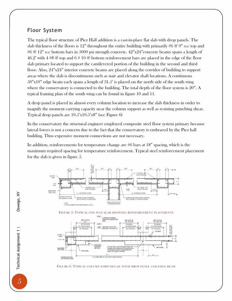
The typical floor structure of Piez Hall addition is a cast-in-place flat slab with drop panels. The
slab thickness of the floors is 12” throughout the entire building with primarily #6 @ 9” o.c top and
#6 @ 12” o.c bottom bars in 5000 psi strength concrete. 42”x24”concrete beams spans a length of
46.2’ with 4 #8 @ top and 6 # 10 @ bottom reinforcement bars are placed in the edge of the floor
slab primary located to support the cantilevered portion of the building in the second and third
floor. Also, 24”x24” interior concrete beams are placed along the corridor of building to support
areas where the slab is discontinuous such as stair and elevator shaft locations. A continuous
50”x10” edge beam each spans a length of 31.5’ is placed on the north side of the south wing
where the conservatory is connected to the building. The total depth of the floor system is 20”. A
typical framing plan of the south wing can be found in figure 10 and 11.
A drop panel is placed in almost every column location to increase the slab thickness in order to
magnify the moment carrying capacity near the column support as well as resisting punching shear.
Typical drop panels are 10.5’x10.5’x8” (see Figure 6)
In the conservatory the structural engineer employed composite steel floor system primary because
lateral forces is not a concern due to the fact that the conservatory is embraced by the Piez hall
building. Thus expensive moment connections are not necessary.
In addition, reinforcements for temperature change are #6 bars at 18” spacing, which is the
maximum required spacing for temperature reinforcement. Typical steel reinforcement placement
for the slab is given in figure 5.
FIGURE 5: TYPICAL ONE WAY SLAB SHOWING REINFORCEMENT PLACEMENTS
FIGURE 6: TYPICAL COLUMN STRIP DETAIL WITH DROP PANEL AND EDGE BEAM
6
Tec
hnic
al A
ssig
nmen
t 1
|
O
sweg
o, N
Y
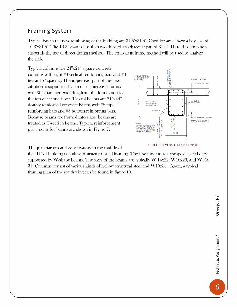
Framing System
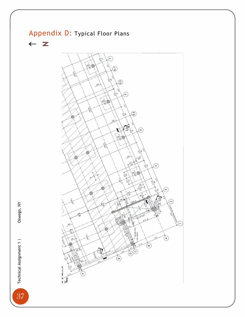
Typical bay in the new south wing of the building are 31.5’x31.5’. Corridor areas have a bay size of
10.3’x31.5’. The 10.3’ span is less than two third of its adjacent span of 31.5’. Thus, this limitation
suspends the use of direct design method. The equivalent frame method will be used to analyze
the slab.
Typical columns are 24”x24” square concrete
columns with eight #8 vertical reinforcing bars and #3
ties at 15” spacing. The upper east part of the new
addition is supported by circular concrete columns
with 30” diameter extending from the foundation to
the top of second floor. Typical beams are 24”x24”
doubly reinforced concrete beams with #6 top
reinforcing bars and #8 bottom reinforcing bars.
Because beams are framed into slabs, beams are
treated as T-section beams. Typical reinforcement
placements for beams are shown in Figure 7.
The planetarium and conservatory in the middle of
the “U” of building is built with structural steel framing. The floor system is a composite steel deck
supported by W-shape beams. The sizes of the beams are typically W 14x22, W16x26, and W16x
31. Columns consist of various kinds of hollow structural steel and W10x33. Again, a typical
framing plan of the south wing can be found in figure 10.
FIGURE 7: TYPICAL BEAM SECTION
7
Tec
hnic
al A
ssig
nmen
t 1
|
O
sweg
o, N
Y
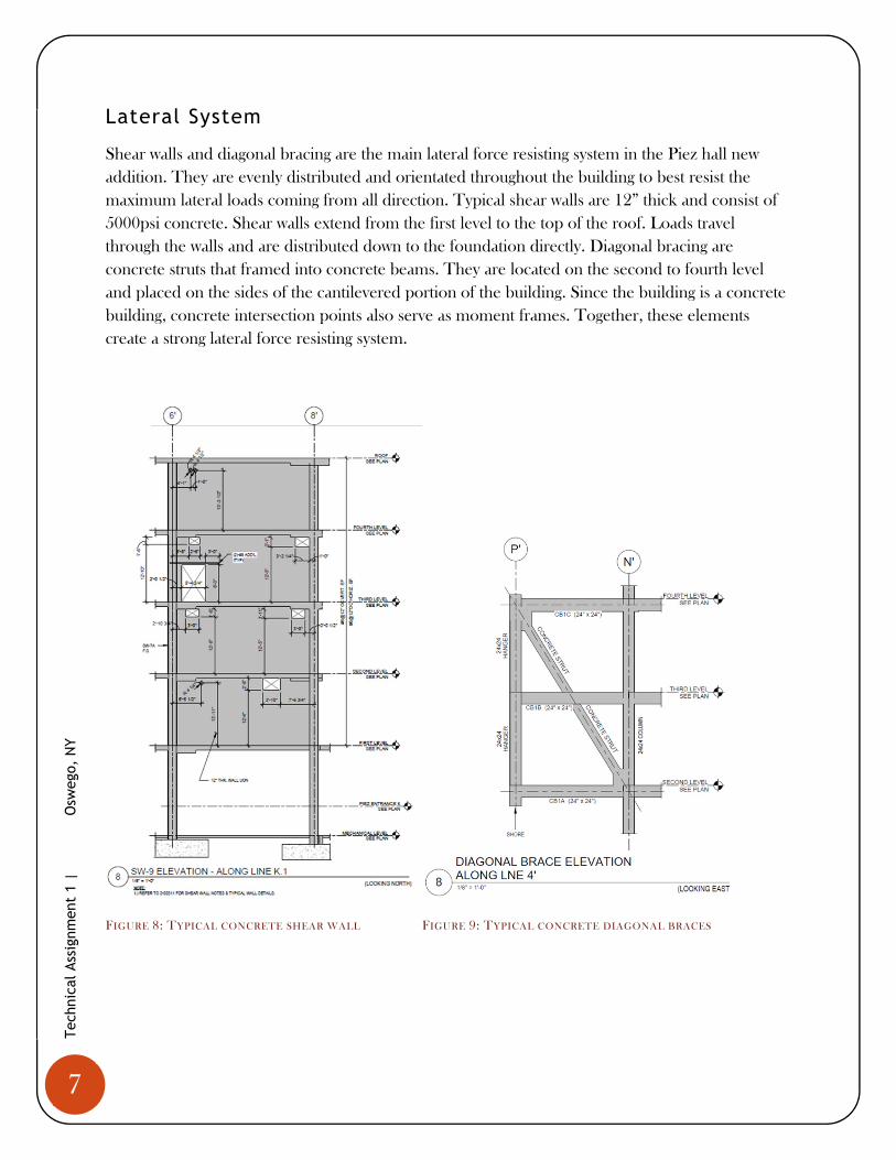
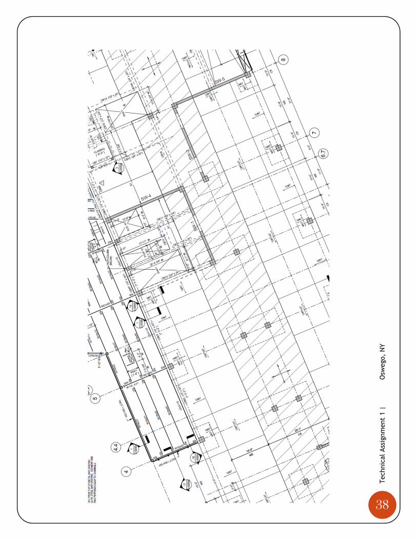
Lateral System
Shear walls and diagonal bracing are the main lateral force resisting system in the Piez hall new
addition. They are evenly distributed and orientated throughout the building to best resist the
maximum lateral loads coming from all direction. Typical shear walls are 12” thick and consist of
5000psi concrete. Shear walls extend from the first level to the top of the roof. Loads travel
through the walls and are distributed down to the foundation directly. Diagonal bracing are
concrete struts that framed into concrete beams. They are located on the second to fourth level
and placed on the sides of the cantilevered portion of the building. Since the building is a concrete
building, concrete intersection points also serve as moment frames. Together, these elements
create a strong lateral force resisting system.
FIGURE 8: TYPICAL CONCRETE SHEAR WALL FIGURE 9: TYPICAL CONCRETE DIAGONAL BRACES

8
Tec
hnic
al A
ssig
nmen
t 1
|
O
sweg
o, N
Y
FIGURE 10: SHEAR WALL LOCATIONS OF A TYPICAL FLOOR

9
Tec
hnic
al A
ssig
nmen
t 1
|
O
sweg
o, N
Y
Roof System
There are three different kinds of roof system for the Piez hall extension. Steel decks and steel
beams are used to support the roof for the planetarium. The roof for the cantilever part of the
third level is designed to let people walk on top of them. Therefore, a fairly thick roof of 10”
concrete is required. All other roof for the fourth level uses 6.5” thick concrete because they are
not intended for excessive live load. On top of the roof, there are photovoltaic array, skylights,
wind turbine and mechanical equipment that contribute to LEED.
Design Codes
Building Code Requirements for Structural Concrete (ACI 318-05)
Specifications for Masonry Structures (ACI 530.1)
Building Code Requirements for Masonry Structures (ACI 530)
Masonry Structure Building Code Commentary (ACI)
AISC Specifications and Code (AISC)
Structural Welding Code – Steel (AWS D1.1 2002)
Structural Welding Code – Sheet Steel
Building Code of New York State 2007
Minimum Design Loads for Buildings and Other Structures (ASCE 7-02)
Design Codes used for Thesis
Minimum Design Loads for Buildings and Other Structures (ASCE 7-10)
International Building Code (2009 Edition)
Building Code Requirement for Reinforced Concrete (ACI 318-11)
Steel Construction Manual (AISC 14th Edition)

10
Tec
hnic
al A
ssig
nmen
t 1
|
O
sweg
o, N
Y
Materials Used
Concrete
Usage Strength (psi) Weight (pcf)
Footings 3000 Normal
Grade Beams 4000 Normal
Foundation Walls and Piers 4000 Normal
Columns and Shear Walls 5000 Normal
Framed Slabs and Beams 5000 Normal
Slabs-on-Grade 3000 Normal
Slabs-on-Steel-Deck 3000 Normal
All Other Concrete 4000 Normal
TABLE 1: SUMMARY OF MATERIAL USED WITH STRENGTH AND DESIGN STANDARD
Steel
Type Standard Grade
Typical Bars ASTM A-615 60
Welded Bars ASTM A-706 60
Steel Fibers ASTM A-820 Type 1 N/A
Wide Flange Shapes, WT’s ASTM A992 50
Channels and Angles ASTM A36 N/A
Pipe ASTM A53 B
Hollow Structural Sections (Rectangular & Round)
ASTM A500 B
High Strength Bolts, Nuts and Washers
ASTM A325 or ASTM A-490
N/A
Anchor Rods ASTM F1554 36
Welding Electrode AWS A5.1 or A5.5 E70XX
All Other Steel Members ASTM A36 UON N/A
TABLE 2: SUMMARY OF MATERIAL USED WITH STRENGTH AND DESIGN STANDARD

11
Tec
hnic
al A
ssig
nmen
t 1
|
O
sweg
o, N
Y
Gravity Loads
Dead, live and snow loads are computed and compared to the loads listed on the structural
drawings. After determining the loads using ASCE 7-10, spot checks on members of the structural
system were checked to verify their adequacy to carry gravity loads.
Dead and Live Loads
Although the Structural engineer has given a superimposed dead load of 15psf for all levels, but a
more conservative and general superimposed dead load of 20psf were used in the calculation.
Façade, column, shear wall and slab were all taken into account to obtain the overall dead load in
each level. The exterior wall consists of curtain wall, CMU, precast concrete panels in different
location. Thus to simplify the calculation, a uniform 30psf were taken as the load of the façade in
all sides of the building. The overall weight of the building is found to be 29577 kips. This total
weight is needed to compute the base shear for seismic calculation later on.
Weight Per Level Level Weight (kips) Weight (psf)
1 5293.10 197.67
2 6449.73 221.54
3 6246.66 222.84
4 6246.66 222.84
Roof 3265.58 121.95
Total Weight 29577.02
TABLE 3: DISTRIBUTION OF WEIGHT PER LEVEL AND TOTAL WEIGHT

12
Tec
hnic
al A
ssig
nmen
t 1
|
O
sweg
o, N
Y
Live Loads shown in the middle column of Table 4 are given by the structural engineer. The
structural engineer is rather conservative to use all design live load to be 100psf when an 80psf can
typically be used for educational occupancy. Since this is a University building, typical floor is likely
to be classrooms which have live load of 50psf as defined by ASCE 7-10. Similarly, public spaces
can be interpreted as corridor above the first floor which has a live load of 80psf.
Live Load Space Design Live Load (psf) ASCE 7-10 Live Load (psf)
Typical Floors 100 50
Public Spaces 100 80
Exit Corridors 100 100
Stairs 100 100
Lobbies 100 100
TABLE 4: COMPARISON OF LIVE LOADS
Snow Loads
Following the procedure outlined in ASCE 7-10, the result of snow loads were obtained. The
resulting snow loads were found to be 46psf. This is close to what the structural engineer had
calculated.

13
Tec
hnic
al A
ssig
nmen
t 1
|
O
sweg
o, N
Y
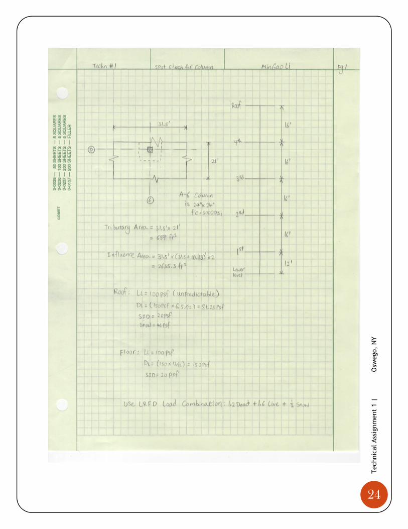
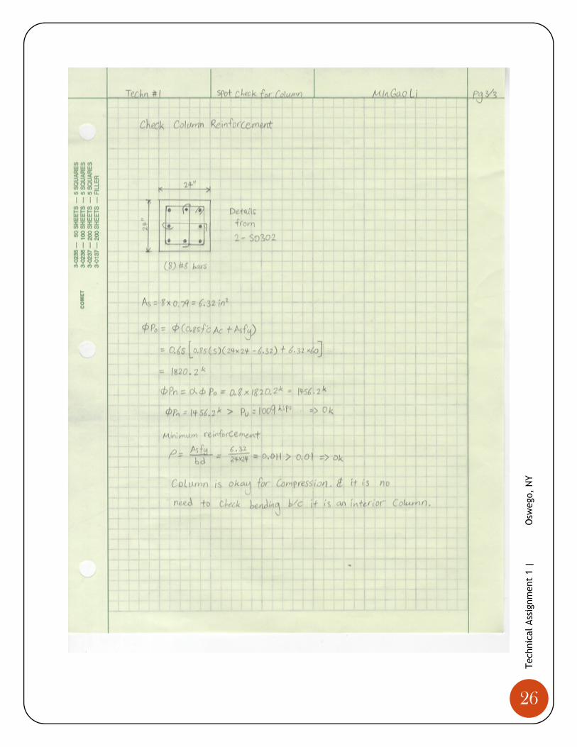
Column Gravity Check
Column D-6 was chosen to do a
spot check because it was an
interior column. In another
words, only the compressive
strength of the column was
needed to check. This greatly
reduced the time it will take to
determine second order effects
introduced by lateral forces. The
column was a 24”x24” square
reinforced column in a 21’x31.5’
bay with eight #8 bar
reinforcement and #3 ties at 15” spacing. When calculating the gravity loads of the column, roof
live load was not reduced in order to be conservative. Live loads in all other floors were 100psf
and reduced accordingly. It was found that D-6 had a strength capacity way exceeded the applied
gravity loads. Detailed calculation can be found in Appendix A for gravity load calculations.
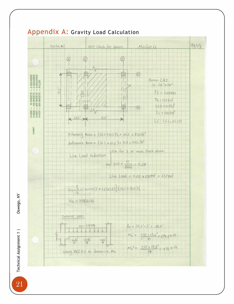
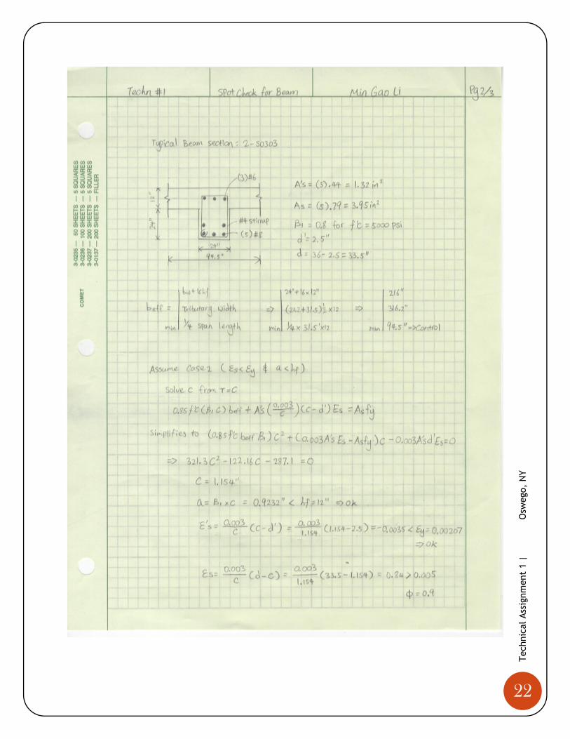
Beam Gravity Check
Beam CB2 spanned along line 6’ and
between lines N’ and M’. This beam was
a 24”x24” doubly reinforced beam with a
length of 31.5’. The top reinforcements
were three #6 bars, the bottom
reinforcements were five #8 bars and #4
stirrups were at 10” spacing. The beam
was framed into the floor slab to from a
T beam with h=12”. Live load reduction
was applied. The maximum design
moment was determined using ACI
moment coefficient from chapter 8.3.
The beam was found to be adequately
designed to resist both bending and
shear. Also, deflection of the beam was properly checked against Table 9.5a of ACI318-11 and no
issue was found. Again, detailed calculations can be found in Appendix A for gravity load
calculations.
FIGURE 11: TYPICAL FRAMING PLAN SHOWING BEAM CB2
FIGURE 12: TYPICAL FRAMING PLAN SHOWING COLUMN D-6

14
Tec
hnic
al A
ssig
nmen
t 1
|
O
sweg
o, N
Y
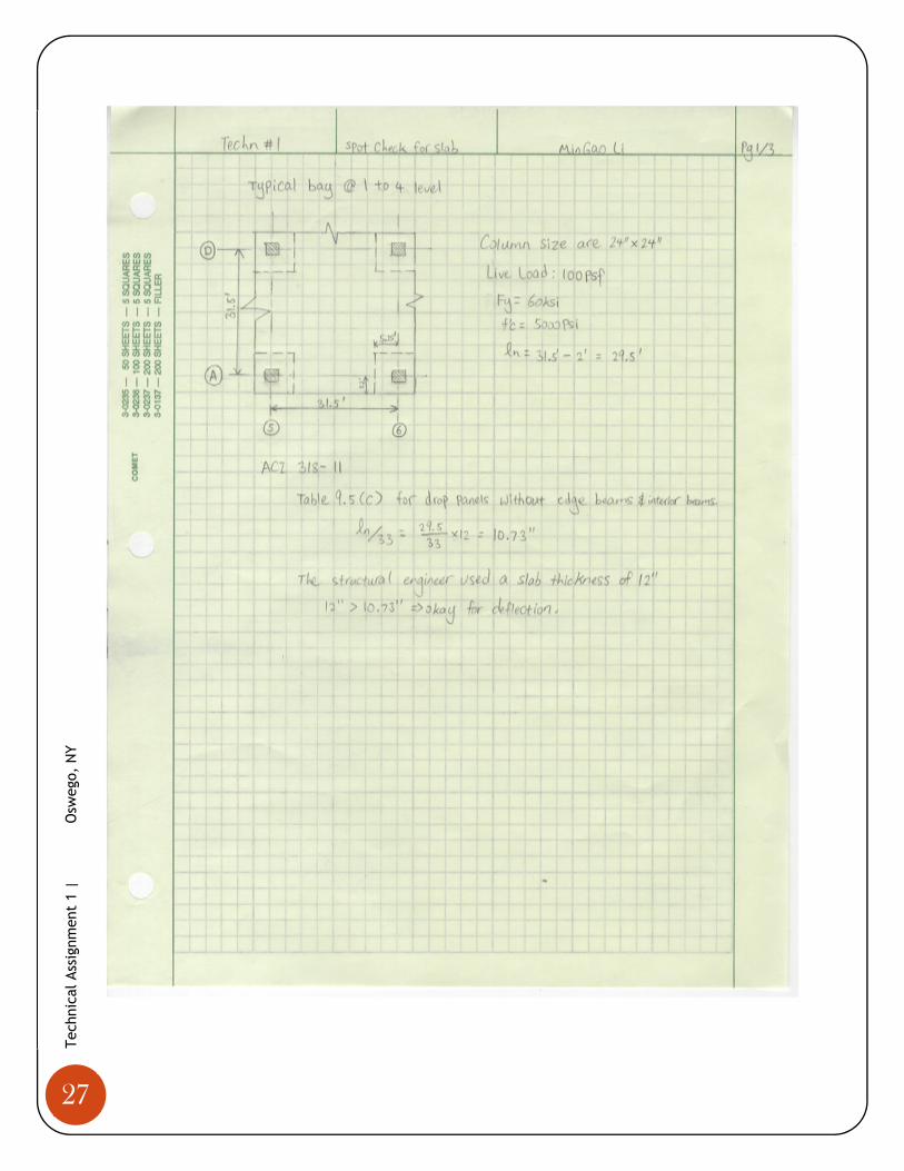
Slab Gravity Check
A spot check was performed in an exterior 31.5’x31.5’ bay enclosed by line A,D,5 and 6 for a
typical floor (see Figure 11). The slab was 12” thick with 5000psi strength concrete. The slab was
checked against ACI 318-11 table 9.5c for minimum slab thickness. Since the adjacent clear span
had a length of 10.33’, it was less than 2/3 of 31.5’, which means the direct design method was not
allowed to use here. Thus the equivalent frame method was needed to determine the moments in
the column and middle strip as shown in table 5. ACI 318-11 section 11.11 provides guidelines for
punching shear failure checks. The slab was checked to be adequate for deflection.
TABLE 5: MOMENT DISTRIBUTION
FIGURE 13: MOMENT DISTRIBUTION FROM SP SLAB

15
Tec
hnic
al A
ssig
nmen
t 1
|
O
sweg
o, N
Y
Lateral Loads
Wind Loads
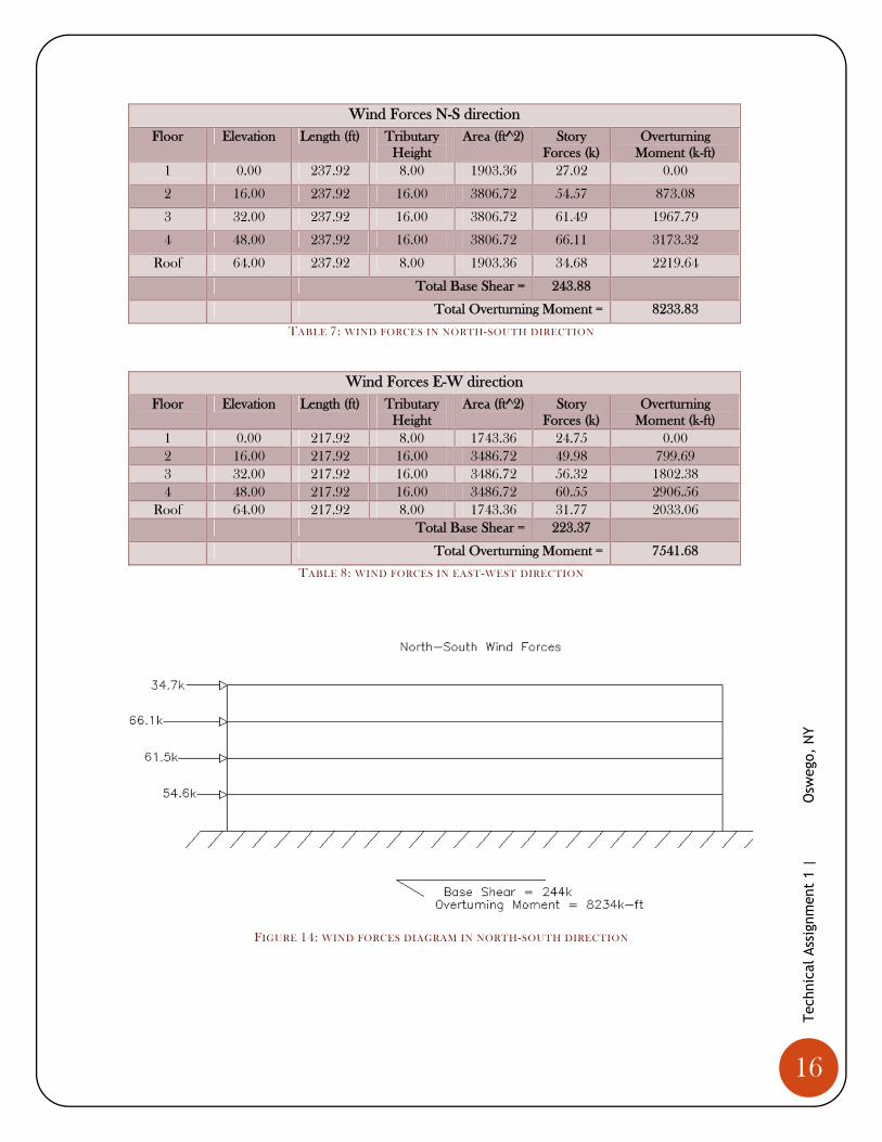
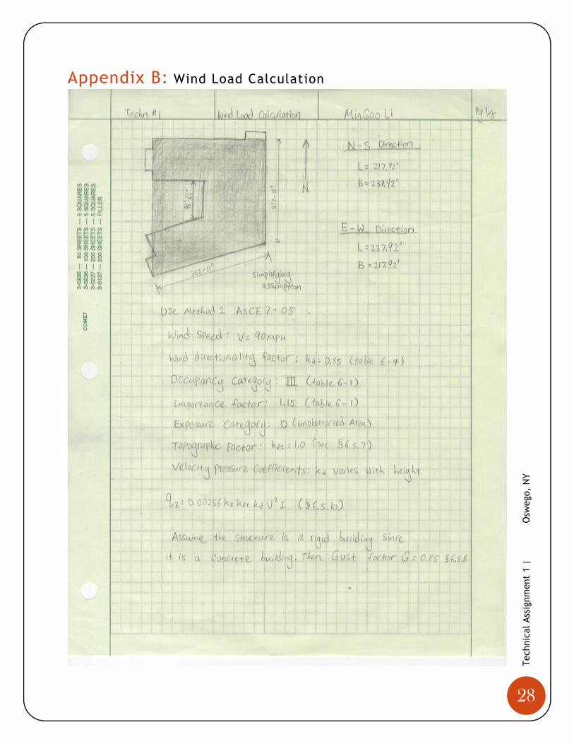
Wind loads were calculated with the MWFR Analytical Procedure. A simplified building shape
was used to approximate the size of the U-shaped building. After making such simplification, a
building footprint of 237.92’x217.92’x64’ was developed to calculate the wind pressure. This
simplification overestimates the size of the original building, and therefore it was a conservative
approach. This was done mainly to ease the use of the MWFR Analytical Procedure. The wind
loads are collected by the components and cladding of the exterior enclosure. The façade then
transfer these loads to the floor system, which further directs the load to the lateral force resisting
system within the building and down all the way to the foundation. A base shear of 244 kips were
found in the North-South direction and a 224kips base shear was found in the East-West direction.
The building was assumed to be a rigid building, hence a gust factor equals to 0.85 was used in the
calculation as defined by section 6.5.8 of ASCE 7-10. Most calculations were performed using
Microsoft Excel to avoid repetitive procedures. Wind pressures, including windward, leeward,
sideward, uplift at roof and internal pressure were found in Table 6. Windward pressure was then
distributed into each level of the building. Internal pressures have been calculated, but they were
not included in both windward and leeward pressures because they eventually cancelled out.
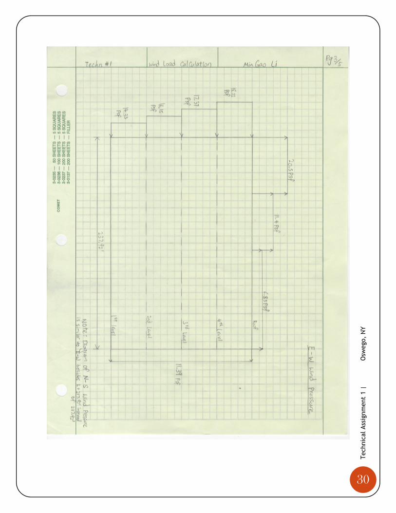
Figures 14 and 15 contain a diagram representing the wind forces in the N-S and E-W direction of
the building. Since the simplified building was a fairly square box, the North-South direction wind
pressure was the same as the East-West direct pressure except the building’s base was 217’ instead
of 237’. For more details, refer to Appendix B for wind load calculation.
Wind Pressures for all directions
Wall Floor Distances (ft)
Wind Pressure
(psf)
Internal Pressure (psf) Net Pressure (psf)
0.18 -0.18 0.18 -0.18
Windward Wall 1 0.00 14.20 4.82 -4.82 9.37 19.02
2 16.00 14.33 4.82 -4.82 9.51 19.16
3 32.00 16.15 4.82 -4.82 11.33 20.98
4 48.00 17.37 4.82 -4.82 12.54 22.19
Roof 64.00 18.22 4.82 -4.82 13.40 23.04
Leeward Walls All All -11.39 4.82 -4.82 -16.21 -6.57
Side Walls All All -15.94 4.82 -4.82 -20.77 -11.12
Roof Roof 0 to h -20.50 4.82 -4.82 -25.32 -15.68
Roof h to 2h -11.39 4.82 -4.82 -16.21 -6.57
Roof > 2h -6.83 4.82 -4.82 -11.66 -2.01
TABLE 6: WIND PRESSURE IN EITHER DIRECTION
16
Tec
hnic
al A
ssig
nmen
t 1
|
O
sweg
o, N
Y
Wind Forces N-S direction
Floor Elevation Length (ft) Tributary Height
Area (ft^2) Story Forces (k)
Overturning Moment (k-ft)
1 0.00 237.92 8.00 1903.36 27.02 0.00
2 16.00 237.92 16.00 3806.72 54.57 873.08
3 32.00 237.92 16.00 3806.72 61.49 1967.79
4 48.00 237.92 16.00 3806.72 66.11 3173.32
Roof 64.00 237.92 8.00 1903.36 34.68 2219.64
Total Base Shear = 243.88
Total Overturning Moment = 8233.83
TABLE 7: WIND FORCES IN NORTH-SOUTH DIRECTION
Wind Forces E-W direction
Floor Elevation Length (ft) Tributary Height
Area (ft^2) Story Forces (k)
Overturning Moment (k-ft)
1 0.00 217.92 8.00 1743.36 24.75 0.00 2 16.00 217.92 16.00 3486.72 49.98 799.69 3 32.00 217.92 16.00 3486.72 56.32 1802.38 4 48.00 217.92 16.00 3486.72 60.55 2906.56
Roof 64.00 217.92 8.00 1743.36 31.77 2033.06 Total Base Shear = 223.37
Total Overturning Moment = 7541.68
TABLE 8: WIND FORCES IN EAST-WEST DIRECTION
FIGURE 14: WIND FORCES DIAGRAM IN NORTH-SOUTH DIRECTION

17
Tec
hnic
al A
ssig
nmen
t 1
|
O
sweg
o, N
Y
FIGURE 15: WIND FORCES DIAGRAM IN EAST-WEST DIRECTION
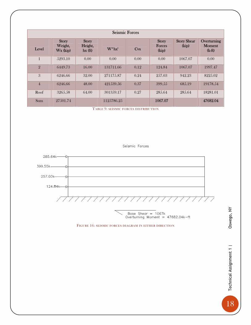
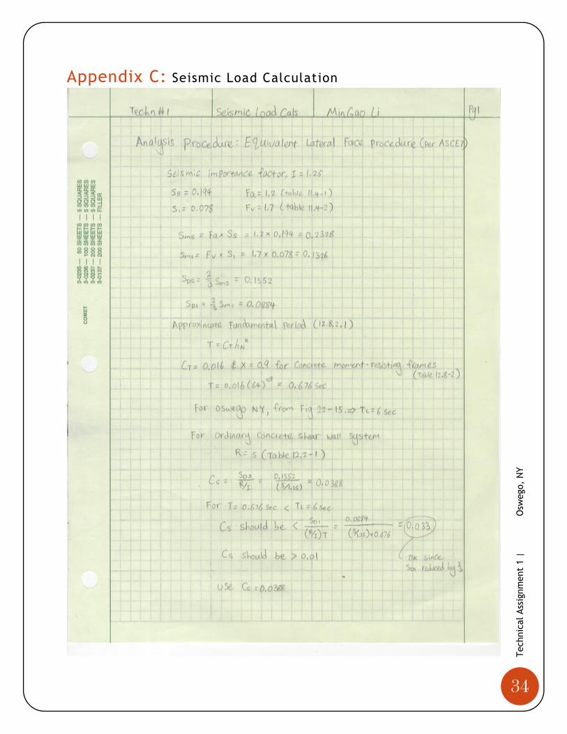
Seismic Loads
The seismic loads were obtained using the equivalent lateral force procedure given in Chapters 12
of ASCE 7-10. Test boring results of the specification shows that the site is classified as class “C”
for very dense soil and soft rocks. The corresponding spectral response accelerations were 0.194
for Ss and 0.078 for S1. The site coefficients were found to be Fa equals to 1.2 and Fv equals to
1.7. The approximate fundamental period of the building was estimated based on section 12.8.2.1
and was determined to be 0.676 second. This tells us that the structure was very stiff and it did not
behave well during earthquakes. Similar to wind load, seismic load transfers from the floor slabs of
the building to the lateral system of the building and down to the foundation.
In Figure 16, a seismic base shear of 1067 kips was determined, which has only 2.6% difference
from the 1040 kips base shear that was given in the structural drawings. This slight difference was
most likely due to the errors in calculating the total weight of the building. Also, seismic loads were
determined to be the controlling force in this analysis in either direction. This was expected since
the building has a very large base and a relatively low overall height. Moreover, it is indicated in the
structural drawing that the building is designed to resist a seismic base shear of 1040 kips. Thus, it
was determined that wind loads were not a controlling design factor for Piez Hall addition.
However, the effect of wind load on component and cladding of the façade must be thoroughly
investigated. Due to the amount of time permitted, this was not included in this report.
18
Tec
hnic
al A
ssig
nmen
t 1
|
O
sweg
o, N
Y
Seismic Forces
Level
Story Weight, Wx (kip)
Story Height, hx (ft)
W*hxk
Cvx
Story Forces (kip)
Story Shear (kip)
Overturning Moment
(k-ft)
1 5293.10 0.00 0.00 0.00 0.00 1067.07 0.00
2 6449.73 16.00 131711.66 0.12 124.84 1067.07 1997.47
3 6246.66 32.00 271175.87 0.24 257.03 942.23 8225.02
4 6246.66 48.00 421539.56 0.37 399.55 685.19 19178.54
Roof 3265.58 64.00 301359.17 0.27 285.64 285.64 18281.01
Sum 27501.74 1125786.25 1067.07 47682.04
TABLE 9: SEISMIC FORCES DISTRIBUTION
FIGURE 16: SEISMIC FORCES DIAGRAM IN EITHER DIRECTION
19
Tec
hnic
al A
ssig
nmen
t 1
|
O
sweg
o, N
Y
Conclusion
The task of technical assignment one was to analyze the existing structural condition of Piez Hall
extension. By examining the component and details of the building, a better understanding of the
overall structural system as a whole was gained. Through spot checks, it was determined that the
building was adequate to carry all the gravity loads. According to ACI 318-11, beam and slab were
found to have no problems in deflection and shear failure.
Superimposed dead loads were assumed to be 20psf in the calculation for overall weight of the
building. Live loads given in the structural drawings were checked against ASCE 7-10 and the
differences are explained and discussed.
Various kinds of lateral loads were also determined per ASCE 7-10 and included in this report.
Wind and seismic loads were both calculated in order to obtain the base shear and overturning
moment of the building produced by these loads. Throughout the process, many simplification
and assumptions were made; especially the geometry of the building was modified in order to
simplify the calculation of wind loads. All in all, it was determined that seismic loads will produce
the greatest overturning moment and base shear in all directions. This was expected since Piez
Hall was a mid-rise building with a large base. Only seismic loads needed to be taken into
consideration when designing the lateral force resisting system of the building. In technical report
3, the transfer of lateral loads through the resisting system to the foundation will be examined in
detail.

20
Tec
hnic
al A
ssig
nmen
t 1
|
O
sweg
o, N
Y
Appendices
21
Tec
hnic
al A
ssig
nmen
t 1
|
O
sweg
o, N
Y
Appendix A: Gravity Load Calculation
22
Tec
hnic
al A
ssig
nmen
t 1
|
O
sweg
o, N
Y

23
Tec
hnic
al A
ssig
nmen
t 1
|
O
sweg
o, N
Y
24
Tec
hnic
al A
ssig
nmen
t 1
|
O
sweg
o, N
Y

25
Tec
hnic
al A
ssig
nmen
t 1
|
O
sweg
o, N
Y
26
Tec
hnic
al A
ssig
nmen
t 1
|
O
sweg
o, N
Y
27
Tec
hnic
al A
ssig
nmen
t 1
|
O
sweg
o, N
Y
28
Tec
hnic
al A
ssig
nmen
t 1
|
O
sweg
o, N
Y
Appendix B: Wind Load Calculation

29
Tec
hnic
al A
ssig
nmen
t 1
|
O
sweg
o, N
Y
30
Tec
hnic
al A
ssig
nmen
t 1
|
O
sweg
o, N
Y

31
Tec
hnic
al A
ssig
nmen
t 1
|
O
sweg
o, N
Y

32
Tec
hnic
al A
ssig
nmen
t 1
|
O
sweg
o, N
Y

33
Tec
hnic
al A
ssig
nmen
t 1
|
O
sweg
o, N
Y
Wind Calculation
Level Elevation (ft) Kz qz (psf)
1st 0.00 1.03 20.88
2nd 16.00 1.04 21.08
3rd 32.00 1.17 23.76
4th 48.00 1.26 25.54
Roof 64.00 1.32 26.80
Level Windward Leeward Side Wall
1st 14.20 ‐11.39 ‐15.94
2nd 14.33 ‐11.39 ‐15.94
3rd 16.15 ‐11.39 ‐15.94
4th 17.37 ‐11.39 ‐15.94
Roof 18.22 ‐11.39 ‐15.94
Roof Cp
0 to h ‐0.90 ‐20.50
h to 2h ‐0.50 ‐11.39
> 2h ‐0.30 ‐6.83
Windward 0.80
Leeward ‐0.50
Side Wall ‐0.70
34
Tec
hnic
al A
ssig
nmen
t 1
|
O
sweg
o, N
Y
Appendix C: Seismic Load Calculation

35
Tec
hnic
al A
ssig
nmen
t 1
|
O
sweg
o, N
Y
Seismic and weight of entire building
k= 1.09for T = 0.676 (eq 12.8‐12)
Façade Weight = 30 psf
Level Preimeter (ft) Tributary Height (ft) Area (ft^2) Weight (kips)
1.00 1028.70 8.00 8229.60 246.89
2.00 1028.70 16.00 16459.20 493.78
3.00 1028.70 16.00 16459.20 493.78
4.00 795.60 16.00 12729.60 381.89
Roof 1028.70 8.00 8229.60 246.89
Shear Wall Weight
Level Volume (ft^3) Weight (kips)
1.00 1445.00 216.75
2.00 2886.00 432.90
3.00 2886.00 432.90
4.00 2886.00 432.90
Roof 1445.00 216.75
Superimposed Dead Load = 20psf
Level Floor Area (ft^2) Weight (kips)
1.00 33964.80 679.30
2.00 33964.80 679.30
3.00 33964.80 679.30
4.00 18631.20 372.62
Roof 33964.80 679.30
36
Tec
hnic
al A
ssig
nmen
t 1
|
O
sweg
o, N
Y
Column Weight
Level Numer of column
Width or Dia (ft) Depth (ft)
Tributary Height (ft)
Volume (ft^3) Weight (kips)
1.00 62.00 2.00 2.00 8.00 1984.00 297.60
2.00 60.00 2.00 2.00 16.00 3840.00 576.00
3.00 58.00 2.00 2.00 16.00 3712.00 556.80
4.00 58.00 2.00 2.00 16.00 3712.00 556.80
Roof 58.00 2.00 2.00 8.00 1856.00 278.40
2265.60
Slab Weight
Level Floor Area (ft^2) Slab Thickness (in) Weight (kips)
1.00 33964.80 12.00 5094.72
2.00 33964.80 12.00 5094.72
3.00 33964.80 12.00 5094.72
4.00 18631.20 12.00 2794.68
Roof 33964.80 6.00 2547.36
Total Weight per Level
Level Weight (kips)
1.00 6535.25
2.00 7276.69
3.00 7257.49
4.00 4538.89
Roof 3968.69
Total Weight 29577.02
V 1147.59
V 1040
37
Tec
hnic
al A
ssig
nmen
t 1
|
O
sweg
o, N
Y
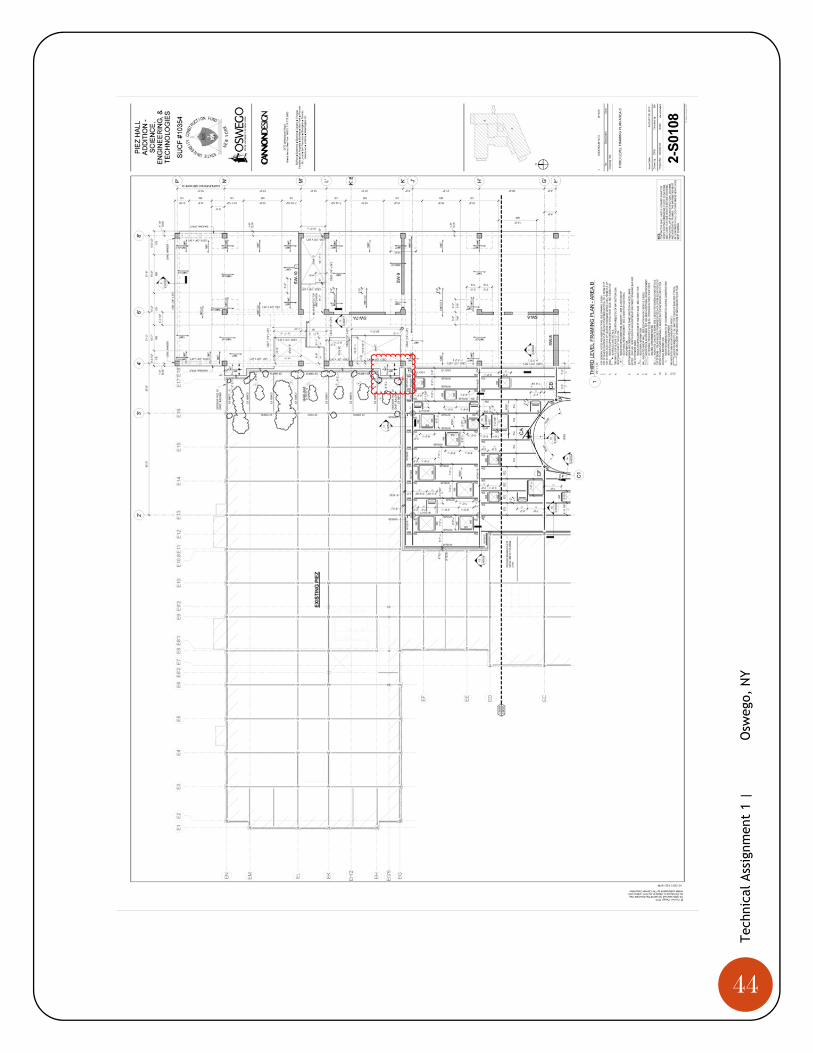
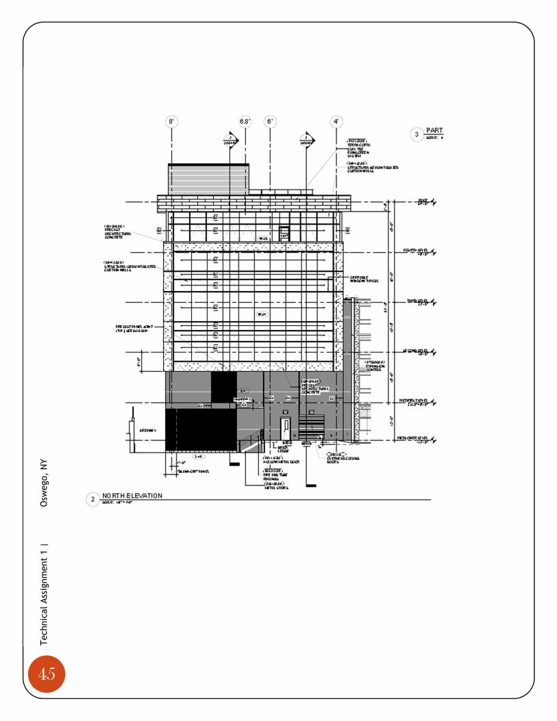
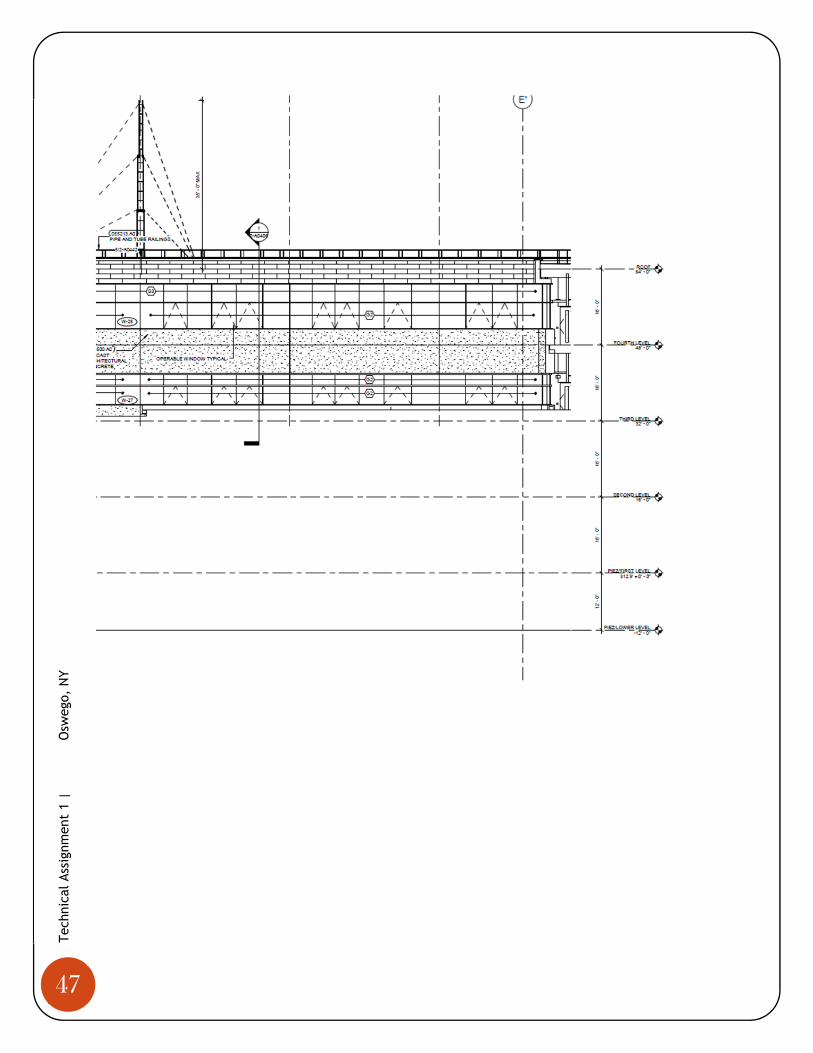
Appendix D: Typical Floor Plans
38
Tec
hnic
al A
ssig
nmen
t 1
|
O
sweg
o, N
Y

39
Tec
hnic
al A
ssig
nmen
t 1
|
O
sweg
o, N
Y

40
Tec
hnic
al A
ssig
nmen
t 1
|
O
sweg
o, N
Y

41
Tec
hnic
al A
ssig
nmen
t 1
|
O
sweg
o, N
Y

42
Tec
hnic
al A
ssig
nmen
t 1
|
O
sweg
o, N
Y

43
Tec
hnic
al A
ssig
nmen
t 1
|
O
sweg
o, N
Y
44
Tec
hnic
al A
ssig
nmen
t 1
|
O
sweg
o, N
Y
45
Tec
hnic
al A
ssig
nmen
t 1
|
O
sweg
o, N
Y

46
Tec
hnic
al A
ssig
nmen
t 1
|
O
sweg
o, N
Y
47
Tec
hnic
al A
ssig
nmen
t 1
|
O
sweg
o, N
Y
Related Documents