Medium voltage products Technical Application Papers No. 19 Smart grids 3. Standard IEC 61850

Welcome message from author
This document is posted to help you gain knowledge. Please leave a comment to let me know what you think about it! Share it to your friends and learn new things together.
Transcript
Medium voltage products
Technical Application Papers No. 19Smart grids3. Standard IEC 61850

1
Index
2 1. Introduction 3 2. IEC 61850: concept and structure 5 2.1 The basic approach of IEC 61850 5 2.2 The object-oriented data model 7 2.3 The services envisaged for the data model 8 2.4 Performance requirements 9 2.5 Mapping and communication stacks 9 2.6 Ethernet and the station and processes buses 12 2.7 Redundancy 16 2.8 Engineering supported by SCL language 16 2.9 IEC 61850, a lasting concept 17 3. ABB products based on IEC 61850 17 3.1 Native development of IEC 61850 in ABB
protection and monitoring devices 19 3.2 Installation and testing of ABB automation
systems in substations 24 3.3 The ABB verification and validation site for IEC 61850 26 4. Abbreviations and acronyms used in IEC 61850
2
This was the goal pursued by IEC (International Electrotechnical Commission) when it addressed the issue that led to publication, in 2004, of a new standard for the purpose of:– providing a single protocol for a complete substation;– developing a common format able to describe the
substation and facilitate object-oriented modelling of the data required in the substation itself;
– defining the basic services required so that data can be transferred using different communication protocols;
– allowing interoperability between products from different manufacturers.
ANSI (American National Standards Institute) supported the new standard right from the start in an effort that required more than 60 experts and almost ten years of work. IEC 61850 provides a standardized structure for integrating substation components, functional characteristics, the structure of the data in the devices, data designation conventions, establishing how the applications must interact and monitor the devices and lastly, conformance testing. IEC 61850 was very quickly accepted and only two years after having been issued was already being requested by the major part of the market as communication standard The reasons for its success stem from the fact that designing, installing, configuring and servicing a traditional communication infrastructure is a costly business while the benefits introduced by IEC 61850 reduce these costs to a considerable extent while safeguarding, thanks to standardization, the investment.
1. Introduction
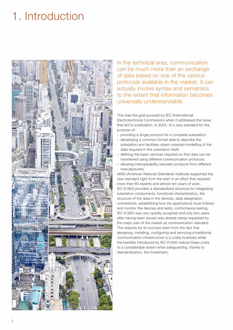
In the technical area, communication can be much more than an exchange of data based on one of the various protocols available in the market. It can actually involve syntax and semantics to the extent that information becomes universally understandable.
3
Substation A Substation B
2. IEC 61850: concept and structure
In the past, all distribution automation systems were based on proprietary solutions and protocols or on use of communication standards from other application fields, such as DNP3 or IEC 60870-5-104.The problem with these solutions was that they made interoperability between different suppliers or even between different versions of switchgear produced by the same manufacturer, particularly arduous. It took more than twenty years before the need for a standard for communication in substations able to resolve the interoperability issues was formalized. A further aim was to create a standard able to support the continuous and rapid technological developments in this field. This explains the evolution sustained by IEC 61850, which passed from edition 1 to edition 2 with the addition of certain characteristics such as:– clarification of certain parts like buffered reporting, the
mode switch (in test mode) and hierarchical control of accesses (local/remote);
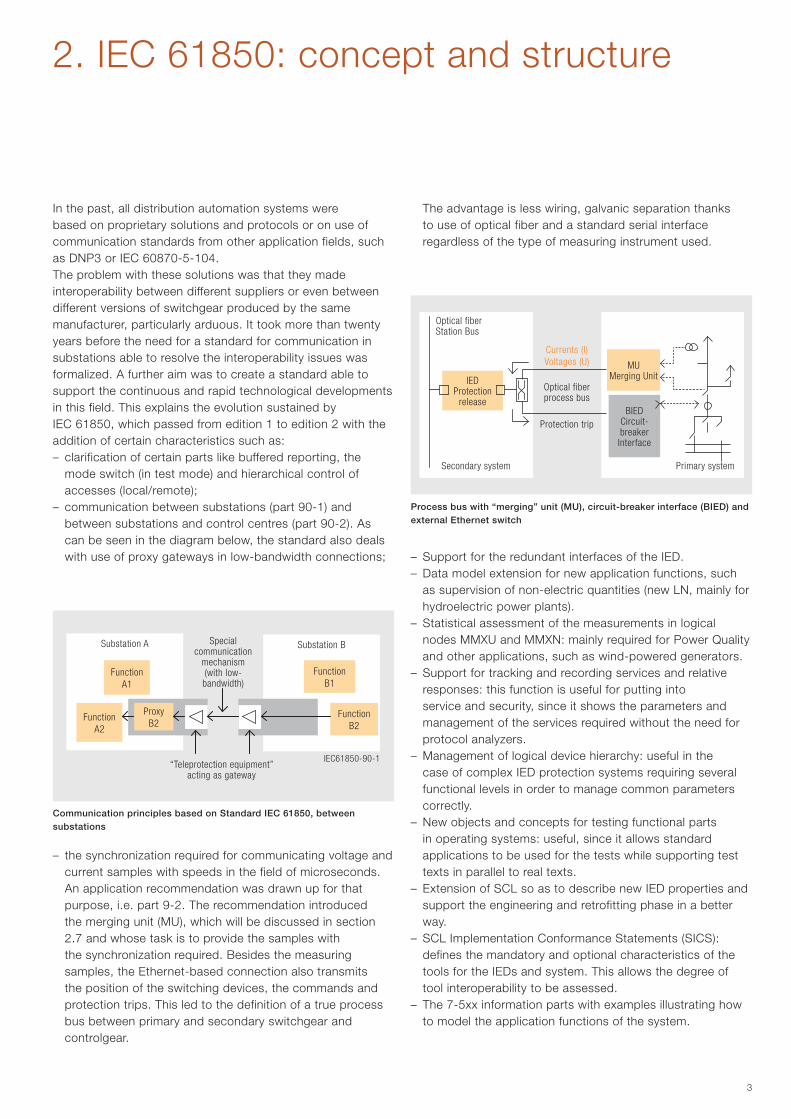
– communication between substations (part 90-1) and between substations and control centres (part 90-2). As can be seen in the diagram below, the standard also deals with use of proxy gateways in low-bandwidth connections;
– the synchronization required for communicating voltage and current samples with speeds in the field of microseconds. An application recommendation was drawn up for that purpose, i.e. part 9-2. The recommendation introduced the merging unit (MU), which will be discussed in section 2.7 and whose task is to provide the samples with the synchronization required. Besides the measuring samples, the Ethernet-based connection also transmits the position of the switching devices, the commands and protection trips. This led to the definition of a true process bus between primary and secondary switchgear and controlgear.
The advantage is less wiring, galvanic separation thanks to use of optical fiber and a standard serial interface regardless of the type of measuring instrument used.
– Support for the redundant interfaces of the IED.– Data model extension for new application functions, such
as supervision of non-electric quantities (new LN, mainly for hydroelectric power plants).
– Statistical assessment of the measurements in logical nodes MMXU and MMXN: mainly required for Power Quality and other applications, such as wind-powered generators.
– Support for tracking and recording services and relative responses: this function is useful for putting into service and security, since it shows the parameters and management of the services required without the need for protocol analyzers.
– Management of logical device hierarchy: useful in the case of complex IED protection systems requiring several functional levels in order to manage common parameters correctly.
– New objects and concepts for testing functional parts in operating systems: useful, since it allows standard applications to be used for the tests while supporting test texts in parallel to real texts.
– Extension of SCL so as to describe new IED properties and support the engineering and retrofitting phase in a better way.
– SCL Implementation Conformance Statements (SICS): defines the mandatory and optional characteristics of the tools for the IEDs and system. This allows the degree of tool interoperability to be assessed.
– The 7-5xx information parts with examples illustrating how to model the application functions of the system.
FunctionA1
FunctionB1
IEDProtection
release
MUMerging Unit
BIEDCircuit-breakerInterface
Optical fiber Station Bus
Secondary system Primary system
Currents (I)Voltages (U)
Optical fiber process bus
Protection trip
FunctionA2
FunctionB2
ProxyB2
Special communication
mechanism (with low- bandwidth)
“Teleprotection equipment”acting as gateway
IEC61850-90-1
Communication principles based on Standard IEC 61850, between substations
Process bus with “merging” unit (MU), circuit-breaker interface (BIED) and external Ethernet switch
4
2. IEC 61850: concept and structure
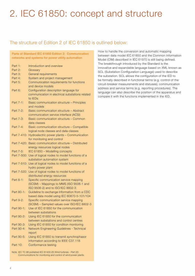
The structure of Edition 2 of IEC 61850 is outlined below:
How to handle the conversion and automatic mapping between data model IEC 61850 and the Common Information Model (CIM) described in IEC 61970 is still being defined.The breakthrough introduced by the Standard is the innovative and expandable language based on XML known as SCL (Substation Configuration Language) used to describe the substation. SCL allows the configuration of the IED to be formally described in functional terms (e.g. control of the circuit-breaker measurements and statuses), communication address and service terms (e.g. reporting procedures). The language can also describe the position of the apparatus and compare it with the functions implemented in the IED.
Parts of Standard IEC 61850 Edition 2: Communication networks and systems for power utility automation
Part 1: Introduction and overviewPart 2: GlossaryPart 3: General requirementsPart 4: System and project managementPart 5: Communication requirements for functions
and device modelsPart 6: Configuration description language for
communication in electrical substations related to IEDs
Part 7-1: Basic communication structure – Principles and models
Part 7-2: Basic communication structure – Abstract communication service interface (ACSI)
Part 7-3: Basic communication structure – Common data classes
Part 7-4: Basic communication structure – Compatible logical node classes and data classes
Part 7-410: Hydroelectric power plants – Communication for monitoring and control
Part 7-420: Basic communication structure – Distributed energy resources logical nodes
Part 7-5: IEC 61850 – Modelling conceptsPart 7-500: Use of logical nodes to model functions of a
substation automation systemPart 7-510: Use of logical nodes to model functions of a
hydro power plantPart 7-520: Use of logical nodes to model functions of
distributed energy resourcesPart 8-1: Specific communication service mapping
(SCSM) – Mappings to MMS (ISO 9506-1 and ISO 9506-2) and to ISO/IEC 8802-3
Part 80-1: Guideline to exchange information from a CDC based data model using IEC 60870-5-101/104
Part 9-2: Specific communication service mapping (SCSM) – Sampled values over ISO/IEC 8802-3
Part 90-1: Use of IEC 61850 for the communication between substations
Part 90-2: Using IEC 61850 for the communication between substations and control centres
Part 90-3: Using IEC 61850 for condition monitoringPart 90-4: Network Engineering Guidelines - Technical
reportPart 90-5: Using IEC 61850 to transmit synchrophasor
information according to IEEE C37.118Part 10: Conformance testing
Note: IEC TC 88 published IEC 61400-25 Wind turbines - Part 25: Communications for monitoring and control of wind power plants.
5
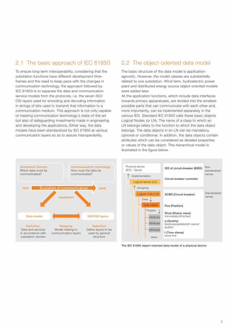
2.1 The basic approach of IEC 61850To ensure long-term interoperability, considering that the substation functions have different development time-frames and the need to keep pace with the changes in communication technology, the approach followed by IEC 61850 is to separate the data and communication service models from the protocols, i.e. the seven ISO/OSI layers used for encoding and decoding information in strings of bits used to transmit that information to a communication medium. This approach is not only capable of meeting communication technology's state-of-the-art but also of safeguarding investments made in engineering and developing the applications. Either way, the data models have been standardized by IEC 61850 at various communication layers so as to assure interoperability.
Substation DomainWhich data must be communicated?
Communication technologyHow must the data be communicated?
DefinitionData and services in accordance with substation domain
MappingModel relating to
communication layers
SelectionDefine layers to be
used by general structure
Data model ISO/OSI layers
2.2 The object-oriented data model The basic structure of the data model is application-agnostic. However, the model classes are substantially related to one substation. Wind farm, hydroelectric power plant and distributed energy source object-oriented models were added later.All the application functions, which include data interfaces towards primary apparatuses, are divided into the smallest possible parts that can communicate with each other and, more importantly, can be inplemented separately in the various IED. Standard IEC 61850 calls these basic objects Logical Nodes (or LN). The name of a class to which an LN belongs refers to the function to which the data object belongs. The data objects in an LN can be mandatory, optional or conditional. In addition, the data objects contain attributes which can be considered as detailed properties or values of the data object. This hierarchical model is illustrated in the figure below.
The IEC 61850 object-oriented data model of a physical device
slow rapid
separation
Evolution of communication
Logical device (LD)
Logical node (LN)
Data object
Property
Value
t (Time stamp)record time
q (Quality)Good/unacceptable/with reserve/doubtful
Stval (Status value)Intermediate/off/on/fault
Pos (Position)
XCBR (Circuit-breaker)
Data
Grouping
Implementation
Non-standardized names
Standardized names
Attribute
Attribute
Attribute
IED of circuit-breaker (BIED)
Circuit-breaker controller
Physical device (IED) - Server
6
2. IEC 61850: concept and structure
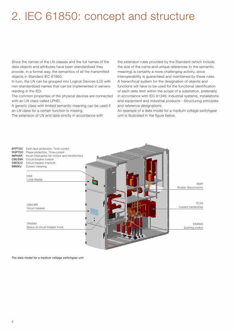
Since the names of the LN classes and the full names of the data objects and attributes have been standardized they provide, in a formal way, the semantics of all the transmitted objects in Standard IEC 61850.In turn, the LN can be grouped into Logical Devices (LD) with non-standardized names that can be implemented in servers residing in the IED.The common properties of the physical devices are connected with an LN class called LPHD.A generic class with limited semantic meaning can be used if an LN class for a certain function is missing.The extension of LN and data strictly in accordance with
The data model for a medium voltage switchgear unit
the extension rules provided by the Standard (which include the size of the name and unique references to the semantic meaning) is certainly a more challenging activity, since interoperability is guaranteed and maintained by these rules.A hierarchical system for the designation of objects and functions will have to be used for the functional identification of each data item within the scope of a substation, preferably in accordance with IEC 81346: Industrial systems, installations and equipment and industrial products - Structuring principles and reference designations.An example of a data model for a medium voltage switchgear unit is illustrated in the figure below.
IHMILocal display
XSWIBusbar disconnector
TCTRCurrent transformer
ESXSWIEarthing switch
CBXCBR Circuit-breaker
TRXSWI Status of circuit-breaker truck
EFPTOC Earth fault protection, Time-currentPHPTOC Phase protection, Time-currentINPHAR Inrush interceptor for motors and transformersCBCSWI Circuit-breaker controlCBCILO Circuit-breaker interlockIMMXU Current metering
7
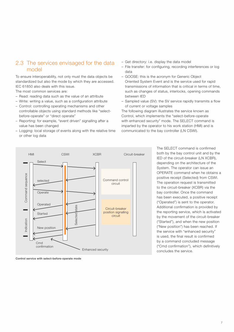
Control service with select-before-operate mode
The SELECT command is confirmed both by the bay control unit and by the IED of the circuit-breaker (LN XCBR), depending on the architecture of the System. The operator can issue an OPERATE command when he obtains a positive receipt (Selected) from CSWI. The operation request is transmitted to the circuit-breaker (XCBR) via the bay controller. Once the command has been executed, a positive receipt (“Operated”) is sent to the operator. Additional confirmation is provided by the reporting service, which is activated by the movement of the circuit-breaker (“Started”), and when the new position (“New position”) has been reached. If the service with “enhanced security” is used, the final result is confirmed by a command concluded message (“Cmd confirmation”), which definitively concludes the service.
2.3 The services envisaged for the data model
To ensure interoperability, not only must the data objects be standardized but also the mode by which they are accessed. IEC 61850 also deals with this issue.The most common services are: – Read: reading data such as the value of an attribute– Write: writing a value, such as a configuration attribute– Control: controlling operating mechanisms and other
controllable objects using standard methods like “select-before-operate” or “direct operate”
– Reporting: for example, “event driven” signalling after a value has been changed
– Logging: local storage of events along with the relative time or other log data
– Get directory: i.e. display the data model– File transfer: for configuring, recording interferences or log
data– GOOSE: this is the acronym for Generic Object
Oriented System Event and is the service used for rapid transmissions of information that is critical in terms of time, such as changes of status, interlocks, opening commands between IED
– Sampled value (SV): the SV service rapidly transmits a flow of current or voltage samples
The following diagram illustrates the service known as Control, which implements the “select-before-operate with enhanced security” mode. The SELECT command is imparted by the operator to his work station (HMI) and is communicated to the bay controller (LN CSWI).
HMI CSWI XCBR Circuit-breaker
Command control circuit
Circuit-breaker position signalling
circuit
Enhanced security
Cmd confirmation
New position
Started
Operated
Operate
selected
Sel
ecte
d s
tate
Select
Ind
icat
ion
Com
man
d s
eque
nce
8
2. IEC 61850: concept and structure
Physical connection (wired circuit)
requirements
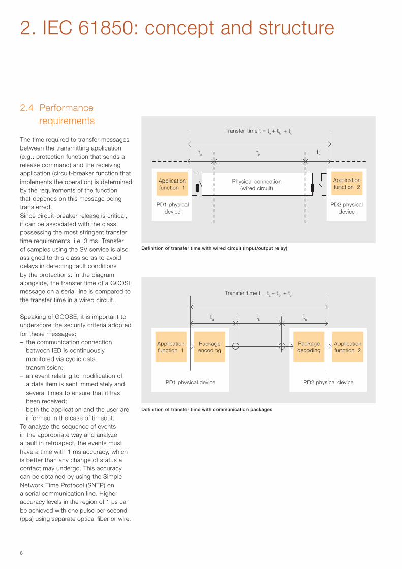
The time required to transfer messages between the transmitting application (e.g.: protection function that sends a release command) and the receiving application (circuit-breaker function that implements the operation) is determined by the requirements of the function that depends on this message being transferred. Since circuit-breaker release is critical, it can be associated with the class possessing the most stringent transfer time requirements, i.e. 3 ms. Transfer of samples using the SV service is also assigned to this class so as to avoid delays in detecting fault conditions by the protections. In the diagram alongside, the transfer time of a GOOSE message on a serial line is compared to the transfer time in a wired circuit.
Speaking of GOOSE, it is important to underscore the security criteria adopted for these messages:– the communication connection
between IED is continuously monitored via cyclic data transmission;
– an event relating to modification of a data item is sent immediately and several times to ensure that it has been received;
– both the application and the user are informed in the case of timeout.
To analyze the sequence of events in the appropriate way and analyze a fault in retrospect, the events must have a time with 1 ms accuracy, which is better than any change of status a contact may undergo. This accuracy can be obtained by using the Simple Network Time Protocol (SNTP) on a serial communication line. Higher accuracy levels in the region of 1 µs can be achieved with one pulse per second (pps) using separate optical fiber or wire.
2.4 Performance
Definition of transfer time with wired circuit (input/output relay)
Definition of transfer time with communication packages
Transfer time t = ta + tb + tc
Transfer time t = ta + tb + tc
Package encoding
Package decoding
PD2 physical devicePD1 physical device
ta
ta
tb
tb
tc
tc
Application function 1
PD1 physical device
Application function 2
PD2 physical device
Application function 1
Application function 2
9
2.5 Mapping and communication stacks
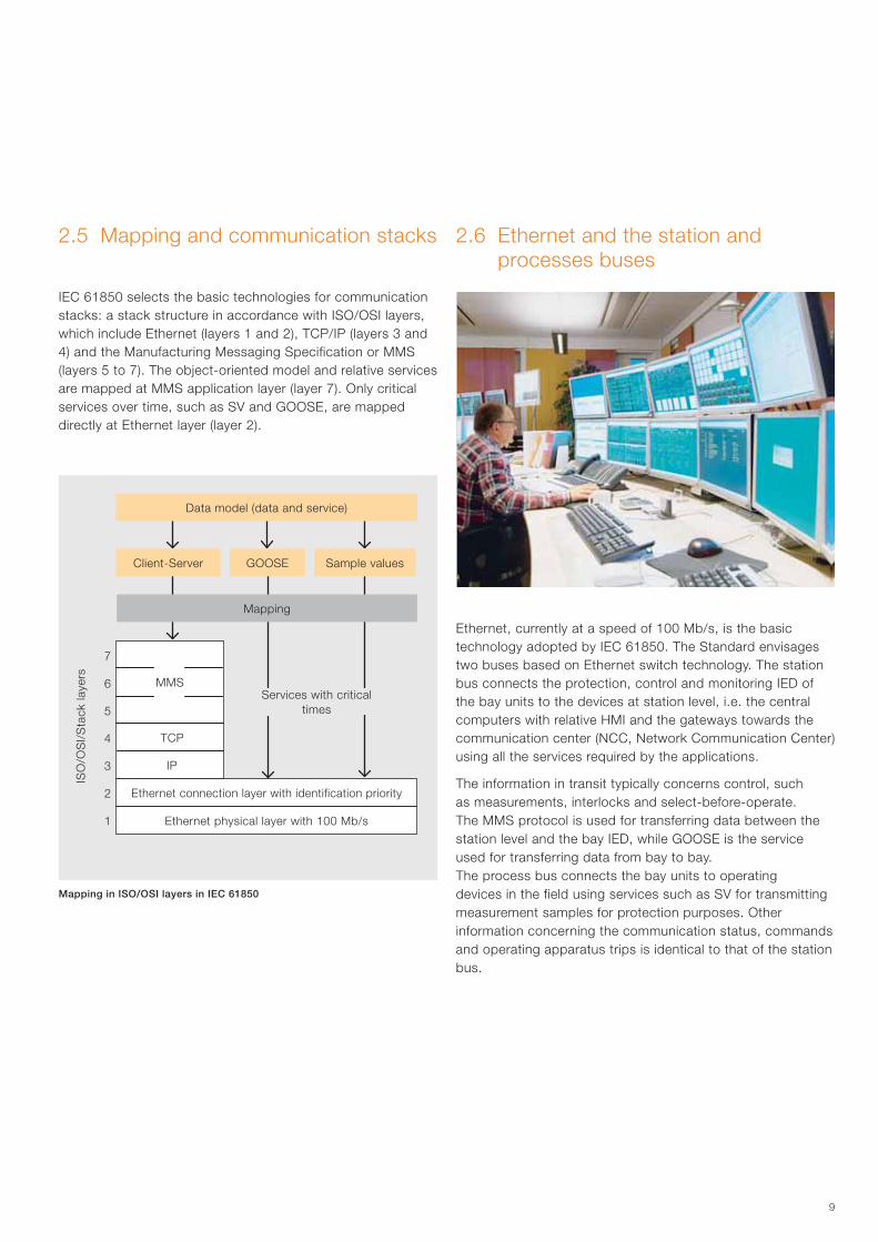
IEC 61850 selects the basic technologies for communication stacks: a stack structure in accordance with ISO/OSI layers, which include Ethernet (layers 1 and 2), TCP/IP (layers 3 and 4) and the Manufacturing Messaging Specification or MMS (layers 5 to 7). The object-oriented model and relative services are mapped at MMS application layer (layer 7). Only critical services over time, such as SV and GOOSE, are mapped directly at Ethernet layer (layer 2).
Ethernet, currently at a speed of 100 Mb/s, is the basic technology adopted by IEC 61850. The Standard envisages two buses based on Ethernet switch technology. The station bus connects the protection, control and monitoring IED of the bay units to the devices at station level, i.e. the central computers with relative HMI and the gateways towards the communication center (NCC, Network Communication Center) using all the services required by the applications.
The information in transit typically concerns control, such as measurements, interlocks and select-before-operate. The MMS protocol is used for transferring data between the station level and the bay IED, while GOOSE is the service used for transferring data from bay to bay.The process bus connects the bay units to operating devices in the field using services such as SV for transmitting measurement samples for protection purposes. Other information concerning the communication status, commands and operating apparatus trips is identical to that of the station bus.
2.6 Ethernet and the station and processes buses
Mapping in ISO/OSI layers in IEC 61850
Services with critical times
ISO
/OS
I/S
tack
laye
rs
MMS
7
6
5
4
3
2
1
TCP
IP
Ethernet connection layer with identification priority
Ethernet physical layer with 100 Mb/s
Client-Server GOOSE Sample values
Mapping
Data model (data and service)
10
2. IEC 61850: concept and structure
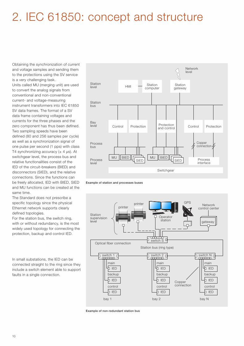
Obtaining the synchronization of current and voltage samples and sending them to the protections using the SV service is a very challenging task.Units called MU (merging unit) are used to convert the analog signals from conventional and non-conventional current- and voltage-measuring instrument transformers into IEC 61850 SV data frames. The format of a SV data frame containing voltages and currents for the three phases and the zero component has thus been defined. Two sampling speeds have been defined (80 and 256 samples per cycle) as well as a synchronization signal of one pulse per second (1 pps) with class T4 synchronizing accuracy (± 4 µs). At switchgear level, the process bus and relative functionalities consist of the IED of the circuit-breakers (BIED) and disconnectors (SIED), and the relative connections. Since the functions can be freely allocated, IED with BIED, SIED and MU functions can be created at the same time. The Standard does not prescribe a specific topology since the physical Ethernet network supports clearly defined topologies. For the station bus, the switch ring, with or without redundancy, is the most widely used topology for connecting the protection, backup and control IED.
In small substations, the IED can be connected straight to the ring since they include a switch element able to support faults in a single connection.
Example of station and processes buses
Example of non-redundant station bus
Station level
Station bus
Bay level
Process bus
Process level
Network level
Copper connection
Switchgear
MU MUBIED BIEDSIED SIED
Station supervision level
printer GPS
Optical fiber connection
Operator station
Station bus (ring type)
Copper connection
Network control center
Control Protection
Process interface
Control ProtectionProtection and control
Station computerHMI Station
gateway
switch S
gateway
switch 1 switch 2 switch N
IED IED IED
IED IED IED
IED IED IED
main main main
backup backup backup
control control control
bay 1 bay 2 bay N
printer
11
PMC2
PMC2
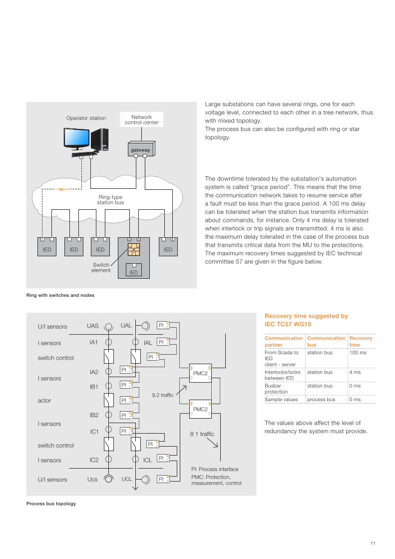
Large substations can have several rings, one for each voltage level, connected to each other in a tree network, thus with mixed topology. The process bus can also be configured with ring or star topology.
The downtime tolerated by the substation's automation system is called “grace period”. This means that the time the communication network takes to resume service after a fault must be less than the grace period. A 100 ms delay can be tolerated when the station bus transmits information about commands, for instance. Only 4 ms delay is tolerated when interlock or trip signals are transmitted. 4 ms is also the maximum delay tolerated in the case of the process bus that transmits critical data from the MU to the protections. The maximum recovery times suggested by IEC technical committee 57 are given in the figure below.
Communication partner
Communication bus
Recovery time
From Scada to IEDclient - server
station bus 100 ms
Interlocks/locks between IED
station bus 4 ms
Busbar protection
station bus 0 ms
Sample values process bus 0 ms
Recovery time suggested by IEC TC57 WG10
The values above affect the level of redundancy the system must provide.
UAS
IA1
IA2
IB1
IB2
IC1
IC2
Ucs UCL
ICL
UAL
IAL
9.2 traffic
8 1 traffic
U/I sensors
I sensors
I sensors
I sensors
U/I sensors
I sensors
actor
switch control
switch control
PI: Process interface
PMC: Protection,measurement, control
PI
PI
PI
PI
PI
PI
PI
PI
PI
PI
PI
Ring with switches and nodes
Process bus topology
IED IED IED
IED
IED
Operator station
Ring-type station bus
gateway
Network control center
Switch element
12
2. IEC 61850: concept and structure
switch switchswitch switch
switch switch
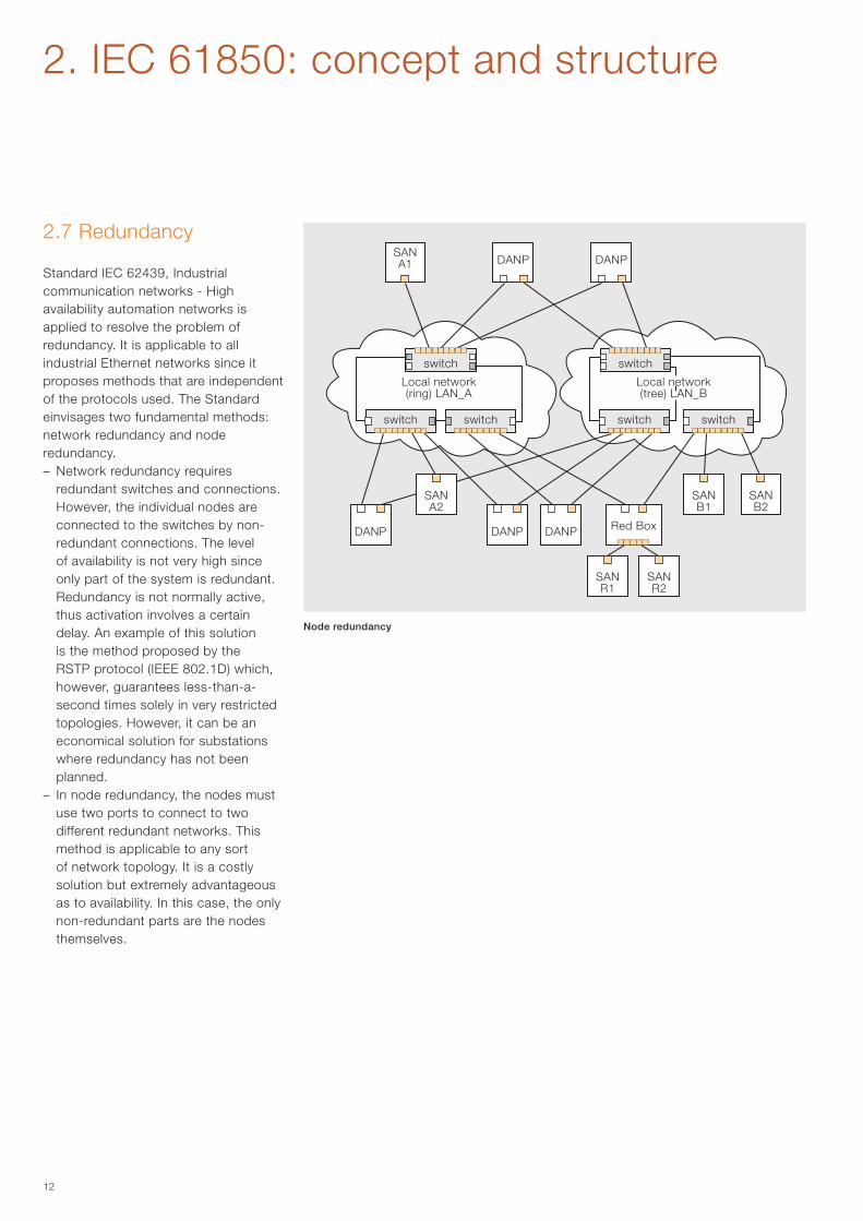
2.7 Redundancy
Standard IEC 62439, Industrial communication networks - High availability automation networks is applied to resolve the problem of redundancy. It is applicable to all industrial Ethernet networks since it proposes methods that are independent of the protocols used. The Standard einvisages two fundamental methods: network redundancy and node redundancy. – Network redundancy requires
redundant switches and connections. However, the individual nodes are connected to the switches by non-redundant connections. The level of availability is not very high since only part of the system is redundant. Redundancy is not normally active, thus activation involves a certain delay. An example of this solution is the method proposed by the RSTP protocol (IEEE 802.1D) which, however, guarantees less-than-a-second times solely in very restricted topologies. However, it can be an economical solution for substations where redundancy has not been planned.
– In node redundancy, the nodes must use two ports to connect to two different redundant networks. This method is applicable to any sort of network topology. It is a costly solution but extremely advantageous as to availability. In this case, the only non-redundant parts are the nodes themselves.
Node redundancy
Local network (ring) LAN_A
Local network (tree) LAN_B
DANP
SANA2
SANB1
SANB2
SANR1
SANR2
DANP
DANPSANA1 DANP
DANP Red Box
13
nodenode node node node
switch
switch
switch
switchswitch
switchswitch switch
switch
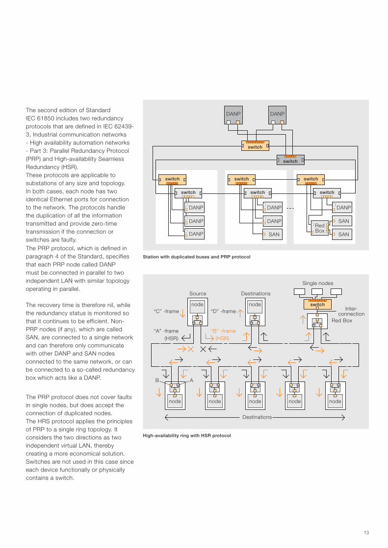
The second edition of Standard IEC 61850 includes two redundancy protocols that are defined in IEC 62439-3, Industrial communication networks - High availability automation networks - Part 3: Parallel Redundancy Protocol (PRP) and High-availability Seamless Redundancy (HSR). These protocols are applicable to substations of any size and topology. In both cases, each node has two identical Ethernet ports for connection to the network. The protocols handle the duplication of all the information transmitted and provide zero-time transmission if the connection or switches are faulty. The PRP protocol, which is defined in paragraph 4 of the Standard, specifies that each PRP node called DANP must be connected in parallel to two independent LAN with similar topology operating in parallel.
The recovery time is therefore nil, while the redundancy status is monitored so that it continues to be efficient. Non-PRP nodes (if any), which are called SAN, are connected to a single network and can therefore only communicate with other DANP and SAN nodes connected to the same network, or can be connected to a so-called redundancy box which acts like a DANP.
The PRP protocol does not cover faults in single nodes, but does accept the connection of duplicated nodes.The HRS protocol applies the principles of PRP to a single ring topology. It considers the two directions as two independent virtual LAN, thereby creating a more economical solution. Switches are not used in this case since each device functionally or physically contains a switch.
Station with duplicated buses and PRP protocol
High-availability ring with HSR protocol
Source
(HSR)
Red Box
(HSR)
“D” -frame
AB
“B” -frame
“C” -frame
“A” -frame
Destinations
Single nodes
Destinations
Inter-connection
DANPDANP
DANP
RedBox
SAN
SAN
DANP
DANP
DANP
DANP
DANP
SAN
nodenode
14
2. IEC 61850: concept and structure
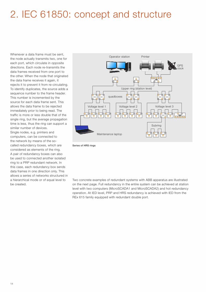
Whenever a data frame must be sent, the node actually transmits two, one for each port, which circulate in opposite directions. Each node re-transmits the data frames received from one port to the other. When the node that originated the data frame receives it again, it rejects it to prevent it from re-circulating. To identify duplicates, the source adds a sequence number to the frame header. This number is incremented by the source for each data frame sent. This allows the data frame to be rejected immediately prior to being read. The traffic is more or less double that of the single ring, but the average propagation time is less, thus the ring can support a similar number of devices.Single nodes, e.g. printers and computers, can be connected to the network by means of the so-called redundancy boxes, which are considered as elements of the ring.A pair of redundancy boxes can also be used to connected another isolated ring to a PRP redundant network. In this case, each redundancy box sends data frames in one direction only. This allows a series of networks structured in a hierarchical mode or of equal level to be created.
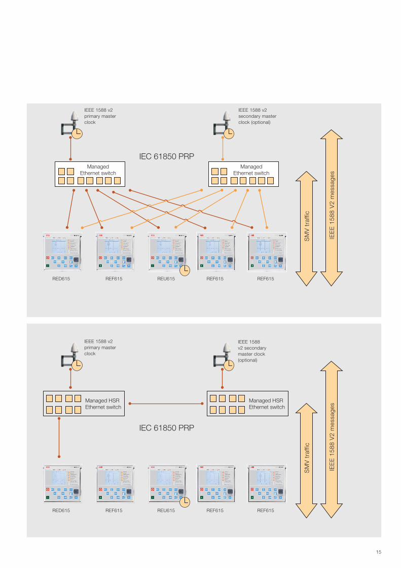
Two concrete examples of redundant systems with ABB apparatus are illustrated on the next page. Full redundancy in the entire system can be achieved at station level with two computers (MicroSCADA1 and MicroSCADA2) and hot redundancy operation. At IED level, PRP and HRS redundancy is achieved with IED from the REx 615 family equipped with redundant double port.
Series of HRS rings
Operator station Printer
Upper ring (station level)
Voltage level 1 Voltage level 2
quadboxes
GPSclock
Voltage level 3
Subring
Maintenance laptop
15
IEEE 1588 v2 primary master clock
IEEE 1588 v2 primary master clock
IEEE 1588 v2 secondary master clock (optional)
IEEE 1588 v2 secondary master clock (optional)
RED615
RED615
REF615
REF615
REU615
REU615
REF615
REF615
REF615
REF615
SM
V t
raffi
cS
MV
tra
ffic
IEE
E 1
588
V2
mes
sage
sIE
EE
158
8 V
2 m
essa
ges
IEC 61850 PRP
IEC 61850 PRP
ManagedEthernet switch
Managed HSREthernet switch
Managed HSREthernet switch
ManagedEthernet switch
16
2. IEC 61850: concept and structure
2.8 Engineering supported by SCL language
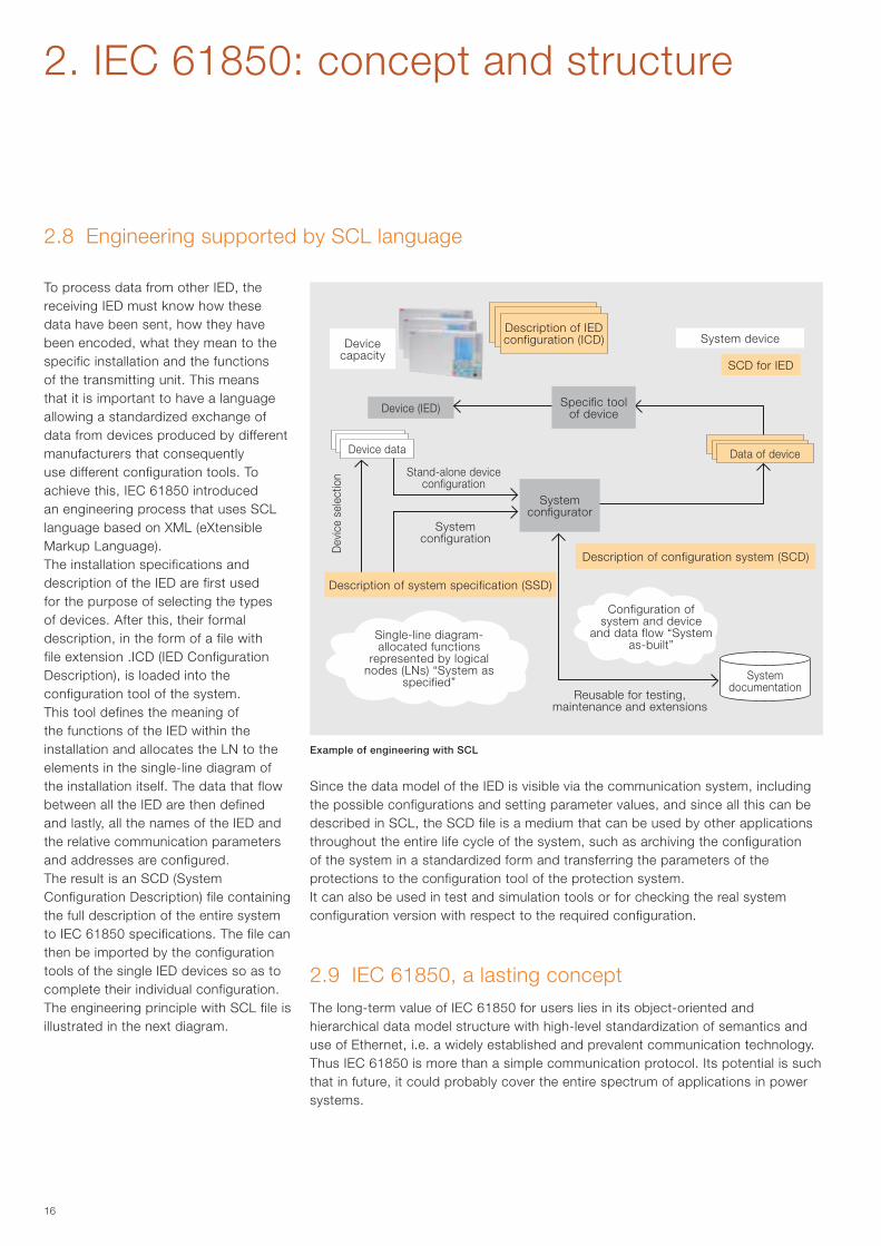
To process data from other IED, the receiving IED must know how these data have been sent, how they have been encoded, what they mean to the specific installation and the functions of the transmitting unit. This means that it is important to have a language allowing a standardized exchange of data from devices produced by different manufacturers that consequently use different configuration tools. To achieve this, IEC 61850 introduced an engineering process that uses SCL language based on XML (eXtensible Markup Language).The installation specifications and description of the IED are first used for the purpose of selecting the types of devices. After this, their formal description, in the form of a file with file extension .ICD (IED Configuration Description), is loaded into the configuration tool of the system.This tool defines the meaning of the functions of the IED within the installation and allocates the LN to the elements in the single-line diagram of the installation itself. The data that flow between all the IED are then defined and lastly, all the names of the IED and the relative communication parameters and addresses are configured.The result is an SCD (System Configuration Description) file containing the full description of the entire system to IEC 61850 specifications. The file can then be imported by the configuration tools of the single IED devices so as to complete their individual configuration. The engineering principle with SCL file is illustrated in the next diagram.
2.9 IEC 61850, a lasting conceptThe long-term value of IEC 61850 for users lies in its object-oriented and hierarchical data model structure with high-level standardization of semantics and use of Ethernet, i.e. a widely established and prevalent communication technology. Thus IEC 61850 is more than a simple communication protocol. Its potential is such that in future, it could probably cover the entire spectrum of applications in power systems.
Since the data model of the IED is visible via the communication system, including the possible configurations and setting parameter values, and since all this can be described in SCL, the SCD file is a medium that can be used by other applications throughout the entire life cycle of the system, such as archiving the configuration of the system in a standardized form and transferring the parameters of the protections to the configuration tool of the protection system.It can also be used in test and simulation tools or for checking the real system configuration version with respect to the required configuration.
Example of engineering with SCL
Device capacity
System device
Device (IED)
SCD for IED
Stand-alone device configuration
Dev
ice
sele
ctio
n
System configuration
Single-line diagram-allocated functions
represented by logical nodes (LNs) “System as
specified”
Configuration of system and device
and data flow “System as-built”
System documentation
Description of configuration system (SCD)
Reusable for testing, maintenance and extensions
Device data
Description of IED configuration (ICD)
Data of device
System configurator
Description of system specification (SSD)
Specific tool of device
17
3. ABB products based on IEC 61850
3.1 Native development of IEC 61850 in ABB protection and monitoring devices
In an IED design where IEC 61850 is implemented in the native mode, the life-cycle of the device must be considered from its actual specifications, throughout the development of both device and system, their putting into service and finally their operation and maintenance. In short, an IED based on IEC 61850 must:– be able to provide the system and other IED and tools (even
when produced by other manufacturers) with a complete set of protection and control data in accordance with the data model and in order to ensure the correct level of interoperability;
– provide rapid communication and a good performance level of the applications so that the GOOSE services can be used in the best possible way in critical situations, such as the creation of interlocks between bays and distributed protection algorithms;
– conform to data modelling and use SCL for engineering the system, configuring the devices, diagnostics and putting into service;
– be able to suppoprt further developments, e.g. for the transmission of current and voltage samples and synchronization accuracy.
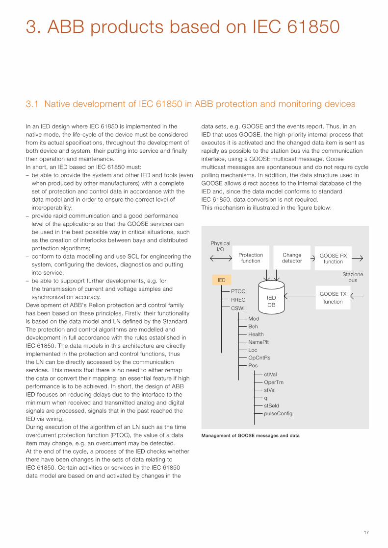
Development of ABB's Relion protection and control family has been based on these principles. Firstly, their functionality is based on the data model and LN defined by the Standard. The protection and control algorithms are modelled and development in full accordance with the rules established in IEC 61850. The data models in this architecture are directly implemented in the protection and control functions, thus the LN can be directly accessed by the communication services. This means that there is no need to either remap the data or convert their mapping: an essential feature if high performance is to be achieved. In short, the design of ABB IED focuses on reducing delays due to the interface to the minimum when received and transmitted analog and digital signals are processed, signals that in the past reached the IED via wiring.During execution of the algorithm of an LN such as the time overcurrent protection function (PTOC), the value of a data item may change, e.g. an overcurrent may be detected. At the end of the cycle, a process of the IED checks whether there have been changes in the sets of data relating to IEC 61850. Certain activities or services in the IEC 61850 data model are based on and activated by changes in the
data sets, e.g. GOOSE and the events report. Thus, in an IED that uses GOOSE, the high-priority internal process that executes it is activated and the changed data item is sent as rapidly as possible to the station bus via the communication interface, using a GOOSE multicast message. Goose multicast messages are spontaneous and do not require cycle polling mechanisms. In addition, the data structure used in GOOSE allows direct access to the internal database of the IED and, since the data model conforms to standard IEC 61850, data conversion is not required.This mechanism is illustrated in the figure below:
Management of GOOSE messages and data
Physical I/O
Stazione bus
IEDDB
Mod
Beh
Health
NamePlt
Loc
OpCntRs
Pos
ctlVal
OperTm
stVal
q
stSeld
pulseConfig
PTOC
RREC
CSWI
IED
GOOSE TX
function
Protection function
Change detector
GOOSE RX function
18
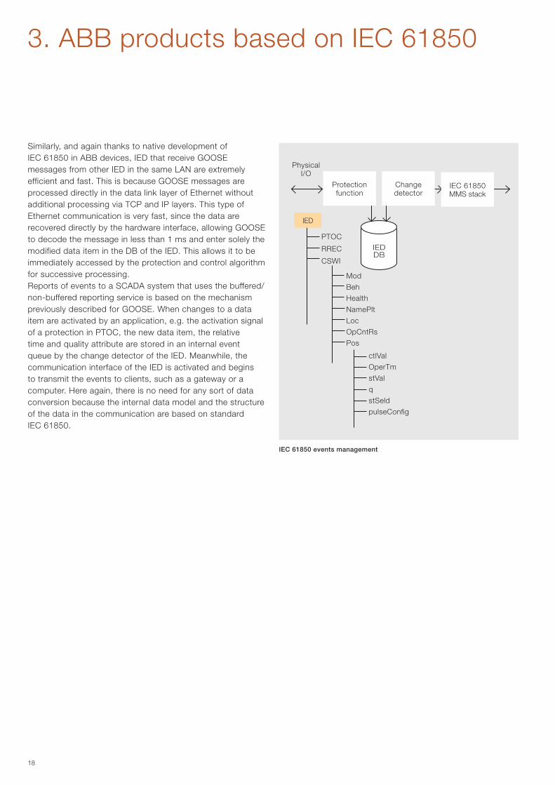
Similarly, and again thanks to native development of IEC 61850 in ABB devices, IED that receive GOOSE messages from other IED in the same LAN are extremely efficient and fast. This is because GOOSE messages are processed directly in the data link layer of Ethernet without additional processing via TCP and IP layers. This type of Ethernet communication is very fast, since the data are recovered directly by the hardware interface, allowing GOOSE to decode the message in less than 1 ms and enter solely the modified data item in the DB of the IED. This allows it to be immediately accessed by the protection and control algorithm for successive processing.Reports of events to a SCADA system that uses the buffered/non-buffered reporting service is based on the mechanism previously described for GOOSE. When changes to a data item are activated by an application, e.g. the activation signal of a protection in PTOC, the new data item, the relative time and quality attribute are stored in an internal event queue by the change detector of the IED. Meanwhile, the communication interface of the IED is activated and begins to transmit the events to clients, such as a gateway or a computer. Here again, there is no need for any sort of data conversion because the internal data model and the structure of the data in the communication are based on standard IEC 61850.
3. ABB products based on IEC 61850
IEC 61850 events management
Physical I/O
IEDDB
Mod
Beh
Health
NamePlt
Loc
OpCntRs
Pos
ctlVal
OperTm
stVal
q
stSeld
pulseConfig
PTOC
RREC
CSWI
IED
Protection function
Change detector
IEC 61850 MMS stack
19
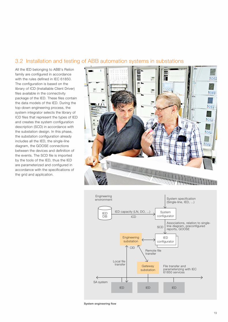
3.2 Installation and testing of ABB automation systems in substationsAll the IED belonging to ABB's Relion family are configured in accordance with the rules defined in IEC 61850. The configuration is based on the library of ICD (Installable Client Driver) files available in the connectivity package of the IED. These files contain the data models of the IED. During the top-down engineering process, the system integrator selects the library of ICD files that represent the types of IED and creates the system configuration description (SCD) in accordance with the substation design. In this phase, the substation configuration already includes all the IED, the single-line diagram, the GOOSE connections between the devices and definition of the events. The SCD file is imported by the tools of the IED, thus the IED are parameterized and configured in accordance with the specifications of the grid and application.
System engineering flow
Engineering environment System specification
(Single-line, IED, ...)
IED capacity (LN, DO, ...)
Associations, relation to single-line diagram, preconfigured reports, GOOSE
Remote file transfer
Local file transfer File transfer and
parameterizing with IEC 61850 services
Gateway substation
Engineering substation
IED IED IED
IEDDB
IED configurator
System configurator
SA system
SCD
ICD
CID
20
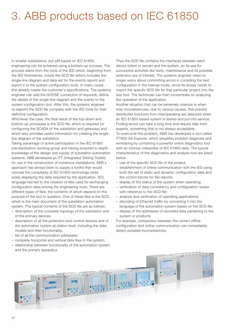
In smaller substations, but still based on IEC 61850, engineering can be achieved using a bottom-up process. The process starts from the tools of the IED which, beginning from the IED themselves, create the SCD file (which includes the single-line diagram and data set for the events report) and export it to the system configuration tools. In many cases, this already meets the customer's specifications. The systems engineer can add the GOOSE connection (if required), define the details of the single-line diagram and the events to the system configuration tool. After this, the systems engineer re-exports the SCD file complete with the IED tools for their definitive configuration.Whichever the case, the final result of the top-down and bottom-up processes is the SCD file, which is required for configuring the SCADA of the substation and gateways and which also provides useful information for creating the single-line diagram of the substation. Taking advantage of active participation in the IEC 61850 standardization working group and having acquired in-depth knowledge of the design and supply of substation automation systems, ABB developed an ITT (Integrated Testing Toolkit) for use in the construction of numerous installations. ABB's approach has always been to supply a toolkit that would conceal the complexity of IEC 61850 technology while solely displaying the data required by the application. SCL language has led to the creation of files used for exchanging configuration data among the engineering tools. There are different types of files, the contents of which depend on the purpose of the tool in question. One of these files is the SCD, which is the main document of the substation automation system. The typical contents of the SCD file are as follows:– description of the complete topology of the substation and
of the primary devices;– description of all the protection and control devices and of
the automation system at station level, including the data models and their functionality;
– list of all the communication addresses;– complete horizontal and vertical data flow in the system;– relationship between functionality of the automation system
and the primary apparatus.
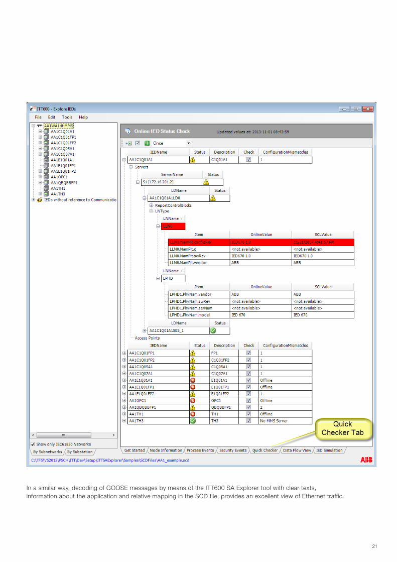
Thus the SCD file contains the interfaces between each device (client or server) and the system, so its use for successive activities like tests, maintenance and its possible extension are of interest. The systems engineer need no longer worry about committing errors in compiling the test configuration in the manual mode, since he simply needs to import the specific SCD file for that particular project into the test tool. The technician can then concentrate on analyzing the operation of the application. Another situation that can be extremely onerous is when time inconsistencies, due to various causes, that prevent distributed functions from interoperating are detected when an IEC 61850-based system is tested and put into service. Finding errors can take a long time and require help from experts, something that is not always acceptable. To overcome this problem, ABB has developed a tool called ITT600 SA Explorer, which simplifies problem diagnosis and remedying by combining a powerful online diagnostics tool with an intrinsic interpreter of IEC 61850 data. The typical characteristics of the diagnostics and analysis tool are listed below:– use of the specific SCD file of the project;– establishment of online communication with the IED using
both the set of static and dynamic configuration data and the control blocks for the reports;
– display of the status of the system when operating;– verification of data consistency and configuration review
with reference to the SCD file;– analysis and verification of operating applications;– decoding of Ethernet traffic by converting it into the
language of the automation system based on the SCD file;– display of the addresses of recorded data pertaining to the
system or products.For example, comparison between the correct offline configuration and online communication can immediately detect possible inconsistencies.
3. ABB products based on IEC 61850
21
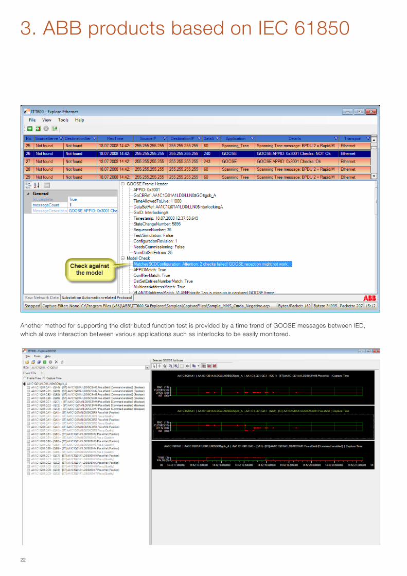
In a similar way, decoding of GOOSE messages by means of the ITT600 SA Explorer tool with clear texts, information about the application and relative mapping in the SCD file, provides an excellent view of Ethernet traffic.
22
Another method for supporting the distributed function test is provided by a time trend of GOOSE messages between IED, which allows interaction between various applications such as interlocks to be easily monitored.
3. ABB products based on IEC 61850
23
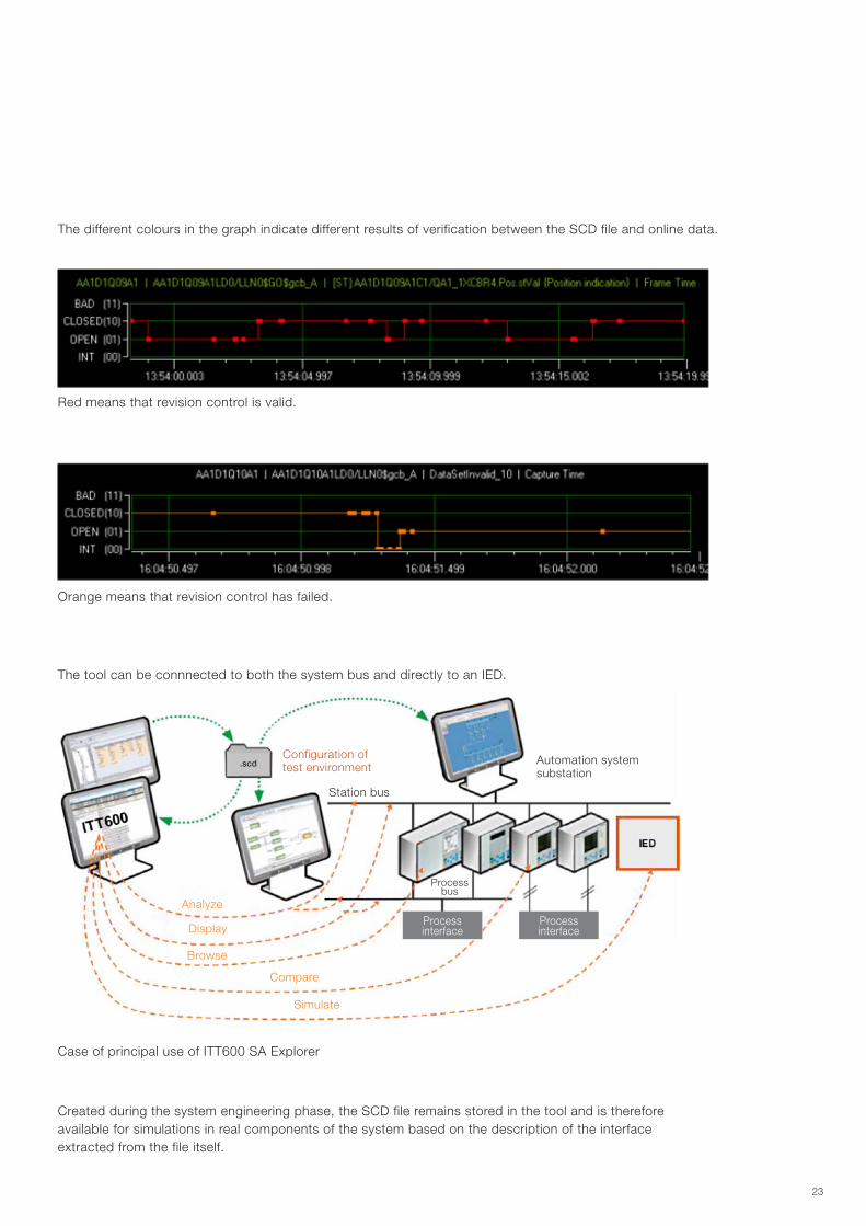
The different colours in the graph indicate different results of verification between the SCD file and online data.
The tool can be connnected to both the system bus and directly to an IED.
Created during the system engineering phase, the SCD file remains stored in the tool and is therefore available for simulations in real components of the system based on the description of the interface extracted from the file itself.
Red means that revision control is valid.
Orange means that revision control has failed.
Case of principal use of ITT600 SA Explorer
Configuration of test environment
Automation system substation
Station bus
Analyze
Display
Browse
Compare
Simulate
Process bus
Process interface
Process interface
.scd
24
3.3 The ABB verification and validation site for IEC 61850
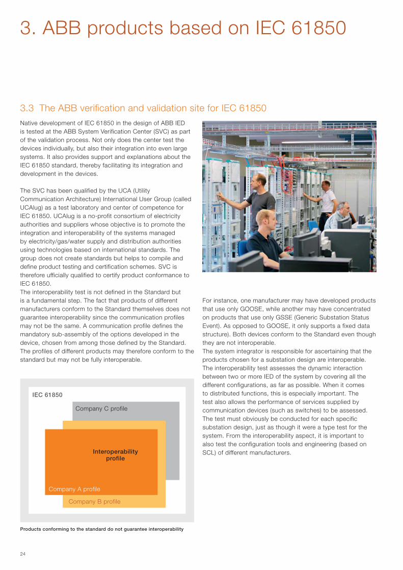
The SVC has been qualified by the UCA (Utility Communication Architecture) International User Group (called UCAlug) as a test laboratory and center of competence for IEC 61850. UCAlug is a no-profit consortium of electricity authorities and suppliers whose objective is to promote the integration and interoperability of the systems managed by electricity/gas/water supply and distribution authorities using technologies based on international standards. The group does not create standards but helps to compile and define product testing and certification schemes. SVC is therefore ufficially qualified to certify product conformance to IEC 61850.The interoperability test is not defined in the Standard but is a fundamental step. The fact that products of different manufacturers conform to the Standard themselves does not guarantee interoperability since the communication profiles may not be the same. A communication profile defines the mandatory sub-assembly of the options developed in the device, chosen from among those defined by the Standard. The profiles of different products may therefore conform to the standard but may not be fully interoperable.
For instance, one manufacturer may have developed products that use only GOOSE, while another may have concentrated on products that use only GSSE (Generic Substation Status Event). As opposed to GOOSE, it only supports a fixed data structure). Both devices conform to the Standard even though they are not interoperable. The system integrator is responsible for ascertaining that the products chosen for a substation design are interoperable.The interoperability test assesses the dynamic interaction between two or more IED of the system by covering all the different configurations, as far as possible. When it comes to distributed functions, this is especially important. The test also allows the performance of services supplied by communication devices (such as switches) to be assessed. The test must obviously be conducted for each specific substation design, just as though it were a type test for the system. From the interoperability aspect, it is important to also test the configuration tools and engineering (based on SCL) of different manufacturers.
3. ABB products based on IEC 61850
IEC 61850
Company C profile
Native development of IEC 61850 in the design of ABB IED is tested at the ABB System Verification Center (SVC) as part of the validation process. Not only does the center test the devices individually, but also their integration into even large systems. It also provides support and explanations about the IEC 61850 standard, thereby facilitating its integration and development in the devices.
Interoperability profile
Products conforming to the standard do not guarantee interoperability
Company A profile
Company B profile
Company C profile
25
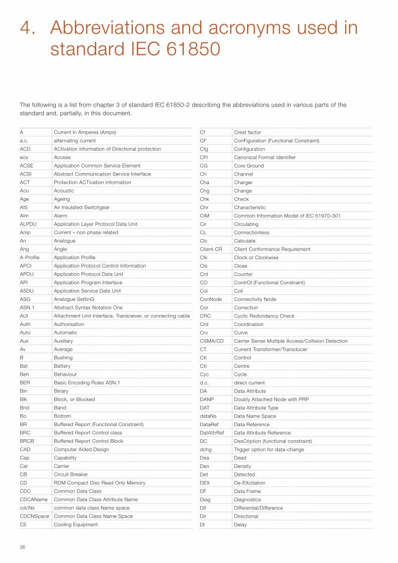
Test sequence for a customer's project
R&D test sequence
Factory test
Type test on device
Factory test validation
Integration test
Test on site Test on site validation
System test
Sequence of tests conducted by R&D, guarantee operation regardless of application design
Test sequence for a customer's project
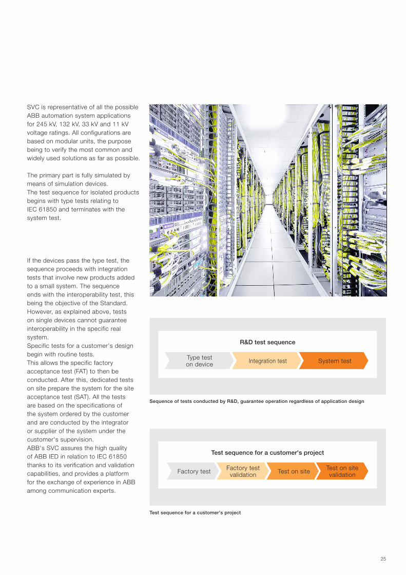
SVC is representative of all the possible ABB automation system applications for 245 kV, 132 kV, 33 kV and 11 kV voltage ratings. All configurations are based on modular units, the purpose being to verify the most common and widely used solutions as far as possible.
The primary part is fully simulated by means of simulation devices.The test sequence for isolated products begins with type tests relating to IEC 61850 and terminates with the system test.
If the devices pass the type test, the sequence proceeds with integration tests that involve new products added to a small system. The sequence ends with the interoperability test, this being the objective of the Standard. However, as explained above, tests on single devices cannot guarantee interoperability in the specific real system. Specific tests for a customer's design begin with routine tests. This allows the specific factory acceptance test (FAT) to then be conducted. After this, dedicated tests on site prepare the system for the site acceptance test (SAT). All the tests are based on the specifications of the system ordered by the customer and are conducted by the integrator or supplier of the system under the customer's supervision.ABB's SVC assures the high quality of ABB IED in relation to IEC 61850 thanks to its verification and validation capabilities, and provides a platform for the exchange of experience in ABB among communication experts.
26
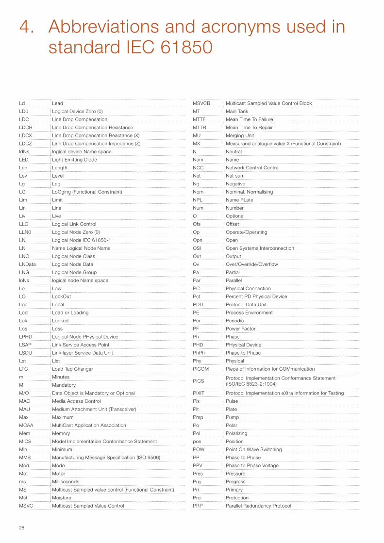
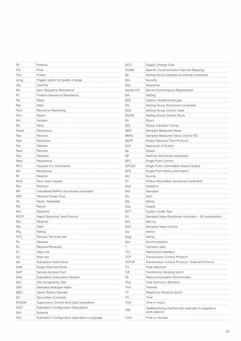
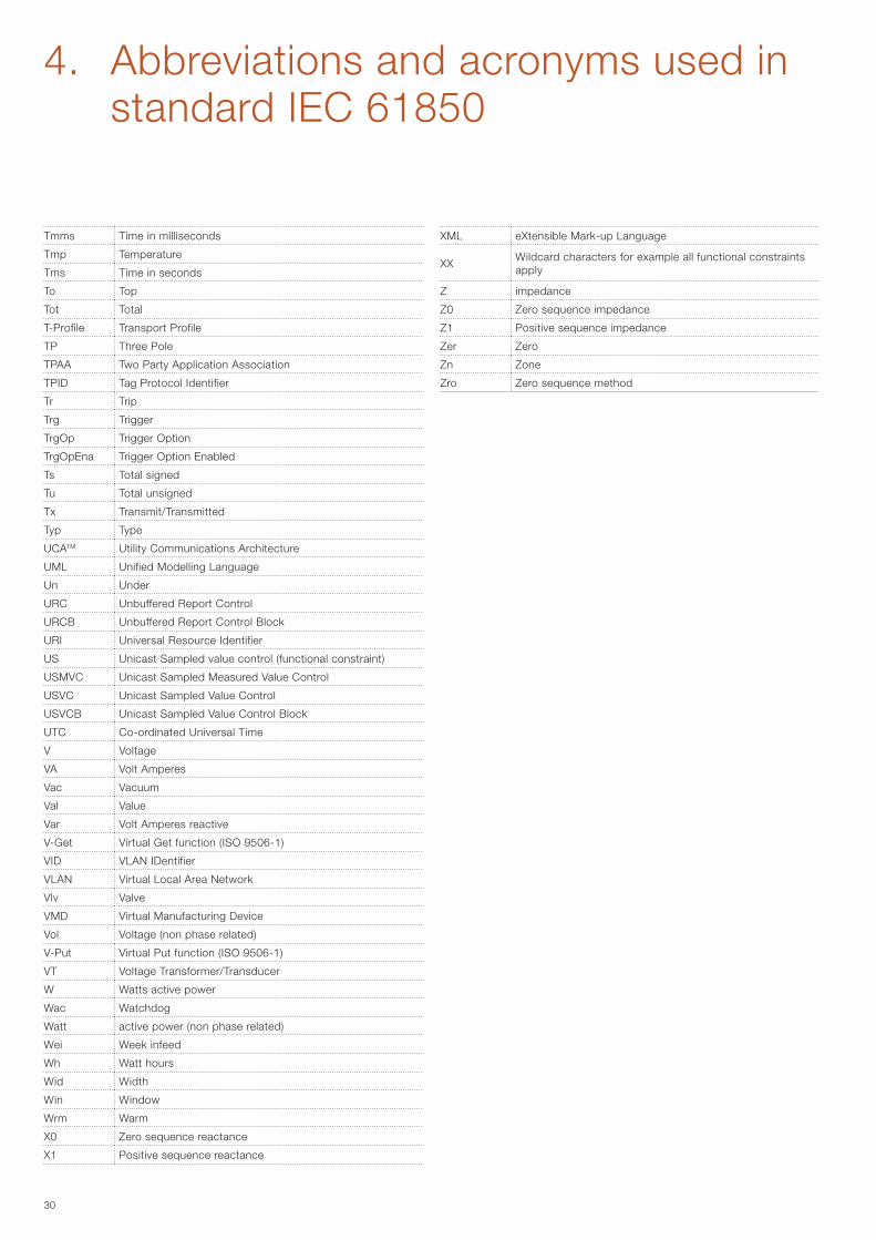
4. Abbreviations and acronyms used in standard IEC 61850
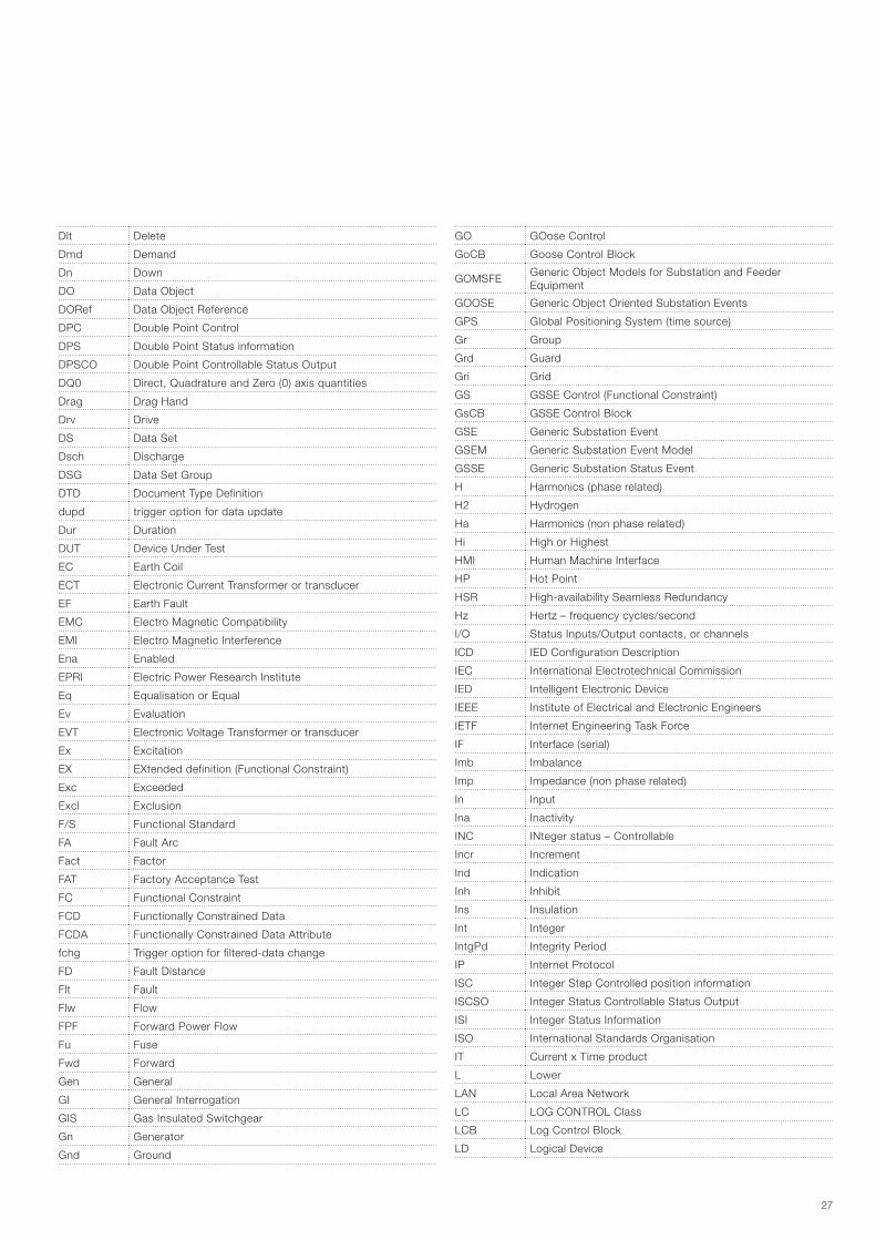
The following is a list from chapter 3 of standard IEC 61850-2 describing the abbreviations used in various parts of the standard and, partially, in this document.
A Current in Amperes (Amps)
a.c. alternating current
ACD ACtivation information of Directional protection
acs Access
ACSE Application Common Service Element
ACSI Abstract Communication Service Interface
ACT Protection ACTivation information
Acu Acoustic
Age Ageing
AIS Air Insulated Switchgear
Alm Alarm
ALPDU Application Layer Protocol Data Unit
Amp Current – non phase related
An Analogue
Ang Angle
A-Profile Application Profile
APCI Application Protocol Control Information
APDU Application Protocol Data Unit
API Application Program Interface
ASDU Application Service Data Unit
ASG Analogue SettinG
ASN.1 Abstract Syntax Notation One
AUI Attachment Unit Interface, Transceiver, or connecting cable
Auth Authorisation
Auto Automatic
Aux Auxiliary
Av Average
B Bushing
Bat Battery
Beh Behaviour
BER Basic Encoding Rules ASN.1
Bin Binary
Blk Block, or Blocked
Bnd Band
Bo Bottom
BR Buffered Report (Functional Constraint)
BRC Buffered Report Control class
BRCB Buffered Report Control Block
CAD Computer Aided Design
Cap Capability
Car Carrier
CB Circuit Breaker
CD ROM Compact Disc Read Only Memory
CDC Common Data Class
CDCAName Common Data Class Attribute Name
cdcNs common data class Name space
CDCNSpace Common Data Class Name Space
CE Cooling Equipment
Cf Crest factor
CF ConFiguration (Functional Constraint)
Cfg Configuration
CFI Canonical Format Identifier
CG Core Ground
Ch Channel
Cha Charger
Chg Change
Chk Check
Chr Characteristic
CIM Common Information Model of IEC 61970-301
Cir Circulating
CL Connectionless
Clc Calculate
Client-CR Client Conformance Requirement
Clk Clock or Clockwise
Cls Close
Cnt Counter
CO ContrOl (Functional Constraint)
Col Coil
ConNode Connectivity Node
Cor Correction
CRC Cyclic Redundancy Check
Crd Coordination
Crv Curve
CSMA/CD Carrier Sense Multiple Access/Collision Detection
CT Current Transformer/Transducer
Ctl Control
Ctr Centre
Cyc Cycle
d.c. direct current
DA Data Attribute
DANP Doubly Attached Node with PRP
DAT Data Attribute Type
dataNs Data Name Space
DataRef Data Reference
DatAttrRef Data Attribute Reference
DC DesCription (functional constraint)
dchg Trigger option for data-change
Dea Dead
Den Density
Det Detected
DEX De-EXcitation
DF Data Frame
Diag Diagnostics
Dif Differential/Difference
Dir Directional
Dl Delay
27
Dlt Delete
Dmd Demand
Dn Down
DO Data Object
DORef Data Object Reference
DPC Double Point Control
DPS Double Point Status information
DPSCO Double Point Controllable Status Output
DQ0 Direct, Quadrature and Zero (0) axis quantities
Drag Drag Hand
Drv Drive
DS Data Set
Dsch Discharge
DSG Data Set Group
DTD Document Type Definition
dupd trigger option for data update
Dur Duration
DUT Device Under Test
EC Earth Coil
ECT Electronic Current Transformer or transducer
EF Earth Fault
EMC Electro Magnetic Compatibility
EMI Electro Magnetic Interference
Ena Enabled
EPRI Electric Power Research Institute
Eq Equalisation or Equal
Ev Evaluation
EVT Electronic Voltage Transformer or transducer
Ex Excitation
EX EXtended definition (Functional Constraint)
Exc Exceeded
Excl Exclusion
F/S Functional Standard
FA Fault Arc
Fact Factor
FAT Factory Acceptance Test
FC Functional Constraint
FCD Functionally Constrained Data
FCDA Functionally Constrained Data Attribute
fchg Trigger option for filtered-data change
FD Fault Distance
Flt Fault
Flw Flow
FPF Forward Power Flow
Fu Fuse
Fwd Forward
Gen General
GI General Interrogation
GIS Gas Insulated Switchgear
Gn Generator
Gnd Ground
GO GOose Control
GoCB Goose Control Block
GOMSFE Generic Object Models for Substation and Feeder Equipment
GOOSE Generic Object Oriented Substation Events
GPS Global Positioning System (time source)
Gr Group
Grd Guard
Gri Grid
GS GSSE Control (Functional Constraint)
GsCB GSSE Control Block
GSE Generic Substation Event
GSEM Generic Substation Event Model
GSSE Generic Substation Status Event
H Harmonics (phase related)
H2 Hydrogen
Ha Harmonics (non phase related)
Hi High or Highest
HMI Human Machine Interface
HP Hot Point
HSR High-availability Seamless Redundancy
Hz Hertz – frequency cycles/second
I/O Status Inputs/Output contacts, or channels
ICD IED Configuration Description
IEC International Electrotechnical Commission
IED Intelligent Electronic Device
IEEE Institute of Electrical and Electronic Engineers
IETF Internet Engineering Task Force
IF Interface (serial)
Imb Imbalance
Imp Impedance (non phase related)
In Input
Ina Inactivity
INC INteger status – Controllable
Incr Increment
Ind Indication
Inh Inhibit
Ins Insulation
Int Integer
IntgPd Integrity Period
IP Internet Protocol
ISC Integer Step Controlled position information
ISCSO Integer Status Controllable Status Output
ISI Integer Status Information
ISO International Standards Organisation
IT Current x Time product
L Lower
LAN Local Area Network
LC LOG CONTROL Class
LCB Log Control Block
LD Logical Device
28
Ld Lead
LD0 Logical Device Zero (0)
LDC Line Drop Compensation
LDCR Line Drop Compensation Resistance
LDCX Line Drop Compensation Reactance (X)
LDCZ Line Drop Compensation Impedance (Z)
ldNs logical device Name space
LED Light Emitting Diode
Len Length
Lev Level
Lg Lag
LG LoGging (Functional Constraint)
Lim Limit
Lin Line
Liv Live
LLC Logical Link Control
LLN0 Logical Node Zero (0)
LN Logical Node IEC 61850-1
LN Name Logical Node Name
LNC Logical Node Class
LNData Logical Node Data
LNG Logical Node Group
lnNs logical node Name space
Lo Low
LO LockOut
Loc Local
Lod Load or Loading
Lok Locked
Los Loss
LPHD Logical Node PHysical Device
LSAP Link Service Access Point
LSDU Link layer Service Data Unit
Lst List
LTC Load Tap Changer
m Minutes
M Mandatory
M/O Data Object is Mandatory or Optional
MAC Media Access Control
MAU Medium Attachment Unit (Transceiver)
Max Maximum
MCAA MultiCast Application Association
Mem Memory
MICS Model Implementation Conformance Statement
Min Minimum
MMS Manufacturing Message Specification (ISO 9506)
Mod Mode
Mot Motor
ms Milliseconds
MS Multicast Sampled value control (Functional Constraint)
Mst Moisture
MSVC Multicast Sampled Value Control
MSVCB Multicast Sampled Value Control Block
MT Main Tank
MTTF Mean Time To Failure
MTTR Mean Time To Repair
MU Merging Unit
MX Measurand analogue value X (Functional Constraint)
N Neutral
Nam Name
NCC Network Control Centre
Net Net sum
Ng Negative
Nom Nominal, Normalising
NPL Name PLate
Num Number
O Optional
Ofs Offset
Op Operate/Operating
Opn Open
OSI Open Systems Interconnection
Out Output
Ov Over/Override/Overflow
Pa Partial
Par Parallel
PC Physical Connection
Pct Percent PD Physical Device
PDU Protocol Data Unit
PE Process Environment
Per Periodic
PF Power Factor
Ph Phase
PHD PHysical Device
PhPh Phase to Phase
Phy Physical
PICOM Piece of Information for COMmunication
PICS Protocol Implementation Conformance Statement (ISO/IEC 8823-2:1994)
PIXIT Protocol Implementation eXtra Information for Testing
Pls Pulse
Plt Plate
Pmp Pump
Po Polar
Pol Polarizing
pos Position
POW Point On Wave Switching
PP Phase to Phase
PPV Phase to Phase Voltage
Pres Pressure
Prg Progress
Pri Primary
Pro Protection
PRP Parallel Redundancy Protocol
4. Abbreviations and acronyms used in standard IEC 61850
29
Ps Positive
Pst Post
Pwr Power
qchg Trigger option for quality-change
Qty Quantity
R0 Zero Sequence Resistance
R1 Positive Sequence Resistance
Ra Raise
Rat Ratio
Rcd Record or Recording
Rch Reach
Rcl Reclaim
Re Retry
React Reactance
Rec Reclose
Red Reduction
Rel Release
Rem Remote
Res Residual
Rest Resistance
RFC Request For Comments
Ris Resistance
Rl Relation
Rms Root mean square
Rot Rotation
RP Unbuffered RePort (functional constraint)
RPF Reverse Power Flow
Rs Reset, Resetable
Rsl Result
Rst Restraint
RSTP Rapid Spanning Tree Protocol
Rsv Reserve
Rte Rate
Rtg Rating
RTU Remote Terminal Unit
Rv Reverse
Rx Receive/Received
S1 Step one
S2 Step two
SA Substation Automation
SAN Singly Attached Node
SAP Service Access Point
SAS Substation Automation System
SAT Site Acceptance Test
SAV Sampled Analogue Value
SBO Select Before Operate
SC Secondary Converter
SCADA Supervisory Control And Data Acquisition
SCD Substation Configuration Description
Sch Scheme
SCL Substation Configuration description Language
SCO Supply Change Over
SCSM Specific Communication Service Mapping
SE Setting Group Editable (functional constraint)
Sec Security
Seq Sequence
Server-CR Server-Conformance Requirement
Set Setting
SF6 Sulphur HexaFluoride gas
SG Setting Group (functional constraint)
SGC Setting Group Control class
SGCB Setting Group Control Block
Sh Shunt
SIG Status Indication Group
SMV Sampled Measured Value
SMVC Sampled Measured Value Control IEC
SNTP Simple Network Time Protocol
SoE Sequence of Events
Sp Speed
SP SetPoint (functional constraint)
SPC Single Point Control
SPCSO Single Point Controllable Status Output
SPS Single Point Status information
Src Source
ST STatus information (functional constraint)
Stat Statistics
Std Standard
Str Start
Sts Stress
Sup Supply
SUT System Under Test
SV Sampled Value (functional constraint – SV substitution)
Svc Service
SVC Sampled Value Control
Sw Switch
Swg Swing
Syn Synchronisation
T Transient data
TCI TeleControl Interface
TCP Transmission Control Protocol
TCP/IP Transmission Control Protocol / Internet Protocol
Td Total distortion
Tdf Transformer derating factor
TE Telecommunication Environment
Thd Total harmonic distortion
Thm Thermal
Tif Telephone influence factor
Tm Time
Tmh Time in hours
TMI TeleMonitoring Interface (for example to engineer’s work-station)
Tmm Time in minutes
30
Tmms Time in milliseconds
Tmp Temperature
Tms Time in seconds
To Top
Tot Total
T-Profile Transport Profile
TP Three Pole
TPAA Two Party Application Association
TPID Tag Protocol Identifier
Tr Trip
Trg Trigger
TrgOp Trigger Option
TrgOpEna Trigger Option Enabled
Ts Total signed
Tu Total unsigned
Tx Transmit/Transmitted
Typ Type
UCATM Utility Communications Architecture
UML Unified Modelling Language
Un Under
URC Unbuffered Report Control
URCB Unbuffered Report Control Block
URI Universal Resource Identifier
US Unicast Sampled value control (functional constraint)
USMVC Unicast Sampled Measured Value Control
USVC Unicast Sampled Value Control
USVCB Unicast Sampled Value Control Block
UTC Co-ordinated Universal Time
V Voltage
VA Volt Amperes
Vac Vacuum
Val Value
Var Volt Amperes reactive
V-Get Virtual Get function (ISO 9506-1)
VID VLAN IDentifier
VLAN Virtual Local Area Network
Vlv Valve
VMD Virtual Manufacturing Device
Vol Voltage (non phase related)
V-Put Virtual Put function (ISO 9506-1)
VT Voltage Transformer/Transducer
W Watts active power
Wac Watchdog
Watt active power (non phase related)
Wei Week infeed
Wh Watt hours
Wid Width
Win Window
Wrm Warm
X0 Zero sequence reactance
X1 Positive sequence reactance
XML eXtensible Mark-up Language
XX Wildcard characters for example all functional constraints apply
Z impedance
Z0 Zero sequence impedance
Z1 Positive sequence impedance
Zer Zero
Zn Zone
Zro Zero sequence method
4. Abbreviations and acronyms used in standard IEC 61850

31
ABB S.p.A. ABB SACE Division Medium Voltage Products Via Friuli, 4I-24044 DalmineTel.: +39 035 6952 111Fax: +39 035 6952 874e-mail: [email protected]
www.abb.com
1VC
P00
0645
- R
ev. A
, - e
n - 2
017.
01 -
(Tec
hnic
al g
uide
- S
mar
t grid
s - 3
. Sta
ndar
d IE
C 6
1850
) (gs
) The data and illustrations are not binding. We reserve the right to make changes without notice in the course of technical development of the product.
© Copyright 2017 ABB. All rights reserved.
Contact us
Related Documents