Homework 3 - Working with UART and RMS Developing Java ME Embedded Applications by Using a Raspberry Pi: Homework for Lesson 3 Assumptions You have successfully completed the homework for lesson 1 and lesson 2 You have a breadboard (half or full size) and the following components: Adafruit Ultimate GPS Breakout with a breakaway header soldered to the breakout board. Breadboard wires 26-pin ribbon cable and Adafruit cobbler or equivalent Note: make sure you use the 8.1 Early Access software for Raspberry Pi Install the gpsd daemon Open a PuTTY window connected to your Raspberry Pi, and enter: sudo apt-get install gpsd gpsd-clients python-gps Part 1: Test the GPS device using the USB to Serial TTL cable In this assignment, you will connect the GPS sensor to your Raspberry Pi using the USB to Serial TTL cable. Note: this is an optional exercise, and if you don't have the Adafruit USB to TTL serial cable, you can skip this assignment. Consult the Lesson 3-3 video for more information. If your Raspberry Pi is on, halt it and then unplug power. In a PuTTY window, enter sudo halt . Wait about 10 seconds, and then unplug the power cable. Wire the USB to Serial TTL connector to the breakout pins of your GPS device. Note: if you haven't already soldered the header pins to the breakout board, you will need to do that first. Connect the red wire from the USB cable to the VIN pin on the GPS device. Connect the black wire to the GND pin. Connect the green wire to the RX pin. Connect the white wire to the TX pin. Plug the USB cable into the Rasbperry Pi and boot the Raspberry Pi by plugging power back in. Note: The GPS device Fix LED will flash once a second until the GPS chip has a fix, and then it will flash only once every 15 seconds. The time required to get a fix depends upon your location and can take several minutes. The GPS device works better when located near a window or outdoors. Enter ls /dev/ttyUSB* to determine which USB port the cable is connected to. Enter sudo gpsd /dev/ttyUSB0 -F /var/run/gpsd.sock to start the gpsd daemon on the device address. Note: in this example the USB port is 0. Enter cgps -s to start the GPS client and display the output from the device as formatted data. Troubleshooting: If the client starts and then exits without displaying data, make sure that you have a fix - see the note above. If you do, then kill the gpsd daemon and restart it. Enter cat /dev/ttyUSB0 (use your port number) - if you do not see strings of characters, check your connections. Team Collaboration Java_Embedded_Open_Onli...

Welcome message from author
This document is posted to help you gain knowledge. Please leave a comment to let me know what you think about it! Share it to your friends and learn new things together.
Transcript
Homework 3 - Working with UART and RMS
Developing Java ME Embedded Applications by Using a Raspberry Pi:Homework for Lesson 3
Assumptions
You have successfully completed the homework for lesson 1 and lesson 2
You have a breadboard (half or full size) and the following components:
Adafruit Ultimate GPS Breakout with a breakaway header soldered to the breakout board.
Breadboard wires
26-pin ribbon cable and Adafruit cobbler or equivalent
Note: make sure you use the 8.1 Early Access software for Raspberry Pi
Install the gpsd daemon
Open a PuTTY window connected to your Raspberry Pi, and enter:
sudo apt-get install gpsd gpsd-clients python-gps
Part 1: Test the GPS device using the USB to Serial TTL cable
In this assignment, you will connect the GPS sensor to your Raspberry Pi using the USB to Serial TTL cable.
Note: this is an optional exercise, and if you don't have the Adafruit USB to TTL serial cable, you can skip this
assignment.
Consult the Lesson 3-3 video for more information.
If your Raspberry Pi is on, halt it and then unplug power.
In a PuTTY window, enter sudo halt.
Wait about 10 seconds, and then unplug the power cable.
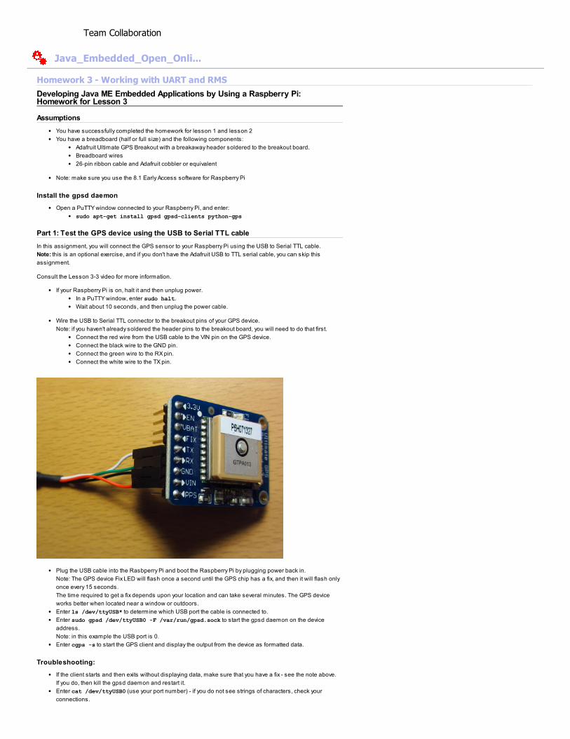
Wire the USB to Serial TTL connector to the breakout pins of your GPS device.
Note: if you haven't already soldered the header pins to the breakout board, you will need to do that first.
Connect the red wire from the USB cable to the VIN pin on the GPS device.
Connect the black wire to the GND pin.
Connect the green wire to the RX pin.
Connect the white wire to the TX pin.
Plug the USB cable into the Rasbperry Pi and boot the Raspberry Pi by plugging power back in.
Note: The GPS device Fix LED will flash once a second until the GPS chip has a fix, and then it will flash only
once every 15 seconds.
The time required to get a fix depends upon your location and can take several minutes. The GPS device
works better when located near a window or outdoors.
Enter ls /dev/ttyUSB* to determine which USB port the cable is connected to.
Enter sudo gpsd /dev/ttyUSB0 -F /var/run/gpsd.sock to start the gpsd daemon on the device
address.
Note: in this example the USB port is 0.
Enter cgps -s to start the GPS client and display the output from the device as formatted data.
Troubleshooting:
If the client starts and then exits without displaying data, make sure that you have a fix - see the note above.
If you do, then kill the gpsd daemon and restart it.
Enter cat /dev/ttyUSB0 (use your port number) - if you do not see strings of characters, check your
connections.
Team Collaboration
Java_Embedded_Open_Onli...

Part 2: Connect the GPS device using the Raspberry Pi GPIO header
In this assignment, you wire the GPS device to the transmit and receive pins on the GPIO header.
Setup
Per the lesson 3-3 video instructions, configure the Raspberry Pi to allow you to use /dev/ttyAMA0.
Edit cmdline.txt with the command: sudo nano /boot/cmdline.txt
Remove console=ttyAMA0,115200 kgdboc=ttyAMA0,115200 from the first line in the file.
Press Ctrl + O and Enter, and then press Ctrl + X to write and close the file.
Edit /etc/inittab with the command: sudo nano /etc/inittab
Comment out the last line (enter a # at the beginning of the line).
Press Ctrl + O and Enter to write the file.
Press Ctrl + X to close the file.
Reboot the Pi with the command: sudo reboot
Power off the Pi to perform the wiring below.
Wire the GPS device as described in video, using GPIO Pin 14 and GPIO pin 15. A couple important notes:
Be sure to use 3.3V for VIN and NOT 5V. The device is capable of handling both, but we strongly
suggest you ONLY use 3.3 V.
TX on the GPS breakout is wired to RXD on the Cobbler breakout, and RX on the GPS is wired to TXD.
Use this diagram to help, or this Fritzing diagram , courtesy of Brent Stains.
Connect the ribbon cable from the Pi to the Cobbler (if not already connected)
Power the Pi and reconnect using PuTTY.
Test the Setup
Enter sudo gpsd /dev/ttyAMA0 -F /var/run/gpsd.sock to start the gpsd daemon on the device
address.
When the GPS device has a fix, enter cgps -s to start the GPS client and display the output from the device
as formatted data. If the Fix LED is flashing more than once every 15 seconds, cgps will simply terminate.
Troubleshooting
If you are not getting any data from the GPS:
Double-check that you correctly cross-wired TX on the GPS breakout to RXD on the Cobbler breakout, and RX
on the GPS to TXD.
Place the GPS device close to a window. In general, GPS works better with a line of sight to the sky.
Wait for the device to acquire a fix. This may take a few minutes, depending upon your location. The device
will have a fix when the Fix LED on the GPS breakout board flashes once every 15 seconds. If it flashing
more frequently, it means it does not yet have a fix.
Enter cat /dev/ttyAMA0 in the PuTTY window (use the USB port number you discovered in step 3). You should
see strings of characters. If not, recheck your connections.
Kill and restart the gpsd daemon.
Part 3: Read data from the GPS device using Java ME Embedded
In this assignment, write the required portions of the GPSDataRecorder project to read the position and velocity
strings from the GPS device.
Consult the Lesson 3-2, 3-3 and 3-4 videos for information on writing this code.
Open the provided NetBeans template project, GPSDataRecorderTemplate.zip from the Supporting
Materials section.
The UML diagram describes the relationship between the classes you will need to construct to read the
Adafruit GPS sensor using either a comm connection to /dev/ttyAMA0, or the UART on port 40.

Your task is to implement the AdaFruitGPSSensor abstract class, and the AdaFruitGPSUARTSensor class.
Refer to the videos in lessons 3-2, 3-3 and 3-4 for help.
The AdaFruitGPSSensor class processes the NMEA strings read from the device
The UARTSensor class extends the GPSSensor class and implements a UART connection.
Open the AdaFruitGPSSensor class.
Find the readDataLine method.
This method reads a string from BufferedReader serialBufferedReader and looks for a String
that begins with a "$" character.
Implement the code needed.
Find the geRawData method
This method looks for a string that matches a particular NMEA "sentence", one that begins
with the String type passed to the method.
Implement code needed to check for the type passed to the method and return the remainder
of the string if the type is matched.
Find the getPosition method.
This method checks the rawData string returned from the getRawData(POSITION_TAG)
method.
Implement the code needed to perform the following tasks:
Split the rawData string into tokens using the splitCSVString method.
Check that at least 10 fields are returned.
Using the tokens returned, parse the strings into latitude, longitude, and altitude.
Refer to the video for more information about which of the tokens in the 10 fields represents
which values.
Find the getVelocity method.
This method checks the rawData string returned from the getRawData(VELOCITY_TAG)
method.
Implement the code needed to perform the following tasks:
Split the rawData string into tokens
Check that at least 8 tokens are returned
Using the tokens returned, parse the data into track and velocity.
Be sure that your code handles partial sentences, looks for the correct start character ($), and checks
the number of elements in the sentence.
Use the $GPGGA NMEA string for position (POSITION_TAG)
Important fields are: 1, 2, 3, 4, & 8
Use $GPVTG NMEA string for velocity (VELOCITY_TAG)
important fields are: 0 & 6
Open the AdaFruitGPSUARTSensor class
Implement the code needed in the constructor to:
Open a UART connection using the UART_DEVICE_ID defined in the class
Set the baud rate to 9600 - this is the native speed for the device
Open an input stream using the Channels class
Open a BufferedReader from the input stream (remember that you need an
InputStreamReader first)
Assign the buffered reader to "serialBufferedReader" - this field is defined in
AdaFruitGPSSensor.
The GPSTestMIDlet class will print the position and velocity strings using the message format defined by the
document, events-data-message-doc.pdf, in the Supporting Materials section.
An example position string is: Position: ^^1395075961,37.297,N,122.147,W,9.90 ̂- the first field is
timestamp.
An example velocity string is: Velocity: ^^^1395075961,63.31,1.05
A combined position and velocity string is:
^^1395075961,37.297,N,122.147,W,9.90^1395075961,63.31,1.05
Add the appropriate permissions to your project
jdk.dio.DeviceMgmtPermission "*:*" "open"
jdk.dio.uart.UARTPermission "*:*"
Note that the UARTPermission is not strictly required.
If you get stuck, ask a question on the forum.
Testing
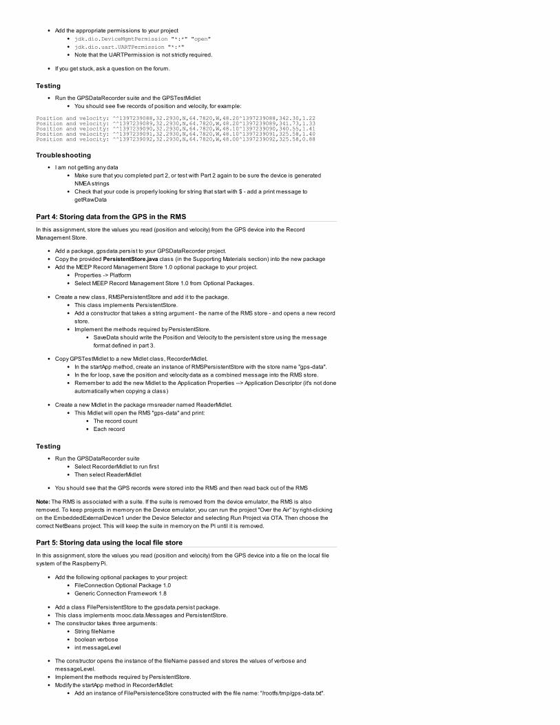
Run the GPSDataRecorder suite and the GPSTestMidlet
You should see five records of position and velocity, for example:
Position and velocity: ̂ 1̂397239088,32.2930,N,64.7820,W,48.20̂1397239088,342.30,1.22Position and velocity: ̂ 1̂397239089,32.2930,N,64.7820,W,48.20̂1397239089,341.73,1.33Position and velocity: ̂ 1̂397239090,32.2930,N,64.7820,W,48.10̂1397239090,340.55,1.41Position and velocity: ̂ 1̂397239091,32.2930,N,64.7820,W,48.10̂1397239091,325.58,1.40Position and velocity: ̂ 1̂397239092,32.2930,N,64.7820,W,48.00̂1397239092,325.58,0.88
Troubleshooting
I am not getting any data
Make sure that you completed part 2, or test with Part 2 again to be sure the device is generated
NMEA strings
Check that your code is properly looking for string that start with $ - add a print message to
getRawData
Part 4: Storing data from the GPS in the RMS
In this assignment, store the values you read (position and velocity) from the GPS device into the Record
Management Store.
Add a package, gpsdata.persist to your GPSDataRecorder project.
Copy the provided PersistentStore.java class (in the Supporting Materials section) into the new package
Add the MEEP Record Management Store 1.0 optional package to your project.
Properties -> Platform
Select MEEP Record Management Store 1.0 from Optional Packages.
Create a new class, RMSPersistentStore and add it to the package.
This class implements PersistentStore.
Add a constructor that takes a string argument - the name of the RMS store - and opens a new record
store.
Implement the methods required by PersistentStore.
SaveData should write the Position and Velocity to the persistent store using the message
format defined in part 3.
Copy GPSTestMidlet to a new Midlet class, RecorderMidlet.
In the startApp method, create an instance of RMSPersistentStore with the store name "gps-data".
In the for loop, save the position and velocity data as a combined message into the RMS store.
Remember to add the new Midlet to the Application Properties --> Application Descriptor (it's not done
automatically when copying a class)
Create a new Midlet in the package rmsreader named ReaderMidlet.
This Midlet will open the RMS "gps-data" and print:
The record count
Each record
Testing
Run the GPSDataRecorder suite
Select RecorderMidlet to run first
Then select ReaderMidlet
You should see that the GPS records were stored into the RMS and then read back out of the RMS
Note: The RMS is associated with a suite. If the suite is removed from the device emulator, the RMS is also
removed. To keep projects in memory on the Device emulator, you can run the project "Over the Air" by right-clicking
on the EmbeddedExternalDevice1 under the Device Selector and selecting Run Project via OTA. Then choose the
correct NetBeans project. This will keep the suite in memory on the Pi until it is removed.
Part 5: Storing data using the local file store
In this assignment, store the values you read (position and velocity) from the GPS device into a file on the local file
system of the Raspberry Pi.
Add the following optional packages to your project:
FileConnection Optional Package 1.0
Generic Connection Framework 1.8
Add a class FilePersistentStore to the gpsdata.persist package.
This class implements mooc.data.Messages and PersistentStore.
The constructor takes three arguments:
String fileName
boolean verbose
int messageLevel
The constructor opens the instance of the fileName passed and stores the values of verbose and
messageLevel.
Implement the methods required by PersistentStore.
Modify the startApp method in RecorderMidlet:
Add an instance of FilePersistenceStore constructed with the file name: "/rootfs/tmp/gps-data.txt".
In the for loop, save the Position and Velocity data to the FilePersistenceStore instance in addition to
the RMS.
Add the following permissions to your project:
javax.microedition.io.Connector.file.read
javax.microedition.io.Connector.file.write
Testing
Run the GPSDataRecorder suite
Run the RecorderMidlet
In a PuTTY windows connected to the Raspberry Pi, change directories to /tmp
Display the results of the local file using cat.
Going Further
Modify the project so that rather than storing to the file in parallel, the file is opened and written as a backing
store for the RMS when the RecorderMidlet is detroyed.
Copyright © 2008, 2013, Oracle and/or its affiliates. All rights reserved. About Beehive Team Collaboration
Related Documents