Team 1 Final Report Jordan Schaenzle Peter Tuuk Job Vranish Brad Zoodsma Mike Zwagerman Monday, October 22, 2007

Welcome message from author
This document is posted to help you gain knowledge. Please leave a comment to let me know what you think about it! Share it to your friends and learn new things together.
Transcript

Team 1 Final Report
Jordan Schaenzle
Peter Tuuk
Job Vranish
Brad Zoodsma
Mike Zwagerman
Monday, October 22, 2007

© 2007 Calvin College and Jordan Schaenzle,
Peter Tuuk, Job Vranish, Brad Zoodsma, Mike Zwagerman

Executive Summary
The purpose of this project is to create a device that is able to pause, stop, and rewind an FM
radio broadcast. We believe this will improve a person’s life because he or she will never miss
their favorite song again on the radio. Imagine a world where you don’t need to miss your radio
program to answer a phone call. Our device will solve that problem.

Table of Contents
1 Introduction............................................................................................................................. 9
1.1 Team .............................................................................................................................. 9
2 Project ................................................................................................................................... 11
3 Project Scope ........................................................................................................................ 12
3.1 The Challenge .............................................................................................................. 12
3.1.1 Hardware ............................................................................................................. 12
3.1.2 Software .............................................................................................................. 13
3.2 Design Norms .............................................................................................................. 14
3.2.1 Justice .................................................................................................................. 14
3.2.2 Cultural Appropriateness ..................................................................................... 14
3.2.3 Transparency ....................................................................................................... 15
3.3 Requirements ............................................................................................................... 15
3.3.1 Prototype Requirements ...................................................................................... 15
3.3.2 Production Requirements .................................................................................... 18
3.4 Prior Work ................................................................................................................... 21
3.4.1 Patents ................................................................................................................. 21
3.4.2 Post Project Completion Research ...................................................................... 22
4 The Solution.......................................................................................................................... 23
4.1 Preliminary Research ................................................................................................... 23
4.1.1 Market Research .................................................................................................. 23
4.1.2 Datasheets ............................................................................................................ 24
4.2 Hardware ...................................................................................................................... 24
4.2.1 FM Tuner (si4701) .............................................................................................. 25
4.2.2 Audio Codec (UCB1400) .................................................................................... 25
4.2.3 SBC (Intel XScale PXA255 CPU module) ......................................................... 26
4.2.4 LCD (LP35) ......................................................................................................... 26
4.2.5 Miscellaneous ...................................................................................................... 28
4.2.6 BOM .................................................................................................................... 30
4.3 Software ....................................................................................................................... 32
4.3.1 Overview of Software Goals ............................................................................... 32
4.3.2 Outline of Specific Software Goals/Acomplishments ......................................... 32
4.3.3 Overview of Software Design Process ................................................................ 37
4.3.4 Overview of Final Software Design .................................................................... 45

4.4 Design Considerations and Criteria ............................................................................. 47
4.4.1 Design considerations/criteria ............................................................................. 47
4.4.2 Design alternatives and analysis .......................................................................... 49
4.4.3 Decision (may use matrix) .................................................................................. 50
4.5 Budget .......................................................................................................................... 53
4.5.1 Prototype ............................................................................................................. 53
4.5.2 Production – economic analysis .......................................................................... 57
4.6 Software ....................................................................................................................... 71
4.7 Project Management .................................................................................................... 71
4.7.1 Team Member Roles ........................................................................................... 71
4.7.2 Work Breakdown Structure ................................................................................. 73
4.7.3 Schedule .............................................................................................................. 76
4.7.4 Contingency Plans ............................................................................................... 76
4.7.5 Assembly Drawing .............................................................................................. 77
4.7.6 Circuit Diagrams ................................................................................................. 78
4.7.7 Task Specifications.............................................................................................. 78
5 Testing .................................................................................................................................. 78
5.1 Debugging Techniques ................................................................................................ 78
5.1.1 IC supporting Circuitry ....................................................................................... 78
5.1.2 Test Drivers ......................................................................................................... 79
5.2 Part Isolation Testing Circuits. ..................................................................................... 79
5.2.1 SBC (Intel XScale PXA255 CPU module) ......................................................... 79
5.2.2 LCD (LP35) ......................................................................................................... 80
5.2.3 FM Tuner (si4701) .............................................................................................. 81
5.2.4 Audio Codec touch screen driver (UCB1400) .................................................... 81
5.2.5 Power Regulation ................................................................................................ 82
5.2.6 MP3 Compression (MAS3587F) ......................................................................... 83
5.3 Test Procedure.............................................................................................................. 84
5.3.1 Physical ............................................................................................................... 84
5.3.2 Functional ............................................................................................................ 84
5.3.3 Testing Table ....................................................................................................... 84
5.4 Test Summary .............................................................................................................. 86
5.4.1 Test Results. ........................................................................................................ 86
6 Unsolved Issues .................................................................................................................... 87

6.1 MP3 Encoding ............................................................................................................. 87
6.1.1 Why We chose Micronas MAS3587F ................................................................. 87
6.1.2 Part Description ................................................................................................... 88
6.1.3 Trouble ................................................................................................................ 90
6.2 Antenna ........................................................................................................................ 91
6.3 Tuner Lists ................................................................................................................... 91
6.4 Headphones ................................................................... Error! Bookmark not defined.
6.5 Stereo Audio - CS4299 ................................................................................................ 91
6.6 MP3 Chip ...................................................................... Error! Bookmark not defined.
6.7 MP3 Chip ...................................................................... Error! Bookmark not defined.
6.8 MP3 Chip ...................................................................... Error! Bookmark not defined.
7 Concluding Thoughts ............................................................................................................ 92
8 Acknowledgements ............................................................................................................... 92
9 Appendices ........................................................................................................................... 93
9.1 Source Code ............................................................................................................... 106
9.1.1 SBC Software ....................................................... Error! Bookmark not defined.
9.1.2 FM Chip Software ................................................ Error! Bookmark not defined.
9.1.3 LCD Software ...................................................... Error! Bookmark not defined.
Table of Figures
Figure 1 - Senior Design Team 1 Picture ...................................................................................... 10
Figure 2 - Functional Block Diagram ............................................................................................ 12
Figure 3 - Block Diagram .............................................................................................................. 24
Figure 4 - FM Chip Size ................................................................................................................ 25
Figure 5 - UCB1400 Chip Size ..................................................................................................... 26
Figure 6 - Intel XScale Processor .................................................................................................. 26
Figure 7 - LCD and User Interface ................................................................................................ 27
Figure 8 - Scanning for Stations .................................................................................................... 28
Figure 9 - Crystal Oscillator .......................................................................................................... 29
Figure 10 - Power Regulation........................................................................................................ 29
Figure 11 - Radio Artist Rendering ............................................................................................... 78
Figure 12 SBC Evaluation Kit Used For SBC Functionality Testing ........................................... 79
Figure 13 PCB Board Used for LCD Functionality Testing ......................................................... 80
Figure 14 PCB Board with FM Tuner IC used for Functionality Testing ..................................... 81
Figure 15 PCB Board with FM Audio Codec IC used for Functionality Testing ......................... 82
Figure 16 PCB board with Power Regulation ICs used for Functionality Testing ....................... 83
Figure 17 PCB Board with MP3 IC used for Functionality Testing ............................................. 83
Figure 18 MAS 3587F Pinout ....................................................................................................... 89
Table of Tables
Table 1 Production Non-labor Costs (per unit) ............................................................................. 30
Table 2 Prototype Non-labor Costs ............................................................................................... 53
Table 3 Prototype Labor Costs ...................................................................................................... 57
Table 4 Retail Price Of Product with Various ROE ...................................................................... 69
Table 5 Test Procedure and Results .............................................................................................. 84
Table of Equations
Equation 1 Power Dissipation Equation ........................................................................................ 49

Abbreviations
µP Microprocessor
AC97 Audio Codec 1997
ADC Analog to Digital Converter
BOM Bill of Materials
DAC Digital to Analog Converter
DSP Digital Signal Processor
FM Frequency Modulated
GPIO General Purpose Input/Output
I2C Inter-Integrated Circuit
I2S Inter-Integrated Circuit Sound
kHz Kilohertz
MP3 MPEG-1 Audio Layer-3
MPEG Moving Picture Experts Group
PCB Printed Circuit Board
PCM Pulse Code Modulation
PPFS Project Proposal and Feasibility Study
OS Operating System
Ofcom Office of Communications
RBDS Radio Broadcast Data System
RDS Radio Data System
SBC Single Board Computer
SPI Serial Peripheral Interface
TBD To Be Determined
USB Universal Serial Bus
VCR Video Cassette Recorder

1 Introduction
Calvin College is a liberal arts college located in Grand Rapids, MI. Founded in 18761 as a
seminary for the Christian Reformed Church, Calvin has grown to educate 4,2002 each year
students in a wide range of fields. Calvin College’s engineering department offers Accreditation
Board for Engineering and Technology (ABET) accredited degrees in Chemical, Civil, Electrical
& Computer, and Mechanical Engineering. As part of the Engineering curriculum students must
complete the Engineering 339/340 sequence known as Senior Design. Each student, in a group of
4 or 5, studies and designs a solution to a problem or to fill a need. This paper is in fulfillment of
the proposal requirement for this class.
1.1 Team
Calvin College Senior Design 2006-2007 Team 1, shown in Figure 1, is composed of five
electrical and computer engineering students: Jordan Schaenzle, Peter Tuuk, Job Vranish, Bradley
Zoodsma, and Michael Zwagerman.
1 http://www.calvin.edu/about/history.htm
2 http://www.calvin.edu/admin/admissions/profile.htm
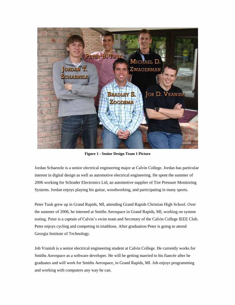
Figure 1 - Senior Design Team 1 Picture
Jordan Schaenzle is a senior electrical engineering major at Calvin College. Jordan has particular
interest in digital design as well as automotive electrical engineering. He spent the summer of
2006 working for Schrader Electronics Ltd, an automotive supplier of Tire Pressure Monitoring
Systems. Jordan enjoys playing his guitar, woodworking, and participating in many sports.
Peter Tuuk grew up in Grand Rapids, MI, attending Grand Rapids Christian High School. Over
the summer of 2006, he interned at Smiths Aerospace in Grand Rapids, MI, working on system
testing. Peter is a captain of Calvin’s swim team and Secretary of the Calvin College IEEE Club.
Peter enjoys cycling and competing in triathlons. After graduation Peter is going to attend
Georgia Institute of Technology.
Job Vranish is a senior electrical engineering student at Calvin College. He currently works for
Smiths Aerospace as a software developer. He will be getting married to his fiancée after he
graduates and will work for Smiths Aerospace, in Grand Rapids, MI. Job enjoys programming
and working with computers any way he can.

Brad Zoodsma is a senior electrical engineering student at Calvin College. He is currently
working in his third year at Smiths Aerospace in Grand Rapids, MI. He worked on the systems
design team where he moderated many peer reviews and ran different tests. Brad enjoys doing
hardware design. He enjoys playing many different sports, and working on his car. After Brad
graduates he will work for Rockwell Collins, located in Cedar Rapids, IA.
Michael Zwagerman is a senior electrical engineer at Calvin College. He has spend the last year
also working on both firmware and hardware projects as an engineering intern at DornerWorks
Ltd, an electrical engineering consulting firm in Grand Rapids Michigan. Before that he worked
as an engineering intern at Innotec Group, a Zeeland Michigan based manufacturing company.
After graduation Mike will work for DornerWorks Ltd.
We will work together to create a device called fmNOW.
2 Project
fmNOW is a TiVO-like product for radio. We have noticed that many times when a person listens
to the radio they change stations when a commercial plays. More often than not, when a person
switches stations, the song on the next station is in the middle of the song. Moreover, if the song
is one that the user enjoys there is no way to “go back in time” to hear the beginning of the song.
That’s where our project comes in. Our project is a device that a person can use to listen to,
pause, rewind, and save multiple radio stations. The user will be able to switch between multiple
radio stations and never miss a second of music, news, sports or any other radio program. The
user may be able to transfer the songs from our device to a separate device. This will eliminate
the frustration of missing your favorite song, that key play, or any of the information that is so
important in today’s world.
This paper will detail the results of our feasibility and design analysis over the course of the first
semester. We will start by outlining our general objectives for the project. Then we will lay out
the requirement for the project completion.

3 Project Scope
This section describes the scope of the project.
3.1 The Challenge
Our team presented itself with a great challenge. We decided to make a digital radio recording
device. This was a fun project to work on because it is applicable to every one in our group. We
can all relate to changing the station and catching the end of one of our favorite songs. Our device
takes in radio from the FM band, decodes it using an audio codec, and saves it in the memory of
the SBC. The user selects the station using the LCD screen which sends a signal to the SBC
which in turn tunes the FM chips to change the station. A functional block diagram can be seen in
Figure 2.
FM Tuner
FM Tuner
Audio Codec
UCB1400
Audio Codec
CS4299
Single Board
Computer
User Interface & LCD
RAC97
AC97
GPIO
R
I2C Control
Speaker
L R
Antenna
L
L
AC97
Touch
Screen
Figure 2 - Functional Block Diagram
From the above diagram, it is easy to see that the Single Board Computer is critical to the
function of our design. The SBC is connected, and controls every part of the design.
3.1.1 Hardware
This section describes the hardware aspects that we needed to make our project successful.
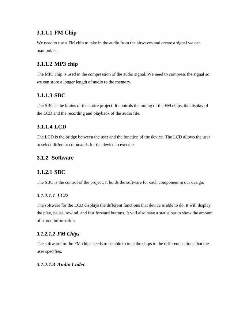
3.1.1.1 FM Chip
We need to use a FM chip to take in the audio from the airwaves and create a signal we can
manipulate.
3.1.1.2 MP3 chip
The MP3 chip is used in the compression of the audio signal. We need to compress the signal so
we can store a longer length of audio to the memory.
3.1.1.3 SBC
The SBC is the brains of the entire project. It controls the tuning of the FM chips, the display of
the LCD and the recording and playback of the audio file.
3.1.1.4 LCD
The LCD is the bridge between the user and the function of the device. The LCD allows the user
to select different commands for the device to execute.
3.1.2 Software
3.1.2.1 SBC
The SBC is the control of the project. It holds the software for each component in our design.
3.1.2.1.1 LCD
The software for the LCD displays the different functions that device is able to do. It will display
the play, pause, rewind, and fast forward buttons. It will also have a status bar to show the amount
of stored information.
3.1.2.1.2 FM Chips
The software for the FM chips needs to be able to tune the chips to the different stations that the
user specifies.
3.1.2.1.3 Audio Codec

3.2 Design Norms
As Christian engineers we have a responsibility to think about the Christian principles and norms
that apply to our project.
3.2.1 Justice
Justice is one norm that we believe specifically applies to fmNOW. A design is just if it is
developed in such a way that its implementation is not unfair to any group of people or any
individual. The design must respect the rights of not only it’s users but all of the stakeholders
involved. Many problems have come about with the introduction of digital media into our society.
These especially center on the new capability of copying and stealing music. One feature we are
considering implementing in our device is the capability to export stored audio files from the
device onto some form or portable media such as a USB flash drive or a similar product. The
intention of this feature is that a user would be able to record an audio clip from the radio and
transfer it to their computer. Our concern is that this would enable people to copy and distribute
music in a manner that is prohibited by copyright laws. After much consideration, our team has
decided that this issue will most likely not be a problem for our product. Our group did some
research and found that, in one case, the Supreme Court ruled that Video Cassette Recorder
(VCR) manufacturer Sony Corporation would not be held responsible for any copyright
violations that were perpetrated using their device3. Our product would not be doing anything
materially different than a VCR. Additionally, standard audio cassette recorders have been
capable of recording the radio for years. From this precedent our group concluded that our design
does not issue injustice.
3.2.2 Cultural Appropriateness
Another design norm, which in a way ties into the first, is Cultural Appropriateness. This design
norm requires that the product “fits in” to the cultural into which it is introduced. Examining our
product, it is clear that fmNOW is culturally appropriate. We live in a time where, elementary-
school-age children are learning to operate computers and use portable Motion Picture Experts
Group (MPEG) Layer 3 (mp3) players, cell phones, and countless other technical gadgets. Music
playing devices are now being utilized in nearly every location throughout our world. They’re in
the car, the bathroom, the kitchen, the office, the lawnmower, built into winter hats –you name
the place, and someone has probably put a radio there. People in our society love music
3 Sony Corp. v. Universal City Studios, Inc., 464 U.S. 417 (1984).

everywhere they go and fmNOW is designed to bring the enjoyment of music to the next level.
Our device will plug into a standard 120V electrical outlet which is accessible in every home that
has electricity in the U.S. Once the device is turned on, it can be operated by nearly anyone who
can use a DVD player or frequency modulated (FM) radio.
3.2.3 Transparency
This also relates to the design norm Transparency. The idea behind transparency is that the user
interaction is simple and straightforward. The product should not operate in a manner that does
not make sense to a common user. Also included within the transparency norm is reliability. The
product should function as it is intended to function, consistent with the products advertisements
and the user’s expectations.
3.3 Requirements
The following is a list of minimum requirements that fmNOW will meet.
3.3.1 Prototype Requirements
3.3.1.1 Functional
3.3.1.1.1 The device shall be able to sample FM radio audio data from no less
than 2 FM broadcasts simultaneously in stereo quality
3.3.1.1.2 The device shall allow the user to select any station in the FM band for
listening
3.3.1.1.3 The device shall allow the user to pause (for no less than 5 minutes)
and resume, one radio audio stream
3.3.1.1.4 The device shall allow the user to listen to one radio stream, switch to a
second radio stream and rewind up to 5 minutes, the second stream
3.3.1.1.5 The user shall be able to rewind or fast-forward the active stream at a
rate of 10 seconds of recorded time per 1 second of real time

3.3.1.1.6 fmNOW shall be able to store data onto an onboard memory source
3.3.1.2 Performance
3.3.1.3 Power
3.3.1.3.1 fmNOW shall be powered by an DC power source
3.3.1.4 Size
3.3.1.4.1 The device shall be no bigger than a form factor of 1’ x 6” x 8” (W x H
x D)
COMMENT: The market study showed that maximum dimensions for these types of radios are
18.5 x 14.5 x 14 inches (W x H x D).
3.3.1.5 Weight
3.3.1.5.1 The device shall weigh no more than 10 lbs
COMMENT: This is so the device is easily moved
3.3.1.6 Audio Quality
3.3.1.6.1 The device shall minimally be able to store radio streams at a rate of
44.1 kHz at 16 bit digital quality providing a net raw digital quality of
172KB/s4
3.3.1.6.2 The device shall be able to playback audio streams at 44.1 kHz
3.3.1.7 Cost
3.3.1.7.1 The prototype shall cost no more than $360
4 44100 samples/s × 2 Bytes /sample × 2. channels = 172 KB/s

3.3.1.8 Storage
3.3.1.8.1 The device shall be able to record up to 5 minutes per station
3.3.1.9 1.1.9 Interface
3.3.1.9.1 The user interface shall be reasonably intuitive with controls similar to
those of current radios and music listening devices
3.3.1.9.2 The interface shall allow the user to select an FM broadcast to listen to
3.3.1.9.3 The interface shall show the current station that is being listened to as
well as the other stations being recorded
3.3.1.9.4 The interface shall be able to show different screens to show different
functions
3.3.1.9.5 A button shall be considered pushed once it has been engaged, not
when it is released. During the period when the button is held down,
pushing another button will not do anything
3.3.1.9.6 A button push shall cause a noise to indicate to the user that it has
been pushed
3.3.1.9.7 The interface shall allow the user to pause, resume, or rewind an
active broadcast
3.3.1.9.8 The interface shall allow the user to pause, resume, rewind, or forward
a recorded broadcast
3.3.1.9.9 The interface shall allow the user to switch from a paused broadcast to
any another broadcast and vice-versa
3.3.1.9.10 The interface shall allow the user to turn fmNOW on and off

3.3.1.9.11 fmNOW shall have a light that signals to the user if the unit is on
or not
3.3.2 Production Requirements
3.3.2.1 Functional
3.3.2.1.1 The device shall be able to sample FM radio audio data from no less
than 3 FM broadcasts simultaneously in stereo quality
3.3.2.1.2 The device shall allow the user to select any station in the FM band for
listening
3.3.2.1.3 The device shall allow the user to preset 4 stations and switch between
them
3.3.2.1.4 The device shall allow the user to pause (for no less than 30 minutes)
and resume, one radio audio stream
3.3.2.1.5 The device shall allow the user to listen to one radio stream, switch to a
second radio stream and rewind up to 30 minutes, the second stream
3.3.2.1.6 The user shall be able to rewind or fast-forward the active stream at a
2x speed by pushing the rewind or fast forward button. If the user
pushes the rewind or fast forward a second time the device will rewind
or fast forward at a rate of 5x speed. If the user pushes the rewind or
fast forward a third time the device will rewind or fast forward at a rate
of 20x speed
3.3.2.1.7 fmNOW shall be able to transfer stored files to another source using
an external memory source such as USB, Compact Flash, Secure
Digital, or the like

3.3.2.2 Performance
3.3.2.3 Power
3.3.2.3.1 fmNOW will be powered by a DC power source
3.3.2.3.2 fmNOW will have maximum power dissipation of 20Watts
COMMENT: We are trying to minimize cost; power is not our focus
3.3.2.4 Environmental
3.3.2.4.1 Our device shall operate in the humidity range of 0 to 80% non-
condensing
3.3.2.4.2 fmNOW shall operate at a temperature range of 0ºC to 70ºC
3.3.2.4.3 fmNOW shall be able to withstand a vibration of 9.8 m/s2 at a
frequency of 10Hz
3.3.2.5 Size
3.3.2.5.1 The device shall be no bigger than a form factor of 1’ x 6” x 8” (W x H
x D)
COMMENT: The market study showed that maximum dimensions for these types of radios are
18.5 x 14.5 x 14 inches (W x H x D).
3.3.2.6 Weight
3.3.2.6.1 The device shall weigh no more than 20 lbs
COMMENT: This is so the device is easily moved.

3.3.2.7 Audio Quality
3.3.2.7.1 The device will minimally be able to store radio streams at a rate of
44.1kHz at 16 bit digital quality providing a net raw digital quality of
172KB/s5
3.3.2.7.2 The device shall be able to playback audio streams at 44.1kHz
3.3.2.8 Cost
3.3.2.8.1 The production can cost no more than $28 bill of materials (BOM) cost
3.3.2.9 Storage
3.3.2.9.1 The device shall be able to record up to 40 minutes per station
3.3.2.10 Interface
3.3.2.10.1 The user interface shall be maximally intuitive with controls
similar to those of current radios and music listening devices
3.3.2.10.2 The interface shall allow the user to select an FM broadcast to
listen to
3.3.2.10.3 The interface shall show the current station that is being listened
to as well as the other stations being recorded
3.3.2.10.4 The interface shall be able to show different screens to show
different functions
3.3.2.10.5 If a button shall be considered pushed once it has been engaged,
not when it is released During the period when the button is held
down, pushing another button will not do anything
5 44100 samples/s × 2 Bytes /sample × 2. channels = 172 KB/s

3.3.2.10.6 A button push shall cause a noise to indicate to the user that it has
been pushed
3.3.2.10.7 The interface shall allow the user to pause, resume, or rewind an
active broadcast
3.3.2.10.8 The interface shall allow the user to pause, resume, rewind, or
forward a recorded broadcast
3.3.2.10.9 The interface shall allow the user to switch from a paused
broadcast to any another broadcast and vice-versa
3.3.2.10.10 The interface shall allow the user to turn fmNOW on and off
3.3.2.10.11 fmNOW will have a light that signals to the user if the unit is on or
not
3.4 Prior Work
3.4.1 Patents
During the first semester of this year, before undertaking design and construction of our device,
our group did a great deal of research in order to decide which components to use and how we
wanted our device to function. We also spent time searching through the United States Patent
database to see if anyone had patented a device that could rewind FM radio. We found that
products did exist that had such functionality but all of these required the device being connected
to a PC. The technology of recording songs and audio clips for later listening has been
implemented and patented by ADS Tech. Their product, Instant FM Music™ (US Patent
#5790958) is a complete USB hardware/software package that interfaces with a personal
computer. The device records the user’s favorite songs, podcasts, and sporting events
automatically, and separates and identifies the songs for easy playback. Instant FM Music™ is
similar to fmNOW but has key differences. ADS Tech’s product is not designed to operate
independently from a computer, while fmNOW has the capability of being without a computer6.
6 McCoy, M.S. U.S. Patent 5790958, 1995, United States Patent and Trademark Office.

Another product with similar features to fmNOW is Griffin Technology’s iFM™. This device
plugs directly into an iPod™ providing additional FM radio features. The iFM allows the user to
listen to FM radio broadcasts via the iPod™. If the “Record” button is pressed, the iPod™ will
record the FM broadcast and store it in the iPods™ internal memory. The amount of audio time
which can be stored is only limited by the iPods internal memory space. This device is also
similar to fmNOW, but with several key differences. First, iFM™ does not allow the user to
rewind the radio while listening to it. The user must first record the audio file, then go to the
media library and play the clip as if it were any other audio file on in the iPod’s™ memory.
Another difference is that iFM™ does not continually record a station. If a user tunes to a station
and finds that a song is half over there is no way to listen to the beginning of the song. Griffin
Technology does not have a patent for this device. We assume this is because all their product
really does is record FM music and they did not invent the technology used to do that7.
3.4.2 Post Project Completion Research
This past week, after finishing our project, our team discussed the possibility of pursuing a patent
for our device. After doing a bit more research we found, to our disappointment, that a patent had
been issued in January of 2007 for a “Multiple Radio Signal Processing and Storing Method and
Apparatus”. 8 This device functions almost exactly the same as we designed our device to
function. We feel that this patent is broad enough that it would cover any form of device with the
functionality of fmNOW. Having found this we have decided that we will no longer pursue a
patent for our device.
7 Deitz, Corey. "iFM Turns iPod into FM Radio, Recorder and Remote Control." About.com: Radio. 31
July 2005. 7 Dec. 2006 <http://radio.about.com/od/pdasipodscellphones/a/aa073105a.htm>. 8 Michael D. Ellis, Caron S. Ellis, “Multiple Radio Signal Processing and Storing Method and
Apparatus,” U.S. Patent 7171174, Jan 30, 2007.

4 The Solution
4.1 Preliminary Research
4.1.1 Market Research
fmNOW design objectives place us in competition with other radio manufacturers. Our solution
provides us an added value solution to existing radios with coincides with future customer
preferences and trends. Ofcom (Office of Communication), the official regulator for the UK
communications industries, conducted three workshops in June 2004. They performed 24 in-
depth interviews and carried out a survey of 1,000 people across Britain. They found that 26% of
people are very interested and 32% of people are quite interested in a device that provides pause,
rewind and live broadcasts recording capabilities.9 We also found that there are 70 million radios
sold in the United States every year.10
fmNOW therefore decided that a reasonable estimate for
the first year production units is approximately 33% of the interested 58% of 70 million totaling
13,398,000 units.
Most of our market research was done for the purpose of planning the physical properties of our
device. Amazon.com was used to perform a market survey of countertop and tabletop radios. The
products that were found and used for this study can be found below. Based on this study and our
prior knowledge of electronics, we have determined that the device should meet the following
criterion: The device should weigh no more than twenty pounds so that it can be moved easily.
The device will most likely have a rectangular shape of the smallest size possible so that it does
not take up much space on a counter or table. The market study showed that maximum
dimensions for these types of radios are 18.5 x 14.5 x 14 inches (W x H x D). Our target size has
been set at 1’ x 6” x 8” which puts us well within the acceptable size. Our study also showed that
the price of home radios ranges from inexpensive models around $20 dollars to the higher end
radios which sell for around $500. Our goal is to make our product as inexpensive as possible so
that it can be available to more people. Our estimated cost of production is about $36.22. We
would like to have a profit margin of 50%. We also assume that there will be an estimated mark
9 Devices and Desires of the Next Generation of Radio Listeners. 23 July 2004. Ofcom. 8 Dec. 2006.
10 Digital radio hailed by broadcasters but faces challenges. 2005. The Associated Press. 6 Dec. 2006
<http://www.usatoday.com/tech/news/techinnovations/2002-10-21-digital-radio_x.htm>.
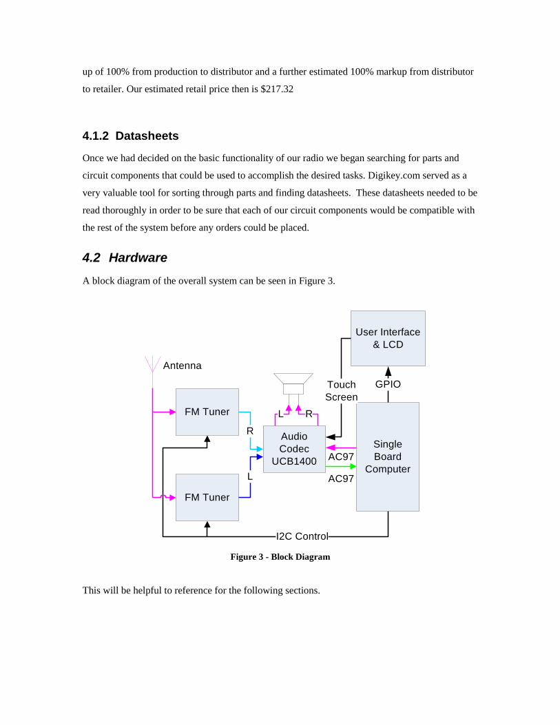
up of 100% from production to distributor and a further estimated 100% markup from distributor
to retailer. Our estimated retail price then is $217.32
4.1.2 Datasheets
Once we had decided on the basic functionality of our radio we began searching for parts and
circuit components that could be used to accomplish the desired tasks. Digikey.com served as a
very valuable tool for sorting through parts and finding datasheets. These datasheets needed to be
read thoroughly in order to be sure that each of our circuit components would be compatible with
the rest of the system before any orders could be placed.
4.2 Hardware
A block diagram of the overall system can be seen in Figure 3.
FM Tuner
FM Tuner
Audio
Codec
UCB1400
Single
Board
Computer
User Interface
& LCD
R
AC97
GPIO
L
I2C Control
L R
Antenna
AC97
Touch
Screen
Figure 3 - Block Diagram
This will be helpful to reference for the following sections.

4.2.1 FM Tuner (si4701)
The FM Tuner chip we chose to use was the SI4701. The chip can be seen in Figure 4. This chip
has the ability to not only tune to the different FM stations, but it also can decode the RDS tags
associated with the current song that is playing. This feature caught our eye as a bonus feature
that could be an additional add-on to our system. The ability to do a sweep of the FM band to
locate strong signals where the stations are is also a desirable trait of this chip. Because of this
feature we were able to do a do a fresh scan for the stations instead of hard coding in a list of
stations. The audio was sent from the FM Tuners to the Audio Codec.
Figure 4 - FM Chip Size
4.2.2 Audio Codec (UCB1400)
The audio codec we chose is the UCB1400. The chip can be seen in Figure 5. It is one of the
audio codecs that we used to make the streaming audio easier to store to the memory. Basically
the audio codec is like a sound card for a PC. The audio codec takes in analog audio and converts
it into a digital signal and stores it on the memory. Once the information is asked for it takes the
digital audio signal and converts it back to an analog signal. The digital audio signal is then stored
in the buffer of the SBC.

Figure 5 - UCB1400 Chip Size
4.2.3 SBC (Intel XScale PXA255 CPU module)
The SBC is like a mini PC. It is an Intel XScale PXA255 chip. The microprocessor board can be
seen in Figure. We used it in our prototype design because this is a popular and powerful µP for
embedded solutions that is available to us at no cost through Calvin College. It provides
substantial General Purpose Input/Output (GPIO) pins. We have available free Linux firmware
and we acquired the chip on a single board computer (SBC) with an evaluation and development
environment from Calvin College. The SBC controls all the other parts of our system.
Figure 6 - Intel XScale Processor
4.2.4 LCD (LP35)
The LCD we used in our project is a 3.5 inch (diagonal) touch screen. The LCD is manufactured
by Samsung Electronics. It is the part of our project that displays the user interface. The user
interface can be seen on the LCD in Figure 7.

Figure 7 - LCD and User Interface
As you can see in the figure, there is a pause button that allows the user to pause the current
station that he is listening to. There are fast forward and rewind buttons which allow the user to
move forward or reverse in the current stream by 5 seconds either direction. There are two
different tune buttons to select a different radio station for either the listening station, or the
buffering station. If you push one of the tune buttons the device will do a scan of the fm band and
display a list of stations that are currently available as seen in Figure 8.

Figure 8 - Scanning for Stations
There is also a slide indicator which shows the user how far back from the content that is
currently being played on the radio.
4.2.5 Miscellaneous
There were some other parts that were connected to the entire system. Those are described in the
following sections.
4.2.5.1 Crystal Oscillator
A crystal oscillator is an electronic circuit that uses the mechanical resonance of a vibrating
crystal of piezoelectric material to create an electrical signal with a very precise frequency. This
frequency is commonly used to keep track of time (as in quartz wristwatches), to provide a stable
clock signal for digital integrated circuits, and to stabilize frequencies for radio transmitters.11
The
oscillator can be seen in Figure 9. This circuit was needed for the FM Tuner chips, and would
have been used for the MP3 chips had we gotten them to work consistently.
11
http://en.wikipedia.org/wiki/Crystal_oscillator

Figure 9 - Crystal Oscillator
4.2.5.2 Power
Our group engineered our own power regulation circuit. This circuit can be seen in Figure 10.
This circuit takes an unregulated voltage source in the range of 13.5V – 30V and converts it to a
clean voltage at the levels of 12V, 5V and 3.3V. This is necessary to provide power to the
different components of our system.
Figure 10 - Power Regulation

4.2.6 BOM
4.2.6.1 Prototype
The total non-labor costs of the prototype process are tabulated in Table 1.
4.2.6.2 Production
The total non-labor cost of a production part can be found in Table 1. These costs are derived
from digikey (a real immediate source of hardware). A quantity of 5000 units was assumed to
receive a quantity discount. More information on this quantity can be found in the
Table 1 Production Non-labor Costs (per unit)
Item Item Cost Quantity Cost
Per Unit Prototype Cost $0.15 1 $0.15
64MB SDRAM MT48LC2M32B2TG-5:G or Similar $3.40 1 $3.40
64MB Flash Memory AT49BV6416C-70CI SL383 or Similar $0.87 1 $0.87
CAP 1UF 25V CERAMIC X7R 1206 $0.11 2 $0.23
CAP 220UF 35V ELECT WT SMD $0.10 1 $0.10
CAP CER .022UF 10% 100V X7R 1206 $0.08 4 $0.31
CAP CER .33UF 25V 10% X7R 1206 $0.10 4 $0.41
CAP CERAMIC 100PF 50V NP0 1206 $0.03 3 $0.09
CAP CERAMIC 22PF 50V NP0 0402 $0.01 1 $0.01
CAP CERAMIC 22PF 50V NP0 1206 $0.03 2 $0.06
CAP TANT 47UF 6.3V 20% SMD $0.16 1 $0.16
CONN AUDIO JACK 3.5MM STEREO $0.44 1 $0.44
CONN FEMALE 50POS DL .1" TIN SMD $2.83 1 $2.83
CONN HEADER 44POS 2MM GOLD SMD $1.75 1 $1.75
CRYSTAL 24.576 MHZ CYL TYPE $0.34 1 $0.34
CRYSTAL 32.768KHZ 12.5PF CYL $0.15 1 $0.15
IC AUDIO CODEC '97 48-TQFP $3.44 2 $6.88
IC AUDIO CODEC W/TCH SCRN 48LQFP $3.38 1 $3.38
IC FM RADIO TUNER 24QFN $10.35 3 $31.05
IC REG POSITIVE 3A LDO TO-220 $1.18 1 $1.18
IC REG POSITIVE 3A LDO TO-263 $1.19 1 $1.19

IC SINGLE INVERTER GATE SC70-5 $0.11 1 $0.11
INDUCTOR .27UH 5% FIXED SMD $0.15 1 $0.15
RES 1.60K OHM 1/4W 1% 1206 SMD $0.02 3 $0.07
RES 10.0 OHM 1/4W 1% 1206 SMD $0.02 1 $0.02
MCR18EZHF4991 $0.01 4 $0.04
RES 300K OHM 1/8W .5% SMD 1206 $0.08 1 $0.08
RES 47K OHM 1/4W 5% 1206 SMD $0.01 2 $0.01
RES 10M OHM 1/4W 5% 1206 SMD $0.01 1 $0.01
RES 4.7K OHM 1/8W 5% 0805 SMD $0.00 1 $0.00
CONN PWR JACK DC 0.65X2.75MM SMD $0.32 1 $0.32
50 OHMS SMA JACK EDGE MOUNT BRASS $1.13 1 $1.13
CONN SOCKET DIMM 144POS VERT AU $5.06 1 $5.06
CAP CER .22UF 50V X7R 10% 1206 $0.06 4 $0.23
CAP CERM 33PF 50V C0G 5% 1206 $0.02 1 $0.02
CAP CERAMIC .22UF 50V X7R 1206 $0.16 2 $0.32
CAP CERM .1UF 50V Y5V 1206 $0.05 13 $0.70
CAP CER 0.22UF 25V X8R 10% 0805 $0.05 8 $0.43
DIODE RF DUAL 100V 140MA SOT-23 $0.18 1 $0.18
IC MICRO PROCESSOR 200MHZ 256BGA $14.45 1 $14.45
Optrex TFT 3.5 T-51379L035J-FW-P-AA LCD $30.00 1 $30.00
IC DIG SIG PROCESSOR 144-TQFP $6.48 3 $19.44
Net Circuit Components: $127.57
PCB (not populated) $7.69 1 $7.69
PCB Assembly $12.13 1 $12.13
Enclosure $2.00 1 $2.00
Product Assembly $1.20 1 $1.20
Product Packaging $3.00 1 $3.00
Estimated Total Non-Labor Cost (Per Unit): $153.74

4.3 Software
4.3.1 Overview of Software Goals
The software in our system provides the “glue” that ties all of our hardware components
together and provides a convenient interface for the user to control them. The design of the
software was broken up into seven functional components:
Interface to FM tuners
Interface to MP3 Encoders
Interface to UCB1400
Buffering of Incoming Audio
Interface to LCD
Interface to Touchscreen
Graphical User Interface
Our goals and what we acomplished for each component is detailed in the following sections.
4.3.2 Outline of Specific Software Goals/Acomplishments
4.3.2.1 Outline of Specific Software Goals/Acomplishments
For the software objectives or each functional component we list what was required for
minimal functality, what functionality we would like to have (optimal functionality), and what we
actually got working in our final prototype (working functionality). If there is no difference
between the optimal and minimal functionality, the optimal functionality is omitted.
The details of the design process for each component is detailed in a later section.
4.3.2.2 Outline of Specific Software Goals/Acomplishments
This is the software interface for the control of the FM tuners. It is implemented using a
preexisting I2C driver and a custom kernel driver (used to provide the FM tuner initialization
sequence) for kernel level hardware interface, and a simple C++ library for higher level functions
such as tune, and scan.
Minimum functionality:
The ablility to tune both FM tuners to any FM station desired
Optimal functionality:
The ablility to tune both FM tuners to any station desired, scan the FM band for available
stations, and read RDS tags from any station broadcasting them.
Working functionality:
We were able to tune both FM tuners to any station desired, and scan the FM band for
available stations.
4.3.2.3 Interface to MP3 Encoders
This is the software interface for controlling and collecting data from the MP3 encoders.
Minimum functionality:
The ablility to configure the mp3 chip to compress audio and to take compressed mp3
data from the chip and store it in memory.
Working functionality:
We were unable to get the mp3 chip working on the hardware level (see section 6.1). So
the programming of this interface was not completed.

4.3.2.4 Interface to UCB1400
This is the software interface to the UCB1400 audio codec. This is primarily used for the
recoding and playback of PCM digital audio (the UCB1400 is also used for the touchscreen but
that is detailed in a following section). This was implemented using a preexisting AC97 ALSA
kernel driver for the kernel hardware interface and C++ code using the ALSA library for control
of the higher level record and playback functions.
Minimum functionality:
The ability to record and playback digital audio at the same time.
Optimal functionality:
The ability to record and playback 16bit 44.1kHz stereo digital audio at the same time
Working functionality:
We were able to get this device fully operational. We were able to record and playback
16bit 44.1kHz stereo digital audio at the same time.
4.3.2.5 Buffering of Incoming Audio
The is the software the takes the recorded audio data and stores it in a buffer if a form
that is easy to playback later. It also needs to provide an way to change the playback position in
the buffer (this is needed for the rewind and fast forward features) It does not need any direct
contact with the hardware. It is implemented using a ring buffer.
Minimum functionality:
The ability to store 10 seconds of audio and be able to keep track of the position in the
buffer for one channel.

Optimal functionality:
The ability to store a much longer amount of audio (up to the available memory on the
SBC, (this is probably 40-50MB or about 4 minutes)) and keep track of the position in the buffer
for two channels.
Working functionality:
We were able to get the ring buffer fully operational. We were able to use buffer sizes up
to 45MB, store recorded audio, and keep track of the position of the two output streams in the
buffer.
4.3.2.6 Interface to LCD
This is the software interface to the LCD hardware which is used for drawing the GUI. It
is implemented using a prexisting linux framebuffer driver.
Minimum functionality:
The ability to display visually recognizable frames at a 320x240 resolution with 8 bit
color.
Optimal functionality:
The ability to display visually clear frames at a 320x240 resolution with 16 bit color.
Working functionality:
We were able to get the LCD operational at 320x240 resolution with 16 bit color.
However, the colors on the screen were inverted. We found in the LCD datasheet that the was a
bit in a register on the LCD that could be configured over a SPI bus that inverted the colors, but
we did not have enough time to solve it completely. Instead we simply changed the colors in the
software, if we thought the inverted ones were ugly.

4.3.2.7 Interface to Touchscreen
This is the software interface to the touchscreen controller on the UCB1400. It is
implemented using a prexisting kernel driver for the kernel hardware interface and Tslib for the
userspace interface (which the GUI can talk to directly). Most of the data communication is sent
over the AC97 bus right along with the audio data, but there is an interupt line that is independent
from the AC97 bus that is used to generate touchscreen interupts.
Minimum functionality:
The ability to have mouse clicks generated from touching the screen.
Optimal functionality:
In addition to the ability to touch the screen and generate mouse clicks. We would like to
be able to click-and-drag and also have some touch filtering as touchscreens can get jittery
without it.
Working functionality:
We have the touchscreen fully operational. We a full 'mouse like' functionality (we can
drag and click) as well as filtering.
4.3.2.8 Graphical User Interface
This interface is the connection between the user and the rest of the system. It uses the
touchscreen and LCD interfaces to get input and provide feedback from the user. It was
implemented using C++ and the qtopia library.
Minimum functionality:
The ability to allow the user to instruct the system to tune to a particular station and to
change where in the buffer he/she was listening from.

Optimal functionality:
The GUI would provide a very intuitive and good looking interface. That would provide
visual feedback on where in the buffer a user was, what station he/she was listening to and allow
them to tune to a station and change the position in the buffer.
Working functionality:
We were able to get very good GUI functionality. The user interface was simple, intuitive
and allowed the user to scan for available stations, and change the position in the buffer. However
we would have liked to allow the user to tune to any station, even if our scan did not detect it, but
we were unable to complete that feature in time.
4.3.3 Overview of Software Design Process
This section provides and overview of the major software design decisions. The different
design alternatives were evaluated based on the following criteria:
Time required for setup:
This is the estimated time required, for a particuar alternative, to cross-compile any libraries
needed, transfer them to the SBC and configure the linux environment on the SBC apropriately.
Time needed for writing the actual software:
Once we have everything setup, this is the estimated time spent actually coding the software for a
given alternative.
Memory requirements:
This is an estimate of the memory requirements for a particular alternative. We only considered
the nonvolatile (flash) memory requirements as they were always higher than the volatile (RAM)
requirements and we had twice as much RAM as Flash memeory (32MB Flash, 64MB RAM)

Runtime performance requirements:
This is an estimate of how costly in CPU runtime performance is a particular alternative.
Cost (for licensing):
This is an estimate of the licencing cost of a particular alternative.
The goal in our design process was to minimize all five criteria; however time was usually our
limiting factor.
4.3.3.1 Choosing SBC Operating System
Linux is the only operating system that the SBC manufacturer supported for use on the SBC. The
manufacturer provided linux kernel source code with patches for use on this specific SBC as well
as a precompiled cross compiler and a basic linux system on a flash filesystem image.
The provided linux kernel already had many drivers for the SBC ready to go.
Most notably
it came with:
An I2C driver that could be used with any given GPIO pins
Alsa sound drivers for the UCB1400 audio codec
Touch screen drivers for the UCB1400 audio codec
Linux framebuffer driver for the LCD controller
We were also fairly familiar with the Linux operating system, which would aid in setup
and configuration. Plus other people have used Linux on the same SBC and as such there are
forums and documentation on the internet about the use of Linux on the SBC.
It may have been possible to use windows CE or some other OS, but the estimated setup
time was far greater as they were not supported on our hardware and many critical drivers may
have needed to be designed by hand. Application software would have taken a little longer to
write on another OS as we have experience with writing applications on linux but not with other
embedded systems. The memory and runtime performance requirements would be about the

same. The linux OS is free, however other embedded operating systems such as windows CE cost
money. A decision matrix of our alternatives is show below (a lower score is better).
Criteria Points/Unit Supplied Linux OS Other embedded OS
Setup Time 5/hour 15 hours 75 hours
Development
Time
5/hour 25 hours 45 hours
Memory
Requirements
15 / MB 6 6
Runtime
Requirements
5 / % used 5 % 5%
Cost 1/$ 0 40
Total Points: 315 755
The supplied linux OS is by far a better option.
4.3.3.2 Choosing a Language
We broke our options for which language we would use into three basic options: pure C,
C++, or another language such as ocaml or Python. The advantage of using C is that it requires
very little setup time and easy interface with the kernel drivers (which are written in C), however
C can get a bit clunky with more complex code. C++ is much less clunky but requires a bit more
work to link to C librarys and the kernel. Other languages such as python have the advantage of
being much more elegant and easy to use than C or C++, but interfacing to other librarys that are
designed to work with C or C++ require a lot more setup time.
A decision matrix showing the alternatives is shown below:
Criteria Points/Unit Code primarily in
C
Code primarily in
C++
Use other
language
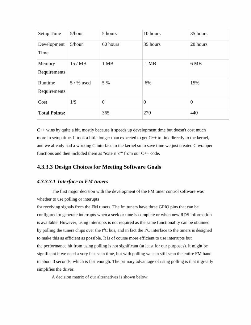
Setup Time 5/hour 5 hours 10 hours 35 hours
Development
Time
5/hour 60 hours 35 hours 20 hours
Memory
Requirements
15 / MB 1 MB 1 MB 6 MB
Runtime
Requirements
5 / % used 5 % 6% 15%
Cost 1/$ 0 0 0
Total Points: 365 270 440
C++ wins by quite a bit, mostly because it speeds up development time but doesn't cost much
more in setup time. It took a little longer than expected to get C++ to link directly to the kernel,
and we already had a working C interface to the kernel so to save time we just created C wrapper
functions and then included them as "extern 'c'" from our C++ code.
4.3.3.3 Design Choices for Meeting Software Goals
4.3.3.3.1 Interface to FM tuners
The first major decision with the development of the FM tuner control software was
whether to use polling or interupts
for receiving signals from the FM tuners. The fm tuners have three GPIO pins that can be
configured to generate interrupts when a seek or tune is complete or when new RDS information
is available. However, using interrupts is not required as the same functionality can be obtained
by polling the tuners chips over the I2C bus, and in fact the I
2C interface to the tuners is designed
to make this as efficient as possible. It is of course more efficient to use interrupts but
the performance hit from using polling is not significant (at least for our purposes). It might be
significant it we need a very fast scan time, but with polling we can still scan the entire FM band
in about 3 seconds, which is fast enough. The primary advantage of using polling is that it greatly
simplifies the driver.
A decision matrix of our alternatives is shown below:

Criteria Points/Unit Polling Interrupts
Setup Time 5/hour 5 hours 15 hours
Development
Time
5/hour 20 hours 20 hours
Memory
Requirements
15 / MB 0 0
Runtime
Requirements
5 / % used 1 % 0%
Cost 1/$ 0 0
Total Points: 130 175
Polling wins by a significant amount.
The other decision we had to make was whether to put the majority of the FM control
code in the FM driver or to put it in the userspace. But since we went with polling, we could put
all control code in the userspace (except for a very small driver for FM chip initialization) since
we could do all of our communication with the FM chips through the I2C interface for which we
already had a driver. Which is what we decided to do since it is generally accepted that you want
to keep things out of the kernel if it can be helped, and it also aids with debugging.
4.3.3.3.2 Interface to MP3 Encoders
The software interfaces to the MP3 Encoders were not developed as we were unable to get the
MP3 encoders working on a hardware level.
4.3.3.3.3 Interface to UCB1400
An ALSA (Advanced Linux Sound Architecture) driver for the UCB1400 audio codec
was already provided by the SBC manufacturer that worked perfectly. So there wasn't any reason
to use something else for the kernel hardware interface. For the software interface however, there
were a couple options. The kernel driver could be controlled through the ALSA library, or it
could be controlled via an OSS (Open Sound System) emulation driver (which was also provided

and worked perfectly). The advantage of using OSS is that it uses a standard linux character
device for the userspace interface, which simplifies interfacing with the driver and requires less
memory since is doesn't need a library. Some of the disadvantages however are that OSS requires
slightly more processing power as it runs over an emulation layer (audacityteam.org) and it is an
older interface that is generally considered obsolete (http://osdir.com) and as such it is much
harder to find good documentation and examples for how to use the interface.
The advantage of using ALSA is that there is really good documentation and examples
for how to use it, and it performs slightly better than OSS. The disadvantage using ALSA is that it
would require compiling and setting up the ALSA library (OSS does not need a library) as well
more memory on the SBC for the ALSA library.
A decision matrix for the two alternatives is show below:
Criteria Points/Unit ALSA OSS
Setup Time 5/hour 6 hours 0 hours
Development
Time
5/hour 8 hours 18 hours
Memory
Requirements
15 / MB 2 MB 0
Runtime
Requirements
5 / % used 2 % 5%
Cost 1/$ 0 0
Total Points: 110 115
ALSA wins but only by a small margin.
4.3.3.3.4 Buffering of Incoming Audio
We needed a way to store incoming audio and keep track of two position in a buffer
A ring buffer is the best implementation of this. We used a modified ring buffer that had two
pointers consumer pointers and one feeder pointer. When we got to the point of writing the
software we had already decided that our first prototype was only going to have one stereo audio

codec with the left and right channels taking a signal from each tuner, and as such we needed to
separate the left and right channels from the incoming audio stream into two seperate mono
channels. The question is, do we take it apart before we store it in the buffer, or when we take
data our of the buffer?
The audio data from the audio codec had the left and right channels interleaved so
seperating out one of the channels requires copying every other 16-bit sample which is a
processor intensive operation. If we seperated the channels when we put data into the buffer we
would have to continually seperate both channels as we were recording, however if we seperated
the channel when reading from the buffer, we only have to seperate out a single channel (since we
only want to listen to one tuner at a time) which is more processor efficient and takes about the
same amount of time to implement and is the implementation that we chose to take.
4.3.3.3.5 Interface to LCD
For the kernel hardware interface to the LCD we just used the linux framebuffer driver
provided by the supplied linux kernel as there were no other alternatives that we knew of (other
than writing our own linux framebuffer driver from scratch, but why do that if you already have a
working one?). We had some minor difficulties configuring the driver to interface to our LCD
but those were quickly resolved.
There were more alternatives to how we could connect the framebuffer to our user
interface software, but those are detailed in the Graphical User Interface section below.
4.3.3.3.6 Interface to Touchscreen
The the kernel hardware interface to the touchscreen we again use the linux touchscreen
driver provided by the supplied linux kernel. We had a very difficult time getting the interupt to
work but we eventually resolved that issue. For the userspace interface we used a library called
Tslib. At first we didn't realize that such a library was needed as we thought that the touchscreen
driver would create a device node that could be used directly (as that is how it works for regular
mice). However when we got the driver working we realized that an extra layer was needed. The
library that we selected for our GUI (Qtopia) recommended we used Tslib and included
instructions for how to get it working. It only took us three or four more hours before we had the
library working and full touchscreen functionality. So we never did an analysis on different
alternatives to the library since the one we found worked fine.

4.3.3.3.7 Graphical User Interface
There were several different alternatives for how we were going to connect to the linux
framebuffer and touchscreen drivers to provide a GUI for the user. The four most promising
alternatives were as follows:
Write our software to talk to the linux framebuffer and touchscreen driver directly.
Use the Qtopia graphical environment
Use GTK directly on top of the linux framebuffer
Use GTK through an X11 server
Writing our software to talk to the linux framebuffer and touchscreen has the advantage
of taking less memory and requireing no setup time (as we are talking to the drivers directly), but
it would require quite a bit of work to get a reasonable amount of functionality.
Using Qtopia has the advantage of really good documentation and all of the details of
talking to the touchscreen and framebuffer is taken care of by the library. The library is very
intuitive and easy to use making development very efficient. It also comes with a virtual
frambuffer program that allows for testing of applications on a different computer than the target,
which also speeds up development time. The only real disadvantage of using the library is the
moderate memory footprint that it requires.
Using GTK directly on top of the linux frambuffer has the advantage of abstracting a lot
of the interaction with the framebuffer and touchscreen controller, however, GTK for the linux
framebuffer is not well maintained, “The linux-fb GDK target is unmaintained and may not work
or even compile.” (http://developer.gnome.org) so it make take a bit more to get things setup.
Also GTK is not quite as nice as Qt and may require a bit more work to do what we want.
Using GTK though an X11 server has the advantage of having X11 handle the frambuffer
and touchscreen controller. X11 is also better maintained than GTK-framebuffer. However it
would require a substancial amount of time to setup X11 and it would require quite a large
memory footprint.
A decision matrix of the alternatives is shown below:
Criteria Points/Unit Direct Qtopia GTK-framebuffer GTK - X11

Setup Time 5/hour 0 hours 10 hours 30 hours 40
Development
Time
5/hour 70 hours 35 hours 40 hours 35
Memory
Requirements
15 / MB 1 MB 6 MB 6 MB 11MB
Runtime
Requirements
5 / % used 1 % 5% 8% 12%
Cost 1/$ 0 0 0 0
Total Points: 370 340 480 600
Qtopia wins by a small but distinct margin.
The Qtopia is free for non comercial/open source projects like ours, however our final production
product would probably use the linux framebuffer directly as Qtopia would have to be licenced
for comercial use.
4.3.4 Overview of Final Software Design
A copy of our commented source code is attached, but here is an overview of the final
software design for the actual code that we wrote.
A UML diagram of our software is show below:
(#NOTE diagram)
Our software code is divided into four sections:
An FM tuner control class (which can be instantiated for each tuner you wanted to use)
A ring buffer class
What we called an ALSA Ring class (A class that handles the recording/playback and the
control of the ringbuffer)
GUI classes
FM Tuner Control Class:

This class provides a simple interface for tuning and scanning and handles all the details
of the handshaking and FM control internally. The class can be instantiated for each tuner needed
and only needs to be passed an I2C device file for which to communicate to the FM tuner.
Ring Buffer Class:
This class provides a simple interface for storing and retreiving data from a ring buffer. It
provides methods for storing data into the buffer, retreiving data from the buffer and setting the
position in the buffer via a “delay” of how far behind a particlar consumsion pointer was from
the producer pointer. Intrementing/ decrementing the pointers and keeping track of delays is
handled internally.
ALSA Ring Class:
This class provides a simple interface for pausing/resuming switching channels and
changing how much a channel is delayed. Audio recording runs in it's own thread and continually
stores audio data into the ring buffer. Playback is implemented using a callback that is called
whenever the ALSA buffer can take more data, at which point the current channel is pulled out of
the ring buffer and passed to ALSA for playback. It hides all the audio and buffering
implementation details from the other classes.
GUI Classes:
These are a set of classes that control the graphical user interface. Each visual window or
'page' displayed to the user is implemented as its own class in Qt. These classes inherit the Qt
QWidget class and provide the user interface. Button clicks and other user input are linked to
methods in the GUI classes via Qt's signals and slots. The GUI classes then call methods in the
ALSA ring buffer class or the FM tuner classes acordingly.
In conclusion, while we did not get all of our design operational as we had hoped, however we
were able to make a proof of concept and are very pleased with what we accomplished. We were
able to start with an idea and bring it through design to a working implementation. We learned a
lot about debugging, working on a team, and bringing an idea to eventually to a working
prototype.
For the finer details see comments in the attached source code.

4.4 Design Considerations and Criteria
4.4.1 Design considerations/criteria
A wide variety of factors were considered in the design and creation of this product. The
requirements for the product were the first considerations. All the other considerations were
aimed at meeting these requirements or other goals not spelled out in the requirements.
4.4.1.1 Cost
4.4.1.1.1 Production
Designing a consumer product, cost was a primary concern for us in our design process. Because
the market for technology is highly inelastic at our price-point and technology level, we strove to
keep costs down.
4.4.1.1.2 Prototype
Given the limits of our resources, we sought products for our prototype with which we could
work without high expenditures. For us this meant using parts available on campus for many of
the more expensive aspects of our design. Without these considerations, a prototype fmNOW
would not have been possible. So, while we would have like to have searched for ideal
components more suited to our application, this consideration caused us to choose devices that
were within our budge.
4.4.1.2 Ease of Implementation
We sought components and devices that were easy for us to use. Devices with simple interfaces
were favored over those with more complicated interfaces. In a prototype situation, the
functionality of the device is more important than performance, so the former goal was favored
over the latter.
4.4.1.3 Availability
Without any volume with which to bargain, we were left to purchase components from
distributors and retail shops. We sought parts that were available easily so we could replace any
parts that were rendered non-functional as part of our design and testing. We also wanted sources
that were reputable and known so we could have confidence that our shipments would arrive as
promised.
4.4.1.4 Familiarity with solution
4.4.1.4.1 Team familiarity
Some solutions and devices were familiar to members of the group who had worked with them in
class or at work. These solutions were highly favored over others because experience with the
solution can eliminate hours of frustrating debugging and floundering in confusion.
4.4.1.4.2 Global familiarity
This relates to how much information is known about a certain device or solution and how
accessible that information is. This included favoring standardized busses and open-source
software as those solutions are well-documents and such documentation is readily available on
the internet.
4.4.1.5 Performance
We desired fast operation and high capabilities in the devices incorporated into our design. This
applies to processing ability, data throughput, output current, and other measurable factors. We
wanted a slight over-design on our prototype to give us flexibility and a margin or error. These
considerations are not as important in the production design because the capabilities of the
components and the demands of the operations will be more fully known.
4.4.1.6 Physical Size
We desired to develop as small a device as possible. But, size was not a primary concern as we
envisioned our device being used in the countertop setting. We envision future use in portable
and automobile settings, which would place higher demands on size. For now, operability was
much more valuable than small size
4.4.1.7 Demands on system resources
4.4.1.7.1 Microprocessor
The microprocessor on our single board computer is a system resource. Interfaces that demand
less processor resources, either clock time or I/O, are favored over those that demand more. For
example, serial communications favored over parallel communications because of the limited
number of GPIO pins.

4.4.1.7.2 Voltage requirements
We wanted to generate as few voltages as possible to power all the elements on our circuit.
Toward this goal, we selected parts that used either 3.3V or 5V as input, as these voltages were
already be generated to power the display.
4.4.1.7.3 Heat Dissipation
Our system generated heat. We wanted to keep this to a minimum, because excess heat means
more cooling capacity demanded. Toward this end, we sometimes selected higher rated
components that we could operate further from their maximum ratings at lower temperature,
rather than pick a component that barely got the job done and would have to be driven near its
maximum rating at all times.
4.4.2 Design alternatives and analysis
4.4.2.1 Simulation – FEA, Pspice, etc.
4.4.2.2 Hand analysis, MathCAD, design calculations
4.4.2.2.1 Power Calculations
Complicated electronic circuits like ours use electricity to run the components. Different
components require different potentials and current. These have to be provided to the circuit
through our power regulation circuitry. Converting from one voltage to another uses power
according to the Equation 1. This means the low voltages of 3.3V and 5.0V that are most
commonly used on our project generate considerable excess power.
Equation 1 Power Dissipation Equation
IVoutVinP
Since all the power that is used by circuit must be down-converted from the input voltage.
Excess power is converted to heat in the devices that dissipate that power. We have designed the
power regulation circuitry to cope with the maximum demands presented by our parts and the
maximum input voltage.

4.4.2.2.2 Heat Dissipation Calculations
All electrical devices that use power generate heat as a byproduct of that power used. Our
devices generate heat. Our prototype board did not use an enclosure, which aided the convective
dissipation of heat through the ambient air. A later-stage prototype would have a plastic
enclosure which would make such heat dissipation more difficult. Calculations were carried out
to consider the effect of all our components and the enclosure. Our device should operate around
48°C, which will not threaten the operation or functionality of any of our components.
For further details and complete calculations see Appendix I.
4.4.3 Decision (may use matrix)
Decisions for our team were made using many sources of information and the engineering
judgment developed over years of experience. These decisions were made every day. Some
were important, some were less importmant. We would discuss the topic with other group
members, conduct some research, and make an informed choice of which direction to pursue. For
some of the decisions we developed decision matrices.
4.4.3.1 Prototype
Decisions for the prototype were made as the course developed. These decisions were often
forced by necessity without the luxury of time and perspective. For these reasons, availability
and ease of implementation were often favored because of the immediate nature of those
considerations.
4.4.3.1.1 Tuner Method
We had to decide whether to design our own tuning circuitry of to use an integrated
circuit tuner. The criteria are shown below:
Cost
Ease of
Implementation Scalability Flexibility
Total
Points
Goal 20 20 5 5 50

Design our own
tuners/demodulators
by hand (except for
ADC) 15 10 4 4 33
Use a single FM tuner
chip 15 20 5 5 45
4.4.3.1.2 Microprocessor Form
We had to choose whether to use a NIOS processor available on a Calvin-owned FPGA
or to purchase a processor.
Prototype Microprocessor Alternatives
Cost
Time
to
Desig
n
Availabilit
y of Open
Source
Resources
Relabilit
y
Expansio
n Ease
Performanc
e
Total
Score
Goal 20 40 10 5 5 20 100
Off-The-
Shelf 20 40 10 5 1 20 96
Template
(Nios) 20 28 3 4 5 14 74
4.4.3.2 Production
4.4.3.2.1 LCD
LCD Display Options
Cost
Availability of
Documentation Resolution Brightness
Total
Points
Goal 20 20 10 5 55
Optrex: T-51963GD035J-MLW-AGN 20 20 8 4 52

AEI Components: ALCD35VGATS 10 20 10 5 45
Samsung: LTV350QV-F04 19 15 8 5 47
4.4.3.2.2 Microprocessor
Cost
Time to
Design
Availability
of Open
Source
Resources Reliability
Expansion
Ease Performance
Total
Score
Goal 20 40 10 5 5 20 100
Intel PXA255 (400 MHz) 6 40 10 5 0 17 78
Intel PXA255 (300 MHz) 12 40 10 5 0 15 82
Intel PXA255 (200 MHz) 18 40 10 5 0 13 86
Design a Custom one 5 5 3 3 5 20 41
Intel Xscale FWIXP420BB 17 40 10 5 0 13 85
Intel RISC GCIXP1240AC 1 40 10 5 2 20 78
From our decision matrix we have chosen to use a similar processor to the one that we
are using in our prototype. We chose a similar chip with a slower clock speed because we have
shown that this chip works. Also we decided that if we have compression chips we would not
need as high of a clock speed. Designing our own chip would be nice because we could
customize it to our specific design, however it would be very time consuming.
4.4.3.2.3 Digital Signal Processor
Production DSP
Cost MMACS Interface Availability
Total
Points
Goal 40 40 15 5 100
TMS320VC5402PGE100 35 30 12 5 82
DSP56303VF100B1 25 30 12 1 68
ADSP-21992YST 15 30 10 5 60

4.5 Budget
The budget section contains information about how much money we spent on our prototype and
how much money we calculated would be required to create a company and produce a final
production design
4.5.1 Prototype
Table 2 Prototype Non-labor Costs
Item (Non Labor) Part Number Quantity Unit Cost Total Cost Vendor
CRYSTAL 24.576
MHZ CYL TYPE 300-8450-ND 2 $ 0.81 $ 1.62 Digikey
BOARD EVAL FOR
SI4701 336-1381-ND 1 $ 150.00 $ 150.00 Digikey
CAP .39UF 6.3V
CERAMIC X5R 0603 PCC1910CT-ND 10 $ 0.23 $ 2.34 Digikey
CAP 120UF 6.3V
ELECT POLY SMD 565-3112-1-ND 5 $ 0.81 $ 4.04 Digikey
CAP 1UF 25V
CERAMIC X7R 1206 PCC1893CT-ND 10 $ 0.25 $ 2.50 Digikey
CAP 220PF 50V
CERAMIC X7R 1206 311-1164-1-ND 10 $ 0.09 $ 0.90 Digikey
CAP 220UF 35V
ELECT WT SMD 493-2205-1-ND 5 $ 0.53 $ 2.66 Digikey
CAP 390PF 50V
CERAMIC X7R 1206 311-1205-1-ND 10 $ 0.10 $ 0.98 Digikey
CAP CER .022UF
10% 100V X7R 1206 478-1525-1-ND 10 $ 0.33 $ 3.30 Digikey
CAP CER .33UF 25V
10% X7R 1206 490-1783-1-ND 10 $ 0.43 $ 4.31 Digikey
CAP CERAMIC 311-1161-1-ND 10 $ 0.11 $ 1.05 Digikey

100PF 50V NP0 1206
CAP CERAMIC
10UF 25V X5R 1206 PCC2414CT-ND 10 $ 0.55 $ 5.45 Digikey
CAP CERAMIC 18PF
50V NP0 1206 311-1152-1-ND 10 $ 0.17 $ 1.70 Digikey
CAP CERAMIC 22PF
50V NP0 0402 399-1015-1-ND 10 $ 0.02 $ 0.24 Digikey
CAP CERAMIC 22PF
50V NP0 1206 311-1154-1-ND 10 $ 0.10 $ 0.97 Digikey
CAP CERAMIC
470PF 50V NP0 1206 399-1213-1-ND 10 $ 0.22 $ 2.20 Digikey
CAP TANT 1.5UF
10V 20% SMD 511-1455-1-ND 8 $ 0.33 $ 2.64 Digikey
CAP TANT 3.3UF
10V 20% SMD 511-1459-1-ND 6 $ 0.33 $ 1.98 Digikey
CAP TANT 4.7UF
6.3V 20% SMD 511-1442-1-ND 8 $ 0.33 $ 2.64 Digikey
CAP TANT 47UF
6.3V 20% SMD 511-1452-1-ND 8 $ 0.33 $ 2.64 Digikey
CONN AUDIO JACK
3.5MM STEREO CP-3544-ND 2 $ 1.00 $ 2.00 Digikey
CONN FEMALE
50POS DL .1" TIN
SMD S4594-ND 3 $ 7.45 $ 22.35 Digikey
CONN HEADER
20POS .100" STR
15AU WM17464-ND 5 $ 2.23 $ 11.15 Digikey
CONN HEADER
44POS 2MM GOLD
SMD H1792-ND 2 $ 4.06 $ 8.12 Digikey
CRYSTAL 18.432
MHZ HC49/US 300-8505-ND 2 $ 0.70 $ 1.40 Digikey
CRYSTAL 24.576 300-8450-ND 2 $ 0.81 $ 1.62 Digikey

MHZ CYL TYPE
CRYSTAL
32.768KHZ 12.5PF
CYL X802-ND 5 $ 0.30 $ 1.50 Digikey
FERRITE CHIP 2500
OHM 50MA 0603 490-1028-1-ND 10 $ 0.06 $ 0.56 Digikey
IC AUDIO CODEC
'97 48-TQFP 598-1044-ND 2 $ 5.64 $ 11.28 Digikey
IC AUDIO CODEC
W/TCH SCRN
48LQFP 568-1323-1-ND 1 $ 5.40 $ 5.40 Digikey
IC AUDIO POWER
AMPLIFIER 8-SOIC LM4910MA-ND 4 $ 1.43 $ 5.72 Digikey
IC Fm Radio Tuner 336-1379-ND ? $ 73.31 Digikey
IC FM RADIO
TUNER 24QFN 336-1379-ND 1 $ 17.25 $ 17.25 Digikey
IC REG LIN 2A
ULDO HI-EFF 8-
SOIC 497-4596-1-ND 6 $ 2.85 $ 17.10 Digikey
IC REG POS 12V 3A
LDO TO-263
LM1085ISX-12CT-
ND 3 $ 3.00 $ 9.00 Digikey
IC REG POSITIVE
3A LDO TO-220 LM1085IT-5.0-ND 2 $ 2.98 $ 5.96 Digikey
IC REG POSITIVE
3A LDO TO-263 LM1085IS-3.3-ND 2 $ 3.00 $ 6.00 Digikey
IC SINGLE
INVERTER GATE
SC70-5 296-8488-1-ND 3 $ 0.40 $ 1.20 Digikey
INDUCTOR .27UH
5% FIXED SMD PCD1177CT-ND 4 $ 0.35 $ 1.40 Digikey
MP3 Encoder MAS3587F 5 $ 29.80 $ 149.00 Snail Instr
PCB MP3 / FM Board 1 $ 59.00 $ 59.00 ExpressPCB
PCB UCB/Power 1 $ 59.00 $ 59.00 ExpressPCB

Board
PCB Universal
Connector Board 1 $ - $ - Calvin
PCB Final Prototype
Board 1 $ 42.53 $ 42.53
Advance
Circuits
Protyping Adapter
(FM Tuner) 1 $ 43.14 $ 43.14 Ironwood
RES 1.60K OHM
1/4W 1% 1206 SMD
RHM1.60KFCT-
ND 10 $ 0.05 $ 0.47 Digikey
RES 10.0 OHM 1/4W
1% 1206 SMD 541-10.0FCT-ND 6 $ 0.05 $ 0.30 Digikey
RES 10.0K OHM
1/4W 1% 1206 SMD
311-10.0KFRCT-
ND 10 $ 0.09 $ 0.88 Digikey
RES 20.0K OHM
1/4W 1% 1206 SMD
311-20.0KFRCT-
ND 10 $ 0.09 $ 0.88 Digikey
RES 220K OHM
1/4W 5% 1206 SMD
311-220KERCT-
ND 10 $ 0.08 $ 0.78 Digikey
RES 3.16K OHM
1/4W 1% 1206 SMD
RHM3.16KFCT-
ND 10 $ 0.05 $ 0.47 Digikey
RES 4.99K OHM
1/4W 1% 1206 SMD
RHM4.99KFRCT-
ND 10 $ 0.05 $ 0.46 Digikey
RES 5.60K OHM
1/4W 1% 1206 SMD
RHM5.60KFCT-
ND 10 $ 0.05 $ 0.47 Digikey
SBC Dev Kit Starterkit_2 1 $ - $ - Calvin
Shipping & Handling 1 $ 92.81 $ 92.81
Single Board
Computer (SBC) Triton-ETN 1 $ - $ - Calvin
Taxes 1 $ 19.67 $ 19.67
Touch Screen Display
and Module LP-35 1 $ - $ - Calvin
Total Non-Labor $ 866.34

Costs:
Total Cost $ 866.34
Table 3 Prototype Labor Costs
Item Item Cost Quantity Total Cost Vendor
Labor:
Design Labor $100.00 1117 $111,700.00
Senior
Design Team
1
Total Labor Cost: $111,700.00
The prototype costs were broken down into labor and non-labor categories listed in Table 2 and
Table 3 respectively. Table 2 consists of all the expenses the group incurred during the course of
the semester. Table 3 is just a tabulation of the total member hours worked during both semesters
at a cost of $100 dollars an hour.
4.5.2 Production – economic analysis
4.5.2.1 The Business
4.5.2.1.1 Description of the Business
Team 1 fmNOW of senior design class 2007 at Calvin College will form a Limited Liability
Company Filing will begin in the summer of 2007 under the purposed name fmNOW LLC. The
initial employee’s of the company will consist of 5 members each sharing one fifth ownership:
Jordan Schaenzle, Peter Tuuk, Job Vranish, Brad Zoodsma and Mike Zwagerman. Titles and
responsibilities are to be determined at this point.
4.5.2.1.2 Alternatives
there are many alternative companies to file for. To decide which type of company we should
start we compiled a list of companies that were of interest and we could practically start. Below is
a decision matrix listing all the choices we considered

4.5.2.1.3 Ease of Setup
Setting up a company can be difficult and time consuming. We wish the form this company in a
relatively easy and timely manner we assigned a relatively moderate value of 10 to this category
as it is important, but not the most important category.
4.5.2.1.4 Financial Benefits
Certain types of businesses provide ways of minimizing the taxes that an owner of the business
might undertake. We gave this category a value of 20 to insure that it was valued as much as any
other category.
4.5.2.1.5 Liability
Owning a business can present a certain level of unwanted liability on an owner. This liability
should be minimized if possible. This category is worth as much as financial benefits. We assign
a value of 20.
4.5.2.1.6 Ease of Change
Ownership of our business can potentially change in the future. This is a measure of how easy the
company can change hands to a similar or different company time or ownership percentage.
Ease
of
Setup
Financial
Benefits Liability
Ease of
Change
Total
Points
Goal 10 20 20 5 55
Corporation of Delaware 0 0 20 5 25
Corporation of Nevada 0 0 20 5 25
General Partnership 20 20 0 0 40
Limited Liability Limited
Partnership 5 20 15 0 40
Series Limited Liability Company 0 20 20 0 40
Limited Partnership 17 20 10 0 47
Limited Liability Partnership 17 20 20 0 57
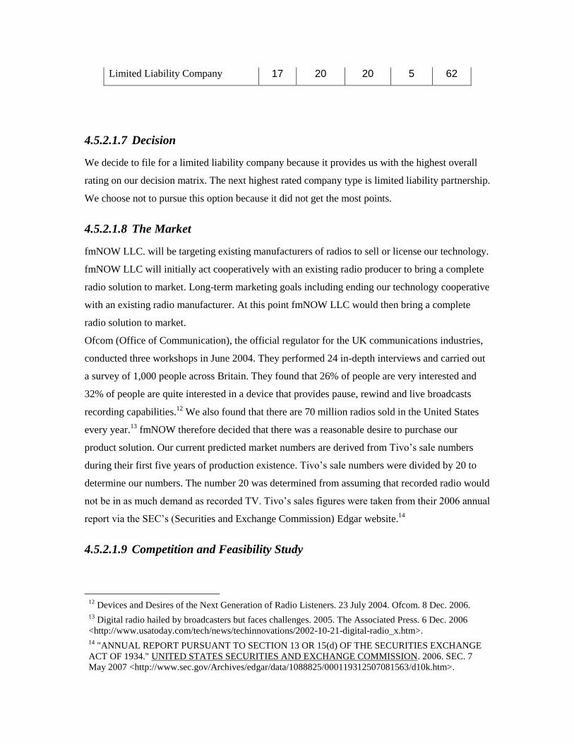
Limited Liability Company 17 20 20 5 62
4.5.2.1.7 Decision
We decide to file for a limited liability company because it provides us with the highest overall
rating on our decision matrix. The next highest rated company type is limited liability partnership.
We choose not to pursue this option because it did not get the most points.
4.5.2.1.8 The Market
fmNOW LLC. will be targeting existing manufacturers of radios to sell or license our technology.
fmNOW LLC will initially act cooperatively with an existing radio producer to bring a complete
radio solution to market. Long-term marketing goals including ending our technology cooperative
with an existing radio manufacturer. At this point fmNOW LLC would then bring a complete
radio solution to market.
Ofcom (Office of Communication), the official regulator for the UK communications industries,
conducted three workshops in June 2004. They performed 24 in-depth interviews and carried out
a survey of 1,000 people across Britain. They found that 26% of people are very interested and
32% of people are quite interested in a device that provides pause, rewind and live broadcasts
recording capabilities.12
We also found that there are 70 million radios sold in the United States
every year.13
fmNOW therefore decided that there was a reasonable desire to purchase our
product solution. Our current predicted market numbers are derived from Tivo’s sale numbers
during their first five years of production existence. Tivo’s sale numbers were divided by 20 to
determine our numbers. The number 20 was determined from assuming that recorded radio would
not be in as much demand as recorded TV. Tivo’s sales figures were taken from their 2006 annual
report via the SEC’s (Securities and Exchange Commission) Edgar website.14
4.5.2.1.9 Competition and Feasibility Study
12
Devices and Desires of the Next Generation of Radio Listeners. 23 July 2004. Ofcom. 8 Dec. 2006. 13
Digital radio hailed by broadcasters but faces challenges. 2005. The Associated Press. 6 Dec. 2006
<http://www.usatoday.com/tech/news/techinnovations/2002-10-21-digital-radio_x.htm>. 14
"ANNUAL REPORT PURSUANT TO SECTION 13 OR 15(d) OF THE SECURITIES EXCHANGE
ACT OF 1934." UNITED STATES SECURITIES AND EXCHANGE COMMISSION. 2006. SEC. 7
May 2007 <http://www.sec.gov/Archives/edgar/data/1088825/000119312507081563/d10k.htm>.

Currently there are no competitive companies in this market and a feasibility study has yet to be
completed
4.5.2.1.10 Location of Business
The business will be located in Grand Rapids MI. We are forming the business here primarily due
to the relative proximity of the business owners.
4.5.2.1.11 Management
The company will consist of 5 members. (The owners) No management decisions have been
made at this time.
4.5.2.1.12 Personnel
The company will consist of 5 members. (The owners) No other personal decision has been made
at his time.
4.5.2.2 Financial Data
4.5.2.2.1 Sources and Application of Funding
Initially all funding shall be received from owners of the company. Future investment should be
taken from equity retained from previous profits.
4.5.2.2.2 Capital Equipment and Furniture Lists
Initially no capital or furniture is required. fmNOW LLC will mainly be selling intellectual
property.
4.5.2.2.3 Projected Balance Sheet
Initial Balance sheets for the company are not very interesting for the first stage of the business.
They provide only the ground work for the company. In this initial stage the owners of the
company will provide only a minimal investment. After a technology sale has been completed the
profits will dispersed to the owners. After fmNOW LLC. has ended its agreement with its radio
manufacturing partner it will begin its financial statements as if it was a startup company. The
owners of the company will at that time have the choice to reinvest in the company before banks
will be sought for additional funding.

The following financial information assume that the first stage has passed and we are currently
about to begin the second stage of company life.
OPENING DAY BALANCE SHEET
fmNOW LLC.
ASSETS
Current Assets
Cash in Bank $ 108,301
Inventory 1,011,224
Prepaid Expenses -
Other -
Total Current Assets $ 1,119,525
Fixed Assets
Machinery & Equipment $ -
IT & Associated Software $ 25,000
Furniture & Fixtures 20,000
Leasehold Improvements 2,000
Real Estate / Buildings 351,475
Other 2,000
Total Fixed Assets $ 400,475
Other Assets
Specify $ -
Specify -
Total Other Assets $ -
Total Assets $ 1,520,000
LIABILITIES & NET WORTH
Current Liabilities
Accounts Payable $ 250,000
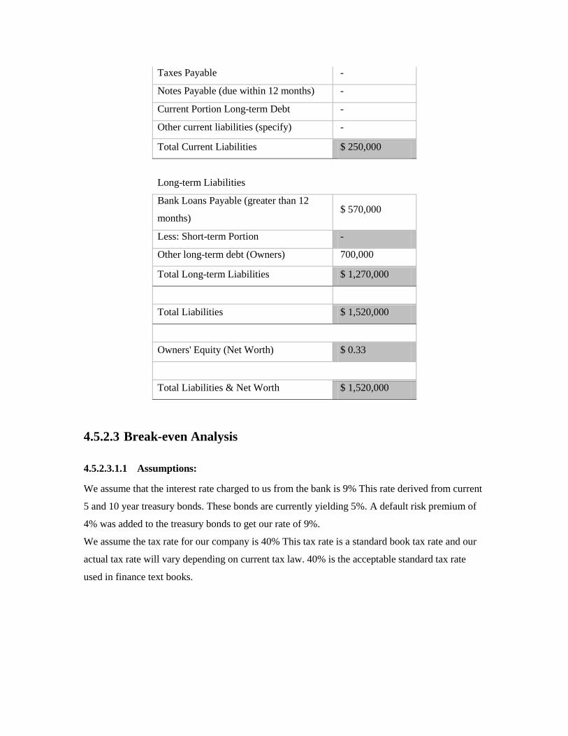
Taxes Payable -
Notes Payable (due within 12 months) -
Current Portion Long-term Debt -
Other current liabilities (specify) -
Total Current Liabilities $ 250,000
Long-term Liabilities
Bank Loans Payable (greater than 12
months) $ 570,000
Less: Short-term Portion -
Other long-term debt (Owners) 700,000
Total Long-term Liabilities $ 1,270,000
Total Liabilities $ 1,520,000
Owners' Equity (Net Worth) $ 0.33
Total Liabilities & Net Worth $ 1,520,000
4.5.2.3 Break-even Analysis
4.5.2.3.1.1 Assumptions:
We assume that the interest rate charged to us from the bank is 9% This rate derived from current
5 and 10 year treasury bonds. These bonds are currently yielding 5%. A default risk premium of
4% was added to the treasury bonds to get our rate of 9%.
We assume the tax rate for our company is 40% This tax rate is a standard book tax rate and our
actual tax rate will vary depending on current tax law. 40% is the acceptable standard tax rate
used in finance text books.

Break Even Analysis Assuming Constant IRR (Internal Rate of Return) of 5%
Year 0 1 2 3 4 5
Units Sold 0 5702.5 9110.25 13909.375 9011.625 11092.5
Sales $0.00 $1,311,700.36 $2,095,557.77 $3,199,462.02 $2,072,871.85 $2,551,518.85
Cost Personnel ($250,000.00) ($262,500.00) ($275,625.00) ($289,406.25) ($303,876.56) ($319,070.39)
Cost BOM & Assembly $0.00 ($1,011,224.33) ($1,615,520.63) ($2,466,549.47) ($1,598,031.46) ($1,967,033.03)
Cost Building and Assets ($368,475.00) $0.00 $0.00 $0.00 $0.00 $0.00
Total Costs: ($618,475.00) ($1,273,724.33) ($1,891,145.63) ($2,755,955.72) ($1,901,908.02) ($2,286,103.42)
EBIT ($618,475.00) $37,976.03 $204,412.14 $443,506.30 $170,963.83 $265,415.43
Interest $51,300.00 $51,300.00 $51,300.00 $51,300.00 $51,300.00 $51,300.00
EBT ($669,775.00) ($13,323.97) $153,112.14 $392,206.30 $119,663.83 $214,115.43
Tax ($267,910.00) ($5,329.59) $61,244.86 $156,882.52 $47,865.53 $85,646.17
Accumulated Tax ($267,910.00) ($273,239.59) ($211,994.73) ($55,112.21) ($7,246.68) $78,399.50
Net Income ($401,865.00) ($7,994.38) $91,867.28 $235,323.78 $71,798.30 $128,469.26
Cash Flows ($669,775.00) ($13,323.97) $153,112.14 $392,206.30 $119,663.83 $135,715.94
PV (Year 1) ($12,689.49)
PV (Year 2) $138,877.22
PV (Year 3) $338,802.55
PV (Year 4) $98,447.73
PV (Year 5) $106,336.99
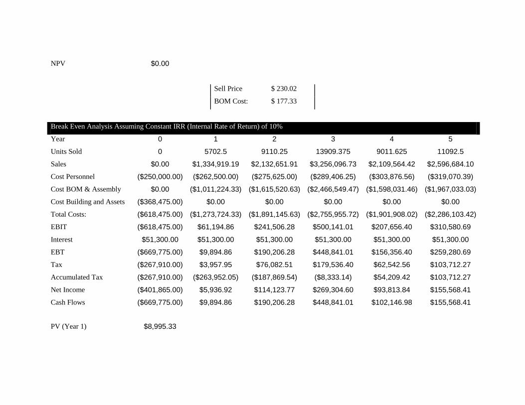
NPV $0.00
Sell Price $ 230.02
BOM Cost: $ 177.33
Break Even Analysis Assuming Constant IRR (Internal Rate of Return) of 10%
Year 0 1 2 3 4 5
Units Sold 0 5702.5 9110.25 13909.375 9011.625 11092.5
Sales $0.00 $1,334,919.19 $2,132,651.91 $3,256,096.73 $2,109,564.42 $2,596,684.10
Cost Personnel ($250,000.00) ($262,500.00) ($275,625.00) ($289,406.25) ($303,876.56) ($319,070.39)
Cost BOM & Assembly $0.00 ($1,011,224.33) ($1,615,520.63) ($2,466,549.47) ($1,598,031.46) ($1,967,033.03)
Cost Building and Assets ($368,475.00) $0.00 $0.00 $0.00 $0.00 $0.00
Total Costs: ($618,475.00) ($1,273,724.33) ($1,891,145.63) ($2,755,955.72) ($1,901,908.02) ($2,286,103.42)
EBIT ($618,475.00) $61,194.86 $241,506.28 $500,141.01 $207,656.40 $310,580.69
Interest $51,300.00 $51,300.00 $51,300.00 $51,300.00 $51,300.00 $51,300.00
EBT ($669,775.00) $9,894.86 $190,206.28 $448,841.01 $156,356.40 $259,280.69
Tax ($267,910.00) $3,957.95 $76,082.51 $179,536.40 $62,542.56 $103,712.27
Accumulated Tax ($267,910.00) ($263,952.05) ($187,869.54) ($8,333.14) $54,209.42 $103,712.27
Net Income ($401,865.00) $5,936.92 $114,123.77 $269,304.60 $93,813.84 $155,568.41
Cash Flows ($669,775.00) $9,894.86 $190,206.28 $448,841.01 $102,146.98 $155,568.41
PV (Year 1) $8,995.33
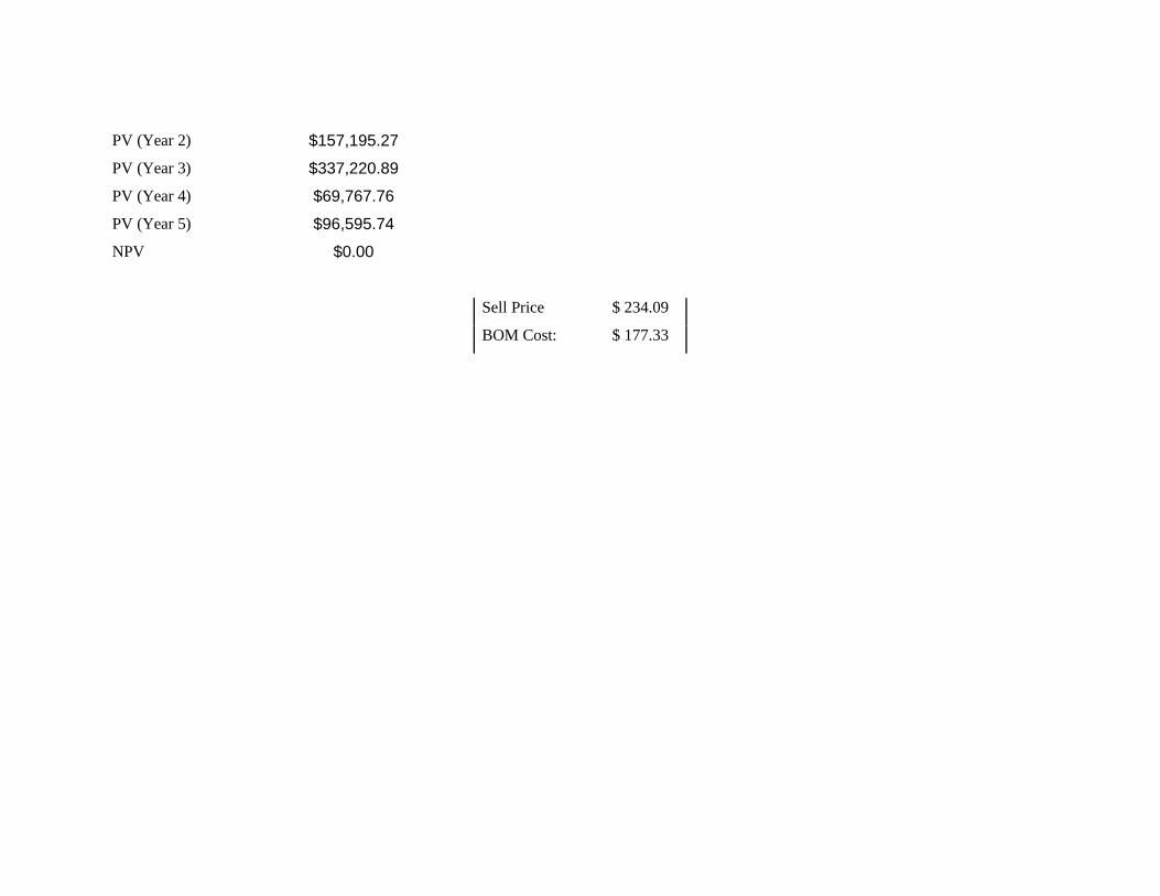
PV (Year 2) $157,195.27
PV (Year 3) $337,220.89
PV (Year 4) $69,767.76
PV (Year 5) $96,595.74
NPV $0.00
Sell Price $ 234.09
BOM Cost: $ 177.33
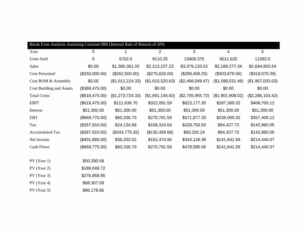
Break Even Analysis Assuming Constant IRR (Internal Rate of Return) of 20%
Year 0 1 2 3 4 5
Units Sold 0 5702.5 9110.25 13909.375 9011.625 11092.5
Sales $0.00 $1,385,361.03 $2,213,237.23 $3,379,133.02 $2,189,277.34 $2,694,803.54
Cost Personnel ($250,000.00) ($262,500.00) ($275,625.00) ($289,406.25) ($303,876.56) ($319,070.39)
Cost BOM & Assembly $0.00 ($1,011,224.33) ($1,615,520.63) ($2,466,549.47) ($1,598,031.46) ($1,967,033.03)
Cost Building and Assets ($368,475.00) $0.00 $0.00 $0.00 $0.00 $0.00
Total Costs: ($618,475.00) ($1,273,724.33) ($1,891,145.63) ($2,755,955.72) ($1,901,908.02) ($2,286,103.42)
EBIT ($618,475.00) $111,636.70 $322,091.59 $623,177.30 $287,369.32 $408,700.12
Interest $51,300.00 $51,300.00 $51,300.00 $51,300.00 $51,300.00 $51,300.00
EBT ($669,775.00) $60,336.70 $270,791.59 $571,877.30 $236,069.32 $357,400.12
Tax ($267,910.00) $24,134.68 $108,316.64 $228,750.92 $94,427.73 $142,960.05
Accumulated Tax ($267,910.00) ($243,775.32) ($135,458.68) $93,292.24 $94,427.73 $142,960.05
Net Income ($401,865.00) $36,202.02 $162,474.96 $343,126.38 $141,641.59 $214,440.07
Cash Flows ($669,775.00) $60,336.70 $270,791.59 $478,585.06 $141,641.59 $214,440.07
PV (Year 1) $50,280.58
PV (Year 2) $188,049.72
PV (Year 3) $276,958.95
PV (Year 4) $68,307.09
PV (Year 5) $86,178.66

NPV $0.00
Sell Price $ 242.94
BOM Cost: $ 177.33
Break Even Analysis Assuming Constant IRR (Internal Rate of Return) of 50%
Year 0 1 2 3 4 5
Units Sold 0 5702.5 9110.25 13909.375 9011.625 11092.5
Sales $0.00 $1,557,663.29 $2,488,505.39 $3,799,407.78 $2,461,565.53 $3,029,965.82
Cost Personnel ($250,000.00) ($262,500.00) ($275,625.00) ($289,406.25) ($303,876.56) ($319,070.39)
Cost BOM & Assembly $0.00 ($1,011,224.33) ($1,615,520.63) ($2,466,549.47) ($1,598,031.46) ($1,967,033.03)
Cost Building and Assets ($368,475.00) $0.00 $0.00 $0.00 $0.00 $0.00
Total Costs: ($618,475.00) ($1,273,724.33) ($1,891,145.63) ($2,755,955.72) ($1,901,908.02) ($2,286,103.42)
EBIT ($618,475.00) $283,938.97 $597,359.76 $1,043,452.06 $559,657.51 $743,862.40
Interest $51,300.00 $51,300.00 $51,300.00 $51,300.00 $51,300.00 $51,300.00
EBT ($669,775.00) $232,638.97 $546,059.76 $992,152.06 $508,357.51 $692,562.40
Tax ($267,910.00) $93,055.59 $218,423.90 $396,860.82 $203,343.00 $277,024.96
Accumulated Tax ($267,910.00) ($174,854.41) $43,569.49 $396,860.82 $203,343.00 $277,024.96
Net Income ($401,865.00) $139,583.38 $327,635.86 $595,291.23 $305,014.51 $415,537.44
Cash Flows ($669,775.00) $232,638.97 $502,490.27 $595,291.23 $305,014.51 $415,537.44
PV (Year 1) $155,092.64

PV (Year 2) $223,329.01
PV (Year 3) $176,382.59
PV (Year 4) $60,249.78
PV (Year 5) $54,720.98
NPV $0.00
Sell Price $ 273.15
BOM Cost: $ 177.33

Determining the break-even cost of product is a supply side analysis. It does not tell us how many units
we are going to sell, but instead uses some arbitrary projected sales volumes and calculates the price per
good where the total cost (fixed and variable) are equivalent to the total income derived from the price of
the good.
Breaking even in 5 years may sound like an aggressive repayment schedule. It is not. This amount of time
is necessary due to the unit volume projections. At 5 years the volume of parts is potentially on a
downward decline. The actual projected figures were taken from TiVo’s actual sales over the past 5 years
divided by a factor of 20. This number was chosen because we believe the market is in lower demand for
a radio TiVO like device than an actual TiVO. We do believe, however, that the demand figures follow
the same pattern as the operation and timing of the devices is similar.
It is worth noting that we initially do a break even analysis using 5% ROE. This is mainly to compensate
for inflation. The current inflation rate is 2.5%. A 5% is about double the current inflation rate, but it
accounts for any fluctuations in the in the inflation rate. It should be noted that this initial calculation with
a 5% ROE was mainly use do determine the real breakeven analysis assuming no real interest was earned
on initial private equity.
4.5.2.3.2 Internal Rate of Return
With some good insight we can see that starting a business is like an investment. Like any good
investment a company returns interest over time. Our company is slightly different than just a generic
investment requiring a return. Instead we are planning to work at this new company we start. While the
actual responsibly of each member have not been entirely hammered out each member will work on two
tasks. The first task of the business will require maintaining the company and the second task will require
research and development of a new product idea to launch in under 5 years.
Because the owners of the company are not looking to make money back the same way that money is
returned on a standard investment we chose salaries of $50,000 that are adjusted each year for inflation by
increasing each salary by 5% each year. This is a safe estimate and can be adjusted later if needed.
We choose to use an IRR of 5% for the break even analysis because it illustrates only a return great
enough to maintain inflation. We also reiterated the calculations with an IRR of 10% to illustrate the
increase in the retail price of the product.
As we increase the ROE rate from 5%, 10%, 20% and 50% we see the retail price of the product increases
in small amounts.
Table 4 Retail Price Of Product with Various ROE
Retail Price for Various ROE
ROE % 5% 10% 20% 50%

Retail
Price $ 230.02 $ 234.09 $ 242.94 $ 273.15
4.5.2.4 Interest Rate
4.5.2.4.1.1 Amount of Debt
Debt is a useful tool when utilized properly. Debt can increase the rate or return of investors and can
lower the actual amount of personal equity invested. Too much debt can be expensive and can give the
person providing debt too much control. It is important to maintain a proper debt to equity ratio. For a
well established company this ratio is usually around 50%.15
Our company will not be well established at
first, but we would also like to take advantage of debt. We will use a debt to equity ratio of approximately
45% this gives our company a healthy portion of debt that is on the light side of the golden 50%.
The interest rate for our loans is higher than standard treasury 5 year bond. This rate was chosen to
accommodate for the potential default risk of our company. This is the interest rate a lender would
require.16
4.5.2.4.2 Tax Rate
This is a ballpark tax rate that will be adjusted when actual taxes are accrued from our company.
4.5.2.4.3 Accumulated Tax
Small businesses and usually businesses in genera
l can roll over negative taxes to credit positive future taxes in forthcoming years.
4.5.2.4.4 Fixed Cost
The large fixed costs for our company is the building modeled after This is a factory office combo
building currently for sale offering approximately 4000 square feet of room. Breakeven Analysis for these
calculations was simplified to a single purchase instead of a mortgage. Also estimates were taken with
regard to furniture and supplies purchased in the first year of business operation.
4.5.2.4.5 Variable Costs
15
Hershey via Edgar @ SEC 16
http://www.bloomberg.com/markets/rates/index.html

The only variable cost that our business has to confront is the raw cost of materials for our product and
the assembly of our product. The BOM cost of a production unit would be $ 177.33.
4.5.2.4.6 Present value
Present value notion is taking future costs or income and discounting it back to the present at a constant
rate. In this case the constant rate was the IRR.
4.5.2.4.7 Net Present value
Net present value is the summation of all the present values in the current year. This value determines if
an investment will cost or make money depending on a certain discount rate. In our company the discount
rate and IRR are set to account for inflation.
4.5.2.4.8 Sell Price
Sell price is the price at which we will sell the product. This price was determined from creating a NPV
equal to 0. In essence the sell price is the price required to break even These prices are shown in Table 4.
At this time we do not have enough information to decide on a ROE.
This price will also be the retail price. We will not needing a distributor or retailer as we will sell our
products online or over the phone.
4.6 Software
4.6.1.1 SBC
4.6.1.2 LCD
4.6.1.3 FM
4.7 Project Management
4.7.1 Team Member Roles
4.7.1.1 Jordan Schaenzle
Jordan Schaenzle spent a large amount of time working with a printed circuit board program called
PCAD. A free 30 day trial version of this software was given to fmNOW to be used for laying out a
circuit. Jordan laid out the circuit schematics and circuit board traces for the prototype 0 board which was

manufactured in the lab in the science building. Jordan also laid out the schematic and routed the traces
for the overall design which was intended to be ordered for the final prototype board. The final prototype
board was never ordered because of shortages of time and money.
Jordan worked on debugging the prototype 0 board along with other group members after it was
fabricated. He also designed an audio amplifier that was intended to be used for testing the fm tuner chips
however this amplifier was never used as we found it to be unnecessary. Jordan researched antenna
circuits which could be implemented on the SI4701 chip and designed the antenna circuit for the final
board.
4.7.1.2 Peter Tuuk
Peter did a lot of work with the MP3 Chip as well as designing some of the printed circuit board
the team used throughout the design process.
4.7.1.3 Job Vranish
Job Vranish’s work consisted mostly of software writing. But, he also was a key debugger of
hardware throughout the semester.
4.7.1.4 Brad Zoodsma
Brad Zoodsma did a good job of getting the ball rolling on many different aspects of the project. He
worked on the initial layout for the mp3 chip and the FM chip. He also did the wiring of the mp3 chip.
Brad did the layout of the mp3 chip on the breadboard and tested different configurations of resistors and
capacitors in regards to the chip. He designed the initial layout of the LCD, power regulation, UCB1400,
and FM chip board. This was what was on display for design night. Brad also started the calculating the
amount of power that our device would consume. Brad also wrote the requirements for the prototype and
the final design, and did the UML diagram.
4.7.1.5 Mike Zwagerman
Mike Zwagerman designed the miscellaneous integrated circuit support circuitry which consists of the
regulation circuitry for both for prototype 0 and prototype 1, the crystal oscillation circuitry for the FM
tuner chips and the audio codec, preliminary testing hardware to talk to the FM tuner chips in VHDL. He
also supported hardware development and debugging by creating and setting up breadboard circuitry for

the FM tuner chips, the UCB1400 and CS4299. He also soldered every IC that was used over the course
of the year except for the FM tuners. He also worked cooperatively with Jordan to layout the final design
night display PCB. He also assisted the project from a non-technical aspect by doing market research and
laying out an entire business plan. He also assisted non-technically by creating the preliminary website
and updating it. He also worked on various system documentation tasks consisting of, but not limited to:
creating and giving PowerPoint presentations, working on the PPFS and final report.
4.7.2 Work Breakdown Structure
The following table shows the expected and actual hours spend for the specific parts of the project. Items
which have zero expected hours are tasks which we neglected to allot time for when planning for the
project.
Senior Design Project
Expected
Hours
Actual
Hours
Final Report 200 0
Compile First Revision 150 0
Peer Revision of Final Report 50 0
Write Project Proposal and Feasibility Study 82 133
Write the Abstract 1 1
Write background setting (research, etc.) 8 12
Cost Analysis 8 15
Design Alternatives 8 10
Objectives 1 5
Requirements 2 5
Task Specifications 2 6
Schedule 1 3
Monthly Budget Report (last day of month) 1 2
Peer Revision of PPFS 50 74
Presentations 34 51
Presentation 1 6 7
Prepare/Write 5 5
Practice 1 2
Presentation 2 6 6
Prepare/Write 5 5

Practice 1 1
Presentation 3 6 0
Prepare/Write 5 0
Practice 1 0
Presentation 4 6 12
Prepare/Write 5 10
Practice 1 2
Presentation 5 10 26
Prepare/Write 5 20
Practice 1 6
Design fmNOW 1260 885
Research 130 71
RDS 20 12
Tuning Methods 20 15
DSP 20 10
Recording Medium 20 5
Processors 30 10
LCD 20 10
CS4299 0 4
UCB1400 0 5
Prototype Hardware Design 425 688
Decision Making 14 35
Group discussion and brainstorming 8 20
Construct Design Matricies 4 10
Meet with team mentor 2 5
Prototype construction 411 653
Order Parts 1 5
Establish Tuner to SBC interface 100 75
Establish mp3 to SBC interface 100 175
Talk to UCB1400 and get Touchscreen
working 0 32
Design and build Prototype Zero board 0 65
Get LCD Operational 0 30
Assemble all hardware components of 50 40

device
General debugging of overall device 100 200
Tweek user iterface 60 15
Establish communication between CS4299 and SBC 0 16
Prototype Software Design 375 100
Write software requirements 10 5
Write software 250 60
Block Diagram 20 5
Debug 70 20
choose design alternatives 25 10
Production Hardware Design 35 26
Group discussion and brainstorming 20 20
Construct Design Matricies 10 5
Meet with team mentor 5 1
Production Software Design 295 0
Write software requirements 20 0
Write software 200 0
Block Diagram 10 0
Debug 50 0
choose design alternatives 15 0
Webpage 10 11
Original construction 5 6
Updates 5 5
Posters 6 24
Original construction 5 4
Updates 1 20
Advertisement 3 7
Design 2 4
Updates 1 3
Project Brief for Industrial Consultant 3 3
Compile document and prepare 2 2
Meeting time 1 1
Project Brief for Industrial Consultant 2 12 3
Compile document and prepare 10 2

Meeting time 2 1
Total Hours 1610 1117
4.7.3 Schedule
Below is the general schedule which our team followed for this project.
4.7.4 Contingency Plans
Because of the complexity of this project our group devised several contingency plans which we
could fall back on if we got to the point where a certain component of our design could not be
realized. These contingency plans are as follows
4.7.4.1 MAS3587
Because the MP3 chip (MAS3587) serves only to compress the audio and allow more time to be
buffered this component of the design was not crucial to our prototype. We had decided that if we
could not get it functional within a reasonable amount of time, we would abandon development with
the chip and use plain uncompressed audio in our system. After struggling with the MP3 chip for
over three weeks, and still not getting it to power up consistently we decided to scrap it and move on.
We used the UCB1400 as our analog to digital converter instead.
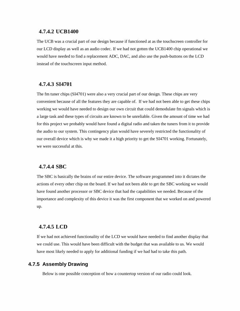
4.7.4.2 UCB1400
The UCB was a crucial part of our design because if functioned at as the touchscreen controller for
our LCD display as well as an audio codec. If we had not gotten the UCB1400 chip operational we
would have needed to find a replacement ADC, DAC, and also use the push-buttons on the LCD
instead of the touchscreen input method.
4.7.4.3 SI4701
The fm tuner chips (SI4701) were also a very crucial part of our design. These chips are very
convenient because of all the features they are capable of. If we had not been able to get these chips
working we would have needed to design our own circuit that could demodulate fm signals which is
a large task and these types of circuits are known to be unreliable. Given the amount of time we had
for this project we probably would have found a digital radio and taken the tuners from it to provide
the audio to our system. This contingency plan would have severely restricted the functionality of
our overall device which is why we made it a high priority to get the SI4701 working. Fortunately,
we were successful at this.
4.7.4.4 SBC
The SBC is basically the brains of our entire device. The software programmed into it dictates the
actions of every other chip on the board. If we had not been able to get the SBC working we would
have found another processor or SBC device that had the capabilities we needed. Because of the
importance and complexity of this device it was the first component that we worked on and powered
up.
4.7.4.5 LCD
If we had not achieved functionality of the LCD we would have needed to find another display that
we could use. This would have been difficult with the budget that was available to us. We would
have most likely needed to apply for additional funding if we had had to take this path.
4.7.5 Assembly Drawing
Below is one possible conception of how a countertop version of our radio could look.

Figure 11 - Radio Artist Rendering
4.7.6 Circuit Diagrams
The circuit schematic for the final board is split up into sections for each major component of the circuit.
These diagrams can be found in Appendix B through Appendix F. The overall circuit layout for the
prototype board which we fabricated in Calvin’s PCB lab is also found in the Appendix as item G. The
overall system circuit layout for the final board which we intended to send to Advanced Circuits is
located in found in the appendix labeled H.
4.7.7 Task Specifications
5 Testing
Project testing for fmNOW was constructed from two forms of testing at different levels of development.
First during the projects stage of board implementation and development each IC (Integrated Circuit)
chosen for the project was tested individually with supporting circuitry for proper and complete
functionality. Secondly the entire project was tested to determine if the project requirement had been
successfully met.
5.1 Debugging Techniques
5.1.1 IC supporting Circuitry
It is important to insure that parts of the project function properly. If parts of the project do not function
properly, other alternatives and solutions must be found to insure the success of the project. To insure
each IC we ordered functioned just as the documentation suggested, we created daughter support PCB

(Printed Circuit Boards) that literally mapped each IC trace to a header pin. This is true in all cases except
for the power regulation circuitry; this circuitry was simple enough that we designed a PCB for these ICs
straight away with a high confidence. This approach allowed us to implant our IC’s in their own bread
board circuit. A breadboard circuit is very customizable and can be used to fine tune the IC’s supporting
circuitry with the least amount of work. Breadboards are also a convenient way to measure individual
signal circuitry. As soon as each IC had its own breadboard circuit we would be able to test the IC for
functionality.
5.1.2 Test Drivers
Test drivers were written for the MP3, FM Tuner and Audio Codec ICs. These were written in C and built
for the SBC running Linux. These test drivers were verified simultaneously with the hardware as they
were used to test the hardware.
5.2 Part Isolation Testing Circuits.
Because we were interested in debugging each IC individually, some extra circuitry was required to prove
each chip’s functionality. For example, the FM tuner IC outputs analog audio, but the audio needs
application before it can be heard. An amplifier circuit was designed to amplify the FM tuner chip only
during this debugging stage of the project.
5.2.1 SBC (Intel XScale PXA255 CPU module)
The SBC we received from Calvin came supplied with a Starter-Kit II evaluation kit shown in Figure 12.
This evaluation kit allowed us to test the functionality of the SBC early on. We Tested that we fully
installed Linux on the SBC. We tested that we were fully able to change and control the GPIO (General
Purpose Input / Output) pins with test drivers. We were going to use this GPIO pins to control the other
devices in the circuit.
Figure 12 SBC Evaluation Kit Used For SBC Functionality Testing
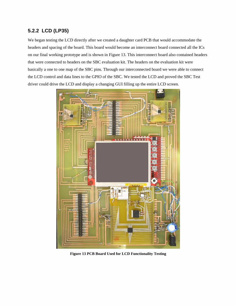
5.2.2 LCD (LP35)
We began testing the LCD directly after we created a daughter card PCB that would accommodate the
headers and spacing of the board. This board would become an interconnect board connected all the ICs
on our final working prototype and is shown in Figure 13. This interconnect board also contained headers
that were connected to headers on the SBC evaluation kit. The headers on the evaluation kit were
basically a one to one map of the SBC pins. Through our interconnected board we were able to connect
the LCD control and data lines to the GPIO of the SBC. We tested the LCD and proved the SBC Test
driver could drive the LCD and display a changing GUI filling up the entire LCD screen.
Figure 13 PCB Board Used for LCD Functionality Testing

5.2.3 FM Tuner (si4701)
The FM tuner ICs were soldered to a daughter card that mapped the chip’s leads to header pins on the
daughter card. This daughter card was setup in a breadboard with supporting circuitry as show in Figure
14. FM tuner control and data wires (I2C) from the IC were connected to the SBC GPIO though the
breadboard. With our FM tuner test driver we were able to tune to radio stations on command and hear
their broadcasts, determine RSSI (Receive Signal Strength Indication) value of each station in the FM
band, and scan the entire FM band compile a list of stations containing a RSSI above a specified level.
Figure 14 PCB Board with FM Tuner IC used for Functionality Testing
5.2.4 Audio Codec touch screen driver (UCB1400)
The audio coded IC was soldered to a daughter card that mapped the chip’s leads to header pins on the
daughter card. This daughter card was setup in a breadboard with supporting circuitry as show in Figure
15. Audio Codec control and data wires (AC’97) from the IC were connected to the SBC GPIO though
the breadboard. With our audio codec test driver we were able to save a digital file from analog audio.
Play analog audio from a digital file. We were also able to do both operations simultaneously.

Figure 15 PCB Board with FM Audio Codec IC used for Functionality Testing
When both the LCD and the audio codec were operating independently we began integration of
components. We soldered the audio codec daughter board with audio codec attached to the circuit
interconnect board in Figure 13. This interconnect board connected both the LCD and the audio codec
control and data lines the SBC GPIO as well as connecting the LCD touch screen data lines to the audio
codec. With our touch screen test driver we were able to move a cursor to all positions on the screen and
push buttons on the LCD displayed GUI.
5.2.5 Power Regulation
A power regulation daughter card, shown in Figure 16, was created to attach the power regulation surface
mount circuitry. This circuitry successfully took in 13.5 V to 30 V and outputted 12V, 3.3V and 5V at
200 mA each. This amount of power was enough to run all the components in our system, with a wide
margin. At this load each component was operating within normal operating conditions and each
component was capable of more power. Minimally five times more power.
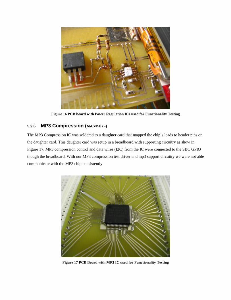
Figure 16 PCB board with Power Regulation ICs used for Functionality Testing
5.2.6 MP3 Compression (MAS3587F)
The MP3 Compression IC was soldered to a daughter card that mapped the chip’s leads to header pins on
the daughter card. This daughter card was setup in a breadboard with supporting circuitry as show in
Figure 17. MP3 compression control and data wires (I2C) from the IC were connected to the SBC GPIO
though the breadboard. With our MP3 compression test driver and mp3 support circuitry we were not able
communicate with the MP3 chip consistently
Figure 17 PCB Board with MP3 IC used for Functionality Testing
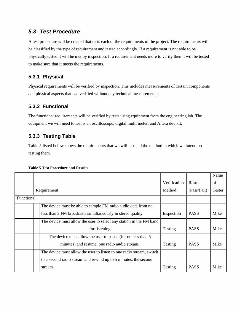
5.3 Test Procedure
A test procedure will be created that tests each of the requirements of the project. The requirements will
be classified by the type of requirement and tested accordingly. If a requirement is not able to be
physically tested it will be met by inspection. If a requirement needs more to verify then it will be tested
to make sure that it meets the requirements.
5.3.1 Physical
Physical requirements will be verified by inspection. This includes measurements of certain components
and physical aspects that can verified without any technical measurements.
5.3.2 Functional
The functional requirements will be verified by tests using equipment from the engineering lab. The
equipment we will need to test is an oscilloscope, digital multi meter, and Altera dev kit.
5.3.3 Testing Table
Table 5 listed below shows the requirements that we will test and the method in which we intend on
testing them.
Table 5 Test Procedure and Results
Requirement:
Verification
Method
Result
(Pass/Fail)
Name
of
Tester
Functional:
The device must be able to sample FM radio audio data from no
less than 2 FM broadcasts simultaneously in stereo quality Inspection PASS Mike
The device must allow the user to select any station in the FM band
for listening Testing PASS Mike
The device must allow the user to pause (for no less than 5
minutes) and resume, one radio audio stream. Testing PASS Mike
The device must allow the user to listen to one radio stream, switch
to a second radio stream and rewind up to 5 minutes, the second
stream. Testing PASS Mike

The user must be able to rewind or fast-forward the active stream
at a rate of 10 seconds of recorded time per 1 second of real time. Testing PASS Mike
fmNOW will be able to store data onto an onboard memory source Testing PASS Mike
Performance:
Power
fmNOW will be powered by an DC power source Inspection PASS Mike
Size:
The device must be no bigger than a form factor of 1’ x 6” x 8” (W
x H x D) Inspection PASS Mike
Weight:
The device must weigh no more than 10 lbs Inspection PASS Mike
Quality:
The device will minimally be able to store radio streams at a rate of
44.1kHz at 16 bit digital quality providing a net raw digital quality
of 172KB /s [1] Testing PASS Mike
The device must be able to playback audio streams at 44kHz Testing PASS Mike
Cost:
The prototype can cost no more than $360 Inspection FAIL Mike
Storage:
The device shall be able to record up to 5 minutes per station Testing PASS Mike
Interface :
The user interface must be reasonably intuitive with controls
similar to those of current radios and music listening devices. Inspection PASS Mike
The interface must allow the user to select an FM broadcast to
listen to Testing PASS Mike
The interface shall show the current station that is being listened to
as well as the other stations being recorded Testing PASS Mike
The interface shall be able to show different screens to show
different functions Testing PASS Mike
If a button shall be considered pushed once it has been engaged,
not when it is released. During the period when the button is held
down, pushing another button will not do anything. Testing PASS Mike

A button push shall cause a noise to indicate to the user that it has
been pushed Testing FAIL Mike
The interface must allow the user to pause, resume, or rewind an
active broadcast. Testing PASS Mike
The interface must allow the user to pause, resume, rewind, or
forward a recorded broadcast. Testing PASS Mike
The interface must allow the user to switch from a paused
broadcast to any another broadcast and vice-versa Testing PASS Mike
The interface must allow the user to turn fmNOW on and off Testing PASS Mike
fmNOW will have a light that signals to the user if the unit is on or
not Inspection PASS Mike
5.4 Test Summary
We were able to use a test plan an test procedure to validate our final working project based on part
functionality and requirement testing.
5.4.1 Test Results.
5.4.1.1 Individual IC Functionality
With our part isolation testing circuits we were able to get all our critical ICs up and fully functional. We
were able to determine that the MP3 chip would not operate correctly for the final prototype. This allowed
us to eliminate the part and still meet the minimum project requirements.
5.4.1.2 Project Functionality
Using our test procedure we were able to determine if our project solution met our project requirements.
From this procedure we see that we did not meet 2 requirements. We exceeded our budget requirement
and did not comply with our button push requirement. These two requirements were sacrificed in order to
pass the rest of the project requirement in the time allowed. More money was needed to purchase parts
and PCBs and have them arrive in time to show off our working prototype. The button requirement was
deemed unimportant and the letter of the requirement was not met but the idea behind the requirement
was met. We can push only one button at a time. These two requirement failures doe not cause our project
to become a failure. The requirements were drawn up by us to conform our design to meet the goals of

pause able and rewind able radio device. These goals were still met, and so a successful project was
created.
6 Unsolved Issues
6.1 MP3 Encoding
6.1.1 Why We chose Micronas MAS3587F
We wanted to use a form of audio compression to maximize the pause, rewind, and fast-forward
functionality of fmNOW. There are many available algorithms for audio compression including AAC
(Advanced Audio Coding), Ogg Vorbis, and MP3. MP3 is a Motion Picture Experts Group (MPEG)
audio compression format developed in the late 1980’s17
by Karlsheinz Brandenburg at the University of
Erlangen-Nuremberg. It delivers varying compression rates based on the bitrate used in the encoding
process. AAC is another MPEG standard developed later which theoretically delivers better performance
at decreased storage size. Ogg Vorbis is an open-source audio coding algorithm that was released to in its
first stable version in 200218
. Of these three formats, MP3 is the most widely used and most common.
For this reason we chose this format to encode our audio.
There were two ways to encode the raw audio. We could do so using software running on our
general purpose CPU or use a dedicated hardware component to deliver encoded audio to the CPU.
Because of the computational complexity of the audio encoding operation and the finite computational
resources of our CPU we chose to source the encoding operation off CPU in a dedicated component.
This decision gave rise to the search for a dedicated MP3 encoding solution. The number of
devices that are available to complete this task is small. Decoding MP3 audio is very frequently
accomplished in handheld devices including any portable music player, but audio encoding is most often
done outside of real-time and within the comforts of a higher-performance desktop PC. So, our search for
such a device led to a disappointing set of options. Among those options was to use a general purpose
digital signal processor (DSP). Such devices are readily available, but do not offer the ease and speed of
implementation we required. They must be programmed with firmware and software must be written to
run on the processor. These activities are time-consuming and outside the scope of our experience.
Because of requirement was so narrowly focused, we decided to look for a dedicated MP3 encoder that
would require minimal configuration and setup.
17
http://en.wikipedia.org/wiki/MP3 18
http://en.wikipedia.org/wiki/Vorbis
After spending a great deal of time sifting through search engine results and reading web-forums
we came across a single chip that seemed to meet our requirements. This chip was made by Micronas and
was designed primarily for the purpose of MP3 compression. We used the only part we could find to fill
the role in our design. This chip was only available from a supplier in the Czech Republic.
6.1.2 Part Description
The Micronas MAS3587F is an integrated circuit component in the LQFT64 package. Its
functions include digital to analog (ADC) conversion, digital to analog (DAC) conversion, real-time MP3
encoding from analog input, DC/DC converters to condition and step-up supply voltage. It is controlled
primarily through the Inter-Integrated Circuit (I2C) bus. Digital MP3 frames are communicated to
memory or the microcontroller over parallel I/O, headphone output amplification, and internal oscillator
functionality. Besides a controller and non-volatile memory, the MAS3587F provides the functionality of
a portable music player. We needed the MP3 encoding, but not the other parts.

Figure 18 MAS 3587F Pinout
The communication protocol for controlling the devices was I2C. Having a working I
2C driver
that had been tested successfully on other devices, we were confident that communication with the MAS
device would proceed similarly. So, we planned out our communication sequence.
To disable the DC/DC converters and rely on external power.
To startup the signal processing core
To startup the audio codec
To set parameters for MP3 encoding including input source and output destination
To un-mute all outputs
To enable conversion
The command sequence was derived from the 40-page I2C interface section in the manual.

6.1.3 Trouble
Knowing the I2C interface and the command sequence that we expected to function, we started testing
our device. We never got much beyond this point, as the device did not respond to repeated I2C that were
rebuffed again and again. The device would not even give acknowledge bits in the I2C call and response
sequence. This was disconcerting, to say the least.
Seeing this failure, we looked for causes of a non-responsive system. Our thoughts turned to the complex
power regulation circuitry. This circuitry is included to optimize the operation of the device in a batter-
powered environment. As such, the part runs through a series of checks before demands a certain input
sequence before powering up.
We attempted to follow these procedures to the letter. We attempted using different power-supply
configurations as described in the datasheets and application notes. We made requests for support from
Micronas which were denied on the grounds that the device was no longer supported for new designs,
such as ours.
With little indication from the chip as to what was going on inside, we had little idea which direction to
pursue. So we pursued many different courses of action. We tried soldering on a new chip. We tried
rewiring the protoboard, using different sections of protoboard, using different supply voltages for digital
and analog supply, and progressively changing the startup timing sequences.
We also received indication that the part was receiving power because it would enable an appropriate
output when the power supply reached the 3.0 V threshold. We also received a square wave output from
the clock output pin, indicating at least some part of the device powered up.
These items made the successful startup of the device seem tantalizingly close, which led us to continue
work on the project even when deadlines for its completion or abandonment had past.
Finally, we decided that to obtain a working project to show on Design Night, we needed to focus on
remediation rather than simply working on solve the existing problem. This meant forgoing the desired
compression of the MP3 algorithm and settling for shorter recording buffer. We still needed to convert
the analog output of the FM tuner circuits to digital form for the SBC. The way this was done was by
using the ADC functionality of the UCB1400 audio codec (in parallel with the DAC output operation) to
bring the audio into the SBC as raw WAV audio files.
One way we could have avoided the time crunch we could have left extra time in our schedule for the
unexpected. If we would have left a cushion of time to leave for the unexpected problems that we ran into
we would have possibly been able to get the MP3 chip working.

Even though we did not get the mp3 chip working for our final prototype we could still provide the
necessary functionality to prove our concept. The only thing that using a MP3 compression chip would do
is allow us to record for a longer period of time.
6.2 Antenna
We desired to find an antenna that would use our built-in antenna jack. This turned out to be a problem,
because the antenna we had was designed to receive Bluetooth communications and was thus designed
for a frequency range that is far from that of the FM band. There was no difference in reception of FM
stations with or without the antenna. This meant we needed to find another way to improve the reception
of our device. We ended up buying an antenna from RadioShack that was operable but not aesthetically
pleasing or very effective.
To implement this commercially, we would need to vastly improve the reception of FM stations.
Presently, there are many known stations in the area that are not being received. We need to use more
effective noise suppression techniques, perhaps separate antennas for each tuner, and more reliable
connection between tuner and antenna. We
6.3 Tuner Lists
Presently, the when the tuners are polled for a list of receivable stations, they present different lists. This
is because of slight differences in the reception of the different tuners. We could improve this if we were
to improve reception, but a software solution of saving a list that would have the stations of each tuner
would go a long way to improving the user experience. This would allow the user to tune to more
stations and eliminate the frustration of finding a station on one scan and not on the next.
6.4 Stereo Audio - CS4299
Our original plans called for the Micronas MAS3587F to handle ADC duties between the tuners and the
SBC. However, when this was abandoned, this operation needed to be complete by another device. We
found that we could use the ADC functionality of our audio codec to handle this.
Prototype 0, shown at design night, only supports mono sound from each channel. This is because the
sound from both tuners is routed through a single channel of a stereo ADC. To make this possible we
used mono sound from each tuner, one through the left channel of the ADC another through the right
channel. This allowed us to have an operational product without

Our plans for Prototype 1 call for the implementation of a secondary audio codec to support another
channel of ADC. We had selected and ordered a CS4299 to fulfill this duty. On the printed circuit board
for Prototype 1, we left jumpers to revert back to a single audio codec and mono sound. We were,
however, not able to receive the printed circuit board in time for Senior Design Night, nor were we able to
get the CS4299 to turn on. With more time and effort, this likely would have been possible, but we
needed to dedicate the SBC to software development rather than hardware debugging as the Senior
Design Night drew nearer. To this end, we gave up the stereo audio. Since the users at Senior Design
Night were likely not able to tell mono FM broadcasts (played over both speakers) from stereo FM we
feel that very little was lost from a demonstration standpoint.
6.5 EMI Pickup
The device we demonstrated on Senior Design Night was very susceptible to errors caused by
interference and small changes in pin voltages. For example, the device would be sent to and
unrecoverable (except by cycling power) state if a soldering iron was switched on or off, or a fluorescent
lamp switched on or off. Additionally, the device would often reset if a person brushed a pin connected
to the SBC. These errors could be minimized by using fewer ribbon cables, or shielding the circuit board
with a ground plane.
7 Concluding Thoughts
In the beginning of this project we wanted to have an interesting and challenging design project and we
proved that it was indeed interesting and very challenging. We had a hard time getting the MP3 chip to
work consistently.
8 Acknowledgements
fmNOW has received much help from others throughout this year. We would like to thank the following
people for their help and support on this project:
- Professor Steve VanderLeest, our team advisor and mentor, for his help and encouragement
throughout this entire project
- Tim Theriault, for being our team’s industrial consultant
- Smiths Aerospace for assisting us in soldering our FM chip
- Todd Burghgraef, from DornerWorks Ltd for his time in mentoring our group

9 Appendices
Appendix A
Market Research
Bose Wave Music System - Platinum White Price: $499.00
Product Dimensions: 8.6 x 14.6 x 4.2 inches ;
8.7 pounds
Classic CRL11 Sunset Melodies AM/FM CD Nostalgic Cathedral Song Console
Measures 11.8 x 14.8 x 11 inches (W x D x H)
Shipping Weight: 13.00 pounds
Panasonic SC-PM03 Executive Microsystem
list price: $99.00
Dimensions: 18.5 x 11.7 x 8.8 inches ;
Shipping Weight: 23.00 pounds
Boston Acoustics Recepter Radio AM/FM clock radio with dual alarms White
$149.99
Shipping weight: 4.9 Pounds
No size listed

Tivoli Platinum Series Model One Henry Kloss table radio Piano black
$199.99
Shipping weight 5.56 pounds
Actual weight: 4.52 pounds
Dimensions: 4.5"H x 8.375"W x 5.25"D 11.43cm H x 21.27cm W x 13.34cm
JWin JL-K733 Under-Counter AM/FM Clock Radio with CD Player
$34.95
Product Dimensions: 15.0 x 5.0 x 10.5 inches
Shipping Weight: 6.00 pounds
Teac SR-L35W Wall-Mounting or Tabletop Stereo with CD Player and AM/FM
Tuner, White $123.75
Measures 15 by 9 by 4.6 inches (W x H x D); includes remote control
Weight 9.5 pounds
Crosley CR37 Bluebird AM/FM Radio with Cassette Deck
Price: $129.95
Measures 14 x 14 x 7.5 inches (W x H x D)
Shipping Weight: 11.00 pounds
JWIN JLK533 Kitchen Under-Counter AM/FM Clock Radio With CD Player
Price: $34.50
Measures: Not Available
Shipping Weight: 7.00 pounds

GE 75300 GE Slim Spacemaker CD player with Digital Clock and AM / FM Radio, Under-Counter
Mounting system.
Price: $89.99
Product Dimensions: 5 x 15.6 x 13.7 inches
Weight: 8.3 pounds
Crosley Radio CR221 Solo Radio
Price: $114.99
Weight: 6.00 pounds
Dimensions not available

Appendix B
SBC Circuit Diagram
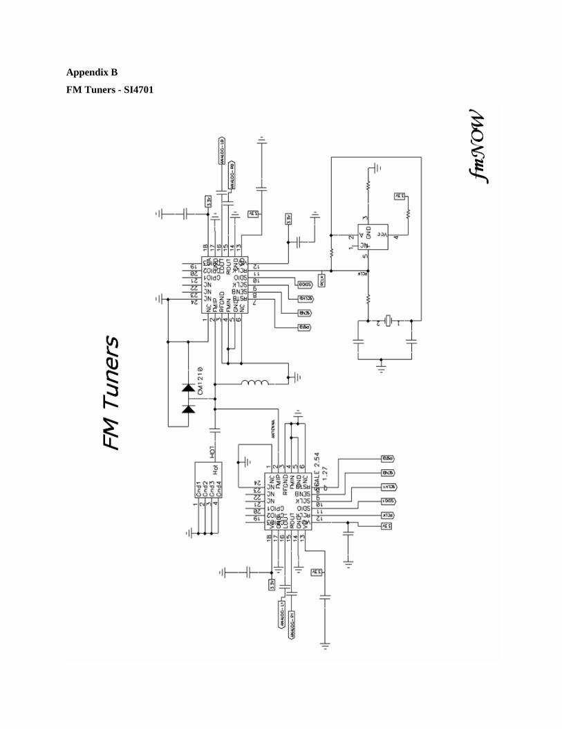
Appendix B
FM Tuners - SI4701

Appendix C
LCD Connections

Appendix D
Audio Codec – UCB1400

Appendix E
Audio Codec – UCB1400


Appendix F
Power Distribution

Appendix G
Prototype 0 Circuit Diagram

Appendix H
Final Printed Circuit Board

Appendix I
Power and Heat Dissipation Calculations
voltage 30V
current .18A
Ptyp voltage current Ptyp 5.4 W
Maximum ratings
Pfm 5.8V 500mA Pprocessor 2598mW PDSP 3 300 A 3.6V PUCB 3.3V 18 12( )mA
Pmax 3Pfm Pprocessor 3PDSP 3 PUCB Pmax 11.605W
Heat off board
k1 20W
m2
K
Area 5in 5in 2
T1typPtyp
Area
1
k1 T1max
Pmax
Area
1
k1
T1typ 8.37K T1max 17.987K
Heat Across Enclosure (Plastic)
k2 0.03W
m K L
1
8in
Opening guesses:
T2max 1K T2typ 1K
Given
Ptyp
Areak2
T2typ
L
T2typ Find T2typ T2typ 17.717 C
Given
Pmax
Areak2
T2max
L
T2max Find T2max T2max 38.073 C
Tambient 531.67R (72 degrees Fahrenheit)
Tmax T1max T2max Tmax 56.061 C
Tboardmax Tambient Tmax Tboardmax 78 C
Ttyp T1typ T2typ Ttyp 46.956 F
Tboardtyp Tambient Ttyp Tboardtyp 48 C

10 Source Code
See attached
Related Documents


