6 Catalog 82068 Dimensions are shown for Dimensions are in inches and Canada: +1 (905) 475-6222 UK: +44 (0) 800-267666 Revised 4-12 reference purposes only. millimeters unless otherwise Mexico/C. Am.: +52 (0) 55-1106-0800 France: +33 (0) 1-3420-8686 Specifications subject specified. Latin/S. Am.: +54 (0) 11-4733-2200 Netherlands: +31 (0) 73-6246-999 www.te.com to change. USA: +1 (800) 522-6752 Germany: +49 (0) 6251-133-1999 China: +86 (0) 400-820-6015 AMPLIMITE Subminiature D Connectors Note: All part numbers are RoHS compliant. AMPLIMITE .050 Series Cable Assemblies, Series III AMPLIMITE .050 Series Connectors, Series III To meet Standard Applications the following 106 ohm, black jacketed cable assemblies are avail- able. For AMPLIMITE .050 Series cable assemblies that meet other impedance requirements or other lengths consult TE. Part Numbers Application Assembly 2 Feet 2 Meters 3 Meters 50 pos. .050 Series Plug to SCSI-2 50 pos. .050 Series Plug 750254-1 5750254-2 750254-3 68 pos. .050 Series Plug to SCSI-2* 68 pos. .050 Series Plug — 5750732-2 5750732-4 RS-232 26 pos. .050 Series Plug to (Alternate) 26 pos. .050 Series Plug — 750255-2 750255-3 Part Numbers Application Assembly 5 Meters 15 Meters 25 Meters IPI-2 and 100 pos. .050 Series Plug to HIPPI 100 pos. .050 Series Plug 749755-2 — — *This version has spring latches. Consult TE for availability of jackscrew version. Note: .050 centerline ribbon cable assemblies are available in single or double ended versions.These assemblies are made using AMPLIMITE .050 Series panel mount connectors, AMPLIMITE .050 Series all-plastic connectors and AMP-LATCH Novo receptacles. Consult TE. SCSI—Small Computer Systems Interface HIPPI—High Performance Parallel Interface IPI—Intelligent Peripheral Interface RS-232 (Alternate) IPI-2 and HIPPI SCSI-1 to SCSI-2 SCSI-2 RS-232 (Alternate) to RS-232

Welcome message from author
This document is posted to help you gain knowledge. Please leave a comment to let me know what you think about it! Share it to your friends and learn new things together.
Transcript
6Catalog 82068 Dimensions are shown for Dimensions are in inches and Canada: +1 (905) 475-6222 UK: +44 (0) 800-267666Revised 4-12 reference purposes only. millimeters unless otherwise Mexico/C. Am.: +52 (0) 55-1106-0800 France: +33 (0) 1-3420-8686
Specifications subject specified. Latin/S. Am.: +54 (0) 11-4733-2200 Netherlands: +31 (0) 73-6246-999www.te.com to change. USA: +1 (800) 522-6752 Germany: +49 (0) 6251-133-1999 China: +86 (0) 400-820-6015
AMPLIMITE Subminiature D Connectors
Note: All part numbers are RoHS compliant.
AMPLIMITE .050 Series Cable Assemblies, Series III
AMPL
IMIT
E.0
50Se
ries
Conn
ecto
rs,S
erie
sIII
To meet StandardApplications the following106 ohm, black jacketedcable assemblies are avail-able. For AMPLIMITE .050Series cable assemblies thatmeet other impedancerequirements or otherlengths consult TE.
Part NumbersApplication Assembly
2 Feet 2 Meters 3 Meters
50 pos. .050 Series Plug toSCSI-2 50 pos. .050 Series Plug 750254-1 5750254-2 750254-3
68 pos. .050 Series Plug toSCSI-2* 68 pos. .050 Series Plug — 5750732-2 5750732-4
RS-232 26 pos. .050 Series Plug to(Alternate) 26 pos. .050 Series Plug — 750255-2 750255-3
Part NumbersApplication Assembly
5 Meters 15 Meters 25 Meters
IPI-2 and 100 pos. .050 Series Plug toHIPPI 100 pos. .050 Series Plug 749755-2 — —
*This version has spring latches. Consult TE for availability of jackscrew version.Note: .050 centerline ribbon cable assemblies are available in single or double ended versions. These assemblies are
made using AMPLIMITE .050 Series panel mount connectors, AMPLIMITE .050 Series all-plastic connectorsand AMP-LATCH Novo receptacles. Consult TE.
SCSI—Small Computer Systems InterfaceHIPPI—High Performance Parallel InterfaceIPI—Intelligent Peripheral Interface
RS-232 (Alternate)
IPI-2 and HIPPI
SCSI-1 to SCSI-2SCSI-2
RS-232 (Alternate)to RS-232
7Catalog 82068 Dimensions are shown for Dimensions are in inches and Canada: +1 (905) 475-6222 UK: +44 (0) 800-267666Revised 4-12 reference purposes only. millimeters unless otherwise Mexico/C. Am.: +52 (0) 55-1106-0800 France: +33 (0) 1-3420-8686
Specifications subject specified. Latin/S. Am.: +54 (0) 11-4733-2200 Netherlands: +31 (0) 73-6246-999www.te.com to change. USA: +1 (800) 522-6752 Germany: +49 (0) 6251-133-1999 China: +86 (0) 400-820-6015
AMPLIMITE Subminiature D Connectors
Note: All part numbers are RoHS compliant.
AMPLIMITE .050 Series Right-Angle Receptacle Headers, Series III
AMPLIM
ITE.050
SeriesConnectors,Series
III
Materials:Housing — Thermoplastic, 94V-0rated, black. SMT compatibleShell —Steel, plated bright nickel overcopperBracket — Zinc, plated nickel overcopperContacts —Phosphor bronze, duplexplated [.000030] 0.00076 min. gold onmating end; tin on solder end; all under-plated nickel
Technical Documents:Product Specifications — 108-1228Application Specifications —114-40029
.463[11.76]
.118±.003[3.00±0.08]
K
.406[10.31]
2-56 UNC 2BHoles
.100[2.54]Typ.
G
E
FPosition 1
Last Position
.050[1.27]
Typ.
ShownWith Boardlocks ShownWith Boardlocks ShownWith Boardlocks
Part Numbersw/ Rails and Latchblocks w/o Rails, w/ Latchblocks w/o Rails, w/o Latchblocks
No. of Dimensions With .100 [2.54] With .100 [2.54] With .100 [2.54] With .120 [3.05]Pos. E F G K Solder Tails Solder Tails Solder Tails Solder Tails
Without With Without With Without With WithBoardlocks Boardlocks Boardlocks Boardlocks Boardlocks Boardlocks Boardlocks
40 1.580 .950 1.815 1.415 — 1761028-2 — 5787082-3 — 5787170-4* —40.13 24.13 46.10 35.94
50 1.830 1.200 2.065 1.665 5787190-5 1761028-3 5787394-5 5787082-5 — 5787170-5* 5787362-5*46.48 30.48 52.45 42.29
50 1.830 1.200 2.065 1.665 — 5787266-5* — 5787395-5* — — —46.48 30.48 52.45 42.29
68 2.280 1.650 2.515 2.115 5787190-7 1761028-4 5787394-7 5787082-7 5787169-7* 5787170-7* 5787362-7*57.91 41.91 63.88 53.72
100 3.080 2.450 3.315 2.915 — 1761028-5 — 5787082-9 5787169-9* 5787170-9* 5787362-9*78.23 62.23 84.20 74.04
*Has 4-40 threaded mating holes (2 places), for use with female screwlock Part No. 750644-1.
Note: Refer to TE Customer drawings and Application Spec for PCB & panel layouts.
8Catalog 82068 Dimensions are shown for Dimensions are in inches and Canada: +1 (905) 475-6222 UK: +44 (0) 800-267666Revised 4-12 reference purposes only. millimeters unless otherwise Mexico/C. Am.: +52 (0) 55-1106-0800 France: +33 (0) 1-3420-8686
Specifications subject specified. Latin/S. Am.: +54 (0) 11-4733-2200 Netherlands: +31 (0) 73-6246-999www.te.com to change. USA: +1 (800) 522-6752 Germany: +49 (0) 6251-133-1999 China: +86 (0) 400-820-6015
AMPLIMITE Subminiature D Connectors
Note: All part numbers are RoHS compliant.
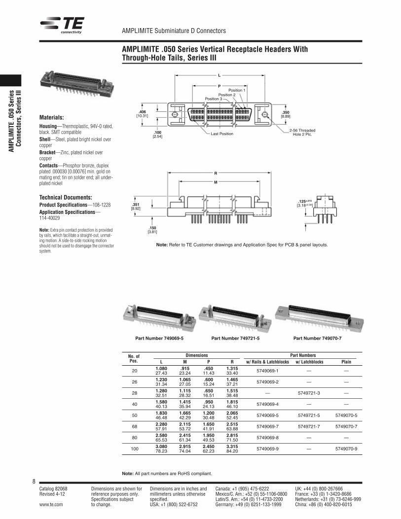
AMPLIMITE .050 Series Vertical Receptacle Headers WithThrough-Hole Tails, Series III
AMPL
IMIT
E.0
50Se
ries
Conn
ecto
rs,S
erie
sIII
Last Position.100[2.54]
.350[8.89]
.406[10.31]
L
P
2-56 ThreadedHole 2 Plc.
Position 1Position 2
Position 3
Materials:Housing—Thermoplastic, 94V-0 rated,black. SMT compatibleShell—Steel, plated bright nickel overcopperBracket—Zinc, plated nickel overcopperContacts—Phosphor bronze, duplexplated .000030 [0.00076] min. gold onmating end; tin on solder end; all under-plated nickel
Technical Documents:Product Specifications—108-1228Application Specifications—114-40029
Note: Extra pin contact protection is providedby rails, which facilitate a straight-out, unmat-ing motion. A side-to-side rocking motionshould not be used to disengage the connectorsystem.
.125±.015[3.18±0.38].351
[8.92]
.150[3.81]
R
M
Part Number 749069-5
No. of Dimensions Part NumbersPos. L M P R w/ Rails & Latchblocks w/ Latchblocks Plain
20 1.080 .915 .450 1.315 5749069-1 — —27.43 23.24 11.43 33.40
26 1.230 1.065 .600 1.465 5749069-2 — —31.34 27.05 15.24 37.21
28 1.280 1.115 .650 1.515 — 5749721-3 —32.51 28.32 16.51 38.48
40 1.580 1.415 .950 1.815 5749069-4 — —40.13 35.94 24.13 46.10
50 1.830 1.665 1.200 2.065 5749069-5 5749721-5 5749070-546.48 42.29 30.48 52.45
68 2.280 2.115 1.650 2.515 5749069-7 5749721-7 5749070-757.91 53.72 41.91 63.88
80 2.580 2.415 1.950 2.815 5749069-8 — —65.53 61.34 49.53 71.50
100 3.080 2.915 2.450 3.315 5749069-9 — 5749070-978.23 74.04 62.23 84.20
Note: Refer to TE Customer drawings and Application Spec for PCB & panel layouts.
Part Number 749721-5 Part Number 749070-7
9Catalog 82068 Dimensions are shown for Dimensions are in inches and Canada: +1 (905) 475-6222 UK: +44 (0) 800-267666Revised 4-12 reference purposes only. millimeters unless otherwise Mexico/C. Am.: +52 (0) 55-1106-0800 France: +33 (0) 1-3420-8686
Specifications subject specified. Latin/S. Am.: +54 (0) 11-4733-2200 Netherlands: +31 (0) 73-6246-999www.te.com to change. USA: +1 (800) 522-6752 Germany: +49 (0) 6251-133-1999 China: +86 (0) 400-820-6015
AMPLIMITE Subminiature D Connectors
Note: All part numbers are RoHS compliant.
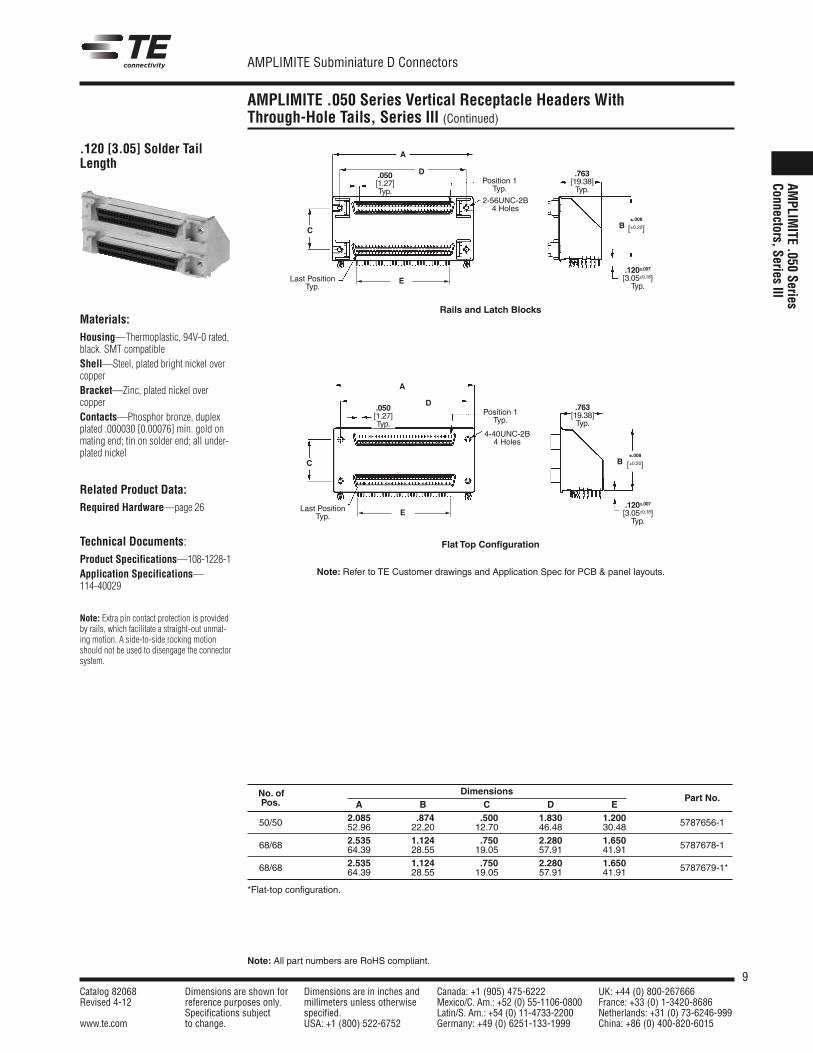
AMPLIMITE .050 Series Vertical Receptacle Headers WithThrough-Hole Tails, Series III (Continued)
AMPLIM
ITE.050
SeriesConnectors,Series
III
No. of DimensionsPart No.Pos. A B C D E
2.085 .874 .500 1.830 1.20050/50 52.96 22.20 12.70 46.48 30.48 5787656-1
2.535 1.124 .750 2.280 1.65068/68 64.39 28.55 19.05 57.91 41.91 5787678-1
2.535 1.124 .750 2.280 1.65068/68 64.39 28.55 19.05 57.91 41.91*5787679-1*
*Flat-top configuration.
E
E
.120 [3.05] Solder TailLength
Materials:Housing—Thermoplastic, 94V-0 rated,black. SMT compatibleShell—Steel, plated bright nickel overcopperBracket—Zinc, plated nickel overcopperContacts—Phosphor bronze, duplexplated .000030 [0.00076] min. gold onmating end; tin on solder end; all under-plated nickel
Related Product Data:Required Hardware—page 26
Technical Documents:Product Specifications—108-1228-1Application Specifications—114-40029
Note: Extra pin contact protection is providedby rails, which facilitate a straight-out unmat-ing motion. A side-to-side rocking motionshould not be used to disengage the connectorsystem.
C
C
A
A
D
D
.120±.007[3.05±0.18]Typ.
.120±.007[3.05±0.18]Typ.
.050[1.27]Typ.
.050[1.27]Typ.
.763[19.38]Typ.
.763[19.38]Typ.
Position 1Typ.
Position 1Typ.
Last PositionTyp.
Last PositionTyp.
2-56UNC-2B4 Holes
4-40UNC-2B4 Holes
±.008
[±0.20]
±.008
[±0.20]
B
B
Rails and Latch Blocks
Flat Top Configuration
Note: Refer to TE Customer drawings and Application Spec for PCB & panel layouts.
10Catalog 82068 Dimensions are shown for Dimensions are in inches and Canada: +1 (905) 475-6222 UK: +44 (0) 800-267666Revised 4-12 reference purposes only. millimeters unless otherwise Mexico/C. Am.: +52 (0) 55-1106-0800 France: +33 (0) 1-3420-8686
Specifications subject specified. Latin/S. Am.: +54 (0) 11-4733-2200 Netherlands: +31 (0) 73-6246-999www.te.com to change. USA: +1 (800) 522-6752 Germany: +49 (0) 6251-133-1999 China: +86 (0) 400-820-6015
AMPLIMITE Subminiature D Connectors
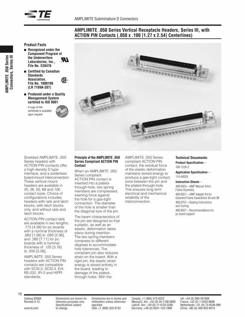
AMPLIMITE .050 Series Vertical Receptacle Headers, Series III, withACTION PIN Contacts (.050 x .100 [1.27 x 2.54] Centerlines)
AMPL
IMIT
E.0
50Se
ries
Conn
ecto
rs,S
erie
sIII
Shielded AMPLIMITE .050Series headers withACTION PIN contacts offera high-density D typeinterface, and a solderlessboard-mount interconnection.These vertical mountheaders are available in20, 26, 50, 68 and 100contact sizes. Choice ofconfigurations includes;headers with rails and latchblocks, with latch blocksonly, and without rails andlatch blocks.
ACTION PIN contact tailsare available in two lengths;.173 [4.39] for pc boardswith a nominal thickness of.062 [1.56] to .093 [2.36],and .280 [7.11] for pcboards with a nominalthickness of .125 [3.18]to .200 [5.08].
AMPLIMITE .050 Seriesheaders with ACTION PINcontacts are compatiblewith SCSI-2, SCSI-3, EIARS-232, IPI-2 and HIPPIstandards.
Principle of the AMPLIMITE .050Series Compliant ACTION PINContact
When an AMPLIMITE .050Series compliantACTION PIN contact isinserted into a plated-through-hole, two springmembers are compressed,exerting force againstthe hole for a gas-tightconnection. The diameterof the hole is smaller thanthe diagonal size of the pin.
The beam characteristics ofthe pin are designed so thata plastic, as well as anelastic, deformation takesplace during insertion.The two spring memberscompress to differentdegrees to accommodatehole tolerances. Thecompliant pin also reducesstrain on the board. With arigid pin, the elastic strainenergy is stored entirely inthe board, leading todamage of the plated-through holes. With the
AMPLIMITE .050 Seriescompliant ACTION PINcontact, the residual forceof the elastic deformationmaintains stored energy toproduce a gas-tight contactzone between the pin andthe plated-through-hole.This ensures long termelectrical and mechanicalreliability of theinterconnection.
Product Facts� Recognized under the
Component Program ofthe UnderwritersLaboratories, Inc.,File No. E28476
� Certified by CanadianStandardsAssociation,File No. 1088108(LR 7189A-207)
� Produced under a QualityManagement Systemcertified to ISO 9001
� A copy of thecertificate is availableupon request
R
R
Technical Documents:Product Specification—108-1228-2
Application Specification—114-40029
Instruction Sheets—408 6923—AMP Manual ArborFrame Assembly408 9027—AMP Adapter Kit forGreenerd Frame Assemblies 3A and 3B408 9757—Seating Instructionsand Tooling408 6927—Recommendations forpc board support
ISO
Certified9001
11Catalog 82068 Dimensions are shown for Dimensions are in inches and Canada: +1 (905) 475-6222 UK: +44 (0) 800-267666Revised 4-12 reference purposes only. millimeters unless otherwise Mexico/C. Am.: +52 (0) 55-1106-0800 France: +33 (0) 1-3420-8686
Specifications subject specified. Latin/S. Am.: +54 (0) 11-4733-2200 Netherlands: +31 (0) 73-6246-999www.te.com to change. USA: +1 (800) 522-6752 Germany: +49 (0) 6251-133-1999 China: +86 (0) 400-820-6015
AMPLIMITE Subminiature D Connectors
Note: All part numbers are RoHS compliant.
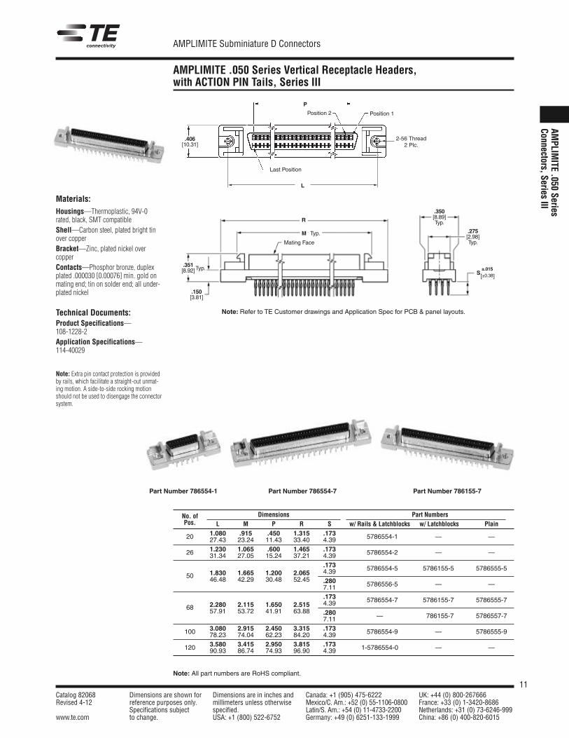
AMPLIMITE .050 Series Vertical Receptacle Headers,with ACTION PIN Tails, Series III
AMPLIM
ITE.050
SeriesConnectors,Series
III
2-56 Thread2 Plc.
L
Last Position
Position 1Position 2
.406[10.31]
P
Mating Face
Typ.
Typ..351[8.92]
.150[3.81]
.275[2.98]Typ.
.350[8.89]Typ.R
M
S±.015
[±0.38]
Materials:Housings—Thermoplastic, 94V-0rated, black, SMT compatibleShell—Carbon steel, plated bright tinover copperBracket—Zinc, plated nickel overcopperContacts—Phosphor bronze, duplexplated .000030 [0.00076] min. gold onmating end; tin on solder end; all under-plated nickel
Technical Documents:Product Specifications—108-1228-2Application Specifications—114-40029
Note: Extra pin contact protection is providedby rails, which facilitate a straight-out unmat-ing motion. A side-to-side rocking motionshould not be used to disengage the connectorsystem.
No. of Dimensions Part NumbersPos. L M P R S w/ Rails & Latchblocks w/ Latchblocks Plain
20 1.080 .915 .450 1.315 .173 5786554-1 — —27.43 23.24 11.43 33.40 4.39
26 1.230 1.065 .600 1.465 .173 5786554-2 — —31.34 27.05 15.24 37.21 4.39.173 5786554-5 5786155-5 5786555-5
50 1.830 1.665 1.200 2.065 4.3946.48 42.29 30.48 52.45 .280 5786556-5 — —7.11
.173 5786554-7 5786155-7 5786555-768 2.280 2.115 1.650 2.515 4.39
57.91 53.72 41.91 63.88 .280 — 786155-7 5786557-77.11
100 3.080 2.915 2.450 3.315 .173 5786554-9 — 5786555-978.23 74.04 62.23 84.20 4.39
120 3.580 3.415 2.950 3.815 .173 1-5786554-0 — —90.93 86.74 74.93 96.90 4.39
Note: Refer to TE Customer drawings and Application Spec for PCB & panel layouts.
Part Number 786554-1 Part Number 786554-7 Part Number 786155-7
12Catalog 82068 Dimensions are shown for Dimensions are in inches and Canada: +1 (905) 475-6222 UK: +44 (0) 800-267666Revised 4-12 reference purposes only. millimeters unless otherwise Mexico/C. Am.: +52 (0) 55-1106-0800 France: +33 (0) 1-3420-8686
Specifications subject specified. Latin/S. Am.: +54 (0) 11-4733-2200 Netherlands: +31 (0) 73-6246-999www.te.com to change. USA: +1 (800) 522-6752 Germany: +49 (0) 6251-133-1999 China: +86 (0) 400-820-6015
AMPLIMITE Subminiature D Connectors
Note: All part numbers are RoHS compliant.
AMPLIMITE .050 Series Cable Plug Connectors, Series III
AMPL
IMIT
E.0
50Se
ries
Conn
ecto
rs,S
erie
sIII
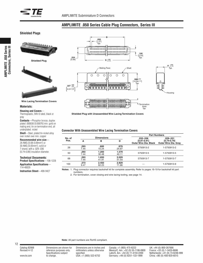
Materials:Housing and Covers—Thermoplastic, 94V-0 rated, black orgrayContacts—Phosphor bronze, duplexplated .000030 [0.00076] min. gold onmating end, tin on termination end, allunderplated .nickelShell—Steel, plated tin-nickel alloyover nickel over min. copperRecommended wire size—28 AWG [0.08-0.09mm2] or30 AWG [0.05mm2], solid or7 strand, with a .029-.036[0.74-0.89] insulation diameter.
Technical Documents:Product Specifications—108-1228Application Specifications—114-40029Instruction Sheet—408-9427
B
Housing
.050[1.27]Typ.
.224[5.69]
.100[2.54]Typ.
+.003.327 -.002
+0.08[8.31-0.05]
.588±.010[14.94±0.25]Typ.
Mating Face Shell
±.003D [±0.08]
±.003A [±0.08]
Typ.
TerminationAreaTyp.
Shielded Plugs
Shielded Plug with UnassembledWire Lacing Termination Covers
Shielded Plug
Wire Lacing Termination Covers
Part NumbersNo. of Dimensions .032-.036 .029-.031Pos. A B D [0.81-0.91] [0.74-0.79]
OuterWire Dia. Black OuterWire Dia. Gray.293 .600 .97926 7.44 15.24 24.87 5750913-2 1-5750913-2
.293 1.200 1.57950 7.44 30.48 40.11 5750913-5 1-5750913-5
.293 1.650 2.02968 7.44 41.91 51.54 5750913-7 1-5750913-7
.373 2.450 2.829100 9.47 62.23 71.86 — 1-5750913-9
Notes: 1. Plug connector requires backshell kit for complete assembly. Refer to pages 16-19 for backshell kit partnumbers.
2. For termination, cover closing and wire lacing tooling, see page 14.
Connector With Unassembled Wire Lacing Termination Covers
13Catalog 82068 Dimensions are shown for Dimensions are in inches and Canada: +1 (905) 475-6222 UK: +44 (0) 800-267666Revised 4-12 reference purposes only. millimeters unless otherwise Mexico/C. Am.: +52 (0) 55-1106-0800 France: +33 (0) 1-3420-8686
Specifications subject specified. Latin/S. Am.: +54 (0) 11-4733-2200 Netherlands: +31 (0) 73-6246-999www.te.com to change. USA: +1 (800) 522-6752 Germany: +49 (0) 6251-133-1999 China: +86 (0) 400-820-6015
AMPLIMITE Subminiature D Connectors
Note: All part numbers are RoHS compliant.
AMPLIMITE .050 Series Cable Plug Connectors, Series III (Continued)
AMPLIM
ITE.050
SeriesConnectors,Series
III
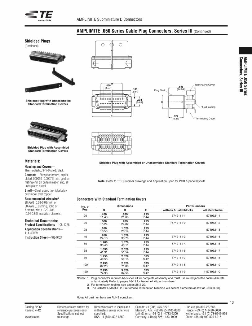
Shielded Plugs(Continued)
.050[1.27]
Terminating Cover
.327[8.31]
E
D
B
.100[2.54]
.224[5.69]
.588[14.94]
Plug Housing
Plug Shell
Terminating Cover
Shielded Plug with UnassembledStandard Termination Covers
Shielded Plug with Assembled or Unassembled Standard Termination Covers
No. of Dimensions Part NumbersPos. B D E w/Rails & Latchblocks w/Latchblocks
.450 .829 .29320 11.43 21.06 7.44 5749111-1 5749621-1
.600 .979 .29326 15.24 24.87 7.44 1-5749111-0 5749621-2
.650 1.029 .29328 16.50 26.14 7.44 — 5749621-3
.950 1.329 .29340 24.13 33.76 7.44 5749111-3 5749621-4
1.200 1.579 .29350 30.48 40.11 7.44 5749111-4 5749621-5
1.650 2.029 .29368 41.91 51.54 7.44 5749111-6 5749621-7
1.950 2.329 .37380 49.53 59.16 9.47 5749111-7 5749621-8
2.450 2.829 .373100 62.23 71.86 9.47 5749111-8 5749621-9
2.950 3.329 .373120 74.93 84.56 9.47 5749111-9 1-5749621-0
Notes: 1. Plug connector requires backshell kit for complete assembly and must use round jacketed cable (discreteor laminated). Refer to pages 16-19 for backshell kit part numbers.
2. For termination tooling, see pages 28 & 29.3. The CHAMPOMATOR 2.5 Automatic Termination Machine will accept diameters as low as .023 [0.58].
Shielded Plug with AssembledStandard Termination Covers
Materials:Housing and Covers—Thermoplastic, 94V-0 rated, blackContacts—Phosphor bronze, duplexplated .000030 [0.00076] min. gold onmating end, tin on termination end, allunderplated nickelShell—Steel, plated tin-nickel alloyover nickel over copperRecommended wire size3 —28 AWG [0.08-0.09mm2] or30 AWG [0.05mm2], solid or7 strand, with a .029-.036[0.74-0.89] insulation diameter.
Technical Documents:Product Specifications—108-1228Application Specifications—114-40029Instruction Sheet—408-9427
Connectors With Standard Termination Covers
Note: Refer to TE Customer drawings and Application Spec for PCB & panel layouts.
14Catalog 82068 Dimensions are shown for Dimensions are in inches and Canada: +1 (905) 475-6222 UK: +44 (0) 800-267666Revised 4-12 reference purposes only. millimeters unless otherwise Mexico/C. Am.: +52 (0) 55-1106-0800 France: +33 (0) 1-3420-8686
Specifications subject specified. Latin/S. Am.: +54 (0) 11-4733-2200 Netherlands: +31 (0) 73-6246-999www.te.com to change. USA: +1 (800) 522-6752 Germany: +49 (0) 6251-133-1999 China: +86 (0) 400-820-6015
AMPLIMITE Subminiature D Connectors
Note: All part numbers are RoHS compliant.
AMPLIMITE .050 Series Cable Plug Connectors, Series III (Continued)
AMPL
IMIT
E.0
50Se
ries
Conn
ecto
rs,S
erie
sIII
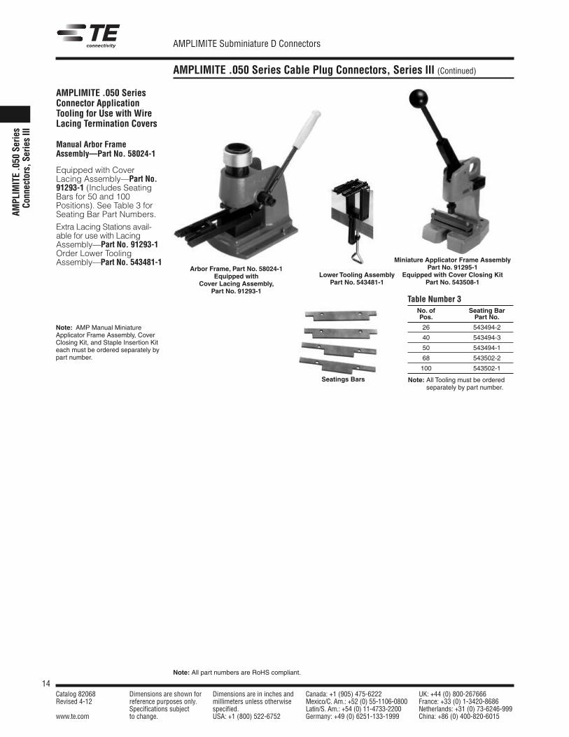
AMPLIMITE .050 SeriesConnector ApplicationTooling for Use with WireLacing Termination Covers
Manual Arbor FrameAssembly—Part No. 58024-1
Equipped with CoverLacing Assembly—Part No.91293-1 (Includes SeatingBars for 50 and 100Positions). See Table 3 forSeating Bar Part Numbers.
Extra Lacing Stations avail-able for use with LacingAssembly—Part No. 91293-1Order Lower ToolingAssembly—Part No. 543481-1
Arbor Frame, Part No. 58024-1Equipped with
Cover Lacing Assembly,Part No. 91293-1
Seatings Bars
No. of Seating BarPos. Part No.
26 543494-2
40 543494-3
50 543494-1
68 543502-2
100 543502-1
Note: All Tooling must be orderedseparately by part number.
Table Number 3
Miniature Applicator Frame AssemblyPart No. 91295-1
Equipped with Cover Closing KitPart No. 543508-1
Note: AMP Manual MiniatureApplicator Frame Assembly, CoverClosing Kit, and Staple Insertion Kiteach must be ordered separately bypart number.
Lower Tooling AssemblyPart No. 543481-1
15Catalog 82068 Dimensions are shown for Dimensions are in inches and Canada: +1 (905) 475-6222 UK: +44 (0) 800-267666Revised 4-12 reference purposes only. millimeters unless otherwise Mexico/C. Am.: +52 (0) 55-1106-0800 France: +33 (0) 1-3420-8686
Specifications subject specified. Latin/S. Am.: +54 (0) 11-4733-2200 Netherlands: +31 (0) 73-6246-999www.te.com to change. USA: +1 (800) 522-6752 Germany: +49 (0) 6251-133-1999 China: +86 (0) 400-820-6015
AMPLIMITE Subminiature D Connectors
Note: All part numbers are RoHS compliant.
AMPLIMITE .050 Series Cable Receptacle Connectors, Series III
AMPLIM
ITE.050
SeriesConnectors,Series
III
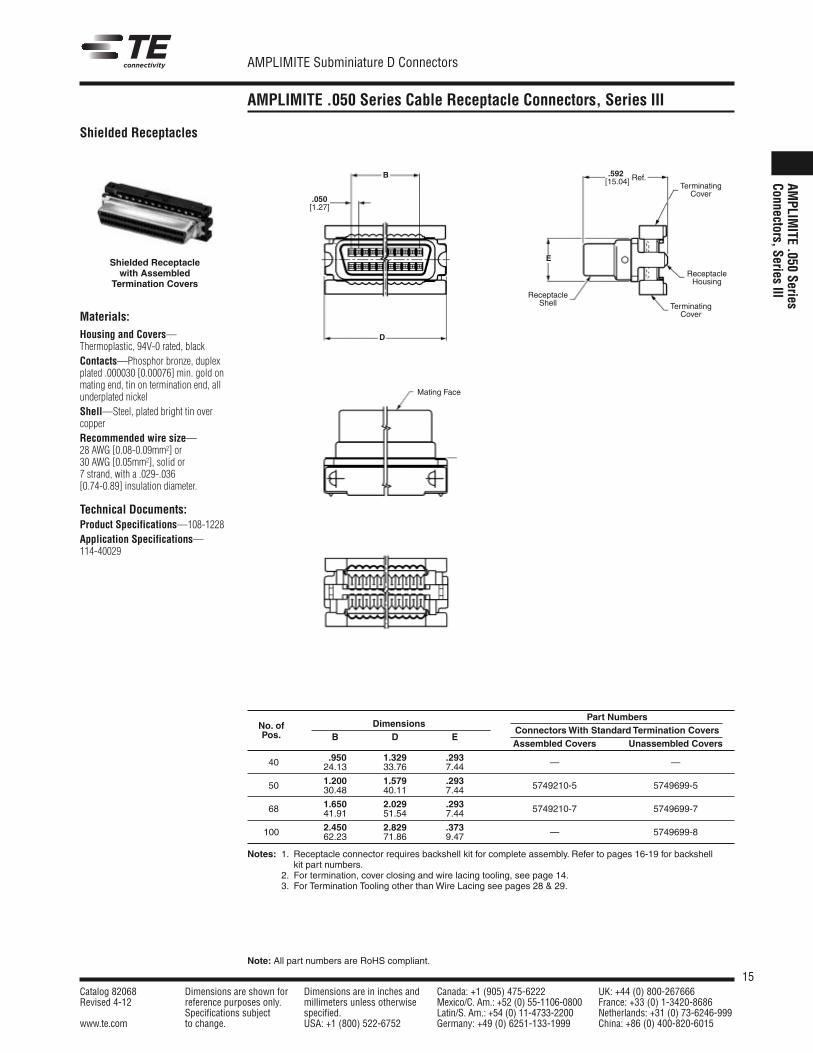
Materials:Housing and Covers—Thermoplastic, 94V-0 rated, blackContacts—Phosphor bronze, duplexplated .000030 [0.00076] min. gold onmating end, tin on termination end, allunderplated nickelShell—Steel, plated bright tin overcopperRecommended wire size—28 AWG [0.08-0.09mm2] or30 AWG [0.05mm2], solid or7 strand, with a .029-.036[0.74-0.89] insulation diameter.
Technical Documents:Product Specifications—108-1228Application Specifications—114-40029
Shielded Receptacles
Shielded Receptaclewith Assembled
Termination Covers
B
D
.592[15.04] Ref.
E
TerminatingCover
ReceptacleHousing
ReceptacleShell
.050[1.27]
TerminatingCover
Mating Face
Part NumbersNo. of Dimensions
ConnectorsWith Standard Termination CoversPos. B D EAssembled Covers Unassembled Covers
.950 1.329 .29340 24.13 33.76 7.44 — —
1.200 1.579 .29350 30.48 40.11 7.44 5749210-5 5749699-5
1.650 2.029 .29368 41.91 51.54 7.44 5749210-7 5749699-7
2.450 2.829 .373100 62.23 71.86 9.47 — 5749699-8
Notes: 1. Receptacle connector requires backshell kit for complete assembly. Refer to pages 16-19 for backshellkit part numbers.
2. For termination, cover closing and wire lacing tooling, see page 14.3. For Termination Tooling other than Wire Lacing see pages 28 & 29.
16Catalog 82068 Dimensions are shown for Dimensions are in inches and Canada: +1 (905) 475-6222 UK: +44 (0) 800-267666Revised 4-12 reference purposes only. millimeters unless otherwise Mexico/C. Am.: +52 (0) 55-1106-0800 France: +33 (0) 1-3420-8686
Specifications subject specified. Latin/S. Am.: +54 (0) 11-4733-2200 Netherlands: +31 (0) 73-6246-999www.te.com to change. USA: +1 (800) 522-6752 Germany: +49 (0) 6251-133-1999 China: +86 (0) 400-820-6015
AMPLIMITE Subminiature D Connectors
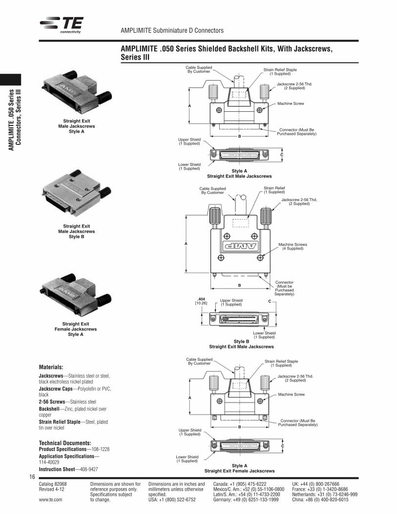
AMPLIMITE .050 Series Shielded Backshell Kits, With Jackscrews,Series III
AMPL
IMIT
E.0
50Se
ries
Conn
ecto
rs,S
erie
sIII
Materials:Jackscrews—Stainless steel or steel,black electroless nickel platedJackscrew Caps—Polyolefin or PVC,black2-56 Screws—Stainless steelBackshell—Zinc, plated nickel overcopperStrain Relief Staple—Steel, platedtin over nickel
Technical Documents:Product Specifications—108-1228Application Specifications—114-40029Instruction Sheet—408-9427
Straight ExitMale Jackscrews
Style A
Straight ExitMale Jackscrews
Style B
Style AStraight Exit Male Jackscrews
Style BStraight Exit Male Jackscrews
Straight ExitFemale Jackscrews
Style A
Style AStraight Exit Female Jackscrews
A
B
C
Cable SuppliedBy Customer Strain Relief Staple
(1 Supplied)
Jackscrew 2-56 Thd.(2 Supplied)
Machine Screw
Connector (Must BePurchased Separately)
Upper Shield(1 Supplied)
Lower Shield(1 Supplied)
A
B
C
Cable SuppliedBy Customer Strain Relief Staple
(1 Supplied)
Jackscrew 2-56 Thd.(2 Supplied)
Machine Screw
Connector (Must BePurchased Separately)
Upper Shield(1 Supplied)
A
B
C
Cable SuppliedBy Customer
Connector(Must bePurchasedSeparately)
.404[10.26]
Strain Relief(1 Supplied)
Jackscrew 2-56 Thd.(2 Supplied)
Machine Screws(4 Supplied)
Upper Shield(1 Supplied)
Lower Shield(1 Supplied)
Lower Shield(1 Supplied)
17Catalog 82068 Dimensions are shown for Dimensions are in inches and Canada: +1 (905) 475-6222 UK: +44 (0) 800-267666Revised 4-12 reference purposes only. millimeters unless otherwise Mexico/C. Am.: +52 (0) 55-1106-0800 France: +33 (0) 1-3420-8686
Specifications subject specified. Latin/S. Am.: +54 (0) 11-4733-2200 Netherlands: +31 (0) 73-6246-999www.te.com to change. USA: +1 (800) 522-6752 Germany: +49 (0) 6251-133-1999 China: +86 (0) 400-820-6015
AMPLIMITE Subminiature D Connectors
Note: All part numbers are RoHS compliant.
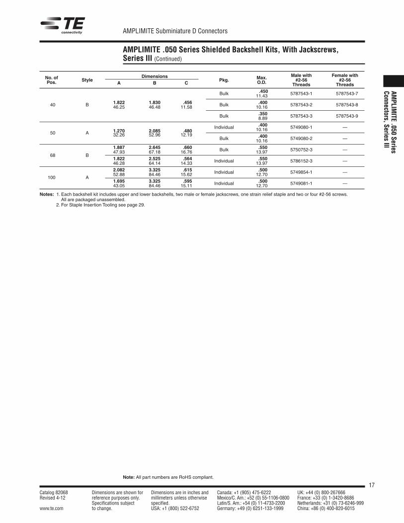
AMPLIMITE .050 Series Shielded Backshell Kits, With Jackscrews,Series III (Continued)
AMPLIM
ITE.050
SeriesConnectors,Series
III
No. of Dimensions Max. Male with Female with
Pos. StyleA B C
Pkg. O.D. #2-56 #2-56Threads Threads
.450Bulk 11.43 5787543-1 1-5787543-7
40 B 1.822 1.830 .456 .40046.25 46.48 11.58 Bulk 10.16 5787543-2 1-5787543-8
.350Bulk 8.89 5787543-3 1-5787543-9
.400
50 A 1.270 2.085 .480Individual 10.16 5749080-1 —
32.26 52.96 12.19 .400Bulk 10.16 5749080-2 —
1.887 2.645 .660 .550
68 B47.93 67.18 16.76 Bulk 13.97 5750752-3 —
1.822 2.525 .564 .55046.28 64.14 14.33 Individual 13.97 5786152-3 —
2.082 3.325 .615 .500
100 A52.88 84.46 15.62 Individual 12.70 5749854-1 —
1.695 3.325 .595 .50043.05 84.46 15.11 Individual 12.70 5749081-1 —
Notes: 1. Each backshell kit includes upper and lower backshells, two male or female jackscrews, one strain relief staple and two or four #2-56 screws.All are packaged unassembled.
Notes: 2. For Staple Insertion Tooling see page 29.
18Catalog 82068 Dimensions are shown for Dimensions are in inches and Canada: +1 (905) 475-6222 UK: +44 (0) 800-267666Revised 4-12 reference purposes only. millimeters unless otherwise Mexico/C. Am.: +52 (0) 55-1106-0800 France: +33 (0) 1-3420-8686
Specifications subject specified. Latin/S. Am.: +54 (0) 11-4733-2200 Netherlands: +31 (0) 73-6246-999www.te.com to change. USA: +1 (800) 522-6752 Germany: +49 (0) 6251-133-1999 China: +86 (0) 400-820-6015
AMPLIMITE Subminiature D Connectors
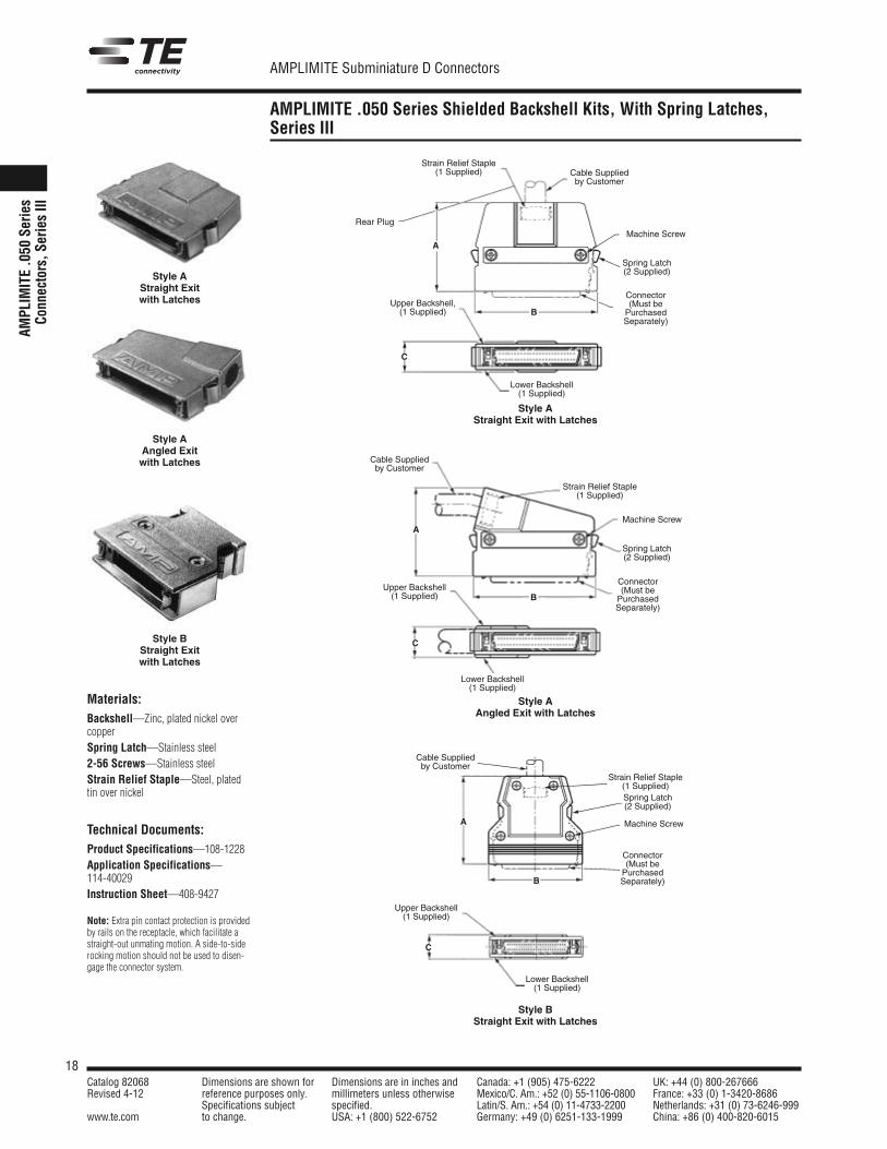
AMPLIMITE .050 Series Shielded Backshell Kits, With Spring Latches,Series III
AMPL
IMITE.0
50Se
ries
Conn
ectors,S
eriesIII
Materials:Backshell—Zinc, plated nickel overcopperSpring Latch—Stainless steel2-56 Screws—Stainless steelStrain Relief Staple—Steel, platedtin over nickel
Technical Documents:Product Specifications—108-1228Application Specifications—114-40029Instruction Sheet—408-9427
Note: Extra pin contact protection is providedby rails on the receptacle, which facilitate astraight-out unmating motion. A side-to-siderocking motion should not be used to disen-gage the connector system.
Style AStraight Exitwith Latches
Style AStraight Exit with Latches
Style BStraight Exitwith Latches
Style BStraight Exit with Latches
Style AAngled Exitwith Latches
Style AAngled Exit with Latches
C
Upper Backshell,(1 Supplied)
A
Cable Suppliedby Customer
B
Connector(Must bePurchasedSeparately)
Spring Latch(2 Supplied)
Strain Relief Staple(1 Supplied)
Lower Backshell(1 Supplied)
Rear PlugMachine Screw
C
Upper Backshell(1 Supplied)
A
Cable Suppliedby Customer
B
Connector(Must bePurchasedSeparately)
Spring Latch(2 Supplied)
Machine Screw
Strain Relief Staple(1 Supplied)
Lower Backshell(1 Supplied)
C
Upper Backshell(1 Supplied)
A
Cable Suppliedby Customer
B
Connector(Must bePurchasedSeparately)
Spring Latch(2 Supplied)
Strain Relief Staple(1 Supplied)
Lower Backshell(1 Supplied)
Machine Screw
19Catalog 82068 Dimensions are shown for Dimensions are in inches and Canada: +1 (905) 475-6222 UK: +44 (0) 800-267666Revised 4-12 reference purposes only. millimeters unless otherwise Mexico/C. Am.: +52 (0) 55-1106-0800 France: +33 (0) 1-3420-8686
Specifications subject specified. Latin/S. Am.: +54 (0) 11-4733-2200 Netherlands: +31 (0) 73-6246-999www.te.com to change. USA: +1 (800) 522-6752 Germany: +49 (0) 6251-133-1999 China: +86 (0) 400-820-6015
AMPLIMITE Subminiature D Connectors
Note: All part numbers are RoHS compliant.
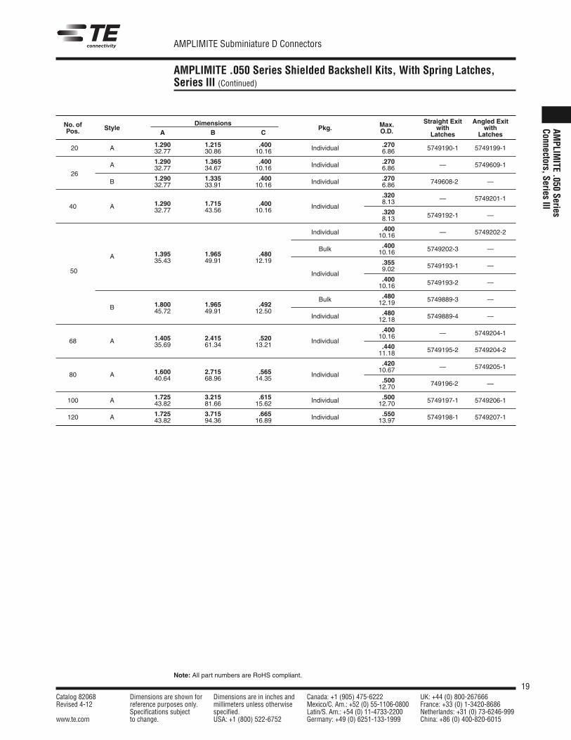
AMPLIMITE .050 Series Shielded Backshell Kits, With Spring Latches,Series III (Continued)
AMPLIM
ITE.050
SeriesConnectors,Series
III
Straight Exit Angled ExitNo. of StyleDimensions
Pkg. Max. with withPos. A B C O.D. Latches Latches
1.290 1.215 .400 .27020 A 32.77 30.86 10.16 Individual 6.86 5749190-1 5749199-1
A 1.290 1.365 .400 .270
2632.77 34.67 10.16 Individual 6.86 — 5749609-1
1.290 1.335 .400 .270B 32.77 33.91 10.16 Individual 6.86 749608-2 —
.3201.290 1.715 .400 8.13 — 5749201-1
40 A 32.77 43.56 10.16 Individual.3208.13 5749192-1 —
.400Individual 10.16 — 5749202-2
.400
A 1.395 1.965 .480Bulk 10.16 5749202-3 —
35.43 49.91 12.19 .3559.02 5749193-1 —
50 Individual.40010.16 5749193-2 —
.4801.800 1.965 .492
Bulk 12.19 5749889-3 —B 45.72 49.91 12.50 .480Individual 12.18 5749889-4 —
.4001.405 2.415 .520 10.16 — 5749204-1
68 A 35.69 61.34 13.21 Individual.44011.18 5749195-2 5749204-2
.4201.600 2.715 .565 10.67 — 5749205-1
80 A 40.64 68.96 14.35 Individual.50012.70 749196-2 —
1.725 3.215 .615 .500100 A 43.82 81.66 15.62 Individual 12.70 5749197-1 5749206-1
1.725 3.715 .665 .550120 A 43.82 94.36 16.89 Individual 13.97 5749198-1 5749207-1

20Catalog 82068 Dimensions are shown for Dimensions are in inches and Canada: +1 (905) 475-6222 UK: +44 (0) 800-267666Revised 4-12 reference purposes only. millimeters unless otherwise Mexico/C. Am.: +52 (0) 55-1106-0800 France: +33 (0) 1-3420-8686
Specifications subject specified. Latin/S. Am.: +54 (0) 11-4733-2200 Netherlands: +31 (0) 73-6246-999www.te.com to change. USA: +1 (800) 522-6752 Germany: +49 (0) 6251-133-1999 China: +86 (0) 400-820-6015
AMPLIMITE Subminiature D Connectors
Note: All part numbers are RoHS compliant.
AMPLIMITE .050 Series Shielded Enclosure Kits,With Male Jackscrews, Series III
AMPL
IMITE.0
50Se
ries
Conn
ectors,S
eriesIII
68-Position
Material and Finish:Backshells—ZincBoot—PVC, blackJackscrews—Stainless steel and PVC,blackStaple—Carbon steel, plated tin overnickelScrews—Stainless steel, #2-56 threads
Technical Documents:
Product Specifications—108-1228Application Specifications—114-40029
Notes: 1. Each enclosure kit contains two backshells, one boot, two jackscrews,one staple and two screws. All are packaged unassembled.
2. For staple insertion tooling see page 29.3. Meets SCSI-3 standards.
Connector(Must bePurchasedSeparately)
.550[13.97]Max.Dia.
1.887[47.93]
.660[16.76]
Cable Suppliedby Customer
2.645[67.18]
.520[13.21]
No. of Part Number Part NumberPos. Male 2-56 Jackscrews Male 4-40 Jackscrews
68 5750752-1 5750752-2

21Catalog 82068 Dimensions are shown for Dimensions are in inches and Canada: +1 (905) 475-6222 UK: +44 (0) 800-267666Revised 4-12 reference purposes only. millimeters unless otherwise Mexico/C. Am.: +52 (0) 55-1106-0800 France: +33 (0) 1-3420-8686
Specifications subject specified. Latin/S. Am.: +54 (0) 11-4733-2200 Netherlands: +31 (0) 73-6246-999www.te.com to change. USA: +1 (800) 522-6752 Germany: +49 (0) 6251-133-1999 China: +86 (0) 400-820-6015
AMPLIMITE Subminiature D Connectors
Note: All part numbers are RoHS compliant.
AMPLIMITE .050 Series Panel Mount Receptacle AssembliesWithout Rails, With Latch Blocks, Series III
AMPLIM
ITE.050
SeriesConnectors,Series
III
Materials:Housing and Termination Covers—Thermoplastic, 94V-0 rated, blackShell—Steel, plated bright nickel overcopperBracket—Zinc, plated nickel overcopperContacts—Phosphor bronze, duplexplated .000030 [0.00076] min. gold onmating end, bright tin in terminationarea, all nickel underplatedRecommended wire size—28 AWG [0.08-0.09mm2] or30 AWG [0.05mm2], solid or7 strand, with a .029-.036[0.74-0.89] insulation diameter or.050 [1.27] centerline, 28 AWG[0.08-0.09mm2] stranded, PVC, flatribbon cable.
Technical Documents:Product Specifications—108-1228Application Specifications—114-40029
C
±.007[±0.18]D
E
.201±.002[5.11±0.05]
.170±.002[4.32±0.05]
.406[10.31]
F
.050[1.27]Typ.
2-56 UNC*2 Plc.
Mating Face
.596[15.14]Typ.
Ref.
±.004[±0.10]
Recessed CavityIdentification
ContactTyp.
Housing
Part NumbersConnectorsWith UnassembledWire LacingTermination Covers
.032-.036 .029-.031No. of Dimensions
ConnectorsWith Assembled
[0.81-0.91] [0.74-0.79]Pos. C D E F StandardTermination Covers
OuterWire Dia. OuterWire Dia.
1.830 1.629 2.065 1.66550 46.48 41.38 52.45 42.29 1-749656-1 5-786862-5 6-786862-5
1.830 1.629 2.065 1.66550 46.48 41.38 52.45 42.29 5-750640-1* 5-786865-5* —
2.280 2.079 2.515 2.11568 57.91 52.81 63.88 53.72 1-749656-2 — —
3.580 3.379 3.815 3.415120 90.93 85.83 96.90 86.74 6-749656-0 — —
*Part Numbers 5-750640-1 and 5-786865-5 have 4-40 threaded holes. All others have 2-56 threaded holes.Note: For termination, cover closing and wire lacing tooling, see page 14.Note: For termination tooling other than wire lacing see pages 28 & 29.
Note: Refer to TE Customer drawings and Application Spec for PCB & panel layouts.
22Catalog 82068 Dimensions are shown for Dimensions are in inches and Canada: +1 (905) 475-6222 UK: +44 (0) 800-267666Revised 4-12 reference purposes only. millimeters unless otherwise Mexico/C. Am.: +52 (0) 55-1106-0800 France: +33 (0) 1-3420-8686
Specifications subject specified. Latin/S. Am.: +54 (0) 11-4733-2200 Netherlands: +31 (0) 73-6246-999www.te.com to change. USA: +1 (800) 522-6752 Germany: +49 (0) 6251-133-1999 China: +86 (0) 400-820-6015
AMPLIMITE Subminiature D Connectors
Note: All part numbers are RoHS compliant.
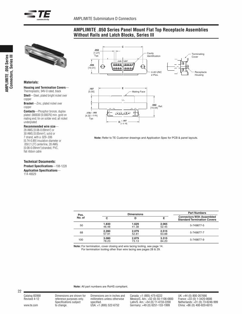
AMPLIMITE .050 Series Panel Mount Flat Top Receptacle AssembliesWithout Rails and Latch Blocks, Series III
AMPL
IMITE.0
50Se
ries
Conn
ectors,S
eriesIII
Materials:Housing and Termination Covers—Thermoplastic, 94V-0 rated, blackShell—Steel, plated bright nickel overcopperBracket—Zinc, plated nickel overcopperContacts—Phosphor bronze, duplexplated .000030 [0.00076] min. gold onmating end; tin on solder end; all nickelunderplatedRecommended wire size—28 AWG [0.08-0.09mm2] or30 AWG [0.05mm2], solid or7 strand, with a .029-.036[0.74-0.89] insulation diameter or.050 [1.27] centerline, 28 AWG[0.08-0.09mm2] stranded, PVC,flat ribbon cable
Technical Documents:Product Specifications—108-1228Application Specifications—114-40029
Dimensions Part NumbersPos.
C D E ConnectorsWith AssembledNo. ofStandard Termination Covers
1.830 1.629 2.06550 46.48 41.38 52.45 5-749877-5
2.280 2.079 2.51568 57.91 52.81 63.88 5-749877-7
3.080 2.879 3.315100 78.23 73.13 84.20 5-749877-9
Note: For termination, cover closing and wire lacing tooling, see page 14.Note: For termination tooling other than wire lacing see pages 28 & 29.
Note: Refer to TE Customer drawings and Application Spec for PCB & panel layouts.
C
EMating Face
TerminatingCover
ReceptacleHousing
4-40 UNC2 Plcs.
CavityIdentification
D ± .007[± 0.18]
.592[15.04]
.197[5.00]
.406[10.31]
.050[1.27]Typ.
.170 ± .002
[4.32 ± 0.05]Typ.
Ref.
23Catalog 82068 Dimensions are shown for Dimensions are in inches and Canada: +1 (905) 475-6222 UK: +44 (0) 800-267666Revised 4-12 reference purposes only. millimeters unless otherwise Mexico/C. Am.: +52 (0) 55-1106-0800 France: +33 (0) 1-3420-8686
Specifications subject specified. Latin/S. Am.: +54 (0) 11-4733-2200 Netherlands: +31 (0) 73-6246-999www.te.com to change. USA: +1 (800) 522-6752 Germany: +49 (0) 6251-133-1999 China: +86 (0) 400-820-6015
AMPLIMITE Subminiature D Connectors
Note: All part numbers are RoHS compliant.
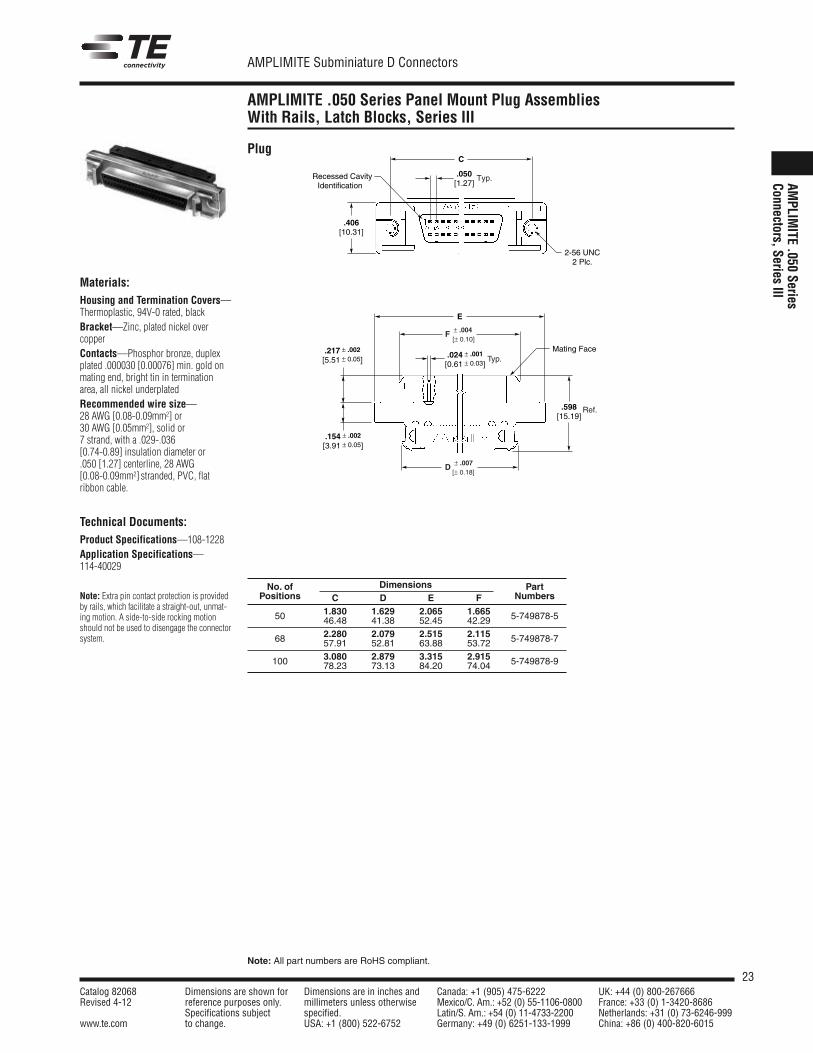
AMPLIMITE .050 Series Panel Mount Plug AssembliesWith Rails, Latch Blocks, Series III
AMPLIM
ITE.050
SeriesConnectors,Series
IIIMaterials:Housing and Termination Covers—Thermoplastic, 94V-0 rated, blackBracket—Zinc, plated nickel overcopperContacts—Phosphor bronze, duplexplated .000030 [0.00076] min. gold onmating end, bright tin in terminationarea, all nickel underplatedRecommended wire size—28 AWG [0.08-0.09mm2] or30 AWG [0.05mm2], solid or7 strand, with a .029-.036[0.74-0.89] insulation diameter or.050 [1.27] centerline, 28 AWG[0.08-0.09mm2] stranded, PVC, flatribbon cable.
Technical Documents:Product Specifications—108-1228Application Specifications—114-40029
Note: Extra pin contact protection is providedby rails, which facilitate a straight-out, unmat-ing motion. A side-to-side rocking motionshould not be used to disengage the connectorsystem.
Plug
2-56 UNC 2 Plc.
Recessed CavityIdentification
C
.050[1.27]
.406[10.31]
Typ.
Mating Face
E
.598 [15.19]
.024 ± .001
[0.61 ± 0.03]
F ± .004[± 0.10]
Typ.
D ± .007[± 0.18]
.217 ± .002
[5.51 ± 0.05]
.154 ± .002
[3.91 ± 0.05]
Ref.
No. of Dimensions PartPositions C D E F Numbers
50 1.830 1.629 2.065 1.665 5-749878-546.48 41.38 52.45 42.29
68 2.280 2.079 2.515 2.115 5-749878-757.91 52.81 63.88 53.72
100 3.080 2.879 3.315 2.915 5-749878-978.23 73.13 84.20 74.04
24Catalog 82068 Dimensions are shown for Dimensions are in inches and Canada: +1 (905) 475-6222 UK: +44 (0) 800-267666Revised 4-12 reference purposes only. millimeters unless otherwise Mexico/C. Am.: +52 (0) 55-1106-0800 France: +33 (0) 1-3420-8686
Specifications subject specified. Latin/S. Am.: +54 (0) 11-4733-2200 Netherlands: +31 (0) 73-6246-999www.te.com to change. USA: +1 (800) 522-6752 Germany: +49 (0) 6251-133-1999 China: +86 (0) 400-820-6015
AMPLIMITE Subminiature D Connectors
Note: All part numbers are RoHS compliant.
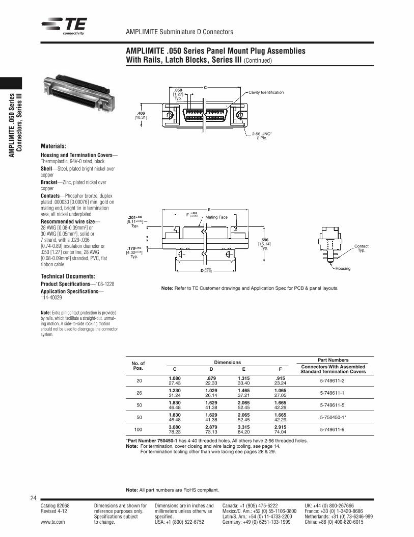
AMPLIMITE .050 Series Panel Mount Plug AssembliesWith Rails, Latch Blocks, Series III (Continued)
AMPL
IMITE.0
50Se
ries
Conn
ectors,S
eriesIII
Materials:Housing and Termination Covers—Thermoplastic, 94V-0 rated, blackShell—Steel, plated bright nickel overcopperBracket—Zinc, plated nickel overcopperContacts—Phosphor bronze, duplexplated .000030 [0.00076] min. gold onmating end, bright tin in terminationarea, all nickel underplatedRecommended wire size—28 AWG [0.08-0.09mm2] or30 AWG [0.05mm2], solid or7 strand, with a .029-.036[0.74-0.89] insulation diameter or.050 [1.27] centerline, 28 AWG[0.08-0.09mm2] stranded, PVC, flatribbon cable.
Technical Documents:Product Specifications—108-1228Application Specifications—114-40029
Note: Extra pin contact protection is providedby rails, which facilitate a straight-out, unmat-ing motion. A side-to-side rocking motionshould not be used to disengage the connectorsystem.
.201±.002[5.11±0.05]Typ.
E
C
±.004F [±0.05]
±.007D [±0.18]
.170±.002[4.32±0.05]Typ.
.596[15.14]Typ.
.050[1.27]Typ.
.406[10.31]
Mating Face
ContactTyp.
Housing
Cavity Identification
2-56 UNC*2 Plc.
Dimensions Part NumbersNo. of
C D E F ConnectorsWith AssembledPos.Standard Termination Covers
1.080 .879 1.315 .91520 27.43 22.33 33.40 23.24 5-749611-2*
1.230 1.029 1.465 1.06526 31.24 26.14 37.21 27.05 5-749611-1*
1.830 1.629 2.065 1.66550 46.48 41.38 52.45 42.29 5-749611-5*
1.830 1.629 2.065 1.66550 46.48 41.38 52.45 42.29 5-750450-1*
3.080 2.879 3.315 2.915100 78.23 73.13 84.20 74.04 5-749611-9*
*Part Number 750450-1 has 4-40 threaded holes. All others have 2-56 threaded holes.Note: For termination, cover closing and wire lacing tooling, see page 14.Note: For termination tooling other than wire lacing see pages 28 & 29.
Note: Refer to TE Customer drawings and Application Spec for PCB & panel layouts.
25Catalog 82068 Dimensions are shown for Dimensions are in inches and Canada: +1 (905) 475-6222 UK: +44 (0) 800-267666Revised 4-12 reference purposes only. millimeters unless otherwise Mexico/C. Am.: +52 (0) 55-1106-0800 France: +33 (0) 1-3420-8686
Specifications subject specified. Latin/S. Am.: +54 (0) 11-4733-2200 Netherlands: +31 (0) 73-6246-999www.te.com to change. USA: +1 (800) 522-6752 Germany: +49 (0) 6251-133-1999 China: +86 (0) 400-820-6015
AMPLIMITE Subminiature D Connectors
Note: All part numbers are RoHS compliant.
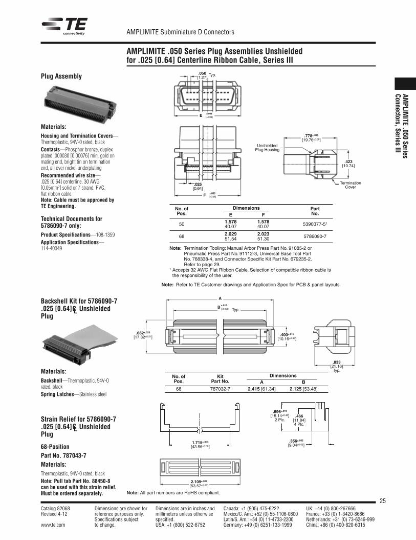
AMPLIMITE .050 Series Plug Assemblies Unshieldedfor .025 [0.64] Centerline Ribbon Cable, Series III
AMPLIM
ITE.050
SeriesConnectors,Series
III
Backshell Kit for 5786090-7.025 [0.64] C UnshieldedPlug
Materials:Housing and Termination Covers—Thermoplastic, 94V-0 rated, blackContacts—Phosphor bronze, duplexplated .000030 [0.00076] min. gold onmating end, bright tin on terminationend, all over nickel underplatingRecommended wire size—.025 [0.64] centerline, 30 AWG[0.05mm2] solid or 7 strand, PVC,flat ribbon cable.Note: Cable must be approved byTE Engineering.
Technical Documents for5786090-7 only:Product Specifications—108-1359Application Specifications—114-40049
No. of Dimensions PartPos. E F No.
1.578 1.57850 40.07 40.07 5390377-51
2.029 2.02368 51.54 51.30 5786090-7
±.003[±0.08]
.050[1.27]
Typ.
E
±.003[±0.08]F
.025[0.64]
UnshieldedPlug Housing
TerminationCover
.423[10.74]
.833[21.16]Typ.
.466[11.84]4 Plc.
B±.015
[±0.38]
A
Typ.
.682±.020[17.32±0.51]
.400±.015[10.16±0.38]
.596±.019[15.14±0.48]2 Plc.
.356±.002[9.04±0.05]
1.715±.003[43.56±0.08]
2.109±.009[53.57±0.23]
.778±.015[19.76±0.38]
Plug Assembly
Materials:Backshell—Thermoplastic, 94V-0rated, blackSpring Latches—Stainless steel
Strain Relief for 5786090-7.025 [0.64] C UnshieldedPlug
68-PositionPart No. 787043-7Materials:Thermoplastic, 94V-0 rated, blackNote: Pull tab Part No. 88450-8can be used with this strain relief.Must be ordered separately.
CL
CL
No. of Kit DimensionsPos. Part No. A B68 787032-7 2.415 [61.34] 2.125 [53.48]
Note: Termination Tooling: Manual Arbor Press Part No. 91085-2 orPneumatic Press Part No. 91112-3, Universal Base Tool PartNo. 768338-4, and Connector Specific Kit Part No. 679235-2.Refer to page 29.
1 Accepts 32 AWG Flat Ribbon Cable. Selection of compatible ribbon cable isthe responsibility of the user.
Note: Refer to TE Customer drawings and Application Spec for PCB & panel layouts.
26Catalog 82068 Dimensions are shown for Dimensions are in inches and Canada: +1 (905) 475-6222 UK: +44 (0) 800-267666Revised 4-12 reference purposes only. millimeters unless otherwise Mexico/C. Am.: +52 (0) 55-1106-0800 France: +33 (0) 1-3420-8686
Specifications subject specified. Latin/S. Am.: +54 (0) 11-4733-2200 Netherlands: +31 (0) 73-6246-999www.te.com to change. USA: +1 (800) 522-6752 Germany: +49 (0) 6251-133-1999 China: +86 (0) 400-820-6015
AMPLIMITE Subminiature D Connectors
Note: All part numbers are RoHS compliant.
AMPLIMITE .050 Series Hardware and Dust Covers, Series III
AMPL
IMITE.0
50Se
ries
Conn
ectors,S
eriesIII
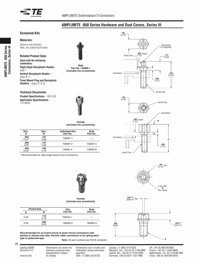
Materials:Stainless steel (female)Steel, zinc plated black (male)
Related Product Data:Used with the followingconnectors:Right-Angle Receptacle Header—page 7Vertical Receptacle Header—pages 8-11Panel Mount Plug and ReceptacleHeaders—pages 21 & 22
Technical Documents:Product Specifications—108-1228Application Specifications—114-40029
MalePart No. 749086-1
(Includes two screwlocks)
Female(Includes two screwlocks)
.187[4.75]
Screwlock(2 Supplied)
.177[4.50]
#4-40 Thd.
.532[13.51]
.050[1.27]
.062[1.57]#2-56 Thd.
B
A
#2-56 Thd.
.187[4.75]
#4-40 Thd.
Screwlock
Connector
Connector
Typ.
Dia..187[4.75]
.027±.003[0.69±0.08]
2-56 UNCB
Min. Deep
.100±.003[2.54±0.08]
.355[9.02]
A
Screwlock Kits
Dim. Dim. Individual Kits BulkA B Part No. Part No..562 .15714.27 3.99 749087-1 —
.380 .1579.65 3.99 749087-21 749087-3
.562 .16514.27 4.19 749087-4* 749087-8
1 Recommended for right-angle board mount connectors.
Female(Includes two screwlocks)
Recommended for pc board mount of panel mount connectors withlatches or latches and rails. Permits cable connectors to be spring latch-type or jackscrew-type
Panel
.062[1.57]
Panel
.050[1.27]
Thread Size Kits BulkA B Part No. Part No.
.1104-40 2.79 750644-1* —
.0902-56 2.29 786585-2 786585-3

27Catalog 82068 Dimensions are shown for Dimensions are in inches and Canada: +1 (905) 475-6222 UK: +44 (0) 800-267666Revised 4-12 reference purposes only. millimeters unless otherwise Mexico/C. Am.: +52 (0) 55-1106-0800 France: +33 (0) 1-3420-8686
Specifications subject specified. Latin/S. Am.: +54 (0) 11-4733-2200 Netherlands: +31 (0) 73-6246-999www.te.com to change. USA: +1 (800) 522-6752 Germany: +49 (0) 6251-133-1999 China: +86 (0) 400-820-6015
AMPLIMITE Subminiature D Connectors
AMPLIMITE .050 Series Performance Specifications andTechnical Documents
AMPLIM
ITE.050
SeriesConnectors,Series
III
Performance Specifications forRight-Angle, Vertical and .050Centerline Cable Products
Performance Specifications for.025 [1.27] Centerline RibbonCable Product. Same as aboveexcept:
Mating Cycles (Durability): 500 max.
Current Rating (30°C T-Rise): 1A max., 50% energized
Termination Resistance (Mated): 25 milliohms max.
Insulation Resistance: 1000 megohms min.
Dielectric Withstanding Voltage: 500 VAC
Header Processing Temperature: +220°C max. for 3 minutes
Temperature Range: –55°C to 105°C
Current Rating (30°C T-Rise): 1A max. center four contacts energized (two from top row, twofrom bottom row)
Termination Resistance (Mated): 50 milliohms max.
Product Specifications:108-1228 AMPLIMITE .050 Series Printed Circuit Board Mounted and Cable Applied108-1359 AMPLIMITE .050 Series .025 [0.64] Centerline Connectors108-1228 AMPLIMITE .050 Series Stacked Connectors108-1228-2 AMPLIMITE .050 Series ACTION PIN Connectors108-1228-3 AMPLIMITE .050 Series SBus Connectors
Application Specifications:114-40029 AMPLIMITE .050 Series Printed Circuit Board Mounted and Cable Applied
Connectors114-40049 AMPLIMITE .050 Series .025 [0.64] Centerline Connectors
Instruction Sheets:408-6923 AMP Manual Arbor Frame Assembly408-6927 TE Design Recommendations for Printed Circuit Board
Support Fixture408-9200 AMP Single Wire Insertion Tool408-9822 Wire Termination Tooling Kit for CHAMPOMATOR 2.5 Machine408-9820 AMP Cover Closing and Staple Inserter Kits408-9663 AMP Mass Insertion Tool408-9750 AMP Cover Lacing Fixture408-9757 AMP Tooling Assembly for ACTION PIN Receptacles408-9817 AMP Manual Miniature Applicator Frame Assembly408-9427 Round-to-Flat Cable Termination408-9875 AMP Universal Base Tool for .025 [0.64] C Connectors408-9892 AMP Tool Kit for .025 [0.64] C Connectors
Customer Manuals:409-5839 CHAMPOMATOR 2.5 Machine409-5791 Control Unit for CHAMPOMATOR 2.5 Machine
CL
CL
28Catalog 82068 Dimensions are shown for Dimensions are in inches and Canada: +1 (905) 475-6222 UK: +44 (0) 800-267666Revised 4-12 reference purposes only. millimeters unless otherwise Mexico/C. Am.: +52 (0) 55-1106-0800 France: +33 (0) 1-3420-8686
Specifications subject specified. Latin/S. Am.: +54 (0) 11-4733-2200 Netherlands: +31 (0) 73-6246-999www.te.com to change. USA: +1 (800) 522-6752 Germany: +49 (0) 6251-133-1999 China: +86 (0) 400-820-6015
AMPLIMITE Subminiature D Connectors
Note: All part numbers are RoHS compliant.
AMPLIMITE .050 Series Application Tooling, Series III
AMPL
IMITE.0
50Se
ries
Conn
ectors,S
eriesIII
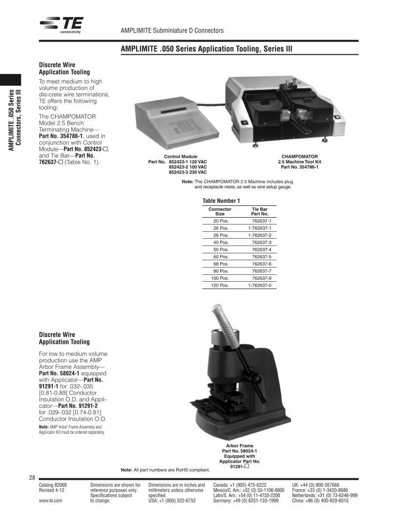
Discrete WireApplication ToolingTo meet medium to highvolume production ofdis-crete wire terminations,TE offers the followingtooling:
The CHAMPOMATORModel 2.5 BenchTerminating Machine—Part No. 354786-1, used inconjunction with ControlModule—Part No. 852423-▫,and Tie Bar—Part No.762637-▫ (Table No. 1).
Discrete WireApplication Tooling
For low to medium volumeproduction use the AMPArbor Frame Assembly—Part No. 58024-1 equippedwith Applicator—Part No.91291-1 for .032-.035[0.81-0.89] ConductorInsulation O.D. and Appli-cator—Part No. 91291-2for .029-.032 [0.74-0.81]Conductor Insulation O.D.
Connector Tie BarSize Part No.
20 Pos. 1-762637-1
26 Pos. 1-762637-1
28 Pos. 1-762637-2
40 Pos. 1-762637-3
50 Pos. 1-762637-4
60 Pos. 1-762637-5
68 Pos. 1-762637-6
80 Pos. 1-762637-7
100 Pos. 1-762637-9
120 Pos. 1-762637-0
Note: The CHAMPOMATOR 2.5 Machine includes plugand receptacle nests, as well as wire setup gauge.
Control ModulePart No. 852423-1 120 VAC
852423-2 100 VAC852423-3 230 VAC
CHAMPOMATOR2.5 Machine Tool KitPart No. 354786-1
Table Number 1
Note: AMP Arbor Frame Assembly andApplicator Kit must be ordered separately.
Arbor FramePart No. 58024-1Equipped with
Applicator Part No.91291-▫
29Catalog 82068 Dimensions are shown for Dimensions are in inches and Canada: +1 (905) 475-6222 UK: +44 (0) 800-267666Revised 4-12 reference purposes only. millimeters unless otherwise Mexico/C. Am.: +52 (0) 55-1106-0800 France: +33 (0) 1-3420-8686
Specifications subject specified. Latin/S. Am.: +54 (0) 11-4733-2200 Netherlands: +31 (0) 73-6246-999www.te.com to change. USA: +1 (800) 522-6752 Germany: +49 (0) 6251-133-1999 China: +86 (0) 400-820-6015
AMPLIMITE Subminiature D Connectors
Note: All part numbers are RoHS compliant.
AMPLIMITE .050 Series Application Tooling, Series III (Continued)
AMPLIM
ITE.050
SeriesConnectors,Series
III
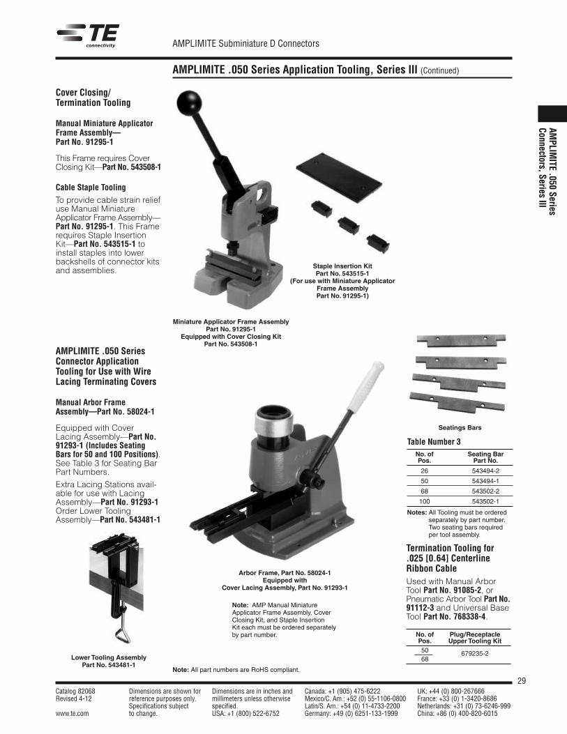
Cover Closing/Termination Tooling
Manual Miniature ApplicatorFrame Assembly—Part No. 91295-1
This Frame requires CoverClosing Kit—Part No. 543508-1
Cable Staple Tooling
To provide cable strain reliefuse Manual MiniatureApplicator Frame Assembly—Part No. 91295-1. This Framerequires Staple InsertionKit—Part No. 543515-1 toinstall staples into lowerbackshells of connector kitsand assemblies.
AMPLIMITE .050 SeriesConnector ApplicationTooling for Use with WireLacing Terminating Covers
Manual Arbor FrameAssembly—Part No. 58024-1
Equipped with CoverLacing Assembly—Part No.91293-1 (Includes SeatingBars for 50 and 100 Positions).See Table 3 for Seating BarPart Numbers.
Extra Lacing Stations avail-able for use with LacingAssembly—Part No. 91293-1Order Lower ToolingAssembly—Part No. 543481-1
Arbor Frame, Part No. 58024-1Equipped with
Cover Lacing Assembly, Part No. 91293-1
Seatings Bars
No. of Seating BarPos. Part No.
26 543494-2
50 543494-1
68 543502-2
100 543502-1
Notes: All Tooling must be orderedseparately by part number.Two seating bars requiredper tool assembly.
Table Number 3
Termination Tooling for.025 [0.64] CenterlineRibbon CableUsed with Manual ArborTool Part No. 91085-2, orPneumatic Arbor Tool Part No.91112-3 and Universal BaseTool Part No. 768338-4.
Staple Insertion KitPart No. 543515-1
(For use with Miniature ApplicatorFrame AssemblyPart No. 91295-1)
Miniature Applicator Frame AssemblyPart No. 91295-1
Equipped with Cover Closing KitPart No. 543508-1
Note: AMP Manual MiniatureApplicator Frame Assembly, CoverClosing Kit, and Staple InsertionKit each must be ordered separatelyby part number. No. of Plug/Receptacle
Pos. Upper Tooling Kit50 679235-268Lower Tooling Assembly
Part No. 543481-1
30Catalog 82068 Dimensions are shown for Dimensions are in inches and Canada: +1 (905) 475-6222 UK: +44 (0) 800-267666Revised 4-12 reference purposes only. millimeters unless otherwise Mexico/C. Am.: +52 (0) 55-1106-0800 France: +33 (0) 1-3420-8686
Specifications subject specified. Latin/S. Am.: +54 (0) 11-4733-2200 Netherlands: +31 (0) 73-6246-999www.te.com to change. USA: +1 (800) 522-6752 Germany: +49 (0) 6251-133-1999 China: +86 (0) 400-820-6015
AMPLIMITE Subminiature D Connectors
Shielded AMPLIMITE .050 Series Slimline Connectors
AMPL
IMITE.0
50Se
ries
Conn
ectors,S
eriesIII
Product Facts�� Compact design, profile
for the right-angle header1.230 x .588 [31.24 x 14.94],vertical header 1.230 x .433[31.24 x 11.00], right-anglestacked headers 1.230 x.803 [31.24 x 20.40]
�� Housings and covers madeof UL 94V-0 rated thermo-plastic
�� Headers are compatiblewith surface mount reflowsolder processes
�� Header footprint for right-angle and stacked configura-tions is .100 x .050[2.54 x 1.27] staggeredcenterlines
�� Right-angle and stackedheaders feature integralboardlocks for positive boardretention and grounding
�� Stacked headers reduceoverall total header volumeby 48% and PC board areaby 38%
�� Stacked headers offeroptional contact shield foradditional EMI/RFI protection
�� Plugs preloaded with insulation displacementcontacts (IDC) provide fast,reliable and economical terminations
�� Aesthetically designed back-shell kits feature easy-to-usefinger grip jackscrews tosecure mated connectors
�� Listed and complies with UL1863, CommunicationCircuit Accessories,File No. E81956
�� Certified byCanadian StandardsAssociationFile No. 1088108 (LR 7189A-207)
� Produced under a QualityManagement System certi-fied to ISO 9001
� A copy of the certificate is available upon request
R
R
ISO
Certified9001
Shielded AMPLIMITE .050Series, Slimline Connectorsanswer today’s industryrequirement for higher density in a smaller overallpackage. The present lineconsists of 26 position,shielded right-angle, 26position right-angle stackedPCB receptacle header, andmating 26 position plugconnectors. All header, plugand backshell housings aremade of UL 94V-0 ratedthermoplastic. PCB headersare compatible with surfacemount reflow solderprocesses. Right-angle andstacked PCB headers fea-ture con-tact footprints on.100 x .050 [2.54 x 1.27]staggered centerlines.
The compact design of theright-angle header packagemeasures only 1.230 W x.588 D x .300 H [31.24 W x14.94 D x 7.62 H] for maxi-mum board real estate con-servation. Right-angle PCBheaders feature integral
boardlocks for positive boardretention and grounding.
Right-angle stacked headersprovide 52 contacts in apackage only .635 [16.13]high, allowing parallel(board-over-board) boardspacing of .800 [20.32].Centerlines between the topconnector and the bottomconnector measure .335[8.51] when compared to.400 [10.16] on the standard.050 Series stacked headers.This results in an over-allreduction of total headervolume, in comparison tothe standard AMPLIMITE.050 Series header, of 48%,and a comparative reductionin PC board area of 38%.
Stacked header boardretention and stabilizationis provided by two board-locks and four groundingposts. In addition, anoptional rear contact shieldis available for additionalEMI/RFI protection.
The mating plug connectorconsists of a thermoplastichousing, preloaded withinsulation displacementcontacts (IDC) for fast, reli-able terminations that offergreater applied cost sav-ings. TE offers a choice oftermination equipment tomeet your productionrequirements.
The backshell hardware kitincludes a two-piece, aes-thetically designed, thermo-plastic cover over an innerand outer shield and two,high strength #2-56 malejackscrews with insulatedheads (easy finger gripcaps) to secure mated connectors.
The AMPLIMITE .050Series, Slimline family ofconnectors offers keyedcoupling. This feature elimi-nates the problem of mis-match mating of plug andreceptacle, particularly instacked applications.
31Catalog 82068 Dimensions are shown for Dimensions are in inches and Canada: +1 (905) 475-6222 UK: +44 (0) 800-267666Revised 4-12 reference purposes only. millimeters unless otherwise Mexico/C. Am.: +52 (0) 55-1106-0800 France: +33 (0) 1-3420-8686
Specifications subject specified. Latin/S. Am.: +54 (0) 11-4733-2200 Netherlands: +31 (0) 73-6246-999www.te.com to change. USA: +1 (800) 522-6752 Germany: +49 (0) 6251-133-1999 China: +86 (0) 400-820-6015
AMPLIMITE Subminiature D Connectors
Note: All part numbers are RoHS compliant.
Shielded AMPLIMITE .050 Series Slimline Connectors (Continued)
AMPLIM
ITE .050 SeriesConnectors, Series III
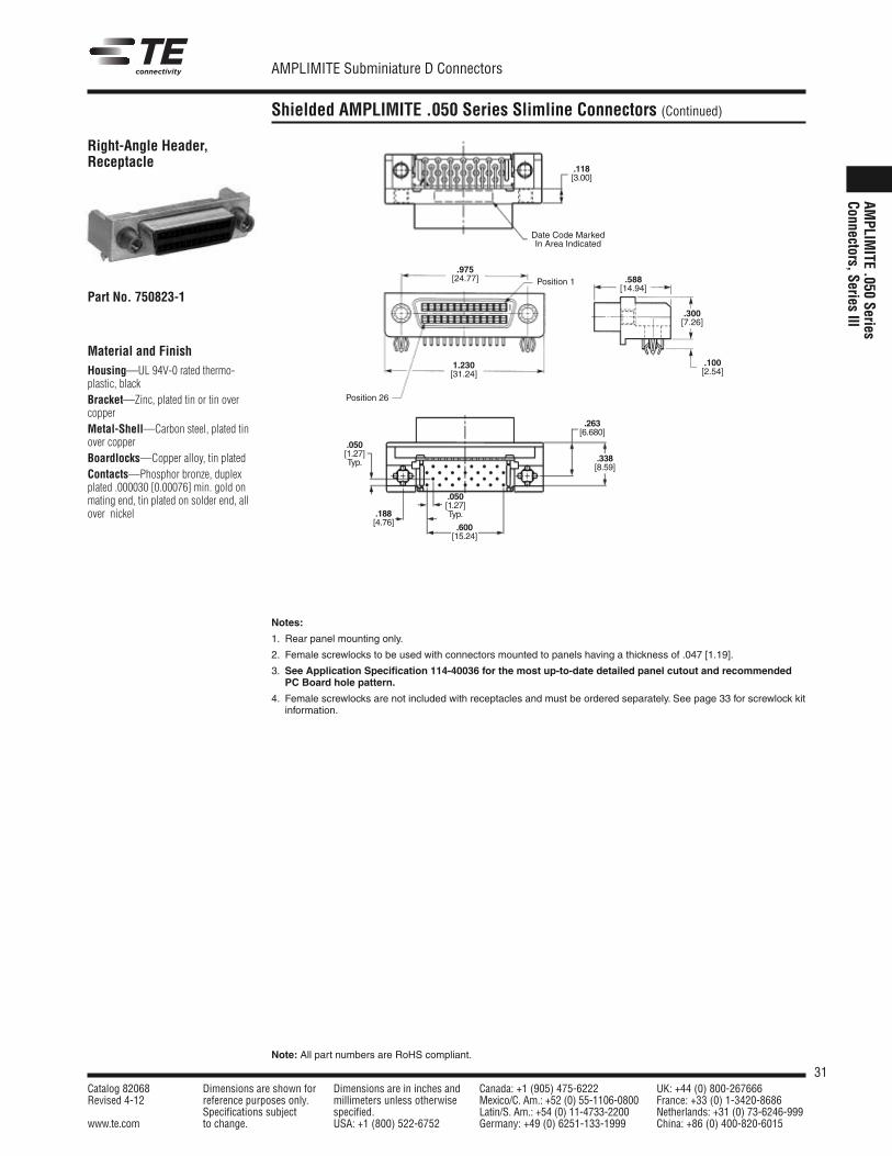
Material and FinishHousing—UL 94V-0 rated thermo-plastic, blackBracket—Zinc, plated tin or tin overcopperMetal-Shell—Carbon steel, plated tinover copperBoardlocks—Copper alloy, tin platedContacts—Phosphor bronze, duplexplated .000030 [0.00076] min. gold onmating end, tin plated on solder end, allover nickel
.975[24.77] .588
[14.94]
.300[7.26]
.100[2.54]
1.230[31.24]
Position 1
Position 26
Right-Angle Header,Receptacle
Part No. 750823-1
Notes:
1. Rear panel mounting only.
2. Female screwlocks to be used with connectors mounted to panels having a thickness of .047 [1.19].
3. See Application Specification 114-40036 for the most up-to-date detailed panel cutout and recommendedPC Board hole pattern.
4. Female screwlocks are not included with receptacles and must be ordered separately. See page 33 for screwlock kitinformation.
.118[3.00]
Date Code MarkedIn Area Indicated
.263[6.680]
.338[8.59]
.188[4.76]
.050[1.27]Typ.
.600[15.24]
.050[1.27]Typ.
32Catalog 82068 Dimensions are shown for Dimensions are in inches and Canada: +1 (905) 475-6222 UK: +44 (0) 800-267666Revised 4-12 reference purposes only. millimeters unless otherwise Mexico/C. Am.: +52 (0) 55-1106-0800 France: +33 (0) 1-3420-8686
Specifications subject specified. Latin/S. Am.: +54 (0) 11-4733-2200 Netherlands: +31 (0) 73-6246-999www.te.com to change. USA: +1 (800) 522-6752 Germany: +49 (0) 6251-133-1999 China: +86 (0) 400-820-6015
AMPLIMITE Subminiature D Connectors
Note: All part numbers are RoHS compliant.
Shielded AMPLIMITE .050 Series Slimline Connectors (Continued)
AMPL
IMITE .0
50 Ser
ies
Conn
ectors, S
eries III
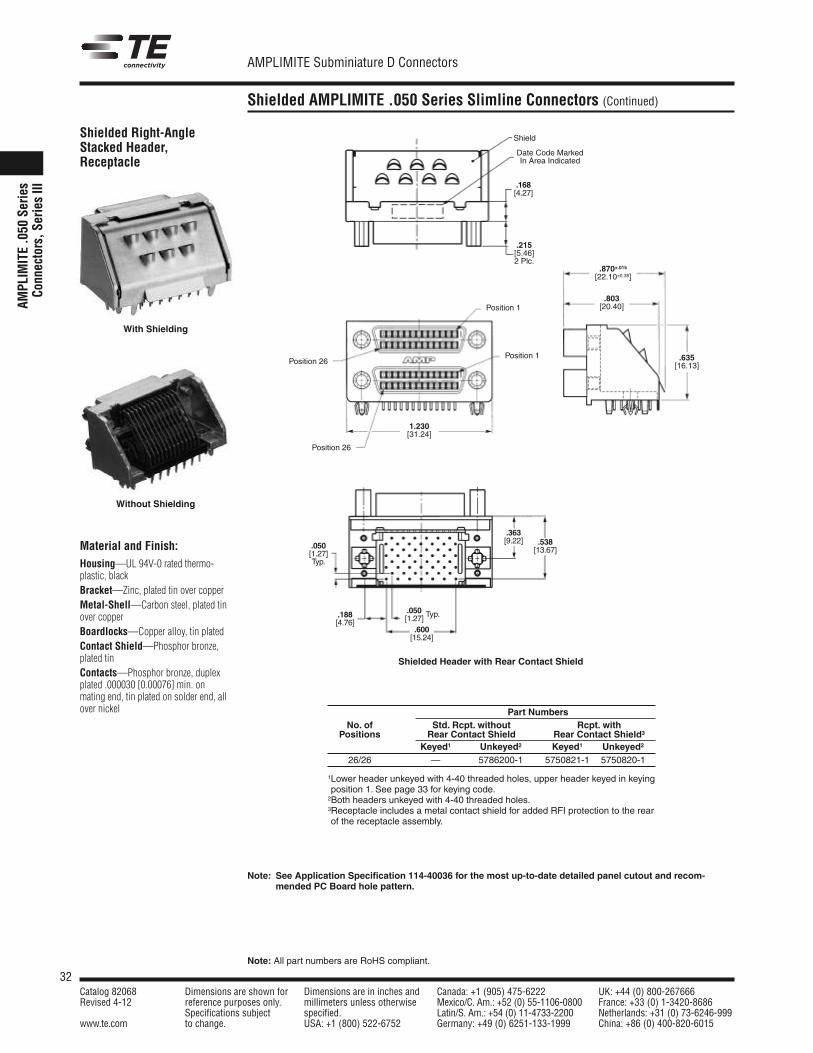
Material and Finish:Housing—UL 94V-0 rated thermo-plastic, blackBracket—Zinc, plated tin over copperMetal-Shell—Carbon steel, plated tinover copperBoardlocks—Copper alloy, tin platedContact Shield—Phosphor bronze,plated tinContacts—Phosphor bronze, duplexplated .000030 [0.00076] min. onmating end, tin plated on solder end, allover nickel
Shielded Right-AngleStacked Header,Receptacle
1.230[31.24]
.870±.015[22.10±0.38]
.803[20.40]
.635[16.13]
Position 1
Position 1Position 26
Position 26
Shielded Header with Rear Contact Shield
Part NumbersNo. of Std. Rcpt. without Rcpt. withPositions Rear Contact Shield Rear Contact Shield3
Keyed1 Unkeyed2 Keyed1 Unkeyed2
26/26 — 5786200-1 5750821-1 5750820-1
1Lower header unkeyed with 4-40 threaded holes, upper header keyed in keyingposition 1. See page 33 for keying code.2Both headers unkeyed with 4-40 threaded holes.3Receptacle includes a metal contact shield for added RFI protection to the rearof the receptacle assembly.
Shield
Date Code MarkedIn Area Indicated
.050[1.27]Typ.
.188[4.76]
.538[13.67]
.363[9.22]
.215[5.46]2 Plc.
.168[4.27]
.600[15.24]
.050[1.27] Typ.
Note: See Application Specification 114-40036 for the most up-to-date detailed panel cutout and recom-mended PC Board hole pattern.
With Shielding
Without Shielding
33Catalog 82068 Dimensions are shown for Dimensions are in inches and Canada: +1 (905) 475-6222 UK: +44 (0) 800-267666Revised 4-12 reference purposes only. millimeters unless otherwise Mexico/C. Am.: +52 (0) 55-1106-0800 France: +33 (0) 1-3420-8686
Specifications subject specified. Latin/S. Am.: +54 (0) 11-4733-2200 Netherlands: +31 (0) 73-6246-999www.te.com to change. USA: +1 (800) 522-6752 Germany: +49 (0) 6251-133-1999 China: +86 (0) 400-820-6015
AMPLIMITE Subminiature D Connectors
Note: All part numbers are RoHS compliant.
Shielded AMPLIMITE .050 Series Slimline Connectors (Continued)
AMPLIM
ITE .050 SeriesConnectors, Series III
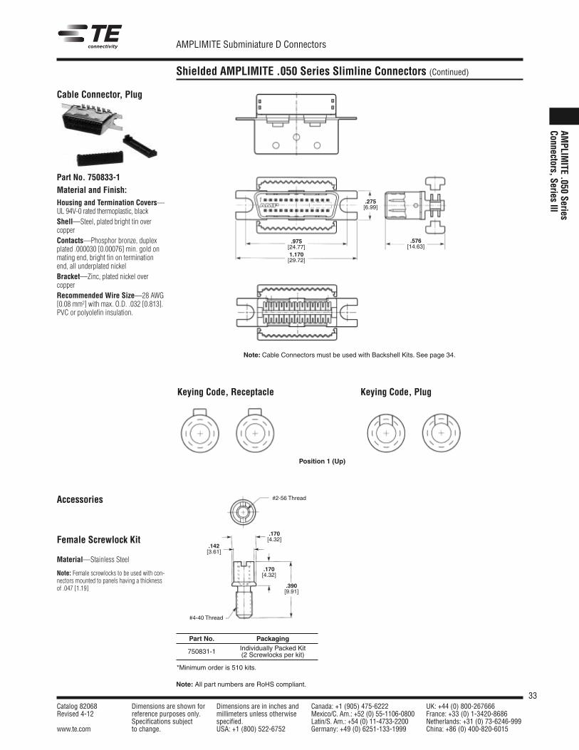
Material and Finish:Housing and Termination Covers—UL 94V-0 rated thermoplastic, blackShell—Steel, plated bright tin overcopperContacts—Phosphor bronze, duplexplated .000030 [0.00076] min. gold onmating end, bright tin on terminationend, all underplated nickelBracket—Zinc, plated nickel over copperRecommended Wire Size—28 AWG[0.08 mm2] with max. O.D. .032 [0.813].PVC or polyolefin insulation.
Cable Connector, Plug
Part No. 750833-1
Note: Cable Connectors must be used with Backshell Kits. See page 34.
.275[6.99]
.975[24.77]1.170[29.72]
.576[14.63]
Keying Code, Receptacle Keying Code, Plug
Accessories
Female Screwlock Kit
Material—Stainless Steel
Note: Female screwlocks to be used with con-nectors mounted to panels having a thicknessof .047 [1.19]
Position 1 (Up)
#2-56 Thread
#4-40 Thread
.142[3.61]
.170[4.32]
.170[4.32]
.390[9.91]
Part No. PackagingIndividually Packed Kit750831-1 (2 Screwlocks per kit)
*Minimum order is 510 kits.
34Catalog 82068 Dimensions are shown for Dimensions are in inches and Canada: +1 (905) 475-6222 UK: +44 (0) 800-267666Revised 4-12 reference purposes only. millimeters unless otherwise Mexico/C. Am.: +52 (0) 55-1106-0800 France: +33 (0) 1-3420-8686
Specifications subject specified. Latin/S. Am.: +54 (0) 11-4733-2200 Netherlands: +31 (0) 73-6246-999www.te.com to change. USA: +1 (800) 522-6752 Germany: +49 (0) 6251-133-1999 China: +86 (0) 400-820-6015
AMPLIMITE Subminiature D Connectors
Note: All part numbers are RoHS compliant.
Shielded AMPLIMITE .050 Series Slimline Connectors (Continued)
AMPL
IMITE .0
50 Ser
ies
Conn
ectors, S
eries III
Backshell Kits
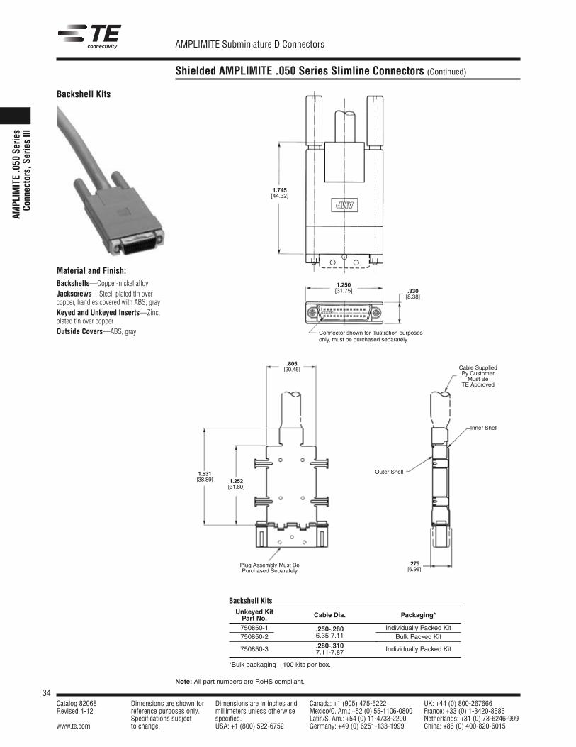
Material and Finish:Backshells—Copper-nickel alloyJackscrews—Steel, plated tin overcopper, handles covered with ABS, grayKeyed and Unkeyed Inserts—Zinc,plated tin over copperOutside Covers—ABS, gray Connector shown for illustration purposes
only, must be purchased separately.
1.745[44.32]
1.250[31.75] .330
[8.38]
Backshell KitsUnkeyed KitPart No. Cable Dia. Packaging*
750850-1 .250-.280 Individually Packed Kit750850-2 6.35-7.11 Bulk Packed Kit
750850-3 .280-.310 Individually Packed Kit7.11-7.87
*Bulk packaging—100 kits per box.
.805[20.45]
1.531[38.89] 1.252
[31.80]
Plug Assembly Must BePurchased Separately
.275[6.98]
Outer Shell
Inner Shell
Cable SuppliedBy CustomerMust Be
TE Approved
35Catalog 82068 Dimensions are shown for Dimensions are in inches and Canada: +1 (905) 475-6222 UK: +44 (0) 800-267666Revised 4-12 reference purposes only. millimeters unless otherwise Mexico/C. Am.: +52 (0) 55-1106-0800 France: +33 (0) 1-3420-8686
Specifications subject specified. Latin/S. Am.: +54 (0) 11-4733-2200 Netherlands: +31 (0) 73-6246-999www.te.com to change. USA: +1 (800) 522-6752 Germany: +49 (0) 6251-133-1999 China: +86 (0) 400-820-6015
AMPLIMITE Subminiature D Connectors
Note: All part numbers are RoHS compliant.
Shielded AMPLIMITE .050 Series Slimline Connectors, Application Tooling
AMPLIM
ITE .050 SeriesConnectors, Series III
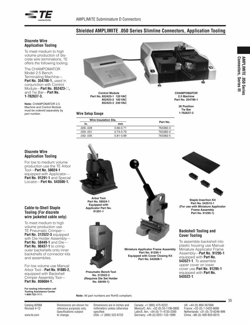
Discrete WireApplication ToolingTo meet medium to high volume production of dis-crete wire terminations, TEoffers the following tooling:
The CHAMPOMATORModel 2.5 BenchTerminating Machine—Part No. 354786-1, used inconjunction with ControlModule—Part No. 852423-��,and Tie Bar—Part No.1-762637-3.
Note: CHAMPOMATOR 2.5Machine and Control Modulemust be ordered separately bypart number.
Discrete WireApplication ToolingFor low to medium volumeproduction use the TE ArborTool—Part No. 58024-1equipped with Applicator—Part No. 91291-1 and SpecialLocator—Part No. 543506-1.
Backshell Tooling andCover ToolingTo assemble backshell intoplastic housing use ManualMiniature Applicator FrameAssembly—Part No. 91295-1equipped with Part No.543521-1. To assembleupper cover on lowercover use Part No. 91295-1equipped with Part No.543522-1.
Cable-to-Shell StapleTooling (For discretewire jacketed cable only)To meet medium to high volume production useTE Pneumatic Crimper—Part No. 312522-3 equippedwith Die Holder Assembly—Part No. 58449-1 and Die—Part No. 90437-1 to crimpouter backshells onto innerbackshells of connector kitsand assemblies.
For low volume use ManualArbor Tool—Part No. 91085-2,equipped with BackshellCrimper Assembly Tool—Part No. 856684-1.
Control ModulePart No. 852423-1 120 VAC
852423-2 100 VAC852423-3 230 VAC
For tooling information callTooling Assistance Center1-800-722-1111.
Pneumatic Bench ToolNo. 312522-3
(Requires Die Set HolderNo. 58449-1)
Staple Insertion KitPart No. 543515-1
(For use with Miniature ApplicatorFrame AssemblyPart No. 91295-1)
Miniature Applicator Frame AssemblyPart No. 91295-1
Equipped with Cover Closing KitPart No. 543508-1
CHAMPOMATOR2.5 Machine
Part No. 354786-1
26 PositionTie Bar
1-762637-3Wire Setup Gauge
Wire Insulation Dia.in. mm
Part No.
.026-.028 0.66-0.71 763382-3
.029-.031 0.74-0.79 763382-4
.032-.035 0.81-0.89 763382-5
Arbor ToolPart No. 58024-1Equipped with
Applicator Part No.91291-1
36Catalog 82068 Dimensions are shown for Dimensions are in inches and Canada: +1 (905) 475-6222 UK: +44 (0) 800-267666Revised 4-12 reference purposes only. millimeters unless otherwise Mexico/C. Am.: +52 (0) 55-1106-0800 France: +33 (0) 1-3420-8686
Specifications subject specified. Latin/S. Am.: +54 (0) 11-4733-2200 Netherlands: +31 (0) 73-6246-999www.te.com to change. USA: +1 (800) 522-6752 Germany: +49 (0) 6251-133-1999 China: +86 (0) 400-820-6015
AMPLIMITE Subminiature D Connectors
Note: All part numbers are RoHS compliant.
Shielded AMPLIMITE .050 Series Contact Arrangements, Performance Specifications, Technical Documents—Slimline Connectors
AMPL
IMITE .0
50 Ser
ies
Conn
ectors, S
eries III
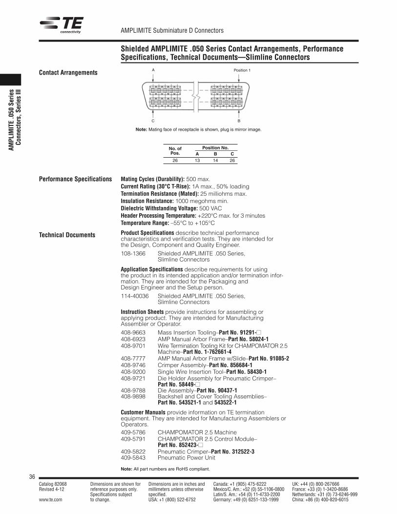
Contact Arrangements
Performance Specifications
Technical Documents
Position 1A
BC
Note: Mating face of receptacle is shown, plug is mirror image.
No. of Position No.Pos. A B C26 13 14 26
Mating Cycles (Durability): 500 max.Current Rating (30°C T-Rise): 1A max., 50% loadingTermination Resistance (Mated): 25 milliohms max.Insulation Resistance: 1000 megohms min.Dielectric Withstanding Voltage: 500 VACHeader Processing Temperature: +220°C max. for 3 minutesTemperature Range: –55°C to +105°C
Product Specifications describe technical performancecharacteristics and verification tests. They are intended forthe Design, Component and Quality Engineer.108-1366 Shielded AMPLIMITE .050 Series,
Slimline Connectors
Application Specifications describe requirements for usingthe product in its intended application and/or termination infor-mation. They are intended for the Packaging andDesign Engineer and the Setup person.114-40036 Shielded AMPLIMITE .050 Series,
Slimline Connectors
Instruction Sheets provide instructions for assembling orapplying product. They are intended for ManufacturingAssembler or Operator.408-9663 Mass Insertion Tooling–Part No. 91291-��408-6923 AMP Manual Arbor Frame–Part No. 58024-1408-9701 Wire Termination Tooling Kit for CHAMPOMATOR 2.5
Machine–Part No. 1-762661-4408-7777 AMP Manual Arbor Frame w/Slide–Part No. 91085-2408-9746 Crimper Assembly–Part No. 856684-1408-9200 Single Wire Insertion Tool–Part No. 58430-1408-9721 Die Holder Assembly for Pneumatic Crimper–
Part No. 58449-��408-9788 Die Assembly–Part No. 90437-1408-9898 Backshell and Cover Tooling Assemblies–
Part No. 543521-1 and 543522-1
Customer Manuals provide information on TE termination equipment. They are intended for Manufacturing Assemblers orOperators.409-5786 CHAMPOMATOR 2.5 Machine409-5791 CHAMPOMATOR 2.5 Control Module–
Part No. 852423-��409-5822 Pneumatic Crimper–Part No. 312522-3409-5843 Pneumatic Power Unit
37Catalog 82068 Dimensions are shown for Dimensions are in inches and Canada: +1 (905) 475-6222 UK: +44 (0) 800-267666Revised 4-12 reference purposes only. millimeters unless otherwise Mexico/C. Am.: +52 (0) 55-1106-0800 France: +33 (0) 1-3420-8686
Specifications subject specified. Latin/S. Am.: +54 (0) 11-4733-2200 Netherlands: +31 (0) 73-6246-999www.te.com to change. USA: +1 (800) 522-6752 Germany: +49 (0) 6251-133-1999 China: +86 (0) 400-820-6015
AMPLIMITE Subminiature D Connectors
Note: All part numbers are RoHS compliant.
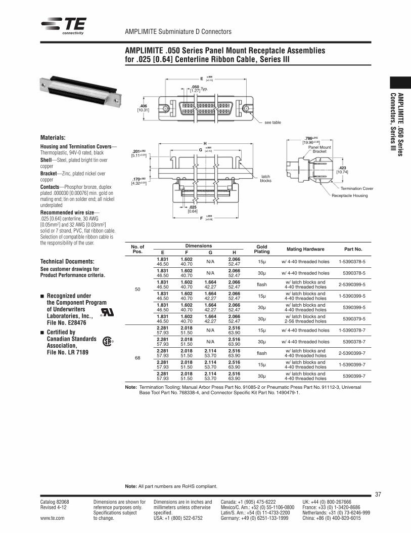
AMPLIMITE .050 Series Panel Mount Receptacle Assembliesfor .025 [0.64] Centerline Ribbon Cable, Series III
AMPLIM
ITE .050 SeriesConnectors, Series III
Materials:Housing and Termination Covers—Thermoplastic, 94V-0 rated, blackShell—Steel, plated bright tin overcopperBracket—Zinc, plated nickel overcopperContacts—Phosphor bronze, duplexplated .000030 [0.00076] min. gold onmating end; tin on solder end; all nickelunderplatedRecommended wire size—.025 [0.64] centerline, 30 AWG[0.05mm2] and 32 AWG [0.03mm2] solid or 7 strand, PVC, flat ribbon cable.Selection of compatible ribbon cable isthe responsibility of the user.
Technical Documents:See customer drawings forProduct Performance criteria.
� Recognized underthe Component Programof UnderwritersLaboratories, Inc.,File No. E28476
� Certified by Canadian StandardsAssociation,File No. LR 7189
R
R
Termination Cover
Receptacle Housing
Panel MountBracket
.423[10.74]
.786±.015[19.96±0.38]
±.006[±0.15]
.406[10.31]
E
±.003[±0.08]F
.025[0.64]
.050[1.27]Typ.
see table
H
.201±.002[5.11±0.05]
.170±.002[4.32±0.05]
G±.004[±0.10]
latchblocks
No. of Dimensions Gold Mating Hardware Part No.Pos. E F G H Plating
1.831 1.602 2.066 w/ 4-40 threaded holes46.50 40.70 N/A 52.47 15µ 1-5390378-5
1.831 1.602 2.066 w/ 4-40 threaded holes46.50 40.70 N/A 52.47 30µ 5390378-5
1.831 1.602 1.664 2.066 w/ latch blocks and
50 46.50 40.70 42.27 52.47 flash 4-40 threaded holes 2-5390399-5
1.831 1.602 1.664 2.066 w/ latch blocks and46.50 40.70 42.27 52.47 15µ 4-40 threaded holes 1-5390399-5
1.831 1.602 1.664 2.066 w/ latch blocks and46.50 40.70 42.27 52.47 30µ 4-40 threaded holes 5390399-5
1.831 1.602 1.664 2.066 w/ latch blocks and46.50 40.70 42.27 52.47 30µ 2-56 threaded holes 5390379-5
2.281 2.018 2.516 w/ 4-40 threaded holes57.93 51.50 N/A 63.90 15µ 1-5390378-7
2.281 2.018 2.516 w/ 4-40 threaded holes57.93 51.50 N/A 63.90 30µ 5390378-7
2.281 2.018 2.114 2.516 w/ latch blocks and
68 57.93 51.50 53.70 63.90 flash 4-40 threaded holes 2-5390399-7
2.281 2.018 2.114 2.516 w/ latch blocks and57.93 51.50 53.70 63.90 15µ 4-40 threaded holes 1-5390399-7
2.281 2.018 2.114 2.516 w/ latch blocks and57.93 51.50 53.70 63.90 30µ 4-40 threaded holes 5390399-7
Note: Termination Tooling: Manual Arbor Press Part No. 91085-2 or Pneumatic Press Part No. 91112-3, UniversalBase Tool Part No. 768338-4, and Connector Specific Kit Part No. 1490479-1.
Related Documents
![3M Four‑Wall Header - Farnell element14 · (UB or UG Pltg. Req’d) Plating: RB = 30µ” [0.76µm] Gold with 200µ” [5.08µm] Matte Tin Solder Tails (RIA E1 & C1 apply)](https://static.cupdf.com/doc/110x72/5c9bbf9e09d3f210138bc66b/3m-fourwall-header-farnell-ub-or-ug-pltg-reqd-plating-rb-30.jpg)