89 For assistance in Europe and China, please see the back cover for a complete listing of our branch offices and contact numbers. Specifications subject to change. TE CONNECTIVITY DEUTSCH DL SERIES MIL-DTL-83723 SERIES III CONNECTORS INTERMATEABLE WITH SOURIAU CONNECTORS AND ALL MIL-DTL-83723 SERIES III TE DEUTSCH DL series MIL-DTL-83723 series III connectors have a quick-mating, three-point bayonet coupling system. TE DEUTSCH DL series connectors are designed for the harsh environments found in communications equipment, industrial equipment, and armored tanks, and are excellent aerospace connectors. These TE DEUTSCH connectors are mil spec to MIL-83723 and have a high-quality contact retention system. The DL series is intermateable with Souriau connectors, all MIL-DTL-83723 series III connectors, and all MIL-DTL-26500 bayonet connectors. For full product details on the TE DEUTSCH DL series MIL-DTL-83723 series III connectors, please see the specifications below. • High-performance military aircraft • Commercial aircraft • Communications equipment • Armored personnel carriers & tanks • High temperature industrial equipment • High-reliability • Outstanding EMI-shielding protection • Operates at extreme temperatures • High-density connectors • Broad range of military and commercial accessories • MIL-DTL-83723 qualified TE Connectivity DEUTSCH DL Series MIL-DTL-83723 Series III Connectors APPLICATIONS FEATURES

Welcome message from author
This document is posted to help you gain knowledge. Please leave a comment to let me know what you think about it! Share it to your friends and learn new things together.
Transcript

89For assistance in Europe and China, please see the back cover for a complete listing of our branch offices and contact numbers.Specifications subject to change.
TE CO
NN
ECTIVITY D
EUTSC
H D
L SERIES MIL-D
TL-83723 SERIES III CO
NN
ECTO
RS
INTERMATEABLE WITH SOURIAU CONNECTORS AND ALL MIL-DTL-83723 SERIES IIITE DEUTSCH DL series MIL-DTL-83723 series III connectors have a quick-mating, three-point bayonet coupling system. TE DEUTSCH DL series connectors are designed for the harsh environments found in communications equipment, industrial equipment, and armored tanks, and are excellent aerospace connectors. These TE DEUTSCH connectors are mil spec to MIL-83723 and have a high-quality contact retention system. The DL series is intermateable with Souriau connectors, all MIL-DTL-83723 series III connectors, and all MIL-DTL-26500 bayonet connectors. For full product details on the TE DEUTSCH DL series MIL-DTL-83723 series III connectors, please see the specifications below.
• High-performance military aircraft
• Commercial aircraft
• Communications equipment
• Armored personnel carriers & tanks
• High temperature industrial equipment
• High-reliability
• Outstanding EMI-shielding protection
• Operates at extreme temperatures
• High-density connectors
• Broad range of military and commercial accessories
• MIL-DTL-83723 qualified
TE Connectivity DEUTSCH DL Series MIL-DTL-83723 Series III Connectors
APPLICATIONS
FEATURES

90 For assistance in North America: +1 800.675.1214 • www.peigenesis.com • [email protected]
TE CO
NN
ECTIVITY D
EUTSC
H D
L SERIES MIL-D
TL-83723 SERIES III CO
NN
ECTO
RS
MATERIALS AND FINISHESShell Aluminium Alloy or Stainless Steel
Shell Plating Electroless Nickel, Olive Drab Chromate over nickel, Anodized, and Passivated
Bayonet Pin Passivated Stainless Steel
Contacts Copper Alloy
Contact Platings 50u" Gold Plated
Insulator Rigid Plastic dielectric
Seals Silicone based elastomer
ELECTRICAL DATA
Test Voltage
SERVICE RATING SEA LEVEL VAC RMS
50000 FEET ALTITUDE VAC RMS
70000 FEET ALTITUDE VAC RMS
110000 FEET ALTITUDE VAC RMS
I 1500 500 375 200
II 2300 750 500 200
Current Rating
CONTACT SIZE DC TEST CURRENT IN AMPS POTENTIAL DROP MILLIVOLT AT 77ºF (25ºC)
20 7.5 <15
16 13 <21
12 23 <22
TECHNICAL SPECIFICATIONS
91For assistance in Europe and China, please see the back cover for a complete listing of our branch offices and contact numbers.Specifications subject to change.
TE CO
NN
ECTIVITY D
EUTSC
H D
L SERIES MIL-D
TL-83723 SERIES III CO
NN
ECTO
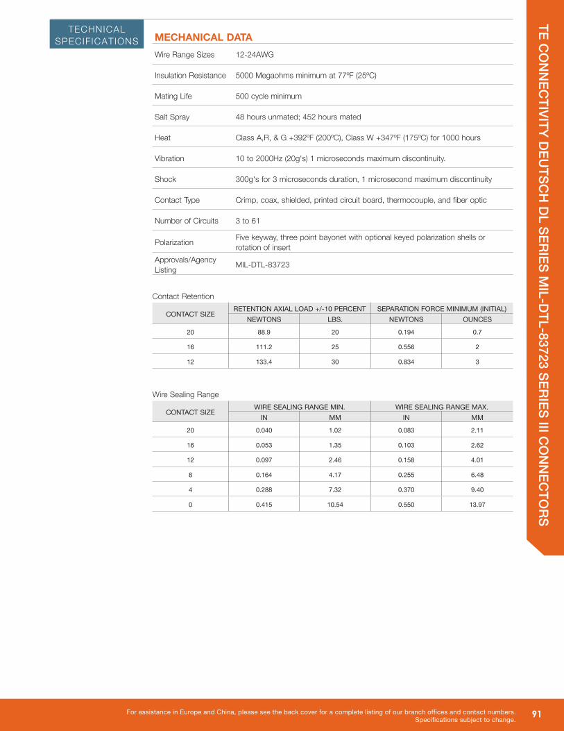
RSMECHANICAL DATAWire Range Sizes 12-24AWG
Insulation Resistance 5000 Megaohms minimum at 77ºF (25ºC)
Mating Life 500 cycle minimum
Salt Spray 48 hours unmated; 452 hours mated
Heat Class A,R, & G +392ºF (200ºC), Class W +347ºF (175ºC) for 1000 hours
Vibration 10 to 2000Hz (20g's) 1 microseconds maximum discontinuity.
Shock 300g's for 3 microseconds duration, 1 microsecond maximum discontinuity
Contact Type Crimp, coax, shielded, printed circuit board, thermocouple, and fiber optic
Number of Circuits 3 to 61
Polarization Five keyway, three point bayonet with optional keyed polarization shells or rotation of insert
Approvals/Agency Listing MIL-DTL-83723
Contact Retention
CONTACT SIZERETENTION AXIAL LOAD +/-10 PERCENT SEPARATION FORCE MINIMUM (INITIAL)
NEWTONS LBS. NEWTONS OUNCES
20 88.9 20 0.194 0.7
16 111.2 25 0.556 2
12 133.4 30 0.834 3
Wire Sealing Range
CONTACT SIZEWIRE SEALING RANGE MIN. WIRE SEALING RANGE MAX.
IN MM IN MM
20 0.040 1.02 0.083 2.11
16 0.053 1.35 0.103 2.62
12 0.097 2.46 0.158 4.01
8 0.164 4.17 0.255 6.48
4 0.288 7.32 0.370 9.40
0 0.415 10.54 0.550 13.97
TECHNICAL SPECIFICATIONS

92 For assistance in North America: +1 800.675.1214 • www.peigenesis.com • [email protected]
TE CO
NN
ECTIVITY D
EUTSC
H D
L SERIES MIL-D
TL-83723 SERIES III CO
NN
ECTO
RS
M83723/73 with Socket contacts
M83723/74 with Pin contactsJam Nut Receptacle
M83723/71 with Socket contacts
M83723/72 with Pin contactsSquare Flange Receptacle
(Military part number example)
HOW TO ORDER 83723/DL SERIES CONNECTORS - MILITARY
A* = Aluminium Shell, black non-conductive anodized platedR = Aluminium Shell, electroless nickel platedW = Aluminium Shell, olive drab cadmium plated
*not available for styles /77 and /78
STEP 2: SELECT FINISH
M83723/75 with Socket contacts
M83723/76 with Pin contactsStandard Plug
STEP 1: SELECT SHELL STYLE, PLUG OR RECEPTACLE
RECEPTACLES PLUGS
M83723/77 with Socket contacts
M83723/78 with Pin contactsShielded Plug
MATING GUIDE
/71 /72 /73 /74 /75 /76 /77 /78
/71 ⁕ ⁕
/72 ⁕ ⁕
/73 ⁕ ⁕
/74 ⁕ ⁕
/75 ⁕ ⁕
/76 ⁕ ⁕
/77 ⁕ ⁕
/78 ⁕ ⁕
Mating connectors will mate a plug to a receptacle, so long as the layout and keying are the same and the contact types are opposite.
Mates with
1 2 3 4 5M83723/76 W 1210 N –LC
SHELL STYLE FINISH LAYOUT POLARIZATION MODIFIER
93For assistance in Europe and China, please see the back cover for a complete listing of our branch offices and contact numbers.Specifications subject to change.
TE CO
NN
ECTIVITY D
EUTSC
H D
L SERIES MIL-D
TL-83723 SERIES III CO
NN
ECTO
RSHOW TO ORDER 83723/DL SERIES CONNECTORS - MILITARY
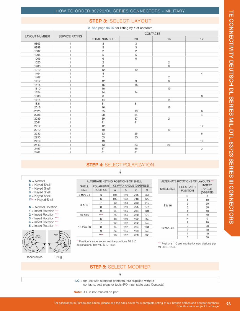
STEP 3: SELECT LAYOUT
N = Normal6 = Keyed Shell7 = Keyed Shell8 = Keyed Shell9 = Keyed ShellY** = Keyed Shell
N = Normal Rotation1 = Insert Rotation ***2 = Insert Rotation ***3 = Insert Rotation ***4 = Insert Rotation ***5 = Insert Rotation ***
STEP 4: SELECT POLARIZATION
a See page 96-97 for listing by # of contacts
LAYOUT NUMBER SERVICE RATINGCONTACTS
TOTAL NUMBER 20 16 120803 I 3 30898 I 3 31002 I 2 21005 I 5 51006 I 6 61020 I 2 21203 I 3 31212 I 12 121404 I 4 41407 I 7 71412 I 12 9 31415 I 15 151610 I 10 101624 I 24 241808 I 8 81814 I 14 141831 I 31 312016 I 16 162025 I 25 19 62028 I 28 24 42039 I 39 37 22041 I 41 412212 I 12 122219 I 19 192232 I 32 26 62255 I 55 552419 I 19 192443 I 43 23 202457 I 57 55 22461 I 61 61
ALTERNATE KEYING POSITIONS OF SHELL
SHELL SIZE
POLARIZING POSITION
KEYWAY ANGLE (DEGREES)A B C D
8 thru 24 N 105 140 215 265
8 & 10
6 102 132 248 3207 80 118 230 3128 35 140 205 2759 64 155 234 304
10 only Y** 25 115 220 270
12 thru 28
6 18 149 192 2597 92 152 222 3428 84 152 204 3349 24 135 199 240
Y** 98 152 268 338
** Position Y supersedes inactive positions 10 & Z designations. Ref MIL-STD-1554
ALTERNATE ROTATIONS OF LAYOUTS ***
SHELL SIZE POLARIZING POSITION
INSERT ANGLE
(DEGREE)
8 & 10
N 01 102 203 304 405 50
12 thru 28
N 01 102 203 304 405 50
*** Positions 1-5 are inactive for new designs per MIL-STD-1554.
Receptacle
PlugReceptacles
–LC = for use with standard contacts, but supplied without contacts, seal plugs or tools (PO must state Less Contacts)
Note: –LC is not marked on part
STEP 5: SELECT MODIFIER

94 For assistance in North America: +1 800.675.1214 • www.peigenesis.com • [email protected]
TE CO
NN
ECTIVITY D
EUTSC
H D
L SERIES MIL-D
TL-83723 SERIES III CO
NN
ECTO
RS
HOW TO ORDER 83723/DL SERIES CONNECTORS - COMMERCIAL
DL66RStandard Plug
DL60RSquare Flange Receptacle
DL64RJam Nut Receptacle
DL66R 12-10 P N -6117 -LCSHELL STYLE LAYOUT CONTACT POLARIZATION FINISH MODIFIER
1 2 3 4 5 6
(Commercial part number example)
STEP 1: SELECT SHELL STYLE, PLUG OR RECEPTACLE
RECEPTACLES PLUGS
DL68GShielded Plug
STEP 2: SELECT LAYOUTa See page 96-97 for listing by # of contacts
LAYOUT NUMBER SERVICE RATING CONTACTSTOTAL NUMBER 20 16 12
8-3 I 3 3
8-98 I 3 3
10-2 I 2 2
10-5 I 5 5
10-6 I 6 6
10-20 I 2 2
12-3 I 3 3
12-12 I 12 12
14-4 I 4 4
14-7 I 7 7
14-12 I 12 9 3
14-15 I 15 15
16-10 I 10 10
16-24 I 24 24
18-08 I 8 8
18-14 I 14 14
18-31 I 31 31
20-16 I 16 16
20-25 I 25 19 6
20-28 I 28 24 4
20-39 I 39 37 2
20-41 I 41 41
22-12 I 12 12
22-19 I 19 19
22-21 I 21 21
22-32 I 32 26 6
22-55 I 55 55
24-19 I 19 19
24-43 I 43 23 20
24-57 I 57 55 2
24-61 I 61 61
Mates with

95For assistance in Europe and China, please see the back cover for a complete listing of our branch offices and contact numbers.Specifications subject to change.
TE CO
NN
ECTIVITY D
EUTSC
H D
L SERIES MIL-D
TL-83723 SERIES III CO
NN
ECTO
RSHOW TO ORDER 83723/DL SERIES CONNECTORS - COMMERCIAL
–LC = for use with standard contacts, but supplied without contacts, seal plugs or tools (PO must state Less Contacts)
Note: –LC is not marked on part
P = Pin S = Socket
STEP 3: SELECT CONTACT
N = Normal6 = Keyed Shell7 = Keyed Shell8 = Keyed Shell9 = Keyed ShellY** = Keyed Shell
STEP 4: SELECT POLARIZATION
STEP 6: SELECT MODIFIER
-6116* = Aluminium Shell, black non-conductive anodized plated -6117 = Aluminium Shell, olive drab cadmium plated-6106 = Aluminium Shell, electroless nickel plated*Not available for shell type DL68G
STEP 5: SELECT FINISH
ALTERNATE KEYING POSITIONS OF SHELL
SHELL SIZE POLARIZING POSITION
KEYWAY ANGLE (DEGREES)A B C D
8 thru 24 N 105 140 215 265
8 & 10
6 102 132 248 3207 80 118 230 3128 35 140 205 2759 64 155 234 304
10 only Y** 25 115 220 270
12 thru 28
6 18 149 192 2597 92 152 222 3428 84 152 204 3349 24 135 199 240
Y** 98 152 268 338
** Position Y supersedes inactive positions 10 & Z designations. Ref MIL-STD-1554

96 For assistance in North America: +1 800.675.1214 • www.peigenesis.com • [email protected]
TE CO
NN
ECTIVITY D
EUTSC
H D
L SERIES MIL-D
TL-83723 SERIES III CO
NN
ECTO
RS
=20 =16 =12
LAYOUT 8-3 8-98 10-2 10-5 10-6
# OF CONTACTS 3-#20 3-#20 2-#20 5-#20 6-#20
SERVICE RATING I I I I I
LAYOUT 10-20 12-3 12-12 14-4 14-7
# OF CONTACTS 2-#16 3-#16 12-#20 4-#12 7-#16
SERVICE RATING I I I I I
LAYOUT 14-12 14-15 16-10 16-24 18-08
# OF CONTACTS 9-#20, 3-#16 15-#20 10-#16 24-#20 8-#12
SERVICE RATING I I I I I
LAYOUT 18-14 18-31 20-16 20-25 20-28
# OF CONTACTS 14-#16 31-#20 16-#16 19-#20, 6-#12 24-#20, 4-#12
SERVICE RATING I I I I I
LAYOUTS BY SHELL SIZE
1
82
3
45
6
7

97For assistance in Europe and China, please see the back cover for a complete listing of our branch offices and contact numbers.Specifications subject to change.
TE CO
NN
ECTIVITY D
EUTSC
H D
L SERIES MIL-D
TL-83723 SERIES III CO
NN
ECTO
RS=20 =16 =12
LAYOUT 20-39 20-41 22-12 22-19
# OF CONTACTS 37-#20, 2-#16 41-#20 12-#12 19-#16
SERVICE RATING I I I I
LAYOUT 24-43 24-57 24-61
# OF CONTACTS 23-#20, 20-#16 55-#20, 2-#12 61-#20
SERVICE RATING I I I
LAYOUT 22-21 22-32 22-55 24-19
# OF CONTACTS 21-#16 26-#20, 6-#12W 55-#20 19-#12
SERVICE RATING I I I I
LAYOUTS BY SHELL SIZE
1617
18
19
7
98
102
3 11
4 12
131415
16 5

98 For assistance in North America: +1 800.675.1214 • www.peigenesis.com • [email protected]
TE CO
NN
ECTIVITY D
EUTSC
H D
L SERIES MIL-D
TL-83723 SERIES III CO
NN
ECTO
RS
CONTACTS
PINS
SOCKETS
CONTACT SIZE
WIRE CRIMP SIZE
RANGE
SOCKET PART
NUMBER
COLOR BANDS WIRE STRIP LENGTHS
WIRE INSULATION SEALING RANGE WIRE HOLE
FILLER
WIRE HOLE
FILLER COLOR1 2 3 IN MM IN MM
20 20,22,24 M39029/5-115 Brown Brown Green 0.1875 4.77 .040/.083 1.02/2.11 MS27488-20-2 Red
16 16,18,20 M39029/5-116 Brown Brown Blue 0.2812 7.14 .053/.103 1.35/2.62 MS27488-16-2 Blue
12 12 & 14 M39029/5-118 Brown Brown Grey 0.2812 7.14 .097/.158 2.46/4.01 MS27488-12-2 Yellow
CONTACT SIZE
WIRE CRIMP SIZE
RANGE
PIN PART NUMBER
COLOR BANDS WIRE STRIP LENGTHS
WIRE INSULATION SEALING RANGE WIRE HOLE
FILLER
WIRE HOLE
FILLER COLOR1 2 3 IN MM IN MM
20 20,22,24 M39029/5-115 Brown Brown Green 0.1875 4.77 .040/.083 1.02/2.11 MS27488-20-2 Red
16 16,18,20 M39029/5-116 Brown Brown Blue 0.2812 7.14 .053/.103 1.35/2.62 MS27488-16-2 Blue
12 12 & 14 M39029/5-118 Brown Brown Grey 0.2812 7.14 .097/.158 2.46/4.01 MS27488-12-2 Yellow
Insert head first, trim excess
Insert head first, trim excess
99For assistance in Europe and China, please see the back cover for a complete listing of our branch offices and contact numbers.Specifications subject to change.
TE CO
NN
ECTIVITY D
EUTSC
H D
L SERIES MIL-D
TL-83723 SERIES III CO
NN
ECTO
RS
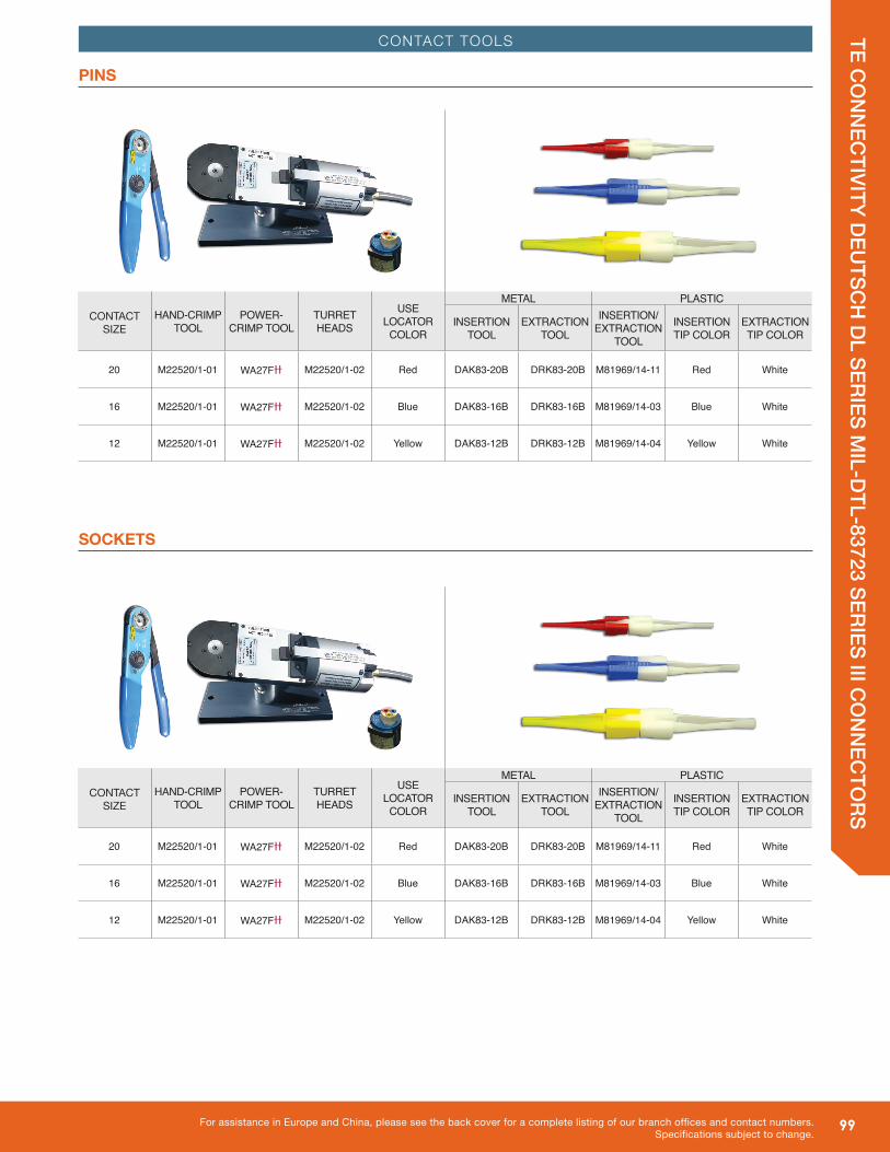
PINS
SOCKETS
CONTACT TOOLS
CONTACTSIZE
HAND-CRIMP TOOL
POWER-CRIMP TOOL
TURRET HEADS
USE LOCATOR
COLOR
METAL PLASTIC
INSERTIONTOOL
EXTRACTION TOOL
INSERTION/EXTRACTION
TOOL
INSERTION TIP COLOR
EXTRACTIONTIP COLOR
20 M22520/1-01 WA27FƗƗ M22520/1-02 Red DAK83-20B DRK83-20B M81969/14-11 Red White
16 M22520/1-01 WA27FƗƗ M22520/1-02 Blue DAK83-16B DRK83-16B M81969/14-03 Blue White
12 M22520/1-01 WA27FƗƗ M22520/1-02 Yellow DAK83-12B DRK83-12B M81969/14-04 Yellow White

100 For assistance in North America: +1 800.675.1214 • www.peigenesis.com • [email protected]
TE CO
NN
ECTIVITY D
EUTSC
H D
L SERIES MIL-D
TL-83723 SERIES III CO
NN
ECTO
RS
PLUGM83723/75, /76, /77, /78 DL66R
FLANGE MOUNTM83723/71 & M83723/72DL60R
DIMENSIONS
SHELL SIZE V DIA. MAX. W THREAD CLASS 2A8 0.782 (19.86) .5000-20 UNF10 0.926 (23.52) .6250-24 UNEF12 1.043 (26.49) .7500-20 UNEF14 1.183 (30.04) .8750-20 UNEF16 1.305 (33.14) 1.000-20 UNEF18 1.391 (35.33) 1.0625-18 UNEF20 1.531 (38.88) 1.1875-18 UNEF22 1.656 (42.06) 1.3125-18 UNEF24 1.777 (45.13) 1.4375-18 UNEF
SHELL SIZE
AA MAX. PANEL THICKNESS A MAX. B +/-.005
(+/- 1.27) C MAX. D +/- .010 (+/- .254)
E +/-.016 (+/- .406)
W THREAD CLASS 2A
G +/-.005 (+/- .127)
H DIA. +/-.005 (+/- .127)
8 .087 (2.21) .118 (3.00) .828 (21.0) .594 (15.1) 1.300 (33.02) .781 (18.24) .062 (1.6) .5000-20 UNF 0.120 (3.05) 0.568 (14.42)
10 .087 (2.21) .118 (3.00) .954 (24.2) .719 (18.3) 1.300 (33.02) .781 (18.24) .062 (1.6) .6250-24 UNEF 0.120 (3.05) 0.685 (17.39)
12 .087 (2.21) .118 (3.00) 1.047 (26.6) .812 (20.6) 1.300 (33.02) .781 (18.24) .062 (1.6) .7500-20 UNEF 0.120 (3.05) 0.864 (21.94)
14 .087 (2.21) .118 (3.00) 1.141 (29.0) .906 (23.0) 1.300 (33.02) .781 (18.24) .062 (1.6) .8750-20 UNEF 0.120 (3.05) 0.989 (25.12)
16 .087 (2.21) .118 (3.00) 1.234 (31.3) .969 (24.6) 1.300 (33.02) .781 (18.24) .062 (1.6) 1.000-20 UNEF 0.120 (3.05) 1.113 (28.27)
18 .087 (2.21) .118 (3.00) 1.328 (33.7) 1.062 (27.0) 1.300 (33.02) .781 (18.24) .062 (1.6) 1.0625-18 UNEF 0.120 (3.05) 1.238 (31.44)
20 .212 (5.38) .212 (5.38) 1.453 (36.9) 1.156 (29.4) 1.300 (33.02) .781 (18.24) .094 (2.4) 1.1875-18 UNEF 0.120 (3.05) 1.363 (34.62)
22 .212 (5.38) .212 (5.38) 1.578 (40.1) 1.250 (31.8) 1.300 (33.02) .781 (18.24) .094 (2.4) 1.3125-18 UNEF 0.120 (3.05) 1.488 (37.79)
24 .212 (5.38) .212 (5.38) 1.703 (43.3) 1.375 (34.9) 1.300 (33.02) .781 (18.24) .094 (2.4) 1.4375-18 UNEF 0.147 (3.73) 1.615 (41.02)
All dimensions in inches (millimeters in parenthesis)
A (TYP) (2)
B (TYP) (2)
C MAX
D(2) E
.130
.190
AA PANEL
.125 MAX
W THD
FMAX
AA PANEL
.125 MAX
Y
ED(2)
G DIA
H DIAB(2)
(TYP)
K (TYP)
L DIA
C MAX
M
.130
.190
BB W THD
N MAX Z
M
R DIA
P
S MAX(TYP)
T DIA
C MAX
D E
.130
.190
W THD
1.230 MAX
VDIA MAX
W THD
130190
A (TYP) (2)
B (TYP) (2)
C MAX
D(2) E
.130
.190
AA PANEL
.125 MAX
W THD
FMAX
AA PANEL
.125 MAX
Y
ED(2)
G DIA
H DIAB(2)
(TYP)
K (TYP)
L DIA
C MAX
M
.130
.190
BB W THD
N MAX Z
M
R DIA
P
S MAX(TYP)
T DIA
C MAX
D E
.130
.190
W THD
1.230 MAX
VDIA MAX
W THD
130190

101For assistance in Europe and China, please see the back cover for a complete listing of our branch offices and contact numbers.Specifications subject to change.
TE CO
NN
ECTIVITY D
EUTSC
H D
L SERIES MIL-D
TL-83723 SERIES III CO
NN
ECTO
RSJAM NUT RECEPTACLEM83723/73 & M83723/74 DL64R
DIMENSIONS
SHELL SIZE BB MAX. PANEL K MAX. L +/-.016
(+/-.406)M +/-.010 (+/-.254) C MAX. W THREAD
CLASS 2A P R DIA.
8 .187 (4.75) .979 (24.87) 1.063 (26.99) .771 (19.58) 1.300 (33.02) .5000-20 UNF .605 (15.37) .635 (16.13)
10 .187 (4.75) 1.104 (28.04) 1.188 (30.16) .771 (19.58) 1.300 (33.02) .6250-24 UNEF .730 (18.54) .760 (19.30)
12 .187 (4.75) 1.291 (32.79) 1.378 (34.94) .771 (19.58) 1.300 (33.02) .7500-20 UNEF .917 (23.29) .947 (24.05)
14 .187 (4.75) 1.391 (35.33) 1.501 (38.11) .771 (19.58) 1.300 (33.02) .8750-20 UNEF .980 (24.89) 1.010 (25.65)
16 .187 (4.75) 1.516 (38.51) 1.626 (41.29) .771 (19.58) 1.300 (33.02) 1.000-20 UNEF 1.105 (28.07) 1.135 (28.83)
18 .187 (4.75) 1.641 (41.68) 1.751 (44.46) .771 (19.58) 1.300 (33.02) 1.0625-18 UNEF 1.229 (31.22) 1.260 (32.00)
20 .250 (6.35) 1.766 (44.86) 1.939 (49.24) .771 (19.58) 1.300 (33.02) 1.1875-18 UNEF 1.354 (34.39) 1.385 (35.18)
22 .250 (6.35) 1.954 (49.63) 2.063 (52.39) .771 (19.58) 1.300 (33.02) 1.3125-18 UNEF 1.479 (37.57) 1.510 (38.35)
24 .219 (5.56) 2.079 (52.81) 2.188 (55.56) .771 (19.58) 1.300 (33.02) 1.4375-18 UNEF 1.604 (40.74) 1.635 (41.53)
All dimensions in inches (millimeters in parenthesis)
A (TYP) (2)
B (TYP) (2)
C MAX
D(2) E
.130
.190
AA PANEL
.125 MAX
W THD
FMAX
AA PANEL
.125 MAX
Y
ED(2)
G DIA
H DIAB(2)
(TYP)
K (TYP)
L DIA
C MAX
M
.130
.190
BB W THD
N MAX Z
M
R DIA
P
S MAX(TYP)
T DIA
C MAX
D E
.130
.190
W THD
1.230 MAX
VDIA MAX
W THD
130190

102 For assistance in North America: +1 800.675.1214 • www.peigenesis.com • [email protected]
TE CO
NN
ECTIVITY D
EUTSC
H D
L SERIES MIL-D
TL-83723 SERIES III CO
NN
ECTO
RS
SHELL SIZE
DUMMY RECEPTACLES OLIVE DRAB OVER CADMIUM PLATED
METAL DUSTCAP
FOR PLUGS FOR RECEPTACLEFLANGED WITH SASH CHAIN
8 M83723/61-28* M83723/59-28* M83723/60-28*10 M83723/61-210* M83723/59-210* M83723/60-210*12 M83723/61-212* M83723/59-212* M83723/60-212*14 M83723/61-214* M83723/59-214* M83723/60-214*16 M83723/61-216* M83723/59-216* M83723/60-216*18 M83723/61-218* M83723/59-218* M83723/60-218*20 M83723/61-220* M83723/59-220* M83723/60-220*22 M83723/61-222* M83723/59-222* M83723/60-222*24 M83723/61-224* M83723/59-224* M83723/60-224*
*Select plating code to match connector plating A = Black Anodized R = Electroless nickel W = Olive drab chromate over cadmium over electroless nickel (500-hour salt spray)
DUMMY RECEPTACLES, DUST CAPS & PLUG CAPS
ACCESSORIES
DUMMY RECEPTACLES, DUST CAPS & PLUG CAPS
All dimensions in inches (millimeters in parenthesis)
STANDARD CABLE CLAMPS
SHELL SIZE
STRAIGHT CLAMP 90° CABLE ENTRY
LOW COST SELF-LOCKING LOW COST SELF-LOCKING MAX MIN
8 M85049/52-1-8* M85049/52S8* M85049/51-1-8* M85049/51S8* .204 (5.18) .125 (3.18)10 M85049/52-1-10* M85049/52S10* M85049/51-1-10* M85049/51S10* .286 (7.26) .187 (4.75)12 M85049/52-1-12* M85049/52S12* M85049/51-1-12* M85049/51S12* .416 (10.57) .291 (7.39)14 M85049/52-1-14* M85049/52S14* M85049/51-1-14* M85049/51S14* .476 (12.09) .351 (8.92)16 M85049/52-1-16* M85049/52S16* M85049/51-1-16* M85049/51S16* .625 (15.88) .501 (12.72)18 M85049/52-1-18* M85049/52S18* M85049/51-1-18* M85049/51S18* .706 (17.93) .518 (13.16)20 M85049/52-1-20* M85049/52S20* M85049/51-1-20* M85049/51S20* .831 (21.11) .581 (14.76)22 M85049/52-1-22* M85049/52S22* M85049/51-1-22* M85049/51S22* .956 (24.28) .644 (16.36)24 M85049/52-1-24* M85049/52S24* M85049/51-1-24* M85049/51S24* 1.081 (27.46) .706 (17.93)
*Select plating code to match connector platingA = Black AnodizedR = Electroless nickelW = Olive drab chromate over cadmium over electroless nickel (500-hour salt spray)
103For assistance in Europe and China, please see the back cover for a complete listing of our branch offices and contact numbers.Specifications subject to change.
TE CO
NN
ECTIVITY D
EUTSC
H D
L SERIES MIL-D
TL-83723 SERIES III CO
NN
ECTO
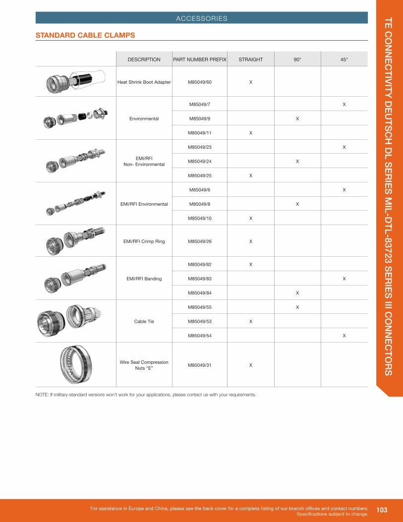
RSACCESSORIES
STANDARD CABLE CLAMPS
DESCRIPTION PART NUMBER PREFIX STRAIGHT 90° 45°
Heat Shrink Boot Adapter M85049/60 X
Environmental
M85049/7 X
M85049/9 X
M85049/11 X
EMI/RFI Non- Environmental
M85049/23 X
M85049/24 X
M85049/25 X
EMI/RFI Environmental
M85049/6 X
M85049/8 X
M85049/10 X
EMI/RFI Crimp Ring M85049/26 X
EMI/RFI Banding
M85049/82 X
M85049/83 X
M85049/84 X
Cable Tie
M85049/55 X
M85049/53 X
M85049/54 X
Wire Seal Compression Nuts “E” M85049/31 X
NOTE: If military-standard versions won’t work for your applications, please contact us with your requirements.

104 For assistance in North America: +1 800.675.1214 • www.peigenesis.com • [email protected]
TE CO
NN
ECTIVITY D
EUTSC
H D
L SERIES MIL-D
TL-83723 SERIES III CO
NN
ECTO
RS
ASSEMBLY INSTRUCTIONS
STEP 1: Strip wires. See above for correct strip length for contact. Insert wire into rear of contact. Wire insulation must push against rear of contact. Wire must be visible through inspection hole.
STEP 2: Use M22520/1-01 crimp tool with proper crimp locator M22520/1-02.
CONTACT SIZE COLOR
20 Red
16 Blue
12 Yellow
STEP 3: Insert contact and wire into tool jaws. To crimp, squeeze handles together fully until ratchet releases and allows handles to expand; otherwise, contact cannot be extracted from tool jaws. Maintain slight insertion pressure on wire while crimping contact to wire.*
*IMPORTANT NOTE: Microsection the contact to verify crimp quality.
STEP 1: Remove backshell and put wired contacts through cable clamp opening.
STEP 2: Use colored end of CIET tool for insertion. Place wire into tool at large opening. To facilitate contact insertion, a minimum six inches of free wire is recommended.
STEP 3: Slide tool on wire while holding thumb against wire at opening. Wire will slip into tool.
WIRE STRIPPING AND CONTACT CRIMPING
CONTACT INSERTION
correct crimp
incorrect crimp

105For assistance in Europe and China, please see the back cover for a complete listing of our branch offices and contact numbers.Specifications subject to change.
TE CO
NN
ECTIVITY D
EUTSC
H D
L SERIES MIL-D
TL-83723 SERIES III CO
NN
ECTO
RSASSEMBLY INSTRUCTIONS
STEP 4: With tool pressed against shoulder of contact, starting at the center cavity, insert wired contact and tool into properly-identified cavity at rear of plug with firm, even pressure. Do not use excessive pressure.
STEP 5: When contact bottoms, a slight click can be heard as tines of metal retaining clip snap into place behind contact shoulder.
STEP 6: Check face of plug or receptacle for proper contact installation. In socket inserts with a large number of contacts, cavities are identified in a spiral pattern. A projecting line from the spiral indicates omission of a letter; a broken circle around a cavity indicates transition between capitals, lower case and double letters.
STEP 7: Withdraw tool from rear of plug. To be sure that contact is locked, pull back lightly on wire. Then remove tool from wire and proceed with other contacts.
STEP 8: After all contacts are inserted, fill unwired cavities with sealing plugs (insert head first and leave end protruding for ease of removal), assemble backshell on rear of connector.
CONTACT INSERTION (CONT.)

106 For assistance in North America: +1 800.675.1214 • www.peigenesis.com • [email protected]
TE CO
NN
ECTIVITY D
EUTSC
H D
L SERIES MIL-D
TL-83723 SERIES III CO
NN
ECTO
RS
ASSEMBLY INSTRUCTIONS
STEP 1: Remove hardware from plug or receptacle and slide hardware back along wire bundle.
STEP 2: Using plastic or metal extraction tool with proper color code corresponding to contact size, place wire in tool.
STEP 3: Insert tool into contact cavity until tool tip bottoms against the contact shoulder, expanding clip retaining tines.
STEP 4: Hold wire firmly in tool and extract wired contact and tool. Repeat operation for all contacts to be extracted.
STEP 5: Fill any empty cavities with wire sealing plugs. Reassemble plug or receptacle hardware.
Note: DTS series shown.
CONTACT EXTRACTION
Related Documents