TDC 461: Basic Telecommunications DePaul University Winter 2001 LoriLee M. Sadler

Welcome message from author
This document is posted to help you gain knowledge. Please leave a comment to let me know what you think about it! Share it to your friends and learn new things together.
Transcript

TDC 461: Basic Telecommunications
DePaul UniversityWinter 2001
LoriLee M. Sadler

Agenda:
• Welcome to TDC 461
• Course Overview• Syllabus Overview• Intro to
Telecommunications
• Brief History of Telecom
• Voice Characteristics
• Analog vs. Digital• Telephone Set• Modems • Fax Machines
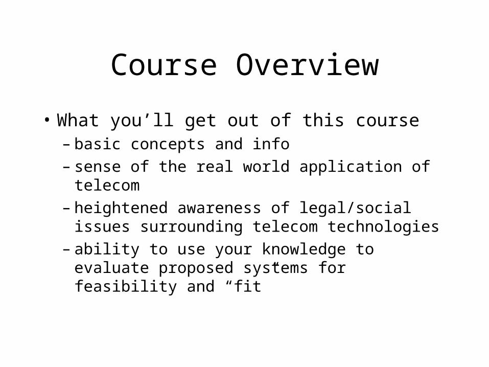
Course Overview
• What you’ll get out of this course– basic concepts and info– sense of the real world application of
telecom– heightened awareness of legal/social
issues surrounding telecom technologies– ability to use your knowledge to evaluate
proposed systems for feasibility and “fit”

Course Overview, cont.
– What do you want to get out of this course?

Syllabus Overview
• Instructor Info• Course Logistics• Grading
– Homeworks– Exams– Academic Integrity
• Class schedule

Class Tools
• Web site• 461 Web tools

What is Telecommunications?
• Voice• Data• Video• Integrated

Why Telecommunications Technology?
• Helps solve communications problems of physical distance.
• Helps solve communications problems of physical barriers.

Quality Measures of Telecommunications
Systems• Cost: • Efficiency:• Quality: • Time:• Ease of Use:

Problems in Telecom
• Legacy systems
• Interoperability: public standards vs. proprietary standards
• Costs

Communications Networks
• What are they?–
• Why do we have them?–
• What is required to make them work?

Network Structure
AmeritechCentral Office
AmeritechCentral Office
PBX
Subscriber LinesCentrex Lines
IXCPOP
AmeritechTandem Office
IXCPOP
Inter-Office Trunks
Dir
ect
IXC
Tru
nkPOP = Point of PresencePBX = Private Branch Exchange

Telecom History1876 - 1998
• Technologies continuously improving:– –
• Regulatory Issues: Who pays for all this? How much competition?
• Business Issues: How much does it cost? What services are available?

History of Transmission Technology
• Through history, voice and data transmission systems are getting
– Higher capacity
– Lower cost

Analog Trunk Technology
First Use Technology Voice Capacity
1865 Two-wirecircuit (onetwisted pair)
Single voicechannel
1900 Four-wirecircuit (twotwisted pair)
12-120 voicechannels
1935 Coaxial cable Up to 10,800channels pertube

Analog Trunk Technology
First Use Technology Voice Capacity
1947 Microwave Up to 10,800channels
1955 Submarinetransatlantic
4000 channels
1962 Satellite 600 channelsper transponder

Digital Trunk Technology
(T-Carrier hierarchy)Signal Carrier Data Rate
VoiceCapacity
DS0 64 Kbps 1
DS1 T-1 (4-wire) 1.544 Mbps 24
DS1C T-1c (4-wire) 3.152 Mbps 48
DS2 T-2 (4-wire) 6.312 Mbps 96
DS3 T-3 (coax,optical fiber)
44.736 Mbps 672
DS4 T-4 (same) 274.176 Mbps 4032

Digital Trunk TechnologySynchronous Optical Network
(SONET)
Signal Media Data RateVoice
Capacity
OC-1 fiber 51.84 Mbps 672
OC-3 fiber 155.52 Mbps 2016
OC-12 fiber 622.08 Mbps 8064
OC-24 fiber 1244.16 Mbps 16,128
OC-48 fiber 2488.32 Mbps 32,256

Year Technology Description
1876 ManualSwitchboards
Operatorscompletecalls
1891 Strowger switch(step-by-step).
Mechanicalarms movedby dialing
1927 Crossbar Commoncontrol
1965 Analog ElectronicSwitching System
Computercontrol
1976 Digital ESS Digital signals
Switching History

Regulatory History
Alexander Graham Bell said:
. . . and the lawsuits began.
Watson, Come Here!I need you!

Regulatory History
1876 Hubbard, Gray and Bell all filetelephone patents
1877 Bell Telephone Company formed
1878 BTC files patent suit againstAmerican Speaking Telephone
1879 National Bell Telephone (NBT)formed via mergers
1880 NBT becomes American Bell

Regulatory History
1881 American Bell buys WesternElectric from Western Union
1885 AT&T formed from AmericanBell
1910 Western Union joins AT&T
1913 AT&T divests Western Unionin anti-trust suit. Agrees tointerconnect independenttelcos

Regulatory History
1934 FCC formed and universaltelephone service is made anational goal (Fed. Comm. Act)
1940 Anti-trust suit against AT&Tpostponed due to WWII
1949 Anti-trust suit filed against AT&T
1956 AT&T settles by limiting WesternElectric manufacturing to Bellcompanies (Consent Decree)

Regulatory History1966 Computer Inquiry I - Bell System
cannot provide data processing
1968 Carterphone decision -Compliant non-Bell devicesmust be allowed to connect.
1974 Anti-trust suit filed against AT&T
1982 AT&T settles by agreeing todivest 22 local operatingcompanies (Consent Decree)

Regulatory History1983 Regional Bell Operating Companies
(RBOCs) formed
1983 FCC rules telcos can only provideequipment (CPE) through separatesubsidiary.
1984 Consent decree is implemented asmodified by Judge Greene (ModifiedFinal Judgement).

Modified Final Judgement1984
• 7 Regional Holding Companies (RHCs) or Regional Bell Operating Companies (RBOCs) formed
• Each RHC composed of multiple Local Exchange Companies (LECs)
• Interexchange Carriers (IXCs) provide long-distance service.

Regional Holding Companies
AmeritechAmeritechBell Atlantic
NYNEX(Bell Atl)
BellSouth
SBC
PacificTelesis(SBC)
US West

Modified Final Judgement1984
• Examples:
– Ameritech, SBC, Southwestern Bell,
etc. are Local Exchange Carriers
(LECs)
– AT&T, MCI, Sprint, etc. are
Interexchange Carriers (IXCs)

Network Structure
AmeritechCentral Office
AmeritechCentral Office
PBX
Subscriber LinesCentrex Lines
IXCPOP
AmeritechTandem Office
IXCPOP
Inter-Office Trunks
Dir
ect
IXC
Tru
nkPOP = Point of PresencePBX = Private Branch Exchange

Modified Final Judgement (1984)
• 231 Local Access and Transport Areas (LATAs) defined in US.
• LECs can provide only intra-LATA service.
• IXCs provide only inter-LATA service.
• LECs must give customers equal access to all IXCs.

Problems with MFJ of 1984:
• No single company (LEC or IXC) can provide all communications services for its customers. This is inefficient.
• LATA boundaries limit LEC services.• Many other companies (Cable TV,
Competitive Access Carriers, etc.) are not constrained by MFJ.

The Solution? Deregulation!
• Telecommunications Act of 1996– Allows IXCs to offer local service– Allows LECs to offer long-distance
service (when they can show competition)
– Allows Competitive LECs (CLECs) to share LEC facilities (for fair competition).
– Allows combination of voice, data, video service packages.

Telecommunications Act (1996)
• LECs must give competitors:– All services at wholesale prices.– Access to telephone numbers,
operator services, directory listings.– Access to poles, ducts, and right-of-
ways.– Physical co-location of equipment
within LEC buildings.

Telecommunications Act (1996)
• A LEC can offer inter-LATA services when substantial competition exists on its network.– The courts are still deciding exactly
what this means...

Telecommunications Act (1996)
Universal Service
• LECs must provide “affordable access” for Schools, Libraries, Health Departments, Hospitals, etc.
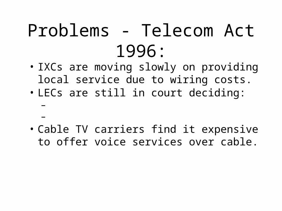
Problems - Telecom Act 1996:
• IXCs are moving slowly on providing local service due to wiring costs.
• LECs are still in court deciding:– –
• Cable TV carriers find it expensive to offer voice services over cable.

The Telephone Set
• Telephone Set:
• Handset:
• Dial Pad:

What is Speech?
Time
Air
Pre
ss
ure
=• Speech is a continuous change in air pressure
over time generated by a vibrating larynx.– It is an analog waveform (can take any value).
– It is a periodic waveform (repeats itself in time)

Periodic Signals
• Amplitude (A) = signal height = volume– Measured in volts
• Frequency = # of signal cycles/sec– Measured in Hertz (cycles per second)
A
tim ef = 1/T
T T

Periodic Signals
• Example: For the signal above:– Amplitude = 3 volts– Fundamental Frequency = 100 Hz
3 V
tim e0.01 sec. 0.01 sec

Voice Characteristics

Bandwidth-Limited Circuits
• analog bandwidth=>• telephone circuit bandwidth=>• filtering=>

Why is Filtering done?
• To save money– –
• Quality is still good–

Speech TransmissionVarying Air Pressure Varying Electrical
Current
Person produces changes in air pressure via vibrating larynx.
Carbon granules in telephone receiver produce varying resistance in response to changes in air pressure
Battery
CentralOffice
-48 v.
Time
Air
Pres
sure
Time
Cur
rent

Speech Reception Varying Electrical Current Varying Air
Pressure
Changes in air pressure move ear drum and are interpreted as speech.
Electromagnet in earpiece moves a diaphragm in response to electrical current changes and produces varying air pressure.
Time
Air
Pres
sure
Time
Cur
rent
CentralOffice

Analog vs. Digital Information
• Analog information contains a continuously changing stream of values.–
• Digital information contains bits (binary digits) representing 0 or 1.–

Analog vs. Digital Signals• Analog signals vary continuously
and can take any value.
• Digital signals change at discrete times and take only fixed discrete values.

Analog vs. Digital Transmission
• Analog repeater circuits take weak signals and amplify them.
• Digital repeater circuits analyze signals, amplify and remove accumulated noise.
Repeater
Regenerator

49
Analog Signaling of Digital Data
Information Source (DTE)
Transmitter (DCE)
Receiver (DCE)
Information Destination
(DTE)
Transmission Network
Digital Data Digital Data
Analog Network (e.g. PSTN)
MODEMMODEM
Analog SignalAnalog Signal

50
Analog Signaling of Digital DataAnalog POTS in the PSTN
Digital ISDN in the PSTN
Analog SignalAnalog Signal
Analog Network (e.g. PSTN)
CO CO
Analog SignalAnalog Signal
Digital Network (e.g. ISDN)
CO COISDN
MODEM
Digital Data
ISDN MODEM
Digital Data
CODEC located in MODEM CODEC located in MODEM
CODEC located in CO SwitchCODEC located in CO Switch

51
Digital Signaling of Analog Data • Analog Data (e.g.voice) needs to be converted to/from a digital signal
– for ISDN service, conversion performed in phone (or ISDN modem at desk top)– for analog POTS, conversion performed within line card at CO (in switch)
• Conversion is performed by a CODEC (Coder / Decoder)
• Desired qualities in a analog signaling scheme include:
– minimal data rate
– minimal quantization noise
– retention of voice fidelity

52
CODEC Operation
CODEC Process
sampler quantizer
analog signal PAM
digital signal (PCM)
FSAMPLE
• Sampler “samples” the analog signal at fixed intervals defined by the sampling frequency, FSAMPLE.
• Quantizer digitizes PAM samples into discrete levels and encodes a n bit binary pattern for each quantized sample

53
CODEC Operation- analog -> digital -
• Resulting data rate = FSAMPLE x n
time
Am
plit
ud
e
0
1
2
3
4
-1
-2
-3
-4 Quantization interval
Binary code
-4 to-3 -3 to -2 -2 to -1 -1 to 0 0 to +1 +1 to 2 2 to 3 3 to 4
000 001 010 011 100 101 110 111
PAM signal
PCM signal

54
CODEC Operation- digital -> analog -
• PCM digital bit stream is collected into eight bits
• sample is placed in the middle of quantization interval defined by binary code
– resulting quantization error lead to quantization noise, QNOISE
• signal is sent through a LPF[FMAX]

Modems• Essentially a CODEC
• MOdulate/DEModulate
• Standard Interface:

56
MODEM Features
• Half duplex vs full duplex
• Synchronous vs asynchronous
• Loopback testing is normally integrated into modem
• Modems accept commands to provision and operate (e.g. FDX|HDX or dial number) using the “Hayes Command set”– driver software uses the commands to provision the modems

57
MODEM standards
MODEMTYPE
Data Rate(bps)
BAUD Rate ModulationMethod
Informationdensity
(bps/Hz)
HDX/FDX comments
03 (V.21) 300 300 FSK 0.1 FDX-2 wire Start deployment in 60’s,one of the 1st modems
202 1200 1200 FSK 0.2 HDX-2 wireFDX-4 wire
Deployment in early 70’s,downward compatiblewith 103
12 (V.22) 1200600
600600
DPSKPSK
0.40.4
FDX-2 wireFDX-2 wire PSK used in V.22 only
V.22bis 2400 600 QAM 0.8 FDX-2 wire deployed world wideduring the late 80’s
01 (V.26) 2400 1200 DPSK 0.4 HDX-2 wireFDX-4 wire
08 (V.27) 4800 1600 DPSK-8 0.8 HDX-2 wireFDX-4 wire
09 (V.29) 9600 2400 QAM-16 1.6 HDX-2 wireFDX-4 wire
Automatic fall back rate to4800 bps is line requiresit,
V.34 orV.fast
28,800 3200 QAM-48 9.3 FDX-2 wire Emerged in 1994,downward compatiblewith most others
V.90 56,000 3200 ModifiedV.34
18.3 FDX-2 wire Emerged in late 1996,only one analog hopallowed, asymmetric datarate

Fax Machines
• Operation
• Regulation: ITU
• Group 3
• Group 4
Related Documents