OPERATING & MAINTENANCE INSTRUCTIONS MANUAL FOR TURBINE VOLUME-1 ADDRESS FOR COMMUNICATION FIELD ENGINEERING SERVICES Turbine & Compressors Engg. Bharat Heavy Electricals Ltd. Ramachandrapuram, Hyderabad - 502 032 ANDHRA PRADESH, INDIA PROJECT : DVC DURGAPUR 2 X 500MW MACHINE NO. : T-0764 TO T-0767 SERVICE : BFPDT TYPE : K1401-2

Welcome message from author
This document is posted to help you gain knowledge. Please leave a comment to let me know what you think about it! Share it to your friends and learn new things together.
Transcript
OPERATING & MAINTENANCE
INSTRUCTIONS MANUAL
FOR
TURBINE
VOLUME-1
ADDRESS FOR
COMMUNICATION
FIELD ENGINEERING SERVICES
Turbine & Compressors Engg.Bharat Heavy Electricals Ltd.Ramachandrapuram,Hyderabad - 502 032ANDHRA PRADESH, INDIA
PROJECT : DVC DURGAPUR
2 X 500MW
MACHINE NO. : T-0764 TO T-0767
SERVICE : BFPDT
TYPE : K1401-2
INDEX FOR VOLUMES
BHARAT HEAVY ELECTRICALS LIMITED 1 of 1
PROJECT: DVC DURGAPUR
2 X 500MW
SERVICE : BFPDT
TYPE : K1401-2 M/C NO. : T-0764 to
T-0767
VOLUME 1 :
VOLUME 2 :
OPERATING & MAINTENANCE
INSTRUCTIONS MANUAL FOR
TURBINE
OPERATING & MAINTENANCE
INSTRUCTIONS MANUAL FOR
AUXILIARIES & INSTRUMENTATION
(III parts)

BHARAT HEAVY ELECTRICALS LIMITED 1 of 1
DVC DURGAPUR 2X500MW BFPDT

6Bharat Heavy Electricals Limited

6Bharat Heavy Electricals Limited

6Bharat Heavy Electricals Limited

6Bharat Heavy Electricals Limited 4

6Bharat Heavy Electricals Limited 5

6Bharat Heavy Electricals Limited 6

1Bharat Heavy Electricals Limited 1

2Bharat Heavy Electricals Limited

2Bharat Heavy Electricals Limited 2

GENERAL


TECHNICAL DATA


GENERAL DESCRIPTION OFSTEAM TURBINE
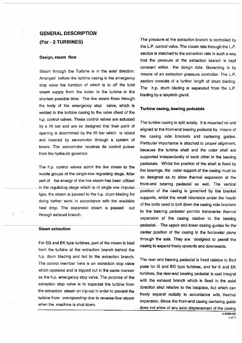


STEAM TURBINE COMPONENTS
1-0462-01 1 of 1
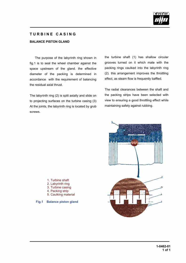
T U R B I N E C A S I N G BALANCE PISTON GLAND
The purpose of the labyrinth ring shown in
fig.1 is to seal the wheel chamber against the
space upstream of the gland. the effective
diameter of the packing is determined in
accordance with the requirement of balancing
the residual axial thrust.
The labyrinth ring (2) is split axially and slide on
to projecting surfaces on the turbine casing (3)
At the joints, the labyrinth ring is located by grub
screws. diameter
the turbine shaft (1) has shallow circular
grooves turned on it which mate with the
packing rings caulked into the labyrinth ring
(2). this arrangement improves the throttling
effect, as steam flow is frequently baffled.
The radial clearances between the shaft and
the packing strips have been selected with
view to ensuring a good throttling effect while
maintaining safety against rubbing.
1. Turbine shaft 2. Labyrinth ring 3. Turbine casing 4. Packing strip 5. Caulking material Fig.1 Balance piston gland
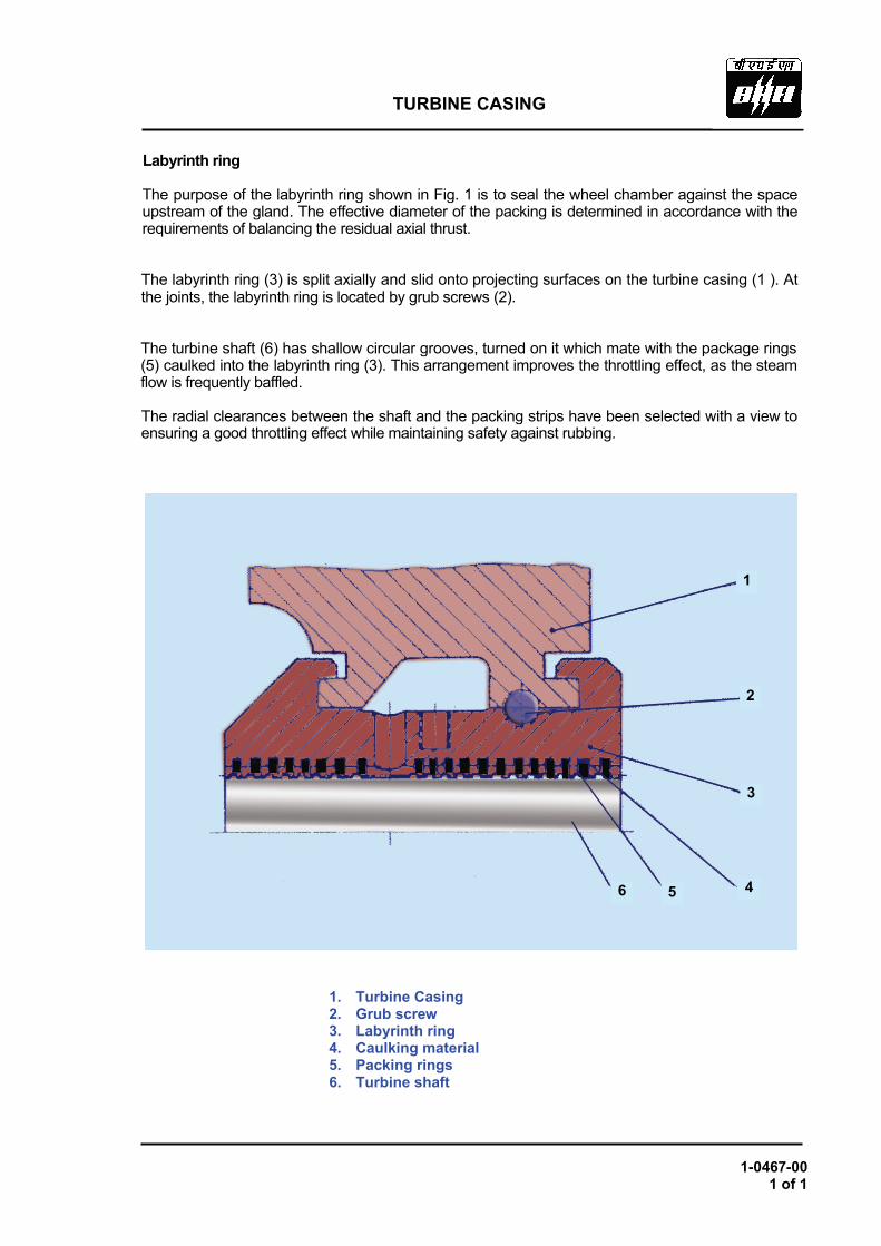
TURBINE CASING
1-0467-00 1 of 1
Labyrinth ring
The purpose of the labyrinth ring shown in Fig. 1 is to seal the wheel chamber against the space upstream of the gland. The effective diameter of the packing is determined in accordance with the requirements of balancing the residual axial thrust.
The labyrinth ring (3) is split axially and slid onto projecting surfaces on the turbine casing (1 ). At the joints, the labyrinth ring is located by grub screws (2).
The turbine shaft (6) has shallow circular grooves, turned on it which mate with the package rings (5) caulked into the labyrinth ring (3). This arrangement improves the throttling effect, as the steam flow is frequently baffled.
The radial clearances between the shaft and the packing strips have been selected with a view to ensuring a good throttling effect while maintaining safety against rubbing.
1. Turbine Casing 2. Grub screw 3. Labyrinth ring 4. Caulking material 5. Packing rings 6. Turbine shaft
1
2
3
45 6
1-0600-01 1 of 3
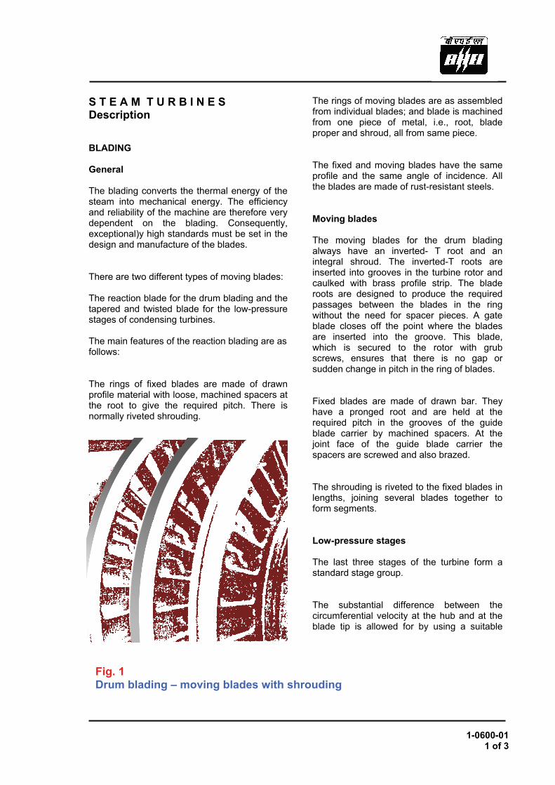
S T E A M T U R B I N E S Description BLADING General The blading converts the thermal energy of the steam into mechanical energy. The efficiency and reliability of the machine are therefore very dependent on the blading. Consequently, exceptional)y high standards must be set in the design and manufacture of the blades. There are two different types of moving blades: The reaction blade for the drum blading and the tapered and twisted blade for the low-pressure stages of condensing turbines. The main features of the reaction blading are as follows: The rings of fixed blades are made of drawn profile material with loose, machined spacers at the root to give the required pitch. There is normally riveted shrouding.
The rings of moving blades are as assembled from individual blades; and blade is machined from one piece of metal, i.e., root, blade proper and shroud, all from same piece. The fixed and moving blades have the same profile and the same angle of incidence. All the blades are made of rust-resistant steels. Moving blades The moving blades for the drum blading always have an inverted- T root and an integral shroud. The inverted-T roots are inserted into grooves in the turbine rotor and caulked with brass profile strip. The blade roots are designed to produce the required passages between the blades in the ring without the need for spacer pieces. A gate blade closes off the point where the blades are inserted into the groove. This blade, which is secured to the rotor with grub screws, ensures that there is no gap or sudden change in pitch in the ring of blades. Fixed blades are made of drawn bar. They have a pronged root and are held at the required pitch in the grooves of the guide blade carrier by machined spacers. At the joint face of the guide blade carrier the spacers are screwed and also brazed. The shrouding is riveted to the fixed blades in lengths, joining several blades together to form segments. Low-pressure stages The last three stages of the turbine form a standard stage group. The substantial difference between the circumferential velocity at the hub and at the blade tip is allowed for by using a suitable profile and stagger
Fig. 1 Drum blading – moving blades with shrouding
1-0600-01 2 of 3
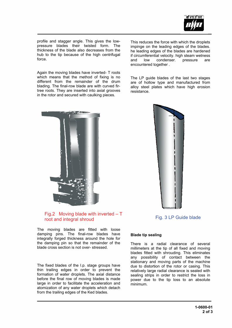
profile and stagger angle. This gives the low-pressure blades their twisted form. The thickness of the blade also decreases from the hub to the tip because of the high centrifugal force. Again the moving blades have inverted- T roots which means that the method of fixing is no different from the remainder of the drum blading. The final-row blade are with curved fir-tree roots. They are inserted into axial grooves in the rotor and secured with caulking pieces. The moving blades are fitted with loose damping pins. The final-row blades have integrally forged thickness around the hole for the damping pin so that the remainder of the blade cross section is not over- stressed. The fixed blades of the I.p. stage groups have thin trailing edges in order to prevent the formation of water droplets. The axial distance before the final row of moving blades is made large in order to facilitate the acceleration and atomization of any water droplets which detach from the trailing edges of the Ked blades.
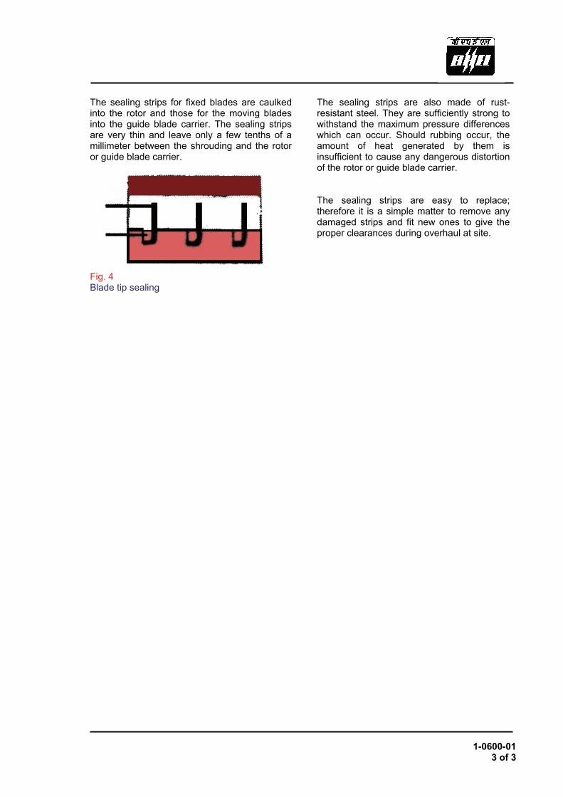
This reduces the force with which the droplets impinge on the leading edges of the blades. he leading edges of the blades are hardened if circumferential velocity. high steam wetness and low condenser. pressure are encountered together . The LP guide blades of the last two stages are of hollow type and manufactured from alloy steel plates which have high erosion resistance. Blade tip sealing There is a radial clearance of several millimeters at the tip of all fixed and moving blades fitted with shrouding. This eliminates any possibility of contact between the stationary and moving parts of the machine due to distortion of the rotor or casing. This relatively large radial clearance is sealed with sealing strips in order to restrict the loss in power due to the tip loss to an absolute minimum.
Fig.2 Moving blade with inverted – T root and integral shroud Fig. 3 LP Guide blade
1-0600-01 3 of 3
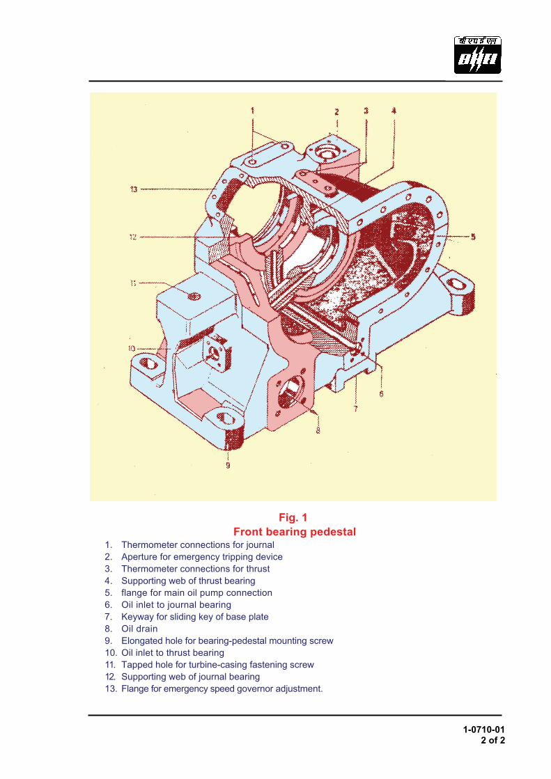
The sealing strips for fixed blades are caulked into the rotor and those for the moving blades into the guide blade carrier. The sealing strips are very thin and leave only a few tenths of a millimeter between the shrouding and the rotor or guide blade carrier. Fig. 4 Blade tip sealing
The sealing strips are also made of rust-resistant steel. They are sufficiently strong to withstand the maximum pressure differences which can occur. Should rubbing occur, the amount of heat generated by them is insufficient to cause any dangerous distortion of the rotor or guide blade carrier. The sealing strips are easy to replace; therefore it is a simple matter to remove any damaged strips and fit new ones to give the proper clearances during overhaul at site.

1-0710-01 2 of 2
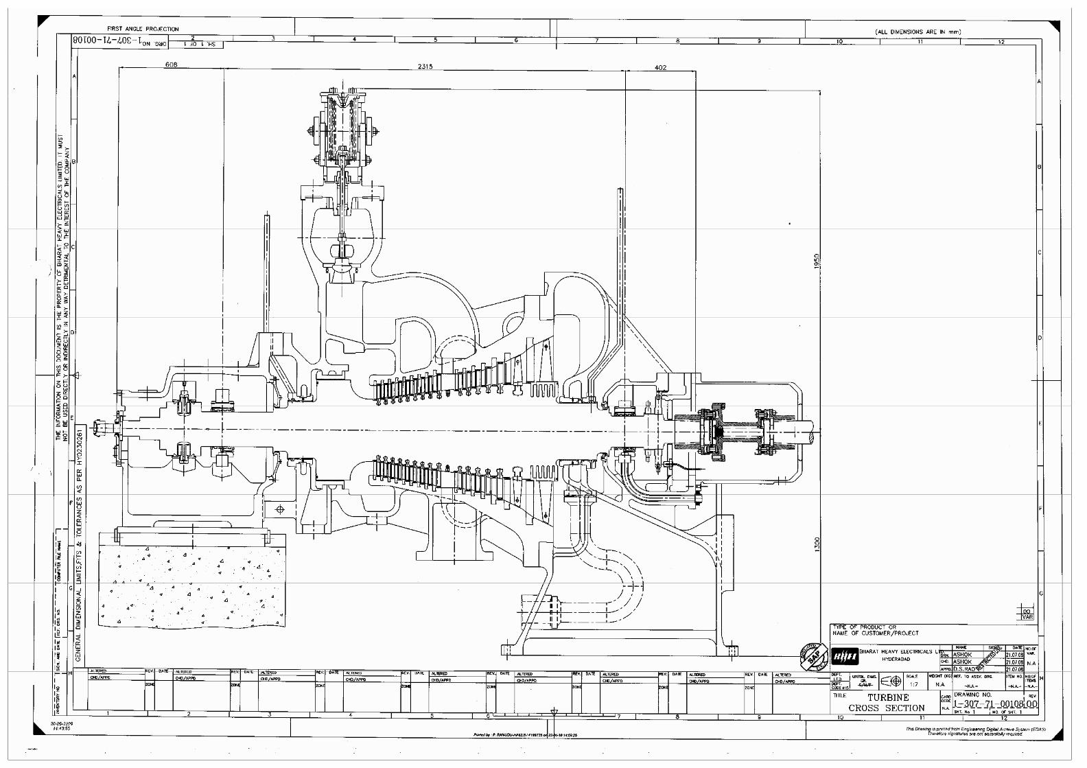
Fig. 1 Front bearing pedestal
1. Thermometer connections for journal 2. Aperture for emergency tripping device 3. Thermometer connections for thrust 4. Supporting web of thrust bearing 5. flange for main oil pump connection 6. Oil inlet to journal bearing 7. Keyway for sliding key of base plate 8. Oil drain 9. Elongated hole for bearing-pedestal mounting screw 10. Oil inlet to thrust bearing 11. Tapped hole for turbine-casing fastening screw 12. Supporting web of journal bearing 13. Flange for emergency speed governor adjustment.

1-0720-01 1 of 2
TURBINE
Thrust Bearing (-2)
Function : The residual axial thrust of the turbine rotor,
in so far as it has not been compensated by the balancing piston in the labyrinth
section, is taken up by the
thrust bearing and transmitted to the front bearing pedestal. The magnitude of the axial force thus acting on the thrust bearing is chiefly determined by the turbine load.
1. Upper bearing shell 6. Dowel pin 2. Cylindrical pin 7. Bearing pad 3. Bearing pad 8. Liner ring 4. Lower bearing shell 9. Arresting plug 5. Socket-head cap screw 10. Thermometer well Fig.1 Thrust bearing

1-0720-01 2 of 2
Design : The thrust bearing is accommodated in the front bearing pedestal. Its principal parts are the upper bearing shell (1), the lower bearing shell (4), and the segmental bearing pads (7). Dimensionally the design has been made so as to prevent axial displacement of the turbine rotor except for the part which is caused by thermal expansion (sf. 1-12 10 00).
The thrust bearing is secured in its position
by the front bearing pedestal and the binder
which is bolted to it.
For this purpose, the pedestal and the binder are both provided with an integrally cast rib which in the assembled state engages with a corresponding annular groove machined in the middle of the bearing shell periphery. Rotation of the radial bearing is prevented by an arresting plug (9). It is screwed into the rib of the binder and engages into a hole drilled into the upper bearing shell.
The two bearing shells are held together by two socket-head cap screws. The relative position of the two shells with respect to each other is fixed by two dowel pins.
2. Cylindrical pin
3. Bearing pad
11. Seating face of segmental pad
12. Running face of segmental pad
13. Collar of rotor shaft Fig. 2. Arrangement of a segmental bearing pad
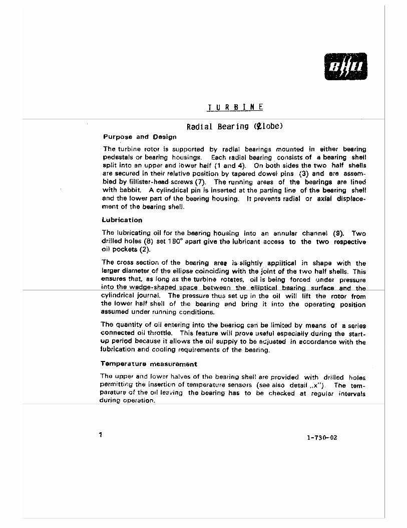

1-0730-02 2 of 2
Hydraulic Jacking devices A further oil pocket (6), machined in the middle of the bottom bearing shell, is connected via a drilled passage (5) with a special oil line of the hydraulic pressure jacking system. When the turbine is being started by means of the turbine gear, high-pressure oil from the jacking system will be admitted through this line to the pockets underneath the rotor journals of the turbine. This has the effect of relieving the bearing from load, because the break-away torque will be reduced and dry friction is avoided. An additional advantage is that the starting torque, which has to be supplied by the turning gear, will be considerably reduced. • Extra equipment
1. Bearing shell, upper shell 2. Oil pocket for bearing oil 3. topper pin 4. bearing shell lower half 5. drilled passage for jacking oil
6. Oil pocket for jacking oil 7. Fillister head screw 8. Drilled passage for bearing oil 9. Annular oil channel 10. Connection for jacking oil
Fig. 1: Radial bearing cross section

Bharat Heavy Electricals Limited 1-0750-03 Page 1 / 2
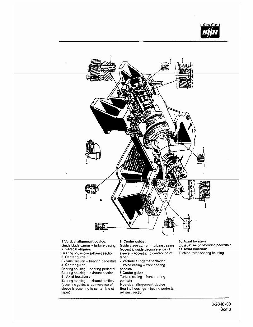
Function The rear support elements - Exhaust Hood, support Paws of the exhaust part and the alignment elements - serve to support the turbine casing and the turbine rotor and for their alignment relative to each other. Design The exhaust hood (1) with its support paws (2) is directly connected to the turbine foundations, whereby the two support paws each rest on a bed plate (7). The bed plates are rigidly anchored to the turbine foundations Base frame. The support paws and bed plates are connected by bolts. However, the bolts are designed such that in case of thermal expansion the support brackets can expand laterally. Freedom of movement can be checked by spacers which must always be easily movable.
Fig. 1 Exhaust part with rear support 1. Exhaust Hood 2. Support Paws 3. Forked prong 4. Adjusting element 5. Mating part 6. Steeped Key 7. Bed Plate
2

Bharat Heavy Electricals Limited 1-0750-03 Page 2 / 2
The rear fixed point of the turbine casing, relative to which the turbine expands towards the front end, is formed by one stepped key (6) per supporting paw inserted transverse to the turbine axis. A forked prong (3) is bolted on beneath the bearing housing as a center guide. A forked prong (3) which is integral to the lower part of the exhaust hood prevents the lateral movements of the turbine casing with the help of the mating part (5) fixed to the foundations / Base frames.
The exhaust hood is split horizontally. It houses the rear journal bearing supporting the turbine rotor in the lower part and bearing cover for the upper part. In between the exhaust portion and rear journal bearing sealing is done by rear oil gland and rear labyrinth gland. The bearing cover designed to accommodate a manual or electro hydraulic shaft turning gear which can be supplied on request.

1-0761-00 1 of 1
Bearing seal ring (Oil Gland) Purpose The bearing seal ring serves for sealing off the bearing pedestal against the turbine casing at the
point where the rotor shaft penetrates from the casing. The scraper rings in the bore of the seal ring
prevent bearing oil from flowing along 1he shaft into the turbine casing. Radially drilled holes starting
from the interstitial spaces between the individual scraper rings form passages for draining the
scraped-off oil into the oil-return pipes connected to the bearing pedestal.
Design: The bearing seal ring is axially split. It fits into appropriate turned grooves in the bearing pedestal.
The upper half of the ring is fixed to the pedestal bearing cap by grup screws.
Heat transfer The transfer of heat from the turbine casing to the bearing pedestal is effectively reduced by a
screw-mounted annular heat shield.
1. Heat shield 2. Top half of bearing seal ring 3. Oil scraper ring 4. Botlom half of bearing seal ring Fig 1 Bearing seal ring

GOVERNING SYSTEM


GOVERNING PROCEDURES

1-1050-00 1 of 2
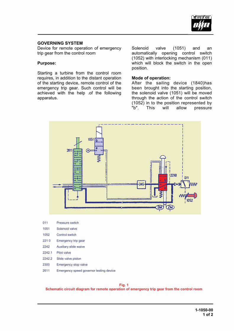
GOVERNING SYSTEM Device for remote operation of emergency trip gear from the control room Purpose: Starting a turbine from the control room requires, in addition to the distant operation of the starting device, remote control of the emergency trip gear. Such control will be achieved with the help .of the following apparatus.
Solenoid valve (1051) and an automatically opening control switch (1052) with interlocking mechanism (011) which will block the switch in the open position. Mode of operation: After the sailing device (1840)has been brought into the starting position, the solenoid valve (1051) will be moved through the action of the control switch (1052) in to the position represented by "b". This will allow pressure
011 Pressure switch
1051 Solenoid valve
1052 Control switch
221 0 Emergency trip gear
2242 Auxiliary slide waive
2242.1 Pilot valve
2242.2 Slide valve piston
2300 Emergency stop valve
2611 Emergency speed governor testing device
Fig. 1Schematic circuit diagram for remote operation of emergency trip gear from the control room


GOVERNING SYSTEM COMPONENTS
1-1200-12 2 of 2
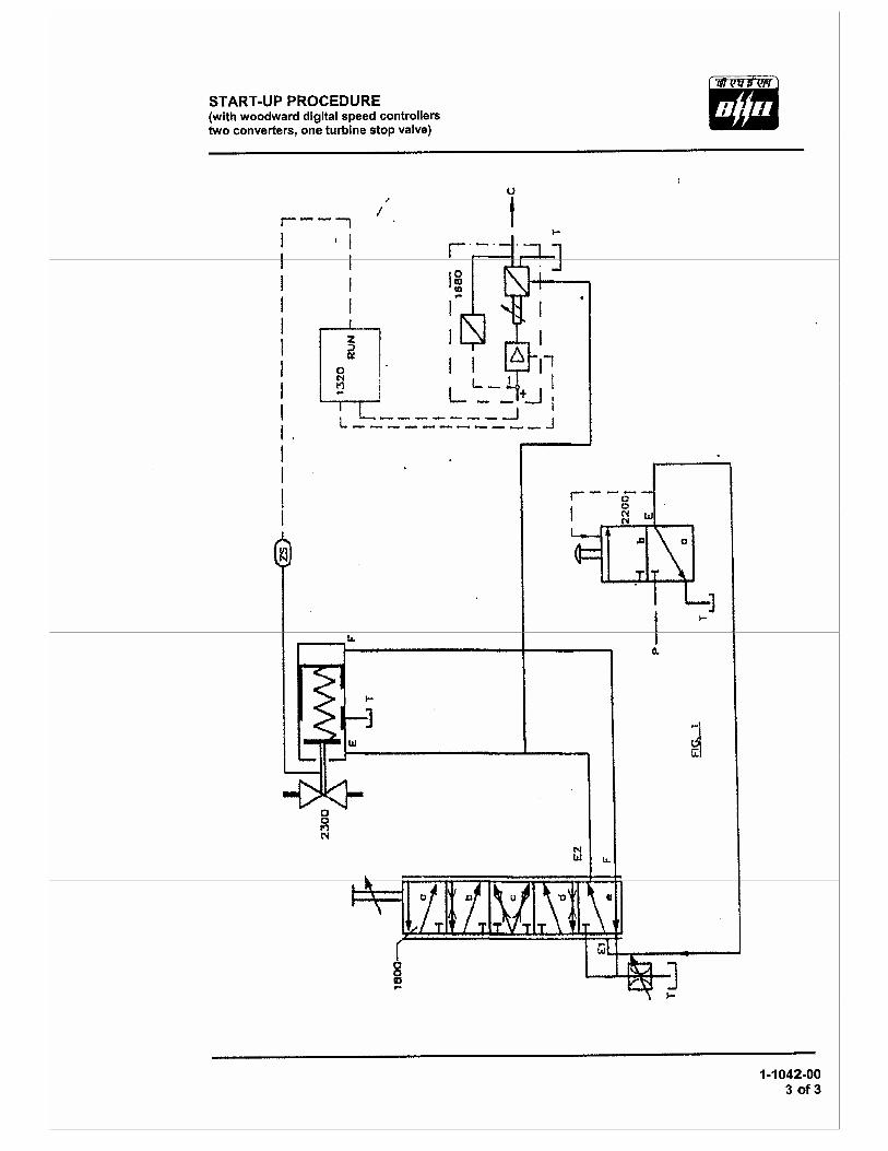
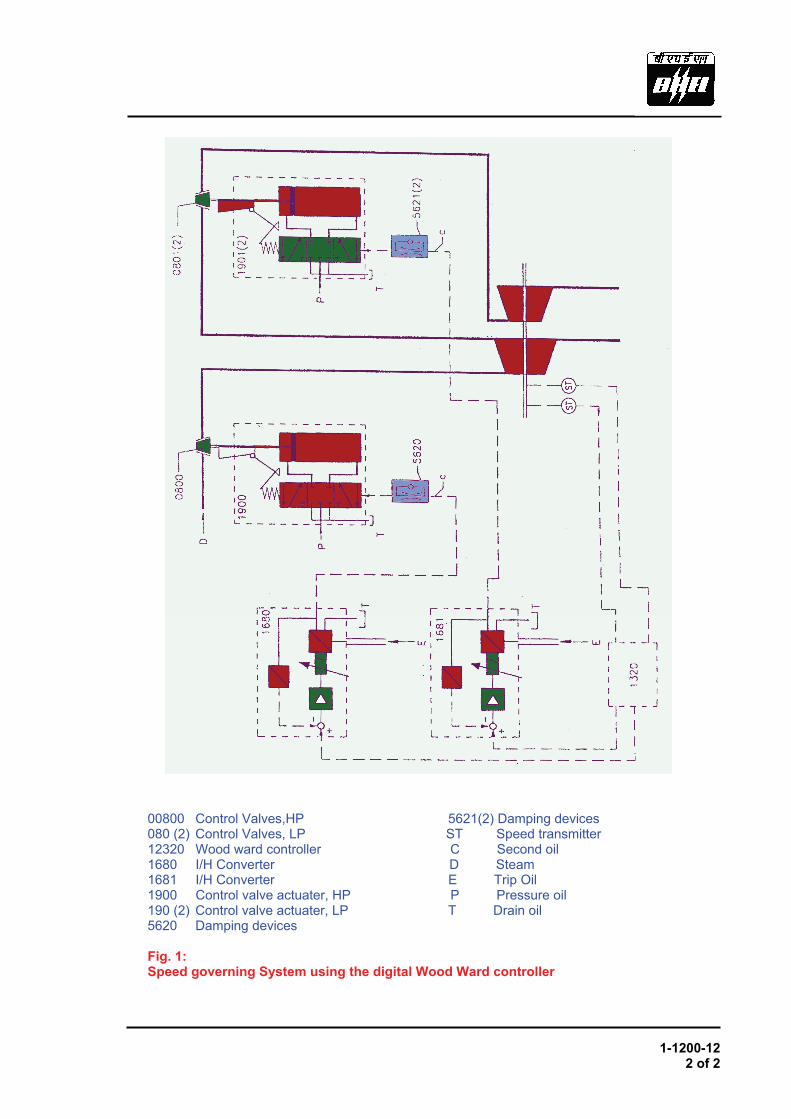
00800 Control Valves,HP 5621(2) Damping devices 080 (2) Control Valves, LP ST Speed transmitter 12320 Wood ward controller C Second oil 1680 I/H Converter D Steam 1681 I/H Converter E Trip Oil 1900 Control valve actuater, HP P Pressure oil 190 (2) Control valve actuater, LP T Drain oil 5620 Damping devices Fig. 1: Speed governing System using the digital Wood Ward controller
1-1900-00 1 of 3
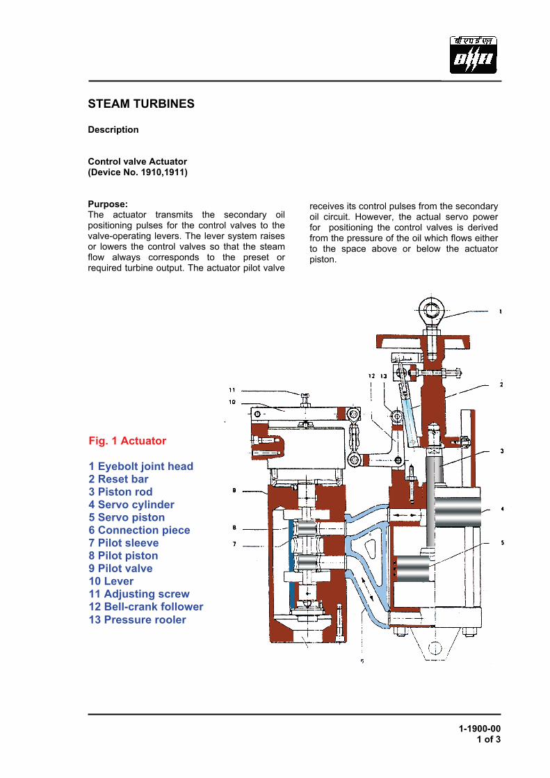
STEAM TURBINES Description Control valve Actuator (Device No. 1910,1911) Purpose: The actuator transmits the secondary oil positioning pulses for the control valves to the valve-operating levers. The lever system raises or lowers the control valves so that the steam flow always corresponds to the preset or required turbine output. The actuator pilot valve b
receives its control pulses from the secondary oil circuit. However, the actual servo power for positioning the control valves is derived from the pressure of the oil which flows either to the space above or below the actuator piston.
Fig. 1 Actuator 1 Eyebolt joint head 2 Reset bar 3 Piston rod 4 Servo cylinder 5 Servo piston 6 Connection piece 7 Pilot sleeve 8 Pilot piston 9 Pilot valve 10 Lever 11 Adjusting screw 12 Bell-crank follower 13 Pressure rooler
1-1900-00 2 of 3
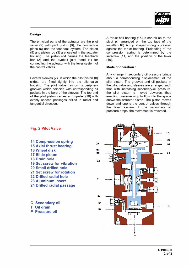
Design : The principal parts of the actuator are the pilot valve (9) with pilot piston (8), the connection piece (6) and the feedback system. The piston (5) and piston rod (3) are located in the actuator housing. The piston rod carries the feedback bar (2) and the eyebolt joint head (1) for connecting the actuator with the lever system of the control valves. Several sleeves (7), in which the pilot piston (8) slides, are fitted tightly into the pilot-valve housing. The pilot valve has on its periphery grooves which coincide with corresponding oil pockets in the bore of the sleeves. The top end of the pilot piston carries an impeller (16) with evenly spaced passages drilled in radial and tangential direction.
A thrust ball bearing (15) is shrunk on to the pivot pin arranged on the top face of the impeller (16). A cup shaped spring is pressed against the thrust bearing. Preloading of the compression spring is determined by the setscrew (11) and the position of the lever (10). Mode of operation : Any change in secondary oil pressure brings about a corresponding displacement of the pilot piston. The grooves and oil pockets in the pilot valve and sleeves are arranged such that, with increasing secondary-oil pressure, the pilot piston is moved upwards, thus enabling pressure oil p to flow into the space above the actuator piston. The piston moves down and opens the control valves through the lever system. If the secondary oil pressure drops, the movement is reversed.
Fig. 2 Pilot Valve 14 Compression spring 15 Axial thrust bearing 16 Wheel disk 17 Slide piston 18 Drain hole 19 Set screw for vibration 20 Small drilled hole 21 Set screw for rotation 22 Drilled radial hole 23 Aluminum insert 24 Drilled radial passage C Secondary oil T Oil drain P Pressure oil

1-1900-00 3 of 3
By means of a feedback bar (2), the piston stroke is fed back to the lever (10) via a bell crank follower (12). The action of that lever on the compression spring opposes the pilot piston movement. The pilot piston reacts to the spring force and returns to its neutral position. The feed back system thus stabilizes the movements. The functional relationship between secondary oil pressure and piston movement can be changed by adjusting the inclination of the feedback bar to the desired position with the help of a setscrew. Such adjustments will affect only the amount of proportional gain, while the secondary oil pressure/piston displacement relationship remains linear with the design of the feedback bar shown here. However, non-linear control characteristics can also be provided through an appropriately shaped cam profile of the feedback bar. Rotation and vibration of pilot piston : Pressure oil p passes through drilled passages in the pilot valve housing to the upper part of the pilot piston. From there, it flows through four radial holes (22) into the cavity of the hollow pilot piston, from where it passes to the drilled radial and tangential passages (24) of impeller (16) from which it escapes.
The permanent flow of oil leaving the impeller (16) from which it escapes. The permanent flow of oil leaving the impeller tangentially imparts a continuous rotational motion to the pilot piston. The setscrew (21) allows adjustment of the speed by adjusting the oil flow volume. The speed can be measured in the aluminum insert (23). The secondary oil pressure acting on its underside imparts a constant axial motion to the pilot valve. This is achieved by a small hole drilled into the lower part of the pilot piston. During every complete revolution of the piston, this hole momentarily over- laps a drain hole (18) in the housing. The quantity of secondary oil which is thus allowed to escape causes a small pressure drop in the secondary oil circuit causing the pilot piston to move downwards by a small amount. When the hole is covered again the piston is lifted until the next overlap. During each of the movements by the pilot piston, a minute volume of pressure oil flows to the actuator piston. This causes slight vibration of the spindles of the control valves, thereby ensuring immediate response of these components to the control pulses of the governor. The vibration stroke of the pilot piston can likewise be adjusted by means of a setscrew ( 19).
Fig. 3 Oil flow through wheel disc

TURBINE PROTECTIVE DEVICES

1-2712-00 1 of 1
SPEED MONITORING (With electronic pick-up of the type manufactured by Messrs. "Jaquet" , " Bently" , or similar) Function: Convenience of operation or local site conditions of a turbine plant sometimes warrant the accurate measuring or remote reading of the turbine speed. To this effect, the speed will be measured by an electromagnetic pick-up which does not require mechanical contact with rotating parts. This signal may also be used as input for supplementary governor and control equipment.
Design and mode of operation:
A steel disk is bolted onto a pinion shaft driven by the turbine rotor or onto the turbine rotor itself at the head end. Near its periphery, the disk carries a number of equally spaced axial holes. The pick-up is screwed into the cover in front of the rotating disk.
When the perforated disk rotates in front of the pick up this produces a frequency proportional to the speed of the turbine rotor. The pick-up frequency is converted into a speed-proportional current in a following converter and measured on an indicating instrument.
1. Indicating instrument 2. Converter: frequency/current 3. Pulse pick-up 4. Perforated disk 5. Drilled hole
Fig. 1 Speed monitoring arrangement

1-2773-00 1 of 1
MEASUREMENT OF AXIAL ROTOR POSITION (With "Reutlinger, Bentley Nevada and the like")
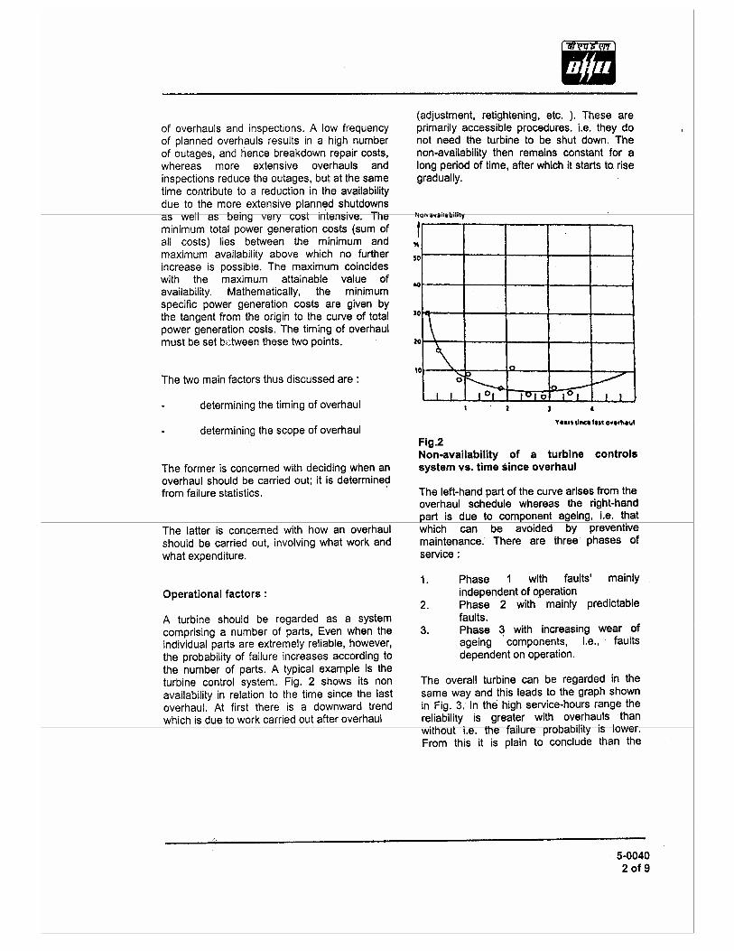
Function: The thrust bearing forms the fixed point of the turbine rotor. An axial displacement of the turbine beyond the given limits (bearing clearances) can have serious consequences. Frequent checks permit early recognition of rotor displacement. If such displacement has occurred it has been shown by experience that immediate tripping will allow the turbine to coast to standstill without causing any secondary damage. Construction and mode of operation: The measuring point is located in the front bearing housing in the immediate vicinity of the thrust bearing. The measuring units (converters) operate on the eddy-current principle. They consist essentiality of a proximate, a transducer and the associated
extension cable. The transducer is arranged perpendicularly to a collar on the turbine rotor. The measuring medium is a high-frequency signal (HF signal) which is generated in the proximitor by means of an auxiliary voltage and fed to a coil in the transducer. The coil transmits the energy to the surrounding atmosphere as a magnetic field. When an electrically conductive material cuts this field eddy currents are produced, the amplitudes of which become larger the closer the turbine rotor comes to the coil in the transducer. The resulting energy loss in the measuring unit reduces the amplitude of the HF signal between the transducer and the proximitor . The amplitude of the HF signal is a function of the gap, i.e. the closer the turbine rotor comes to the transducer the greater the energy loss but the lower the HF voltage. The proximitor measures the amplitude of the HF signal from zero to the negative peak and produces a proportional output voltage which can be used for display (analogue, digital or recorder).
1. Transducer 2. Extension Cable 3. Protective casing 4. Extension Cable 5. Proximitor 6. Console Fig. 1: Electrical measurement of Axial rotor position
1 2
3
4
5
6


LUBE OIL SYSTEM


TURBINE ACCESSORIES


STEAM TURBINES Operation
1-7110-00 1 of 1
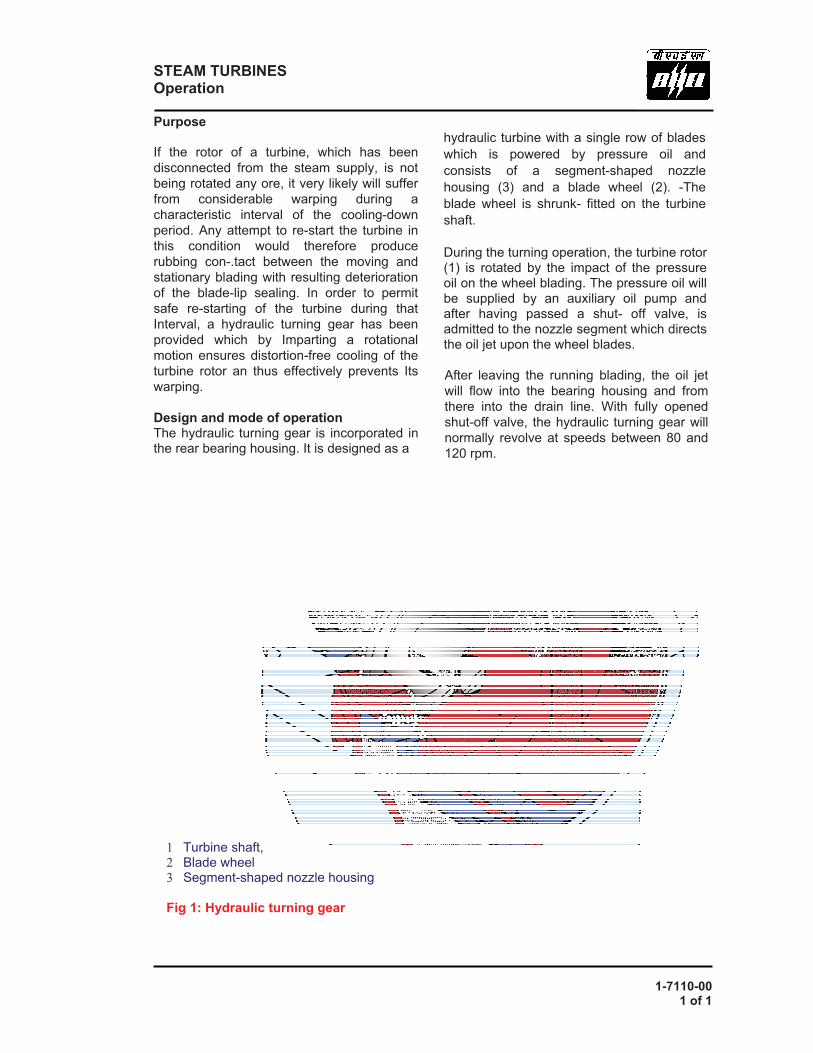
Purpose If the rotor of a turbine, which has been disconnected from the steam supply, is not being rotated any ore, it very likely will suffer from considerable warping during a characteristic interval of the cooling-down period. Any attempt to re-start the turbine in this condition would therefore produce rubbing con-.tact between the moving and stationary blading with resulting deterioration of the blade-lip sealing. In order to permit safe re-starting of the turbine during that Interval, a hydraulic turning gear has been provided which by Imparting a rotational motion ensures distortion-free cooling of the turbine rotor an thus effectively prevents Its warping. Design and mode of operation The hydraulic turning gear is incorporated in the rear bearing housing. It is designed as a
hydraulic turbine with a single row of blades which is powered by pressure oil and consists of a segment-shaped nozzle housing (3) and a blade wheel (2). -The blade wheel is shrunk- fitted on the turbine shaft. During the turning operation, the turbine rotor (1) is rotated by the impact of the pressure oil on the wheel blading. The pressure oil will be supplied by an auxiliary oil pump and after having passed a shut- off valve, is admitted to the nozzle segment which directs the oil jet upon the wheel blades. After leaving the running blading, the oil jet will flow into the bearing housing and from there into the drain line. With fully opened shut-off valve, the hydraulic turning gear will normally revolve at speeds between 80 and 120 rpm.
1 Turbine shaft, 2 Blade wheel 3 Segment-shaped nozzle housing Fig 1: Hydraulic turning gear
1-7650-00 1 of 5
1 2 3 4 5 6 7 8 9
10
11
12
13
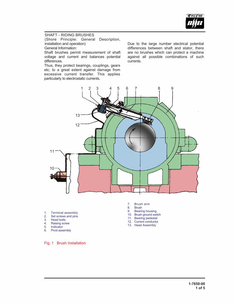
SHAFT - RIDING BRUSHES (Shore Principle: General Description, installation and operation) General Information: Shaft brushes permit measurement of shaft voltage and current and balances potential differences. Thus, they protect bearings, couplings, gears etc; to a great extent against damage from excessive current transfer. This applies particularly to electrostatic currents. 1. Terminal assembly 2. Set screws and pins 3. Head bolts 4. Raising screw 5. Indicator 6. Pivot assembly Fig. 1 Brush Installation
Due to the large number electrical potential differences between shaft and stator, there are no brushes which can protect a machine against all possible combinations of such currents. 7. Brush arm 8. Brush 9. Bearing housing 10. Brush ground switch 11. Bearing pedestal 12. Current conductor 13. Head Assembly


1-7650-00 3 of 5
3
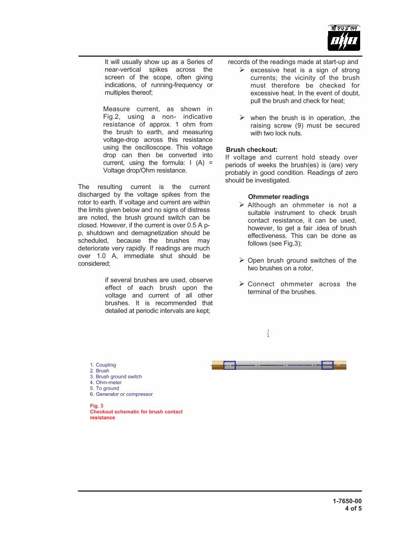
1. Oscilloscope 2. Non – inductive resistance 3. Brush ground switch
Fig. 2 Arrangementr to measure flashing currents (as per P. Nippes)
- Open brush ground switch ; - raise brush by turning brush-raising
screw (4) all the way in, but do not exert force;
- disconnect earthing wire from terminal (1); - remove four head screws (3); - pull brush catridge out - cover opening; - replace brush by removing flat-head
screws. Ensure that the rake of the new brush is in the direction of rotation.
Note : It is not necessary to disassemble the catridge for brush replacement. However, if it is desired to disassemble the catridge components, this can be done by removing the two set screws and pin (2). - carefully insert brush catridge into casing - replace four screws and lock washers; - reconnect terminal - lower brush on to shaft. Note position of
indicator in window; - check contact resistance; - close brush ground switch.
Starting and operation : Before the unit is started, the brushes should be checked with the brush ground switch open, for: - Resistance to casing with brush raised.
This should be infinite; - resistance from the terminal to shaft with
brush down. This should be Zero. In addition : - Check for proper operating of the brush
ground switch in the closed position; - Check for possible difference of
electrical potential between rotor, casing and earth, using a millivolt meter.
Start-up: - The turbine can be started up with the
brush raised and the brush ground switch open;
- at the required speed and with the brush ground switch still open, lower the brush, or only one if here are several. Using in oscilloscope, measure the voltage across the brush ground switch. This is the shaft voltage being generated.
1-7650-00 4 of 5
It will usually show up as a Series of near-vertical spikes across the screen of the scope, often giving indications, of running-frequency or multiples thereof; Measure current, as shown in Fig.2, using a non- indicative resistance of approx. 1 ohm from the brush to earth, and measuring voltage-drop across this resistance using the oscilloscope. This voltage drop can then be converted into current, using the formula: I (A) = Voltage drop/Ohm resistance.
The resulting current is the current discharged by the voltage spikes from the rotor to earth. If voltage and current are within the limits given below and no signs of distress are noted, the brush ground switch can be closed. However, if the current is over 0.5 A p-p, shutdown and demagnetization should be scheduled, because the brushes may deteriorate very rapidly. If readings are much over 1.0 A, immediate shut should be considered;
if several brushes are used, observe effect of each brush upon the voltage and current of all other brushes. It is recommended that detailed at periodic intervals are kept;
records of the readings made at start-up and � excessive heat is a sign of strong
currents; the vicinity of the brush must therefore be checked for excessive heat. In the event of doubt, pull the brush and check for heat;
� when the brush is in operation, .the
raising screw (9) must be secured with two lock nuts.
Brush checkout: If voltage and current hold steady over periods of weeks the brush(es) is (are) very probably in good condition. Readings of zero should be investigated.
Ohmmeter readings � Although an ohmmeter is not a
suitable instrument to check brush contact resistance, it can be used, however, to get a fair .idea of brush effectiveness. This can be done as follows (see Fig.3);
� Open brush ground switches of the
two brushes on a rotor,
� Connect ohmmeter across the terminal of the brushes.
1. Coupling 2. Brush 3. Brush ground switch 4. Ohm-meter 5. To ground 6. Generator or compressor Fig. 3 Checkout schematic for brush contact resistance
1-7650-00 5 of 5
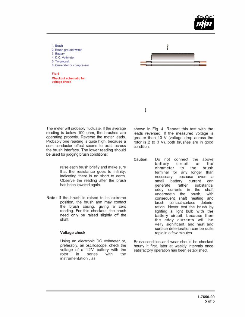
1. Brush 2. Brush ground twitch 3. Battery 4. D.C. Voltmeter 5. To ground 6. Generator or compressor
Fig.4 Checkout schematic for voltage check
The meter will probably fluctuate. If the average reading is below 100 ohm, the brushes are operating properly. Reverse the meter leads. Probably one reading is quite high, because a semi-conductor effect seems to exist across the brush interface. The lower reading should be used for judging brush conditions;
raise each brush briefly and make sure that the resistance goes to infinity, indicating there is no short to earth. Observe the reading after the brush has been lowered again.
Note: If the brush is raised to its extreme position, the brush arm may contact the brush casing, giving a zero reading. For this checkout, the brush need only be raised slightly off the shaft.
Voltage check
Using an electronic DC voltmeter or, preferably, an oscilloscope, check the voltage of a 12V battery with the rotor in series with the instrumentation , as
shown in Fig. 4. Repeat this test with the leads reversed. If the measured voltage is greater than 10 V (voltage drop across the rotor is 2 to 3 V), both brushes are in good condition.
Caution: Do not connect the above battery circuit or the ohmmeter to the brush terminal for any longer than necessary, because even a small battery current can generate rather substantial eddy currents in the shaft underneath the brush, with consequent shaft heating and brush contact-surface deterio- ration. Never test the brush by lighting a light bulb with the battery circuit, because then the eddy currents wil l be very significant, and heat and surface deterioration can be quite rapid in a few minutes.
Brush condition and wear should be checked hourly It first, later at weekly intervals once satisfactory operation has been established.

STEAM AND DRAIN SYSTEM


OPERATION OF STEAM TURBINE


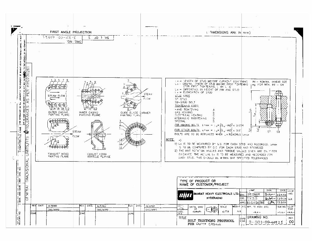
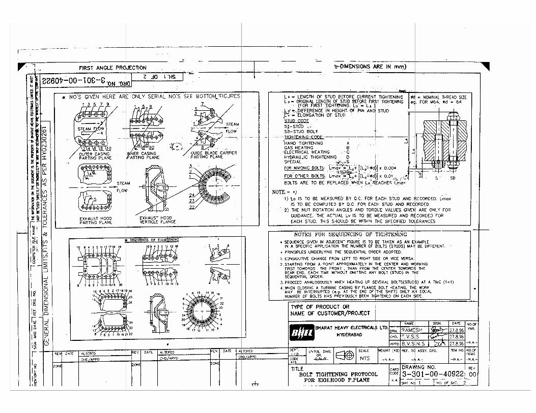
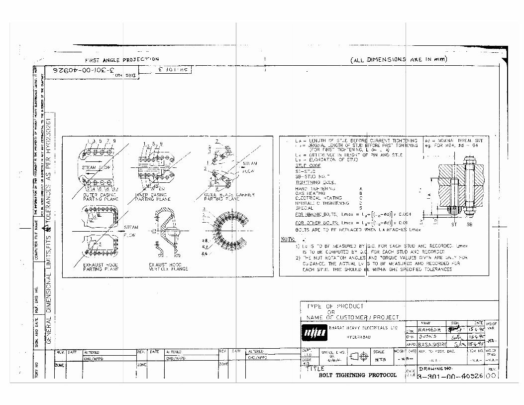
PROTOCOLS FOR BOLT TIGHTENING


MAINTENANCE, OVERHAULING & TROUBLESHOOTING

MAINTENANCE


OVERHAULING


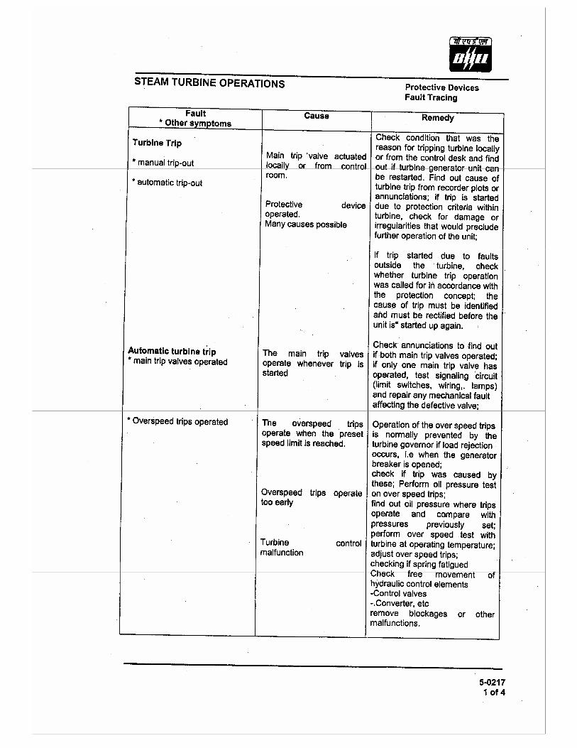
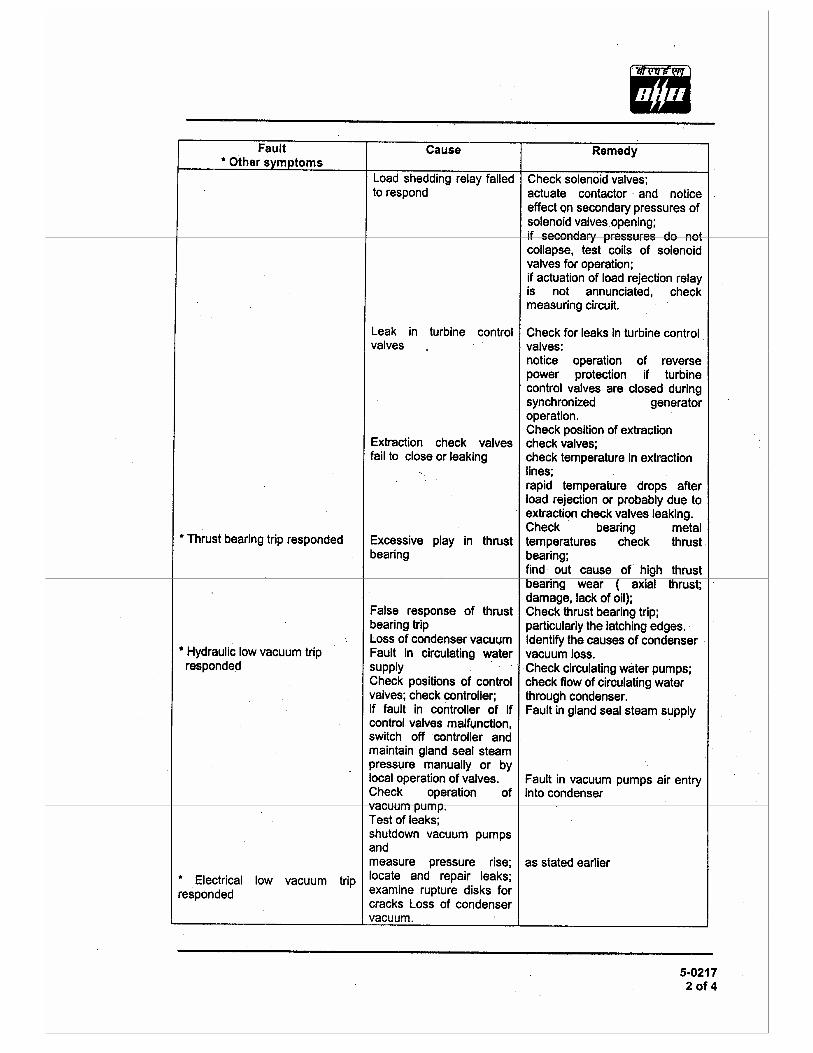
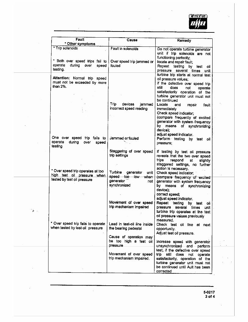
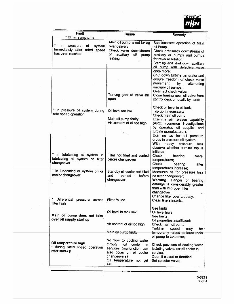
TROUBLESHOOTING


Related Documents