31007118.02 www.schneider-electric.com ConneXium Ethernet Cabling System TCSESM Managed Switch Installation Manual 31007118 8/2008

Welcome message from author
This document is posted to help you gain knowledge. Please leave a comment to let me know what you think about it! Share it to your friends and learn new things together.
Transcript

310
0711
8.02
www.schneider-electric.com
ConneXium Ethernet Cabling SystemTCSESM Managed Switch Installation Manual31007118
8/2008

2

Table of Contents
Safety Information . . . . . . . . . . . . . . . . . . . . . . . . . . . . . . . . . . . .5
About the Book . . . . . . . . . . . . . . . . . . . . . . . . . . . . . . . . . . . . . . .7
Chapter 1 Device Description . . . . . . . . . . . . . . . . . . . . . . . . . . . . . . . . . . . .9General Switch Description . . . . . . . . . . . . . . . . . . . . . . . . . . . . . . . . . . . . . . . . . 10The Switch Versions . . . . . . . . . . . . . . . . . . . . . . . . . . . . . . . . . . . . . . . . . . . . . . 11
Chapter 2 Installation and Startup . . . . . . . . . . . . . . . . . . . . . . . . . . . . . . .17Safety Instructions. . . . . . . . . . . . . . . . . . . . . . . . . . . . . . . . . . . . . . . . . . . . . . . . 18Configurations . . . . . . . . . . . . . . . . . . . . . . . . . . . . . . . . . . . . . . . . . . . . . . . . . . . 19Installation and Startup . . . . . . . . . . . . . . . . . . . . . . . . . . . . . . . . . . . . . . . . . . . . 22
Appendices . . . . . . . . . . . . . . . . . . . . . . . . . . . . . . . . . . . . . . . . . . . . . . 33
Appendix A Technical Data . . . . . . . . . . . . . . . . . . . . . . . . . . . . . . . . . . . . . .35General Technical Hardware Data . . . . . . . . . . . . . . . . . . . . . . . . . . . . . . . . . . . 36Dimension Drawings . . . . . . . . . . . . . . . . . . . . . . . . . . . . . . . . . . . . . . . . . . . . . . 37Electromagnetic Compatibility (EMC) and Physical Resistance . . . . . . . . . . . . . 39Network Expansion . . . . . . . . . . . . . . . . . . . . . . . . . . . . . . . . . . . . . . . . . . . . . . . 40Power Input and Output . . . . . . . . . . . . . . . . . . . . . . . . . . . . . . . . . . . . . . . . . . . 41Recommended Fuses . . . . . . . . . . . . . . . . . . . . . . . . . . . . . . . . . . . . . . . . . . . . . 42Switches and Accessories. . . . . . . . . . . . . . . . . . . . . . . . . . . . . . . . . . . . . . . . . . 43Underlying Standards . . . . . . . . . . . . . . . . . . . . . . . . . . . . . . . . . . . . . . . . . . . . . 44Agency Approvals . . . . . . . . . . . . . . . . . . . . . . . . . . . . . . . . . . . . . . . . . . . . . . . . 45Certifications . . . . . . . . . . . . . . . . . . . . . . . . . . . . . . . . . . . . . . . . . . . . . . . . . . . . 46
Appendix B TCSESM Switch Quick Start Quide. . . . . . . . . . . . . . . . . . . . . .47Overview . . . . . . . . . . . . . . . . . . . . . . . . . . . . . . . . . . . . . . . . . . . . . . . . . . . . . . . 48Preliminary Setup . . . . . . . . . . . . . . . . . . . . . . . . . . . . . . . . . . . . . . . . . . . . . . . . 49Logging On to the System. . . . . . . . . . . . . . . . . . . . . . . . . . . . . . . . . . . . . . . . . . 51Redundancy Configuration . . . . . . . . . . . . . . . . . . . . . . . . . . . . . . . . . . . . . . . . . 55Configuring the HIPER-Ring Version 1 . . . . . . . . . . . . . . . . . . . . . . . . . . . . . . . . 56Configuring the HIPER Ring Version 2 (MPR Draft) . . . . . . . . . . . . . . . . . . . . . . 58Configuring the TCSESM Switch . . . . . . . . . . . . . . . . . . . . . . . . . . . . . . . . . . . . 61Backing Up and Restoring the TCSESM Switch Configuration. . . . . . . . . . . . . . 67
3

4

§
Safety InformationImportant Information
NOTICE Read these instructions carefully, and look at the equipment to become familiar with the device before trying to install, operate, or maintain it. The following special messages may appear throughout this documentation or on the equipment to warn of potential hazards or to call attention to information that clarifies or simplifies a procedure.
The addition of this symbol to a Danger or Warning safety label indicatesthat an electrical hazard exists, which will result in personal injury if theinstructions are not followed.
This is the safety alert symbol. It is used to alert you to potential personalinjury hazards. Obey all safety messages that follow this symbol to avoidpossible injury or death.
DANGER indicates an imminently hazardous situation, which, if not avoided, will result in death or serious injury.
DANGER
WARNING indicates a potentially hazardous situation, which, if not avoided, can result in death, serious injury, or equipment damage.
WARNING
CAUTION indicates a potentially hazardous situation, which, if not avoided, can result in injury or equipment damage.
CAUTION
31007118 7/2008 5

Safety Information
PLEASE NOTE Electrical equipment should be installed, operated, serviced, and maintained only by qualified personnel. No responsibility is assumed by Schneider Electric for any consequences arising out of the use of this material.
© 2008 Schneider Electric. All Rights Reserved.
6 31007118 7/2008

About the Book
At a Glance
Document Scope This manual contains all the information you need to install the ConneXium ESM Ethernet switches before you start configuring them.
Validity Note The data and illustrations found in this book are not binding. We reserve the right to modify our products in line with our policy of continuous product development. The information in this document is subject to change without notice and should not be construed as a commitment by Schneider Electric.
Product Related Information
Schneider Electric assumes no responsibility for any errors that may appear in this document. If you have any suggestions for improvements or amendments or have found errors in this publication, please notify us.
No part of this document may be reproduced in any form or by any means, electronic or mechanical, including photocopying, without express written permission of Schneider Electric. All rights reserved.
When controllers are used for applications with technical safety requirements, please follow the relevant instructions.
Failure to use Schneider Electric software or approved software with our hardware products may result in injury, harm, or improper operating results.
Failure to observe this product related warning can result in injury or equipment damage.
User Comments We welcome your comments about this document. You can reach us by e-mail at [email protected]
31007118 7/2008 7

About the Book
8 31007118 7/2008

31007118 7/2008
1
Device DescriptionAt a Glance
Overview This chapter describes the ESM switches and their different versions.
What's in this Chapter?
This chapter contains the following topics:
Topic Page
General Switch Description 10
The Switch Versions 11
9

Device Description
General Switch Description
Overview An ESM switch is a compact, heavy-duty device suitable for industrial applications which can be installed on a standard DIN Rail. The switches are available in 4, 8, 10, 16 and 24 ports combinations. Two of these ports, uplinks, usually used to implement the ring architectures, could be available in Copper or Fiber (multimode, single mode or mixed) and in 10/100 Mbps or Gigabit speeds.
The 10-60VDC/18-30VAC operating voltage is supplied via a plug-in terminal block with two connections to wire primary and redundant voltage if necessary. An alarm relay allows reporting diagnostic information (P/S, Link signal, Redundancy health) to Control systems. Integrated LEDs allow fast on-site installation and troubleshooting.
The HIPER-Ring redundancy concept allows single and fast implementation of redundant architectures (simple and coupling rings). The diagnostics and operating parameter display functions as well as the labeling field for the IP address provide a quick overview.
You can configure or diagnose the switch using a Web browser, Telnet, or the V.24 serial interface of the switch.
The ConneXium ESM switches allow you to set up in a line, star or ring structure switched industrial ETHERNET networks in accordance with the IEEE 802.3 and 802.3u standards using copper technology or fibre optic conductors. End devices and other infrastructure components can be connected using twisted pair cables or multi and single mode fiber optic cables. The twisted pair ports support autocrossing, autonegotiation and autopolarity.
The devices offer a wide variety of functions:
redundancy functions: (Rapid Spanning Tree, redundant ring structure, ring coupling, redundant power supply)security: Unauthorized messages (MAC or IP based) are blocked.synchronization of the system network time (SNTP)traffic controlfunctional diagnosticspriority (message or port-based)VLANtopology detectionWeb-based interfaceCommand Line Interface (CLI)SNMP
10 31007118 7/2008

Device Description
The Switch Versions
Switch Versions
Part Number Part Number Description
4 Port Version TCSESM043F23F0 4 10/100 TX Managed
TCSESM043F1CU0 3 10/100 TX 1 100 FX-MM Managed
TCSESM043F2CU0 2 10/100 TX 2 100 FX-MM Managed
TCSESM043F1CS0 3 10/100 TX 1 100 FX-SM Managed
TCSESM043F2CS0 2 10/100 TX 2 100 FX-SM Managed
8 Port Version TCSESM083F23F0 8 10/100 TX Managed
TCSESM083F1CU0 7 10/100 TX 1 100 FX-MM Managed
TCSESM083F2CU0 6 10/100 TX 2 100 FX-MM Managed
TCSESM083F1CS0 7 10/100 TX 1 100 FX-SM Managed
TCSESM083F2CS0 6 10/100 TX 2 100 FX-SM Managed
TCSESM083F2CX0 6 10/100 TX 1 100 FX-MM 1 100 FX-SM Managed
16 Port Version TCSESM163F23F0 16 10/100 TX Managed
TCSESM163F2CU0 14 10/100 TX 2 100 FX-MM Managed
24 Port Version TCSESM243F2CU0 22 10/100 TX 2 100 FX-MM Managed
Gigabit - 10 Port Version
TCSESM103F23G0 8 10/100 TX 2 10/100/1000 TX Managed
TCSESM103F2LG0 8 10/100 TX 2 1000 SFP (fiber) Managed
Note: This product ships with open sockets (SFP) on the fiber ports. In order to use these ports, order 1 or 2 fiber modules in any combination (see below).
Fiber Media Modules for Gigabit
TCSEAAF1LFU00 fiber module SFP-SX/LC
TCSEAAF1LFS00 fiber module SFP-LX/LC
TCSEAAF1LFH00 fiber module SFP-LH/LC
Accessories TCSEAM0100 Adapter Memory Back-up Adapter
31007118 7/2008 11

Device Description
Examples of Switch Versions
The figure below shows the 4-port versions of the ESM.
1 Pluggable 6-pin terminal block2 LED display elements3 2-pin DIP switch4 MAC address field5 USB interface6 V.24 access, external management7 IP address field8 Ports in accordance with 10/100 BASE-T(X)9 Protective earth ground
1LNK
ACT
2LNK
ACT
3LNK
ACT
4LNK
ACTIP
Add
ress
MA
C-A
ddre
ss
ConneXium Switch
V.24
ONRM
FAULTRM
PStand
USB
FaultOVO
+24V(P1)
+24V(P2)
Telemecanique
TCSESM043F23F0
1LNK
ACT
2LNK
ACT
3LNK
ACT
4LNK
ACT
IP A
ddre
ss
MA
C-A
ddre
ss
ConneXium Switch
V.24
ONRM
Stand by
FAULT
RM
P
Stand by
USB
Fault
OVOV+24V(P1)
+24V(P2)
Telemecanique
TCSESM043F2CU0/CS0
2
1
1LNK
ACT
2LNK
ACT
3LNK
ACT
4LNK
ACT
IP A
ddre
ss
ConneXium Switch
V.24
ONRMStand by
FAULT
RM
P
Stand by
USB
Fault
OVOV+24V(P1)
+24V(P2)
Telemeca-
TCSESM043F1CU0/CS0
1
MA
C-A
ddre
ss
Twisted pair TX, RJ45, 10/100 Mbit Multimode FX, DSC, 100 MbitSingle mode FX, DSC, 100 Mbit
Port 1 + port 2, freely selectable
1
2
3
45
6
7
8
9
12 31007118 7/2008
Device Description
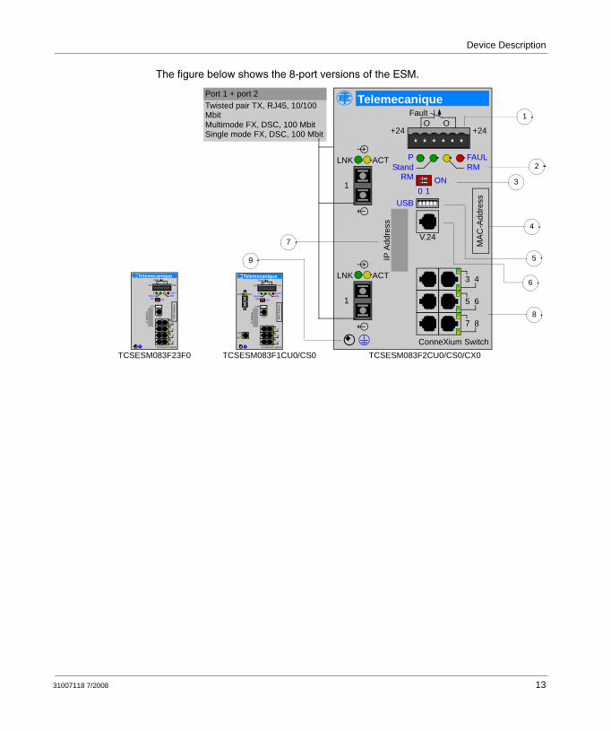
The figure below shows the 8-port versions of the ESM.
Twisted pair TX, RJ45, 10/100 Mbit Multimode FX, DSC, 100 MbitSingle mode FX, DSC, 100 Mbit
Port 1 + port 2
TCSESM083F23F0
3 4
5 6
7 8
IP A
ddre
ss
MA
C-A
ddre
ss
ConneXium Switch
V.24
ONRM
FAULTRM
PStand
USB
FaultOO
+24 +24
Telemecanique
TCSESM083F1CU0/CS0
ACTLNK
LNK
ACT2
3 4
5 6
7 8
IP A
ddre
ss
MA
C-A
ddre
ss
ConneXium Switch
V.24
ONRM
FAULRM
PStand
USB10
FaultOO
+24 +24
Telemecanique
TCSESM083F2CU0/CS0/CX0
ACTLNK
1
ACTLNK
1
3 4
5 6
7 8
IP A
ddre
ss
MA
C-A
ddre
ss
ConneXium Switch
V.24
ONRM
FAULTRM
PStand
USB
FaultOO
+24 +24
Telemecanique
1 2
1
2
3
4
5
6
7
8
9
31007118 7/2008 13

Device Description
The figure below shows the 16-port versions of the ESM.
Twisted pair TX, RJ45, 10/100 Mbit Multimode FX, DSC, 100 Mbit
Port 1 + port 2
11 12
13 14
15 16
IP A
ddre
ss
MA
C-A
ddre
ss
ConneXium Switch
V.24
ONRM
FAULTRM
PStand
USB
FaultOVO
+24V(P1)
+24V
Telemecanique
TCSESM163F2CU0
3 4
5 6
7 8
9 10
ACTLNK
1
ACTLNK
1
11 12
13 14
15 16
IP A
ddre
ss
MA
C-A
ddre
ss
ConneXium Switch
V.24
ONRM
FAULTRM
PStand by
USB
FaultOVOV
+24V(P1)
+24V(P2)
Telemecanique
TCSESM163F23F0
1 2
3 4
5 6
7 8
9 10
9
1
2
3
4
5
6
7
8
14 31007118 7/2008

Device Description
The figure below shows the 24-port version of the ESM.
Multimode FX, DSC, 100 MbitPort 1 + Port 2, freely selectable
19
21
23
IP A
ddre
ss
MAC
-Add
ress
ConneXium Switch
V.24
ONRM
FAULTRM
PStand
USB10
FaultOVO
+24V(P1)
+24V
Telemecanique
TCSESM243F2CU0
3 4
5 6
7 8
9 10
11 12
13
15
17
ACTLNK
1
ACTLNK
1
1
2
3
4
5
6
7
8
9
31007118 7/2008 15

Device Description
The figure below shows the 10-port (gigabit) versions of the ESM.
5 6
7 8
9 10
IP A
ddre
ss
MAC
-Add
ress
ConneXium Switch
V.24
ONRM
FAULTRM
PStand
USB
Fault
OVO+24V(P1)
+24V
Telemecanique
TCSESM103F23G0
3 4
LNK
ACT1
LNK
ACT2
5 6
7 8
9 10
IP A
ddre
ss
MA
C-A
ddre
ss
ConneXium Switch
V.24
ONRM
FAULTRM
PStand by
USB
FaultOVO
+24V +24V
Telemecanique
TCSESM103F2LG0
3 4
ACTLNK
2
ACTLNK
1
Twisted pair TX, RJ45, 10/100/1000 MbitFX, SFP-shaft, 1000 Mbit
Port 1 + Port 2
1
2
3
4
5
6
7
8
9
16 31007118 7/2008

31007118 7/2008
2
Installation and StartupAt a Glance
Overview This chapter describes installation and startup of the product.
What's in this Chapter?
This chapter contains the following topics:
Topic Page
Safety Instructions 18
Configurations 19
Installation and Startup 22
17

Installation and Startup
Safety Instructions
Staff Qualification Requirements
Only appropriately qualified staff should work on or near this equipment. Such staff must be thoroughly acquainted with all the warnings and maintenance measures contained in these operating instructions.The proper and safe operation of this equipment assumes proper transport, appropriate storage and assembly, and careful operation and maintenance.Qualified staff according to these operating instructions or the warning notes are persons familiar with setting up, assembling, starting up, and operating this product and who have appropriate qualifications to cover their activities, such as:
training or instruction/entitlement to switch circuits and equipment/systems on and off, ground them, and identify them in accordance with current safety standards,
training or instruction in accordance with current safety standards in looking after and using appropriate safety equipment,
first aid training.
Recycling Note After has been put out of use, it must be disposed of properly as electronic waste in accordance with the effective local, state and national disposal regulations.
Note: Electricity is used to operate this equipment. Comply in every detail with the safety requirements specified in the operating instructions regarding the voltages to apply.
18 31007118 7/2008

Installation and Startup
Configurations
Line Structure The ESM switches enable backbones in line structures to be built up. Cascading is carried out using the backbone ports:
ConneXiumTCSESM
PremiumQuantum
ConneXium499NEH10410
ConneXium499NES25100
Optical fiber or copper
Shielded twisted paircrossed cord (490NTC000ll)
Shielded twisted paircord (490NTW000ll)
line structure
ConneXium499NEH10410
31007118 7/2008 19

Installation and Startup
Redundant Ring Structure
With the redundancy manager function of the ESM modules you can close the two ends of a line structured backbone to a redundant ring, as shown in the figures below. The ESM switches are integrated into the ring via the backbone ports (ports 1 and 2). If one section fails the reaction time comes to less than 0.5 s at up to 50 ESM modules being cascaded.
The following figure describes a redundant ring structure.
PremiumQuantum ConneXium
499NEH10410
ConneXium499NEH14100
ConneXium499NES25100
ConneXiumTCSESM
Shielded twisted paircord (490NTW000••)
Shielded twisted paircord (490NTC000••)
Configured redundancy manager Optical fiberredundant ringor copper
20 31007118 7/2008

Installation and Startup
Redundant Coupling of Network Segments
The built-in control intelligence of the ESM allows the redundant coupling of network segments. The connection of two network segments is realized via two separate paths. The ESM switches in the redundant line get the redundancy function assigned by the DIP switch setting standby.
The ESM modules in the redundant line and the ESM switches in the main line share their operating states via the control line (crossover Ethernet cable).
After the failure of the main line the redundant ESM modules enable the redundant line within 0.5 s. If the main line is operational again, the ESM switches in the main line inform the redundant ESM modules about this. The main line will be enabled and the redundant line will be disabled within 0.5 s.
The following figure describes a redundant coupling of optical rings structure:
ConneXiumTCSESM
ring 1configured redundancy manager
Master Slave
control line control line
mai
n lin
e
redu
ndan
t lin
e
OpticalShielded twisted pair
crossed cord (490NTC000)Fiber
mai
n lin
e
redu
ndan
t lin
e
redu
ndan
t co
uplin
g of
rin
g1
and
ring
3
redu
ndan
t co
uplin
g of
rin
g1
and
ring
2
ConneXium499NOH10510
ConneXiumTCSESM
configured redundancy manager
ring 2
Optical Fiber Optical Fiber
ring 3
31007118 7/2008 21

Installation and Startup
Installation and Startup
Overview of Installation
On delivery, a switch is always ready for operation.
The following installation procedure has been tried and tested in service:
unpacking and checkingfilling in the labeling fieldadjusting the DIP switch settingsconnecting the terminal block for supply voltage and signal contactfitting the device onto the snap-on rail, groundingfitting the terminal block, startupconnecting the data lines
Controls The standby and redundancy management functions can be switched on and off with the two-pin DIP switches on the front panel of the ESM.
The default setting is ON for both switches.
The table in the following section outlines the various dip switch settings, the TCSESM operation mode, and the TCSESM firmware default settings. For complete details on switch redundancy operation refer to the ConneXium Ethernet Cabling System TCSESM Managed Switch Redundancy Manual 31007216.
Two-Pin DIP Switch
The figure shows the DIP switch.
DUPLICATE ADDRESS HAZARDHaving two or more devices with the same IP address can cause unpredictable operation of your network. Ensure that you will be assigning a unique IP address to the switch.
Failure to follow these instructions can result in death, serious injury, or equipment damage.
WARNING
ONRM
Stand by
22 31007118 7/2008

Installation and Startup
DIP Switch Settings
The table shows the various DIP switch settings you can make and what modes each pair of settings represent.
Supply Voltage The supply voltage can be connected redundantly. Both inputs are decoupled. There is no distributed load. With redundant supply, the transformer supplies the ESM alone with the higher output voltage. The supply voltage is electrically isolated from the housing.
The figure illustrates how to connect the supply voltage on the 6-pin terminal block.
DIP Switches ESM Operation Mode Default ESM Firmware Settings
RM Stand-By HIPER-Ring
Redundancy Manager
Ring Ports
Ring Coupling
Coupling Port
OFF OFF HIPER-Ring Redundancy Mode ON OFF 1 & 2 ON 4
ON OFF HIPER-Ring Redundancy Manager Mode
ON ON 1 & 2 ON 4
OFF ON Standby Mode (HIPER-Ring Coupling or Network Coupling)
ON ON 1 & 2 ON 4
ON ON Software Mode:Use Web or CLI to configure MRP or RSTP Software ModeUse Web or CLI to configure MRP Coupling or Network coupling
OFF OFF
FAULT
+24V(P1) OV OV +24V(P2)
+ +- -9,6...60 VDC 9,6...60 VDC
FAULT
+24V(P1) OV OV +24V(P2)
G~
G~
18...30 VAC 18...30 VAC
31007118 7/2008 23

Installation and Startup
Class 1, Division 2 Wiring Notes
Ground Connection
The front panel of ConneXium switch modules is grounded via a separate ground connection. The grounding screw is located on the front panel of the switches. The Ethernet RJ-45 socket casings are electrically connected to the front panel of the switch.
Signal Contact The signal contact monitors proper functioning of the switch and thus enables remote diagnostics.
The configuration Web pages also allow you to switch the signal contact manually and thus to control external devices.
If the potential-free signal contact (relay contact, open circuit connection) is opened, the following events are reported:
HAZARD OF ELECTRIC SHOCK OR BURNWhen the module is operated with direct plug-in power units, use only:
SELV supply units that comply with IEC 60950/EN 60950 and(in USA and Canada) Class 2 power units that comply with applicable national or regional electrical codes
Connect the ground wire to the PE terminal before you establish any further connections. When you remove connections, disconnect the ground wire last.
Failure to follow these instructions can result in death, serious injury, or equipment damage.
WARNING
Note: Power, input and output (I/O) wiring must be in accordance with Class I, Division 2 wiring methods [Article 501-4(b) of the National Electrical Code, NFPA 70] and the authority having jurisdiction.
Note: Use 60/75 or 75° C copper (CU) wire only.
Note: Peripheral equipment must be suitable for the location in which it is used.
Note: Make sure that the electrical installation meets local or nationally applicable safety regulations.
24 31007118 7/2008

Installation and Startup
At least one of the two supply voltages (supply voltage 1 or 2<9.6 V) has failed. There is a permanent malfunction in the device (internal 3.3 VDC voltage).The link status of at least one port is faulty. Link status messages for individual ports can be can be masked in the configuration of the switch. In the default state, connections are not monitored.Redundancy is no longer provided for.An error has occurred during self-testing.
In the Redundancy Manager mode, the following state is also reported:
Ring redundancy is provided for. In the default state, ring redundancy is not monitored.
Installation Install the device as follows:
Step Action
1 Check whether the DIP switch pre-settings suit your application.
2 Unplug the six-pin terminal block and remove it from the switch module and wire up the supply voltage and indicator lines.
3 Fit the switch on a 35 mm standard DIN EN 50 022 rail:
4 Attach the upper snap-on slide bar on the module to the DIN rail and press it down until it locks in position.
5 Connect the ground wire to terminal block.
6 Reattach the six-pin terminal block to the switch.
7 Turn the power on.
8 Install the Ethernet cables.
8 Start up the switch.
Note: Do not open the module housing.
Note: The ventilation slits must not be covered, inhibiting free air circulation. The distance to the ventilation slots of the housing has to be a minimum of 10 cm.
Note: This is a Class A device. This equipment may cause radio interference if it is used in a residential area. It is the operator´s responsibility to take appropriate preventative measures.
31007118 7/2008 25

Installation and Startup
Interfaces 10/100 Mbit/s Twisted Pair Connection
10/100 Mbit/s ports (R45 socket) enable the connection of end devices or independent network segments in compliance with the IEEE 802.3 100BASE-TX/10BASE-T standards. These ports support:
autonegotiation (Speed and Duplex mode)autocrossing (when autonegotiation is switched on)autopolarity100 Mbit/s half duplex mode, 100 Mbit/s full duplex mode10 Mbit/s half duplex mode, 10 Mbit/s full duplex mode
The default setting is as follows: autonegotiation is activated with the exception of port 1 and 2 (configured by default for Hiper-Ring use): 100 Mbit/s full duplex.
The socket housings are galvanically connected to the front panel.
The figure below describes the pin assignment of a TP/TX interface.
10/100/1000 Mbit/s Twisted Pair Connection
1000 Mbit/s twisted pair connection 1000 Mbit/s twisted pair ports (R45 sockets) allow you to connect end devices or independent network segments in accordance with the IEEE 802.3-2000 (ISO/IEC-3:2000 1000BASE-T standard. These ports support:
autonegotiation (Speed and Duplex mode)autocrossing (when autonegotiation is switched on)autopolarity1000 Mbit/s full duplex mode100 Mbit/s half duplex mode, 100 Mbit/s full duplex mode10 Mbit/s half duplex mode, 10 Mbit/s full duplex mode
Default setting: autonegotiation
The socket housings are galvanically connected to the front panel.
Note: For use in Class 2 circuits.
Note: Use 60/75 or 75 degree C copper (CU) wire only.
Step Action
Pin 8Pin 7Pin 6Pin 5Pin 4Pin 3Pin 2Pin 1
n.c.n.c.TD-n.c.n.c.TD+RD-RD+
26 31007118 7/2008

Installation and Startup
The pin assignment corresponds to MDI-X.
100 Mbit/s F/0 Connection
100 Mbit/s F/O ports (SC Duplex) allow you to connect end devices or independent network segments in accordance with the IEEE 802.3 100BASE-FX standard. These ports support full and half duplex mode.
Default setting: full duplex
1 Gigabit/s F/0 Connection
Gbit/s F/O ports (SFP sockets and LC fiber modules) enable the connection of end devices or independent network segments in accordance with the IEEE 802.3-2000 (ISO/IEC 8802-3:2000) 1000BASE-SX or 1000BASE-LX standard. These ports support: autonegotiation and full duplex mode. Default setting: autonegotiation
Note: Make sure you connect SM ports only to SM ports and MM ports only to MM ports.
Note: Make sure, that you connect LH ports only to LH ports, SX ports only to SX ports and LX ports only to LX ports.
Pin 8Pin 7Pin 6Pin 5Pin 4Pin 3Pin 2Pin 1
BI_DC-
BI_DC+BI_DA-BI_DD-BI_DD+BI_DA+BI_DB-
BI_DB+
31007118 7/2008 27

Installation and Startup
Laser Light
Displays After applying the operating voltage, the software starts and initializes itself. The device then performs a self-test. Various LEDs light up in the process. The process lasts approximately 60 seconds.
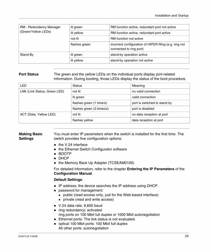
Device Status These LEDs provide information about conditions concerning the operating status of the entire device.
POTENTIAL INJURY OR EQUIPMENT DAMAGELED OR LASER components in accordance with IEC 60825-1 (2001):LASER CLASS 1 - CLASS 1 LASER PRODUCTLaser lightDo not look into the beam or view the beam directly with optical instruments (magnifying glasses, microscope).At a distance of less than 100 mm, failure to observe this precaution can cause injury to your eyes.Light is emitted from the optical connections or from the ends of the connected optical fibers that are connected to the optical connections. LIGHT EMITTING DIODE CLASS 2 M, wave length 650 nm, power <2 mW in accordance with DIN EN 60825-1:2003-10LIGHT EMITTING DIODE CLASS 1 - CLASS 1 LED PRODUCT
Failure to follow these instructions can result in injury or equipment damage.
CAUTION
Device status
FAULTRM
PStand by Green
Yellow
Port Status
LED Status Meaning
P - Power(Green/Yellow LEDs)
lit green both supply voltages on
Iit yellow only one supply voltage on
not lit supply voltage is too low
Fault - Error it red the signal contact is open, i.e. error
not lit the signal contact is closed, i.e. no error
Note: If the manual adjustment is active on the signal contact, the error display is independent of the signal contact setting.
28 31007118 7/2008
Installation and Startup
Port Status The green and the yellow LEDs on the individual ports display port-related information. During booting, those LEDs display the status of the boot procedure.
Making Basic Settings
You must enter IP parameters when the switch is installed for the first time. The switch provides five configuration options:
the V.24 interfacethe Ethernet Switch Configurator softwareBOOTPDHCPthe Memory Back Up Adapter (TCSEAM0100)
For detailed information, refer to the chapter Entering the IP Parameters of the Configuration Manual.
Default Settings:
IP address: the device searches the IP address using DHCP.password for management:
public (read access only, just for the Web-based interface)private (read and write access)
V.24 data rate: 9,600 baudring redundancy: activatedring ports on 100 Mbit full duplex or 1000 Mbit autonegotiationEthernet ports: The link status is not evaluated.optical 100 Mbit ports: 100 Mbit full duplexAll other ports: autonegotiation
RM - Redundancy Manager(Green/Yellow LEDs)
lit green RM function active, redundant port not active
lit yellow RM function active, redundant port active
not lit RM function not active
flashes green incorrect configuration of HIPER-Ring (e.g. ring not connected to ring port)
Stand By lit green stand-by operation active
lit yellow stand-by operation not active
LED Status Meaning
LNK (Link Status, Green LED) not lit no valid connection
lit green valid connection
flashes green (1 time/s) port is switched to stand by
flashes green (3 times/s) port is disabled
ACT (Data, Yellow LED) not lit no data reception at port
flashes yellow data reception at port
31007118 7/2008 29

Installation and Startup
Redundancy Manager switched off (DIP switch RM: OFF)stand-by coupling is switched off (DIP switch: stand-by is switched off)port 4 = control port, port 3 = coupling port for redundant ring coupling
The USB Interface
The USB socket is an interface which allows you to connect a Memory Back Up Adapter (EAM) locally. The EAM is a device which allows you to save and load the configuration and to load the software.
The V.24 Interface (External Management)
RJ11 socket (V.24 interface) is a serial interface which allows you to connect the following devices locally:
an external management station (VT100 terminal or PC with appropriate terminal emulation). (The serial cable that allows external management is part number 490NTRJ11.) This allows you to establish a connection to the Command Line Interface and the System Monitor.Memory Back Up Adapter (EAM)
Settings VT100 Terminal:
Pin Number Signal Name
1 VCC
2 - data
3 + data
4 ground
Speed: 9600 Baud (EMS)
Data: 8 bit
Stopbit: 1 bit
Handshake: off
Parity: none
Note: The socket housing is not galvanically insulated from the front panel of the switch.
Note: The V.24 interface is electrically connected to the supply voltage.
30 31007118 7/2008

Installation and Startup
The figure below describes the pin assignment of the V24 interface.
Removal The following table shows how to remove the switch from the snap-on rail.
Note: You can order the terminal cable separately (ref #: 490NTRJ11).
Pin 6
Pin 1Pin 1
Pin 5
Pin 8
CTSnot connected
TXGND
RXRTS
Step Action
1 Move the screwdriver horizontally under the chassis in the locking slide.
2 Pull this down — without tilting the screwdriver.
3 Pull the switch off the rail.
31007118 7/2008 31

Installation and Startup
32 31007118 7/2008

Appendices
At a Glance
Overview This chapter contains information concerning the technical data of the switch.
What's in this Appendix?
The appendix contains the following chapters:
Chapter Chapter Name Page
A Technical Data 35
B TCSESM Switch Quick Start Quide 47
31007118 7/2008 33

Appendices
34 31007118 7/2008

31007118 7/2008
A
Technical DataAt a Glance
Overview This chapter contains the technical data and the order numbers of the product.
What's in this Chapter?
This chapter contains the following topics:
Topic Page
General Technical Hardware Data 36
Dimension Drawings 37
Electromagnetic Compatibility (EMC) and Physical Resistance 39
Network Expansion 40
Power Input and Output 41
Recommended Fuses 42
Switches and Accessories 43
Underlying Standards 44
Agency Approvals 45
Certifications 46
35

Technical Data
General Technical Hardware Data
Dimensions: W x H x D TCSESM04 47 x 131 x 111 mm1.85 x 5.16 x 4.3 in
TCSESM08 and TCSESM10 74 x 131 x 111 mm2.91 x 5.16 x 4.37 in
TCSESM16 and TCSESM24 111 x 131 x 111 mm4.37 x 5.16 x 4.37 in
Weight TCSESM04 400 g
TCSESM08 410 g
TCSESM10
TCSESM16 600 g
TCSESM24 650 g
Voltage Supply operating voltage 9.6 to 60 VDC or 18 to 30 VAC safety extra-low voltage (SELV), redundant input decoupledRelevant to North America:Nec Class 2 power source 5 A max
Overload Protection at the Input non-exchangeable fuse
Insulation Voltage between Operating Voltage and Housing 800 V
Ambient Conditions operating temperature 0° C (+32° F) to +60° C (+140° F)
storage temperature ambient air: -40° C (-40° F) to +80° C (+176° F)
humidity 10% to 90% (non-condensing)
atmospheric pressure up to 2000 m (795 hPa), higher altitudes on demand)
Pollution Degree 2
Protection Classes laser protection Class 1 in accordance with EN 60825-1 (2001)
protection class IP 20
36 31007118 7/2008

Technical Data
Dimension Drawings
4 and 8 Port Versions
111 13,7330,48
4613
13,
6
0.544.37
5.16
0.14
1.2
1.8
mminch
111 13,7330,48
74
131
3,6
4.37 0.541.2
2.91
5.16
0.14
31007118 7/2008 37

Technical Data
16 and 24 Port Versions
110,3 13,7330,48
110
130
3,6
1.20
4.33
4.34 0.54
5.12
0.14
mminch
38 31007118 7/2008

Technical Data
Electromagnetic Compatibility (EMC) and Physical Resistance
EMC Immunity The product complies with the standards concerning EMC immunity listed below:
EMC Interference The product complies with the standards concerning EMC interference listed below:.
Physical Resistance
The product complies with the standards concerning physical resistance listed below:.
EMC Immunity Kind of Interference Levels
EN 61000-4-2 discharge of static electricity,contact discharge: test level 3 8 kV
EN 61000-4-3 electromagnetic fields,test level 3 (80 -2000 MHz)
20 V/m
EN 61000-4-4 fast transients (burst), test level 3:
power line 4 kV
data line 4 kV
EN 61000-4-5 surge voltages:
EN 61000-4-5 power line: line/line: test level 2 1 kV
power line: line/earth, test level 3 2 kV
data line: test level 3 2 kV
EN 61000-4-6 immunity to conducted disturbances induced by radio frequency fields, test level 3:
10 - 150 kHz 3 V
150 kHz - 80 MHz 10 V
EN 61000-4-9 pulse magnetic fields, test level 4 300 A/m
EMC Interference Classes
EN 55022 Class A
FCC 47 CFR Part 15 Class A
Germanischer Lloyd Classification and Building Regulations VI-7-3 Part 1
Resistance to Standards concerning Resistance
Vibration IEC 60068-2-6, test FC, test levels in accordance with IEC 61131-2Guidelines for the Execution of Prototype Tests, part 1
Shock IEC 60068-2-27, Test EA, test level in accordance with IEC 61131-2
31007118 7/2008 39

Technical Data
Network Expansion
TP Port A twisted pair cable segment is typically 100 m long (cat5e cable for 1000BASE-TX).
100BASE-FX Fiber Optic Port
The table below lists the network expansion data concerning 100BASE-FX fiber optic ports.
1000BASE-FX Fiber Optic Port
The table below lists the network expansion data concerning 1000BASE-FX fiber optic ports.
Description Wave Length
Fiber System Attenuation
Expansion Fiber Data
Multimode FX, DSC, 10/100 Mbit
1300 nm 50/125 μm 0-8 dB 0-5 km 1.0 dB/km, 800 MHz*km
Multimode FX, DSC, 10/100 Mbit
1300 nm 62.5/125 μm 0-11 dB 0-4 km 1.0 dB/km, 500 MHz*km
Single Mode FX, DSC, 10/100 Mbit
1300 nm 9/125 μm 0-16 dB 0-30 km 0.4 dB/km; 3.5 ps/(nm*km)
Description Wave Length Fiber System Attenuation
Example of Fiber Optic Line Length
Fiber Data
M-SFP-SX/LC (MM) 850 nm 50/125 μm 0-7.5 dB 0-550 m 3.0 dB/km, 400 MHz*km
M-SFP-LX/LC (MM) 1310 nm (1) 50/125 μm 0-11 dB 0-550 m 1.0 dB/km, 800 MHz*km
M-SFP-SX/LC (MM) 850 nm 62.5/125 μm 0-7.5 dB 0-275 m 3.2 dB/km, 200 MHz*km
M-SFP-LX/LC (MM) 1310 nm (1) 62.5/125 μm 0-11 dB 0-550 m 1.0 dB/km, 500 MHz*km
M-SFP-LX/LC (SM) 1310 nm 9/125 μm 0-11 dB 0-20 km 0.4 dB/km; 3.5 ps/(nm*km)
M-SFP-LH/LC (LH) 1550 nm 9/125 μm 6-22 dB 24-72 km 0.25 dB/km; 19 ps/(nm*km)
Note: (1) with fiber optic adapter in accordance with IEEE 802.3-2002 clause 38 (single-mode fiber offset-launch mode conditioning patch cord)
40 31007118 7/2008

Technical Data
Power Input and Output
Power Input and Output List
The table shows power input and output for the different switch versions.
Version Power Input Power Output
TCSESM04, 2 TX Ports 5.3 W 18.1 Btu (IT)/h
TCSESM04, 1 FX Port, 1 TX Port 6.5 W 22.2 Btu (IT)/h
TCSESM04, 2 FX Ports 7.7 W 26.3 Btu (IT)/h
TCSESM08, 2 TX Ports 5.3 W 18.1 Btu (IT)/h
TCSESM08, 1 FX Port, 1 TX Port 6.5 W 22.2 Btu (IT)/h
TCSESM08, 2 FX Ports 7.3 W 26.3 Btu (IT)/h
TCSESM10 (with Gigabit Ports), 2 TX Ports 8.9 W 30.4 Btu (IT)/h
TCSESM10 (with Gigabit Ports), 2 FX Ports 8.3 W 28.4 Btu (IT)/h
TCSESM16, 2 TX Ports 9.4 W 32.1 Btu (IT)/h
TCSESM16, 2 FX Ports 11.8 W 40.3 Btu (IT)/h
TCSESM24, 2 FX Ports 15.5 W 52.9 Btu (IT)/h
31007118 7/2008 41

Technical Data
Recommended Fuses
Fuses Recommended fuses:
TCSESM Switch Fuse
TCSESM04xx 1.5A Slow/delay fuse
TCSESM08xx 1.5A Slow/delay fuse
TCSESM10xx 2.0A Slow/delay fuse
TCSESM16xx 2.0A Slow/delay fuse
TCSESM24xx 3.0A Slow/delay fuse
42 31007118 7/2008

Technical Data
Switches and Accessories
Scope of Delivery
The delivery comprises:
selected switch versionterminal block for supply voltage and signal contactdescription and manualsCD ROM
Order Numbers
Part Number Description
4 Port Version TCSESM043F23F0 4 10/100 TX Managed
TCSESM043F1CU0 3 10/100 TX 1 100 FX-MM Managed
TCSESM043F2CU0 2 10/100 TX 2 100 FX-MM Managed
TCSESM043F1CS0 3 10/100 TX 1 100 FX-SM Managed
TCSESM043F2CS0 2 10/100 TX 2 100 FX-SM Managed
8 Port Version TCSESM083F23F0 8 10/100 TX Managed
TCSESM083F1CU0 7 10/100 TX 1 100 FX-MM Managed
TCSESM083F2CU0 6 10/100 TX 2 100 FX-MM Managed
TCSESM083F1CS0 7 10/100 TX 1 100 FX-SM Managed
TCSESM083F2CS0 6 10/100 TX 2 100 FX-SM Managed
TCSESM083F2CX0 6 10/100 TX 1 100 FX-MM 1 100 FX-SM Managed
16 Port Version TCSESM163F23F0 16 10/100 TX Managed
TCSESM163F2CU0 14 10/100 TX 2 100 FX-MM Managed
24 Port Version TCSESM243F2CU0 22 10/100 TX 2 100 FX-MM Managed
Gigabit - 10 Port Version TCSESM103F23G0 8 10/100 TX 2 10/100/1000 TX Managed
TCSESM103F2LG0 8 10/100 TX 2 1000 SFP (fiber) Managed Note: These products ship with open sockets (SFP) on the fiber ports, so in order to use these ports, you must order 1, or 2, media modules shown below.
Fiber Media Modules TCSEAAF1LFU00 SFP-SX/LC fiber module for Gigabit
TCSEAAF1LFS00 SFP-LX/LC fiber module for Gigabit
TCSEAAF1LFH00 SFP-LH/LC fiber module for Gigabit
Accessories TCSEAM0100 Memory Backup Adapter
31007118 7/2008 43

Technical Data
Underlying Standards
Standard Contents of Standard
EN 61000-6-2:2001 Generic standard: immunity for industrial environments
EN 55022:1998 + A1 2000 + A2-2003 Radio interference characteristics of information technology equipment
EN 60950:2001 Safety of information technology equipment
EN 61131-2:200 Programmable logic controllers
EN 50121-4:2000 Railroad applications—EMC: interference and immunity of signal and telecommunications equipment
FCC 46 CFR Part 15:2003 Code of Federal regulations
EN 10155 Declaration (railroad)
EN 61850-3 Communication networks and systems in stations
IEEE 1613 Standard environment and testing requirements for communication networking devices in electric power substations
44 31007118 7/2008

Technical Data
Agency Approvals
Standards Contents of Standard
UL 508 / CSA C22.2 No. 14 Safety of industrial control equipment
UL 1604 / CSA C22.2 No. 213 Electrical equipment for use in Class I and Class II, Div. 2 and Class III hazardous (classified) locations
Germanischer Lloyd Classification and building regulations VI-7-3, part 1, 2003 edition
31007118 7/2008 45

Technical Data
Certifications
The ESM switches have CE certification.
46 31007118 7/2008

31007118 7/2008
B
TCSESM Switch Quick Start QuideAt a Glance
Introduction This chapter provides a quick start guide for the ConneXium TCSESM managed switch. It provides enough basic information to allow you to setup an ESM switch in an industrial network arrangement.
What's in this Chapter?
This chapter contains the following topics:
Topic Page
Overview 48
Preliminary Setup 49
Logging On to the System 51
Redundancy Configuration 55
Configuring the HIPER-Ring Version 1 56
Configuring the HIPER Ring Version 2 (MPR Draft) 58
Configuring the TCSESM Switch 61
Backing Up and Restoring the TCSESM Switch Configuration 67
47

Abbreviated title of Chapter
Overview
Introduction The purpose of this guide is to help you get your Schneider ConneXium TSCESM managed switch up and running as quickly as possible. Although the recommended switch settings that appear in this guide are suitable for many industrial Ethernet applications, they are strictly used in a general sense here, and may not apply to your particular network arrangement. For more detailed information, refer to the manuals listed under Reference Material (below).
The applicable switches covered by this guide include all versions of the ConneXium TSCESM Managed Switches listed on (see Switch Versions , p. 11) .
Hardware/Software Requirements
For the example discussed in this guide, the following hardware items are required:
External power supply capable of providing + 24 VDC.A PC running Windows 2000 or XP software installed.An Ethernet cable (see The V.24 Interface (External Management), p. 30) to connect the PC to the TCSESM switch.EAM0100 Memory Backup AdaptorEthernet Switch Configurator software installed on a PC
Intended Audience
This quick start guide is intended for anyone who is involved in installing and configuring a Schneider TCSESM switch in an industrial network arrangement.
Anyone reading this guide should:
Be familiar with use of high-speed Ethernet switches used in industrial networking arrangements. Understand Ethernet networks and the TCP/IP protocol.
Reference Material
For detailed information regarding the procedures covered by this guide, refer to the following Schneider publications
Basic Configuration Guide 31007122Redundancy Manual 31007126Command Line Interface (CLI) Manual 31007130
All of the above listed manuals (along with this manual) are available on the CD-ROM that was shipped with your TCSESM switch.
48 31007118 7/2008

Abbreviated title of Chapter
Preliminary Setup
Overview In order to perform the initial setup procedure to allow the TCSESM switch to operate in a network environment you will first need to provide it with power, set it’s dip switches, connect the PC to the switch, and run the Configurator software.
Power Requirements
You need to provide 24 VDC power to pins 1 and 6 of the 6-pin terminal block (located at the top-front of the EMS switch). Also, connect a 0 volt common line to pin 3 or 4 on the terminal block. If redundant power supplies are not being used, place a jumper between the two 24V power pins (1 and 6) to prevent a fault condition from occurring (indicated by a solid red Fault LED).
Setting the DIP Switches
The TCSESM’s dip switches (located on the front of the switch) should initially be set to the ON position as shown below.
Setting the TCSESM IP Address
To set the IP address of the switch and logon to it’s web configuration page:
ONRM
Stand by
Step Action
1 Connect an Ethernet cable between your PC and any port of the switch.
2 Install the Ethernet Switch Configurator software (supplied on the CD-ROM that came with the switch) onto the PC.
3 Run the Ethernet Switch Configurator. It will scan the network and list all connected TCSESM switches (see example, below).
Note: If no switches show up, make sure the correct network interface is shown on the pull-down list.
4 Select the switch to be configured.
5 Click on the Signal button and observe that the switch’s LED’s flash.
31007118 7/2008 49

Abbreviated title of Chapter
6 Click on the Properties button to open the Properties for MAC Address dialog box.
7 Type in a Name for your switch
8 In the IP Configuration block, type in the switch’s IP Address and Subnet Mask.
9 Click OK.
10 Click on the WWW button on the Configurator page (step 3) to launch the switch’s web configuration page in Internet Explorer (no internet connection is required).
Step Action
50 31007118 7/2008

Abbreviated title of Chapter
Logging On to the System
The Login Page TCSESM switch’s web configuration login page should now appear on your PC screen as shown below:
The Login for read/write access is admin, and the Password is private. After logging in, clicking the OK button will take you to the System page (see The System Page, p. 52).
If you are unable to see Login page, check that:
You have Java installed on your PC (it’s available on the switch’s CD-ROM or from www.sun.com)Make sure your PC is in the same subnet as the switch. For example, if the switch’s IP address is 10.10.10.5 and its subnet mask is 255.255.255.0, then your PC’s IP address should be between10.10.10.1 and 10.10.10.255.
If the login page still doesn’t appear, reset the IP address of your PC as described below.
OKOK
31007118 7/2008 51

Abbreviated title of Chapter
The PC Address Set PC’s address:
The System Page The System page provides basic information about the switch. It also displays the TCSESM’s top directory tree on the left side on the page.
Step Action
1 In Windows XP, click on Start.
2 Go to Settings → Network Connections → Local Area Connection.
3 Click on Properties.
4 Scroll down and select Internet Protocol (TCP/IP)in the Local Areas Connection Properties dialog box.
5 Click on Properties.
6 Select Use the following IP address in the Internal Protocol (TCP/IP) Properties dialog box.
7 Fill in the IP address and Subnet Mask text boxes.
8 Click OK to display the System page.
Name1
2 3
5
7
4
6
8
LocationContactBasic modulePower supply 1/2Temperature (°C)Uptime
present / Failed33
Device view
18.11.05 11:37
Power supply 2
Device Status
HW: 1.30
TCSESM_2FF96F
Schneider ElectricSchneider TCSESM
0 700 day(s), 3:10:17
System Data
Help?Set Reload
Alarmstarttime
Alarmreason
Reloading data in 90 sec
52 31007118 7/2008

Abbreviated title of Chapter
You can always return to this page by selecting Basics → System at the top of the tree.
The Device Status panel on the page displays the time and cause of the switch’s oldest existing ESM alarm.
In the System data panel, you can change the Name, Location and Contact information and modify the operating Temperature limits (in degrees C) of the switch. The Basic module provides the switch’s part number.
The Power supply 1/2 displays the status of the switch’s power supply(s). If an alarm is shown for a power supply, either redundant power supplies are not being used or the + 24VDC inputs are not jumpered. You can tell the switch to ignore this alarm
The Device view will vary, depending on what switch you are using. The port graphics will indicate which ports are connected.
The switch will automatically reload its data every 90 seconds. Click on the Reload button to force the System page to refresh.
You can find information on most of the configuration pages by clicking on the Help button.
The Power Supply Status
The Power supply 1/2 displays the status of the switch’s power supply(s). If an alarm is shown for a power supply, either redundant power supplies are not being used or the + 24VDC inputs are not jumpered (see Power Requirements, p. 49). You can tell the switch to ignore this alarm as follows:
Step Action
1 Select Diagnostics → Signal Contact to display the Signal Contact page.
2 Select Monitoring correct operation.
3 Select Ignore for Powersupply1 and 2.
4 Click Set.
5 Select Basics → System to return to the System page.
6 Click on the Reload button to refresh the alarm data. The Power supply 1/2 alarm box should now be cleared.
31007118 7/2008 53

Abbreviated title of Chapter
Saving Your Settings
Important: Whenever you make configuration changes, be sure to perform the following procedure in order to save the changes to the switch’s nonvolatile memory.
Reset the Default Settings
To reset the switch to its factory default settings:
Step Action
1 Click on the Set button on each page.
2 Select Basics → Load/Save on the directory tree.
3 In the Save panel, select to Device.
4 Click Save configuration.
Status notPresent
tftp://192.168.1.100/product/product.cfgURL:
current configuration current configuration and from Device
Load configuration
Delete configuration
Help?Set Reload
Load
Save
Delete
EAM
from Device from URL from URL & save to Device via PC
to Device to URL (binary) to PC (binary)to URL (script) to PC (script) Save configuration
Function
Undo modifications of configuration
Period to undo while connection is lost [s] 600 Watchdog IP address 0.0.0.0
Step Action
1 Select Basics → Local/Save on the directory tree.
2 In the Delete panel, (see figure, above) select current configuration and from Device.
3 Click on the Delete configuration button.
54 31007118 7/2008

Abbreviated title of Chapter
Redundancy Configuration
Overview Redundancy configuration includes the physical setup and configuration of the TCSESM switch to accommodate a HIPER-Ring arrangement.
The redundancy status can be monitored via:the Redundancy web pagethe RM LEDfault contactSNMPOPC
The configuration and status functions are both optional and may not apply to your switch configuration. If so, skip this section of the guide and proceed to the next section.
31007118 7/2008 55

Abbreviated title of Chapter
Configuring the HIPER-Ring Version 1
HIPER-Ring Version 1 Configuration
Configuring the switch to perform in a HIPER-Ring shaped network structure involves the following steps:
Step Action
1 On the front of the switch, ensure that the RM and Standby dip switches are in the Off (left side) position.
2 Daisy chain the ring ports of all the switches involved in the network together (default ring ports are 1 and 2).
3 On one of the end switches, place the RM (Redundancy Manager) dip switch to the ON position (see Setting the DIP Switches, p. 49).
4 Connect the last switch to the first to create a ring.
56 31007118 7/2008

Abbreviated title of Chapter
You can use the HIPER-Ring web page to change the HIPER-Ring ports. To access the page, select Redundancy → HIPER-Ring on the main directory tree.
Inactive
Module
Port
Operation
On Off
inactive
Ring Port 1
Module
Port
Operation
Ring Port 2
2
inactive
11
1
Active (redundant line)
Redundancy Manager Status
Redundancy Manager
Information
Version 1 Version 2 (MRP Draft)
Mode
Delete ring configurationReloadSet Help?
Version
31007118 7/2008 57

Abbreviated title of Chapter
Configuring the HIPER Ring Version 2 (MPR Draft)
Configuration Procedure Using the Web-Based Interface
Configure the MRP ring as follows:
Step Action
1 Set up the network according to your requirements.To avoid loops during the configuration, do not connect the redundant path until you have concluded the MRP-Ring configuration.
2 Check that the the RM and Standby DIP switches are in the ON (right) position.
3 Connect the switches to Ethernet cables.
4 Connect a PC to a switch and open the Web-based interface.
5 At the menu tree, go to Redundancy → HIPER-Ring to display the HIPER-Ring dialog box.
58 31007118 7/2008

Abbreviated title of Chapter
6 Select Version 2 (MPR Draft) in the Version box.
7 In the HIPER-Ring dialog box, designate the port numbers for Ring Port 1 and Ring Port 2.
8 The Operation fields in the Ring Port 1 and Ring Port 2 group boxes allow you to view the statuses of these ports:forwarding: This means that the port is switched on and has a link.inactive: This means that the port is blocked and has a link.disabled: This means that the port is switched off.not-connected: This means that the port does not have a link.
9 At the menu tree go to Basics → Port Configuration.
10 Select the following settings for each ring port:Port on: selectedAuto negotation: deselectedManual Configuration: 100 Mbit/s FDXCable Crossing: disable
Note: When you use 100 Mbit/s and full-duplex with twisted pair cables, with the autocrossing function deactivated and Cable Crossing set to enable, you must use a crossover cable.
11 Click On in the Operation frame.
12 Repeat steps 3 to 8 for all switches in the ring.
Step Action
Module
Port
Operation
On Off
inactive
Ring Port 1
Module
Port
Operation
Ring Port 2
2
inactive
11
1
Advanced Mode
Configuration Redundancy Manager
Version 1 Version 2 (MRP Draft)
Mode
Version
Redundancy Manager
Operation
On
Off
VLAN
VLAN ID
Information
31007118 7/2008 59

Abbreviated title of Chapter
13 On one switch at either end of the line, enable the Redundancy Manager by setting the Redundancy Manager Mode to ON.
14 If a switch in the ring does not support the advanced mode for fast switching times, deactivate the advanced mode by unchecking the Advanced Mode check box in the Configuration Redundancy Manager group box.
15 Select the desired value (Standard (500 ms)) or Accelerated (300 ms)) in the Ring Recovery group box for the switch for which you have activated the redundancy manager.Note: Settings in the Ring Recovery group box are ineffective for switches that are not the redundancy manager. Also, if selecting the Accelerated value does not provide the ring stability required for your network, change to the Standard setting.
16 The Information group box allows you to view information status:Redundancy guaranteed: If a path used for the function fails, the redundant path will take over the function of the failed path.Configuration failure: The function is incomplete or has been incorrectly configured.
17 If the MRP ring configuration is not to be assigned to a VLAN, enter 0 in the VLAN ID field.
18 The VLAN group box allows you to assign a MRP-ring to a VLAN. If the MPR-ring is not to be assigned to a VLAN, enter 0 for the VLAN ID. If the MPR-ring is to be assigned to a VLAN, then enter the VLAN ID configured for the ring ports as the VLAN ID.Note: All ring ports must have the same VLAN ID and membership set to U in the static VLAN table.
19 Disable the Spanning Tree protocol on the ports connected to the redundant ring, since Spanning Tree and ring redundancy operate at different reaction speeds:At the menu tree, go to Redundancy → Rapid Spanning Tree → Port to disable Spanning Tree for the ports.
20 Close the line leading to the ring by connecting the two switches at the ends of the line via their ring ports.
Step Action
60 31007118 7/2008

Abbreviated title of Chapter
Configuring the TCSESM Switch
Overview You configure the TCSESM switch by selecting settings and parameters on the various pages contained in the switch’s web configuration software. The switch functions involved with the configuration process are:
MulticastsPortsDiagnostics
Multicasts Page If the switch is to be used in an EtherNet IP Network, its Multicast function must be configured.To setup the Multicasts page:
Step Action
1 Select Switching → Multicasts to display the Multicasts page.
2 Select IGMP Snoopingin the Global Configuration frame.
3 Verify that IGMP active and Protocol Version 2 are both selected
4 Click on the Set button.
31007118 7/2008 61

Abbreviated title of Chapter
Port Configuration Page
To configure the switch’s ports, review the following:
Step Action
1 Select Basics → Port Configuration to display the Port Configuration page.
2 Verify that all copper ports are set (checked) in the Auto negotiation column.Note: This does not apply to any ring ports if the switch is setup for HIPER-Ring redundancy (see Redundancy Configuration, p. 55).
3 If you want the switch’s ports to have link status alarming, check the box for each port that has a full time connection, in the Propagate Connection Error column.Note: You must also turn on monitoring for these ports in the Diagnostics → Ports → Signal Contact page.
4 Identify each port by giving it a name in the Port Name column.
5 To limit unauthorized access to the network, turn off unused ports by unchecking them in the Port on column.
62 31007118 7/2008

Abbreviated title of Chapter
Diagnostics Ports Statistics Page
This page can be used to check for collisions, CRC errors, or fragments. To view the status of these items:
Resetting the Port Statistics Table
To reset the Port Statistics Table:
Step Action
1 Select Diagnostics → Ports → Statistics to display the Statistics Table.
2 Check the Received Fragments, Detected CRC Errors, and Detected Collisions columns for each port. If the data in them is not zero (0) proceed to the next step.
3 Return to the Port Configuration page (see Port Configuration Page, p. 62) and check in the Current Settings column to see if any of these ports are connected at half-duplex (HDX). If any of them are, proceed to the next step.
4 Check to see if the switch supports full-duplex for each of the affected ports. For those that do, deselect Auto-negotiation for each one.
5 Then select either 10 or 100 Mbit/s FDX from the pull-down list in the Manual Configuration column.
1111333344445555
Module PortTransmittedUnicastPackets
ReceivedPackets
ReceivedOctets
ReceivedFragments
DetectedCRC errors
DetectedCollisions
Packets64 bytes
Packets65 to 127 bytes
1111333344445555
000000000000
676091266919
00
000000000000
2743842030742
00
000000000000
2743841208661399
00
0000000000000000
0000000000000000
0000000000000000
000000000000
377820664755
00
000000000000
214446385734
00
Help?Reload
Step Action
1 Select Basics → Restart.
2 Click on Reset port counters.
31007118 7/2008 63

Abbreviated title of Chapter
The Signal Contact Page
The signal contacts are for:
controlling external devices by manually setting the signal contacts.monitoring proper functioning of the switch which makes it possible to perform remote diagnostics.
The signal contact page allows you to configure the normally-closed signal contact to provide indication of:
a lost power supplytemperature out-of-rangeremoval of an EAMa connection errorHIPER-Ring statusstatus of ring/network coupling
For example, a contact could provide indication that a control panel’s temperature is too high, or that there is a break in the HIPER-Ring or that the connection to a PLC was lost.
64 31007118 7/2008

Abbreviated title of Chapter
To configure the signal contact page proceed as follows:
Step Action
1 Go to Diagnostics → Signal Contact.
2 Click Monitoring correct operation in the Mode Signal contact frame, to use the contact for function monitoring.The dialog below appears.
3 In the Monitoring correct operation frame, select the events which you want to monitor by clicking on their associated Monitor option button.
4 If you select temperature monitoring, follow it up by going to Basics → System in the main tree directory.
31007118 7/2008 65

Abbreviated title of Chapter
The Events Log Page
The Events Log page provides a time-stamped log that includes a list of all the switch’s alarms and traps.
To access the log, select Diagnostics → Event Log.
5 In the line Temperature (°C) of the System Data group box, set the temperature thresholds to be monitored.
6 Deselect those events that you do not want to monitor by clicking on the appropriate Ignore option button.
Step Action
NameLocationContactBasic modulePower supply 1/2Temperature (°C)Uptime
present / Failed33
HW: 1.30
TCSESM_2FF96F
Schneider ElectricSchneider TCSESM
0 700 day(s), 3:10:17
System Data
66 31007118 7/2008

Abbreviated title of Chapter
Backing Up and Restoring the TCSESM Switch Configuration
Overview The TCSESM switch configuration should be backed up on a regular basis using a EAM0100 Memory Backup Adaptor. The procedure for backing up the switch is described below.
Backing Up the Switch Configuration
To backup the switch’s configuration and IP address, proceed as follows:
Step Action
1 Plug an EAM0100 into the USB port on the front of the switch.
2 Select Basics → Load/Save at the main directory tree to display the Load/Save page.
3 Select Local in the Save panel.
4 Click on the Save configuration button. The configuration will be stored in both the EAM0100 and the switch’s memory.
5 Click on the Reload button to refresh the display.
31007118 7/2008 67

Abbreviated title of Chapter
The message appearing in the Status list box of the EAM panel displays the current status of the EAM0100 as follows:
notPresent: the EAM0100 in not connectednotInSync: the configuration in the EAM0100 does not match the switch’sok: the configuration in the EAM0100 matches the one in the switch
Restoring the Switch Configuration
You use this procedure:when a switch failure occursto correct a misconfigured switchto copycat the configuration to multiple other switches
To restore the switch’s configuration and IP address, proceed as follows:
When it’s not in use, unplug the EAM0100 from the switch and store it in a safe place near the switch. Also, the EAM0100 can be connected to a PC to archive the switch.cfg configuration file.
Step Action
1 Remove power from the switch
2 Plug an EAM0100 containing a backed-up copy of the switch configuration (see above) into the USB port on the front of the switch.
3 Return power to the switch. The stored configuration and IP address will automatically be loaded to the switch’s memory.
68 31007118 7/2008
Related Documents