TCP/IP & ROUTING PROTOCOLS V.Maheswaran Nair Sub Divisional Engineer BSNL,Trivandrum.

Welcome message from author
This document is posted to help you gain knowledge. Please leave a comment to let me know what you think about it! Share it to your friends and learn new things together.
Transcript

TCP/IP
&
ROUTING PROTOCOLS
V.Maheswaran Nair
Sub Divisional Engineer
BSNL,Trivandrum.
TCP/IP(Transmission Control Protocol/
Internet Protocol)
TCP/IP Protocols provide the ability to connect machines regardless of the underlying network cabling & the Operating Systems in use.
TCP/IP is a piece of networking software for the Internet and networks worldwide.
TCP/IP

TCP/IP protocol suite contain two main things:
Network Applications HTTP (Hyper Text Transfer Protocol) WWW Services
FTP (File Transfer Protocol) for transferring file
SMTP Simple Mail Transfer Protocol) for E Mail
DNS (Domain Name System) etc…
TCP is Used

Networking protocols
Moving packet of data from Source to Destination
Internet Protocols (IP) and Routing Protocols are used.

TCP is responsible for:
Data concurrency
Packet Sequencing
Delivery guarantee
Error Control
Retransmission

Internet address
MAC address
(Node to Node)
IP address
(Source to
Destination)
Port address
(Application)
16 bit
Decimal Notation
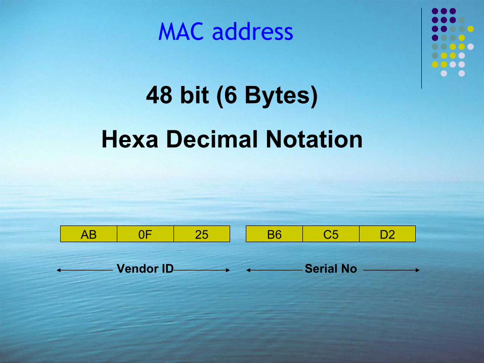
MAC address
48 bit (6 Bytes)
Hexa Decimal Notation
AB 0F 25 B6 C5 D2
Vendor ID Serial No

IP Address
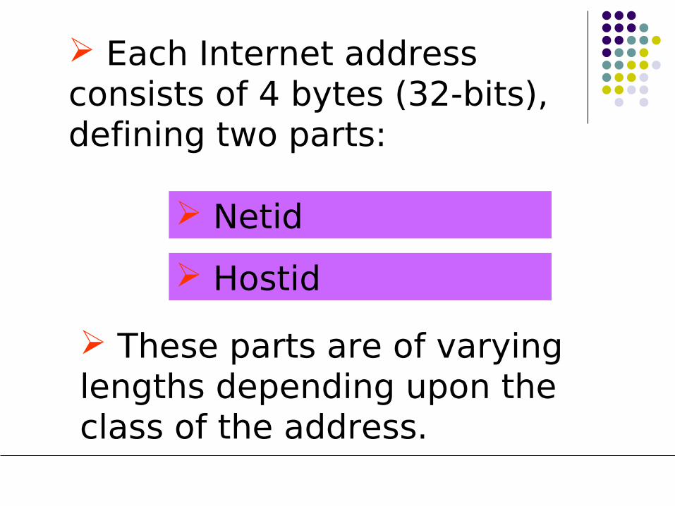
Each Internet address consists of 4 bytes (32-bits), defining two parts:
Hostid
Netid
These parts are of varying lengths depending upon the class of the address.
Dotted Decimal Notation
To make the 32-bit address form more compact and easier to read, Internet addresses are usually written in decimal form with decimal points separating the bytes.

128.11.3.31
10000000 00001011 00000011 00011111
Classes
There are five different IP Address Classes: A, B, C, D & E.
These are designed to cover the needs of different types of organizations.

Host IdNet Id
NIB
Each address is a pair (Netid and Hostid) where the Netid identifies a network and the Hostid identifies a host on that network.

0 NETID HOSTID
10 NETID
110 NETID
HOSTID
1110 MULTICAST ADDRESS
HOSTID
1111 FOR FUTURE USE
A
B
C
D
E
Byte 1 Byte 2 Byte 3 Byte 4
Internet Address Classes
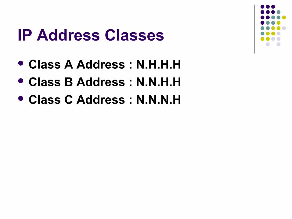
IP Address Classes
Class A Address : N.H.H.H Class B Address : N.N.H.H Class C Address : N.N.N.H

IP address - Classes
Class A 00xxxxxxx xxxxxxxx xxxxxxxx xxxxxxxx
Network Host
Class B
Network Host
1010xxxxxx xxxxxxxx xxxxxxxx xxxxxxxx
Class C
Network Host
110110xxxxx xxxxxxxx xxxxxxxx xxxxxxxx
•IP addressing supports five different address classes - A, B,C,D,E•CLASS A,B,C are available for commercial uses.•The left most bits indicate the network class.
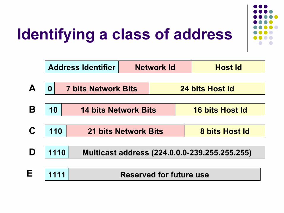
Identifying a class of address
Address Identifier Network Id Host Id
0 7 bits Network Bits 24 bits Host IdA
10 14 bits Network Bits 16 bits Host IdB
110 21 bits Network Bits 8 bits Host IdC
1110 Multicast address (224.0.0.0-239.255.255.255)D
1111 Reserved for future useE
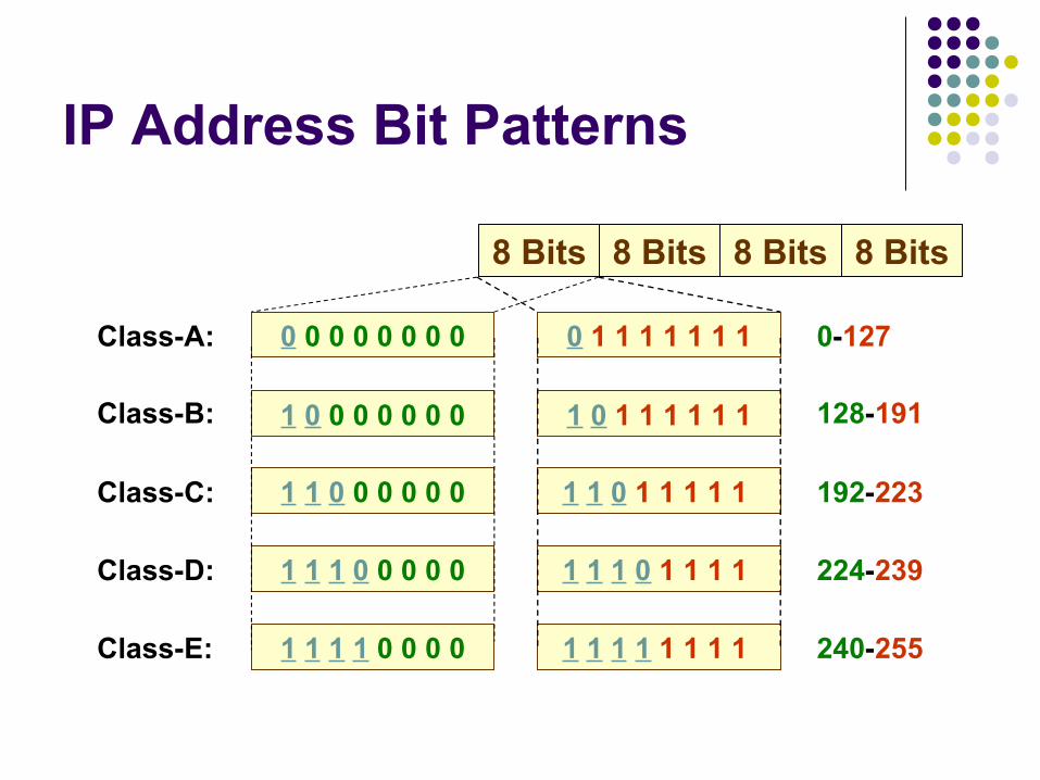
IP Address Bit Patterns
8 Bits8 Bits 8 Bits 8 Bits
Class-A:
Class-B:
Class-C:
Class-D:
Class-E:
0-127
128-191
192-223
224-239
240-255
0 0 0 0 0 0 0 0
1 0 0 0 0 0 0 0
1 1 0 0 0 0 0 0
1 1 1 0 0 0 0 0
1 1 1 1 0 0 0 0
0 1 1 1 1 1 1 1
1 0 1 1 1 1 1 1
1 1 0 1 1 1 1 1
1 1 1 0 1 1 1 1
1 1 1 1 1 1 1 1
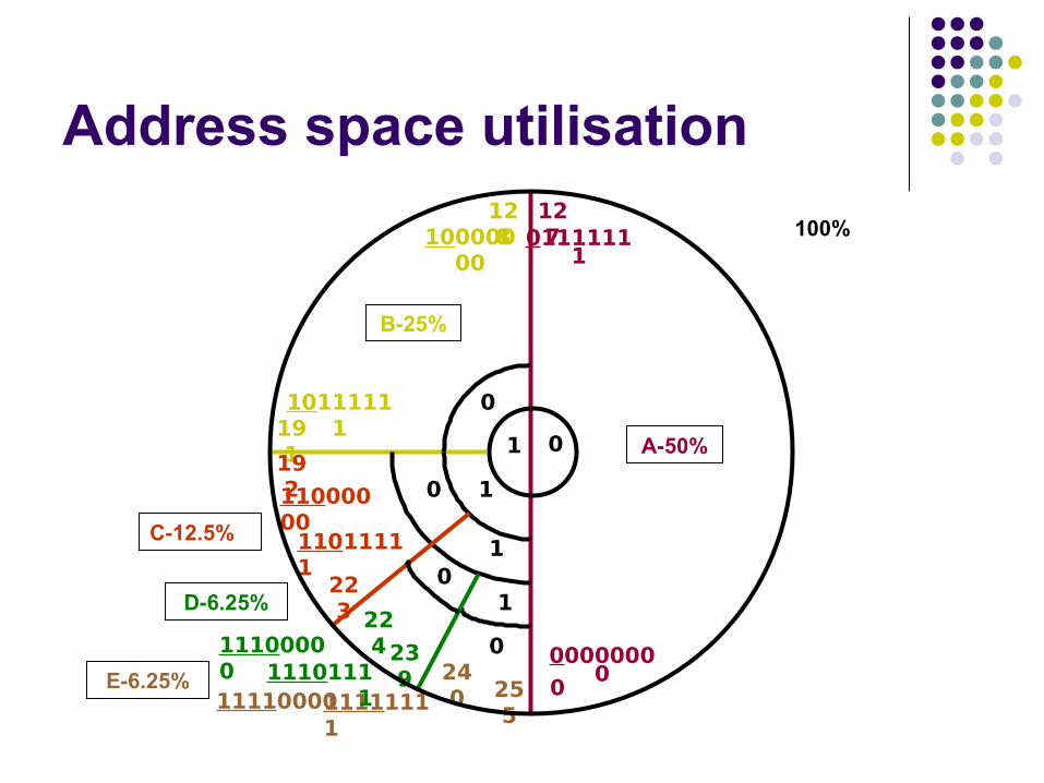
Address space utilisation
01
0
127
00000000
01111111
A-50%
1
0
128
191
10000000
10111111
B-25%
0
1
192
223
11000000
11011111
C-12.5%
240 25
5111100001111111
1
E-6.25%
022423
9
11100000 1110111
1
D-6.25%0
1
100%
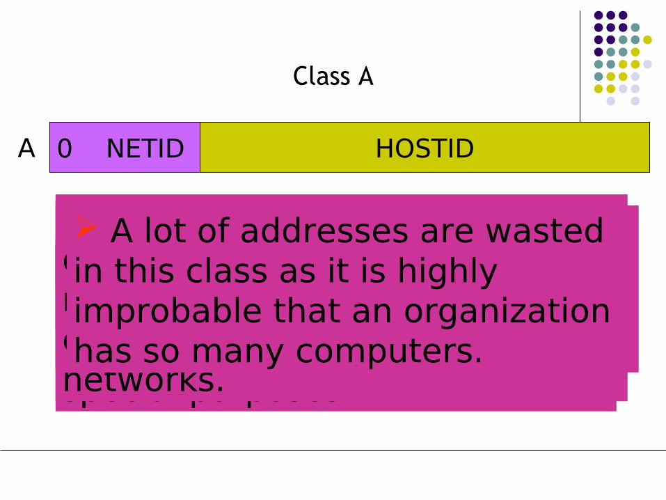
The First Octet defines the netid.
Class A
The left-most bit must be zero to define the class as ‘A’. Remaining seven bits define different networks. Theoretically, we can have 27 = 128 networks. There are actually 126 networks only because two of the addresses are reserved for special purposes.
Each network theoretically can have up to 224 = 16,777,216 hosts.
Two special addresses (hostid all 0s and hostid all 1s) are used for special purposes.
Class ‘A’ addresses are designed for organizations that may have a huge number of computers attached to their networks.
A lot of addresses are wasted in this class as it is highly improbable that an organization has so many computers.
0 NETID HOSTIDA
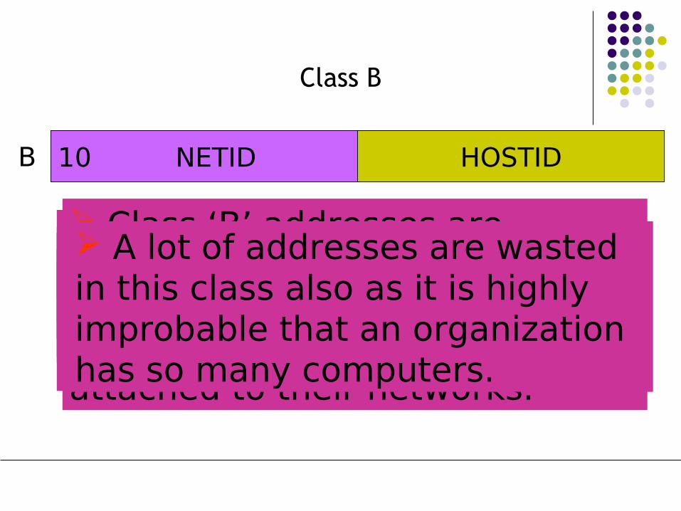
Two Octets define the netid and two octets define the hostid.
Class B
The two left-most bits are 10 to define the class as ‘B’. The next 14-bits define different networks.
We can have 214 = 16,384 networks in class ‘B’. Last 16-bits are used to define the hostid.
Each network theoretically can have up to 216 = 65,536 hosts (or routers).
Two special addresses (hostid all 0s and hostid all 1s) are used for special purposes.
Class ‘B’ addresses are designed for midsize organizations that may have a large number of computers attached to their networks.
A lot of addresses are wasted in this class also as it is highly improbable that an organization has so many computers.
10 NETID HOSTIDB

Three Octets define the netid and one octet define the hostid.
Class C
The three leftmost bits are 110 to define the class as “C’. The next 21-bits define different networks. A class ‘C’ network can have 221 =2,097,152 networks. Eight bits are used to define the hostid.
Theoretically, we can have 28=256 hosts.
Two addresses (all 0s and all 1s) are reserved for special addresses.
Class C addresses are designed for small organizations that have a small number of computers attached to their networks.
110 NETID HOSTIDC
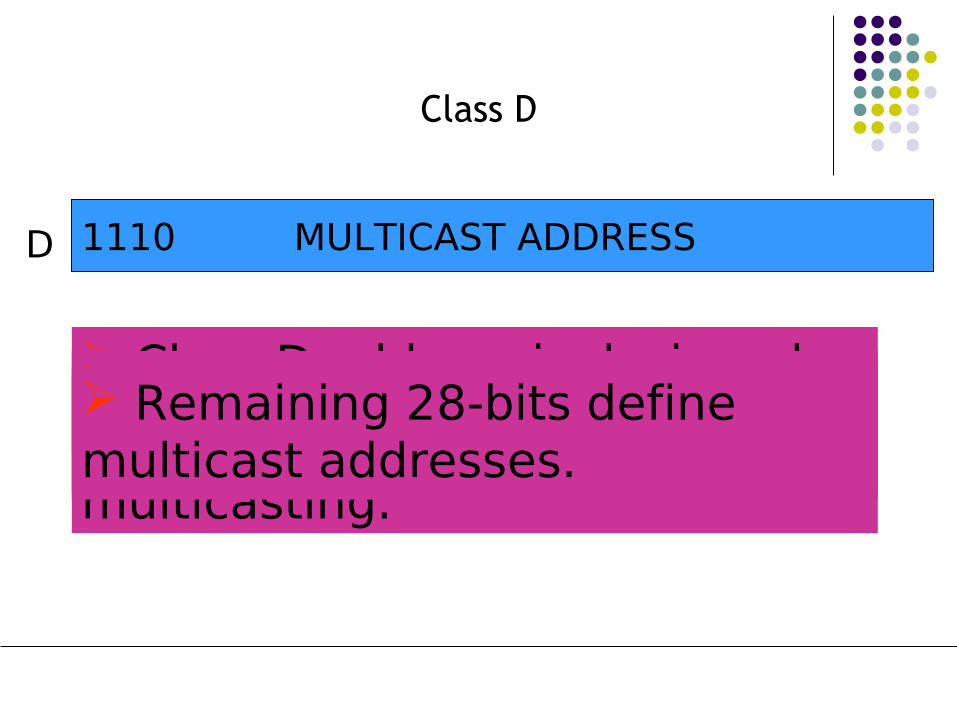
Class D address is designed for multicasting.
Class D
There is no netid or hostid; whole address is used for multicasting.
The first four bits are 1110 to define the class as ‘D’.
Remaining 28-bits define multicast addresses.
1110 MULTICAST ADDRESSD
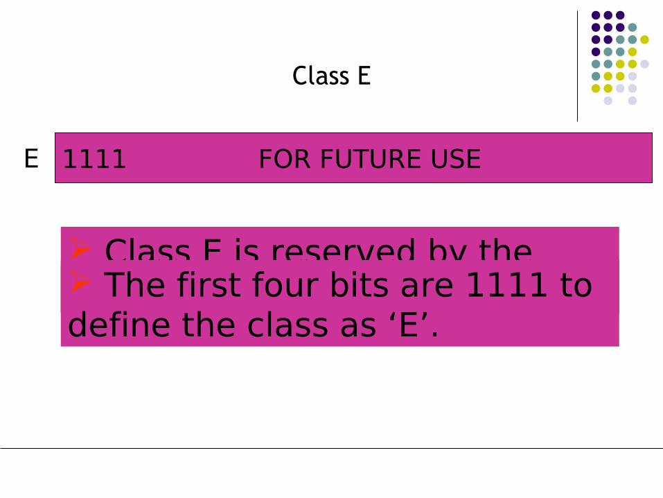
Class E is reserved by the Internet for future use.
Class E
There is no netid or hostid. The first four bits are 1111 to define the class as ‘E’.
1111 FOR FUTURE USEE
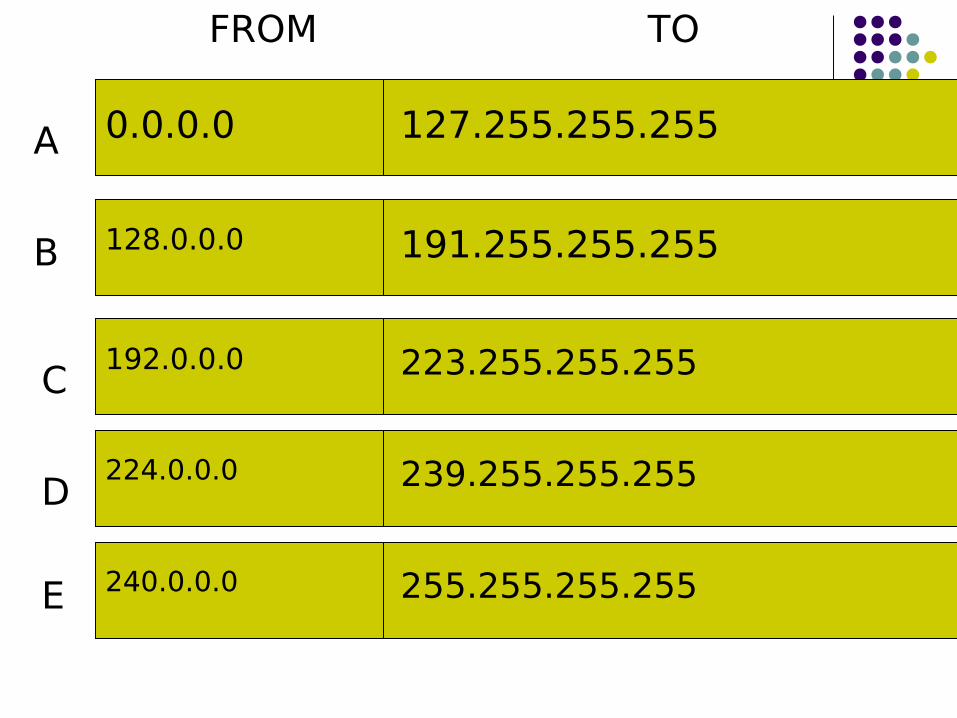
0.0.0.0 127.255.255.255
128.0.0.0 191.255.255.255
192.0.0.0 223.255.255.255
224.0.0.0 239.255.255.255
240.0.0.0 255.255.255.255
A
B
C
D
E
FROM TO

Class No. of networks No. of hosts
A 27 – 2 = 126 224 – 2 = 16,777,214
B 214 = 16,384 216 – 2 = 65,534
C 221 = 2,097,152 28 – 2 = 254
D Not Applicable Not Applicable
E Not Applicable Not Applicable
Number of networks and hosts in each Class
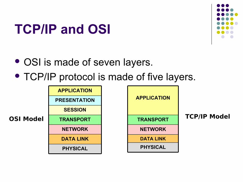
TCP/IP and OSI
OSI is made of seven layers. TCP/IP protocol is made of five layers.
PHYSICAL
DATA LINK
NETWORK
TRANSPORT
APPLICATION
PHYSICAL
DATA LINK
NETWORK
TRANSPORT
SESSION
PRESENTATION
APPLICATION
OSI Model TCP/IP Model
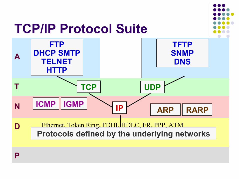
TCP/IP Protocol Suite
D
N
T
A
ICMP IGMPRARPARP
FTPDHCP SMTP
TELNETHTTP
TFTPSNMPDNS
TCP UDP
IP
Protocols defined by the underlying networks
P
Ethernet, Token Ring, FDDI, HDLC, FR, PPP, ATM

Data Encapsulation
Frame
Data
DataPort add (TCP)
TCP Segment
DataPort add (UDP)
UDP Message
Dest MACSource MAC IP Header TCP-UDP Data
TCP-UDP DataSource IP Dest IP
Application
TPT Layer (TCP/UDP)
NW Layer (IP)
Data Link (MAC)
Physical Bits 10000010101001
IP Datagram
TCP Details
Provides application programs access to the network using a reliable connection-oriented transport layer service
TCP sends and receives data reliably using sequence numbers and acknowledgements
TCP is a byte oriented protocol i.e. every byte in each packet is assigned a sequence number
Data stream handed over to TCP is called an unstructured stream
TCP divides this data stream into segments for transmission to remote network

TCP Header.. Octet +0 Octet +1 Octet +2 Octet +3
0 1 2 3 4 5 6 7 0 1 2 3 4 5 6 7 0 1 2 3 4 5 6 7 0 1 2 3 4 5 6 7
SOURCE PORTDESTINATION PORT
SEQUENCE NUMBER
ACKNOWLEDGEMENT NUMBER
HEADLEN
URG
ACK
PSH
RST
SYN
FIN
WINDOW SIZE
CHECKSUMURGENT POINTER
OPTIONS AND PADDING
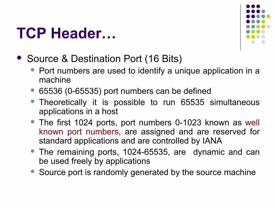
TCP Header…
Source & Destination Port (16 Bits) Port numbers are used to identify a unique application in a
machine 65536 (0-65535) port numbers can be defined Theoretically it is possible to run 65535 simultaneous
applications in a host The first 1024 ports, port numbers 0-1023 known as well
known port numbers, are assigned and are reserved for standard applications and are controlled by IANA
The remaining ports, 1024-65535, are dynamic and can be used freely by applications
Source port is randomly generated by the source machine
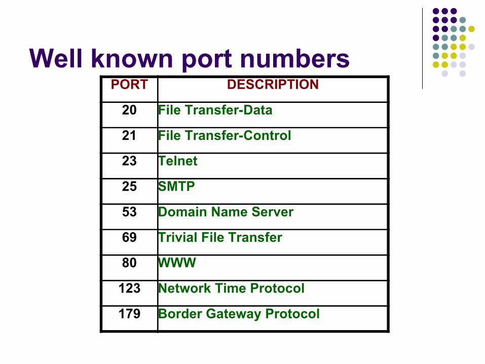
Well known port numbersPORT DESCRIPTION
20 File Transfer-Data
21 File Transfer-Control
23 Telnet
25 SMTP
53 Domain Name Server
69 Trivial File Transfer
80 WWW
123 Network Time Protocol
179 Border Gateway Protocol
TCP Header…
Sequence Number (32 Bits) Helps in establishing TCP connections, along with SYN bit, called
as Three Way Handshake Helps in maintaining account of amount of data being transferred Identifies where the encapsulated data fits within a data stream
from the sender Sequence number is incremented, in the system, every 4
microsecond Acknowledgement Number (32 Bits)
Helps in maintaining account of amount of data being transferred Identifies the sequence number expected from the other end of
data transmission unit
Seq/Ack numbers relation
During TCP Connection Establishment/ Three way handshake Acknowledgement Number Sent = Sequence
Number Received+1
During Data Transfer Acknowledgement Number Sent = Sequence
Number Received + Data Received in Bytes

Three-Way-HandshakeReceiverSender 0 1
0-Closed; 1-Listen; 2-SYN-Sent; 3-SYN-Received; 4-Established
AN-00000
000B01
SN-95426
2
AN- 95427
000B11
SN-16780 3
AN-16781
000B10
SN-95427
4

Data Transfer
AN- 95428
100B10
SN-16781 5
AN- 95427
000B11
SN-16780AN-00000
000B01
SN-95426
AN-16781
000B10
SN-95427
ReceiverSender
0 1
0-Closed; 1-Listen; 2-SYN-Sent; 3-SYN-Received; 4-Established; 5-Data Transfer
23
4
AN-16881
200B10
SN-95428
5AN- 95628
150B10
SN-16881
5
AN-17031
250B10
SN-95628
5AN- 95878
300B10
SN-17031
5

Closing a TCP Connection
ReceiverSender
6-Finish; 0- Closed
0 0
6SN - 95880
AN -17334
0B110 SN - 17334
AN - 95881
0B010
WAITSN - 17334
AN - 95881
0 B110
6
SN - 95881
AN -17334
0B010
TCP Header….
Header Length (4 Bits) Sometimes called Data Offset Indicates the length of header in 32-bit words Identifies the beginning of data Typical value is 5 unless there are options
Flags (6 Bits) Urgent (URG) Acknowledgement (ACK) Push (PSH) Reset (RST) Synchronisation (SYN) Finish (FIN)

TCP Header…..
Window Size (16 Bits) Indicates the size of the sliding window Specifies the number of octets, starting with the
octet indicated by the acknowledgement number, that the sender of the segment will accept from its peer at the other end of the connection before the peer must stop transmitting and wait for an acknowledgement
A default window size is 4096 bytes Used for flow control by using Sliding window
mechanism
Flow Control Sender retains a copy of transmitted data until it
receives an acknowledgment from the remote network.
If no acknowledgment is received, within a specified time, the data is retransmitted by using adaptive retransmission algorithm. TCP records the time of the transmission and sequence
number of the segment. TCP again records the time of the acknowledgement
received. Using this delta, TCP builds a sample round-trip delay time
and uses this to build an average time for a packet to be sent and to receive an acknowledgement
TCP will time out after a number of unsuccessful retransmissions

Sliding Window-Flow ControlMoves to right when
ack is received.
Moves to right when data is sent.
Moves to right or left to fix the size of the window.
Window Size
Sent and ack
Sent but not ack
Can be sent
Can’t be sent
TCP Header…..
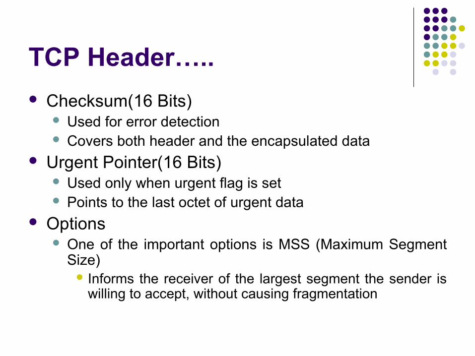
Checksum(16 Bits) Used for error detection Covers both header and the encapsulated data
Urgent Pointer(16 Bits) Used only when urgent flag is set Points to the last octet of urgent data
Options One of the important options is MSS (Maximum Segment
Size) Informs the receiver of the largest segment the sender is
willing to accept, without causing fragmentation
TCP Header……
Padding Consists of 1-3 octets, each equal to zero, to
force the length of TCP header to be in multiples of four octets.
User Datagram Protocol
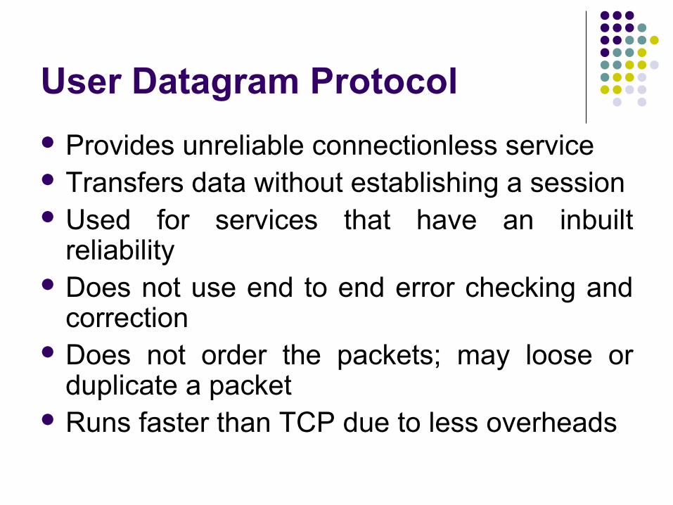
Provides unreliable connectionless service Transfers data without establishing a session Used for services that have an inbuilt
reliability Does not use end to end error checking and
correction Does not order the packets; may loose or
duplicate a packet Runs faster than TCP due to less overheads
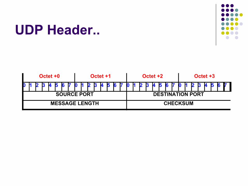
UDP Header..
Octet +0 Octet +1 Octet +2 Octet +3
0 1 2 3 4 5 6 7 0 1 2 3 4 5 6 7 0 1 2 3 4 5 6 7 0 1 2 3 4 5 6 7
SOURCE PORT DESTINATION PORT
MESSAGE LENGTH CHECKSUM
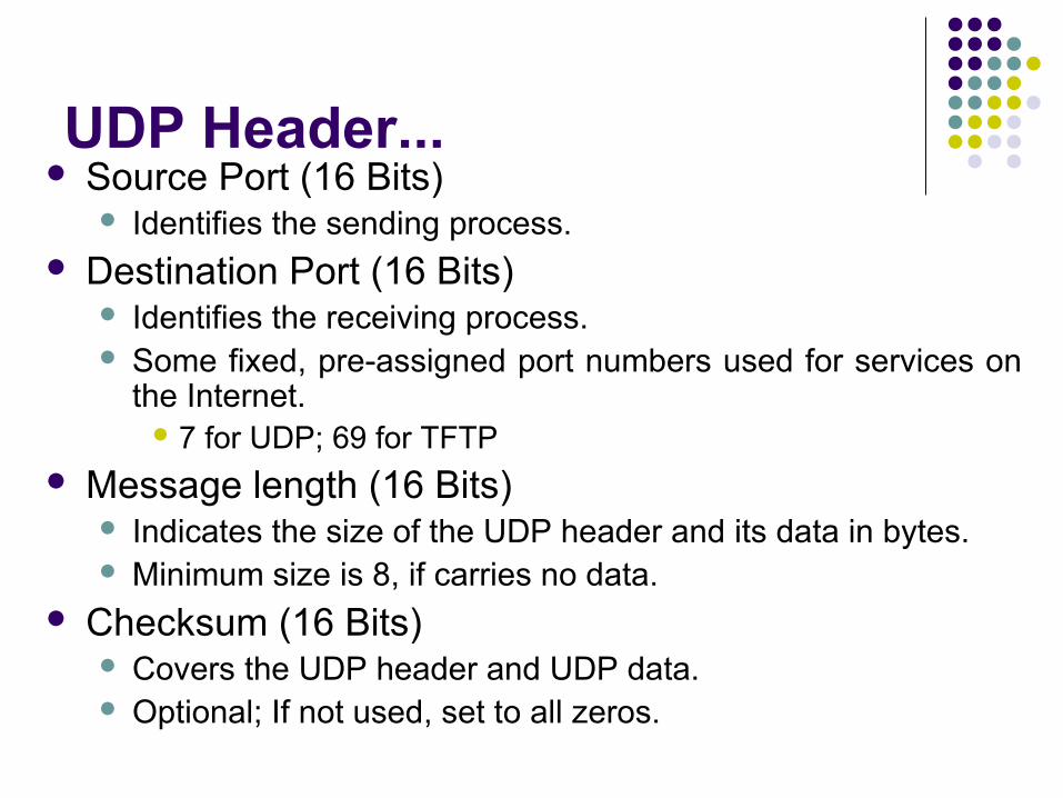
UDP Header... Source Port (16 Bits)
Identifies the sending process. Destination Port (16 Bits)
Identifies the receiving process. Some fixed, pre-assigned port numbers used for services on
the Internet. 7 for UDP; 69 for TFTP
Message length (16 Bits) Indicates the size of the UDP header and its data in bytes. Minimum size is 8, if carries no data.
Checksum (16 Bits) Covers the UDP header and UDP data. Optional; If not used, set to all zeros.
Internet Protocol.
Provides best-effort or connectionless delivery service.
No error checking or tracking If reliability is important, IP must be paired with a
reliable protocol like TCP Transmits blocks of data called datagrams each of
which is transported separately Responsible for IP addressing Datagrams may travel along different routes and
may arrive out of sequence or duplicated.

IP Header.. Octet +0 Octet +1 Octet +2 Octet +3
0 1 2 3 4 5 6 7 0 1 2 3 4 5 6 7 0 1 2 3 4 5 6 7 0 1 2 3 4 5 6 7
VER HLEN TOS TOTAL LENGTH
IDENTIFICATION DF
MF
FRAGMENT OFFSET
TIME TO LIVEPROTOCOL HEADER CHECKSUM
SOURCE ADDRESS OF HOST
DESTINATION ADDRESS OF HOST
OPTIONSPADDING
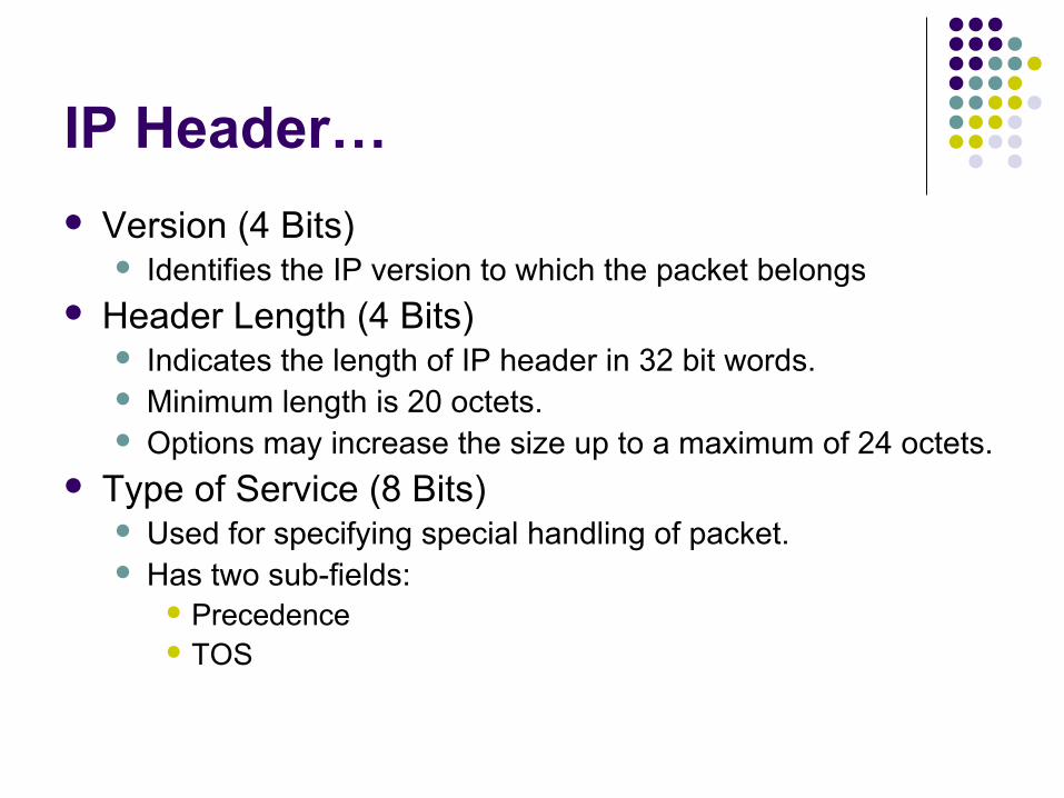
IP Header…
Version (4 Bits) Identifies the IP version to which the packet belongs
Header Length (4 Bits) Indicates the length of IP header in 32 bit words. Minimum length is 20 octets. Options may increase the size up to a maximum of 24 octets.
Type of Service (8 Bits) Used for specifying special handling of packet. Has two sub-fields:
Precedence TOS
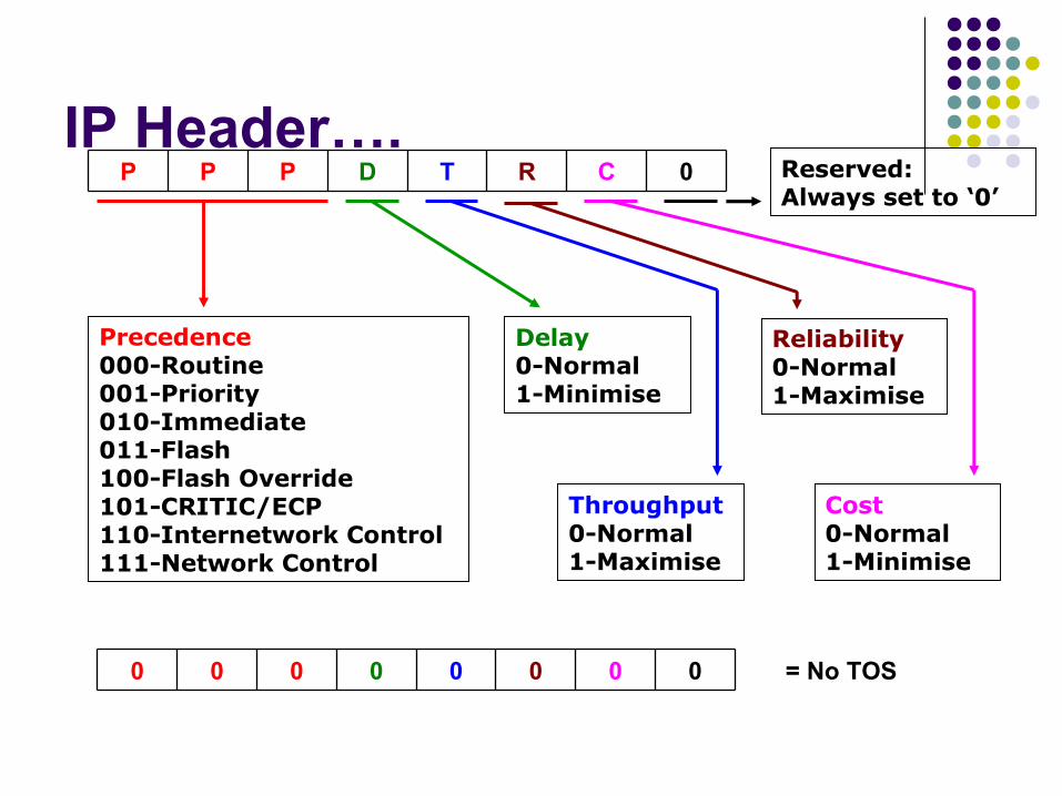
IP Header….0CRTDPPP
Reliability0-Normal1-Maximise
Precedence000-Routine001-Priority010-Immediate011-Flash100-Flash Override101-CRITIC/ECP110-Internetwork Control111-Network Control
Delay0-Normal1-Minimise
Throughput0-Normal1-Maximise
Cost0-Normal1-Minimise
Reserved:Always set to ‘0’
0 = No TOS0000000
IP Header…..
Total Length (16 Bits) Specifies total length of the packet, including header, in
octets Largest decimal number =216= 65535, the maximum
possible size of an IP packet is 65535 octets Total length - header length = Packet’s data payload
Identification (16 Bits) Each datagram is identified by a identification number set
by the source. Normally incremented by 1 for each datagram sent.
IP Header……
Flags (3 Bits) First bit is not used. Second bit is Don’t Fragment (DF) bit Third bit if More Fragment (MF) bit
Maximum Transmit Unit (MTU) is the size of the largest packet, including IP Header, that can be transmitted or received through a data link
Default MTU is 576 bytes, which can be handled by any network without fragmentation

IP Header……
Fragment Offset (13 Bits) The fragmentation occurs at the routers, if the
original packet length exceeds the MTU of a data link
Used only in the cases when a datagram is fragmented on its way
Specifies the offset, in units of eight octets, from the beginning of header to the beginning of the fragment
Each fragment is marked, by router, with the same identifier number
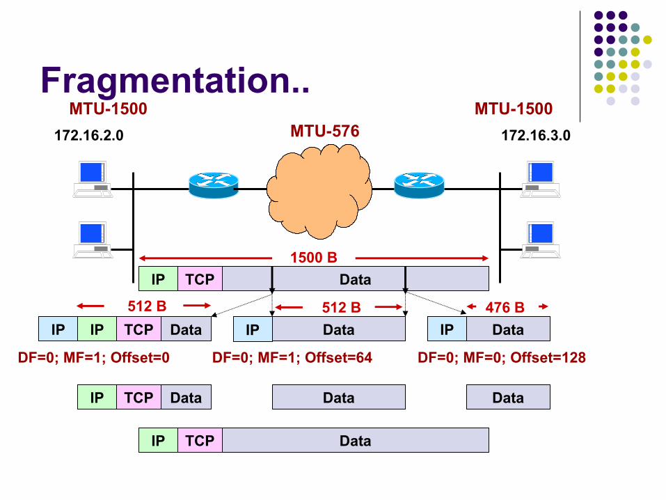
Fragmentation..172.16.2.0 172.16.3.0
MTU-1500 MTU-1500MTU-576
DataTCPIP
1500 B
DataTCPIP
512 B
Data
512 B
Data
476 B
DataTCPIP Data Data
DataTCPIP
IP IP IP
DF=0; MF=1; Offset=0 DF=0; MF=1; Offset=64 DF=0; MF=0; Offset=128
Fragmentation
Only the receiver host reassembles the datagram The destination machine starts a reassembly timer
for about 60-120 seconds. If not all fragments were received, then hosts
discard the packets and sends a time exceeded ICMP message to the source machine
If a single fragment is lost during a transmission, the entire packet must be resent
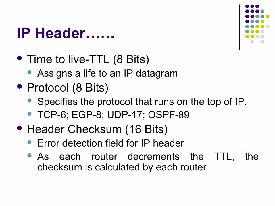
IP Header……
Time to live-TTL (8 Bits) Assigns a life to an IP datagram
Protocol (8 Bits) Specifies the protocol that runs on the top of IP. TCP-6; EGP-8; UDP-17; OSPF-89
Header Checksum (16 Bits) Error detection field for IP header As each router decrements the TTL, the
checksum is calculated by each router
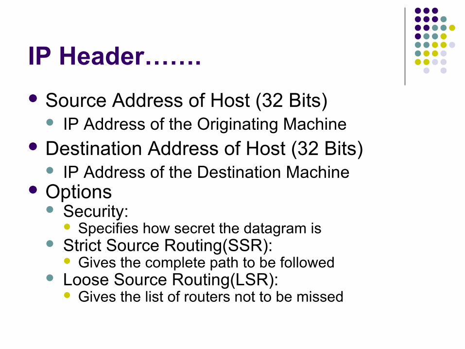
IP Header…….
Source Address of Host (32 Bits) IP Address of the Originating Machine
Destination Address of Host (32 Bits) IP Address of the Destination Machine
Options Security:
Specifies how secret the datagram is Strict Source Routing(SSR):
Gives the complete path to be followed Loose Source Routing(LSR):
Gives the list of routers not to be missed

IP Header……..
Record Route: Makes each router to append its IP address.
Time Stamp: Makes each router to append its IP address and time
stamp.
Padding Ensures that the header ends on a 32 bit
boundary by adding zeros after the option field.

Well known port numbers
PORT DESCRIPTION
20 File Transfer-Data
21 File Transfer-Control
23 Telnet
25 SMTP
53 Domain Name Server
69 Trivial File Transfer
80 WWW
123 Network Time Protocol
179 Border Gateway Protocol
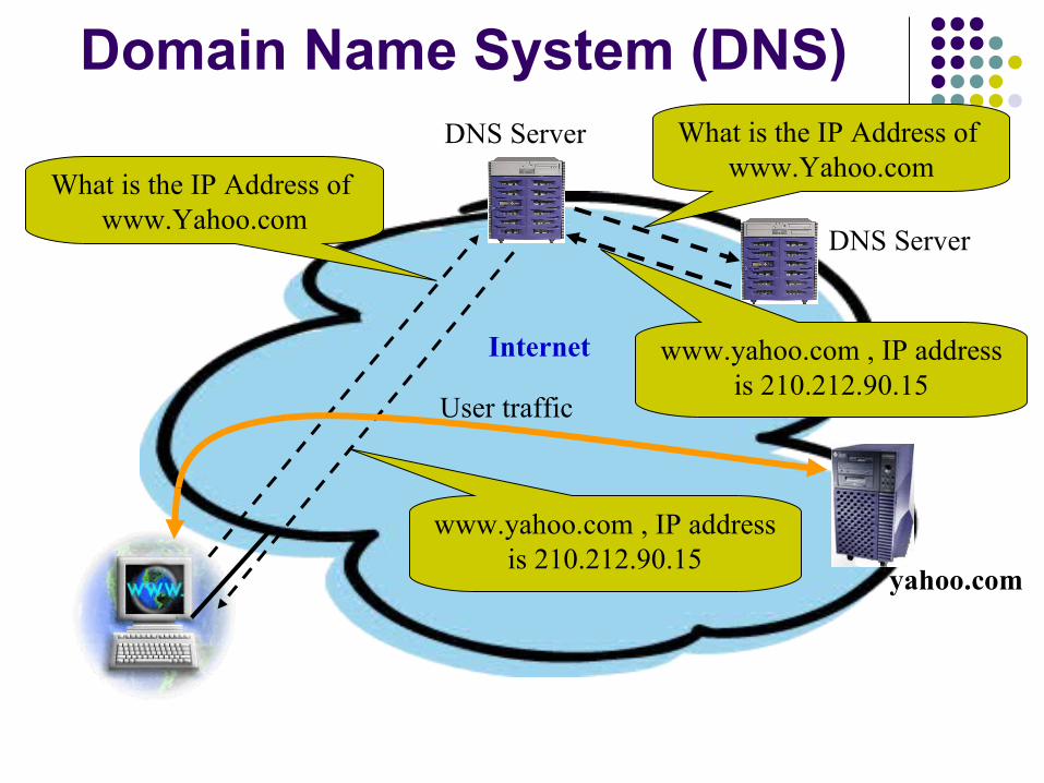
Domain Name System (DNS)
What is the IP Address of www.Yahoo.com
What is the IP Address of www.Yahoo.com
www.yahoo.com , IP address is 210.212.90.15
www.yahoo.com , IP address is 210.212.90.15
User traffic
yahoo.com
DNS Server
DNS Server
Internet
ROUTING PROTOCOLS
Routing Protocol
It is a language a router speaks with other routers
Functions of RP Forwarding, Sharing Updating
information about the reachability and status of the network
Static Routing
Routes to destinations are set up manually Route may be up or down but static routes
will remain in the routing tables and traffic would still be sent towards the route
Not suitable for large networks Also known as Non-adaptive routing
Dynamic Routing
Routes are learnt via an internal or external routing protocols
Network reachability is dependent on the existence and state of the network
Routing decisions change to reflect the changes in topology
Also known as Adaptive routing
Routing Table
A Data base to be maintained by each router.
Created by using algorithms.It contains
Network addressInterface address for reaching the
next router (Hope)Metric
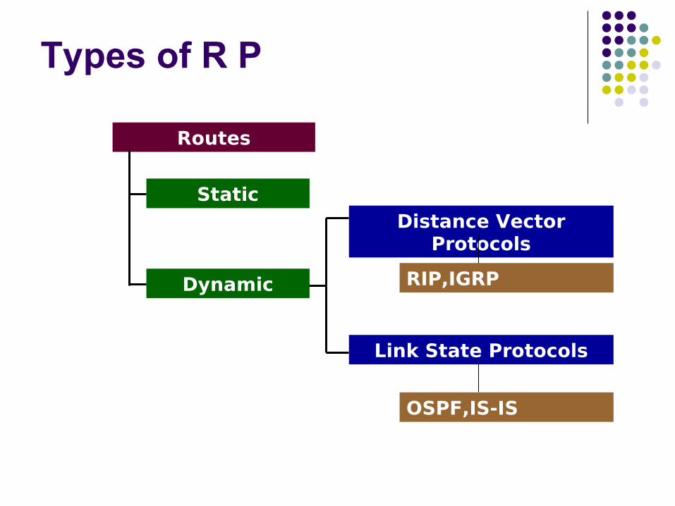
Types of R P
Routes
Static
Dynamic
Distance Vector Protocols
Link State Protocols
RIP,IGRP
OSPF,IS-IS
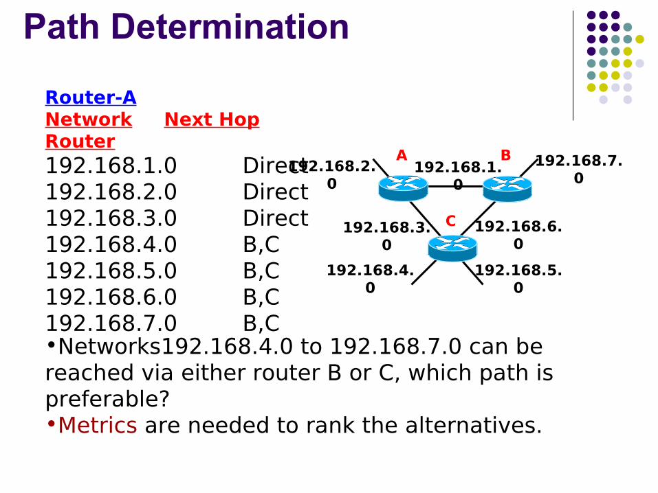
Path Determination
A B
C
192.168.1.0
192.168.7.0
192.168.6.0
192.168.5.0
192.168.2.0
192.168.3.0
192.168.4.0
Router-ANetwork Next Hop Router192.168.1.0 Direct192.168.2.0 Direct192.168.3.0 Direct192.168.4.0 B,C192.168.5.0 B,C192.168.6.0 B,C192.168.7.0 B,C•Networks192.168.4.0 to 192.168.7.0 can be reached via either router B or C, which path is preferable? •Metrics are needed to rank the alternatives.
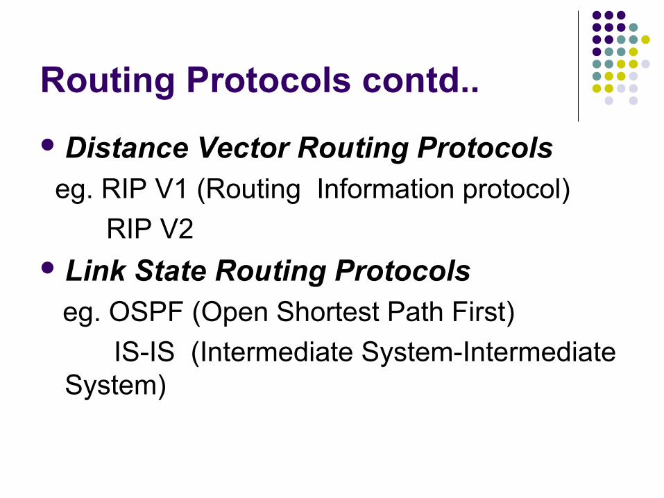
Routing Protocols contd..
Distance Vector Routing Protocols eg. RIP V1 (Routing Information protocol)
RIP V2Link State Routing Protocols eg. OSPF (Open Shortest Path First)
IS-IS (Intermediate System-Intermediate System)
Metrics Hop Count -- Distance Vector
Cost (BW) – Link State
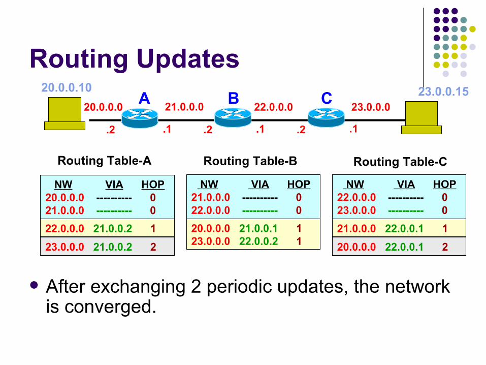
Routing Updates
After exchanging 2 periodic updates, the network is converged.
21.0.0.020.0.0.0 22.0.0.0 23.0.0.0
.2.1 .2.1 .1.2
A B C
23.0.0.0 21.0.0.2 2 20.0.0.0 22.0.0.1 2
22.0.0.0 21.0.0.2 1 20.0.0.0 21.0.0.1 123.0.0.0 22.0.0.2 1
21.0.0.0 22.0.0.1 1
NW VIA HOP20.0.0.0 ---------- 021.0.0.0 ---------- 0
NW VIA HOP21.0.0.0 ---------- 022.0.0.0 ---------- 0
NW VIA HOP22.0.0.0 ---------- 023.0.0.0 ---------- 0
Routing Table-A Routing Table-B Routing Table-C
20.0.0.10 23.0.0.15
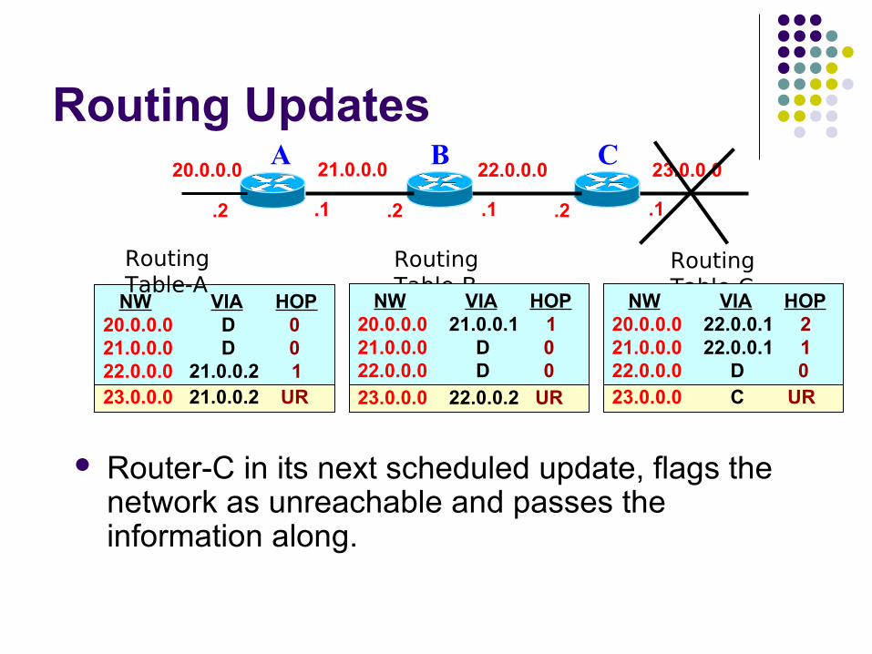
Routing Updates
Router-C in its next scheduled update, flags the network as unreachable and passes the information along.
21.0.0.020.0.0.0 22.0.0.0 23.0.0.0
.2.1 .2.1 .1.2
A B C
NW VIA HOP20.0.0.0 D 021.0.0.0 D 022.0.0.0 21.0.0.2 123.0.0.0 21.0.0.2 2
Routing Table-A
Routing Table-B
Routing Table-C
NW VIA HOP20.0.0.0 21.0.0.1 121.0.0.0 D 022.0.0.0 D 023.0.0.0 22.0.0.2 1
NW VIA HOP20.0.0.0 22.0.0.1 221.0.0.0 22.0.0.1 122.0.0.0 D 023.0.0.0 D 023.0.0.0 C UR23.0.0.0 22.0.0.2 UR23.0.0.0 21.0.0.2 UR
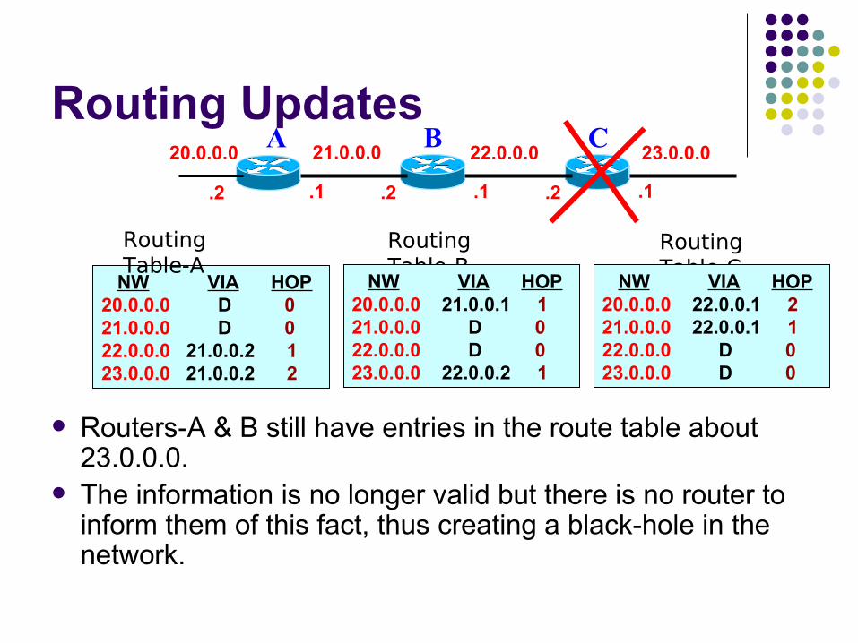
Routing Updates
Routers-A & B still have entries in the route table about 23.0.0.0.
The information is no longer valid but there is no router to inform them of this fact, thus creating a black-hole in the network.
21.0.0.020.0.0.0 22.0.0.0 23.0.0.0
.2.1 .2.1 .1.2
A B C
NW VIA HOP20.0.0.0 D 021.0.0.0 D 022.0.0.0 21.0.0.2 123.0.0.0 21.0.0.2 2
Routing Table-A
Routing Table-B
Routing Table-C
NW VIA HOP20.0.0.0 21.0.0.1 121.0.0.0 D 022.0.0.0 D 023.0.0.0 22.0.0.2 1
NW VIA HOP20.0.0.0 22.0.0.1 221.0.0.0 22.0.0.1 122.0.0.0 D 023.0.0.0 D 0

Route Invalidation Timer
Another Timer, Garbage Collection or Flush Timer, 60 Seconds longer than RIT, is set.
On the expiry of which the route entry will be flushed from the routing table.
21.0.0.020.0.0.0 22.0.0.0 23.0.0.0
.2.1 .2.1 .1.2
A B C
NW VIA HOP TIME20.0.0.0 C 0 RIT21.0.0.0 C 0 RIT22.0.0.0 21.0.0.2 1 RIT23.0.0.0 21.0.0.2 2 RIT
Routing Table-A
Routing Table-B
Routing Table-C
NW VIA HOP TIME20.0.0.0 21.0.0.1 1 RIT21.0.0.0 C 0 RIT22.0.0.0 C 0 RIT23.0.0.0 22.0.0.2 1 RIT
NW VIA HOP TIME20.0.0.0 22.0.0.1 2 RIT21.0.0.0 22.0.0.1 1 RIT22.0.0.0 C 0 RIT23.0.0.0 C 0 RIT0 023.0.0.0 22.0.0.2 UR23.0.0.0 21.0.0.2 UR

RIP Timers
Update Timer 30 Seconds
Route Invalidation Timer 180 Seconds (6 Times the Update Timer)
Garbage Collection Timer 240 seconds (60 Seconds longer than RIT)
LINK STATE ROUTING (OSPF)
Sharing knowledge about theSharing knowledge about the neighbourhood.neighbourhood. Sharing with every other router in theSharing with every other router in the area.area. Sharing when there is a change.Sharing when there is a change.
OSPF operation….
OSPF- Routers send Hello packets out OSPF-enabled interfaces
Two routers sharing a common link, after exchanging Hello packets, become neighbors
OSPF operation…
Link State Advertisements (LSAs) i.e. router’s links and their state, are exchanged between adjacent routers
Each router receiving an LSA from a neighbor records the LSA in Link State Database and sends a copy of the LSA to all of its other neighbors
LSAs are exchanged, until all the routers build identical Link State Databases i.e. the link state databases have been synchronized

OSPF operation….
Each router uses SPF algorithm to calculate a shortest path to every known destination, with itself as root
Each router builds its router table from its SPF Tree
After this, in a stable internetwork, all activities stop except Hello packets are exchanged, after regular intervals of
10 seconds (Hello Interval) between neighbors, as keepalives
LSAs are exchanged every 30 minutes
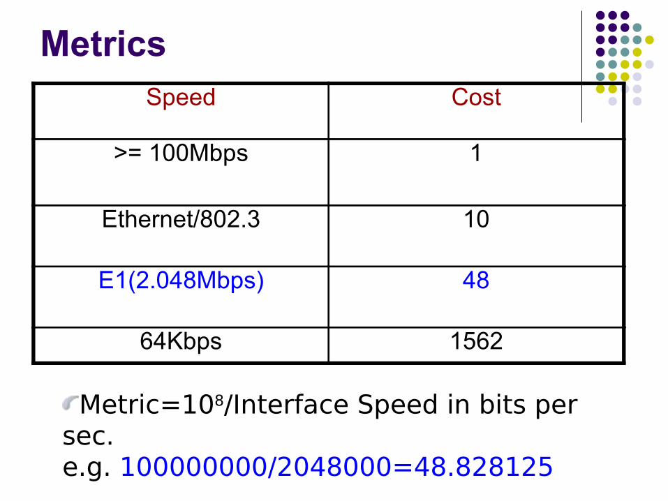
MetricsSpeed Cost
>= 100Mbps 1
Ethernet/802.3 10
E1(2.048Mbps) 48
64Kbps 1562
Metric=108/Interface Speed in bits per sec.e.g. 100000000/2048000=48.828125

Fully adjacent router networkRA-RB-4RA-RC-20RA-RD-5
RD-RA-5RD-RB-3RD-RC-2
RC-RA-20RC-RD-2
RB-RA-4RB-RD-3
A
C
B
D
tn
RC-RA-20RC-RD-2
RC-RA-20 RC-RD-2
RD-RA-5RD-RB-3RD-RC-2
RD-RA-5RD-RB-3RD-RC-2RD-RA-5
RD-RB-3RD-RC-2
RB-RA-4RB-RD-3
RB-RA-4RB-RD-3
RA-RB-4RA-RC-20RA-RD-5
RA-RB-4RA-RC-20RA-RD-5
RA-RB-4RA-RC-20RA-RD-5
tn+1
RC-RA-20RC-RD-2
RB-RA-4RB-RD-3
tn+2
A B
C D
4 4
20
5
2 2
5 3
3
20
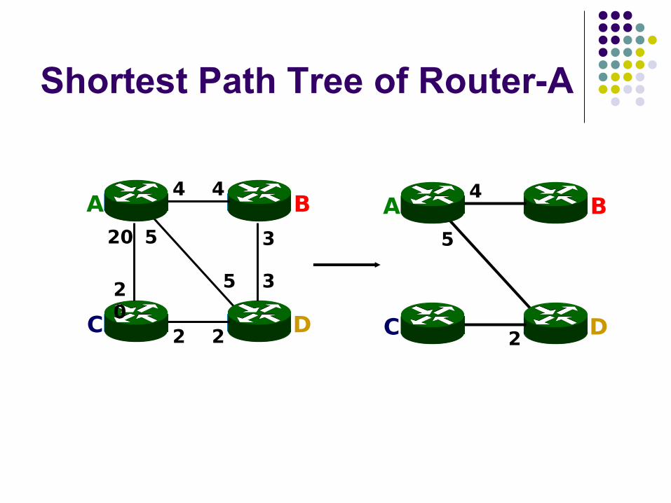
Shortest Path Tree of Router-A
A B
C D
4 4
20 5
2 2
5 3
3
A B
C D
4
5
2
20
PATH VECTOR ROUTING
Path vector routing is similar to distance Path vector routing is similar to distance vector routing. There is at least one node, vector routing. There is at least one node, called the speaker node, in each AS that called the speaker node, in each AS that creates a routing table and advertises it to creates a routing table and advertises it to speaker nodes in the neighboring ASs..speaker nodes in the neighboring ASs..
Boarder Gateway Protocol
Between Two AS
Autonomous System
DefinitionAn autonomous system is a network
under a common administration

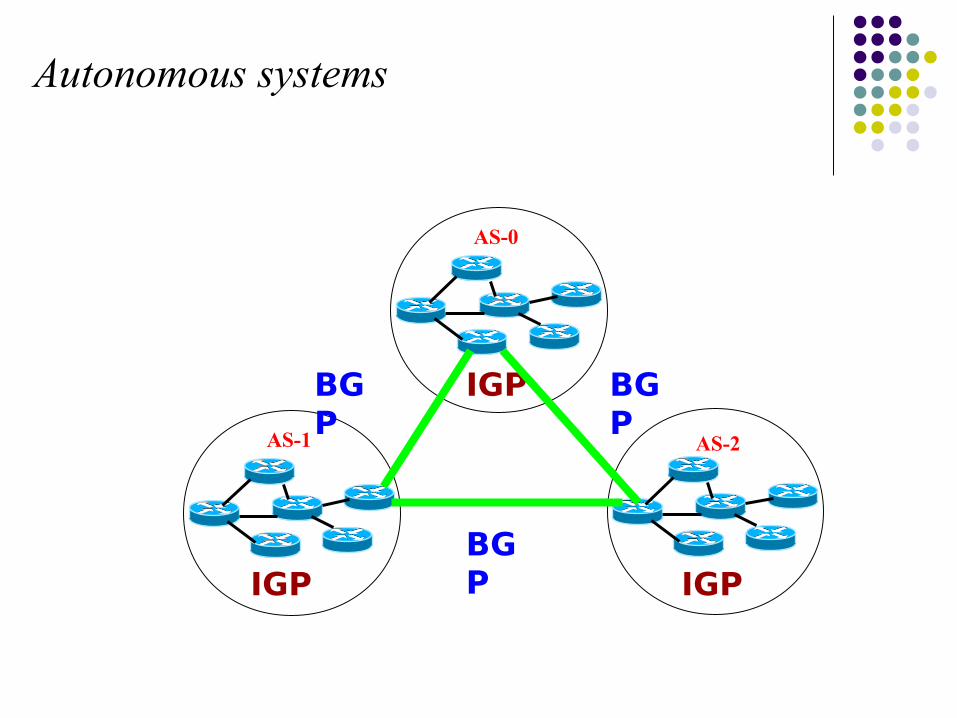
Autonomous systems
Autonomous systems
AS-1 AS-2
AS-0
IGP
IGP IGP
BGP
BGP
BGP
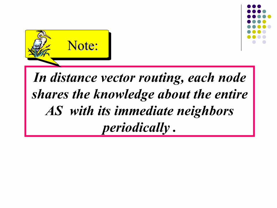
In distance vector routing, each node shares the knowledge about the entire
AS with its immediate neighbors periodically .
Note:Note:
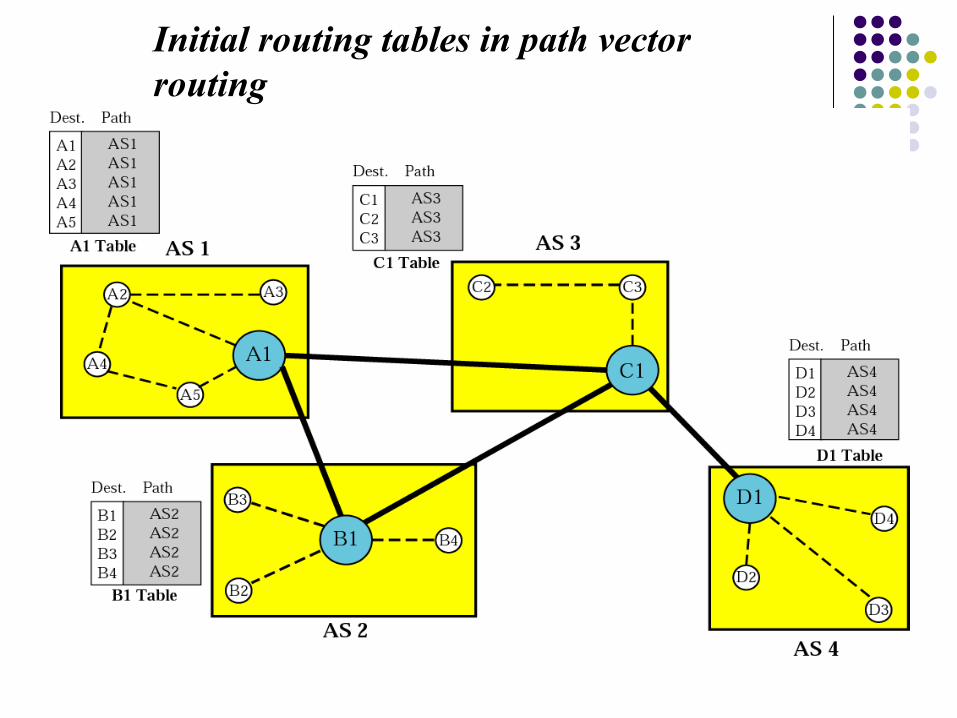
Initial routing tables in path vector routing
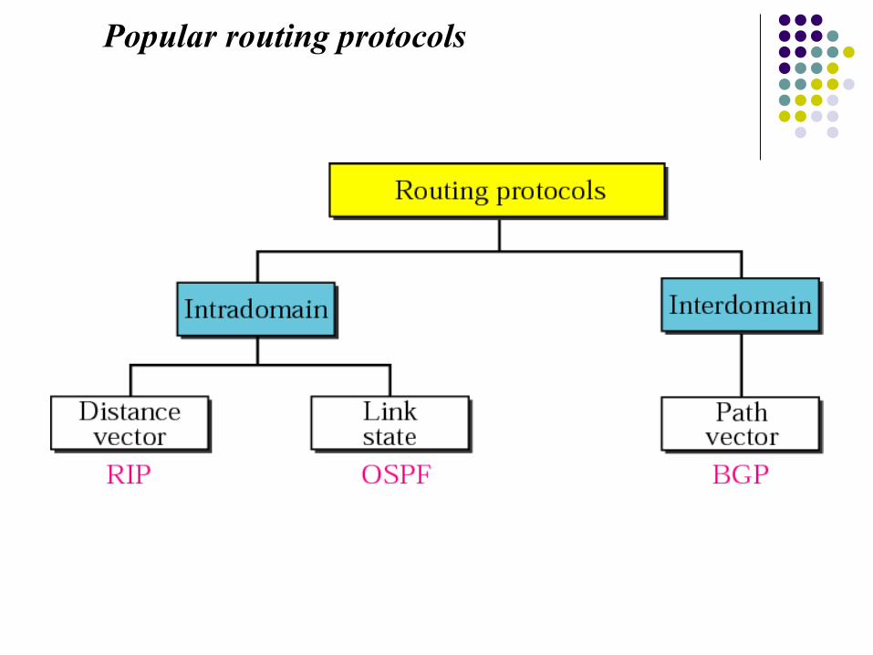
Popular routing protocols

Stabilized tables for four autonomous systems
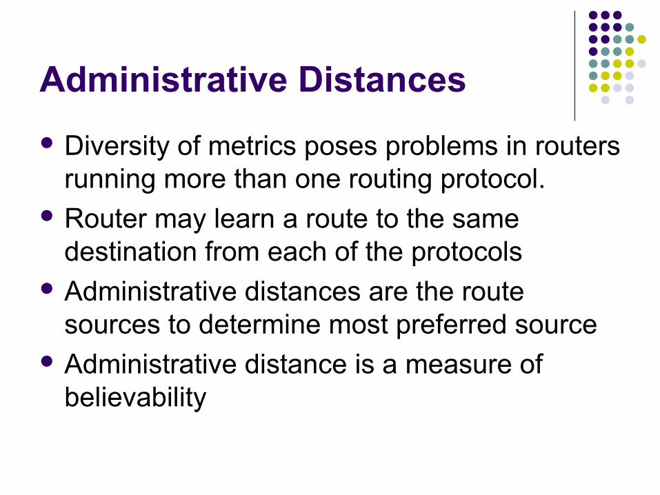
Administrative Distances
Diversity of metrics poses problems in routers running more than one routing protocol.
Router may learn a route to the same destination from each of the protocols
Administrative distances are the route sources to determine most preferred source
Administrative distance is a measure of believability

Administrative Distances
The administrative distance of various protocols is as below: Connected Interface - 0 Static Route - 1 OSPF - 110 IS-IS - 115 RIP - 120 Unknown - 255 The lower the administrative distance, the more
believable the protocol
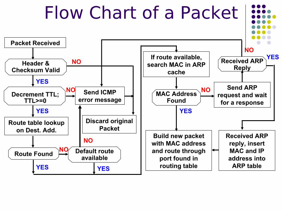
Packet Received
Received ARP Reply
Send ICMP error message
Discard original Packet
Header & Checksum Valid
Route Found
Route table lookup on Dest. Add.
YES
NO
Decrement TTL;TTL>=0
YES
NO
YES
NO
If route available, search MAC in ARP
cache
Default route available
NO
YES
Send ARP request and wait for a response
Build new packet with MAC address and route through
port found in routing table
MAC Address Found
YES
NO
Received ARP reply, insert MAC and IP address into
ARP table
YESNO
Flow Chart of a Packet
Related Documents