TCDS No.: UK.TC.A.00004 Issue: 2 Date: 20 May 2022 Page 1 of 71 Civil Aviation Authority United Kingdom TYPE-CERTIFICATE DATA SHEET UK.TC.A.00004 for Boeing 737 Type Certificate Holder The Boeing Company 737 Logan Ave N Renton WA 98057-0000 USA Model(s): Classic: 737-100 737-200 737-200C 737-300 737-400 737-500 Next Generation: 737-600 737-700 737-800 (737-800BCF) 737-900 737-900ER Max: 737-8 737-9 737-8200 Issue: 2 Date of issue: 20 May 2022

Welcome message from author
This document is posted to help you gain knowledge. Please leave a comment to let me know what you think about it! Share it to your friends and learn new things together.
Transcript
TCDS No.: UK.TC.A.00004 Issue: 2 Date: 20 May 2022 Page 1 of 71
Civil Aviation Authority United Kingdom
TYPE-CERTIFICATE DATA SHEET
UK.TC.A.00004 for
Boeing 737
Type Certificate Holder
The Boeing Company 737 Logan Ave N
Renton WA 98057-0000
USA
Model(s): Classic:
737-100 737-200 737-200C 737-300 737-400 737-500
Next Generation: 737-600 737-700 737-800 (737-800BCF) 737-900 737-900ER
Max: 737-8 737-9 737-8200
Issue: 2
Date of issue: 20 May 2022
TCDS No.: UK.TC.A.00004 Issue: 2 Date: 20 May 2022 Page 2 of 71
EXPLANATORY NOTES
This Type-Certificate Data Sheet (TCDS) is the concise definition of the type-certificated product accepted and or approved by the CAA in the UK for the affected types and models.
This TCDS includes:
1. Details of the type design that affect the TCDS that have been approved or accepted by the CAA in the UK since 01 January 2021.
2. Details of the type design that affected the TCDS and were approved or accepted by EASA before 01 January 2021, but were only incorporated into EASA TCDS IM.A.120 after 01 January 2021 and before the issue of the CAA TCDS UK.TC.A.0004 at Issue 1 and are therefore accepted by the UK under Article 15 of Annex 30 of the UK-EU Trade and Cooperation Agreement.
3. Attachment 1 which is a copy of the EASA TCDS IM.A.120 at Issue 20 dated 17 December 2019 which was the current EASA version at 31 December 2020 and therefore the version of the TCDS for the Boeing 737 accepted by the UK under Article 15 of Annex 30 of the UK-EU Trade and Cooperation Agreement.
4. Attachment 2 which is a copy of Issue 11 of ‘Explanatory Note to EASA TCDS IM.A.120 – Boeing 737’, which is an annex to the EASA TCDS which was created to publish selected EASA Special Conditions, Deviations and Equivalent Safety Findings that are part of the applicable certification basis and was the current EASA version at 31 December 2020 and therefore the version of the TCDS Explanatory Note for the Boeing 737 accepted by the UK under Article 15 of Annex 30 of the UK-EU Trade and Cooperation Agreement.
5. Changes to the information equivalent to EASA Explanatory Note to TCDS IM.A.120 at Issue 11 (Attachment 2) are incorporated as Section 9 of this TCDS.
6. Where there has been no change to Attachments 1 or 2 since 01 January 2021, this will be stated in this TCDS as ‘no change’.
7. Certification Review Items (CRI) issued by UK CAA for validation projects since 01 January 2021 will have the suffix ‘UK’. For example, the first CRI issued by UK CAA against subpart E of the applicable standard is numbered CRI E-01UK.
TCDS No.: UK.TC.A.00004 Issue: 2 Date: 20 May 2022 Page 3 of 71
TABLE OF CONTENTS
Section 1 737-100, -200, -200C, -300, 400, -500 VARIANTS .................................................................................. 5
I. General ............................................................................................................................................................. 5
II. Certification Basis ............................................................................................................................................. 5
III. Technical Characteristic and Operating Limitations ......................................................................................... 5
IV. Operating and Service Instructions ................................................................................................................... 5
V. Operational Suitability Data (OSD) ................................................................................................................... 5
VI. Notes ................................................................................................................................................................. 5
Section 2 ALL NEXT GENERATION SERIES (NG: 737-600, -700, -800, -900, -900ER) ........................................ 6
I. General ............................................................................................................................................................. 6
II. Certification Basis ............................................................................................................................................. 6
III. Technical Characteristic and Operating Limitations ......................................................................................... 6
IV. Operating and Service Instructions ................................................................................................................... 6
V. Operational Suitability Data (OSD) ................................................................................................................... 6
VI. Notes ................................................................................................................................................................. 6
Section 3 737-700 SERIES ....................................................................................................................................... 7
I. General ............................................................................................................................................................. 7
II. Certification Basis ............................................................................................................................................. 7
III. Technical Characteristic and Operating Limitations ......................................................................................... 7
IV. Operating and Service Instructions ................................................................................................................... 7
V. Operational Suitability Data (OSD) ................................................................................................................... 7
VI. Notes ................................................................................................................................................................. 7
Section 4 737-800 SERIES ....................................................................................................................................... 8
Section 4.1 B737-800 Model ........................................................................................................................................ 8
I. General ............................................................................................................................................................. 8
II. Certification Basis ............................................................................................................................................. 8
III. Technical Characteristic and Operating Limitations ......................................................................................... 8
IV. Operating and Service Instructions ................................................................................................................... 8
V. Operational Suitability Data (OSD) ................................................................................................................... 8
VI. Notes ................................................................................................................................................................. 8
Section 4.2 B737-800 Model – Boeing Converted Freighter Major Change ............................................................... 8
I. General ............................................................................................................................................................. 8
II. Certification Basis ............................................................................................................................................. 8
III. Technical Characteristic and Operating Limitations ......................................................................................... 8
IV. Operating and Service Instructions ................................................................................................................... 8
V. Operational Suitability Data (OSD) ................................................................................................................... 8
VI. Notes ................................................................................................................................................................. 8
Section 5 737-600 SERIES ....................................................................................................................................... 9
I. General ............................................................................................................................................................. 9
II. Certification Basis ............................................................................................................................................. 9
III. Technical Characteristic and Operating Limitations ......................................................................................... 9
IV. Operating and Service Instructions ................................................................................................................... 9
TCDS No.: UK.TC.A.00004 Issue: 2 Date: 20 May 2022 Page 4 of 71
V. Operational Suitability Data (OSD) ................................................................................................................... 9
VI. Notes ................................................................................................................................................................. 9
Section 6 737-900 SERIES ..................................................................................................................................... 10
I. General ........................................................................................................................................................... 10
II. Certification Basis ........................................................................................................................................... 10
III. Technical Characteristic and Operating Limitations ....................................................................................... 10
IV. Operating and Service Instructions ................................................................................................................. 10
V. Operational Suitability Data (OSD) ................................................................................................................. 10
VI. Notes ............................................................................................................................................................... 10
Section 7 737-900ER .............................................................................................................................................. 11
I. General ........................................................................................................................................................... 11
II. Certification Basis ........................................................................................................................................... 11
III. Technical Characteristic and Operating Limitations ....................................................................................... 11
IV. Operating and Service Instructions ................................................................................................................. 11
V. Operational Suitability Data (OSD) ................................................................................................................. 11
VI. Notes ............................................................................................................................................................... 11
Section 8 737-8, 737-9, 737-8200 .......................................................................................................................... 12
I. General ........................................................................................................................................................... 12
II. Certification Basis ........................................................................................................................................... 13
III. Technical Characteristic and Operating Limitations ....................................................................................... 20
IV. Operating and Service Instructions ................................................................................................................. 26
V. Operational Suitability Data (OSD) ................................................................................................................. 26
VI. Notes ............................................................................................................................................................... 27
Section 9 Explanatory Note to TCDS (Special Conditions/Deviations/Equivalent Safety Findings) ...................... 28
Section 10 Administration ......................................................................................................................................... 29
I. Acronyms and Abbreviations .......................................................................................................................... 29
II. Type Certificate Holder Record ...................................................................................................................... 30
III. Amendment Record ........................................................................................................................................ 30
Appendix A Detailed Certification Basis of the 737-8/-9/-8200 .................................................................................. 32
Attachment 1 Copy of the EASA TCDS IM.A.120 at Issue 20 dated 17 December 2019 .......................................... 71
Attachment 2 Copy of Issue 11 of the Explanatory Note to EASA TCDS IM.A.120. .................................................. 71
TCDS No.: UK.TC.A.00004 Issue: 2 Date: 20 May 2022 Page 5 of 71
Section 1 737-100, -200, -200C, -300, 400, -500 VARIANTS
I. General No change
II. Certification Basis 6. Adopted FAA Equivalent Safety Findings:
CRI G-GEN1 (Instructions for Continued Airworthiness Equivalent Safety with CS 25.1529) removed at EASA.IM.A.120 Issue 21, 27 January 2021.
III. Technical Characteristic and Operating Limitations No change
IV. Operating and Service Instructions No change
V. Operational Suitability Data (OSD) No change
VI. Notes No change
TCDS No.: UK.TC.A.00004 Issue: 2 Date: 20 May 2022 Page 6 of 71
Section 2 ALL NEXT GENERATION SERIES (NG: 737-600, -700, -800, -900, -900ER)
I. General No change
II. Certification Basis No change
III. Technical Characteristic and Operating Limitations APU supplier amended in paragrapgh 6 at EASA.IM.A.120 Issue 21, 27 January 2021. Paragraph 6 now reads:
6. Auxiliary Power Unit: Auxiliary Power Unit (APU): Honeywell 131-9[B] Limitations: Refer to the APU TCDS/TSO.
IV. Operating and Service Instructions No change
V. Operational Suitability Data (OSD) No change
VI. Notes No change

TCDS No.: UK.TC.A.00004 Issue: 2 Date: 20 May 2022 Page 7 of 71
Section 3 737-700 SERIES
I. General No change
II. Certification Basis No change
III. Technical Characteristic and Operating Limitations No change
IV. Operating and Service Instructions No change
V. Operational Suitability Data (OSD) No change
VI. Notes No change
TCDS No.: UK.TC.A.00004 Issue: 2 Date: 20 May 2022 Page 8 of 71
Section 4 737-800 SERIES
Section 4.1 B737-800 Model
I. General No change
II. Certification Basis No change
III. Technical Characteristic and Operating Limitations No change
IV. Operating and Service Instructions No change
V. Operational Suitability Data (OSD) No change
VI. Notes No change
Section 4.2 B737-800 Model – Boeing Converted Freighter Major Change
I. General No change
II. Certification Basis No change
III. Technical Characteristic and Operating Limitations Other limitations:
Note deleted (‘The 737-800BCF is subjected to a Temporary Operational Limit (TOL) of 2,000 flight cycles or 1 year from time of modification, whichever occurs first.) at EASA.IM.A.120 Issue 24, 11 June 2021 amendment.
IV. Operating and Service Instructions No change
V. Operational Suitability Data (OSD) No change
VI. Notes No change

TCDS No.: UK.TC.A.00004 Issue: 2 Date: 20 May 2022 Page 9 of 71
Section 5 737-600 SERIES
I. General No change
II. Certification Basis No change
III. Technical Characteristic and Operating Limitations No change
IV. Operating and Service Instructions No change
V. Operational Suitability Data (OSD) No change
VI. Notes No change
TCDS No.: UK.TC.A.00004 Issue: 2 Date: 20 May 2022 Page 10 of 71
Section 6 737-900 SERIES
I. General No change
II. Certification Basis No change
III. Technical Characteristic and Operating Limitations No change
IV. Operating and Service Instructions No change
V. Operational Suitability Data (OSD) No change
VI. Notes No change
TCDS No.: UK.TC.A.00004 Issue: 2 Date: 20 May 2022 Page 11 of 71
Section 7 737-900ER
I. General No change
II. Certification Basis No change
III. Technical Characteristic and Operating Limitations No change
IV. Operating and Service Instructions No change
V. Operational Suitability Data (OSD) No change
VI. Notes No change
TCDS No.: UK.TC.A.00004 Issue: 2 Date: 20 May 2022 Page 12 of 71
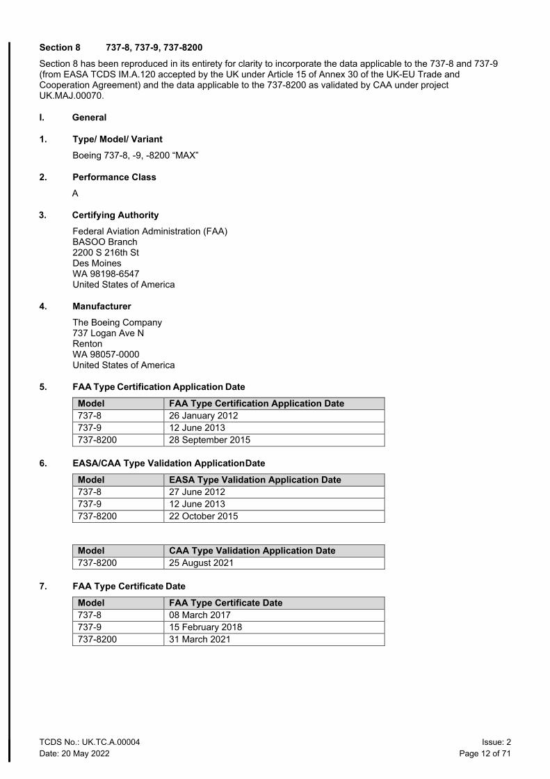
Section 8 737-8, 737-9, 737-8200 Section 8 has been reproduced in its entirety for clarity to incorporate the data applicable to the 737-8 and 737-9 (from EASA TCDS IM.A.120 accepted by the UK under Article 15 of Annex 30 of the UK-EU Trade and Cooperation Agreement) and the data applicable to the 737-8200 as validated by CAA under project UK.MAJ.00070.
I. General
1. Type/ Model/ Variant Boeing 737-8, -9, -8200 “MAX”
2. Performance Class A
3. Certifying Authority Federal Aviation Administration (FAA) BASOO Branch 2200 S 216th St Des Moines WA 98198-6547 United States of America
4. Manufacturer The Boeing Company 737 Logan Ave N Renton WA 98057-0000 United States of America
5. FAA Type Certification Application Date Model FAA Type Certification Application Date 737-8 26 January 2012 737-9 12 June 2013 737-8200 28 September 2015
6. EASA/CAA Type Validation Application Date Model EASA Type Validation Application Date 737-8 27 June 2012 737-9 12 June 2013 737-8200 22 October 2015
Model CAA Type Validation Application Date 737-8200 25 August 2021
7. FAA Type Certificate Date
Model FAA Type Certificate Date 737-8 08 March 2017 737-9 15 February 2018 737-8200 31 March 2021
Section 8: 737-8, 737-9, 737-8200 - continued
TCDS No.: UK.TC.A.00004 Issue: 2 Date: 20 May 2022 Page 13 of 71
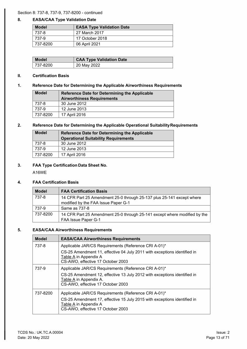
8. EASA/CAA Type Validation Date
Model EASA Type Validation Date 737-8 27 March 2017 737-9 17 October 2018 737-8200 06 April 2021
Model CAA Type Validation Date 737-8200 20 May 2022
II. Certification Basis
1. Reference Date for Determining the Applicable Airworthiness Requirements
Model Reference Date for Determining the Applicable Airworthiness Requirements
737-8 30 June 2012 737-9 12 June 2013 737-8200 17 April 2016
2. Reference Date for Determining the Applicable Operational Suitability Requirements
Model Reference Date for Determining the Applicable Operational Suitability Requirements
737-8 30 June 2012 737-9 12 June 2013 737-8200 17 April 2016
3. FAA Type Certification Data Sheet No. A16WE
4. FAA Certification Basis
Model FAA Certification Basis 737-8 14 CFR Part 25 Amendment 25-0 through 25-137 plus 25-141 except where
modified by the FAA Issue Paper G-1 737-9 Same as 737-8 737-8200 14 CFR Part 25 Amendment 25-0 through 25-141 except where modified by the
FAA Issue Paper G-1
5. EASA/CAA Airworthiness Requirements
Model EASA/CAA Airworthiness Requirements 737-8 Applicable JAR/CS Requirements (Reference CRI A-01)*
CS-25 Amendment 11, effective 04 July 2011 with exceptions identified in Table A in Appendix A CS-AWO, effective 17 October 2003
737-9 Applicable JAR/CS Requirements (Reference CRI A-01)* CS-25 Amendment 12, effective 13 July 2012 with exceptions identified in Table A in Appendix A. CS-AWO, effective 17 October 2003
737-8200 Applicable JAR/CS Requirements (Reference CRI A-01)* CS-25 Amendment 17, effective 15 July 2015 with exceptions identified in Table A in Appendix A CS-AWO, effective 17 October 2003
Section 8: 737-8, 737-9, 737-8200 - continued
TCDS No.: UK.TC.A.00004 Issue: 2 Date: 20 May 2022 Page 14 of 71
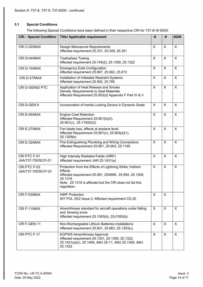
5.1 Special Conditions The following Special Conditions have been defined in their respective CRI for 737-8/-9/-8200:
CRI – Special Condition Title/ Applicable requirement -8 -9 -8200
CRI C-02/MAX Design Manoeuvre Requirements Affected requirement 25.331, 25.349, 25.351
X X X
CRI D-04/MAX Towbarless Towing Affected requirement 25.745(d), 25.1309, 25.1322
X X X
CRI D-15/MAX Emergency Exits Configuration Affected requirement 25.807, 25.562, 25.813
X X X
CRI D-27/MAX Installation of Inflatable Restraint Systems Affected requirement 25.562, 25.785
X X X
CRI D-GEN02 PTC Application of Heat Release and Smoke Density Requirements to Seat Materials Affected Requirement 25.853(d) Appendix F Part IV & V
X X X
CRI D-GEN 9 Incorporation of Inertia Locking Device in Dynamic Seats X X X
CRI E-05/MAX Engine Cowl Retention Affected Requirement 25.901(b)(2), 25.901(c), 25.1193(f)(3)
X X X
CRI E-27/MAX Fan blade loss, effects at airplane level Affected Requirement 25.901(c), 25.903(d)(1), 25.1309(b)
X X X
CRI E-32/MAX Fire Extinguishing Plumbing and Wiring Connections Affected Requirement 25.901, 25.903, 25.1195
X X X
CRI PTC F-01 JAA/737-700/SC/F-01
High Intensity Radiated Fields (HIRF) Affected requirement JAR 25.1431(a)
X X X
CRI PTC F-03 JAA/737-700/SC/F-03
Protection from the Effects of Lightning Strike; Indirect Effects Affected requirement 25.581, 25X899, 25.954, 25.1309, 25.1316 Note: 25.1316 is affected but the CRI does not list this regulation.
X X X
CRI F-03/MAX HIRF Protection INT POL 25/2 Issue 2: Affected requirement CS 25
X X
CRI F-11/MAX Airworthiness standard for aircraft operations under falling and blowing snow Affected requirement 25.1093(b), 25J1093(b)
X X X
CRI F-GEN-11 Non-Rechargeable Lithium Batteries Installations Affected requirement 25.601, 25.863, 25.1353(c)
X X X
CRI PTC F-17 EGPWS Airworthiness Approval Affected requirement 25.1301, 25.1309, 25.1322, 25.1431(a)(c), 25.1459, AMJ 25-11, AMJ 25.1309, AMJ 25.1322
X X X
Section 8: 737-8, 737-9, 737-8200 - continued
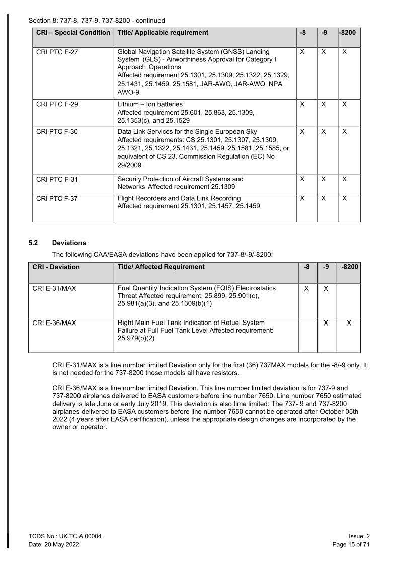
TCDS No.: UK.TC.A.00004 Issue: 2 Date: 20 May 2022 Page 15 of 71
CRI – Special Condition Title/ Applicable requirement -8 -9 -8200
CRI PTC F-27 Global Navigation Satellite System (GNSS) Landing System (GLS) - Airworthiness Approval for Category I Approach Operations Affected requirement 25.1301, 25.1309, 25.1322, 25.1329, 25.1431, 25.1459, 25.1581, JAR-AWO, JAR-AWO NPA AWO-9
X X X
CRI PTC F-29 Lithium – Ion batteries Affected requirement 25.601, 25.863, 25.1309, 25.1353(c), and 25.1529
X X X
CRI PTC F-30 Data Link Services for the Single European Sky Affected requirements: CS 25.1301, 25.1307, 25.1309, 25.1321, 25.1322, 25.1431, 25.1459, 25.1581, 25.1585, or equivalent of CS 23, Commission Regulation (EC) No 29/2009
X X X
CRI PTC F-31 Security Protection of Aircraft Systems and Networks Affected requirement 25.1309
X X X
CRI PTC F-37 Flight Recorders and Data Link Recording Affected requirement 25.1301, 25.1457, 25.1459
X X X
5.2 Deviations The following CAA/EASA deviations have been applied for 737-8/-9/-8200:
CRI - Deviation Title/ Affected Requirement -8 -9 -8200
CRI E-31/MAX Fuel Quantity Indication System (FQIS) Electrostatics Threat Affected requirement: 25.899, 25.901(c), 25.981(a)(3), and 25.1309(b)(1)
X X
CRI E-36/MAX Right Main Fuel Tank Indication of Refuel System Failure at Full Fuel Tank Level Affected requirement: 25.979(b)(2)
X X
CRI E-31/MAX is a line number limited Deviation only for the first (36) 737MAX models for the -8/-9 only. It is not needed for the 737-8200 those models all have resistors. CRI E-36/MAX is a line number limited Deviation. This line number limited deviation is for 737-9 and 737-8200 airplanes delivered to EASA customers before line number 7650. Line number 7650 estimated delivery is late June or early July 2019. This deviation is also time limited: The 737- 9 and 737-8200 airplanes delivered to EASA customers before line number 7650 cannot be operated after October 05th 2022 (4 years after EASA certification), unless the appropriate design changes are incorporated by the owner or operator.
Section 8: 737-8, 737-9, 737-8200 - continued
TCDS No.: UK.TC.A.00004 Issue: 2 Date: 20 May 2022 Page 16 of 71
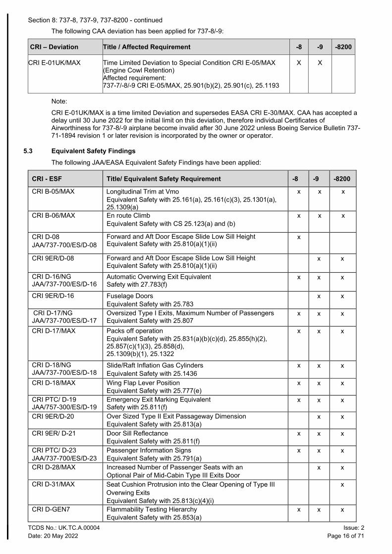
The following CAA deviation has been applied for 737-8/-9:
CRI – Deviation Title / Affected Requirement -8 -9 -8200
CRI E-01UK/MAX Time Limited Deviation to Special Condition CRI E-05/MAX (Engine Cowl Retention) Affected requirement: 737-7/-8/-9 CRI E-05/MAX, 25.901(b)(2), 25.901(c), 25.1193
X X
Note:
CRI E-01UK/MAX is a time limited Deviation and supersedes EASA CRI E-30/MAX. CAA has accepted a delay until 30 June 2022 for the initial limit on this deviation, therefore individual Certificates of Airworthiness for 737-8/-9 airplane become invalid after 30 June 2022 unless Boeing Service Bulletin 737-71-1894 revision 1 or later revision is incorporated by the owner or operator.
5.3 Equivalent Safety Findings The following JAA/EASA Equivalent Safety Findings have been applied:
CRI - ESF Title/ Equivalent Safety Requirement -8 -9 -8200
CRI B-05/MAX Longitudinal Trim at Vmo Equivalent Safety with 25.161(a), 25.161(c)(3), 25.1301(a), 25.1309(a)
x x x
CRI B-06/MAX En route Climb Equivalent Safety with CS 25.123(a) and (b)
x x x
CRI D-08 JAA/737-700/ES/D-08
Forward and Aft Door Escape Slide Low Sill Height Equivalent Safety with 25.810(a)(1)(ii)
x
CRI 9ER/D-08 Forward and Aft Door Escape Slide Low Sill Height Equivalent Safety with 25.810(a)(1)(ii)
x x
CRI D-16/NG JAA/737-700/ES/D-16
Automatic Overwing Exit Equivalent Safety with 27.783(f)
x x x
CRI 9ER/D-16 Fuselage Doors Equivalent Safety with 25.783
x x
CRI D-17/NG JAA/737-700/ES/D-17
Oversized Type I Exits, Maximum Number of Passengers Equivalent Safety with 25.807
x x x
CRI D-17/MAX Packs off operation Equivalent Safety with 25.831(a)(b)(c)(d), 25.855(h)(2), 25.857(c)(1)(3), 25.858(d), 25.1309(b)(1), 25.1322
x x x
CRI D-18/NG JAA/737-700/ES/D-18
Slide/Raft Inflation Gas Cylinders Equivalent Safety with 25.1436
x x x
CRI D-18/MAX Wing Flap Lever Position Equivalent Safety with 25.777(e)
x x x
CRI PTC/ D-19 JAA/757-300/ES/D-19
Emergency Exit Marking Equivalent Safety with 25.811(f)
x x x
CRI 9ER/D-20 Over Sized Type II Exit Passageway Dimension Equivalent Safety with 25.813(a)
x x
CRI 9ER/ D-21 Door Sill Reflectance Equivalent Safety with 25.811(f)
x x x
CRI PTC/ D-23 JAA/737-700/ES/D-23
Passenger Information Signs Equivalent Safety with 25.791(a)
x x x
CRI D-28/MAX Increased Number of Passenger Seats with an Optional Pair of Mid-Cabin Type III Exits Door
x x
CRI D-31/MAX Seat Cushion Protrusion into the Clear Opening of Type III Overwing Exits Equivalent Safety with 25.813(c)(4)(i)
x
CRI D-GEN7 Flammability Testing Hierarchy Equivalent Safety with 25.853(a)
x x x
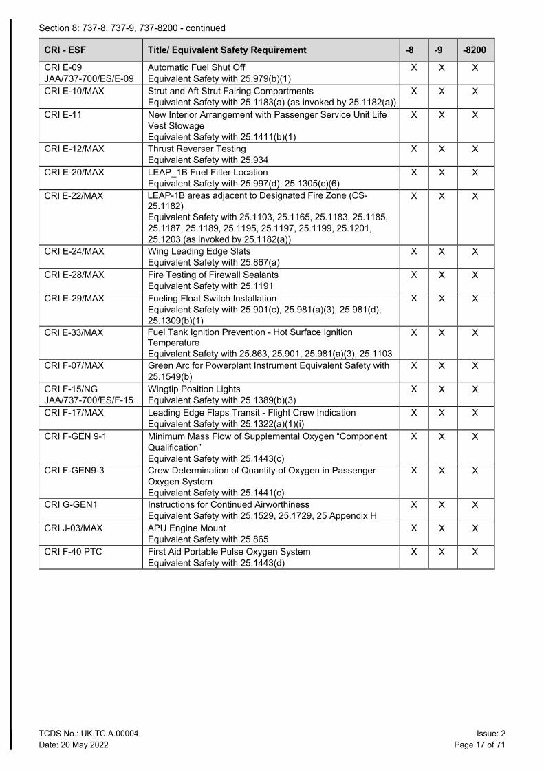
Section 8: 737-8, 737-9, 737-8200 - continued
TCDS No.: UK.TC.A.00004 Issue: 2 Date: 20 May 2022 Page 17 of 71
CRI - ESF Title/ Equivalent Safety Requirement -8 -9 -8200
CRI E-09 JAA/737-700/ES/E-09
Automatic Fuel Shut Off Equivalent Safety with 25.979(b)(1)
X X X
CRI E-10/MAX Strut and Aft Strut Fairing Compartments Equivalent Safety with 25.1183(a) (as invoked by 25.1182(a))
X X X
CRI E-11 New Interior Arrangement with Passenger Service Unit Life Vest Stowage Equivalent Safety with 25.1411(b)(1)
X X X
CRI E-12/MAX Thrust Reverser Testing Equivalent Safety with 25.934
X X X
CRI E-20/MAX LEAP_1B Fuel Filter Location Equivalent Safety with 25.997(d), 25.1305(c)(6)
X X X
CRI E-22/MAX LEAP-1B areas adjacent to Designated Fire Zone (CS- 25.1182) Equivalent Safety with 25.1103, 25.1165, 25.1183, 25.1185, 25.1187, 25.1189, 25.1195, 25.1197, 25.1199, 25.1201, 25.1203 (as invoked by 25.1182(a))
X X X
CRI E-24/MAX Wing Leading Edge Slats Equivalent Safety with 25.867(a)
X X X
CRI E-28/MAX Fire Testing of Firewall Sealants Equivalent Safety with 25.1191
X X X
CRI E-29/MAX Fueling Float Switch Installation Equivalent Safety with 25.901(c), 25.981(a)(3), 25.981(d), 25.1309(b)(1)
X X X
CRI E-33/MAX Fuel Tank Ignition Prevention - Hot Surface Ignition Temperature Equivalent Safety with 25.863, 25.901, 25.981(a)(3), 25.1103
X X X
CRI F-07/MAX Green Arc for Powerplant Instrument Equivalent Safety with 25.1549(b)
X X X
CRI F-15/NG JAA/737-700/ES/F-15
Wingtip Position Lights Equivalent Safety with 25.1389(b)(3)
X X X
CRI F-17/MAX Leading Edge Flaps Transit - Flight Crew Indication Equivalent Safety with 25.1322(a)(1)(i)
X X X
CRI F-GEN 9-1 Minimum Mass Flow of Supplemental Oxygen “Component Qualification” Equivalent Safety with 25.1443(c)
X X X
CRI F-GEN9-3 Crew Determination of Quantity of Oxygen in Passenger Oxygen System Equivalent Safety with 25.1441(c)
X X X
CRI G-GEN1 Instructions for Continued Airworthiness Equivalent Safety with 25.1529, 25.1729, 25 Appendix H
X X X
CRI J-03/MAX APU Engine Mount Equivalent Safety with 25.865
X X X
CRI F-40 PTC First Aid Portable Pulse Oxygen System Equivalent Safety with 25.1443(d)
X X X
Section 8: 737-8, 737-9, 737-8200 - continued
TCDS No.: UK.TC.A.00004 Issue: 2 Date: 20 May 2022 Page 18 of 71
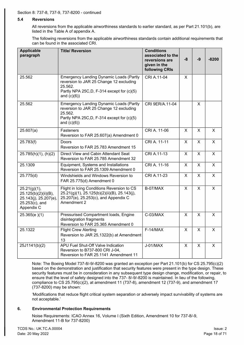
5.4 Reversions All reversions from the applicable airworthiness standards to earlier standard, as per Part 21.101(b), are listed in the Table A of appendix A.
The following reversions from the applicable airworthiness standards contain additional requirements that can be found in the associated CRI.
Applicable paragraph
Title/ Reversion Conditions associated to the reversions are given in the following CRIs
-8
-9
-8200
25.562 Emergency Landing Dynamic Loads (Partly reversion to JAR 25 Change 12 excluding 25.562. Partly NPA 25C,D, F-314 except for (c)(5) and (c)(6))
CRI A.11-04 X
25.562 Emergency Landing Dynamic Loads (Partly reversion to JAR 25 Change 12 excluding 25.562. Partly NPA 25C,D, F-314 except for (c)(5) and (c)(6))
CRI 9ER/A.11-04 X
25.607(a) Fasteners Reversion to FAR 25.607(a) Amendment 0
CRI A. 11-06 X X X
25.783(f) Doors Reversion to FAR 25.783 Amendment 15
CRI A. 11-11 X X X
25.785(h)(1), (h)(2) Direct View and Cabin Attendant Seat Reversion to FAR 25.785 Amendment 32
CRI A.11-13 X X X
25.1309 Equipment, Systems and Installations Reversion to FAR 25.1309 Amendment 0
CRI A. 11-16 X X X
25.775(d) Windshields and Windows Reversion to FAR 25.775(d) Amendment 0
CRI A.11-23 X X X
25.21(g)(1), 25.125(b)(2)(ii)(B), 25.143(j), 25.207(e), 25.253(c), and Appendix C
Flight in Icing Conditions Reversion to CS 25.21(g)(1), 25.125(b)(2)(ii)(B), 25.143(j), 25.207(e), 25.253(c), and Appendix C Amendment 2
B-07/MAX X X X
25.365(e )(1) Pressurised Compartment loads, Engine disintegration fragments Reversion to FAR 25.365 Amendment 0
C-03/MAX X X X
25.1322 Flight Crew Alerting Reversion to JAR 25,1322(b) at Amendment 13
F-14/MAX X X X
25J1141(b)(2) APU Fuel Shut-Off Valve Indication Reversion to B737-800 CRI J-04, Reversion to FAR 25.1141 Amendment 11
J-01/MAX X X X
Note: The Boeing Model 737-8/-9/-8200 was granted an exception per Part 21.101(b) for CS 25.795(c)(2) based on the demonstration and justification that security features were present in the type design. These security features must be in consideration in any subsequent type design change, modification, or repair, to ensure that the level of safety designed into the 737- 8/-9/-8200 is maintained. In lieu of the following, compliance to CS 25.795(c)(2), at amendment 11 (737-8), amendment 12 (737-9), and amendment 17 (737-8200) may be shown:
‘Modifications that reduce flight critical system separation or adversely impact survivability of systems are not acceptable.’
6. Environmental Protection Requirements Noise Requirements: ICAO Annex 16, Volume I (Sixth Edition, Amendment 10 for 737-8/-9, Amendment 11-B for 737-8200)
Section 8: 737-8, 737-9, 737-8200 - continued
TCDS No.: UK.TC.A.00004 Issue: 2 Date: 20 May 2022 Page 19 of 71
Fuel Venting and Exhaust Emission Requirements: ICAO Annex 16, Volume II (Fourth Edition, Amendment 9)
See also TCDSN UK.TC.A.00004
7. Operational Suitability Requirements: JAR MMEL/MEL Amendment 1
CS-CCD Initial Issue 31 January 2014
CS-FCD Initial Issue 31 January 2014
Section 8: 737-8, 737-9, 737-8200 - continued
TCDS No.: UK.TC.A.00004 Issue: 2 Date: 20 May 2022 Page 20 of 71
III. Technical Characteristic and Operating Limitations
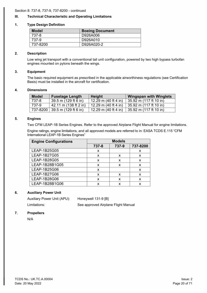
1. Type Design Definition
Model Boeing Document 737-8 D926A006 737-9 D926A010 737-8200 D926A020-2
2. Description Low wing jet transport with a conventional tail unit configuration, powered by two high bypass turbofan engines mounted on pylons beneath the wings.
3. Equipment The basic required equipment as prescribed in the applicable airworthiness regulations (see Certification Basis) must be installed in the aircraft for certification.
4. Dimensions
Model Fuselage Length Height Wingspan with Winglets 737-8 39.5 m (129 ft 6 in) 12.29 m (40 ft 4 in) 35.92 m (117 ft 10 in) 737-9 42.11 m (138 ft 2 in) 12.29 m (40 ft 4 in) 35.92 m (117 ft 10 in) 737-8200 39.5 m (129 ft 6 in) 12.29 m (40 ft 4 in) 35.92 m (117 ft 10 in)
5. Engines Two CFM LEAP-1B Series Engines. Refer to the approved Airplane Flight Manual for engine limitations.
Engine ratings, engine limitations, and all approved models are referred to in: EASA TCDS E.115 “CFM International LEAP-1B Series Engines”
Engine Configurations Models 737-8 737-9 737-8200
LEAP-1B25G05 x x LEAP-1B27G05 x x x LEAP-1B28G05 x x x LEAP-1B28B1G05 x x x LEAP-1B25G06 x x LEAP-1B27G06 x x x LEAP-1B28G06 x x x LEAP-1B28B1G06 x x x
6. Auxiliary Power Unit Auxiliary Power Unit (APU): Honeywell 131-9 [B]
Limitations: See approved Airplane Flight Manual
7. Propellers N/A
Section 8: 737-8, 737-9, 737-8200 - continued
TCDS No.: UK.TC.A.00004 Issue: 2 Date: 20 May 2022 Page 21 of 71
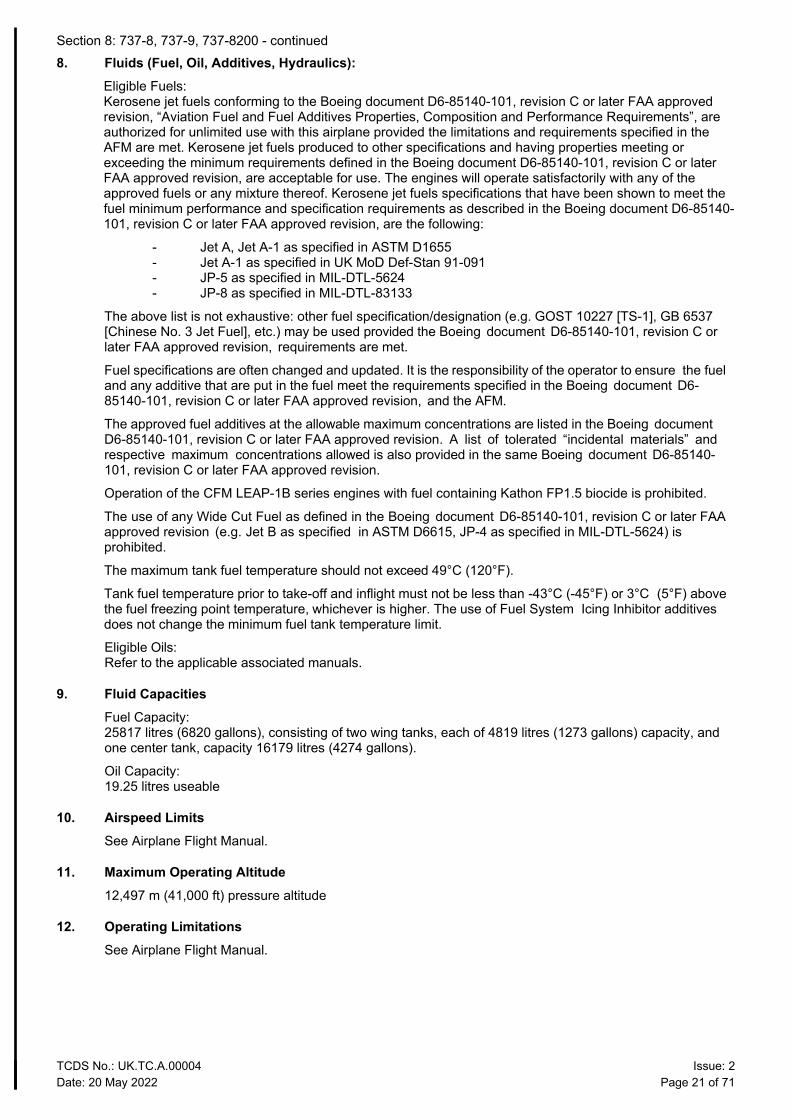
8. Fluids (Fuel, Oil, Additives, Hydraulics): Eligible Fuels: Kerosene jet fuels conforming to the Boeing document D6-85140-101, revision C or later FAA approved revision, “Aviation Fuel and Fuel Additives Properties, Composition and Performance Requirements”, are authorized for unlimited use with this airplane provided the limitations and requirements specified in the AFM are met. Kerosene jet fuels produced to other specifications and having properties meeting or exceeding the minimum requirements defined in the Boeing document D6-85140-101, revision C or later FAA approved revision, are acceptable for use. The engines will operate satisfactorily with any of the approved fuels or any mixture thereof. Kerosene jet fuels specifications that have been shown to meet the fuel minimum performance and specification requirements as described in the Boeing document D6-85140-101, revision C or later FAA approved revision, are the following:
- Jet A, Jet A-1 as specified in ASTM D1655 - Jet A-1 as specified in UK MoD Def-Stan 91-091 - JP-5 as specified in MIL-DTL-5624 - JP-8 as specified in MIL-DTL-83133
The above list is not exhaustive: other fuel specification/designation (e.g. GOST 10227 [TS-1], GB 6537 [Chinese No. 3 Jet Fuel], etc.) may be used provided the Boeing document D6-85140-101, revision C or later FAA approved revision, requirements are met.
Fuel specifications are often changed and updated. It is the responsibility of the operator to ensure the fuel and any additive that are put in the fuel meet the requirements specified in the Boeing document D6-85140-101, revision C or later FAA approved revision, and the AFM.
The approved fuel additives at the allowable maximum concentrations are listed in the Boeing document D6-85140-101, revision C or later FAA approved revision. A list of tolerated “incidental materials” and respective maximum concentrations allowed is also provided in the same Boeing document D6-85140-101, revision C or later FAA approved revision.
Operation of the CFM LEAP-1B series engines with fuel containing Kathon FP1.5 biocide is prohibited.
The use of any Wide Cut Fuel as defined in the Boeing document D6-85140-101, revision C or later FAA approved revision (e.g. Jet B as specified in ASTM D6615, JP-4 as specified in MIL-DTL-5624) is prohibited.
The maximum tank fuel temperature should not exceed 49°C (120°F).
Tank fuel temperature prior to take-off and inflight must not be less than -43°C (-45°F) or 3°C (5°F) above the fuel freezing point temperature, whichever is higher. The use of Fuel System Icing Inhibitor additives does not change the minimum fuel tank temperature limit.
Eligible Oils: Refer to the applicable associated manuals.
9. Fluid Capacities Fuel Capacity: 25817 litres (6820 gallons), consisting of two wing tanks, each of 4819 litres (1273 gallons) capacity, and one center tank, capacity 16179 litres (4274 gallons).
Oil Capacity: 19.25 litres useable
10. Airspeed Limits See Airplane Flight Manual.
11. Maximum Operating Altitude 12,497 m (41,000 ft) pressure altitude
12. Operating Limitations See Airplane Flight Manual.
Section 8: 737-8, 737-9, 737-8200 - continued
TCDS No.: UK.TC.A.00004 Issue: 2 Date: 20 May 2022 Page 22 of 71
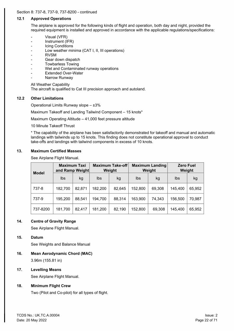
12.1 Approved Operations The airplane is approved for the following kinds of flight and operation, both day and night, provided the required equipment is installed and approved in accordance with the applicable regulations/specifications:
- Visual (VFR) - Instrument (IFR) - Icing Conditions - Low weather minima (CAT I, II, III operations) - RVSM - Gear down dispatch - Towbarless Towing - Wet and Contaminated runway operations - Extended Over-Water - Narrow Runway
All Weather Capability The aircraft is qualified to Cat III precision approach and autoland.
12.2 Other Limitations Operational Limits Runway slope – ±3%
Maximum Takeoff and Landing Tailwind Component – 15 knots*
Maximum Operating Altitude – 41,000 feet pressure altitude
10 Minute Takeoff Thrust
* The capability of the airplane has been satisfactorily demonstrated for takeoff and manual and automatic landings with tailwinds up to 15 knots. This finding does not constitute operational approval to conduct take-offs and landings with tailwind components in excess of 10 knots.
13. Maximum Certified Masses See Airplane Flight Manual.
Model
Maximum Taxi and Ramp Weight
Maximum Take-off Weight
Maximum Landing Weight
Zero Fuel Weight
lbs kg lbs kg lbs kg lbs kg
737-8 182,700 82,871 182,200 82,645 152,800 69,308 145,400 65,952
737-9 195,200 88,541 194,700 88,314 163,900 74,343 156,500 70,987
737-8200 181,700 82,417 181,200 82,190 152,800 69,308 145,400 65,952
14. Centre of Gravity Range See Airplane Flight Manual.
15. Datum See Weights and Balance Manual
16. Mean Aerodynamic Chord (MAC) 3.96m (155.81 in)
17. Levelling Means See Airplane Flight Manual.
18. Minimum Flight Crew Two (Pilot and Co-pilot) for all types of flight.
Section 8: 737-8, 737-9, 737-8200 - continued
TCDS No.: UK.TC.A.00004 Issue: 2 Date: 20 May 2022 Page 23 of 71
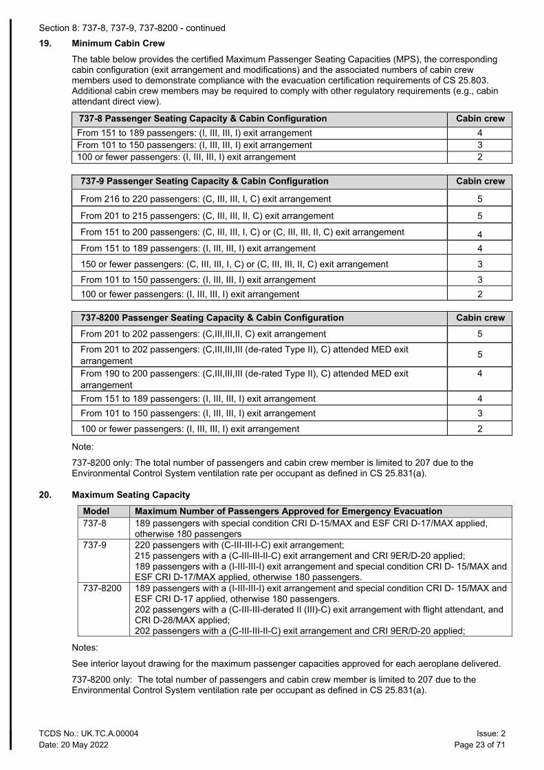
19. Minimum Cabin Crew The table below provides the certified Maximum Passenger Seating Capacities (MPS), the corresponding cabin configuration (exit arrangement and modifications) and the associated numbers of cabin crew members used to demonstrate compliance with the evacuation certification requirements of CS 25.803. Additional cabin crew members may be required to comply with other regulatory requirements (e.g., cabin attendant direct view).
737-8 Passenger Seating Capacity & Cabin Configuration Cabin crew From 151 to 189 passengers: (I, III, III, I) exit arrangement 4 From 101 to 150 passengers: (I, III, III, I) exit arrangement 3 100 or fewer passengers: (I, III, III, I) exit arrangement 2
737-9 Passenger Seating Capacity & Cabin Configuration Cabin crew
From 216 to 220 passengers: (C, III, III, I, C) exit arrangement 5
From 201 to 215 passengers: (C, III, III, II, C) exit arrangement 5
From 151 to 200 passengers: (C, III, III, I, C) or (C, III, III, II, C) exit arrangement 4 From 151 to 189 passengers: (I, III, III, I) exit arrangement 4
150 or fewer passengers: (C, III, III, I, C) or (C, III, III, II, C) exit arrangement 3 From 101 to 150 passengers: (I, III, III, I) exit arrangement 3 100 or fewer passengers: (I, III, III, I) exit arrangement 2
737-8200 Passenger Seating Capacity & Cabin Configuration Cabin crew From 201 to 202 passengers: (C,III,III,II, C) exit arrangement 5 From 201 to 202 passengers: (C,III,III,III (de-rated Type II), C) attended MED exit arrangement
5
From 190 to 200 passengers: (C,III,III,III (de-rated Type II), C) attended MED exit arrangement
4
From 151 to 189 passengers: (I, III, III, I) exit arrangement 4 From 101 to 150 passengers: (I, III, III, I) exit arrangement 3 100 or fewer passengers: (I, III, III, I) exit arrangement 2
Note:
737-8200 only: The total number of passengers and cabin crew member is limited to 207 due to the Environmental Control System ventilation rate per occupant as defined in CS 25.831(a).
20. Maximum Seating Capacity Model Maximum Number of Passengers Approved for Emergency Evacuation 737-8 189 passengers with special condition CRI D-15/MAX and ESF CRI D-17/MAX applied,
otherwise 180 passengers 737-9 220 passengers with (C-III-III-I-C) exit arrangement;
215 passengers with a (C-III-III-II-C) exit arrangement and CRI 9ER/D-20 applied; 189 passengers with a (I-III-III-I) exit arrangement and special condition CRI D- 15/MAX and ESF CRI D-17/MAX applied, otherwise 180 passengers.
737-8200 189 passengers with a (I-III-III-I) exit arrangement and special condition CRI D- 15/MAX and ESF CRI D-17 applied, otherwise 180 passengers. 202 passengers with a (C-III-III-derated II (III)-C) exit arrangement with flight attendant, and CRI D-28/MAX applied; 202 passengers with a (C-III-III-II-C) exit arrangement and CRI 9ER/D-20 applied;
Notes:
See interior layout drawing for the maximum passenger capacities approved for each aeroplane delivered.
737-8200 only: The total number of passengers and cabin crew member is limited to 207 due to the Environmental Control System ventilation rate per occupant as defined in CS 25.831(a).
Section 8: 737-8, 737-9, 737-8200 - continued
TCDS No.: UK.TC.A.00004 Issue: 2 Date: 20 May 2022 Page 24 of 71
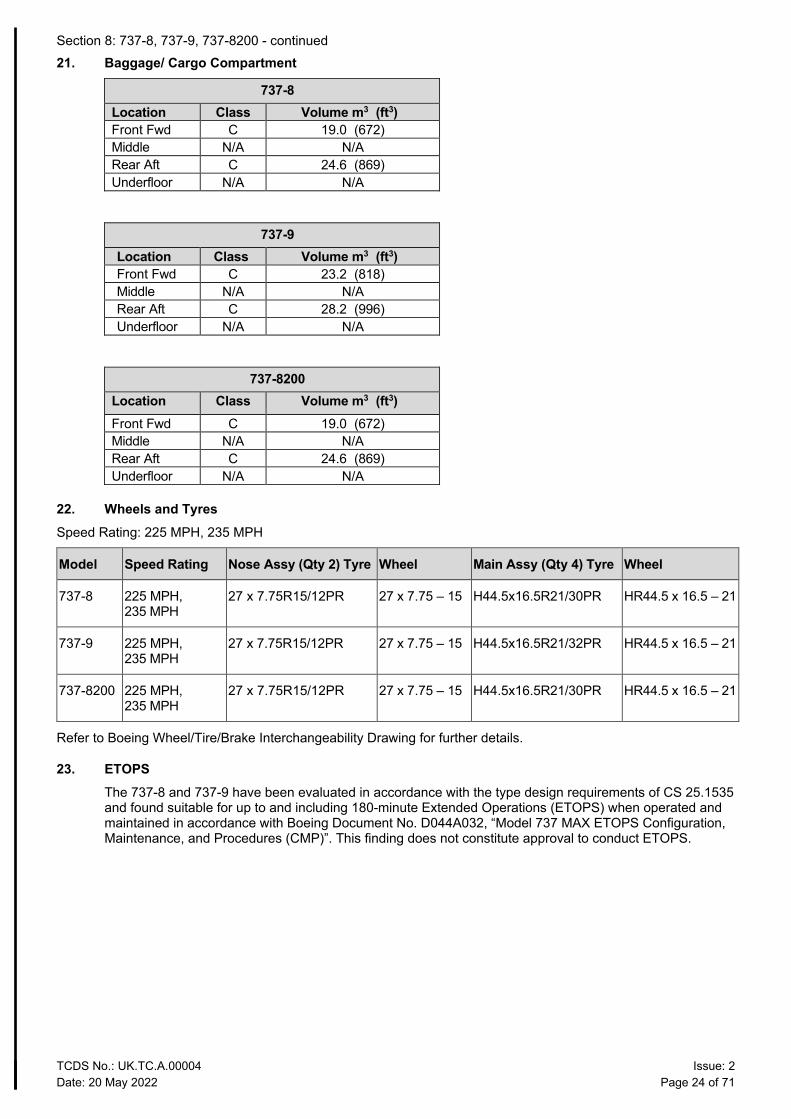
21. Baggage/ Cargo Compartment
737-8 Location Class Volume m3 (ft3) Front Fwd C 19.0 (672) Middle N/A N/A Rear Aft C 24.6 (869) Underfloor N/A N/A
737-9 Location Class Volume m3 (ft3) Front Fwd C 23.2 (818) Middle N/A N/A Rear Aft C 28.2 (996) Underfloor N/A N/A
737-8200 Location Class Volume m3 (ft3) Front Fwd C 19.0 (672) Middle N/A N/A Rear Aft C 24.6 (869) Underfloor N/A N/A
22. Wheels and Tyres Speed Rating: 225 MPH, 235 MPH
Model Speed Rating Nose Assy (Qty 2) Tyre Wheel Main Assy (Qty 4) Tyre Wheel
737-8 225 MPH, 235 MPH
27 x 7.75R15/12PR 27 x 7.75 – 15 H44.5x16.5R21/30PR HR44.5 x 16.5 – 21
737-9 225 MPH, 235 MPH
27 x 7.75R15/12PR 27 x 7.75 – 15 H44.5x16.5R21/32PR HR44.5 x 16.5 – 21
737-8200 225 MPH, 235 MPH
27 x 7.75R15/12PR 27 x 7.75 – 15 H44.5x16.5R21/30PR HR44.5 x 16.5 – 21
Refer to Boeing Wheel/Tire/Brake Interchangeability Drawing for further details.
23. ETOPS The 737-8 and 737-9 have been evaluated in accordance with the type design requirements of CS 25.1535 and found suitable for up to and including 180-minute Extended Operations (ETOPS) when operated and maintained in accordance with Boeing Document No. D044A032, “Model 737 MAX ETOPS Configuration, Maintenance, and Procedures (CMP)”. This finding does not constitute approval to conduct ETOPS.
Section 8: 737-8, 737-9, 737-8200 - continued
TCDS No.: UK.TC.A.00004 Issue: 2 Date: 20 May 2022 Page 25 of 71
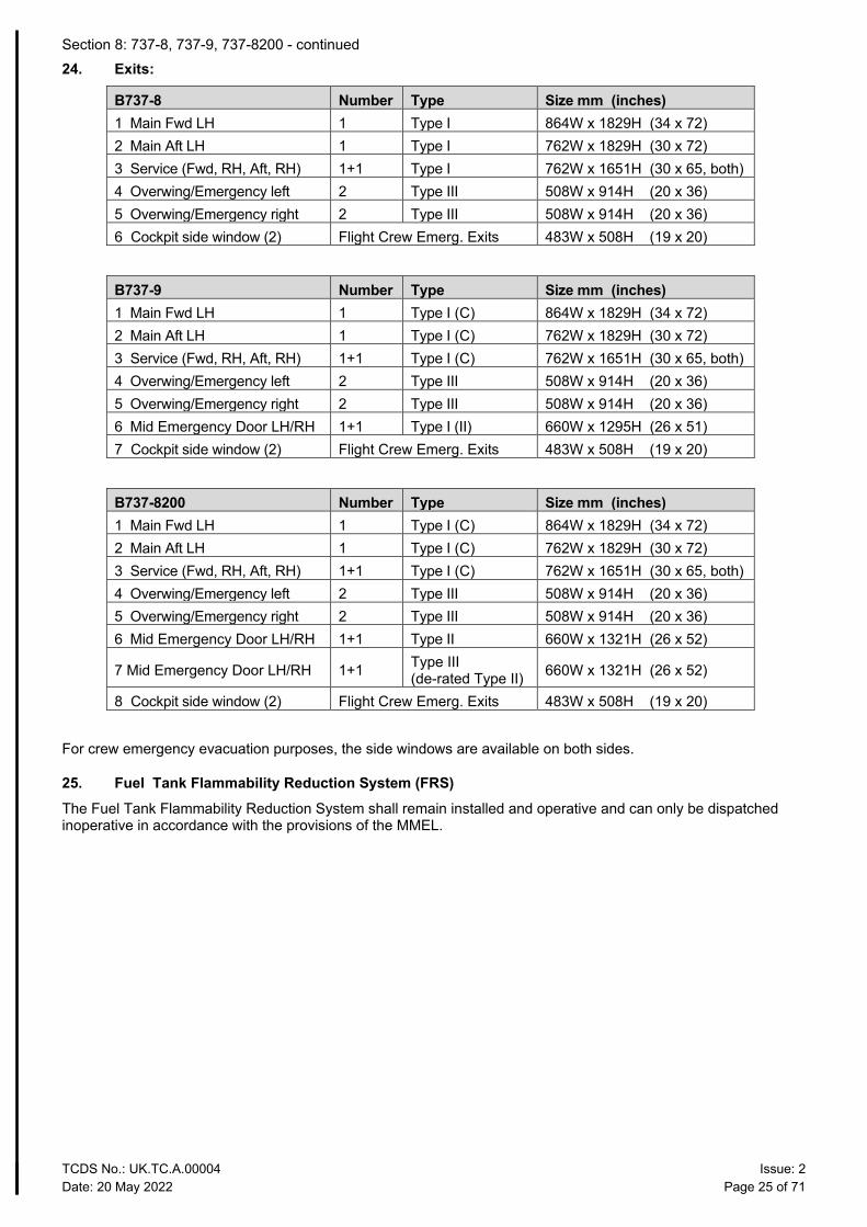
24. Exits:
B737-8 Number Type Size mm (inches) 1 Main Fwd LH 1 Type I 864W x 1829H (34 x 72) 2 Main Aft LH 1 Type I 762W x 1829H (30 x 72) 3 Service (Fwd, RH, Aft, RH) 1+1 Type I 762W x 1651H (30 x 65, both) 4 Overwing/Emergency left 2 Type III 508W x 914H (20 x 36) 5 Overwing/Emergency right 2 Type III 508W x 914H (20 x 36) 6 Cockpit side window (2) Flight Crew Emerg. Exits 483W x 508H (19 x 20)
B737-9 Number Type Size mm (inches) 1 Main Fwd LH 1 Type I (C) 864W x 1829H (34 x 72) 2 Main Aft LH 1 Type I (C) 762W x 1829H (30 x 72) 3 Service (Fwd, RH, Aft, RH) 1+1 Type I (C) 762W x 1651H (30 x 65, both) 4 Overwing/Emergency left 2 Type III 508W x 914H (20 x 36) 5 Overwing/Emergency right 2 Type III 508W x 914H (20 x 36) 6 Mid Emergency Door LH/RH 1+1 Type I (II) 660W x 1295H (26 x 51) 7 Cockpit side window (2) Flight Crew Emerg. Exits 483W x 508H (19 x 20)
B737-8200 Number Type Size mm (inches) 1 Main Fwd LH 1 Type I (C) 864W x 1829H (34 x 72) 2 Main Aft LH 1 Type I (C) 762W x 1829H (30 x 72) 3 Service (Fwd, RH, Aft, RH) 1+1 Type I (C) 762W x 1651H (30 x 65, both) 4 Overwing/Emergency left 2 Type III 508W x 914H (20 x 36) 5 Overwing/Emergency right 2 Type III 508W x 914H (20 x 36) 6 Mid Emergency Door LH/RH 1+1 Type II 660W x 1321H (26 x 52)
7 Mid Emergency Door LH/RH 1+1 Type III (de-rated Type II) 660W x 1321H (26 x 52)
8 Cockpit side window (2) Flight Crew Emerg. Exits 483W x 508H (19 x 20)
For crew emergency evacuation purposes, the side windows are available on both sides.
25. Fuel Tank Flammability Reduction System (FRS) The Fuel Tank Flammability Reduction System shall remain installed and operative and can only be dispatched inoperative in accordance with the provisions of the MMEL.
Section 8: 737-8, 737-9, 737-8200 - continued
TCDS No.: UK.TC.A.00004 Issue: 2 Date: 20 May 2022 Page 26 of 71
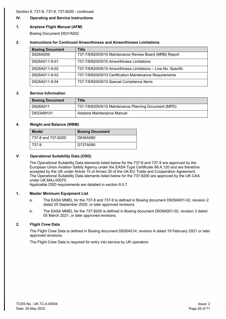
IV. Operating and Service Instructions
1. Airplane Flight Manual (AFM) Boeing Document D631A002
2. Instructions for Continued Airworthiness and Airworthiness Limitations
Boeing Document Title D626A009 737-7/8/8200/9/10 Maintenance Review Board (MRB) Report
D626A011-9-01 737-7/8/8200/9/10 Airworthiness Limitations
D626A011-9-02 737-7/8/8200/9/10 Airworthiness Limitations – Line No. Specific D626A011-9-03 737-7/8/8200/9/10 Certification Maintenance Requirements
D626A011-9-04 737-7/8/8200/9/10 Special Compliance Items
3. Service Information
Boeing Document Title D626A011 737-7/8/8200/9/10 Maintenance Planning Document (MPD)
D633AM101 Airplane Maintenance Manual
4. Weight and Balance (WBM)
Model Boeing Document 737-8 and 737-8200 D636A080
737-9 D737A090
V. Operational Suitability Data (OSD) The Operational Suitability Data elements listed below for the 737-8 and 737-9 are approved by the European Union Aviation Safety Agency under the EASA Type Certificate IM.A.120 and are therefore accepted by the UK under Article 15 of Annex 30 of the UK-EU Trade and Cooperation Agreement. The Operational Suitability Data elements listed below for the 737-8200 are approved by the UK CAA under UK.MAJ.00070. Applicable OSD requirements are detailed in section 8.II.7.
1. Master Minimum Equipment List a. The EASA MMEL for the 737-8 and 737-9 is defined in Boeing document D639A001-02, revision 2
dated 25 September 2020, or later approved revisions.
b. The EASA MMEL for the 737-8200 is defined in Boeing document D639A001-02, revision 3 dated 05 March 2021, or later approved revisions.
2. Flight Crew Data The Flight Crew Data is defined in Boeing document D626A014, revision A dated 19 February 2021 or later approved revisions.
The Flight Crew Data is required for entry into service by UK operators
Section 8: 737-8, 737-9, 737-8200 - continued
TCDS No.: UK.TC.A.00004 Issue: 2 Date: 20 May 2022 Page 27 of 71
3. Cabin Crew Data a. The Cabin Crew Data has been approved as per the defined Operational Suitability Data
Certification Basis, namely CS-CCD- Initial Issue, and as demonstrated by the “Boeing Document D611A099 - Operational Suitability Data - Cabin Crew Data, B737NG and B737-8/-9/-8200 MAX, First Issue, Revision D, dated 29 March 2019”, or later approved revisions.
b. Required for entry into service by UK operators.
c. For Cabin Crew, the aircraft models: B737-9 MAX without Mid Exit Doors (MED) activated and B737-8 MAX are determined to be the same aircraft type.
d. For Cabin Crew, the model B737-9 MAX with MED activated is determined to be a variant to the B737-8 MAX model.
e. For Cabin Crew the model B737-9 MAX “with” or “without” MED activated is determined to be a variant to the aircraft model B737-900ER (with Mid Exit Door (MED) activated), thus, also a variant to the models: B737-600, B737-700, B737-800, B737-900, B737-900ER.
f. For Cabin Crew, the model B737-8200 MAX is determined to be a variant to the B737-900ER (with MED activated) model.
g. For Cabin Crew, the models: B737-600, B737-700, B737-800, B737-900, B737-900/ER, B737 MAX-8/-9, and the B737-8200 are variants to the B737-900ER (with MED activated).
h. For Cabin Crew, the model B737-8200 MAX “with” or “without” MED activated is determined to be a variant to the aircraft model B737-900ER (with Mid Exit Door (MED) activated), thus, also a variant to the models: B737-600, B737-700, B737-800, B737-900, B737-900ER.
VI. Notes 1. Cabin Interior and Seating Configuration must be approved.
2. Additional information is provided in FAA Type Certificate Data Sheet A16WE.
TCDS No.: UK.TC.A.00004 Issue: 2 Date: 20 May 2022 Page 28 of 71
Section 9 Explanatory Note to TCDS (Special Conditions/Deviations/Equivalent Safety Findings)
CRI E-01UK/MAX supersedes EASA CRI E-30/MAX
DEVIATION E-01UK/MAX: Engine Cowl Retention APPLICABILITY: Boeing 737-8/-9 REQUIREMENTS: CRI E-05/MAX (SC), 25.901(b)(2), 25.901(c), 25.1193 ADVISORY MATERIAL: N/A
STATEMENT OF ISSUE:
CAA CRI E-01UK/MAX is the equivalent of EASA CRI E-30/MAX. The Statement of Issue remains unchanged from the EASA CRI and is reproduced verbatim here: In-service experience on large aeroplanes (Boeing, Airbus,…) shows a large number of events of fan cowl loss separation on engines (i.e. CFM-56, V2500, …) and prompted EASA to introduce a Special Condition.
Specific requirements for fan cowl retention on the B737-7/-8/-9 were introduced by CRI E-05/MAX (SC + IM).
Design, test and final certification of the final concept to show compliance to the CRI E-05/MAX Special; Condition cannot be synchronized with completion of certification activities of the B737-8 and -9 therefore those latest cannot be found directly compliant since deviating to the certification basis.
CAA POSITION:
CAA accepts the time deviation to CRI E-05/MAX until the 30 June 2022 provided:
- All the B737-8 and B737-9 delivered before 20 June 2022 will be retrofitted with the new CAA approved design solution compliant with the CRI E-05/MAX.
The EASA position for EASA CRI E-30/MAX for aircraft with the design solution fitted at delivery remains valid and is reproduced verbatim here:
- From 30/06/2016, all the B737-8 and B737-9 will be fitted at delivery with the new design solution - All the B737-7 will be fitted at delivery with the new design solution. - Boeing provides to EASA a programme for the design change containing a schedule for:
o Providing EASA with the new design concept, prototyping before closure of this CRI o Providing EASA with the new detailed design and qualification beginning of 2017 o Providing EASA with the new indication system as part of the -7 design and
Certification Plan etc…
TCDS No.: UK.TC.A.00004 Issue: 2 Date: 20 May 2022 Page 29 of 71
Section 10 Administration
I. Acronyms and Abbreviations
Acronym / Abbreviation Definition AFM Airplane Flight Manual APU Auxiliary Power Unit AWO All Weather Operations CAA Civil Aviation Authority (UK) CMR Certification Maintenance Requirements CRI Certification Review Item CS Certification Specification EASA European Union Aviation Safety Agency EC European Commission ES(F) Equivalent Safety (Finding) ETOPS Extended Range Operations with Two-Engined Aeroplanes EU European Union EU MS European Union Member States EWIS Electrical Wiring Interconnection System FAA Federal Aviation Administration FAR Federal Aviation Regulation FRS Flammibility Reduction Systems HIRF High Intensity Radiated Field ICA Instructions for Continued Airworthiness ICAO International Civil Aviation Organization JAA Joint Aviation Authorities JAR Joint Aviation Requirements MRB Maintenance Review Board NG Next Generation NPA Notice of Proposed Amendment PTC Post Type Certificate SC Special Condition TC Type Certificate TCDS Type Certificate Data Sheet TCDSN Type Certificate Data Sheet for Noise TSO Technical Standards Order
Section 10: Administration - continued
TCDS No.: UK.TC.A.00004 Issue: 2 Date: 20 May 2022 Page 30 of 71
II. Type Certificate Holder Record
TCH Record Period The Boeing Company PO Box 3707 Seattle WA 98124-2207 United States of America The Boeing Company 737 Logan Ave N Renton WA 98057-0000 United States of America
Prior to 20 May 2022 From 20 May 2022
III. Amendment Record
TCDS Issue No.
TCDS Issue Date
Changes TC Issue and Date
1 27 Aug 2021 Initial issue incorporating CAA-approved amendments: • 8 / II / 5.2 CAA CRI E-01UK/MAX supersedes EASA CRI
E-30/MAX • Section 9 CAA CRI E-01UK/MAX supersedes EASA CRI
E-30/MAX Sections 1 through 8 incorporate amendments to EASA TCDS EASA.IM.A.120 issues 21 and 24 that meet the associated design approval dates as defined in Note 2 of this TCDS: • 1 / II / 6 CRI G-GEN1 removed • 2 / III / 6 APU supplier changed to Honeywell • 4 / III / 6 737-800BCF TOL limitation removed • 8 / III / 8 Kathon prohibition text added for LEAP-1B • 8 / V / 1+2 OSD documentation for MAX RTS updated • Appendix A CRI PTC F-30 removed from 25.1302 on 737-
8/-9 list There are no other amendments of issues 21 through to 24 of EASA TCDS EASA.IM.A.120 that meet the conditions of Note 2 of this TCDS.
Issue 1 24 Aug 2021
2 20 May 2022 Section 8 and Appendix A revised in their entirety for clarity to incorporate the existing 737-8 and 737-9 data (from EASA TCDS IM.A.120 accepted by the UK under Article 15 of Annex 30 of the UK-EU Trade and Cooperation Agreement) and adding data applicable to the 737-8200 as validated by CAA under project UK.MAJ.00070. Title page, Section 8.I.4, Section 10.II: Revised to update address of TC holder/Manufacturer. Title page, added 737-8200. Page 2: Notes retitled Explanatory Notes. Page 2: Explanatory Note 2 revised to make specific reference to TCDS UK.TC.A.0004 at Issue 1. Section 8.I.3: Full ZIP code of address of FAA BASOO Branch added. Section 8.I.6: CAA Type Validation Application Date added. Section 8.I.8: EASA type validation date corrected, CAA Type Validation date added. Section 8.II.5.1 requirements corrected for CRI D-04/MAX Section 8.II.5.2 SB reference added for Deviation CRI E-01UK/MAX
Issue 2 20 May 2022
Section 10: Administration - continued
TCDS No.: UK.TC.A.00004 Issue: 2 Date: 20 May 2022 Page 31 of 71
TCDS Issue No.
TCDS Issue Date
Changes TC Issue and Date
Section 8.II.5.3 requirements corrected for CRI B-05/MAX, CRI E-22/MAX, CRI E-33/MAX, title corrected for CRI D-31/MAX Section8.II.5.4 requirement corrected for Reversion related to APU Fuel Shut-Off Valve Indication Section 8.III.13 revised to reflect increased MTOW and MTW for 737-8 model as validated by CAA under project UK.MAJ.00125 Section 10.I: Acronym/Abbreviation list revised.
TCDS No.: UK.TC.A.00004 Issue: 2 Date: 20 May 2022 Page 32 of 71
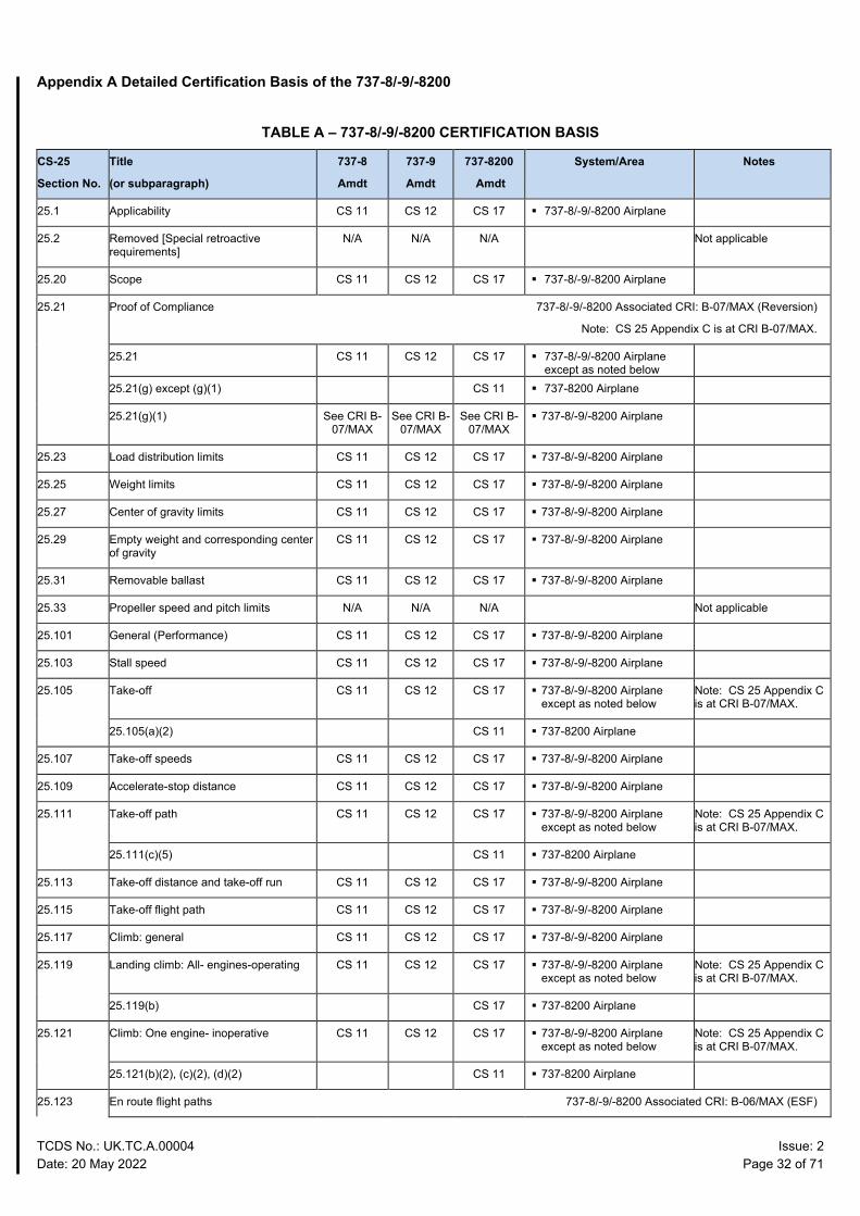
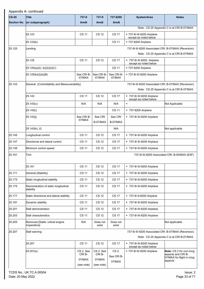
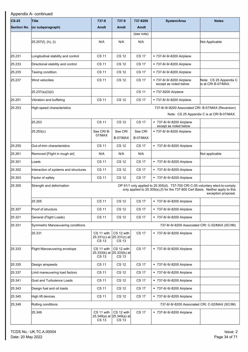
Appendix A Detailed Certification Basis of the 737-8/-9/-8200
TABLE A – 737-8/-9/-8200 CERTIFICATION BASIS
CS-25
Section No.
Title
(or subparagraph)
737-8
Amdt
737-9
Amdt
737-8200
Amdt
System/Area Notes
25.1 Applicability CS 11 CS 12 CS 17 737-8/-9/-8200 Airplane
25.2 Removed [Special retroactive requirements]
N/A N/A N/A Not applicable
25.20 Scope CS 11 CS 12 CS 17 737-8/-9/-8200 Airplane
25.21 Proof of Compliance 737-8/-9/-8200 Associated CRI: B-07/MAX (Reversion)
Note: CS 25 Appendix C is at CRI B-07/MAX.
25.21 CS 11 CS 12 CS 17 737-8/-9/-8200 Airplane except as noted below
25.21(g) except (g)(1) CS 11 737-8200 Airplane
25.21(g)(1) See CRI B- 07/MAX
See CRI B- 07/MAX
See CRI B- 07/MAX
737-8/-9/-8200 Airplane
25.23 Load distribution limits CS 11 CS 12 CS 17 737-8/-9/-8200 Airplane
25.25 Weight limits CS 11 CS 12 CS 17 737-8/-9/-8200 Airplane
25.27 Center of gravity limits CS 11 CS 12 CS 17 737-8/-9/-8200 Airplane
25.29 Empty weight and corresponding center of gravity
CS 11 CS 12 CS 17 737-8/-9/-8200 Airplane
25.31 Removable ballast CS 11 CS 12 CS 17 737-8/-9/-8200 Airplane
25.33 Propeller speed and pitch limits N/A N/A N/A Not applicable
25.101 General (Performance) CS 11 CS 12 CS 17 737-8/-9/-8200 Airplane
25.103 Stall speed CS 11 CS 12 CS 17 737-8/-9/-8200 Airplane
25.105 Take-off CS 11 CS 12 CS 17 737-8/-9/-8200 Airplane except as noted below
Note: CS 25 Appendix C is at CRI B-07/MAX.
25.105(a)(2) CS 11 737-8200 Airplane
25.107 Take-off speeds CS 11 CS 12 CS 17 737-8/-9/-8200 Airplane
25.109 Accelerate-stop distance CS 11 CS 12 CS 17 737-8/-9/-8200 Airplane
25.111 Take-off path CS 11 CS 12 CS 17 737-8/-9/-8200 Airplane except as noted below
Note: CS 25 Appendix C is at CRI B-07/MAX.
25.111(c)(5) CS 11 737-8200 Airplane
25.113 Take-off distance and take-off run CS 11 CS 12 CS 17 737-8/-9/-8200 Airplane
25.115 Take-off flight path CS 11 CS 12 CS 17 737-8/-9/-8200 Airplane
25.117 Climb: general CS 11 CS 12 CS 17 737-8/-9/-8200 Airplane
25.119 Landing climb: All- engines-operating CS 11 CS 12 CS 17 737-8/-9/-8200 Airplane except as noted below
Note: CS 25 Appendix C is at CRI B-07/MAX.
25.119(b) CS 17 737-8200 Airplane
25.121 Climb: One engine- inoperative CS 11 CS 12 CS 17 737-8/-9/-8200 Airplane except as noted below
Note: CS 25 Appendix C is at CRI B-07/MAX.
25.121(b)(2), (c)(2), (d)(2) CS 11 737-8200 Airplane
25.123 En route flight paths 737-8/-9/-8200 Associated CRI: B-06/MAX (ESF)
Appendix A- continued
TCDS No.: UK.TC.A.00004 Issue: 2 Date: 20 May 2022 Page 33 of 71
CS-25
Section No.
Title
(or subparagraph)
737-8
Amdt
737-9
Amdt
737-8200
Amdt
System/Area Notes
Note: CS 25 Appendix C is at CRI B-07/MAX.
25.123 CS 11 CS 12 CS 17 737-8/-9/-8200 Airplane except as noted below
25.123(b) CS 11 737-8200 Airplane
25.125 Landing 737-8/-9/-8200 Associated CRI: B-07/MAX (Reversion)
Note: CS 25 Appendix C is at CRI B-07/MAX.
25.125 CS 11 CS 12 CS 17 737-8/-9/-8200 Airplane except as noted below
25.125(a)(2), (b)(2)(ii)(C) CS 11 737-8200 Airplane
25.125(b)(2)(ii)(B) See CRI B-07/MAX
See CRI B-07/MAX
See CRI B-07/MAX
737-8/-9/-8200 Airplane
25.143 General (Controllability and Maneuverability) 737-8/-9/-8200 Associated CRI: B-07/MAX (Reversion)
Note: CS 25 Appendix C is at CRI B-07/MAX.
25.143 CS 11 CS 12 CS 17 737-8/-9/-8200 Airplane except as noted below
25.143(c) N/A N/A N/A Not Applicable
25.143(i) CS 11 737-8200 Airplane
25.143(j) See CRI B-07/MAX
See CRI
B-07/MAX
See CRI
B-07/MAX
737-8/-9/-8200 Airplane
25.143(k), (l) N/A Not applicable
25.145 Longitudinal control CS 11 CS 12 CS 17 737-8/-9/-8200 Airplane
25.147 Directional and lateral control CS 11 CS 12 CS 17 737-8/-9/-8200 Airplane
25.149 Minimum control speed CS 11 CS 12 CS 17 737-8/-9/-8200 Airplane
25.161 Trim 737-8/-9/-8200 Associated CRI: B-05/MAX (ESF)
25.161 CS 11 CS 12 CS 17 737-8/-9/-8200 Airplane
25.171 General.(Stability) CS 11 CS 12 CS 17 737-8/-9/-8200 Airplane
25.173 Static longitudinal stability CS 11 CS 12 CS 17 737-8/-9/-8200 Airplane
25.175 Demonstration of static longitudinal stability
CS 11 CS 12 CS 17 737-8/-9/-8200 Airplane
25.177 Static directional and lateral stability CS 11 CS 12 CS 17 737-8/-9-8200 Airplane
25.181 Dynamic stability CS 11 CS 12 CS 17 737-8/-9/-8200 Airplane
25.201 Stall demonstration CS 11 CS 12 CS 17 737-8/-9/-8200 Airplane
25.203 Stall characteristics CS 11 CS 12 CS 17 737-8/-9/-8200 Airplane
25.205 Removed [Stalls: critical engine inoperative]
N/A Does not exist
Does not exist
Not applicable
25.207 Stall warning 737-8/-9/-8200 Associated CRI: B-07/MAX (Reversion)
Note: CS 25 Appendix C is at CRI B-07/MAX.
25.207 CS 11 CS 12 CS 17 737-8/-9/-8200 Airplane except as noted below
25.207(e) CS 2, See CRI B-
07/MAX
(see note)
CS 2, See CRI B-
07/MAX
(see note)
CS 2,
See CRI B-
07/MAX
737-8/-9/-8200 Airplane Note: CS 2 for non-icing aspects and CRI B-07/MAX for flight in icing aspects
Appendix A- continued
TCDS No.: UK.TC.A.00004 Issue: 2 Date: 20 May 2022 Page 34 of 71
CS-25
Section No.
Title
(or subparagraph)
737-8
Amdt
737-9
Amdt
737-8200
Amdt
System/Area Notes
(see note)
25.207(f), (h), (i) N/A
N/A N/A Not Applicable
25.231 Longitudinal stability and control CS 11 CS 12 CS 17 737-8/-9/-8200 Airplane
25.233 Directional stability and control CS 11 CS 12 CS 17 737-8/-9/-8200 Airplane
25.235 Taxiing condition CS 11 CS 12 CS 17 737-8/-9/-8200 Airplane
25.237 Wind velocities CS 11 CS 12 CS 17 737-8/-9/-8200 Airplane except as noted below
Note: CS 25 Appendix C is at CRI B-07/MAX.
25.237(a)(3)(ii) CS 11 737-8200 Airplane
25.251 Vibration and buffeting CS 11 CS 12 CS 17 737-8/-9/-8200 Airplane
25.253 High-speed characteristics 737-8/-9/-8200 Associated CRI: B-07/MAX (Reversion)
Note: CS 25 Appendix C is at CRI B-07/MAX.
25.253 CS 11 CS 12 CS 17 737-8/-9/-8200 Airplane except as noted below
25.253(c) See CRI B-07/MAX
See CRI
B-07/MAX
See CRI
B-07/MAX
737-8/-9/-8200 Airplane
25.255 Out-of-trim characteristics CS 11 CS 12 CS 17 737-8/-9/-8200 Airplane
25.261 Removed [Flight in rough air] N/A N/A N/A Not applicable
25.301 Loads CS 11 CS 12 CS 17 737-8/-9/-8200 Airplane
25.302 Interaction of systems and structures CS 11 CS 12 CS 17 737-8/-9/-8200 Airplane
25.303 Factor of safety CS 11 CS 12 CS 17 737-8/-9/-8200 Airplane
25.305 Strength and deformation OP 91/1 only applied to 25.305(d). 737-700 CRI C-05 voluntary elect-to-comply only applied to 25.305(e),(f) for the 737-800 Cert Basis. Neither apply to this
exception proposal.
25.305 CS 11 CS 12 CS 17 737-8/-9/-8200 Airplane
25.307 Proof of structure CS 11 CS 12 CS 17 737-8/-9/-8200 Airplane
25.321 General (Flight Loads) CS 11 CS 12 CS 17 737-8/-9/-8200 Airplane
25.331 Symmetric Manoeuvering conditions 737-8/-9/-8200 Associated CRI: C-02/MAX (SC/IM)
25.331 CS 11 with 25.331(c) at
CS 13
CS 12 with 25.331(c) at
CS 13
CS 17 737-8/-9/-8200 Airplane
25.333 Flight Manoeuvering envelope CS 11 with 25.333(b) at
CS 13
CS 12 with 25.333(b) at
CS 13
CS 17 737-8/-9/-8200 Airplane
25.335 Design airspeeds CS 11 CS 12 CS 17 737-8/-9/-8200 Airplane
25.337 Limit maneuvering load factors CS 11 CS 12 CS 17 737-8/-9/-8200 Airplane
25.341 Gust and Turbulence Loads CS 11 CS 12 CS 17 737-8/-9/-8200 Airplane
25.343 Design fuel and oil loads CS 11 CS 12 CS 17 737-8/-9/-8200 Airplane
25.345 High lift devices CS 11 CS 12 CS 17 737-8/-9/-8200 Airplane
25.349 Rolling conditions 737-8/-9/-8200 Associated CRI: C-02/MAX (SC/IM)
25.349 CS 11 with 25.349(a) at
CS 13
CS 12 with 25.349(a) at
CS 13
CS 17 737-8/-9/-8200 Airplane
Appendix A- continued
TCDS No.: UK.TC.A.00004 Issue: 2 Date: 20 May 2022 Page 35 of 71
CS-25
Section No.
Title
(or subparagraph)
737-8
Amdt
737-9
Amdt
737-8200
Amdt
System/Area Notes
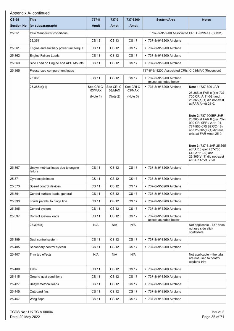
25.351 Yaw Manoeuver conditions 737-8/-9/-8200 Associated CRI: C-02/MAX (SC/IM)
25.351 CS 13 CS 13 CS 17 737-8/-9/-8200 Airplane
25.361 Engine and auxiliary power unit torque CS 11 CS 12 CS 17 737-8/-9/-8200 Airplane
25.362 Engine Failure Loads CS 11 CS 12 CS 17 737-8/-9/-8200 Airplane
25.363 Side Load on Engine and APU Mounts CS 11 CS 12 CS 17 737-8/-9/-8200 Airplane
25.365 Pressurized compartment loads 737-8/-9/-8200 Associated CRIs: C-03/MAX (Reversion)
25.365 CS 11 CS 12 CS 17 737-8/-9/-8200 Airplane except as noted below
25.365(e)(1)
See CRI C- 03/MAX
(Note 1)
See CRI C- 03/MAX
(Note 2)
See CRI C- 03/MAX
(Note 3)
737-8/-9/-8200 Airplane Note 1: 737-800 JAR
25.365 at FAR 0 (per 737- 700 CRI A.11-02) and 25.365(e)(1) did not exist at FAR Amdt 25-0.
Note 2: 737-900ER JAR 25.365 at FAR 0 (per 737-900 CRI 9ER / A.11-01, 737-900 CRI 9ER/C-19) and 25.365(e)(1) did not exist at FAR Amdt 25-0.
Note 3: 737-8 JAR 25.365 at FAR 0 (per 737-700 CRI A.11-02) and 25.365(e)(1) did not exist at FAR Amdt 25-0
25.367 Unsymmetrical loads due to engine failure
CS 11 CS 12 CS 17 737-8/-9/-8200 Airplane
25.371 Gyroscopic loads CS 11 CS 12 CS 17 737-8/-9/-8200 Airplane
25.373 Speed control devices CS 11 CS 12 CS 17 737-8/-9/-8200 Airplane
25.391 Control surface loads: general CS 11 CS 12 CS 17 737-8/-9/-8200 Airplane
25.393 Loads parallel to hinge line CS 11 CS 12 CS 17 737-8/-9/-8200 Airplane
25.395 Control system CS 11 CS 12 CS 17 737-8/-9/-8200 Airplane
25.397 Control system loads CS 11 CS 12 CS 17 737-8/-9/-8200 Airplane except as noted below
25.397(d) N/A N/A N/A Not applicable - 737 does not use side stick controllers
25.399 Dual control system CS 11 CS 12 CS 17 737-8/-9/-8200 Airplane
25.405 Secondary control system CS 11 CS 12 CS 17 737-8/-9/-8200 Airplane
25.407 Trim tab effects N/A N/A N/A Not applicable – the tabs are not used to control airplane trim
25.409 Tabs CS 11 CS 12 CS 17 737-8/-9/-8200 Airplane
25.415 Ground gust conditions CS 11 CS 12 CS 17 737-8/-9/-8200 Airplane
25.427 Unsymmetrical loads CS 11 CS 12 CS 17 737-8/-9/-8200 Airplane
25.445 Outboard fins CS 11 CS 12 CS 17 737-8/-9/-8200 Airplane
25.457 Wing flaps CS 11 CS 12 CS 17 737-8/-9/-8200 Airplane
Appendix A- continued
TCDS No.: UK.TC.A.00004 Issue: 2 Date: 20 May 2022 Page 36 of 71
CS-25
Section No.
Title
(or subparagraph)
737-8
Amdt
737-9
Amdt
737-8200
Amdt
System/Area Notes
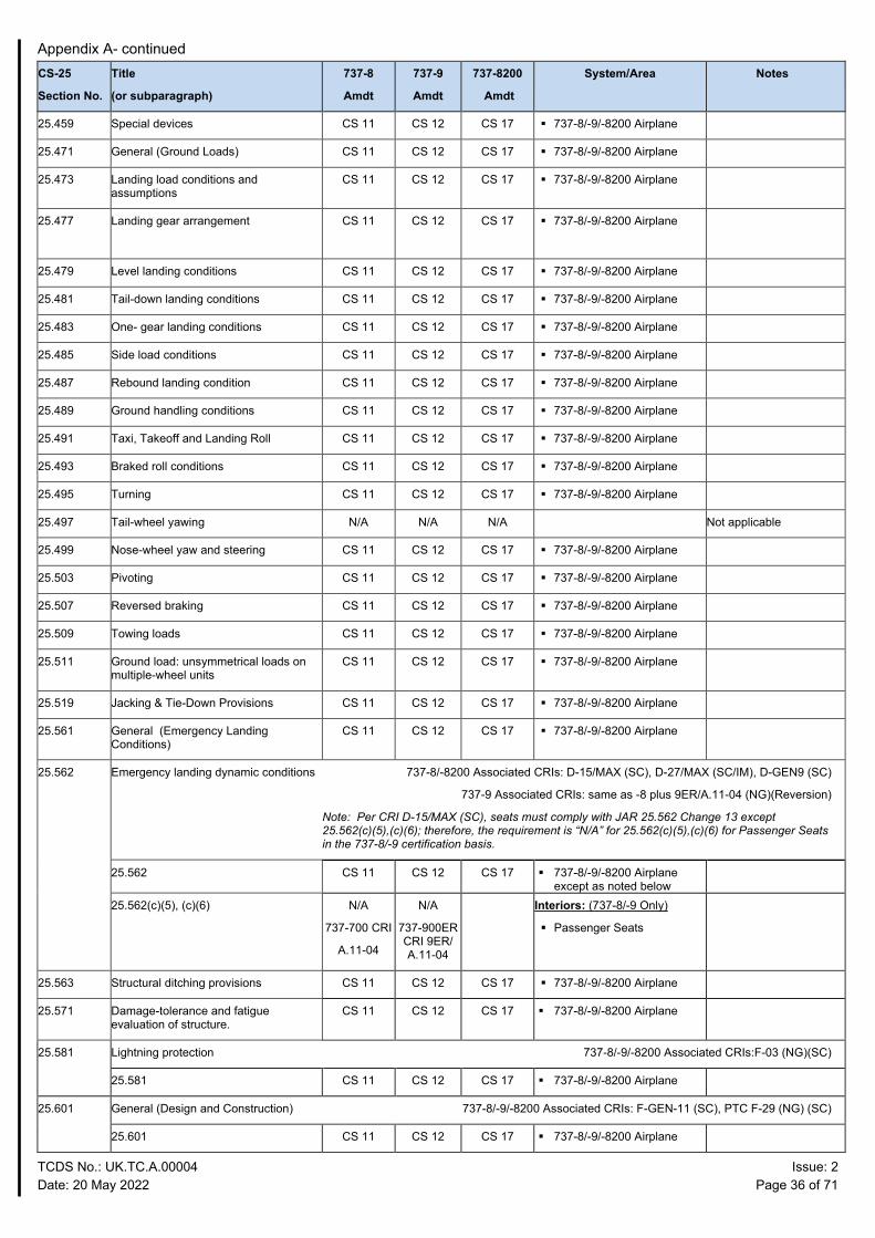
25.459 Special devices CS 11 CS 12 CS 17 737-8/-9/-8200 Airplane
25.471 General (Ground Loads) CS 11 CS 12 CS 17 737-8/-9/-8200 Airplane
25.473 Landing load conditions and assumptions
CS 11 CS 12 CS 17 737-8/-9/-8200 Airplane
25.477 Landing gear arrangement CS 11 CS 12 CS 17 737-8/-9/-8200 Airplane
25.479 Level landing conditions CS 11 CS 12 CS 17 737-8/-9/-8200 Airplane
25.481 Tail-down landing conditions CS 11 CS 12 CS 17 737-8/-9/-8200 Airplane
25.483 One- gear landing conditions CS 11 CS 12 CS 17 737-8/-9/-8200 Airplane
25.485 Side load conditions CS 11 CS 12 CS 17 737-8/-9/-8200 Airplane
25.487 Rebound landing condition CS 11 CS 12 CS 17 737-8/-9/-8200 Airplane
25.489 Ground handling conditions CS 11 CS 12 CS 17 737-8/-9/-8200 Airplane
25.491 Taxi, Takeoff and Landing Roll CS 11 CS 12 CS 17 737-8/-9/-8200 Airplane
25.493 Braked roll conditions CS 11 CS 12 CS 17 737-8/-9/-8200 Airplane
25.495 Turning CS 11 CS 12 CS 17 737-8/-9/-8200 Airplane
25.497 Tail-wheel yawing N/A N/A N/A Not applicable
25.499 Nose-wheel yaw and steering CS 11 CS 12 CS 17 737-8/-9/-8200 Airplane
25.503 Pivoting CS 11 CS 12 CS 17 737-8/-9/-8200 Airplane
25.507 Reversed braking CS 11 CS 12 CS 17 737-8/-9/-8200 Airplane
25.509 Towing loads CS 11 CS 12 CS 17 737-8/-9/-8200 Airplane
25.511 Ground load: unsymmetrical loads on multiple-wheel units
CS 11 CS 12 CS 17 737-8/-9/-8200 Airplane
25.519 Jacking & Tie-Down Provisions CS 11 CS 12 CS 17 737-8/-9/-8200 Airplane
25.561 General (Emergency Landing Conditions)
CS 11 CS 12 CS 17 737-8/-9/-8200 Airplane
25.562 Emergency landing dynamic conditions 737-8/-8200 Associated CRIs: D-15/MAX (SC), D-27/MAX (SC/IM), D-GEN9 (SC)
737-9 Associated CRIs: same as -8 plus 9ER/A.11-04 (NG)(Reversion)
Note: Per CRI D-15/MAX (SC), seats must comply with JAR 25.562 Change 13 except 25.562(c)(5),(c)(6); therefore, the requirement is “N/A” for 25.562(c)(5),(c)(6) for Passenger Seats in the 737-8/-9 certification basis.
25.562 CS 11 CS 12 CS 17 737-8/-9/-8200 Airplane except as noted below
25.562(c)(5), (c)(6) N/A
737-700 CRI
A.11-04
N/A
737-900ER CRI 9ER/ A.11-04
Interiors: (737-8/-9 Only)
Passenger Seats
25.563 Structural ditching provisions CS 11 CS 12 CS 17 737-8/-9/-8200 Airplane
25.571 Damage-tolerance and fatigue evaluation of structure.
CS 11 CS 12 CS 17 737-8/-9/-8200 Airplane
25.581 Lightning protection 737-8/-9/-8200 Associated CRIs:F-03 (NG)(SC)
25.581 CS 11 CS 12 CS 17 737-8/-9/-8200 Airplane
25.601 General (Design and Construction) 737-8/-9/-8200 Associated CRIs: F-GEN-11 (SC), PTC F-29 (NG) (SC)
25.601 CS 11 CS 12 CS 17 737-8/-9/-8200 Airplane
Appendix A- continued
TCDS No.: UK.TC.A.00004 Issue: 2 Date: 20 May 2022 Page 37 of 71
CS-25
Section No.
Title
(or subparagraph)
737-8
Amdt
737-9
Amdt
737-8200
Amdt
System/Area Notes
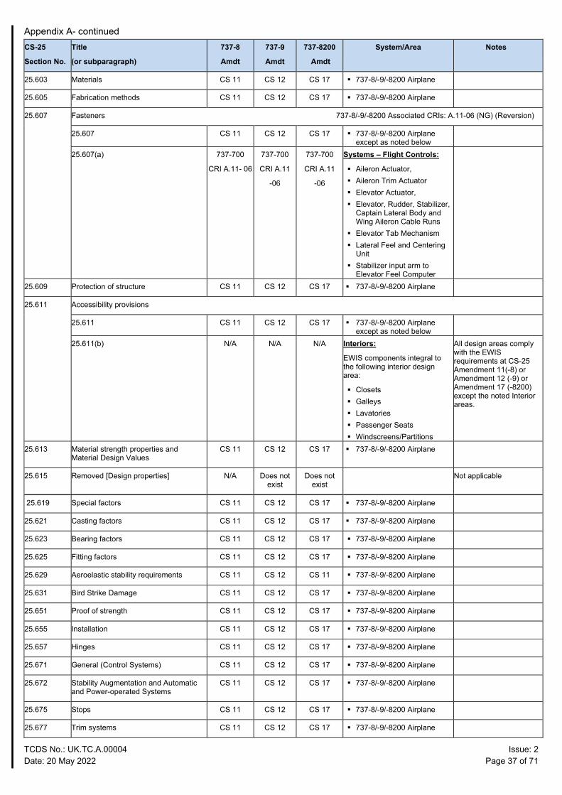
25.603 Materials CS 11 CS 12 CS 17 737-8/-9/-8200 Airplane
25.605 Fabrication methods CS 11 CS 12 CS 17 737-8/-9/-8200 Airplane
25.607 Fasteners 737-8/-9/-8200 Associated CRIs: A.11-06 (NG) (Reversion)
25.607 CS 11 CS 12 CS 17 737-8/-9/-8200 Airplane except as noted below
25.607(a) 737-700
CRI A.11- 06
737-700
CRI A.11
-06
737-700
CRI A.11
-06
Systems – Flight Controls:
Aileron Actuator, Aileron Trim Actuator Elevator Actuator, Elevator, Rudder, Stabilizer,
Captain Lateral Body and Wing Aileron Cable Runs
Elevator Tab Mechanism Lateral Feel and Centering
Unit Stabilizer input arm to
Elevator Feel Computer
25.609 Protection of structure CS 11 CS 12 CS 17 737-8/-9/-8200 Airplane
25.611 Accessibility provisions
25.611 CS 11 CS 12 CS 17 737-8/-9/-8200 Airplane except as noted below
25.611(b) N/A N/A N/A Interiors:
EWIS components integral to the following interior design area:
Closets Galleys Lavatories Passenger Seats Windscreens/Partitions
All design areas comply with the EWIS requirements at CS-25 Amendment 11(-8) or Amendment 12 (-9) or Amendment 17 (-8200) except the noted Interior areas.
25.613 Material strength properties and Material Design Values
CS 11 CS 12 CS 17 737-8/-9/-8200 Airplane
25.615 Removed [Design properties] N/A Does not exist
Does not exist
Not applicable
25.619 Special factors CS 11 CS 12 CS 17 737-8/-9/-8200 Airplane
25.621 Casting factors CS 11 CS 12 CS 17 737-8/-9/-8200 Airplane
25.623 Bearing factors CS 11 CS 12 CS 17 737-8/-9/-8200 Airplane
25.625 Fitting factors CS 11 CS 12 CS 17 737-8/-9/-8200 Airplane
25.629 Aeroelastic stability requirements CS 11 CS 12 CS 11 737-8/-9/-8200 Airplane
25.631 Bird Strike Damage CS 11 CS 12 CS 17 737-8/-9/-8200 Airplane
25.651 Proof of strength CS 11 CS 12 CS 17 737-8/-9/-8200 Airplane
25.655 Installation CS 11 CS 12 CS 17 737-8/-9/-8200 Airplane
25.657 Hinges CS 11 CS 12 CS 17 737-8/-9/-8200 Airplane
25.671 General (Control Systems) CS 11 CS 12 CS 17 737-8/-9/-8200 Airplane
25.672 Stability Augmentation and Automatic and Power-operated Systems
CS 11 CS 12 CS 17 737-8/-9/-8200 Airplane
25.675 Stops CS 11 CS 12 CS 17 737-8/-9/-8200 Airplane
25.677 Trim systems CS 11 CS 12 CS 17 737-8/-9/-8200 Airplane
Appendix A- continued
TCDS No.: UK.TC.A.00004 Issue: 2 Date: 20 May 2022 Page 38 of 71
CS-25
Section No.
Title
(or subparagraph)
737-8
Amdt
737-9
Amdt
737-8200
Amdt
System/Area Notes
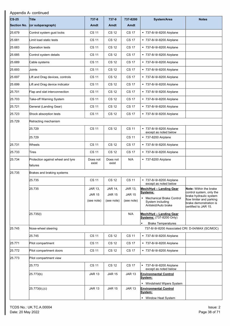
25.679 Control system gust locks CS 11 CS 12 CS 17 737-8/-9/-8200 Airplane
25.681 Limit load static tests CS 11 CS 12 CS 17 737-8/-9/-8200 Airplane
25.683 Operation tests CS 11 CS 12 CS 17 737-8/-9/-8200 Airplane
25.685 Control system details CS 11 CS 12 CS 17 737-8/-9/-8200 Airplane
25.689 Cable systems CS 11 CS 12 CS 17 737-8/-9/-8200 Airplane
25.693 Joints CS 11 CS 12 CS 17 737-8/-9/-8200 Airplane
25.697 Lift and Drag devices, controls CS 11 CS 12 CS 17 737-8/-9/-8200 Airplane
25.699 Lift and Drag device indicator CS 11 CS 12 CS 17 737-8/-9/-8200 Airplane
25.701 Flap and slat interconnection CS 11 CS 12 CS 17 737-8/-9/-8200 Airplane
25.703 Take-off Warning System CS 11 CS 12 CS 17 737-8/-9/-8200 Airplane
25.721 General (Landing Gear) CS 11 CS 12 CS 17 737-8/-9/-8200 Airplane
25.723 Shock absorption tests CS 11 CS 12 CS 17 737-8/-9/-8200 Airplane
25.729 Retracting mechanism
25.729 CS 11 CS 12 CS 11 737-8/-9/-8200 Airplane except as noted below
25.729 CS 11 737-8200 Airplane
25.731 Wheels CS 11 CS 12 CS 17 737-8/-9/-8200 Airplane
25.733 Tires CS 11 CS 12 CS 17 737-8/-9/-8200 Airplane
25.734 Protection against wheel and tyre
failures
Does not exist
Does not exist
N/A 737-8200 Airplane
25.735 Brakes and braking systems
25.735 CS 11 CS 12 CS 11 737-8/-9/-8200 Airplane except as noted below
25.735 JAR 13,
JAR 15
(see note)
JAR 14,
JAR 15
(see note)
JAR 13,
JAR 15
(see note)
Mech/Hyd – Landing Gear Systems:
Mechanical Brake Control System including Antiskid/Auto brake
Note: Within the brake control system, only the brake hydraulic system flow limiter and parking brake demonstration is certified to JAR 15.
25.735(l) N/A Mech/Hyd – Landing Gear Systems: (737-8200 Only)
Brake Temperatures
25.745 Nose-wheel steering 737-8/-9/-8200 Associated CRI: D-04/MAX (SC/MOC)
25.745 CS 11 CS 12 CS 11 737-8/-9/-8200 Airplane
25.771 Pilot compartment CS 11 CS 12 CS 17 737-8/-9/-8200 Airplane
25.772 Pilot compartment doors CS 11 CS 12 CS 17 737-8/-9/-8200 Airplane
25.773 Pilot compartment view
25.773 CS 11 CS 12 CS 17 737-8/-9/-8200 Airplane except as noted below
25.773(b) JAR 13 JAR 15 JAR 13 Environmental Control System:
Windshield Wipers System
25.773(b),(c) JAR 13 JAR 15 JAR 13 Environmental Control System:
Window Heat System
Appendix A- continued
TCDS No.: UK.TC.A.00004 Issue: 2 Date: 20 May 2022 Page 39 of 71
CS-25
Section No.
Title
(or subparagraph)
737-8
Amdt
737-9
Amdt
737-8200
Amdt
System/Area Notes
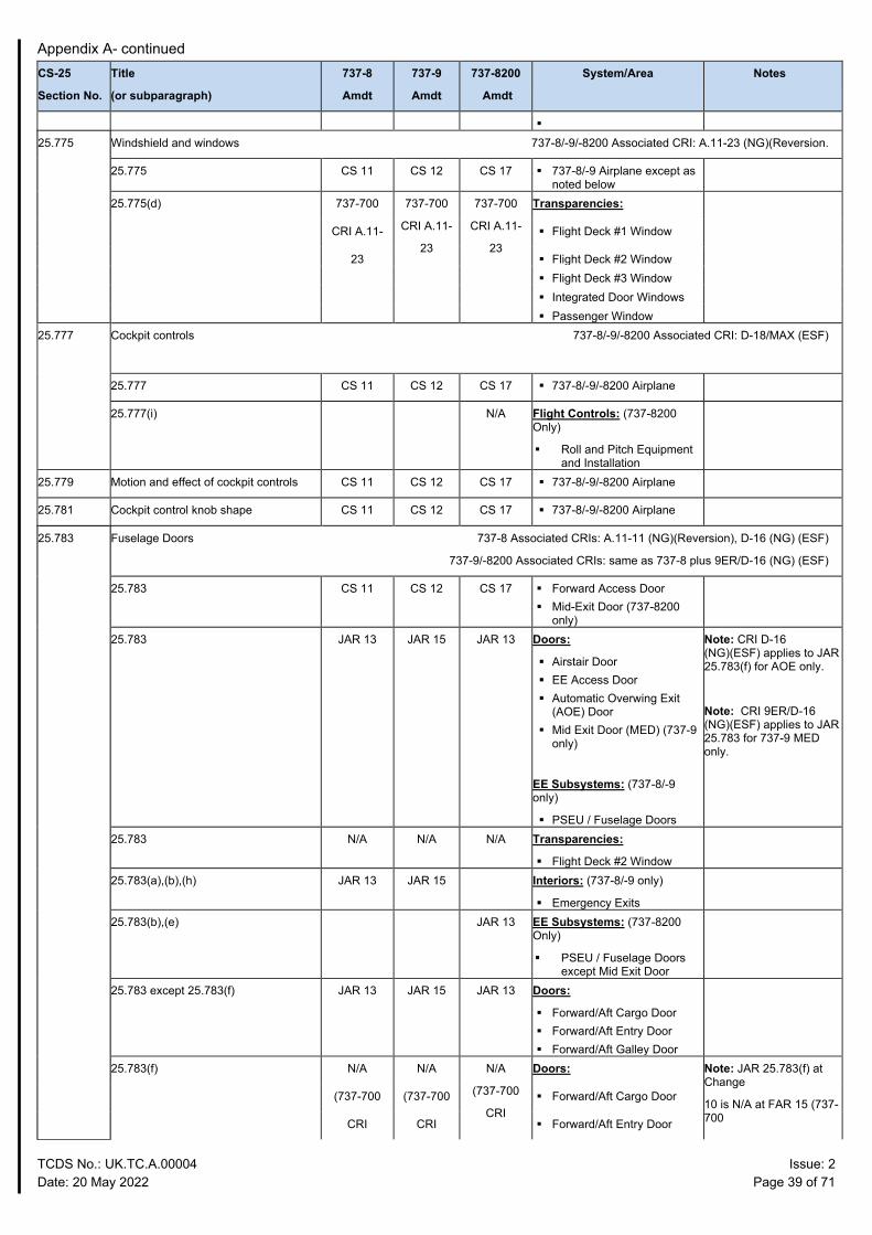
25.775 Windshield and windows 737-8/-9/-8200 Associated CRI: A.11-23 (NG)(Reversion.
25.775 CS 11 CS 12 CS 17 737-8/-9 Airplane except as noted below
25.775(d) 737-700 737-700
CRI A.11-
23
737-700
CRI A.11-
23
Transparencies:
CRI A.11- Flight Deck #1 Window
23 Flight Deck #2 Window Flight Deck #3 Window Integrated Door Windows Passenger Window
25.777 Cockpit controls 737-8/-9/-8200 Associated CRI: D-18/MAX (ESF)
25.777 CS 11 CS 12 CS 17 737-8/-9/-8200 Airplane
25.777(i) N/A Flight Controls: (737-8200 Only)
Roll and Pitch Equipment and Installation
25.779 Motion and effect of cockpit controls CS 11 CS 12 CS 17 737-8/-9/-8200 Airplane
25.781 Cockpit control knob shape CS 11 CS 12 CS 17 737-8/-9/-8200 Airplane
25.783 Fuselage Doors 737-8 Associated CRIs: A.11-11 (NG)(Reversion), D-16 (NG) (ESF)
737-9/-8200 Associated CRIs: same as 737-8 plus 9ER/D-16 (NG) (ESF)
25.783 CS 11 CS 12 CS 17 Forward Access Door Mid-Exit Door (737-8200
only)
25.783 JAR 13 JAR 15 JAR 13 Doors:
Airstair Door EE Access Door Automatic Overwing Exit
(AOE) Door Mid Exit Door (MED) (737-9
only)
EE Subsystems: (737-8/-9 only)
PSEU / Fuselage Doors
Note: CRI D-16 (NG)(ESF) applies to JAR 25.783(f) for AOE only.
Note: CRI 9ER/D-16 (NG)(ESF) applies to JAR 25.783 for 737-9 MED only.
25.783 N/A N/A N/A Transparencies:
Flight Deck #2 Window
25.783(a),(b),(h) JAR 13 JAR 15 Interiors: (737-8/-9 only)
Emergency Exits
25.783(b),(e) JAR 13 EE Subsystems: (737-8200 Only)
PSEU / Fuselage Doors except Mid Exit Door
25.783 except 25.783(f) JAR 13 JAR 15 JAR 13 Doors:
Forward/Aft Cargo Door Forward/Aft Entry Door Forward/Aft Galley Door
25.783(f) N/A N/A N/A
(737-700
CRI
Doors: Note: JAR 25.783(f) at Change
10 is N/A at FAR 15 (737-700
(737-700 (737-700 Forward/Aft Cargo Door
CRI CRI Forward/Aft Entry Door
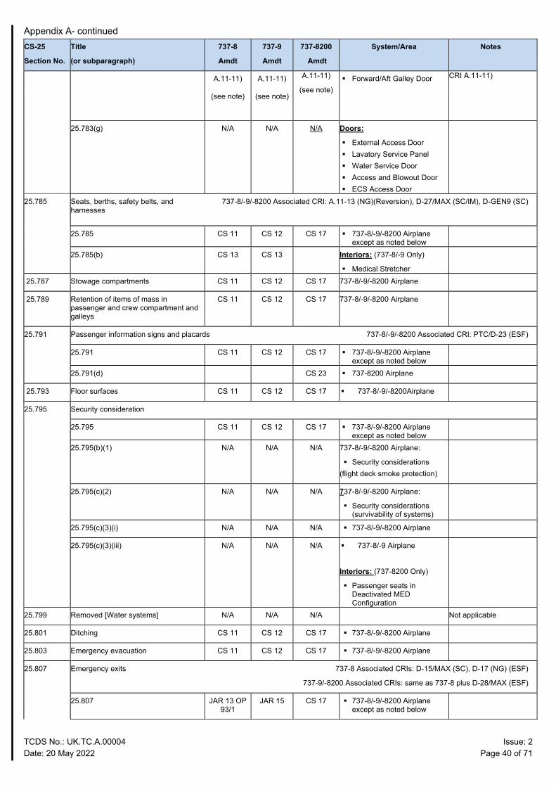
Appendix A- continued
TCDS No.: UK.TC.A.00004 Issue: 2 Date: 20 May 2022 Page 40 of 71
CS-25
Section No.
Title
(or subparagraph)
737-8
Amdt
737-9
Amdt
737-8200
Amdt
System/Area Notes
A.11-11) A.11-11) A.11-11)
(see note) Forward/Aft Galley Door CRI A.11-11)
(see note) (see note)
25.783(g) N/A N/A N/A Doors:
External Access Door Lavatory Service Panel Water Service Door Access and Blowout Door ECS Access Door
25.785 Seats, berths, safety belts, and harnesses
737-8/-9/-8200 Associated CRI: A.11-13 (NG)(Reversion), D-27/MAX (SC/IM), D-GEN9 (SC)
25.785 CS 11 CS 12 CS 17 737-8/-9/-8200 Airplane except as noted below
25.785(b) CS 13 CS 13 Interiors: (737-8/-9 Only)
Medical Stretcher
25.787 Stowage compartments CS 11 CS 12 CS 17 737-8/-9/-8200 Airplane
25.789 Retention of items of mass in passenger and crew compartment and galleys
CS 11 CS 12 CS 17 737-8/-9/-8200 Airplane
25.791 Passenger information signs and placards 737-8/-9/-8200 Associated CRI: PTC/D-23 (ESF)
25.791 CS 11 CS 12 CS 17 737-8/-9/-8200 Airplane except as noted below
25.791(d) CS 23 737-8200 Airplane
25.793 Floor surfaces CS 11 CS 12 CS 17 737-8/-9/-8200Airplane
25.795 Security consideration
25.795 CS 11 CS 12 CS 17 737-8/-9/-8200 Airplane except as noted below
25.795(b)(1) N/A N/A N/A 737-8/-9/-8200 Airplane:
Security considerations (flight deck smoke protection)
25.795(c)(2) N/A N/A N/A 737-8/-9/-8200 Airplane:
Security considerations (survivability of systems)
25.795(c)(3)(i) N/A N/A N/A 737-8/-9/-8200 Airplane
25.795(c)(3)(iii) N/A N/A N/A 737-8/-9 Airplane
Interiors: (737-8200 Only)
Passenger seats in Deactivated MED Configuration
25.799 Removed [Water systems] N/A N/A N/A Not applicable
25.801 Ditching CS 11 CS 12 CS 17 737-8/-9/-8200 Airplane
25.803 Emergency evacuation CS 11 CS 12 CS 17 737-8/-9/-8200 Airplane
25.807 Emergency exits 737-8 Associated CRIs: D-15/MAX (SC), D-17 (NG) (ESF)
737-9/-8200 Associated CRIs: same as 737-8 plus D-28/MAX (ESF)
25.807 JAR 13 OP 93/1
JAR 15 CS 17 737-8/-9/-8200 Airplane except as noted below
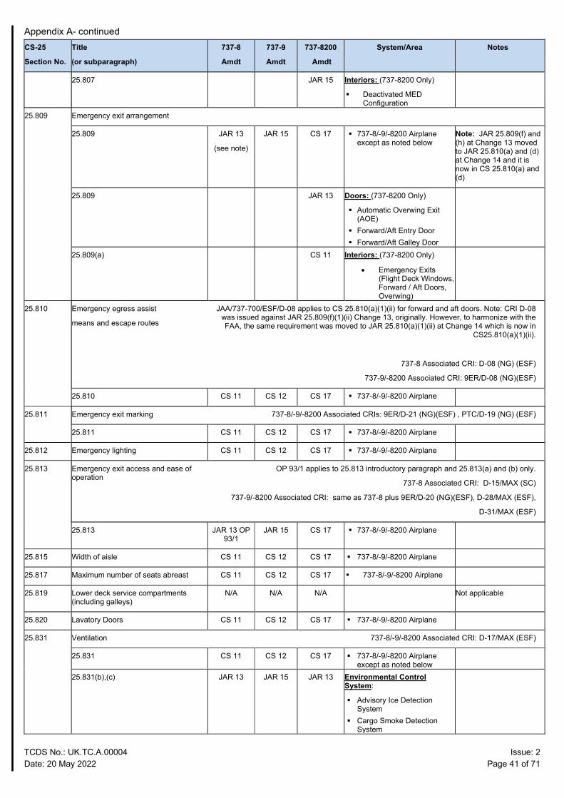
Appendix A- continued
TCDS No.: UK.TC.A.00004 Issue: 2 Date: 20 May 2022 Page 41 of 71
CS-25
Section No.
Title
(or subparagraph)
737-8
Amdt
737-9
Amdt
737-8200
Amdt
System/Area Notes
25.807 JAR 15 Interiors: (737-8200 Only)
Deactivated MED Configuration
25.809 Emergency exit arrangement
25.809 JAR 13
(see note)
JAR 15 CS 17 737-8/-9/-8200 Airplane except as noted below
Note: JAR 25.809(f) and (h) at Change 13 moved to JAR 25.810(a) and (d) at Change 14 and it is now in CS 25.810(a) and (d)
25.809 JAR 13 Doors: (737-8200 Only)
Automatic Overwing Exit (AOE)
Forward/Aft Entry Door Forward/Aft Galley Door
25.809(a) CS 11 Interiors: (737-8200 Only)
• Emergency Exits (Flight Deck Windows, Forward / Aft Doors, Overwing)
25.810 Emergency egress assist
means and escape routes
JAA/737-700/ESF/D-08 applies to CS 25.810(a)(1)(ii) for forward and aft doors. Note: CRI D-08 was issued against JAR 25.809(f)(1)(ii) Change 13, originally. However, to harmonize with the FAA, the same requirement was moved to JAR 25.810(a)(1)(ii) at Change 14 which is now in
CS25.810(a)(1)(ii).
737-8 Associated CRI: D-08 (NG) (ESF)
737-9/-8200 Associated CRI: 9ER/D-08 (NG)(ESF)
25.810 CS 11 CS 12 CS 17 737-8/-9/-8200 Airplane
25.811 Emergency exit marking 737-8/-9/-8200 Associated CRIs: 9ER/D-21 (NG)(ESF) , PTC/D-19 (NG) (ESF)
25.811 CS 11 CS 12 CS 17 737-8/-9/-8200 Airplane
25.812 Emergency lighting CS 11 CS 12 CS 17 737-8/-9/-8200 Airplane
25.813 Emergency exit access and ease of operation
OP 93/1 applies to 25.813 introductory paragraph and 25.813(a) and (b) only.
737-8 Associated CRI: D-15/MAX (SC)
737-9/-8200 Associated CRI: same as 737-8 plus 9ER/D-20 (NG)(ESF), D-28/MAX (ESF),
D-31/MAX (ESF)
25.813 JAR 13 OP 93/1
JAR 15 CS 17 737-8/-9/-8200 Airplane
25.815 Width of aisle CS 11 CS 12 CS 17 737-8/-9/-8200 Airplane
25.817 Maximum number of seats abreast CS 11 CS 12 CS 17 737-8/-9/-8200 Airplane
25.819 Lower deck service compartments (including galleys)
N/A N/A N/A Not applicable
25.820 Lavatory Doors CS 11 CS 12 CS 17 737-8/-9/-8200 Airplane
25.831 Ventilation 737-8/-9/-8200 Associated CRI: D-17/MAX (ESF)
25.831 CS 11 CS 12 CS 17 737-8/-9/-8200 Airplane except as noted below
25.831(b),(c) JAR 13 JAR 15 JAR 13 Environmental Control System:
Advisory Ice Detection System
Cargo Smoke Detection System
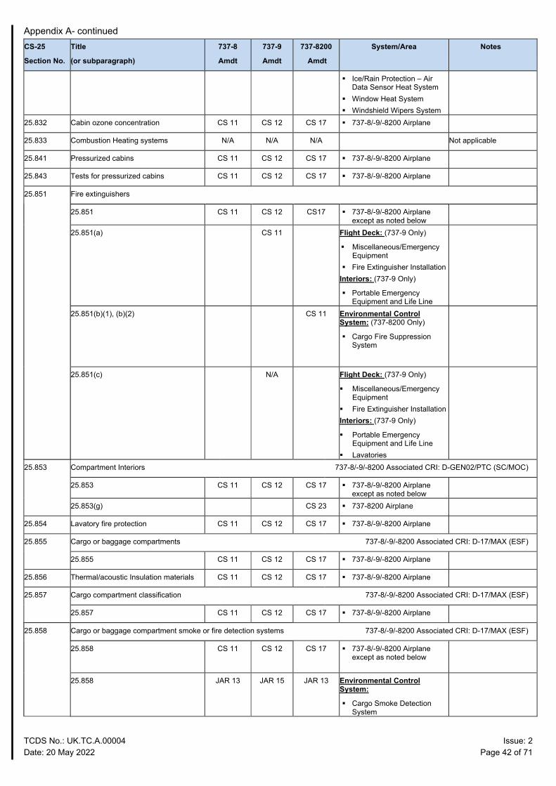
Appendix A- continued
TCDS No.: UK.TC.A.00004 Issue: 2 Date: 20 May 2022 Page 42 of 71
CS-25
Section No.
Title
(or subparagraph)
737-8
Amdt
737-9
Amdt
737-8200
Amdt
System/Area Notes
Ice/Rain Protection – Air Data Sensor Heat System
Window Heat System Windshield Wipers System
25.832 Cabin ozone concentration CS 11 CS 12 CS 17 737-8/-9/-8200 Airplane
25.833 Combustion Heating systems N/A N/A N/A Not applicable
25.841 Pressurized cabins CS 11 CS 12 CS 17 737-8/-9/-8200 Airplane
25.843 Tests for pressurized cabins CS 11 CS 12 CS 17 737-8/-9/-8200 Airplane
25.851 Fire extinguishers
25.851 CS 11 CS 12 CS17 737-8/-9/-8200 Airplane except as noted below
25.851(a) CS 11 Flight Deck: (737-9 Only)
Miscellaneous/Emergency Equipment
Fire Extinguisher Installation Interiors: (737-9 Only)
Portable Emergency Equipment and Life Line
25.851(b)(1), (b)(2) CS 11 Environmental Control System: (737-8200 Only)
Cargo Fire Suppression System
25.851(c) N/A Flight Deck: (737-9 Only)
Miscellaneous/Emergency Equipment
Fire Extinguisher Installation Interiors: (737-9 Only)
Portable Emergency Equipment and Life Line
Lavatories
25.853 Compartment Interiors 737-8/-9/-8200 Associated CRI: D-GEN02/PTC (SC/MOC)
25.853 CS 11 CS 12 CS 17 737-8/-9/-8200 Airplane except as noted below
25.853(g) CS 23 737-8200 Airplane
25.854 Lavatory fire protection CS 11 CS 12 CS 17 737-8/-9/-8200 Airplane
25.855 Cargo or baggage compartments 737-8/-9/-8200 Associated CRI: D-17/MAX (ESF)
25.855 CS 11 CS 12 CS 17 737-8/-9/-8200 Airplane
25.856 Thermal/acoustic Insulation materials CS 11 CS 12 CS 17 737-8/-9/-8200 Airplane
25.857 Cargo compartment classification 737-8/-9/-8200 Associated CRI: D-17/MAX (ESF)
25.857 CS 11 CS 12 CS 17 737-8/-9/-8200 Airplane
25.858 Cargo or baggage compartment smoke or fire detection systems 737-8/-9/-8200 Associated CRI: D-17/MAX (ESF)
25.858
CS 11 CS 12 CS 17 737-8/-9/-8200 Airplane except as noted below
25.858
JAR 13 JAR 15 JAR 13 Environmental Control System:
Cargo Smoke Detection System
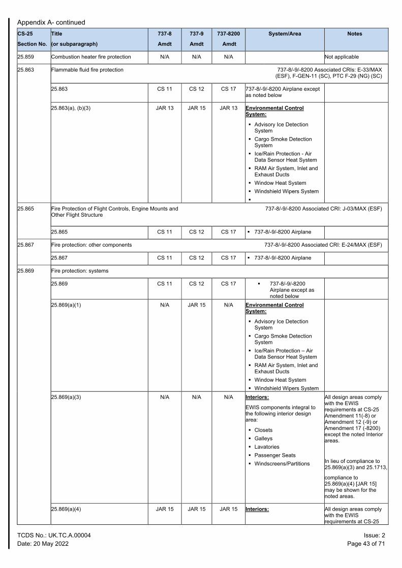
Appendix A- continued
TCDS No.: UK.TC.A.00004 Issue: 2 Date: 20 May 2022 Page 43 of 71
CS-25
Section No.
Title
(or subparagraph)
737-8
Amdt
737-9
Amdt
737-8200
Amdt
System/Area Notes
25.859 Combustion heater fire protection N/A N/A N/A Not applicable
25.863 Flammable fluid fire protection 737-8/-9/-8200 Associated CRIs: E-33/MAX (ESF), F-GEN-11 (SC), PTC F-29 (NG) (SC)
25.863 CS 11 CS 12 CS 17 737-8/-9/-8200 Airplane except as noted below
25.863(a), (b)(3) JAR 13 JAR 15 JAR 13 Environmental Control System:
Advisory Ice Detection System
Cargo Smoke Detection System
Ice/Rain Protection - Air Data Sensor Heat System
RAM Air System, Inlet and Exhaust Ducts
Window Heat System Windshield Wipers System
25.865 Fire Protection of Flight Controls, Engine Mounts and Other Flight Structure
737-8/-9/-8200 Associated CRI: J-03/MAX (ESF)
25.865 CS 11 CS 12 CS 17 737-8/-9/-8200 Airplane
25.867 Fire protection: other components 737-8/-9/-8200 Associated CRI: E-24/MAX (ESF)
25.867 CS 11 CS 12 CS 17 737-8/-9/-8200 Airplane
25.869 Fire protection: systems
25.869 CS 11 CS 12 CS 17 737-8/-9/-8200 Airplane except as noted below
25.869(a)(1) N/A JAR 15 N/A Environmental Control System:
Advisory Ice Detection System
Cargo Smoke Detection System
Ice/Rain Protection – Air Data Sensor Heat System
RAM Air System, Inlet and Exhaust Ducts
Window Heat System Windshield Wipers System
25.869(a)(3) N/A N/A N/A Interiors:
EWIS components integral to the following interior design area:
Closets Galleys Lavatories Passenger Seats Windscreens/Partitions
All design areas comply with the EWIS requirements at CS-25 Amendment 11(-8) or Amendment 12 (-9) or Amendment 17 (-8200) except the noted Interior areas.
In lieu of compliance to 25.869(a)(3) and 25.1713,
compliance to 25.869(a)(4) [JAR 15] may be shown for the noted areas.
25.869(a)(4) JAR 15 JAR 15 JAR 15 Interiors: All design areas comply with the EWIS requirements at CS-25
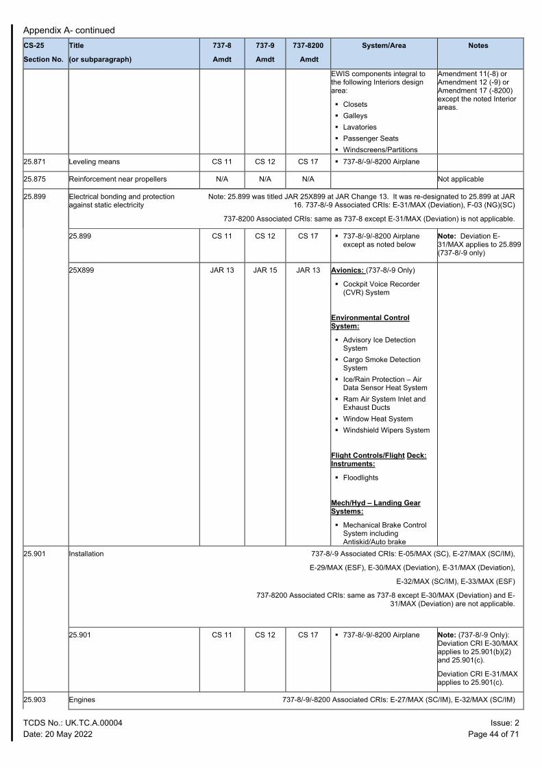
Appendix A- continued
TCDS No.: UK.TC.A.00004 Issue: 2 Date: 20 May 2022 Page 44 of 71
CS-25
Section No.
Title
(or subparagraph)
737-8
Amdt
737-9
Amdt
737-8200
Amdt
System/Area Notes
EWIS components integral to the following Interiors design area:
Closets Galleys Lavatories Passenger Seats Windscreens/Partitions
Amendment 11(-8) or Amendment 12 (-9) or Amendment 17 (-8200) except the noted Interior areas.
25.871 Leveling means CS 11 CS 12 CS 17 737-8/-9/-8200 Airplane
25.875 Reinforcement near propellers N/A N/A N/A Not applicable
25.899 Electrical bonding and protection against static electricity
Note: 25.899 was titled JAR 25X899 at JAR Change 13. It was re-designated to 25.899 at JAR 16. 737-8/-9 Associated CRIs: E-31/MAX (Deviation), F-03 (NG)(SC)
737-8200 Associated CRIs: same as 737-8 except E-31/MAX (Deviation) is not applicable.
25.899 CS 11 CS 12 CS 17 737-8/-9/-8200 Airplane except as noted below
Note: Deviation E-31/MAX applies to 25.899 (737-8/-9 only)
25X899 JAR 13 JAR 15 JAR 13 Avionics: (737-8/-9 Only)
Cockpit Voice Recorder (CVR) System
Environmental Control System:
Advisory Ice Detection System
Cargo Smoke Detection System
Ice/Rain Protection – Air Data Sensor Heat System
Ram Air System Inlet and Exhaust Ducts
Window Heat System Windshield Wipers System
Flight Controls/Flight Deck: Instruments:
Floodlights
Mech/Hyd – Landing Gear Systems:
Mechanical Brake Control System including Antiskid/Auto brake
25.901 Installation 737-8/-9 Associated CRIs: E-05/MAX (SC), E-27/MAX (SC/IM),
E-29/MAX (ESF), E-30/MAX (Deviation), E-31/MAX (Deviation),
E-32/MAX (SC/IM), E-33/MAX (ESF)
737-8200 Associated CRIs: same as 737-8 except E-30/MAX (Deviation) and E-31/MAX (Deviation) are not applicable.
25.901 CS 11 CS 12 CS 17 737-8/-9/-8200 Airplane Note: (737-8/-9 Only): Deviation CRI E-30/MAX applies to 25.901(b)(2) and 25.901(c).
Deviation CRI E-31/MAX applies to 25.901(c).
25.903 Engines 737-8/-9/-8200 Associated CRIs: E-27/MAX (SC/IM), E-32/MAX (SC/IM)
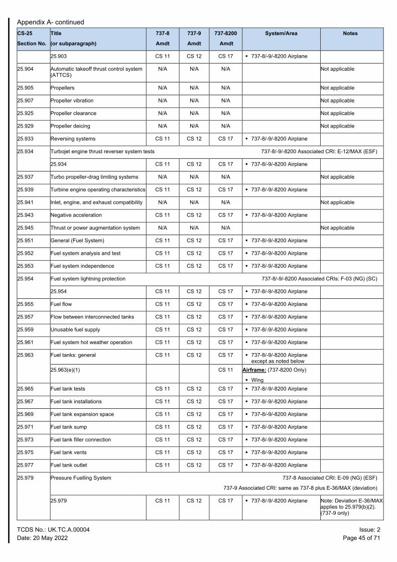
Appendix A- continued
TCDS No.: UK.TC.A.00004 Issue: 2 Date: 20 May 2022 Page 45 of 71
CS-25
Section No.
Title
(or subparagraph)
737-8
Amdt
737-9
Amdt
737-8200
Amdt
System/Area Notes
25.903 CS 11 CS 12 CS 17 737-8/-9/-8200 Airplane
25.904 Automatic takeoff thrust control system (ATTCS)
N/A N/A N/A Not applicable
25.905 Propellers N/A N/A N/A Not applicable
25.907 Propeller vibration N/A N/A N/A Not applicable
25.925 Propeller clearance N/A N/A N/A Not applicable
25.929 Propeller deicing N/A N/A N/A Not applicable
25.933 Reversing systems CS 11 CS 12 CS 17 737-8/-9/-8200 Airplane
25.934 Turbojet engine thrust reverser system tests 737-8/-9/-8200 Associated CRI: E-12/MAX (ESF)
25.934 CS 11 CS 12 CS 17 737-8/-9/-8200 Airplane
25.937 Turbo propeller-drag limiting systems N/A N/A N/A Not applicable
25.939 Turbine engine operating characteristics CS 11 CS 12 CS 17 737-8/-9/-8200 Airplane
25.941 Inlet, engine, and exhaust compatibility N/A N/A N/A Not applicable
25.943 Negative acceleration CS 11 CS 12 CS 17 737-8/-9/-8200 Airplane
25.945 Thrust or power augmentation system N/A N/A N/A Not applicable
25.951 General (Fuel System) CS 11 CS 12 CS 17 737-8/-9/-8200 Airplane
25.952 Fuel system analysis and test CS 11 CS 12 CS 17 737-8/-9/-8200 Airplane
25.953 Fuel system independence CS 11 CS 12 CS 17 737-8/-9/-8200 Airplane
25.954 Fuel system lightning protection 737-8/-9/-8200 Associated CRIs: F-03 (NG) (SC)
25.954 CS 11 CS 12 CS 17 737-8/-9/-8200 Airplane
25.955 Fuel flow CS 11 CS 12 CS 17 737-8/-9/-8200 Airplane
25.957 Flow between interconnected tanks CS 11 CS 12 CS 17 737-8/-9/-8200 Airplane
25.959 Unusable fuel supply CS 11 CS 12 CS 17 737-8/-9/-8200 Airplane
25.961 Fuel system hot weather operation CS 11 CS 12 CS 17 737-8/-9/-8200 Airplane
25.963 Fuel tanks: general CS 11 CS 12 CS 17 737-8/-9/-8200 Airplane except as noted below
25.963(e)(1) CS 11 Airframe: (737-8200 Only)
Wing
25.965 Fuel tank tests CS 11 CS 12 CS 17 737-8/-9/-8200 Airplane
25.967 Fuel tank installations CS 11 CS 12 CS 17 737-8/-9/-8200 Airplane
25.969 Fuel tank expansion space CS 11 CS 12 CS 17 737-8/-9/-8200 Airplane
25.971 Fuel tank sump CS 11 CS 12 CS 17 737-8/-9/-8200 Airplane
25.973 Fuel tank filler connection CS 11 CS 12 CS 17 737-8/-9/-8200 Airplane
25.975 Fuel tank vents CS 11 CS 12 CS 17 737-8/-9/-8200 Airplane
25.977 Fuel tank outlet CS 11 CS 12 CS 17 737-8/-9/-8200 Airplane
25.979 Pressure Fuelling System 737-8 Associated CRI: E-09 (NG) (ESF)
737-9 Associated CRI: same as 737-8 plus E-36/MAX (deviation)
25.979 CS 11 CS 12 CS 17 737-8/-9/-8200 Airplane
Note: Deviation E-36/MAX applies to 25.979(b)(2). (737-9 only)
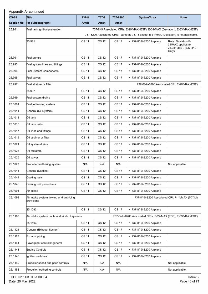
Appendix A- continued
TCDS No.: UK.TC.A.00004 Issue: 2 Date: 20 May 2022 Page 46 of 71
CS-25
Section No.
Title
(or subparagraph)
737-8
Amdt
737-9
Amdt
737-8200
Amdt
System/Area Notes
25.981 Fuel tank ignition prevention 737-8/-9 Associated CRIs: E-29/MAX (ESF), E-31/MAX (Deviation), E-33/MAX (ESF)
737-8200 Associated CRIs: same as 737-8 except E-31/MAX (Deviation) is not applicable.
25.981 CS 11 CS 12 CS 17 737-8/-9/-8200 Airplane Note: Deviation E-31/MAX applies to 25.981(a)(3). (737-8/-9 Only)
25.991 Fuel pumps CS 11 CS 12 CS 17 737-8/-9/-8200 Airplane
25.993 Fuel system lines and fittings CS 11 CS 12 CS 17 737-8/-9/-8200 Airplane
25.994 Fuel System Components CS 11 CS 12 CS 17 737-8/-9/-8200 Airplane
25.995 Fuel valves CS 11 CS 12 CS 17 737-8/-9/-8200 Airplane
25.997 Fuel strainer or filter 737-8/-9/-8200 Associated CRI: E-20/MAX (ESF)
25.997 CS 11 CS 12 CS 17 737-8/-9/-8200 Airplane
25.999 Fuel system drains CS 11 CS 12 CS 17 737-8/-9/-8200 Airplane
25.1001 Fuel jettisoning system CS 11 CS 12 CS 17 737-8/-9/-8200 Airplane
25.1011 General (Oil System) CS 11 CS 12 CS 17 737-8/-9/-8200 Airplane
25.1013 Oil tank CS 11 CS 12 CS 17 737-8/-9/-8200 Airplane
25.1015 Oil tank tests CS 11 CS 12 CS 17 737-8/-9/-8200 Airplane
25.1017 Oil lines and fittings CS 11 CS 12 CS 17 737-8/-9/-8200 Airplane
25.1019 Oil strainer or filter CS 11 CS 12 CS 17 737-8/-9/-8200 Airplane
25.1021 Oil system drains CS 11 CS 12 CS 17 737-8/-9/-8200 Airplane
25.1023 Oil radiators CS 11 CS 12 CS 17 737-8/-9/-8200 Airplane
25.1025 Oil valves CS 11 CS 12 CS 17 737-8/-9/-8200 Airplane
25.1027 Propeller feathering system N/A N/A N/A Not applicable
25.1041 General (Cooling) CS 11 CS 12 CS 17 737-8/-9/-8200 Airplane
25.1043 Cooling tests CS 11 CS 12 CS 17 737-8/-9/-8200 Airplane
25.1045 Cooling test procedures CS 11 CS 12 CS 17 737-8/-9/-8200 Airplane
25.1091 Air intake CS 11 CS 12 CS 17 737-8/-9/-8200 Airplane
25.1093 Air intake system deicing and anti-icing provisions
737-8/-9/-8200 Associated CRI: F-11/MAX (SC/IM)
25.1093 CS 11 CS 12 CS 17 737-8/-9/-8200 Airplane
25.1103 Air Intake system ducts and air duct systems 737-8/-9/-8200 Associated CRIs: E-22/MAX (ESF), E-33/MAX (ESF)
25.1103 CS 11 CS 12 CS 17 737-8/-9/-8200 Airplane
25.1121 General (Exhaust System) CS 11 CS 12 CS 17 737-8/-9/-8200 Airplane
25.1123 Exhaust piping CS 11 CS 12 CS 17 737-8/-9/-8200 Airplane
25.1141 Powerplant controls: general CS 11 CS 12 CS 17 737-8/-9/-8200 Airplane
25.1143 Engine Controls CS 11 CS 12 CS 17 737-8/-9/-8200 Airplane
25.1145 Ignition switches CS 11 CS 12 CS 17 737-8/-9/-8200 Airplane
25.1149 Propeller speed and pitch controls N/A N/A N/A Not applicable
25.1153 Propeller feathering controls N/A N/A N/A Not applicable
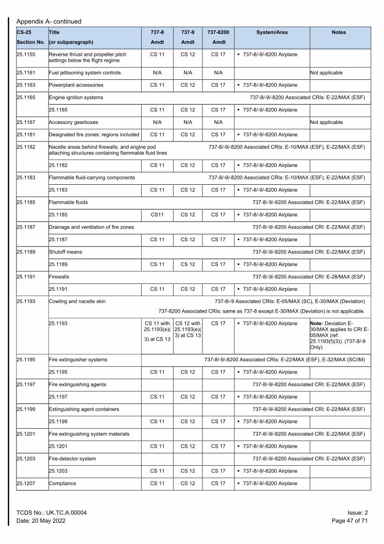
Appendix A- continued
TCDS No.: UK.TC.A.00004 Issue: 2 Date: 20 May 2022 Page 47 of 71
CS-25
Section No.
Title
(or subparagraph)
737-8
Amdt
737-9
Amdt
737-8200
Amdt
System/Area Notes
25.1155 Reverse thrust and propeller pitch settings below the flight regime
CS 11 CS 12 CS 17 737-8/-9/-8200 Airplane
25.1161 Fuel jettisoning system controls N/A N/A N/A Not applicable
25.1163 Powerplant accessories CS 11 CS 12 CS 17 737-8/-9/-8200 Airplane
25.1165 Engine ignition systems 737-8/-9/-8200 Associated CRIs: E-22/MAX (ESF)
25.1165 CS 11 CS 12 CS 17 737-8/-9/-8200 Airplane
25.1167 Accessory gearboxes N/A N/A N/A Not applicable
25.1181 Designated fire zones: regions included CS 11 CS 12 CS 17 737-8/-9/-8200 Airplane
25.1182 Nacelle areas behind firewalls, and engine pod attaching structures containing flammable fluid lines
737-8/-9/-8200 Associated CRIs: E-10/MAX (ESF), E-22/MAX (ESF)
25.1182 CS 11 CS 12 CS 17 737-8/-9/-8200 Airplane
25.1183 Flammable fluid-carrying components 737-8/-9/-8200 Associated CRIs: E-10/MAX (ESF), E-22/MAX (ESF)
25.1183 CS 11 CS 12 CS 17 737-8/-9/-8200 Airplane
25.1185 Flammable fluids 737-8/-9/-8200 Associated CRI: E-22/MAX (ESF)
25.1185 CS11 CS 12 CS 17 737-8/-9/-8200 Airplane
25.1187 Drainage and ventilation of fire zones 737-8/-9/-8200 Associated CRI: E-22/MAX (ESF)
25.1187 CS 11 CS 12 CS 17 737-8/-9/-8200 Airplane
25.1189 Shutoff means 737-8/-9/-8200 Associated CRI: E-22/MAX (ESF)
25.1189 CS 11 CS 12 CS 17 737-8/-9/-8200 Airplane
25.1191 Firewalls 737-8/-9/-8200 Associated CRI: E-28/MAX (ESF)
25.1191 CS 11 CS 12 CS 17 737-8/-9/-8200 Airplane
25.1193 Cowling and nacelle skin 737-8/-9 Associated CRIs: E-05/MAX (SC), E-30/MAX (Deviation)
737-8200 Associated CRIs: same as 737-8 except E-30/MAX (Deviation) is not applicable.
25.1193 CS 11 with 25.1193(e)(
3) at CS 13
CS 12 with 25.1193(e)(3) at CS 13
CS 17 737-8/-9/-8200 Airplane Note: Deviation E-30/MAX applies to CRI E-05/MAX (ref. 25.1193(f)(3)). (737-8/-9 Only)
25.1195 Fire extinguisher systems 737-8/-9/-8200 Associated CRIs: E-22/MAX (ESF), E-32/MAX (SC/IM)
25.1195 CS 11 CS 12 CS 17 737-8/-9/-8200 Airplane
25.1197 Fire extinguishing agents 737-8/-9/-8200 Associated CRI: E-22/MAX (ESF)
25.1197 CS 11 CS 12 CS 17 737-8/-9/-8200 Airplane
25.1199 Extinguishing agent containers 737-8/-9/-8200 Associated CRI: E-22/MAX (ESF)
25.1199 CS 11 CS 12 CS 17 737-8/-9/-8200 Airplane
25.1201 Fire extinguishing system materials 737-8/-9/-8200 Associated CRI: E-22/MAX (ESF)
25.1201 CS 11 CS 12 CS 17 737-8/-9/-8200 Airplane
25.1203 Fire-detector system 737-8/-9/-8200 Associated CRI: E-22/MAX (ESF)
25.1203 CS 11 CS 12 CS 17 737-8/-9/-8200 Airplane
25.1207 Compliance CS 11 CS 12 CS 17 737-8/-9/-8200 Airplane
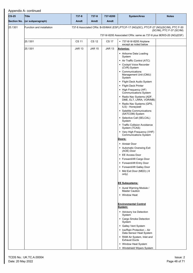
Appendix A- continued
TCDS No.: UK.TC.A.00004 Issue: 2 Date: 20 May 2022 Page 48 of 71
CS-25
Section No.
Title
(or subparagraph)
737-8
Amdt
737-9
Amdt
737-8200
Amdt
System/Area Notes
25.1301 Function and installation 737-8 Associated CRIs: B-05/MAX (ESF),PTC/F-17 (NG)(SC), PTC/F-27 (NG)(SC/IM), PTC F-30 (SC/IM), PTC F-37 (SC/IM)
737-9/-8200 Associated CRIs: same as 737-8 plus 9ER/D-20 (NG)(ESF)
25.1301 CS 11 CS 12 CS 17 737-8/-9/-8200 Airplane except as noted below
25.1301 JAR 13 JAR 15 JAR 13 Avionics:
Airborne Data Loading System
Air Traffic Control (ATC) Cockpit Voice Recorder
(CVR) System Communications
Management Unit (CMU) System
Flight Deck Audio System Flight Deck Printer High Frequency (HF)
Communications System Radio Nav Systems (ADF,
DME, ELT, LRRA, VOR/MB) Radio Nav Systems (GPS,
ILS) - Honeywell Satellite Communications
(SATCOM) System Selective Call (SELCAL)
System Traffic Collision Avoidance
System (TCAS) Very High Frequency (VHF)
Communications System Doors:
Airstair Door Automatic Overwing Exit
(AOE) Door EE Access Door Forward/Aft Cargo Door Forward/Aft Entry Door Forward/Aft Galley Door Mid Exit Door (MED) (-9
only)
EE Subsystems:
Aural Warning Module / Master Caution
Window Heat
Environmental Control System:
Advisory Ice Detection System
Cargo Smoke Detection System
Galley Vent System Ice/Rain Protection – Air
Data Sensor Heat System RAM Air System, Inlet and
Exhaust Ducts Window Heat System Windshield Wipers System
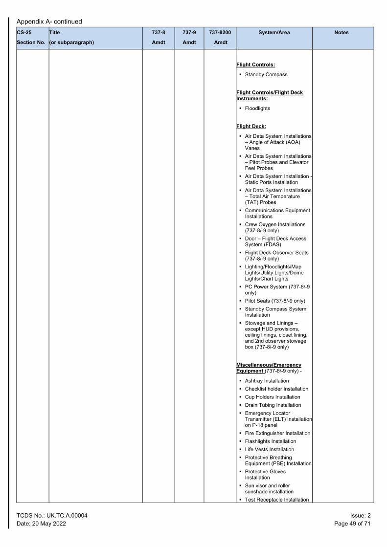
Appendix A- continued
TCDS No.: UK.TC.A.00004 Issue: 2 Date: 20 May 2022 Page 49 of 71
CS-25
Section No.
Title
(or subparagraph)
737-8
Amdt
737-9
Amdt
737-8200
Amdt
System/Area Notes
Flight Controls:
Standby Compass
Flight Controls/Flight Deck Instruments:
Floodlights
Flight Deck:
Air Data System Installations – Angle of Attack (AOA) Vanes
Air Data System Installations – Pitot Probes and Elevator Feel Probes
Air Data System Installation - Static Ports Installation
Air Data System Installations – Total Air Temperature (TAT) Probes
Communications Equipment Installations
Crew Oxygen Installations (737-8/-9 only)
Door – Flight Deck Access System (FDAS)
Flight Deck Observer Seats (737-8/-9 only)
Lighting/Floodlights/Map Lights/Utility Lights/Dome Lights/Chart Lights
PC Power System (737-8/-9 only)
Pilot Seats (737-8/-9 only) Standby Compass System
Installation Stowage and Linings –
except HUD provisions, ceiling linings, closet lining, and 2nd observer stowage box (737-8/-9 only)
Miscellaneous/Emergency Equipment (737-8/-9 only) -
Ashtray Installation Checklist holder Installation Cup Holders Installation Drain Tubing Installation Emergency Locator
Transmitter (ELT) Installation on P-18 panel
Fire Extinguisher Installation Flashlights Installation Life Vests Installation Protective Breathing
Equipment (PBE) Installation Protective Gloves
Installation Sun visor and roller
sunshade installation Test Receptacle Installation
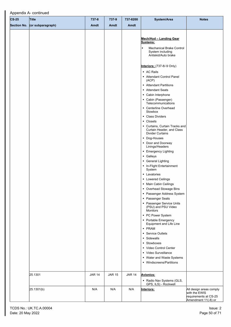
Appendix A- continued
TCDS No.: UK.TC.A.00004 Issue: 2 Date: 20 May 2022 Page 50 of 71
CS-25
Section No.
Title
(or subparagraph)
737-8
Amdt
737-9
Amdt
737-8200
Amdt
System/Area Notes
Mech/Hyd – Landing Gear Systems:
Mechanical Brake Control System including Antiskid/Auto brake
Interiors: (737-8/-9 Only)
AC Rails Attendant Control Panel
(ACP) Attendant Partitions Attendant Seats Cabin Interphone Cabin (Passenger)
Telecommunications Centerline Overhead
Stowbox Class Dividers Closets Curtains, Curtain Tracks and
Curtain Header, and Class Divider Curtains
Dog-Houses Door and Doorway
Linings/Headers Emergency Lighting Galleys General Lighting In-Flight Entertainment
System Lavatories Lowered Ceilings Main Cabin Ceilings Overhead Stowage Bins Passenger Address System Passenger Seats Passenger Service Units
(PSU) and PSU Video Monitors
PC Power System Portable Emergency
Equipment and Life Line PRAM Service Outlets Sidewalls Stowboxes Video Control Center Video Surveillance Water and Waste Systems Windscreens/Partitions
25.1301 JAR 14 JAR 15 JAR 14 Avionics:
Radio Nav Systems (GLS, GPS, ILS) - Rockwell
25.1301(b) N/A N/A N/A Interiors: All design areas comply with the EWIS requirements at CS-25 Amendment 11(-8) or
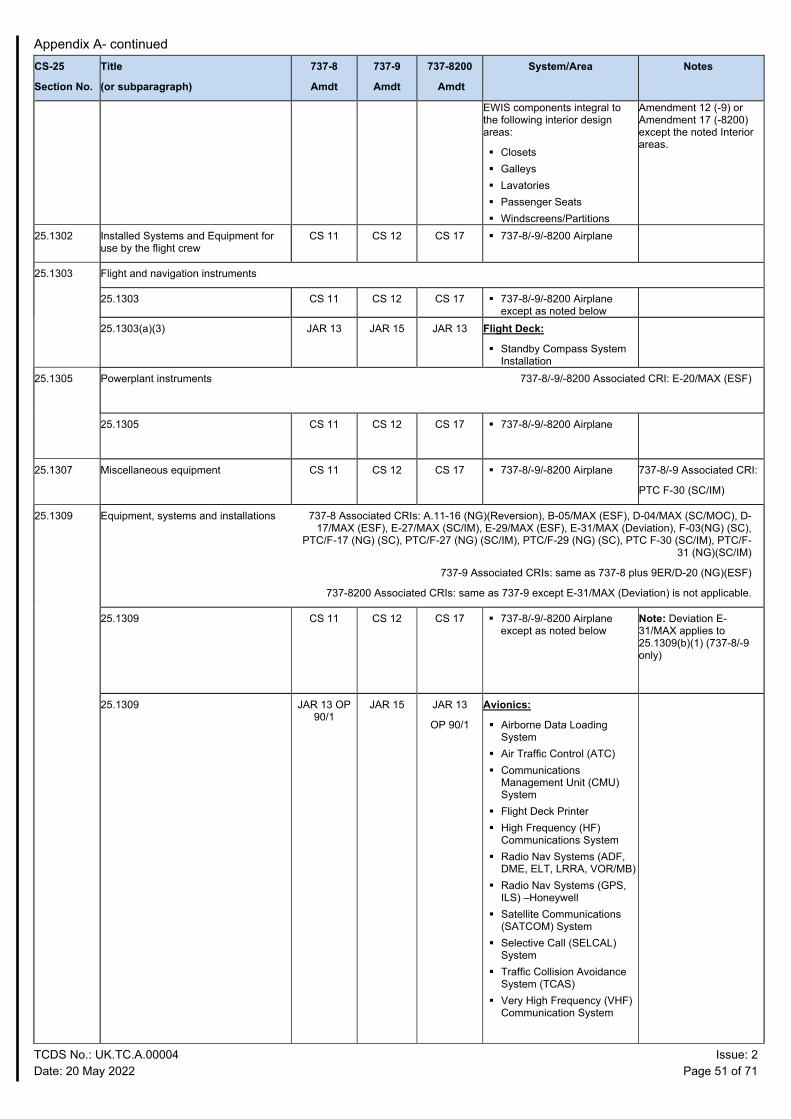
Appendix A- continued
TCDS No.: UK.TC.A.00004 Issue: 2 Date: 20 May 2022 Page 51 of 71
CS-25
Section No.
Title
(or subparagraph)
737-8
Amdt
737-9
Amdt
737-8200
Amdt
System/Area Notes
EWIS components integral to the following interior design areas:
Closets Galleys Lavatories Passenger Seats Windscreens/Partitions
Amendment 12 (-9) or Amendment 17 (-8200) except the noted Interior areas.
25.1302 Installed Systems and Equipment for use by the flight crew
CS 11 CS 12 CS 17 737-8/-9/-8200 Airplane
25.1303 Flight and navigation instruments
25.1303 CS 11 CS 12 CS 17 737-8/-9/-8200 Airplane except as noted below
25.1303(a)(3) JAR 13 JAR 15 JAR 13 Flight Deck:
Standby Compass System Installation
25.1305
Powerplant instruments 737-8/-9/-8200 Associated CRI: E-20/MAX (ESF)
25.1305
CS 11 CS 12 CS 17 737-8/-9/-8200 Airplane
25.1307
Miscellaneous equipment CS 11 CS 12 CS 17 737-8/-9/-8200 Airplane 737-8/-9 Associated CRI:
PTC F-30 (SC/IM)
25.1309 Equipment, systems and installations 737-8 Associated CRIs: A.11-16 (NG)(Reversion), B-05/MAX (ESF), D-04/MAX (SC/MOC), D-17/MAX (ESF), E-27/MAX (SC/IM), E-29/MAX (ESF), E-31/MAX (Deviation), F-03(NG) (SC),
PTC/F-17 (NG) (SC), PTC/F-27 (NG) (SC/IM), PTC/F-29 (NG) (SC), PTC F-30 (SC/IM), PTC/F-31 (NG)(SC/IM)
737-9 Associated CRIs: same as 737-8 plus 9ER/D-20 (NG)(ESF)
737-8200 Associated CRIs: same as 737-9 except E-31/MAX (Deviation) is not applicable.
25.1309
CS 11 CS 12 CS 17 737-8/-9/-8200 Airplane except as noted below
Note: Deviation E-31/MAX applies to 25.1309(b)(1) (737-8/-9 only)
25.1309
JAR 13 OP 90/1
JAR 15 JAR 13
OP 90/1
Avionics:
Airborne Data Loading System
Air Traffic Control (ATC) Communications
Management Unit (CMU) System
Flight Deck Printer High Frequency (HF)
Communications System Radio Nav Systems (ADF,
DME, ELT, LRRA, VOR/MB) Radio Nav Systems (GPS,
ILS) –Honeywell Satellite Communications
(SATCOM) System Selective Call (SELCAL)
System Traffic Collision Avoidance
System (TCAS) Very High Frequency (VHF)
Communication System
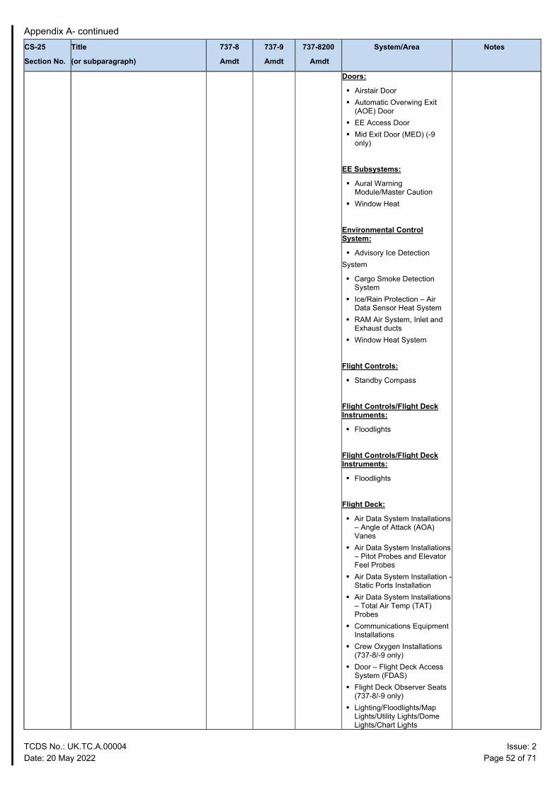
Appendix A- continued
TCDS No.: UK.TC.A.00004 Issue: 2 Date: 20 May 2022 Page 52 of 71
CS-25
Section No.
Title
(or subparagraph)
737-8
Amdt
737-9
Amdt
737-8200
Amdt
System/Area Notes
Doors:
Airstair Door Automatic Overwing Exit
(AOE) Door EE Access Door Mid Exit Door (MED) (-9
only)
EE Subsystems:
Aural Warning Module/Master Caution
Window Heat
Environmental Control System:
Advisory Ice Detection System
Cargo Smoke Detection System
Ice/Rain Protection – Air Data Sensor Heat System
RAM Air System, Inlet and Exhaust ducts
Window Heat System
Flight Controls:
Standby Compass
Flight Controls/Flight Deck Instruments:
Floodlights
Flight Controls/Flight Deck Instruments:
Floodlights
Flight Deck:
Air Data System Installations – Angle of Attack (AOA) Vanes
Air Data System Installations – Pitot Probes and Elevator Feel Probes
Air Data System Installation - Static Ports Installation
Air Data System Installations – Total Air Temp (TAT) Probes
Communications Equipment Installations
Crew Oxygen Installations (737-8/-9 only)
Door – Flight Deck Access System (FDAS)
Flight Deck Observer Seats (737-8/-9 only)
Lighting/Floodlights/Map Lights/Utility Lights/Dome Lights/Chart Lights
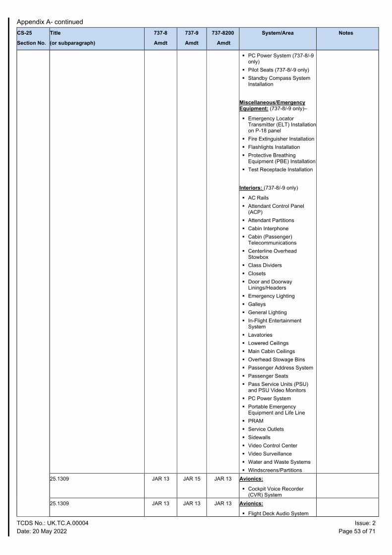
Appendix A- continued
TCDS No.: UK.TC.A.00004 Issue: 2 Date: 20 May 2022 Page 53 of 71
CS-25
Section No.
Title
(or subparagraph)
737-8
Amdt
737-9
Amdt
737-8200
Amdt
System/Area Notes
PC Power System (737-8/-9 only)
Pilot Seats (737-8/-9 only) Standby Compass System
Installation
Miscellaneous/Emergency Equipment: (737-8/-9 only)–
Emergency Locator Transmitter (ELT) Installation on P-18 panel
Fire Extinguisher Installation Flashlights Installation Protective Breathing
Equipment (PBE) Installation Test Receptacle Installation
Interiors: (737-8/-9 only)
AC Rails Attendant Control Panel
(ACP) Attendant Partitions Cabin Interphone Cabin (Passenger)
Telecommunications Centerline Overhead
Stowbox Class Dividers Closets Door and Doorway
Linings/Headers Emergency Lighting Galleys General Lighting In-Flight Entertainment
System Lavatories Lowered Ceilings Main Cabin Ceilings Overhead Stowage Bins Passenger Address System Passenger Seats Pass Service Units (PSU)
and PSU Video Monitors PC Power System Portable Emergency
Equipment and Life Line PRAM Service Outlets Sidewalls Video Control Center Video Surveillance Water and Waste Systems Windscreens/Partitions
25.1309 JAR 13 JAR 15 JAR 13 Avionics:
Cockpit Voice Recorder (CVR) System
25.1309 JAR 13 JAR 13 JAR 13 Avionics:
Flight Deck Audio System
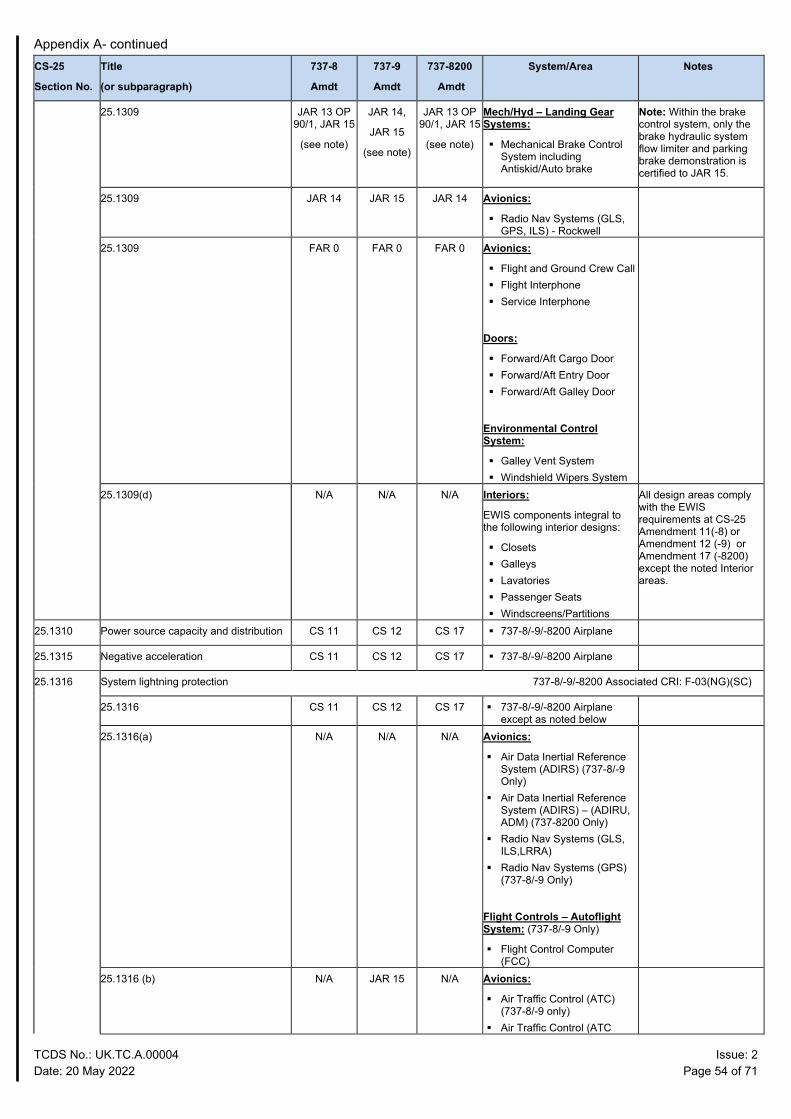
Appendix A- continued
TCDS No.: UK.TC.A.00004 Issue: 2 Date: 20 May 2022 Page 54 of 71
CS-25
Section No.
Title
(or subparagraph)
737-8
Amdt
737-9
Amdt
737-8200
Amdt
System/Area Notes
25.1309
JAR 13 OP 90/1, JAR 15
(see note)
JAR 14,
JAR 15
(see note)
JAR 13 OP 90/1, JAR 15
(see note)
Mech/Hyd – Landing Gear Systems:
Mechanical Brake Control System including Antiskid/Auto brake
Note: Within the brake control system, only the brake hydraulic system flow limiter and parking brake demonstration is certified to JAR 15.
25.1309 JAR 14 JAR 15 JAR 14 Avionics:
Radio Nav Systems (GLS, GPS, ILS) - Rockwell
25.1309 FAR 0
FAR 0
FAR 0 Avionics:
Flight and Ground Crew Call Flight Interphone Service Interphone
Doors:
Forward/Aft Cargo Door Forward/Aft Entry Door Forward/Aft Galley Door
Environmental Control System:
Galley Vent System Windshield Wipers System
25.1309(d) N/A N/A N/A Interiors:
EWIS components integral to the following interior designs:
Closets Galleys Lavatories Passenger Seats Windscreens/Partitions
All design areas comply with the EWIS requirements at CS-25 Amendment 11(-8) or Amendment 12 (-9) or Amendment 17 (-8200) except the noted Interior areas.
25.1310 Power source capacity and distribution CS 11 CS 12 CS 17 737-8/-9/-8200 Airplane
25.1315 Negative acceleration CS 11 CS 12 CS 17 737-8/-9/-8200 Airplane
25.1316 System lightning protection 737-8/-9/-8200 Associated CRI: F-03(NG)(SC)
25.1316 CS 11 CS 12 CS 17 737-8/-9/-8200 Airplane except as noted below
25.1316(a) N/A N/A N/A Avionics:
Air Data Inertial Reference System (ADIRS) (737-8/-9 Only)
Air Data Inertial Reference System (ADIRS) – (ADIRU, ADM) (737-8200 Only)
Radio Nav Systems (GLS, ILS,LRRA)
Radio Nav Systems (GPS) (737-8/-9 Only)
Flight Controls – Autoflight System: (737-8/-9 Only)
Flight Control Computer (FCC)
25.1316 (b) N/A JAR 15 N/A Avionics:
Air Traffic Control (ATC) (737-8/-9 only)
Air Traffic Control (ATC
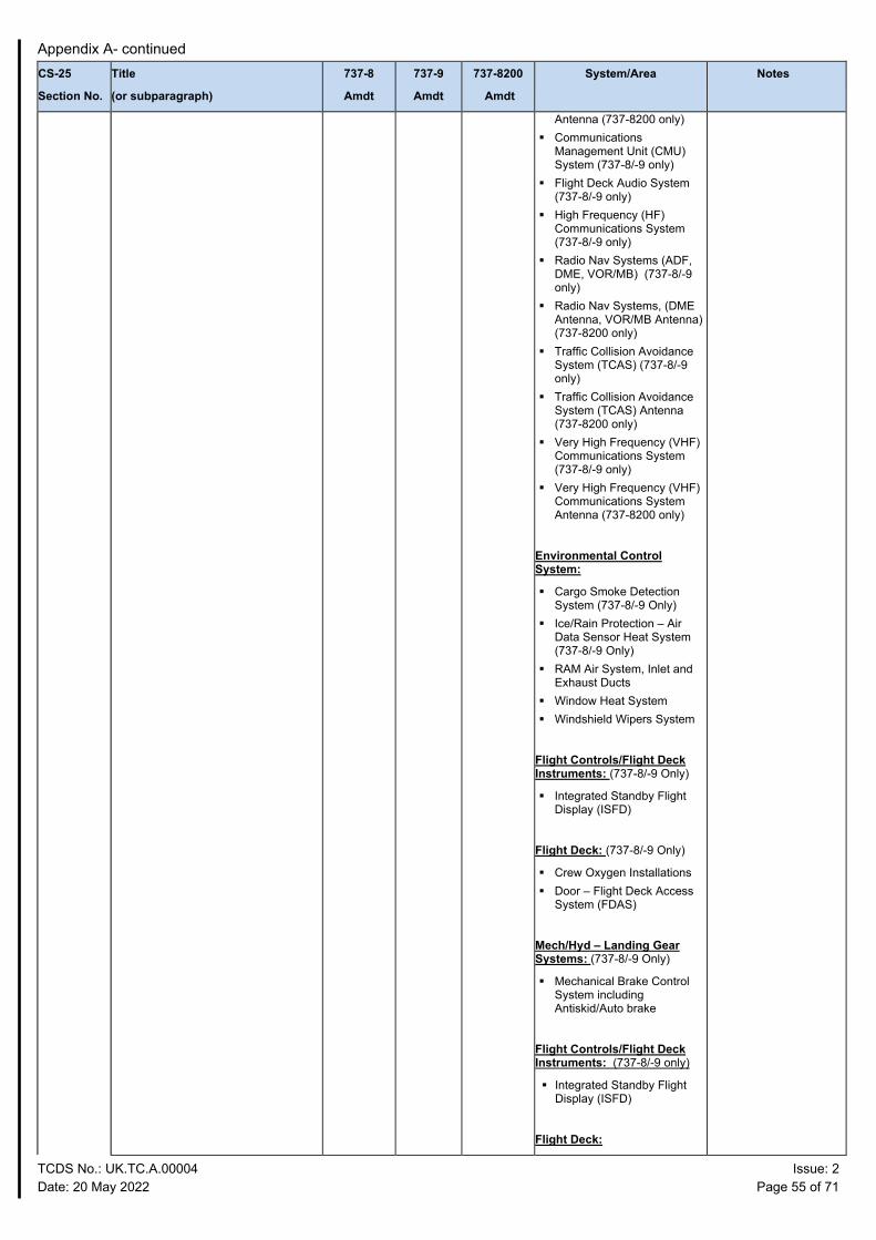
Appendix A- continued
TCDS No.: UK.TC.A.00004 Issue: 2 Date: 20 May 2022 Page 55 of 71
CS-25
Section No.
Title
(or subparagraph)
737-8
Amdt
737-9
Amdt
737-8200
Amdt
System/Area Notes
Antenna (737-8200 only) Communications
Management Unit (CMU) System (737-8/-9 only)
Flight Deck Audio System (737-8/-9 only)
High Frequency (HF) Communications System (737-8/-9 only)
Radio Nav Systems (ADF, DME, VOR/MB) (737-8/-9 only)
Radio Nav Systems, (DME Antenna, VOR/MB Antenna) (737-8200 only)
Traffic Collision Avoidance System (TCAS) (737-8/-9 only)
Traffic Collision Avoidance System (TCAS) Antenna (737-8200 only)
Very High Frequency (VHF) Communications System (737-8/-9 only)
Very High Frequency (VHF) Communications System Antenna (737-8200 only)
Environmental Control System:
Cargo Smoke Detection System (737-8/-9 Only)
Ice/Rain Protection – Air Data Sensor Heat System (737-8/-9 Only)
RAM Air System, Inlet and Exhaust Ducts
Window Heat System Windshield Wipers System
Flight Controls/Flight Deck Instruments: (737-8/-9 Only)
Integrated Standby Flight Display (ISFD)
Flight Deck: (737-8/-9 Only)
Crew Oxygen Installations Door – Flight Deck Access
System (FDAS)
Mech/Hyd – Landing Gear Systems: (737-8/-9 Only)
Mechanical Brake Control System including Antiskid/Auto brake
Flight Controls/Flight Deck Instruments: (737-8/-9 only)
Integrated Standby Flight Display (ISFD)
Flight Deck:
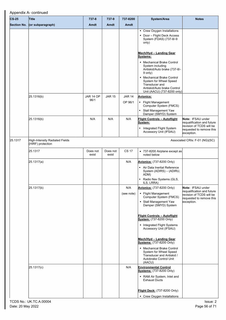
Appendix A- continued
TCDS No.: UK.TC.A.00004 Issue: 2 Date: 20 May 2022 Page 56 of 71
CS-25
Section No.
Title
(or subparagraph)
737-8
Amdt
737-9
Amdt
737-8200
Amdt
System/Area Notes
Crew Oxygen Installations Door – Flight Deck Access
System (FDAS) (737-8/-9 only)
Mech/Hyd – Landing Gear Systems:
Mechanical Brake Control System including Antiskid/Auto brake (737-8/-9 only)
Mechanical Brake Control System for Wheel Speed Transducer and Antiskid/Auto brake Control Unit (AACU) (737-8200 only)
25.1316(b) JAR 14 OP 96/1
JAR 15 JAR 14
OP 96/1
Avionics:
Flight Management Computer System (FMCS)
Stall Management Yaw Damper (SMYD) System
25.1316(b) N/A N/A N/A Flight Controls – Autoflight System:
Integrated Flight System Accessory Unit (IFSAU)
Note: IFSAU under requalification and future revision of TCDS will be requested to remove this exception.
25.1317 High-Intensity Radiated Fields (HIRF) protection
Associated CRIs: F-01 (NG)(SC)
25.1317 Does not exist
Does not exist
CS 17 • 737-8200 Airplane except as noted below
25.1317(a) N/A Avionics: (737-8200 Only)
Air Data Inertial Reference System (ADIRS) – (ADIRU, ADM)
Radio Nav Systems (GLS, ILS, LRRA)
25.1317(b) N/A
(see note)
Avionics: (737-8200 Only)
Flight Management Computer System (FMCS)
Stall Management Yaw Damper (SMYD) System
Flight Controls – Autoflight System: (737-8200 Only)
Integrated Flight Systems Accessory Unit (IFSAU)
Mech/Hyd – Landing Gear Systems: (737-8200 Only)
Mechanical Brake Control System for Wheel Speed Transducer and Antiskid / Autobrake Control Unit (AACU)
Note: IFSAU under requalification and future revision of TCDS will be requested to remove this exception.
25.1317(c) N/A Environmental Control Systems: (737-8200 Only)
RAM Air System, Inlet and Exhaust Ducts
Flight Deck: (737-8200 Only)
Crew Oxygen Installations
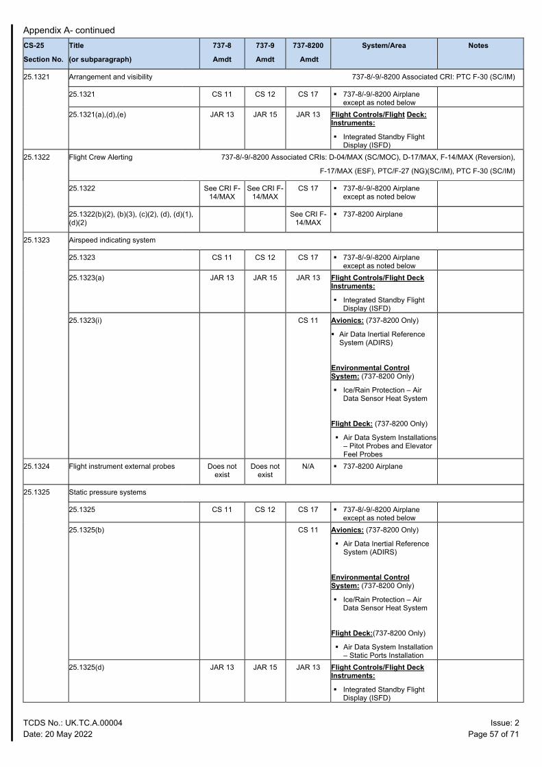
Appendix A- continued
TCDS No.: UK.TC.A.00004 Issue: 2 Date: 20 May 2022 Page 57 of 71
CS-25
Section No.
Title
(or subparagraph)
737-8
Amdt
737-9
Amdt
737-8200
Amdt
System/Area Notes
25.1321 Arrangement and visibility 737-8/-9/-8200 Associated CRI: PTC F-30 (SC/IM)
25.1321 CS 11 CS 12 CS 17 737-8/-9/-8200 Airplane except as noted below
25.1321(a),(d),(e) JAR 13 JAR 15 JAR 13 Flight Controls/Flight Deck: Instruments:
Integrated Standby Flight Display (ISFD)
25.1322 Flight Crew Alerting 737-8/-9/-8200 Associated CRIs: D-04/MAX (SC/MOC), D-17/MAX, F-14/MAX (Reversion),
F-17/MAX (ESF), PTC/F-27 (NG)(SC/IM), PTC F-30 (SC/IM)
25.1322 See CRI F- 14/MAX
See CRI F- 14/MAX
CS 17 737-8/-9/-8200 Airplane except as noted below
25.1322(b)(2), (b)(3), (c)(2), (d), (d)(1), (d)(2)
See CRI F- 14/MAX
737-8200 Airplane
25.1323 Airspeed indicating system
25.1323 CS 11 CS 12 CS 17 737-8/-9/-8200 Airplane except as noted below
25.1323(a) JAR 13 JAR 15 JAR 13 Flight Controls/Flight Deck Instruments:
Integrated Standby Flight Display (ISFD)
25.1323(i) CS 11 Avionics: (737-8200 Only)
Air Data Inertial Reference System (ADIRS)
Environmental Control System: (737-8200 Only)
Ice/Rain Protection – Air Data Sensor Heat System
Flight Deck: (737-8200 Only)
Air Data System Installations – Pitot Probes and Elevator Feel Probes
25.1324 Flight instrument external probes Does not exist
Does not exist
N/A 737-8200 Airplane
25.1325 Static pressure systems
25.1325 CS 11 CS 12 CS 17 737-8/-9/-8200 Airplane except as noted below
25.1325(b) CS 11 Avionics: (737-8200 Only)
Air Data Inertial Reference System (ADIRS)
Environmental Control System: (737-8200 Only)
Ice/Rain Protection – Air Data Sensor Heat System
Flight Deck:(737-8200 Only)
Air Data System Installation – Static Ports Installation
25.1325(d) JAR 13 JAR 15 JAR 13 Flight Controls/Flight Deck Instruments:
Integrated Standby Flight Display (ISFD)
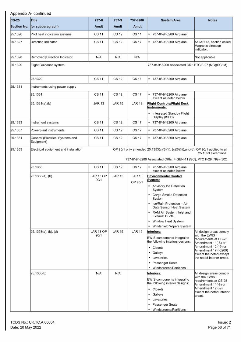
Appendix A- continued
TCDS No.: UK.TC.A.00004 Issue: 2 Date: 20 May 2022 Page 58 of 71
CS-25
Section No.
Title
(or subparagraph)
737-8
Amdt
737-9
Amdt
737-8200
Amdt
System/Area Notes
25.1326 Pilot heat indication systems CS 11 CS 12 CS 11 737-8/-9/-8200 Airplane
25.1327 Direction Indicator CS 11 CS 12 CS 17 737-8/-9/-8200 Airplane At JAR 13, section called Magnetic direction indicator.
25.1328 Removed [Direction Indicator] N/A N/A N/A Not applicable
25.1329 Flight Guidance system 737-8/-9/-8200 Associated CRI: PTC/F-27 (NG)(SC/IM)
25.1329 CS 11 CS 12 CS 11 737-8/-9/-8200 Airplane
25.1331 Instruments using power supply
25.1331 CS 11 CS 12 CS 17 737-8/-9/-8200 Airplane except as noted below
25.1331(a),(b) JAR 13 JAR 15 JAR 13 Flight Controls/Flight Deck Instruments:
Integrated Standby Flight Display (ISFD)
25.1333 Instrument systems CS 11 CS 12 CS 17 737-8/-9/-8200 Airplane
25.1337 Powerplant instruments CS 11 CS 12 CS 17 737-8/-9/-8200 Airplane
25.1351 General (Electrical Systems and Equipment)
CS 11 CS 12 CS 17 737-8/-9/-8200 Airplane
25.1353 Electrical equipment and installation OP 90/1 only amended 25.1353(c)(6)(ii), (c)(6)(iii),and(d). OP 90/1 applied to all 25.1353 exceptions.
737-8/-9/-8200 Associated CRIs: F-GEN-11 (SC), PTC F-29 (NG) (SC)
25.1353 CS 11 CS 12 CS 17 737-8/-9/-8200 Airplane except as noted below
25.1353(a), (b) JAR 13 OP 90/1
JAR 15 JAR 13
OP 90/1
Environmental Control System:
Advisory Ice Detection System
Cargo Smoke Detection System
Ice/Rain Protection – Air Data Sensor Heat System
RAM Air System, Inlet and Exhaust Ducts
Window Heat System Windshield Wipers System
25.1353(a), (b), (d) JAR 13 OP 90/1
JAR 15 JAR 15 Interiors:
EWIS components integral to the following interiors designs:
Closets Galleys Lavatories Passenger Seats Windscreens/Partitions
All design areas comply with the EWIS requirements at CS-25 Amendment 11(-8) or Amendment 12 (-9) or Amendment 17 (-8200) except the noted except the noted Interior areas.
25.1353(b) N/A N/A Interiors:
EWIS components integral to the following interior designs:
Closets Galleys Lavatories Passenger Seats Windscreens/Partitions
All design areas comply with the EWIS requirements at CS-25 Amendment 11(-8) or Amendment 12 (-9) except the noted Interior areas.
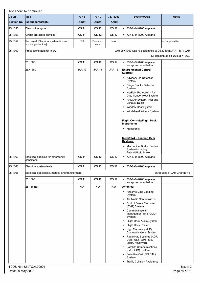
Appendix A- continued
TCDS No.: UK.TC.A.00004 Issue: 2 Date: 20 May 2022 Page 59 of 71
CS-25
Section No.
Title
(or subparagraph)
737-8
Amdt
737-9
Amdt
737-8200
Amdt
System/Area Notes
25.1355 Distribution system CS 11 CS 12 CS 17 737-8/-9/-8200 Airplane
25.1357 Circuit protective devices CS 11 CS 12 CS 17 737-8/-9/-8200 Airplane
25.1359 Removed [Electrical system fire and smoke protection]
N/A Does not exist
N/A Not applicable
25.1360 Precautions against injury JAR 25X1360 was re-designated to 25.1360 at JAR 16; At JAR
13, designated as JAR 25X1360.
25.1360 CS 11 CS 12 CS 17 737-8/-9/-8200 Airplane except as noted below
25X1360 JAR 13 JAR 15 JAR 13 Environmental Control System:
Advisory Ice Detection System
Cargo Smoke Detection System
Ice/Rain Protection - Air Data Sensor Heat System
RAM Air System, Inlet and Exhaust Ducts
Window Heat System Windshield Wipers System
Flight Controls/Flight Deck Instruments:
Floodlights
Mech/Hyd – Landing Gear Systems:
Mechanical Brake Control System including Antiskid/Auto brake
25.1362 Electrical supplies for emergency conditions
CS 11 CS 12 CS 17 737-8/-9/-8200 Airplane
25.1363 Electrical system tests CS 11 CS 12 CS 17 737-8/-9/-8200 Airplane
25.1365 Electrical appliances, motors, and transformers Introduced at JAR Change 16
25.1365 CS 11 CS 12 CS 17 737-8/-9/-8200 Airplane except as noted below
25.1365(d) N/A
N/A N/A Avionics:
Airborne Data Loading System
Air Traffic Control (ATC) Cockpit Voice Recorder
(CVR) System Communications
Management Unit (CMU) System
Flight Deck Audio System Flight Deck Printer High Frequency (HF)
Communications System Radio Nav Systems (ADF,
DME, GLS, GPS, ILS, LRRA, VOR/MB)
Satellite Communications (SATCOM) System
Selective Call (SELCAL) System
Traffic Collision Avoidance
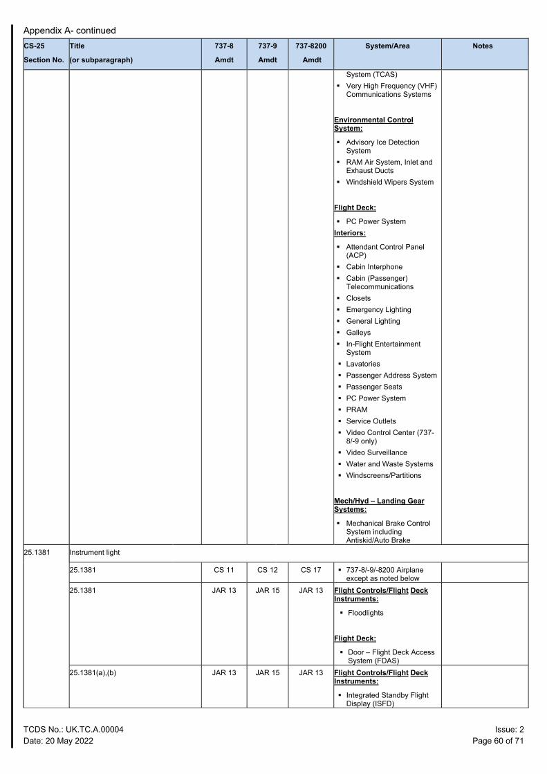
Appendix A- continued
TCDS No.: UK.TC.A.00004 Issue: 2 Date: 20 May 2022 Page 60 of 71
CS-25
Section No.
Title
(or subparagraph)
737-8
Amdt
737-9
Amdt
737-8200
Amdt
System/Area Notes
System (TCAS) Very High Frequency (VHF)
Communications Systems
Environmental Control System:
Advisory Ice Detection System
RAM Air System, Inlet and Exhaust Ducts
Windshield Wipers System
Flight Deck:
PC Power System Interiors:
Attendant Control Panel (ACP)
Cabin Interphone Cabin (Passenger)
Telecommunications Closets Emergency Lighting General Lighting Galleys In-Flight Entertainment
System Lavatories Passenger Address System Passenger Seats PC Power System PRAM Service Outlets Video Control Center (737-
8/-9 only) Video Surveillance Water and Waste Systems Windscreens/Partitions
Mech/Hyd – Landing Gear Systems:
Mechanical Brake Control System including Antiskid/Auto Brake
25.1381 Instrument light
25.1381 CS 11 CS 12 CS 17 737-8/-9/-8200 Airplane except as noted below
25.1381 JAR 13 JAR 15 JAR 13 Flight Controls/Flight Deck Instruments:
Floodlights
Flight Deck:
Door – Flight Deck Access System (FDAS)
25.1381(a),(b) JAR 13 JAR 15 JAR 13 Flight Controls/Flight Deck Instruments:
Integrated Standby Flight Display (ISFD)
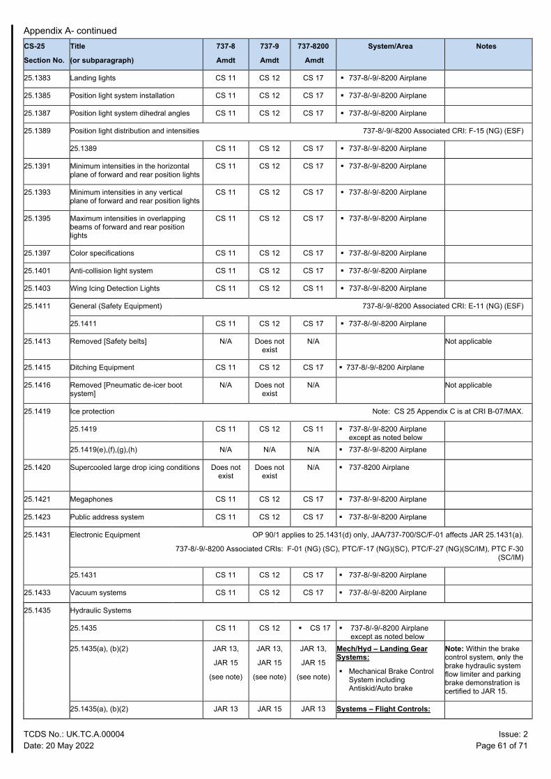
Appendix A- continued
TCDS No.: UK.TC.A.00004 Issue: 2 Date: 20 May 2022 Page 61 of 71
CS-25
Section No.
Title
(or subparagraph)
737-8
Amdt
737-9
Amdt
737-8200
Amdt
System/Area Notes
25.1383 Landing lights CS 11 CS 12 CS 17 737-8/-9/-8200 Airplane
25.1385 Position light system installation CS 11 CS 12 CS 17 737-8/-9/-8200 Airplane
25.1387 Position light system dihedral angles CS 11 CS 12 CS 17 737-8/-9/-8200 Airplane
25.1389 Position light distribution and intensities 737-8/-9/-8200 Associated CRI: F-15 (NG) (ESF)
25.1389 CS 11 CS 12 CS 17 737-8/-9/-8200 Airplane
25.1391 Minimum intensities in the horizontal plane of forward and rear position lights
CS 11 CS 12 CS 17 737-8/-9/-8200 Airplane
25.1393 Minimum intensities in any vertical plane of forward and rear position lights
CS 11 CS 12 CS 17 737-8/-9/-8200 Airplane
25.1395 Maximum intensities in overlapping beams of forward and rear position lights
CS 11 CS 12 CS 17 737-8/-9/-8200 Airplane
25.1397 Color specifications CS 11 CS 12 CS 17 737-8/-9/-8200 Airplane
25.1401 Anti-collision light system CS 11 CS 12 CS 17 737-8/-9/-8200 Airplane
25.1403 Wing Icing Detection Lights CS 11 CS 12 CS 11 737-8/-9/-8200 Airplane
25.1411 General (Safety Equipment) 737-8/-9/-8200 Associated CRI: E-11 (NG) (ESF)
25.1411 CS 11 CS 12 CS 17 737-8/-9/-8200 Airplane
25.1413 Removed [Safety belts] N/A Does not exist
N/A Not applicable
25.1415 Ditching Equipment CS 11 CS 12 CS 17 737-8/-9/-8200 Airplane
25.1416 Removed [Pneumatic de-icer boot system]
N/A Does not exist
N/A Not applicable
25.1419 Ice protection Note: CS 25 Appendix C is at CRI B-07/MAX.
25.1419 CS 11 CS 12 CS 11 737-8/-9/-8200 Airplane except as noted below
25.1419(e),(f),(g),(h) N/A N/A N/A 737-8/-9/-8200 Airplane
25.1420 Supercooled large drop icing conditions
Does not exist
Does not exist
N/A 737-8200 Airplane
25.1421 Megaphones CS 11 CS 12 CS 17 737-8/-9/-8200 Airplane
25.1423 Public address system CS 11 CS 12 CS 17 737-8/-9/-8200 Airplane
25.1431 Electronic Equipment OP 90/1 applies to 25.1431(d) only, JAA/737-700/SC/F-01 affects JAR 25.1431(a).
737-8/-9/-8200 Associated CRIs: F-01 (NG) (SC), PTC/F-17 (NG)(SC), PTC/F-27 (NG)(SC/IM), PTC F-30 (SC/IM)
25.1431 CS 11 CS 12 CS 17 737-8/-9/-8200 Airplane
25.1433 Vacuum systems CS 11 CS 12 CS 17 737-8/-9/-8200 Airplane
25.1435 Hydraulic Systems
25.1435 CS 11 CS 12 CS 17 737-8/-9/-8200 Airplane except as noted below
25.1435(a), (b)(2)
JAR 13,
JAR 15
(see note)
JAR 13,
JAR 15
(see note)
JAR 13,
JAR 15
(see note)
Mech/Hyd – Landing Gear Systems:
Mechanical Brake Control System including Antiskid/Auto brake
Note: Within the brake control system, only the brake hydraulic system flow limiter and parking brake demonstration is certified to JAR 15.
25.1435(a), (b)(2) JAR 13 JAR 15 JAR 13 Systems – Flight Controls:
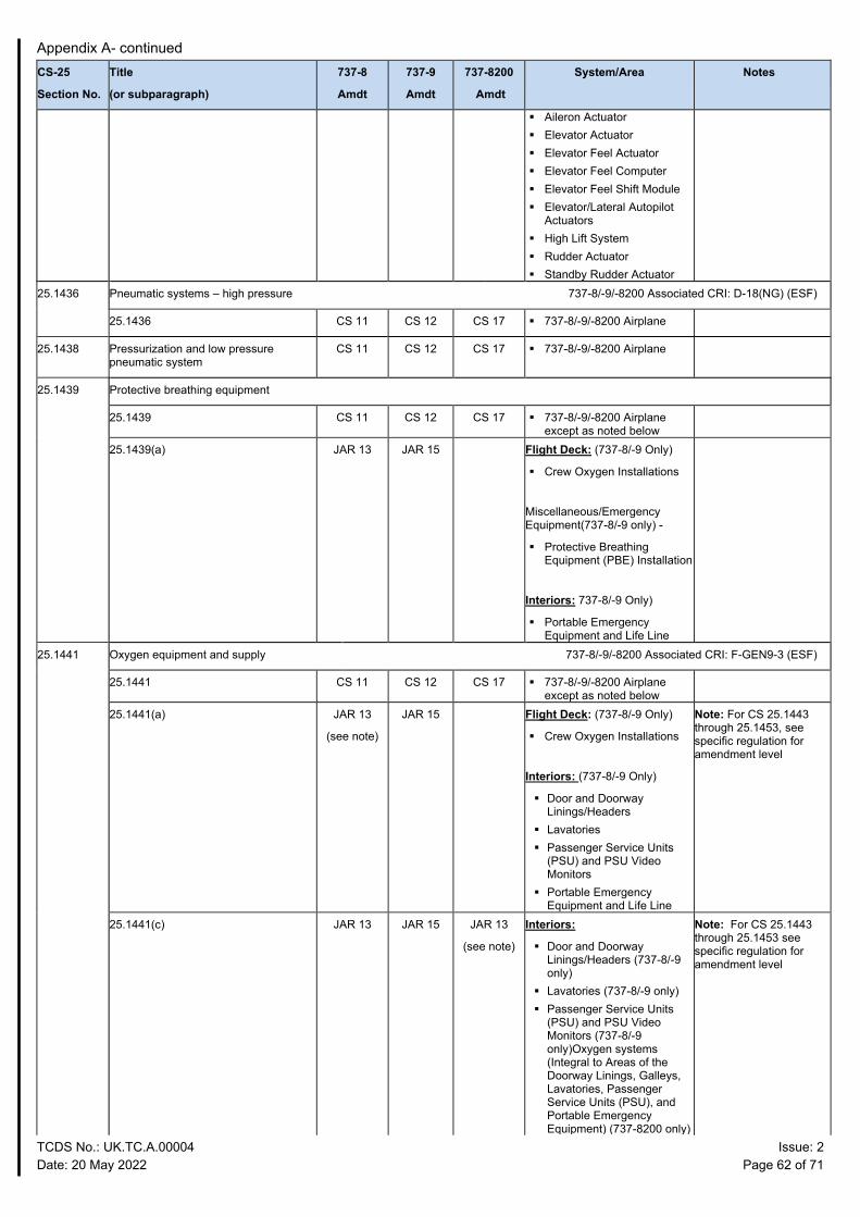
Appendix A- continued
TCDS No.: UK.TC.A.00004 Issue: 2 Date: 20 May 2022 Page 62 of 71
CS-25
Section No.
Title
(or subparagraph)
737-8
Amdt
737-9
Amdt
737-8200
Amdt
System/Area Notes
Aileron Actuator Elevator Actuator Elevator Feel Actuator Elevator Feel Computer Elevator Feel Shift Module Elevator/Lateral Autopilot
Actuators High Lift System Rudder Actuator Standby Rudder Actuator
25.1436 Pneumatic systems – high pressure 737-8/-9/-8200 Associated CRI: D-18(NG) (ESF)
25.1436 CS 11 CS 12 CS 17 737-8/-9/-8200 Airplane
25.1438 Pressurization and low pressure pneumatic system
CS 11 CS 12 CS 17 737-8/-9/-8200 Airplane
25.1439 Protective breathing equipment
25.1439 CS 11 CS 12 CS 17 737-8/-9/-8200 Airplane except as noted below
25.1439(a) JAR 13 JAR 15 Flight Deck: (737-8/-9 Only)
Crew Oxygen Installations
Miscellaneous/Emergency Equipment(737-8/-9 only) -
Protective Breathing Equipment (PBE) Installation
Interiors: 737-8/-9 Only)
Portable Emergency Equipment and Life Line
25.1441 Oxygen equipment and supply 737-8/-9/-8200 Associated CRI: F-GEN9-3 (ESF)
25.1441 CS 11 CS 12 CS 17 737-8/-9/-8200 Airplane except as noted below
25.1441(a) JAR 13
(see note)
JAR 15 Flight Deck: (737-8/-9 Only)
Crew Oxygen Installations
Interiors: (737-8/-9 Only)
Door and Doorway Linings/Headers
Lavatories Passenger Service Units
(PSU) and PSU Video Monitors
Portable Emergency Equipment and Life Line
Note: For CS 25.1443 through 25.1453, see specific regulation for amendment level
25.1441(c) JAR 13 JAR 15 JAR 13
(see note)
Interiors:
Door and Doorway Linings/Headers (737-8/-9 only)
Lavatories (737-8/-9 only) Passenger Service Units
(PSU) and PSU Video Monitors (737-8/-9 only)Oxygen systems (Integral to Areas of the Doorway Linings, Galleys, Lavatories, Passenger Service Units (PSU), and Portable Emergency Equipment) (737-8200 only)
Note: For CS 25.1443 through 25.1453 see specific regulation for amendment level
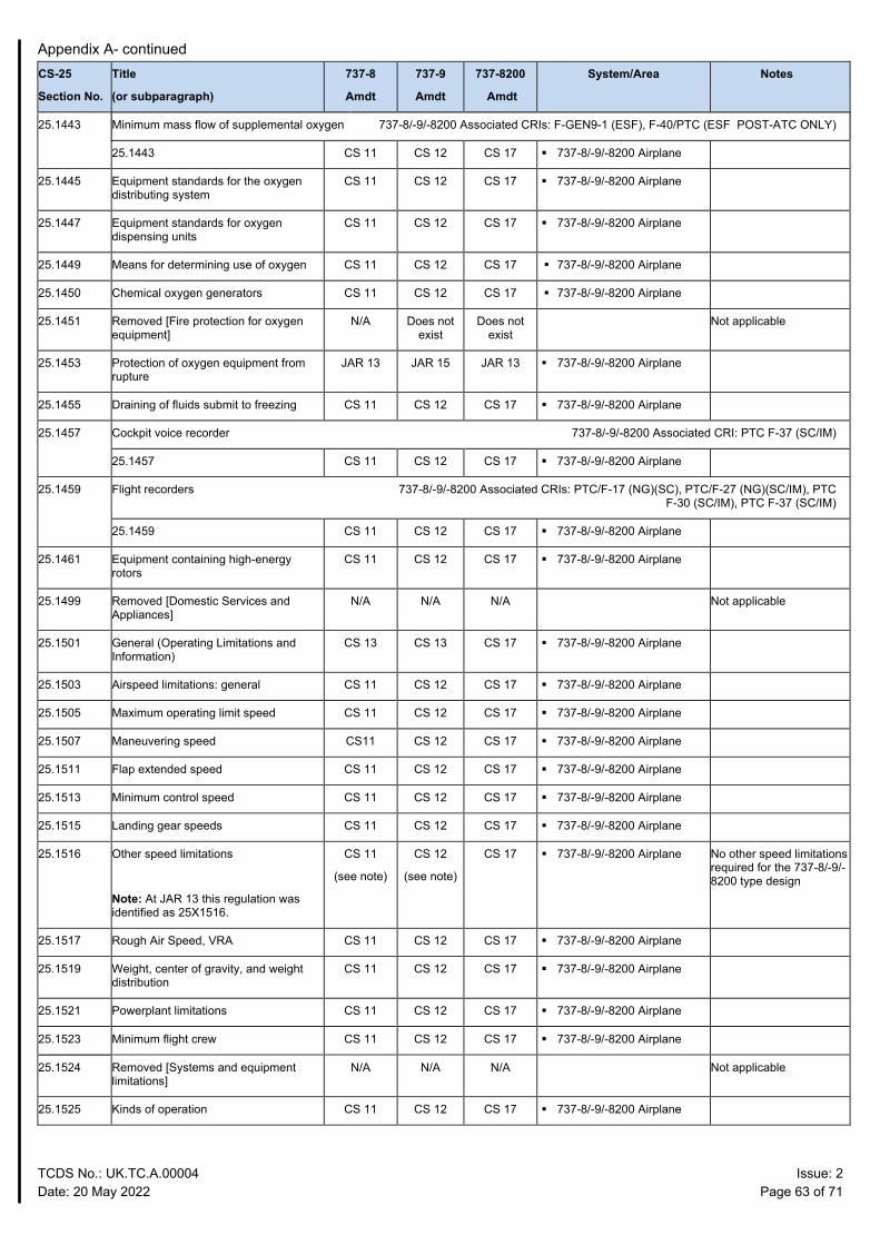
Appendix A- continued
TCDS No.: UK.TC.A.00004 Issue: 2 Date: 20 May 2022 Page 63 of 71
CS-25
Section No.
Title
(or subparagraph)
737-8
Amdt
737-9
Amdt
737-8200
Amdt
System/Area Notes
25.1443 Minimum mass flow of supplemental oxygen 737-8/-9/-8200 Associated CRIs: F-GEN9-1 (ESF), F-40/PTC (ESF POST-ATC ONLY)
25.1443 CS 11 CS 12 CS 17 737-8/-9/-8200 Airplane
25.1445 Equipment standards for the oxygen distributing system
CS 11 CS 12 CS 17 737-8/-9/-8200 Airplane
25.1447 Equipment standards for oxygen dispensing units
CS 11 CS 12 CS 17 737-8/-9/-8200 Airplane
25.1449 Means for determining use of oxygen CS 11 CS 12 CS 17 737-8/-9/-8200 Airplane
25.1450 Chemical oxygen generators CS 11 CS 12 CS 17 737-8/-9/-8200 Airplane
25.1451 Removed [Fire protection for oxygen equipment]
N/A Does not exist
Does not exist
Not applicable
25.1453 Protection of oxygen equipment from rupture
JAR 13 JAR 15 JAR 13 737-8/-9/-8200 Airplane
25.1455 Draining of fluids submit to freezing CS 11 CS 12 CS 17 737-8/-9/-8200 Airplane
25.1457 Cockpit voice recorder 737-8/-9/-8200 Associated CRI: PTC F-37 (SC/IM)
25.1457 CS 11 CS 12 CS 17 737-8/-9/-8200 Airplane
25.1459 Flight recorders 737-8/-9/-8200 Associated CRIs: PTC/F-17 (NG)(SC), PTC/F-27 (NG)(SC/IM), PTC F-30 (SC/IM), PTC F-37 (SC/IM)
25.1459 CS 11 CS 12 CS 17 737-8/-9/-8200 Airplane
25.1461 Equipment containing high-energy rotors
CS 11 CS 12 CS 17 737-8/-9/-8200 Airplane
25.1499 Removed [Domestic Services and Appliances]
N/A N/A N/A Not applicable
25.1501 General (Operating Limitations and Information)
CS 13 CS 13 CS 17 737-8/-9/-8200 Airplane
25.1503 Airspeed limitations: general CS 11 CS 12 CS 17 737-8/-9/-8200 Airplane
25.1505 Maximum operating limit speed CS 11 CS 12 CS 17 737-8/-9/-8200 Airplane
25.1507 Maneuvering speed CS11 CS 12 CS 17 737-8/-9/-8200 Airplane
25.1511 Flap extended speed CS 11 CS 12 CS 17 737-8/-9/-8200 Airplane
25.1513 Minimum control speed CS 11 CS 12 CS 17 737-8/-9/-8200 Airplane
25.1515 Landing gear speeds CS 11 CS 12 CS 17 737-8/-9/-8200 Airplane
25.1516 Other speed limitations
Note: At JAR 13 this regulation was identified as 25X1516.
CS 11
(see note)
CS 12
(see note)
CS 17 737-8/-9/-8200 Airplane No other speed limitations required for the 737-8/-9/-8200 type design
25.1517 Rough Air Speed, VRA CS 11 CS 12 CS 17 737-8/-9/-8200 Airplane
25.1519 Weight, center of gravity, and weight distribution
CS 11 CS 12 CS 17 737-8/-9/-8200 Airplane
25.1521 Powerplant limitations CS 11 CS 12 CS 17 737-8/-9/-8200 Airplane
25.1523 Minimum flight crew CS 11 CS 12 CS 17 737-8/-9/-8200 Airplane
25.1524 Removed [Systems and equipment limitations]
N/A N/A N/A Not applicable
25.1525 Kinds of operation CS 11 CS 12 CS 17 737-8/-9/-8200 Airplane
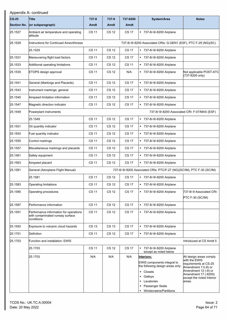
Appendix A- continued
TCDS No.: UK.TC.A.00004 Issue: 2 Date: 20 May 2022 Page 64 of 71
CS-25
Section No.
Title
(or subparagraph)
737-8
Amdt
737-9
Amdt
737-8200
Amdt
System/Area Notes
25.1527 Ambient air temperature and operating altitude
CS 11 CS 12 CS 17 737-8/-9/-8200 Airplane
25.1529 Instructions for Continued Airworthiness 737-8/-9/-8200 Associated CRIs: G-GEN1 (ESF), PTC F-29 (NG)(SC)
25.1529 CS 11 CS 12 CS 17 737-8/-9/-8200 Airplane
25.1531 Maneuvering flight load factors CS 11 CS 12 CS 17 737-8/-9/-8200 Airplane
25.1533 Additional operating limitations CS 11 CS 12 CS 11 737-8/-9/-8200 Airplane
25.1535 ETOPS design approval CS 11 CS 12 N/A 737-8/-9/-8200 Airplane Not applicable POST-ATC (737-8200 only)
25.1541 General (Markings and Placards) CS 11 CS 12 CS 17 737-8/-9/-8200 Airplane
25.1543 Instrument markings: general CS 11 CS 12 CS 17 737-8/-9/-8200 Airplane
25.1545 Airspeed limitation information CS 11 CS 12 CS 17 737-8/-9/-8200 Airplane
25.1547 Magnetic direction indicator CS 11 CS 12 CS 17 737-8/-9/-8200 Airplane
25.1549 Powerplant instruments 737-8/-9/-8200 Associated CRI: F-07/MAX (ESF)
25.1549 CS 11 CS 12 CS 17 737-8/-9/-8200 Airplane
25.1551 Oil quantity indicator CS 11 CS 12 CS 17 737-8/-9/-8200 Airplane
25.1553 Fuel quantity indicator CS 11 CS 12 CS 17 737-8/-9/-8200 Airplane
25.1555 Control markings CS 11 CS 12 CS 17 737-8/-9/-8200 Airplane
25.1557 Miscellaneous markings and placards CS 11 CS 12 CS 17 737-8/-9/-8200 Airplane
25.1561 Safety equipment CS 11 CS 12 CS 17 737-8/-9/-8200 Airplane
25.1563 Airspeed placard CS 11 CS 12 CS 17 737-8/-9/-8200 Airplane
25.1581 General (Aeroplane Flight Manual) 737-8/-9/-8200 Associated CRIs: PTC/F-27 (NG)(SC/IM), PTC F-30 (SC/IM)
25.1581 CS 11 CS 12 CS 17 737-8/-9/-8200 Airplane
25.1583 Operating limitations CS 11 CS 12 CS 17 737-8/-9/-8200 Airplane
25.1585 Operating procedures CS 11 CS 12 CS 17 737-8/-9/-8200 Airplane 737-8/-9 Associated CRI:
PTC F-30 (SC/IM)
25.1587 Performance information CS 11 CS 12 CS 17 737-8/-9/-8200 Airplane
25.1591 Performance information for operations with contaminated runway surface conditions
CS 11 CS 12 CS 17 737-8/-9/-8200 Airplane
25.1593 Exposure to volcanic cloud hazards CS 13 CS 13 CS 17 737-8/-9/-8200 Airplane
25.1701 Definition CS 11 CS 12 CS 17 737-8/-9/-8200 Airplane
25.1703 Function and installation: EWIS Introduced at CS Amdt 5
25.1703 CS 11 CS 12 CS 17 737-8/-9/-8200 Airplane except as noted below
25.1703 N/A N/A N/A Interiors:
EWIS components integral to the following design areas only:
Closets Galleys Lavatories Passenger Seats Windscreens/Partitions
All design areas comply with the EWIS requirements at CS-25 Amendment 11(-8) or Amendment 12 (-9) or Amendment 17 (-8200) except the noted Interior areas.
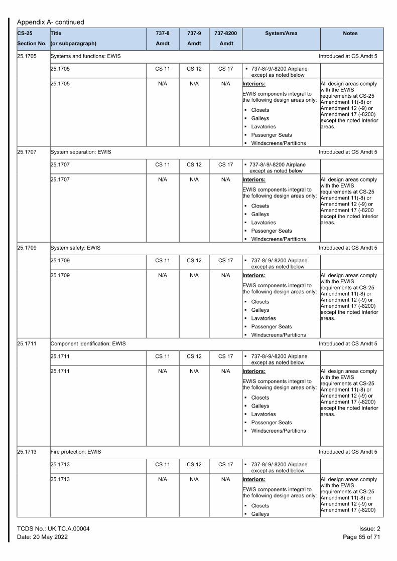
Appendix A- continued
TCDS No.: UK.TC.A.00004 Issue: 2 Date: 20 May 2022 Page 65 of 71
CS-25
Section No.
Title
(or subparagraph)
737-8
Amdt
737-9
Amdt
737-8200
Amdt
System/Area Notes
25.1705 Systems and functions: EWIS Introduced at CS Amdt 5
25.1705 CS 11 CS 12 CS 17 737-8/-9/-8200 Airplane except as noted below
25.1705 N/A N/A N/A Interiors:
EWIS components integral to the following design areas only:
Closets Galleys Lavatories Passenger Seats Windscreens/Partitions
All design areas comply with the EWIS requirements at CS-25 Amendment 11(-8) or Amendment 12 (-9) or Amendment 17 (-8200) except the noted Interior areas.
25.1707 System separation: EWIS Introduced at CS Amdt 5
25.1707 CS 11 CS 12 CS 17 737-8/-9/-8200 Airplane except as noted below
25.1707 N/A N/A N/A Interiors:
EWIS components integral to the following design areas only:
Closets Galleys Lavatories Passenger Seats Windscreens/Partitions
All design areas comply with the EWIS requirements at CS-25 Amendment 11(-8) or Amendment 12 (-9) or Amendment 17 (-8200 except the noted Interior areas.
25.1709 System safety: EWIS Introduced at CS Amdt 5
25.1709 CS 11 CS 12 CS 17 737-8/-9/-8200 Airplane except as noted below
25.1709 N/A N/A N/A Interiors:
EWIS components integral to the following design areas only:
Closets Galleys Lavatories Passenger Seats Windscreens/Partitions
All design areas comply with the EWIS requirements at CS-25 Amendment 11(-8) or Amendment 12 (-9) or Amendment 17 (-8200) except the noted Interior areas.
25.1711 Component identification: EWIS Introduced at CS Amdt 5
25.1711 CS 11 CS 12 CS 17 737-8/-9/-8200 Airplane except as noted below
25.1711 N/A N/A N/A Interiors:
EWIS components integral to the following design areas only:
Closets Galleys Lavatories Passenger Seats Windscreens/Partitions
All design areas comply with the EWIS requirements at CS-25 Amendment 11(-8) or Amendment 12 (-9) or Amendment 17 (-8200) except the noted Interior areas.
25.1713 Fire protection: EWIS Introduced at CS Amdt 5
25.1713 CS 11 CS 12 CS 17 737-8/-9/-8200 Airplane except as noted below
25.1713 N/A N/A N/A Interiors:
EWIS components integral to the following design areas only:
Closets Galleys
All design areas comply with the EWIS requirements at CS-25 Amendment 11(-8) or Amendment 12 (-9) or Amendment 17 (-8200)
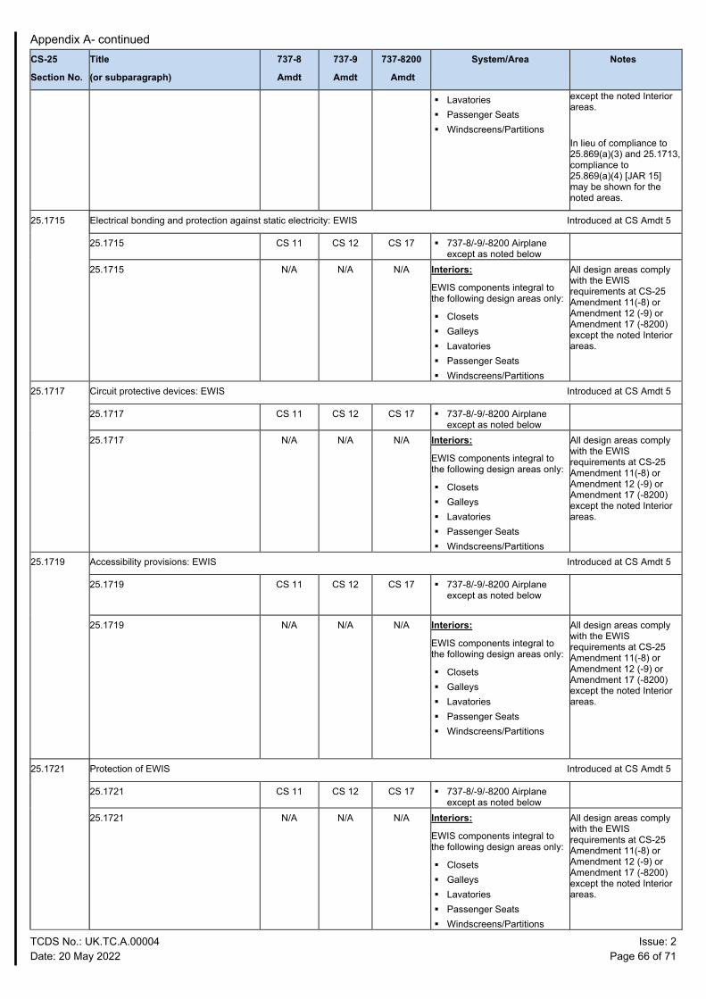
Appendix A- continued
TCDS No.: UK.TC.A.00004 Issue: 2 Date: 20 May 2022 Page 66 of 71
CS-25
Section No.
Title
(or subparagraph)
737-8
Amdt
737-9
Amdt
737-8200
Amdt
System/Area Notes
Lavatories Passenger Seats Windscreens/Partitions
except the noted Interior areas.
In lieu of compliance to 25.869(a)(3) and 25.1713, compliance to 25.869(a)(4) [JAR 15] may be shown for the noted areas.
25.1715 Electrical bonding and protection against static electricity: EWIS Introduced at CS Amdt 5
25.1715 CS 11 CS 12 CS 17 737-8/-9/-8200 Airplane except as noted below
25.1715 N/A N/A N/A Interiors:
EWIS components integral to the following design areas only:
Closets Galleys Lavatories Passenger Seats Windscreens/Partitions
All design areas comply with the EWIS requirements at CS-25 Amendment 11(-8) or Amendment 12 (-9) or Amendment 17 (-8200) except the noted Interior areas.
25.1717 Circuit protective devices: EWIS Introduced at CS Amdt 5
25.1717 CS 11 CS 12 CS 17 737-8/-9/-8200 Airplane except as noted below
25.1717 N/A N/A N/A Interiors:
EWIS components integral to the following design areas only:
Closets Galleys Lavatories Passenger Seats Windscreens/Partitions
All design areas comply with the EWIS requirements at CS-25 Amendment 11(-8) or Amendment 12 (-9) or Amendment 17 (-8200) except the noted Interior areas.
25.1719 Accessibility provisions: EWIS Introduced at CS Amdt 5
25.1719
CS 11 CS 12 CS 17 737-8/-9/-8200 Airplane except as noted below
25.1719 N/A N/A N/A Interiors:
EWIS components integral to the following design areas only:
Closets Galleys Lavatories Passenger Seats Windscreens/Partitions
All design areas comply with the EWIS requirements at CS-25 Amendment 11(-8) or Amendment 12 (-9) or Amendment 17 (-8200) except the noted Interior areas.
25.1721 Protection of EWIS Introduced at CS Amdt 5
25.1721 CS 11 CS 12 CS 17 737-8/-9/-8200 Airplane except as noted below
25.1721 N/A N/A N/A Interiors:
EWIS components integral to the following design areas only:
Closets Galleys Lavatories Passenger Seats Windscreens/Partitions
All design areas comply with the EWIS requirements at CS-25 Amendment 11(-8) or Amendment 12 (-9) or Amendment 17 (-8200) except the noted Interior areas.
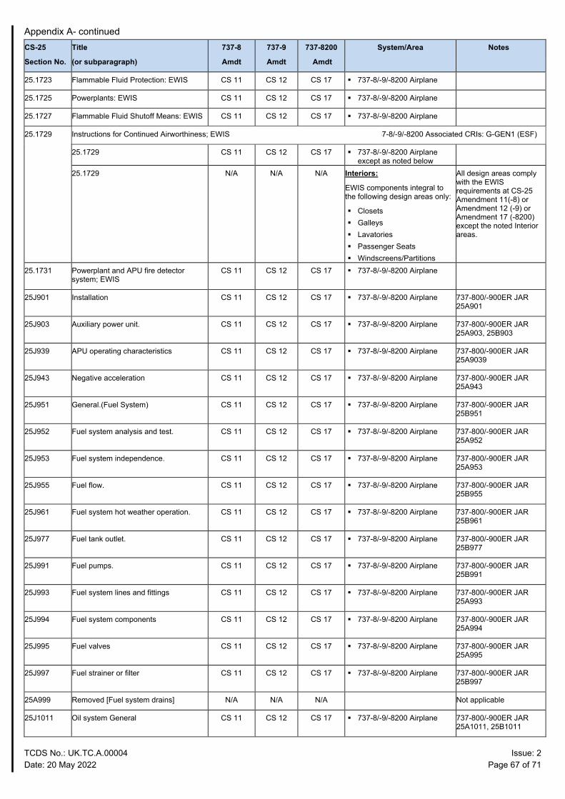
Appendix A- continued
TCDS No.: UK.TC.A.00004 Issue: 2 Date: 20 May 2022 Page 67 of 71
CS-25
Section No.
Title
(or subparagraph)
737-8
Amdt
737-9
Amdt
737-8200
Amdt
System/Area Notes
25.1723 Flammable Fluid Protection: EWIS CS 11 CS 12 CS 17 737-8/-9/-8200 Airplane
25.1725 Powerplants: EWIS CS 11 CS 12 CS 17 737-8/-9/-8200 Airplane
25.1727 Flammable Fluid Shutoff Means: EWIS CS 11 CS 12 CS 17 737-8/-9/-8200 Airplane
25.1729 Instructions for Continued Airworthiness; EWIS 37-8/-9/-8200 Associated CRIs: G-GEN1 (ESF)
25.1729 CS 11 CS 12 CS 17 737-8/-9/-8200 Airplane except as noted below
25.1729 N/A N/A N/A Interiors:
EWIS components integral to the following design areas only:
Closets Galleys Lavatories Passenger Seats Windscreens/Partitions
All design areas comply with the EWIS requirements at CS-25 Amendment 11(-8) or Amendment 12 (-9) or Amendment 17 (-8200) except the noted Interior areas.
25.1731 Powerplant and APU fire detector system; EWIS
CS 11 CS 12 CS 17 737-8/-9/-8200 Airplane
25J901 Installation CS 11 CS 12 CS 17 737-8/-9/-8200 Airplane 737-800/-900ER JAR 25A901
25J903 Auxiliary power unit. CS 11 CS 12 CS 17 737-8/-9/-8200 Airplane 737-800/-900ER JAR 25A903, 25B903
25J939 APU operating characteristics CS 11 CS 12 CS 17 737-8/-9/-8200 Airplane 737-800/-900ER JAR 25A9039
25J943 Negative acceleration CS 11 CS 12 CS 17 737-8/-9/-8200 Airplane 737-800/-900ER JAR 25A943
25J951 General.(Fuel System) CS 11 CS 12 CS 17 737-8/-9/-8200 Airplane 737-800/-900ER JAR 25B951
25J952 Fuel system analysis and test. CS 11 CS 12 CS 17 737-8/-9/-8200 Airplane 737-800/-900ER JAR 25A952
25J953 Fuel system independence. CS 11 CS 12 CS 17 737-8/-9/-8200 Airplane 737-800/-900ER JAR 25A953
25J955 Fuel flow. CS 11 CS 12 CS 17 737-8/-9/-8200 Airplane 737-800/-900ER JAR 25B955
25J961 Fuel system hot weather operation. CS 11 CS 12 CS 17 737-8/-9/-8200 Airplane 737-800/-900ER JAR 25B961
25J977 Fuel tank outlet. CS 11 CS 12 CS 17 737-8/-9/-8200 Airplane 737-800/-900ER JAR 25B977
25J991 Fuel pumps. CS 11 CS 12 CS 17 737-8/-9/-8200 Airplane 737-800/-900ER JAR 25B991
25J993 Fuel system lines and fittings CS 11 CS 12 CS 17 737-8/-9/-8200 Airplane 737-800/-900ER JAR 25A993
25J994 Fuel system components CS 11 CS 12 CS 17 737-8/-9/-8200 Airplane 737-800/-900ER JAR 25A994
25J995 Fuel valves CS 11 CS 12 CS 17 737-8/-9/-8200 Airplane 737-800/-900ER JAR 25A995
25J997 Fuel strainer or filter CS 11 CS 12 CS 17 737-8/-9/-8200 Airplane 737-800/-900ER JAR 25B997
25A999 Removed [Fuel system drains] N/A N/A N/A Not applicable
25J1011 Oil system General CS 11 CS 12 CS 17 737-8/-9/-8200 Airplane 737-800/-900ER JAR 25A1011, 25B1011
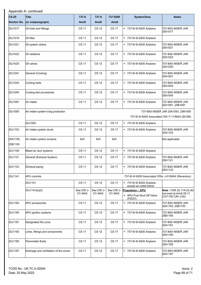
Appendix A- continued
TCDS No.: UK.TC.A.00004 Issue: 2 Date: 20 May 2022 Page 68 of 71
CS-25
Section No.
Title
(or subparagraph)
737-8
Amdt
737-9
Amdt
737-8200
Amdt
System/Area Notes
25J1017 Oil lines and fittings CS 11 CS 12 CS 17 737-8/-9/-8200 Airplane 737-800/-900ER JAR 25A1017
25J1019 Oil filter CS 11 CS 12 CS 17 737-8/-9/-8200 Airplane
25J1021 Oil system drains CS 11 CS 12 CS 17 737-8/-9/-8200 Airplane 737-800/-900ER JAR 25A1021
25J1023 Oil radiators CS 11 CS 12 CS 17 737-8/-9/-8200 Airplane 737-800/-900ER JAR 25A1023
25J1025 Oil valves CS 11 CS 12 CS 17 737-8/-9/-8200 Airplane 737-800/-900ER JAR 25A1025
25J1041 General (Cooling) CS 11 CS 12 CS 17 737-8/-9/-8200 Airplane 737-800/-900ER JAR 25A1041
25J1043 Cooling tests CS 11 CS 12 CS 17 737-8/-9/-8200 Airplane 737-800/-900ER JAR 25A1043
25J1045 Cooling test procedures CS 11 CS 12 CS 17 737-8/-9/-8200 Airplane 737-800/-900ER JAR 25A1045
25J1091 Air intake CS 11 CS 12 CS 17 737-8/-9/-8200 Airplane 737-800/-900ER JAR 25A1091, 25B1091
25J1093 Air intake system icing protection 737-800/-900ER JAR 25A1093, 25B1093
737-8/-9/-8200 Associated CRI: F-11/MAX (SC/IM)
25J1093 CS 11 CS 12 CS 17 737-8/-9/-8200 Airplane
25J1103 Air intake system ducts CS 11 CS 12 CS 17 737-8/-9/-8200 Airplane 737-800/-900ER JAR 25A1103
25A1105,
25B1105
Air intake system screens N/A N/A N/A Not applicable
25J1106 Bleed air duct systems CS 11 CS 12 CS 17 737-8/-9/-8200 Airplane
25J1121 General (Exhaust System) CS 11 CS 12 CS 17 737-8/-9/-8200 Airplane 737-800/-900ER JAR 25A1121
25J1123 Exhaust piping CS 11 CS 12 CS 17 737-8/-9/-8200 Airplane 737-800/-900ER JAR 25A1123
25J1141 APU controls 737-8/-9/-8200 Associated CRIs: J-01/MAX (Reversion)
25J1141 CS 11 CS 12 CS 17 737-8/-9/-8200 Airplane except as noted below
25J1141(b)(2) See CRI J- 01/ MAX
See CRI J- 01/ MAX
See CRI J- 01/ MAX
Propulsion – APU
APU Fuel Shut Off Valve (FSOV)
Note : FAR 25.1141(f) did not exist at Amdt 25-11 (737-700 CRI J-04)
25J1163 APU accessories CS 11 CS 12 CS 17 737-8/-9/-8200 Airplane 737-800/-900ER JAR 25A1163, 25B1163
25J1165 APU ignition systems CS 11 CS 12 CS 17 737-8/-9/-8200 Airplane 737-800/-900ER JAR 25B1165
25J1181 Designated fire zone CS 11 CS 12 CS 17 737-8/-9/-8200 Airplane 737-800/-900ER JAR 25A1181
25J1183 Lines, fittings and components CS 11 CS 12 CS 17 737-8/-9/-8200 Airplane 737-800/-900ER JAR 25A1183
25J1185 Flammable fluids CS 11 CS 12 CS 17 737-8/-9/-8200 Airplane 737-800/-900ER JAR 25A1185
25J1187 Drainage and ventilation of fire zones CS 11 CS 12 CS 17 737-8/-9/-8200 Airplane 737-800/-900ER JAR 25A1187
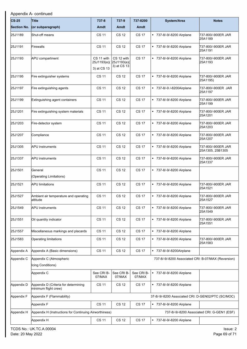
Appendix A- continued
TCDS No.: UK.TC.A.00004 Issue: 2 Date: 20 May 2022 Page 69 of 71
CS-25
Section No.
Title
(or subparagraph)
737-8
Amdt
737-9
Amdt
737-8200
Amdt
System/Area Notes
25J1189 Shut-off means CS 11 CS 12 CS 17 737-8/-9/-8200 Airplane 737-800/-900ER JAR 25A1189
25J1191 Firewalls CS 11 CS 12 CS 17 737-8/-9/-8200 Airplane 737-800/-900ER JAR 25A1191
25J1193 APU compartment CS 11 with 25J1193(e)(
3) at CS 13
CS 12 with 25J1193(e)(3) at CS 13
CS 17 737-8/-9/-8200 Airplane 737-800/-900ER JAR 25A1193
25J1195 Fire extinguisher systems CS 11 CS 12 CS 17 737-8/-9/-8200 Airplane 737-800/-900ER JAR 25A1195)
25J1197 Fire extinguishing agents CS 11 CS 12 CS 17 737-8/-9 /-8200Airplane 737-800/-900ER JAR 25A1197
25J1199 Extinguishing agent containers CS 11 CS 12 CS 17 737-8/-9/-8200 Airplane 737-800/-900ER JAR 25A1199
25J1201 Fire extinguishing system materials CS 11 CS 12 CS 17 737-8/-9/-8200 Airplane 737-800/-900ER JAR 25A1201
25J1203 Fire-detector system CS 11 CS 12 CS 17 737-8/-9/-8200 Airplane 737-800/-900ER JAR 25A1203
25J1207 Compliance CS 11 CS 12 CS 17 737-8/-9/-8200 Airplane 737-800/-900ER JAR 25A1207
25J1305 APU instruments CS 11 CS 12 CS 17 737-8/-9/-8200 Airplane 737-800/-900ER JAR 25A1305, 25B1305
25J1337 APU instruments CS 11 CS 12 CS 17 737-8/-9/-8200 Airplane 737-800/-900ER JAR 25A1337
25J1501 General
(Operating Limitations)
CS 11 CS 12 CS 17 737-8/-9/-8200 Airplane
25J1521 APU limitations CS 11 CS 12 CS 17 737-8/-9/-8200 Airplane 737-800/-900ER JAR 25A1521
25J1527 Ambient air temperature and operating altitude
CS 11 CS 12 CS 17 737-8/-9/-8200 Airplane 737-800/-900ER JAR 25A1527
25J1549 APU instruments CS 11 CS 12 CS 17 737-8/-9/-8200 Airplane 737-800/-900ER JAR 25A1549
25J1551 Oil quantity indicator CS 11 CS 12 CS 17 737-8/-9/-8200 Airplane 737-800/-900ER JAR 25A1551
25J1557 Miscellaneous markings and placards CS 11 CS 12 CS 17 737-8/-9/-8200 Airplane
25J1583 Operating limitations CS 11 CS 12 CS 17 737-8/-9/-8200 Airplane 737-800/-900ER JAR 25A1583
Appendix A Appendix A (Basic dimensions) CS 11 CS 12 CS 17 737-8/-9/-8200Airplane
Appendix C Appendix C (Atmospheric
Icing Conditions)
737-8/-9/-8200 Associated CRI: B-07/MAX (Reversion)
Appendix C See CRI B- 07/MAX
See CRI B- 07/MAX
See CRI B- 07/MAX
737-8/-9/-8200 Airplane
Appendix D Appendix D (Criteria for determining minimum flight crew)
CS 11 CS 12 CS 17 737-8/-9/-8200 Airplane
Appendix F Appendix F (Flammability) 37-8/-9/-8200 Associated CRI: D-GEN02/PTC (SC/MOC)
Appendix F CS 11 CS 12 CS 17 737-8/-9/-8200 Airplane
Appendix H Appendix H (Instructions for Continuing Airworthiness) 737-8/-9/-8200 Associated CRI: G-GEN1 (ESF)
Appendix H CS 11 CS 12 CS 17 737-8/-9/-8200 Airplane
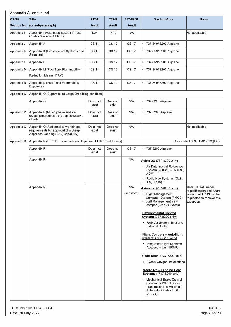
Appendix A- continued
TCDS No.: UK.TC.A.00004 Issue: 2 Date: 20 May 2022 Page 70 of 71
CS-25
Section No.
Title
(or subparagraph)
737-8
Amdt
737-9
Amdt
737-8200
Amdt
System/Area Notes
Appendix I Appendix I (Automatic Takeoff Thrust Control System (ATTCS)
N/A N/A N/A Not applicable
Appendix J Appendix J CS 11 CS 12 CS 17 737-8/-9/-8200 Airplane
Appendix K Appendix K (Interaction of Systems and Structure)
CS 11 CS 12 CS 17 737-8/-9/-8200 Airplane
Appendix L Appendix L CS 11 CS 12 CS 17 737-8/-9/-8200 Airplane
Appendix M Appendix M (Fuel Tank Flammability
Reduction Means (FRM)
CS 11 CS 12 CS 17 737-8/-9/-8200 Airplane
Appendix N Appendix N (Fuel Tank Flammability Exposure)
CS 11 CS 12 CS 17 737-8/-9/-8200 Airplane
Appendix O Appendix O (Supercooled Large Drop icing condition)
Appendix O Does not exist
Does not exist
N/A 737-8200 Airplane
Appendix P Appendix P (Mixed phase and ice crystal icing envelope (deep convective clouds))
Does not exist
Does not exist
N/A 737-8200 Airplane
Appendix Q Appendix Q (Additional airworthiness requirements for approval of a Steep Approach Landing (SAL) capability)
Does not exist
Does not exist
N/A Not applicable
Appendix R Appendix R (HIRF Environments and Equipment HIRF Test Levels) Associated CRIs: F-01 (NG)(SC)
Appendix R Does not exist
Does not exist
CS 17 737-8200 Airplane
Appendix R N/A Avionics: (737-8200 only)
Air Data Inertial Reference System (ADIRS) – (ADIRU, ADM)
Radio Nav Systems (GLS, ILS, LRRA)
Appendix R N/A
(see note) Avionics: (737-8200 only)
Flight Management Computer System (FMCS)
Stall Management Yaw Damper (SMYD) System
Environmental Control System: (737-8200 only)
RAM Air System, Inlet and Exhaust Ducts
Flight Controls – Autoflight System: (737-8200 only)
Integrated Flight Systems Accessory Unit (IFSAU)
Flight Deck: (737-8200 only)
• Crew Oxygen Installations
Mech/Hyd – Landing Gear Systems: (737-8200 only)
Mechanical Brake Control System for Wheel Speed Transducer and Antiskid / Autobrake Control Unit (AACU)
Note: IFSAU under requalification and future revision of TCDS will be requested to remove this exception
TCDS No.: UK.TC.A.00004 Issue: 2 Date: 20 May 2022 Page 71 of 71
Attachment 1 Copy of the EASA TCDS IM.A.120 at Issue 20 dated 17 December 2019
EASA.IM.A.120 Issue 20 Boeing 737.pdf
Attachment 2 Copy of Issue 11 of the Explanatory Note to EASA TCDS IM.A.120. This Explanatory Note published selected EASA Special Conditions, Deviations and Equivalent Safety Findings that are part of the applicable certification basis.
IM.A.120 Boeing737 TCDS APPENDIX ISS 1
– END –

Explanatory Note to TCDS IM.A.120 – Boeing 737 Issue 11
Disclaimer – This document is not exhaustive and it will be updated gradually. Page 1 of 120
This annex to the EASA TCDS IM.A.120 was created to publish selected special conditions / deviations / equivalent safety findings that are part of the applicable certification basis: Table of Contents: Certification Review Items: A-10: Additional requirements for import ...........................................................................................3 A. 11-02: Pressurised Cabin Loads ......................................................................................................5 A. 11-04: Emergency Landing Dynamic Loads ...................................................................................6 A. 11-05: Fatigue and Damage Tolerance ............................................................................................7 A. 11-06: Fasteners ...............................................................................................................................9 A. 11-08: Lift and Drag Device Indicator ..........................................................................................10 A. 11-11: Doors ..................................................................................................................................11 A. 11-12: Seat, Berths, Safety Belts and Harness ..............................................................................12 A. 11-13: Direct view and cabin attendant seat ..................................................................................13 A. 11-16: Equipment Systems and Installations ................................................................................14 A. 11-23: Windshields and Windows .................................................................................................15 A-CCD: OSD Cabin Crew Data (CCD) certification basis ...............................................................16 A-MMEL:OSD Master Minimum Equipment List – Cert. basis .......................................................16 D926A105: OSD Flight Crew ............................................................................................................16 B-05/MAX: Longitudinal trim at Vmo ..............................................................................................17 B-06/MAX: En-route climb ...............................................................................................................18 B-10: Stall Warning Thrust Bias ........................................................................................................19 C-01: Pressurised Cabin Loads ..........................................................................................................20 C-02/MAX: Design Manoeuvre Requirements ..................................................................................21 C-11: Interaction of Systems and Structure .......................................................................................22 9ER/C-11: Interaction of Systems and Structure ...............................................................................28 C-15/PTC: Structural Certification Criteria for Large Antenna Installations ....................................29 9ER/C-20: Fuel tank access covers ....................................................................................................32 D-01: Brakes Requirements Qualification and Testing .....................................................................33 D-02: Hydraulic System Proof Pressure Testing ...............................................................................34 D-04/MAX: Towbarless towing .........................................................................................................35 D-04: Landing Gear Warning .............................................................................................................36 D-06: Towbarless towing ...................................................................................................................37 D-08: Forward and Aft Door Escape Slide Low Sill Height .............................................................38 9ER/D-08: Forward and Aft Door Escape Slide Low Sill Height .....................................................39 D-10: Overwing Hatch Emergency Exit Signs ..................................................................................40 9ER/D-12: Maximum passengers seating configuration ....................................................................41 D-14: Exit configuration ....................................................................................................................42 D-15/MAX: Emergency Exits Configuration ....................................................................................43 D-16: Automatic Overwing Exit (AOE) ............................................................................................45 9ER/D-16: Fuselage Doors ................................................................................................................46 D-17: Oversized Type I Exits, Maximum Number of Passengers .....................................................47 D-17/MAX: Packs off operation ........................................................................................................48 D-18: Slide/Raft Inflation Gas Cylinders ...........................................................................................49 D-18/MAX: Wing Flap Lever Position ..............................................................................................50 PTC/D-19: Emergency Exit Marking .................................................................................................51 9ER/D-20: Oversized Type II Exit passageway Dimension ..............................................................52 9ER/D-21: Door sill reflectance .........................................................................................................53 9ER/D-23: Passenger information signs ............................................................................................54 D-GEN 1 PTC: Fire Resistance of Thermal Insulation Material .......................................................55 D-GEN 2 PTC: Application of heat release and smoke density requirements to seat materials ......56 PTC / D-19: Emergency Exit Marking (Door Sill Reflectance) ........................................................57 PTC / D-21: Emergency Exit Marking (Door Sill Reflectance) ........................................................58 PTC / D-23: Passenger Information Signs .........................................................................................59 D-27/MAX: Installation of inflatable restraint systems .....................................................................60

Explanatory Note to TCDS IM.A.120 – Boeing 737 Issue 11
Disclaimer – This document is not exhaustive and it will be updated gradually. Page 2 of 120
E-05/MAX: Engine Cowl Retention ..................................................................................................63 E-09: Automatic Fuel Shut Off ..........................................................................................................64 E-10/MAX: Strut & Aft Strut Fairing Compartment .........................................................................65 E-10/PTC: Flammability Reduction System .....................................................................................66 E-11/PTC: New Interior Arrangement with Passenger Service Unit Life Vest Stowage ..................71 E-12/MAX: Thrust Reverser Testing .................................................................................................72 E-15/PTC and E-16/PTC: Fuel Tank Safety ......................................................................................73 E-20/MAX: LEAP_1B Fuel Filter Location ......................................................................................74 E-22/MAX: LEAP-1B areas adjacent to Designated Fire Zone (CS-25.1182) .................................75 E-24/MAX: Wing Leading Edge Slats ...............................................................................................76 E-27/MAX: Fan blade loss, effects at airplane level ..........................................................................77 E-28/MAX: Fire testing of firewall Sealant .......................................................................................78 E-29/MAX: Fueling Float Switch Installation ...................................................................................79 E-30/MAX: Engine cowl retention ....................................................................................................80 E-31/MAX: Fuel Quantity Indication System (FQIS) Electrostatics Threat .....................................81 E-32/MAX: Fire Extinguishing Plumbing and Wiring connections ..................................................82 E-33/MAX: Fuel Tank Ignition Prevention – Hot Surface Ignition Temperature .............................83 E-36/MAX: Right Main Fuel Tank Indication of Refuel System Failure at Full Fuel Tank Level ...84 F-01: High Intensity Radiated Fields .................................................................................................85 F-02: Protection from the effects of Lightning strike; direct effects ..................................................86 F-03: Protection from the effects of Lightning Srike; indirect effects ...............................................87 F-03/MAX: HIRF Protection .............................................................................................................88 F-07/MAX: Green Arc for Powerplant Instrument ............................................................................89 F-11/MAX: Airworthiness standard for aircraft operations under falling and blowing snow ...........90 FGEN 9-1: Minimum Mass Flow of Supplemental Oxygen “Component Qualification” ................91 FGEN 9-3: Crew Determination of Quantity of Oxygen in Passenger Oxygen System ...................92 F-15: Wingtip Position Lights ............................................................................................................93 F-17: EGPWS Airworthiness Approval .............................................................................................94 F-17/MAX: Leading Edge FLAPS TRANSIT - flight crew indication .............................................99 F-27/PTC: GNSS Landing System (GLS) - Airworthiness Approval for Category I Approach Operations ........................................................................................................................................100 F-29: Lithium - Ion Batteries ............................................................................................................105 F-30: Data Link Services for the Single European Sky ...................................................................107 F-31 PTC: Security protection of aircraft systems and networks ...................................................108 F-40/MAX: First aid portable pulse oxygen system ........................................................................111 F-GEN10 PTC: Non-rechargeable Lithium Batteries Installations ................................................112 F-GEN11 PTC: Non-rechargeable Lithium Batteries Installations ................................................113 G-GEN01 Instructions for Continued Airworthiness .......................................................................114 H-01: Enhanced airworthiness programme for aeroplane systems – ICA on EWIS .....................116 J-03/MAX: APU Engine mounts .....................................................................................................118 J-04: APU Fuel Shut Off Valve Indication ......................................................................................120

Explanatory Note to TCDS IM.A.120 – Boeing 737 Issue 11
Disclaimer – This document is not exhaustive and it will be updated gradually. Page 3 of 120
ADMINISTRATIVE ITEM A-10: Additional requirements for import APPLICABILITY: Boeing B737-600/-700/-800
REQUIREMENTS: JAR 21 ADVISORY MATERIAL: N/A
In their application for JAA Validation, Boeing requested that the JAA's investigation followed the principles of Concurrent and Cooperative Certification. The procedures followed in the subsequent investigation were largely based on that principle. Boeing designed the B737-700 aiming to comply with both FAA and JAA requirements. Although Boeing have essentially achieved this aim, there are a small number of JAA requirements that the FAA Type Design Standard will not comply with. This CRI defines those requirements as the Additional Requirements for Import. DISCUSSION 1. JAA POSITION The JAA Joint Type Certification Basis is defined by CRI A-01. Those requirements must be satisfied at the time of Type Certification along with those Additional National Design Requirements defined by CRI A-02. Any JAA requirements for Type Certification defined in CRI's A-01 and A-02, that are not complied with by the Type Design Standard, Type Certificated by the FAA, must be included in the JAA Additional Requirements for Import. The Type Design Standard is defined by CRI A-06. Additional National Design Requirements other than those for Type Certification are administered under CRI's A-03 to A-05 inclusive. Each respective country must ensure that their requirements under these CRI's are satisfied. (…) 6 CONCLUSION (February 1998) Further to the proposed list of ARI’s previously identified in this CRI (reference paragraph 6) Boeing has proposed to show compliance with JAR 25.201(d) at Change 14 as amended by NPA 25B-261, by incorporation of a modification to the speed Trim System, (reference the conclusion in CRI B-15). The JAA are including reference to this modification as an ARI, within this CRI. In addition, reference to compliance with 25.X745 (d) for towbarless towing has been included, as administered by CRI D-06 and identified through relevant amendment to the Flight Manual. The table below summarises the JAA Additional Requirements for Import.

Explanatory Note to TCDS IM.A.120 – Boeing 737 Issue 11
Disclaimer – This document is not exhaustive and it will be updated gradually. Page 4 of 120

Explanatory Note to TCDS IM.A.120 – Boeing 737 Issue 11
Disclaimer – This document is not exhaustive and it will be updated gradually. Page 5 of 120
REVERSION: A. 11-02: Pressurised Cabin Loads APPLICABILITY: Boeing B737-600/-700/-800
REQUIREMENTS: JAR 25.365 ADVISORY MATERIAL: N/A
Replacing JAR 25.365 (change 13 plus Orange Papers 90/1 and 91/1) by FAR 25.365 Amendment 0 is acceptable,
when applying the guidelines of NPA 21-7.
All rapid decompression scenarios (resulting from penetration of the fuselage due to uncontained
engine failure) will be included by Boeing when showing compliance to JAR 25.903(d)(1). In
addition the rapid decompression scenarios (resulting from penetration of the fuselage due to
uncontained engine failure) not shown to be extremely improbable will be included by Boeing when
showing compliance to FAR 25 Amendment 0.

Explanatory Note to TCDS IM.A.120 – Boeing 737 Issue 11
Disclaimer – This document is not exhaustive and it will be updated gradually. Page 6 of 120
REVERSION: A. 11-04: Emergency Landing Dynamic Loads APPLICABILITY: Boeing B737-600/-700/-800
REQUIREMENTS: JAR 25.562 (change 13) ADVISORY MATERIAL: N/A
The reversion to JAR 25 Change 12 with respect to JAR 25.562 is accepted by the JAA. CRI A-01, JAA Joint Type Certification Basis, will be amended accordingly. Under the CCC process FAR 25.562 at Amendment 25-64 is included in the Jointly Agreed Type Certification Basis. Each NAA prepared to accept an aircraft without compliance to FAR 25.562 at Amendment 25-64 should note the FAA position with respect to issuance of a waiver for inclusion in an Export Certificate of Airworthiness. FAA POSITION The FAA Type Certification Basis for the Model 737-700 airplane includes FAR Part
25.562 Emergency Landing Dynamic Conditions. The FAA rationale for inclusion of FAR 25.562 in the certification basis is that the installation of 16g seats can provide significant improvements in passenger safety. Additionally, a major portion of the requirements of FAR 25.562 will be requirements of FAR Part 121 prior to the 737-700 certification.
The current JAA position of not requiring JAR 25.562 to be in the certification basis is
different than the FAA certification basis which requires compliance with FAR 25.562. Each JAA member country accepting a 737-600, -700, or -800 without compliance to FAR 25.562 will have to issue a waiver of the FAR 25.562 requirements which will be included in the Export Certificate of Airworthiness.
Based on the JAA granting a reversion to JAR Part 25, Change 12, the FAA assumes that no
FAA resources will be expended in qualifying 16g seats for the 737-700 exported into the JAA member states.

Explanatory Note to TCDS IM.A.120 – Boeing 737 Issue 11
Disclaimer – This document is not exhaustive and it will be updated gradually. Page 7 of 120
REVERSION: A. 11-05: Fatigue and Damage Tolerance APPLICABILITY: Boeing B737-600/-700/-800
REQUIREMENTS: JAR 25.571 ADVISORY MATERIAL: N/A
For structure that is not significantly modified JAA agrees to a partial reversion as detailed below:
(a) General This subparagraph refers to other subparagraphs of JAR 25.571 and also to JAR 25.1529. The JAR-25 applicable to these requirements ( as defined below ) will dictate the applicability of this subparagraph (b) Damage Tolerance Evaluation
1) Attached to this CRI is a table defining what structure of the B737-600/700/800 is considered to be new/significantly modified and what structure is considered to be not significantly modified, compared to the previous B737 models. It also defines the requirement level to which compliance has to be shown. 2) For structure defined as not significantly modified, the JAA team propose to adopt the following Special Condition in the certification basis of the B737-600/700/800: Replace the current JAR 25.571(b) (Change 13 plus Orange Papers 90/1 and 91/1) by the following text:
(b) Fail safe strength. It must be shown by analysis, tests, or both, that catastrophic failure or excessive structural deformation, that could adversely affect the flight characteristics of the aeroplane, are not probable after fatigue failure or obvious partial failure of a single principal structural element. After these types of failure of a single principal structural element, the remaining structure must be able to withstand static loads corresponding to the following:
(1) The limit symmetrical manoeuvring conditions specified in JAR 25.337 up to Vc and in JAR 25.345. (2) The limit gust conditions specified in JAR 25.341 (a) at the specified speeds up to Vc and in JAR 25.345. (3) The limit rolling conditions specified in JAR 25.349 and the limit unsymmetrical conditions specified in JAR 25.367 and JAR 25.427, at speeds up to Vc. (4) The limit yaw manoeuvring conditions specified in JAR 25.351 at the specified speeds up to Vc. (5) For pressurised cabins, the following conditions :
(i) The normal operating differential pressure combined with the expected external aerodynamic pressures applied simultaneously with the flight loading conditions specified in sub-paragraphs (b)(1) to (b)(4) of this paragraph if they have a significant effect. (ii) The maximum value of normal operating differential pressure ( including the expected external aerodynamic pressures during 1 g level flight ) multiplied by a factor of 1.15 omitting other loads.
(6) For landing gear and directly-affected airframe structure, the limit ground loading conditions specified in JAR 25.473 (a) thru (d), JAR 25.491 and JAR 25.493.
These loads will be the basis of the fail safe loads for the revised SSIP
3) Also, for structure defined as not significantly modified, an agreement on a programme addressing continued airworthiness of the Boeing 737-600/700/800 should be reached prior to JAA Type Certification. Additional discussions between Boeing and FAA/JAA specialists will

Explanatory Note to TCDS IM.A.120 – Boeing 737 Issue 11
Disclaimer – This document is not exhaustive and it will be updated gradually. Page 8 of 120
have to provide further clarification on and agreement of this programme. This discussion will be documented in a separate CAI (ref. CAI 03-13).
(c) Safe life Evaluation
The JAA concurs with the Boeing position that all safe-life parts of the B737-600/700/800, will
comply with JAR 25.571(c) Change 13 (plus Orange Papers 90/1 and 91/1). Separate discussion will
have to take place between Boeing and the JAA on the means of compliance.
(d) Sonic Fatigue Strength
The JAA concurs with the Boeing position that compliance will be shown with JAR 25.571(d)
Change 13 (plus Orange Papers 90/1 and 91/1). Separate discussion will have to take place between
Boeing and the JAA on the means of compliance.
(e) Discrete Source Evaluation
The JAA concurs with the Boeing position that compliance will be shown with JAR 25.571(e)
Change 13 (plus Orange Papers 90/1 and 91/1), except as noted in CRI A.11-2. Separate discussion
will have to take place between Boeing and the JAA on the means of compliance.
B737-600/700/800
Classification of Structure (attachment to CRI A.11-5)
Component Classification JAR 25.571(b)
Wing Wing Box TE flaps LE devices Spoilers
SM SM SM SM
Ch. 13 + 2 OP’s Ch. 13 + 2 OP’s Ch. 13 + 2 OP’s Ch. 13 + 2 OP’s
Fuselage Forward access door Forward airstairs door EE bay door Automatic overwing exit
NSM SM SM SM SM
See Special Condition Ch. 13 + 2 OP’s Ch. 13 + 2 OP’s Ch. 13 + 2 OP's Ch. 13 + 2 OP's
Horizontal Stabiliser Vertical Stabiliser
NSM NSM
See Special Condition See Special Condition
Strut Nacelle
New New
Ch. 13 + 2 OP’s Ch. 13 + 2 OP’s
Primary Flight Controls Elevator (1) Rudder (1) Aileron (1)
-tab (1)
NSM NSM NSM SM
See Special Condition See Special Condition See Special Condition Ch. 13 + 2 OP’s
NSM = Not Significantly Modified ( compared to previous B737 models) SM = Significantly Modified ( compared to previous B737 models) (1) Compliance will also be shown to JAR 25.603, Change 13 plus Orange Papers 90/1 and 91/1.

Explanatory Note to TCDS IM.A.120 – Boeing 737 Issue 11
Disclaimer – This document is not exhaustive and it will be updated gradually. Page 9 of 120
REVERSION: A. 11-06: Fasteners APPLICABILITY: Boeing B737-600/-700/-800
REQUIREMENTS: JAR 25.607(a) ADVISORY MATERIAL: N/A
A reversion to FAR 25.607(a) at Amendment 0 is agreed for systems/structure that are not significantly modified and are not affected by such modifications. Such areas are to be agreed by FAA and JAA and documented by Boeing. In order to introduce this reversion into the JAA certification basis the following will apply: For systems/structure that are not significantly modified and are not affected by such modifications replace the text of JAR 25.607(a) with that of FAR 25.607 as follows:
"No self Locking nut may be used on any bolt subject to rotation during aeroplane operation."

Explanatory Note to TCDS IM.A.120 – Boeing 737 Issue 11
Disclaimer – This document is not exhaustive and it will be updated gradually. Page 10 of 120
REVERSION: A. 11-08: Lift and Drag Device Indicator APPLICABILITY: Boeing B737-600/-700/-800
REQUIREMENTS: JAR 25.21, 671, 672, 695 and 699 (change 13) ADVISORY MATERIAL: N/A
JAR 25.21, 25.671 and 25.672 at Change 13 will be included in the JAA Joint Certification Type Basis. This eliminates the need for compliance with Paragraph 25.695 which is not included in JAR 25 at Change 13.
JAA accept the reversion on JAR 25.699(a) Change 13 to FAR 25.699 amendment 0 which only concerns wing flap position indication and doesn't require position indication for spoilers. The high lift device systems will be required to comply with JAR 25.699 at change 13 and both the lift and drag system will be required to comply with JAR 25.699 (b) and (c) at change 13.

Explanatory Note to TCDS IM.A.120 – Boeing 737 Issue 11
Disclaimer – This document is not exhaustive and it will be updated gradually. Page 11 of 120
REVERSION: A. 11-11: Doors APPLICABILITY: Boeing B737-600/-700/-800
REQUIREMENTS: JAR 25.783(f) ADVISORY MATERIAL: N/A
JAA agrees to grant a reversion from JAR 25.783(f) Change 13, to replace the text with that of FAR 25.783(f) Amendment 15. This applies to doors of the existing design, any subsequent changes, or changes that affect the doors will need to be reviewed in consideration as to whether this amendment level remains applicable.

Explanatory Note to TCDS IM.A.120 – Boeing 737 Issue 11
Disclaimer – This document is not exhaustive and it will be updated gradually. Page 12 of 120
REVERSION: A. 11-12: Seat, Berths, Safety Belts and Harness APPLICABILITY: Boeing B737-600/-700/-800
REQUIREMENTS: JAR 25.785(b) ADVISORY MATERIAL: N/A
The request for a reversion from JAR 25.785(a) at Change 13 to JAR 25.785(a) at Change 12 is accepted.

Explanatory Note to TCDS IM.A.120 – Boeing 737 Issue 11
Disclaimer – This document is not exhaustive and it will be updated gradually. Page 13 of 120
REVERSION: A. 11-13: Direct view and cabin attendant seat APPLICABILITY: Boeing B737-600/-700/-800
REQUIREMENTS: JAR 25.785h(1) & (2) Change 13 ADVISORY MATERIAL: N/A
JAA agrees to grant a reversion from JAR 25.785h(1) and (2) Change 13, to replace the text with that of FAR 25.785h(2) (Direct View) and (5) (Cabin Attendant Seat Design) at Amendment 32, following the proposed MOC D. Following consultation with National Aviation Authorities, the CAA has advised that they are likely to issue an ANDR that will define their criteria for complying with JAR 25.785 h(i) which will not allow the use of MOC D.

Explanatory Note to TCDS IM.A.120 – Boeing 737 Issue 11
Disclaimer – This document is not exhaustive and it will be updated gradually. Page 14 of 120
REVERSION: A. 11-16: Equipment Systems and Installations APPLICABILITY: Boeing B737-600/-700/-800
REQUIREMENTS: JAR 25.1309 ADVISORY MATERIAL: AMJ 25.1309
The JAA wishes to draw attention to the Acceptable Techniques section of JAR AMJ 25.1309 paragraph 8 for the aircraft.
The JAA notes that for systems that are new, significantly modified and / or significantly
affected by change, Major failure conditions must also be considered. JAR AMJ 25.1309 para 12(c) provides acceptable guidance material.
A reversion to FAR 25.1309 Amdt 25-0 is granted for those systems that are not; new, significantly modified and/or affected by a significantly change.

Explanatory Note to TCDS IM.A.120 – Boeing 737 Issue 11
Disclaimer – This document is not exhaustive and it will be updated gradually. Page 15 of 120
REVERSION: A. 11-23: Windshields and Windows APPLICABILITY: Boeing B737-600/-700/-800
REQUIREMENTS: JAR 25.775(d) ADVISORY MATERIAL: N/A
JAA agrees that a reversion may be granted for the windshields and windows from JAR 25.775(d) Change 13 (including Orange Papers 90/1 and 91/1) to the amendment level in the original FAA Certification Basis FAR 25.775(d) at Amendment 0.

Explanatory Note to TCDS IM.A.120 – Boeing 737 Issue 11
Disclaimer – This document is not exhaustive and it will be updated gradually. Page 16 of 120
CERTIFICATION BASIS: A-CCD: OSD Cabin Crew Data (CCD) certification basis APPLICABILITY: Boeing B737-600/-700/-800/-900/-900ER/-8
REQUIREMENTS: Regulation (EU) 748/2012 of 03 August 2012, as amended by EU Regulation N°69/2014, Article 7a Annex I (Part 21) 21.A.17B
ADVISORY MATERIAL: N/A
Certification basis for the establishment of Operational Suitability Data (OSD) Cabin Crew for B737-600/-700/-800/-900/-900ER, the currently applicable:
CS-CCD, Initial Issue dated 31 January 2014
CERTIFICATION BASIS: A-MMEL:OSD Master Minimum Equipment List – Cert. basis APPLICABILITY: Boeing B737-600/-700/-800/-900/-900ER/-8
REQUIREMENTS: EU Regulation N°69/2014, Article 7a Annex I (Part 21) 21.A.17B ADVISORY MATERIAL: N/A
JAR-MMEL/MEL Amendment 1, Section1, Subparts A and B is the appropriate OSD MMEL certification basis for the B737-600/-700/-800/-900/-900ER.
CERTIFICATION BASIS: D926A105: OSD Flight Crew APPLICABILITY: Boeing B737-600/-700/-800/-900/-900ER/-8
REQUIREMENTS: EU Regulation N°69/2014, Article 7a Annex I (Part 21) 21.A.17B ADVISORY MATERIAL: N/A
The data contained in this document are agreed on the basis of elect to comply with CS-FCD, Initial Issue, dated 31 Jan 2014.

Explanatory Note to TCDS IM.A.120 – Boeing 737 Issue 11
Disclaimer – This document is not exhaustive and it will be updated gradually. Page 17 of 120
EQUIVALENT SAFETY FINDING:
B-05/MAX: Longitudinal trim at Vmo
APPLICABILITY: Boeing B737-7/-8/-9
REQUIREMENTS: CS 25.161(a), CS 25.161(c)(3), CS 25.1301(a) and CS 25.1309(a)
ADVISORY MATERIAL: N/A
STATEMENT OF ISSUE The aisle stand trim switches can be used to trim the airplane throughout the flight envelope and fully complies with the reference regulation Simulation has demonstrated that the thumb switch trim does not have enough authority to completely trim the aircraft longitudinally in certain corners of the flight envelope, e.g. gear up/flaps up, aft center of gravity, near Vmo/Mmo corner, and gear down/flaps up, at speeds above 230 kts. In those cases, longitudinal trim is achieved by using the manual stabilizer trim wheel to position the stabilizer. The trim wheel can be used to trim the airplane throughout the entire flight envelope. In addition, the autopilot has the authority to trim the airplane in these conditions. The reference regulation and policy do not specify the method of trim, nor do they state that when multiple pilot trim control paths exist that they must each independently be able to trim the airplane throughout the flight envelope. Boeing did not initially consider this to be a compliance issue because trim could always be achieved, even during the conditions where use of the aisle stand trim switch was required. Subsequent to flight testing, the FAA-TAD expressed concern with compliance to the reference regulation based on an interpretation of the intent behind “trim”. The main issue being that longitudinal trim cannot be achieved throughout the flight envelope using thumb switch trim only. EASA POSITION Boeing set the thumb switch limits in order to increase the level of safety for out-of-trim dive characteristics (CS 25.255(a)(1)). The resulting thumb switch limits require an alternative trim method to meet CS 25.161 trim requirements in certain corners of the operational envelope. The need to use the trim wheel is considered unusual, as it is only required for manual flight in those corners of the envelope. The increased safety provided by the Boeing design limits on the thumb switches (for out-of-trim dive characteristics) provides a compensating factor for the inability to use the thumb switches throughout the entire flight envelope. Furthermore, the additional crew procedures and training material will clearly explain to pilots the situations where use of the trim wheel may be needed due to lack of trim authority with the wheel mounted switches. The trim systems on the 737Max provide an appropriate level of safety relative to longitudinal trim capability.

Explanatory Note to TCDS IM.A.120 – Boeing 737 Issue 11
Disclaimer – This document is not exhaustive and it will be updated gradually. Page 18 of 120
EQUIVALENT SAFETY FINDING:
B-06/MAX: En-route climb
APPLICABILITY: Boeing B737-7/-8/-9
REQUIREMENTS: CS 25.123(a) and (b) ADVISORY MATERIAL: N/A
STATEMENT OF ISSUE Amendment 25/3 changes to CS §25.123 regarding en route climb speed (Venroute): • Establishes a minimum speed criteria (Venroute ≥ VFTO) • Requires evaluation compared to stall speed with ice The objectives of the amended regulation are appropriate; however, there are two issues that prevent a direct showing of literal compliance for the 737 MAX. These are: 1) At some weights, the 737 MAX VFTO is expected to be faster than the speed selected for en route climb. This is in conflict with the literal wording of the regulation, but as described in the next section this does not conflict with the intent of the regulation. 2) The regulation requires that the en route climb speed be compared to VSR with ice and VFTO, both of which are only defined for altitudes within a few thousand feet of maximum airport altitudes, while en route climb speeds must be determined up to higher altitudes. For these two reasons, an equivalent level of safety finding is necessary to establish a clear path for demonstration of compliance. EASA POSITION The proposed compensating factors meet the level of safety intended by the regulation.

Explanatory Note to TCDS IM.A.120 – Boeing 737 Issue 11
Disclaimer – This document is not exhaustive and it will be updated gradually. Page 19 of 120
SPECIAL CONDITION: B-10: Stall Warning Thrust Bias APPLICABILITY: Boeing B737-600/-700/-800
REQUIREMENTS: JAR 25.207(c) as amended by NPA 25B-215 ADVISORY MATERIAL: N/A
JAR 25.207(c) as amended by NPA 25B-215. Amend this paragraph to remove references to engines idling and throttles closed and the reference stall speed so that it reads as follows:
"(c) When the speed is reduced at a rate not exceeding 1 knot per second, stall warning must begin, in each normal configuration, at a speed, VSW, exceeding the speed where CL is first a maximum by not less than 3 knots or 3%, whichever is greater. Stall warning must continue throughout the demonstration, until the angle of attack is reduced to approximately that at which stall warning is initiated. [See ACJ 25.207(c)]".
The effect of these amendments is to extend the requirement for a minimum stall warning margin to thrust levels above flight idle. It is not necessarily the intention that full stalls be demonstrated at maximum thrust, but it must be shown that thrust bias does not result in stall warning margins below the level required in JAR 25.207(c).

Explanatory Note to TCDS IM.A.120 – Boeing 737 Issue 11
Disclaimer – This document is not exhaustive and it will be updated gradually. Page 20 of 120
SPECIAL CONDITION C-01: Pressurised Cabin Loads APPLICABILITY: Boeing B737-600/-700/-800/-900
REQUIREMENTS: JAR 25.365 and JAA INT/POL/25/7 ADVISORY MATERIAL: N/A
In addition to the specific requirement of JAR 25.365(e), all structure, components or parts, both internal and external to the pressurised compartments, the failure of which could interfere with continued safe flight and landing, must be designed to withstand the differential pressure loads resulting from a sudden release of pressure through the openings specified in JAR 25.365(e) at any approved operating altitude. In complying with this requirement, the differential pressure must be combined in a rational and conservative manner with the 1-g level flight loads and any loads arising from the emergency depressurisation conditions. These may be considered as ultimate conditions; however any deformations associated with these conditions must not interfere with continued safe flight and landing.

Explanatory Note to TCDS IM.A.120 – Boeing 737 Issue 11
Disclaimer – This document is not exhaustive and it will be updated gradually. Page 21 of 120
SPECIAL CONDITION C-02/MAX: Design Manoeuvre Requirements APPLICABILITY: Boeing B737-7/-8/-9
REQUIREMENTS: CS 25.331, 25.349, 25.351 ADVISORY MATERIAL: N/A
Add to CS 25.331(c) paragraph (c)(3): It must be established that manoeuvre loads induced by the system itself (e.g. abrupt changes in orders made possible by electric rather than mechanical combination of different inputs) are acceptably accounted for. Replace CS 25.349(a) by: (a) Manoeuvring: the following conditions, speeds and cockpit roll control motions (except as the motions may be limited by pilot effort) must be considered in combination with an aeroplane load factor from zero to two-thirds of the limit positive manoeuvring load factor. In determining the resulting control surface deflections the torsional flexibility of the wing must be considered in accordance with CS 25.301(b): (1) Conditions corresponding to maximum steady rolling velocities and conditions corresponding to maximum angular accelerations must be investigated. For the angular acceleration conditions zero rolling velocity may be assumed in the absence of a rational time history investigation of the manoeuvre. (2) At VA movement of the cockpit roll control up to the limit is assumed. The position of the cockpit roll control must be maintained until a steady roll rate is achieved and then must be returned suddenly to the neutral position. (3) At VC, the cockpit roll control must be moved suddenly and maintained so as to achieve a roll rate not less than that obtained in sub-paragraph (2) of this paragraph. (4) At VD, the cockpit roll control must be moved suddenly and maintained so as to achieve a roll rate not less than one-third of that obtained in sub-paragraph (2) of this paragraph. (5) It must be established that manoeuvre loads induced by the system itself (i.e. abrupt changes in orders made possible by elec¬trical rather than mechanical combination of different inputs) are accepta¬bly accounted for. Amend paragraph CS 25.351(a) as follows: (a) With the aeroplane in unaccelerated flight at zero yaw, it is assumed that the cockpit rudder control is suddenly displaced (with critical rate) to the maximum deflection, as limited by the stops. Add to CS 25.351 paragraph (e): (e) It must be established that manoeuvre loads induced by the system itself (i.e. abrupt changes in orders made possible by elec¬trical rather than mechanical combination of different inputs) are accepta¬bly accounted for.

Explanatory Note to TCDS IM.A.120 – Boeing 737 Issue 11
Disclaimer – This document is not exhaustive and it will be updated gradually. Page 22 of 120
SPECIAL CONDITION: C-11: Interaction of Systems and Structure APPLICABILITY: Boeing B737-600/-700/-800
REQUIREMENTS: JAR 25.302 ADVISORY MATERIAL: N/A
1 ) Add the following text : 25.302 Interaction of systems and structures For an aeroplane equipped with systems which directly, or as a result of a failure or malfunction, affect structural performance, the influence of these systems and their failure conditions must be accounted for in showing compliance with the requirements of Subpart C and D. (See ACJ 25.302).
2 ) Replace the current ACJ 25.301(b) with the following text: ACJ 25.301(b) Loads (Interpretative material) See JAR 25.301 (b) and JAR 25.361(d) 1. In the determination of the load conditions up to the prescribed limit load level, any
significant non-linearity (e.g. due to aerodynamics and/or aeroelasticity) should be taken into account unless it would be conservative to ignore such non-linearities.
2. The engine and its mounting structure are to be stressed to the loading cases for the
aeroplane as a whole, including manoeuvring and gust loading conditions, together with conservative estimates of torque, thrust, gyroscopic loading and any loading which may result from engine fans. Full allowance should be made for structural flexibility effects in landing cases. This also applies to auxiliary power units.
3 ) Add the following ACJ :
ACJ 25.302 Interaction of systems and structures (interpretative material) 1. INTRODUCTION This ACJ defines criteria which are found adequate for an aeroplane equipped with systems which directly, or as a result of a failure or malfunction, affect structural performance, and should therefore be associated with agreed methods of demonstrations. This ACJ is intended to be applicable to flight controls, load alleviation systems and flutter control systems. If this ACJ is used for other systems, care should be taken that some items might have to be adapted to the specific system. These criteria only address the direct structural consequences of the systems responses and performances and therefore cannot be considered in isolation but should be included in the overall safety evaluation of the aircraft. The presentation of these criteria may, in some instances, duplicate standards already established for this evaluation. The defined criteria are applicable to structure, the failure of which could prevent continued safe flight and landing. Beyond these criteria, additional studies may be defined depending upon the specific characteristics of the aircraft. The purpose of these studies is to examine areas where there is concern that current writing of the requirements may not be sufficient in order to check certain situations which are considered realistic. The precise need for additional requirements associated with these studies and/or their level of severity will depend on the

Explanatory Note to TCDS IM.A.120 – Boeing 737 Issue 11
Disclaimer – This document is not exhaustive and it will be updated gradually. Page 23 of 120
sensitivity of the aircraft to those conditions and the conclusion that these problems may show the aircraft to have a lower level of safety than a conventional aircraft. 2. DEFINITIONS 2.1 Structural performance: Capability of the aeroplane to meet the structural requirements of JAR-25. 2.2 Flight limitations: Limitations which can be applied to the aeroplane flight conditions following an in
flight occurrence and that are included in the Flight Manual (e.g. Speed limitations, avoidance of severe weather conditions etc.).
2.3 Operational limitations Limitations - including flight limitations - that can be applied to the aircraft
operating conditions before dispatch (e.g. fuel and payload limitations). 2.4 Probabilistic terms: The probabilistic terms, such as probable, improbable and extremely improbable,
used in this ACJ should be understood as defined in AMJ 25.1309. 2.5 Failure Condition: The term failure condition is defined in AMJ 25.1309, however this ACJ applies
only to system failure conditions that affect the structural performance of the aeroplane (e.g. failure conditions that induce loads or change the response of the aeroplane to inputs such as gusts or pilot actions).
3. SYSTEM FULLY OPERATIVE With the system full operative the following apply: 3.1 Determination of limit loads Limit loads should be derived in all normal operating configurations of the systems
from all the limit conditions specified in Subpart C, taking into account any special behaviour of such systems or associated functions or any effect on the structural performance of the aircraft which may occur up to the limit loads. In particular any significant non-linearity (rate of displacement of control surface, thresholds or any other system non-linearities) should be accounted for in a realistic or conservative way when deriving limit loads from limit conditions.
3.2 Strength requirements The aircraft should meet the strength requirements of JAR-25 (static strength,
residual strength) using the specified factors to derive ultimate loads from the limit loads defined above. The effect of non-linearities should be investigated beyond limit conditions to ensure the behaviour of the systems presents no anomaly compared to the behaviour below the limit conditions. However, conditions beyond limit conditions need not to be considered when it can be shown that the aeroplane has design features that make it impossible to exceed those limit conditions.
3.3 Flutter requirements The aeroplane must meet the aeroelastic stability requirements of JAR 25.629. 4. SYSTEM IN FAILURE CONDITION 4.1 For any system failure condition not shown to be extremely improbable, the
following apply:

Explanatory Note to TCDS IM.A.120 – Boeing 737 Issue 11
Disclaimer – This document is not exhaustive and it will be updated gradually. Page 24 of 120
4.1.1 At the time of occurrence Starting from 1g level flight conditions, a realistic scenario, including pilot
corrective actions, should be established to determine the loads occurring at the time of failure and immediately after failure. The aeroplane should be able to withstand these loads, multiplied by an appropriate factor of safety that is related to the probability of occurrence of the failure. The factor of safety (F.S.) is defined in Figure 1.
Figure 1
Factor of Safety at Time of Occurrence
(i) These loads should also be used in the damage tolerance evaluation required by
JAR 25.571 (b) if the failure condition is probable. (ii) A flutter, divergence and control reversal justification should be made up to VD
or 1.15 VC, whichever is greater. However at altitudes where the speed is limited by Mach number, compliance need be shown only up to MD as defined in JAR 25.335 (b). For failure conditions which result in a speed increase beyond VC/MC, freedom from flutter and divergence should be shown to increased speeds, so that the above speed margins are maintained.
(iii) Notwithstanding the strength conditions described in this subparagraph, failure
of the system which result in forced structural vibrations (oscillatory failures) must not produce peak loads that could result in detrimental deformation of the primary structure.
4.1.2 For continuation of the flight For the aeroplane in the system failed state, and considering any appropriate
reconfiguration and flight limitation, the following apply: (i) Static and residual strength should be determined for loads derived from
the following conditions: - the limit symmetrical manoeuvring conditions specified in § 25.331 at speeds up to VC and in § 25.345 - the limit gust conditions specified in § 25.341 at speeds up to VC and in § 25.345 - the limit rolling conditions specified in § 25.349 and the limit unsymmetrical conditions specified in §§ 25.367 and 25.427 (b) and (c) at speeds up to VC - the limit yaw manoeuvring conditions specified in § 25.351 at speeds up to VC - the limit ground loading conditions specified in §§ 25.473 and 25.491
(ii) For static strength substantiation, each part of the structure should be able to
withstand the loads in subparagraph 4.1.2(i) multiplied by a factor of safety depending on the probability of being in this failure state. The factor of safety is defined in Figure 2.

Explanatory Note to TCDS IM.A.120 – Boeing 737 Issue 11
Disclaimer – This document is not exhaustive and it will be updated gradually. Page 25 of 120
Figure 2 Factor of Safety for Continuation of Flight
Qj = Tj * pj where Tj = Average time spent in failure condition Pj = Probability of occurrence of failure mode Note: If Pj is greater than 10-3, per flight hour then a 1.5 factor of safety must be
used and static and residual strength must be determined for loads derived from all limit conditions specified in Subpart C for the reconfigured aeroplane.
(iii) For the residual strength substantiation as defined in JAR 25.571(b), structures
affected by failure of the system and with damage in combination with the system failure, a reduced factor may be applied to the residual strength loads of JAR 25.571(b). However the residual strength level should not be less than the 1g flight load combined with the loads introduced by the failure condition plus two thirds of the load increments of the conditions specified in JAR 25.571(b) applied in both positive and negative directions (if appropriate). This residual strength substantiation need not be conducted for improbable failure conditions. The residual strength factor (R.S.F.) is defined in Figure 3.
Figure 3
Residual Strength Factor
Qj = Tj * pj where Tj = Average time spent in failure condition Pj = Probability of occurrence of failure mode Note: If Pj is greater than 10-3, per flight hour then a residual strength factor of 1.0
should be used. (iv) If the loads induced by the failure state have a significant influence on damage
propagation then their effects must be taken into account. (v) Freedom from flutter, divergence and control reversal should be shown up to a speed
as defined in Figure 4.

Explanatory Note to TCDS IM.A.120 – Boeing 737 Issue 11
Disclaimer – This document is not exhaustive and it will be updated gradually. Page 26 of 120
Figure 4
Clearance speed
V' = Clearance speed required for failure conditions as defined in sub-paragraph 4.1.1(ii) V'' = Clearance speed required for normal (unfailed) conditions by JAR 25.629(b). Qj = Tj * Pj where: Tj = Average time spent in failure condition Pj = Probability of occurrence of failure mode Note: If Pj is greater than 10-3, per flight hour, then the clearance speed must not be less
than V'' (vi) Freedom from flutter, divergence and control reversal should also be shown up to
V', in Figure 4, for any probable failure condition combined with any damage required or selected for investigation by JAR 25.571(b).
(vii) If the Mission Analysis method is used to account for continuous turbulence, all the
systems failure conditions associated with their probability should be accounted for in a rational or conservative manner in order to ensure that the probability of exceeding the limit load is not higher than the value prescribed in ACJ 25.305(d).
4.2 Warning considerations For system failure detection and warning the following apply: 4.2.1 Before flight The system should be checked for failure conditions, not extremely improbable, that
degrade the structural capability below the level required by JAR-25. The crew should be made aware of these failures, if they exist, before flight.
4.2.2 During flight The existence of any failure condition, which is not extremely improbable, during
flight that could significantly affect the structural capability of the aeroplane (for example, a reduction in factor of safety below 1.25, or flutter margin below V''), and for which the associated reduction in airworthiness can be minimised by suitable flight limitations, should be signalled to the crew.
4.2.3 For dispatch in known failure condition If the aeroplane is to be knowingly dispatched in a system failure condition that
reduces the structural performance then operational limitations should be provided whose effects, combined with those of the failure condition, allow the aeroplane to meet the structural requirements of JAR-25. Subsequent system failures should also be considered.
4 ) Delete the current ACJ 25.1329 5.2.1(a) and ACJ 25.1329 5.2.2(a)

Explanatory Note to TCDS IM.A.120 – Boeing 737 Issue 11
Disclaimer – This document is not exhaustive and it will be updated gradually. Page 27 of 120
5 ) Insert the following ACJ 25.1329 5.2.6 : In case the failure condition produces any additional load on the structure or has an impact on the structural capabilities of the aeroplane, this must be addressed according to §25.302.

Explanatory Note to TCDS IM.A.120 – Boeing 737 Issue 11
Disclaimer – This document is not exhaustive and it will be updated gradually. Page 28 of 120
SPECIAL CONDITION: 9ER/C-11: Interaction of Systems and Structure APPLICABILITY: Boeing B737-900ER
REQUIREMENTS: JAR 25.302 ADVISORY MATERIAL: ACJ 25.301 ACJ 25.302
The CRI C-11 Interaction of Systems and Structure raised for B737-700 is
applicable to B737-900ER.

Explanatory Note to TCDS IM.A.120 – Boeing 737 Issue 11
Disclaimer – This document is not exhaustive and it will be updated gradually. Page 29 of 120
EQUIVALENT SAFETY FINDING:
C-15/PTC: Structural Certification Criteria for Large Antenna Installations
APPLICABILITY: Boeing B737-800/-900ER
REQUIREMENTS: JAR 25.23, 25.251, 25.301, 25.365, 25.571, 25.581, 25.603, 25.605, 25.609, 25.613, 25.629, 25.631, 25.841, 25.901, 25.1419, 25.1529, and Appendix H
ADVISORY MATERIAL: -
STATEMENT OF ISSUE The consequences of loss of an antenna and/or radome become more significant with an increased size and weight of the antenna/radome installation. Therefore, past practice as applied to small antenna installations may not always be sufficient when applied to a large antenna installation. In fact, if loss of the antenna and/or radome is deemed catastrophic either due to decompression, or due to the antenna and/or radome striking the vertical or horizontal stabilizers, or for some other reason, then the structural certification criteria are more stringent. EASA POSITION EASA requests that the applicant provides the means of compliance for each of the regulations identified below. JAR 25.23 Load Distribution Limits The effect of the antenna/radome installation on the weight, centre of gravity, and load distribution limits of the aeroplane must be considered. These changes must be documented in the weight and balance document as required by JAR 25.29 and JAR 25.1519. JAR 25.251 Vibration and Buffeting (CRI C-05 per TCDS A.120) The effects of vibration and buffeting on the aeroplane must be considered, as well as on the antenna/radome installation itself up to VDF/MDF. Boeing has requested an equivalent level of safety ELOS (FAA has raised IP F-1) finding to show by means other than flight testing that the installation of this Ku-Band antenna will not cause excessive vibration under any speed and power conditions up to VDF/MDF. JAR 25.301(b) Flight Loads Validation Methods used to determine load intensities and distribution must be validated by flight load measurement unless the methods used for determining those loading conditions are shown to be reliable, or conservative. JAR 25.365(e) Pressurized Compartment Loads Rapid pressurization of the antenna compartment (radome) must be considered as outlined in JAR 25.365(e)(3) if loss of the radome/antenna could interfere with continued safe flight and landing. JAR 25.365(e)(3) requires the consideration of “the maximum opening caused by aeroplane or equipment failures not shown to be extremely improbable.” EASA’s interpretation of JAR 25.365(e)(3) is that to address structural failures, the opening size resulting from a skin bay failure (bounded by two adjacent frames and two adjacent stringers) should generally be considered (i.e. is not extremely improbable) as a minimum opening size, unless a smaller opening can be justified based upon the maximum level of cracking that can be conservatively expected when a directed inspection for the structure under the radome exists in the ALS. (The assumed crack size and resulting opening should account for bulging affects and the possibility of missed opportunities for detection.) Failures to equipment and items such as seals should also be considered separately and in combination with structural failures as appropriate. Consideration of JAR 25.365(e)(1) is not required as the engine disintegration is assumed to adequately “vent” any remaining section of radome if the compartment beneath is penetrated. Application of the formula hole size requirement of JAR 25.365(e)(2) is also not required,

Explanatory Note to TCDS IM.A.120 – Boeing 737 Issue 11
Disclaimer – This document is not exhaustive and it will be updated gradually. Page 30 of 120
since, for the size of radome being considered, the majority of hole sizes up to the maximum stated in the formula will exceed the boundary of the antenna/radome. Furthermore, the potential for such large openings to create debris problems equivalent to or worse than the loss of the antenna alone supports the position that application of JAR 25.365(e)(2) to such antenna would be beyond the accepted intent of the rule. Rather, the focus for compliance to the decompression requirement should be consideration of any airframe or equipment failures not shown to be extremely improbable, as explained above. JAR 25.571 Damage Tolerance and Fatigue Evaluation of Structure (CRI A.11-05 per TCDS A.120) A damage tolerance evaluation must be performed on any radome/antenna structure whose failure due to fatigue, corrosion or accidental damage could result in loss of the antenna/radome and subsequent tail strike, or other hazard such as rapid decompression of the aeroplane. Any inspection that is determined necessary as a result of this evaluation must be addressed as per JAR 25.1529 and Appendix H. JAR 25.581 Lightning Strike The antenna and radome installation must be designed such that the aeroplane is protected against catastrophic effects from lightning. JAR 25.603 Materials Materials used must conform to approved specifications. The suitability of the material to withstand the operational environment (e.g. temperature and humidity) must be assessed. JAR 25.605 Fabrication Methods The methods of fabrication used must produce a consistently sound structure. Each new fabrication method must be substantiated by a test program. JAR 25.609 Protection of Structure Each part of the structure must be suitably protected against deterioration or loss of strength in service and must have provisions for ventilation and drainage where necessary for protection. JAR 25.613 Material Strength Properties and Design Values Design values used to design the antenna/radome installation must be established on a statistical basis. The applicant must take into account the operational environmental conditions (e.g. temperature and humidity) when establishing design values. JAR 25.629 Aeroelastic Stability Requirements (CRI C-05 per TCDS A.120) The applicant must demonstrate by analysis and/or test that the aeroplane is free from aeroelastic instability with the antenna and radome installed. This may be accomplished by a comparative analysis showing that the aeroelastic stability of the aeroplane will be unaffected by the change. If the antenna/radome installation is not conformal to the fuselage, such as an antenna/radome mounted above the fuselage, the installation itself must also comply with JAR 25.629. JAR 25.631 Bird Strike The applicant must show that a bird strike on the antenna/radome, including attachments, will not prevent continued safe flight and landing. This includes consideration of parts that may separate from the aeroplane. This requirement need not be considered if it can be demonstrated that a bird cannot strike the antenna/radome, including attachments, within the normal flight envelope. JAR 25.841 Cabin Pressurization Certain aeroplanes approved for operation at high altitude (above 41.000 ft) have Special Conditions addressing pressurization. For these aeroplanes, the requirements defined in the Special Condition apply to any modification of the pressure vessel. JAR 25.901(c) Sustained Engine Imbalance

Explanatory Note to TCDS IM.A.120 – Boeing 737 Issue 11
Disclaimer – This document is not exhaustive and it will be updated gradually. Page 31 of 120
The applicant may need to consider the effects of sustained engine imbalance (windmilling) if the antenna/radome design is such that it would be susceptible to structural failure due to vibration. It must be shown that the resulting vibration will not cause a structural failure of the antenna/radome installation that would result in a foreseeable hazard, either at the point of failure or downstream. AMC 25-24 provides further guidance on this subject. JAR 25.1419 Icing Ice shedding from the antenna/radome installation should be considered. It must be shown that such shedding and the resulting damage to other parts of the aeroplane does not interfere with continued safe flight and landing. JAR 25.1529 & Appendix H Instructions for Continued Airworthiness The applicant must demonstrate compliance by developing an appropriate maintenance and inspection program. Airworthiness Directives The applicant should address any Airworthiness Directive(s) applicable to the area of the antenna/radome installation. The means of demonstrating compliance with §25.251(b) is cited in the rule (“each part of the airplane must be demonstrated in flight to be free from excessive vibration under any appropriate speed and power conditions up to VDF/MDF”). Therefore, a flight demonstration out to VDF/MDF is required to demonstrate compliance with the rule. When external modifications are made to an existing type design, compliance with §25.251(b) must be addressed. The FAA has determined that if it can be shown by an acceptable method that the original compliance finding for this rule remains valid (i.e., no vibration/buffet issues exist due to the change), an equivalent level of safety has been shown. However, if the original certification for this rule does not remain valid due to potential effects of the external modification, direct compliance with the rule must be re-demonstrated. The Applicant proposes to demonstrate that the modifications to this aircraft have not affected the 737NG series aircraft compliance with §25.251(b) using a combination of design similarity and aerodynamic analysis. Documents have been prepared to demonstrate that the design does not affect the original compliance finding of “free from excessive vibration” for the aircraft. The analysis is based on computational fluid dynamics (CFD) and has been performed using a validated (Navier-Stokes) code. This analysis was performed by a company having personnel with significant experience with CFD analyses and having successfully completed similar analyses on previous FAA programs. In addition, certification flight testing up to VMO/MMO will be conducted on a production 737-800 aircraft to perform a qualitative assessment that no buffeting condition exists up to that speed to show compliance with §25.251. A CFD flow field analysis for the 737-800 will be provided to support the position that the modified aircraft will be free from excessive vibration under any appropriate speed up to VDF/MDF. The local flow fields around the area of modification will be used to demonstrate local unsteady flow characteristics. Flow field characteristics downstream of the modified area will also be used to validate the Ku band antenna radome installation design and location that ensures attached flow, thus demonstrating compliance with regard to §25.251(b). This result will be applied to the 737-900ER by similarity analysis. In summary, based on the proposal above, the applicant states that an in-flight demonstration of the Boeing 737NG aircraft out to VDF/MDF is not required to demonstrate compliance with FAR §25.251(b).

Explanatory Note to TCDS IM.A.120 – Boeing 737 Issue 11
Disclaimer – This document is not exhaustive and it will be updated gradually. Page 32 of 120
EQUIVALENT SAFETY FINDING:
9ER/C-20: Fuel tank access covers
APPLICABILITY: Boeing B737-900ER
REQUIREMENTS: JAR 25.963(g) change 14 ADVISORY MATERIAL: ACJ 25.963(g) ACJ 25.963-1 AMJ 20-128A P-NPA 25E-304
Statement of Issue
JAR 25 change 14 introduced a new requirement JAR25.963(g) which requires that the strength of fuel tank access doors is adequate to withstand impact from engine or tyre debris. A tyre fragment and low energy engine debris model is defined in ACJ 25.963(g).
ESF EASA accepts the proposal for the fitment of the B777-200LR/300ER fuel tank access covers meets the intent of JAR 25.963(g) and that based on testing and acceptance of the B777 covers and relative impact energies testing would not be required to demonstrate compliance for the B737-900ER. In addition, the covers are outside the engine debris zone.

Explanatory Note to TCDS IM.A.120 – Boeing 737 Issue 11
Disclaimer – This document is not exhaustive and it will be updated gradually. Page 33 of 120
SPECIAL CONDITION: D-01: Brakes Requirements Qualification and Testing APPLICABILITY: Boeing B737-600/-700/-800
REQUIREMENTS: JAR 25.735/NPA 25B,D,G-244 and JAA Interim Policy INT/POL/25/6
ADVISORY MATERIAL: N/A
A. Amend JAR 25.735(a) to read:
(a) Each brake must be approved and tested for compliance in accordance with the Policy Paper Number INT/POL/25/6 (included in JAA Administrative and Guidance Material Section Three - Certification, October 1 1993) except that Paragraph 4.v of the Policy is deleted and replaced by the following text:
Within 20 seconds of completion of the stop, or brake pressure release in
accordance with sub-paragraph iv, the brake pressure shall be adjusted to the pressure equivalent to the normal parking brake pressure and maintained for 3 minutes. No continuous/sustained fire which extends above the level of the highest point of the tyre is allowed before 5 minutes have elapsed after application of the parking brake pressure; until this time has elapsed, neither fire fighting means or artificial coolants shall be applied.
The time when the first fuse plug operates, if applicable, is to be recorded. [See also ACJ 25.735(a)].
B. Add a new paragraph 25.735 (k) to read as follows:
(k) Each wheel brake assembly must be provided with a means to indicate the limit of permitted wear. The means must be reliable and readily inspected.
C. Add a new ACJ to read as follows:
ACJ 25.735 (f)(1) as amended by NPA 25 B, D, G 244. In each case, energy to be absorbed should be established with no credit for reverse thrust.
D. Add a new ACJ to read as follows: ACJ 25.735(k) The brake assembly heat pack is deemed to be unserviceable and to have reached its permitted wear limit when it is no longer capable of performing all of its intended function.

Explanatory Note to TCDS IM.A.120 – Boeing 737 Issue 11
Disclaimer – This document is not exhaustive and it will be updated gradually. Page 34 of 120
DEVIATION D-02: Hydraulic System Proof Pressure Testing APPLICABILITY: Boeing B737-600/-700/-800
REQUIREMENTS: JAR 25.1435 (b) (1)
ADVISORY MATERIAL: N/A
DEVIATION A range-of-motion test of the complete hydraulic system at 3400 psig and component testing at 1.5 times operating pressure (4500 psig ) per JAR 25.1435 (a) (10) shall be performed instead of the test mandated by JAR 25.1435 (b) (1) which specifies using 1.5 times the working pressure.

Explanatory Note to TCDS IM.A.120 – Boeing 737 Issue 11
Disclaimer – This document is not exhaustive and it will be updated gradually. Page 35 of 120
SPECIAL CONDITION: D-04/MAX: Towbarless towing APPLICABILITY: Boeing B737-8
REQUIREMENTS: CS 25.745(d), CS 25.1309, CS 25.1322 ADVISORY MATERIAL: JAA INT/POL/25/13
Replace the entire text of the current paragraph CS 25.745(d) with the following: CS 25.745 Nose-wheel steering (d) The nose-wheel steering system, towing attachment(s), and associated elements must be designed or protected by appropriate means such that during ground manoeuvring operations effected by means independent of the aeroplane: (1) Damage affecting the safe operation of the nose-wheel steering system is precluded, or (2) A flight crew alert is provided, before the start of taxiing, if damage may have occurred (see AMC 25.1322).

Explanatory Note to TCDS IM.A.120 – Boeing 737 Issue 11
Disclaimer – This document is not exhaustive and it will be updated gradually. Page 36 of 120
SPECIAL CONDITION: D-04: Landing Gear Warning APPLICABILITY: Boeing B737-600/-700/-800
REQUIREMENTS: JAR 25.729 (e)(2) to (4) ADVISORY MATERIAL: N/A
1. Special Condition
Delete the existing sub-paras 25.729 (e)(2) to (e)(4) inclusive and substitute the following:
(e)(2) The flightcrew must be given an aural warning that functions continuously, or is periodically repeated, if a landing is attempted when the landing gear is not locked down. (see ACJ25.729 (e))
(e)(3) The warning must give sufficient time to allow the landing gear to be locked down or a go - around to be made.
(e)(4) There must not be a manual shut-off means readily available to flightcrew for the warning required by paragraph (e)(2) of this section such that it could be operated instinctively, inadvertently or by habitual reflexive action. (see ACJ 25.729 (e))
(e)(5) The system used to generate the aural warning must be designed to minimise false or inappropriate alerts. (see ACJ.25.729 (e))
(e)(6) Failures of systems used to inhibit the landing gear aural warning, that would prevent the warning system from operating, must be improbable.
Note: This Special Condition creates a new (e) (5) and (e) (6), the present 25.729 (e)(5) must be changed into (e)(7).
2. Interpretative Material
Add to ACJ 25.729 (e) the following:
The warning required by 25.729 (e)(2) should preferably operate whatever the position of the wing trailing edge devices or the number of engines operating.
The design should be such that nuisance activation of warning is minimised, for example:
(i) When the landing gear is retracted: -After a take-off following an engine failure.
-During a take-off when a common flap setting is used for take-off and landing.
(ii) When the throttles are closed in normal descent.
(iii) When flying at low altitude in clean or low speed configuration (special operation).
Inhibition of the warning above a safe altitude out of final approach phase either automatically or by some other means to prevent these situations is acceptable, but it should automatically reset for a further approach.
Means to deactivate the warning required in para 25.729 (e) may be installed for use in abnormal or emergency conditions provided that it is not readily available to the flight crew, i.e. the control device is protected against inadvertent actuation by the flight crew and its deactivated state is obvious to the flight crew.

Explanatory Note to TCDS IM.A.120 – Boeing 737 Issue 11
Disclaimer – This document is not exhaustive and it will be updated gradually. Page 37 of 120
EQUIVALENT SAFETY FINDING
D-06: Towbarless towing
APPLICABILITY: Boeing B737-600/-700/-800
REQUIREMENTS: 25.X745 (d) ADVISORY MATERIAL: N/A
The design of the nose landing gear incorporates means to preclude damage to the steering system in the event that loads induced in the steering system by conventional towbar activities approach the capability of the design to withstand the loads. The applicant is intending to give approval to other methods of towing the airplane, typically referred to as "Towbarless Towing" which utilises means which do not connect to the aeroplane nose landing gear via the protection device installed to ensure compliance with the Requirement. Consequently, when such methods are used, compliance with the requirement cannot be assured with the current design.
The applicant state that they will provide a reliable and unmistakable warning on the TLTV when damage may have occurred to the aeroplane steering system. JAA requires that Boeing document D6-56872, which defines towbarless towing vehicle assessment criteria, must clearly define the reliability objectives for the detection means installed on the TLTV. Section 09-11-00-2, Towing Maintenance Practices, of the 737-600/700/800 airplane maintenance manual must clearly define instructions and limitations for towing and procedures for the towing equipment. The vehicles which have been approved in accordance with the Boeing document D6-56872 must be clearly stated in the Maintenance Manual. On the basis that the aircraft flight manual limitations section will be amended with the following; “towbarless towing operations are restricted to towbarless tow vehicles that are designed and operated to preclude damage to the steering system during towbarless towing operations, or which provide reliable and unmistakable warning when damage to the aeroplane steering system may have occurred. Specific Towbarless towing vehicles that are equipped with steering system protection or oversteer indication systems and are approved, are listed in Boeing documentation D6-56872, towbarless towing vehicle assessment criteria .”

Explanatory Note to TCDS IM.A.120 – Boeing 737 Issue 11
Disclaimer – This document is not exhaustive and it will be updated gradually. Page 38 of 120
EQUIVALENT SAFETY FINDING
D-08: Forward and Aft Door Escape Slide Low Sill Height
APPLICABILITY: Boeing B737-600/-700/-800
REQUIREMENTS: JAR 25.809(f)(1)(ii) change 13 ADVISORY MATERIAL: N/A
JAR 25.809(f)(l)(ii) requires that the escape slide be automatically erected after deployment. In certain adverse airplane attitudes, low sill height, the escape slides at the forward and aft doors may not automatically inflate. Due to the length of the automatic inflation lanyard, the escape slide must drop approximately 52.0 inches (forward door) and 50.0 inches (aft door) from the door sill for the slide to automatically inflate. The inflation lanyard must be long enough to prevent the escape slide inflation system from being activated during the inboard door movement portion of the door opening cycle and therefore cannot be shortened. The minimum door sill height for the forward door will be 41.5 inches and 21.8 inches for the aft door. All of the following conditions must occur to produce a forward door sill height of 41.5 inches and aft door sill height of 21.8 inches and these conditions can occur at only one door at a time: Forward Door: a. Nose gear and one main landing gear collapses b. Engine and nacelles gone c. Airplane resting on wing tip opposite to collapsed main gear. Aft Door: a. Only one main landing gear collapses b. Engine nacelles remain intact c. Airplane centre of gravity falls aft of 23.0% MAC The escape slides will inflate manually under all conditions. Development tests conducted thus far have demonstrated the escape slide to be usable at these minimum sill heights. In summary, deployment of the escape slide at low sill height may or may not result in automatic deployment, depending on the attitude of the slide valise as it drops of the door and it hits the ground. At low sill heights, passengers may be readily evacuated without the use of a slide. In addition, flight attendants will be trained in the use of the manual backup handle for manual slide inflation. A flight attendant seat is installed near the forward and aft doors and an attendant is more likely to open the door. In any event, suitable placarding has been added to the manual inflation handle to direct manual inflation if required. The forward and aft door escape slide installations provide an equivalent level of safety as required in JAR 25.809)(f)(l)(ii). Similar equivalent level of safety findings were provided by the FAA for the Model 737-300/400/500 aft door and 757-200 Door No. 4 escape slide installations.

Explanatory Note to TCDS IM.A.120 – Boeing 737 Issue 11
Disclaimer – This document is not exhaustive and it will be updated gradually. Page 39 of 120
EQUIVALENT SAFETY FINDING
9ER/D-08: Forward and Aft Door Escape Slide Low Sill Height
APPLICABILITY: Boeing B737-900ER
REQUIREMENTS: JAR 25.810(a)(1)(ii) change 15 ADVISORY MATERIAL: N/A
ESF D-08 raised for B737-700 applies. Please note that the applicable requirement was moved -from JAR 25.809(f)(1)(ii) at JAR 25 change 13 -to JAR 25.810(a)(1)(ii) at JAR 25 change 15

Explanatory Note to TCDS IM.A.120 – Boeing 737 Issue 11
Disclaimer – This document is not exhaustive and it will be updated gradually. Page 40 of 120
EQUIVALENT SAFETY FINDING
D-10: Overwing Hatch Emergency Exit Signs
APPLICABILITY: Boeing B737-600/-700/-800
REQUIREMENTS: JAR 25.812(b)(1)(i) ADVISORY MATERIAL: N/A
JAR 25.812(b)(1)(i) requires that the letters on the emergency exit signs have a height to stroke-width ratio of not more than 7:1 nor less than 6:1. The applicant has submitted exit signs that do not comply with the required stroke-width and are requesting an equivalent safety finding for JAR 25.812(b)(1)(i), overwing hatch emergency exit signs, on Model 737-600/700/800 airplanes. The overwing emergency exit sign is installed above the overwing hatch(es) to aid passengers and flight crews in locating the overwing emergency exit(s). The height to stroke-width ratio varies on portions of the exit sign letters with some strokes wider and others narrower than the requirements of JAR 25.812. On the signs with widely spaced letters, e.g. part number BAC27NPA0368 "EXIT", the ratio varies from 6.9:1 to 5.6:1. The conspicuity and readability of the overwing exit signs are not affected by a slight variation in height or stroke-width. The lettering is considered to produce clear, distinct and uncrowded signs and in the case of widely spaced lettering the strokes are wider than the 6:1 requirement to prevent a thin looking appearance and to enhance the legibility. Therefore, it is concluded that the proposed overwing exit signs meet the intent of JAR 25.812 by providing signs which have a legibility equivalent to that required by JAR 25.812(b)(1)(i).

Explanatory Note to TCDS IM.A.120 – Boeing 737 Issue 11
Disclaimer – This document is not exhaustive and it will be updated gradually. Page 41 of 120
EQUIVALENT SAFETY FINDING
9ER/D-12: Maximum passengers seating configuration
APPLICABILITY: Boeing B737-900ER
REQUIREMENTS: JAR 25.807(d) change 15 ADVISORY MATERIAL: N/A
Statement of Issue With the introduction of Mid Exit Doors (MED) on the B737-900ER model the question of maximum certificated passenger numbers arises. ESF Three different configurations:
“Two doors” i.e. with the MED disabled and covered internally such that their presence is invisible to aircraft occupants
“Three doors, type II” i.e. with the MED rated as Type II exits and provided with reduced access passageways accepted by ESF (ref. CRI 9ER/D20)
“Three doors, type I” i.e. with the MED rated as Type I exits and their access provisions fully compliant with all CS25 requirements for Type I exits
Three different configurations and corresponding maximum numbers of passengers:
“Two doors”: 189 passengers (same certification basis as for the B737-900, CRI D-14 and D-17)
“Three doors, type II”: 215 passengers “Three doors, type I”: 220 passengers

Explanatory Note to TCDS IM.A.120 – Boeing 737 Issue 11
Disclaimer – This document is not exhaustive and it will be updated gradually. Page 42 of 120
SPECIAL CONDITION D-14: Exit configuration APPLICABILITY: B737-600/-700/-800/-900/-900ER
REQUIREMENTS: JAR 25.807 (Special Condition i.a.w. JAR21) ADVISORY MATERIAL: N/A
Special Condition Number JAA/737-700/SC/D-14 applies in combination with the Equivalent Safety Finding detailed in CRI D-17 (oversized Type I Exits), to enable the maximum passenger seat capacity as follows when the new Automatic Overwing Exits are embodied:
737-600 149 Passengers 737-700 149 Passengers 737-800 189 Passengers
Special Condition JAA/737-700/SC/D-14; New (Novel) Design Overwing Type III Exit: In addition to satisfying the criteria in JAR 25 at Change 13 for a Type III exit; 1) Each new (novel) design overwing Type III exit must be capable of being opened automatically after manual operation of the handle, when there is no fuselage deformation, within 3 seconds measured from the time when the opening means is actuated to the time when the exit is fully opened. If a cover is provided over the handle the removal of the cover is included in this time. 2) The access to the exit must be provided by a vertically projected passageway of at least 13 inches between seats, 10 inches of which must be within the projected opening of the exit provided. Encroachment of the seat cushion into the exit opening is allowed (see JAR 25.813(c)(1), Change 13) provided that it can be demonstrated by test that this encroachment does not adversely affect evacuation compared with the traditional hatch with no encroachment. The maximum compressed cushion encroachment allowed is 1.7 inches above exit lower sill. The exit hatch must be automatically stowed clear of the aperture projected opening within the time specified above and the exit hatch must not impede egress. 3) In addition JAA require the following tests to establish:
a) Ease of operation This shall include operation by naive persons, representative of the travelling public, to establish the ability of passengers to operate the exit in the established time.
b) Proof of concept These proof of concept tests shall establish that for evacuation of passengers seated in the overwing area, they can egress the aircraft without unforeseen difficulty or hazard demonstrating that the exits provide a safe and effective means of evacuation. This must be conducted with a double overwing exit configuration, onto a representative wing escape path. The conditions of JAR 25.803 must be applied. c) Comparison with state of the Type I exit and state of the art Type III exits. The AOE average time to exit 40 passengers, must be less than or equal to a straight line drawn between the JAR Type III average time to exit 35 passengers, and the JAR Type I time to exit 45 passengers. In addition, an allowable tolerance of one (1) passenger will be acceptable for the AOE.
4) Seats must comply with JAR 25.562 Change 13 except 25.562(c)(5) and (c)(6). 5) The “outboard Seat Removed” configuration is not permitted for cabin arrangements with
a seating capacity of 185 or more.

Explanatory Note to TCDS IM.A.120 – Boeing 737 Issue 11
Disclaimer – This document is not exhaustive and it will be updated gradually. Page 43 of 120
SPECIAL CONDITION D-15/MAX: Emergency Exits Configuration APPLICABILITY: B737-7/-8/-9
REQUIREMENTS: JAR 25.807 ; JAR 25.562 ADVISORY MATERIAL: ESF CRI D-17 (737 NG)
A) Seats installed on the B737-8 must comply with JAR 25.562 Change 13 except
25.562(c)(5) and (c)(6), regardless of the seating capacity of the aeroplane.
B) Special Condition B) applies in combination with the Equivalent Safety Finding detailed in
CRI D-17 (oversized Type I Exits), to enable the maximum passenger seat capacity as follows
when the new Automatic Overwing Exits are embodied:
737-600 149 Passengers
737-700 149 Passengers
737-800 189 Passengers
New (Novel) Design Overwing Type III Exit:
In addition to satisfying the criteria in JAR 25 at Change 13 for a Type III exit;
1) Each new (novel) design overwing Type III exit must be capable of being opened
automatically after manual operation of the handle, when there is no fuselage deformation,
within 3 seconds measured from the time when the opening means is actuated to the time
when the exit is fully opened. If a cover is provided over the handle the removal of the cover
is included in this time. The exit hatch must be automatically stowed clear of the aperture
projected opening within the time specified above and the exit hatch must not impede egress.
2) The access to the exit must be provided by:
i) a vertically projected passageway of at least 13 inches between seats, 10 inches of which
must be within the projected opening of the exit provided. Encroachment of the seat cushion
into the exit opening is allowed (see JAR 25.813(c)(1), Change 13) provided that it can be
demonstrated by test that this encroachment does not adversely affect evacuation compared
with the traditional hatch with no encroachment. The maximum uncompressed cushion
encroachment allowed is 3.7 inches above exit lower sill. The maximum compressed cushion
encroachment allowed is 1.7 inches above exit lower sill.
ii) In lieu of one 13 inch passageway, two 6 inch passageways with the outboard seat
removed may be used.
3) In addition EASA require the following tests to establish:
i) Ease of operation
This shall include operation by naive persons, representative of the travelling public, to
establish the ability of passengers to operate the exit in the established time.
ii) Proof of concept
These proof of concept tests shall establish that for evacuation of passengers seated in the
overwing area, they can egress the aircraft without unforeseen difficulty or hazard
demonstrating that the exits provide a safe and effective means of evacuation. This must be
conducted with a double overwing exit configuration, onto a representative wing escape path.
The conditions of JAR 25.803 must be applied.
iii) Comparison with state of the Type I exit and state of the art Type III exits.
The AOE average time to exit 40 passengers, must be less than or equal to a straight line
drawn between the JAR Type III average time to exit 35 passengers, and the JAR Type I time
to exit 45 passengers. In addition, an allowable tolerance of one (1) passenger will be
acceptable for the AOE.

Explanatory Note to TCDS IM.A.120 – Boeing 737 Issue 11
Disclaimer – This document is not exhaustive and it will be updated gradually. Page 44 of 120
4) The “outboard Seat Removed” configuration is not permitted for cabin arrangements with
a seating capacity of 185 or more.
5) Placards showing the method of opening the AOE (Type III) must be located on each seat
back so as to be directly visible by an occupant of a seat bounding the exit access.

Explanatory Note to TCDS IM.A.120 – Boeing 737 Issue 11
Disclaimer – This document is not exhaustive and it will be updated gradually. Page 45 of 120
EQUIVALENT SAFETY FINDING
D-16: Automatic Overwing Exit (AOE)
APPLICABILITY: Boeing B737-600/-700/-800
REQUIREMENTS: JAR 25.783(f) ADVISORY MATERIAL: N/A
Equivalent Safety Finding against JAR 25.783(f) requires that "external doors must have provisions to prevent the initiation of pressurization of the airplane to an unsafe level if the door is not fully closed and locked.". The AOE design provides a level of safety equivalent to that required by JAR 25.783(f) by a vent door which monitors the latches prior to engagement of the lock which is provided by the flight lock. Moreover, the flight lock monitors the latches condition as soon as the throttles are advanced for take-off and throughout the flight. The status of the flight lock is indicated on the flight deck.

Explanatory Note to TCDS IM.A.120 – Boeing 737 Issue 11
Disclaimer – This document is not exhaustive and it will be updated gradually. Page 46 of 120
EQUIVALENT SAFETY FINDING
9ER/D-16: Fuselage Doors
APPLICABILITY: Boeing B737-900ER/-8/-9
REQUIREMENTS: JAR 25.783 ADVISORY MATERIAL: NPA25D-301
STATEMENT OF ISSUE EASA POSITION The technical provisions are sufficient to realize compliance of the door design with NPA 25D-301 Issue 1, as well as with the JAR25 change 15 on an ESF basis:

Explanatory Note to TCDS IM.A.120 – Boeing 737 Issue 11
Disclaimer – This document is not exhaustive and it will be updated gradually. Page 47 of 120
EQUIVALENT SAFETY FINDING
D-17: Oversized Type I Exits, Maximum Number of Passengers
APPLICABILITY: Boeing B737-600/-700/-800
REQUIREMENTS: JAR 25.807, JAR 21.21(c)(2) ADVISORY MATERIAL: N/A
JAAC have concluded that an Equivalent Safety Finding may be granted for the maximum number of passengers requested by Boeing as follows; 737-600 145 passengers 737-700 145 passengers 737-800 180 passengers This is based on the floor level exits satisfying the Type C exit criteria of NPRM 90-4.

Explanatory Note to TCDS IM.A.120 – Boeing 737 Issue 11
Disclaimer – This document is not exhaustive and it will be updated gradually. Page 48 of 120
EQUIVALENT SAFETY FINDING
D-17/MAX: Packs off operation
APPLICABILITY: Boeing B737-7/-8/-9
REQUIREMENTS: CS 25.831(a)(b)(c)(d), 25.1309(b)(1), 25.855(h)(2), 25.857(c)(1)(3), and 25.858(d), CRI F-14/MAX
ADVISORY MATERIAL: N/A
STATEMENT OF ISSUE CS 25.831(a) states : (a) Each passenger and crew compartment must be ventilated and each crew compartment must have enough fresh air (but not less than 0.28 m 3 /min. (10 cubic ft per minute) per crewmember) to enable crewmembers to perform their duties without undue discomfort or fatigue. (See AMC 25.831 (a).). For the Model 737-8 direct compliance to CS 25.831(a) is not possible for some air-conditioning packs off operation periods (i.e., at take off, no fresh air for crew members). EASA POSITION Following compensating factors were demonstrated to achieve an Equivalent Level of Safety to CS 25.831(a): - means to annunciate to the flight crew that the pressurisation system (conditioned air supply) is selected off. - the ventilation system continues to provide an acceptable environment in the passenger cabin and cockpit for the brief period when the pressurisation system is not operating. The degradation of crewmember air quality will not reach the level that would cause undue discomfort and fatigue to the point that it could affect the performance of their duties. - Furthermore, equipment environment is evaluated during those short periods to ensure equipment reliability and performances are not impaired. This evaluation should cover the extremes of ambient hot air temperatures in which the aeroplane is expected to operate. - Finally, the air conditioning packs-off operation is intended to be a short duration operation. Therefore, the maximum period of operation in this configuration is defined by the applicant and specified in the AFM, along with any related operating procedures necessary to maintain compliance with the regulatory issues discussed above.

Explanatory Note to TCDS IM.A.120 – Boeing 737 Issue 11
Disclaimer – This document is not exhaustive and it will be updated gradually. Page 49 of 120
EQUIVALENT SAFETY FINDING
D-18: Slide/Raft Inflation Gas Cylinders
APPLICABILITY: Boeing B737-600/-700/-800
REQUIREMENTS: JAR 25X1436 ADVISORY MATERIAL: N/A
Compliance to JAR 25X1436(c)(2), which requires the entire system to be tested in an airplane or mock-up to verify proper performance, will be demonstrated by means of the system level certification testing in respect of the Slide/Raft Inflation Gas Cylinders, based upon compliance with the appropriate United States DOT requirement, which is an acceptable method based upon satisfactory in-service experience with these components.

Explanatory Note to TCDS IM.A.120 – Boeing 737 Issue 11
Disclaimer – This document is not exhaustive and it will be updated gradually. Page 50 of 120
EQUIVALENT SAFETY FINDING
D-18/MAX: Wing Flap Lever Position
APPLICABILITY: Boeing B737-7/-8/-9
REQUIREMENTS: CS 25.777(e) ADVISORY MATERIAL: N/A
STATEMENT OF ISSUE The Boeing Model 737-7/-8/-9 aeroplane flight deck design for the wing flap control lever does not directly comply with the cockpit controls requirements of CS 25.777(e). The location of the flap control lever is to the right of the thrust control (i.e., throttle) levers on the right side of the control stand pedestal and shares the axis of rotation with the thrust control levers. Boeing has proposed compliance by and Equivalent Safety Finding (ESF). EASA POSITION EASA considers that Beoing’s design is equivalently safe to CS 25.777(e). EASA accepts the following compensation and/or mitigations measures: (2)To enable both the flight crew members to access control lever without disturbing other controls
Compensation/Mitigation The Boeing design control separation distance (vertical and lateral) between the wing flap control and adjacent controls provides adequate hand clearance for either pilot to operate controls without disturbing other controls or pilot operations. While the Boeing design (flap laterally separated from throttles in lieu of aft) does require crew compensation when right seat pilot has control of throttles, compensation is minimal and in no instance is control reach challenged. While the control separation is not per requirement, control grouping and related hand movements are decreased (as compared to having the flap lever located aft of throttles).
(3)To enable both the flight crew members to observe the control lever positions from their seated position.
Compensation/Mitigation From either pilot position looking forward (either looking along flight path or viewing the primary flight display (PFD)), eye movement (and in some instances slight head movement) will allow either pilot to visually identify control handle position. With regard to this aspect, the Boeing design allows pilots to more readily view the control lever position (as opposed to a design having the lever located aft of throttles).
Per considerations above, the impact of the Boeing design difference from CS25.777(e) requirement is minimal. Operationally, either a flap to throttle design having lateral separation or a fore/aft separation have been found safe.

Explanatory Note to TCDS IM.A.120 – Boeing 737 Issue 11
Disclaimer – This document is not exhaustive and it will be updated gradually. Page 51 of 120
EQUIVALENT SAFETY FINDING
PTC/D-19: Emergency Exit Marking
APPLICABILITY: Boeing B737-600/-700/-800/-900/-900ER/-8/-9 /757/767/777/747
REQUIREMENTS: JAR 25.811(f) ADVISORY MATERIAL: N/A
STATEMENT OF ISSUE The Boeing Company requests an equivalent safety finding for Jar 25.811(f) EASA POSITION EASA concluded that a difference in reflectance of 25 percent between the metal door sill plate and the exit door two-inch band is equivalent to the requirements of FAR 25.811(f), provided the difference of the remaining area, especially the band to the fuselage below the sill, exceeds the minimum FAA standards

Explanatory Note to TCDS IM.A.120 – Boeing 737 Issue 11
Disclaimer – This document is not exhaustive and it will be updated gradually. Page 52 of 120
EQUIVALENT SAFETY FINDING
9ER/D-20: Oversized Type II Exit passageway Dimension
APPLICABILITY: B737-900ER
REQUIREMENTS: JAR 25.813(a); 25.1301(a); 25.1309(a) at change 15 ADVISORY MATERIAL: N/A
An Equivalent Safety Finding has been granted to the B737900ER to allow for 13-inch wide passageways leading to the pair of new floor level 26-inch by 51-inch tall exits (designated Mid Exit Doors, MED) in lieu of the required 20inch passageways. The associated passenger capacity is 215. The compensating features are the following:

Explanatory Note to TCDS IM.A.120 – Boeing 737 Issue 11
Disclaimer – This document is not exhaustive and it will be updated gradually. Page 53 of 120
EQUIVALENT SAFETY FINDING
9ER/D-21: Door sill reflectance
APPLICABILITY: B737-900ER
REQUIREMENTS: JAR 25.811(f) at change 15 ADVISORY MATERIAL: N/A
Statement of Issue (Note: this CRI is using material from B777 CRI D-LR-6) JAR 25.811(f) requires a 2-inch colored band to outline the exit doors and the color contrast between the band and the surrounding fuselage surface to be distinguishable. The contrast must be such that if the reflectance of the darker color is 15 percent or less, the reflectance of the light color must be at least 45 percent. When the reflectance of the darker color is greater than 15 percent, at least a 30 percent difference between its reflectance and the reflectance of the lighter color must be provided. The emergency markings on the applicable aircraft do not comply with JAR 25.811(f) in that the reflectance difference between the exit bands and the metal door sill is less than the required 30 percent. The Boeing Company has requested an Equivalent Safety Finding to JAR 25.811(f) where the reflectance is less than 30 percent between the metal door sill and the door band since the reflectance contrast of most of the remaining area exceeds the minimum standards. ESF FAA Issue Paper C-14, “Door Sill Reflectance on B727, B737, B747, B757, B767 and B777”, dated September 12, 1997,documents an Equivalent Safety Finding (ESF) for §25.811 that pertains to JAA CRI D-LR-6. In the Issue Paper, the FAA determined that a difference of 25% between the metal door sill and the exit door 2” band is equivalent to the requirements of §25.811(f) provided the difference of the remaining area, especially the band to the fuselage below the sill, exceeds the minimum FAA standards (30%).

Explanatory Note to TCDS IM.A.120 – Boeing 737 Issue 11
Disclaimer – This document is not exhaustive and it will be updated gradually. Page 54 of 120
EQUIVALENT SAFETY FINDING
9ER/D-23: Passenger information signs
APPLICABILITY: B737-900ER
REQUIREMENTS: JAR 25.791(a) at change 15 ADVISORY MATERIAL: N/A
Statement of Issue JAR25.791(a) requires that if smoking is not allowed, then "No Smoking" placards are required. If smoking is allowed, lighted signs which notify when smoking is prohibited must be operable by a member of the flight crew, Boeing proposes an equivalent safety finding per JAR21.21(c)(2) for hardwiring on electrically illuminated no smoking section. ESF The ESF granted in the frame of the validation of the B757-300 (CRI D-05) applies: “Either one of the following options meet the intent of 25.791: 1)For airplanes, smoking is to be allowed - Install unambiguous combination of "No Smoking" placards and lighted signs, and allow lighted installed lighted signs to remain "active" (switchable on and off by crew). 2)For airplanes, smoking is not allowed - Install electrically illuminated signs to provide the only means of conveying the no-smoking message, and hardwire those signs "ON" whenever the airplane is powered.”

Explanatory Note to TCDS IM.A.120 – Boeing 737 Issue 11
Disclaimer – This document is not exhaustive and it will be updated gradually. Page 55 of 120
SPECIAL CONDITION D-GEN 1 PTC: Fire Resistance of Thermal Insulation Material APPLICABILITY: Boeing B737-600/-700/-800-900ER, B747-400/-400F, B767-
200/-300/400ER, B777-200/-200LR/-300/-300ER
REQUIREMENTS: CS25.856 & Appendix F ADVISORY MATERIAL: N/A
SPECIAL CONDITION New CS25.856: “Thermal/acoustic insulation material installed in the fuselage must meet the flame propagation test requirements of part VI of Appendix F to CS25, or other approved equivalent test requirements. This requirement does not apply to "small parts," as defined in subpart I of Appendix F to CS25.” Also, to maintain consistency with existing requirements, this special condition amends CS 25.853(a) and CS 25.855(d) as follows: “ JAR 25.853 Compartment interiors. (a) Except for thermal/acoustic insulation materials, materials (including finishes or decorative surfaces applied to the materials) must meet the applicable test criteria prescribed in part I of appendix F or other approved equivalent methods, regardless of the passenger capacity of the aeroplane. ” “ JAR 25.855 Cargo or baggage compartments. (d) Except for thermal/acoustic insulation materials, all other materials used in the construction of the cargo or baggage compartment must meet the applicable test criteria prescribed in part I of appendix F or other approved equivalent methods. ”

Explanatory Note to TCDS IM.A.120 – Boeing 737 Issue 11
Disclaimer – This document is not exhaustive and it will be updated gradually. Page 56 of 120
SPECIAL CONDITION D-GEN 2 PTC: Application of heat release and smoke density requirements to seat materials
APPLICABILITY: B737 -600/ -700/ -800/ -900/ -900ER/NG
REQUIREMENTS: CS 25.853(d); Appendix F part IV & V; Part 21 § 21A.16B ADVISORY MATERIAL: N/A
1. Except as provided in paragraph 3 of these special conditions, compliance with JAR25, Appendix F, parts IV and V, heat release and smoke emission, is required for seats that incorporate non- traditional, large, non-metallic panels that may either be a single component or multiple components in a concentrated area in their design.
2. The applicant may designate up to and including 0.13935 m² (1.5 square feet) of non-
traditional, non-metallic panel material per seat place that does not have to comply with special condition Number 1, above. A triple seat assembly may have a total of 0.41805 m² (4.5 square feet) excluded on any portion of the assembly (e.g., outboard seat place 0.0929 m² (1 square foot), middle 0.0929 m² (1 square foot), and inboard 0.23225 m² (2.5 square feet)).
3. Seats do not have to meet the test requirements of JAR 25, Appendix F, parts IV and V,
when installed in compartments that are not otherwise required to meet these requirements. Examples include:
a. Airplanes with passenger capacities of 19 or less and b. Airplanes exempted from smoke and heat release requirements.
4. Only airplanes associated with new seat certification programs applied for after the
effective date of these special conditions will be affected by the requirements in these special conditions. This Special Condition is not applicable to:
a. the existing airplane fleet and follow-on deliveries of airplanes with previously certified interiors,
b. For minor layout changes and major layout changes of already certified versions that:
does not affect seat design; does not introduce changes to seat design that affect panels that could
be defined as “non- traditional, large, non-metallic panels”.

Explanatory Note to TCDS IM.A.120 – Boeing 737 Issue 11
Disclaimer – This document is not exhaustive and it will be updated gradually. Page 57 of 120
EQUIVALENT SAFETY FINDING
PTC / D-19: Emergency Exit Marking (Door Sill Reflectance)
APPLICABILITY: Boeing B757-300, B737-600/-700/-800/-900
REQUIREMENTS: JAR 25.811(f) ADVISORY MATERIAL: N/A
FAR 25.811(f) requires a 2-inch coloured band outlining the exit, with a contrast such that if the reflectance of the darker colour is 15% or less, the reflectance of the lighter colour must be at least 45%. A minimum reflectance difference of 30% is required when the darker colour's reflectance is more than 15%. In the issue paper, the FAA concluded that a difference in reflectance of 25% percent between the metal door sill plate and the exit door two-inch band is equivalent to the requirements of FAR 25.811(f), provided the difference of the remaining area, especially the band to the fuselage below the sill, exceeds the minimum FAA standards (30%). This CRI is closed due to similarity to the B757-300, Equivalent Safety Finding will be referenced in EASA Type Certification Bases.

Explanatory Note to TCDS IM.A.120 – Boeing 737 Issue 11
Disclaimer – This document is not exhaustive and it will be updated gradually. Page 58 of 120
EQUIVALENT SAFETY FINDING
PTC / D-21: Emergency Exit Marking (Door Sill Reflectance)
APPLICABILITY: Boeing B737-600/-700/-800/-900
REQUIREMENTS: JAR 25.811(f) ADVISORY MATERIAL: N/A
FAR 25.811(f) requires a 2-inch coloured band outlining the exit, with a contrast such that if the reflectance of the darker colour is 15% or less, the reflectance of the lighter colour must be at least 45%. A minimum reflectance difference of 30% is required when the darker colour's reflectance is more than 15%. In the issue paper, the FAA concluded that a difference in reflectance of 25% percent between the metal door sill plate and the exit door two-inch band is equivalent to the requirements of FAR 25.811(f), provided the difference of the remaining area, especially the band to the fuselage below the sill, exceeds the minimum FAA standards (30%).

Explanatory Note to TCDS IM.A.120 – Boeing 737 Issue 11
Disclaimer – This document is not exhaustive and it will be updated gradually. Page 59 of 120
EQUIVALENT SAFETY FINDING
PTC / D-23: Passenger Information Signs
APPLICABILITY: Boeing B737-600/-700/-800
REQUIREMENTS: JAR 25.791(a) ADVISORY MATERIAL: N/A
Use of electrically illuminated signs in lieu of placards indicating when smoking is prohibited. The proposed equivalent safety finding is identical to that in the CRI D-05 for the B757-300, and the existing FAA Issue Paper extended to all Boeing Modells. The EASA panel 8 specialist has reviewed the Boeing position and referenced material. It is considered to be an acceptable basis upon which an Equivalent Safety Finding to JAR25.791(a) may be granted. This ESF is the same as that which has been granted previously by EASA teams on other Boeing validation programmes: “it is concluded that either one of the following options meet the intent of the FAR25.791 for the 757-300; and it is proposed that approval of the two following options be granted: 1) For airplanes, smoking is to be allowed - Install unambiguous combination of "No
Smoking" placards and lighted signs, and allow lighted installed lighted signs to remain "active" (switchable on and off by crew).
2) For airplanes, smoking is not allowed - Install electrically illuminated signs to
provide the only means of conveying the no-smoking message, and hardwire those signs "ON" when ever the airplane is powered.”

Explanatory Note to TCDS IM.A.120 – Boeing 737 Issue 11
Disclaimer – This document is not exhaustive and it will be updated gradually. Page 60 of 120
SPECIAL CONDITIONS D-27/MAX: Installation of inflatable restraint systems APPLICABILITY: Boeing B737-8/-9/-7/-8200/-10
REQUIREMENTS: CS 25.562, 25.785 ADVISORY MATERIAL: N/A
1) HIC Characteristic The existing means of controlling Front Row Head Injury Criterion (HIC) result in an unquantified but normally predictable progressive reduction of injury severity for impact conditions less than the maximum specified by the rule. Airbag technology however involves a step change on protection for impacts below and above that at which the airbag device deploys. This could result in the HIC being higher at an intermediate impact condition than that resulting from the maximum. It is acceptable for HIC to have such a non-linear or step change characteristic provided that the value does not exceed 1000 at any condition at which the airbag does or does not deploy, up to the maximum severity pulse specified by the requirements. Tests must be performed to demonstrate this taking into account any necessary tolerances for deployment. 2) Intermediate Pulse Shape The existing ideal triangular maximum severity pulse is defined in FAA AC 25.562-1B. EASA considers that for the evaluation and testing of less severe pulses, a similar triangular pulse should be used with acceleration, rise time, and velocity change scaled accordingly. 3) Protection During Secondary Impacts EASA acknowledges that the inflatable lap belt will not provide protection during secondary impacts after actuation. However, evidence must be provided that the post-deployment features of the installation shall not result in an unacceptable injury hazard. This must include consideration of the deflation characteristics in addition to physical effects. As a minimum, a qualitative assessment shall be provided. Furthermore, the case where a small impact is followed by a large impact must be addressed. In such a case if the minimum deceleration severity at which the airbag is set to deploy is unnecessarily low, the bag's protection may be lost by the time the second larger impact occurs. It must be substantiated that the trigger point for airbag deployment has been chosen to maximize the probability of the protection being available when needed. 4) Protection of Occupants other than 50th Percentile The existing policy is to consider other percentile occupants on a judgmental basis only i.e. not using direct testing of inquiry criteria but evidence from head paths etc. to determine likely areas of impact. The same philosophy may be used for inflatable lap belts in that test results for other size occupants need not be submitted. However, sufficient evidence must be provided that other size occupants are protected. A range of stature from a two-year-old child to a ninety-five percentile male must be considered. In addition the following situations must be taken into account: •The seat occupant is holding an infant, including the case where a supplemental loop infant restraint is used: • The seat occupant is a child in a child restraint device. • The seat occupant is a pregnant woman 5) Occupants Adopting the Brace Position

Explanatory Note to TCDS IM.A.120 – Boeing 737 Issue 11
Disclaimer – This document is not exhaustive and it will be updated gradually. Page 61 of 120
There is no requirement for protection to be assessed or measured for seat occupants in any other position or configuration than seated alone upright, as specified in FAA AC 25.562-1B. However, it must be shown that the inflatable lap belt does not, in itself, form a hazard to any occupant in a brace position or a person in between the brace position and upright position during deployment. 6)It must be shown that the gas generator does not release hazardous quantities of gas or particulate matter into the cabin. 7)It must be ensured by design that the inflatable lap belt cannot be used in the incorrect orientation (twisted) such that improper deployment would result. 8)The probability of inadvertent deployment must be shown to be acceptably low. The seated occupant must not be seriously injured as a result of the inflatable label deployment, including when loosely attached. Inadvertent deployment must not cause a hazard to the aircraft or cause injury to anyone who may be positioned close to the inflatable lap belt (e.g. seated in an adjacent seat or standing adjacent to the seat). Cases where the inadvertently deploying inflatable lap belt is buckled or unbuckled around a seated occupant and where it is buckled or unbuckled in an empty seat must be considered. 9)It must be demonstrated that the inflatable restraint belt when deployed does not impair access to the seatbelt or harness release means, and does not hinder evacuation, including consideration of adjacent seat places and the aisle. 10)There must be a means for a crewmember to verify the integrity of the inflatable lap belt activation system prior to each flight, or the integrity of the inflatable lap belt activation system must be demonstrated to reliably operate between inspection intervals. 11)It must be shown that the inflatable lap belt is not susceptible to inadvertent deployment as a result of wear and tear, or inertial loads resulting from in-flight or ground manoeuvres likely to be experienced in service. 12)The equipment must meet the requirements of CS 25.1316 with associated guidance material (B737 MAX CRI F-04/MAX for indirect effects of lightning). Electro static discharge must also be considered. 13)The equipment must meet the requirements for HIRF (B737 MAX CRI F-01/NG and F-03/MAX) with an additional minimum RF test as per the applicable category of RTCA DO-160 Section 20. 14) The inflatable lap belt mechanisms and controls must be protected from external contamination associated with that which could occur on or around passenger seating. 15)The inflatable lap belt installation must be protected from the effects of fire such that no hazard to occupants will result. 16)The inflatable lap belt must provide adequate protection for each occupant regardless of the number of occupants of the seat assembly or adjacent seats considering that unoccupied seats may have active inflatable lap belt. 17)The inflatable lap belt must function properly after loss of normal aircraft electrical power and after a transverse separation in the fuselage at the most critical location. A separation at the location of the airbag does not have to be considered. 18)It is accepted that a material suitable for the inflatable bag that will meet the normally accepted flammability standard for a textile, i.e. the 12 second vertical test of CS-25 Appendix F, Part 1, Paragraph (b)(4), is not currently available. In recognition of the overall safety benefit of inflatable lap belts, and in lieu of this standard, it is acceptable for the material of inflatable bag to have an average burn rate of no greater than

Explanatory Note to TCDS IM.A.120 – Boeing 737 Issue 11
Disclaimer – This document is not exhaustive and it will be updated gradually. Page 62 of 120
2.5 inches/minute when tested using the horizontal flammability test of CS-25 Appendix F, part I, paragraph (b)(5). If lithium-ion non-rechargeable batteries are used to power the AAIR, the batteries must be comply with CRI F-GEN11. However, if rechargeable lithium-ion batteries are used, additional special conditions apply (F-29/PTC). 19)Neck Injury Criteria: The installation of inflatable restraint systems must protect the occupant from experiencing serious neck injury. The assessment of neck injury must be conducted with the airbag activated unless there is reason to also consider that the neck injury potential would be higher below the airbag activation threshold. If so, additional tests may be required. EASA finds that it is reasonable to adopt the neck injury criteria recently proposed by the FAA listed in the FMVSS 571.208 using the FAA Hybrid III ATD. a) The neck loads and moments during the entire impact event are limited as follows: The Nij must be below 1.0, where Nij =Fz/Fzc + My/Myc, and Nij intercepts limited to: Fzc = 1530 Ib for tension Fzc = 1385 Ib for compression Myc = 229 Ib·ft in flexion Myc = 100 Ib·ft in extension b) In addition, peak FZ must be below 937 Ib in tension and 899 Ib in compression. c)Available biomechanics texts, citing relevant research literature , indicate that there is a high risk of injury for head rotation over 114 degrees. To account for the degree of uncertainty in determining the rotation angle from observation of test video, rotation of the head about its vertical axis relative to the torso is limited to 105 degrees in either direction from forward-facing. d)Impact of the neck with any surface could cause serious neck injury from concentrated loading and is not allowed Concentrated loading on the neck is unacceptable during any phase of the test and the neck shall not carrying any load between the ATD and the seat system. Incidental contact of the neck, such as a sliding motion against a flat surface, or a headrest, during rebound may be acceptable. (Visual evidence and load data shall be collected during the test to show that neck contact is not load carrying.)

Explanatory Note to TCDS IM.A.120 – Boeing 737 Issue 11
Disclaimer – This document is not exhaustive and it will be updated gradually. Page 63 of 120
SPECIAL CONDITIONS E-05/MAX: Engine Cowl Retention APPLICABILITY: Boeing B737-7/-8/-9
REQUIREMENTS: 25.901(b)(2), 25.901(c), 25.1193 ADVISORY MATERIAL: N/A
Add to CS 25.1193 the following material: CS 25.1193 Cowling and nacelle skin. * * * * * (e) Each aeroplane must-- * * * * * (4) Be designed and constructed to preclude minimize any inflight opening or loss of cowling or nacelle skin which could prevent continued safe flight and landing. (f) The retention system for each removable or openable cowling must— (1) Keep the cowling closed and secured under the operational loads identified in paragraph (a) of this paragraph following each of these specific conditions: (i)Improper fastening of any single latching, locking, or other retention device, or the failure of any single latch or hinge retention system structural element; or (ii) (reserved) Engine compartment fire, engine case burnthrough, or rupture of any pressurized components within the nacelle. (2) Have readily accessible means of closing and securing the cowling that do not require excessive force or manual dexterity; and (3) Have a reliable means for effectively verifying that the cowling is secured prior to each takeoff. Note 1: all dispatch configuration (MMEL and CDL) shall be considered for showing compliance with this Special condition. Note 2: typically, for turbofan, the cowling addressed under this Special Condition are fan cowling; thrust reverser cowls have shown a satisfactory in-service experience and are not intended to be addressed under the requirements of this special condition.

Explanatory Note to TCDS IM.A.120 – Boeing 737 Issue 11
Disclaimer – This document is not exhaustive and it will be updated gradually. Page 64 of 120
EQUIVALENT SAFETY FINDING
E-09: Automatic Fuel Shut Off
APPLICABILITY: Boeing B737-600/-700/-800
REQUIREMENTS: JAR 25.979(b)(1) ADVISORY MATERIAL: N/A
Equivalent safety to the JAR paragraph 25.979(b)(1) requirement for a means to "allow checking for proper shutoff operation before each fuelling of the tank". The float switch has been in service on all 737-200, -300, -400 and 0599 airplane models for many years and has proven high reliability (Mean Time Between Unscheduled Removal rate of approximately 29,000 hours). In addition, the refuel panel indicators at the fuelling station will provide failure indication of the float switch to shutoff fuelling by flashing the quantity readouts on-off every second when the fuel loaded exceeds the maximum quantity readouts on-off every second when the fuel loaded exceeds the maximum quantity approved for that tank. This design along with the vent system capability to handle the overflow without damage to the wing in addition to adequate fuelling instructions provided on the refuel panel (…) provide the compensating factors which provide an equivalent level of safety.

Explanatory Note to TCDS IM.A.120 – Boeing 737 Issue 11
Disclaimer – This document is not exhaustive and it will be updated gradually. Page 65 of 120
EQUIVALENT SAFETY FINDING
E-10/MAX: Strut & Aft Strut Fairing Compartment
APPLICABILITY: Boeing B737-7/-8/-9
REQUIREMENTS: CS 25.1182(a), CS 25.1183(a) ADVISORY MATERIAL: N/A
STATEMENT OF ISSUE The Strut and Aft Strut fairing compartment are portion of the pylon structure and do contain flammable fluids therefore are under the applicability of CS 25.1182. Among the various requirements called and imposed by CS 25.1182, CS 25.1183 requires flammable fluid containing components to be at least fire resistant The hydraulic lines and fittings in the aft strut fairing compartment, and, fuel and hydraulic lines in the strut compartment have not been shown to be fire resistant. EASA POSITION Based on the materials used and construction of the flammable fluid lines installed in the strut and the aft strut fairing leakage zones, the fluid lines are intrinsically fire resistant. The ESF was consulted from 12/01/2017 until the 2nd of February 2017. Comments were received, with no impact on the CRI.

Explanatory Note to TCDS IM.A.120 – Boeing 737 Issue 11
Disclaimer – This document is not exhaustive and it will be updated gradually. Page 66 of 120
SPECIAL CONDITION E-10/PTC: Flammability Reduction System APPLICABILITY: Boeing B737-200/200C/300/400/500/600/700/800/900
REQUIREMENTS: FAR 25.981(c), JAR 25.1309, NPA 10.2004, JAR 21.16(a)(1) ADVISORY MATERIAL: N/A

Explanatory Note to TCDS IM.A.120 – Boeing 737 Issue 11
Disclaimer – This document is not exhaustive and it will be updated gradually. Page 67 of 120

Explanatory Note to TCDS IM.A.120 – Boeing 737 Issue 11
Disclaimer – This document is not exhaustive and it will be updated gradually. Page 68 of 120

Explanatory Note to TCDS IM.A.120 – Boeing 737 Issue 11
Disclaimer – This document is not exhaustive and it will be updated gradually. Page 69 of 120

Explanatory Note to TCDS IM.A.120 – Boeing 737 Issue 11
Disclaimer – This document is not exhaustive and it will be updated gradually. Page 70 of 120

Explanatory Note to TCDS IM.A.120 – Boeing 737 Issue 11
Disclaimer – This document is not exhaustive and it will be updated gradually. Page 71 of 120
EQUIVALENT SAFETY FINDING
E-11/PTC: New Interior Arrangement with Passenger Service Unit Life Vest Stowage
APPLICABILITY: Boeing B737-700/-800/-900ER/-8/-9
REQUIREMENTS: JAR 25.1411(f) ADVISORY MATERIAL: N/A
STATEMENT OF ISSUE Boeing is introducing a new interior architecture into the 737NG model aircraft. This new design includes a change to the passenger service units (PSU), which incorporates changes to the optional overhead life vest stowage compartment from a side-by-side presentation of the life vests to a sequential presentation of life vests. It was identified during the development of the issue paper MOC that the proposed design changes in the PSU stowage configuration did not meet the FAA’s criteria to be “directly accessible” per 14 CFR 25.1411(b)(1) due to the sequential deployment of life vests – i.e. a subsequent vest is presented to the passengers after the initial vest is retrieved. The issue paper MOC was then modified to reflect an ELOS for 14 CFR 25.1411(b)(1). EASA POSITION EASA fully agrees with the approach used by the FAA and concurs with the conclusions of the FAA Issue Paper C-1, “Equivalent Level of Safety and Means of Compliance for Life Vest Stowage in Overhead Passenger Service Units (PSU)”, closed at stage 4 on 5th August 2010 and of the related FAA ELOS Memo PS10-0077-C-1, dated 13th August 2010 “.

Explanatory Note to TCDS IM.A.120 – Boeing 737 Issue 11
Disclaimer – This document is not exhaustive and it will be updated gradually. Page 72 of 120
EQUIVALENT SAFETY FINDING
E-12/MAX: Thrust Reverser Testing
APPLICABILITY: Boeing B737-7/-8/-9
REQUIREMENTS: CS 25.934, CS-E 890 ADVISORY MATERIAL: N/A
STATEMENT OF ISSUE The Boeing B737-8, equipped with CFM LEAP-1B engines, is fitted with thrust reversers. Boeing shall therefore demonstrate compliance with CS 25.934 which requires that the “thrust reversers installed on turbo-jet engines must meet the requirements of CS-E 890” which deals with thrust reverser testing. CS-E 890 (b) requests that "The thrust reverser shall be fitted to the Engine for the whole of the Endurance Test of CS-E 740 and a representative control system shall be used". However, the engine manufacturer does not intend to install the Boeing B737-8 thrust reverser unit during their Engine type certification 150h Endurance test requested by CS-E 890. Similar situations have occurred on other large transport aircraft, usually resulting from the thrust reverser being an airframe part not supplied by the engine manufacturer. EASA POSITION The use of a production thrust reverser during the forward thrust running of the engine was demonstrated as to not being necessary. The proposed Boeing strategy is accepted as it is in line with past identified and accepted compensating factors.

Explanatory Note to TCDS IM.A.120 – Boeing 737 Issue 11
Disclaimer – This document is not exhaustive and it will be updated gradually. Page 73 of 120
EQUIVALENT SAFETY FINDING
E-15/PTC and E-16/PTC: Fuel Tank Safety
APPLICABILITY: Boeing B737
REQUIREMENTS: CS 25.981 ADVISORY MATERIAL: AMC 25.981(a)
SPECIAL CONDITION: FUEL TANK SAFETY The applicant shall demonstrate that any design change potentially affecting fuel tank safety is compliant with CS 25.981 as modified at Amendment 1, and its associated guidance material as found in AMC 25.981(a). From the release date of this CRI, any qualification activity should consider up-to-date standards, as delineated in the AMC to 25.981(a), instead of relying on older, obsolete standards. Note 1: it is fully recognized that on an existing designs this approach might not be always practical. In such cases, the applicant, with the explicit agreement of EASA, might consider alternatives to this Special Condition. Note 2: CS 25.981 post Amendment 1 and FAR 25.981 post Amendment 102 are Significant Standard differences (SSD). While both requirements have their own backgrounds and merits, it certainly appears that some specific text of FAR 25.981 is difficult to address, for instance the considerations related to latent failure not shown to be extremely improbable. EASA clearly does not intent to pre-empt the application of FAR 25.981 at Amendment 102 with this Special Condition; it is EASA’s understanding that FAA is working to establish a policy on this topic. Since both rules are SSD, the assessment associated with Change Product Rule (21.101 and associated guidance material) might result in different decisions regarding the need to update the original certification basis.

Explanatory Note to TCDS IM.A.120 – Boeing 737 Issue 11
Disclaimer – This document is not exhaustive and it will be updated gradually. Page 74 of 120
EQUIVALENT SAFETY FINDING
E-20/MAX: LEAP_1B Fuel Filter Location
APPLICABILITY: Boeing B737-7/-8/-9
REQUIREMENTS: CS 25.997(d), CS 25.1305(c)(6) ADVISORY MATERIAL: N/A
STATEMENT OF ISSUE B737-8 / LEAP-1B engine fuel system does not feature a fuel filter meeting the position required by CS 25.997(d):
CS 25.997 requires that “There must be a fuel strainer or filter between the fuel tank outlet and the inlet of either the fuel metering device or an engine driven positive displacement pump, whichever is nearer the fuel tank outlet. This fuel strainer or filter must (d) have the capacity (with respect to operating limitations established for the engine) to ensure that engine fuel system functioning is not impaired, with the fuel contaminated to a degree (with respect to particle size and density) that is greater than that established for the engine in CS–E.”
EASA POSITION The LEAP-1B engine design meets the intent of CS 25.997(d) and CS 25.1305(c)(6). The engine fuel system components and architecture used in showing compliance to CS-E 250(c), CS-E 560(b)(1) and CS-E 670 are not modified or changed in any way after CS-E certification of the engine as a result of installing the engine onto the airframe. 25.997(d) The EASA initial position states that the LEAP-1B engine fuel system does not strictly comply with CS 25.997 because the engine fuel filter is located upstream of the fuel metering device but is downstream of the engine driven positive displacement pump. Boeing offers the following compensating factors in the LEAP-1B engine design to show that the design meets the intent of CS 25.997(d) and the related regulation CS 25.1305(c)(6). The LEAP-1B incorporates both a Fuel Metering Unit (FMU) and a Split Control Unit (SCU). The design of this fuel filter system employs not one filtering device as described by CS 25.997, but two filtering devices, a strainer upstream from the filter. 25.1305(c)(6) The Boeing Model 737 MAX equipped with LEAP-1B engines incorporates a combination of status messages and alerts to notify flight and maintenance crews of actual and impending bypasses of the fuel strainer, main heat exchanger (MHX) and main fuel filter.

Explanatory Note to TCDS IM.A.120 – Boeing 737 Issue 11
Disclaimer – This document is not exhaustive and it will be updated gradually. Page 75 of 120
EQUIVALENT SAFETY FINDING
E-22/MAX: LEAP-1B areas adjacent to Designated Fire Zone (CS-25.1182)
APPLICABILITY: Boeing B737-7/-8/-9
REQUIREMENTS: CS 25.1103(b), 25.1165(e), 25.1182, 25.1183, 25.1185(c), 25.1187, 25.1189, 25.1195 to 1203
ADVISORY MATERIAL: AMC 25.1189, 25.1195(b)
STATEMENT OF ISSUE On B737-8 MAX applications, Boeing assessed the Propulsion System areas adjacent to Designated Fire Zone (DFZ) versus compliance to CS 25.1182. This analysis evidenced that B737-8 MAX Propulsion System areas adjacent to DFZ are not all strictly compliant to CS 25.1182 as no fire detection and extinguishing systems will be installed in these areas. EASA POSITION The design has been demonstrated to be equivalently safe:
- Lower bifurcation: the only potentially flammable fluid carrying lines in this zone are constructed of a fire-proof material and exceed the fire withstanding criteria imposed by CS 25.1182(a) / CS 25.1183(a). The increase fire withstanding capability of these lines mitigates the potential for fire to propagate from the engine core fire zone into the lower bifurcation zone.
- Thrust reverser sleeve: the only potentially flammable fluid carrying components in this zone are constructed of a fire-proof material in the vicinity of the firewall and exceed the fire withstanding criteria imposed by CS 25.1182(a) / CS 25.1183(a). The increase fire withstanding capability of these components in the vicinity of the fan compartment firewall mitigates the potential for fire to propagate from the fan compartment fire zone into the thrust reverser sleeves.

Explanatory Note to TCDS IM.A.120 – Boeing 737 Issue 11
Disclaimer – This document is not exhaustive and it will be updated gradually. Page 76 of 120
EQUIVALENT SAFETY FINDING
E-24/MAX: Wing Leading Edge Slats
APPLICABILITY: Boeing B737-7/-8/-9
REQUIREMENTS: CS 25.867(a) ADVISORY MATERIAL: -
STATEMENT OF ISSUE The slat trailing edge would be penetrated by fire within the required 5 min flame exposure necessary to declare a fire resistant capability. EASA POSITION EASA accepts the following compensating factors on the provision that a supplementary one showing the residual (in time and/or surface) intrinsic fire withstanding capability of the slat trailing edge design is identified:
- Removal (or burn through) of the trailing edge of the wing leading edge slat would result in exposed fire resistant surfaces
- There are no exposed systems under the slat trailing edge wedge - If the trailing edge of the wing leading edge slat is partially or entirely removed, the
effect on airplane performance and handling will not create an additional hazard This ESF was under public consultation from 23/07/2015 until 13/08/2015. No comments.

Explanatory Note to TCDS IM.A.120 – Boeing 737 Issue 11
Disclaimer – This document is not exhaustive and it will be updated gradually. Page 77 of 120
SPECIAL CONDITIONS E-27/MAX: Fan blade loss, effects at airplane level APPLICABILITY: Boeing B737-8/-9
REQUIREMENTS: CS25.901(c), 25.903(c), 25.903(d)(1), 25.1309(b) ADVISORY MATERIAL: AMC 25.901(c), AC 25-24, AMC 20.128A
Add to CS 25.901(c) the following material:
CS 25.901 Installation
* * * * *
(c) The powerplant installation must comply with CS 25.1309, except that the effects of the following need not comply
with CS 25.1309(b):
* * * * *
*(4) fan blade failure at the top of the retention means
(as per LEAP-1B Special Condition, compliance to 25.1309 considers fan blade failure at the inner annulus flowpath
line)

Explanatory Note to TCDS IM.A.120 – Boeing 737 Issue 11
Disclaimer – This document is not exhaustive and it will be updated gradually. Page 78 of 120
EQUIVALENT SAFETY FINDING
E-28/MAX: Fire testing of firewall Sealant
APPLICABILITY: Boeing B737-7/-8/-9
REQUIREMENTS: 25.1191 ADVISORY MATERIAL: AMC 25.1191
STATEMENT OF ISSUE CS 25.1191 requires that each engine be isolated from the rest of the airplane by fireproof firewalls to prevent the propagation of fire originating from the engine fire zones to the rest of the airplane and states : (a) Each engine, fuel-burning heater, other combustion equipment intended for operation in flight, and the combustion, turbine, and tailpipe sections of turbine engines, must be isolated from the rest of the aeroplane by firewalls, shrouds, or equivalent means. (b) Each firewall and shroud must be – (1) Fireproof; (2) Constructed so that no hazardous quantity of air, fluid, or flame can pass from the compartment to other parts of the aeroplane; (3) Constructed so that each opening is sealed with close fitting fireproof grommets, bushings, or firewall fittings; and (4) Protected against corrosion. CS 25.1191(b)(1) requires firewall to be fireproof. For a firewall function under fire, the following pass/fail criteria are generally been found acceptable during EASA fire test plan review: Firewall – pass/fail criteria:
•Shall be capable of withstanding the loads specified throughout the test period. • No significant increase of the flame pattern during the test •No burning of the backside of the specimen during or following the burner removal at the end of the test. •Any burning on the impingement face following burner removal shall be submitted to the checking authority for acceptance. •No backside ignition of the outgassing during test. Outgassing of the back side shall be investigated to determine if a risk of ignition exists. • No flame penetration.
Boeing has proposed 737-7/-8/-9 Inlet aft bulkhead and mid strut firewalls designs that include a limited amount of firewall sealant on the non-fire or “cold” side of the firewall that has a possibility of igniting during a fire in the fan compartment fire zone of core compartment fire zone respectively. The Boeing design does not fulfil the pass criteria allowing to declare by direct compliance demonstration that the firewall sealant are fireproof since those latest are prone to have backside ignition. Boeing shall demonstrate that their design offers compensating factors. EASA POSITION The design was demonstrated to be equivalently safe for the inlet aft bulkhead firewall considering the flowing compensating factors:
- The area adjacent to the firewall containing the firewall sealant on the cool side are “dry bays” and do not have any flammable fluid carrying components, lines or vapor
- There are no other combustible materials adjacent to the sealant - The sealant on the cold side is of a limited quantity which limits the potential flame
size and intensity in the unlikely event of ignition The content of the ESF has been published for public comments, no comment was received.

Explanatory Note to TCDS IM.A.120 – Boeing 737 Issue 11
Disclaimer – This document is not exhaustive and it will be updated gradually. Page 79 of 120
EQUIVALENT SAFETY FINDING
E-29/MAX: Fueling Float Switch Installation
APPLICABILITY: Boeing B737-7/-8/-9
REQUIREMENTS: CS 25.901(c), 25.981(a)(3), & (d), 25.1309(b)(1) ADVISORY MATERIAL: -
STATEMENT OF ISSUE The Boeing Model 737-7, 737-8 and 737-9 (737 MAX) airplanes will use a fueling float switch in each fuel tank to provide automatic shutoff of pressure fueling, via a fueling shutoff valve, when the fuel tanks have reached full capacity. The wiring from the fueling shutoff valve to the float switch is routed through aluminum conduit in the fuel tank. The wiring carries voltage and current levels that do not meet the intrinsically safe levels provided in Advisory Circular (AC) 25.981-1C. The float switch wiring and conduit installation on the Model 737 MAX airplanes is not a failsafe design, and therefore, it does not directly comply with CS 25.901(c), 25.981 (a)(3) and 25.1309(b)(1). Contamination of the fueling float switch by moisture or fuel, and chafing of the float switch wiring in the conduit could present an ignition source inside the fuel tank that could cause a fire or explosion. Therefore, Boeing is seeking an EASA finding of equivalent level of safety. EASA POSITION The aircraft design was accepted as equivalently safe considering following compensating factors:
1.Non-conductive convoluted conduit liner design is essentially a dual conduit similar to that discussed in AC 25.981-1C. The convoluted conduit liner has been shown through qualification testing to eliminate the wear and contact concern. 2.Non-conductive convoluted conduit liner design centers wires in the conduit which eliminates contact with the conduit and provides multiple support points that eliminate the wear concern seen with wires routed in conduits without the convoluted liner. 3.Float switch wiring is more flexible compared to the boost pump wiring that has been seen to chafe in the conduit, because it has only two wires verses 3 and is a smaller gage wire. These differences reduce contact pressure in the conduit liner bend areas. The convoluted liner distributes the contact pressure across 4 convolutes per inch rather than have point loads at isolated locations in the conduit. 4.Float switch conduit liner is fully qualified. Qualification tests included vibration testing simulating more than airplane life and exposure to fluids such as fuel, water, hydraulic fluid, etc. with no wear or degradation observed. 5.Inspection of float switch assemblies from 737NG airplanes with over 40,000 hours of service confirms the qualification test results showing no wear. 6.Enhanced, independent, manufacturing and maintenance controls assure the convoluted liner is installed properly. 7.The current Critical Design Configuration Control Limitation (CDCCL) will be carried forward to the 737 MAX. 8.A new Airworthiness Limitation (AWL) Airworthiness Limitation Instruction (ALI) will require periodic replacement of the main tank fueling float switch assemblies and the center tank float switch and liner system.
This ESF was published for public comments from 18/01/2017 until 08/02/2017. No comments was received.

Explanatory Note to TCDS IM.A.120 – Boeing 737 Issue 11
Disclaimer – This document is not exhaustive and it will be updated gradually. Page 80 of 120
DEVIATION E-30/MAX: Engine cowl retention APPLICABILITY: Boeing B737-8/-9
REQUIREMENTS: CRI E-05/MAX (SC), 25.901(b)(2), 25.901(c), 25.1193 ADVISORY MATERIAL: N/A
STATEMENT OF ISSUE: In-service experience on large airplanes (Boeing, Airbus,…) shows a large number of events of fan cowl loss separation occurring on engines (i.e CFM-56, V2500,…) and prompted EASA to introduce a Special Condition. Specific requirements for fan cowl retention on the B737-7/-8/-9 were introduced by CRI E-05/MAX (SC + IM). Design, test and certification of the final concept to show compliance to the CRI E-05/MAX Special Condition cannot be synchronized with completion of certification activities of the B737-8 and -9 therefore those latest cannot be found directly compliant since deviating to the certification basis. EASA POSITION EASA accepts the time deviation to CRI E-05/MAX until the 30/06/2021 provided: -All the B737-8 and B737-9 delivered before 30/06/2021 will be retrofitted with the new EASA approved design solution compliant with the CRI E-05/MAX -From 30/06/2016, all the B737-8 and B737-9 will be fitted at delivery with the new design solution - All the B737-7 will be fitted at delivery with the new design solution. -Boeing provides to EASA a programme for the design change containing a schedule for:
o Providing EASA with the new design concept, prototyping before closure of this CRI
o Providing EASA with the new detailed design and qualification beginning of 2017
o Providing EASA with the new indication system as part of the -7 design and Certification Plan etc…
The CRI was consulted from 29/09/2016 to the 24/10/2016.

Explanatory Note to TCDS IM.A.120 – Boeing 737 Issue 11
Disclaimer – This document is not exhaustive and it will be updated gradually. Page 81 of 120
DEVIATION E-31/MAX: Fuel Quantity Indication System (FQIS) Electrostatics Threat
APPLICABILITY: Boeing B737-8/-9
REQUIREMENTS: CS 25.899, CS 25.901(c), CS 25.981(a), CS 25.1309(b) ADVISORY MATERIAL: AMC 25.899, AMC 25.981
STATEMENT OF ISSUE: During aircraft fuelling, the fuel may accumulate an electrical charge inside the aircraft fuel tank due to the fuel velocity. Electrostatic charge due to fuel velocity (AMC 25.899) could lead to ignition sources into fuel tank which risk of explosion is addressed via CS 25.901, CS 25.981 and CS 25.1309. On the B737MAX, electrostatic charge on Fuel Quantity Indication System (FQIS) tank unit Lo-Z tubes, compensator Lo-Z tubes and the tank unit and compensator Hi-Z Shield are safely discharged via the wiring to the grounds within the Fuel Quantity Processor Unit (FQPU). A failure resulting in one of these surfaces being completely isolated may result in the isolated component to exceed the minimum ignition energy of AMC 25.981. EASA POSITION EASA generally concurs to the Boeing proposed answer concerning the B737 MAX. Public consultation took place from the 25th January 2017 up to the 15th of February 2017. No comments were received. The deviation from CS 25.901(c) amdt. 11, CS 25.981(a)(3)amdt. 11 and CS 25.1309(b)(1) amdt. 11 is accepted to be granted to Boeing for the first nineteen (19) airplanes of the 737 MAX family (seventeen 737-8 and two 737-9).

Explanatory Note to TCDS IM.A.120 – Boeing 737 Issue 11
Disclaimer – This document is not exhaustive and it will be updated gradually. Page 82 of 120
SPECIAL CONDITIONS E-32/MAX: Fire Extinguishing Plumbing and Wiring connections
APPLICABILITY: Boeing B737-7/-8/-9
REQUIREMENTS: CS 25.901, CS 25.903, CS 25.1195, Part 21.A.16B (a)(3) ADVISORY MATERIAL: AMC 25.901, AMC 25.1195
The fire extinguishing plumbing and electrical connections must be constructed, arranged and installed such that cross connection is not possible during installation and maintenance actions (regular, trouble shooting and repair).

Explanatory Note to TCDS IM.A.120 – Boeing 737 Issue 11
Disclaimer – This document is not exhaustive and it will be updated gradually. Page 83 of 120
EQUIVALENT SAFETY FINDING
E-33/MAX: Fuel Tank Ignition Prevention – Hot Surface Ignition Temperature
APPLICABILITY: Boeing B737-7/-8/-9
REQUIREMENTS: CS 25.863, CS 25.901, CS 25.981(a)(3) , CS 25.1103 ADVISORY MATERIAL: AMC 25.863, AMC 25.981
STATEMENT OF ISSUE CS 25.981Fuel tank ignition prevention (see AMC 25.981) requires : (a) No ignition source may be present at each point in the fuel tank or fuel tank system where catastrophic failure could occur due to ignition of fuel or vapours. This must be shown by: (1) Determining the highest temperature allowing a safe margin below the lowest expected auto-ignition temperature of the fuel in the fuel tanks. (2) Demonstrating that no temperature at each place inside each fuel tank where fuel ignition is possible will exceed the temperature determined under sub-paragraph (a)(1) of this paragraph. This must be verified under all probable operating, failure, and malfunction conditions of each component whose operation, failure, or malfunction could increase the temperature inside the tank. (3) Demonstrating that an ignition source does not result from each single failure and from all combinations of failures not shown to be Extremely Improbable as per 25.1309. (See AMC 25.981(a)) CS 25.863 Flammable fluid fire protection (See AMC 25.863) requires: (a)In each area where flammable fluids or vapours might escape by leakage of a fluid system, there must be means to minimise the probability of ignition of the fluids and vapours, and the resultant hazards if ignition does occur. (See AMC 25.863 (a).) (b) … Boeing has proposed, for certification of the Boeing Model 737-7/-8/-9 (737 MAX) airplanes with CFM LEAP-1B engines, to use a maximum surface temperature for the fuel tanks that is above the limits provided in the guidance in AMC 25.981(a), “Ignition precautions,” AMC 25.863(a) flammable fluid protection in showing compliance with the referenced regulations. Boeing has requested use of 500 °F (260°C) as an acceptable hot surface ignition temperature in order to address failures of the bleed air system that could cause temperatures of the internal surface of the fuel tanks to exceed 200 °C. The 400°F / 200°C value is derived from jet fuel Auto Ignition Temperature (considered at 450°F) with some margins (50°F) and had been extensively and commonly used for years in the compliance demonstrations for fire and fuel tank explosion risk problematics. This temperature had been used as well for maximum allowable hot surface temperature without further substantiation. EASA POSITION The aircraft design is considered equivalently safe: there is a very specific single failure burst duct condition that will produce a transient fuel tank inner wall temperature above 400°F but the fuel tank inner wall temperature will remain below the fuel auto ignition temperature of 450°F. While this unlikely transient condition reduces the inherent margin, it still remains below the accepted auto ignition temperature of fuel. The CRI was published for public consultation from 23/02/2017 until the 9th of March 2017. No comment was received.

Explanatory Note to TCDS IM.A.120 – Boeing 737 Issue 11
Disclaimer – This document is not exhaustive and it will be updated gradually. Page 84 of 120
DEVIATION E-36/MAX: Right Main Fuel Tank Indication of Refuel System Failure at Full Fuel Tank Level
APPLICABILITY: Boeing B737-7/-9/-8200
REQUIREMENTS: CS25.979(b)(2) ADVISORY MATERIAL: N/A
STATEMENT OF ISSUE: For the 737 MAX, the individual tank fueling indicators will flash when the automatic shutoff volume is exceeded, before fuel spills into the surge tank. This is an indication to the refueler that a fuel spill is imminent, therefore, refueling should be stopped. The flashing volume threshold for the Right Main Tank was designed too high. At certain airplane attitudes and with variability from FQIS measurement tolerances, some airplanes, if the volumetric top off (VTO) system fails to stop refueling when the right main tank is full, fuel could transfer to the right wing surge tank, drain out of the surge tank through the fuel tank vent and spill before flashing occurs on the right tank (tank 2) indicator. This fuel spill could be hazardous if there were an ignition source in the area of the right fuel tank vent. This system behaviour deviates from CS 25.979(b)(2) intend : (b) An automatic shutoff means must be provided to prevent the quantity of fuel in each tank from exceeding the maximum quantity approved for that tank. This means must – (2) Provide indication at each fuelling station of failure of the shutoff means to stop the fuel flow at the maximum quantity approved for that tank. . EASA POSITION EASA agrees with the analysis conducted by Boeing and determines that the deviation from CS 25.979(b)(2) still meets the essential requirements for airworthiness, and in particular 1.c. of Annex I to Regulation (EC) No 216/2008. It is EASA opinion that the Deviation shall be limited over time. Understanding that a design solution with a revised Fuel Quantity Processor Unit (FQPU) software will be available mid 2019 for showing direct compliance for the aircraft line number 7650 and onwards and knowing that the solution retrofit is not technically complex, the deviation is limited to 4 Years from Entry Into Service. This CRI was published on the EASA website for the regular consultation process to be performed. At the closure of the consultation period, no comments were received.

Explanatory Note to TCDS IM.A.120 – Boeing 737 Issue 11
Disclaimer – This document is not exhaustive and it will be updated gradually. Page 85 of 120
SPECIAL CONDITION F-01: High Intensity Radiated Fields APPLICABILITY: Boeing B737-600/-700/-800/-900/-900ER
REQUIREMENTS: JAR25.1431(a), change 13 & JAA Interim Policy INT/POL/25/2 ADVISORY MATERIAL: N/A
The aeroplane systems and associated components, considered separately and in relation with other systems, must be designed and installed so that (see drat AMJ 25.1317 dated 17 January 1992):
1. each system that performs a critical or essential function is not adversely affected when the aeroplane is exposed to the normal HIRF environment
2. all critical functions must not be adversely affected when the aeroplane is exposed to the certification HIRF environment
3. after the aeroplane is exposed to the certification HIRF environment, each affected system that performs a critical function recovers normal operation without requiring any crew action, unless this conflicts with other operational or functional requirements of that system.
For the purpose of this section, the following definitions apply: 1. Critical function: a function whose failure would prevent the continued safe flight and
landing of the aeroplane 2. Essential function: a function whose failure would reduce the capability of the
aeroplane or the ability of the crew to cope with adverse operating conditions 3. The definitions of Normal and Certification HIRF environments, frequency bqnds and
corresponding average and peak levels are defined Table 1 and Table 2 of CRI F-01
TABLE 1: Certification HIRF environment Note: at 10 kHz – 100 kHz a High Impedance Field of 320V/m peak exists, AMJ 25.1317 should be referred to for the applicability of this environment. TABLE 2: Normal HIRF environment

Explanatory Note to TCDS IM.A.120 – Boeing 737 Issue 11
Disclaimer – This document is not exhaustive and it will be updated gradually. Page 86 of 120
SPECIAL CONDITION F-02: Protection from the effects of Lightning strike; direct effects
APPLICABILITY: Boeing B737-600/-700/-800/-900/-900ER
REQUIREMENTS: JAR 25X899; ACJ 25X899 and JAA INT/POL/25/03 ADVISORY MATERIAL: N/A
The lightning current characteristics defined in table 1 and 2 of ACJ 25X899 do not line up with the latest current models as specified in the internationally agreed SAE Committee AE4L revision B and Culham CLM-R163 documents SC JAA/737-700/SC/F-02. For compliance with JAR 25X899, the zoning and current voltage waveforms as specified in FAA AC20-53A shall be used in lieu of those specified in tables 1 and 2 of ACJ 25X899. In addition to the FAA AC, an additional 0.5 m zone 2 extension inboard of the existing zone 1 should be considered (wing and empennage tips)

Explanatory Note to TCDS IM.A.120 – Boeing 737 Issue 11
Disclaimer – This document is not exhaustive and it will be updated gradually. Page 87 of 120
SPECIAL CONDITION F-03: Protection from the effects of Lightning Srike; indirect effects
APPLICABILITY: Boeing B737-600/-700/-800/-900/-900ER
REQUIREMENTS: JAR25.581 ; 25X899 ; 25.954 ; 25.1309 and JAA INT/POL/25/4 ADVISORY MATERIAL: N/A
Each system whose failure to function properly would prevent the continued safe flight and landing of the aircraft, must be designed and installed to ensure that the aircraft can perform its intended function during and after exposure to lightning. Each system whose failure to function properly would reduce the capacity of the aeroplane or the ability of the flight crew to cope with adverse operating conditions must be designed and installed to ensure that it can perform its intended function after exposure to lightning. The lightning strike models to be used for system justification shall be as described in FAA AC 20-136 dated March 5, 1990.

Explanatory Note to TCDS IM.A.120 – Boeing 737 Issue 11
Disclaimer – This document is not exhaustive and it will be updated gradually. Page 88 of 120
SPECIAL CONDITIONS F-03/MAX: HIRF Protection APPLICABILITY: Boeing B737-7/-8/-9
REQUIREMENTS: CS25 ADVISORY MATERIAL: JAA INT POL 25/2 Issue 2
The aeroplane electrical and electronic systems, equipment, and installations considered separately and in relation to other systems must be designed and installed so that: a.Each function, the failure of which would prevent the continued safe flight and landing of the aeroplane:
Is not adversely affected when the aeroplane is exposed to the Certification HIRF environment defined in Appendix 1. Following aeroplane exposure to the Certification HIRF environment, each affected system that performs such a function automatically recovers normal operation unless this conflicts with other operational or functional requirements of that system.
b.Each system that performs a function, the failure of which would prevent the continued safe flight and landing of the aeroplane, is not adversely affected when the aeroplane is exposed to the normal HIRF environment defined in Appendix 1. c.Each system that performs a function, the failure of which would cause large reductions in the capability of the aeroplane or the ability of the crew to cope with adverse operating conditions, is not adversely affected when the equipment providing these functions is exposed to the equipment HIRF test levels defined in Appendix 1. d.Each system that performs a function, the failure of which would reduce the capability of the aeroplane or the ability of the crew to cope with adverse operating conditions, is not adversely affected when the equipment providing these functions is exposed to the equipment HIRF test levels defined in Appendix 1.

Explanatory Note to TCDS IM.A.120 – Boeing 737 Issue 11
Disclaimer – This document is not exhaustive and it will be updated gradually. Page 89 of 120
EQUIVALENT SAFETY FINDING
F-07/MAX: Green Arc for Powerplant Instrument
APPLICABILITY: Boeing B737-7/-8/-9
REQUIREMENTS: CS 25.1549(b) ADVISORY MATERIAL: AMC CS 25.1549(b)
STATEMENT OF ISSUE CS 25.1549(b) states:
CS 25.1549 Powerplant instruments (See AMC 25.1549)….
For each required powerplant instrument, as appropriate to the type of instrument:
(b) Each normal operating range must be marked with a green arc or green line, not extending beyond the maximum and minimum safe limits;
B737-8 design features powerplant instruments in accordance to CS 25.1305. Per CS 25.1549(b), these required powerplant instruments shall have a green arcs. B737-8 powerplant indicating dials are showed with white arcs for the normal operating range.
EASA POSITION The design was accepted as equivalently safe to the 25.1549(b) requirements considering: - the “white arcs” are dial outlines. Boeing does not use white nor green arcs on the propulsion instruments - Green or White lights, bands or flags are not used since 1) they are not related to operational procedures 2) their elimination reduces dial face clutter and simplifies instrument display 3) equivalent safety exists with green bands removed In addition, it was accepted that the total concept of only annunciating non-normal conditions improves effectiveness in detecting non-normal conditions due to the emphasis placed on crew awareness of non-normal indications.

Explanatory Note to TCDS IM.A.120 – Boeing 737 Issue 11
Disclaimer – This document is not exhaustive and it will be updated gradually. Page 90 of 120
SPECIAL CONDITIONS F-11/MAX: Airworthiness standard for aircraft operations under falling and blowing snow
APPLICABILITY: Boeing B737-7/-8/-9
REQUIREMENTS: CS 25.1093(b), CS 25J1093(b) ADVISORY MATERIAL: JAA INT POL 25/2 Issue 2
Add a paragraph (ii) to CS 25.1093(b)(1) to read as follows : CS 25.1093 Air intake system de-icing and anti-icing provisions … (b) Turbine engines (1) Each turbine engine must operate throughout the flight power range of the engine (including idling), without the accumulation of ice on the engine, inlet system components, or airframe components that would adversely affect engine operation or cause a serious loss of power or thrust (see AMC 25.1093 (b).) – (i) Under the icing conditions specified in Appendix C. (ii) Reserved In falling and blowing snow within the limitations (AFM) established for the aeroplane for such operation

Explanatory Note to TCDS IM.A.120 – Boeing 737 Issue 11
Disclaimer – This document is not exhaustive and it will be updated gradually. Page 91 of 120
EQUIVALENT SAFETY FINDING
FGEN 9-1: Minimum Mass Flow of Supplemental Oxygen “Component Qualification”
APPLICABILITY: Boeing 717-200, 737-200, 737-300, 737-400, 737-500, 737-600, 737-700, 737-800, 737-900, 737-900ER, 737-8, 737-9, 757-200, 757-300, 767-200, 767-300, 767-400ER, 777-200, 777-200LR, 777-300, 777-300ER, DC-9-81, DC-9-82, DC-9-83, DC-9-87, MD-11, MD-88, MD-90-30
REQUIREMENTS: CS 25.1443(c) ADVISORY MATERIAL: -
STATEMENT OF ISSUE It is proposed that EASA accept use of parameters developed by Boeing in conjunction with experts from the medical community and AS 8025 in lieu of direct compliance with the parameters specified in JAR 25.1443(c). EASA POSITION In common with the FAA, EASA recognises that whilst a pulse oxygen system could be made to comply with JAR/FAR25.1443(c), this would nullify the advantages realised by such a system. Recognising the above, EASA’s highlights the need to be involved in all stages of MoC development to satisfy the ESF.

Explanatory Note to TCDS IM.A.120 – Boeing 737 Issue 11
Disclaimer – This document is not exhaustive and it will be updated gradually. Page 92 of 120
EQUIVALENT SAFETY FINDING
FGEN 9-3: Crew Determination of Quantity of Oxygen in Passenger Oxygen System
APPLICABILITY: Boeing 717-200, 737-200, 737-300, 737-400, 737-500, 737-600, 737-700, 737-800, 737-900, 737-900ER, 737-8, 737-9, 757-200, 757-300, 767-200, 767-300, 767-400ER, 777-200, 777-200LR, 777-300, 777-300ER, DC-9-81, DC-9-82, DC-9-83, DC-9-87, MD-11, MD-88, MD-90-30
REQUIREMENTS: CS 25.1441(c) ADVISORY MATERIAL: -
STATEMENT OF ISSUE The applicable A/C types will utilise a pulse oxygen system to protect the passengers from harmful effects of hypoxia. As designed, the system will not meet the EASA Certification Specification 25.1441(c) which requires the provision of a means to allow the crew to readily determine, during flight, the quantity of oxygen available in each oxygen supply source. EASA recognizes that JAR 25.1441(c) had introduced at Change 13 an exception of indication for chemical generators, which was inadvertently removed at Change 16 during harmonization exercise with FAA CFR Part 25. EASA POSITION EASA recognises that the use of small sealed, one-time use gaseous bottles is very similar in concept to that of chemical oxygen generators, which also do not provide oxygen quantity information to the flight deck. The conditions to be met can therefore be compared to accepted practice on chemical oxygen generators and therefore be common for both types of oxygen supply sources. EASA considers, in review of Boeing ESF request, that the system design can make the system equivalently safe to those systems that provide oxygen quantity information per JAR 25.1441(c). EASA has defined generic criteria for this specific ESF and these are listed in Appendix A of this CRI. It is the consideration of EASA that the Boeing request would meet these criteria, however EASA requests Boeing confirmation, in response to this CRI issue that, for the applicable A/C types, the passenger oxygen system provided meets the conditions listed below: 1)A detailed description of the design details must be provided to describe the compensating features which provide an equivalent level of safety. 2)The oxygen supply source is designed and tested to ensure that it will retain its required quantity of oxygen or chemicals throughout its expected life limit under foreseeable operating conditions. 3) A means is provided for maintenance to readily determine when oxygen is no longer available in the supply source due to inadvertent activation. 4) The life limit of the oxygen supply source is established by test and analysis. 5)Each oxygen supply source is labelled such that the expiration date can be easily determined by maintenance. 6) Boeing defines maintenance and inspection procedures in the maintenance planning documents to ensure that the oxygen supply source
a. that are discharged are removed from the airplane, b. are not installed on the airplane past their expiration date.
7) Each oxygen supply source does not supply oxygen to more than six oxygen masks.

Explanatory Note to TCDS IM.A.120 – Boeing 737 Issue 11
Disclaimer – This document is not exhaustive and it will be updated gradually. Page 93 of 120
EQUIVALENT SAFETY FINDING
F-15: Wingtip Position Lights
APPLICABILITY: Boeing B737-600/-700/-800
REQUIREMENTS: JAR 25.1389(b)(3) ADVISORY MATERIAL: N/A
The maximum intensities of the proposed position lights in the overlap areas A and B do not affect signal clarity and meet the intent of FAR & JAR 25.1389 (b) (3) because of the following reasons: (a) the exceeding intensities of the proposed position lights in the overlap areas A & B are insignificant and would not adversely affect the signal clarity. The wingtip separation and main beam intensity levels of the position lights will maintain the clarity signal. (b) In all cases, the exceeding intensities in the overlap areas are in extreme angles and very narrow. (c) Each of the forward and aft position lights, equipped with two 100 watt halogen lamps, provides intensities which are substantially greater than the intensities required by the FAR & JAR 25.1391 and 25.1393.

Explanatory Note to TCDS IM.A.120 – Boeing 737 Issue 11
Disclaimer – This document is not exhaustive and it will be updated gradually. Page 94 of 120
EQUIVALENT SAFETY FINDING
F-17: EGPWS Airworthiness Approval
APPLICABILITY: Boeing B737-700/-8/-9
REQUIREMENTS: JAR 25.1389(b)(3) ADVISORY MATERIAL: N/A
The EGPWS is a new system with unique functions including the terrain awareness display, alerting function and the TCF function. There are issues associated with these unique features that Manufacturer must address in order to show compliance with the applicable requirements. 1. System qualification It is reminded that the certification requirements listed in this CRI only apply to the enhanced GPWS part. The basic GPWS modes should comply with DO 161A. Furthermore, all modes of the basic GPWS must be demonstrated. If the equipment design includes a digital computer, the software must be developed in accordance with RTCA DO-178B/EUROCAE ED-12B. If residing in the same line replaceable unit and using the same electronics hardware (e.g. microprocessors, data busses, etc.) the software of the EGPWS must be independently partitioned from the basic TSO C92 (c) GPWS. 2. Failure Modes and criticalities a) Basic GPWS : The addition of the EGPWS functions must not adversely affect the functionality, reliability or integrity of the basic GPWS. b) Enhanced Part : Loss of EGPWS display function must not adversely affect the functions of the weather radar and the predictive windshear warning (PWS). In order to show compliance with JAR 25.1301, 1309 (b)(c)(d), Boeing must establish that the hazards associated with EGPWS installation are identified, evaluated and comply with the applicable guidance and objectives of AMJ 25.1309. The following specific failure modes must be specifically addressed : - Aural and Visual Alerts : Undetected loss or malfunction of the EGPWS aural and visual alerts must be remote. - Display : The probability of misleading information on the display must be remote. The following failure modes should be specifically addressed : - When the terrain alert is displayed and no threat is there. - No terrain alert is displayed and there is a threat. - No terrain is displayed and terrain is actually present. Notes : - here above, -threat- should be understood as follows : No terrain alert is displayed and terrain exists in the path of the airplane that satisfies the criteria for alerting . - the potential for any hazards associated with crew use of the display to confirm GPWS or EGPWS alerts should be addressed.

Explanatory Note to TCDS IM.A.120 – Boeing 737 Issue 11
Disclaimer – This document is not exhaustive and it will be updated gradually. Page 95 of 120
To be consistent with the above safety criteria, any software that would cause or contribute to a major failure condition at the aircraft level should be developed to RTCA DO-178B/EUROCAE ED-12B level C. 3. Terrain Data a. Database process. There are currently no specific JAA certification standards for airborne terrain data bases. To minimise erroneous data that could have misleading information, the software which operates the database should be developed in accordance with RTCA DO 178B/EUROCAE ED-12B. The development and methodology used to validate the database process and verify it must be presented. DO 200A "Preparation, Verification and Distribution of User-Selectable Navigation Database" may be used as a guideline. This process should at least show how raw data is utilised, how it will be implemented into the database, and how it will be verified. The process should also identify : - the source of the raw data, - what percentage of the total data base is provided by that source, - what are the requirements for the sources data where credit is taken for the accuracy/integrity of these data. Information should be provided to know how the source validates, and ensures quality that is delivered is what has been specified. b. Required Terrain Accuracy
Boeing must show that the terrain database accuracy is compatible with the algorithms. This
accuracy must be taken into account to show compliance to 25.1309 and to the safety objectives
listed in the CRI. c. Error Rate Acceptability. The probability of errors contained in the database should be consistent with the safety objectives identified in the system safety analysis. d. Update Availability. To comply with JAR §25.1529, it must be stated in the Instructions for continued Airworthiness when the database needs to be updated and how this update has to be implemented. Means should be provided to verify the Database validity. 4. Navigation Source for EGPWS The navigation system that serves as the navigation source for the EGPWS may affect the usability of the EGPWS system. It must be demonstrated that the accuracy of the EGPWS navigation source is suitable for each phase of flight for which approval is sought. The EGPWS navigation source may be the same as the primary navigation system for the airplane, provided that the safety objectives mentioned in this CRI are met. Areas of operations or other factors which adversely affect navigation performance to the extent that the EGPWS will be unreliable or potentially misleading must be enunciated to the flight crew. Flight crew procedures to disable or otherwise not use the EGPWS (if necessary) must be identified.

Explanatory Note to TCDS IM.A.120 – Boeing 737 Issue 11
Disclaimer – This document is not exhaustive and it will be updated gradually. Page 96 of 120
The basic approval status of the navigation system with which the EGPWS will interface must be presented. Where applicable, use of TSO and Advisory Circular approval is recommended. 5. Alerts and Terrain Display Compliance to JAR 25.1322 should be shown. An acceptable means of compliance is provided in AMJ 25.1322. a. Terrain Alerting An aural alert should be proposed to warn the pilot of approaching terrain other than the basic GPWS. This alert shall annunciate prior to the basic GPWS "pull up" warnings when the aircraft relative to the display approaches the target terrain. It is understood that two levels of alerts for the two different alerting regions are proposed. One alerting region is for warnings, which will be red and the other alerting region for cautions, which will be yellow.
The EGPWS must be demonstrated to perform its intended function when the aircraft is operated in
normal conditions.
The predictive algorithm should be designed to take into account the crew workload and should not
rely on exceptional piloting skill or alertness. In particular, various parameters affecting the
recovery manoeuvre (load factor, pilot's reaction time, go-around procedure, ...) will be evaluated
during simulator and flight tests. Areas of operations where no satisfactory Terrain Data are available, to the extent that the EGPWS will be unreliable or potentially misleading, must be identified to the flight crew (Irrespective of terrain display selection). Suitable flight crew procedures to deal with this situation must be developed and included in the AFM. b. Alerting Design The alerting system design for the EGPWS must include a rationale for the alert level and alerting nomenclature and desired flight crew response to the alert. It must also be ensured that the escape algorithms are compatible with the aircraft performance. The EGPWS alerts must be shown to be distinct and non confusing, especially with basic GPWS modes. In addition, it should be demonstrated that during turns performed according to normal procedures, the EGPWS will not create hazardous situation by enunciating undesirable pull up. c. Nuisance alerts It must be shown by flight and/or simulation that the alerting algorithm will minimise caution or warning alerts when the airplane is operated normally. (Demonstration of a 10-4 objective would be acceptable) d. Display Inoperative Condition. If there is a failure mode in which the display may be inoperative, but the EGPWS is operative, or vice versa, an annunciation must be provided to the flight crew of the failure mode. This annunciation must be clear, unambiguous and distinguishable from other failure annunciations.

Explanatory Note to TCDS IM.A.120 – Boeing 737 Issue 11
Disclaimer – This document is not exhaustive and it will be updated gradually. Page 97 of 120
6. Proof of concept The applicant must show that the algorithms, used in conjunction with the terrain database, performs its intended functions, i.e. provides alerts only when necessary. One acceptable method would be to flight test a number of approaches and departures, particularly for runways situated in significant terrain. As an alternative, simulation and/or analysis may be used. Regardless of the method, the demonstration should include the effects of inherent terrain data base errors (i.e. should use the database as it is envisioned for the final product), and anticipated altitude/position errors. Airports with significant terrain, for this purpose, are defined as airports with terrain that is more than 1000 feet above runway elevation within 10 nautical miles of the runway. Given this definition, 1134 (about 24%) of the 4814 airports world-wide with runways 3500 ft and longer are situated in significant terrain. Successfully demonstrating 500 or more significant approaches or departures for at least 250 different airports situated in significant terrain (given anticipated position/altitude errors) should assure that the system is robust enough to avoid an unacceptable high rate of unwanted alerts for normal flight operations. Data exists for approximately 300 turbine-powered aircraft accidents and incidents involving CFIT which have occurred world-wide over the course of the last 25 years. Validation of system performance against these accidents/incidents scenarios is the best predictor of effectiveness in avoiding future accidents. Consequently, the applicant should demonstrate that the system provides timely alerts for a representative sample of these accidents/incidents scenarios. Roughly, 100 cases should be examined at a minimum. One criterion to establish adequate alerting times would be that the system exceeds the current alert times of mode 2 (excessive closure rate to terrain) and mode 4 (unsafe terrain clearance) of the basic GPWS (as defined in TSO C92c). Simulation is the most practical and effective means to provide this demonstration. Alternative methods that provide equivalent demonstration of effectiveness would be acceptable. 7. Displays/Human Factors The display of the terrain should meet the guidelines provided in AMJ 25-11. The justification for the design of the displayed information should be documented. The justifications should include a discussion on the use of colour and for the coding of the information. If the EGPWS share display space with the weather radar display, the potential for confusion with this display should be minimised. a. Human Factors. Human factors support should be provided for decisions regarding display presentation. Evaluation by a representative pilot population should verify that the display as presented does not have human factors that would trap or have pitfalls, such as display perceptual, or interpretative problems. There should be also an unambiguous annunciation that the selection of the displays is in the terrain mode rather than any other mode. b. Flight Crew Use of the EGPWS System The use of the EGPWS system as an integrated part of the current flight deck must be demonstrated. The use of EGPWS must be shown to be compatible with the operation of the current technology navigation system including paper charts, traffic alert and collision avoidance (TCAS) and weather avoidance systems ( Predictive Windshear ) . In addition, methods for flight crew error detection and proposed recovery strategies should be described. c Terrain Display It must be demonstrated that the EGPWS can achieve the following set of minimum design goals : - The terrain display should be manually selectable by the flight crew. This does not preclude an automatic pop-up mode.

Explanatory Note to TCDS IM.A.120 – Boeing 737 Issue 11
Disclaimer – This document is not exhaustive and it will be updated gradually. Page 98 of 120
- The system should have a simple means that can be used to de-select the terrain display after an automatic "pop up". - The terrain display should be accurate enough to allow the flight crew to readily determine whether the terrain of interest presents an impending threat to the airplane . - The terrain display should be clear, unambiguous, and readily usable by the flight crew during day and night operations under all ambient lighting conditions expected in service. - The terrain display should complement and be compatible with the terrain alerting function of the EGPWS. 8. Recording (DFDR) With respect to the requirements of JAR 25.1459 (e), the enhanced features of the EGPWS are considered to be a novel and unique characteristic requiring specific accident recording considerations. This aspect can be satisfied by recording the following parameters : - Selection of terrain display mode including pop-up status, - Terrain alerts, both cautions and warnings. - ON/OFF position. 9 Airplane Flight Manual Supplement An evaluation should be made to determine the limitations that the system will provide and how the system will affect operation. Boeing should propose procedures and limitations to be included in the Limitations Section of the AFMS taking into account the above requirements . 10 MMEL Considerations should be given to MMEL aspects . 11 In service experience follow-up With the aim to follow-up the in service experience, it is requested that the applicant together with the vendor and the operators put in place the adequate means in order to collect the crews reports (e.g. undue warnings,...), analyse the data, and propose as deemed necessary changes to the design and/or procedures .

Explanatory Note to TCDS IM.A.120 – Boeing 737 Issue 11
Disclaimer – This document is not exhaustive and it will be updated gradually. Page 99 of 120
EQUIVALENT SAFETY FINDING
F-17/MAX: Leading Edge FLAPS TRANSIT - flight crew indication
APPLICABILITY: Boeing B737-7/-8/-9
REQUIREMENTS: CS 25.1322(a)(1)(i) ADVISORY MATERIAL:
STATEMENT OF ISSUE The LE FLAPS TRANSIT indication is located on the engine display immediately below the trailing edge flap position indicator and illuminates during leading edge device transit (LE not in commanded position) and extinguishes when the leading edge devices are in their commanded position. The LE FLAPS TRANSIT indication remains illuminated in the event of a leading edge failure to reach commanded position. On the 737-700, -800, and -900/-900ER (hereafter referred to as 737 NG), this indication is a dedicated amber light on the forward panel. On the 737 MAX, this indication is an emulated amber light on the forward engine display. The functional behavior of the indication is unchanged from the model 737 NG. EASA POSITION Indication features, functions and operation of the high lift leading edge flaps in the 737 airplane provide the compensating factors for an equivalent level of safety: 1. The color amber used for the LE FLAPS TRANSIT indication implies a flight envelope limitation that must be complied with until the indication extinguishes. 2.For a leading edge device failure when the airplane is decelerating, there are multiple layers of low speed awareness provided (low airspeed amber band, AIRSPEED LOW voice alert, lower barber pole displays, and eventually stick shaker) that are still in effect. 3.The LE FLAPS TRANSIT indication has an established meaning to flight crews on the 737. 4.LE DEVICES indicator on the overhead panel provides specific position information for the leading edge devices. 5.Operating procedures specifying that flight crews confirm LE FLAPS TRANSIT is extinguished when devices are in commanded position. Sufficient information is provided for the flight crew to identify non-normal conditions of the leading edge flaps and for them to determine the appropriate actions in the associated non-normal checklist. Appropriate use of the color amber to imply an operational limit or caution condition applies to the airplane while the indication is provided. Additional situational information based upon actual leading edge position helps protect low airspeed should the leading edges fail to extend to the commanded position when the airplane is slowing during approach. 737 pilots interact with the amber LE FLAPS TRANSIT and green LE FLAPS EXT indication during every flight and there is sufficient and appropriate flight crew training regarding these indications. Normal operational procedures and checklists are in place that will assure the flight crew detects the non-normal conditions which for which this crew alert annunciates. On these grounds, and although an alternative way of certifying the system may have been preferable, EASA supports the FAA position that the system is acceptable as designed. The ESF has been subject to public consultation from 18 January 2017 to 8 February 2017. No comment was received.

Explanatory Note to TCDS IM.A.120 – Boeing 737 Issue 11
Disclaimer – This document is not exhaustive and it will be updated gradually. Page 100 of 120
SPECIAL CONDITIONS F-27/PTC: GNSS Landing System (GLS) - Airworthiness Approval for Category I Approach Operations
APPLICABILITY: Boeing 737-700/-8/–9
REQUIREMENTS: JAR 25.1301, 25.1309, 25.1322, 25.1329, 25.1335, 25.1431, 25.1459, 25.1581, JAR-AWO, JAR-AWO, NPA AWO-9
ADVISORY MATERIAL: AMJ 25-11, AMJ 25.1309, AMJ 25.1322, ACJ 25.1329, JAA (OPS) TGL No. 23, FAA AC 120-29A
1.1 GLS as an ILS Look-alike approach and landing system NPA AWO-9 enables the certification of MLS as an ILS look-alike function. The scope of the NPA covers the approval of Autoland (with and without rollout), Category II and III operations and Takeoff guidance and makes changes to JAR-AWO Subparts 1, 2, 3, and 4 respectively. For ILS look-alike, the assumption is that the multi-mode receiver output has the same characteristics and behaviour (including failure modes) of the equivalent ILS signal, and therefore the autopilot control laws and monitoring are unaffected. It also assumes that in respect of the MLS ground facility model, the MLS quality is equal to or better than that of ILS and requires no further substantiation. The NPA contains criteria for integration of an additional landing system aid (in this case MLS) into the flight deck annunciations and displays. It also introduces a new ACJ AWO-1 that defines criteria for the re-certification of the all weather operations function following the installation of new or modified navigation receivers providing ILS/MLS capability. The EASA consider that the concepts described in this NPA may also be applied to the introduction of GLS, albeit with special considerations for Category I approach operations and automatic landing. 1.2 Category I Approach The EASA has no specific criteria for Category I within JAR-AWO. However, through the EASA/FAA harmonisation process, the Harmonisation Working Group saw the need to include Category I criteria and this has been documented in paragraph 5.1.3 and Appendix 2 of AC 120-29A dated August 12, 2002. The EASA eventually plans to introduce a new subpart to JAR-AWO to address Category I operations that will be based on this material. For this programme the EASA intends to apply the relevant criteria from AC 120-29A, specifically Category I performance and performance demonstration criteria. 1.3 Autoland The use of the autoland system on ILS Category I facilities or on Category II/III facilities when Low Visibility Procedures (LVP) are not in force, are conducted for a number of reasons: • For crew qualification purposes - initial and recurrent training and checking as well as maintaining recency • Operational demonstration and in-service proving • System verification including scheduled maintenance and corrective maintenance • Crew workload, in particular during marginal conditions JAA Leaflet No. 23 (to be superseded by JAR-OPS 1 IEM material) provides guidance as to the potential risks and the operational procedures to ensure the safety of the autoland under these conditions. In particular, flight crews are to be alert to potential ILS beam disturbances due to the absence of protection, ground station switchover times not in accordance with Category III requirements and irregularities with the pre-threshold terrain. Sudden and unexpected flight control movements may occur at low altitude or during the landing and rollout. Nevertheless, on a good quality ILS beam and assuming a satisfactory operational assessment, the landing

Explanatory Note to TCDS IM.A.120 – Boeing 737 Issue 11
Disclaimer – This document is not exhaustive and it will be updated gradually. Page 101 of 120
performance is considered to be acceptable and supports the operational procedures mentioned above. The clearance to use the autoland system on an ILS Category I facility or on a Category II/III facility when LVPs are not in force is subject to the same limitations applied during the original autoland performance compliance demonstration e.g., wind limits (head, cross and tail), runway elevation, one-engine inoperative, autothrottle inoperative, glidepath angle, runway slope and profile. At this time Boeing is not seeking approval for autoland to support Category III operations based on GLS, but is requesting approval to allow automatic landings to be conducted following a GLS approach in Category I or better weather conditions. This application will require a demonstration to show both a safe autoland or adequate pilot cues to support visual recognition and subsequent recovery action in making a manual landing or go-around as appropriate. Compliance with JAR-AWO ACJ AWO 131, including a statistical analysis and flight test validation of such, is not considered necessary given that: • The autoland function is already approved on the Boeing 737NG • The GLS is being approved for ILS look-alike operations • An operational assessment is required for each facility/runway • Operations are limited to Category I weather minima or better • Flight crews have responsibility for monitoring performance. It should be noted that this airworthiness approval does not constitute a general clearance for use of the autoland system on a GBAS ground station in Category II or III weather conditions. This will require a demonstration of compliance against ACJ AWO-131 with a signal-in-space model representative of a Performance Type 2 or Performance Type 3 facility. However, a statement of demonstrated performance may be included in the Normal Procedures of the Airplane Flight Manual (AFM) to support subsequent operational approval under the conditions set out in JAA Leaflet No. 23. 1.4 GBAS The GLS service, provided by a GBAS, is different from ILS in its operation and may provide many improvements over ILS (e.g., signal quality, reduced low visibility sensitive areas). However, the GLS is a new and evolving system and different evaluation and assessment methods need to be considered for: • Ground station issues e.g., airborne system response to ground station failure modes • Runway characteristics e.g., short and long, ground profile • Novel displays e.g., distance to threshold as an alternative to display of DME • MMR characteristics e.g., GLS conversion algorithm for ILS look-alike 1.5 Future Applicability to Category III Approach The EASA want to state clearly that this CRI does not constitute a precedent for future Category III applications on the GLS system for Boeing 737NG and other types. 2. ASSUMPTIONS FOR THE AIRWORTHINESS APPROVAL In conducting the airworthiness approval, certain assumptions have to be made concerning the infrastructure and operating environment. Para 6.1 of Appendix 2 to AC 120-29A states that: “The certification plan should describe how any non-aircraft elements of the approach system relate to the aircraft system from a performance, integrity and availability perspective.”

Explanatory Note to TCDS IM.A.120 – Boeing 737 Issue 11
Disclaimer – This document is not exhaustive and it will be updated gradually. Page 102 of 120
The assumptions for the airworthiness approval are considered to include the following ground service aspects: • The GBAS ground station shall be compliant with ICAO Annex 10 SARPS for Category I operations • Operational use of the GLS to be based on instrument procedures that are shown to be equivalent to ILS e.g., protection surfaces or appropriate GLS instrument approach procedure criteria, as and when developed • Appropriate charting of the GLS procedure • Promulgation of Air Traffic Services procedures covering GLS operations •Assessment of the compatibility of the operating environment including consideration of the potential effects of multi-path on the GLS signal-in-space (airframe, ground bounce, buildings, parked aircraft) • Approval of the Air Traffic Service in accordance with national requirements. 3. AIRWORTHINESS ASSESSMENT The EASA will assess the Boeing GLS function against the following airworthiness requirements: 3.1 Category I Approach 3.1.1FAA AC 120-29A paragraph 5.1.3 - Airborne System Requirements and Appendix 2 – Airborne Systems for Category I. This Advisory Circular addresses the equipment and installation criteria as well as defining the applicable performance, integrity and availability requirements for Category I operations. 3.1.2 ILS Look-alike equivalence - Principles of ACJ AWO-1 in JAA NPA AWO-9 Para 6.1 certification process Para 6.2 equipment approval Para 6.3 aircraft installation approval Para 8.1 impact assessment Para 8.2 failure analysis: – impact on MUH – consideration of failures from the antenna through to the EDFCS Para 8.4 antenna location (navigation reference point) Para 8.5 flight testing based on AC 120-29A Appendix 2 performance demonstration Para 8.6 documentation 3.1.3The acceptability of the cockpit display and alerting systems to support the operation. 3.1.4The EASA recommends that a Deviation Alerting system similar to that required of Category II operations based on ILS (refer to JAR AWO 236) be provided for GLS. The applicant should provide rationale for a different alerting profile than that identified in JAR-AWO 236. 3.1.5 The (different) GBAS signal-in-space service volume should not introduce any inappropriate aeroplane system behaviour when conducting an ILS-like operation e.g. capture. 3.1.6The effects on the airborne system due to failures of the GBAS ground station should be investigated, taking into account the Standards and Recommended Practices of ICAO Annex 10.

Explanatory Note to TCDS IM.A.120 – Boeing 737 Issue 11
Disclaimer – This document is not exhaustive and it will be updated gradually. Page 103 of 120
The validation of the effects of ground station failures on the airborne system should include the effects of SIS Failure Flag (i.e. an alert) and Position Error < Alert Limit (i.e. bias error). It should also highlight any anomalous signal detection and rejection, and alerting provided. Although assuming ILS look-alike signal characteristics, consideration should be given to the differences between ILS and GBAS signal-in-space, including input signal deflection magnitude, rate, signal interruptions and whether these might render the existing EDFCS fault detection and rejection mechanisms inadequate. Where the position error is less that the alert limit, effect on normal performance should be assessed. 3.1.7Normal performance and failure demonstrations should use analysis, simulation or flight test, as appropriate. 3.1.8To satisfy the requirements of JAR 25.1459 (e), use of the GLS concept is considered to be a novel and unique characteristic requiring specific accident recording considerations. As a minimum, the applicant should consider recording of the following parameters: a) GLS DDM deviations (lateral and vertical) b) GLS channel tuning (to differentiate DDM from ILS, MLS or GLS). For MMR equipment qualification, the applicant should consider the applicability of: •EUROCAE ED-88, MOPS for MMR including ILS, MLS and GPS for Supplemental means of Navigation, i.e. partitioning requirements •FAA TSO C-161, Ground Based Augmentation System Positioning and Navigation Equipment. (RTCA DO-253A – MOPS for GPS LAAS Airborne Equipment) •FAA TSO C-162, Ground Based Augmentation System Very High Frequency Data Broadcast Equipment (RTCA DO-253A) •RTCA DO-246B, GNSS Based Precision Approach LAAS – Signal-In-Space Interface Control Document (ICD). The environmental and software qualification of the GLS function of the MMR shall be compliant to RTCA DO-160D/EUROCAE ED-14D and RTCA DO-178B/EUROCAE ED-12B respectively. Where ASICs and PLDs are used, compliance with Boeing Design Assurance Guideline for PLDs and ASICs (Document number D6-81999) should be demonstrated. 3.2 Autoland The projected change in landing and rollout performance (as applicable) when conducting operations based on GLS when compared to demonstrated performance based on ILS should be assessed. The impact of failures of the GBAS ground station on the flare, landing and rollout functions within the GLS should be assessed (see paragraph 3.1.6 and 3.1.7 above). 3.3 Flight Test and Simulator Demonstration Programme The flight test and simulator demonstration programme supporting this approval should be submitted to the EASA for agreement. Within the Limitations already defined for the autoland system on the Boeing 737NG for an ILS facility, the GLS programme should address the following (as applicable): • Demonstration of acceptable (safe) autoland performance •Adequacy of pilot recognition of GBAS failure modes and demonstration of either a manual landing or a safe go-around from any point on the approach to touchdown • Aeroplane configurations, weight, cg, flap configurations • Number of ground facilities • Variation in runway profiles e.g., lengths, slopes etc. • Range of approach gradients • Range of environmental conditions i.e. head, cross and tail winds

Explanatory Note to TCDS IM.A.120 – Boeing 737 Issue 11
Disclaimer – This document is not exhaustive and it will be updated gradually. Page 104 of 120
• Aerodrome elevation i.e. high altitude autoland • Variation in performance due to day-to-day variations in the satellite constellation The applicant should provide an assessment of the rationale that the programme proposed is appropriate for the EASA to grant the application as submitted. 4. AIRPLANE FLIGHT MANUAL Boeing should submit for approval by the EASA Boeing 737 Team, Airplane Flight Manual (AFM) Pages applicable to the addition of the GLS function on the 737NG. Where applicable, for aircraft equipped with Head-up Guidance (HGS) Boeing should make clear in the AFM that the use of the Head-up Guidance (HGS) with GLS has not been demonstrated and is subject to a separate approval programme and AFM entry. EASA public comments phase was completed 28 May 2005. No adverse comments have been received.

Explanatory Note to TCDS IM.A.120 – Boeing 737 Issue 11
Disclaimer – This document is not exhaustive and it will be updated gradually. Page 105 of 120
SPECIAL CONDITION F-29: Lithium - Ion Batteries APPLICABILITY: Boeing 737 -600/-700/-800/–900 and -900ER
REQUIREMENTS: JAR 25.601, 25.863, 25.1309, 25.1353(c), and 25.1529 ADVISORY MATERIAL: N/A
SPECIAL CONDITION
Lithium-ion batteries and battery installations must be designed and installed as follows:
(1) Safe cell temperatures and pressures must be maintained during any probable
charging or discharging condition, or during any failure of the charging or battery
monitoring system not shown to be extremely remote. The Li-ion battery installation
must be designed to preclude explosion in the event of those failures.
(2) Li-ion batteries must be designed to preclude the occurrence of self-sustaining,
uncontrolled increases in temperature or pressure.
(3) No explosive or toxic gasses emitted by any Li-ion battery in normal operation
or as the result of any failure of the battery charging or monitoring system, or
battery installation not shown to be extremely remote, may accumulate in
hazardous quantities within the aeroplane.
(4) Li-ion battery installations must meet the requirements of JAR 25.863(a)
through (d).
(5) No corrosive fluids or gasses that may escape from any Li-ion battery may
damage surrounding aeroplane structures or adjacent essential equipment.
(6) Each Li-ion battery installation must have provisions to prevent any hazardous
effect on structure or essential systems that may be caused by the maximum
amount of heat the battery can generate during a short circuit of the battery or of its
individual cells.

Explanatory Note to TCDS IM.A.120 – Boeing 737 Issue 11
Disclaimer – This document is not exhaustive and it will be updated gradually. Page 106 of 120
(7) Li-ion battery installations must have a system to control the charging rate of
the battery automatically so as to prevent battery overheating or overcharging, and,
(i) A battery temperature sensing and over-temperature warning system
with a means for automatically disconnecting the battery from its charging
source in the event of an over-temperature condition or,
(ii) A battery failure sensing and warning system with a means for
automatically disconnecting the battery from its charging source in the event
of battery failure.
(8) Any Li-ion battery installation whose function is required for safe operation of
the aeroplane, must incorporate a monitoring and warning feature that will provide
an indication to the appropriate flight crewmembers, whenever the SOC of the
batteries have fallen below levels considered acceptable for dispatch of the
aeroplane.
(9) The Instructions for Continued Airworthiness must contain maintenance
requirements for measurements of battery capacity at appropriate intervals to
ensure that batteries whose function is required for safe operation of the aeroplane
will perform their intended function as long as the batteries are installed in the
aeroplane. The Instructions for Continued Airworthiness must also contain
maintenance procedures for Li-ion batteries in spares storage to prevent the
replacement of batteries whose function is required for safe operation of the
aeroplane, with batteries that have experienced degraded charge retention ability or
other damage due to prolonged storage at low SOC.
Compliance with the requirements of this Special Condition must be shown by test or, with
the concurrence of EASA, by analysis.

Explanatory Note to TCDS IM.A.120 – Boeing 737 Issue 11
Disclaimer – This document is not exhaustive and it will be updated gradually. Page 107 of 120
Special Condition F-30: Data Link Services for the Single European Sky APPLICABILITY: Boeing B737-600/-700/-800
REQUIREMENTS: JAR/FAR 25.1301, 25.1307, 25.1309, 25.1321, 25.1322, 25.1431, 25.1459, 25.1581, 25.1585, Commission Regulation (EC) No 29/2009
ADVISORY MATERIAL: EUROCAE ED-120, ED-78A, ED-110B, ED-92A (Radio VDL/M2), ICAO Annex 10 Vol II & III, ICAO Doc 9776, ARINC Specification 631-5
SPECIAL CONDITION A system capable of providing Data Link Services that complies with the safety, performance and interoperability standards as detailed in the Appendix 1 must be provided if operations are to be conducted within the airspace as defined by the Commission Regulation (EC) No 29/2009. 1. The following Data link services must be provided: 1.1. Data Link Initiation Capability (DLIC), to enable the exchange of the necessary information for the establishment of Data Link communications between ground and aircraft systems. 1.2. ATC Communication Management (ACM), to provide automated assistance to flight crews and air traffic controllers for conducting the transfer of ATC communications (voice and data). 1.3. ATC Clearances (ACL), to provide flight crews and air traffic controllers with the ability to conduct operational exchanges. 1.4. ATC Microphone Check (AMC), to provide air traffic controllers with the capability to send an instruction to several Data Link equipped aircraft, at the same time, in order to instruct flight crews to verify that their voice communication equipment is not blocking a given voice channel.

Explanatory Note to TCDS IM.A.120 – Boeing 737 Issue 11
Disclaimer – This document is not exhaustive and it will be updated gradually. Page 108 of 120
SPECIAL CONDITION F-31 PTC: Security protection of aircraft systems and networks
APPLICABILITY: Boeing B737-600/-700/-800/-900/-900ER/-8
REQUIREMENTS: 25.1309 ADVISORY MATERIAL: EUROCAE ED-202
SPECIAL CONDITIONS a) The applicant shall ensure security protection of the systems and networks of the aircraft from any remote or local access by unauthorized sources if corruption of these systems and networks (including hardware, software, data) by an inadvertent or intentional attack would impair safety, and b) The applicant shall ensure that the security threats to the aircraft, including those possibly caused by maintenance activity or by any unprotected connecting equipment/devices inside or outside the A/C, are identified, assessed and risk mitigation strategies are implemented to protect the aircraft systems from all adverse impacts on safety, and c) Appropriate procedures shall be established to ensure that the approved security protection of the aircraft’s systems and networks is maintained following future changes to the Type Certificated design. GENERIC I.M. Aircraft systems and networks covered by 25.1309 should be assessed against potential failure caused by information security threats in order to evaluate their vulnerabilities to these threats. To do so an acceptable means is to perform a Particular Risk Analysis, called in the rest of this AMC “Network Security Assessment”, that is described in section I. As a result of this assessment, either the aircraft systems have no known vulnerabilities, or the vulnerabilities cannot be exploited by any security threat to create a Hazard of a Failure Condition that has an effect deemed unacceptable against CS 25.1309. When vulnerabilities exist and protection mechanisms are needed to fulfil this requirement, validation and verifications of these security protection mechanisms, as described in section II, should demonstrate that the implemented mechanisms provide the expected protection against information security threats. When required, Instruction for Continued Airworthiness as described in section III should be developed to maintain the security efficiency after the entry into service of the Aircraft. I. AIRCRAFT SYSTEMS AND NETWORK SECURITY ASSESSMENT As recommended in ED-79A/ARP-4754A and ED-135/ARP-4761, a Particular Risk Analysis is required when risks, as those events or influences which are outside the system(s) and item(s) concerned, but which may violate failure independence claims, may be encountered. Having identified the appropriate risks with respect to the design under consideration, each risk should be the subject of a specific study to examine and document the simultaneous or cascading effect(s) of each risk. The objective is to ensure that any safety related effects are either eliminated or the risk is shown to be acceptable. In this context, the applicant should develop an analysis, similar to the Particular Risk Analysis dedicated to Aircraft Systems and Network Information Security, hereafter referred to as the Network Security Assessment. It should include: 1. identification and detailed definition or the information security threats, risks and vulnerabilities 2. identification of the impacted assets 3. review of the consequences on safety of the information security threat on the affected items
Note: the following documentation should be used as input, when appropriate: FHA, FMEA or PSSA
4. review of the potential effect of the information security threats on the aircraft safety 5. Determination if the consequences are acceptable.
a. If yes, preparation of justification for certification b. If no,

Explanatory Note to TCDS IM.A.120 – Boeing 737 Issue 11
Disclaimer – This document is not exhaustive and it will be updated gradually. Page 109 of 120
i. implementation, description and justification of a protection mechanism(s), ii. Identification of the vulnerabilities associated with incorrect operation or loss of the protection mechanisms
6. Definition of the Security Level for all implemented protection mechanism. This security level determination should encompass:
a. the effectiveness of the protection mechanism, b. the likelihood of the information security thread to occur and, c. the acceptability of the risk, depending on its effect to the safety. When a system and network security rule violation may, as a result of this assessment, generate an unsafe condition, this violation should be reported timely to the crew or maintenance operators. Guidance can be found in AMC 25.1309 § 9(5) Crew and Maintenance Actions (i), (ii) and (iii).
The applicant should gain the agreement of the EASA for those assigned protection levels and their network security protection plan(s). Guidance for performing security risk assessments for airworthiness on Aircraft Systems and Network, and for Security Level determination can be found in document EUROCAE ED-202/ RTCA DO-326. This Network Security Assessment should be performed for any design change which may have an effect on the Aircraft Systems and Network Security. II. VALIDATION AND VERIFICATION OF THE AIRCRAFT SYSTEMS AND NETWORK SECURITY PROTECTION When vulnerabilities have been identified during the Network Security Assessment, and when these vulnerabilities require the implementation of protection mechanisms, security verifications should demonstrate that Aircraft safety is not lowered by information security threats. These security verifications should d. establish the correct functioning of security technical features, and e. verify the absence of unintended functionality, and f. verify the absence of new vulnerabilities introduced by the protection mechanism. These verifications should be performed as much as possible by security testing. Security testing addresses the aircraft system from the perspective of a potential adversary, using network access or other vulnerabilities identified in the Network Security Assessment, potentially including: d. Network access; e. Logical remote access where enabled; and f. Forged data (such as malware, coherently corrupted data tables, configuration files). In case that these verifications cannot be established through functional testing, they may be done by combinations of analysis, (security oriented) robustness testing, inspection and review. III. INSTRUCTION AND INFORMATION FOR CONTINUED AIRWORTHINESS The applicant should identify the network security assets and protection mechanism to be addressed by the ICA of the aircraft (for example: physical and operational security, auditing and monitoring of the security efficiency, key management procedures that are used as assumptions in the security assurance process) and develop the appropriate procedure to maintain the security efficiency after the aircraft enters commercial service. When an in-service occurrence is reported, the applicant should consider the possibility to be originated by a system and network security rule violation and should take any required corrective action accordingly. When a system and network security rule violation has

Explanatory Note to TCDS IM.A.120 – Boeing 737 Issue 11
Disclaimer – This document is not exhaustive and it will be updated gradually. Page 110 of 120
generated an unsafe condition, then information about occurrence, investigation results and recovery actions will be reported to the Agency in accordance with Part 21A.3. The Applicant should also assess the impact of new threats not foreseen during previous Network Security Assessment, on the aircraft systems and networks. In case the assessment would identify an unacceptable hazard of Failure Condition, the Applicant should notify the Operators of the need to update the protection means.

Explanatory Note to TCDS IM.A.120 – Boeing 737 Issue 11
Disclaimer – This document is not exhaustive and it will be updated gradually. Page 111 of 120
EQUIVALENT SAFETY FINDING
F-40/MAX: First aid portable pulse oxygen system
APPLICABILITY: Boeing B737-7/-8/-9
REQUIREMENTS: CS 25.1443(d) ADVISORY MATERIAL: -
STATEMENT OF ISSUE Boeing is proposing to install portable pulse oxygen bottles (PPOS) on the 737 in order to allow customers more choices when configuring their airplanes and support commonality within their fleet. These bottles do not meet the oxygen delivery requirements of CS 25.1443(d) (and 14 CFR 25.1443(d). EASA POSITION The ESF CRI raised on that topic for the B787 aircraft applies (CRI F-30), aligned on the FAA IP ES-20. The design has been accepted as equivalently safe considering: a test was passed demonstrating that the PPOS oxygen delivery provided an equivalent physiological effect to a person as indicated by their SaO2 level when subjected to a hypoxic condition induced by a combination of exercise and reduced partial pressure of oxygen brought about by increase altitude in an altitude chamber.

Explanatory Note to TCDS IM.A.120 – Boeing 737 Issue 11
Disclaimer – This document is not exhaustive and it will be updated gradually. Page 112 of 120
SPECIAL CONDITION F-GEN10 PTC: Non-rechargeable Lithium Batteries Installations
APPLICABILITY: Boeing B717, B727, B737, B747, B757, B767, B777, DC-10, MD11, DC-9, MD80
REQUIREMENTS: CS 25.601, 25.863, 25.869, 25.1301, 25.1309, 25.1353(c), 25.1529, 25.1360 (b)
ADVISORY MATERIAL: -
Applicability limited to Boeing installation of Honeywell CVR/FDR. In lieu of the requirements of CS 25.1353(c) (1) through (c)(4), non-rechargeable Lithium batteries and battery installations must comply with the following special conditions: 1. Be designed so that safe cell temperatures and pressures are maintained under all foreseeable
operating conditions to preclude fire and explosion. 2. Be designed to preclude the occurrence of self-sustaining, uncontrolled increases in
temperature or pressure. 3. Not emit explosive or toxic gases in normal operation, or as a result of its failure, that may
accumulate in hazardous quantities within the airplane. 4. Must meet the requirements of CS 25.863(a) through (d). 5. Not damage surrounding structure or adjacent systems, equipment or electrical wiring of the
airplane from corrosive fluids or gases that may escape. 6. Have provisions to prevent any hazardous effect on structure or essential systems caused by
the maximum amount of heat it can generate due to any failure of it or its individual cells. 7. Be capable of automatically controlling the discharge rate of each cell to prevent overheating,
back charging, charge imbalance, and uncontrollable temperature and pressure. 8. Have a means to be automatically disconnected from its discharging circuit in the event of an
over-temperature condition, cell failure or battery failure. 9. Have a means for the flight crew or maintenance personnel to determine the battery charge
state if its function is required for safe operation of the airplane. Note 1: A battery system consists of the battery, battery charger and any protective, monitoring and alerting circuitry or hardware inside or outside of the battery. It also includes vents (where necessary) and packaging. For the purpose of this special condition, a battery and battery system are referred to as a battery. Note 2: These special conditions apply to all non-rechargeable lithium battery installations in lieu of CS 25.863 and 25.1353(b)(1) through (b)(4). Section 25.1353(b)(1) through (b)(4) will remain in effect for other battery installations.

Explanatory Note to TCDS IM.A.120 – Boeing 737 Issue 11
Disclaimer – This document is not exhaustive and it will be updated gradually. Page 113 of 120
SPECIAL CONDITION F-GEN11 PTC: Non-rechargeable Lithium Batteries Installations
APPLICABILITY: Boeing B717, B727, B737, B747, B757, B767, B777, B787, DC-10, MD11, DC-9, MD80
REQUIREMENTS: CS 25.601, 25.863, 25.1353(c) ADVISORY MATERIAL: -
Applicability for all non-rechargeable Lithium batteries installations/relocations.
In lieu of the requirements of CS 25.1353(c) (1) through (c)(4), non-rechargeable Lithium batteries and battery installations must comply with the following special conditions:
1. Be designed so that safe cell temperatures and pressures are maintained under all foreseeable operating conditions to preclude fire and explosion.
2. Be designed to preclude the occurrence of self-sustaining, uncontrolled increases in temperature or pressure.
3. Not emit explosive or toxic gases in normal operation, or as a result of its failure, that may accumulate in hazardous quantities within the airplane.
4. Must meet the requirements of CS 25.863(a) through (d). 5. Not damage surrounding structure or adjacent systems, equipment or electrical wiring of the
airplane from corrosive fluids or gases that may escape and that may cause a major or more severe failure condition.
6. Have provisions to prevent any hazardous effect on airplane structure or essential systems caused by the maximum amount of heat it can generate due to any failure of it or its individual cells.
7. Have a means to detect its failure and alert the flight crew in case its failure affects safe operation of the aircraft.
8. Have a means for the flight crew or maintenance personnel to determine the battery charge state if its function is required for safe operation of the airplane.
Note 1: A battery system consists of the battery and any protective, monitoring and alerting circuitry or hardware inside or outside of the battery. It also includes vents (where necessary) and packaging. For the purpose of this special condition, a battery and battery system are referred to as a battery. Note 2: These special conditions apply to all non-rechargeable lithium battery installations in lieu of 25.1353(c)(1) through (c)(4). Section 25.1353(c)(1) through (c)(4) will remain in effect for other battery installations.

Explanatory Note to TCDS IM.A.120 – Boeing 737 Issue 11
Disclaimer – This document is not exhaustive and it will be updated gradually. Page 114 of 120
EQUIVALENT SAFETY FINDING
G-GEN01 Instructions for Continued Airworthiness
APPLICABILITY: Boeing B787-8/-9, B747-8/-8F, 737-600/-700-700C/-800/-900/-900ER, 737-7/-8/-9, 767-200/-300/-300F/-400ER/-2C, 777-200/-300/-300ER/-200LR and 777F
REQUIREMENTS: CS 25.1529, CS25 Appendix H ADVISORY MATERIAL: N/A
EASA Statement of Issue:
Boeing has developed a specific set of documentation that is not literally in compliance with the certification requirements. The Airworthiness Limitations Section (ALS) is not provided as part of the “principal manual” as requested by H25.4(b) of CS 25 Appendix H.
FAA Issue Paper ELOS G-8 - Background (Jan 22, 2009) of Issue:
Section 25.1529 states that the applicant must prepare ICA in accordance with appendix H to part 25. App H section H25.2 states:
(b) The instructions for continued airworthiness must be in form of a manual or manuals as appropriate for the quantity of data to be provided
(c) The format of the manual or manuals must provide for a practical arrangement App H section H25.4 ALS states in pertinent part: ( b) If the instructions for continued airworthiness consist of multiple documents, the section required by this paragraph (i.e. ALS) must be included in the principal manual (underline added for emphasis) Boeing has proposed to provide al operators of Boeing airplanes with all required ICA documents, but the ALS will not be part of the “principal manual” as required by the rule. The ICA document (i.e. many electronic files) would be contained within a single electronic repository available wia the internet at www.myboeingfleet.com (MBF).Airline customers would be able to download this information and customize it to fit the structure of their specific general maintenance manual. The ALS data would be contained within Section 9 of the MPD document for each model (…).
FAA Issue Paper ELOS G-8 - FAA position (Jan 22, 2009) of Issue:
The FAA request that Boeing provide an applicant’s position justifying how the proposed format of the ALSprovides an equivalent level of safety to the requirements of 25.1529 in accordance wiy the provisions of 21.21(b). (…).
FAA Issue Paper ELOS G-8 - FAA Conclusion (March 27, 2013):
The FAA concurs that the Boeing’s proposed format of the ICAs provides an ELOS to the ICA ALS format / structure related requirements listed below. All other requirements of the regulations listed remain applicable:
25.1529 ICA amendment 25-123
25.1729 ICA: EWIS , amendment 25-123
Part 25 appendix H, amendments 25-102, 25-123, 25-132
To utilize the provisions of this ELOS, the following conditions apply:
The MPD Section 9 document must be titled “Airworthiness Limitations and Certification Maintenance Requirements” (ref D011Z009-03 (787), D011U721-02 (747), D626A001-9 (737), D62T001-9 (767), D622W001-9 (777)

Explanatory Note to TCDS IM.A.120 – Boeing 737 Issue 11
Disclaimer – This document is not exhaustive and it will be updated gradually. Page 115 of 120
The sub-document contents referenced in MPD section 9(ref D*******-*-01 through -04) must be recognized as ICA
The title for documents ref D011Z009-03-04 (787), D011U721-02-04 (747), D626A001-9-04 (737), D62T001-9-04 (767), D622W001-9-04 (777) must be “Special Compliance Items / Airworthiness Limitations” Note: the FAA understands that MBF system software revisions will be required to update these titles for certain airplane models. These updates are to be accomplished as soon as practicable, but no later than one year (…)
The MPD section 9 document and all the related sub-documents must be complete at issuance of the type certificate, or prior to delivery for the first airplane or issuance of a standard certificate of airworthiness, whichever occurs later.
Access to these documents must be provided to the FAA Access to these documents must be provided to the airline customers and
modifiers, provided the parties requesting access agree to Boeing’s conditions for access and proper contracts are in place.
This finding of equivalent safety may also be applied to future derivatives of the model series identified above by listing the associated ELOS summary memorandum in the relevant sections of each model type certificate data sheet. (…)
EASA Position: (Issue 1, 24 March 2014) EASA acknowledges Boeing Position expressed in the FAA Issue Paper ELOS G-8 as subject “Inclusion of Airworthiness Limitations with the Boeing ICA Manuals”, closed at stage 4 March 27, 2013 (see Appendix A) and concurs with Boeing and FAA’s Position. As that FAA Issue Paper ELOS G-8 is accepted and adopted by EASA, this CRI can be closed

Explanatory Note to TCDS IM.A.120 – Boeing 737 Issue 11
Disclaimer – This document is not exhaustive and it will be updated gradually. Page 116 of 120
SPECIAL CONDITION H-01: Enhanced airworthiness programme for aeroplane systems – ICA on EWIS
APPLICABILITY: Boeing B717, B727, B737, B747, B757, B767, B777, DC-10, MD11, DC-8, DC-9, MD80, MD90 (all FAR26.11 affected models)
REQUIREMENTS: Part 21A.16B(a)(3), 21A.3B(c )(1), CS25.1529 & Appendix H ADVISORY MATERIAL: AMC 25 Subpart H
Add to: Appendix H Instructions for Continued Airworthiness H25.5 Electrical Wiring Interconnection Systems Instructions for Continued Airworthiness The applicant must prepare Instructions for Continued Airworthiness (ICA) applicable to Electrical Wiring Interconnection System (EWIS) as defined below that include the following: Maintenance and inspection requirements for the EWIS developed with the use of an enhanced zonal analysis procedure (EZAP) that includes:
a. Identification of each zone of the aeroplane.
b. Identification of each zone that contains EWIS.
c. Identification of each zone containing EWIS that also contains combustible materials.
d. Identification of each zone in which EWIS is in close proximity to both primary and back-up hydraulic, mechanical, or electrical flight controls and lines.
e. Identification of –
• Tasks, and the intervals for performing those tasks, that will reduce the likelihood of ignition sources and accumulation of combustible material, and
• Procedures, and the intervals for performing those procedures, that will effectively clean the EWIS components of combustible material if there is not an effective task to reduce the likelihood of combustible material accumulation.
f. Instructions for protections and caution information that will minimize contamination and accidental damage to EWIS, as applicable, during the performance of maintenance, alteration, or repairs.
The ICA must be in the form of a document appropriate for the information to be provided, and they must be easily recognizable as EWIS ICA.
For the purpose of this Appendix H25.5, the following EWIS definition applies:
(a) Electrical wiring interconnection system (EWIS) means any wire, wiring device, or combination of these, including termination devices, installed in any area of the aeroplane for the purpose of transmitting electrical energy, including data and signals between two or more intended termination points. Except as provided for in subparagraph (c) of this paragraph, this includes:
(1) Wires and cables.
(2) Bus bars.

Explanatory Note to TCDS IM.A.120 – Boeing 737 Issue 11
Disclaimer – This document is not exhaustive and it will be updated gradually. Page 117 of 120
Special Condition H-01 continued
(3) The termination point on electrical devices, including those on relays, interrupters, switches, contactors, terminal blocks, and circuit breakers and other circuit protection devices.
(4) Connectors, including feed-through connectors.
(5) Connector accessories.
(6) Electrical grounding and bonding devices and their associated connections.
(7) Electrical splices.
(8) Materials used to provide additional protection for wires, including wire insulation, wire sleeving, and conduits that have electrical termination for the purpose of bonding.
(9) Shields or braids.
(10) Clamps and other devices used to route and support the wire bundle.
(11) Cable tie devices.
(12) Labels or other means of identification.
(13) Pressure seals.
(b) The definition in subparagraph (a) of this paragraph covers EWIS components inside shelves, panels, racks, junction boxes, distribution panels, and back-planes of equipment racks, including, but not limited to, circuit board back-planes, wire integration units and external wiring of equipment.
(c) Except for the equipment indicated in subparagraph (b) of this paragraph, EWIS components inside the following equipment, and the external connectors that are part of that equipment, are excluded from the definition in subparagraph (a) of this paragraph:
(1) Electrical equipment or avionics that is qualified to environmental conditions and testing procedures when those conditions and procedures are -
(i) Appropriate for the intended function and operating environment, and
(ii) Acceptable to the Agency.
(2) Portable electrical devices that are not part of the type design of the aeroplane. This includes personal entertainment devices and laptop computers.
(3) Fibre optics.

Explanatory Note to TCDS IM.A.120 – Boeing 737 Issue 11
Disclaimer – This document is not exhaustive and it will be updated gradually. Page 118 of 120
EQUIVALENT SAFETY FINDING
J-03/MAX: APU Engine mounts
APPLICABILITY: Boeing B737-7/-8/-9
REQUIREMENTS: CS 25.865 ADVISORY MATERIAL: -
STATEMENT OF ISSUE The APU mount attach points would normally be covered by TSO C-77b and CS-APU for a new APU, but the 131-9[B] was approved in the early 1990s to TSO C-77a and JAR-APU at amendment 2, which did not have a rule about fire proof engine mounts. So for the 737-8 the APU attach points as well as the aircraft side APU engine mounts are being addressed under 25.865. There is one APU mount attach point on the 131-9[B] APU as installed in the 737-800 and as will be installed in the 737-8. The left forward mount point uses a slotted link so that it does not normally carry any load. It is intended to limit the deflection of the APU in the event of a failure of one of the primary mount paths. The fourth attach point is not required for any mount or load regulation compliance. It was added during development of the 737-700 for an added level of safety due to the tight fit of the 131-9[B] APU into the space. This fourth mount also attaches to the aluminum APU load compressor scroll case. It is very closely surrounded by the external pipe work on the APU. With the current APU configuration it is not possible to install insulation to shield this attach point from a fire. This Finding is only concerned with the APU left forward mount attachment point. The 737-700 IP A-06 and the 777-200 IP A-10 for the main engine mounts allowed: “The failsafe features of the design may be taken into account if it can be shown that a foreseeable fire condition could not affect the integrity of the alternate load paths when those paths are not fireproof (i.e. not made of steel).” In the 737-8 case the failsafe feature / alternate load path is not relied upon in the event of fire. The primary elements are being shown to be fireproof. However the left forward mount APU engine mount at the APU case will not be shown to be fire proof. Therefore, Boeing cannot demonstrate the Model 737-8, 737-9 and 737-7 (737 MAX) airplanes directly comply with the requirements of CS 25.865 for the auxiliary power unit (APU) installation. EASA POSITION EASA accepted the design to be equivalently safe to that intended by CS 25.865 with respect to the APU mount system ability to withstand the effects of fire in the APU fire zone based on the following compensating factors: 1) All of the primary mounts will be shown to be fireproof. 2) The left forward mount point is not within the engine rotor failure or combustor burn through threat area. 3) The APU gearbox has been shown to withstand a fire for 15 minutes without spilling the oil from the sump. The left forward mount is slotted and unable to carry any load unless at least one of the primary mounts is already failed. The presence of the displacement limiter is a compensating feature that provides an additional level of safety beyond the requirements of the regulation 25.865. Boeing have shown that the design as described in this IP is more capable and protects against more threats and is therefore a greater level of safety than a fully compliant design as is found on every other APU equipped jet transport we know of yet in service. List of compensating Features: Automatic APU shutdown upon detecting a fire in the compartment reduces the probability of a long fire exposure.

Explanatory Note to TCDS IM.A.120 – Boeing 737 Issue 11
Disclaimer – This document is not exhaustive and it will be updated gradually. Page 119 of 120
The deflection limiter is shown to be capable of supporting the required loads to maintain the APU in position with a fire elsewhere in the compartment. Full containment of all rotors for a tri-hub burst of any APU stage. The presence of the deflection limiter allows us to retain the APU in position for all rotor burst scenarios rather than address potential damage to structure and flight home.

Explanatory Note to TCDS IM.A.120 – Boeing 737 Issue 11
Disclaimer – This document is not exhaustive and it will be updated gradually. Page 120 of 120
REVERSION: J-04: APU Fuel Shut Off Valve Indication APPLICABILITY: Boeing B737-600/-700/-800
REQUIREMENTS: JAR 25A1141(f)(2) ADVISORY MATERIAL: N/A
A reversion may be granted from JAR 25A1141(f)(2) to FAR 25.1141 Amendment 11 which does not require a valve position indicator. This is agreed for the APU fuel valve on the basis of it not being significantly modified from the 737-100 and having an acceptable service history. The remainder of JAR 25A1141 at Change 13 must be satisfied.
-- END --

TCDS No.: IM.A.120
Issue: 20
Boeing 737 Page 1 of 110
Date: 17 Dec 2019
TE.CERT.00048-002©European Union Aviation Safety Agency. All rights reserved. ISO9001 Certified. Page 1 of
110
Proprietary document. Copies are not controlled. Confirm revision status through the EASA-Internet/Intranet.
An agency of the European Union
TYPE-CERTIFICATE
DATA SHEET
No. EASA.IM.A.120
for
BOEING 737
Type Certificate Holder:
The Boeing Company
1901 Oakesdale Ave SW Renton, WA 98057-2623
USA
For Models: “Classic”: “Next Generation”: “Max”: 737-100 737-600 737-8 737-200 737-700 737-9 737-200C 737-800
737-300 (737-800BCF)
737-400 737-900
737-500 737-900ER

TCDS No.: IM.A.120
Issue: 20
Boeing 737 Page 2 of 110
Date: 17 Dec 2019
TE.CERT.00048-002©European Union Aviation Safety Agency. All rights reserved. ISO9001 Certified. Page 2 of
110
Proprietary document. Copies are not controlled. Confirm revision status through the EASA-Internet/Intranet.
An agency of the European Union
Intentionally left blank

TCDS No.: IM.A.120
Issue: 20
Boeing 737 Page 3 of 110
Date: 17 Dec 2019
TE.CERT.00048-002©European Union Aviation Safety Agency. All rights reserved. ISO9001 Certified. Page 3 of 110
Proprietary document. Copies are not controlled. Confirm revision status through the EASA-Internet/Intranet.
An agency of the European Union
TABLE OF CONTENTS TABLE OF CONTENTS ................................................................................................................ 3
SECTION 1: 737-100, -200, -200C, -300, -400, -500 VARIANTS ................................................ 5
I. General .......................................................................................................................... 5
II. Certification Basis ........................................................................................................ 6
III. Technical Characteristics and Operational Limitations ............................................. 7
IV. Operating and Service Instructions ............................................................................ 9
V. Operational Suitability Data (OSD) ............................................................................ 10
VI. Notes ........................................................................................................................... 10
SECTION 2: PERTINENT TO ALL NEXT GENERATION SERIES (NG: 737-600, -700, -800, -900, -900ER) ............................................................................................................................... 11
I. General ........................................................................................................................ 11
II. Certification Basis ...................................................................................................... 11
III. Technical Characteristics and Operational Limitations ........................................... 11
IV. Operating and Servicing Instructions ....................................................................... 13
V. Operational Suitability Data (OSD) ............................................................................ 14
VI. Notes: .......................................................................................................................... 15
SECTION 3: 737-700 Series ..................................................................................................... 16
I. General ........................................................................................................................ 16
II. Certification Basis ...................................................................................................... 16
III. Technical Characteristics and Operational Limitations .................................................... 21
IV. Operating and Servicing Instructions ................................................................................. 23
V. Operational Suitability Data (OSD) ............................................................................ 24
VI. Notes ........................................................................................................................... 24
SECTION 4: 737-800 Series ..................................................................................................... 25
4.1 B737-800 Model .................................................................................................................. 25
I. General ........................................................................................................................ 25
II. Certification Basis ...................................................................................................... 25
III. Technical Characteristics and Operational Limitations .......................................... 26
IV. Operating and Servicing Instructions ....................................................................... 28
V. Operational Suitability Data (OSD) ............................................................................ 28
VI. Notes ........................................................................................................................... 29
4.2 B737-800 Model – Boeing Converted Freighter Major Change ....................................... 30
I. General .................................................................................................................................. 30
II. Certification Basis ................................................................................................................ 30
III. Technical Characteristics and Operational Limitations ................................................... 32
IV. Operating and Service Instructions ................................................................................... 33
V. Operating Suitability Data (OSD) ........................................................................................ 33
VI. Notes ................................................................................................................................... 34
SECTION 5: 737-600 Series ..................................................................................................... 35
I. General ........................................................................................................................ 35
II. Certification Basis ...................................................................................................... 35
III. Technical Characteristics and Operational Limitations ........................................... 35
IV. Operating and Servicing Instructions ....................................................................... 37
V. Operational Suitability Data (OSD) ............................................................................ 38
VI. Notes ........................................................................................................................... 38
SECTION 6: 737-900 Series ..................................................................................................... 39
I. General ........................................................................................................................ 39

TCDS No.: IM.A.120
Issue: 20
Boeing 737 Page 4 of 110
Date: 17 Dec 2019
TE.CERT.00048-002©European Union Aviation Safety Agency. All rights reserved. ISO9001 Certified. Page 4 of 110
Proprietary document. Copies are not controlled. Confirm revision status through the EASA-Internet/Intranet.
An agency of the European Union
II. Certification Basis ...................................................................................................... 39
III. Technical Characteristics and Operational Limitations ........................................... 44
IV. Operating and Servicing Instructions ....................................................................... 46
V. Operational Suitability Data (OSD) ............................................................................ 46
VI. Notes ........................................................................................................................... 46
SECTION 7: 737-900ER ............................................................................................................ 47
I. General ........................................................................................................................ 47
II. Certification Basis ...................................................................................................... 47
III. Technical Characteristics and Operational Limitations ........................................... 53
IV. Operating and Servicing Instructions ....................................................................... 55
V. Operational Suitability Data (OSD) ............................................................................ 56
VI. Notes ........................................................................................................................... 56
SECTION 8: 737-8, 737-9 .......................................................................................................... 57
I. General ........................................................................................................................ 57
II. Certification Basis ...................................................................................................... 58
III. Technical Characteristics and Operational Limitations ........................................... 65
IV. Operating and Service Instructions........................................................................... 70
V. Operating Suitability Data (OSD) ............................................................................... 70
VI. Notes ........................................................................................................................... 71
SECTION: ADMINISTRATIVE ................................................................................................... 72
I. Acronyms and Abbreviations .................................................................................... 72
II. Type Certificate Holder Record ................................................................................. 72
III. Change Record ........................................................................................................... 73
Appendix A Detailed Certification Basis of the 737-8/-9 ......................................................... 77

TCDS No.: IM.A.120 Issue: 20
Boeing 737 Page 5 of 110 Date: 17 Dec 2019
TE.CERT.00048-002©European Union Aviation Safety Agency. All rights reserved. ISO9001 Certified. Page 5 of
110
Proprietary document. Copies are not controlled. Confirm revision status through the EASA-Internet/Intranet.
An agency of the European Union
SECTION 1: 737-100, -200, -200C, -300, -400, -500 VARIANTS
I.General
1. Type / Model / Variant: Boeing 737-100, -200, -200C, -300, -400, -500
2. Performance Class: A
3. Certifying Authority: Federal Aviation Administration (FAA) BASOO Branch 2200 S 216th St
Des Moines, WA 98198 United States of America
4. Manufacturer: The Boeing Company P.O. Box 3707 Seattle, WA 98124-2207 United States of America
5. EASA Validation Application Date The 737-100, -200, -200C, -300, -400 and -500 series were not subject to a validation by JAA prior to EASA, therefore they are accepted by EASA under the provisions of EU Regulation 1702/2003.
6. FAA Type Certification Date: December 15, 1967 (737-100) (First Type Certificate issuance)
December 21, 1967 (737-200)
October 29, 1968 (737-200C)
November 14, 1984 (737-300)
September 02, 1988 (737-400)
February 12, 1990 (737-500)
7. EASA Type Validation Date January 23, 1968 (737-130) (First TC issued within EU MS by LBA Germany)
July 12, 1968 (737-204)
(First TC issued within EU MS by UKCAA)
September 9, 1969 (737-248C) (First TC issued within EU MS by IAA Ireland)
January 29, 1985 (737-3T5)
(First TC issued within EU MS by UKCAA)
September 14, 1988 (737-4Y0) (First TC issued within EU MS by UKCAA)
March 7, 1990 (737-505)
(First TC issued within EU MS by CAA Norway)

TCDS No.: IM.A.120
Issue: 20
Boeing 737 Page 6 of 110
Date: 17 Dec 2019
SECTION 1: 737-100, -200, -200C, -300, -400, -500 VARIANTS – continued
TE.CERT.00048-002©European Union Aviation Safety Agency. All rights reserved. ISO9001 Certified. Page 6 of 110
Proprietary document. Copies are not controlled. Confirm revision status through the EASA-Internet/Intranet.
An agency of the European Union
II. Certification Basis
1. FAA Type Certificate Data Sheet: No. A16WE
2. FAA Certification Basis: Refer to FAA Type Certificate Data Sheet (TCDS) No. A16WE
3. JAA/EASA Airworthiness Requirements: In accordance with Regulation (EC) 1702/2003 FAR Part 25 as defined in FAA TCDS A16WE
4. Special Conditions: for adopted special conditions refer to FAA TCDS A16WE, as supplemented by the following:
CRI PTC/E-10 Flammability Reduction System INT/POL/25/12: Affected requirement FAR 25.981 (c), JAR 25.1309, NPA 10-2004, JAR 21.16(a)(1) (not applicable to the 737-100)
CRI E-15 PTC Fuel Tank Safety – Including Lightning Protection for Structure INT/POL/25/12: Affected requirement CS 25.981 Amdt 1,
CS 25.981(a)(3), CS 25.954
(applicable ot the 737-300/-400/-500 only)
CRI E-16/PTC Fuel Tank Safety INT/POL/25/12: Affected requirement CS 25.981 Amdt 1 (not applicable to 737-600)
CRI F-GEN10 PTC Non-rechargeable Lithium Batteries Installations CS 25.601, 25.863, 25.869, 25.1301, 25.1309, 25.1353(c), 25.1529, 25.1360 (b)
CRI H-01 “Instructions for Continued Airworthiness (ICA) on Electrical Wiring Interconnecting Systems (EWIS)” Affected requirement Part 21A.16(b)(3), 21A.21(c)(3), CS 25.1529 & Appendix H
5. Adopted FAA Exemptions: Refer to FAA TCDS A16WE
6. Adopted FAA Equivalent Safety Findings: Refer to FAA TCDS A16WE supplemented by the following:
CRI F-GEN9-1 Minimum Mass Flow of Supplemental Oxygen “Component Qualification” Equivalent Safety with JAR 25.1443(c) (not applicable to the 737-100/-200C)
CRI F-GEN9-3 Crew Determination of Quantity of Oxygen in Passenger Oxygen System Equivalent Safety with JAR 25.1441(c) (not applicable to the 737-100/-200/-200C)
CRI G-GEN1 Instructions for Continued Airworthiness Equivalent Safety with

TCDS No.: IM.A.120
Issue: 20
Boeing 737 Page 7 of 110
Date: 17 Dec 2019
SECTION 1: 737-100, -200, -200C, -300, -400, -500 VARIANTS – continued
TE.CERT.00048-002©European Union Aviation Safety Agency. All rights reserved. ISO9001 Certified. Page 7 of 110
Proprietary document. Copies are not controlled. Confirm revision status through the EASA-Internet/Intranet.
An agency of the European Union
CS 25.1529
7. Environmental Protection Standards: Noise: ICAO Annex 16, Volume I Special Federal
Aviation Regulation 27
See also TCDSN EASA.IM.A.120
III. Technical Characteristics and Operational Limitations
1. Type Design Definition: Boeing Top Collector Drawing No. 65-73701
2. Description: Low wing jet transport with a conventional tail unit configuration, powered by two high bypass turbofan engines mounted on pylons beneath the wings
3. Equipment: The basic required equipment as prescribed in the applicable airworthiness regulations (see Certification Basis) must be installed in the aircraft for certification.
4. Dimensions:
Series -100 -200/200C -300 -400 -500 Length 28.65 m 30.48 m 33.4 m 36.45 m 31.01 m Wingspan 28.35 m 28.35 m 28.88 m
Height 11.28 m 11.28 m 11.13 m
5. Engines
737-100, 200, and 200C: 2 Pratt and Whitney Turbofan Engines JT8D-7, JT8D-7A, JT8D-7B, T8D-9, JT8D-9A, JT8D-15, JT8D-15A, JT8D- 17, and JT8D-17A
737-300, -400, -500: 2 CFM-56-3-B1, CFM-56-3B-2 or CFM-56-3C-1 Turbofan Engines.
Refer to the Approved Airplane Flight Manual for aircraft engine and engine intermix eligibility.
For limitations see FAA TCDS no E3NE (Pratt and Whitney engines) or E2GL/E21EU (CFM engines) or approved Airplane Flight Manual.
6. Auxiliary Power Unit: Honeywell GTCP 85-129
Honeywell GTCP 36-280 Hamilton Sundstrand APS 2000
7. Propellers: N/A
8. Fluids (Fuel, Oil, Additives, See FAA TCDS A16WE and approved
Hydraulics) Airplane Flight Manual
9. Fluid Capacities: See appropriate Weight and Balance Manual, Boeing Document D6-15066
10. Airspeed Limits: See approved Airplane Flight Manual
11. Maximum Operating Altitude: See approved Airplane Flight Manual
12. All Weather Capability: See approved Airplane Flight Manual

TCDS No.: IM.A.120
Issue: 20
Boeing 737 Page 8 of 110
Date: 17 Dec 2019
SECTION 1: 737-100, -200, -200C, -300, -400, -500 VARIANTS – continued
TE.CERT.00048-002©European Union Aviation Safety Agency. All rights reserved. ISO9001 Certified. Page 8 of 110
Proprietary document. Copies are not controlled. Confirm revision status through the EASA-Internet/Intranet.
An agency of the European Union
13. Maximum Certified Masses: See approved Airplane Flight Manual for actual approved weights of individual airplanes
-100/200 -300 -400 -500 lbs Kg lbs Kg lbs Kg lbs Kg MTW 128600 58331 140000 63502 150500 68265 136500 61915 MTOW 128100 58105 139500 63276 150000 68038 136000 61688 MLW 107000 48534 116600 52888 124000 56245 110000 49895 MZFW 99000 44905 109600 49713 117000 53070 103000 46720
(Specified weights are Increased Design Weights approved post-initial Type Validation)
14. Centre of Gravity Range: See approved Airplane Flight Manual
15. Datum: See appropiate Weights and Balance Manual
The airplane reference origin of coordinates is a point located 540 inches forward of the center section wing front spar centerline, at buttock line zero, (i.e., aircraft fore/aft centerline as viewed in plane view) and at water line zero. (737-100 Series) All production body stations coincide numerically with moment arms. Horizontal distance of datum to nose gear jack point is286 inches for the 737-100 Series, 250 inches for the 737-200 Series, and 207.7 inches for the 737-300 Series, 135.7 inches for the 737-400 Series, 261.7 inches for the 737-500 Series.
16. Mean Aerodynamic Chord: See appropriate Weights and Balance Manual
(MAC) Boeing Document No. D6-15066 17. Levelling Means: See approved Airplane Flight Manual
18. Minimum Flight Crew: Two (2): Pilot and Co-pilot, for all types of flight
19. Minimum Cabin Crew
The tables below provide the certified Maximum Passenger Seating Capacities (MPS), the corresponding cabin configuration (exit arrangement and modifications) and the associated numbers of cabin crew members used to demonstrate compliance with the evacuation certification requirements of CS 25.803. Additional cabin crew members may be required to comply with other regulatory requirements (e.g., cabin attendant direct view).
B737-300
Passenger Seating Capacity & Cabin Configuration Cabin crew
From 101 to 149 passengers: (I, III, I) exit arrangement 3
100 or fewer passengers: (I, III, I) exit arrangement 2

TCDS No.: IM.A.120
Issue: 20
Boeing 737 Page 9 of 110
Date: 17 Dec 2019
SECTION 1: 737-100, -200, -200C, -300, -400, -500 VARIANTS – continued
TE.CERT.00048-002©European Union Aviation Safety Agency. All rights reserved. ISO9001 Certified. Page 9 of 110
Proprietary document. Copies are not controlled. Confirm revision status through the EASA-Internet/Intranet.
An agency of the European Union
B737-400
Passenger Seating Capacity & Cabin Configuration Cabin crew
From 151 to 188 passengers: (I, III, III, I) exit arrangement 4
From 101 to 150 passengers: (I, III, III, I) exit arrangement 3
100 or fewer passengers: (I, III, III, I) exit arrangement 2
B737-500
Passenger Seating Capacity & Cabin Configuration Cabin crew
From 101 to 140 passengers: (I, III, I) exit arrangement 3
100 or fewer passengers: (I, III, I) exit arrangement 2
20. Maximum Seating Capacity: For maximum number of passengers see item 20. Exits
Note: The maximum number of passengers approved for emergency evacuation is dependant on door configuration, see 20) below. See interior layout drawing for the maximum passenger capacities approved for each aeroplane delivered.
21. Exits:
Type (LH and RH) Maximum Passenger
-100 I-III-I 113 (124) *
-200 I-III-I 119 (136) *
-300 I-III-I 149
-400 I-III-III-I 188
-500 I-III-I 140
* See FAA TCDS A16WE for details
22. Baggage/Cargo Compartment: See appropriate Weights and Balance Manual
Boeing Document No. D6-1506
23. Wheels and Tyres: Nose Assy (Qty 2) Main Assy (Qty 4) Speed Rating: See approved Airplane Flight Manual Refer to Boeing Wheel/Tire/Brake Interchangeability Drawing for further details.
IV.Operating and Service Instructions
1. Flight Manual: Since validation of the Boeing 737-100/-200/-200C/-300/- 400/-500 model was conducted by individual NAAs and not under JAA process, there is no generic JAA AFM format. It is the responsibility of the State of Registry to establish that

TCDS No.: IM.A.120
Issue: 20
Boeing 737 Page 10 of 110
Date: 17 Dec 2019
SECTION 1: 737-100, -200, -200C, -300, -400, -500 VARIANTS – continued
TE.CERT.00048-002©European Union Aviation Safety Agency. All rights reserved. ISO9001 Certified. Page 10 of 110
Proprietary document. Copies are not controlled. Confirm revision status through the EASA-Internet/Intranet.
An agency of the European Union
the AFM for an individual aircraft contains appropriate and relevant data and limitations.
2. Mandatory Maintenance See FAA TCDS A16WE
Instructions: Life Limited Parts and required inspection intervals are listed in the EASA approved Airworthiness Limitations Section (Section 9) of the Boeing Maintenance Planning Data Document D6-38278.
3. Service Letters and Service As Published by Boeing and approved by the FAA
Bulletins: 4. Required Equipment:
V.Operational Suitability Data (OSD)
The Operational Suitability Data elements listed below are approved by the European Union Aviation Safety Agency under the EASA Type Certificate IM.A.120 as per Commission Regulation (EU) 748/2012 as amended by Commission Regulation (EU) No 69/2014.
1. Master Minimum Equipment List
No MMEL available (Not required per Commission Regulation (EU) No 69/2014 of 27 January 2014)
2. Flight Crew Data
No FCD available (Not required per Commission Regulation (EU) No 69/2014 of 27 January 2014)
3. Cabin Crew Data
No CCD available (Not required per Commission Regulation (EU) No 69/2014 of 27 January 2014)
VI. Notes
1. Cabin Interior and Seating Configuration must be approved. 2. Additional information is provided in FAA Type Certificate Data Sheet A16WE.

TCDS No.: IM.A.120
Issue: 20
Boeing 737 Page 11 of 110
Date: 17 Dec 2019
SECTION 2: PERTINENT TO ALL NEXT GENERATION SERIES (NG: 737-600, -700, -800, -900, -900ER) – continued
TE.CERT.00048-002©European Union Aviation Safety Agency. All rights reserved. ISO9001 Certified. Page 11 of 110
Proprietary document. Copies are not controlled. Confirm revision status through the EASA-Internet/Intranet.
An agency of the European Union
SECTION 2: PERTINENT TO ALL NEXT GENERATION SERIES (NG: 737-600, -700, -800, -900, -900ER)
I.General
1. Type / Model / Variant: Boeing 737-600, -700, -800, -900, -900ER “Next Generation”, NG – Series
2. Performance Class: A
3. Certifying Authority: Federal Aviation Administration (FAA) BASOO Branch 2200 S 216th St Des Moines, WA 98198 United States of America
4. Manufacturer: The Boeing Company
P.O. Box 3707 Seattle, WA 98124-2207 United States of America
5. FAA Certification Application Date: See individual data (Section 3 to 7)
6. EASA Validation Application Date See individual data (Section 3 to 7)
7. FAA Type Certification Date: See individual data (Section 3 to 7)
8. EASA Type Validation Date See individual data (Section 3 to 7)
II. Certification Basis
See individual data (Sections 3 to 7).
III. Technical Characteristics and Operational Limitations
1. Production Basis: Manufactured under Production Certificate 700
2. Type Design Definition: See individual data (Section 3 to 7)
3. Description: Low wing jet transport with a conventional tail unit configuration, powered by two high bypass turbofan engines mounted on pylons beneath the wings.

TCDS No.: IM.A.120
Issue: 20
Boeing 737 Page 12 of 110
Date: 17 Dec 2019
SECTION 2: PERTINENT TO ALL NEXT GENERATION SERIES (NG: 737-600, -700, -800, -900, -900ER) – continued
TE.CERT.00048-002©European Union Aviation Safety Agency. All rights reserved. ISO9001 Certified. Page 12 of 110
Proprietary document. Copies are not controlled. Confirm revision status through the EASA-Internet/Intranet.
An agency of the European Union
4. Dimensions:
Series -700 -800 -600 -900 -900ER Length 32.18 m
(105 ft 7 in) 39.5 m
(129 ft 6 in) 31.2 m
(102 ft 6 in) 42.1 m
(138 ft 2 in) 42.1 m
(138 ft 2 in) Wingspan 34.32 m (112 ft 7 in)
Span with Winglets 35.79 m (117 ft 5 in) Height 12.57 m (41 ft 3 in)
5. Engines: 2 CFM 56-7B or -7B/2 or -7B/3 or -7BE Series Turbofan Engines. Refer to the Approved Airplane Flight Manual for engine limitations. The CFM56-7B/2 series have double annular combustors and provide the same thrust as the CFM56-7B series engines at the respective engine ratings and are approved for all models except the CFM56-7B-18/2 engine rating.
The CFM56-7B/3 series are the so-called “Tech Insertion” engines, they have single annular combustors and provide the same thrust as the CFM56-7B series at the respective engine ratings.
The CFM56-7BE series have single annular combustors and provide the same thrust as the CFM56-7B series at the respective engine ratings.
Engine ratings and all approved models are referred to in: EASA TCDS E.004 “CFM International CFM56-7B Engines”
6. Auxiliary Power Unit: Auxiliary Power Unit (APU): Allied Signal AS 131-9 [B]
Limitations: Refer to the APU TCDS / TSO 7. Propellers: N/A
8. Fluids (Fuel, Oil, Additives, Eligible Fuels:
Hydraulics): ASTM Specification D-1655 Jet A, JAR A1 MIL-T-5624G; JP-5 MIL-T-83133; JP-8 Refer to Airplane Flight Manual for other approved fuels.
Eligible Oils: See CFM 56-7B ServiceBulletin 79-001 as revised.
9. Fluid Capacities: Fuel Capacity:
26024 litres (6875 US Gallons), consisting of two wing tanks, each of 4875 litres (1288 US Gallons) capacity, and one centre tank, capacity 16274 litres (4299 US Gallons).
Oil Capacity: 10.3 litres useable
10. Air Speeds: See Airplane Flight Manual

TCDS No.: IM.A.120
Issue: 20
Boeing 737 Page 13 of 110
Date: 17 Dec 2019
SECTION 2: PERTINENT TO ALL NEXT GENERATION SERIES (NG: 737-600, -700, -800, -900, -900ER) – continued
TE.CERT.00048-002©European Union Aviation Safety Agency. All rights reserved. ISO9001 Certified. Page 13 of 110
Proprietary document. Copies are not controlled. Confirm revision status through the EASA-Internet/Intranet.
An agency of the European Union
11. Maximum Operating Altitude: 12,497 m (41,000 ft) pressure altitude
12. All Weather Capability: Cat 3
13. Maximum Certified Masses: See individual data (Section 3 to 7)
14. Centre of Gravity Range: See Airplane Flight Manual
15. Datum: See Weights and Balance Manual
16. Mean Aerodynamic Chord: 3.96m (155.81 in) (MAC)
17. Levelling Means: See approved Airplane Flight Manual
18. Minimum Flight Crew: Two (Pilot and Co-pilot) for all types of flight
19. Maximum Seating Capacity: See individual data (Section 3 to 7)
20. Exits: See individual data (Section 3 to 7)
21. Baggage/Cargo Compartment: See individual data (Section 3 to 7)
22. Wheels and Tyres: Speed Rating: 225 MPH, (-900ER: 235 MPH)
Nose Assy (Qty 2) Tyre: 27 x 7.75 - 15 or 27 x 7.75 - R15 Wheel: 27 x 7.75 – 15 Main Assy (Qty 4) Tyre: H43.5 x 16.0 - 21 or H44.5 x 16.5 – 21 Wheel: HR44.5 x 16.5 – 21
Refer to Boeing Wheel/Tire/Brake Interchangeability Drawing for further details
23. ETOPS: 737-600 / -700 / -800 / -900 / -900ER
The type design reliability and performance of this airplane has been evaluated in accordance with AMC 20- 6 and found suitable for extended range operations when configured in accordance with Boeing Document D044A007 "737-600/-700/-800/-900/-900ER ETOPS Configuration, Maintenance and Procedures". This finding does not constitute approval to conduct extended range operations. ETOPS approval for the -600, -700, - 800, -900, and -900ER is determined by NAA operating policies
IV.Operating and Servicing Instructions
1. Flight Manual: Since validation of the 737-700 model was conducted under JAA process, there is a generic JAA/EASA AFM format.

TCDS No.: IM.A.120
Issue: 20
Boeing 737 Page 14 of 110
Date: 17 Dec 2019
SECTION 2: PERTINENT TO ALL NEXT GENERATION SERIES (NG: 737-600, -700, -800, -900, -900ER) – continued
TE.CERT.00048-002©European Union Aviation Safety Agency. All rights reserved. ISO9001 Certified. Page 14 of 110
Proprietary document. Copies are not controlled. Confirm revision status through the EASA-Internet/Intranet.
An agency of the European Union
2. Mandatory Maintenance Instructions:
CMRs Model 737 MRB Report Life Limited Parts and required inspection intervals are listed in the EASA approved Airworthiness Limitations Section (Section 9) of the Boeing Maintenance Planning Data Document D626A001.
3. Service Letters and Service Bulletins:
As published by Boeing and approved by FAA.
4. Required Equipment: All equipment as prescribed in Section II (Certification Basis) above must be installed in the aircraft.
V. Operational Suitability Data (OSD)
The Operational Suitability Data elements listed below are approved by the European Union Aviation Safety Agency under the EASA Type Certificate IM.A.120 as per Commission Regulation (EU) 748/2012 as amended by Commission Regulation (EU) No 69/2014.
1. Master Minimum Equipment List
a. Master Minimum Equipment List (MMEL): The applicable certification specifications for the Boeing B737-600/-700/-800/-900/-900ER MMEL, reference D6-32545-ESEM, consist of JAR-MMEL/MEL Amendment 1, Section 1, Subpart A &B as recorded in CRI A-MMEL.
b. Required for entry into service by EU operator.
2. Flight Crew Data a. The Flight Crew data, With regard to the transition of the OEB recommendations
to OSD FC documents for the Boeing B737-600/-700/-800/-900/-900ER, reference D926A105, the data are agreed on the basis of elect to comply with CS-FCD, Initial Issue, dated 31 Jan 2014.
b. Required for entry into service by EU operator. c. Pilot Type Rating: “B737-300-900”.
Note: These data cover the models B737-300/400/500/600/700/800/900/900ER. Differences are addressed in D926A105
3. Cabin Crew Data a. The Cabin Crew Data has been approved as per the defined Operational
Suitability Data Certification Basis recorded in CRI A-CCD, and as demonstrated by the “Boeing Document D611A099 Operational Suitability Data - Cabin Crew Data - Boeing 737NG” certification basis for the establishment of Operational Suitability Data (OSD) Cabin Crew for B737-600/-700/-800/-900/-900ER is CS-CCD, Initial Issue dated 31 January 2014.
b. Required for entry into service by EU operator. c. The “Next Generation” B737-600; B737-700; B737-800; 737-900 aircraft
models are determined to be variants to the aircraft model B737-900ER (with Mid Exit Door (MED) activated).

TCDS No.: IM.A.120
Issue: 20
Boeing 737 Page 15 of 110
Date: 17 Dec 2019
SECTION 2: PERTINENT TO ALL NEXT GENERATION SERIES (NG: 737-600, -700, -800, -900, -900ER) – continued
TE.CERT.00048-002©European Union Aviation Safety Agency. All rights reserved. ISO9001 Certified. Page 15 of 110
Proprietary document. Copies are not controlled. Confirm revision status through the EASA-Internet/Intranet.
An agency of the European Union
VI. Notes:
1. Cabin Interior and Seating Configuration must be approved. 2. Additional information is provided in FAA Type Certificate Data Sheet A16WE.

TCDS No.: IM.A.120 Issue: 20
Boeing 737 Page 16 of 110 Date: 17 Dec 2019
TE.CERT.00048-002©European Union Aviation Safety Agency. All rights reserved. ISO9001 Certified. Page 16 of 110
Proprietary document. Copies are not controlled. Confirm revision status through the EASA-Internet/Intranet.
An agency of the European Union
SECTION 3: 737-700 Series
I.General
1. Type / Model / Variant: Boeing 737-700
2. FAA Certification Application Date: February 04, 1993
3. JAA Validation Application Date: (Reference date for JAA validation)
August 04, 1993
4. FAA Type Certification Date: November 07, 1997
5. EASA/JAA Type Validation Date: February 18, 1998
II. Certification Basis
1. FAA Type Certificate Data Sheet: No. A16WE
2. FAA Certification Basis: FAR Part 25 Amendment 25-77 except where modified by the FAA Issue Paper G-1
3. JAA/EASA Airworthiness Requirements: JAR 25 Change 13, effective 5 October 1989 Orange Paper 90/1, effective 11 May 1990 Orange Paper 91/1, effective 12 April 1991 JAR AWO Chg. 1, effective 29 November 1985 Orange Paper AWO/91/1, effective 28 November 1991 (Note also see AWO Change 2) JAA IL-23 RVSM, effective April 1994 - (Boeing letter B-T111-96-1357 dated Dec 12, 1996)
The following NPAs have been applied:
NPA 25,B,D,G-244
CRI A.11-17
25.109
Accelerate Stop Distances and Related Performances
NPA 25C-213
CRI C-17
25.571(e); 25.903
Discrete source damage due to rotor burst
NPA 25B215
CRI B-02
25.103; 25.107;
25.119; 25.125;
25.143; 25.207
Stall and Stall Warning Speeds and Manoeuvre Capability
NPA 25B-217
CRI B-04
25.101-25.123;
25.149; 25.1582-
25.1591
Reduced Thrust
NPA AWO 2 All Weather Operations
NPA AWO 5 All Weather Operations
NPA 25.B,C,D-236
CRI C-05
25.629 Flutter, Deformation and Fail Safe Criteria
NPA 25J-246 CRI J-03 25B1305 APU Instruments
NPA 25C260
CRI C-06
25.335(b)(2) with ACJ
Design Dive Speed (JAR 25.335(b)(2) plus ACJ at Ch.14)

TCDS No.: IM.A.120
Issue: 20
Boeing 737 Page 17 of 110
Date: 17 Dec 2019
SECTION 3: 737-700 SERIES – continued
TE.CERT.00048-002©European Union Aviation Safety Agency. All rights reserved. ISO9001 Certified. Page 17 of 110
Proprietary document. Copies are not controlled. Confirm revision status through the EASA-Internet/Intranet.
An agency of the European Union
NPA 25C260
25.499(e) Nose Wheel Steering (JAR 25.499(e))
NPA 25B261
B-08; B-11; B-13; B-15
Flight requirements+
201(d)
Harmonisation of JAR/FAR 25 Flight Requirements
In addition, the following requirements have been applied:
JAR AWO Change 2: All Weather Operations Special Condition JAA/737-700/SC/C-07 (JAR 25.427(b)(3) FAA/JAA Harmonised version) in place of JAR 25.427(b)(3) Static Ground Load Conditions (Jacking): JAR 25.519(b) in accordance with JAR 25 Amendment 25/96/1 Stalling Speeds for Structural Design (defined in CRI C-12) Type III Emergency Exit Operating Handle Illumination JAR 25.811(e) at JAR 25 Chg. 14
3.1. Reversions:
The following reversions from the defined certification basis have been applied:
CRI A. 11-02 Pressurised Cabin Loads JAR 25.365 Reversion to FAR 25.365 Amendment 0
CRI A. 11-04 Emergency Landing Dynamic Loads JAR 25.562 Reversion to JAR 25 Change 12 which excludes para .562
CRI A. 11-05 Fatigue and Damage Tolerance JAR 25.571 Partial Reversion to FAR 25.571 Amendment 0
CRI A. 11-06 Fasteners JAR 25.607(a) Reversion to FAR 25.607(a) Amendment 0
CRI A. 11-08 Lift and Drag Device Indicator JAR 25.699(a) Reversion to FAR 25.699 Amendment 0
CRI A. 11-11 Doors JAR 25.783(f) Reversion to FAR 25.783 Amendment 15
CRI A. 11-12 Seat, Berths, Safety Belts and Harness JAR 25.785(a) Reversion to JAR 25.785(a) Change 12
CRI A.11-13 Direct View and Cabin Attendant Seat JAR 25.785h(1) & (2) Reversion to FAR 25.785 Amendment 32
CRI A. 11-16 Equipment Systems and Installations JAR 25.1309 Reversion to FAR 25.1309 Amendment 0
CRI A.11-23 Windshields and Windows JAR 25.775(d) Reversion to FAR 25.775(d) Amendment 0
CRI J-04 APU Fuel Shut Off Valve Indication JAR 25A1141(f)(2) Reversion to FAR 25.1141 Amendment 11

TCDS No.: IM.A.120
Issue: 20
Boeing 737 Page 18 of 110
Date: 17 Dec 2019
SECTION 3: 737-700 SERIES – continued
TE.CERT.00048-002©European Union Aviation Safety Agency. All rights reserved. ISO9001 Certified. Page 18 of 110
Proprietary document. Copies are not controlled. Confirm revision status through the EASA-Internet/Intranet.
An agency of the European Union
4. Special Conditions:
The following JAA Special Conditions have been applied defined in their respective CRI:
CRI B-10 Stall Warning Thrust Bias JAA/737-700/SC/B-10 Affected JAR 25.207(c) as amended by NPA 25B-215
CRI C-01 Pressurised Cabin Loads JAA/737-700/SC/C-01 INT/POL/25/7 Affected requirement JAR 25.365
CRI C-11 Interaction of Systems and Structure JAA/737-700/SC/C-11 Affected requirement JAR 25.302
CRI D-01 Brakes Requirements Qualification and Testing JAA/737-700/SC/D-01 INT/POL/25/6: Affected requirement JAR 25.735
CRI D-04 Landing Gear Warning JAA/737-700/SC/D-04 INT/POL/25/1: Affected requirement JAR 25.729(e)(2) to (4)
CRI D-14 Exit Configuration JAA/737-700/SC/D-14 Affected requirement JAR 25.807, JAR 25.562, JAR 25.813
CRI D-GEN01 PTC Fire Resistance of Thermal Insulation Material
Affected requirement CS25.856 & Appendix F
CRI D-GEN02 PTC Application of Heat Release and Smoke Density Requirements to Seat Materials Affected Requirement CS 25.853(d) Appendix F Part IV & V Part 21 §21A.16B
CRI E-10 Installation of Seat Inflatable Restraint Systems
CRI PTC/E-10 Flammibility Reduction Systems (FRS) INT/POL/25/12:
Affected requirement FAR 25.981 (c), JAR 25.1309, NPA 10-2004, JAR 21.16(a)(1)
Affected requirement JAR 25.1301
CRI E-16/PTC Fuel Tank Safety
Affected requirement CS 25.981 Amdt 1
CRI F-01 High Intensity Radiated Field (HIRF) JAA/737-700/SC/F-01 INT/POL/25/2: Affected requirement JAR 25.1431(a)
CRI F-02 Protection from Effects of Lightning Strike; Direct Effects JAA/737-700/SC/F-02 INT/POL/25/3: Affected requirement JAR 25X899 and
ACJ 25X899
CRI F-03 Protection from Effects of Lightning Strike; Indirect Effects JAA/737-700/SC/F-03 INT/POL/25/4: Affected requirement JAR 25.581, 25.899
25.954, 25.1309
CRI PTC/F-17 EGPWS Airworthiness Approval

TCDS No.: IM.A.120
Issue: 20
Boeing 737 Page 19 of 110
Date: 17 Dec 2019
SECTION 3: 737-700 SERIES – continued
TE.CERT.00048-002©European Union Aviation Safety Agency. All rights reserved. ISO9001 Certified. Page 19 of 110
Proprietary document. Copies are not controlled. Confirm revision status through the EASA-Internet/Intranet.
An agency of the European Union
Affected requirement JAR 25.1301, JAR 25.1309(b)(c)(d), JAR 25.1431(a)(c), JAR 25.1459
CRI PTC/F-18 Multi-Sensor Navigation Systems for specified operational use Affected requirement JAR 25.1301, .1303, .1309, .1321, .1322, .1331, .1431, .1457, .1541, .X1524, .1583
CRI PTC F-23 CIAP/IRNAV and NPS Human Factors Evaluation Affected requirement INT/POL 25/14, JAR 25.771(a) and (e), 25.777(a), 25.1301, 25.1303, 25.1309, 25.1523
CRI PTC/F-27 GNSS Landing System (GLS) – Airworthiness Approval for Category I Approach Operations Affected requirement 25.1301, 25.1309, 25.1322, 25.1329, 25.1335, 25.1431, 25.1459, 25.1581, JAR-AWO, JAR-AWO NPA AWO-9
CRI F-29 Lithium Ion Batteries Affected requirement JAR 25.601, 25.863, 25.1309, 25.1353(c) and 25.1529
CRI F-30
CRI F-31(PTC)
Data Link Services for the Single European Sky EUROCAE ED-120, ED-78A, ED-110B, ED-92A (Radio VDL/M2); Affected Requirements: JAR/FAR 25.1301, 25.1307, 25.1309, 25.1321, 25.1322, 25.1431, 25.1459, 25.1581, 25.1585, Commission Regulation (EC) No 29/2009 Security Protection of Aircraft Systems and Networks Affected requirement JAR 25.1309
CRI F-GEN10 PTC Non-rechargeable Lithium Batteries Installations CS 25.601, 25.863, 25.869, 25.1301, 25.1309, 25.1353(c), 25.1529, 25.1360 (b) (only for installation of Honeywell CVR P/N
980-6032-003 and FDR P/N 980-4750-003)
CRI F-GEN-11 Non-rechargeable Lithium Batteries Installations CS 25.601, 25.863, 25.1353(c) (for all installations not covered by F-GEN 10)
CRI G-01 ETOPS Approval (180 minutes)
Affected Requirements JAA Information Leaflet No. 20
CRI H-01 “Instructions for Continued Airworthiness (ICA) on Electrical Wiring Interconnecting Systems (EWIS)” Affected requirement Part 21A.16(b)(3), 21A.21(c)(3), CS 25.1529 & Appendix H
5. Exemptions/Deviations:
The following Partial JAA Exemption has been applied:
CRI D-02 Hydraulic System Proof Pressure Testing JAA/737-700/PE/D-02 Partial Exemption Against JAR 25

TCDS No.: IM.A.120
Issue: 20
Boeing 737 Page 20 of 110
Date: 17 Dec 2019
SECTION 3: 737-700 SERIES – continued
TE.CERT.00048-002©European Union Aviation Safety Agency. All rights reserved. ISO9001 Certified. Page 20 of 110
Proprietary document. Copies are not controlled. Confirm revision status through the EASA-Internet/Intranet.
An agency of the European Union
1435(b)(1)
The following EASA Deviation has been applied:
CRI PTC D-22 Tech Insertion engines and New Thrust Reverser Cascades Intermix for 737-600/-700/-800/-900 LN No. 1 Thru 2230 Deviation Against 25.305, 25.307(a), 25.601, 25.603(c), 26.613(a)(b), 25.1103(d) at Ch 13
CRI D-29 CFM 56-7B Technology Insertion Engines and new Thrust Reverser Cascades
6. Equivalent Safety Findings: The following JAA Equivalent Safety Findings have been applied: CRI PTC C-14 Landing Gear Safe Lives – Fatigue Scatter Factors
Equivalent Safety with JAR 25.571 Change 15
CRI D-06 Towbarless Towing JAA/737-700/ES/D-06 Equivalent Safety with JAR 25X745(d)
CRI D-08 Forward and Aft Door Escape Slide Low Sill Height JAA/737-700/ES/D-08 Equivalent Safety with JAR 25.809(f)(1)(ii)
CRI D-10 Overwing Hatch Emergency Exit Signs JAA/737-700/ES/D-10 Equivalent Safety with JAR 25.812(b)(1)(i)
CRI D-16 Automatic Overwing Exit JAA/737-700/ES/D-16 Equivalent Safety with JAR 27.783(f)
CRI D-17 Oversized Type I Exits, Maximum Number of Passengers JAA/737-700/ES/D-17 Equivalent Safety with JAR 25.807
CRI D-18 Slide/Raft Inflation Gas Cylinders JAA/737-700/ES/D-18 Equivalent Safety with JAR 25X1436
CRI PTC/ D-19 Door Sill Reflectance JAA/757-300/ES/D-19 Equivalent Safety with JAR 25.811(f)
CRI PTC/D-21 Emergency Exit Marking Equivalent Safety with JAR 25.811(f)
CRI 9ER/ D-21 Door Sill Reflectance Equivalent Safety with JAR 25.811(f)
CRI PTC/ D-23 Passenger Information Signs JAA/737-700/ES/D-23 Equivalent Safety with JAR 853(d)
CRI E-09 Automatic Fuel Shut Off JAA/737-700/ES/E-09 Equivalent Safety with JAR 25.979(b)(1)
CRI E-11 New Interior Arrangement with Passenger Service Unit Life Vest Stowage Equivalent Safety with JAR 25.1411(f) (not applicable to the 737-600)
CRI F-15 Wing Position Lights JAA/737-700/ES/F-15 Equivalent Safety with JAR 25.1389(b)(3)
CRI F-GEN 9-1 Minimum Mass Flow of Supplemental Oxygen “Component

TCDS No.: IM.A.120
Issue: 20
Boeing 737 Page 21 of 110
Date: 17 Dec 2019
SECTION 3: 737-700 SERIES – continued
TE.CERT.00048-002©European Union Aviation Safety Agency. All rights reserved. ISO9001 Certified. Page 21 of 110
Proprietary document. Copies are not controlled. Confirm revision status through the EASA-Internet/Intranet.
An agency of the European Union
Qualification” Equivalent Safety with JAR 25.1443(c)
CRI F-GEN9-3 Crew Determination of Quantity of Oxygen in Passenger Oxygen System
Equivalent Safety with JAR 25.1441(c)
CRI G-GEN1 Instructions for Continued Airworthiness Equivalent Safety with CS 25.1529, CD25 Appendix H
7. OSD requirements
- As defined in CRI A-MMEL issue 1: for B737-600/-700/-800/-900/-900ER, JAR-MMEL/MEL Amendment 1, Section 1, Subpart A & B is applicable.
- As defined in document D926A105: B737-600/-700/-800/-900/-900ER, CS-FCD, Initial Issue, dated 31 Jan 2014 is applicable
- As defined in CRI A-CCD issue 1: for B737-600/-700/-800/-900/-900ER, CS-CCD, Initial Issue dated 31 January 2014 is applicable.
8. Environmental Protection Standards: Noise: ICAO Annex 16, Volume I (Third Edition)
Fuel: ICAO Annex 16, Volume II (Second Edition) See also TCDSN EASA.IM.A.120
III. Technical Characteristics and Operational Limitations
1. Production Basis: Manufactured under Production Certificate 700
2. Type Design Definition: Defined by Boeing Top Drawing No. 001A0001-700 Rev. AG, dated January 12, 1998, and later approved changes and Production Revision Record (PRR) No. 38280.
(737-700 IGW) Boeing Top Drawing No. 001A0001-2703 Rev. CA, dated October 13, 1998, and later approved changes and Production Revision Record (PRR) No. 38280
3. Description: Refer to Section 2 (data pertinent to all NG Series)
4. Dimensions: Refer to Section 2 (data pertinent to all NG Series)
5. Engines:
6. Auxiliary Power Unit: Refer to Section 2 (data pertinent to all NG Series)
7. Propellers: N/A
CFM56- 7B20 7B22 7B24 7B26 7B27/B3 7B20/2 7B22/3 7B24/2 7B26/B1 7B27/3B3 7B20/3 7B22E 7B24/3 7B26/3F 7B27E/B3 7B20E 7B24E 7B26E
7B26E/B1 7B26E/B2
7B26E/B2F 7B26E/F

TCDS No.: IM.A.120
Issue: 20
Boeing 737 Page 22 of 110
Date: 17 Dec 2019
SECTION 3: 737-700 SERIES – continued
TE.CERT.00048-002©European Union Aviation Safety Agency. All rights reserved. ISO9001 Certified. Page 22 of 110
Proprietary document. Copies are not controlled. Confirm revision status through the EASA-Internet/Intranet.
An agency of the European Union
8. Fluids (Fuel, Oil, Additives,: Refer to Section 2 (data pertinent to all NG Series) Hydraulics)
9. Fluid Capacities: Refer to Section 2 (data pertinent to all NG Series)
10. Airspeed Limits: See Airplane Flight Manual
11. Maximum Operating Altitude: 12,497 m (41,000 ft) pressure altitude
12. All Weather Capability: See Airplane Flight Manual
13. Maximum Certified Masses:
737-700* 737-700 IGW** Taxi and Ramp 155,000 lbs. 70,306 kg, 171,500 lbs. 77,791 kg. Take-off 154,500 lbs. 70,080 kg. 171,000 lbs. 77,564 kg. Landing 129,200 lbs. 58,604 kg. 134,000 lbs. 60,781 kg. Zero Fuel 121,700 lbs. 55,202 kg. 126,000 lbs. 57,152 kg.
* Specified weights for -700 are Increased Design Weights approved post-initial Type Validation ** Reference Boeing PLOD B-T111-98-2097 (737-700 IGW Revision F)
14. Centre of Gravity Range: Refer to Airplane Flight Manual
15. Datum: See Weights and Balance Manual
16. Mean Aerodynamic Chord: 3.96 m (155.81
in) (MAC) 17. Levelling Means: See Weight and Balance Manual
18. Minimum Flight Crew: Two (Pilot and Co-pilot) for all types of flight
19. Minimum Cabin Crew
The table below provides the certified Maximum Passenger Seating Capacities (MPS), the corresponding cabin configuration (exit arrangement and modifications) and the associated numbers of cabin crew members used to demonstrate compliance with the evacuation certification requirements of CS 25.803. Additional cabin crew members may be required to comply with other regulatory requirements (e.g., cabin attendant direct view).
Passenger Seating Capacity & Cabin Configuration Cabin crew
From 101 to 149 passengers: (I, III, I) exit arrangement 3
100 or fewer passengers: (I, III, I) exit arrangement 2
20. Maximum Seating Capacity: (-) Passengers
Note: The maximum number of passengers approved for emergency evacuation is 149 with JAA / 737-700/SC/D- 14 applicable, otherwise 145. See interior layout drawing for the maximum passenger capacities approved for each aeroplane delivered.

TCDS No.: IM.A.120
Issue: 20
Boeing 737 Page 23 of 110
Date: 17 Dec 2019
SECTION 3: 737-700 SERIES – continued
TE.CERT.00048-002©European Union Aviation Safety Agency. All rights reserved. ISO9001 Certified. Page 23 of 110
Proprietary document. Copies are not controlled. Confirm revision status through the EASA-Internet/Intranet.
An agency of the European Union
21. Exits:
B737-700 Number Type Size mm (inches) 1 Main Fwd LH 1 Type I 864W x 1829H (34 x 72),
2 Main Aft LH 1 Type I 762W x 1829H (30 x 72),
3 Service (Fwd, RH, Aft, RH) 1+1 Type I 762W x 1651H (30 x 65 - both) 4 Overwing/Emergency left 1 Type III 508W x 914H (20 x 36) 5 Overwing/Emergency right 1 Type III 508W x 914H (20 x 36) 6 Flight Crew Emergency Exits 1 + 1 Sliding 483W x 508H (19 x 20 - both)
22. Baggage/Cargo Compartment:
Location Class Volume m3 (ft3)
Front Fwd D 11.37 (406) Middle N/A N/A
Rear Aft D 16.7 (596) Underfloor N/A N/A
23. Wheels and Tyres: Refer to Section 2 (data pertinent to all NG Series)
24. ETOPS Operation: Refer to Section 2 (data pertinent to all NG Series)
25. Fuel Tank Flammability
Reduction System (FRS): Aircraft which have made their first flight after 1 January 2012 must be equipped with a fuel tank Flammability Reduction System (EASA SIB 2010-10)
Flammability Reduction Systems have been installed on aircraft line numbers 1820 and 1831 in December 2005, and then since mid 2008 on aircraft line number 2517, 2620 and on.
This system shall remain installed and operative and can only be dispatched inoperative in accordance with the provisions of the MMEL
IV. Operating and Servicing Instructions
1. Flight Manual: Airplane Flight Manual, Document No. D631A001.J01
2. Service Information: Maintenance Manual, Document No. D633A101
Maintenance Review Board Report Revision 1; 19 November 1997 or subsequent JAA approved revision
Airworthiness Limitations and Certification Maintenance Requirements: 737-600/700/800 Maintenance Planning Document (MPD) Document Section 9 Ref.: D626A001, Revision dated September 1997, and later revisions thereof
Service Letters and Service Bulletins

TCDS No.: IM.A.120
Issue: 20
Boeing 737 Page 24 of 110
Date: 17 Dec 2019
SECTION 3: 737-700 SERIES – continued
TE.CERT.00048-002©European Union Aviation Safety Agency. All rights reserved. ISO9001 Certified. Page 24 of 110
Proprietary document. Copies are not controlled. Confirm revision status through the EASA-Internet/Intranet.
An agency of the European Union
3. Required Equipment: The approved equipment is listed in: (737-700) CRI A-10
V. Operational Suitability Data (OSD)
The Operational Suitability Data elements listed below are approved by the European Union Aviation Safety Agency under the EASA Type Certificate IM.A.120 as per Commission Regulation (EU) 748/2012 as amended by Commission Regulation (EU) No 69/2014. Applicable OSD requirements are detailed in section 3.II.7.
1. Master Minimum Equipment List
(see section 2.V)
2. Flight Crew Data (see section 2.V)
3. Cabin Crew Data
(see section 2.V)
VI. Notes
1. Airplanes modified by Boeing design change “Lower Cabin Altitude” are capable of maintaining a cabin
altitude of 6500 feet in lieu of the standard 8000 feet when operating at a cruising altitude of 41,000 feet. This
modification has been approved by EASA STC 10042295.

TCDS No.: IM.A.120
Issue: 20
Boeing 737 Page 25 of 110
Date: 17 Dec 2019
SECTION 4: 737-800 SERIES – continued
* #
TE.CERT.00048-002©European Union Aviation Safety Agency. All rights reserved. ISO9001 Certified. Page 25 of 110
Proprietary document. Copies are not controlled. Confirm revision status through the EASA-Internet/Intranet.
An agency of the European Union
SECTION 4: 737-800 Series 4.1 B737-800 Model I. General
1. Type / Model / Variant: Boeing 737-800
2. FAA Certification Application Date: February 04, 1993
3. JAA Validation Application Date: August 04, 1993 (Reference date for JAA validation)
4. FAA Type Certification Date: March 13, 1998
5. EASA/JAA Type Validation Date: April 09, 1998 II. Certification Basis
1. FAA Type Certificate Data Sheet: No. A16WE
2. FAA Certification Basis: As for Boeing 737-700, see Section 3
3. JAA/EASA Airworthiness Requirements:
a. For aircraft without in-production winglets: As for Boeing 737-700, see Section 3
b. For aircraft with in-production winglets: i. Applicable requirements for affected area: The affected area are the wingtip position and anti-collision lights, light fixtures and wiring within the wingtip, the winglets, wing box, wing spars and wing skins. The applicable requirements are defined in JAR 25 Change 14, effective 27 May 1994, Orange Paper 96/1, effective 19 April 1996, JAR AWO Change 2, effective 1st August 1996 and JAA IL-23-RVSM, effective April 1994.
Two Equivalent Safety Findings apply:
JAA/737-800/ES/F-01 (PTC) CRI F-01 Forward Wingtip (Winglet) 8.5v Position Lights-Intensities Equivalent Safety with JAR 25.1389(b)(1), 25.1389(b)(2) 25.1391, 25.1395
JAA/737-800/ES/F-02 (PTC) CRI F-02 Forward Wingtip (Winglet) 8.5v Position Lights- Overlapping Intensities: Equivalent Safety with JAR 25.1389(b)(3) and 25.1395
.
ii. Applicable requirements for non-affected area The non-affected area are in particular (but not limited to) engine struts, fuselage, empennage, landing gear. The applicable requirements are those defined for Boeing 737-700 in Section 3

TCDS No.: IM.A.120
Issue: 20
Boeing 737 Page 26 of 110
Date: 17 Dec 2019
SECTION 4: 737-800 SERIES – continued
* #
TE.CERT.00048-002©European Union Aviation Safety Agency. All rights reserved. ISO9001 Certified. Page 26 of 110
Proprietary document. Copies are not controlled. Confirm revision status through the EASA-Internet/Intranet.
An agency of the European Union
4. Special Conditions: As for Boeing 737-700, see Section 3
5. Exemptions/Deviations: As for Boeing 737-700, see Section 3
6. Equivalent Safety Findings: As for Boeing 737-700, see Section 3 and the following: CRI C-15/PTC Structural Certification Criteria for Large Antenna Installations Equivalent Safety with JAR 25.23, 25.251, 25.301, 25.365,
25.571, 25.581, 25.603, 25.605, 25.609, 25.613, 25.629, 25.631, 25.841, 25.901, 25.1419, 25.1529, and Appendix H
CRI F-01 PTC Forward Wingtip (Winglet) 8.5 volt Position Litght Intensities Equivalent Safety with JAR 25.1389(b), 25.1391, 25.1395 CRI F-02 PTC Forward Wingtip (Winglet) 8.5 volt Position Lights – Overlapping Intensities Equivalent Safety with Jar 25.1389(b)(3) and 25.1395 7. OSD requirements
- As defined in CRI A-MMEL issue 1: for B737-600/-700/-800/-900/-900ER, JAR-MMEL/MEL Amendment 1, Section 1, Subpart A &B is applicable.
- As defined in document D926A105: B737-600/-700/-800/-900/-900ER, CS-FCD, Initial Issue, dated 31 Jan 2014 is applicable
- As defined in CRI A-CCD issue 1: for B737-600/-700/-800/-900/-900ER, CS-CCD, Initial Issue dated 31 January 2014 is applicable.
8. Environmental Protection Standards: As for Boeing 737-700, see Section 3 III. Technical Characteristics and Operational Limitations
1. Production Basis: Manufactured under Production Certificate 700 2. Type Design Definition: Defined by Boeing Top Drawing No. 001A0001-800 Rev. AK,
dated February 27, 1998, and later approved changes and Production Revision Record (PRR) No. 38280.
3. Description: Refer to Section 2 (data pertinent to all NG Series) 4. Dimensions: Refer to Section 2 (data pertinent to all NG Series) 5. Engines:
CFM56- 7B24 7B24/3
7B24/3B1 7B24E
7B24E/B1
7B26 7B26/2 7B26/3
7B26/3F 7B26E
7B26E/F
7B27 7B27/2 7B27/3
7B27/3F 7B27E
7B27E/F
7B27/B1 7B27/3B1
7B27/3B1F 7B27/3B3 7B27E/B1
7B27E/B1F 7B27E/B3
6. Auxiliary Power Unit: Refer to Section 2 (data pertinent to all NG Series)

TCDS No.: IM.A.120
Issue: 20
Boeing 737 Page 27 of 110
Date: 17 Dec 2019
SECTION 4: 737-800 SERIES – continued
* #
TE.CERT.00048-002©European Union Aviation Safety Agency. All rights reserved. ISO9001 Certified. Page 27 of 110
Proprietary document. Copies are not controlled. Confirm revision status through the EASA-Internet/Intranet.
An agency of the European Union
7. Propellers: N/A 8. Fluids (Fuel, Oil, Additives,: Refer to Section 2 (data pertinent to all NG Series)
Hydraulics)
9. Fluid Capacities: Refer to Section 2 (data pertinent to all NG Series) 10. Airspeed Limits: See Airplane Flight Manual 11. Maximum Operating Altitude: 12,497 m (41,000 ft) pressure altitude 12. All Weather Capability: See Airplane Flight Manual 13. Maximum Certified Masses:
Taxi and Ramp 174,900 lbs. 79,333 kg.
Take-off 174,200 lbs. 79,015 kg. Landing 146,300 lbs. 66,360 kg.
Zero Fuel 138,300 lbs. 62,731 kg.
* Specified weight approved post-initial Type Validation
14. Centre of Gravity Range: Refer to Airplane Flight Manual
15. Datum: See Weights and Balance Manual
16. Mean Aerodynamic Chord 3.96 m (155.81 in) (MAC):
17. Levelling Means: See Weight and Balance Manual
18. Minimum Flight Crew: Two (Pilot and Co-pilot) for all types of flight
19. Maximum Seating Capacity: (-) Passengers
Note: The maximum number of passengers approved for emergency evacuation is 189 (with JAA/737-700/SC/D-14 applicable - or otherwise: 180). See interior layout drawing for the maximum passenger capacities approved for each aeroplane delivered.
20. Exits:
B737-800 Number Type Size mm (inches) 1 Main Fwd LH 1 Type I 864W x 1829H (34 x 72), 2 Main Aft LH 1 Type I 762W x 1829H (30 x 72), 3 Service (Fwd, RH, Aft, RH) 1+1 Type I 762W x 1651H (30 x 65-both) 4 Overwing/Emergency left 2 Type III 508W x 914H (20 x 36) 5 Overwing/Emergency right 2 Type III 508W x 914H (20 x 36) 6 Cockpit side window (2) Flight Crew Emerg. Exits 483W x 508H (19 x 20)
For crew emergency evacuation purposes, the side windows are available on both sides.

TCDS No.: IM.A.120
Issue: 20
Boeing 737 Page 28 of 110
Date: 17 Dec 2019
SECTION 4: 737-800 SERIES – continued
* #
TE.CERT.00048-002©European Union Aviation Safety Agency. All rights reserved. ISO9001 Certified. Page 28 of 110
Proprietary document. Copies are not controlled. Confirm revision status through the EASA-Internet/Intranet.
An agency of the European Union
21. Baggage/Cargo Compartment:
Location Class Volume m3 (ft3)
Front Fwd D 19.6 (692) Middle N/A N/A
Rear Aft D 25.46 (899) Underfloor N/A N/A
22. Wheels and Tyres: Refer to Section 2 (data pertinent to all NG Series)
23. ETOPS Operation: Refer to Section 2 (data pertinent to all NG Series)
24. Fuel Tank Flammability Reduction System (FRS): Aircraft which have made their first flight after 1 January 2012
must be equipped with a fuel tank Flammability Reduction System (EASA SIB 2010-10)
Flammability Reduction Systems have been installed on aircraft line numbers 1820 and 1831 in December 2005, and then since mid 2008 on aircraft line number 2517, 2620 and on.
This system shall remain installed and operative and can only be dispatched inoperative in accordance with the provisions of the MMEL
IV. Operating and Servicing Instructions 1. Flight Manual: Airplane Flight Manual, Document No. D631A001.J02
2. Service Information: Maintenance Manual, Document No. D633A101
Maintenance Review Board Report Revision 1; 19 November 1997 or subsequent JAA/EASA approved revision
Airworthiness Limitations and Certification Maintenance Requirements: 737-600/700/800 Maintenance Planning Document (MPD) Document Section 9 Ref.: D626A001, Revision Dated September 1997, and later revisions thereof
Service Letters and Service Bulletins
3. Required Equipment: The approved equipment is listed in: (737-700) CRI A-10 V. Operational Suitability Data (OSD)
The Operational Suitability Data elements listed below are approved by the European Union Aviation Safety Agency under the EASA Type Certificate IM.A.120 as per Commission Regulation (EU) 748/2012 as amended by Commission Regulation (EU) No 69/2014. Applicable OSD requirements are detailed in section 4.II.7.

TCDS No.: IM.A.120
Issue: 20
Boeing 737 Page 29 of 110
Date: 17 Dec 2019
SECTION 4: 737-800 SERIES – continued
* #
TE.CERT.00048-002©European Union Aviation Safety Agency. All rights reserved. ISO9001 Certified. Page 29 of 110
Proprietary document. Copies are not controlled. Confirm revision status through the EASA-Internet/Intranet.
An agency of the European Union
1. Master Minimum Equipment List (see section 2.V)
2. Flight Crew Data
(see section 2.V)
3. Cabin Crew Data (see section 2.V)
VI. Notes
None

TCDS No.: IM.A.120
Issue: 20
Boeing 737 Page 30 of 110
Date: 17 Dec 2019
SECTION 4: 737-800 SERIES – continued
* #
TE.CERT.00048-002©European Union Aviation Safety Agency. All rights reserved. ISO9001 Certified. Page 30 of 110
Proprietary document. Copies are not controlled. Confirm revision status through the EASA-Internet/Intranet.
An agency of the European Union
4.2 B737-800 Model – Boeing Converted Freighter Major Change
I. General
The 737-800 BCF (Boeing Converted Freighter) is a 737-800 series passenger airplane that has been modified to operate in a freighter configuration. This is a major change to the B737-800 model, not a new model. These aircraft remain 737-800 model aircraft for documentation purposes on this TCDS and with regard to the applicability of airworthiness directives. Because of the magnitude of this design change, the certification basis for the changed aspects was required to be established and documented in accordance with section 21.101 (Changed Product Rule). Paragraph numbering is consistent with that of section 4. Any paragraph not included in this section for the B737-800BCF is therefore unchanged from the B737-800 (including noise and emissions requirements). 1. Type-Model Variant: Boeing 737-800 BCF (Boeing Converted Freighter) 2. FAA Certification Application Date: October 29, 2014 3. EASA Validation Application Date: March 23, 2016 4. FAA Type Certificate Date: April 06, 2018 5. EASA Type Validation Date: April 12, 2018 II. Certification Basis
1. FAA Type Certification Data Sheet: No. A16WE 2. FAA Certification Basis: 14 CFR Part 25 Amendment 25-0 through 25-138
except where modified by the FAA Issue Paper G-1 3. EASA Airworthiness Requirements for non-affected Area: As for Boeing 737-800 baseline model, see Section 4.1. 4 EASA Airworthiness Requirements for affected Area: Affected Area definition:
• Main Deck Cargo Door (MDCD).
• Modification of fuselage surround structure for installation of MDCD: MDCD surround structure perimeter located from STA 360 to STA 500H (S-4R to S24L) with the MDCD located from STA 440 to STA 500D (S-3L to S-17L.)
• Modification of floor structure to accommodate cargo loads and handling: floor structure modified in Sections 41, 43, 44, 46 and 47. (STA 344 – STA 986)
• Removal of passenger interior configuration for installation of main deck Class E cargo compartment and supernumerary area.
• Installation of Class E main deck cargo Fire Detection System.

TCDS No.: IM.A.120
Issue: 20
Boeing 737 Page 31 of 110
Date: 17 Dec 2019
SECTION 4: 737-800 SERIES – continued
* #
TE.CERT.00048-002©European Union Aviation Safety Agency. All rights reserved. ISO9001 Certified. Page 31 of 110
Proprietary document. Copies are not controlled. Confirm revision status through the EASA-Internet/Intranet.
An agency of the European Union
• Installation of new main deck Cargo Handling System (CHS) and Rigid Cargo Barrier (RCB) placards via third party STC.
• Airplane environmental control systems, mechanical, hydraulic, electrical systems revisions to support passenger to freighter modification.
Applicable JAR/CS Requirements: CS-25 Amendment 15, effective July 21, 2014 with reversions identified in section 9.II.8. CS-AWO, effective October 17 2003 5. Special Conditions: The following Special Conditions have been defined in their respective CRI:
CRI D-30 PTC
Courier Compartment Affected requirement CS 25.857(e) amdt 15
CRI D-31 PTC
Access to class E cargo compartment in flight Affected requirement CS 25.855, 25.857, 25.1309, 25.1439, 25.1443 at amdt 15
CRI F-GEN-11 Non-Rechargeable Lithium Batteries Installations Affected requirement CS 25.601, 25.863, 25.1353(c)
5. Deviations: N/A 6. Equivalent Safety Findings: The following JAA/EASA Equivalent Safety Findings have been applied: CRI F-39 PTC 737-800 BCF installation of a common supplemental oxygen
system for flight crew and supernumeraries Equivalent Safety with CS 25.1445(a) amdt 15
7. Operational Suitability Requirements: As for Boeing 737-800, see Section 4. 8. Reversions All reversions from the applicable airworthiness standards to earlier standard, as per Part 21.101(b), are listed below. The following reversions from the applicable airworthiness standards contain additional requirements that can be found in the associated CRI.
Applicable paragraph Reversion Conditions associated to the reversions are given in the following CRIs
CS 25.365(e)(1)(2) Pressurised Compartment loads, Engine disintegration fragments Reversion to FAR 25.365 Amendment 0
737-700 CRI A.11- 02, plus JAA/737- 700/SC/C-1
CS 25.734 Protection Against Wheel and Tyre

TCDS No.: IM.A.120
Issue: 20
Boeing 737 Page 32 of 110
Date: 17 Dec 2019
SECTION 4: 737-800 SERIES – continued
* #
TE.CERT.00048-002©European Union Aviation Safety Agency. All rights reserved. ISO9001 Certified. Page 32 of 110
Proprietary document. Copies are not controlled. Confirm revision status through the EASA-Internet/Intranet.
An agency of the European Union
Applicable paragraph Reversion Conditions associated to the reversions are given in the following CRIs
Failures Reversion to JAR 25.729(f) at Change 13
CS 25.795(b)(1) Security Considerations Not applicable
CS 25.1301 Function and installation Reversion to JAR 25.1301 at Change 13 EWIS Components: reversion to 25.1703-1733, except for 1707(c)
CRI F-GEN-11, CRI F-GEN9-4
CS 25.1301(b) Function and installation: EWIS Not applicable
CRI H-01
CS 25.1309 Equipment Systems and Installations Reversion to JAR 25.1309 at Change 13 with OP 90/1
CRI A.11-16, CRI F-GEN-11, CRI F-GEN9-4
CS 25.1309(d) Equipment Systems and Installations: EWIS Not applicable
CRI H-01
CS 25.1322 Flight Crew Alerting Reversion to JAR 25.1322 at Change 13/14
CS 25.1703-1733 excepted 1707(c)
Electrical Wiring Interconnection Systems (EWIS) Not applicable
CRI H-01
III. Technical Characteristics and Operational Limitations
(Characteristics not mentioned below are identical to those of the B737-800 baseline model) 1. Type Design Definition: Boeing Top Project Drawing 800A0003 2. Maximum Certified Masses: There are no increases to the 737-800 Operational Weights.
Taxi and Ramp 174,900 lbs. 79,333 kg. Take-off 174,200 lbs. 79,015 kg. Landing 146,300 lbs. 66,360 kg.
Zero Fuel 138,300 lbs. 62,731 kg. 3. Maximum Seating Capacity Maximum Passenger Capacity 0 (Zero) Passengers. Up to 6 (six) Supernumeraries within the Flight Deck and courier compartment. 2 (two) Flight Crew members. 20. Exits
B737-800BCF Number Type Size mm (inches) 1 Main Fwd LH 1 Type I 864W x 1829H (34 x 72), 3 Service (Fwd, RH) 1 Type I 762W x 1651H (30 x 65-both)
6 Cockpit side window (2) Flight Crew Emerg. Exits 483W x 508H (19 x 20)

TCDS No.: IM.A.120
Issue: 20
Boeing 737 Page 33 of 110
Date: 17 Dec 2019
SECTION 4: 737-800 SERIES – continued
* #
TE.CERT.00048-002©European Union Aviation Safety Agency. All rights reserved. ISO9001 Certified. Page 33 of 110
Proprietary document. Copies are not controlled. Confirm revision status through the EASA-Internet/Intranet.
An agency of the European Union
For crew emergency evacuation purposes, the side windows are available on both sides. Overwing and Aft exits are deactivated.
4. Baggage/Cargo Compartment:
Location Class Volume m3 (ft3) Main Deck E 144.4 (5100) Front Fwd D 19.0 (670) Middle N/A N/A Rear Aft D 25.0 (883)
Underfloor N/A N/A
5. Other limitations:
- The 737-800BCF is not approved for ETOPS - The 737-800BCF is subjected to a Temporary Operational Limit (TOL) of 2,000 flight cycles
or 1 year from time of modification, whichever occurs first.
IV. Operating and Service Instructions
1. Airplane Flight Manual (AFM): Boeing Document D631A001
2. Service Information: Airworthiness Limitations and Certification Maintenance Requirements: 737-600/700/800 Maintenance Planning Document (MPD) Document Section 9 Ref.: D626A001, Revision Dated September 1997, and later revisions thereof.
Service Letters and Service Bulletins as published by Boeing and approved by the FAA.
4. Weight and Balance (WBM): Boeing Document D043A584
V. Operating Suitability Data (OSD) The Operational Suitability Data elements listed below are approved by the European Union Aviation Safety Agency under the EASA Type Certificate IM.A.120 as per Commission Regulation (EU) 748/2012 as amended by Commission Regulation (EU) No 69/2014. Applicable OSD requirements are detailed in section 9.II.7. 1. Master Minimum Equipment List OSD MMEL requirements as per section 2.V. The EASA MMEL is defined in Boeing document D6-32545-ESEM, revision 4 dated April 05th, 2018, or later approved revisions. 2. Flight Crew Data OSD FCD requirements as per section 2.V . The Flight Crew Data is defined in Boeing document D926A105, revision C dated November 24 2017 or later approved revisions. 3. Cabin Crew Data

TCDS No.: IM.A.120
Issue: 20
Boeing 737 Page 34 of 110
Date: 17 Dec 2019
SECTION 4: 737-800 SERIES – continued
* #
TE.CERT.00048-002©European Union Aviation Safety Agency. All rights reserved. ISO9001 Certified. Page 34 of 110
Proprietary document. Copies are not controlled. Confirm revision status through the EASA-Internet/Intranet.
An agency of the European Union
OSD CCD requirements as per section 2.V . VI. Notes
Following STC must be installed in conjunction with this installation: -EASA.IM.A.S01078 LiteAir Aviation Products Inc. Window plugs (10015384) -10065167 Ventura Aerospace Inc. 9g Rigid Cargo barrier -10065171 Ancra International LLC Cargo Loading system
1. Airplanes modified by Boeing design change “Lower Cabin Altitude” are capable of
maintaining a cabin altitude of 6500 feet in lieu of the standard 8000 feet when operating at a cruising altitude of 41,000 feet. This modification has been approved by EASA STC 10042295.

TCDS No.: IM.A.120
Issue: 20
Boeing 737 Page 35 of 110
Date: 17 Dec 2019
SECTION 5: 737-600 Series – continued
TE.CERT.00048-002©European Union Aviation Safety Agency. All rights reserved. ISO9001 Certified. Page 35 of 110
Proprietary document. Copies are not controlled. Confirm revision status through the EASA-Internet/Intranet.
An agency of the European Union
SECTION 5: 737-600 Series
I.General
1. Type / Model / Variant: Boeing 737-600
2. FAA Certification Application Date: February 04, 1993
3. JAA Validation Application Date: (Reference date for JAA validation)
August 04, 1993
4. FAA Type Certification Date: August 12, 1998
5. EASA/JAA Type Validation Date: September 09, 1998
II. Certification Basis
1. FAA Type Certificate Data Sheet: No. A16WE
2. FAA Certification Basis: As for Boeing 737-700, see Section 3
3. JAA/EASA Airworthiness Requirements: As for Boeing 737-700, see Section 3
4. Special Conditions: As for Boeing 737-700, see Section 3
5. Exemptions/Deviations: As for Boeing 737-700, see Section 3
6. Equivalent Safety Findings: As for Boeing 737-700, see Section 3
7. Operational Suitability Data: As for Boeing 737-700, see Section 3
8. Environmental Protection Standards: As for Boeing 737-700, see Section 3
III. Technical Characteristics and Operational Limitations
1. Production Basis: Manufactured under Production Certificate 700
2. Type Design Definition: Defined by Boeing Top Drawing No. 001A0001-600 Rev. AW, dated June 08, 1998, and later approved changes and Production Revision Record (PRR) No. 38280.
3. Description: Refer to Section 2 (data pertinent to all NG Series)
4. Dimensions: Refer to Section 2 (data pertinent to all NG Series)
5. Engines:
CFM56- 7B18/3 7B20 7B20/2 7B20/3 7B20E
7B22 7B22/2 7B22/3 7B22E
6. Auxiliary Power Unit: Refer to Section 2 (data pertinent to all NG Series)
7. Propellers: N/A

TCDS No.: IM.A.120
Issue: 20
Boeing 737 Page 36 of 110
Date: 17 Dec 2019
SECTION 5: 737-600 Series – continued
TE.CERT.00048-002©European Union Aviation Safety Agency. All rights reserved. ISO9001 Certified. Page 36 of 110
Proprietary document. Copies are not controlled. Confirm revision status through the EASA-Internet/Intranet.
An agency of the European Union
8.
Fluids (Fuel, Oil, Additives,: Hydraulics)
Refer to Section 2 (data pertinent to all NG Series)
9. Fluid Capacities: Refer to Section 2 (data pertinent to all NG Series) 10. Airspeed Limits: See Airplane Flight Manual
11. Maximum Operating Altitude: 12,497 m (41,000 ft) pressure altitude
12. All Weather Capability: See Airplane Flight Manual
13. Maximum Certified Masses:
Taxi and Ramp 146,000 lbs. 66,224 kg. Take-off 145,500 lbs. 65,997 kg. Landing 120,500 lbs. 54,657 kg. Zero Fuel 114,000 lbs. 51,709 kg.
14. Centre of Gravity Range: Refer to Airplane Flight Manual 15. Datum: See Weights and Balance Manual
16. Mean Aerodynamic Chord: 3.96 m (155.81 in) (MAC)
17. Levelling Means: See Weight and Balance Manual
18. Minimum Flight Crew: Two (Pilot and Co-pilot) for all types of flight
19. Minimum Cabin Crew
The table below provides the certified Maximum Passenger Seating Capacities (MPS), the corresponding cabin
configuration (exit arrangement and modifications) and the associated numbers of cabin crew members used
to demonstrate compliance with the evacuation certification requirements of CS 25.803. Additional cabin crew
members may be required to comply with other regulatory requirements (e.g., cabin attendant direct view).
Passenger Seating Capacity & Cabin Configuration Cabin crew
From 101 to 145 passengers: (I, III, I) exit arrangement 3
100 or fewer passengers: (I, III, I) exit arrangement 2
20. Maximum Seating Capacity: (-) Passengers
Note: The maximum number of passengers approved for emergency evacuation is 149 (with JAA/737-700/SC/D-14 applicable - or otherwise: 145). See interior layout drawing for the maximum passenger capacities approved for each aeroplane delivered.

TCDS No.: IM.A.120
Issue: 20
Boeing 737 Page 37 of 110
Date: 17 Dec 2019
SECTION 5: 737-600 Series – continued
TE.CERT.00048-002©European Union Aviation Safety Agency. All rights reserved. ISO9001 Certified. Page 37 of 110
Proprietary document. Copies are not controlled. Confirm revision status through the EASA-Internet/Intranet.
An agency of the European Union
21. Exits:
For crew emergency evacuation purposes, the side windows are available on both sides. 22. Baggage/Cargo Compartment:
Location Class Volume m3 (ft3)
Front Fwd D 7.59 (268) Middle N/A N/A Rear Aft D 13.8 (488) Underfloor N/A N/A
23. Wheels and Tyres: Refer to Section 2 (data pertinent to all NG Series)
24. ETOPS Operation: Refer to Section 2 (data pertinent to all NG Series) 25. Fuel Tank Flammability
Reduction System (FRS): Aircraft which have made their first flight after 1 January 2012 must be equipped with a fuel tank Flammability Reduction System (EASA SIB 2010-10)
Flammability Reduction Systems have been installed on aircraft line numbers 1820 and 1831 in December 2005, and then since mid 2008 on aircraft line number 2517, 2620 and on.
This system shall remain installed and operative and can only be dispatched inoperative in accordance with the provisions of the MMEL
IV.Operating and Servicing Instructions
1. Flight Manual: Airplane Flight Manual, Document No. D631A001.J03
2. Service Information: Maintenance Manual, Document No. D633A101
Maintenance Review Board Report Revision 1; 19 November 1997 or subsequent JAA/EASA approved revision
Airworthiness Limitations and Certification Maintenance Requirements: 737-600/700/800 Maintenance Planning Document (MPD) Document Section 9 Ref.: D626A001, Revision dated September 1997, and later revisions thereof
Service Letters and Service Bulletins
3. Required Equipment: The approved equipment is listed in: (737-700) CRI A-10
B737-600 Number Type Size mm (inches) 1 Main Fwd LH 1 Type I 864W x 1829H (34 x 72), 2 Main Aft LH 1 Type I 762W x 1829H (30 x 72), 3 Service (Fwd, RH, Aft, RH) 1+1 Type I 762W x 1651H (30 x 65-both) 4 Overwing/Emergency left 1 Type III 508W x 914H (20 x 36) 5 Overwing/Emergency right 1 Type III 508W x 914H (20 x 36)
6 Cockpit side window (2) Flight Crew Emerg. Exits 483W x 508H (19 x 20)

TCDS No.: IM.A.120
Issue: 20
Boeing 737 Page 38 of 110
Date: 17 Dec 2019
SECTION 5: 737-600 Series – continued
TE.CERT.00048-002©European Union Aviation Safety Agency. All rights reserved. ISO9001 Certified. Page 38 of 110
Proprietary document. Copies are not controlled. Confirm revision status through the EASA-Internet/Intranet.
An agency of the European Union
V. Operational Suitability Data (OSD)
The Operational Suitability Data elements listed below are approved by the European Union Aviation Safety Agency under the EASA Type Certificate IM.A.120 as per Commission Regulation (EU) 748/2012 as amended by Commission Regulation (EU) No 69/2014. Applicable OSD requirements are detailed in section 5.II.7.
1. Master Minimum Equipment List
(see section 2.V)
2. Flight Crew Data (see section 2.V)
3. Cabin Crew Data (see section 2.V)
VI. Notes
None

TCDS No.: IM.A.120 Boeing 737 Page 39 of 110
TE.CERT.00048-002©European Union Aviation Safety Agency. All rights reserved. ISO9001 Certified. Page 39 of 110
Proprietary document. Copies are not controlled. Confirm revision status through the EASA-Internet/Intranet.
An agency of the European Union
Issue: 19 Date: 14 Jun 2019
SECTION 6: 737-900 Series
I.General
1. Type / Model / Variant: Boeing 737-900
2. FAA Certification Application Date: October 14, 1997
3. JAA Validation Application Date: (Reference date for JAA validation)
October 14, 1997
4. FAA Type Certification Date: April 17, 2001
5. EASA/JAA Type Validation Date: April 19, 2001
II. Certification Basis
1. FAA Type Certificate Data Sheet: No. A16WE
2. FAA Certification Basis: FAR Part 25 Amendment 25-91 except where modified by the FAA Issue Paper G-1
3. JAA/EASA Airworthiness Requirements: Applicable JAR Requirements (Reference CRI 9/A-01) JAR 25 Change 14, effective 27 May 1994 Orange Paper 96/1, effective 19 April 1996 JAR AWO Change 2, effective 01 August 1996 JAA IL-23 RVSM, effective April 1994
The following NPAs have been applied:
NPA 25,B,D,G-244
CRI A.11-17
25.109
Accelerate Stop Distances and Related Performances
NPA 25C-213
CRI C-17
25.571(e); 25.903
Discrete source damage due to rotor burst
NPA 25B215
CRI B-02
25.103; 25.107;
25.119; 25.125;
25.143; 25.207
Stall and Stall Warning Speeds and Manoeuvre Capability
NPA 25B-217
CRI B-04
25.101-25.123;
25.149; 25.1582-
25.1591
Reduced Thrust
NPA AWO 2 All Weather Operations
NPA AWO 5 All Weather Operations
NPA 25.B,C,D-236
CRI C-05
25.629 Flutter, Deformation and Fail Safe Criteria
NPA 25J-246 CRI J-03 25B1305 APU Instruments
NPA 25C260
CRI C-06
25.335(b)(2) with ACJ
Design Dive Speed (JAR 25.335(b)(2) plus ACJ at Ch.14)
NPA 25C260
25.499(e) Nose Wheel Steering (JAR 25.499(e))

TCDS No.: IM.A.120
Issue: 20
Boeing 737 Page 40 of 110
Date: 17 Dec 2019
SECTION 6: 737-900 Series – continued
TE.CERT.00048-002©European Union Aviation Safety Agency. All rights reserved. ISO9001 Certified. Page 40 of 110
Proprietary document. Copies are not controlled. Confirm revision status through the EASA-Internet/Intranet.
An agency of the European Union
NPA 25C-260 JAR 25.415 and
JAR 25.519 Reference JAR 25.415 and JAR 25.519
NPA 25B261
B-08; B-11; B-13; B-15
Flight requirements+
201(d)
Harmonisation of JAR/FAR 25 Flight Requirements
NPA 25C-282
C-05
25.629
Harmonisation of Structures Requirements
In addition, the following requirements have been applied: JAR AWO Change 2: All Weather Operations Special Condition JAA/737-700/SC/C-07: (JAR 25.427(b)(3)FAA/JAA Harmonised version) in place of JAR 25.427(b)(3) Static Ground Load Conditions (Jacking): JAR 25.519(b) in accordance with JAR 25 Amendment 25/96/1 Stalling Speeds for Structural Design (defined in CRI C-12) Type III Emergency Exit Operating Handle Illumination JAR 25.811(e) at JAR 25 Chg. 14 ETOPS Approval (180 Minutes): JAA Information Leaflet Number 20 (1st July 1995 Revised)
3.1.Reversions:
The following Reversions from the defined certification basis have been applied:
CRI A.11-04 Emergency Landing Dynamic Loads JAR 25.562 Reversion to JAR 25 Change 12 excluding paragraph .562
Note: Special Condition JAA/737-700/SC/D-14 which is applicable to the model -900 requires compliance to 25.562 at change 13 (same as change 14) except for 25.562(c)(5) and (c)(6).
CRI A.11-06 Fasteners JAR 25.607(a) Reversion to FAR 25.607(a) Amendment 0
CRI A.11-08 Lift and Drag Device Indicator JAR 25.699(a) Reversion to FAR 25.699 Amendment 0
CRI A.11-11 Doors JAR 25.783(f) Reversion to FAR 25.783 Amendment 15
CRI A.11-12 Seat, Berths, Safety Belts and Harness JAR 25.785(a) Reversion to JAR 25.785(a) Change 12
CRI A.11-16 Equipment, Systems and Installations JAR 25.1309 Reversion to FAR 25.1309 Amendment 0
CRI A.11-23 Windshields and Windows JAR 25.775(d) Reversion to FAR 25.775(d) Amendment 0
CRI J-04 APU Fuel Shut Off Valve Indication JAR 25A1141(f)(2) Reversion to FAR 25.1141 Amendment 11

TCDS No.: IM.A.120
Issue: 20
Boeing 737 Page 41 of 110
Date: 17 Dec 2019
SECTION 6: 737-900 Series – continued
TE.CERT.00048-002©European Union Aviation Safety Agency. All rights reserved. ISO9001 Certified. Page 41 of 110
Proprietary document. Copies are not controlled. Confirm revision status through the EASA-Internet/Intranet.
An agency of the European Union
CRI 9/A.11-01 JAR 25.365
Pressurised Cabin Loads Reversion to FAR 25.365 Amendment 0
CRI 9/A.11-02 Fuel Tank Access Covers
JAR 25.963(g)(1) Reversion to FAR 25 963 (e)(1) Amendment 69
CRI 9/A11-03 JAR 25.1329
Automatic Pilot System Reversion to JAR 25.1329 Change 13 and associated ACJ
CRI 9/A11-04 AMJ 25-11
Electronic Display Systems Reversion to JAR 25 Change 13 and associated ACJ
4. Special Conditions:
The following JAA Special Conditions have been applied defined in their respective CRI:
JAA/737-700/SC/B-10 Stall Warning Thrust Bias CRI B-10 Affected Requirement JAR 25.207(c)
as amended by NPA 25B-215
JAA/737-700/SC/C-01 Pressurized Cabin Loads CRI C-01 INT/POL/25/7 Affected requirement JAR 25.365
JAA/737-700/SC/C-11 Interaction of Systems and Structure CRI C-11 Affected requirement JAR 25.302
JAA/737-700/SC/D-01 Brakes Requirements Qualification and Testing CRI D-01 INT/POL/25/6 Affected requirement JAR 25.735
JAA/737-700/SC/D-04 Landing Gear Warning CRI D-04 INT/POL/25/1: Affected requirement JAR 25.729(e)(2) to (4)
JAA/737-700/SC/D-14 Exit Configuration CRI D-14 Affected Requirement: JAR 25.807, JAR 25.562, JAR
25.813
CRI PTC/E-10 Flammibility Reduction Systems (FRS) INT/POL/25/12: Affected requirement FAR 25.981 (c), JAR 25.1309, NPA 10-2004, JAR 21.16(a)(1)
CRI E-16/PTC Fuel Tank Safety
Affected requirement CS 25.981 Amdt 1
JAA/737-700/SC/F-01 High Intensity Radiated Field (HIRF) CRI F-01 INT/POL/25/2: Affected requirement JAR 25.1431(a)
JAA/737-700/SC/F-02 Protection from Effects of Lightning Strike; Direct Effects CRI F-02 INT/POL/25/3: Affected requirement JAR 25X899 and ACJ
25X899
JAA/737-700/SC/F-03 Protection from Effects of Lightning Strike; Indirect Effects CRI F-03 INT/POL/25/4: Affected requirement JAR 25.581, 25.899,

TCDS No.: IM.A.120
Issue: 20
Boeing 737 Page 42 of 110
Date: 17 Dec 2019
SECTION 6: 737-900 Series – continued
TE.CERT.00048-002©European Union Aviation Safety Agency. All rights reserved. ISO9001 Certified. Page 42 of 110
Proprietary document. Copies are not controlled. Confirm revision status through the EASA-Internet/Intranet.
An agency of the European Union
25.954, 25.1309
CRI PTC F-23 CIAP/IRNAV and NPS Human Factors Evaluation Affected requirement INT/POL 25/14, JAR 25.771(a) and (e) 25.777(a), 25.1301, 25.1303, 25.1309, 25.1523
CRI PTC/F-27 GNSS Landing System (GLS) – Airworthiness Approval for Category I Apporach Operations Affected requirement 25.1301, 25.1309, 25.1322, 25.1329, 25.1335, 25.1431, 25.1459, 25.1581, JAR-AWO, JAR-AWO NPA AWO-9
CRI F-29 Lithium Ion Batteries
Affected requirement JAR 25.601, 25.863, 25.1309, 25.1353(c) and 25.1529
CRI F-30 Data Link Services for the Single European Sky
EUROCAE ED-120, ED-78A, ED-110B, ED-92A (Radio VDL/M2); Affected Requirements: JAR/FAR 25.1301, 25.1307, 25.1309, 25.1321, 25.1322, 25.1431, 25.1459, 25.1581, 25.1585, Commission Regulation (EC) No 29/2009
CRI F-31(PTC) Security Protection of Aircraft Systems and Networks
Affected requirement JAR 25.1309 (not applicable to 737-600)
CRI F-GEN10 PTC Non-rechargeable Lithium Batteries Installations
CS 25.601, 25.863, 25.869, 25.1301, 25.1309, 25.1353(c), 25.1529, 25.1360 (b) (only for installation of Honeywell CVR P/N 980-6032-003 and FDR P/N 980-4750-003)
CRI F-GEN-11 Non-rechargeable Lithium Batteries Installations CS 25.601, 25.863, 25.1353(c) (for all installations not
covered by F-GEN 10) CRI H-01 “Instructions for Continued Airworthiness (ICA) on Electrical
Wiring Interconnecting Systems (EWIS)” Affected requirement Part 21A.16(b)(3), 21A.21(c)(3), CS 25.1529 & Appendix H
5. Exemptions/Deviations:
The following partial JAA Exemption has been applied:
JAA/737-700/PE/D-02 Hydraulic System Pressure Testing CRI D-02 Partial Exemption Against JAR 25 1435(b)(1)
The following EASA Deviation has been applied:
CRI PTC D-22 Tech Insertion Engines and New Thrust Reverser Cascades Intermix for 737-600/-700/-800/-900 LN: 1 through 2230 Deviation Against 25.305, 25.307(a), 25.601, 25.603(c), 26.613(a)(b), 25.1103(d) at Ch 13

TCDS No.: IM.A.120
Issue: 20
Boeing 737 Page 43 of 110
Date: 17 Dec 2019
SECTION 6: 737-900 Series – continued
TE.CERT.00048-002©European Union Aviation Safety Agency. All rights reserved. ISO9001 Certified. Page 43 of 110
Proprietary document. Copies are not controlled. Confirm revision status through the EASA-Internet/Intranet.
An agency of the European Union
CRI D-29 CFM 56-7B Technology Insertion Engines and new
Thrust Reverser Cascades
6. Equivalent Safety Findings:
JAA/737-900/ES/9/C-01
Material Strength Properties and Design Values
CRI 9/C-01 Equivalent Safety with JAR 25.613
JAA/737-900/ES/9/C-04 CRI 9/C-04
Control Systems Equivalent Safety with JAR 25.395(a)
CRI PTC C-14 Landing Gear Safe Lives – Fatigue Scatter Factors
Equivalent Safety with JAR 25.571 Change 15
JAA/737-900/ES/9/D-02 CRI 9/D-02
Environmental Control Systems (Packs Off Take-Off) Equivalent Safety with JAR 25.831 (a)
JAA/737-700/ES/D-08 CRI D-08
Forward and Aft Door Escape Slide Low Sill Height Equivalent Safety with JAR 25.809(f)(1)(ii)
JAA/737-700/ES/D-16 CRI D-16
Automatic Overwing Exit Equivalent Safety with JAR 25.783(f)
JAA/737-700/ES/D-17 CRI D-17
Oversized Type I Exits, Maximum Number of Passengers
JAA/737-700/ES/D-18 CRI D-18
Slide/Raft Inflation Gas Cylinders Equivalent Safety with JAR 25X1436
CRI PTC/D-21 Emergency Exit Marking
Equivalent Safety with JAR 25.811(f)
JAA/737-700/ES/D-21 CRI 9ER/ D-21
Door Sill Reflectance Equivalent Safety with JAR 25.811(f)
JAA/737-700/ES/D-23 CRI PTC/D-23
Passenger Information Signs Equivalent Safety with JAR 25.853(d)
JAA/737-700/ES/E-09 CRI E-09
Automatic Fuel Shut Off Equivalent Safety with JAR 25.979(b)(1)
JAA/737-700/ES/F-15 CRI F-15
Wing Tip Position Lights Equivalent Safety with JAR 25.1389(b)(3)
CRI F-GEN 9-1 Minimum Mass Flow of Supplemental Oxygen “Component
Qualification” Equvalent Safety with JAR 25.1443(c)
CRI F-GEN9-3 Crew Determination of Quantity of Oxygen in Passenger
Oxygen System Equivalent Safety with JAR 25.1441(c)

TCDS No.: IM.A.120
Issue: 20
Boeing 737 Page 44 of 110
Date: 17 Dec 2019
SECTION 6: 737-900 Series – continued
TE.CERT.00048-002©European Union Aviation Safety Agency. All rights reserved. ISO9001 Certified. Page 44 of 110
Proprietary document. Copies are not controlled. Confirm revision status through the EASA-Internet/Intranet.
An agency of the European Union
CRI G-GEN1 Instructions for Continued Airworthiness
Equivalent Safety with CS 25.1529, CS25 Appendix H
7. OSD requirements - As defined in CRI A-MMEL issue 1: for B737-600/-700/-800/-900/-900ER,
JAR-MMEL/MEL Amendment 1, Section 1, Subpart A & B is applicable.
- As defined in document D926A105: B737-600/-700/-800/-900/-900ER, CS-FCD, Initial Issue, dated 31 Jan 2014 is applicable
- As defined in CRI A-CCD issue 1: for B737-600/-700/-800/-900/-900ER, CS-CCD, Initial Issue dated 31 January 2014 is applicable.
8. Environmental Protection Standards: As for Boeing 737-700, see Section 3
III. Technical Characteristics and Operational Limitations
1. Production Basis: Manufactured under Production Certificate 700
2. Type Design Definition: Defined by Boeing Top Drawing No. 001A0001-900 Rev. HK, dated March 06, 2001, and later approved changes and Production Revision Record (PRR) No. 38906.
3. Description: Refer to Section 2 (data pertinent to all NG Series)
4. Dimensions: Refer to Section 2 (data pertinent to all NG Series)
5. Engines:
CFM56- 7B24 7B26 7B27 7B27/B1 7B24/3 7B26/3 7B27/3 7B27/3B1
7B24/3B1 7B26/3F 7B27/3F 7B27/3B3 7B24E 7B26E 7B27E 7B27E/B1
7B24E/B1 7B26E/F 7B27E/F 7B27E/B3
6. Auxiliary Power Unit: Refer to Section 2 (data pertinent to all NG Series)
7. Propellers: N/A
8. Fluids (Fuel, Oil, Additives,: Refer to Section 2 (data pertinent to all NG Series) Hydraulics)
9. Fluid Capacities: Refer to Section 2 (data pertinent to all NG Series)
10. Airspeed Limits: See Airplane Flight Manual
11. Maximum Operating Altitude: 12,497 m (41,000 ft) pressure altitude
12. All Weather Capability: See Airplane Flight Manual
13. Maximum Certified Masses: Taxi and Ramp 174,700 lbs. 79,242 kg. Take-off 174,200 lbs. 79,015 kg.
Landing 147,300 lbs. 66,814 kg. Zero Fuel 140,300 lbs. 63,639 kg.
14. Centre of Gravity Range: Refer to Airplane Flight Manual

TCDS No.: IM.A.120
Issue: 20
Boeing 737 Page 45 of 110
Date: 17 Dec 2019
SECTION 6: 737-900 Series – continued
TE.CERT.00048-002©European Union Aviation Safety Agency. All rights reserved. ISO9001 Certified. Page 45 of 110
Proprietary document. Copies are not controlled. Confirm revision status through the EASA-Internet/Intranet.
An agency of the European Union
15. Datum: See Weights and Balance Manual
16. Mean Aerodynamic Chord 3.96 m (155.81 in) (MAC):
17. Levelling Means: See Weight and Balance Manual
18. Minimum Flight Crew: Two (Pilot and Co-pilot) for all types of flight
19. Minimum Cabin Crew
The table below provides the certified Maximum Passenger Seating Capacities (MPS), the corresponding cabin configuration (exit arrangement and modifications) and the associated numbers of cabin crew members used to demonstrate compliance with the evacuation certification requirements of CS 25.803. Additional cabin crew members may be required to comply with other regulatory requirements (e.g., cabin attendant direct view).
Passenger Seating Capacity & Cabin Configuration Cabin crew
From 151 to 189 passengers: (I, III, III, I) exit arrangement 4
From 101 to 150 passengers: (I, III, III, I) exit arrangement 3
100 or fewer passengers: (I, III, III, I) exit arrangement 2
20. Maximum Seating Capacity: (-) Passengers
Note: The maximum number of passengers approved for emergency evacuation is 189 (with JAA/737-700/SC/D-14 applicable) or otherwise: 180 See interior layout drawing for the maximum passenger capacities approved for each aeroplane delivered.
21. Exits:
For crew emergency evacuation purposes, the side windows are available on both sides.
22. Baggage/Cargo Compartment:
Location Class Volume m3 (ft3)
Front Fwd C 23.5 (830) Middle N/A N/A Rear Aft C 28.2 (996) Underfloor N/A N/A
23. Wheels and Tyres: Refer to Section 2 (data pertinent to all NG Series)
24. ETOPS Operation: Refer to Section 2 (data pertinent to all NG Series)
25. Fuel Tank Flammability Reduction System (FRS): Aircraft which have made their first flight after 1 January
B737-900 Number Type Size mm (inches) 1 Main Fwd LH 1 Type I 864W x 1829H (34 x 72),
2 Main Aft LH 1 Type I 762W x 1829H (30 x 72), 3 Service (Fwd, RH, Aft, RH) 1+1 Type I 762W x 1651H (30 x 65-
4 Overwing/Emergency left 2 Type III 508W x 914H (20 x 36) 5 Overwing/Emergency right 2 Type III 508W x 914H (20 x 36)
6 Cockpit side window (2) Flight Crew Emerg. Exits 483W x 508H (19 x 20)

TCDS No.: IM.A.120
Issue: 20
Boeing 737 Page 46 of 110
Date: 17 Dec 2019
SECTION 6: 737-900 Series – continued
TE.CERT.00048-002©European Union Aviation Safety Agency. All rights reserved. ISO9001 Certified. Page 46 of 110
Proprietary document. Copies are not controlled. Confirm revision status through the EASA-Internet/Intranet.
An agency of the European Union
2012 must be equipped with a fuel tank Flammability Reduction System (EASA SIB 2010-10)
Flammability Reduction Systems have been installed on aircraft line numbers 1820 and 1831 in December 2005, and then since mid 2008 on aircraft line number 2517, 2620 and on.
This system shall remain installed and operative and can only be dispatched inoperative in accordance with the provisions of the MMEL
IV.Operating and Servicing Instructions
1. Flight Manual: Airplane Flight Manual, Document No. D631A001.J04
2. Service Information: Maintenance Manual, Document No. D633A101
Maintenance Review Board Report Revision 3 together with MRBR Supplement for 737-900 as JAA Approved 12 January 2000; subsequent JAA approved revision
Airworthiness Limitations and Certification Maintenance Requirements: 737-600/700/800 Maintenance Planning Document (MPD) Document Section 9 Ref.: D626A001, Revision dated March 2001, and later revisions thereof
Service Letters and Service Bulletins.
3. Required Equipment: The approved equipment is listed in: (737-900) CRI 9/A-10
V. Operational Suitability Data (OSD)
The Operational Suitability Data elements listed below are approved by the European Union Aviation Safety Agency under the EASA Type Certificate IM.A.120 as per Commission Regulation (EU) 748/2012 as amended by Commission Regulation (EU) No 69/2014. Applicable OSD requirements are detailed in section 6.II.7.
1. Master Minimum Equipment List
(see section 2.V)
2. Flight Crew Data (see section 2.V)
3. Cabin Crew Data
(see section 2.V)
VI. Notes
None

TCDS No.: IM.A.120
Issue: 20
Boeing 737 Page 47 of 110
Date: 17 Dec 2019
TE.CERT.00048-002©European Union Aviation Safety Agency. All rights reserved. ISO9001 Certified. Page 47 of 110
Proprietary document. Copies are not controlled. Confirm revision status through the EASA-Internet/Intranet.
An agency of the European Union
SECTION 7: 737-900ER
I.General
1. Type / Model / Variant: Boeing 737-900ER
2. FAA Certification Application Date: June 05, 2002
3. JAA Validation Application Date: (Reference date for JAA validation)
January 10, 2002 June 05, 2002
4. FAA Type Certification Date: April 20, 2007
5. EASA/JAA Type Validation Date: April 22, 2008
II. Certification Basis
1. FAA Type Certificate Data Sheet: No. A16WE
2. FAA Certification Basis: FAR Part 25 Amendment 25-108 except where modified by the FAA Issue Paper G-1
3. JAA/EASA Airworthiness Requirements: Applicable JAR Requirements (Reference CRI 9ER/A-01)* JAR 25 Change 15, effective 01 October 2000 JAR AWO Change 2, effective 01 August 1996 JAA IL-23 RVSM, effective April 1994
In addition to the -900 model the following NPAs have been applied in various CRIs:
NPA 25B, C, D-236 Flutter, Deformation and Fail Safe Criteria NPA 25C, D, F-314 Better Plan for Harmonization – Cabin Safety NPA 25F-274 Introduction of MLS and Upgrade of Equipment Software Standards NPA 25D-301 Issue 1 Doors NPA 25D-336 Reinforced Cockpit Doors to Enhance Aeroplane Security NPA 25D-320 Revised Standards for Cargo or Baggage Compartments in
Transport Category Aeroplanes
* NOTE: CRIs initially raised for the model -700 as cross-referenced in CRI 9ER/A-01 as applicable do not have a prefix. CRIs initially raised for the model -900 as cross- referenced therein as applicable are identified by the prefix “9/”.CRIs which are specific to the Boeing 737 submodel -900ER are identified by the prefix “9ER/”.

TCDS No.: IM.A.120
Issue: 20
Boeing 737 Page 48 of 110
Date: 17 Dec 2019
SECTION 7: 737-900ER Series – continued
TE.CERT.00048-002©European Union Aviation Safety Agency. All rights reserved. ISO9001 Certified. Page 48 of 110
Proprietary document. Copies are not controlled. Confirm revision status through the EASA-Internet/Intranet.
An agency of the European Union
3.1. Reversions:
The following Reversions as defined by the respective (-700 or -900) CRI's, were identified and accepted as part of the JAA Validation of the Boeing 737-700 and -900 models and are requested by Boeing and agreed by EASA for the certification basis for the validation of the Boeing 737-900ER design change:
CRI A.11-06 Fasteners JAR 25.607(a) Reversion to FAR 25.607(a) Amendment 0
CRI A. 11-08 Lift and Drag Device Indicator JAR 25.699(a) Reversion to FAR 25.699 Amendment 0
CRI A.11-11 Doors JAR 25.783(f) Reversion to FAR 25.783(f) Amendment 15 CRI A. 11-16 Equipment, Systems and Installations JAR 25.1309 Reversion to FAR 25.1309 Amendment 0
CRI A. 11-23 Windshields and Windows JAR 25.775(d) Reversion to FAR 25.775(d) Amendment 0 CRI 9/A. 11-03 Automatic Pilot System JAR 25.1329 Reversion to JAR 25.1329 Change 13 and associated ACJ
CRI 9/A. 11-04 Electronic Display Systems AMJ 25-11 Reversion to JAR 25 Change and associated ACJ
CRI J-04 APU Fuel Shut Off Valve Indication JAR 25A1141(f)(2) Reversion to FAR 25.1141 Amendment 11
The following reversions as defined by the respective CRI's have been identified to be not applicable for the EASA Validation of the Boeing 737-900ER model:
JAR 25.571 ch. 15 Fatigue and Damage Tolerance (CRI A.11-5) Boeing requested re-reversion to Chg 15.
The following reversions as defined by the respective CRI's have been identified and accepted as part of the EASA Validation of the Boeing 737-900ER model:
JAR 25.571(c) Fatigue Safe-Life Scatter Factors – CRI 9ER/C-14 Harmonized Scatter Factor – JAR 25 Chg 15
JAR 25.365 Pressurized Cabin Loads (partly) CRI 9/A. 11-01 Reversion to FAR 25.365 Amendment 0 (with exception CRI 9ER/C-19 to the aft pressure bulkhead area, which is a significant
change) JAR 25 Chr 15, CRI 9ER/C-19 applies
JAR 25.493 Braked Roll Conditions CRI 9ER/C-21 Reversion to Chg 14 based on unchanged area.
JAR 25.562 Emergency Landing Dynamic Loads CRI 9ER/A.11-04 Partly reversion to JAR 25 Change 12 excluding Paragraph
25.562. Partly NPA 25C,D, F-314 except for (c)(5) and (c)(6)
JAR 25.729(f) and Protection of Equipment on the Landing Gear and in Wheel

TCDS No.: IM.A.120
Issue: 20
Boeing 737 Page 49 of 110
Date: 17 Dec 2019
SECTION 7: 737-900ER Series – continued
TE.CERT.00048-002©European Union Aviation Safety Agency. All rights reserved. ISO9001 Certified. Page 49 of 110
Proprietary document. Copies are not controlled. Confirm revision status through the EASA-Internet/Intranet.
An agency of the European Union
25.1309 Wells. Reversion to Change 14 including OP 96/1
3.2. Elect to Comply:
Boeing elected to comply with the following requirements as part of the Models 737-700 and 737-900 JAA Validation. These updated CRIs are for the model (-900ER):
CRI 9ER/B-07 All Weather Operations
JAR NPAs AWO 2 dtd. Nov 1991 and AWO 5 dtd. Jul 1994
CRI 9ER/C-05 Flutter, Deformation and Fail Safe Criteria JAR 25.629 in accordance with NPA-25B, C, D – 236 dated Dec 1996, SSG(98/8)
CRI 9ER/C-12 JAR 25.333, 335(c)(d)(e), 479(a), 481(a), 729(a)
Stalling Speeds for Structural Design TGM/25/6 is to be used for B737-900ER while Boeing proposed to use CRI C-12. JAR 25 Chg 15 applies
CRI 9ER/D-02 Towbarless Towing JAR 25X745(d) Introduce Special Condition CRI be reopened. INT/POL/25/13 instead of RNPA 25D-275
CRI 9ER/F-04 Software Policy JAR 25.1309 Chg 15 applies
CRI PTC G-01 (Rev. Sep/1999)
ETOPS Approval (180 minutes) AMC 20-6
CRI PTC G-02 Aeroplane Flight Manual JAR 25.1581, ACJ and AMJ 25.1581
CRI PTC G-03 ETOPS Approval (Performance Charts)
JAR 25.335(b)(2) Design Dive Speed JAR 25 Chg 15 applies
JAR 25.427(b)(3) No CRI issued
Round the Clock Gust JAR 25 Chg 15 applied – CRI C-07 not applicable
JAR 25.499(e) Nose Wheel Steering JAR 25 Chg 15 applies
JAR 25.519(b) Jacking JAR 25 Chg 15 applies
JAR 25.415 Ground Gust JAR 25 Chg 15 applies
4. Special Conditions:
The following JAA Special Conditions as defined by the respective (-700) CRI's, were identified as part of the JAA Validation of the Boeing 737-700 model and are applicable to, and form part of, the EASA Certification Basis for the Validation Boeing 737-900ER model:

TCDS No.: IM.A.120
Issue: 20
Boeing 737 Page 50 of 110
Date: 17 Dec 2019
SECTION 7: 737-900ER Series – continued
TE.CERT.00048-002©European Union Aviation Safety Agency. All rights reserved. ISO9001 Certified. Page 50 of 110
Proprietary document. Copies are not controlled. Confirm revision status through the EASA-Internet/Intranet.
An agency of the European Union
JAA/737-700/SC/B-10 Stall Warning Thrust Bias CRI B-10 Affected Requirement JAR 25-207(c)
JAA/737-700/SC/D-01 Brakes requirements qualification and testing CRI D-01 Affected requirements JAR 25.735/NPA 25B,D,G-244 and JAA Interim Policy INT/POL/25/6 JAA/737-700/SC/D-04 Landing gear warning CRI D-04 Affected requirements JAR 25.729 (e)(2) to (4)
JAA/737-700/SC/D-14 Exit Configuration CRI D-14 Affected requirements JAR 25.807, JAR 25.562 and JAR
25.813(c)(1)
JAA/737-700/SC/F-01 High Intensity Radiated Field (HIRF) CRI F-01 INT/POL/25/2: Affected requirement JAR 25.1431(a) JAA/737-700/SC/F-02 Protection from Effects of Lightning Strike; Direct Effects CRI F-02 INT/POL/25/3: Affected requirements: JAR 25X899 and ACJ 25X899
JAA/737-700/SC/F-03 Protection from Effects of Lightning Strike; Indirect Effect CRI F-03 INT/POL/25/4 Affected requirements: JAR 25.581, 25.899,
J5.954, 25.1309
CRI F-GEN10 PTC Non-rechargeable Lithium Batteries Installations CS 25.601, 25.863, 25.869, 25.1301, 25.1309, 25.1353(c), 25.1529, 25.1360 (b) (only for installation of Honeywell CVR P/N 980-6032-003 and FDR P/N 980-4750-003)
CRI F-GEN-11 Non-rechargeable Lithium Batteries Installations
CS 25.601, 25.863, 25.1353(c) (for all installations not covered by F-GEN 10)
The following EASA Special Conditions have been applied defined in their respective CRI:
CRI D-GEN01 PTC Fire Resistance of Thermal Insulation Material Affected requirement CS25.856 & Appendix F
CRI D-GEN02 PTC Application of Heat Release and Smoke Density
Requirements for Seat Materials Affected Requirements: CS 25.853(d); Appendix F part IV and V; Part 21 §21A.16B
CRI PTC/E-10 Flammibility Reduction Systems (FRS)
INT/POL/25/12: Affected requirement FAR 25.981 (c), JAR 25.1309, NPA 10-2004, JAR 21.16(a)(1)
CRI E-16/PTC Fuel Tank Safety
Affected requirement CS 25.981 Amdt 1
CRI PTC F-23 CIAP/IRNAV and NPS Human Factors Evaluation Affected requirement INT/POL 25/14, JAR 25.771(a) and (e), 25.777(a), 25.1301, 25.1303, 25.1309, 25.1523

TCDS No.: IM.A.120
Issue: 20
Boeing 737 Page 51 of 110
Date: 17 Dec 2019
SECTION 7: 737-900ER Series – continued
TE.CERT.00048-002©European Union Aviation Safety Agency. All rights reserved. ISO9001 Certified. Page 51 of 110
Proprietary document. Copies are not controlled. Confirm revision status through the EASA-Internet/Intranet.
An agency of the European Union
CRI F-29 Lithium Ion Batteries Affected requirement JAR 25.601, 25.863, 25.1309, 25.1353(c) and 25.1529
CRI F-30 Data Link Services for the Single European Sky
EUROCAE ED-120, ED-78A, ED-110B, ED-92A (Radio VDL/M2); Affected Requirements: JAR/FAR 25.1301, 25.1307, 25.1309, 25.1321, 25.1322, 25.1431, 25.1459, 25.1581, 25.1585, Commission Regulation (EC) No 29/2009
CRI F-31(PTC) Security Protection of Aircraft Systems and Networks
Affected requirement JAR 25.1309
CRI H-01 “Instructions for Continued Airworthiness (ICA) on Electrical Wiring Interconnecting Systems (EWIS)” Affected requirement Part 21A.16(b)(3), 21A.21(c)(3), CS 25.1529 & Appendix H
The following Special Conditions have been identified which are specific to the model 737-900ER:
CRI 9ER/C-11 Interaction of Systems and Structure
Affected requirement JAR 25.302
5. Exemptions/Deviations:
The following Partial Deviation/Exemption has been applied:
JAA/737-700/PE/D-02 Hydraulic System Proof Pressure Testing CRI D-02 Partial Deviation against JAR 25 1435(b)(1)
6. Equivalent Safety Findings:
The following Equivalent Safety Findings were identified as part of the JAA Validation of the models -700/-900 or 757-300 and have been requested by Boeing and agreed by EASA to be applicable for model -900ER:
CRI C-15/PTC Structural Certification Criteria for Large Antenna
Installations Equivalent Safety with JAR 25.23, 25.251, 25.301, 25.365, 25.571, 25.581, 25.603, 25.605, 25.609, 25.613, 25.629, 25.631, 25.841, 25.901, 25.1419, 25.1529, and Appendix H
JAA/737-700/ES/D-16 Automatic Overwing Exit (AOE) CRI D-16 Equivalent Safety with JAR 25.783(f)
JAA/737-700/ES/D-17 Oversized Type I Exits, Maximum Number of Passengers CRI D-17 up to 145/145/180 Equivalent Safety with JAR 25.807
JAA/737-700/ES/D-18 Slide/Raft Inflation Gas Cylinders CRI D-18 Equivalent Safety with JAR 25X1436
JAA/757-300/ES/D-19 Emergency Exit Markings CRI D-19 JAR 25.811(f)

TCDS No.: IM.A.120
Issue: 20
Boeing 737 Page 52 of 110
Date: 17 Dec 2019
SECTION 7: 737-900ER Series – continued
TE.CERT.00048-002©European Union Aviation Safety Agency. All rights reserved. ISO9001 Certified. Page 52 of 110
Proprietary document. Copies are not controlled. Confirm revision status through the EASA-Internet/Intranet.
An agency of the European Union
JAA/737-700/ES/E-09 Automatic Fuel Shut Off CRI E-09 Equivalent Safety with JAR 25.979(b)(1)
JAR 25.1411(f) New Interior Arrangement with Passenger Service Unit Life CRI E-11 Vest Stowage
Equivalent Safety withJAR 25.1411(f)
JAA/737-700/ES/F-15 Wing Tip Position Lights CRI F-15 Equivalent Safety with JAR 25.1389(b)(3)
JAR 25.1443(c) Minimum Mass Flow of Supplemental Oxygen “Component CRI F-GEN 9-1 Qualification”
Equivalent Safety with JAR 25.1443(c)
JAR 25.1441(c) Crew Determination of Quantity of Oxygen in Passenger CRI F-GEN9-3 Oxygen System
Equivalent Safety with JAR 25.1441(c)
CS 25.1529 Instructions for Continued Airworthiness CRI G-GEN1 Equivalent Safety with CS 25.1529, CS25 Appendix H
JAA/737-900/ES/9/C-01 Material Strength Properties and Design Values CRI 9/C-01 Equivalent Safety with JAR 25.613
JAA/737/900/ES/9/C-04 Control Systems CRI 9/C-04 Equivalent Safety with JAR 25.395(a)
JAA/737-900/ES/9/D-02 Environmental Control Systems (Packs Off Take-Off) CRI 9/D-02 Equivalent Safety with JAR 25.831(a)
The following Equivalent Safety Findings have been agreed between Boeing and EASA specific to the model 737-900ER:
JAR25.810(a)(1)(ii)ch 15 Forward and Aft Door Escape Slide Low Sill Height For JAR 25.809(f)(1)(ii) Equivalent Safety with JAR 25.810(a)(1)(ii) CRI 9ER/D-08
JAA/737-700/ES/D-16 Automatic Overwing Exit CRI 9ER/D-16 Equivalent Safety with JAR 25.783(f)
JAR 25.963(g) Fuel Tank Access Covers CRI 9ER/C-20 Equivalent Safety with JAR 25.963(g)
JAR 25.807(d) Maximum Passenger Seating Configuration CRI 9ER/D-12
JAR 25.813(a) Over Sized Type II Exit Passageway Dimension CRI 9ER/D-20 Equivalent Safety with JAR 25.813(a)
JAR 25.811(f) Door Sill Reflectance CRI 9ER/D-21
JAR 25.795(a)(2) Reinforced Cockpit Doors CRI 9ER/D-22 Acceptance of FAA Memorandum

TCDS No.: IM.A.120
Issue: 20
Boeing 737 Page 53 of 110
Date: 17 Dec 2019
SECTION 7: 737-900ER Series – continued
TE.CERT.00048-002©European Union Aviation Safety Agency. All rights reserved. ISO9001 Certified. Page 53 of 110
Proprietary document. Copies are not controlled. Confirm revision status through the EASA-Internet/Intranet.
An agency of the European Union
PS-ANM100-2001-115-11
JAR 25.811(f) Emergency Exit Markings CRI 9ER/D-22 (Door Sill Reflectance)
JAR 25.791(a) Passenger Information Signs and Placards Use of CRI 9ER/D-23 Electrically Illuminated Signs in lieu of Placards
7. OSD requirements
- As defined in CRI A-MMEL issue 1: for B737-600/-700/-800/-900/-900ER,
JAR-MMEL/MEL Amendment 1, Section 1, Subpart A & B is applicable.
- As defined in document D926A105: B737-600/-700/-800/-900/-900ER, CS-FCD, Initial Issue, dated 31 Jan 2014 is applicable
- As defined in CRI A-CCD issue 1: for B737-600/-700/-800/-900/-900ER, CS-CCD, Initial Issue dated 31 January 2014 is applicable.
8. Environmental Protection Standards: As for Boeing 737-700, see Section 3
III. Technical Characteristics and Operational Limitations
1. Production Basis: Manufactured under Production Certificate 700
2. Type Design Definition: Defined by Boeing Document 737-900ER Amended Type Design Configuration, DDL 737-900ER Rev B, and later approved changes
3. Description: Refer to Section 2 (data pertinent to all NG Series)
4.
Dimensions:
Length 42.1m (138 ft 2 in) Span 34.32 m (112 ft 7 in) Height 12.57 m (41 ft 3 in)
5.
Engines:
CFM56- 7B24 7B24/3
7B24/3B1 7B24E
7B24E/B1
7B26 7B26/3
7B26/3F 7B26E
7B26E/F
7B27 7B27/3
7B27/3F 7B27E
7B27E/F
7B27/B1 7B27/3B1
7B27/3B1F 7B27E/B1
7B27E/B1F
7B27/B3 7B27/3B3 7B27E/B3
6. Auxiliary Power Unit: Refer to Section 2 (data pertinent to all NG Series)
7. Propellers: N/A
8. Fluids (Fuel, Oil, Additives,: Refer to Section 2 (data pertinent to all NG Series) Hydraulics)
9. Fluid Capacities: Refer to Section 2 (data pertinent to all NG Series)
10. Airspeed Limits: See Airplane Flight Manual
11. Maximum Operating Altitude: 12,497 m (41,000 ft) pressure altitude

TCDS No.: IM.A.120
Issue: 20
Boeing 737 Page 54 of 110
Date: 17 Dec 2019
SECTION 7: 737-900ER Series – continued
TE.CERT.00048-002©European Union Aviation Safety Agency. All rights reserved. ISO9001 Certified. Page 54 of 110
Proprietary document. Copies are not controlled. Confirm revision status through the EASA-Internet/Intranet.
An agency of the European Union
12. All Weather Capability: See Airplane Flight Manual
13. Maximum Certified Masses:
Taxi and Ramp 188,200 lbs. 85,366 kg. Take-off 187,700 lbs. 85,139 kg.
Landing 157,300 lbs. 71,350 kg. Zero Fuel 149,300 lbs. 67,721 kg.
14. Centre of Gravity Range: Refer to Airplane Flight Manual
15. Datum: See Weight and Balance Manual
16. Mean Aerodynamic Chord: 3.96 m (155.81 in) (MAC)
17. Levelling Means: See Weight and Balance Manual
18. Minimum Flight Crew: Two (Pilot and Co-pilot) for all types of flight
19. Minimum Cabin Crew
The table below provides the certified Maximum Passenger Seating Capacities (MPS), the corresponding cabin configuration (exit arrangement and modifications) and the associated numbers of cabin crew members used to demonstrate compliance with the evacuation certification requirements of CS 25.803. Additional cabin crew members may be required to comply with other regulatory requirements (e.g., cabin attendant direct view).
Passenger Seating Capacity & Cabin Configuration Cabin crew
From 216 to 220 passengers: (C, III, III, I, C) exit arrangement 5
From 201 to 215 passengers: (C, III, III, II, C) or (C, III, III, I, C) exit
arrangement
5
From 190 to 200 passengers: (C, III, III, II, C) or (C, III, III, I, C) exit
arrangement
4
From 151 to 189 passengers: (I, III, III, I), (C, III, III, II, C) or (C, III, III, I,
C) exit arrangement
4
From 101 to 150 passengers: (I, III, III, I), (C, III, III, II, C) or (C, III, III, I,
C) exit arrangement
3
100 or fewer passengers: (I, III, III, I) exit arrangement 2
20. Maximum Seating Capacity: (-) Passengers
Note: The maximum number of passengers approved for emergency evacuation is 220 (with Passenger Passageway acc. CRI 9ER/D-20), or otherwise: 215 (with downsized Passageway acc. CRI 9ER/D-20), or otherwise with blocked MED unserviceable: 189.
See interior layout drawing for the maximum passenger capacities approved for each aeroplane delivered.

TCDS No.: IM.A.120
Issue: 20
Boeing 737 Page 55 of 110
Date: 17 Dec 2019
SECTION 7: 737-900ER Series – continued
TE.CERT.00048-002©European Union Aviation Safety Agency. All rights reserved. ISO9001 Certified. Page 55 of 110
Proprietary document. Copies are not controlled. Confirm revision status through the EASA-Internet/Intranet.
An agency of the European Union
21. Exits:
x 20)
For crew emergency evacuation purposes, the side windows are available on both sides. 22. Baggage/Cargo Compartment:
Location Class Volume m3 (ft3)
Front Fwd C 23.4 (825) Middle N/A N/A Rear Aft C 28.2 (996) Underfloor N/A N/A
23. Wheels and Tyres: Nose Assy (Qty 2) Tyre: 27 x 7.75 - 15 or 27 x 7.75 - R15 Wheel: 27 x 7.75 – 15
Main Assy (Qty 4) Tyre: H44.5 x 16.5 – 21 Wheel: H44.5 x 16.5 – 21 Speed Rating: 235 MPH refer to Section 2 (data pertinent to all NG Series)
24. ETOPS Operation: Refer to Section 2 (data pertinent to all NG Series) 25. Fuel Tank Flammability
Reduction System (FRS): Aircraft which have made their first flight after 1 January 2012 must be equipped with a fuel tank Flammability Reduction System (EASA SIB 2010-10)
Flammability Reduction Systems have been installed on aircraft line numbers 1820 and 1831 in December 2005, and then since mid 2008 on aircraft line number 2517, 2620 and on.
This system shall remain installed and operative and can only be dispatched inoperative in accordance with the provisions of the MMEL.
IV.Operating and Servicing Instructions
1. Flight Manual: Airplane Flight Manual, Document No. D631A001.J05 (04)
2. Service Information: Maintenance Manual, Document No. D633A101
Maintenance Review Board Document D626A001-MRBR
with MRBR Supplement for 737-900ER as EASA approved June 12, 2006
B737-900ER Number Type Size mm (inches) 1 Main Fwd LH 1 Type I 864W x 1829H (34 x 72), 2 Main Aft LH 1 Type I 762W x 1829H (30 x 72), 3 Service (Fwd, RH, Aft, RH) 1+1 Type I 762W x 1651H (30 x 65 – both) 4 Overwing/Emergency left 2 Type III 508W x 914H (20 x 36) 5 Overwing/Emergency right 2 Type III 508W x 914H (20 x 36) 6 Mid Emergency Door LH/RH 1+1 Type I(II) 660W x 1295H (26 x 51)
7 Cockpit side window (2) Flight Crew Emerg. Exits 483W x 508H (19

TCDS No.: IM.A.120
Issue: 20
Boeing 737 Page 56 of 110
Date: 17 Dec 2019
SECTION 7: 737-900ER Series – continued
TE.CERT.00048-002©European Union Aviation Safety Agency. All rights reserved. ISO9001 Certified. Page 56 of 110
Proprietary document. Copies are not controlled. Confirm revision status through the EASA-Internet/Intranet.
An agency of the European Union
Airworthiness Limitations and Certification Maintenance Requirements: 737-600/700/800/900 Maintenance Planning Document (MPD) Document Section 9 Ref.: D626A001, Revision (R2) dated March 2007, and later revisions
Service Letters and Service Bulletins.
3. Required Equipment: The approved equipment is listed in: (737-700) CRI A-10
V. Operational Suitability Data (OSD)
The Operational Suitability Data elements listed below are approved by the European Union Aviation Safety Agency under the EASA Type Certificate IM.A.120 as per Commission Regulation (EU) 748/2012 as amended by Commission Regulation (EU) No 69/2014. Applicable OSD requirements are detailed in section 7.II.7.
1. Master Minimum Equipment List
(see section 2.V)
2. Flight Crew Data (see section 2.V)
3. Cabin Crew Data
(see section 2.V)
VI. Notes
1. Airplanes modified by Boeing design change “Lower Cabin Altitude” are capable of maintaining a cabin altitude of 6500 feet in lieu of the standard 8000 feet when operating at a cruising altitude of 41,000 feet. This modification has been approved by EASA STC 10042295.

TCDS No.: IM.A.120
Issue: 20
Boeing 737 Page 57 of 110
Date: 17 Dec 2019
TE.CERT.00048-002©European Union Aviation Safety Agency. All rights reserved. ISO9001 Certified. Page 57 of 110
Proprietary document. Copies are not controlled. Confirm revision status through the EASA-Internet/Intranet.
An agency of the European Union
SECTION 8: 737-8, 737-9
I.General
1. Type/ Model/ Variant: Boeing 737-8, -9 “MAX”
2. Performance Class A
3. Certifying Authority Federal Aviation Administration (FAA) BASOO Branch 2200 S 216th St Des Moines, WA 98198 United States of America
4. Manufacturer The Boeing Company
P.O. Box 3707 Seattle, WA 98124-2207 United States of America
5. FAA Type Certification Application Date:
Model FAA Type Certification Application Date 737-8 January 26, 2012 737-9 June 12, 2013
6. EASA Type Validation Application Date:
Model EASA Type Validation Application Date 737-8 June 27, 2012 737-9 June 12, 2013
7. FAA Type Certificate Date:
Model FAA Type Certificate Date 737-8 March 8, 2017 737-9 February 15, 2018
8. EASA Type Validation Date:
Model EASA Type Validation Date
737-8 March 27, 2017
737-9 Oct. 15th 2018

TCDS No.: IM.A.120 Issue: 20
Boeing 737 Page 58 of 110 Date: 17 Dec 2019
SECTION 8: 737-8/-9 - continued
TE.CERT.00048-002©European Union Aviation Safety Agency. All rights reserved. ISO9001 Certified. Page 58 of 110
Proprietary document. Copies are not controlled. Confirm revision status through the EASA-Internet/Intranet.
An agency of the European Union
II. Certification Basis
1. Reference Date for Determining the Applicable Airworthiness Requirements:
Model Reference Date for Determining the Applicable Airworthiness Requirements
737-8 June 30, 2012 737-9 June 12, 2013
2. Reference Date for Determining the Applicable Operational Suitability Requirements:
Model Reference Date for Determining the Applicable Operational Suitability Requirements
737-8 June 30, 2012 737-9 June 12, 2013
3. FAA Type Certification Data Sheet: No. A16WE 4. FAA Certification Basis
Model FAA Certification Basis
737-8 14 CFR Part 25 Amendment 25-0 through 25-137 plus 25-141 except where modified by the FAA Issue Paper G-1
737-9 Same as 737-8
5. EASA Airworthiness Requirements:
Model EASA Airworthiness Requirements
737-8 Applicable JAR/CS Requirements (Reference CRI A-01)*
CS-25 Amendment 11, effective July 4, 2011 with exceptions identified in Table A in Appendix A
CS-AWO, effective October 17, 2003
737-9 Applicable JAR/CS Requirements (Reference CRI A-01)*
CS-25 Amendment 12, effective July 13, 2012 with exceptions identified in Table A in Appendix A.
CS-AWO, effective October 17, 2003

TCDS No.: IM.A.120 Issue: 20
Boeing 737 Page 59 of 110 Date: 17 Dec 2019
SECTION 8: 737-8/-9 - continued
TE.CERT.00048-002©European Union Aviation Safety Agency. All rights reserved. ISO9001 Certified. Page 59 of 110
Proprietary document. Copies are not controlled. Confirm revision status through the EASA-Internet/Intranet.
An agency of the European Union
5.1 Special Conditions The following Special Conditions have been defined in their respective CRI for 737-8/-9:
CRI – Special Condition Title/ Applicable requirement
CRI C-02/MAX Design Manoeuvre Requirements Affected requirement 25.331, 25.349, 25.351
CRI D-04/MAX Towbarless Towing Affected requirement 25.745(d),
CRI D-15/MAX Emergency Exits Configuration Affected requirement 25.807, 25.562, 25.813
CRI D-27/MAX Installation of Inflatable Restraint Systems Affected requirement 25.562, 25.785
CRI D-GEN02 PTC Application of Heat Release and Smoke Density Requirements to Seat Materials Affected Requirement 25.853(d) Appendix F Part IV & V
CRI E-05/MAX Engine Cowl Retention Affected Requirement 25.901(b)(2), 25.901(c), 25.1193(f)(3)
CRI E-27/MAX Fan blade loss, effects at airplane level Affected Requirement 25.901(c), 25.903(d)(1), 25.1309(b)
CRI E-32/MAX Fire Extinguishing Plumbing and Wiring Connections Affected Requirement 25.901, 25.903, 25.1195
CRI PTC F-01 JAA/737-700/SC/F-01
High Intensity Radiated Fields (HIRF) Affected requirement JAR 25.1431(a)
CRI PTC F-03 JAA/737-700/SC/F-03
Protection from the Effects of Lightning Strike; Indirect Effects Affected requirement 25.581, 25X899, 25.954, 25.1309, 25.1316 Note: 25.1316 is affected but the CRI does not list this regulation.
CRI F-03/MAX HIRF Protection INT POL 25/2 Issue 2: Affected requirement CS 25
CRI F-11/MAX Airworthiness standard for aircraft operations under falling and blowing snow Affected requirement 25.1093(b), 25J1093(b)
CRI F-GEN-11 Non-Rechargeable Lithium Batteries Installations Affected requirement 25.601, 25.863, 25.1353(c)
CRI PTC F-17 EGPWS Airworthiness Approval Affected requirement 25.1301, 25.1309, 25.1322, 25.1431(a)(c), 25.1459, AMJ 25-11, AMJ 25.1309, AMJ 25.1322

TCDS No.: IM.A.120 Issue: 20
Boeing 737 Page 60 of 110 Date: 17 Dec 2019
SECTION 8: 737-8/-9 - continued
TE.CERT.00048-002©European Union Aviation Safety Agency. All rights reserved. ISO9001 Certified. Page 60 of 110
Proprietary document. Copies are not controlled. Confirm revision status through the EASA-Internet/Intranet.
An agency of the European Union
CRI – Special Condition Title/ Applicable requirement
CRI PTC F-27 Global Navigation Satellite System (GNSS) Landing System (GLS) - Airworthiness Approval for Category I Approach Operations Affected requirement 25.1301, 25.1309, 25.1322, 25.1329, 25.1431, 25.1459, 25.1581, JAR-AWO, JAR-AWO NPA AWO-9
CRI PTC F-29 Lithium – Ion batteries Affected requirement 25.601, 25.863, 25.1309, 25.1353(c), and 25.1529
CRI PTC F-30 Data Link Services for the Single European Sky Affected requirements: CS 25.1301, 25.1302, 25.1307, 25.1309, 25.1321, 25.1322, 25.1431, 25.1459, 25.1581, 25.1585, or equivalent of CS 23, Commission Regulation (EC) No 29/2009
CRI PTC F-31 Security Protection of Aircraft Systems and Networks Affected requirement 25.1309
CRI PTC F-37 Flight Recorders and Data Link Recording
5.2 Deviations: The following EASA deviations have been applied for 737-8/-9:
CRI - Deviation Title/ Affected Requirement
CRI E-30/MAX Time Limited Deviation to Special Condition CRI E-05/MAX (Engine cowl retention) Affected requirement: 737-7/-8/-9 CRI E-05/MAX, 25.901(b)(2), 25.901(c), 25.1193
CRI E-31/MAX Fuel Quantity Indication System (FQIS) Electrostatics Threat Affected requirement: 25.899, 25.901(c), 25.981(a)(3), and 25.1309(b)(1)
Note: CRI E-30/MAX is a time limited Deviation. The 737-8/-9 airplanes cannot be operated after June 30, 2021, unless the appropriate design changes are incorporated by the owner or operator.
The following EASA deviation has been applied for 737-9/-7/-8200:
CRI - Deviation Title/ Affected Requirement
CRI E-36/MAX Right Main Fuel Tank Indication of Refuel System Failure at Full Fuel Tank Level Affected requirement: 25.979(b)(2)
Note: CRI E-36/MAX is a line number limited deviation. This line number limited deviation is for 737-9, 737-7 and 737-8200 airplanes delivered to EASA customers before line number 7650. Line number 7650 estimated delivery is late June or early July 2019. This deviation is also time limited:

TCDS No.: IM.A.120 Issue: 20
Boeing 737 Page 61 of 110 Date: 17 Dec 2019
SECTION 8: 737-8/-9 - continued
TE.CERT.00048-002©European Union Aviation Safety Agency. All rights reserved. ISO9001 Certified. Page 61 of 110
Proprietary document. Copies are not controlled. Confirm revision status through the EASA-Internet/Intranet.
An agency of the European Union
The 737-9, 737-7 and 737-8200 airplanes delivered to EASA customers before line number 7650
cannot be operated after October 05th 2022 (4 years after EASA certification), unless the appropriate design changes are incorporated by the owner or operator.
5.3 Equivalent Safety Findings:
The following JAA/EASA Equivalent Safety Findings have been applied:
CRI - ESF Title/ Equivalent Safety Requirement Affected Model
737-8 737-9
CRI B-05/MAX Longitudinal Trim at Vmo Equivalent Safety with 25.161(a), 25.161(c)(3)
x x
CRI B-06/MAX En route Climb Equivalent Safety with CS 25.123(a) and (b)
x x
CRI D-08 JAA/737-700/ES/D-08
Forward and Aft Door Escape Slide Low Sill Height Equivalent Safety with 25.810(a)(1)(ii)
x
CRI 9ER/D-08 Forward and Aft Door Escape Slide Low Sill Height Equivalent Safety with 25.810(a)(1)(ii)
x
CRI D-16/NG JAA/737-700/ES/D-16
Automatic Overwing Exit Equivalent Safety with 27.783(f)
x x
CRI 9ER/D-16 Fuselage Doors Equivalent Safety with 25.783
x
CRI D-17/NG JAA/737-700/ES/D-17
Oversized Type I Exits, Maximum Number of Passengers Equivalent Safety with 25.807
x x
CRI D-17/MAX Packs off operation Equivalent Safety with 25.831(a)(b)(c)(d), 25.855(h)(2), 25.857(c)(1)(3), 25.858(d), 25.1309(b)(1), 25.1322
x x
CRI D-18/NG JAA/737-700/ES/D-18
Slide/Raft Inflation Gas Cylinders Equivalent Safety with 25.1436
x x
CRI D-18/MAX Wing Flap Lever Position Equivalent Safety with 25.777(e)
x x
CRI PTC/ D-19 JAA/757-300/ES/D-19
Emergency Exit Marking Equivalent Safety with 25.811(f)
x x
CRI 9ER/D-20 Over Sized Type II Exit Passageway Dimension Equivalent Safety with 25.813(a)
x
CRI 9ER/ D-21 Door Sill Reflectance Equivalent Safety with 25.811(f)
x x
CRI PTC/ D-23 JAA/737-700/ES/D-23
Passenger Information Signs Equivalent Safety with 25.791(a)
x x
CRI E-09/PTC JAA/737-700/ES/E-09
Automatic Fuel Shut Off Equivalent Safety with 25.979(b)(1)
x x
CRI E-10/MAX Strut and Aft Strut Fairing Compartments Equivalent Safety with 25.1183(a) (as invoked by 25.1182(a))
x x

TCDS No.: IM.A.120 Issue: 20
Boeing 737 Page 62 of 110 Date: 17 Dec 2019
SECTION 8: 737-8/-9 - continued
TE.CERT.00048-002©European Union Aviation Safety Agency. All rights reserved. ISO9001 Certified. Page 62 of 110
Proprietary document. Copies are not controlled. Confirm revision status through the EASA-Internet/Intranet.
An agency of the European Union
CRI - ESF Title/ Equivalent Safety Requirement Affected Model
737-8 737-9
CRI E-11/PTC New Interior Arrangement with Passenger Service Unit Life Vest Stowage Equivalent Safety with 25.1411(b)(1)
x x
CRI E-12/MAX Thrust Reverser Testing Equivalent Safety with 25.934
x x
CRI E-20/MAX LEAP_1B Fuel Filter Location Equivalent Safety with 25.997(d), 25.1305(c)(6)
x x
CRI E-22/MAX LEAP-1B areas adjacent to Designated Fire Zone (CS- 25.1182)
Equivalent Safety with 25.1183, 25.1195, 25.1197, 25.1199, 25.1201, 25.1203 (as invoked by 25.1182(a))
x x
CRI E-24/MAX Wing Leading Edge Slats Equivalent Safety with 25.867(a)
x x
CRI E-28/MAX Fire Testing of Firewall Sealants Equivalent Safety with 25.1191
x x
CRI E-29/MAX Fueling Float Switch Installation Equivalent Safety with 25.901(c), 25.981(a)(3), 25.981(d), 25.1309(b)(1)
x x
CRI E-33/MAX Fuel Tank Ignition Prevention - Hot Surface Ignition Temperature
Equivalent Safety with 25.863, 25.901, 25.981(a)(3)
x x
CRI F-07/MAX Green Arc for Powerplant Instrument Equivalent Safety with 25.1549(b)
x x
CRI F-15/NG JAA/737-700/ES/F-15
Wingtip Position Lights Equivalent Safety with 25.1389(b)(3)
x x
CRI F-17/MAX Leading Edge Flaps Transit - Flight Crew Indication Equivalent Safety with 25.1322(a)(1)(i)
x x
CRI F-GEN 9-1 Minimum Mass Flow of Supplemental Oxygen “Component Qualification”
Equivalent Safety with 25.1443(c)
x x
CRI F-GEN9-3 Crew Determination of Quantity of Oxygen in Passenger Oxygen System Equivalent Safety with 25.1441(c)
x x
CRI G-GEN1 Instructions for Continued Airworthiness Equivalent Safety with 25.1529, 25.1729, 25 Appendix H
x x
CRI J-03/MAX APU Engine Mount Equivalent Safety with 25.865
x x
CRI F-40 PTC First Aid Portable Pulse Oxygen System Equivalent Safety with 25.1443(d)
x x

TCDS No.: IM.A.120 Issue: 20
Boeing 737 Page 63 of 110 Date: 17 Dec 2019
SECTION 8: 737-8/-9 - continued
TE.CERT.00048-002©European Union Aviation Safety Agency. All rights reserved. ISO9001 Certified. Page 63 of 110
Proprietary document. Copies are not controlled. Confirm revision status through the EASA-Internet/Intranet.
An agency of the European Union
5.4 Reversions All reversions from the applicable airworthiness standards to earlier standard, as per Part 21.101(b), are listed in the Table A of appendix A. The following reversions from the applicable airworthiness standards contain additional requirements that can be found in the associated CRI.
Applicable paragraph
Title/ Reversion Conditions associated to the reversions are given in the following CRIs
Affected Model
737-8 737-9
25.562 Emergency Landing Dynamic Loads (Partly reversion to JAR 25 Change 12 excluding 25.562. Partly NPA 25C,D, F-314 except for (c)(5) and (c)(6))
CRI A.11-04 x
25.562 Emergency Landing Dynamic Loads (Partly reversion to JAR 25 Change 12 excluding 25.562. Partly NPA 25C,D, F-314 except for (c)(5) and (c)(6))
CRI 9ER/A.11-04 x
25.607(a) Fasteners Reversion to FAR 25.607(a) Amendment 0
CRI A. 11-06 x x
25.783(f) Doors Reversion to FAR 25.783 Amendment 15
CRI A. 11-11 x x
25.785(h)(1), (h)(2) Direct View and Cabin Attendant Seat Reversion to FAR 25.785 Amendment 32
CRI A.11-13 x x
25.1309 Equipment, Systems and InstallationsReversion to FAR 25.1309 Amendment 0
CRI A. 11-16 x x
25.775(d) Windshields and Windows Reversion to FAR 25.775(d) Amendment 0
CRI A.11-23 x x
25.21(g)(1), 25.125(b)(2)(ii)(B), 25.143(j), 25.207(e), 25.253(c), and Appendix C
Flight in Icing Conditions Reversion to CS 25.21(g)(1), 25.125(b)(2)(ii)(B), 25.143(j), 25.207(e), 25.253(c), and Appendix C Amendment 2
B-07/MAX x x
25.365(e )(1) Pressurised Compartment loads, Engine disintegration fragments Reversion to FAR 25.365 Amendment 0
C-03/MAX x x

TCDS No.: IM.A.120 Issue: 20
Boeing 737 Page 64 of 110 Date: 17 Dec 2019
SECTION 8: 737-8/-9 - continued
TE.CERT.00048-002©European Union Aviation Safety Agency. All rights reserved. ISO9001 Certified. Page 64 of 110
Proprietary document. Copies are not controlled. Confirm revision status through the EASA-Internet/Intranet.
An agency of the European Union
Applicable paragraph
Title/ Reversion Conditions associated to the reversions are given in the following CRIs
Affected Model
737-8 737-9
25.1322 Flight Crew Alerting Reversion to JAR 25,1322(b) at Amendment 13
F-14/MAX x x
25J1141(a), 25J1141(b)(1), 25J1141(c), 25J1141(d), 25J1141(e)
APU Fuel Shut-Off Valve Indication Reversion to B737-800 CRI J-04, Reversion to FAR 25.1141 Amendment 11
J-01/MAX x x
Note: The Boeing Model 737-8/-9 was granted an exception per Part 21.101(b) for CS 25.795(c)(2) based on the demonstration and justification that security features were present in the type design. These security features must be in consideration in any subsequent type design change, modification, or repair, to ensure that the level of safety designed into the 737-8/-9 is maintained. In lieu of the following, compliance to CS 25.795(c)(2), at amendment 11 (737-8) and amendment 12 (737-9), may be shown:
‘Modifications that reduce flight critical system separation or adversely impact survivability of systems are not acceptable.’
6. Environmental Protection Requirements:
Noise Requirements: ICAO Annex 16, Volume I (Sixth Edition, Amendment 10)
Fuel Venting and Exhaust Emission Requirements: ICAO Annex 16, Volume II (Fourth Edition, Amendment 9)
See also TCDSN EASA.IM.A.120
7. Operational Suitability Requirements:
JAR MMEL/MEL Amendment 1 CS-CCD Initial Issue January 31, 2014 CS-FCD Initial Issue January 31, 2014

TCDS No.: IM.A.120 Issue: 20
Boeing 737 Page 65 of 110 Date: 17 Dec 2019
SECTION 8: 737-8/-9 - continued
TE.CERT.00048-002©European Union Aviation Safety Agency. All rights reserved. ISO9001 Certified. Page 65 of 110
Proprietary document. Copies are not controlled. Confirm revision status through the EASA-Internet/Intranet.
An agency of the European Union
III. Technical Characteristics and Operational Limitations
1. Type Design Definition: Model Boeing Document 737-8 D926A006 737-9 D926A010
2. Description:
Low wing jet transport with a conventional tail unit configuration, powered by two high bypass turbofan engines mounted on pylons beneath the wings.
3. Equipment:
The basic required equipment as prescribed in the applicable airworthiness regulations (see Certification Basis) must be installed in the aircraft for certification.
4. Dimensions:
Model Fuselage Length Height Wingspan with Winglets
737-8 39.5 m (129 ft 6 in) 12.29 m (40 ft 4 in) 35.92 m (117 ft 10 in) 737-9 42.11 m (138 ft 2 in) 12.29 m (40 ft 4 in) 35.92 m (117 ft 10 in)
5. Engines:
Two CFM LEAP-1B Series Engines. Refer to the approved Airplane Flight Manual for engine limitations. Engine ratings, engine limitations, and all approved models are referred to in: EASA TCDS E.115 “CFM International LEAP-1B Series Engines”
Engine Configurations Models
737-8 737-9
LEAP-1B25G05 x
LEAP-1B27G05 x x
LEAP-1B28G05 x x
LEAP-1B28B1G05 x x
LEAP-1B25G06 x
LEAP-1B27G06 x x
LEAP-1B28G06 x x
LEAP-1B28B1G06 x x
6. Auxiliary Power Unit: Auxiliary Power Unit (APU): Honeywell 131-9 [B] Limitations: See approved Airplane Flight Manual
7. Propellers: N/A

TCDS No.: IM.A.120 Issue: 20
Boeing 737 Page 66 of 110 Date: 17 Dec 2019
SECTION 8: 737-8/-9 - continued
TE.CERT.00048-002©European Union Aviation Safety Agency. All rights reserved. ISO9001 Certified. Page 66 of 110
Proprietary document. Copies are not controlled. Confirm revision status through the EASA-Internet/Intranet.
An agency of the European Union
8. Fluids (Fuel, Oil, Additives, Hydraulics):
Eligible Fuels:
Kerosene jet fuels conforming to the Boeing D6-85140-101 document “Aviation Fuel and Fuel Additives Properties, Composition and Performance Requirements”, are authorized for unlimited use with this airplane provided the limitations and requirements specified in the AFM are met. Kerosene jet fuels produced to other specifications and having properties meeting or exceeding the minimum requirements defined in the D6-85140-101 document are acceptable for use. The engines will operate satisfactorily with any of the approved fuels or any mixture thereof. Kerosene jet fuels specifications that have been shown to meet the fuel minimum performance and specification requirements as described in the D6-85140-101 documents are the following:
- Jet A, Jet A-1 as specified in ASTM D1655 - Jet A-1 as specified in UK MoD Def-Stan 91-091 - JP-5 as specified in MIL-DTL-5624 - JP-8 as specified in MIL-DTL-83133 The above list is not exhaustive: other fuel specification/designation (e.g. GOST 10227 [TS-1], GB 6537 [Chinese No. 3 Jet Fuel], etc.) may be used provided the D6-85140-101 requirements are met.
Fuel specifications are often changed and updated. It is the responsibility of the operator to ensure the fuel and any additive that are put in the fuel meet the requirements specified in the D6-85140- 101 document and the AFM. The approved fuel additives at the allowable maximum concentrations are listed in the Boeing D6- 85140-101 document. A list of tolerated “incidental materials” and respective maximum concentrations allowed is also provided in the same Boeing D6-85140-101 document.
The use of any Wide Cut Fuel as defined in the D6-85140-101 document (e.g. Jet B as specified in ASTM D6615, JP-4 as specified in MIL-DTL-5624) is prohibited.
The maximum tank fuel temperature should not exceed 49°C (120°F).
Tank fuel temperature prior to take-off and inflight must not be less than -43°C (-45°F) or 3°C (5°F) above the fuel freezing point temperature, whichever is higher. The use of Fuel System Icing Inhibitor additives does not change the minimum fuel tank temperature limit. Eligible Oils: Refer to the applicable associated manuals.
9. Fluid Capacities
Fuel Capacity: 25817 litres (6820 gallons), consisting of two wing tanks, each of 4819 litres (1273 gallons) capacity, and one center tank, capacity 16179 litres (4274 gallons). Oil Capacity: 19.25 litres useable
10. Airspeed Limits: See Airplane Flight Manual. 11. Maximum Operating Altitude: 12,497 m (41,000 ft) pressure altitude

TCDS No.: IM.A.120 Issue: 20
Boeing 737 Page 67 of 110 Date: 17 Dec 2019
SECTION 8: 737-8/-9 - continued
TE.CERT.00048-002©European Union Aviation Safety Agency. All rights reserved. ISO9001 Certified. Page 67 of 110
Proprietary document. Copies are not controlled. Confirm revision status through the EASA-Internet/Intranet.
An agency of the European Union
12. Operating Limitations: See Airplane Flight Manual. 12.1 Approved Operations:
The airplane is approved for the following kinds of flight and operation, both day and night, provided the required equipment is installed and approved in accordance with the applicable regulations/specifications:
- Visual (VFR) - Instrument (IFR) - Icing Conditions - Low weather minima (CAT I, II, III operations) - RVSM - Gear down dispatch - Towbarless Towing - Wet and Contaminated runway operations - Extended Over-Water - Narrow Runway
All Weather Capability The aircraft is qualified to Cat III precision approach and autoland.
12.2 Other Limitations:
Operational Limits Runway slope – ±3%
Maximum Takeoff and Landing Tailwind Component – 15 knots* Maximum Operating Altitude – 41,000 feet pressure altitude
10 Minute Takeoff Thrust
* The capability of the airplane has been satisfactorily demonstrated for takeoff and manual and automatic landings with tailwinds up to 15 knots. This finding does not constitute operational approval to conduct take-offs and landings with tailwind components in excess of 10 knots.
13. Maximum Certified Masses: See Airplane Flight Manual.
Model Maximum Taxi and Ramp Weight
Maximum Take-off Weight
Maximum Landing Weight
Zero Fuel Weight
737-8 181,700 lbs.
82,417 kg.
181,200 lbs.
82,190 kg.
152,800 lbs.
69,308 kg.
145,400 lbs.
65,952 kg.
737-9 195,200 lbs.
88,541 kg.
194,700 lbs.
88,314 kg.
163,900 lbs.
74,343 kg.
156,500 lbs.
70,987 kg.
14. Centre of Gravity Range: See Airplane Flight Manual
15. Datum: See Weights and Balance Manual
16. Mean Aerodynamic Chord (MAC): 3.96m (155.81 in)
17. Levelling Means: See Airplane Flight Manual
18. Minimum Flight Crew: Two (Pilot and Co-pilot) for all types of flight

TCDS No.: IM.A.120 Issue: 20
Boeing 737 Page 68 of 110 Date: 17 Dec 2019
SECTION 8: 737-8/-9 - continued
TE.CERT.00048-002©European Union Aviation Safety Agency. All rights reserved. ISO9001 Certified. Page 68 of 110
Proprietary document. Copies are not controlled. Confirm revision status through the EASA-Internet/Intranet.
An agency of the European Union
19. Minimum Cabin Crew:
The table below provides the certified Maximum Passenger Seating Capacities (MPS), the corresponding cabin configuration (exit arrangement and modifications) and the associated numbers of cabin crew members used to demonstrate compliance with the evacuation certification requirements of CS 25.803. Additional cabin crew members may be required to comply with other regulatory requirements (e.g., cabin attendant direct view).
737-8 Passenger Seating Capacity & Cabin Configuration Cabin crew
From 151 to 189 passengers: (I, III, III, I) exit arrangement 4 From 101 to 150 passengers: (I, III, III, I) exit arrangement 3
100 or fewer passengers: (I, III, III, I) exit arrangement 2
737-9 Passenger Seating Capacity & Cabin Configuration Cabin crew
From 201 to 220 passengers: (C, III, III, I, C) exit arrangement 5
From 201 to 220 passengers: (C, III, III, II, C) exit arrangement 5
From 151 to 200 passengers: (C, III, III, I, C) or (C, III, III, II, C) exit arrangement
4
From 151 to 189 passengers: (I, III, III, I) exit arrangement 4
150 or fewer passengers: (C, III, III, I, C) or (C, III, III, II, C) exit arrangement
3
From 101 to 150 passengers: (I, III, III, I) exit arrangement 3
100 or fewer passengers: (I, III, III, I) exit arrangement 2
20. Maximum Seating Capacity:
Model Maximum Number of Passengers Approved for Emergency Evacuation 737-8 189 passengers with special condition CRI D-15/MAX applied, otherwise 180
passengers
737-9 220 passengers with (C-III-III-I-C) exit arrangement; 215 passengers with a (C-III-III-II-C) exit arrangement and CRI 9ER/D-20 applied; 189 passengers with a (I-III-III-I) exit arrangement and special condition CRI D-15/MAX applied, otherwise 180 passengers.
See interior layout drawing for the maximum passenger capacities approved for each aeroplane delivered.
21. Baggage/ Cargo Compartment:
737-8: 737-9:
Location Class Volume m3 m3 (ft3)
Location Class Volume m3
(ft3) Front Fwd C 19.0 (672) Front Fwd C 23.2 (818) Middle N/A N/A Middle N/A N/A Rear Aft C 24.6 (869) Rear Aft C 28.2 (996)
Underfloor N/A N/A Underfloor N/A N/A

TCDS No.: IM.A.120 Issue: 20
Boeing 737 Page 69 of 110 Date: 17 Dec 2019
SECTION 8: 737-8/-9 - continued
TE.CERT.00048-002©European Union Aviation Safety Agency. All rights reserved. ISO9001 Certified. Page 69 of 110
Proprietary document. Copies are not controlled. Confirm revision status through the EASA-Internet/Intranet.
An agency of the European Union
22. Wheels and Tyres: Speed Rating: 225 MPH, 235 MPH
Model Speed Rating
Nose Assy (Qty 2) Tyre
Wheel Main Assy (Qty 4) Tyre
Wheel
737-8 225 MPH, 235 MPH
27 x 7.75R15/12PR 27 x 7.75 – 15 H44.5x16.5R21/30PR HR44.5 x 16.5 – 21
737-9 225 MPH, 235 MPH
27 x 7.75R15/12PR 27 x 7.75 – 15 H44.5x16.5R21/32PR HR44.5 x 16.5 – 21
Refer to Boeing Wheel/Tire/Brake Interchangeability Drawing for further details 23. ETOPS:
The 737-8 and 737-9 have been evaluated in accordance with the type design requirements of CS 25.1535 and found suitable for up to and including 180-minute Extended Operations (ETOPS) when operated and maintained in accordance with Boeing Document No. D044A032, “Model 737 MAX ETOPS Configuration, Maintenance, and Procedures (CMP)”. This finding does not constitute approval to conduct ETOPS.
24. Exits:
B737-8 Number Type Size mm (inches)
1 Main Fwd LH 1 Type I 864W x 1829H (34 x 72)
2 Main Aft LH 1 Type I 762W x 1829H (30 x 72)
3 Service (Fwd, RH, Aft, RH) 1+1 Type I 762W x 1651H (30 x 65, both)
4 Overwing/Emergency left 2 Type III 508W x 914H (20 x 36)
5 Overwing/Emergency right 2 Type III 508W x 914H (20 x 36)
6 Cockpit side window (2) Flight Crew Emerg. Exits 483W x 508H (19 x 20)
B737-9 Number Type Size mm (inches)
1 Main Fwd LH 1 Type I 864W x 1829H (34 x 72)
2 Main Aft LH 1 Type I 762W x 1829H (30 x 72)
3 Service (Fwd, RH, Aft, RH) 1+1 Type I 762W x 1651H (30 x 65, both)
4 Overwing/Emergency left 2 Type III 508W x 914H (20 x 36)
5 Overwing/Emergency right 2 Type III 508W x 914H (20 x 36)
6 Mid Emergency Door LH/RH 1+1 Type I (II) 660W x 1295H (26 x 51)
7 Cockpit side window (2) Flight Crew Emerg. Exits 483W x 508H (19 x 20)
For crew emergency evacuation purposes, the side windows are available on both sides.
25. Fuel Tank Flammability Reduction System (FRS):
The Fuel Tank Flammability Reduction System shall remain installed and operative and can only be dispatched inoperative in accordance with the provisions of the MMEL.

TCDS No.: IM.A.120 Issue: 20
Boeing 737 Page 70 of 110 Date: 17 Dec 2019
SECTION 8: 737-8/-9 - continued
TE.CERT.00048-002©European Union Aviation Safety Agency. All rights reserved. ISO9001 Certified. Page 70 of 110
Proprietary document. Copies are not controlled. Confirm revision status through the EASA-Internet/Intranet.
An agency of the European Union
IV. Operating and Service Instructions
1. Airplane Flight Manual (AFM): Boeing Document D631A002 2. Instructions for Continued Airworthiness and Airworthiness Limitations:
Boeing Document Title D626A009 737-7/8/8200/9/10 Maintenance Review Board (MRB) Report
D626A011-9-01 737-7/8/8200/9/10 Airworthiness Limitations
D626A011-9-02 737-7/8/8200/9/10 Airworthiness Limitations – Line No. Specific
D626A011-9-03 737-7/8/8200/9/10 Certification Maintenance Requirements
D626A011-9-04 737-7/8/8200/9/10 Special Compliance Items
3. Service Information:
Boeing Document Title
D626A011 737-7/8/8200/9/10 Maintenance Planning Document (MPD)
D633AM101 Airplane Maintenance Manual
4. Weight and Balance (WBM): Boeing Document D636A090
V. Operating Suitability Data (OSD)
The Operational Suitability Data elements listed below are approved by the European Union Aviation Safety Agency under the EASA Type Certificate IM.A.120 as per Commission Regulation (EU) 748/2012 as amended by Commission Regulation (EU) No 69/2014. Applicable OSD requirements are detailed in section 8.II.7.
1. Master Minimum Equipment List
The EASA MMEL is defined in Boeing document D639A001-02, revision 1 dated 20 Apr 2018, or later approved revisions.
2. Flight Crew Data
The Flight Crew Data is defined in Boeing document D926A105, revision C dated 21 November 2017 or later approved revisions. The Flight Crew Data is required for entry into service by EU operator.
3. Cabin Crew Data
a. The Cabin Crew Data has been approved as per the defined Operational Suitability Data
Certification Basis, namely CS-CCD- Initial Issue, and as demonstrated by the “Boeing Document D611A099 - Operational Suitability Data - Cabin Crew Data, B737NG and B737-8/-9 MAX, First Issue, Revision 2, dated 28 February 2018”, or later approved revisions.
b. Required for entry into service by EU operator. c. For Cabin Crew, the aircraft models: B737-9 MAX without Mid Exit Doors (MED) activated
and B737-8 MAX are determined to be the same aircraft type. d. For Cabin Crew, the model B737-9 MAX with MED activated is determined to be a variant to

TCDS No.: IM.A.120 Issue: 20
Boeing 737 Page 71 of 110 Date: 17 Dec 2019
SECTION 8: 737-8/-9 - continued
TE.CERT.00048-002©European Union Aviation Safety Agency. All rights reserved. ISO9001 Certified. Page 71 of 110
Proprietary document. Copies are not controlled. Confirm revision status through the EASA-Internet/Intranet.
An agency of the European Union
the B737-8 MAX model.
e. For Cabin Crew the model B737-9 MAX “with” or “without” MED activated is determined to be a variant to the aircraft model B737-900ER (with Mid Exit Door (MED) activated), thus, also a variant to the models: B737-600, B737-700, B737-800, B737-900, B737-900ER.
VI. Notes
1. Cabin Interior and Seating Configuration must be approved.
2. 737-8 airplanes modified by Boeing Service Bulletin 737-21-1217 Lower Cabin Altitude (LCA) modification are capable of maintaining a cabin altitude of 6,500 feet in lieu of the standard 8,000 feet when operating at a cruising altitude of 41,000 feet. This modification has been approved for airplanes listed in Boeing Service Bulletin 737-21-1217 Revision 1, dated July 17, 2018, or later approved revision.
3. Additional information is provided in FAA Type Certificate Data Sheet A16WE.

TCDS No.: IM.A.120 Issue: 20
Boeing 737 Page 72 of 110 Date: 17 Dec 2019
TE.CERT.00048-002©European Union Aviation Safety Agency. All rights reserved. ISO9001 Certified. Page 72 of 110
Proprietary document. Copies are not controlled. Confirm revision status through the EASA-Internet/Intranet.
An agency of the European Union
SECTION: ADMINISTRATIVE
I.Acronyms and Abbreviations
AFM Airplane Flight Manual
APU Auxiliary Power Unit
AWO All Weather Operations
CAA Civil Aviation Authority
CMR Certification Maintenance Requirements
CRI Certification Review Item
CS Certification Specification
EASA European Union Aviation Safety Agency
EC European Commission
ES(F) Equivalent Safety (Finding)
ETOPS Extended Range Operations with Two-Engined Aeroplanes
EU European Union
EU MS European Union Member States
EWIS Electrical Wiring Interconnection System
FAA Federal Aviation Administration
FAR Federal Aviation Regulation
FRS Flammibility Reduction Systems
HIRF High Intensity Radiated Field
IAA Irish Aviation Authority
ICA Instructions for Continued Airworthiness
ICAO International Civil Aviation Organization
IGW Increased Gross Weight
JAA Joint Aviation Authorities
JAR Joint Aviation Requirements
LBA Luftfahrt-Bundesamt (CAA Germany)
MRB Maintenance Review Board
NAA National Aviation Authority
NG Next Generation
NPA Notice of Proposed Amendment
PTC Post Type Certificate
SC Special Condition
TC Type Certificate
TCDS Type Certificate Data Sheet
TCDSN Type Certificate Data Sheet for Noise
TSO Technical Standards Order
II. Type Certificate Holder Record
The Boeing Company P.O. Box 3707 Seattle, WA 98124-2207 United States of America

TCDS No.: IM.A.120
Issue: 20
Boeing 737 Page 73 of 110
Date: 17 Dec 2019
SECTION: ADMINISTRATIVE – continued
TE.CERT.00048-002©European Union Aviation Safety Agency. All rights reserved. ISO9001 Certified. Page 73 of 110
Proprietary document. Copies are not controlled. Confirm revision status through the EASA-Internet/Intranet.
An agency of the European Union
III. Change Record
Starting with issue 07
Issue Date Changes TC issue Issue 07 11/10/2011 Section 2-7.III.5 (NG): Addition of engine variants
Section 2.III.17: Added term “approved” wrt AFM Section 3.II.4: JAR 25.562 added to text CRI D-14 Section 3 II.4, 6.II.4, 7.II.4: CRI PTC/E-10 added Section 7.II.3: Paragraph 4.4 MOCs deleted Section 7.II.4: CRI PTC/D-GEN02 added Section “Administrative” added
Issue 02 07/07/2008
Issue 08 03/11/2011 Section 3.II.4 Removal of the duplicate sentence before CRI PTC/E-10. Section 3.III.24 Added Fuel Tank Flammability Reduction System Requirments Section 4.III.24 Added Fuel Tank Flammability Reduction System Requirments Section 5.III.23 Corrected list to sequential numbers Section 5.III.24 Added Fuel Tank Flammability Reduction System Requirments Section 6.II.4 Removal of the duplicate sentence before CRI PTC/E-10. Section 6.III.23 Corrected list to sequential numbers Section 6.III.24 Added Fuel Tank Flammability Reduction System Requirments Section 7.III.24 Added Fuel Tank Flammability Reduction System Requirments
Issue 09 12/07/2012 Section 1.II.4.and Section 2.II: Introduction of CRI H-01 for ICA on EWIS
ssue 10 10/01/2014 1st page: The Boeing Company address Section 1.II.3, 3.II 3 JAA Airworthiness requirements: - Change the title to JAA/EASA Airworthiness Requirements Section 3.II.3 JAA Airworthiness requirements: - Change the title to JAA/EASA Airworthiness Requirements - Identification of applicable paragraphs and CRI associated to each NPA. - Correction of applicable paragraph 25.519(b) instead of 25.X519(b) - For the CRI C-11, removal of affected requirement 25.310(b) - For the CRI D-14, addition of affected requirement JAR 25.813 - Addition of two Special Conditions: CRI F-29 and CRI F-30 Sections 3. III.12; 4.III.12; 5.III.12; 6.III.12; 7.III.12: All weather capability: Reference to the AFM instead of the category. Section 6.II.3 JAA Airworthiness requirements: - Change the title to JAA/EASA Airworthiness Requirements - Identification of applicable paragraphs and CRI associated to each NPA. - Correction of applicable paragraph 25.519(b) instead

TCDS No.: IM.A.120
Issue: 20
Boeing 737 Page 74 of 110
Date: 17 Dec 2019
SECTION: ADMINISTRATIVE – continued
TE.CERT.00048-002©European Union Aviation Safety Agency. All rights reserved. ISO9001 Certified. Page 74 of 110
Proprietary document. Copies are not controlled. Confirm revision status through the EASA-Internet/Intranet.
An agency of the European Union
Issue Date Changes TC issue
of 25.X519(b) - For the CRI D-14, addition of affected requirement JAR 25.813 - Addition of two Special Conditions: CRI F-29 and CRI F-30
Section 7 II.3 JAA/EASA Airworthiness Requirements - Change the title to JAA/EASA Airworthiness Requirements - For the CRI D-14, addition of affected requirement JAR 25.562 - Addition of two Special Conditions: CRI F-29 and CRI F-30
Issue 11 14/12/2015 -Editorial changes to page one -OSD implementation in Sections V -Section 1.II.4: Addition of Special Condition CRIs PTC/E-10, E-15 PTC E-16/PTC and F-GEN10 PTC -Section 1.II.6: Addition of Equivalent Safety Finding CRIs F-GEN 9-1, F-GEN9-3 and G-GEN1 -Section 1.III.13: Updated the maximum weight values to incorporate increases that were approved post type validation -Section 1.III.22: Corrected typo “Oty” to Qty” -Section 2.II: Removed Special Condition CRI H-01 -Section 2.III.9: Corrected “Gall” to “Gallons” -Section 3.II.3.1: Added Reversion CRI A.11-13 -Section 3.II.4: Added Special Conditions CRIs D- GEN02 PTC, E-10, E-16/PTC, PTC F-23, PTC/F-17, PTC/F-18, PTC/F-27, F-31(PTC) , F-GEN10 PTC, G-01 and H-01 -Section 3.II.5: Added Deviation CRI PTC D-22 -Section 3.II.6: Added Equivalent Safety Finding CRIs PTC C-14, PTC/D-21, 9ER/D-21, F-GEN 9-1, F-GEN9-3 and G-GEN1 -Section 3.III.13: Corrected the kilogram value of maximum taxi and ramp weight -Section 4.II.6: Added Equivalent Safety Finding CRIs C-15/PTC, F-01 PTC and F-02 PTC -Section 4.III.13: Updated the maximum taxi and ramp weights to incorporate increases that were approved post type validation. Also corrected the kilogram values of each of the certified masses -Section 5.III.13 Updated the maximum weight values to incorporate increases that were approved post type validation -Section 6.II.4: Added Special Condition CRI E-16/PTC, PTC F-23, PTC/F-27, F-31(PTC) , F-GEN10 PTC and H-01 Section 6.II.5: Added Deviation CRI PTC D-22 -Section 6.II.6: Added Equivalent Safety Finding CRIs PTC C-14, PTC/D-21, 9ER/D-21, F-GEN 9-1, F-GEN9-3 and G-GEN1 -Section 6.III.13: Updated the maximum landing weight values to incorporate increases that were approved post type validation. Corrected the kilogram value of maximum taxi and ramp, take-off and landing weights.
Issue 02 07/07/2008

TCDS No.: IM.A.120
Issue: 20
Boeing 737 Page 75 of 110
Date: 17 Dec 2019
SECTION: ADMINISTRATIVE – continued
TE.CERT.00048-002©European Union Aviation Safety Agency. All rights reserved. ISO9001 Certified. Page 75 of 110
Proprietary document. Copies are not controlled. Confirm revision status through the EASA-Internet/Intranet.
An agency of the European Union
Issue Date Changes TC issue
-Section 7.II.3.1: Corrected the JAR referenced under Reversion CRI A.11-5 from “2571” to “571”. Moved CRIs 9ER/F04 and 9ER/C-21 to present them in sequence -Section 7.II.3.2: inserted CRI PTC/G-02 -Section 7.II.4: Added Special Condition CRIs F-GEN10 PTC, D-GEN01 PTC, D-GEN02 PTC, E-16/PTC, PTC F-23, F-31(PTC) and H-01 -Section 7.II.6: Added Equivalent Safety Finding CRIs C-15/PTC, E-11, F-GEN 9-1, F-GEN9-3, G-GEN1, and 9ER/D-21. Moved several CRIs to present the listing in sequence -Section 7.III.13: Corrected each of the kilogram values
Issue 12 27/03/2017 -Section 8 “737-8” added. To be completed with inputs by CVU -Page1: references to B737-8 and Max series added -Section 4.II.3: B737-800 Winglets affected/non-affected area as per letter B-H320-2000-00472 -Sections 3 to 7: applicable OSD requirements detailed in the respective sub-sections II
Issue 02 07/07/2008
Issue 13 28/07/2017
-Section 8.III.23 ETOPS completed -OSD data: statement “or later approved revisions” added to the document rev. number if mentioned. -F-GEN-11 CRI added to sections 1.II, 3.II, 6.II and 7.II -clarification about F-GEN10 PTC applicability added in sections 1.II, 3.II, 6.II and 7.II -typos corrected
Issue 02 07/07/2008
Issue 14 12/04/2018 - Section 4: split into 4.1 for the B737-800 baseline model and 4.2 for the B737-800 BCF significant major change
- Section 2.V OSD requirements explicitly stated Section 8: III.13 Weights corrected (metric values)
Issue 02 07/07/2008
Issue 15 13/09/2018 - B737-8 LEAP engines section III.5 amended with –G06 variants.
- Minimum Cabin Crew indications added in section III.19 for models -300/-400/-500/-600/-700/-900 and -900ER
- FAA postal address updated - Lower Cabin Altitude Notes added in Section VI of
B737-700/-800/-900ER/-8
Issue 02 07/07/2008
Issue 16 05/10/2018 - B737-9 Model added in Section 8 - former “Section 9” renumbered to “Section 8” - B737-9 certification basis integrated in Table A of Appendix A
Issue 02 07/07/2008
Issue 17 17/10/2018 - B737-9 LEAP engines section III.5 amended with –G06 variants.
Issue 02 07/07/2008
Issue 18 24/05/2019 - B737-8/9 certification basis updated with reference to CRI PTC F-30 and PTC F-37 (table 8.II.5.1 and Appendix A)
- Section 3.II.4 amended to include F-GEN11 in the 737-700 certification basis
Issue 02 07/07/2008
Issue Date Changes TC issue

TCDS No.: IM.A.120
Issue: 20
Boeing 737 Page 76 of 110
Date: 17 Dec 2019
SECTION: ADMINISTRATIVE – continued
TE.CERT.00048-002©European Union Aviation Safety Agency. All rights reserved. ISO9001 Certified. Page 76 of 110
Proprietary document. Copies are not controlled. Confirm revision status through the EASA-Internet/Intranet.
An agency of the European Union
Issue Date - Changes TC issue
Issue 19 14 Jun 2019 - Section 4.2/ III / 5 operating limitations for 737-800 BCF updated.
Issue 02 07/07/2008
Issue 20 12 Dec 2019 - Section 8 II 6 B737-8/9 Fuel Venting and Exhaust
Emission Requirements updated.
- EASA new logo and footer introduced.
Issue 02 07/07/2008

TCDS No.: IM.A.120
Issue: 20
Boeing 737 Page 77 of 110
Date: 17 Dec 2019
SECTION: Appendix A – continued
TE.CERT.00048-002©European Union Aviation Safety Agency. All rights reserved. ISO9001 Certified. Page 77 of 110
Proprietary document. Copies are not controlled. Confirm revision status through the EASA-Internet/Intranet.
An agency of the European Union
Appendix A Detailed Certification Basis of the
737-8/-9
TABLE A – 737-8/-9 CERTIFICATION BASIS
CS-25 Section
No.
Title (or subparagraph)
737-8 Amdt
737-9 Amdt
System/Area Notes
25.1 Applicability CS 11 CS 12 737-8/-9 Airplane
25.2 Removed [Special retroactive requirements]
N/A N/A Not applicable
25.20 Scope CS 11 CS 12 737-8/-9 Airplane
25.21 Proof of Compliance 737-8 Associated CRI: B-07/MAX (Reversion) 737-9 Associated CRI: same as 737-8
25.21 CS 11 CS 12 737-8/-9 Airplane except as noted below
25.21(g)(1) See CRI B- 07/MAX
See CRI B- 07/MAX
737-8/-9 Airplane
25.23 Load distribution limits CS 11 CS 12 737-8/-9 Airplane
25.25 Weight limits CS 11 CS 12 737-8/-9 Airplane
25.27 Center of gravity limits CS 11 CS 12 737-8/-9 Airplane
25.29 Empty weight and corresponding center of gravity
CS 11 CS 12 737-8/-9 Airplane
25.31 Removable ballast CS 11 CS 12 737-8/-9 Airplane
25.33 Propeller speed and pitch limits N/A N/A Not applicable
25.101 General (Performance) CS 11 CS 12 737-8/-9 Airplane
25.103 Stall speed CS 11 CS 12 737-8/-9 Airplane
25.105 Take-off CS 11 CS 12 737-8/-9 Airplane
25.107 Take-off speeds CS 11 CS 12 737-8/-9 Airplane
25.109 Accelerate-stop distance CS 11 CS 12 737-8/-9 Airplane
25.111 Take-off path CS 11 CS 12 737-8/-9 Airplane
25.113 Take-off distance and take-off run CS 11 CS 12 737-8/-9 Airplane
25.115 Take-off flight path CS 11 CS 12 737-8/-9 Airplane
25.117 Climb: general CS 11 CS 12 737-8/-9 Airplane
25.119 Landing climb: All- engines-operating
CS 11 CS 12 737-8/-9 Airplane
25.121 Climb: One engine- inoperative CS 11 CS 12 737-8/-9 Airplane
25.123 En route flight paths 737-8 Associated CRI: B-06/MAX (ESF) 737-9 Associated CRI: same as 737-8
25.123 CS 11 CS 12 737-8/-9 Airplane
25.125 Landing 737-8 Associated CRI: B-07/MAX (Reversion) 737-9 Associated CRI: same as 737-8
25.125 CS 11 CS 12 737-8/-9 Airplane except as
noted below
25.125(b)(2)(ii)(B) See CRI B-07/MAX
See CRI B-07/MAX
737-8/-9 Airplane
25.143 General (Controllability and Maneuverability) 737-8 Associated CRI: B-07/MAX (Reversion) 737-9 Associated CRI: same as 737-8

TCDS No.: IM.A.120
Issue: 20
Boeing 737 Page 78 of 110
Date: 17 Dec 2019
SECTION: Appendix A – continued
TE.CERT.00048-002©European Union Aviation Safety Agency. All rights reserved. ISO9001 Certified. Page 78 of 110
Proprietary document. Copies are not controlled. Confirm revision status through the EASA-Internet/Intranet.
An agency of the European Union
CS-25
Section No.
Title (or subparagraph)
737-8 Amdt
737-9 Amdt
System/Area Notes
25.143 CS 11 CS 12 737-8/-9 Airplane except as noted below
25.143(c) N/A N/A 737-8/-9 Airplane
25.143(j) See CRI B-07/MAX
See CRI B-07/MAX
737-8/-9 Airplane
25.145 Longitudinal control CS 11 CS 12 737-8/-9 Airplane
25.147 Directional and lateral control CS 11 CS 12 737-8/-9 Airplane
25.149 Minimum control speed CS 11 CS 12 737-8/-9 Airplane
25.161 Trim 737-8 Associated CRI: B-05/MAX (ESF) 737-9 Associated CRI: same as 737-8
25.161 CS 11 CS 12 737-8/-9 Airplane
25.171 General.(Stability) CS 11 CS 12 737-8/-9 Airplane
25.173 Static longitudinal stability CS 11 CS 12 737-8/-9 Airplane
25.175 Demonstration of static longitudinal stability
CS 11 CS 12 737-8/-9 Airplane
25.177 Static directional and lateral stability
CS 11 CS 12 737-8/-9 Airplane
25.181 Dynamic stability CS 11 CS 12 737-8/-9 Airplane
25.201 Stall demonstration CS 11 CS 12 737-8/-9 Airplane
25.203 Stall characteristics CS 11 CS 12 737-8/-9 Airplane
25.205 Removed [Stalls: critical engine inoperative]
N/A Does not exist
Not applicable
25.207 Stall warning 737-8 Associated CRI: B-07/MAX (Reversion) 737-9 Associated CRI: same as 737-8
25.207 CS 11 CS 12 737-8/-9 Airplane except as
noted below
25.207(e) CS 2, See CRI B-
07/MAX (see note)
CS 2, See CRI B-
07/MAX (see note)
737-8/-9 Airplane Note: CS 2 for non-icing aspects and CRI B-07/MAX for flight in icing aspects
25.207(f), (h), (i) N/A N/A 737-8/-9 Airplane
25.231 Longitudinal stability and control CS 11 CS 12 737-8/-9 Airplane
25.233 Directional stability and control CS 11 CS 12 737-8/-9 Airplane
25.235 Taxiing condition CS 11 CS 12 737-8/-9 Airplane
25.237 Wind velocities CS 11 CS 12 737-8/-9 Airplane
25.251 Vibration and buffeting CS 11 CS 12 737-8/-9 Airplane
25.253 High-speed characteristics 737-8 Associated CRI: B-07/MAX (Reversion) 737-9 Associated CRI: same as 737-8
25.253 CS 11 CS 12 737-8/-9 Airplane except as noted below
25.253(c) See CRI B-07/MAX
See CRI B-07/MAX
737-8/-9 Airplane
25.255 Out-of-trim characteristics CS 11 CS 12 737-8/-9 Airplane
25.261 Removed [Flight in rough air] N/A N/A Not applicable

TCDS No.: IM.A.120
Issue: 20
Boeing 737 Page 79 of 110
Date: 17 Dec 2019
SECTION: Appendix A – continued
TE.CERT.00048-002©European Union Aviation Safety Agency. All rights reserved. ISO9001 Certified. Page 79 of 110
Proprietary document. Copies are not controlled. Confirm revision status through the EASA-Internet/Intranet.
An agency of the European Union
CS-25 Section
No.
Title (or subparagraph)
737-8 Amdt
737-9 Amdt
System/Area Notes
25.301 Loads CS 11 CS 12 737-8/-9 Airplane
25.302 Interaction of systems and structures
CS 11 CS 12 737-8/-9 Airplane
25.303 Factor of safety No change except for re-designation from JAR to CS
25.303 CS 11 CS 12 737-8/-9 Airplane
25.305 Strength and deformation OP 91/1 only applied to 25.305(d). 737-700 CRI C-05 voluntary elect-to-comply only applied to 25.305(e),(f) for the 737-800
Cert Basis. Neither apply to this exception proposal.
25.305 CS 11 CS 12 737-8/-9 Airplane
25.307 Proof of structure CS 11 CS 12 737-8/-9 Airplane
25.321 General (Flight Loads) CS 11 CS 12 737-8/-9 Airplane
25.331 Symmetric Manoeuvering conditions 737-8 Associated CRI: C-02/MAX (SC/IM) 737-9 Associated CRI: same as 737-8
25.331 CS 11 with 25.331(c) at
CS 13
CS 12 with 25.331(c) at
CS 13
737-8/-9 Airplane
25.333 Flight Manoeuvering envelope CS 11 with 25.333(b) at
CS 13
CS 12 with 25.333(b) at
CS 13
737-8/-9 Airplane
25.335 Design airspeeds CS 11 CS 12 737-8/-9 Airplane
25.337 Limit maneuvering load factors CS 11 CS 12 737-8/-9 Airplane
25.341 Gust and Turbulence Loads CS 11 CS 12 737-8/-9 Airplane
25.343 Design fuel and oil loads CS 11 CS 12 737-8/-9 Airplane
25.345 High lift devices CS 11 CS 12 737-8/-9 Airplane
25.349 Rolling conditions 737-8 Associated CRI: C-02/MAX (SC/IM) 737-9 Associated CRI: same as 737-8
25.349 CS 11 with
25.349(a) at CS 13
CS 12 with 25.349(a) at
CS 13
737-8/-9 Airplane
25.351 Yaw Manoeuver conditions 737-8 Associated CRI: C-02/MAX (SC/IM) 737-9 Associated CRI: same as 737-8
25.351 CS 13 CS 13 737-8/-9 Airplane
25.361 Engine and auxiliary power unit torque
CS 11 CS 12 737-8/-9 Airplane
25.362 Engine Failure Loads CS 11 CS 12 737-8/-9 Airplane
25.363 Side Load on Engine and APU Mounts
CS 11 CS 12 737-8/-9 Airplane
25.365 Pressurized compartment loads 737-8 Associated CRIs: C-03/MAX (Reversion) 737-9 Associated CRI: same as 737-8
25.365 CS 11 CS 12 737-8/-9 Airplane except as
noted below
25.365(e)(1)
See CRI C- 03/MAX
See CRI C- 03/MAX
737-8/-9 Airplane Note: 737-800 JAR 25.365 at FAR 0 (per 737- 700 CRI A.11-02) and 25.365(e)(1) did not exist at FAR Amdt 25-0. Note: 737-900ER JAR 25.365 at FAR 0 (per 737-900 CRI 9ER / A.11-01, 737-900 CRI 9ER/C-19) and 25.365(e)(1) did not exist at FAR Amdt 25-0.

TCDS No.: IM.A.120
Issue: 20
Boeing 737 Page 80 of 110
Date: 17 Dec 2019
SECTION: Appendix A – continued
TE.CERT.00048-002©European Union Aviation Safety Agency. All rights reserved. ISO9001 Certified. Page 80 of 110
Proprietary document. Copies are not controlled. Confirm revision status through the EASA-Internet/Intranet.
An agency of the European Union
CS-25 Section
No.
Title (or subparagraph)
737-8 Amdt
737-9 Amdt
System/Area Notes
25.367 Unsymmetrical loads due to engine failure
CS 11 CS 12 737-8/-9 Airplane
25.371 Gyroscopic loads CS 11 CS 12 737-8/-9 Airplane
25.373 Speed control devices CS 11 CS 12 737-8/-9 Airplane
25.391 Control surface loads: general CS 11 CS 12 737-8/-9 Airplane

TCDS No.: IM.A.120
Issue: 20
Boeing 737 Page 81 of 110
Date: 17 Dec 2019
SECTION: Appendix A – continued
TE.CERT.00048-002©European Union Aviation Safety Agency. All rights reserved. ISO9001 Certified. Page 81 of 110
Proprietary document. Copies are not controlled. Confirm revision status through the EASA-Internet/Intranet.
An agency of the European Union
CS-25 Section
No.
Title (or subparagraph)
737-8 Amdt
737-9 Amdt
System/Area Notes
25.393 Loads parallel to hinge line CS 11 CS 12 737-8/-9 Airplane
25.395 Control system CS 11 CS 12 737-8/-9 Airplane
25.397 Control system loads CS 11 CS 12 737-8/-9 Airplane
25.399 Dual control system CS 11 CS 12 737-8/-9 Airplane
25.405 Secondary control system CS 11 CS 12 737-8/-9 Airplane
25.407 Trim tab effects N/A N/A Not applicable – the tabs are not used to control
airplane trim
25.409 Tabs CS 11 CS 12 737-8/-9 Airplane
25.415 Ground gust conditions CS 11 CS 12 737-8/-9 Airplane
25.427 Unsymmetrical loads CS 11 CS 12 737-8/-9 Airplane
25.445 Outboard fins CS 11 CS 12 737-8/-9 Airplane
25.457 Wing flaps CS 11 CS 12 737-8/-9 Airplane
25.459 Special devices CS 11 CS 12 737-8/-9 Airplane
25.471 General (Ground Loads) CS 11 CS 12 737-8/-9 Airplane
25.473 Landing load conditions and assumptions
CS 11 CS 12 737-8/-9 Airplane
25.477 Landing gear arrangement CS 11 CS 12 737-8/-9 Airplane
25.479 Level landing conditions CS 11 CS 12 737-8/-9 Airplane
25.481 Tail-down landing conditions CS 11 CS 12 737-8/-9 Airplane
25.483 One- gear landing conditions CS 11 CS 12 737-8/-9 Airplane
25.485 Side load conditions CS 11 CS 12 737-8/-9 Airplane
25.487 Rebound landing condition CS 11 CS 12 737-8/-9 Airplane
25.489 Ground handling conditions CS 11 CS 12 737-8/-9 Airplane
25.491 Taxi, Takeoff and Landing Roll CS 11 CS 12 737-8/-9 Airplane
25.493 Braked roll conditions CS 11 CS 12 737-8/-9 Airplane
25.495 Turning CS 11 CS 12 737-8/-9 Airplane
25.497 Tail-wheel yawing N/A N/A Not applicable
25.499 Nose-wheel yaw and steering CS 11 CS 12 737-8/-9 Airplane
25.503 Pivoting CS 11 CS 12 737-8/-9 Airplane
25.507 Reversed braking CS 11 CS 12 737-8/-9 Airplane
25.509 Towing loads CS 11 CS 12 737-8/-9 Airplane
25.511 Ground load: unsymmetrical loads on multiple-wheel units
CS 11 CS 12 737-8/-9 Airplane
25.519 Jacking & Tie-Down Provisions CS 11 CS 12 737-8/-9 Airplane
25.561 General (Emergency Landing Conditions)
CS 11 CS 12 737-8/-9 Airplane
25.562 Emergency landing dynamic conditions
737-8 Associated CRIs: D-15/MAX (SC), D-27/MAX (SC/IM) 737-9 Associated CRIs: same as -8 plus 9ER/A.11-04 (NG)(Reversion)
Note: Per CRI D-15/MAX (SC), seats must comply with JAR 25.562 Change 13 except 25.562(c)(5),(c)(6); therefore, the requirement is “N/A” for 25.562(c)(5),(c)(6) for Passenger Seats in the 737-8/-9 certification basis.

TCDS No.: IM.A.120
Issue: 20
Boeing 737 Page 82 of 110
Date: 17 Dec 2019
SECTION: Appendix A – continued
TE.CERT.00048-002©European Union Aviation Safety Agency. All rights reserved. ISO9001 Certified. Page 82 of 110
Proprietary document. Copies are not controlled. Confirm revision status through the EASA-Internet/Intranet.
An agency of the European Union
CS-25
Section No.
Title (or subparagraph)
737-8 Amdt
737-9 Amdt
System/Area Notes
25.562 CS 11 CS 12 737-8/-9 Airplane except as noted below
25.562(c)(5), (c)(6) N/A 737-700 CRI
A.11-04
N/A 737-900ER CRI 9ER/ A.11-04
Interiors: Passenger Seats
25.563 Structural ditching provisions CS 11 CS 12 737-8/-9 Airplane
25.571 Damage-tolerance and fatigue evaluation of structure.
CS 11 CS 12 737-8/-9 Airplane
25.581 Lightning protection 737-8 Associated CRIs:F-03 (NG)(SC) 737-9 Associated CRI: same as 737-8
25.581 CS 11 CS 12 737-8/-9 Airplane
25.601 General (Design and Construction) No change except for re-designation from JAR to CS. 737-8 Associated CRIs: F-GEN-11 (SC), PTC F-29 (NG) (SC)
737-9 Associated CRI: same as 737-8
25.601 CS 11 CS 12 737-8/-9 Airplane
25.603 Materials CS 11 CS 12 737-8/-9 Airplane
25.605 Fabrication methods CS 11 CS 12 737-8/-9 Airplane
25.607 Fasteners 737-8 Associated CRIs: A.11-06 (NG) (Reversion) 737-9 Associated CRI: same as 737-8
25.607 CS 11 CS 12 737-8/-9 Airplane except as
noted below
25.607(a) 737-700 CRI A.11-
06
737-700 CRI A.11
-06
Systems – Flight Controls: Aileron Actuator, Aileron Trim Actuator Elevator Actuator, Elevator, Rudder, Stabilizer,
Captain Lateral Body and Wing Aileron Cable Runs
Elevator Tab Mechanism Lateral Feel and
Centering Unit Stabilizer input arm to
Elevator Feel Computer
25.609 Protection of structure No change except for re-designation from JAR to CS.
25.609 CS 11 CS 12 737-8/-9 Airplane
25.611 Accessibility provisions
25.611 CS 11 CS 12 737-8/-9 Airplane except as noted below
25.611(b) N/A N/A Interiors: EWIS components integral to the following interior design area: Closets Galleys Lavatories Passenger Seats Windscreens
All design areas comply with the EWIS requirements at CS-25 Amendment 11(-8) or Amendment 12 (-9) except the noted Interior areas.
25.613 Material strength properties and Material Design Values
CS 11 CS 12 737-8/-9 Airplane
25.615 Removed [Design properties] N/A Does not exist
Not applicable
25.619 Special factors No change except for re-designation from JAR to CS

TCDS No.: IM.A.120
Issue: 20
Boeing 737 Page 83 of 110
Date: 17 Dec 2019
SECTION: Appendix A – continued
TE.CERT.00048-002©European Union Aviation Safety Agency. All rights reserved. ISO9001 Certified. Page 83 of 110
Proprietary document. Copies are not controlled. Confirm revision status through the EASA-Internet/Intranet.
An agency of the European Union
CS-25
Section No.
Title (or subparagraph)
737-8 Amdt
737-9 Amdt
System/Area Notes
25.619 CS 11 CS 12 737-8/-9 Airplane
25.621 Casting factors CS 11 CS 12 737-8/-9 Airplane
25.623 Bearing factors No change except for re-designation from JAR to CS.
25.623 CS 11 CS 12 737-8/-9 Airplane
25.625 Fitting factors CS 11 CS 12 737-8/-9 Airplane
25.629 Aeroelastic stability requirements CS 11 CS 12 737-8/-9 Airplane
25.631 Bird Strike Damage CS 11 CS 12 737-8/-9 Airplane
25.651 Proof of strength CS 11 CS 12 737-8/-9 Airplane
25.655 Installation CS 11 CS 12 737-8/-9 Airplane
25.657 Hinges CS 11 CS 12 737-8/-9 Airplane
25.671 General (Control Systems) CS 11 CS 12 737-8/-9 Airplane
25.672 Stability Augmentation and Automatic and Power-operated Systems
CS 11 CS 12 737-8/-9 Airplane
25.675 Stops CS 11 CS 12 737-8/-9 Airplane
25.677 Trim systems CS 11 CS 12 737-8/-9 Airplane
25.679 Control system gust locks CS 11 CS 12 737-8/-9 Airplane
25.681 Limit load static tests CS 11 CS 12 737-8/-9 Airplane
25.683 Operation tests CS 11 CS 12 737-8/-9 Airplane
25.685 Control system details CS 11 CS 12 737-8/-9 Airplane
25.689 Cable systems No change except for re-designation from JAR to CS.
25.689 CS 11 CS 12 737-8/-9 Airplane
25.693 Joints CS 11 CS 12 737-8/-9 Airplane
25.697 Lift and Drag devices, controls CS 11 CS 12 737-8/-9 Airplane
25.699 Lift and Drag device indicator CS 11 CS 12 737-8/-9 Airplane
25.701 Flap and slat interconnection CS 11 CS 12 737-8/-9 Airplane
25.703 Take-off Warning System CS 11 CS 12 737-8/-9 Airplane
25.721 General (Landing Gear) CS 11 CS 12 737-8/-9 Airplane
25.723 Shock absorption tests CS 11 CS 12 737-8/-9 Airplane
25.729 Retracting mechanism CS 11 CS 12 737-8/-9 Airplane
25.731 Wheels CS 11 CS 12 737-8/-9 Airplane
25.733 Tires CS 11 CS 12 737-8/-9 Airplane
25.735 Brakes and braking systems
25.735 CS 11 CS 12 737-8/-9 Airplane except as noted below
25.735 JAR 13, JAR 15
(see note)
JAR 14,
JAR 15 (see note)
Mech/Hyd – Landing Gear Systems: Mechanical Brake Control
System including Antiskid/Auto brake
Note: Within the brake control system, only the brake hydraulic system flow limiter and parking brake demonstration is certified to JAR 15.
25.745 Nose-wheel steering 737-8 Associated CRI: D-04/MAX (SC/MOC) 737-9 Associated CRI: same as 737-8
25.745 CS 11 CS 12 737-8/-9 Airplane

TCDS No.: IM.A.120
Issue: 20
Boeing 737 Page 84 of 110
Date: 17 Dec 2019
SECTION: Appendix A – continued
TE.CERT.00048-002©European Union Aviation Safety Agency. All rights reserved. ISO9001 Certified. Page 84 of 110
Proprietary document. Copies are not controlled. Confirm revision status through the EASA-Internet/Intranet.
An agency of the European Union
CS-25
Section No.
Title (or subparagraph)
737-8 Amdt
737-9 Amdt
System/Area Notes
25.771 Pilot compartment CS 11 CS 12 737-8/-9 Airplane
25.772 Pilot compartment doors CS 11 CS 12 737-8/-9 Airplane
25.773 Pilot compartment view
25.773 CS 11 CS 12 737-8/-9 Airplane except as noted below
25.773(b) JAR 13 JAR 15 Environmental Control System: Windshield Wipers
System
25.773(b),(c) JAR 13 JAR 15 Environmental Control System: Window Heat System
25.775 Windshield and windows 737-8 Associated CRI: A.11-23 (NG)(Reversion) 737-9 Associated CRI: same as 737-8
25.775 CS 11 CS 12 737-8/-9 Airplane except as noted below
25.775(d) 737-700 737-700 CRI A.11-
23
Transparencies: CRI A.11- Flight Deck #1 Window
23 Flight Deck #2 Window Flight Deck #3 Window Integrated Door Windows Passenger Window
25.777 Cockpit controls 737-8 Associated CRI: D-18/MAX (ESF) 737-9 Associated CRI: same as 737-8
25.777 CS 11 CS 12 737-8/-9 Airplane
25.779 Motion and effect of cockpit controls
CS 11 CS 12 737-8/-9 Airplane
25.781 Cockpit control knob shape CS 11 CS 12 737-8/-9 Airplane 25.783 Fuselage Doors 737-700 CRI A.11-11 applies to JAR 25.783(f). JAA/737-700/ESF/D-16
applies to JAR 25.783(f) for AOE only. JAA/737-900ER/ESF/9ER/D-16 applies to JAR 25.783 for MED only.
737-8 Associated CRIs: A.11-11 (NG)(Reversion), D-16 (NG) (ESF) 737-9 Associated CRIs: same as 737-8 plus 9ER/D-16 (NG) (ESF)
25.783 CS 11 CS 12 Doors: Forward Access Door
25.783 JAR 13 JAR 15 Doors: Airstair Door EE Access Door Automatic Overwing Exit
(AOE) Door Mid Exit Door (MED) (-9 only) EE Subsystems: PSEU / Fuselage Doors
25.783 N/A N/A Transparencies: Flight Deck #2 Window
25.783(a),(b),(h) JAR 13 JAR 15 Interiors: Emergency Exits
25.783 except 25.783(f) JAR 13 JAR 15 Doors: Forward/Aft Cargo Door Forward/Aft Entry Door Forward/Aft Galley Door
25.783(f) N/A N/A Doors: Note: JAR 25.783(f) at Change (737-700 (737-700 Forward/Aft Cargo Door 10 is N/A at FAR 15 (737-700
CRI CRI Forward/Aft Entry Door CRI A.11-11) A.11-11) A.11-11) Forward/Aft Galley Door (see note) (see note)

TCDS No.: IM.A.120
Issue: 20
Boeing 737 Page 85 of 110
Date: 17 Dec 2019
SECTION: Appendix A – continued
TE.CERT.00048-002©European Union Aviation Safety Agency. All rights reserved. ISO9001 Certified. Page 85 of 110
Proprietary document. Copies are not controlled. Confirm revision status through the EASA-Internet/Intranet.
An agency of the European Union
CS-25Section
No.
Title (or subparagraph)
737-8 Amdt
737-9 Amdt
System/Area Notes
25.783(g) N/A N/A Doors: External Access Door,
Lavatory Service Panel, Water Service Door, Access and Blowout Door, ECS Access Door
25.785 Seats, berths, safety belts, and harnesses
737-8 Associated CRI: A.11-13 (NG)(Reversion), D-27/MAX (SC/IM) 737-9 Associated CRI: same as 737-8
25.785 CS 11 CS 12 737-8/-9 Airplane except as noted below
25.785(b) CS 13 CS 13 Interiors: Medical Stretcher
25.787 Stowage compartments No change except for re-designation from JAR to CS.
25.787 CS 11 CS 12 737-8/-9 Airplane
25.789 Retention of items of mass in passenger and crew compartment and galleys
No change except for re-designation from JAR to CS.
25.789 CS 11 CS 12 737-8/-9 Airplane
25.791 Passenger information signs and placards
737-8 Associated CRI: PTC/D-23 (ESF) 737-9 Associated CRI: same as 737-8
25.791 CS 11 CS 12 737-8/-9 Airplane
25.793 Floor surfaces No change except for re-designation from JAR to CS
25.793 CS 11 CS 12 737-8/-9 Airplane
25.795 Security consideration Introduced at JAR Change 16.
25.795 CS 11 CS 12 737-8/-9 Airplane except as noted below
25.795(b)(1) N/A 737-9 Airplane: Security considerations (flight deck smoke protection)
25.795(c)(2) N/A N/A 737-8/-9 Airplane: Security considerations
(survivability of systems)
25.795(c)(3)(i), (c)(3)(iii) N/A N/A 737-8/-9 Airplane
25.799 Removed [Water systems] N/A N/A Not applicable
25.801 Ditching CS 11 CS 12 737-8/-9 Airplane
25.803 Emergency evacuation CS 11 CS 12 737-8/-9 Airplane
25.807 Emergency exits Reference: NPA 25C,D,F-314. 737-8 Associated CRIs: D-15/MAX (SC), D-17 (NG) (ESF)
737-9 Associated CRIs: same as 737-8
25.807 JAR 13 OP 93/1
JAR 15 737-8/-9 Airplane
25.809 Emergency exit arrangement JAR 13 (see note)
JAR 15 737-8/-9 Airplane Note: JAR 25.809(f) and (h) at Change 13 moved to JAR 25.810(a) and (d) at Change 14 and it is now in CS 25.810(a) and (d)
25.810 Emergency egress assist means and escape routes
JAA/737-700/ESF/D-08 applies to CS 25.810(a)(1)(ii) for forward and aft doors. Note: CRI D-08 was issued against JAR 25.809(f)(1)(ii) Change 13, originally.
However, to harmonize with the FAA, the same requirement was moved to JAR 25.810(a)(1)(ii) at Change 14 which is now in CS25.810(a)(1)(ii).
737-8 Associated CRI: D-08 (NG) (ESF)
737-9 Associated CRI: 9ER/D-08 (NG)(ESF)
25.810 CS 11 CS 12 737-8/-9 Airplane

TCDS No.: IM.A.120
Issue: 20
Boeing 737 Page 86 of 110
Date: 17 Dec 2019
SECTION: Appendix A – continued
TE.CERT.00048-002©European Union Aviation Safety Agency. All rights reserved. ISO9001 Certified. Page 86 of 110
Proprietary document. Copies are not controlled. Confirm revision status through the EASA-Internet/Intranet.
An agency of the European Union
CS-25Section
No.
Title (or subparagraph)
737-8 Amdt
737-9 Amdt
System/Area Notes
25.811 Emergency exit marking 737-8 Associated CRIs: 9ER/D-21 (NG)(ESF) , PTC/D-19 (NG) (ESF) 737-9 Associated CRI: same as 737-8
25.811 CS 11 CS 12 737-8/-9 Airplane
25.812 Emergency lighting CS 11 CS 12 737-8/-9 Airplane
25.813 Emergency exit access and ease of operation
OP 93/1 applies to 25.813 introductory paragraph and 25.813(a) and (b) only. 737-8 Associated CRI: D-15/MAX (SC)
737-9 Associated CRI: same as 737-8 plus 9ER/D-20 (NG)(ESF)
25.813 JAR 13 OP 93/1
JAR 15 737-8/-9 Airplane
25.815 Width of aisle CS 11 CS 12 737-8/-9 Airplane
25.817 Maximum number of seats abreast No change except for re-designation from JAR to CS
25.817 CS 11 CS 12 737-8/-9 Airplane
25.819 Lower deck service compartments (including galleys)
N/A N/A Not applicable
25.820 Lavatory Doors CS 11 CS 12 737-8/-9 Airplane
25.831 Ventilation 737-8 Associated CRI: D-17/MAX (ESF) 737-9 Associated CRI: same as 737-8
25.831 CS 11 CS 12 737-8/-9 Airplane except as noted below
25.831(b),(c) JAR 13 JAR 15 Environmental Control System:
Advisory Ice Detection System
Cargo Smoke Detection System
Ice/Rain Protection – Air Data Sensor Heat System
Window Heat System Windshield Wipers
System
25.832 Cabin ozone concentration CS 11 CS 12 737-8/-9 Airplane
25.833 Combustion Heating systems N/A N/A Not applicable
25.841 Pressurized cabins CS 11 CS 12 737-8/-9 Airplane
25.843 Tests for pressurized cabins CS 11 CS 12 737-8/-9 Airplane
25.851 Fire extinguishers
25.851 CS 11 737-8 Airplane
25.851 CS 12 737-9 Airplane except as noted below
25.851(a) CS 11 Flight Deck: Miscellaneous/Emergency Equipment Fire Extinguisher Installation
Interiors: Portable Emergency
Equipment and Life Line
25.851(c) N/A Flight Deck: Miscellaneous/Emergency Equipment Fire Extinguisher Installation
Interiors: Portable Emergency
Equipment and Life Line Lavatories

TCDS No.: IM.A.120
Issue: 20
Boeing 737 Page 87 of 110
Date: 17 Dec 2019
SECTION: Appendix A – continued
TE.CERT.00048-002©European Union Aviation Safety Agency. All rights reserved. ISO9001 Certified. Page 87 of 110
Proprietary document. Copies are not controlled. Confirm revision status through the EASA-Internet/Intranet.
An agency of the European Union
CS-25 Section
No.
Title (or subparagraph)
737-8 Amdt
737-9 Amdt
System/Area Notes
25.853 Compartment Interiors 737-8 Associated CRI: D-GEN02/PTC (SC/MOC) 737-9 Associated CRI: same as 737-8
25.853 CS 11 CS 12 737-8/-9 Airplane
25.854 Lavatory fire protection Introduced at JAR Change 14
25.854 CS 11 CS 12 737-8/-9 Airplane
25.855 Cargo or baggage compartments 737-8 Associated CRI: D-17/MAX (ESF) 737-9 Associated CRI: same as 737-8
25.855 CS 11 CS 12 737-8/-9 Airplane
25.856 Thermal/acoustic Insulation materials CS 11 CS 12 737-8/-9 Airplane
25.857 Cargo compartment classification 737-8 Associated CRI: D-17/MAX (ESF) 737-9 Associated CRI: same as 737-8
25.857 CS 11 CS 12 737-8/-9 Airplane
25.858 Cargo or baggage compartment s m o k e or fire detection systems
737-8 Associated CRI: D-17/MAX (ESF) 737-9 Associated CRI: same as 737-8
25.858
CS 11 CS 12 737-8/-9 Airplane except as noted below
25.858
JAR 13 JAR 15 Environmental Control System: Cargo Smoke Detection
System
25.859 Combustion heater fire protection N/A N/A Not applicable
25.863 Flammable fluid fire protection 737-8 Associated CRIs: E-33/MAX (ESF), F-GEN-11 (SC), PTC F-29 (NG) (SC) 737-9 Associated CRIs: same as 737-8
25.863 CS 11 CS 12 737-8/-9 Airplane except as noted below
25.863(a), (b)(3) JAR 13 JAR 15 Environmental Control System: Advisory Ice Detection
System Cargo Smoke Detection
System
Ice/Rain Protection - Air Data Sensor Heat System
RAM Air System, Inlet and Exhaust Ducts
Window Heat System Windshield Wipers System
25.865 Fire Protection of Flight Controls, Engine Mounts and Other Flight Structure
737-8 Associated CRI: J-03/MAX (ESF) 737-9 Associated CRI: same as 737-8
25.865 CS 11 CS 12 737-8/-9 Airplane
25.867 Fire protection: other components 737-8 Associated CRI: E-24/MAX (ESF) 737-9 Associated CRI: same as 737-8
25.867 CS 11 CS 12 737-8/-9 Airplane
25.869 Fire protection: systems Introduced at JAR Change 14.
25.869 CS 11 CS 12 737-8/-9 Airplane except as noted below

TCDS No.: IM.A.120
Issue: 20
Boeing 737 Page 88 of 110
Date: 17 Dec 2019
SECTION: Appendix A – continued
TE.CERT.00048-002©European Union Aviation Safety Agency. All rights reserved. ISO9001 Certified. Page 88 of 110
Proprietary document. Copies are not controlled. Confirm revision status through the EASA-Internet/Intranet.
An agency of the European Union
CS-25 Section
No.
Title (or subparagraph)
737-8 Amdt
737-9 Amdt
System/Area Notes
25.869(a)(1) N/A JAR 15 Environmental Control System: Advisory Ice Detection
System Cargo Smoke Detection
System
Ice/Rain Protection – Air Data Sensor Heat System
RAM Air System, Inlet and Exhaust Ducts
Window Heat System Windshield Wipers System
25.869(a)(3) N/A N/A Interiors: EWIS components integral to the following interior design area: Closets Galleys Lavatories Passenger Seats Windscreens
All design areas comply with the EWIS requirements at CS-25 Amendment 11(-8) or Amendment 12 (-9) except the noted Interior areas.
In lieu of compliance to 25.869(a)(3) and 25.1713, compliance to 25.869(a)(4) [JAR 15] may be shown for the noted areas.
25.869(a)(4) JAR 15 JAR 15 Interiors: EWIS components integral to the following Interiors design area: Closets Galleys Lavatories Passenger Seats Windscreens
All design areas comply with the EWIS requirements at CS-25 Amendment 11(-8) or Amendment 12 (-9) except the noted Interior areas.
25.871 Leveling means CS 11 CS 12 737-8/-9 Airplane
25.875 Reinforcement near propellers N/A N/A Not applicable
25.899 Electrical bonding and protection against static electricity
Note: 25.899 was titled JAR 25X899 at JAR Change 13. It was re-designated to 25.899 at JAR 16.
737-8 Associated CRIs: E-31/MAX (Deviation), F-03 (NG)(SC)
737-9 Associated CRIs: same as 737-8
25.899 CS 11 CS 12 737-8/-9 Airplane except as noted below
25X899 JAR 13 JAR 15 Avionics: Cockpit Voice Recorder
(CVR) System Environmental Control System: Advisory Ice Detection
System Cargo Smoke Detection
System Ice/Rain Protection – Air
Data Sensor Heat System Ram Air System Inlet and
Exhaust Ducts Window Heat System Windshield Wipers
System Flight Controls/Flight Deck: Instruments: Floodlights
Mech/Hyd – Landing Gear Systems: Mechanical Brake Control
System including Antiskid/Auto brake

TCDS No.: IM.A.120
Issue: 20
Boeing 737 Page 89 of 110
Date: 17 Dec 2019
SECTION: Appendix A – continued
TE.CERT.00048-002©European Union Aviation Safety Agency. All rights reserved. ISO9001 Certified. Page 89 of 110
Proprietary document. Copies are not controlled. Confirm revision status through the EASA-Internet/Intranet.
An agency of the European Union
CS-25
Section No.
Title (or subparagraph)
737-8 Amdt
737-9 Amdt
System/Area Notes
25.901 Installation 737-8 Associated CRIs: E-05/MAX (SC), E-27/MAX (SC/IM), E- 29/MAX (ESF), E-30/MAX (Deviation), E-31/MAX (Deviation),
E-32/MAX (SC/IM), E-33/MAX (ESF) 737-9 Associated CRI: same as 737-8
25.901 CS 11 CS 12 737-8/-9 Airplane Note: Deviation E-30/MAX applies to 25.901(b)(2) and 25.901(c). Deviation E-31/MAX applies to 25.901(c).
25.903 Engines 737-8 Associated CRIs: E-27/MAX (SC/IM), E-32/MAX (SC/IM) 737-9 Associated CRI: same as 737-8
25.903 CS 11 CS 12 737-8/-9 Airplane
25.904 Automatic takeoff thrust control system (ATTCS)
N/A N/A Not applicable
25.905 Propellers N/A N/A Not applicable
25.907 Propeller vibration N/A N/A Not applicable
25.925 Propeller clearance N/A N/A Not applicable
25.929 Propeller deicing N/A N/A Not applicable
25.933 Reversing systems CS 11 CS 12 737-8/-9 Airplane
25.934 Turbojet engine thrust reverser system tests 737-8 Associated CRI: E-12/MAX (ESF) 737-9 Associated CRI: same as 737-8
25.934 CS 11 CS 12 737-8/-9 Airplane
25.937 Turbo propeller-drag limiting systems
N/A N/A Not applicable
25.939 Turbine engine operating characteristics
CS 11 CS 12 737-8/-9 Airplane
25.941 Inlet, engine, and exhaust compatibility N/A N/A Not applicable
25.943 Negative acceleration CS 11 CS 12 737-8/-9 Airplane
25.945 Thrust or power augmentation system N/A N/A Not applicable
25.951 General (Fuel System) CS 11 CS 12 737-8/-9 Airplane
25.952 Fuel system analysis and test CS 11 CS 12 737-8/-9 Airplane
25.953 Fuel system independence CS 11 CS 12 737-8/-9 Airplane
25.954 Fuel system lightning protection 737-8 Associated CRIs: F-03 (NG) (SC) 737-9 Associated CRI: same as 737-8
25.954 CS 11 CS 12 737-8/-9 Airplane
25.955 Fuel flow CS 11 CS 12 737-8/-9 Airplane
25.957 Flow between interconnected tanks CS 11 CS 12 737-8/-9 Airplane
25.959 Unusable fuel supply CS 11 CS 12 737-8/-9 Airplane
25.961 Fuel system hot weather operation CS 11 CS 12 737-8/-9 Airplane
25.963 Fuel tanks: general CS 11 CS 12 737-8/-9 Airplane
25.965 Fuel tank tests CS 11 CS 12 737-8/-9 Airplane
25.967 Fuel tank installations CS 11 CS 12 737-8/-9 Airplane
25.969 Fuel tank expansion space CS 11 CS 12 737-8/-9 Airplane
25.971 Fuel tank sump CS 11 CS 12 737-8/-9 Airplane
25.973 Fuel tank filler connection CS 11 CS 12 737-8/-9 Airplane
25.975 Fuel tank vents CS 11 CS 12 737-8/-9 Airplane

TCDS No.: IM.A.120
Issue: 20
Boeing 737 Page 90 of 110
Date: 17 Dec 2019
SECTION: Appendix A – continued
TE.CERT.00048-002©European Union Aviation Safety Agency. All rights reserved. ISO9001 Certified. Page 90 of 110
Proprietary document. Copies are not controlled. Confirm revision status through the EASA-Internet/Intranet.
An agency of the European Union
CS-25 Section
No.
Title (or subparagraph)
737-8 Amdt
737-9 Amdt
System/Area Notes
25.977 Fuel tank outlet CS 11 CS 12 737-8/-9 Airplane
25.979 Pressure Fuelling System 737-8 Associated CRI: E-09 (NG) (ESF) 737-9 Associated CRI: same as 737-8 plus E-36/MAX (deviation)
25.979 CS 11 CS 12 737-8/-9 Airplane
Note: Deviation E-36/MAX applies to 25.979(b)(2).
25.981 Fuel tank ignition prevention 737-8 Associated CRIs: E-29/MAX (ESF), E-31/MAX (Deviation),
E-33/MAX (ESF)
737-9 Associated CRIs: same as 737-8
25.981 CS 11 CS 12 737-8/-9 Airplane Note: Deviation E-31/MAX applies to 25.981(a)(3).
25.991 Fuel pumps CS 11 CS 12 737-8/-9 Airplane
25.993 Fuel system lines and fittings CS 11 CS 12 737-8/-9 Airplane
25.994 Fuel System Components CS 11 CS 12 737-8/-9 Airplane
25.995 Fuel valves CS 11 CS 12 737-8/-9 Airplane
25.997 Fuel strainer or filter 737-8 Associated CRI: E-20/MAX (ESF) 737-9 Associated CRI: same as 737-8
25.997 CS 11 CS 12 737-8/-9 Airplane
25.999 Fuel system drains CS 11 CS 12 737-8/-9 Airplane
25.1001 Fuel jettisoning system CS 11 CS 12 737-8/-9 Airplane
25.1011 General (Oil System) CS 11 CS 12 737-8/-9 Airplane
25.1013 Oil tank CS 11 CS 12 737-8/-9 Airplane
25.1015 Oil tank tests CS 11 CS 12 737-8/-9 Airplane
25.1017 Oil lines and fittings CS 11 CS 12 737-8/-9 Airplane
25.1019 Oil strainer or filter CS 11 CS 12 737-8/-9 Airplane
25.1021 Oil system drains CS 11 CS 12 737-8/-9 Airplane
25.1023 Oil radiators CS 11 CS 12 737-8/-9 Airplane
25.1025 Oil valves CS 11 CS 12 737-8/-9 Airplane
25.1027 Propeller feathering system N/A N/A Not applicable
25.1041 General (Cooling) CS 11 CS 12 737-8/-9 Airplane
25.1043 Cooling tests CS 11 CS 12 737-8/-9 Airplane
25.1045 Cooling test procedures CS 11 CS 12 737-8/-9 Airplane
25.1091 Air intake CS 11 CS 12 737-8/-9 Airplane
25.1093 Air intake system deicing and anti-icing provisions
737-8 Associated CRI: F-11/MAX (SC/IM) 737-9 Associated CRI: same as 737-8
25.1093 CS 11 CS 12 737-8/-9 Airplane
25.1103 Air Intake system ducts and air duct systems
737-8 Associated CRIs: E-22/MAX (ESF), E-33/MAX (ESF) 737-9 Associated CRI: same as 737-8
25.1103 CS 11 CS 12 737-8/-9 Airplane
25.1121 General (Exhaust System) CS 11 CS 12 737-8/-9 Airplane
25.1123 Exhaust piping CS 11 CS 12 737-8/-9 Airplane
25.1141 Powerplant controls: general CS 11 CS 12 737-8/-9 Airplane
25.1143 Engine Controls CS 11 CS 12 737-8/-9 Airplane
25.1145 Ignition switches CS 11 CS 12 737-8/-9 Airplane
25.1149 Propeller speed and pitch controls N/A N/A Not applicable
25.1153 Propeller feathering controls N/A N/A Not applicable
25.1155 Reverse thrust and propeller pitch settings below the flight regime
CS 11 CS 12 737-8/-9 Airplane

TCDS No.: IM.A.120
Issue: 20
Boeing 737 Page 91 of 110
Date: 17 Dec 2019
SECTION: Appendix A – continued
TE.CERT.00048-002©European Union Aviation Safety Agency. All rights reserved. ISO9001 Certified. Page 91 of 110
Proprietary document. Copies are not controlled. Confirm revision status through the EASA-Internet/Intranet.
An agency of the European Union
CS-25
Section No.
Title (or subparagraph)
737-8 Amdt
737-9 Amdt
System/Area Notes
25.1161 Fuel jettisoning system controls N/A N/A Not applicable
25.1163 Powerplant accessories CS 11 CS 12 737-8/-9 Airplane
25.1165 Engine ignition systems 737-8 Associated CRIs: E-22/MAX (ESF) 737-9 Associated CRIs: same as 737-8
25.1165 CS 11 CS 12 737-8/-9 Airplane
25.1167 Accessory gearboxes N/A N/A Not applicable
25.1181 Designated fire zones: regions included CS 11 CS 12 737-8/-9 Airplane
25.1182 Nacelle areas behind firewalls, and engine pod attaching structures containing flammable fluid lines
737-8 Associated CRIs: E-10/MAX (ESF), E-22/MAX (ESF) 737-9 Associated CRIs: same as 737-8
25.1182 CS 11 CS 12 737-8/-9 Airplane
25.1183 Flammable fluid-carrying components 737-8 Associated CRIs: E-10/MAX (ESF), E-22/MAX (ESF) 737-9 Associated CRIs: same as 737-8
25.1183 CS 11 CS 12 737-8/-9 Airplane
25.1185 Flammable fluids 737-8 Associated CRI: E-22/MAX (ESF) 737-9 Associated CRI: same as 737-8
25.1185 CS11 CS 12 737-8/-9 Airplane
25.1187 Drainage and ventilation of fire zones 737-8 Associated CRI: E-22/MAX (ESF) 737-9 Associated CRI: same as 737-8
25.1187 CS 11 CS 12 737-8/-9 Airplane
25.1189 Shutoff means 737-8 Associated CRI: E-22/MAX (ESF) 737-9 Associated CRI: same as 737-8
25.1189 CS 11 CS 12 737-8/-9 Airplane
25.1191 Firewalls 737-8 Associated CRI: E-28/MAX (ESF) 737-9 Associated CRI: same as 737-8
25.1191 CS 11 CS 12 737-8/-9 Airplane 25.1193 Cowling and nacelle skin 737-8 Associated CRIs: E-05/MAX (SC), E-30/MAX (Deviation)
737-9 Associated CRIs: same as 737-8 25.1193 CS 11 with
25.1193(e)(
3) at CS 13
CS 12 with 25.1193(e)(
3) at CS 13
737-8/-9 Airplane Note: Deviation E-30/MAX applies to CRI E-05/MAX (ref. 25.1193(f)(3)).
25.1195 Fire extinguisher systems 737-8 Associated CRIs: E-22/MAX (ESF), E-32/MAX (SC/IM) 737-9 Associated CRIs: same as 737-8
25.1195 CS 11 CS 12 737-8/-9 Airplane
25.1197 Fire extinguishing agents 737-8 Associated CRI: E-22/MAX (ESF) 737-9 Associated CRIs: same as 737-8
25.1197 CS 11 CS 12 737-8/-9 Airplane
25.1199 Extinguishing agent containers 737-8 Associated CRI: E-22/MAX (ESF) 737-9 Associated CRI: same as 737-8
25.1199 CS 11 CS 12 737-8/-9 Airplane
25.1201 Fire extinguishing system materials 737-8 Associated CRI: E-22/MAX (ESF) 737-9 Associated CRI: same as 737-8
25.1201 CS 11 CS 12 737-8/-9 Airplane
25.1203 Fire-detector system 737-8 Associated CRI: E-22/MAX (ESF) 737-9 Associated CRI: same as 737-8
25.1203 CS 11 CS 12 737-8/-9 Airplane
25.1207 Compliance CS 11 CS 12 737-8/-9 Airplane
25.1301 Function and installation 737-8 Associated CRIs: B-05/MAX (ESF),PTC/F-17 (NG)(SC), PTC/F-27 (NG)(SC/IM), PTC F-30 (SC/IM) PTC F-37 737-9 Associated CRIs: same as 737-8 plus 9ER/D-20 (NG)(ESF)
25.1301 CS 11 CS 12 737-8/-9 Airplane except as noted below

TCDS No.: IM.A.120
Issue: 20
Boeing 737 Page 92 of 110
Date: 17 Dec 2019
SECTION: Appendix A – continued
TE.CERT.00048-002©European Union Aviation Safety Agency. All rights reserved. ISO9001 Certified. Page 92 of 110
Proprietary document. Copies are not controlled. Confirm revision status through the EASA-Internet/Intranet.
An agency of the European Union
CS-25 Section
No.
Title (or subparagraph)
737-8 Amdt
737-9 Amdt
System/Area Notes
25.1301 (cont)
25.1301 JAR 13 JAR 15 Avionics: Airborne Data Loading
System Air Traffic Control (ATC) Cockpit Voice Recorder
(CVR) System Communications
Management Unit (CMU) System
Flight Deck Audio System Flight Deck Printer High Frequency (HF)
Communications System Radio Nav Systems (ADF,
DME, ELT, LRRA, VOR/MB) Radio Nav Systems (GPS,
ILS) - Honeywell Satellite Communications
(SATCOM) System Selective Call (SELCAL)
System Traffic Collision Avoidance
System (TCAS) Very High Frequency
(VHF) Communications System
Doors: Airstair Door Automatic Overwing Exit
(AOE) Door EE Access Door Forward/Aft Cargo Door Forward/Aft Entry Door Forward/Aft Galley Door Mid Exit Door (MED) (-9 only) EE Subsytems: Aural Warning Module /
Master Caution Window Heat Environmental Control System: Advisory Ice Detection
System Cargo Smoke Detection
System Galley Vent System Ice/Rain Protection – Air
Data Sensor Heat System RAM Air System, Inlet
and Exhaust Ducts Window Heat System Windshield Wipers
System Flight Controls: Standby Compass Flight Controls/Flight Deck Instruments: Floodlights

TCDS No.: IM.A.120
Issue: 20
Boeing 737 Page 93 of 110
Date: 17 Dec 2019
SECTION: Appendix A – continued
TE.CERT.00048-002©European Union Aviation Safety Agency. All rights reserved. ISO9001 Certified. Page 93 of 110
Proprietary document. Copies are not controlled. Confirm revision status through the EASA-Internet/Intranet.
An agency of the European Union
CS-25 Section
No.
Title (or subparagraph)
737-8 Amdt
737-9 Amdt
System/Area Notes
25.1301 (cont)
Flight Deck: Air Data System
Installations – Angle of Attack (AOA) Vanes
Air Data System Installations – Pitot Probes and Elevator Feel Probes
Air Data System Installation - Static Ports Installation
Air Data System Installations – Total Air Temperature (TAT) Probes
Communications Equipment Installations
Crew Oxygen Installations Door – Flight Deck Access
System (FDAS) Flight Deck Observer
Seats Lighting/Floodlights/Map
Lights/Utility Lights/Dome Lights/Chart Lights
PC Power System Pilot Seats Standby Compass
System Installation Stowage and Linings –
except HUD provisions, ceiling linings, closet lining, and 2nd observer stowage box
Miscellaneous/Emergency Equipment - Ashtray Installation Checklist holder
Installation Cup Holders Installation Drain Tubing Installation Emergency Locator
Transmitter (ELT) Installation on P-18 panel
Fire Extinguisher Installation
Flashlights Installation
Life Vests Installation
Protective Breathing Equipment (PBE) Installation
Protective Gloves Installation
Sun visor and roller sunshade installation
Test Receptacle Installation

TCDS No.: IM.A.120
Issue: 20
Boeing 737 Page 94 of 110
Date: 17 Dec 2019
SECTION: Appendix A – continued
TE.CERT.00048-002©European Union Aviation Safety Agency. All rights reserved. ISO9001 Certified. Page 94 of 110
Proprietary document. Copies are not controlled. Confirm revision status through the EASA-Internet/Intranet.
An agency of the European Union
CS-25
Section No.
Title (or subparagraph)
737-8 Amdt
737-9 Amdt
System/Area Notes
25.1301 (cont)
Interiors: AC Rails Attendant Control Panel
(ACP) Attendant Partitions Attendant Seats Cabin Interphone Cabin (Passenger)
Telecommunications Centerline Overhead
Stowbox Class Dividers Closets Curtains, Curtain Tracks and
Curtain Header, and Class Divider Curtains
Dog-Houses Door and Doorway
Linings/Headers Emergency Lighting Galleys General Lighting In-Flight Entertainment
System Lavatories Lowered Ceilings Main Cabin Ceilings Overhead Stowage Bins Passenger Address
System Passenger Seats Passenger Service Units
(PSU) and PSU Video Monitors
PC Power System Portable Emergency
Equipment and Life Line PRAM Service Outlets Sidewalls Stowboxes Video Control Center Video Surveillance Water and Waste
Systems Windscreens Mech/Hyd – Landing Gear Systems: Mechanical Brake Control
System including Antiskid/Auto brake
25.1301 JAR 14 JAR 15 Avionics: Radio Nav Systems
(GLS, GPS, ILS) - Rockwell
25.1301(b) N/A N/A Interiors:
EWIS components integral to the following interior design areas: Closets Galleys Lavatories Passenger Seats Windscreens
All design areas comply with the EWIS requirements at CS-25 Amendment 11(-8) or Amendment 12 (-9) except the noted Interior areas.
25.1302 Installed Systems and Equipment for use by the flight crew
CS 11 CS 12 737-8/-9 Airplane 737-8/-9 Associated CRI: PTC F-30 (SC/IM)
25.1303 Flight and navigation instruments 25.1303 CS 11 CS 12 737-8/-9 Airplane except as
noted below

TCDS No.: IM.A.120
Issue: 20
Boeing 737 Page 95 of 110
Date: 17 Dec 2019
SECTION: Appendix A – continued
TE.CERT.00048-002©European Union Aviation Safety Agency. All rights reserved. ISO9001 Certified. Page 95 of 110
Proprietary document. Copies are not controlled. Confirm revision status through the EASA-Internet/Intranet.
An agency of the European Union
CS-25 Section
No.
Title (or subparagraph)
737-8 Amdt
737-9 Amdt
System/Area Notes
25.1303(a)(3) JAR 13 JAR 15 Flight Deck:
Standby Compass System Installation
25.1305
Powerplant instruments 737-8 Associated CRI: E-20/MAX (ESF) 737-9 Associated CRI: same as 737-8
25.1305 CS 11 CS 12 737-8/-9 Airplane
25.1307
Miscellaneous equipment CS 11 CS 12 737-8/-9 Airplane 737-8/-9 Associated CRI:
PTC F-30 (SC/IM)
25.1309 Equipment, systems and installations 737-8 Associated CRIs: 9ER/D-20 (NG)(ESF), A.11-16 (NG)(Reversion), B-05/MAX (ESF), D-04/MAX (SC/MOC), D-17/MAX (ESF), E-27/MAX (SC/IM), E-
29/MAX (ESF), E-31/MAX (Deviation), F-03(NG) (SC), PTC/F-17 (NG) (SC), PTC/F-27 (NG) (SC/IM), PTC/F-29 (NG) (SC), PTC F-30 (SC/IM), PTC/F-31
(NG)(SC/IM) 737-9 Associated CRI: same as 737-8
25.1309
CS 11 CS 12 737-8/-9 Airplane except as noted below
Note: Deviation E-31/MAX applies to 25.1309(b)(1)
25.1309
JAR 13 OP 90/1
JAR 15 Avionics: Airborne Data Loading System Air Traffic Control (ATC) Communications Management
Unit (CMU) System Flight Deck Printer High Frequency (HF)
Communications System Radio Nav Systems (ADF,
DME, ELT, LRRA, VOR/MB) Radio Nav Systems (GPS, ILS)
–Honeywell Satellite Communications
(SATCOM) System Selective Call (SELCAL)
System Traffic Collision Avoidance
System (TCAS) Very High Frequency (VHF)
Communication System Doors: Airstair Door Automatic Overwing Exit (AOE)
Door EE Access Door Mid Exit Door (MED) (-9 only) EE Subsytems: Aural Warning Module/Master
Caution Window Heat
Environmental Control System: Advisory Ice Detection System Cargo Smoke Detection
System Ice/Rain Protection – Air Data
Sensor Heat System RAM Air System, Inlet
and Exhaust ducts Window Heat System
Flight Controls: Standby Compass
Flight Controls/Flight Deck Instruments: Floodlights

TCDS No.: IM.A.120
Issue: 20
Boeing 737 Page 96 of 110
Date: 17 Dec 2019
SECTION: Appendix A – continued
TE.CERT.00048-002©European Union Aviation Safety Agency. All rights reserved. ISO9001 Certified. Page 96 of 110
Proprietary document. Copies are not controlled. Confirm revision status through the EASA-Internet/Intranet.
An agency of the European Union
CS-25
Section No.
Title (or subparagraph)
737-8 Amdt
737-9 Amdt
System/Area Notes
25.1309 (cont)
Flight Deck: Air Data System
Installations – Angle of Attack (AOA) Vanes
Air Data System Installations – Pitot Probes and Elevator Feel Probes
Air Data System Installation - Static Ports Installation
Air Data System Installations – Total Air Temp (TAT) Probes
Communications Equipment Installations
Crew Oxygen Installations Door – Flight Deck Access
System (FDAS) Flight Deck Observer
Seats Lighting/Floodlights/Map
Lights/Utility Lights/Dome Lights/Chart Lights
PC Power System Pilot Seats Standby Compass
System Installation Miscellaneous/Emergency Equipment – Emergency Locator
Transmitter (ELT) Installation on P-18 panel
Fire Extinguisher Installation
Flashlights Installation Protective Breathing
Equip (PBE) Inst Test Receptacle
Installation Interiors: AC Rails Attendant Control Panel
(ACP) Attendant Partitions Cabin Interphone Cabin (Passenger)
Telecommunications Centerline Overhead
Stowbox Class Dividers Closets Door and Doorway
Linings/Headers Emergency Lighting Galleys General Lighting In-Flight Entertainment
System Lavatories Lowered Ceilings Main Cabin Ceilings Overhead Stowage Bins Passenger Address
System Passenger Seats Pass Service Units (PSU)
and PSU Video Monitors PC Power System Portable Emergency
Equipment and Life Line PRAM

TCDS No.: IM.A.120
Issue: 20
Boeing 737 Page 97 of 110
Date: 17 Dec 2019
SECTION: Appendix A – continued
TE.CERT.00048-002©European Union Aviation Safety Agency. All rights reserved. ISO9001 Certified. Page 97 of 110
Proprietary document. Copies are not controlled. Confirm revision status through the EASA-Internet/Intranet.
An agency of the European Union
CS-25 Section
No.
Title (or subparagraph)
737-8 Amdt
737-9 Amdt
System/Area Notes
25.1309 (cont)
Service Outlets Sidewalls Video Control Center Video Surveillance Water and Waste
Systems Windscreens
25.1309 JAR 13 JAR 15 Avionics: Cockpit Voice Recorder
(CVR) System
25.1309 JAR 13 JAR 13 Avionics: Flight Deck Audio System
25.1309
JAR 13 OP 90/1, JAR 15
(see note)
JAR 14, JAR 15
(see note)
Mech/Hyd – Landing Gear Systems:
Mechanical Brake Control System including Antiskid/Auto brake
Note: Within the brake control system, only the brake hydraulic system flow limiter and parking brake demonstration is certified to JAR 15.
25.1309 JAR 14 JAR 15 Avionics: Radio Nav Systems
(GLS, GPS, ILS) - Rockwell
25.1309 FAR 0
FAR 0
Avionics: Flight and Ground Crew Call Flight Interphone Service Interphone Doors: Forward/Aft Cargo Door Forward/Aft Entry Door Forward/Aft Galley Door
Environmental Control
System: Galley Vent System Windshield Wipers
System
25.1309(d) N/A N/A Interiors:
EWIS components integral to the following interior designs:
Closets Galleys Lavatories Passenger Seats Windscreens
All design areas comply with the EWIS requirements at CS-25 Amendment 11(-8) or Amendment 12 (-9) except the noted Interior areas.

TCDS No.: IM.A.120
Issue: 20
Boeing 737 Page 98 of 110
Date: 17 Dec 2019
SECTION: Appendix A – continued
TE.CERT.00048-002©European Union Aviation Safety Agency. All rights reserved. ISO9001 Certified. Page 98 of 110
Proprietary document. Copies are not controlled. Confirm revision status through the EASA-Internet/Intranet.
An agency of the European Union
CS-25
Section No.
Title (or subparagraph)
737-8 Amdt
737-9 Amdt
System/Area Notes
25.1310 Power source capacity and distribution Introduced at JAR Change 16.
25.1310 CS 11 CS 12 737-8/-9 Airplane
25.1315 Negative acceleration CS 11 CS 12 737-8/-9 Airplane
25.1316 System lightning protection 737-8 Associated CRI: F-03(NG)(SC) 737-9 Associated CRI: same as 737-8
25.1316 CS 11 CS 12 737-8/-9 Airplane except as noted below
25.1316(a) N/A N/A Avionics: Air Data Inertial
Reference System (ADIRS)
Radio Nav Systems (GLS, GPS, ILS,LRRA)
Flight Controls – Autoflight System: Flight Control Computer
(FCC)
25.1316 (b) N/A JAR 15 Avionics: Air Traffic Control (ATC) Communications
Management Unit (CMU) System
Flight Deck Audio System High Frequency (HF)
Communications System Radio Nav Systems
(ADF, DME, VOR/MB) Traffic Collision
Avoidance System (TCAS)
Very High Frequency (VHF) Communications System
Environmental Control System: Cargo Smoke Detection
System Ice/Rain Protection – Air
Data Sensor Heat System RAM Air System, Inlet
and Exhaust Ducts Window Heat System Windshield Wipers
System Flight Controls/Flight Deck Instruments: Integrated Standby Flight
Display (ISFD) Flight Deck: Crew Oxygen Installations Door – Flight Deck Access
System (FDAS) Mech/Hyd – Landing Gear Systems: Mechanical Brake Control
System including Antiskid/Auto brake

TCDS No.: IM.A.120
Issue: 20
Boeing 737 Page 99 of 110
Date: 17 Dec 2019
SECTION: Appendix A – continued
TE.CERT.00048-002©European Union Aviation Safety Agency. All rights reserved. ISO9001 Certified. Page 99 of 110
Proprietary document. Copies are not controlled. Confirm revision status through the EASA-Internet/Intranet.
An agency of the European Union
CS-25
Section No.
Title (or subparagraph)
737-8 Amdt
737-9 Amdt
System/Area Notes
25.1316(b) JAR 14 OP 96/1
JAR 15 Avionics: Flight Management
Computer System (FMCS)
Stall Management Yaw Damper (SMYD) System
25.1316(b) N/A N/A Flight Controls – Autoflight System: Integrated Flight System
Accessory Unit (IFSAU)
25.1321 Arrangement and visibility 737-8/-9 Associated CRI: PTC F-30 (SC/IM)
25.1321 CS 11 CS 12 737-8/-9 Airplane except as noted below
25.1321(a),(d),(e) JAR 13 JAR 15 Flight Controls/Flight Deck: Instruments: Integrated Standby Flight
Display (ISFD)
25.1322 Flight Crew Alerting 737-8 Associated CRIs: D-04/MAX (SC/MOC), D-17/MAX, F-14/MAX (Reversion), F-17/MAX (ESF), PTC/F-27 (NG)(SC/IM), PTC F-30 (SC/IM)
737-9 Associated CRIs: same as 737-8
25.1322 See CRI F- 14/MAX
See CRI F- 14/MAX
737-8/-9 Airplane
25.1323 Airspeed indicating system
25.1323 CS 11 CS 12 737-8/-9 Airplane except as noted below
25.1323(a) JAR 13 JAR 15 Flight Controls/Flight Deck Instruments: Integrated Standby Flight
Display (ISFD)
25.1325 Static pressure systems
25.1325 CS 11 CS 12 737-8/-9 Airplane except as noted below
25.1325(d) JAR 13 JAR 15 Flight Controls/Flight Deck Instruments: Integrated Standby Flight
Display (ISFD)
25.1326 Pilot heat indication systems CS 11 CS 12 737-8/-9 Airplane
25.1327 Direction Indicator CS 11 CS 12 737-8/-9 Airplane At JAR 13, section called Magnetic direction indicator.
25.1328 Removed [Direction Indicator] N/A N/A Not applicable
25.1329 Flight Guidance system 737-8 Associated CRI: PTC/F-27 (NG)(SC/IM) 737-9 Associated CRI: same as 737-8
25.1329 CS 11 CS 12 737-8/-9 Airplane
25.1331 Instruments using power supply
25.1331 CS 11 CS 12 737-8/-9 Airplane except as noted below
25.1331(a),(b) JAR 13 JAR 15 Flight Controls/Flight Deck Instruments: Integrated Standby Flight
Display (ISFD)
25.1333 Instrument systems CS 11 CS 12 737-8/-9 Airplane

TCDS No.: IM.A.120
Issue: 20
Boeing 737 Page 100 of 110
Date: 17 Dec 2019
SECTION: Appendix A – continued
TE.CERT.00048-002©European Union Aviation Safety Agency. All rights reserved. ISO9001 Certified. Page 100 of 110
Proprietary document. Copies are not controlled. Confirm revision status through the EASA-Internet/Intranet.
An agency of the European Union
CS-25
Section No.
Title (or subparagraph)
737-8 Amdt
737-9 Amdt
System/Area Notes
25.1337 Powerplant instruments CS 11 CS 12 737-8/-9 Airplane
25.1351 General (Electrical Systems and Equipment)
CS 11 CS 12 737-8/-9 Airplane
25.1353 Electrical equipment and installation OP 90/1 only amended 25.1353(c)(6)(ii), (c)(6)(iii),and(d). OP 90/1 applied to all 25.1353 exceptions.
737-8 Associated CRIs: F-GEN-11 (SC), PTC F-29 (NG) (SC) 737-9 Associated CRIs: same as 737-8
25.1353 CS 11 CS 12 737-8/-9 Airplane except as noted below
25.1353(a), (b) JAR 13 OP 90/1
JAR 15 Environmental Control System: Advisory Ice Detection
System Cargo Smoke Detection
System Ice/Rain Protection – Air
Data Sensor Heat System RAM Air System, Inlet
and Exhaust Ducts Window Heat System Windshield Wipers
System
25.1353(a), (b), (d) JAR 13 OP 90/1
JAR 15 Interiors: EWIS components integral to the following interiors designs: Closets Galleys Lavatories Passenger Seats Windscreens
All design areas comply with the EWIS requirements at CS-25 Amendment 11(-8) or Amendment 12 (-9) except the noted Interior areas.
25.1353(b) N/A N/A Interiors: EWIS components integral to the following interior designs: Closets Galleys Lavatories Passenger Seats Windscreens
All design areas comply with the EWIS requirements at CS-25 Amendment 11(-8) or Amendment 12 (-9) except the noted Interior areas.
25.1355 Distribution system CS 11 CS 12 737-8/-9 Airplane
25.1357 Circuit protective devices CS 11 CS 12 737-8/-9 Airplane
25.1359 Removed [Electrical system fire and smoke protection]
N/A Does not exist
Not applicable
25.1360 Precautions against injury JAR 25X1360 was re-designated to 25.1360 at JAR 16; At JAR 13, designated as JAR 25X1360.
25.1360 CS 11 CS 12 737-8/-9 Airplane except as noted below
25X1360 JAR 13 JAR 15 Environmental Control System: Advisory Ice Detection
System Cargo Smoke Detection
System Ice/Rain Protection - Air Data
Sensor Heat System

TCDS No.: IM.A.120
Issue: 20
Boeing 737 Page 101 of 110
Date: 17 Dec 2019
SECTION: Appendix A – continued
TE.CERT.00048-002©European Union Aviation Safety Agency. All rights reserved. ISO9001 Certified. Page 101 of 110
Proprietary document. Copies are not controlled. Confirm revision status through the EASA-Internet/Intranet.
An agency of the European Union
CS-25 Section No.
Title (or subparagraph)
737-8 Amdt
737-9 Amdt
System/Area Notes
RAM Air System, Inlet and Exhaust Ducts
Window Heat System Windshield Wipers System
Flight Controls/Flight Deck Instruments: Floodlights
Mech/Hyd – Landing Gear Systems: Mechanical Brake Control
System including Antiskid/Auto brake
25.1362 Electrical supplies for emergency conditions
CS 11 CS 12 737-8/-9 Airplane
25.1363 Electrical system tests CS 11 CS 12 737-8/-9 Airplane
25.1365 Electrical appliances, motors, and transformers Introduced at JAR Change 16
25.1365 CS 11 CS 12 737-8/-9 Airplane except as noted below
25.1365(d) N/A
N/A Avionics: Airborne Data Loading
System Air Traffic Control (ATC) Cockpit Voice Recorder
(CVR) System Communications
Management Unit (CMU) System
Flight Deck Audio System Flight Deck Printer High Frequency (HF)
Communications System Radio Nav Systems (ADF,
DME, GLS, GPS, ILS, LRRA, VOR/MB)
Satellite Communications (SATCOM) System
Selective Call (SELCAL) System
Traffic Collision Avoidance System (TCAS)
Very High Frequency (VHF) Communications Systems
Environmental Control System: Advisory Ice Detection
System RAM Air System, Inlet and
Exhaust Ducts Windshield Wipers System
Flight Deck: PC Power System
Interiors: Attendant Control Panel
(ACP) Cabin Interphone Cabin (Passenger)
Telecommunications Closets Emergency Lighting General Lighting Galleys In-Flight Entertainment
Note: Within the brake control system, only the brake hydraulic system flow limiter and parking brake demonstration is certified to JAR 15.

TCDS No.: IM.A.120
Issue: 20
Boeing 737 Page 102 of 110
Date: 17 Dec 2019
SECTION: Appendix A – continued
TE.CERT.00048-002©European Union Aviation Safety Agency. All rights reserved. ISO9001 Certified. Page 102 of 110
Proprietary document. Copies are not controlled. Confirm revision status through the EASA-Internet/Intranet.
An agency of the European Union
CS-25 Section
No.
Title (or subparagraph)
737-8 Amdt
System/Area Notes
System Lavatories Passenger Address
System Passenger Seats PC Power System PRAM Service Outlets Video Control Center Video Surveillance Water and Waste
Systems Windscreens
Mech/Hyd – Landing Gear Systems: Mechanical Brake Control
System including Antiskid/Auto Brake
2advancements
5.1381
Instrument light
25.1381 CS 11 CS 12 737-8/-9 Airplane except as noted below
25.1381 JAR 13 JAR 15 Flight Controls/Flight Deck Instruments: Floodlights
Flight Deck: Door – Flight Deck Access
System (FDAS)
25.1381(a),(b) JAR 13 JAR 15 Flight Controls/Flight Deck Instruments: Integrated Standby Flight
Display (ISFD)
25.1383 Landing lights CS 11 CS 12 737-8/-9 Airplane
25.1385 Position light system installation CS 11 CS 12 737-8/-9 Airplane
25.1387 Position light system dihedral angles
CS 11 CS 12 737-8/-9 Airplane
25.1389 Position light distribution and intensities 737-8 Associated CRI: F-15 (NG) (ESF) 737-9 Associated CRI: same as 737-8
25.1389 CS 11 CS 12 737-8/-9 Airplane
25.1391 Minimum intensities in the horizontal plane of forward and rear position lights
CS 11 CS 12 737-8/-9 Airplane
25.1393 Minimum intensities in any vertical plane of forward and rear position lights
CS 11 CS 12 737-8/-9 Airplane
25.1395 Maximum intensities in overlapping beams of forward and rear position lights
CS 11 CS 12 737-8/-9 Airplane
25.1397 Color specifications CS 11 CS 12 737-8/-9 Airplane
25.1401 Anti-collision light system CS 11 CS 12 737-8/-9 Airplane
25.1403 Wing Icing Detection Lights CS 11 CS 12 737-8/-9 Airplane
25.1411 General (Safety Equipment) 737-8 Associated CRI: E-11 (NG) (ESF) 737-9 Associated CRI: same as 737-8
25.1411 CS 11 CS 12 737-8/-9 Airplane

TCDS No.: IM.A.120
Issue: 20
Boeing 737 Page 103 of 110
Date: 17 Dec 2019
SECTION: Appendix A – continued
TE.CERT.00048-002©European Union Aviation Safety Agency. All rights reserved. ISO9001 Certified. Page 103 of 110
Proprietary document. Copies are not controlled. Confirm revision status through the EASA-Internet/Intranet.
An agency of the European Union
CS-25
Section No.
Title (or subparagraph)
737-8 Amdt
737-9 Amdt
System/Area Notes
25.1413 Removed [Safety belts] N/A Does not exist
Not applicable
25.1415 Ditching Equipment CS 11 CS 12 737-8/-9 Airplane
25.1416 Removed [Pneumatic de- icer boot system]
N/A Does not exist
Not applicable
25.1419 Ice protection
25.1419 CS 11 CS 12 737-8/-9 Airplane except as noted below
25.1419(e),(f),(g),(h) N/A N/A 737-8/-9 Airplane
25.1421 Megaphones No change except for re-designation from JAR to CS
25.1421 CS 11 CS 12 737-8/-9 Airplane
25.1423 Public address system CS 11 CS 12 737-8/-9 Airplane
25.1431 Electronic Equipment OP 90/1 applies to 25.1431(d) only, JAA/737-700/SC/F-01 affects JAR 25.1431(a).
737-8 Associated CRIs: F-01 (NG) (SC), PTC/F-17 (NG)(SC), PTC/F-27 (NG)(SC/IM), PTC F-30 (SC/IM) 737-9 Associated CRIs: same as 737-8
25.1431 CS 11 CS 12 737-8/-9 Airplane
25.1433 Vacuum systems CS 11 CS 12 737-8/-9 Airplane
25.1435 Hydraulic Systems
25.1435 CS 11 CS 12 737-8/-9 Airplane except as noted below
25.1435(a), (b)(2)
JAR 13, JAR 15
(see note)
JAR 13, JAR 15
(see note)
Mech/Hyd – Landing Gear Systems: Mechanical Brake Control
System including Antiskid/Auto brake
Note: Within the brake control system, only the brake hydraulic system flow limiter and parking brake demonstration is certified to JAR 15.
25.1435(a), (b)(2) JAR 13 JAR 15 Systems – Flight Controls: Aileron Actuator Elevator Actuator Elevator Feel Actuator Elevator Feel Computer Elevator Feel Shift
Module Elevator/Lateral Autopilot
Actuators High Lift System Rudder Actuator Standby Rudder Actuator
25.1436 Pneumatic systems – high pressure 737-8 Associated CRI: D-18(NG) (ESF) 737-9 Associated CRI: same as 737-8
25.1436 CS 11 CS 12 737-8/-9 Airplane
25.1438 Pressurization and low pressure pneumatic system
No change except for re-designation from JAR to CS.
25.1438 CS 11 CS 12 737-8/-9 Airplane
25.1439 Protective breathing equipment
25.1439 CS 11 CS 12 737-8/-9 Airplane except as noted below
25.1439(a) JAR 13 JAR 15 Flight Deck: Crew Oxygen Installations
Miscellaneous/Emergency Equipment -

TCDS No.: IM.A.120
Issue: 20
Boeing 737 Page 104 of 110
Date: 17 Dec 2019
SECTION: Appendix A – continued
TE.CERT.00048-002©European Union Aviation Safety Agency. All rights reserved. ISO9001 Certified. Page 104 of 110
Proprietary document. Copies are not controlled. Confirm revision status through the EASA-Internet/Intranet.
An agency of the European Union
CS-25 Section
No.
Title (or subparagraph)
737-8 Amdt
737-9 Amdt
System/Area Notes
Protective Breathing Equipment (PBE) Installation
Interiors: Portable Emergency
Equipment and Life Line
25.1441 Oxygen equipment and supply 737-8 Associated CRI: F-GEN9-3 (ESF) 737-9 Associated CRI: same as 737-8
25.1441 CS 11 CS 12 737-8/-9 Airplane except as
noted below
25.1441(a) JAR 13 (see note)
JAR 15 Flight Deck: Crew Oxygen Installations
Interiors: Door and Doorway
Linings/Headers Lavatories Passenger Service Units
(PSU) and PSU Video Monitors
Portable Emergency Equipment and Life Line
Note: For CS 25.1443 through 25.1453, see specific regulation for amendment level
25.1441(c) JAR 13 JAR 15 Interiors: Door and Doorway
Linings/Headers Lavatories Passenger Service Units
(PSU) and PSU Video Monitors
25.1443 Minimum mass flow of supplemental oxygen 737-8 Associated CRIs: F-GEN9-1 (ESF), F-40/PTC (ESF POST-ATC ONLY) 737-9 Associated CRI: same as 737-8
25.1443 CS 11 CS 12 737-8/-9 Airplane
25.1445 Equipment standards for the oxygen distributing system
CS 11 CS 12 737-8/-9 Airplane
25.1447 Equipment standards for oxygen dispensing units
CS 11 CS 12 737-8/-9 Airplane
25.1449 Means for determining use of oxygen
CS 11 CS 12 737-8/-9 Airplane
25.1450 Chemical oxygen generators CS 11 CS 12 737-8/-9 Airplane
25.1451 Removed [Fire protection for oxygen equipment]
N/A Does not exist
Not applicable
25.1453 Protection of oxygen equipment from rupture
JAR 13 JAR 15 737-8/-9 Airplane
25.1455 Draining of fluids submit to freezing No change except for re-designation from JAR to CS
25.1455 CS 11 CS 12 737-8/-9 Airplane
25.1457 Cockpit voice recorder CS 11 CS 12 737-8/-9 Airplane 737-8/-9 Associated CRI: PTC F-37 (SC/IM)
25.1459 Flight recorders 737-8 Associated CRIs: PTC/F-17 (NG)(SC), PTC/F-27 (NG)(SC/IM), PTC F-30 (SC/IM), PTC F-37 (SC/IM)
737-9 Associated CRIs: same as 737-8
25.1459 CS 11 CS 12 737-8/-9 Airplane
25.1461 Equipment containing high-energy rotors No change except for re-designation from JAR to CS.
25.1461 CS 11 CS 12 737-8/-9 Airplane
25.1499 Removed [Domestic Services and Appliances]
N/A N/A Not applicable
25.1501 General (Operating Limitations and Information)
CS 13 CS 13 737-8/-9 Airplane

TCDS No.: IM.A.120
Issue: 20
Boeing 737 Page 105 of 110
Date: 17 Dec 2019
SECTION: Appendix A – continued
TE.CERT.00048-002©European Union Aviation Safety Agency. All rights reserved. ISO9001 Certified. Page 105 of 110
Proprietary document. Copies are not controlled. Confirm revision status through the EASA-Internet/Intranet.
An agency of the European Union
CS-25 Section
No.
Title (or subparagraph)
737-8 Amdt
737-9 Amdt
System/Area Notes
25.1503 Airspeed limitations: general CS 11 CS 12 737-8/-9 Airplane
25.1505 Maximum operating limit speed CS 11 CS 12 737-8/-9 Airplane
25.1507 Maneuvering speed CS11 CS 12 737-8/-9 Airplane
25.1511 Flap extended speed CS 11 CS 12 737-8/-9 Airplane
25.1513 Minimum control speed CS 11 CS 12 737-8/-9 Airplane
25.1515 Landing gear speeds CS 11 CS 12 737-8/-9 Airplane
25.1516 Other speed limitations Note: At JAR 13 this regulation was identified as 25X1516.
CS 11 (see note)
CS 12 (see note)
737-8/-9 Airplane No other speed limitations required for the 737-8/-9 type design
25.1517 Rough Air Speed, VRA CS 11 CS 12 737-8/-9 Airplane
25.1519 Weight, center of gravity, and weight distribution
CS 11 CS 12 737-8/-9 Airplane
25.1521 Powerplant limitations CS 11 CS 12 737-8/-9 Airplane
25.1523 Minimum flight crew No change except for re-designation from JAR to CS.
25.1523 CS 11 CS 12 737-8/-9 Airplane
25.1524 Removed [Systems and equipment limitations]
N/A N/A Not applicable
25.1525 Kinds of operation CS 11 CS 12 737-8/-9 Airplane
25.1527 Ambient air temperature and operating altitude
CS 11 CS 12 737-8/-9 Airplane
25.1529 Instructions for Continued Airworthiness 737-8 Associated CRIs: G-GEN1 (ESF), PTC F-29 (NG)(SC) 737-9 Associated CRIs: same as 737-8
25.1529 CS 11 CS 12 737-8/-9 Airplane
25.1531 Maneuvering flight load factors CS 11 CS 12 737-8/-9 Airplane
25.1533 Additional operating limitations CS 11 CS 12 737-8/-9 Airplane
25.1535 ETOPS design approval CS 11 CS 12 737-8/-9 Airplane
25.1541 General (Markings and Placards) No change except for re-designation from JAR to CS.
25.1541 CS 11 CS 12 737-8/-9 Airplane
25.1543 Instrument markings: general CS 11 CS 12 737-8/-9 Airplane
25.1545 Airspeed limitation information CS 11 CS 12 737-8/-9 Airplane
25.1547 Magnetic direction indicator CS 11 CS 12 737-8/-9 Airplane
25.1549 Powerplant instruments 737-8 Associated CRI: F-07/MAX (ESF) 737-9 Associated CRI: same as 737-8
25.1549 CS 11 CS 12 737-8/-9 Airplane
25.1551 Oil quantity indicator CS 11 CS 12 737-8/-9 Airplane
25.1553 Fuel quantity indicator CS 11 CS 12 737-8/-9 Airplane
25.1555 Control markings No change except for re-designation from JAR to CS
25.1555 CS 11 CS 12 737-8/-9 Airplane
25.1557 Miscellaneous markings and placards No change except for re-designation from JAR to CS
25.1557 CS 11 CS 12 737-8/-9 Airplane
25.1561 Safety equipment No change except for re-designation from JAR to CS.
25.1561 CS 11 CS 12 737-8/-9 Airplane

TCDS No.: IM.A.120
Issue: 20
Boeing 737 Page 106 of 110
Date: 17 Dec 2019
SECTION: Appendix A – continued
TE.CERT.00048-002©European Union Aviation Safety Agency. All rights reserved. ISO9001 Certified. Page 106 of 110
Proprietary document. Copies are not controlled. Confirm revision status through the EASA-Internet/Intranet.
An agency of the European Union
CS-25 Section
No.
Title (or subparagraph)
737-8 Amdt
737-9 Amdt
System/Area Notes
25.1563 Airspeed placard CS 11 CS 12 737-8/-9 Airplane
25.1581 General (Aeroplane Flight Manual) 737-8 Associated CRIs: PTC/F-27 (NG)(SC/IM), PTC F-30 (SC/IM) 737-9 Associated CRI: same as 737-8
25.1581 CS 11 CS 12 737-8/-9 Airplane
25.1583 Operating limitations CS 11 CS 12 737-8/-9 Airplane
25.1585 Operating procedures CS 11 CS 12 737-8/-9 Airplane 737-8/-9 Associated CRI:
PTC F-30 (SC/IM)
25.1587 Performance information CS 11 CS 12 737-8/-9 Airplane
25.1591 Performance information for operations with contaminated runway surface conditions
CS 11 CS 12 737-8/-9 Airplane
25.1593 Exposure to volcanic cloud hazards
CS 13 CS 13 737-8/-9 Airplane
25.1701 Definition CS 11 CS 12 737-8/-9 Airplane
25.1703 Function and installation: EWIS Introduced at CS Amdt 5
25.1703 CS 11 CS 12 737-8/-9 Airplane except as noted below
25.1703 N/A N/A Interiors: EWIS components integral to the following design areas only: Closets Galleys Lavatories Passenger Seats Windscreens
All design areas comply with the EWIS requirements at CS-25 Amendment 11(-8) or Amendment 12 (-9) except the noted Interior areas.
25.1705 Systems and functions: EWIS Introduced at CS Amdt 5
25.1705 CS 11 CS 12 737-8/-9 Airplane except as noted below
25.1705 N/A N/A Interiors: EWIS components integral to the following design areas only: Closets Galleys Lavatories Passenger Seats Windscreens
All design areas comply with the EWIS requirements at CS-25 Amendment 11(-8) or Amendment 12 (-9) except the noted Interior areas.
25.1707 System separation: EWIS Introduced at CS Amdt 5
25.1707 CS 11 CS 12 737-8/-9 Airplane except as noted below
25.1707 N/A N/A Interiors: EWIS components integral to the following design areas only: Closets Galleys Lavatories Passenger Seats Windscreens
All design areas comply with the EWIS requirements at CS-25 Amendment 11(-8) or Amendment 12 (-9) except the noted Interior areas.
25.1709 System safety: EWIS Introduced at CS Amdt 5
25.1709 CS 11 CS 12 737-8/-9 Airplane except as noted below
25.1709 N/A N/A Interiors: EWIS components integral to the following design areas only: Closets
All design areas comply with the EWIS requirements at CS-25 Amendment 11(-8) or Amendment 12 (-9) except the noted Interior areas.

TCDS No.: IM.A.120
Issue: 20
Boeing 737 Page 107 of 110
Date: 17 Dec 2019
SECTION: Appendix A – continued
TE.CERT.00048-002©European Union Aviation Safety Agency. All rights reserved. ISO9001 Certified. Page 107 of 110
Proprietary document. Copies are not controlled. Confirm revision status through the EASA-Internet/Intranet.
An agency of the European Union
CS-25 Section
No.
Title (or subparagraph)
737-8 Amdt
737-9 Amdt
System/Area Notes
Galleys Lavatories Passenger Seats Windscreens
25.1711 Component identification: EWIS Introduced at CS Amdt 5
25.1711 CS 11 CS 12 737-8/-9 Airplane except as noted below
25.1711 N/A N/A Interiors: EWIS components integral to the following design areas only: Closets Galleys Lavatories Passenger Seats Windscreens
All design areas comply with the EWIS requirements at CS-25 Amendment 11(-8) or Amendment 12 (-9) except the noted Interior areas.
25.1713 Fire protection: EWIS Introduced at CS Amdt 5.
25.1713 CS 11 CS 12 737-8/-9 Airplane except as noted below
25.1713 N/A N/A Interiors: EWIS components integral to the following design areas only: Closets Galleys Lavatories Passenger Seats Windscreens
All design areas comply with the EWIS requirements at CS-25 Amendment 11(-8) or Amendment 12 (-9) except the noted Interior areas.
In lieu of compliance to 25.869(a)(3) and 25.1713, compliance to 25.869(a)(4) [JAR 15] may be shown for the noted areas.
25.1715 Electrical bonding and protection against static electricity: EWIS Introduced at CS Amdt 5
25.1715 CS 11 CS 12 737-8/-9 Airplane except as noted below
25.1715 N/A N/A Interiors: EWIS components integral to the following design areas only: Closets Galleys Lavatories Passenger Seats Windscreens
All design areas comply with the EWIS requirements at CS-25 Amendment 11(-8) or Amendment 12 (-9) except the noted Interior areas.
25.1717 Circuit protective devices: EWIS Introduced at CS Amdt 5
25.1717 CS 11 CS 12 737-8/-9 Airplane except as noted below
25.1717 N/A N/A Interiors: EWIS components integral to the following design areas only: Closets Galleys Lavatories Passenger Seats Windscreens
All design areas comply with the EWIS requirements at CS-25 Amendment 11(-8) or Amendment 12 (-9) except the noted Interior areas.
25.1719 Accessibility provisions: EWIS Introduced at CS Amdt 5
25.1719 CS 11 CS 12 737-8/-9 Airplane except as noted below
25.1719 N/A N/A Interiors: EWIS components integral to the following design areas only:
All design areas comply with the EWIS requirements at CS-25 Amendment 11(-8) or Amendment 12 (-9) except the noted Interior areas.

TCDS No.: IM.A.120
Issue: 20
Boeing 737 Page 108 of 110
Date: 17 Dec 2019
SECTION: Appendix A – continued
TE.CERT.00048-002©European Union Aviation Safety Agency. All rights reserved. ISO9001 Certified. Page 108 of 110
Proprietary document. Copies are not controlled. Confirm revision status through the EASA-Internet/Intranet.
An agency of the European Union
CS-25 Section
No.
Title (or subparagraph)
737-8 Amdt
737-9 Amdt
System/Area Notes
Closets Galleys Lavatories Passenger Seats Windscreens
25.1721 Protection of EWIS Introduced at CS Amdt 5
25.1721 CS 11 CS 12 737-8/-9 Airplane except as noted below
25.1721 N/A N/A Interiors: EWIS components integral to the following design areas only: Closets Galleys Lavatories Passenger Seats Windscreens
All design areas comply with the EWIS requirements at CS-25 Amendment 11(-8) or Amendment 12 (-9) except the noted Interior areas.
25.1723 Flammable Fluid Protection: EWIS
CS 11 CS 12 737-8/-9 Airplane
25.1725 Powerplants: EWIS CS 11 CS 12 737-8/-9 Airplane
25.1727 Flammable Fluid Shutoff Means: EWIS
CS 11 CS 12 737-8/-9 Airplane
25.1729 Instructions for Continued Airworthiness; EWIS 737-8 Associated CRIs: G-GEN1 (ESF) 737-9 Associated CRIs: same as 737-8
25.1729 CS 11 CS 12 737-8/-9 Airplane except as noted below
25.1729 N/A N/A Interiors: EWIS components integral to the following design areas only: Closets Galleys Lavatories Passenger Seats Windscreens
All design areas comply with the EWIS requirements at CS-25 Amendment 11(-8) or Amendment 12 (-9) except the noted Interior areas.
25.1731 Powerplant and APU fire detector system; EWIS
CS 11 CS 12 737-8/-9 Airplane
25J901 Installation CS 11 CS 12 737-8/-9 Airplane 737-800/-900ER JAR 25A901
25J903 Auxiliary power unit. CS 11 CS 12 737-8/-9 Airplane 737-800/-900ER JAR 25A903, 25B903
25J939 APU operating characteristics
CS 11 CS 12 737-8/-9 Airplane 737-800/-900ER JAR 25A9039
25J943 Negative acceleration CS 11 CS 12 737-8/-9 Airplane 737-800/-900ER JAR 25A943
25J951 General.(Fuel System) CS 11 CS 12 737-8/-9 Airplane 737-800/-900ER JAR 25B951
25J952 Fuel system analysis and test. CS 11 CS 12 737-8/-9 Airplane 737-800/-900ER JAR 25A952
25J953 Fuel system independence. CS 11 CS 12 737-8/-9 Airplane 737-800/-900ER JAR 25A953
25J955 Fuel flow. CS 11 CS 12 737-8/-9 Airplane 737-800/-900ER JAR 25B955
25J961 Fuel system hot weather operation. CS 11 CS 12 737-8/-9 Airplane 737-800/-900ER JAR 25B961
25J977 Fuel tank outlet. CS 11 CS 12 737-8/-9 Airplane 737-800/-900ER JAR 25B977
25J991 Fuel pumps. CS 11 CS 12 737-8/-9 Airplane 737-800/-900ER JAR 25B991
25J993 Fuel system lines and fittings CS 11 CS 12 737-8/-9 Airplane 737-800/-900ER JAR 25A993
25J994 Fuel system components CS 11 CS 12 737-8/-9 Airplane 737-800/-900ER JAR 25A994

TCDS No.: IM.A.120
Issue: 20
Boeing 737 Page 109 of 110
Date: 17 Dec 2019
SECTION: Appendix A – continued
TE.CERT.00048-002©European Union Aviation Safety Agency. All rights reserved. ISO9001 Certified. Page 109 of 110
Proprietary document. Copies are not controlled. Confirm revision status through the EASA-Internet/Intranet.
An agency of the European Union
CS-25 Section
No.
Title (or subparagraph)
737-8 Amdt
737-9 Amdt
System/Area Notes
25J995 Fuel valves CS 11 CS 12 737-8/-9 Airplane 737-800/-900ER JAR 25A995
25J997 Fuel strainer or filter CS 11 CS 12 737-8/-9 Airplane 737-800/-900ER JAR 25B997
25A999 Removed [Fuel system drains] N/A N/A Not applicable
25J1011 Oil system General CS 11 CS 12 737-8/-9 Airplane 737-800/-900ER JAR 25A1011, 25B1011
25J1017 Oil lines and fittings CS 11 CS 12 737-8/-9 Airplane 737-800/-900ER JAR 25A1017
25J1019 Oil filter CS 11 CS 12 737-8/-9 Airplane
25J1021 Oil system drains CS 11 CS 12 737-8/-9 Airplane 737-800/-900ER JAR 25A1021
25J1023 Oil radiators CS 11 CS 12 737-8/-9 Airplane 737-800/-900ER JAR 25A1023
25J1025 Oil valves CS 11 CS 12 737-8/-9 Airplane 737-800/-900ER JAR 25A1025
25J1041 General (Cooling) CS 11 CS 12 737-8/-9 Airplane 737-800/-900ER JAR 25A1041
25J1043 Cooling tests CS 11 CS 12 737-8/-9 Airplane 737-800/-900ER JAR 25A1043
25J1045 Cooling test procedures CS 11 CS 12 737-8/-9 Airplane 737-800/-900ER JAR 25A1045
25J1091 Air intake CS 11 CS 12 737-8/-9 Airplane 737-800/-900ER JAR 25A1091, 25B1091
25J1093 Air intake system icing protection 737-800/-900ER JAR 25A1093, 25B1093
737-8 Associated CRI: F-11/MAX (SC/IM) 737-9 Associated CRI: same as 737-8
25J1093 CS 11 CS 12 737-8/-9 Airplane
25J1103 Air intake system ducts CS 11 CS 12 737-8/-9 Airplane 737-800/-900ER JAR 25A1103
25A1105, 25B1105
Air intake system screens N/A N/A Not applicable
25J1106 Bleed air duct systems CS 11 CS 12 737-8/-9 Airplane
25J1121 General (Exhaust System) CS 11 CS 12 737-8/-9 Airplane 737-800/-900ER JAR 25A1121
25J1123 Exhaust piping CS 11 CS 12 737-8/-9 Airplane 737-800/-900ER JAR 25A1123
25J1141 APU controls 737-8 Associated CRIs: J-01/MAX (Reversion) 737-9 Associated CRI: same as 737-8
25J1141 CS 11 CS 12 737-8/-9 Airplane except as
noted below
25J1141(b)(2) See CRI J- 01/ MAX
See CRI J- 01/ MAX
Propulsion – APU APU Fuel Shut Off Valve
(FSOV)
Note : FAR 25.1141(f) did not exist at Amdt 25-11 (737-700 CRI J-04)
25J1163 APU accessories CS 11 CS 12 737-8/-9 Airplane 737-800/-900ER JAR 25A1163, 25B1163
25J1165 APU ignition systems CS 11 CS 12 737-8/-9 Airplane 737-800/-900ER JAR 25B1165
25J1181 Designated fire zone CS 11 CS 12 737-8/-9 Airplane 737-800/-900ER JAR 25A1181
25J1183 Lines, fittings and components CS 11 CS 12 737-8/-9 Airplane 737-800/-900ER JAR 25A1183
25J1185 Flammable fluids CS 11 CS 12 737-8/-9 Airplane 737-800/-900ER JAR 25A1185
25J1187 Drainage and ventilation of fire zones CS 11 CS 12 737-8/-9 Airplane 737-800/-900ER JAR 25A1187
25J1189 Shut-off means CS 11 CS 12 737-8/-9 Airplane 737-800/-900ER JAR 25A1189
25J1191 Firewalls CS 11 CS 12 737-8/-9 Airplane 737-800/-900ER JAR 25A1191
25J1193 APU compartment 737-800/-900ER JAR 25A1193
25J1193 CS 11 with 25J1193(e)( 3) at CS 13
CS 12 with 25J1193(e)(
3) at CS 13
737-8/-9 Airplane
25J1195 Fire extinguisher systems CS 11 CS 12 737-8/-9 Airplane 737-800/-900ER JAR 25A1195)
25J1197 Fire extinguishing agents CS 11 CS 12 737-8/-9 Airplane 737-800/-900ER JAR 25A1197

TCDS No.: IM.A.120
Issue: 20
Boeing 737 Page 110 of 110
Date: 17 Dec 2019
SECTION: Appendix A – continued
TE.CERT.00048-002©European Union Aviation Safety Agency. All rights reserved. ISO9001 Certified. Page 110 of 110
Proprietary document. Copies are not controlled. Confirm revision status through the EASA-Internet/Intranet.
An agency of the European Union
CS-25 Section
No.
Title (or subparagraph)
737-8 Amdt
737-9 Amdt
System/Area Notes
25J1199 Extinguishing agent containers CS 11 CS 12 737-8/-9 Airplane 737-800/-900ER JAR 25A1199
25J1201 Fire extinguishing system materials CS 11 CS 12 737-8/-9 Airplane 737-800/-900ER JAR 25A1201
25J1203 Fire-detector system CS 11 CS 12 737-8/-9 Airplane 737-800/-900ER JAR 25A1203
25J1207 Compliance CS 11 CS 12 737-8/-9 Airplane 737-800/-900ER JAR 25A1207
25J1305 APU instruments CS 11 CS 12 737-8/-9 Airplane 737-800/-900ER JAR 25A1305, 25B1305
25J1337 APU instruments CS 11 CS 12 737-8/-9 Airplane 737-800/-900ER JAR 25A1337
25J1501 General (Operating Limitations)
CS 11 CS 12 737-8/-9 Airplane
25J1521 APU limitations CS 11 CS 12 737-8/-9 Airplane 737-800/-900ER JAR 25A1521
25J1527 Ambient air temperature and operating altitude
CS 11 CS 12 737-8/-9 Airplane 737-800/-900ER JAR 25A1527
25J1549 APU instruments CS 11 CS 12 737-8/-9 Airplane 737-800/-900ER JAR 25A1549
25J1551 Oil quantity indicator CS 11 CS 12 737-8/-9 Airplane 737-800/-900ER JAR 25A1551
25J1557 Miscellaneous markings and placards CS 11 CS 12 737-8/-9 Airplane
25J1583 Operating limitations CS 11 CS 12 737-8/-9 Airplane 737-800/-900ER JAR 25A1583
Appendix A Appendix A (Basic dimensions) CS 11 CS 12 737-8/-9 Airplane
Appendix C Appendix C (Atmospheric
Icing Conditions)
737-8 Associated CRI: B-07/MAX (Reversion) 737-9 Associated CRI: same as 737-8
Appendix C See CRI B-
07/MAX See CRI B-
07/MAX 737-8/-9 Airplane
Appendix D Appendix D (Criteria for determining minimum flight crew)
CS 11 CS 12 737-8/-9 Airplane
Appendix F Appendix F (Flammability) 737-8 Associated CRI: D-GEN02/PTC (SC/MOC) 737-9 Associated CRI: same as 737-8
Appendix F CS 11 CS 12 737-8/-9 Airplane
Appendix H Appendix H (Instructions for Continuing Airworthiness)
737-8 Associated CRI: G-GEN1 (ESF) 737-9 Associated CRI: same as 737-8
Appendix H CS 11 CS 12 737-8/-9 Airplane
Appendix I Appendix I (Automatic Takeoff Thrust Control System (ATTCS)
N/A N/A Not applicable
Appendix J Appendix J CS 11 CS 12 737-8/-9 Airplane
Appendix K Appendix K (Interaction of Systems and Structure)
CS 11 CS 12 737-8/-9 Airplane
Appendix L Appendix L CS 11 CS 12 737-8/-9 Airplane
Appendix M Appendix M (Fuel Tank Flammability Reduction Means (FRM)
CS 11 CS 12 737-8/-9 Airplane
Appendix N Appendix N (Fuel Tank Flammability Exposure)
CS 11 CS 12 737-8/-9 Airplane
- END -
Related Documents


