C AMERON API G ATE V ALVES

Welcome message from author
This document is posted to help you gain knowledge. Please leave a comment to let me know what you think about it! Share it to your friends and learn new things together.
Transcript

C A M E R O N A P I G A T E V A LV E S
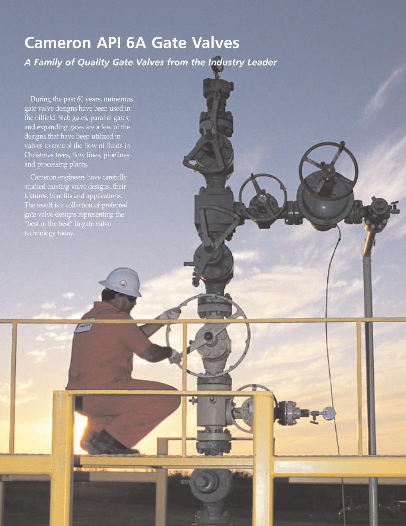
During the past 60 years, numerousgate valve designs have been used inthe oilfield. Slab gates, parallel gates,and expanding gates are a few of thedesigns that have been utilized invalves to control the flow of fluids inChristmas trees, flow lines, pipelinesand processing plants.
Cameron engineers have carefullystudied existing valve designs, theirfeatures, benefits and applications.The result is a collection of preferredgate valve designs representing theÒbest of the bestÓ in gate valve technology today.
Cameron API 6A Gate ValvesA Family of Quality Gate Valves from the Industry Leader
The new Cameron gate valve product line offers:
¥ Valves for applications from 2000 to 20,000 psi WP.
¥ Large and small bore valves.
¥ Valves fitting a wide range of land, offshore and subsea applications.
¥ Cast and forged bodies.
¥ Expanding and slab gate designs.
¥ Components constructed of various alloys for severe service applications.
¥ Designs suitable for actuation and compatible with a wide range of actuators.
CameronÕs more than one-half century of experiencedesigning, testing, installing and refurbishing gatevalves has established a worldwide reputation for manufacturing excellence.
Every valve must meet the exacting standards mandat-ed by its end use. To ensure these standards are achieved,Cameron uses state-of-the-art materials and machinery inits manufacturing process. Thus, it is not surprising thatCameronÕs reputation carries over to customer service, adedication to quality assurance, intensive service person-nel training programs, and CameronÕs highly regardednetwork of aftermarket facilities.
It is this attention to total quality and excellence thatenables Cameron to consistently deliver the worldÕsfinest gate valves to fill its customerÕs needs.
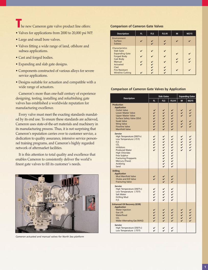
Comparison of Cameron Gate Valves by Application
Cameron actuated and manual valves for North Sea platform
Comparison of Cameron Gate Valves
Description Slab Gates Expanding Gates
FL FLS FLS-R M M215
ProductionApplicationOutlet Valve ✔ ✔ ✔ ✔ ✔
Lower Master Valve ✔ ✔ ✔ ✔ ✔
Upper Master Valve ✔ ✔ ✔ ✔ ✔
Surface Safety Valve (SSV) ✔ ✔ ✔
Swab Valve ✔ ✔ ✔ ✔ ✔
Wing Valve ✔ ✔ ✔ ✔ ✔
Flowline Valve ✔ ✔ ✔ ✔ ✔
Manifold Valve ✔ ✔ ✔
ServiceHigh Temperature (350˚F+) ✔ ✔ ✔ ✔ ✔
Low Temperature (-75˚F) ✔ ✔ ✔ ✔ ✔
H2S ✔ ✔ ✔ ✔ ✔
CO2 ✔ ✔ ✔ ✔ ✔
Inhibitors ✔ ✔ ✔ ✔ ✔
Produced Water ✔ ✔ ✔ ✔ ✔
High Chlorides ✔ ✔
Free Sulphur ✔ ✔
Fracturing Proppants ✔ ✔
Mercury (Trace) ✔ ✔
Acidizing ✔ ✔
Sand ✔ ✔
DrillingApplicationMud Manifold Valve ✔ ✔ ✔
Choke and Kill Valve ✔ ✔ ✔
Fracturing Valve ✔ ✔
ServiceHigh Temperature (350˚F+) ✔ ✔ ✔
Low Temperature (-75˚F) ✔ ✔ ✔
Salt Water ✔ ✔ ✔
Drilling Mud ✔ ✔ ✔
H2S ✔ ✔ ✔
Enhanced Oil Recovery (EOR)ApplicationWater Injection ✔ ✔ ✔ ✔ ✔
Gas Lift ✔ ✔ ✔ ✔ ✔
Waterflood ✔ ✔ ✔ ✔ ✔
CO2 ✔ ✔ ✔ ✔ ✔
Water Alternating Gas (WAG) ✔ ✔ ✔ ✔ ✔
ServiceHigh Temperature (350˚F+) ✔ ✔ ✔
Low Temperature (-75˚F) ✔ ✔ ✔
Description FL FLS FLS-R M M215
EnvironmentSurface ✔ ✔ ✔ ✔ ✔
Subsea ✔ ✔
CharacteristicsSlab Gate ✔ ✔ ✔
Expanding Gate ✔ ✔
Forged Body ✔ ✔ ✔
Cast Body ✔ ✔
Manual ✔ ✔ ✔ ✔ ✔
Actuated ✔ ✔
Clad ✔ ✔
Fire Resistant ✔ ✔ ✔ ✔
Wireline Cutting ✔ ✔ ✔
1
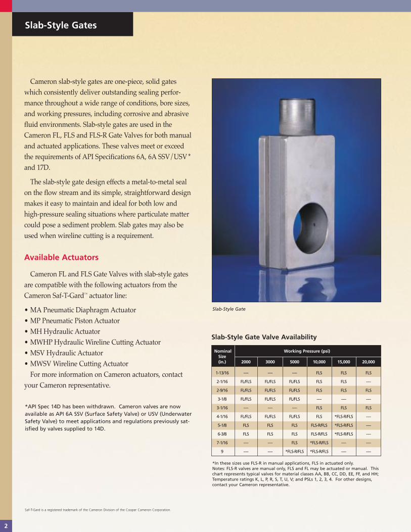
Cameron slab-style gates are one-piece, solid gateswhich consistently deliver outstanding sealing perfor-mance throughout a wide range of conditions, bore sizes,and working pressures, including corrosive and abrasivefluid environments. Slab-style gates are used in theCameron FL, FLS and FLS-R Gate Valves for both manualand actuated applications. These valves meet or exceedthe requirements of API Specifications 6A, 6A SSV/USV *and 17D.
The slab-style gate design effects a metal-to-metal sealon the flow stream and its simple, straightforward designmakes it easy to maintain and ideal for both low andhigh-pressure sealing situations where particulate mattercould pose a sediment problem. Slab gates may also beused when wireline cutting is a requirement.
Available Actuators
Cameron FL and FLS Gate Valves with slab-style gatesare compatible with the following actuators from theCameron Saf-T-Gardª actuator line:
¥ MA Pneumatic Diaphragm Actuator¥ MP Pneumatic Piston Actuator¥ MH Hydraulic Actuator¥ MWHP Hydraulic Wireline Cutting Actuator¥ MSV Hydraulic Actuator ¥ MWSV Wireline Cutting Actuator
For more information on Cameron actuators, contact your Cameron representative.
Slab-Style Gates
Slab-Style Gate Valve Availability
Slab-Style Gate
Nominal Working Pressure (psi) Size(in.) 2000 3000 5000 10,000 15,000 20,000
1-13/16 ---- ---- ---- FLS FLS FLS
2-1/16 FL/FLS FL/FLS FL/FLS FLS FLS ----
2-9/16 FL/FLS FL/FLS FL/FLS FLS FLS FLS
3-1/8 FL/FLS FL/FLS FL/FLS ---- ---- ----
3-1/16 ---- ---- ---- FLS FLS FLS
4-1/16 FL/FLS FL/FLS FL/FLS FLS *FLS-R/FLS ----
5-1/8 FLS FLS FLS FLS-R/FLS *FLS-R/FLS ----
6-3/8 FLS FLS FLS FLS-R/FLS *FLS-R/FLS ----
7-1/16 ---- ---- FLS *FLS-R/FLS ---- ----
9 ---- ---- *FLS-R/FLS *FLS-R/FLS ---- ----
*In these sizes use FLS-R in manual applications, FLS in actuated only. Notes: FLS-R valves are manual only, FLS and FL may be actuated or manual. Thischart represents typical valves for material classes AA, BB, CC, DD, EE, FF, and HH;Temperature ratings K, L, P, R, S, T, U, V; and PSLs 1, 2, 3, 4. For other designs,contact your Cameron representative.
2
*API Spec 14D has been withdrawn. Cameron valves are nowavailable as API 6A SSV (Surface Safety Valve) or USV (UnderwaterSafety Valve) to meet applications and regulations previously sat-isfied by valves supplied to 14D.
Saf-T-Gard is a registered trademark of the Cameron Division of the Cooper Cameron Corporation.

Recognized worldwide as the Pow-R-Sealª gate design,expanding-style gates are used in Cameron M and M215Gate Valves. This popular gate design is used in manualvalves to produce a high seating force against both theupstream and downstream seats simultaneously as thehandwheel is tightened. This force effects a tight mechan-ical seal which is unaffected by line pressure fluctuationsor vibration. The expanding gate allows a positivemechanical seal across both seats both upstream anddownstream, with or without line pressure.
The gate assembly uses an angular gate face which iscollapsed during travel. When closed, a stop causes anyfurther downward travel to force the faces of the gateassembly outward to effect a positive line flow seal.When opened, a stop causes any further upward travel toforce bottom faces to expand and seal against the seats toisolate flow from the valve body cavity.
Expanding-Style Gate Valve Availability
Expanding gates provide a mechanical sealing method that ensures lowpressure sealing. As the valve opens, upward travel of the loose gate segment is stopped by the bonnet. As the main gate segment continuesupward, the two halves of the gate are forced apart by their tapered mat-ing surfaces. When the valve is closed, downward travel of the loose gatesegment is stopped by the body. As the main gate segment continuesdownward, the two halves of the gate are again forced apart by theirtapered mating surfaces.
Open Position
Expanding-Style Gate
Closed Position
Expanding Gate Sealing Method
Nominal Working Pressure (psi)Size (in.) 2000 3000 5000 10,000
1-13/16 ---- ---- ---- M215
2-1/16 M M M M215
2-9/16 M M M M215
3-1/8 M M M ----
3-1/16 ---- ---- ---- M215
4-1/16 M M M ----
Note: This chart represents typical valves for material classes AA, BB, CC, DD,EE and FF; Temperature ratings K, L, P, R, S, T, U, V; and PSLs 1, 2. For otherdesigns, contact your Cameron representative.
Expanding-Style Gates
3
Pow-R-Seal is a registered trademark of the Cameron Division of the Cooper Cameron Corporation.

FL Gate Valve
The Cameron FL Gate Valve has earned a reputa-tion in all types of applications. The FLis a full-bore, through-conduit valveavailable in standard double flange,threaded-end and special block bodyconfigurations. It is a forged valve which is
available in 2000, 3000 and 5000 psi WP and in bore sizes from 2-1/16Ó to 4-1/16Ó and can be fitted with a wide range of Cameron actuators.
Features and Benefits
¥ Bi-directional design provides flow direction versatility and increased service life.
¥ Positive metal-to-metal sealing (gate-to-seat and seat-to-body).
¥ Simple, reliable gate and seat design promotes ease of fieldservice and minimal spare parts inventory.
¥ Spring-loaded, pressure energized, non-elastomeric lip-sealbetween each seat and body assists in low pressure sealing.It also protects against intrusion of particle contaminants into the body cavity and seal areas.
¥ Stem seal design covers full range of pressures,temperatures, and fluids encountered inwellhead and manifold service.
¥ Metal-to-metal bonnet seal.
¥ Stem can be backseated to allow stem sealreplacement with valve under pressure.
¥ Grease injection fitting located downstream of stem backseat for safety. Fitting located in bonnet,eliminating body penetration.
¥ Bearing cap grease fitting allows positive bearing lubrication.
¥ Easy closing and sealing without excessive force.
4
FL SealCameron FL Gate Valves incorporatea single spring-loaded lip seal asshown in this detail.

C
FL Operating and Dimensional Data(inches and pounds)
FL Valve Trim Chart
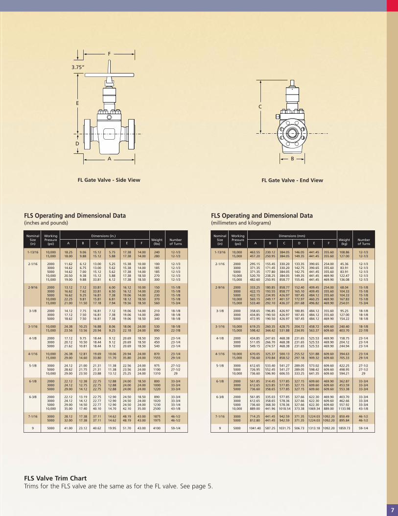
FL Gate Valve - Side View
FL Operating and Dimensional Data(millimeters and kilograms)
F
A
B
D
E
3.75”
5
FL Gate Valve - End View
Nominal Working Dimensions (in.) Flanged Number Size Pressure Weight of (in.) (psi)
A A B C D E F(lbs) Turns
(Thd) (Flgd)
2-1/16 2000 10.62 11.62 6.12 13.00 5.25 15.38 14.00 160 12-1/33000 10.62 14.62 6.75 13.00 5.62 15.38 14.00 170 12-1/35000 10.62 14.62 7.00 15.12 5.62 17.38 14.00 175 12-1/3
2-9/16 2000 12.38 13.12 7.12 13.88 6.00 16.12 14.00 200 15-1/83000 12.38 16.62 7.62 13.88 6.05 16.12 14.00 220 15-1/85000 12.38 16.62 9.25 16.81 7.38 19.06 14.00 230 15-1/8
3-1/8 2000 13.62 14.12 7.75 16.81 7.12 19.06 14.00 240 18-1/83000 13.62 17.12 7.50 16.81 7.38 19.06 14.00 260 18-1/85000 13.62 18.62 7.50 16.81 7.38 19.06 18.50 360 18-1/8
4-1/16 2000 15.38 17.12 9.75 18.44 9.12 20.69 14.00 350 23-1/43000 15.38 20.12 10.50 18.44 9.12 20.69 18.50 450 23-1/45000 16.54 21.62 10.81 18.44 9.12 20.69 18.50 520 23-1/4
Nominal Working Dimensions (mm) Flanged Number Size Pressure Weight of (in.) (psi)
A A B C D E F(kg) Turns
(Thd) (Flgd)
2-1/16 2000 269.75 295.15 155.45 330.20 133.35 390.65 355.60 72.57 12-1/33000 269.75 371.35 171.45 330.20 142.75 390.65 355.60 77.11 12-1/35000 269.75 371.35 177.80 384.05 142.75 441.45 355.60 79.38 12-1/3
2-9/16 2000 314.45 333.25 180.85 352.55 152.40 409.45 355.60 90.72 15-1/83000 314.45 422.15 193.55 352.55 153.67 409.45 355.60 99.79 15-1/85000 314.45 422.15 234.95 426.97 187.45 484.12 355.60 104.33 15-1/8
3-1/8 2000 345.95 358.65 196.85 426.97 180.85 484.12 355.60 108.86 18-1/83000 345.95 434.85 190.50 426.97 187.45 484.12 355.60 117.93 18-1/85000 345.95 472.95 190.50 426.97 187.45 484.12 469.90 163.29 18-1/8
4-1/16 2000 390.65 434.85 247.65 468.38 231.65 525.53 355.60 158.76 23-1/43000 390.65 511.05 266.70 468.38 231.65 525.53 469.90 204.12 23-1/45000 420.12 549.15 274.57 468.38 231.65 525.53 469.90 235.87 23-1/4
API 6A Body and Stem Gate Seat Classification Bonnet Material Material/Coating Material/Coating Material/Coating
AA - General Service Alloy steel Alloy steel nitrided Alloy steel nitrided Alloy steel nitrided
BB - General Service Alloy steel AISI 410 SS nitrided AISI 410 SS nitrided Solid cobalt alloy or or chrome-plated 410, cobalt alloy hard-faced
CC - General Service 12 Cr SS AISI 410 SS nitrIted AISI 410 SS nitrided Solid cobalt alloy or or chrome-plated 410, cobalt alloy hard-faced
DD - Sour Service* Alloy steel Alloy steel nickel-plated Alloy steel hard-faced or Solid cobalt alloy or duplex nickel-coated 410, cobalt alloy hard-faced
EE - Sour Service* Alloy steel AISI 410 SS nitrided AISI 410 SS hard-faced Solid cobalt alloy or 410, cobalt alloy hard-faced
FF - Sour Service* 12 Cr SS AISI 410 SS nitrided AISI 410 SS hard-faced Solid cobalt alloy or 410, cobalt alloy hard-faced
HH - Sour Service* Alloy steel clad with Alloy 718 Alloy 718 hard-faced Solid cobalt alloy oralloy 625 or solid alloy 718 alloy 718 hard-faced
* as defined by NACE Standard MR 0175 Note: Specifications are subject to change without notice. Special trims are available upon request.

6
FLS Gate Valve
The Cameron FLS Gate Valve is widely recognized as a high quality valve forall types of applications. The FLS is a full-bore, through-conduit valveavailable in standard double flange,threaded-end and special block body
configurations. It is a forged valve available in pressure ratings from 2000 to 20,000 psi and bore sizes from 1-13/16Ó to 9Ó. The FLS is CameronÕs standard valve for critical requirements including clad and subsea applications. It can be fitted with a wide range of Cameron actuators.
Features and Benefits
¥ Bi-directional design provides flow direction versatility and increased service life.
¥ Positive metal-to-metal sealing (gate-to-seat and seat-to-body).
¥ Simple, reliable gate and seat design promotes ease offield service and minimal spare parts inventory.
¥ Two spring-loaded, pressure energized, non-elastomeric lip-seals between each seat and body assist in low pressure sealing. They also protect against intrusion of particle contaminants into the body cavity and seal areas.
¥ Stem seal design covers full range of pres-sures, temperatures, and fluids encountered in wellhead and manifold service.
¥ Metal-to-metal bonnet seal, (pressure energized 10,000 psi WP and above).
¥ Stem can be backseated to allow stem seal replacement with the valve under pressure.
¥ Grease injection fitting located downstream ofstem backseat for safety. Fitting located in bonnet, eliminating body penetration.
¥ Bearing cap grease fitting allows positive bearing lubrication.
¥ Easy closing and sealing without excessive torque.
FLS SealCameron FLS Gate Valves incorporatedual spring-loaded lip seals as shown in this detail.
TC10028/TC1201 Gate Valve Bro 6/4/1999 11:10 AM Page 9
7
FLS Operating and Dimensional Data(inches and pounds)
FLS Operating and Dimensional Data(millimeters and kilograms)
FLS Valve Trim ChartTrims for the FLS valve are the same as for the FL valve. See page 5.
Nominal Working Dimensions (in.)Size Pressure
A B C D E FWeight Number
(in) (psi) (lbs) of Turns
1-13/16 10,000 18.25 9.06 15.12 5.75 17.38 14.00 240 12-1/315,000 18.00 9.88 15.12 5.88 17.38 14.00 280 12-1/3
2-1/16 2000 11.62 6.12 13.00 5.25 15.38 10.00 100 12-1/33000 14.62 6.75 13.00 5.62 15.38 14.00 185 12-1/35000 14.62 7.00 15.12 5.62 17.38 14.00 185 12-1/3
10,000 20.50 9.38 15.12 5.88 17.38 18.50 270 12-1/315,000 19.00 9.88 33.81 6.12 17.38 18.50 300 12-1/3
2-9/16 2000 13.12 7.12 33.81 6.00 16.12 10.00 150 15-1/83000 16.62 7.62 33.81 6.50 16.12 14.00 230 15-1/85000 16.62 9.25 16.81 7.38 19.06 14.00 230 15-1/8
10,000 22.25 9.81 15.81 6.81 18.12 18.50 370 15-1/815,000 21.00 11.50 17.18 7.94 19.56 18.50 560 15-3/4
3-1/8 2000 14.12 7.75 16.81 7.12 19.06 14.00 210 18-1/83000 17.12 7.50 16.81 7.38 19.06 14.00 280 18-1/85000 18.62 7.50 16.81 7.38 19.06 18.50 340 18-1/8
3-1/16 10,000 24.38 10.25 16.88 8.06 18.06 24.00 530 18-1/815,000 23.56 13.56 20.94 9.25 22.18 24.00 890 22-7/8
4-1/8 2000 17.12 9.75 18.44 9.12 20.69 18.50 350 23-1/43000 20.12 10.50 18.44 9.12 20.69 18.50 450 23-1/45000 21.62 10.81 18.44 9.12 20.69 18.50 540 23-1/4
4-1/16 10,000 26.38 12.81 19.69 10.06 20.94 24.00 870 23-1/415,000 29.00 14.60 33.80 11.70 35.80 24.00 1555 29-1/4
5-1/8 3000 24.12 21.00 21.31 11.38 22.56 24.00 975 27-1/25000 28.62 21.75 21.31 11.38 23.56 24.00 1100 27-1/2
10,000 29.00 23.50 23.88 13.12 25.25 24.00 1310 29
6-1/8 2000 22.12 12.38 22.75 12.88 24.00 18.50 800 33-3/43000 24.12 12.75 22.75 12.88 24.00 24.00 1000 33-3/45000 29.00 14.12 22.75 12.88 24.00 24.00 1220 33-3/4
6-3/8 2000 22.12 13.19 22.75 12.90 24.50 18.50 890 33-3/43000 24.12 14.12 22.77 12.90 24.50 24.00 1020 33-3/45000 29.00 14.50 22.77 12.90 24.50 24.00 1230 33-1/4
10,000 35.00 17.40 40.10 14.70 42.10 35.00 2500 43-1/8
7-1/16 3000 28.12 17.38 37.11 14.62 48.19 43.00 1875 46-1/25000 32.00 17.38 37.11 14.62 48.19 43.00 1975 46-1/2
9 5000 41.00 23.12 40.62 19.95 51.70 43.00 4100 59-1/4
Nominal Working Dimensions (mm)Size Pressure
A B C D E FWeight Number
(in) (psi) (kg) of Turns
1-13/16 10,000 463.55 230.12 384.05 146.05 441.45 355.60 108.86 12-1/315,000 457.20 250.95 384.05 149.35 441.45 355.60 127.00 12-1/3
2-1/16 2000 295.15 155.45 330.20 133.35 390.65 254.00 45.36 12-1/33000 371.35 171.45 330.20 142.75 390.65 355.60 83.91 12-1/35000 371.35 177.80 384.05 142.75 441.45 355.60 83.91 12-1/3
10,000 520.70 238.25 384.05 149.35 441.45 469.90 122.47 12-1/315,000 482.60 250.95 858.77 155.45 441.45 469.90 136.08 12-1/3
2-9/16 2000 333.25 180.85 858.77 152.40 409.45 254.00 68.04 15-1/83000 422.15 193.55 858.77 165.10 409.45 355.60 104.33 15-1/85000 422.15 234.95 426.97 187.45 484.12 355.60 104.33 15-1/8
10,000 565.15 249.17 401.57 172.97 460.25 469.90 167.83 15-1/815,000 533.40 292.10 436.37 201.68 496.82 469.90 254.01 15-3/4
3-1/8 2000 358.65 196.85 426.97 180.85 484.12 355.60 95.25 18-1/83000 434.85 190.50 426.97 187.45 484.12 355.60 127.00 18-1/85000 472.95 190.50 426.97 187.45 484.12 469.90 154.22 18-1/8
3-1/16 10,000 619.25 260.35 428.75 204.72 458.72 609.60 240.40 18-1/815,000 598.42 344.42 531.88 234.95 563.37 609.60 403.70 22-7/8
4-1/8 2000 434.85 247.65 468.38 231.65 525.53 469.90 158.75 23-1/43000 511.05 266.70 468.38 231.65 525.53 469.90 204.12 23-1/45000 549.15 274.57 468.38 231.65 525.53 469.90 244.94 23-1/4
4-1/16 10,000 670.05 325.37 500.13 255.52 531.88 609.60 394.63 23-1/415,000 736.60 370.84 858.52 297.18 909.32 609.60 705.33 29-1/4
5-1/8 3000 612.65 533.40 541.27 289.05 573.02 609.60 422.25 27-1/25000 726.95 552.45 541.27 289.05 598.42 609.60 498.95 27-1/2
10,000 736.60 596.90 606.55 333.25 641.35 609.60 594.21 29
6-1/8 2000 561.85 314.45 577.85 327.15 609.60 469.90 362.87 33-3/43000 612.65 323.85 577.85 327.15 609.60 609.60 453.59 33-3/45000 736.60 358.65 577.85 327.15 609.60 609.60 553.38 33-3/4
6-3/8 2000 561.85 335.03 577.85 327.66 622.30 469.90 403.70 33-3/43000 612.65 358.65 578.36 327.66 622.30 609.60 462.66 33-3/45000 736.60 368.30 578.36 327.66 622.30 609.60 557.92 33-3/4
10,000 889.00 441.96 1018.54 373.38 1069.34 889.00 1133.98 43-1/8
7-1/16 3000 714.25 441.45 942.59 371.35 1224.03 1092.20 850.49 46-1/25000 812.80 441.45 942.59 371.35 1224.03 1092.20 895.84 46-1/2
9 5000 1041.40 587.25 1031.75 506.73 1313.18 1092.20 1859.73 59-1/4
C
FL Gate Valve - Side View
F
A B
D
E
3.75”
FL Gate Valve - End View
TC10028/TC1201 Gate Valve Bro 6/4/1999 11:12 AM Page 10
8
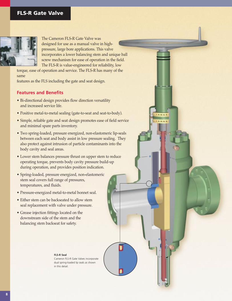
FLS-R Gate Valve
The Cameron FLS-R Gate Valve wasdesigned for use as a manual valve in high-pressure, large bore applications. This valveincorporates a lower balancing stem and unique ballscrew mechanism for ease of operation in the field.The FLS-R is value-engineered for reliability, low
torque, ease of operation and service. The FLS-R has many of thesame features as the FLS including the gate and seat design.
Features and Benefits
¥ Bi-directional design provides flow direction versatilityand increased service life.
¥ Positive metal-to-metal sealing (gate-to-seat and seat-to-body).
¥ Simple, reliable gate and seat design promotes ease of field service and minimal spare parts inventory.
¥ Two spring-loaded, pressure energized, non-elastomeric lip-seals between each seat and body assist in low pressure sealing. They also protect against intrusion of particle contaminants into the body cavity and seal areas.
¥ Lower stem balances pressure thrust on upper stem to reduce operating torque, prevents body cavity pressure build-up during operation, and provides position indication.
¥ Spring-loaded, pressure energized, non-elastomeric stem seal covers full range of pressures, temperatures, and fluids.
¥ Pressure-energized metal-to-metal bonnet seal.
¥ Either stem can be backseated to allow stemseal replacement with valve under pressure.
¥ Grease injection fittings located on the downstream side of the stem and the balancing stem backseat for safety.
FLS-R SealCameron FLS-R Gate Valves incorporatedual spring-loaded lip seals as shown in this detail.
TC10028/TC1201 Gate Valve Bro 6/4/1999 11:14 AM Page 11
9
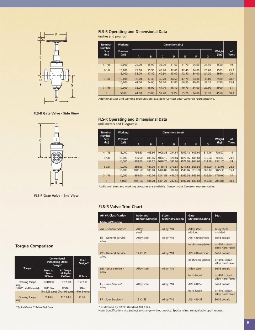
FLS-R Operating and Dimensional Data(inches and pounds)
3.75"
FLS-R Gate Valve - End View
FLS-R Gate Valve - Side View
FLS-R Operating and Dimensional Data(millimeters and kilograms)
F
A
D
E
G
B
C
Nominal Working Dimensions (in.)Number
Size Pressure Weight of (in.) (psi)
A B C D E F G(lbs) Turns
4-1/16 15,000 29.00 15.90 39.70 11.60 41.70 24.00 24.40 1550 19
5-1/8 10,000 29.00 15.90 40.40 12.60 42.40 24.00 26.60 1565 23.215,000 35.00 17.80 40.50 15.00 42.50 34.00 24.20 2980 24
6-3/8 10,000 35.00 17.40 45.70 14.60 47.70 34.00 30.00 2500 28.815,000 41.00 24.00 58.90 12.00 60.90 40.00 34.10 6780 15.4
7-1/16 10,000 35.00 18.90 47.70 18.10 49.70 34.00 29.00 3900 31
9 5000 41.00 23.00 53.20 9.75 55.20 24.00 33.70 4550 38.3
Nominal Working Dimensions (mm)Number
Size Pressure Weight of (in.) (psi)
A B C D E F G(kg) Turns
4-1/16 15,000 736.60 403.86 1008.38 294.64 1059.18 609.60 619.76 703.07 19
5-1/8 10,000 736.60 403.86 1026.16 320.04 1076.96 609.60 675.64 709.87 23.215,000 889.00 452.12 1028.70 381.00 1079.50 863.60 614.68 1351.70 24
6-3/8 10,000 889.00 441.96 1160.78 370.84 1211.58 863.60 762.00 1133.98 28.815,000 1041.40 609.60 1496.06 304.80 1546.86 1016.00 866.14 3075.35 15.4
7-1/16 10,000 889.00 480.06 1211.58 459.74 1262.38 863.60 736.60 1769.00 31
9 5,000 1041.40 584.20 1351.28 247.65 1402.08 609.60 855.98 2063.84 38.3
Additional sizes and working pressures are available. Contact your Cameron representative.
Additional sizes and working pressures are available. Contact your Cameron representative.
*Typical Values **Actual Test Data
Torque Comparison
Conventional (Non-Rising Stem)
FLS-R
Design*Design**
TorqueDirect to 6:1 Torque
Stem Multiplier39 Turns 234 Turns 31 Turns
Opening Torque 1500 ft-lbf 313 ft-lbf 150 ft-lb(avg.)(10,000 psi differential) 2035 Nm 425 Nm 20Nm
(first 3.25 turns) (first 19.5 turns) (first 3 turns)
Opening Torque 55 ft-lbf 11.5 ft-lbf 15 ft-lb(avg.)
FLS-R Valve Trim Chart
API 6A Classification Body and Stem Gate Seat Bonnet Material Material/Coating Material/Coating
Material/Coating
AA - General Service Alloy Alloy 718 Alloy steel Alloy steelsteel nitrided nitrided
BB - General Service Alloy steel Alloy 718 AISI 410 nitrided Solid cobaltalloy
or chrome-plated or 410, cobaltalloy hard-faced
CC - General Service 12 Cr SS Alloy 718 AISI 410 nitrided Solid cobaltalloy
or chrome-plated or 410, cobaltalloy hard-faced
DD - Sour Service * Alloy steel Alloy 718 Alloy steel Solid cobaltalloy
hard-faced or 410, cobaltalloy hard-faced
EE - Sour Service* Alloy steel Alloy 718 AISI 410 SS Solid cobaltalloy
hard-faced or 410, cobaltalloy hard-faced
FF - Sour Service * 12 Cr SS Alloy 718 AISI 410 SS Solid cobalt
* as defined by NACE Standard MR 0175 Note: Specifications are subject to change without notice. Special trims are available upon request.
TC10028/TC1201 Gate Valve Bro 6/4/1999 11:16 AM Page 12

10
M Gate Valves
The Cameron M Gate Valve, with expandingPow-R-Seal gate design, non-rising stem, andmetal-to-metal sealing provides safe, depend-able service in applications of 2000 to 5000 psiWP. It is available in sizes from 2-1/16Óthrough 4-1/16Ó with either threaded or
flanged ends. The M valve is available in trims for alltypes of oilfield service, including extreme sour gas.
Features and Benefits
¥ Metal-to-metal sealing (gate-to-seat and seat-to-body).
¥ Expanding gate design creates a positive mechanical seal across the seats, with or without line pressure.
¥ Full-bore, through-conduit gate-to-seat seal maximizes valve life by virtually eliminating turbulence and pressure drop.
¥ Gate skirts reduce loss of body lubricants.
¥ Low running stress enhances life of the gate-to-seat interface.
¥ Upper/lower roller thrust bearings are isolated from well fluid, minimizing torque.
¥ Stem packing can be re-energized with valve under pressure.
¥ Non-rising stem permits valve installation in closer quarters.
¥ Seats, gates, stem, and other working parts are field replaceable.
TC10028/TC1201 Gate Valve Bro 6/4/1999 11:45 AM Page 13

11
M Valve Trim Chart
M Operating and Dimensional Data(inches and pounds)
M Operating and Dimensional Data(millimeters and kilograms)
4.25"
M Gate Valve - Side View
M Gate Valve - End View
F
A
D
E
C
B
Nominal Working Dimensions (in.) Flanged Number
Size Pressure Weight of (in.) (psi)
A A B C D E F(lbs) Turns
(Thd) (Flgd)
2-1/16 2000 9.65 11.62 7.25 14.75 5.12 15.38 10.50 155 133000 9.81 14.62 7.25 14.75 5.12 15.38 12.75 155 135000 9.81 14.62 7.25 14.75 5.12 15.38 12.75 155 13
2-9/16 2000 12.38 13.12 8.00 15.50 5.94 16.31 12.75 210 15-1/23000 12.38 16.62 8.00 15.50 5.94 16.31 16.00 210 15-1/25000 12.38 16.62 8.00 15.50 5.94 16.31 16.00 210 15-1/2
3-1/8 2000 11.38 14.12 9.25 17.69 7.31 18.50 16.00 270 203000 11.38 17.12 9.25 17.69 7.31 18.50 16.00 270 205000 11.56 18.62 9.25 17.69 7.31 18.50 16.00 300 20
4-1/16 2000 14.62 17.12 12.25 21.31 9.06 22.50 20.00 380 24-1/23000 14.62 20.12 12.25 21.31 9.06 22.50 20.00 380 24-1/2
Nominal Working Dimensions (mm) Flanged Number
Size Pressure Weight of (in.) (psi)
A A B C D E F(kg) Turns
(Thd) (Flgd)
2-1/16 2000 245.11 295.15 184.15 374.65 130.05 390.65 266.70 70.31 133000 249.17 371.35 184.15 374.65 130.05 390.65 323.85 70.31 135000 249.17 371.35 184.15 374.65 130.05 390.65 323.85 70.31 13
2-9/16 2000 314.45 333.25 203.20 393.70 150.88 414.27 323.85 95.25 15-1/23000 314.45 422.15 203.20 393.70 150.88 414.27 406.40 95.25 15-1/25000 314.45 422.15 203.20 393.70 150.88 414.27 406.40 95.25 15-1/2
3-1/8 2000 289.05 358.65 234.95 449.33 185.67 469.90 406.40 122.47 203000 289.05 434.85 234.95 449.33 185.67 469.90 406.40 122.47 205000 293.62 472.95 234.95 449.33 185.67 469.90 406.40 136.08 20
4-1/16 2000 371.35 434.85 311.15 541.27 230.12 571.50 508.00 172.37 24-1/23000 371.35 511.05 311.15 541.27 230.12 571.50 508.00 172.37 24-1/2
API 6A Body and Stem Gate Seat Classification Bonnet Material Material/Coating Material/Coating Material/Coating
AA - General Service Alloy steel Alloy steel Alloy steel Alloy steel
BB - General Service Alloy steel 17-4PH SS 410 SS nitrided 410 SS nitrided
CC - General Service 12 Cr SS 17-4PH SS 410 SS nitrided 410 SS nitrided
DD - Sour Service * Alloy steel 17-4PH SS Alloy steel nitrided Alloy steel nitrided
EE - Sour Service* Alloy steel 17-4PH SS 410 SS nitrided 410 SS nitrided
FF - Sour Service * 12 Cr SS 17-4PH SS 410 SS cobalt alloy 410 SS cobalt alloyhard-faced hard-faced
* as defined by NACE Standard MR 0175 Note: Specifications are subject to change without notice. Special trims are available upon request.
TC10028/TC1201 Gate Valve Bro 6/4/1999 11:46 AM Page 14

12
M215 Gate Valve
The Cameron M215 Gate Valve, with expand-ing Pow-R-Seal gate design, pres-sure balanced stem, andmetal-to-metal sealing provides safe,dependable service in
10,000 psi WP applications. It is available in sizesfrom 1-13/16Ó through 3-1/16Ó with flanged ends. TheM215 is available in trims for all types of oilfield service,including extreme sour gas.
Features and Benefits
¥ Pressure balancing lower stem reduces load on the bear-ings and stem threads, resulting in lower operating torque.
¥ Metal-to-metal sealing (gate-to-seat and seat-to-body).
¥ Stem threads are outside the valve body, removed from wellbore fluids.
¥ Expanding gates create a positive mechanical seal across the seats, with or without line pressure.
¥ Positive mechanical seal of gatesisolates body
cavity from wellbore pressure, permitting pressure venting, whether valve is open or closed.
¥ Full-bore, through-conduit design virtually eliminates turbulence and pressure drop.
¥ Seats, gates, stem and other working parts are field replaceable.
¥ Injectable stem packing can be re-energized while the valve is under
TC10028/TC1201 Gate Valve Bro 6/4/1999 11:48 AM Page 15
13
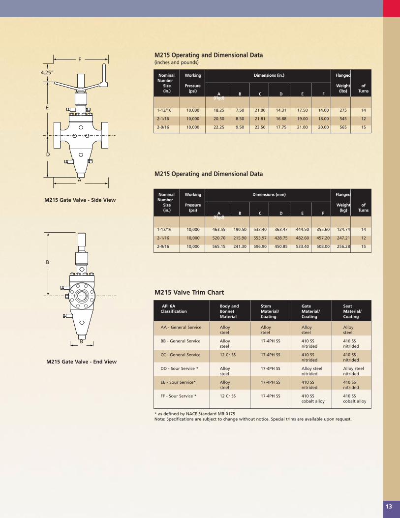
M215 Operating and Dimensional Data(inches and pounds)
M215 Operating and Dimensional Data
M215 Gate Valve - Side View
M215 Gate Valve - End View
M215 Valve Trim Chart
Nominal Working Dimensions (in.) FlangedNumber
Size Pressure Weight of (in.) (psi)
A B C D E F(lbs) Turns
(Flgd)
1-13/16 10,000 18.25 7.50 21.00 14.31 17.50 14.00 275 14
2-1/16 10,000 20.50 8.50 21.81 16.88 19.00 18.00 545 12
2-9/16 10,000 22.25 9.50 23.50 17.75 21.00 20.00 565 15
Nominal Working Dimensions (mm) FlangedNumber
Size Pressure Weight of (in.) (psi)
A B C D E F(kg) Turns
(Flgd)
1-13/16 10,000 463.55 190.50 533.40 363.47 444.50 355.60 124.74 14
2-1/16 10,000 520.70 215.90 553.97 428.75 482.60 457.20 247.21 12
2-9/16 10,000 565.15 241.30 596.90 450.85 533.40 508.00 256.28 15
API 6A Body and Stem Gate Seat Classification Bonnet Material/ Material/ Material/
Material Coating Coating Coating
AA - General Service Alloy Alloy Alloy Alloy steel steel steel steel
BB - General Service Alloy 17-4PH SS 410 SS 410 SS steel nitrided nitrided
CC - General Service 12 Cr SS 17-4PH SS 410 SS 410 SS nitrided nitrided
DD - Sour Service * Alloy 17-4PH SS Alloy steel Alloy steel steel nitrided nitrided
EE - Sour Service* Alloy 17-4PH SS 410 SS 410 SS steel nitrided nitrided
FF - Sour Service * 12 Cr SS 17-4PH SS 410 SS 410 SS cobalt alloy cobalt alloy
* as defined by NACE Standard MR 0175 Note: Specifications are subject to change without notice. Special trims are available upon request.
F
E
D
B
B
A
4.25”
TC10028/TC1201 Gate Valve Bro 6/4/1999 11:49 AM Page 16

© Cooper Cameron Corporation, Cameron Division, Printed in USA, 3/99, TG/5M, WR10028/TC1201
Western Hemisphere
Cameron
PO Box 1212
Houston Texas 77251-1212
Tel 713 939 2211
Fax 713 939 2620
http://www.camerondiv.com
Eastern Hemisphere
Cooper Cameron (U.K.) Ltd.
205 Holland Park Avenue
London, WII 4XB
England
Tel 44 171 6020888
Fax 44 171 6027228
http://www.camerondiv.com
Asia Pacific/Middle East
Cooper Cameron (Singapore) Pte. Ltd.
No. 2 Gul Circle, Jurong Industrial Est
Locked Bag Service No. 3
Jurong Town Post Office
Singapore 2262
Republic Of Singapore
Tel 65 8613355
Fax 65 8616197
http://www.camerondiv.com
Related Documents


