J A Snipes, 13 th US-Japan Workshop on MHD Control 23 – 25 November 2008 1 Physics Effects of TBMs on Plasma Operations in ITER ITER Organization J A Snipes

Welcome message from author
This document is posted to help you gain knowledge. Please leave a comment to let me know what you think about it! Share it to your friends and learn new things together.
Transcript

J A Snipes, 13th US-Japan Workshop on MHD Control 23 – 25 November 2008 1
Physics Effects of TBMs on Plasma Operations in ITER
ITER Organization
J A Snipes
J A Snipes, 13th US-Japan Workshop on MHD Control 23 – 25 November 2008 2
Helium Cooled Lithium-Lead Test Blanket Module

J A Snipes, 13th US-Japan Workshop on MHD Control 23 – 25 November 2008 3
Helium Cooled Lithium-Lead TBM Details
Mass of ferromagnetic steel = 1300 kgSix TBMs to be installed with two in each horizontal port at ϕ
= 0°
and ±40°
J A Snipes, 13th US-Japan Workshop on MHD Control 23 – 25 November 2008 4
TBM stray fields effects on plasma breakdown
Stray field modifications of the plasma equilibrium
Error field at q=2 surface may produce locked modes
TBM stray fields will also enhance magnetic braking of vϕPossible effects on access to H-mode
Expected to reduce thermal confinement in H-mode
TBM field perturbation increases energetic particle losses
Relative effects of low and high toroidal mode numbers
Effects of TBM correction coils
TBM Effects on Plasma Operations

J A Snipes, 13th US-Japan Workshop on MHD Control 23 – 25 November 2008 5
Recent calculations by Lamzin, et al. estimate peak total stray fields at breakdown ~ 2 mTat R0 in front of two HCLL TBMs
Since a null for breakdown needs to be less than a few mT, this stray field may be tolerable particularly with ECH assist
TBM Stray Fields at BreakdownVacuum Field Between Two HCLL TBMs
J A Snipes, 13th US-Japan Workshop on MHD Control 23 – 25 November 2008 6
80 160 240 320240
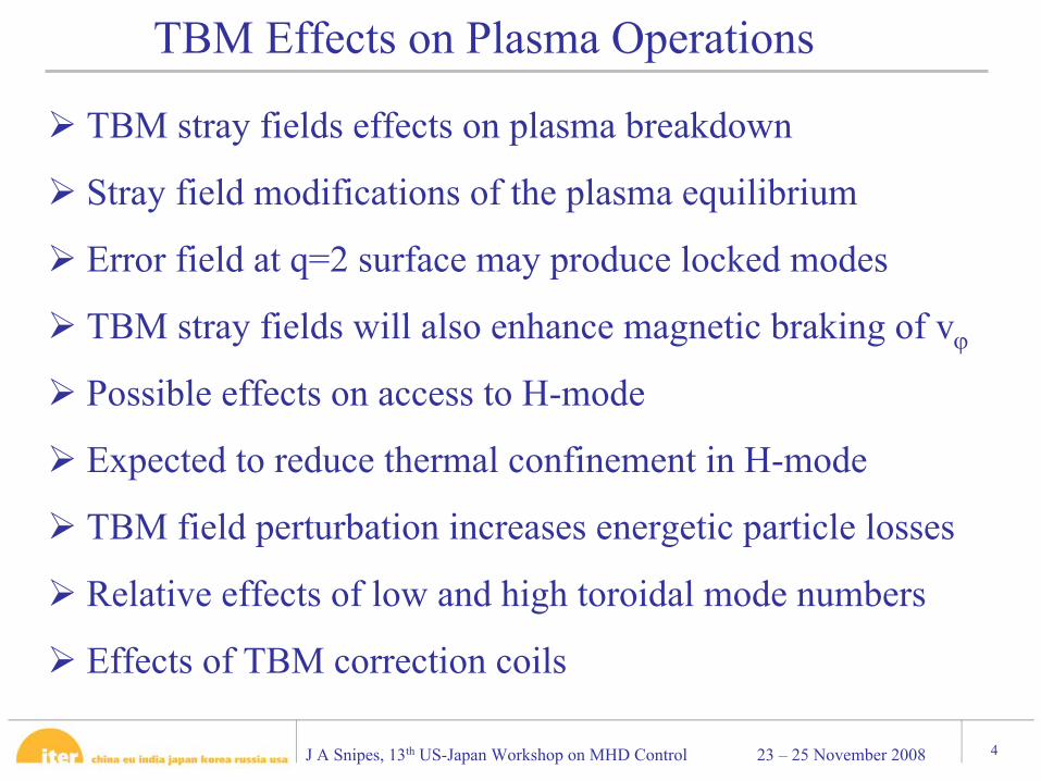
The plasma is calculated to bulge out toward the TBMs by ΔR~12 mm locally
TBM Stray Fields Modify Plasma Equilibrium30 G60 G
The magnetic moments in the TBM align with the field and the field lines return through the plasma opposing the field in the plasma reducing the field where it is already at a minimum TF ripple
Midplane Field at the Plasma Boundary
Toroidal angle [deg]
Black: FI, Red: FI+HCLL
J A Snipes, 13th US-Japan Workshop on MHD Control 23 – 25 November 2008 7
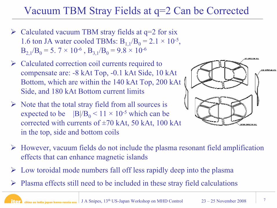
Calculated vacuum TBM stray fields at q=2 for six 1.6 ton JA water cooled TBMs: B1,1/B0 = 2.1 × 10⁻⁵, B2,1/B0 = 5. 7 × 10⁻⁶ , B3,1/B0 = 9.8 × 10⁻⁶
Calculated correction coil currents required to compensate are: -8 kAt Top, -0.1 kAt Side, 10 kAtBottom, which are within the 140 kAt Top, 200 kAtSide, and 180 kAt Bottom current limits
Note that the total stray field from all sources is expected to be |B|/B0 < 11 × 10-5 which can be corrected with currents of ±70 kAt, 50 kAt, 100 kAtin the top, side and bottom coils
Vacuum TBM Stray Fields at q=2 Can be Corrected
However, vacuum fields do not include the plasma resonant field amplification effects that can enhance magnetic islands
Low toroidal mode numbers fall off less rapidly deep into the plasma
Plasma effects still need to be included in these stray field calculations
J A Snipes, 13th US-Japan Workshop on MHD Control 23 – 25 November 2008 8
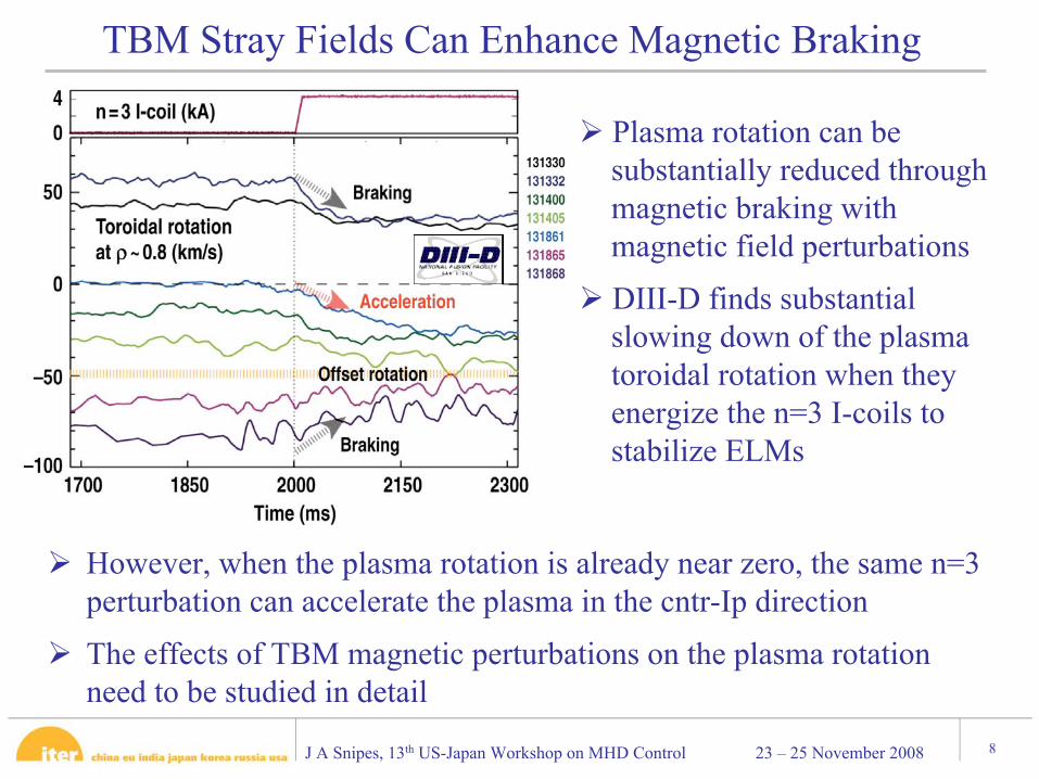
However, when the plasma rotation is already near zero, the same n=3 perturbation can accelerate the plasma in the cntr-Ip direction
The effects of TBM magnetic perturbations on the plasma rotationneed to be studied in detail
TBM Stray Fields Can Enhance Magnetic Braking
Plasma rotation can be substantially reduced through magnetic braking with magnetic field perturbations
DIII-D finds substantial slowing down of the plasma toroidal rotation when they energize the n=3 I-coils to stabilize ELMs
J A Snipes, 13th US-Japan Workshop on MHD Control 23 – 25 November 2008 9
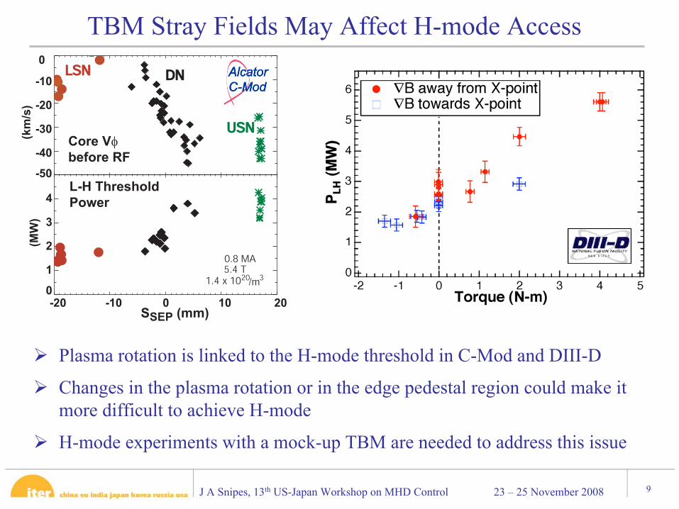
Plasma rotation is linked to the H-mode threshold in C-Mod and DIII-D
Changes in the plasma rotation or in the edge pedestal region could make it more difficult to achieve H-mode
H-mode experiments with a mock-up TBM are needed to address this issue
TBM Stray Fields May Affect H-mode Access
-2 -1 0 1 2-50
-40
-30
-20
-10
0
(km
/s)
LSNLSN DNDN
USNUSN
-20 -10 0 10 20SSEP (mm)
0
1
2
3
4
(MW
)
Core Vφ
before RF
5.4 T0.8 MA
1.4 x 10²⁰/m3
L-H Threshold
Power
J A Snipes, 13th US-Japan Workshop on MHD Control 23 – 25 November 2008 10
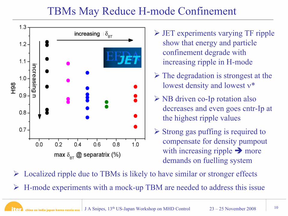
Localized ripple due to TBMs is likely to have similar or stronger effects
H-mode experiments with a mock-up TBM are needed to address this issue
TBMs May Reduce H-mode Confinement
increasing JET experiments varying TF ripple show that energy and particle confinement degrade with increasing ripple in H-mode
The degradation is strongest at the lowest density and lowest ν*
NB driven co-Ip rotation also decreases and even goes cntr-Ip at the highest ripple values
Strong gas puffing is required to compensate for density pumpoutwith increasing ripple more demands on fuelling system
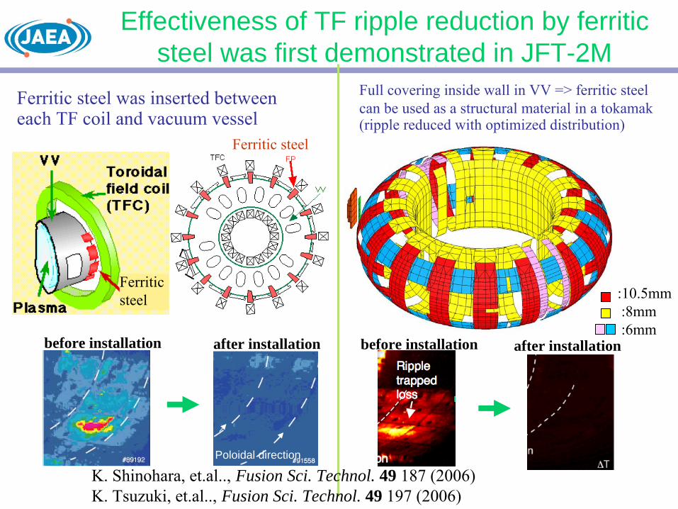
Effectiveness of TF ripple reduction by ferritic steel was first demonstrated in JFT-2M
:10.5mm:8mm:6mm
before installation
Full covering inside wall in VV => ferritic steel can be used as a structural material in a tokamak
(ripple reduced with optimized distribution)
Poloidal direction
before installation
Ferritic steel was inserted between each TF coil and vacuum vessel
K. Shinohara, et.al..,
Fusion Sci. Technol. 49 187 (2006)K. Tsuzuki, et.al..,
Fusion Sci. Technol. 49 197 (2006)
after installation after installation
Ferritic steel
Ferritic steel

Effectiveness of TF ripple reduction was also demonstrated in JT-60U
Ripple trapped loss
Ferritic steel
K. Shinohara, et.al. , Nucl. Fusion 47, 997 (2007)
before installation
after installation:ripple well reduced
Temperature increment was <20 oC from IRTV measurement heat flux < 0.2MW/m2 (after installation)
> 1 MW/m2 (before installation)
NB of 22 MW was injected for 1.5 s
J A Snipes, 13th US-Japan Workshop on MHD Control 23 – 25 November 2008 13
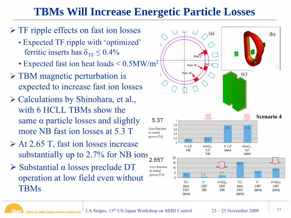
TF ripple effects on fast ion losses•
Expected TF ripple with ‘optimized’
ferritic inserts has δTF
≤
0.4%• Expected fast ion heat loads < 0.5MW/m2
TBM magnetic perturbation is expected to increase fast ion lossesCalculations by Shinohara, et al., with 6 HCLL TBMs show the same α particle losses and slightly more NB fast ion losses at 5.3 TAt 2.65 T, fast ion losses increase substantially up to 2.7% for NB ionsSubstantial α losses preclude DT operation at low field even without TBMs
TBMs Will Increase Energetic Particle Losses
Scenario 4
J A Snipes, 13th US-Japan Workshop on MHD Control 23 – 25 November 2008 14
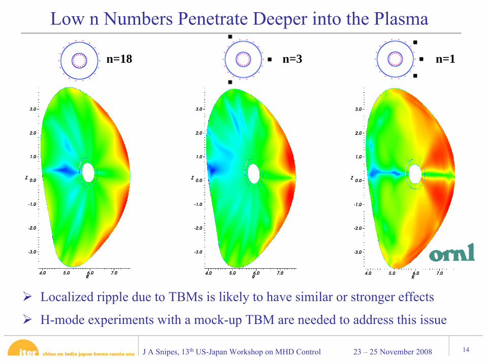
Localized ripple due to TBMs is likely to have similar or stronger effects
H-mode experiments with a mock-up TBM are needed to address this issue
Low n Numbers Penetrate Deeper into the Plasma
n=18 n=3 n=1
J A Snipes, 13th US-Japan Workshop on MHD Control 23 – 25 November 2008 15
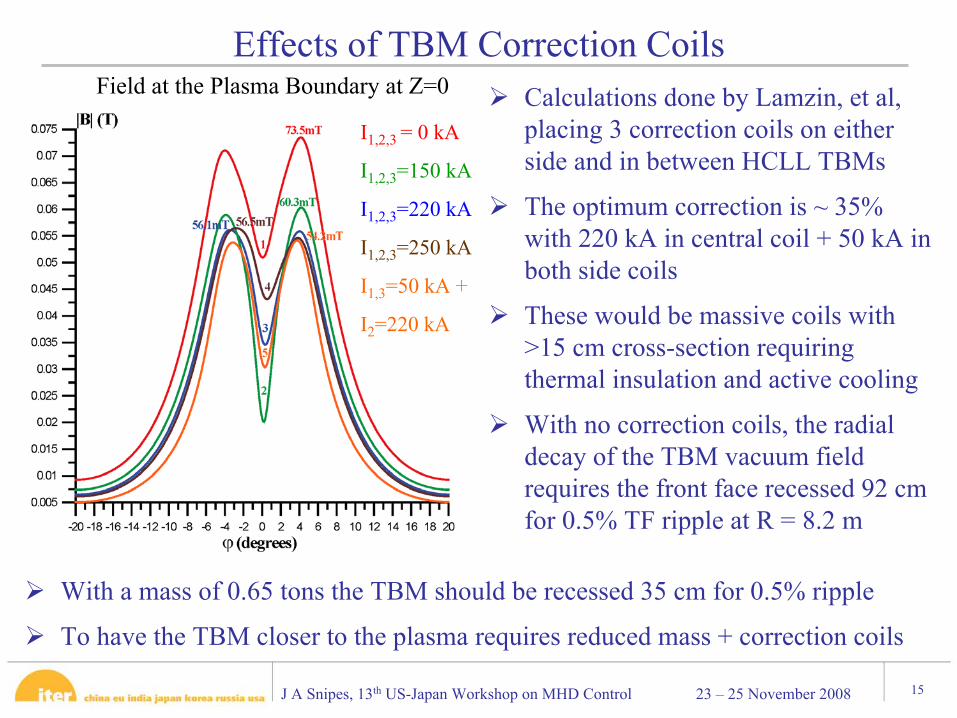
With a mass of 0.65 tons the TBM should be recessed 35 cm for 0.5% ripple
To have the TBM closer to the plasma requires reduced mass + correction coils
Effects of TBM Correction Coils Calculations done by Lamzin, et al, placing 3 correction coils on either side and in between HCLL TBMs
The optimum correction is ~ 35% with 220 kA in central coil + 50 kA in both side coils
These would be massive coils with >15 cm cross-section requiring thermal insulation and active cooling
With no correction coils, the radial decay of the TBM vacuum field requires the front face recessed 92 cm for 0.5% TF ripple at R = 8.2 m
Field at the Plasma Boundary at Z=0
I1,2,3 = 0 kA
I1,2,3
=150 kA
I1,2,3
=220 kA
I1,2,3
=250 kA
I1,3
=50 kA +
I2
=220 kA
J A Snipes, 13th US-Japan Workshop on MHD Control 23 – 25 November 2008 16
•
Effects of TBMs on breakdown are probably tolerable with ECH assist•
Plasma equilibrium outward bulge ΔR~12 mm will require increased gaps to avoid enhanced heat loads
•
Calculated m/n=2,1 error field expected to be correctable to avoid locked modes but makes additional demands on correction coils
•
Effects on magnetic braking of plasma rotation still need to be assessedNeed magnetic braking calculations and rotation experiments with a mock-up TBM
•
Possible effect on H-mode threshold can only be assessed with experiment
Need H-mode threshold experiments with a mock-up TBM
•
Reduced H-mode confinement expected for ripple > 0.5% but needs to be assessed with TBM mock-up experiments in H-mode
Need H-mode confinement experiments with mock-up TBM
Conclusions I
J A Snipes, 13th US-Japan Workshop on MHD Control 23 – 25 November 2008 17
•
Enhanced fast ion heat loads expected to be < 0.5 MW/m2 but calculations with 3D plasma equilibrium still need to be checked
Need 3D equilibrium calculations of fast ion heat loads with TBMs
•
A toroidally symmetric distribution of TBMs would reduce penetration of TBM stray field effects deep into the plasma but calculations
need
checkingNeed to quantify change in TBM field penetration with n=3 symmetry
•
Placing the TBMs at R=8.73 m (recessed 35 cm) and reducing the mass to 0.65 tons may eliminate the need for correction coils to obtain TBM ripple < 0.5%
Need to determine the impact on TBM program of ½ size TBM and 35 cm distance to the first wall
Conclusions II
Related Documents