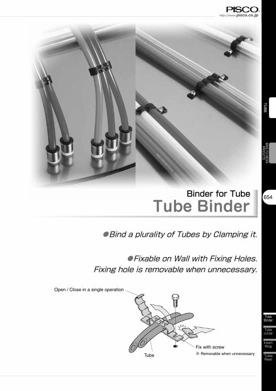
h t t p : / / w w w . p i s c o . c o . j p http://www.pisco.co.jp 654 Tube Binder Tube cutter Insert Ring Tube Reel TUBE MAKE-TO-ORDER PRODUCTS Binder for Tube Tube Binder ● Bind a plurality of Tubes by Clamping it. ● Fixable on Wall with Fixing Holes. Fixing hole is removable when unnecessary. Open / Close in a single operation Tube Fix with screw ※ Removable when unnecessary

Welcome message from author
This document is posted to help you gain knowledge. Please leave a comment to let me know what you think about it! Share it to your friends and learn new things together.
Transcript
http://www.pisco.co.jphttp://www.pisco.co.jp
654
TubeBinder
Tubecutter
InsertRing
TubeReel
TUBE
MAKE-TO-ORDERPRODUCTS
Binder for TubeTube Binder
●Bind a plurality of Tubes by Clamping it.
●Fixable on Wall with Fixing Holes.Fixing hole is removable when unnecessary.
Open / Close in a single operation
Tube
Fix with screw※ Removable when unnecessary

Tube Series
655
TubeBinder
Tube Binder
Anti-SpatterTube
Fluororesin /Polyamide Tube
CoilingTube
Multi-coreTube
StandardTube
TUB
EVA
LVE
CONT
ROLL
ERFI
TTIN
G
Twin CoilingTube
Clean RoomTube
Anti-StalicTube
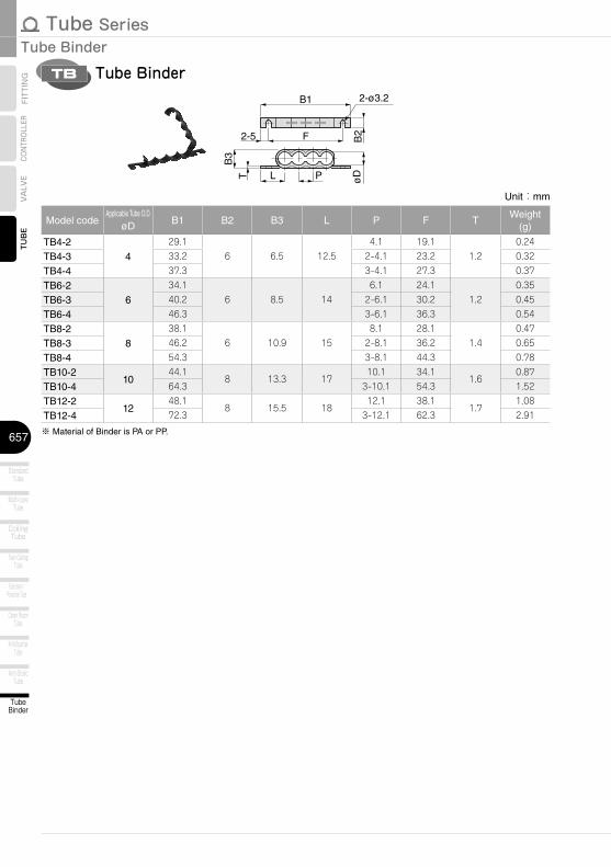
■ Model Designation (Example)
6TB 4
① Tube dia (O.D.)
② Number of bound tubesCode 2 3 4
Number of tubes 2 3 4
Code 4 6 8 10 12O.D. (mm) ø4 ø6 ø8 ø10 ø12
Tube Binder①
Tube dia (O.D.)
②Number of bound tubes

http://www.pisco.co.jphttp://www.pisco.co.jp
656
TubeBinder
Tubecutter
InsertRing
TubeReel
TUBE
MAKE-TO-ORDERPRODUCTS
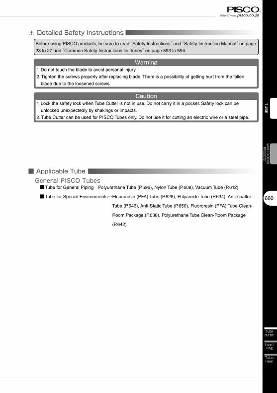
Detailed Safety InstructionsBefore using PISCO products, be sure to read “Safety Instructions” and “Safety Instruction Manual” on page
23 to 27 and “Common Safety Instructions for Tubes” on page 593 to 594.
■ Applicable TubePISCO Tubes ■ Tube for General Piping…Polyurethane Tube (P.596), Nylon Tube (P.608), Vacuum Tube (P.612)
■ Tube for Special Environments… Fluororesin (PFA) Tube (P.628), Polyamide Tube (P.634), Anti-spatter
Tube (P.646), Anti-Static Tube (P.650), Fluororesin (PFA) Tube Clean-
Room Package (P.638), Polyurethane Tube Clean-Room Package
(P.642)
Tube Series
657
TubeBinder
Tube Binder
Anti-SpatterTube
Fluororesin /Polyamide Tube
CoilingTube
Multi-coreTube
StandardTube
TUB
EVA
LVE
CONT
ROLL
ERFI
TTIN
G
Twin CoilingTube
Clean RoomTube
Anti-StalicTube
Unit:mm
Model codeApplicable Tube O.D.
øD B1 B2 B3 L P F TWeight
(g)
TB4-24
29.16 6.5 12.5
4.1 19.11.2
0.24
TB4-3 33.2 2-4.1 23.2 0.32
TB4-4 37.3 3-4.1 27.3 0.37
TB6-26
34.16 8.5 14
6.1 24.11.2
0.35
TB6-3 40.2 2-6.1 30.2 0.45
TB6-4 46.3 3-6.1 36.3 0.54
TB8-28
38.16 10.9 15
8.1 28.11.4
0.47
TB8-3 46.2 2-8.1 36.2 0.65
TB8-4 54.3 3-8.1 44.3 0.78
TB10-210
44.18 13.3 17
10.1 34.11.6
0.87
TB10-4 64.3 3-10.1 54.3 1.52
TB12-212
48.18 15.5 18
12.1 38.11.7
1.08
TB12-4 72.3 3-12.1 62.3 2.91
※ Material of Binder is PA or PP.
Tube BinderTB
2-5 F
L P
B1
øDT
B3
B2
2-ø3.2

23
Safety Instructions
SAFETY Instructions
Warning
This safety instructions aim to prevent personal injury and damage to properties by requiring proper use of PISCO products. Be certain to follow ISO 4414 and JIS B 8370
ISO 4414:Pneumatic fluid power…Recomendations for the application of equipment to transmission and control systems.
JIS B 8370:General rules and safety requirements for systems and their components.This safety instructions is classified into “Danger”, “Warning” and “Caution” depending on the degree of danger or damages caused by improper use of PISCO products.
1. Selection of pneumatic products① A user who is a pneumatic system designer or has sufficient experience
and technical expertise should select PISCO products.② Due to wide variety of operating conditions and applications for PISCO
products, carry out the analysis and evaluation on PISCO products. The pneumatic system designer is solely responsible for assuring that the user's requirements are met and that the application presents no health or safety hazards. All designers are required to fully understand the specifications of PISCO products and constitute all systems based on the latest catalog or information, considering any malfunctions.
2. Handle the pneumatic equipment with enough knowledge and experience① Improper use of compressed air is dangerous. Assembly, operation
and maintenance of machines using pneumatic equipment should be conducted by a person with enough knowledge and experience.
3. Do not operate machine / equipment or remove pneumatic equipment until safety is confirmed.① Make sure that preventive measures against falling work-pieces or
sudden movements of machine are completed before inspection or maintenance of these machine.
② Make sure the above preventive measures are completed. A compressed air supply and the power supply to the machine must be off, and also the compressed air in the systems must be exhausted.
③ Restart the machines with care after ensuring to take all preventive measures against sudden movements.
Danger Hazardous conditions. It can cause death or serious personal injury.
Warning Hazardous conditions depending on usages. Improper use of PISCO products can cause death or serious personal injury.
Caution Hazardous conditions depending on usages. Improper use of PISCO products can cause personal injury or damages to properties.
※ . This safety instructions are subject to change without notice.

http://www.pisco.co.jphttp://www.pisco.co.jp
24
Disclaimer1. PISCO does not take any responsibility for any incidental or indirect
loss, such as production line stop, interruption of business, loss of benefits, personal injury, etc., caused by any failure on use or application of PISCO products.
2. PISCO does not take any responsibility for any loss caused by natural disasters, fires not related to PISCO products, acts by third parties, and intentional or accidental damages of PISCO products due to incorrect usage.
3. PISCO does not take any responsibility for any loss caused by improper usage of PISCO products such as exceeding the specification limit or not following the usage the published instructions and catalog allow.
4. PISCO does not take any responsibility for any loss caused by remodeling of PISCO products, or by combinational use with non-PISCO products and other software systems.
5. The damages caused by the defect of Pisco products shall be covered but limited to the full amount of the PISCO products paid by the customer.

25
Safety Instructions
SAFETY INSTRUCTION MANUAL
Danger1. Do not use PISCO products for the following applications.
① Equipment used for maintaining / handling human life and body.② Equipment used for moving / transporting human.③ Equipment specifically used for safety purposes.
Warning1. Do not use PISCO products under the following conditions.
① Beyond the specifications or conditions stated in the catalog, or the instructions.② Under the direct sunlight or outdoors.③ Excessive vibrations and impacts.④ Exposure / adhere to corrosive gas, inflammable gas, chemicals, seawater, water and vapor. *
* Some products can be used under the condition above(④), refer to the details of specification and condition of each product.
2. Do not disassemble or modify PISCO products, which affect the performance, function, and basic structure of the product.
3. Turn off the power supply, stop the air supply to PISCO products, and make sure there is no residual air pressure in the pipes before maintenance and inspection.
4. Do not touch the release-ring of push-in fitting when there is a working pressure. The lock may be released by the physical contact, and tube may fly out or slip out.
5. Frequent switchover of compressed air may generate heat, and there is a risk of causing burn injury.
6. Avoid any load on PISCO products, such as a tensile strength, twisting and bending. Otherwise, there is a risk of causing damage to the products.
7. As for applications where threads or tubes swing / rotate, use Rotary Joints, High Rotary Joints or Multi-Circuit Rotary Block only. The other PISCO products can be damaged in these applications.
8. Use only Die Temperature Control Fitting Series, Tube Fitting Stainless SUS316 Series, Tube Fitting Stainless SUS316 Compression Fitting Series or Tube Fitting Brass Series under the condition of over 60℃ (140°F) water or thermal oil. Other PISCO products can be damaged by heat and hydrolysis under the condition above.
9. As for the condition required to dissipate static electricity or provide an antistatic performance, use EG series fitting and antistatic products only, and do not use other PISCO products. There is a risk that static electricity can cause system defects or failures.
10. Use only Fittings with a characteristic of spatter-proof such as Anti-spatter or Brass series in a place where flame and weld spatter is produced. There is a risk of causing fire by sparks.
11. Turn off the power supply to PISCO products, and make sure there is no residual air pressure in the pipes and equipment before maintenance. Follow the instructions below in order to ensure safety.① Make sure the safety of all systems related to PISCO products before maintenance.② Restart of operation after maintenance shall be proceeded with care after
ensuring safety of the system by preventive measures against unexpected movements of machines and devices where pneumatic equipment is used.
③ Keep enough space for maintenance when designing a circuit.12. Take safety measures such as providing a protection cover if there is a
risk of causing damages or fires on machine / facilities by a fluid leakage.
PISCO products are designed and manufactured for use in general industrial machines. Be sure to read and follow the instructions below.

http://www.pisco.co.jphttp://www.pisco.co.jp
26
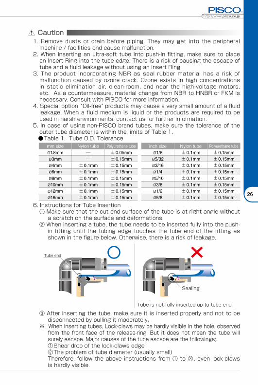
Caution1. Remove dusts or drain before piping. They may get into the peripheral
machine / facilities and cause malfunction.2. When inserting an ultra-soft tube into push-in fitting, make sure to place
an Insert Ring into the tube edge. There is a risk of causing the escape of tube and a fluid leakage without using an Insert Ring.
3. The product incorporating NBR as seal rubber material has a risk of malfunction caused by ozone crack. Ozone exists in high concentrations in static elimination air, clean-room, and near the high-voltage motors, etc. As a countermeasure, material change from NBR to HNBR or FKM is necessary. Consult with PISCO for more information.
4. Special option “Oil-free” products may cause a very small amount of a fluid leakage. When a fluid medium is liquid or the products are required to be used in harsh environments, contact us for further information.
5. In case of using non-PISCO brand tubes, make sure the tolerance of the outer tube diameter is within the limits of Table 1.
●Table 1. Tube O.D. Tolerancemm size Nylon tube Polyurethane tube inch size Nylon tube Polyurethane tubeø1.8mm ─ ±0.05mm ø1/8 ±0.1mm ±0.15mmø3mm ─ ±0.15mm ø5/32 ±0.1mm ±0.15mmø4mm ±0.1mm ±0.15mm ø3/16 ±0.1mm ±0.15mmø6mm ±0.1mm ±0.15mm ø1/4 ±0.1mm ±0.15mmø8mm ±0.1mm ±0.15mm ø5/16 ±0.1mm ±0.15mmø10mm ±0.1mm ±0.15mm ø3/8 ±0.1mm ±0.15mmø12mm ±0.1mm ±0.15mm ø1/2 ±0.1mm ±0.15mmø16mm ±0.1mm ±0.15mm ø5/8 ±0.1mm ±0.15mm
6. Instructions for Tube Insertion① Make sure that the cut end surface of the tube is at right angle without
a scratch on the surface and deformations.② When inserting a tube, the tube needs to be inserted fully into the push-
in fitting until the tubing edge touches the tube end of the fitting as shown in the figure below. Otherwise, there is a risk of leakage.
Tube end
Sealing
Tube is not fully inserted up to tube end.
③ After inserting the tube, make sure it is inserted properly and not to be disconnected by pulling it moderately.
※. When inserting tubes, Lock-claws may be hardly visible in the hole, observed from the front face of the release-ring. But it does not mean the tube will surely escape. Major causes of the tube escape are the followings; ①Shear drop of the lock-claws edge②The problem of tube diameter (usually small)Therefore, follow the above instructions from ① to ③, even lock-claws is hardly visible.

27
7. Instructions for Tube Disconnection① Make sure there is no air pressure inside of the tube, before disconnecting it.② Push the release-ring of the push-in fitting evenly and deeply enough to
pull out the tube toward oneself. By insufficient pushing of the release-ring, the tube may not be pulled out or damaged by scratch, and tube shavings may remain inside of the fitting, which may cause the leakage later.
8. Instructions for Installing a fitting① When installing a fitting, use proper tools to tighten a hexagonal-column
or an inner hexagonal socket. When inserting a hex key into the inner hexagonal socket of the fitting, be careful so that the tool does not touch lock-claws. The deformation of lock-claws may result in a poor performance of systems or an escape of the tube.
② Refer to Table 2 which shows the recommended tightening torque. Do not exceed these limits to tighten a thread. Excessive tightening may break the thread part or deform the gasket and cause a fluid leakage. Tightening thread with tightening torque lower than these limits may cause a loosened thread or a fluid leakage.
③ Adjust the tube direction while tightening thread within these limits, since some PISCO products are not rotatable after the installation.
●Table 2: Recommended tightening torque / Sealock color / Gasket materialsThread type Thread size Tightening torque Sealock color Gasket materials
Metric thread
M3×0.5 0.7N·m
─
SUS304NBR
M5×0.8 1.0 ~ 1.5N·mM6×1 2 ~ 2.7N·m
M3×0.5 0.5 ~ 0.6N·m
POMM5×0.8 1 ~ 1.5N·mM6×0.75 0.8 ~ 1N·mM8×0.75 1 ~ 2N·m
Taper pipe thread
R1/8 7 ~ 9N·m
White ─R1/4 12 ~ 14N·mR3/8 22 ~ 24N·mR1/2 28 ~ 30N·m
Unified thread No.10-32UNF 1.0 ~ 1.5N·m ─ SUS304、NBR
National pipe thread taper
1/16-27NPT 7 ~ 9N·m
White ─1/8-27NPT 7 ~ 9N·m1/4-18NPT 12 ~ 14N·m3/8-18NPT 22 ~ 24N·m1/2-14NPT 28 ~ 30N·m
※ These values may differ for some products. Refer to each specification as well.9. Instructions for removing a fitting
① When removing a fitting, use proper tools to loosen a hexagonal-column or an inner hex bolt.
② Remove the sealant stuck on the mating equipment. The remained sealant may get into the peripheral equipment and cause malfunctions.
10. Arrange piping avoiding any load on fittings and tubes such as twist, tensile, moment load, shaking and physical impact. These may cause damages to fittings, tube deformations, bursting and the escape of tubes.
Safety Instructions
Tube SeriesTUBE
593
VALVE
CONTROLLER
FITTING Common Safety Instructions for Tubes
Warning
Before selecting or using PISCO products, read the following instructions. Read the detailed instructions for individual series as well as the instructions below.
1. Avoid any load on Tubes such as tensile strength, twisting and bending. These may cause the crush, burst and escape of Tubes.
2. Protect Tubes from scratches caused by snagging or kinking. It may cause the burst of Tubes.
3. The burst pressure of Tubes drops as temperature rises. Read the operating pressure in the catalog well, and apply safety factor.
4. The minimum bending radius and the minimum installation radius are reference values at 20℃ and 65% RH. They are not guaranteed values. Refer to the minimum bending radius when Tubes are wound around a mandrel (round bar). As for the other operating conditions, refer to the minimum installation radius. These values vary depending on operating environments or the tube length. In order to make sure the suitability of Tubes, carry out the operation test by the user's actual machine before using Tubes.
5. Place Insert Ring into the edge of soft tubes like UD Series or tubes inserted to Push-In Fittings with a water fluid. There is a possibility of escape of Tube without Insert Ring.
6. Only Anti-spatter Tube can be used under the flame and weld spatter condition. Otherwise, there is a possibility of danger to catch fire by sparks.
7. Only Soft Nylon Tube can be used for warm water or thermal oil. Otherwise, tubes may burst due to deterioration.
8. Only Anti-static Tube can be used under the condition required to dissipate static electricity or provide an anti-static performance. There is a possibility that static electricity can cause malfunction or other troubles with the system.
9. An abnormal rise in temperature due to adiabatic compression may cause damage to Tubes.
10. If Tubes are used with any fluid or under any condition / environment other than listed in the catalog, as well as used outdoors, the conformity evaluation with the actual machine and safety measures taken by the responsible person are highly recommended.

StandardTube
Multi-coreTube
CoilingTube
Twin CoilingTube
Fluororesin /Polyamide Tube
Clean RoomTube
Anti-SpatterTube
Anti-StalicTube
TubeBinder
Tubecutter
InsertRing
http://www.pisco.co.jphttp://www.pisco.co.jp
594
TubeReel
TUBE
MAKE-TO-ORDERPRODUCTS
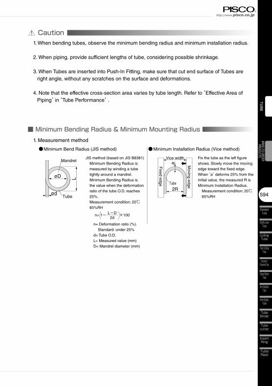
Caution1. When bending tubes, observe the minimum bending radius and minimum installation radius.
2. When piping, provide sufficient lengths of tube, considering possible shrinkage.
3. When Tubes are inserted into Push-In Fitting, make sure that cut end surface of Tubes are right angle, without any scratches on the surface and deformations.
4. Note that the effective cross-section area varies by tube length. Refer to “Effective Area of Piping” in “Tube Performance” .
■ Minimum Bending Radius & Minimum Mounting Radius1. Measurement method
●Minimum Bend Radius (JIS method) ●Minimum Installation Radius (Vice method)
JIS method (based on JIS B8381) Minimum Bending Radius is
measured by winding a tube tightly around a mandrel. Minimum Bending Radius is the value when the deformation ratio of the tube O.D. reaches 25%. Measurement condition: 20℃
65%RH
n= 1-─── ×100 L-D2d
n= Deformation ratio (%). Standard: under 25%
d= Tube O.D. L= Measured value (mm) D= Mandrel diameter (mm)
Fix the tube as the left figure shows. Slowly move the moving edge toward the fixed edge. When “a” deforms 25% from the initial value, the measured R is Minimum Installation Radius. Measurement condition: 20℃
65%RH
LøD
ød
Mandrel
Tube
Fixed edge
Moving edgeTube
Vice width
a
2R

Tube SeriesTUBE
595
VALVE
CONTROLLER
FITTING Tube Performance
■ Effective Sectional Area of Piping
1 2 5 10 20 50 100
1000
500
200
100
50
10
5
1
0.5
0.1
Piping length (m)
Effe
ctiv
e S
ectio
nal A
rea
(mm
2 )
Tube I.D. ø11Tube I.D. ø9Tube I.D. ø7.5Tube I.D. ø6.5Tube I.D. ø6(ø5.9)Tube I.D. ø5Tube I.D. ø4Tube I.D. ø3.48
Tube I.D. ø2.5(ø2.36)Tube I.D. ø2
http://www.pisco.co.jphttp://www.pisco.co.jp
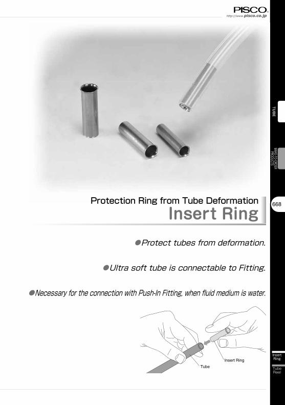
668
InsertRing
TubeReel
TUBE
MAKE-TO-ORDERPRODUCTS
Protection Ring from Tube DeformationInsert Ring
●Protect tubes from deformation.
●Ultra soft tube is connectable to Fitting.
●Necessary for the connection with Push-In Fitting, when fluid medium is water.
Insert Ring
Tube

Tube Series
669
InsertRing
Insert Ring
Tubecutter
TubeBinder
Anti-SpatterTube
Fluororesin /Polyamide Tube
CoilingTube
Multi-coreTube
StandardTube
TUB
EVA
LVE
CONT
ROLL
ERFI
TTIN
G
Twin CoilingTube
Clean RoomTube
Anti-StalicTube
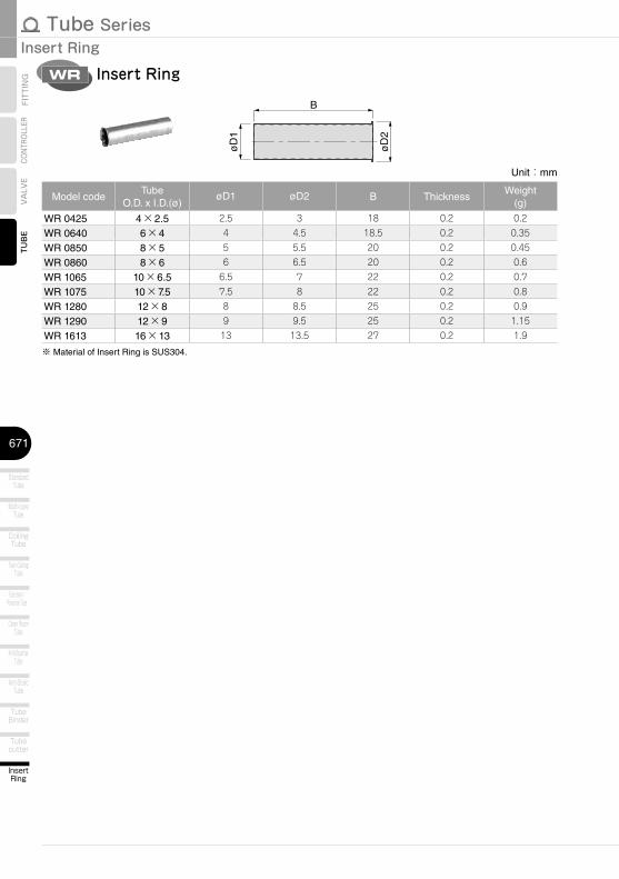
■ Model Designation (Example)
0640WR
① Tube dia.Code 0425 0640 0850 0860 1065 1075 1280 1290 1613
Tube O.D. (mm) ø4 ø6 ø8 ø8 ø10 ø10 ø12 ø12 ø16
Tube I.D. (mm) ø2.5 ø4 ø5 ø6 ø6.5 ø7.5 ø8 ø9 ø13
Insert Ring ①Tube dia.

http://www.pisco.co.jphttp://www.pisco.co.jp
670
InsertRing
TubeReel
TUBE
MAKE-TO-ORDERPRODUCTS
Detailed Safety InstructionsBefore using PISCO products, be sure to read “Safety Instructions” and “Safety Instruction Manual” on page
23 to 27 and “Common Safety Instructions for Tubes” on page 593 to 594.
■ Applicable Tube and Related ProductsPISCO’s Push-In Fittings and Tubes
Caution1. There is a possibility of dropping-off of Insert Ring from a tube edge into the piping, depending on the
combination with Tubes. Implement specific countermeasures in advance, for the case that it flows down
into pipes and cause a problem.
Tube Series
671
InsertRing
Insert Ring
Tubecutter
TubeBinder
Anti-SpatterTube
Fluororesin /Polyamide Tube
CoilingTube
Multi-coreTube
StandardTube
TUB
EVA
LVE
CONT
ROLL
ERFI
TTIN
G
Twin CoilingTube
Clean RoomTube
Anti-StalicTube
Insert RingWR
Unit:mm
Model codeTube
O.D. x I.D.(ø)øD1 øD2 B Thickness
Weight(g)
WR 0425 4×2.5 2.5 3 18 0.2 0.2
WR 0640 6×4 4 4.5 18.5 0.2 0.35
WR 0850 8×5 5 5.5 20 0.2 0.45
WR 0860 8×6 6 6.5 20 0.2 0.6
WR 1065 10×6.5 6.5 7 22 0.2 0.7
WR 1075 10×7.5 7.5 8 22 0.2 0.8
WR 1280 12×8 8 8.5 25 0.2 0.9
WR 1290 12×9 9 9.5 25 0.2 1.15
WR 1613 16×13 13 13.5 27 0.2 1.9
※ Material of Insert Ring is SUS304.
B
øD
1
øD
2

23
Safety Instructions
SAFETY Instructions
Warning
This safety instructions aim to prevent personal injury and damage to properties by requiring proper use of PISCO products. Be certain to follow ISO 4414 and JIS B 8370
ISO 4414:Pneumatic fluid power…Recomendations for the application of equipment to transmission and control systems.
JIS B 8370:General rules and safety requirements for systems and their components.This safety instructions is classified into “Danger”, “Warning” and “Caution” depending on the degree of danger or damages caused by improper use of PISCO products.
1. Selection of pneumatic products① A user who is a pneumatic system designer or has sufficient experience
and technical expertise should select PISCO products.② Due to wide variety of operating conditions and applications for PISCO
products, carry out the analysis and evaluation on PISCO products. The pneumatic system designer is solely responsible for assuring that the user's requirements are met and that the application presents no health or safety hazards. All designers are required to fully understand the specifications of PISCO products and constitute all systems based on the latest catalog or information, considering any malfunctions.
2. Handle the pneumatic equipment with enough knowledge and experience① Improper use of compressed air is dangerous. Assembly, operation
and maintenance of machines using pneumatic equipment should be conducted by a person with enough knowledge and experience.
3. Do not operate machine / equipment or remove pneumatic equipment until safety is confirmed.① Make sure that preventive measures against falling work-pieces or
sudden movements of machine are completed before inspection or maintenance of these machine.
② Make sure the above preventive measures are completed. A compressed air supply and the power supply to the machine must be off, and also the compressed air in the systems must be exhausted.
③ Restart the machines with care after ensuring to take all preventive measures against sudden movements.
Danger Hazardous conditions. It can cause death or serious personal injury.
Warning Hazardous conditions depending on usages. Improper use of PISCO products can cause death or serious personal injury.
Caution Hazardous conditions depending on usages. Improper use of PISCO products can cause personal injury or damages to properties.
※ . This safety instructions are subject to change without notice.

http://www.pisco.co.jphttp://www.pisco.co.jp
24
Disclaimer1. PISCO does not take any responsibility for any incidental or indirect
loss, such as production line stop, interruption of business, loss of benefits, personal injury, etc., caused by any failure on use or application of PISCO products.
2. PISCO does not take any responsibility for any loss caused by natural disasters, fires not related to PISCO products, acts by third parties, and intentional or accidental damages of PISCO products due to incorrect usage.
3. PISCO does not take any responsibility for any loss caused by improper usage of PISCO products such as exceeding the specification limit or not following the usage the published instructions and catalog allow.
4. PISCO does not take any responsibility for any loss caused by remodeling of PISCO products, or by combinational use with non-PISCO products and other software systems.
5. The damages caused by the defect of Pisco products shall be covered but limited to the full amount of the PISCO products paid by the customer.

25
Safety Instructions
SAFETY INSTRUCTION MANUAL
Danger1. Do not use PISCO products for the following applications.
① Equipment used for maintaining / handling human life and body.② Equipment used for moving / transporting human.③ Equipment specifically used for safety purposes.
Warning1. Do not use PISCO products under the following conditions.
① Beyond the specifications or conditions stated in the catalog, or the instructions.② Under the direct sunlight or outdoors.③ Excessive vibrations and impacts.④ Exposure / adhere to corrosive gas, inflammable gas, chemicals, seawater, water and vapor. *
* Some products can be used under the condition above(④), refer to the details of specification and condition of each product.
2. Do not disassemble or modify PISCO products, which affect the performance, function, and basic structure of the product.
3. Turn off the power supply, stop the air supply to PISCO products, and make sure there is no residual air pressure in the pipes before maintenance and inspection.
4. Do not touch the release-ring of push-in fitting when there is a working pressure. The lock may be released by the physical contact, and tube may fly out or slip out.
5. Frequent switchover of compressed air may generate heat, and there is a risk of causing burn injury.
6. Avoid any load on PISCO products, such as a tensile strength, twisting and bending. Otherwise, there is a risk of causing damage to the products.
7. As for applications where threads or tubes swing / rotate, use Rotary Joints, High Rotary Joints or Multi-Circuit Rotary Block only. The other PISCO products can be damaged in these applications.
8. Use only Die Temperature Control Fitting Series, Tube Fitting Stainless SUS316 Series, Tube Fitting Stainless SUS316 Compression Fitting Series or Tube Fitting Brass Series under the condition of over 60℃ (140°F) water or thermal oil. Other PISCO products can be damaged by heat and hydrolysis under the condition above.
9. As for the condition required to dissipate static electricity or provide an antistatic performance, use EG series fitting and antistatic products only, and do not use other PISCO products. There is a risk that static electricity can cause system defects or failures.
10. Use only Fittings with a characteristic of spatter-proof such as Anti-spatter or Brass series in a place where flame and weld spatter is produced. There is a risk of causing fire by sparks.
11. Turn off the power supply to PISCO products, and make sure there is no residual air pressure in the pipes and equipment before maintenance. Follow the instructions below in order to ensure safety.① Make sure the safety of all systems related to PISCO products before maintenance.② Restart of operation after maintenance shall be proceeded with care after
ensuring safety of the system by preventive measures against unexpected movements of machines and devices where pneumatic equipment is used.
③ Keep enough space for maintenance when designing a circuit.12. Take safety measures such as providing a protection cover if there is a
risk of causing damages or fires on machine / facilities by a fluid leakage.
PISCO products are designed and manufactured for use in general industrial machines. Be sure to read and follow the instructions below.

http://www.pisco.co.jphttp://www.pisco.co.jp
26
Caution1. Remove dusts or drain before piping. They may get into the peripheral
machine / facilities and cause malfunction.2. When inserting an ultra-soft tube into push-in fitting, make sure to place
an Insert Ring into the tube edge. There is a risk of causing the escape of tube and a fluid leakage without using an Insert Ring.
3. The product incorporating NBR as seal rubber material has a risk of malfunction caused by ozone crack. Ozone exists in high concentrations in static elimination air, clean-room, and near the high-voltage motors, etc. As a countermeasure, material change from NBR to HNBR or FKM is necessary. Consult with PISCO for more information.
4. Special option “Oil-free” products may cause a very small amount of a fluid leakage. When a fluid medium is liquid or the products are required to be used in harsh environments, contact us for further information.
5. In case of using non-PISCO brand tubes, make sure the tolerance of the outer tube diameter is within the limits of Table 1.
●Table 1. Tube O.D. Tolerancemm size Nylon tube Polyurethane tube inch size Nylon tube Polyurethane tubeø1.8mm ─ ±0.05mm ø1/8 ±0.1mm ±0.15mmø3mm ─ ±0.15mm ø5/32 ±0.1mm ±0.15mmø4mm ±0.1mm ±0.15mm ø3/16 ±0.1mm ±0.15mmø6mm ±0.1mm ±0.15mm ø1/4 ±0.1mm ±0.15mmø8mm ±0.1mm ±0.15mm ø5/16 ±0.1mm ±0.15mmø10mm ±0.1mm ±0.15mm ø3/8 ±0.1mm ±0.15mmø12mm ±0.1mm ±0.15mm ø1/2 ±0.1mm ±0.15mmø16mm ±0.1mm ±0.15mm ø5/8 ±0.1mm ±0.15mm
6. Instructions for Tube Insertion① Make sure that the cut end surface of the tube is at right angle without
a scratch on the surface and deformations.② When inserting a tube, the tube needs to be inserted fully into the push-
in fitting until the tubing edge touches the tube end of the fitting as shown in the figure below. Otherwise, there is a risk of leakage.
Tube end
Sealing
Tube is not fully inserted up to tube end.
③ After inserting the tube, make sure it is inserted properly and not to be disconnected by pulling it moderately.
※. When inserting tubes, Lock-claws may be hardly visible in the hole, observed from the front face of the release-ring. But it does not mean the tube will surely escape. Major causes of the tube escape are the followings; ①Shear drop of the lock-claws edge②The problem of tube diameter (usually small)Therefore, follow the above instructions from ① to ③, even lock-claws is hardly visible.

27
7. Instructions for Tube Disconnection① Make sure there is no air pressure inside of the tube, before disconnecting it.② Push the release-ring of the push-in fitting evenly and deeply enough to
pull out the tube toward oneself. By insufficient pushing of the release-ring, the tube may not be pulled out or damaged by scratch, and tube shavings may remain inside of the fitting, which may cause the leakage later.
8. Instructions for Installing a fitting① When installing a fitting, use proper tools to tighten a hexagonal-column
or an inner hexagonal socket. When inserting a hex key into the inner hexagonal socket of the fitting, be careful so that the tool does not touch lock-claws. The deformation of lock-claws may result in a poor performance of systems or an escape of the tube.
② Refer to Table 2 which shows the recommended tightening torque. Do not exceed these limits to tighten a thread. Excessive tightening may break the thread part or deform the gasket and cause a fluid leakage. Tightening thread with tightening torque lower than these limits may cause a loosened thread or a fluid leakage.
③ Adjust the tube direction while tightening thread within these limits, since some PISCO products are not rotatable after the installation.
●Table 2: Recommended tightening torque / Sealock color / Gasket materialsThread type Thread size Tightening torque Sealock color Gasket materials
Metric thread
M3×0.5 0.7N·m
─
SUS304NBR
M5×0.8 1.0 ~ 1.5N·mM6×1 2 ~ 2.7N·m
M3×0.5 0.5 ~ 0.6N·m
POMM5×0.8 1 ~ 1.5N·mM6×0.75 0.8 ~ 1N·mM8×0.75 1 ~ 2N·m
Taper pipe thread
R1/8 7 ~ 9N·m
White ─R1/4 12 ~ 14N·mR3/8 22 ~ 24N·mR1/2 28 ~ 30N·m
Unified thread No.10-32UNF 1.0 ~ 1.5N·m ─ SUS304、NBR
National pipe thread taper
1/16-27NPT 7 ~ 9N·m
White ─1/8-27NPT 7 ~ 9N·m1/4-18NPT 12 ~ 14N·m3/8-18NPT 22 ~ 24N·m1/2-14NPT 28 ~ 30N·m
※ These values may differ for some products. Refer to each specification as well.9. Instructions for removing a fitting
① When removing a fitting, use proper tools to loosen a hexagonal-column or an inner hex bolt.
② Remove the sealant stuck on the mating equipment. The remained sealant may get into the peripheral equipment and cause malfunctions.
10. Arrange piping avoiding any load on fittings and tubes such as twist, tensile, moment load, shaking and physical impact. These may cause damages to fittings, tube deformations, bursting and the escape of tubes.
Safety Instructions

Tube SeriesTUBE
593
VALVE
CONTROLLER
FITTING Common Safety Instructions for Tubes
Warning
Before selecting or using PISCO products, read the following instructions. Read the detailed instructions for individual series as well as the instructions below.
1. Avoid any load on Tubes such as tensile strength, twisting and bending. These may cause the crush, burst and escape of Tubes.
2. Protect Tubes from scratches caused by snagging or kinking. It may cause the burst of Tubes.
3. The burst pressure of Tubes drops as temperature rises. Read the operating pressure in the catalog well, and apply safety factor.
4. The minimum bending radius and the minimum installation radius are reference values at 20℃ and 65% RH. They are not guaranteed values. Refer to the minimum bending radius when Tubes are wound around a mandrel (round bar). As for the other operating conditions, refer to the minimum installation radius. These values vary depending on operating environments or the tube length. In order to make sure the suitability of Tubes, carry out the operation test by the user's actual machine before using Tubes.
5. Place Insert Ring into the edge of soft tubes like UD Series or tubes inserted to Push-In Fittings with a water fluid. There is a possibility of escape of Tube without Insert Ring.
6. Only Anti-spatter Tube can be used under the flame and weld spatter condition. Otherwise, there is a possibility of danger to catch fire by sparks.
7. Only Soft Nylon Tube can be used for warm water or thermal oil. Otherwise, tubes may burst due to deterioration.
8. Only Anti-static Tube can be used under the condition required to dissipate static electricity or provide an anti-static performance. There is a possibility that static electricity can cause malfunction or other troubles with the system.
9. An abnormal rise in temperature due to adiabatic compression may cause damage to Tubes.
10. If Tubes are used with any fluid or under any condition / environment other than listed in the catalog, as well as used outdoors, the conformity evaluation with the actual machine and safety measures taken by the responsible person are highly recommended.

StandardTube
Multi-coreTube
CoilingTube
Twin CoilingTube
Fluororesin /Polyamide Tube
Clean RoomTube
Anti-SpatterTube
Anti-StalicTube
TubeBinder
Tubecutter
InsertRing
http://www.pisco.co.jphttp://www.pisco.co.jp
594
TubeReel
TUBE
MAKE-TO-ORDERPRODUCTS
Caution1. When bending tubes, observe the minimum bending radius and minimum installation radius.
2. When piping, provide sufficient lengths of tube, considering possible shrinkage.
3. When Tubes are inserted into Push-In Fitting, make sure that cut end surface of Tubes are right angle, without any scratches on the surface and deformations.
4. Note that the effective cross-section area varies by tube length. Refer to “Effective Area of Piping” in “Tube Performance” .
■ Minimum Bending Radius & Minimum Mounting Radius1. Measurement method
●Minimum Bend Radius (JIS method) ●Minimum Installation Radius (Vice method)
JIS method (based on JIS B8381) Minimum Bending Radius is
measured by winding a tube tightly around a mandrel. Minimum Bending Radius is the value when the deformation ratio of the tube O.D. reaches 25%. Measurement condition: 20℃
65%RH
n= 1-─── ×100 L-D2d
n= Deformation ratio (%). Standard: under 25%
d= Tube O.D. L= Measured value (mm) D= Mandrel diameter (mm)
Fix the tube as the left figure shows. Slowly move the moving edge toward the fixed edge. When “a” deforms 25% from the initial value, the measured R is Minimum Installation Radius. Measurement condition: 20℃
65%RH
LøD
ød
Mandrel
Tube
Fixed edge
Moving edgeTube
Vice width
a
2R
Tube SeriesTUBE
595
VALVE
CONTROLLER
FITTING Tube Performance
■ Effective Sectional Area of Piping
1 2 5 10 20 50 100
1000
500
200
100
50
10
5
1
0.5
0.1
Piping length (m)
Effe
ctiv
e S
ectio
nal A
rea
(mm
2 )
Tube I.D. ø11Tube I.D. ø9Tube I.D. ø7.5Tube I.D. ø6.5Tube I.D. ø6(ø5.9)Tube I.D. ø5Tube I.D. ø4Tube I.D. ø3.48
Tube I.D. ø2.5(ø2.36)Tube I.D. ø2
http://www.pisco.co.jphttp://www.pisco.co.jp
658
Tubecutter
InsertRing
TubeReel
TUB
EMAKE-TO-ORDER
PRODUCTS
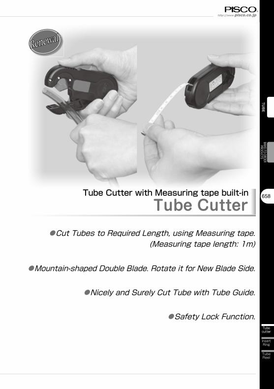
Tube Cutter with Measuring tape built-inTube Cutter
●Cut Tubes to Required Length, using Measuring tape.(Measuring tape length: 1m)
●Mountain-shaped Double Blade. Rotate it for New Blade Side.
●Nicely and Surely Cut Tube with Tube Guide.
●Safety Lock Function.
Tube Series
659
Tubecutter
Tube Cutter
TubeBinder
Anti-SpatterTube
Fluororesin /Polyamide Tube
CoilingTube
Multi-coreTube
StandardTube
TUB
EVA
LVE
CONT
ROLL
ERFI
TTIN
G
Twin CoilingTube
Clean RoomTube
Anti-StalicTube
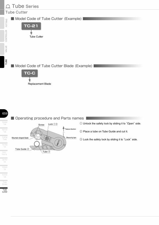
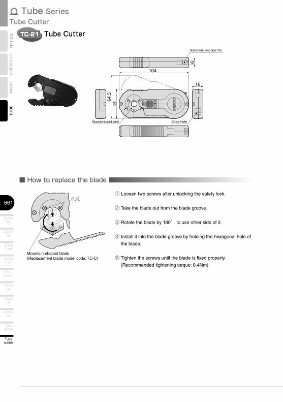
■ Model Code of Tube Cutter (Example)
TC-21
Tube Cutter
■ Model Code of Tube Cutter Blade (Example)
TC-C
Replacement Blade
■ Operating procedure and Parts names
Measuring tape
Lock ①③Screw
Takeout direction
Tube Guide ②Tube ②
Mountain-shaped blade
① Unlock the safety lock by sliding it to “Open” side.
② Place a tube on Tube Guide and cut it.
③ Lock the safety lock by sliding it to “Lock” side.
http://www.pisco.co.jphttp://www.pisco.co.jp
660
Tubecutter
InsertRing
TubeReel
TUBE
MAKE-TO-ORDERPRODUCTS
Detailed Safety InstructionsBefore using PISCO products, be sure to read “Safety Instructions” and “Safety Instruction Manual” on page
23 to 27 and “Common Safety Instructions for Tubes” on page 593 to 594.
■ Applicable TubeGeneral PISCO Tubes ■ Tube for General Piping…Polyurethane Tube (P.596), Nylon Tube (P.608), Vacuum Tube (P.612)
■ Tube for Special Environments… Fluororesin (PFA) Tube (P.628), Polyamide Tube (P.634), Anti-spatter
Tube (P.646), Anti-Static Tube (P.650), Fluororesin (PFA) Tube Clean-
Room Package (P.638), Polyurethane Tube Clean-Room Package
(P.642)
Warning1. Do not touch the blade to avoid personal injury.
2. Tighten the screws properly after replacing blade. There is a possibility of getting hurt from the fallen
blade due to the loosened screws.
Caution1. Lock the safety lock when Tube Cutter is not in use. Do not carry it in a pocket. Safety lock can be
unlocked unexpectedly by shakings or impacts.
2. Tube Cutter can be used for PISCO Tubes only. Do not use it for cutting an electric wire or a steel pipe.
Tube Series
661
Tubecutter
Tube Cutter
TubeBinder
Anti-SpatterTube
Fluororesin /Polyamide Tube
CoilingTube
Multi-coreTube
StandardTube
TUB
EVA
LVE
CONT
ROLL
ERFI
TTIN
G
Twin CoilingTube
Clean RoomTube
Anti-StalicTube
Tube CutterTC-21
LOC
K
OP
EN
16
64.5
44
6
104
Mountain-shaped blade
Built-in measuring tape (1m)
Strap hole
■ How to replace the blade
①,⑤
④③
②
Mountain-shaped blade(Replacement blade model code: TC-C)
① Loosen two screws after unlocking the safety lock.
② Take the blade out from the blade groove.
③ Rotate the blade by 180° to use other side of it.
④ Install it into the blade groove by holding the hexagonal hole of
the blade.
⑤ Tighten the screws until the blade is fixed properly.
(Recommended tightening torque: 0.4Nm)

23
Safety Instructions
SAFETY Instructions
Warning
This safety instructions aim to prevent personal injury and damage to properties by requiring proper use of PISCO products. Be certain to follow ISO 4414 and JIS B 8370
ISO 4414:Pneumatic fluid power…Recomendations for the application of equipment to transmission and control systems.
JIS B 8370:General rules and safety requirements for systems and their components.This safety instructions is classified into “Danger”, “Warning” and “Caution” depending on the degree of danger or damages caused by improper use of PISCO products.
1. Selection of pneumatic products① A user who is a pneumatic system designer or has sufficient experience
and technical expertise should select PISCO products.② Due to wide variety of operating conditions and applications for PISCO
products, carry out the analysis and evaluation on PISCO products. The pneumatic system designer is solely responsible for assuring that the user's requirements are met and that the application presents no health or safety hazards. All designers are required to fully understand the specifications of PISCO products and constitute all systems based on the latest catalog or information, considering any malfunctions.
2. Handle the pneumatic equipment with enough knowledge and experience① Improper use of compressed air is dangerous. Assembly, operation
and maintenance of machines using pneumatic equipment should be conducted by a person with enough knowledge and experience.
3. Do not operate machine / equipment or remove pneumatic equipment until safety is confirmed.① Make sure that preventive measures against falling work-pieces or
sudden movements of machine are completed before inspection or maintenance of these machine.
② Make sure the above preventive measures are completed. A compressed air supply and the power supply to the machine must be off, and also the compressed air in the systems must be exhausted.
③ Restart the machines with care after ensuring to take all preventive measures against sudden movements.
Danger Hazardous conditions. It can cause death or serious personal injury.
Warning Hazardous conditions depending on usages. Improper use of PISCO products can cause death or serious personal injury.
Caution Hazardous conditions depending on usages. Improper use of PISCO products can cause personal injury or damages to properties.
※ . This safety instructions are subject to change without notice.

http://www.pisco.co.jphttp://www.pisco.co.jp
24
Disclaimer1. PISCO does not take any responsibility for any incidental or indirect
loss, such as production line stop, interruption of business, loss of benefits, personal injury, etc., caused by any failure on use or application of PISCO products.
2. PISCO does not take any responsibility for any loss caused by natural disasters, fires not related to PISCO products, acts by third parties, and intentional or accidental damages of PISCO products due to incorrect usage.
3. PISCO does not take any responsibility for any loss caused by improper usage of PISCO products such as exceeding the specification limit or not following the usage the published instructions and catalog allow.
4. PISCO does not take any responsibility for any loss caused by remodeling of PISCO products, or by combinational use with non-PISCO products and other software systems.
5. The damages caused by the defect of Pisco products shall be covered but limited to the full amount of the PISCO products paid by the customer.

25
Safety Instructions
SAFETY INSTRUCTION MANUAL
Danger1. Do not use PISCO products for the following applications.
① Equipment used for maintaining / handling human life and body.② Equipment used for moving / transporting human.③ Equipment specifically used for safety purposes.
Warning1. Do not use PISCO products under the following conditions.
① Beyond the specifications or conditions stated in the catalog, or the instructions.② Under the direct sunlight or outdoors.③ Excessive vibrations and impacts.④ Exposure / adhere to corrosive gas, inflammable gas, chemicals, seawater, water and vapor. *
* Some products can be used under the condition above(④), refer to the details of specification and condition of each product.
2. Do not disassemble or modify PISCO products, which affect the performance, function, and basic structure of the product.
3. Turn off the power supply, stop the air supply to PISCO products, and make sure there is no residual air pressure in the pipes before maintenance and inspection.
4. Do not touch the release-ring of push-in fitting when there is a working pressure. The lock may be released by the physical contact, and tube may fly out or slip out.
5. Frequent switchover of compressed air may generate heat, and there is a risk of causing burn injury.
6. Avoid any load on PISCO products, such as a tensile strength, twisting and bending. Otherwise, there is a risk of causing damage to the products.
7. As for applications where threads or tubes swing / rotate, use Rotary Joints, High Rotary Joints or Multi-Circuit Rotary Block only. The other PISCO products can be damaged in these applications.
8. Use only Die Temperature Control Fitting Series, Tube Fitting Stainless SUS316 Series, Tube Fitting Stainless SUS316 Compression Fitting Series or Tube Fitting Brass Series under the condition of over 60℃ (140°F) water or thermal oil. Other PISCO products can be damaged by heat and hydrolysis under the condition above.
9. As for the condition required to dissipate static electricity or provide an antistatic performance, use EG series fitting and antistatic products only, and do not use other PISCO products. There is a risk that static electricity can cause system defects or failures.
10. Use only Fittings with a characteristic of spatter-proof such as Anti-spatter or Brass series in a place where flame and weld spatter is produced. There is a risk of causing fire by sparks.
11. Turn off the power supply to PISCO products, and make sure there is no residual air pressure in the pipes and equipment before maintenance. Follow the instructions below in order to ensure safety.① Make sure the safety of all systems related to PISCO products before maintenance.② Restart of operation after maintenance shall be proceeded with care after
ensuring safety of the system by preventive measures against unexpected movements of machines and devices where pneumatic equipment is used.
③ Keep enough space for maintenance when designing a circuit.12. Take safety measures such as providing a protection cover if there is a
risk of causing damages or fires on machine / facilities by a fluid leakage.
PISCO products are designed and manufactured for use in general industrial machines. Be sure to read and follow the instructions below.

http://www.pisco.co.jphttp://www.pisco.co.jp
26
Caution1. Remove dusts or drain before piping. They may get into the peripheral
machine / facilities and cause malfunction.2. When inserting an ultra-soft tube into push-in fitting, make sure to place
an Insert Ring into the tube edge. There is a risk of causing the escape of tube and a fluid leakage without using an Insert Ring.
3. The product incorporating NBR as seal rubber material has a risk of malfunction caused by ozone crack. Ozone exists in high concentrations in static elimination air, clean-room, and near the high-voltage motors, etc. As a countermeasure, material change from NBR to HNBR or FKM is necessary. Consult with PISCO for more information.
4. Special option “Oil-free” products may cause a very small amount of a fluid leakage. When a fluid medium is liquid or the products are required to be used in harsh environments, contact us for further information.
5. In case of using non-PISCO brand tubes, make sure the tolerance of the outer tube diameter is within the limits of Table 1.
●Table 1. Tube O.D. Tolerancemm size Nylon tube Polyurethane tube inch size Nylon tube Polyurethane tubeø1.8mm ─ ±0.05mm ø1/8 ±0.1mm ±0.15mmø3mm ─ ±0.15mm ø5/32 ±0.1mm ±0.15mmø4mm ±0.1mm ±0.15mm ø3/16 ±0.1mm ±0.15mmø6mm ±0.1mm ±0.15mm ø1/4 ±0.1mm ±0.15mmø8mm ±0.1mm ±0.15mm ø5/16 ±0.1mm ±0.15mmø10mm ±0.1mm ±0.15mm ø3/8 ±0.1mm ±0.15mmø12mm ±0.1mm ±0.15mm ø1/2 ±0.1mm ±0.15mmø16mm ±0.1mm ±0.15mm ø5/8 ±0.1mm ±0.15mm
6. Instructions for Tube Insertion① Make sure that the cut end surface of the tube is at right angle without
a scratch on the surface and deformations.② When inserting a tube, the tube needs to be inserted fully into the push-
in fitting until the tubing edge touches the tube end of the fitting as shown in the figure below. Otherwise, there is a risk of leakage.
Tube end
Sealing
Tube is not fully inserted up to tube end.
③ After inserting the tube, make sure it is inserted properly and not to be disconnected by pulling it moderately.
※. When inserting tubes, Lock-claws may be hardly visible in the hole, observed from the front face of the release-ring. But it does not mean the tube will surely escape. Major causes of the tube escape are the followings; ①Shear drop of the lock-claws edge②The problem of tube diameter (usually small)Therefore, follow the above instructions from ① to ③, even lock-claws is hardly visible.

27
7. Instructions for Tube Disconnection① Make sure there is no air pressure inside of the tube, before disconnecting it.② Push the release-ring of the push-in fitting evenly and deeply enough to
pull out the tube toward oneself. By insufficient pushing of the release-ring, the tube may not be pulled out or damaged by scratch, and tube shavings may remain inside of the fitting, which may cause the leakage later.
8. Instructions for Installing a fitting① When installing a fitting, use proper tools to tighten a hexagonal-column
or an inner hexagonal socket. When inserting a hex key into the inner hexagonal socket of the fitting, be careful so that the tool does not touch lock-claws. The deformation of lock-claws may result in a poor performance of systems or an escape of the tube.
② Refer to Table 2 which shows the recommended tightening torque. Do not exceed these limits to tighten a thread. Excessive tightening may break the thread part or deform the gasket and cause a fluid leakage. Tightening thread with tightening torque lower than these limits may cause a loosened thread or a fluid leakage.
③ Adjust the tube direction while tightening thread within these limits, since some PISCO products are not rotatable after the installation.
●Table 2: Recommended tightening torque / Sealock color / Gasket materialsThread type Thread size Tightening torque Sealock color Gasket materials
Metric thread
M3×0.5 0.7N·m
─
SUS304NBR
M5×0.8 1.0 ~ 1.5N·mM6×1 2 ~ 2.7N·m
M3×0.5 0.5 ~ 0.6N·m
POMM5×0.8 1 ~ 1.5N·mM6×0.75 0.8 ~ 1N·mM8×0.75 1 ~ 2N·m
Taper pipe thread
R1/8 7 ~ 9N·m
White ─R1/4 12 ~ 14N·mR3/8 22 ~ 24N·mR1/2 28 ~ 30N·m
Unified thread No.10-32UNF 1.0 ~ 1.5N·m ─ SUS304、NBR
National pipe thread taper
1/16-27NPT 7 ~ 9N·m
White ─1/8-27NPT 7 ~ 9N·m1/4-18NPT 12 ~ 14N·m3/8-18NPT 22 ~ 24N·m1/2-14NPT 28 ~ 30N·m
※ These values may differ for some products. Refer to each specification as well.9. Instructions for removing a fitting
① When removing a fitting, use proper tools to loosen a hexagonal-column or an inner hex bolt.
② Remove the sealant stuck on the mating equipment. The remained sealant may get into the peripheral equipment and cause malfunctions.
10. Arrange piping avoiding any load on fittings and tubes such as twist, tensile, moment load, shaking and physical impact. These may cause damages to fittings, tube deformations, bursting and the escape of tubes.
Safety Instructions

Tube SeriesTUBE
593
VALVE
CONTROLLER
FITTING Common Safety Instructions for Tubes
Warning
Before selecting or using PISCO products, read the following instructions. Read the detailed instructions for individual series as well as the instructions below.
1. Avoid any load on Tubes such as tensile strength, twisting and bending. These may cause the crush, burst and escape of Tubes.
2. Protect Tubes from scratches caused by snagging or kinking. It may cause the burst of Tubes.
3. The burst pressure of Tubes drops as temperature rises. Read the operating pressure in the catalog well, and apply safety factor.
4. The minimum bending radius and the minimum installation radius are reference values at 20℃ and 65% RH. They are not guaranteed values. Refer to the minimum bending radius when Tubes are wound around a mandrel (round bar). As for the other operating conditions, refer to the minimum installation radius. These values vary depending on operating environments or the tube length. In order to make sure the suitability of Tubes, carry out the operation test by the user's actual machine before using Tubes.
5. Place Insert Ring into the edge of soft tubes like UD Series or tubes inserted to Push-In Fittings with a water fluid. There is a possibility of escape of Tube without Insert Ring.
6. Only Anti-spatter Tube can be used under the flame and weld spatter condition. Otherwise, there is a possibility of danger to catch fire by sparks.
7. Only Soft Nylon Tube can be used for warm water or thermal oil. Otherwise, tubes may burst due to deterioration.
8. Only Anti-static Tube can be used under the condition required to dissipate static electricity or provide an anti-static performance. There is a possibility that static electricity can cause malfunction or other troubles with the system.
9. An abnormal rise in temperature due to adiabatic compression may cause damage to Tubes.
10. If Tubes are used with any fluid or under any condition / environment other than listed in the catalog, as well as used outdoors, the conformity evaluation with the actual machine and safety measures taken by the responsible person are highly recommended.
StandardTube
Multi-coreTube
CoilingTube
Twin CoilingTube
Fluororesin /Polyamide Tube
Clean RoomTube
Anti-SpatterTube
Anti-StalicTube
TubeBinder
Tubecutter
InsertRing
http://www.pisco.co.jphttp://www.pisco.co.jp
594
TubeReel
TUBE
MAKE-TO-ORDERPRODUCTS
Caution1. When bending tubes, observe the minimum bending radius and minimum installation radius.
2. When piping, provide sufficient lengths of tube, considering possible shrinkage.
3. When Tubes are inserted into Push-In Fitting, make sure that cut end surface of Tubes are right angle, without any scratches on the surface and deformations.
4. Note that the effective cross-section area varies by tube length. Refer to “Effective Area of Piping” in “Tube Performance” .
■ Minimum Bending Radius & Minimum Mounting Radius1. Measurement method
●Minimum Bend Radius (JIS method) ●Minimum Installation Radius (Vice method)
JIS method (based on JIS B8381) Minimum Bending Radius is
measured by winding a tube tightly around a mandrel. Minimum Bending Radius is the value when the deformation ratio of the tube O.D. reaches 25%. Measurement condition: 20℃
65%RH
n= 1-─── ×100 L-D2d
n= Deformation ratio (%). Standard: under 25%
d= Tube O.D. L= Measured value (mm) D= Mandrel diameter (mm)
Fix the tube as the left figure shows. Slowly move the moving edge toward the fixed edge. When “a” deforms 25% from the initial value, the measured R is Minimum Installation Radius. Measurement condition: 20℃
65%RH
LøD
ød
Mandrel
Tube
Fixed edge
Moving edgeTube
Vice width
a
2R

Tube SeriesTUBE
595
VALVE
CONTROLLER
FITTING Tube Performance
■ Effective Sectional Area of Piping
1 2 5 10 20 50 100
1000
500
200
100
50
10
5
1
0.5
0.1
Piping length (m)
Effe
ctiv
e S
ectio
nal A
rea
(mm
2 )
Tube I.D. ø11Tube I.D. ø9Tube I.D. ø7.5Tube I.D. ø6.5Tube I.D. ø6(ø5.9)Tube I.D. ø5Tube I.D. ø4Tube I.D. ø3.48
Tube I.D. ø2.5(ø2.36)Tube I.D. ø2
http://www.pisco.co.jphttp://www.pisco.co.jp
662
Tubecutter
InsertRing
TubeReel
TUBE
MAKE-TO-ORDERPRODUCTS
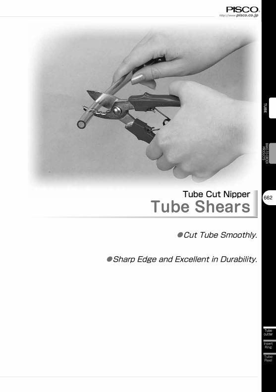
Tube Cut NipperTube Shears
●Cut Tube Smoothly.
●Sharp Edge and Excellent in Durability.
Tube Series
663
Tube Cut Nipper
Tubecutter
TubeBinder
Anti-SpatterTube
Fluororesin /Polyamide Tube
CoilingTube
Multi-coreTube
StandardTube
TUBE
VALVE
CONTROLLER
FITTING
Twin CoilingTube
Clean RoomTube
Anti-StalicTube
Detailed Safety InstructionsBefore using PISCO products, be sure to read “Safety Instructions” and “Safety Instruction Manual” on page
23 to 27 and “Common Safety Instructions for Tubes” on page 593 to 594.
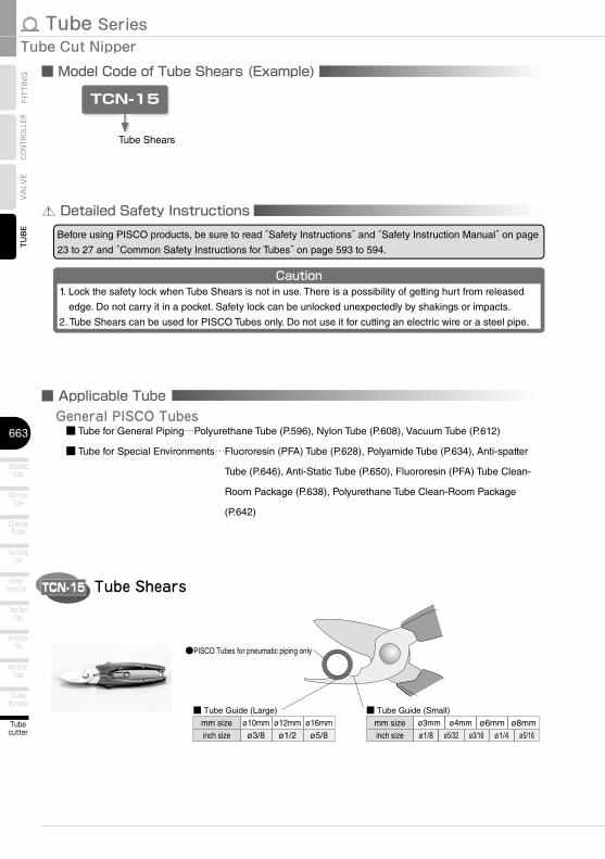
■ Model Code of Tube Shears (Example)
TCN-15
Tube Shears
Caution1. Lock the safety lock when Tube Shears is not in use. There is a possibility of getting hurt from released
edge. Do not carry it in a pocket. Safety lock can be unlocked unexpectedly by shakings or impacts.
2. Tube Shears can be used for PISCO Tubes only. Do not use it for cutting an electric wire or a steel pipe.
Tube ShearsTCN-15
mm size ø10mm ø12mm ø16mminch size ø3/8 ø1/2 ø5/8
ø3mm ø4mm ø6mm ø8mmø1/8 ø5/32 ø3/16 ø5/16ø1/4
mm sizeinch size
■ Tube Guide (Large)
●PISCO Tubes for pneumatic piping only
■ Tube Guide (Small)
■ Applicable TubeGeneral PISCO Tubes ■ Tube for General Piping…Polyurethane Tube (P.596), Nylon Tube (P.608), Vacuum Tube (P.612)
■ Tube for Special Environments… Fluororesin (PFA) Tube (P.628), Polyamide Tube (P.634), Anti-spatter
Tube (P.646), Anti-Static Tube (P.650), Fluororesin (PFA) Tube Clean-
Room Package (P.638), Polyurethane Tube Clean-Room Package
(P.642)

23
Safety Instructions
SAFETY Instructions
Warning
This safety instructions aim to prevent personal injury and damage to properties by requiring proper use of PISCO products. Be certain to follow ISO 4414 and JIS B 8370
ISO 4414:Pneumatic fluid power…Recomendations for the application of equipment to transmission and control systems.
JIS B 8370:General rules and safety requirements for systems and their components.This safety instructions is classified into “Danger”, “Warning” and “Caution” depending on the degree of danger or damages caused by improper use of PISCO products.
1. Selection of pneumatic products① A user who is a pneumatic system designer or has sufficient experience
and technical expertise should select PISCO products.② Due to wide variety of operating conditions and applications for PISCO
products, carry out the analysis and evaluation on PISCO products. The pneumatic system designer is solely responsible for assuring that the user's requirements are met and that the application presents no health or safety hazards. All designers are required to fully understand the specifications of PISCO products and constitute all systems based on the latest catalog or information, considering any malfunctions.
2. Handle the pneumatic equipment with enough knowledge and experience① Improper use of compressed air is dangerous. Assembly, operation
and maintenance of machines using pneumatic equipment should be conducted by a person with enough knowledge and experience.
3. Do not operate machine / equipment or remove pneumatic equipment until safety is confirmed.① Make sure that preventive measures against falling work-pieces or
sudden movements of machine are completed before inspection or maintenance of these machine.
② Make sure the above preventive measures are completed. A compressed air supply and the power supply to the machine must be off, and also the compressed air in the systems must be exhausted.
③ Restart the machines with care after ensuring to take all preventive measures against sudden movements.
Danger Hazardous conditions. It can cause death or serious personal injury.
Warning Hazardous conditions depending on usages. Improper use of PISCO products can cause death or serious personal injury.
Caution Hazardous conditions depending on usages. Improper use of PISCO products can cause personal injury or damages to properties.
※ . This safety instructions are subject to change without notice.

http://www.pisco.co.jphttp://www.pisco.co.jp
24
Disclaimer1. PISCO does not take any responsibility for any incidental or indirect
loss, such as production line stop, interruption of business, loss of benefits, personal injury, etc., caused by any failure on use or application of PISCO products.
2. PISCO does not take any responsibility for any loss caused by natural disasters, fires not related to PISCO products, acts by third parties, and intentional or accidental damages of PISCO products due to incorrect usage.
3. PISCO does not take any responsibility for any loss caused by improper usage of PISCO products such as exceeding the specification limit or not following the usage the published instructions and catalog allow.
4. PISCO does not take any responsibility for any loss caused by remodeling of PISCO products, or by combinational use with non-PISCO products and other software systems.
5. The damages caused by the defect of Pisco products shall be covered but limited to the full amount of the PISCO products paid by the customer.
25
Safety Instructions
SAFETY INSTRUCTION MANUAL
Danger1. Do not use PISCO products for the following applications.
① Equipment used for maintaining / handling human life and body.② Equipment used for moving / transporting human.③ Equipment specifically used for safety purposes.
Warning1. Do not use PISCO products under the following conditions.
① Beyond the specifications or conditions stated in the catalog, or the instructions.② Under the direct sunlight or outdoors.③ Excessive vibrations and impacts.④ Exposure / adhere to corrosive gas, inflammable gas, chemicals, seawater, water and vapor. *
* Some products can be used under the condition above(④), refer to the details of specification and condition of each product.
2. Do not disassemble or modify PISCO products, which affect the performance, function, and basic structure of the product.
3. Turn off the power supply, stop the air supply to PISCO products, and make sure there is no residual air pressure in the pipes before maintenance and inspection.
4. Do not touch the release-ring of push-in fitting when there is a working pressure. The lock may be released by the physical contact, and tube may fly out or slip out.
5. Frequent switchover of compressed air may generate heat, and there is a risk of causing burn injury.
6. Avoid any load on PISCO products, such as a tensile strength, twisting and bending. Otherwise, there is a risk of causing damage to the products.
7. As for applications where threads or tubes swing / rotate, use Rotary Joints, High Rotary Joints or Multi-Circuit Rotary Block only. The other PISCO products can be damaged in these applications.
8. Use only Die Temperature Control Fitting Series, Tube Fitting Stainless SUS316 Series, Tube Fitting Stainless SUS316 Compression Fitting Series or Tube Fitting Brass Series under the condition of over 60℃ (140°F) water or thermal oil. Other PISCO products can be damaged by heat and hydrolysis under the condition above.
9. As for the condition required to dissipate static electricity or provide an antistatic performance, use EG series fitting and antistatic products only, and do not use other PISCO products. There is a risk that static electricity can cause system defects or failures.
10. Use only Fittings with a characteristic of spatter-proof such as Anti-spatter or Brass series in a place where flame and weld spatter is produced. There is a risk of causing fire by sparks.
11. Turn off the power supply to PISCO products, and make sure there is no residual air pressure in the pipes and equipment before maintenance. Follow the instructions below in order to ensure safety.① Make sure the safety of all systems related to PISCO products before maintenance.② Restart of operation after maintenance shall be proceeded with care after
ensuring safety of the system by preventive measures against unexpected movements of machines and devices where pneumatic equipment is used.
③ Keep enough space for maintenance when designing a circuit.12. Take safety measures such as providing a protection cover if there is a
risk of causing damages or fires on machine / facilities by a fluid leakage.
PISCO products are designed and manufactured for use in general industrial machines. Be sure to read and follow the instructions below.
http://www.pisco.co.jphttp://www.pisco.co.jp
26
Caution1. Remove dusts or drain before piping. They may get into the peripheral
machine / facilities and cause malfunction.2. When inserting an ultra-soft tube into push-in fitting, make sure to place
an Insert Ring into the tube edge. There is a risk of causing the escape of tube and a fluid leakage without using an Insert Ring.
3. The product incorporating NBR as seal rubber material has a risk of malfunction caused by ozone crack. Ozone exists in high concentrations in static elimination air, clean-room, and near the high-voltage motors, etc. As a countermeasure, material change from NBR to HNBR or FKM is necessary. Consult with PISCO for more information.
4. Special option “Oil-free” products may cause a very small amount of a fluid leakage. When a fluid medium is liquid or the products are required to be used in harsh environments, contact us for further information.
5. In case of using non-PISCO brand tubes, make sure the tolerance of the outer tube diameter is within the limits of Table 1.
●Table 1. Tube O.D. Tolerancemm size Nylon tube Polyurethane tube inch size Nylon tube Polyurethane tubeø1.8mm ─ ±0.05mm ø1/8 ±0.1mm ±0.15mmø3mm ─ ±0.15mm ø5/32 ±0.1mm ±0.15mmø4mm ±0.1mm ±0.15mm ø3/16 ±0.1mm ±0.15mmø6mm ±0.1mm ±0.15mm ø1/4 ±0.1mm ±0.15mmø8mm ±0.1mm ±0.15mm ø5/16 ±0.1mm ±0.15mmø10mm ±0.1mm ±0.15mm ø3/8 ±0.1mm ±0.15mmø12mm ±0.1mm ±0.15mm ø1/2 ±0.1mm ±0.15mmø16mm ±0.1mm ±0.15mm ø5/8 ±0.1mm ±0.15mm
6. Instructions for Tube Insertion① Make sure that the cut end surface of the tube is at right angle without
a scratch on the surface and deformations.② When inserting a tube, the tube needs to be inserted fully into the push-
in fitting until the tubing edge touches the tube end of the fitting as shown in the figure below. Otherwise, there is a risk of leakage.
Tube end
Sealing
Tube is not fully inserted up to tube end.
③ After inserting the tube, make sure it is inserted properly and not to be disconnected by pulling it moderately.
※. When inserting tubes, Lock-claws may be hardly visible in the hole, observed from the front face of the release-ring. But it does not mean the tube will surely escape. Major causes of the tube escape are the followings; ①Shear drop of the lock-claws edge②The problem of tube diameter (usually small)Therefore, follow the above instructions from ① to ③, even lock-claws is hardly visible.

27
7. Instructions for Tube Disconnection① Make sure there is no air pressure inside of the tube, before disconnecting it.② Push the release-ring of the push-in fitting evenly and deeply enough to
pull out the tube toward oneself. By insufficient pushing of the release-ring, the tube may not be pulled out or damaged by scratch, and tube shavings may remain inside of the fitting, which may cause the leakage later.
8. Instructions for Installing a fitting① When installing a fitting, use proper tools to tighten a hexagonal-column
or an inner hexagonal socket. When inserting a hex key into the inner hexagonal socket of the fitting, be careful so that the tool does not touch lock-claws. The deformation of lock-claws may result in a poor performance of systems or an escape of the tube.
② Refer to Table 2 which shows the recommended tightening torque. Do not exceed these limits to tighten a thread. Excessive tightening may break the thread part or deform the gasket and cause a fluid leakage. Tightening thread with tightening torque lower than these limits may cause a loosened thread or a fluid leakage.
③ Adjust the tube direction while tightening thread within these limits, since some PISCO products are not rotatable after the installation.
●Table 2: Recommended tightening torque / Sealock color / Gasket materialsThread type Thread size Tightening torque Sealock color Gasket materials
Metric thread
M3×0.5 0.7N·m
─
SUS304NBR
M5×0.8 1.0 ~ 1.5N·mM6×1 2 ~ 2.7N·m
M3×0.5 0.5 ~ 0.6N·m
POMM5×0.8 1 ~ 1.5N·mM6×0.75 0.8 ~ 1N·mM8×0.75 1 ~ 2N·m
Taper pipe thread
R1/8 7 ~ 9N·m
White ─R1/4 12 ~ 14N·mR3/8 22 ~ 24N·mR1/2 28 ~ 30N·m
Unified thread No.10-32UNF 1.0 ~ 1.5N·m ─ SUS304、NBR
National pipe thread taper
1/16-27NPT 7 ~ 9N·m
White ─1/8-27NPT 7 ~ 9N·m1/4-18NPT 12 ~ 14N·m3/8-18NPT 22 ~ 24N·m1/2-14NPT 28 ~ 30N·m
※ These values may differ for some products. Refer to each specification as well.9. Instructions for removing a fitting
① When removing a fitting, use proper tools to loosen a hexagonal-column or an inner hex bolt.
② Remove the sealant stuck on the mating equipment. The remained sealant may get into the peripheral equipment and cause malfunctions.
10. Arrange piping avoiding any load on fittings and tubes such as twist, tensile, moment load, shaking and physical impact. These may cause damages to fittings, tube deformations, bursting and the escape of tubes.
Safety Instructions

Tube SeriesTUBE
593
VALVE
CONTROLLER
FITTING Common Safety Instructions for Tubes
Warning
Before selecting or using PISCO products, read the following instructions. Read the detailed instructions for individual series as well as the instructions below.
1. Avoid any load on Tubes such as tensile strength, twisting and bending. These may cause the crush, burst and escape of Tubes.
2. Protect Tubes from scratches caused by snagging or kinking. It may cause the burst of Tubes.
3. The burst pressure of Tubes drops as temperature rises. Read the operating pressure in the catalog well, and apply safety factor.
4. The minimum bending radius and the minimum installation radius are reference values at 20℃ and 65% RH. They are not guaranteed values. Refer to the minimum bending radius when Tubes are wound around a mandrel (round bar). As for the other operating conditions, refer to the minimum installation radius. These values vary depending on operating environments or the tube length. In order to make sure the suitability of Tubes, carry out the operation test by the user's actual machine before using Tubes.
5. Place Insert Ring into the edge of soft tubes like UD Series or tubes inserted to Push-In Fittings with a water fluid. There is a possibility of escape of Tube without Insert Ring.
6. Only Anti-spatter Tube can be used under the flame and weld spatter condition. Otherwise, there is a possibility of danger to catch fire by sparks.
7. Only Soft Nylon Tube can be used for warm water or thermal oil. Otherwise, tubes may burst due to deterioration.
8. Only Anti-static Tube can be used under the condition required to dissipate static electricity or provide an anti-static performance. There is a possibility that static electricity can cause malfunction or other troubles with the system.
9. An abnormal rise in temperature due to adiabatic compression may cause damage to Tubes.
10. If Tubes are used with any fluid or under any condition / environment other than listed in the catalog, as well as used outdoors, the conformity evaluation with the actual machine and safety measures taken by the responsible person are highly recommended.

StandardTube
Multi-coreTube
CoilingTube
Twin CoilingTube
Fluororesin /Polyamide Tube
Clean RoomTube
Anti-SpatterTube
Anti-StalicTube
TubeBinder
Tubecutter
InsertRing
http://www.pisco.co.jphttp://www.pisco.co.jp
594
TubeReel
TUBE
MAKE-TO-ORDERPRODUCTS
Caution1. When bending tubes, observe the minimum bending radius and minimum installation radius.
2. When piping, provide sufficient lengths of tube, considering possible shrinkage.
3. When Tubes are inserted into Push-In Fitting, make sure that cut end surface of Tubes are right angle, without any scratches on the surface and deformations.
4. Note that the effective cross-section area varies by tube length. Refer to “Effective Area of Piping” in “Tube Performance” .
■ Minimum Bending Radius & Minimum Mounting Radius1. Measurement method
●Minimum Bend Radius (JIS method) ●Minimum Installation Radius (Vice method)
JIS method (based on JIS B8381) Minimum Bending Radius is
measured by winding a tube tightly around a mandrel. Minimum Bending Radius is the value when the deformation ratio of the tube O.D. reaches 25%. Measurement condition: 20℃
65%RH
n= 1-─── ×100 L-D2d
n= Deformation ratio (%). Standard: under 25%
d= Tube O.D. L= Measured value (mm) D= Mandrel diameter (mm)
Fix the tube as the left figure shows. Slowly move the moving edge toward the fixed edge. When “a” deforms 25% from the initial value, the measured R is Minimum Installation Radius. Measurement condition: 20℃
65%RH
LøD
ød
Mandrel
Tube
Fixed edge
Moving edgeTube
Vice width
a
2R

Tube SeriesTUBE
595
VALVE
CONTROLLER
FITTING Tube Performance
■ Effective Sectional Area of Piping
1 2 5 10 20 50 100
1000
500
200
100
50
10
5
1
0.5
0.1
Piping length (m)
Effe
ctiv
e S
ectio
nal A
rea
(mm
2 )
Tube I.D. ø11Tube I.D. ø9Tube I.D. ø7.5Tube I.D. ø6.5Tube I.D. ø6(ø5.9)Tube I.D. ø5Tube I.D. ø4Tube I.D. ø3.48
Tube I.D. ø2.5(ø2.36)Tube I.D. ø2
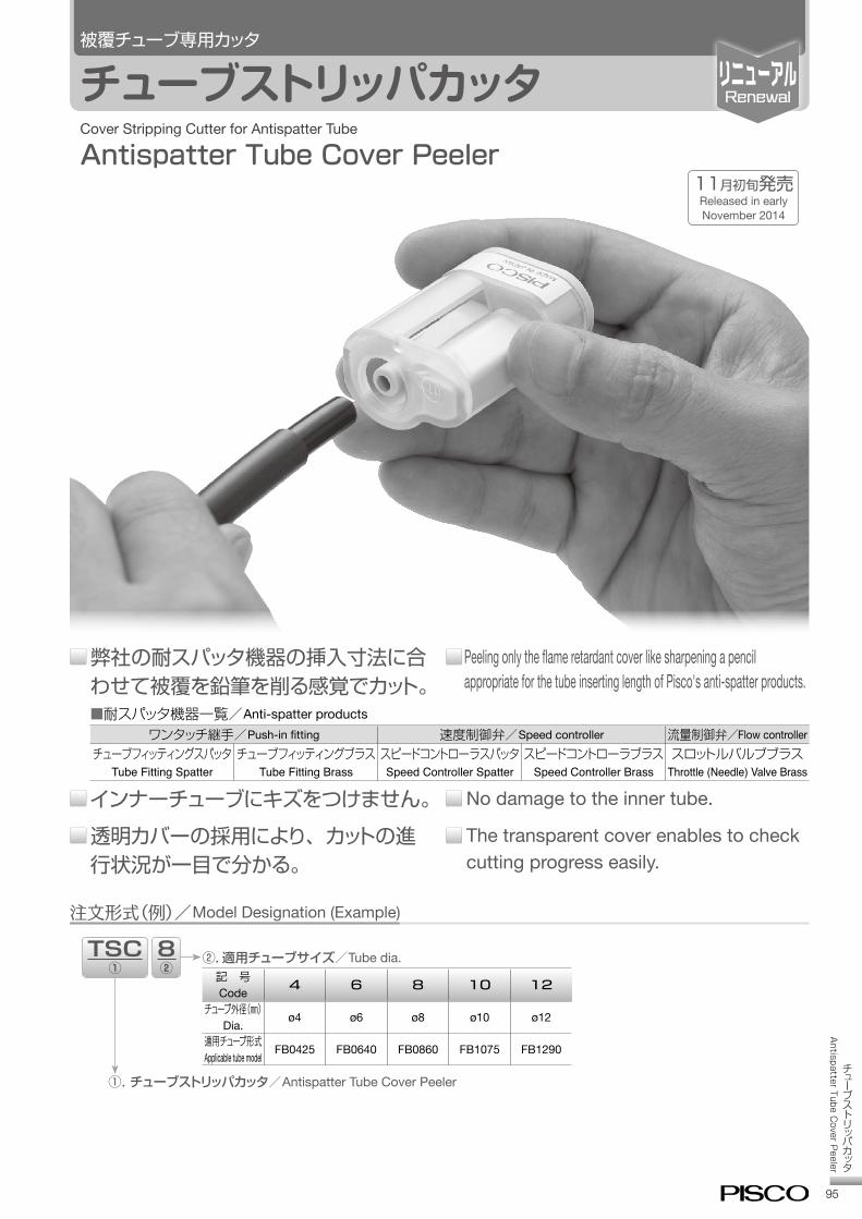
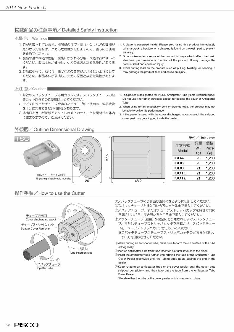
チューブストリッパカッタ/Antispatter Tube Cover Peeler
95
チューブストリッパカッタ
Antispatter T
ube Cover P
eeler
被覆チューブ専用カッタ
チューブストリッパカッタ
弊社の耐スパッタ機器の挿入寸法に合わせて被覆を鉛筆を削る感覚でカット。■耐スパッタ機器一覧/Anti-spatter products
ワンタッチ継手/Push-in fitting 速度制御弁/Speed controller 流量制御弁/Flow controllerチューブフィッティングスパッタ
Tube Fitting Spatterチューブフィッティングブラス
Tube Fitting BrassスピードコントローラスパッタSpeed Controller Spatter
スピードコントローラブラスSpeed Controller Brass
スロットルバルブブラスThrottle (Needle) Valve Brass
Peeling only the flame retardant cover like sharpening a pencil appropriate for the tube inserting length of Pisco's anti-spatter products.
No damage to the inner tube.
The transparent cover enables to check cutting progress easily.
インナーチューブにキズをつけません。
透明カバーの採用により、カットの進行状況が一目で分かる。
Cover Stripping Cutter for Antispatter Tube
Antispatter Tube Cover Peeler
注文形式(例)/Model Designation (Example)
TSC①8②
②. 適用チューブサイズ/Tube dia.記 号Code 4 6 8 10 12
チューブ外径(㎜)Dia. ø4 ø6 ø8 ø10 ø12
適用チューブ形式Applicable tube model FB0425 FB0640 FB0860 FB1075 FB1290
①.チューブストリッパカッタ/Antispatter Tube Cover Peeler
11月初旬発売Released in early November 2014
2014 New Products
96
適応チューブサイズ刻印Engraving of applicable tube size
48.2
37.5
26
掲載商品の注意事項/Detailed Safety Instruction警 告/Warnings
注 意/Cautions
1.刃が内蔵されています。樹脂部のひび・割れ・欠けなどの破損が見つかった場合は、ケガの危険性がありますので、直ちにご使用を止めてください。
2.製品の基本構造や性能・機能にかかわる分解・改造は行わないでください。製品本体が破損し、ケガの原因となる危険性があります。
3.製品に引張り、ねじり、曲げなどの負荷がかからないようにしてください。製品本体が破損し、ケガの原因となる危険性があります。
1.弊社のスパッタチューブ専用カッタです。スパッタチューブの被覆カット以外でのご使用は止めてください。
2.ひどく曲がったチューブや潰れたチューブのご使用は、製品機能を十分に発揮できない可能性があります。
3.排出口を塞いだ状態でカットしますとカットした被覆材が本体内に詰まりますので、ご注意ください。
1. A blade is equipped inside. Please stop using this product immediately when a crack, a fracture, or a chipping is found on the resin part to prevent an injury.
2. Do not dismantle or remodel the product in ways which affect the basic structure, performance or function of the product. It may damage the product itself and cause an injury.
3. Avoid putting load on the product such as pulling, twisting, or bending. It may damage the product itself and cause an injury.
1. This peeler is designated for PISCO Antispatter Tube (flame-retardant tube). Do not use it for other purposes except for peeling the cover of Antispatter Tube.
2. When using for an excessively bent or crushed tube, the product may not be able to deliver its performance.
3. If the peeler is used with the cover discharging spout closed, the stripped cover part may get clogged inside the peeler.
外観図/Outline Dimensional Drawing
操作手順/How to use the Cutter
単位/Unit:mm
注文形式Model
質量WT.
(g)
価格Price(¥)
TSC4 20 1,200TSC6 20 1,200TSC8 21 1,200TSC10 21 1,200TSC12 21 1,200
①スパッタチューブの切断面が直角になるように切断してください。②スパッタチューブを挿入口から刃に当たるまで挿入してください。③スパッタチューブ、またはチューブストリッパカッタを時計方向に回転させながら、突き当たるところまで挿入してください。
④アウターチューブ(被覆)が完全に切り離されるまでスパッタチューブ、またはチューブストリッパカッタを回転させ、スパッタチューブをチューブストリッパカッタから抜いてください。 ※スパッタチューブかチューブストリッパカッタのどちらか回しやすい方を回転させてください。
①When cutting an antispatter tube, make sure to form the cut surface of the tube orthogonally.
② Inert an antispatter tube from tube insertion slot until it touches the blade.③ Insert the antispatter tube further with rotating the tube or the Antispatter Tube
Cover Peeler clockwise until the tubing edge abuts against the end in the peeler.
④Keep rotating an antispatter tube or the cover peeler until the cover gets stripped completely, and then take out the tube from the Antispatter Tube Cover Peeler.
* Rotate either the tube or the cover peeler which is easier to rotate.
②
③、④
③、④
スパッタチューブSpatter Tube
チューブストリッパカッタSpatter Cover Remover
チューブ挿入口Tube insertion slot
チューブ排出口Cover discharging spout
TSC
http://www.pisco.co.jphttp://www.pisco.co.jp
672
TubeReel
TUBE
MAKE-TO-ORDERPRODUCTS
Reel for TubeTube Reel
●Easy to Supply and Change Tube.
●4 Width Selections according to Tube Sizes.
●Reusable Reel.・The reel is reusable to reduce waste.
・Material of the reel is all plastic.
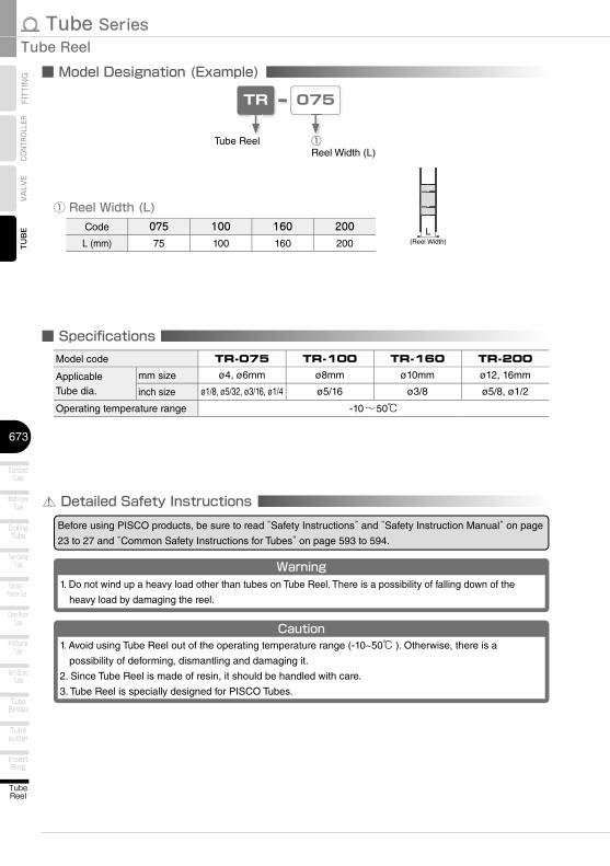
Tube Series
673
Tube Reel
TubeReel
InsertRing
Tubecutter
TubeBinder
Anti-SpatterTube
Fluororesin /Polyamide Tube
CoilingTube
Multi-coreTube
StandardTube
TUB
EVA
LVE
CONT
ROLL
ERFI
TTIN
G
Twin CoilingTube
Clean RoomTube
Anti-StalicTube
Detailed Safety InstructionsBefore using PISCO products, be sure to read “Safety Instructions” and “Safety Instruction Manual” on page
23 to 27 and “Common Safety Instructions for Tubes” on page 593 to 594.
■ Model Designation (Example)
① Reel Width (L)Code 075 100 160 200
L (mm) 75 100 160 200
TR 075
Tube Reel ①Reel Width (L)
L(Reel Width)
Warning1. Do not wind up a heavy load other than tubes on Tube Reel. There is a possibility of falling down of the
heavy load by damaging the reel.
Caution1. Avoid using Tube Reel out of the operating temperature range (-10~50℃ ). Otherwise, there is a
possibility of deforming, dismantling and damaging it.
2. Since Tube Reel is made of resin, it should be handled with care.
3. Tube Reel is specially designed for PISCO Tubes.
■ Specifi cationsModel code TR-075 TR-100 TR-160 TR-200
ApplicableTube dia.
mm size ø4, ø6mm ø8mm ø10mm ø12, 16mm
inch size ø1/8, ø5/32, ø3/16, ø1/4 ø5/16 ø3/8 ø5/8, ø1/2
Operating temperature range -10~50℃
http://www.pisco.co.jphttp://www.pisco.co.jp
674
TubeReel
TUBE
MAKE-TO-ORDERPRODUCTS
■ Applicable Tube and Related ProductsPolyurethane Tube………P.596※ . Contact us for the other tubes
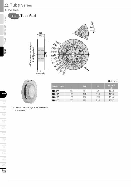
Tube Series
675
Tube Reel
TubeReel
InsertRing
Tubecutter
TubeBinder
Anti-SpatterTube
Fluororesin /Polyamide Tube
CoilingTube
Multi-coreTube
StandardTube
TUB
EVA
LVE
CONT
ROLL
ERFI
TTIN
G
Twin CoilingTube
Clean RoomTube
Anti-StalicTube
Tube ReelTR
Unit:mm
Model code L B1 B2Weight
(g)
TR-075 75 97 91 1248
TR-100 100 122 116 1270
TR-160 160 182 176 1318
TR-200 200 222 216 1357
6-ø17
3-ø10
3-ø12
3-ø16(5/8)
3-ø3.18(1/8)
3-ø4.76(3/16)
3-ø6.3
5(1/4)
3-ø9.5
3(3/8)
3-ø12
.7(1/2
)
3-ø8(5/16)
3-ø6
3-ø4(5/32)
B2B1
L(Reel Width)
ø50
.8(C
ente
r ho
le)
ø47
0
ø23
0(R
ecom
men
ded
win
ding
dia
.)
8º
(Rot
atio
n an
gle)
※ . Tube shown in image is not included in
the product.
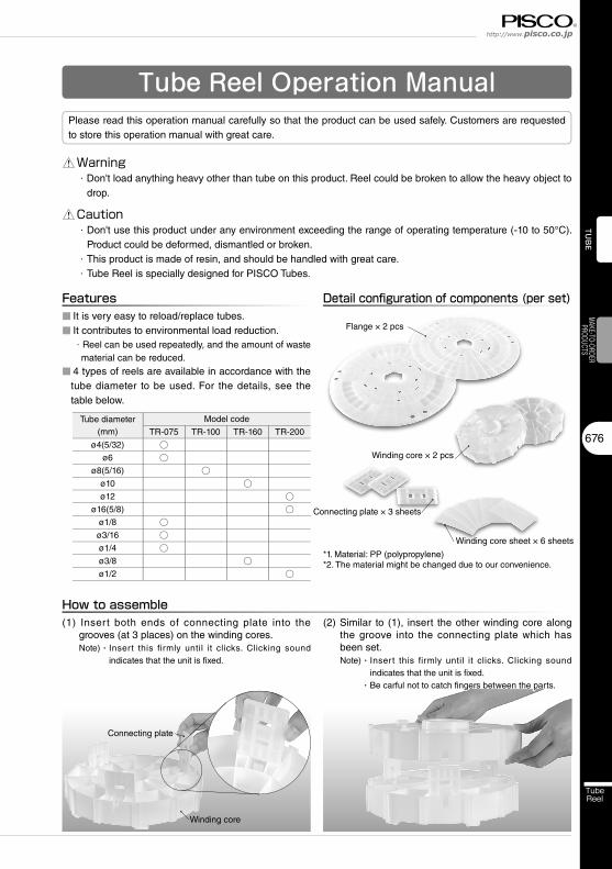
http://www.pisco.co.jphttp://www.pisco.co.jp
676
TubeReel
TUB
EMAKE-TO-ORDER
PRODUCTS
Tube Reel Operation ManualPlease read this operation manual carefully so that the product can be used safely. Customers are requested to store this operation manual with great care.
Warning・Don't load anything heavy other than tube on this product. Reel could be broken to allow the heavy object to
drop.
Caution・Don't use this product under any environment exceeding the range of operating temperature (-10 to 50°C).
Product could be deformed, dismantled or broken.
・This product is made of resin, and should be handled with great care.
・Tube Reel is specially designed for PISCO Tubes.
Features■ It is very easy to reload/replace tubes.■ It contributes to environmental load reduction.
・Reel can be used repeatedly, and the amount of waste material can be reduced.
■ 4 types of reels are available in accordance with the tube diameter to be used. For the details, see the table below.
Detail confi guration of components (per set)
Flange × 2 pcs
Winding core × 2 pcs
Connecting plate × 3 sheets
Winding core sheet × 6 sheets
How to assemble(1) Insert both ends of connecting plate into the
grooves (at 3 places) on the winding cores.Note)・ Insert this firmly until it clicks. Clicking sound
indicates that the unit is fixed.
(2) Similar to (1), insert the other winding core along the groove into the connecting plate which has been set.Note)・ Insert this firmly until it clicks. Clicking sound
indicates that the unit is fixed.
・Be carful not to catch fingers between the parts.
Winding core
Connecting plate
Tube diameter(mm)
Model code
TR-075 TR-100 TR-160 TR-200
ø4(5/32) ○ø6 ○
ø8(5/16) ○ø10 ○ø12 ○
ø16(5/8) ○ø1/8 ○ø3/16 ○ø1/4 ○ø3/8 ○ø1/2 ○
*1. Material: PP (polypropylene)*2. The material might be changed due to our convenience.
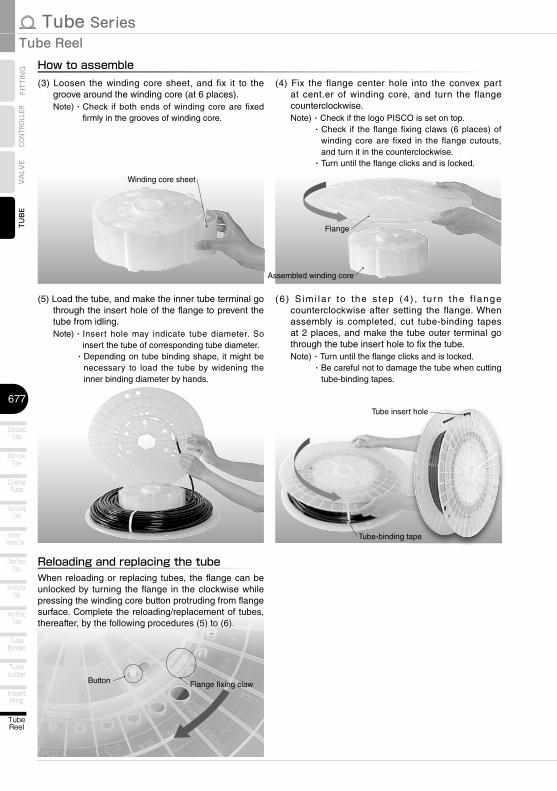
Tube Series
677
Tube Reel
TubeReel
InsertRing
Tubecutter
TubeBinder
Anti-SpatterTube
Fluororesin /Polyamide Tube
CoilingTube
Multi-coreTube
StandardTube
TUB
EVA
LVE
CONT
ROLL
ERFI
TTIN
G
Twin CoilingTube
Clean RoomTube
Anti-StalicTube
(3) Loosen the winding core sheet, and fix it to the groove around the winding core (at 6 places).Note)・ Check if both ends of winding core are fixed
firmly in the grooves of winding core.
(4) Fix the flange center hole into the convex part at cent.er of winding core, and turn the flange counterclockwise.Note)・Check if the logo PISCO is set on top.
・Check if the flange fixing claws (6 places) of winding core are fixed in the flange cutouts, and turn it in the counterclockwise.
・Turn until the flange clicks and is locked.
(5) Load the tube, and make the inner tube terminal go through the insert hole of the flange to prevent the tube from idling.Note)・ Insert hole may indicate tube diameter. So
insert the tube of corresponding tube diameter.・Depending on tube binding shape, it might be
necessary to load the tube by widening the inner binding diameter by hands.
Reloading and replacing the tubeWhen reloading or replacing tubes, the flange can be unlocked by turning the flange in the clockwise while pressing the winding core button protruding from flange surface. Complete the reloading/replacement of tubes, thereafter, by the following procedures (5) to (6).
(6 ) S im i l a r to t he s tep (4 ) , t u r n the f l ange counterclockwise after setting the flange. When assembly is completed, cut tube-binding tapes at 2 places, and make the tube outer terminal go through the tube insert hole to fix the tube.Note)・ Turn until the flange clicks and is locked.
・Be careful not to damage the tube when cutting tube-binding tapes.
Button
How to assemble
Winding core sheet
Flange
Assembled winding core
Tube-binding tape
Flange fixing claw
Tube insert hole
23
Safety Instructions
SAFETY Instructions
Warning
This safety instructions aim to prevent personal injury and damage to properties by requiring proper use of PISCO products. Be certain to follow ISO 4414 and JIS B 8370
ISO 4414:Pneumatic fluid power…Recomendations for the application of equipment to transmission and control systems.
JIS B 8370:General rules and safety requirements for systems and their components.This safety instructions is classified into “Danger”, “Warning” and “Caution” depending on the degree of danger or damages caused by improper use of PISCO products.
1. Selection of pneumatic products① A user who is a pneumatic system designer or has sufficient experience
and technical expertise should select PISCO products.② Due to wide variety of operating conditions and applications for PISCO
products, carry out the analysis and evaluation on PISCO products. The pneumatic system designer is solely responsible for assuring that the user's requirements are met and that the application presents no health or safety hazards. All designers are required to fully understand the specifications of PISCO products and constitute all systems based on the latest catalog or information, considering any malfunctions.
2. Handle the pneumatic equipment with enough knowledge and experience① Improper use of compressed air is dangerous. Assembly, operation
and maintenance of machines using pneumatic equipment should be conducted by a person with enough knowledge and experience.
3. Do not operate machine / equipment or remove pneumatic equipment until safety is confirmed.① Make sure that preventive measures against falling work-pieces or
sudden movements of machine are completed before inspection or maintenance of these machine.
② Make sure the above preventive measures are completed. A compressed air supply and the power supply to the machine must be off, and also the compressed air in the systems must be exhausted.
③ Restart the machines with care after ensuring to take all preventive measures against sudden movements.
Danger Hazardous conditions. It can cause death or serious personal injury.
Warning Hazardous conditions depending on usages. Improper use of PISCO products can cause death or serious personal injury.
Caution Hazardous conditions depending on usages. Improper use of PISCO products can cause personal injury or damages to properties.
※ . This safety instructions are subject to change without notice.
http://www.pisco.co.jphttp://www.pisco.co.jp
24
Disclaimer1. PISCO does not take any responsibility for any incidental or indirect
loss, such as production line stop, interruption of business, loss of benefits, personal injury, etc., caused by any failure on use or application of PISCO products.
2. PISCO does not take any responsibility for any loss caused by natural disasters, fires not related to PISCO products, acts by third parties, and intentional or accidental damages of PISCO products due to incorrect usage.
3. PISCO does not take any responsibility for any loss caused by improper usage of PISCO products such as exceeding the specification limit or not following the usage the published instructions and catalog allow.
4. PISCO does not take any responsibility for any loss caused by remodeling of PISCO products, or by combinational use with non-PISCO products and other software systems.
5. The damages caused by the defect of Pisco products shall be covered but limited to the full amount of the PISCO products paid by the customer.

25
Safety Instructions
SAFETY INSTRUCTION MANUAL
Danger1. Do not use PISCO products for the following applications.
① Equipment used for maintaining / handling human life and body.② Equipment used for moving / transporting human.③ Equipment specifically used for safety purposes.
Warning1. Do not use PISCO products under the following conditions.
① Beyond the specifications or conditions stated in the catalog, or the instructions.② Under the direct sunlight or outdoors.③ Excessive vibrations and impacts.④ Exposure / adhere to corrosive gas, inflammable gas, chemicals, seawater, water and vapor. *
* Some products can be used under the condition above(④), refer to the details of specification and condition of each product.
2. Do not disassemble or modify PISCO products, which affect the performance, function, and basic structure of the product.
3. Turn off the power supply, stop the air supply to PISCO products, and make sure there is no residual air pressure in the pipes before maintenance and inspection.
4. Do not touch the release-ring of push-in fitting when there is a working pressure. The lock may be released by the physical contact, and tube may fly out or slip out.
5. Frequent switchover of compressed air may generate heat, and there is a risk of causing burn injury.
6. Avoid any load on PISCO products, such as a tensile strength, twisting and bending. Otherwise, there is a risk of causing damage to the products.
7. As for applications where threads or tubes swing / rotate, use Rotary Joints, High Rotary Joints or Multi-Circuit Rotary Block only. The other PISCO products can be damaged in these applications.
8. Use only Die Temperature Control Fitting Series, Tube Fitting Stainless SUS316 Series, Tube Fitting Stainless SUS316 Compression Fitting Series or Tube Fitting Brass Series under the condition of over 60℃ (140°F) water or thermal oil. Other PISCO products can be damaged by heat and hydrolysis under the condition above.
9. As for the condition required to dissipate static electricity or provide an antistatic performance, use EG series fitting and antistatic products only, and do not use other PISCO products. There is a risk that static electricity can cause system defects or failures.
10. Use only Fittings with a characteristic of spatter-proof such as Anti-spatter or Brass series in a place where flame and weld spatter is produced. There is a risk of causing fire by sparks.
11. Turn off the power supply to PISCO products, and make sure there is no residual air pressure in the pipes and equipment before maintenance. Follow the instructions below in order to ensure safety.① Make sure the safety of all systems related to PISCO products before maintenance.② Restart of operation after maintenance shall be proceeded with care after
ensuring safety of the system by preventive measures against unexpected movements of machines and devices where pneumatic equipment is used.
③ Keep enough space for maintenance when designing a circuit.12. Take safety measures such as providing a protection cover if there is a
risk of causing damages or fires on machine / facilities by a fluid leakage.
PISCO products are designed and manufactured for use in general industrial machines. Be sure to read and follow the instructions below.

http://www.pisco.co.jphttp://www.pisco.co.jp
26
Caution1. Remove dusts or drain before piping. They may get into the peripheral
machine / facilities and cause malfunction.2. When inserting an ultra-soft tube into push-in fitting, make sure to place
an Insert Ring into the tube edge. There is a risk of causing the escape of tube and a fluid leakage without using an Insert Ring.
3. The product incorporating NBR as seal rubber material has a risk of malfunction caused by ozone crack. Ozone exists in high concentrations in static elimination air, clean-room, and near the high-voltage motors, etc. As a countermeasure, material change from NBR to HNBR or FKM is necessary. Consult with PISCO for more information.
4. Special option “Oil-free” products may cause a very small amount of a fluid leakage. When a fluid medium is liquid or the products are required to be used in harsh environments, contact us for further information.
5. In case of using non-PISCO brand tubes, make sure the tolerance of the outer tube diameter is within the limits of Table 1.
●Table 1. Tube O.D. Tolerancemm size Nylon tube Polyurethane tube inch size Nylon tube Polyurethane tubeø1.8mm ─ ±0.05mm ø1/8 ±0.1mm ±0.15mmø3mm ─ ±0.15mm ø5/32 ±0.1mm ±0.15mmø4mm ±0.1mm ±0.15mm ø3/16 ±0.1mm ±0.15mmø6mm ±0.1mm ±0.15mm ø1/4 ±0.1mm ±0.15mmø8mm ±0.1mm ±0.15mm ø5/16 ±0.1mm ±0.15mmø10mm ±0.1mm ±0.15mm ø3/8 ±0.1mm ±0.15mmø12mm ±0.1mm ±0.15mm ø1/2 ±0.1mm ±0.15mmø16mm ±0.1mm ±0.15mm ø5/8 ±0.1mm ±0.15mm
6. Instructions for Tube Insertion① Make sure that the cut end surface of the tube is at right angle without
a scratch on the surface and deformations.② When inserting a tube, the tube needs to be inserted fully into the push-
in fitting until the tubing edge touches the tube end of the fitting as shown in the figure below. Otherwise, there is a risk of leakage.
Tube end
Sealing
Tube is not fully inserted up to tube end.
③ After inserting the tube, make sure it is inserted properly and not to be disconnected by pulling it moderately.
※. When inserting tubes, Lock-claws may be hardly visible in the hole, observed from the front face of the release-ring. But it does not mean the tube will surely escape. Major causes of the tube escape are the followings; ①Shear drop of the lock-claws edge②The problem of tube diameter (usually small)Therefore, follow the above instructions from ① to ③, even lock-claws is hardly visible.
27
7. Instructions for Tube Disconnection① Make sure there is no air pressure inside of the tube, before disconnecting it.② Push the release-ring of the push-in fitting evenly and deeply enough to
pull out the tube toward oneself. By insufficient pushing of the release-ring, the tube may not be pulled out or damaged by scratch, and tube shavings may remain inside of the fitting, which may cause the leakage later.
8. Instructions for Installing a fitting① When installing a fitting, use proper tools to tighten a hexagonal-column
or an inner hexagonal socket. When inserting a hex key into the inner hexagonal socket of the fitting, be careful so that the tool does not touch lock-claws. The deformation of lock-claws may result in a poor performance of systems or an escape of the tube.
② Refer to Table 2 which shows the recommended tightening torque. Do not exceed these limits to tighten a thread. Excessive tightening may break the thread part or deform the gasket and cause a fluid leakage. Tightening thread with tightening torque lower than these limits may cause a loosened thread or a fluid leakage.
③ Adjust the tube direction while tightening thread within these limits, since some PISCO products are not rotatable after the installation.
●Table 2: Recommended tightening torque / Sealock color / Gasket materialsThread type Thread size Tightening torque Sealock color Gasket materials
Metric thread
M3×0.5 0.7N·m
─
SUS304NBR
M5×0.8 1.0 ~ 1.5N·mM6×1 2 ~ 2.7N·m
M3×0.5 0.5 ~ 0.6N·m
POMM5×0.8 1 ~ 1.5N·mM6×0.75 0.8 ~ 1N·mM8×0.75 1 ~ 2N·m
Taper pipe thread
R1/8 7 ~ 9N·m
White ─R1/4 12 ~ 14N·mR3/8 22 ~ 24N·mR1/2 28 ~ 30N·m
Unified thread No.10-32UNF 1.0 ~ 1.5N·m ─ SUS304、NBR
National pipe thread taper
1/16-27NPT 7 ~ 9N·m
White ─1/8-27NPT 7 ~ 9N·m1/4-18NPT 12 ~ 14N·m3/8-18NPT 22 ~ 24N·m1/2-14NPT 28 ~ 30N·m
※ These values may differ for some products. Refer to each specification as well.9. Instructions for removing a fitting
① When removing a fitting, use proper tools to loosen a hexagonal-column or an inner hex bolt.
② Remove the sealant stuck on the mating equipment. The remained sealant may get into the peripheral equipment and cause malfunctions.
10. Arrange piping avoiding any load on fittings and tubes such as twist, tensile, moment load, shaking and physical impact. These may cause damages to fittings, tube deformations, bursting and the escape of tubes.
Safety Instructions

Tube SeriesTUBE
593
VALVE
CONTROLLER
FITTING Common Safety Instructions for Tubes
Warning
Before selecting or using PISCO products, read the following instructions. Read the detailed instructions for individual series as well as the instructions below.
1. Avoid any load on Tubes such as tensile strength, twisting and bending. These may cause the crush, burst and escape of Tubes.
2. Protect Tubes from scratches caused by snagging or kinking. It may cause the burst of Tubes.
3. The burst pressure of Tubes drops as temperature rises. Read the operating pressure in the catalog well, and apply safety factor.
4. The minimum bending radius and the minimum installation radius are reference values at 20℃ and 65% RH. They are not guaranteed values. Refer to the minimum bending radius when Tubes are wound around a mandrel (round bar). As for the other operating conditions, refer to the minimum installation radius. These values vary depending on operating environments or the tube length. In order to make sure the suitability of Tubes, carry out the operation test by the user's actual machine before using Tubes.
5. Place Insert Ring into the edge of soft tubes like UD Series or tubes inserted to Push-In Fittings with a water fluid. There is a possibility of escape of Tube without Insert Ring.
6. Only Anti-spatter Tube can be used under the flame and weld spatter condition. Otherwise, there is a possibility of danger to catch fire by sparks.
7. Only Soft Nylon Tube can be used for warm water or thermal oil. Otherwise, tubes may burst due to deterioration.
8. Only Anti-static Tube can be used under the condition required to dissipate static electricity or provide an anti-static performance. There is a possibility that static electricity can cause malfunction or other troubles with the system.
9. An abnormal rise in temperature due to adiabatic compression may cause damage to Tubes.
10. If Tubes are used with any fluid or under any condition / environment other than listed in the catalog, as well as used outdoors, the conformity evaluation with the actual machine and safety measures taken by the responsible person are highly recommended.

StandardTube
Multi-coreTube
CoilingTube
Twin CoilingTube
Fluororesin /Polyamide Tube
Clean RoomTube
Anti-SpatterTube
Anti-StalicTube
TubeBinder
Tubecutter
InsertRing
http://www.pisco.co.jphttp://www.pisco.co.jp
594
TubeReel
TUBE
MAKE-TO-ORDERPRODUCTS
Caution1. When bending tubes, observe the minimum bending radius and minimum installation radius.
2. When piping, provide sufficient lengths of tube, considering possible shrinkage.
3. When Tubes are inserted into Push-In Fitting, make sure that cut end surface of Tubes are right angle, without any scratches on the surface and deformations.
4. Note that the effective cross-section area varies by tube length. Refer to “Effective Area of Piping” in “Tube Performance” .
■ Minimum Bending Radius & Minimum Mounting Radius1. Measurement method
●Minimum Bend Radius (JIS method) ●Minimum Installation Radius (Vice method)
JIS method (based on JIS B8381) Minimum Bending Radius is
measured by winding a tube tightly around a mandrel. Minimum Bending Radius is the value when the deformation ratio of the tube O.D. reaches 25%. Measurement condition: 20℃
65%RH
n= 1-─── ×100 L-D2d
n= Deformation ratio (%). Standard: under 25%
d= Tube O.D. L= Measured value (mm) D= Mandrel diameter (mm)
Fix the tube as the left figure shows. Slowly move the moving edge toward the fixed edge. When “a” deforms 25% from the initial value, the measured R is Minimum Installation Radius. Measurement condition: 20℃
65%RH
LøD
ød
Mandrel
Tube
Fixed edge
Moving edgeTube
Vice width
a
2R

Tube SeriesTUBE
595
VALVE
CONTROLLER
FITTING Tube Performance
■ Effective Sectional Area of Piping
1 2 5 10 20 50 100
1000
500
200
100
50
10
5
1
0.5
0.1
Piping length (m)
Effe
ctiv
e S
ectio
nal A
rea
(mm
2 )
Tube I.D. ø11Tube I.D. ø9Tube I.D. ø7.5Tube I.D. ø6.5Tube I.D. ø6(ø5.9)Tube I.D. ø5Tube I.D. ø4Tube I.D. ø3.48
Tube I.D. ø2.5(ø2.36)Tube I.D. ø2
Related Documents