T&B ® Cable Tray Metallic cable tray — A

Welcome message from author
This document is posted to help you gain knowledge. Please leave a comment to let me know what you think about it! Share it to your friends and learn new things together.
Transcript
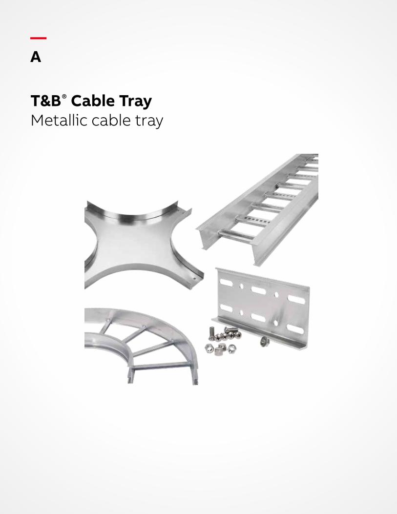
T&B® Cable TrayMetallic cable tray
— A

T&B Cable TrayMetallic cable tray
— A
Introduction A4
Technical information A6
Aluminum cable tray A32
Steel cable tray A116
One-piece cable tray A174
Channel tray A208
Common accessories A235
Grounding and bonding A239
Superstrut® support systems A242
— Table of contentsSection A
B1 copy starts here
B2 copy starts here
B3 copy starts here
A4 T& B C A B LE TR AY M E TA L L I C C A B L E TR AY
—T&B Cable trayIntroduction
Cable tray wiring systems offer significant advantages over conduit pipe and other wiring systems. Cable tray is more cost efficient, more reliable, more adaptable to changing needs and easier to maintain. In addition, its design does not contribute to potential safety problems associated with other wiring systems.
The benefits of cable trayAn evaluation of the costs and benefits of various wiring systems should be done in the design phase. Avoiding the system selection process or deferring it until construction, often results in higher costs, scheduling delays and a system that will not meet future needs.
Selection of a wiring system that is not the most suitable for a particular application in terms of cost, potential corrosion and electrical considerations can lead to numerous problems, including excessive initial cost, poor design, faulty installation, extra maintenance, future power outages and unnecessary safety concerns.
Cost efficiencyExtensive experience has shown that the overall cost of a cable tray installation (including conductor, material and installation labor costs) may be as much as 60% less than a comparable conduit wiring system.
Cable tray systems, including trays, supports, fittings and other materials, are generally much less expensive than conduit wiring systems. In addition, major cost savings are generated by the relative ease of installation. Labor costs of installing a cable tray system can run up to 50% less. Total cost savings will vary with the complexity and size of the installation.
Direct cost savings are easy to calculate during the design phase of an installation, but the enormous advantages of cable tray may accrue only over time. The system’s reliability, adaptability, ease of maintenance and inherent safety features result in many other types of cost savings, including:• Lower engineering and maintenance costs• Less need to reconfigure system as needs change• Less down time for electrical and data
handling systems• Fewer environmental problems resulting from
loss of power to essential equipment
ReliabilityCable tray systems offer unsurpassed reliability, resulting in less maintenance and down time –important considerations for all installations and especially for industries such as data communications and financial services.
In addition, since cable tray is an open system, moisture build-up problems are eliminated and damage to cable insulation during installation is also greatly reduced.
A5I NTR O D U C TI O N
AdaptabilityA major advantage of cable tray systems derives from their adaptability to new needs and technology. The pace of change in the economy, constantly shifting competitive pressures and rapid introduction of innovative technologies are all accelerating. More than ever before, businesses must be prepared to quickly expand facilities, change products or introduce new processes. The flexibility of the wiring system is a key consideration.
Modifying a cable tray system or adding cables to meet new needs is relatively easy because cables can enter or exit a tray at any point, and initial design considerations can build in extra capacity as part of the planning process. Cable tray’s inherent adaptability allows rewiring for future expansion, building redesign or new technologies without disruption or need to replace the entire wiring system.
MaintenanceCable tray wiring systems require less maintenance than conduit systems. When maintenance is necessary, it is easier, less time-consuming and less labor intensive.
The physical condition and status of both the cable tray and cables can be inspected visually, something that is not possible with conduit systems. In addition, it is also easy to see if there is sufficient capacity in the trays for additional cables. As was noted above, changing or adding cables can also be accomplished easily.
Another comparative benefit of cable tray systems is that they do not act as channels of moisture paths, as conduit wiring systems do. Conduit systems tend to collect condensation resulting from changes in temperature and then channel the moisture to electrical equipment, where it can lead to corrosion and failure.
Cable tray and tray cable are also less susceptible to fire loss than conduit. An external fire usually results in damage to only a few feet of a cable tray system, while wire insulation inside a conduit suffers significant damage and thermoplastic insulation may actually fuse to the conduit.
SafetyCable wiring systems lack the inherent safety concerns of conduit systems.
By its nature, a conduit wiring system can serve as a flow-through for corrosive, explosive and toxic gases in the same way that it channels moisture.
The conduit installation process can also present a safety issue for electricians. The process requires that a conduit system be installed from one enclosure to another before pulling in the conductors, leaving the electricians exposed to any live, energized equipment that may be in the enclosures. In contrast, installers can pull tray cables from near one termination enclosure to the next before they are inserted into the enclosures and then terminated.
Finally, in installations where cable tray can be used as the equipment grounding conductor (per NEC standards), it is easy to visually check the system components as well as conduct checks for electrical continuity.
B1 copy starts here
B2 copy starts here
B3 copy starts here
A6 T& B C A B LE TR AY M E TA L L I C C A B L E TR AY
AccessoriesDevices that are used to supplement the function of straight sections and fittings, and include such items as drop outs, covers, conduit adapters, hold-down devices and dividers.
Cable tray connectorA device that joins cable tray straight sections or fittings, or both. The basic types of connectors are: • Rigid • Expansion • Adjustable • Reducer
Cable tray fittingA device that is used to change the direction, elevation or width of a cable tray system.
Cable tray supportA device that provides adequate means for supporting cable tray sections or fittings, or both. The basic types of cable tray supports are: • Cantilever bracket• Trapeze • Individual and suspension
Channel cable trayA prefabricated metal structure consisting of a one-piece ventilated bottom or solid bottom channel section, or both, not exceeding 6 inches in width.
Ladder cable trayA prefabricated metal structure consisting of two longitudinal side rails connected by individual transverse members.
Solid bottom cable trayA prefabricated metal structure consisting of a bottom with no openings within integral or separate longitudinal side rails.
One-piece/unit cable trayA prefabricated metal structure consisting of a one-piece solid or ventilated bottom.
Horizontal crossA cable tray fitting that is suitable for joining cable trays in four directions at 90° intervals in the same plane.
Horizontal bendA cable tray fitting that changes the direction in the same plane.
Horizontal teeA cable tray fitting that is suitable for joining cable trays in three directions at 90˚ intervals in the same plane.
Metallic cable tray systemA metallic assembly of cable tray straight sections, fittings, and accessories that forms a rigid structural system to support cables.
ReducerA cable tray fitting that is suitable for joining cable trays of different widths in the same plane. A straight reducer has two symmetrical offset sides. A right-hand reducer, when viewed from the large end, has a straight side on the right. A left-hand reducer, when viewed from the large end, has a straight side on the left.
Straight sectionA length of cable tray that has no change in direction or size.
Ventilated bottomA cable tray bottom having openings sufficient for the passage of air and utilizing 75% or less of the plane area of the surface to support cables.
Vertical bendA cable tray fitting that changes direction to a different plane. An inside vertical elbow changes direction upward from the horizontal plane. An outside vertical elbow changes direction downward from the horizontal plane.
—Technical informationGlossary of terms
A7TECH N I C A L I N FO R M ATI O N
—Technical informationUnique design features
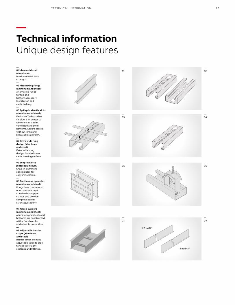
—01 I-beam side rail (aluminum) Maximum structural strength.—02 Alternating rungs (aluminum and steel)Alternating rungs for top and bottom accessory installation and cable lashing.—03 Ty-Rap® cable tie slots (aluminum and steel)Exclusive Ty-Rap cable tie slots 1 in. center to center on all ladder ventilated and solid bottoms. Secure cables without kinks and keep cables uniform.—04 Extra wide rung design (aluminum and steel)Extra wide rung design for maximum cable bearing surface.—05 Snap-in splice plates (aluminum)Snap-in aluminum splice plates for easy installation.—06 Continuous open slot (aluminum and steel)Rungs have continuous open slot to accept standard strut pipe clamps and provide complete barrier strip adjustability.—07 Added support (aluminum and steel)Aluminum and steel solid bottoms are constructed with a flat sheet for added cable protection.—08 Adjustable barrier strips (aluminum and steel)Barrier strips are fully adjustable (side to side) for use in straight sections and fittings.
—01
—02
—03
—04
—05
—06
—07
—08
1.5 m/72"
3 m/144"
B1 copy starts here
B2 copy starts here
B3 copy starts here
A8 T& B C A B LE TR AY M E TA L L I C C A B L E TR AY
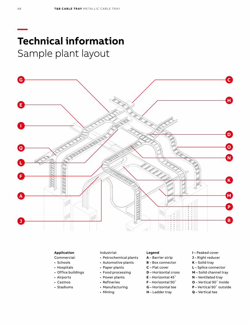
LegendA – Barrier stripB – Box connectorC – Flat coverD – Horizontal crossE – Horizontal 45˚F – Horizontal 90˚G – Horizontal teeH – Ladder tray
I – Peaked coverJ – Right reducerK – Solid trayL – Splice connectorM – Solid channel trayN – Ventilated trayO – Vertical 90˚ insideP – Vertical 90˚ outsideQ – Vertical tee
ApplicationCommercial:• Schools• Hospitals• Office buildings• Airports• Casinos• Stadiums
Industrial:• Petrochemical plants• Automotive plants• Paper plants• Food processing• Power plants• Refineries• Manufacturing• Mining
—Technical informationSample plant layout
G
H
C
I
L
O
D
E
N
Q
KF
A
P
M
J B
A9TECH N I C A L I N FO R M ATI O N
1
2
3
4
5
6
7
8
—Technical informationSelection process
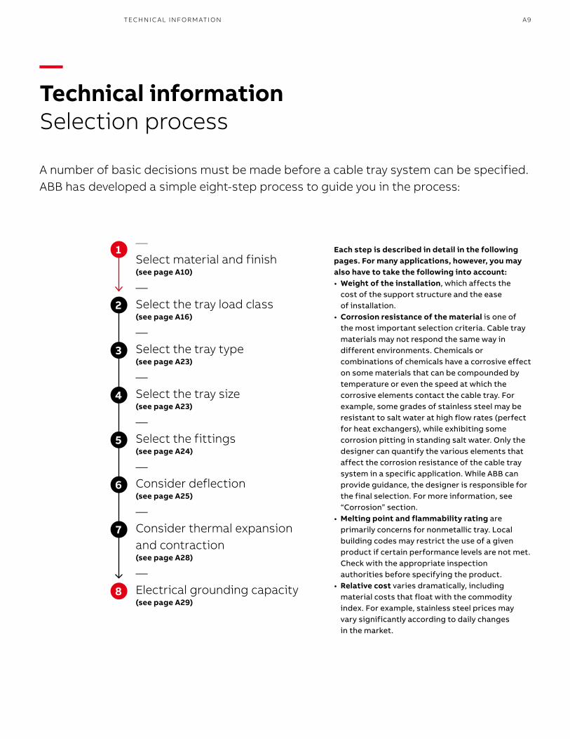
A number of basic decisions must be made before a cable tray system can be specified. ABB has developed a simple eight-step process to guide you in the process:
—Select material and finish (see page A10)
—Select the tray load class (see page A16)
—Select the tray type(see page A23)
—Select the tray size(see page A23)
—Select the fittings(see page A24)
—Consider deflection(see page A25)
—Consider thermal expansion and contraction (see page A28)
—Electrical grounding capacity (see page A29)
Each step is described in detail in the following pages. For many applications, however, you may also have to take the following into account:• Weight of the installation, which affects the
cost of the support structure and the ease of installation.
• Corrosion resistance of the material is one of the most important selection criteria. Cable tray materials may not respond the same way in different environments. Chemicals or combinations of chemicals have a corrosive effect on some materials that can be compounded by temperature or even the speed at which the corrosive elements contact the cable tray. For example, some grades of stainless steel may be resistant to salt water at high flow rates (perfect for heat exchangers), while exhibiting some corrosion pitting in standing salt water. Only the designer can quantify the various elements that affect the corrosion resistance of the cable tray system in a specific application. While ABB can provide guidance, the designer is responsible for the final selection. For more information, see “Corrosion” section.
• Melting point and flammability rating are primarily concerns for nonmetallic tray. Local building codes may restrict the use of a given product if certain performance levels are not met. Check with the appropriate inspection authorities before specifying the product.
• Relative cost varies dramatically, including material costs that float with the commodity index. For example, stainless steel prices may vary significantly according to daily changes in the market.
B1 copy starts here
B2 copy starts here
B3 copy starts here
A10 T& B C A B LE TR AY M E TA L L I C C A B L E TR AY
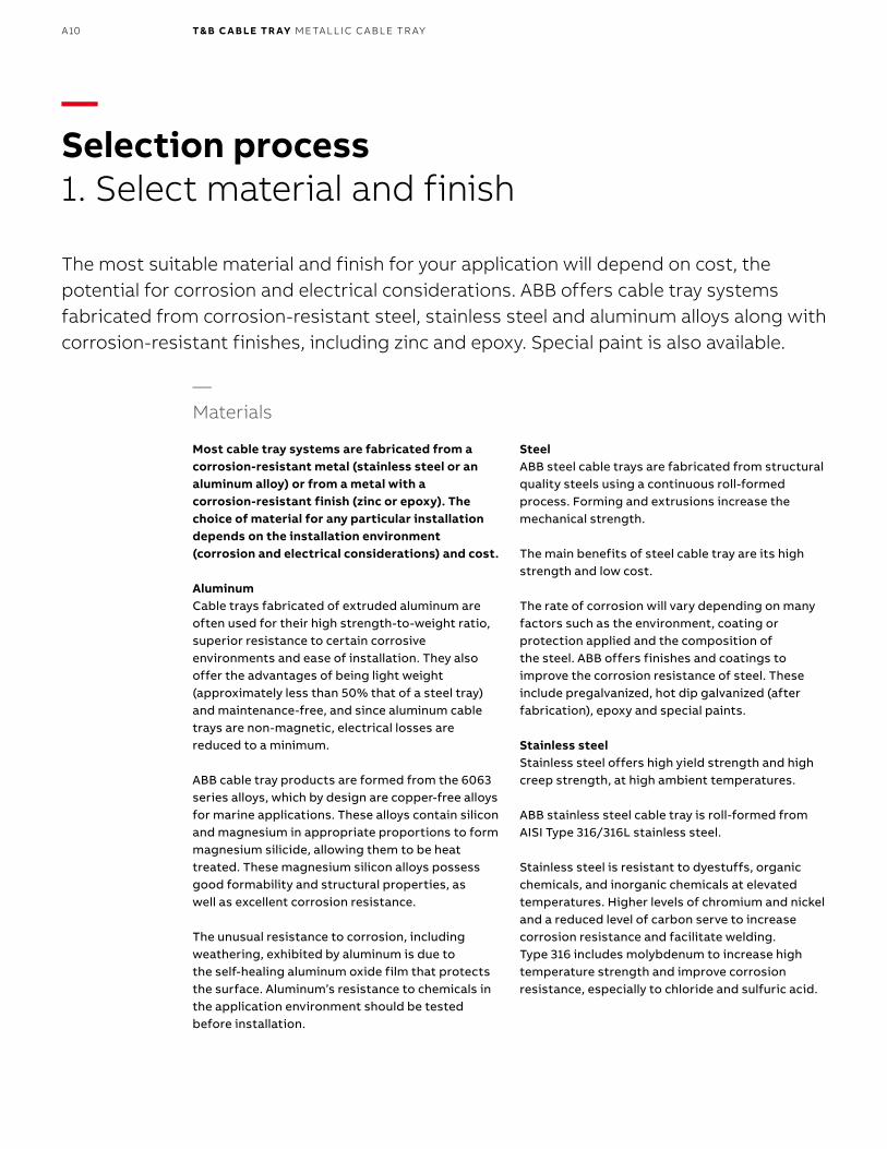
—Materials
Most cable tray systems are fabricated from a corrosion-resistant metal (stainless steel or an aluminum alloy) or from a metal with a corrosion-resistant finish (zinc or epoxy). The choice of material for any particular installation depends on the installation environment (corrosion and electrical considerations) and cost.
AluminumCable trays fabricated of extruded aluminum are often used for their high strength-to-weight ratio, superior resistance to certain corrosive environments and ease of installation. They also offer the advantages of being light weight (approximately less than 50% that of a steel tray) and maintenance-free, and since aluminum cable trays are non-magnetic, electrical losses are reduced to a minimum.
ABB cable tray products are formed from the 6063 series alloys, which by design are copper-free alloys for marine applications. These alloys contain silicon and magnesium in appropriate proportions to form magnesium silicide, allowing them to be heat treated. These magnesium silicon alloys possess good formability and structural properties, as well as excellent corrosion resistance.
The unusual resistance to corrosion, including weathering, exhibited by aluminum is due to the self-healing aluminum oxide film that protects the surface. Aluminum’s resistance to chemicals in the application environment should be tested before installation.
SteelABB steel cable trays are fabricated from structural quality steels using a continuous roll-formed process. Forming and extrusions increase the mechanical strength.
The main benefits of steel cable tray are its high strength and low cost.
The rate of corrosion will vary depending on many factors such as the environment, coating or protection applied and the composition of the steel. ABB offers finishes and coatings to improve the corrosion resistance of steel. These include pregalvanized, hot dip galvanized (after fabrication), epoxy and special paints.
Stainless steelStainless steel offers high yield strength and high creep strength, at high ambient temperatures.
ABB stainless steel cable tray is roll-formed from AISI Type 316/316L stainless steel.
Stainless steel is resistant to dyestuffs, organic chemicals, and inorganic chemicals at elevated temperatures. Higher levels of chromium and nickel and a reduced level of carbon serve to increase corrosion resistance and facilitate welding. Type 316 includes molybdenum to increase high temperature strength and improve corrosion resistance, especially to chloride and sulfuric acid.
—Selection process1. Select material and finish
The most suitable material and finish for your application will depend on cost, the potential for corrosion and electrical considerations. ABB offers cable tray systems fabricated from corrosion-resistant steel, stainless steel and aluminum alloys along with corrosion-resistant finishes, including zinc and epoxy. Special paint is also available.
A11TECH N I C A L I N FO R M ATI O N
—Finishes
Electrogalvanized coatingsThe most widely used coating for cable tray is galvanizing. It is cost-effective, protects against a wide variety of environ mental chemicals and is self-healing if an area becomes unprotected through cuts or scratches.
Steel is coated with zinc through electrolysis by dipping steel into a bath of zinc salts. A combination of carbonates, hydroxides and zinc oxides forms a protective film to protect the zinc itself. Resistance to corrosion is directly related to the thickness of the coating and the harshness of the environ ment.
PregalvanizedPregalvanized, also known as mill-galvanized or hot dip mill-galvanized, is produced in a rolling mill by passing steel coils through molten zinc. These coils are then slit to size and fabricated.
Areas not normally coated during fabrication, such as cuts and welds, are protected by neighboring zinc, which works as a sacrificial anode. During welding, a small area directly affected by heat is also left bare, but the same self-healing process occurs.
G90 requires a coating of 0.90 ounces of zinc per square foot of steel, or 0.32 ounces per square foot on each side of the metal sheet. In accordance with A653/A653M-06a, pregalvanized steel is not generally recommended for outdoor use or in industrial environments.
Hot-dipped galvanizedAfter the steel cable tray has been manufactured and assem bled, the entire tray is immersed in a bath of molten zinc, resulting in a coating of all surfaces, as well as all edges, holes and welds.
Coating thickness is determined by the length of time each part is immersed in the bath and the speed of removal. Hot-dip galvanizing after fabrication creates a much thicker coating than the pregalvanized and electrogalvanized process, a minimum of 3.0 ounces per square foot of steel or 1.50 ounces per square foot on each side of the sheet (according to ASTMA123, grade 65).
The process is recommended for cable tray used in most outdoor environments and many harsh industrial environment applications.
Other coatingsEpoxy and special paint coatings are available on request.
—Corrosion
Corrosion of metal occurs naturally when the metal is exposed to chemical or electrochemical attack. The atoms on the exposed surface of the metal come into contact with a substance, leading to deterioration of the metal through a chemical or electrochemical reaction. The corroding medium can be a liquid, gas or solid.
Although all metals are susceptible to corrosion, they corrode in different ways and at various speeds. Pure aluminum, bronze, brass, most stainless steels and zinc corrode relatively slowly, but some aluminum alloys, structural grades of iron and steel and the 400 series of stainless steels corrode quickly unless protected.
Electrochemical corrosionElectrochemical corrosion is caused by an electrical current flow between two dissimilar metals, or if a difference of potential exists, between two areas of the same metal surface.
The energy flow occurs only in the presence of an electrolyte, a moist conductor that contains ions, which carry an electric charge. Solutions of acids, alkalies and salts contain ions, making water –especially salt water – an excellent electrolyte.
B1 copy starts here
B2 copy starts here
B3 copy starts here
A12 T& B C A B LE TR AY M E TA L L I C C A B L E TR AY
—Common types of corrosion
Galvanic corrosionGalvanic corrosion results from the electrochemical reaction that occurs in the presence of an electrolyte when two dissimilar metals are in contact. The strength of the reaction and the extent of the corrosion depend on a number of factors, including the conductivity of the electrolyte and potential difference of the metals.The metal with less resistance becomes anodic and more subject to corrosion, while the more resistant becomes cathodic.
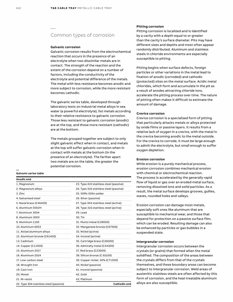
The galvanic series table, developed through laboratory tests on industrial metal alloys in sea water (a powerful electrolyte), list metals according to their relative resistance to galvanic corrosion. Those less resistant to galvanic corrosion (anodic) are at the top, and those more resistant (cathodic) are at the bottom.
The metals grouped together are subject to only slight galvanic effect when in contact, and metals at the top will suffer galvanic corrosion when in contact with metals at the bottom (in the presence of an electrolyte). The farther apart two metals are on the table, the greater the potential corrosion.
Pitting corrosionPitting corrosion is localized and is identified by a cavity with a depth equal to or greater than the cavity’s surface diameter. Pits may have different sizes and depths and most often appear randomly distributed. Aluminum and stainless steels in chloride environments are especially susceptible to pitting.
Pitting begins when surface defects, foreign particles or other variations in the metal lead to fixation of anodic (corroded) and cathodic (protected) sites on the metal surface. Acidic metal chlorides, which form and accumulate in the pit as a result of anodes attracting chloride ions, accelerate the pitting process over time. The nature of pitting often makes it difficult to estimate the amount of damage.
Crevice corrosion Crevice corrosion is a specialized form of pitting that particularly attacks metals or alloys protected by oxide films or passive layers. It results from a relative lack of oxygen in a crevice, with the metal in the crevice becoming anodic to the metal outside. For the crevice to corrode, it must be large enough to admit the electrolyte, but small enough to suffer oxygen depletion.
Erosion corrosionWhile erosion is a purely mechanical process, erosion corrosion combines mechanical erosion with chemical or electrochemical reaction. The process is accelerated by the generally rapid flow of liquid or gas over an eroded metal surface, removing dissolved ions and solid particles. As a result, the metal surface develops grooves, gullies, waves, rounded holes and valleys.
Erosion corrosion can damage most metals, especially soft ones like aluminum that are susceptible to mechanical wear, and those that depend for protection on a passive surface film, which can be eroded. Resulting damage can also be enhanced by particles or gas bubbles in a suspended state.
Intergranular corrosionIntergranular corrosion occurs between the crystals (or grains) that formed when the metal solidified. The composition of the areas between the crystals differs from that of the crystals themselves, and these boundary areas can become subject to intergranular corrosion. Weld areas of austenitic stainless steels are often affected by this form of corrosion, and the heat-treatable aluminum alloys are also susceptible.
Anodic end
1. Magnesium 23. Type 410 stainless steel (passive)
2. Magnesium alloys 24. Type 316 stainless steel (passive)
3. Zinc 25. 50Pb-50Sn solder
4. Galvanized steel 26. Silver (passive)
5. Naval brass (C46400) 27. Type 304 stainless steel (active)
6. Aluminum 5052H 28. Type 316 stainless steel (active)
7. Aluminum 3004 29. Lead
8. Aluminum 3003 30. Tin
9. Aluminum 1100 31. Muntz metal (C28000)
10. Aluminum 6053 32. Manganese bronze (C67500)
11. Alclad aluminum alloys 33. Nickel (active)
12. Aluminum bronze (C61400) 34. Inconel (active)
13. Cadmium 35. Cartridge brass (C26000)
14. Copper (C11000) 36. Admiralty metal (C44300)
15. Aluminum 2017 37. Red brass (C23000)
16. Aluminum 2024 38. Silicon bronze (C 65100)
17. Low-carbon steel 39. Copper nickel, 30% (C71500)
18. Wrought iron 40. Nickel (passive)
19. Cast iron 41. Inconel (passive)
20. Monel 42. Gold
21. Ni-resist 43. Platinum
22. Type 304 stainless steel (passive) Cathodic end
—Galvanic series table
A13TECH N I C A L I N FO R M ATI O N
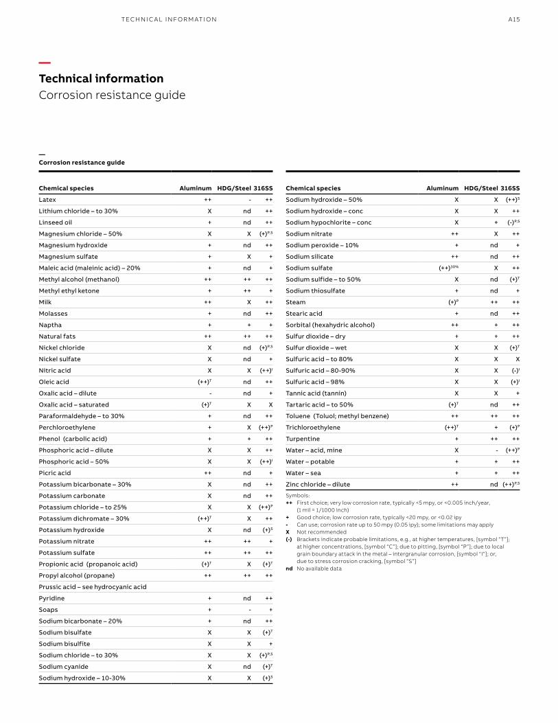
—Corrosion resistance guide
The following table has been compiled as a guide for selecting appropriate cable trays for various industrial environments. The information can only be used as a guide because corrosion processes are dictated by the unique circumstances of any particular assembly.
Corrosion is significantly affected by trace impurities which, at times, can become concentrated through wet/dry cycles in locations that are prone to condensation and evaporation. It is not uncommon to find aggressive mists created from contaminant species, notably from sulfur or halogen sources.
Temperature greatly influences corrosion, sometimes increasing the rate of metal loss, (a rule-of-thumb guide is that a 30 °C change in temperature results in a 10X change in corrosion rate). Sometimes corrosion attack slows down at higher temperatures because oxygen levels in aqueous solutions are lowered as temperatures increase. If an environment completely dries out then there can be no corrosion.
Stress-associated corrosion might occur when assemblies are poorly installed and/or fabricated, e.g., on-site welding or mechanical fastening. Premature failure can result from: corrosion fatigue, which can occur in any environment; stress corrosion cracking, which occurs in the presence of a specific chemical when the metal is under a tensile stress, which may be residual or applied, (e.g., from poor fabrication or welding); fretting, where two adjacent surfaces (under load) are subjected to an oscillatory motion across the mating surfaces.
Design should minimize the risk of stress concentrations within a structure. Examples include sharp profiles, abrupt section changes and threaded screws. These measures are particularly important for metals that are prone to stress corrosion cracking in specific media. Design plays a significant role in exacerbating corrosion. Non-draining locations create liquid traps; local metal-to-metal (or metal-to- non-metal) contact points (e.g., mechanical assembly bolts with washers or spacers), permit crevice corrosion and/or galvanic corrosion to occur.
Areas that are poorly maintained, (e.g., surfaces are not regularly or properly washed and stubborn deposits remain on the metal surface), are particularly prone to localized corrosion damage due to different levels of oxygen under and adjacent to the location in question (differential aeration). Resulting damage from these situations is in the form of small holes (pits). In each of the examples just quoted, there is a restricted supply of oxygen. Thus, metals (e.g., aluminum, stainless steels, zinc) that rely on oxygen to form protective corrosion films (oxides, hydroxides, carbonates, etc.) may be prone to localized pitting and/or crevice corrosion.
A further example of localized corrosion occurs when dissimilar metals contact each other in the presence of a corrodent, i.e., galvanic corrosion. Each metal will corrode, but the one that is most active (anode) can be more corroded, especially when there is a large surrounding area of the less active (cathodic) metal. It is wise to avoid small anodic areas. Some examples include: steel bolts (small area of anodic metal) in stainless steel plate (large area of cathodic metal); steel bolts in copper plate – the steel corrodes. There can be environmental influences, for example, a fluid that contains active metallic species, like copper ion, contacts with aluminum (copper picked up from aqueous solutions conveyed in copper pipe) – the aluminum corrodes. A further dramatic example is provided when trace quantities of mercury contact aluminum – the aluminum corrodes very rapidly. These are examples of deposit corrosion.
B1 copy starts here
B2 copy starts here
B3 copy starts here
A14 T& B C A B LE TR AY M E TA L L I C C A B L E TR AY
—Technical informationCorrosion resistance guide
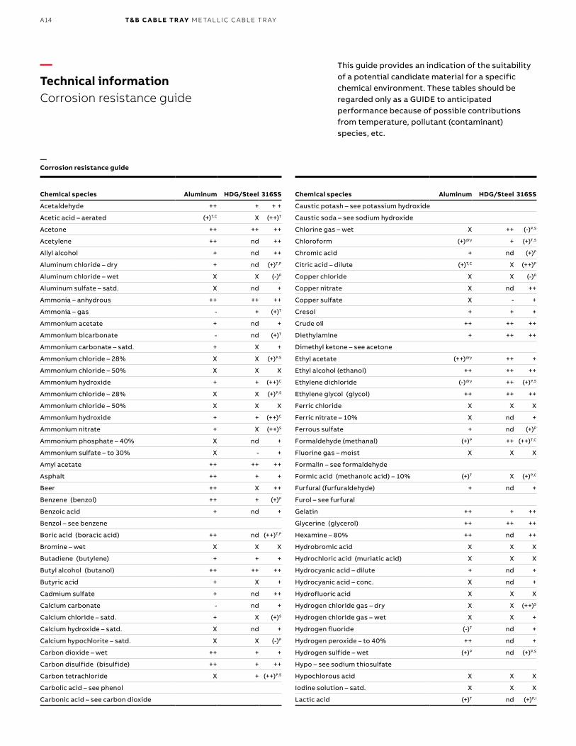
This guide provides an indication of the suitability of a potential candidate material for a specific chemical environment. These tables should be regarded only as a GUIDE to anticipated performance because of possible contributions from temperature, pollutant (contaminant) species, etc.
Chemical species Aluminum HDG/Steel 316SS
Acetaldehyde ++ + + +
Acetic acid – aerated (+)T,C X (++)T
Acetone ++ ++ ++
Acetylene ++ nd ++
Allyl alcohol + nd ++
Aluminum chloride – dry + nd (+)T,P
Aluminum chloride – wet X X (-)P
Aluminum sulfate – satd. X nd +
Ammonia – anhydrous ++ ++ ++
Ammonia – gas - + (+)T
Ammonium acetate + nd +
Ammonium bicarbonate - nd (+)T
Ammonium carbonate – satd. + X +
Ammonium chloride – 28% X X (+)P,S
Ammonium chloride – 50% X X X
Ammonium hydroxide + + (++)C
Ammonium chloride – 28% X X (+)P,S
Ammonium chloride – 50% X X X
Ammonium hydroxide + + (++)C
Ammonium nitrate + X (++)S
Ammonium phosphate – 40% X nd +
Ammonium sulfate – to 30% X - +
Amyl acetate ++ ++ ++
Asphalt ++ + +
Beer ++ X ++
Benzene (benzol) ++ + (+)P
Benzoic acid + nd +
Benzol – see benzene
Boric acid (boracic acid) ++ nd (++)T,P
Bromine – wet X X X
Butadiene (butylene) + + +
Butyl alcohol (butanol) ++ ++ ++
Butyric acid + X +
Cadmium sulfate + nd ++
Calcium carbonate - nd +
Calcium chloride – satd. + X (+)S
Calcium hydroxide – satd. X nd +
Calcium hypochlorite – satd. X X (-)P
Carbon dioxide – wet ++ + +
Carbon disulfide (bisulfide) ++ + ++
Carbon tetrachloride X + (++)P,S
Carbolic acid – see phenol
Carbonic acid – see carbon dioxide
Chemical species Aluminum HDG/Steel 316SS
Caustic potash – see potassium hydroxide
Caustic soda – see sodium hydroxide
Chlorine gas – wet X ++ (-)P,S
Chloroform (+)dry + (+)T,S
Chromic acid + nd (+)P
Citric acid – dilute (+)T,C X (++)P
Copper chloride X X (-)P
Copper nitrate X nd ++
Copper sulfate X - +
Cresol + + +
Crude oil ++ ++ ++
Diethylamine + ++ ++
Dimethyl ketone – see acetone
Ethyl acetate (++)dry ++ +
Ethyl alcohol (ethanol) ++ ++ ++
Ethylene dichloride (-)dry ++ (+)P,S
Ethylene glycol (glycol) ++ ++ ++
Ferric chloride X X X
Ferric nitrate – 10% X nd +
Ferrous sulfate + nd (+)P
Formaldehyde (methanal) (+)P ++ (++)T,C
Fluorine gas – moist X X X
Formalin – see formaldehyde
Formic acid (methanoic acid) – 10% (+)T X (+)P,C
Furfural (furfuraldehyde) + nd +
Furol – see furfural
Gelatin ++ + ++
Glycerine (glycerol) ++ ++ ++
Hexamine – 80% ++ nd ++
Hydrobromic acid X X X
Hydrochloric acid (muriatic acid) X X X
Hydrocyanic acid – dilute + nd +
Hydrocyanic acid – conc. X nd +
Hydrofluoric acid X X X
Hydrogen chloride gas – dry X X (++)S
Hydrogen chloride gas – wet X X +
Hydrogen fluoride (-)T nd +
Hydrogen peroxide – to 40% ++ nd +
Hydrogen sulfide – wet (+)P nd (+)P,S
Hypo – see sodium thiosulfate
Hypochlorous acid X X X
Iodine solution – satd. X X X
Lactic acid (+)T nd (+)P,I
—Corrosion resistance guide
A15TECH N I C A L I N FO R M ATI O N
Symbols:++ First choice; very low corrosion rate, typically <5 mpy, or <0.005 inch/year,
(1 mil = 1/1000 inch)+ Good choice; low corrosion rate, typically <20 mpy, or <0.02 ipy- Can use; corrosion rate up to 50 mpy (0.05 ipy); some limitations may applyX Not recommended(-) Brackets indicate probable limitations, e.g., at higher temperatures, [symbol “T”];
at higher concentrations, [symbol “C”]; due to pitting, [symbol “P”]; due to local grain boundary attack in the metal – intergranular corrosion, [symbol “I”]; or, due to stress corrosion cracking, [symbol “S”]
nd No available data
Chemical species Aluminum HDG/Steel 316SS
Latex ++ - ++
Lithium chloride – to 30% X nd ++
Linseed oil + nd ++
Magnesium chloride – 50% X X (+)P,S
Magnesium hydroxide + nd ++
Magnesium sulfate + X +
Maleic acid (maleinic acid) – 20% + nd +
Methyl alcohol (methanol) ++ ++ ++
Methyl ethyl ketone + ++ +
Milk ++ X ++
Molasses + nd ++
Naptha + + +
Natural fats ++ ++ ++
Nickel chloride X nd (+)P,S
Nickel sulfate X nd +
Nitric acid X X (++)I
Oleic acid (++)T nd ++
Oxalic acid – dilute - nd +
Oxalic acid – saturated (+)T X X
Paraformaldehyde – to 30% + nd ++
Perchloroethylene + X (++)P
Phenol (carbolic acid) + + ++
Phosphoric acid – dilute X X ++
Phosphoric acid – 50% X X (++)I
Picric acid ++ nd +
Potassium bicarbonate – 30% X nd ++
Potassium carbonate X nd ++
Potassium chloride – to 25% X X (++)P
Potassium dichromate – 30% (++)T X ++
Potassium hydroxide X nd (+)S
Potassium nitrate ++ ++ +
Potassium sulfate ++ ++ ++
Propionic acid (propanoic acid) (+)T X (+)T
Propyl alcohol (propane) ++ ++ ++
Prussic acid – see hydrocyanic acid
Pyridine + nd ++
Soaps + - +
Sodium bicarbonate – 20% + nd ++
Sodium bisulfate X X (+)T
Sodium bisulfite X X +
Sodium chloride – to 30% X X (+)P,S
Sodium cyanide X nd (+)T
Sodium hydroxide – 10-30% X X (+)S
Chemical species Aluminum HDG/Steel 316SS
Sodium hydroxide – 50% X X (++)S
Sodium hydroxide – conc X X ++
Sodium hypochlorite – conc X + (-)P,S
Sodium nitrate ++ X ++
Sodium peroxide – 10% + nd +
Sodium silicate ++ nd ++
Sodium sulfate (++)30% X ++
Sodium sulfide – to 50% X nd (+)T
Sodium thiosulfate + nd +
Steam (+)P ++ ++
Stearic acid + nd ++
Sorbital (hexahydric alcohol) ++ + ++
Sulfur dioxide – dry + + ++
Sulfur dioxide – wet X X (+)T
Sulfuric acid – to 80% X X X
Sulfuric acid – 80-90% X X (-)I
Sulfuric acid – 98% X X (+)I
Tannic acid (tannin) X X +
Tartaric acid – to 50% (+)T nd ++
Toluene (Toluol; methyl benzene) ++ ++ ++
Trichloroethylene (++)T + (+)P
Turpentine + ++ ++
Water – acid, mine X - (++)P
Water – potable + + ++
Water – sea + + ++
Zinc chloride – dilute ++ nd (++)P,S
—Corrosion resistance guide
—Technical informationCorrosion resistance guide
B1 copy starts here
B2 copy starts here
B3 copy starts here
A16 T& B C A B LE TR AY M E TA L L I C C A B L E TR AY
Loadkg/m (lb/ft.) Span. m (ft.)
kg/m (lb/ft.) 1.5 (5) 2.4 (8) 3.0 (10) 3.7 (12) 6.0 (20)
37 (25) 5AA 8AA 10AA 12AA 20AA
74 (50) 5A 8A 10A 12A 20A
112 (75) – 8B – 12B 20B
149 (100) – 8C – 12C 20C
Note: These ratings are also used in Mexico
Loadkg/m (lb/ft.) Span. m (ft.)
kg/m (lb/ft.) 1.5 (5) 2.0 (6.5) 2.5 (8.2) 3.0 (10) 4.0 (13) 5.0 (16.4) 6.0 (20)
37 (25) – – – A – – –
45 (30) – – A – – – –
62 (42) – A – – – – –
67 (45) – – – – – – D
82 (55) – – – – – D –
97 (65) – – – C – – –
99 (67) A – – – – – –
112 (75) – – – – – – E
113 (76) – – – – D – –
119 (80) – – C – – – –
137 (92) – – – – – E –
164 (110) – C – – – – –
179 (120) – – – D – – –
189 (127) – – – – E – –
259 (174) C – – – – – –
299 (200) – – – E – – –
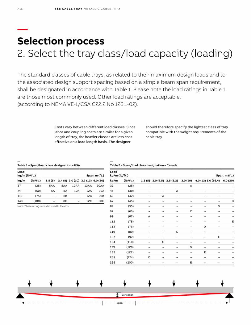
—Selection process2. Select the tray class/load capacity (loading)
The standard classes of cable trays, as related to their maximum design loads and to the associated design support spacing based on a simple beam span requirement, shall be designated in accordance with Table 1. Please note the load ratings in Table 1 are those most commonly used. Other load ratings are acceptable. (according to NEMA VE-1/CSA C22.2 No 126.1-02).
Costs vary between different load classes. Since labor and coupling costs are similar for a given length of tray, the heavier classes are less cost-effective on a load length basis. The designer
should therefore specify the lightest class of tray compatible with the weight requirements of the cable tray.
—Table 1 – Span/load class designation – USA
—Table 2 – Span/load class designation – Canada
Deflection
Span
A17TECH N I C A L I N FO R M ATI O N
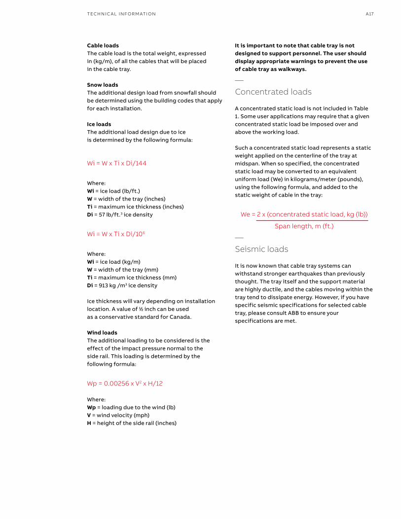
Cable loadsThe cable load is the total weight, expressed in (kg/m), of all the cables that will be placed in the cable tray.
Snow loadsThe additional design load from snowfall should be determined using the building codes that apply for each installation.
Ice loadsThe additional load design due to ice is determined by the following formula:
Wi = W x Ti x Di/144
Where: Wi = ice load (lb/ft.) W = width of the tray (inches) Ti = maximum ice thickness (inches) Di = 57 lb/ft.3 ice density
Wi = W x Ti x Di/106
Where: Wi = ice load (kg/m) W = width of the tray (mm) Ti = maximum ice thickness (mm) Di = 913 kg /m3 ice density
Ice thickness will vary depending on installation location. A value of 11⁄22 inch can be used as a conservative standard for Canada.
Wind loads The additional loading to be considered is the effect of the impact pressure normal to the side rail. This loading is determined by the following formula:
Wp = 0.00256 x V2 x H/12
Where: Wp = loading due to the wind (lb) V = wind velocity (mph) H = height of the side rail (inches)
It is important to note that cable tray is not designed to support personnel. The user should display appropriate warnings to prevent the use of cable tray as walkways.
—Concentrated loads
A concentrated static load is not included in Table 1. Some user applications may require that a given concentrated static load be imposed over and above the working load.
Such a concentrated static load represents a static weight applied on the centerline of the tray at midspan. When so specified, the concentrated static load may be converted to an equivalent uniform load (We) in kilograms/meter (pounds), using the following formula, and added to the static weight of cable in the tray:
We = 2 x (concentrated static load, kg (lb))
Span length, m (ft.)
—Seismic loads
It is now known that cable tray systems can withstand stronger earthquakes than previously thought. The tray itself and the support material are highly ductile, and the cables moving within the tray tend to dissipate energy. However, if you have specific seismic specifications for selected cable tray, please consult ABB to ensure your specifications are met.
B1 copy starts here
B2 copy starts here
B3 copy starts here
A18 T& B C A B LE TR AY M E TA L L I C C A B L E TR AY
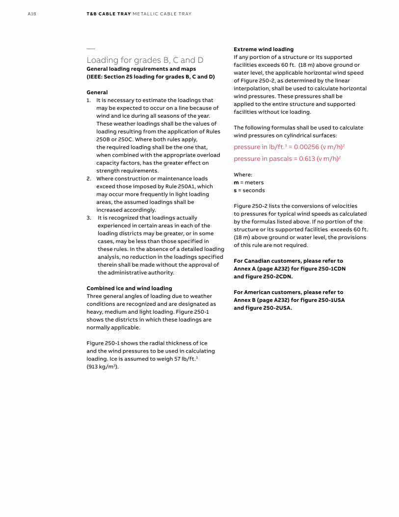
—Loading for grades B, C and DGeneral loading requirements and maps (IEEE: Section 25 loading for grades B, C and D)
General1. It is necessary to estimate the loadings that
may be expected to occur on a line because of wind and ice during all seasons of the year. These weather loadings shall be the values of loading resulting from the application of Rules 250B or 250C. Where both rules apply, the required loading shall be the one that, when combined with the appropriate overload capacity factors, has the greater effect on strength requirements.
2. Where construction or maintenance loads exceed those imposed by Rule 250A1, which may occur more frequently in light loading areas, the assumed loadings shall be increased accordingly.
3. It is recognized that loadings actually experienced in certain areas in each of the loading districts may be greater, or in some cases, may be less than those specified in these rules. In the absence of a detailed loading analysis, no reduction in the loadings specified therein shall be made without the approval of the administrative authority.
Combined ice and wind loading Three general angles of loading due to weather conditions are recognized and are designated as heavy, medium and light loading. Figure 250-1 shows the districts in which these loadings are normally applicable.
Figure 250-1 shows the radial thickness of ice and the wind pressures to be used in calculating loading. Ice is assumed to weigh 57 lb/ft.3
(913 kg/m3).
Extreme wind loading If any portion of a structure or its supported facilities exceeds 60 ft. (18 m) above ground or water level, the applicable horizontal wind speed of Figure 250-2, as determined by the linear interpolation, shall be used to calculate horizontal wind pressures. These pressures shall be applied to the entire structure and supported facilities without ice loading.
The following formulas shall be used to calculate wind pressures on cylindrical surfaces:
pressure in lb/ft.3 = 0.00256 (v m/h)2
pressure in pascals = 0.613 (v m/h)2
Where: m = meters s = seconds
Figure 250-2 lists the conversions of velocities to pressures for typical wind speeds as calculated by the formulas listed above. If no portion of the structure or its supported facilities exceeds 60 ft. (18 m) above ground or water level, the provisions of this rule are not required.
For Canadian customers, please refer to Annex A (page A232) for figure 250-1CDN and figure 250-2CDN.
For American customers, please refer to Annex B (page A232) for figure 250-1USA and figure 250-2USA.
A19TECH N I C A L I N FO R M ATI O N
—Structural design
An installed cable tray system functions as a beam under a uniformly distributed load. The four basic beam configurations found in cable installations are simple, continuous, cantilever and fixed. Each is attached to the cable tray support in a different way.
Continuous beamCable tray sections forming spans constitute a continuous beam configuration, the most common found in cable tray installations. This configuration exhibits characteristics of the simple beam and the fixed beam. For example, with loads applied to all spans at the same time, the ends spans function like simple beams, while the counterbalancing loads on either side of a support function like a fixed beam. As the number of spans increases, the continuous beam behaves increasingly like a fixed beam, and the maximum deflection continues to decrease. As this occurs, the system’s load carrying capability increases.
Simple beamA straight section of cable tray supported at both ends but not fastened functions as a simple beam. Under a load, the tray will exhibit deflection. The load carrying capacity of a cable tray unit should be based on simple beam loading, since this type of loading occurs at run ends, offsets, etc., in any tray system. The NEMA/CSA Load Test is a simple beam, uniformly distributed load test, used primarily because it is easy to test and represents the worst case beam condition compared to continuous or fixed configurations. The only criterion for NEMA/CSA acceptance is the ability to support 150% of the rated load.
Fixed beamLike the cantilever beam, a fixed beam applies more to the cable tray supports than the tray itself, because both ends of a fixed beam are firmly attached to the supports. The rigid attachment prevents movement and increases load bearing ability.
Cantilever beamA cantilever beam has more to do with the cable tray supports than the tray. Attaching one end of a beam to a support while the other end remains unsupported, as when wall mounting a bracket, creates a cantilever beam configuration. Obviously, with one end unsupported, the load rating of a cantilever beam is significantly less than that of a simple beam.
Design loadingsBasic cable trays are designed on the basis of maximum allowable stress for a certain section and material. The allowable cable load varies with the span, type and width of the tray.
SplicingSince the need for a continuous system requires that side rails be spliced, splice plates must be both strong and easy to install. The ABB aluminum snap-in splice plate allows hands-free installation of hardware for easier assembly. If practical, splices in a continuous span cable tray system should be installed at points of minimum stress. Unspliced straight sections should be used on all simple spans and on end spans of continuous span runs. Straight section lengths should be equal to or greater than the span length to ensure not more than one splice between supports.
Examples of splicing configurations are shown on page A25.
Basic design stressesAllowable working stresses are the basis for all structural design. Since they must be of such magnitude as to assure the safety of the structure against failure, their selection is a matter of prime importance. In practice, a basic design stress is determined by dividing the strength of the material by a factor of safety. The determining factors in establishing a set of basic design stresses for a structure are therefore the mechanical properties of the materials and suitable factors of safety. Yield strength and ultimate strength are the mechanical properties most commonly considered to govern design. Values for these properties are readily obtainable. In determining the factor of safety, the designer must usually be guided by current practice – the “standard specifications” adopted by various technical societies and associations – and his or her own judgment and experience.
B1 copy starts here
B2 copy starts here
B3 copy starts here
A20 T& B C A B LE TR AY M E TA L L I C C A B L E TR AY
—Structural design (continued)
Factors of safetySince a low value for the factor of safety results in economy of material, the designer seeks to establish a value as low as is practical, based on sound engineering judgment and experience. In making the determination, consideration of the following factors are highly important:
• The accuracy with which the loads to represent service conditions are selected and assumed. If there is much doubt concerning these loads, the basic design stress will have to be more conservative than under conditions where the loads are known with considerable accuracy.
• The accuracy with which the stresses in the members of a structure are calculated. Many approximations are used in structural design to estimate stress distribution. The choice of a factor of safety should be consistent with how accurate the analysis is. The more precise the method, the greater the allowable unit stress may be.
• The significance of the structure being designed. The designer must keep in mind the relative importance of the structure and appraise the possibility of its failure causing significant property damage or loss of life. In this respect, the significance of the design will govern the choice of a factor of safety to a considerable extent.
The factors of safety used in designing most common types of structures are an outgrowth of the experience gained from many applications and tests – even failures. The trend in recent years has been to reduce the factors of safety in line with improved quality of material and increasing knowledge of stress distribution. Further reductions may be made in the future as greater accuracy in determinations becomes possible and practicable.
Application of design stresses to cable tray systemsA cable tray manufacturer must design standard products to accommodate the great variations encountered in applications. The factors affecting the selection of a suitable basic design stress necessarily result in more conservative stresses than might otherwise be required.
An engineer who is in a position to determine specific stress requirements with a far greater degree of accuracy may consider that the manufacturer’s basic design stresses are too conservative for a particular project. Using individual experience and judgment, he or she would establish a new set of basic design stresses, selecting those safety factors that would result in a cable tray system best suited to meet the projected service conditions. With these stresses, the engineer can easily calculate an increase or decrease in the manufacturer’s loading data, since the load is always in direct proportion to the stress.
The factors of safety used in determining maximum allowable stresses are as follows:
Aluminum alloys• For tension: the lower of 11⁄33 the minimum
ultimate strength or 11⁄22 the minimum yield strength in tension.
• For compression: the lower of 11⁄33 the minimum ultimate strength or 22⁄55 the minimum yield strength in compression.
• For shear: the lower of 11⁄33 the minimum ultimate strength or 11⁄22 the minimum yield strength in shear.
For hot rolled steels• For tension: the lower of 11⁄22 the minimum ultimate
strength or the minimum yield point in tension times 0.61.
• For compression: the lower of 11⁄22 the minimum ultimate strength or the minimum yield point in compression times 0.61.
• For shear: maximum stress not to exceed a value of 22⁄33 the basic design stress for tension.
Design efficiencyA tray designed to perform its required function with the minimum weight (which facilitates installation) requires the material to be used in the most effective manner. The design requirements of side rails are different from those of rungs or ventilated bottom; fabricated tray allows the designer to use different shapes and thicknesses of metal to the best advantage. The strength of the side rail and rungs is increased by the proper use of metal in the high strength heat-treated aluminum or continuously rolled cold-worked steel sections.
A21TECH N I C A L I N FO R M ATI O N
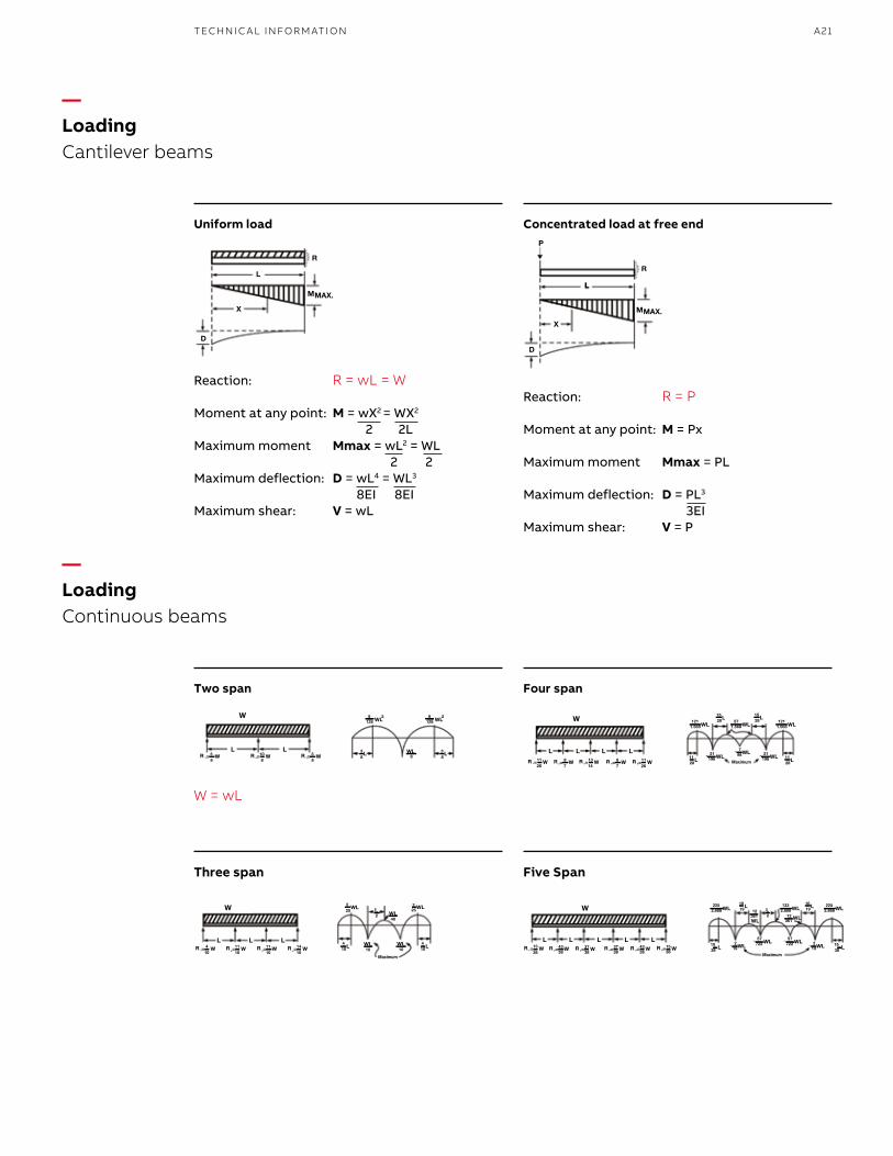
—LoadingCantilever beams
—LoadingContinuous beams
Uniform load
Reaction: R = wL = W
Moment at any point: M = wX2 = WX2
2 2LMaximum moment Mmax = wL2 = WL 2 2Maximum deflection: D = wL4 = WL3
8EI 8EIMaximum shear: V = wL
Two span
W = wL
Three span
Concentrated load at free end
Reaction: R = P
Moment at any point: M = Px
Maximum moment Mmax = PL
Maximum deflection: D = PL3
3EIMaximum shear: V = P
Four span
Five Span
B1 copy starts here
B2 copy starts here
B3 copy starts here
A22 T& B C A B LE TR AY M E TA L L I C C A B L E TR AY
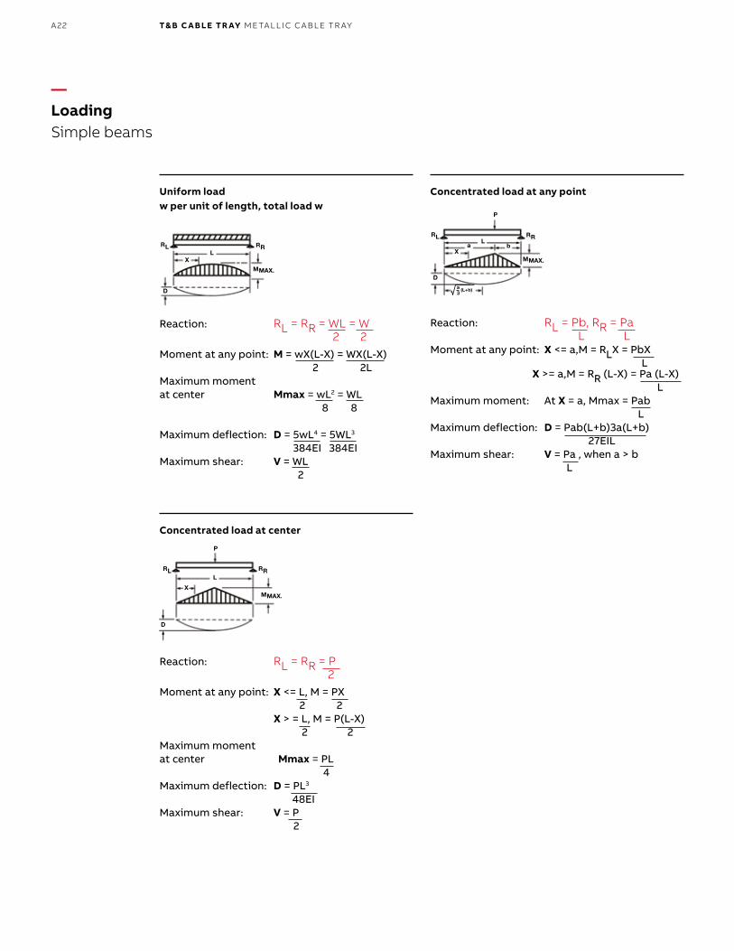
—LoadingSimple beams
Uniform loadw per unit of length, total load w
Reaction: RL = RR = WL = W 2 2Moment at any point: M = wX(L-X) = WX(L-X) 2 2LMaximum moment at center Mmax = wL2 = WL 8 8
Maximum deflection: D = 5wL4 = 5WL3
384EI 384EIMaximum shear: V = WL 2
Concentrated load at center
Reaction: RL = RR = P 2Moment at any point: X <= L, M = PX 2 2 X > = L, M = P(L-X) 2 2Maximum moment at center Mmax = PL 4Maximum deflection: D = PL3
48EIMaximum shear: V = P 2
Concentrated load at any point
Reaction: RL = Pb, RR = Pa L LMoment at any point: X <= a,M = RLX = PbX L X >= a,M = RR (L-X) = Pa (L-X) LMaximum moment: At X = a, Mmax = Pab LMaximum deflection: D = Pab(L+b)3a(L+b) 27EILMaximum shear: V = Pa , when a > b L
A23TECH N I C A L I N FO R M ATI O N
—Selection process3. Select the tray type
—Selection process4. Select the tray size
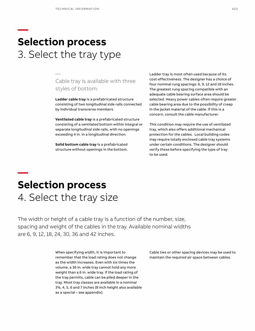
The width or height of a cable tray is a function of the number, size, spacing and weight of the cables in the tray. Available nominal widths are 6, 9, 12, 18, 24, 30, 36 and 42 inches.
When specifying width, it is important to remember that the load rating does not change as the width increases. Even with six times the volume, a 36 in. wide tray cannot hold any more weight than a 6 in. wide tray. If the load rating of the tray permits, cable can be piled deeper in the tray. Most tray classes are available in a nominal 355⁄88, 4, 5, 6 and 7 inches (8 inch height also available as a special – see appendix).
—Cable tray is available with three styles of bottom:
Ladder cable tray is a prefabricated structure consisting of two longitudinal side rails connected by individual transverse members.
Ventilated cable tray is a prefabricated structure consisting of a ventilated bottom within integral or separate longitudinal side rails, with no openings exceeding 4 in. in a longitudinal direction.
Solid bottom cable tray is a prefabricated structure without openings in the bottom.
Ladder tray is most often used because of its cost-effectiveness. The designer has a choice of four nominal rung spacings: 6, 9, 12 and 18 inches. The greatest rung spacing compatible with an adequate cable bearing surface area should be selected. Heavy power cables often require greater cable bearing area due to the possibility of creep in the jacket material of the cable. If this is a concern, consult the cable manufacturer.
This condition may require the use of ventilated tray, which also offers additional mechanical protection for the cables. Local building codes may require totally enclosed cable tray systems under certain conditions. The designer should verify these before specifying the type of tray to be used.
Cable ties or other spacing devices may be used to maintain the required air space between cables.
B1 copy starts here
B2 copy starts here
B3 copy starts here
A24 T& B C A B LE TR AY M E TA L L I C C A B L E TR AY
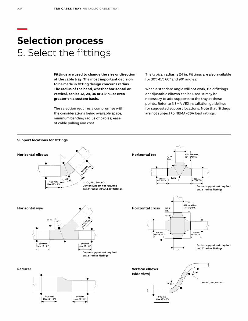
Fittings are used to change the size or direction of the cable tray. The most important decision to be made in fitting design concerns radius. The radius of the bend, whether horizontal or vertical, can be 12, 24, 36 or 48 in., or even greater on a custom basis.
The selection requires a compromise with the considerations being available space, minimum bending radius of cables, ease of cable pulling and cost.
The typical radius is 24 in. Fittings are also available for 30°, 45°, 60° and 90° angles.
When a standard angle will not work, field fittings or adjustable elbows can be used. It may be necessary to add supports to the tray at these points. Refer to NEMA VE2 installation guidelines for suggested support locations. Note that fittings are not subject to NEMA/CSA load ratings.
—Selection process5. Select the fittings
Support locations for fittings
Horizontal elbows
Horizontal wye
Reducer
Horizontal tee
Horizontal cross
Vertical elbows(side view)
= 30o, 45o, 60o, 90o
Center support not requiredon 12" radius 30o and 45o fittings
Center support not requiredon 12" radius fittings
Center support not requiredon 12" radius fittings
Center support not requiredon 12" radius fittings
600 mmMax. (2' – 0")
2/3 Rtyp.
2/3 Rtyp.
1/2 L
600 mm Max.(2' – 0") typ.
600 mm Max.(2' – 0") typ.
600 mmMax. (2' – 0")
600 mmMax. (2' – 0")
600 mmMax. (2' – 0")
600 mmMax. (2' – 0")
600 mmMax. (2' – 0")
600 mmMax. (2' – 0")
600 mmMax. (2' – 0")
600 mmMax. (2' – 0")
Ø = 30o, 45o, 60o, 90o
Ø
Ø
25.50
450
600 mmMax. (2' – 0")
600 mm
Max. (
2' – 0
")
600 mm
Max. (2' –
0")
1/2 Ø
A25TECH N I C A L I N FO R M ATI O N
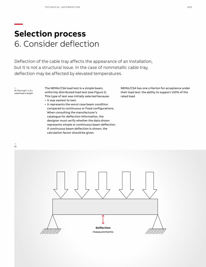
—01 Test load = 1.5 xrated load x length
—01
—Selection process6. Consider deflection
Deflection of the cable tray affects the appearance of an installation, but it is not a structural issue. In the case of nonmetallic cable tray, deflection may be affected by elevated temperatures.
The NEMA/CSA load test is a simple beam, uniformly distributed load test (see Figure 1). This type of test was initially selected because:• It was easiest to test.• It represents the worst case beam condition
compared to continuous or fixed configurations. When consulting the manufacturer’s catalogue for deflection information, the designer must verify whether the data shown represents simple or continuous beam deflection. If continuous beam deflection is shown, the calculation factor should be given.
NEMA/CSA has one criterion for acceptance under their load test: the ability to support 150% of the rated load.
Deflectionmeasurements
B1 copy starts here
B2 copy starts here
B3 copy starts here
A26 T& B C A B LE TR AY M E TA L L I C C A B L E TR AY
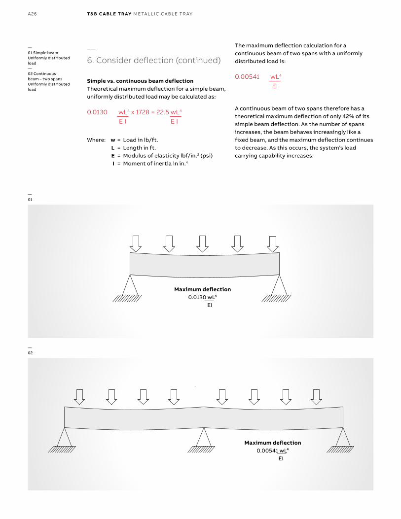
—6. Consider deflection (continued)
Simple vs. continuous beam deflectionTheoretical maximum deflection for a simple beam, uniformly distributed load may be calculated as:
0.0130 wL4 x 1728 = 22.5 wL4
E I E I
Where: w = Load in lb/ft. L = Length in ft. E = Modulus of elasticity lbf/in.2 (psi) I = Moment of inertia in in.4
The maximum deflection calculation for a continuous beam of two spans with a uniformly distributed load is:
0.00541 wL4
EI
A continuous beam of two spans therefore has a theoretical maximum deflection of only 42% of its simple beam deflection. As the number of spans increases, the beam behaves increasingly like a fixed beam, and the maximum deflection continues to decrease. As this occurs, the system’s load carrying capability increases.
Maximum Deflection
.0130 wL4
EI
Simple Beam
Uniformly Distributed Load
Continuous Beam – Two Spans
Uniformly Distributed Load
Maximum Deflection
.00541 wL4
EI
Maximum Deflection
.0130 wL4
EI
Simple Beam
Uniformly Distributed Load
Continuous Beam – Two Spans
Uniformly Distributed Load
Maximum Deflection
.00541 wL4
EI
—01
—02
—01 Simple beamUniformly distributedload—02 Continuousbeam – two spansUniformly distributedload
Maximum deflection0.0130 wL⁴
EI
Maximum deflection0.00541 wL⁴
EI
A27TECH N I C A L I N FO R M ATI O N
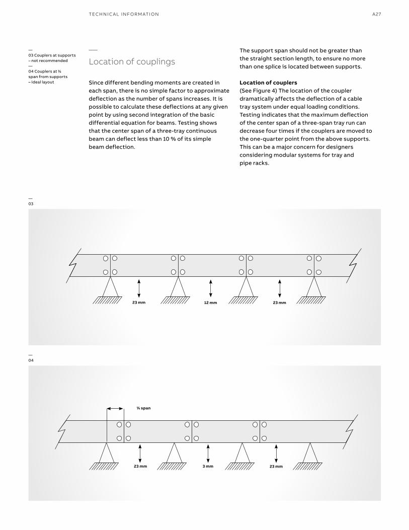
—Location of couplings
Since different bending moments are created in each span, there is no simple factor to approximate deflection as the number of spans increases. It is possible to calculate these deflections at any given point by using second integration of the basic differential equation for beams. Testing shows that the center span of a three-tray continuous beam can deflect less than 10 % of its simple beam deflection.
—03 Couplers at supports – not recommended—04 Couplers at 11⁄44 span from supports – ideal layout
—03
—04
The support span should not be greater than the straight section length, to ensure no more than one splice is located between supports.
Location of couplers(See Figure 4) The location of the coupler dramatically affects the deflection of a cable tray system under equal loading conditions. Testing indicates that the maximum deflection of the center span of a three-span tray run can decrease four times if the couplers are moved to the one-quarter point from the above supports.This can be a major concern for designers considering modular systems for tray and pipe racks.
23 mm 12 mm 23 mm
11⁄44 span
23 mm 3 mm 23 mm
B1 copy starts here
B2 copy starts here
B3 copy starts here
A28 T& B C A B LE TR AY M E TA L L I C C A B L E TR AY
—Selection process7. Consider thermal expansion and contraction
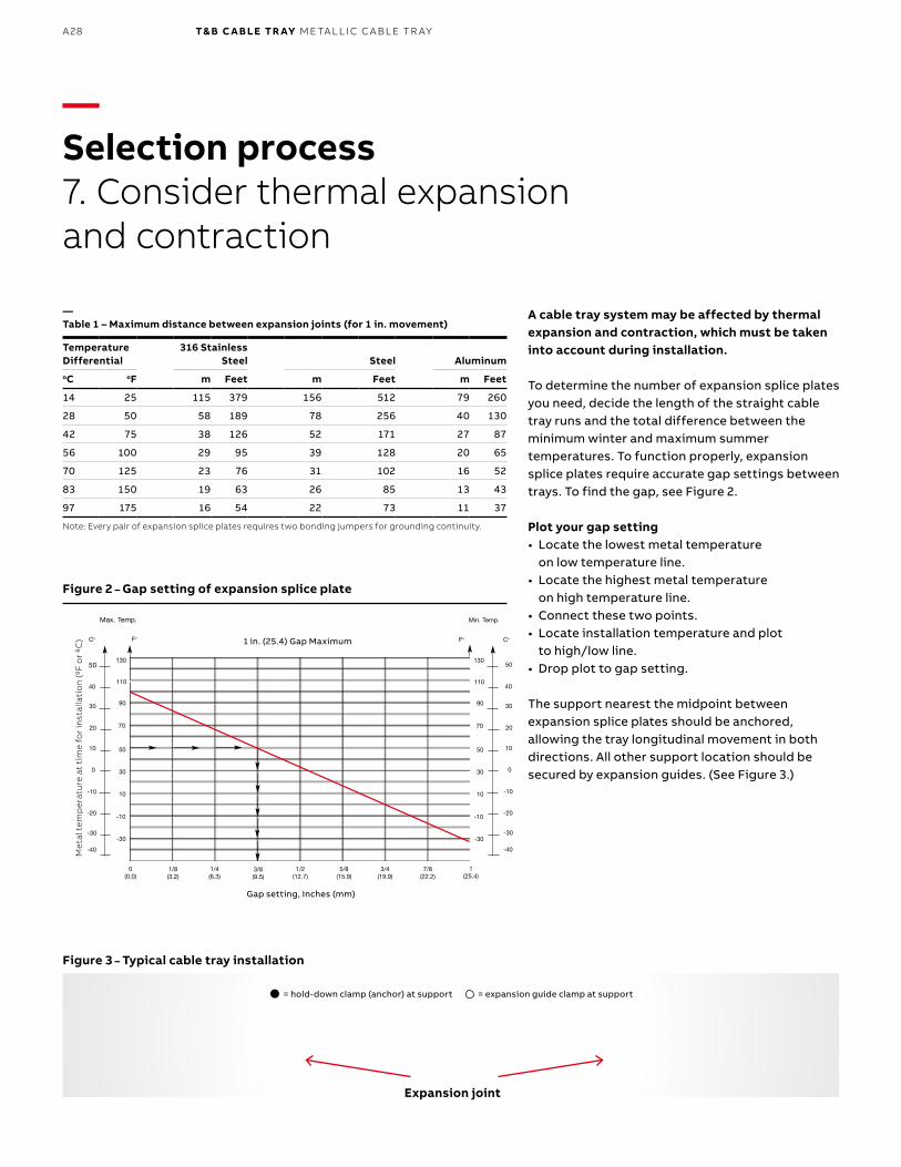
A cable tray system may be affected by thermal expansion and contraction, which must be taken into account during installation.
To determine the number of expansion splice plates you need, decide the length of the straight cable tray runs and the total difference between the minimum winter and maximum summer temperatures. To function properly, expansion splice plates require accurate gap settings between trays. To find the gap, see Figure 2.
Plot your gap setting• Locate the lowest metal temperature
on low temperature line.• Locate the highest metal temperature
on high temperature line.• Connect these two points.• Locate installation temperature and plot
to high/low line. • Drop plot to gap setting.
The support nearest the midpoint between expansion splice plates should be anchored, allowing the tray longitudinal movement in both directions. All other support location should be secured by expansion guides. (See Figure 3.)
Gap setting, Inches (mm)
Met
al t
emp
erat
ure
at
tim
e fo
r in
stal
lati
on
(ºF
or
ºC) 1 in. (25.4) Gap Maximum
Expansion Splice Plates(Bonding Jumpers required
on each side of tray)
= hold down clamp (anchor) at support= expansion guide clamp at support Expansion joint
= hold-down clamp (anchor) at support = expansion guide clamp at support
Temperature Differential
316 Stainless Steel Steel Aluminum
oC oF m Feet m Feet m Feet
14 25 115 379 156 512 79 260
28 50 58 189 78 256 40 130
42 75 38 126 52 171 27 87
56 100 29 95 39 128 20 65
70 125 23 76 31 102 16 52
83 150 19 63 26 85 13 43
97 175 16 54 22 73 11 37
Note: Every pair of expansion splice plates requires two bonding jumpers for grounding continuity.
—Table 1 – Maximum distance between expansion joints (for 1 in. movement)
Figure 2 – Gap setting of expansion splice plate
Figure 3 – Typical cable tray installation
A29TECH N I C A L I N FO R M ATI O N
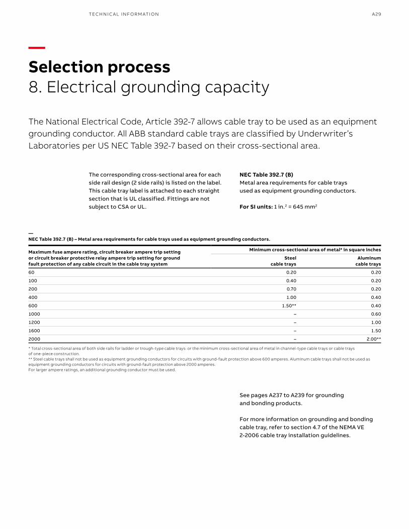
—NEC Table 392.7 (B) – Metal area requirements for cable trays used as equipment grounding conductors.
Maximum fuse ampere rating, circuit breaker ampere trip setting or circuit breaker protective relay ampere trip setting for ground fault protection of any cable circuit in the cable tray system
Minimum cross-sectional area of metal* in square inches
Steelcable trays
Aluminumcable trays
60 0.20 0.20
100 0.40 0.20
200 0.70 0.20
400 1.00 0.40
600 1.50** 0.40
1000 – 0.60
1200 – 1.00
1600 – 1.50
2000 – 2.00**
—Selection process8. Electrical grounding capacity
The National Electrical Code, Article 392-7 allows cable tray to be used as an equipment grounding conductor. All ABB standard cable trays are classified by Underwriter’s Laboratories per US NEC Table 392-7 based on their cross-sectional area.
The corresponding cross-sectional area for each side rail design (2 side rails) is listed on the label. This cable tray label is attached to each straight section that is UL classified. Fittings are not subject to CSA or UL.
See pages A237 to A239 for grounding and bonding products.
For more information on grounding and bonding cable tray, refer to section 4.7 of the NEMA VE 2-2006 cable tray installation guidelines.
* Total cross-sectional area of both side rails for ladder or trough-type cable trays: or the minimum cross-sectional area of metal in channel-type cable trays or cable trays of one-piece construction.** Steel cable trays shall not be used as equipment grounding conductors for circuits with ground-fault protection above 600 amperes. Aluminum cable trays shall not be used as equipment grounding conductors for circuits with ground-fault protection above 2000 amperes.For larger ampere ratings, an additional grounding conductor must be used.
NEC Table 392.7 (B)Metal area requirements for cable traysused as equipment grounding conductors.
For SI units: 1 in.2 = 645 mm2
B1 copy starts here
B2 copy starts here
B3 copy starts here
A30 T& B C A B LE TR AY M E TA L L I C C A B L E TR AY
—Engineering cable traySpecification—Cable tray
• Cable tray shall be by one manufacturer and shall consist of straight sections, fittings and accessories per NEMA VE1-2006/CSA C22.2 No. 126.1-02. Cable tray must be listed by UL as equipment grounding conductor. There shall be no burrs, projections or sharp edges to damage the cable insulation.
—Material
• Aluminum – All side rails, and rungs shall be of extruded aluminum type 6063-T6. Side rails shall be of I-beam construction.
• Pregalvanized steel – All side rails and rungs shall be of steel conforming to the requirements of ASTM A653/A653M-06a with G90 coating thickness. Side rail shall be reinforced with flanges turned inward.
• Hot-dipped galvanized steel – All side rails and rungs shall be made from steel conforming to the requirements of A1008/A1008M-07,SS grade 33, type 2 or A1011/A1011-06b SS, grade 33 and shall be hot-dipped galvanized after manufacture per ASTM A123 providing a minimum thickness of 1.50 oz per ft.2
• Stainless steel – All cable tray and accessories shall be of type AISI 316 stainless steel.
—Tray types
• Ladder – Ladder tray shall incorporate two side rails connected by lateral rungs. Rungs shall provide minimum 1 in. bearing surface and have slots perpendicular to the centerline of the rung on 1 in. centers for attachment of cable ties. Rungs shall also have an open slot to facilitate attachment of pipe straps and other accessories. Rungs shall be installed at 6, 9, 12 or 18 in. spacing. The rungs shall not be below the bottom of the side rail.
• Solid Bottom – Solid bottom tray shall incorporate two side rails connected by rungs on 12 in. centers with a solid sheet applied below the rungs.
• Ventilated trough – Ventilated trough tray shall incorporate two side rails connected by rungs at 4 in. spacing.
—Dimensions
• Side rail height – Side rails heights shall be 355⁄88, 4, 5, 6 and 7 in. Minimum loading depths shall be 255⁄88, 3, 4, 5, and 6 in.
• Length – All cable tray straight sections shall be supplied in 12 ft., 24 ft., 3 m and 6 m lengths.
• Width – Cable tray shall be supplied in 6, 9, 12, 18, 24, 30 and 36 in. widths as required.
• Radius fittings – For all fittings requiring a radius, that radius shall be 12, 24, 36 or 48 in. and shall be measured to the nearest perpendicular surface.
—Accessories
• Covers and accessories – Covers shall be supplied to protect tray cable where needed. Appropriate hold-downs shall be supplied to properly attach the covers to the tray.
• Splice plates – Aluminum splice plates shall be designed to snap into tray side rail and shall be supplied with four square neck carriage bolts and hex nuts for attachment. Steel splice plates shall be supplied with four square neck carriage bolts and hex nuts for attachment.
—Loading capabilities
• Cable tray shall meet specified NEMA/CSA load ratings with safety factor of 1.5. The cable tray should also be able to support a 200 lb concentrated load at midspan over and above stated cable load.
—Design and manufacture• Cable tray design shall be that of T&B Cable Tray systems as
manufactured by ABB.
A31
Load kg/m (lb/ft.) Span, m (ft.)
kg/m (lb/ft.) 1.5 (5) 2.4 (8) 3.0 (10) 3.7 (12) 6.0 (20)
37 (25) 5AA 8AA 10AA 12AA 20AA
74 (50) 5A 8A 10A 12A 20A
112 (75) – 8B – 12B 20B
149 (100) – 8C – 12C 20C
Note: These ratings are also used in Mexico.
Load kg/m (lb/ft.) Span, m (ft.)
kg/m (lb/ft.) 1.5 (5) 2.0 2.53.0 (10) 4.0 5.0 6.0 (20)
37 (25) – – – A – – –
45 (30) – – A – – – –
62 (42) – A – – – – –
67 (45) – – – – – – D
82 (55) – – – – – D –
97 (65) – – – C – – –
99 (67) A – – – – – –
112 (75) – – – – – – E
113 (76) – – – – D – –
119 (80) – – C – – – –
137 (92) – – – – – E –
164 (110) – C – – – – –
179 (120) – – – D – – –
189 (127) – – – – E – –
259 (174) C – – – – – –
299 (200) – – – E – – –
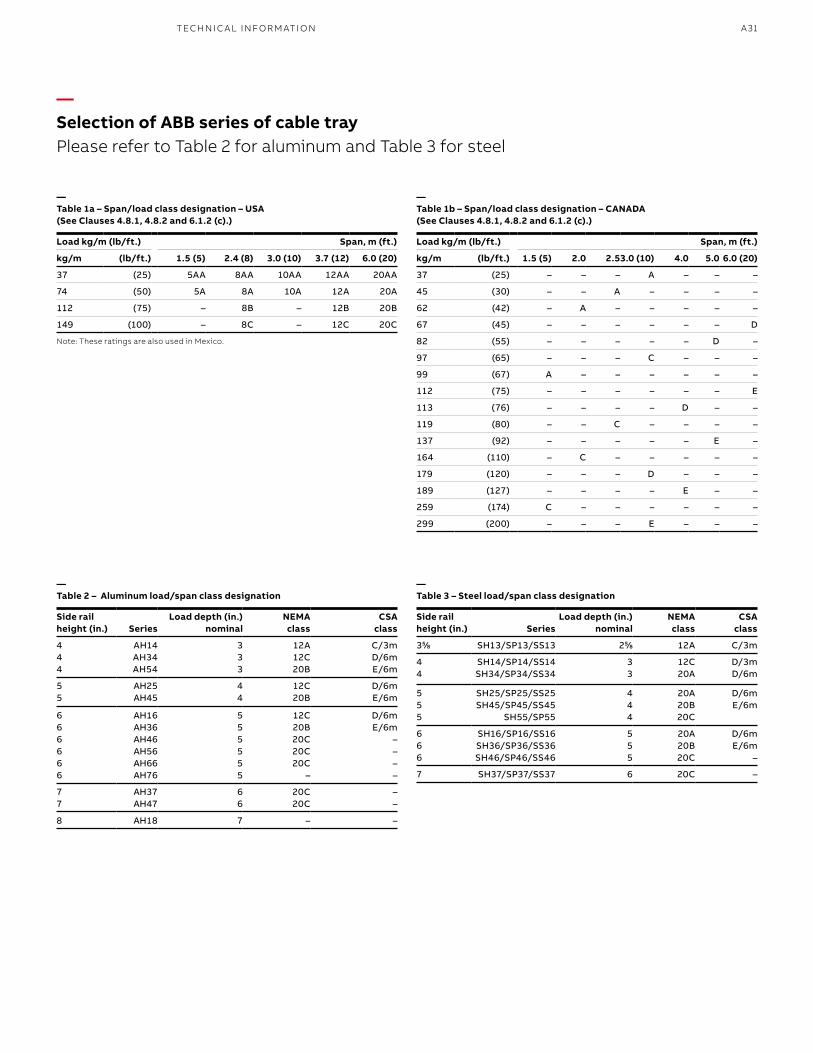
—Selection of ABB series of cable trayPlease refer to Table 2 for aluminum and Table 3 for steel
—Table 1a – Span/load class designation – USA (See Clauses 4.8.1, 4.8.2 and 6.1.2 (c).)
—Table 2 – Aluminum load/span class designation
—Table 1b – Span/load class designation – CANADA (See Clauses 4.8.1, 4.8.2 and 6.1.2 (c).)
—Table 3 – Steel load/span class designation
Side rail height (in.) Series
Load depth (in.) nominal
NEMA class
CSA class
444
AH14AH34AH54
333
12A12C20B
C/3mD/6mE/6m
55
AH25AH45
44
12C20B
D/6mE/6m
666666
AH16AH36AH46AH56AH66 AH76
555555
12C20B20C20C20C
–
D/6mE/6m
––––
77
AH37AH47
66
20C20C
––
8 AH18 7 – –
Side rail height (in.) Series
Load depth (in.) nominal
NEMA class
CSA class
355⁄88 SH13/SP13/SS13 255⁄88 12A C/3m
44
SH14/SP14/SS14SH34/SP34/SS34
3 3
12C20A
D/3mD/6m
555
SH25/SP25/SS25SH45/SP45/SS45
SH55/SP55
444
20A20B20C
D/6mE/6m
666
SH16/SP16/SS16SH36/SP36/SS36SH46/SP46/SS46
555
20A20B20C
D/6mE/6m
–
7 SH37/SP37/SS37 6 20C –
TECH N I C A L I N FO R M ATI O N
B1 copy starts here
B2 copy starts here
B3 copy starts here
A32 T& B C A B LE TR AY M E TA L L I C C A B L E TR AY
A33A LU M I N U M C A B L E TR AY
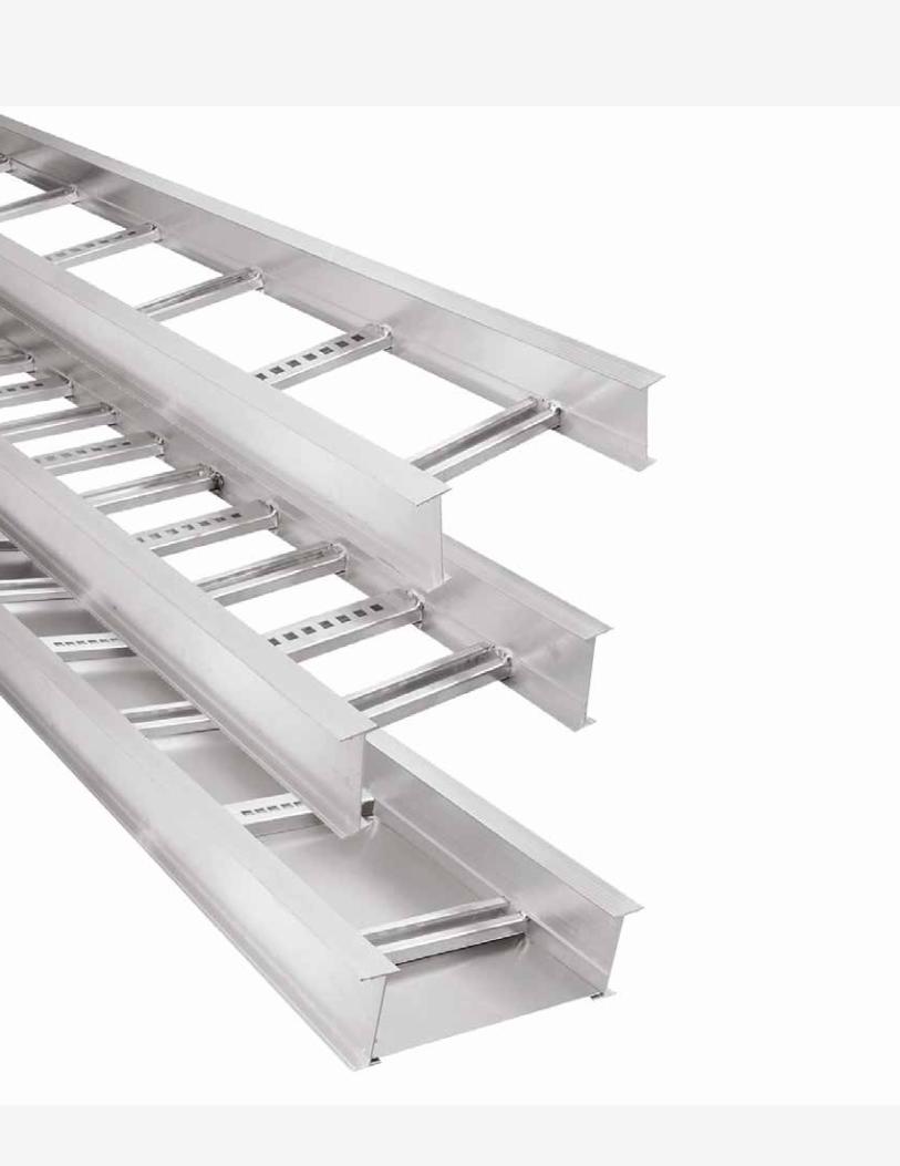
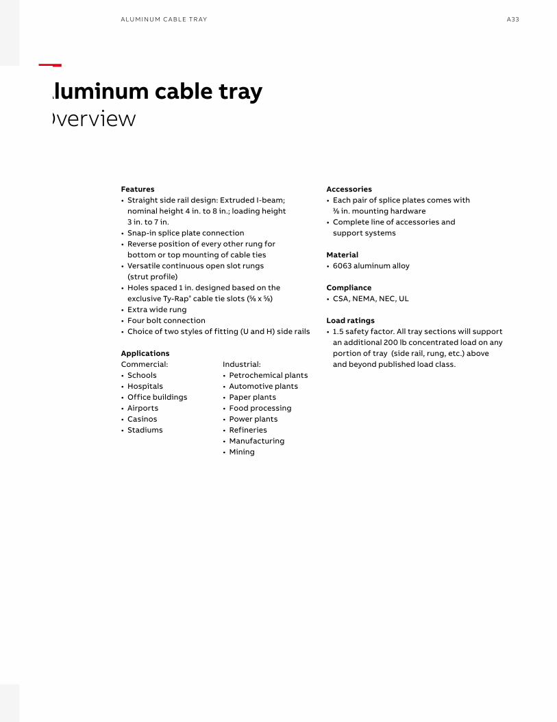
—Aluminum cable trayOverview
Features• Straight side rail design: Extruded I-beam;
nominal height 4 in. to 8 in.; loading height 3 in. to 7 in.
• Snap-in splice plate connection• Reverse position of every other rung for
bottom or top mounting of cable ties• Versatile continuous open slot rungs
(strut profile)• Holes spaced 1 in. designed based on the
exclusive Ty-Rap® cable tie slots (55⁄88 x 55⁄88)• Extra wide rung• Four bolt connection• Choice of two styles of fitting (U and H) side rails
Accessories• Each pair of splice plates comes with
33⁄88 in. mounting hardware• Complete line of accessories and
support systems
Material• 6063 aluminum alloy
Compliance• CSA, NEMA, NEC, UL
Load ratings• 1.5 safety factor. All tray sections will support
an additional 200 lb concentrated load on any portion of tray (side rail, rung, etc.) above and beyond published load class.
ApplicationsCommercial:• Schools• Hospitals• Office buildings• Airports• Casinos• Stadiums
Industrial:• Petrochemical plants• Automotive plants• Paper plants• Food processing• Power plants• Refineries• Manufacturing• Mining
B1 copy starts here
B2 copy starts here
B3 copy starts here
A34 T& B C A B LE TR AY M E TA L L I C C A B L E TR AY
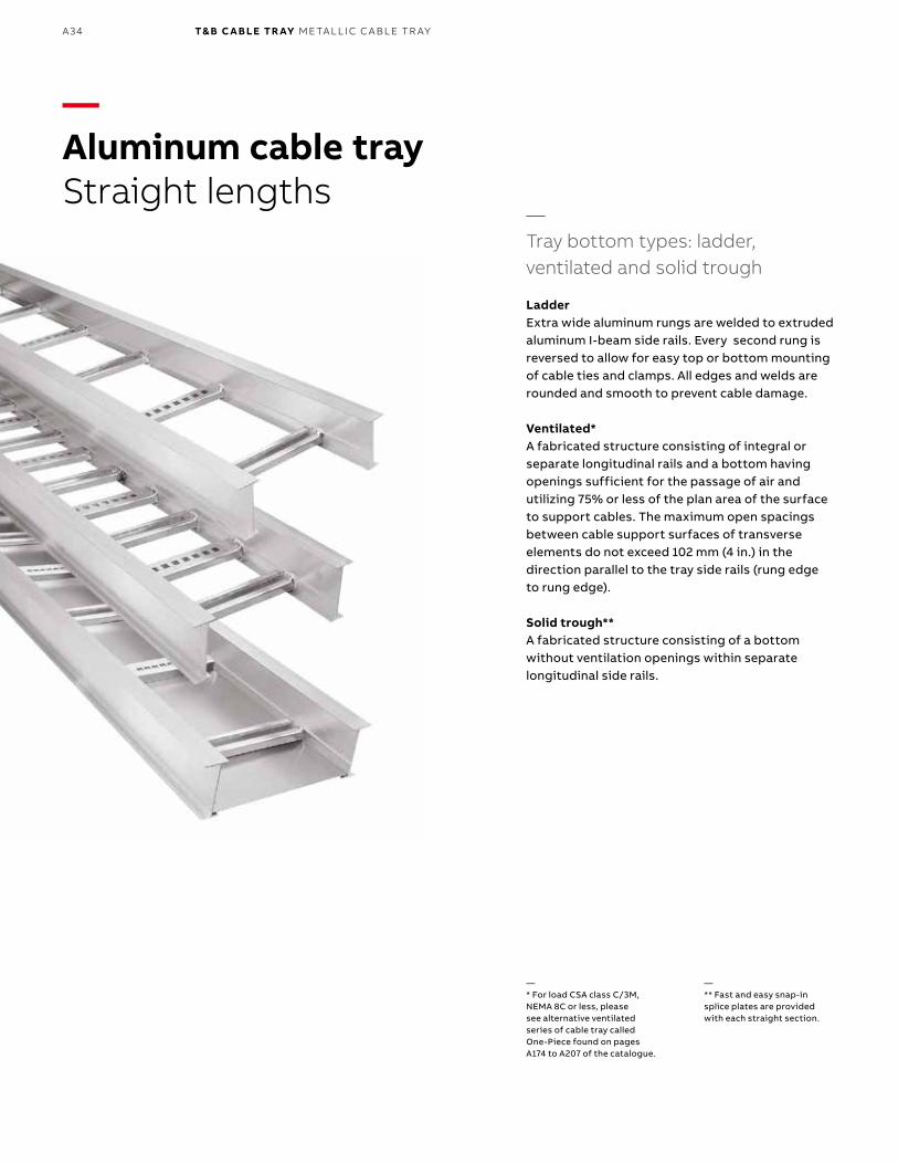
—Aluminum cable trayStraight lengths
—Tray bottom types: ladder, ventilated and solid trough
Ladder Extra wide aluminum rungs are welded to extruded aluminum I-beam side rails. Every second rung is reversed to allow for easy top or bottom mounting of cable ties and clamps. All edges and welds are rounded and smooth to prevent cable damage.
Ventilated* A fabricated structure consisting of integral or separate longitudinal rails and a bottom having openings sufficient for the passage of air and utilizing 75% or less of the plan area of the surface to support cables. The maximum open spacings between cable support surfaces of transverse elements do not exceed 102 mm (4 in.) in the direction parallel to the tray side rails (rung edge to rung edge).
Solid trough**A fabricated structure consisting of a bottom without ventilation openings within separate longitudinal side rails.
—* For load CSA class C/3M, NEMA 8C or less, please see alternative ventilated series of cable tray called One-Piece found on pages A174 to A207 of the catalogue.
—** Fast and easy snap-in splice plates are provided with each straight section.
A35A LU M I N U M C A B L E TR AY
—Straight lengths number selection
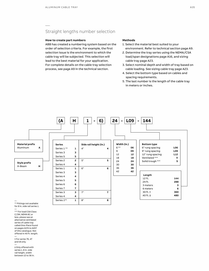
How to create part numbersABB has created a numbering system based on the order of selection criteria. For example, the first selection issue is the environment to which the cable tray will be subjected. This selection will lead to the best material for your application. For complete details on the cable tray selection process, see page A9 in the technical section.
Methods1. Select the material best suited to your
environment. Refer to technical section page A9.2. Determine the tray series using the NEMA/CSA
load/span designations page A16, and sizing cable tray page A23.
3. Select nominal depth and width of tray based on cable loading. See sizing cable tray page A23.
4. Select the bottom type based on cables and spacing requirements.
5. The last number is the length of the cable tray in meters or inches.
Material prefixAluminum A
Width (in.)6 ** 069 0912 1218 1824 2430 3036 3642 42
Bottom type6" rung spacing L069" rung spacing L0912" rung spacing L12Ventilated *** VSolid trough *** S
Length12 ft. 14424 ft. 2883 meters 36 meters 630 ft. † 36040 ft. ‡ 480
Style prefixH-Beam H
(A H 1 - 6) 24 - L09 - 144
Series
Series 1 ** 1
Series 3 3
Series 5 5
Series 2 2
Series 4 4
Series 1 1
Series 3 3
Series 4 4
Series 5 5
Series 6 6
Series 7 7
Series 3 3
Series 4 4
Series 1** 1
Side rail height (in.)
4" 4
5" 5
6" 6
7" 7
8" 8—** Fittings not available for 8 in. side rail series 1.—*** For load CSA Class C/3M, NEMA 8C or less, please see an alternative ventilated series of cable tray called One-Piece found on pages A174 to A207 of this catalogue. Not offered in 40 ft. length.—† For series 76, 47 and 18 only.—‡ Only offered with series 1, 8 in. side rail height, width between 12 to 36 in.
B1 copy starts here
B2 copy starts here
B3 copy starts here
A36 T& B C A B LE TR AY M E TA L L I C C A B L E TR AY
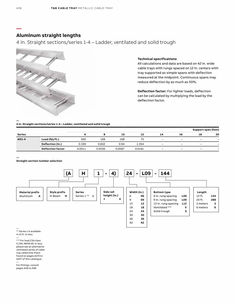
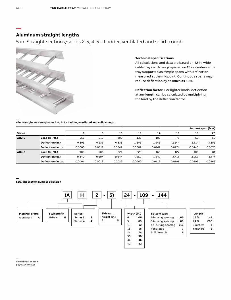
Technical specificationsAll calculations and data are based on 42 in. wide cable trays with rungs spaced on 12 in. centers with tray supported as simple spans with deflection measured at the midpoint. Continuous spans may reduce deflection by as much as 50%.
Deflection factor: For lighter loads, deflection can be calculated by multiplying the load by the deflection factor.
Material prefixAluminum A
Width (in.)6 069 0912 1218 1824 2430 3036 3642 42
Bottom type6 in. rung spacing L069 in. rung spacing L0912 in. rung spacing L12Ventilated *** VSolid trough S
Length12 ft. 14424 ft. 2883 meters 36 meters 6
Style prefixH-Beam H
SeriesSeries 1 ** 1
Side rail height (in.)4 4
(A H 1 - 4) 24 - L09 - 144
Series
Support span (feet)
6 8 10 12 14 16 18 20
AH1-4 Load (lb)/ft.) 300 169 108 75 – – – –
Deflection (in.) 0.339 0.602 0.94 1.354 – – – –
Deflection factor 0.0011 0.0036 0.0087 0.0181 – – – –
—Aluminum straight lengths 4 in. Straight sections/series 1-4 – Ladder, ventilated and solid trough
—4 in. Straight sections/series 1-4 – Ladder, ventilated and solid trough
—** Series 1 is available in 12 ft. or less.—*** For load CSA class C/3M, NEMA 8C or less, please see an alternative ventilated series of cable tray called One-Piece found on pages A174 to A207 of this catalogue.—For fittings, consult pages A48 to A98.
—Straight section number selection
A37A LU M I N U M C A B L E TR AY
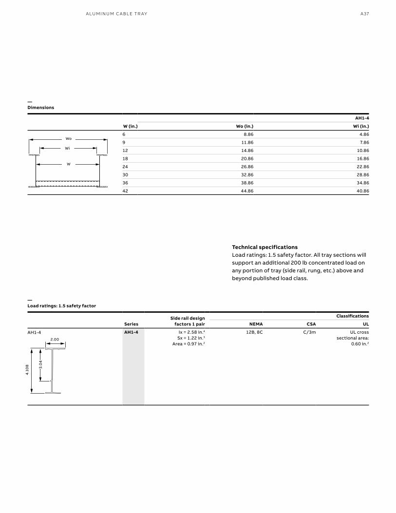
AH1-4
W (in.) Wo (in.) Wi (in.)
6 8.86 4.86
9 11.86 7.86
12 14.86 10.86
18 20.86 16.86
24 26.86 22.86
30 32.86 28.86
36 38.86 34.86
42 44.86 40.86
SeriesSide rail design
factors 1 pair
Classifications
NEMA CSA UL
AH1-4 Ix = 2.58 in.4 Sx = 1.22 in.3
Area = 0.97 in.2
12B, 8C C/3m UL cross sectional area:
0.60 in.2
Wo
Wi
W
AH1-4
—Dimensions
—Load ratings: 1.5 safety factor
Technical specificationsLoad ratings: 1.5 safety factor. All tray sections will support an additional 200 lb concentrated load on any portion of tray (side rail, rung, etc.) above and beyond published load class.
3.0
4
2.00
4.1
08
B1 copy starts here
B2 copy starts here
B3 copy starts here
A38 T& B C A B LE TR AY M E TA L L I C C A B L E TR AY
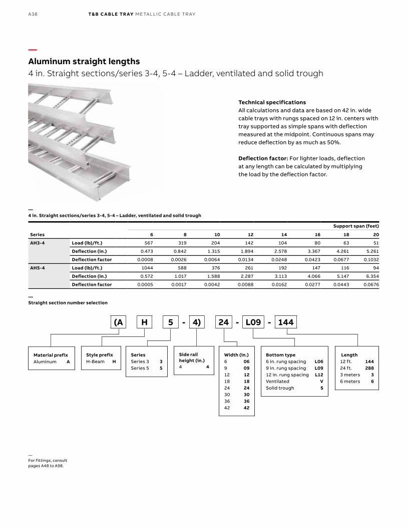
Series
Support span (feet)
6 8 10 12 14 16 18 20
AH3-4 Load (lb)/ft.) 567 319 204 142 104 80 63 51
Deflection (in.) 0.473 0.842 1.315 1.894 2.578 3.367 4.261 5.261
Deflection factor 0.0008 0.0026 0.0064 0.0134 0.0248 0.0423 0.0677 0.1032
AH5-4 Load (lb)/ft.) 1044 588 376 261 192 147 116 94
Deflection (in.) 0.572 1.017 1.588 2.287 3.113 4.066 5.147 6.354
Deflection factor 0.0005 0.0017 0.0042 0.0088 0.0162 0.0277 0.0443 0.0676
Technical specificationsAll calculations and data are based on 42 in. wide cable trays with rungs spaced on 12 in. centers with tray supported as simple spans with deflection measured at the midpoint. Continuous spans may reduce deflection by as much as 50%.
Deflection factor: For lighter loads, deflection at any length can be calculated by multiplying the load by the deflection factor.
—Aluminum straight lengths 4 in. Straight sections/series 3-4, 5-4 – Ladder, ventilated and solid trough
—4 in. Straight sections/series 3-4, 5-4 – Ladder, ventilated and solid trough
—Straight section number selection
Material prefixAluminum A
Width (in.)6 069 0912 1218 1824 2430 3036 3642 42
Bottom type6 in. rung spacing L069 in. rung spacing L0912 in. rung spacing L12Ventilated VSolid trough S
Length12 ft. 14424 ft. 2883 meters 36 meters 6
Style prefixH-Beam H
SeriesSeries 3 3Series 5 5
Side rail height (in.)4 4
(A H 5 - 4) 24 - L09 - 144
—For fittings, consult pages A48 to A98.
A39A LU M I N U M C A B L E TR AY
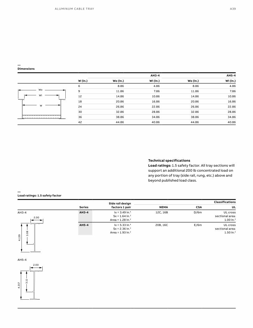
—Dimensions
—Load ratings: 1.5 safety factor
AH3-4 AH5-4
W (in.) Wo (in.) Wi (in.) Wo (in.) Wi (in.)
6 8.86 4.86 8.86 4.86
9 11.86 7.86 11.86 7.86
12 14.86 10.86 14.86 10.86
18 20.86 16.86 20.86 16.86
24 26.86 22.86 26.86 22.86
30 32.86 28.86 32.86 28.86
36 38.86 34.86 38.86 34.86
42 44.86 40.86 44.86 40.86
SeriesSide rail design
factors 1 pair
Classifications
NEMA CSA UL
AH3-4 Ix = 3.49 in.4
Sx = 1.64 in.3
Area = 1.28 in.2
12C, 16B D/6m UL cross sectional area:
1.00 in.2
AH5-4 Ix = 5.33 in.4 Sx = 2.36 in.3
Area = 1.93 in.2
20B, 16C E/6m UL cross sectional area:
1.50 in.2
Wo
Wi
W
Technical specificationsLoad ratings: 1.5 safety factor. All tray sections will support an additional 200 lb concentrated load on any portion of tray (side rail, rung, etc.) above and beyond published load class.
AH3-4
AH5-4
2.00
4.2
17 3.11
4.1
39 3.0
8
2.00
B1 copy starts here
B2 copy starts here
B3 copy starts here
A40 T& B C A B LE TR AY M E TA L L I C C A B L E TR AY
Series
Support span (feet)
6 8 10 12 14 16 18 20
AH2-5 Load (lb)/ft.) 556 313 200 139 102 78 62 50
Deflection (in.) 0.302 0.536 0.838 1.206 1.642 2.144 2.714 3.351
Deflection factor 0.0005 0.0017 0.0042 0.0087 0.0161 0.0274 0.0440 0.0670
AH4-5 Load (lb)/ft.) 900 506 324 225 165 127 100 81
Deflection (in.) 0.340 0.604 0.944 1.359 1.849 2.416 3.057 3.774
Deflection factor 0.0004 0.0012 0.0029 0.0060 0.0112 0.0191 0.0306 0.0466
Technical specificationsAll calculations and data are based on 42 in. wide cable trays with rungs spaced on 12 in. centers with tray supported as simple spans with deflection measured at the midpoint. Continuous spans may reduce deflection by as much as 50%.
Deflection factor: For lighter loads, deflection at any length can be calculated by multiplying the load by the deflection factor.
—Aluminum straight lengths 5 in. Straight sections/series 2-5, 4-5 – Ladder, ventilated and solid trough
—4 in. Straight sections/series 3-4, 5-4 – Ladder, ventilated and solid trough
—For fittings, consult pages A48 to A98.
Material prefixAluminum A
Width (in.)6 069 0912 1218 1824 2430 3036 3642 42
Bottom type6 in. rung spacing L069 in. rung spacing L0912 in. rung spacing L12Ventilated VSolid trough S
Length12 ft. 14424 ft. 2883 meters 36 meters 6
Style prefixH-Beam H
SeriesSeries 2 2Series 4 4
Side rail height (in.)5 5
(A H 2 - 5) 24 - L09 - 144
—Straight section number selection
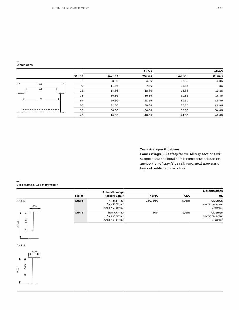
A41A LU M I N U M C A B L E TR AY
SeriesSide rail design
factors 1 pair
Classifications
NEMA CSA UL
AH2-5 Ix = 5.37 in.4 Sx = 2.02 in.3
Area = 1.39 in.2
12C, 16A D/6m UL cross sectional area:
1.00 in.2
AH4-5 Ix = 7.73 in.4 Sx = 2.92 in.3
Area = 1.94 in.2
20B E/6m UL cross sectional area:
1.50 in.2
Wo
Wi
W
AH2-5 AH4-5
W (in.) Wo (in.) Wi (in.) Wo (in.) Wi (in.)
6 8.86 4.86 8.86 4.86
9 11.86 7.86 11.86 7.86
12 14.86 10.86 14.86 10.86
18 20.86 16.86 20.86 16.86
24 26.86 22.86 26.86 22.86
30 32.86 28.86 32.86 28.86
36 38.86 34.86 38.86 34.86
42 44.86 40.86 44.86 40.86
—Dimensions
—Load ratings: 1.5 safety factor
Technical specificationsLoad ratings: 1.5 safety factor. All tray sections will support an additional 200 lb concentrated load on any portion of tray (side rail, rung, etc.) above and beyond published load class.
AH2-5
AH4-5
5.0
41
2.00
3.9
4
5.10
2.00
4.0
0
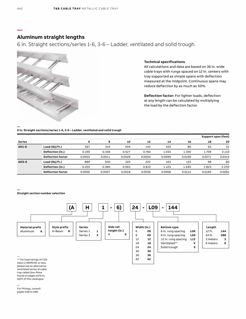
B1 copy starts here
B2 copy starts here
B3 copy starts here
A42 T& B C A B LE TR AY M E TA L L I C C A B L E TR AY
Technical specificationsAll calculations and data are based on 36 in. wide cable trays with rungs spaced on 12 in. centers with tray supported as simple spans with deflection measured at the midpoint. Continuous spans may reduce deflection by as much as 50%.
Deflection factor: For lighter loads, deflection at any length can be calculated by multiplying the load by the deflection factor.
—Aluminum straight lengths 6 in. Straight sections/series 1-6, 3-6 – Ladder, ventilated and solid trough
—6 in. Straight sections/series 1-6, 3-6 – Ladder, ventilated and solid trough
—** For load ratings of CSA class C/NEMA 8C or less, please see an alternative ventilated series of cable tray called One-Piece found on pages A174 to A207 of this catalogue.
—For fittings, consult pages A48 to A98.
—Straight section number selection
Series
Support span (feet)
6 8 10 12 14 16 18 20
AH1-6 Load (lb)/ft.) 567 319 204 142 104 80 63 51
Deflection (in.) 0.190 0.338 0.527 0.760 1.034 1.350 1.709 2.110
Deflection factor 0.0003 0.0011 0.0026 0.0054 0.0099 0.0169 0.0271 0.0414
AH3-6 Load (lb)/ft.) 889 500 320 222 163 125 99 80
Deflection (in.) 0.203 0.360 0.563 0.810 1.103 1.440 1.823 2.250
Deflection factor 0.0002 0.0007 0.0018 0.0036 0.0068 0.0115 0.0185 0.0281
Material prefixAluminum A
Width (in.)6 069 0912 1218 1824 2430 3036 3642 42
Bottom type6 in. rung spacing L069 in. rung spacing L0912 in. rung spacing L12Ventilated** VSolid trough S
Length12 ft. 14424 ft. 2883 meters 36 meters 6
Style prefixH-Beam H
SeriesSeries 1 1Series 3 3
Side rail height (in.)6 6
(A H 1 - 6) 24 - L09 - 144
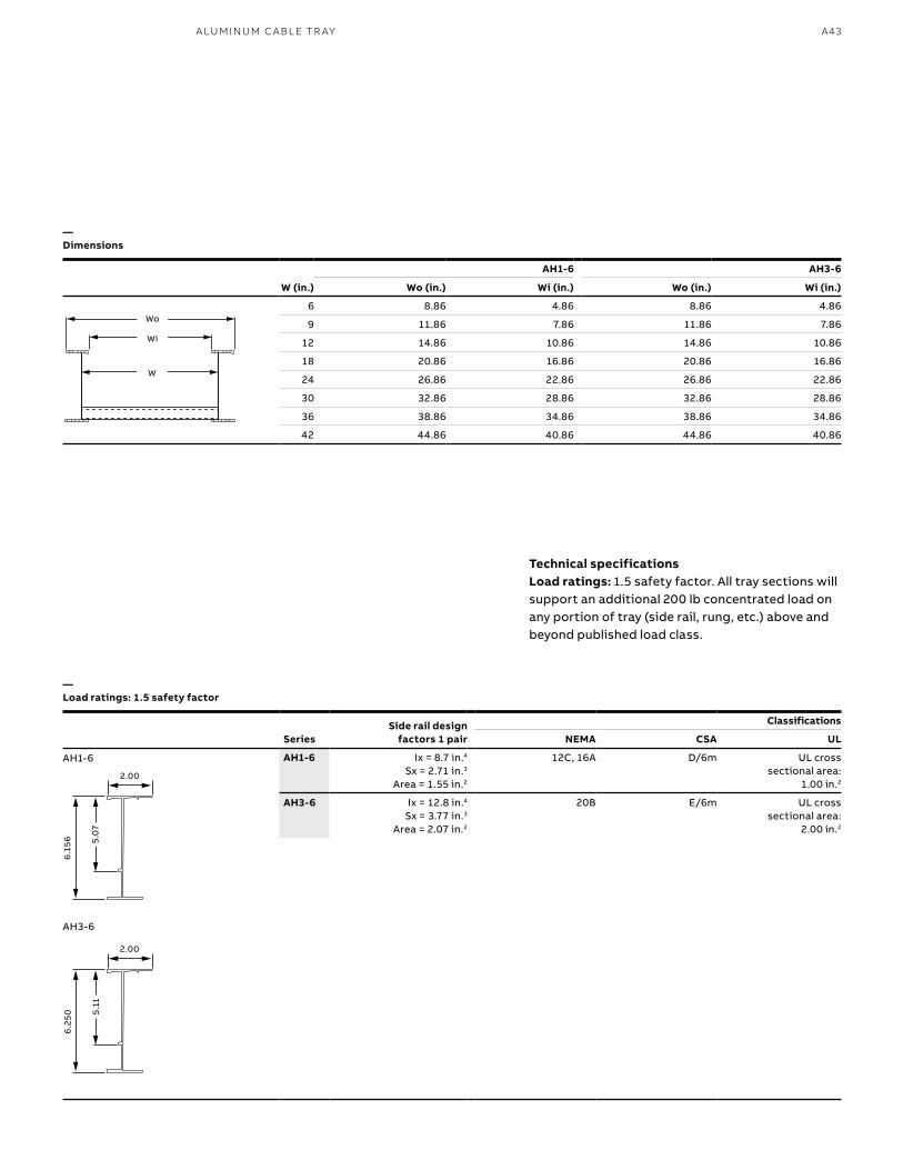
A43A LU M I N U M C A B L E TR AY
—Dimensions
—Load ratings: 1.5 safety factor
Technical specificationsLoad ratings: 1.5 safety factor. All tray sections will support an additional 200 lb concentrated load on any portion of tray (side rail, rung, etc.) above and beyond published load class.
AH1-6 AH3-6
W (in.) Wo (in.) Wi (in.) Wo (in.) Wi (in.)
6 8.86 4.86 8.86 4.86
9 11.86 7.86 11.86 7.86
12 14.86 10.86 14.86 10.86
18 20.86 16.86 20.86 16.86
24 26.86 22.86 26.86 22.86
30 32.86 28.86 32.86 28.86
36 38.86 34.86 38.86 34.86
42 44.86 40.86 44.86 40.86
SeriesSide rail design
factors 1 pair
Classifications
NEMA CSA UL
AH1-6 Ix = 8.7 in.4 Sx = 2.71 in.3
Area = 1.55 in.2
12C, 16A D/6m UL cross sectional area:
1.00 in.2
AH3-6 Ix = 12.8 in.4 Sx = 3.77 in.3
Area = 2.07 in.2
20B E/6m UL cross sectional area:
2.00 in.2
Wo
Wi
W
AH1-6
AH3-6
2.00
6.1
56 5.0
7
2.00
6.2
50
5.11
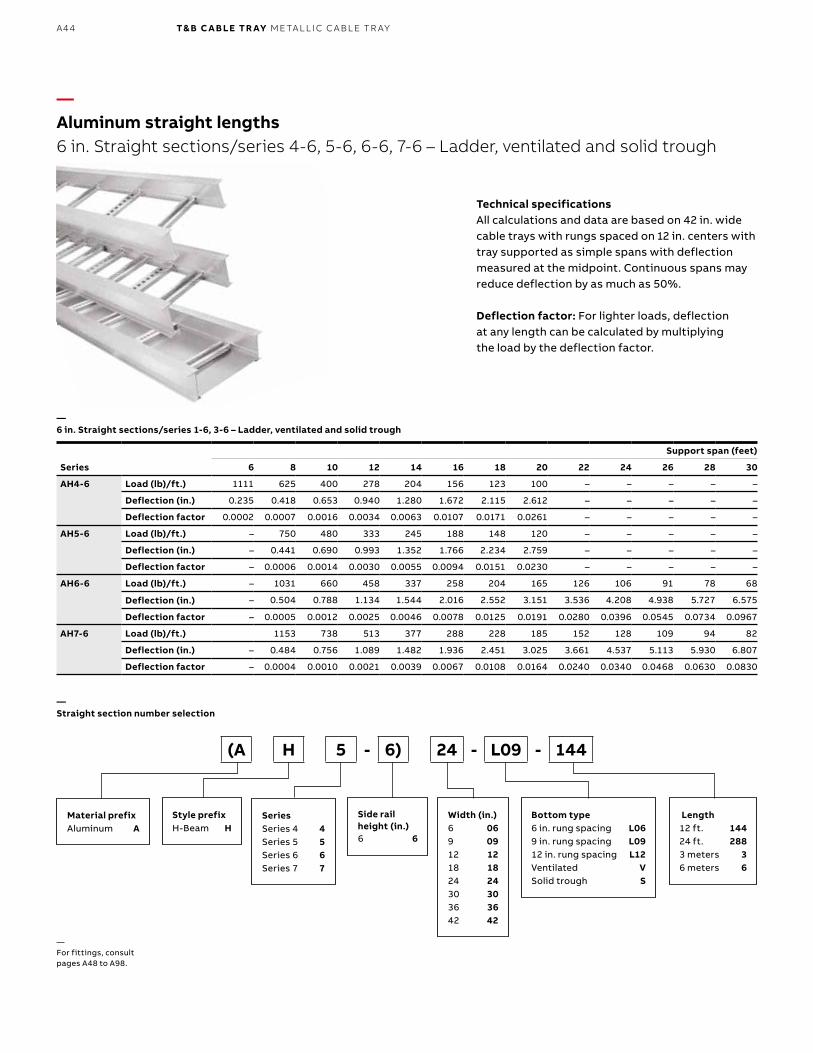
B1 copy starts here
B2 copy starts here
B3 copy starts here
A44 T& B C A B LE TR AY M E TA L L I C C A B L E TR AY
—Aluminum straight lengths 6 in. Straight sections/series 4-6, 5-6, 6-6, 7-6 – Ladder, ventilated and solid trough
—6 in. Straight sections/series 1-6, 3-6 – Ladder, ventilated and solid trough
—For fittings, consult pages A48 to A98.
—Straight section number selection
Series
Support span (feet)
6 8 10 12 14 16 18 20 22 24 26 28 30
AH4-6 Load (lb)/ft.) 1111 625 400 278 204 156 123 100 – – – – –
Deflection (in.) 0.235 0.418 0.653 0.940 1.280 1.672 2.115 2.612 – – – – –
Deflection factor 0.0002 0.0007 0.0016 0.0034 0.0063 0.0107 0.0171 0.0261 – – – – –
AH5-6 Load (lb)/ft.) – 750 480 333 245 188 148 120 – – – – –
Deflection (in.) – 0.441 0.690 0.993 1.352 1.766 2.234 2.759 – – – – –
Deflection factor – 0.0006 0.0014 0.0030 0.0055 0.0094 0.0151 0.0230 – – – – –
AH6-6 Load (lb)/ft.) – 1031 660 458 337 258 204 165 126 106 91 78 68
Deflection (in.) – 0.504 0.788 1.134 1.544 2.016 2.552 3.151 3.536 4.208 4.938 5.727 6.575
Deflection factor – 0.0005 0.0012 0.0025 0.0046 0.0078 0.0125 0.0191 0.0280 0.0396 0.0545 0.0734 0.0967
AH7-6 Load (lb)/ft.) 1153 738 513 377 288 228 185 152 128 109 94 82
Deflection (in.) – 0.484 0.756 1.089 1.482 1.936 2.451 3.025 3.661 4.537 5.113 5.930 6.807
Deflection factor – 0.0004 0.0010 0.0021 0.0039 0.0067 0.0108 0.0164 0.0240 0.0340 0.0468 0.0630 0.0830
Technical specificationsAll calculations and data are based on 42 in. wide cable trays with rungs spaced on 12 in. centers with tray supported as simple spans with deflection measured at the midpoint. Continuous spans may reduce deflection by as much as 50%.
Deflection factor: For lighter loads, deflection at any length can be calculated by multiplying the load by the deflection factor.
Material prefixAluminum A
Width (in.)6 069 0912 1218 1824 2430 3036 3642 42
Bottom type6 in. rung spacing L069 in. rung spacing L0912 in. rung spacing L12Ventilated VSolid trough S
Length12 ft. 14424 ft. 2883 meters 36 meters 6
Style prefixH-Beam H
SeriesSeries 4 4Series 5 5Series 6 6Series 7 7
Side rail height (in.)6 6
(A H 5 - 6) 24 - L09 - 144
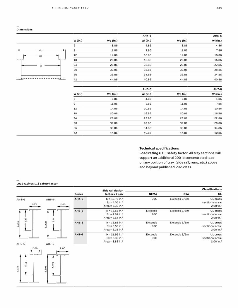
A45A LU M I N U M C A B L E TR AY
—Dimensions
—Load ratings: 1.5 safety factor
Technical specificationsLoad ratings: 1.5 safety factor. All tray sections will support an additional 200 lb concentrated load on any portion of tray (side rail, rung, etc.) above and beyond published load class.
SeriesSide rail design
factors 1 pair
Classifications
NEMA CSA UL
AH4-6 Ix = 13.78 in.4 Sx = 4.05 in.3
Area = 2.32 in.2
20C Exceeds E/6m UL cross sectional area:
2.00 in.2
AH5-6 Ix = 15.66 in.4 Sx = 4.64 in.3
Area = 2.67 in.2
Exceeds 20C
Exceeds E/6m UL cross sectional area:
2.00 in.2
AH6-6 Ix = 18.85 in.4 Sx = 5.53 in.3
Area = 3.26 in.2
Exceeds 20C
Exceeds E/6m UL cross sectional area:
2.00 in.2
AH7-6 Ix = 21.95 in.4 Sx = 6.32 in.3
Area = 3.82 in.2
Exceeds 20C
Exceeds E/6m UL cross sectional area:
2.00 in.2
AH4-6 AH5-6
W (in.) Wo (in.) Wi (in.) Wo (in.) Wi (in.)
6 8.86 4.86 8.86 4.86
9 11.86 7.86 11.86 7.86
12 14.86 10.86 14.86 10.86
18 20.86 16.86 20.86 16.86
24 26.86 22.86 26.86 22.86
30 32.86 28.86 32.86 28.86
36 38.86 34.86 38.86 34.86
42 44.86 40.86 44.86 40.86
AH6-6 AH7-6
W (in.) Wo (in.) Wi (in.) Wo (in.) Wi (in.)
6 8.86 4.86 8.86 4.86
9 11.86 7.86 11.86 7.86
12 14.86 10.86 14.86 10.86
18 20.86 16.86 20.86 16.86
24 26.86 22.86 26.86 22.86
30 32.86 28.86 32.86 28.86
36 38.86 34.86 38.86 34.86
42 44.86 40.86 44.86 40.86
Wo
Wi
W
AH4-6
AH6-6
AH5-6
AH7-6
2.00
6.2
58 5.12
2.00
6.2
80 5.
14
6.3
28
6.3
955.
13
5.17
5
2.00 2.00
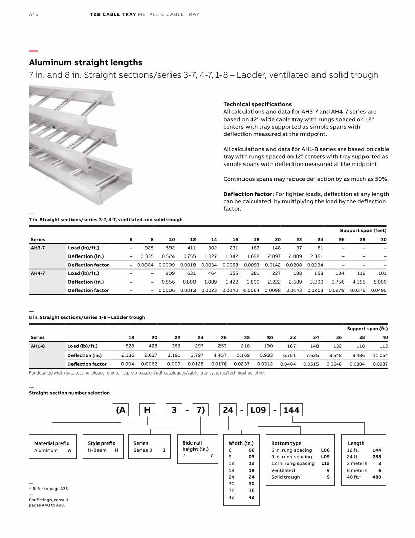
B1 copy starts here
B2 copy starts here
B3 copy starts here
A46 T& B C A B LE TR AY M E TA L L I C C A B L E TR AY
Series
Support span (feet)
6 8 10 12 14 16 18 20 22 24 26 28 30
AH3-7 Load (lb)/ft.) – 925 592 411 302 231 183 148 97 81 – – –
Deflection (in.) – 0.335 0.524 0.755 1.027 1.342 1.698 2.097 2.009 2.391 – – –
Deflection factor – 0.0004 0.0009 0.0018 0.0034 0.0058 0.0093 0.0142 0.0208 0.0294 – – –
AH4-7 Load (lb)/ft.) – – 909 631 464 355 281 227 188 158 134 116 101
Deflection (in.) – – 0.556 0.800 1.089 1.422 1.800 2.222 2.689 3.200 3.756 4.356 5.000
Deflection factor – – 0.0006 0.0013 0.0023 0.0040 0.0064 0.0098 0.0143 0.0203 0.0279 0.0376 0.0495
—Aluminum straight lengths 7 in. and 8 in. Straight sections/series 3-7, 4-7, 1-8 – Ladder, ventilated and solid trough
—7 in. Straight sections/series 3-7, 4-7, ventilated and solid trough
—* Refer to page A35.—For fittings, consult pages A48 to A98.
—Straight section number selection
Technical specificationsAll calculations and data for AH3-7 and AH4-7 series are based on 42'' wide cable tray with rungs spaced on 12" centers with tray supported as simple spans with deflection measured at the midpoint.
All calculations and data for AH1-8 series are based on cable tray with rungs spaced on 12" centers with tray supported as simple spans with deflection measured at the midpoint.
Continuous spans may reduce deflection by as much as 50%.
Deflection factor: For lighter loads, deflection at any length can be calculated by multiplying the load by the deflection factor.
Material prefixAluminum A
Width (in.)6 069 0912 1218 1824 2430 3036 3642 42
Bottom type6 in. rung spacing L069 in. rung spacing L0912 in. rung spacing L12Ventilated VSolid trough S
Length12 ft. 14424 ft. 2883 meters 36 meters 640 ft.* 480
Style prefixH-Beam H
SeriesSeries 3 3
Side rail height (in.)7 7
(A H 3 - 7) 24 - L09 - 144
Series
Support span (ft.)
18 20 22 24 26 28 30 32 34 36 38 40
AH1-8 Load (lb)/ft.) 528 428 353 297 253 218 190 167 148 132 118 112
Deflection (in.) 2.136 2.637 3.191 3.797 4.457 5.169 5.933 6.751 7.625 8.548 9.486 11.054
Deflection factor 0.004 0.0062 0.009 0.0128 0.0176 0.0237 0.0312 0.0404 0.0515 0.0648 0.0804 0.0987
For detailed width load testing, please refer to http://tnb.ca/en/pdf-catalogues/cable-tray-systems/technical-bulletin/.
—8 in. Straight sections/series 1-8 – Ladder trough
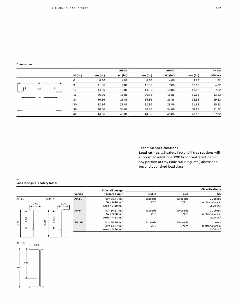
A47A LU M I N U M C A B L E TR AY
AH3-7 AH4-7 AH1-8
W (in.) Wo (in.) Wi (in.) Wo (in.) Wi (in.) Wo (in.) Wi (in.)
6 8.86 4.86 8.86 4.86 7.82 1.82
9 11.86 7.86 11.86 7.86 10.82 4.82
12 14.86 10.86 14.86 10.86 13.82 7.82
18 20.86 16.86 20.86 16.86 19.82 13.82
24 26.86 22.86 26.86 22.86 25.82 19.82
30 32.86 28.86 32.86 28.86 31.82 25.82
36 38.86 34.86 38.86 34.86 37.82 31.82
42 44.86 40.86 44.86 40.86 43.82 37.82
SeriesSide rail design
factors 1 pair
Classifications
NEMA CSA UL
AH3-7 Ix = 25.41 in.4 Sx = 6.46 in.3
Area = 3.29 in.2
Exceeds 20C
Exceeds E/6m
UL cross sectional area:
2.00 in.2
AH4-7 Ix = 36.81 in.4 Sx = 9.08 in.3
Area = 4.63 in.2
Exceeds 20C
Exceeds E/6m
UL cross sectional area:
2.00 in.2
AH1-8 Ix = 58.36 in.4 Sx = 13.37 in.3
Area = 5.86 in.2
Exceeds 20C
Exceeds E/6m
UL cross sectional area:
2.00 in.2
Wo
Wi
W
—Dimensions
—Load ratings: 1.5 safety factor
Technical specificationsLoad ratings: 1.5 safety factor. All tray sections will support an additional 200 lb concentrated load on any portion of tray (side rail, rung, etc.) above and beyond published load class.
2.00
6.1
8
7.34
7 5.9
54
7.50
0
2.00
AH3-7
AH1-8
AH4-7
3.00
6.23
8.00
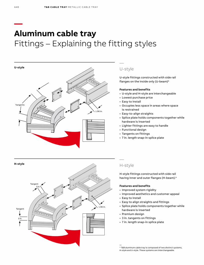
B1 copy starts here
B2 copy starts here
B3 copy starts here
A48 T& B C A B LE TR AY M E TA L L I C C A B L E TR AY
—Aluminum cable trayFittings – Explaining the fitting styles
Tangents
1.96 in.
—U-style
U-style fittings constructed with side rail flanges on the inside only (U-beam)*
Features and benefits• U-style and H-style are interchangeable• Lowest purchase price• Easy to install• Occupies less space in areas where space
is restrained• Easy-to-align straights• Splice plate holds components together while
hardware is inserted• Lighter fittings are easy to handle• Functional design• Tangents on fittings• 7 in. length snap-in splice plate
U-style
—* T&B aluminum cable tray is composed of two distinct systems, H-style and U-style. These systems are interchangeable.
—H-style
H-style fittings constructed with side rail having inner and outer flanges (H-beam).*
Features and benefits• Improved system rigidity• Improved aesthetics and customer appeal• Easy to install• Easy to align straights and fittings• Splice plate holds components together while
hardware is inserted• Premium design• 3 in. tangents on fittings• 7 in. length snap-in splice plate
3 in.
3 in.
Tangent
Tangent1.96 in.
H-style
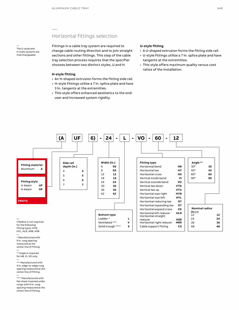
A49A LU M I N U M C A B L E TR AY
—Horizontal fittings selection
Fittings in a cable tray system are required to change cable routing direction and to join straight sections and other fittings. This step of the cable tray selection process requires that the specifier chooses between two distinct styles, U and H.
H-style fitting• An H-shaped extrusion forms the fitting side rail.• H-style fittings utilize a 7 in. splice plate and have
3 in. tangents at the extremities.• This style offers enhanced aesthetics to the end-
user and increased system rigidity.
PREFIX
—The U-style and H-style systems are interchangeable.
Fitting materialAluminum A
Width (in.)6 069 0912 1218 1824 2430 3036 3642 42
Bottom typeLadder * LVentilated *** VSolid trough **** S
Angle **30o 3045o 4560o 6090o 90
Fitting typeHorizontal bend HBHorizontal tee HTHorizontal cross HXVertical inside bend VIVertical outside bend VOVertical tee down VTDVertical tee up VTUHorizontal wye right HYRHorizontal wye left HYLHorizontal reducing tee RTHorizontal expanding tee ETHorizontal expand cross EXHorizontal left reducer HLRHorizontal straight reducer HSRHorizontal right reducer HRRCable support fitting CS
Fitting styleU-beam UFH-beam HF
(A UF 6) - 24 - L - VO - 60 - 12
Side rail depth (in.)
4 4
5 5
6 6
7 7
U-style fitting• A U-shaped extrusion forms the fitting side rail.• U-style fittings utilize a 7 in. splice plate and have
tangents at the extremities.• This style offers maximum quality versus cost
ratios of the installation.
—† Radius is not required for the following fitting types: HYR, HYL, HLR, HRR, HSR—* Manufactured with 9 in. rung spacing measured at the center line of fitting.—** Angle is required for HB, VI, VO only.—*** Manufactured with 4 in. edge-to-edge rung spacing measured at the center line of fitting.—**** Manufactured with flat sheet inserted under rungs with 9 in. rung spacing measured at the center line of fitting.
Nominal radius (in.) †12 1224 2436 3648 48
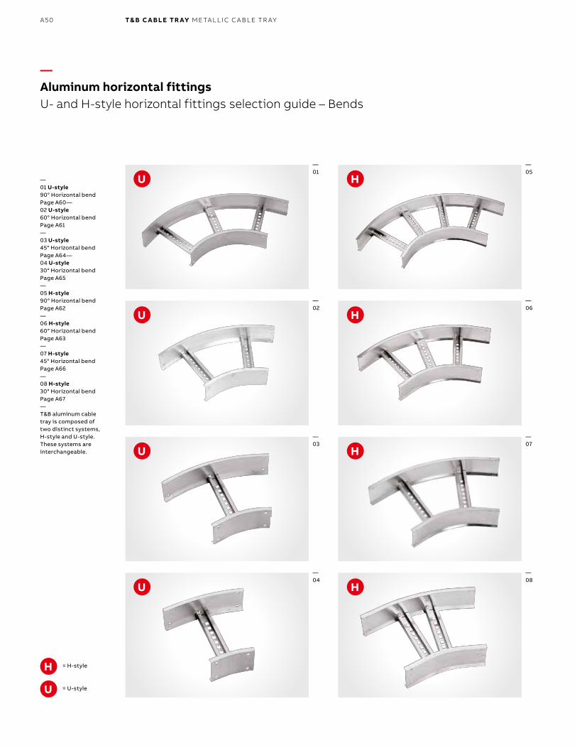
B1 copy starts here
B2 copy starts here
B3 copy starts here
A50 T& B C A B LE TR AY M E TA L L I C C A B L E TR AY
—Aluminum horizontal fittingsU- and H-style horizontal fittings selection guide – Bends
—01
—02
—03
= H-style
= U-style
—04
—05
—06
—07
—08
U
U
U
U
U
H
H
H
H
H
—01 U-style90° Horizontal bendPage A60—02 U-style60° Horizontal bendPage A61—03 U-style45° Horizontal bendPage A64—04 U-style30° Horizontal bendPage A65—05 H-style 90° Horizontal bendPage A62—06 H-style 60° Horizontal bendPage A63—07 H-style 45° Horizontal bendPage A66—08 H-style 30° Horizontal bendPage A67—T&B aluminum cable tray is composed of two distinct systems, H-style and U-style. These systems are interchangeable.
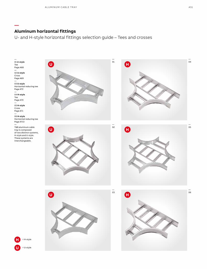
A51A LU M I N U M C A B L E TR AY
—Aluminum horizontal fittingsU- and H-style horizontal fittings selection guide – Tees and crosses
—01
—02
—03
= H-style
= U-style
—04
—05
—06
U
U
U
U
H
H
H
H
—01 U-styleTeePage A68—02 U-styleCrossPage A69—03 U-styleHorizontal reducing teePage A72—04 H-style TeePage A70—05 H-style CrossPage A71—06 H-style Horizontal reducing teePage A713—T&B aluminum cable tray is composed of two distinct systems, H-style and U-style. These systems are interchangeable.
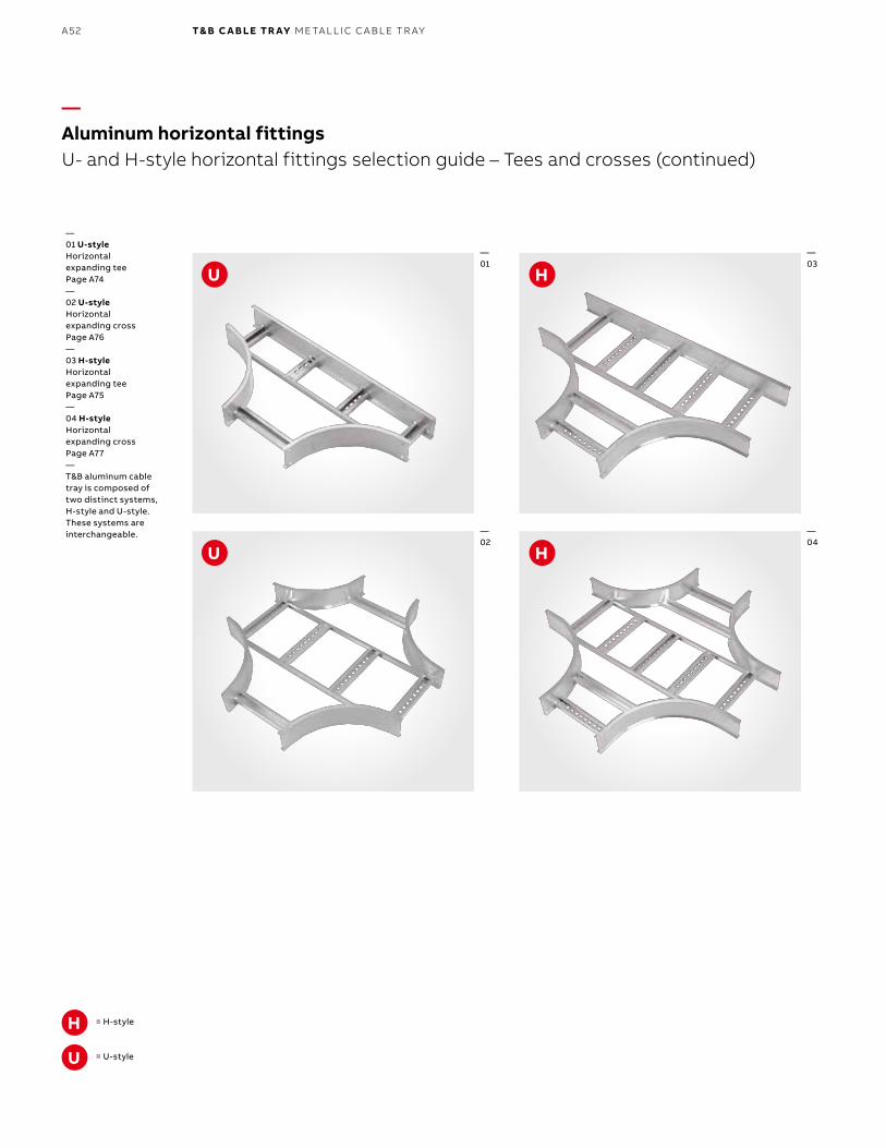
B1 copy starts here
B2 copy starts here
B3 copy starts here
A52 T& B C A B LE TR AY M E TA L L I C C A B L E TR AY
—Aluminum horizontal fittingsU- and H-style horizontal fittings selection guide – Tees and crosses (continued)
= H-style
= U-styleU
H
—01 U-style Horizontal expanding teePage A74—02 U-styleHorizontal expanding crossPage A76—03 H-style Horizontal expanding teePage A75—04 H-style Horizontal expanding crossPage A77—T&B aluminum cable tray is composed of two distinct systems, H-style and U-style. These systems are interchangeable.
—01
—02
—03
—04
H
H
U
U
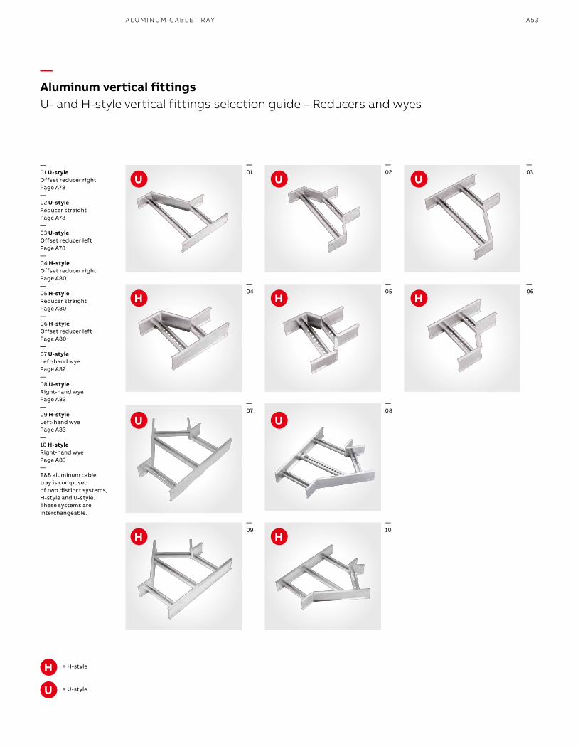
A53A LU M I N U M C A B L E TR AY
—Aluminum vertical fittingsU- and H-style vertical fittings selection guide – Reducers and wyes
—01
—04
—07
—09
—02
—05
—08
—10
—03
—06
—01 U-style Offset reducer rightPage A78—02 U-styleReducer straightPage A78—03 U-styleOffset reducer leftPage A78—04 H-style Offset reducer rightPage A80—05 H-style Reducer straightPage A80—06 H-style Offset reducer leftPage A80—07 U-styleLeft-hand wyePage A82—08 U-styleRight-hand wyePage A82—09 H-styleLeft-hand wyePage A83—10 H-styleRight-hand wyePage A83—T&B aluminum cable tray is composed of two distinct systems, H-style and U-style. These systems are interchangeable.
= H-style
= U-styleU
H
H HH
U UU
HH
UU
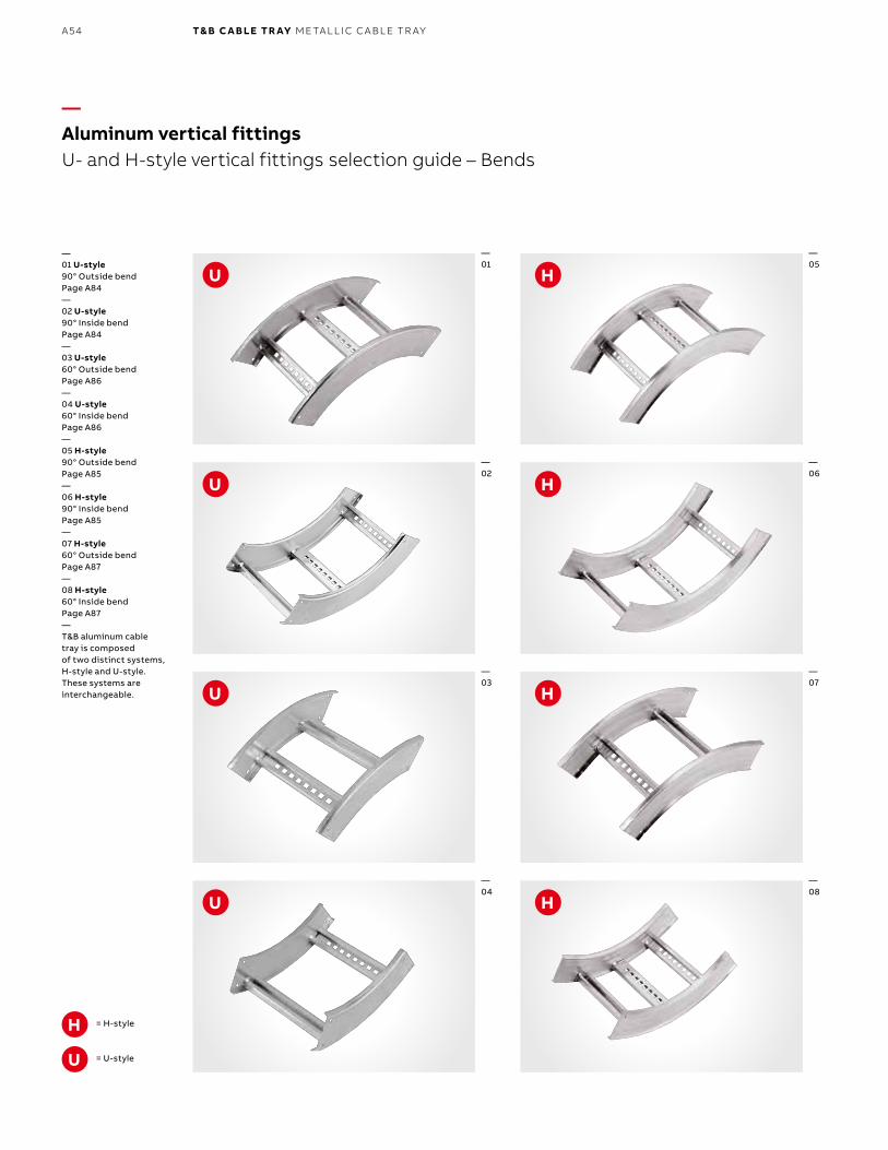
B1 copy starts here
B2 copy starts here
B3 copy starts here
A54 T& B C A B LE TR AY M E TA L L I C C A B L E TR AY
—Aluminum vertical fittingsU- and H-style vertical fittings selection guide – Bends
= H-style
= U-styleU
H
—01 U-style90° Outside bendPage A84—02 U-style 90° Inside bendPage A84—03 U-style60° Outside bendPage A86—04 U-style60° Inside bendPage A86—05 H-style 90° Outside bendPage A85—06 H-style 90° Inside bendPage A85—07 H-style 60° Outside bendPage A87—08 H-style60° Inside bendPage A87—T&B aluminum cable tray is composed of two distinct systems, H-style and U-style. These systems are interchangeable.
—01
—02
—03
—04
—05
—06
—07
—08
H
H
H
H
U
U
U
U
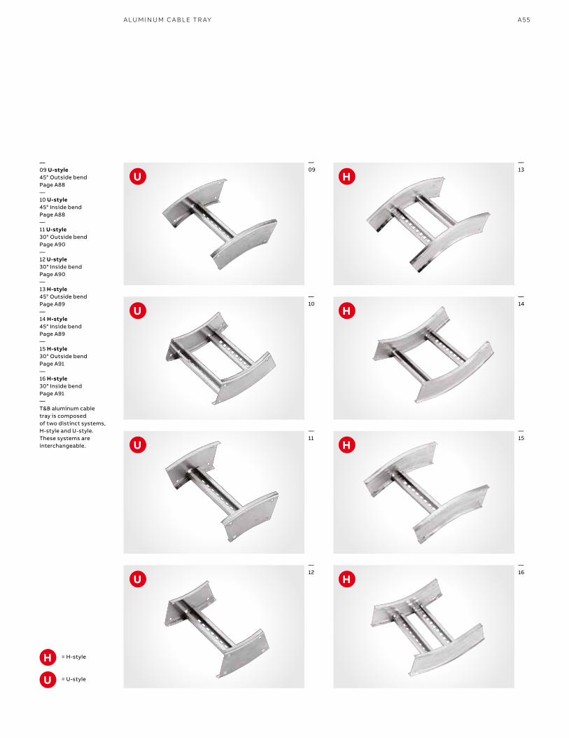
A55A LU M I N U M C A B L E TR AY
= H-style
= U-styleU
H
—09 U-style45° Outside bendPage A88—10 U-style 45° Inside bendPage A88—11 U-style30° Outside bendPage A90—12 U-style30° Inside bendPage A90—13 H-style 45° Outside bendPage A89—14 H-style 45° Inside bendPage A89—15 H-style 30° Outside bendPage A91—16 H-style30° Inside bendPage A91—T&B aluminum cable tray is composed of two distinct systems, H-style and U-style. These systems are interchangeable.
—09
—10
—11
—12
—13
—14
—15
—16
H
H
H
H
U
U
U
U
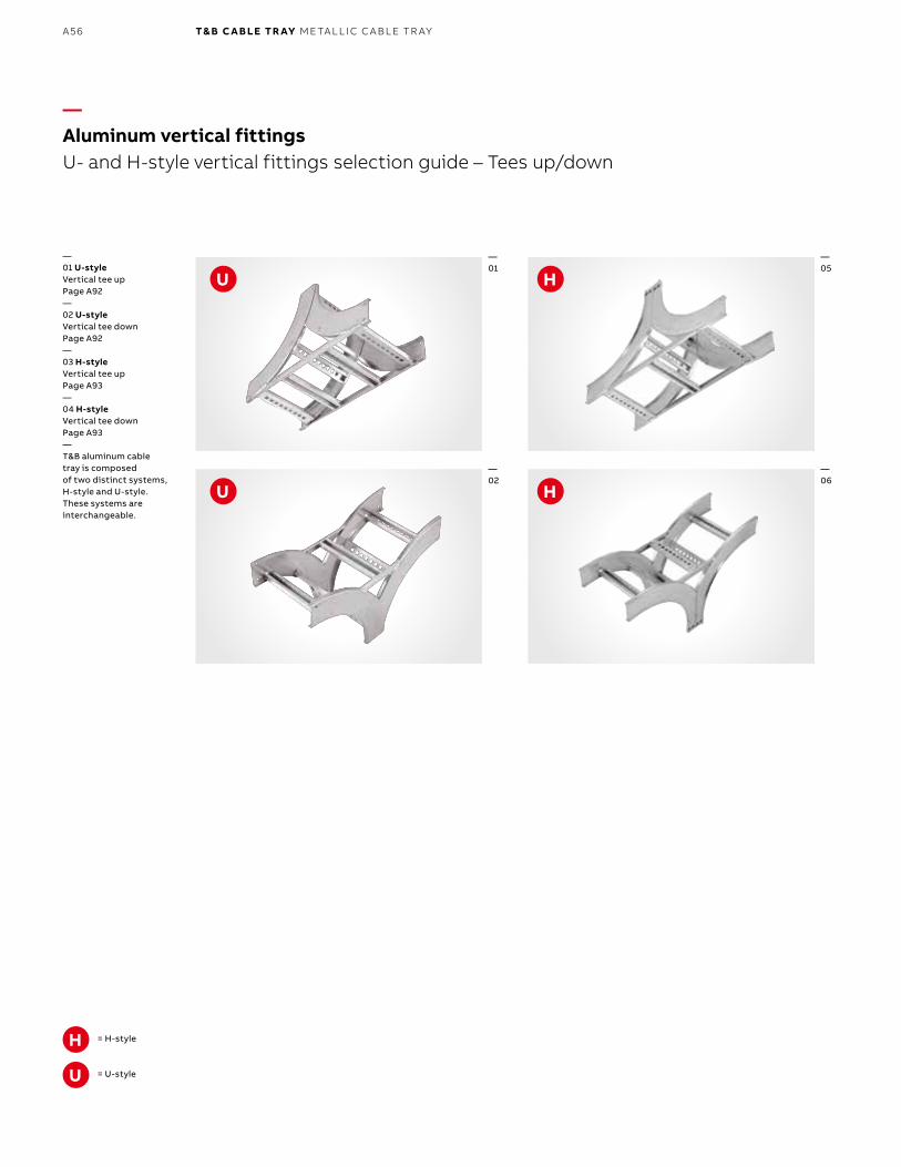
B1 copy starts here
B2 copy starts here
B3 copy starts here
A56 T& B C A B LE TR AY M E TA L L I C C A B L E TR AY
—Aluminum vertical fittingsU- and H-style vertical fittings selection guide – Tees up/down
= H-style
= U-styleU
H
—01 U-style Vertical tee upPage A92—02 U-styleVertical tee downPage A92—03 H-style Vertical tee upPage A93—04 H-style Vertical tee downPage A93—T&B aluminum cable tray is composed of two distinct systems, H-style and U-style. These systems are interchangeable.
—01
—02
—05
—06
H
H
U
U
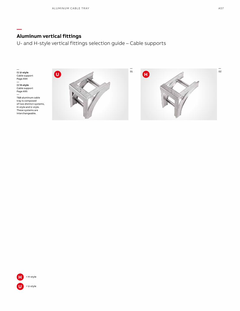
A57A LU M I N U M C A B L E TR AY
—Aluminum vertical fittingsU- and H-style vertical fittings selection guide – Cable supports
= H-style
= U-styleU
H
—01 U-style Cable supportPage A94—02 H-style Cable supportPage A95—T&B aluminum cable tray is composed of two distinct systems, H-style and U-style. These systems are interchangeable.
—01
—02
HU
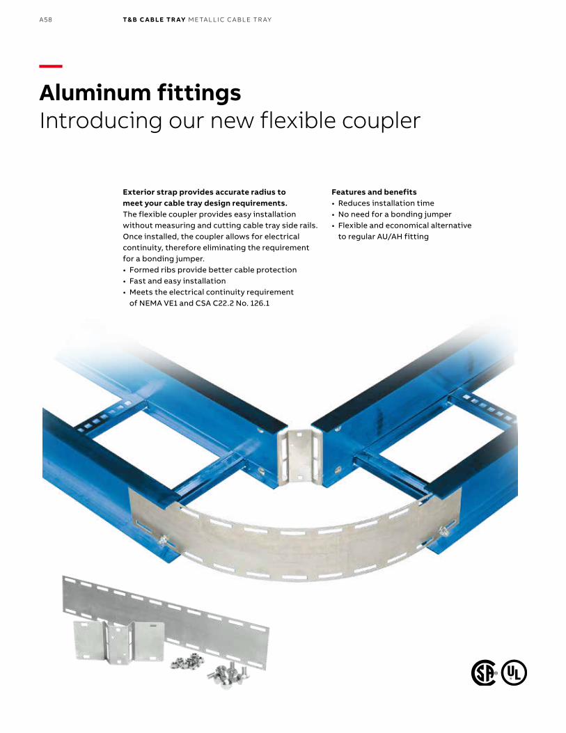
B1 copy starts here
B2 copy starts here
B3 copy starts here
A58 T& B C A B LE TR AY M E TA L L I C C A B L E TR AY
—Aluminum fittingsIntroducing our new flexible coupler
Exterior strap provides accurate radius to meet your cable tray design requirements.The flexible coupler provides easy installation without measuring and cutting cable tray side rails. Once installed, the coupler allows for electrical continuity, therefore eliminating the requirement for a bonding jumper.• Formed ribs provide better cable protection• Fast and easy installation• Meets the electrical continuity requirement
of NEMA VE1 and CSA C22.2 No. 126.1
Features and benefits• Reduces installation time• No need for a bonding jumper• Flexible and economical alternative
to regular AU/AH fitting
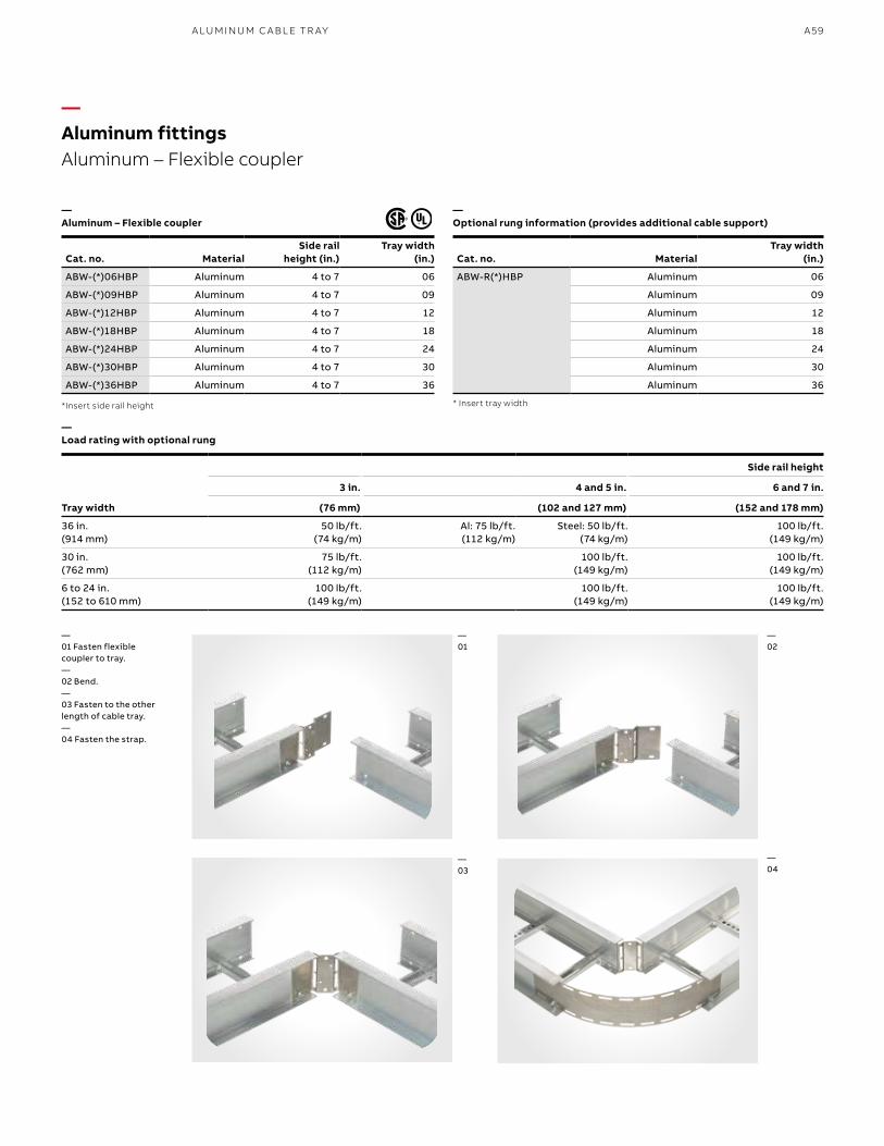
A59A LU M I N U M C A B L E TR AY
Cat. no. MaterialSide rail
height (in.)Tray width
(in.)
ABW-(*)06HBP Aluminum 4 to 7 06
ABW-(*)09HBP Aluminum 4 to 7 09
ABW-(*)12HBP Aluminum 4 to 7 12
ABW-(*)18HBP Aluminum 4 to 7 18
ABW-(*)24HBP Aluminum 4 to 7 24
ABW-(*)30HBP Aluminum 4 to 7 30
ABW-(*)36HBP Aluminum 4 to 7 36
*Insert side rail height
Cat. no. MaterialTray width
(in.)
ABW-R(*)HBP Aluminum 06
Aluminum 09
Aluminum 12
Aluminum 18
Aluminum 24
Aluminum 30
Aluminum 36
* Insert tray width
Tray width
Side rail height
3 in. 4 and 5 in. 6 and 7 in.
(76 mm) (102 and 127 mm) (152 and 178 mm)
36 in.(914 mm)
50 lb/ft.(74 kg/m)
Al: 75 lb/ft.(112 kg/m)
Steel: 50 lb/ft.(74 kg/m)
100 lb/ft.(149 kg/m)
30 in.(762 mm)
75 lb/ft.(112 kg/m)
100 lb/ft.(149 kg/m)
100 lb/ft.(149 kg/m)
6 to 24 in.(152 to 610 mm)
100 lb/ft.(149 kg/m)
100 lb/ft.(149 kg/m)
100 lb/ft.(149 kg/m)
—Aluminum fittingsAluminum – Flexible coupler
—Aluminum – Flexible coupler
—Load rating with optional rung
—Optional rung information (provides additional cable support)
—01 Fasten flexible coupler to tray.—02 Bend.—03 Fasten to the other length of cable tray.—04 Fasten the strap.
—01
—03
—04
—02
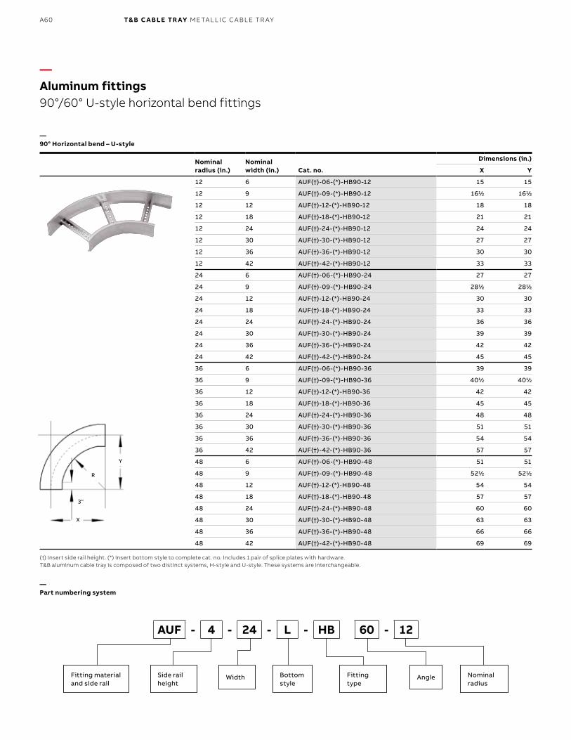
B1 copy starts here
B2 copy starts here
B3 copy starts here
A60 T& B C A B LE TR AY M E TA L L I C C A B L E TR AY
Nominal radius (in.)
Nominal width (in.) Cat. no.
Dimensions (in.)
X Y
12 6 AUF(†)-06-(*)-HB90-12 15 15
12 9 AUF(†)-09-(*)-HB90-12 1611⁄22 1611⁄22
12 12 AUF(†)-12-(*)-HB90-12 18 18
12 18 AUF(†)-18-(*)-HB90-12 21 21
12 24 AUF(†)-24-(*)-HB90-12 24 24
12 30 AUF(†)-30-(*)-HB90-12 27 27
12 36 AUF(†)-36-(*)-HB90-12 30 30
12 42 AUF(†)-42-(*)-HB90-12 33 33
24 6 AUF(†)-06-(*)-HB90-24 27 27
24 9 AUF(†)-09-(*)-HB90-24 2811⁄22 2811⁄22
24 12 AUF(†)-12-(*)-HB90-24 30 30
24 18 AUF(†)-18-(*)-HB90-24 33 33
24 24 AUF(†)-24-(*)-HB90-24 36 36
24 30 AUF(†)-30-(*)-HB90-24 39 39
24 36 AUF(†)-36-(*)-HB90-24 42 42
24 42 AUF(†)-42-(*)-HB90-24 45 45
36 6 AUF(†)-06-(*)-HB90-36 39 39
36 9 AUF(†)-09-(*)-HB90-36 4011⁄22 4011⁄22
36 12 AUF(†)-12-(*)-HB90-36 42 42
36 18 AUF(†)-18-(*)-HB90-36 45 45
36 24 AUF(†)-24-(*)-HB90-36 48 48
36 30 AUF(†)-30-(*)-HB90-36 51 51
36 36 AUF(†)-36-(*)-HB90-36 54 54
36 42 AUF(†)-42-(*)-HB90-36 57 57
48 6 AUF(†)-06-(*)-HB90-48 51 51
48 9 AUF(†)-09-(*)-HB90-48 5211⁄22 5211⁄22
48 12 AUF(†)-12-(*)-HB90-48 54 54
48 18 AUF(†)-18-(*)-HB90-48 57 57
48 24 AUF(†)-24-(*)-HB90-48 60 60
48 30 AUF(†)-30-(*)-HB90-48 63 63
48 36 AUF(†)-36-(*)-HB90-48 66 66
48 42 AUF(†)-42-(*)-HB90-48 69 69
(†) Insert side rail height. (*) Insert bottom style to complete cat. no. Includes 1 pair of splice plates with hardware.T&B aluminum cable tray is composed of two distinct systems, H-style and U-style. These systems are interchangeable.
—Aluminum fittings90°/60° U-style horizontal bend fittings
—90° Horizontal bend – U-style
—Part numbering system
Fitting materialand side rail
Side rail height
Fitting type
Angle Nominal radius
Bottom style
Width
AUF - 4 - 24 - L - HB 60 - 12
X
3"
R
Y
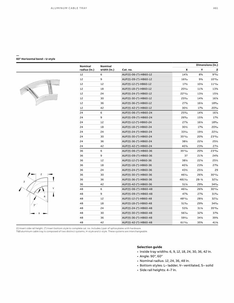
A61A LU M I N U M C A B L E TR AY
Nominalradius (in.)
Nominalwidth (in.) Cat. no.
Dimensions (in.)
X Y Z
12 6 AUF(†)-06-(*)-HB60-12 1477⁄88 855⁄88 91515⁄1616
12 9 AUF(†)-09-(*)-HB60-12 1633⁄1616 933⁄88 101313⁄1616
12 12 AUF(†)-12-(*)-HB60-12 1711⁄22 1011⁄88 111111⁄1616
12 18 AUF(†)-18-(*)-HB60-12 2011⁄1616 1155⁄88 1333⁄88
12 24 AUF(†)-24-(*)-HB60-12 221111⁄1616 1311⁄88 1511⁄88
12 30 AUF(†)-30-(*)-HB60-12 2555⁄1616 1455⁄88 1677⁄88
12 36 AUF(†)-36-(*)-HB60-12 2777⁄88 1611⁄88 1899⁄1616
12 42 AUF(†)-42-(*)-HB60-12 3011⁄22 1755⁄88 2055⁄1616
24 6 AUF(†)-06-(*)-HB60-24 2555⁄1616 1455⁄88 1677⁄88
24 9 AUF(†)-09-(*)-HB60-24 2699⁄1616 1533⁄88 1733⁄44
24 12 AUF(†)-12-(*)-HB60-24 2777⁄88 1611⁄88 1899⁄1616
24 18 AUF(†)-18-(*)-HB60-24 3011⁄22 1755⁄88 2055⁄1616
24 24 AUF(†)-24-(*)-HB60-24 3311⁄1616 1911⁄88 2211⁄1616
24 30 AUF(†)-30-(*)-HB60-24 351111⁄1616 2055⁄88 231313⁄1616
24 36 AUF(†)-36-(*)-HB60-24 3811⁄44 2211⁄88 2511⁄22
24 42 AUF(†)-42-(*)-HB60-24 4077⁄88 2355⁄88 2711⁄44
36 6 AUF(†)-06-(*)-HB60-36 351111⁄1616 2055⁄88 231313⁄1616
36 9 AUF(†)-09-(*)-HB60-36 37 2133⁄88 2455⁄88
36 12 AUF(†)-12-(*)-HB60-36 3811⁄44 2211⁄88 2511⁄22
36 18 AUF(†)-18-(*)-HB60-36 4077⁄88 2355⁄88 2722⁄88
36 24 AUF(†)-24-(*)-HB60-36 4311⁄22 2511⁄88 29
36 30 AUF(†)-30-(*)-HB60-36 4611⁄1616 2655⁄88 301111⁄1616
36 36 AUF(†)-36-(*)-HB60-36 48111⁄1616 28-11⁄88 3277⁄1616
36 42 AUF(†)-42-(*)-HB60-36 5111⁄44 2955⁄88 3433⁄1616
48 6 AUF(†)-06-(*)-HB60-48 4611⁄1616 2655⁄88 301111⁄1616
48 9 AUF(†)-09-(*)-HB60-48 4733⁄88 2733⁄88 3199⁄1616
48 12 AUF(†)-12-(*)-HB60-48 481111⁄1616 2811⁄88 3277⁄1616
48 18 AUF(†)-18-(*)-HB60-48 5144⁄1616 2955⁄88 3433⁄1616
48 24 AUF(†)-24-(*)-HB60-48 5377⁄88 3111⁄88 351515⁄1616
48 30 AUF(†)-30-(*)-HB60-48 5677⁄1616 3255⁄88 3755⁄88
48 36 AUF(†)-36-(*)-HB60-48 5911⁄1616 3411⁄88 3933⁄88
48 42 AUF(†)-42-(*)-HB60-48 611111⁄1616 3555⁄88 4111⁄88
(†) Insert side rail height. (*) Insert bottom style to complete cat. no. Includes 1 pair of splice plates with hardware.T&B aluminum cable tray is composed of two distinct systems, H-style and U-style. These systems are interchangeable.
—60° Horizontal bend – U-style
Selection guide• Inside tray widths: 6, 9, 12, 18, 24, 30, 36, 42 in.• Angle: 90°, 60°• Nominal radius: 12, 24, 36, 48 in. • Bottom styles: L– ladder, V– ventilated, S– solid• Side rail heights: 4–7 in.
X
3"
R
Y
Z
Z
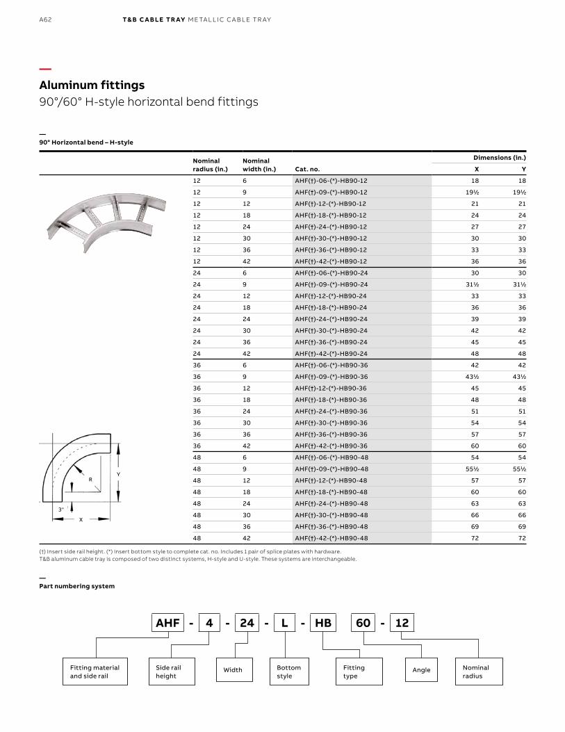
B1 copy starts here
B2 copy starts here
B3 copy starts here
A62 T& B C A B LE TR AY M E TA L L I C C A B L E TR AY
Nominal radius (in.)
Nominal width (in.) Cat. no.
Dimensions (in.)
X Y
12 6 AHF(†)-06-(*)-HB90-12 18 18
12 9 AHF(†)-09-(*)-HB90-12 1911⁄22 1911⁄22
12 12 AHF(†)-12-(*)-HB90-12 21 21
12 18 AHF(†)-18-(*)-HB90-12 24 24
12 24 AHF(†)-24-(*)-HB90-12 27 27
12 30 AHF(†)-30-(*)-HB90-12 30 30
12 36 AHF(†)-36-(*)-HB90-12 33 33
12 42 AHF(†)-42-(*)-HB90-12 36 36
24 6 AHF(†)-06-(*)-HB90-24 30 30
24 9 AHF(†)-09-(*)-HB90-24 3111⁄22 3111⁄22
24 12 AHF(†)-12-(*)-HB90-24 33 33
24 18 AHF(†)-18-(*)-HB90-24 36 36
24 24 AHF(†)-24-(*)-HB90-24 39 39
24 30 AHF(†)-30-(*)-HB90-24 42 42
24 36 AHF(†)-36-(*)-HB90-24 45 45
24 42 AHF(†)-42-(*)-HB90-24 48 48
36 6 AHF(†)-06-(*)-HB90-36 42 42
36 9 AHF(†)-09-(*)-HB90-36 4311⁄22 4311⁄22
36 12 AHF(†)-12-(*)-HB90-36 45 45
36 18 AHF(†)-18-(*)-HB90-36 48 48
36 24 AHF(†)-24-(*)-HB90-36 51 51
36 30 AHF(†)-30-(*)-HB90-36 54 54
36 36 AHF(†)-36-(*)-HB90-36 57 57
36 42 AHF(†)-42-(*)-HB90-36 60 60
48 6 AHF(†)-06-(*)-HB90-48 54 54
48 9 AHF(†)-09-(*)-HB90-48 5511⁄22 5511⁄22
48 12 AHF(†)-12-(*)-HB90-48 57 57
48 18 AHF(†)-18-(*)-HB90-48 60 60
48 24 AHF(†)-24-(*)-HB90-48 63 63
48 30 AHF(†)-30-(*)-HB90-48 66 66
48 36 AHF(†)-36-(*)-HB90-48 69 69
48 42 AHF(†)-42-(*)-HB90-48 72 72
(†) Insert side rail height. (*) Insert bottom style to complete cat. no. Includes 1 pair of splice plates with hardware.T&B aluminum cable tray is composed of two distinct systems, H-style and U-style. These systems are interchangeable.
—Aluminum fittings90°/60° H-style horizontal bend fittings
—90° Horizontal bend – H-style
—Part numbering system
Fitting materialand side rail
Side rail height
Fitting type
Angle Nominal radius
Bottom style
Width
AHF - 4 - 24 - L - HB 60 - 12
X
3"
RY
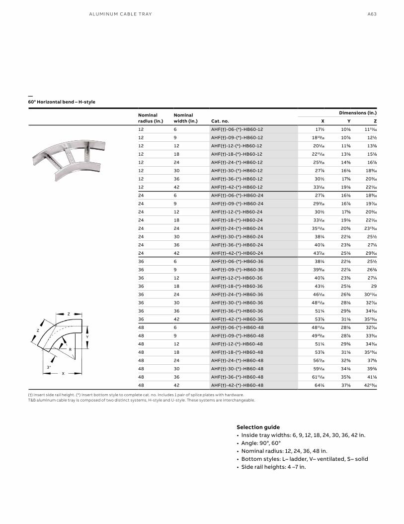
A63 A LU M I N U M C A B L E TR AY
Nominal radius (in.)
Nominal width (in.) Cat. no.
Dimensions (in.)
X Y Z
12 6 AHF(†)-06-(*)-HB60-12 1711⁄22 1011⁄88 111111⁄1616
12 9 AHF(†)-09-(*)-HB60-12 181313⁄1616 1077⁄88 1211⁄22
12 12 AHF(†)-12-(*)-HB60-12 2011⁄1616 1155⁄88 1333⁄88
12 18 AHF(†)-18-(*)-HB60-12 221111⁄1616 1311⁄88 1511⁄88
12 24 AHF(†)-24-(*)-HB60-12 2555⁄1616 1455⁄88 1677⁄88
12 30 AHF(†)-30-(*)-HB60-12 2777⁄88 1611⁄88 1899⁄1616
12 36 AHF(†)-36-(*)-HB60-12 3011⁄22 1755⁄88 2055⁄1616
12 42 AHF(†)-42-(*)-HB60-12 3311⁄1616 1911⁄88 2211⁄1616
24 6 AHF(†)-06-(*)-HB60-24 2777⁄88 1611⁄88 1899⁄1616
24 9 AHF(†)-09-(*)-HB60-24 2933⁄1616 1677⁄88 1977⁄1616
24 12 AHF(†)-12-(*)-HB60-24 3011⁄22 1755⁄88 2055⁄1616
24 18 AHF(†)-18-(*)-HB60-24 3311⁄1616 1911⁄88 2211⁄1616
24 24 AHF(†)-24-(*)-HB60-24 351111⁄1616 2055⁄88 231313⁄1616
24 30 AHF(†)-30-(*)-HB60-24 3811⁄44 2211⁄88 2511⁄22
24 36 AHF(†)-36-(*)-HB60-24 4077⁄88 2355⁄88 2711⁄44
24 42 AHF(†)-42-(*)-HB60-24 4377⁄1616 2511⁄88 2955⁄1616
36 6 AHF(†)-06-(*)-HB60-36 3811⁄44 2211⁄88 2511⁄22
36 9 AHF(†)-09-(*)-HB60-36 3999⁄1616 2277⁄88 2633⁄88
36 12 AHF(†)-12-(*)-HB60-36 4077⁄88 2355⁄88 2711⁄44
36 18 AHF(†)-18-(*)-HB60-36 4311⁄22 2511⁄88 29
36 24 AHF(†)-24-(*)-HB60-36 4611⁄1616 2655⁄88 301111⁄1616
36 30 AHF(†)-30-(*)-HB60-36 481111⁄1616 2811⁄88 3277⁄1616
36 36 AHF(†)-36-(*)-HB60-36 5111⁄44 2955⁄88 3433⁄1616
36 42 AHF(†)-42-(*)-HB60-36 5377⁄88 3111⁄88 351515⁄1616
48 6 AHF(†)-06-(*)-HB60-48 481111⁄1616 2811⁄88 3277⁄1616
48 9 AHF(†)-09-(*)-HB60-48 491515⁄1616 2877⁄88 3355⁄1616
48 12 AHF(†)-12-(*)-HB60-48 5111⁄44 2955⁄88 3433⁄1616
48 18 AHF(†)-18-(*)-HB60-48 5377⁄88 3111⁄88 351515⁄1616
48 24 AHF(†)-24-(*)-HB60-48 5677⁄1616 3255⁄88 3755⁄88
48 30 AHF(†)-30-(*)-HB60-48 5911⁄1616 3411⁄88 3933⁄88
48 36 AHF(†)-36-(*)-HB60-48 611111⁄1616 3555⁄88 4111⁄88
48 42 AHF(†)-42-(*)-HB60-48 6411⁄44 3711⁄88 421313⁄1616
(†) Insert side rail height. (*) Insert bottom style to complete cat. no. Includes 1 pair of splice plates with hardware.T&B aluminum cable tray is composed of two distinct systems, H-style and U-style. These systems are interchangeable.
—60° Horizontal bend – H-style
Selection guide• Inside tray widths: 6, 9, 12, 18, 24, 30, 36, 42 in.• Angle: 90°, 60°• Nominal radius: 12, 24, 36, 48 in.• Bottom styles: L– ladder, V– ventilated, S– solid• Side rail heights: 4 –7 in.
X
3"
R
Y
Z
Z
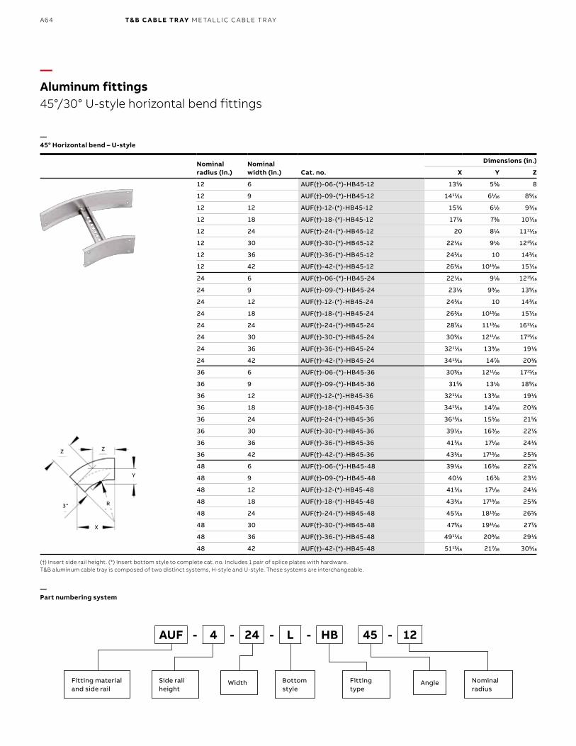
B1 copy starts here
B2 copy starts here
B3 copy starts here
A64 T& B C A B LE TR AY M E TA L L I C C A B L E TR AY
Nominalradius (in.)
Nominalwidth (in.) Cat. no.
Dimensions (in.)
X Y Z
12 6 AUF(†)-06-(*)-HB45-12 1355⁄88 555⁄88 8
12 9 AUF(†)-09-(*)-HB45-12 141111⁄1616 611⁄1616 899⁄1616
12 12 AUF(†)-12-(*)-HB45-12 1533⁄44 611⁄22 933⁄1616
12 18 AUF(†)-18-(*)-HB45-12 1777⁄88 733⁄88 1077⁄1616
12 24 AUF(†)-24-(*)-HB45-12 20 811⁄44 111111⁄1616
12 30 AUF(†)-30-(*)-HB45-12 2211⁄1616 911⁄88 121515⁄1616
12 36 AUF(†)-36-(*)-HB45-12 2433⁄1616 10 1433⁄1616
12 42 AUF(†)-42-(*)-HB45-12 2655⁄1616 101515⁄1616 1577⁄1616
24 6 AUF(†)-06-(*)-HB45-24 2211⁄1616 911⁄88 121515⁄1616
24 9 AUF(†)-09-(*)-HB45-24 2311⁄88 999⁄1616 1399⁄1616
24 12 AUF(†)-12-(*)-HB45-24 2433⁄1616 10 1433⁄1616
24 18 AUF(†)-18-(*)-HB45-24 2655⁄1616 101515⁄1616 1577⁄1616
24 24 AUF(†)-24-(*)-HB45-24 2877⁄1616 111313⁄1616 161111⁄1616
24 30 AUF(†)-30-(*)-HB45-24 3099⁄1616 121111⁄1616 171515⁄1616
24 36 AUF(†)-36-(*)-HB45-24 321111⁄1616 1399⁄1616 1911⁄88
24 42 AUF(†)-42-(*)-HB45-24 341313⁄1616 1477⁄88 2033⁄88
36 6 AUF(†)-06-(*)-HB45-36 3099⁄1616 121111⁄1616 171515⁄1616
36 9 AUF(†)-09-(*)-HB45-36 3155⁄88 1311⁄88 1899⁄1616
36 12 AUF(†)-12-(*)-HB45-36 321111⁄1616 1399⁄1616 1911⁄88
36 18 AUF(†)-18-(*)-HB45-36 341313⁄1616 1477⁄1616 2033⁄88
36 24 AUF(†)-24-(*)-HB45-36 361515⁄1616 1555⁄1616 2155⁄88
36 30 AUF(†)-30-(*)-HB45-36 3911⁄1616 1633⁄1616 2277⁄88
36 36 AUF(†)-36-(*)-HB45-36 4133⁄1616 1711⁄1616 2411⁄88
36 42 AUF(†)-42-(*)-HB45-36 4355⁄1616 171515⁄1616 2533⁄88
48 6 AUF(†)-06-(*)-HB45-48 3911⁄1616 1633⁄1616 2277⁄88
48 9 AUF(†)-09-(*)-HB45-48 4011⁄88 1633⁄88 2311⁄22
48 12 AUF(†)-12-(*)-HB45-48 4133⁄1616 1711⁄1616 2411⁄88
48 18 AUF(†)-18-(*)-HB45-48 4355⁄1616 171515⁄1616 2533⁄88
48 24 AUF(†)-24-(*)-HB45-48 4577⁄1616 181313⁄1616 2655⁄88
48 30 AUF(†)-30-(*)-HB45-48 4799⁄1616 191111⁄1616 2777⁄88
48 36 AUF(†)-36-(*)-HB45-48 491111⁄1616 2099⁄1616 2911⁄88
48 42 AUF(†)-42-(*)-HB45-48 511313⁄1616 2177⁄1616 3055⁄1616
—Aluminum fittings45°/30° U-style horizontal bend fittings
—45° Horizontal bend – U-style
—Part numbering system
Fitting materialand side rail
Side rail height
Fitting type
Angle Nominal radius
Bottom style
Width
AUF - 4 - 24 - L - HB 45 - 12
X
3" R
Z Z
Y
(†) Insert side rail height. (*) Insert bottom style to complete cat. no. Includes 1 pair of splice plates with hardware.T&B aluminum cable tray is composed of two distinct systems, H-style and U-style. These systems are interchangeable.
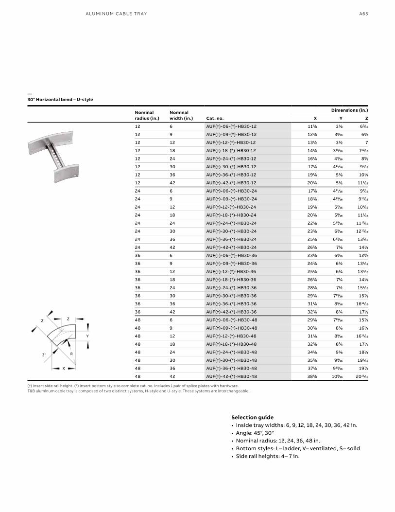
A65A LU M I N U M C A B L E TR AY
Nominalradius (in.)
Nominalwidth (in.) Cat. no.
Dimensions (in.)
X Y Z
12 6 AUF(†)-06-(*)-HB30-12 1155⁄88 311⁄88 633⁄1616
12 9 AUF(†)-09-(*)-HB30-12 1233⁄88 355⁄1616 655⁄88
12 12 AUF(†)-12-(*)-HB30-12 1311⁄22 311⁄22 7
12 18 AUF(†)-18-(*)-HB30-12 1455⁄88 31515⁄1616 71313⁄1616
12 24 AUF(†)-24-(*)-HB30-12 1611⁄88 455⁄1616 855⁄88
12 30 AUF(†)-30-(*)-HB30-12 1755⁄88 41111⁄1616 977⁄1616
12 36 AUF(†)-36-(*)-HB30-12 1911⁄88 511⁄88 1011⁄44
12 42 AUF(†)-42-(*)-HB30-12 2055⁄88 511⁄22 1111⁄1616
24 6 AUF(†)-06-(*)-HB30-24 1755⁄88 41111⁄1616 977⁄1616
24 9 AUF(†)-09-(*)-HB30-24 1833⁄88 41515⁄1616 91313⁄1616
24 12 AUF(†)-12-(*)-HB30-24 1911⁄88 522⁄1616 1044⁄1616
24 18 AUF(†)-18-(*)-HB30-24 2055⁄88 588⁄1616 1111⁄1616
24 24 AUF(†)-24-(*)-HB30-24 2211⁄88 51515⁄1616 111313⁄1616
24 30 AUF(†)-30-(*)-HB30-24 2355⁄88 655⁄1616 121010⁄1616
24 36 AUF(†)-36-(*)-HB30-24 2511⁄88 61212⁄1616 1377⁄1616
24 42 AUF(†)-42-(*)-HB30-24 2655⁄88 711⁄88 1411⁄44
36 6 AUF(†)-06-(*)-HB30-36 2355⁄88 655⁄1616 1255⁄88
36 9 AUF(†)-09-(*)-HB30-36 2433⁄88 611⁄22 1311⁄1616
36 12 AUF(†)-12-(*)-HB30-36 2511⁄88 633⁄44 1377⁄1616
36 18 AUF(†)-18-(*)-HB30-36 2655⁄88 711⁄44 1411⁄44
36 24 AUF(†)-24-(*)-HB30-36 2811⁄88 711⁄22 1511⁄1616
36 30 AUF(†)-30-(*)-HB30-36 2955⁄88 71515⁄1616 1577⁄88
36 36 AUF(†)-36-(*)-HB30-36 3111⁄88 855⁄1616 161111⁄1616
36 42 AUF(†)-42-(*)-HB30-36 3255⁄88 833⁄44 1711⁄22
48 6 AUF(†)-06-(*)-HB30-48 2955⁄88 71515⁄1616 1577⁄88
48 9 AUF(†)-09-(*)-HB30-48 3033⁄88 811⁄88 1611⁄44
48 12 AUF(†)-12-(*)-HB30-48 3111⁄88 855⁄1616 161111⁄1616
48 18 AUF(†)-18-(*)-HB30-48 3255⁄88 833⁄44 1711⁄22
48 24 AUF(†)-24-(*)-HB30-48 3411⁄88 911⁄88 1811⁄44
48 30 AUF(†)-30-(*)-HB30-48 3555⁄88 999⁄1616 1911⁄1616
48 36 AUF(†)-36-(*)-HB30-48 3711⁄88 91515⁄1616 1977⁄88
48 42 AUF(†)-42-(*)-HB30-48 3855⁄88 1055⁄1616 201111⁄1616
—30° Horizontal bend – U-style
(†) Insert side rail height. (*) Insert bottom style to complete cat. no. Includes 1 pair of splice plates with hardware.T&B aluminum cable tray is composed of two distinct systems, H-style and U-style. These systems are interchangeable.
X
3" R
Z Z
Y
Selection guide• Inside tray widths: 6, 9, 12, 18, 24, 30, 36, 42 in.• Angle: 45°, 30°• Nominal radius: 12, 24, 36, 48 in.• Bottom styles: L– ladder, V– ventilated, S– solid• Side rail heights: 4– 7 in.
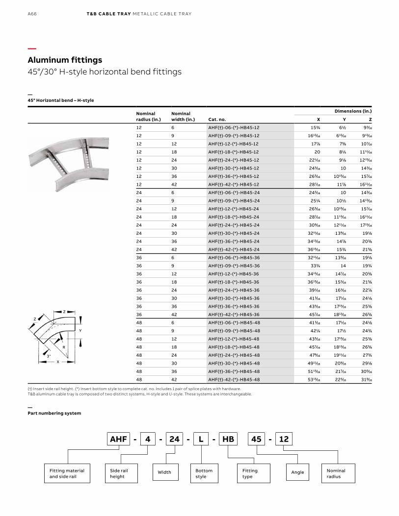
B1 copy starts here
B2 copy starts here
B3 copy starts here
A66 T& B C A B LE TR AY M E TA L L I C C A B L E TR AY
Nominalradius (in.)
Nominalwidth (in.) Cat. no.
Dimensions (in.)
X Y Z
12 6 AHF(†)-06-(*)-HB45-12 1533⁄44 611⁄22 933⁄1616
12 9 AHF(†)-09-(*)-HB45-12 161313⁄1616 61515⁄1616 91313⁄1616
12 12 AHF(†)-12-(*)-HB45-12 1777⁄88 733⁄88 1077⁄1616
12 18 AHF(†)-18-(*)-HB45-12 20 811⁄44 111111⁄1616
12 24 AHF(†)-24-(*)-HB45-12 2211⁄1616 911⁄88 121515⁄1616
12 30 AHF(†)-30-(*)-HB45-12 2433⁄1616 10 1433⁄1616
12 36 AHF(†)-36-(*)-HB45-12 2655⁄1616 101515⁄1616 1577⁄1616
12 42 AHF(†)-42-(*)-HB45-12 2877⁄1616 1177⁄88 161111⁄1616
24 6 AHF(†)-06-(*)-HB45-24 2433⁄1616 10 1433⁄1616
24 9 AHF(†)-09-(*)-HB45-24 2511⁄44 1011⁄22 141313⁄1616
24 12 AHF(†)-12-(*)-HB45-24 2655⁄1616 101515⁄1616 1577⁄1616
24 18 AHF(†)-18-(*)-HB45-24 2877⁄1616 111313⁄1616 161111⁄1616
24 24 AHF(†)-24-(*)-HB45-24 3099⁄1616 121111⁄1616 171515⁄1616
24 30 AHF(†)-30-(*)-HB45-24 321111⁄1616 1399⁄1616 1911⁄88
24 36 AHF(†)-36-(*)-HB45-24 341313⁄1616 1477⁄88 2033⁄88
24 42 AHF(†)-42-(*)-HB45-24 361515⁄1616 1533⁄44 2155⁄88
36 6 AHF(†)-06-(*)-HB45-36 321111⁄1616 1399⁄1616 1911⁄88
36 9 AHF(†)-09-(*)-HB45-36 3333⁄44 14 1933⁄44
36 12 AHF(†)-12-(*)-HB45-36 341313⁄1616 1477⁄1616 2033⁄88
36 18 AHF(†)-18-(*)-HB45-36 361515⁄1616 1555⁄1616 2155⁄88
36 24 AHF(†)-24-(*)-HB45-36 3911⁄1616 1633⁄1616 2277⁄88
36 30 AHF(†)-30-(*)-HB45-36 4133⁄1616 1711⁄1616 2411⁄88
36 36 AHF(†)-36-(*)-HB45-36 4355⁄1616 171515⁄1616 2533⁄88
36 42 AHF(†)-42-(*)-HB45-36 4577⁄1616 181313⁄1616 2655⁄88
48 6 AHF(†)-06-(*)-HB45-48 4133⁄1616 1711⁄1616 2411⁄88
48 9 AHF(†)-09-(*)-HB45-48 4211⁄44 1711⁄22 2433⁄44
48 12 AHF(†)-12-(*)-HB45-48 4355⁄1616 171515⁄1616 2533⁄88
48 18 AHF(†)-18-(*)-HB45-48 4577⁄1616 181313⁄1616 2655⁄88
48 24 AHF(†)-24-(*)-HB45-48 4799⁄1616 191111⁄1616 2733⁄44
48 30 AHF(†)-30-(*)-HB45-48 491111⁄1616 2099⁄1616 2911⁄88
48 36 AHF(†)-36-(*)-HB45-48 511313⁄1616 2177⁄1616 3055⁄1616
48 42 AHF(†)-42-(*)-HB45-48 531515⁄1616 2255⁄1616 3199⁄1616
—Aluminum fittings45°/30° H-style horizontal bend fittings
—45° Horizontal bend – H-style
—Part numbering system
(†) Insert side rail height. (*) Insert bottom style to complete cat. no. Includes 1 pair of splice plates with hardware.T&B aluminum cable tray is composed of two distinct systems, H-style and U-style. These systems are interchangeable.
Fitting materialand side rail
Side rail height
Fitting type
Angle Nominal radius
Bottom style
Width
AHF - 4 - 24 - L - HB 45 - 12
X3"
R
Z
Z
Y
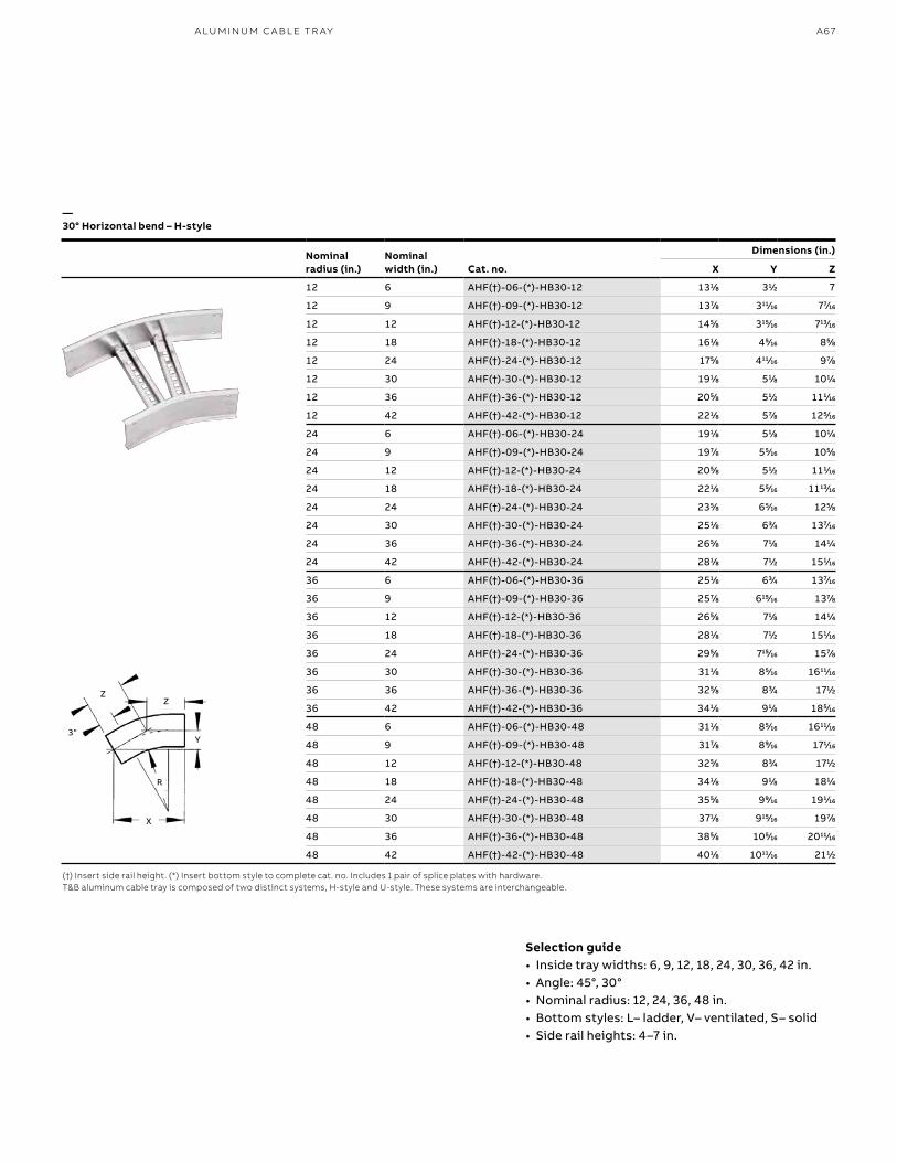
A67A LU M I N U M C A B L E TR AY
—30° Horizontal bend – H-style
(†) Insert side rail height. (*) Insert bottom style to complete cat. no. Includes 1 pair of splice plates with hardware.T&B aluminum cable tray is composed of two distinct systems, H-style and U-style. These systems are interchangeable.
R
Selection guide• Inside tray widths: 6, 9, 12, 18, 24, 30, 36, 42 in.• Angle: 45°, 30°• Nominal radius: 12, 24, 36, 48 in.• Bottom styles: L– ladder, V– ventilated, S– solid• Side rail heights: 4–7 in.
3"Y
ZZ
Nominalradius (in.)
Nominalwidth (in.) Cat. no.
Dimensions (in.)
X Y Z
12 6 AHF(†)-06-(*)-HB30-12 1311⁄88 311⁄22 7
12 9 AHF(†)-09-(*)-HB30-12 1377⁄88 31111⁄1616 777⁄1616
12 12 AHF(†)-12-(*)-HB30-12 1455⁄88 31515⁄1616 71313⁄1616
12 18 AHF(†)-18-(*)-HB30-12 1611⁄88 455⁄1616 855⁄88
12 24 AHF(†)-24-(*)-HB30-12 1755⁄88 41111⁄1616 977⁄88
12 30 AHF(†)-30-(*)-HB30-12 1911⁄88 511⁄88 1011⁄44
12 36 AHF(†)-36-(*)-HB30-12 2055⁄88 511⁄22 1111⁄1616
12 42 AHF(†)-42-(*)-HB30-12 2211⁄88 577⁄88 1255⁄1616
24 6 AHF(†)-06-(*)-HB30-24 1911⁄88 511⁄88 1011⁄44
24 9 AHF(†)-09-(*)-HB30-24 1977⁄88 555⁄1616 1055⁄88
24 12 AHF(†)-12-(*)-HB30-24 2055⁄88 511⁄22 1111⁄1616
24 18 AHF(†)-18-(*)-HB30-24 2211⁄88 555⁄1616 111313⁄1616
24 24 AHF(†)-24-(*)-HB30-24 2355⁄88 655⁄1616 1255⁄88
24 30 AHF(†)-30-(*)-HB30-24 2511⁄88 633⁄44 1377⁄1616
24 36 AHF(†)-36-(*)-HB30-24 2655⁄88 711⁄88 1411⁄44
24 42 AHF(†)-42-(*)-HB30-24 2811⁄88 711⁄22 1511⁄1616
36 6 AHF(†)-06-(*)-HB30-36 2511⁄88 633⁄44 1377⁄1616
36 9 AHF(†)-09-(*)-HB30-36 2577⁄88 61515⁄1616 1377⁄88
36 12 AHF(†)-12-(*)-HB30-36 2655⁄88 711⁄88 1411⁄44
36 18 AHF(†)-18-(*)-HB30-36 2811⁄88 711⁄22 1511⁄1616
36 24 AHF(†)-24-(*)-HB30-36 2955⁄88 71515⁄1616 1577⁄88
36 30 AHF(†)-30-(*)-HB30-36 3111⁄88 855⁄1616 161111⁄1616
36 36 AHF(†)-36-(*)-HB30-36 3255⁄88 833⁄44 1711⁄22
36 42 AHF(†)-42-(*)-HB30-36 3411⁄88 911⁄88 1855⁄1616
48 6 AHF(†)-06-(*)-HB30-48 3111⁄88 855⁄1616 161111⁄1616
48 9 AHF(†)-09-(*)-HB30-48 3177⁄88 899⁄1616 1711⁄1616
48 12 AHF(†)-12-(*)-HB30-48 3255⁄88 833⁄44 1711⁄22
48 18 AHF(†)-18-(*)-HB30-48 3411⁄88 911⁄88 1811⁄44
48 24 AHF(†)-24-(*)-HB30-48 3555⁄88 999⁄1616 1911⁄1616
48 30 AHF(†)-30-(*)-HB30-48 3711⁄88 91515⁄1616 1977⁄88
48 36 AHF(†)-36-(*)-HB30-48 3855⁄88 1055⁄1616 201111⁄1616
48 42 AHF(†)-42-(*)-HB30-48 4011⁄88 101111⁄1616 2111⁄22
X
R
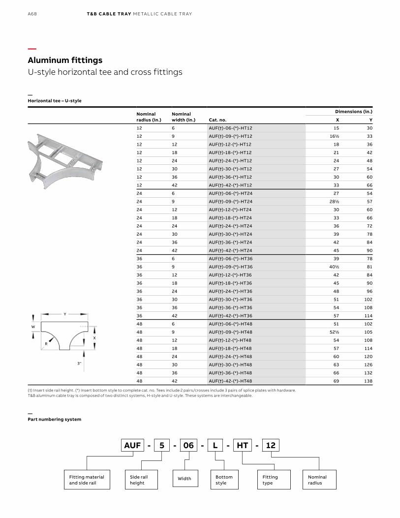
B1 copy starts here
B2 copy starts here
B3 copy starts here
A68 T& B C A B LE TR AY M E TA L L I C C A B L E TR AY
Nominalradius (in.)
Nominal width (in.) Cat. no.
Dimensions (in.)
X Y
12 6 AUF(†)-06-(*)-HT12 15 30
12 9 AUF(†)-09-(*)-HT12 1611⁄22 33
12 12 AUF(†)-12-(*)-HT12 18 36
12 18 AUF(†)-18-(*)-HT12 21 42
12 24 AUF(†)-24-(*)-HT12 24 48
12 30 AUF(†)-30-(*)-HT12 27 54
12 36 AUF(†)-36-(*)-HT12 30 60
12 42 AUF(†)-42-(*)-HT12 33 66
24 6 AUF(†)-06-(*)-HT24 27 54
24 9 AUF(†)-09-(*)-HT24 2811⁄22 57
24 12 AUF(†)-12-(*)-HT24 30 60
24 18 AUF(†)-18-(*)-HT24 33 66
24 24 AUF(†)-24-(*)-HT24 36 72
24 30 AUF(†)-30-(*)-HT24 39 78
24 36 AUF(†)-36-(*)-HT24 42 84
24 42 AUF(†)-42-(*)-HT24 45 90
36 6 AUF(†)-06-(*)-HT36 39 78
36 9 AUF(†)-09-(*)-HT36 4011⁄22 81
36 12 AUF(†)-12-(*)-HT36 42 84
36 18 AUF(†)-18-(*)-HT36 45 90
36 24 AUF(†)-24-(*)-HT36 48 96
36 30 AUF(†)-30-(*)-HT36 51 102
36 36 AUF(†)-36-(*)-HT36 54 108
36 42 AUF(†)-42-(*)-HT36 57 114
48 6 AUF(†)-06-(*)-HT48 51 102
48 9 AUF(†)-09-(*)-HT48 5211⁄22 105
48 12 AUF(†)-12-(*)-HT48 54 108
48 18 AUF(†)-18-(*)-HT48 57 114
48 24 AUF(†)-24-(*)-HT48 60 120
48 30 AUF(†)-30-(*)-HT48 63 126
48 36 AUF(†)-36-(*)-HT48 66 132
48 42 AUF(†)-42-(*)-HT48 69 138
—Aluminum fittingsU-style horizontal tee and cross fittings
—Horizontal tee – U-style
—Part numbering system
(†) Insert side rail height. (*) Insert bottom style to complete cat. no. Tees include 2 pairs/crosses include 3 pairs of splice plates with hardware.T&B aluminum cable tray is composed of two distinct systems, H-style and U-style. These systems are interchangeable.
X
3"
R
Y
W
Fitting materialand side rail
Side rail height
Fitting type
Nominal radius
Bottom style
Width
AUF - 5 - 06 - L - HT - 12

A69A LU M I N U M C A B L E TR AY
Nominalradius (in.)
Nominal width (in.) Cat. no.
Dimensions (in.)
X Y
12 6 AUF(†)-06-(*)-HX12 15 30
12 9 AUF(†)-09-(*)-HX12 1611⁄22 33
12 12 AUF(†)-12-(*)-HX12 18 36
12 18 AUF(†)-18-(*)-HX12 21 42
12 24 AUF(†)-24-(*)-HX12 24 48
12 30 AUF(†)-30-(*)-HX12 27 54
12 36 AUF(†)-36-(*)-HX12 30 60
12 42 AUF(†)-42-(*)-HX12 33 66
24 6 AUF(†)-06-(*)-HX24 27 54
24 9 AUF(†)-09-(*)-HX24 2811⁄22 57
24 12 AUF(†)-12-(*)-HX24 30 60
24 18 AUF(†)-18-(*)-HX24 33 66
24 24 AUF(†)-24-(*)-HX24 36 72
24 30 AUF(†)-30-(*)-HX24 39 78
24 36 AUF(†)-36-(*)-HX24 42 84
24 42 AUF(†)-42-(*)-HX24 45 90
36 6 AUF(†)-06-(*)-HX36 39 78
36 9 AUF(†)-09-(*)-HX36 4011⁄22 81
36 12 AUF(†)-12-(*)-HX36 42 84
36 18 AUF(†)-18-(*)-HX36 45 90
36 24 AUF(†)-24-(*)-HX36 48 96
36 30 AUF(†)-30-(*)-HX36 51 102
36 36 AUF(†)-36-(*)-HX36 54 108
36 42 AUF(†)-42-(*)-HX36 57 114
48 6 AUF(†)-06-(*)-HX48 51 102
48 9 AUF(†)-09-(*)-HX48 5211⁄22 105
48 12 AUF(†)-12-(*)-HX48 54 108
48 18 AUF(†)-18-(*)-HX48 57 114
48 24 AUF(†)-24-(*)-HX48 60 120
48 30 AUF(†)-30-(*)-HX48 63 126
48 36 AUF(†)-36-(*)-HX48 66 132
48 42 AUF(†)-42-(*)-HX48 69 138
—Horizontal cross – U-style
(†) Insert side rail height. (*) Insert bottom style to complete cat. no. Tees include 2 pairs/crosses include 3 pairs of splice plates with hardware.T&B aluminum cable tray is composed of two distinct systems, H-style and U-style. These systems are interchangeable.
Selection guide• Inside tray widths: 6, 9, 12, 18, 24, 30, 36, 42 in.• Nominal radius: 12, 24, 36, 48 in. • Bottom styles: L– ladder, V– ventilated, S– solid• Side rail heights: 4–7 in.
X
3"
R
Y
W
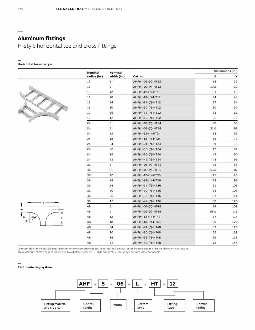
B1 copy starts here
B2 copy starts here
B3 copy starts here
A70 T& B C A B LE TR AY M E TA L L I C C A B L E TR AY
Nominalradius (in.)
Nominal width (in.) Cat. no.
Dimensions (in.)
X Y
12 6 AHF(†)-06-(*)-HT12 18 36
12 9 AHF(†)-09-(*)-HT12 1911⁄22 39
12 12 AHF(†)-12-(*)-HT12 21 42
12 18 AHF(†)-18-(*)-HT12 24 48
12 24 AHF(†)-24-(*)-HT12 27 54
12 30 AHF(†)-30-(*)-HT12 30 60
12 36 AHF(†)-36-(*)-HT12 33 66
12 42 AHF(†)-42-(*)-HT12 36 72
24 6 AHF(†)-06-(*)-HT24 30 60
24 9 AHF(†)-09-(*)-HT24 3111⁄22 63
24 12 AHF(†)-12-(*)-HT24 33 66
24 18 AHF(†)-18-(*)-HT24 36 72
24 24 AHF(†)-24-(*)-HT24 39 78
24 30 AHF(†)-30-(*)-HT24 42 84
24 36 AHF(†)-36-(*)-HT24 45 90
24 42 AHF(†)-42-(*)-HT24 48 96
36 6 AHF(†)-06-(*)-HT36 42 84
36 9 AHF(†)-09-(*)-HT36 4311⁄22 87
36 12 AHF(†)-12-(*)-HT36 45 90
36 18 AHF(†)-18-(*)-HT36 48 96
36 24 AHF(†)-24-(*)-HT36 51 102
36 30 AHF(†)-30-(*)-HT36 54 108
36 36 AHF(†)-36-(*)-HT36 57 114
36 42 AHF(†)-42-(*)-HT36 60 120
48 6 AHF(†)-06-(*)-HT48 54 108
48 9 AHF(†)-09-(*)-HT48 5511⁄22 111
48 12 AHF(†)-12-(*)-HT48 57 114
48 18 AHF(†)-18-(*)-HT48 60 120
48 24 AHF(†)-24-(*)-HT48 63 126
48 30 AHF(†)-30-(*)-HT48 66 132
48 36 AHF(†)-36-(*)-HT48 69 138
48 42 AHF(†)-42-(*)-HT48 72 144
—Aluminum fittingsH-style horizontal tee and cross fittings
—Horizontal tee – H-style
—Part numbering system
(†) Insert side rail height. (*) Insert bottom style to complete cat. no. Tees include 2 pairs/crosses include 3 pairs of splice plates with hardware.T&B aluminum cable tray is composed of two distinct systems, H-style and U-style. These systems are interchangeable.
Fitting materialand side rail
Side rail height
Fitting type
Nominal radius
Bottom style
Width
AHF - 5 - 06 - L - HT - 12
X3" R
Y
W
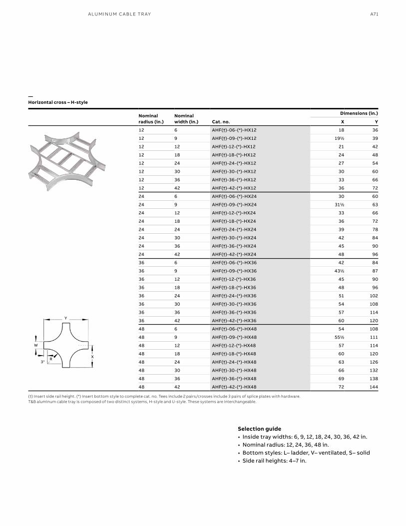
A71A LU M I N U M C A B L E TR AY
Nominalradius (in.)
Nominal width (in.) Cat. no.
Dimensions (in.)
X Y
12 6 AHF(†)-06-(*)-HX12 18 36
12 9 AHF(†)-09-(*)-HX12 1911⁄22 39
12 12 AHF(†)-12-(*)-HX12 21 42
12 18 AHF(†)-18-(*)-HX12 24 48
12 24 AHF(†)-24-(*)-HX12 27 54
12 30 AHF(†)-30-(*)-HX12 30 60
12 36 AHF(†)-36-(*)-HX12 33 66
12 42 AHF(†)-42-(*)-HX12 36 72
24 6 AHF(†)-06-(*)-HX24 30 60
24 9 AHF(†)-09-(*)-HX24 3111⁄22 63
24 12 AHF(†)-12-(*)-HX24 33 66
24 18 AHF(†)-18-(*)-HX24 36 72
24 24 AHF(†)-24-(*)-HX24 39 78
24 30 AHF(†)-30-(*)-HX24 42 84
24 36 AHF(†)-36-(*)-HX24 45 90
24 42 AHF(†)-42-(*)-HX24 48 96
36 6 AHF(†)-06-(*)-HX36 42 84
36 9 AHF(†)-09-(*)-HX36 4311⁄22 87
36 12 AHF(†)-12-(*)-HX36 45 90
36 18 AHF(†)-18-(*)-HX36 48 96
36 24 AHF(†)-24-(*)-HX36 51 102
36 30 AHF(†)-30-(*)-HX36 54 108
36 36 AHF(†)-36-(*)-HX36 57 114
36 42 AHF(†)-42-(*)-HX36 60 120
48 6 AHF(†)-06-(*)-HX48 54 108
48 9 AHF(†)-09-(*)-HX48 5511⁄22 111
48 12 AHF(†)-12-(*)-HX48 57 114
48 18 AHF(†)-18-(*)-HX48 60 120
48 24 AHF(†)-24-(*)-HX48 63 126
48 30 AHF(†)-30-(*)-HX48 66 132
48 36 AHF(†)-36-(*)-HX48 69 138
48 42 AHF(†)-42-(*)-HX48 72 144
—Horizontal cross – H-style
(†) Insert side rail height. (*) Insert bottom style to complete cat. no. Tees include 2 pairs/crosses include 3 pairs of splice plates with hardware.T&B aluminum cable tray is composed of two distinct systems, H-style and U-style. These systems are interchangeable.
X3"
R
Y
W
Selection guide• Inside tray widths: 6, 9, 12, 18, 24, 30, 36, 42 in.• Nominal radius: 12, 24, 36, 48 in.• Bottom styles: L– ladder, V– ventilated, S– solid• Side rail heights: 4–7 in.
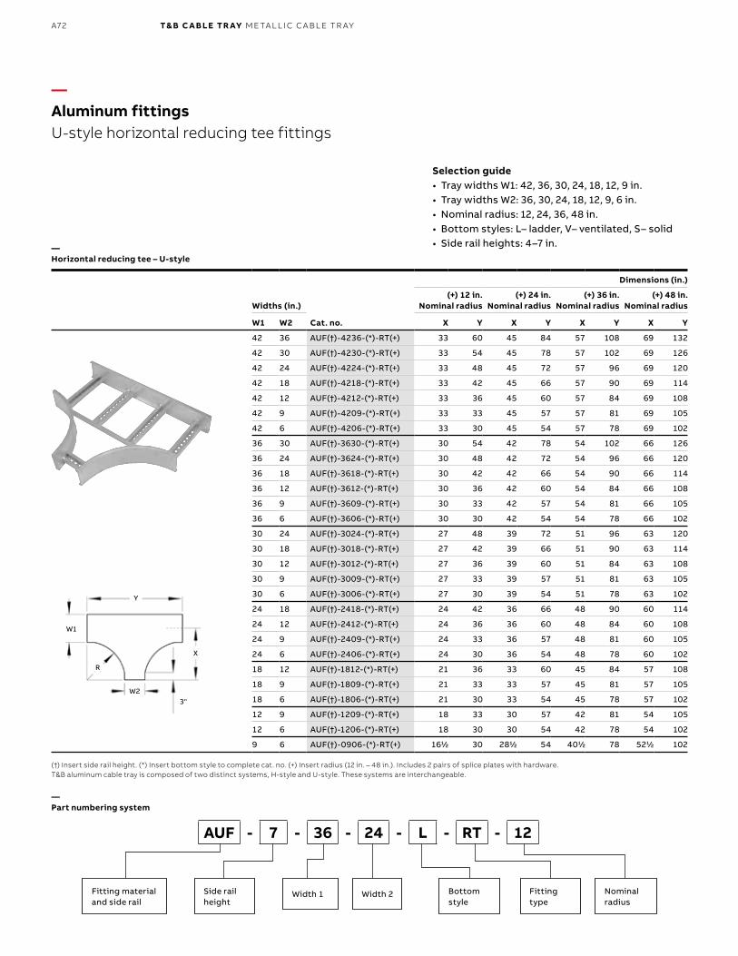
B1 copy starts here
B2 copy starts here
B3 copy starts here
A72 T& B C A B LE TR AY M E TA L L I C C A B L E TR AY
Widths (in.)
Cat. no.
Dimensions (in.)
(+) 12 in. Nominal radius
(+) 24 in. Nominal radius
(+) 36 in. Nominal radius
(+) 48 in. Nominal radius
W1 W2 X Y X Y X Y X Y
42 36 AUF(†)-4236-(*)-RT(+) 33 60 45 84 57 108 69 132
42 30 AUF(†)-4230-(*)-RT(+) 33 54 45 78 57 102 69 126
42 24 AUF(†)-4224-(*)-RT(+) 33 48 45 72 57 96 69 120
42 18 AUF(†)-4218-(*)-RT(+) 33 42 45 66 57 90 69 114
42 12 AUF(†)-4212-(*)-RT(+) 33 36 45 60 57 84 69 108
42 9 AUF(†)-4209-(*)-RT(+) 33 33 45 57 57 81 69 105
42 6 AUF(†)-4206-(*)-RT(+) 33 30 45 54 57 78 69 102
36 30 AUF(†)-3630-(*)-RT(+) 30 54 42 78 54 102 66 126
36 24 AUF(†)-3624-(*)-RT(+) 30 48 42 72 54 96 66 120
36 18 AUF(†)-3618-(*)-RT(+) 30 42 42 66 54 90 66 114
36 12 AUF(†)-3612-(*)-RT(+) 30 36 42 60 54 84 66 108
36 9 AUF(†)-3609-(*)-RT(+) 30 33 42 57 54 81 66 105
36 6 AUF(†)-3606-(*)-RT(+) 30 30 42 54 54 78 66 102
30 24 AUF(†)-3024-(*)-RT(+) 27 48 39 72 51 96 63 120
30 18 AUF(†)-3018-(*)-RT(+) 27 42 39 66 51 90 63 114
30 12 AUF(†)-3012-(*)-RT(+) 27 36 39 60 51 84 63 108
30 9 AUF(†)-3009-(*)-RT(+) 27 33 39 57 51 81 63 105
30 6 AUF(†)-3006-(*)-RT(+) 27 30 39 54 51 78 63 102
24 18 AUF(†)-2418-(*)-RT(+) 24 42 36 66 48 90 60 114
24 12 AUF(†)-2412-(*)-RT(+) 24 36 36 60 48 84 60 108
24 9 AUF(†)-2409-(*)-RT(+) 24 33 36 57 48 81 60 105
24 6 AUF(†)-2406-(*)-RT(+) 24 30 36 54 48 78 60 102
18 12 AUF(†)-1812-(*)-RT(+) 21 36 33 60 45 84 57 108
18 9 AUF(†)-1809-(*)-RT(+) 21 33 33 57 45 81 57 105
18 6 AUF(†)-1806-(*)-RT(+) 21 30 33 54 45 78 57 102
12 9 AUF(†)-1209-(*)-RT(+) 18 33 30 57 42 81 54 105
12 6 AUF(†)-1206-(*)-RT(+) 18 30 30 54 42 78 54 102
9 6 AUF(†)-0906-(*)-RT(+) 1611⁄22 30 2811⁄22 54 4011⁄22 78 5211⁄22 102
—Aluminum fittingsU-style horizontal reducing tee fittings
—Horizontal reducing tee – U-style
—Part numbering system
(†) Insert side rail height. (*) Insert bottom style to complete cat. no. (+) Insert radius (12 in. – 48 in.). Includes 2 pairs of splice plates with hardware. T&B aluminum cable tray is composed of two distinct systems, H-style and U-style. These systems are interchangeable.
Selection guide• Tray widths W1: 42, 36, 30, 24, 18, 12, 9 in.• Tray widths W2: 36, 30, 24, 18, 12, 9, 6 in.• Nominal radius: 12, 24, 36, 48 in. • Bottom styles: L– ladder, V– ventilated, S– solid• Side rail heights: 4–7 in.
X
3"
R
Y
W1
W2
Fitting materialand side rail
Side rail height
Bottom style
Nominal radius
Width 2
AUF - 7 - 36 - 24 - L - RT - 12
Fitting type
Width 1
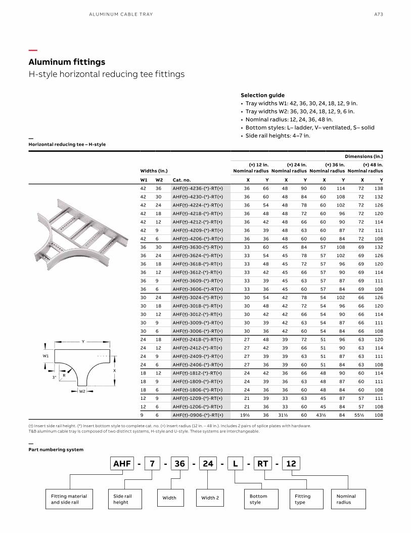
A73A LU M I N U M C A B L E TR AY
—Aluminum fittingsH-style horizontal reducing tee fittings
—Horizontal reducing tee – H-style
—Part numbering system
(†) Insert side rail height. (*) Insert bottom style to complete cat. no. (+) Insert radius (12 in. – 48 in.). Includes 2 pairs of splice plates with hardware. T&B aluminum cable tray is composed of two distinct systems, H-style and U-style. These systems are interchangeable.
Widths (in.)
Cat. no.
Dimensions (in.)
(+) 12 in. Nominal radius
(+) 24 in. Nominal radius
(+) 36 in. Nominal radius
(+) 48 in. Nominal radius
W1 W2 X Y X Y X Y X Y
42 36 AHF(†)-4236-(*)-RT(+) 36 66 48 90 60 114 72 138
42 30 AHF(†)-4230-(*)-RT(+) 36 60 48 84 60 108 72 132
42 24 AHF(†)-4224-(*)-RT(+) 36 54 48 78 60 102 72 126
42 18 AHF(†)-4218-(*)-RT(+) 36 48 48 72 60 96 72 120
42 12 AHF(†)-4212-(*)-RT(+) 36 42 48 66 60 90 72 114
42 9 AHF(†)-4209-(*)-RT(+) 36 39 48 63 60 87 72 111
42 6 AHF(†)-4206-(*)-RT(+) 36 36 48 60 60 84 72 108
36 30 AHF(†)-3630-(*)-RT(+) 33 60 45 84 57 108 69 132
36 24 AHF(†)-3624-(*)-RT(+) 33 54 45 78 57 102 69 126
36 18 AHF(†)-3618-(*)-RT(+) 33 48 45 72 57 96 69 120
36 12 AHF(†)-3612-(*)-RT(+) 33 42 45 66 57 90 69 114
36 9 AHF(†)-3609-(*)-RT(+) 33 39 45 63 57 87 69 111
36 6 AHF(†)-3606-(*)-RT(+) 33 36 45 60 57 84 69 108
30 24 AHF(†)-3024-(*)-RT(+) 30 54 42 78 54 102 66 126
30 18 AHF(†)-3018-(*)-RT(+) 30 48 42 72 54 96 66 120
30 12 AHF(†)-3012-(*)-RT(+) 30 42 42 66 54 90 66 114
30 9 AHF(†)-3009-(*)-RT(+) 30 39 42 63 54 87 66 111
30 6 AHF(†)-3006-(*)-RT(+) 30 36 42 60 54 84 66 108
24 18 AHF(†)-2418-(*)-RT(+) 27 48 39 72 51 96 63 120
24 12 AHF(†)-2412-(*)-RT(+) 27 42 39 66 51 90 63 114
24 9 AHF(†)-2409-(*)-RT(+) 27 39 39 63 51 87 63 111
24 6 AHF(†)-2406-(*)-RT(+) 27 36 39 60 51 84 63 108
18 12 AHF(†)-1812-(*)-RT(+) 24 42 36 66 48 90 60 114
18 9 AHF(†)-1809-(*)-RT(+) 24 39 36 63 48 87 60 111
18 6 AHF(†)-1806-(*)-RT(+) 24 36 36 60 48 84 60 108
12 9 AHF(†)-1209-(*)-RT(+) 21 39 33 63 45 87 57 111
12 6 AHF(†)-1206-(*)-RT(+) 21 36 33 60 45 84 57 108
9 6 AHF(†)-0906-(*)-RT(+) 1911⁄22 36 3111⁄22 60 4311⁄22 84 5511⁄22 108
Selection guide• Tray widths W1: 42, 36, 30, 24, 18, 12, 9 in.• Tray widths W2: 36, 30, 24, 18, 12, 9, 6 in.• Nominal radius: 12, 24, 36, 48 in. • Bottom styles: L– ladder, V– ventilated, S– solid• Side rail heights: 4–7 in.
X
3" R
Y
W1
W2
Fitting materialand side rail
Side rail height
Bottom style
Nominal radius
Width 2Width
AHF - 7 - 36 - 24 - L - RT - 12
Fitting type
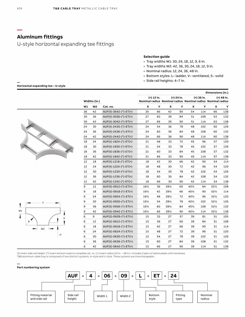
B1 copy starts here
B2 copy starts here
B3 copy starts here
A74 T& B C A B LE TR AY M E TA L L I C C A B L E TR AY
Widths (in.)
Cat. no.
Dimensions (in.)
(+) 12 in. Nominal radius
(+) 24 in. Nominal radius
(+) 36 in. Nominal radius
(+) 48 in. Nominal radius
W1 W2 X Y X Y X Y X Y
36 42 AUF(†)-3642-(*)-ET(+) 30 66 42 90 54 114 66 138
30 36 AUF(†)-3036-(*)-ET(+) 27 60 39 84 51 108 63 132
30 42 AUF(†)-3042-(*)-ET(+) 27 66 39 90 51 114 63 138
24 30 AUF(†)-2430-(*)-ET(+) 24 54 36 78 48 102 60 126
24 36 AUF(†)-2436-(*)-ET(+) 24 60 36 84 48 108 60 132
24 42 AUF(†)-2442-(*)-ET(+) 24 66 36 90 48 114 60 138
18 24 AUF(†)-1824-(*)-ET(+) 21 48 33 72 45 96 57 120
18 30 AUF(†)-1830-(*)-ET(+) 21 54 33 78 45 102 57 126
18 36 AUF(†)-1836-(*)-ET(+) 21 60 33 84 45 108 57 132
18 42 AUF(†)-1842-(*)-ET(+) 21 66 33 90 45 114 57 138
12 18 AUF(†)-1218-(*)-ET(+) 18 42 30 66 42 90 54 114
12 24 AUF(†)-1224-(*)-ET(+) 18 48 30 72 42 96 54 120
12 30 AUF(†)-1230-(*)-ET(+) 18 54 30 78 42 102 54 126
12 36 AUF(†)-1236-(*)-ET(+) 18 60 30 84 42 108 54 132
12 42 AUF(†)-1242-(*)-ET(+) 18 66 30 90 42 114 54 138
9 12 AUF(†)-0912-(*)-ET(+) 1611⁄22 36 2811⁄22 60 4011⁄22 84 5211⁄22 108
9 18 AUF(†)-0918-(*)-ET(+) 1611⁄22 42 2811⁄22 66 4011⁄22 90 5211⁄22 114
9 24 AUF(†)-0924-(*)-ET(+) 1611⁄22 48 2811⁄22 72 4011⁄22 96 5211⁄22 120
9 30 AUF(†)-0930-(*)-ET(+) 1611⁄22 54 2811⁄22 78 4011⁄22 102 5211⁄22 126
9 36 AUF(†)-0936-(*)-ET(+) 1611⁄22 60 2811⁄22 84 4011⁄22 108 5211⁄22 132
9 42 AUF(†)-0942-(*)-ET(+) 1611⁄22 66 2811⁄22 90 4011⁄22 114 5211⁄22 138
6 9 AUF(†)-0609-(*)-ET(+) 15 33 27 57 39 81 51 105
6 12 AUF(†)-0612-(*)-ET(+) 15 36 27 60 39 84 51 108
6 18 AUF(†)-0618-(*)-ET(+) 15 42 27 66 39 90 51 114
6 24 AUF(†)-0624-(*)-ET(+) 15 48 27 72 39 96 51 120
6 30 AUF(†)-0630-(*)-ET(+) 15 54 27 78 39 102 51 126
6 36 AUF(†)-0636-(*)-ET(+) 15 60 27 84 39 108 51 132
6 42 AUF(†)-0642-(*)-ET(+) 15 66 27 90 39 114 51 138
—Aluminum fittingsU-style horizontal expanding tee fittings
—Part numbering system
(†) Insert side rail height. (*) Insert bottom style to complete cat. no. (+) Insert radius (12 in. – 48 in.). Includes 2 pairs of splice plates with hardware.T&B aluminum cable tray is composed of two distinct systems, H-style and U-style. These systems are interchangeable.
Selection guide• Tray widths W1: 30, 24, 18, 12, 9, 6 in.• Tray widths W2: 42, 36, 30, 24, 18, 12, 9 in.• Nominal radius: 12, 24, 36, 48 in.• Bottom styles: L– ladder, V– ventilated, S– solid• Side rail heights: 4–7 in.—
Horizontal expanding tee – U-style
Fitting materialand side rail
Side rail height
Bottom style
Nominal radius
Width 2Width 1
AUF - 4 - 06 - 09 - L - ET - 24
Fitting type
X
3"
R
Y
W1
W2
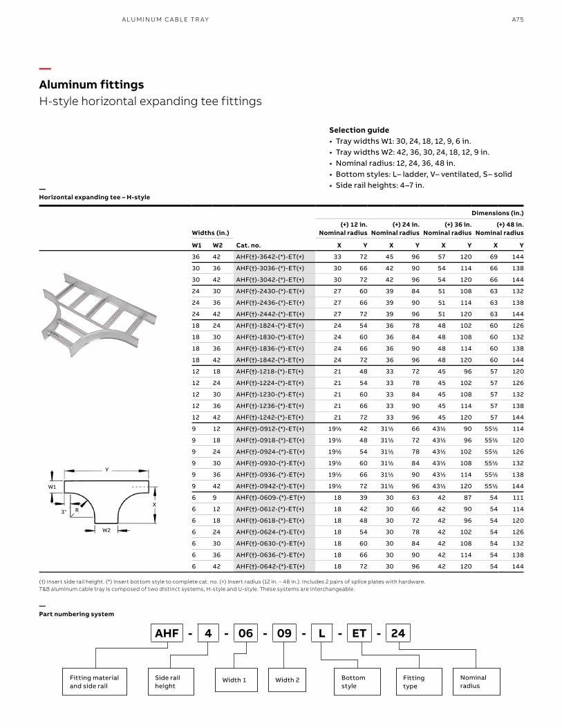
A75A LU M I N U M C A B L E TR AY
Widths (in.)
Cat. no.
Dimensions (in.)
(+) 12 in. Nominal radius
(+) 24 in. Nominal radius
(+) 36 in. Nominal radius
(+) 48 in. Nominal radius
W1 W2 X Y X Y X Y X Y
36 42 AHF(†)-3642-(*)-ET(+) 33 72 45 96 57 120 69 144
30 36 AHF(†)-3036-(*)-ET(+) 30 66 42 90 54 114 66 138
30 42 AHF(†)-3042-(*)-ET(+) 30 72 42 96 54 120 66 144
24 30 AHF(†)-2430-(*)-ET(+) 27 60 39 84 51 108 63 132
24 36 AHF(†)-2436-(*)-ET(+) 27 66 39 90 51 114 63 138
24 42 AHF(†)-2442-(*)-ET(+) 27 72 39 96 51 120 63 144
18 24 AHF(†)-1824-(*)-ET(+) 24 54 36 78 48 102 60 126
18 30 AHF(†)-1830-(*)-ET(+) 24 60 36 84 48 108 60 132
18 36 AHF(†)-1836-(*)-ET(+) 24 66 36 90 48 114 60 138
18 42 AHF(†)-1842-(*)-ET(+) 24 72 36 96 48 120 60 144
12 18 AHF(†)-1218-(*)-ET(+) 21 48 33 72 45 96 57 120
12 24 AHF(†)-1224-(*)-ET(+) 21 54 33 78 45 102 57 126
12 30 AHF(†)-1230-(*)-ET(+) 21 60 33 84 45 108 57 132
12 36 AHF(†)-1236-(*)-ET(+) 21 66 33 90 45 114 57 138
12 42 AHF(†)-1242-(*)-ET(+) 21 72 33 96 45 120 57 144
9 12 AHF(†)-0912-(*)-ET(+) 1911⁄22 42 3111⁄22 66 4311⁄22 90 5511⁄22 114
9 18 AHF(†)-0918-(*)-ET(+) 1911⁄22 48 3111⁄22 72 4311⁄22 96 5511⁄22 120
9 24 AHF(†)-0924-(*)-ET(+) 1911⁄22 54 3111⁄22 78 4311⁄22 102 5511⁄22 126
9 30 AHF(†)-0930-(*)-ET(+) 1911⁄22 60 3111⁄22 84 4311⁄22 108 5511⁄22 132
9 36 AHF(†)-0936-(*)-ET(+) 1911⁄22 66 3111⁄22 90 4311⁄22 114 5511⁄22 138
9 42 AHF(†)-0942-(*)-ET(+) 1911⁄22 72 3111⁄22 96 4311⁄22 120 5511⁄22 144
6 9 AHF(†)-0609-(*)-ET(+) 18 39 30 63 42 87 54 111
6 12 AHF(†)-0612-(*)-ET(+) 18 42 30 66 42 90 54 114
6 18 AHF(†)-0618-(*)-ET(+) 18 48 30 72 42 96 54 120
6 24 AHF(†)-0624-(*)-ET(+) 18 54 30 78 42 102 54 126
6 30 AHF(†)-0630-(*)-ET(+) 18 60 30 84 42 108 54 132
6 36 AHF(†)-0636-(*)-ET(+) 18 66 30 90 42 114 54 138
6 42 AHF(†)-0642-(*)-ET(+) 18 72 30 96 42 120 54 144
—Aluminum fittingsH-style horizontal expanding tee fittings
—Part numbering system
(†) Insert side rail height. (*) Insert bottom style to complete cat. no. (+) Insert radius (12 in. – 48 in.). Includes 2 pairs of splice plates with hardware.T&B aluminum cable tray is composed of two distinct systems, H-style and U-style. These systems are interchangeable.
Selection guide• Tray widths W1: 30, 24, 18, 12, 9, 6 in.• Tray widths W2: 42, 36, 30, 24, 18, 12, 9 in.• Nominal radius: 12, 24, 36, 48 in.• Bottom styles: L– ladder, V– ventilated, S– solid• Side rail heights: 4–7 in.—
Horizontal expanding tee – H-style
Fitting materialand side rail
Side rail height
Bottom style
Nominal radius
Width 2Width 1 Fitting type
X3" R
Y
W1
W2
AHF - 4 - 06 - 09 - L - ET - 24
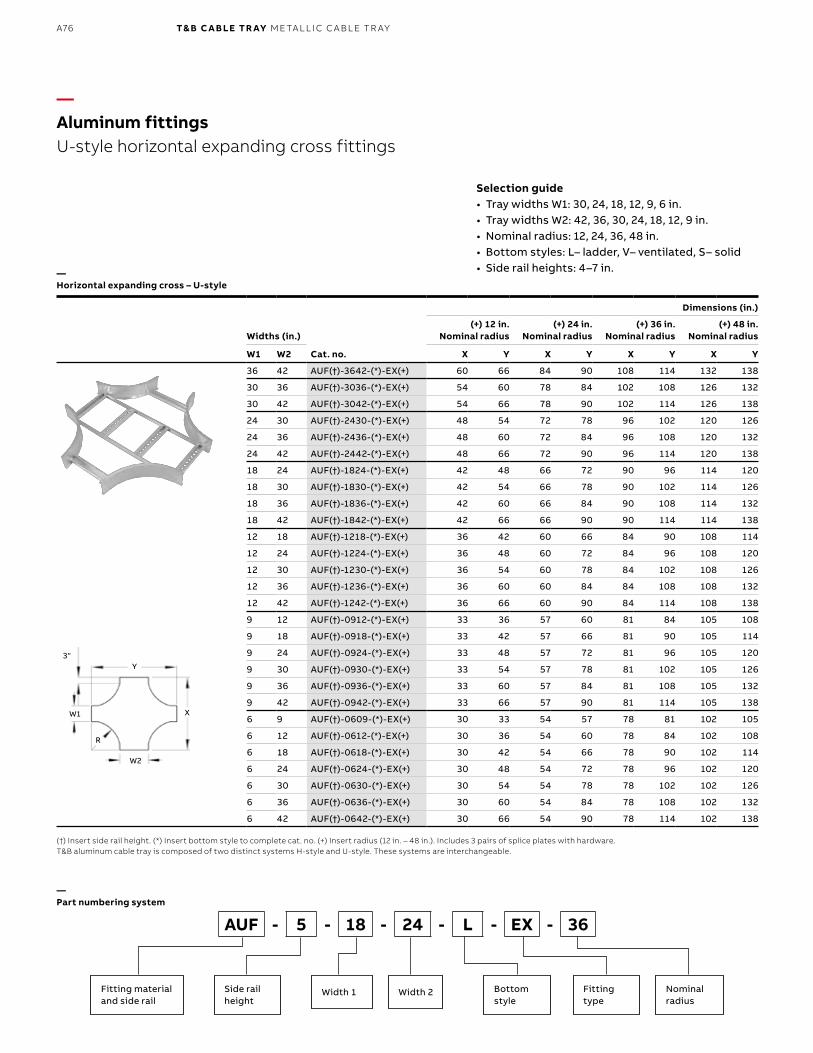
B1 copy starts here
B2 copy starts here
B3 copy starts here
A76 T& B C A B LE TR AY M E TA L L I C C A B L E TR AY
Widths (in.)
Cat. no.
Dimensions (in.)
(+) 12 in. Nominal radius
(+) 24 in. Nominal radius
(+) 36 in. Nominal radius
(+) 48 in. Nominal radius
W1 W2 X Y X Y X Y X Y
36 42 AUF(†)-3642-(*)-EX(+) 60 66 84 90 108 114 132 138
30 36 AUF(†)-3036-(*)-EX(+) 54 60 78 84 102 108 126 132
30 42 AUF(†)-3042-(*)-EX(+) 54 66 78 90 102 114 126 138
24 30 AUF(†)-2430-(*)-EX(+) 48 54 72 78 96 102 120 126
24 36 AUF(†)-2436-(*)-EX(+) 48 60 72 84 96 108 120 132
24 42 AUF(†)-2442-(*)-EX(+) 48 66 72 90 96 114 120 138
18 24 AUF(†)-1824-(*)-EX(+) 42 48 66 72 90 96 114 120
18 30 AUF(†)-1830-(*)-EX(+) 42 54 66 78 90 102 114 126
18 36 AUF(†)-1836-(*)-EX(+) 42 60 66 84 90 108 114 132
18 42 AUF(†)-1842-(*)-EX(+) 42 66 66 90 90 114 114 138
12 18 AUF(†)-1218-(*)-EX(+) 36 42 60 66 84 90 108 114
12 24 AUF(†)-1224-(*)-EX(+) 36 48 60 72 84 96 108 120
12 30 AUF(†)-1230-(*)-EX(+) 36 54 60 78 84 102 108 126
12 36 AUF(†)-1236-(*)-EX(+) 36 60 60 84 84 108 108 132
12 42 AUF(†)-1242-(*)-EX(+) 36 66 60 90 84 114 108 138
9 12 AUF(†)-0912-(*)-EX(+) 33 36 57 60 81 84 105 108
9 18 AUF(†)-0918-(*)-EX(+) 33 42 57 66 81 90 105 114
9 24 AUF(†)-0924-(*)-EX(+) 33 48 57 72 81 96 105 120
9 30 AUF(†)-0930-(*)-EX(+) 33 54 57 78 81 102 105 126
9 36 AUF(†)-0936-(*)-EX(+) 33 60 57 84 81 108 105 132
9 42 AUF(†)-0942-(*)-EX(+) 33 66 57 90 81 114 105 138
6 9 AUF(†)-0609-(*)-EX(+) 30 33 54 57 78 81 102 105
6 12 AUF(†)-0612-(*)-EX(+) 30 36 54 60 78 84 102 108
6 18 AUF(†)-0618-(*)-EX(+) 30 42 54 66 78 90 102 114
6 24 AUF(†)-0624-(*)-EX(+) 30 48 54 72 78 96 102 120
6 30 AUF(†)-0630-(*)-EX(+) 30 54 54 78 78 102 102 126
6 36 AUF(†)-0636-(*)-EX(+) 30 60 54 84 78 108 102 132
6 42 AUF(†)-0642-(*)-EX(+) 30 66 54 90 78 114 102 138
—Aluminum fittingsU-style horizontal expanding cross fittings
—Part numbering system
(†) Insert side rail height. (*) Insert bottom style to complete cat. no. (+) Insert radius (12 in. – 48 in.). Includes 3 pairs of splice plates with hardware.T&B aluminum cable tray is composed of two distinct systems H-style and U-style. These systems are interchangeable.
Selection guide• Tray widths W1: 30, 24, 18, 12, 9, 6 in.• Tray widths W2: 42, 36, 30, 24, 18, 12, 9 in.• Nominal radius: 12, 24, 36, 48 in.• Bottom styles: L– ladder, V– ventilated, S– solid• Side rail heights: 4–7 in.—
Horizontal expanding cross – U-style
Fitting materialand side rail
Side rail height
Bottom style
Nominal radius
Width 2Width 1
AUF - 5 - 18 - 24 - L - EX - 36
Fitting type
X
3"
R
W1
W2
Y
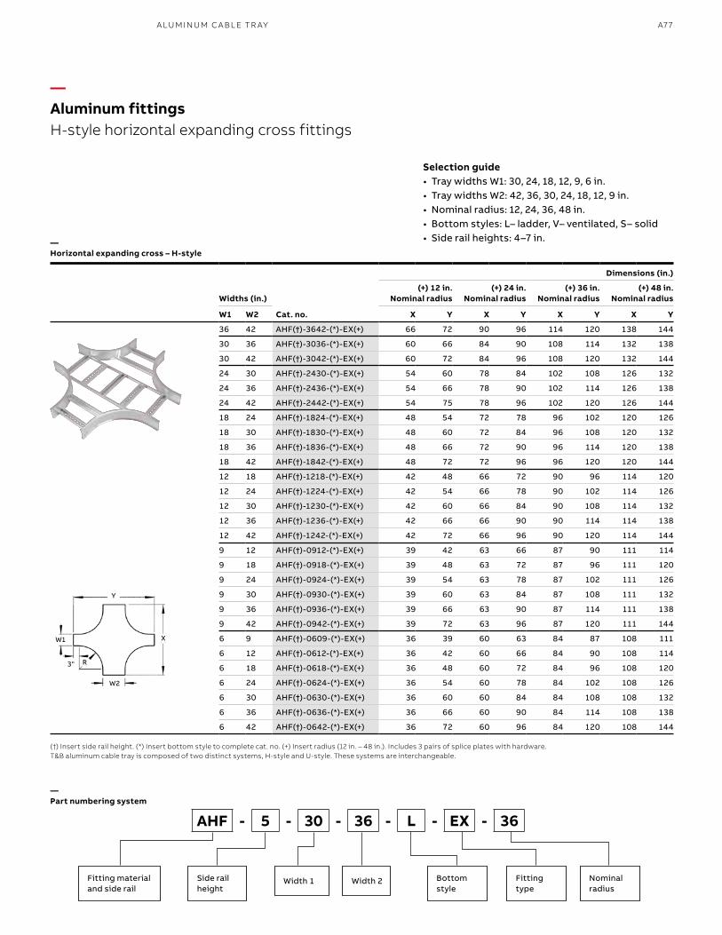
A77A LU M I N U M C A B L E TR AY
—Aluminum fittingsH-style horizontal expanding cross fittings
—Part numbering system
(†) Insert side rail height. (*) Insert bottom style to complete cat. no. (+) Insert radius (12 in. – 48 in.). Includes 3 pairs of splice plates with hardware.T&B aluminum cable tray is composed of two distinct systems, H-style and U-style. These systems are interchangeable.
Selection guide• Tray widths W1: 30, 24, 18, 12, 9, 6 in.• Tray widths W2: 42, 36, 30, 24, 18, 12, 9 in.• Nominal radius: 12, 24, 36, 48 in.• Bottom styles: L– ladder, V– ventilated, S– solid• Side rail heights: 4–7 in.—
Horizontal expanding cross – H-style
Fitting materialand side rail
Side rail height
Bottom style
Nominal radius
Width 2Width 1
AHF - 5 - 30 - 36 - L - EX - 36
Fitting type
Widths (in.)
Cat. no.
Dimensions (in.)
(+) 12 in. Nominal radius
(+) 24 in. Nominal radius
(+) 36 in. Nominal radius
(+) 48 in. Nominal radius
W1 W2 X Y X Y X Y X Y
36 42 AHF(†)-3642-(*)-EX(+) 66 72 90 96 114 120 138 144
30 36 AHF(†)-3036-(*)-EX(+) 60 66 84 90 108 114 132 138
30 42 AHF(†)-3042-(*)-EX(+) 60 72 84 96 108 120 132 144
24 30 AHF(†)-2430-(*)-EX(+) 54 60 78 84 102 108 126 132
24 36 AHF(†)-2436-(*)-EX(+) 54 66 78 90 102 114 126 138
24 42 AHF(†)-2442-(*)-EX(+) 54 75 78 96 102 120 126 144
18 24 AHF(†)-1824-(*)-EX(+) 48 54 72 78 96 102 120 126
18 30 AHF(†)-1830-(*)-EX(+) 48 60 72 84 96 108 120 132
18 36 AHF(†)-1836-(*)-EX(+) 48 66 72 90 96 114 120 138
18 42 AHF(†)-1842-(*)-EX(+) 48 72 72 96 96 120 120 144
12 18 AHF(†)-1218-(*)-EX(+) 42 48 66 72 90 96 114 120
12 24 AHF(†)-1224-(*)-EX(+) 42 54 66 78 90 102 114 126
12 30 AHF(†)-1230-(*)-EX(+) 42 60 66 84 90 108 114 132
12 36 AHF(†)-1236-(*)-EX(+) 42 66 66 90 90 114 114 138
12 42 AHF(†)-1242-(*)-EX(+) 42 72 66 96 90 120 114 144
9 12 AHF(†)-0912-(*)-EX(+) 39 42 63 66 87 90 111 114
9 18 AHF(†)-0918-(*)-EX(+) 39 48 63 72 87 96 111 120
9 24 AHF(†)-0924-(*)-EX(+) 39 54 63 78 87 102 111 126
9 30 AHF(†)-0930-(*)-EX(+) 39 60 63 84 87 108 111 132
9 36 AHF(†)-0936-(*)-EX(+) 39 66 63 90 87 114 111 138
9 42 AHF(†)-0942-(*)-EX(+) 39 72 63 96 87 120 111 144
6 9 AHF(†)-0609-(*)-EX(+) 36 39 60 63 84 87 108 111
6 12 AHF(†)-0612-(*)-EX(+) 36 42 60 66 84 90 108 114
6 18 AHF(†)-0618-(*)-EX(+) 36 48 60 72 84 96 108 120
6 24 AHF(†)-0624-(*)-EX(+) 36 54 60 78 84 102 108 126
6 30 AHF(†)-0630-(*)-EX(+) 36 60 60 84 84 108 108 132
6 36 AHF(†)-0636-(*)-EX(+) 36 66 60 90 84 114 108 138
6 42 AHF(†)-0642-(*)-EX(+) 36 72 60 96 84 120 108 144
X
3" R
W1
W2
Y
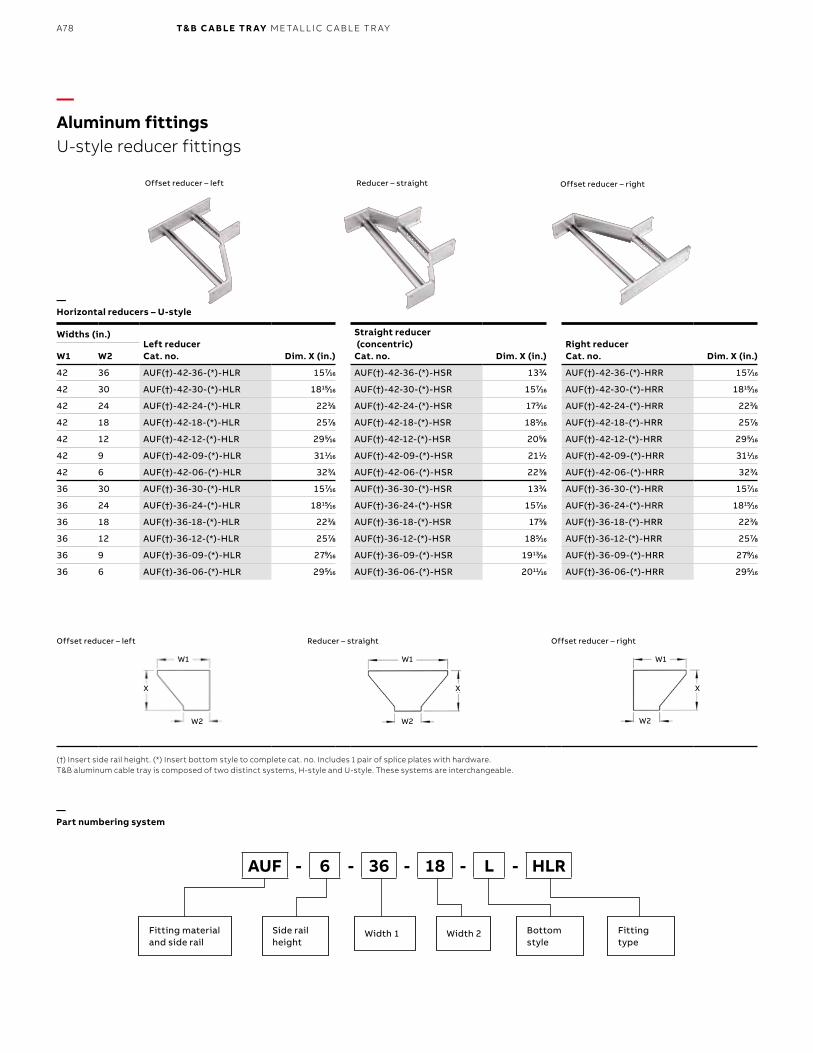
B1 copy starts here
B2 copy starts here
B3 copy starts here
A78 T& B C A B LE TR AY M E TA L L I C C A B L E TR AY
Widths (in.)Left reducerCat. no.
Straight reducer (concentric)Cat. no.
Right reducerCat. no.W1 W2 Dim. X (in.) Dim. X (in.) Dim. X (in.)
42 36 AUF(†)-42-36-(*)-HLR 1577⁄1616 AUF(†)-42-36-(*)-HSR 1333⁄44 AUF(†)-42-36-(*)-HRR 1577⁄1616
42 30 AUF(†)-42-30-(*)-HLR 181515⁄1616 AUF(†)-42-30-(*)-HSR 1577⁄1616 AUF(†)-42-30-(*)-HRR 181515⁄1616
42 24 AUF(†)-42-24-(*)-HLR 2233⁄88 AUF(†)-42-24-(*)-HSR 1733⁄1616 AUF(†)-42-24-(*)-HRR 2233⁄88
42 18 AUF(†)-42-18-(*)-HLR 2577⁄88 AUF(†)-42-18-(*)-HSR 1855⁄1616 AUF(†)-42-18-(*)-HRR 2577⁄88
42 12 AUF(†)-42-12-(*)-HLR 2955⁄1616 AUF(†)-42-12-(*)-HSR 2055⁄88 AUF(†)-42-12-(*)-HRR 2955⁄1616
42 9 AUF(†)-42-09-(*)-HLR 3111⁄1616 AUF(†)-42-09-(*)-HSR 2111⁄22 AUF(†)-42-09-(*)-HRR 3111⁄1616
42 6 AUF(†)-42-06-(*)-HLR 3233⁄44 AUF(†)-42-06-(*)-HSR 2233⁄88 AUF(†)-42-06-(*)-HRR 3233⁄44
36 30 AUF(†)-36-30-(*)-HLR 1577⁄1616 AUF(†)-36-30-(*)-HSR 1333⁄44 AUF(†)-36-30-(*)-HRR 1577⁄1616
36 24 AUF(†)-36-24-(*)-HLR 181515⁄1616 AUF(†)-36-24-(*)-HSR 1577⁄1616 AUF(†)-36-24-(*)-HRR 181515⁄1616
36 18 AUF(†)-36-18-(*)-HLR 2233⁄88 AUF(†)-36-18-(*)-HSR 1733⁄88 AUF(†)-36-18-(*)-HRR 2233⁄88
36 12 AUF(†)-36-12-(*)-HLR 2577⁄88 AUF(†)-36-12-(*)-HSR 1855⁄1616 AUF(†)-36-12-(*)-HRR 2577⁄88
36 9 AUF(†)-36-09-(*)-HLR 2799⁄1616 AUF(†)-36-09-(*)-HSR 191313⁄1616 AUF(†)-36-09-(*)-HRR 2799⁄1616
36 6 AUF(†)-36-06-(*)-HLR 2955⁄1616 AUF(†)-36-06-(*)-HSR 201111⁄1616 AUF(†)-36-06-(*)-HRR 2955⁄1616
—Aluminum fittingsU-style reducer fittings
—Part numbering system
(†) Insert side rail height. (*) Insert bottom style to complete cat. no. Includes 1 pair of splice plates with hardware.T&B aluminum cable tray is composed of two distinct systems, H-style and U-style. These systems are interchangeable.
—Horizontal reducers – U-style
Offset reducer – right
Offset reducer – right
Reducer – straight
Reducer – straight
Offset reducer – left
Offset reducer – left
W1 W1 W1
W2 W2 W2
X X X
AUF - 6 - 36 - 18 - L - HLR
Fitting materialand side rail
Side rail height
Bottom style
Width 2Width 1 Fitting type
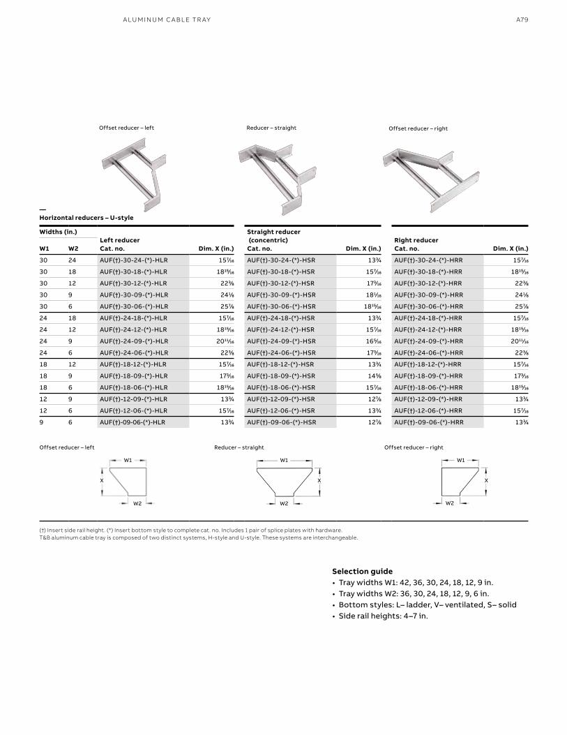
A79
Widths (in.)Left reducerCat. no.
Straight reducer (concentric)Cat. no.
Right reducerCat. no.W1 W2 Dim. X (in.) Dim. X (in.) Dim. X (in.)
30 24 AUF(†)-30-24-(*)-HLR 1577⁄1616 AUF(†)-30-24-(*)-HSR 1333⁄44 AUF(†)-30-24-(*)-HRR 1577⁄1616
30 18 AUF(†)-30-18-(*)-HLR 181515⁄1616 AUF(†)-30-18-(*)-HSR 1577⁄1616 AUF(†)-30-18-(*)-HRR 181515⁄1616
30 12 AUF(†)-30-12-(*)-HLR 2233⁄88 AUF(†)-30-12-(*)-HSR 1733⁄1616 AUF(†)-30-12-(*)-HRR 2233⁄88
30 9 AUF(†)-30-09-(*)-HLR 2411⁄88 AUF(†)-30-09-(*)-HSR 1811⁄1616 AUF(†)-30-09-(*)-HRR 2411⁄88
30 6 AUF(†)-30-06-(*)-HLR 2577⁄88 AUF(†)-30-06-(*)-HSR 181515⁄1616 AUF(†)-30-06-(*)-HRR 2577⁄88
24 18 AUF(†)-24-18-(*)-HLR 1577⁄1616 AUF(†)-24-18-(*)-HSR 1333⁄44 AUF(†)-24-18-(*)-HRR 1577⁄1616
24 12 AUF(†)-24-12-(*)-HLR 181515⁄1616 AUF(†)-24-12-(*)-HSR 1577⁄1616 AUF(†)-24-12-(*)-HRR 181515⁄1616
24 9 AUF(†)-24-09-(*)-HLR 201111⁄1616 AUF(†)-24-09-(*)-HSR 1655⁄1616 AUF(†)-24-09-(*)-HRR 201111⁄1616
24 6 AUF(†)-24-06-(*)-HLR 2233⁄88 AUF(†)-24-06-(*)-HSR 1733⁄1616 AUF(†)-24-06-(*)-HRR 2233⁄88
18 12 AUF(†)-18-12-(*)-HLR 1577⁄1616 AUF(†)-18-12-(*)-HSR 1333⁄44 AUF(†)-18-12-(*)-HRR 1577⁄1616
18 9 AUF(†)-18-09-(*)-HLR 1733⁄1616 AUF(†)-18-09-(*)-HSR 1455⁄88 AUF(†)-18-09-(*)-HRR 1733⁄1616
18 6 AUF(†)-18-06-(*)-HLR 181515⁄1616 AUF(†)-18-06-(*)-HSR 1577⁄1616 AUF(†)-18-06-(*)-HRR 181515⁄1616
12 9 AUF(†)-12-09-(*)-HLR 1333⁄44 AUF(†)-12-09-(*)-HSR 1277⁄88 AUF(†)-12-09-(*)-HRR 1333⁄44
12 6 AUF(†)-12-06-(*)-HLR 1577⁄1616 AUF(†)-12-06-(*)-HSR 1333⁄44 AUF(†)-12-06-(*)-HRR 1577⁄1616
9 6 AUF(†)-09-06-(*)-HLR 1333⁄44 AUF(†)-09-06-(*)-HSR 1277⁄88 AUF(†)-09-06-(*)-HRR 1333⁄44
A LU M I N U M C A B L E TR AY
Selection guide• Tray widths W1: 42, 36, 30, 24, 18, 12, 9 in.• Tray widths W2: 36, 30, 24, 18, 12, 9, 6 in.• Bottom styles: L– ladder, V– ventilated, S– solid• Side rail heights: 4–7 in.
—Horizontal reducers – U-style
(†) Insert side rail height. (*) Insert bottom style to complete cat. no. Includes 1 pair of splice plates with hardware.T&B aluminum cable tray is composed of two distinct systems, H-style and U-style. These systems are interchangeable.
Offset reducer – rightReducer – straightOffset reducer – left
W1 W1 W1
W2 W2 W2
X X X
Offset reducer – rightReducer – straightOffset reducer – left
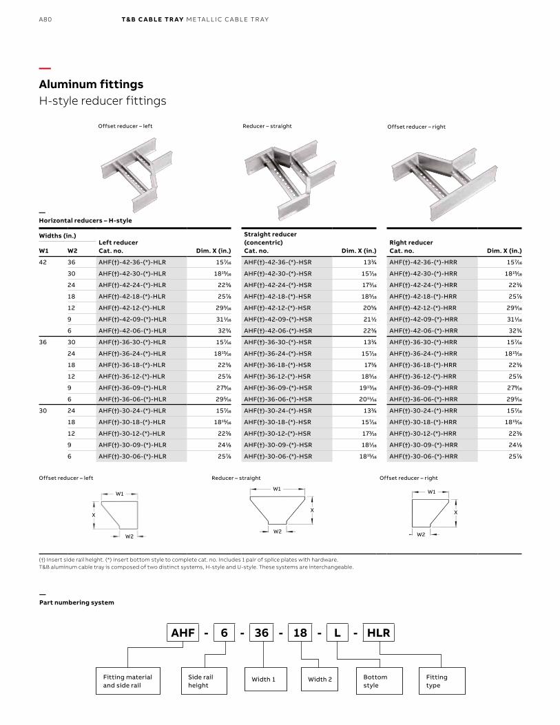
B1 copy starts here
B2 copy starts here
B3 copy starts here
A80 T& B C A B LE TR AY M E TA L L I C C A B L E TR AY
Widths (in.)Left reducerCat. no.
Straight reducer (concentric)Cat. no.
Right reducerCat. no.W1 W2 Dim. X (in.) Dim. X (in.) Dim. X (in.)
42 36 AHF(†)-42-36-(*)-HLR 1577⁄1616 AHF(†)-42-36-(*)-HSR 1333⁄44 AHF(†)-42-36-(*)-HRR 1577⁄1616
30 AHF(†)-42-30-(*)-HLR 181515⁄1616 AHF(†)-42-30-(*)-HSR 1577⁄1616 AHF(†)-42-30-(*)-HRR 181515⁄1616
24 AHF(†)-42-24-(*)-HLR 2233⁄88 AHF(†)-42-24-(*)-HSR 1733⁄1616 AHF(†)-42-24-(*)-HRR 2233⁄88
18 AHF(†)-42-18-(*)-HLR 2577⁄88 AHF(†)-42-18-(*)-HSR 1855⁄1616 AHF(†)-42-18-(*)-HRR 2577⁄88
12 AHF(†)-42-12-(*)-HLR 2955⁄1616 AHF(†)-42-12-(*)-HSR 2055⁄88 AHF(†)-42-12-(*)-HRR 2955⁄1616
9 AHF(†)-42-09-(*)-HLR 3111⁄1616 AHF(†)-42-09-(*)-HSR 2111⁄22 AHF(†)-42-09-(*)-HRR 3111⁄1616
6 AHF(†)-42-06-(*)-HLR 3233⁄44 AHF(†)-42-06-(*)-HSR 2233⁄88 AHF(†)-42-06-(*)-HRR 3233⁄44
36 30 AHF(†)-36-30-(*)-HLR 1577⁄1616 AHF(†)-36-30-(*)-HSR 1333⁄44 AHF(†)-36-30-(*)-HRR 1577⁄1616
24 AHF(†)-36-24-(*)-HLR 181515⁄1616 AHF(†)-36-24-(*)-HSR 1577⁄1616 AHF(†)-36-24-(*)-HRR 181515⁄1616
18 AHF(†)-36-18-(*)-HLR 2233⁄88 AHF(†)-36-18-(*)-HSR 1733⁄88 AHF(†)-36-18-(*)-HRR 2233⁄88
12 AHF(†)-36-12-(*)-HLR 2577⁄88 AHF(†)-36-12-(*)-HSR 1855⁄1616 AHF(†)-36-12-(*)-HRR 2577⁄88
9 AHF(†)-36-09-(*)-HLR 2799⁄1616 AHF(†)-36-09-(*)-HSR 191313⁄1616 AHF(†)-36-09-(*)-HRR 2799⁄1616
6 AHF(†)-36-06-(*)-HLR 2955⁄1616 AHF(†)-36-06-(*)-HSR 201111⁄1616 AHF(†)-36-06-(*)-HRR 2955⁄1616
30 24 AHF(†)-30-24-(*)-HLR 1577⁄1616 AHF(†)-30-24-(*)-HSR 1333⁄44 AHF(†)-30-24-(*)-HRR 1577⁄1616
18 AHF(†)-30-18-(*)-HLR 181515⁄1616 AHF(†)-30-18-(*)-HSR 1577⁄1616 AHF(†)-30-18-(*)-HRR 181515⁄1616
12 AHF(†)-30-12-(*)-HLR 2233⁄88 AHF(†)-30-12-(*)-HSR 1733⁄1616 AHF(†)-30-12-(*)-HRR 2233⁄88
9 AHF(†)-30-09-(*)-HLR 2411⁄88 AHF(†)-30-09-(*)-HSR 1811⁄1616 AHF(†)-30-09-(*)-HRR 2411⁄88
6 AHF(†)-30-06-(*)-HLR 2577⁄88 AHF(†)-30-06-(*)-HSR 181515⁄1616 AHF(†)-30-06-(*)-HRR 2577⁄88
—Aluminum fittingsH-style reducer fittings
(†) Insert side rail height. (*) Insert bottom style to complete cat. no. Includes 1 pair of splice plates with hardware.T&B aluminum cable tray is composed of two distinct systems, H-style and U-style. These systems are interchangeable.
Offset reducer – right
Offset reducer – right
Reducer – straight
Reducer – straight
Offset reducer – left
Offset reducer – left
—Horizontal reducers – H-style
—Part numbering system
AHF - 6 - 36 - 18 - L - HLR
Fitting materialand side rail
Side rail height
Bottom style
Width 2Width 1 Fitting type
W1W1 W1
W2W2 W2
XX X
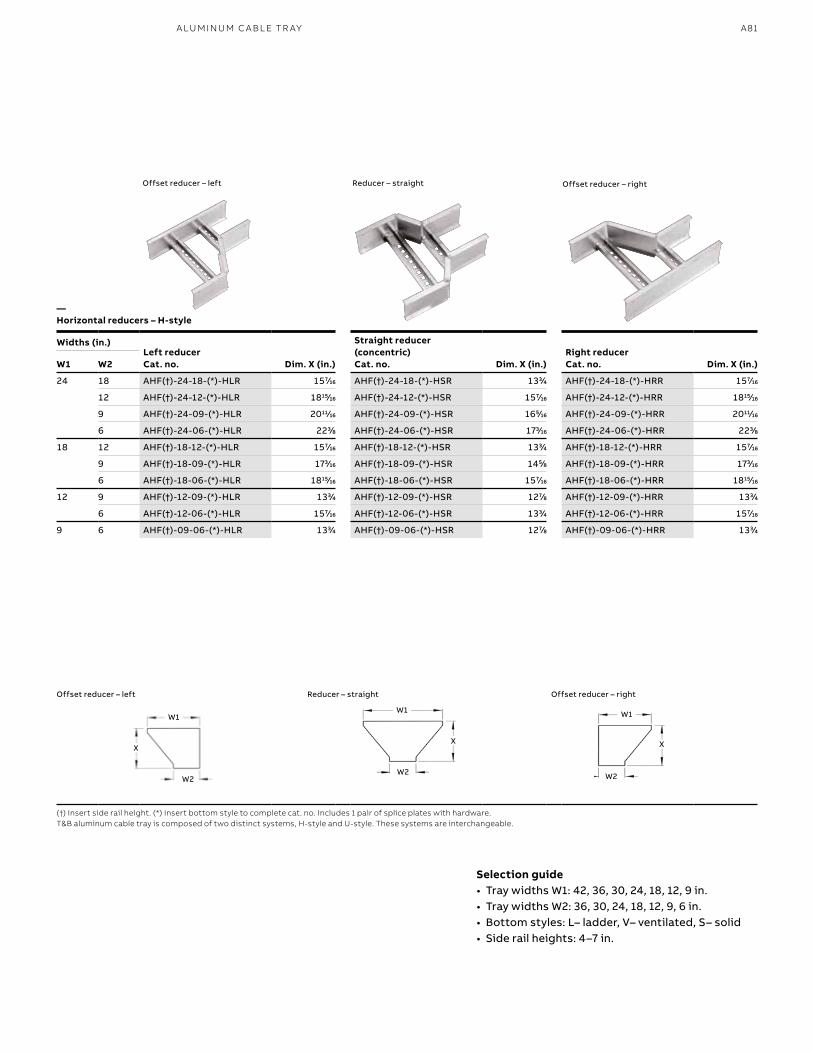
A81A LU M I N U M C A B L E TR AY
Selection guide• Tray widths W1: 42, 36, 30, 24, 18, 12, 9 in.• Tray widths W2: 36, 30, 24, 18, 12, 9, 6 in.• Bottom styles: L– ladder, V– ventilated, S– solid• Side rail heights: 4–7 in.
Widths (in.)Left reducerCat. no.
Straight reducer (concentric)Cat. no.
Right reducerCat. no.W1 W2 Dim. X (in.) Dim. X (in.) Dim. X (in.)
24 18 AHF(†)-24-18-(*)-HLR 1577⁄1616 AHF(†)-24-18-(*)-HSR 1333⁄44 AHF(†)-24-18-(*)-HRR 1577⁄1616
12 AHF(†)-24-12-(*)-HLR 181515⁄1616 AHF(†)-24-12-(*)-HSR 1577⁄1616 AHF(†)-24-12-(*)-HRR 181515⁄1616
9 AHF(†)-24-09-(*)-HLR 201111⁄1616 AHF(†)-24-09-(*)-HSR 1655⁄1616 AHF(†)-24-09-(*)-HRR 201111⁄1616
6 AHF(†)-24-06-(*)-HLR 2233⁄88 AHF(†)-24-06-(*)-HSR 1733⁄1616 AHF(†)-24-06-(*)-HRR 2233⁄88
18 12 AHF(†)-18-12-(*)-HLR 1577⁄1616 AHF(†)-18-12-(*)-HSR 1333⁄44 AHF(†)-18-12-(*)-HRR 1577⁄1616
9 AHF(†)-18-09-(*)-HLR 1733⁄1616 AHF(†)-18-09-(*)-HSR 1455⁄88 AHF(†)-18-09-(*)-HRR 1733⁄1616
6 AHF(†)-18-06-(*)-HLR 181515⁄1616 AHF(†)-18-06-(*)-HSR 1577⁄1616 AHF(†)-18-06-(*)-HRR 181515⁄1616
12 9 AHF(†)-12-09-(*)-HLR 1333⁄44 AHF(†)-12-09-(*)-HSR 1277⁄88 AHF(†)-12-09-(*)-HRR 1333⁄44
6 AHF(†)-12-06-(*)-HLR 1577⁄1616 AHF(†)-12-06-(*)-HSR 1333⁄44 AHF(†)-12-06-(*)-HRR 1577⁄1616
9 6 AHF(†)-09-06-(*)-HLR 1333⁄44 AHF(†)-09-06-(*)-HSR 1277⁄88 AHF(†)-09-06-(*)-HRR 1333⁄44
(†) Insert side rail height. (*) Insert bottom style to complete cat. no. Includes 1 pair of splice plates with hardware.T&B aluminum cable tray is composed of two distinct systems, H-style and U-style. These systems are interchangeable.
Offset reducer – right
Offset reducer – right
Reducer – straight
Reducer – straight
Offset reducer – left
Offset reducer – left
—Horizontal reducers – H-style
W1W1 W1
W2W2 W2
XX X
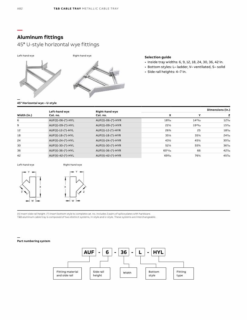
B1 copy starts here
B2 copy starts here
B3 copy starts here
A82 T& B C A B LE TR AY M E TA L L I C C A B L E TR AY
Width (in.)Left-hand wye Cat. no.
Right-hand wye Cat. no.
Dimensions (in.)
X Y Z
6 AUF(†)-06-(*)-HYL AUF(†)-06-(*)-HYR 1855⁄1616 141313⁄1616 1277⁄1616
9 AUF(†)-09-(*)-HYL AUF(†)-09-(*)-HYR 2211⁄22 191515⁄1616 1577⁄1616
12 AUF(†)-12-(*)-HYL AUF(†)-12-(*)-HYR 2633⁄44 25 1877⁄1616
18 AUF(†)-18-(*)-HYL AUF(†)-18-(*)-HYR 3511⁄44 3511⁄44 2477⁄1616
24 AUF(†)-24-(*)-HYL AUF(†)-24-(*)-HYR 4311⁄22 4511⁄22 3077⁄1616
30 AUF(†)-30-(*)-HYL AUF(†)-30-(*)-HYR 5211⁄44 5533⁄44 3677⁄1616
36 AUF(†)-36-(*)-HYL AUF(†)-36-(*)-HYR 601111⁄1616 66 4277⁄1616
42 AUF(†)-42-(*)-HYL AUF(†)-42-(*)-HYR 6933⁄1616 7611⁄44 4577⁄1616
—Aluminum fittings45° U-style horizontal wye fittings
(†) Insert side rail height. (*) Insert bottom style to complete cat. no. Includes 2 pairs of splice plates with hardware.T&B aluminum cable tray is composed of two distinct systems, H-style and U-style. These systems are interchangeable.
Right-hand wye
Right-hand wye
Left-hand wye
Left-hand wye
—45° Horizontal wye – U-style
Selection guide• Inside tray widths: 6, 9, 12, 18, 24, 30, 36, 42 in.• Bottom styles: L– ladder, V– ventilated, S– solid• Side rail heights: 4–7 in.
AUF - 6 - 36 - L - HYL
Fitting materialand side rail
Side rail height
Bottom style
Width Fitting type
—Part numbering system
YY
WW
XX
ZZ
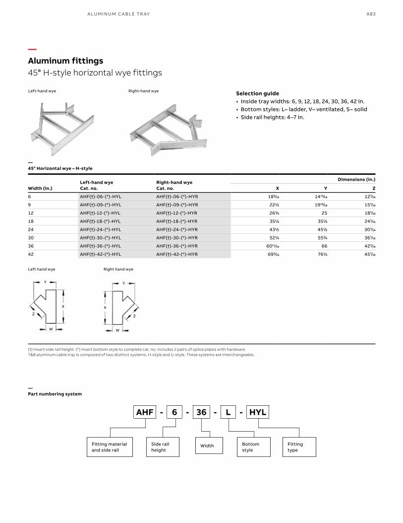
A83A LU M I N U M C A B L E TR AY
—Aluminum fittings45° H-style horizontal wye fittings
(†) Insert side rail height. (*) Insert bottom style to complete cat. no. Includes 2 pairs of splice plates with hardware.T&B aluminum cable tray is composed of two distinct systems, H-style and U-style. These systems are interchangeable.
Right-hand wye
Right hand wye
Left-hand wye
Left hand wye
—45° Horizontal wye – H-style
Selection guide• Inside tray widths: 6, 9, 12, 18, 24, 30, 36, 42 in.• Bottom styles: L– ladder, V– ventilated, S– solid• Side rail heights: 4–7 in.
AHF - 6 - 36 - L - HYL
Fitting materialand side rail
Side rail height
Bottom style
Width Fitting type
—Part numbering system
Width (in.)Left-hand wye Cat. no.
Right-hand wye Cat. no.
Dimensions (in.)
X Y Z
6 AHF(†)-06-(*)-HYL AHF(†)-06-(*)-HYR 1855⁄1616 141313⁄1616 1277⁄1616
9 AHF(†)-09-(*)-HYL AHF(†)-09-(*)-HYR 2211⁄22 191515⁄1616 1577⁄1616
12 AHF(†)-12-(*)-HYL AHF(†)-12-(*)-HYR 2633⁄44 25 1877⁄1616
18 AHF(†)-18-(*)-HYL AHF(†)-18-(*)-HYR 3511⁄44 3511⁄44 2477⁄1616
24 AHF(†)-24-(*)-HYL AHF(†)-24-(*)-HYR 4311⁄22 4511⁄22 3077⁄1616
30 AHF(†)-30-(*)-HYL AHF(†)-30-(*)-HYR 5211⁄44 5533⁄44 3677⁄1616
36 AHF(†)-36-(*)-HYL AHF(†)-36-(*)-HYR 601111⁄1616 66 4277⁄1616
42 AHF(†)-42-(*)-HYL AHF(†)-42-(*)-HYR 6933⁄1616 7611⁄44 4577⁄1616
Y Y
W W
X X
Z Z
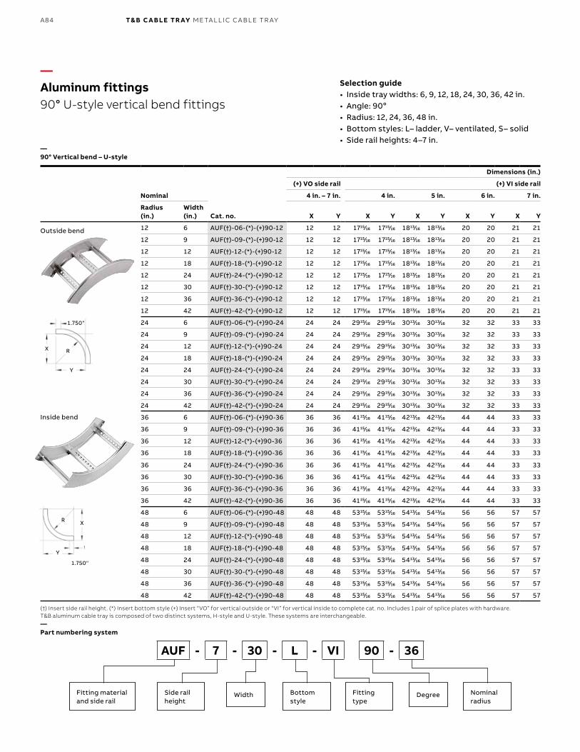
B1 copy starts here
B2 copy starts here
B3 copy starts here
A84 T& B C A B LE TR AY M E TA L L I C C A B L E TR AY
Nominal
Cat. no.
Dimensions (in.)
(+) VO side rail (+) VI side rail
4 in. – 7 in. 4 in. 5 in. 6 in. 7 in.
Radius (in.)
Width (in.) X Y X Y X Y X Y X Y
12 6 AUF(†)-06-(*)-(+)90-12 12 12 171515⁄1616 171515⁄1616 181313⁄1616 181313⁄1616 20 20 21 21
12 9 AUF(†)-09-(*)-(+)90-12 12 12 171515⁄1616 171515⁄1616 181313⁄1616 181313⁄1616 20 20 21 21
12 12 AUF(†)-12-(*)-(+)90-12 12 12 171515⁄1616 171515⁄1616 181313⁄1616 181313⁄1616 20 20 21 21
12 18 AUF(†)-18-(*)-(+)90-12 12 12 171515⁄1616 171515⁄1616 181313⁄1616 181313⁄1616 20 20 21 21
12 24 AUF(†)-24-(*)-(+)90-12 12 12 171515⁄1616 171515⁄1616 181313⁄1616 181313⁄1616 20 20 21 21
12 30 AUF(†)-30-(*)-(+)90-12 12 12 171515⁄1616 171515⁄1616 181313⁄1616 181313⁄1616 20 20 21 21
12 36 AUF(†)-36-(*)-(+)90-12 12 12 171515⁄1616 171515⁄1616 181313⁄1616 181313⁄1616 20 20 21 21
12 42 AUF(†)-42-(*)-(+)90-12 12 12 171515⁄1616 171515⁄1616 181313⁄1616 181313⁄1616 20 20 21 21
24 6 AUF(†)-06-(*)-(+)90-24 24 24 291515⁄1616 291515⁄1616 301313⁄1616 301313⁄1616 32 32 33 33
24 9 AUF(†)-09-(*)-(+)90-24 24 24 291515⁄1616 291515⁄1616 301313⁄1616 301313⁄1616 32 32 33 33
24 12 AUF(†)-12-(*)-(+)90-24 24 24 291515⁄1616 291515⁄1616 301313⁄1616 301313⁄1616 32 32 33 33
24 18 AUF(†)-18-(*)-(+)90-24 24 24 291515⁄1616 291515⁄1616 301313⁄1616 301313⁄1616 32 32 33 33
24 24 AUF(†)-24-(*)-(+)90-24 24 24 291515⁄1616 291515⁄1616 301313⁄1616 301313⁄1616 32 32 33 33
24 30 AUF(†)-30-(*)-(+)90-24 24 24 291515⁄1616 291515⁄1616 301313⁄1616 301313⁄1616 32 32 33 33
24 36 AUF(†)-36-(*)-(+)90-24 24 24 291515⁄1616 291515⁄1616 301313⁄1616 301313⁄1616 32 32 33 33
24 42 AUF(†)-42-(*)-(+)90-24 24 24 291515⁄1616 291515⁄1616 301313⁄1616 301313⁄1616 32 32 33 33
36 6 AUF(†)-06-(*)-(+)90-36 36 36 411515⁄1616 411515⁄1616 421313⁄1616 421313⁄1616 44 44 33 33
36 9 AUF(†)-09-(*)-(+)90-36 36 36 411515⁄1616 411515⁄1616 421313⁄1616 421313⁄1616 44 44 33 33
36 12 AUF(†)-12-(*)-(+)90-36 36 36 411515⁄1616 411515⁄1616 421313⁄1616 421313⁄1616 44 44 33 33
36 18 AUF(†)-18-(*)-(+)90-36 36 36 411515⁄1616 411515⁄1616 421313⁄1616 421313⁄1616 44 44 33 33
36 24 AUF(†)-24-(*)-(+)90-36 36 36 411515⁄1616 411515⁄1616 421313⁄1616 421313⁄1616 44 44 33 33
36 30 AUF(†)-30-(*)-(+)90-36 36 36 411515⁄1616 411515⁄1616 421313⁄1616 421313⁄1616 44 44 33 33
36 36 AUF(†)-36-(*)-(+)90-36 36 36 411515⁄1616 411515⁄1616 421313⁄1616 421313⁄1616 44 44 33 33
36 42 AUF(†)-42-(*)-(+)90-36 36 36 411515⁄1616 411515⁄1616 421313⁄1616 421313⁄1616 44 44 33 33
48 6 AUF(†)-06-(*)-(+)90-48 48 48 531515⁄1616 531515⁄1616 541313⁄1616 541313⁄1616 56 56 57 57
48 9 AUF(†)-09-(*)-(+)90-48 48 48 531515⁄1616 531515⁄1616 541313⁄1616 541313⁄1616 56 56 57 57
48 12 AUF(†)-12-(*)-(+)90-48 48 48 531515⁄1616 531515⁄1616 541313⁄1616 541313⁄1616 56 56 57 57
48 18 AUF(†)-18-(*)-(+)90-48 48 48 531515⁄1616 531515⁄1616 541313⁄1616 541313⁄1616 56 56 57 57
48 24 AUF(†)-24-(*)-(+)90-48 48 48 531515⁄1616 531515⁄1616 541313⁄1616 541313⁄1616 56 56 57 57
48 30 AUF(†)-30-(*)-(+)90-48 48 48 531515⁄1616 531515⁄1616 541313⁄1616 541313⁄1616 56 56 57 57
48 36 AUF(†)-36-(*)-(+)90-48 48 48 531515⁄1616 531515⁄1616 541313⁄1616 541313⁄1616 56 56 57 57
48 42 AUF(†)-42-(*)-(+)90-48 48 48 531515⁄1616 531515⁄1616 541313⁄1616 541313⁄1616 56 56 57 57
—Aluminum fittings90° U-style vertical bend fittings
—90° Vertical bend – U-style
Outside bend
Inside bend
1.750"
1.750"
X
X
R
R
Y
Y
(†) Insert side rail height. (*) Insert bottom style (+) Insert “VO” for vertical outside or “VI” for vertical inside to complete cat. no. Includes 1 pair of splice plates with hardware.T&B aluminum cable tray is composed of two distinct systems, H-style and U-style. These systems are interchangeable.
Selection guide• Inside tray widths: 6, 9, 12, 18, 24, 30, 36, 42 in.• Angle: 90o• Radius: 12, 24, 36, 48 in.• Bottom styles: L– ladder, V– ventilated, S– solid• Side rail heights: 4–7 in.
—Part numbering system
AUF - 7 - 30 - L - VI 90 - 36
Fitting materialand side rail
Side rail height
Bottom style
Nominalradius
Width Fitting type
Degree
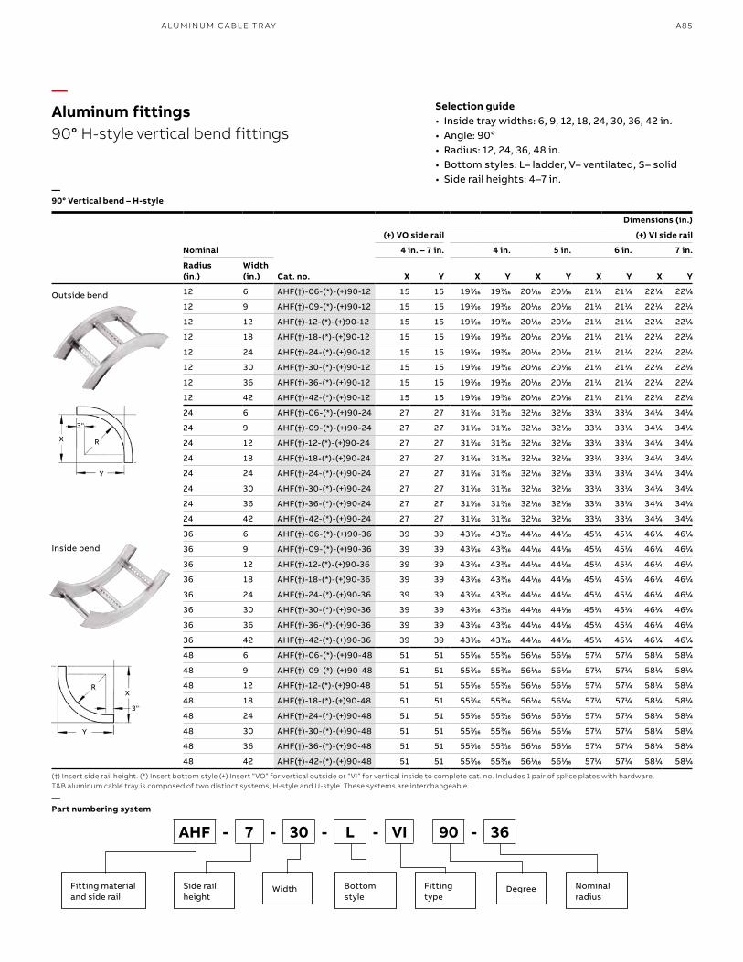
A85A LU M I N U M C A B L E TR AY
—Aluminum fittings90° H-style vertical bend fittings
—90° Vertical bend – H-style
Outside bend
Inside bend
(†) Insert side rail height. (*) Insert bottom style (+) Insert “VO” for vertical outside or “VI” for vertical inside to complete cat. no. Includes 1 pair of splice plates with hardware.T&B aluminum cable tray is composed of two distinct systems, H-style and U-style. These systems are interchangeable.
Selection guide• Inside tray widths: 6, 9, 12, 18, 24, 30, 36, 42 in.• Angle: 90o• Radius: 12, 24, 36, 48 in. • Bottom styles: L– ladder, V– ventilated, S– solid• Side rail heights: 4–7 in.
—Part numbering system
AHF - 7 - 30 - L - VI 90 - 36
Fitting materialand side rail
Side rail height
Bottom style
Nominalradius
Width Fitting type
Degree
Nominal
Cat. no.
Dimensions (in.)
(+) VO side rail (+) VI side rail
4 in. – 7 in. 4 in. 5 in. 6 in. 7 in.
Radius (in.)
Width (in.) X Y X Y X Y X Y X Y
12 6 AHF(†)-06-(*)-(+)90-12 15 15 1933⁄1616 1933⁄1616 2011⁄1616 2011⁄1616 2111⁄44 2111⁄44 2211⁄44 2211⁄44
12 9 AHF(†)-09-(*)-(+)90-12 15 15 1933⁄1616 1933⁄1616 2011⁄1616 2011⁄1616 2111⁄44 2111⁄44 2211⁄44 2211⁄44
12 12 AHF(†)-12-(*)-(+)90-12 15 15 1933⁄1616 1933⁄1616 2011⁄1616 2011⁄1616 2111⁄44 2111⁄44 2211⁄44 2211⁄44
12 18 AHF(†)-18-(*)-(+)90-12 15 15 1933⁄1616 1933⁄1616 2011⁄1616 2011⁄1616 2111⁄44 2111⁄44 2211⁄44 2211⁄44
12 24 AHF(†)-24-(*)-(+)90-12 15 15 1933⁄1616 1933⁄1616 2011⁄1616 2011⁄1616 2111⁄44 2111⁄44 2211⁄44 2211⁄44
12 30 AHF(†)-30-(*)-(+)90-12 15 15 1933⁄1616 1933⁄1616 2011⁄1616 2011⁄1616 2111⁄44 2111⁄44 2211⁄44 2211⁄44
12 36 AHF(†)-36-(*)-(+)90-12 15 15 1933⁄1616 1933⁄1616 2011⁄1616 2011⁄1616 2111⁄44 2111⁄44 2211⁄44 2211⁄44
12 42 AHF(†)-42-(*)-(+)90-12 15 15 1933⁄1616 1933⁄1616 2011⁄1616 2011⁄1616 2111⁄44 2111⁄44 2211⁄44 2211⁄44
24 6 AHF(†)-06-(*)-(+)90-24 27 27 3133⁄1616 3133⁄1616 3211⁄1616 3211⁄1616 3311⁄44 3311⁄44 3411⁄44 3411⁄44
24 9 AHF(†)-09-(*)-(+)90-24 27 27 3133⁄1616 3133⁄1616 3211⁄1616 3211⁄1616 3311⁄44 3311⁄44 3411⁄44 3411⁄44
24 12 AHF(†)-12-(*)-(+)90-24 27 27 3133⁄1616 3133⁄1616 3211⁄1616 3211⁄1616 3311⁄44 3311⁄44 3411⁄44 3411⁄44
24 18 AHF(†)-18-(*)-(+)90-24 27 27 3133⁄1616 3133⁄1616 3211⁄1616 3211⁄1616 3311⁄44 3311⁄44 3411⁄44 3411⁄44
24 24 AHF(†)-24-(*)-(+)90-24 27 27 3133⁄1616 3133⁄1616 3211⁄1616 3211⁄1616 3311⁄44 3311⁄44 3411⁄44 3411⁄44
24 30 AHF(†)-30-(*)-(+)90-24 27 27 3133⁄1616 3133⁄1616 3211⁄1616 3211⁄1616 3311⁄44 3311⁄44 3411⁄44 3411⁄44
24 36 AHF(†)-36-(*)-(+)90-24 27 27 3133⁄1616 3133⁄1616 3211⁄1616 3211⁄1616 3311⁄44 3311⁄44 3411⁄44 3411⁄44
24 42 AHF(†)-42-(*)-(+)90-24 27 27 3133⁄1616 3133⁄1616 3211⁄1616 3211⁄1616 3311⁄44 3311⁄44 3411⁄44 3411⁄44
36 6 AHF(†)-06-(*)-(+)90-36 39 39 4333⁄1616 4333⁄1616 4411⁄1616 4411⁄1616 4511⁄44 4511⁄44 4611⁄44 4611⁄44
36 9 AHF(†)-09-(*)-(+)90-36 39 39 4333⁄1616 4333⁄1616 4411⁄1616 4411⁄1616 4511⁄44 4511⁄44 4611⁄44 4611⁄44
36 12 AHF(†)-12-(*)-(+)90-36 39 39 4333⁄1616 4333⁄1616 4411⁄1616 4411⁄1616 4511⁄44 4511⁄44 4611⁄44 4611⁄44
36 18 AHF(†)-18-(*)-(+)90-36 39 39 4333⁄1616 4333⁄1616 4411⁄1616 4411⁄1616 4511⁄44 4511⁄44 4611⁄44 4611⁄44
36 24 AHF(†)-24-(*)-(+)90-36 39 39 4333⁄1616 4333⁄1616 4411⁄1616 4411⁄1616 4511⁄44 4511⁄44 4611⁄44 4611⁄44
36 30 AHF(†)-30-(*)-(+)90-36 39 39 4333⁄1616 4333⁄1616 4411⁄1616 4411⁄1616 4511⁄44 4511⁄44 4611⁄44 4611⁄44
36 36 AHF(†)-36-(*)-(+)90-36 39 39 4333⁄1616 4333⁄1616 4411⁄1616 4411⁄1616 4511⁄44 4511⁄44 4611⁄44 4611⁄44
36 42 AHF(†)-42-(*)-(+)90-36 39 39 4333⁄1616 4333⁄1616 4411⁄1616 4411⁄1616 4511⁄44 4511⁄44 4611⁄44 4611⁄44
48 6 AHF(†)-06-(*)-(+)90-48 51 51 5533⁄1616 5533⁄1616 5611⁄1616 5611⁄1616 5711⁄44 5711⁄44 5811⁄44 5811⁄44
48 9 AHF(†)-09-(*)-(+)90-48 51 51 5533⁄1616 5533⁄1616 5611⁄1616 5611⁄1616 5711⁄44 5711⁄44 5811⁄44 5811⁄44
48 12 AHF(†)-12-(*)-(+)90-48 51 51 5533⁄1616 5533⁄1616 5611⁄1616 5611⁄1616 5711⁄44 5711⁄44 5811⁄44 5811⁄44
48 18 AHF(†)-18-(*)-(+)90-48 51 51 5533⁄1616 5533⁄1616 5611⁄1616 5611⁄1616 5711⁄44 5711⁄44 5811⁄44 5811⁄44
48 24 AHF(†)-24-(*)-(+)90-48 51 51 5533⁄1616 5533⁄1616 5611⁄1616 5611⁄1616 5711⁄44 5711⁄44 5811⁄44 5811⁄44
48 30 AHF(†)-30-(*)-(+)90-48 51 51 5533⁄1616 5533⁄1616 5611⁄1616 5611⁄1616 5711⁄44 5711⁄44 5811⁄44 5811⁄44
48 36 AHF(†)-36-(*)-(+)90-48 51 51 5533⁄1616 5533⁄1616 5611⁄1616 5611⁄1616 5711⁄44 5711⁄44 5811⁄44 5811⁄44
48 42 AHF(†)-42-(*)-(+)90-48 51 51 5533⁄1616 5533⁄1616 5611⁄1616 5611⁄1616 5711⁄44 5711⁄44 5811⁄44 5811⁄44
3"
3"
X
X
R
R
Y
Y
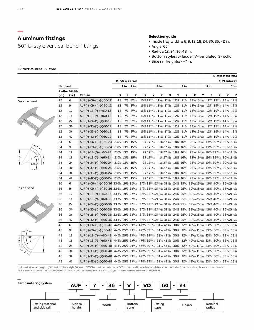
B1 copy starts here
B2 copy starts here
B3 copy starts here
A86 T& B C A B LE TR AY M E TA L L I C C A B L E TR AY
Nominal
Cat. no.
Dimensions (in.)
(+) VO side rail (+) VI side rail
4 in. – 7 in. 4 in. 5 in. 6 in. 7 in.
Radius (in.)
Width (in.) X Y Z X Y Z X Y Z X Y Z X Y Z
12 6 AUF(†)-06-(*)-(+)60-12 13 711⁄22 81111⁄1616 1655⁄88 111111⁄1616 1111⁄1616 1777⁄1616 1255⁄88 1155⁄88 1833⁄88 131111⁄1616 1211⁄44 1955⁄1616 1433⁄44 1277⁄88
12 9 AUF(†)-09-(*)-(+)60-12 13 711⁄22 81111⁄1616 1655⁄88 111111⁄1616 1111⁄1616 1777⁄1616 1255⁄88 1155⁄88 1833⁄88 131111⁄1616 1211⁄44 1955⁄1616 1433⁄44 1277⁄88
12 12 AUF(†)-12-(*)-(+)60-12 13 711⁄22 81111⁄1616 1655⁄88 111111⁄1616 1111⁄1616 1777⁄1616 1255⁄88 1155⁄88 1833⁄88 131111⁄1616 1211⁄44 1955⁄1616 1433⁄44 1277⁄88
12 18 AUF(†)-18-(*)-(+)60-12 13 711⁄22 81111⁄1616 1655⁄88 111111⁄1616 1111⁄1616 1777⁄1616 1255⁄88 1155⁄88 1833⁄88 131111⁄1616 1211⁄44 1955⁄1616 1433⁄44 1277⁄88
12 24 AUF(†)-24-(*)-(+)60-12 13 711⁄22 81111⁄1616 1655⁄88 111111⁄1616 1111⁄1616 1777⁄1616 1255⁄88 1155⁄88 1833⁄88 131111⁄1616 1211⁄44 1955⁄1616 1433⁄44 1277⁄88
12 30 AUF(†)-30-(*)-(+)60-12 13 711⁄22 81111⁄1616 1655⁄88 111111⁄1616 1111⁄1616 1777⁄1616 1255⁄88 1155⁄88 1833⁄88 131111⁄1616 1211⁄44 1955⁄1616 1433⁄44 1277⁄88
12 36 AUF(†)-36-(*)-(+)60-12 13 711⁄22 81111⁄1616 1655⁄88 111111⁄1616 1111⁄1616 1777⁄1616 1255⁄88 1155⁄88 1833⁄88 131111⁄1616 1211⁄44 1955⁄1616 1433⁄44 1277⁄88
12 42 AUF(†)-42-(*)-(+)60-12 13 711⁄22 81111⁄1616 1655⁄88 111111⁄1616 1111⁄1616 1777⁄1616 1255⁄88 1155⁄88 1833⁄88 131111⁄1616 1211⁄44 1955⁄1616 1433⁄44 1277⁄88
24 6 AUF(†)-06-(*)-(+)60-24 2377⁄1616 1311⁄22 1555⁄88 27 171111⁄1616 18 271313⁄1616 1855⁄88 1699⁄1616 2833⁄44 191111⁄1616 1933⁄1616 291111⁄1616 2033⁄44 191313⁄1616
24 9 AUF(†)-09-(*)-(+)60-24 2377⁄1616 1311⁄22 1555⁄88 27 171111⁄1616 18 271313⁄1616 1855⁄88 1699⁄1616 2833⁄44 191111⁄1616 1933⁄1616 291111⁄1616 2033⁄44 191313⁄1616
24 12 AUF(†)-12-(*)-(+)60-24 2377⁄1616 1311⁄22 1555⁄88 27 171111⁄1616 18 271313⁄1616 1855⁄88 1699⁄1616 2833⁄44 191111⁄1616 1933⁄1616 291111⁄1616 2033⁄44 191313⁄1616
24 18 AUF(†)-18-(*)-(+)60-24 2377⁄1616 1311⁄22 1555⁄88 27 171111⁄1616 18 271313⁄1616 1855⁄88 1699⁄1616 2833⁄44 191111⁄1616 1933⁄1616 291111⁄1616 2033⁄44 191313⁄1616
24 24 AUF(†)-24-(*)-(+)60-24 2377⁄1616 1311⁄22 1555⁄88 27 171111⁄1616 18 271313⁄1616 1855⁄88 1699⁄1616 2833⁄44 191111⁄1616 1933⁄1616 291111⁄1616 2033⁄44 191313⁄1616
24 30 AUF(†)-30-(*)-(+)60-24 2377⁄1616 1311⁄22 1555⁄88 27 171111⁄1616 18 271313⁄1616 1855⁄88 1699⁄1616 2833⁄44 191111⁄1616 1933⁄1616 291111⁄1616 2033⁄44 191313⁄1616
24 36 AUF(†)-36-(*)-(+)60-24 2377⁄1616 1311⁄22 1555⁄88 27 171111⁄1616 18 271313⁄1616 1855⁄88 1699⁄1616 2833⁄44 191111⁄1616 1933⁄1616 291111⁄1616 2033⁄44 191313⁄1616
24 42 AUF(†)-42-(*)-(+)60-24 2377⁄1616 1311⁄22 1555⁄88 27 171111⁄1616 18 271313⁄1616 1855⁄88 1699⁄1616 2833⁄44 191111⁄1616 1933⁄1616 291111⁄1616 2033⁄44 191313⁄1616
36 6 AUF(†)-06-(*)-(+)60-36 331313⁄1616 1911⁄22 2299⁄1616 3777⁄1616 231111⁄1616 241515⁄1616 3833⁄1616 2455⁄88 2577⁄1616 3933⁄1616 251111⁄1616 2611⁄88 4011⁄1616 2633⁄44 261111⁄1616
36 9 AUF(†)-09-(*)-(+)60-36 331313⁄1616 1911⁄22 2299⁄1616 3777⁄1616 231111⁄1616 241515⁄1616 3833⁄1616 2455⁄88 2577⁄1616 3933⁄1616 251111⁄1616 2611⁄88 4011⁄1616 2633⁄44 261111⁄1616
36 12 AUF(†)-12-(*)-(+)60-36 331313⁄1616 1911⁄22 2299⁄1616 3777⁄1616 231111⁄1616 241515⁄1616 3833⁄1616 2455⁄88 2577⁄1616 3933⁄1616 251111⁄1616 2611⁄88 4011⁄1616 2633⁄44 261111⁄1616
36 18 AUF(†)-18-(*)-(+)60-36 331313⁄1616 1911⁄22 2299⁄1616 3777⁄1616 231111⁄1616 241515⁄1616 3833⁄1616 2455⁄88 2577⁄1616 3933⁄1616 251111⁄1616 2611⁄88 4011⁄1616 2633⁄44 261111⁄1616
36 24 AUF(†)-24-(*)-(+)60-36 331313⁄1616 1911⁄22 2299⁄1616 3777⁄1616 231111⁄1616 241515⁄1616 3833⁄1616 2455⁄88 2577⁄1616 3933⁄1616 251111⁄1616 2611⁄88 4011⁄1616 2633⁄44 261111⁄1616
36 30 AUF(†)-30-(*)-(+)60-36 331313⁄1616 1911⁄22 2299⁄1616 3777⁄1616 231111⁄1616 241515⁄1616 3833⁄1616 2455⁄88 2577⁄1616 3933⁄1616 251111⁄1616 2611⁄88 4011⁄1616 2633⁄44 261111⁄1616
36 36 AUF(†)-36-(*)-(+)60-36 331313⁄1616 1911⁄22 2299⁄1616 3777⁄1616 231111⁄1616 241515⁄1616 3833⁄1616 2455⁄88 2577⁄1616 3933⁄1616 251111⁄1616 2611⁄88 4011⁄1616 2633⁄44 261111⁄1616
36 42 AUF(†)-42-(*)-(+)60-36 331313⁄1616 1911⁄22 2299⁄1616 3777⁄1616 231111⁄1616 241515⁄1616 3833⁄1616 2455⁄88 2577⁄1616 3933⁄1616 251111⁄1616 2611⁄88 4011⁄1616 2633⁄44 261111⁄1616
48 6 AUF(†)-06-(*)-(+)60-48 4433⁄1616 2511⁄22 2977⁄1616 471313⁄1616 291111⁄1616 3177⁄88 4899⁄1616 3055⁄88 3233⁄88 4999⁄1616 311111⁄1616 3311⁄1616 5077⁄1616 3233⁄44 3355⁄88
48 9 AUF(†)-09-(*)-(+)60-48 4433⁄1616 2511⁄22 2977⁄1616 471313⁄1616 291111⁄1616 3177⁄88 4899⁄1616 3055⁄88 3233⁄88 4999⁄1616 311111⁄1616 3311⁄1616 5077⁄1616 3233⁄44 3355⁄88
48 12 AUF(†)-12-(*)-(+)60-48 4433⁄1616 2511⁄22 2977⁄1616 471313⁄1616 291111⁄1616 3177⁄88 4899⁄1616 3055⁄88 3233⁄88 4999⁄1616 311111⁄1616 3311⁄1616 5077⁄1616 3233⁄44 3355⁄88
48 18 AUF(†)-18-(*)-(+)60-48 4433⁄1616 2511⁄22 2977⁄1616 471313⁄1616 291111⁄1616 3177⁄88 4899⁄1616 3055⁄88 3233⁄88 4999⁄1616 311111⁄1616 3311⁄1616 5077⁄1616 3233⁄44 3355⁄88
48 24 AUF(†)-24-(*)-(+)60-48 4433⁄1616 2511⁄22 2977⁄1616 471313⁄1616 291111⁄1616 3177⁄88 4899⁄1616 3055⁄88 3233⁄88 4999⁄1616 311111⁄1616 3311⁄1616 5077⁄1616 3233⁄44 3355⁄88
48 30 AUF(†)-30-(*)-(+)60-48 4433⁄1616 2511⁄22 2977⁄1616 471313⁄1616 291111⁄1616 3177⁄88 4899⁄1616 3055⁄88 3233⁄88 4999⁄1616 311111⁄1616 3311⁄1616 5077⁄1616 3233⁄44 3355⁄88
48 36 AUF(†)-36-(*)-(+)60-48 4433⁄1616 2511⁄22 2977⁄1616 471313⁄1616 291111⁄1616 3177⁄88 4899⁄1616 3055⁄88 3233⁄88 4999⁄1616 311111⁄1616 3311⁄1616 5077⁄1616 3233⁄44 3355⁄88
48 42 AUF(†)-42-(*)-(+)60-48 4433⁄1616 2511⁄22 2977⁄1616 471313⁄1616 291111⁄1616 3177⁄88 4899⁄1616 3055⁄88 3233⁄88 4999⁄1616 311111⁄1616 3311⁄1616 5077⁄1616 3233⁄44 3355⁄88
—Aluminum fittings60° U-style vertical bend fittings
—60° Vertical bend – U-style
(†) Insert side rail height. (*) Insert bottom style (+) Insert “VO” for vertical outside or “VI” for vertical inside to complete cat. no. Includes 1 pair of splice plates with hardware.T&B aluminum cable tray is composed of two distinct systems, H-style and U-style. These systems are interchangeable.
Selection guide• Inside tray widths: 6, 9, 12, 18, 24, 30, 36, 42 in.• Angle: 60o• Radius: 12, 24, 36, 48 in. • Bottom styles: L– ladder, V– ventilated, S– solid• Side rail heights: 4–7 in.
—Part numbering system
Outside bend
Inside bend
AUF - 7 - 36 - V - VO 60 - 24
Fitting materialand side rail
Side rail height
Bottom style
Nominalradius
Width Fitting type
Degree
R
Y
1.750"
Z
ZX
R
Y
1.750"
Z
ZX
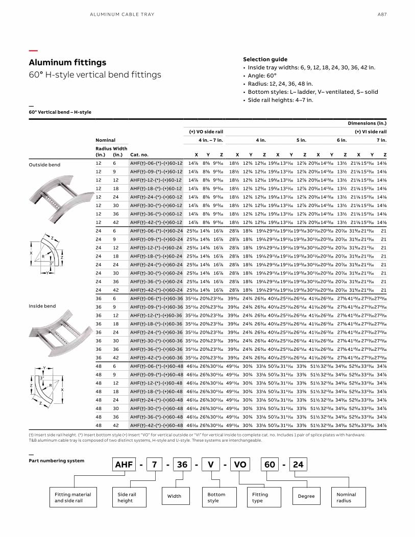
A87A LU M I N U M C A B L E TR AY
—Aluminum fittings60° H-style vertical bend fittings
—60° Vertical bend – H-style
(†) Insert side rail height. (*) Insert bottom style (+) Insert “VO” for vertical outside or “VI” for vertical inside to complete cat. no. Includes 1 pair of splice plates with hardware.T&B aluminum cable tray is composed of two distinct systems, H-style and U-style. These systems are interchangeable.
Selection guide• Inside tray widths: 6, 9, 12, 18, 24, 30, 36, 42 in.• Angle: 60o• Radius: 12, 24, 36, 48 in. • Bottom styles: L– ladder, V– ventilated, S– solid• Side rail heights: 4–7 in.
—Part numbering system
Outside bend
Inside bend
AHF - 7 - 36 - V - VO 60 - 24
Fitting materialand side rail
Side rail height
Bottom style
Nominalradius
Width Fitting type
Degree
Nominal
Cat. no.
Dimensions (in.)
(+) VO side rail (+) VI side rail
4 in. – 7 in. 4 in. 5 in. 6 in. 7 in.
Radius (in.)
Width (in.) X Y Z X Y Z X Y Z X Y Z X Y Z
12 6 AHF(†)-06-(*)-(+)60-12 1477⁄88 855⁄88 91515⁄1616 1811⁄22 1233⁄44 1255⁄1616 1955⁄1616 131111⁄1616 1277⁄88 2055⁄1616 141313⁄1616 1311⁄22 2111⁄88 151313⁄1616 1411⁄88
12 9 AHF(†)-09-(*)-(+)60-12 1477⁄88 855⁄88 91515⁄1616 1811⁄22 1233⁄44 1255⁄1616 1955⁄1616 131111⁄1616 1277⁄88 2055⁄1616 141313⁄1616 1311⁄22 2111⁄88 151313⁄1616 1411⁄88
12 12 AHF(†)-12-(*)-(+)60-12 1477⁄88 855⁄88 91515⁄1616 1811⁄22 1233⁄44 1255⁄1616 1955⁄1616 131111⁄1616 1277⁄88 2055⁄1616 141313⁄1616 1311⁄22 2111⁄88 151313⁄1616 1411⁄88
12 18 AHF(†)-18-(*)-(+)60-12 1477⁄88 855⁄88 91515⁄1616 1811⁄22 1233⁄44 1255⁄1616 1955⁄1616 131111⁄1616 1277⁄88 2055⁄1616 141313⁄1616 1311⁄22 2111⁄88 151313⁄1616 1411⁄88
12 24 AHF(†)-24-(*)-(+)60-12 1477⁄88 855⁄88 91515⁄1616 1811⁄22 1233⁄44 1255⁄1616 1955⁄1616 131111⁄1616 1277⁄88 2055⁄1616 141313⁄1616 1311⁄22 2111⁄88 151313⁄1616 1411⁄88
12 30 AHF(†)-30-(*)-(+)60-12 1477⁄88 855⁄88 91515⁄1616 1811⁄22 1233⁄44 1255⁄1616 1955⁄1616 131111⁄1616 1277⁄88 2055⁄1616 141313⁄1616 1311⁄22 2111⁄88 151313⁄1616 1411⁄88
12 36 AHF(†)-36-(*)-(+)60-12 1477⁄88 855⁄88 91515⁄1616 1811⁄22 1233⁄44 1255⁄1616 1955⁄1616 131111⁄1616 1277⁄88 2055⁄1616 141313⁄1616 1311⁄22 2111⁄88 151313⁄1616 1411⁄88
12 42 AHF(†)-42-(*)-(+)60-12 1477⁄88 855⁄88 91515⁄1616 1811⁄22 1233⁄44 1255⁄1616 1955⁄1616 131111⁄1616 1277⁄88 2055⁄1616 141313⁄1616 1311⁄22 2111⁄88 151313⁄1616 1411⁄88
24 6 AHF(†)-06-(*)-(+)60-24 2555⁄1616 1455⁄88 1677⁄88 2877⁄88 1833⁄44 1911⁄44 291111⁄1616 191111⁄1616 191313⁄1616 301111⁄1616 201313⁄1616 2077⁄1616 3199⁄1616 211313⁄1616 21
24 9 AHF(†)-09-(*)-(+)60-24 2555⁄1616 1455⁄88 1677⁄88 2877⁄88 1833⁄44 1911⁄44 291111⁄1616 191111⁄1616 191313⁄1616 301111⁄1616 201313⁄1616 2077⁄1616 3199⁄1616 211313⁄1616 21
24 12 AHF(†)-12-(*)-(+)60-24 2555⁄1616 1455⁄88 1677⁄88 2877⁄88 1833⁄44 1911⁄44 291111⁄1616 191111⁄1616 191313⁄1616 301111⁄1616 201313⁄1616 2077⁄1616 3199⁄1616 211313⁄1616 21
24 18 AHF(†)-18-(*)-(+)60-24 2555⁄1616 1455⁄88 1677⁄88 2877⁄88 1833⁄44 1911⁄44 291111⁄1616 191111⁄1616 191313⁄1616 301111⁄1616 201313⁄1616 2077⁄1616 3199⁄1616 211313⁄1616 21
24 24 AHF(†)-24-(*)-(+)60-24 2555⁄1616 1455⁄88 1677⁄88 2877⁄88 1833⁄44 1911⁄44 291111⁄1616 191111⁄1616 191313⁄1616 301111⁄1616 201313⁄1616 2077⁄1616 3199⁄1616 211313⁄1616 21
24 30 AHF(†)-30-(*)-(+)60-24 2555⁄1616 1455⁄88 1677⁄88 2877⁄88 1833⁄44 1911⁄44 291111⁄1616 191111⁄1616 191313⁄1616 301111⁄1616 201313⁄1616 2077⁄1616 3199⁄1616 211313⁄1616 21
24 36 AHF(†)-36-(*)-(+)60-24 2555⁄1616 1455⁄88 1677⁄88 2877⁄88 1833⁄44 1911⁄44 291111⁄1616 191111⁄1616 191313⁄1616 301111⁄1616 201313⁄1616 2077⁄1616 3199⁄1616 211313⁄1616 21
24 42 AHF(†)-42-(*)-(+)60-24 2555⁄1616 1455⁄88 1677⁄88 2877⁄88 1833⁄44 1911⁄44 291111⁄1616 191111⁄1616 191313⁄1616 301111⁄1616 201313⁄1616 2077⁄1616 3199⁄1616 211313⁄1616 21
36 6 AHF(†)-06-(*)-(+)60-36 351111⁄1616 2055⁄88 231313⁄1616 3955⁄1616 2433⁄44 2633⁄1616 4011⁄1616 251111⁄1616 261111⁄1616 4111⁄1616 261313⁄1616 2733⁄88 411515⁄1616 271313⁄1616271515⁄1616
36 9 AHF(†)-09-(*)-(+)60-36 351111⁄1616 2055⁄88 231313⁄1616 3955⁄1616 2433⁄44 2633⁄1616 4011⁄1616 251111⁄1616 261111⁄1616 4111⁄1616 261313⁄1616 2733⁄88 411515⁄1616 271313⁄1616271515⁄1616
36 12 AHF(†)-12-(*)-(+)60-36 351111⁄1616 2055⁄88 231313⁄1616 3955⁄1616 2433⁄44 2633⁄1616 4011⁄1616 251111⁄1616 261111⁄1616 4111⁄1616 261313⁄1616 2733⁄88 411515⁄1616 271313⁄1616271515⁄1616
36 18 AHF(†)-18-(*)-(+)60-36 351111⁄1616 2055⁄88 231313⁄1616 3955⁄1616 2433⁄44 2633⁄1616 4011⁄1616 251111⁄1616 261111⁄1616 4111⁄1616 261313⁄1616 2733⁄88 411515⁄1616 271313⁄1616271515⁄1616
36 24 AHF(†)-24-(*)-(+)60-36 351111⁄1616 2055⁄88 231313⁄1616 3955⁄1616 2433⁄44 2633⁄1616 4011⁄1616 251111⁄1616 261111⁄1616 4111⁄1616 261313⁄1616 2733⁄88 411515⁄1616 271313⁄1616271515⁄1616
36 30 AHF(†)-30-(*)-(+)60-36 351111⁄1616 2055⁄88 231313⁄1616 3955⁄1616 2433⁄44 2633⁄1616 4011⁄1616 251111⁄1616 261111⁄1616 4111⁄1616 261313⁄1616 2733⁄88 411515⁄1616 271313⁄1616271515⁄1616
36 36 AHF(†)-36-(*)-(+)60-36 351111⁄1616 2055⁄88 231313⁄1616 3955⁄1616 2433⁄44 2633⁄1616 4011⁄1616 251111⁄1616 261111⁄1616 4111⁄1616 261313⁄1616 2733⁄88 411515⁄1616 271313⁄1616271515⁄1616
36 42 AHF(†)-42-(*)-(+)60-36 351111⁄1616 2055⁄88 231313⁄1616 3955⁄1616 2433⁄44 2633⁄1616 4011⁄1616 251111⁄1616 261111⁄1616 4111⁄1616 261313⁄1616 2733⁄88 411515⁄1616 271313⁄1616271515⁄1616
48 6 AHF(†)-06-(*)-(+)60-48 4611⁄1616 2655⁄88301111⁄1616 491111⁄1616 3033⁄44 3311⁄88 5077⁄1616 311111⁄1616 3355⁄88 5111⁄22 321313⁄1616 3455⁄1616 5255⁄1616 331313⁄1616 3477⁄88
48 9 AHF(†)-09-(*)-(+)60-48 4611⁄1616 2655⁄88301111⁄1616 491111⁄1616 3033⁄44 3311⁄88 5077⁄1616 311111⁄1616 3355⁄88 5111⁄22 321313⁄1616 3455⁄1616 5255⁄1616 331313⁄1616 3477⁄88
48 12 AHF(†)-12-(*)-(+)60-48 4611⁄1616 2655⁄88301111⁄1616 491111⁄1616 3033⁄44 3311⁄88 5077⁄1616 311111⁄1616 3355⁄88 5111⁄22 321313⁄1616 3455⁄1616 5255⁄1616 331313⁄1616 3477⁄88
48 18 AHF(†)-18-(*)-(+)60-48 4611⁄1616 2655⁄88301111⁄1616 491111⁄1616 3033⁄44 3311⁄88 5077⁄1616 311111⁄1616 3355⁄88 5111⁄22 321313⁄1616 3455⁄1616 5255⁄1616 331313⁄1616 3477⁄88
48 24 AHF(†)-24-(*)-(+)60-48 4611⁄1616 2655⁄88301111⁄1616 491111⁄1616 3033⁄44 3311⁄88 5077⁄1616 311111⁄1616 3355⁄88 5111⁄22 321313⁄1616 3455⁄1616 5255⁄1616 331313⁄1616 3477⁄88
48 30 AHF(†)-30-(*)-(+)60-48 4611⁄1616 2655⁄88301111⁄1616 491111⁄1616 3033⁄44 3311⁄88 5077⁄1616 311111⁄1616 3355⁄88 5111⁄22 321313⁄1616 3455⁄1616 5255⁄1616 331313⁄1616 3477⁄88
48 36 AHF(†)-36-(*)-(+)60-48 4611⁄1616 2655⁄88301111⁄1616 491111⁄1616 3033⁄44 3311⁄88 5077⁄1616 311111⁄1616 3355⁄88 5111⁄22 321313⁄1616 3455⁄1616 5255⁄1616 331313⁄1616 3477⁄88
48 42 AHF(†)-42-(*)-(+)60-48 4611⁄1616 2655⁄88301111⁄1616 491111⁄1616 3033⁄44 3311⁄88 5077⁄1616 311111⁄1616 3355⁄88 5111⁄22 321313⁄1616 3455⁄1616 5255⁄1616 331313⁄1616 3477⁄88
R
R
Y
Y
3"
3"
Z
Z
Z
Z
X
X
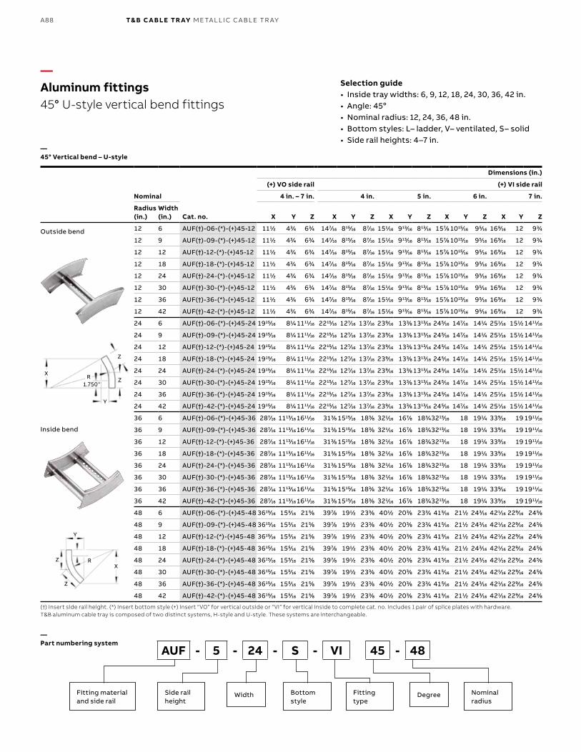
B1 copy starts here
B2 copy starts here
B3 copy starts here
A88 T& B C A B LE TR AY M E TA L L I C C A B L E TR AY
Nominal
Cat. no.
Dimensions (in.)
(+) VO side rail (+) VI side rail
4 in. – 7 in. 4 in. 5 in. 6 in. 7 in.
Radius (in.)
Width (in.) X Y Z X Y Z X Y Z X Y Z X Y Z
12 6 AUF(†)-06-(*)-(+)45-12 1111⁄22 433⁄44 633⁄44 1477⁄1616 81515⁄1616 877⁄1616 1511⁄1616 91313⁄1616 81313⁄1616 1577⁄88 101515⁄1616 955⁄1616 1699⁄1616 12 933⁄44
12 9 AUF(†)-09-(*)-(+)45-12 1111⁄22 433⁄44 633⁄44 1477⁄1616 81515⁄1616 877⁄1616 1511⁄1616 91313⁄1616 81313⁄1616 1577⁄88 101515⁄1616 955⁄1616 1699⁄1616 12 933⁄44
12 12 AUF(†)-12-(*)-(+)45-12 1111⁄22 433⁄44 633⁄44 1477⁄1616 81515⁄1616 877⁄1616 1511⁄1616 91313⁄1616 81313⁄1616 1577⁄88 101515⁄1616 955⁄1616 1699⁄1616 12 933⁄44
12 18 AUF(†)-18-(*)-(+)45-12 1111⁄22 433⁄44 633⁄44 1477⁄1616 81515⁄1616 877⁄1616 1511⁄1616 91313⁄1616 81313⁄1616 1577⁄88 101515⁄1616 955⁄1616 1699⁄1616 12 933⁄44
12 24 AUF(†)-24-(*)-(+)45-12 1111⁄22 433⁄44 633⁄44 1477⁄1616 81515⁄1616 877⁄1616 1511⁄1616 91313⁄1616 81313⁄1616 1577⁄88 101515⁄1616 955⁄1616 1699⁄1616 12 933⁄44
12 30 AUF(†)-30-(*)-(+)45-12 1111⁄22 433⁄44 633⁄44 1477⁄1616 81515⁄1616 877⁄1616 1511⁄1616 91313⁄1616 81313⁄1616 1577⁄88 101515⁄1616 955⁄1616 1699⁄1616 12 933⁄44
12 36 AUF(†)-36-(*)-(+)45-12 1111⁄22 433⁄44 633⁄44 1477⁄1616 81515⁄1616 877⁄1616 1511⁄1616 91313⁄1616 81313⁄1616 1577⁄88 101515⁄1616 955⁄1616 1699⁄1616 12 933⁄44
12 42 AUF(†)-42-(*)-(+)45-12 1111⁄22 433⁄44 633⁄44 1477⁄1616 81515⁄1616 877⁄1616 1511⁄1616 91313⁄1616 81313⁄1616 1577⁄88 101515⁄1616 955⁄1616 1699⁄1616 12 933⁄44
24 6 AUF(†)-06-(*)-(+)45-24 191515⁄1616 811⁄44 111111⁄1616 221515⁄1616 1277⁄1616 1377⁄1616 2399⁄1616 1333⁄88 131313⁄1616 2455⁄1616 1477⁄1616 1411⁄44 2511⁄1616 1511⁄22 141111⁄1616
24 9 AUF(†)-09-(*)-(+)45-24 191515⁄1616 811⁄44 111111⁄1616 221515⁄1616 1277⁄1616 1377⁄1616 2399⁄1616 1333⁄88 131313⁄1616 2455⁄1616 1477⁄1616 1411⁄44 2511⁄1616 1511⁄22 141111⁄1616
24 12 AUF(†)-12-(*)-(+)45-24 191515⁄1616 811⁄44 111111⁄1616 221515⁄1616 1277⁄1616 1377⁄1616 2399⁄1616 1333⁄88 131313⁄1616 2455⁄1616 1477⁄1616 1411⁄44 2511⁄1616 1511⁄22 141111⁄1616
24 18 AUF(†)-18-(*)-(+)45-24 191515⁄1616 811⁄44 111111⁄1616 221515⁄1616 1277⁄1616 1377⁄1616 2399⁄1616 1333⁄88 131313⁄1616 2455⁄1616 1477⁄1616 1411⁄44 2511⁄1616 1511⁄22 141111⁄1616
24 24 AUF(†)-24-(*)-(+)45-24 191515⁄1616 811⁄44 111111⁄1616 221515⁄1616 1277⁄1616 1377⁄1616 2399⁄1616 1333⁄88 131313⁄1616 2455⁄1616 1477⁄1616 1411⁄44 2511⁄1616 1511⁄22 141111⁄1616
24 30 AUF(†)-30-(*)-(+)45-24 191515⁄1616 811⁄44 111111⁄1616 221515⁄1616 1277⁄1616 1377⁄1616 2399⁄1616 1333⁄88 131313⁄1616 2455⁄1616 1477⁄1616 1411⁄44 2511⁄1616 1511⁄22 141111⁄1616
24 36 AUF(†)-36-(*)-(+)45-24 191515⁄1616 811⁄44 111111⁄1616 221515⁄1616 1277⁄1616 1377⁄1616 2399⁄1616 1333⁄88 131313⁄1616 2455⁄1616 1477⁄1616 1411⁄44 2511⁄1616 1511⁄22 141111⁄1616
24 42 AUF(†)-42-(*)-(+)45-24 191515⁄1616 811⁄44 111111⁄1616 221515⁄1616 1277⁄1616 1377⁄1616 2399⁄1616 1333⁄88 131313⁄1616 2455⁄1616 1477⁄1616 1411⁄44 2511⁄1616 1511⁄22 141111⁄1616
36 6 AUF(†)-06-(*)-(+)45-36 2877⁄1616 111313⁄1616 161111⁄1616 3133⁄88 151515⁄1616 1833⁄88 3211⁄1616 1677⁄88 1833⁄44321313⁄1616 18 1911⁄44 3399⁄1616 19 191111⁄1616
36 9 AUF(†)-09-(*)-(+)45-36 2877⁄1616 111313⁄1616 161111⁄1616 3133⁄88 151515⁄1616 1833⁄88 3211⁄1616 1677⁄88 1833⁄44321313⁄1616 18 1911⁄44 3399⁄1616 19 191111⁄1616
36 12 AUF(†)-12-(*)-(+)45-36 2877⁄1616 111313⁄1616 161111⁄1616 3133⁄88 151515⁄1616 1833⁄88 3211⁄1616 1677⁄88 1833⁄44321313⁄1616 18 1911⁄44 3399⁄1616 19 191111⁄1616
36 18 AUF(†)-18-(*)-(+)45-36 2877⁄1616 111313⁄1616 161111⁄1616 3133⁄88 151515⁄1616 1833⁄88 3211⁄1616 1677⁄88 1833⁄44321313⁄1616 18 1911⁄44 3399⁄1616 19 191111⁄1616
36 24 AUF(†)-24-(*)-(+)45-36 2877⁄1616 111313⁄1616 161111⁄1616 3133⁄88 151515⁄1616 1833⁄88 3211⁄1616 1677⁄88 1833⁄44321313⁄1616 18 1911⁄44 3399⁄1616 19 191111⁄1616
36 30 AUF(†)-30-(*)-(+)45-36 2877⁄1616 111313⁄1616 161111⁄1616 3133⁄88 151515⁄1616 1833⁄88 3211⁄1616 1677⁄88 1833⁄44321313⁄1616 18 1911⁄44 3399⁄1616 19 191111⁄1616
36 36 AUF(†)-36-(*)-(+)45-36 2877⁄1616 111313⁄1616 161111⁄1616 3133⁄88 151515⁄1616 1833⁄88 3211⁄1616 1677⁄88 1833⁄44321313⁄1616 18 1911⁄44 3399⁄1616 19 191111⁄1616
36 42 AUF(†)-42-(*)-(+)45-36 2877⁄1616 111313⁄1616 161111⁄1616 3133⁄88 151515⁄1616 1833⁄88 3211⁄1616 1677⁄88 1833⁄44321313⁄1616 18 1911⁄44 3399⁄1616 19 191111⁄1616
48 6 AUF(†)-06-(*)-(+)45-48 361515⁄1616 1555⁄1616 2155⁄88 3977⁄88 1911⁄22 2333⁄88 4011⁄22 2033⁄88 2333⁄44 4155⁄1616 2111⁄22 2433⁄1616 4211⁄1616 2299⁄1616 2455⁄88
48 9 AUF(†)-09-(*)-(+)45-48 361515⁄1616 1555⁄1616 2155⁄88 3977⁄88 1911⁄22 2333⁄88 4011⁄22 2033⁄88 2333⁄44 4155⁄1616 2111⁄22 2433⁄1616 4211⁄1616 2299⁄1616 2455⁄88
48 12 AUF(†)-12-(*)-(+)45-48 361515⁄1616 1555⁄1616 2155⁄88 3977⁄88 1911⁄22 2333⁄88 4011⁄22 2033⁄88 2333⁄44 4155⁄1616 2111⁄22 2433⁄1616 4211⁄1616 2299⁄1616 2455⁄88
48 18 AUF(†)-18-(*)-(+)45-48 361515⁄1616 1555⁄1616 2155⁄88 3977⁄88 1911⁄22 2333⁄88 4011⁄22 2033⁄88 2333⁄44 4155⁄1616 2111⁄22 2433⁄1616 4211⁄1616 2299⁄1616 2455⁄88
48 24 AUF(†)-24-(*)-(+)45-48 361515⁄1616 1555⁄1616 2155⁄88 3977⁄88 1911⁄22 2333⁄88 4011⁄22 2033⁄88 2333⁄44 4155⁄1616 2111⁄22 2433⁄1616 4211⁄1616 2299⁄1616 2455⁄88
48 30 AUF(†)-30-(*)-(+)45-48 361515⁄1616 1555⁄1616 2155⁄88 3977⁄88 1911⁄22 2333⁄88 4011⁄22 2033⁄88 2333⁄44 4155⁄1616 2111⁄22 2433⁄1616 4211⁄1616 2299⁄1616 2455⁄88
48 36 AUF(†)-36-(*)-(+)45-48 361515⁄1616 1555⁄1616 2155⁄88 3977⁄88 1911⁄22 2333⁄88 4011⁄22 2033⁄88 2333⁄44 4155⁄1616 2111⁄22 2433⁄1616 4211⁄1616 2299⁄1616 2455⁄88
48 42 AUF(†)-42-(*)-(+)45-48 361515⁄1616 1555⁄1616 2155⁄88 3977⁄88 1911⁄22 2333⁄88 4011⁄22 2033⁄88 2333⁄44 4155⁄1616 2111⁄22 2433⁄1616 4211⁄1616 2299⁄1616 2455⁄88
—Aluminum fittings45° U-style vertical bend fittings
—45° Vertical bend – U-style
(†) Insert side rail height. (*) Insert bottom style (+) Insert “VO” for vertical outside or “VI” for vertical inside to complete cat. no. Includes 1 pair of splice plates with hardware.T&B aluminum cable tray is composed of two distinct systems, H-style and U-style. These systems are interchangeable.
Selection guide• Inside tray widths: 6, 9, 12, 18, 24, 30, 36, 42 in.• Angle: 45o• Nominal radius: 12, 24, 36, 48 in.• Bottom styles: L– ladder, V– ventilated, S– solid• Side rail heights: 4–7 in.
—Part numbering system
Outside bend
Inside bend
AUF - 5 - 24 - S - VI 45 - 48
Fitting materialand side rail
Side rail height
Bottom style
Nominalradius
Width Fitting type
Degree
R
R
Y
Y
1.750"
Z
Z
Z
Z
X
X
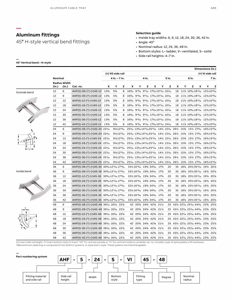
A89A LU M I N U M C A B L E TR AY
—Aluminum fittings45° H-style vertical bend fittings
—45° Vertical bend – H-style
(†) Insert side rail height. (*) Insert bottom style (+) Insert “VO” for vertical outside or “VI” for vertical inside to complete cat. no. Includes 1 pair of splice plates with hardware.T&B aluminum cable tray is composed of two distinct systems, H-style and U-style. These systems are interchangeable.
Selection guide• Inside tray widths: 6, 9, 12, 18, 24, 30, 36, 42 in.• Angle: 45o• Nominal radius: 12, 24, 36, 48 in.• Bottom styles: L– ladder, V– ventilated, S– solid• Side rail heights: 4–7 in.
—Part numbering system
Outside bend
Inside bend
AHF - 5 - 24 - S - VI 45 - 48
Fitting materialand side rail
Side rail height
Bottom style
Nominalradius
Width Fitting type
Degree
Nominal
Cat. no.
Dimensions (in.)
(+) VO side rail (+) VI side rail
4 in. – 7 in. 4 in. 5 in. 6 in. 7 in.
Radius (in.)
Width (in.) X Y Z X Y Z X Y Z X Y Z X Y Z
12 6 AHF(†)-06-(*)-(+)45-12 1355⁄88 555⁄88 8 1699⁄1616 91313⁄1616 91111⁄1616 1733⁄1616 101111⁄1616 1011⁄1616 18 1177⁄88 1099⁄1616 181111⁄1616 1277⁄88 101515⁄1616
12 9 AHF(†)-09-(*)-(+)45-12 1355⁄88 555⁄88 8 1699⁄1616 91313⁄1616 91111⁄1616 1733⁄1616 101111⁄1616 1011⁄1616 18 1177⁄88 1099⁄1616 181111⁄1616 1277⁄88 101515⁄1616
12 12 AHF(†)-12-(*)-(+)45-12 1355⁄88 555⁄88 8 1699⁄1616 91313⁄1616 91111⁄1616 1733⁄1616 101111⁄1616 1011⁄1616 18 1177⁄88 1099⁄1616 181111⁄1616 1277⁄88 101515⁄1616
12 18 AHF(†)-18-(*)-(+)45-12 1355⁄88 555⁄88 8 1699⁄1616 91313⁄1616 91111⁄1616 1733⁄1616 101111⁄1616 1011⁄1616 18 1177⁄88 1099⁄1616 181111⁄1616 1277⁄88 101515⁄1616
12 24 AHF(†)-24-(*)-(+)45-12 1355⁄88 555⁄88 8 1699⁄1616 91313⁄1616 91111⁄1616 1733⁄1616 101111⁄1616 1011⁄1616 18 1177⁄88 1099⁄1616 181111⁄1616 1277⁄88 101515⁄1616
12 30 AHF(†)-30-(*)-(+)45-12 1355⁄88 555⁄88 8 1699⁄1616 91313⁄1616 91111⁄1616 1733⁄1616 101111⁄1616 1011⁄1616 18 1177⁄88 1099⁄1616 181111⁄1616 1277⁄88 101515⁄1616
12 36 AHF(†)-36-(*)-(+)45-12 1355⁄88 555⁄88 8 1699⁄1616 91313⁄1616 91111⁄1616 1733⁄1616 101111⁄1616 1011⁄1616 18 1177⁄88 1099⁄1616 181111⁄1616 1277⁄88 101515⁄1616
12 42 AHF(†)-42-(*)-(+)45-12 1355⁄88 555⁄88 8 1699⁄1616 91313⁄1616 91111⁄1616 1733⁄1616 101111⁄1616 1011⁄1616 18 1177⁄88 1099⁄1616 181111⁄1616 1277⁄88 101515⁄1616
24 6 AHF(†)-06-(*)-(+)45-24 2211⁄1616 911⁄88121515⁄1616 2511⁄1616 1355⁄1616 141111⁄1616 251111⁄1616 1411⁄44 1511⁄1616 2611⁄22 1533⁄88 1511⁄22 2733⁄1616 1633⁄88 151515⁄1616
24 9 AHF(†)-09-(*)-(+)45-24 2211⁄1616 911⁄88121515⁄1616 2511⁄1616 1355⁄1616 141111⁄1616 251111⁄1616 1411⁄44 1511⁄1616 2611⁄22 1533⁄88 1511⁄22 2733⁄1616 1633⁄88 151515⁄1616
24 12 AHF(†)-12-(*)-(+)45-24 2211⁄1616 911⁄88121515⁄1616 2511⁄1616 1355⁄1616 141111⁄1616 251111⁄1616 1411⁄44 1511⁄1616 2611⁄22 1533⁄88 1511⁄22 2733⁄1616 1633⁄88 151515⁄1616
24 18 AHF(†)-18-(*)-(+)45-24 2211⁄1616 911⁄88121515⁄1616 2511⁄1616 1355⁄1616 141111⁄1616 251111⁄1616 1411⁄44 1511⁄1616 2611⁄22 1533⁄88 1511⁄22 2733⁄1616 1633⁄88 151515⁄1616
24 24 AHF(†)-24-(*)-(+)45-24 2211⁄1616 911⁄88121515⁄1616 2511⁄1616 1355⁄1616 141111⁄1616 251111⁄1616 1411⁄44 1511⁄1616 2611⁄22 1533⁄88 1511⁄22 2733⁄1616 1633⁄88 151515⁄1616
24 30 AHF(†)-30-(*)-(+)45-24 2211⁄1616 911⁄88121515⁄1616 2511⁄1616 1355⁄1616 141111⁄1616 251111⁄1616 1411⁄44 1511⁄1616 2611⁄22 1533⁄88 1511⁄22 2733⁄1616 1633⁄88 151515⁄1616
24 36 AHF(†)-36-(*)-(+)45-24 2211⁄1616 911⁄88121515⁄1616 2511⁄1616 1355⁄1616 141111⁄1616 251111⁄1616 1411⁄44 1511⁄1616 2611⁄22 1533⁄88 1511⁄22 2733⁄1616 1633⁄88 151515⁄1616
24 42 AHF(†)-42-(*)-(+)45-24 2211⁄1616 911⁄88121515⁄1616 2511⁄1616 1355⁄1616 141111⁄1616 251111⁄1616 1411⁄44 1511⁄1616 2611⁄22 1533⁄88 1511⁄22 2733⁄1616 1633⁄88 151515⁄1616
36 6 AHF(†)-06-(*)-(+)45-36 3099⁄1616 121111⁄1616 171515⁄1616 3311⁄22 161313⁄1616 1955⁄88 3433⁄1616 1733⁄44 20 35 1877⁄88 2011⁄22 351111⁄1616 1977⁄88 2077⁄88
36 9 AHF(†)-09-(*)-(+)45-36 3099⁄1616 121111⁄1616 171515⁄1616 3311⁄22 161313⁄1616 1955⁄88 3433⁄1616 1733⁄44 20 35 1877⁄88 2011⁄22 351111⁄1616 1977⁄88 2077⁄88
36 12 AHF(†)-12-(*)-(+)45-36 3099⁄1616 121111⁄1616 171515⁄1616 3311⁄22 161313⁄1616 1955⁄88 3433⁄1616 1733⁄44 20 35 1877⁄88 2011⁄22 351111⁄1616 1977⁄88 2077⁄88
36 18 AHF(†)-18-(*)-(+)45-36 3099⁄1616 121111⁄1616 171515⁄1616 3311⁄22 161313⁄1616 1955⁄88 3433⁄1616 1733⁄44 20 35 1877⁄88 2011⁄22 351111⁄1616 1977⁄88 2077⁄88
36 24 AHF(†)-24-(*)-(+)45-36 3099⁄1616 121111⁄1616 171515⁄1616 3311⁄22 161313⁄1616 1955⁄88 3433⁄1616 1733⁄44 20 35 1877⁄88 2011⁄22 351111⁄1616 1977⁄88 2077⁄88
36 30 AHF(†)-30-(*)-(+)45-36 3099⁄1616 121111⁄1616 171515⁄1616 3311⁄22 161313⁄1616 1955⁄88 3433⁄1616 1733⁄44 20 35 1877⁄88 2011⁄22 351111⁄1616 1977⁄88 2077⁄88
36 36 AHF(†)-36-(*)-(+)45-36 3099⁄1616 121111⁄1616 171515⁄1616 3311⁄22 161313⁄1616 1955⁄88 3433⁄1616 1733⁄44 20 35 1877⁄88 2011⁄22 351111⁄1616 1977⁄88 2077⁄88
36 42 AHF(†)-42-(*)-(+)45-36 3099⁄1616 121111⁄1616 171515⁄1616 3311⁄22 161313⁄1616 1955⁄88 3433⁄1616 1733⁄44 20 35 1877⁄88 2011⁄22 351111⁄1616 1977⁄88 2077⁄88
48 6 AHF(†)-06-(*)-(+)45-48 3911⁄1616 1633⁄1616 2277⁄88 42 2033⁄88 2455⁄88 4255⁄88 2111⁄44 25 4311⁄22 2277⁄1616 2577⁄1616 4433⁄1616 2333⁄88 2577⁄88
48 9 AHF(†)-09-(*)-(+)45-48 3911⁄1616 1633⁄1616 2277⁄88 42 2033⁄88 2455⁄88 4255⁄88 2111⁄44 25 4311⁄22 2277⁄1616 2577⁄1616 4433⁄1616 2333⁄88 2577⁄88
48 12 AHF(†)-12-(*)-(+)45-48 3911⁄1616 1633⁄1616 2277⁄88 42 2033⁄88 2455⁄88 4255⁄88 2111⁄44 25 4311⁄22 2277⁄1616 2577⁄1616 4433⁄1616 2333⁄88 2577⁄88
48 18 AHF(†)-18-(*)-(+)45-48 3911⁄1616 1633⁄1616 2277⁄88 42 2033⁄88 2455⁄88 4255⁄88 2111⁄44 25 4311⁄22 2277⁄1616 2577⁄1616 4433⁄1616 2333⁄88 2577⁄88
48 24 AHF(†)-24-(*)-(+)45-48 3911⁄1616 1633⁄1616 2277⁄88 42 2033⁄88 2455⁄88 4255⁄88 2111⁄44 25 4311⁄22 2277⁄1616 2577⁄1616 4433⁄1616 2333⁄88 2577⁄88
48 30 AHF(†)-30-(*)-(+)45-48 3911⁄1616 1633⁄1616 2277⁄88 42 2033⁄88 2455⁄88 4255⁄88 2111⁄44 25 4311⁄22 2277⁄1616 2577⁄1616 4433⁄1616 2333⁄88 2577⁄88
48 36 AHF(†)-36-(*)-(+)45-48 3911⁄1616 1633⁄1616 2277⁄88 42 2033⁄88 2455⁄88 4255⁄88 2111⁄44 25 4311⁄22 2277⁄1616 2577⁄1616 4433⁄1616 2333⁄88 2577⁄88
48 42 AHF(†)-42-(*)-(+)45-48 3911⁄1616 1633⁄1616 2277⁄88 42 2033⁄88 2455⁄88 4255⁄88 2111⁄44 25 4311⁄22 2277⁄1616 2577⁄1616 4433⁄1616 2333⁄88 2577⁄88
X
X
R
R
Y
Y
Z
Z
Z
Z
3"
3"
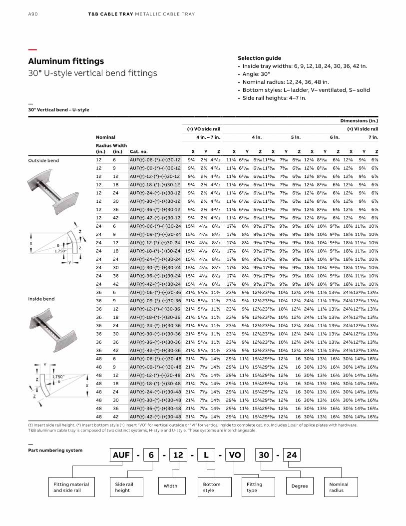
B1 copy starts here
B2 copy starts here
B3 copy starts here
A90 T& B C A B LE TR AY M E TA L L I C C A B L E TR AY
—Aluminum fittings30° U-style vertical bend fittings
—30° Vertical bend – U-style
(†) Insert side rail height. (*) Insert bottom style (+) Insert “VO” for vertical outside or “VI” for vertical inside to complete cat. no. Includes 1 pair of splice plates with hardware.T&B aluminum cable tray is composed of two distinct systems, H-style and U-style. These systems are interchangeable.
Selection guide• Inside tray widths: 6, 9, 12, 18, 24, 30, 36, 42 in.• Angle: 30o• Nominal radius: 12, 24, 36, 48 in.• Bottom styles: L– ladder, V– ventilated, S– solid• Side rail heights: 4–7 in.
—Part numbering system
Nominal
Cat. no.
Dimensions (in.)
(+) VO side rail (+) VI side rail
4 in. – 7 in. 4 in. 5 in. 6 in. 7 in.
Radius (in.)
Width (in.) X Y Z X Y Z X Y Z X Y Z X Y Z
12 6 AUF(†)-06-(*)-(+)30-12 911⁄44 211⁄22 41515⁄1616 1133⁄88 61111⁄1616 611⁄1616 111313⁄1616 799⁄1616 655⁄1616 1233⁄88 81111⁄1616 655⁄88 1277⁄88 933⁄44 677⁄88
12 9 AUF(†)-09-(*)-(+)30-12 911⁄44 211⁄22 41515⁄1616 1133⁄88 61111⁄1616 611⁄1616 111313⁄1616 799⁄1616 655⁄1616 1233⁄88 81111⁄1616 655⁄88 1277⁄88 933⁄44 677⁄88
12 12 AUF(†)-12-(*)-(+)30-12 911⁄44 211⁄22 41515⁄1616 1133⁄88 61111⁄1616 611⁄1616 111313⁄1616 799⁄1616 655⁄1616 1233⁄88 81111⁄1616 655⁄88 1277⁄88 933⁄44 677⁄88
12 18 AUF(†)-18-(*)-(+)30-12 911⁄44 211⁄22 41515⁄1616 1133⁄88 61111⁄1616 611⁄1616 111313⁄1616 799⁄1616 655⁄1616 1233⁄88 81111⁄1616 655⁄88 1277⁄88 933⁄44 677⁄88
12 24 AUF(†)-24-(*)-(+)30-12 911⁄44 211⁄22 41515⁄1616 1133⁄88 61111⁄1616 611⁄1616 111313⁄1616 799⁄1616 655⁄1616 1233⁄88 81111⁄1616 655⁄88 1277⁄88 933⁄44 677⁄88
12 30 AUF(†)-30-(*)-(+)30-12 911⁄44 211⁄22 41515⁄1616 1133⁄88 61111⁄1616 611⁄1616 111313⁄1616 799⁄1616 655⁄1616 1233⁄88 81111⁄1616 655⁄88 1277⁄88 933⁄44 677⁄88
12 36 AUF(†)-36-(*)-(+)30-12 911⁄44 211⁄22 41515⁄1616 1133⁄88 61111⁄1616 611⁄1616 111313⁄1616 799⁄1616 655⁄1616 1233⁄88 81111⁄1616 655⁄88 1277⁄88 933⁄44 677⁄88
12 42 AUF(†)-42-(*)-(+)30-12 911⁄44 211⁄22 41515⁄1616 1133⁄88 61111⁄1616 611⁄1616 111313⁄1616 799⁄1616 655⁄1616 1233⁄88 81111⁄1616 655⁄88 1277⁄88 933⁄44 677⁄88
24 6 AUF(†)-06-(*)-(+)30-24 1511⁄44 411⁄1616 833⁄1616 1733⁄88 811⁄44 955⁄1616 171313⁄1616 933⁄1616 999⁄1616 1833⁄88 1011⁄44 91313⁄1616 1877⁄88 1155⁄1616 1011⁄88
24 9 AUF(†)-09-(*)-(+)30-24 1511⁄44 411⁄1616 833⁄1616 1733⁄88 811⁄44 955⁄1616 171313⁄1616 933⁄1616 999⁄1616 1833⁄88 1011⁄44 91313⁄1616 1877⁄88 1155⁄1616 1011⁄88
24 12 AUF(†)-12-(*)-(+)30-24 1511⁄44 411⁄1616 833⁄1616 1733⁄88 811⁄44 955⁄1616 171313⁄1616 933⁄1616 999⁄1616 1833⁄88 1011⁄44 91313⁄1616 1877⁄88 1155⁄1616 1011⁄88
24 18 AUF(†)-18-(*)-(+)30-24 1511⁄44 411⁄1616 833⁄1616 1733⁄88 811⁄44 955⁄1616 171313⁄1616 933⁄1616 999⁄1616 1833⁄88 1011⁄44 91313⁄1616 1877⁄88 1155⁄1616 1011⁄88
24 24 AUF(†)-24-(*)-(+)30-24 1511⁄44 411⁄1616 833⁄1616 1733⁄88 811⁄44 955⁄1616 171313⁄1616 933⁄1616 999⁄1616 1833⁄88 1011⁄44 91313⁄1616 1877⁄88 1155⁄1616 1011⁄88
24 30 AUF(†)-30-(*)-(+)30-24 1511⁄44 411⁄1616 833⁄1616 1733⁄88 811⁄44 955⁄1616 171313⁄1616 933⁄1616 999⁄1616 1833⁄88 1011⁄44 91313⁄1616 1877⁄88 1155⁄1616 1011⁄88
24 36 AUF(†)-36-(*)-(+)30-24 1511⁄44 411⁄1616 833⁄1616 1733⁄88 811⁄44 955⁄1616 171313⁄1616 933⁄1616 999⁄1616 1833⁄88 1011⁄44 91313⁄1616 1877⁄88 1155⁄1616 1011⁄88
24 42 AUF(†)-42-(*)-(+)30-24 1511⁄44 411⁄1616 833⁄1616 1733⁄88 811⁄44 955⁄1616 171313⁄1616 933⁄1616 999⁄1616 1833⁄88 1011⁄44 91313⁄1616 1877⁄88 1155⁄1616 1011⁄88
36 6 AUF(†)-06-(*)-(+)30-36 2111⁄44 51111⁄1616 1133⁄88 2333⁄88 977⁄88 1211⁄22231313⁄1616 1033⁄44 1233⁄44 2433⁄88 1177⁄88 1311⁄1616 2477⁄88 121515⁄1616 1355⁄1616
36 9 AUF(†)-09-(*)-(+)30-36 2111⁄44 51111⁄1616 1133⁄88 2333⁄88 977⁄88 1211⁄22231313⁄1616 1033⁄44 1233⁄44 2433⁄88 1177⁄88 1311⁄1616 2477⁄88 121515⁄1616 1355⁄1616
36 12 AUF(†)-12-(*)-(+)30-36 2111⁄44 51111⁄1616 1133⁄88 2333⁄88 977⁄88 1211⁄22231313⁄1616 1033⁄44 1233⁄44 2433⁄88 1177⁄88 1311⁄1616 2477⁄88 121515⁄1616 1355⁄1616
36 18 AUF(†)-18-(*)-(+)30-36 2111⁄44 51111⁄1616 1133⁄88 2333⁄88 977⁄88 1211⁄22231313⁄1616 1033⁄44 1233⁄44 2433⁄88 1177⁄88 1311⁄1616 2477⁄88 121515⁄1616 1355⁄1616
36 24 AUF(†)-24-(*)-(+)30-36 2111⁄44 51111⁄1616 1133⁄88 2333⁄88 977⁄88 1211⁄22231313⁄1616 1033⁄44 1233⁄44 2433⁄88 1177⁄88 1311⁄1616 2477⁄88 121515⁄1616 1355⁄1616
36 30 AUF(†)-30-(*)-(+)30-36 2111⁄44 51111⁄1616 1133⁄88 2333⁄88 977⁄88 1211⁄22231313⁄1616 1033⁄44 1233⁄44 2433⁄88 1177⁄88 1311⁄1616 2477⁄88 121515⁄1616 1355⁄1616
36 36 AUF(†)-36-(*)-(+)30-36 2111⁄44 51111⁄1616 1133⁄88 2333⁄88 977⁄88 1211⁄22231313⁄1616 1033⁄44 1233⁄44 2433⁄88 1177⁄88 1311⁄1616 2477⁄88 121515⁄1616 1355⁄1616
36 42 AUF(†)-42-(*)-(+)30-36 2111⁄44 51111⁄1616 1133⁄88 2333⁄88 977⁄88 1211⁄22231313⁄1616 1033⁄44 1233⁄44 2433⁄88 1177⁄88 1311⁄1616 2477⁄88 121515⁄1616 1355⁄1616
48 6 AUF(†)-06-(*)-(+)30-48 2111⁄44 755⁄1616 1455⁄88 2933⁄88 1111⁄22 1533⁄44291313⁄1616 1233⁄88 16 3033⁄88 1311⁄22 1611⁄44 3077⁄88 1499⁄1616 1699⁄1616
48 9 AUF(†)-09-(*)-(+)30-48 2111⁄44 755⁄1616 1455⁄88 2933⁄88 1111⁄22 1533⁄44291313⁄1616 1233⁄88 16 3033⁄88 1311⁄22 1611⁄44 3077⁄88 1499⁄1616 1699⁄1616
48 12 AUF(†)-12-(*)-(+)30-48 2111⁄44 755⁄1616 1455⁄88 2933⁄88 1111⁄22 1533⁄44291313⁄1616 1233⁄88 16 3033⁄88 1311⁄22 1611⁄44 3077⁄88 1499⁄1616 1699⁄1616
48 18 AUF(†)-18-(*)-(+)30-48 2111⁄44 755⁄1616 1455⁄88 2933⁄88 1111⁄22 1533⁄44291313⁄1616 1233⁄88 16 3033⁄88 1311⁄22 1611⁄44 3077⁄88 1499⁄1616 1699⁄1616
48 24 AUF(†)-24-(*)-(+)30-48 2111⁄44 755⁄1616 1455⁄88 2933⁄88 1111⁄22 1533⁄44291313⁄1616 1233⁄88 16 3033⁄88 1311⁄22 1611⁄44 3077⁄88 1499⁄1616 1699⁄1616
48 30 AUF(†)-30-(*)-(+)30-48 2111⁄44 755⁄1616 1455⁄88 2933⁄88 1111⁄22 1533⁄44291313⁄1616 1233⁄88 16 3033⁄88 1311⁄22 1611⁄44 3077⁄88 1499⁄1616 1699⁄1616
48 36 AUF(†)-36-(*)-(+)30-48 2111⁄44 755⁄1616 1455⁄88 2933⁄88 1111⁄22 1533⁄44291313⁄1616 1233⁄88 16 3033⁄88 1311⁄22 1611⁄44 3077⁄88 1499⁄1616 1699⁄1616
48 42 AUF(†)-42-(*)-(+)30-48 2111⁄44 755⁄1616 1455⁄88 2933⁄88 1111⁄22 1533⁄44291313⁄1616 1233⁄88 16 3033⁄88 1311⁄22 1611⁄44 3077⁄88 1499⁄1616 1699⁄1616
Outside bend
Inside bend
AUF - 6 - 12 - L - VO 30 - 24
Fitting materialand side rail
Side rail height
Bottom style
Nominalradius
Width Fitting type
Degree
R
Y
1.750"Z
Z
X
R
Y
1.750"
Z
Z
X
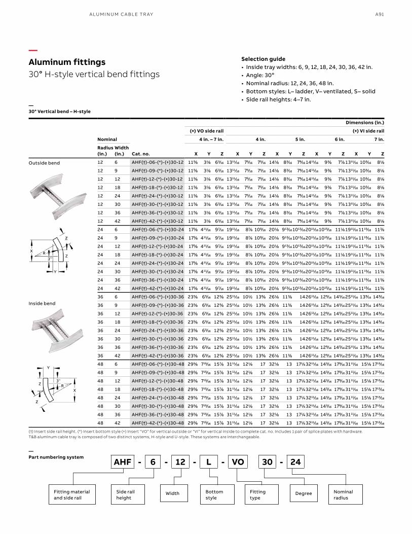
A91A LU M I N U M C A B L E TR AY
—Aluminum fittings30° H-style vertical bend fittings
—30° Vertical bend – H-style
(†) Insert side rail height. (*) Insert bottom style (+) Insert “VO” for vertical outside or “VI” for vertical inside to complete cat. no. Includes 1 pair of splice plates with hardware.T&B aluminum cable tray is composed of two distinct systems, H-style and U-style. These systems are interchangeable.
Selection guide• Inside tray widths: 6, 9, 12, 18, 24, 30, 36, 42 in.• Angle: 30o• Nominal radius: 12, 24, 36, 48 in.• Bottom styles: L– ladder, V– ventilated, S– solid• Side rail heights: 4–7 in.
—Part numbering system
Outside bend
Inside bend
AHF - 6 - 12 - L - VO 30 - 24
Fitting materialand side rail
Side rail height
Bottom style
Nominalradius
Width Fitting type
Degree
Nominal
Cat. no.
Dimensions (in.)
(+) VO side rail (+) VI side rail
4 in. – 7 in. 4 in. 5 in. 6 in. 7 in.
Radius (in.)
Width (in.) X Y Z X Y Z X Y Z X Y Z X Y Z
12 6 AHF(†)-06-(*)-(+)30-12 1155⁄88 311⁄88 633⁄1616 131111⁄1616 755⁄1616 755⁄1616 1411⁄88 833⁄1616 799⁄1616 141111⁄1616 933⁄88 777⁄88 131111⁄1616 1055⁄1616 811⁄88
12 9 AHF(†)-09-(*)-(+)30-12 1155⁄88 311⁄88 633⁄1616 131111⁄1616 755⁄1616 755⁄1616 1411⁄88 833⁄1616 799⁄1616 141111⁄1616 933⁄88 777⁄88 131111⁄1616 1055⁄1616 811⁄88
12 12 AHF(†)-12-(*)-(+)30-12 1155⁄88 311⁄88 633⁄1616 131111⁄1616 755⁄1616 755⁄1616 1411⁄88 833⁄1616 799⁄1616 141111⁄1616 933⁄88 777⁄88 131111⁄1616 1055⁄1616 811⁄88
12 18 AHF(†)-18-(*)-(+)30-12 1155⁄88 311⁄88 633⁄1616 131111⁄1616 755⁄1616 755⁄1616 1411⁄88 833⁄1616 799⁄1616 141111⁄1616 933⁄88 777⁄88 131111⁄1616 1055⁄1616 811⁄88
12 24 AHF(†)-24-(*)-(+)30-12 1155⁄88 311⁄88 633⁄1616 131111⁄1616 755⁄1616 755⁄1616 1411⁄88 833⁄1616 799⁄1616 141111⁄1616 933⁄88 777⁄88 131111⁄1616 1055⁄1616 811⁄88
12 30 AHF(†)-30-(*)-(+)30-12 1155⁄88 311⁄88 633⁄1616 131111⁄1616 755⁄1616 755⁄1616 1411⁄88 833⁄1616 799⁄1616 141111⁄1616 933⁄88 777⁄88 131111⁄1616 1055⁄1616 811⁄88
12 36 AHF(†)-36-(*)-(+)30-12 1155⁄88 311⁄88 633⁄1616 131111⁄1616 755⁄1616 755⁄1616 1411⁄88 833⁄1616 799⁄1616 141111⁄1616 933⁄88 777⁄88 131111⁄1616 1055⁄1616 811⁄88
12 42 AHF(†)-42-(*)-(+)30-12 1155⁄88 311⁄88 633⁄1616 131111⁄1616 755⁄1616 755⁄1616 1411⁄88 833⁄1616 799⁄1616 141111⁄1616 933⁄88 777⁄88 131111⁄1616 1055⁄1616 811⁄88
24 6 AHF(†)-06-(*)-(+)30-24 1755⁄88 41111⁄1616 977⁄1616 191111⁄1616 877⁄88 1099⁄1616 2011⁄88 91313⁄1616 101313⁄1616201111⁄1616 101515⁄1616 1111⁄88 191111⁄1616 111515⁄1616 1133⁄88
24 9 AHF(†)-09-(*)-(+)30-24 1755⁄88 41111⁄1616 977⁄1616 191111⁄1616 877⁄88 1099⁄1616 2011⁄88 91313⁄1616 101313⁄1616201111⁄1616 101515⁄1616 1111⁄88 191111⁄1616 111515⁄1616 1133⁄88
24 12 AHF(†)-12-(*)-(+)30-24 1755⁄88 41111⁄1616 977⁄1616 191111⁄1616 877⁄88 1099⁄1616 2011⁄88 91313⁄1616 101313⁄1616201111⁄1616 101515⁄1616 1111⁄88 191111⁄1616 111515⁄1616 1133⁄88
24 18 AHF(†)-18-(*)-(+)30-24 1755⁄88 41111⁄1616 977⁄1616 191111⁄1616 877⁄88 1099⁄1616 2011⁄88 91313⁄1616 101313⁄1616201111⁄1616 101515⁄1616 1111⁄88 191111⁄1616 111515⁄1616 1133⁄88
24 24 AHF(†)-24-(*)-(+)30-24 1755⁄88 41111⁄1616 977⁄1616 191111⁄1616 877⁄88 1099⁄1616 2011⁄88 91313⁄1616 101313⁄1616201111⁄1616 101515⁄1616 1111⁄88 191111⁄1616 111515⁄1616 1133⁄88
24 30 AHF(†)-30-(*)-(+)30-24 1755⁄88 41111⁄1616 977⁄1616 191111⁄1616 877⁄88 1099⁄1616 2011⁄88 91313⁄1616 101313⁄1616201111⁄1616 101515⁄1616 1111⁄88 191111⁄1616 111515⁄1616 1133⁄88
24 36 AHF(†)-36-(*)-(+)30-24 1755⁄88 41111⁄1616 977⁄1616 191111⁄1616 877⁄88 1099⁄1616 2011⁄88 91313⁄1616 101313⁄1616201111⁄1616 101515⁄1616 1111⁄88 191111⁄1616 111515⁄1616 1133⁄88
24 42 AHF(†)-42-(*)-(+)30-24 1755⁄88 41111⁄1616 977⁄1616 191111⁄1616 877⁄88 1099⁄1616 2011⁄88 91313⁄1616 101313⁄1616201111⁄1616 101515⁄1616 1111⁄88 191111⁄1616 111515⁄1616 1133⁄88
36 6 AHF(†)-06-(*)-(+)30-36 2355⁄88 655⁄1616 1255⁄88 251111⁄1616 1011⁄22 1366⁄88 2611⁄88 1133⁄88 14 261111⁄1616 1299⁄1616 1455⁄1616 251111⁄1616 1399⁄1616 1499⁄1616
36 9 AHF(†)-09-(*)-(+)30-36 2355⁄88 655⁄1616 1255⁄88 251111⁄1616 1011⁄22 1366⁄88 2611⁄88 1133⁄88 14 261111⁄1616 1299⁄1616 1455⁄1616 251111⁄1616 1399⁄1616 1499⁄1616
36 12 AHF(†)-12-(*)-(+)30-36 2355⁄88 655⁄1616 1255⁄88 251111⁄1616 1011⁄22 1366⁄88 2611⁄88 1133⁄88 14 261111⁄1616 1299⁄1616 1455⁄1616 251111⁄1616 1399⁄1616 1499⁄1616
36 18 AHF(†)-18-(*)-(+)30-36 2355⁄88 655⁄1616 1255⁄88 251111⁄1616 1011⁄22 1366⁄88 2611⁄88 1133⁄88 14 261111⁄1616 1299⁄1616 1455⁄1616 251111⁄1616 1399⁄1616 1499⁄1616
36 24 AHF(†)-24-(*)-(+)30-36 2355⁄88 655⁄1616 1255⁄88 251111⁄1616 1011⁄22 1366⁄88 2611⁄88 1133⁄88 14 261111⁄1616 1299⁄1616 1455⁄1616 251111⁄1616 1399⁄1616 1499⁄1616
36 30 AHF(†)-30-(*)-(+)30-36 2355⁄88 655⁄1616 1255⁄88 251111⁄1616 1011⁄22 1366⁄88 2611⁄88 1133⁄88 14 261111⁄1616 1299⁄1616 1455⁄1616 251111⁄1616 1399⁄1616 1499⁄1616
36 36 AHF(†)-36-(*)-(+)30-36 2355⁄88 655⁄1616 1255⁄88 251111⁄1616 1011⁄22 1366⁄88 2611⁄88 1133⁄88 14 261111⁄1616 1299⁄1616 1455⁄1616 251111⁄1616 1399⁄1616 1499⁄1616
36 42 AHF(†)-42-(*)-(+)30-36 2355⁄88 655⁄1616 1255⁄88 251111⁄1616 1011⁄22 1366⁄88 2611⁄88 1133⁄88 14 261111⁄1616 1299⁄1616 1455⁄1616 251111⁄1616 1399⁄1616 1499⁄1616
48 6 AHF(†)-06-(*)-(+)30-48 2955⁄88 71515⁄1616 1577⁄88 311111⁄1616 1211⁄88 17 3211⁄88 13 1711⁄44 321111⁄1616 1433⁄1616 1799⁄1616 311111⁄1616 1511⁄88 171313⁄1616
48 9 AHF(†)-09-(*)-(+)30-48 2955⁄88 71515⁄1616 1577⁄88 311111⁄1616 1211⁄88 17 3211⁄88 13 1711⁄44 321111⁄1616 1433⁄1616 1799⁄1616 311111⁄1616 1511⁄88 171313⁄1616
48 12 AHF(†)-12-(*)-(+)30-48 2955⁄88 71515⁄1616 1577⁄88 311111⁄1616 1211⁄88 17 3211⁄88 13 1711⁄44 321111⁄1616 1433⁄1616 1799⁄1616 311111⁄1616 1511⁄88 171313⁄1616
48 18 AHF(†)-18-(*)-(+)30-48 2955⁄88 71515⁄1616 1577⁄88 311111⁄1616 1211⁄88 17 3211⁄88 13 1711⁄44 321111⁄1616 1433⁄1616 1799⁄1616 311111⁄1616 1511⁄88 171313⁄1616
48 24 AHF(†)-24-(*)-(+)30-48 2955⁄88 71515⁄1616 1577⁄88 311111⁄1616 1211⁄88 17 3211⁄88 13 1711⁄44 321111⁄1616 1433⁄1616 1799⁄1616 311111⁄1616 1511⁄88 171313⁄1616
48 30 AHF(†)-30-(*)-(+)30-48 2955⁄88 71515⁄1616 1577⁄88 311111⁄1616 1211⁄88 17 3211⁄88 13 1711⁄44 321111⁄1616 1433⁄1616 1799⁄1616 311111⁄1616 1511⁄88 171313⁄1616
48 36 AHF(†)-36-(*)-(+)30-48 2955⁄88 71515⁄1616 1577⁄88 311111⁄1616 1211⁄88 17 3211⁄88 13 1711⁄44 321111⁄1616 1433⁄1616 1799⁄1616 311111⁄1616 1511⁄88 171313⁄1616
48 42 AHF(†)-42-(*)-(+)30-48 2955⁄88 71515⁄1616 1577⁄88 311111⁄1616 1211⁄88 17 3211⁄88 13 1711⁄44 321111⁄1616 1433⁄1616 1799⁄1616 311111⁄1616 1511⁄88 171313⁄1616
R
Y
Y
3"
3"
Z
Z
Z
Z R
X
X
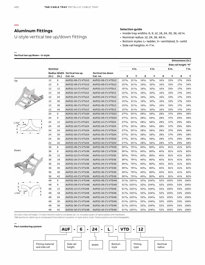
B1 copy starts here
B2 copy starts here
B3 copy starts here
A92 T& B C A B LE TR AY M E TA L L I C C A B L E TR AY
—Aluminum fittingsU-style vertical tee up/down fittings
—Vertical tee up/down – U-style
(†) Insert side rail height. (*) Insert bottom style to complete cat. no. Includes 2 pairs of splice plates with hardware.T&B aluminum cable tray is composed of two distinct systems, H-style and U-style. These systems are interchangeable.
Selection guide• Inside tray widths: 6, 9, 12, 18, 24, 30, 36, 42 in.• Nominal radius: 12, 24, 36, 48 in.• Bottom styles: L– ladder, V– ventilated, S– solid• Side rail heights: 4–7 in.
—Part numbering system
Nominal
Vertical tee upCat. no.
Vertical tee downCat. no.
Dimensions (in.)
Side rail height “H”
4 in. 5 in. 6 in. 7 in.
Radius (in.)
Width (in.) X Y X Y X Y X Y
12 6 AUF(†)-06-(*)-VTU12 AUF(†)-06-(*)-VTD12 151313⁄1616 311111⁄1616 1655⁄1616 3299⁄1616 1677⁄88 3333⁄44 1733⁄88 3433⁄44
12 9 AUF(†)-09-(*)-VTU12 AUF(†)-09-(*)-VTD12 151313⁄1616 311111⁄1616 1655⁄1616 3299⁄1616 1677⁄88 3333⁄44 1733⁄88 3433⁄44
12 12 AUF(†)-12-(*)-VTU12 AUF(†)-12-(*)-VTD12 151313⁄1616 311111⁄1616 1655⁄1616 3299⁄1616 1677⁄88 3333⁄44 1733⁄88 3433⁄44
12 18 AUF(†)-18-(*)-VTU12 AUF(†)-18-(*)-VTD12 151313⁄1616 311111⁄1616 1655⁄1616 3299⁄1616 1677⁄88 3333⁄44 1733⁄88 3433⁄44
12 24 AUF(†)-24-(*)-VTU12 AUF(†)-24-(*)-VTD12 151313⁄1616 311111⁄1616 1655⁄1616 3299⁄1616 1677⁄88 3333⁄44 1733⁄88 3433⁄44
12 30 AUF(†)-30-(*)-VTU12 AUF(†)-30-(*)-VTD12 151313⁄1616 311111⁄1616 1655⁄1616 3299⁄1616 1677⁄88 3333⁄44 1733⁄88 3433⁄44
12 36 AUF(†)-36-(*)-VTU12 AUF(†)-36-(*)-VTD12 151313⁄1616 311111⁄1616 1655⁄1616 3299⁄1616 1677⁄88 3333⁄44 1733⁄88 3433⁄44
12 42 AUF(†)-42-(*)-VTU12 AUF(†)-42-(*)-VTD12 151313⁄1616 311111⁄1616 1655⁄1616 3299⁄1616 1677⁄88 3333⁄44 1733⁄88 3433⁄44
24 6 AUF(†)-06-(*)-VTU24 AUF(†)-06-(*)-VTD24 271313⁄1616 551111⁄1616 2855⁄1616 5699⁄1616 2877⁄88 5733⁄44 2933⁄88 5833⁄44
24 9 AUF(†)-09-(*)-VTU24 AUF(†)-09-(*)-VTD24 271313⁄1616 551111⁄1616 2855⁄1616 5699⁄1616 2877⁄88 5733⁄44 2933⁄88 5833⁄44
24 12 AUF(†)-12-(*)-VTU24 AUF(†)-12-(*)-VTD24 271313⁄1616 551111⁄1616 2855⁄1616 5699⁄1616 2877⁄88 5733⁄44 2933⁄88 5833⁄44
24 18 AUF(†)-18-(*)-VTU24 AUF(†)-18-(*)-VTD24 271313⁄1616 551111⁄1616 2855⁄1616 5699⁄1616 2877⁄88 5733⁄44 2933⁄88 5833⁄44
24 24 AUF(†)-24-(*)-VTU24 AUF(†)-24-(*)-VTD24 271313⁄1616 551111⁄1616 2855⁄1616 5699⁄1616 2877⁄88 5733⁄44 2933⁄88 5833⁄44
24 30 AUF(†)-30-(*)-VTU24 AUF(†)-30-(*)-VTD24 271313⁄1616 551111⁄1616 2855⁄1616 5699⁄1616 2877⁄88 5733⁄44 2933⁄88 5833⁄44
24 36 AUF(†)-36-(*)-VTU24 AUF(†)-36-(*)-VTD24 271313⁄1616 551111⁄1616 2855⁄1616 5699⁄1616 2877⁄88 5733⁄44 2933⁄88 5833⁄44
24 42 AUF(†)-42-(*)-VTU24 AUF(†)-42-(*)-VTD24 271313⁄1616 551111⁄1616 2855⁄1616 5699⁄1616 2877⁄88 5733⁄44 2933⁄88 5833⁄44
36 6 AUF(†)-06-(*)-VTU36 AUF(†)-06-(*)-VTD36 391313⁄1616 791111⁄1616 4055⁄1616 8099⁄1616 4077⁄88 8133⁄44 4133⁄88 8233⁄44
36 9 AUF(†)-09-(*)-VTU36 AUF(†)-09-(*)-VTD36 391313⁄1616 791111⁄1616 4055⁄1616 8099⁄1616 4077⁄88 8133⁄44 4133⁄88 8233⁄44
36 12 AUF(†)-12-(*)-VTU36 AUF(†)-12-(*)-VTD36 391313⁄1616 791111⁄1616 4055⁄1616 8099⁄1616 4077⁄88 8133⁄44 4133⁄88 8233⁄44
36 18 AUF(†)-18-(*)-VTU36 AUF(†)-18-(*)-VTD36 391313⁄1616 791111⁄1616 4055⁄1616 8099⁄1616 4077⁄88 8133⁄44 4133⁄88 8233⁄44
36 24 AUF(†)-24-(*)-VTU36 AUF(†)-24-(*)-VTD36 391313⁄1616 791111⁄1616 4055⁄1616 8099⁄1616 4077⁄88 8133⁄44 4133⁄88 8233⁄44
36 30 AUF(†)-30-(*)-VTU36 AUF(†)-30-(*)-VTD36 391313⁄1616 791111⁄1616 4055⁄1616 8099⁄1616 4077⁄88 8133⁄44 4133⁄88 8233⁄44
36 36 AUF(†)-36-(*)-VTU36 AUF(†)-36-(*)-VTD36 391313⁄1616 791111⁄1616 4055⁄1616 8099⁄1616 4077⁄88 8133⁄44 4133⁄88 8233⁄44
36 42 AUF(†)-42-(*)-VTU36 AUF(†)-42-(*)-VTD36 391313⁄1616 791111⁄1616 4055⁄1616 8099⁄1616 4077⁄88 8133⁄44 4133⁄88 8233⁄44
48 6 AUF(†)-06-(*)-VTU48 AUF(†)-06-(*)-VTD48 511313⁄1616 1031111⁄1616 5255⁄1616 10499⁄1616 5277⁄88 10533⁄44 5333⁄88 10633⁄44
48 9 AUF(†)-09-(*)-VTU48 AUF(†)-09-(*)-VTD48 511313⁄1616 1031111⁄1616 5255⁄1616 10499⁄1616 5277⁄88 10533⁄44 5333⁄88 10633⁄44
48 12 AUF(†)-12-(*)-VTU48 AUF(†)-12-(*)-VTD48 511313⁄1616 1031111⁄1616 5255⁄1616 10499⁄1616 5277⁄88 10533⁄44 5333⁄88 10633⁄44
48 18 AUF(†)-18-(*)-VTU48 AUF(†)-18-(*)-VTD48 511313⁄1616 1031111⁄1616 5255⁄1616 10499⁄1616 5277⁄88 10533⁄44 5333⁄88 10633⁄44
48 24 AUF(†)-24-(*)-VTU48 AUF(†)-24-(*)-VTD48 511313⁄1616 1031111⁄1616 5255⁄1616 10499⁄1616 5277⁄88 10533⁄44 5333⁄88 10633⁄44
48 30 AUF(†)-30-(*)-VTU48 AUF(†)-30-(*)-VTD48 511313⁄1616 1031111⁄1616 5255⁄1616 10499⁄1616 5277⁄88 10533⁄44 5333⁄88 10633⁄44
48 36 AUF(†)-36-(*)-VTU48 AUF(†)-36-(*)-VTD48 511313⁄1616 1031111⁄1616 5255⁄1616 10499⁄1616 5277⁄88 10533⁄44 5333⁄88 10633⁄44
48 42 AUF(†)-42-(*)-VTU48 AUF(†)-42-(*)-VTD48 511313⁄1616 1031111⁄1616 5255⁄1616 10499⁄1616 5277⁄88 10533⁄44 5333⁄88 10633⁄44
Up
Down
AUF - 6 - 24 - L - VTD - 12
Fitting materialand side rail
Side rail height
Bottom style
Nominalradius
Width Fitting type
R
R
Y
Y
1.750"
1.750"
X
X
H
H
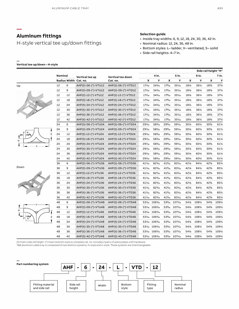
A93A LU M I N U M C A B L E TR AY
—Aluminum fittingsH-style vertical tee up/down fittings
—Vertical tee up/down – H-style
(†) Insert side rail height. (*) Insert bottom style to complete cat. no. Includes 2 pairs of splice plates with hardware.T&B aluminum cable tray is composed of two distinct systems, H-style and U-style. These systems are interchangeable.
Selection guide• Inside tray widths: 6, 9, 12, 18, 24, 30, 36, 42 in.• Nominal radius: 12, 24, 36, 48 in.• Bottom styles: L– ladder, V– ventilated, S– solid• Side rail heights: 4–7 in.
—Part numbering system
Up
Down
AHF - 6 - 24 - L - VTD - 12
Fitting materialand side rail
Side rail height
Bottom style
Nominalradius
Width Fitting type
Nominal Vertical tee upCat. no.
Vertical tee downCat. no.
Side rail height “H”
4 in. 5 in. 6 in. 7 in.
Radius Width X Y X Y X Y X Y
12 6 AHF(†)-06-(*)-VTU12 AHF(†)-06-(*)-VTD12 1711⁄1616 3433⁄1616 1799⁄1616 3511⁄1616 1811⁄88 3611⁄44 1855⁄88 3711⁄44
12 9 AHF(†)-09-(*)-VTU12 AHF(†)-09-(*)-VTD12 1711⁄1616 3433⁄1616 1799⁄1616 3511⁄1616 1811⁄88 3611⁄44 1855⁄88 3711⁄44
12 12 AHF(†)-12-(*)-VTU12 AHF(†)-12-(*)-VTD12 1711⁄1616 3433⁄1616 1799⁄1616 3511⁄1616 1811⁄88 3611⁄44 1855⁄88 3711⁄44
12 18 AHF(†)-18-(*)-VTU12 AHF(†)-18-(*)-VTD12 1711⁄1616 3433⁄1616 1799⁄1616 3511⁄1616 1811⁄88 3611⁄44 1855⁄88 3711⁄44
12 24 AHF(†)-24-(*)-VTU12 AHF(†)-24-(*)-VTD12 1711⁄1616 3433⁄1616 1799⁄1616 3511⁄1616 1811⁄88 3611⁄44 1855⁄88 3711⁄44
12 30 AHF(†)-30-(*)-VTU12 AHF(†)-30-(*)-VTD12 1711⁄1616 3433⁄1616 1799⁄1616 3511⁄1616 1811⁄88 3611⁄44 1855⁄88 3711⁄44
12 36 AHF(†)-36-(*)-VTU12 AHF(†)-36-(*)-VTD12 1711⁄1616 3433⁄1616 1799⁄1616 3511⁄1616 1811⁄88 3611⁄44 1855⁄88 3711⁄44
12 42 AHF(†)-42-(*)-VTU12 AHF(†)-42-(*)-VTD12 1711⁄1616 3433⁄1616 1799⁄1616 3511⁄1616 1811⁄88 3611⁄44 1855⁄88 3711⁄44
24 6 AHF(†)-06-(*)-VTU24 AHF(†)-06-(*)-VTD24 2911⁄1616 5833⁄1616 2999⁄1616 5911⁄1616 3011⁄88 6011⁄44 3055⁄88 6111⁄44
24 9 AHF(†)-09-(*)-VTU24 AHF(†)-09-(*)-VTD24 2911⁄1616 5833⁄1616 2999⁄1616 5911⁄1616 3011⁄88 6011⁄44 3055⁄88 6111⁄44
24 12 AHF(†)-12-(*)-VTU24 AHF(†)-12-(*)-VTD24 2911⁄1616 5833⁄1616 2999⁄1616 5911⁄1616 3011⁄88 6011⁄44 3055⁄88 6111⁄44
24 18 AHF(†)-18-(*)-VTU24 AHF(†)-18-(*)-VTD24 2911⁄1616 5833⁄1616 2999⁄1616 5911⁄1616 3011⁄88 6011⁄44 3055⁄88 6111⁄44
24 24 AHF(†)-24-(*)-VTU24 AHF(†)-24-(*)-VTD24 2911⁄1616 5833⁄1616 2999⁄1616 5911⁄1616 3011⁄88 6011⁄44 3055⁄88 6111⁄44
24 30 AHF(†)-30-(*)-VTU24 AHF(†)-30-(*)-VTD24 2911⁄1616 5833⁄1616 2999⁄1616 5911⁄1616 3011⁄88 6011⁄44 3055⁄88 6111⁄44
24 36 AHF(†)-36-(*)-VTU24 AHF(†)-36-(*)-VTD24 2911⁄1616 5833⁄1616 2999⁄1616 5911⁄1616 3011⁄88 6011⁄44 3055⁄88 6111⁄44
24 42 AHF(†)-42-(*)-VTU24 AHF(†)-42-(*)-VTD24 2911⁄1616 5833⁄1616 2999⁄1616 5911⁄1616 3011⁄88 6011⁄44 3055⁄88 6111⁄44
36 6 AHF(†)-06-(*)-VTU36 AHF(†)-06-(*)-VTD36 4111⁄1616 8233⁄1616 4199⁄1616 8311⁄1616 4211⁄88 8411⁄44 4255⁄88 8511⁄44
36 9 AHF(†)-09-(*)-VTU36 AHF(†)-09-(*)-VTD36 4111⁄1616 8233⁄1616 4199⁄1616 8311⁄1616 4211⁄88 8411⁄44 4255⁄88 8511⁄44
36 12 AHF(†)-12-(*)-VTU36 AHF(†)-12-(*)-VTD36 4111⁄1616 8233⁄1616 4199⁄1616 8311⁄1616 4211⁄88 8411⁄44 4255⁄88 8511⁄44
36 18 AHF(†)-18-(*)-VTU36 AHF(†)-18-(*)-VTD36 4111⁄1616 8233⁄1616 4199⁄1616 8311⁄1616 4211⁄88 8411⁄44 4255⁄88 8511⁄44
36 24 AHF(†)-24-(*)-VTU36 AHF(†)-24-(*)-VTD36 4111⁄1616 8233⁄1616 4199⁄1616 8311⁄1616 4211⁄88 8411⁄44 4255⁄88 8511⁄44
36 30 AHF(†)-30-(*)-VTU36 AHF(†)-30-(*)-VTD36 4111⁄1616 8233⁄1616 4199⁄1616 8311⁄1616 4211⁄88 8411⁄44 4255⁄88 8511⁄44
36 36 AHF(†)-36-(*)-VTU36 AHF(†)-36-(*)-VTD36 4111⁄1616 8233⁄1616 4199⁄1616 8311⁄1616 4211⁄88 8411⁄44 4255⁄88 8511⁄44
36 42 AHF(†)-42-(*)-VTU36 AHF(†)-42-(*)-VTD36 4111⁄1616 8233⁄1616 4199⁄1616 8311⁄1616 4211⁄88 8411⁄44 4255⁄88 8511⁄44
48 6 AHF(†)-06-(*)-VTU48 AHF(†)-06-(*)-VTD48 5311⁄1616 10633⁄1616 5399⁄1616 10711⁄1616 5411⁄88 10811⁄44 5455⁄88 10911⁄44
48 9 AHF(†)-09-(*)-VTU48 AHF(†)-09-(*)-VTD48 5311⁄1616 10633⁄1616 5399⁄1616 10711⁄1616 5411⁄88 10811⁄44 5455⁄88 10911⁄44
48 12 AHF(†)-12-(*)-VTU48 AHF(†)-12-(*)-VTD48 5311⁄1616 10633⁄1616 5399⁄1616 10711⁄1616 5411⁄88 10811⁄44 5455⁄88 10911⁄44
48 18 AHF(†)-18-(*)-VTU48 AHF(†)-18-(*)-VTD48 5311⁄1616 10633⁄1616 5399⁄1616 10711⁄1616 5411⁄88 10811⁄44 5455⁄88 10911⁄44
48 24 AHF(†)-24-(*)-VTU48 AHF(†)-24-(*)-VTD48 5311⁄1616 10633⁄1616 5399⁄1616 10711⁄1616 5411⁄88 10811⁄44 5455⁄88 10911⁄44
48 30 AHF(†)-30-(*)-VTU48 AHF(†)-30-(*)-VTD48 5311⁄1616 10633⁄1616 5399⁄1616 10711⁄1616 5411⁄88 10811⁄44 5455⁄88 10911⁄44
48 36 AHF(†)-36-(*)-VTU48 AHF(†)-36-(*)-VTD48 5311⁄1616 10633⁄1616 5399⁄1616 10711⁄1616 5411⁄88 10811⁄44 5455⁄88 10911⁄44
48 42 AHF(†)-42-(*)-VTU48 AHF(†)-42-(*)-VTD48 5311⁄1616 10633⁄1616 5399⁄1616 10711⁄1616 5411⁄88 10811⁄44 5455⁄88 10911⁄44
R
R
Y
Y
3"
3"
X
X
H
H
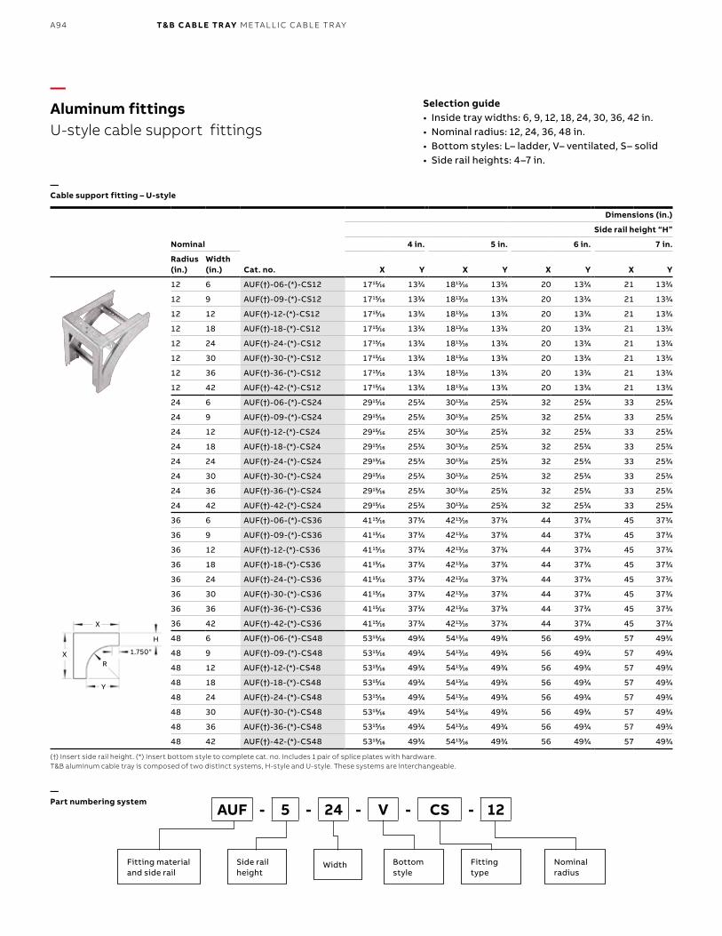
B1 copy starts here
B2 copy starts here
B3 copy starts here
A94 T& B C A B LE TR AY M E TA L L I C C A B L E TR AY
Nominal
Cat. no.
Dimensions (in.)
Side rail height “H”
4 in. 5 in. 6 in. 7 in.
Radius (in.)
Width (in.) X Y X Y X Y X Y
12 6 AUF(†)-06-(*)-CS12 171515⁄1616 1333⁄44 181313⁄1616 1333⁄44 20 1333⁄44 21 1333⁄44
12 9 AUF(†)-09-(*)-CS12 171515⁄1616 1333⁄44 181313⁄1616 1333⁄44 20 1333⁄44 21 1333⁄44
12 12 AUF(†)-12-(*)-CS12 171515⁄1616 1333⁄44 181313⁄1616 1333⁄44 20 1333⁄44 21 1333⁄44
12 18 AUF(†)-18-(*)-CS12 171515⁄1616 1333⁄44 181313⁄1616 1333⁄44 20 1333⁄44 21 1333⁄44
12 24 AUF(†)-24-(*)-CS12 171515⁄1616 1333⁄44 181313⁄1616 1333⁄44 20 1333⁄44 21 1333⁄44
12 30 AUF(†)-30-(*)-CS12 171515⁄1616 1333⁄44 181313⁄1616 1333⁄44 20 1333⁄44 21 1333⁄44
12 36 AUF(†)-36-(*)-CS12 171515⁄1616 1333⁄44 181313⁄1616 1333⁄44 20 1333⁄44 21 1333⁄44
12 42 AUF(†)-42-(*)-CS12 171515⁄1616 1333⁄44 181313⁄1616 1333⁄44 20 1333⁄44 21 1333⁄44
24 6 AUF(†)-06-(*)-CS24 291515⁄1616 2533⁄44 301313⁄1616 2533⁄44 32 2533⁄44 33 2533⁄44
24 9 AUF(†)-09-(*)-CS24 291515⁄1616 2533⁄44 301313⁄1616 2533⁄44 32 2533⁄44 33 2533⁄44
24 12 AUF(†)-12-(*)-CS24 291515⁄1616 2533⁄44 301313⁄1616 2533⁄44 32 2533⁄44 33 2533⁄44
24 18 AUF(†)-18-(*)-CS24 291515⁄1616 2533⁄44 301313⁄1616 2533⁄44 32 2533⁄44 33 2533⁄44
24 24 AUF(†)-24-(*)-CS24 291515⁄1616 2533⁄44 301313⁄1616 2533⁄44 32 2533⁄44 33 2533⁄44
24 30 AUF(†)-30-(*)-CS24 291515⁄1616 2533⁄44 301313⁄1616 2533⁄44 32 2533⁄44 33 2533⁄44
24 36 AUF(†)-36-(*)-CS24 291515⁄1616 2533⁄44 301313⁄1616 2533⁄44 32 2533⁄44 33 2533⁄44
24 42 AUF(†)-42-(*)-CS24 291515⁄1616 2533⁄44 301313⁄1616 2533⁄44 32 2533⁄44 33 2533⁄44
36 6 AUF(†)-06-(*)-CS36 411515⁄1616 3733⁄44 421313⁄1616 3733⁄44 44 3733⁄44 45 3733⁄44
36 9 AUF(†)-09-(*)-CS36 411515⁄1616 3733⁄44 421313⁄1616 3733⁄44 44 3733⁄44 45 3733⁄44
36 12 AUF(†)-12-(*)-CS36 411515⁄1616 3733⁄44 421313⁄1616 3733⁄44 44 3733⁄44 45 3733⁄44
36 18 AUF(†)-18-(*)-CS36 411515⁄1616 3733⁄44 421313⁄1616 3733⁄44 44 3733⁄44 45 3733⁄44
36 24 AUF(†)-24-(*)-CS36 411515⁄1616 3733⁄44 421313⁄1616 3733⁄44 44 3733⁄44 45 3733⁄44
36 30 AUF(†)-30-(*)-CS36 411515⁄1616 3733⁄44 421313⁄1616 3733⁄44 44 3733⁄44 45 3733⁄44
36 36 AUF(†)-36-(*)-CS36 411515⁄1616 3733⁄44 421313⁄1616 3733⁄44 44 3733⁄44 45 3733⁄44
36 42 AUF(†)-42-(*)-CS36 411515⁄1616 3733⁄44 421313⁄1616 3733⁄44 44 3733⁄44 45 3733⁄44
48 6 AUF(†)-06-(*)-CS48 531515⁄1616 4933⁄44 541313⁄1616 4933⁄44 56 4933⁄44 57 4933⁄44
48 9 AUF(†)-09-(*)-CS48 531515⁄1616 4933⁄44 541313⁄1616 4933⁄44 56 4933⁄44 57 4933⁄44
48 12 AUF(†)-12-(*)-CS48 531515⁄1616 4933⁄44 541313⁄1616 4933⁄44 56 4933⁄44 57 4933⁄44
48 18 AUF(†)-18-(*)-CS48 531515⁄1616 4933⁄44 541313⁄1616 4933⁄44 56 4933⁄44 57 4933⁄44
48 24 AUF(†)-24-(*)-CS48 531515⁄1616 4933⁄44 541313⁄1616 4933⁄44 56 4933⁄44 57 4933⁄44
48 30 AUF(†)-30-(*)-CS48 531515⁄1616 4933⁄44 541313⁄1616 4933⁄44 56 4933⁄44 57 4933⁄44
48 36 AUF(†)-36-(*)-CS48 531515⁄1616 4933⁄44 541313⁄1616 4933⁄44 56 4933⁄44 57 4933⁄44
48 42 AUF(†)-42-(*)-CS48 531515⁄1616 4933⁄44 541313⁄1616 4933⁄44 56 4933⁄44 57 4933⁄44
—Aluminum fittingsU-style cable support fittings
—Cable support fitting – U-style
(†) Insert side rail height. (*) Insert bottom style to complete cat. no. Includes 1 pair of splice plates with hardware.T&B aluminum cable tray is composed of two distinct systems, H-style and U-style. These systems are interchangeable.
—Part numbering system
Selection guide• Inside tray widths: 6, 9, 12, 18, 24, 30, 36, 42 in.• Nominal radius: 12, 24, 36, 48 in.• Bottom styles: L– ladder, V– ventilated, S– solid• Side rail heights: 4–7 in.
R
Y
1.750"X
X
H
AUF - 5 - 24 - V - CS - 12
Fitting materialand side rail
Side rail height
Bottom style
Nominalradius
Width Fitting type
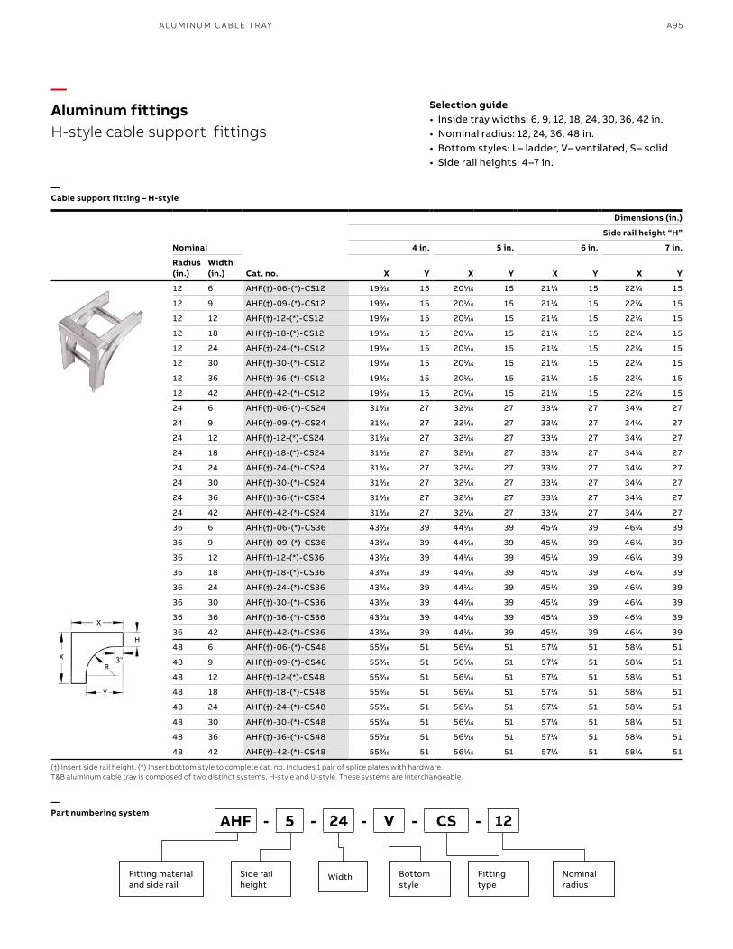
A95A LU M I N U M C A B L E TR AY
—Aluminum fittingsH-style cable support fittings
—Cable support fitting – H-style
(†) Insert side rail height. (*) Insert bottom style to complete cat. no. Includes 1 pair of splice plates with hardware.T&B aluminum cable tray is composed of two distinct systems, H-style and U-style. These systems are interchangeable.
—Part numbering system
Selection guide• Inside tray widths: 6, 9, 12, 18, 24, 30, 36, 42 in.• Nominal radius: 12, 24, 36, 48 in.• Bottom styles: L– ladder, V– ventilated, S– solid• Side rail heights: 4–7 in.
AHF - 5 - 24 - V - CS - 12
Fitting materialand side rail
Side rail height
Bottom style
Nominalradius
Width Fitting type
Nominal
Cat. no.
Dimensions (in.)
Side rail height “H”
4 in. 5 in. 6 in. 7 in.
Radius (in.)
Width (in.) X Y X Y X Y X Y
12 6 AHF(†)-06-(*)-CS12 1933⁄1616 15 2011⁄1616 15 2111⁄44 15 2211⁄44 15
12 9 AHF(†)-09-(*)-CS12 1933⁄1616 15 2011⁄1616 15 2111⁄44 15 2211⁄44 15
12 12 AHF(†)-12-(*)-CS12 1933⁄1616 15 2011⁄1616 15 2111⁄44 15 2211⁄44 15
12 18 AHF(†)-18-(*)-CS12 1933⁄1616 15 2011⁄1616 15 2111⁄44 15 2211⁄44 15
12 24 AHF(†)-24-(*)-CS12 1933⁄1616 15 2011⁄1616 15 2111⁄44 15 2211⁄44 15
12 30 AHF(†)-30-(*)-CS12 1933⁄1616 15 2011⁄1616 15 2111⁄44 15 2211⁄44 15
12 36 AHF(†)-36-(*)-CS12 1933⁄1616 15 2011⁄1616 15 2111⁄44 15 2211⁄44 15
12 42 AHF(†)-42-(*)-CS12 1933⁄1616 15 2011⁄1616 15 2111⁄44 15 2211⁄44 15
24 6 AHF(†)-06-(*)-CS24 3133⁄1616 27 3211⁄1616 27 3311⁄44 27 3411⁄44 27
24 9 AHF(†)-09-(*)-CS24 3133⁄1616 27 3211⁄1616 27 3311⁄44 27 3411⁄44 27
24 12 AHF(†)-12-(*)-CS24 3133⁄1616 27 3211⁄1616 27 3311⁄44 27 3411⁄44 27
24 18 AHF(†)-18-(*)-CS24 3133⁄1616 27 3211⁄1616 27 3311⁄44 27 3411⁄44 27
24 24 AHF(†)-24-(*)-CS24 3133⁄1616 27 3211⁄1616 27 3311⁄44 27 3411⁄44 27
24 30 AHF(†)-30-(*)-CS24 3133⁄1616 27 3211⁄1616 27 3311⁄44 27 3411⁄44 27
24 36 AHF(†)-36-(*)-CS24 3133⁄1616 27 3211⁄1616 27 3311⁄44 27 3411⁄44 27
24 42 AHF(†)-42-(*)-CS24 3133⁄1616 27 3211⁄1616 27 3311⁄44 27 3411⁄44 27
36 6 AHF(†)-06-(*)-CS36 4333⁄1616 39 4411⁄1616 39 4511⁄44 39 4611⁄44 39
36 9 AHF(†)-09-(*)-CS36 4333⁄1616 39 4411⁄1616 39 4511⁄44 39 4611⁄44 39
36 12 AHF(†)-12-(*)-CS36 4333⁄1616 39 4411⁄1616 39 4511⁄44 39 4611⁄44 39
36 18 AHF(†)-18-(*)-CS36 4333⁄1616 39 4411⁄1616 39 4511⁄44 39 4611⁄44 39
36 24 AHF(†)-24-(*)-CS36 4333⁄1616 39 4411⁄1616 39 4511⁄44 39 4611⁄44 39
36 30 AHF(†)-30-(*)-CS36 4333⁄1616 39 4411⁄1616 39 4511⁄44 39 4611⁄44 39
36 36 AHF(†)-36-(*)-CS36 4333⁄1616 39 4411⁄1616 39 4511⁄44 39 4611⁄44 39
36 42 AHF(†)-42-(*)-CS36 4333⁄1616 39 4411⁄1616 39 4511⁄44 39 4611⁄44 39
48 6 AHF(†)-06-(*)-CS48 5533⁄1616 51 5611⁄1616 51 5711⁄44 51 5811⁄44 51
48 9 AHF(†)-09-(*)-CS48 5533⁄1616 51 5611⁄1616 51 5711⁄44 51 5811⁄44 51
48 12 AHF(†)-12-(*)-CS48 5533⁄1616 51 5611⁄1616 51 5711⁄44 51 5811⁄44 51
48 18 AHF(†)-18-(*)-CS48 5533⁄1616 51 5611⁄1616 51 5711⁄44 51 5811⁄44 51
48 24 AHF(†)-24-(*)-CS48 5533⁄1616 51 5611⁄1616 51 5711⁄44 51 5811⁄44 51
48 30 AHF(†)-30-(*)-CS48 5533⁄1616 51 5611⁄1616 51 5711⁄44 51 5811⁄44 51
48 36 AHF(†)-36-(*)-CS48 5533⁄1616 51 5611⁄1616 51 5711⁄44 51 5811⁄44 51
48 42 AHF(†)-42-(*)-CS48 5533⁄1616 51 5611⁄1616 51 5711⁄44 51 5811⁄44 51
Y
3"
X
X
H
R
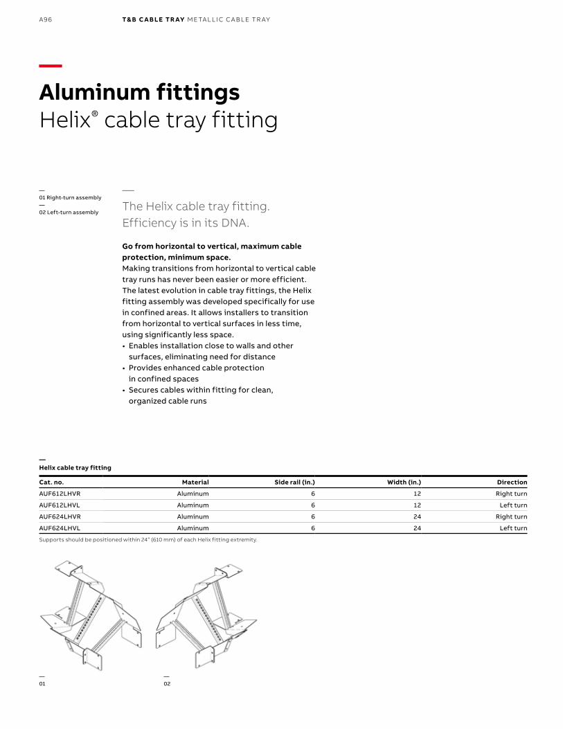
B1 copy starts here
B2 copy starts here
B3 copy starts here
A96 T& B C A B LE TR AY M E TA L L I C C A B L E TR AY
—The Helix cable tray fitting. Efficiency is in its DNA.
Go from horizontal to vertical, maximum cable protection, minimum space.Making transitions from horizontal to vertical cable tray runs has never been easier or more efficient. The latest evolution in cable tray fittings, the Helix
fitting assembly was developed specifically for use in confined areas. It allows installers to transition from horizontal to vertical surfaces in less time, using significantly less space. • Enables installation close to walls and other
surfaces, eliminating need for distance• Provides enhanced cable protection
in confined spaces• Secures cables within fitting for clean,
organized cable runs
—Aluminum fittingsHelix® cable tray fitting
—01 Right-turn assembly—02 Left-turn assembly
Cat. no. Material Side rail (in.) Width (in.) Direction
AUF612LHVR Aluminum 6 12 Right turn
AUF612LHVL Aluminum 6 12 Left turn
AUF624LHVR Aluminum 6 24 Right turn
AUF624LHVL Aluminum 6 24 Left turn
Supports should be positioned within 24” (610 mm) of each Helix fitting extremity.
—Helix cable tray fitting
—01
—02
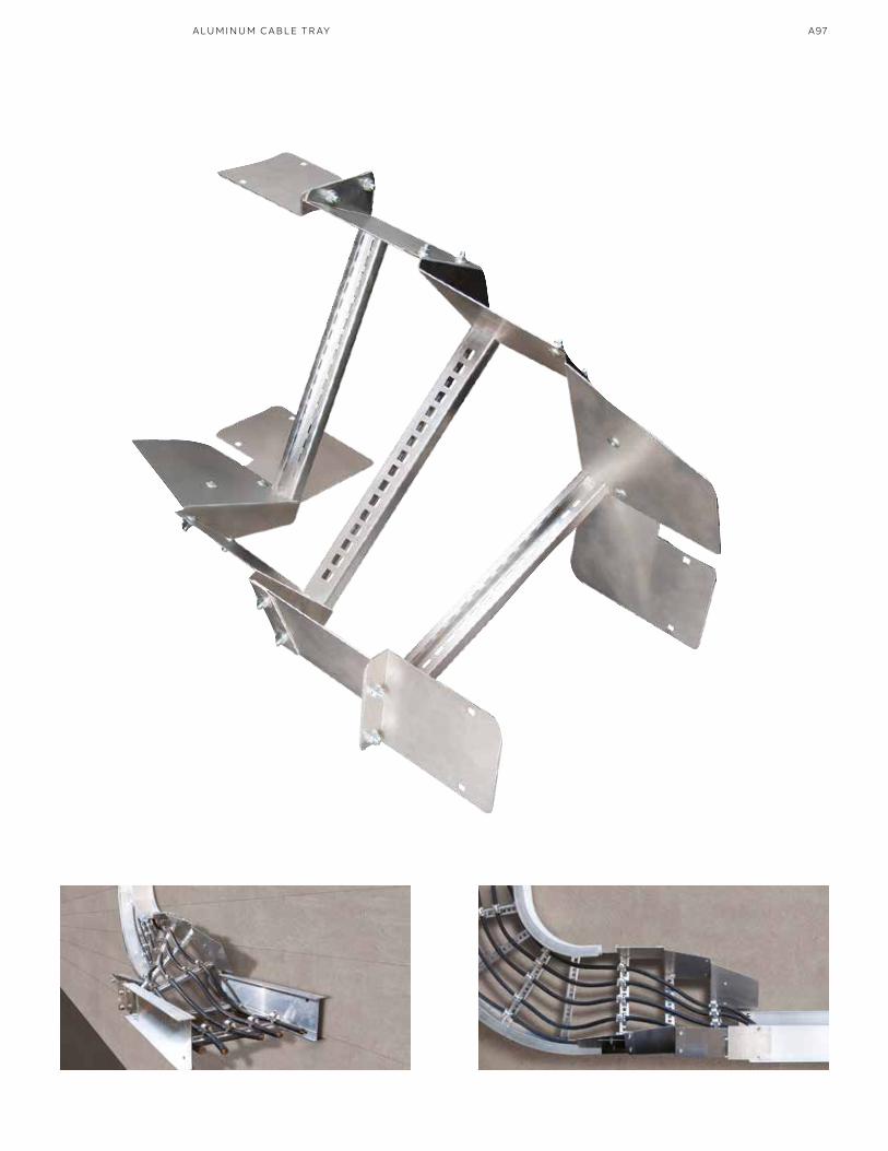
A97A LU M I N U M C A B L E TR AY
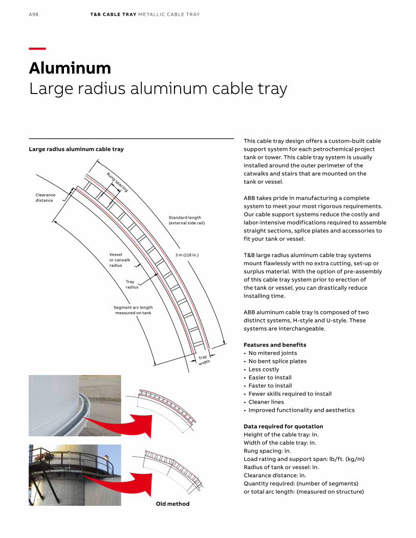
B1 copy starts here
B2 copy starts here
B3 copy starts here
A98 T& B C A B LE TR AY M E TA L L I C C A B L E TR AY
This cable tray design offers a custom-built cable support system for each petrochemical project tank or tower. This cable tray system is usually installed around the outer perimeter of the catwalks and stairs that are mounted on the tank or vessel.
ABB takes pride in manufacturing a complete system to meet your most rigorous requirements. Our cable support systems reduce the costly and labor-intensive modifications required to assemble straight sections, splice plates and accessories to fit your tank or vessel.
T&B large radius aluminum cable tray systems mount flawlessly with no extra cutting, set-up or surplus material. With the option of pre-assembly of this cable tray system prior to erection of the tank or vessel, you can drastically reduce installing time.
ABB aluminum cable tray is composed of two distinct systems, H-style and U-style. These systems are interchangeable.
Features and benefits• No mitered joints• No bent splice plates• Less costly • Easier to install• Faster to install• Fewer skills required to install• Cleaner lines• Improved functionality and aesthetics
Data required for quotationHeight of the cable tray: in.Width of the cable tray: in.Rung spacing: in.Load rating and support span: lb/ft. (kg/m)Radius of tank or vessel: in.Clearance distance: in.Quantity required: (number of segments)or total arc length: (measured on structure)
—AluminumLarge radius aluminum cable tray
Large radius aluminum cable tray
Rung spacing
Vesselor catwalkradius
Trayradius
Segment arc lengthmeasured on tank
Tray
width
Clearancedistance
Standard length(external side rail)
3 m (118 in.)
Old method
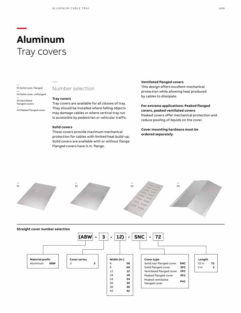
A99
—Number selection
Tray coversTray covers are available for all classes of tray. They should be installed where falling objects may damage cables or where vertical tray run is accessible by pedestrian or vehicular traffic.
Solid coversThese covers provide maximum mechanical protection for cables with limited heat build-up. Solid covers are available with or without flange.Flanged covers have 11⁄22 in. flange.
Ventilated flanged coversThis design offers excellent mechanical protection while allowing heat produced by cables to dissipate.
For extreme applications: Peaked flanged covers, peaked ventilated covers Peaked covers offer mechanical protection and reduce pooling of liquids on the cover.
Cover mounting hardware must be ordered separately.
—01
—02
—03
—03
—01 Solid cover, flanged—02 Solid cover, unflanged—03 Ventilated flanged covers—04 Peaked flanged cover
Material prefixAluminum ABW
Cover series3 3
Width (in.)6 069 0912 1218 1824 2430 3036 3642 42
Cover typeSolid non-flanged cover SNCSolid flanged cover SFCVentilated flanged cover VFCPeaked flanged cover PFCPeaked ventilated flanged cover
PVC
Length72 in. 723 m 3
(ABW - 3 - 12) - SNC - 72
Straight cover number selection
—AluminumTray covers
A LU M I N U M C A B L E TR AY
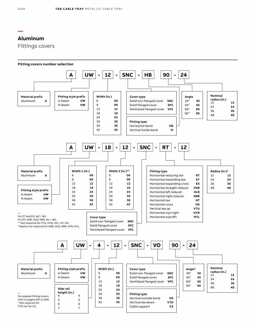
B1 copy starts here
B2 copy starts here
B3 copy starts here
A100 T& B C A B LE TR AY M E TA L L I C C A B L E TR AY
—AluminumFittings covers
Fitting covers number selection
Material prefixAluminum A
Material prefixAluminum A
Material prefixAluminum A
Fitting style prefixU-beam UWH-beam HW
Fitting style prefixU-beam UWH-beam HW
Side rail height (in.)4 45 56 67 7
Fitting style prefixU-beam UWH-beam HW
Width (in.)6 069 0912 1218 1824 2430 3036 3642 42
Width (in.)6 069 0912 1218 1824 2430 3036 3642 42
Width 2 (in.)**6 069 0912 1218 1824 2430 3036 3642 42
Width 1 (in.)6 069 0912 1218 1824 2430 3036 3642 42
Cover typeSolid non-flanged cover SNCSolid flanged cover SFCVentilated flanged cover VFC
Cover typeSolid non-flanged cover SNCSolid flanged cover SFCVentilated flanged cover VFC
Cover typeSolid non-flanged cover SNCSolid flanged cover SFCVentilated flanged cover VFC
Fitting typeHorizontal bend HBVertical inside bend VI
Fitting typeVertical outside bend VOVertical tee down VTDCable support CS
Fitting typeHorizontal reducing tee RTHorizontal expanding tee ETHorizontal expanding cross EXHorizontal straight reducer HSRHorizontal left reducer HLRHorizontal right reducer HRRHorizontal tee HTHorizontal cross HXVertical tee up VTUHorizontal wye right HYRHorizontal wye left HYL
Nominal radius (in.)12 1224 2436 3648 48
Nominal radius (in.)12 1224 2436 3648 48
Radius (in.)*12 1224 2436 3648 48
Angle30° 3045° 4560° 6090° 90
Angle*30° 3045° 4560° 6090° 90
A UW - 12 - SNC - HB 90 - 24
A UW - 4 - 12 - SNC - VO 90 - 24
A UW - 18 - 12 - SNC - RT - 12
—For ET and EX, W2 > W1. For RT, HSR, HLR, HRR, W1 > W2.** Not required for VTU, HYR, HYL, HT, HX.* Radius not required for HSR, HLR, HRR, HYR, HYL.
—For peaked fitting covers refer to pages A97 to A99* Not required for VTD nor for CS.
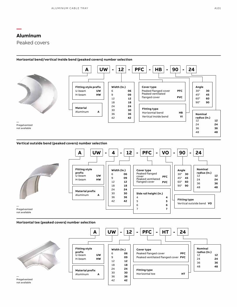
A101
—AluminumPeaked covers
Horizontal bend/vertical inside bend (peaked covers) number selection
Vertical outside bend (peaked covers) number selection
Horizontal tee (peaked covers) number selection
MaterialAluminum A
Material prefixAluminum A
Material prefixAluminum A
Fitting style prefixU-beam UWH-beam HW
Fitting style prefixU-beam UWH-beam HW
Fitting style prefixU-beam UWH-beam HW
Width (in.)6 069 0912 1218 1824 2430 3036 3642 42
Width (in.)6 069 0912 1218 1824 2430 3036 3642 42
Width (in.)6 069 0912 1218 1824 2430 3036 3642 42
Cover typePeaked flanged cover PFCPeaked ventilated flanged cover PVC
Cover typePeaked flanged cover PFCPeaked ventilated flanged cover PVC
Cover typePeaked flanged cover PFCPeaked ventilated flanged cover PVC
Fitting typeHorizontal bend HBVertical inside bend VI
Fitting typeVertical outside bend VO
Fitting typeHorizontal tee HT
Side rail height (in.)4 45 56 67 7
Nominal radius (in.)12 1224 2436 3648 48
Nominal radius (in.)12 1224 2436 3648 48
Nominal radius (in.)12 1224 2436 3648 48
Angle30° 3045° 4560° 6090° 90
Angle30° 3045° 4560° 6090° 90
A UW - 12 - PFC - HB - 90 - 24
A UW - 4 - 12 - PFC - VO - 90 - 24
A UW - 12 - PFC - HT - 24
—Pregalvanized not available
—Pregalvanized not available
—Pregalvanized not available
A LU M I N U M C A B L E TR AY
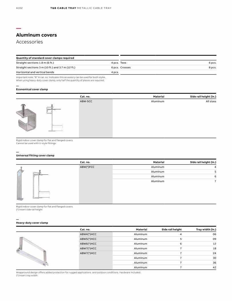
B1 copy starts here
B2 copy starts here
B3 copy starts here
A102 T& B C A B LE TR AY M E TA L L I C C A B L E TR AY
Cat. no. Material Side rail height Tray width (in.)
ABW4(*)HCC Aluminum 4 06
ABW5(*)HCC Aluminum 5 09
ABW6(*)HCC Aluminum 6 12
ABW7(*)HCC Aluminum 7 18
ABW7(*)HCC Aluminum 7 24
Aluminum 7 30
Aluminum 7 36
Aluminum 7 42
—Aluminum coversAccessories
Quantity of standard cover clamps required
Straight sections 1.8 m (6 ft.) 4 pcs. Tees 6 pcs.
Straight sections 3 m (10 ft.) and 3.7 m (12 ft.) 6 pcs. Crosses 8 pcs.
Horizontal and vertical bends 4 pcs.
Important note: “B” in cat. no. indicates this accessory can be used for both styles.When using heavy-duty cover clamp, only half the quantity of pieces are required.
Rigid indoor cover clamp for flat and flanged covers.Cannot be used with U-style fittings.
Rigid indoor cover clamp for flat and flanged covers.(*) Insert side rail height
Wraparound design offers added protection for rugged applications and outdoor conditions. Hardware included.(*) Insert tray width
—Economical cover clamp
—Universal fitting cover clamp
—Heavy-duty cover clamp
Cat. no. Material Side rail height (in.)
ABW-SCC Aluminum All sizes
Cat. no. Material Side rail height (in.)
ABW(*)FCC Aluminum 4
Aluminum 5
Aluminum 6
Aluminum 7
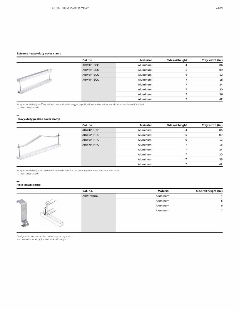
A103
Wraparound design offers added protection for rugged applications and outdoor conditions. Hardware included.(*) Insert tray width
Wraparound design formed to fit peaked cover for outdoor applications. Hardware included.(*) Insert tray width
Designed to secure cable tray to support system.Hardware included, (*) Insert side rail height
—Extreme heavy-duty cover clamp
—Heavy-duty peaked cover clamp
—Hold-down clamp
Cat. no. Material Side rail height (in.)
ABW(*)HDC Aluminum 4
Aluminum 5
Aluminum 6
Aluminum 7
Cat. no. Material Side rail height Tray width (in.)
ABW4(*)ECC Aluminum 4 06
ABW5(*)ECC Aluminum 5 09
ABW6(*)ECC Aluminum 6 12
ABW7(*)ECC Aluminum 7 18
Aluminum 7 24
Aluminum 7 30
Aluminum 7 36
Aluminum 7 42
Cat. no. Material Side rail height Tray width (in.)
ABW4(*)HPC Aluminum 4 06
ABW5(*)HPC Aluminum 5 09
ABW6(*)HPC Aluminum 6 12
ABW7(*)HPC Aluminum 7 18
Aluminum 7 24
Aluminum 7 30
Aluminum 7 36
Aluminum 7 42
A LU M I N U M C A B L E TR AY
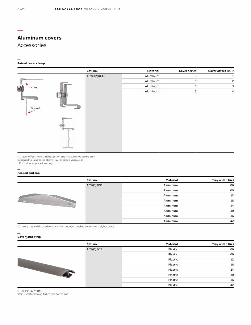
B1 copy starts here
B2 copy starts here
B3 copy starts here
A104 T& B C A B LE TR AY M E TA L L I C C A B L E TR AY
Cat. no. Material Tray width (in.)
ABW(*)PCS Plastic 06
Plastic 09
Plastic 12
Plastic 18
Plastic 24
Plastic 30
Plastic 36
Plastic 42
—Aluminum coversAccessories
—Raised cover clamp
—Peaked end cap
—Cover joint strip
(*) Cover offset. For straight section and PFC and SFC covers only.Designed to raise cover above tray for added ventilation.† For indoor applications only.
(*) Insert tray width. Used for transition between peaked covers to straight covers.
(*) Insert tray width. Strip used for joining flat covers end to end.
Cat. no. Material Cover series Cover offset (in.)*
ABW3(*)RCC† Aluminum 3 1
Aluminum 3 2
Aluminum 3 3
Aluminum 3 4
Side rail
Cover
Cat. no. Material Tray width (in.)
ABW(*)PEC Aluminum 06
Aluminum 09
Aluminum 12
Aluminum 18
Aluminum 24
Aluminum 30
Aluminum 36
Aluminum 42
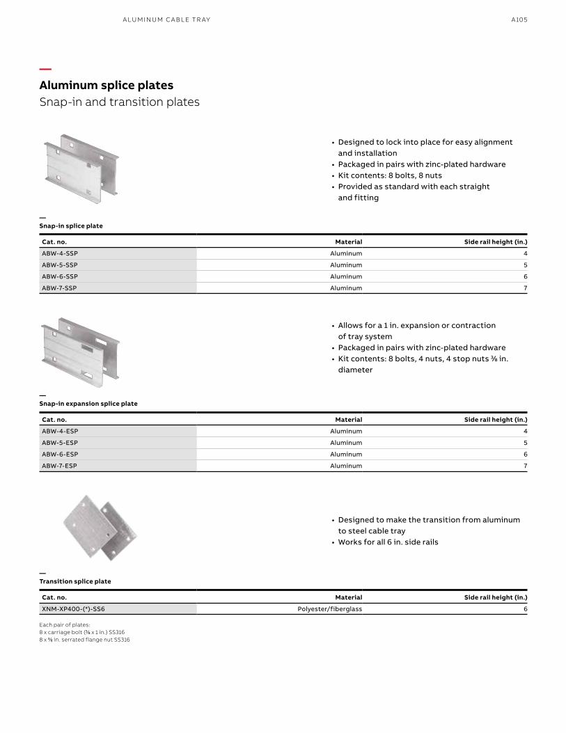
A105
—Snap-in splice plate
—Snap-in expansion splice plate
—Transition splice plate
Each pair of plates:8 x carriage bolt (33⁄88 x 1 in.) SS316 8 x 33⁄88 in. serrated flange nut SS316
—Aluminum splice platesSnap-in and transition plates
• Designed to lock into place for easy alignment and installation
• Packaged in pairs with zinc-plated hardware • Kit contents: 8 bolts, 8 nuts• Provided as standard with each straight
and fitting
• Allows for a 1 in. expansion or contraction of tray system
• Packaged in pairs with zinc-plated hardware • Kit contents: 8 bolts, 4 nuts, 4 stop nuts 33⁄88 in.
diameter
• Designed to make the transition from aluminum to steel cable tray
• Works for all 6 in. side rails
Cat. no. Material Side rail height (in.)
ABW-4-SSP Aluminum 4
ABW-5-SSP Aluminum 5
ABW-6-SSP Aluminum 6
ABW-7-SSP Aluminum 7
Cat. no. Material Side rail height (in.)
ABW-4-ESP Aluminum 4
ABW-5-ESP Aluminum 5
ABW-6-ESP Aluminum 6
ABW-7-ESP Aluminum 7
Cat. no. Material Side rail height (in.)
XNM-XP400-(*)-SS6 Polyester/fiberglass 6
A LU M I N U M C A B L E TR AY
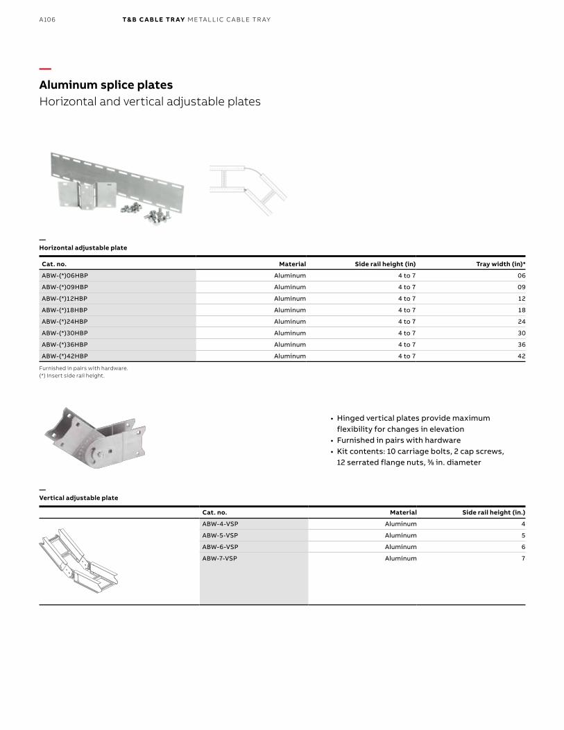
B1 copy starts here
B2 copy starts here
B3 copy starts here
A106 T& B C A B LE TR AY M E TA L L I C C A B L E TR AY
Cat. no. Material Side rail height (in.)
ABW-4-VSP Aluminum 4
ABW-5-VSP Aluminum 5
ABW-6-VSP Aluminum 6
ABW-7-VSP Aluminum 7
• Hinged vertical plates provide maximum flexibility for changes in elevation
• Furnished in pairs with hardware • Kit contents: 10 carriage bolts, 2 cap screws,
12 serrated flange nuts, 33⁄88 in. diameter
—Aluminum splice platesHorizontal and vertical adjustable plates
—Horizontal adjustable plate
—Vertical adjustable plate
Furnished in pairs with hardware.(*) Insert side rail height.
Cat. no. Material Side rail height (in) Tray width (in)*
ABW-(*)06HBP Aluminum 4 to 7 06
ABW-(*)09HBP Aluminum 4 to 7 09
ABW-(*)12HBP Aluminum 4 to 7 12
ABW-(*)18HBP Aluminum 4 to 7 18
ABW-(*)24HBP Aluminum 4 to 7 24
ABW-(*)30HBP Aluminum 4 to 7 30
ABW-(*)36HBP Aluminum 4 to 7 36
ABW-(*)42HBP Aluminum 4 to 7 42
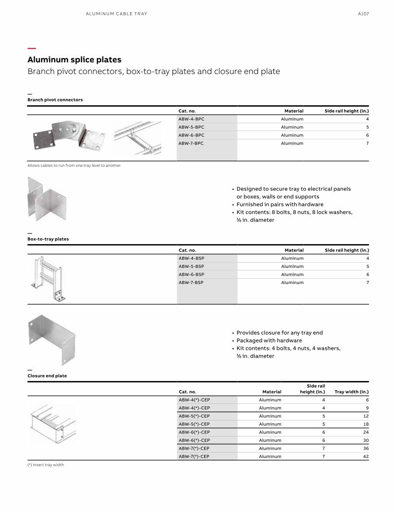
A107
• Designed to secure tray to electrical panels or boxes, walls or end supports
• Furnished in pairs with hardware • Kit contents: 8 bolts, 8 nuts, 8 lock washers,
33⁄88 in. diameter
—Branch pivot connectors
—Box-to-tray plates
—Closure end plate
Cat. no. Material Side rail height (in.)
ABW-4-BPC Aluminum 4
ABW-5-BPC Aluminum 5
ABW-6-BPC Aluminum 6
ABW-7-BPC Aluminum 7
Cat. no. MaterialSide rail
height (in.) Tray width (in.)
ABW-4(*)-CEP Aluminum 4 6
ABW-4(*)-CEP Aluminum 4 9
ABW-5(*)-CEP Aluminum 5 12
ABW-5(*)-CEP Aluminum 5 18
ABW-6(*)-CEP Aluminum 6 24
ABW-6(*)-CEP Aluminum 6 30
ABW-7(*)-CEP Aluminum 7 36
ABW-7(*)-CEP Aluminum 7 42
• Provides closure for any tray end • Packaged with hardware • Kit contents: 4 bolts, 4 nuts, 4 washers,
33⁄88 in. diameter
—Aluminum splice platesBranch pivot connectors, box-to-tray plates and closure end plate
Allows cables to run from one tray level to another.
(*) Insert tray width
Cat. no. Material Side rail height (in.)
ABW-4-BSP Aluminum 4
ABW-5-BSP Aluminum 5
ABW-6-BSP Aluminum 6
ABW-7-BSP Aluminum 7
A LU M I N U M C A B L E TR AY
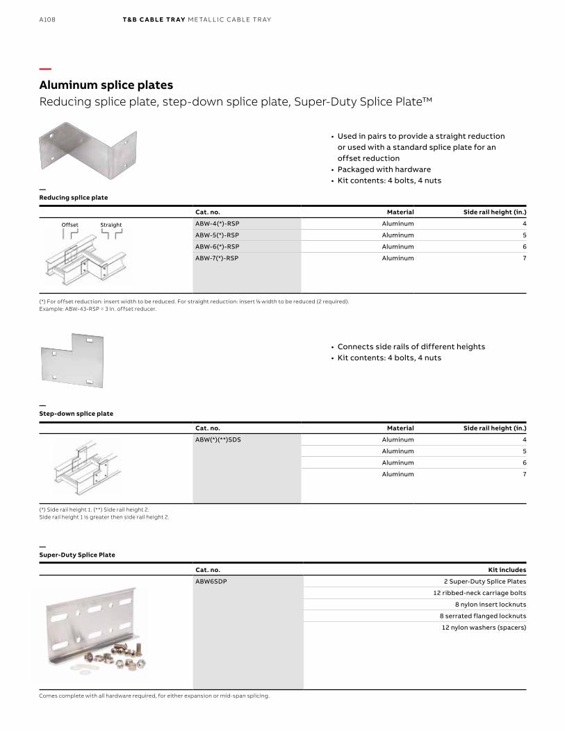
B1 copy starts here
B2 copy starts here
B3 copy starts here
A108 T& B C A B LE TR AY M E TA L L I C C A B L E TR AY
StraightOffset
—Aluminum splice platesReducing splice plate, step-down splice plate, Super-Duty Splice Plate™
—Reducing splice plate
—Step-down splice plate
• Used in pairs to provide a straight reduction or used with a standard splice plate for an offset reduction
• Packaged with hardware • Kit contents: 4 bolts, 4 nuts
• Connects side rails of different heights • Kit contents: 4 bolts, 4 nuts
Cat. no. Material Side rail height (in.)
ABW-4(*)-RSP Aluminum 4
ABW-5(*)-RSP Aluminum 5
ABW-6(*)-RSP Aluminum 6
ABW-7(*)-RSP Aluminum 7
(*) For offset reduction: insert width to be reduced. For straight reduction: insert 11⁄22 width to be reduced (2 required). Example: ABW-43-RSP = 3 in. offset reducer.
(*) Side rail height 1. (**) Side rail height 2. Side rail height 1 is greater then side rail height 2.
Cat. no. Material Side rail height (in.)
ABW(*)(**)SDS Aluminum 4
Aluminum 5
Aluminum 6
Aluminum 7
Cat. no. Kit includes
ABW6SDP 2 Super-Duty Splice Plates
12 ribbed-neck carriage bolts
8 nylon insert locknuts
8 serrated flanged locknuts
12 nylon washers (spacers)
Comes complete with all hardware required, for either expansion or mid-span splicing.
—Super-Duty Splice Plate
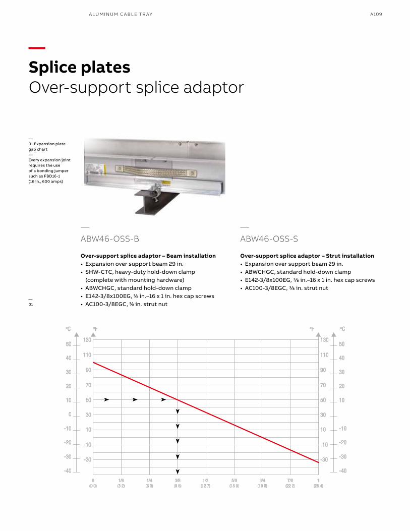
A109A LU M I N U M C A B L E TR AY
—ABW46-OSS-B
Over-support splice adaptor – Beam installation• Expansion over support beam 29 in.• SHW-CTC, heavy-duty hold-down clamp
(complete with mounting hardware)• ABWCHGC, standard hold-down clamp• E142-3/8x100EG, 33⁄88 in.–16 x 1 in. hex cap screws• AC100-3/8EGC, 33⁄88 in. strut nut
—Splice platesOver-support splice adaptor
—01 Expansion plate gap chart—Every expansion joint requires the use of a bonding jumper such as FBD16-1 (16 in., 600 amps)
—01
—ABW46-OSS-S
Over-support splice adaptor – Strut installation• Expansion over support beam 29 in.• ABWCHGC, standard hold-down clamp• E142-3/8x100EG, 3/8 in.–16 x 1 in. hex cap screws• AC100-3/8EGC, 3/8 in. strut nut
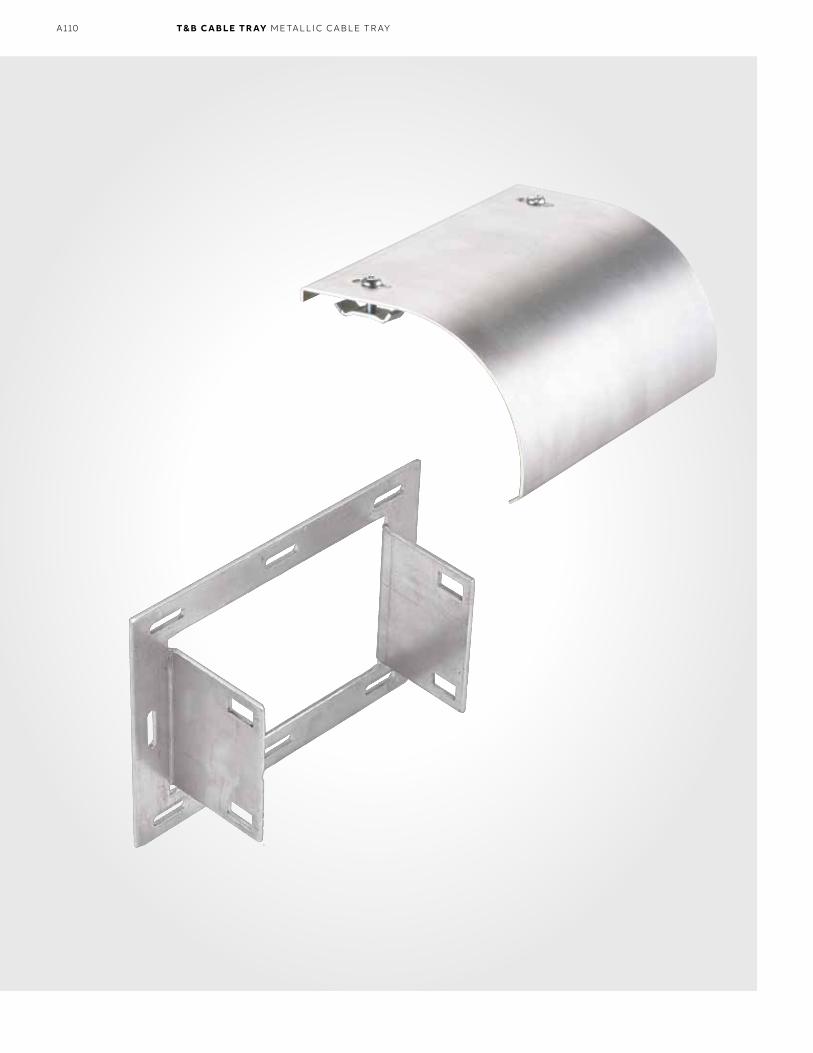
B1 copy starts here
B2 copy starts here
B3 copy starts here
A110 T& B C A B LE TR AY M E TA L L I C C A B L E TR AY
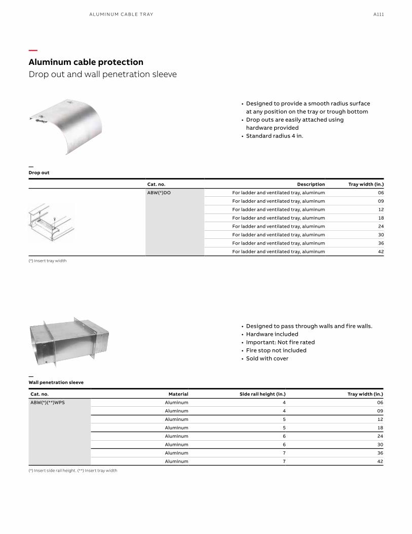
A111A LU M I N U M C A B L E TR AY
• Designed to provide a smooth radius surface at any position on the tray or trough bottom
• Drop outs are easily attached using hardware provided
• Standard radius 4 in.
• Designed to pass through walls and fire walls. • Hardware included • Important: Not fire rated • Fire stop not included• Sold with cover
—Aluminum cable protectionDrop out and wall penetration sleeve
—Drop out
—Wall penetration sleeve
Cat. no. Description Tray width (in.)
ABW(*)DO For ladder and ventilated tray, aluminum 06
For ladder and ventilated tray, aluminum 09
For ladder and ventilated tray, aluminum 12
For ladder and ventilated tray, aluminum 18
For ladder and ventilated tray, aluminum 24
For ladder and ventilated tray, aluminum 30
For ladder and ventilated tray, aluminum 36
For ladder and ventilated tray, aluminum 42
(*) Insert tray width
(*) Insert side rail height. (**) Insert tray width
Cat. no. Material Side rail height (in.) Tray width (in.)
ABW(*)(**)WPS Aluminum 4 06
Aluminum 4 09
Aluminum 5 12
Aluminum 5 18
Aluminum 6 24
Aluminum 6 30
Aluminum 7 36
Aluminum 7 42
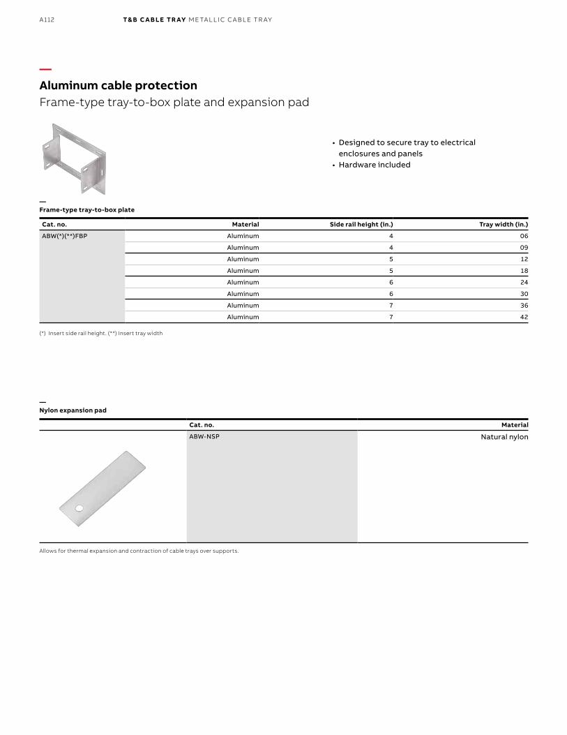
B1 copy starts here
B2 copy starts here
B3 copy starts here
A112 T& B C A B LE TR AY M E TA L L I C C A B L E TR AY
Cat. no. Material
ABW-NSP Natural nylon
—Frame-type tray-to-box plate
—Nylon expansion pad
—Aluminum cable protectionFrame-type tray-to-box plate and expansion pad
• Designed to secure tray to electrical enclosures and panels
• Hardware included
Allows for thermal expansion and contraction of cable trays over supports.
Cat. no. Material Side rail height (in.) Tray width (in.)
ABW(*)(**)FBP Aluminum 4 06
Aluminum 4 09
Aluminum 5 12
Aluminum 5 18
Aluminum 6 24
Aluminum 6 30
Aluminum 7 36
Aluminum 7 42
(*) Insert side rail height. (**) Insert tray width
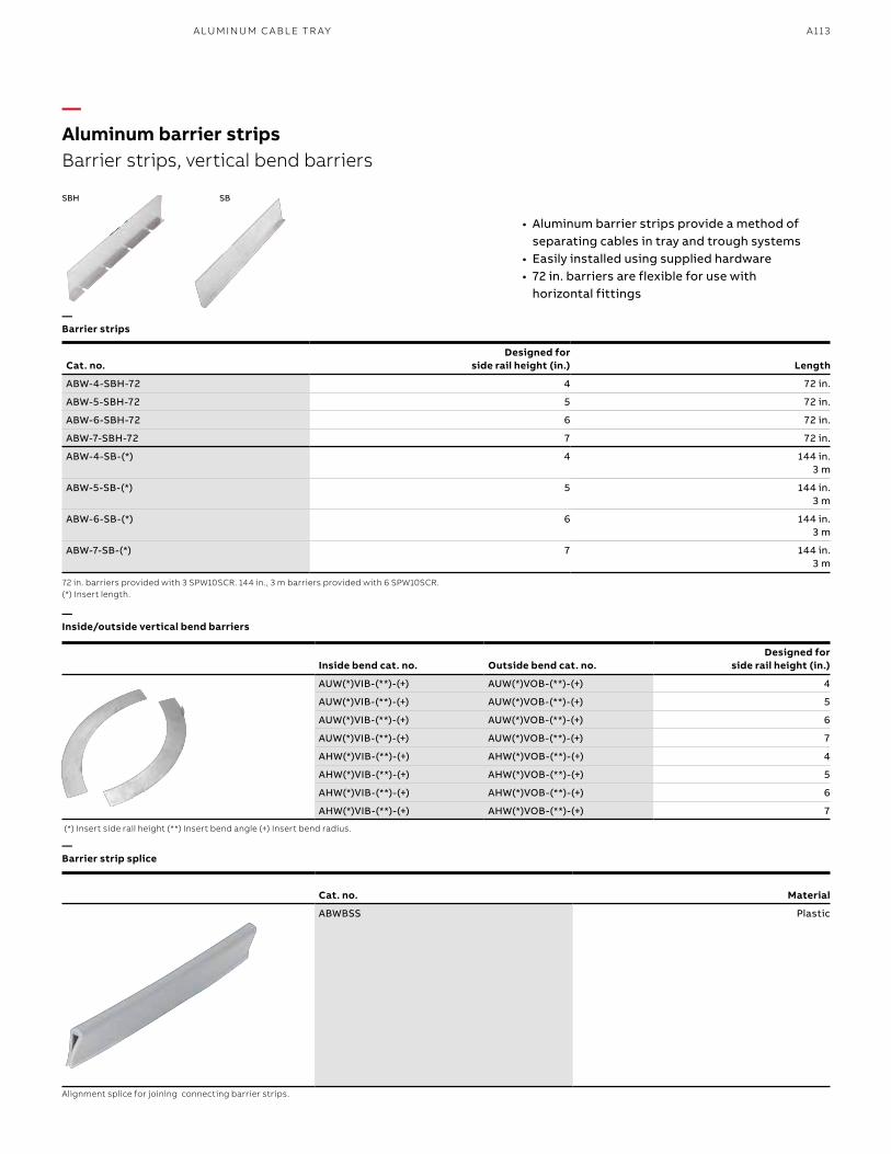
A113A LU M I N U M C A B L E TR AY
—Barrier strips
—Inside/outside vertical bend barriers
—Barrier strip splice
—Aluminum barrier stripsBarrier strips, vertical bend barriers
• Aluminum barrier strips provide a method of separating cables in tray and trough systems
• Easily installed using supplied hardware • 72 in. barriers are flexible for use with
horizontal fittings
72 in. barriers provided with 3 SPW10SCR. 144 in., 3 m barriers provided with 6 SPW10SCR. (*) Insert length.
(*) Insert side rail height (**) Insert bend angle (+) Insert bend radius.
Alignment splice for joining connecting barrier strips.
Cat. no. Material
ABWBSS Plastic
SBH SB
Cat. no.Designed for
side rail height (in.) Length
ABW-4-SBH-72 4 72 in.
ABW-5-SBH-72 5 72 in.
ABW-6-SBH-72 6 72 in.
ABW-7-SBH-72 7 72 in.
ABW-4-SB-(*) 4 144 in.3 m
ABW-5-SB-(*) 5 144 in.3 m
ABW-6-SB-(*) 6 144 in.3 m
ABW-7-SB-(*) 7 144 in.3 m
Inside bend cat. no. Outside bend cat. no.Designed for
side rail height (in.)
AUW(*)VIB-(**)-(+) AUW(*)VOB-(**)-(+) 4
AUW(*)VIB-(**)-(+) AUW(*)VOB-(**)-(+) 5
AUW(*)VIB-(**)-(+) AUW(*)VOB-(**)-(+) 6
AUW(*)VIB-(**)-(+) AUW(*)VOB-(**)-(+) 7
AHW(*)VIB-(**)-(+) AHW(*)VOB-(**)-(+) 4
AHW(*)VIB-(**)-(+) AHW(*)VOB-(**)-(+) 5
AHW(*)VIB-(**)-(+) AHW(*)VOB-(**)-(+) 6
AHW(*)VIB-(**)-(+) AHW(*)VOB-(**)-(+) 7
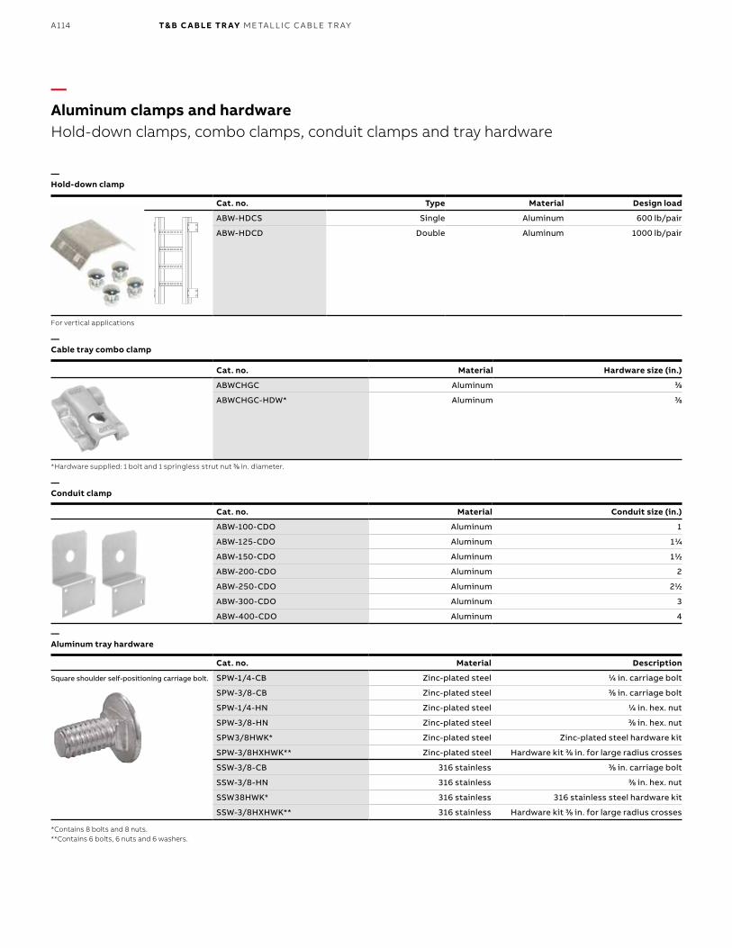
B1 copy starts here
B2 copy starts here
B3 copy starts here
A114 T& B C A B LE TR AY M E TA L L I C C A B L E TR AY
—Hold-down clamp
—Cable tray combo clamp
—Conduit clamp
—Aluminum tray hardware
—Aluminum clamps and hardwareHold-down clamps, combo clamps, conduit clamps and tray hardware
For vertical applications
*Hardware supplied: 1 bolt and 1 springless strut nut 33⁄88 in. diameter.
*Contains 8 bolts and 8 nuts. **Contains 6 bolts, 6 nuts and 6 washers.
Cat. no. Type Material Design load
ABW-HDCS Single Aluminum 600 lb/pair
ABW-HDCD Double Aluminum 1000 lb/pair
Cat. no. Material Hardware size (in.)
ABWCHGC Aluminum 33⁄88
ABWCHGC-HDW* Aluminum 33⁄88
Cat. no. Material Conduit size (in.)
ABW-100-CDO Aluminum 1
ABW-125-CDO Aluminum 111⁄44
ABW-150-CDO Aluminum 111⁄22
ABW-200-CDO Aluminum 2
ABW-250-CDO Aluminum 211⁄22
ABW-300-CDO Aluminum 3
ABW-400-CDO Aluminum 4
Cat. no. Material Description
SPW-1/4-CB Zinc-plated steel 11⁄44 in. carriage bolt
SPW-3/8-CB Zinc-plated steel 33⁄88 in. carriage bolt
SPW-1/4-HN Zinc-plated steel 11⁄44 in. hex. nut
SPW-3/8-HN Zinc-plated steel 33⁄88 in. hex. nut
SPW3/8HWK* Zinc-plated steel Zinc-plated steel hardware kit
SPW-3/8HXHWK** Zinc-plated steel Hardware kit 33⁄88 in. for large radius crosses
SSW-3/8-CB 316 stainless 33⁄88 in. carriage bolt
SSW-3/8-HN 316 stainless 33⁄88 in. hex. nut
SSW38HWK* 316 stainless 316 stainless steel hardware kit
SSW-3/8HXHWK** 316 stainless Hardware kit 33⁄88 in. for large radius crosses
Square shoulder self-positioning carriage bolt.
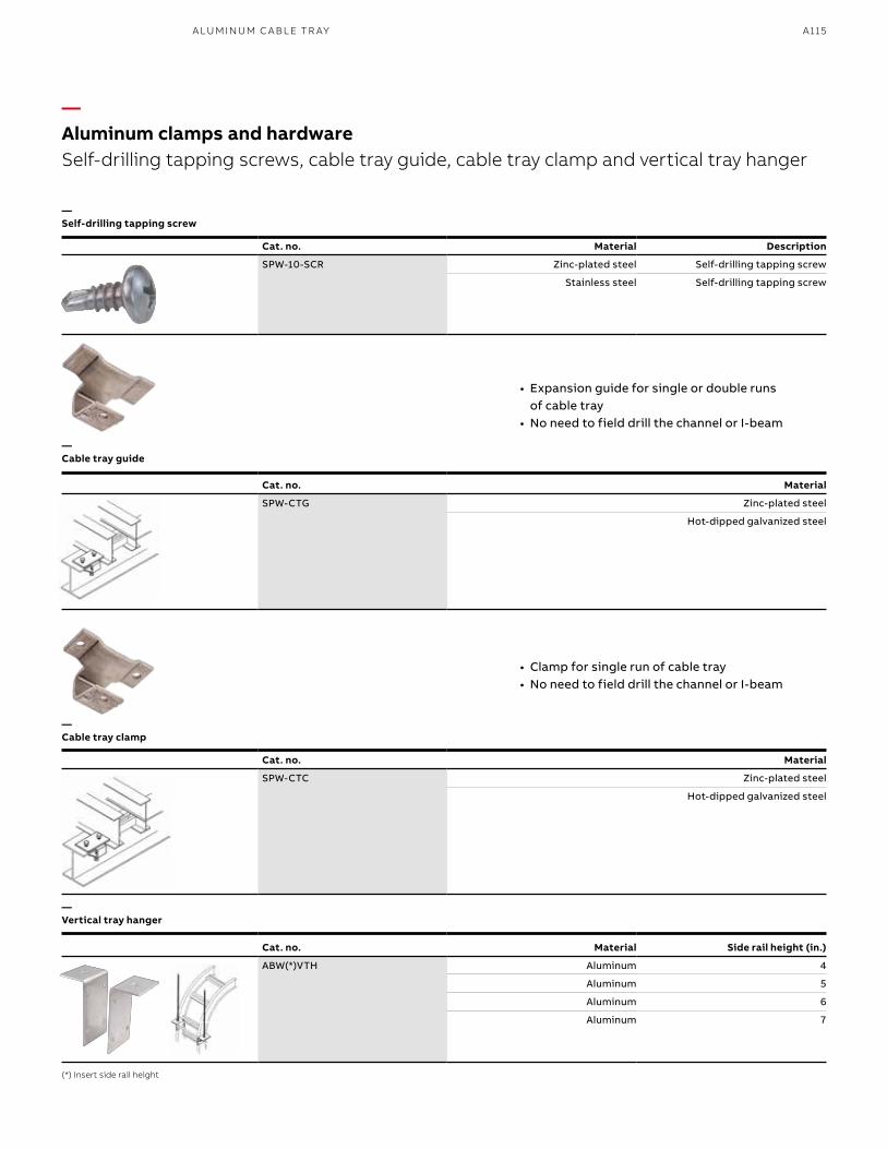
A115A LU M I N U M C A B L E TR AY
Cat. no. Material Description
SPW-10-SCR Zinc-plated steel Self-drilling tapping screw
Stainless steel Self-drilling tapping screw
—Self-drilling tapping screw
—Cable tray guide
—Cable tray clamp
—Vertical tray hanger
—Aluminum clamps and hardwareSelf-drilling tapping screws, cable tray guide, cable tray clamp and vertical tray hanger
(*) Insert side rail height
Cat. no. Material Side rail height (in.)
ABW(*)VTH Aluminum 4
Aluminum 5
Aluminum 6
Aluminum 7
• Expansion guide for single or double runs of cable tray
• No need to field drill the channel or I-beam
• Clamp for single run of cable tray• No need to field drill the channel or I-beam
Cat. no. Material
SPW-CTG Zinc-plated steel
Hot-dipped galvanized steel
Cat. no. Material
SPW-CTC Zinc-plated steel
Hot-dipped galvanized steel
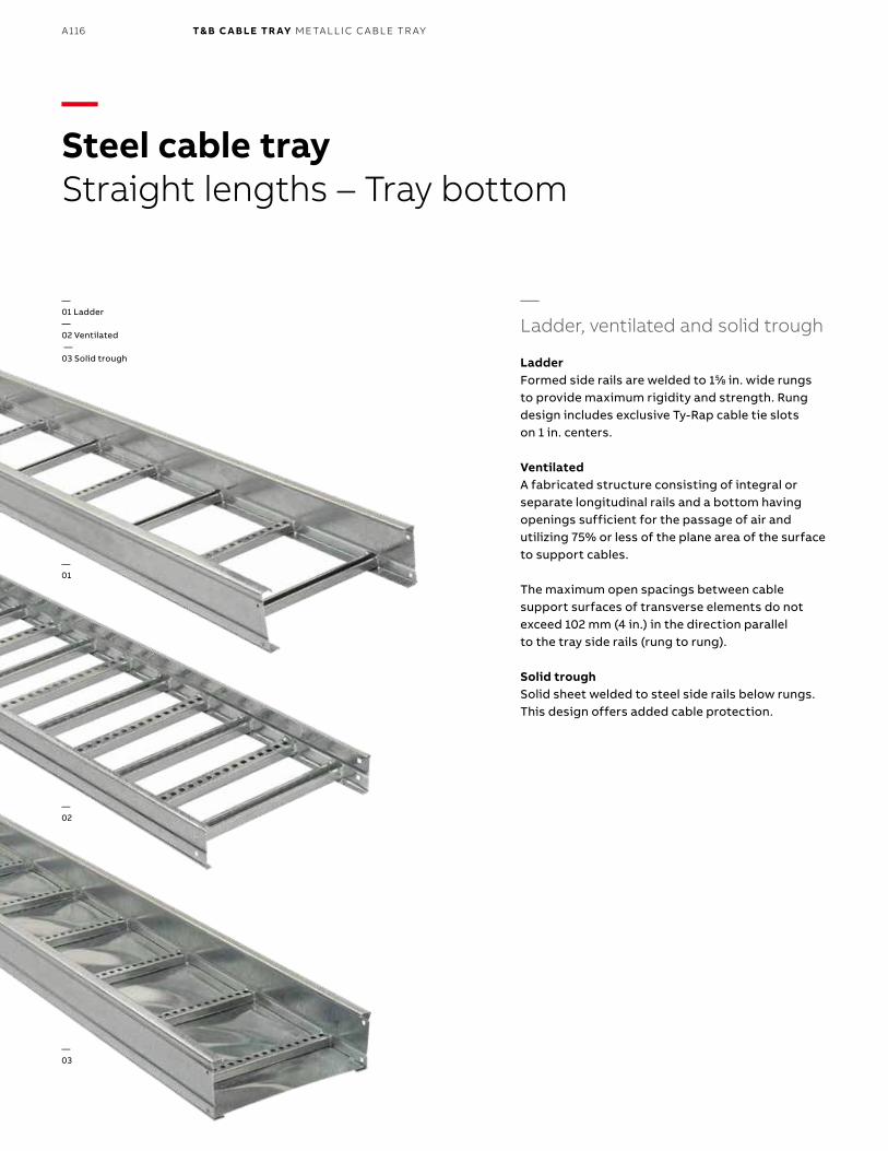
B1 copy starts here
B2 copy starts here
B3 copy starts here
A116 T& B C A B LE TR AY M E TA L L I C C A B L E TR AY
—Steel cable trayStraight lengths – Tray bottom
—Ladder, ventilated and solid trough
LadderFormed side rails are welded to 155⁄88 in. wide rungs to provide maximum rigidity and strength. Rung design includes exclusive Ty-Rap cable tie slots on 1 in. centers.
VentilatedA fabricated structure consisting of integral or separate longitudinal rails and a bottom having openings sufficient for the passage of air and utilizing 75% or less of the plane area of the surface to support cables.
The maximum open spacings between cable support surfaces of transverse elements do not exceed 102 mm (4 in.) in the direction parallel to the tray side rails (rung to rung).
Solid troughSolid sheet welded to steel side rails below rungs. This design offers added cable protection.
—01 Ladder—02 Ventilated —03 Solid trough
—01
—02
—03
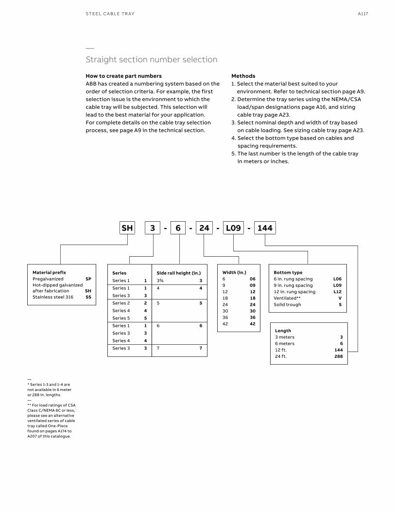
A117S TEEL C A B L E TR AY
—Straight section number selection
How to create part numbersABB has created a numbering system based on the order of selection criteria. For example, the first selection issue is the environment to which the cable tray will be subjected. This selection will lead to the best material for your application. For complete details on the cable tray selection process, see page A9 in the technical section.
Methods1. Select the material best suited to your
environment. Refer to technical section page A9.2. Determine the tray series using the NEMA/CSA
load/span designations page A16, and sizing cable tray page A23.
3. Select nominal depth and width of tray based on cable loading. See sizing cable tray page A23.
4. Select the bottom type based on cables and spacing requirements.
5. The last number is the length of the cable tray in meters or inches.
Material prefixPregalvanized SPHot-dipped galvanized after fabrication SHStainless steel 316 SS
Width (in.)6 069 0912 1218 1824 2430 3036 3642 42
Bottom type6 in. rung spacing L069 in. rung spacing L0912 in. rung spacing L12Ventilated** VSolid trough S
Length3 meters 36 meters 612 ft. 14424 ft. 288
SH 3 - 6 - 24 - L09 - 144
Series
Series 1 1
Series 1 1
Series 3 3
Series 2 2
Series 4 4
Series 5 5
Series 1 1
Series 3 3
Series 4 4
Series 3 3
Side rail height (in.)
355⁄88 3
4 4
5 5
6 6
7 7
—* Series 1-3 and 1-4 are not available in 6 meter or 288 in. lengths.—** For load ratings of CSA Class C/NEMA 8C or less, please see an alternative ventilated series of cable tray called One-Piece found on pages A174 to A207 of this catalogue.
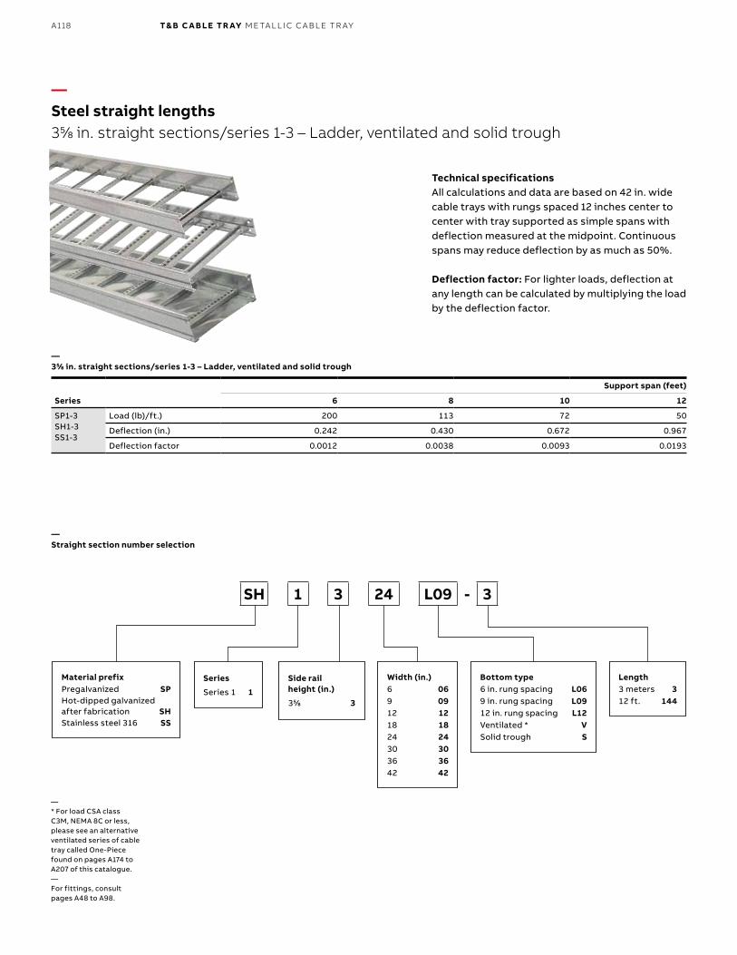
B1 copy starts here
B2 copy starts here
B3 copy starts here
A118 T& B C A B LE TR AY M E TA L L I C C A B L E TR AY
Series
Support span (feet)
6 8 10 12
SP1-3SH1-3SS1-3
Load (lb)/ft.) 200 113 72 50
Deflection (in.) 0.242 0.430 0.672 0.967
Deflection factor 0.0012 0.0038 0.0093 0.0193
—Steel straight lengths355⁄88 in. straight sections/series 1-3 – Ladder, ventilated and solid trough
Technical specificationsAll calculations and data are based on 42 in. wide cable trays with rungs spaced 12 inches center to center with tray supported as simple spans with deflection measured at the midpoint. Continuous spans may reduce deflection by as much as 50%.
Deflection factor: For lighter loads, deflection at any length can be calculated by multiplying the load by the deflection factor.
—* For load CSA class C3M, NEMA 8C or less, please see an alternative ventilated series of cable tray called One-Piece found on pages A174 to A207 of this catalogue.—For fittings, consult pages A48 to A98.
Material prefixPregalvanized SPHot-dipped galvanized after fabrication SHStainless steel 316 SS
Width (in.)6 069 0912 1218 1824 2430 3036 3642 42
Bottom type6 in. rung spacing L069 in. rung spacing L0912 in. rung spacing L12Ventilated * VSolid trough S
Length3 meters 312 ft. 144
SH 1 3 24 L09 - 3
Series
Series 1 1
—355⁄88 in. straight sections/series 1-3 – Ladder, ventilated and solid trough
—Straight section number selection
Side rail height (in.)
355⁄88 3
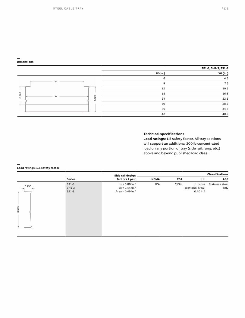
A119S TEEL C A B L E TR AY
Technical specificationsLoad ratings: 1.5 safety factor. All tray sections will support an additional 200 lb concentrated load on any portion of tray (side rail, rung, etc.) above and beyond published load class.
SeriesSide rail design
factors 1 pair
Classifications
NEMA CSA UL ABS
SP1-3SH1-3SS1-3
Ix = 0.80 in.4 Sx = 0.44 in.3
Area = 0.49 in.2
12A C/3m UL cross sectional area :
0.40 in.2
Stainless steelonly
—Dimensions
—Load ratings: 1.5 safety factor
SP1-3, SH1-3, SS1-3
W (in.) Wi (in.)
6 4.5
9 7.5
12 10.5
18 16.5
24 22.5
30 28.5
36 34.5
42 40.5
WI
2.58
7
W3.
625
3.6
25
0.750
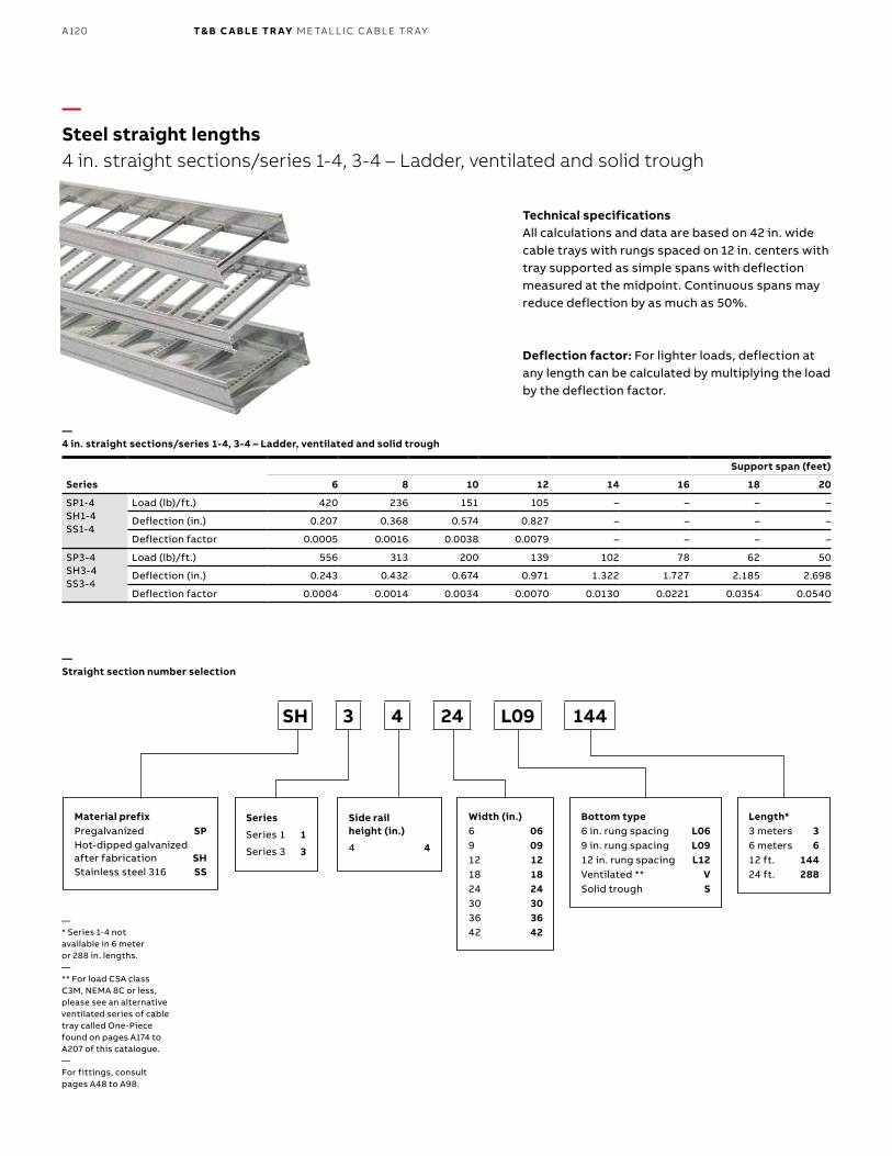
B1 copy starts here
B2 copy starts here
B3 copy starts here
A120 T& B C A B LE TR AY M E TA L L I C C A B L E TR AY
—Steel straight lengths4 in. straight sections/series 1-4, 3-4 – Ladder, ventilated and solid trough
—* Series 1-4 not available in 6 meter or 288 in. lengths.— ** For load CSA class C3M, NEMA 8C or less, please see an alternative ventilated series of cable tray called One-Piece found on pages A174 to A207 of this catalogue.—For fittings, consult pages A48 to A98.
SH 3 4 24 L09 144
—Straight section number selection
—4 in. straight sections/series 1-4, 3-4 – Ladder, ventilated and solid trough
Technical specificationsAll calculations and data are based on 42 in. wide cable trays with rungs spaced on 12 in. centers with tray supported as simple spans with deflection measured at the midpoint. Continuous spans may reduce deflection by as much as 50%.
Deflection factor: For lighter loads, deflection at any length can be calculated by multiplying the load by the deflection factor.
Series
Support span (feet)
6 8 10 12 14 16 18 20
SP1-4SH1-4SS1-4
Load (lb)/ft.) 420 236 151 105 – – – –
Deflection (in.) 0.207 0.368 0.574 0.827 – – – –
Deflection factor 0.0005 0.0016 0.0038 0.0079 – – – –
SP3-4SH3-4SS3-4
Load (lb)/ft.) 556 313 200 139 102 78 62 50
Deflection (in.) 0.243 0.432 0.674 0.971 1.322 1.727 2.185 2.698
Deflection factor 0.0004 0.0014 0.0034 0.0070 0.0130 0.0221 0.0354 0.0540
Material prefixPregalvanized SPHot-dipped galvanized after fabrication SHStainless steel 316 SS
Width (in.)6 069 0912 1218 1824 2430 3036 3642 42
Bottom type6 in. rung spacing L069 in. rung spacing L0912 in. rung spacing L12Ventilated ** VSolid trough S
Length*3 meters 36 meters 612 ft. 14424 ft. 288
Series
Series 1 1
Series 3 3
Side rail height (in.)
4 4
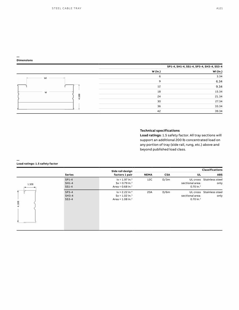
A121S TEEL C A B L E TR AY
SeriesSide rail design
factors 1 pair
Classifications
NEMA CSA UL ABS
SP1-4SH1-4SS1-4
Ix = 1.97 in.4 Sx = 0.79 in.3
Area = 0.68 in.2
12C D/3m UL cross sectional area:
0.70 in.2
Stainless steelonly
SP3-4SH3-4SS3-4
Ix = 2.22 in.4 Sx = 1.02 in.3
Area = 1.08 in.2
20A D/6m UL cross sectional area:
0.70 in.2
Stainless steelonly
Technical specificationsLoad ratings: 1.5 safety factor. All tray sections will support an additional 200 lb concentrated load on any portion of tray (side rail, rung, etc.) above and beyond published load class.
—Dimensions
—Load ratings: 1.5 safety factor
SP1-4, SH1-4, SS1-4, SP3-4, SH3-4, SS3-4
W (in.) Wi (in.)
6 3.34
9 6.34
12 9.34
18 15.34
24 21.34
30 27.34
36 33.34
42 39.34
4.18
8WI
W
4.1
88
1.328
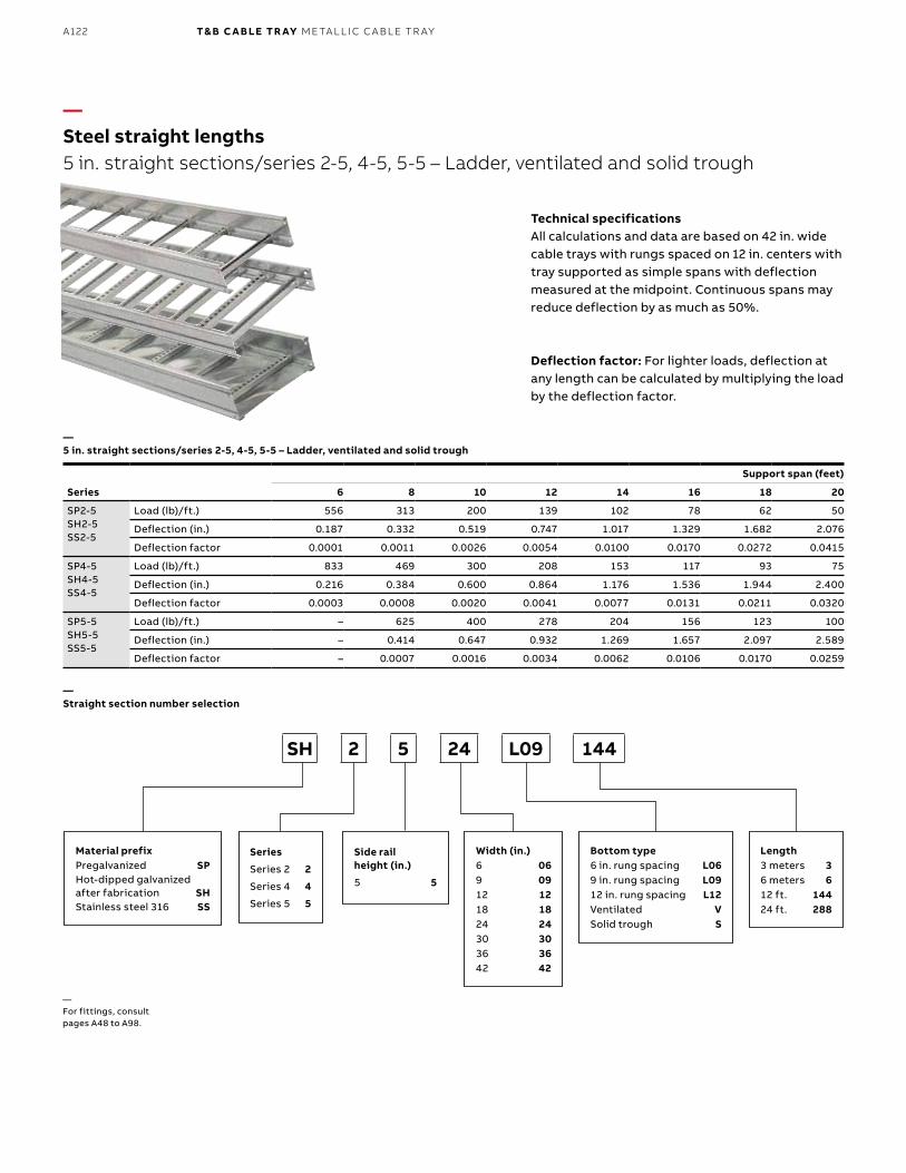
B1 copy starts here
B2 copy starts here
B3 copy starts here
A122 T& B C A B LE TR AY M E TA L L I C C A B L E TR AY
Series
Support span (feet)
6 8 10 12 14 16 18 20
SP2-5SH2-5SS2-5
Load (lb)/ft.) 556 313 200 139 102 78 62 50
Deflection (in.) 0.187 0.332 0.519 0.747 1.017 1.329 1.682 2.076
Deflection factor 0.0001 0.0011 0.0026 0.0054 0.0100 0.0170 0.0272 0.0415
SP4-5SH4-5SS4-5
Load (lb)/ft.) 833 469 300 208 153 117 93 75
Deflection (in.) 0.216 0.384 0.600 0.864 1.176 1.536 1.944 2.400
Deflection factor 0.0003 0.0008 0.0020 0.0041 0.0077 0.0131 0.0211 0.0320
SP5-5SH5-5SS5-5
Load (lb)/ft.) – 625 400 278 204 156 123 100
Deflection (in.) – 0.414 0.647 0.932 1.269 1.657 2.097 2.589
Deflection factor – 0.0007 0.0016 0.0034 0.0062 0.0106 0.0170 0.0259
—Steel straight lengths5 in. straight sections/series 2-5, 4-5, 5-5 – Ladder, ventilated and solid trough
—Straight section number selection
—5 in. straight sections/series 2-5, 4-5, 5-5 – Ladder, ventilated and solid trough
Technical specificationsAll calculations and data are based on 42 in. wide cable trays with rungs spaced on 12 in. centers with tray supported as simple spans with deflection measured at the midpoint. Continuous spans may reduce deflection by as much as 50%.
Deflection factor: For lighter loads, deflection at any length can be calculated by multiplying the load by the deflection factor.
—For fittings, consult pages A48 to A98.
SH 2 5 24 L09 144
Material prefixPregalvanized SPHot-dipped galvanized after fabrication SHStainless steel 316 SS
Width (in.)6 069 0912 1218 1824 2430 3036 3642 42
Bottom type6 in. rung spacing L069 in. rung spacing L0912 in. rung spacing L12Ventilated VSolid trough S
Length3 meters 36 meters 612 ft. 14424 ft. 288
Series
Series 2 2
Series 4 4
Series 5 5
Side rail height (in.)
5 5
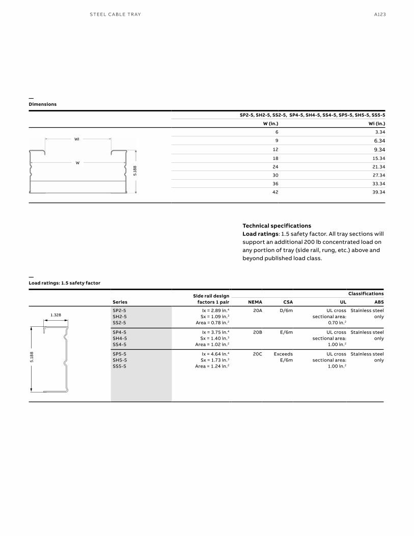
A123S TEEL C A B L E TR AY
Technical specificationsLoad ratings: 1.5 safety factor. All tray sections will support an additional 200 lb concentrated load on any portion of tray (side rail, rung, etc.) above and beyond published load class.
—Dimensions
—Load ratings: 1.5 safety factor
SP2-5, SH2-5, SS2-5, SP4-5, SH4-5, SS4-5, SP5-5, SH5-5, SS5-5
W (in.) Wi (in.)
6 3.34
9 6.34
12 9.34
18 15.34
24 21.34
30 27.34
36 33.34
42 39.34
5.18
8WI
W
SeriesSide rail design
factors 1 pair
Classifications
NEMA CSA UL ABS
SP2-5SH2-5SS2-5
Ix = 2.89 in.4 Sx = 1.09 in.3
Area = 0.78 in.2
20A D/6m UL cross sectional area:
0.70 in.2
Stainless steelonly
SP4-5SH4-5SS4-5
Ix = 3.75 in.4 Sx = 1.40 in.3
Area = 1.02 in.2
20B E/6m UL cross sectional area:
1.00 in.2
Stainless steelonly
SP5-5SH5-5SS5-5
Ix = 4.64 in.4
Sx = 1.73 in.3
Area = 1.24 in.2
20C ExceedsE/6m
UL cross sectional area:
1.00 in.2
Stainless steelonly5.
188
1.328
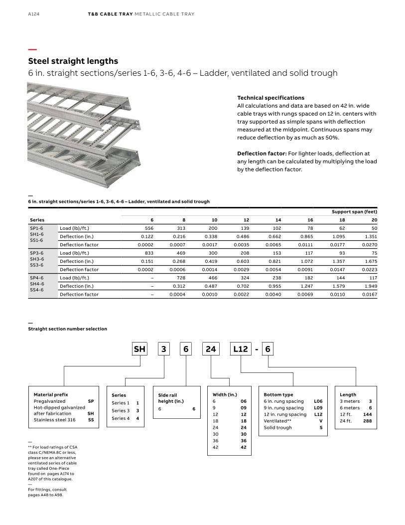
B1 copy starts here
B2 copy starts here
B3 copy starts here
A124 T& B C A B LE TR AY M E TA L L I C C A B L E TR AY
—Steel straight lengths6 in. straight sections/series 1-6, 3-6, 4-6 – Ladder, ventilated and solid trough
—Straight section number selection
—6 in. straight sections/series 1-6, 3-6, 4-6 – Ladder, ventilated and solid trough
Technical specificationsAll calculations and data are based on 42 in. wide cable trays with rungs spaced on 12 in. centers with tray supported as simple spans with deflection measured at the midpoint. Continuous spans may reduce deflection by as much as 50%.
Deflection factor: For lighter loads, deflection at any length can be calculated by multiplying the load by the deflection factor.
SH 3 6 24 L12 - 6
Material prefixPregalvanized SPHot-dipped galvanized after fabrication SHStainless steel 316 SS
Width (in.)6 069 0912 1218 1824 2430 3036 3642 42
Bottom type6 in. rung spacing L069 in. rung spacing L0912 in. rung spacing L12Ventilated** VSolid trough S
Length3 meters 36 meters 612 ft. 14424 ft. 288
Series
Series 1 1
Series 3 3
Series 4 4
Side rail height (in.)
6 6
Series
Support span (feet)
6 8 10 12 14 16 18 20
SP1-6SH1-6SS1-6
Load (lb)/ft.) 556 313 200 139 102 78 62 50
Deflection (in.) 0.122 0.216 0.338 0.486 0.662 0.865 1.095 1.351
Deflection factor 0.0002 0.0007 0.0017 0.0035 0.0065 0.0111 0.0177 0.0270
SP3-6SH3-6SS3-6
Load (lb)/ft.) 833 469 300 208 153 117 93 75
Deflection (in.) 0.151 0.268 0.419 0.603 0.821 1.072 1.357 1.675
Deflection factor 0.0002 0.0006 0.0014 0.0029 0.0054 0.0091 0.0147 0.0223
SP4-6SH4-6SS4-6
Load (lb)/ft.) – 728 466 324 238 182 144 117
Deflection (in.) – 0.312 0.487 0.702 0.955 1.247 1.579 1.949
Deflection factor – 0.0004 0.0010 0.0022 0.0040 0.0069 0.0110 0.0167
— ** For load ratings of CSA class C/NEMA 8C or less, please see an alternative ventilated series of cable tray called One-Piece found on pages A174 to A207 of this catalogue.—For fittings, consult pages A48 to A98.
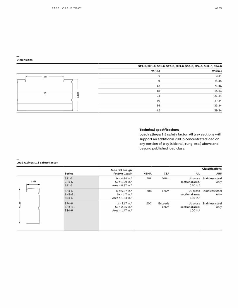
A125S TEEL C A B L E TR AY
Technical specificationsLoad ratings: 1.5 safety factor. All tray sections will support an additional 200 lb concentrated load on any portion of tray (side rail, rung, etc.) above and beyond published load class.
—Dimensions
—Load ratings: 1.5 safety factor
SeriesSide rail design
factors 1 pair
Classifications
NEMA CSA UL ABS
SP1-6SH1-6SS1-6
Ix = 4.44 in.4 Sx = 1.39 in.3
Area = 0.87 in.2
20A D/6m UL cross sectional area:
0.70 in.2
Stainless steelonly
SP3-6SH3-6SS3-6
Ix = 5.37 in.4 Sx = 1.7 in.3
Area = 1.23 in.2
20B E/6m UL cross sectional area:
1.00 in.2
Stainless steelonly
SP4-6SH4-6SS4-6
Ix = 7.17 in.4
Sx = 2.25 in.3
Area = 1.47 in.2
20C ExceedsE/6m
UL cross sectional area:
1.00 in.2
Stainless steelonly
SP1-6, SH1-6, SS1-6, SP3-6, SH3-6, SS3-6, SP4-6, SH4-6, SS4-6
W (in.) Wi (in.)
6 3.34
9 6.34
12 9.34
18 15.34
24 21.34
30 27.34
36 33.34
42 39.34
6.18
8WI
W
6.1
88
1.328
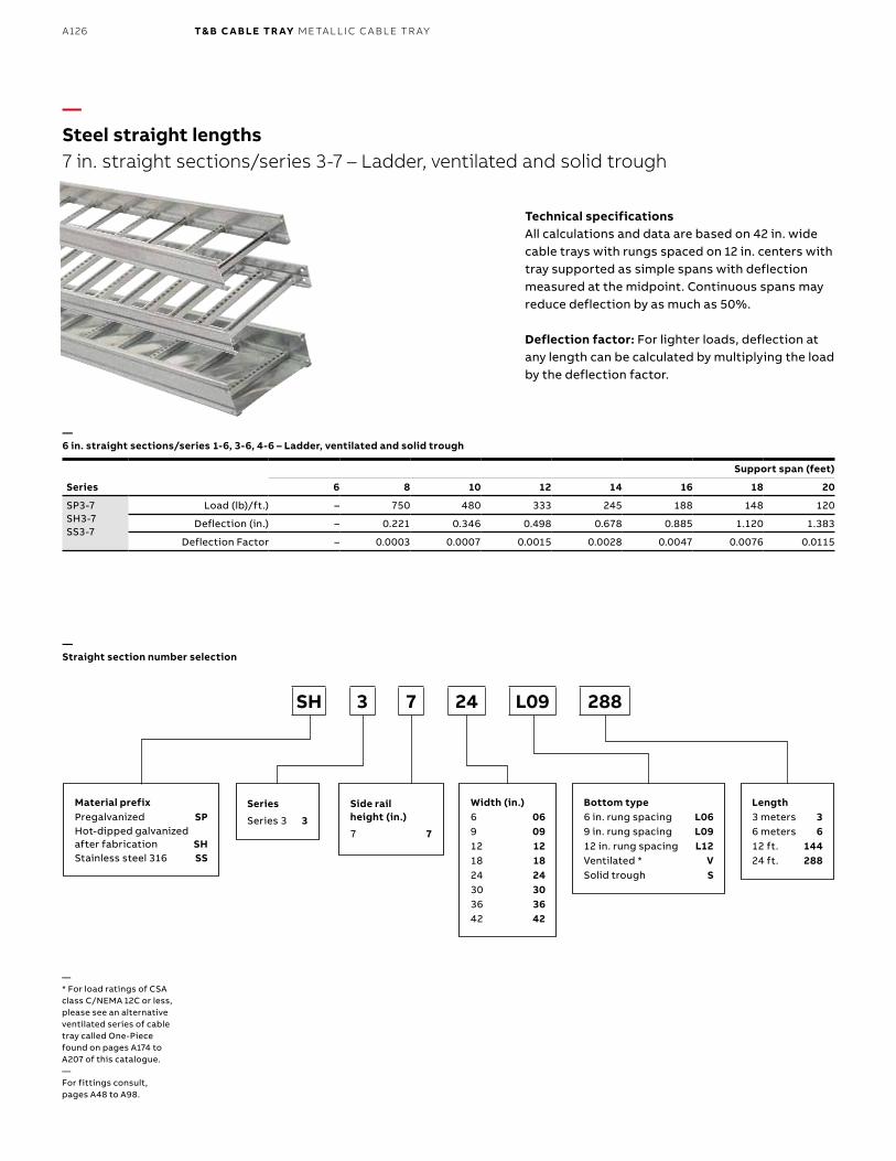
B1 copy starts here
B2 copy starts here
B3 copy starts here
A126 T& B C A B LE TR AY M E TA L L I C C A B L E TR AY
Series
Support span (feet)
6 8 10 12 14 16 18 20
SP3-7SH3-7SS3-7
Load (lb)/ft.) – 750 480 333 245 188 148 120
Deflection (in.) – 0.221 0.346 0.498 0.678 0.885 1.120 1.383
Deflection Factor – 0.0003 0.0007 0.0015 0.0028 0.0047 0.0076 0.0115
—Steel straight lengths7 in. straight sections/series 3-7 – Ladder, ventilated and solid trough
—Straight section number selection
—6 in. straight sections/series 1-6, 3-6, 4-6 – Ladder, ventilated and solid trough
Technical specificationsAll calculations and data are based on 42 in. wide cable trays with rungs spaced on 12 in. centers with tray supported as simple spans with deflection measured at the midpoint. Continuous spans may reduce deflection by as much as 50%.
Deflection factor: For lighter loads, deflection at any length can be calculated by multiplying the load by the deflection factor.
SH 3 7 24 L09 288
Material prefixPregalvanized SPHot-dipped galvanized after fabrication SHStainless steel 316 SS
Width (in.)6 069 0912 1218 1824 2430 3036 3642 42
Bottom type6 in. rung spacing L069 in. rung spacing L0912 in. rung spacing L12Ventilated * VSolid trough S
Length3 meters 36 meters 612 ft. 14424 ft. 288
Series
Series 3 3
Side rail height (in.)
7 7
— * For load ratings of CSA class C/NEMA 12C or less, please see an alternative ventilated series of cable tray called One-Piece found on pages A174 to A207 of this catalogue.—For fittings consult, pages A48 to A98.
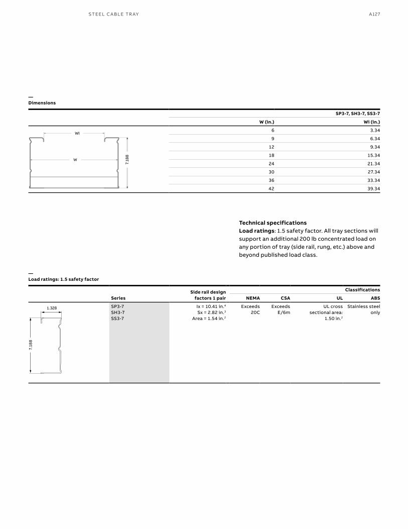
A127S TEEL C A B L E TR AY
Technical specificationsLoad ratings: 1.5 safety factor. All tray sections will support an additional 200 lb concentrated load on any portion of tray (side rail, rung, etc.) above and beyond published load class.
—Dimensions
—Load ratings: 1.5 safety factor
SeriesSide rail design
factors 1 pair
Classifications
NEMA CSA UL ABS
SP3-7SH3-7SS3-7
Ix = 10.41 in.4 Sx = 2.82 in.3
Area = 1.54 in.2
Exceeds20C
Exceeds E/6m
UL cross sectional area:
1.50 in.2
Stainless steelonly
SP3-7, SH3-7, SS3-7
W (in.) Wi (in.)
6 3.34
9 6.34
12 9.34
18 15.34
24 21.34
30 27.34
36 33.34
42 39.34
WI
7.18
8
W
1.328
7.18
8
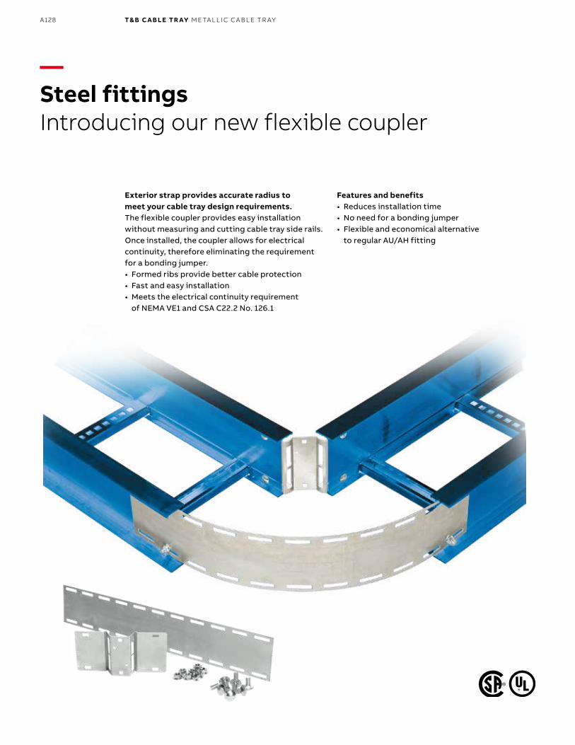
B1 copy starts here
B2 copy starts here
B3 copy starts here
A128 T& B C A B LE TR AY M E TA L L I C C A B L E TR AY
—Steel fittingsIntroducing our new flexible coupler
Exterior strap provides accurate radius to meet your cable tray design requirements.The flexible coupler provides easy installation without measuring and cutting cable tray side rails. Once installed, the coupler allows for electrical continuity, therefore eliminating the requirement for a bonding jumper.• Formed ribs provide better cable protection• Fast and easy installation• Meets the electrical continuity requirement
of NEMA VE1 and CSA C22.2 No. 126.1
Features and benefits• Reduces installation time• No need for a bonding jumper• Flexible and economical alternative
to regular AU/AH fitting
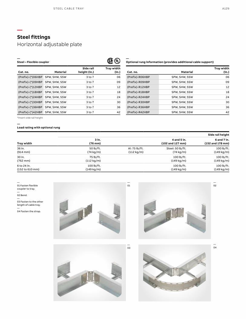
A129S TEEL C A B L E TR AY
Cat. no. MaterialSide rail
height (in.)Tray width
(in.)
(Prefix)-(*)06HBP SPW, SHW, SSW 3 to 7 06
(Prefix)-(*)09HBP SPW, SHW, SSW 3 to 7 09
(Prefix)-(*)12HBP SPW, SHW, SSW 3 to 7 12
(Prefix)-(*)18HBP SPW, SHW, SSW 3 to 7 18
(Prefix)-(*)24HBP SPW, SHW, SSW 3 to 7 24
(Prefix)-(*)30HBP SPW, SHW, SSW 3 to 7 30
(Prefix)-(*)36HBP SPW, SHW, SSW 3 to 7 36
(Prefix)-(*)42HBP SPW, SHW, SSW 3 to 7 42
*Insert side rail height
Cat. no. MaterialTray width
(in.)
(Prefix)-R06HBP SPW, SHW, SSW 06
(Prefix)-R09HBP SPW, SHW, SSW 09
(Prefix)-R12HBP SPW, SHW, SSW 12
(Prefix)-R18HBP SPW, SHW, SSW 18
(Prefix)-R24HBP SPW, SHW, SSW 24
(Prefix)-R30HBP SPW, SHW, SSW 30
(Prefix)-R36HBP SPW, SHW, SSW 36
(Prefix)-R42HBP SPW, SHW, SSW 42
Tray width
Side rail height
3 in.(76 mm)
4 and 5 in.(102 and 127 mm)
6 and 7 in.(152 and 178 mm)
36 in.(914 mm)
50 lb/ft.(74 kg/m)
Al: 75 lb/ft.(112 kg/m)
Steel: 50 lb/ft.(74 kg/m)
100 lb/ft.(149 kg/m)
30 in.(762 mm)
75 lb/ft.(112 kg/m)
100 lb/ft.(149 kg/m)
100 lb/ft.(149 kg/m)
6 to 24 in.(152 to 610 mm)
100 lb/ft.(149 kg/m)
100 lb/ft.(149 kg/m)
100 lb/ft.(149 kg/m)
—Steel fittingsHorizontal adjustable plate
—Steel – Flexible coupler
—Load rating with optional rung
—Optional rung information (provides additional cable support)
—01 Fasten flexible coupler to tray.—02 Bend.—03 Fasten to the other length of cable tray.—04 Fasten the strap.
—01
—03
—04
—02
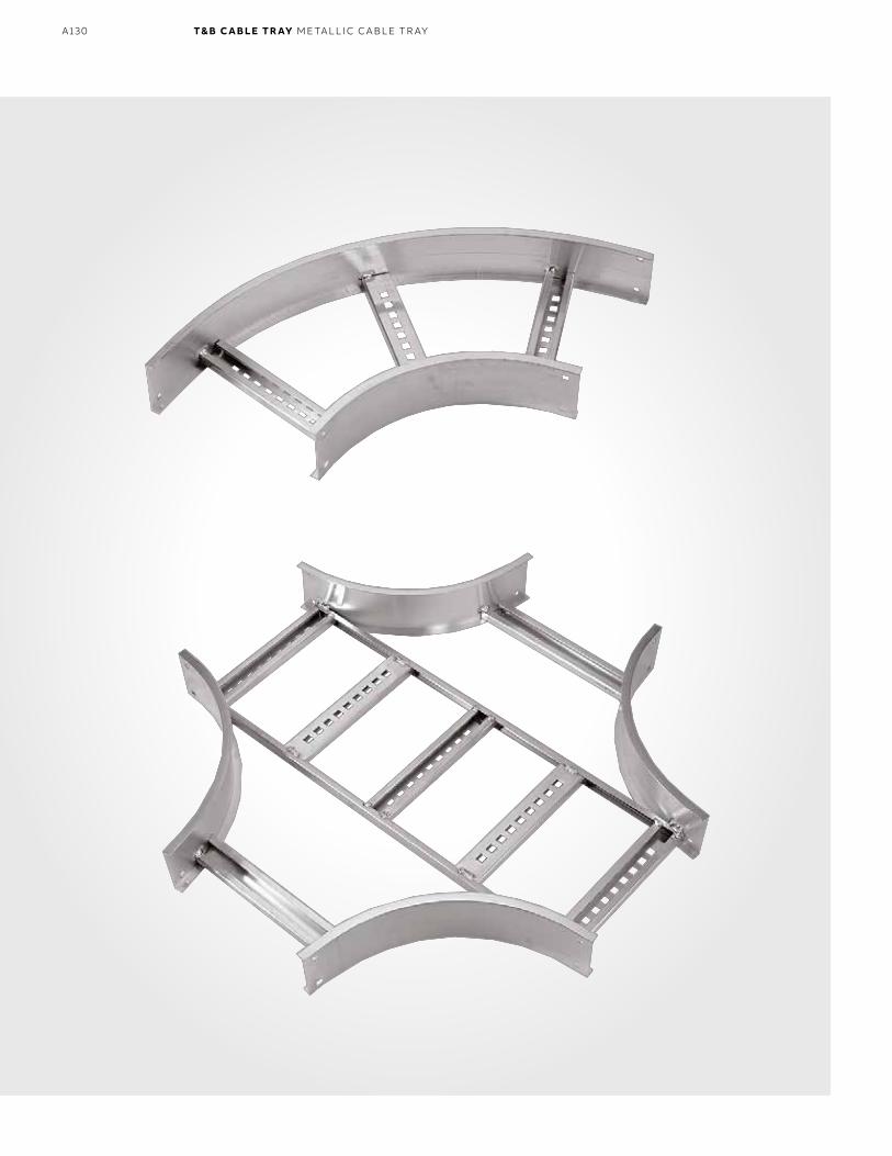
B1 copy starts here
B2 copy starts here
B3 copy starts here
A130 T& B C A B LE TR AY M E TA L L I C C A B L E TR AY
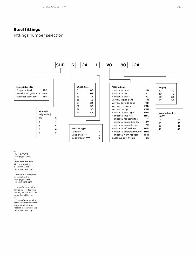
A131S TEEL C A B L E TR AY
SHF 6 24 L VO 90 24
Material prefixPregalvanized SPFHot-dipped galvanized SHF Stainless steel 316 SSF
Width (in.)6 069 0912 1218 1824 2430 3036 3642 42
Bottom typeLadder * LVentilated *** VSolid trough **** S
Fitting typeHorizontal bend HBHorizontal tee HTHorizontal cross HXVertical inside bend VIVertical outside bend VOVertical tee down VTDVertical tee up VTUHorizontal wye right HYRHorizontal wye left HYLHorizontal reducing tee RTHorizontal expanding tee ETHorizontal expand cross EXHorizontal left reducer HLRHorizontal straight reducer HSRHorizontal right reducer HRRCable support fitting CS
Angle†30° 30 45° 4560° 6090° 90
Nominal radius (in.)**12 1224 2436 3648 48
Side rail height (in.)
355⁄88 3
4 4
5 5
6 6
7 7
— † For HB, VI, VO fitting types only.— * Manufactured with 9 in. rung spacing measured at the center line of fitting.— ** Radius is not required for the following fitting types: HYR, HYL, HLR, HRR, HSR.— *** Manufactured with 4 in. edge-to-edge rung spacing measured at the center line of fitting.— **** Manufactured with flat sheet inserted under rungs with 9 in. rung spacing measured at the center line of fitting.
—Steel fittingsFittings number selection
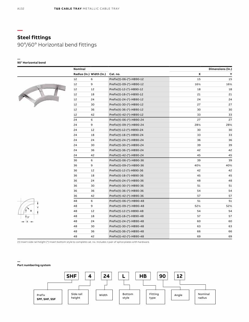
B1 copy starts here
B2 copy starts here
B3 copy starts here
A132 T& B C A B LE TR AY M E TA L L I C C A B L E TR AY
Nominal
Cat. no.
Dimensions (in.)
Radius (in.) Width (in.) X Y
12 6 Prefix(†)-06-(*)-HB90-12 15 15
12 9 Prefix(†)-09-(*)-HB90-12 1611⁄22 1611⁄22
12 12 Prefix(†)-12-(*)-HB90-12 18 18
12 18 Prefix(†)-18-(*)-HB90-12 21 21
12 24 Prefix(†)-24-(*)-HB90-12 24 24
12 30 Prefix(†)-30-(*)-HB90-12 27 27
12 36 Prefix(†)-36-(*)-HB90-12 30 30
12 42 Prefix(†)-42-(*)-HB90-12 33 33
24 6 Prefix(†)-06-(*)-HB90-24 27 27
24 9 Prefix(†)-09-(*)-HB90-24 2811⁄22 2811⁄22
24 12 Prefix(†)-12-(*)-HB90-24 30 30
24 18 Prefix(†)-18-(*)-HB90-24 33 33
24 24 Prefix(†)-24-(*)-HB90-24 36 36
24 30 Prefix(†)-30-(*)-HB90-24 39 39
24 36 Prefix(†)-36-(*)-HB90-24 42 42
24 42 Prefix(†)-42-(*)-HB90-24 45 45
36 6 Prefix(†)-06-(*)-HB90-36 39 39
36 9 Prefix(†)-09-(*)-HB90-36 4011⁄22 4011⁄22
36 12 Prefix(†)-12-(*)-HB90-36 42 42
36 18 Prefix(†)-18-(*)-HB90-36 45 45
36 24 Prefix(†)-24-(*)-HB90-36 48 48
36 30 Prefix(†)-30-(*)-HB90-36 51 51
36 36 Prefix(†)-36-(*)-HB90-36 54 54
36 42 Prefix(†)-42-(*)-HB90-36 57 57
48 6 Prefix(†)-06-(*)-HB90-48 51 51
48 9 Prefix(†)-09-(*)-HB90-48 5211⁄22 5211⁄22
48 12 Prefix(†)-12-(*)-HB90-48 54 54
48 18 Prefix(†)-18-(*)-HB90-48 57 57
48 24 Prefix(†)-24-(*)-HB90-48 60 60
48 30 Prefix(†)-30-(*)-HB90-48 63 63
48 36 Prefix(†)-36-(*)-HB90-48 66 66
48 42 Prefix(†)-42-(*)-HB90-48 69 69
—Steel fittings90o/60o Horizontal bend fittings
(†) Insert side rail height (*) Insert bottom style to complete cat. no. Includes 1 pair of splice plates with hardware.
—Part numbering system
SHF 4 24 L HB 90 12
—90o Horizontal bend
3"
YR
X
PrefixSPF, SHF, SSF
Side rail height
Bottom style
AngleWidth Fitting type
Nominalradius
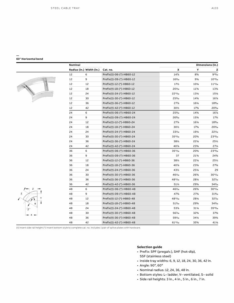
A133S TEEL C A B L E TR AY
Nominal
Cat. no.
Dimensions (in.)
Radius (in.) Width (in.) X Y Z
12 6 Prefix(†)-06-(*)-HB60-12 1477⁄88 855⁄88 91515⁄1616
12 9 Prefix(†)-09-(*)-HB60-12 1633⁄1616 933⁄88 101313⁄1616
12 12 Prefix(†)-12-(*)-HB60-12 1711⁄22 1011⁄88 111111⁄1616
12 18 Prefix(†)-18-(*)-HB60-12 2011⁄1616 1155⁄88 1333⁄88
12 24 Prefix(†)-24-(*)-HB60-12 221111⁄1616 1311⁄88 1511⁄88
12 30 Prefix(†)-30-(*)-HB60-12 2555⁄1616 1455⁄88 1677⁄88
12 36 Prefix(†)-36-(*)-HB60-12 2777⁄88 1611⁄88 1899⁄1616
12 42 Prefix(†)-42-(*)-HB60-12 3011⁄22 1755⁄88 2055⁄1616
24 6 Prefix(†)-06-(*)-HB60-24 2555⁄1616 1455⁄88 1677⁄88
24 9 Prefix(†)-09-(*)-HB60-24 2699⁄1616 1533⁄88 1733⁄44
24 12 Prefix(†)-12-(*)-HB60-24 2777⁄88 1611⁄88 1899⁄1616
24 18 Prefix(†)-18-(*)-HB60-24 3011⁄22 1755⁄88 2055⁄1616
24 24 Prefix(†)-24-(*)-HB60-24 3311⁄1616 1911⁄88 2211⁄1616
24 30 Prefix(†)-30-(*)-HB60-24 351111⁄1616 2055⁄88 231313⁄1616
24 36 Prefix(†)-36-(*)-HB60-24 3811⁄44 2211⁄88 2511⁄22
24 42 Prefix(†)-42-(*)-HB60-24 4077⁄88 2355⁄88 2711⁄44
36 6 Prefix(†)-06-(*)-HB60-36 351111⁄1616 2055⁄88 231313⁄1616
36 9 Prefix(†)-09-(*)-HB60-36 37 2133⁄88 2455⁄88
36 12 Prefix(†)-12-(*)-HB60-36 3811⁄44 2211⁄88 2511⁄22
36 18 Prefix(†)-18-(*)-HB60-36 4077⁄88 2355⁄88 2722⁄88
36 24 Prefix(†)-24-(*)-HB60-36 4311⁄22 2511⁄88 29
36 30 Prefix(†)-30-(*)-HB60-36 4611⁄1616 2655⁄88 301111⁄1616
36 36 Prefix(†)-36-(*)-HB60-36 481111⁄1616 2811⁄88 3277⁄1616
36 42 Prefix(†)-42-(*)-HB60-36 5111⁄44 2955⁄88 3433⁄1616
48 6 Prefix(†)-06-(*)-HB60-48 4611⁄1616 2655⁄88 301111⁄1616
48 9 Prefix(†)-09-(*)-HB60-48 4733⁄88 2733⁄88 3199⁄1616
48 12 Prefix(†)-12-(*)-HB60-48 481111⁄1616 2811⁄88 3277⁄1616
48 18 Prefix(†)-18-(*)-HB60-48 5144⁄1616 2955⁄88 3433⁄1616
48 24 Prefix(†)-24-(*)-HB60-48 5377⁄88 3111⁄88 351515⁄1616
48 30 Prefix(†)-30-(*)-HB60-48 5677⁄1616 3255⁄88 3755⁄88
48 36 Prefix(†)-36-(*)-HB60-48 5911⁄1616 3411⁄88 3933⁄88
48 42 Prefix(†)-42-(*)-HB60-48 611111⁄1616 3555⁄88 4111⁄88
(†) Insert side rail height (*) Insert bottom style to complete cat. no. Includes 1 pair of splice plates with hardware.
—60o Horizontal bend
3"
X
R
Z
Z
Y
Selection guide• Prefix: SPF (pregalv.), SHF (hot-dip),
SSF (stainless steel)• Inside tray widths: 6, 9, 12, 18, 24, 30, 36, 42 in.• Angle: 90o, 60o• Nominal radius: 12, 24, 36, 48 in. • Bottom styles: L– ladder, V– ventilated, S– solid• Side rail heights: 3 in., 4 in., 5 in., 6 in., 7 in.
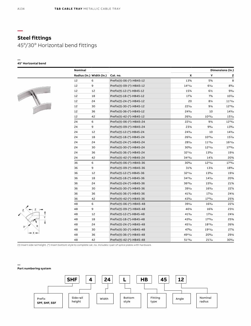
B1 copy starts here
B2 copy starts here
B3 copy starts here
A134 T& B C A B LE TR AY M E TA L L I C C A B L E TR AY
Nominal
Cat. no.
Dimensions (in.)
Radius (in.) Width (in.) X Y Z
12 6 Prefix(†)-06-(*)-HB45-12 1355⁄88 555⁄88 8
12 9 Prefix(†)-09-(*)-HB45-12 141111⁄1616 611⁄1616 899⁄1616
12 12 Prefix(†)-12-(*)-HB45-12 1533⁄44 611⁄22 933⁄1616
12 18 Prefix(†)-18-(*)-HB45-12 1777⁄88 733⁄88 1077⁄1616
12 24 Prefix(†)-24-(*)-HB45-12 20 811⁄44 111111⁄1616
12 30 Prefix(†)-30-(*)-HB45-12 2211⁄1616 911⁄88 121515⁄1616
12 36 Prefix(†)-36-(*)-HB45-12 2433⁄1616 10 1433⁄1616
12 42 Prefix(†)-42-(*)-HB45-12 2655⁄1616 101515⁄1616 1577⁄1616
24 6 Prefix(†)-06-(*)-HB45-24 2211⁄1616 911⁄88 121515⁄1616
24 9 Prefix(†)-09-(*)-HB45-24 2311⁄88 999⁄1616 1399⁄1616
24 12 Prefix(†)-12-(*)-HB45-24 2433⁄1616 10 1433⁄1616
24 18 Prefix(†)-18-(*)-HB45-24 2655⁄1616 101515⁄1616 1577⁄1616
24 24 Prefix(†)-24-(*)-HB45-24 2877⁄1616 111313⁄1616 161111⁄1616
24 30 Prefix(†)-30-(*)-HB45-24 3099⁄1616 121111⁄1616 171515⁄1616
24 36 Prefix(†)-36-(*)-HB45-24 321111⁄1616 1399⁄1616 1911⁄88
24 42 Prefix(†)-42-(*)-HB45-24 341313⁄1616 1477⁄88 2033⁄88
36 6 Prefix(†)-06-(*)-HB45-36 3099⁄1616 121111⁄1616 171515⁄1616
36 9 Prefix(†)-09-(*)-HB45-36 3155⁄88 1311⁄88 1899⁄1616
36 12 Prefix(†)-12-(*)-HB45-36 321111⁄1616 1399⁄1616 1911⁄88
36 18 Prefix(†)-18-(*)-HB45-36 341313⁄1616 1477⁄1616 2033⁄88
36 24 Prefix(†)-24-(*)-HB45-36 361515⁄1616 1555⁄1616 2155⁄88
36 30 Prefix(†)-30-(*)-HB45-36 3911⁄1616 1633⁄1616 2277⁄88
36 36 Prefix(†)-36-(*)-HB45-36 4133⁄1616 1711⁄1616 2411⁄88
36 42 Prefix(†)-42-(*)-HB45-36 4355⁄1616 171515⁄1616 2533⁄88
48 6 Prefix(†)-06-(*)-HB45-48 3911⁄1616 1633⁄1616 2277⁄88
48 9 Prefix(†)-09-(*)-HB45-48 4011⁄88 1633⁄88 2311⁄22
48 12 Prefix(†)-12-(*)-HB45-48 4133⁄1616 1711⁄1616 2411⁄88
48 18 Prefix(†)-18-(*)-HB45-48 4355⁄1616 171515⁄1616 2533⁄88
48 24 Prefix(†)-24-(*)-HB45-48 4577⁄1616 181313⁄1616 2655⁄88
48 30 Prefix(†)-30-(*)-HB45-48 4799⁄1616 191111⁄1616 2777⁄88
48 36 Prefix(†)-36-(*)-HB45-48 491111⁄1616 2099⁄1616 2911⁄88
48 42 Prefix(†)-42-(*)-HB45-48 511313⁄1616 2177⁄1616 3055⁄1616
—Steel fittings45o/30o Horizontal bend fittings
(†) Insert side rail height. (*) Insert bottom style to complete cat. no. Includes 1 pair of splice plates with hardware.
—Part numbering system
—45o Horizontal bend
SHF 4 24 L HB 45 12
PrefixSPF, SHF, SSF
Side rail height
Bottom style
AngleWidth Fitting type
Nominalradius
3"
X
R
Z Z
Y
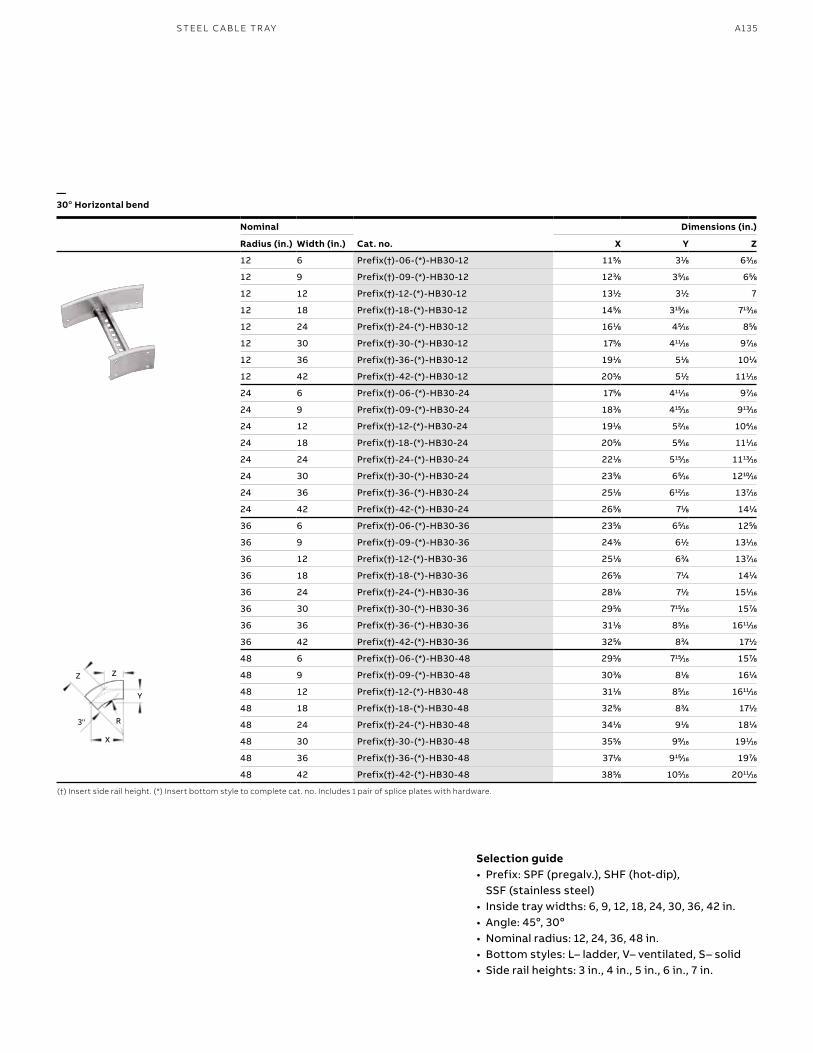
A135S TEEL C A B L E TR AY
Nominal
Cat. no.
Dimensions (in.)
Radius (in.) Width (in.) X Y Z
12 6 Prefix(†)-06-(*)-HB30-12 1155⁄88 311⁄88 633⁄1616
12 9 Prefix(†)-09-(*)-HB30-12 1233⁄88 355⁄1616 655⁄88
12 12 Prefix(†)-12-(*)-HB30-12 1311⁄22 311⁄22 7
12 18 Prefix(†)-18-(*)-HB30-12 1455⁄88 31515⁄1616 71313⁄1616
12 24 Prefix(†)-24-(*)-HB30-12 1611⁄88 455⁄1616 855⁄88
12 30 Prefix(†)-30-(*)-HB30-12 1755⁄88 41111⁄1616 977⁄1616
12 36 Prefix(†)-36-(*)-HB30-12 1911⁄88 511⁄88 1011⁄44
12 42 Prefix(†)-42-(*)-HB30-12 2055⁄88 511⁄22 1111⁄1616
24 6 Prefix(†)-06-(*)-HB30-24 1755⁄88 41111⁄1616 977⁄1616
24 9 Prefix(†)-09-(*)-HB30-24 1833⁄88 41515⁄1616 91313⁄1616
24 12 Prefix(†)-12-(*)-HB30-24 1911⁄88 522⁄1616 1044⁄1616
24 18 Prefix(†)-18-(*)-HB30-24 2055⁄88 588⁄1616 1111⁄1616
24 24 Prefix(†)-24-(*)-HB30-24 2211⁄88 51515⁄1616 111313⁄1616
24 30 Prefix(†)-30-(*)-HB30-24 2355⁄88 655⁄1616 121010⁄1616
24 36 Prefix(†)-36-(*)-HB30-24 2511⁄88 61212⁄1616 1377⁄1616
24 42 Prefix(†)-42-(*)-HB30-24 2655⁄88 711⁄88 1411⁄44
36 6 Prefix(†)-06-(*)-HB30-36 2355⁄88 655⁄1616 1255⁄88
36 9 Prefix(†)-09-(*)-HB30-36 2433⁄88 611⁄22 1311⁄1616
36 12 Prefix(†)-12-(*)-HB30-36 2511⁄88 633⁄44 1377⁄1616
36 18 Prefix(†)-18-(*)-HB30-36 2655⁄88 711⁄44 1411⁄44
36 24 Prefix(†)-24-(*)-HB30-36 2811⁄88 711⁄22 1511⁄1616
36 30 Prefix(†)-30-(*)-HB30-36 2955⁄88 71515⁄1616 1577⁄88
36 36 Prefix(†)-36-(*)-HB30-36 3111⁄88 855⁄1616 161111⁄1616
36 42 Prefix(†)-42-(*)-HB30-36 3255⁄88 833⁄44 1711⁄22
48 6 Prefix(†)-06-(*)-HB30-48 2955⁄88 71515⁄1616 1577⁄88
48 9 Prefix(†)-09-(*)-HB30-48 3033⁄88 811⁄88 1611⁄44
48 12 Prefix(†)-12-(*)-HB30-48 3111⁄88 855⁄1616 161111⁄1616
48 18 Prefix(†)-18-(*)-HB30-48 3255⁄88 833⁄44 1711⁄22
48 24 Prefix(†)-24-(*)-HB30-48 3411⁄88 911⁄88 1811⁄44
48 30 Prefix(†)-30-(*)-HB30-48 3555⁄88 999⁄1616 1911⁄1616
48 36 Prefix(†)-36-(*)-HB30-48 3711⁄88 91515⁄1616 1977⁄88
48 42 Prefix(†)-42-(*)-HB30-48 3855⁄88 1055⁄1616 201111⁄1616
(†) Insert side rail height. (*) Insert bottom style to complete cat. no. Includes 1 pair of splice plates with hardware.
—30o Horizontal bend
X
R
3"
Z Z
Y
X
R
Selection guide• Prefix: SPF (pregalv.), SHF (hot-dip),
SSF (stainless steel)• Inside tray widths: 6, 9, 12, 18, 24, 30, 36, 42 in.• Angle: 45o, 30o• Nominal radius: 12, 24, 36, 48 in. • Bottom styles: L– ladder, V– ventilated, S– solid• Side rail heights: 3 in., 4 in., 5 in., 6 in., 7 in.
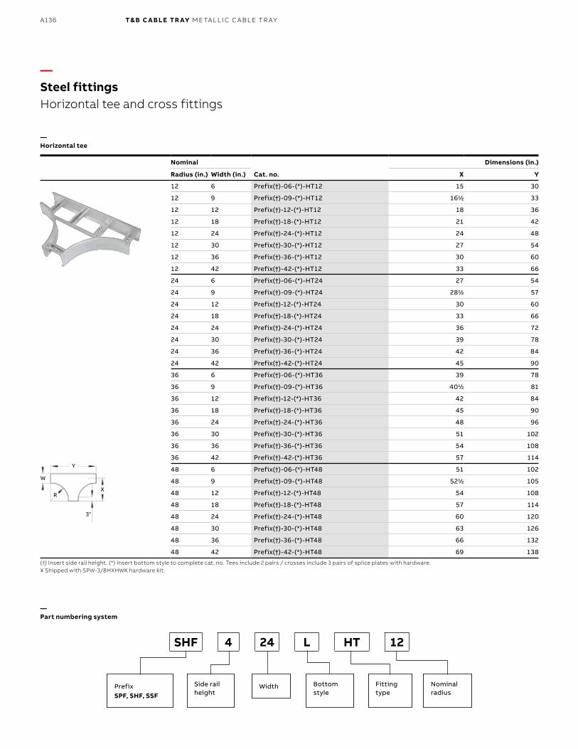
B1 copy starts here
B2 copy starts here
B3 copy starts here
A136 T& B C A B LE TR AY M E TA L L I C C A B L E TR AY
—Steel fittings Horizontal tee and cross fittings
(†) Insert side rail height. (*) Insert bottom style to complete cat. no. Tees include 2 pairs / crosses include 3 pairs of splice plates with hardware.¥ Shipped with SPW-3/8HXHWK hardware kit.
—Part numbering system
—Horizontal tee
SHF 4 24 L HT 12
PrefixSPF, SHF, SSF
Side rail height
Bottom style
Width Fitting type
Nominalradius
Nominal
Cat. no.
Dimensions (in.)
Radius (in.) Width (in.) X Y
12 6 Prefix(†)-06-(*)-HT12 15 30
12 9 Prefix(†)-09-(*)-HT12 1611⁄22 33
12 12 Prefix(†)-12-(*)-HT12 18 36
12 18 Prefix(†)-18-(*)-HT12 21 42
12 24 Prefix(†)-24-(*)-HT12 24 48
12 30 Prefix(†)-30-(*)-HT12 27 54
12 36 Prefix(†)-36-(*)-HT12 30 60
12 42 Prefix(†)-42-(*)-HT12 33 66
24 6 Prefix(†)-06-(*)-HT24 27 54
24 9 Prefix(†)-09-(*)-HT24 2811⁄22 57
24 12 Prefix(†)-12-(*)-HT24 30 60
24 18 Prefix(†)-18-(*)-HT24 33 66
24 24 Prefix(†)-24-(*)-HT24 36 72
24 30 Prefix(†)-30-(*)-HT24 39 78
24 36 Prefix(†)-36-(*)-HT24 42 84
24 42 Prefix(†)-42-(*)-HT24 45 90
36 6 Prefix(†)-06-(*)-HT36 39 78
36 9 Prefix(†)-09-(*)-HT36 4011⁄22 81
36 12 Prefix(†)-12-(*)-HT36 42 84
36 18 Prefix(†)-18-(*)-HT36 45 90
36 24 Prefix(†)-24-(*)-HT36 48 96
36 30 Prefix(†)-30-(*)-HT36 51 102
36 36 Prefix(†)-36-(*)-HT36 54 108
36 42 Prefix(†)-42-(*)-HT36 57 114
48 6 Prefix(†)-06-(*)-HT48 51 102
48 9 Prefix(†)-09-(*)-HT48 5211⁄22 105
48 12 Prefix(†)-12-(*)-HT48 54 108
48 18 Prefix(†)-18-(*)-HT48 57 114
48 24 Prefix(†)-24-(*)-HT48 60 120
48 30 Prefix(†)-30-(*)-HT48 63 126
48 36 Prefix(†)-36-(*)-HT48 66 132
48 42 Prefix(†)-42-(*)-HT48 69 138
3"
X
W
R
Y
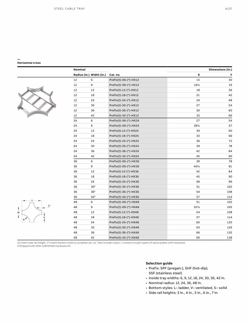
A137S TEEL C A B L E TR AY
(†) Insert side rail height. (*) Insert bottom style to complete cat. no. Tees include 2 pairs / crosses include 3 pairs of splice plates with hardware.¥ Shipped with SPW-3/8HXHWK hardware kit.
—Horizontal cross
Nominal
Cat. no.
Dimensions (in.)
Radius (in.) Width (in.) X Y
12 6 Prefix(†)-06-(*)-HX12 15 30
12 9 Prefix(†)-09-(*)-HX12 1611⁄22 33
12 12 Prefix(†)-12-(*)-HX12 18 36
12 18 Prefix(†)-18-(*)-HX12 21 42
12 24 Prefix(†)-24-(*)-HX12 24 48
12 30 Prefix(†)-30-(*)-HX12 27 54
12 36 Prefix(†)-36-(*)-HX12 30 60
12 42 Prefix(†)-42-(*)-HX12 33 66
24 6 Prefix(†)-06-(*)-HX24 27 54
24 9 Prefix(†)-09-(*)-HX24 2811⁄22 57
24 12 Prefix(†)-12-(*)-HX24 30 60
24 18 Prefix(†)-18-(*)-HX24 33 66
24 24 Prefix(†)-24-(*)-HX24 36 72
24 30 Prefix(†)-30-(*)-HX24 39 78
24 36 Prefix(†)-36-(*)-HX24 42 84
24 42 Prefix(†)-42-(*)-HX24 45 90
36 6 Prefix(†)-06-(*)-HX36 39 78
36 9 Prefix(†)-09-(*)-HX36 4011⁄22 81
36 12 Prefix(†)-12-(*)-HX36 42 84
36 18 Prefix(†)-18-(*)-HX36 45 90
36 24 Prefix(†)-24-(*)-HX36 48 96
36 30¥ Prefix(†)-30-(*)-HX36 51 102
36 36¥ Prefix(†)-36-(*)-HX36 54 108
36 42¥ Prefix(†)-42-(*)-HX36 57 114
48 6 Prefix(†)-06-(*)-HX48 51 102
48 9 Prefix(†)-09-(*)-HX48 5211⁄22 105
48 12 Prefix(†)-12-(*)-HX48 54 108
48 18 Prefix(†)-18-(*)-HX48 57 114
48 24 Prefix(†)-24-(*)-HX48 60 120
48 30 Prefix(†)-30-(*)-HX48 63 126
48 36 Prefix(†)-36-(*)-HX48 66 132
48 42 Prefix(†)-42-(*)-HX48 69 138
Selection guide• Prefix: SPF (pregalv.), SHF (hot-dip),
SSF (stainless steel)• Inside tray widths: 6, 9, 12, 18, 24, 30, 36, 42 in.• Nominal radius: 12, 24, 36, 48 in. • Bottom styles: L– ladder, V– ventilated, S– solid• Side rail heights: 3 in., 4 in., 5 in., 6 in., 7 in.
3"
X
W
R
Y
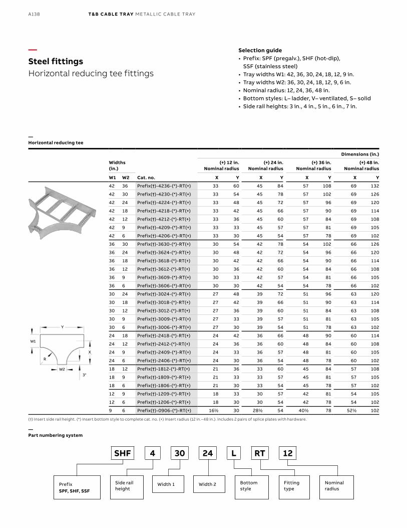
B1 copy starts here
B2 copy starts here
B3 copy starts here
A138 T& B C A B LE TR AY M E TA L L I C C A B L E TR AY
Dimensions (in.)
Widths (in.)
Cat. no.
(+) 12 in. Nominal radius
(+) 24 in. Nominal radius
(+) 36 in. Nominal radius
(+) 48 in. Nominal radius
W1 W2 X Y X Y X Y X Y
42 36 Prefix(†)-4236-(*)-RT(+) 33 60 45 84 57 108 69 132
42 30 Prefix(†)-4230-(*)-RT(+) 33 54 45 78 57 102 69 126
42 24 Prefix(†)-4224-(*)-RT(+) 33 48 45 72 57 96 69 120
42 18 Prefix(†)-4218-(*)-RT(+) 33 42 45 66 57 90 69 114
42 12 Prefix(†)-4212-(*)-RT(+) 33 36 45 60 57 84 69 108
42 9 Prefix(†)-4209-(*)-RT(+) 33 33 45 57 57 81 69 105
42 6 Prefix(†)-4206-(*)-RT(+) 33 30 45 54 57 78 69 102
36 30 Prefix(†)-3630-(*)-RT(+) 30 54 42 78 54 102 66 126
36 24 Prefix(†)-3624-(*)-RT(+) 30 48 42 72 54 96 66 120
36 18 Prefix(†)-3618-(*)-RT(+) 30 42 42 66 54 90 66 114
36 12 Prefix(†)-3612-(*)-RT(+) 30 36 42 60 54 84 66 108
36 9 Prefix(†)-3609-(*)-RT(+) 30 33 42 57 54 81 66 105
36 6 Prefix(†)-3606-(*)-RT(+) 30 30 42 54 54 78 66 102
30 24 Prefix(†)-3024-(*)-RT(+) 27 48 39 72 51 96 63 120
30 18 Prefix(†)-3018-(*)-RT(+) 27 42 39 66 51 90 63 114
30 12 Prefix(†)-3012-(*)-RT(+) 27 36 39 60 51 84 63 108
30 9 Prefix(†)-3009-(*)-RT(+) 27 33 39 57 51 81 63 105
30 6 Prefix(†)-3006-(*)-RT(+) 27 30 39 54 51 78 63 102
24 18 Prefix(†)-2418-(*)-RT(+) 24 42 36 66 48 90 60 114
24 12 Prefix(†)-2412-(*)-RT(+) 24 36 36 60 48 84 60 108
24 9 Prefix(†)-2409-(*)-RT(+) 24 33 36 57 48 81 60 105
24 6 Prefix(†)-2406-(*)-RT(+) 24 30 36 54 48 78 60 102
18 12 Prefix(†)-1812-(*)-RT(+) 21 36 33 60 45 84 57 108
18 9 Prefix(†)-1809-(*)-RT(+) 21 33 33 57 45 81 57 105
18 6 Prefix(†)-1806-(*)-RT(+) 21 30 33 54 45 78 57 102
12 9 Prefix(†)-1209-(*)-RT(+) 18 33 30 57 42 81 54 105
12 6 Prefix(†)-1206-(*)-RT(+) 18 30 30 54 42 78 54 102
9 6 Prefix(†)-0906-(*)-RT(+) 1611⁄22 30 2811⁄22 54 4011⁄22 78 5211⁄22 102
—Steel fittingsHorizontal reducing tee fittings
(†) Insert side rail height. (*) Insert bottom style to complete cat. no. (+) Insert radius (12 in.–48 in.). Includes 2 pairs of splice plates with hardware.
—Part numbering system
—Horizontal reducing tee
3"
X
W1
W2
R
Y
SHF 4 30 24 L RT 12
PrefixSPF, SHF, SSF
Side rail height
Bottom style
Width 1 Width 2 Fitting type
Nominalradius
Selection guide• Prefix: SPF (pregalv.), SHF (hot-dip),
SSF (stainless steel)• Tray widths W1: 42, 36, 30, 24, 18, 12, 9 in.• Tray widths W2: 36, 30, 24, 18, 12, 9, 6 in.• Nominal radius: 12, 24, 36, 48 in. • Bottom styles: L– ladder, V– ventilated, S– solid• Side rail heights: 3 in., 4 in., 5 in., 6 in., 7 in.
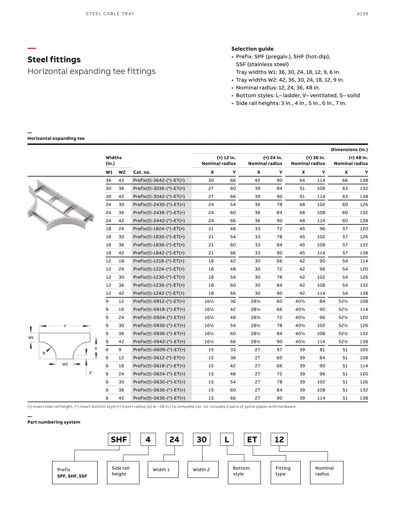
A139S TEEL C A B L E TR AY
—Steel fittingsHorizontal expanding tee fittings
(†) Insert side rail height. (*) Insert bottom style (+) Insert radius (12 in.–48 in.) to complete cat. no. Includes 2 pairs of splice plates with hardware.
—Part numbering system
—Horizontal expanding tee
SHF 4 24 30 L ET 12
PrefixSPF, SHF, SSF
Side rail height
Bottom style
Width 1 Width 2 Fitting type
Nominalradius
Selection guide• Prefix: SPF (pregalv.), SHF (hot-dip),
SSF (stainless steel) Tray widths W1: 36, 30, 24, 18, 12, 9, 6 in.
• Tray widths W2: 42, 36, 30, 24, 18, 12, 9 in. • Nominal radius: 12, 24, 36, 48 in. • Bottom styles: L– ladder, V– ventilated, S– solid• Side rail heights: 3 in., 4 in., 5 in., 6 in., 7 in.
Dimensions (in.)
Widths (in.)
Cat. no.
(+) 12 in. Nominal radius
(+) 24 in. Nominal radius
(+) 36 in. Nominal radius
(+) 48 in. Nominal radius
W1 W2 X Y X Y X Y X Y
36 42 Prefix(†)-3642-(*)-ET(+) 30 66 42 90 54 114 66 138
30 36 Prefix(†)-3036-(*)-ET(+) 27 60 39 84 51 108 63 132
30 42 Prefix(†)-3042-(*)-ET(+) 27 66 39 90 51 114 63 138
24 30 Prefix(†)-2430-(*)-ET(+) 24 54 36 78 48 102 60 126
24 36 Prefix(†)-2436-(*)-ET(+) 24 60 36 84 48 108 60 132
24 42 Prefix(†)-2442-(*)-ET(+) 24 66 36 90 48 114 60 138
18 24 Prefix(†)-1824-(*)-ET(+) 21 48 33 72 45 96 57 120
18 30 Prefix(†)-1830-(*)-ET(+) 21 54 33 78 45 102 57 126
18 36 Prefix(†)-1836-(*)-ET(+) 21 60 33 84 45 108 57 132
18 42 Prefix(†)-1842-(*)-ET(+) 21 66 33 90 45 114 57 138
12 18 Prefix(†)-1218-(*)-ET(+) 18 42 30 66 42 90 54 114
12 24 Prefix(†)-1224-(*)-ET(+) 18 48 30 72 42 96 54 120
12 30 Prefix(†)-1230-(*)-ET(+) 18 54 30 78 42 102 54 126
12 36 Prefix(†)-1236-(*)-ET(+) 18 60 30 84 42 108 54 132
12 42 Prefix(†)-1242-(*)-ET(+) 18 66 30 90 42 114 54 138
9 12 Prefix(†)-0912-(*)-ET(+) 1611⁄22 36 2811⁄22 60 4011⁄22 84 5211⁄22 108
9 18 Prefix(†)-0918-(*)-ET(+) 1611⁄22 42 2811⁄22 66 4011⁄22 90 5211⁄22 114
9 24 Prefix(†)-0924-(*)-ET(+) 1611⁄22 48 2811⁄22 72 4011⁄22 96 5211⁄22 120
9 30 Prefix(†)-0930-(*)-ET(+) 1611⁄22 54 2811⁄22 78 4011⁄22 102 5211⁄22 126
9 36 Prefix(†)-0936-(*)-ET(+) 1611⁄22 60 2811⁄22 84 4011⁄22 108 5211⁄22 132
9 42 Prefix(†)-0942-(*)-ET(+) 1611⁄22 66 2811⁄22 90 4011⁄22 114 5211⁄22 138
6 9 Prefix(†)-0609-(*)-ET(+) 15 33 27 57 39 81 51 105
6 12 Prefix(†)-0612-(*)-ET(+) 15 36 27 60 39 84 51 108
6 18 Prefix(†)-0618-(*)-ET(+) 15 42 27 66 39 90 51 114
6 24 Prefix(†)-0624-(*)-ET(+) 15 48 27 72 39 96 51 120
6 30 Prefix(†)-0630-(*)-ET(+) 15 54 27 78 39 102 51 126
6 36 Prefix(†)-0636-(*)-ET(+) 15 60 27 84 39 108 51 132
6 42 Prefix(†)-0636-(*)-ET(+) 15 66 27 90 39 114 51 138
3"
X
W1
W2
R
Y
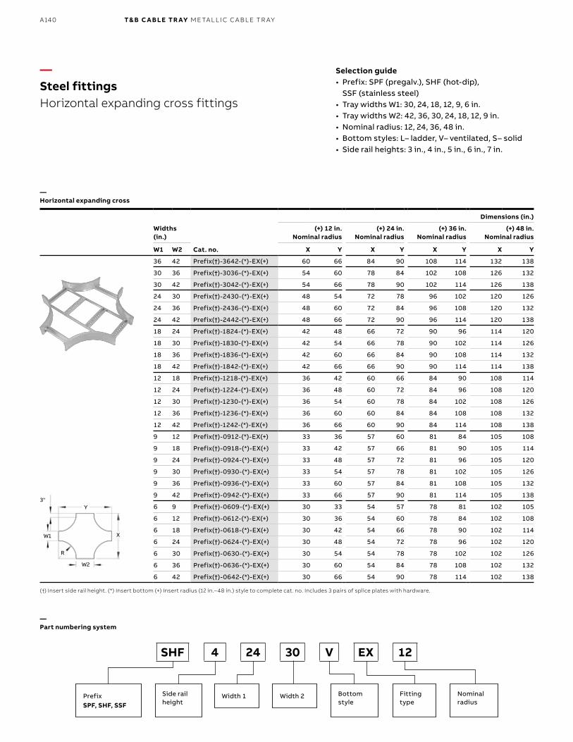
B1 copy starts here
B2 copy starts here
B3 copy starts here
A140 T& B C A B LE TR AY M E TA L L I C C A B L E TR AY
Dimensions (in.)
Widths (in.)
Cat. no.
(+) 12 in. Nominal radius
(+) 24 in. Nominal radius
(+) 36 in. Nominal radius
(+) 48 in. Nominal radius
W1 W2 X Y X Y X Y X Y
36 42 Prefix(†)-3642-(*)-EX(+) 60 66 84 90 108 114 132 138
30 36 Prefix(†)-3036-(*)-EX(+) 54 60 78 84 102 108 126 132
30 42 Prefix(†)-3042-(*)-EX(+) 54 66 78 90 102 114 126 138
24 30 Prefix(†)-2430-(*)-EX(+) 48 54 72 78 96 102 120 126
24 36 Prefix(†)-2436-(*)-EX(+) 48 60 72 84 96 108 120 132
24 42 Prefix(†)-2442-(*)-EX(+) 48 66 72 90 96 114 120 138
18 24 Prefix(†)-1824-(*)-EX(+) 42 48 66 72 90 96 114 120
18 30 Prefix(†)-1830-(*)-EX(+) 42 54 66 78 90 102 114 126
18 36 Prefix(†)-1836-(*)-EX(+) 42 60 66 84 90 108 114 132
18 42 Prefix(†)-1842-(*)-EX(+) 42 66 66 90 90 114 114 138
12 18 Prefix(†)-1218-(*)-EX(+) 36 42 60 66 84 90 108 114
12 24 Prefix(†)-1224-(*)-EX(+) 36 48 60 72 84 96 108 120
12 30 Prefix(†)-1230-(*)-EX(+) 36 54 60 78 84 102 108 126
12 36 Prefix(†)-1236-(*)-EX(+) 36 60 60 84 84 108 108 132
12 42 Prefix(†)-1242-(*)-EX(+) 36 66 60 90 84 114 108 138
9 12 Prefix(†)-0912-(*)-EX(+) 33 36 57 60 81 84 105 108
9 18 Prefix(†)-0918-(*)-EX(+) 33 42 57 66 81 90 105 114
9 24 Prefix(†)-0924-(*)-EX(+) 33 48 57 72 81 96 105 120
9 30 Prefix(†)-0930-(*)-EX(+) 33 54 57 78 81 102 105 126
9 36 Prefix(†)-0936-(*)-EX(+) 33 60 57 84 81 108 105 132
9 42 Prefix(†)-0942-(*)-EX(+) 33 66 57 90 81 114 105 138
6 9 Prefix(†)-0609-(*)-EX(+) 30 33 54 57 78 81 102 105
6 12 Prefix(†)-0612-(*)-EX(+) 30 36 54 60 78 84 102 108
6 18 Prefix(†)-0618-(*)-EX(+) 30 42 54 66 78 90 102 114
6 24 Prefix(†)-0624-(*)-EX(+) 30 48 54 72 78 96 102 120
6 30 Prefix(†)-0630-(*)-EX(+) 30 54 54 78 78 102 102 126
6 36 Prefix(†)-0636-(*)-EX(+) 30 60 54 84 78 108 102 132
6 42 Prefix(†)-0642-(*)-EX(+) 30 66 54 90 78 114 102 138
—Steel fittingsHorizontal expanding cross fittings
—Part numbering system
—Horizontal expanding cross
Selection guide• Prefix: SPF (pregalv.), SHF (hot-dip),
SSF (stainless steel)• Tray widths W1: 30, 24, 18, 12, 9, 6 in.• Tray widths W2: 42, 36, 30, 24, 18, 12, 9 in.• Nominal radius: 12, 24, 36, 48 in. • Bottom styles: L– ladder, V– ventilated, S– solid• Side rail heights: 3 in., 4 in., 5 in., 6 in., 7 in.
(†) Insert side rail height. (*) Insert bottom (+) Insert radius (12 in.–48 in.) style to complete cat. no. Includes 3 pairs of splice plates with hardware.
3"
XW1
W2
R
Y
SHF 4 24 30 V EX 12
PrefixSPF, SHF, SSF
Side rail height
Bottom style
Width 1 Width 2 Fitting type
Nominalradius
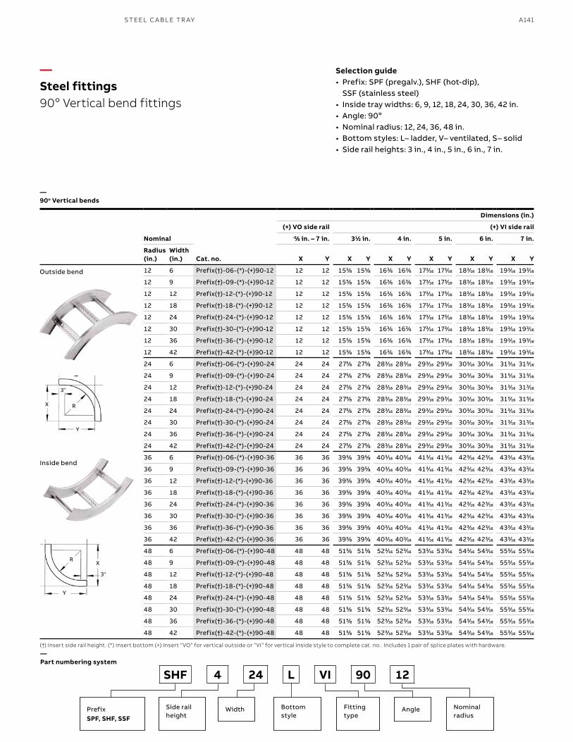
A141S TEEL C A B L E TR AY
—Steel fittings90o Vertical bend fittings
—Part numbering system
—90o Vertical bends
Selection guide• Prefix: SPF (pregalv.), SHF (hot-dip),
SSF (stainless steel)• Inside tray widths: 6, 9, 12, 18, 24, 30, 36, 42 in.• Angle: 90o• Nominal radius: 12, 24, 36, 48 in.• Bottom styles: L– ladder, V– ventilated, S– solid• Side rail heights: 3 in., 4 in., 5 in., 6 in., 7 in.
(†) Insert side rail height. (*) Insert bottom (+) Insert “VO” for vertical outside or “VI” for vertical inside style to complete cat. no. Includes 1 pair of splice plates with hardware.
SHF 4 24 L VI 90 12
PrefixSPF, SHF, SSF
Side rail height
Bottom style
Width AngleFitting type
Nominalradius
Dimensions (in.)
Nominal
(+) VO side rail (+) VI side rail-5-5⁄88 in. – 7 in. 311⁄22 in. 4 in. 5 in. 6 in. 7 in.
Radius (in.)
Width (in.) Cat. no. X Y X Y X Y X Y X Y X Y
12 6 Prefix(†)-06-(*)-(+)90-12 12 12 1555⁄88 1555⁄88 1633⁄66 1633⁄66 1733⁄1616 1733⁄1616 1833⁄1616 1833⁄1616 1933⁄1616 1933⁄1616
12 9 Prefix(†)-09-(*)-(+)90-12 12 12 1555⁄88 1555⁄88 1633⁄66 1633⁄66 1733⁄1616 1733⁄1616 1833⁄1616 1833⁄1616 1933⁄1616 1933⁄1616
12 12 Prefix(†)-12-(*)-(+)90-12 12 12 1555⁄88 1555⁄88 1633⁄66 1633⁄66 1733⁄1616 1733⁄1616 1833⁄1616 1833⁄1616 1933⁄1616 1933⁄1616
12 18 Prefix(†)-18-(*)-(+)90-12 12 12 1555⁄88 1555⁄88 1633⁄66 1633⁄66 1733⁄1616 1733⁄1616 1833⁄1616 1833⁄1616 1933⁄1616 1933⁄1616
12 24 Prefix(†)-24-(*)-(+)90-12 12 12 1555⁄88 1555⁄88 1633⁄66 1633⁄66 1733⁄1616 1733⁄1616 1833⁄1616 1833⁄1616 1933⁄1616 1933⁄1616
12 30 Prefix(†)-30-(*)-(+)90-12 12 12 1555⁄88 1555⁄88 1633⁄66 1633⁄66 1733⁄1616 1733⁄1616 1833⁄1616 1833⁄1616 1933⁄1616 1933⁄1616
12 36 Prefix(†)-36-(*)-(+)90-12 12 12 1555⁄88 1555⁄88 1633⁄66 1633⁄66 1733⁄1616 1733⁄1616 1833⁄1616 1833⁄1616 1933⁄1616 1933⁄1616
12 42 Prefix(†)-42-(*)-(+)90-12 12 12 1555⁄88 1555⁄88 1633⁄66 1633⁄66 1733⁄1616 1733⁄1616 1833⁄1616 1833⁄1616 1933⁄1616 1933⁄1616
24 6 Prefix(†)-06-(*)-(+)90-24 24 24 2755⁄88 2755⁄88 2833⁄1616 2833⁄1616 2933⁄1616 2933⁄1616 3033⁄1616 3033⁄1616 3133⁄1616 3133⁄1616
24 9 Prefix(†)-09-(*)-(+)90-24 24 24 2755⁄88 2755⁄88 2833⁄1616 2833⁄1616 2933⁄1616 2933⁄1616 3033⁄1616 3033⁄1616 3133⁄1616 3133⁄1616
24 12 Prefix(†)-12-(*)-(+)90-24 24 24 2755⁄88 2755⁄88 2833⁄1616 2833⁄1616 2933⁄1616 2933⁄1616 3033⁄1616 3033⁄1616 3133⁄1616 3133⁄1616
24 18 Prefix(†)-18-(*)-(+)90-24 24 24 2755⁄88 2755⁄88 2833⁄1616 2833⁄1616 2933⁄1616 2933⁄1616 3033⁄1616 3033⁄1616 3133⁄1616 3133⁄1616
24 24 Prefix(†)-24-(*)-(+)90-24 24 24 2755⁄88 2755⁄88 2833⁄1616 2833⁄1616 2933⁄1616 2933⁄1616 3033⁄1616 3033⁄1616 3133⁄1616 3133⁄1616
24 30 Prefix(†)-30-(*)-(+)90-24 24 24 2755⁄88 2755⁄88 2833⁄1616 2833⁄1616 2933⁄1616 2933⁄1616 3033⁄1616 3033⁄1616 3133⁄1616 3133⁄1616
24 36 Prefix(†)-36-(*)-(+)90-24 24 24 2755⁄88 2755⁄88 2833⁄1616 2833⁄1616 2933⁄1616 2933⁄1616 3033⁄1616 3033⁄1616 3133⁄1616 3133⁄1616
24 42 Prefix(†)-42-(*)-(+)90-24 24 24 2755⁄88 2755⁄88 2833⁄1616 2833⁄1616 2933⁄1616 2933⁄1616 3033⁄1616 3033⁄1616 3133⁄1616 3133⁄1616
36 6 Prefix(†)-06-(*)-(+)90-36 36 36 3955⁄88 3955⁄88 4033⁄1616 4033⁄1616 4133⁄1616 4133⁄1616 4233⁄1616 4233⁄1616 4333⁄1616 4333⁄1616
36 9 Prefix(†)-09-(*)-(+)90-36 36 36 3955⁄88 3955⁄88 4033⁄1616 4033⁄1616 4133⁄1616 4133⁄1616 4233⁄1616 4233⁄1616 4333⁄1616 4333⁄1616
36 12 Prefix(†)-12-(*)-(+)90-36 36 36 3955⁄88 3955⁄88 4033⁄1616 4033⁄1616 4133⁄1616 4133⁄1616 4233⁄1616 4233⁄1616 4333⁄1616 4333⁄1616
36 18 Prefix(†)-18-(*)-(+)90-36 36 36 3955⁄88 3955⁄88 4033⁄1616 4033⁄1616 4133⁄1616 4133⁄1616 4233⁄1616 4233⁄1616 4333⁄1616 4333⁄1616
36 24 Prefix(†)-24-(*)-(+)90-36 36 36 3955⁄88 3955⁄88 4033⁄1616 4033⁄1616 4133⁄1616 4133⁄1616 4233⁄1616 4233⁄1616 4333⁄1616 4333⁄1616
36 30 Prefix(†)-30-(*)-(+)90-36 36 36 3955⁄88 3955⁄88 4033⁄1616 4033⁄1616 4133⁄1616 4133⁄1616 4233⁄1616 4233⁄1616 4333⁄1616 4333⁄1616
36 36 Prefix(†)-36-(*)-(+)90-36 36 36 3955⁄88 3955⁄88 4033⁄1616 4033⁄1616 4133⁄1616 4133⁄1616 4233⁄1616 4233⁄1616 4333⁄1616 4333⁄1616
36 42 Prefix(†)-42-(*)-(+)90-36 36 36 3955⁄88 3955⁄88 4033⁄1616 4033⁄1616 4133⁄1616 4133⁄1616 4233⁄1616 4233⁄1616 4333⁄1616 4333⁄1616
48 6 Prefix(†)-06-(*)-(+)90-48 48 48 5155⁄88 5155⁄88 5233⁄1616 5233⁄1616 5333⁄1616 5333⁄1616 5433⁄1616 5433⁄1616 5533⁄1616 5533⁄1616
48 9 Prefix(†)-09-(*)-(+)90-48 48 48 5155⁄88 5155⁄88 5233⁄1616 5233⁄1616 5333⁄1616 5333⁄1616 5433⁄1616 5433⁄1616 5533⁄1616 5533⁄1616
48 12 Prefix(†)-12-(*)-(+)90-48 48 48 5155⁄88 5155⁄88 5233⁄1616 5233⁄1616 5333⁄1616 5333⁄1616 5433⁄1616 5433⁄1616 5533⁄1616 5533⁄1616
48 18 Prefix(†)-18-(*)-(+)90-48 48 48 5155⁄88 5155⁄88 5233⁄1616 5233⁄1616 5333⁄1616 5333⁄1616 5433⁄1616 5433⁄1616 5533⁄1616 5533⁄1616
48 24 Prefix(†)-24-(*)-(+)90-48 48 48 5155⁄88 5155⁄88 5233⁄1616 5233⁄1616 5333⁄1616 5333⁄1616 5433⁄1616 5433⁄1616 5533⁄1616 5533⁄1616
48 30 Prefix(†)-30-(*)-(+)90-48 48 48 5155⁄88 5155⁄88 5233⁄1616 5233⁄1616 5333⁄1616 5333⁄1616 5433⁄1616 5433⁄1616 5533⁄1616 5533⁄1616
48 36 Prefix(†)-36-(*)-(+)90-48 48 48 5155⁄88 5155⁄88 5233⁄1616 5233⁄1616 5333⁄1616 5333⁄1616 5433⁄1616 5433⁄1616 5533⁄1616 5533⁄1616
48 42 Prefix(†)-42-(*)-(+)90-48 48 48 5155⁄88 5155⁄88 5233⁄1616 5233⁄1616 5333⁄1616 5333⁄1616 5433⁄1616 5433⁄1616 5533⁄1616 5533⁄1616
Outside bend
Inside bend
3"
3"
Y
Y
X
X
R
R
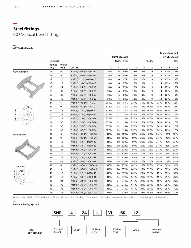
B1 copy starts here
B2 copy starts here
B3 copy starts here
A142 T& B C A B LE TR AY M E TA L L I C C A B L E TR AY
Dimensions (in.)
Nominal
(+) VO side rail (+) VI side rail
355⁄88 in. – 7 in. 311⁄22 in. 4 in.
Radius (in.)
Width (in.) Cat. no. X Y Z X Y Z X Y Z
12 6 Prefix(†)-06-(*)-(+)60-12 1033⁄88 6 61515⁄1616 1311⁄22 955⁄88 9 14 1033⁄1616 933⁄88
12 9 Prefix(†)-09-(*)-(+)60-12 1033⁄88 6 61515⁄1616 1311⁄22 955⁄88 9 14 1033⁄1616 933⁄88
12 12 Prefix(†)-12-(*)-(+)60-12 1033⁄88 6 61515⁄1616 1311⁄22 955⁄88 9 14 1033⁄1616 933⁄88
12 18 Prefix(†)-18-(*)-(+)60-12 1033⁄88 6 61515⁄1616 1311⁄22 955⁄88 9 14 1033⁄1616 933⁄88
12 24 Prefix(†)-24-(*)-(+)60-12 1033⁄88 6 61515⁄1616 1311⁄22 955⁄88 9 14 1033⁄1616 933⁄88
12 30 Prefix(†)-30-(*)-(+)60-12 1033⁄88 6 61515⁄1616 1311⁄22 955⁄88 9 14 1033⁄1616 933⁄88
12 36 Prefix(†)-36-(*)-(+)60-12 1033⁄88 6 61515⁄1616 1311⁄22 955⁄88 9 14 1033⁄1616 933⁄88
12 42 Prefix(†)-42-(*)-(+)60-12 1033⁄88 6 61515⁄1616 1311⁄22 955⁄88 9 14 1033⁄1616 933⁄88
24 6 Prefix(†)-06-(*)-(+)60-24 201313⁄1616 12 1377⁄88 231515⁄1616 1555⁄88 151515⁄1616 2477⁄1616 1633⁄1616 1611⁄44
24 9 Prefix(†)-09-(*)-(+)60-24 201313⁄1616 12 1377⁄88 231515⁄1616 1555⁄88 151515⁄1616 2477⁄1616 1633⁄1616 1611⁄44
24 12 Prefix(†)-12-(*)-(+)60-24 201313⁄1616 12 1377⁄88 231515⁄1616 1555⁄88 151515⁄1616 2477⁄1616 1633⁄1616 1611⁄44
24 18 Prefix(†)-18-(*)-(+)60-24 201313⁄1616 12 1377⁄88 231515⁄1616 1555⁄88 151515⁄1616 2477⁄1616 1633⁄1616 1611⁄44
24 24 Prefix(†)-24-(*)-(+)60-24 201313⁄1616 12 1377⁄88 231515⁄1616 1555⁄88 151515⁄1616 2477⁄1616 1633⁄1616 1611⁄44
24 30 Prefix(†)-30-(*)-(+)60-24 201313⁄1616 12 1377⁄88 231515⁄1616 1555⁄88 151515⁄1616 2477⁄1616 1633⁄1616 1611⁄44
24 36 Prefix(†)-36-(*)-(+)60-24 201313⁄1616 12 1377⁄88 231515⁄1616 1555⁄88 151515⁄1616 2477⁄1616 1633⁄1616 1611⁄44
24 42 Prefix(†)-42-(*)-(+)60-24 201313⁄1616 12 1377⁄88 231515⁄1616 1555⁄88 151515⁄1616 2477⁄1616 1633⁄1616 1611⁄44
36 6 Prefix(†)-06-(*)-(+)60-36 3133⁄1616 18 201313⁄1616 3455⁄1616 2155⁄88 2277⁄88 341313⁄1616 2233⁄44 2333⁄1616
36 9 Prefix(†)-09-(*)-(+)60-36 3133⁄1616 18 201313⁄1616 3455⁄1616 2155⁄88 2277⁄88 341313⁄1616 2233⁄44 2333⁄1616
36 12 Prefix(†)-12-(*)-(+)60-36 3133⁄1616 18 201313⁄1616 3455⁄1616 2155⁄88 2277⁄88 341313⁄1616 2233⁄44 2333⁄1616
36 18 Prefix(†)-18-(*)-(+)60-36 3133⁄1616 18 201313⁄1616 3455⁄1616 2155⁄88 2277⁄88 341313⁄1616 2233⁄44 2333⁄1616
36 24 Prefix(†)-24-(*)-(+)60-36 3133⁄1616 18 201313⁄1616 3455⁄1616 2155⁄88 2277⁄88 341313⁄1616 2233⁄44 2333⁄1616
36 30 Prefix(†)-30-(*)-(+)60-36 3133⁄1616 18 201313⁄1616 3455⁄1616 2155⁄88 2277⁄88 341313⁄1616 2233⁄44 2333⁄1616
36 36 Prefix(†)-36-(*)-(+)60-36 3133⁄1616 18 201313⁄1616 3455⁄1616 2155⁄88 2277⁄88 341313⁄1616 2233⁄44 2333⁄1616
36 42 Prefix(†)-42-(*)-(+)60-36 3133⁄1616 18 201313⁄1616 3455⁄1616 2155⁄88 2277⁄88 341313⁄1616 2233⁄44 2333⁄1616
48 6 Prefix(†)-06-(*)-(+)60-48 4199⁄1616 24 271111⁄1616 441111⁄1616 2755⁄88 291313⁄1616 4533⁄1616 2833⁄1616 3011⁄88
48 9 Prefix(†)-09-(*)-(+)60-48 4199⁄1616 24 271111⁄1616 441111⁄1616 2755⁄88 291313⁄1616 4533⁄1616 2833⁄1616 3011⁄88
48 12 Prefix(†)-12-(*)-(+)60-48 4199⁄1616 24 271111⁄1616 441111⁄1616 2755⁄88 291313⁄1616 4533⁄1616 2833⁄1616 3011⁄88
48 18 Prefix(†)-18-(*)-(+)60-48 4199⁄1616 24 271111⁄1616 441111⁄1616 2755⁄88 291313⁄1616 4533⁄1616 2833⁄1616 3011⁄88
48 24 Prefix(†)-24-(*)-(+)60-48 4199⁄1616 24 271111⁄1616 441111⁄1616 2755⁄88 291313⁄1616 4533⁄1616 2833⁄1616 3011⁄88
48 30 Prefix(†)-30-(*)-(+)60-48 4199⁄1616 24 271111⁄1616 441111⁄1616 2755⁄88 291313⁄1616 4533⁄1616 2833⁄1616 3011⁄88
48 36 Prefix(†)-36-(*)-(+)60-48 4199⁄1616 24 271111⁄1616 441111⁄1616 2755⁄88 291313⁄1616 4533⁄1616 2833⁄1616 3011⁄88
48 42 Prefix(†)-42-(*)-(+)60-48 4199⁄1616 24 271111⁄1616 441111⁄1616 2755⁄88 291313⁄1616 4533⁄1616 2833⁄1616 3011⁄88
—Steel fittings60o Vertical bend fittings
—60o Vertical bends
Outside bend
Inside bend
(†) Insert side rail height. (*) Insert bottom (+) Insert “VO” for vertical outside or “VI” for vertical inside style to complete cat. no. Includes 1 pair of splice plates with hardware.
—Part numbering system
SHF 4 24 L VI 60 12
PrefixSPF, SHF, SSF
Side rail height
Bottom style
Width AngleFitting type
Nominalradius
1.750"
1.750"
Y
Y
X
X
Z
Z
Z
Z
R
R
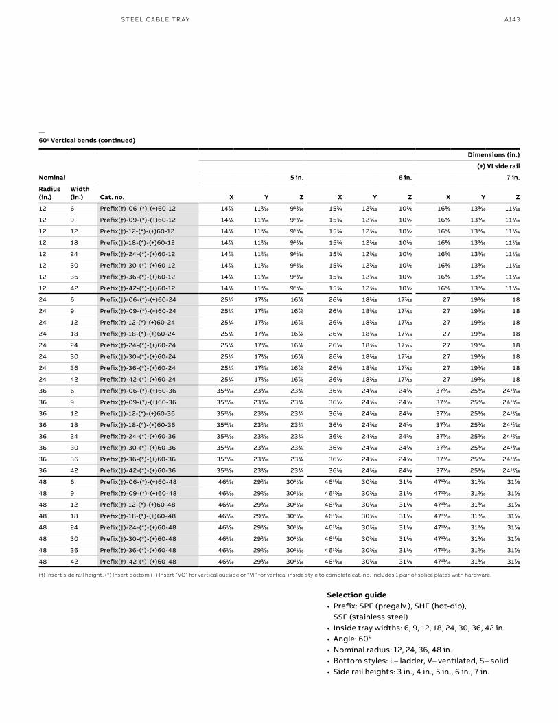
A143S TEEL C A B L E TR AY
Dimensions (in.)
Nominal
(+) VI side rail
5 in. 6 in. 7 in.
Radius (in.)
Width (in.) Cat. no. X Y Z X Y Z X Y Z
12 6 Prefix(†)-06-(*)-(+)60-12 1477⁄88 1133⁄1616 91515⁄1616 1533⁄44 1233⁄1616 1011⁄22 1655⁄88 1333⁄1616 1111⁄1616
12 9 Prefix(†)-09-(*)-(+)60-12 1477⁄88 1133⁄1616 91515⁄1616 1533⁄44 1233⁄1616 1011⁄22 1655⁄88 1333⁄1616 1111⁄1616
12 12 Prefix(†)-12-(*)-(+)60-12 1477⁄88 1133⁄1616 91515⁄1616 1533⁄44 1233⁄1616 1011⁄22 1655⁄88 1333⁄1616 1111⁄1616
12 18 Prefix(†)-18-(*)-(+)60-12 1477⁄88 1133⁄1616 91515⁄1616 1533⁄44 1233⁄1616 1011⁄22 1655⁄88 1333⁄1616 1111⁄1616
12 24 Prefix(†)-24-(*)-(+)60-12 1477⁄88 1133⁄1616 91515⁄1616 1533⁄44 1233⁄1616 1011⁄22 1655⁄88 1333⁄1616 1111⁄1616
12 30 Prefix(†)-30-(*)-(+)60-12 1477⁄88 1133⁄1616 91515⁄1616 1533⁄44 1233⁄1616 1011⁄22 1655⁄88 1333⁄1616 1111⁄1616
12 36 Prefix(†)-36-(*)-(+)60-12 1477⁄88 1133⁄1616 91515⁄1616 1533⁄44 1233⁄1616 1011⁄22 1655⁄88 1333⁄1616 1111⁄1616
12 42 Prefix(†)-42-(*)-(+)60-12 1477⁄88 1133⁄1616 91515⁄1616 1533⁄44 1233⁄1616 1011⁄22 1655⁄88 1333⁄1616 1111⁄1616
24 6 Prefix(†)-06-(*)-(+)60-24 2511⁄44 1733⁄1616 1677⁄88 2611⁄88 1833⁄1616 1777⁄1616 27 1933⁄1616 18
24 9 Prefix(†)-09-(*)-(+)60-24 2511⁄44 1733⁄1616 1677⁄88 2611⁄88 1833⁄1616 1777⁄1616 27 1933⁄1616 18
24 12 Prefix(†)-12-(*)-(+)60-24 2511⁄44 1733⁄1616 1677⁄88 2611⁄88 1833⁄1616 1777⁄1616 27 1933⁄1616 18
24 18 Prefix(†)-18-(*)-(+)60-24 2511⁄44 1733⁄1616 1677⁄88 2611⁄88 1833⁄1616 1777⁄1616 27 1933⁄1616 18
24 24 Prefix(†)-24-(*)-(+)60-24 2511⁄44 1733⁄1616 1677⁄88 2611⁄88 1833⁄1616 1777⁄1616 27 1933⁄1616 18
24 30 Prefix(†)-30-(*)-(+)60-24 2511⁄44 1733⁄1616 1677⁄88 2611⁄88 1833⁄1616 1777⁄1616 27 1933⁄1616 18
24 36 Prefix(†)-36-(*)-(+)60-24 2511⁄44 1733⁄1616 1677⁄88 2611⁄88 1833⁄1616 1777⁄1616 27 1933⁄1616 18
24 42 Prefix(†)-42-(*)-(+)60-24 2511⁄44 1733⁄1616 1677⁄88 2611⁄88 1833⁄1616 1777⁄1616 27 1933⁄1616 18
36 6 Prefix(†)-06-(*)-(+)60-36 351111⁄1616 2333⁄1616 2333⁄44 3611⁄22 2433⁄1616 2433⁄88 3777⁄1616 2533⁄1616 241515⁄1616
36 9 Prefix(†)-09-(*)-(+)60-36 351111⁄1616 2333⁄1616 2333⁄44 3611⁄22 2433⁄1616 2433⁄88 3777⁄1616 2533⁄1616 241515⁄1616
36 12 Prefix(†)-12-(*)-(+)60-36 351111⁄1616 2333⁄1616 2333⁄44 3611⁄22 2433⁄1616 2433⁄88 3777⁄1616 2533⁄1616 241515⁄1616
36 18 Prefix(†)-18-(*)-(+)60-36 351111⁄1616 2333⁄1616 2333⁄44 3611⁄22 2433⁄1616 2433⁄88 3777⁄1616 2533⁄1616 241515⁄1616
36 24 Prefix(†)-24-(*)-(+)60-36 351111⁄1616 2333⁄1616 2333⁄44 3611⁄22 2433⁄1616 2433⁄88 3777⁄1616 2533⁄1616 241515⁄1616
36 30 Prefix(†)-30-(*)-(+)60-36 351111⁄1616 2333⁄1616 2333⁄44 3611⁄22 2433⁄1616 2433⁄88 3777⁄1616 2533⁄1616 241515⁄1616
36 36 Prefix(†)-36-(*)-(+)60-36 351111⁄1616 2333⁄1616 2333⁄44 3611⁄22 2433⁄1616 2433⁄88 3777⁄1616 2533⁄1616 241515⁄1616
36 42 Prefix(†)-42-(*)-(+)60-36 351111⁄1616 2333⁄1616 2333⁄44 3611⁄22 2433⁄1616 2433⁄88 3777⁄1616 2533⁄1616 241515⁄1616
48 6 Prefix(†)-06-(*)-(+)60-48 4611⁄1616 2933⁄1616 301111⁄1616 461515⁄1616 3033⁄1616 3111⁄88 471313⁄1616 3133⁄1616 3177⁄88
48 9 Prefix(†)-09-(*)-(+)60-48 4611⁄1616 2933⁄1616 301111⁄1616 461515⁄1616 3033⁄1616 3111⁄88 471313⁄1616 3133⁄1616 3177⁄88
48 12 Prefix(†)-12-(*)-(+)60-48 4611⁄1616 2933⁄1616 301111⁄1616 461515⁄1616 3033⁄1616 3111⁄88 471313⁄1616 3133⁄1616 3177⁄88
48 18 Prefix(†)-18-(*)-(+)60-48 4611⁄1616 2933⁄1616 301111⁄1616 461515⁄1616 3033⁄1616 3111⁄88 471313⁄1616 3133⁄1616 3177⁄88
48 24 Prefix(†)-24-(*)-(+)60-48 4611⁄1616 2933⁄1616 301111⁄1616 461515⁄1616 3033⁄1616 3111⁄88 471313⁄1616 3133⁄1616 3177⁄88
48 30 Prefix(†)-30-(*)-(+)60-48 4611⁄1616 2933⁄1616 301111⁄1616 461515⁄1616 3033⁄1616 3111⁄88 471313⁄1616 3133⁄1616 3177⁄88
48 36 Prefix(†)-36-(*)-(+)60-48 4611⁄1616 2933⁄1616 301111⁄1616 461515⁄1616 3033⁄1616 3111⁄88 471313⁄1616 3133⁄1616 3177⁄88
48 42 Prefix(†)-42-(*)-(+)60-48 4611⁄1616 2933⁄1616 301111⁄1616 461515⁄1616 3033⁄1616 3111⁄88 471313⁄1616 3133⁄1616 3177⁄88
—60o Vertical bends (continued)
Selection guide• Prefix: SPF (pregalv.), SHF (hot-dip),
SSF (stainless steel)• Inside tray widths: 6, 9, 12, 18, 24, 30, 36, 42 in.• Angle: 60o• Nominal radius: 12, 24, 36, 48 in. • Bottom styles: L– ladder, V– ventilated, S– solid• Side rail heights: 3 in., 4 in., 5 in., 6 in., 7 in.
(†) Insert side rail height. (*) Insert bottom (+) Insert “VO” for vertical outside or “VI” for vertical inside style to complete cat. no. Includes 1 pair of splice plates with hardware.
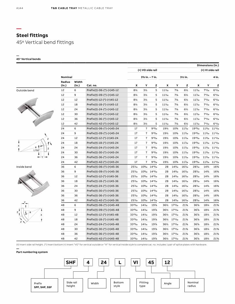
B1 copy starts here
B2 copy starts here
B3 copy starts here
A144 T& B C A B LE TR AY M E TA L L I C C A B L E TR AY
Dimensions (in.)
Nominal
(+) VO side rail (+) VI side rail
355⁄88 in. – 7 in. 311⁄22 in. 4 in.
Radius (in.)
Width (in.) Cat. no. X Y Z X Y Z X Y Z
12 6 Prefix(†)-06-(*)-(+)45-12 811⁄22 311⁄22 5 1111⁄1616 711⁄88 611⁄22 1177⁄1616 71111⁄1616 61111⁄1616
12 9 Prefix(†)-09-(*)-(+)45-12 811⁄22 311⁄22 5 1111⁄1616 711⁄88 611⁄22 1177⁄1616 71111⁄1616 61111⁄1616
12 12 Prefix(†)-12-(*)-(+)45-12 811⁄22 311⁄22 5 1111⁄1616 711⁄88 611⁄22 1177⁄1616 71111⁄1616 61111⁄1616
12 18 Prefix(†)-18-(*)-(+)45-12 811⁄22 311⁄22 5 1111⁄1616 711⁄88 611⁄22 1177⁄1616 71111⁄1616 61111⁄1616
12 24 Prefix(†)-24-(*)-(+)45-12 811⁄22 311⁄22 5 1111⁄1616 711⁄88 611⁄22 1177⁄1616 71111⁄1616 61111⁄1616
12 30 Prefix(†)-30-(*)-(+)45-12 811⁄22 311⁄22 5 1111⁄1616 711⁄88 611⁄22 1177⁄1616 71111⁄1616 61111⁄1616
12 36 Prefix(†)-36-(*)-(+)45-12 811⁄22 311⁄22 5 1111⁄1616 711⁄88 611⁄22 1177⁄1616 71111⁄1616 61111⁄1616
12 42 Prefix(†)-42-(*)-(+)45-12 811⁄22 311⁄22 5 1111⁄1616 711⁄88 611⁄22 1177⁄1616 71111⁄1616 61111⁄1616
24 6 Prefix(†)-06-(*)-(+)45-24 17 7 91515⁄1616 1911⁄22 1055⁄88 1177⁄1616 191515⁄1616 1133⁄1616 111111⁄1616
24 9 Prefix(†)-09-(*)-(+)45-24 17 7 91515⁄1616 1911⁄22 1055⁄88 1177⁄1616 191515⁄1616 1133⁄1616 111111⁄1616
24 12 Prefix(†)-12-(*)-(+)45-24 17 7 91515⁄1616 1911⁄22 1055⁄88 1177⁄1616 191515⁄1616 1133⁄1616 111111⁄1616
24 18 Prefix(†)-18-(*)-(+)45-24 17 7 91515⁄1616 1911⁄22 1055⁄88 1177⁄1616 191515⁄1616 1133⁄1616 111111⁄1616
24 24 Prefix(†)-24-(*)-(+)45-24 17 7 91515⁄1616 1911⁄22 1055⁄88 1177⁄1616 191515⁄1616 1133⁄1616 111111⁄1616
24 30 Prefix(†)-30-(*)-(+)45-24 17 7 91515⁄1616 1911⁄22 1055⁄88 1177⁄1616 191515⁄1616 1133⁄1616 111111⁄1616
24 36 Prefix(†)-36-(*)-(+)45-24 17 7 91515⁄1616 1911⁄22 1055⁄88 1177⁄1616 191515⁄1616 1133⁄1616 111111⁄1616
24 42 Prefix(†)-42-(*)-(+)45-24 17 7 91515⁄1616 1911⁄22 1055⁄88 1177⁄1616 191515⁄1616 1133⁄1616 111111⁄1616
36 6 Prefix(†)-06-(*)-(+)45-36 2577⁄1616 1099⁄1616 141515⁄1616 28 1433⁄1616 1677⁄1616 2877⁄1616 1433⁄44 1655⁄88
36 9 Prefix(†)-09-(*)-(+)45-36 2577⁄1616 1099⁄1616 141515⁄1616 28 1433⁄1616 1677⁄1616 2877⁄1616 1433⁄44 1655⁄88
36 12 Prefix(†)-12-(*)-(+)45-36 2577⁄1616 1099⁄1616 141515⁄1616 28 1433⁄1616 1677⁄1616 2877⁄1616 1433⁄44 1655⁄88
36 18 Prefix(†)-18-(*)-(+)45-36 2577⁄1616 1099⁄1616 141515⁄1616 28 1433⁄1616 1677⁄1616 2877⁄1616 1433⁄44 1655⁄88
36 24 Prefix(†)-24-(*)-(+)45-36 2577⁄1616 1099⁄1616 141515⁄1616 28 1433⁄1616 1677⁄1616 2877⁄1616 1433⁄44 1655⁄88
36 30 Prefix(†)-30-(*)-(+)45-36 2577⁄1616 1099⁄1616 141515⁄1616 28 1433⁄1616 1677⁄1616 2877⁄1616 1433⁄44 1655⁄88
36 36 Prefix(†)-36-(*)-(+)45-36 2577⁄1616 1099⁄1616 141515⁄1616 28 1433⁄1616 1677⁄1616 2877⁄1616 1433⁄44 1655⁄88
36 42 Prefix(†)-42-(*)-(+)45-36 2577⁄1616 1099⁄1616 141515⁄1616 28 1433⁄1616 1677⁄1616 2877⁄1616 1433⁄44 1655⁄88
48 6 Prefix(†)-06-(*)-(+)45-48 331515⁄1616 1411⁄1616 1977⁄88 3611⁄22 171111⁄1616 2133⁄88 3677⁄88 1811⁄44 2155⁄88
48 9 Prefix(†)-09-(*)-(+)45-48 331515⁄1616 1411⁄1616 1977⁄88 3611⁄22 171111⁄1616 2133⁄88 3677⁄88 1811⁄44 2155⁄88
48 12 Prefix(†)-12-(*)-(+)45-48 331515⁄1616 1411⁄1616 1977⁄88 3611⁄22 171111⁄1616 2133⁄88 3677⁄88 1811⁄44 2155⁄88
48 18 Prefix(†)-18-(*)-(+)45-48 331515⁄1616 1411⁄1616 1977⁄88 3611⁄22 171111⁄1616 2133⁄88 3677⁄88 1811⁄44 2155⁄88
48 24 Prefix(†)-24-(*)-(+)45-48 331515⁄1616 1411⁄1616 1977⁄88 3611⁄22 171111⁄1616 2133⁄88 3677⁄88 1811⁄44 2155⁄88
48 30 Prefix(†)-30-(*)-(+)45-48 331515⁄1616 1411⁄1616 1977⁄88 3611⁄22 171111⁄1616 2133⁄88 3677⁄88 1811⁄44 2155⁄88
48 36 Prefix(†)-36-(*)-(+)45-48 331515⁄1616 1411⁄1616 1977⁄88 3611⁄22 171111⁄1616 2133⁄88 3677⁄88 1811⁄44 2155⁄88
48 42 Prefix(†)-42-(*)-(+)45-48 331515⁄1616 1411⁄1616 1977⁄88 3611⁄22 171111⁄1616 2133⁄88 3677⁄88 1811⁄44 2155⁄88
—Steel fittings45o Vertical bend fittings
—45o Vertical bends
(†) Insert side rail height. (*) Insert bottom (+) Insert “VO” for vertical outside or “VI” for vertical inside style to complete cat. no. Includes 1 pair of splice plates with hardware.
—Part numbering system
Outside bend
Inside bend
SHF 4 24 L VI 45 12
PrefixSPF, SHF, SSF
Side rail height
Bottom style
Width AngleFitting type
Nominalradius
1.750"
Y
Y
X
X
Z
Z
Z
Z
Z
R
R
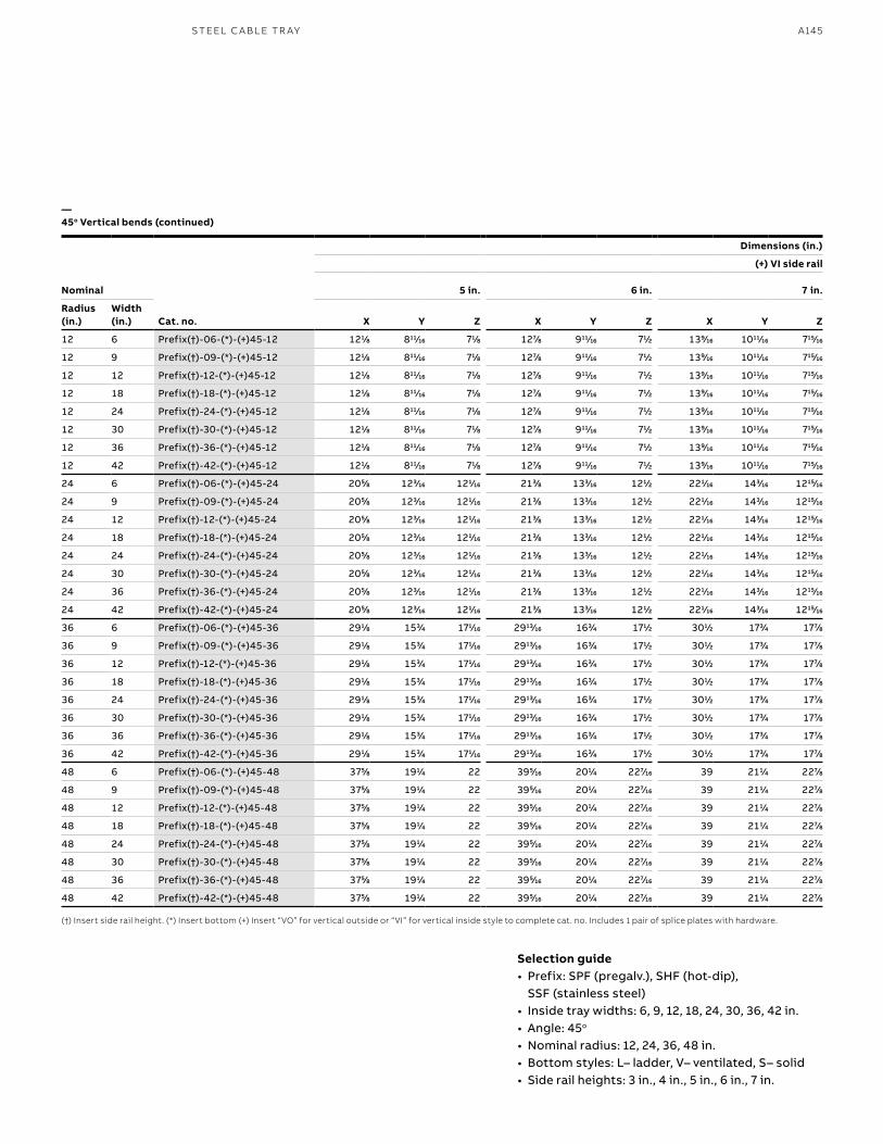
A145S TEEL C A B L E TR AY
Dimensions (in.)
Nominal
(+) VI side rail
5 in. 6 in. 7 in.
Radius (in.)
Width (in.) Cat. no. X Y Z X Y Z X Y Z
12 6 Prefix(†)-06-(*)-(+)45-12 1211⁄88 81111⁄1616 711⁄88 1277⁄88 91111⁄1616 711⁄22 1399⁄1616 101111⁄1616 71515⁄1616
12 9 Prefix(†)-09-(*)-(+)45-12 1211⁄88 81111⁄1616 711⁄88 1277⁄88 91111⁄1616 711⁄22 1399⁄1616 101111⁄1616 71515⁄1616
12 12 Prefix(†)-12-(*)-(+)45-12 1211⁄88 81111⁄1616 711⁄88 1277⁄88 91111⁄1616 711⁄22 1399⁄1616 101111⁄1616 71515⁄1616
12 18 Prefix(†)-18-(*)-(+)45-12 1211⁄88 81111⁄1616 711⁄88 1277⁄88 91111⁄1616 711⁄22 1399⁄1616 101111⁄1616 71515⁄1616
12 24 Prefix(†)-24-(*)-(+)45-12 1211⁄88 81111⁄1616 711⁄88 1277⁄88 91111⁄1616 711⁄22 1399⁄1616 101111⁄1616 71515⁄1616
12 30 Prefix(†)-30-(*)-(+)45-12 1211⁄88 81111⁄1616 711⁄88 1277⁄88 91111⁄1616 711⁄22 1399⁄1616 101111⁄1616 71515⁄1616
12 36 Prefix(†)-36-(*)-(+)45-12 1211⁄88 81111⁄1616 711⁄88 1277⁄88 91111⁄1616 711⁄22 1399⁄1616 101111⁄1616 71515⁄1616
12 42 Prefix(†)-42-(*)-(+)45-12 1211⁄88 81111⁄1616 711⁄88 1277⁄88 91111⁄1616 711⁄22 1399⁄1616 101111⁄1616 71515⁄1616
24 6 Prefix(†)-06-(*)-(+)45-24 2055⁄88 1233⁄1616 1211⁄1616 2133⁄88 1333⁄1616 1211⁄22 2211⁄1616 1433⁄1616 121515⁄1616
24 9 Prefix(†)-09-(*)-(+)45-24 2055⁄88 1233⁄1616 1211⁄1616 2133⁄88 1333⁄1616 1211⁄22 2211⁄1616 1433⁄1616 121515⁄1616
24 12 Prefix(†)-12-(*)-(+)45-24 2055⁄88 1233⁄1616 1211⁄1616 2133⁄88 1333⁄1616 1211⁄22 2211⁄1616 1433⁄1616 121515⁄1616
24 18 Prefix(†)-18-(*)-(+)45-24 2055⁄88 1233⁄1616 1211⁄1616 2133⁄88 1333⁄1616 1211⁄22 2211⁄1616 1433⁄1616 121515⁄1616
24 24 Prefix(†)-24-(*)-(+)45-24 2055⁄88 1233⁄1616 1211⁄1616 2133⁄88 1333⁄1616 1211⁄22 2211⁄1616 1433⁄1616 121515⁄1616
24 30 Prefix(†)-30-(*)-(+)45-24 2055⁄88 1233⁄1616 1211⁄1616 2133⁄88 1333⁄1616 1211⁄22 2211⁄1616 1433⁄1616 121515⁄1616
24 36 Prefix(†)-36-(*)-(+)45-24 2055⁄88 1233⁄1616 1211⁄1616 2133⁄88 1333⁄1616 1211⁄22 2211⁄1616 1433⁄1616 121515⁄1616
24 42 Prefix(†)-42-(*)-(+)45-24 2055⁄88 1233⁄1616 1211⁄1616 2133⁄88 1333⁄1616 1211⁄22 2211⁄1616 1433⁄1616 121515⁄1616
36 6 Prefix(†)-06-(*)-(+)45-36 2911⁄88 1533⁄44 1711⁄1616 291313⁄1616 1633⁄44 1711⁄22 3011⁄22 1733⁄44 1777⁄88
36 9 Prefix(†)-09-(*)-(+)45-36 2911⁄88 1533⁄44 1711⁄1616 291313⁄1616 1633⁄44 1711⁄22 3011⁄22 1733⁄44 1777⁄88
36 12 Prefix(†)-12-(*)-(+)45-36 2911⁄88 1533⁄44 1711⁄1616 291313⁄1616 1633⁄44 1711⁄22 3011⁄22 1733⁄44 1777⁄88
36 18 Prefix(†)-18-(*)-(+)45-36 2911⁄88 1533⁄44 1711⁄1616 291313⁄1616 1633⁄44 1711⁄22 3011⁄22 1733⁄44 1777⁄88
36 24 Prefix(†)-24-(*)-(+)45-36 2911⁄88 1533⁄44 1711⁄1616 291313⁄1616 1633⁄44 1711⁄22 3011⁄22 1733⁄44 1777⁄88
36 30 Prefix(†)-30-(*)-(+)45-36 2911⁄88 1533⁄44 1711⁄1616 291313⁄1616 1633⁄44 1711⁄22 3011⁄22 1733⁄44 1777⁄88
36 36 Prefix(†)-36-(*)-(+)45-36 2911⁄88 1533⁄44 1711⁄1616 291313⁄1616 1633⁄44 1711⁄22 3011⁄22 1733⁄44 1777⁄88
36 42 Prefix(†)-42-(*)-(+)45-36 2911⁄88 1533⁄44 1711⁄1616 291313⁄1616 1633⁄44 1711⁄22 3011⁄22 1733⁄44 1777⁄88
48 6 Prefix(†)-06-(*)-(+)45-48 3755⁄88 1911⁄44 22 3955⁄1616 2011⁄44 2277⁄1616 39 2111⁄44 2277⁄88
48 9 Prefix(†)-09-(*)-(+)45-48 3755⁄88 1911⁄44 22 3955⁄1616 2011⁄44 2277⁄1616 39 2111⁄44 2277⁄88
48 12 Prefix(†)-12-(*)-(+)45-48 3755⁄88 1911⁄44 22 3955⁄1616 2011⁄44 2277⁄1616 39 2111⁄44 2277⁄88
48 18 Prefix(†)-18-(*)-(+)45-48 3755⁄88 1911⁄44 22 3955⁄1616 2011⁄44 2277⁄1616 39 2111⁄44 2277⁄88
48 24 Prefix(†)-24-(*)-(+)45-48 3755⁄88 1911⁄44 22 3955⁄1616 2011⁄44 2277⁄1616 39 2111⁄44 2277⁄88
48 30 Prefix(†)-30-(*)-(+)45-48 3755⁄88 1911⁄44 22 3955⁄1616 2011⁄44 2277⁄1616 39 2111⁄44 2277⁄88
48 36 Prefix(†)-36-(*)-(+)45-48 3755⁄88 1911⁄44 22 3955⁄1616 2011⁄44 2277⁄1616 39 2111⁄44 2277⁄88
48 42 Prefix(†)-42-(*)-(+)45-48 3755⁄88 1911⁄44 22 3955⁄1616 2011⁄44 2277⁄1616 39 2111⁄44 2277⁄88
—45o Vertical bends (continued)
(†) Insert side rail height. (*) Insert bottom (+) Insert “VO” for vertical outside or “VI” for vertical inside style to complete cat. no. Includes 1 pair of splice plates with hardware.
Selection guide• Prefix: SPF (pregalv.), SHF (hot-dip),
SSF (stainless steel)• Inside tray widths: 6, 9, 12, 18, 24, 30, 36, 42 in.• Angle: 45o
• Nominal radius: 12, 24, 36, 48 in. • Bottom styles: L– ladder, V– ventilated, S– solid• Side rail heights: 3 in., 4 in., 5 in., 6 in., 7 in.
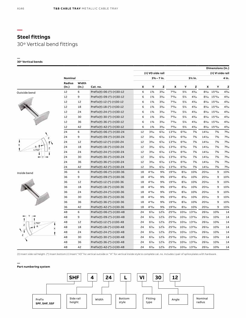
B1 copy starts here
B2 copy starts here
B3 copy starts here
A146 T& B C A B LE TR AY M E TA L L I C C A B L E TR AY
Dimensions (in.)
Nominal
(+) VO side rail (+) VI side rail
355⁄88 – 7 in. 311⁄22 in. 4 in.
Radius (in.)
Width (in.) Cat. no. X Y Z X Y Z X Y Z
12 6 Prefix(†)-06-(*)-(+)30-12 6 155⁄88 333⁄1616 71313⁄1616 511⁄44 433⁄1616 811⁄1616 151313⁄1616 455⁄1616
12 9 Prefix(†)-09-(*)-(+)30-12 6 155⁄88 333⁄1616 71313⁄1616 511⁄44 433⁄1616 811⁄1616 151313⁄1616 455⁄1616
12 12 Prefix(†)-12-(*)-(+)30-12 6 155⁄88 333⁄1616 71313⁄1616 511⁄44 433⁄1616 811⁄1616 151313⁄1616 455⁄1616
12 18 Prefix(†)-18-(*)-(+)30-12 6 155⁄88 333⁄1616 71313⁄1616 511⁄44 433⁄1616 811⁄1616 151313⁄1616 455⁄1616
12 24 Prefix(†)-24-(*)-(+)30-12 6 155⁄88 333⁄1616 71313⁄1616 511⁄44 433⁄1616 811⁄1616 151313⁄1616 455⁄1616
12 30 Prefix(†)-30-(*)-(+)30-12 6 155⁄88 333⁄1616 71313⁄1616 511⁄44 433⁄1616 811⁄1616 151313⁄1616 455⁄1616
12 36 Prefix(†)-36-(*)-(+)30-12 6 155⁄88 333⁄1616 71313⁄1616 511⁄44 433⁄1616 811⁄1616 151313⁄1616 455⁄1616
12 42 Prefix(†)-42-(*)-(+)30-12 6 155⁄88 333⁄1616 71313⁄1616 511⁄44 433⁄1616 811⁄1616 151313⁄1616 455⁄1616
24 6 Prefix(†)-06-(*)-(+)30-24 12 333⁄1616 677⁄1616 131313⁄1616 61313⁄1616 733⁄88 1411⁄1616 733⁄88 799⁄1616
24 9 Prefix(†)-09-(*)-(+)30-24 12 333⁄1616 677⁄1616 131313⁄1616 61313⁄1616 733⁄88 1411⁄1616 733⁄88 799⁄1616
24 12 Prefix(†)-12-(*)-(+)30-24 12 333⁄1616 677⁄1616 131313⁄1616 61313⁄1616 733⁄88 1411⁄1616 733⁄88 799⁄1616
24 18 Prefix(†)-18-(*)-(+)30-24 12 333⁄1616 677⁄1616 131313⁄1616 61313⁄1616 733⁄88 1411⁄1616 733⁄88 799⁄1616
24 24 Prefix(†)-24-(*)-(+)30-24 12 333⁄1616 677⁄1616 131313⁄1616 61313⁄1616 733⁄88 1411⁄1616 733⁄88 799⁄1616
24 30 Prefix(†)-30-(*)-(+)30-24 12 333⁄1616 677⁄1616 131313⁄1616 61313⁄1616 733⁄88 1411⁄1616 733⁄88 799⁄1616
24 36 Prefix(†)-36-(*)-(+)30-24 12 333⁄1616 677⁄1616 131313⁄1616 61313⁄1616 733⁄88 1411⁄1616 733⁄88 799⁄1616
24 42 Prefix(†)-42-(*)-(+)30-24 12 333⁄1616 677⁄1616 131313⁄1616 61313⁄1616 733⁄88 1411⁄1616 733⁄88 799⁄1616
36 6 Prefix(†)-06-(*)-(+)30-36 18 41313⁄1616 955⁄88 191313⁄1616 877⁄1616 1055⁄88 2011⁄1616 9 1033⁄44
36 9 Prefix(†)-09-(*)-(+)30-36 18 41313⁄1616 955⁄88 191313⁄1616 877⁄1616 1055⁄88 2011⁄1616 9 1033⁄44
36 12 Prefix(†)-12-(*)-(+)30-36 18 41313⁄1616 955⁄88 191313⁄1616 877⁄1616 1055⁄88 2011⁄1616 9 1033⁄44
36 18 Prefix(†)-18-(*)-(+)30-36 18 41313⁄1616 955⁄88 191313⁄1616 877⁄1616 1055⁄88 2011⁄1616 9 1033⁄44
36 24 Prefix(†)-24-(*)-(+)30-36 18 41313⁄1616 955⁄88 191313⁄1616 877⁄1616 1055⁄88 2011⁄1616 9 1033⁄44
36 30 Prefix(†)-30-(*)-(+)30-36 18 41313⁄1616 955⁄88 191313⁄1616 877⁄1616 1055⁄88 2011⁄1616 9 1033⁄44
36 36 Prefix(†)-36-(*)-(+)30-36 18 41313⁄1616 955⁄88 191313⁄1616 877⁄1616 1055⁄88 2011⁄1616 9 1033⁄44
36 42 Prefix(†)-42-(*)-(+)30-36 18 41313⁄1616 955⁄88 191313⁄1616 877⁄1616 1055⁄88 2011⁄1616 9 1033⁄44
48 6 Prefix(†)-06-(*)-(+)30-48 24 677⁄1616 1277⁄88 251313⁄1616 1011⁄1616 131313⁄1616 2611⁄1616 1055⁄88 14
48 9 Prefix(†)-09-(*)-(+)30-48 24 677⁄1616 1277⁄88 251313⁄1616 1011⁄1616 131313⁄1616 2611⁄1616 1055⁄88 14
48 12 Prefix(†)-12-(*)-(+)30-48 24 677⁄1616 1277⁄88 251313⁄1616 1011⁄1616 131313⁄1616 2611⁄1616 1055⁄88 14
48 18 Prefix(†)-18-(*)-(+)30-48 24 677⁄1616 1277⁄88 251313⁄1616 1011⁄1616 131313⁄1616 2611⁄1616 1055⁄88 14
48 24 Prefix(†)-24-(*)-(+)30-48 24 677⁄1616 1277⁄88 251313⁄1616 1011⁄1616 131313⁄1616 2611⁄1616 1055⁄88 14
48 30 Prefix(†)-30-(*)-(+)30-48 24 677⁄1616 1277⁄88 251313⁄1616 1011⁄1616 131313⁄1616 2611⁄1616 1055⁄88 14
48 36 Prefix(†)-36-(*)-(+)30-48 24 677⁄1616 1277⁄88 251313⁄1616 1011⁄1616 131313⁄1616 2611⁄1616 1055⁄88 14
48 42 Prefix(†)-42-(*)-(+)30-48 24 677⁄1616 1277⁄88 251313⁄1616 1011⁄1616 131313⁄1616 2611⁄1616 1055⁄88 14
—Steel fittings 30o Vertical bend fittings
—30o Vertical bends
(†) Insert side rail height. (*) Insert bottom (+) Insert “VO” for vertical outside or “VI” for vertical inside style to complete cat. no. Includes 1 pair of splice plates with hardware.
—Part numbering system
Outside bend
Inside bend
SHF 4 24 L VI 30 12
PrefixSPF, SHF, SSF
Side rail height
Bottom style
Width AngleFitting type
Nominalradius
1.750"
1.750"
Y
Y
X
X
Z
Z
Z
ZR
R
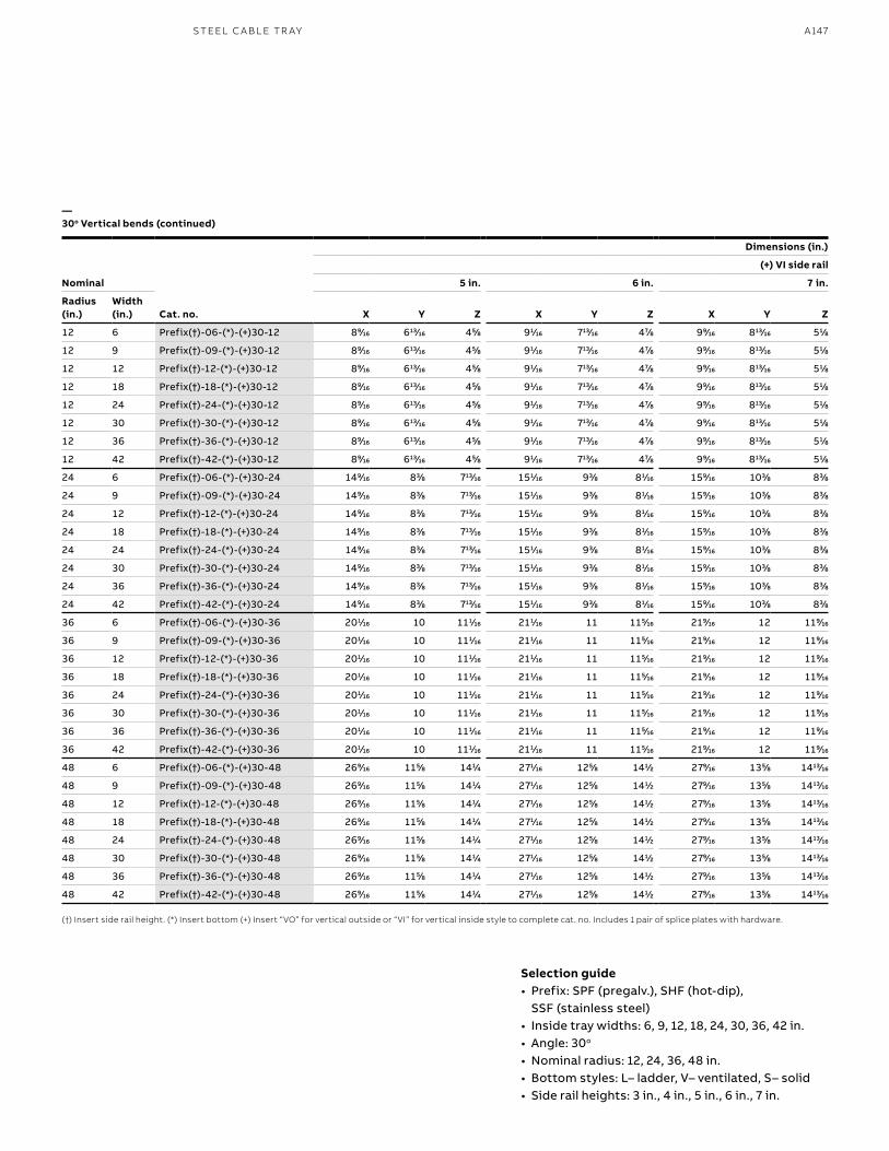
A147S TEEL C A B L E TR AY
Dimensions (in.)
Nominal
(+) VI side rail
5 in. 6 in. 7 in.
Radius (in.)
Width (in.) Cat. no. X Y Z X Y Z X Y Z
12 6 Prefix(†)-06-(*)-(+)30-12 899⁄1616 61313⁄1616 455⁄88 911⁄1616 71313⁄1616 477⁄88 999⁄1616 81313⁄1616 511⁄88
12 9 Prefix(†)-09-(*)-(+)30-12 899⁄1616 61313⁄1616 455⁄88 911⁄1616 71313⁄1616 477⁄88 999⁄1616 81313⁄1616 511⁄88
12 12 Prefix(†)-12-(*)-(+)30-12 899⁄1616 61313⁄1616 455⁄88 911⁄1616 71313⁄1616 477⁄88 999⁄1616 81313⁄1616 511⁄88
12 18 Prefix(†)-18-(*)-(+)30-12 899⁄1616 61313⁄1616 455⁄88 911⁄1616 71313⁄1616 477⁄88 999⁄1616 81313⁄1616 511⁄88
12 24 Prefix(†)-24-(*)-(+)30-12 899⁄1616 61313⁄1616 455⁄88 911⁄1616 71313⁄1616 477⁄88 999⁄1616 81313⁄1616 511⁄88
12 30 Prefix(†)-30-(*)-(+)30-12 899⁄1616 61313⁄1616 455⁄88 911⁄1616 71313⁄1616 477⁄88 999⁄1616 81313⁄1616 511⁄88
12 36 Prefix(†)-36-(*)-(+)30-12 899⁄1616 61313⁄1616 455⁄88 911⁄1616 71313⁄1616 477⁄88 999⁄1616 81313⁄1616 511⁄88
12 42 Prefix(†)-42-(*)-(+)30-12 899⁄1616 61313⁄1616 455⁄88 911⁄1616 71313⁄1616 477⁄88 999⁄1616 81313⁄1616 511⁄88
24 6 Prefix(†)-06-(*)-(+)30-24 1499⁄1616 833⁄88 71313⁄1616 1511⁄1616 933⁄88 811⁄1616 1599⁄1616 1033⁄88 833⁄88
24 9 Prefix(†)-09-(*)-(+)30-24 1499⁄1616 833⁄88 71313⁄1616 1511⁄1616 933⁄88 811⁄1616 1599⁄1616 1033⁄88 833⁄88
24 12 Prefix(†)-12-(*)-(+)30-24 1499⁄1616 833⁄88 71313⁄1616 1511⁄1616 933⁄88 811⁄1616 1599⁄1616 1033⁄88 833⁄88
24 18 Prefix(†)-18-(*)-(+)30-24 1499⁄1616 833⁄88 71313⁄1616 1511⁄1616 933⁄88 811⁄1616 1599⁄1616 1033⁄88 833⁄88
24 24 Prefix(†)-24-(*)-(+)30-24 1499⁄1616 833⁄88 71313⁄1616 1511⁄1616 933⁄88 811⁄1616 1599⁄1616 1033⁄88 833⁄88
24 30 Prefix(†)-30-(*)-(+)30-24 1499⁄1616 833⁄88 71313⁄1616 1511⁄1616 933⁄88 811⁄1616 1599⁄1616 1033⁄88 833⁄88
24 36 Prefix(†)-36-(*)-(+)30-24 1499⁄1616 833⁄88 71313⁄1616 1511⁄1616 933⁄88 811⁄1616 1599⁄1616 1033⁄88 833⁄88
24 42 Prefix(†)-42-(*)-(+)30-24 1499⁄1616 833⁄88 71313⁄1616 1511⁄1616 933⁄88 811⁄1616 1599⁄1616 1033⁄88 833⁄88
36 6 Prefix(†)-06-(*)-(+)30-36 2011⁄1616 10 1111⁄1616 2111⁄1616 11 1155⁄1616 2199⁄1616 12 1199⁄1616
36 9 Prefix(†)-09-(*)-(+)30-36 2011⁄1616 10 1111⁄1616 2111⁄1616 11 1155⁄1616 2199⁄1616 12 1199⁄1616
36 12 Prefix(†)-12-(*)-(+)30-36 2011⁄1616 10 1111⁄1616 2111⁄1616 11 1155⁄1616 2199⁄1616 12 1199⁄1616
36 18 Prefix(†)-18-(*)-(+)30-36 2011⁄1616 10 1111⁄1616 2111⁄1616 11 1155⁄1616 2199⁄1616 12 1199⁄1616
36 24 Prefix(†)-24-(*)-(+)30-36 2011⁄1616 10 1111⁄1616 2111⁄1616 11 1155⁄1616 2199⁄1616 12 1199⁄1616
36 30 Prefix(†)-30-(*)-(+)30-36 2011⁄1616 10 1111⁄1616 2111⁄1616 11 1155⁄1616 2199⁄1616 12 1199⁄1616
36 36 Prefix(†)-36-(*)-(+)30-36 2011⁄1616 10 1111⁄1616 2111⁄1616 11 1155⁄1616 2199⁄1616 12 1199⁄1616
36 42 Prefix(†)-42-(*)-(+)30-36 2011⁄1616 10 1111⁄1616 2111⁄1616 11 1155⁄1616 2199⁄1616 12 1199⁄1616
48 6 Prefix(†)-06-(*)-(+)30-48 2699⁄1616 1155⁄88 1411⁄44 2711⁄1616 1255⁄88 1411⁄22 2799⁄1616 1355⁄88 141313⁄1616
48 9 Prefix(†)-09-(*)-(+)30-48 2699⁄1616 1155⁄88 1411⁄44 2711⁄1616 1255⁄88 1411⁄22 2799⁄1616 1355⁄88 141313⁄1616
48 12 Prefix(†)-12-(*)-(+)30-48 2699⁄1616 1155⁄88 1411⁄44 2711⁄1616 1255⁄88 1411⁄22 2799⁄1616 1355⁄88 141313⁄1616
48 18 Prefix(†)-18-(*)-(+)30-48 2699⁄1616 1155⁄88 1411⁄44 2711⁄1616 1255⁄88 1411⁄22 2799⁄1616 1355⁄88 141313⁄1616
48 24 Prefix(†)-24-(*)-(+)30-48 2699⁄1616 1155⁄88 1411⁄44 2711⁄1616 1255⁄88 1411⁄22 2799⁄1616 1355⁄88 141313⁄1616
48 30 Prefix(†)-30-(*)-(+)30-48 2699⁄1616 1155⁄88 1411⁄44 2711⁄1616 1255⁄88 1411⁄22 2799⁄1616 1355⁄88 141313⁄1616
48 36 Prefix(†)-36-(*)-(+)30-48 2699⁄1616 1155⁄88 1411⁄44 2711⁄1616 1255⁄88 1411⁄22 2799⁄1616 1355⁄88 141313⁄1616
48 42 Prefix(†)-42-(*)-(+)30-48 2699⁄1616 1155⁄88 1411⁄44 2711⁄1616 1255⁄88 1411⁄22 2799⁄1616 1355⁄88 141313⁄1616
—30o Vertical bends (continued)
(†) Insert side rail height. (*) Insert bottom (+) Insert “VO” for vertical outside or “VI” for vertical inside style to complete cat. no. Includes 1 pair of splice plates with hardware.
Selection guide• Prefix: SPF (pregalv.), SHF (hot-dip),
SSF (stainless steel)• Inside tray widths: 6, 9, 12, 18, 24, 30, 36, 42 in.• Angle: 30o
• Nominal radius: 12, 24, 36, 48 in. • Bottom styles: L– ladder, V– ventilated, S– solid• Side rail heights: 3 in., 4 in., 5 in., 6 in., 7 in.
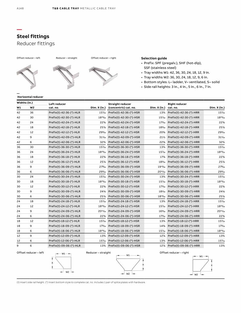
B1 copy starts here
B2 copy starts here
B3 copy starts here
A148 T& B C A B LE TR AY M E TA L L I C C A B L E TR AY
Widths (in.) Left reducercat. no. Dim. X (in.)
Straight reducer (concentric) cat. no. Dim. X (in.)
Right reducercat. no. Dim. X (in.)W1 W2
42 36 Prefix(†)-42-36-(*)-HLR 1577⁄1616 Prefix(†)-42-36-(*)-HSR 1333⁄44 Prefix(†)-42-36-(*)-HRR 1577⁄1616
42 30 Prefix(†)-42-30-(*)-HLR 181515⁄1616 Prefix(†)-42-30-(*)-HSR 1577⁄1616 Prefix(†)-42-30-(*)-HRR 181515⁄1616
42 24 Prefix(†)-42-24-(*)-HLR 2233⁄88 Prefix(†)-42-24-(*)-HSR 1733⁄1616 Prefix(†)-42-24-(*)-HRR 2233⁄88
42 18 Prefix(†)-42-18-(*)-HLR 2577⁄88 Prefix(†)-42-18-(*)-HSR 1855⁄1616 Prefix(†)-42-18-(*)-HRR 2577⁄88
42 12 Prefix(†)-42-12-(*)-HLR 2955⁄1616 Prefix(†)-42-12-(*)-HSR 2055⁄88 Prefix(†)-42-12-(*)-HRR 2955⁄1616
42 9 Prefix(†)-42-09-(*)-HLR 3111⁄1616 Prefix(†)-42-09-(*)-HSR 2111⁄22 Prefix(†)-42-09-(*)-HRR 3111⁄1616
42 6 Prefix(†)-42-06-(*)-HLR 3233⁄44 Prefix(†)-42-06-(*)-HSR 2233⁄88 Prefix(†)-42-06-(*)-HRR 3233⁄44
36 30 Prefix(†)-36-30-(*)-HLR 1577⁄1616 Prefix(†)-36-30-(*)-HSR 1333⁄44 Prefix(†)-36-30-(*)-HRR 1577⁄1616
36 24 Prefix(†)-36-24-(*)-HLR 181515⁄1616 Prefix(†)-36-24-(*)-HSR 1577⁄1616 Prefix(†)-36-24-(*)-HRR 181515⁄1616
36 18 Prefix(†)-36-18-(*)-HLR 2233⁄88 Prefix(†)-36-18-(*)-HSR 1733⁄88 Prefix(†)-36-18-(*)-HRR 2233⁄88
36 12 Prefix(†)-36-12-(*)-HLR 2577⁄88 Prefix(†)-36-12-(*)-HSR 1855⁄1616 Prefix(†)-36-12-(*)-HRR 2577⁄88
36 9 Prefix(†)-36-09-(*)-HLR 2799⁄1616 Prefix(†)-36-09-(*)-HSR 191313⁄1616 Prefix(†)-36-09-(*)-HRR 2799⁄1616
36 6 Prefix(†)-36-06-(*)-HLR 2955⁄1616 Prefix(†)-36-06-(*)-HSR 201111⁄1616 Prefix(†)-36-06-(*)-HRR 2955⁄1616
30 24 Prefix(†)-30-24-(*)-HLR 1577⁄1616 Prefix(†)-30-24-(*)-HSR 1333⁄44 Prefix(†)-30-24-(*)-HRR 1577⁄1616
30 18 Prefix(†)-30-18-(*)-HLR 181515⁄1616 Prefix(†)-30-18-(*)-HSR 1577⁄1616 Prefix(†)-30-18-(*)-HRR 181515⁄1616
30 12 Prefix(†)-30-12-(*)-HLR 2233⁄88 Prefix(†)-30-12-(*)-HSR 1733⁄1616 Prefix(†)-30-12-(*)-HRR 2233⁄88
30 9 Prefix(†)-30-09-(*)-HLR 2411⁄88 Prefix(†)-30-09-(*)-HSR 1811⁄1616 Prefix(†)-30-09-(*)-HRR 2411⁄88
30 6 Prefix(†)-30-06-(*)-HLR 2577⁄88 Prefix(†)-30-06-(*)-HSR 181515⁄1616 Prefix(†)-30-06-(*)-HRR 2577⁄88
24 18 Prefix(†)-24-18-(*)-HLR 1577⁄1616 Prefix(†)-24-18-(*)-HSR 1333⁄44 Prefix(†)-24-18-(*)-HRR 1577⁄1616
24 12 Prefix(†)-24-12-(*)-HLR 181515⁄1616 Prefix(†)-24-12-(*)-HSR 1577⁄1616 Prefix(†)-24-12-(*)-HRR 181515⁄1616
24 9 Prefix(†)-24-09-(*)-HLR 201111⁄1616 Prefix(†)-24-09-(*)-HSR 1655⁄1616 Prefix(†)-24-09-(*)-HRR 201111⁄1616
24 6 Prefix(†)-24-06-(*)-HLR 2233⁄88 Prefix(†)-24-06-(*)-HSR 1733⁄1616 Prefix(†)-24-06-(*)-HRR 2233⁄88
18 12 Prefix(†)-18-12-(*)-HLR 1577⁄1616 Prefix(†)-18-12-(*)-HSR 1333⁄44 Prefix(†)-18-12-(*)-HRR 1577⁄1616
18 9 Prefix(†)-18-09-(*)-HLR 1733⁄1616 Prefix(†)-18-09-(*)-HSR 1455⁄88 Prefix(†)-18-09-(*)-HRR 1733⁄1616
18 6 Prefix(†)-18-06-(*)-HLR 181515⁄1616 Prefix(†)-18-06-(*)-HSR 1577⁄1616 Prefix(†)-18-06-(*)-HRR 181515⁄1616
12 9 Prefix(†)-12-09-(*)-HLR 1333⁄44 Prefix(†)-12-09-(*)-HSR 1277⁄88 Prefix(†)-12-09-(*)-HRR 1333⁄44
12 6 Prefix(†)-12-06-(*)-HLR 1577⁄1616 Prefix(†)-12-06-(*)-HSR 1333⁄44 Prefix(†)-12-06-(*)-HRR 1577⁄1616
9 6 Prefix(†)-09-06-(*)-HLR 1333⁄44 Prefix(†)-09-06-(*)-HSR 1277⁄88 Prefix(†)-09-06-(*)-HRR 1333⁄44
—Steel fittingsReducer fittings
— Horizontal reducer
Offset reducer – right
Offset reducer – right
Reducer – straight
Reducer – straight
Offset reducer – left
Offset reducer – left
(†) Insert side rail height. (*) Insert bottom style to complete cat. no. Includes 1 pair of splice plates with hardware.
Selection guide• Prefix: SPF (pregalv.), SHF (hot-dip),
SSF (stainless steel)• Tray widths W1: 42, 36, 30, 24, 18, 12, 9 in.• Tray widths W2: 36, 30, 24, 18, 12, 9, 6 in.• Bottom styles: L– ladder, V– ventilated, S– solid• Side rail heights: 3 in., 4 in., 5 in., 6 in., 7 in.
XX X
W2W2 W2
W1W1 W1
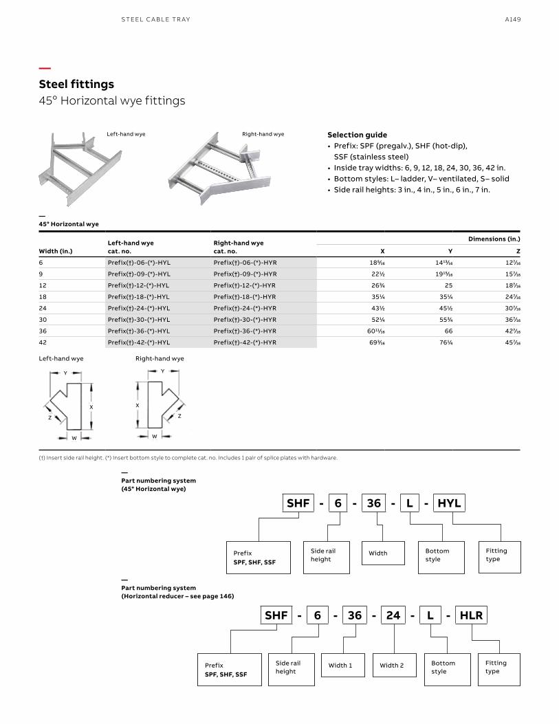
A149S TEEL C A B L E TR AY
—Steel fittings45o Horizontal wye fittings
—45° Horizontal wye
Right-hand wyeLeft-hand wye
Left Hand Wye
(†) Insert side rail height. (*) Insert bottom style to complete cat. no. Includes 1 pair of splice plates with hardware.
Selection guide• Prefix: SPF (pregalv.), SHF (hot-dip),
SSF (stainless steel)• Inside tray widths: 6, 9, 12, 18, 24, 30, 36, 42 in.• Bottom styles: L– ladder, V– ventilated, S– solid• Side rail heights: 3 in., 4 in., 5 in., 6 in., 7 in.
—Part numbering system (Horizontal reducer – see page 146)
—Part numbering system (45° Horizontal wye)
SHF - 6 - 36 - 24 - L - HLR
SHF - 6 - 36 - L - HYL
PrefixSPF, SHF, SSF
Side rail height
Bottom style
Width 1 Fitting type
PrefixSPF, SHF, SSF
Side rail height
Bottom style
Width Fitting type
Width 2
Width (in.)Left-hand wye cat. no.
Right-hand wye cat. no.
Dimensions (in.)
X Y Z
6 Prefix(†)-06-(*)-HYL Prefix(†)-06-(*)-HYR 1855⁄1616 141313⁄1616 1277⁄1616
9 Prefix(†)-09-(*)-HYL Prefix(†)-09-(*)-HYR 2211⁄22 191515⁄1616 1577⁄1616
12 Prefix(†)-12-(*)-HYL Prefix(†)-12-(*)-HYR 2633⁄44 25 1877⁄1616
18 Prefix(†)-18-(*)-HYL Prefix(†)-18-(*)-HYR 3511⁄44 3511⁄44 2477⁄1616
24 Prefix(†)-24-(*)-HYL Prefix(†)-24-(*)-HYR 4311⁄22 4511⁄22 3077⁄1616
30 Prefix(†)-30-(*)-HYL Prefix(†)-30-(*)-HYR 5211⁄44 5533⁄44 3677⁄1616
36 Prefix(†)-36-(*)-HYL Prefix(†)-36-(*)-HYR 601111⁄1616 66 4277⁄1616
42 Prefix(†)-42-(*)-HYL Prefix(†)-42-(*)-HYR 6933⁄1616 7611⁄44 4577⁄1616
Left-hand wye Right-hand wye
W W
X X
Z Z
Y Y
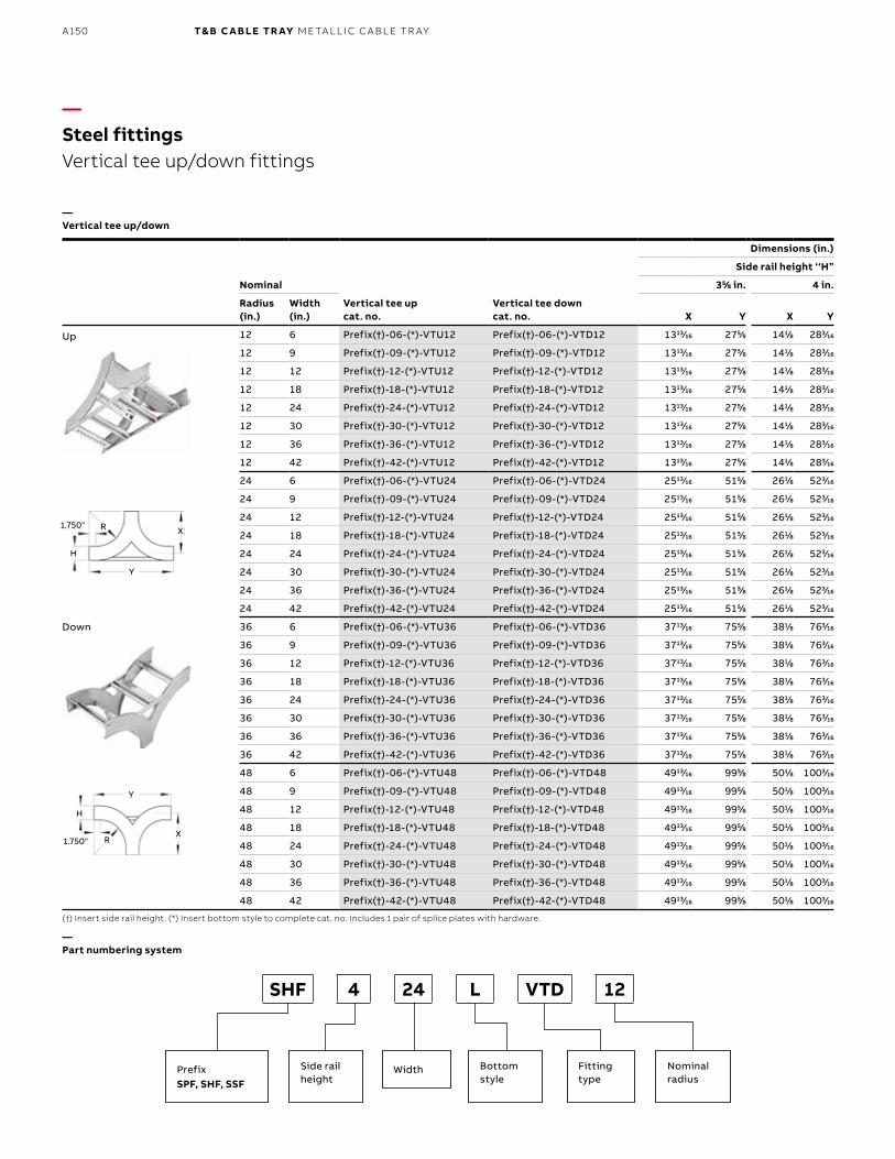
B1 copy starts here
B2 copy starts here
B3 copy starts here
A150 T& B C A B LE TR AY M E TA L L I C C A B L E TR AY
Nominal
Vertical tee upcat. no.
Vertical tee downcat. no.
Dimensions (in.)
Side rail height ‘‘H”
355⁄88 in. 4 in.
Radius (in.)
Width (in.) X Y X Y
12 6 Prefix(†)-06-(*)-VTU12 Prefix(†)-06-(*)-VTD12 131313⁄1616 2755⁄88 1411⁄88 2833⁄1616
12 9 Prefix(†)-09-(*)-VTU12 Prefix(†)-09-(*)-VTD12 131313⁄1616 2755⁄88 1411⁄88 2833⁄1616
12 12 Prefix(†)-12-(*)-VTU12 Prefix(†)-12-(*)-VTD12 131313⁄1616 2755⁄88 1411⁄88 2833⁄1616
12 18 Prefix(†)-18-(*)-VTU12 Prefix(†)-18-(*)-VTD12 131313⁄1616 2755⁄88 1411⁄88 2833⁄1616
12 24 Prefix(†)-24-(*)-VTU12 Prefix(†)-24-(*)-VTD12 131313⁄1616 2755⁄88 1411⁄88 2833⁄1616
12 30 Prefix(†)-30-(*)-VTU12 Prefix(†)-30-(*)-VTD12 131313⁄1616 2755⁄88 1411⁄88 2833⁄1616
12 36 Prefix(†)-36-(*)-VTU12 Prefix(†)-36-(*)-VTD12 131313⁄1616 2755⁄88 1411⁄88 2833⁄1616
12 42 Prefix(†)-42-(*)-VTU12 Prefix(†)-42-(*)-VTD12 131313⁄1616 2755⁄88 1411⁄88 2833⁄1616
24 6 Prefix(†)-06-(*)-VTU24 Prefix(†)-06-(*)-VTD24 251313⁄1616 5155⁄88 2611⁄88 5233⁄1616
24 9 Prefix(†)-09-(*)-VTU24 Prefix(†)-09-(*)-VTD24 251313⁄1616 5155⁄88 2611⁄88 5233⁄1616
24 12 Prefix(†)-12-(*)-VTU24 Prefix(†)-12-(*)-VTD24 251313⁄1616 5155⁄88 2611⁄88 5233⁄1616
24 18 Prefix(†)-18-(*)-VTU24 Prefix(†)-18-(*)-VTD24 251313⁄1616 5155⁄88 2611⁄88 5233⁄1616
24 24 Prefix(†)-24-(*)-VTU24 Prefix(†)-24-(*)-VTD24 251313⁄1616 5155⁄88 2611⁄88 5233⁄1616
24 30 Prefix(†)-30-(*)-VTU24 Prefix(†)-30-(*)-VTD24 251313⁄1616 5155⁄88 2611⁄88 5233⁄1616
24 36 Prefix(†)-36-(*)-VTU24 Prefix(†)-36-(*)-VTD24 251313⁄1616 5155⁄88 2611⁄88 5233⁄1616
24 42 Prefix(†)-42-(*)-VTU24 Prefix(†)-42-(*)-VTD24 251313⁄1616 5155⁄88 2611⁄88 5233⁄1616
36 6 Prefix(†)-06-(*)-VTU36 Prefix(†)-06-(*)-VTD36 371313⁄1616 7555⁄88 3811⁄88 7633⁄1616
36 9 Prefix(†)-09-(*)-VTU36 Prefix(†)-09-(*)-VTD36 371313⁄1616 7555⁄88 3811⁄88 7633⁄1616
36 12 Prefix(†)-12-(*)-VTU36 Prefix(†)-12-(*)-VTD36 371313⁄1616 7555⁄88 3811⁄88 7633⁄1616
36 18 Prefix(†)-18-(*)-VTU36 Prefix(†)-18-(*)-VTD36 371313⁄1616 7555⁄88 3811⁄88 7633⁄1616
36 24 Prefix(†)-24-(*)-VTU36 Prefix(†)-24-(*)-VTD36 371313⁄1616 7555⁄88 3811⁄88 7633⁄1616
36 30 Prefix(†)-30-(*)-VTU36 Prefix(†)-30-(*)-VTD36 371313⁄1616 7555⁄88 3811⁄88 7633⁄1616
36 36 Prefix(†)-36-(*)-VTU36 Prefix(†)-36-(*)-VTD36 371313⁄1616 7555⁄88 3811⁄88 7633⁄1616
36 42 Prefix(†)-42-(*)-VTU36 Prefix(†)-42-(*)-VTD36 371313⁄1616 7555⁄88 3811⁄88 7633⁄1616
48 6 Prefix(†)-06-(*)-VTU48 Prefix(†)-06-(*)-VTD48 491313⁄1616 9955⁄88 5011⁄88 10033⁄1616
48 9 Prefix(†)-09-(*)-VTU48 Prefix(†)-09-(*)-VTD48 491313⁄1616 9955⁄88 5011⁄88 10033⁄1616
48 12 Prefix(†)-12-(*)-VTU48 Prefix(†)-12-(*)-VTD48 491313⁄1616 9955⁄88 5011⁄88 10033⁄1616
48 18 Prefix(†)-18-(*)-VTU48 Prefix(†)-18-(*)-VTD48 491313⁄1616 9955⁄88 5011⁄88 10033⁄1616
48 24 Prefix(†)-24-(*)-VTU48 Prefix(†)-24-(*)-VTD48 491313⁄1616 9955⁄88 5011⁄88 10033⁄1616
48 30 Prefix(†)-30-(*)-VTU48 Prefix(†)-30-(*)-VTD48 491313⁄1616 9955⁄88 5011⁄88 10033⁄1616
48 36 Prefix(†)-36-(*)-VTU48 Prefix(†)-36-(*)-VTD48 491313⁄1616 9955⁄88 5011⁄88 10033⁄1616
48 42 Prefix(†)-42-(*)-VTU48 Prefix(†)-42-(*)-VTD48 491313⁄1616 9955⁄88 5011⁄88 10033⁄1616
—Steel fittingsVertical tee up/down fittings
Up
Down
—Vertical tee up/down
(†) Insert side rail height. (*) Insert bottom style to complete cat. no. Includes 1 pair of splice plates with hardware.
—Part numbering system
SHF 4 24 L VTD 12
PrefixSPF, SHF, SSF
Side rail height
Bottom style
Width Fitting type
Nominalradius
X
X
Y
Y
H
H
R
R
1.750"
1.750"
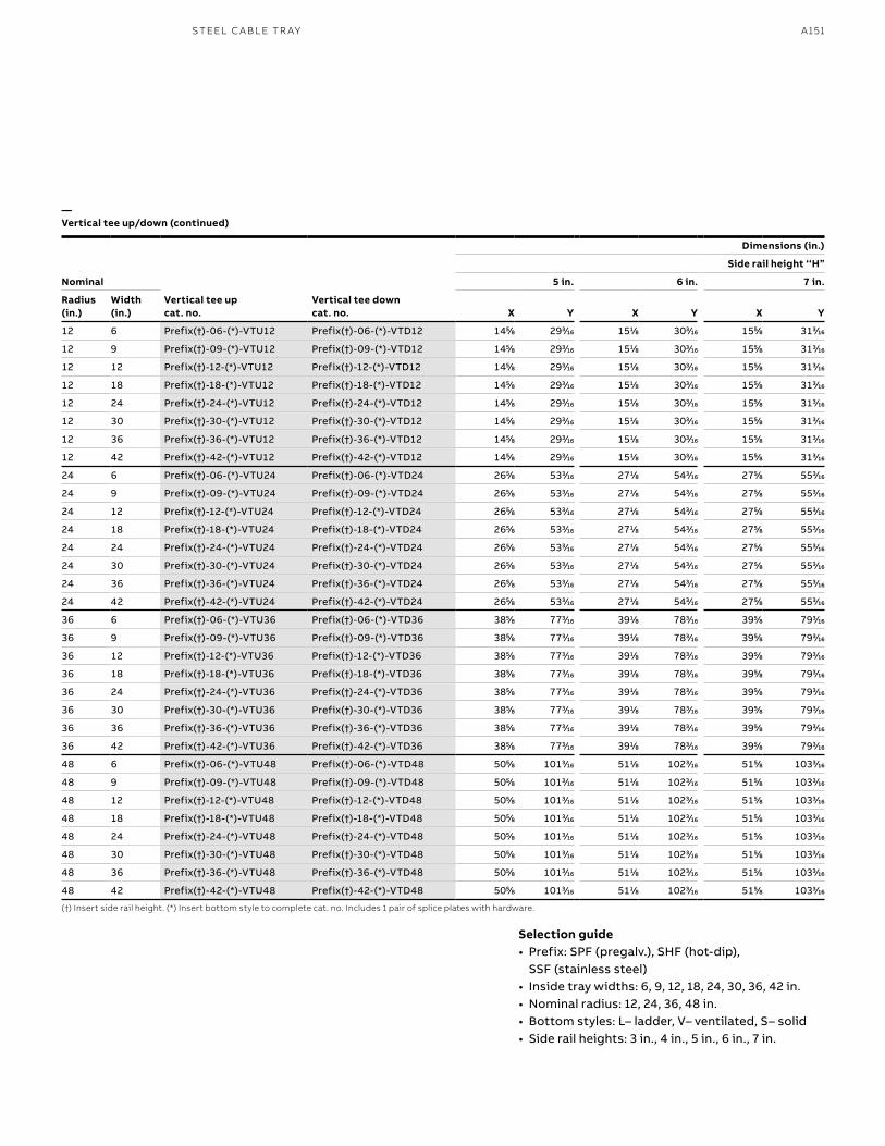
A151S TEEL C A B L E TR AY
Nominal
Vertical tee upcat. no.
Vertical tee downcat. no.
Dimensions (in.)
Side rail height ‘‘H”
5 in. 6 in. 7 in.
Radius (in.)
Width (in.) X Y X Y X Y
12 6 Prefix(†)-06-(*)-VTU12 Prefix(†)-06-(*)-VTD12 1455⁄88 2933⁄1616 1511⁄88 3033⁄1616 1555⁄88 3133⁄1616
12 9 Prefix(†)-09-(*)-VTU12 Prefix(†)-09-(*)-VTD12 1455⁄88 2933⁄1616 1511⁄88 3033⁄1616 1555⁄88 3133⁄1616
12 12 Prefix(†)-12-(*)-VTU12 Prefix(†)-12-(*)-VTD12 1455⁄88 2933⁄1616 1511⁄88 3033⁄1616 1555⁄88 3133⁄1616
12 18 Prefix(†)-18-(*)-VTU12 Prefix(†)-18-(*)-VTD12 1455⁄88 2933⁄1616 1511⁄88 3033⁄1616 1555⁄88 3133⁄1616
12 24 Prefix(†)-24-(*)-VTU12 Prefix(†)-24-(*)-VTD12 1455⁄88 2933⁄1616 1511⁄88 3033⁄1616 1555⁄88 3133⁄1616
12 30 Prefix(†)-30-(*)-VTU12 Prefix(†)-30-(*)-VTD12 1455⁄88 2933⁄1616 1511⁄88 3033⁄1616 1555⁄88 3133⁄1616
12 36 Prefix(†)-36-(*)-VTU12 Prefix(†)-36-(*)-VTD12 1455⁄88 2933⁄1616 1511⁄88 3033⁄1616 1555⁄88 3133⁄1616
12 42 Prefix(†)-42-(*)-VTU12 Prefix(†)-42-(*)-VTD12 1455⁄88 2933⁄1616 1511⁄88 3033⁄1616 1555⁄88 3133⁄1616
24 6 Prefix(†)-06-(*)-VTU24 Prefix(†)-06-(*)-VTD24 2655⁄88 5333⁄1616 2711⁄88 5433⁄1616 2755⁄88 5533⁄1616
24 9 Prefix(†)-09-(*)-VTU24 Prefix(†)-09-(*)-VTD24 2655⁄88 5333⁄1616 2711⁄88 5433⁄1616 2755⁄88 5533⁄1616
24 12 Prefix(†)-12-(*)-VTU24 Prefix(†)-12-(*)-VTD24 2655⁄88 5333⁄1616 2711⁄88 5433⁄1616 2755⁄88 5533⁄1616
24 18 Prefix(†)-18-(*)-VTU24 Prefix(†)-18-(*)-VTD24 2655⁄88 5333⁄1616 2711⁄88 5433⁄1616 2755⁄88 5533⁄1616
24 24 Prefix(†)-24-(*)-VTU24 Prefix(†)-24-(*)-VTD24 2655⁄88 5333⁄1616 2711⁄88 5433⁄1616 2755⁄88 5533⁄1616
24 30 Prefix(†)-30-(*)-VTU24 Prefix(†)-30-(*)-VTD24 2655⁄88 5333⁄1616 2711⁄88 5433⁄1616 2755⁄88 5533⁄1616
24 36 Prefix(†)-36-(*)-VTU24 Prefix(†)-36-(*)-VTD24 2655⁄88 5333⁄1616 2711⁄88 5433⁄1616 2755⁄88 5533⁄1616
24 42 Prefix(†)-42-(*)-VTU24 Prefix(†)-42-(*)-VTD24 2655⁄88 5333⁄1616 2711⁄88 5433⁄1616 2755⁄88 5533⁄1616
36 6 Prefix(†)-06-(*)-VTU36 Prefix(†)-06-(*)-VTD36 3855⁄88 7733⁄1616 3911⁄88 7833⁄1616 3955⁄88 7933⁄1616
36 9 Prefix(†)-09-(*)-VTU36 Prefix(†)-09-(*)-VTD36 3855⁄88 7733⁄1616 3911⁄88 7833⁄1616 3955⁄88 7933⁄1616
36 12 Prefix(†)-12-(*)-VTU36 Prefix(†)-12-(*)-VTD36 3855⁄88 7733⁄1616 3911⁄88 7833⁄1616 3955⁄88 7933⁄1616
36 18 Prefix(†)-18-(*)-VTU36 Prefix(†)-18-(*)-VTD36 3855⁄88 7733⁄1616 3911⁄88 7833⁄1616 3955⁄88 7933⁄1616
36 24 Prefix(†)-24-(*)-VTU36 Prefix(†)-24-(*)-VTD36 3855⁄88 7733⁄1616 3911⁄88 7833⁄1616 3955⁄88 7933⁄1616
36 30 Prefix(†)-30-(*)-VTU36 Prefix(†)-30-(*)-VTD36 3855⁄88 7733⁄1616 3911⁄88 7833⁄1616 3955⁄88 7933⁄1616
36 36 Prefix(†)-36-(*)-VTU36 Prefix(†)-36-(*)-VTD36 3855⁄88 7733⁄1616 3911⁄88 7833⁄1616 3955⁄88 7933⁄1616
36 42 Prefix(†)-42-(*)-VTU36 Prefix(†)-42-(*)-VTD36 3855⁄88 7733⁄1616 3911⁄88 7833⁄1616 3955⁄88 7933⁄1616
48 6 Prefix(†)-06-(*)-VTU48 Prefix(†)-06-(*)-VTD48 5055⁄88 10133⁄1616 5111⁄88 10233⁄1616 5155⁄88 10333⁄1616
48 9 Prefix(†)-09-(*)-VTU48 Prefix(†)-09-(*)-VTD48 5055⁄88 10133⁄1616 5111⁄88 10233⁄1616 5155⁄88 10333⁄1616
48 12 Prefix(†)-12-(*)-VTU48 Prefix(†)-12-(*)-VTD48 5055⁄88 10133⁄1616 5111⁄88 10233⁄1616 5155⁄88 10333⁄1616
48 18 Prefix(†)-18-(*)-VTU48 Prefix(†)-18-(*)-VTD48 5055⁄88 10133⁄1616 5111⁄88 10233⁄1616 5155⁄88 10333⁄1616
48 24 Prefix(†)-24-(*)-VTU48 Prefix(†)-24-(*)-VTD48 5055⁄88 10133⁄1616 5111⁄88 10233⁄1616 5155⁄88 10333⁄1616
48 30 Prefix(†)-30-(*)-VTU48 Prefix(†)-30-(*)-VTD48 5055⁄88 10133⁄1616 5111⁄88 10233⁄1616 5155⁄88 10333⁄1616
48 36 Prefix(†)-36-(*)-VTU48 Prefix(†)-36-(*)-VTD48 5055⁄88 10133⁄1616 5111⁄88 10233⁄1616 5155⁄88 10333⁄1616
48 42 Prefix(†)-42-(*)-VTU48 Prefix(†)-42-(*)-VTD48 5055⁄88 10133⁄1616 5111⁄88 10233⁄1616 5155⁄88 10333⁄1616
—Vertical tee up/down (continued)
(†) Insert side rail height. (*) Insert bottom style to complete cat. no. Includes 1 pair of splice plates with hardware.
Selection guide• Prefix: SPF (pregalv.), SHF (hot-dip),
SSF (stainless steel)• Inside tray widths: 6, 9, 12, 18, 24, 30, 36, 42 in.• Nominal radius: 12, 24, 36, 48 in. • Bottom styles: L– ladder, V– ventilated, S– solid• Side rail heights: 3 in., 4 in., 5 in., 6 in., 7 in.
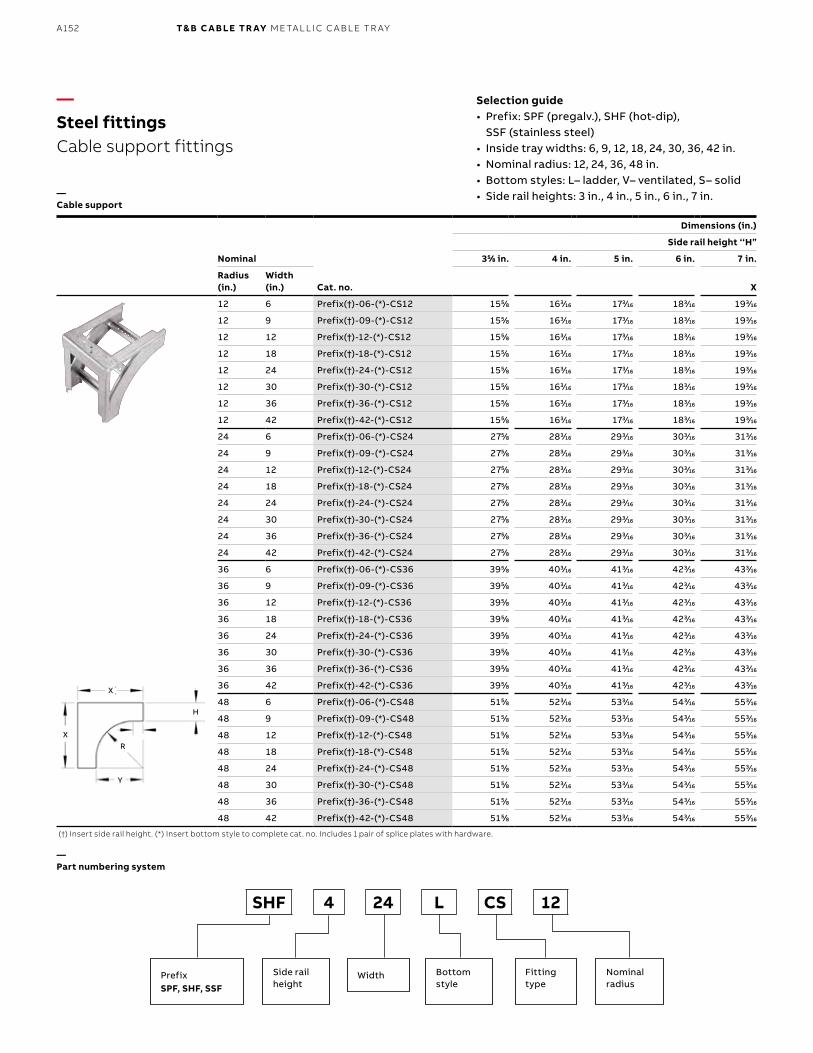
B1 copy starts here
B2 copy starts here
B3 copy starts here
A152 T& B C A B LE TR AY M E TA L L I C C A B L E TR AY
Nominal
Cat. no.
Dimensions (in.)
Side rail height ‘‘H”
355⁄88 in. 4 in. 5 in. 6 in. 7 in.
Radius (in.)
Width (in.) X
12 6 Prefix(†)-06-(*)-CS12 1555⁄88 1633⁄1616 1733⁄1616 1833⁄1616 1933⁄1616
12 9 Prefix(†)-09-(*)-CS12 1555⁄88 1633⁄1616 1733⁄1616 1833⁄1616 1933⁄1616
12 12 Prefix(†)-12-(*)-CS12 1555⁄88 1633⁄1616 1733⁄1616 1833⁄1616 1933⁄1616
12 18 Prefix(†)-18-(*)-CS12 1555⁄88 1633⁄1616 1733⁄1616 1833⁄1616 1933⁄1616
12 24 Prefix(†)-24-(*)-CS12 1555⁄88 1633⁄1616 1733⁄1616 1833⁄1616 1933⁄1616
12 30 Prefix(†)-30-(*)-CS12 1555⁄88 1633⁄1616 1733⁄1616 1833⁄1616 1933⁄1616
12 36 Prefix(†)-36-(*)-CS12 1555⁄88 1633⁄1616 1733⁄1616 1833⁄1616 1933⁄1616
12 42 Prefix(†)-42-(*)-CS12 1555⁄88 1633⁄1616 1733⁄1616 1833⁄1616 1933⁄1616
24 6 Prefix(†)-06-(*)-CS24 2755⁄88 2833⁄1616 2933⁄1616 3033⁄1616 3133⁄1616
24 9 Prefix(†)-09-(*)-CS24 2755⁄88 2833⁄1616 2933⁄1616 3033⁄1616 3133⁄1616
24 12 Prefix(†)-12-(*)-CS24 2755⁄88 2833⁄1616 2933⁄1616 3033⁄1616 3133⁄1616
24 18 Prefix(†)-18-(*)-CS24 2755⁄88 2833⁄1616 2933⁄1616 3033⁄1616 3133⁄1616
24 24 Prefix(†)-24-(*)-CS24 2755⁄88 2833⁄1616 2933⁄1616 3033⁄1616 3133⁄1616
24 30 Prefix(†)-30-(*)-CS24 2755⁄88 2833⁄1616 2933⁄1616 3033⁄1616 3133⁄1616
24 36 Prefix(†)-36-(*)-CS24 2755⁄88 2833⁄1616 2933⁄1616 3033⁄1616 3133⁄1616
24 42 Prefix(†)-42-(*)-CS24 2755⁄88 2833⁄1616 2933⁄1616 3033⁄1616 3133⁄1616
36 6 Prefix(†)-06-(*)-CS36 3955⁄88 4033⁄1616 4133⁄1616 4233⁄1616 4333⁄1616
36 9 Prefix(†)-09-(*)-CS36 3955⁄88 4033⁄1616 4133⁄1616 4233⁄1616 4333⁄1616
36 12 Prefix(†)-12-(*)-CS36 3955⁄88 4033⁄1616 4133⁄1616 4233⁄1616 4333⁄1616
36 18 Prefix(†)-18-(*)-CS36 3955⁄88 4033⁄1616 4133⁄1616 4233⁄1616 4333⁄1616
36 24 Prefix(†)-24-(*)-CS36 3955⁄88 4033⁄1616 4133⁄1616 4233⁄1616 4333⁄1616
36 30 Prefix(†)-30-(*)-CS36 3955⁄88 4033⁄1616 4133⁄1616 4233⁄1616 4333⁄1616
36 36 Prefix(†)-36-(*)-CS36 3955⁄88 4033⁄1616 4133⁄1616 4233⁄1616 4333⁄1616
36 42 Prefix(†)-42-(*)-CS36 3955⁄88 4033⁄1616 4133⁄1616 4233⁄1616 4333⁄1616
48 6 Prefix(†)-06-(*)-CS48 5155⁄88 5233⁄1616 5333⁄1616 5433⁄1616 5533⁄1616
48 9 Prefix(†)-09-(*)-CS48 5155⁄88 5233⁄1616 5333⁄1616 5433⁄1616 5533⁄1616
48 12 Prefix(†)-12-(*)-CS48 5155⁄88 5233⁄1616 5333⁄1616 5433⁄1616 5533⁄1616
48 18 Prefix(†)-18-(*)-CS48 5155⁄88 5233⁄1616 5333⁄1616 5433⁄1616 5533⁄1616
48 24 Prefix(†)-24-(*)-CS48 5155⁄88 5233⁄1616 5333⁄1616 5433⁄1616 5533⁄1616
48 30 Prefix(†)-30-(*)-CS48 5155⁄88 5233⁄1616 5333⁄1616 5433⁄1616 5533⁄1616
48 36 Prefix(†)-36-(*)-CS48 5155⁄88 5233⁄1616 5333⁄1616 5433⁄1616 5533⁄1616
48 42 Prefix(†)-42-(*)-CS48 5155⁄88 5233⁄1616 5333⁄1616 5433⁄1616 5533⁄1616
—Steel fittingsCable support fittings
—Cable support
(†) Insert side rail height. (*) Insert bottom style to complete cat. no. Includes 1 pair of splice plates with hardware.
—Part numbering system
SHF 4 24 L CS 12
PrefixSPF, SHF, SSF
Side rail height
Bottom style
Width Fitting type
Nominalradius
Selection guide• Prefix: SPF (pregalv.), SHF (hot-dip),
SSF (stainless steel)• Inside tray widths: 6, 9, 12, 18, 24, 30, 36, 42 in.• Nominal radius: 12, 24, 36, 48 in. • Bottom styles: L– ladder, V– ventilated, S– solid• Side rail heights: 3 in., 4 in., 5 in., 6 in., 7 in.
X
H
R
Y
X
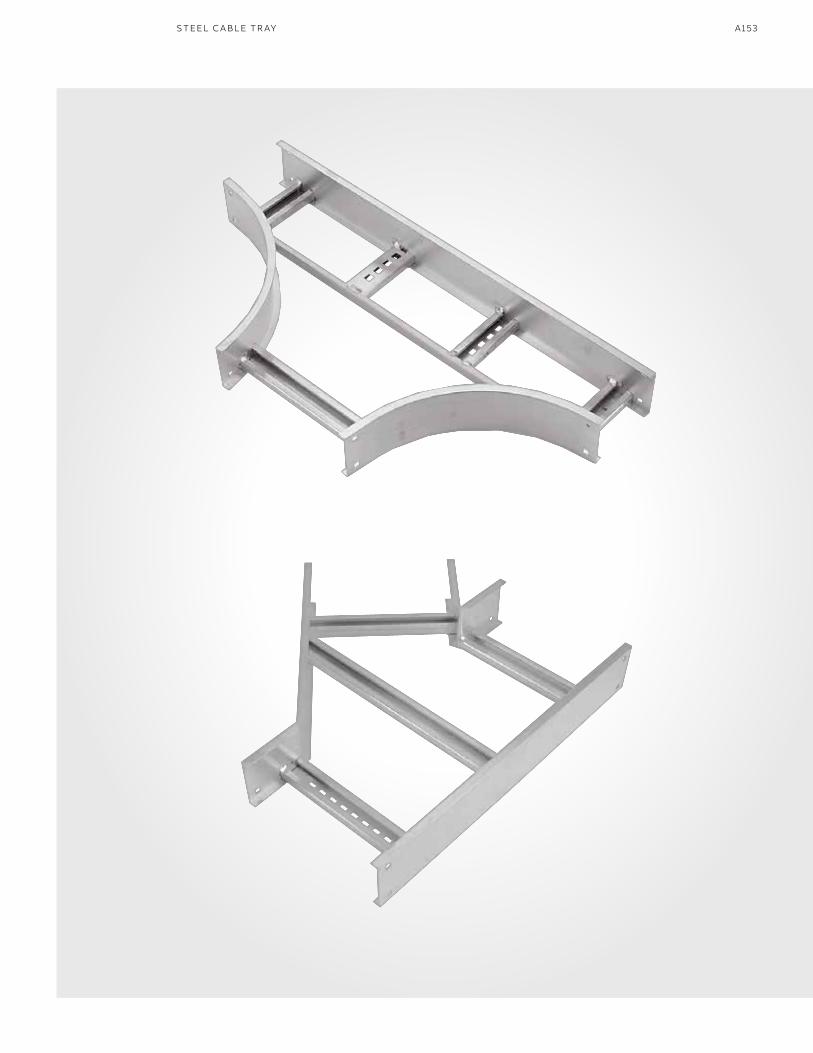
A153S TEEL C A B L E TR AY
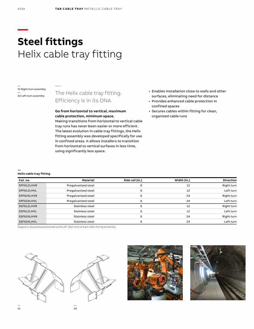
B1 copy starts here
B2 copy starts here
B3 copy starts here
A154 T& B C A B LE TR AY M E TA L L I C C A B L E TR AY
—Steel fittingsHelix cable tray fitting
—The Helix cable tray fitting. Efficiency is in its DNA
Go from horizontal to vertical, maximum cable protection, minimum space.Making transitions from horizontal to vertical cable tray runs has never been easier or more efficient. The latest evolution in cable tray fittings, the Helix fitting assembly was developed specifically for use in confined areas. It allows installers to transition from horizontal to vertical surfaces in less time, using significantly less space.
Cat. no. Material Side rail (in.) Width (in.) Direction
SPF612LHVR Pregalvanized steel 6 12 Right turn
SPF612LHVL Pregalvanized steel 6 12 Left turn
SPF624LHVR Pregalvanized steel 6 24 Right turn
SPF624LHVL Pregalvanized steel 6 24 Left turn
SSF612LHVR Stainless steel 6 12 Right turn
SSF612LHVL Stainless steel 6 12 Left turn
SSF624LHVR Stainless steel 6 24 Right turn
SSF624LHVL Stainless steel 6 24 Left turn
Supports should be positioned within 24” (610 mm) of each Helix fitting extremity.
• Enables installation close to walls and other surfaces, eliminating need for distance
• Provides enhanced cable protection in confined spaces
• Secures cables within fitting for clean, organized cable runs
—Helix cable tray fitting
—01
—02
—01 Right-turn assembly—02 Left-turn assembly
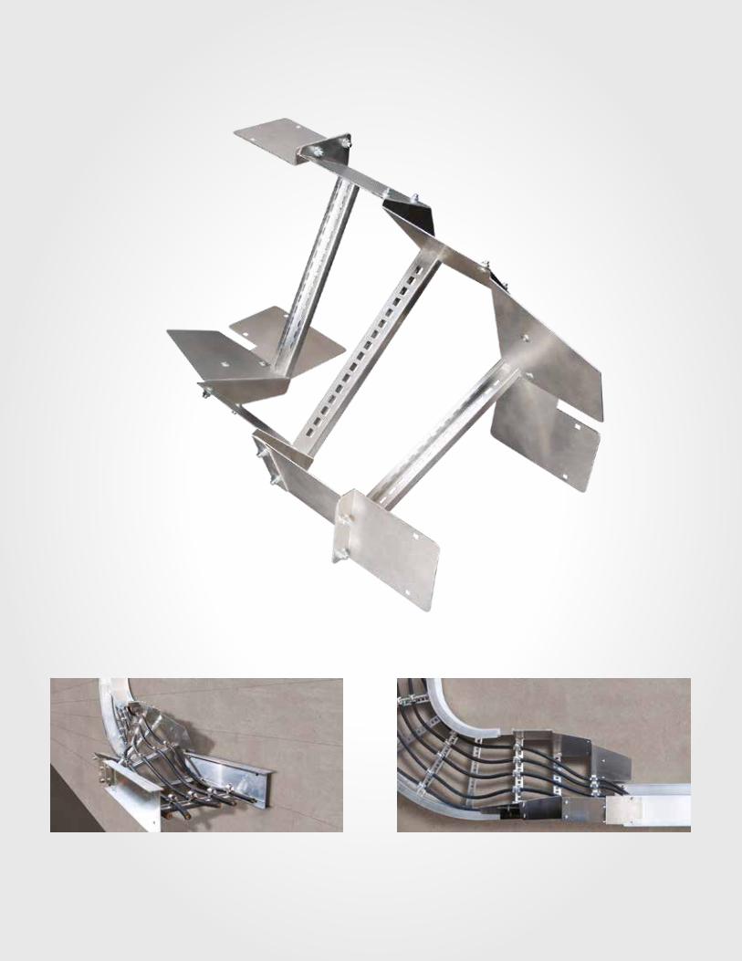
A155S TEEL C A B L E TR AY
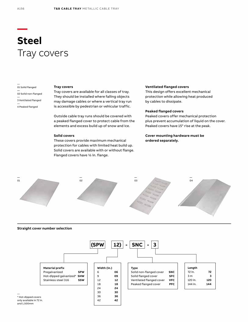
B1 copy starts here
B2 copy starts here
B3 copy starts here
A156 T& B C A B LE TR AY M E TA L L I C C A B L E TR AY
Tray coversTray covers are available for all classes of tray. They should be installed where falling objects may damage cables or where a vertical tray run is accessible by pedestrian or vehicular traffic.
Outside cable tray runs should be covered with a peaked flanged cover to protect cable from the elements and excess build up of snow and ice.
Solid coversThese covers provide maximum mechanical protection for cables with limited heat build up. Solid covers are available with or without flange. Flanged covers have 1/2 in. flange.
Ventilated flanged coversThis design offers excellent mechanical protection while allowing heat produced by cables to dissipate.
Peaked flanged covers Peaked covers offer mechanical protection plus prevent accumulation of liquid on the cover. Peaked covers have 15° rise at the peak.
Cover mounting hardware must be ordered separately.
—01
—02
—03
—04
—01 Solid flanged—02 Solid non-flanged—3 Ventilated flanged—4 Peaked flanged
—* Hot-dipped covers only available in 72 in. and 1,500mm
Material prefixPregalvanized SPWHot-dipped galvanized* SHWStainless steel 316 SSW
Width (in.)6 069 0912 1218 1824 2430 3036 3642 42
TypeSolid non-flanged cover SNCSolid flanged cover SFCVentilated flanged cover VFCPeaked flanged cover PFC
(SPW 12) - SNC - 3
Straight cover number selection
—SteelTray covers
Length72 in. 723 m 3120 in. 120144 in. 144
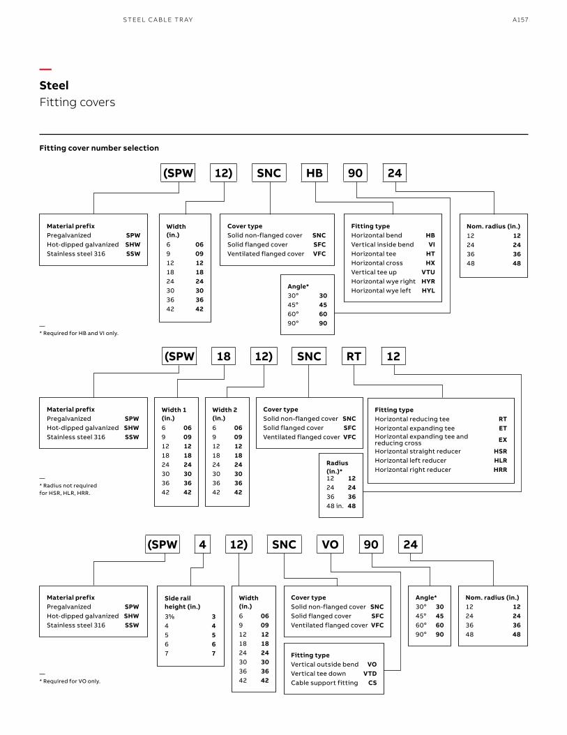
A157S TEEL C A B L E TR AY
Fitting cover number selection
—SteelFitting covers
—* Required for HB and VI only.
—* Radius not required for HSR, HLR, HRR.
—* Required for VO only.
Material prefixPregalvanized SPWHot-dipped galvanized SHWStainless steel 316 SSW
Material prefixPregalvanized SPWHot-dipped galvanized SHWStainless steel 316 SSW
Material prefixPregalvanized SPWHot-dipped galvanized SHWStainless steel 316 SSW
Width (in.)6 069 0912 1218 1824 2430 3036 3642 42
Width 1 (in.) 6 069 0912 1218 1824 2430 3036 3642 42
Width (in.)6 069 0912 1218 1824 2430 3036 3642 42
Width 2 (in.)6 069 0912 1218 1824 2430 3036 3642 42
Cover typeSolid non-flanged cover SNCSolid flanged cover SFCVentilated flanged cover VFC
Cover typeSolid non-flanged cover SNCSolid flanged cover SFCVentilated flanged cover VFC
Cover typeSolid non-flanged cover SNCSolid flanged cover SFCVentilated flanged cover VFC
Side rail height (in.)355⁄88 34 45 56 67 7
Fitting typeHorizontal bend HBVertical inside bend VIHorizontal tee HTHorizontal cross HXVertical tee up VTUHorizontal wye right HYRHorizontal wye left HYL
Fitting typeHorizontal reducing tee RTHorizontal expanding tee ETHorizontal expanding tee and reducing cross EX
Horizontal straight reducer HSRHorizontal left reducer HLRHorizontal right reducer HRR
Fitting typeVertical outside bend VOVertical tee down VTDCable support fitting CS
Nom. radius (in.)12 1224 2436 3648 48
Angle*30o 3045o 4560o 6090o 90
Angle*30o 3045o 4560o 6090o 90
Radius (in.)*12 1224 2436 3648 in. 48
Nom. radius (in.)12 1224 2436 3648 48
(SPW 12) SNC HB 90 24
(SPW 18 12) SNC RT 12
(SPW 4 12) SNC VO 90 24
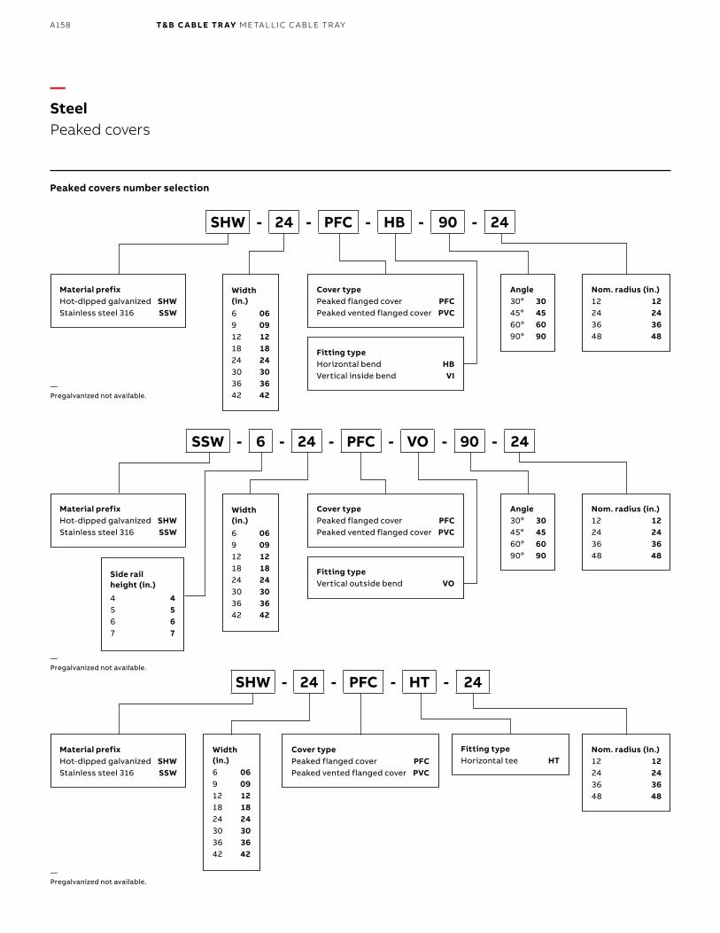
B1 copy starts here
B2 copy starts here
B3 copy starts here
A158 T& B C A B LE TR AY M E TA L L I C C A B L E TR AY
—SteelPeaked covers
—Pregalvanized not available.
—Pregalvanized not available.
—Pregalvanized not available.
Material prefixHot-dipped galvanized SHWStainless steel 316 SSW
Material prefixHot-dipped galvanized SHWStainless steel 316 SSW
Material prefixHot-dipped galvanized SHWStainless steel 316 SSW
Width (in.)6 069 0912 1218 1824 2430 3036 3642 42
Width (in.)6 069 0912 1218 1824 2430 3036 3642 42
Width (in.)6 069 0912 1218 1824 2430 3036 3642 42
Cover typePeaked flanged cover PFCPeaked vented flanged cover PVC
Cover typePeaked flanged cover PFCPeaked vented flanged cover PVC
Cover typePeaked flanged cover PFCPeaked vented flanged cover PVC
Fitting typeHorizontal bend HBVertical inside bend VI
Fitting typeVertical outside bend VO
Fitting typeHorizontal tee HT
Angle30o 3045o 4560o 6090o 90
Angle30o 3045o 4560o 6090o 90
Nom. radius (in.)12 1224 2436 3648 48
Nom. radius (in.)12 1224 2436 3648 48
Nom. radius (in.)12 1224 2436 3648 48
SHW - 24 - PFC - HB - 90 - 24
SSW - 6 - 24 - PFC - VO - 90 - 24
SHW - 24 - PFC - HT - 24
Peaked covers number selection
Side rail height (in.)
4 45 56 67 7
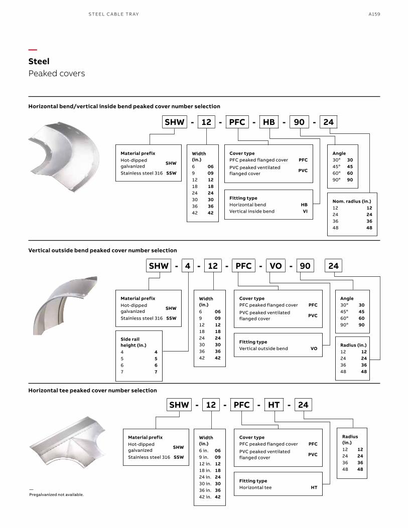
A159S TEEL C A B L E TR AY
—SteelPeaked covers
—Pregalvanized not available.
Material prefixHot-dipped galvanized
SHW
Stainless steel 316 SSW
Material prefixHot-dipped galvanized
SHW
Stainless steel 316 SSW
Material prefixHot-dipped galvanized
SHW
Stainless steel 316 SSW
Width (in.) 6 069 0912 1218 1824 2430 3036 3642 42
Width (in.)6 069 0912 1218 1824 2430 3036 3642 42
Width (in.)6 in. 069 in. 0912 in. 1218 in. 1824 in. 2430 in. 3036 in. 3642 in. 42
Cover typePFC peaked flanged cover PFC
PVC peaked ventilated flanged cover
PVC
Cover typePFC peaked flanged cover PFC
PVC peaked ventilated flanged cover
PVC
Cover typePFC peaked flanged cover PFC
PVC peaked ventilated flanged cover
PVC
Fitting typeHorizontal bend HBVertical inside bend VI
Fitting typeVertical outside bend VO
Fitting typeHorizontal tee HT
Angle30o 3045o 4560o 6090o 90
Angle30o 3045o 4560o 6090o 90
Nom. radius (in.)12 1224 2436 3648 48
Radius (in.)12 1224 2436 3648 48
Radius (in.)12 1224 2436 3648 48
SHW - 12 - PFC - HB - 90 - 24
SHW - 4 - 12 - PFC - VO - 90 24
SHW - 12 - PFC - HT - 24
Horizontal bend/vertical inside bend peaked cover number selection
Vertical outside bend peaked cover number selection
Horizontal tee peaked cover number selection
Side rail height (in.)4 45 56 67 7
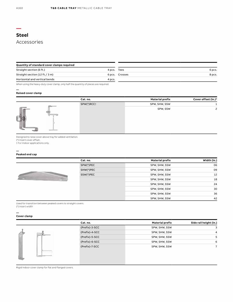
B1 copy starts here
B2 copy starts here
B3 copy starts here
A160 T& B C A B LE TR AY M E TA L L I C C A B L E TR AY
Cat. no. Material prefix Width (in.)
SPW(*)PEC SPW, SHW, SSW 06
SHW(*)PEC SPW, SHW, SSW 09
SSW(*)PEC SPW, SHW, SSW 12
SPW, SHW, SSW 18
SPW, SHW, SSW 24
SPW, SHW, SSW 30
SPW, SHW, SSW 36
SPW, SHW, SSW 42
—SteelAccessories
Quantity of standard cover clamps required
Straight section (6 ft.) 4 pcs.
Straight section (12 ft./ 3 m) 6 pcs.
Horizontal and vertical bends 4 pcs.
When using the heavy-duty cover clamp, only half the quantity of pieces are required.
Designed to raise cover above tray for added ventilation. (*) Insert cover offset. † For indoor applications only.
Used for transition between peaked covers to straight covers. (*) Insert width
Rigid indoor cover clamp for flat and flanged covers.
Tees 6 pcs.
Crosses 8 pcs.
—Raised cover clamp
—Peaked end cap
—Cover clamp
Cat. no. Material prefix Cover offset (in.)*
SPW(*)RCC† SPW, SHW, SSW 1
SPW, SSW 2
Cat. no. Material prefix Side rail height (in.)
(Prefix)-3-SCC SPW, SHW, SSW 3
(Prefix)-4-SCC SPW, SHW, SSW 4
(Prefix)-5-SCC SPW, SHW, SSW 5
(Prefix)-6-SCC SPW, SHW, SSW 6
(Prefix)-7-SCC SPW, SHW, SSW 7
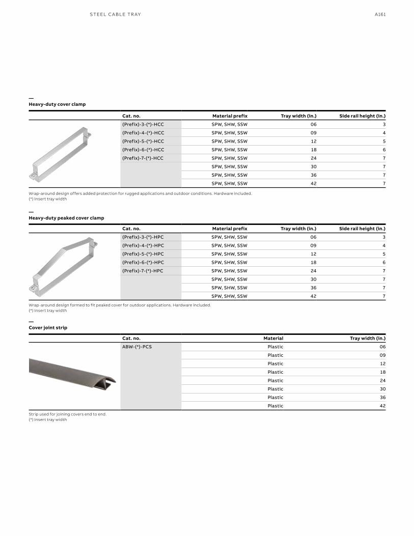
A161S TEEL C A B L E TR AY
Wrap-around design offers added protection for rugged applications and outdoor conditions. Hardware included.(*) Insert tray width
Wrap-around design formed to fit peaked cover for outdoor applications. Hardware included.(*) Insert tray width
Strip used for joining covers end to end.(*) Insert tray width
—Heavy-duty cover clamp
—Heavy-duty peaked cover clamp
—Cover joint strip
Cat. no. Material Tray width (in.)
ABW-(*)-PCS Plastic 06
Plastic 09
Plastic 12
Plastic 18
Plastic 24
Plastic 30
Plastic 36
Plastic 42
Cat. no. Material prefix Tray width (in.) Side rail height (in.)
(Prefix)-3-(*)-HCC SPW, SHW, SSW 06 3
(Prefix)-4-(*)-HCC SPW, SHW, SSW 09 4
(Prefix)-5-(*)-HCC SPW, SHW, SSW 12 5
(Prefix)-6-(*)-HCC SPW, SHW, SSW 18 6
(Prefix)-7-(*)-HCC SPW, SHW, SSW 24 7
SPW, SHW, SSW 30 7
SPW, SHW, SSW 36 7
SPW, SHW, SSW 42 7
Cat. no. Material prefix Tray width (in.) Side rail height (in.)
(Prefix)-3-(*)-HPC SPW, SHW, SSW 06 3
(Prefix)-4-(*)-HPC SPW, SHW, SSW 09 4
(Prefix)-5-(*)-HPC SPW, SHW, SSW 12 5
(Prefix)-6-(*)-HPC SPW, SHW, SSW 18 6
(Prefix)-7-(*)-HPC SPW, SHW, SSW 24 7
SPW, SHW, SSW 30 7
SPW, SHW, SSW 36 7
SPW, SHW, SSW 42 7
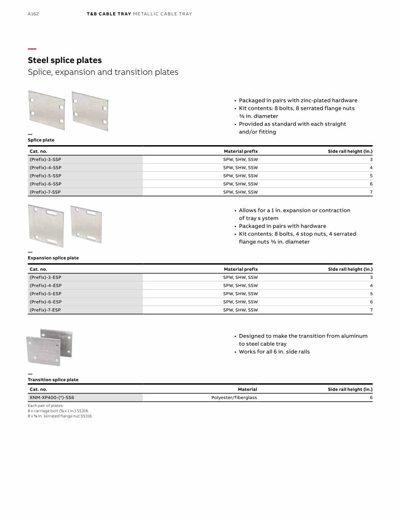
B1 copy starts here
B2 copy starts here
B3 copy starts here
A162 T& B C A B LE TR AY M E TA L L I C C A B L E TR AY
Each pair of plates:8 x carriage bolt (33⁄88 x 1 in.) SS316 8 x 33⁄88 in. serrated flange nut SS316
—Steel splice platesSplice, expansion and transition plates
—Expansion splice plate
—Splice plate
—Transition splice plate
• Packaged in pairs with zinc-plated hardware • Kit contents: 8 bolts, 8 serrated flange nuts
3/8 in. diameter• Provided as standard with each straight
and/or fitting
• Allows for a 1 in. expansion or contraction of tray s ystem
• Packaged in pairs with hardware• Kit contents: 8 bolts, 4 stop nuts, 4 serrated
flange nuts 3/8 in. diameter
• Designed to make the transition from aluminum to steel cable tray
• Works for all 6 in. side rails
Cat. no. Material prefix Side rail height (in.)
(Prefix)-3-SSP SPW, SHW, SSW 3
(Prefix)-4-SSP SPW, SHW, SSW 4
(Prefix)-5-SSP SPW, SHW, SSW 5
(Prefix)-6-SSP SPW, SHW, SSW 6
(Prefix)-7-SSP SPW, SHW, SSW 7
Cat. no. Material prefix Side rail height (in.)
(Prefix)-3-ESP SPW, SHW, SSW 3
(Prefix)-4-ESP SPW, SHW, SSW 4
(Prefix)-5-ESP SPW, SHW, SSW 5
(Prefix)-6-ESP SPW, SHW, SSW 6
(Prefix)-7-ESP SPW, SHW, SSW 7
Cat. no. Material Side rail height (in.)
XNM-XP400-(*)-SS6 Polyester/fiberglass 6
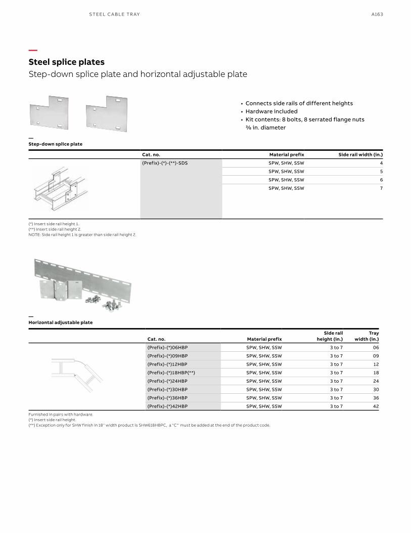
A163S TEEL C A B L E TR AY
Cat. no. Material prefixSide rail
height (in.)Tray
width (in.)
(Prefix)-(*)06HBP SPW, SHW, SSW 3 to 7 06
(Prefix)-(*)09HBP SPW, SHW, SSW 3 to 7 09
(Prefix)-(*)12HBP SPW, SHW, SSW 3 to 7 12
(Prefix)-(*)18HBP(**) SPW, SHW, SSW 3 to 7 18
(Prefix)-(*)24HBP SPW, SHW, SSW 3 to 7 24
(Prefix)-(*)30HBP SPW, SHW, SSW 3 to 7 30
(Prefix)-(*)36HBP SPW, SHW, SSW 3 to 7 36
(Prefix)-(*)42HBP SPW, SHW, SSW 3 to 7 42
—Steel splice platesStep-down splice plate and horizontal adjustable plate
—Step-down splice plate
—Horizontal adjustable plate
• Connects side rails of different heights • Hardware included • Kit contents: 8 bolts, 8 serrated flange nuts
3/8 in. diameter
Cat. no. Material prefix Side rail width (in.)
(Prefix)-(*)-(**)-SDS SPW, SHW, SSW 4
SPW, SHW, SSW 5
SPW, SHW, SSW 6
SPW, SHW, SSW 7
(*) Insert side rail height 1. (**) Insert side rail height 2. NOTE: Side rail height 1 is greater than side rail height 2.
Furnished in pairs with hardware.(*) Insert side rail height.(**) Exception only for SHW finish in 18'' width product is SHW618HBPC, a "C"' must be added at the end of the product code.
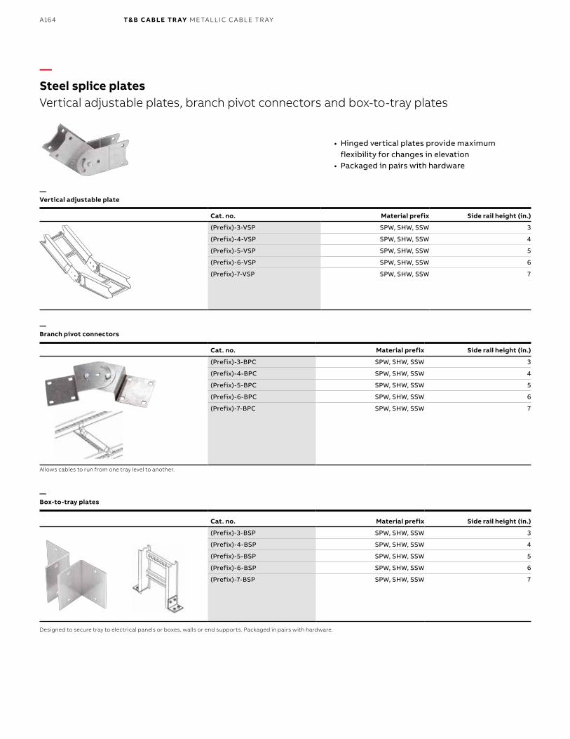
B1 copy starts here
B2 copy starts here
B3 copy starts here
A164 T& B C A B LE TR AY M E TA L L I C C A B L E TR AY
Cat. no. Material prefix Side rail height (in.)
(Prefix)-3-BSP SPW, SHW, SSW 3
(Prefix)-4-BSP SPW, SHW, SSW 4
(Prefix)-5-BSP SPW, SHW, SSW 5
(Prefix)-6-BSP SPW, SHW, SSW 6
(Prefix)-7-BSP SPW, SHW, SSW 7
—Steel splice platesVertical adjustable plates, branch pivot connectors and box-to-tray plates
• Hinged vertical plates provide maximum flexibility for changes in elevation
• Packaged in pairs with hardware
—Vertical adjustable plate
—Branch pivot connectors
—Box-to-tray plates
Cat. no. Material prefix Side rail height (in.)
(Prefix)-3-VSP SPW, SHW, SSW 3
(Prefix)-4-VSP SPW, SHW, SSW 4
(Prefix)-5-VSP SPW, SHW, SSW 5
(Prefix)-6-VSP SPW, SHW, SSW 6
(Prefix)-7-VSP SPW, SHW, SSW 7
Allows cables to run from one tray level to another.
Designed to secure tray to electrical panels or boxes, walls or end supports. Packaged in pairs with hardware.
Cat. no. Material prefix Side rail height (in.)
(Prefix)-3-BPC SPW, SHW, SSW 3
(Prefix)-4-BPC SPW, SHW, SSW 4
(Prefix)-5-BPC SPW, SHW, SSW 5
(Prefix)-6-BPC SPW, SHW, SSW 6
(Prefix)-7-BPC SPW, SHW, SSW 7
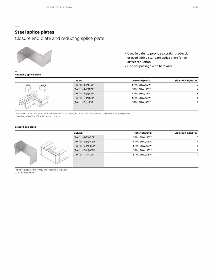
A165S TEEL C A B L E TR AY
—Steel splice platesClosure end plate and reducing splice plate
• Used in pairs to provide a straight reduction or used with a standard splice plate for an offset reduction
• One per package with hardware
—Reducing splice plate
—Closure end plate
* For offset reduction: Insert width to be reduced. For straight reduction: Insert 11⁄22 width to be reduced (2 required). Example: SPW-503-RSP = 3 in. offset reducer
Provides closure for any tray end. Hardware included.(*) Insert tray width
StraightOffset
Cat. no. Material prefix Side rail height (in.)
(Prefix)-3-(*)RSP SPW, SHW, SSW 3
(Prefix)-4-(*)RSP SPW, SHW, SSW 4
(Prefix)-5-(*)RSP SPW, SHW, SSW 5
(Prefix)-6-(*)RSP SPW, SHW, SSW 6
(Prefix)-7-(*)RSP SPW, SHW, SSW 7
Cat. no. Material prefix Side rail height (in.)
(Prefix)-3-(*)-CEP SPW, SHW, SSW 3
(Prefix)-4-(*)-CEP SPW, SHW, SSW 4
(Prefix)-5-(*)-CEP SPW, SHW, SSW 5
(Prefix)-6-(*)-CEP SPW, SHW, SSW 6
(Prefix)-7-(*)-CEP SPW, SHW, SSW 7
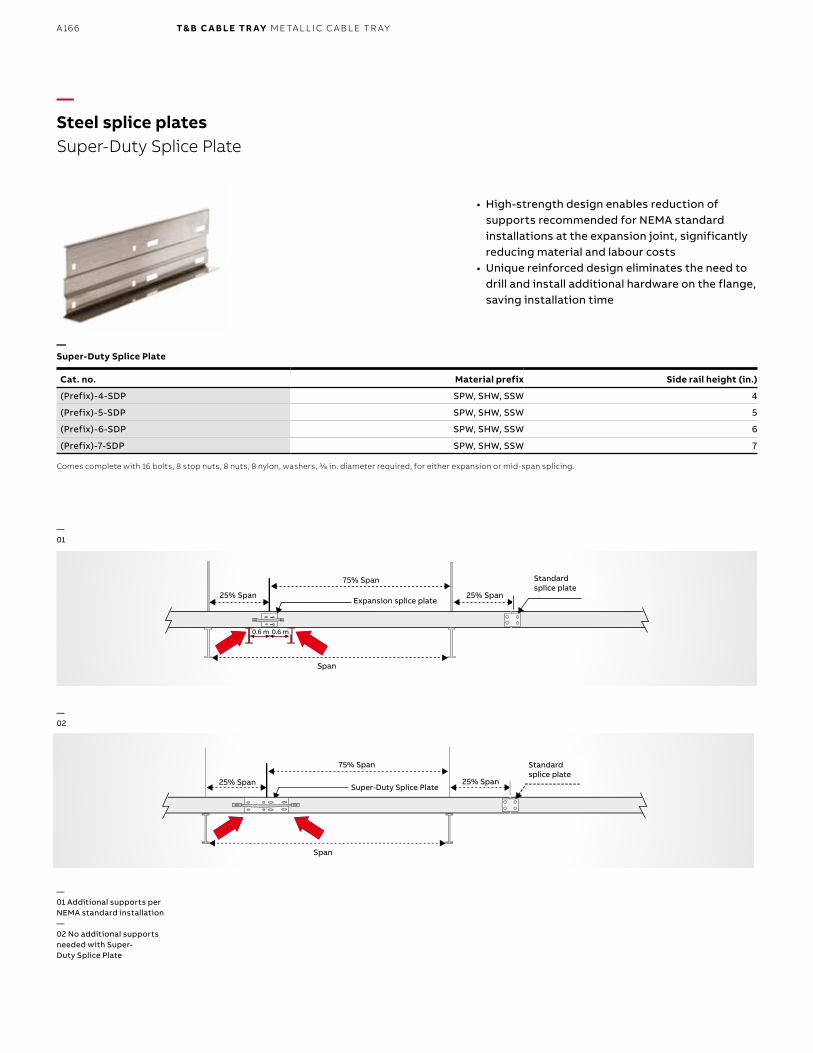
B1 copy starts here
B2 copy starts here
B3 copy starts here
A166 T& B C A B LE TR AY M E TA L L I C C A B L E TR AY
Cat. no. Material prefix Side rail height (in.)
(Prefix)-4-SDP SPW, SHW, SSW 4
(Prefix)-5-SDP SPW, SHW, SSW 5
(Prefix)-6-SDP SPW, SHW, SSW 6
(Prefix)-7-SDP SPW, SHW, SSW 7
—Steel splice platesSuper-Duty Splice Plate
• High-strength design enables reduction of supports recommended for NEMA standard installations at the expansion joint, significantly reducing material and labour costs
• Unique reinforced design eliminates the need to drill and install additional hardware on the flange, saving installation time
—Super-Duty Splice Plate
Comes complete with 16 bolts, 8 stop nuts, 8 nuts, 8 nylon, washers, 3/8 in. diameter required, for either expansion or mid-span splicing.
—01
—02
—01 Additional supports per NEMA standard installation—02 No additional supports needed with Super-Duty Splice Plate
0.6 m 0.6 m
Expansion Splice Plate
75% Span
25% Span
Span
StandardSplice Plate25% Span25% Span
25% Span
0.6 m 0.6 m
25% Span
25% Span
75% Span
75% Span
Span
Span
Standardsplice plate
Standardsplice plate
Expansion splice plate
Super-Duty Splice Plate
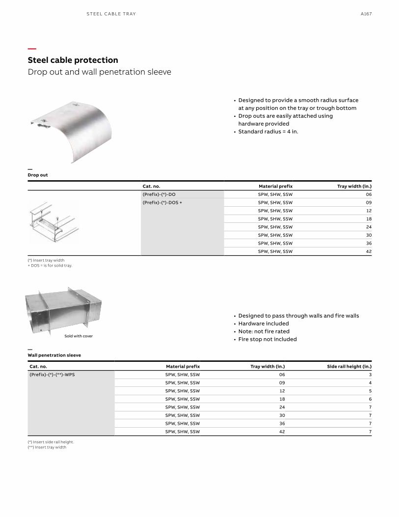
A167S TEEL C A B L E TR AY
• Designed to provide a smooth radius surface at any position on the tray or trough bottom
• Drop outs are easily attached using hardware provided
• Standard radius = 4 in.
• Designed to pass through walls and fire walls • Hardware included• Note: not fire rated• Fire stop not included
—Drop out
—Wall penetration sleeve
(*) Insert tray width + DOS = is for solid tray.
(*) Insert side rail height. (**) Insert tray width
—Steel cable protectionDrop out and wall penetration sleeve
Cat. no. Material prefix Tray width (in.)
(Prefix)-(*)-DO SPW, SHW, SSW 06
(Prefix)-(*)-DOS + SPW, SHW, SSW 09
SPW, SHW, SSW 12
SPW, SHW, SSW 18
SPW, SHW, SSW 24
SPW, SHW, SSW 30
SPW, SHW, SSW 36
SPW, SHW, SSW 42
Sold with cover
Cat. no. Material prefix Tray width (in.) Side rail height (in.)
(Prefix)-(*)-(**)-WPS SPW, SHW, SSW 06 3
SPW, SHW, SSW 09 4
SPW, SHW, SSW 12 5
SPW, SHW, SSW 18 6
SPW, SHW, SSW 24 7
SPW, SHW, SSW 30 7
SPW, SHW, SSW 36 7
SPW, SHW, SSW 42 7
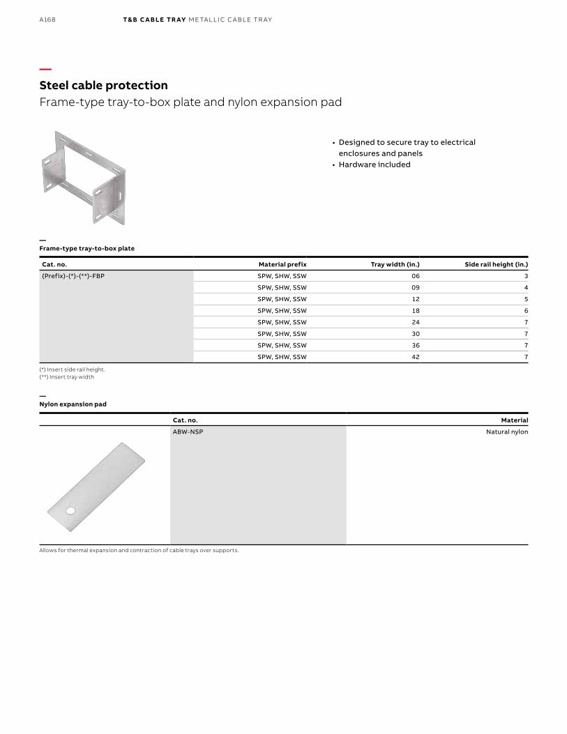
B1 copy starts here
B2 copy starts here
B3 copy starts here
A168 T& B C A B LE TR AY M E TA L L I C C A B L E TR AY
Cat. no. Material
ABW-NSP Natural nylon
—Steel cable protectionFrame-type tray-to-box plate and nylon expansion pad
• Designed to secure tray to electrical enclosures and panels
• Hardware included
—Frame-type tray-to-box plate
—Nylon expansion pad
Cat. no. Material prefix Tray width (in.) Side rail height (in.)
(Prefix)-(*)-(**)-FBP SPW, SHW, SSW 06 3
SPW, SHW, SSW 09 4
SPW, SHW, SSW 12 5
SPW, SHW, SSW 18 6
SPW, SHW, SSW 24 7
SPW, SHW, SSW 30 7
SPW, SHW, SSW 36 7
SPW, SHW, SSW 42 7
(*) Insert side rail height. (**) Insert tray width
Allows for thermal expansion and contraction of cable trays over supports.
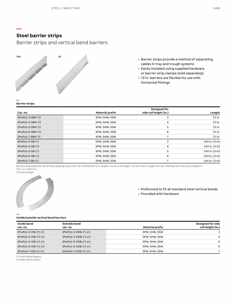
A169S TEEL C A B L E TR AY
Barriers provided with self drilling-tapping screw CAT. NO. SPW10SCR 72 in. length: 3 screw 3 m length: 5 screw 144 in. length: 6 screw. SHW barriers are only available in 72 in. or 1,500 mm. (*) Insert length.
(*) Insert bend degree (+) Insert bend radius.
• Barrier strips provide a method of separating cables in tray and trough systems
• Easily installed using supplied hardware or barrier strip clamps (sold separately)
• 72 in. barriers are flexible for use with horizontal fittings
• Preformed to fit all standard steel vertical bends• Provided with hardware
—Barrier strips
—Inside/outside vertical bend barriers
—Steel barrier stripsBarrier strips and vertical bend barriers
SBH SB
Cat. no. Material prefixDesigned for
side rail height (in.) Length
(Prefix)-3-SBH-72 SPW, SHW, SSW 3 72 in.
(Prefix)-4-SBH-72 SPW, SHW, SSW 4 72 in.
(Prefix)-5-SBH-72 SPW, SHW, SSW 5 72 in.
(Prefix)-6-SBH-72 SPW, SHW, SSW 6 72 in.
(Prefix)-7-SBH-72 SPW, SHW, SSW 7 72 in.
(Prefix)-3-SB-(*) SPW, SHW, SSW 3 144 in. (3 m)
(Prefix)-4-SB-(*) SPW, SHW, SSW 4 144 in. (3 m)
(Prefix)-5-SB-(*) SPW, SHW, SSW 5 144 in. (3 m)
(Prefix)-6-SB-(*) SPW, SHW, SSW 6 144 in. (3 m)
(Prefix)-7-SB-(*) SPW, SHW, SSW 7 144 in. (3 m)
Inside bend cat. no.
Outside bend cat. no. Material prefix
Designed for side rail height (in.)
(Prefix)-3-VIB-(*)-(+) (Prefix)-3-VOB-(*)-(+) SPW, SHW, SSW 3
(Prefix)-4-VIB-(*)-(+) (Prefix)-4-VOB-(*)-(+) SPW, SHW, SSW 4
(Prefix)-5-VIB-(*)-(+) (Prefix)-5-VOB-(*)-(+) SPW, SHW, SSW 5
(Prefix)-6-VIB-(*)-(+) (Prefix)-6-VOB-(*)-(+) SPW, SHW, SSW 6
(Prefix)-7-VIB-(*)-(+) (Prefix)-7-VOB-(*)-(+) SPW, SHW, SSW 7
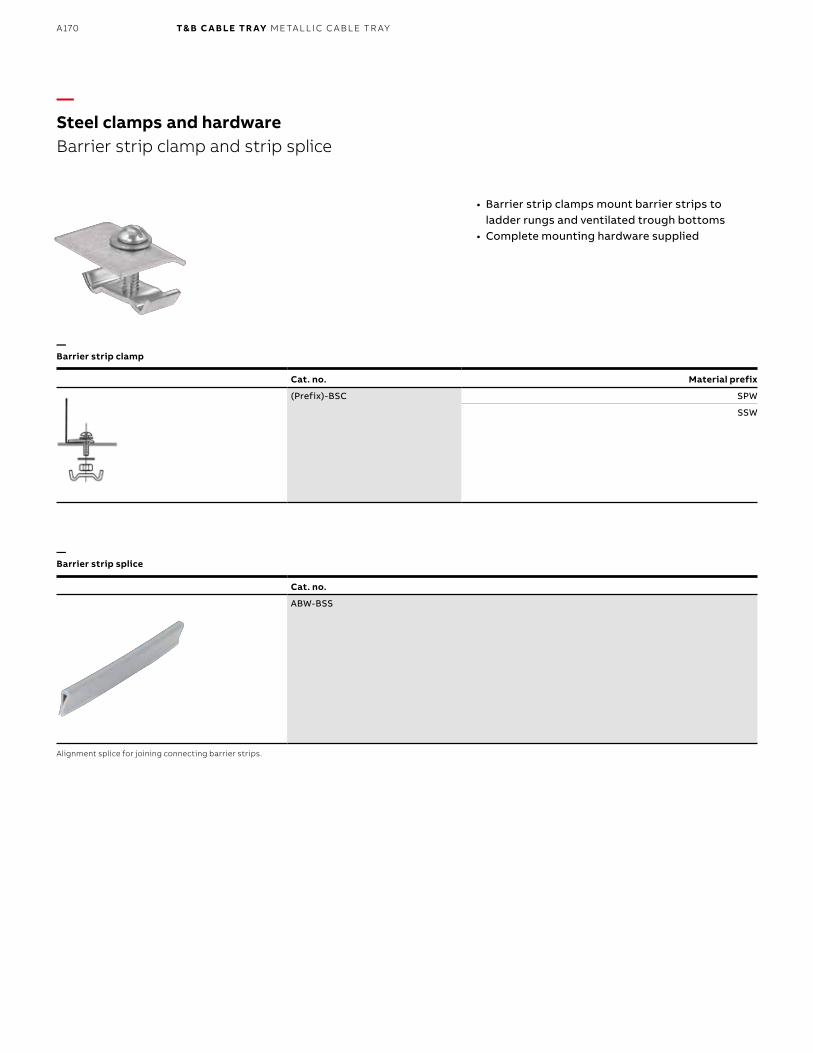
B1 copy starts here
B2 copy starts here
B3 copy starts here
A170 T& B C A B LE TR AY M E TA L L I C C A B L E TR AY
Cat. no.
ABW-BSS
—Steel clamps and hardwareBarrier strip clamp and strip splice
• Barrier strip clamps mount barrier strips to ladder rungs and ventilated trough bottoms
• Complete mounting hardware supplied
—Barrier strip clamp
—Barrier strip splice
Alignment splice for joining connecting barrier strips.
Cat. no. Material prefix
(Prefix)-BSC SPW
SSW
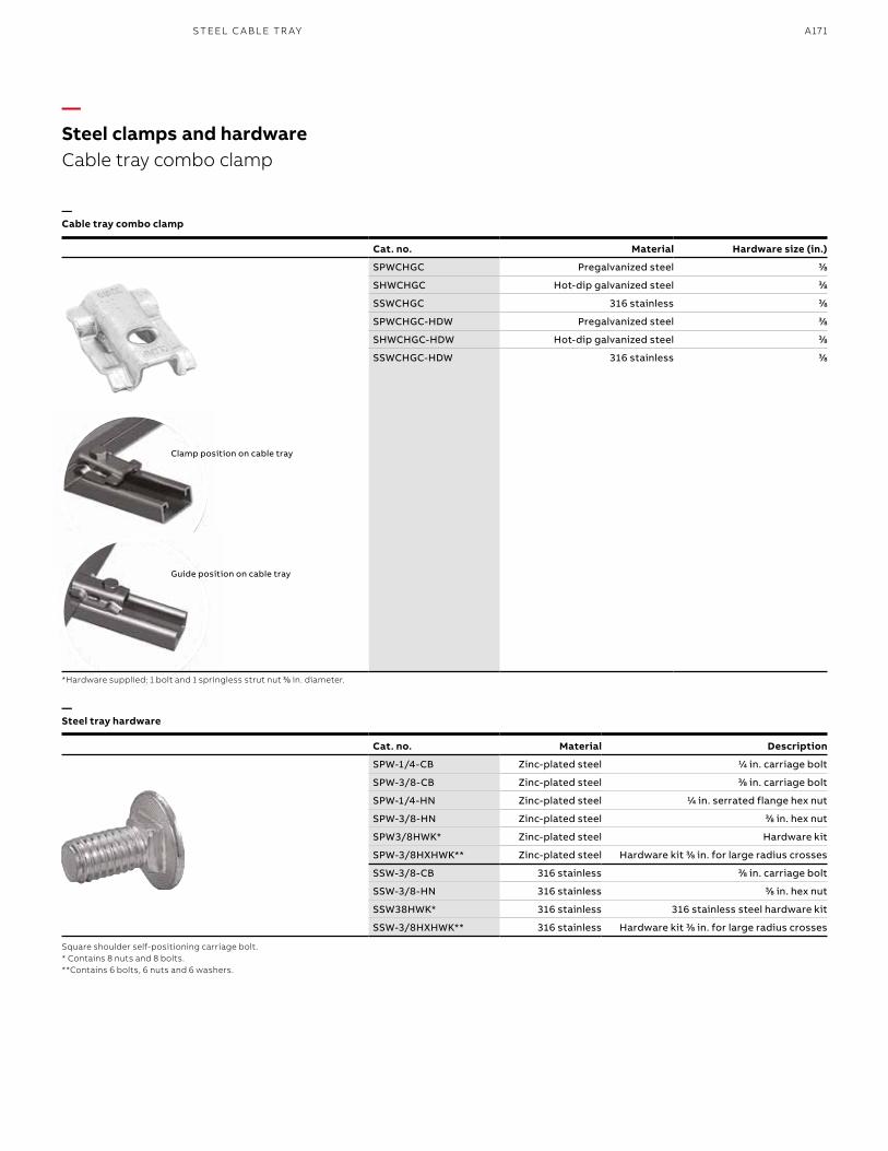
A171S TEEL C A B L E TR AY
Cat. no. Material Description
SPW-1/4-CB Zinc-plated steel 11⁄44 in. carriage bolt
SPW-3/8-CB Zinc-plated steel 33⁄88 in. carriage bolt
SPW-1/4-HN Zinc-plated steel 11⁄44 in. serrated flange hex nut
SPW-3/8-HN Zinc-plated steel 33⁄88 in. hex nut
SPW3/8HWK* Zinc-plated steel Hardware kit
SPW-3/8HXHWK** Zinc-plated steel Hardware kit 33⁄88 in. for large radius crosses
SSW-3/8-CB 316 stainless 33⁄88 in. carriage bolt
SSW-3/8-HN 316 stainless 33⁄88 in. hex nut
SSW38HWK* 316 stainless 316 stainless steel hardware kit
SSW-3/8HXHWK** 316 stainless Hardware kit 33⁄88 in. for large radius crosses
—Steel clamps and hardwareCable tray combo clamp
—Cable tray combo clamp
—Steel tray hardware
Cat. no. Material Hardware size (in.)
SPWCHGC Pregalvanized steel 33⁄88
SHWCHGC Hot-dip galvanized steel 33⁄88
SSWCHGC 316 stainless 33⁄88
SPWCHGC-HDW Pregalvanized steel 33⁄88
SHWCHGC-HDW Hot-dip galvanized steel 33⁄88
SSWCHGC-HDW 316 stainless 33⁄8 8
Clamp position on cable tray
Guide position on cable tray
*Hardware supplied: 1 bolt and 1 springless strut nut 33⁄8 8 in. diameter.
Square shoulder self-positioning carriage bolt.* Contains 8 nuts and 8 bolts.**Contains 6 bolts, 6 nuts and 6 washers.
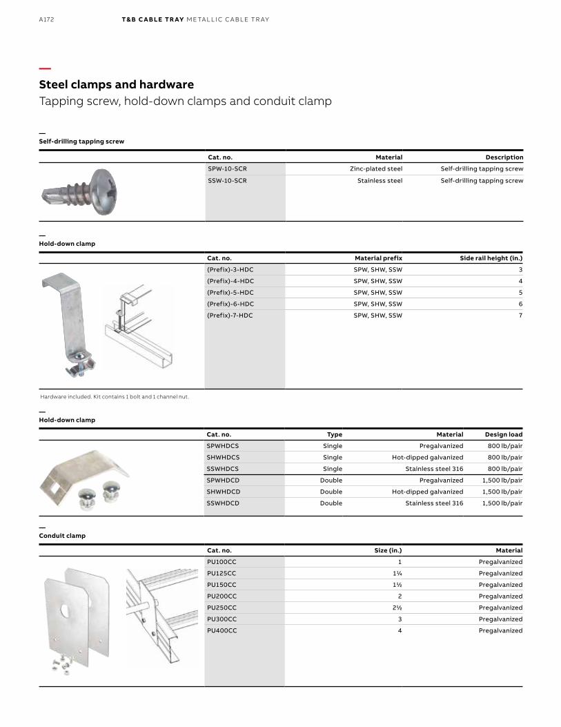
B1 copy starts here
B2 copy starts here
B3 copy starts here
A172 T& B C A B LE TR AY M E TA L L I C C A B L E TR AY
—Steel clamps and hardwareTapping screw, hold-down clamps and conduit clamp
—Hold-down clamp
—Hold-down clamp
—Conduit clamp
—Self-drilling tapping screw
Cat. no. Material prefix Side rail height (in.)
(Prefix)-3-HDC SPW, SHW, SSW 3
(Prefix)-4-HDC SPW, SHW, SSW 4
(Prefix)-5-HDC SPW, SHW, SSW 5
(Prefix)-6-HDC SPW, SHW, SSW 6
(Prefix)-7-HDC SPW, SHW, SSW 7
Hardware included. Kit contains 1 bolt and 1 channel nut.
Cat. no. Type Material Design load
SPWHDCS Single Pregalvanized 800 lb/pair
SHWHDCS Single Hot-dipped galvanized 800 lb/pair
SSWHDCS Single Stainless steel 316 800 lb/pair
SPWHDCD Double Pregalvanized 1,500 lb/pair
SHWHDCD Double Hot-dipped galvanized 1,500 lb/pair
SSWHDCD Double Stainless steel 316 1,500 lb/pair
Cat. no. Material Description
SPW-10-SCR Zinc-plated steel Self-drilling tapping screw
SSW-10-SCR Stainless steel Self-drilling tapping screw
Cat. no. Size (in.) Material
PU100CC 1 Pregalvanized
PU125CC 111⁄44 Pregalvanized
PU150CC 111⁄22 Pregalvanized
PU200CC 2 Pregalvanized
PU250CC 211⁄22 Pregalvanized
PU300CC 3 Pregalvanized
PU400CC 4 Pregalvanized
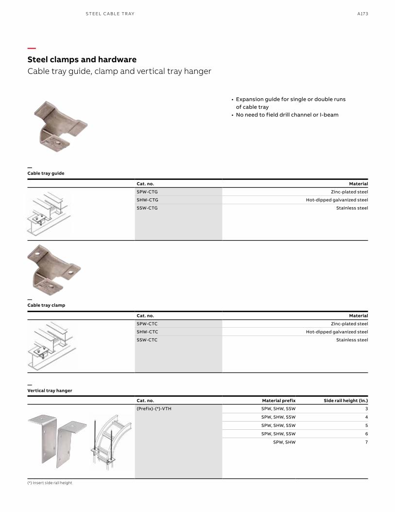
A173S TEEL C A B L E TR AY
Cat. no. Material prefix Side rail height (in.)
(Prefix)-(*)-VTH SPW, SHW, SSW 3
SPW, SHW, SSW 4
SPW, SHW, SSW 5
SPW, SHW, SSW 6
SPW, SHW 7
—Steel clamps and hardwareCable tray guide, clamp and vertical tray hanger
—Cable tray guide
—Cable tray clamp
—Vertical tray hanger
(*) Insert side rail height
• Expansion guide for single or double runs of cable tray
• No need to field drill channel or I-beam
Cat. no. Material
SPW-CTG Zinc-plated steel
SHW-CTG Hot-dipped galvanized steel
SSW-CTG Stainless steel
Cat. no. Material
SPW-CTC Zinc-plated steel
SHW-CTC Hot-dipped galvanized steel
SSW-CTC Stainless steel
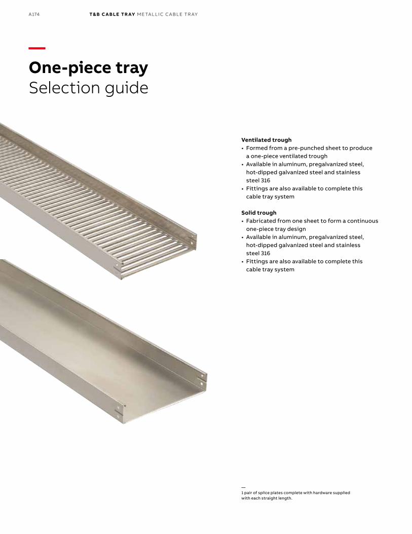
B1 copy starts here
B2 copy starts here
B3 copy starts here
A174 T& B C A B LE TR AY M E TA L L I C C A B L E TR AY
—One-piece traySelection guide
Ventilated trough• Formed from a pre-punched sheet to produce
a one-piece ventilated trough• Available in aluminum, pregalvanized steel,
hot-dipped galvanized steel and stainless steel 316
• Fittings are also available to complete this cable tray system
Solid trough• Fabricated from one sheet to form a continuous
one-piece tray design• Available in aluminum, pregalvanized steel,
hot-dipped galvanized steel and stainless steel 316
• Fittings are also available to complete this cable tray system
—1 pair of splice plates complete with hardware supplied with each straight length.
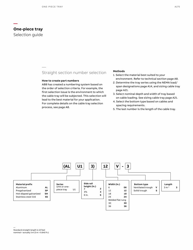
A175O N E- PIECE TR AY
—Straight section number selection
How to create part numbersABB has created a numbering system based on the order of selection criteria. For example, the first selection issue is the environment to which the cable tray will be subjected. This selection will lead to the best material for your application. For complete details on the cable tray selection process, see page A8.
—One-piece tray Selection guide
Methods1. Select the material best suited to your
environment. Refer to technical section page A8.2. Determine the tray series using the NEMA load/
span designations page A14, and sizing cable tray page A21.
3. Select nominal depth and width of tray based on cable loading. See sizing cable tray page A21.
4. Select the bottom type based on cables and spacing requirements.
5. The last number is the length of the cable tray.
Material prefixAluminum ALPregalvanized SPHot-dipped galvanized SHStainless steel 316 SS
Side rail height (in.)2 2355⁄88 36 in. 6
SeriesUnit or one-piece tray U1
Width (in.)6 0612 1218 1824 24Welded flat rung30 3036 36
Length3 m * 3
Bottom typeVentilated trough VSolid trough S
(AL U1 3) 12 V - 3
—Standard straight length is 10 feet nominal = actually 3 m (3 m = 9.842 ft.)

B1 copy starts here
B2 copy starts here
B3 copy starts here
A176 T& B C A B LE TR AY M E TA L L I C C A B L E TR AY
Series
Support span (feet)
6 8 10
ALU12 Load (lb/ft.) 69 39 25
Deflection (in.) 0.382 0.730 1.000
Deflection factor 0.006 0.019 0.040
SPU12 SHU12
Load (lb/ft.) 69 39 25
Deflection (in.) 0.382 0.730 1.000
Deflection factor 0.006 0.019 0.040
SSU12 Load (lb/ft.) 69 39 25
Deflection (in.) 0.382 0.730 1.000
Deflection factor 0.006 0.019 0.040
Material prefixAluminum ALPregalvanized SPHot-dipped galvanized SHStainless steel 316 SS
Side rail height (in.)2 2
SeriesUnit or one-piece tray U1
Width (in.)6 0612 1218 1824 24Welded flat rung30 3036 36
Length3 m * 3
Bottom typeVentilated trough VSolid trough S
(AL U1 2) 12 V - 3
—One-piece tray straight lengths2 in. straight sections/AL, SP, SH, SS – Solid and vented
—2 in. straight sections/AL, SP, SH, SS – Solid and vented
—Straight section number selection
—* Standard straight length is 10 feet nominal = actually 3 m (3 m = 9.842 ft.)—For fittings, consult pages A182 to A200.
Technical specificationsAll calculations and data are based on 36 in. wide cable trays with rungs spaced on 12 in. centers with tray supported as simple spans with deflection measured at the midpoint. Continuous spans may reduce deflection by as much as 50%.
Deflection factor: For lighter loads, deflection at any length can be calculated by multiplying the load by the deflection factor.
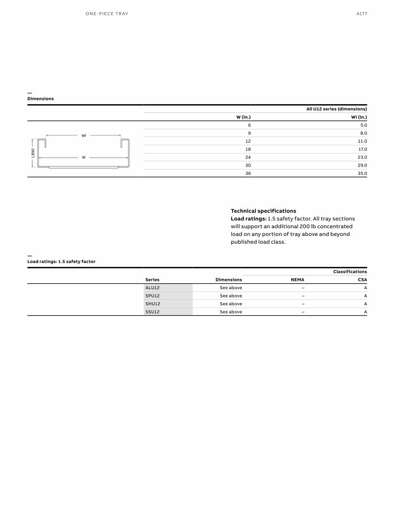
A177
All U12 series (dimensions)
W (in.) Wi (in.)
6 5.0
9 8.0
12 11.0
18 17.0
24 23.0
30 29.0
36 35.0
—Dimensions
—Load ratings: 1.5 safety factor
Series Dimensions
Classifications
NEMA CSA
ALU12 See above – A
SPU12 See above – A
SHU12 See above – A
SSU12 See above – A
1.89
0
WI
W
Technical specificationsLoad ratings: 1.5 safety factor. All tray sections will support an additional 200 lb concentrated load on any portion of tray above and beyond published load class.
O N E- PI ECE TR AY
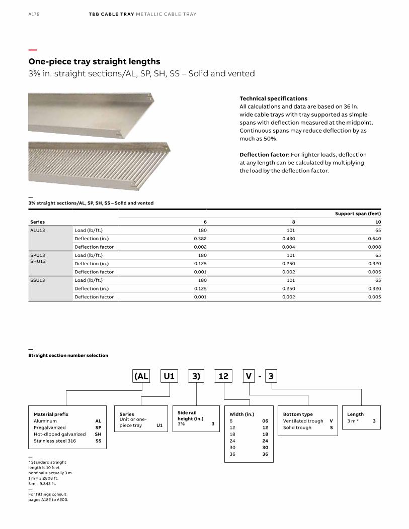
B1 copy starts here
B2 copy starts here
B3 copy starts here
A178 T& B C A B LE TR AY M E TA L L I C C A B L E TR AY
—One-piece tray straight lengths355⁄88 in. straight sections/AL, SP, SH, SS – Solid and vented
—355⁄88 straight sections/AL, SP, SH, SS – Solid and vented
—Straight section number selection
Technical specificationsAll calculations and data are based on 36 in. wide cable trays with tray supported as simple spans with deflection measured at the midpoint. Continuous spans may reduce deflection by as much as 50%.
Deflection factor: For lighter loads, deflection at any length can be calculated by multiplying the load by the deflection factor.
—* Standard straight length is 10 feet nominal = actually 3 m. 1 m = 3.2808 ft. 3 m = 9.842 ft.—For fittings consult pages A182 to A200.
Series
Support span (feet)
6 8 10
ALU13 Load (lb/ft.) 180 101 65
Deflection (in.) 0.382 0.430 0.540
Deflection factor 0.002 0.004 0.008
SPU13 SHU13
Load (lb/ft.) 180 101 65
Deflection (in.) 0.125 0.250 0.320
Deflection factor 0.001 0.002 0.005
SSU13 Load (lb/ft.) 180 101 65
Deflection (in.) 0.125 0.250 0.320
Deflection factor 0.001 0.002 0.005
Material prefixAluminum ALPregalvanized SPHot-dipped galvanized SHStainless steel 316 SS
Side rail height (in.)355⁄88 3
SeriesUnit or one-piece tray U1
Width (in.)6 0612 1218 1824 2430 3036 36
Length3 m * 3
Bottom typeVentilated trough VSolid trough S
(AL U1 3) 12 V - 3
—Straight section number selection
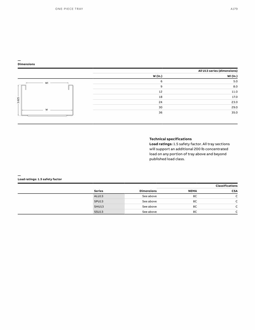
A179
—Dimensions
—Load ratings: 1.5 safety factor
All U13 series (dimensions)
W (in.) Wi (in.)
6 5.0
9 8.0
12 11.0
18 17.0
24 23.0
30 29.0
36 35.0W
WI
3.62
5
Technical specificationsLoad ratings: 1.5 safety factor. All tray sections will support an additional 200 lb concentrated load on any portion of tray above and beyond published load class.
Series Dimensions
Classifications
NEMA CSA
ALU13 See above 8C C
SPU13 See above 8C C
SHU13 See above 8C C
SSU13 See above 8C C
O N E- PI ECE TR AY

B1 copy starts here
B2 copy starts here
B3 copy starts here
A180 T& B C A B LE TR AY M E TA L L I C C A B L E TR AY
—One-piece tray straight lengths6 in. straight sections/AL, SP, SH, SS – Solid and vented
—6 in. straight sections/AL, SP, SH, SS – Solid and vented
Technical specificationsAll calculations and data are based on 36 in. wide cable trays with tray supported as simple spans with deflection measured at the midpoint. Continuous spans may reduce deflection by as much as 50%.
Deflection factor: For lighter loads, deflection at any length can be calculated by multiplying the load by the deflection factor.
—* Standard straight length is 10 feet nominal = actually 3 m.1 m = 3.2808 ft. 3 m = 9.842 ft.—For fittings, consult pages A182 to A200.
—Straight section number selection
Series
Support span (feet)
6 8 10
ALU16 Load (lb/ft.) 180 101 65
Deflection (in.) 0.082 0.128 0.160
Deflection Factor 0.000 0.001 0.008
SPU16 SHU16
Load (lb/ft.) 180 101 65
Deflection (in.) 0.125 0.250 0.320
Deflection Factor 0.001 0.002 0.005
SSU16 Load (lb/ft.) 180 101 65
Deflection (in.) 0.125 0.250 0.320
Deflection Factor 0.001 0.002 0.005
Material prefixAluminum ALPregalvanized SPHot-dipped galvanized SHStainless steel 316 SS
Side rail height (in.)6 in. 6
SeriesUnit or one-piece tray U1
Width (in.)6 0612 1218 1824 2430 3036 36
Length3 m * 3
Bottom typeVentilated trough VSolid trough S
(AL U1 6) 12 V - 3
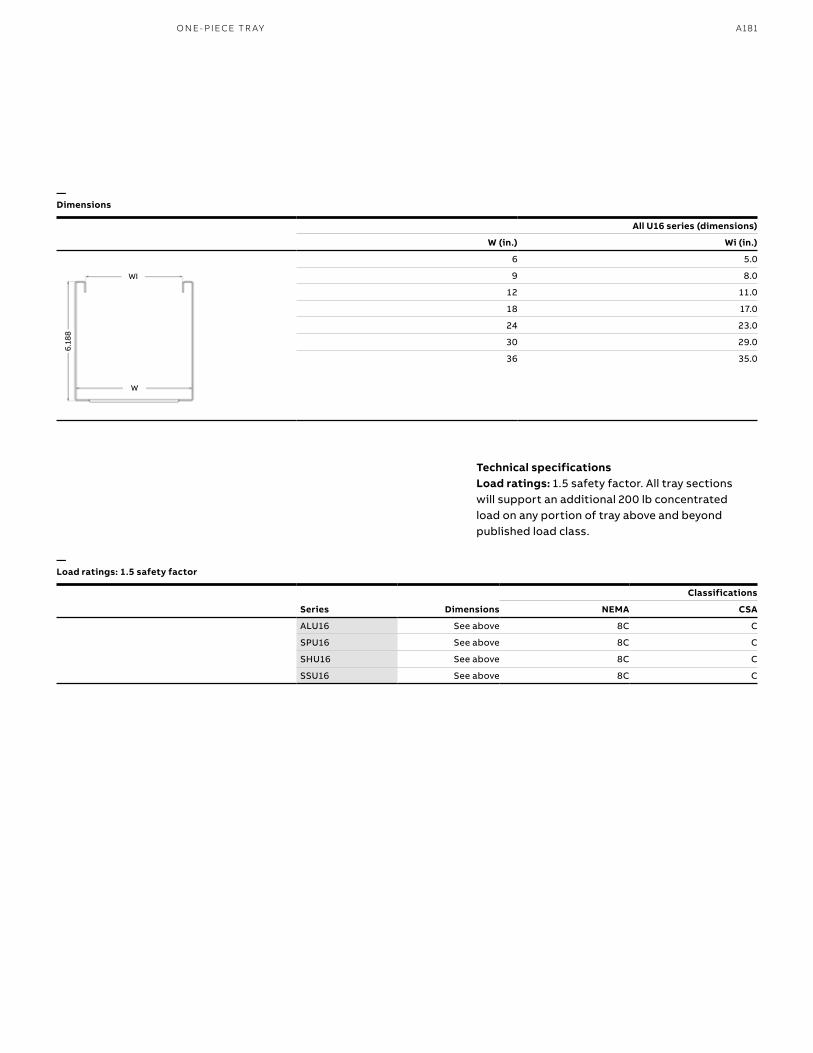
A181
—Dimensions
—Load ratings: 1.5 safety factor
Technical specificationsLoad ratings: 1.5 safety factor. All tray sections will support an additional 200 lb concentrated load on any portion of tray above and beyond published load class.
Series Dimensions
Classifications
NEMA CSA
ALU16 See above 8C C
SPU16 See above 8C C
SHU16 See above 8C C
SSU16 See above 8C C
All U16 series (dimensions)
W (in.) Wi (in.)
6 5.0
9 8.0
12 11.0
18 17.0
24 23.0
30 29.0
36 35.0
W
WI
6.18
8
O N E- PI ECE TR AY
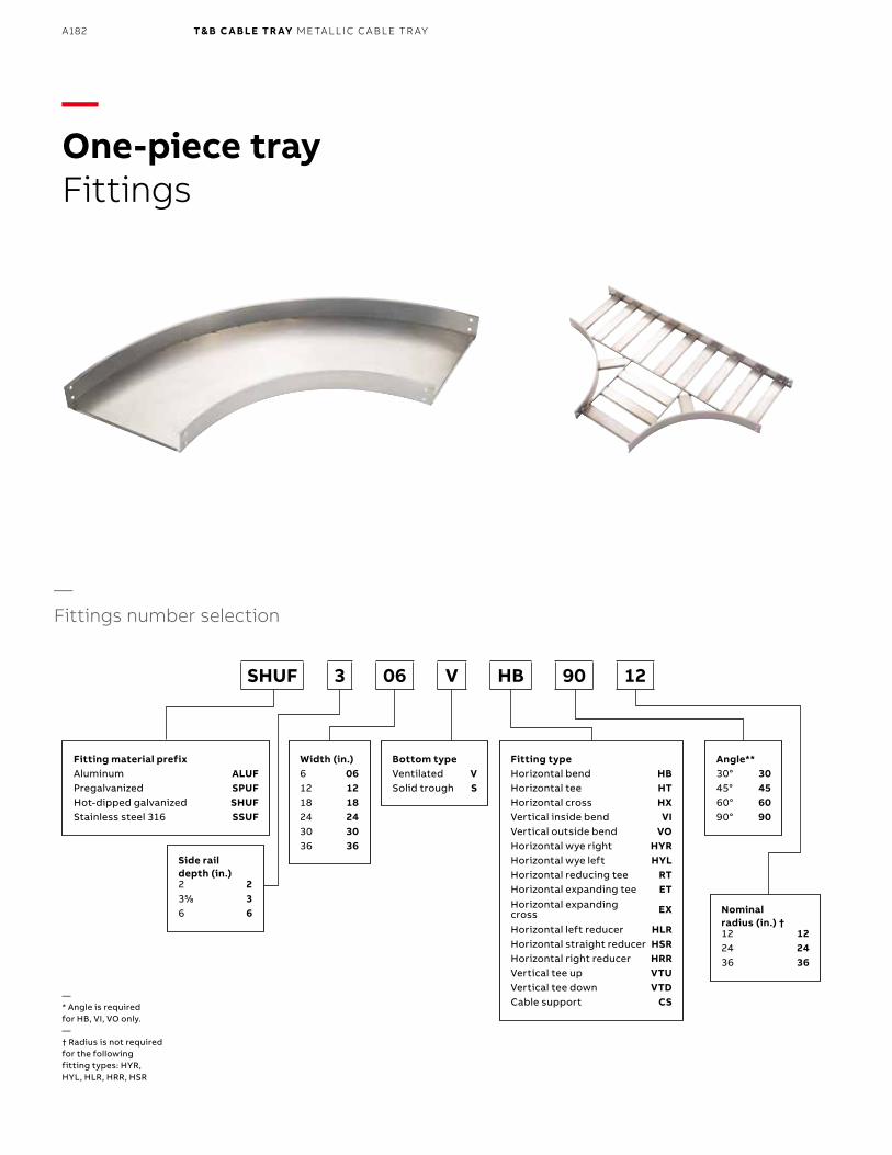
B1 copy starts here
B2 copy starts here
B3 copy starts here
A182 T& B C A B LE TR AY M E TA L L I C C A B L E TR AY
—One-piece trayFittings
Fitting material prefixAluminum ALUFPregalvanized SPUFHot-dipped galvanized SHUFStainless steel 316 SSUF
Fitting typeHorizontal bend HBHorizontal tee HTHorizontal cross HXVertical inside bend VIVertical outside bend VOHorizontal wye right HYRHorizontal wye left HYLHorizontal reducing tee RTHorizontal expanding tee ETHorizontal expanding cross EX
Horizontal left reducer HLRHorizontal straight reducer HSRHorizontal right reducer HRRVertical tee up VTUVertical tee down VTDCable support CS
Side rail depth (in.)2 2355⁄88 36 6 Nominal
radius (in.) †12 1224 2436 36
Width (in.)6 0612 1218 1824 2430 3036 36
Angle**30° 3045° 4560° 6090° 90
Bottom typeVentilated VSolid trough S
SHUF 3 06 V HB 90 12
—Fittings number selection
— * Angle is required for HB, VI, VO only.— † Radius is not required for the following fitting types: HYR, HYL, HLR, HRR, HSR
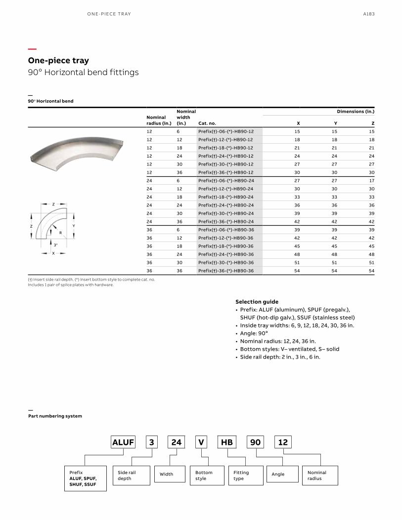
A183
Nominalradius (in.)
Nominal width (in.) Cat. no.
Dimensions (in.)
X Y Z
12 6 Prefix(†)-06-(*)-HB90-12 15 15 15
12 12 Prefix(†)-12-(*)-HB90-12 18 18 18
12 18 Prefix(†)-18-(*)-HB90-12 21 21 21
12 24 Prefix(†)-24-(*)-HB90-12 24 24 24
12 30 Prefix(†)-30-(*)-HB90-12 27 27 27
12 36 Prefix(†)-36-(*)-HB90-12 30 30 30
24 6 Prefix(†)-06-(*)-HB90-24 27 27 17
24 12 Prefix(†)-12-(*)-HB90-24 30 30 30
24 18 Prefix(†)-18-(*)-HB90-24 33 33 33
24 24 Prefix(†)-24-(*)-HB90-24 36 36 36
24 30 Prefix(†)-30-(*)-HB90-24 39 39 39
24 36 Prefix(†)-36-(*)-HB90-24 42 42 42
36 6 Prefix(†)-06-(*)-HB90-36 39 39 39
36 12 Prefix(†)-12-(*)-HB90-36 42 42 42
36 18 Prefix(†)-18-(*)-HB90-36 45 45 45
36 24 Prefix(†)-24-(*)-HB90-36 48 48 48
36 30 Prefix(†)-30-(*)-HB90-36 51 51 51
36 36 Prefix(†)-36-(*)-HB90-36 54 54 54
—One-piece tray 90o Horizontal bend fittings
—90o Horizontal bend
(†) Insert side rail depth. (*) Insert bottom style to complete cat. no. Includes 1 pair of splice plates with hardware.
X
3"
R
Y
Z
Z
—Part numbering system
PrefixALUF, SPUF,SHUF, SSUF
WidthSide rail depth
Bottom style
Angle Nominalradius
Fitting type
ALUF 3 24 V HB 90 12
Selection guide• Prefix: ALUF (aluminum), SPUF (pregalv.),
SHUF (hot-dip galv.), SSUF (stainless steel)• Inside tray widths: 6, 9, 12, 18, 24, 30, 36 in.• Angle: 90o• Nominal radius: 12, 24, 36 in.• Bottom styles: V– ventilated, S– solid• Side rail depth: 2 in., 3 in., 6 in.
O N E- PI ECE TR AY
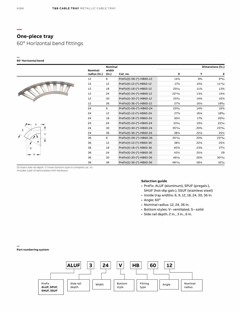
B1 copy starts here
B2 copy starts here
B3 copy starts here
A184 T& B C A B LE TR AY M E TA L L I C C A B L E TR AY
Nominalradius (in.)
Nominalwidth (in.) Cat. no.
Dimensions (in.)
X Y Z
12 6 Prefix(†)-06-(*)-HB60-12 1477⁄88 855⁄88 91515⁄1616
12 12 Prefix(†)-12-(*)-HB60-12 1711⁄22 1011⁄88 111111⁄1616
12 18 Prefix(†)-18-(*)-HB60-12 2011⁄1616 1155⁄88 1333⁄88
12 24 Prefix(†)-24-(*)-HB60-12 221111⁄1616 1311⁄88 1511⁄88
12 30 Prefix(†)-30-(*)-HB60-12 2555⁄1616 1455⁄88 1677⁄88
12 36 Prefix(†)-36-(*)-HB60-12 2777⁄88 1611⁄88 1899⁄1616
24 6 Prefix(†)-06-(*)-HB60-24 2555⁄1616 1455⁄88 1677⁄88
24 12 Prefix(†)-12-(*)-HB60-24 2777⁄88 1611⁄88 1899⁄1616
24 18 Prefix(†)-18-(*)-HB60-24 3011⁄22 1755⁄88 2055⁄1616
24 24 Prefix(†)-24-(*)-HB60-24 3311⁄1616 1911⁄88 2211⁄1616
24 30 Prefix(†)-30-(*)-HB60-24 351111⁄1616 2055⁄88 231313⁄1616
24 36 Prefix(†)-36-(*)-HB60-24 3811⁄44 2211⁄88 2511⁄22
36 6 Prefix(†)-06-(*)-HB60-36 351111⁄1616 2055⁄88 231313⁄1616
36 12 Prefix(†)-12-(*)-HB60-36 3811⁄44 2211⁄88 2511⁄22
36 18 Prefix(†)-18-(*)-HB60-36 4077⁄88 2355⁄88 2711⁄44
36 24 Prefix(†)-24-(*)-HB60-36 4311⁄22 2511⁄88 29
36 30 Prefix(†)-30-(*)-HB60-36 4611⁄1616 2655⁄88 301111⁄1616
36 36 Prefix(†)-36-(*)-HB60-36 481111⁄1616 2811⁄88 3277⁄1616
—60o Horizontal bend
—One-piece tray60o Horizontal bend fittings
Selection guide• Prefix: ALUF (aluminum), SPUF (pregalv.),
SHUF (hot-dip galv.), SSUF (stainless steel)• Inside tray widths: 6, 9, 12, 18, 24, 30, 36 in.• Angle: 60o• Nominal radius: 12, 24, 36 in.• Bottom styles: V– ventilated, S– solid• Side rail depth: 2 in., 3 in., 6 in.
—Part numbering system
PrefixALUF, SPUF,SHUF, SSUF
WidthSide rail depth
Bottom style
Angle Nominalradius
Fitting type
ALUF 3 24 V HB 60 12
X
3"
R
Y
Z
Z
(†) Insert side rail depth. (*) Insert bottom style to complete cat. no. Includes 1 pair of splice plates with hardware.
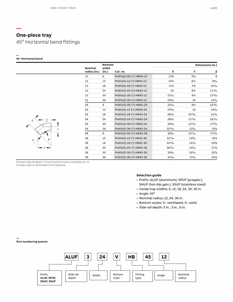
A185
Nominalradius (in.)
Nominalwidth (in.) Cat. no.
Dimensions (in.)
X Y Z
12 6 Prefix(†)-06-(*)-HB45-12 1355⁄88 555⁄88 8
12 12 Prefix(†)-12-(*)-HB45-12 1533⁄44 611⁄22 933⁄1616
12 18 Prefix(†)-18-(*)-HB45-12 1777⁄88 733⁄88 1077⁄1616
12 24 Prefix(†)-24-(*)-HB45-12 20 811⁄44 111111⁄1616
12 30 Prefix(†)-30-(*)-HB45-12 2211⁄1616 911⁄88 121515⁄1616
12 36 Prefix(†)-36-(*)-HB45-12 2433⁄1616 10 1433⁄1616
24 6 Prefix(†)-06-(*)-HB45-24 2211⁄1616 911⁄88 121515⁄1616
24 12 Prefix(†)-12-(*)-HB45-24 2433⁄1616 10 1433⁄1616
24 18 Prefix(†)-18-(*)-HB45-24 2655⁄1616 101515⁄1616 1577⁄1616
24 24 Prefix(†)-24-(*)-HB45-24 2877⁄1616 111313⁄1616 161111⁄1616
24 30 Prefix(†)-30-(*)-HB45-24 3099⁄1616 121111⁄1616 171515⁄1616
24 36 Prefix(†)-36-(*)-HB45-24 321111⁄1616 1399⁄1616 1911⁄88
36 6 Prefix(†)-06-(*)-HB45-36 3099⁄1616 121111⁄1616 171515⁄1616
36 12 Prefix(†)-12-(*)-HB45-36 321111⁄1616 1399⁄1616 1911⁄88
36 18 Prefix(†)-18-(*)-HB45-36 341313⁄1616 1477⁄1616 2033⁄88
36 24 Prefix(†)-24-(*)-HB45-36 361515⁄1616 1555⁄1616 2155⁄88
36 30 Prefix(†)-30-(*)-HB45-36 3911⁄1616 1633⁄1616 2277⁄88
36 36 Prefix(†)-36-(*)-HB45-36 4133⁄1616 1711⁄1616 2411⁄88
—One-piece tray 45o Horizontal bend fittings
—45o Horizontal bend
—Part numbering system
(†) Insert side rail depth. (*) Insert bottom style to complete cat. no. Includes 1 pair of splice plates with hardware.
X
3" R
Y
Z Z
PrefixALUF, SPUF,SHUF, SSUF
WidthSide rail depth
Bottom style
Angle Nominalradius
Fitting type
ALUF 3 24 V HB 45 12
Selection guide• Prefix: ALUF (aluminum), SPUF (pregalv.),
SHUF (hot-dip galv.), SSUF (stainless steel)• Inside tray widths: 6, 12, 18, 24, 30, 36 in.• Angle: 45o • Nominal radius: 12, 24, 36 in. • Bottom styles: V– ventilated, S– solid• Side rail depth: 2 in., 3 in., 6 in.
O N E- PI ECE TR AY
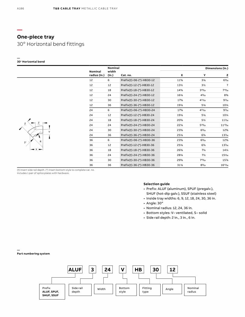
B1 copy starts here
B2 copy starts here
B3 copy starts here
A186 T& B C A B LE TR AY M E TA L L I C C A B L E TR AY
—One-piece tray30o Horizontal bend fittings
Selection guide• Prefix: ALUF (aluminum), SPUF (pregalv.),
SHUF (hot-dip galv.), SSUF (stainless steel)• Inside tray widths: 6, 9, 12, 18, 24, 30, 36 in.• Angle: 30o• Nominal radius: 12, 24, 36 in.• Bottom styles: V– ventilated, S– solid• Side rail depth: 2 in., 3 in., 6 in.
—Part numbering system
(†) Insert side rail depth. (*) Insert bottom style to complete cat. no. Includes 1 pair of splice plates with hardware.
Nominalradius (in.)
Nominalwidth (in.) Cat. no.
Dimensions (in.)
X Y Z
12 6 Prefix(†)-06-(*)-HB30-12 1155⁄88 311⁄88 633⁄1616
12 12 Prefix(†)-12-(*)-HB30-12 1311⁄22 311⁄22 7
12 18 Prefix(†)-18-(*)-HB30-12 1455⁄88 31515⁄1616 71313⁄1616
12 24 Prefix(†)-24-(*)-HB30-12 1611⁄88 455⁄1616 855⁄88
12 30 Prefix(†)-30-(*)-HB30-12 1755⁄88 41111⁄1616 977⁄1616
12 36 Prefix(†)-36-(*)-HB30-12 1911⁄88 511⁄88 1011⁄44
24 6 Prefix(†)-06-(*)-HB30-24 1755⁄88 41111⁄1616 977⁄1616
24 12 Prefix(†)-12-(*)-HB30-24 1911⁄88 511⁄88 1011⁄44
24 18 Prefix(†)-18-(*)-HB30-24 2055⁄88 511⁄22 1111⁄1616
24 24 Prefix(†)-24-(*)-HB30-24 2211⁄88 51515⁄1616 111313⁄1616
24 30 Prefix(†)-30-(*)-HB30-24 2355⁄88 655⁄1616 1255⁄88
24 36 Prefix(†)-36-(*)-HB30-24 2511⁄88 633⁄44 1377⁄1616
36 6 Prefix(†)-06-(*)-HB30-36 2355⁄88 655⁄1616 1255⁄88
36 12 Prefix(†)-12-(*)-HB30-36 2511⁄88 633⁄44 1377⁄1616
36 18 Prefix(†)-18-(*)-HB30-36 2655⁄88 711⁄44 1411⁄44
36 24 Prefix(†)-24-(*)-HB30-36 2811⁄88 711⁄22 1511⁄1616
36 30 Prefix(†)-30-(*)-HB30-36 2955⁄88 71515⁄1616 1577⁄88
36 36 Prefix(†)-36-(*)-HB30-36 3111⁄88 855⁄1616 161111⁄1616
—30o Horizontal bend
PrefixALUF, SPUF,SHUF, SSUF
WidthSide rail depth
Bottom style
Angle Nominalradius
Fitting type
ALUF 3 24 V HB 30 12
X
3" R
Y
Z Z
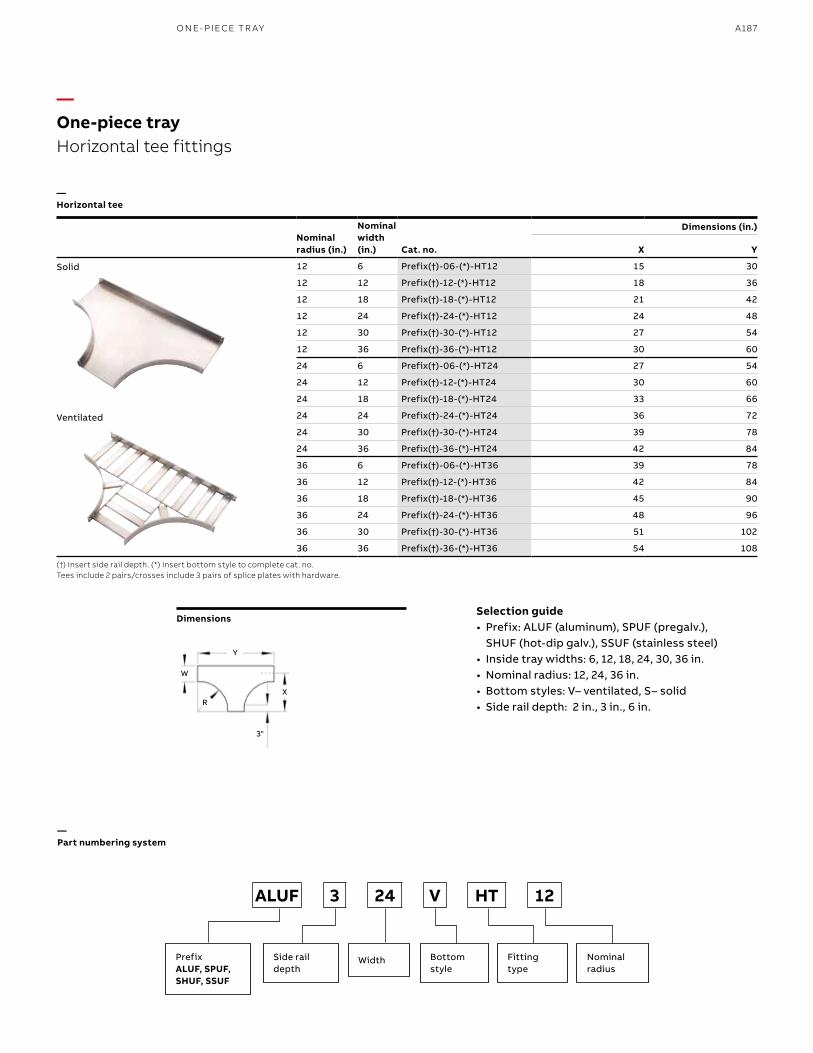
A187
(†) Insert side rail depth. (*) Insert bottom style to complete cat. no.Tees include 2 pairs/crosses include 3 pairs of splice plates with hardware.
—Horizontal tee
Nominalradius (in.)
Nominalwidth (in.) Cat. no.
Dimensions (in.)
X Y
12 6 Prefix(†)-06-(*)-HT12 15 30
12 12 Prefix(†)-12-(*)-HT12 18 36
12 18 Prefix(†)-18-(*)-HT12 21 42
12 24 Prefix(†)-24-(*)-HT12 24 48
12 30 Prefix(†)-30-(*)-HT12 27 54
12 36 Prefix(†)-36-(*)-HT12 30 60
24 6 Prefix(†)-06-(*)-HT24 27 54
24 12 Prefix(†)-12-(*)-HT24 30 60
24 18 Prefix(†)-18-(*)-HT24 33 66
24 24 Prefix(†)-24-(*)-HT24 36 72
24 30 Prefix(†)-30-(*)-HT24 39 78
24 36 Prefix(†)-36-(*)-HT24 42 84
36 6 Prefix(†)-06-(*)-HT36 39 78
36 12 Prefix(†)-12-(*)-HT36 42 84
36 18 Prefix(†)-18-(*)-HT36 45 90
36 24 Prefix(†)-24-(*)-HT36 48 96
36 30 Prefix(†)-30-(*)-HT36 51 102
36 36 Prefix(†)-36-(*)-HT36 54 108
Dimensions
Solid
Ventilated
—One-piece tray Horizontal tee fittings
Selection guide• Prefix: ALUF (aluminum), SPUF (pregalv.),
SHUF (hot-dip galv.), SSUF (stainless steel)• Inside tray widths: 6, 12, 18, 24, 30, 36 in.• Nominal radius: 12, 24, 36 in.• Bottom styles: V– ventilated, S– solid• Side rail depth: 2 in., 3 in., 6 in.
X
3"
R
Y
W
—Part numbering system
PrefixALUF, SPUF,SHUF, SSUF
WidthSide rail depth
Bottom style
Nominalradius
Fitting type
ALUF 3 24 V HT 12
O N E- PI ECE TR AY
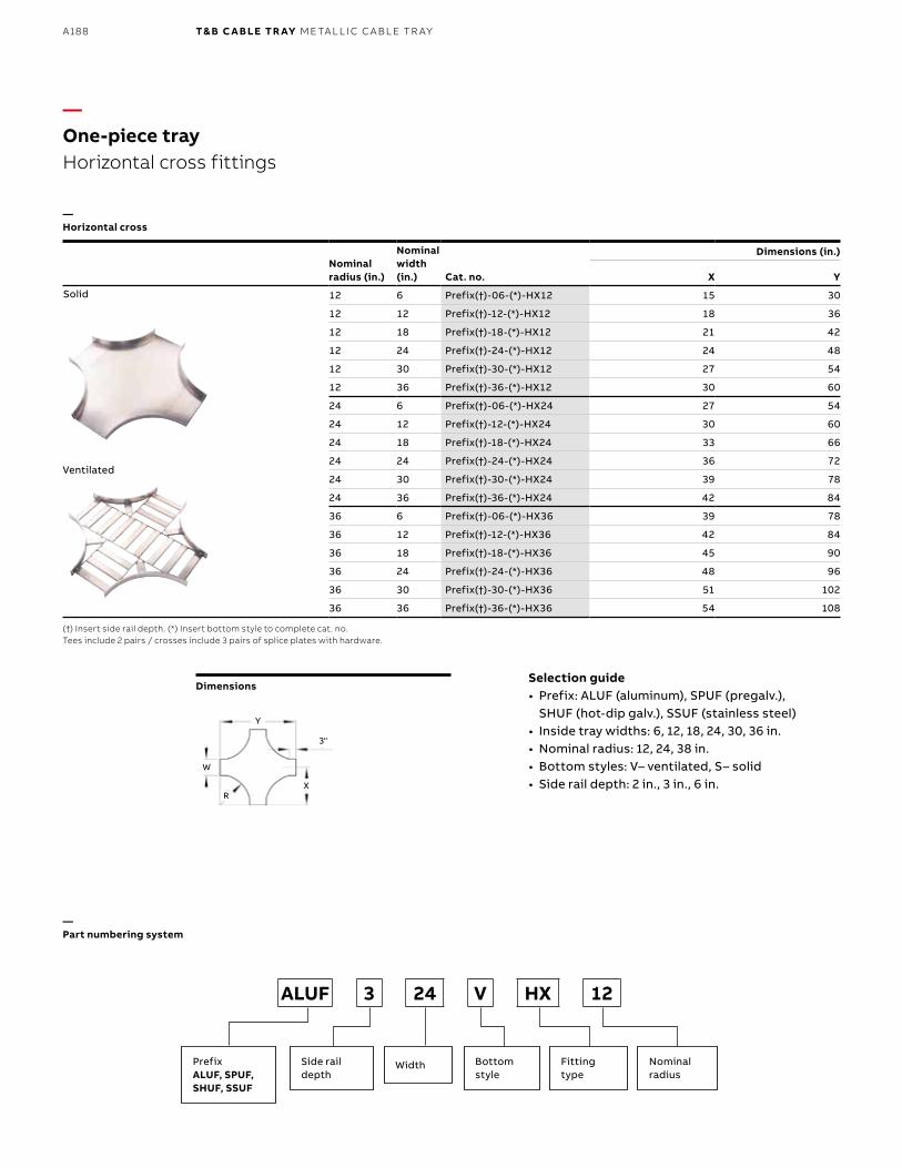
B1 copy starts here
B2 copy starts here
B3 copy starts here
A188 T& B C A B LE TR AY M E TA L L I C C A B L E TR AY
Nominalradius (in.)
Nominalwidth (in.) Cat. no.
Dimensions (in.)
X Y
12 6 Prefix(†)-06-(*)-HX12 15 30
12 12 Prefix(†)-12-(*)-HX12 18 36
12 18 Prefix(†)-18-(*)-HX12 21 42
12 24 Prefix(†)-24-(*)-HX12 24 48
12 30 Prefix(†)-30-(*)-HX12 27 54
12 36 Prefix(†)-36-(*)-HX12 30 60
24 6 Prefix(†)-06-(*)-HX24 27 54
24 12 Prefix(†)-12-(*)-HX24 30 60
24 18 Prefix(†)-18-(*)-HX24 33 66
24 24 Prefix(†)-24-(*)-HX24 36 72
24 30 Prefix(†)-30-(*)-HX24 39 78
24 36 Prefix(†)-36-(*)-HX24 42 84
36 6 Prefix(†)-06-(*)-HX36 39 78
36 12 Prefix(†)-12-(*)-HX36 42 84
36 18 Prefix(†)-18-(*)-HX36 45 90
36 24 Prefix(†)-24-(*)-HX36 48 96
36 30 Prefix(†)-30-(*)-HX36 51 102
36 36 Prefix(†)-36-(*)-HX36 54 108
—One-piece trayHorizontal cross fittings
Selection guide• Prefix: ALUF (aluminum), SPUF (pregalv.),
SHUF (hot-dip galv.), SSUF (stainless steel)• Inside tray widths: 6, 12, 18, 24, 30, 36 in.• Nominal radius: 12, 24, 38 in. • Bottom styles: V– ventilated, S– solid• Side rail depth: 2 in., 3 in., 6 in.
—Part numbering system
(†) Insert side rail depth. (*) Insert bottom style to complete cat. no.Tees include 2 pairs / crosses include 3 pairs of splice plates with hardware.
—Horizontal cross
Solid
Ventilated
Dimensions
X
3"
R
Y
W
PrefixALUF, SPUF,SHUF, SSUF
WidthSide rail depth
Bottom style
Nominalradius
Fitting type
ALUF 3 24 V HX 12

A189
(†) Insert side rail depth. (*) Insert bottom style (+) Insert radius (12 in. – 36 in.) to complete cat. no. Includes 2 pairs of splice plates with hardware.
Widths (in.)
Cat. no.
Dimensions (in.)
(+) 12 in. Nominal radius
(+) 24 in. Nominal radius
(+) 36 in. Nominal radius
W1 W2 X Y X Y X Y
36 30 Prefix(†)-3630-(*)-RT(+) 30 54 42 78 54 102
36 24 Prefix(†)-3624-(*)-RT(+) 30 48 42 72 54 96
36 18 Prefix(†)-3618-(*)-RT(+) 30 42 42 66 54 90
36 12 Prefix(†)-3612-(*)-RT(+) 30 36 42 60 54 84
36 6 Prefix(†)-3606-(*)-RT(+) 30 30 42 54 54 78
30 24 Prefix(†)-3024-(*)-RT(+) 27 48 39 72 51 96
30 18 Prefix(†)-3018-(*)-RT(+) 27 42 39 66 51 90
30 12 Prefix(†)-3012-(*)-RT(+) 27 36 39 60 51 84
30 6 Prefix(†)-3006-(*)-RT(+) 27 30 39 54 51 78
24 18 Prefix(†)-2418-(*)-RT(+) 24 42 36 66 48 90
24 12 Prefix(†)-2412-(*)-RT(+) 24 36 36 60 48 84
24 6 Prefix(†)-2406-(*)-RT(+) 24 30 36 54 48 78
18 12 Prefix(†)-1812-(*)-RT(+) 21 36 33 60 45 84
18 6 Prefix(†)-1806-(*)-RT(+) 21 30 33 54 45 78
12 6 Prefix(†)-1206-(*)-RT(+) 18 30 30 54 42 78
—One-piece tray Horizontal reducing tee fittings
—Horizontal reducing tee
Selection guide• Prefix: ALUF (aluminum), SPUF (pregalv.),
SHUF (hot-dip galv.), SSUF (stainless steel)• Tray widths W1: 36, 30, 24, 18, 12 in.• Tray widths W2: 30, 24, 18, 12, 6 in.• Nominal radius: 12, 24, 36 in. • Bottom styles: V– ventilated, S– solid• Side rail depth: 2 in., 3 in., 6 in.
—Part numbering system
PrefixALUF, SPUF,SHUF, SSUF
Width 1 Width 2Side rail depth
Bottom style
Nominalradius
Fitting type
ALUF 3 24 12 V RT 12
X
3"
R
Y
W1
W2
O N E- PI ECE TR AY
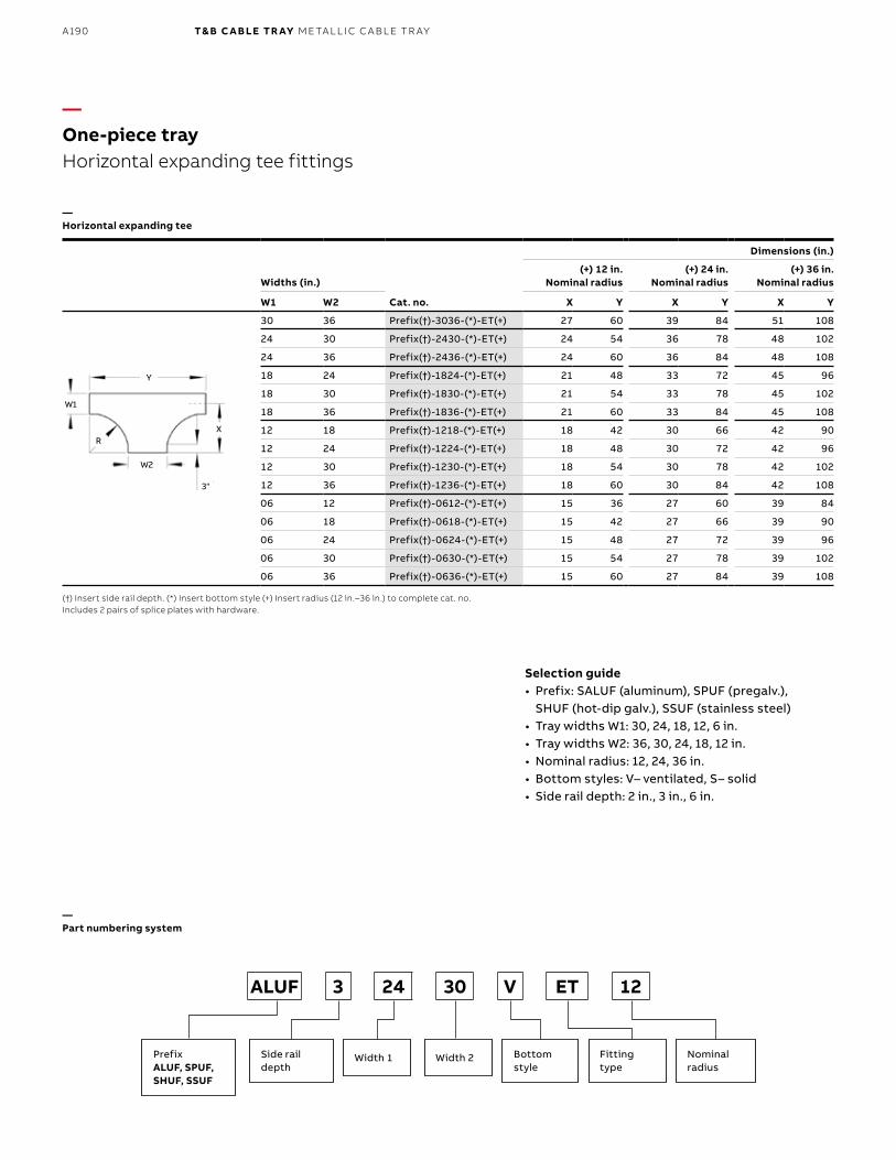
B1 copy starts here
B2 copy starts here
B3 copy starts here
A190 T& B C A B LE TR AY M E TA L L I C C A B L E TR AY
Widths (in.)
Cat. no.
Dimensions (in.)
(+) 12 in. Nominal radius
(+) 24 in. Nominal radius
(+) 36 in. Nominal radius
W1 W2 X Y X Y X Y
30 36 Prefix(†)-3036-(*)-ET(+) 27 60 39 84 51 108
24 30 Prefix(†)-2430-(*)-ET(+) 24 54 36 78 48 102
24 36 Prefix(†)-2436-(*)-ET(+) 24 60 36 84 48 108
18 24 Prefix(†)-1824-(*)-ET(+) 21 48 33 72 45 96
18 30 Prefix(†)-1830-(*)-ET(+) 21 54 33 78 45 102
18 36 Prefix(†)-1836-(*)-ET(+) 21 60 33 84 45 108
12 18 Prefix(†)-1218-(*)-ET(+) 18 42 30 66 42 90
12 24 Prefix(†)-1224-(*)-ET(+) 18 48 30 72 42 96
12 30 Prefix(†)-1230-(*)-ET(+) 18 54 30 78 42 102
12 36 Prefix(†)-1236-(*)-ET(+) 18 60 30 84 42 108
06 12 Prefix(†)-0612-(*)-ET(+) 15 36 27 60 39 84
06 18 Prefix(†)-0618-(*)-ET(+) 15 42 27 66 39 90
06 24 Prefix(†)-0624-(*)-ET(+) 15 48 27 72 39 96
06 30 Prefix(†)-0630-(*)-ET(+) 15 54 27 78 39 102
06 36 Prefix(†)-0636-(*)-ET(+) 15 60 27 84 39 108
—One-piece trayHorizontal expanding tee fittings
—Part numbering system
(†) Insert side rail depth. (*) Insert bottom style (+) Insert radius (12 in.–36 in.) to complete cat. no.Includes 2 pairs of splice plates with hardware.
—Horizontal expanding tee
X
3"
R
Y
W1
W2
Selection guide• Prefix: SALUF (aluminum), SPUF (pregalv.),
SHUF (hot-dip galv.), SSUF (stainless steel)• Tray widths W1: 30, 24, 18, 12, 6 in.• Tray widths W2: 36, 30, 24, 18, 12 in. • Nominal radius: 12, 24, 36 in. • Bottom styles: V– ventilated, S– solid• Side rail depth: 2 in., 3 in., 6 in.
PrefixALUF, SPUF,SHUF, SSUF
Width 1 Width 2Side rail depth
Bottom style
Nominalradius
Fitting type
ALUF 3 24 30 V ET 12
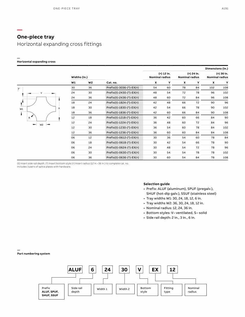
A191
Widths (in.)
Cat. no.
Dimensions (in.)
(+) 12 in. Nominal radius
(+) 24 in. Nominal radius
(+) 36 in. Nominal radius
W1 W2 X Y X Y X Y
30 36 Prefix(†)-3036-(*)-EX(+) 54 60 78 84 102 108
24 30 Prefix(†)-2430-(*)-EX(+) 48 54 72 78 96 102
24 36 Prefix(†)-2436-(*)-EX(+) 48 60 72 84 96 108
18 24 Prefix(†)-1824-(*)-EX(+) 42 48 66 72 90 96
18 30 Prefix(†)-1830-(*)-EX(+) 42 54 66 78 90 102
18 36 Prefix(†)-1836-(*)-EX(+) 42 60 66 84 90 108
12 18 Prefix(†)-1218-(*)-EX(+) 36 42 60 66 84 90
12 24 Prefix(†)-1224-(*)-EX(+) 36 48 60 72 84 96
12 30 Prefix(†)-1230-(*)-EX(+) 36 54 60 78 84 102
12 36 Prefix(†)-1236-(*)-EX(+) 36 60 60 84 84 108
06 12 Prefix(†)-0612-(*)-EX(+) 30 36 54 60 78 84
06 18 Prefix(†)-0618-(*)-EX(+) 30 42 54 66 78 90
06 24 Prefix(†)-0624-(*)-EX(+) 30 48 54 72 78 96
06 30 Prefix(†)-0630-(*)-EX(+) 30 54 54 78 78 102
06 36 Prefix(†)-0636-(*)-EX(+) 30 60 54 84 78 108
(†) Insert side rail depth. (*) Insert bottom style (+) Insert radius (12 in.–36 in.) to complete cat. no.Includes 3 pairs of splice plates with hardware.
—One-piece tray Horizontal expanding cross fittings
—Horizontal expanding cross
X
3"
R
Y
W1
W2
Selection guide• Prefix: ALUF (aluminum), SPUF (pregalv.),
SHUF (hot-dip galv.), SSUF (stainless steel)• Tray widths W1: 30, 24, 18, 12, 6 in.• Tray widths W2: 36, 30, 24, 18, 12 in.• Nominal radius: 12, 24, 36 in. • Bottom styles: V– ventilated, S– solid• Side rail depth: 2 in., 3 in., 6 in.
—Part numbering system
PrefixALUF, SPUF,SHUF, SSUF
Width 1 Width 2Side rail depth
Bottom style
Nominalradius
Fitting type
ALUF 6 24 30 V EX 12
O N E- PI ECE TR AY
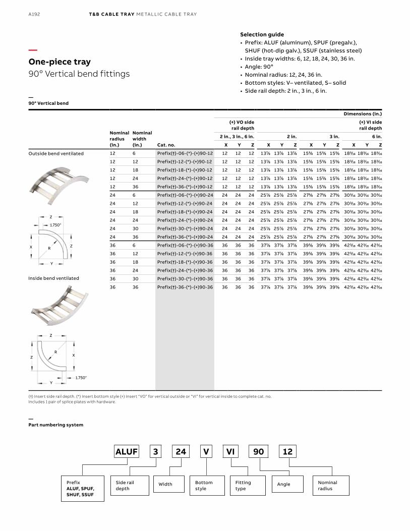
B1 copy starts here
B2 copy starts here
B3 copy starts here
A192 T& B C A B LE TR AY M E TA L L I C C A B L E TR AY
Nominalradius (in.)
Nominalwidth (in.) Cat. no.
Dimensions (in.)
(+) VO side rail depth
(+) VI side rail depth
2 in., 3 in., 6 in. 2 in. 3 in. 6 in.
X Y Z X Y Z X Y Z X Y Z
12 6 Prefix(†)-06-(*)-(+)90-12 12 12 12 1377⁄88 1377⁄88 1377⁄88 1555⁄88 1555⁄88 1555⁄88 1833⁄1616 1833⁄1616 1833⁄1616
12 12 Prefix(†)-12-(*)-(+)90-12 12 12 12 1377⁄88 1377⁄88 1377⁄88 1555⁄88 1555⁄88 1555⁄88 1833⁄1616 1833⁄1616 1833⁄1616
12 18 Prefix(†)-18-(*)-(+)90-12 12 12 12 1377⁄88 1377⁄88 1377⁄88 1555⁄88 1555⁄88 1555⁄88 1833⁄1616 1833⁄1616 1833⁄1616
12 24 Prefix(†)-24-(*)-(+)90-12 12 12 12 1377⁄88 1377⁄88 1377⁄88 1555⁄88 1555⁄88 1555⁄88 1833⁄1616 1833⁄1616 1833⁄1616
12 36 Prefix(†)-36-(*)-(+)90-12 12 12 12 1377⁄88 1377⁄88 1377⁄88 1555⁄88 1555⁄88 1555⁄88 1833⁄1616 1833⁄1616 1833⁄1616
24 6 Prefix(†)-06-(*)-(+)90-24 24 24 24 2577⁄88 2577⁄88 2577⁄88 2755⁄88 2755⁄88 2755⁄88 3033⁄1616 3033⁄1616 3033⁄1616
24 12 Prefix(†)-12-(*)-(+)90-24 24 24 24 2577⁄88 2577⁄88 2577⁄88 2755⁄88 2755⁄88 2755⁄88 3033⁄1616 3033⁄1616 3033⁄1616
24 18 Prefix(†)-18-(*)-(+)90-24 24 24 24 2577⁄88 2577⁄88 2577⁄88 2755⁄88 2755⁄88 2755⁄88 3033⁄1616 3033⁄1616 3033⁄1616
24 24 Prefix(†)-24-(*)-(+)90-24 24 24 24 2577⁄88 2577⁄88 2577⁄88 2755⁄88 2755⁄88 2755⁄88 3033⁄1616 3033⁄1616 3033⁄1616
24 30 Prefix(†)-30-(*)-(+)90-24 24 24 24 2577⁄88 2577⁄88 2577⁄88 2755⁄88 2755⁄88 2755⁄88 3033⁄1616 3033⁄1616 3033⁄1616
24 36 Prefix(†)-36-(*)-(+)90-24 24 24 24 2577⁄88 2577⁄88 2577⁄88 2755⁄88 2755⁄88 2755⁄88 3033⁄1616 3033⁄1616 3033⁄1616
36 6 Prefix(†)-06-(*)-(+)90-36 36 36 36 3777⁄88 3777⁄88 3777⁄88 3955⁄88 3955⁄88 3955⁄88 4233⁄1616 4233⁄1616 4233⁄1616
36 12 Prefix(†)-12-(*)-(+)90-36 36 36 36 3777⁄88 3777⁄88 3777⁄88 3955⁄88 3955⁄88 3955⁄88 4233⁄1616 4233⁄1616 4233⁄1616
36 18 Prefix(†)-18-(*)-(+)90-36 36 36 36 3777⁄88 3777⁄88 3777⁄88 3955⁄88 3955⁄88 3955⁄88 4233⁄1616 4233⁄1616 4233⁄1616
36 24 Prefix(†)-24-(*)-(+)90-36 36 36 36 3777⁄88 3777⁄88 3777⁄88 3955⁄88 3955⁄88 3955⁄88 4233⁄1616 4233⁄1616 4233⁄1616
36 30 Prefix(†)-30-(*)-(+)90-36 36 36 36 3777⁄88 3777⁄88 3777⁄88 3955⁄88 3955⁄88 3955⁄88 4233⁄1616 4233⁄1616 4233⁄1616
36 36 Prefix(†)-36-(*)-(+)90-36 36 36 36 3777⁄88 3777⁄88 3777⁄88 3955⁄88 3955⁄88 3955⁄88 4233⁄1616 4233⁄1616 4233⁄1616
—One-piece tray90o Vertical bend fittings
—90° Vertical bend
Outside bend ventilated
Inside bend ventilated
(†) Insert side rail depth. (*) Insert bottom style (+) Insert “VO” for vertical outside or “VI” for vertical inside to complete cat. no. Includes 1 pair of splice plates with hardware.
—Part numbering system
PrefixALUF, SPUF,SHUF, SSUF
Width AngleSide rail depth
Bottom style
Nominalradius
Fitting type
ALUF 3 24 V VI 90 12
Selection guide• Prefix: ALUF (aluminum), SPUF (pregalv.),
SHUF (hot-dip galv.), SSUF (stainless steel)• Inside tray widths: 6, 12, 18, 24, 30, 36 in.• Angle: 90o• Nominal radius: 12, 24, 36 in.• Bottom styles: V– ventilated, S– solid• Side rail depth: 2 in., 3 in., 6 in.
X
X
1.750"
1.750"
R
R
Y
Y
Z
Z
Z
Z
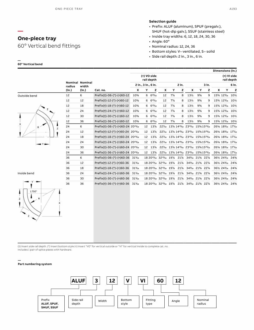
A193
Outside bend
Inside bend
(†) Insert side rail depth. (*) Insert bottom style (+) Insert “VO” for vertical outside or “VI” for vertical inside to complete cat. no. Includes 1 pair of splice plates with hardware.
PrefixALUF, SPUF,SHUF, SSUF
Width AngleSide rail depth
Bottom style
Nominalradius
Fitting type
ALUF 3 12 V VI 60 12
Selection guide• Prefix: ALUF (aluminum), SPUF (pregalv.),
SHUF (hot-dip galv.), SSUF (stainless steel)• Inside tray widths: 6, 12, 18, 24, 30, 36• Angle: 60o• Nominal radius: 12, 24, 36• Bottom styles: V– ventilated, S– solid• Side rail depth: 2 in., 3 in., 6 in.
Nominalradius (in.)
Nominalwidth (in.) Cat. no.
Dimensions (in.)
(+) VO side rail depth
(+) VI side rail depth
2 in., 3 in., 6 in. 2 in. 3 in. 6 in.
X Y Z X Y Z X Y Z X Y Z
12 6 Prefix(†)-06-(*)-(+)60-12 1033⁄88 6 61515⁄1616 12 777⁄88 8 1311⁄22 955⁄88 9 1533⁄44 1233⁄1616 1011⁄22
12 12 Prefix(†)-12-(*)-(+)60-12 1033⁄88 6 61515⁄1616 12 777⁄88 8 1311⁄22 955⁄88 9 1533⁄44 1233⁄1616 1011⁄22
12 18 Prefix(†)-18-(*)-(+)60-12 1033⁄88 6 61515⁄1616 12 777⁄88 8 1311⁄22 955⁄88 9 1533⁄44 1233⁄1616 1011⁄22
12 24 Prefix(†)-24-(*)-(+)60-12 1033⁄88 6 61515⁄1616 12 777⁄88 8 1311⁄22 955⁄88 9 1533⁄44 1233⁄1616 1011⁄22
12 30 Prefix(†)-30-(*)-(+)60-12 1033⁄88 6 61515⁄1616 12 777⁄88 8 1311⁄22 955⁄88 9 1533⁄44 1233⁄1616 1011⁄22
12 36 Prefix(†)-36-(*)-(+)60-12 1033⁄88 6 61515⁄1616 12 777⁄88 8 1311⁄22 955⁄88 9 1533⁄44 1233⁄1616 1011⁄22
24 6 Prefix(†)-06-(*)-(+)60-24 201313⁄1616 12 1377⁄88 2277⁄1616 1377⁄88 141515⁄1616 231515⁄1616 1555⁄88 151515⁄1616 2611⁄88 1833⁄1616 1777⁄1616
24 12 Prefix(†)-12-(*)-(+)60-24 201313⁄1616 12 1377⁄88 2277⁄1616 1377⁄88 141515⁄1616 231515⁄1616 1555⁄88 151515⁄1616 2611⁄88 1833⁄1616 1777⁄1616
24 18 Prefix(†)-18-(*)-(+)60-24 201313⁄1616 12 1377⁄88 2277⁄1616 1377⁄88 141515⁄1616 231515⁄1616 1555⁄88 151515⁄1616 2611⁄88 1833⁄1616 1777⁄1616
24 24 Prefix(†)-24-(*)-(+)60-24 201313⁄1616 12 1377⁄88 2277⁄1616 1377⁄88 141515⁄1616 231515⁄1616 1555⁄88 151515⁄1616 2611⁄88 1833⁄1616 1777⁄1616
24 30 Prefix(†)-30-(*)-(+)60-24 201313⁄1616 12 1377⁄88 2277⁄1616 1377⁄88 141515⁄1616 231515⁄1616 1555⁄88 151515⁄1616 2611⁄88 1833⁄1616 1777⁄1616
24 36 Prefix(†)-36-(*)-(+)60-24 201313⁄1616 12 1377⁄88 2277⁄1616 1377⁄88 141515⁄1616 231515⁄1616 1555⁄88 151515⁄1616 2611⁄88 1833⁄1616 1777⁄1616
36 6 Prefix(†)-06-(*)-(+)60-36 3133⁄1616 18 201313⁄1616 321313⁄1616 1977⁄88 2177⁄88 3455⁄1616 2155⁄88 2277⁄88 3611⁄22 2433⁄1616 2433⁄88
36 12 Prefix(†)-12-(*)-(+)60-36 3133⁄1616 18 201313⁄1616 321313⁄1616 1977⁄88 2177⁄88 3455⁄1616 2155⁄88 2277⁄88 3611⁄22 2433⁄1616 2433⁄88
36 18 Prefix(†)-18-(*)-(+)60-36 3133⁄1616 18 201313⁄1616 321313⁄1616 1977⁄88 2177⁄88 3455⁄1616 2155⁄88 2277⁄88 3611⁄22 2433⁄1616 2433⁄88
36 24 Prefix(†)-24-(*)-(+)60-36 3133⁄1616 18 201313⁄1616 321313⁄1616 1977⁄88 2177⁄88 3455⁄1616 2155⁄88 2277⁄88 3611⁄22 2433⁄1616 2433⁄88
36 30 Prefix(†)-30-(*)-(+)60-36 3133⁄1616 18 201313⁄1616 321313⁄1616 1977⁄88 2177⁄88 3455⁄1616 2155⁄88 2277⁄88 3611⁄22 2433⁄1616 2433⁄88
36 36 Prefix(†)-36-(*)-(+)60-36 3133⁄1616 18 201313⁄1616 321313⁄1616 1977⁄88 2177⁄88 3455⁄1616 2155⁄88 2277⁄88 3611⁄22 2433⁄1616 2433⁄88
—One-piece tray 60o Vertical bend fittings
—60° Vertical bend
—Part numbering system
X
X
R
R
Y
Y
Z
Z
Z
Z
1.750"
O N E- PI ECE TR AY
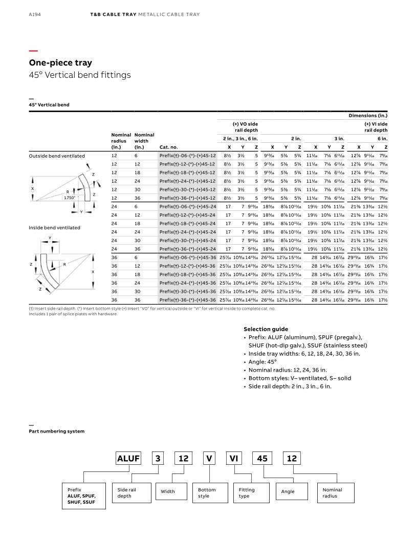
B1 copy starts here
B2 copy starts here
B3 copy starts here
A194 T& B C A B LE TR AY M E TA L L I C C A B L E TR AY
Nominalradius (in.)
Nominalwidth (in.) Cat. no.
Dimensions (in.)
(+) VO side rail depth
(+) VI side rail depth
2 in., 3 in., 6 in. 2 in. 3 in. 6 in.
X Y Z X Y Z X Y Z X Y Z
12 6 Prefix(†)-06-(*)-(+)45-12 811⁄22 311⁄22 5 91313⁄1616 533⁄88 533⁄44 1111⁄1616 711⁄88 61111⁄1616 1277⁄88 91111⁄1616 799⁄1616
12 12 Prefix(†)-12-(*)-(+)45-12 811⁄22 311⁄22 5 91313⁄1616 533⁄88 533⁄44 1111⁄1616 711⁄88 61111⁄1616 1277⁄88 91111⁄1616 799⁄1616
12 18 Prefix(†)-18-(*)-(+)45-12 811⁄22 311⁄22 5 91313⁄1616 533⁄88 533⁄44 1111⁄1616 711⁄88 61111⁄1616 1277⁄88 91111⁄1616 799⁄1616
12 24 Prefix(†)-24-(*)-(+)45-12 811⁄22 311⁄22 5 91313⁄1616 533⁄88 533⁄44 1111⁄1616 711⁄88 61111⁄1616 1277⁄88 91111⁄1616 799⁄1616
12 30 Prefix(†)-30-(*)-(+)45-12 811⁄22 311⁄22 5 91313⁄1616 533⁄88 533⁄44 1111⁄1616 711⁄88 61111⁄1616 1277⁄88 91111⁄1616 799⁄1616
12 36 Prefix(†)-36-(*)-(+)45-12 811⁄22 311⁄22 5 91313⁄1616 533⁄88 533⁄44 1111⁄1616 711⁄88 61111⁄1616 1277⁄88 91111⁄1616 799⁄1616
24 6 Prefix(†)-06-(*)-(+)45-24 17 7 91515⁄1616 1855⁄1616 877⁄88 101111⁄1616 1911⁄22 1055⁄88 1177⁄1616 2133⁄88 1333⁄1616 1211⁄22
24 12 Prefix(†)-12-(*)-(+)45-24 17 7 91515⁄1616 1855⁄1616 877⁄88 101111⁄1616 1911⁄22 1055⁄88 1177⁄1616 2133⁄88 1333⁄1616 1211⁄22
24 18 Prefix(†)-18-(*)-(+)45-24 17 7 91515⁄1616 1855⁄1616 877⁄88 101111⁄1616 1911⁄22 1055⁄88 1177⁄1616 2133⁄88 1333⁄1616 1211⁄22
24 24 Prefix(†)-24-(*)-(+)45-24 17 7 91515⁄1616 1855⁄1616 877⁄88 101111⁄1616 1911⁄22 1055⁄88 1177⁄1616 2133⁄88 1333⁄1616 1211⁄22
24 30 Prefix(†)-30-(*)-(+)45-24 17 7 91515⁄1616 1855⁄1616 877⁄88 101111⁄1616 1911⁄22 1055⁄88 1177⁄1616 2133⁄88 1333⁄1616 1211⁄22
24 36 Prefix(†)-36-(*)-(+)45-24 17 7 91515⁄1616 1855⁄1616 877⁄88 101111⁄1616 1911⁄22 1055⁄88 1177⁄1616 2133⁄88 1333⁄1616 1211⁄22
36 6 Prefix(†)-06-(*)-(+)45-36 2577⁄1616 1099⁄1616 141515⁄1616 261313⁄1616 1277⁄1616 151111⁄1616 28 1433⁄1616 1677⁄1616 291313⁄1616 1633⁄44 1711⁄22
36 12 Prefix(†)-12-(*)-(+)45-36 2577⁄1616 1099⁄1616 141515⁄1616 261313⁄1616 1277⁄1616 151111⁄1616 28 1433⁄1616 1677⁄1616 291313⁄1616 1633⁄44 1711⁄22
36 18 Prefix(†)-18-(*)-(+)45-36 2577⁄1616 1099⁄1616 141515⁄1616 261313⁄1616 1277⁄1616 151111⁄1616 28 1433⁄1616 1677⁄1616 291313⁄1616 1633⁄44 1711⁄22
36 24 Prefix(†)-24-(*)-(+)45-36 2577⁄1616 1099⁄1616 141515⁄1616 261313⁄1616 1277⁄1616 151111⁄1616 28 1433⁄1616 1677⁄1616 291313⁄1616 1633⁄44 1711⁄22
36 30 Prefix(†)-30-(*)-(+)45-36 2577⁄1616 1099⁄1616 141515⁄1616 261313⁄1616 1277⁄1616 151111⁄1616 28 1433⁄1616 1677⁄1616 291313⁄1616 1633⁄44 1711⁄22
36 36 Prefix(†)-36-(*)-(+)45-36 2577⁄1616 1099⁄1616 141515⁄1616 261313⁄1616 1277⁄1616 151111⁄1616 28 1433⁄1616 1677⁄1616 291313⁄1616 1633⁄44 1711⁄22
—One-piece tray45o Vertical bend fittings
Outside bend ventilated
Inside bend ventilated
—45° Vertical bend
(†) Insert side rail depth. (*) Insert bottom style (+) Insert “VO” for vertical outside or “VI” for vertical inside to complete cat. no.Includes 1 pair of splice plates with hardware.
X
X
R
R1.750"
Y
Y
Z
Z
Z
Z
—Part numbering system
PrefixALUF, SPUF,SHUF, SSUF
Width AngleSide rail depth
Bottom style
Nominalradius
Fitting type
ALUF 3 12 V VI 45 12
Selection guide• Prefix: ALUF (aluminum), SPUF (pregalv.),
SHUF (hot-dip galv.), SSUF (stainless steel)• Inside tray widths: 6, 12, 18, 24, 30, 36 in.• Angle: 45o• Nominal radius: 12, 24, 36 in.• Bottom styles: V– ventilated, S– solid• Side rail depth: 2 in., 3 in., 6 in.
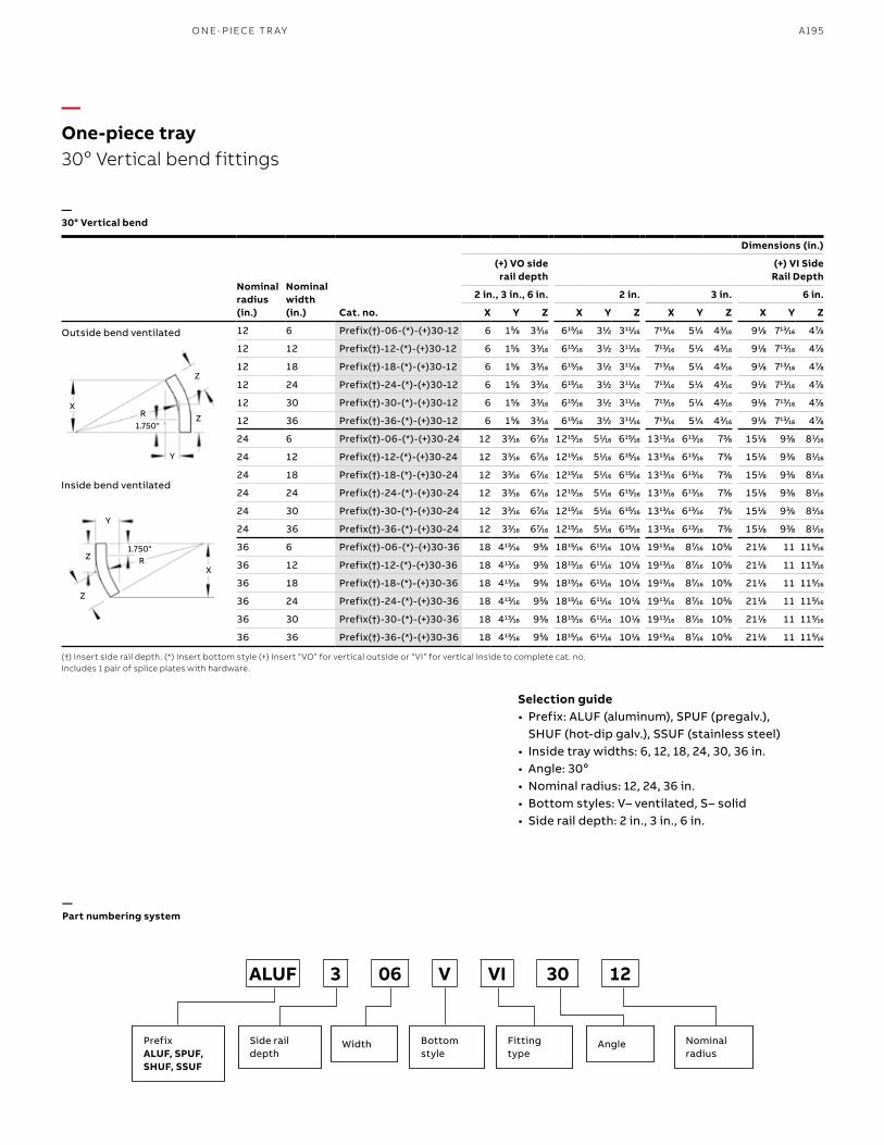
A195
Outside bend ventilated
Inside bend ventilated
(†) Insert side rail depth. (*) Insert bottom style (+) Insert “VO” for vertical outside or “VI” for vertical inside to complete cat. no.Includes 1 pair of splice plates with hardware.
Selection guide• Prefix: ALUF (aluminum), SPUF (pregalv.),
SHUF (hot-dip galv.), SSUF (stainless steel)• Inside tray widths: 6, 12, 18, 24, 30, 36 in.• Angle: 30o• Nominal radius: 12, 24, 36 in.• Bottom styles: V– ventilated, S– solid• Side rail depth: 2 in., 3 in., 6 in.
Nominalradius (in.)
Nominalwidth (in.) Cat. no.
Dimensions (in.)
(+) VO side rail depth
(+) VI Side Rail Depth
2 in., 3 in., 6 in. 2 in. 3 in. 6 in.
X Y Z X Y Z X Y Z X Y Z
12 6 Prefix(†)-06-(*)-(+)30-12 6 155⁄88 333⁄1616 61515⁄1616 311⁄22 31111⁄1616 71313⁄1616 511⁄44 433⁄1616 911⁄88 71313⁄1616 477⁄88
12 12 Prefix(†)-12-(*)-(+)30-12 6 155⁄88 333⁄1616 61515⁄1616 311⁄22 31111⁄1616 71313⁄1616 511⁄44 433⁄1616 911⁄88 71313⁄1616 477⁄88
12 18 Prefix(†)-18-(*)-(+)30-12 6 155⁄88 333⁄1616 61515⁄1616 311⁄22 31111⁄1616 71313⁄1616 511⁄44 433⁄1616 911⁄88 71313⁄1616 477⁄88
12 24 Prefix(†)-24-(*)-(+)30-12 6 155⁄88 333⁄1616 61515⁄1616 311⁄22 31111⁄1616 71313⁄1616 511⁄44 433⁄1616 911⁄88 71313⁄1616 477⁄88
12 30 Prefix(†)-30-(*)-(+)30-12 6 155⁄88 333⁄1616 61515⁄1616 311⁄22 31111⁄1616 71313⁄1616 511⁄44 433⁄1616 911⁄88 71313⁄1616 477⁄88
12 36 Prefix(†)-36-(*)-(+)30-12 6 155⁄88 333⁄1616 61515⁄1616 311⁄22 31111⁄1616 71313⁄1616 511⁄44 433⁄1616 911⁄88 71313⁄1616 477⁄88
24 6 Prefix(†)-06-(*)-(+)30-24 12 333⁄1616 677⁄1616 121515⁄1616 511⁄1616 61515⁄1616 131313⁄1616 61313⁄1616 733⁄88 1511⁄88 933⁄88 811⁄1616
24 12 Prefix(†)-12-(*)-(+)30-24 12 333⁄1616 677⁄1616 121515⁄1616 511⁄1616 61515⁄1616 131313⁄1616 61313⁄1616 733⁄88 1511⁄88 933⁄88 811⁄1616
24 18 Prefix(†)-18-(*)-(+)30-24 12 333⁄1616 677⁄1616 121515⁄1616 511⁄1616 61515⁄1616 131313⁄1616 61313⁄1616 733⁄88 1511⁄88 933⁄88 811⁄1616
24 24 Prefix(†)-24-(*)-(+)30-24 12 333⁄1616 677⁄1616 121515⁄1616 511⁄1616 61515⁄1616 131313⁄1616 61313⁄1616 733⁄88 1511⁄88 933⁄88 811⁄1616
24 30 Prefix(†)-30-(*)-(+)30-24 12 333⁄1616 677⁄1616 121515⁄1616 511⁄1616 61515⁄1616 131313⁄1616 61313⁄1616 733⁄88 1511⁄88 933⁄88 811⁄1616
24 36 Prefix(†)-36-(*)-(+)30-24 12 333⁄1616 677⁄1616 121515⁄1616 511⁄1616 61515⁄1616 131313⁄1616 61313⁄1616 733⁄88 1511⁄88 933⁄88 811⁄1616
36 6 Prefix(†)-06-(*)-(+)30-36 18 41313⁄1616 955⁄88 181515⁄1616 61111⁄1616 1011⁄88 191313⁄1616 877⁄1616 1055⁄88 2111⁄88 11 1155⁄1616
36 12 Prefix(†)-12-(*)-(+)30-36 18 41313⁄1616 955⁄88 181515⁄1616 61111⁄1616 1011⁄88 191313⁄1616 877⁄1616 1055⁄88 2111⁄88 11 1155⁄1616
36 18 Prefix(†)-18-(*)-(+)30-36 18 41313⁄1616 955⁄88 181515⁄1616 61111⁄1616 1011⁄88 191313⁄1616 877⁄1616 1055⁄88 2111⁄88 11 1155⁄1616
36 24 Prefix(†)-24-(*)-(+)30-36 18 41313⁄1616 955⁄88 181515⁄1616 61111⁄1616 1011⁄88 191313⁄1616 877⁄1616 1055⁄88 2111⁄88 11 1155⁄1616
36 30 Prefix(†)-30-(*)-(+)30-36 18 41313⁄1616 955⁄88 181515⁄1616 61111⁄1616 1011⁄88 191313⁄1616 877⁄1616 1055⁄88 2111⁄88 11 1155⁄1616
36 36 Prefix(†)-36-(*)-(+)30-36 18 41313⁄1616 955⁄88 181515⁄1616 61111⁄1616 1011⁄88 191313⁄1616 877⁄1616 1055⁄88 2111⁄88 11 1155⁄1616
—One-piece tray 30o Vertical bend fittings
—30° Vertical bend
X
X
R
R
1.750"
1.750"
Y
Y
Z
Z
Z
Z
PrefixALUF, SPUF,SHUF, SSUF
Width AngleSide rail depth
Bottom style
Nominalradius
Fitting type
ALUF 3 06 V VI 30 12
—Part numbering system
O N E- PI ECE TR AY
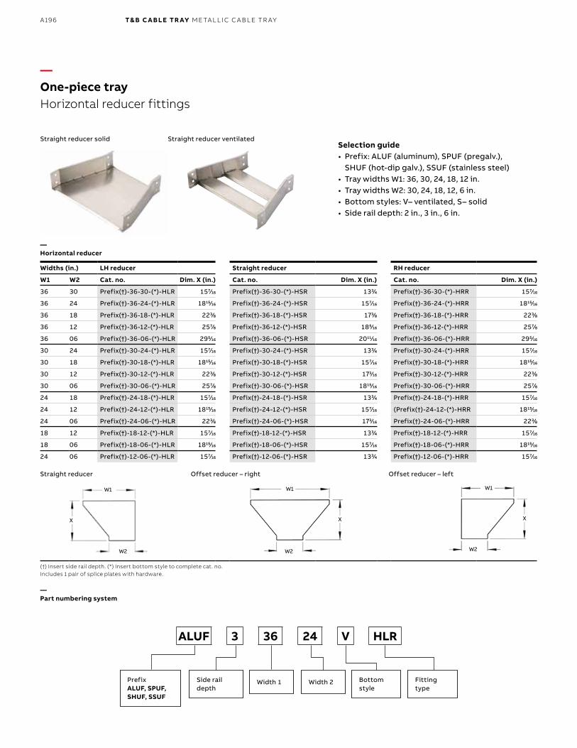
B1 copy starts here
B2 copy starts here
B3 copy starts here
A196 T& B C A B LE TR AY M E TA L L I C C A B L E TR AY
Widths (in.) LH reducer Straight reducer RH reducer
W1 W2 Cat. no. Dim. X (in.) Cat. no. Dim. X (in.) Cat. no. Dim. X (in.)
36 30 Prefix(†)-36-30-(*)-HLR 1577⁄1616 Prefix(†)-36-30-(*)-HSR 1333⁄44 Prefix(†)-36-30-(*)-HRR 1577⁄1616
36 24 Prefix(†)-36-24-(*)-HLR 181515⁄1616 Prefix(†)-36-24-(*)-HSR 1577⁄1616 Prefix(†)-36-24-(*)-HRR 181515⁄1616
36 18 Prefix(†)-36-18-(*)-HLR 2233⁄88 Prefix(†)-36-18-(*)-HSR 1733⁄88 Prefix(†)-36-18-(*)-HRR 2233⁄88
36 12 Prefix(†)-36-12-(*)-HLR 2577⁄88 Prefix(†)-36-12-(*)-HSR 1855⁄1616 Prefix(†)-36-12-(*)-HRR 2577⁄88
36 06 Prefix(†)-36-06-(*)-HLR 2955⁄1616 Prefix(†)-36-06-(*)-HSR 201111⁄1616 Prefix(†)-36-06-(*)-HRR 2955⁄1616
30 24 Prefix(†)-30-24-(*)-HLR 1577⁄1616 Prefix(†)-30-24-(*)-HSR 1333⁄44 Prefix(†)-30-24-(*)-HRR 1577⁄1616
30 18 Prefix(†)-30-18-(*)-HLR 181515⁄1616 Prefix(†)-30-18-(*)-HSR 1577⁄1616 Prefix(†)-30-18-(*)-HRR 181515⁄1616
30 12 Prefix(†)-30-12-(*)-HLR 2233⁄88 Prefix(†)-30-12-(*)-HSR 1733⁄1616 Prefix(†)-30-12-(*)-HRR 2233⁄88
30 06 Prefix(†)-30-06-(*)-HLR 2577⁄88 Prefix(†)-30-06-(*)-HSR 181515⁄1616 Prefix(†)-30-06-(*)-HRR 2577⁄88
24 18 Prefix(†)-24-18-(*)-HLR 1577⁄1616 Prefix(†)-24-18-(*)-HSR 1333⁄44 Prefix(†)-24-18-(*)-HRR 1577⁄1616
24 12 Prefix(†)-24-12-(*)-HLR 181515⁄1616 Prefix(†)-24-12-(*)-HSR 1577⁄1616 (Prefix(†)-24-12-(*)-HRR 181515⁄1616
24 06 Prefix(†)-24-06-(*)-HLR 2233⁄88 Prefix(†)-24-06-(*)-HSR 1733⁄1616 Prefix(†)-24-06-(*)-HRR 2233⁄88
18 12 Prefix(†)-18-12-(*)-HLR 1577⁄1616 Prefix(†)-18-12-(*)-HSR 1333⁄44 Prefix(†)-18-12-(*)-HRR 1577⁄1616
18 06 Prefix(†)-18-06-(*)-HLR 181515⁄1616 Prefix(†)-18-06-(*)-HSR 1577⁄1616 Prefix(†)-18-06-(*)-HRR 181515⁄1616
24 06 Prefix(†)-12-06-(*)-HLR 1577⁄1616 Prefix(†)-12-06-(*)-HSR 1333⁄44 Prefix(†)-12-06-(*)-HRR 1577⁄1616
—One-piece trayHorizontal reducer fittings
—Horizontal reducer
Straight reducer solid
Straight reducer
Straight reducer ventilated
Offset reducer – right Offset reducer – left
(†) Insert side rail depth. (*) Insert bottom style to complete cat. no.Includes 1 pair of splice plates with hardware.
Selection guide• Prefix: ALUF (aluminum), SPUF (pregalv.),
SHUF (hot-dip galv.), SSUF (stainless steel)• Tray widths W1: 36, 30, 24, 18, 12 in.• Tray widths W2: 30, 24, 18, 12, 6 in.• Bottom styles: V– ventilated, S– solid• Side rail depth: 2 in., 3 in., 6 in.
—Part numbering system
PrefixALUF, SPUF,SHUF, SSUF
Width 1 Width 2Side rail depth
Bottom style
Fitting type
ALUF 3 36 24 V HLR
X X X
W1 W1 W1
W2 W2 W2
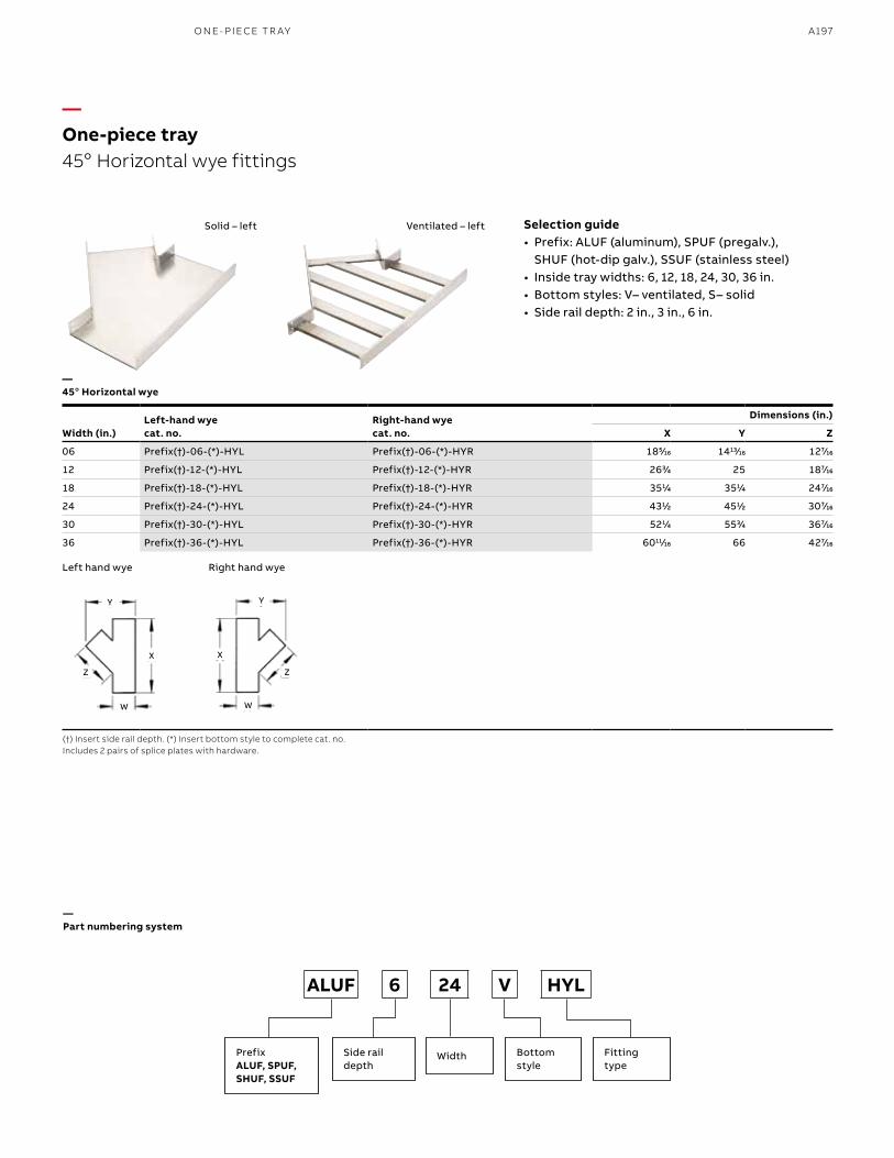
A197
—45o Horizontal wye
Solid – left Ventilated – left
(†) Insert side rail depth. (*) Insert bottom style to complete cat. no.Includes 2 pairs of splice plates with hardware.
Selection guide• Prefix: ALUF (aluminum), SPUF (pregalv.),
SHUF (hot-dip galv.), SSUF (stainless steel)• Inside tray widths: 6, 12, 18, 24, 30, 36 in.• Bottom styles: V– ventilated, S– solid• Side rail depth: 2 in., 3 in., 6 in.
Width (in.)Left-hand wyecat. no.
Right-hand wyecat. no.
Dimensions (in.)
X Y Z
06 Prefix(†)-06-(*)-HYL Prefix(†)-06-(*)-HYR 1855⁄1616 141313⁄1616 1277⁄1616
12 Prefix(†)-12-(*)-HYL Prefix(†)-12-(*)-HYR 2633⁄44 25 1877⁄1616
18 Prefix(†)-18-(*)-HYL Prefix(†)-18-(*)-HYR 3511⁄44 3511⁄44 2477⁄1616
24 Prefix(†)-24-(*)-HYL Prefix(†)-24-(*)-HYR 4311⁄22 4511⁄22 3077⁄1616
30 Prefix(†)-30-(*)-HYL Prefix(†)-30-(*)-HYR 5211⁄44 5533⁄44 3677⁄1616
36 Prefix(†)-36-(*)-HYL Prefix(†)-36-(*)-HYR 601111⁄1616 66 4277⁄1616
—One-piece tray 45o Horizontal wye fittings
Left hand wye Right hand wye
Z Z
W W
X X
Y Y
PrefixALUF, SPUF,SHUF, SSUF
WidthSide rail depth
Bottom style
Fitting type
ALUF 6 24 V HYL
—Part numbering system
O N E- PI ECE TR AY
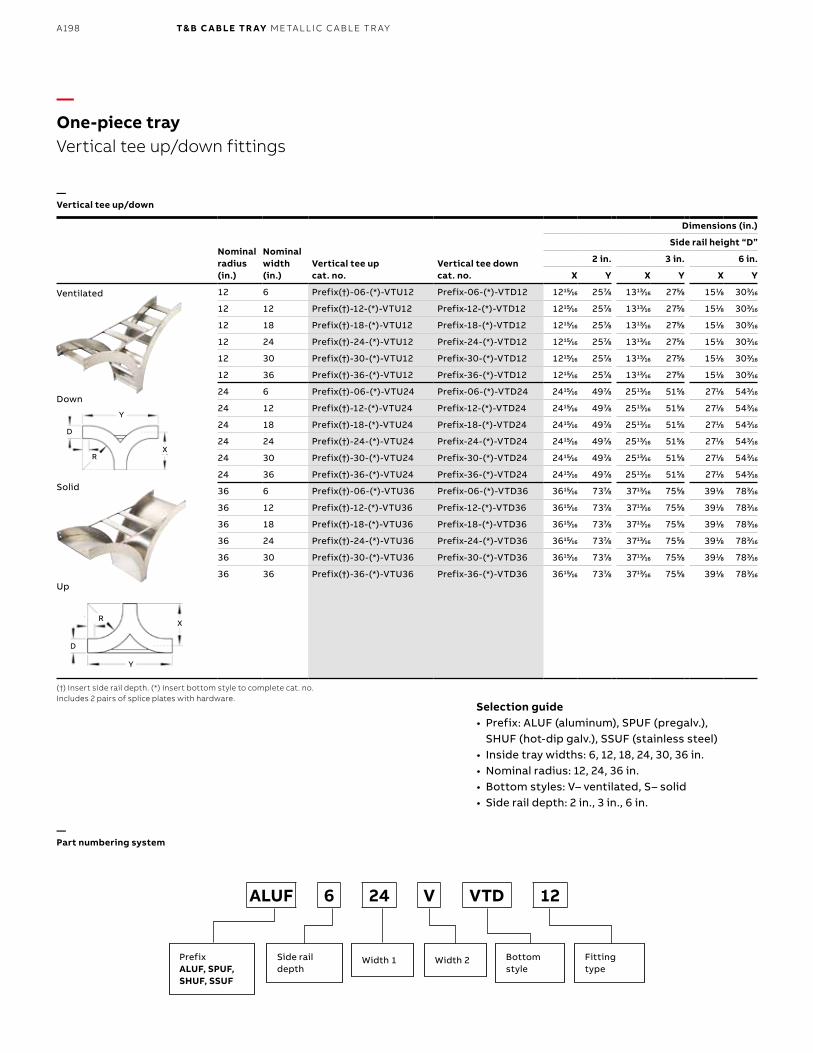
B1 copy starts here
B2 copy starts here
B3 copy starts here
A198 T& B C A B LE TR AY M E TA L L I C C A B L E TR AY
Nominalradius (in.)
Nominalwidth (in.)
Vertical tee upcat. no.
Vertical tee downcat. no.
Dimensions (in.)
Side rail height “D”
2 in. 3 in. 6 in.
X Y X Y X Y
12 6 Prefix(†)-06-(*)-VTU12 Prefix-06-(*)-VTD12 121515⁄1616 2577⁄88 131313⁄1616 2755⁄88 1511⁄88 3033⁄1616
12 12 Prefix(†)-12-(*)-VTU12 Prefix-12-(*)-VTD12 121515⁄1616 2577⁄88 131313⁄1616 2755⁄88 1511⁄88 3033⁄1616
12 18 Prefix(†)-18-(*)-VTU12 Prefix-18-(*)-VTD12 121515⁄1616 2577⁄88 131313⁄1616 2755⁄88 1511⁄88 3033⁄1616
12 24 Prefix(†)-24-(*)-VTU12 Prefix-24-(*)-VTD12 121515⁄1616 2577⁄88 131313⁄1616 2755⁄88 1511⁄88 3033⁄1616
12 30 Prefix(†)-30-(*)-VTU12 Prefix-30-(*)-VTD12 121515⁄1616 2577⁄88 131313⁄1616 2755⁄88 1511⁄88 3033⁄1616
12 36 Prefix(†)-36-(*)-VTU12 Prefix-36-(*)-VTD12 121515⁄1616 2577⁄88 131313⁄1616 2755⁄88 1511⁄88 3033⁄1616
24 6 Prefix(†)-06-(*)-VTU24 Prefix-06-(*)-VTD24 241515⁄1616 4977⁄88 251313⁄1616 5155⁄88 2711⁄88 5433⁄1616
24 12 Prefix(†)-12-(*)-VTU24 Prefix-12-(*)-VTD24 241515⁄1616 4977⁄88 251313⁄1616 5155⁄88 2711⁄88 5433⁄1616
24 18 Prefix(†)-18-(*)-VTU24 Prefix-18-(*)-VTD24 241515⁄1616 4977⁄88 251313⁄1616 5155⁄88 2711⁄88 5433⁄1616
24 24 Prefix(†)-24-(*)-VTU24 Prefix-24-(*)-VTD24 241515⁄1616 4977⁄88 251313⁄1616 5155⁄88 2711⁄88 5433⁄1616
24 30 Prefix(†)-30-(*)-VTU24 Prefix-30-(*)-VTD24 241515⁄1616 4977⁄88 251313⁄1616 5155⁄88 2711⁄88 5433⁄1616
24 36 Prefix(†)-36-(*)-VTU24 Prefix-36-(*)-VTD24 241515⁄1616 4977⁄88 251313⁄1616 5155⁄88 2711⁄88 5433⁄1616
36 6 Prefix(†)-06-(*)-VTU36 Prefix-06-(*)-VTD36 361515⁄1616 7377⁄88 371313⁄1616 7555⁄88 3911⁄88 7833⁄1616
36 12 Prefix(†)-12-(*)-VTU36 Prefix-12-(*)-VTD36 361515⁄1616 7377⁄88 371313⁄1616 7555⁄88 3911⁄88 7833⁄1616
36 18 Prefix(†)-18-(*)-VTU36 Prefix-18-(*)-VTD36 361515⁄1616 7377⁄88 371313⁄1616 7555⁄88 3911⁄88 7833⁄1616
36 24 Prefix(†)-24-(*)-VTU36 Prefix-24-(*)-VTD36 361515⁄1616 7377⁄88 371313⁄1616 7555⁄88 3911⁄88 7833⁄1616
36 30 Prefix(†)-30-(*)-VTU36 Prefix-30-(*)-VTD36 361515⁄1616 7377⁄88 371313⁄1616 7555⁄88 3911⁄88 7833⁄1616
36 36 Prefix(†)-36-(*)-VTU36 Prefix-36-(*)-VTD36 361515⁄1616 7377⁄88 371313⁄1616 7555⁄88 3911⁄88 7833⁄1616
—One-piece trayVertical tee up/down fittings
—Vertical tee up/down
Down
Solid
Up
Ventilated
(†) Insert side rail depth. (*) Insert bottom style to complete cat. no.Includes 2 pairs of splice plates with hardware.
Selection guide• Prefix: ALUF (aluminum), SPUF (pregalv.),
SHUF (hot-dip galv.), SSUF (stainless steel)• Inside tray widths: 6, 12, 18, 24, 30, 36 in.• Nominal radius: 12, 24, 36 in.• Bottom styles: V– ventilated, S– solid• Side rail depth: 2 in., 3 in., 6 in.
—Part numbering system
PrefixALUF, SPUF,SHUF, SSUF
Width 1 Width 2Side rail depth
Bottom style
Fitting type
ALUF 6 24 V VTD 12
X
Y
D
D
R
Y
X
R
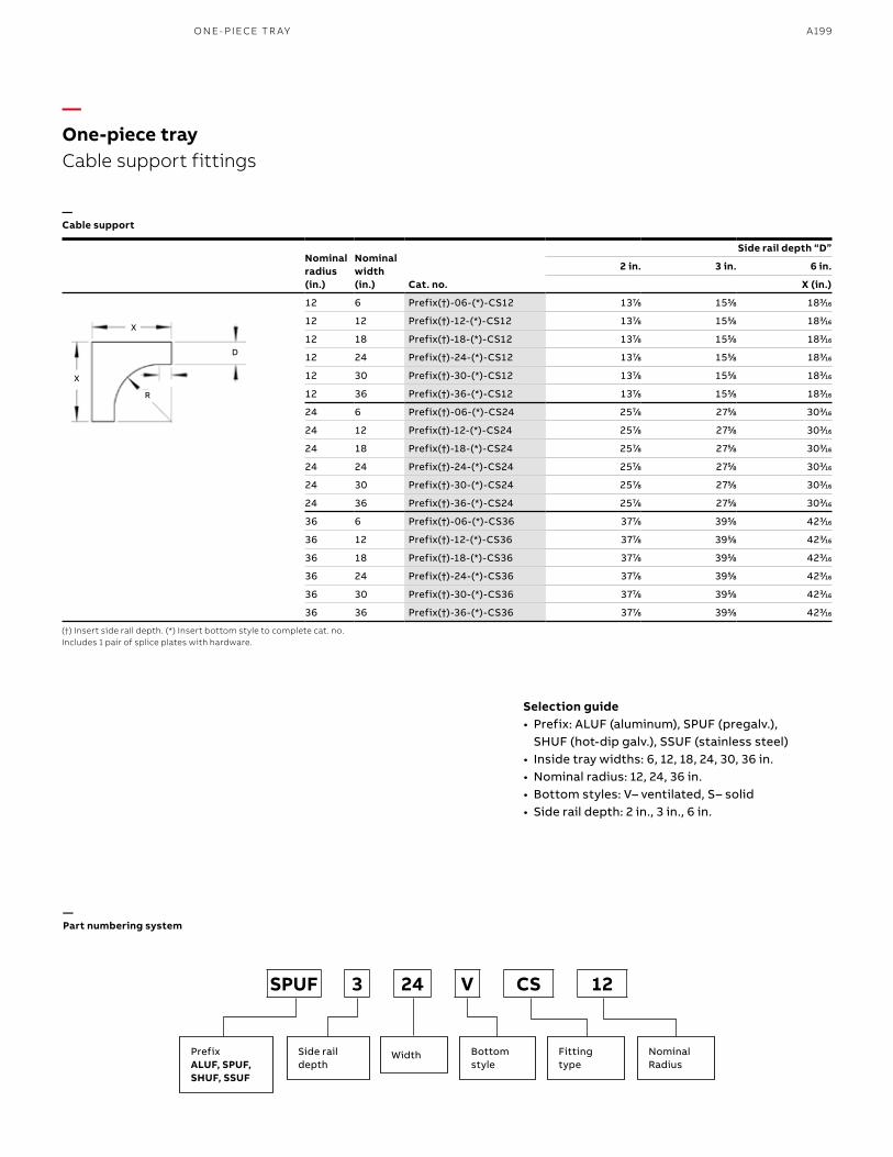
A199
Nominalradius (in.)
Nominalwidth (in.) Cat. no.
Side rail depth “D”
2 in. 3 in. 6 in.
X (in.)
12 6 Prefix(†)-06-(*)-CS12 1377⁄88 1555⁄88 1833⁄1616
12 12 Prefix(†)-12-(*)-CS12 1377⁄88 1555⁄88 1833⁄1616
12 18 Prefix(†)-18-(*)-CS12 1377⁄88 1555⁄88 1833⁄1616
12 24 Prefix(†)-24-(*)-CS12 1377⁄88 1555⁄88 1833⁄1616
12 30 Prefix(†)-30-(*)-CS12 1377⁄88 1555⁄88 1833⁄1616
12 36 Prefix(†)-36-(*)-CS12 1377⁄88 1555⁄88 1833⁄1616
24 6 Prefix(†)-06-(*)-CS24 2577⁄88 2755⁄88 3033⁄1616
24 12 Prefix(†)-12-(*)-CS24 2577⁄88 2755⁄88 3033⁄1616
24 18 Prefix(†)-18-(*)-CS24 2577⁄88 2755⁄88 3033⁄1616
24 24 Prefix(†)-24-(*)-CS24 2577⁄88 2755⁄88 3033⁄1616
24 30 Prefix(†)-30-(*)-CS24 2577⁄88 2755⁄88 3033⁄1616
24 36 Prefix(†)-36-(*)-CS24 2577⁄88 2755⁄88 3033⁄1616
36 6 Prefix(†)-06-(*)-CS36 3777⁄88 3955⁄88 4233⁄1616
36 12 Prefix(†)-12-(*)-CS36 3777⁄88 3955⁄88 4233⁄1616
36 18 Prefix(†)-18-(*)-CS36 3777⁄88 3955⁄88 4233⁄1616
36 24 Prefix(†)-24-(*)-CS36 3777⁄88 3955⁄88 4233⁄1616
36 30 Prefix(†)-30-(*)-CS36 3777⁄88 3955⁄88 4233⁄1616
36 36 Prefix(†)-36-(*)-CS36 3777⁄88 3955⁄88 4233⁄1616
—One-piece tray Cable support fittings
—Cable support
(†) Insert side rail depth. (*) Insert bottom style to complete cat. no.Includes 1 pair of splice plates with hardware.
D
X
X
R
SPUF 3 24 V CS 12
—Part numbering system
Selection guide• Prefix: ALUF (aluminum), SPUF (pregalv.),
SHUF (hot-dip galv.), SSUF (stainless steel)• Inside tray widths: 6, 12, 18, 24, 30, 36 in.• Nominal radius: 12, 24, 36 in.• Bottom styles: V– ventilated, S– solid• Side rail depth: 2 in., 3 in., 6 in.
PrefixALUF, SPUF,SHUF, SSUF
WidthSide rail depth
Bottom style
Fitting type
Nominal Radius
O N E- PI ECE TR AY
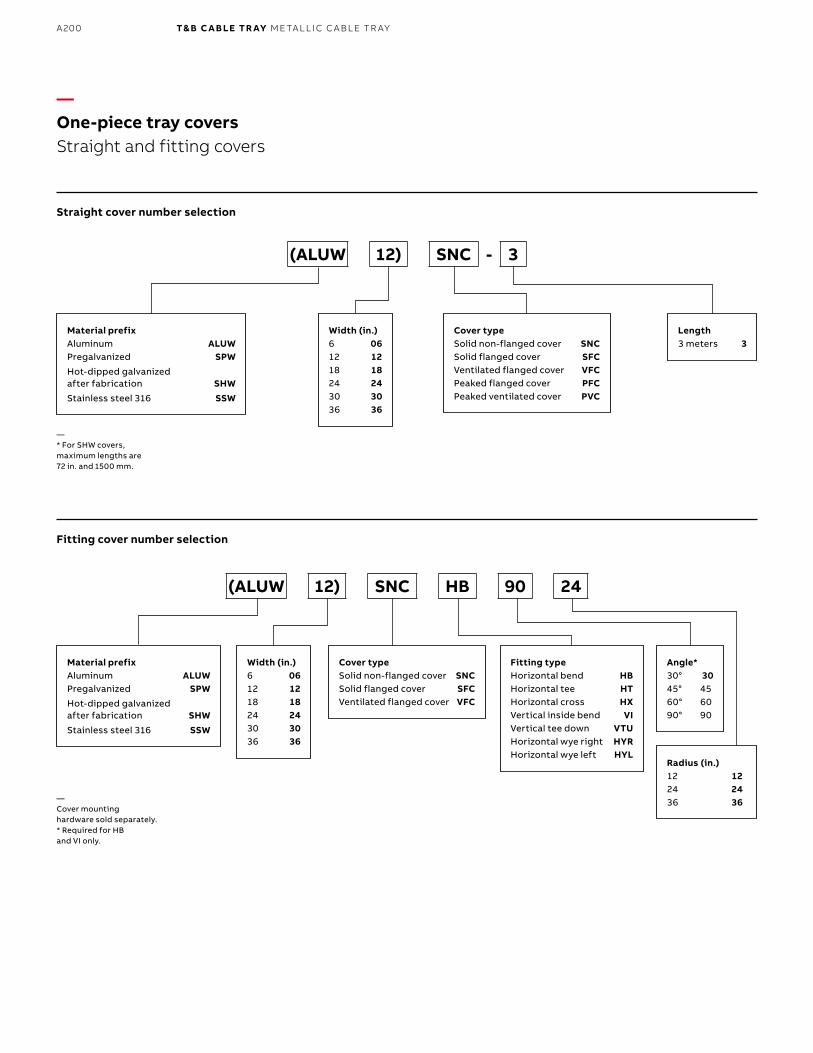
B1 copy starts here
B2 copy starts here
B3 copy starts here
A200 T& B C A B LE TR AY M E TA L L I C C A B L E TR AY
—One-piece tray coversStraight and fitting covers
Straight cover number selection
Fitting cover number selection
Material prefixAluminum ALUWPregalvanized SPWHot-dipped galvanized after fabrication SHWStainless steel 316 SSW
Material prefixAluminum ALUWPregalvanized SPWHot-dipped galvanized after fabrication SHWStainless steel 316 SSW
Cover typeSolid non-flanged cover SNCSolid flanged cover SFCVentilated flanged cover VFCPeaked flanged cover PFCPeaked ventilated cover PVC
Cover typeSolid non-flanged cover SNCSolid flanged cover SFCVentilated flanged cover VFC
Fitting typeHorizontal bend HBHorizontal tee HTHorizontal cross HXVertical inside bend VIVertical tee down VTUHorizontal wye right HYRHorizontal wye left HYL
Width (in.)6 0612 1218 1824 2430 3036 36
Width (in.)6 0612 1218 1824 2430 3036 36
Length3 meters 3
Angle*30° 3045° 4560° 6090° 90
Radius (in.)12 1224 2436 36
(ALUW 12) SNC - 3
(ALUW 12) SNC HB 90 24
— * For SHW covers, maximum lengths are 72 in. and 1500 mm.
— Cover mounting hardware sold separately.* Required for HB and VI only.
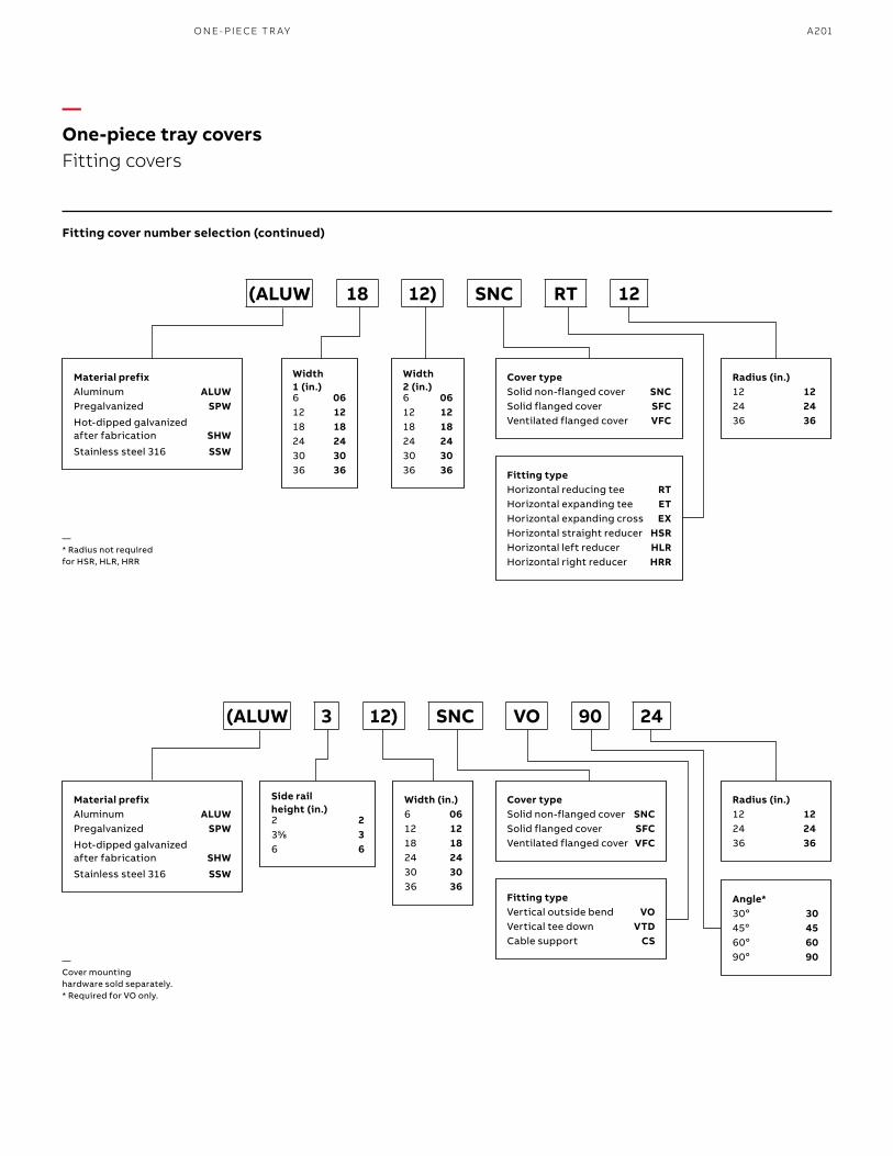
A201
Fitting cover number selection (continued)
Material prefixAluminum ALUWPregalvanized SPWHot-dipped galvanized after fabrication SHWStainless steel 316 SSW
Material prefixAluminum ALUWPregalvanized SPWHot-dipped galvanized after fabrication SHWStainless steel 316 SSW
Cover typeSolid non-flanged cover SNCSolid flanged cover SFCVentilated flanged cover VFC
Cover typeSolid non-flanged cover SNCSolid flanged cover SFCVentilated flanged cover VFC
Fitting typeHorizontal reducing tee RTHorizontal expanding tee ETHorizontal expanding cross EXHorizontal straight reducer HSRHorizontal left reducer HLRHorizontal right reducer HRR
Fitting typeVertical outside bend VOVertical tee down VTDCable support CS
Width 1 (in.)6 0612 1218 1824 2430 3036 36
Width (in.)6 0612 1218 1824 2430 3036 36
Width 2 (in.)6 0612 1218 1824 2430 3036 36
Side rail height (in.)2 2355⁄88 36 6
Radius (in.)12 1224 2436 36
Radius (in.)12 1224 2436 36
Angle*30o 3045o 4560o 6090o 90
(ALUW 18 12) SNC RT 12
(ALUW 3 12) SNC VO 90 24
— * Radius not required for HSR, HLR, HRR
— Cover mounting hardware sold separately.* Required for VO only.
—One-piece tray covers Fitting covers
O N E- PI ECE TR AY
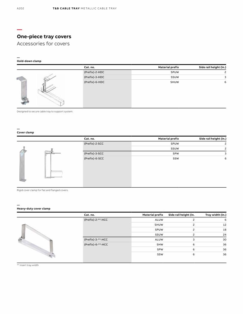
B1 copy starts here
B2 copy starts here
B3 copy starts here
A202 T& B C A B LE TR AY M E TA L L I C C A B L E TR AY
Cat. no. Material prefix Side rail height (in.)
(Prefix)-2-HDC SPUW 2
(Prefix)-3-HDC SSUW 3
(Prefix)-6-HDC SHUW 6
—One-piece tray coversAccessories for covers
—Hold-down clamp
—Cover clamp
—Heavy-duty cover clamp
Designed to secure cable tray to support system.
Rigid cover clamp for flat and flanged covers.
** Insert tray width
Cat. no. Material prefix Side rail height (in. Tray width (in.)
(Prefix)-2-**-HCC ALUW 2 6
SHUW 2 12
SPUW 2 18
SSUW 2 24
(Prefix)-3-**-HCC ALUW 3 30
(Prefix)-6-**-HCC SHW 6 36
SPW 6 36
SSW 6 36
Cat. no. Material prefix Side rail height (in.)
(Prefix)-2-SCC SPUW 2
SSUW 2
(Prefix)-3-SCC SPW 3
(Prefix)-6-SCC SSW 6
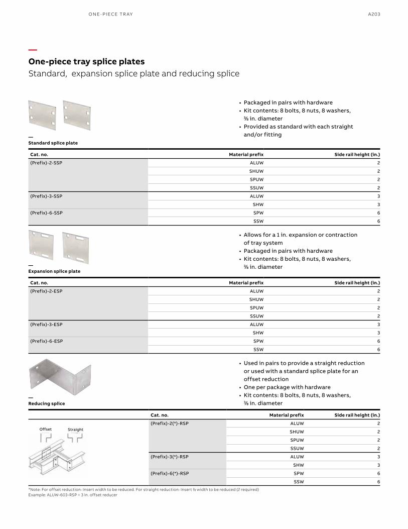
A203
*Note: For offset reduction: Insert width to be reduced. For straight reduction: Insert 11⁄22 width to be reduced (2 required)Example: ALUW-603-RSP = 3 in. offset reducer
Cat. no. Material prefix Side rail height (in.)
(Prefix)-2(*)-RSP ALUW 2
SHUW 2
SPUW 2
SSUW 2
(Prefix)-3(*)-RSP ALUW 3
SHW 3
(Prefix)-6(*)-RSP SPW 6
SSW 6
Offset Straight
—One-piece tray splice platesStandard, expansion splice plate and reducing splice
—Standard splice plate
—Expansion splice plate
—Reducing splice
Cat. no. Material prefix Side rail height (in.)
(Prefix)-2-SSP ALUW 2
SHUW 2
SPUW 2
SSUW 2
(Prefix)-3-SSP ALUW 3
SHW 3
(Prefix)-6-SSP SPW 6
SSW 6
• Packaged in pairs with hardware • Kit contents: 8 bolts, 8 nuts, 8 washers,
33⁄88 in. diameter• Provided as standard with each straight
and/or fitting
• Allows for a 1 in. expansion or contraction of tray system
• Packaged in pairs with hardware • Kit contents: 8 bolts, 8 nuts, 8 washers,
33⁄88 in. diameter
• Used in pairs to provide a straight reduction or used with a standard splice plate for an offset reduction
• One per package with hardware • Kit contents: 8 bolts, 8 nuts, 8 washers,
33⁄88 in. diameter
Cat. no. Material prefix Side rail height (in.)
(Prefix)-2-ESP ALUW 2
SHUW 2
SPUW 2
SSUW 2
(Prefix)-3-ESP ALUW 3
SHW 3
(Prefix)-6-ESP SPW 6
SSW 6
O N E- PI ECE TR AY
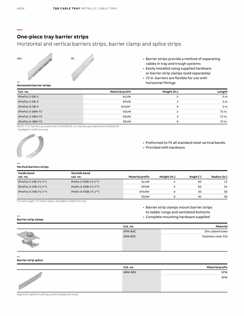
B1 copy starts here
B2 copy starts here
B3 copy starts here
A204 T& B C A B LE TR AY M E TA L L I C C A B L E TR AY
Cat. no. Material prefix
ABW-BSS SPW
SPW
SBH SB
—One-piece tray barrier stripsHorizontal and vertical barriers strips, barrier clamp and splice strips
—Horizontal barrier strips
—Barrier strip clamp
—Barrier strip splice
—Vertical barriers strips
NOTE: 72 in. barriers provided with 3 SPW10SCR, 3 m barriers provided with 6 SPW10SCR *Available in 1500 mm only.
Alignment splice for joining connecting barrier strips.
(*) Insert angle (**) Insert radius. †Available in 1500 mm only.
• Barrier strips provide a method of separating cables in tray and trough systems
• Easily installed using supplied hardware or barrier strip clamps (sold separately)
• 72 in. barriers are flexible for use with horizontal fittings
• Barrier strip clamps mount barrier strips to ladder rungs and ventilated bottoms
• Complete mounting hardware supplied
• Preformed to fit all standard steel vertical bends. • Provided with hardware
Cat. no. Material prefix Height (in.) Length
(Prefix)-2-SB-3 ALUW 2 3 m
(Prefix)-3-SB-3 SPUW 3 3 m
(Prefix)-6-SB-3 SHUW* 6 3 m
(Prefix)-2-SBH-72 SSUW 2 72 in.
(Prefix)-3-SBH-72 SSUW 3 72 in.
(Prefix)-6-SBH-72 SSUW 6 72 in.
Inside bend cat. no.
Outside bend cat. no. Material prefix Height (in.) Angle (°) Radius (in.)
(Prefix)-2-VIB-(*)-(**) Prefix-2-VOB-(*)-(**) ALUW 2 90 12
(Prefix)-3-VIB-(*)-(**) Prefix-3-VOB-(*)-(**) SPUW 3 60 24
(Prefix)-6-VIB-(*)-(**) Prefix-6-VOB-(*)-(**) SHUW† 6 30 36
SSUW 6 45 36
Cat. no. Material
SPW-BSC Zinc-plated steel
SSW-BSC Stainless steel 316
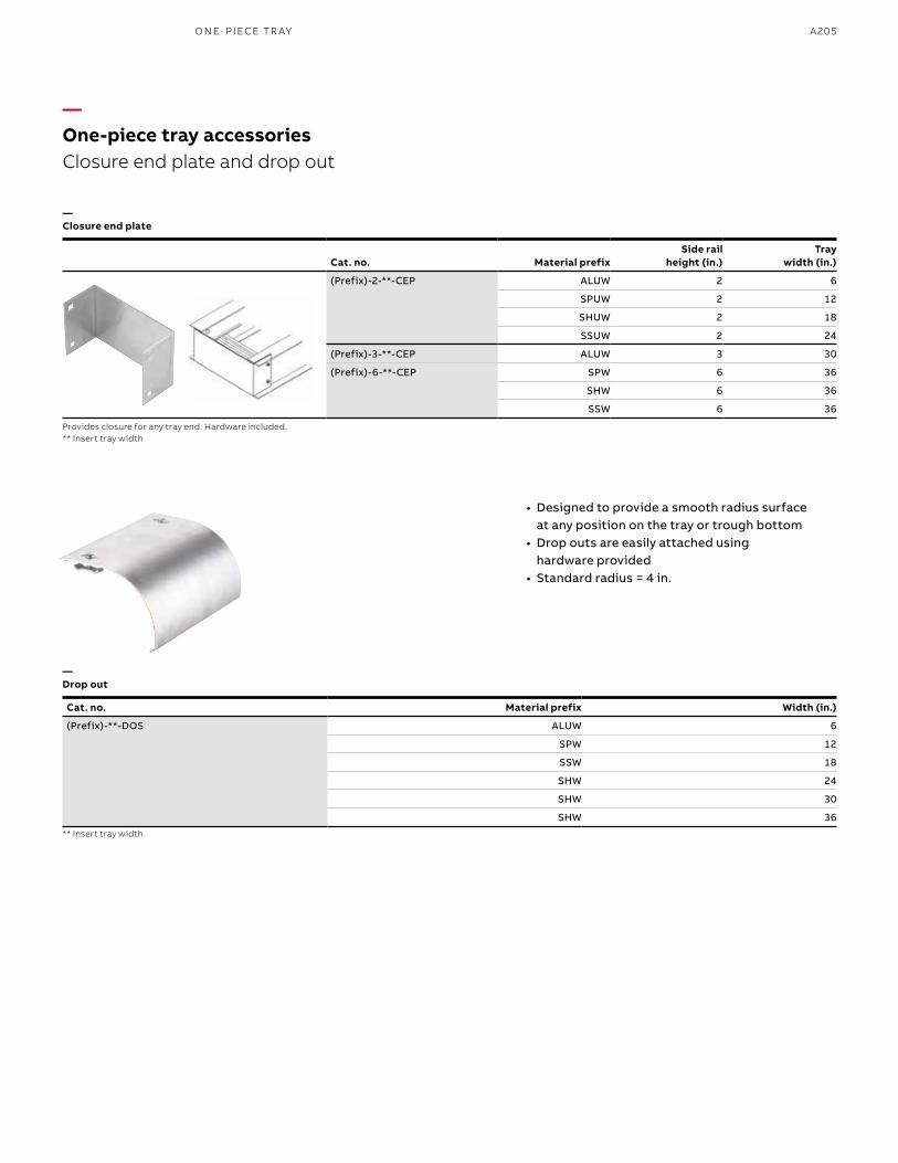
A205
—Closure end plate
Provides closure for any tray end. Hardware included.** Insert tray width
—One-piece tray accessoriesClosure end plate and drop out
—Drop out
** Insert tray width
• Designed to provide a smooth radius surface at any position on the tray or trough bottom
• Drop outs are easily attached using hardware provided
• Standard radius = 4 in.
Cat. no. Material prefix Width (in.)
(Prefix)-**-DOS ALUW 6
SPW 12
SSW 18
SHW 24
SHW 30
SHW 36
Cat. no. Material prefixSide rail
height (in.)Tray
width (in.)
(Prefix)-2-**-CEP ALUW 2 6
SPUW 2 12
SHUW 2 18
SSUW 2 24
(Prefix)-3-**-CEP ALUW 3 30
(Prefix)-6-**-CEP SPW 6 36
SHW 6 36
SSW 6 36
O N E- PIECE TR AY
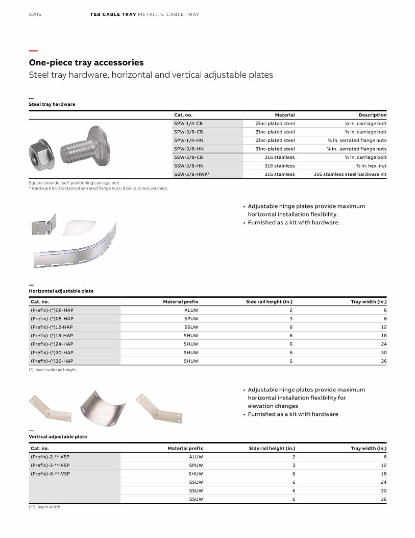
B1 copy starts here
B2 copy starts here
B3 copy starts here
A206 T& B C A B LE TR AY M E TA L L I C C A B L E TR AY
• Adjustable hinge plates provide maximum horizontal installation flexibility for elevation changes
• Furnished as a kit with hardware
—One-piece tray accessoriesSteel tray hardware, horizontal and vertical adjustable plates
—Vertical adjustable plate
Cat. no. Material Description
SPW-1/4-CB Zinc-plated steel 11⁄44 in. carriage bolt
SPW-3/8-CB Zinc-plated steel 33⁄88 in. carriage bolt
SPW-1/4-HN Zinc-plated steel 11⁄44 in. serrated flange nuts
SPW-3/8-HN Zinc-plated steel 33⁄88 in. serrated flange nuts
SSW-3/8-CB 316 stainless 33⁄88 in. carriage bolt
SSW-3/8-HN 316 stainless 33⁄88 in. hex. nut
SSW-3/8-HWK* 316 stainless 316 stainless steel hardware kit
—Steel tray hardware
Square shoulder self-positioning carriage bolt.* Hardware kit: Contains 8 serrated flange nuts, 8 bolts, 8 lock washers.
(**) Insert width
Cat. no. Material prefix Side rail height (in.) Tray width (in.)
(Prefix)-(*)06-HAP ALUW 2 6
(Prefix)-(*)08-HAP SPUW 3 8
(Prefix)-(*)12-HAP SSUW 6 12
(Prefix)-(*)18-HAP SHUW 6 18
(Prefix)-(*)24-HAP SHUW 6 24
(Prefix)-(*)30-HAP SHUW 6 30
(Prefix)-(*)36-HAP SHUW 6 36
—Horizontal adjustable plate
(*) Insert side rail height
• Adjustable hinge plates provide maximum horizontal installation flexibility.
• Furnished as a kit with hardware.
Cat. no. Material prefix Side rail height (in.) Tray width (in.)
(Prefix)-2-**-VSP ALUW 2 6
(Prefix)-3-**-VSP SPUW 3 12
(Prefix)-6-**-VSP SHUW 6 18
SSUW 6 24
SSUW 6 30
SSUW 6 36
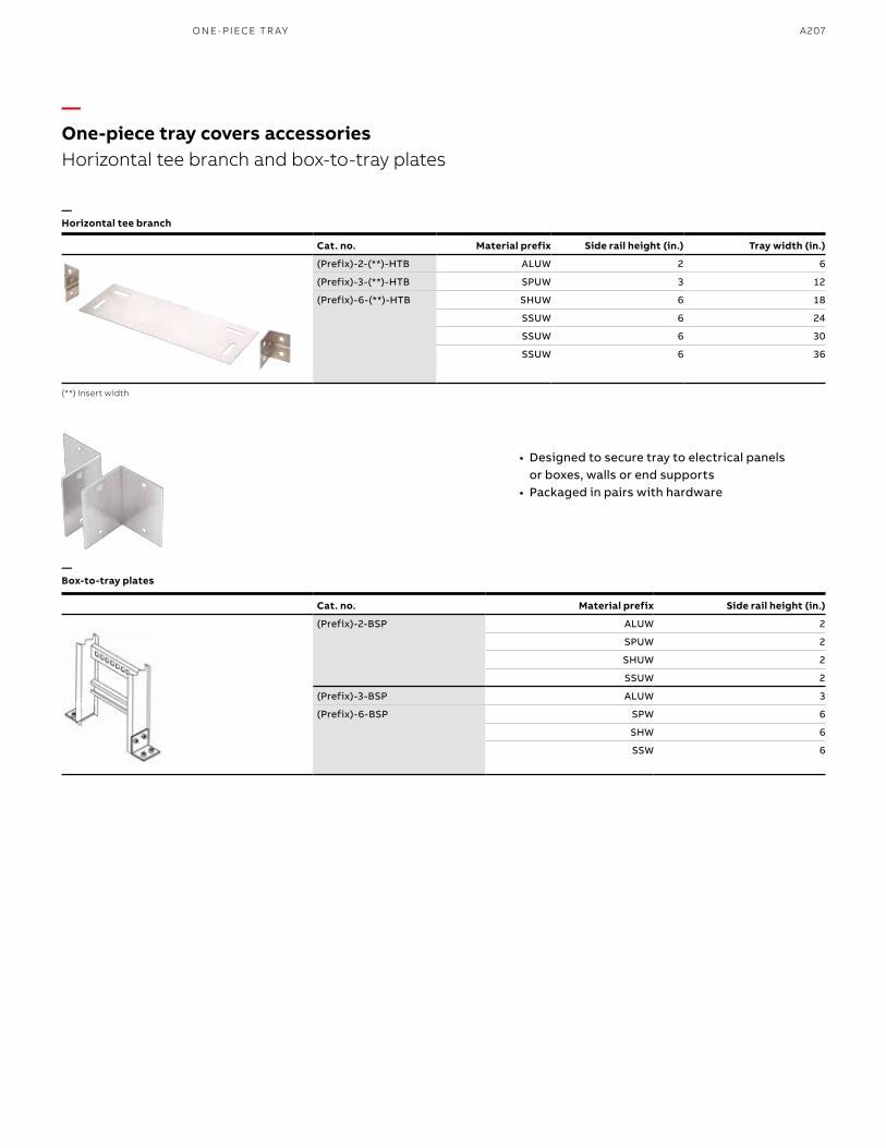
A207
Cat. no. Material prefix Side rail height (in.)
(Prefix)-2-BSP ALUW 2
SPUW 2
SHUW 2
SSUW 2
(Prefix)-3-BSP ALUW 3
(Prefix)-6-BSP SPW 6
SHW 6
SSW 6
• Designed to secure tray to electrical panels or boxes, walls or end supports
• Packaged in pairs with hardware
—One-piece tray covers accessoriesHorizontal tee branch and box-to-tray plates
—Horizontal tee branch
—Box-to-tray plates
(**) Insert width
Cat. no. Material prefix Side rail height (in.) Tray width (in.)
(Prefix)-2-(**)-HTB ALUW 2 6
(Prefix)-3-(**)-HTB SPUW 3 12
(Prefix)-6-(**)-HTB SHUW 6 18
SSUW 6 24
SSUW 6 30
SSUW 6 36
O N E- PI ECE TR AY
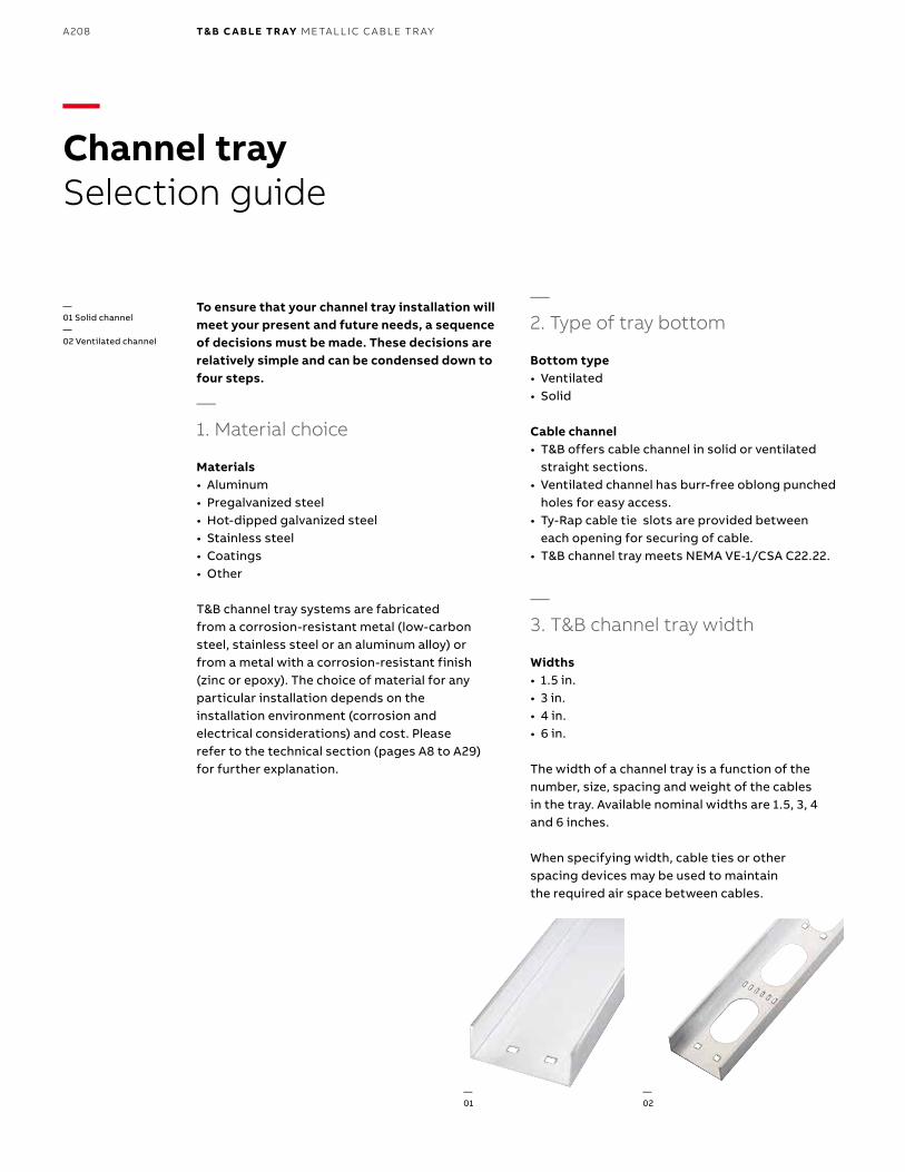
B1 copy starts here
B2 copy starts here
B3 copy starts here
A208 T& B C A B LE TR AY M E TA L L I C C A B L E TR AY
—Channel traySelection guide
To ensure that your channel tray installation will meet your present and future needs, a sequence of decisions must be made. These decisions are relatively simple and can be condensed down to four steps.
—1. Material choice
Materials• Aluminum• Pregalvanized steel• Hot-dipped galvanized steel• Stainless steel• Coatings• Other
T&B channel tray systems are fabricated from a corrosion-resistant metal (low-carbon steel, stainless steel or an aluminum alloy) or from a metal with a corrosion-resistant finish (zinc or epoxy). The choice of material for any particular installation depends on the installation environment (corrosion and electrical considerations) and cost. Please refer to the technical section (pages A8 to A29) for further explanation.
—2. Type of tray bottom
Bottom type• Ventilated• Solid
Cable channel• T&B offers cable channel in solid or ventilated
straight sections.• Ventilated channel has burr-free oblong punched
holes for easy access.• Ty-Rap cable tie slots are provided between
each opening for securing of cable.• T&B channel tray meets NEMA VE-1/CSA C22.22.
—3. T&B channel tray width
Widths• 1.5 in.• 3 in.• 4 in.• 6 in.
The width of a channel tray is a function of the number, size, spacing and weight of the cables in the tray. Available nominal widths are 1.5, 3, 4 and 6 inches.
When specifying width, cable ties or other spacing devices may be used to maintain the required air space between cables.
— 01 Solid channel— 02 Ventilated channel
—01
—02
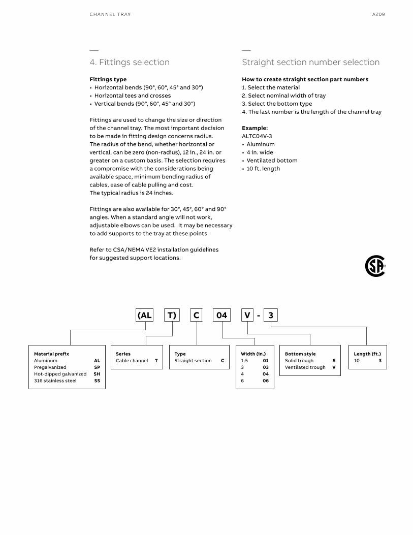
A209CH A N N EL TR AY
—4. Fittings selection
Fittings type• Horizontal bends (90°, 60°, 45° and 30°)• Horizontal tees and crosses• Vertical bends (90°, 60°, 45° and 30°)
Fittings are used to change the size or direction of the channel tray. The most important decision to be made in fitting design concerns radius. The radius of the bend, whether horizontal or vertical, can be zero (non-radius), 12 in., 24 in. or greater on a custom basis. The selection requires a compromise with the considerations being available space, minimum bending radius of cables, ease of cable pulling and cost. The typical radius is 24 inches.
Fittings are also available for 30°, 45°, 60° and 90° angles. When a standard angle will not work, adjustable elbows can be used. It may be necessary to add supports to the tray at these points.
Refer to CSA/NEMA VE2 installation guidelines for suggested support locations.
—Straight section number selection
How to create straight section part numbers1. Select the material2. Select nominal width of tray3. Select the bottom type4. The last number is the length of the channel tray
Example:ALTC04V-3• Aluminum• 4 in. wide• Ventilated bottom• 10 ft. length
Material prefixAluminum ALPregalvanized SPHot-dipped galvanized SH316 stainless steel SS
TypeStraight section C
Bottom styleSolid trough SVentilated trough V
Width (in.)1.5 013 034 046 06
SeriesCable channel T
Length (ft.)10 3
(AL T) C 04 V - 3
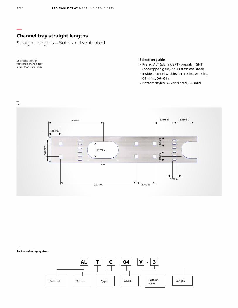
B1 copy starts here
B2 copy starts here
B3 copy starts here
A210 T& B C A B LE TR AY M E TA L L I C C A B L E TR AY
4 in.
2.175 in.
9.625 in. 2.375 in.
0.512 in.
0.188 in.
0.312 in.1.625 in.
1.188 in.
5.429 in. 2.886 in.2.498 in.
—Channel tray straight lengthsStraight lengths – Solid and ventilated
—01 Bottom view of ventilated channel tray larger than 1.5 in. wide
Selection guide• Prefix: ALT (alum.), SPT (pregalv.), SHT
(hot-dipped galv.), SST (stainless steel)• Inside channel widths: 01=1.5 in., 03=3 in.,
04=4 in., 06=6 in.• Bottom styles: V– ventilated, S– solid
—01
—Part numbering system
Material Series Type Width LengthBottom style
AL T C 04 V - 3
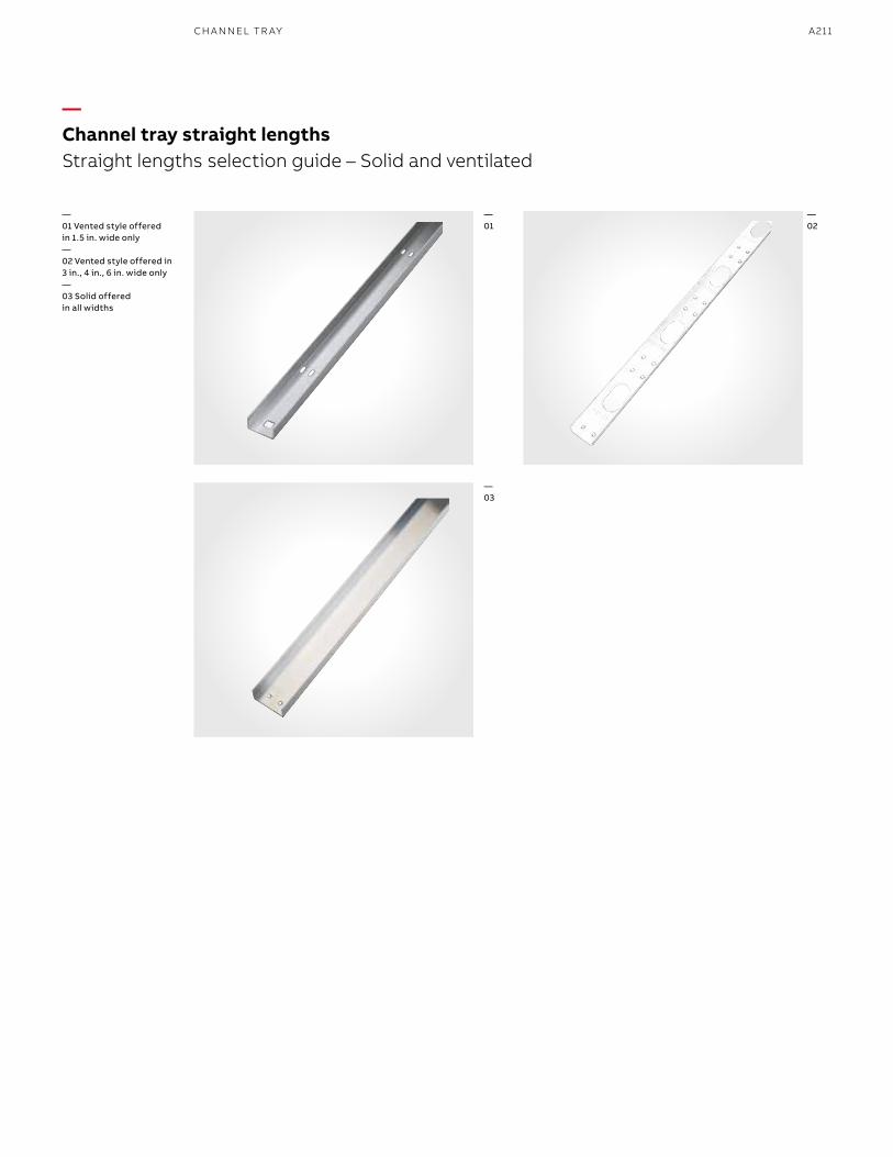
A211
—Channel tray straight lengthsStraight lengths selection guide – Solid and ventilated
—01 Vented style offered in 1.5 in. wide only—02 Vented style offered in 3 in., 4 in., 6 in. wide only—03 Solid offered in all widths
—01
—02
—03
CH A N N EL TR AY
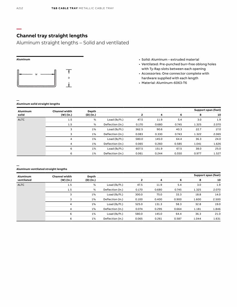
B1 copy starts here
B2 copy starts here
B3 copy starts here
A212 T& B C A B LE TR AY M E TA L L I C C A B L E TR AY
WD
—Channel tray straight lengthsAluminum straight lengths – Solid and ventilated
Aluminum • Solid: Aluminum – extruded material• Ventilated: Pre-punched burr-free oblong holes
with Ty-Rap slots between each opening• Accessories: One connector complete with
hardware supplied with each length• Material: Aluminum-6063-T6
Aluminum solid
Channel width (W) (in.)
Depth (D) (in.)
Support span (feet)
2 4 6 8 10
ALTC 1.5 33⁄44 Load (lb/ft.) 47.5 11.9 5.4 3.0 1.9
1.5 33⁄44 Deflection (in.) 0.170 0.680 0.745 1.325 2.070
3 133⁄88 Load (lb/ft.) 362.5 90.6 40.3 22.7 17.0
3 133⁄88 Deflection (in.) 0.083 0.330 0.743 1.322 2.065
4 155⁄88 Load (lb/ft.) 580.0 145.0 64.4 36.3 24.0
4 155⁄88 Deflection (in.) 0.065 0.260 0.585 1.041 1.626
6 133⁄44 Load (lb/ft.) 607.5 151.9 67.5 38.0 25.0
6 133⁄44 Deflection (in.) 0.061 0.244 0.550 0.977 1.527
Aluminum ventilated
Channel width (W) (in.)
Depth (D) (in.)
Support span (feet)
2 4 6 8 10
ALTC 1.5 33⁄44 Load (lb/ft.) 47.5 11.9 5.4 3.0 1.9
1.5 33⁄44 Deflection (in.) 0.170 0.680 0.745 1.325 2.070
3 133⁄88 Load (lb/ft.) 300.0 75.0 33.3 18.8 14.0
3 133⁄88 Deflection (in.) 0.100 0.400 0.900 1.600 2.500
4 155⁄88 Load (lb/ft.) 525.0 131.3 58.3 32.8 19.0
4 155⁄88 Deflection (in.) 0.074 0.295 0.664 1.181 1.846
6 133⁄44 Load (lb/ft.) 580.0 145.0 64.4 36.3 21.0
6 133⁄44 Deflection (in.) 0.065 0.261 0.587 1.044 1.631
—Aluminum solid straight lengths
—Aluminum ventilated straight lengths
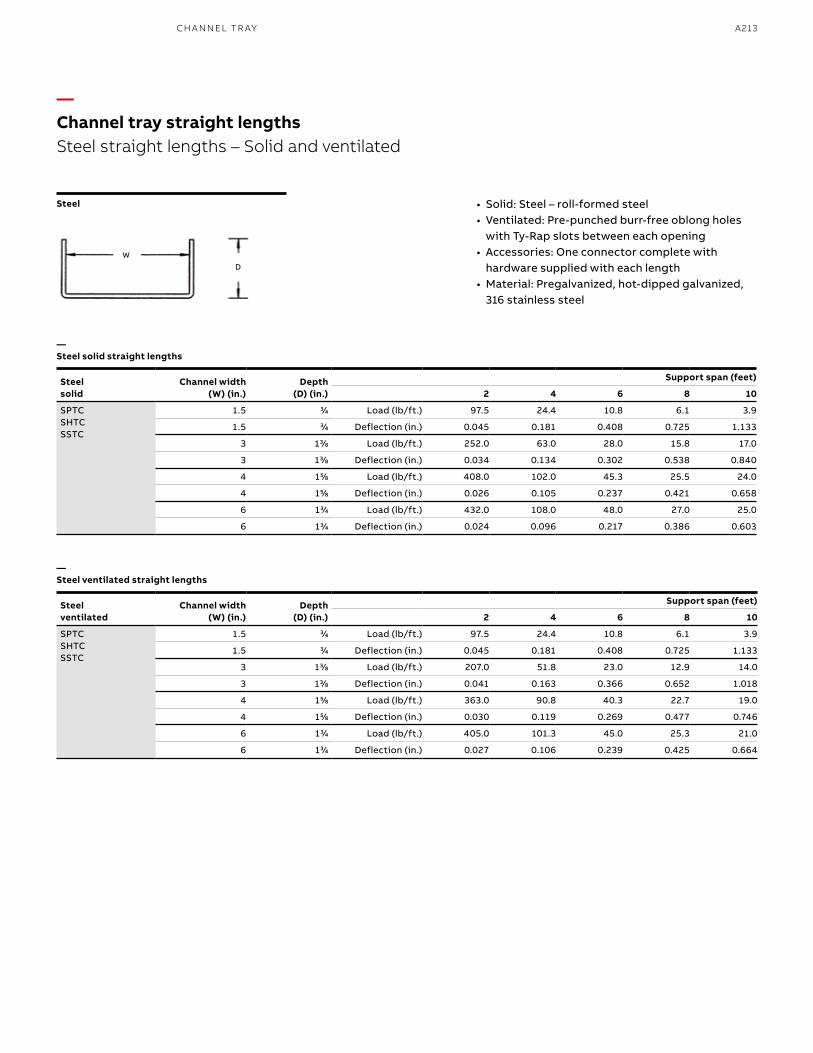
A213
Steel ventilated
Channel width (W) (in.)
Depth (D) (in.)
Support span (feet)
2 4 6 8 10
SPTCSHTCSSTC
1.5 33⁄44 Load (lb/ft.) 97.5 24.4 10.8 6.1 3.9
1.5 33⁄44 Deflection (in.) 0.045 0.181 0.408 0.725 1.133
3 133⁄88 Load (lb/ft.) 207.0 51.8 23.0 12.9 14.0
3 133⁄88 Deflection (in.) 0.041 0.163 0.366 0.652 1.018
4 155⁄88 Load (lb/ft.) 363.0 90.8 40.3 22.7 19.0
4 155⁄88 Deflection (in.) 0.030 0.119 0.269 0.477 0.746
6 133⁄44 Load (lb/ft.) 405.0 101.3 45.0 25.3 21.0
6 133⁄44 Deflection (in.) 0.027 0.106 0.239 0.425 0.664
WD
—Channel tray straight lengthsSteel straight lengths – Solid and ventilated
Steel • Solid: Steel – roll-formed steel• Ventilated: Pre-punched burr-free oblong holes
with Ty-Rap slots between each opening• Accessories: One connector complete with
hardware supplied with each length• Material: Pregalvanized, hot-dipped galvanized,
316 stainless steel
—Steel solid straight lengths
—Steel ventilated straight lengths
Steel solid
Channel width (W) (in.)
Depth (D) (in.)
Support span (feet)
2 4 6 8 10
SPTCSHTCSSTC
1.5 33⁄44 Load (lb/ft.) 97.5 24.4 10.8 6.1 3.9
1.5 33⁄44 Deflection (in.) 0.045 0.181 0.408 0.725 1.133
3 133⁄88 Load (lb/ft.) 252.0 63.0 28.0 15.8 17.0
3 133⁄88 Deflection (in.) 0.034 0.134 0.302 0.538 0.840
4 155⁄88 Load (lb/ft.) 408.0 102.0 45.3 25.5 24.0
4 155⁄88 Deflection (in.) 0.026 0.105 0.237 0.421 0.658
6 133⁄44 Load (lb/ft.) 432.0 108.0 48.0 27.0 25.0
6 133⁄44 Deflection (in.) 0.024 0.096 0.217 0.386 0.603
CH A N N EL TR AY
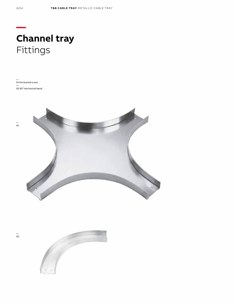
B1 copy starts here
B2 copy starts here
B3 copy starts here
A214 T& B C A B LE TR AY M E TA L L I C C A B L E TR AY
—Channel trayFittings
—01 Horizontal cross—02 90o Horizontal bend
—01
—02
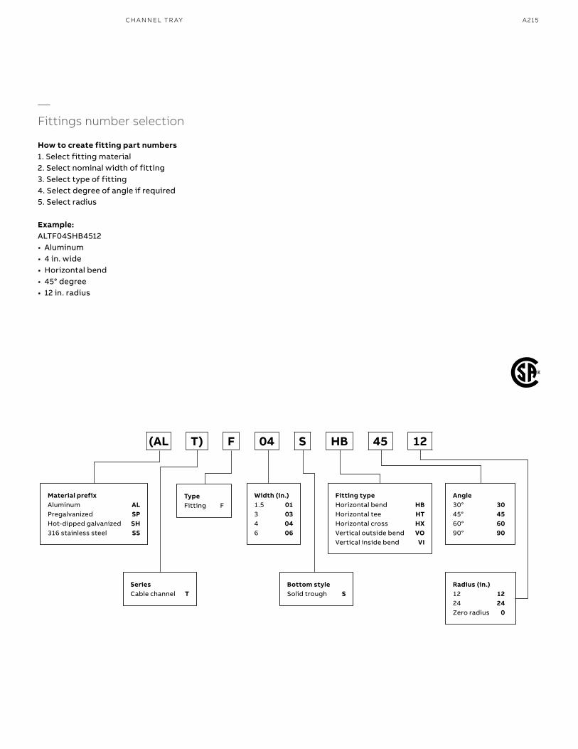
A215
—Fittings number selection
How to create fitting part numbers1. Select fitting material2. Select nominal width of fitting3. Select type of fitting4. Select degree of angle if required5. Select radius
Example:ALTF04SHB4512• Aluminum• 4 in. wide• Horizontal bend• 45° degree• 12 in. radius
Material prefixAluminum ALPregalvanized SPHot-dipped galvanized SH316 stainless steel SS
Angle30° 3045° 4560° 6090° 90
Radius (in.)12 1224 24Zero radius 0
Fitting typeHorizontal bend HBHorizontal tee HTHorizontal cross HXVertical outside bend VOVertical inside bend VI
TypeFitting F
Bottom styleSolid trough S
Width (in.)1.5 013 034 046 06
SeriesCable channel T
(AL T) F 04 S HB 45 12
CH A N N EL TR AY
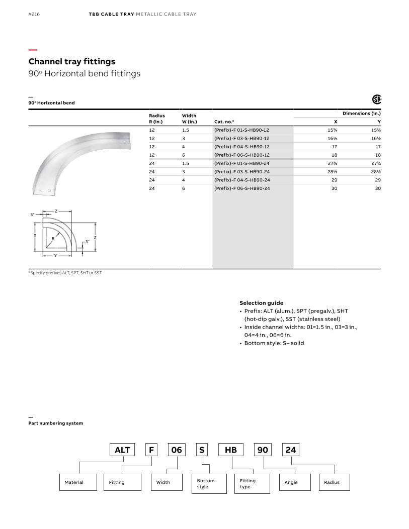
B1 copy starts here
B2 copy starts here
B3 copy starts here
A216 T& B C A B LE TR AY M E TA L L I C C A B L E TR AY
Radius R (in.)
WidthW (in.) Cat. no.*
Dimensions (in.)
X Y
12 1.5 (Prefix)-F 01-S-HB90-12 1533⁄44 1533⁄44
12 3 (Prefix)-F 03-S-HB90-12 1611⁄22 1611⁄22
12 4 (Prefix)-F 04-S-HB90-12 17 17
12 6 (Prefix)-F 06-S-HB90-12 18 18
24 1.5 (Prefix)-F 01-S-HB90-24 2733⁄44 2733⁄44
24 3 (Prefix)-F 03-S-HB90-24 2811⁄22 2811⁄22
24 4 (Prefix)-F 04-S-HB90-24 29 29
24 6 (Prefix)-F 06-S-HB90-24 30 30
—Channel tray fittings90o Horizontal bend fittings
—90o Horizontal bend
Selection guide• Prefix: ALT (alum.), SPT (pregalv.), SHT
(hot-dip galv.), SST (stainless steel)• Inside channel widths: 01=1.5 in., 03=3 in.,
04=4 in., 06=6 in.• Bottom style: S– solid
*Specify prefixes ALT, SPT, SHT or SST
Y
X
3"
3"Z
Z
R
—Part numbering system
Material Fitting Width Angle RadiusBottom style
Fitting type
ALT F 06 S HB 90 24
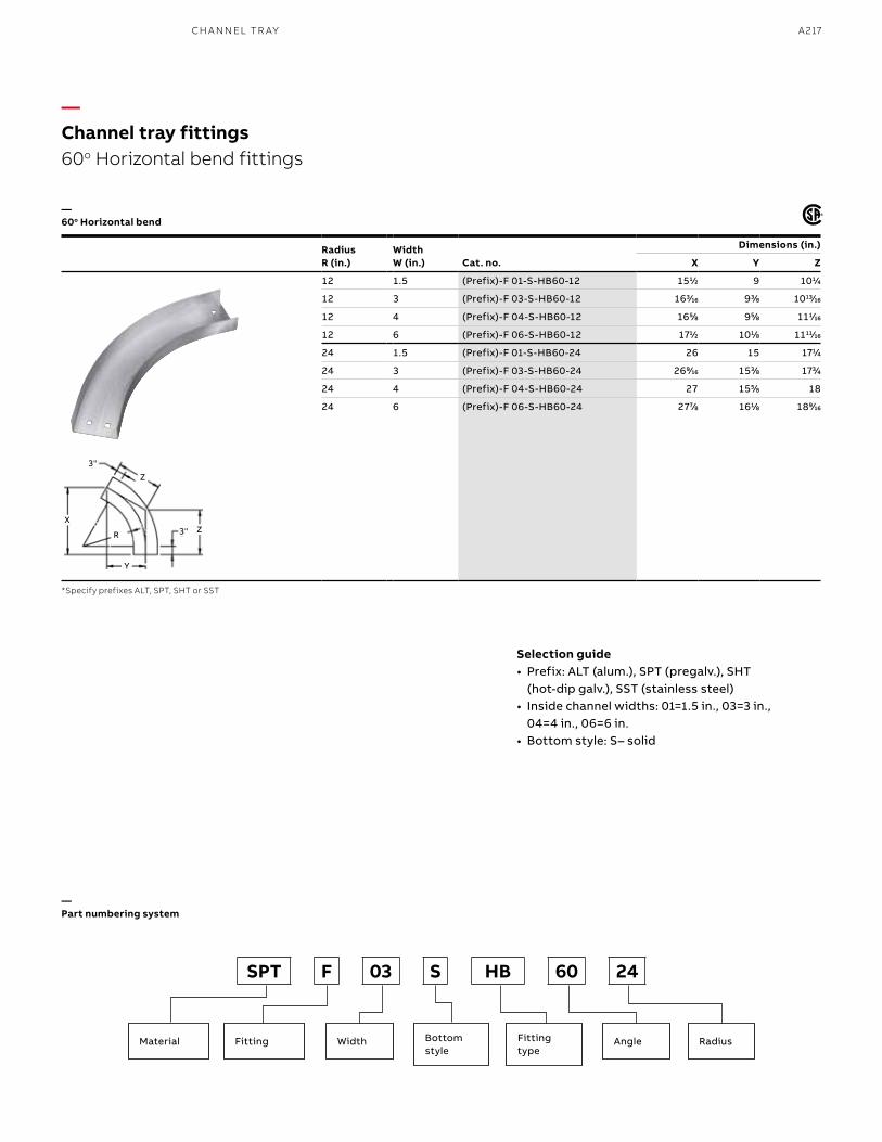
A217
—60o Horizontal bend
Selection guide• Prefix: ALT (alum.), SPT (pregalv.), SHT
(hot-dip galv.), SST (stainless steel)• Inside channel widths: 01=1.5 in., 03=3 in.,
04=4 in., 06=6 in.• Bottom style: S– solid
*Specify prefixes ALT, SPT, SHT or SST
—Part numbering system
Material Fitting Width Angle RadiusBottom style
Fitting type
SPT F 03 S HB 60 24
Radius R (in.)
WidthW (in.) Cat. no.
Dimensions (in.)
X Y Z
12 1.5 (Prefix)-F 01-S-HB60-12 1511⁄22 9 1011⁄44
12 3 (Prefix)-F 03-S-HB60-12 1633⁄1616 933⁄88 101313⁄1616
12 4 (Prefix)-F 04-S-HB60-12 1655⁄88 955⁄88 1111⁄1616
12 6 (Prefix)-F 06-S-HB60-12 1711⁄22 1011⁄88 111111⁄1616
24 1.5 (Prefix)-F 01-S-HB60-24 26 15 1711⁄44
24 3 (Prefix)-F 03-S-HB60-24 2699⁄1616 1533⁄88 1733⁄44
24 4 (Prefix)-F 04-S-HB60-24 27 1555⁄88 18
24 6 (Prefix)-F 06-S-HB60-24 2777⁄88 1611⁄88 1899⁄1616
—Channel tray fittings60o Horizontal bend fittings
Y
X
3"
3" Z
Z
R
CH A N N EL TR AY
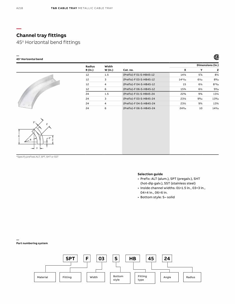
B1 copy starts here
B2 copy starts here
B3 copy starts here
A218 T& B C A B LE TR AY M E TA L L I C C A B L E TR AY
—Channel tray fittings45o Horizontal bend fittings
Radius R (in.)
WidthW (in.) Cat. no.
Dimensions (in.)
X Y Z
12 1.5 (Prefix)-F 01-S-HB45-12 1411⁄88 577⁄88 811⁄44
12 3 (Prefix)-F 03-S-HB45-12 141111⁄1616 611⁄1616 899⁄1616
12 4 (Prefix)-F 04-S-HB45-12 15 611⁄44 81313⁄1616
12 6 (Prefix)-F 06-S-HB45-12 1533⁄44 611⁄22 933⁄1616
24 1.5 (Prefix)-F 01-S-HB45-24 2255⁄88 933⁄88 1311⁄44
24 3 (Prefix)-F 03-S-HB45-24 2311⁄88 999⁄1616 1399⁄1616
24 4 (Prefix)-F 04-S-HB45-24 2311⁄22 933⁄44 1333⁄44
24 6 (Prefix)-F 06-S-HB45-24 2433⁄1616 10 1433⁄1616
—45o Horizontal bend
*Specify prefixes ALT, SPT, SHT or SST
Y
X
3"
3"Z
Z
R
Selection guide• Prefix: ALT (alum.), SPT (pregalv.), SHT
(hot-dip galv.), SST (stainless steel)• Inside channel widths: 01=1.5 in., 03=3 in.,
04=4 in., 06=6 in.• Bottom style: S– solid
—Part numbering system
Material Fitting Width Angle RadiusBottom style
Fitting type
SPT F 03 S HB 45 24
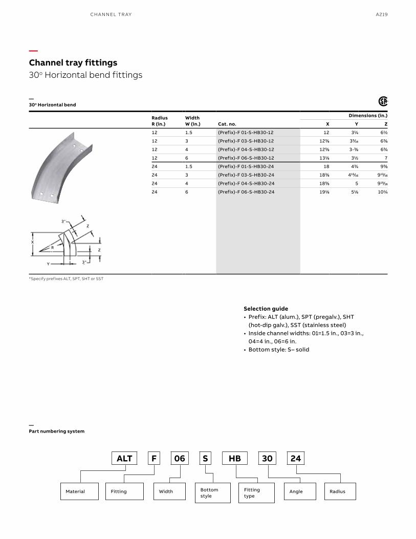
A219
Radius R (in.)
WidthW (in.) Cat. no.
Dimensions (in.)
X Y Z
12 1.5 (Prefix)-F 01-S-HB30-12 12 311⁄44 611⁄22
12 3 (Prefix)-F 03-S-HB30-12 1233⁄88 355⁄1616 655⁄88
12 4 (Prefix)-F 04-S-HB30-12 1255⁄88 3-33⁄88 633⁄44
12 6 (Prefix)-F 06-S-HB30-12 1311⁄88 311⁄22 7
24 1.5 (Prefix)-F 01-S-HB30-24 18 433⁄44 955⁄88
24 3 (Prefix)-F 03-S-HB30-24 1833⁄88 41515⁄1616 91313⁄1616
24 4 (Prefix)-F 04-S-HB30-24 1855⁄88 5 91515⁄1616
24 6 (Prefix)-F 06-S-HB30-24 1911⁄88 511⁄88 1011⁄44
—30o Horizontal bend
Selection guide• Prefix: ALT (alum.), SPT (pregalv.), SHT
(hot-dip galv.), SST (stainless steel)• Inside channel widths: 01=1.5 in., 03=3 in.,
04=4 in., 06=6 in.• Bottom style: S– solid
*Specify prefixes ALT, SPT, SHT or SST
—Part numbering system
—Channel tray fittings30o Horizontal bend fittings
Y
X
3"
3"
Z
Z
R
Material Fitting Width Angle RadiusBottom style
Fitting type
ALT F 06 S HB 30 24
CH A N N EL TR AY
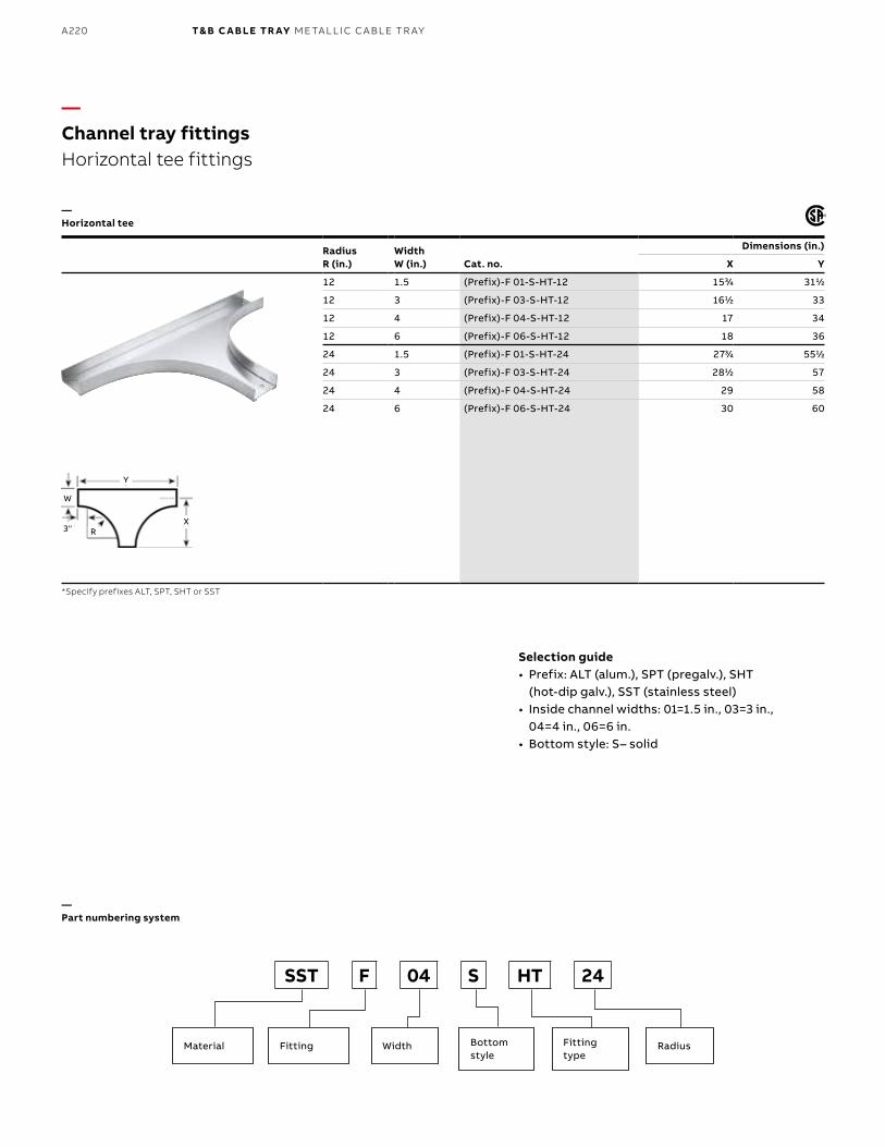
B1 copy starts here
B2 copy starts here
B3 copy starts here
A220 T& B C A B LE TR AY M E TA L L I C C A B L E TR AY
Radius R (in.)
WidthW (in.) Cat. no.
Dimensions (in.)
X Y
12 1.5 (Prefix)-F 01-S-HT-12 1533⁄44 3111⁄22
12 3 (Prefix)-F 03-S-HT-12 1611⁄22 33
12 4 (Prefix)-F 04-S-HT-12 17 34
12 6 (Prefix)-F 06-S-HT-12 18 36
24 1.5 (Prefix)-F 01-S-HT-24 2733⁄44 5511⁄22
24 3 (Prefix)-F 03-S-HT-24 2811⁄22 57
24 4 (Prefix)-F 04-S-HT-24 29 58
24 6 (Prefix)-F 06-S-HT-24 30 60
—Channel tray fittingsHorizontal tee fittings
—Horizontal tee
*Specify prefixes ALT, SPT, SHT or SST
Selection guide• Prefix: ALT (alum.), SPT (pregalv.), SHT
(hot-dip galv.), SST (stainless steel)• Inside channel widths: 01=1.5 in., 03=3 in.,
04=4 in., 06=6 in.• Bottom style: S– solid
Y
X3"
W
R
—Part numbering system
Material Fitting Width RadiusBottom style
Fitting type
SST F 04 S HT 24
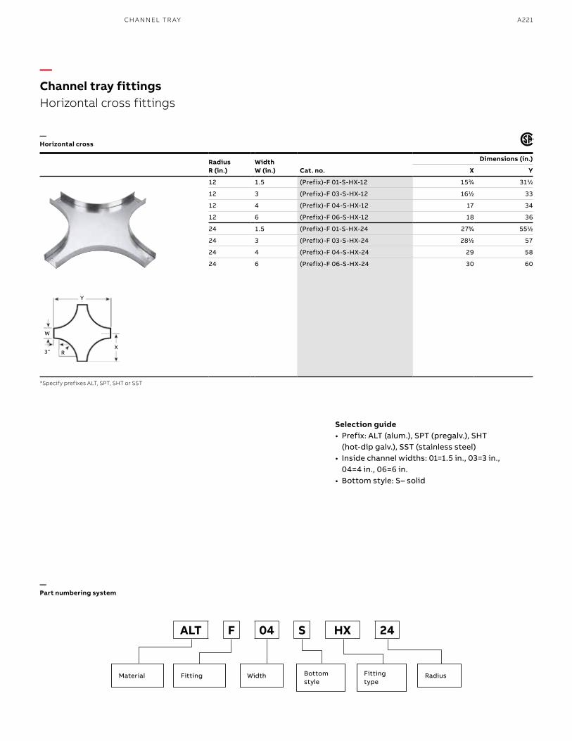
A221
Radius R (in.)
WidthW (in.) Cat. no.
Dimensions (in.)
X Y
12 1.5 (Prefix)-F 01-S-HX-12 1533⁄44 3111⁄22
12 3 (Prefix)-F 03-S-HX-12 1611⁄22 33
12 4 (Prefix)-F 04-S-HX-12 17 34
12 6 (Prefix)-F 06-S-HX-12 18 36
24 1.5 (Prefix)-F 01-S-HX-24 2733⁄44 5511⁄22
24 3 (Prefix)-F 03-S-HX-24 2811⁄22 57
24 4 (Prefix)-F 04-S-HX-24 29 58
24 6 (Prefix)-F 06-S-HX-24 30 60
—Horizontal cross
Selection guide• Prefix: ALT (alum.), SPT (pregalv.), SHT
(hot-dip galv.), SST (stainless steel)• Inside channel widths: 01=1.5 in., 03=3 in.,
04=4 in., 06=6 in.• Bottom style: S– solid
*Specify prefixes ALT, SPT, SHT or SST
—Channel tray fittingsHorizontal cross fittings
—Part numbering system
Material Fitting Width RadiusBottom style
Fitting type
ALT F 04 S HX 24
Y
X3"
W
R
CH A N N EL TR AY
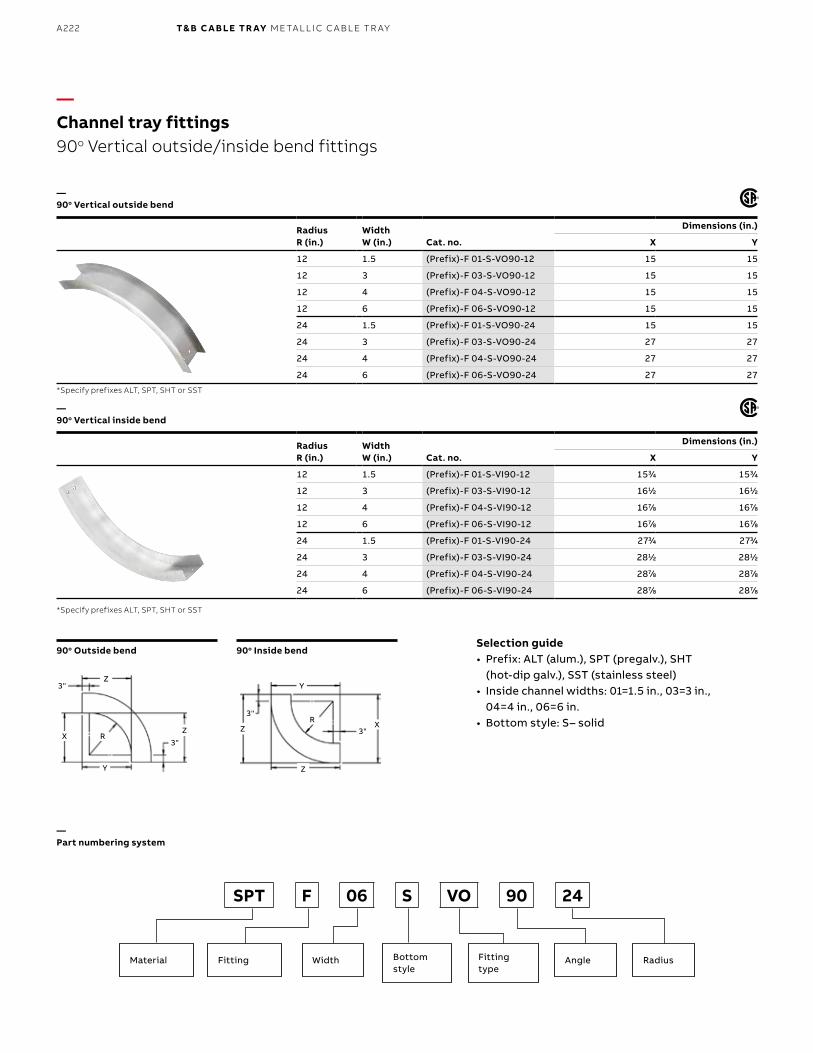
B1 copy starts here
B2 copy starts here
B3 copy starts here
A222 T& B C A B LE TR AY M E TA L L I C C A B L E TR AY
Radius R (in.)
WidthW (in.) Cat. no.
Dimensions (in.)
X Y
12 1.5 (Prefix)-F 01-S-VO90-12 15 15
12 3 (Prefix)-F 03-S-VO90-12 15 15
12 4 (Prefix)-F 04-S-VO90-12 15 15
12 6 (Prefix)-F 06-S-VO90-12 15 15
24 1.5 (Prefix)-F 01-S-VO90-24 15 15
24 3 (Prefix)-F 03-S-VO90-24 27 27
24 4 (Prefix)-F 04-S-VO90-24 27 27
24 6 (Prefix)-F 06-S-VO90-24 27 27
Radius R (in.)
WidthW (in.) Cat. no.
Dimensions (in.)
X Y
12 1.5 (Prefix)-F 01-S-VI90-12 1533⁄44 1533⁄44
12 3 (Prefix)-F 03-S-VI90-12 1611⁄22 1611⁄22
12 4 (Prefix)-F 04-S-VI90-12 1677⁄88 1677⁄88
12 6 (Prefix)-F 06-S-VI90-12 1677⁄88 1677⁄88
24 1.5 (Prefix)-F 01-S-VI90-24 2733⁄44 2733⁄44
24 3 (Prefix)-F 03-S-VI90-24 2811⁄22 2811⁄22
24 4 (Prefix)-F 04-S-VI90-24 2877⁄88 2877⁄88
24 6 (Prefix)-F 06-S-VI90-24 2877⁄88 2877⁄88
—Channel tray fittings90o Vertical outside/inside bend fittings
—90o Vertical outside bend
—90o Vertical inside bend
*Specify prefixes ALT, SPT, SHT or SST
*Specify prefixes ALT, SPT, SHT or SST
90o Outside bend 90o Inside bendSelection guide• Prefix: ALT (alum.), SPT (pregalv.), SHT
(hot-dip galv.), SST (stainless steel)• Inside channel widths: 01=1.5 in., 03=3 in.,
04=4 in., 06=6 in.• Bottom style: S– solid
Y
Y
XX
3"3"
3"
3"
Z Z
Z
Z
R
R
—Part numbering system
Material Fitting Width RadiusAngleBottom style
Fitting type
SPT F 06 S VO 90 24
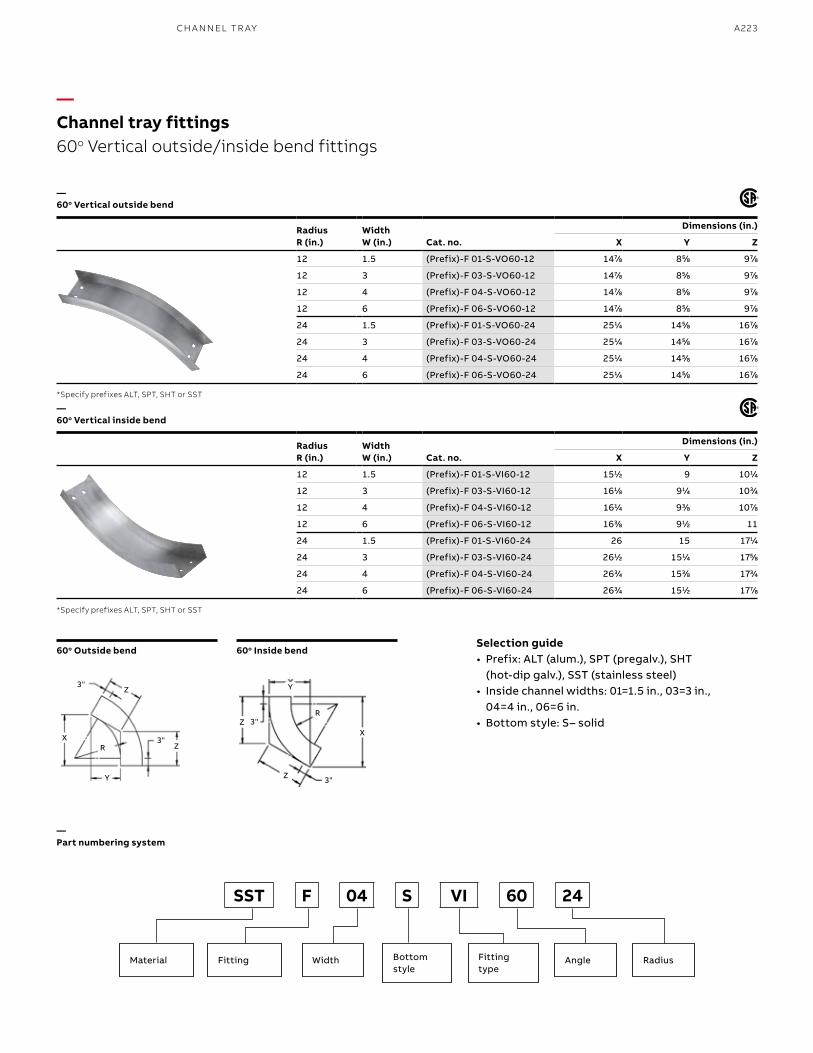
A223
—60o Vertical inside bend
60o Outside bend 60o Inside bend
—Part numbering system
Material Fitting Width RadiusAngleBottom style
Fitting type
SST F 04 S VI 60 24
Radius R (in.)
WidthW (in.) Cat. no.
Dimensions (in.)
X Y Z
12 1.5 (Prefix)-F 01-S-VO60-12 1477⁄88 855⁄88 977⁄88
12 3 (Prefix)-F 03-S-VO60-12 1477⁄88 855⁄88 977⁄88
12 4 (Prefix)-F 04-S-VO60-12 1477⁄88 855⁄88 977⁄88
12 6 (Prefix)-F 06-S-VO60-12 1477⁄88 855⁄88 977⁄88
24 1.5 (Prefix)-F 01-S-VO60-24 2511⁄44 1455⁄88 1677⁄88
24 3 (Prefix)-F 03-S-VO60-24 2511⁄44 1455⁄88 1677⁄88
24 4 (Prefix)-F 04-S-VO60-24 2511⁄44 1455⁄88 1677⁄88
24 6 (Prefix)-F 06-S-VO60-24 2511⁄44 1455⁄88 1677⁄88
Radius R (in.)
WidthW (in.) Cat. no.
Dimensions (in.)
X Y Z
12 1.5 (Prefix)-F 01-S-VI60-12 1511⁄22 9 1011⁄44
12 3 (Prefix)-F 03-S-VI60-12 1611⁄88 911⁄44 1033⁄44
12 4 (Prefix)-F 04-S-VI60-12 1611⁄44 933⁄88 1077⁄88
12 6 (Prefix)-F 06-S-VI60-12 1633⁄88 911⁄22 11
24 1.5 (Prefix)-F 01-S-VI60-24 26 15 1711⁄44
24 3 (Prefix)-F 03-S-VI60-24 2611⁄22 1511⁄44 1755⁄88
24 4 (Prefix)-F 04-S-VI60-24 2633⁄44 1533⁄88 1733⁄44
24 6 (Prefix)-F 06-S-VI60-24 2633⁄44 1511⁄22 1777⁄88
—60o Vertical outside bend
Selection guide• Prefix: ALT (alum.), SPT (pregalv.), SHT
(hot-dip galv.), SST (stainless steel)• Inside channel widths: 01=1.5 in., 03=3 in.,
04=4 in., 06=6 in.• Bottom style: S– solid
*Specify prefixes ALT, SPT, SHT or SST
*Specify prefixes ALT, SPT, SHT or SST
—Channel tray fittings60o Vertical outside/inside bend fittings
Y
Y
XX
3"
3"
3"
3"
Z
Z
Z
Z
R
R
CH A N N EL TR AY
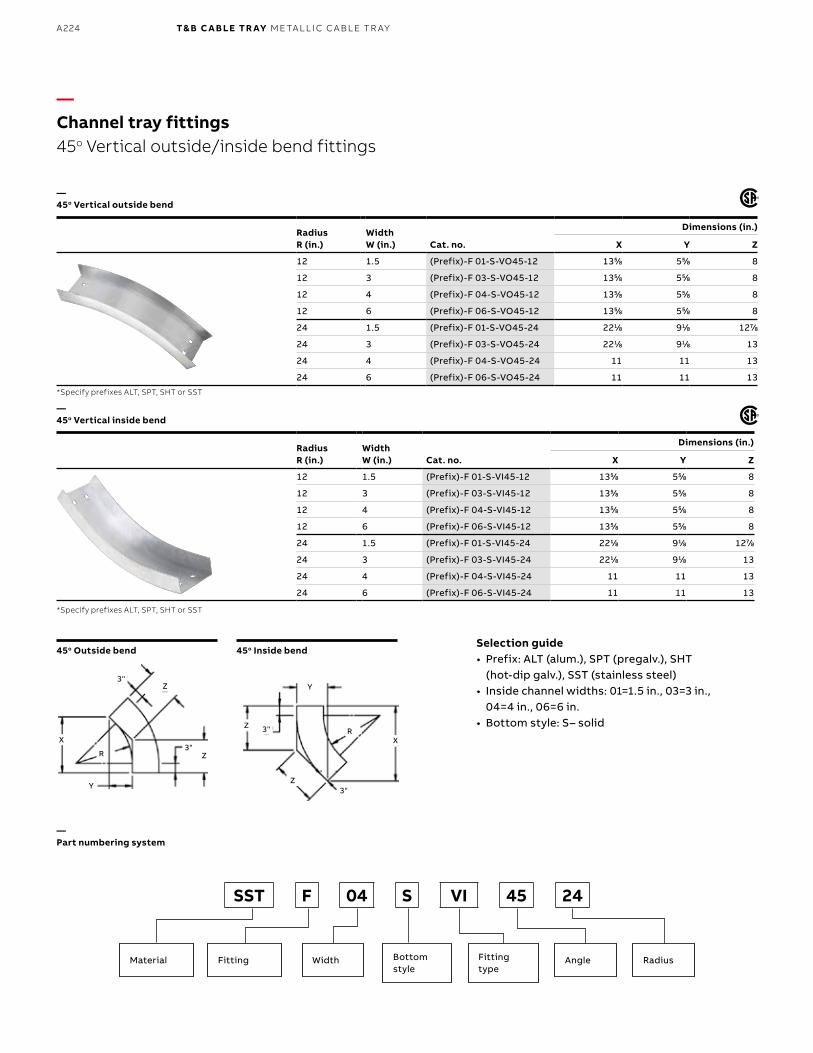
B1 copy starts here
B2 copy starts here
B3 copy starts here
A224 T& B C A B LE TR AY M E TA L L I C C A B L E TR AY
Radius R (in.)
WidthW (in.) Cat. no.
Dimensions (in.)
X Y Z
12 1.5 (Prefix)-F 01-S-VO45-12 1355⁄88 555⁄88 8
12 3 (Prefix)-F 03-S-VO45-12 1355⁄88 555⁄88 8
12 4 (Prefix)-F 04-S-VO45-12 1355⁄88 555⁄88 8
12 6 (Prefix)-F 06-S-VO45-12 1355⁄88 555⁄88 8
24 1.5 (Prefix)-F 01-S-VO45-24 2211⁄88 911⁄88 1277⁄88
24 3 (Prefix)-F 03-S-VO45-24 2211⁄88 911⁄88 13
24 4 (Prefix)-F 04-S-VO45-24 11 11 13
24 6 (Prefix)-F 06-S-VO45-24 11 11 13
Radius R (in.)
WidthW (in.) Cat. no.
Dimensions (in.)
X Y Z
12 1.5 (Prefix)-F 01-S-VI45-12 1355⁄88 555⁄88 8
12 3 (Prefix)-F 03-S-VI45-12 1355⁄88 555⁄88 8
12 4 (Prefix)-F 04-S-VI45-12 1355⁄88 555⁄88 8
12 6 (Prefix)-F 06-S-VI45-12 1355⁄88 555⁄88 8
24 1.5 (Prefix)-F 01-S-VI45-24 2211⁄88 911⁄88 1277⁄88
24 3 (Prefix)-F 03-S-VI45-24 2211⁄88 911⁄88 13
24 4 (Prefix)-F 04-S-VI45-24 11 11 13
24 6 (Prefix)-F 06-S-VI45-24 11 11 13
—Channel tray fittings45o Vertical outside/inside bend fittings
—45o Vertical outside bend
—45o Vertical inside bend
*Specify prefixes ALT, SPT, SHT or SST
*Specify prefixes ALT, SPT, SHT or SST
45o Outside bend 45o Inside bend
Y
Y
X X
3"
3"
3"
3"
Z
Z
Z
ZR
R
—Part numbering system
Material Fitting Width RadiusAngleBottom style
Fitting type
SST F 04 S VI 45 24
Selection guide• Prefix: ALT (alum.), SPT (pregalv.), SHT
(hot-dip galv.), SST (stainless steel)• Inside channel widths: 01=1.5 in., 03=3 in.,
04=4 in., 06=6 in.• Bottom style: S– solid
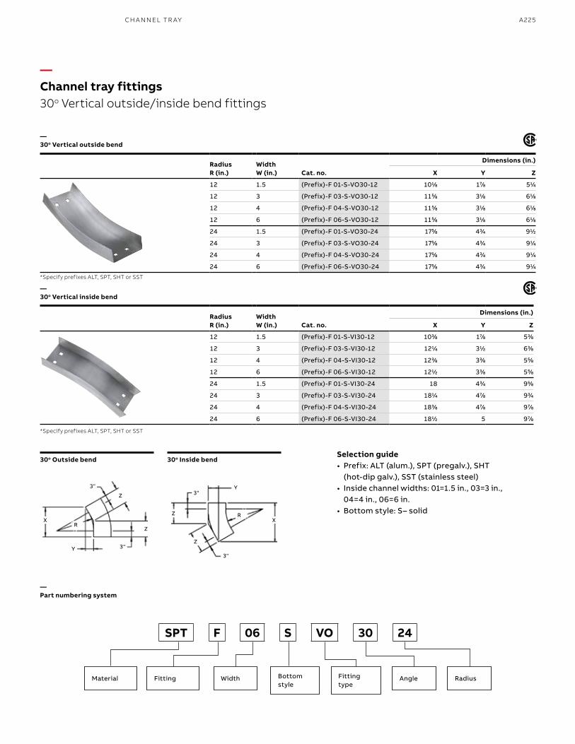
A225
—30o Vertical outside bend
—30o Vertical inside bend
*Specify prefixes ALT, SPT, SHT or SST
*Specify prefixes ALT, SPT, SHT or SST
30o Outside bend 30o Inside bendSelection guide• Prefix: ALT (alum.), SPT (pregalv.), SHT
(hot-dip galv.), SST (stainless steel)• Inside channel widths: 01=1.5 in., 03=3 in.,
04=4 in., 06=6 in.• Bottom style: S– solid
Radius R (in.)
WidthW (in.) Cat. no.
Dimensions (in.)
X Y Z
12 1.5 (Prefix)-F 01-S-VO30-12 1011⁄88 177⁄88 511⁄44
12 3 (Prefix)-F 03-S-VO30-12 1155⁄88 311⁄88 611⁄88
12 4 (Prefix)-F 04-S-VO30-12 1155⁄88 311⁄88 611⁄88
12 6 (Prefix)-F 06-S-VO30-12 1155⁄88 311⁄88 611⁄88
24 1.5 (Prefix)-F 01-S-VO30-24 1755⁄88 433⁄44 911⁄22
24 3 (Prefix)-F 03-S-VO30-24 1755⁄88 433⁄44 911⁄44
24 4 (Prefix)-F 04-S-VO30-24 1755⁄88 433⁄44 911⁄44
24 6 (Prefix)-F 06-S-VO30-24 1755⁄88 433⁄44 911⁄44
Radius R (in.)
WidthW (in.) Cat. no.
Dimensions (in.)
X Y Z
12 1.5 (Prefix)-F 01-S-VI30-12 1033⁄88 177⁄88 533⁄88
12 3 (Prefix)-F 03-S-VI30-12 1211⁄44 311⁄22 633⁄88
12 4 (Prefix)-F 04-S-VI30-12 1233⁄88 333⁄88 555⁄88
12 6 (Prefix)-F 06-S-VI30-12 1211⁄22 333⁄88 555⁄88
24 1.5 (Prefix)-F 01-S-VI30-24 18 433⁄44 955⁄88
24 3 (Prefix)-F 03-S-VI30-24 1811⁄44 477⁄88 933⁄44
24 4 (Prefix)-F 04-S-VI30-24 1833⁄88 477⁄88 977⁄88
24 6 (Prefix)-F 06-S-VI30-24 1811⁄22 5 977⁄88
—Channel tray fittings30o Vertical outside/inside bend fittings
—Part numbering system
Material Fitting Width RadiusAngleBottom style
Fitting type
SPT F 06 S VO 30 24
Y
Y
X X
3"3"
3"
3"
Z
Z
Z
Z
R
R
R
CH A N N EL TR AY
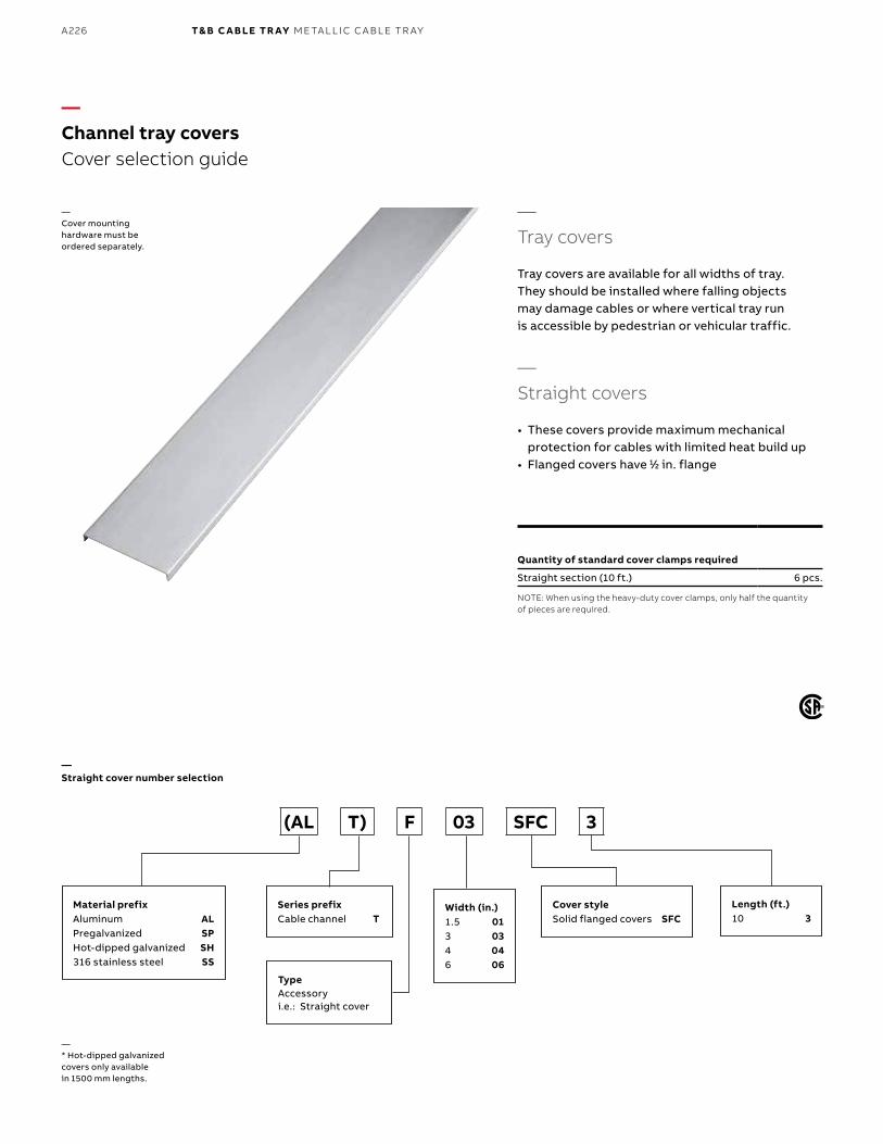
B1 copy starts here
B2 copy starts here
B3 copy starts here
A226 T& B C A B LE TR AY M E TA L L I C C A B L E TR AY
—Channel tray coversCover selection guide
—* Hot-dipped galvanized covers only available in 1500 mm lengths.
—Tray covers
Tray covers are available for all widths of tray. They should be installed where falling objects may damage cables or where vertical tray run is accessible by pedestrian or vehicular traffic.
—Straight covers
• These covers provide maximum mechanical protection for cables with limited heat build up
• Flanged covers have 11⁄22 in. flange
—Straight cover number selection
Material prefixAluminum ALPregalvanized SPHot-dipped galvanized SH316 stainless steel SS
Length (ft.)10 3
Cover styleSolid flanged covers SFC
Series prefixCable channel T
Width (in.)1.5 013 034 046 06
TypeAccessoryi.e.: Straight cover
(AL T) F 03 SFC 3
Quantity of standard cover clamps required
Straight section (10 ft.) 6 pcs.
NOTE: When using the heavy-duty cover clamps, only half the quantity of pieces are required.
—Cover mounting hardware must be ordered separately.
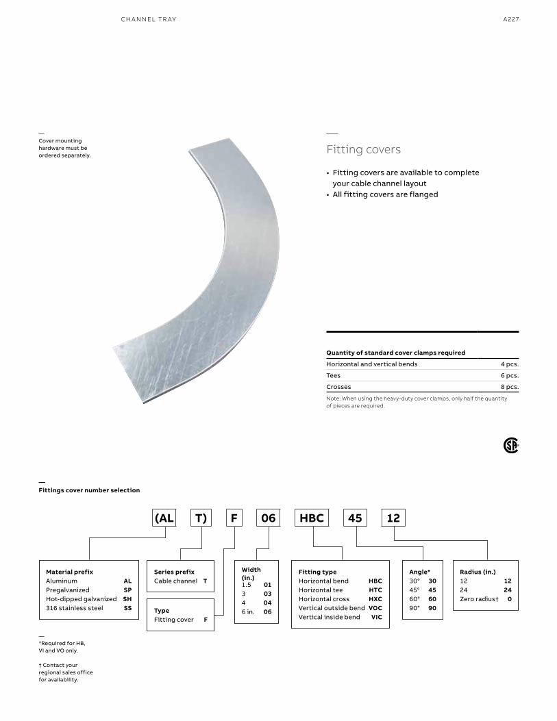
A227
—Cover mounting hardware must be ordered separately.
—Fitting covers
• Fitting covers are available to complete your cable channel layout
• All fitting covers are flanged
—Fittings cover number selection
Material prefixAluminum ALPregalvanized SPHot-dipped galvanized SH316 stainless steel SS
Fitting typeHorizontal bend HBCHorizontal tee HTCHorizontal cross HXCVertical outside bend VOCVertical inside bend VIC
Series prefixCable channel T
TypeFitting cover F
Width (in.)1.5 013 034 046 in. 06
Angle*30° 3045° 4560° 6090° 90
Radius (in.)12 1224 24Zero radius† 0
(AL T) F 06 HBC 45 12
Quantity of standard cover clamps required
Horizontal and vertical bends 4 pcs.
Tees 6 pcs.
Crosses 8 pcs.
Note: When using the heavy-duty cover clamps, only half the quantity of pieces are required.
CH A N N EL TR AY
—*Required for HB, VI and VO only.
† Contact your regional sales office for availability.
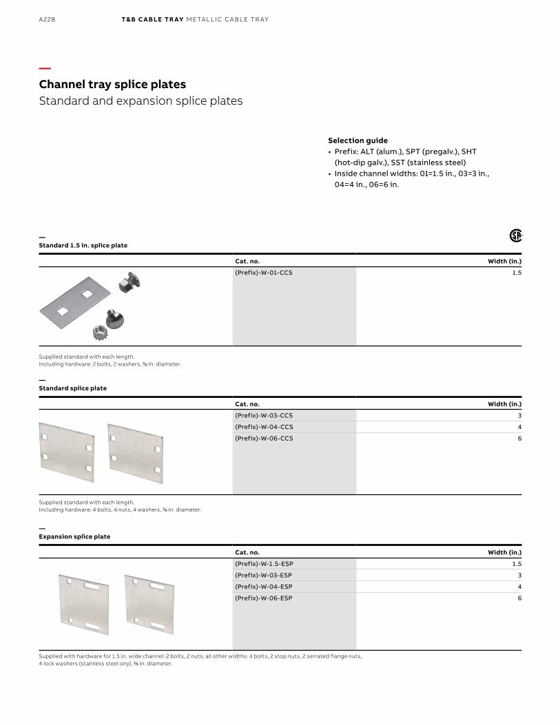
B1 copy starts here
B2 copy starts here
B3 copy starts here
A228 T& B C A B LE TR AY M E TA L L I C C A B L E TR AY
—Channel tray splice platesStandard and expansion splice plates
—Standard 1.5 in. splice plate
—Standard splice plate
—Expansion splice plate
Selection guide• Prefix: ALT (alum.), SPT (pregalv.), SHT
(hot-dip galv.), SST (stainless steel)• Inside channel widths: 01=1.5 in., 03=3 in.,
04=4 in., 06=6 in.
Cat. no. Width (in.)
(Prefix)-W-01-CCS 1.5
Supplied standard with each length.Including hardware: 2 bolts, 2 washers, 33⁄88 in. diameter.
Supplied standard with each length. Including hardware: 4 bolts, 4 nuts, 4 washers, 33⁄88 in. diameter.
Supplied with hardware for 1.5 in. wide channel: 2 bolts, 2 nuts; all other widths: 4 bolts, 2 stop nuts, 2 serrated flange nuts, 4 lock washers (stainless steel ony), 33⁄88 in. diameter.
Cat. no. Width (in.)
(Prefix)-W-03-CCS 3
(Prefix)-W-04-CCS 4
(Prefix)-W-06-CCS 6
Cat. no. Width (in.)
(Prefix)-W-1.5-ESP 1.5
(Prefix)-W-03-ESP 3
(Prefix)-W-04-ESP 4
(Prefix)-W-06-ESP 6
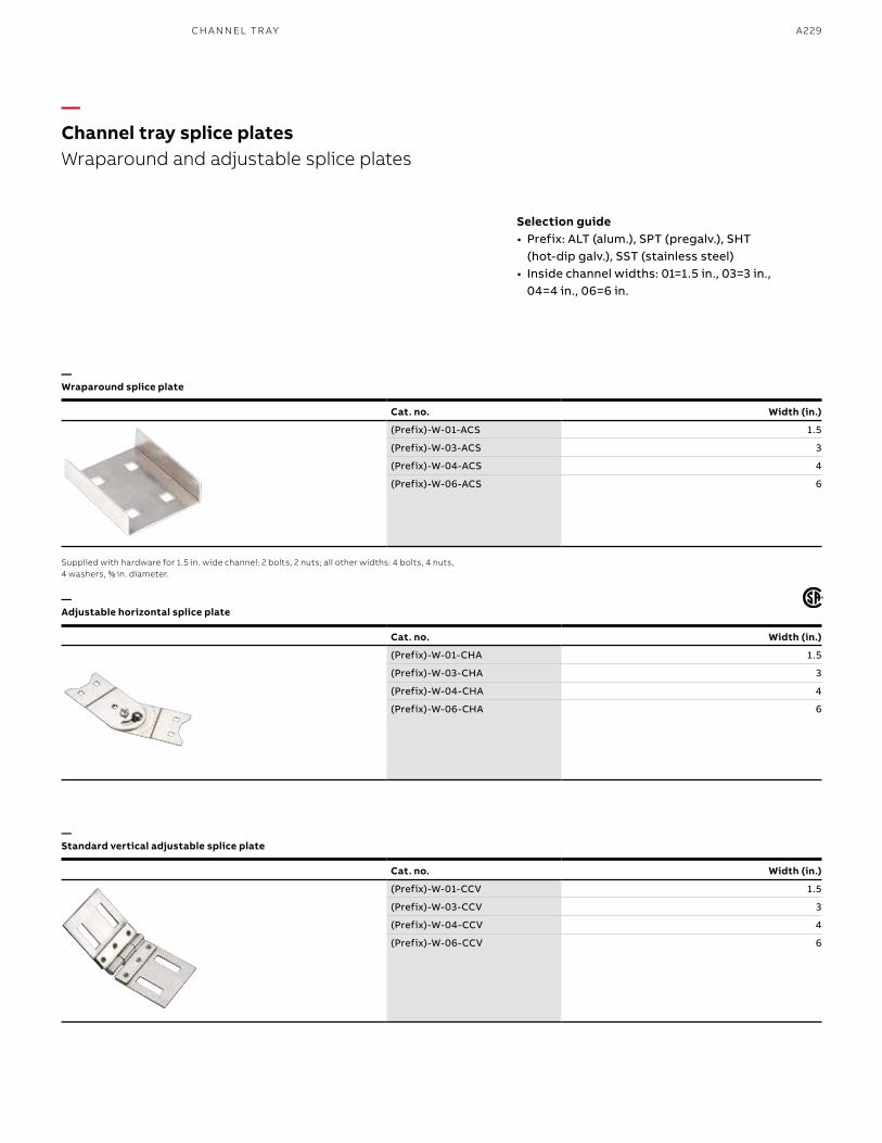
A229
Cat. no. Width (in.)
(Prefix)-W-01-ACS 1.5
(Prefix)-W-03-ACS 3
(Prefix)-W-04-ACS 4
(Prefix)-W-06-ACS 6
—Channel tray splice platesWraparound and adjustable splice plates
—Wraparound splice plate
—Adjustable horizontal splice plate
—Standard vertical adjustable splice plate
Selection guide• Prefix: ALT (alum.), SPT (pregalv.), SHT
(hot-dip galv.), SST (stainless steel)• Inside channel widths: 01=1.5 in., 03=3 in.,
04=4 in., 06=6 in.
Supplied with hardware for 1.5 in. wide channel: 2 bolts, 2 nuts; all other widths: 4 bolts, 4 nuts, 4 washers, 33⁄88 in. diameter.
Cat. no. Width (in.)
(Prefix)-W-01-CHA 1.5
(Prefix)-W-03-CHA 3
(Prefix)-W-04-CHA 4
(Prefix)-W-06-CHA 6
Cat. no. Width (in.)
(Prefix)-W-01-CCV 1.5
(Prefix)-W-03-CCV 3
(Prefix)-W-04-CCV 4
(Prefix)-W-06-CCV 6
CH A N N EL TR AY
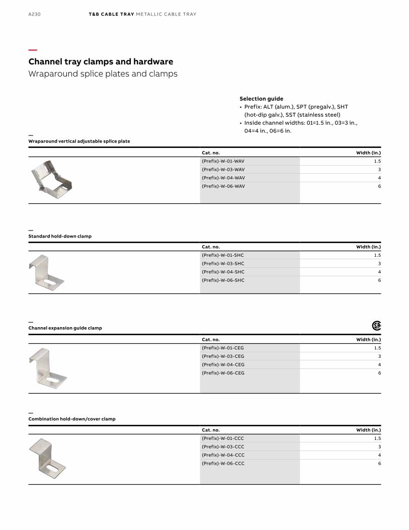
B1 copy starts here
B2 copy starts here
B3 copy starts here
A230 T& B C A B LE TR AY M E TA L L I C C A B L E TR AY
Cat. no. Width (in.)
(Prefix)-W-01-SHC 1.5
(Prefix)-W-03-SHC 3
(Prefix)-W-04-SHC 4
(Prefix)-W-06-SHC 6
—Channel tray clamps and hardwareWraparound splice plates and clamps
Selection guide• Prefix: ALT (alum.), SPT (pregalv.), SHT
(hot-dip galv.), SST (stainless steel)• Inside channel widths: 01=1.5 in., 03=3 in.,
04=4 in., 06=6 in.—Wraparound vertical adjustable splice plate
—Standard hold-down clamp
—Channel expansion guide clamp
—Combination hold-down/cover clamp
Cat. no. Width (in.)
(Prefix)-W-01-WAV 1.5
(Prefix)-W-03-WAV 3
(Prefix)-W-04-WAV 4
(Prefix)-W-06-WAV 6
Cat. no. Width (in.)
(Prefix)-W-01-CEG 1.5
(Prefix)-W-03-CEG 3
(Prefix)-W-04-CEG 4
(Prefix)-W-06-CEG 6
Cat. no. Width (in.)
(Prefix)-W-01-CCC 1.5
(Prefix)-W-03-CCC 3
(Prefix)-W-04-CCC 4
(Prefix)-W-06-CCC 6
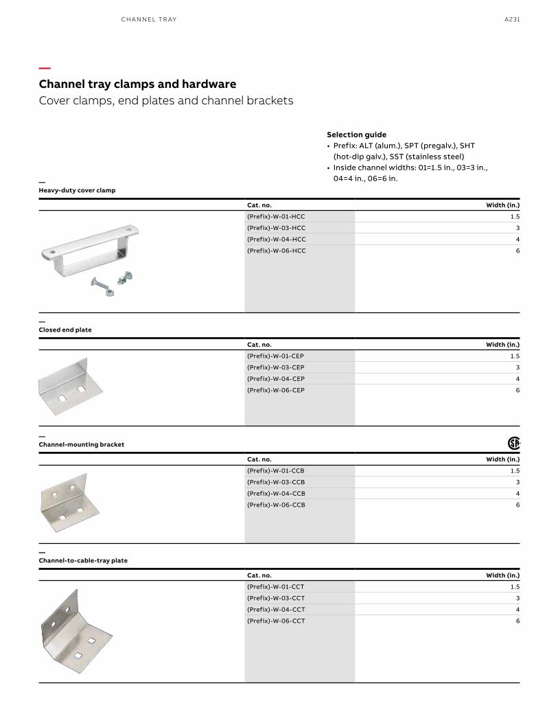
A231
—Channel tray clamps and hardwareCover clamps, end plates and channel brackets
—Heavy-duty cover clamp
—Closed end plate
—Channel-mounting bracket
—Channel-to-cable-tray plate
Cat. no. Width (in.)
(Prefix)-W-01-CEP 1.5
(Prefix)-W-03-CEP 3
(Prefix)-W-04-CEP 4
(Prefix)-W-06-CEP 6
Cat. no. Width (in.)
(Prefix)-W-01-HCC 1.5
(Prefix)-W-03-HCC 3
(Prefix)-W-04-HCC 4
(Prefix)-W-06-HCC 6
Cat. no. Width (in.)
(Prefix)-W-01-CCB 1.5
(Prefix)-W-03-CCB 3
(Prefix)-W-04-CCB 4
(Prefix)-W-06-CCB 6
Cat. no. Width (in.)
(Prefix)-W-01-CCT 1.5
(Prefix)-W-03-CCT 3
(Prefix)-W-04-CCT 4
(Prefix)-W-06-CCT 6
CH A N N EL TR AY
Selection guide• Prefix: ALT (alum.), SPT (pregalv.), SHT
(hot-dip galv.), SST (stainless steel)• Inside channel widths: 01=1.5 in., 03=3 in.,
04=4 in., 06=6 in.
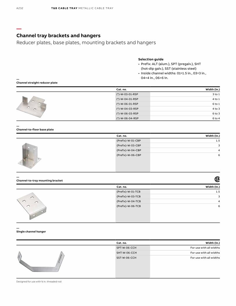
B1 copy starts here
B2 copy starts here
B3 copy starts here
A232 T& B C A B LE TR AY M E TA L L I C C A B L E TR AY
Cat. no. Width (in.)
(Prefix)-W-01-CBP 1.5
(Prefix)-W-03-CBP 3
(Prefix)-W-04-CBP 4
(Prefix)-W-06-CBP 6
—Channel tray brackets and hangersReducer plates, base plates, mounting brackets and hangers
Selection guide• Prefix: ALT (alum.), SPT (pregalv.), SHT
(hot-dip galv.), SST (stainless steel)• Inside channel widths: 01=1.5 in., 03=3 in.,
04=4 in., 06=6 in.—Channel straight reducer plate
—Channel-to-floor base plate
—Channel-to-tray mounting bracket
—Single channel hanger
Cat. no. Width (in.)
(*)-W-03-01-RSP 3 to 1
(*)-W-04-01-RSP 4 to 1
(*)-W-06-01-RSP 6 to 1
(*)-W-04-03-RSP 4 to 3
(*)-W-06-03-RSP 6 to 3
(*)-W-06-04-RSP 6 to 4
Cat. no. Width (in.)
(Prefix)-W-01-TCB 1.5
(Prefix)-W-03-TCB 3
(Prefix)-W-04-TCB 4
(Prefix)-W-06-TCB 6
Cat. no. Width (in.)
SPT-W-06-CCH For use with all widths
SHT-W-06-CCH For use with all widths
SST-W-06-CCH For use with all widths
Designed for use with 11⁄22 in. threaded rod
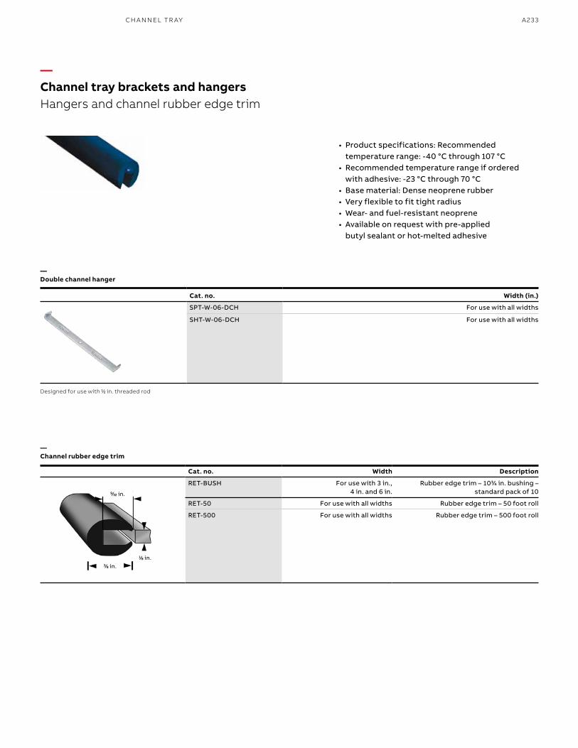
A233
—Channel tray brackets and hangersHangers and channel rubber edge trim
• Product specifications: Recommended temperature range: -40 °C through 107 °C
• Recommended temperature range if ordered with adhesive: -23 °C through 70 °C
• Base material: Dense neoprene rubber• Very flexible to fit tight radius• Wear- and fuel-resistant neoprene• Available on request with pre-applied
butyl sealant or hot-melted adhesive
—Channel rubber edge trim
11⁄88 in.33⁄88 in.
Cat. no. Width Description
RET-BUSH For use with 3 in., 4 in. and 6 in.
Rubber edge trim – 1033⁄44 in. bushing – standard pack of 10
RET-50 For use with all widths Rubber edge trim – 50 foot roll
RET-500 For use with all widths Rubber edge trim – 500 foot roll
99⁄3232 in.
—Double channel hanger
Cat. no. Width (in.)
SPT-W-06-DCH For use with all widths
SHT-W-06-DCH For use with all widths
Designed for use with 11⁄22 in. threaded rod
CH A N N EL TR AY
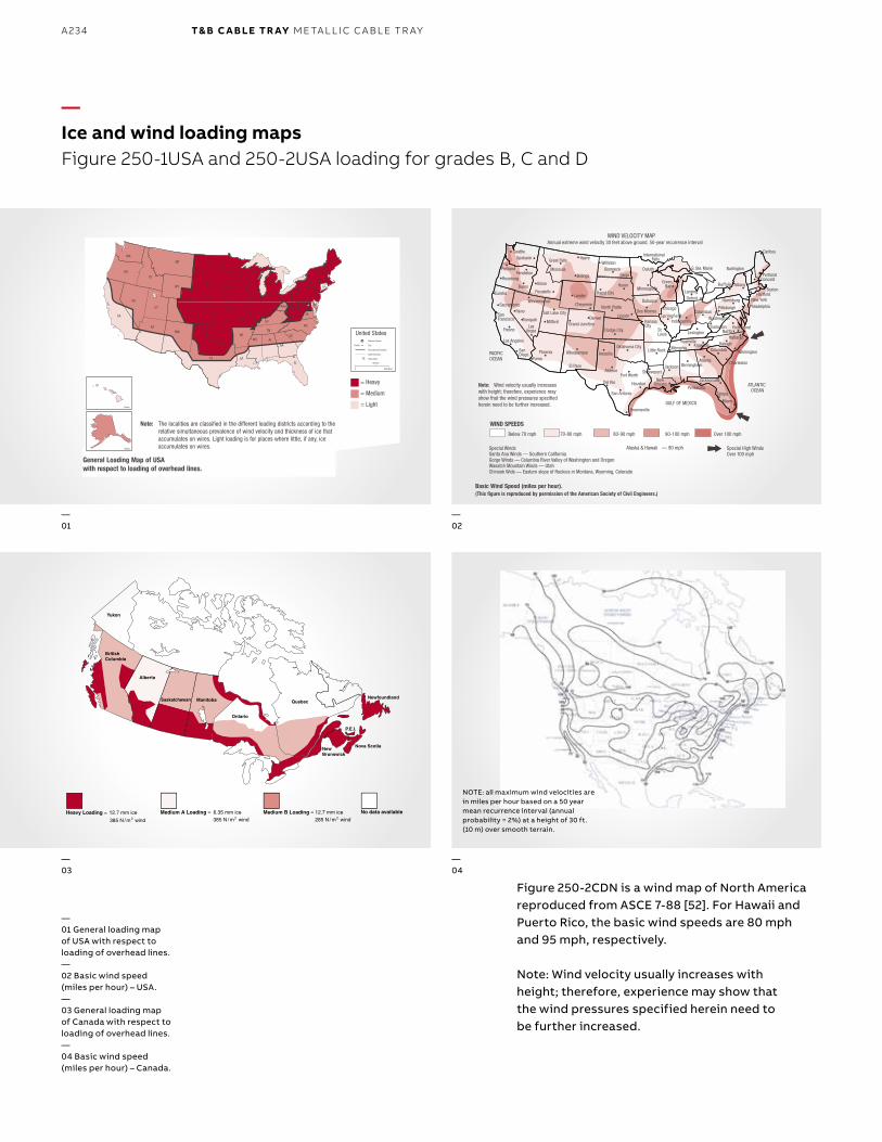
B1 copy starts here
B2 copy starts here
B3 copy starts here
A234 T& B C A B LE TR AY M E TA L L I C C A B L E TR AY
—Ice and wind loading mapsFigure 250-1USA and 250-2USA loading for grades B, C and D
General Loading Map of USAwith respect to loading of overhead lines.
Note: Wind velocity usually increaseswith height; therefore, experience mayshow that the wind pressures specifiedherein need to be further increased.
DE
FL
NM
DEMD
TX
OK
KS
NE
SD
NDMT
WY
COUT
ID
AZ
NV
WA
CA
OR
KY
ME
NY
PA
MI
VTNH
MA RICT
VAWV
OH
IN
IL
NCTN
SCALMS
AR
LA
MO
IA
MN
WI
NJ
GA
Washington DC
Hawaii
Alaska
TX
National Capital
City
International Boundary
State Boundary
State Name
0
United States
Seattle
400 Miles
400 km
= Heavy
= Medium
= Light
FFiigg.. 225500--11UU SSAA
Note: The localities are classified in the different loading districts according to therelative simultaneous prevalence of wind velocity and thickness of ice thataccumulates on wires. Light loading is for places where little, if any, iceaccumulates on wires.
GULF OF MEXICO
ATLANTIC OCEAN
PACIFICOCEAN
Dodge City
SeattleSpokane
PortlandPendleton
Roseburg
BurnsBoise
Pocatello
Missoula
Great Falls
Billings
Lander
Cheyenne
Eureka
Winnemucoa
Yuma
SanDiego
Los Angeles
Las VegasFresno
TonopahSan Francisco
SacramentoReno
Phoenix
Milford
Salt Lake City
Grand JunctionDenver
Albuquerque
El Paso
Amarillo
Abilene
Del Rio
Oklahoma City
Fort Worth
Houston
San Antonio
Little Rock
Shreveport
New Orleans
Jackson
MemphisNashville
KnoxvilleColumbia
AtlantaBirmingham
Pensacola
Jacksonville
Tampa
Miami
Brownsville
CharlestonLexington
Burlington
Albany
HartfordHarrisburg
Pittsburgh
Washington
NorforkRichmond
Hattaras
InternationalFalls
Raleigh
Wilmington
Chicago
LansingDetroit
S. Ste. Marie
Columbus
Caribou
PortlandConcord
Boston
New York
Philadelphia
Green Bay
Dubuque
Des Moines
KansasCity
St. Louis
Indianapolis
HavreWilliston
BismarckFargo
Rapid City
Huron
Duluth
Minneapolis
North Platte
Lincoln
Charleston
WIND SPEEDS
Below 70 mph 70-80 mph 80-90 mph 90-100 mph Over 100 mph
Special High WindsOver 100 mph
Alaska & Hawaii — 90 mphSpecial WindsSanta Ana Winds — Southern CaliforniaGorge Winds — Columbia River Valley of Washington and OregonWasatch Mountain Winds — UtahChinook Wids — Eastern slope of Rockies in Montana, Wyoming, Colorado
WIND VELOCITY MAPAnnual extreme wind velocity 30 feet above ground, 50-year recurrence interval
Basic Wind Speed (miles per hour).(This figure is reproduced by permission of the American Society of Civil Engineers.)
FFiigg.. 225500--22UU SSAA
NOTE: all maximum wind velocities are in miles per hour based on a 50 year mean recurrence interval (annual probability = 2%) at a height of 30 ft. (10 m) over smooth terrain.
Figure 250-2CDN is a wind map of North America reproduced from ASCE 7-88 [52]. For Hawaii and Puerto Rico, the basic wind speeds are 80 mph and 95 mph, respectively.
Note: Wind velocity usually increases with height; therefore, experience may show that the wind pressures specified herein need to be further increased.
—01 General loading map of USA with respect to loading of overhead lines.—02 Basic wind speed (miles per hour) – USA.—03 General loading map of Canada with respect to loading of overhead lines.—04 Basic wind speed (miles per hour) – Canada.
—01
—03
—02
—04
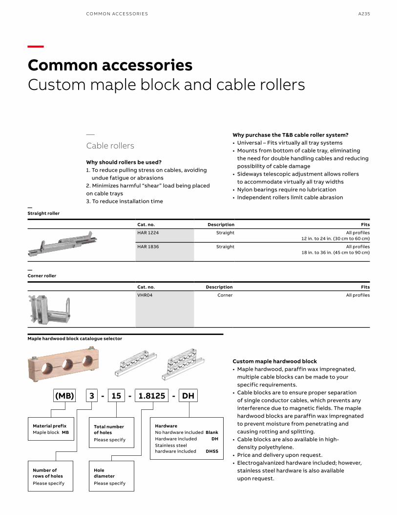
A235CO M M O N ACCE SSO R I E S
Cat. no. Description Fits
VHR04 Corner All profiles
—Common accessoriesCustom maple block and cable rollers
—Cable rollers
Why should rollers be used?1. To reduce pulling stress on cables, avoiding
undue fatigue or abrasions2. Minimizes harmful “shear” load being placed on cable trays3. To reduce installation time
Why purchase the T&B cable roller system?• Universal – Fits virtually all tray systems• Mounts from bottom of cable tray, eliminating
the need for double handling cables and reducing possibility of cable damage
• Sideways telescopic adjustment allows rollers to accommodate virtually all tray widths
• Nylon bearings require no lubrication• Independent rollers limit cable abrasion
Custom maple hardwood block• Maple hardwood, paraffin wax impregnated,
multiple cable blocks can be made to your specific requirements.
• Cable blocks are to ensure proper separation of single conductor cables, which prevents any interference due to magnetic fields. The maple hardwood blocks are paraffin wax impregnated to prevent moisture from penetrating and causing rotting and splitting.
• Cable blocks are also available in high- density polyethylene.
• Price and delivery upon request.• Electrogalvanized hardware included; however,
stainless steel hardware is also available upon request.
—Straight roller
—Corner roller
Cat. no. Description Fits
HAR 1224 Straight All profiles 12 in. to 24 in. (30 cm to 60 cm)
HAR 1836 Straight All profiles 18 in. to 36 in. (45 cm to 90 cm)
Maple hardwood block catalogue selector
Material prefixMaple block MB
HardwareNo hardware included BlankHardware included DHStainless steel hardware included DHSS
Number of rows of holesPlease specify
Total number of holesPlease specify
Hole diameterPlease specify
(MB) 3 - 15 - 1.8125 - DH
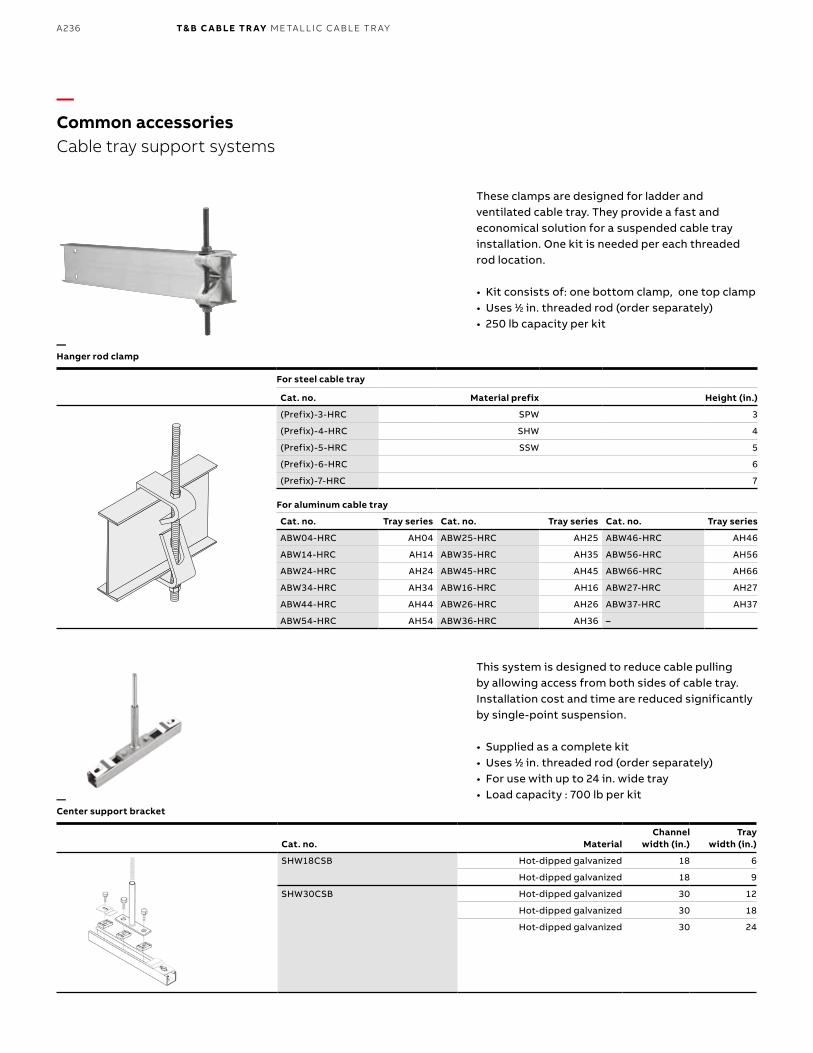
B1 copy starts here
B2 copy starts here
B3 copy starts here
A236 T& B C A B LE TR AY M E TA L L I C C A B L E TR AY
—Common accessoriesCable tray support systems
These clamps are designed for ladder and ventilated cable tray. They provide a fast and economical solution for a suspended cable tray installation. One kit is needed per each threaded rod location.
• Kit consists of: one bottom clamp, one top clamp• Uses 11⁄22 in. threaded rod (order separately)• 250 lb capacity per kit
This system is designed to reduce cable pulling by allowing access from both sides of cable tray. Installation cost and time are reduced significantly by single-point suspension.
• Supplied as a complete kit• Uses 11⁄22 in. threaded rod (order separately)• For use with up to 24 in. wide tray• Load capacity : 700 lb per kit
—Hanger rod clamp
—Center support bracket
For steel cable tray
Cat. no. Material prefix Height (in.)
(Prefix)-3-HRC SPW 3
(Prefix)-4-HRC SHW 4
(Prefix)-5-HRC SSW 5
(Prefix)-6-HRC 6
(Prefix)-7-HRC 7
For aluminum cable tray
Cat. no. Tray series Cat. no. Tray series Cat. no. Tray series
ABW04-HRC AH04 ABW25-HRC AH25 ABW46-HRC AH46
ABW14-HRC AH14 ABW35-HRC AH35 ABW56-HRC AH56
ABW24-HRC AH24 ABW45-HRC AH45 ABW66-HRC AH66
ABW34-HRC AH34 ABW16-HRC AH16 ABW27-HRC AH27
ABW44-HRC AH44 ABW26-HRC AH26 ABW37-HRC AH37
ABW54-HRC AH54 ABW36-HRC AH36 –
Cat. no. MaterialChannel
width (in.)Tray
width (in.)
SHW18CSB Hot-dipped galvanized 18 6
Hot-dipped galvanized 18 9
SHW30CSB Hot-dipped galvanized 30 12
Hot-dipped galvanized 30 18
Hot-dipped galvanized 30 24
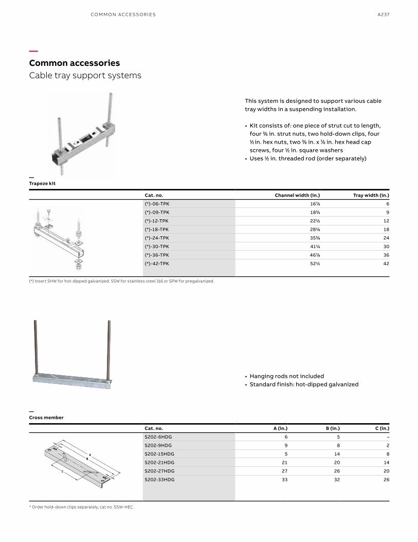
A237
—Common accessoriesCable tray support systems
This system is designed to support various cable tray widths in a suspending installation.
• Kit consists of: one piece of strut cut to length, four 33⁄88 in. strut nuts, two hold-down clips, four 11⁄2 2 in. hex nuts, two 33⁄88 in. x 77⁄88 in. hex head cap screws, four 11⁄22 in. square washers
• Uses 11⁄22 in. threaded rod (order separately)
• Hanging rods not included• Standard finish: hot-dipped galvanized
—Trapeze kit
—Cross member
Cat. no. Channel width (in.) Tray width (in.)
(*)-06-TPK 1677⁄88 6
(*)-09-TPK 1833⁄44 9
(*)-12-TPK 2211⁄22 12
(*)-18-TPK 2811⁄88 18
(*)-24-TPK 3555⁄88 24
(*)-30-TPK 4111⁄44 30
(*)-36-TPK 4677⁄88 36
(*)-42-TPK 5211⁄22 42
(*) Insert SHW for hot-dipped galvanized. SSW for stainless steel 316 or SPW for pregalvanized.
* Order hold-down clips separately, cat no. SSW-HEC.
Cat. no. A (in.) B (in.) C (in.)
S202-6HDG 6 5 –
S202-9HDG 9 8 2
S202-15HDG 5 14 8
S202-21HDG 21 20 14
S202-27HDG 27 26 20
S202-33HDG 33 32 26
CO M M O N ACCE SSO R I E S
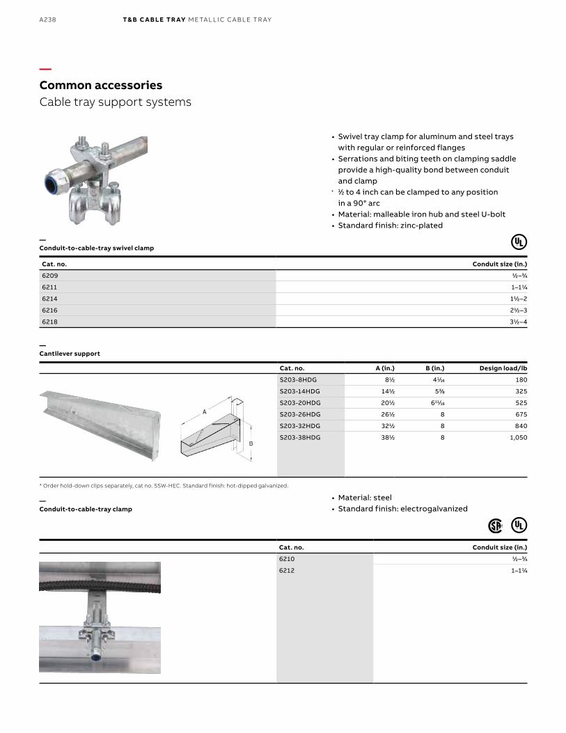
B1 copy starts here
B2 copy starts here
B3 copy starts here
A238 T& B C A B LE TR AY M E TA L L I C C A B L E TR AY
Cat. no. Conduit size (in.)
6210 11⁄22–33⁄44
6212 1–111⁄44
—Common accessoriesCable tray support systems
• Swivel tray clamp for aluminum and steel trays with regular or reinforced flanges
• Serrations and biting teeth on clamping saddle provide a high-quality bond between conduit and clamp
• • 11⁄22 to 4 inch can be clamped to any position in a 90° arc
• Material: malleable iron hub and steel U-bolt• Standard finish: zinc-plated
• Material: steel• Standard finish: electrogalvanized
—Conduit-to-cable-tray swivel clamp
—Cantilever support
—Conduit-to-cable-tray clamp
Cat. no. Conduit size (in.)
6209 11⁄22–33⁄44
6211 1–111⁄44
6214 111⁄22–2
6216 211⁄22–3
6218 311⁄22–4
* Order hold-down clips separately, cat no. SSW-HEC. Standard finish: hot-dipped galvanized.
Cat. no. A (in.) B (in.) Design load/lb
S203-8HDG 811⁄22 411⁄1616 180
S203-14HDG 1411⁄22 533⁄88 325
S203-20HDG 2011⁄22 61111⁄1616 525
S203-26HDG 2611⁄22 8 675
S203-32HDG 3211⁄22 8 840
S203-38HDG 3811⁄22 8 1,050
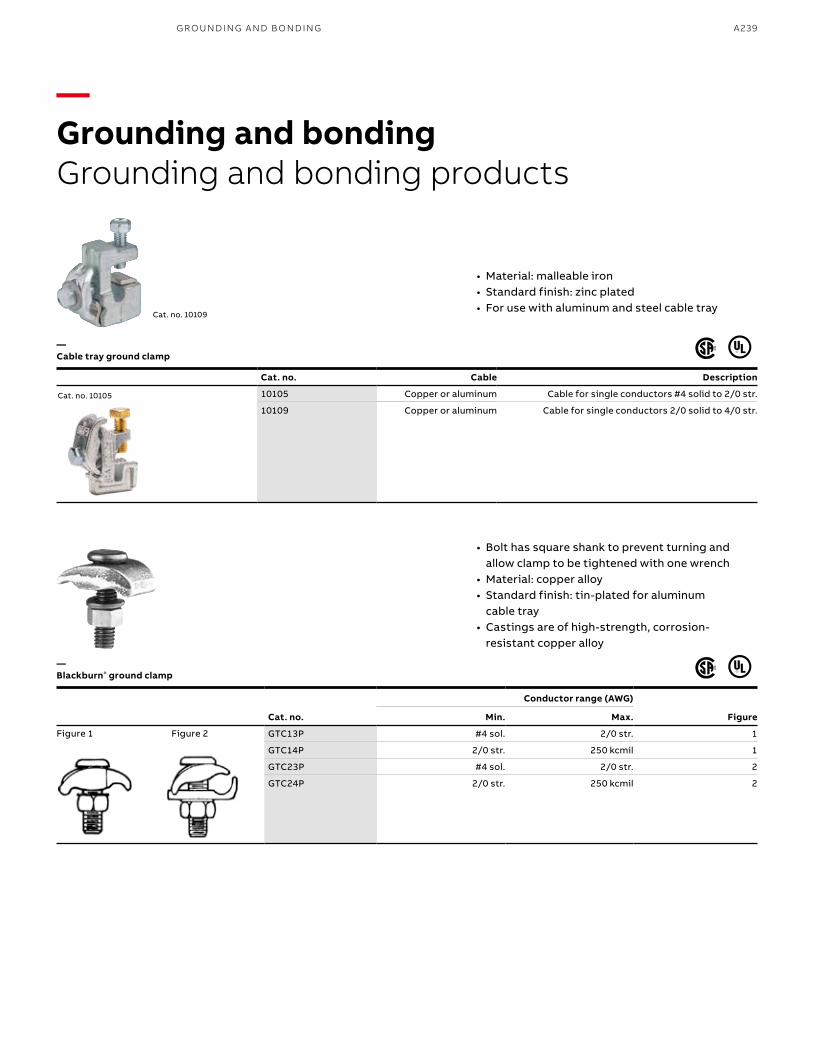
A239
Cat. no. Cable Description
10105 Copper or aluminum Cable for single conductors #4 solid to 2/0 str.
10109 Copper or aluminum Cable for single conductors 2/0 solid to 4/0 str.
G R O U N D I N G A N D B O N D I N G
• Material: malleable iron• Standard finish: zinc plated• For use with aluminum and steel cable tray
• Bolt has square shank to prevent turning and allow clamp to be tightened with one wrench
• Material: copper alloy• Standard finish: tin-plated for aluminum
cable tray• Castings are of high-strength, corrosion-
resistant copper alloy
Cat. no.
Conductor range (AWG)
FigureMin. Max.
GTC13P #4 sol. 2/0 str. 1
GTC14P 2/0 str. 250 kcmil 1
GTC23P #4 sol. 2/0 str. 2
GTC24P 2/0 str. 250 kcmil 2
Cat. no. 10109
Cat. no. 10105
Figure 1 Figure 2
—Grounding and bondingGrounding and bonding products
—Cable tray ground clamp
—Blackburn® ground clamp
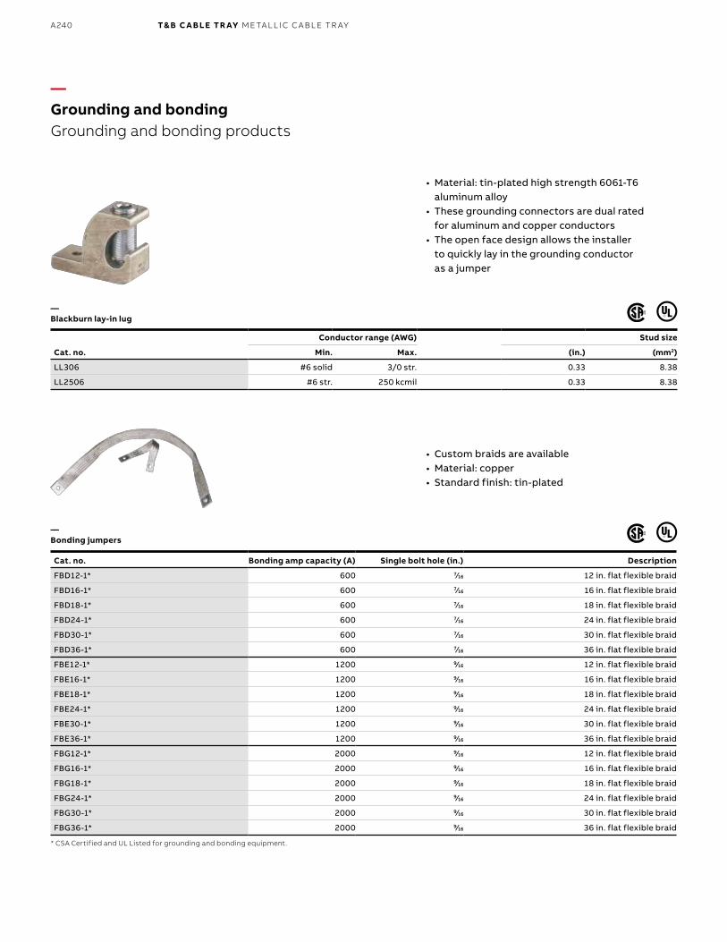
B1 copy starts here
B2 copy starts here
B3 copy starts here
A240 T& B C A B LE TR AY M E TA L L I C C A B L E TR AY
Cat. no. Bonding amp capacity (A) Single bolt hole (in.) Description
FBD12-1* 600 77⁄1616 12 in. flat flexible braid
FBD16-1* 600 77⁄1616 16 in. flat flexible braid
FBD18-1* 600 77⁄1616 18 in. flat flexible braid
FBD24-1* 600 77⁄1616 24 in. flat flexible braid
FBD30-1* 600 77⁄1616 30 in. flat flexible braid
FBD36-1* 600 77⁄1616 36 in. flat flexible braid
FBE12-1* 1200 99⁄1616 12 in. flat flexible braid
FBE16-1* 1200 99⁄1616 16 in. flat flexible braid
FBE18-1* 1200 99⁄1616 18 in. flat flexible braid
FBE24-1* 1200 99⁄1616 24 in. flat flexible braid
FBE30-1* 1200 99⁄1616 30 in. flat flexible braid
FBE36-1* 1200 99⁄1616 36 in. flat flexible braid
FBG12-1* 2000 99⁄1616 12 in. flat flexible braid
FBG16-1* 2000 99⁄1616 16 in. flat flexible braid
FBG18-1* 2000 99⁄1616 18 in. flat flexible braid
FBG24-1* 2000 99⁄1616 24 in. flat flexible braid
FBG30-1* 2000 99⁄1616 30 in. flat flexible braid
FBG36-1* 2000 99⁄1616 36 in. flat flexible braid
—Grounding and bondingGrounding and bonding products
• Custom braids are available• Material: copper • Standard finish: tin-plated
• Material: tin-plated high strength 6061-T6 aluminum alloy
• These grounding connectors are dual rated for aluminum and copper conductors
• The open face design allows the installer to quickly lay in the grounding conductor as a jumper
—Bonding jumpers
—Blackburn lay-in lug
Cat. no.
Conductor range (AWG) Stud size
Min. Max. (in.) (mm2)
LL306 #6 solid 3/0 str. 0.33 8.38
LL2506 #6 str. 250 kcmil 0.33 8.38
* CSA Certified and UL Listed for grounding and bonding equipment.
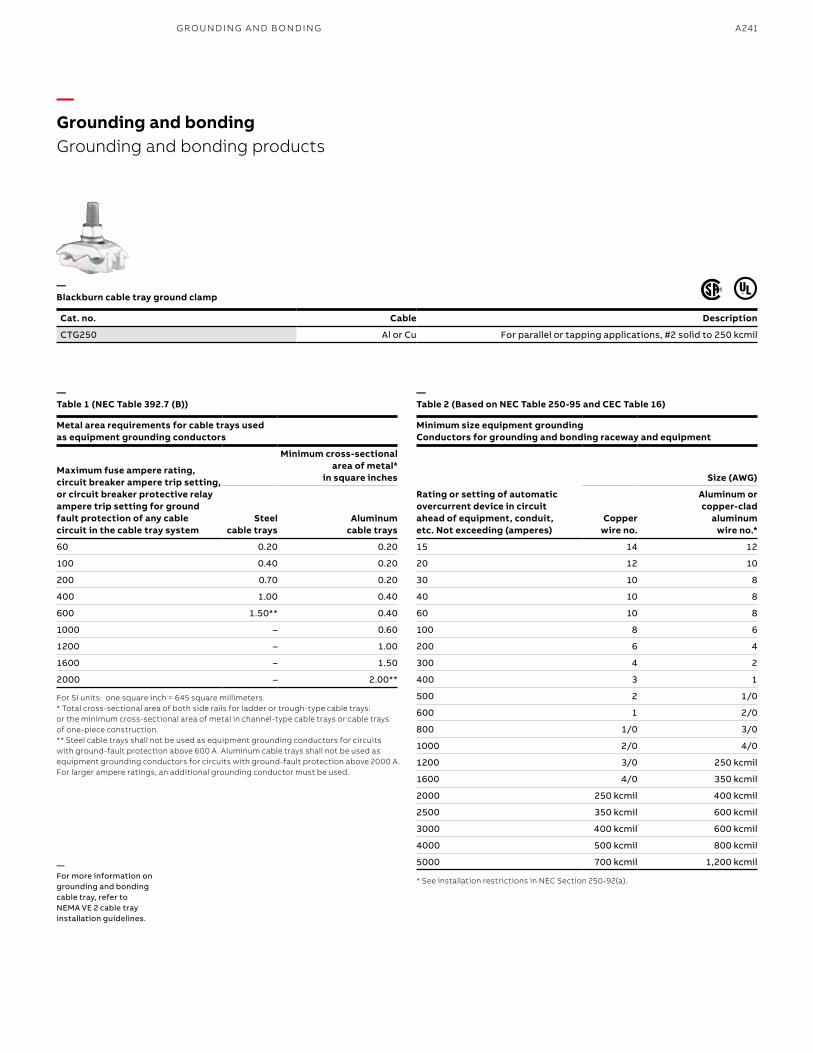
A241
—Grounding and bondingGrounding and bonding products
—Blackburn cable tray ground clamp
—Table 1 (NEC Table 392.7 (B))
—Table 2 (Based on NEC Table 250-95 and CEC Table 16)
Cat. no. Cable Description
CTG250 Al or Cu For parallel or tapping applications, #2 solid to 250 kcmil
For SI units: one square inch = 645 square millimeters.* Total cross-sectional area of both side rails for ladder or trough-type cable trays: or the minimum cross-sectional area of metal in channel-type cable trays or cable trays of one-piece construction.** Steel cable trays shall not be used as equipment grounding conductors for circuits with ground-fault protection above 600 A. Aluminum cable trays shall not be used as equipment grounding conductors for circuits with ground-fault protection above 2000 A.For larger ampere ratings, an additional grounding conductor must be used.
* See installation restrictions in NEC Section 250-92(a).
Metal area requirements for cable trays used as equipment grounding conductors
Minimum size equipment grounding Conductors for grounding and bonding raceway and equipment
Maximum fuse ampere rating, circuit breaker ampere trip setting, or circuit breaker protective relay ampere trip setting for ground fault protection of any cable circuit in the cable tray system
Minimum cross-sectional area of metal*
in square inches
Rating or setting of automatic overcurrent device in circuit ahead of equipment, conduit, etc. Not exceeding (amperes)
Size (AWG)
Steelcable trays
Aluminumcable trays
Copper wire no.
Aluminum or copper-clad
aluminum wire no.*
60 0.20 0.20 15 14 12
100 0.40 0.20 20 12 10
200 0.70 0.20 30 10 8
400 1.00 0.40 40 10 8
600 1.50** 0.40 60 10 8
1000 – 0.60 100 8 6
1200 – 1.00 200 6 4
1600 – 1.50 300 4 2
2000 – 2.00** 400 3 1
500 2 1/0
600 1 2/0
800 1/0 3/0
1000 2/0 4/0
1200 3/0 250 kcmil
1600 4/0 350 kcmil
2000 250 kcmil 400 kcmil
2500 350 kcmil 600 kcmil
3000 400 kcmil 600 kcmil
4000 500 kcmil 800 kcmil
5000 700 kcmil 1,200 kcmil—For more information on grounding and bonding cable tray, refer to NEMA VE 2 cable tray installation guidelines.
G R O U N D I N G A N D B O N D I N G
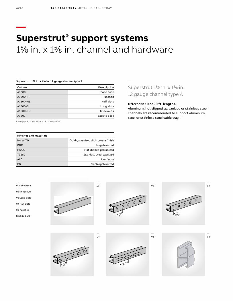
B1 copy starts here
B2 copy starts here
B3 copy starts here
A242 T& B C A B LE TR AY M E TA L L I C C A B L E TR AY
—Superstrut® support systems155⁄88 in. x 155⁄88 in. channel and hardware
—Superstrut 155⁄88 in. x 155⁄88 in. 12 gauge channel type A
Offered in 10 or 20 ft. lengths.Aluminum, hot-dipped galvanized or stainless steel channels are recommended to support aluminum, steel or stainless steel cable tray.
17/8"
2" 4"
6"
Finishes and materials
No suffix Gold galvanized dichromate finish
PGC Pregalvanized
HDGC Hot-dipped galvanized
T316L Stainless steel type 316
ALC Aluminum
EG Electrogalvanized
Example: A1200HS10ALC, A120020HDGC
Cat. no. Description
A1200 Solid base
A1200-P Punched
A1200-HS Half slots
A1200-S Long slots
A1200-KO Knockouts
A1202 Back to back
—Superstrut 155⁄88 in. x 155⁄88 in. 12 gauge channel type A
—01 Solid base—02 Knockouts—03 Long slots—04 Half slots—05 Punched—Back to back
—01
—04
—03
—06
—02
—05
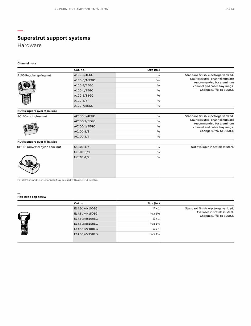
A243SU PER S TR U T SU PP O RT S Y S TEMS
Cat. no. Size (in.)
A100-1/4EGC 11⁄44 Standard finish: electrogalvanized.Stainless steel channel nuts are
recommended for aluminum channel and cable tray rungs.
Change suffix to SS6(C).
A100-5/16EGC 55⁄1616
A100-3/8EGC 33⁄88
A100-1/2EGC 11⁄22
A100-5/8EGC 55⁄88
A100-3/4 33⁄44
A100-7/8EGC 77⁄88
Nut is square over 11⁄22 in. size
AC100-1/4EGC 11⁄44 Standard finish: electrogalvanized.Stainless steel channel nuts are
recommended for aluminum channel and cable tray rungs.
Change suffix to SS6(C).
AC100-3/8EGC 33⁄88
AC100-1/2EGC 11⁄22
AC100-5/8 55⁄88
AC100-3/4 33⁄44
Nut is square over 11⁄22 in. size
UC100-1/4 11⁄44 Not available in stainless steel.
UC100-3/8 33⁄88
UC100-1/2 11⁄22
A100 Regular spring nut
AC100 springless nut
UC100 Universal nylon cone nut
For all 155⁄88 in. and 111⁄22 in. channels; May be used with ALL strut depths.
—Channel nuts
—Hex head cap screw
—Superstrut support systemsHardware
Cat. no. Size (in.)
E142-1/4x100EG 11⁄44 x 1 Standard finish: electrogalvanized.Available in stainless steel.
Change suffix to SS6(C).E142-1/4x150EG 11⁄44 x 111⁄22
E142-3/8x100EG 33⁄88 x 1
E142-3/8x150EG 33⁄88 x 111⁄22
E142-1/2x100EG 11⁄22 x 1
E142-1/2x150EG 11⁄22 x 111⁄22
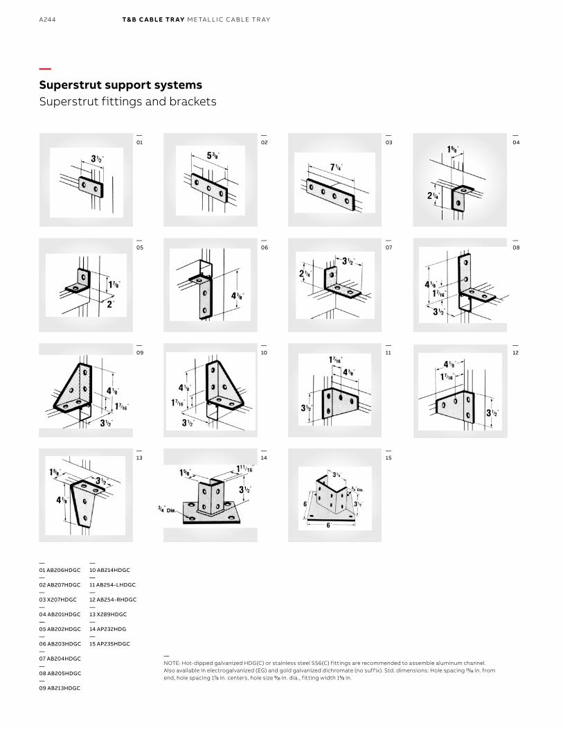
B1 copy starts here
B2 copy starts here
B3 copy starts here
A244 T& B C A B LE TR AY M E TA L L I C C A B L E TR AY
—Superstrut support systemsSuperstrut fittings and brackets
—NOTE: Hot-dipped galvanized HDG(C) or stainless steel SS6(C) fittings are recommended to assemble aluminum channel. Also available in electrogalvanized (EG) and gold galvanized dichromate (no suffix). Std. dimensions: Hole spacing 1313⁄1616 in. from end, hole spacing 177⁄88 in. centers, hole size 99⁄1616 in. dia., fitting width 155⁄88 in.
—01 AB206HDGC—02 AB207HDGC—03 X207HDGC—04 AB201HDGC—05 AB202HDGC—06 AB203HDGC—07 AB204HDGC—08 AB205HDGC—09 AB213HDGC
—10 AB214HDGC—11 AB254-LHDGC—12 AB254-RHDGC—13 X289HDGC—14 AP232HDG—15 AP235HDGC
—01
—05
—09
—13
—02
—06
—10
—14
—03
—07
—11
—15
—04
—08
—12
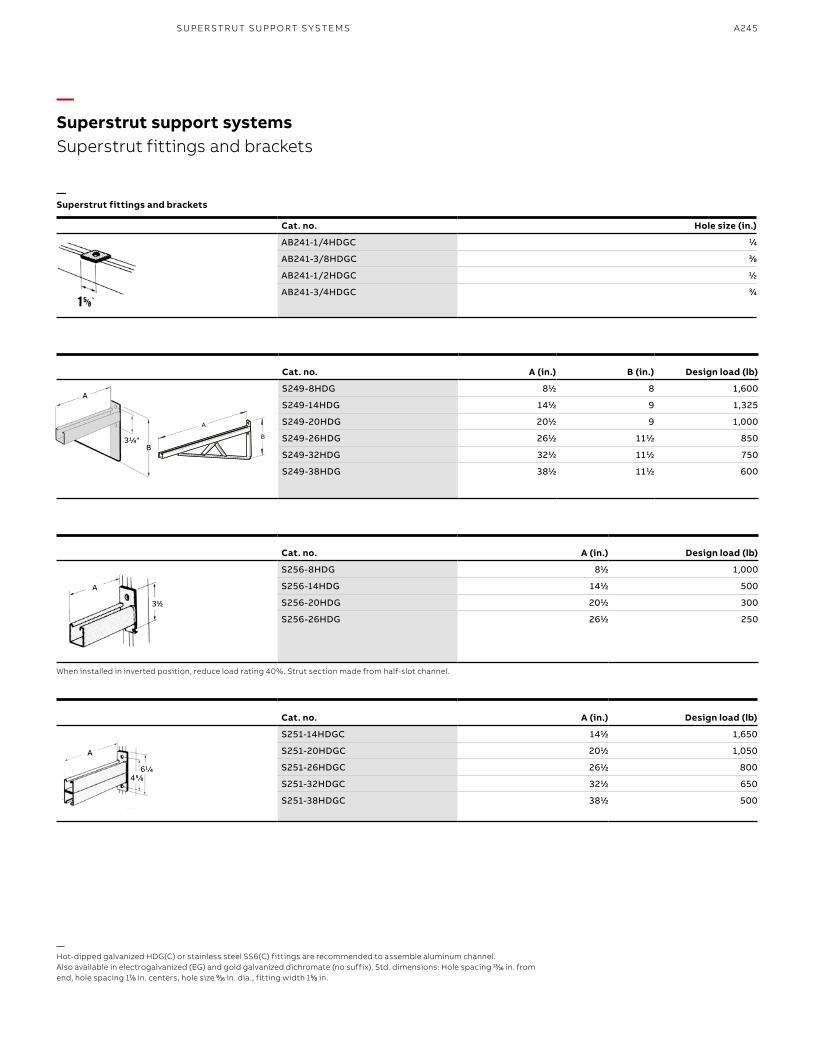
A245
—Superstrut support systemsSuperstrut fittings and brackets
—Hot-dipped galvanized HDG(C) or stainless steel SS6(C) fittings are recommended to assemble aluminum channel. Also available in electrogalvanized (EG) and gold galvanized dichromate (no suffix). Std. dimensions: Hole spacing 1313⁄1616 in. from end, hole spacing 177⁄88 in. centers, hole size 99⁄1616 in. dia., fitting width 155⁄88 in.
When installed in inverted position, reduce load rating 40%. Strut section made from half-slot channel.
Cat. no. A (in.) B (in.) Design load (lb)
S249-8HDG 811⁄22 8 1,600
S249-14HDG 1411⁄22 9 1,325
S249-20HDG 2011⁄22 9 1,000
S249-26HDG 2611⁄22 1111⁄22 850
S249-32HDG 3211⁄22 1111⁄22 750
S249-38HDG 3811⁄22 1111⁄22 600
Cat. no. A (in.) Design load (lb)
S256-8HDG 811⁄22 1,000
S256-14HDG 1411⁄22 500
S256-20HDG 2011⁄22 300
S256-26HDG 2611⁄22 250
Cat. no. A (in.) Design load (lb)
S251-14HDGC 1411⁄22 1,650
S251-20HDGC 2011⁄22 1,050
S251-26HDGC 2611⁄22 800
S251-32HDGC 3211⁄22 650
S251-38HDGC 3811⁄22 500
Cat. no. Hole size (in.)
AB241-1/4HDGC 11⁄44
AB241-3/8HDGC 33⁄88
AB241-1/2HDGC 11⁄22
AB241-3/4HDGC 33⁄44
—Superstrut fittings and brackets
A
311⁄22
A
455 ⁄88611 ⁄44
SU PER S TR U T SU PP O RT S Y S TEMS
A
B
A
B31/4"
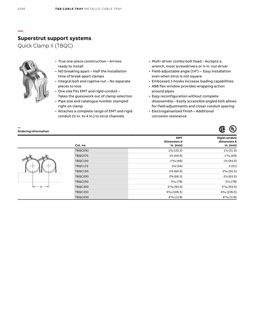
B1 copy starts here
B2 copy starts here
B3 copy starts here
A246 T& B C A B LE TR AY M E TA L L I C C A B L E TR AY
Cat. no.
EMTDimension A
in. (mm)
Rigid conduitdimension A
in. (mm)
TBQC050 155⁄1616 (33.5) 111⁄44 (31.5)
TBQC075 133⁄44 (44.5) 11111⁄1616 (43)
TBQC100 11313⁄1616 (46) 133⁄44 (44.5)
TBQC125 211⁄88 (54) 2 (51)
TBQC150 233⁄88 (60.5) 233⁄1616 (55.5)
TBQC200 255⁄88 (66.5) 211⁄22 (63.5)
TBQC250 311⁄1616 (78) 311⁄1616 (78)
TBQC300 31111⁄1616 (93.5) 31111⁄1616 (93.5)
TBQC350 433⁄1616 (106.5) 433⁄1616 (106.5)
TBQC400 41111⁄1616 (119) 41111⁄1616 (119)
• True one-piece construction – Arrives ready to install
• NO breaking apart – Half the installation time of break apart clamps
• Integral bolt and captive nut – No separate pieces to lose
• One size fits EMT and rigid conduit – Takes the guesswork out of clamp selection
• Pipe size and catalogue number stamped right on clamp
• Attaches a complete range of EMT and rigid conduit (11⁄22 in. to 4 in.) to strut channels
—Superstrut support systemsQuick Clamp II (TBQC)
• Multi-driver combo bolt head – Accepts a wrench, most screwdrivers or 11⁄22 in. nut driver
• Field-adjustable angle (±4°) – Easy installation even when strut is not square
• Embossed J-hooks increase loading capabilities• ABB flex window provides wrapping action
around pipes• Easy reconfiguration without complete
disassembly – Easily accessible angled bolt allows for field adjustments and closer conduit spacing
• Electrogalvanized finish – Additional corrosion resistance
—Ordering information
A
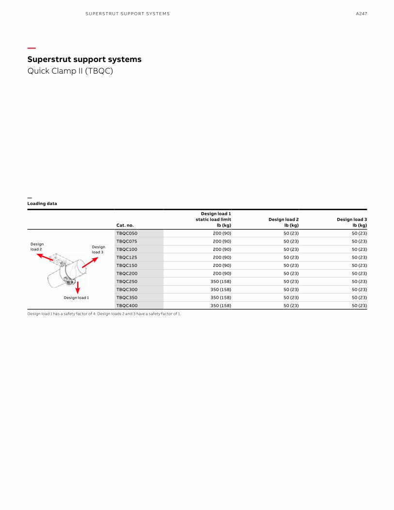
A247
—Superstrut support systemsQuick Clamp II (TBQC)
—Loading data
Cat. no.
Design load 1 static load limit
lb (kg)Design load 2
lb (kg)Design load 3
lb (kg)
TBQC050 200 (90) 50 (23) 50 (23)
TBQC075 200 (90) 50 (23) 50 (23)
TBQC100 200 (90) 50 (23) 50 (23)
TBQC125 200 (90) 50 (23) 50 (23)
TBQC150 200 (90) 50 (23) 50 (23)
TBQC200 200 (90) 50 (23) 50 (23)
TBQC250 350 (158) 50 (23) 50 (23)
TBQC300 350 (158) 50 (23) 50 (23)
TBQC350 350 (158) 50 (23) 50 (23)
TBQC400 350 (158) 50 (23) 50 (23)
Design load 1 has a safety factor of 4. Design loads 2 and 3 have a safety factor of 1.
Design load 3
Design load 1
Design load 2
SU PER S TR U T SU PP O RT S Y S TEMS
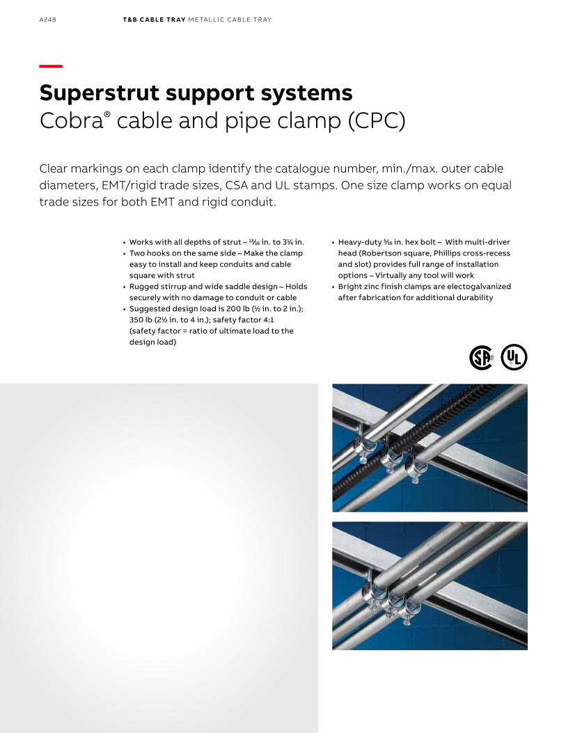
B1 copy starts here
B2 copy starts here
B3 copy starts here
A248 T& B C A B LE TR AY M E TA L L I C C A B L E TR AY
—Superstrut support systemsCobra® cable and pipe clamp (CPC)
Clear markings on each clamp identify the catalogue number, min./max. outer cable diameters, EMT/rigid trade sizes, CSA and UL stamps. One size clamp works on equal trade sizes for both EMT and rigid conduit.
• Works with all depths of strut – 1313⁄1616 in. to 311⁄44 in.• Two hooks on the same side – Make the clamp
easy to install and keep conduits and cable square with strut
• Rugged stirrup and wide saddle design – Holds securely with no damage to conduit or cable
• Suggested design load is 200 lb (11⁄22 in. to 2 in.); 350 lb (211⁄22 in. to 4 in.); safety factor 4:1 (safety factor = ratio of ultimate load to the design load)
• Heavy-duty 55⁄1616 in. hex bolt – With multi-driver head (Robertson square, Phillips cross-recess and slot) provides full range of installation options – Virtually any tool will work
• Bright zinc finish clamps are electogalvanized after fabrication for additional durability
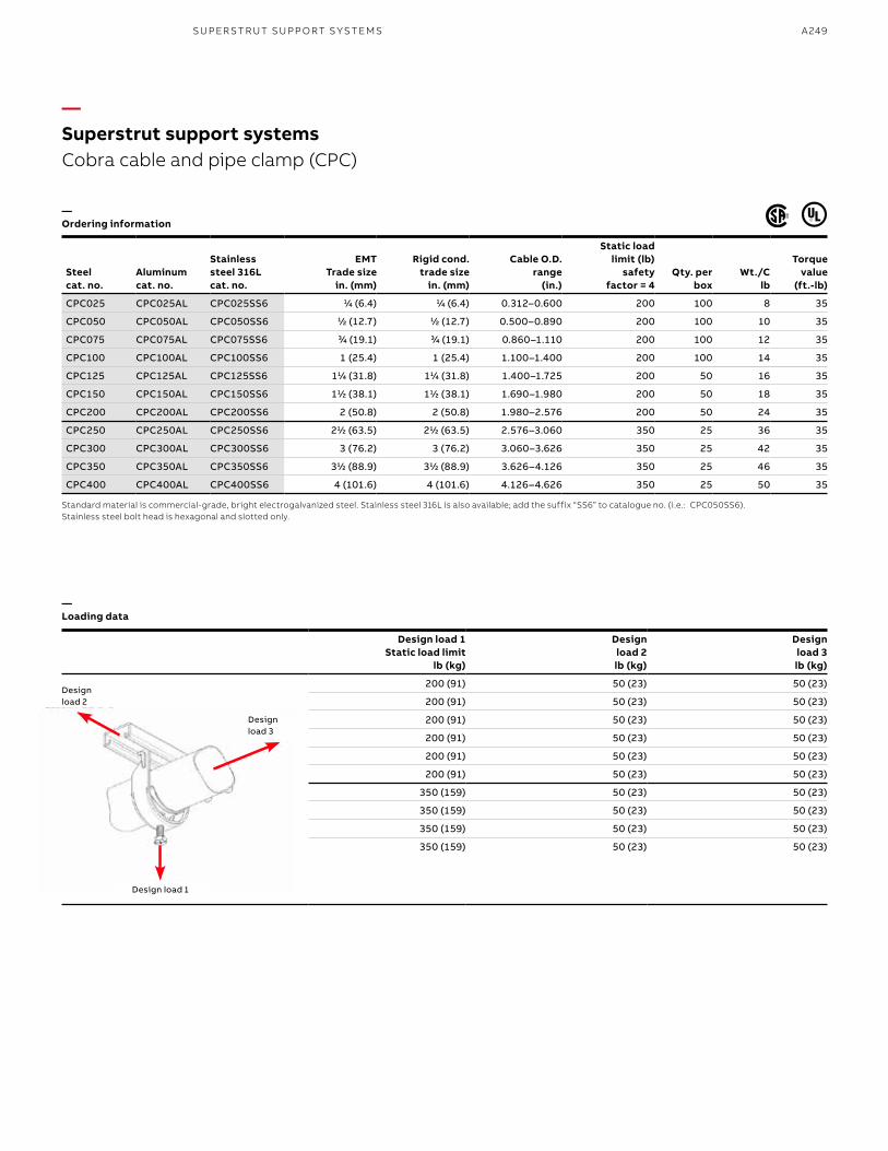
A249SU PER S TR U T SU PP O RT S Y S TEMS
Steel cat. no.
Aluminumcat. no.
Stainless steel 316Lcat. no.
EMT Trade size
in. (mm)
Rigid cond. trade size
in. (mm)
Cable O.D. range
(in.)
Static load limit (lb)
safety factor = 4
Qty. per box
Wt./C lb
Torquevalue
(ft.-lb)
CPC025 CPC025AL CPC025SS6 11⁄44 (6.4) 11⁄44 (6.4) 0.312–0.600 200 100 8 35
CPC050 CPC050AL CPC050SS6 11⁄22 (12.7) 11⁄22 (12.7) 0.500–0.890 200 100 10 35
CPC075 CPC075AL CPC075SS6 33⁄44 (19.1) 33⁄44 (19.1) 0.860–1.110 200 100 12 35
CPC100 CPC100AL CPC100SS6 1 (25.4) 1 (25.4) 1.100–1.400 200 100 14 35
CPC125 CPC125AL CPC125SS6 111⁄44 (31.8) 111⁄44 (31.8) 1.400–1.725 200 50 16 35
CPC150 CPC150AL CPC150SS6 111⁄22 (38.1) 111⁄22 (38.1) 1.690–1.980 200 50 18 35
CPC200 CPC200AL CPC200SS6 2 (50.8) 2 (50.8) 1.980–2.576 200 50 24 35
CPC250 CPC250AL CPC250SS6 211⁄22 (63.5) 211⁄22 (63.5) 2.576–3.060 350 25 36 35
CPC300 CPC300AL CPC300SS6 3 (76.2) 3 (76.2) 3.060–3.626 350 25 42 35
CPC350 CPC350AL CPC350SS6 311⁄22 (88.9) 311⁄22 (88.9) 3.626–4.126 350 25 46 35
CPC400 CPC400AL CPC400SS6 4 (101.6) 4 (101.6) 4.126–4.626 350 25 50 35
Design load 1 Static load limit
lb (kg)
Design load 2 lb (kg)
Design load 3 lb (kg)
200 (91) 50 (23) 50 (23)
200 (91) 50 (23) 50 (23)
200 (91) 50 (23) 50 (23)
200 (91) 50 (23) 50 (23)
200 (91) 50 (23) 50 (23)
200 (91) 50 (23) 50 (23)
350 (159) 50 (23) 50 (23)
350 (159) 50 (23) 50 (23)
350 (159) 50 (23) 50 (23)
350 (159) 50 (23) 50 (23)
Design load 2
Design load 3
Design load 1
—Superstrut support systemsCobra cable and pipe clamp (CPC)
—Ordering information
—Loading data
Standard material is commercial-grade, bright electrogalvanized steel. Stainless steel 316L is also available; add the suffix “SS6” to catalogue no. (i.e.: CPC050SS6). Stainless steel bolt head is hexagonal and slotted only.
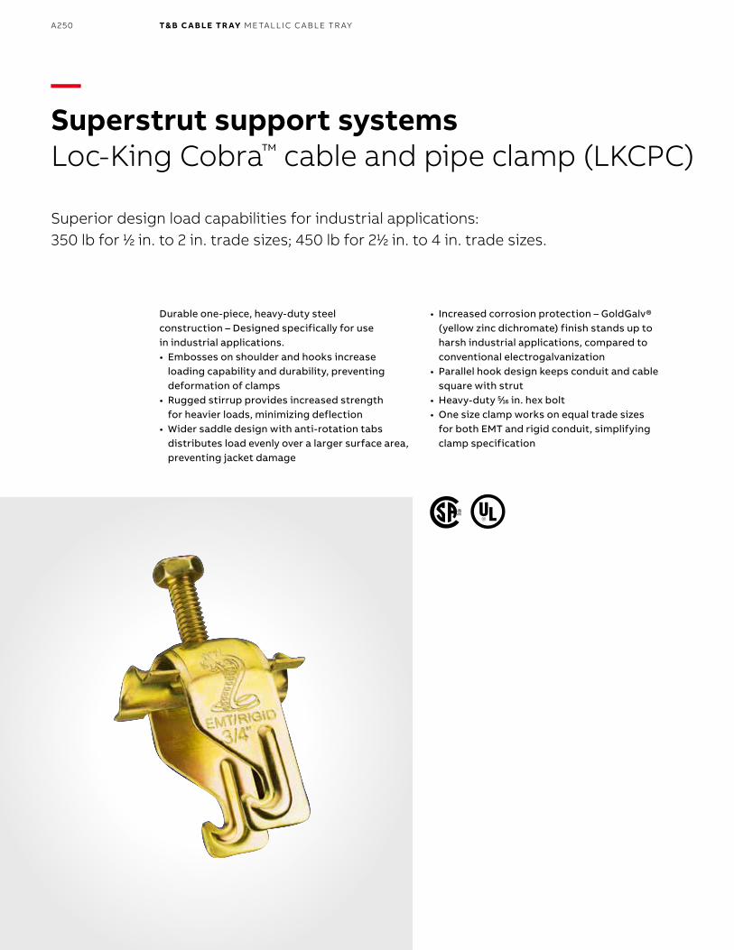
B1 copy starts here
B2 copy starts here
B3 copy starts here
A250 T& B C A B LE TR AY M E TA L L I C C A B L E TR AY
—Superstrut support systemsLoc-King Cobra™ cable and pipe clamp (LKCPC)
Superior design load capabilities for industrial applications: 350 lb for 11⁄22 in. to 2 in. trade sizes; 450 lb for 211⁄22 in. to 4 in. trade sizes.
Durable one-piece, heavy-duty steel construction – Designed specifically for use in industrial applications.• Embosses on shoulder and hooks increase
loading capability and durability, preventing deformation of clamps
• Rugged stirrup provides increased strength for heavier loads, minimizing deflection
• Wider saddle design with anti-rotation tabs distributes load evenly over a larger surface area, preventing jacket damage
• Increased corrosion protection – GoldGalv® (yellow zinc dichromate) finish stands up to harsh industrial applications, compared to conventional electrogalvanization
• Parallel hook design keeps conduit and cable square with strut
• Heavy-duty 55⁄1616 in. hex bolt• One size clamp works on equal trade sizes
for both EMT and rigid conduit, simplifying clamp specification
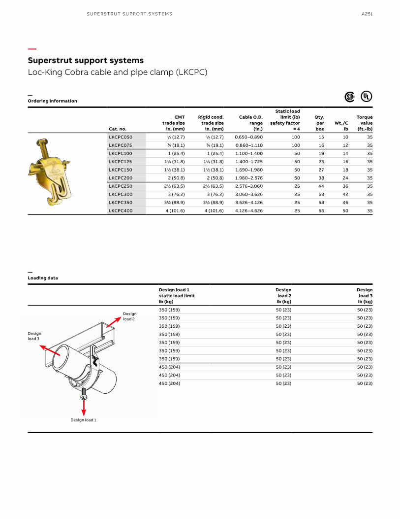
A251
Design load 1 static load limit lb (kg)
Design load 2 lb (kg)
Design load 3
lb (kg)
350 (159) 50 (23) 50 (23)
350 (159) 50 (23) 50 (23)
350 (159) 50 (23) 50 (23)
350 (159) 50 (23) 50 (23)
350 (159) 50 (23) 50 (23)
350 (159) 50 (23) 50 (23)
350 (159) 50 (23) 50 (23)
450 (204) 50 (23) 50 (23)
450 (204) 50 (23) 50 (23)
450 (204) 50 (23) 50 (23)
Cat. no.
EMT trade size
in. (mm)
Rigid cond. trade size
in. (mm)
Cable O.D. range
(in.)
Static load limit (lb)
safety factor = 4
Qty. per box
Wt./C lb
Torquevalue
(ft.-lb)
LKCPC050 11⁄22 (12.7) 11⁄22 (12.7) 0.650–0.890 100 15 10 35
LKCPC075 33⁄44 (19.1) 33⁄44 (19.1) 0.860–1.110 100 16 12 35
LKCPC100 1 (25.4) 1 (25.4) 1.100–1.400 50 19 14 35
LKCPC125 111⁄44 (31.8) 111⁄44 (31.8) 1.400–1.725 50 23 16 35
LKCPC150 111⁄22 (38.1) 111⁄22 (38.1) 1.690–1.980 50 27 18 35
LKCPC200 2 (50.8) 2 (50.8) 1.980–2.576 50 38 24 35
LKCPC250 211⁄22 (63.5) 211⁄22 (63.5) 2.576–3.060 25 44 36 35
LKCPC300 3 (76.2) 3 (76.2) 3.060–3.626 25 53 42 35
LKCPC350 311⁄22 (88.9) 311⁄22 (88.9) 3.626–4.126 25 58 46 35
LKCPC400 4 (101.6) 4 (101.6) 4.126–4.626 25 66 50 35
—Superstrut support systemsLoc-King Cobra cable and pipe clamp (LKCPC)
—Ordering information
—Loading data
Design load 1
Design load 2
Design load 3
SU PER S TR U T SU PP O RT S Y S TEMS
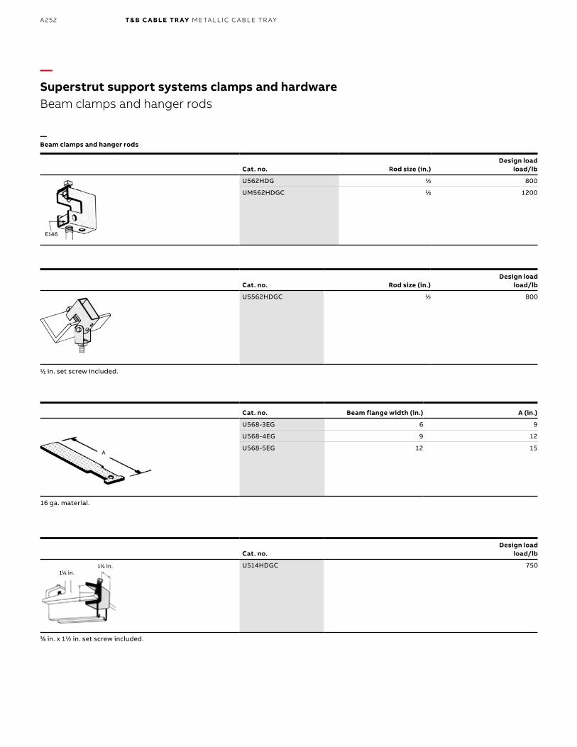
B1 copy starts here
B2 copy starts here
B3 copy starts here
A252 T& B C A B LE TR AY M E TA L L I C C A B L E TR AY
—Superstrut support systems clamps and hardwareBeam clamps and hanger rods
—Beam clamps and hanger rods
Cat. no. Rod size (in.)Design load
load/lb
E146E146
U562HDG 11⁄22 800
UM562HDGC 11⁄22 1200
Cat. no. Rod size (in.)Design load
load/lb
US562HDGC 11⁄22 800
Cat. no.Design load
load/lb
U514HDGC 750
11⁄22 in. set screw included.
16 ga. material.
33⁄88 in. x 111⁄22 in. set screw included.
Cat. no. Beam flange width (in.) A (in.)
U568-3EG 6 9
U568-4EG 9 12
U568-5EG 12 15A
111⁄44 in.111⁄44 in.
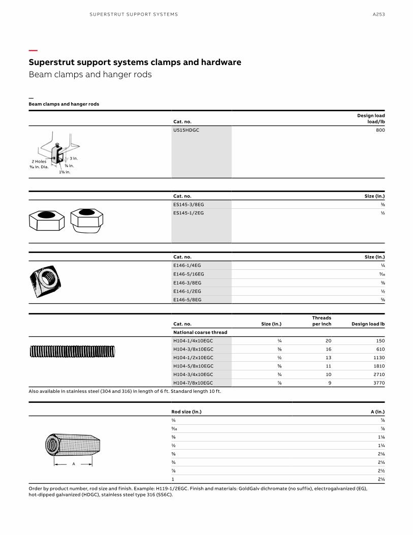
A253
Also available in stainless steel (304 and 316) in length of 6 ft. Standard length 10 ft.
—Superstrut support systems clamps and hardwareBeam clamps and hanger rods
—Beam clamps and hanger rods
Cat. no.Design load
load/lb
U515HDGC 800
3 in.
155⁄88 in.
2 Holes99⁄1616 in. Dia.
A
33⁄88 in.
Cat. no. Size (in.)
ES145-3/8EG 33⁄88
ES145-1/2EG 11⁄22
Cat. no. Size (in.)
E146-1/4EG 11⁄44
E146-5/16EG 55⁄1616
E146-3/8EG 33⁄88
E146-1/2EG 11⁄22
E146-5/8EG 55⁄88
Cat. no. Size (in.)Threads per inch Design load lb
National coarse thread
H104-1/4x10EGC 11⁄44 20 150
H104-3/8x10EGC 33⁄88 16 610
H104-1/2x10EGC 11⁄22 13 1130
H104-5/8x10EGC 55⁄88 11 1810
H104-3/4x10EGC 33⁄44 10 2710
H104-7/8x10EGC 77⁄88 9 3770
Rod size (in.) A (in.)11⁄44 77⁄8855⁄1616 77⁄8833⁄88 111⁄8811⁄22 111⁄4455⁄88 211⁄8833⁄44 211⁄4477⁄88 211⁄22
1 211⁄44
Order by product number, rod size and finish. Example: H119-1/2EGC. Finish and materials: GoldGalv dichromate (no suffix), electrogalvanized (EG), hot-dipped galvanized (HDGC), stainless steel type 316 (SS6C).
SU PER S TR U T SU PP O RT S Y S TEMS
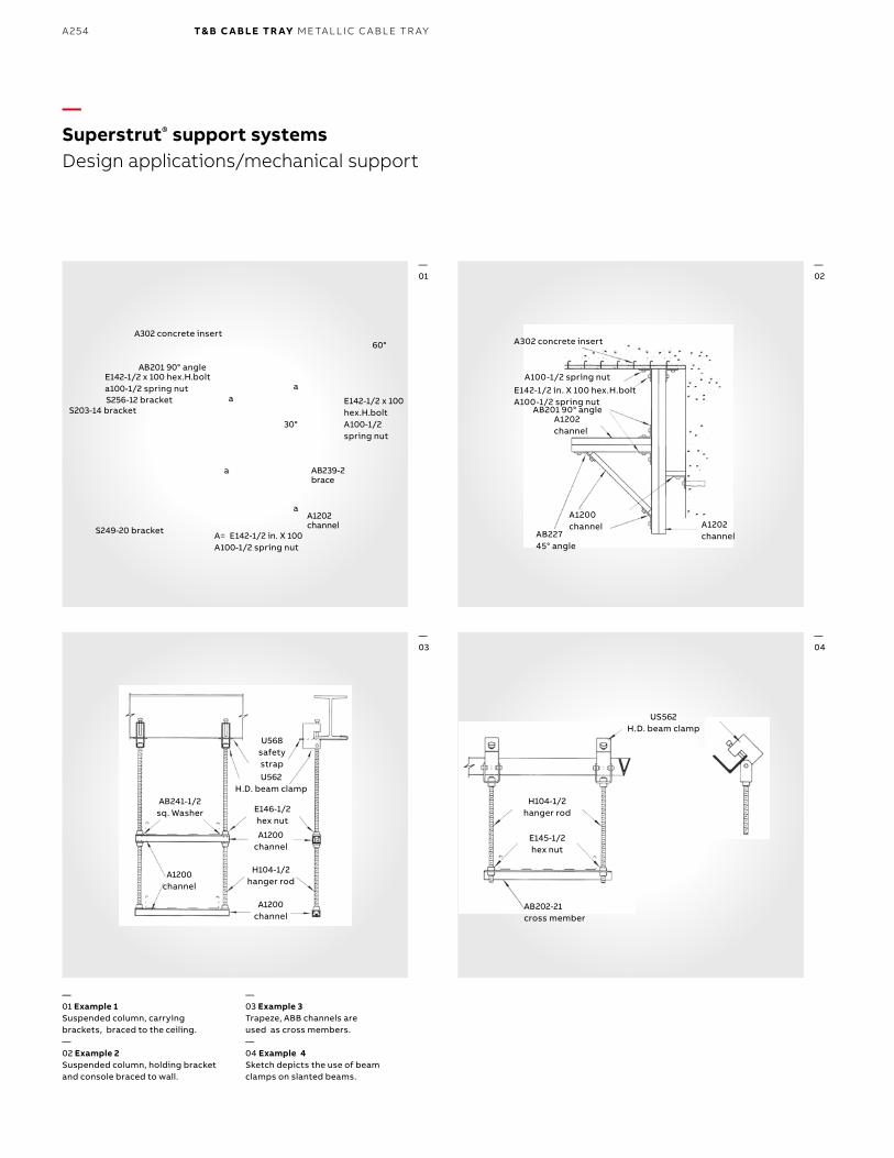
B1 copy starts here
B2 copy starts here
B3 copy starts here
A254 T& B C A B LE TR AY M E TA L L I C C A B L E TR AY
H104-1/2 hanger rod
AB202-21 cross member
E145-1/2 hex nut
US562 H.D. beam clamp
A302 concrete insert
E142-1/2 in. X 100 hex.H.bolt A100-1/2 spring nut
AB201 90° angle
AB227 45° angle
A1202 channel
A1200 channel A1202
channel
A100-1/2 spring nut
AB241-1/2 sq. Washer
A1200 channel
U568 safety strapU562
H.D. beam clamp
E146-1/2 hex nut
A1200 channel
A1200 channel
H104-1/2 hanger rod
—Superstrut® support systemsDesign applications/mechanical support
—01 Example 1Suspended column, carrying brackets, braced to the ceiling.—02 Example 2Suspended column, holding bracket and console braced to wall.
—03 Example 3Trapeze, ABB channels are used as cross members.—04 Example 4Sketch depicts the use of beam clamps on slanted beams.
—01
—03
—02
—04
A302 concrete insert
AB201 90° angleE142-1/2 x 100 hex.H.bolt a100-1/2 spring nutS256-12 bracket
S203-14 bracket
S249-20 bracket A= E142-1/2 in. X 100 A100-1/2 spring nut
E142-1/2 x 100 hex.H.bolt A100-1/2 spring nut
AB239-2 brace
A1202 channel
60°
30°
a
a
aa
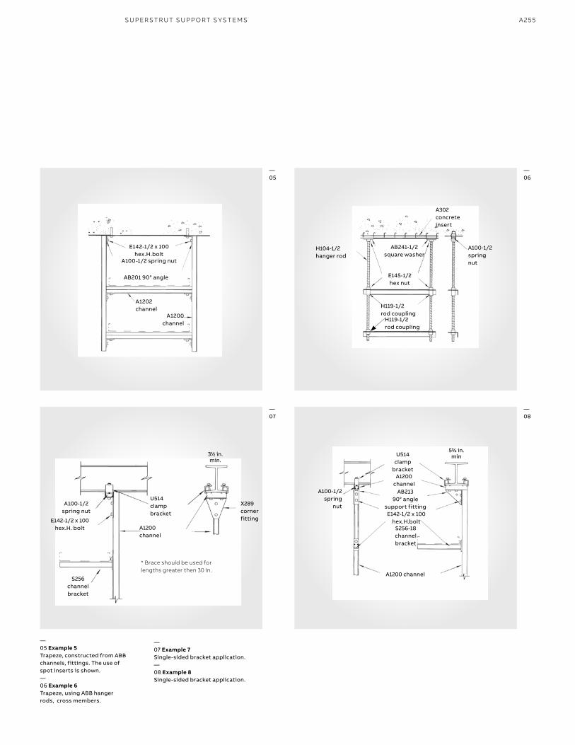
A255
AB201 90° angle
E142-1/2 x 100 hex.H.bolt
A100-1/2 spring nut
A1202 channel
A1200 channel
H104-1/2 hanger rod
A302 concrete insert
AB241-1/2 square washer
E145-1/2 hex nut
A100-1/2 spring nut
H119-1/2 rod coupling
H119-1/2 rod coupling
—05 Example 5Trapeze, constructed from ABB channels, fittings. The use of spot inserts is shown.—06 Example 6Trapeze, using ABB hanger rods, cross members.
—07 Example 7Single-sided bracket application.—08 Example 8Single-sided bracket application.
—05
—07
—06
—08
533⁄44 in. minU514
clamp bracket
A1200 channel
AB213 90° angle
support fittingE142-1/2 x 100
hex.H.boltS256-18 channel bracket
A100-1/2spring
nut
A1200 channel
311⁄22 in. min.
A100-1/2 spring nut
E142-1/2 x 100 hex.H. bolt
S256 channel bracket
U514 clamp bracket
A1200 channel
X289 corner fitting
* Brace should be used for lengths greater then 30 in.
SU PER S TR U T SU PP O RT S Y S TEMS
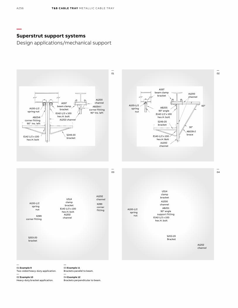
B1 copy starts here
B2 copy starts here
B3 copy starts here
A256 T& B C A B LE TR AY M E TA L L I C C A B L E TR AY
—Superstrut support systemsDesign applications/mechanical support
A100-1/2 spring nut
AB254l corner fitting
90° ins. left
E142 1/2 x 100hex.H. bolt
A597 beam clamp
bracket
E142-1/2 x 100 hex.H. bolt
A1202 channel
S249-20 bracket
A1200 channel
AB254-l corner fitting
90° ins. left
A100-1/2spring
nut
X289 corner fitting
S203-20 bracket
U514 clamp
bracketE142-1/2 x 100
hex.H. boltA1202
channel
A1202 channel
X289 corner fitting A100-1/2
spring nut
U514 clamp
bracket
A1200 channel
AB201 90° angle
support fittingE142-1/2 x 100
hex.H. bolt
S203-20Bracket
A1202 channel
A597 beam clamp
bracketA1200 channel
A100-1/2 spring
nut
AB205 90° angle
E142-1/2 x 100 hex.H. bolt
S249-20 bracket
E142-1/2 x 100 hex.H. Bolt
A1200channel
AB239-2 brace
60°
30°
—01
—03
—02
—04
—01 Example 9Two-sided heavy-duty application.—02 Example 10Heavy-duty bracket application.
—03 Example 11Brackets parallel to beam.—04 Example 12Brackets perpendicular to beam.
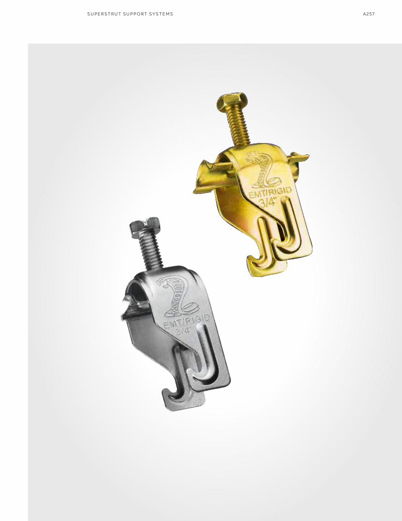
A257SU PER S TR U T SU PP O RT S Y S TEMS

B1 copy starts here
B2 copy starts here
B3 copy starts here
A258 T& B C A B LE TR AY M E TA L L I C C A B L E TR AY
Related Documents