JOURNAL CLUB Vikraman.S

Task group report 135 cyberknie
Jul 13, 2015
Welcome message from author
This document is posted to help you gain knowledge. Please leave a comment to let me know what you think about it! Share it to your friends and learn new things together.
Transcript

JOURNAL CLUB
Vikraman.S
Quality Assurance for Cyberknife

Questions ?
Questions ? • Mould ?
• Reference CT Marker ?
• Patient Setup ?
• Patient Collision system ?
• Isocentre ?
• SSD ?
• Field Size ?
• Reference field size ?
• Dosimetry ?
• Beam Data ?
• QA ?
• Setup verification ?
• 3D Cone beam CT verification ?
• DRR Verification ?
• Delivery QA ?
• PDD,TPR,Output Factors,Kq ?
Introduction
• Fundamental of SRS is to accurate placement of intended radiation dose .
• Small errors can lead to inaccurate estimate of accumulate dose
• Consist of Linear accelerator, Manipulator arms and couch/Robotic couch
• Manipulator arms calibrated to direct the beams at the intersection of two orthogonal beams.
• Movements of the robotic manipulator controlled by computer in turn technologist
• TPS – Montecarlo /Ray searching ,Inverse optimization
• Isocentre /Non Isocentre
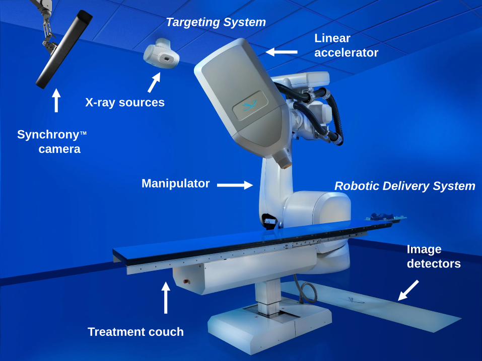
Synchrony™
camera
Treatment couch
Linear
accelerator
Manipulator
Image
detectors
X-ray sources
Targeting System
Robotic Delivery System
Physicist
Record Keeping
• Quality Assurance and Quality control
• Good record keeping can increase work efficiency and reduce the risk of making errors
• Recommended – Every QA test there should be written guideline which clearly defines the objective ,lists the action levels for the test and corrective actions to be taken when these levels are exceeded.
• Essential to keep hand written /Electronic record in a well organized file
• Clear definition of steps for action levels
Terminology
• AQA – Auto QA
• DQA- Delivery QA
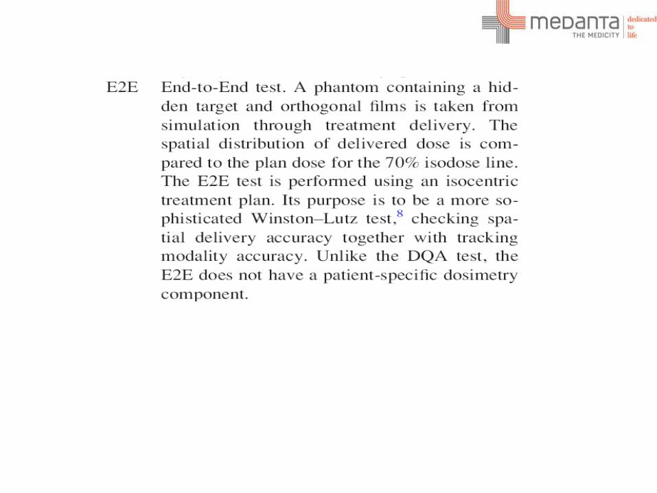
• E2E – End to End test
• EMO – Emergency motion off
• EPO – Emergency power off
• Geometric Isocentre – A point in space defined by the position of isocrystal
• Treatment Isocentre – common crossing point of cyberknife beams and need not to be geometric isocentre
• Isocrystal - A light sensitive detector of about 1.5 mm diameter mounted at the tip of rigid post.

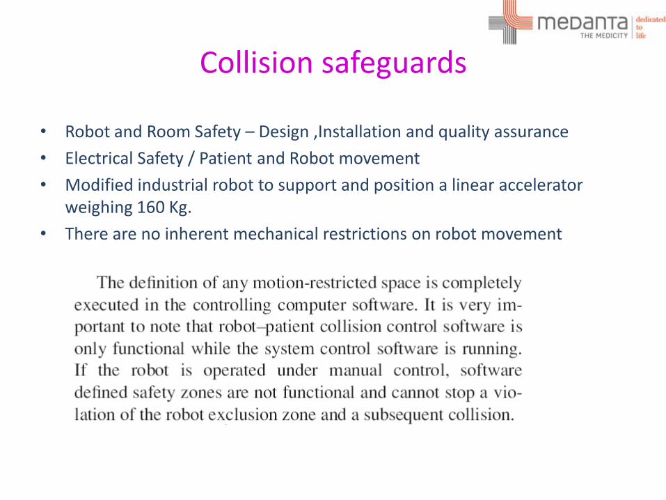
Collision safeguards
• Robot and Room Safety – Design ,Installation and quality assurance
• Electrical Safety / Patient and Robot movement
• Modified industrial robot to support and position a linear accelerator weighing 160 Kg.
• There are no inherent mechanical restrictions on robot movement
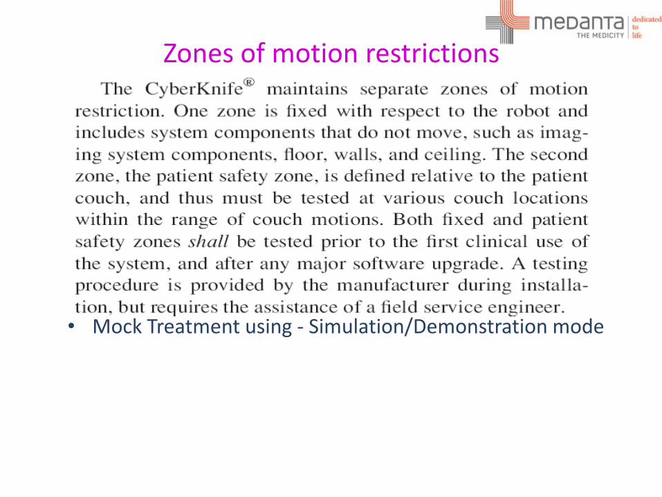
Zones of motion restrictions
• Mock Treatment using - Simulation/Demonstration mode
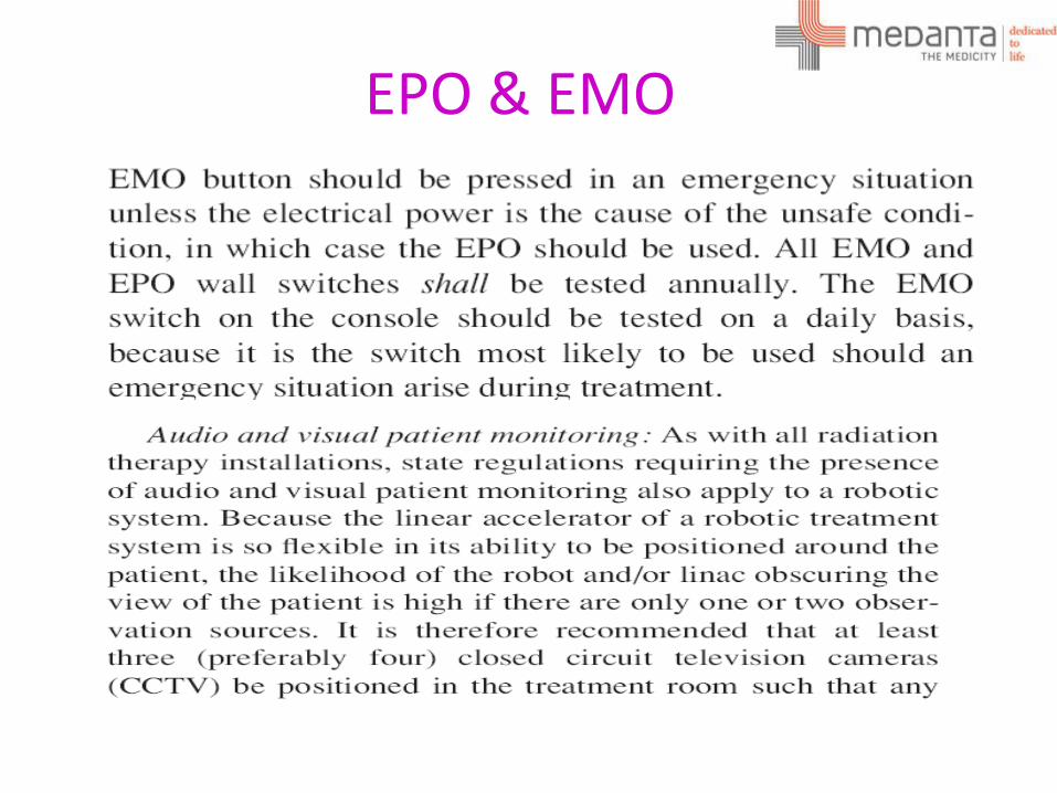
EPO & EMO
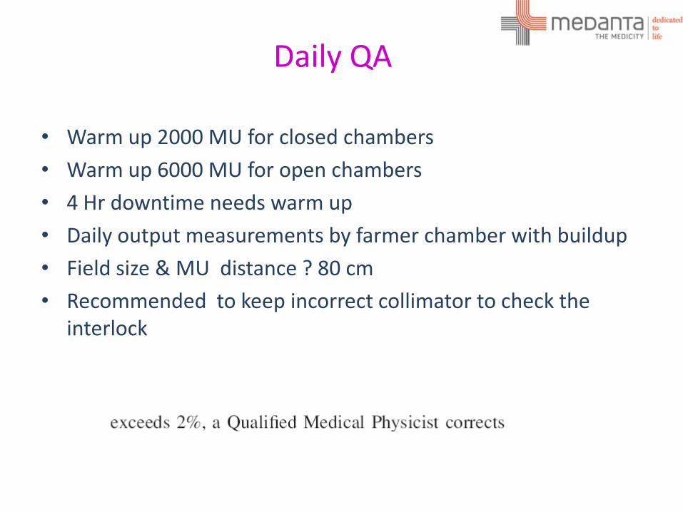
Daily QA
• Warm up 2000 MU for closed chambers
• Warm up 6000 MU for open chambers
• 4 Hr downtime needs warm up
• Daily output measurements by farmer chamber with buildup
• Field size & MU distance ? 80 cm
• Recommended to keep incorrect collimator to check the interlock
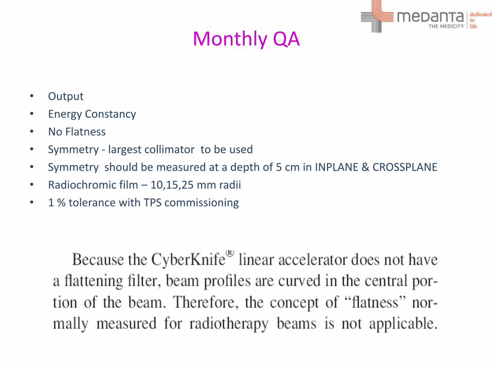
Monthly QA
• Output
• Energy Constancy
• No Flatness
• Symmetry - largest collimator to be used
• Symmetry should be measured at a depth of 5 cm in INPLANE & CROSSPLANE
• Radiochromic film – 10,15,25 mm radii
• 1 % tolerance with TPS commissioning
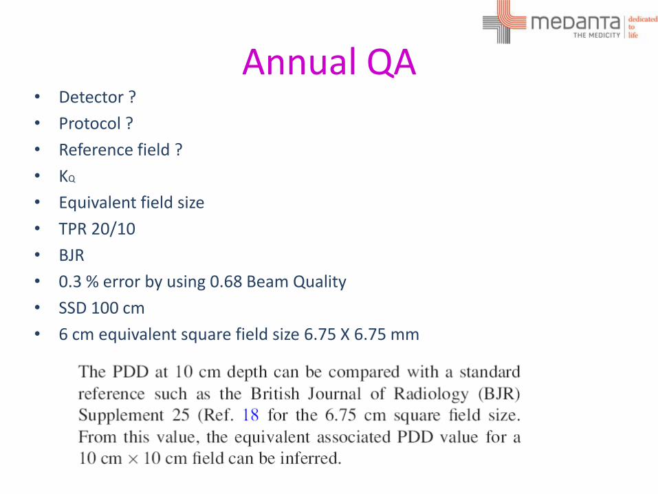
Annual QA • Detector ?
• Protocol ?
• Reference field ?
• KQ
• Equivalent field size
• TPR 20/10
• BJR
• 0.3 % error by using 0.68 Beam Quality
• SSD 100 cm
• 6 cm equivalent square field size 6.75 X 6.75 mm
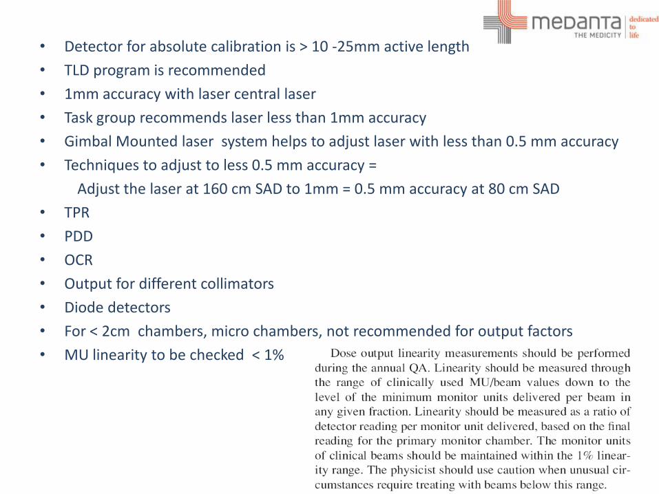
• Detector for absolute calibration is > 10 -25mm active length
• TLD program is recommended
• 1mm accuracy with laser central laser
• Task group recommends laser less than 1mm accuracy
• Gimbal Mounted laser system helps to adjust laser with less than 0.5 mm accuracy
• Techniques to adjust to less 0.5 mm accuracy =
Adjust the laser at 160 cm SAD to 1mm = 0.5 mm accuracy at 80 cm SAD
• TPR
• PDD
• OCR
• Output for different collimators
• Diode detectors
• For < 2cm chambers, micro chambers, not recommended for output factors
• MU linearity to be checked < 1%
IMAGING ? • No recommendations for IMAGING QA from Accuray,
• No Baseline for IMAGING QA apart from ATP
• Task group recommends
Imaging geometry
X ray generators and sources
Amorphous Silicon detector
Patient dose due to image guidance
Dose delivery accuracy depends on IMAGING
Imaging core technology for frameless SRS
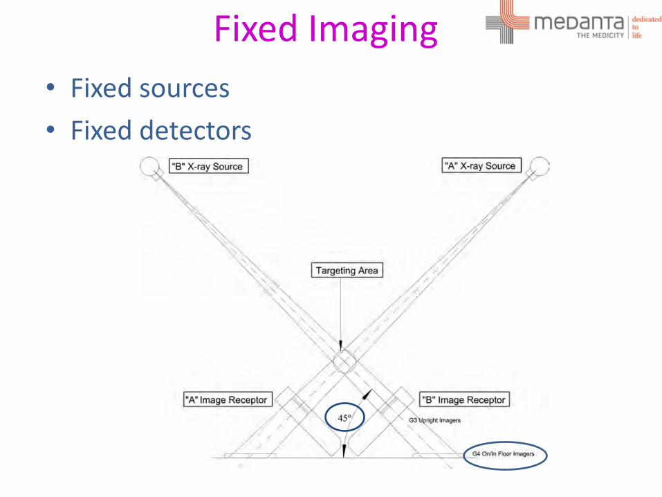
Fixed Imaging
• Fixed sources
• Fixed detectors
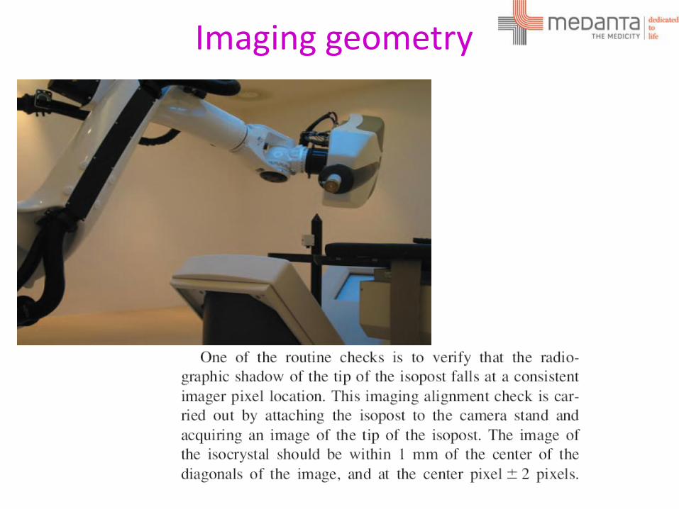
Imaging geometry
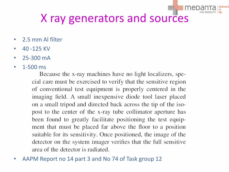
X ray generators and sources
• 2.5 mm Al filter
• 40 -125 KV
• 25-300 mA
• 1-500 ms
• AAPM Report no 14 part 3 and No 74 of Task group 12
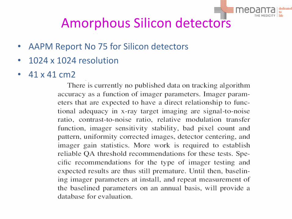
Amorphous Silicon detectors
• AAPM Report No 75 for Silicon detectors
• 1024 x 1024 resolution
• 41 x 41 cm2
Patient dose due to image guidance
• G4 Source to Isocentre separation = 225 cm
• Isocentre to detector distance = 141 cm
• Active area = 41 x 41 cm2
• 0.1 – 0.70 mGy per image .
Exit dose & Entrance dose ?
AAPM Report No 75 is recommended to estimate the Entrance dose
TPS • Montecarlo
• Ray tracing
• Software Testing based on AAPM report 53
• Secondary MU is part of QA as per AAPM report 114
• 2 % tolerance with cumulative of all beams at reference point
• 20 % lower dose in MC vs. Ray tracing ( Depends on the tumor size and location)
• Custom CT model
• Inhomgeneity corrections
• Modelled output factors tolerance is 0.5 % ( SRS)
• Recommended to use Anthromorphic phantoms with films for DQA
• Delivery QA is recommended for every patient for 90 % pass rate with 2% & 2mm gamma criteria.
• Aim for less peripheral dose while planning

Tracking System
• Bony Structure tracking
• Fiducial Tracking
• Soft tissue Tracking
Bony - 6D Skull tracking & Xsight Spine
Soft - X Sight Lung without need of Fiducial
Fiducial – With marker
Synchrony
In Tempo Adaptive imaging
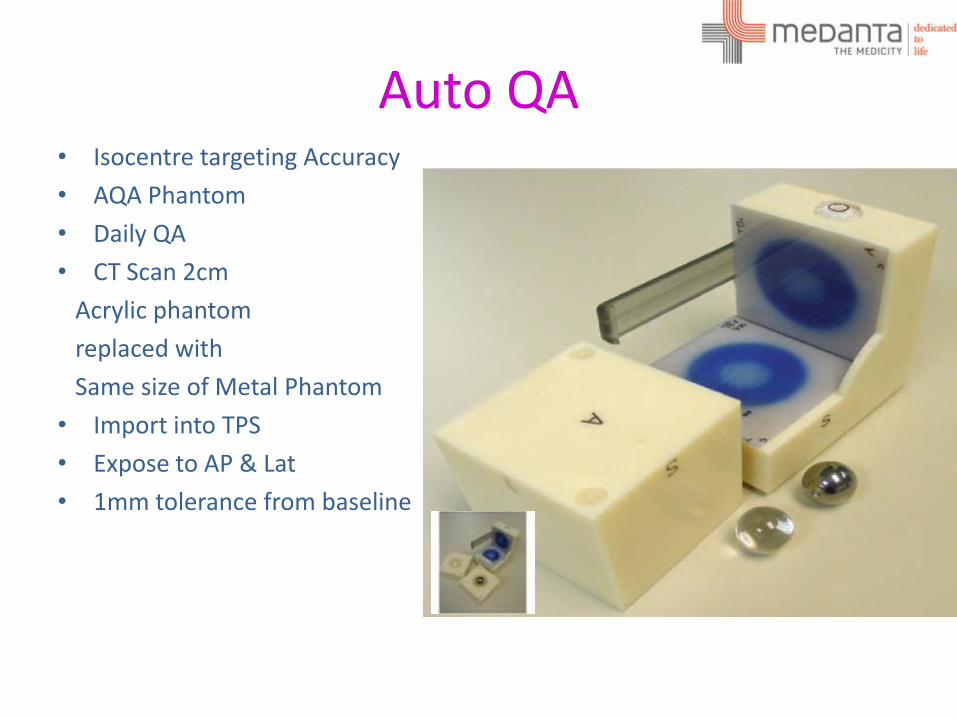
Auto QA • Isocentre targeting Accuracy
• AQA Phantom
• Daily QA
• CT Scan 2cm
Acrylic phantom
replaced with
Same size of Metal Phantom
• Import into TPS
• Expose to AP & Lat
• 1mm tolerance from baseline
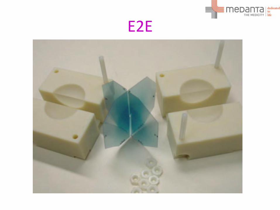
E2E
DQA
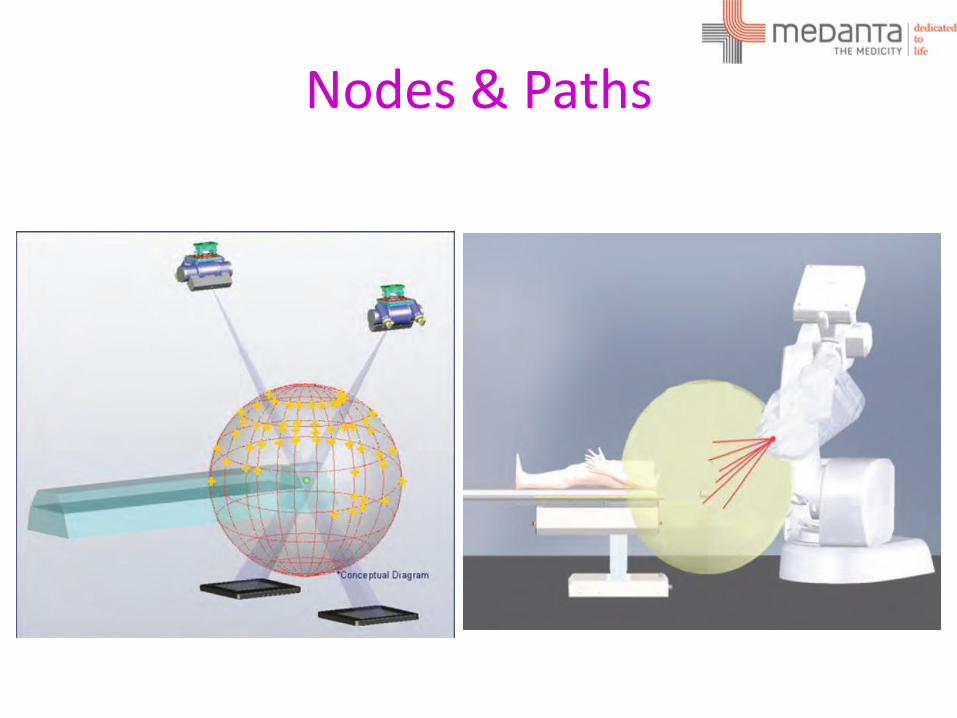
Nodes & Paths

•Questions ?
Related Documents