SOFiSTiK AG, 2014 SSD Task Earthquake SOFiSTiK Structural Desktop Tutorial Introducing Task Earthquake

Welcome message from author
This document is posted to help you gain knowledge. Please leave a comment to let me know what you think about it! Share it to your friends and learn new things together.
Transcript
SOFiSTiK AG, 2014
SSD
Task Earthquake
SOFiSTiK Structural Desktop
Tutorial Introducing Task Earthquake
SSD Task Earthquake
General 1
Contents 1 General .......................................................................................................................... 2
2 Task Earthquake ............................................................................................................ 3
3 Example Earthquake Calculation .................................................................................... 7
3.1 Start SSD ................................................................................................................ 9
3.2 Definition of Materials and Cross Sections .............................................................10
3.3 System- and Load definition with SOFiPLUS(-X) ....................................................11
3.4 Analysis of Single Load Cases ...............................................................................12
3.5 Task Earthquake ....................................................................................................12
3.6 Define Combinations and Superpositioning ............................................................17
3.7 Design ....................................................................................................................20
4 Accidental Torsional Effects ..........................................................................................23
5 Tipps and Tricks ............................................................................................................27
5.1 Earthquake and Raft Foundations ..........................................................................27
5.2 Earthquake and Piles .............................................................................................27
6 Literature .......................................................................................................................28
SSD Task Earthquake
General 2
1 General
The following Tutorial describes the general workflow of the task “Earthquake”. Guided by
the “Earthquake” task wizard, all necessary input will be defined.
The focus of these calculations is based on the Elastic Response Spectra method.
For further information we refer you to our handbooks DYNA_1.pdf and DYNR_1.pdf and to
further technical literature.
This tutorial is based on program version 2014. Inside our Infoportal you will find the tutorials for the older program versions as well.
SSD Task Earthquake
Task Earthquake 3
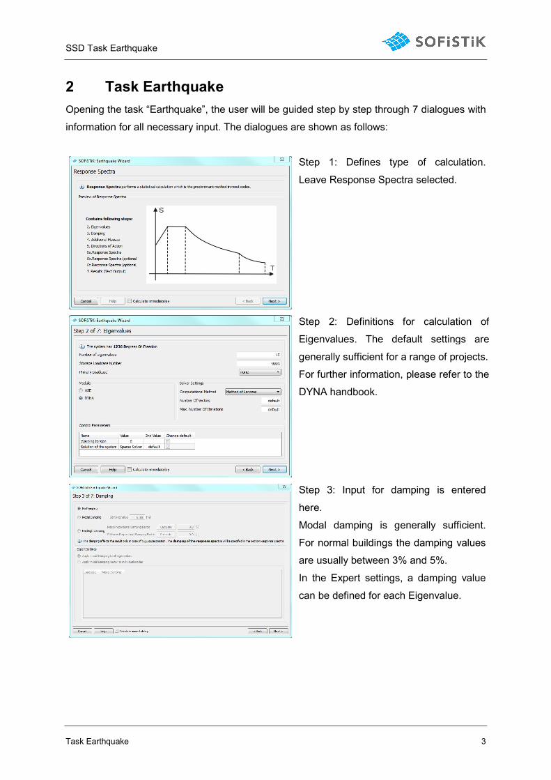
2 Task Earthquake
Opening the task “Earthquake”, the user will be guided step by step through 7 dialogues with
information for all necessary input. The dialogues are shown as follows:
Step 1: Defines type of calculation.
Leave Response Spectra selected.
Step 2: Definitions for calculation of
Eigenvalues. The default settings are
generally sufficient for a range of projects.
For further information, please refer to the
DYNA handbook.
Step 3: Input for damping is entered
here.
Modal damping is generally sufficient.
For normal buildings the damping values
are usually between 3% and 5%.
In the Expert settings, a damping value
can be defined for each Eigenvalue.
SSD Task Earthquake
Task Earthquake 4
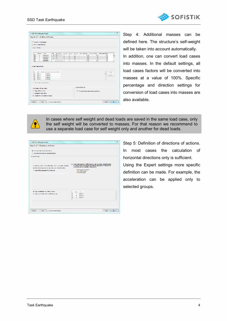
Step 4: Additional masses can be
defined here. The structure’s self-weight
will be taken into account automatically.
In addition, one can convert load cases
into masses. In the default settings, all
load cases factors will be converted into
masses at a value of 100%. Specific
percentage and direction settings for
conversion of load cases into masses are
also available.
In cases where self weight and dead loads are saved in the same load case, only the self weight will be converted to masses. For that reason we recommend to use a separate load case for self weight only and another for dead loads.
Step 5: Definition of directions of actions.
In most cases the calculation of
horizontal directions only is sufficient.
Using the Expert settings more specific
definition can be made. For example, the
acceleration can be applied only to
selected groups.
SSD Task Earthquake
Task Earthquake 5
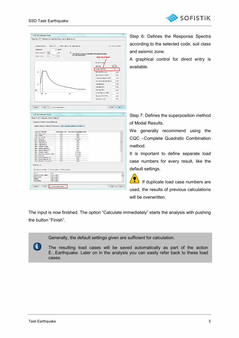
Step 6: Defines the Response Spectra
according to the selected code, soil class
and seismic zone.
A graphical control for direct entry is
available.
Step 7: Defines the superposition method
of Modal Results.
We generally recommend using the
CQC –Complete Quadratic Combination
method.
It is important to define separate load
case numbers for every result, like the
default settings.
If duplicate load case numbers are
used, the results of previous calculations
will be overwritten.
The input is now finished. The option “Calculate immediately” starts the analysis with pushing
the button “Finish”.
Generally, the default settings given are sufficient for calculation.
The resulting load cases will be saved automatically as part of the action E...Earthquake. Later on in the analysis you can easily refer back to these load cases.
SSD Task Earthquake
Task Earthquake 6
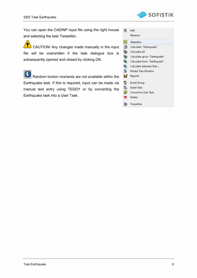
You can open the CADINP input file using the right mouse
and selecting the task Texteditor.
CAUTION! Any changes made manually in the input
file will be overwritten if the task dialogue box is
subsequently opened and closed by clicking OK.
Random torsion moments are not available within the
Earthquake task. If this is required, input can be made via
manual text entry using TEDDY or by converting the
Earthquake task into a User Task.
SSD Task Earthquake
Example Earthquake Calculation 7
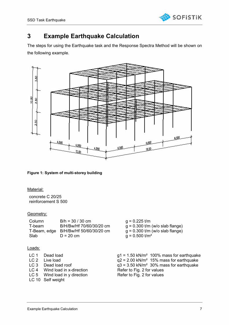
3 Example Earthquake Calculation
The steps for using the Earthquake task and the Response Spectra Method will be shown on
the following example.
Figure 1: System of multi-storey building
Material:
concrete C 20/25 reinforcement S 500
Geometry:
Column B/h = 30 / 30 cm g = 0.225 t/m T-beam B/H/Bw/Hf 70/60/30/20 cm g = 0.300 t/m (w/o slab flange) T-Beam, edge B/H/Bw/Hf 50/60/30/20 cm g = 0.300 t/m (w/o slab flange) Slab D = 20 cm g = 0.500 t/m²
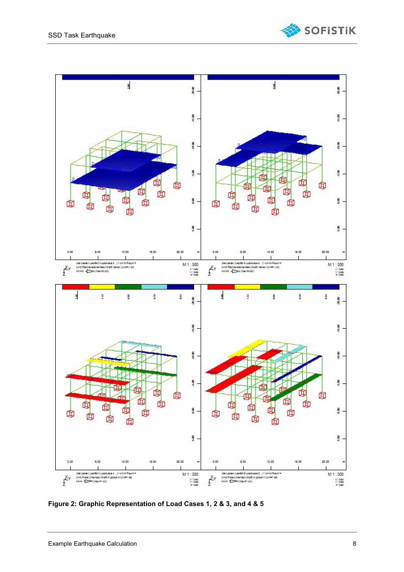
Loads:
LC 1 Dead load g1 = 1.50 kN/m² 100% mass for earthquake LC 2 Live load q2 = 2.00 kN/m² 15% mass for earthquake LC 3 Dead load roof q3 = 3.50 kN/m² 30% mass for earthquake LC 4 Wind load in x-direction Refer to Fig. 2 for values LC 5 Wind load in y direction Refer to Fig. 2 for values LC 10 Self weight
SSD Task Earthquake
Example Earthquake Calculation 8
Figure 2: Graphic Representation of Load Cases 1, 2 & 3, and 4 & 5
SSD Task Earthquake
Example Earthquake Calculation 9
Values for Earthquake Analysis:
Response Spectra EC-8 Type 1 Acceleration 0.4 m/s² Seismic Zone I Soil Class A Horizontal Acceleration Factor 1.0 Vertical Acceleration Factor 0.0
The separate steps for defining the complete analysis will be explained below.
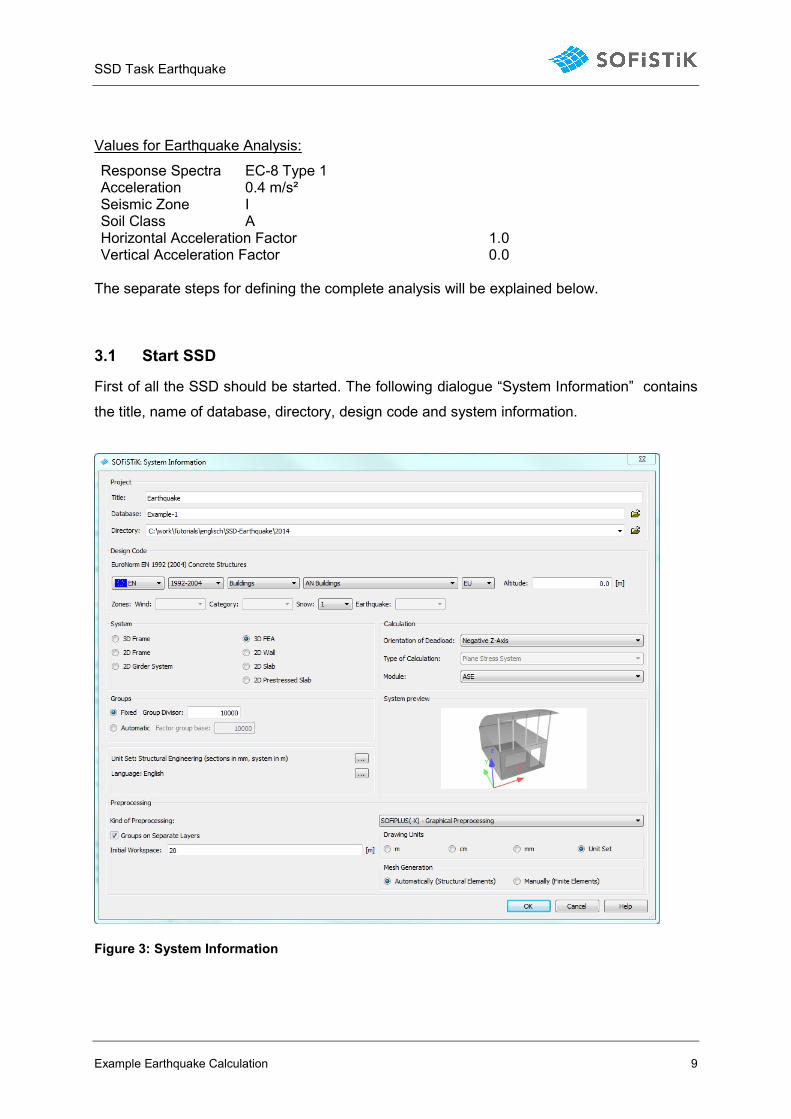
3.1 Start SSD
First of all the SSD should be started. The following dialogue “System Information” contains
the title, name of database, directory, design code and system information.
Figure 3: System Information
SSD Task Earthquake
Example Earthquake Calculation 10
3.2 Definition of Materials and Cross Sections
Finishing the System Information dialogue with OK, the program automatically defines a new
set of materials. Concrete grade C20/25 and S500B reinforcement are default materials
which are suitable for use in this example.
Figure 4: Task Tree - Materials and Cross Sections
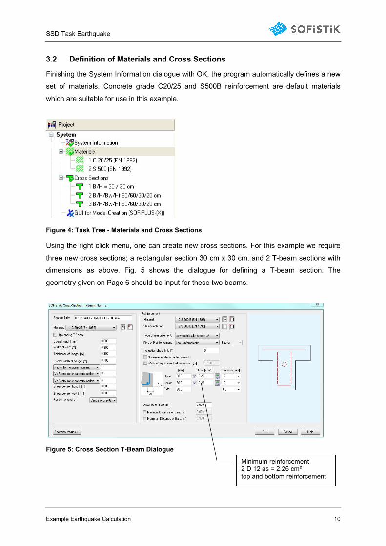
Using the right click menu, one can create new cross sections. For this example we require
three new cross sections; a rectangular section 30 cm x 30 cm, and 2 T-beam sections with
dimensions as above. Fig. 5 shows the dialogue for defining a T-beam section. The
geometry given on Page 6 should be input for these two beams.
Figure 5: Cross Section T-Beam Dialogue
Minimum reinforcement 2 D 12 as = 2.26 cm² top and bottom reinforcement
SSD Task Earthquake
Example Earthquake Calculation 11
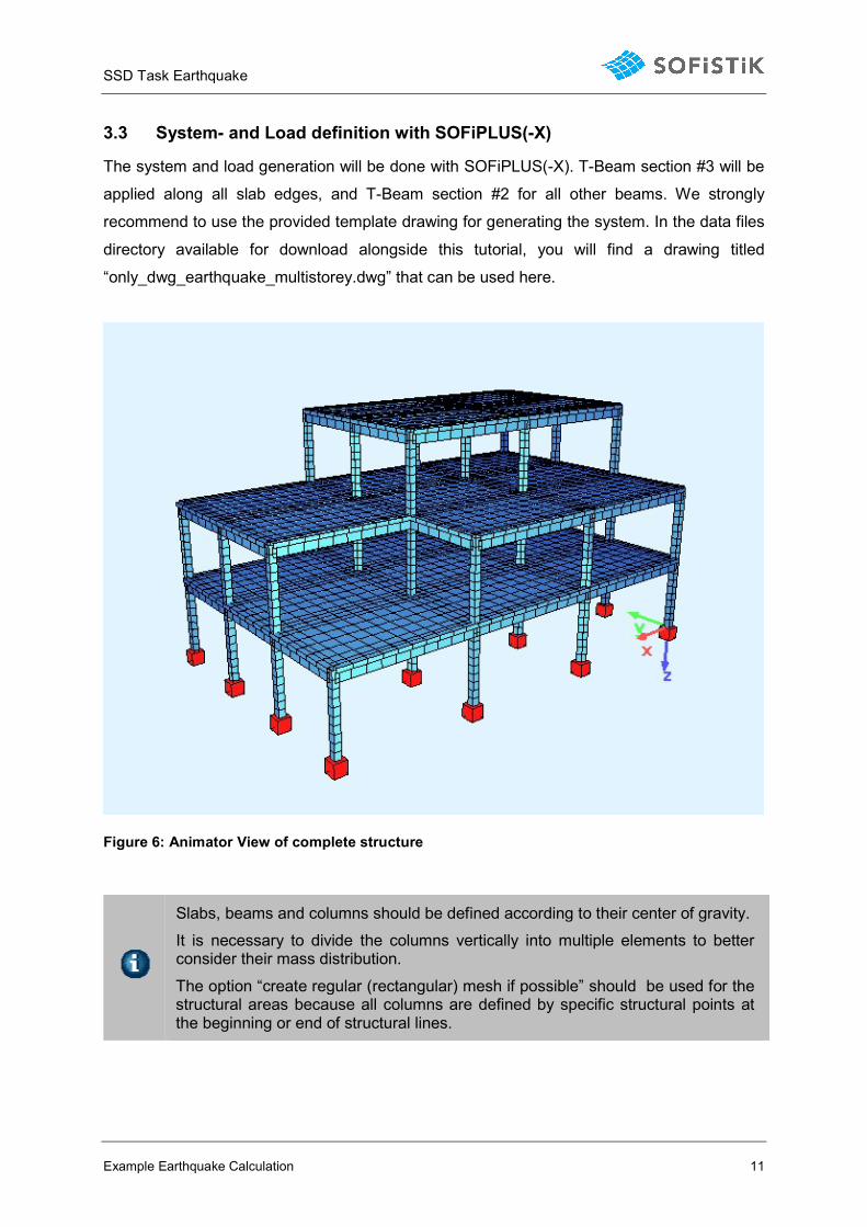
3.3 System- and Load definition with SOFiPLUS(-X)
The system and load generation will be done with SOFiPLUS(-X). T-Beam section #3 will be
applied along all slab edges, and T-Beam section #2 for all other beams. We strongly
recommend to use the provided template drawing for generating the system. In the data files
directory available for download alongside this tutorial, you will find a drawing titled
“only_dwg_earthquake_multistorey.dwg” that can be used here.
Figure 6: Animator View of complete structure
Slabs, beams and columns should be defined according to their center of gravity.
It is necessary to divide the columns vertically into multiple elements to better consider their mass distribution.
The option “create regular (rectangular) mesh if possible” should be used for the structural areas because all columns are defined by specific structural points at the beginning or end of structural lines.
SSD Task Earthquake
Example Earthquake Calculation 12
Create the required loadcases and actions within the Loadcase Manager. Refer to Fig. 2 for
details of area loadings which are to be applied using the “Structural Element Loads > Area
Load” tool. Line loads will then be applied to the perimeter of the floor by using the tool Free
Line Loads, and using the “PIck lines or curves” tool in the right click menu. Use the line
loads displayed in Fig. 2. The load case LC10 has been defined for self-weight only. Activate
the automatic calculation of self weight for this load case within the load case manager,
column SW, factor 1.0.
Define self weight within a single load case #10 without any additional dead loads
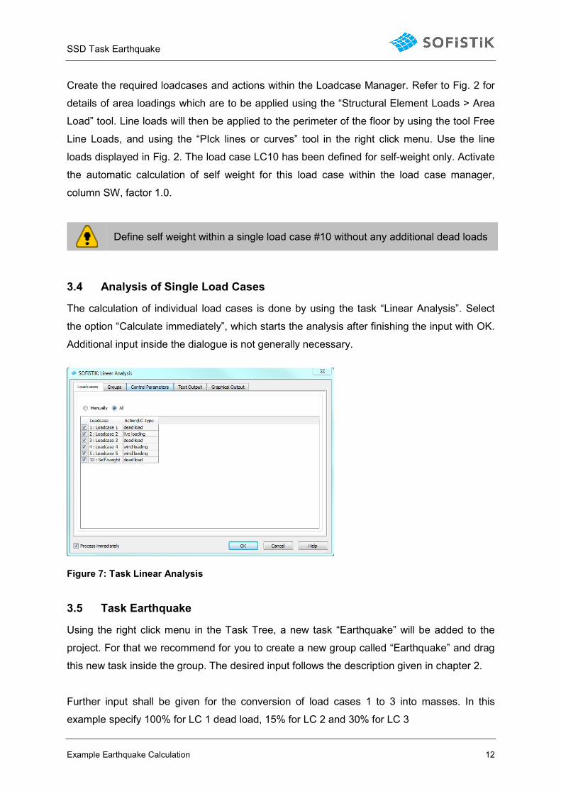
3.4 Analysis of Single Load Cases
The calculation of individual load cases is done by using the task “Linear Analysis”. Select
the option “Calculate immediately”, which starts the analysis after finishing the input with OK.
Additional input inside the dialogue is not generally necessary.
Figure 7: Task Linear Analysis
3.5 Task Earthquake
Using the right click menu in the Task Tree, a new task “Earthquake” will be added to the
project. For that we recommend for you to create a new group called “Earthquake” and drag
this new task inside the group. The desired input follows the description given in chapter 2.
Further input shall be given for the conversion of load cases 1 to 3 into masses. In this
example specify 100% for LC 1 dead load, 15% for LC 2 and 30% for LC 3
SSD Task Earthquake
Example Earthquake Calculation 13
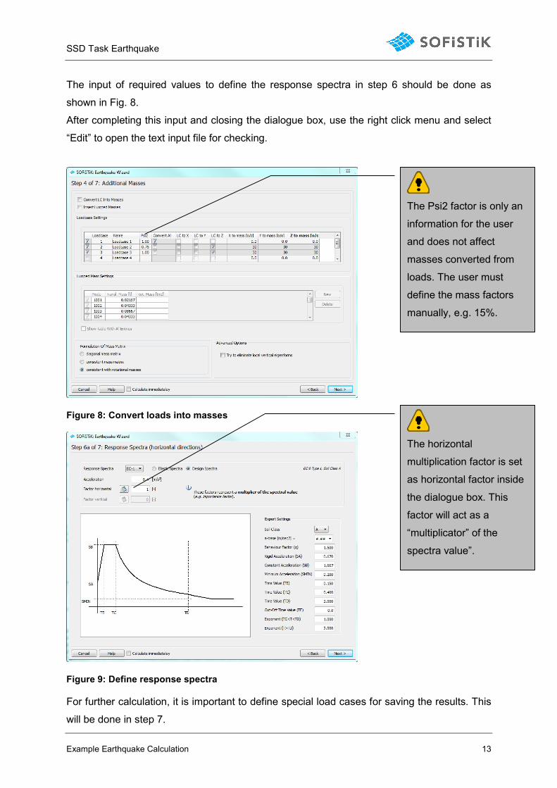
The input of required values to define the response spectra in step 6 should be done as
shown in Fig. 8.
After completing this input and closing the dialogue box, use the right click menu and select
“Edit” to open the text input file for checking.
Figure 8: Convert loads into masses
Figure 9: Define response spectra
For further calculation, it is important to define special load cases for saving the results. This
will be done in step 7.
The horizontal
multiplication factor is set
as horizontal factor inside
the dialogue box. This
factor will act as a
“multiplicator” of the
spectra value”.
The Psi2 factor is only an
information for the user
and does not affect
masses converted from
loads. The user must
define the mass factors
manually, e.g. 15%.
SSD Task Earthquake
Example Earthquake Calculation 14
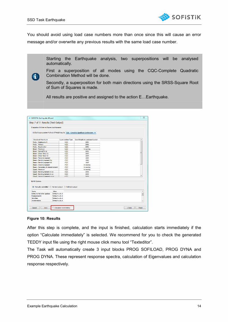
You should avoid using load case numbers more than once since this will cause an error
message and/or overwrite any previous results with the same load case number.
Starting the Earthquake analysis, two superpositions will be analysed automatically.
First a superposition of all modes using the CQC-Complete Quadratic Combination Method will be done.
Secondly, a superposition for both main directions using the SRSS-Square Root of Sum of Squares is made.
All results are positive and assigned to the action E…Earthquake.
Figure 10: Results
After this step is complete, and the input is finished, calculation starts immediately if the
option “Calculate immediately” is selected. We recommend for you to check the generated
TEDDY input file using the right mouse click menu tool “Texteditor”.
The Task will automatically create 3 input blocks PROG SOFILOAD, PROG DYNA and
PROG DYNA. These represent response spectra, calculation of Eigenvalues and calculation
response respectively.
SSD Task Earthquake
Example Earthquake Calculation 15
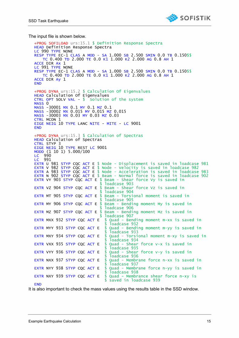
The input file is shown below.
+PROG SOFILOAD urs:15.1 $ Definition Response Spectra HEAD Definition Response Spectra LC 990 TYPE NONE RESP TYPE EC-1 CLAS A MOD - SA 1.000 SB 2.500 SMIN 0.0 TB 0.150$$
TC 0.400 TD 2.000 TE 0.0 K1 1.000 K2 2.000 AG 0.8 AH 1 ACCE DIR Ax 1 LC 991 TYPE NONE RESP TYPE EC-1 CLAS A MOD - SA 1.000 SB 2.500 SMIN 0.0 TB 0.150$$
TC 0.400 TD 2.000 TE 0.0 K1 1.000 K2 2.000 AG 0.8 AH 1 ACCE DIR Ay 1 END +PROG DYNA urs:15.2 $ Calculation Of Eigenvalues HEAD Calculation Of Eigenvalues CTRL OPT SOLV VAL - $ Solution of the system MASS 0 MASS -30001 MX 0.1 MY 0.1 MZ 0.1 MASS -30002 MX 0.015 MY 0.015 MZ 0.015 MASS -30003 MX 0.03 MY 0.03 MZ 0.03 CTRL MCON 1 EIGE NEIG 10 TYPE LANC NITE - MITE - LC 9001 END +PROG DYNA urs:15.3 $ Calculation of Spectras HEAD Calculation of Spectras CTRL STYP 3 EIGE NEIG 10 TYPE REST LC 9001 MODD (1 10 1) 5.000/100 LC 990 LC 991 EXTR U 981 STYP CQC ACT E $ Node - Displacement is saved in loadcase 981 EXTR V 982 STYP CQC ACT E $ Node - Velocity is saved in loadcase 982 EXTR A 983 STYP CQC ACT E $ Node - Acceleration is saved in loadcase 983 EXTR N 902 STYP CQC ACT E $ Beam - Normal force is saved in loadcase 902 EXTR VY 903 STYP CQC ACT E $ Beam - Shear force Vy is saved in
$ loadcase 903 EXTR VZ 904 STYP CQC ACT E $ Beam - Shear force Vz is saved in
$ loadcase 904 EXTR MT 905 STYP CQC ACT E $ Beam - Torsional moment is saved in
$ loadcase 905 EXTR MY 906 STYP CQC ACT E $ Beam - Bending moment My is saved in
$ loadcase 906 EXTR MZ 907 STYP CQC ACT E $ Beam - Bending moment Mz is saved in
$ loadcase 907 EXTR MXX 932 STYP CQC ACT E $ Quad - Bending moment m-xx is saved in
$ loadcase 932 EXTR MYY 933 STYP CQC ACT E $ Quad - Bending moment m-yy is saved in
$ loadcase 933 EXTR MXY 934 STYP CQC ACT E $ Quad - Torsional moment m-xy is saved in
$ loadcase 934 EXTR VXX 935 STYP CQC ACT E $ Quad - Shear force v-x is saved in
$ loadcase 935 EXTR VYY 936 STYP CQC ACT E $ Quad - Shear force v-y is saved in
$ loadcase 936 EXTR NXX 937 STYP CQC ACT E $ Quad - Membrane force n-xx is saved in
$ loadcase 937 EXTR NYY 938 STYP CQC ACT E $ Quad - Membrane force n-yy is saved in
$ loadcase 938 EXTR NXY 939 STYP CQC ACT E $ Quad - Membrance shear force n-xy is
$ saved in loadcase 939 END
It is also important to check the mass values using the results table in the SSD window.
SSD Task Earthquake
Example Earthquake Calculation 16
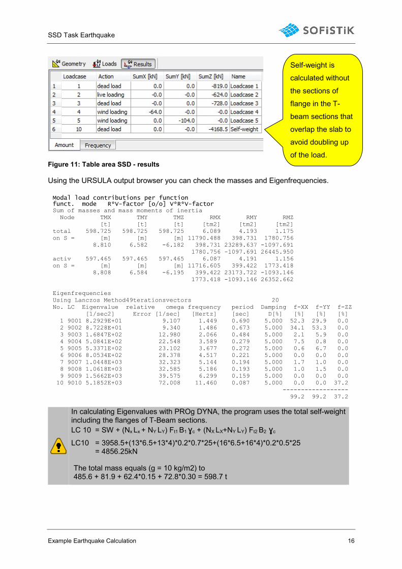
Figure 11: Table area SSD - results
Using the URSULA output browser you can check the masses and Eigenfrequencies.
Modal load contributions per function funct. mode R*V-factor [o/o] V*R*V-factor Sum of masses and mass moments of inertia Node TMX TMY TMZ RMX RMY RMZ [t] [t] [t] [tm2] [tm2] [tm2] total 598.725 598.725 598.725 6.089 4.193 1.175 on S = [m] [m] [m] 11790.488 398.731 1780.756 8.810 6.582 -6.182 398.731 23289.637 -1097.691 1780.756 -1097.691 26445.950 activ 597.465 597.465 597.465 6.087 4.191 1.156 on S = [m] [m] [m] 11716.605 399.422 1773.418 8.808 6.584 -6.195 399.422 23173.722 -1093.146 1773.418 -1093.146 26352.662 Eigenfrequencies Using Lanczos Method49terationsvectors 20 No. LC Eigenvalue relative omega frequency period Damping f-XX f-YY f-ZZ [1/sec2] Error [1/sec] [Hertz] [sec] D[%] [%] [%] [%] 1 9001 8.2929E+01 9.107 1.449 0.690 5.000 52.3 29.9 0.0 2 9002 8.7228E+01 9.340 1.486 0.673 5.000 34.1 53.3 0.0 3 9003 1.6847E+02 12.980 2.066 0.484 5.000 2.1 5.9 0.0 4 9004 5.0841E+02 22.548 3.589 0.279 5.000 7.5 0.8 0.0 5 9005 5.3371E+02 23.102 3.677 0.272 5.000 0.6 6.7 0.0 6 9006 8.0534E+02 28.378 4.517 0.221 5.000 0.0 0.0 0.0 7 9007 1.0448E+03 32.323 5.144 0.194 5.000 1.7 1.0 0.0 8 9008 1.0618E+03 32.585 5.186 0.193 5.000 1.0 1.5 0.0 9 9009 1.5662E+03 39.575 6.299 0.159 5.000 0.0 0.0 0.0 10 9010 5.1852E+03 72.008 11.460 0.087 5.000 0.0 0.0 37.2 ------------------ 99.2 99.2 37.2
In calculating Eigenvalues with PROg DYNA, the program uses the total self-weight including the flanges of T-Beam sections. LC 10 = SW + (Nx Lx + NY LY) Ft1 B1 ɣc + (NX LX+NY LY) Ft2 B2 ɣc
LC10 = 3958.5+(13*6.5+13*4)*0.2*0.7*25+(16*6.5+16*4)*0.2*0.5*25 = 4856.25kN
The total mass equals (g = 10 kg/m2) to 485.6 + 81.9 + 62.4*0.15 + 72.8*0.30 = 598.7 t
Self-weight is
calculated without
the sections of
flange in the T-
beam sections that
overlap the slab to
avoid doubling up
of the load.
SSD Task Earthquake
Example Earthquake Calculation 17
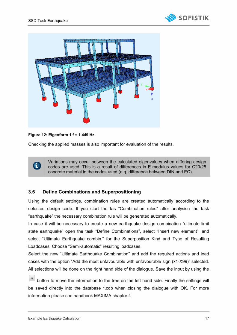
Figure 12: Eigenform 1 f = 1.449 Hz
Checking the applied masses is also important for evaluation of the results.
Variations may occur between the calculated eigenvalues when differing design codes are used. This is a result of differences in E-modulus values for C20/25 concrete material in the codes used (e.g. difference between DIN and EC).
3.6 Define Combinations and Superpositioning
Using the default settings, combination rules are created automatically according to the
selected design code. If you start the tas “Combination rules” after analysisn the task
“earthquake” the necessary combination rule will be generated automatically.
In case it will be necessary to create a new earthquake design combination “ultimate limit
state earthquake” open the task “Define Combinations”, select “Insert new element”, and
select “Ultimate Earthquake combin.” for the Superposition Kind and Type of Resulting
Loadcases. Choose “Semi-automatic” resulting loadcases.
Select the new “Ultimate Earthquake Combination” and add the required actions and load
cases with the option “Add the most unfavourable with unfavourable sign (x1-X99)” selected.
All selections will be done on the right hand side of the dialogue. Save the input by using the
button to move the information to the tree on the left hand side. Finally the settings will
be saved directly into the database *.cdb when closing the dialogue with OK. For more
information please see handbook MAXIMA chapter 4.
SSD Task Earthquake
Example Earthquake Calculation 18
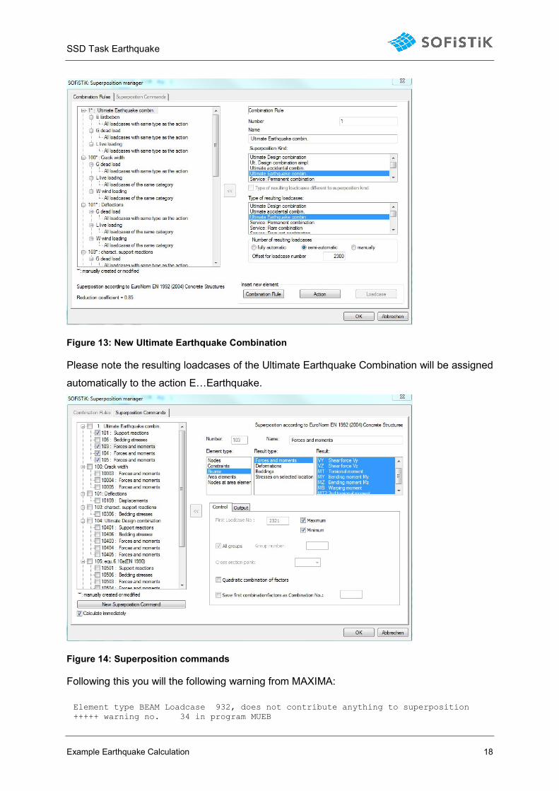
Figure 13: New Ultimate Earthquake Combination
Please note the resulting loadcases of the Ultimate Earthquake Combination will be assigned
automatically to the action E…Earthquake.
Figure 14: Superposition commands
Following this you will the following warning from MAXIMA:
Element type BEAM Loadcase 932, does not contribute anything to superposition +++++ warning no. 34 in program MUEB
SSD Task Earthquake
Example Earthquake Calculation 19
The reason behind this warning is based on the principle that all loads containing results
from the task “Earthquake” will be saved in only one action E…Earthquake.
When combining beam forces also the load cases containing only QUAD forces will be used.
It is obvious, that QUAD forces will not affect the beam forces. That is exactely, what the
warning tells you.
Now we can go further on with the design.
After this is complete, the next step is to calculate the design.
The results from the earthquake analysis contain element forces and moments, but NO nodal results.
If using the Task “Superpositioning” for both ULS and Earthquake superposition, only element results will be saved. These are existing results for both combinations, so will cause later warnings in further ULS area design.
Please use separate “Superposition” task instances for ULS and Earthquake design to obtain all necessary results.
SSD Task Earthquake
Example Earthquake Calculation 20
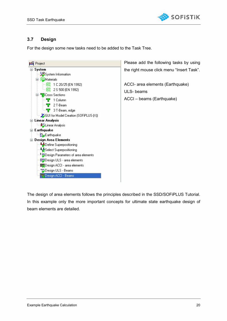
3.7 Design
For the design some new tasks need to be added to the Task Tree.
Please add the following tasks by using
the right mouse click menu “Insert Task”.
ACCI- area elements (Earthquake)
ULS- beams
ACCI – beams (Earthquake)
The design of area elements follows the principles described in the SSD/SOFiPLUS Tutorial.
In this example only the more important concepts for ultimate state earthquake design of
beam elements are detailed.
SSD Task Earthquake
Example Earthquake Calculation 21
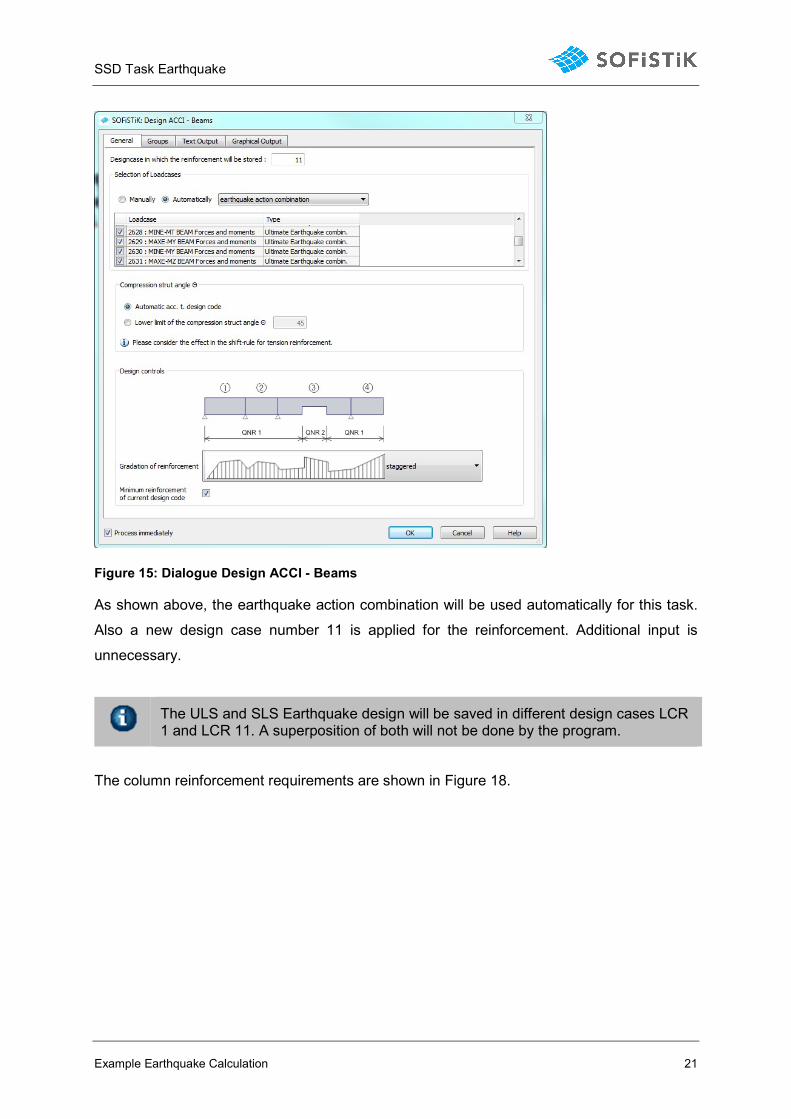
Figure 15: Dialogue Design ACCI - Beams
As shown above, the earthquake action combination will be used automatically for this task.
Also a new design case number 11 is applied for the reinforcement. Additional input is
unnecessary.
The ULS and SLS Earthquake design will be saved in different design cases LCR 1 and LCR 11. A superposition of both will not be done by the program.
The column reinforcement requirements are shown in Figure 18.
SSD Task Earthquake
Example Earthquake Calculation 22
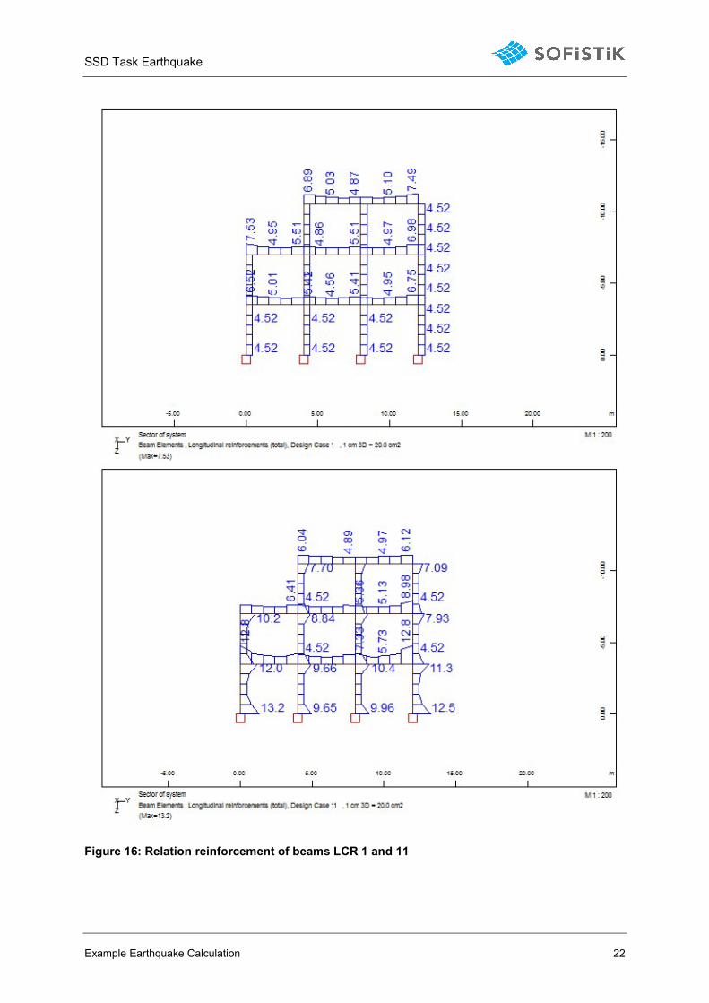
Figure 16: Relation reinforcement of beams LCR 1 and 11
SSD Task Earthquake
Accidental Torsional Effects 23
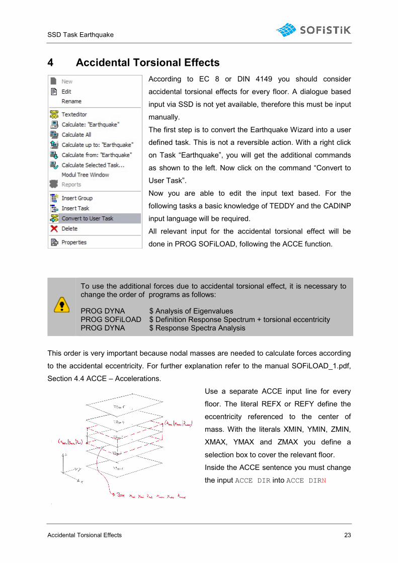
4 Accidental Torsional Effects
According to EC 8 or DIN 4149 you should consider
accidental torsional effects for every floor. A dialogue based
input via SSD is not yet available, therefore this must be input
manually.
The first step is to convert the Earthquake Wizard into a user
defined task. This is not a reversible action. With a right click
on Task “Earthquake”, you will get the additional commands
as shown to the left. Now click on the command “Convert to
User Task”.
Now you are able to edit the input text based. For the
following tasks a basic knowledge of TEDDY and the CADINP
input language will be required.
All relevant input for the accidental torsional effect will be
done in PROG SOFiLOAD, following the ACCE function.
To use the additional forces due to accidental torsional effect, it is necessary to change the order of programs as follows:
PROG DYNA $ Analysis of Eigenvalues PROG SOFiLOAD $ Definition Response Spectrum + torsional eccentricity PROG DYNA $ Response Spectra Analysis
This order is very important because nodal masses are needed to calculate forces according
to the accidental eccentricity. For further explanation refer to the manual SOFiLOAD_1.pdf,
Section 4.4 ACCE – Accelerations.
Use a separate ACCE input line for every
floor. The literal REFX or REFY define the
eccentricity referenced to the center of
mass. With the literals XMIN, YMIN, ZMIN,
XMAX, YMAX and ZMAX you define a
selection box to cover the relevant floor.
Inside the ACCE sentence you must change
the input ACCE DIR into ACCE DIRN
SSD Task Earthquake
Accidental Torsional Effects 24
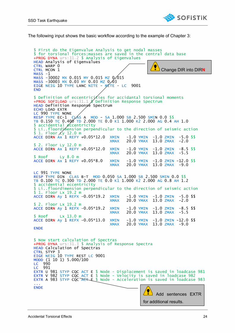
The following input shows the basic workflow according to the example of Chapter 3:
$ First do the Eigenvalue Analysis to get nodal masses $ for torsional forces;masses are saved in the central data base +PROG DYNA urs:31.2 $ Analysis of Eigenvalues HEAD Analysis of Eigenvalues CTRL WARP 0 CTRL MCON 1 MASS -1 MASS -30002 MX 0.015 MY 0.015 MZ 0.015 MASS -30003 MX 0.03 MY 0.03 MZ 0.03 EIGE NEIG 10 TYPE LANC NITE - MITE - LC 9001 END $ Definition of eccentricities for accidantal torsional moments +PROG SOFILOAD urs:31.1 $ Definition Response Spectrum HEAD Definition Response Spectrum ECHO LOAD EXTR LC 990 TYPE NONE RESP TYPE EC-1 CLAS A MOD - SA 1.000 SB 2.500 SMIN 0.0 $$ TB 0.150 TC 0.400 TD 2.000 TE 0.0 K1 1.000 K2 2.000 AG 0.4 AH 1.0 $ accidential eccentricity $ Li..floordimension perpendicular to the direction of seismic action $ 1. Floor Ly 12.0 m ACCE DIRN Ax 1 REFY +0.05*12.0 XMIN -1.0 YMIN -1.0 ZMIN -5.0 $$ XMAX 20.0 YMAX 13.0 ZMAX -2.0 $ 2. Floor Ly 12.0 m ACCE DIRN Ax 1 REFY +0.05*12.0 XMIN -1.0 YMIN -1.0 ZMIN -8.5 $$ XMAX 20.0 YMAX 13.0 ZMAX -5.5 $ Roof Ly 8.0 m ACCE DIRN Ax 1 REFY +0.05*8.0 XMIN -1.0 YMIN -1.0 ZMIN -12.0 $$ XMAX 20.0 YMAX 13.0 ZMAX -9.0 LC 991 TYPE NONE RESP TYPE DIN CLAS B-T MOD 0.050 SA 1.000 SB 2.500 SMIN 0.0 $$ TB 0.100 TC 0.300 TD 2.000 TE 0.0 K1 1.000 K2 2.000 AG 0.8 AH 1.2 $ accidential eccentricity $ Li..floordimension perpendicular to the direction of seismic action $ 1. Floor Lx 19.2 m ACCE DIRN Ay 1 REFX -0.05*19.2 XMIN -1.0 YMIN -1.0 ZMIN -5.0 $$ XMAX 20.0 YMAX 13.0 ZMAX -2.0 $ 2. Floor Lx 19.2 m ACCE DIRN Ay 1 REFX -0.05*19.2 XMIN -1.0 YMIN -1.0 ZMIN -8.5 $$ XMAX 20.0 YMAX 13.0 ZMAX -5.5 $ Roof Lx 13.0 m ACCE DIRN Ay 1 REFX -0.05*13.0 XMIN -1.0 YMIN -1.0 ZMIN -12.0 $$ XMAX 20.0 YMAX 13.0 ZMAX -9.0 ENDE $ Now start calculation of Spectras +PROG DYNA urs:31.3 $ Analysis of Response Spectra HEAD Calculation of Spectras CTRL STYP 3 EIGE NEIG 10 TYPE REST LC 9001 MODD (1 10 1) 5.000/100 LC 990 LC 991 EXTR U 981 STYP CQC ACT E $ Node - Displacement is saved in loadcase 981 EXTR V 982 STYP CQC ACT E $ Node - Velocity is saved in loadcase 982 EXTR A 983 STYP CQC ACT E $ Node - Acceleration is saved in loadcase 983 ... ENDE
Change DIR into DIRN
Add sentences EXTR
for additional results.
SSD Task Earthquake
Accidental Torsional Effects 25
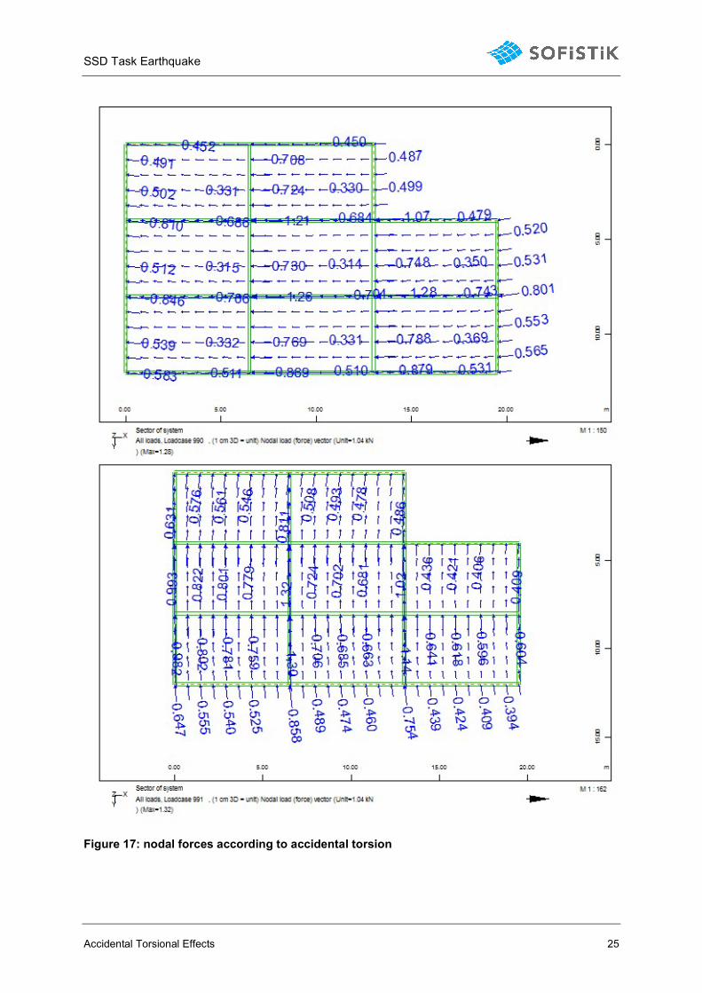
Figure 17: nodal forces according to accidental torsion
SSD Task Earthquake
Accidental Torsional Effects 26
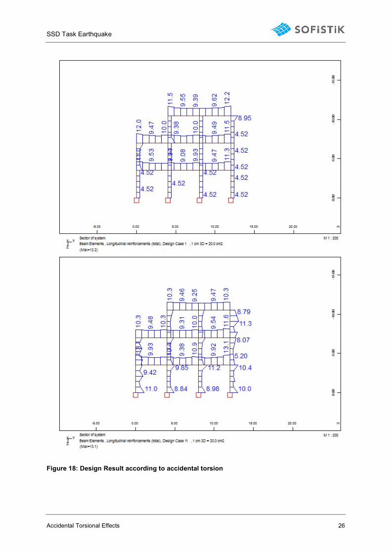
Figure 18: Design Result according to accidental torsion
SSD Task Earthquake
Tipps and Tricks 27
5 Tipps and Tricks
5.1 Earthquake and Raft Foundations
The calculation using the response spectra method is a pure linear elastic calculation.
Therefore, the following questions arise in the case of a raft foundation:
1. Are there tensile stresses in the foundation?
2. If yes, how can I recognize this and adjust my model accordingly?
Basically, no node forces and bedding stresses are available as results from a response
spectra calculation. This is due to the fact that the individual modes and the directions are
superimposed for every single element. Therefore no corresponding forces and moments
exist for neighboring elements.
However, there are deformation, velocity, and acceleration available as nodal results.
These results are always positive. But they will be superimposed with unfavourable sign
together with the constant and variable loads. From that results, one can judge about the
behaviour of the raft foundation and whether or not a gap occurs.
In the case of a gap, it is possible to deactivate the bedding of the raft foundation in partial
areas using the SOFiPLUS command “attribute areas”. As a result of the reduced foundation
area, a load transfer is simulated, so that there are no lifting forces in the remaining plate.
The size of the attribute area must be determined manually and iteratively.
5.2 Earthquake and Piles
In case of a pile foundation, modelled with extended piles, DYNA can determine
superimposed results. However, the piles are acting for tensile and compressive forces in the
same way. Also there are no corresponding forces and moments available for the other piles.
Alternatively, the piles can be modeled via spring elements. Here too, the bearing forces of
the springs are determined as tensile and compressive forces. In the case of tension springs,
these springs could be deactivated by group during the earthquake calculation, thus
simulating the failure.
For the spring elements it is possible to work with the so-called result sets = RSET. Defining
a result set with all springs it is possible to evaluate the maximum spring force of the spring
No. 1 including the corresponding spring forces of the remaining springs. The result sets
need to be defined in the module SOFiMSHA. A Definition via an SSD task is not yet
available.
A maximum of 255 springs can be processed in one RSET.
You can find an example on RSET in the TEDDY examples of the SOFiMSHA module.
SSD Task Earthquake
Literature 28
6 Literature
[1] SOFiSTiK AG; DYNA Manual Version 12.74, 2010
[2] Flesch, R.; Baudynamik Praxisgerecht
Band I Berechnungsgrundlagen
Band II Beispiels
Bauverlag Wiesbaden 1993 / 1997
[3] Petersen Chr.; Dynamik der Baukonstruktionen, Vieweg Verlag 1996
You will find more references to further literature inside our program manuals
Related Documents