TAS71-R001E TA Version 4.0 Issue Date December 1, 2006 REFERENCE MANUAL ++ Function Block Reference Guide Technical Access

TAS71-R001E Ver4 DIASYS-IDOL++ Function Block Reference Guide
Oct 28, 2014
Welcome message from author
This document is posted to help you gain knowledge. Please leave a comment to let me know what you think about it! Share it to your friends and learn new things together.
Transcript

TAS71-R001E
TA Version 4.0 Issue Date December 1, 2006
REFERENCE
MANUAL
++ Function Block Reference Guide
Technical Access
Notes
1 Please be aware that due to product improvements and modifications, the product description inthis manual may differ in certain respects from the actual product.
2 This manual may not be distributed or reproduced in whole or in part without permission.
3 The contents covered in this manual are subjected to change without prior notice.
4 Please be aware that no liability whatsoever will be accepted for consequences arising from theuse of this manual.
5 If the customer installs products other than the software or hardware supplied by MitsubishiHeavy Industries in the personal computer or computer network running DIASYS Netmation®,the operation of the DIASYS Netmation® system devices including the controller (MPS) is notguaranteed.
6 Although every effort has been made to endure the clarity, correctness and accuracy of thecontents, in case you required clarification on any point, or notice any error or discrepancy,please do not hesitate to contact us.
• "Excel" is a trademark of Microsoft Corporation.
• "VISIO" is a trademark of Visio Corporation.
• DIASYS Netmation® is a trademark of Mitsubishi HeavyIndustoried, Ltd.
TAS71-R001E
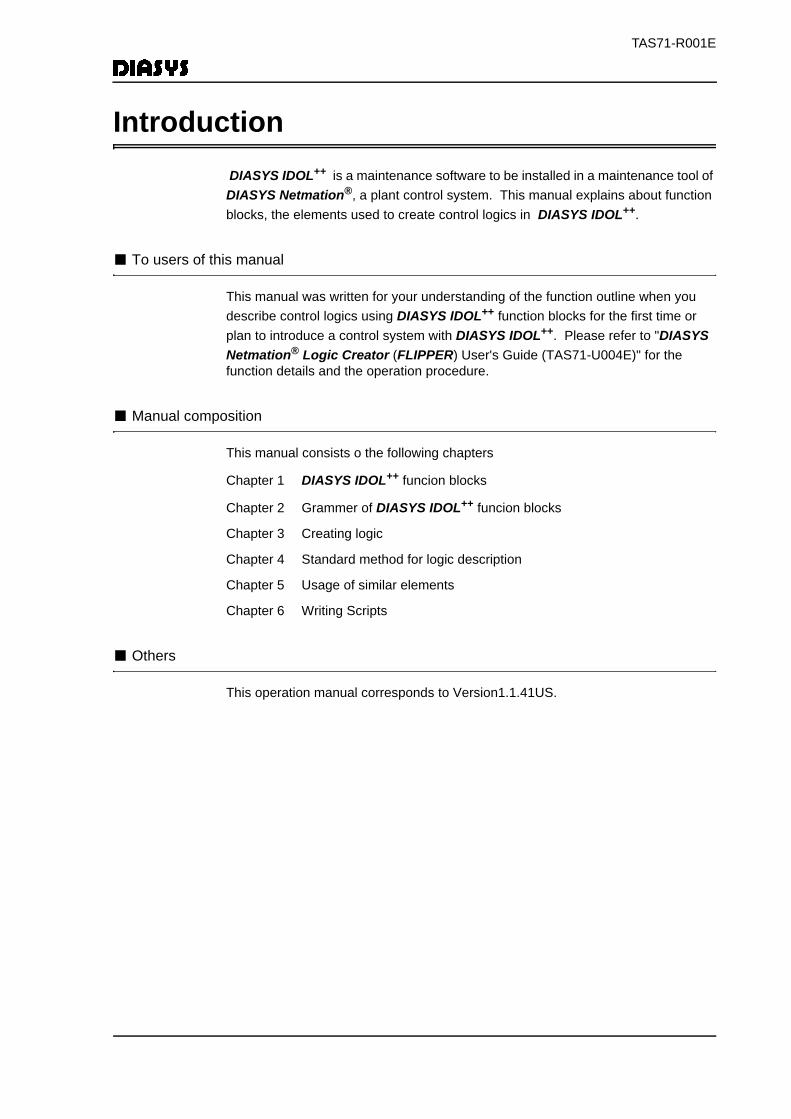
Introduction DIASYS IDOL++ is a maintenance software to be installed in a maintenance tool of DIASYS Netmation®, a plant control system. This manual explains about function blocks, the elements used to create control logics in DIASYS IDOL++.
■ To users of this manual
This manual was written for your understanding of the function outline when you describe control logics using DIASYS IDOL++ function blocks for the first time or plan to introduce a control system with DIASYS IDOL++. Please refer to "DIASYS Netmation® Logic Creator (FLIPPER) User's Guide (TAS71-U004E)" for the function details and the operation procedure.
■ Manual composition
This manual consists o the following chapters
Chapter 1 DIASYS IDOL++ funcion blocks
Chapter 2 Grammer of DIASYS IDOL++ funcion blocks
Chapter 3 Creating logic
Chapter 4 Standard method for logic description
Chapter 5 Usage of similar elements
Chapter 6 Writing Scripts
■ Others
This operation manual corresponds to Version1.1.41US.

DIASYS Netmation®Manual MapThe following lists DIASYS Netmation® manuals.
CategorySystem general (Describes the
system general.)
Engineering Maintenance Station (EMS)(Describes an EMS tool used for setting and maintenance of the control system.)
System description
Describes a system overview, characteristics, functions and specifications.
Operation manual
Describes how to operate the system.
Reference manual
Describes the graphic symbols. Also refer to the applicable opera-tion manual.
Installation guide
Describes the soft-ware and hardware requirements, and installation proce-dures.
Maintenance man-ual
Describes mainte-nance of the sys-tem.
First Step Guide to DIASYS
Netmation
TAS71-E002E
SystemDescription
TAS71-E001E
StartGuide
TAS71-U001E
Maintenance Tool (EMS)
User’s Guide(For Win-
dows XP)TAS71-U052E
GraphicCreator(MARLIN)
User’s Guide(For Win-
dows XP)TAS71-U053E
LogicCreator(FLIPPER)
User’s Guide
TAS71-U004E
ListCreator(CORAL)
User’s Guide
TAS71-U005E
LoopPlateCreator
(SCALLOP)User’s Guide (For
Windows XP)
TAS71-U057E
Graphic Parts Reference
Guide
TAS71-R006E
Function Block Reference
Guide
TAS71-R001E
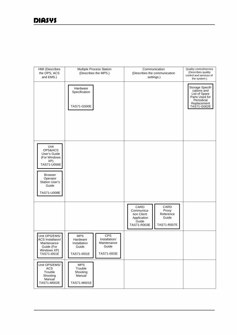
HMI (Describes the OPS, ACS
and EMS.)
Multiple Process Station (Describes the MPS.)
Communication(Describes the communication
settings.)
Quality control/service(Describes quality
control and services of the system.)
Hardware Specification
TAS71-G500E
Storage Specifi-cations and List of Spare
Parts Used for Periodical
ReplacementTAS71-G002E
Unit OPS&ACS
User’s Guide(For Windows
XP)TAS71-U056E
Browser Operator
Station User’s Guide
TAS71-U008E
CARDCommunica-
tion Client Application
GuideTAS71-R003E
CARDProxy
Reference Guide
TAS71-R007E
Unit OPS/EMS/ACS Installaion/
Maintenance Guide (For
Windows XP)TAS71-I051E
MPS Hardware Installation
Guide
TAS71-I001E
CPSInstallation/
Maintenance Guide
TAS71-I003E
Unit OPS/EMS/ACS
TroubleShooting Manual
TAS71-M002E
MPSTrouble
Shooting Manual
TAS71-M001E

TAS71-R001E
Description rules
Note
A supplementary note describes important supplementary information.
Caution
A caution describes an operation or information that is required to prevent damaging a device or software, losing data, or creating ineffective results.

TAS71-R001E
TAS71-R001E
i
Table of Contents
IntroductionDIASYS Netmation®Manual MapDescription rulesTable of contents
1 DIASYS-IDOL++ Function Blocks ................................................................................. 1-11.1 Basic Concept....................................................................................................... 1-11.2 Control Logic......................................................................................................... 1-21.3 Logic Sheet ........................................................................................................... 1-31.4 Creation and Execution of Logic ........................................................................... 1-41.5 Function Blocks..................................................................................................... 1-5
1.5.1 Function Block Types .................................................................................... 1-51.5.2 Types of Logic That Can be Created ............................................................ 1-6
2 Grammar of DIASYS-IDOL++ Function Blocks ............................................................. 2-12.1 Logic Sheet and Drawing Elements ..................................................................... 2-12.2 Function Block Classification ................................................................................ 2-1
2.2.1 Input/Output Blocks ....................................................................................... 2-22.2.2 Control Arithmetic Blocks .............................................................................. 2-32.2.3 Operator Station Blocks ................................................................................ 2-32.2.4 Data Logging Blocks ..................................................................................... 2-32.2.5 System Blocks............................................................................................... 2-32.2.6 External Communication Blocks.................................................................... 2-32.2.7 Tag Names/Signal Names ............................................................................ 2-42.2.8 Parameter...................................................................................................... 2-5
2.3 Connection Lines .................................................................................................. 2-62.3.1 What Connection Lines are .......................................................................... 2-6
2.4 I/O Signal Distinction............................................................................................. 2-82.4.1 Function Blocks with Multiple Input ............................................................... 2-82.4.2 Display Format of Input Signals .................................................................... 2-8
2.5 Data between Sheets/Data inside Sheet ............................................................ 2-102.5.1 Data between Logic Sheet (CED/CEA/CEI)................................................ 2-102.5.2 Data inside Logic Sheet (CID)..................................................................... 2-11
2.6 Macro Elements .................................................................................................. 2-122.6.1 What a Macro Element is ........................................................................... 2-12
2.7 Quality Information Added to Function Blocks .................................................... 2-142.8 Function-Block Property ..................................................................................... 2-16
3 Creating Logic .............................................................................................................. 3-13.1 Basic Operation .................................................................................................... 3-1
3.1.1 Startup of LogicCreator (FLIPPER)............................................................... 3-13.2 Creating Logic Sheet ............................................................................................ 3-4
3.2.1 Creating New Process Block Configuration ................................................. 3-53.2.2 Adding a Process Block to a Process Block Configuration ........................... 3-73.2.3 Adding a Logic Sheet to a Process Block ..................................................... 3-83.2.4 Deleting a Logic Sheet and a Process Block .............................................. 3-12
3.3 Logic Sheet Drawing........................................................................................... 3-133.3.1 Element Drawing ......................................................................................... 3-133.3.2 Drawing Connection Lines .......................................................................... 3-20
TAS71-R001E
ii
3.3.3 Undoing Connection Lines ..........................................................................3-223.4 Creating Sheet Data............................................................................................3-23
3.4.1 Executing Loop-Build...................................................................................3-233.5 Completing Drawing............................................................................................3-253.6 Loading Sheet Data.............................................................................................3-26
3.6.1 Offline Sheet Loading ..................................................................................3-263.6.2 Online Sheet Loading ..................................................................................3-32
4 Standard Method for Logic Description.........................................................................4-14.1 Conversion of Engineering Value for Process Input Signals.................................4-14.2 Tracking Processing..............................................................................................4-1
4.2.1 What Tracking is ...........................................................................................4-14.3 Processing at Initialization.....................................................................................4-3
4.3.1 Initialization of Analog Signals.......................................................................4-44.3.2 Initialization of Digital Signals ........................................................................4-4
4.4 CRT Operation ......................................................................................................4-64.4.1 Examples of Writing the Operation Logic for Loop Plates .............................4-6
4.5 Data Logging Function (e.g. Warning Judgement, Report Data Collection) .......4-134.5.1 Warning Logic..............................................................................................4-134.5.2 Logic of Report Data Processing.................................................................4-14
4.6 Interface Logic with PLC and DCS Made by Other Companies..........................4-144.6.1 Interface with PLC and DCS........................................................................4-144.6.2 Common Data Domain for Communication.................................................4-154.6.3 Access Logic to I/O Data Domain................................................................4-15
5 Usage of Similar Elements............................................................................................5-15.1 Analog Switch........................................................................................................5-1
5.1.1 Types of Analog Switch Elements .................................................................5-15.1.2 Element Action ..............................................................................................5-25.1.3 Element Feature ............................................................................................5-3
5.2 Proportional Integral Controller .............................................................................5-35.2.1 Types of Proportional Integral Controller .......................................................5-3
5.3 One Shot ...............................................................................................................5-45.3.1 One Shot Types.............................................................................................5-4
6 Writing Scripts ..............................................................................................................6-16.1 Creating New Scripts.............................................................................................6-16.2 Checking the Operation of the Created Script.......................................................6-66.3 Creating Scripts Using Existing Scripts ...............................................................6-106.4 Specifications for Script Computing Blocks.........................................................6-12
6.4.1 Elements of a script .....................................................................................6-126.5 Script Syntax .......................................................................................................6-13
6.5.1 Structure of source code .............................................................................6-136.5.2 Arguments ...................................................................................................6-136.5.3 Variables......................................................................................................6-146.5.4 Operators.....................................................................................................6-14
6.6 Control statements ..............................................................................................6-156.6.1 Propagating quality ......................................................................................6-156.6.2 Comments ...................................................................................................6-15
6.7 Using Intrinsic Variables and Functions, and User-defined Functions ................6-166.7.1 Special intrinsic variables ............................................................................6-166.7.2 Arithmetic intrinsic functions ........................................................................6-17
TAS71-R001E
iii
6.7.3 Steam table functions.................................................................................. 6-186.8 Script Examples .................................................................................................. 6-336.9 Influence of Changing the Script Call Elements being Used .............................. 6-356.10 Operation Errors ............................................................................................... 6-376.11 Notes on Creating a Script................................................................................ 6-37
6.11.1 Tracking..................................................................................................... 6-376.11.2 Online sheet loading.................................................................................. 6-376.11.3 Script subroutine call ................................................................................. 6-37
Appendix-1 Function Block DescriptionAppendix-1 Function Block ListGlossary

TAS71-R001E
iv

TAS71-R001E
1
1 DIASYS-IDOL++ Function Blocks
This chapter explains basic concept and outlines of DIASYS-IDOL++ function blocks.
1.1 Basic Concept
DIASYS-IDOL++ function blocks are the control logic description language for the plant control unit accumulated with MHI’s ample know-how on Plant Control.
Application of DIASYS-IDOL++ function blocks can realize the plant automation that is satisfactory to users in all aspects such as reliability, performance, extensibility, etc.
The basic concept of DIASYS-IDOL++ function blocks is shown below.
(1) High reliabilityHigh reliability resulted from strict quality-control structure and is proved by numerous achievement.
(2) Easy maintenanceControl-arithmetic programing becomes available by drawing the control logic used on design drawings traditionally, on CRT of EMS. Special programing knowledge is not necessary.
(3) Excellent control arithmetic functionHigh-level control arithmetic is realized with the combination of 180 types of control arithmetic elements. Furhtermore, the continous and sequence controls are available for handling on the same logic. All the parts are prepared for the use in the control system such as Operator Station display method, data logging function of alarm detection logic, etc. and can be expressed on the same sheet.
(4) Easy tuningOnline tuning can be performed with monitoring control logic-arithmetic status on CRT screens.
High reliability based on our great achievement Easy maintenance Excellent control arithmetic function to flexibly cope with
continous control and sequence conrol Easy online logic monitoring and tuning
1.1 Basic Concept
1-1

TAS71-R001E
1
1.2 Control LogicDIASYS-IDOL++ function blocks are the programing language which describes arithmetic logic in the Multiple Process Station (MPS). The logic is described on the maintenance tool and the program completed by this is executed in the Multiple Process Station (MPS).
This chapter explains the logic control configuration in DIASYS-IDOL++.
Fig. 1.2-1 Control system configuration
EMS
Printer
Unit Network
Local Network
MPS
Logic calculation is executed.
Logic description and tuning are executed by using DIASYS-IDOL++ function block.
1.2 Control Logic
1-2
TAS71-R001E
1
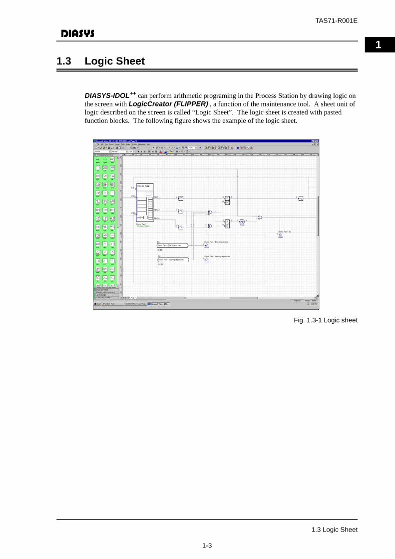
1.3 Logic SheetDIASYS-IDOL++ can perform arithmetic programing in the Process Station by drawing logic on the screen with LogicCreator (FLIPPER) , a function of the maintenance tool. A sheet unit of logic described on the screen is called “Logic Sheet”. The logic sheet is created with pasted function blocks. The following figure shows the example of the logic sheet.
Fig. 1.3-1 Logic sheet
1.3 Logic Sheet
1-3
TAS71-R001E
1
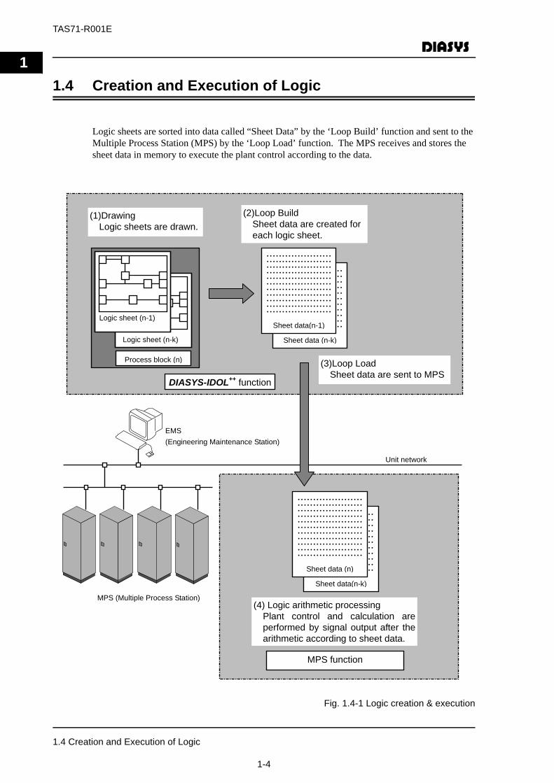
1.4 Creation and Execution of LogicLogic sheets are sorted into data called “Sheet Data” by the ‘Loop Build’ function and sent to the Multiple Process Station (MPS) by the ‘Loop Load’ function. The MPS receives and stores the sheet data in memory to execute the plant control according to the data.
Fig. 1.4-1 Logic creation & execution
EMS
(Engineering Maintenance Station)
MPS (Multiple Process Station)
Unit network
(4) Logic arithmetic processing
Plant control and calculation are
performed by signal output after the
arithmetic according to sheet data.
MPS function
.....................
.....................
.....................
.....................
.....................
.....................
.....................
.....................
.....................
.....................
.....................
Sheet data(n-k)
.....................
.....................
.....................
.....................
.....................
.....................
.....................
.....................
.....................
.....................
.....................
Sheet data (n)
DIASYS-IDOL++
function
(1)Drawing
Logic sheets are drawn.
(2)Loop Build
Sheet data are created for
each logic sheet.
(3)Loop Load
Sheet data are sent to MPS
Logic sheet (n-k)
Logic sheet (n-1)
Process block (n)
.....................
.....................
.....................
.....................
.....................
.....................
.....................
.....................
.....................
.....................
.....................
Sheet data (n-k)
.....................
.....................
.....................
.....................
.....................
.....................
.....................
.....................
.....................
.....................
.....................
Sheet data(n-1)
1.4 Creation and Execution of Logic
1-4
TAS71-R001E
1
1.5 Function Blocks1.5.1 Function Block Types
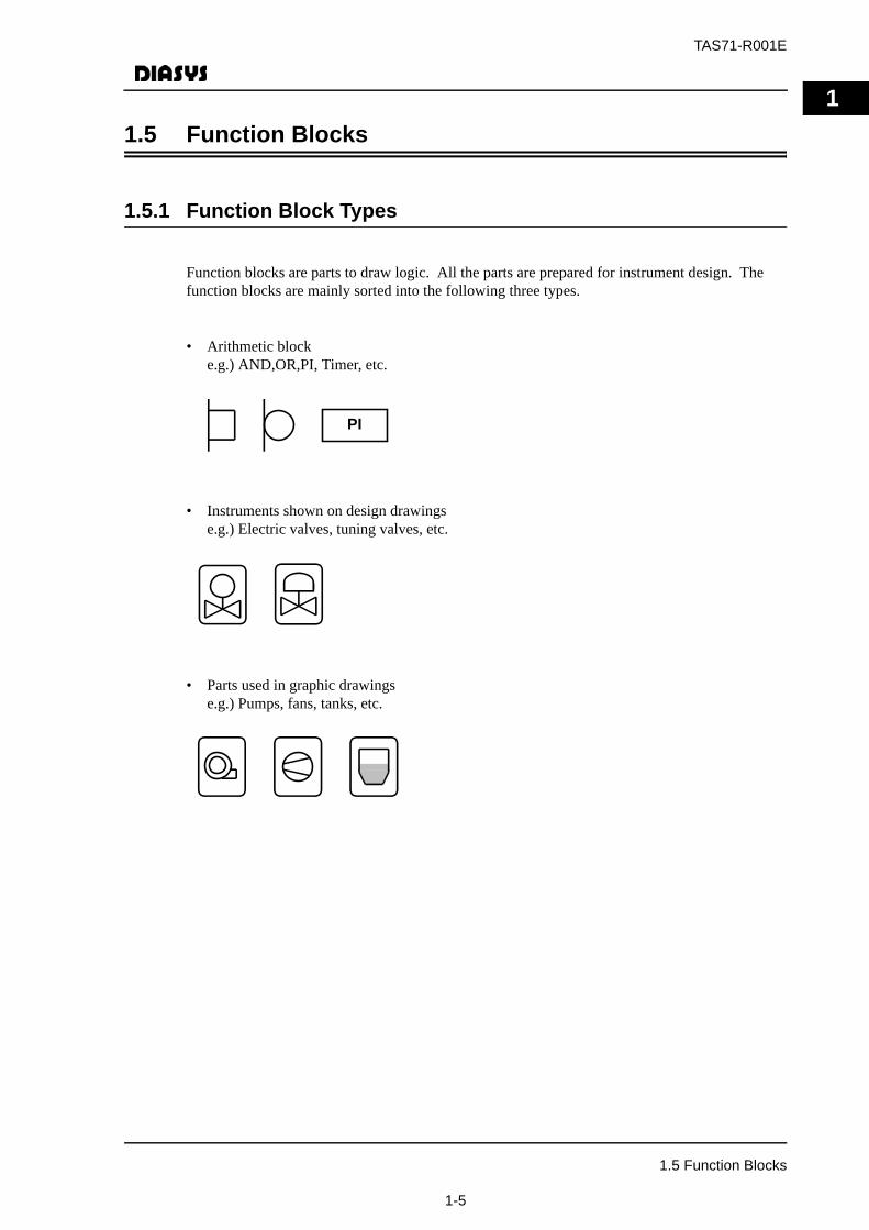
Function blocks are parts to draw logic. All the parts are prepared for instrument design. The function blocks are mainly sorted into the following three types.
• Arithmetic blocke.g.) AND,OR,PI, Timer, etc.
• Instruments shown on design drawingse.g.) Electric valves, tuning valves, etc.
• Parts used in graphic drawingse.g.) Pumps, fans, tanks, etc.
PI
1.5 Function Blocks
1-5
TAS71-R001E
1
1.5.2 Types of Logic That Can be CreatedThe following logic can be created in the logic sheet.
• Plant control logic
Control logic such as main-steam temperature control, airstream quantity control, etc.
• Operator Station display/Operation logic
Manual operation for valves on the graphic displayed in Operator Station (color switch by the status change, flickering, etc.) and logic such as linking with process values of control loop plates etc.
• Alarm-detection logic
Logic such as alarm setting/judgement, etc.
• Data creation logic for reports
Data creation logic for reports by combining function blocks such as average process for printing-report data collection, ON time sizing, pulse sizing, etc.
• Performance calculation block
Complex calculation processsing like efficient calculation etc. is available for description with combination of logic using script language blocks.
• Interface with PLC
Interface logic with PLC, which makes plant total operation and control possible.
1.5 Function Blocks
1-6
TAS71-R001E
2
2 Grammar of DIASYS-IDOL++ Function BlocksThis chapter explains the grammar of DIASYS-IDOL++ function blocks which are necessary forlogic-sheet drawing. In other words, the following is the explanation about logic elements (I/Oelements/arithmetic elements), connection lines, arrows and data delivery between logic sheets.
2.1 Logic Sheet and Drawing Elements
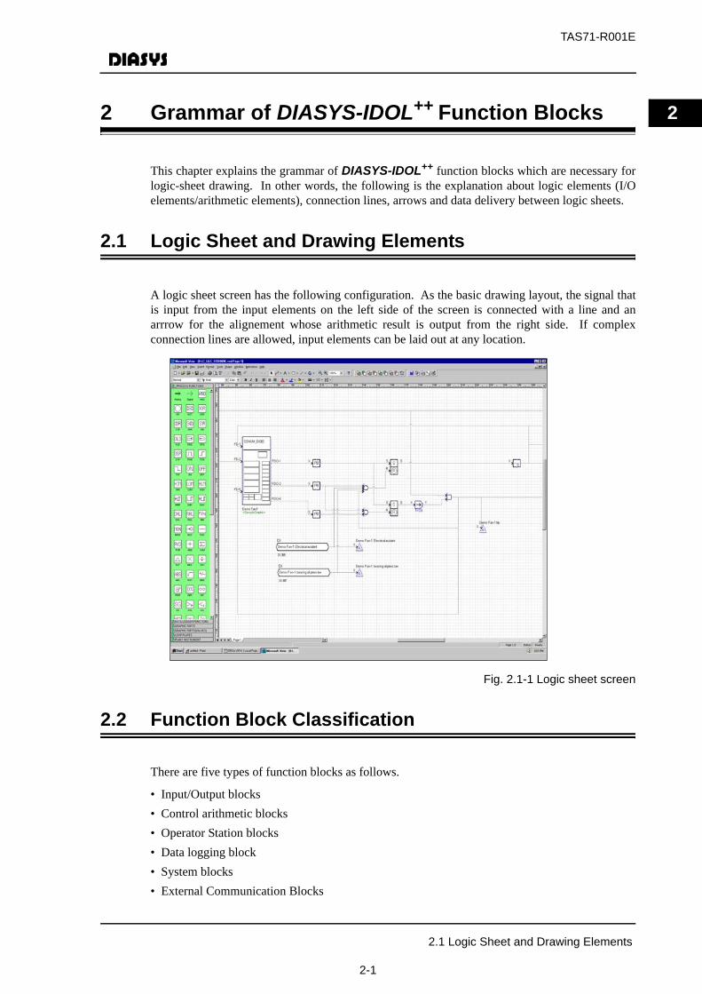
A logic sheet screen has the following configuration. As the basic drawing layout, the signal thatis input from the input elements on the left side of the screen is connected with a line and anarrrow for the alignement whose arithmetic result is output from the right side. If complexconnection lines are allowed, input elements can be laid out at any location.
Fig. 2.1-1 Logic sheet screen
2.2 Function Block Classification
There are five types of function blocks as follows.
• Input/Output blocks• Control arithmetic blocks• Operator Station blocks• Data logging block• System blocks• External Communication Blocks
2.1 Logic Sheet and Drawing Elements
2-1
TAS71-R001E
2
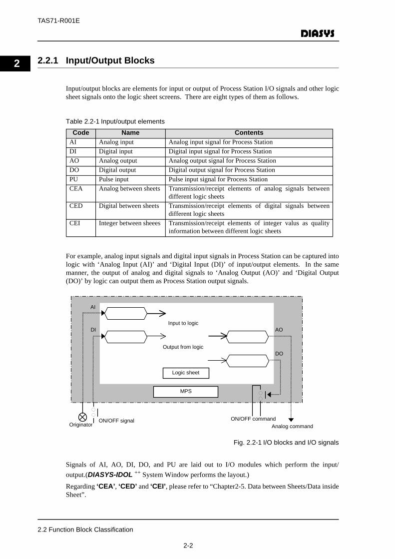
2.2.1 Input/Output BlocksInput/output blocks are elements for input or output of Process Station I/O signals and other logicsheet signals onto the logic sheet screens. There are eight types of them as follows.
Table 2.2-1 Input/output elements
For example, analog input signals and digital input signals in Process Station can be captured intologic with ‘Analog Input (AI)’ and ‘Digital Input (DI)’ of input/output elements. In the samemanner, the output of analog and digital signals to ‘Analog Output (AO)’ and ‘Digital Output(DO)’ by logic can output them as Process Station output signals.
Fig. 2.2-1 I/O blocks and I/O signals
Signals of AI, AO, DI, DO, and PU are laid out to I/O modules which perform the input/output.(DIASYS-IDOL ++ System Window performs the layout.)
Regarding ‘CEA’, ‘CED’ and ‘CEI’, please refer to “Chapter2-5. Data between Sheets/Data insideSheet”.
Code Name ContentsAI Analog input Analog input signal for Process StationDI Digital input Digital input signal for Process StationAO Analog output Analog output signal for Process StationDO Digital output Digital output signal for Process StationPU Pulse input Pulse input signal for Process StationCEA Analog between sheets Transmission/receipt elements of analog signals between
different logic sheetsCED Digital between sheets Transmission/receipt elements of digital signals between
different logic sheetsCEI Integer between sheees Transmission/receipt elements of integer valus as quality
information between different logic sheets
ON/OFF commandOriginator Analog command
ON/OFF signal
MPS
Output from logic
Input to logic
Logic sheet
AI
DI AO
DO
2.2 Function Block Classification
2-2
TAS71-R001E
2
2.2.2 Control Arithmetic BlocksControl arithmetic blocks have calculation functions to execute control logic. They execute thecalculation designated by each block according to the signal values connected to the arithmeticelement, in order to output the result.
Control logic are described with combination of control arithmetic blocks. Refer to “Appendix-1.Function Block Description” for the detailed functions of the elements.
2.2.3 Operator Station Blocks
Operator station blocks are used for drawing system diagrams such as process flow, plant flow,etc. They are prepared with control and monitoring blocks for plant configuration devices, e.g.indicators (digital indicators/firm-shape analog indicators), auxilliaries (tank level/pumps).
Refer to “DIASYS-IDOL++ Graphic Parts Reference Guide (TAS71-R006E)” for the detailedfunctions of each block.
2.2.4 Data Logging Blocks
Data logging blocks are used for warning judgement and printing-report data collection includedin the data logger function.
Refer to “DIASYS-IDOL++ Graphic Parts Reference Guide (TAS71-R006E)” for the detailedfunctions of each block.
2.2.5 System Blocks
These are blocks for analog I/O, digital I/O, and integer value I/O used by the system in ProcessStation. They are not used in normal logic but only for Process Station design.
Refer to “Appendix-1. Function Block Description” for the detailed functions of the elements.
2.2.6 External Communication Blocks
The external communication blocks support the communications with networks outsideNetmation, such as IEC60870 communication.For details about the features of each block, see “Appendix-1 Explanation of Functional Blocks”.
2.2 Function Block Classification
2-3

TAS71-R001E
2
2.2.7 Tag Names/Signal NamesTag and signal names can be set up in function blocks.
They are set up when the logic sheet is drawn. Please refer to “DIASYS Netmation®
LogicCreator (FLIPPER) User’s Guide (TAS71-U004E)” for the detailed explanation.
Fig. 2.2-2 Tag/signal names
AI example
Signal name :FUEL OIL SUPPPLY PRESS-2Tag name :BTMP-AI002
Signal range :0.0 to 1.0%
AO example
Signal name :CONTROL OIL SUPPLY PRESS
Tag name :ABC-RB.01
Signal range :0.0 to 1. 0%
2.2 Function Block Classification
2-4

TAS71-R001E
2
2.2.8 ParameterParameters can be defined with external input and fixed values.
Principally, those for function blocks with possibility to become variable in control can performexternal input. However, there are function blocks such as ‘Polyline Function (FX)’ with manyparameters and special-structured parameters like loop names of ‘Loop Arithmetic Call (CLL)’,which can only set up with fixed-value definition. Function block codes are used as parameters ifthere are external input corresponding to the parameters. If there are not any input, they willperform arithmetic using the interior parameter of the function blocks.
Parameters can be shown as below for the same function block.
(1) In the Case of Exterior Input
(2) In the Case of No Exterior Input
The parameter set up in the property is used.
2.2 Function Block Classification
2-5
TAS71-R001E
2
2.3 Connection Lines2.3.1 What Connection Lines are
In the logic sheet screen, the data captured by I/O blocks such as ‘Analog Input (AI)’ and ‘DigitalInput (DI)’ are connected to arithmetic elements with connection lines. Control logic is formedby input of arithmetic-element output signals to another arithmetic elements by connection lines.
Moreover, input of arithmetic-element output signals to output elements like ‘Analog Output(AO)’ and ‘Digital Output (DO)’ with connection lines can output command values and controlarithmetic results from the MPS.
In short, the connection lines show the data flow.
(1) Types of Connection Lines
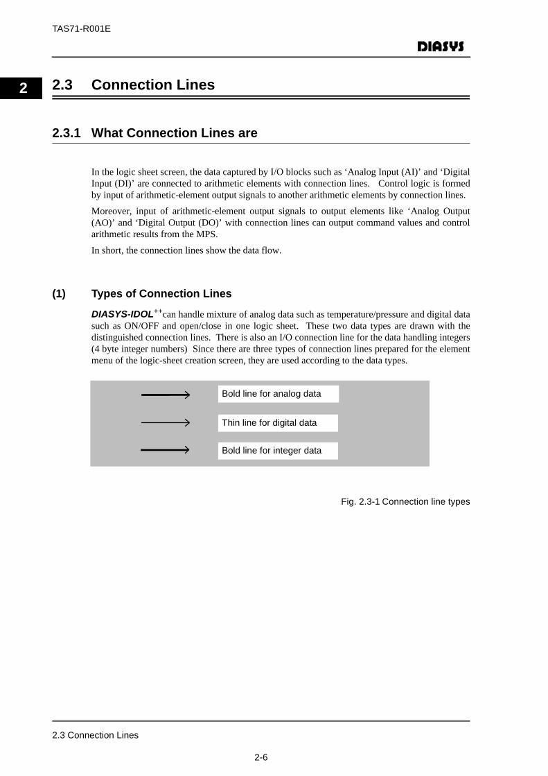
DIASYS-IDOL++can handle mixture of analog data such as temperature/pressure and digital datasuch as ON/OFF and open/close in one logic sheet. These two data types are drawn with thedistinguished connection lines. There is also an I/O connection line for the data handling integers(4 byte integer numbers) Since there are three types of connection lines prepared for the elementmenu of the logic-sheet creation screen, they are used according to the data types.
Fig. 2.3-1 Connection line types
Bold line for analog data
Thin line for digital data
Bold line for integer data
2.3 Connection Lines
2-6

TAS71-R001E
2
(2) Connection Error for LinesIt will be an error if lines that do not conform are tried for connection because the data types aredetermined for the connection according to the logic element type.Fig. 2.3-2 Example of wrong connections
Though an ‘AI’ element outputs analog data, they are connected with the digital-data line.
Though a ‘S ’’ element inputs digital data from No.1&2 inputs, the analog data line is connected with No. 2 inpout.
R
2.3 Connection Lines
2-7
TAS71-R001E
2
2.4 I/O Signal Distinction2.4.1 Function Blocks with Multiple Input
Some function blocks are input with multiple signals. Those blocks are classified into two typesaccording to the input signal handling.
(1) Those that handle all input signals in the same manner as far as the meaning is concerned
e.g.)AND, OR, ADD, etc.(2) Whose input signals have different meanings in terms of function-block arithmetic
processing.
e.g.)SSR, DLT, PI, etc.In item (2), logic should be described by distinguishing I/O signals.
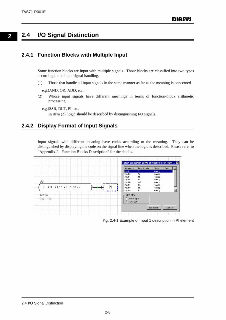
2.4.2 Display Format of Input Signals
Input signals with different meaning have codes according to the meaning. They can bedistinguished by displaying the code on the signal line when the logic is described. Please refer to“Appendix-2. Function Blocks Description” for the details.
Fig. 2.4-1 Example of Input 1 description in PI element
2.4 I/O Signal Distinction
2-8

TAS71-R001E
2
Also, arrows can be used to distinguish the input. However, this method can be applied to fourinput types at the maximum. The same arrows are displayed from the input 5 onward as thosestarting from input 1.The following are the shapes of four arrrows.
Fig. 2.4-2 Arrow types
Fig. 2.4-3 Example of Input 1,2,and 3 in T element
Input 1
Input 2
Input 3
Input 4
2.4 I/O Signal Distinction
2-9
TAS71-R001E
2
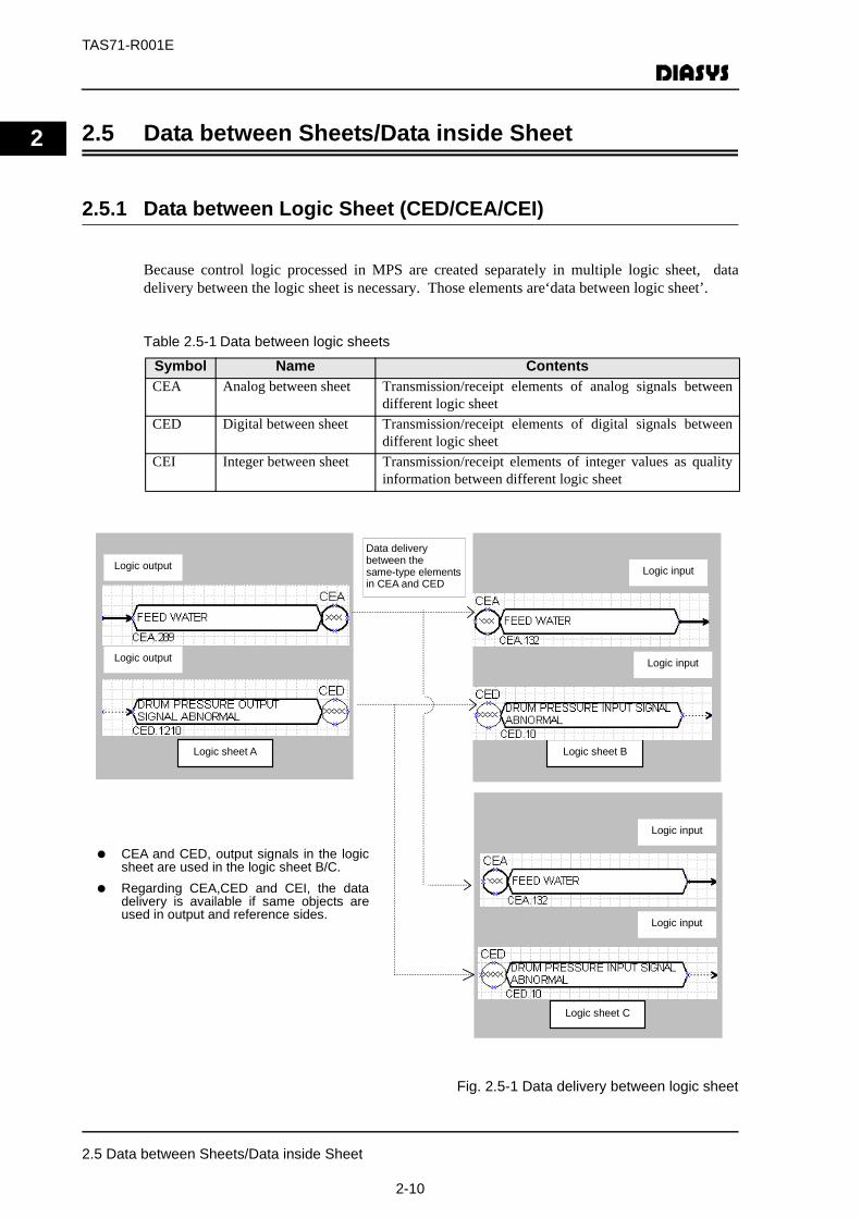
2.5 Data between Sheets/Data inside Sheet2.5.1 Data between Logic Sheet (CED/CEA/CEI)
Because control logic processed in MPS are created separately in multiple logic sheet, datadelivery between the logic sheet is necessary. Those elements are‘data between logic sheet’.
Table 2.5-1 Data between logic sheets
Fig. 2.5-1 Data delivery between logic sheet
Symbol Name ContentsCEA Analog between sheet Transmission/receipt elements of analog signals between
different logic sheetCED Digital between sheet Transmission/receipt elements of digital signals between
different logic sheetCEI Integer between sheet Transmission/receipt elements of integer values as quality
information between different logic sheet
Logic output
Logic output
Logic sheet A
Data delivery between the same-type elements in CEA and CED
Logic sheet B
Logic input
Logic input
Logic sheet C
Logic input
Logic input
CEA and CED, output signals in the logicsheet are used in the logic sheet B/C.
Regarding CEA,CED and CEI, the datadelivery is available if same objects areused in output and reference sides.
2.5 Data between Sheets/Data inside Sheet
2-10
TAS71-R001E
2
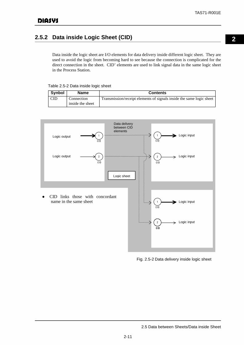
2.5.2 Data inside Logic Sheet (CID)Data inside the logic sheet are I/O elements for data delivery inside different logic sheet. They areused to avoid the logic from becoming hard to see because the connection is complicated for thedirect connection in the sheet. CID’ elements are used to link signal data in the same logic sheetin the Process Station.
Table 2.5-2 Data inside logic sheet
Fig. 2.5-2 Data delivery inside logic sheet
Synbol Name ContentsCID Connection
inside the sheetTransmission/receipt elements of signals inside the same logic sheet
CID links those with concordantname in the same sheet
Logic output
Logic output
Logic input
Logic input
Logic input
Logic input
Logic sheet
Data delivery between CID elements
1
CID
2
CID
1
CID
2
CID
1
CID
2
CID
2
CID
2.5 Data between Sheets/Data inside Sheet
2-11
TAS71-R001E
2
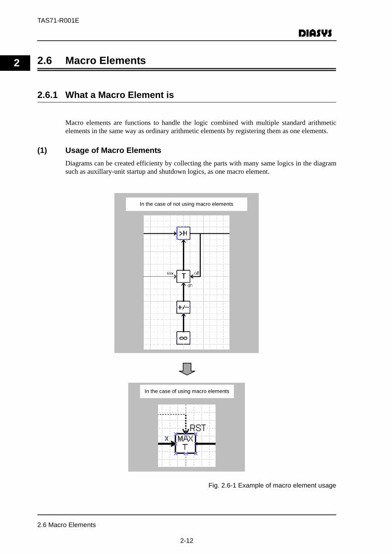
2.6 Macro Elements2.6.1 What a Macro Element is
Macro elements are functions to handle the logic combined with multiple standard arithmeticelements in the same way as ordinary arithmetic elements by registering them as one elements.
(1) Usage of Macro ElementsDiagrams can be created efficienty by collecting the parts with many same logics in the diagramsuch as auxillary-unit startup and shutdown logics, as one macro element.
Fig. 2.6-1 Example of macro element usage
In the case of using macro elements
In the case of not using macro elements
2.6 Macro Elements
2-12
TAS71-R001E
2
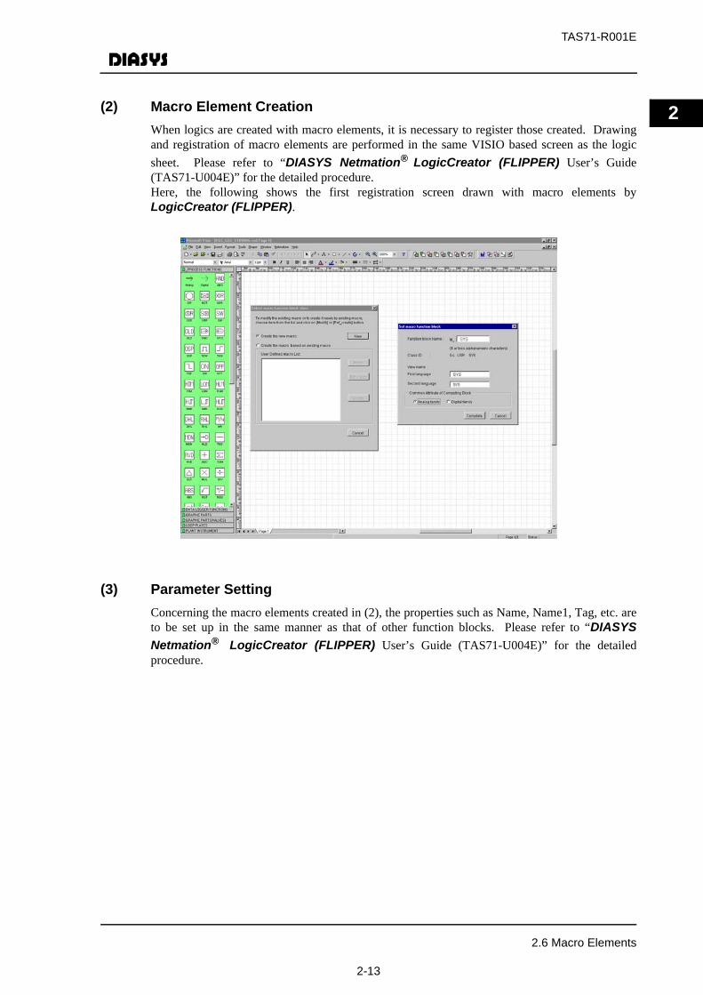
(2) Macro Element CreationWhen logics are created with macro elements, it is necessary to register those created. Drawingand registration of macro elements are performed in the same VISIO based screen as the logicsheet. Please refer to “DIASYS Netmation® LogicCreator (FLIPPER) User’s Guide(TAS71-U004E)” for the detailed procedure.Here, the following shows the first registration screen drawn with macro elements byLogicCreator (FLIPPER).(3) Parameter SettingConcerning the macro elements created in (2), the properties such as Name, Name1, Tag, etc. areto be set up in the same manner as that of other function blocks. Please refer to “DIASYSNetmation® LogicCreator (FLIPPER) User’s Guide (TAS71-U004E)” for the detailedprocedure.
2.6 Macro Elements
2-13

TAS71-R001E
2
2.7 Quality Information Added to Function Blocks
(1) What Quality Information is
DIASYS-IDOL++ function blocks have various quality data (the data set and input signalabnormality) other than the process data as additional information.For instance, logic data have the quality as attached information and are transmitted via thefunction blocks to change the quality of data display in Operator Station. The transmission rulesand the designation if the transmission is peformed or not are different depending on the propertyof the logic composed of function blocks. Therefore, arithmetic-element calculation methods etc.are previously defined using quality judgement, element output in case of abnormality, andquality-abnormality signals for the input.
The quality information is displayed when the property is opened during OPS logic-statusmonitoring.
Example)
FX
Input signal quality is transmitted to the output. The green display changes as soon as it is judged as quality abnormality.
T
Input signal quality on the selected side is transmitted to the output.
2.7 Quality Information Added to Function Blocks
2-14

TAS71-R001E
2
(2) Quality-Information TypesData quality has a structure to distinguish if the following six items and their factors are occurringin their functions or transmitted from input signals.Table 2.7-1 List of quality information
(3) Thinking on Quality TransmissionInput signal quality is transmitted to the output quality for arithmetic performance of functionblocks. The action is based on the following rules.
Table 2.7-2 List of quality transmission
Quality factor ContentsRange-over upper limit AI signal range is over the upper limit.Range-over lower limit AI signal range is over the lower limit.Data-accessunavailability
The access is not performed normally to I/O controller or I/Omodule. The communication is stopped for communicationdata between systems.
Block-arithmetic error The calculation is not performed normally following thearithmetic specification.(Zero division, negative square-root extraction, etc.)
Scan exclusion The scan exclusion is performed manually.Data set The data set is performed manually.
Items RulesOperator Stationdisplay and printingreports
To display and print the process status on the Operator Station screen orthe reports, the colors and the display format should be modifiedaccording the quality. The input signal quality should be all transmittedfor the Operator Station interface blocks.
Digital input signal Regarding the digital signal input to function blocks, it is not targeted asthe quality transmission principally.
Function blocks withclear I/O relation
The quality is transmitted for those whose output are decided by one inputsignal such as line-shape conversion, polyline function, etc. On the otherhand, the quality transmission is not performed for those whosecalculation results are output for multiple input signals, e.g. proportionalintegral, analog memory, etc.
The same number ofmultiple input
When multiple input such as addition, multiplication, etc. have the samemeaning, the quality OR is transmitted for each input signal.
Signal selection Regarding the function blocks that select one signal from multiple inputsuch analog switching/high value selection, etc., the calculation isimplemented ignoring the quality and the selected signal quality istransmitted to the output.
Blocks performed withdata operation
Regarding the function blocks performed with scan exclusion and data setin the data operation functions, only the quality for scan exclusion anddata set is output regardless of the I/O signal quality.
2.7 Quality Information Added to Function Blocks
2-15
TAS71-R001E
2
2.8 Function-Block PropertyThe property of function blocks is shown below.
• Items required of setting
Parameter used in control arithmeticSignal/tag names used in I/O, warnings, etc.Engineering-value range used in I/O processing of AI and AO
• Items not required of setting
There are elements added with tag and names but not required of input basically because they are significant only when they are released . e.g.) arithmetic element names.
2.8 Function-Block Property
2-16
TAS71-R001E
3
3 Creating Logic
In this chapter, the basic procedure is explained for the control-logic creation using DIASYS-IDOL++ function blocks. Please refer to “DIASYS Netmation® LogicCreator (FLIPPER)User’s Guide (TAS71-U004E)” for the detailed explantion of logic creation operation on themaintenance tool.
3.1 Basic Operation
LogicCreator (FLIPPER) start-up operation is explained here. First of all, it is necessary tostart up ORCA View to create logic.
3.1.1 Startup of LogicCreator (FLIPPER)
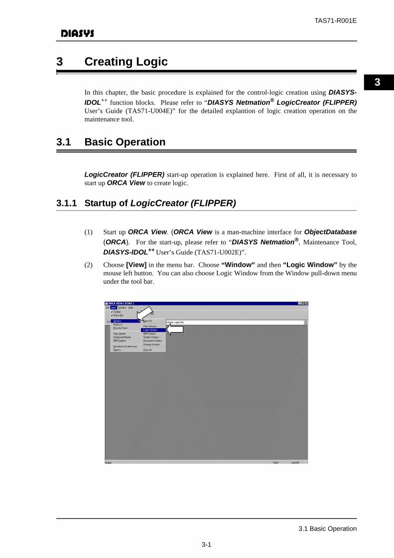
(1) Start up ORCA View. (ORCA View is a man-machine interface for ObjectDatabase(ORCA). For the start-up, please refer to “DIASYS Netmation®, Maintenance Tool,DIASYS-IDOL++ User’s Guide (TAS71-U002E)”.
(2) Choose [View] in the menu bar. Choose “Window” and then “Logic Window” by themouse left button. You can also choose Logic Window from the Window pull-down menuunder the tool bar.
3.1 Basic Operation
3-1
TAS71-R001E
3
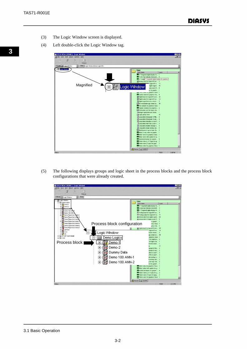
(3) The Logic Window screen is displayed.
(4) Left double-click the Logic Window tag.
(5) The following displays groups and logic sheet in the process blocks and the process blockconfigurations that were already created.
Magnified
Process block
Process block configuration
3.1 Basic Operation
3-2

TAS71-R001E
3
(6) Left-click the tag of the group you wish to open. The logic sheet that belongs to the chosengroup sheet is displayed.
(7) Right-click on the logic sheet and then choose [Open].
(8) VISIO2000-base LogicCreator (FLIPPER) is started up.
3.1 Basic Operation
3-3

TAS71-R001E
3
3.2 Creating Logic Sheet
A logic sheet is created with the following composition.
Fig. 3.2-1 Logic-sheet configuration diagram
Note
Process block configurations and process blocks are used for sorting out and saving the sheets as directories.
Process Block Configuration
Logic Window
Process block Block1
Sheet
Sheet
Sheet
Sheet
Process block Block2
3.2 Creating Logic Sheet
3-4
TAS71-R001E
3
3.2.1 Creating New Process Block Configuration
The following operation should be implemented for creating a new process block configuration.
(1) Right-click Logic Winow or choose Create New in [Object (O)] in the menu bar.
(2) The “Create New - Class Selection” dialogue box is displayed. Click “Territory”.When creating a logic sheet by using LogicCreator (FLIPPER), choose the “Territory”tab and then “Logic group”.
“Territory” sheet:It is one unit that mainly stores the list that belongs to a group and hasthe same structure as that of a Windows folder.
“Design” sheet:Body object itself is stored.
“Collection” sheet:It is an aggregate of data included in objects and stores data with arraystructures.
Choose the [Next] button.
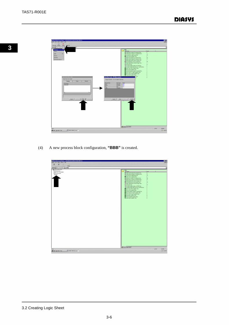
(3) The “Property Setup for FIN Object” dialogue box is displayed. Input a name of theprocess block configuration in the “Name” (e.g.: ABC). Here, input the “BBB” in it asan example.
“Name” is not usually used for English-version system. It is used in the case of switchingto other languages. Please refer to Chapter 2.6.16 for the method of switching the indicatedlanguage. The default, “Logic group” should remain here as an example. Inputinformation on supplementary data in the “Tag” as the need arises. The default, “Key”should remain here as an example. As a general rule, a recognition number of ControlSystem is to be input as a Tag. -/*Choose the [Complete] button.
Note
Input of “Property setup” is defined when the letters turn blue.
3.2 Creating Logic Sheet
3-5
TAS71-R001E
3
(4) A new process block configuration, “BBB” is created.
3.2 Creating Logic Sheet
3-6
TAS71-R001E
3
3.2.2 Adding a Process Block to a Process Block Configuration
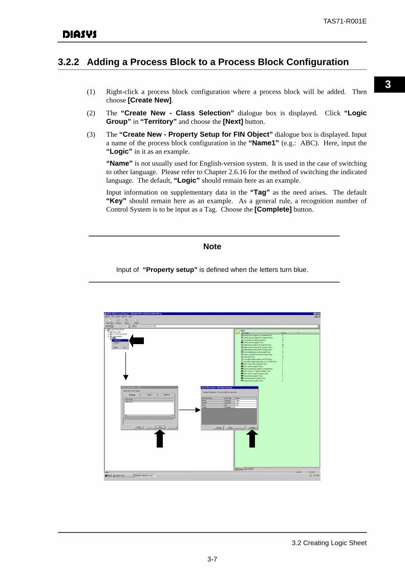
(1) Right-click a process block configuration where a process block will be added. Thenchoose [Create New].
(2) The “Create New - Class Selection” dialogue box is displayed. Click “LogicGroup” in “Territory” and choose the [Next] button.
(3) The “Create New - Property Setup for FIN Object” dialogue box is displayed. Inputa name of the process block configuration in the “Name1” (e.g.: ABC). Here, input the“Logic” in it as an example.
“Name” is not usually used for English-version system. It is used in the case of switchingto other language. Please refer to Chapter 2.6.16 for the method of switching the indicatedlanguage. The default, “Logic” should remain here as an example.
Input information on supplementary data in the “Tag” as the need arises. The default“Key” should remain here as an example. As a general rule, a recognition number ofControl System is to be input as a Tag. Choose the [Complete] button.
Note
Input of “Property setup” is defined when the letters turn blue.
3.2 Creating Logic Sheet
3-7

TAS71-R001E
3
(4) Left double-click the BBB indication tag. You can see that the process block, “Logic” isadded to the process block configuration.
3.2.3 Adding a Logic Sheet to a Process Block
(1) Right-click the process block where a logic sheet is added and then choose [Create New].
(2) The “Create New - Class Selection” dialogue box is displayed. Choose“Downloadable logic sheet (standard)” in the “Design” sheet. Choose the [Next]button.
(3) The “Create New - Body Object Selection” dialogue box is displayed. Check“Create new Body Object”. Choose the [Next] button.
3.2 Creating Logic Sheet
3-8
TAS71-R001E
3
Note“Create new Body Object” is chosen as default. In case body objects already exist and new files are created from their diversion, choose “Select Existing Body Object”. In this case, there are two methods, namely, the one to select appropriate objects from the list and the other to find them from the “TAG Input/Select” column.
(4) The “Create New - Property Setup for Body Object” dialogue box is displayed.Input the required information in the item. Although there are not any properties that needinput without fail here, input of “Name1” will make it easier to recognize the data. InputTOP2 in the “Name1” and MDS for “Author” Choose the [Next] button.
Name: This is not used in English-version system. Name1: Input a name of a logic sheet.Tag: Input a sheet number.Revision number: Please do not input as it is automatically processed.Revised date: Input a revision date.Drawing No.: Input a drawing number.Create date: Input a date of the file creationAuthor: Input a name of the person who created the file.Reviser: Input a name of the person who revised the file.Comment: Input a reason for the revision.Submit status: Input a status of submitting drawing. Access Flag: Please do not input due to its exclusive control purpose
Note
Input is defined when the letters turn blue.
3.2 Creating Logic Sheet
3-9

TAS71-R001E
3
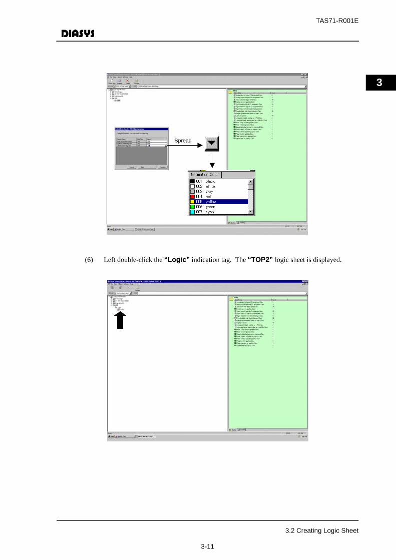
(5) The “Create New - Property Setup for Fin Object” dialogue box is displayed. Width,height and color of the background are set up for monitoring logic computing status. Inputof the background width and height is not required as LogicCreator (FLIPPER)automatically calculates them from the sheet size established at the time of Loop-build andstores them in this domain.
Background width for monitoring view: Width number value (pixel value)
Background height for monitoring view: Height number value (pixel value)
Background color for monitoring view: Input a number from the dialogue box.
The pull-down menu is displayed by clicking a color type in “Date Type” when thebackground color is input for monitoring view. On clicking the pull-down menu, theNetmation Color dialogue box is shown. Choose a color number (001 to 430).
Here, choose “005”for yellow as an example.
Choose the [Complete] button.
3.2 Creating Logic Sheet
3-10
TAS71-R001E
3
(6) Left double-click the “Logic” indication tag. The “TOP2” logic sheet is displayed.
Spread
3.2 Creating Logic Sheet
3-11
TAS71-R001E
3
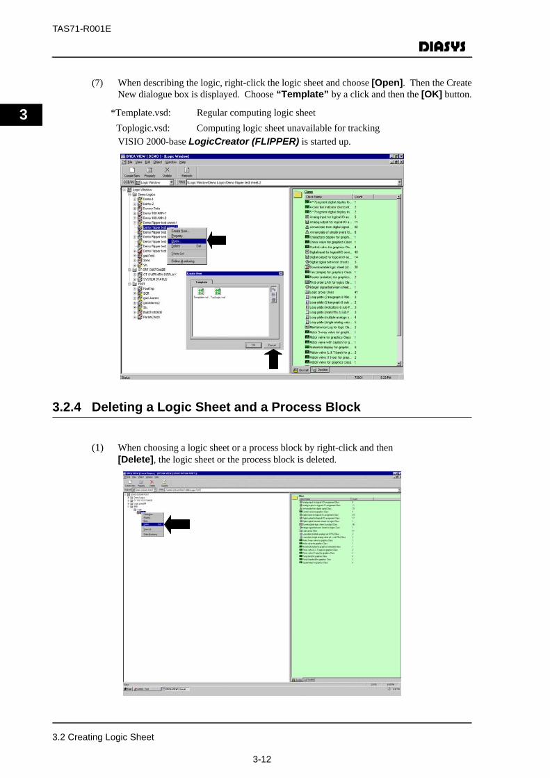
(7) When describing the logic, right-click the logic sheet and choose [Open]. Then the CreateNew dialogue box is displayed. Choose “Template” by a click and then the [OK] button.
*Template.vsd: Regular computing logic sheetToplogic.vsd: Computing logic sheet unavailable for tracking VISIO 2000-base LogicCreator (FLIPPER) is started up.
3.2.4 Deleting a Logic Sheet and a Process Block
(1) When choosing a logic sheet or a process block by right-click and then[Delete], the logic sheet or the process block is deleted.
3.2 Creating Logic Sheet
3-12

TAS71-R001E
3
3.3 Logic Sheet Drawing
The procedure of drawing is explained with the following logic sheet as an example.
(1) This logic sheet is a logic to output the sum of two AI (Analog Input) signals to AO(Analog Output) signal.
3.3.1 Element Drawing
(1) ‘AI277’ is to be drawn. Choose the element to be drawn from a stencil and drag it to theposition you wish it to be drawn. Choose ‘AI’ in the “PROCESS FUNCTIONS”. ‘AI’element is drawn at the designated position.
(2) The “Create New - Body Object Selection” dialogue box is displayed. Put a mark on“Create new Body Object” as an example and then choose the [Next] button. In caseof using the data that were already set up by other Window, etc., choose “Selectexisting Body Object” and then an appropriate tag.
Note
When AI is newly created by LogicCreator (FLIPPER) as the above, it should be set with necessary setup by other Window (I/O allocation of System Window).
3.3 Logic Sheet Drawing
3-13
TAS71-R001E
3
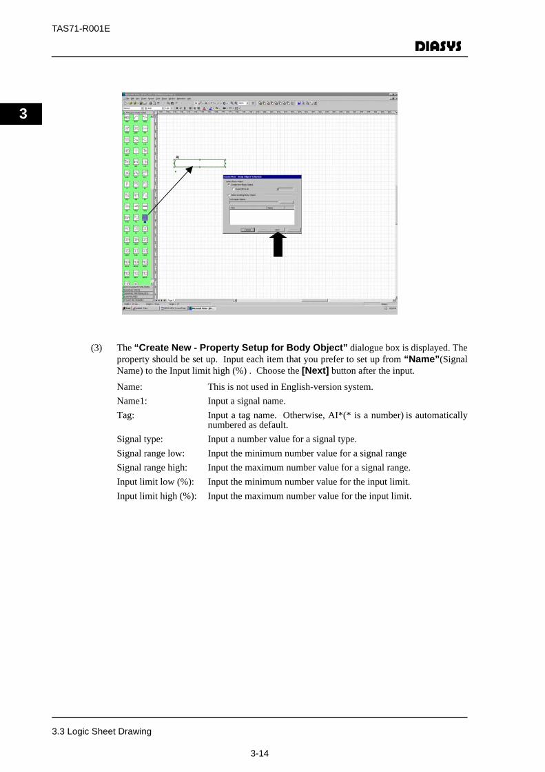
(3) The “Create New - Property Setup for Body Object” dialogue box is displayed. Theproperty should be set up. Input each item that you prefer to set up from “Name”(SignalName) to the Input limit high (%) . Choose the [Next] button after the input.
Name: This is not used in English-version system.Name1: Input a signal name.Tag: Input a tag name. Otherwise, AI*(* is a number) is automatically
numbered as default.Signal type: Input a number value for a signal type.Signal range low: Input the minimum number value for a signal rangeSignal range high: Input the maximum number value for a signal range.Input limit low (%): Input the minimum number value for the input limit.Input limit high (%): Input the maximum number value for the input limit.
3.3 Logic Sheet Drawing
3-14
TAS71-R001E
3
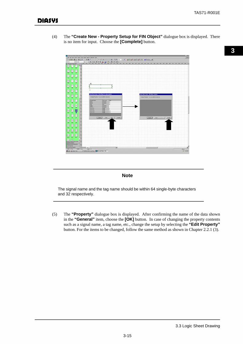
(4) The “Create New - Property Setup for FIN Object” dialogue box is displayed. Thereis no item for input. Choose the [Complete] button.
Note
The signal name and the tag name should be within 64 single-byte characters and 32 respectively.
(5) The “Property” dialogue box is displayed. After confirming the name of the data shownin the “General” item, choose the [OK] button. In case of changing the property contentssuch as a signal name, a tag name, etc., change the setup by selecting the “Edit Property”button. For the items to be changed, follow the same method as shown in Chapter 2.2.1 (3).
3.3 Logic Sheet Drawing
3-15
TAS71-R001E
3
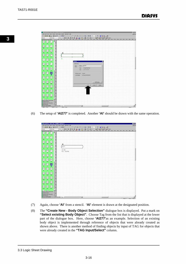
(6) The setup of ‘AI277’ is completed. Another ‘AI’ should be drawn with the same operation.
(7) Again, choose ‘AI’ from a stencil. ‘AI’ element is drawn at the designated position.
(8) The “Create New - Body Object Selection” dialogue box is displayed. Put a mark on“Select existing Body Object”. Choose Tag from the list that is displayed at the lowerpart of the dialogue box. Here, choose ‘AI277’as an example. Selection of an existingbody object is implemented through reference of objects that were already created asshown above. There is another method of finding objects by input of TAG for objects thatwere already created in the “TAG Input/Select” column.
3.3 Logic Sheet Drawing
3-16

TAS71-R001E
3
(9) The “Create New - Property Setup for FIN Object” dialogue box is displayed.Choose the [Complete] button.
(10) The “Property” dialogue box is displayed. The setup is the same as explained in Chapter2.2.1 (5). Choose the [OK] button. The setup of ‘AI277’ is completed.
(11) Then, ‘AO001’ is to be drawn to indicate an output signal to the sheet. After choosing theelement to be drawn from a stencil, drag it to the position you wish it to be drawn. Choose‘AO’ in the “PROCESS FUNCTIONS” stencil. ‘AO’ element is drawn at the designatedposition.
(12) The “Create New - Body Object Selection” dialogue box is displayed. Put a mark on“Create new Body Object” as an example and then choose the [Next] button.
(13) The “Create New - Property Setup for Body Object” dialogue box is displayed. Theproperty should be set up. Input each item that you prefer to set up from “Name”(SignalName) to the output limit high (%). Choose the [Next] button after the input.
(14) Name: This is not used in English-version system.
Name1: Input a signal name.Tag: Input a tag name.Otherwise, AI * (* is a number) is automatically
numbered as default.Signal type: Input a number value for a signal type.Signal range low: Input the minimum number value for a signal range.Signal range high: Input the maximum number value for a signal range.Output limit low (%): Input the minimum number value for the output limitOutput limit high (%): Input the maximum number value for the output limit.
3.3 Logic Sheet Drawing
3-17

TAS71-R001E
3
(15) The “Create New - Property Setup for Fin Object” dialogue box is displayed. Thereis no item for input. Choose the [Complete] button.
(16) The “Property” dialogue box is displayed. After confirming the name of the data shownin the “General” item, choose the [OK] button. In case of changing the property contentssuch as a signal name, a tag name, etc., change the setup by selecting the “Edit Property”button. For the items to be changed, follow the same method as shown in Chapter 2.2.1 (3).Here, the following shows 158 is the No. for the Control System as an example.
3.3 Logic Sheet Drawing
3-18
TAS71-R001E
3
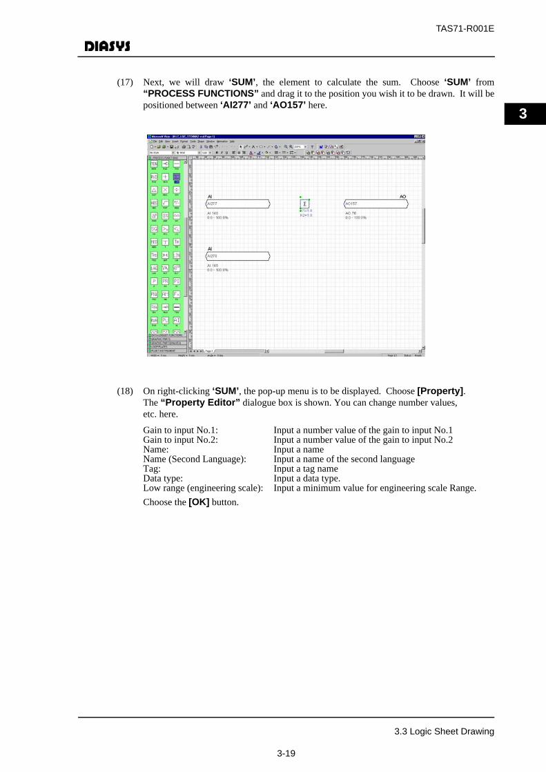
(17) Next, we will draw ‘SUM’, the element to calculate the sum. Choose ‘SUM’ from“PROCESS FUNCTIONS” and drag it to the position you wish it to be drawn. It will bepositioned between ‘AI277’ and ‘AO157’ here.
(18) On right-clicking ‘SUM’, the pop-up menu is to be displayed. Choose [Property].The “Property Editor” dialogue box is shown. You can change number values, etc. here.
Gain to input No.1: Input a number value of the gain to input No.1Gain to input No.2: Input a number value of the gain to input No.2Name: Input a nameName (Second Language): Input a name of the second languageTag: Input a tag nameData type: Input a data type.Low range (engineering scale): Input a minimum value for engineering scale Range.Choose the [OK] button.
3.3 Logic Sheet Drawing
3-19

TAS71-R001E
3
3.3.2 Drawing Connection Lines
Drawn elements are to be connected with a connection line. The connection line is drawn byselecting positions to be connected after the selection of analog signal or digital signal from the“PROCESS FUNCTIONS” stencil and the connector tool in the menu bar.
Moreover, the stencil for the analog/digital lines is opened for the connection as shown above, byselecting [Connector Tool] - [Connect Analog Line] or [Connect Digital Line] ofNetmation in the menu bar. Another method is to select [Connect Analog Line] or[Connect Digital Line] tool button.
(1) ‘AI277’ and ‘SUM’ will be connected with a connection line. Left-click the ConnectorTool in the tool bar. Then, choose ‘Analog’ element from the “PROCESSFUNCTIONS” stencil by clicking.
(2) Put a cursor mark on ‘AI277’.
(3) Next, move the cursor to ‘SUM’ with the left button pressed down. Then, release thebutton. The two elements are connected with the line now.
(4) When they are connected, the “Select connection points of function blockinput…” dialogue box is displayed. It specify a signal type and a signal name to be inputto ‘SUM’. Next, choose the “Selection” button after choosing an arrow type or a fonttype for “Line style”.
Arrow type: Only for an arrowFont type: Input signal name is displayed on the arrow.
3.3 Logic Sheet Drawing
3-20

TAS71-R001E
3
(5) ‘AI277’and’SUM’,’AO157’and ‘SUM’are connected with connection lines with the sameoperation. The connection lines are completed now.In case of moving ‘AI277’and’SUM’onthe screen, the connection line is automatically connected and the shape of the connectionline changes. Please refer to Chapter 3.3.3 for “Undoing Connection Line”.
3.3 Logic Sheet Drawing
3-21
TAS71-R001E
3
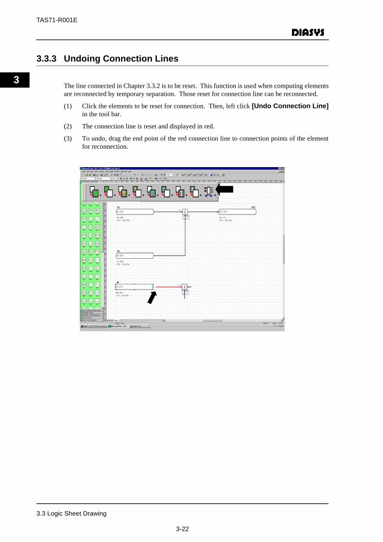
3.3.3 Undoing Connection Lines
The line connected in Chapter 3.3.2 is to be reset. This function is used when computing elementsare reconnected by temporary separation. Those reset for connection line can be reconnected.
(1) Click the elements to be reset for connection. Then, left click [Undo Connection Line]in the tool bar.
(2) The connection line is reset and displayed in red.
(3) To undo, drag the end point of the red connection line to connection points of the elementfor reconnection.
3.3 Logic Sheet Drawing
3-22
TAS71-R001E
3
3.4 Creating Sheet Data
The sheet data used for MPS computing are created from created logic sheet. Creating sheet datais executed by [Build] function of [Netmation] functions in the tool bar.
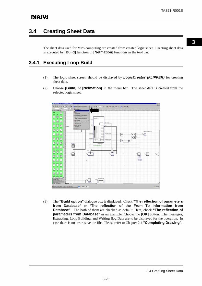
3.4.1 Executing Loop-Build
(1) The logic sheet screen should be displayed by LogicCreator (FLIPPER) for creatingsheet data.
(2) Choose [Build] of [Netmation] in the menu bar. The sheet data is created from theselected logic sheet.
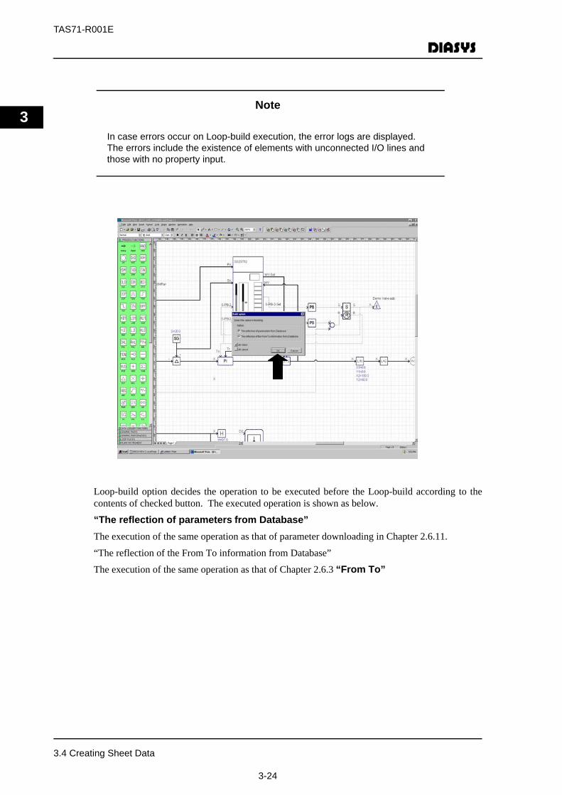
(3) The “Build option” dialogue box is displayed. Check “The reflection of parametersfrom Database” or “The reflection of the From To information fromDatabase”. The both of them are checked as default. Here, check “The reflection ofparameters from Database” as an example. Choose the [OK] button. The messages,Extracting, Loop Building, and Writing Ilog Data are to be displayed for the operation. Incase there is no error, save the file. Please refer to Chapter 2.4 “Completing Drawing”.
3.4 Creating Sheet Data
3-23
TAS71-R001E
3
NoteIn case errors occur on Loop-build execution, the error logs are displayed.The errors include the existence of elements with unconnected I/O lines and those with no property input.
Loop-build option decides the operation to be executed before the Loop-build according to thecontents of checked button. The executed operation is shown as below.
“The reflection of parameters from Database”The execution of the same operation as that of parameter downloading in Chapter 2.6.11.
“The reflection of the From To information from Database”
The execution of the same operation as that of Chapter 2.6.3 “From To”
3.4 Creating Sheet Data
3-24
TAS71-R001E
3
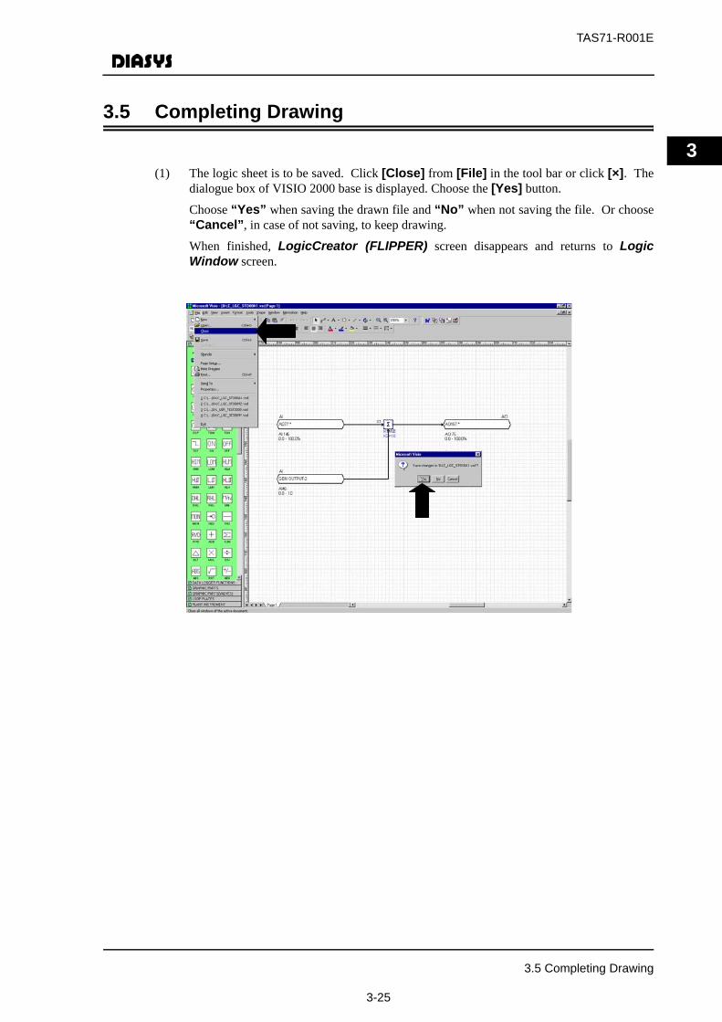
3.5 Completing Drawing
(1) The logic sheet is to be saved. Click [Close] from [File] in the tool bar or click [×]. Thedialogue box of VISIO 2000 base is displayed. Choose the [Yes] button.
Choose “Yes” when saving the drawn file and “No” when not saving the file. Or choose“Cancel”, in case of not saving, to keep drawing.
When finished, LogicCreator (FLIPPER) screen disappears and returns to LogicWindow screen.
3.5 Completing Drawing
3-25

TAS71-R001E
3
3.6 Loading Sheet Data
Sheet data is to be loaded to process station from ORCA View System Window. Please refer toDIASYS Netmation®, Maintenance Tool, DIASYS-IDOL++ User’s Guide (TAS71-U002E) forthe details of System Window.
Sheet loading is available for both online and offline.
Please refer to Chapter 3.6.1 for offline sheet loading.
Please refer to Chapter 3.6.2 for online sheet loading.
3.6.1 Offline Sheet Loading
(1) Click [View] in the ORCA View tool bar. Choose Window and then [SystemWindow].
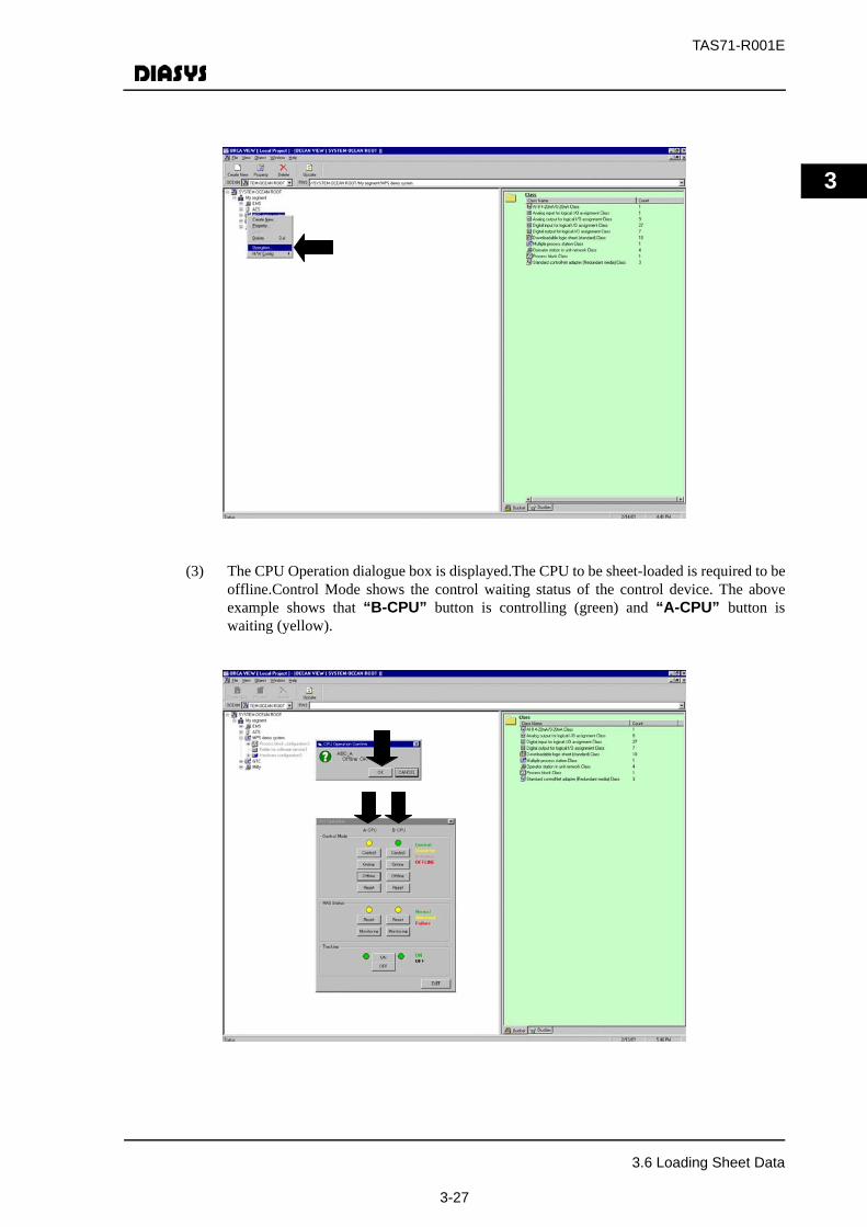
(2) Right-click the process block group to be sheet-loaded from the list of registered processblocks. Choose [Operation].
3.6 Loading Sheet Data
3-26
TAS71-R001E
3
(3) The CPU Operation dialogue box is displayed.The CPU to be sheet-loaded is required to beoffline.Control Mode shows the control waiting status of the control device. The aboveexample shows that “B-CPU” button is controlling (green) and “A-CPU” button iswaiting (yellow).
3.6 Loading Sheet Data
3-27
TAS71-R001E
3
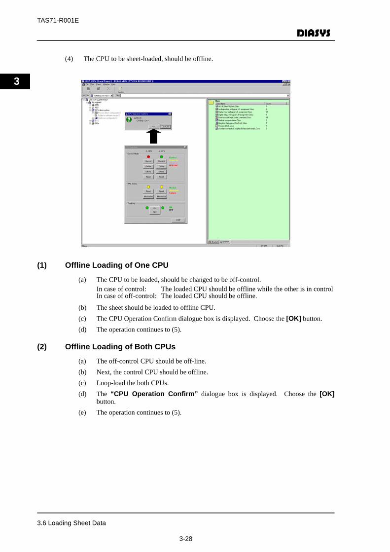
(4) The CPU to be sheet-loaded, should be offline.
(1) Offline Loading of One CPU
(a) The CPU to be loaded, should be changed to be off-control.In case of control: The loaded CPU should be offline while the other is in controlIn case of off-control: The loaded CPU should be offline.
(b) The sheet should be loaded to offline CPU.(c) The CPU Operation Confirm dialogue box is displayed. Choose the [OK] button.(d) The operation continues to (5).
(2) Offline Loading of Both CPUs
(a) The off-control CPU should be off-line.(b) Next, the control CPU should be offline.(c) Loop-load the both CPUs.(d) The “CPU Operation Confirm” dialogue box is displayed. Choose the [OK]
button.(e) The operation continues to (5).
3.6 Loading Sheet Data
3-28
TAS71-R001E
3
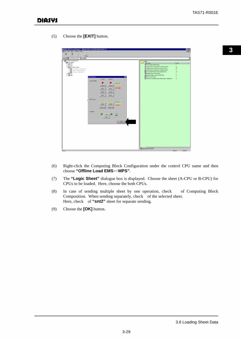
(5) Choose the [EXIT] button.
(6) Right-click the Computing Block Configuration under the control CPU name and thenchoose “Offline Load EMS=>MPS”.
(7) The “Logic Sheet” dialogue box is displayed. Choose the sheet (A-CPU or B-CPU) forCPUs to be loaded. Here, choose the both CPUs.
(8) In case of sending multiple sheet by one operation, check of Computing BlockComposition. When sending separately, check of the selected sheet. Here, check of “snt2” sheet for separate sending.
(9) Choose the [OK] button.
3.6 Loading Sheet Data
3-29
TAS71-R001E
3
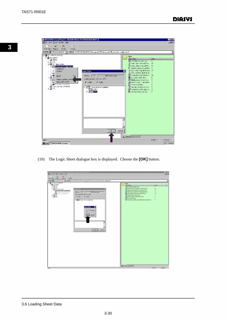
(10) The Logic Sheet dialogue box is displayed. Choose the [OK] button.
3.6 Loading Sheet Data
3-30

TAS71-R001E
3
(11) When the sheet-loading is completed, “A-CPU: Normal termination” and “B-CPU:Normal termination” are displayed.
(12) Choose the [Cancel] button. The loading is all completed now.
(13) Right-click the Process Station performed with sheet load and choose Operation.
(14) The “CPU Operation Confirm” dialogue box is displayed. There is a message display,“Online OK?” Choose the [OK] button. Now, the Process Station executes theinitialization of sheet data etc.
(15) Choose the [EXIT] button.
3.6 Loading Sheet Data
3-31
TAS71-R001E
3
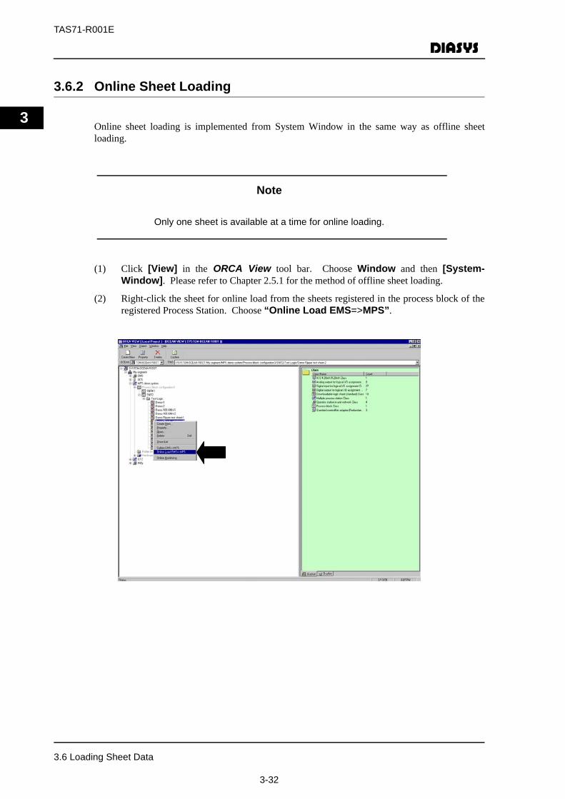
3.6.2 Online Sheet Loading
Online sheet loading is implemented from System Window in the same way as offline sheetloading.
Note
Only one sheet is available at a time for online loading.
(1) Click [View] in the ORCA View tool bar. Choose Window and then [System-Window]. Please refer to Chapter 2.5.1 for the method of offline sheet loading.
(2) Right-click the sheet for online load from the sheets registered in the process block of theregistered Process Station. Choose “Online Load EMS=>MPS”.
3.6 Loading Sheet Data
3-32
TAS71-R001E
3
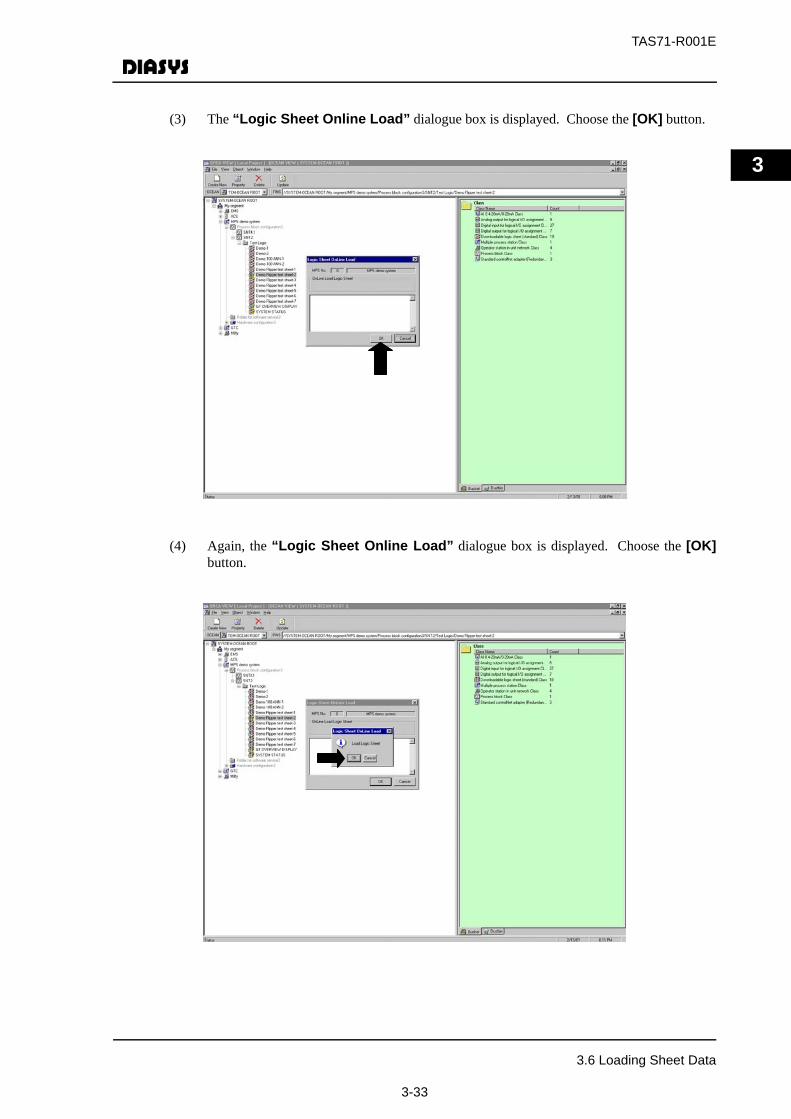
(3) The “Logic Sheet Online Load” dialogue box is displayed. Choose the [OK] button.
(4) Again, the “Logic Sheet Online Load” dialogue box is displayed. Choose the [OK]button.
3.6 Loading Sheet Data
3-33
TAS71-R001E
3
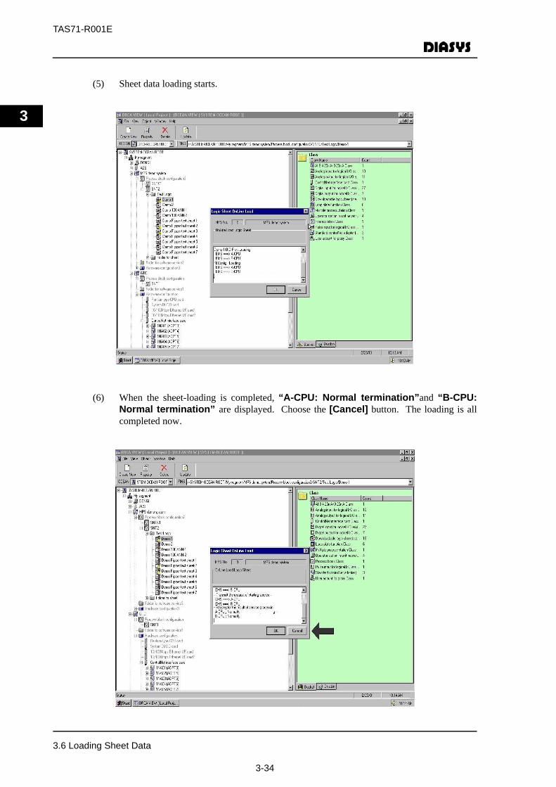
(5) Sheet data loading starts.
(6) When the sheet-loading is completed, “A-CPU: Normal termination”and “B-CPU:Normal termination” are displayed. Choose the [Cancel] button. The loading is allcompleted now.
3.6 Loading Sheet Data
3-34
TAS71-R001E
4
4 Standard Method for Logic Description
This chapter explains the standard description method for the logic which is often used to createlogic.
4.1 Conversion of Engineering Value for Process InputSignals
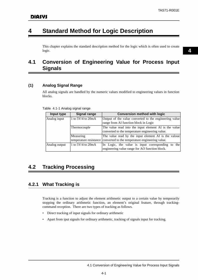
(1) Analog Signal RangeAll analog signals are handled by the numeric values modified to engineering values in functionblocks.
Table 4.1-1 Analog signal range
4.2 Tracking Processing
4.2.1 What Tracking is
Tracking is a function to adjust the element arithmetic output to a certain value by temporarilystopping the ordinary arithmetic function, an element’s original feature, through tracking-command reception. There are two types of tracking as follows.
• Direct tracking of input signals for ordinary arithmetic
• Apart from iput signals for ordinary arithmetic, tracking of signals input for tracking.
Input type Signal range Conversion method with logicAnalog input 1 to 5V/4 to 20mA Output of the value converted to the engineering value
range from AI function block in LogicThermocouple The value read into the input element AI is the value
converted to the temperature engineering value.Measuringtemperature resistance
The value read by the input element AI is the valoueconverted to the temperature engineering value.
Analog output 1 to 5V/4 to 20mA In Logic, the value is input corresponding to theengineering value range for AO function block.
4.1 Conversion of Engineering Value for Process Input Signals
4-1
TAS71-R001E
4
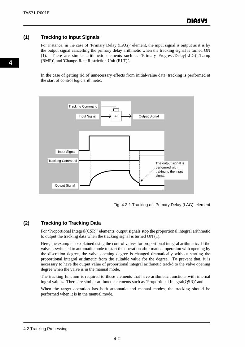
(1) Tracking to Input SignalsFor instance, in the case of ‘Primary Delay (LAG)’ element, the input signal is output as it is bythe output signal cancelling the primary delay arithmetic when the tracking signal is turned ON(1). There are similar arithmetic elements such as ‘Primary Progress/Delay(LLG)’,‘Lamp(RMP)', and 'Change-Rate Restriction Unit (RLT)’.
In the case of getting rid of unnecessary effects from initial-value data, tracking is performed atthe start of control logic arithmetic.
Fig. 4.2-1 Tracking of‘ Primary Delay (LAG)’ element
(2) Tracking to Tracking DataFor ‘Proportional Integral(CSR)’ elements, output signals stop the proportional integral arithmeticto output the tracking data when the tracking signal is turned ON (1).
Here, the example is explained using the control valves for proportional integral arithmetic. If thevalve is switched to automatic mode to start the operation after manual operation with opening bythe discretion degree, the valve opening degree is changed dramatically without starting theproportional integral arithmetic from the suitable value for the degree. To prevent that, it isnecessary to have the output value of proportional integral arithmetic trackd to the valve openingdegree when the valve is in the manual mode.
The tracking function is required to those elements that have arithmetic functions with internalingral values. There are similar arithmetic elements such as ‘Proportional Integral(QSR)’ and
When the target operation has both automatic and manual modes, the tracking should beperformed when it is in the manual mode.
The output signal is performed with traking to the input signal.
Tracking Command
Tracking Command
Output Signal
Output Signal
Input Signal
Input Signal
LAG
4.2 Tracking Processing
4-2

TAS71-R001E
4
Fig. 4.2-2 Tracking of ‘Proportional Integral (PI)’ and ‘Analog Memory(AM)’
4.3 Processing at Initialization
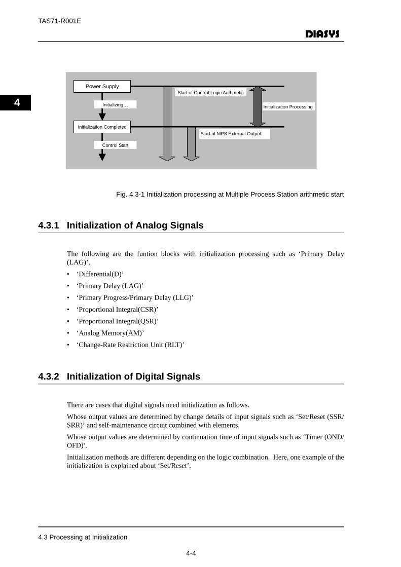
As soon as the Multiple Process Station is started up, the control logic arithmetic is started runningas well as the basic software. However, the elements with internal sizing-value arithmeticfunction such as ‘Primary Delay (LAG)’ and ‘Proportional Integral(PI)’, have some cases thatthey cannot start the right arithmetic because of the sizing value instability at arithmetic start.Furthermore, there are other cases the elements that change internal memory for the output onlywhen the input signals are modified such as ‘Set/Reset (SSR/SRR)’, cannot output the right outputvalue due to the instability of internal memory at the time of arithmetic start.
Therefore, necessary initialization processing should be performed in the ‘Initializing...’ status atProcess-Station startup. Regarding the output from the control logic arithmetic to the outside,there is not output of analog and digital signals from the Multiple Process Station because the
Manual Control
Temp. Setting Value
Manual Inc.PB
Manual Dec.PB
In the case of automatic control,‘PI’ output becomes the valve-open degree command value and ‘AM’ isperformed with tracking to the degree input. In the case of manual control, ‘AM’ output becomes the valve-open degree command value and ‘PI’ isperformed with traking to the degree input.
SG
TPI△
AM
Valve-Open Degree Command
AO
201
Valve-Open Degree Input (engineering value)
AI
101
Temp. Input(enginering value)
AI
001
4.3 Processing at Initialization
4-3
TAS71-R001E
4
Fig. 4.3-1 Initialization processing at Multiple Process Station arithmetic start
4.3.1 Initialization of Analog Signals
The following are the funtion blocks with initialization processing such as ‘Primary Delay(LAG)’.
• ‘Differential(D)’
• ‘Primary Delay (LAG)’
• ‘Primary Progress/Primary Delay (LLG)’
• ‘Proportional Integral(CSR)’
• ‘Proportional Integral(QSR)’
• ‘Analog Memory(AM)’
• ‘Change-Rate Restriction Unit (RLT)’
4.3.2 Initialization of Digital Signals
There are cases that digital signals need initialization as follows.
Whose output values are determined by change details of input signals such as ‘Set/Reset (SSR/SRR)’ and self-maintenance circuit combined with elements.
Whose output values are determined by continuation time of input signals such as ‘Timer (OND/OFD)’.
Initialization methods are different depending on the logic combination. Here, one example of theinitialization is explained about ‘Set/Reset’.
Power Supply
Start of Control Logic Arithmetic
Start of MPS External Output
Initializing… Initialization Processing
Control Start
Initialization Completed
4.3 Processing at Initialization
4-4

TAS71-R001E
4
Fig. 4.3-2 Logic of Set/Reset
In these cases, logics are combined so that initialization values are determined for ‘Set/Reset’according to the actual valve status at the start of arithmetic.
Fig. 4.3-3 Set/Reset initialization
Valve-Open Condition
Valve-Close Condition
Valve-Open Condition
Valve-Close Condition
If valve-open/close conditions are One-Shot signals, the output cannot be determined at thestart of arithmetic. (In this logic, it becomes the close).
R
S
Valve-Open Condition
Valve-Close Condition
Valve-Open Condition
Valve-Close Condition
If valve-open/close conditions are One-Shot signals, the output cannot be determined at thestart of arithmetic. (In this logic, it becomes the close).
R
S
4.3 Processing at Initialization
4-5
TAS71-R001E
4
4.4 CRT Operation
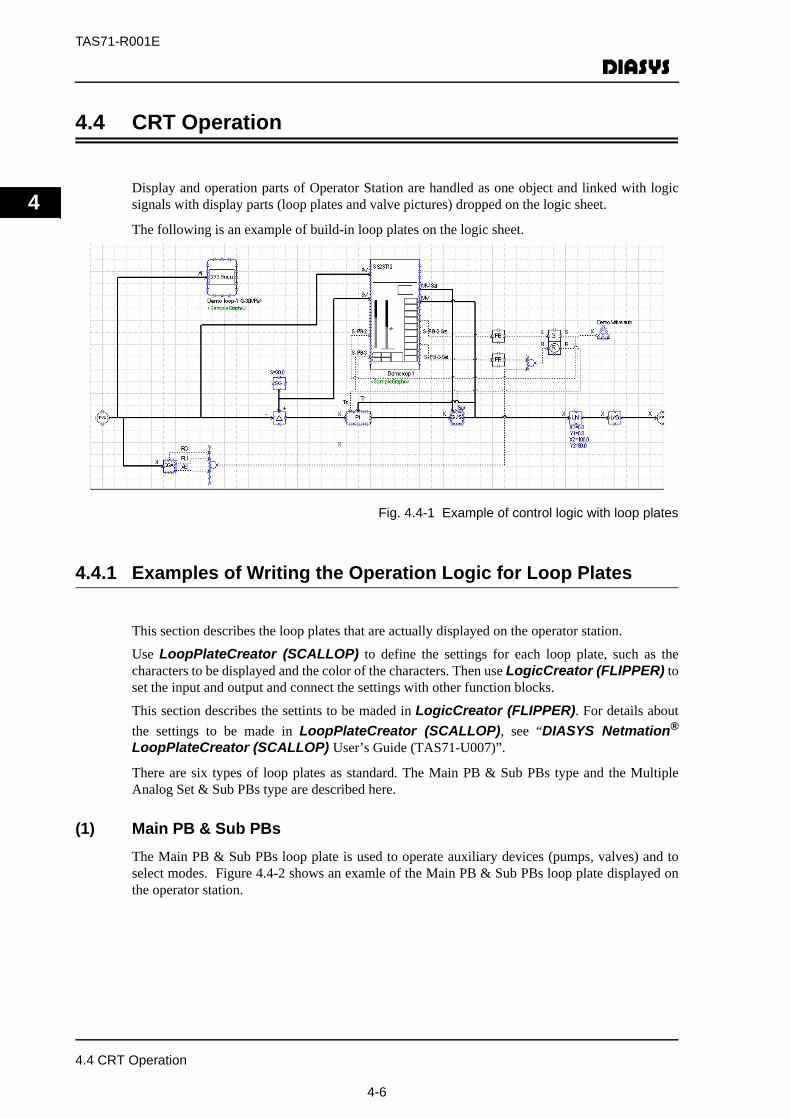
Display and operation parts of Operator Station are handled as one object and linked with logicsignals with display parts (loop plates and valve pictures) dropped on the logic sheet.
The following is an example of build-in loop plates on the logic sheet.
Fig. 4.4-1 Example of control logic with loop plates
4.4.1 Examples of Writing the Operation Logic for Loop Plates
This section describes the loop plates that are actually displayed on the operator station.
Use LoopPlateCreator (SCALLOP) to define the settings for each loop plate, such as thecharacters to be displayed and the color of the characters. Then use LogicCreator (FLIPPER) toset the input and output and connect the settings with other function blocks.
This section describes the settints to be maded in LogicCreator (FLIPPER). For details aboutthe settings to be made in LoopPlateCreator (SCALLOP), see “DIASYS Netmation®
LoopPlateCreator (SCALLOP) User’s Guide (TAS71-U007)”.
There are six types of loop plates as standard. The Main PB & Sub PBs type and the MultipleAnalog Set & Sub PBs type are described here.
(1) Main PB & Sub PBsThe Main PB & Sub PBs loop plate is used to operate auxiliary devices (pumps, valves) and toselect modes. Figure 4.4-2 shows an examle of the Main PB & Sub PBs loop plate displayed onthe operator station.
4.4 CRT Operation
4-6

TAS71-R001E
4
Figure 4.4-2 Example display of the Main PB & Sub PBs loop plate on OPS
In the main PB area of the Main PB & Sub PBs loop plate, up to five operations and displays canbe performed. In the sub PB area, up to ten operations and displays can be performed. However,TAGGING is fixed and its usage is limited.
For details about the configuration of the Main PB & Sub PBs loop plate, see Chapter 2“Specifications of Loop Plates” in “DIASYS Netmation® LoopPlateCreator (SCALLOP)User’s Guide (TAS71-U007)”.
In the example of Figure 4.4-2, two elements are set in the main PB area and seven elements areset in the sub PB area for operation and display.
Figure 4.4-3 shows an example operation monitoring logic of the Main PB & Sub PBs loop platedescribed in Figure 4.4-2.
Figure 4.4-3 Example operation monitoring logic of the Main PB & Sub PBs loop plate
Sub PB area
Main PB area
FLT
TOV
REM
FD-1RUN
STOP
PAB
AUTO
S-PB-2
S-PB-8
S-PB-9S-PB-10
02HAG12AM101 FD-2
S-PB-9-Set
S-PB-10-Set
LP START UP PUMP A <HRSG LP CIRCUIT FLOW>
MANU
S-PB-3S-PB-4
FDO-1
FDO-2
PB
PB
PB
PB
4.4 CRT Operation
4-7
TAS71-R001E
4
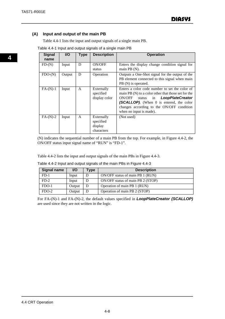
(A) Input and output of the main PBTable 4.4-1 lists the input and output signals of a single main PB.
Table 4.4-1 Input and output signals of a single main PB
(N) indicates the sequential number of a main PB from the top. For example, in Figure 4.4-2, theON/OFF status input signal name of “RUN” is “FD-1”.
Table 4.4-2 lists the input and output signals of the main PBs in Figure 4.4-3.
Table 4.4-2 Input and output signals of the main PBs in Figure 4.4-3
For FA-(N)-1 and FA-(N)-2, the default values specified in LoopPlateCreator (SCALLOP)are used since they are not written in the logic.
Signal name
I/O Type Description Operation
FD-(N) Input D ON/OFFstatus
Enters the display change condition signal formain PB (N).
FDO-(N) Output D Operation Outputs a One-Shot signal for the output of thePB element connected to this signal when mainPB (N) is operated.
FA-(N)-1 Input A Externallyspecifieddisplay color
Enters a color code number to set the color ofmain PB (N) to a color other that those set for theON/OFF status in LoopPlateCreator(SCALLOP). (When 0 is entered, the colorchanges according to the ON/OFF conditionwhen no input is made).
FA-(N)-2 Input A Externallyspecifieddisplaycharacters
(Not used)
Signal name I/O Type DescriptionFD-1 Input D ON/OFF status of main PB 1 (RUN) FD-2 Input D ON/OFF status of main PB 2 (STOP)FDO-1 Output D Operation of main PB 1 (RUN)FDO-2 Output D Operation of main PB 2 (STOP)
4.4 CRT Operation
4-8
TAS71-R001E
4
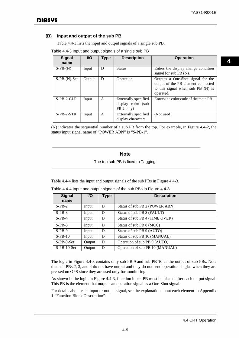
(B) Input and output of the sub PBTable 4.4-3 lists the input and output signals of a single sub PB.
Table 4.4-3 Input and output signals of a single sub PB
(N) indicates the sequential number of a sub PB from the top. For example, in Figure 4.4-2, thestatus input signal name of “POWER ABN” is “S-PB-1”.
NoteThe top sub PB is fixed to Tagging.
Table 4.4-4 lists the input and output signals of the sub PBs in Figure 4.4-3.
Table 4.4-4 Input and output signals of the sub PBs in Figure 4.4-3
The logic in Figure 4.4-3 contains only sub PB 9 and sub PB 10 as the output of sub PBs. Notethat sub PBs 2, 3, and 4 do not have output and they do not send operation singlas when they arepressed on OPS since they are used only for monitoring.
As shown in the logic in Figure 4.4-3, function block PB must be placed after each output signal.This PB is the element that outputs an operation signal as a One-Shot signal.
For details about each input or output signal, see the explanation about each element in Appendix1 “Function Block Description”.
Signal name
I/O Type Description Operation
S-PB-(N) Input D Status Enters the display change conditionsignal for sub PB (N).
S-PB-(N)-Set Output D Operation Outputs a One-Shot signal for theoutput of the PB element connectedto this signal when sub PB (N) isoperated.
S-PB-2-CLR Input A Externally specifieddisplay color (subPB 2 only)
Enters the color code of the main PB.
S-PB-2-STR Input A Externally specifieddisplay characters
(Not used)
Signal name
I/O Type Description
S-PB-2 Input D Status of sub PB 2 (POWER ABN)S-PB-3 Input D Status of sub PB 3 (FAULT)S-PB-4 Input D Status of sub PB 4 (TIME OVER)
S-PB-8 Input D Status of sub PB 8 (MCC)S-PB-9 Input D Status of sub PB 9 (AUTO)S-PB-10 Input D Status of sub PB 10 (MANUAL)S-PB-9-Set Output D Operation of sub PB 9 (AUTO)S-PB-10-Set Output D Operation of sub PB 10 (MANUAL)
4.4 CRT Operation
4-9

TAS71-R001E
4
(2) Multiple Analog Set & Sub PBsThe Multiple Analog Set & Sub PBs loop plate is used for analog tuning devices. Figure 4.4-4 shows the Multiple Analog Set & Sub PBs loop plate displayed on the operatorstation.
Figure 4.4-4 Example display of the Multiple Analog Set & Sub PBs loop plate on OPS
The PV, MV, SV display and operation area in the Multiple Analog Set & Sub PBs loop platedisplays the process value (PV), the set value (SV), and the manual value (MV) as the SV and theMV increase or decrease. The 3 digit display area displays up to three analog signals.
For details about the configuration of the Multiple Analog Set & Sub PBs loop plate, see Chapter2 “Specifications of Loop Plates” in “DIASYS Netmation® LoopPlateCreator(SCALLOP) User’s Guide (TAS71-U007)”.
Figure 4.4-5 shows an example operation monitoring logic of the Multiple Analog Set & Sub PBsloop plate described in Figure 4.4-4.
Figure 4.4-5 Example operation monitoring logic of the Multiple Analog Set & Sub PBs loopplate
PV, MV, SV display and operation
3 digit display area
Sub PB area
V1PVV2MVV3SV
PV
MV
SV
IINH
DINH
AUTO
MANU
MV-I-PRHS-PB-7
MV-D-PRHS-PB-8S-PB-9
S-PB-10
<**>MBV01AA701 MV-Set
S-PB-9-Set
S-PB-10-Set
LUBE OIL TEMP CONTROL VALVE <LUBE OIL DIAGRAM>
PB
PB
CEA
CEA
<GC180>
<GC180>
CEAGC180_01
CEAGC180_03
LUBE OIL TEMP CONTROLMVHI LIMIT
LUBE OIL TEMP CONTROLMVLOW LIMIT
S
H
L
S/S
Y
OH
OL
4.4 CRT Operation
4-10
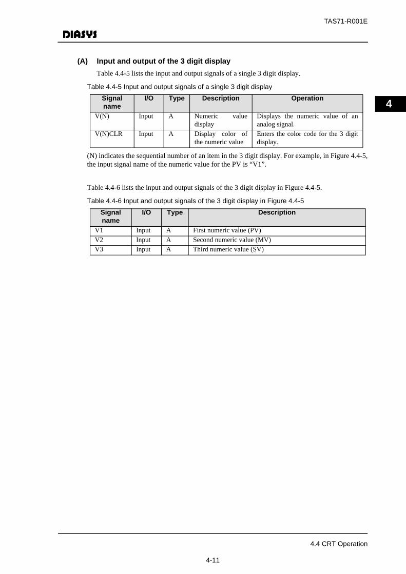
TAS71-R001E
4
(A) Input and output of the 3 digit display Table 4.4-5 lists the input and output signals of a single 3 digit display.
Table 4.4-5 Input and output signals of a single 3 digit display
(N) indicates the sequential number of an item in the 3 digit display. For example, in Figure 4.4-5,the input signal name of the numeric value for the PV is “V1”.
Table 4.4-6 lists the input and output signals of the 3 digit display in Figure 4.4-5.
Table 4.4-6 Input and output signals of the 3 digit display in Figure 4.4-5
Signal name
I/O Type Description Operation
V(N) Input A Numeric valuedisplay
Displays the numeric value of ananalog signal.
V(N)CLR Input A Display color ofthe numeric value
Enters the color code for the 3 digitdisplay.
Signal name
I/O Type Description
V1 Input A First numeric value (PV)V2 Input A Second numeric value (MV)V3 Input A Third numeric value (SV)
4.4 CRT Operation
4-11

TAS71-R001E
4
(B) Input and output of the PV, MV, SV display and operationTable 4.4-7 lists the input and output signals of a single PV, MV, SV display and operation.
Table 4.4-7 Input and output signals of a single PV, MV, SV display and operation
Table 4.4-8 lists the input and output signals of the PV, MV, SV display and operation in Figure4.4-5.
Table 4.4-8 Input and output signals of the PV, MV, SV display and operation in Figure 4.4-5
As shown in the logic in Figure 4.4-5, S/S (increase/decrease operation) must be placed after theoutput signal. S/S is the element that accepts an increase/decrease operation of an analog value.
Signal name
I/O Type Description Operation
MV-SET Output A MV set value Outputs the MV set value operated onthe loop plate.
SV-SET Output A SV set value Outputs the SV set value operated onthe loop plate.
MV-I-PRH Input D MV increaseprohibition
Enters ON to prohibit increasing thevalue of the MV on the loop plate.
MV-D-PRH Input D MV decreaseprohibition
Enters ON to prohibt descresing thevalue of the MV on the loop plate.
SV-I-PRH Input D SV increaseprohibition
Enters ON to prohibit increasing thevalue of the SV on the loop plate.
SV-D-PRH Input D SV decreaseprohibition
Enters ON to prohibit decreaseing thevalue of the SV on the loop plate.
PV Input A PV value Enters the PV value. MV Input A MV value Enters the MV value. SV Input A SV value Enters the SV value. ANN1 Input A Warning value Enters the warning value. ANN2 Input A Warning value Enters the warning value. REF Input A Referene value Enters the reference value. PVCIr Input A Externally
entered PV colorEnters the color code for displaying thePV.
MVCIr Input A Externallyentered MV color
Enters the color code for displaying theMV.
SVCIr Input A Externallyentered SV color
Enters the color code for displaying theSV.
Signal name I/O Type DescriptionMV-I-PRH Input D MV increase prohibitionMV-D-PRH Input D MV decrease prohibitionMV-SET Output A MV set value
4.4 CRT Operation
4-12
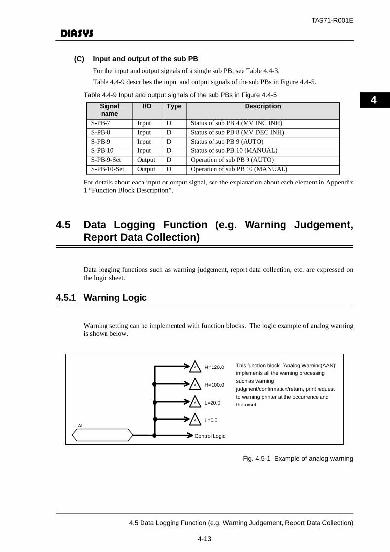
TAS71-R001E
4
(C) Input and output of the sub PBFor the input and output signals of a single sub PB, see Table 4.4-3.
Table 4.4-9 describes the input and output signals of the sub PBs in Figure 4.4-5.
Table 4.4-9 Input and output signals of the sub PBs in Figure 4.4-5
For details about each input or output signal, see the explanation about each element in Appendix1 “Function Block Description”.
4.5 Data Logging Function (e.g. Warning Judgement,Report Data Collection)
Data logging functions such as warning judgement, report data collection, etc. are expressed onthe logic sheet.
4.5.1 Warning Logic
Warning setting can be implemented with function blocks. The logic example of analog warningis shown below.
Fig. 4.5-1 Example of analog warning
Signal name
I/O Type Description
S-PB-7 Input D Status of sub PB 4 (MV INC INH)S-PB-8 Input D Status of sub PB 8 (MV DEC INH)S-PB-9 Input D Status of sub PB 9 (AUTO)S-PB-10 Input D Status of sub PB 10 (MANUAL)S-PB-9-Set Output D Operation of sub PB 9 (AUTO)S-PB-10-Set Output D Operation of sub PB 10 (MANUAL)
Control Logic
A
A
A
A
H=120.0
H=100.0
L=20.0
L=0.0
This function block‘Analog Warning(AAN)’implements all the warning processing such as warning judgment/confirmation/return, print request to warning printer at the occurrence and the reset.
AI
4.5 Data Logging Function (e.g. Warning Judgement, Report Data Collection)
4-13
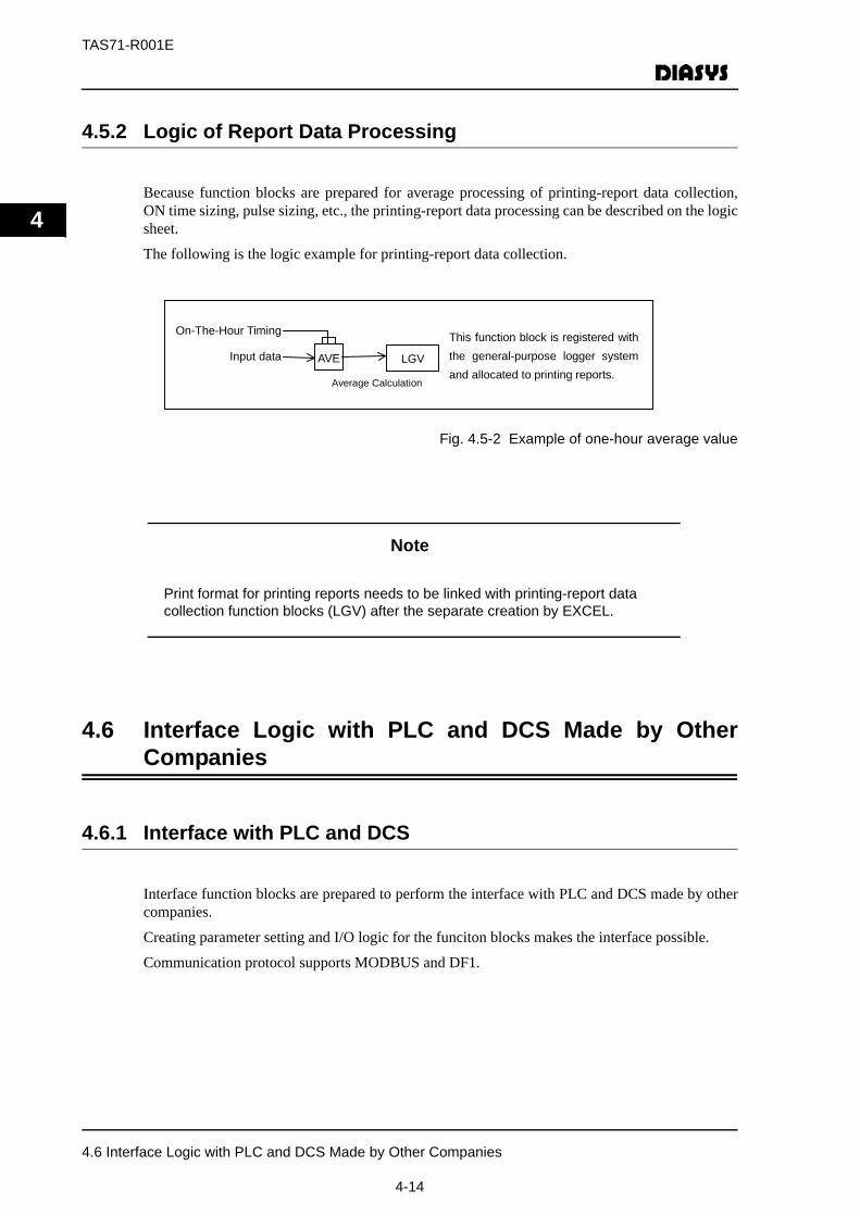
TAS71-R001E
4
4.5.2 Logic of Report Data Processing
Because function blocks are prepared for average processing of printing-report data collection,ON time sizing, pulse sizing, etc., the printing-report data processing can be described on the logicsheet.
The following is the logic example for printing-report data collection.
Fig. 4.5-2 Example of one-hour average value
Note
Print format for printing reports needs to be linked with printing-report data collection function blocks (LGV) after the separate creation by EXCEL.
4.6 Interface Logic with PLC and DCS Made by OtherCompanies
4.6.1 Interface with PLC and DCS
Interface function blocks are prepared to perform the interface with PLC and DCS made by othercompanies.
Creating parameter setting and I/O logic for the funciton blocks makes the interface possible.
Communication protocol supports MODBUS and DF1.
AVE Input data
On-The-Hour Timing This function block is registered with the general-purpose logger system and allocated to printing reports.
Average Calculation
LGV
4.6 Interface Logic with PLC and DCS Made by Other Companies
4-14
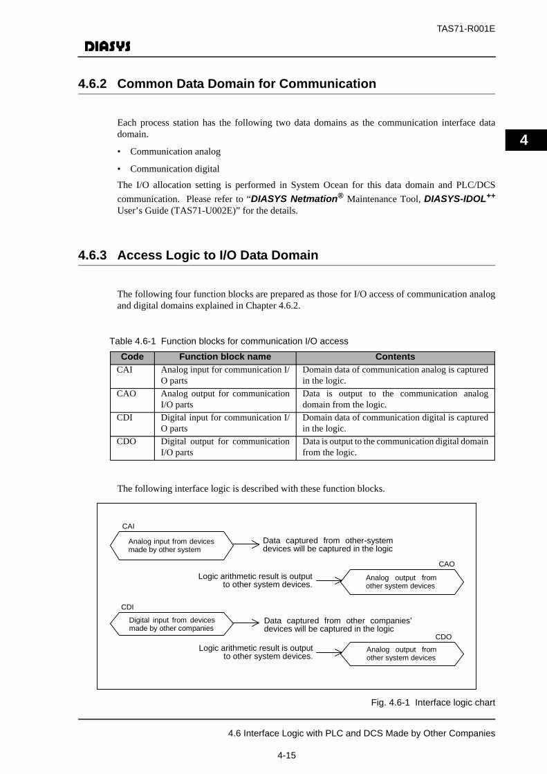
TAS71-R001E
4
4.6.2 Common Data Domain for Communication
Each process station has the following two data domains as the communication interface datadomain.
• Communication analog
• Communication digital
The I/O allocation setting is performed in System Ocean for this data domain and PLC/DCScommunication. Please refer to “DIASYS Netmation® Maintenance Tool, DIASYS-IDOL++
User’s Guide (TAS71-U002E)” for the details.
4.6.3 Access Logic to I/O Data Domain
The following four function blocks are prepared as those for I/O access of communication analogand digital domains explained in Chapter 4.6.2.
Table 4.6-1 Function blocks for communication I/O access
The following interface logic is described with these function blocks.
Fig. 4.6-1 Interface logic chart
Code Function block name ContentsCAI Analog input for communication I/
O partsDomain data of communication analog is capturedin the logic.
CAO Analog output for communicationI/O parts
Data is output to the communication analogdomain from the logic.
CDI Digital input for communication I/O parts
Domain data of communication digital is capturedin the logic.
CDO Digital output for communicationI/O parts
Data is output to the communication digital domainfrom the logic.
Analog input from devicesmade by other system
CAI
Digital input from devicesmade by other companies
CDI
Analog output fromother system devices
CAO
Data captured from other-systemdevices will be captured in the logic
Logic arithmetic result is output to other system devices.
Data captured from other companies’devices will be captured in the logic
Analog output fromother system devices
CDO Logic arithmetic result is output
to other system devices.
4.6 Interface Logic with PLC and DCS Made by Other Companies
4-15
TAS71-R001E
4
MEMO
4.6 Interface Logic with PLC and DCS Made by Other Companies
4-16
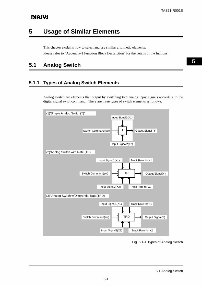
TAS71-R001E
5
5 Usage of Similar Elements
This chapter explains how to select and use similar arithmetic elements.
Please refer to “Appendix-1 Function Block Description” for the details of the funtions.
5.1 Analog Switch
5.1.1 Types of Analog Switch Elements
Analog switch are elements that output by switching two analog input signals according to thedigital signal swith command. There are three types of switch elements as follows.
Fig. 5.1-1 Types of Analog Switch
(1)’Simple Analog Switch(T)’
Input Signal1(X1)
Output Signal (Y)
Input Signal2(X2)
Switch Command(sw)
(2)’Analog Switch with Rate (TR)’
Track Rate for X1
Track Rate for X2
Input Signal1(X1)
Output Signal(Y)
Input Signal2(X2)
Switch Command(sw)
(3)’ Analog Switch w/Differential Rate(TRD)’
Track Rate for X1
Track Rate for X2
Input Signal1(X1)
Output Signal(Y)
Input Signal2(X2)
Switch Command(sw)
T
TR
TRD
5.1 Analog Switch
5-1
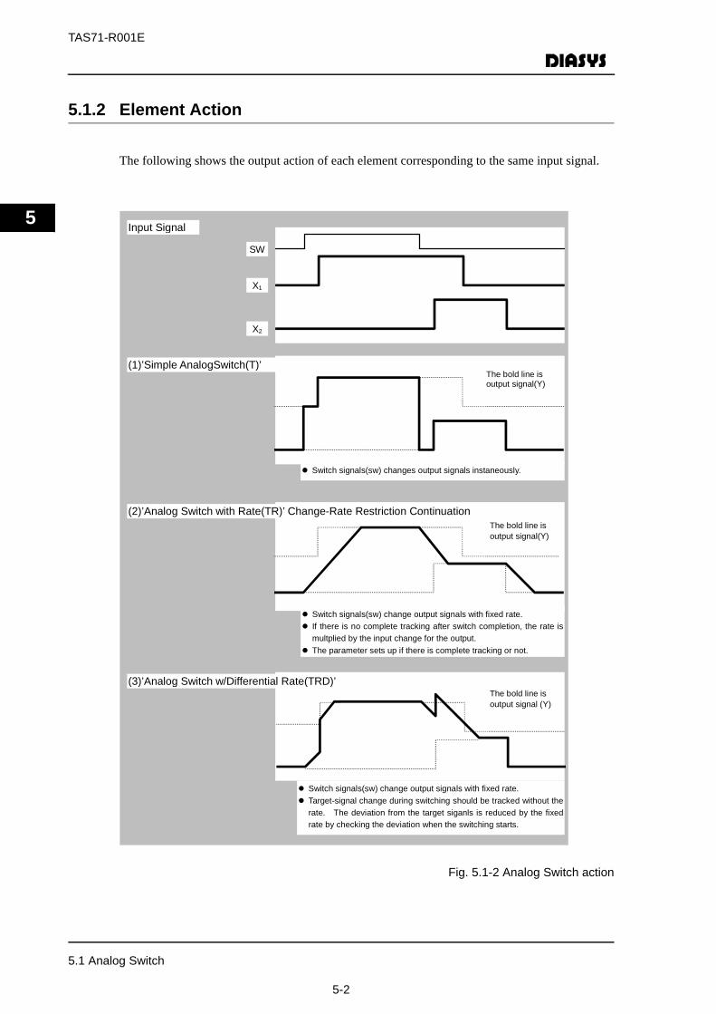
TAS71-R001E
5
5.1.2 Element Action
The following shows the output action of each element corresponding to the same input signal.
Fig. 5.1-2 Analog Switch action
Input Signal
SW
X1
X2
The bold line is output signal(Y)
(2)’Analog Switch with Rate(TR)’ Change-Rate Restriction Continuation
Switch signals(sw) change output signals with fixed rate. If there is no complete tracking after switch completion, the rate is multplied by the input change for the output. The parameter sets up if there is complete tracking or not.
(1)’Simple AnalogSwitch(T)’ The bold line is output signal(Y)
Switch signals(sw) changes output signals instaneously.
(3)’Analog Switch w/Differential Rate(TRD)’The bold line is output signal (Y)
Switch signals(sw) change output signals with fixed rate. Target-signal change during switching should be tracked without the rate. The deviation from the target siganls is reduced by the fixed rate by checking the deviation when the switching starts.
5.1 Analog Switch
5-2
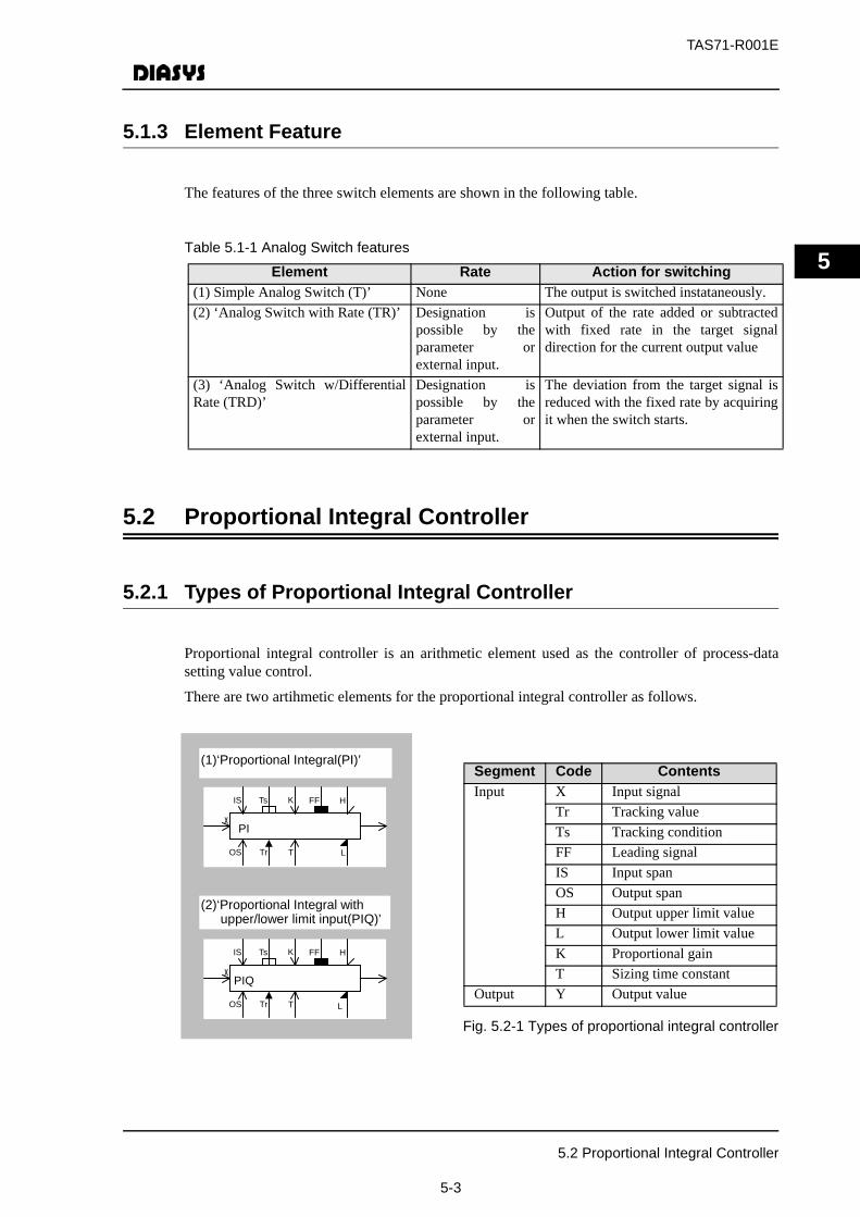
TAS71-R001E
5
5.1.3 Element Feature
The features of the three switch elements are shown in the following table.
Table 5.1-1 Analog Switch features
5.2 Proportional Integral Controller
5.2.1 Types of Proportional Integral Controller
Proportional integral controller is an arithmetic element used as the controller of process-datasetting value control.
There are two artihmetic elements for the proportional integral controller as follows.
Fig. 5.2-1 Types of proportional integral controller
Element Rate Action for switching(1) Simple Analog Switch (T)’ None The output is switched instataneously.(2) ‘Analog Switch with Rate (TR)’ Designation is
possible by theparameter orexternal input.
Output of the rate added or subtractedwith fixed rate in the target signaldirection for the current output value
(3) ‘Analog Switch w/DifferentialRate (TRD)’
Designation ispossible by theparameter orexternal input.
The deviation from the target signal isreduced with the fixed rate by acquiringit when the switch starts.
Segment Code ContentsInput X Input signal
Tr Tracking valueTs Tracking conditionFF Leading signalIS Input spanOS Output spanH Output upper limit valueL Output lower limit valueK Proportional gainT Sizing time constant
Output Y Output value
(1)‘Proportional Integral(PI)’
X
IS
PI
H
LOS
K
T
FFTs
Tr
(2)‘Proportional Integral with upper/lower limit input(PIQ)’
X
IS
PIQ
H
LOS
K
T
FFTs
Tr
5.2 Proportional Integral Controller
5-3

TAS71-R001E
5
(1) ‘Proportional Integral (PI)’The integral value will continue the integral to the upper or lower limit regardless of theproportion even when the output reaches the upper or lower limit. When enough time has passedafter the output is reached to the upper or lower limit, the output stays at the upper or lower limitunless the input becomes the negative or positive. Even when the input is constantly fluctuating,the output does not move further than the upper or lower limit with this element being the upper/lower limit, as long as the code of the input value does not change.
Usage:Used often for wide-open valves at normal operation (such as spray valves used only foremergency or high-pressure escape valves, etc.)
(2) ‘Proportional Integral with Upper/Lower Limit Input (PIQ)’The integral value will stop the integral as soon as the output reaches the upper or lower limit.Even if enough time has passed after the output reaches the upper or lower limit, the outputchanges with the proportion when the input positive or negative value is changed. When the inputis constantly fluctuatiing, the output is also changing around the upper or lower limit with thiselement being the upper or lower limit.
Usage:Used often for operation-end used in the medium open degree at normal operation.
Please refer to “Appendix-2 Description of Logic Function Blocks” for the behaviourof’Proportional Integral(PI)’ and’Proportional Integral with Upper/Lower Limit Input(PIQ)’.
5.3 One Shot
5.3.1 One Shot Types
One Shot are artihemtic elements that output ON for the fixed time when digital input signals arechanged.
There are four types of arithmetic elements for One Shot as follows.
5.3 One Shot
5-4
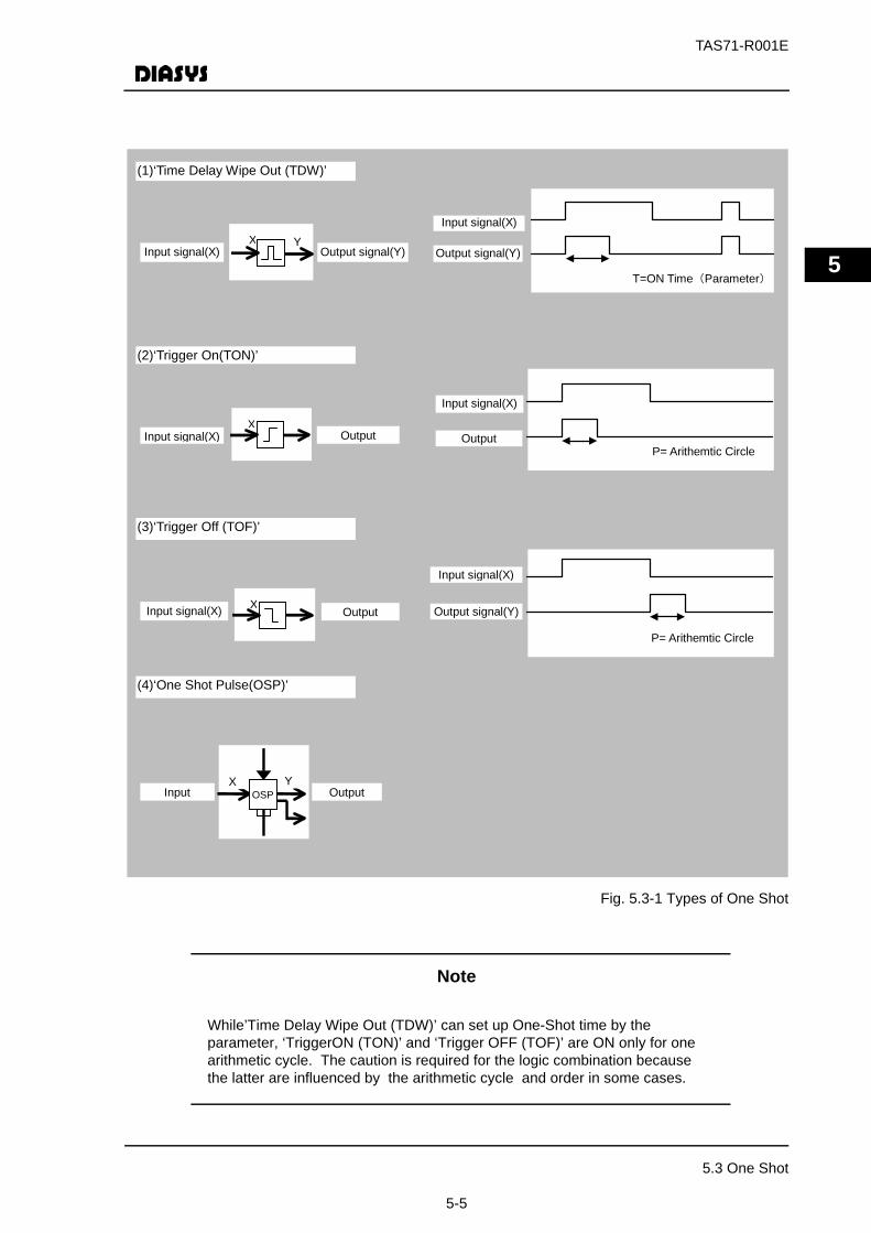
TAS71-R001E
5
Fig. 5.3-1 Types of One Shot
Note
While’Time Delay Wipe Out (TDW)’ can set up One-Shot time by the parameter, ‘TriggerON (TON)’ and ‘Trigger OFF (TOF)’ are ON only for one arithmetic cycle. The caution is required for the logic combination because the latter are influenced by the arithmetic cycle and order in some cases.
Output signal(Y)
T=ON Time(Parameter)
Input signal(X)
Output P= Arithemtic Circle
Input signal(X)
P= Arithemtic Circle Output signal(Y)
Input signal(X)
(1)‘Time Delay Wipe Out (TDW)’
(2)‘Trigger On(TON)’
(3)‘Trigger Off (TOF)’
Input signal(X) Output signal(Y)X Y
XInput signal(X) Output
XInput signal(X) Output
(4)‘One Shot Pulse(OSP)’
Input Output OSP X Y
5.3 One Shot
5-5
TAS71-R001E
5
MEMO
5.3 One Shot
5-6
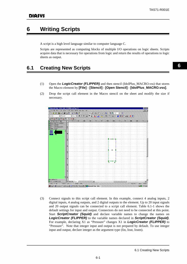
TAS71-R001E
6
6 Writing Scripts
A script is a high level language similar to computer language C.
Scripts are represented as computing blocks of multiple I/O operations on logic sheets. Scriptsacquire data that is necessary for operations from logic and return the results of operations to logicsheets as output.
6.1 Creating New Scripts
(1) Open the LogicCreator (FLIPPER) and then stencil (IdolPlus_MACRO.vss) that storesthe Macro element by [File] - [Stencil] - [Open Stencil] - [IdolPlus_MACRO.vss].
(2) Drop the script call element in the Macro stencil on the sheet and modify the size ifnecessary.
(3) Connect signals to this script call element. In this example, connect 4 analog inputs, 2digital inputs, 4 analog outputs, and 2 digital outputs to the element. Up to 20 input signalsand 20 output signals can be connected to a script call element. Table 6.1-1 shows thedefault settings for input and output. Connectors do not need to be connected at this point.Start ScriptCreator (Squid) and declare variable names to change the names onLogicCreator (FLIPPER) to the variable names declared in ScriptCreator (Squid).For example, declaring X1 as “Pressure” changes X1 in LogicCreator (FLIPPER) to“Pressure”. Note that integer input and output is not prepared by default. To use integerinput and output, declare integer as the argument type (Iin, Iout, Ioutn).
6.1 Creating New Scripts
6-1
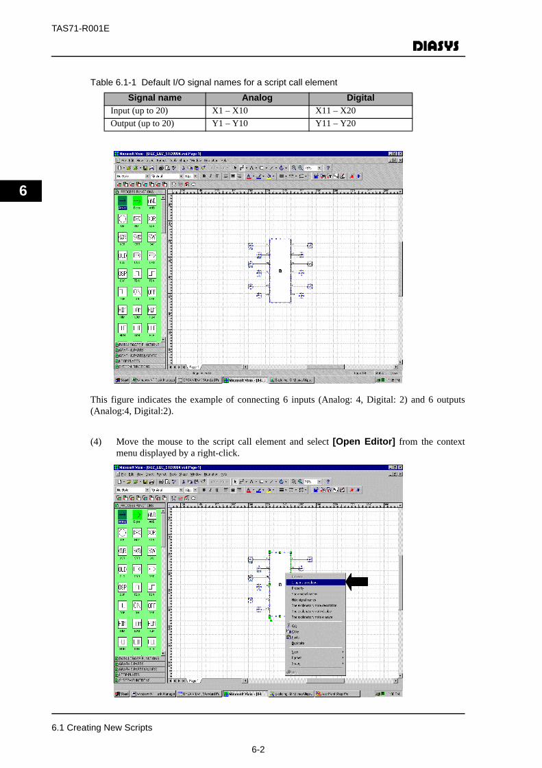
TAS71-R001E
6
Table 6.1-1 Default I/O signal names for a script call element
This figure indicates the example of connecting 6 inputs (Analog: 4, Digital: 2) and 6 outputs(Analog:4, Digital:2).
(4) Move the mouse to the script call element and select [Open Editor] from the contextmenu displayed by a right-click.
Signal name Analog DigitalInput (up to 20) X1 – X10 X11 – X20Output (up to 20) Y1 – Y10 Y11 – Y20
6.1 Creating New Scripts
6-2

TAS71-R001E
6
(5) The dialogue box is displayed. Select the “Create the new script function block (selected asthe default)” and the [OK] button.
(6) The script creator is started up. formation of I/O connecting line which was connected byLogic Creator (FLIFFER), is indicated as parameter of function.
6.1 Creating New Scripts
6-3
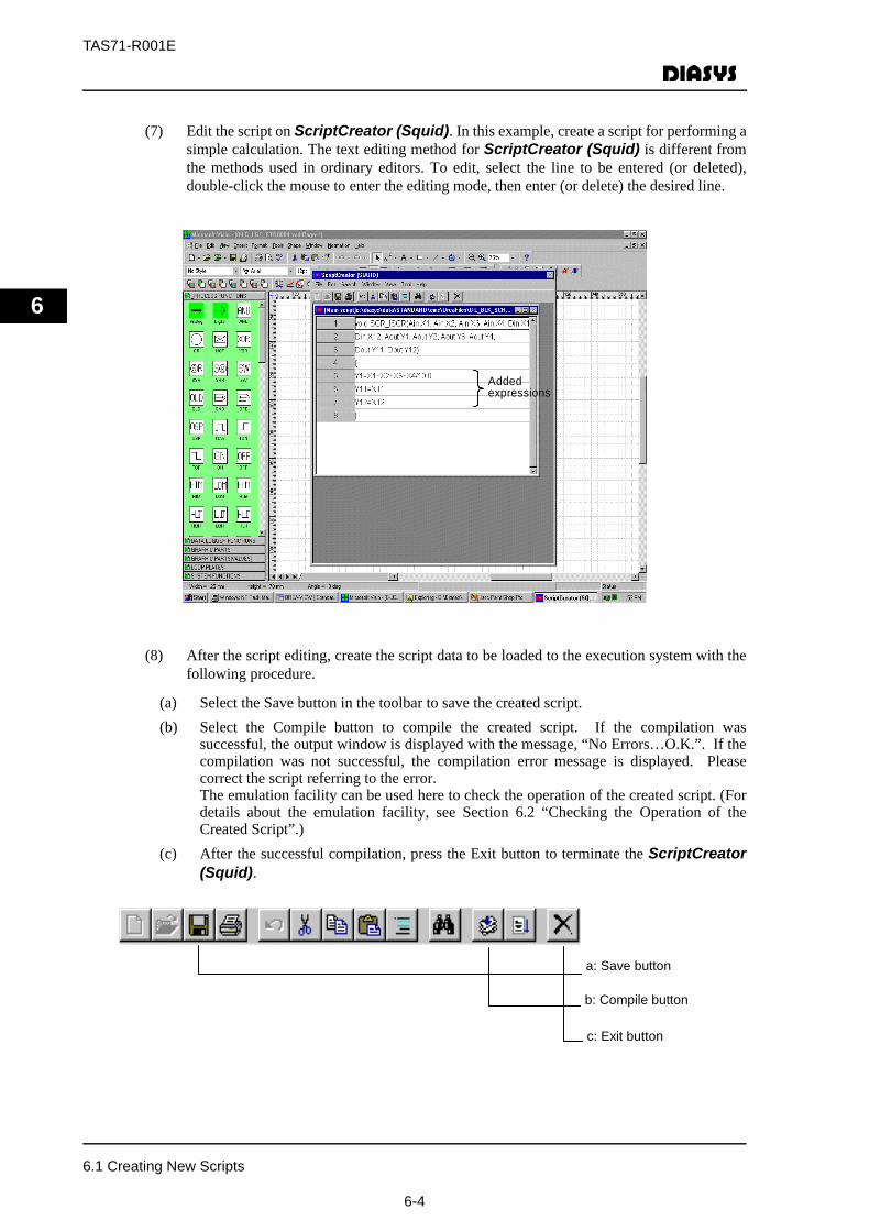
TAS71-R001E
6
(7) Edit the script on ScriptCreator (Squid). In this example, create a script for performing asimple calculation. The text editing method for ScriptCreator (Squid) is different fromthe methods used in ordinary editors. To edit, select the line to be entered (or deleted),double-click the mouse to enter the editing mode, then enter (or delete) the desired line.
(8) After the script editing, create the script data to be loaded to the execution system with thefollowing procedure.
(a) Select the Save button in the toolbar to save the created script.(b) Select the Compile button to compile the created script. If the compilation was
successful, the output window is displayed with the message, “No Errors…O.K.”. If thecompilation was not successful, the compilation error message is displayed. Pleasecorrect the script referring to the error.The emulation facility can be used here to check the operation of the created script. (Fordetails about the emulation facility, see Section 6.2 “Checking the Operation of theCreated Script”.)
(c) After the successful compilation, press the Exit button to terminate the ScriptCreator(Squid).
Added expressions
a: Save button
b: Compile button
c: Exit button
6.1 Creating New Scripts
6-4

TAS71-R001E
6
(9) The contents revised on the script is reflected on the script call element on LogicCreator(FLIPPER).
(10) Right-click the created script call to display the Property input screen. Input the name here.(here, input Script Text as an example.) Press the [OK] button.
(11) Execute Loop-build by LogicCreator (FLIPPER). For how to execute loop build, seeSection 3.4.
6.1 Creating New Scripts
6-5
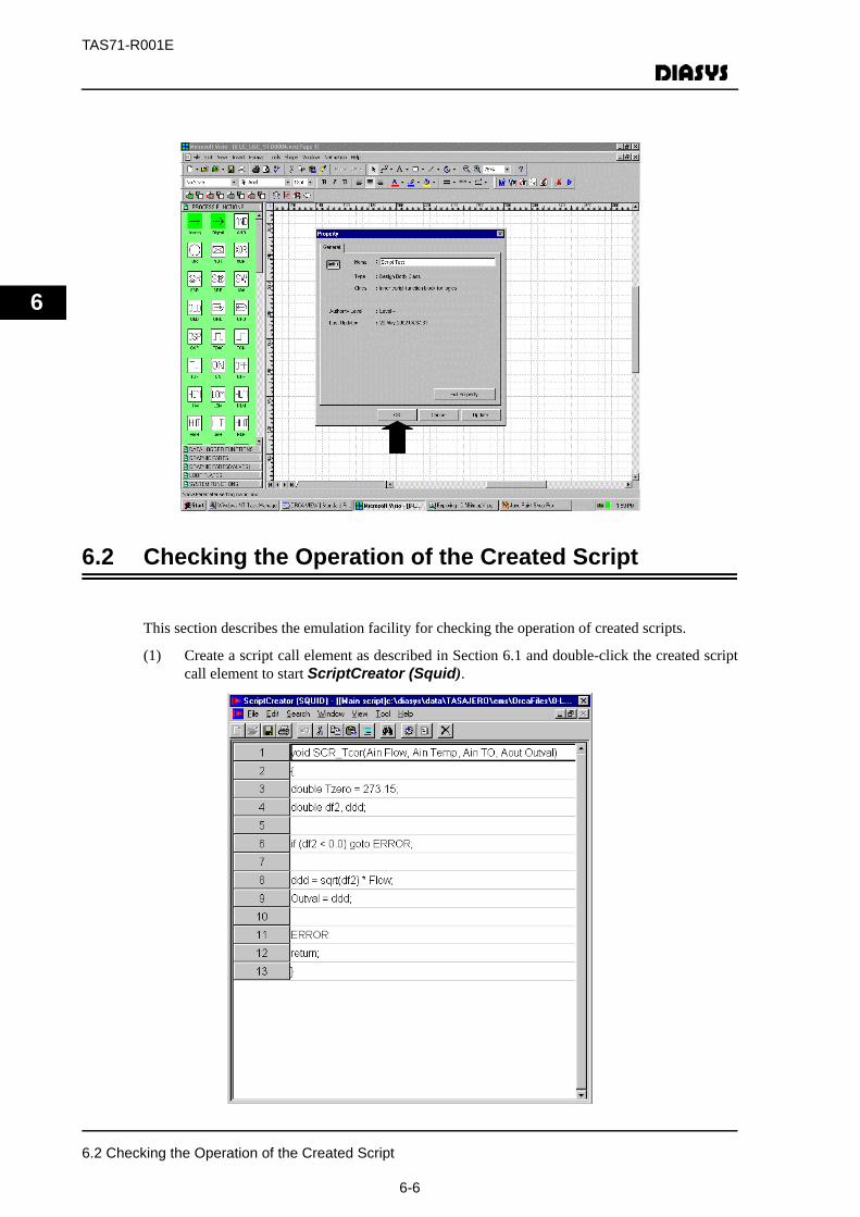
TAS71-R001E
6
6.2 Checking the Operation of the Created Script
This section describes the emulation facility for checking the operation of created scripts.
(1) Create a script call element as described in Section 6.1 and double-click the created scriptcall element to start ScriptCreator (Squid).
6.2 Checking the Operation of the Created Script
6-6

TAS71-R001E
6
(2) Select [Emulate] from the [Tool] menu at the top of ScriptCreator (Squid) to displaythe Emulate screen. Enter argument values. When an argument value is entered, the qualityis displayed in hexadecimal. Table 6.2-1 lists the quality values and the meaning.
Table 6.2-1 Meaning of quality values (hexadecimal input)
Quality value
Meaning Quality value
Meaning
0 Normal (default) 2001 Upper limit for the local range1 Upper limit for the
propagation range 2002 Lower limit for the local range
2 Lower limit for thepropagation range
2004 Local data inaccessible
4 Propagation data inaccessible 2008 No scan for local data8 No scan for propagation 4000 Local block calculation error
(real number overflow)10 Data insertion or manual
specification for propagation4100 Local block calculation error
Enter argument values.
6.2 Checking the Operation of the Created Script
6-7

TAS71-R001E
6
(3) Press the [Execute] button to execute calculation once on the maintenance tool anddisplay the result of the calculation and command buttons.
(4) Each time the [Go] command button is pressed, the calculation is repeated. As the result ofthe calculation, the values of variables are displayed in the [Result] box. The meaning ofthe variables displayed in the [Result] box is as follows:
• opcode_count: Number of instructions of the intermediate language that are executed
• call_depth: Depth of the repeated subroutine call
• istack_count: Number of integer stacks used
• dstack_coun: Number of real number stacks used
Command buttons
Result of calculation
6.2 Checking the Operation of the Created Script
6-8
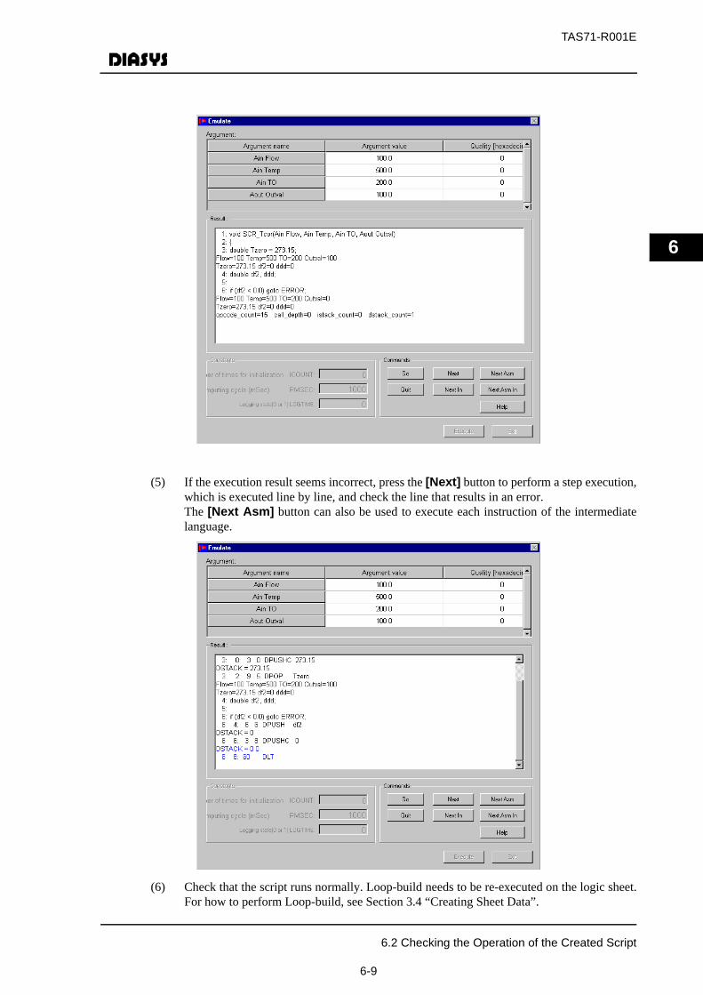
TAS71-R001E
6
(5) If the execution result seems incorrect, press the [Next] button to perform a step execution,which is executed line by line, and check the line that results in an error. The [Next Asm] button can also be used to execute each instruction of the intermediatelanguage.
(6) Check that the script runs normally. Loop-build needs to be re-executed on the logic sheet.For how to perform Loop-build, see Section 3.4 “Creating Sheet Data”.
6.2 Checking the Operation of the Created Script
6-9

TAS71-R001E
6
6.3 Creating Scripts Using Existing Scripts
This section describes how to create a new script using an existing script.
(1) Create the script call element in the same procedure as that of 6.1 and select Open Editorfrom the menu opened by a right-click.
(2) The dialogue box is displayed for script creation. Select “Create the script function blockbased on existing script function block”. Then, the name list of scripts already created isdisplayed. Next, select the script for reference in the list and the[OK]button. (here, select“New script test” created in 1.)In this case, the function of the script previously created is copied as a new script.
6.3 Creating Scripts Using Existing Scripts
6-10

TAS71-R001E
6
(3) The ScriptCreator (Squid) is started up. You can confirm the script previously createdis described in the curly braces.
However, please note the argument of the function changes according to the connection status ofthe connector on LogicCreator (FLIPPER).
(4) Execute [Edit Script] - [Save] - [Compile] - [Exit] in the same way as in 1.
(5) Return to LogicCreator (FLIPPER) to execute Build.
6.3 Creating Scripts Using Existing Scripts
6-11

TAS71-R001E
6
6.4 Specifications for Script Computing Blocks
This section describes the elements and syntax used in a script and the functions that can be usedon ScriptCreator (Squid).
6.4.1 Elements of a script
Table 6.4-1 lists the elements of a script.
Table 6.4-1 Elements of a script
Item Description LimitNumber of lines in ascript
Number of lines in a script 400 lines
Number of inputsand outputs
Analog input 20 itemsDigital input 20 items
Integer input 20 itemsAnalog output 20 itemsDigital output 20 items
Integer output 20 itemsSize of intermediatecode
Size of the intermediate code (2-byte and 4-byte) that iscreated by compiling a script
4000 words
Number of symbols Total number of symbols including variable names andfunction names
200symbols
Number of labelswith automaticallyassigned numbers
Total number of labels with the numbers automaticallyassigned at compilation (users do not directly assignnumbers to labels)The number of labels used in each process is as follows:For statement, while statement, do-while statement: 4If-else statement: 2If statement: 1
200 labels
Byte length of storedvariables
Total number of bytes of stored variables 2000 bytes
Byte length ofconstants
Total number of bytes of constantsTotal number of bytes in the data described as “1.0” or“100” in the script
4000 bytes
Byte length of localvariables
Number of bytes of local variables 4000 bytes
Byte length ofarguments
Total number of bytes of arguments 4000 bytes
Number ofintermediate codesexecuted
Number of intermediate codes executed in the script (toprevent infinite loops)
10000codes
6.4 Specifications for Script Computing Blocks
6-12
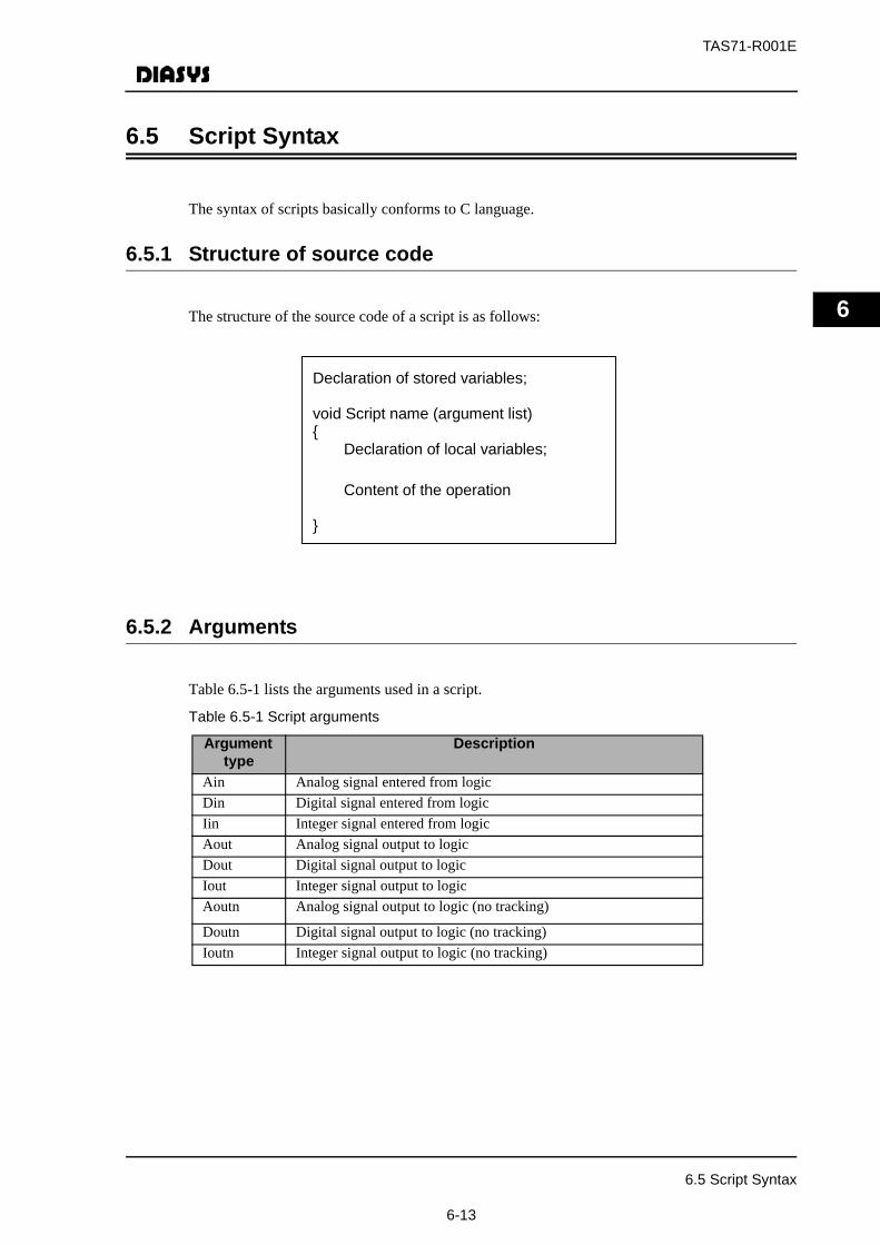
TAS71-R001E
6
6.5 Script Syntax
The syntax of scripts basically conforms to C language.
6.5.1 Structure of source code
The structure of the source code of a script is as follows:
6.5.2 Arguments
Table 6.5-1 lists the arguments used in a script.
Table 6.5-1 Script arguments
Argument type
Description
Ain Analog signal entered from logicDin Digital signal entered from logicIin Integer signal entered from logicAout Analog signal output to logic Dout Digital signal output to logic Iout Integer signal output to logicAoutn Analog signal output to logic (no tracking)
Doutn Digital signal output to logic (no tracking)Ioutn Integer signal output to logic (no tracking)
Declaration of stored variables; void Script name (argument list) {
Declaration of local variables;
Content of the operation }
6.5 Script Syntax
6-13
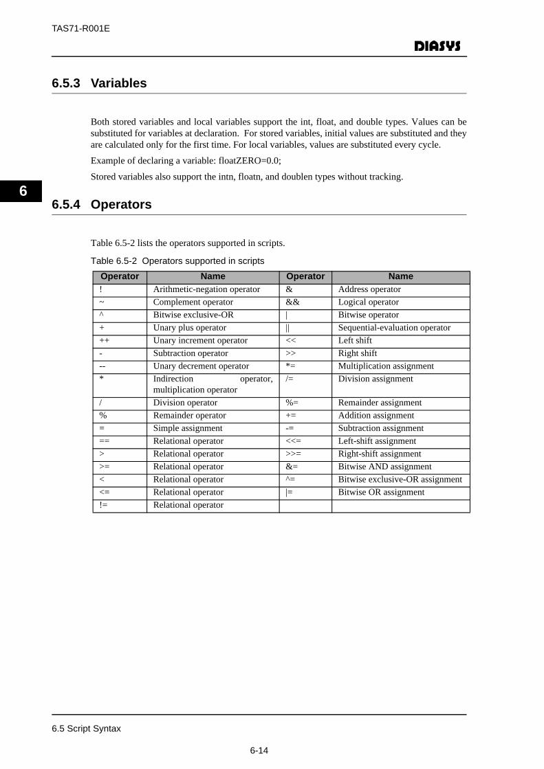
TAS71-R001E
6
6.5.3 Variables
Both stored variables and local variables support the int, float, and double types. Values can besubstituted for variables at declaration. For stored variables, initial values are substituted and theyare calculated only for the first time. For local variables, values are substituted every cycle.
Example of declaring a variable: floatZERO=0.0;
Stored variables also support the intn, floatn, and doublen types without tracking.
6.5.4 Operators
Table 6.5-2 lists the operators supported in scripts.
Table 6.5-2 Operators supported in scripts
Operator Name Operator Name! Arithmetic-negation operator & Address operator~ Complement operator && Logical operator^ Bitwise exclusive-OR | Bitwise operator+ Unary plus operator || Sequential-evaluation operator++ Unary increment operator << Left shift- Subtraction operator >> Right shift-- Unary decrement operator *= Multiplication assignment* Indirection operator,
multiplication operator/= Division assignment
/ Division operator %= Remainder assignment% Remainder operator += Addition assignment= Simple assignment -= Subtraction assignment== Relational operator <<= Left-shift assignment> Relational operator >>= Right-shift assignment>= Relational operator &= Bitwise AND assignment < Relational operator ^= Bitwise exclusive-OR assignment<= Relational operator |= Bitwise OR assignment!= Relational operator
6.5 Script Syntax
6-14

TAS71-R001E
6
6.6 Control statements
Table 6.5-3 lists the control statements supported in scripts. (Note that the switch statement is notsupported.)
Table 6.5-3 Control statements supported in scripts
6.6.1 Propagating quality
The quality of data is represented by Q (variable name) and the quality of input can be propagatedto output.
Example:Q(Y1)=Q(X1);Propagate the quality of input X1 to Y1.
For details about quality information, see Section 2.7 “Quality Information Added to FunctionBlocks”.
6.6.2 Comments
Comments can be written in scripts using the same format used in C language. See below.
/*Comment/*
Control statement
Description
if statement A branch instruction that occurs based on a specific condition.if - elsestatement
A branch instruction that executes one of two sections of code based on aspecific condition.
for statement Repeats a section of code for a specified number of times. whilestatement
Evaluates a predefined condition and repeats a section of code while thepredefined condition is satisfied.
do - whilestatement
Executes a section of code and evaluates a predefined condition, thenrepeats the section of code while the predefined condition is satisfied.
gotostatement
Transfers execution to some other statement.
breakstatement
Exits a loop or switch.
continuestatement
Returns to the beginning of a loop.
returnstatement
Returns to the call source.
6.6 Control statements
6-15
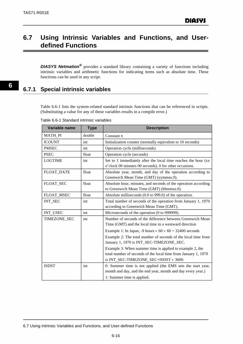
TAS71-R001E
6
6.7 Using Intrinsic Variables and Functions, and User-defined Functions
DIASYS Netmation® provides a standard library containing a variety of functions includingintrinsic variables and arithmetic functions for indicating items such as absolute time. Thesefunctions can be used in any script.
6.7.1 Special intrinsic variables
Table 6.6-1 lists the system-related standard intrinsic functions that can be referenced in scripts.(Substituting a value for any of these variables results in a compile error.)
Table 6.6-1 Standard intrinsic variables
Variable name Type Description
MATH_PI double Constant πICOUNT int Initialization counter (normally equivalent to 10 seconds) PMSEC int Operation cycle (milliseconds) PSEC float Operation cycle (seconds) LOGTIME int Set to 1 immediately after the local time reaches the hour (xx
o’clock 00 minutes 00 seconds). 0 for other occasions.FLOAT_DATE float Absolute year, month, and day of the operation according to
Greenwich Mean Time (GMT) (yymmss.0).FLOAT_SEC float Absolute hour, minutes, and seconds of the operation according
to Greenwich Mean Time (GMT) (hhmmss.0). FLOAT_MSEC float Absolute milliseconds (0.0 to 999.0) of the operation. INT_SEC int Total number of seconds of the operation from January 1, 1970
according to Greenwich Mean Time (GMT). INT_USEC int Microseconds of the operation (0 to 999999). TIMEZONE_SEC int Number of seconds of the difference between Greenwich Mean
Time (GMT) and the local time in a westward directionExample 1: In Japan, -9 hours × 60 × 60 = 32400 secondsExample 2: The total number of seconds of the local time fromJanuary 1, 1970 is INT_SEC-TIMEZONE_SEC.Example 3: When summer time is applied to example 2, the total number of seconds of the local time from January 1, 1970 is INT_SEC-TIMEZONE_SEC+ISDST × 3600.
ISDST int 0: Summer time is not applied (the EMS sets the start year,month and day, and the end year, month and day every year.)1: Summer time is applied.
6.7 Using Intrinsic Variables and Functions, and User-defined Functions
6-16

TAS71-R001E
6
6.7.2 Arithmetic intrinsic functions
Table 6.6-2 lists the arithmetic intrinsic functions that can be used in scripts. If the input exceeds aspecified range, a sheet operation error occurs.
Table 6.6-2 Arithmetic intrinsic functions that can be used in scripts
1In this script editor, π is represented as MATH_PI (see Table 6.6-1). For example, sin(πy/2) is represented as sin(MATH_PI*y/2.0).
Function Description
double sqrt(double x) Square root (x ≥ 0)double pow(double x, double y) Power (x > 0)double pow10(double x) Power of 10double exp(double x) Exponential functiondouble log10(double x) Log function (base 10) (x > 0)double log(double x) Log function (base e) (x > 0)double fmod(double x, double y) Remainder function (y ≠ 0). The sign is the same as x. double fabs(double x) Absolute valueint abs(int x) Absolute valuedouble sinh(double x) Hyperbolic sine functiondouble cosh(double x) Hyperbolic cosine functiondouble tanh(double x) Hyperbolic tangent functiondouble sin(double x) Trigonometric function (sine function)1
double cos(double x) Trigonometric function (cosine function)1
double tan(double x) Trigonometric function (tangent function)1
double asin(double x) Inverse trigonometric sine function (-1 ≤ x ≤ 1)double acos(double x) Inverse trigonometric cosine function (-1 ≤ x ≤ 1)double atan2(double y, double x) Inverse trigonometric tangent function tan-1 (y/x)double atan(double x) Inverse trigonometric tangent function tan-1 (x)double min(double x, double y) Minimum values of x and ydouble max(double x, double y) Maximum values of x and yint nint(double x) Integer closest to real number x (-2147483648 ≤ nint(x) ≤
2147483648)3rcf. Fractions are discarded when the value is converted to aninteger using (int).
double floor(double x) Maximum integer no greater than real number x is converted to areal number
double ceil(double x) Minimum integer no smaller than real number x is converted to areal number
6.7 Using Intrinsic Variables and Functions, and User-defined Functions
6-17
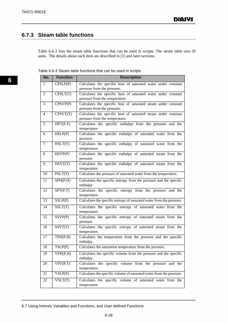
TAS71-R001E
6
6.7.3 Steam table functions
Table 6.6-3 lists the steam table functions that can be used in scripts. The steam table uses SIunits. The details about each item are described in [1] and later sections.
Table 6.6-3 Steam table functions that can be used in scripts
No. Function Description1 CPSLP(P) Calculates the specific heat of saturated water under constant
pressure from the pressure.2 CPSLT(T) Calculates the specific heat of saturated water under constant
pressure from the temperature.3 CPSVP(P) Calculates the specific heat of saturated steam under constant
pressure from the pressure. 4 CPSVT(T) Calculates the specific heat of saturated steam under constant
pressure from the temperature.5 HPT(P,T) Calculates the specific enthalpy from the pressure and the
temperature.6 HSLP(P) Calculates the specific enthalpy of saturated water from the
pressure.7 HSLT(T) Calculates the specific enthalpy of saturated water from the
temperature.8 HSVP(P) Calculates the specific enthalpy of saturated steam from the
pressure.9 HSVT(T) Calculates the specific enthalpy of saturated steam from the
temperature.10 PSLT(T) Calculates the pressure of saturated water from the temperature.
11 SPH(P,H) Calculates the specific entropy from the pressure and the specificenthalpy.
12 SPT(P,T) Calculates the specific entropy from the pressure and thetemperature.
13 SSLP(P) Calculates the specific entropy of saturated water from the pressure.
14 SSLT(T) Calculates the specific entropy of saturated water from thetemperature.
15 SSVP(P) Calculates the specific entropy of saturated steam from thepressure.
16 SSVT(T) Calculates the specific entropy of saturated steam from thetemperature.
17 TPH(P,H) Calculates the temperature from the pressure and the specificenthalpy.
18 TSLP(P) Calculates the saturation temperature from the pressure.
19 VPH(P,H) Calculates the specific volume from the pressure and the specificenthalpy.
20 VPT(P,T) Calculates the specific volume from the pressure and thetemperature.
21 VSLP(P) Calculates the specific volume of saturated water from the pressure.
22 VSLT(T) Calculates the specific volume of saturated water from thetemperature.
6.7 Using Intrinsic Variables and Functions, and User-defined Functions
6-18
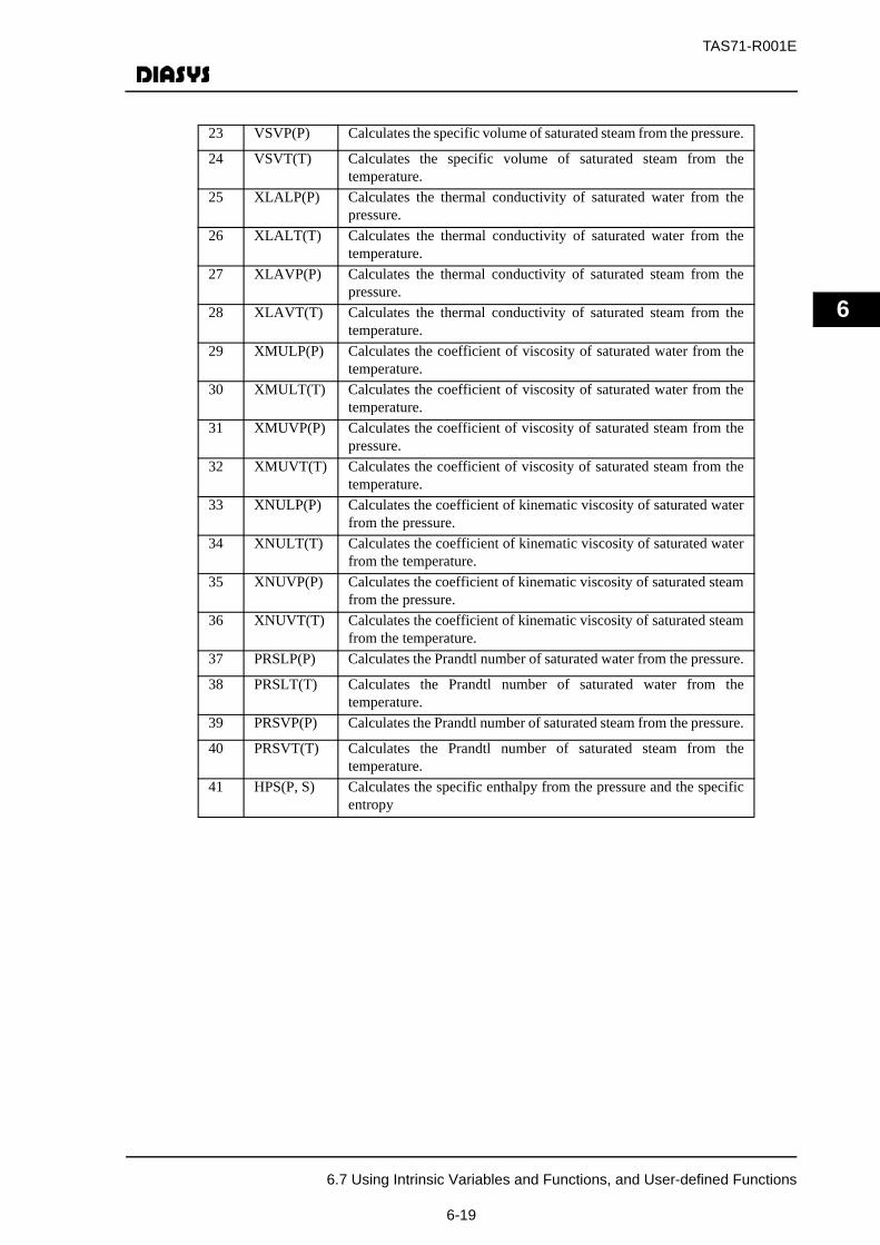
TAS71-R001E
6
23 VSVP(P) Calculates the specific volume of saturated steam from the pressure.
24 VSVT(T) Calculates the specific volume of saturated steam from thetemperature.
25 XLALP(P) Calculates the thermal conductivity of saturated water from thepressure.
26 XLALT(T) Calculates the thermal conductivity of saturated water from thetemperature.
27 XLAVP(P) Calculates the thermal conductivity of saturated steam from thepressure.
28 XLAVT(T) Calculates the thermal conductivity of saturated steam from thetemperature.
29 XMULP(P) Calculates the coefficient of viscosity of saturated water from thetemperature.
30 XMULT(T) Calculates the coefficient of viscosity of saturated water from thetemperature.
31 XMUVP(P) Calculates the coefficient of viscosity of saturated steam from thepressure.
32 XMUVT(T) Calculates the coefficient of viscosity of saturated steam from thetemperature.
33 XNULP(P) Calculates the coefficient of kinematic viscosity of saturated waterfrom the pressure.
34 XNULT(T) Calculates the coefficient of kinematic viscosity of saturated waterfrom the temperature.
35 XNUVP(P) Calculates the coefficient of kinematic viscosity of saturated steamfrom the pressure.
36 XNUVT(T) Calculates the coefficient of kinematic viscosity of saturated steamfrom the temperature.
37 PRSLP(P) Calculates the Prandtl number of saturated water from the pressure.
38 PRSLT(T) Calculates the Prandtl number of saturated water from thetemperature.
39 PRSVP(P) Calculates the Prandtl number of saturated steam from the pressure.
40 PRSVT(T) Calculates the Prandtl number of saturated steam from thetemperature.
41 HPS(P, S) Calculates the specific enthalpy from the pressure and the specificentropy
6.7 Using Intrinsic Variables and Functions, and User-defined Functions
6-19
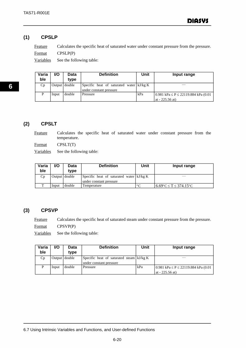
TAS71-R001E
6
(1) CPSLP
Feature Calculates the specific heat of saturated water under constant pressure from the pressure.Format CPSLP(P)Variables See the following table:
(2) CPSLT
Feature Calculates the specific heat of saturated water under constant pressure from thetemperature.
Format CPSLT(T)Variables See the following table:
(3) CPSVP
Feature Calculates the specific heat of saturated steam under constant pressure from the pressure.Format CPSVP(P)Variables See the following table:
Variable
I/O Data type
Definition Unit Input range
Cp Output double Specific heat of saturated waterunder constant pressure
kJ/kg K ―
P Input double Pressure kPa 0.981 kPa ≤ P ≤ 22119.884 kPa (0.01 at - 225.56 at)
Variable
I/O Data type
Definition Unit Input range
Cp Output double Specific heat of saturated waterunder constant pressure
kJ/kg K ―
T Input double Temperature °C 6.69°C ≤ T ≤ 374.15°C
Variable
I/O Data type
Definition Unit Input range
Cp Output double Specific heat of saturated steamunder constant pressure
kJ/kg K ―
P Input double Pressure kPa 0.981 kPa ≤ P ≤ 22119.884 kPa (0.01 at - 225.56 at)
6.7 Using Intrinsic Variables and Functions, and User-defined Functions
6-20
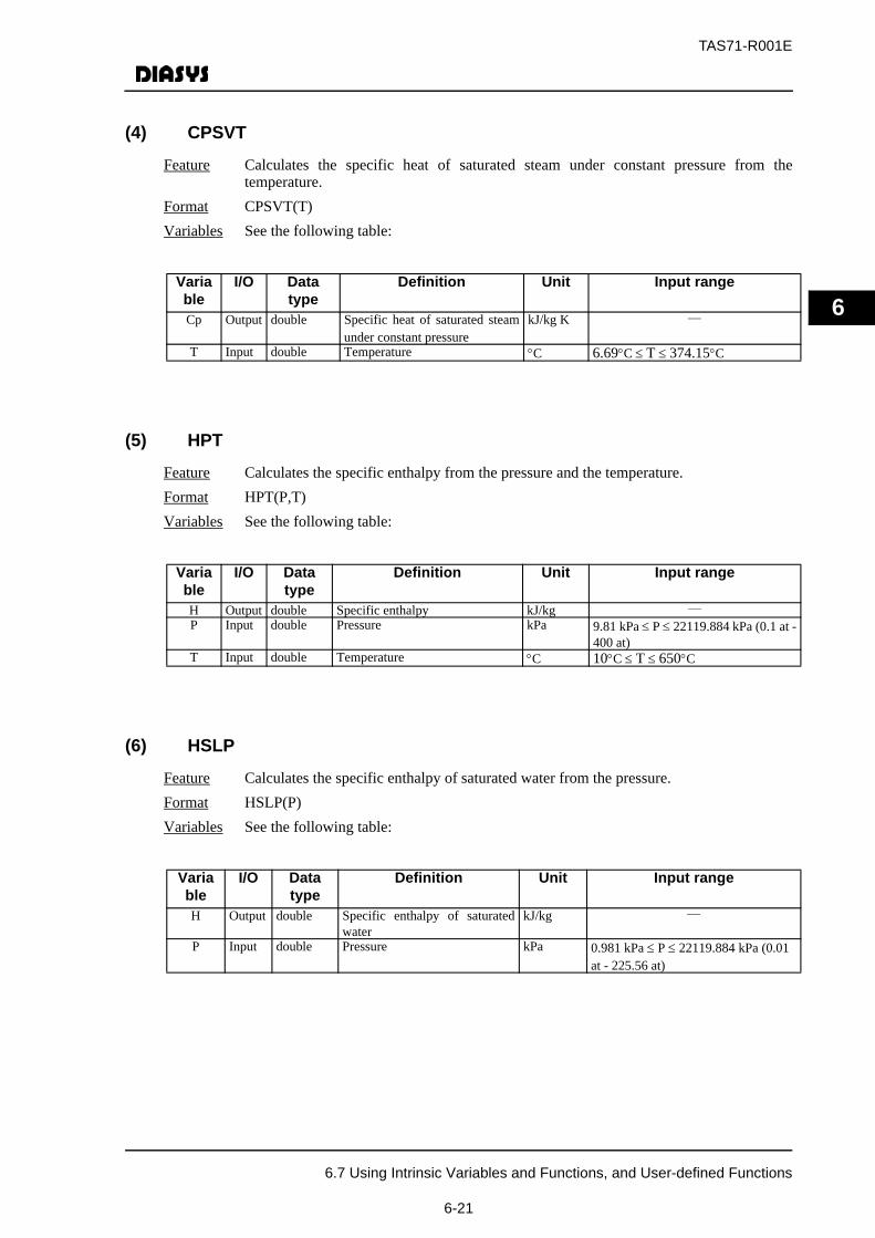
TAS71-R001E
6
(4) CPSVT
Feature Calculates the specific heat of saturated steam under constant pressure from thetemperature.
Format CPSVT(T)Variables See the following table:
(5) HPT
Feature Calculates the specific enthalpy from the pressure and the temperature.Format HPT(P,T)Variables See the following table:
(6) HSLP
Feature Calculates the specific enthalpy of saturated water from the pressure.Format HSLP(P)Variables See the following table:
Variable
I/O Data type
Definition Unit Input range
Cp Output double Specific heat of saturated steamunder constant pressure
kJ/kg K ―
T Input double Temperature °C 6.69°C ≤ T ≤ 374.15°C
Variable
I/O Data type
Definition Unit Input range
H Output double Specific enthalpy kJ/kg ―P Input double Pressure kPa 9.81 kPa ≤ P ≤ 22119.884 kPa (0.1 at -
400 at)T Input double Temperature °C 10°C ≤ T ≤ 650°C
Variable
I/O Data type
Definition Unit Input range
H Output double Specific enthalpy of saturatedwater
kJ/kg ―
P Input double Pressure kPa 0.981 kPa ≤ P ≤ 22119.884 kPa (0.01 at - 225.56 at)
6.7 Using Intrinsic Variables and Functions, and User-defined Functions
6-21
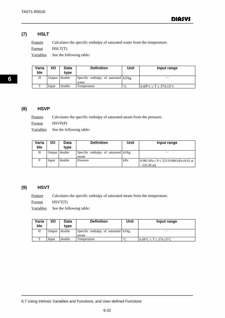
TAS71-R001E
6
(7) HSLT
Feature Calculates the specific enthalpy of saturated water from the temperature.Format HSLT(T)Variables See the following table:
(8) HSVP
Feature Calculates the specific enthalpy of saturated steam from the pressure.Format HSVP(P)Variables See the following table:
(9) HSVT
Feature Calculates the specific enthalpy of saturated steam from the temperature.Format HSVT(T)Variables See the following table:
Variable
I/O Data type
Definition Unit Input range
H Output double Specific enthalpy of saturatedwater
kJ/kg ―
T Input double Temperature °C 6.69°C ≤ T ≤ 374.15°C
Variable
I/O Data type
Definition Unit Input range
H Output double Specific enthalpy of saturatedsteam
kJ/kg ―
P Input double Pressure kPa 0.981 kPa ≤ P ≤ 22119.884 kPa (0.01 at - 225.56 at)
Variable
I/O Data type
Definition Unit Input range
H Output double Specific enthalpy of saturatedsteam
kJ/kg ―
T Input double Temperature °C 6.69°C ≤ T ≤ 374.15°C
6.7 Using Intrinsic Variables and Functions, and User-defined Functions
6-22
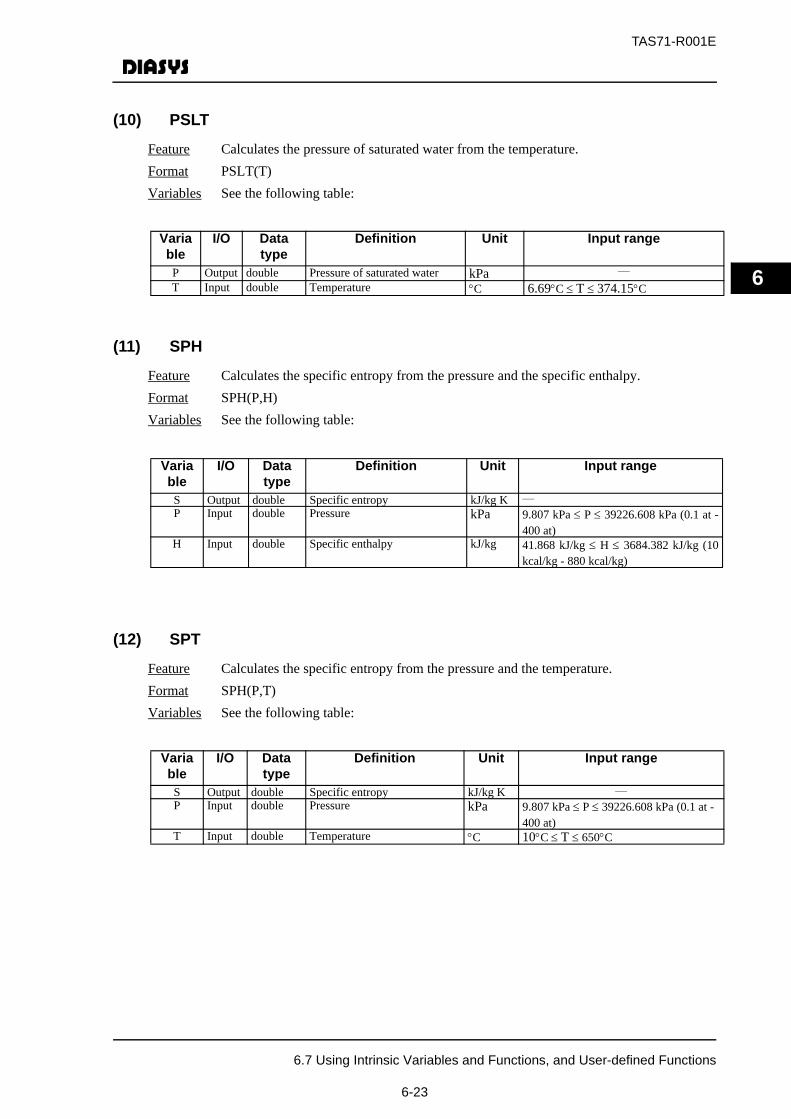
TAS71-R001E
6
(10) PSLT
Feature Calculates the pressure of saturated water from the temperature.Format PSLT(T)Variables See the following table:
(11) SPH
Feature Calculates the specific entropy from the pressure and the specific enthalpy.Format SPH(P,H)Variables See the following table:
(12) SPT
Feature Calculates the specific entropy from the pressure and the temperature.Format SPH(P,T)Variables See the following table:
Variable
I/O Data type
Definition Unit Input range
P Output double Pressure of saturated water kPa ―
T Input double Temperature °C 6.69°C ≤ T ≤ 374.15°C
Variable
I/O Data type
Definition Unit Input range
S Output double Specific entropy kJ/kg K ―P Input double Pressure kPa 9.807 kPa ≤ P ≤ 39226.608 kPa (0.1 at -
400 at)H Input double Specific enthalpy kJ/kg 41.868 kJ/kg ≤ H ≤ 3684.382 kJ/kg (10
kcal/kg - 880 kcal/kg)
Variable
I/O Data type
Definition Unit Input range
S Output double Specific entropy kJ/kg K ―P Input double Pressure kPa 9.807 kPa ≤ P ≤ 39226.608 kPa (0.1 at -
400 at)T Input double Temperature °C 10°C ≤ T ≤ 650°C
6.7 Using Intrinsic Variables and Functions, and User-defined Functions
6-23
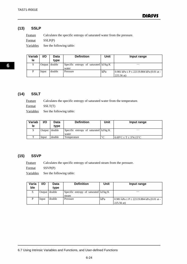
TAS71-R001E
6
(13) SSLP
Feature Calculates the specific entropy of saturated water from the pressure.Format SSLP(P)Variables See the following table:
(14) SSLT
Feature Calculates the specific entropy of saturated water from the temperature.Format SSLT(T)Variables See the following table:
(15) SSVP
Feature Calculates the specific entropy of saturated steam from the pressure.Format SSVP(P)Variables See the following table:
Variable
I/O Data type
Definition Unit Input range
S Output double Specific entropy of saturatedwater
kJ/kg K ―
P Input double Pressure kPa 0.981 kPa ≤ P ≤ 22119.884 kPa (0.01 at - 225.56 at)
Variable
I/O Data type
Definition Unit Input range
S Output double Specific entropy of saturatedwater
kJ/kg K ―
T Input double Temperature °C 6.69°C ≤ T ≤ 374.15°C
Variable
I/O Data type
Definition Unit Input range
S Output double Specific entropy of saturatedsteam
kJ/kg K ―
P Input double Pressure kPa 0.981 kPa ≤ P ≤ 22119.884 kPa (0.01 at - 225.56 at)
6.7 Using Intrinsic Variables and Functions, and User-defined Functions
6-24
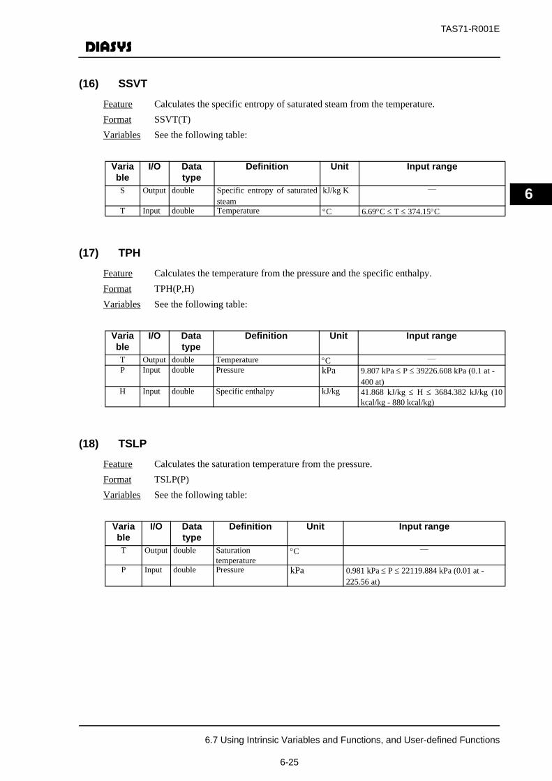
TAS71-R001E
6
(16) SSVT
Feature Calculates the specific entropy of saturated steam from the temperature.Format SSVT(T)Variables See the following table:
(17) TPH
Feature Calculates the temperature from the pressure and the specific enthalpy.Format TPH(P,H)Variables See the following table:
(18) TSLP
Feature Calculates the saturation temperature from the pressure.Format TSLP(P)Variables See the following table:
Variable
I/O Data type
Definition Unit Input range
S Output double Specific entropy of saturatedsteam
kJ/kg K ―
T Input double Temperature °C 6.69°C ≤ T ≤ 374.15°C
Variable
I/O Data type
Definition Unit Input range
T Output double Temperature °C ―
P Input double Pressure kPa 9.807 kPa ≤ P ≤ 39226.608 kPa (0.1 at - 400 at)
H Input double Specific enthalpy kJ/kg 41.868 kJ/kg ≤ H ≤ 3684.382 kJ/kg (10kcal/kg - 880 kcal/kg)
Variable
I/O Data type
Definition Unit Input range
T Output double Saturationtemperature
°C ―
P Input double Pressure kPa 0.981 kPa ≤ P ≤ 22119.884 kPa (0.01 at - 225.56 at)
6.7 Using Intrinsic Variables and Functions, and User-defined Functions
6-25

TAS71-R001E
6
(19) VPH
Feature Calculates the specific volume from the pressure and the specific enthalpy.Format VPH(P,H)Variables See the following table:
(20) VPT
Feature Calculates the specific volume from the pressure and the temperature.Format VPT(P,T)Variables See the following table:
(21) VSLP
Feature Calculates the specific volume of saturated water from the pressure.Format VSLP(P)Variables See the following table:
Variable
I/O Data type
Definition Unit Input range
V Output double Specific volume m3/kg ―
P Input double Pressure kPa 9.807 kPa ≤ P ≤ 39226.608 kPa (0.1 at - 400 at)
H Input double Specific enthalpy kJ/kg 41.868 kJ/kg ≤ H ≤ 3684.382 kJ/kg (10 kcal/kg- 880 kcal/kg)
Variable
I/O Data type
Definition Unit Input range
V Output double Specific volume m3/kg ―
P Input double Pressure kPa 9.807 kPa ≤ P ≤ 39226.608 kPa (0.1 at - 400 at)
T Input double Temperature °C 10°C ≤ T ≤ 650°C
Variable
I/O Data type
Definition Unit Input range
V Output double Specific volume ofsaturated water
m3/kg ―
P Input double Pressure kPa 0.981 kPa ≤ P ≤ 22119.884 kPa (0.01 at - 225.56 at)
6.7 Using Intrinsic Variables and Functions, and User-defined Functions
6-26

TAS71-R001E
6
(22) VSLT
Feature Calculates the specific volume of saturated water from the temperature.Format VSLT(T)Variables See the following table:
(23) VSVP
Feature Calculates the specific volume of saturated steam from the pressure.Format VSVP(P)Variables See the following table:
(24) VSVT
Feature Calculates the specific volume of saturated steam from the temperature.Format VSVT(T)Variables See the following table:
Variable
I/O Data type
Definition Unit Input range
V Output double Specific volume ofsaturated water
m3/kg ―
T Input double Temperature °C 6.69°C ≤ T ≤ 374.15°C
Variable
I/O Data type
Definition Unit Input range
V Output double Specific volume of saturated steam
m3/kg ―
P Input double Pressure kPa 0.981 kPa ≤ P ≤ 22119.884 kPa (0.01 at - 225.56 at)
Variable
I/O Data type
Definition Unit Input range
V Output double Specific volume of saturated steam
m3/kg ―
T Input double Temperature °C 6.69°C ≤ T ≤ 374.15°C
6.7 Using Intrinsic Variables and Functions, and User-defined Functions
6-27
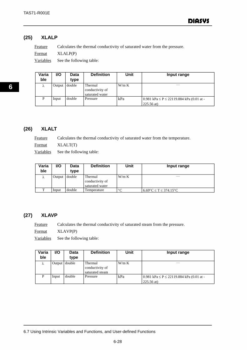
TAS71-R001E
6
(25) XLALP
Feature Calculates the thermal conductivity of saturated water from the pressure.Format XLALP(P)Variables See the following table:
(26) XLALT
Feature Calculates the thermal conductivity of saturated water from the temperature.Format XLALT(T)Variables See the following table:
(27) XLAVP
Feature Calculates the thermal conductivity of saturated steam from the pressure.Format XLAVP(P)Variables See the following table:
Variable
I/O Data type
Definition Unit Input range
λ Output double Thermal conductivity of saturated water
W/m K ―
P Input double Pressure kPa 0.981 kPa ≤ P ≤ 22119.884 kPa (0.01 at - 225.56 at)
Variable
I/O Data type
Definition Unit Input range
λ Output double Thermal conductivity of saturated water
W/m K ―
T Input double Temperature °C 6.69°C ≤ T ≤ 374.15°C
Variable
I/O Data type
Definition Unit Input range
λ Output double Thermal conductivity of saturated steam
W/m K ―
P Input double Pressure kPa 0.981 kPa ≤ P ≤ 22119.884 kPa (0.01 at - 225.56 at)
6.7 Using Intrinsic Variables and Functions, and User-defined Functions
6-28
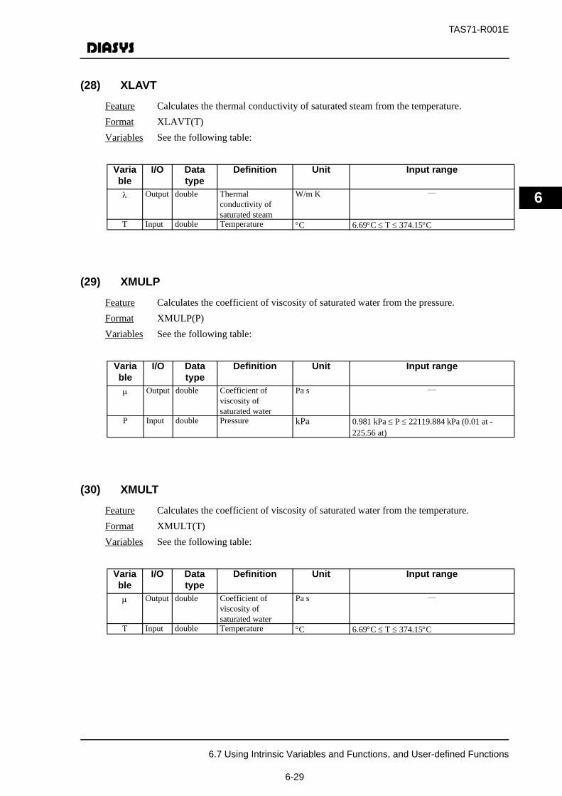
TAS71-R001E
6
(28) XLAVT
Feature Calculates the thermal conductivity of saturated steam from the temperature.Format XLAVT(T)Variables See the following table:
(29) XMULP
Feature Calculates the coefficient of viscosity of saturated water from the pressure.Format XMULP(P)Variables See the following table:
(30) XMULT
Feature Calculates the coefficient of viscosity of saturated water from the temperature.Format XMULT(T)Variables See the following table:
Variable
I/O Data type
Definition Unit Input range
λ Output double Thermal conductivity of saturated steam
W/m K ―
T Input double Temperature °C 6.69°C ≤ T ≤ 374.15°C
Variable
I/O Data type
Definition Unit Input range
μ Output double Coefficient of viscosity of saturated water
Pa s ―
P Input double Pressure kPa 0.981 kPa ≤ P ≤ 22119.884 kPa (0.01 at - 225.56 at)
Variable
I/O Data type
Definition Unit Input range
μ Output double Coefficient of viscosity of saturated water
Pa s ―
T Input double Temperature °C 6.69°C ≤ T ≤ 374.15°C
6.7 Using Intrinsic Variables and Functions, and User-defined Functions
6-29
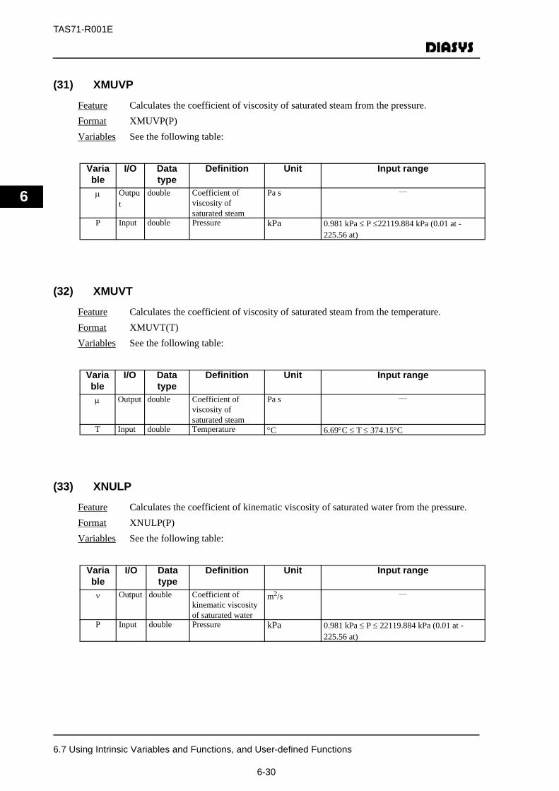
TAS71-R001E
6
(31) XMUVP
Feature Calculates the coefficient of viscosity of saturated steam from the pressure.Format XMUVP(P)Variables See the following table:
(32) XMUVT
Feature Calculates the coefficient of viscosity of saturated steam from the temperature.Format XMUVT(T)Variables See the following table:
(33) XNULP
Feature Calculates the coefficient of kinematic viscosity of saturated water from the pressure.Format XNULP(P)Variables See the following table:
Variable
I/O Data type
Definition Unit Input range
μ Output
double Coefficient of viscosity of saturated steam
Pa s ―
P Input double Pressure kPa 0.981 kPa ≤ P ≤22119.884 kPa (0.01 at - 225.56 at)
Variable
I/O Data type
Definition Unit Input range
μ Output double Coefficient of viscosity of saturated steam
Pa s ―
T Input double Temperature °C 6.69°C ≤ T ≤ 374.15°C
Variable
I/O Data type
Definition Unit Input range
ν Output double Coefficient of kinematic viscosity of saturated water
m2/s ―
P Input double Pressure kPa 0.981 kPa ≤ P ≤ 22119.884 kPa (0.01 at - 225.56 at)
6.7 Using Intrinsic Variables and Functions, and User-defined Functions
6-30
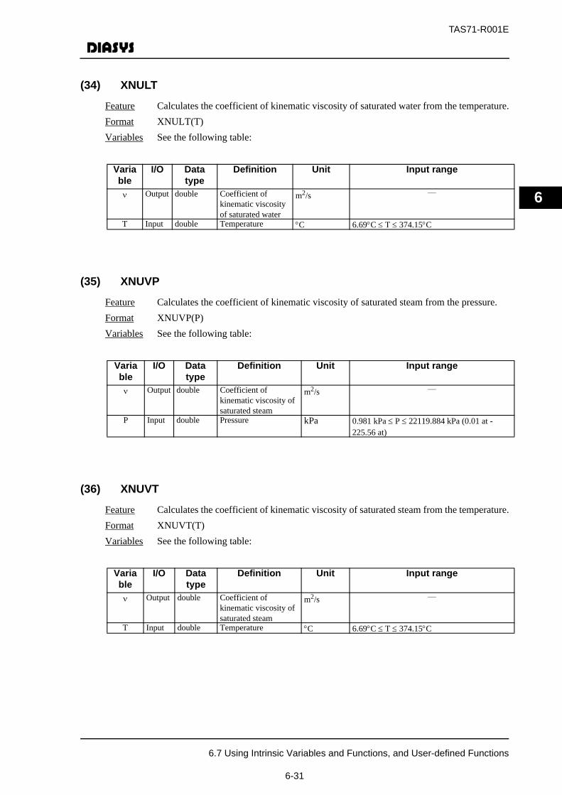
TAS71-R001E
6
(34) XNULT
Feature Calculates the coefficient of kinematic viscosity of saturated water from the temperature.Format XNULT(T)Variables See the following table:
(35) XNUVP
Feature Calculates the coefficient of kinematic viscosity of saturated steam from the pressure.Format XNUVP(P)Variables See the following table:
(36) XNUVT
Feature Calculates the coefficient of kinematic viscosity of saturated steam from the temperature.Format XNUVT(T)Variables See the following table:
Variable
I/O Data type
Definition Unit Input range
ν Output double Coefficient of kinematic viscosity of saturated water
m2/s ―
T Input double Temperature °C 6.69°C ≤ T ≤ 374.15°C
Variable
I/O Data type
Definition Unit Input range
ν Output double Coefficient of kinematic viscosity of saturated steam
m2/s ―
P Input double Pressure kPa 0.981 kPa ≤ P ≤ 22119.884 kPa (0.01 at - 225.56 at)
Variable
I/O Data type
Definition Unit Input range
ν Output double Coefficient of kinematic viscosity of saturated steam
m2/s ―
T Input double Temperature °C 6.69°C ≤ T ≤ 374.15°C
6.7 Using Intrinsic Variables and Functions, and User-defined Functions
6-31

TAS71-R001E
6
(37) PRSLP
Feature Calculates the Prandtl number of saturated water from the pressure.Format PRSLP(P)Variables See the following table:
(38) PRSLT
Feature Calculates the Prandtl number of saturated water from the temperature.Format PRSLT(T)Variables See the following table:
(39) PRSVP
Feature Calculates the Prandtl number of saturated steam from the pressure.Format PRSVP(P)Variables See the following table:
Variable
I/O Data type
Definition Unit Input range
Pr Output double Prandtl number of saturated water
― ―
P Input double Pressure kPa 0.981 kPa ≤ P ≤ 22119.884 kPa (0.01 at - 225.56 at)
Variable
I/O Data type
Definition Unit Input range
Pr Output double Prandtl number of saturated water
― ―
T Input double Temperature °C 6.69°C ≤ T ≤ 374.15°C
Variable
I/O Data type
Definition Unit Input range
Pr Output double Prandtl number of saturated steam
― ―
P Input double Pressure kPa 0.981 kPa ≤ P ≤ 22119.884 kPa (0.01 at - 225.56 at)
6.7 Using Intrinsic Variables and Functions, and User-defined Functions
6-32
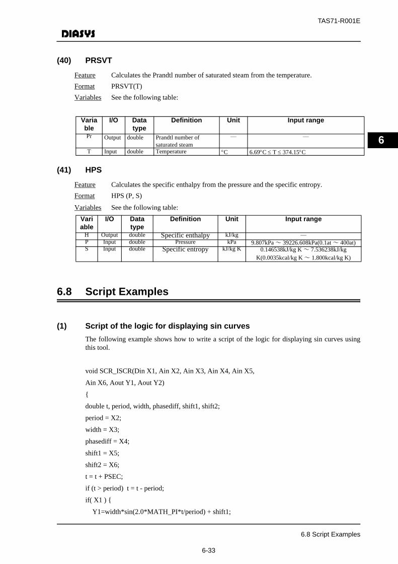
TAS71-R001E
6
(40) PRSVT
Feature Calculates the Prandtl number of saturated steam from the temperature.Format PRSVT(T)Variables See the following table:
(41) HPS
Feature Calculates the specific enthalpy from the pressure and the specific entropy.Format HPS (P, S)
Variables See the following table:
6.8 Script Examples
(1) Script of the logic for displaying sin curvesThe following example shows how to write a script of the logic for displaying sin curves usingthis tool.
void SCR_ISCR(Din X1, Ain X2, Ain X3, Ain X4, Ain X5,
Ain X6, Aout Y1, Aout Y2)
{
double t, period, width, phasediff, shift1, shift2;
period = X2;
width = X3;
phasediff = X4;
shift1 = X5;
shift2 = X6;
t = t + PSEC;
if (t > period) t = t - period;
if( X1 ) {
Y1=width*sin(2.0*MATH_PI*t/period) + shift1;
Variable
I/O Data type
Definition Unit Input range
Pr Output double Prandtl number of saturated steam
― ―
T Input double Temperature °C 6.69°C ≤ T ≤ 374.15°C
Variable
I/O Data type
Definition Unit Input range
H Output double Specific enthalpy kJ/kg ―P Input double Pressure kPa 9.807kPa ~ 39226.608kPa(0.1at ~ 400at)S Input double Specific entropy kJ/kg K 0.146538kJ/kg K ~ 7.536238kJ/kg
K(0.0035kcal/kg K ~ 1.800kcal/kg K)
6.8 Script Examples
6-33
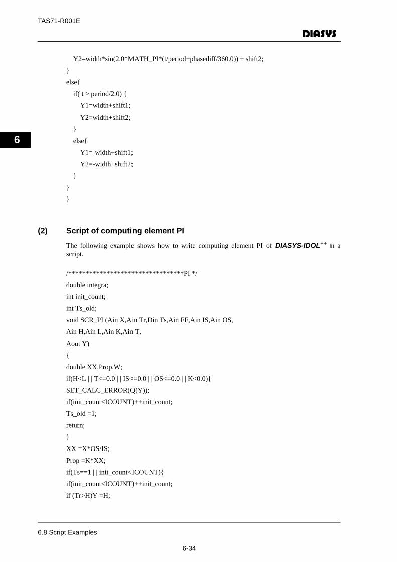
TAS71-R001E
6
Y2=width*sin(2.0*MATH_PI*(t/period+phasediff/360.0)) + shift2;
}
else{
if( t > period/2.0) {
Y1=width+shift1;
Y2=width+shift2;
}
else{
Y1=-width+shift1;
Y2=-width+shift2;
}
}
}
(2) Script of computing element PI
The following example shows how to write computing element PI of DIASYS-IDOL++ in ascript.
/*********************************PI */
double integra;
int init_count;
int Ts_old;
void SCR_PI (Ain X,Ain Tr,Din Ts,Ain FF,Ain IS,Ain OS,
Ain H,Ain L,Ain K,Ain T,
Aout Y)
{
double XX,Prop,W;
if(H<L | | T<=0.0 | | IS<=0.0 | | OS<=0.0 | | K<0.0){
SET_CALC_ERROR(Q(Y));
if(init_count<ICOUNT)++init_count;
Ts_old =1;
return;
}
XX =X*OS/IS;
Prop =K*XX;
if(Ts==1 | | init_count<ICOUNT){
if(init_count<ICOUNT)++init_count;
if (Tr>H)Y =H;
6.8 Script Examples
6-34

TAS71-R001E
6
else if(Tr<L)Y =L;
else Y =Tr;
integral =Y- FF- Prop;
Q(Y)=Q(Tr);
}
else {
if(Ts_old==1)integral =Y- FF- Prop;
integral =integral+XX*PSEC/T;
if(X>=0.0){
if (integral>H- FF )integral =H- FF;
else if(integral<L- FF- Prop)integral =L- FF- Prop;
}
else {
if (integral>H- FF- Prop)integral =H- FF- Prop;
else if(integral<L- FF )integral =L- FF;
}
W =integral+FF+Prop;
if (W>H)Y =H;
else if(W<L)Y =L;
else Y =W;
Q(Y)=Q(X)| Q(FF)| Q(K);
}
Ts_old =Ts;
}
6.8 Script Examples
6-35
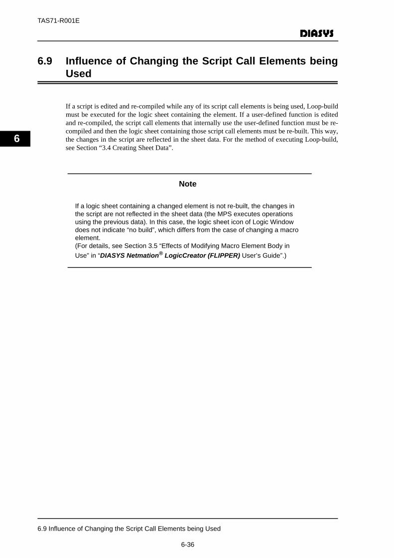
TAS71-R001E
6
6.9 Influence of Changing the Script Call Elements beingUsed
If a script is edited and re-compiled while any of its script call elements is being used, Loop-buildmust be executed for the logic sheet containing the element. If a user-defined function is editedand re-compiled, the script call elements that internally use the user-defined function must be re-compiled and then the logic sheet containing those script call elements must be re-built. This way,the changes in the script are reflected in the sheet data. For the method of executing Loop-build,see Section “3.4 Creating Sheet Data”.
Note
If a logic sheet containing a changed element is not re-built, the changes in the script are not reflected in the sheet data (the MPS executes operations using the previous data). In this case, the logic sheet icon of Logic Window does not indicate “no build”, which differs from the case of changing a macro element.(For details, see Section 3.5 “Effects of Modifying Macro Element Body in Use” in “DIASYS Netmation® LogicCreator (FLIPPER) User’s Guide”.)
6.9 Influence of Changing the Script Call Elements being Used
6-36
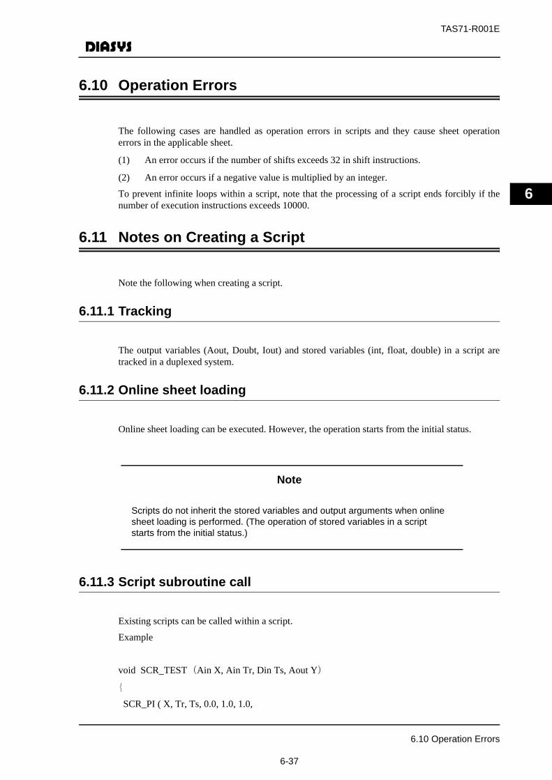
TAS71-R001E
6
6.10 Operation Errors
The following cases are handled as operation errors in scripts and they cause sheet operationerrors in the applicable sheet.
(1) An error occurs if the number of shifts exceeds 32 in shift instructions.
(2) An error occurs if a negative value is multiplied by an integer.
To prevent infinite loops within a script, note that the processing of a script ends forcibly if thenumber of execution instructions exceeds 10000.
6.11 Notes on Creating a Script
Note the following when creating a script.
6.11.1 Tracking
The output variables (Aout, Doubt, Iout) and stored variables (int, float, double) in a script aretracked in a duplexed system.
6.11.2 Online sheet loading
Online sheet loading can be executed. However, the operation starts from the initial status.
Note
Scripts do not inherit the stored variables and output arguments when online sheet loading is performed. (The operation of stored variables in a script starts from the initial status.)
6.11.3 Script subroutine call
Existing scripts can be called within a script.
Example
void SCR_TEST(Ain X, Ain Tr, Din Ts, Aout Y)
{
SCR_PI ( X, Tr, Ts, 0.0, 1.0, 1.0,
6.10 Operation Errors
6-37

TAS71-R001E
6
1000.0, 0.0, 20.0, 100.0,
Y);
}
Arguments are divided into the following two types ((1) and (2)). Arguments of the same type canpass arguments to one another.
(1)Analog values: Ain, Aout, Aoutn, float, double
(2)Digital or integer values: Din, Dout, Doutn, Iin, Iout, Ioutn, int
(Types Ain, Aout, Aoutn, Din, Dout, Doutn, Iin, Iout and Ioutn have quality and their direction(input or output) is fixed. int, float, and double do not have quality and their direction (input oroutput) is not fixed.)
Multidimensional arrays can be passed as arguments. However, arrays cause a great load on theCPU since all the values in arrays are copied to the subroutine when it is called and all the valuesin arrays are copied to the call source when control returns from the subroutine.
If the type of input argument arrays in a subroutine is input (Ain, Din, Iin), the arrays are notcopied since the arrays are not changed in the routine. Therefore, the load on the CPU is less whencontrol is returned from the subroutine.
If fixed-type arrays (const int, const float, const double) are used, the arrays are not copied eithersince the arrays are not changed in the routine. Therefore, the load on the CPU is less whencontrol is returned from the subroutine.
Example
const float C[5][20] = {{0.0, 0.0, 1.0, 2.0, 2.0,4.0, 3.0,8.0, 4.0,12.0,
5.0,14.0, 6.0,15.0, 0.0,0.0, 0.0,0.0, 0.0, 0.0},
{0.0, 0.1, 1.0, 2.1, 2.0,4.1, 3.0,8.1, 4.0,12.1,
5.0,14.1, 6.0,15.1, 0.0,0.0, 0.0,0.0, 0.0, 0.0},
{0.0, 0.2, 1.0, 2.2, 2.0,4.2, 3.0,8.2, 4.0,12.2,
5.0,14.2, 6.0,15.2, 0.0,0.0, 0.0,0.0, 0.0, 0.0},
{0.0, 0.3, 1.0, 2.3, 2.0,4.3, 3.0,8.3, 4.0,12.3,
5.0,14.3, 6.0,15.3, 0.0,0.0, 0.0,0.0, 0.0, 0.0},
{0.0, 0.4, 1.0, 2.4, 2.0,4.4, 3.0,8.4, 4.0,12.4,
5.0,14.4, 6.0,15.4, 0.0,0.0, 0.0,0.0, 0.0, 0.0}};
/********************************* FX */
void SCR_FX5(Ain X, Iin Mode, Aout Y)
{
SCR_FX(X, C[Mode], Y);
}
6.11 Notes on Creating a Script
6-38

TAS71-R001E
Appendix-1 Function Block Description
APP-1-1
Appendix-1 Function Block Description
Appendix-1 Function Block Description
Appendix-1 describes the details of function blocks.
• Function
Functions and symbols for function blocks are explained here.
• Input/Output
This section describes codes, types and description of function block input/output signals.
• Setting
This section describes properties of function block.
• Control parameter
This section describes parameters and default values of function block.
• Action
This section describes outline of action..
• Quality handling/Processing at initialization
This section describes quality propagation information and processing at initialization. Refer to Subsection 2.7 for the details of quality.
No Type Description1 A Analog2 D Digital3 I Integer4 EA Event analog5 ED Event digital

TAS71-R001E
Appendix-1 Function Block Description
APP-1-2
MEMO

TAS71-R001E
Appendix-1 Function Block Description
APP-1-3
ELEMENT SYMBOLCODE
FUNCTION
INPUT/OUTPUT
設定項目SETTING
CONTROL PARAMETERNothing
ACTION
QUALITY HANDLING/PROCESSING AT INITIALIZATION【Quality Handling】No processing in consideration of quality【Processing at Initialization】Nothing in particular
No Code Type DescriptionNo.1 input X01 D Condition input (Max.20)No.1 output Y D Logical Conjunction
EE Example of 3 condition input
Output of logical conjunction for 3 input signals
Input1
Input1
Input3
Logic Conjunction 1 ANDPROCESS FUNCTIONS
• Output of logical conjunction for multiple input conditions
• 20 input conditions at the maximum
• ON output only when all the input conditions are all ON
• OFF output even when there is only one OFF input condition
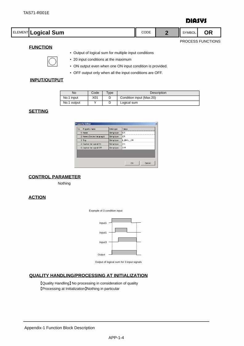
ELEMENT SYMBOLCODE
TAS71-R001E
Appendix-1 Function Block Description
APP-1-4
FUNCTION
INPUT/OUTPUT
設定項目SETTING
CONTROL PARAMETERNothing
ACTION
QUALITY HANDLING/PROCESSING AT INITIALIZATION【Quality Handling】No processing in consideration of quality【Processing at Initialization】Nothing in particular
No Code Type DescriptionNo.1 input X01 D Condition input (Max.20)No.1 output Y D Logical sum
EEExample of 3 condition input
Output
Output of logical sum for 3 input signals
Input1
Input1
Input3
Logical Sum 2 OR
• Output of logical sum for multiple input conditions
• 20 input conditions at the maximum
• ON output even when one ON input condition is provided.
• OFF output only when all the input conditions are OFF.
PROCESS FUNCTIONS
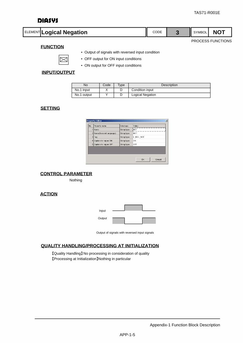
TAS71-R001E
Appendix-1 Function Block Description
APP-1-5
ELEMENT SYMBOLCODE
FUNCTION
INPUT/OUTPUT
設定項目SETTING
CONTROL PARAMETERNothing
ACTION
QUALITY HANDLING/PROCESSING AT INITIALIZATION【Quality Handling】No processing in consideration of quality【Processing at Initialization】Nothing in particular
No Code Type DescriptionNo.1 input X D Condition inputNo.1 output Y D Logical Negation
Output
Output of signals with reversed input signals
Input
Logical Negation 3 NOT
• Output of signals with reversed input condition
• OFF output for ON input conditions
• ON output for OFF input conditions
PROCESS FUNCTIONS
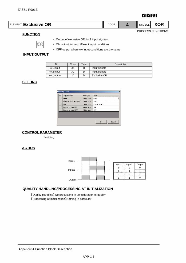
ELEMENT SYMBOLCODE
TAS71-R001E
Appendix-1 Function Block Description
APP-1-6
FUNCTION
INPUT/OUTPUT
設定項目SETTING
CONTROL PARAMETERNothing
ACTION
QUALITY HANDLING/PROCESSING AT INITIALIZATION【Quality Handling】No processing in consideration of quality【Processing at Initialization】Nothing in particular
No Code Type DescriptionNo.1 input X1 D Input signalsNo.2 input X2 D Input signalsNo.1 output Y D Exclusive OR
Input1
Input2
Output
Input1 Input2 Output 0 0 0 0 1 1 1 0 1 1 1 0
Exclusive OR 4 XOR
• Output of exclusive OR for 2 input signals
• ON output for two different input conditions
• OFF output when two input conditions are the same.
PROCESS FUNCTIONS
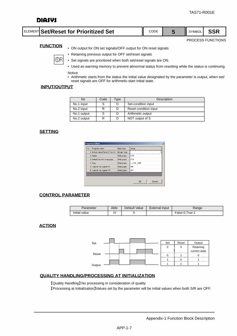
TAS71-R001E
Appendix-1 Function Block Description
APP-1-7
ELEMENT SYMBOLCODE
FUNCTION
INPUT/OUTPUT
設定項目SETTING
CONTROL PARAMETER
ACTION
QUALITY HANDLING/PROCESSING AT INITIALIZATION【Quality Handling】No processing in consideration of quality【Processing at Initialization】Values set by the parameter will be initial values when both S/R are OFF.
No Code Type DescriptionNo.1 input S D Set-condition inputNo.2 input R D Reset-condition inputNo.1 output S D Arithmetic outputNo.2 output R D NOT output of S
Parameter Abbr. Default Value External Input RangeInitial value IV 0 False:0,True:1
Reset
Set
Output
Set Reset Output 0 0 Retaining
current state0 1 0 1 0 1 1 1 1
Set/Reset for Prioritized Set 5 SSR
• ON output for ON set signals/OFF output for ON reset signals
• Retaining previous output for OFF set/reset signals
• Set signals are prioritized when both set/reset signals are ON.
• Used as warning memory to prevent abnormal status from resetting while the status is continuing.
Notice• Arithmetic starts from the status the initial value designated by the parameter is output, when set/
reset signals are OFF for arithmetic-start initial state.
PROCESS FUNCTIONS

ELEMENT SYMBOLCODE
TAS71-R001E
Appendix-1 Function Block Description
APP-1-8
FUNCTION
INPUT/OUTPUT
設定項目SETTING
CONTROL PARAMETER
ACTION
QUALITY HANDLING/PROCESSING AT INITIALIZATION【Quality Handling】No processing in consideration of quality【Processing at Initialization】Values set by the parameter will be initial values when both S/R are OFF.
No Code Type DescriptionNo.1 input S D Set-condition inputNo.2 input R D Reset-condition inputNo.1 output S D Arithmetic outputNo.2 output R D NOT output of S
Parameter Abbr. Default Value External Input RangeInitial value IV 0 False:0,True:1
Set
Reset
Output
Set Reset Output 0 0 Retaining
current state0 1 0 1 0 1 1 1 0
Set/Reset for Prioritized Reset 6 SRR
• ON output for ON set signals/OFF output for ON reset signals
• Retaining previous output for OFF set/reset signals
• Reset signals are prioritized when both set/reset signals are ON.
• Used for mode switching by automatic/manual push buttons, etc.
Notice• Arithmetic starts from the status the initial value designated by the parameter is output,
when set/reset signals are OFF for arithmetic-start initial state.
PROCESS FUNCTIONS
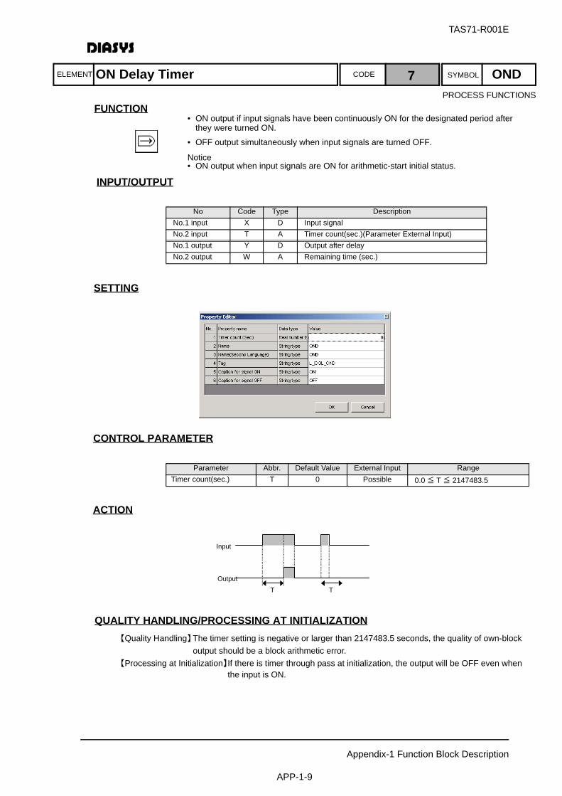
TAS71-R001E
Appendix-1 Function Block Description
APP-1-9
ELEMENT SYMBOLCODE
FUNCTION
INPUT/OUTPUT
設定項目SETTING
CONTROL PARAMETER
ACTION
QUALITY HANDLING/PROCESSING AT INITIALIZATION【Quality Handling】The timer setting is negative or larger than 2147483.5 seconds, the quality of own-block
output should be a block arithmetic error.【Processing at Initialization】If there is timer through pass at initialization, the output will be OFF even when
the input is ON.
No Code Type DescriptionNo.1 input X D Input signalNo.2 input T A Timer count(sec.)(Parameter External Input)No.1 output Y D Output after delayNo.2 output W A Remaining time (sec.)
Parameter Abbr. Default Value External Input RangeTimer count(sec.) T 0 Possible 0.0 ≦ T ≦ 2147483.5
T T
Input
Output
ON Delay Timer 7 OND
• ON output if input signals have been continuously ON for the designated period after they were turned ON.
• OFF output simultaneously when input signals are turned OFF.
Notice• ON output when input signals are ON for arithmetic-start initial status.
PROCESS FUNCTIONS
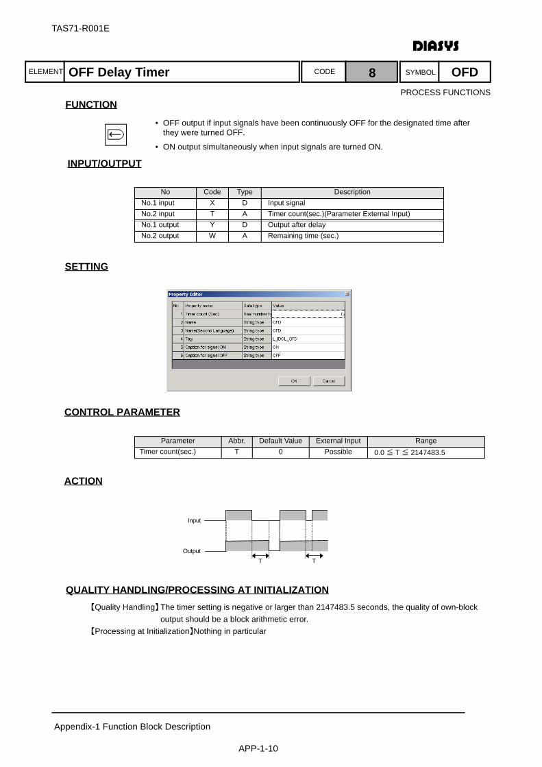
ELEMENT SYMBOLCODE
TAS71-R001E
Appendix-1 Function Block Description
APP-1-10
FUNCTION
INPUT/OUTPUT
設定項目SETTING
CONTROL PARAMETER
ACTION
QUALITY HANDLING/PROCESSING AT INITIALIZATION【Quality Handling】The timer setting is negative or larger than 2147483.5 seconds, the quality of own-block
output should be a block arithmetic error.【Processing at Initialization】Nothing in particular
No Code Type DescriptionNo.1 input X D Input signalNo.2 input T A Timer count(sec.)(Parameter External Input)No.1 output Y D Output after delayNo.2 output W A Remaining time (sec.)
Parameter Abbr. Default Value External Input RangeTimer count(sec.) T 0 Possible 0.0 ≦ T ≦ 2147483.5
T T
Input
Output
OFF Delay Timer 8 OFD
• OFF output if input signals have been continuously OFF for the designated time after they were turned OFF.
• ON output simultaneously when input signals are turned ON.
PROCESS FUNCTIONS
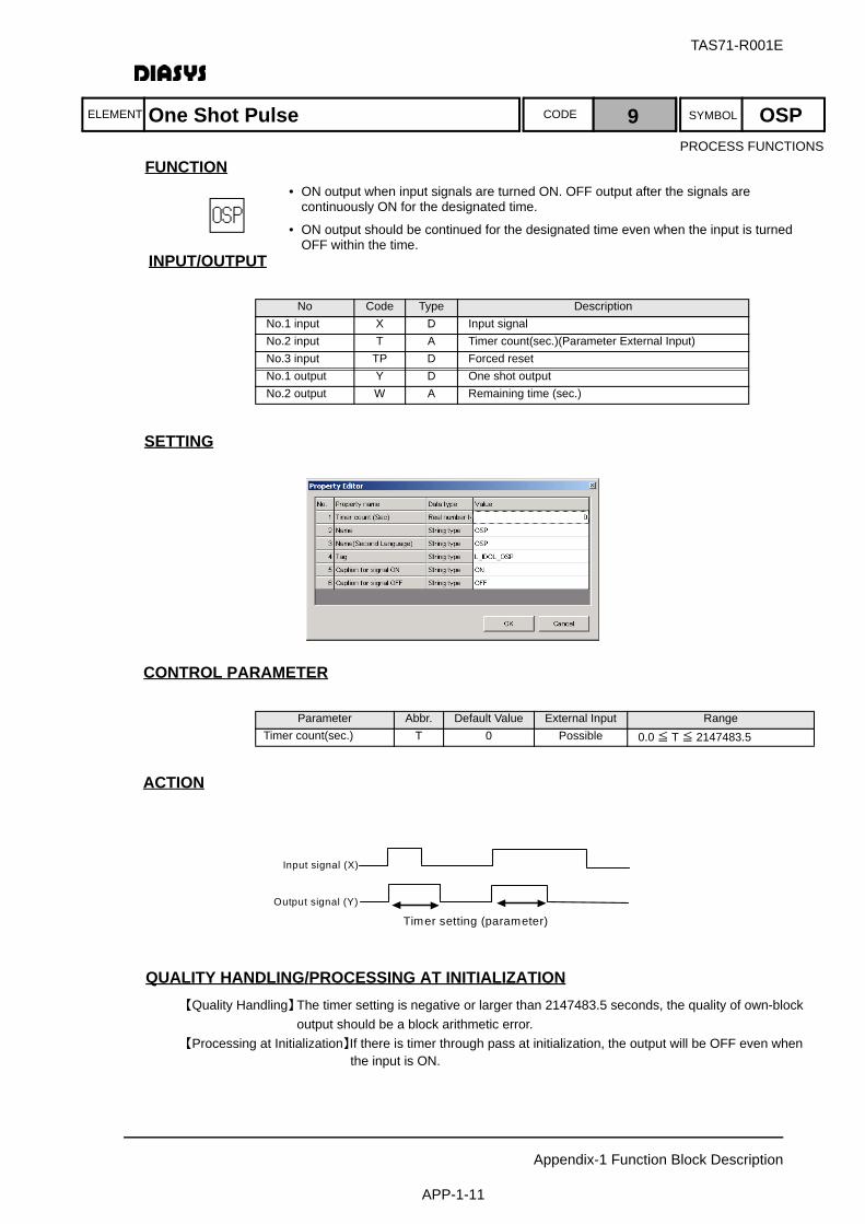
TAS71-R001E
Appendix-1 Function Block Description
APP-1-11
ELEMENT SYMBOLCODE
FUNCTION
INPUT/OUTPUT
設定項目SETTING
CONTROL PARAMETER
ACTION
QUALITY HANDLING/PROCESSING AT INITIALIZATION【Quality Handling】The timer setting is negative or larger than 2147483.5 seconds, the quality of own-block
output should be a block arithmetic error.【Processing at Initialization】If there is timer through pass at initialization, the output will be OFF even when
the input is ON.
No Code Type DescriptionNo.1 input X D Input signalNo.2 input T A Timer count(sec.)(Parameter External Input)No.3 input TP D Forced resetNo.1 output Y D One shot outputNo.2 output W A Remaining time (sec.)
Parameter Abbr. Default Value External Input RangeTimer count(sec.) T 0 Possible 0.0 ≦ T ≦ 2147483.5
Output signal (Y)
Input signal (X)
Timer setting (parameter)
One Shot Pulse 9 OSP
• ON output when input signals are turned ON. OFF output after the signals are continuously ON for the designated time.
• ON output should be continued for the designated time even when the input is turned OFF within the time.
PROCESS FUNCTIONS

ELEMENT SYMBOLCODE
TAS71-R001E
Appendix-1 Function Block Description
APP-1-12
FUNCTION
INPUT/OUTPUT
設定項目SETTING
CONTROL PARAMETER
ACTION
QUALITY HANDLING/PROCESSING AT INITIALIZATION【Quality Handling】The timer setting is negative or larger than 2147483.5 seconds, the quality of own-block
output should be a block arithmetic error.【Processing at Initialization】If there is timer through pass at initialization, the output will be OFF even when
the input is ON.
No Code Type DescriptionNo.1 input X D Input signalNo.2 input T A Timer count(sec.)(Parameter External Input)No.1 output Y D One shot outputNo.2 output W A Remaining time (sec.)
Parameter Abbr. Default Value External Input RangeTimer count(sec.) T 0 Possible 0.0 ≦ T ≦ 2147483.5
Input
OutputT T
Time Delay Wipe Out 10 TDW
• ON output when input signals are turned ON. OFF output after the signals are continuously ON for the designated time.
• OFF output immediately after the input is turned OFF.
• Used for creation of One-Shot startup command signals, etc.
PROCESS FUNCTIONS
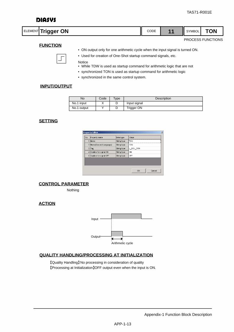
TAS71-R001E
Appendix-1 Function Block Description
APP-1-13
ELEMENT SYMBOLCODE
FUNCTION
INPUT/OUTPUT
設定項目SETTING
CONTROL PARAMETERNothing
ACTION
QUALITY HANDLING/PROCESSING AT INITIALIZATION【Quality Handling】No processing in consideration of quality【Processing at Initialization】OFF output even when the input is ON.
No Code Type DescriptionNo.1 input X D Input signalNo.1 output Y D Trigger ON
Input
Output
Arithmetic cycle
Trigger ON 11 TON
• ON output only for one arithmetic cycle when the input signal is turned ON.
• Used for creation of One-Shot startup command signals, etc.
Notice• While TDW is used as startup command for arithmetic logic that are not • synchronized TON is used as startup command for arithmetic logic• synchronized in the same control system.
PROCESS FUNCTIONS

ELEMENT SYMBOLCODE
TAS71-R001E
Appendix-1 Function Block Description
APP-1-14
FUNCTION
INPUT/OUTPUT
設定項目SETTING
CONTROL PARAMETERNothing
ACTION
QUALITY HANDLING/PROCESSING AT INITIALIZATION【Quality Handling】No processing in consideration of quality【Processing at Initialization】OFF output even when the input is OFF.
No Code Type DescriptionNo.1 input X D Input signalNo.1 output Y D Trigger OFF
Input
Output
Arithmetic cycle
Trigger OFF 12 TOF
• ON output only for one arithmetic cycle when the input signal is turned OFF.
• Used for creation of One-Shot startup command signals, etc.
PROCESS FUNCTIONS
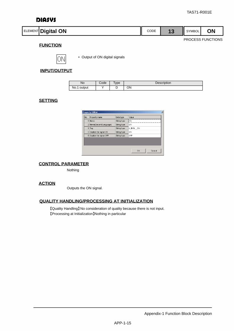
TAS71-R001E
Appendix-1 Function Block Description
APP-1-15
ELEMENT SYMBOLCODE
FUNCTION
INPUT/OUTPUT
設定項目SETTING
CONTROL PARAMETERNothing
ACTIONOutputs the ON signal.
QUALITY HANDLING/PROCESSING AT INITIALIZATION【Quality Handling】No consideration of quality because there is not input.【Processing at Initialization】Nothing in particular
No Code Type DescriptionNo.1 output Y D ON
Digital ON 13 ON
• Output of ON digital signals
PROCESS FUNCTIONS

ELEMENT SYMBOLCODE
TAS71-R001E
Appendix-1 Function Block Description
APP-1-16
FUNCTION
INPUT/OUTPUT
設定項目SETTING
CONTROL PARAMETERNothing
ACTIONOutputs the OFF signal.
QUALITY HANDLING/PROCESSING AT INITIALIZATION【Quality Handling】No consideration of quality because there is not input.【Processing at Initialization】Nothing in particular
No Code Type DescriptionNo.1 output Y D OFF
Digital OFF 14 OFF
• Output of OFF digital signals
PROCESS FUNCTIONS
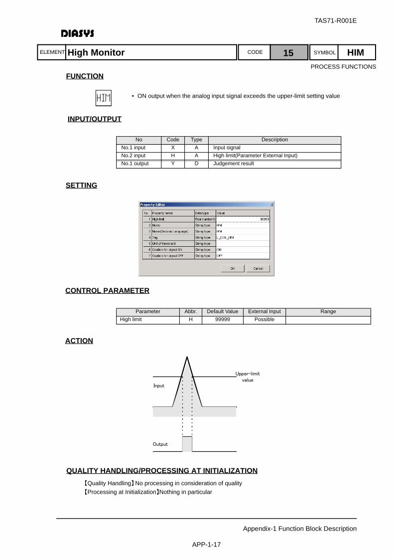
TAS71-R001E
Appendix-1 Function Block Description
APP-1-17
ELEMENT SYMBOLCODE
FUNCTION
INPUT/OUTPUT
設定項目SETTING
CONTROL PARAMETER
ACTION
QUALITY HANDLING/PROCESSING AT INITIALIZATION【Quality Handling】No processing in consideration of quality【Processing at Initialization】Nothing in particular
No Code Type DescriptionNo.1 input X A Input signalNo.2 input H A High limit(Parameter External Input)No.1 output Y D Judgement result
Parameter Abbr. Default Value External Input RangeHigh limit H 99999 Possible
Upper-limitvalue
Output
Input
High Monitor 15 HIM
• ON output when the analog input signal exceeds the upper-limit setting value
PROCESS FUNCTIONS
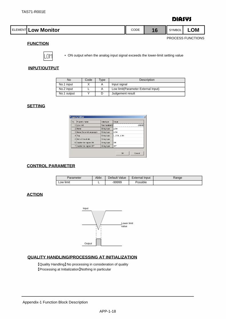
ELEMENT SYMBOLCODE
TAS71-R001E
Appendix-1 Function Block Description
APP-1-18
FUNCTION
INPUT/OUTPUT
設定項目SETTING
CONTROL PARAMETER
ACTION
QUALITY HANDLING/PROCESSING AT INITIALIZATION【Quality Handling】No processing in consideration of quality【Processing at Initialization】Nothing in particular
No Code Type DescriptionNo.1 input X A Input signalNo.2 input L A Low limit(Parameter External Input)No.1 output Y D Judgement result
Parameter Abbr. Default Value External Input RangeLow limit L -99999 Possible
Input
Output
Lower limitvalue
Low Monitor 16 LOM
• ON output when the analog input signal exceeds the lower-limit setting value
PROCESS FUNCTIONS

TAS71-R001E
Appendix-1 Function Block Description
APP-1-19
ELEMENT SYMBOLCODE
FUNCTION
INPUT/OUTPUT
設定項目SETTING
CONTROL PARAMETER
ACTION
QUALITY HANDLING/PROCESSING AT INITIALIZATION【Quality Handling】If the high setting value is smaller than the low setting value, the quality of own-block output
should be a block arithmetic error.【Processing at Initialization】Nothing in particular
No Code Type DescriptionNo.1 input X A Input signalNo.2 input H A High limit(Parameter External Input)No.3 input L A Low limit(Parameter External Input)No.1 output Y D Judgement result
Parameter Abbr. Default Value External Input RangeLow limit L -99999 Possible L ≦ HHigh limit H 99999 Possible L ≦ H
Input
Output
Upper limitvalue
Lower limitvalue
H/L Monitor 17 HLM
• ON output when the analog input signal exceeds the upper or lower-limit setting value
• Used for judging H/L warning for the signal
Notice• OFF output when the input is equal to the upper or lower-limit setting value
• Block arithmetic error in the case the upper and lower-limit setting values are reversed.
PROCESS FUNCTIONS
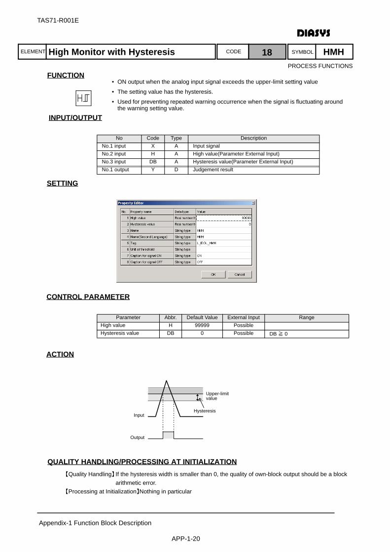
ELEMENT SYMBOLCODE
TAS71-R001E
Appendix-1 Function Block Description
APP-1-20
FUNCTION
INPUT/OUTPUT
設定項目SETTING
CONTROL PARAMETER
ACTION
QUALITY HANDLING/PROCESSING AT INITIALIZATION【Quality Handling】If the hysteresis width is smaller than 0, the quality of own-block output should be a block
arithmetic error. 【Processing at Initialization】Nothing in particular
No Code Type DescriptionNo.1 input X A Input signalNo.2 input H A High value(Parameter External Input)No.3 input DB A Hysteresis value(Parameter External Input)No.1 output Y D Judgement result
Parameter Abbr. Default Value External Input RangeHigh value H 99999 PossibleHysteresis value DB 0 Possible DB ≧ 0
Input
Output
Hysteresis
Upper-limitvalue
High Monitor with Hysteresis 18 HMH
• ON output when the analog input signal exceeds the upper-limit setting value
• The setting value has the hysteresis.
• Used for preventing repeated warning occurrence when the signal is fluctuating around the warning setting value.
PROCESS FUNCTIONS
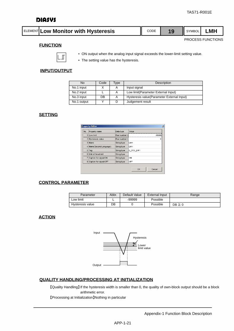
TAS71-R001E
Appendix-1 Function Block Description
APP-1-21
ELEMENT SYMBOLCODE
FUNCTION
INPUT/OUTPUT
設定項目SETTING
CONTROL PARAMETER
ACTION
QUALITY HANDLING/PROCESSING AT INITIALIZATION【Quality Handling】If the hysteresis width is smaller than 0, the quality of own-block output should be a block
arithmetic error. 【Processing at Initialization】Nothing in particular
No Code Type DescriptionNo.1 input X A Input signalNo.2 input L A Low limit(Parameter External Input)No.3 input DB A Hysteresis value(Parameter External Input)No.1 output Y D Judgement result
Parameter Abbr. Default Value External Input RangeLow limit L -99999 PossibleHysteresis value DB 0 Possible DB ≧ 0
Input
Output
Hysteresis
Lowerlimit value
Low Monitor with Hysteresis 19 LMH
• ON output when the analog input signal exceeds the lower-limit setting value.
• The setting value has the hysteresis.
PROCESS FUNCTIONS
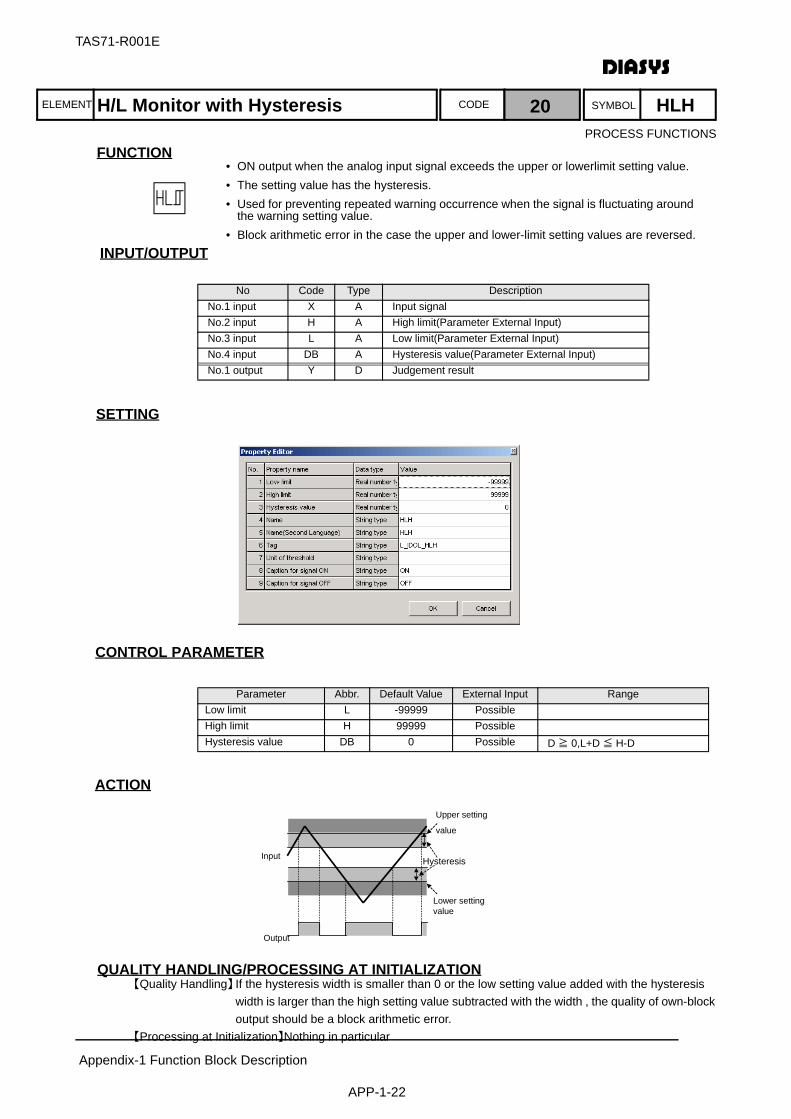
ELEMENT SYMBOLCODE
TAS71-R001E
Appendix-1 Function Block Description
APP-1-22
FUNCTION
INPUT/OUTPUT
設定項目SETTING
CONTROL PARAMETER
ACTION
QUALITY HANDLING/PROCESSING AT INITIALIZATION【Quality Handling】If the hysteresis width is smaller than 0 or the low setting value added with the hysteresis
width is larger than the high setting value subtracted with the width , the quality of own-block output should be a block arithmetic error.
【Processing at Initialization】Nothing in particular
No Code Type DescriptionNo.1 input X A Input signalNo.2 input H A High limit(Parameter External Input)No.3 input L A Low limit(Parameter External Input)No.4 input DB A Hysteresis value(Parameter External Input)No.1 output Y D Judgement result
Parameter Abbr. Default Value External Input RangeLow limit L -99999 PossibleHigh limit H 99999 PossibleHysteresis value DB 0 Possible D ≧ 0,L+D ≦ H-D
Output
Input
Lower settingvalue
Hysteresis
Upper setting
value
H/L Monitor with Hysteresis 20 HLH
• ON output when the analog input signal exceeds the upper or lowerlimit setting value.• The setting value has the hysteresis.• Used for preventing repeated warning occurrence when the signal is fluctuating around
the warning setting value.• Block arithmetic error in the case the upper and lower-limit setting values are reversed.
PROCESS FUNCTIONS
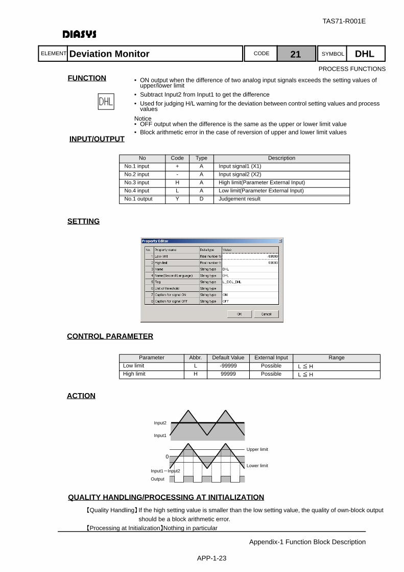
TAS71-R001E
Appendix-1 Function Block Description
APP-1-23
ELEMENT SYMBOLCODE
FUNCTION
INPUT/OUTPUT
設定項目SETTING
CONTROL PARAMETER
ACTION
QUALITY HANDLING/PROCESSING AT INITIALIZATION【Quality Handling】If the high setting value is smaller than the low setting value, the quality of own-block output
should be a block arithmetic error.【Processing at Initialization】Nothing in particular
No Code Type DescriptionNo.1 input + A Input signal1 (X1)No.2 input - A Input signal2 (X2)No.3 input H A High limit(Parameter External Input)No.4 input L A Low limit(Parameter External Input)No.1 output Y D Judgement result
Parameter Abbr. Default Value External Input RangeLow limit L -99999 Possible L ≦ HHigh limit H 99999 Possible L ≦ H
Input1-Input2
0
Input1
Input2
Output
Lower limit
Upper limit
Deviation Monitor 21 DHL
• ON output when the difference of two analog input signals exceeds the setting values of upper/lower limit
• Subtract Input2 from Input1 to get the difference• Used for judging H/L warning for the deviation between control setting values and process
valuesNotice• OFF output when the difference is the same as the upper or lower limit value• Block arithmetic error in the case of reversion of upper and lower limit values
PROCESS FUNCTIONS
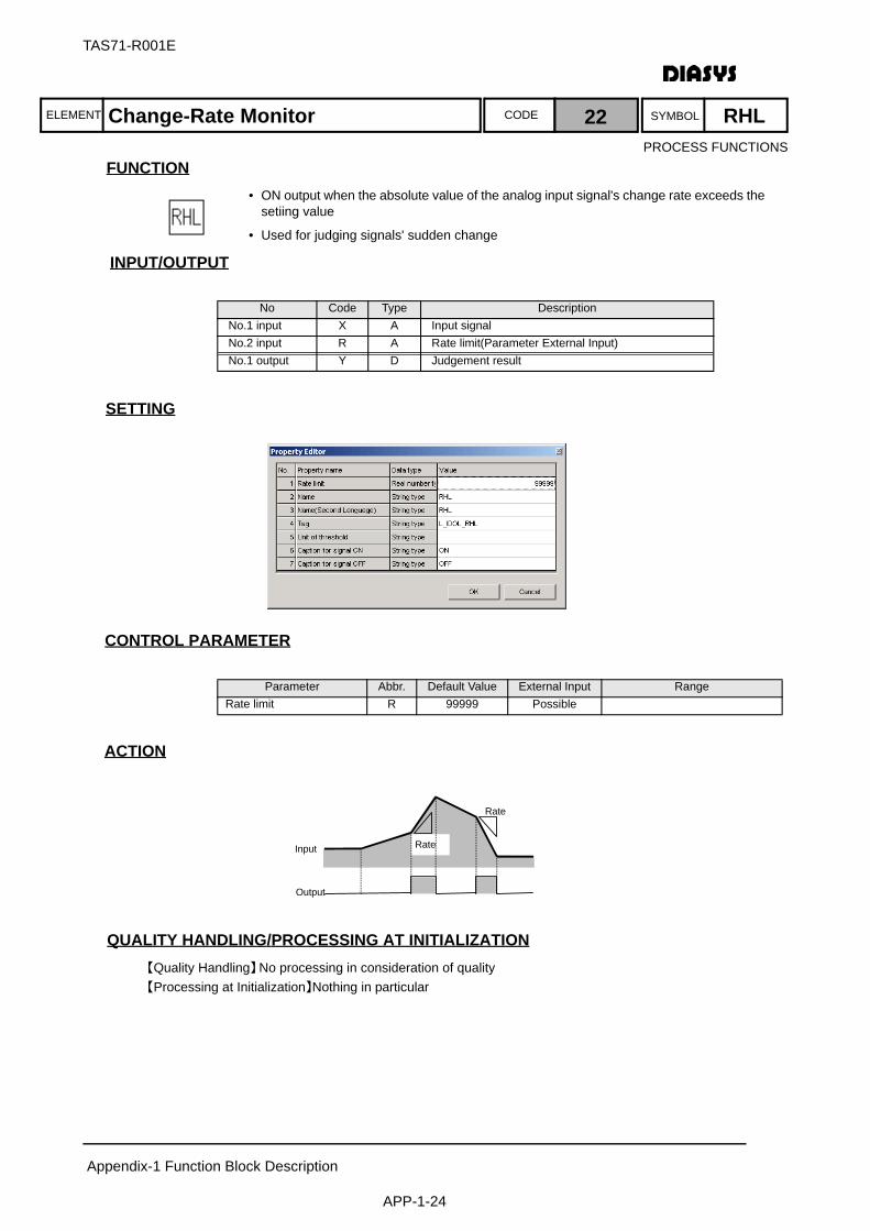
ELEMENT SYMBOLCODE
TAS71-R001E
Appendix-1 Function Block Description
APP-1-24
FUNCTION
INPUT/OUTPUT
設定項目SETTING
CONTROL PARAMETER
ACTION
QUALITY HANDLING/PROCESSING AT INITIALIZATION【Quality Handling】No processing in consideration of quality【Processing at Initialization】Nothing in particular
No Code Type DescriptionNo.1 input X A Input signalNo.2 input R A Rate limit(Parameter External Input)No.1 output Y D Judgement result
Parameter Abbr. Default Value External Input RangeRate limit R 99999 Possible
Rate
Rate
Input
Output
Change-Rate Monitor 22 RHL
• ON output when the absolute value of the analog input signal's change rate exceeds the setiing value
• Used for judging signals' sudden change
PROCESS FUNCTIONS
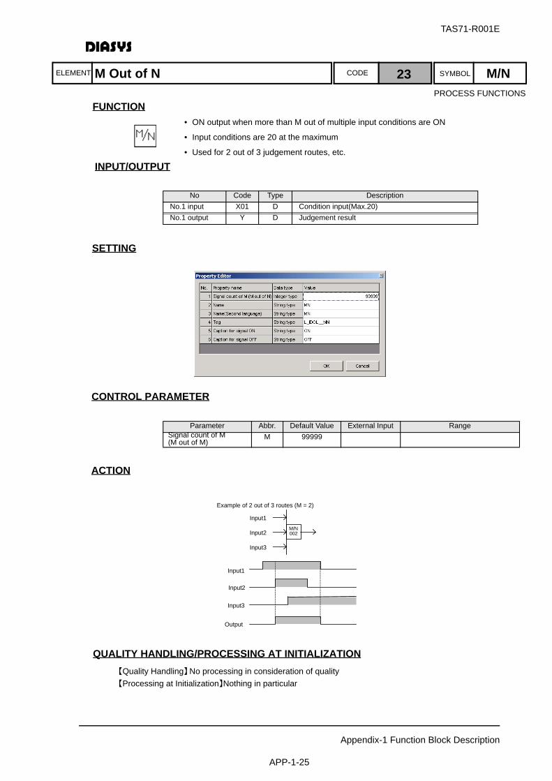
TAS71-R001E
Appendix-1 Function Block Description
APP-1-25
ELEMENT SYMBOLCODE
FUNCTION
INPUT/OUTPUT
設定項目SETTING
CONTROL PARAMETER
ACTION
QUALITY HANDLING/PROCESSING AT INITIALIZATION【Quality Handling】No processing in consideration of quality【Processing at Initialization】Nothing in particular
No Code Type DescriptionNo.1 input X01 D Condition input(Max.20)No.1 output Y D Judgement result
Parameter Abbr. Default Value External Input RangeSignal count of M(M out of M)
M 99999
M/N002
Example of 2 out of 3 routes (M = 2)
Input1
Input2
Input3
Input1
Input2
Input3
Output
M Out of N 23 M/N
• ON output when more than M out of multiple input conditions are ON
• Input conditions are 20 at the maximum
• Used for 2 out of 3 judgement routes, etc.
PROCESS FUNCTIONS
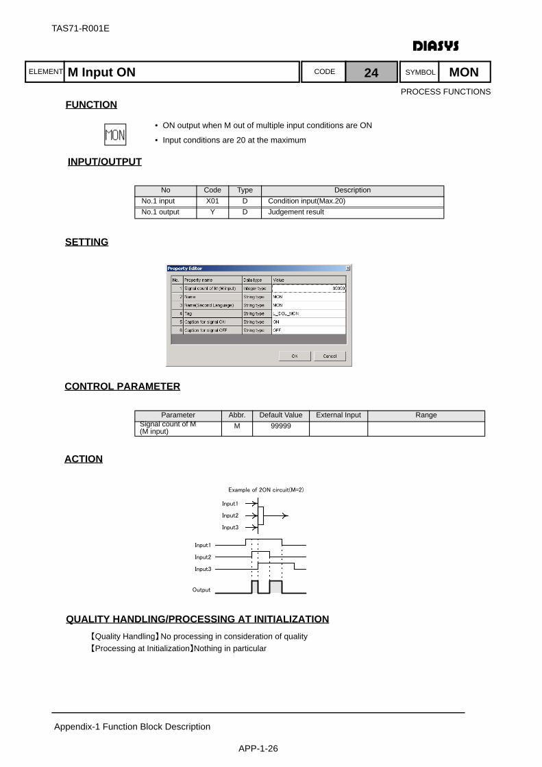
ELEMENT SYMBOLCODE
TAS71-R001E
Appendix-1 Function Block Description
APP-1-26
FUNCTION
INPUT/OUTPUT
設定項目SETTING
CONTROL PARAMETER
ACTION
QUALITY HANDLING/PROCESSING AT INITIALIZATION【Quality Handling】No processing in consideration of quality【Processing at Initialization】Nothing in particular
No Code Type DescriptionNo.1 input X01 D Condition input(Max.20)No.1 output Y D Judgement result
Parameter Abbr. Default Value External Input RangeSignal count of M(M input)
M 99999
Input2
Input1
Input3
Output
Input1
Input2
Input3
Example of 2ON circuit(M=2)
M Input ON 24 MON
• ON output when M out of multiple input conditions are ON
• Input conditions are 20 at the maximum
PROCESS FUNCTIONS

TAS71-R001E
Appendix-1 Function Block Description
APP-1-27
ELEMENT SYMBOLCODE
FUNCTION
INPUT/OUTPUT
設定項目SETTINGNothing
CONTROL PARAMETERNothing
ACTION
By combining PAC and UPC, 32 points of a digital signal can be passed using the inter-sheet integerconnection element for a singlepoint.
QUALITY HANDLING/PROCESSING AT INITIALIZATION【Quality Handling】No processing in consideration of quality【Processing at Initialization】Nothing in particular
No Code Type DescriptionNo.1 input X I Input signalNo.1 output Y0 D ON/OFF status for 0 bit
~ ~ ~ ~No.32 output Y31 D ON/OFF status for 31th bit
ON X0
X1
X2
PAC
ON
ON X29
X30
X31 ON
PAC outputPAC output
CEI
<Man-1>
→D Y0
Y1
Y2
UPCY29
Y30
Y31
PAC outputPAC output
CEI
<Man-1>
→D
→D
→D
→D
→D
OFF
OFF
Unpack 25 UPC
• Subordinate 32 bits of input signal (integer) are output as digital data with one point for each bit.
PROCESS FUNCTIONS

ELEMENT SYMBOLCODE
TAS71-R001E
Appendix-1 Function Block Description
APP-1-28
FUNCTION
INPUT/OUTPUT
設定項目SETTING
CONTROL PARAMETER
ACTION
QUALITY HANDLING/PROCESSING AT INITIALIZATION【Quality Handling】The timer setting is negative or larger than 2147483.5 sec., the quality of own-block output
should be a block arithmetic error.【Processing at Initialization】Nothing in particular
No Code Type DescriptionNo.1 input X D Flicker ONNo.2 input on A ON count(Parameter External Input)No.3 input off A OFF count(Parameter External Input)No.1 output Y D Flicker signal
Parameter Abbr. Default Value External Input RangeON count on 1 Possible 0.0 ≦ on ≦ 2147483.5OFF count off 1 Possible 0.0 ≦ on ≦ 2147483.5
X
Y
Ton
Toff
Flicker 26 FLC
• Output of flicker signals that repeat ON/OFF for designated time.
• Used for warning flicker display, etc.
PROCESS FUNCTIONS
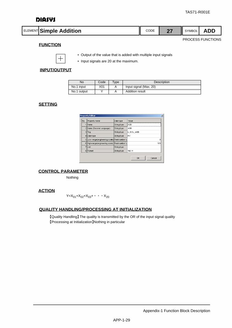
TAS71-R001E
Appendix-1 Function Block Description
APP-1-29
ELEMENT SYMBOLCODE
FUNCTION
INPUT/OUTPUT
設定項目SETTING
CONTROL PARAMETERNothing
ACTIONY=X01+X02+X03+・・・X20
QUALITY HANDLING/PROCESSING AT INITIALIZATION【Quality Handling】The quality is transmitted by the OR of the input signal quality【Processing at Initialization】Nothing in particular
No Code Type DescriptionNo.1 input X01 A Input signal (Max. 20)No.1 output Y A Addition result
Simple Addition 27 ADD
• Output of the value that is added with multiple input signals
• Input signals are 20 at the maximum.
PROCESS FUNCTIONS
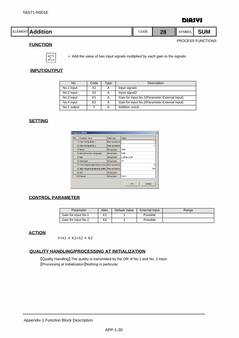
ELEMENT SYMBOLCODE
TAS71-R001E
Appendix-1 Function Block Description
APP-1-30
FUNCTION
INPUT/OUTPUT
設定項目SETTING
CONTROL PARAMETER
ACTIONY=X1 × K1+X2 × K2
QUALITY HANDLING/PROCESSING AT INITIALIZATION【Quality Handling】The quality is transmitted by the OR of No.1 and No. 2 input【Processing at Initialization】Nothing in particular
No Code Type DescriptionNo.1 input X1 A Input signal1No.2 input X2 A Input signal2No.3 input K1 A Gain for input No.1(Parameter External Input)No.4 input K2 A Gain for input No.2(Parameter External Input)No.1 output Y A Addition result
Parameter Abbr. Default Value External Input RangeGain for input No.1 K1 1 PossibleGain for input No.2 K2 1 Possible
Addition 28 SUM
• Add the value of two input signals multiplied by each gain to the signals
PROCESS FUNCTIONS
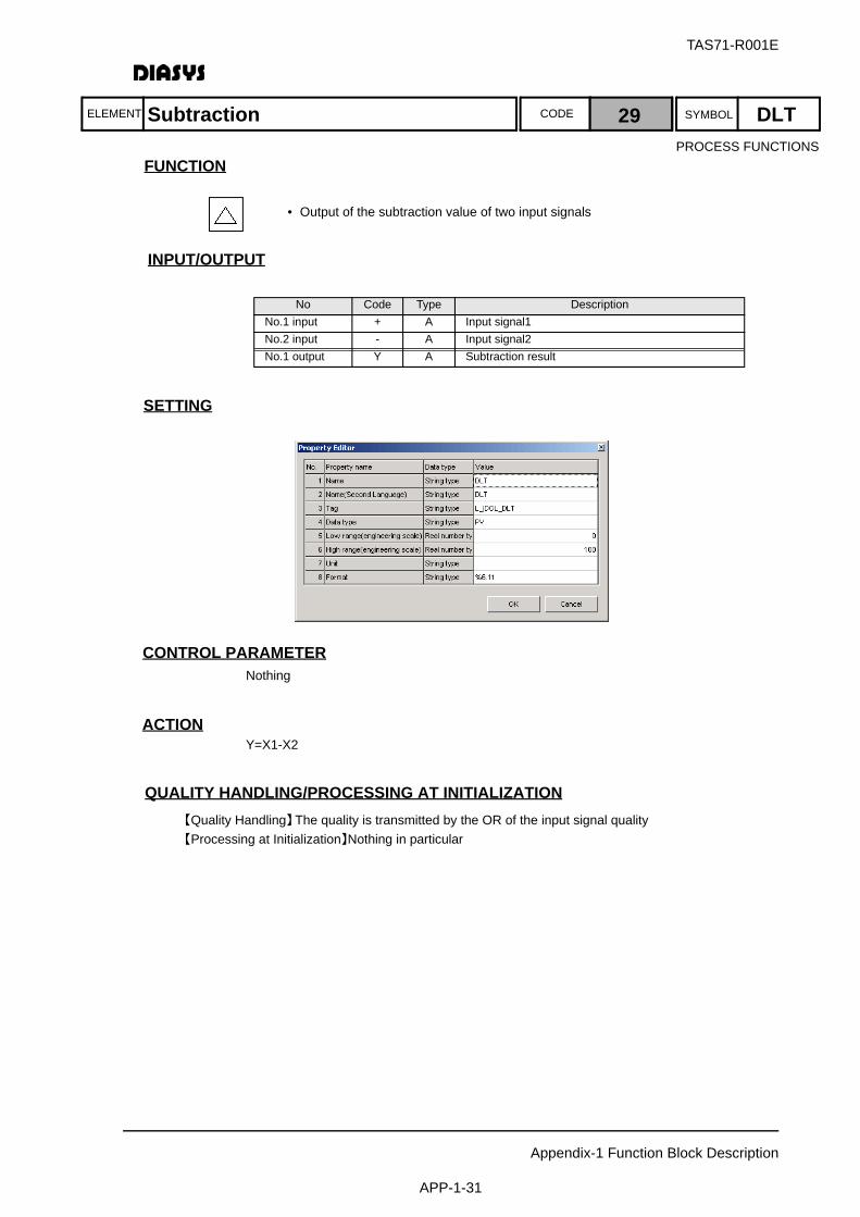
TAS71-R001E
Appendix-1 Function Block Description
APP-1-31
ELEMENT SYMBOLCODE
FUNCTION
INPUT/OUTPUT
設定項目SETTING
CONTROL PARAMETERNothing
ACTIONY=X1-X2
QUALITY HANDLING/PROCESSING AT INITIALIZATION【Quality Handling】The quality is transmitted by the OR of the input signal quality【Processing at Initialization】Nothing in particular
No Code Type DescriptionNo.1 input + A Input signal1No.2 input - A Input signal2 No.1 output Y A Subtraction result
Subtraction 29 DLT
• Output of the subtraction value of two input signals
PROCESS FUNCTIONS
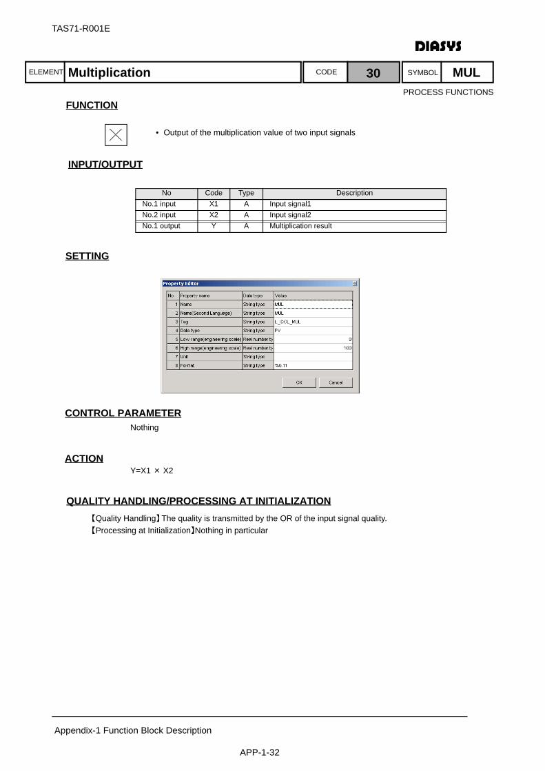
ELEMENT SYMBOLCODE
TAS71-R001E
Appendix-1 Function Block Description
APP-1-32
FUNCTION
INPUT/OUTPUT
設定項目SETTING
CONTROL PARAMETERNothing
ACTIONY=X1 × X2
QUALITY HANDLING/PROCESSING AT INITIALIZATION【Quality Handling】The quality is transmitted by the OR of the input signal quality.【Processing at Initialization】Nothing in particular
No Code Type DescriptionNo.1 input X1 A Input signal1No.2 input X2 A Input signal2No.1 output Y A Multiplication result
Multiplication 30 MUL
• Output of the multiplication value of two input signals
PROCESS FUNCTIONS

ELEMENT SYMBOLCODE
TAS71-R001E
Appendix-1 Function Block Description
APP-1-33
FUNCTION
INPUT/OUTPUT
SETTING
CONTROL PARAMETERNothing
ACTIONY=N/D
QUALITY HANDLING/PROCESSING AT INITIALIZATION【Quality Handling】The quality is transmitted by the OR of the input signal quality.
The quality of My Block output should be a block arithmetic error at the zero division.【Processing at Initialization】Nothing in particular
No Code Type DescriptionNo.1 input N A Input signal1No.2 input D A Input signal2 No.1 output Y A Division result
Division 31 DIV
• Output of the division value of two signals
PROCESS FUNCTIONS
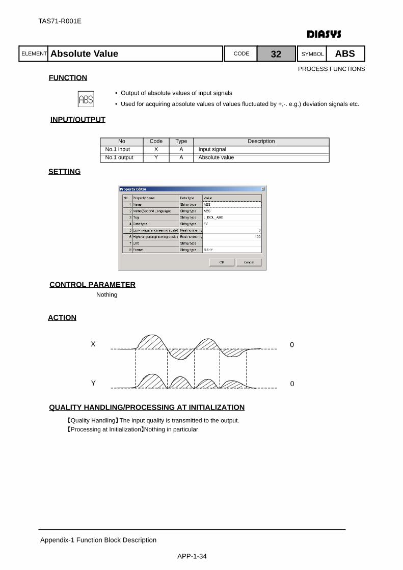
ELEMENT SYMBOLCODE
TAS71-R001E
Appendix-1 Function Block Description
APP-1-34
FUNCTION
INPUT/OUTPUT
SETTING
CONTROL PARAMETERNothing
ACTION
QUALITY HANDLING/PROCESSING AT INITIALIZATION【Quality Handling】The input quality is transmitted to the output.【Processing at Initialization】Nothing in particular
No Code Type DescriptionNo.1 input X A Input signalNo.1 output Y A Absolute value
X 0
Y 0
Absolute Value 32 ABS
• Output of absolute values of input signals
• Used for acquiring absolute values of values fluctuated by +,-. e.g.) deviation signals etc.
PROCESS FUNCTIONS

ELEMENT SYMBOLCODE
TAS71-R001E
Appendix-1 Function Block Description
APP-1-35
FUNCTION
INPUT/OUTPUT
SETTING
CONTROL PARAMETERNothing
ACTION
QUALITY HANDLING/PROCESSING AT INITIALIZATION【Quality Handling】The input quality is transmitted to the output.
The quality of My Block output should not be a block【Processing at Initialization】Nothing in particular
No Code Type DescriptionNo.1 input X A Input signalNo.1 output Y A Square-root extraction value
Input≦0
Input>0
Output=0
Output= Input
Square-Root Extraction 33 ROT
• Output of square-root of input signals
PROCESS FUNCTIONS
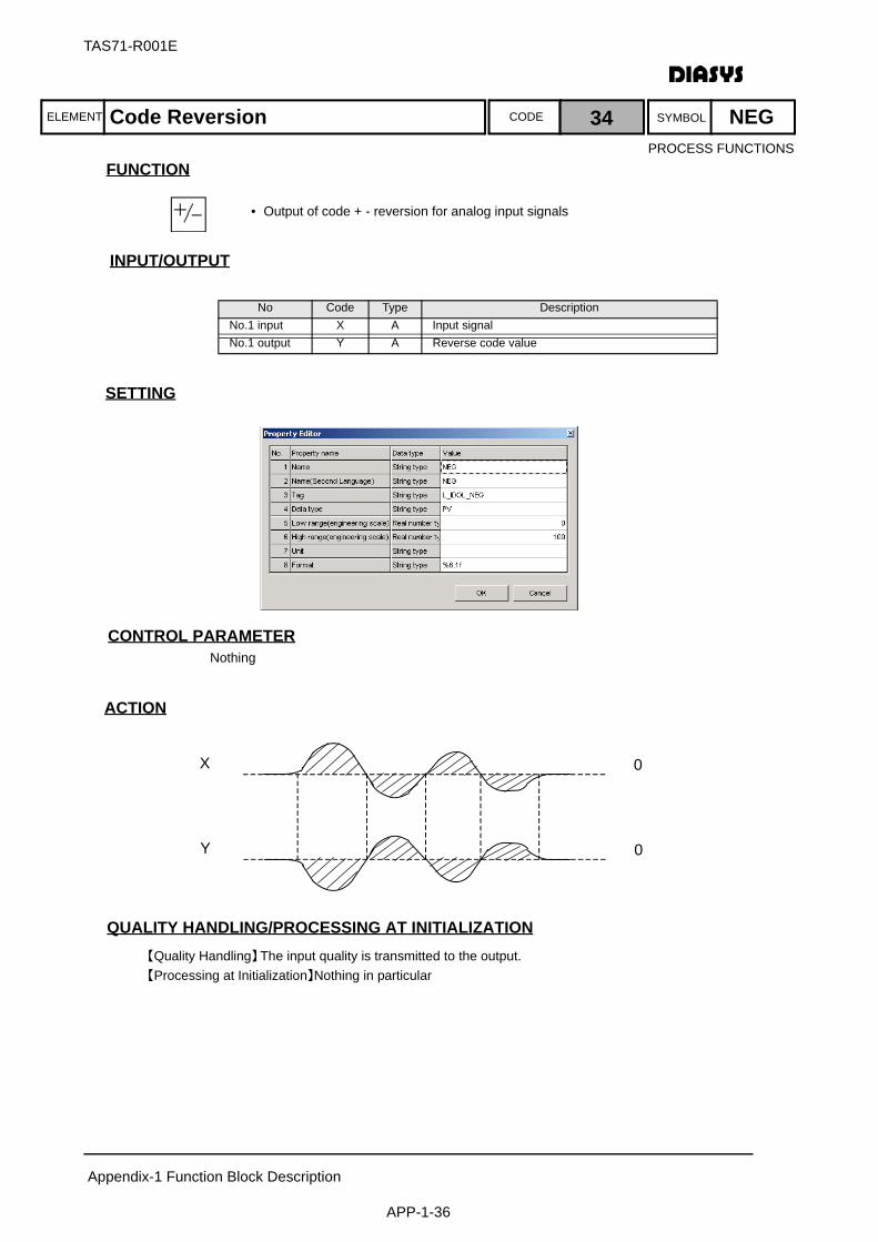
ELEMENT SYMBOLCODE
TAS71-R001E
Appendix-1 Function Block Description
APP-1-36
FUNCTION
INPUT/OUTPUT
SETTING
CONTROL PARAMETERNothing
ACTION
QUALITY HANDLING/PROCESSING AT INITIALIZATION【Quality Handling】The input quality is transmitted to the output. 【Processing at Initialization】Nothing in particular
No Code Type DescriptionNo.1 input X A Input signalNo.1 output Y A Reverse code value
X 0
Y 0
Code Reversion 34 NEG
• Output of code + - reversion for analog input signals
PROCESS FUNCTIONS
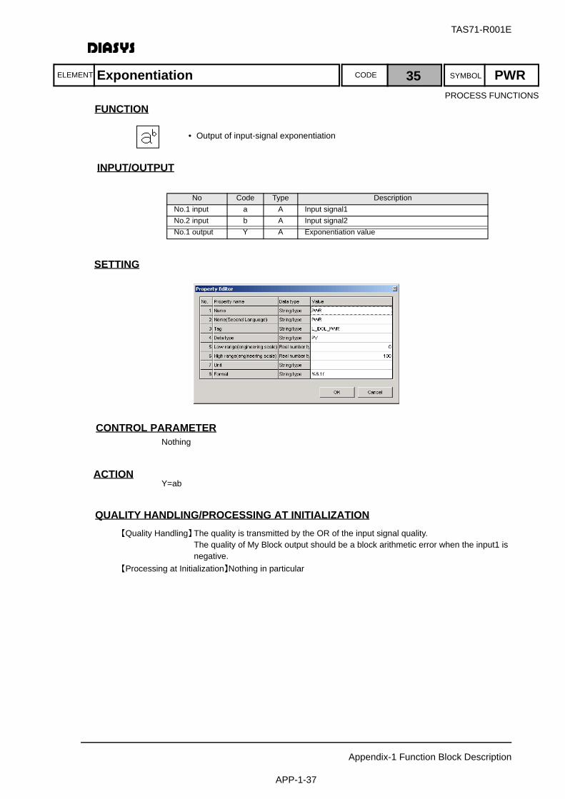
ELEMENT SYMBOLCODE
TAS71-R001E
Appendix-1 Function Block Description
APP-1-37
FUNCTION
INPUT/OUTPUT
SETTING
CONTROL PARAMETERNothing
ACTIONY=ab
QUALITY HANDLING/PROCESSING AT INITIALIZATION【Quality Handling】The quality is transmitted by the OR of the input signal quality.
The quality of My Block output should be a block arithmetic error when the input1 is negative.
【Processing at Initialization】Nothing in particular
No Code Type DescriptionNo.1 input a A Input signal1No.2 input b A Input signal2No.1 output Y A Exponentiation value
Exponentiation 35 PWR
• Output of input-signal exponentiation
PROCESS FUNCTIONS

ELEMENT SYMBOLCODE
TAS71-R001E
Appendix-1 Function Block Description
APP-1-38
FUNCTION
INPUT/OUTPUT
SETTING
CONTROL PARAMETERNothing
ACTIONOutputs the 0.0 signal.
QUALITY HANDLING/PROCESSING AT INITIALIZATION【Quality Handling】No consideration for quality because there is no input.【Processing at Initialization】Nothing in particular
No Code Type DescriptionNo.1 output Y A 0.0
Analog Zero Output 36 ZER
• Output of 0% analog signal
• Used for setting values
PROCESS FUNCTIONS

ELEMENT SYMBOLCODE
TAS71-R001E
Appendix-1 Function Block Description
APP-1-39
FUNCTION
INPUT/OUTPUT
SETTING
CONTROL PARAMETERNothing
ACTIONOutputs the ∞ signal.
QUALITY HANDLING/PROCESSING AT INITIALIZATION【Quality Handling】No consideration for quality because there is no input.【Processing at Initialization】Nothing in particular
No Code Type DescriptionNo.1 output Y A 3.40 × 1038
Analog Maximum-Value Output 37 INF
• Output of 3.40 × 1038 analog signal
• Used for setting value for change rate, etc.
PROCESS FUNCTIONS
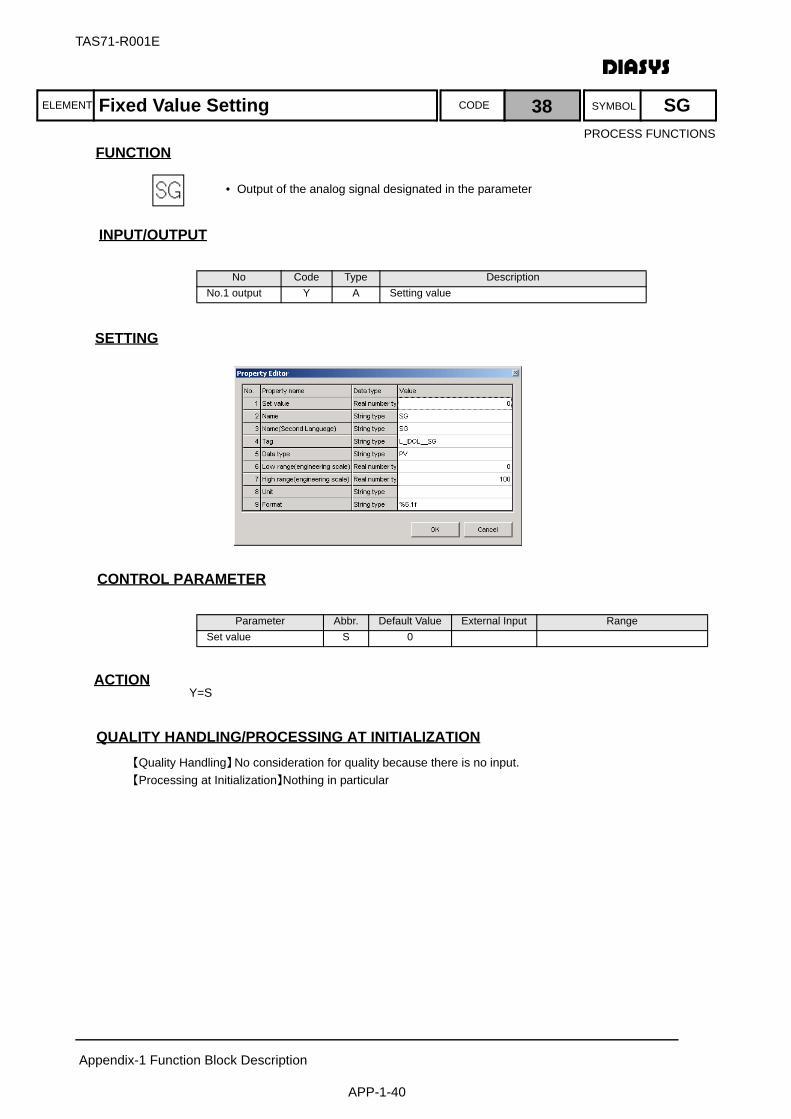
ELEMENT SYMBOLCODE
TAS71-R001E
Appendix-1 Function Block Description
APP-1-40
FUNCTION
INPUT/OUTPUT
SETTING
CONTROL PARAMETER
ACTIONY=S
QUALITY HANDLING/PROCESSING AT INITIALIZATION【Quality Handling】No consideration for quality because there is no input.【Processing at Initialization】Nothing in particular
No Code Type DescriptionNo.1 output Y A Setting value
Parameter Abbr. Default Value External Input RangeSet value S 0
Fixed Value Setting 38 SG
• Output of the analog signal designated in the parameter
PROCESS FUNCTIONS
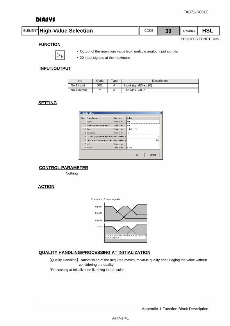
ELEMENT SYMBOLCODE
TAS71-R001E
Appendix-1 Function Block Description
APP-1-41
FUNCTION
INPUT/OUTPUT
SETTING
CONTROL PARAMETERNothing
ACTION
QUALITY HANDLING/PROCESSING AT INITIALIZATION【Quality Handling】Transmission of the acquired maximum value quality after judging the value without
considering the quality【Processing at Initialization】Nothing in particular
No Code Type DescriptionNo.1 input X01 A Input signal(Max.20)No.1 output Y A The Max. value
E xam ple of Exam ple of 3 input s ignals
Input1
Input2
Input3
O utput
O utput the m axim um value from 3 input s ignals
High-Value Selection 39 HSL
• Output of the maximum value from multiple analog input signals
• 20 input signals at the maximum
PROCESS FUNCTIONS

ELEMENT SYMBOLCODE
TAS71-R001E
Appendix-1 Function Block Description
APP-1-42
FUNCTION
INPUT/OUTPUT
SETTING
CONTROL PARAMETERNothing
ACTION
QUALITY HANDLING/PROCESSING AT INITIALIZATION【Quality Handling】Transmission of the acquired minimum value quality after judging the value without
considering the quality【Processing at Initialization】Nothing in particular
No Code Type DescriptionNo.1 input X01 A Input signal(Max.20)No.1 output Y A The Min. value
Example of 3 input signals
Output the maximum value from 3 input signals
Input 3
Input 2
Input 1
Output
Low-Value Selection 40 LSL
• Output of the maximum value from multiple analog input signals
• 20 input signals at the maximum
PROCESS FUNCTIONS

ELEMENT SYMBOLCODE
TAS71-R001E
Appendix-1 Function Block Description
APP-1-43
FUNCTION
INPUT/OUTPUT
SETTING
CONTROL PARAMETERNothing
ACTION
QUALITY HANDLING/PROCESSING AT INITIALIZATION【Quality Handling】Transmission of the acquired intermediate value quality after judging the value without
considering the quality【Processing at Initialization】Nothing in particular
No Code Type DescriptionNo.1 input X1 A Input signal 1No.2 input X2 A Input signal 2No.3 input X3 A Input signal 3No.1 output Y A The intermediate value
Input1
Input2
Input3
Output
Intermediate Value Selection 41 MED
• Output of the intermediate value from three analog input signals
PROCESS FUNCTIONS

ELEMENT SYMBOLCODE
TAS71-R001E
Appendix-1 Function Block Description
APP-1-44
FUNCTION
INPUT/OUTPUT
SETTING
CONTROL PARAMETER
ACTION
QUALITY HANDLING/PROCESSING AT INITIALIZATION【Quality Handling】The quality of No. 1 input is transmitted. If the high setting value is smaller than the low
setting value, the quality of own-block output should be a block arithmetic error.【Processing at Initialization】Nothing in particular
No Code Type DescriptionNo.1 input X A Input signal No.2 input H A High limit(Parameter External Input)No.3 input L A Low limit(Parameter External Input)No.1 output Y A Restriction value of Upper/Lower Limit
Parameter Abbr. Default Value External Input Range
Low limit L -99999 Possible L ≦ HHigh limit H 99999 Possible L ≦ H
Upper limit
Lower limit
Input
Output
Restriction of Upper/Lower Limit 42 LMT
• Output of the input signal multiplied by upper and lower limit restriction
• Used for restrictions for process input's range over, etc.
PROCESS FUNCTIONS
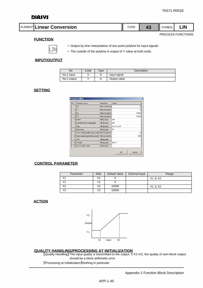
ELEMENT SYMBOLCODE
TAS71-R001E
Appendix-1 Function Block Description
APP-1-45
FUNCTION
INPUT/OUTPUT
SETTING
CONTROL PARAMETER
ACTION
QUALITY HANDLING/PROCESSING AT INITIALIZATION【Quality Handling】The input quality is transmitted to the output. If X1>X2, the quality of own-block output
should be a block arithmetic error.【Processing at Initialization】Nothing in particular
No Code Type DescriptionNo.1 input X A Input signal No.1 output Y A Output value
Parameter Abbr. Default Value External Input RangeX1 X1 0 X1 ≦ X2Y1 Y1 0X2 X2 10000 X1 ≦ X2Y2 Y2 10000
Y1
Y2
X1 X2
Output
Input
Linear Conversion 43 LIN
• Output by liner interpolation of two-point polyline for input signals
• The outside of the polyline is output of Y value at both ends.
PROCESS FUNCTIONS

ELEMENT SYMBOLCODE
TAS71-R001E
Appendix-1 Function Block Description
APP-1-46
FUNCTION
INPUT/OUTPUT
SETTING
CONTROL PARAMETER
ACTION
QUALITY HANDLING/PROCESSING AT INITIALIZATION【Quality Handling】The quality of No. 1 input should be transmitted. If the primary-delay time constant is
negative, the quality of own-block output should be a block arithmetic error.【Processing at Initialization】The output is tracked to the input value.
No Code Type DescriptionNo.1 input X A Input signal No.2 input T A Time constant(Parameter External Input)No.3 input TP D TrackingNo.1 output Y A Primary-delay value
Parameter Abbr. Default Value External Input RangeTime constant T 0 Possible TP ≧ 0
Tracking
Time constantTT
Input
Output1
1+TsOutput= Input
Primary Delay 44 LAG
• Output of the value that is performed with primary-delay calculation for the input signal
PROCESS FUNCTIONS
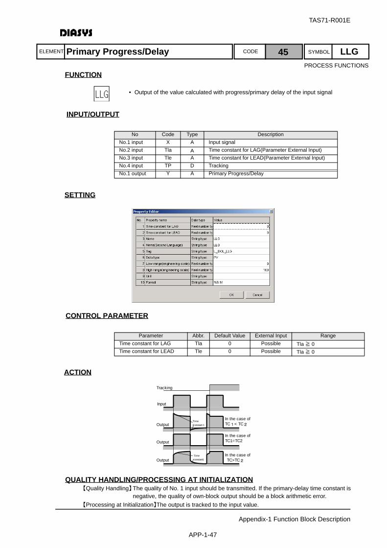
ELEMENT SYMBOLCODE
TAS71-R001E
Appendix-1 Function Block Description
APP-1-47
FUNCTION
INPUT/OUTPUT
SETTING
CONTROL PARAMETER
ACTION
QUALITY HANDLING/PROCESSING AT INITIALIZATION【Quality Handling】The quality of No. 1 input should be transmitted. If the primary-delay time constant is
negative, the quality of own-block output should be a block arithmetic error.【Processing at Initialization】The output is tracked to the input value.
No Code Type DescriptionNo.1 input X A Input signal No.2 input Tla A Time constant for LAG(Parameter External Input)No.3 input Tle A Time constant for LEAD(Parameter External Input)No.4 input TP D TrackingNo.1 output Y A Primary Progress/Delay
Parameter Abbr. Default Value External Input RangeTime constant for LAG Tla 0 Possible Tla ≧ 0Time constant for LEAD Tle 0 Possible Tla ≧ 0
Tracking
In the case ofTC1=TC2
In the case of TC>TC2
き
Input
Output
Output
Output
In the case ofTC1< TC2
き
TimeConstant 1
Timeconstant1
Primary Progress/Delay 45 LLG
• Output of the value calculated with progress/primary delay of the input signal
PROCESS FUNCTIONS
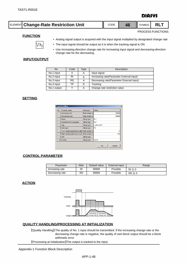
ELEMENT SYMBOLCODE
TAS71-R001E
Appendix-1 Function Block Description
APP-1-48
FUNCTION
INPUT/OUTPUT
SETTING
CONTROL PARAMETER
ACTION
QUALITY HANDLING/PROCESSING AT INITIALIZATION【Quality Handling】The quality of No. 1 input should be transmitted. If the increasing change rate or the
decreasing change rate is negative, the quality of own-block output should be a block arithmetic error.
【Processing at Initialization】The output is tracked to the input.
No Code Type DescriptionNo.1 input X A Input signal No.2 input RI A Increasing rate(Parameter External Input)No.3 input RD A Decreasing rate(Parameter External Input)No.4 input TP D TrackingNo.1 output Y A Change-rate restriction value
Parameter Abbr. Default Value External Input RangeIncreasing rate RI 99999 Possible RI ≧ 0Decreasing rate RD 99999 Possible RD ≧ 0
Tracking
Input
OutputDecreasingchange rate
Increasingchange rate
Change-Rate Restriction Unit 46 RLT
• Analog signal output is acquired with the input signal multiplied by designated change rate
• The input signal should be output as it is when the tracking signal is ON
• Use increasing-direction change rate for increasing input signal and decreasing-direction change rate for the decreasing.
PROCESS FUNCTIONS
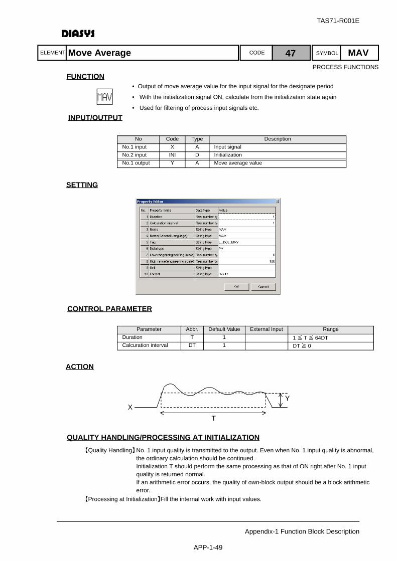
ELEMENT SYMBOLCODE
TAS71-R001E
Appendix-1 Function Block Description
APP-1-49
FUNCTION
INPUT/OUTPUT
SETTING
CONTROL PARAMETER
ACTION
QUALITY HANDLING/PROCESSING AT INITIALIZATION【Quality Handling】No. 1 input quality is transmitted to the output. Even when No. 1 input quality is abnormal,
the ordinary calculation should be continued.Initialization T should perform the same processing as that of ON right after No. 1 input quality is returned normal.If an arithmetic error occurs, the quality of own-block output should be a block arithmetic error.
【Processing at Initialization】Fill the internal work with input values.
No Code Type DescriptionNo.1 input X A Input signal No.2 input INI D InitializationNo.1 output Y A Move average value
Parameter Abbr. Default Value External Input RangeDuration T 1 1 ≦ T ≦ 64DTCalcuration interval DT 1 DT ≧ 0
X Y
T
Move Average 47 MAV
• Output of move average value for the input signal for the designate period
• With the initialization signal ON, calculate from the initialization state again
• Used for filtering of process input signals etc.
PROCESS FUNCTIONS
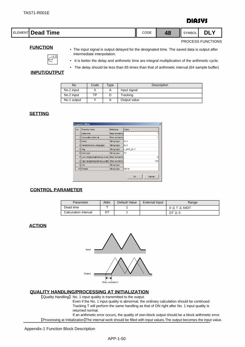
ELEMENT SYMBOLCODE
TAS71-R001E
Appendix-1 Function Block Description
APP-1-50
FUNCTION
INPUT/OUTPUT
SETTING
CONTROL PARAMETER
ACTION
QUALITY HANDLING/PROCESSING AT INITIALIZATION【Quality Handling】No. 1 input quality is transmitted to the output.
Even if the No. 1 input quality is abnormal, the ordinary calculation should be continued.Tracking T will perform the same handling as that of ON right after No. 1 input quality is returned normal.If an arithmetic error occurs, the quality of own-block output should be a block arithmetic error.
【Processing at Initialization】The internal work should be filled with input values.The output becomes the input value.
No Code Type DescriptionNo.1 input X A Input signal No.2 input TP D TrackingNo.1 output Y A Output value
Parameter Abbr. Default Value External Input RangeDead time T 1 0 ≦ T ≦ 64DTCalcuration interval DT 1 DT ≧ 0
Time constantT
Input
Output
Dead Time 48 DLY
• The input signal is output delayed for the designated time. The saved data is output after intermediate interpolation.
• It is better the delay and arithmetic time are integral multiplication of the arithmetic cycle.
• The delay should be less than 65 times than that of arithmetic interval.(64 sample buffer)
PROCESS FUNCTIONS
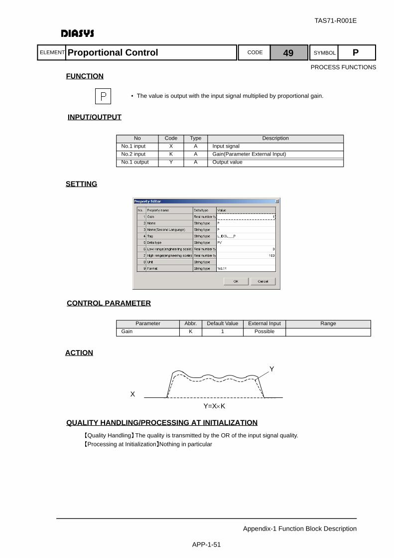
ELEMENT SYMBOLCODE
TAS71-R001E
Appendix-1 Function Block Description
APP-1-51
FUNCTION
INPUT/OUTPUT
SETTING
CONTROL PARAMETER
ACTION
QUALITY HANDLING/PROCESSING AT INITIALIZATION【Quality Handling】The quality is transmitted by the OR of the input signal quality.【Processing at Initialization】Nothing in particular
No Code Type DescriptionNo.1 input X A Input signal No.2 input K A Gain(Parameter External Input)No.1 output Y A Output value
Parameter Abbr. Default Value External Input RangeGain K 1 Possible
X
Y
Y=X×K
Proportional Control 49 P
• The value is output with the input signal multiplied by proportional gain.
PROCESS FUNCTIONS
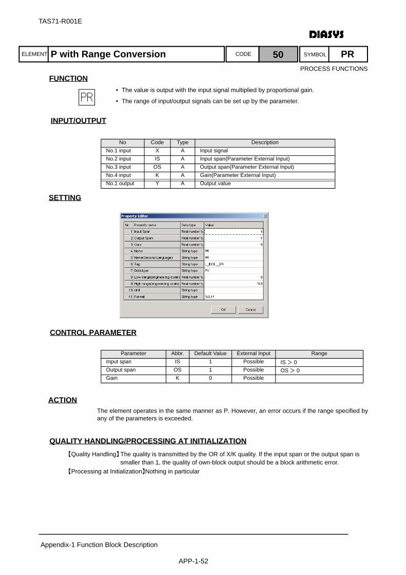
ELEMENT SYMBOLCODE
TAS71-R001E
Appendix-1 Function Block Description
APP-1-52
FUNCTION
INPUT/OUTPUT
SETTING
CONTROL PARAMETER
ACTIONThe element operates in the same manner as P. However, an error occurs if the range specified byany of the parameters is exceeded.
QUALITY HANDLING/PROCESSING AT INITIALIZATION【Quality Handling】The quality is transmitted by the OR of X/K quality. If the input span or the output span is
smaller than 1, the quality of own-block output should be a block arithmetic error.【Processing at Initialization】Nothing in particular
No Code Type DescriptionNo.1 input X A Input signal No.2 input IS A Input span(Parameter External Input)No.3 input OS A Output span(Parameter External Input)No.4 input K A Gain(Parameter External Input)No.1 output Y A Output value
Parameter Abbr. Default Value External Input RangeInput span IS 1 Possible IS > 0Output span OS 1 Possible OS > 0Gain K 0 Possible
P with Range Conversion 50 PR
• The value is output with the input signal multiplied by proportional gain.
• The range of input/output signals can be set up by the parameter.
PROCESS FUNCTIONS
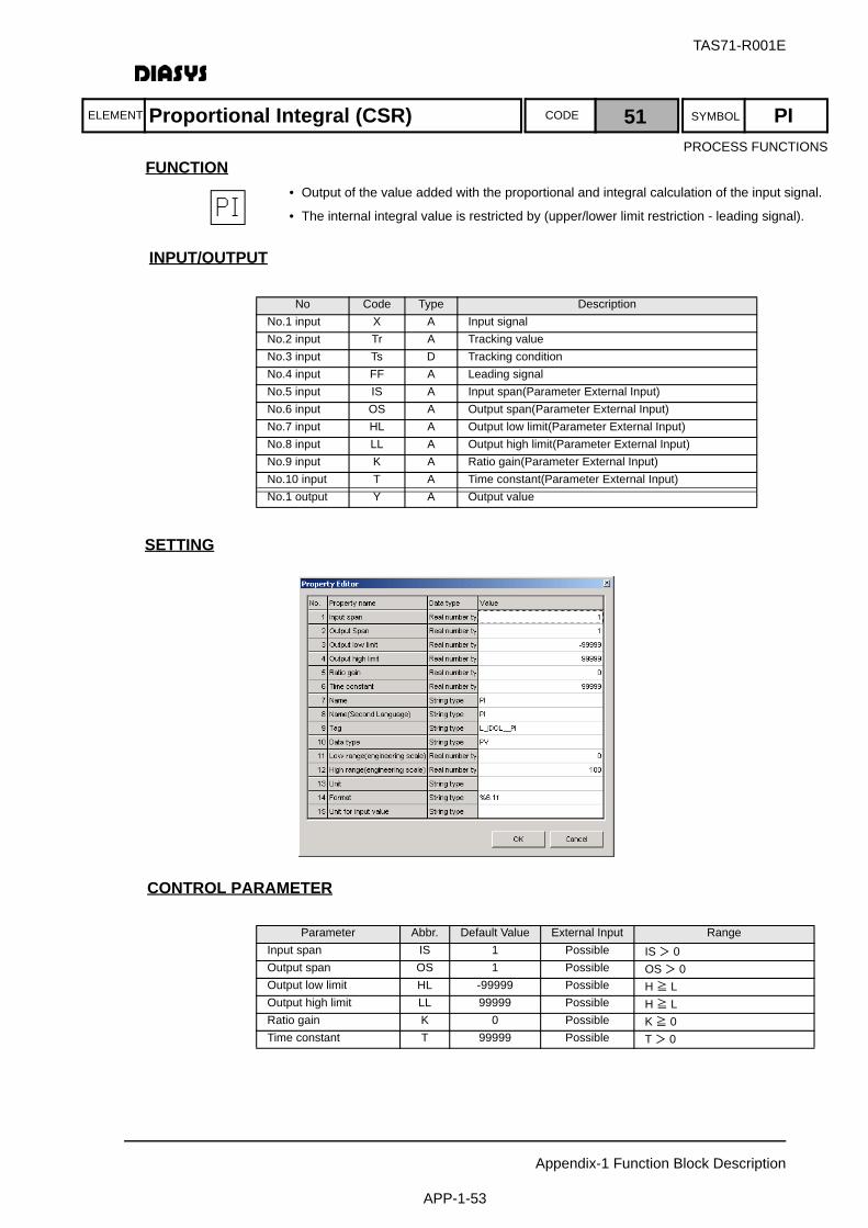
ELEMENT SYMBOLCODE
TAS71-R001E
Appendix-1 Function Block Description
APP-1-53
FUNCTION
INPUT/OUTPUT
SETTING
CONTROL PARAMETER
No Code Type DescriptionNo.1 input X A Input signal No.2 input Tr A Tracking valueNo.3 input Ts D Tracking conditionNo.4 input FF A Leading signalNo.5 input IS A Input span(Parameter External Input)No.6 input OS A Output span(Parameter External Input)No.7 input HL A Output low limit(Parameter External Input)No.8 input LL A Output high limit(Parameter External Input)No.9 input K A Ratio gain(Parameter External Input)No.10 input T A Time constant(Parameter External Input)No.1 output Y A Output value
Parameter Abbr. Default Value External Input RangeInput span IS 1 Possible IS > 0Output span OS 1 Possible OS > 0Output low limit HL -99999 Possible H ≧ LOutput high limit LL 99999 Possible H ≧ LRatio gain K 0 Possible K ≧ 0Time constant T 99999 Possible T > 0
Proportional Integral (CSR) 51 PI
• Output of the value added with the proportional and integral calculation of the input signal.
• The internal integral value is restricted by (upper/lower limit restriction - leading signal).
PROCESS FUNCTIONS

TAS71-R001E
Appendix-1 Function Block Description
APP-1-54
ACTION
QUALITY HANDLING/PROCESSING AT INITIALIZATION【Quality Handling】The OR of X/K/FF quality is transmitted if Ts=OFF
The OR of Tr/FF quality is transmitted if Ts=ONIf the input span or the output span is smaller than 0, the quality of own-block output should be a block arithmetic error.
【Processing at Initialization】Tracking condition T will handle it as ON
Output of PI (Before limit)
P:Output of Proportion
Input 0
Y:PI Output
Output lower
Ouput ofIntegral
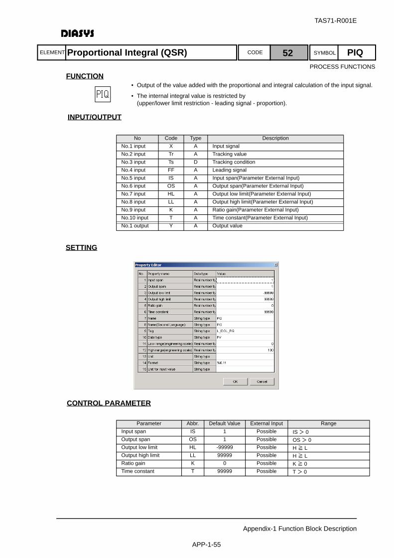
ELEMENT SYMBOLCODE
TAS71-R001E
Appendix-1 Function Block Description
APP-1-55
FUNCTION
INPUT/OUTPUT
SETTING
CONTROL PARAMETER
No Code Type DescriptionNo.1 input X A Input signal No.2 input Tr A Tracking valueNo.3 input Ts D Tracking conditionNo.4 input FF A Leading signalNo.5 input IS A Input span(Parameter External Input)No.6 input OS A Output span(Parameter External Input)No.7 input HL A Output low limit(Parameter External Input)No.8 input LL A Output high limit(Parameter External Input)No.9 input K A Ratio gain(Parameter External Input)No.10 input T A Time constant(Parameter External Input)No.1 output Y A Output value
Parameter Abbr. Default Value External Input RangeInput span IS 1 Possible IS > 0Output span OS 1 Possible OS > 0Output low limit HL -99999 Possible H ≧ LOutput high limit LL 99999 Possible H ≧ LRatio gain K 0 Possible K ≧ 0Time constant T 99999 Possible T > 0
Proportional Integral (QSR) 52 PIQ
• Output of the value added with the proportional and integral calculation of the input signal.
• The internal integral value is restricted by (upper/lower limit restriction - leading signal - proportion).
PROCESS FUNCTIONS
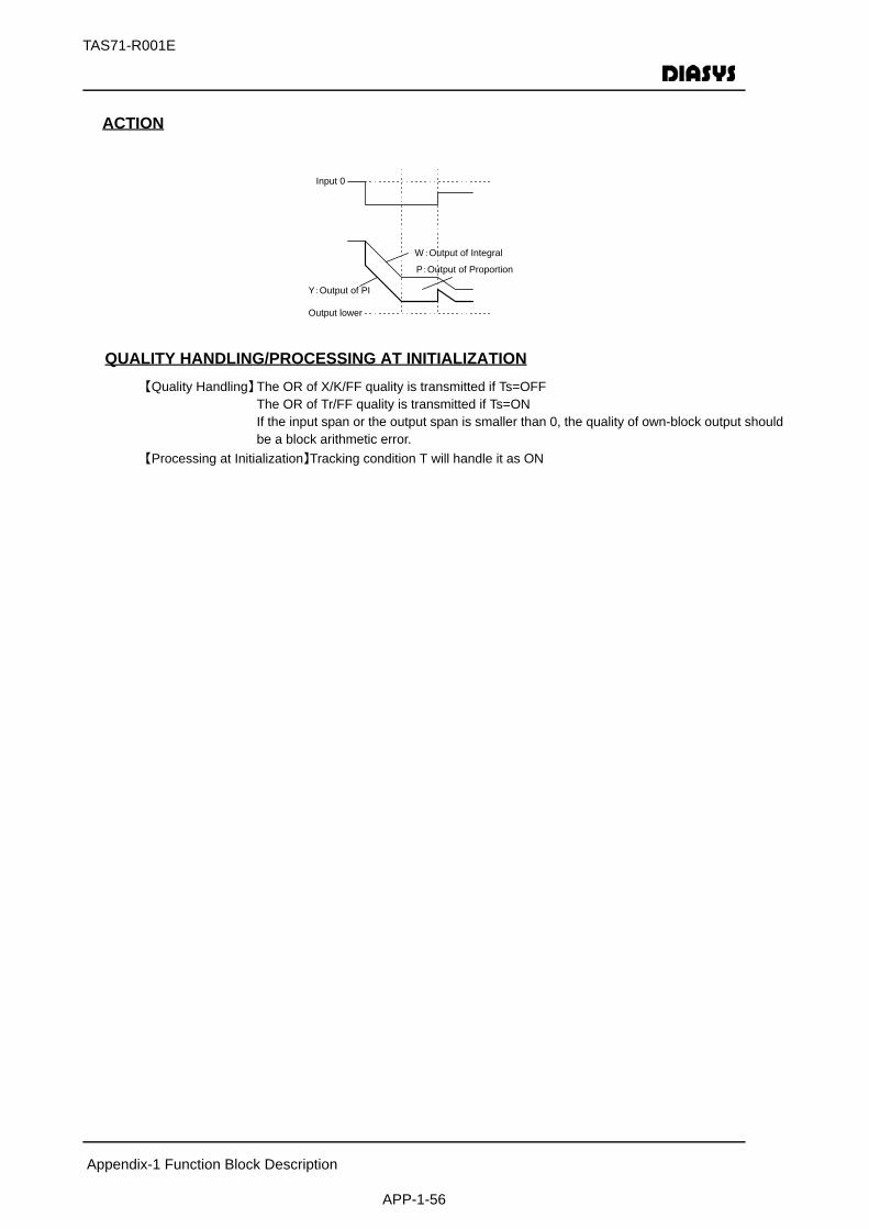
TAS71-R001E
Appendix-1 Function Block Description
APP-1-56
ACTION
QUALITY HANDLING/PROCESSING AT INITIALIZATION【Quality Handling】The OR of X/K/FF quality is transmitted if Ts=OFF
The OR of Tr/FF quality is transmitted if Ts=ONIf the input span or the output span is smaller than 0, the quality of own-block output should be a block arithmetic error.
【Processing at Initialization】Tracking condition T will handle it as ON
Input 0
Y:Output of PI
Output lower
W:Output of Integral
P:Output of Proportion

ELEMENT SYMBOLCODE
TAS71-R001E
Appendix-1 Function Block Description
APP-1-57
FUNCTION
INPUT/OUTPUT
SETTING
CONTROL PARAMETER
ACTION
QUALITY HANDLING/PROCESSING AT INITIALIZATION【Quality Handling】The quality of No. 1 input should be transmitted. If the time constant is negative, the quality
of ownblock 【Processing at Initialization】Tracking condition T will process as ON operation.
No Code Type DescriptionNo.1 input X A Input signal No.2 input K A Gain(Parameter External Input)No.3 input T A Time constant(Parameter External Input)No.4 input TP D Reset SWNo.1 output Y A Output value
Parameter Abbr. Default Value External Input RangeGain K 0 PossibleTime constant T 100 Possible T ≧ 0
Inclination R(/sec)
TC T
0
Reset
Input
Output
K×R
Ts1+Ts
Output=K ・Input
Differential Calculus 53 D
• Output of the value incompletely differentiated of input signals
PROCESS FUNCTIONS
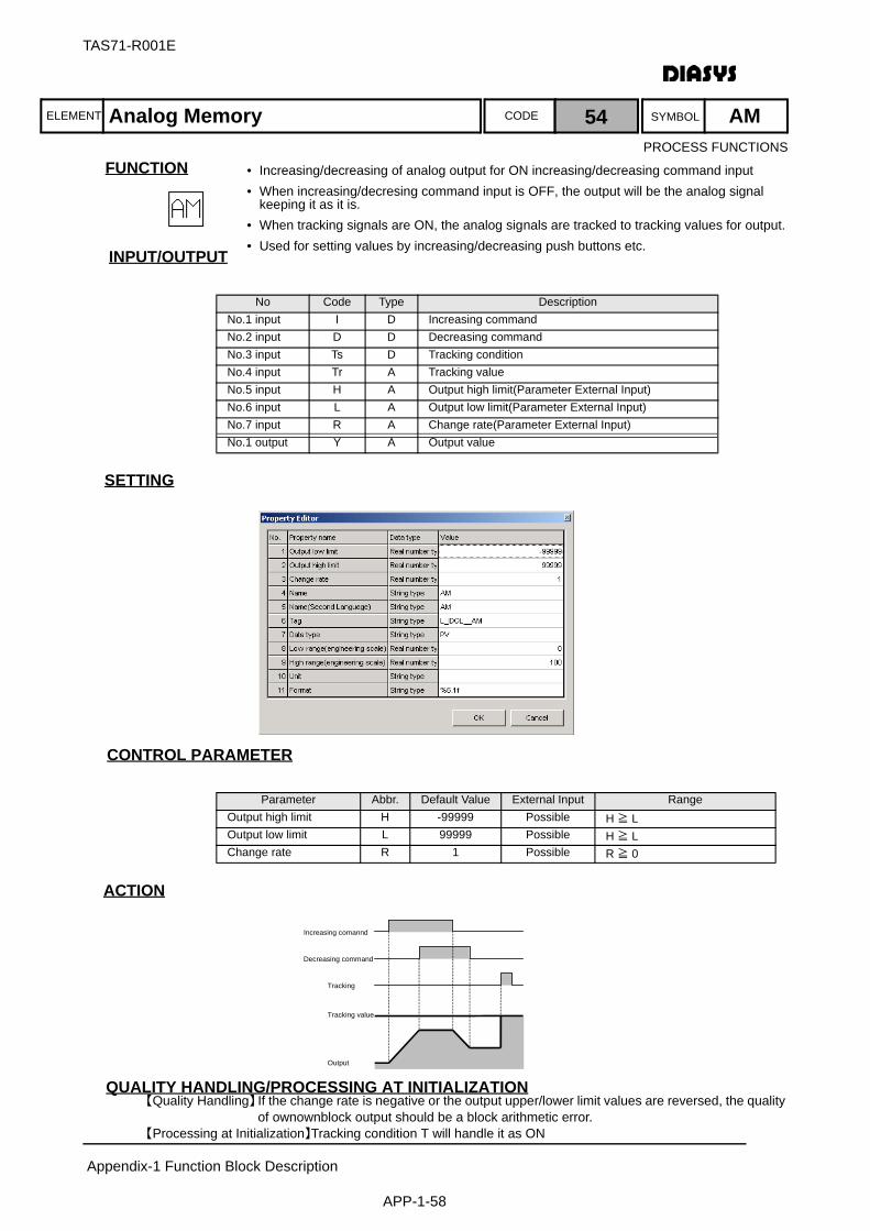
ELEMENT SYMBOLCODE
TAS71-R001E
Appendix-1 Function Block Description
APP-1-58
FUNCTION
INPUT/OUTPUT
SETTING
CONTROL PARAMETER
ACTION
QUALITY HANDLING/PROCESSING AT INITIALIZATION【Quality Handling】If the change rate is negative or the output upper/lower limit values are reversed, the quality
of ownownblock output should be a block arithmetic error.【Processing at Initialization】Tracking condition T will handle it as ON
No Code Type DescriptionNo.1 input I D Increasing commandNo.2 input D D Decreasing commandNo.3 input Ts D Tracking conditionNo.4 input Tr A Tracking valueNo.5 input H A Output high limit(Parameter External Input)No.6 input L A Output low limit(Parameter External Input)No.7 input R A Change rate(Parameter External Input)No.1 output Y A Output value
Parameter Abbr. Default Value External Input RangeOutput high limit H -99999 Possible H ≧ LOutput low limit L 99999 Possible H ≧ LChange rate R 1 Possible R ≧ 0
Increasing comannd
Decreasing command
Tracking value
Tracking
Output
Analog Memory 54 AM
• Increasing/decreasing of analog output for ON increasing/decreasing command input• When increasing/decresing command input is OFF, the output will be the analog signal
keeping it as it is.• When tracking signals are ON, the analog signals are tracked to tracking values for output.• Used for setting values by increasing/decreasing push buttons etc.
PROCESS FUNCTIONS

ELEMENT SYMBOLCODE
TAS71-R001E
Appendix-1 Function Block Description
APP-1-59
FUNCTION
INPUT/OUTPUT
SETTING
No Code Type DescriptionNo.1 input X A Input signalNo.1 output Y A Output value
Polyline Function 55 FX
• Output of the value that is performed with function calculation for the input signal. Polyline point is 10 at the maximum.
• If the X-axis value is not set, the polyline extends to the previous point for the smaller point than the previous one.
• The outside of the polyline will be output of Y value at both ends.
PROCESS FUNCTIONS

TAS71-R001E
Appendix-1 Function Block Description
APP-1-60
CONTROL PARAMETER
ACTION
QUALITY HANDLING/PROCESSING AT INITIALIZATION【Quality Handling】The input quality is transmitted to the output 【Processing at Initialization】Nothing in particular
Parameter Abbr. Default Value External Input RangeX1 C1 0Y1 C2 0X2 C3 10000Y2 C4 10000X3 C5 0Y3 C6 0X4 C7 0Y4 C8 0X5 C9 0Y5 C10 0X6 C11 0Y6 C12 0X7 C13 0Y7 C14 0X8 C15 0Y8 C16 0X9 C17 0Y9 C18 0X10 C19 0Y10 C20 0
Output
Y1
Y2
Y3
Y4
Y5 Y6
Y7
Y8
Y9
Y10
X2 X3 X4X1 X5 X6 X8 X9 X10X7Input
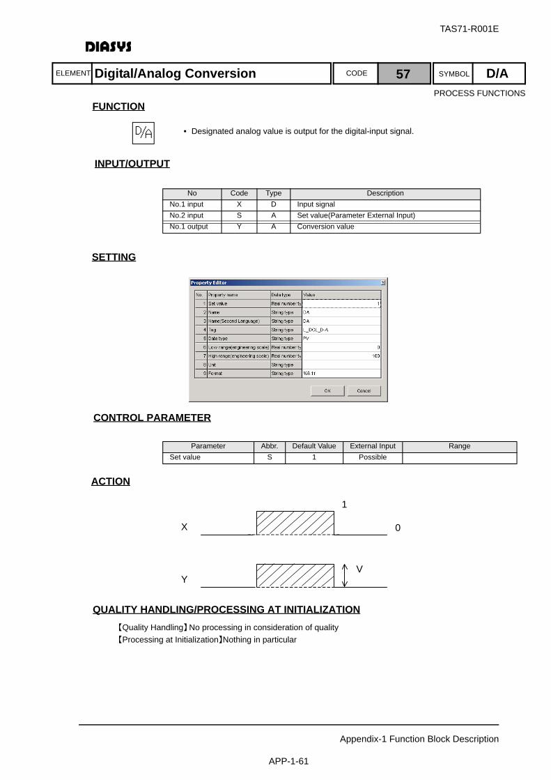
ELEMENT SYMBOLCODE
TAS71-R001E
Appendix-1 Function Block Description
APP-1-61
FUNCTION
INPUT/OUTPUT
SETTING
CONTROL PARAMETER
ACTION
QUALITY HANDLING/PROCESSING AT INITIALIZATION【Quality Handling】No processing in consideration of quality【Processing at Initialization】Nothing in particular
No Code Type DescriptionNo.1 input X D Input signalNo.2 input S A Set value(Parameter External Input)No.1 output Y A Conversion value
Parameter Abbr. Default Value External Input RangeSet value S 1 Possible
1
X 0
Y V
Digital/Analog Conversion 57 D/A
• Designated analog value is output for the digital-input signal.
PROCESS FUNCTIONS
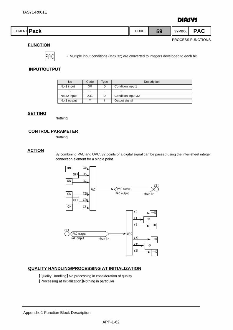
ELEMENT SYMBOLCODE
TAS71-R001E
Appendix-1 Function Block Description
APP-1-62
FUNCTION
INPUT/OUTPUT
SETTINGNothing
CONTROL PARAMETERNothing
ACTIONBy combining PAC and UPC, 32 points of a digital signal can be passed using the inter-sheet integerconnection element for a single point.
QUALITY HANDLING/PROCESSING AT INITIALIZATION【Quality Handling】No processing in consideration of quality【Processing at Initialization】Nothing in particular
No Code Type DescriptionNo.1 input X0 D Condition input1
~ ~ ~ ~No.32 input X31 D Condition input 32No.1 output Y I Output signal
ON
OFF
X0
X1
X2
PAC
ON
ON
OFF
X29
X30
X31 ON
PAC output PAC output
CEI
<Man-1>
→D Y0
Y1
Y2
UPC Y29
Y30
Y31
PAC output PAC output
CEI
<Man-1>
→D
→D
→D
→D
→D
Pack 59 PAC
• Multiple input conditions (Max.32) are converted to integers developed to each bit.
PROCESS FUNCTIONS

ELEMENT SYMBOLCODE
TAS71-R001E
Appendix-1 Function Block Description
APP-1-63
FUNCTION
INPUT/OUTPUT
SETTINGNothing
CONTROL PARAMETERNothing
ACTIONThe element outputs the arithmetic cycle of the logic sheet.
QUALITY HANDLING/PROCESSING AT INITIALIZATION【Quality Handling】Always handle them as normal.【Processing at Initialization】Nothing in particular
No Code Type DescriptionNo.1 output Y A Arithmetic cycle (msec)
Arithmetic Cycle 60 DT
• The arithmetic cycle is fetched for the logic sheet.
PROCESS FUNCTIONS
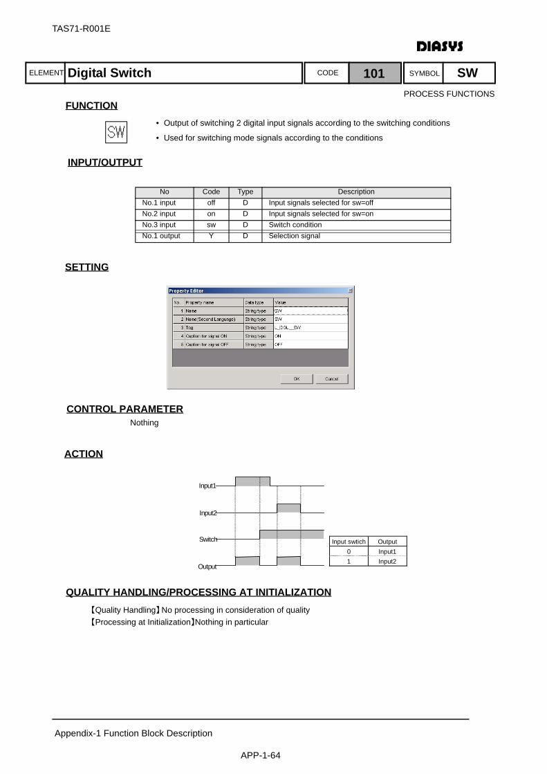
ELEMENT SYMBOLCODE
TAS71-R001E
Appendix-1 Function Block Description
APP-1-64
FUNCTION
INPUT/OUTPUT
SETTING
CONTROL PARAMETERNothing
ACTION
QUALITY HANDLING/PROCESSING AT INITIALIZATION【Quality Handling】No processing in consideration of quality【Processing at Initialization】Nothing in particular
No Code Type DescriptionNo.1 input off D Input signals selected for sw=offNo.2 input on D Input signals selected for sw=onNo.3 input sw D Switch conditionNo.1 output Y D Selection signal
Input1
Input2
Switch
Output
Input swtich Output 0 Input1 1 Input2
Digital Switch 101 SW
• Output of switching 2 digital input signals according to the switching conditions
• Used for switching mode signals according to the conditions
PROCESS FUNCTIONS
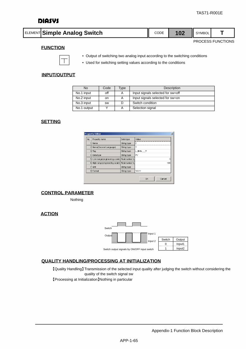
ELEMENT SYMBOLCODE
TAS71-R001E
Appendix-1 Function Block Description
APP-1-65
FUNCTION
入 出 力INPUT/OUTPUT
SETTING
CONTROL PARAMETERNothing
ACTION
QUALITY HANDLING/PROCESSING AT INITIALIZATION【Quality Handling】Transmission of the selected input quality after judging the switch without considering the
quality of the switch signal sw【Processing at Initialization】Nothing in particular
No Code Type DescriptionNo.1 input off A Input signals selected for sw=offNo.2 input on A Input signals selected for sw=onNo.3 input sw D Switch conditionNo.1 output Y A Selection signal
Output
Input 2
Input 1
Switch output signals by ON/OFF input switch
Switch
Switch Output 0 Input1 1 Input2
Simple Analog Switch 102 T
• Output of switching two analog input according to the switching conditions
• Used for switching setting values according to the conditions
PROCESS FUNCTIONS
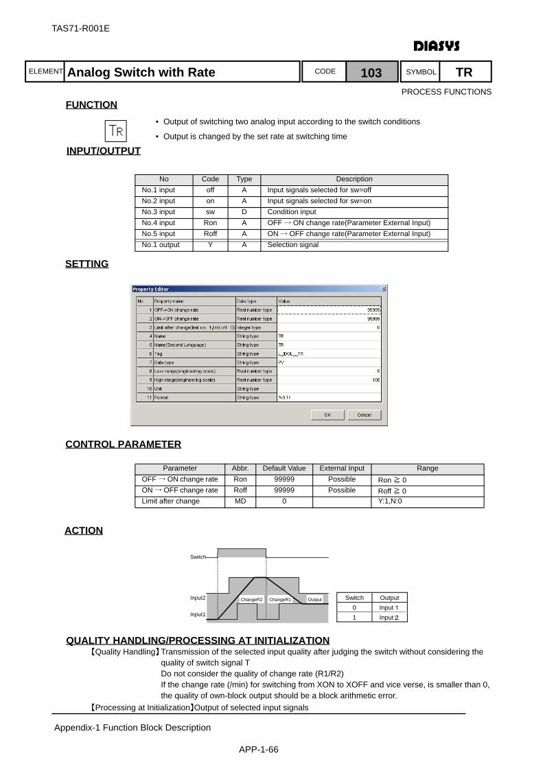
ELEMENT SYMBOLCODE
TAS71-R001E
Appendix-1 Function Block Description
APP-1-66
FUNCTION
入 出 力INPUT/OUTPUT
SETTING
CONTROL PARAMETER
ACTION
QUALITY HANDLING/PROCESSING AT INITIALIZATION【Quality Handling】Transmission of the selected input quality after judging the switch without considering the
quality of switch signal TDo not consider the quality of change rate (R1/R2)If the change rate (/min) for switching from XON to XOFF and vice verse, is smaller than 0, the quality of own-block output should be a block arithmetic error.
【Processing at Initialization】Output of selected input signals
No Code Type DescriptionNo.1 input off A Input signals selected for sw=offNo.2 input on A Input signals selected for sw=onNo.3 input sw D Condition inputNo.4 input Ron A OFF → ON change rate(Parameter External Input)No.5 input Roff A ON → OFF change rate(Parameter External Input)No.1 output Y A Selection signal
Parameter Abbr. Default Value External Input RangeOFF → ON change rate Ron 99999 Possible Ron ≧ 0ON → OFF change rate Roff 99999 Possible Roff ≧ 0Limit after change MD 0 Y:1,N:0
Switch
Input2
Input1
ChangeR2 ChangeR1 Output Switch Output 0 Input1 1 Input2
Analog Switch with Rate 103 TR
• Output of switching two analog input according to the switch conditions
• Output is changed by the set rate at switching time
PROCESS FUNCTIONS

ELEMENT SYMBOLCODE
TAS71-R001E
Appendix-1 Function Block Description
APP-1-67
FUNCTION
入 出 力INPUT/OUTPUT
SETTING
CONTROL PARAMETER
ACTION
QUALITY HANDLING/PROCESSING AT INITIALIZATION【Quality Handling】Transmission of the selected input quality after judging the switch without considering the
quality of switch signal TDo not consider the quality of change rate (R1/R2)If the change rate (/min) for switching from XON to XOFF and vice verse, is smaller than 0, the quality of own-block output should be a block arithmetic error.
【Processing at Initialization】Output of selected input signals
No Code Type DescriptionNo.1 input off A Input signals selected for sw=offNo.2 input on A Input signals selected for sw=onNo.3 input sw D Condition inputNo.4 input Ron A OFF → ON change rate(Parameter External Input)No.5 input Roff A ON → OFF change rate(Parameter External Input)No.1 output Y A Selection signal
Parameter Abbr. Default Value External Input RangeOFF → ON change rate Ron 99999 Possible Ron ≧ 0ON → OFF change rate Roff 99999 Possible Roff ≧ 0
Change Rate1Change Rate2
Input 2
Input 1 Output
Input Switch
Deviation (Input1/O)Deviation(Input2/O)
0 0
Analog Switch with Differential Rate 104 TRD
• Output of switching two analog input according to the switch conditions
• Should be reduced according to the rate set with deviation of target input at the time of switch
PROCESS FUNCTIONS
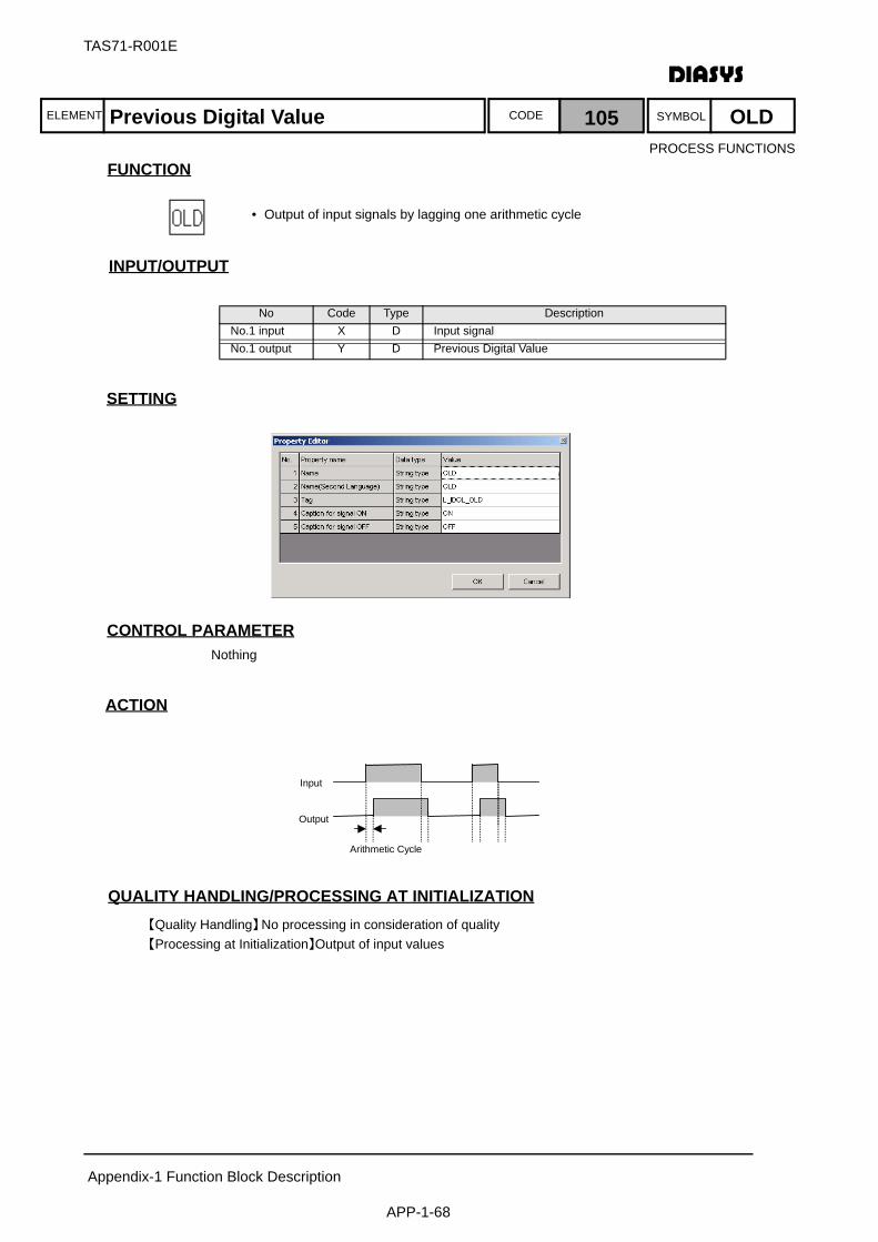
ELEMENT SYMBOLCODE
TAS71-R001E
Appendix-1 Function Block Description
APP-1-68
FUNCTION
入 出 力INPUT/OUTPUT
SETTING
CONTROL PARAMETERNothing
ACTION
QUALITY HANDLING/PROCESSING AT INITIALIZATION【Quality Handling】No processing in consideration of quality 【Processing at Initialization】Output of input values
No Code Type DescriptionNo.1 input X D Input signalNo.1 output Y D Previous Digital Value
Arithmetic Cycle
Input
Output
Previous Digital Value 105 OLD
• Output of input signals by lagging one arithmetic cycle
PROCESS FUNCTIONS
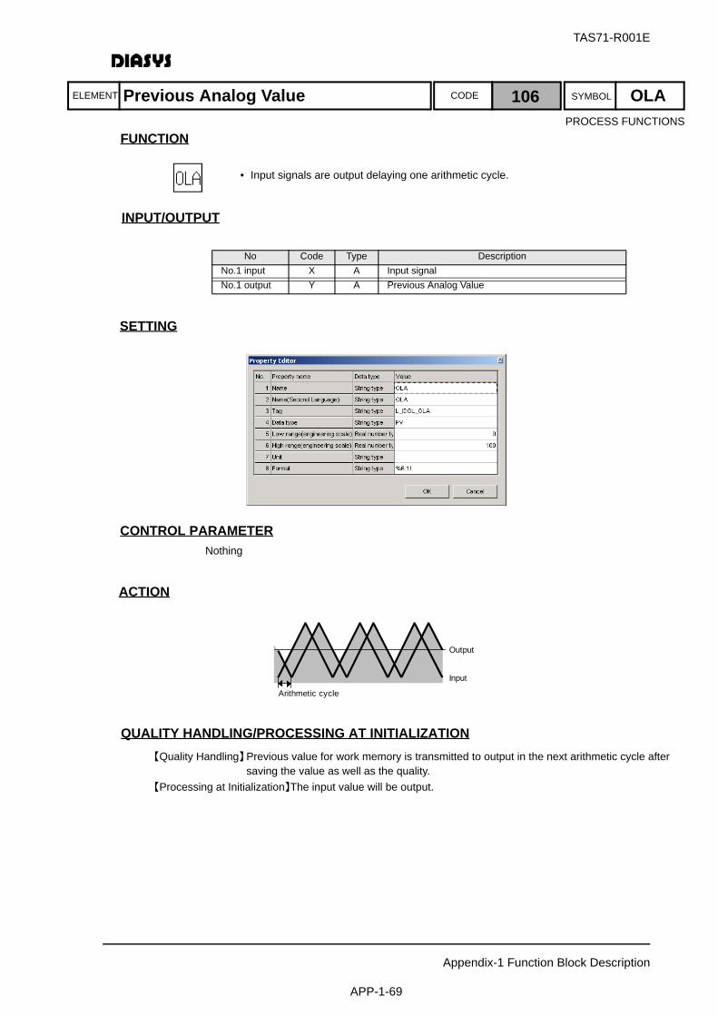
ELEMENT SYMBOLCODE
TAS71-R001E
Appendix-1 Function Block Description
APP-1-69
FUNCTION
入 出 力INPUT/OUTPUT
SETTING
CONTROL PARAMETERNothing
ACTION
QUALITY HANDLING/PROCESSING AT INITIALIZATION【Quality Handling】Previous value for work memory is transmitted to output in the next arithmetic cycle after
saving the value as well as the quality.【Processing at Initialization】The input value will be output.
No Code Type DescriptionNo.1 input X A Input signalNo.1 output Y A Previous Analog Value
Arithmetic cycle
Output
Input
Previous Analog Value 106 OLA
• Input signals are output delaying one arithmetic cycle.
PROCESS FUNCTIONS
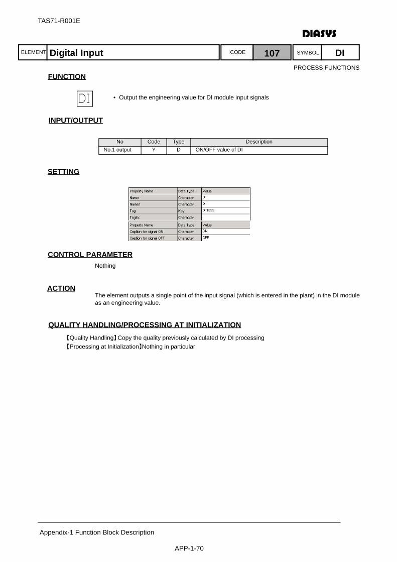
ELEMENT SYMBOLCODE
TAS71-R001E
Appendix-1 Function Block Description
APP-1-70
FUNCTION
入 出 力INPUT/OUTPUT
SETTING
CONTROL PARAMETERNothing
ACTIONThe element outputs a single point of the input signal (which is entered in the plant) in the DI moduleas an engineering value.
QUALITY HANDLING/PROCESSING AT INITIALIZATION【Quality Handling】Copy the quality previously calculated by DI processing 【Processing at Initialization】Nothing in particular
No Code Type DescriptionNo.1 output Y D ON/OFF value of DI
Digital Input 107 DI
• Output the engineering value for DI module input signals
PROCESS FUNCTIONS
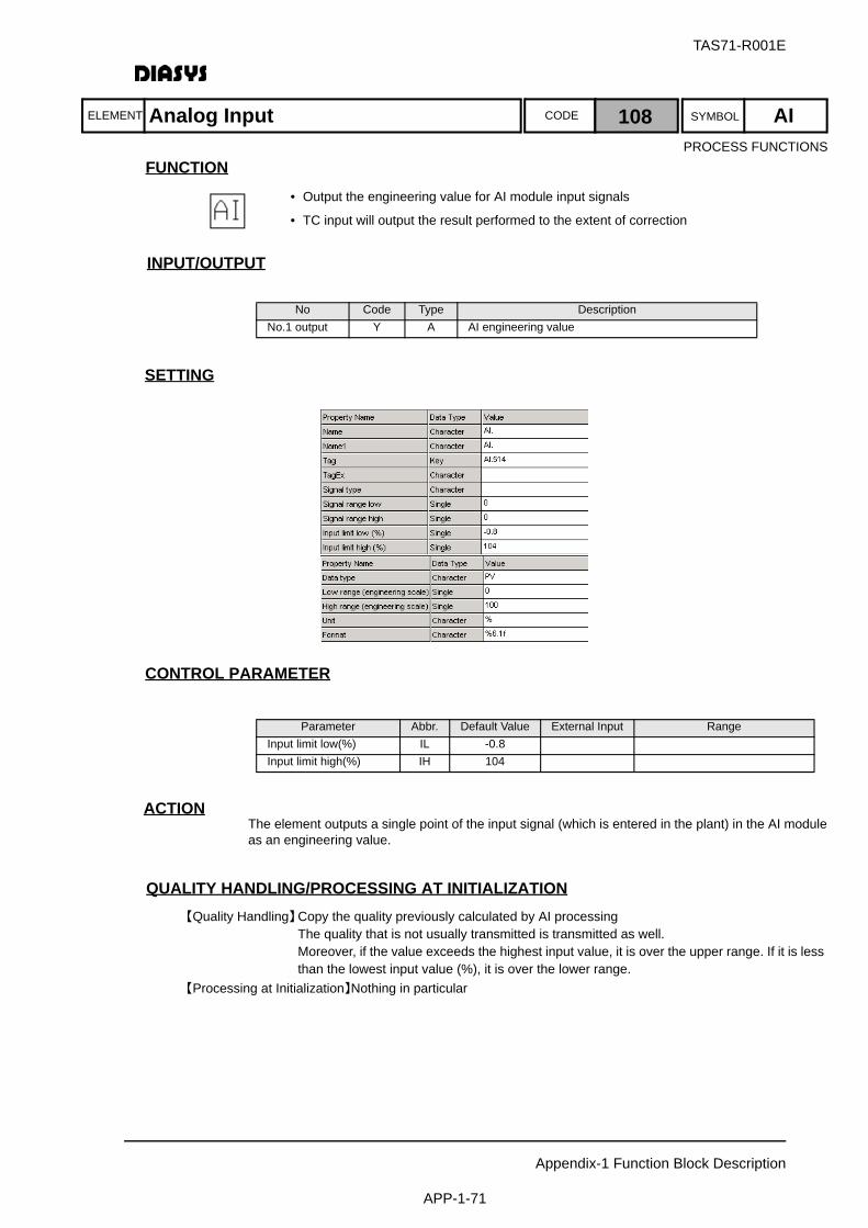
ELEMENT SYMBOLCODE
TAS71-R001E
Appendix-1 Function Block Description
APP-1-71
FUNCTION
入 出 力INPUT/OUTPUT
SETTING
CONTROL PARAMETER
ACTIONThe element outputs a single point of the input signal (which is entered in the plant) in the AI moduleas an engineering value.
QUALITY HANDLING/PROCESSING AT INITIALIZATION【Quality Handling】Copy the quality previously calculated by AI processing The quality that is not usually transmitted is transmitted as well.
Moreover, if the value exceeds the highest input value, it is over the upper range. If it is less than the lowest input value (%), it is over the lower range.
【Processing at Initialization】Nothing in particular
No Code Type DescriptionNo.1 output Y A AI engineering value
Parameter Abbr. Default Value External Input RangeInput limit low(%) IL -0.8Input limit high(%) IH 104
Analog Input 108 AI
• Output the engineering value for AI module input signals
• TC input will output the result performed to the extent of correction
PROCESS FUNCTIONS

ELEMENT SYMBOLCODE
TAS71-R001E
Appendix-1 Function Block Description
APP-1-72
FUNCTION
入 出 力INPUT/OUTPUT
SETTING
CONTROL PARAMETERNothing
ACTIONThe element outputs a single point of the input signal (which is entered in the plant) in the DI moduleas a pulse.
QUALITY HANDLING/PROCESSING AT INITIALIZATION【Quality Handling】Copy the quality previously calculated by PI processing【Processing at Initialization】Nothing in particular
No Code Type DescriptionNo.1 output Y A Pulse counter value
Pulse Input 109 PU
• Output of the PI-module input signal as the pulse value
PROCESS FUNCTIONS
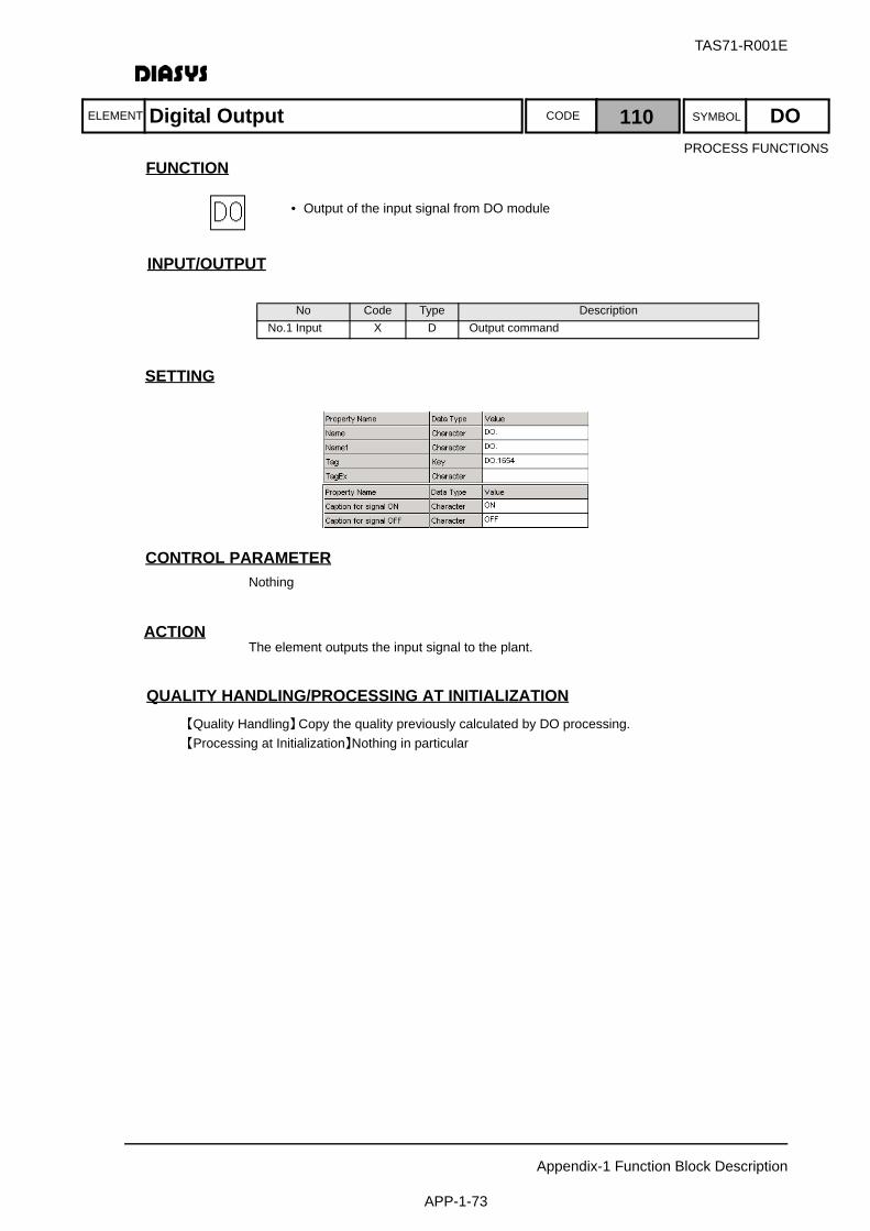
ELEMENT SYMBOLCODE
TAS71-R001E
Appendix-1 Function Block Description
APP-1-73
FUNCTION
入 出 力INPUT/OUTPUT
SETTING
CONTROL PARAMETERNothing
ACTIONThe element outputs the input signal to the plant.
QUALITY HANDLING/PROCESSING AT INITIALIZATION【Quality Handling】Copy the quality previously calculated by DO processing.【Processing at Initialization】Nothing in particular
No Code Type DescriptionNo.1 Input X D Output command
Digital Output 110 DO
• Output of the input signal from DO module
PROCESS FUNCTIONS
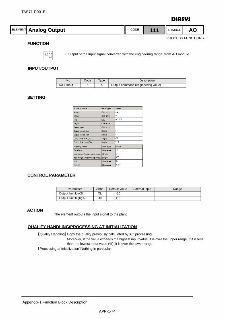
ELEMENT SYMBOLCODE
TAS71-R001E
Appendix-1 Function Block Description
APP-1-74
FUNCTION
入 出 力INPUT/OUTPUT
SETTING
CONTROL PARAMETER
ACTIONThe element outputs the input signal to the plant.
QUALITY HANDLING/PROCESSING AT INITIALIZATION【Quality Handling】Copy the quality previously calculated by AO processing.
Moreover, if the value exceeds the highest input value, it is over the upper range. If it is less than the lowest input value (%), it is over the lower range.
【Processing at Initialization】Nothing in particular
No Code Type DescriptionNo.1 Input X A Output command (engineering value)
Parameter Abbr. Default Value External Input RangeOutput limit low(%) OL -10Output limit high(%) OH 110
Analog Output 111 AO
• Output of the input signal converted with the engineering range, from AO module
PROCESS FUNCTIONS
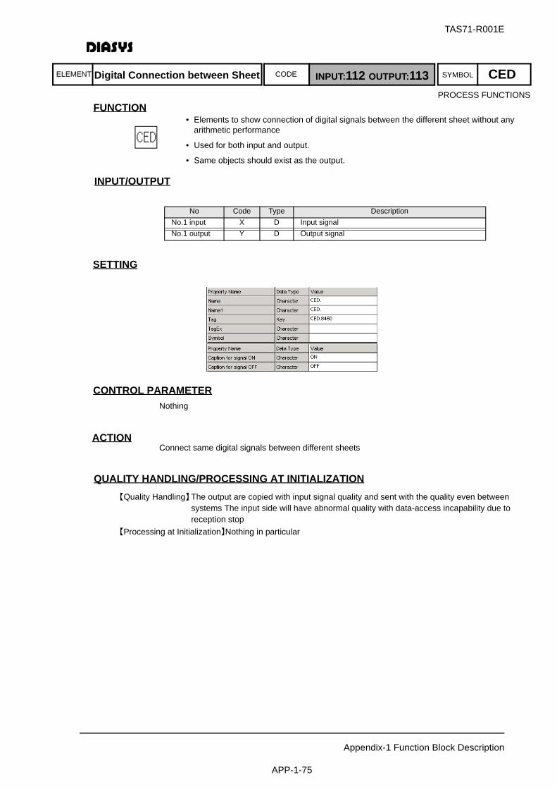
ELEMENT SYMBOLCODE
TAS71-R001E
Appendix-1 Function Block Description
APP-1-75
FUNCTION
入 出 力INPUT/OUTPUT
SETTING
CONTROL PARAMETERNothing
ACTIONConnect same digital signals between different sheets
QUALITY HANDLING/PROCESSING AT INITIALIZATION【Quality Handling】The output are copied with input signal quality and sent with the quality even between
systems The input side will have abnormal quality with data-access incapability due to reception stop
【Processing at Initialization】Nothing in particular
No Code Type DescriptionNo.1 input X D Input signalNo.1 output Y D Output signal
• Elements to show connection of digital signals between the different sheet without any arithmetic performance
• Used for both input and output.
• Same objects should exist as the output.
Digital Connection between Sheet INPUT:112 OUTPUT:113 CEDPROCESS FUNCTIONS
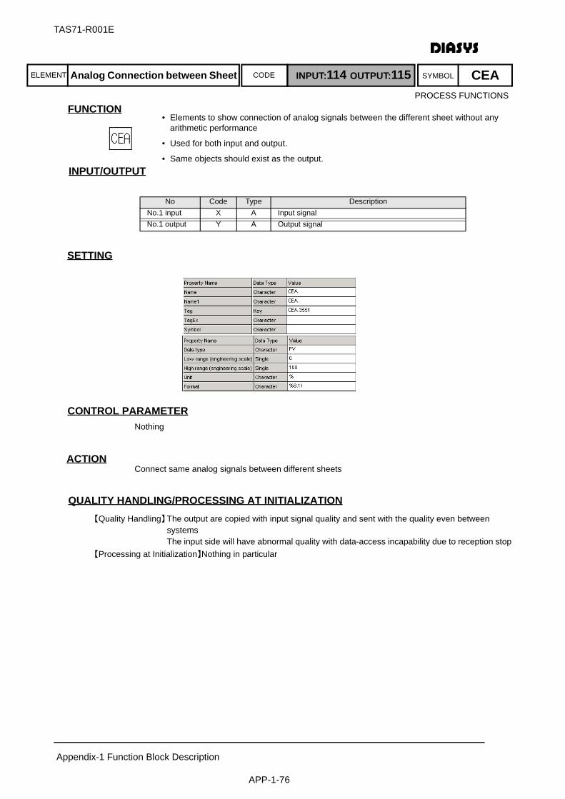
ELEMENT SYMBOLCODE
TAS71-R001E
Appendix-1 Function Block Description
APP-1-76
FUNCTION
入 出 力INPUT/OUTPUT
SETTING
CONTROL PARAMETERNothing
ACTIONConnect same analog signals between different sheets
QUALITY HANDLING/PROCESSING AT INITIALIZATION【Quality Handling】The output are copied with input signal quality and sent with the quality even between
systems The input side will have abnormal quality with data-access incapability due to reception stop
【Processing at Initialization】Nothing in particular
No Code Type DescriptionNo.1 input X A Input signalNo.1 output Y A Output signal
• Elements to show connection of analog signals between the different sheet without any arithmetic performance
• Used for both input and output.
• Same objects should exist as the output.
Analog Connection between Sheet INPUT:114 OUTPUT:115 CEAPROCESS FUNCTIONS
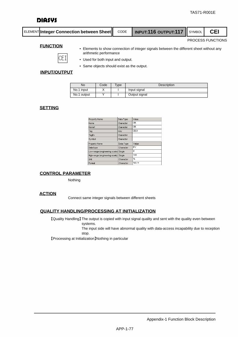
ELEMENT SYMBOLCODE
TAS71-R001E
Appendix-1 Function Block Description
APP-1-77
FUNCTION
入 出 力INPUT/OUTPUT
SETTING
CONTROL PARAMETERNothing
ACTIONConnect same integer signals between different sheets
QUALITY HANDLING/PROCESSING AT INITIALIZATION【Quality Handling】The output is copied with input signal quality and sent with the quality even between
systems. The input side will have abnormal quality with data-access incapability due to reception stop.
【Processing at Initialization】Nothing in particular
No Code Type DescriptionNo.1 input X I Input signalNo.1 output Y I Output signal
• Elements to show connection of integer signals between the different sheet without any arithmetic performance
• Used for both input and output.
• Same objects should exist as the output.
Integer Connection between Sheet INPUT:116 OUTPUT:117 CEIPROCESS FUNCTIONS

ELEMENT SYMBOLCODE
TAS71-R001E
Appendix-1 Function Block Description
APP-1-78
FUNCTION
入 出 力INPUT/OUTPUT
SETTING
CONTROL PARAMETER
ACTIONThe element sends and receives signals to and from the macro logic. For details about setting themacro logic, see Section 2.6 "Macro Elements".
QUALITY HANDLING/PROCESSING AT INITIALIZATION【Quality Handling】The input is copied with the connection element quality of the logic sheet.
The output is copied with the input signal quality.【Processing at Initialization】Nothing in particular
No Code Type DescriptionNo.1 input X D Input signalNo.1 output Y D Output signal
Parameter Abbr. Default Value External Input RangeNumber No 1
• Blocks to perform interface of external analog signals in Macroblock logic sheet.
• Used for both input/output sides.
• The sequence number of an input in the macro call element depends on the location of the input. The upper left is the first input.
• The sequence number of an output in the macro call element depends on the location of the output. The lower right is the last output.
Macro I/F Digital INPUT:118 OUTPUT:119 MCDPROCESS FUNCTIONS

ELEMENT SYMBOLCODE
TAS71-R001E
Appendix-1 Function Block Description
APP-1-79
FUNCTION
入 出 力INPUT/OUTPUT
SETTING
CONTROL PARAMETER
ACTIONThe element sends and receives signals to and from the macro logic. For details about setting themacro logic, see Section 2.6 "Macro Elements".
QUALITY HANDLING/PROCESSING AT INITIALIZATION【Quality Handling】The input is copied with the connection element quality of the logic sheet.
The output is copied with the input signal quality.【Processing at Initialization】Nothing in particular
No Code Type DescriptionNo.1 input X A Input signalNo.1 output Y A Output signal
Parameter Abbr. Default Value External Input RangeNumber No 1
• Blocks to perform interface of external integer signals in Macroblock logic sheet.
• Used for both input/output
• The sequence number of an input in the macro call element depends on the location of the input. The upper left is the first input.
• The sequence number of an output in the macro call element depends on the location of the output. The lower right is the last output.
Macro I/F Analog INPUT:120 OUTPUT:121 MCAPROCESS FUNCTIONS

ELEMENT SYMBOLCODE
TAS71-R001E
Appendix-1 Function Block Description
APP-1-80
FUNCTION
入 出 力INPUT/OUTPUT
SETTING
CONTROL PARAMETER
ACTIONThe element sends and receives signals to and from the macro logic. For details about setting themacro logic, see Section 2.6 "Macro Elements".
QUALITY HANDLING/PROCESSING AT INITIALIZATION【Quality Handling】The input is copied with the connection element quality of the logic sheet.
The output is copied with the input signal quality.【Processing at Initialization】Nothing in particular
No Code Type DescriptionNo.1 input X I Input signalNo.1 output Y I Output signal
Parameter Abbr. Default Value External Input RangeNumber No 1
• Blocks to perform interface of external digital signals in Macro-block logic sheet.
• Used for both input/o
• The sequence number of an input in the macro call element depends on the location of the input. The upper left is the first input.
• The sequence number of an output in the macro call element depends on the location of the output. The lower right is the last output.
Macro I/F Integer INPUT:122 OUTPUT:123 MCIPROCESS FUNCTIONS

ELEMENT SYMBOLCODE
TAS71-R001E
Appendix-1 Function Block Description
APP-1-81
FUNCTION
入 出 力INPUT/OUTPUT
SETTING
CONTROL PARAMETERNothing
ACTIONThe element connects the same signals on the same sheet.
QUALITY HANDLING/PROCESSING AT INITIALIZATION【Quality Handling】All the qualities are transmitted. 【Processing at Initialization】Nothing in particular
No Code Type DescriptionNo.1 input X A/D/I Input signalNo.1 output Y A/D/I Output signal
• These are elements to show connection in the same sheet and not performed with any arithmetics.
• Used for all the data types of analog, digital, and integer.
• Used for both input/output.
• Elements with the same name should exist in the sheet as the output.
Connection Inside Sheet INPUT:124 OUTPUT:125 CIDPROCESS FUNCTIONS
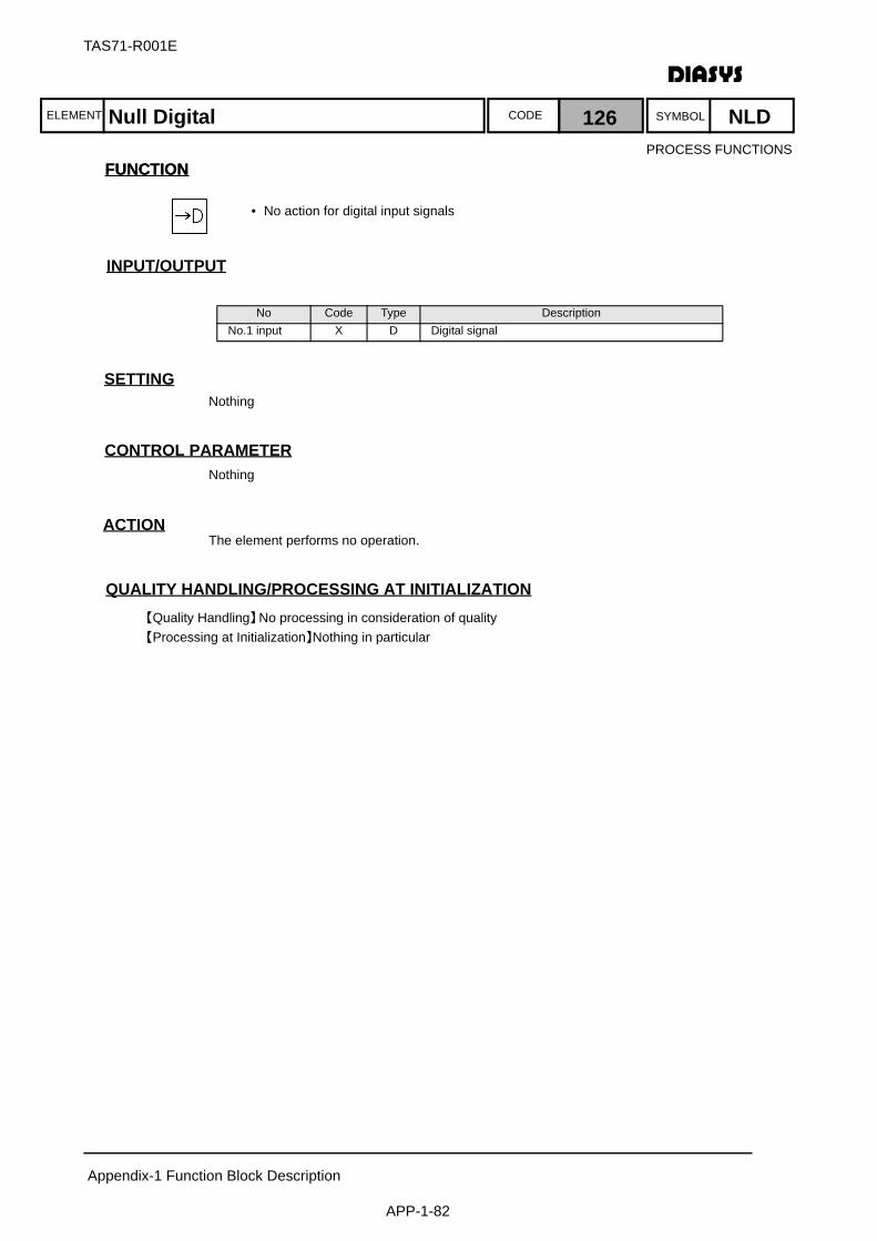
ELEMENT SYMBOLCODE
TAS71-R001E
Appendix-1 Function Block Description
APP-1-82
FUNCTIONFUNCTION
入 出 力INPUT/OUTPUT
SETTINGNothing
CONTROL PARAMETERNothing
ACTIONThe element performs no operation.
QUALITY HANDLING/PROCESSING AT INITIALIZATION【Quality Handling】No processing in consideration of quality 【Processing at Initialization】Nothing in particular
No Code Type DescriptionNo.1 input X D Digital signal
Null Digital 126 NLD
• No action for digital input signals
PROCESS FUNCTIONS
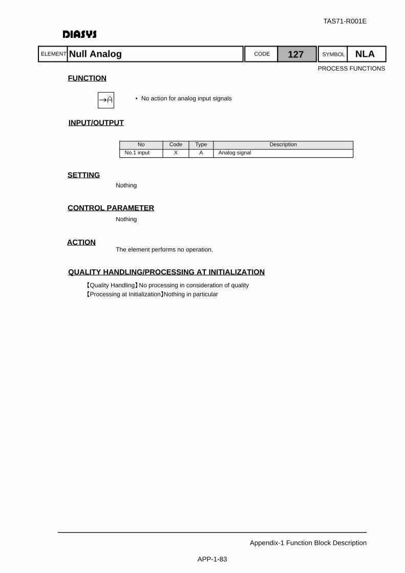
ELEMENT SYMBOLCODE
TAS71-R001E
Appendix-1 Function Block Description
APP-1-83
FUNCTION
入 出 力INPUT/OUTPUT
SETTINGNothing
CONTROL PARAMETERNothing
ACTIONThe element performs no operation.
QUALITY HANDLING/PROCESSING AT INITIALIZATION【Quality Handling】No processing in consideration of quality 【Processing at Initialization】Nothing in particular
No Code Type DescriptionNo.1 input X A Analog signal
Null Analog 127 NLA
• No action for analog input signals
PROCESS FUNCTIONS

ELEMENT SYMBOLCODE
TAS71-R001E
Appendix-1 Function Block Description
APP-1-84
FUNCTION
入 出 力INPUT/OUTPUT
SETTINGNothing
CONTROL PARAMETERNothing
ACTIONNo action
QUALITY HANDLING/PROCESSING AT INITIALIZATION【Quality Handling】No processing in consideration of quality【Processing at Initialization】Nothing in particular
No Code Type DescriptionNo.1 input X I Integer signal
Null Integer 128 NLI
• No action to integer input values
DATA LOGGAR FUNCTIONS
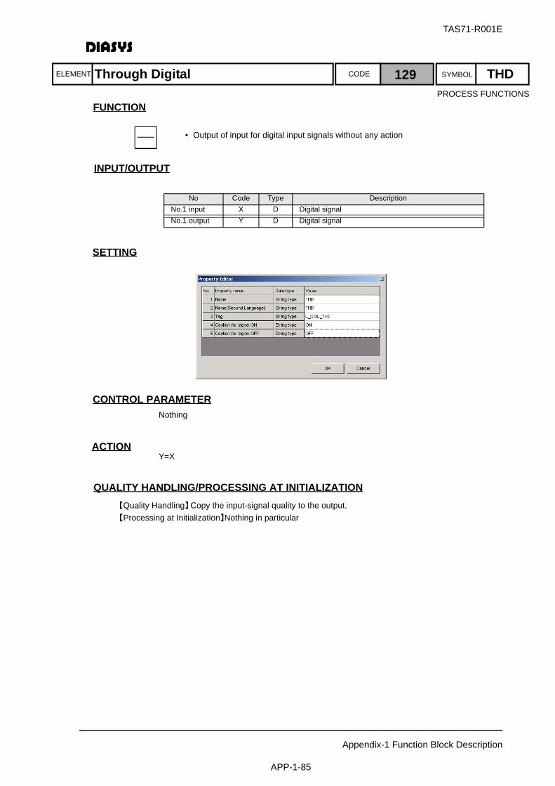
ELEMENT SYMBOLCODE
TAS71-R001E
Appendix-1 Function Block Description
APP-1-85
FUNCTION
入 出 力INPUT/OUTPUT
SETTING
CONTROL PARAMETERNothing
ACTIONY=X
QUALITY HANDLING/PROCESSING AT INITIALIZATION【Quality Handling】Copy the input-signal quality to the output.【Processing at Initialization】Nothing in particular
No Code Type DescriptionNo.1 input X D Digital signalNo.1 output Y D Digital signal
Through Digital 129 THD
• Output of input for digital input signals without any action
PROCESS FUNCTIONS
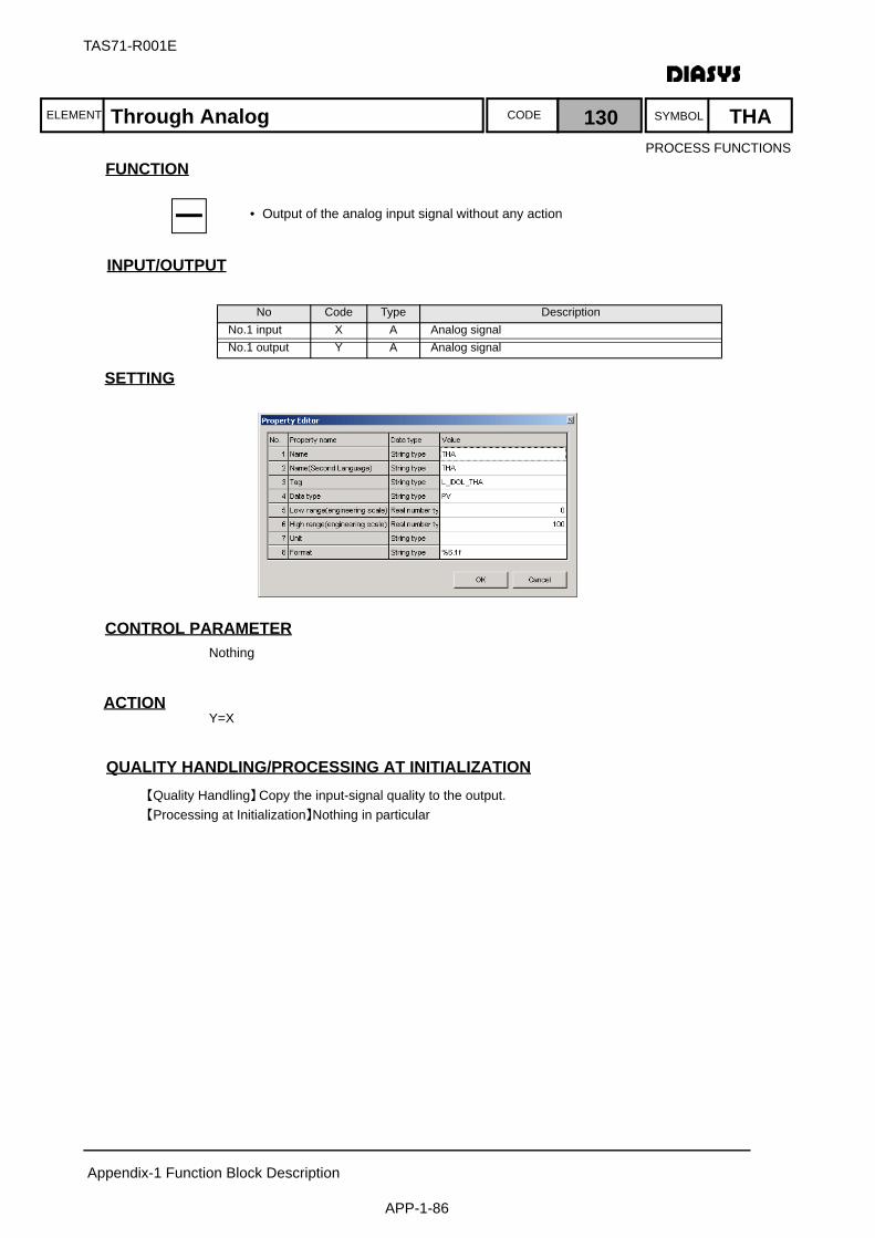
ELEMENT SYMBOLCODE
TAS71-R001E
Appendix-1 Function Block Description
APP-1-86
FUNCTION
入 出 力INPUT/OUTPUT
SETTING
CONTROL PARAMETERNothing
ACTIONY=X
QUALITY HANDLING/PROCESSING AT INITIALIZATION【Quality Handling】Copy the input-signal quality to the output.【Processing at Initialization】Nothing in particular
No Code Type DescriptionNo.1 input X A Analog signalNo.1 output Y A Analog signal
Through Analog 130 THA
• Output of the analog input signal without any action
PROCESS FUNCTIONS

ELEMENT SYMBOLCODE
TAS71-R001E
Appendix-1 Function Block Description
APP-1-87
FUNCTION
入 出 力INPUT/OUTPUT
SETTING
CONTROL PARAMETERNothing
ACTIONY=X
QUALITY HANDLING/PROCESSING AT INITIALIZATION【Quality Handling】Copy the input-signal quality to the output.【Processing at Initialization】Nothing in particular
No Code Type DescriptionNo.1 input X I Integer signalNo.1 output Y I Integer signal
Through Integer 131 THI
• No action to integer input values
DATA LOGGAR FUNCTIONS
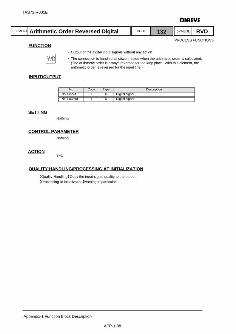
ELEMENT SYMBOLCODE
TAS71-R001E
Appendix-1 Function Block Description
APP-1-88
FUNCTION
入 出 力INPUT/OUTPUT
SETTINGNothing
CONTROL PARAMETERNothing
ACTIONY=X
QUALITY HANDLING/PROCESSING AT INITIALIZATION【Quality Handling】Copy the input-signal quality to the output.【Processing at Initialization】Nothing in particular
No Code Type DescriptionNo.1 input X D Digital signalNo.1 output Y D Digital signal
Arithmetic Order Reversed Digital 132 RVD
• Output of the digital input signals without any action
• The connection is handled as disconnected when the arithmetic order is calculated.(The arithmetic order is always reversed for the loop place. With this element, the arithmetic order is reversed for the input line.)
PROCESS FUNCTIONS
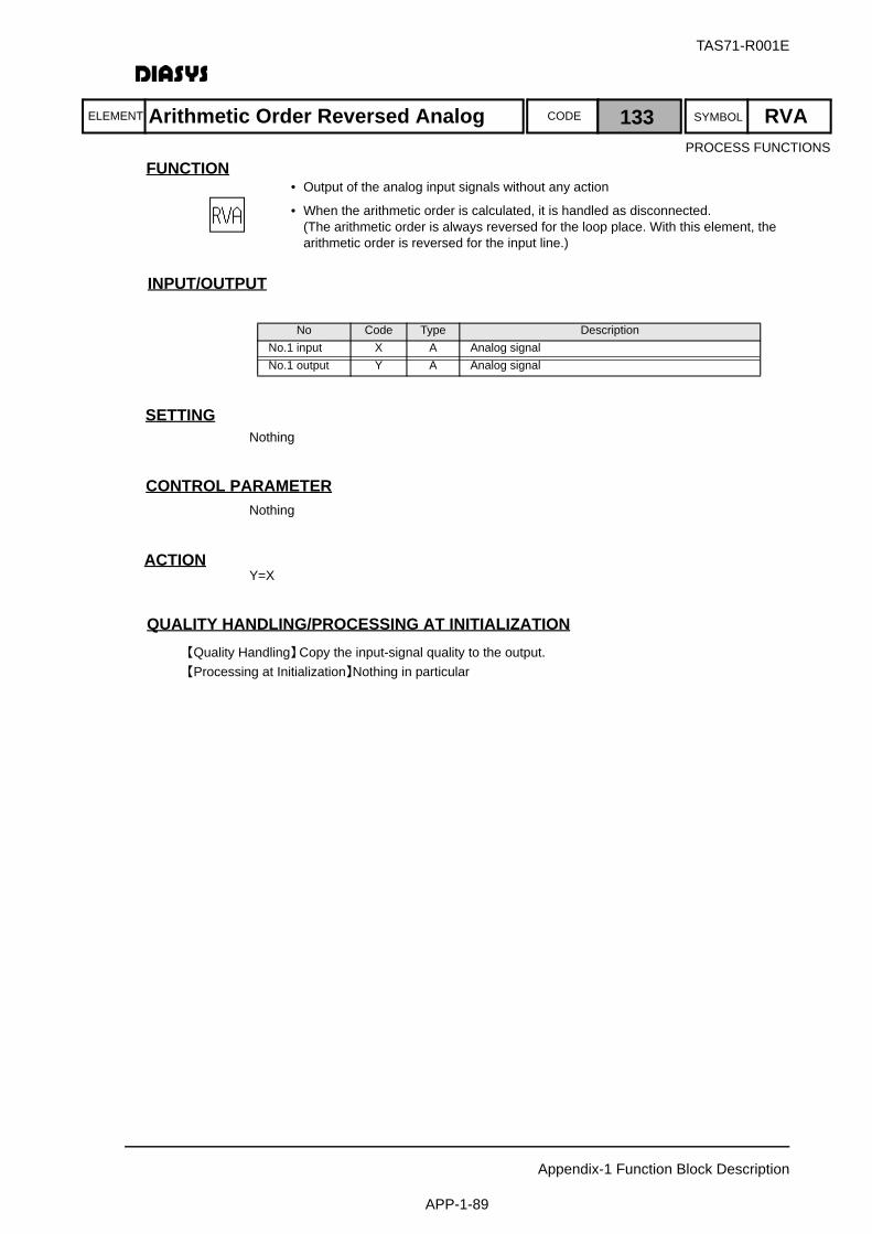
ELEMENT SYMBOLCODE
TAS71-R001E
Appendix-1 Function Block Description
APP-1-89
FUNCTION
入 出 力INPUT/OUTPUT
SETTINGNothing
CONTROL PARAMETERNothing
ACTIONY=X
QUALITY HANDLING/PROCESSING AT INITIALIZATION【Quality Handling】Copy the input-signal quality to the output.【Processing at Initialization】Nothing in particular
No Code Type DescriptionNo.1 input X A Analog signalNo.1 output Y A Analog signal
Arithmetic Order Reversed Analog 133 RVA
• Output of the analog input signals without any action
• When the arithmetic order is calculated, it is handled as disconnected.(The arithmetic order is always reversed for the loop place. With this element, the arithmetic order is reversed for the input line.)
PROCESS FUNCTIONS

ELEMENT SYMBOLCODE
TAS71-R001E
Appendix-1 Function Block Description
APP-1-90
FUNCTION
入 出 力INPUT/OUTPUT
SETTINGNothing
CONTROL PARAMETERNothing
ACTIONY=X
QUALITY HANDLING/PROCESSING AT INITIALIZATION【Quality Handling】Copy the input-signal quality to the output.【Processing at Initialization】Nothing in particular
No Code Type DescriptionNo.1 input X I Integer signalNo.1 output Y I Integer signal
Arithmetic Order Reversed Integer 134 RVI
• Output of integer input value without any action
• The connection should be handled as disconnected when the arithmetic order is calculated.(The arithmetic order is always reversed for the loop place. With this element, the arithmetic order is reversed for the input line.)
DATA LOGGAR FUNCTIONS
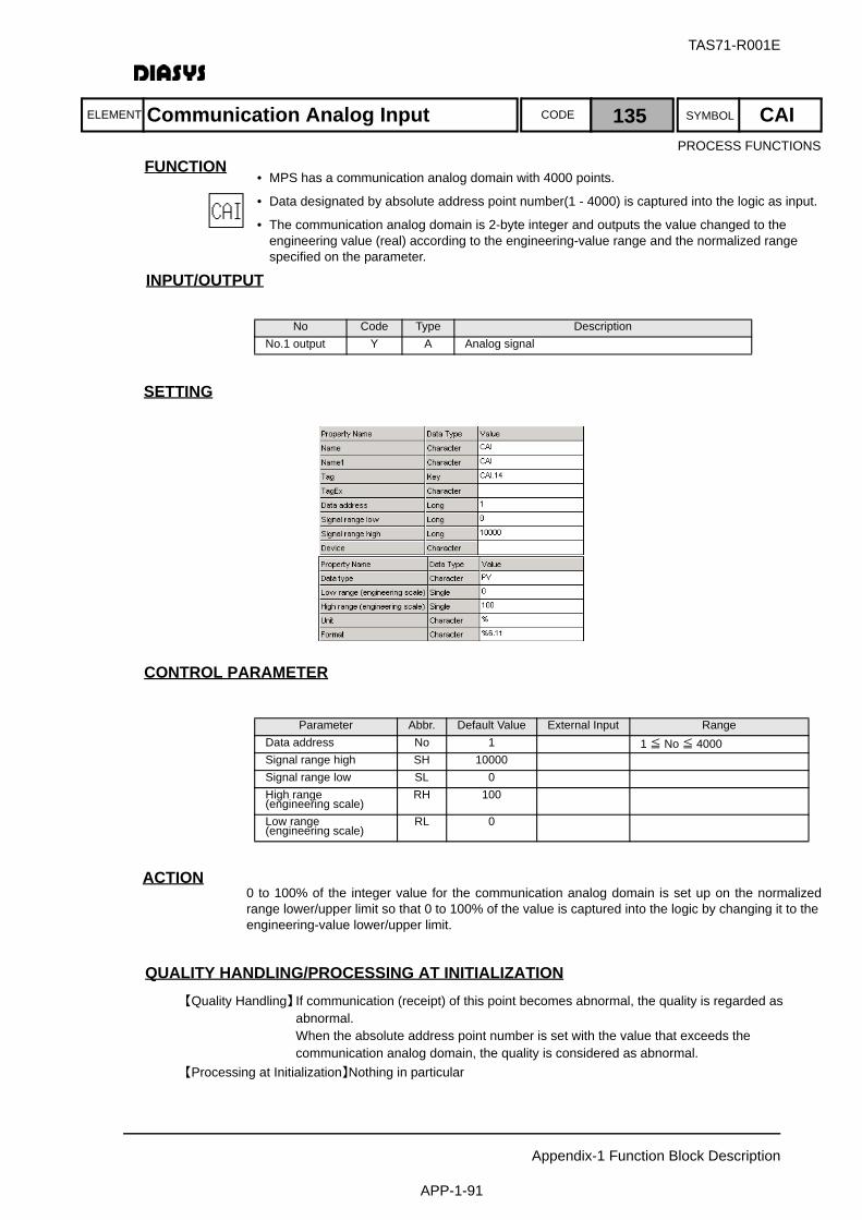
ELEMENT SYMBOLCODE
TAS71-R001E
Appendix-1 Function Block Description
APP-1-91
FUNCTION
入 出 力INPUT/OUTPUT
SETTING
CONTROL PARAMETER
ACTION0 to 100% of the integer value for the communication analog domain is set up on the normalizedrange lower/upper limit so that 0 to 100% of the value is captured into the logic by changing it to theengineering-value lower/upper limit.
QUALITY HANDLING/PROCESSING AT INITIALIZATION【Quality Handling】If communication (receipt) of this point becomes abnormal, the quality is regarded as
abnormal.When the absolute address point number is set with the value that exceeds the communication analog domain, the quality is considered as abnormal.
【Processing at Initialization】Nothing in particular
No Code Type DescriptionNo.1 output Y A Analog signal
Parameter Abbr. Default Value External Input RangeData address No 1 1 ≦ No ≦ 4000Signal range high SH 10000Signal range low SL 0High range (engineering scale)
RH 100
Low range(engineering scale)
RL 0
Communication Analog Input 135 CAI
• MPS has a communication analog domain with 4000 points.
• Data designated by absolute address point number(1 - 4000) is captured into the logic as input.
• The communication analog domain is 2-byte integer and outputs the value changed to the engineering value (real) according to the engineering-value range and the normalized range specified on the parameter.
PROCESS FUNCTIONS
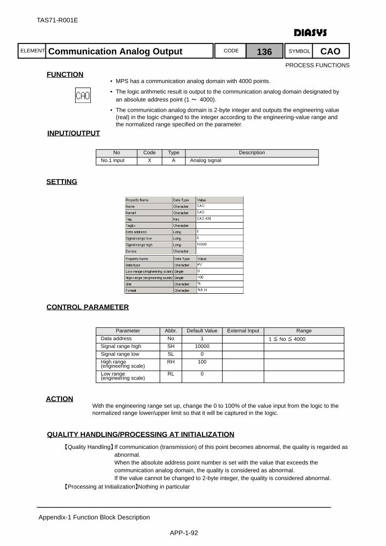
ELEMENT SYMBOLCODE
TAS71-R001E
Appendix-1 Function Block Description
APP-1-92
FUNCTION
入 出 力INPUT/OUTPUT
SETTING
CONTROL PARAMETER
ACTIONWith the engineering range set up, change the 0 to 100% of the value input from the logic to thenormalized range lower/upper limit so that it will be captured in the logic.
QUALITY HANDLING/PROCESSING AT INITIALIZATION【Quality Handling】If communication (transmission) of this point becomes abnormal, the quality is regarded as
abnormal.When the absolute address point number is set with the value that exceeds the communication analog domain, the quality is considered as abnormal.If the value cannot be changed to 2-byte integer, the quality is considered abnormal.
【Processing at Initialization】Nothing in particular
No Code Type DescriptionNo.1 input X A Analog signal
Parameter Abbr. Default Value External Input RangeData address No 1 1 ≦ No ≦ 4000Signal range high SH 10000Signal range low SL 0High range (engineering scale)
RH 100
Low range(engineering scale)
RL 0
Communication Analog Output 136 CAO
• MPS has a communication analog domain with 4000 points.
• The logic arithmetic result is output to the communication analog domain designated by an absolute address point (1 ~ 4000).
• The communication analog domain is 2-byte integer and outputs the engineering value (real) in the logic changed to the integer according to the engineering-value range and the normalized range specified on the parameter.
PROCESS FUNCTIONS
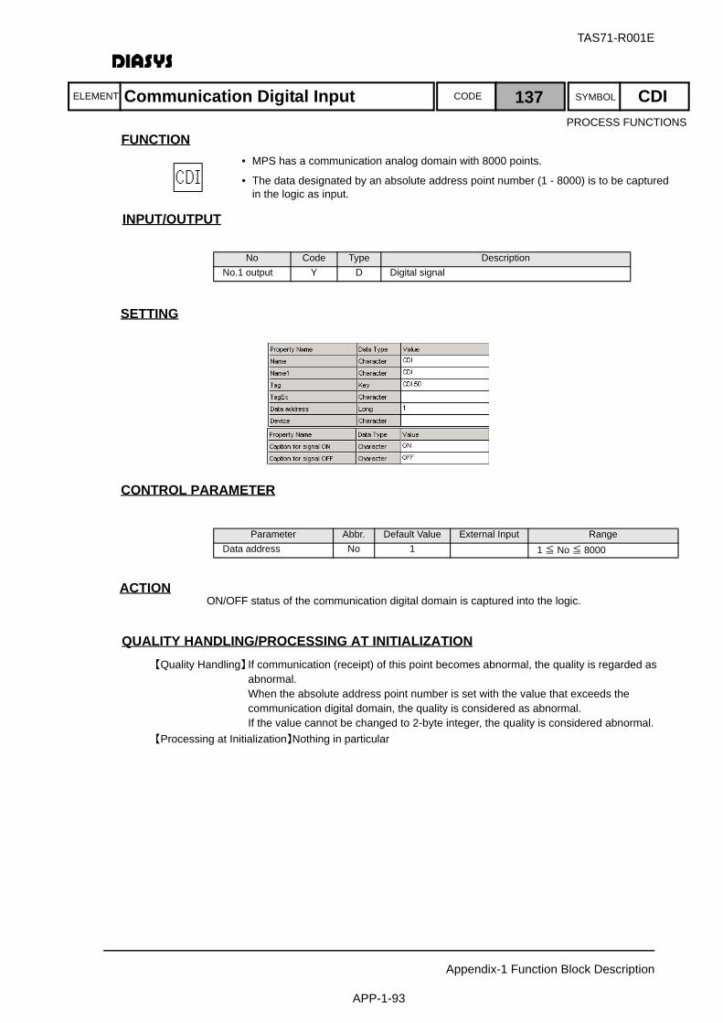
ELEMENT SYMBOLCODE
TAS71-R001E
Appendix-1 Function Block Description
APP-1-93
FUNCTION
入 出 力INPUT/OUTPUT
SETTING
CONTROL PARAMETER
ACTIONON/OFF status of the communication digital domain is captured into the logic.
QUALITY HANDLING/PROCESSING AT INITIALIZATION【Quality Handling】If communication (receipt) of this point becomes abnormal, the quality is regarded as
abnormal.When the absolute address point number is set with the value that exceeds the communication digital domain, the quality is considered as abnormal.If the value cannot be changed to 2-byte integer, the quality is considered abnormal.
【Processing at Initialization】Nothing in particular
No Code Type DescriptionNo.1 output Y D Digital signal
Parameter Abbr. Default Value External Input RangeData address No 1 1 ≦ No ≦ 8000
Communication Digital Input 137 CDI
• MPS has a communication analog domain with 8000 points.
• The data designated by an absolute address point number (1 - 8000) is to be captured in the logic as input.
PROCESS FUNCTIONS
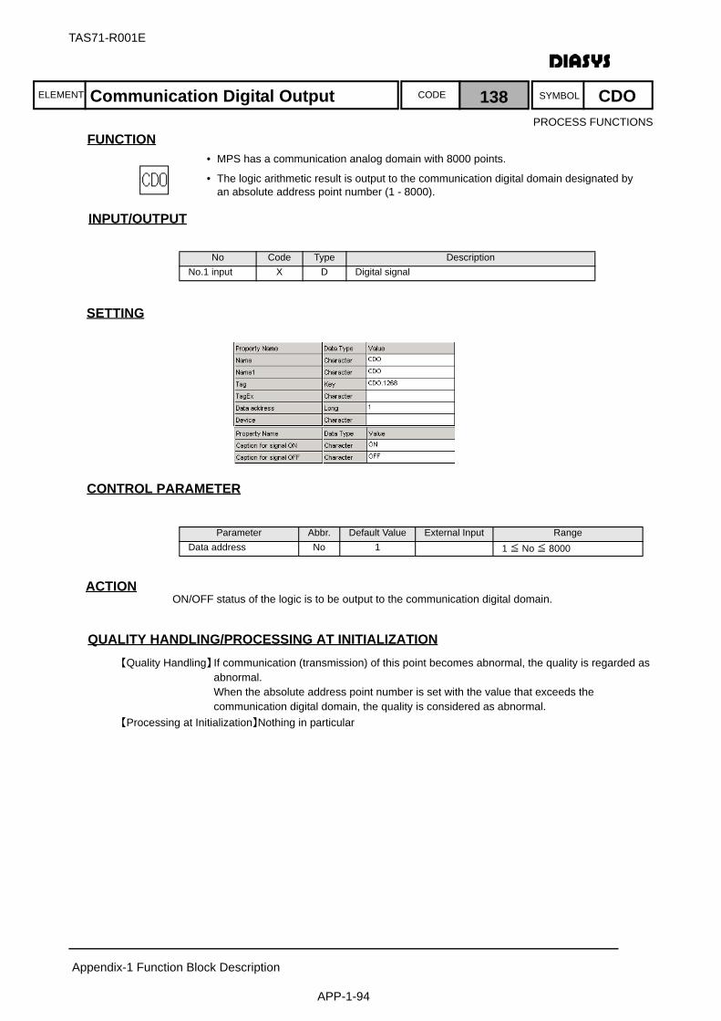
ELEMENT SYMBOLCODE
TAS71-R001E
Appendix-1 Function Block Description
APP-1-94
FUNCTION
入 出 力INPUT/OUTPUT
SETTING
CONTROL PARAMETER
ACTIONON/OFF status of the logic is to be output to the communication digital domain.
QUALITY HANDLING/PROCESSING AT INITIALIZATION【Quality Handling】If communication (transmission) of this point becomes abnormal, the quality is regarded as
abnormal.When the absolute address point number is set with the value that exceeds the communication digital domain, the quality is considered as abnormal.
【Processing at Initialization】Nothing in particular
No Code Type DescriptionNo.1 input X D Digital signal
Parameter Abbr. Default Value External Input RangeData address No 1 1 ≦ No ≦ 8000
Communication Digital Output 138 CDO
• MPS has a communication analog domain with 8000 points.
• The logic arithmetic result is output to the communication digital domain designated by an absolute address point number (1 - 8000).
PROCESS FUNCTIONS

ELEMENT SYMBOLCODE
TAS71-R001E
Appendix-1 Function Block Description
APP-1-95
FUNCTION
入 出 力INPUT/OUTPUT
SETTING
CONTROL PARAMETERNothing
ACTIONNo action
QUALITY HANDLING/PROCESSING AT INITIALIZATION【Quality Handling】Only the quality is updated if the quality is abnormal because of the communication status
or the I/O module status.【Processing at Initialization】None.
No Code Type DescriptionNo.1 output Y I Integer data packed as 32 digital bits
32 points digital input 162 DI32
• The element acquires the data of 32 digital inputs from the special DI domain of FXVIMO1 as the picked-up integer data and outputs it to the logic.
• The unpack element (UPC) is used to acquire individual signals.
PROCESS FUNCTIONS

ELEMENT SYMBOLCODE
TAS71-R001E
Appendix-1 Function Block Description
APP-1-96
FUNCTION
入 出 力INPUT/OUTPUT
SETTING
CONTROL PARAMETERNothing
ACTIONNo action
QUALITY HANDLING/PROCESSING AT INITIALIZATION【Quality Handling】Only the quality is updated if the quality is abnormal because of the communication status
or the I/O module status.【Processing at Initialization】None.
No Code Type DescriptionNo.1 input X I Integer data packed as 32 digital bits
32 points digital output 163 DO32
• The element outputs all the data of 32 digital outputs from the logic to the special DO domain of FXVIMO1.
PROCESS FUNCTIONS
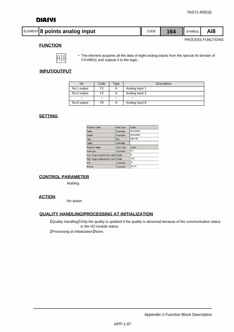
ELEMENT SYMBOLCODE
TAS71-R001E
Appendix-1 Function Block Description
APP-1-97
FUNCTION
入 出 力INPUT/OUTPUT
SETTING
CONTROL PARAMETERNothing
ACTIONNo action
QUALITY HANDLING/PROCESSING AT INITIALIZATION【Quality Handling】Only the quality is updated if the quality is abnormal because of the communication status
or the I/O module status.【Processing at Initialization】None.
No Code Type DescriptionNo.1 output Y1 A Analog input 1No.2 output Y2 A Analog input 2
~ ~ ~ ~No.8 output Y8 A Analog input 8
8 points analog input 164 AI8
• The element acquires all the data of eight analog inputs from the special AI domain of FXVIMO1 and outputs it to the logic.
PROCESS FUNCTIONS
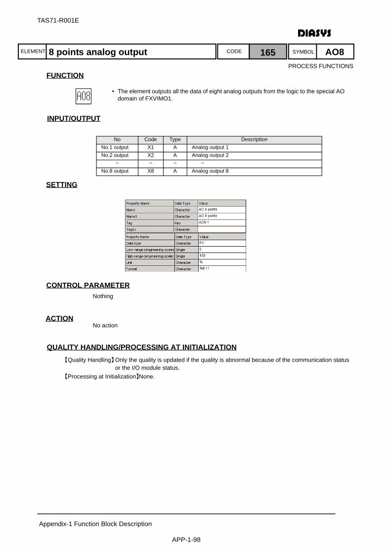
ELEMENT SYMBOLCODE
TAS71-R001E
Appendix-1 Function Block Description
APP-1-98
FUNCTION
入 出 力INPUT/OUTPUT
SETTING
CONTROL PARAMETERNothing
ACTIONNo action
QUALITY HANDLING/PROCESSING AT INITIALIZATION【Quality Handling】Only the quality is updated if the quality is abnormal because of the communication status
or the I/O module status.【Processing at Initialization】None.
No Code Type DescriptionNo.1 output X1 A Analog output 1No.2 output X2 A Analog output 2
~ ~ ~ ~No.8 output X8 A Analog output 8
8 points analog output 165 AO8
• The element outputs all the data of eight analog outputs from the logic to the special AO domain of FXVIMO1.
PROCESS FUNCTIONS

ELEMENT SYMBOLCODE
TAS71-R001E
Appendix-1 Function Block Description
APP-1-99
FUNCTION
入 出 力INPUT/OUTPUT
SETTING
CONTROL PARAMETERNothing
ACTIONThe element sets an input as an output when a trigger input is set to on and writes the input in a filewith quality.As the output, the element uses the input that is written in the file.
QUALITY HANDLING/PROCESSING AT INITIALIZATION【Quality Handling】When a new input is added or the file is damaged, access is denied and the value is 0
(displayed in yellow).When an input is written in the file for the first time, the quality of the input is transmitted.The quality to be transmitted to the output is the quality of the input when the trigger input is set to on (if a quality error occurs, the frame is displayed in yellow).
【Processing at Initialization】The element reads values and quality from the file at the startup and sets them as outputs. The element waits until the initialization is completed.The standby system tracks the outputs from the control system while the initialization is performed.The standby system writes the tracked output values in the file when it takes over the control system.
No Code Type DescriptionNo.1 input X A Input signalNo.2 input SW D Storage triggerNo.1 output Y A Digital output
Register analog 166 RGA
• The element writes an input such as a calculated value and an instruction value in a file when a trigger input is set to on.
• The element reads the above values from the file when the controller restarts and sets them as outputs.
Note:The trigger inputs for writing the file must be at least one minute apart considering the upper limit for rewriting the CompactFlash card used to store the file.
PROCESS FUNCTIONS
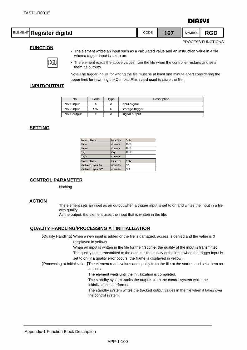
ELEMENT SYMBOLCODE
TAS71-R001E
Appendix-1 Function Block Description
APP-1-100
FUNCTION
入 出 力INPUT/OUTPUT
SETTING
CONTROL PARAMETERNothing
ACTIONThe element sets an input as an output when a trigger input is set to on and writes the input in a filewith quality.As the output, the element uses the input that is written in the file.
QUALITY HANDLING/PROCESSING AT INITIALIZATION【Quality Handling】When a new input is added or the file is damaged, access is denied and the value is 0
(displayed in yellow).When an input is written in the file for the first time, the quality of the input is transmitted.The quality to be transmitted to the output is the quality of the input when the trigger input is set to on (if a quality error occurs, the frame is displayed in yellow).
【Processing at Initialization】The element reads values and quality from the file at the startup and sets them as outputs. The element waits until the initialization is completed.The standby system tracks the outputs from the control system while the initialization is performed.The standby system writes the tracked output values in the file when it takes over the control system.
No Code Type DescriptionNo.1 input X A Input signalNo.2 input SW D Storage triggerNo.1 output Y A Digital output
Register digital 167 RGDPROCESS FUNCTIONS
• The element writes an input such as a calculated value and an instruction value in a file when a trigger input is set to on.
• The element reads the above values from the file when the controller restarts and sets them as outputs.
Note:The trigger inputs for writing the file must be at least one minute apart considering the upper limit for rewriting the CompactFlash card used to store the file.
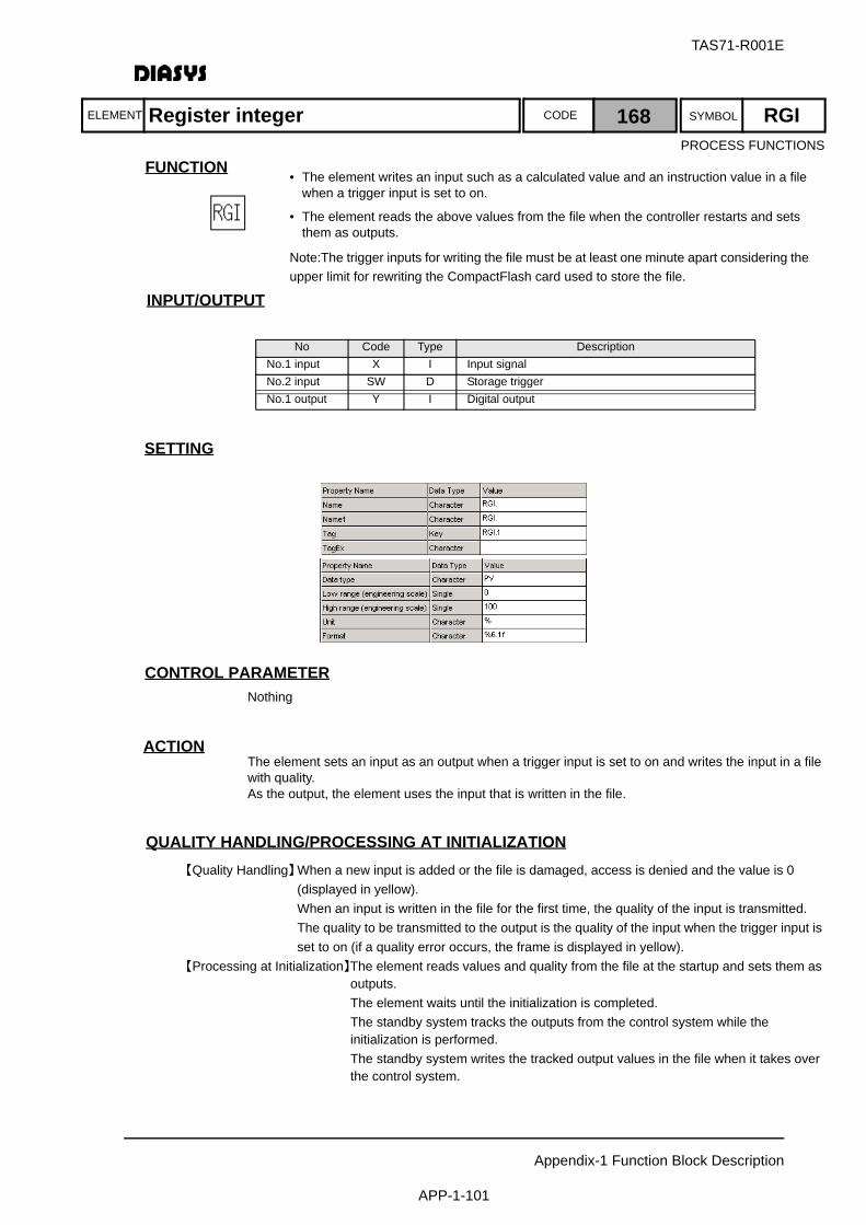
ELEMENT SYMBOLCODE
TAS71-R001E
Appendix-1 Function Block Description
APP-1-101
FUNCTION
入 出 力INPUT/OUTPUT
SETTING
CONTROL PARAMETERNothing
ACTIONThe element sets an input as an output when a trigger input is set to on and writes the input in a filewith quality.As the output, the element uses the input that is written in the file.
QUALITY HANDLING/PROCESSING AT INITIALIZATION【Quality Handling】When a new input is added or the file is damaged, access is denied and the value is 0
(displayed in yellow).When an input is written in the file for the first time, the quality of the input is transmitted.The quality to be transmitted to the output is the quality of the input when the trigger input is set to on (if a quality error occurs, the frame is displayed in yellow).
【Processing at Initialization】The element reads values and quality from the file at the startup and sets them as outputs. The element waits until the initialization is completed.The standby system tracks the outputs from the control system while the initialization is performed.The standby system writes the tracked output values in the file when it takes over the control system.
No Code Type DescriptionNo.1 input X I Input signalNo.2 input SW D Storage triggerNo.1 output Y I Digital output
Register integer 168 RGIPROCESS FUNCTIONS
• The element writes an input such as a calculated value and an instruction value in a file when a trigger input is set to on.
• The element reads the above values from the file when the controller restarts and sets them as outputs.
Note:The trigger inputs for writing the file must be at least one minute apart considering the upper limit for rewriting the CompactFlash card used to store the file.

ELEMENT SYMBOLCODE
TAS71-R001E
Appendix-1 Function Block Description
APP-1-102
FUNCTION
入 出 力INPUT/OUTPUT
SETTING
CONTROL PARAMETER
ACTIONNo action
QUALITY HANDLING/PROCESSING AT INITIALIZATION【Quality Handling】The quality of the output is always normal.【Processing at Initialization】None.
No Code Type DescriptionNo.1 output Y D On/off setting
Parameter Abbr. Default Value External Input RangeSet value S 0
Digital constant 169 DG
• The element enables (on) or disables (off) digital output based on the on/off setting of the parameter (digital).
PROCESS FUNCTIONS
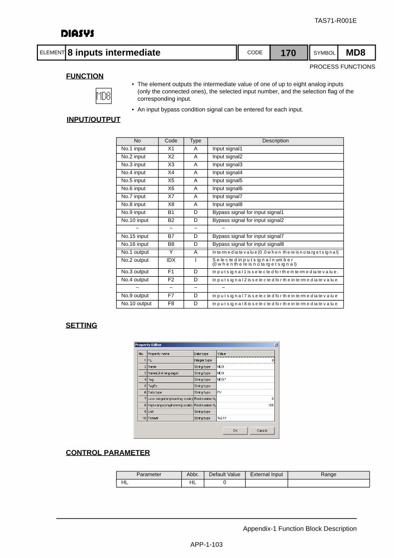
ELEMENT SYMBOLCODE
TAS71-R001E
Appendix-1 Function Block Description
APP-1-103
FUNCTION
入 出 力INPUT/OUTPUT
SETTING
CONTROL PARAMETER
No Code Type DescriptionNo.1 input X1 A Input signal1No.2 input X2 A Input signal2No.3 input X3 A Input signal3No.4 input X4 A Input signal4No.5 input X5 A Input signal5No.6 input X6 A Input signal6No.7 input X7 A Input signal7No.8 input X8 A Input signal8No.9 input B1 D Bypass signal for input signal1 No.10 input B2 D Bypass signal for input signal2
~ ~ ~ ~No.15 input B7 D Bypass signal for input signal7No.16 input B8 D Bypass signal for input signal8No.1 output Y A In te rm e d ia te v a lu e (0 .0 w h e n th e re is n o ta rg e t s ig n a l)
No.2 output IDX I S e le c te d in p u t s ig n a l n um b e r (0 w h e n th e re is n o ta rg e t s ig n a l)
No.3 output F1 D In p u t s ig n a l 1 is s e le c te d fo r th e in te rm e d ia te v a lu e .
No.4 output F2 D In p u t s ig n a l 2 is s e le c te d fo r th e in te rm e d ia te v a lu e
~ ~ ~ ~No.9 output F7 D In p u t s ig n a l 7 is s e le c te d fo r th e in te rm e d ia te v a lu e
No.10 output F8 D In p u t s ig n a l 8 is s e le c te d fo r th e in te rm e d ia te v a lu e
Parameter Abbr. Default Value External Input RangeHL HL 0
8 inputs intermediate 170 MD8
• The element outputs the intermediate value of one of up to eight analog inputs (only the connected ones), the selected input number, and the selection flag of the corresponding input.
• An input bypass condition signal can be entered for each input.
PROCESS FUNCTIONS
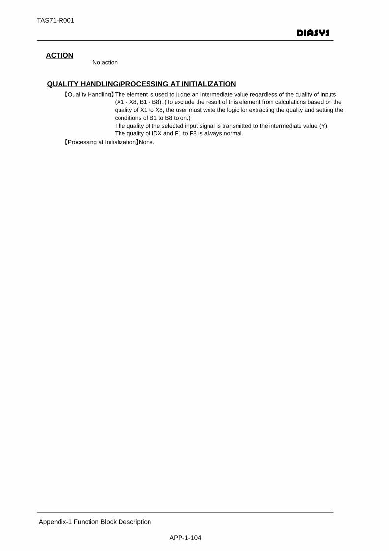
TAS71-R001
Appendix-1 Function Block Description
APP-1-104
ACTIONNo action
QUALITY HANDLING/PROCESSING AT INITIALIZATION【Quality Handling】The element is used to judge an intermediate value regardless of the quality of inputs
(X1 - X8, B1 - B8). (To exclude the result of this element from calculations based on the quality of X1 to X8, the user must write the logic for extracting the quality and setting the conditions of B1 to B8 to on.)The quality of the selected input signal is transmitted to the intermediate value (Y).The quality of IDX and F1 to F8 is always normal.
【Processing at Initialization】None.
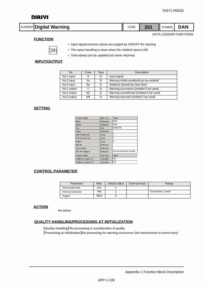
ELEMENT SYMBOLCODE
TAS71-R001E
Appendix-1 Function Block Description
APP-1-105
FUNCTION
INPUT/OUTPUT
SETTING
初期化時の処理CONTROL PARAMETER
ACTIONNo action
QUALITY HANDLING/PROCESSING AT INITIALIZATION【Quality Handling】No processing in consideration of quality【Processing at Initialization】No processing for warning occurrence (No transmission to event trace)
No Code Type DescriptionNo.1 input X D Input signalNo.2 input Su D Warning inhibit condition(can be omitted)No.3 input Re D Refailure (should be One Shot)No.1 output Y D Warning occurrence (omitted if not used)No.2 output NC D Warning unconfirmed (omitted if not used)No.3 output NR D Warning returned (omitted if not used)
Parameter Abbr. Default Value External Input RangeAnnunciate level LVL 1Print out inservice PR 1 0:exclusive, 1:used
Region REG 0
Digital Warning 201 DAN
• Input signal process values are judged by ON/OFF for warning
• The same handling is done when the refailed input is ON
• Time stamp can be updated but never returned
DATA LOGGAR FUNCTIONS

ELEMENT SYMBOLCODE
TAS71-R001E
Appendix-1 Function Block Description
APP-1-106
FUNCTION
INPUT/OUTPUT
SETTING
初期化時の処理CONTROL PARAMETER
ACTIONNo action
QUALITY HANDLING/PROCESSING AT INITIALIZATION【Quality Handling】If the dead band is negative, the quality of Own-block output should be a block arithmetic error【Processing at Initialization】No processing for warning occurrence (No transmission to event trace)
No Code Type DescriptionNo.1 input X A Input signalNo.2 input S A Setting value(Parameter External Input)No.3 input Su D Warning inhibit conditionNo.1 output Y D Warning occurrenceNo.2 output NC D Warning unconfirmedNo.3 output NR D Warning returned
Parameter Abbr. Default Value External Input RangeThreshold S 9999Hysteresis DB 0 DB ≧ 0Category(1:H 2:L 3:R) ANN 1 1:H,2:L,3:RAnnunciate level LVL 1Print out inservice PR 1 0:Exclusive,1:UsedRegion REG 0
Analog Warning 202 AAN
• Input signal process values are judged for warning by settingvalue input or parameters
• There are 3 types of judgement as follows•Upper limit (H)•Lower limit (L)•Change rate (R)
DATA LOGGAR FUNCTIONS
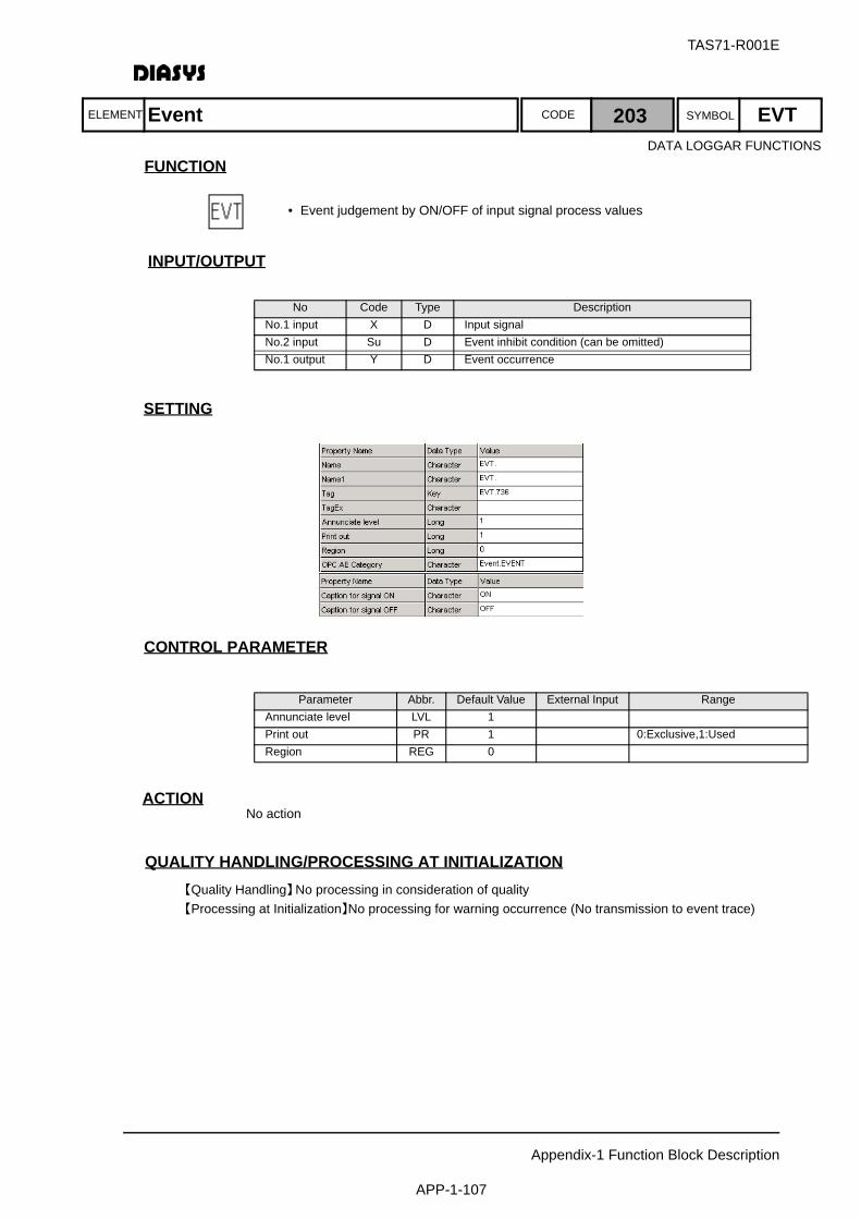
ELEMENT SYMBOLCODE
TAS71-R001E
Appendix-1 Function Block Description
APP-1-107
FUNCTION
INPUT/OUTPUT
SETTING
初期化時の処理CONTROL PARAMETER
ACTIONNo action
QUALITY HANDLING/PROCESSING AT INITIALIZATION【Quality Handling】No processing in consideration of quality【Processing at Initialization】No processing for warning occurrence (No transmission to event trace)
No Code Type DescriptionNo.1 input X D Input signalNo.2 input Su D Event inhibit condition (can be omitted)No.1 output Y D Event occurrence
Parameter Abbr. Default Value External Input RangeAnnunciate level LVL 1Print out PR 1 0:Exclusive,1:UsedRegion REG 0
Event 203 EVT
• Event judgement by ON/OFF of input signal process values
DATA LOGGAR FUNCTIONS
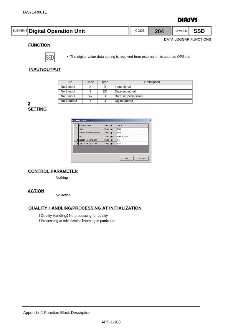
ELEMENT SYMBOLCODE
TAS71-R001E
Appendix-1 Function Block Description
APP-1-108
FUNCTION
INPUT/OUTPUT
SETTING2
初期化時の処理CONTROL PARAMETERNothing
ACTIONNo action
QUALITY HANDLING/PROCESSING AT INITIALIZATION【Quality Handling】No processing for quality【Processing at Initialization】Nothing in particular
No Code Type DescriptionNo.1 input X D Input signalNo.2 input S ED Data-set signalNo.3 input sw D Data-set permissionNo.1 output Y D Digital output
Digital Operation Unit 204 SSD
• The digital-value data setting is received from external units such as OPS etc
DATA LOGGAR FUNCTIONS

ELEMENT SYMBOLCODE
TAS71-R001E
Appendix-1 Function Block Description
APP-1-109
FUNCTION
INPUT/OUTPUT
SETTINGNothing
初期化時の処理CONTROL PARAMETERNothing
ACTIONNo action
QUALITY HANDLING/PROCESSING AT INITIALIZATION【Quality Handling】Calculate with the above calculation expression.
The output qualities are all normal【Processing at Initialization】Nothing in particular
No Code Type DescriptionNo.1 input X D Input signalNo.1 output RO D Range-over upper limit (Reserved)tNo.2 output RU D Range-over lower limit (Reserved)No.3 output AE D Data access incapabilityNo.4 output CN D Scan exclusionNo.5 output DS D Data setNo.6 output UK D Unfixed My Element outputNo.7 output CE D Block arithmetic error
Quality Fetch Digital 205 QGD
• Acquiring each quality code status by ON/OFF from input-signal quality information
DATA LOGGAR FUNCTIONS

ELEMENT SYMBOLCODE
TAS71-R001E
Appendix-1 Function Block Description
APP-1-110
FUNCTION
INPUT/OUTPUT
SETTINGNothing
初期化時の処理CONTROL PARAMETERNothing
ACTIONNo action
QUALITY HANDLING/PROCESSING AT INITIALIZATION【Quality Handling】Calculate with the above calculation expression.
The output qualities are all normal【Processing at Initialization】Nothing in particular
No Code Type DescriptionNo.1 input X A Input signalNo.1 output RO D Range-over upper limitNo.2 output RU D Range-over lower limitNo.3 output AE D Data access incapabilityNo.4 output CN D Scan exclusionNo.5 output DS D Data setNo.6 output UK D Unfixed My Element outputNo.7 output CE D Block arithmetic error
Quality Fetch Analog 206 QGA
• Acquiring each quality code status by ON/OFF from input-signal quality information
DATA LOGGAR FUNCTIONS

ELEMENT SYMBOLCODE
TAS71-R001E
Appendix-1 Function Block Description
APP-1-111
FUNCTION
INPUT/OUTPUT
SETTINGNothing
初期化時の処理CONTROL PARAMETERNothing
ACTIONNo action
QUALITY HANDLING/PROCESSING AT INITIALIZATION【Quality Handling】Calculate with the above calculation expression.【Processing at Initialization】Nothing in particular
No Code Type DescriptionNo.1 input X D Input signalNo.2 input RO D Range-over upper limit (Reserved)No.3 input RU D Range-over lower limit (Reserved)No.4 input AE D Data access incapabilityNo.5 input CN D Scan exclusionNo.6 input DS D Data setNo.7 input UK D Unfixed My Element outputNo.8 input CE D Block arithmetic errorNo.1 output Y D Output signal
Quality Insertion Digital 207 QSD
• Quality signal status are set for element output quality
DATA LOGGAR FUNCTIONS
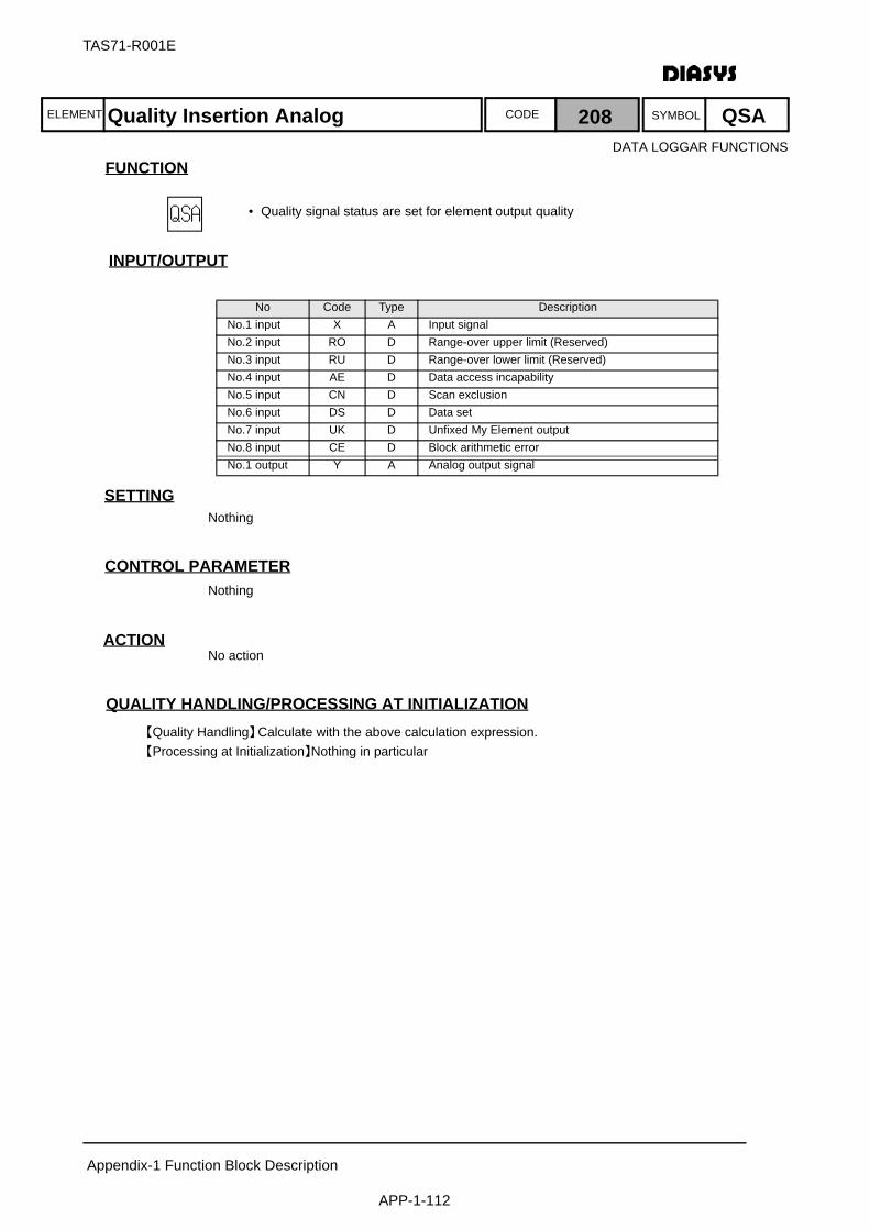
ELEMENT SYMBOLCODE
TAS71-R001E
Appendix-1 Function Block Description
APP-1-112
FUNCTION
INPUT/OUTPUT
SETTINGNothing
初期化時の処理CONTROL PARAMETERNothing
ACTIONNo action
QUALITY HANDLING/PROCESSING AT INITIALIZATION【Quality Handling】Calculate with the above calculation expression.【Processing at Initialization】Nothing in particular
No Code Type DescriptionNo.1 input X A Input signalNo.2 input RO D Range-over upper limit (Reserved)No.3 input RU D Range-over lower limit (Reserved)No.4 input AE D Data access incapabilityNo.5 input CN D Scan exclusionNo.6 input DS D Data setNo.7 input UK D Unfixed My Element outputNo.8 input CE D Block arithmetic errorNo.1 output Y A Analog output signal
Quality Insertion Analog 208 QSA
• Quality signal status are set for element output quality
DATA LOGGAR FUNCTIONS

ELEMENT SYMBOLCODE
TAS71-R001E
Appendix-1 Function Block Description
APP-1-113
FUNCTION
INPUT/OUTPUT
SETTING
初期化時の処理CONTROL PARAMETER
ACTIONNo action
QUALITY HANDLING/PROCESSING AT INITIALIZATION【Quality Handling】If the sampling cycle exceeds the arithmetic cycle by 2147483647 scaling factor or is
smaller by 0.5 scaling factor, the quality of Own-block output should be a block arithmetic error.If the input signal quality is not fixed with the output, it should be calculated considering the calculation condition is OFF.The output quality should be incapable of data access when the calculation exclusion conditions are approved continuously for memory trigger entry.
【Processing at Initialization】Nothing in particular
No Code Type DescriptionNo.1 input X A Input signalNo.2 input Su D Calcuration exclusion conditionsNo.3 input sw D Memory triggerNo.1 output Y A Average value
Parameter Abbr. Default Value External Input RangeCalcuration interval DT 1 Divisor of 3600(sec)
Average Value 209 AVE
• Calculate the average value of input data that is not approved as the calculation exclusion conditions
• While the value is output continuing the average processing until the trigger is ON, the internal is reset and starts new-average from next time
Calculation precision• Internal work variables should be twice as precise as the reals
• Please note valid digit number decreases as the sampling frequency increases
DATA LOGGAR FUNCTIONS
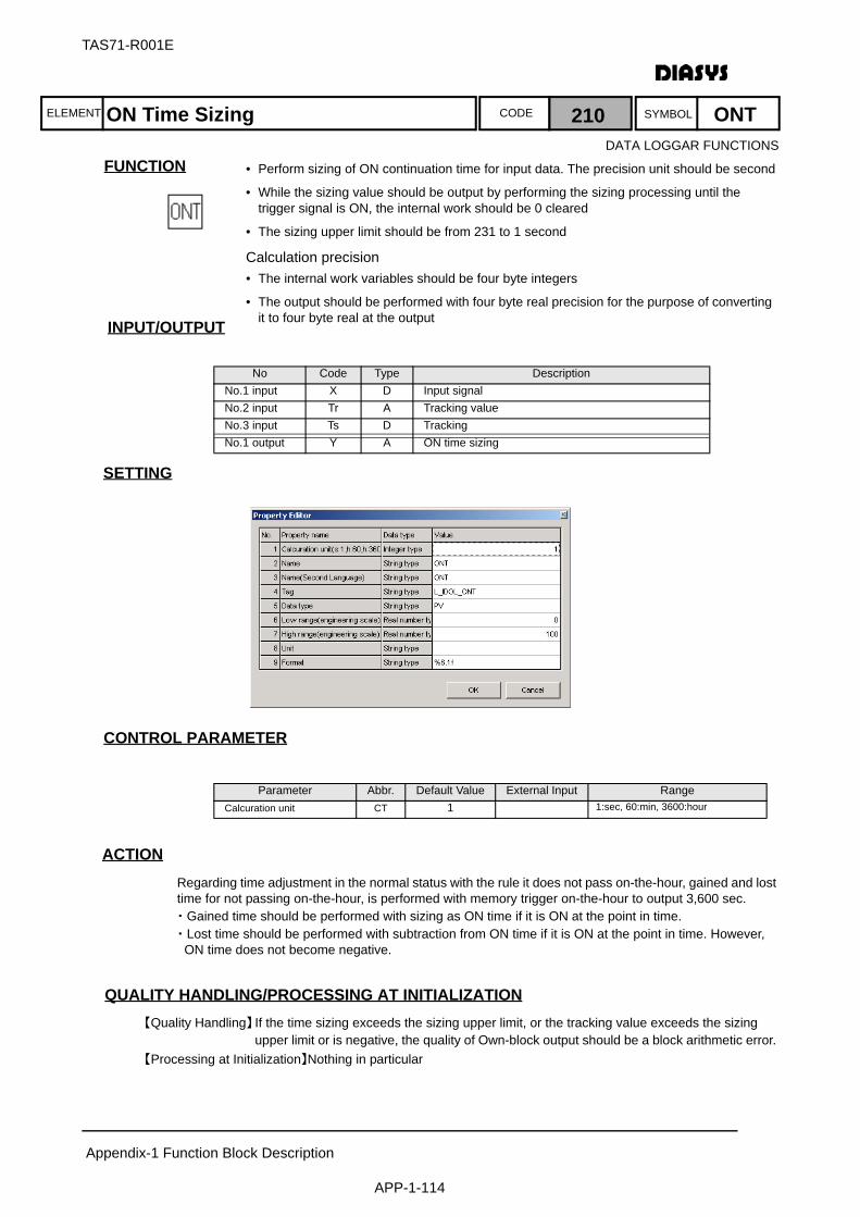
ELEMENT SYMBOLCODE
TAS71-R001E
Appendix-1 Function Block Description
APP-1-114
FUNCTION
INPUT/OUTPUT
SETTING
初期化時の処理CONTROL PARAMETER
ACTIONRegarding time adjustment in the normal status with the rule it does not pass on-the-hour, gained and lost time for not passing on-the-hour, is performed with memory trigger on-the-hour to output 3,600 sec.・Gained time should be performed with sizing as ON time if it is ON at the point in time.・Lost time should be performed with subtraction from ON time if it is ON at the point in time. However, ON time does not become negative.
QUALITY HANDLING/PROCESSING AT INITIALIZATION【Quality Handling】If the time sizing exceeds the sizing upper limit, or the tracking value exceeds the sizing
upper limit or is negative, the quality of Own-block output should be a block arithmetic error. 【Processing at Initialization】Nothing in particular
No Code Type DescriptionNo.1 input X D Input signalNo.2 input Tr A Tracking valueNo.3 input Ts D TrackingNo.1 output Y A ON time sizing
Parameter Abbr. Default Value External Input RangeCalcuration unit CT 1 1:sec, 60:min, 3600:hour
ON Time Sizing 210 ONT
• Perform sizing of ON continuation time for input data. The precision unit should be second
• While the sizing value should be output by performing the sizing processing until the trigger signal is ON, the internal work should be 0 cleared
• The sizing upper limit should be from 231 to 1 second
Calculation precision• The internal work variables should be four byte integers
• The output should be performed with four byte real precision for the purpose of converting it to four byte real at the output
DATA LOGGAR FUNCTIONS
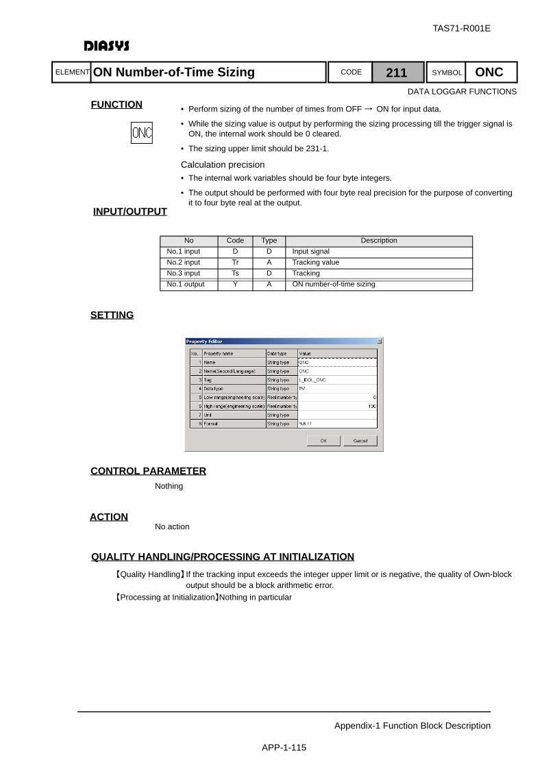
ELEMENT SYMBOLCODE
TAS71-R001E
Appendix-1 Function Block Description
APP-1-115
FUNCTION
INPUT/OUTPUT
SETTING
初期化時の処理CONTROL PARAMETERNothing
ACTIONNo action
QUALITY HANDLING/PROCESSING AT INITIALIZATION【Quality Handling】If the tracking input exceeds the integer upper limit or is negative, the quality of Own-block
output should be a block arithmetic error.【Processing at Initialization】Nothing in particular
No Code Type DescriptionNo.1 input D D Input signalNo.2 input Tr A Tracking valueNo.3 input Ts D TrackingNo.1 output Y A ON number-of-time sizing
ON Number-of-Time Sizing 211 ONC
• Perform sizing of the number of times from OFF → ON for input data.
• While the sizing value is output by performing the sizing processing till the trigger signal is ON, the internal work should be 0 cleared.
• The sizing upper limit should be 231-1.
Calculation precision• The internal work variables should be four byte integers.
• The output should be performed with four byte real precision for the purpose of converting it to four byte real at the output.
DATA LOGGAR FUNCTIONS
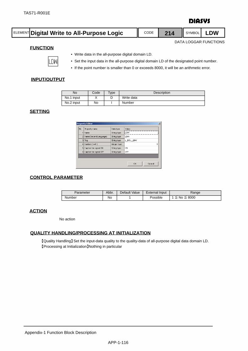
ELEMENT SYMBOLCODE
TAS71-R001E
Appendix-1 Function Block Description
APP-1-116
FUNCTION
INPUT/OUTPUT
SETTING
初期化時の処理CONTROL PARAMETER
ACTIONNo action
QUALITY HANDLING/PROCESSING AT INITIALIZATION【Quality Handling】Set the input-data quality to the quality-data of all-purpose digital data domain LD. 【Processing at Initialization】Nothing in particular
No Code Type DescriptionNo.1 input X D Write dataNo.2 input No I Number
Parameter Abbr. Default Value External Input RangeNumber No 1 Possible 1 ≦ No ≦ 8000
Digital Write to All-Purpose Logic 214 LDW
• Write data in the all-purpose digital domain LD.
• Set the input data in the all-purpose digital domain LD of the designated point number.
• If the point number is smaller than 0 or exceeds 8000, it will be an arithmetic error.
DATA LOGGAR FUNCTIONS

ELEMENT SYMBOLCODE
TAS71-R001E
Appendix-1 Function Block Description
APP-1-117
FUNCTION
INPUT/OUTPUT
SETTING
初期化時の処理CONTROL PARAMETER
ACTIONNo action
QUALITY HANDLING/PROCESSING AT INITIALIZATION【Quality Handling】Set the input-data quality to the quality-data of all-purpose analog domain LA 【Processing at Initialization】Nothing in particular
No Code Type DescriptionNo.1 input X A Write dataNo.2 input No I Number(Parameter External Input)
Parameter Abbr. Default Value External Input RangeNumber No 1 Possible 1 ≦ No ≦ 2000
Analog Write to All-Purpose Logic 215 LAW
• Write data in the all-purpose analog domain LA.
• Set the input data in the all-purpose analog domain LA of the designated point number.
• If the point number is smaller than 0 or exceeds 2000, it will be an arithmetic error.
DATA LOGGAR FUNCTIONS
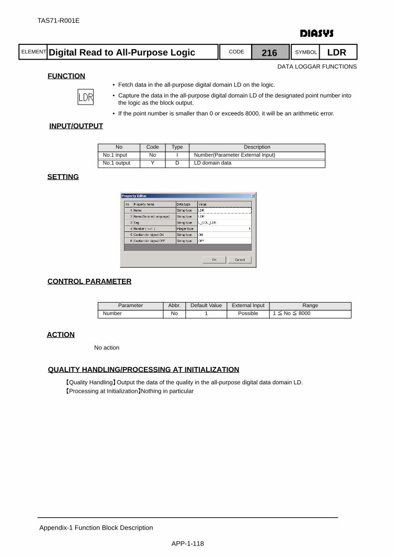
ELEMENT SYMBOLCODE
TAS71-R001E
Appendix-1 Function Block Description
APP-1-118
FUNCTION
INPUT/OUTPUT
SETTING
初期化時の処理CONTROL PARAMETER
ACTIONNo action
QUALITY HANDLING/PROCESSING AT INITIALIZATION【Quality Handling】Output the data of the quality in the all-purpose digital data domain LD. 【Processing at Initialization】Nothing in particular
No Code Type DescriptionNo.1 input No I Number(Parameter External Input)No.1 output Y D LD domain data
Parameter Abbr. Default Value External Input RangeNumber No 1 Possible 1 ≦ No ≦ 8000
Digital Read to All-Purpose Logic 216 LDR
• Fetch data in the all-purpose digital domain LD on the logic.
• Capture the data in the all-purpose digital domain LD of the designated point number into the logic as the block output.
• If the point number is smaller than 0 or exceeds 8000, it will be an arithmetic error.
DATA LOGGAR FUNCTIONS
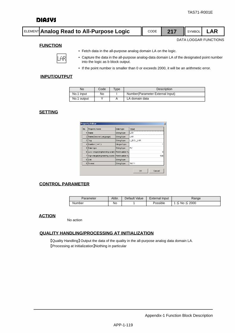
ELEMENT SYMBOLCODE
TAS71-R001E
Appendix-1 Function Block Description
APP-1-119
FUNCTION
INPUT/OUTPUT
SETTING
初期化時の処理CONTROL PARAMETER
ACTIONNo action
QUALITY HANDLING/PROCESSING AT INITIALIZATION【Quality Handling】Output the data of the quality in the all-purpose analog data domain LA.【Processing at Initialization】Nothing in particular
No Code Type DescriptionNo.1 input No I Number(Parameter External Input)No.1 output Y A LA domain data
Parameter Abbr. Default Value External Input RangeNumber No 1 Possible 1 ≦ No ≦ 2000
Analog Read to All-Purpose Logic 217 LAR
• Fetch data in the all-purpose analog domain LA on the logic.
• Capture the data in the all-purpose analog-data domain LA of the designated point number into the logic as b block output.
• If the point number is smaller than 0 or exceeds 2000, it will be an arithmetic error.
DATA LOGGAR FUNCTIONS

ELEMENT SYMBOLCODE
TAS71-R001E
Appendix-1 Function Block Description
APP-1-120
FUNCTION
INPUT/OUTPUT
SETTING
初期化時の処理CONTROL PARAMETER
ACTION
QUALITY HANDLING/PROCESSING AT INITIALIZATION【Quality Handling】SW quality is not considered. Handled according to the LDR/LDW quality processing for SW
status.【Processing at Initialization】Nothing in particular
No Code Type DescriptionNo.1 input X D Write dataNo.2 input SW D SwitchNo.3 input No I Number(Parameter External Input)No.1 output Y D LD domain data
Parameter Abbr. Default Value External Input RangeNumber No 1 Possible 1 ≦ No ≦ 8000
LDR
No.
Y
SW=ON
LDWX
No.
Y
SW=OFF
Digital for All-Purpose Logic w/Switch 218 LDS
• Control the read/write of all-purpose digital data by SW status
• In case of SW = OFF, LDW action. LDR action for SW=ON
• If the point number is smaller than 0 or exceeds 8000, it will be an arithmetic error.
DATA LOGGAR FUNCTIONS
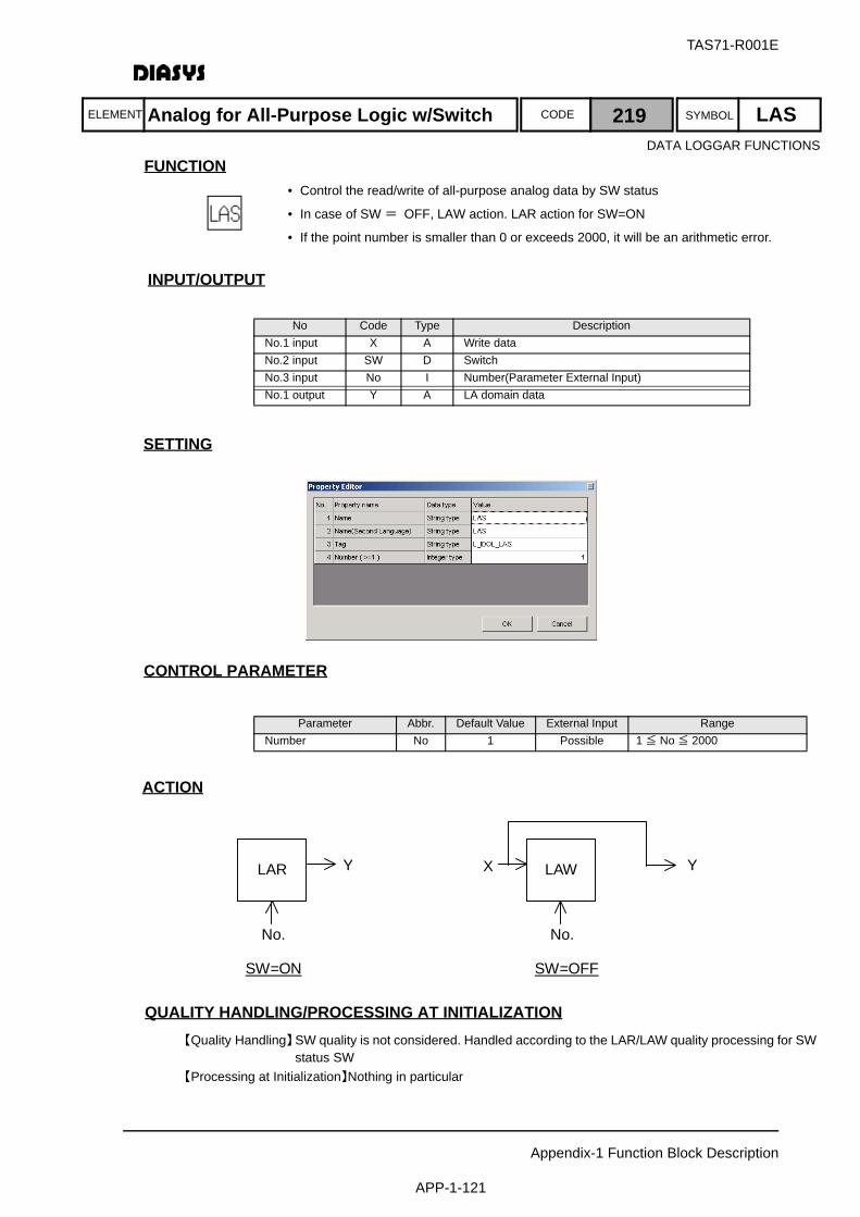
ELEMENT SYMBOLCODE
TAS71-R001E
Appendix-1 Function Block Description
APP-1-121
FUNCTION
INPUT/OUTPUT
SETTING
初期化時の処理CONTROL PARAMETER
ACTION
QUALITY HANDLING/PROCESSING AT INITIALIZATION【Quality Handling】SW quality is not considered. Handled according to the LAR/LAW quality processing for SW
status SW 【Processing at Initialization】Nothing in particular
No Code Type DescriptionNo.1 input X A Write dataNo.2 input SW D SwitchNo.3 input No I Number(Parameter External Input)No.1 output Y A LA domain data
Parameter Abbr. Default Value External Input RangeNumber No 1 Possible 1 ≦ No ≦ 2000
LAR
No.
Y
SW=ON
LAWX
No.
Y
SW=OFF
Analog for All-Purpose Logic w/Switch 219 LASDATA LOGGAR FUNCTIONS
• Control the read/write of all-purpose analog data by SW status
• In case of SW = OFF, LAW action. LAR action for SW=ON
• If the point number is smaller than 0 or exceeds 2000, it will be an arithmetic error.
ELEMENT SYMBOLCODE
TAS71-R001E
Appendix-1 Function Block Description
APP-1-122
FUNCTION
INPUT/OUTPUT
SETTINGNothing
初期化時の処理CONTROL PARAMETERNothing
ACTIONNo action
QUALITY HANDLING/PROCESSING AT INITIALIZATION【Quality Handling】No processing in consideration of quality due to no input 【Processing at Initialization】Nothing in particular
No Code Type DescriptionNo.1 output Y I Calendar integer value
Calendar 220 CLD
• Output of integer values summing-up seconds from 00:00, Jan. 1, 1970
• This value does not change during one arithmetic cycle
DATA LOGGAR FUNCTIONS
ELEMENT SYMBOLCODE
TAS71-R001E
Appendix-1 Function Block Description
APP-1-123
FUNCTION
INPUT/OUTPUT
SETTINGNothing
初期化時の処理CONTROL PARAMETERNothing
ACTIONNo action
QUALITY HANDLING/PROCESSING AT INITIALIZATION【Quality Handling】No processing in consideration of quality due to no input 【Processing at Initialization】Nothing in particular
No Code Type DescriptionNo.1 output Y A msec value
Fetching msec 221 MSCDATA LOGGAR FUNCTIONS
• The msec values is fetched for the current time.
• This value does not change during one arithmetic cycle

ELEMENT SYMBOLCODE
TAS71-R001E
Appendix-1 Function Block Description
APP-1-124
FUNCTION
INPUT/OUTPUT
SETTING
初期化時の処理CONTROL PARAMETER
ACTIONBy combining this element and the CLD element, the current year, month, day, hour, minutes, andseconds can be used as analog data in the logic using YMD parameters.
QUALITY HANDLING/PROCESSING AT INITIALIZATION【Quality Handling】No. 1 input quality should be output as it is. 【Processing at Initialization】Nothing in particular
No Code Type DescriptionNo.1 input TM I Time dataNo.1 output Y A Real value for Y/M/D/h/m/s/w
Parameter Abbr. Default Value External Input RangeUnit TUNT 1 1:sec, 2:min, 3:hour, 4:Day,
5 :Month, 6:Year, 7:Week
YMD Y →A
YMD M →A
YMD D →A
YMD h →A
YMD m →A
YMD s →A
CLD
Fetching Year/Month/Date/Hour/Minute/Second/Week of the Day 222 YMD
• Fetching real values from time data by year, month, day, hour, minute, second, and week-of-the-day.
DATA LOGGAR FUNCTIONS

ELEMENT SYMBOLCODE
TAS71-R001E
Appendix-1 Function Block Description
APP-1-125
FUNCTION
INPUT/OUTPUT
SETTING
初期化時の処理CONTROL PARAMETERNothing
ACTIONNo action
QUALITY HANDLING/PROCESSING AT INITIALIZATION【Quality Handling】The OR of input-signal quality is transmitted.
Own-block output quality should be a block arithmetic error for the following cases.Input for year is not 1970 to 2099Input for month is not 1 to 12Input for date is not 1 to 31Input for time is not 0 to 23Input for minute is not 0 to 59.
【Processing at Initialization】Nothing in particular
No Code Type DescriptionNo.1 input Y A Year, Range: 1970 ≦ year ≦ 2099No.2 input M A Month, Range: 1 ≦ month ≦ 12No.3 input D A Day, Range: 1 ≦ day ≦ 31No.4 input h A Hour, Range: 0 ≦ hour ≦ 23No.5 input m A Minute, Range: 0 ≦ min ≦ 59No.6 input s A Second, Range: 0 ≦ sec ≦ 59No.1 output Y I Calendar integer value
Time Creation 223 CTMDATA LOGGAR FUNCTIONS
• Creating time data from each data of Y/M/D/h/m/s

ELEMENT SYMBOLCODE
TAS71-R001E
Appendix-1 Function Block Description
APP-1-126
FUNCTION
INPUT/OUTPUT
SETTING
初期化時の処理CONTROL PARAMETERNothing
ACTIONNo action
QUALITY HANDLING/PROCESSING AT INITIALIZATION【Quality Handling】The input quality is transmitted to the output.
If the real input cannot expressed in integer, it will be a block arithmetic error.【Processing at Initialization】Nothing in particular
No Code Type DescriptionNo.1 input X A Input signal,
Range:-2147483648 ≦×≦ 2147483648No.1 output Y I Integer output
Real/Integer Conversion 224 R2I
• Output the real input by converting it to integer
• If exceeding the integer range, it will be a block arithmetic error.
DATA LOGGAR FUNCTIONS
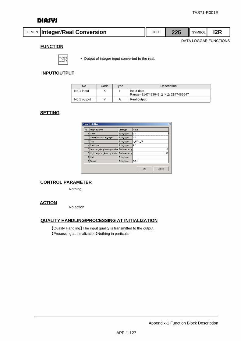
ELEMENT SYMBOLCODE
TAS71-R001E
Appendix-1 Function Block Description
APP-1-127
FUNCTION
INPUT/OUTPUT
SETTING
初期化時の処理CONTROL PARAMETERNothing
ACTIONNo action
QUALITY HANDLING/PROCESSING AT INITIALIZATION【Quality Handling】The input quality is transmitted to the output.【Processing at Initialization】Nothing in particular
No Code Type DescriptionNo.1 input X I Input data
Range:-2147483648 ≦×≦ 2147483647No.1 output Y A Real output
Integer/Real Conversion 225 I2RDATA LOGGAR FUNCTIONS
• Output of integer input converted to the real.
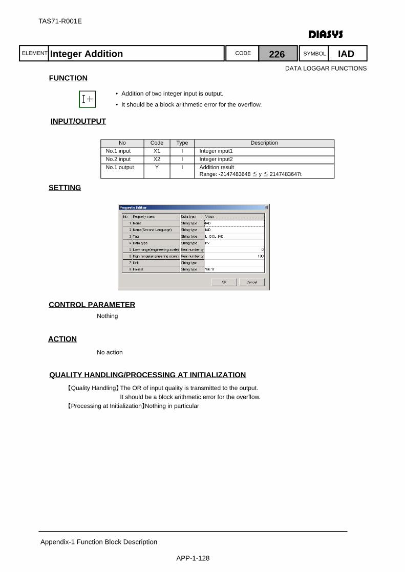
ELEMENT SYMBOLCODE
TAS71-R001E
Appendix-1 Function Block Description
APP-1-128
FUNCTION
INPUT/OUTPUT
SETTING
初期化時の処理CONTROL PARAMETERNothing
ACTIONNo action
QUALITY HANDLING/PROCESSING AT INITIALIZATION【Quality Handling】The OR of input quality is transmitted to the output.
It should be a block arithmetic error for the overflow.【Processing at Initialization】Nothing in particular
No Code Type DescriptionNo.1 input X1 I Integer input1No.2 input X2 I Integer input2No.1 output Y I Addition result
Range: -2147483648 ≦ y ≦ 2147483647t
Integer Addition 226 IAD
• Addition of two integer input is output.
• It should be a block arithmetic error for the overflow.
DATA LOGGAR FUNCTIONS
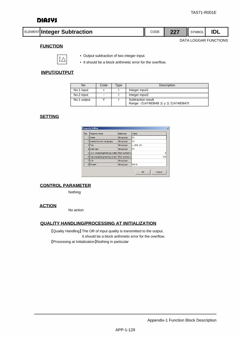
ELEMENT SYMBOLCODE
TAS71-R001E
Appendix-1 Function Block Description
APP-1-129
FUNCTION
INPUT/OUTPUT
SETTING
初期化時の処理CONTROL PARAMETERNothing
ACTIONNo action
QUALITY HANDLING/PROCESSING AT INITIALIZATION【Quality Handling】The OR of input quality is transmitted to the output.
It should be a block arithmetic error for the overflow.【Processing at Initialization】Nothing in particular
No Code Type DescriptionNo.1 input + I Integer input1No.2 input - I Integer input2No.1 output Y I Subtraction result
Range: -2147483648 ≦ y ≦ 2147483647t
Integer Subtraction 227 IDLDATA LOGGAR FUNCTIONS
• Output subtraction of two integer input.
• It should be a block arithmetic error for the overflow.
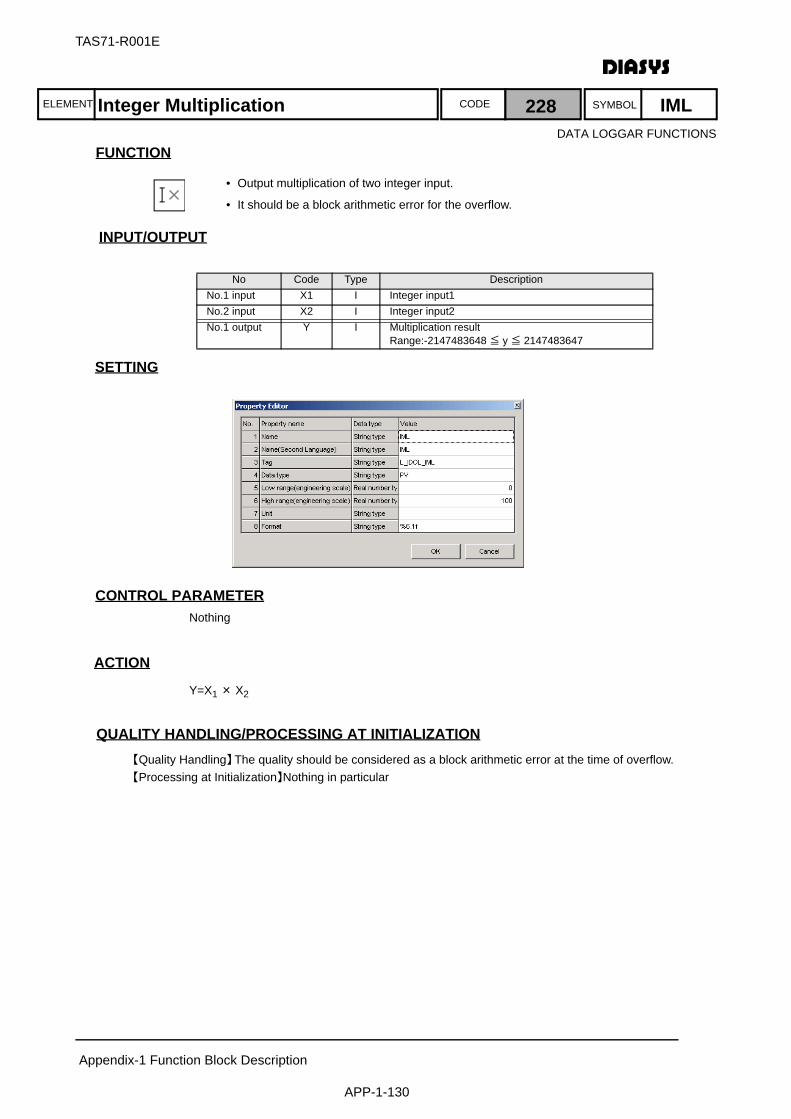
ELEMENT SYMBOLCODE
TAS71-R001E
Appendix-1 Function Block Description
APP-1-130
FUNCTION
INPUT/OUTPUT
SETTING
初期化時の処理CONTROL PARAMETERNothing
ACTION
Y=X1 × X2
QUALITY HANDLING/PROCESSING AT INITIALIZATION【Quality Handling】The quality should be considered as a block arithmetic error at the time of overflow.【Processing at Initialization】Nothing in particular
No Code Type DescriptionNo.1 input X1 I Integer input1No.2 input X2 I Integer input2No.1 output Y I Multiplication result
Range:-2147483648 ≦ y ≦ 2147483647
Integer Multiplication 228 IML
• Output multiplication of two integer input.
• It should be a block arithmetic error for the overflow.
DATA LOGGAR FUNCTIONS
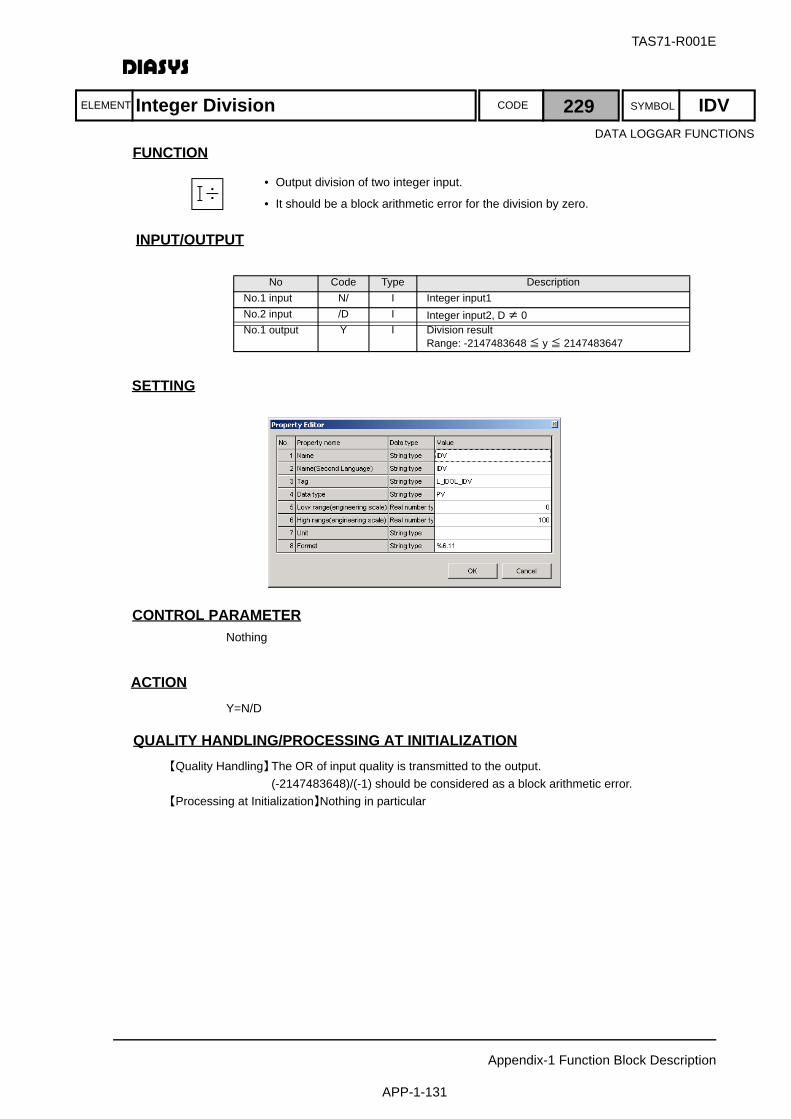
ELEMENT SYMBOLCODE
TAS71-R001E
Appendix-1 Function Block Description
APP-1-131
FUNCTION
INPUT/OUTPUT
SETTING
初期化時の処理CONTROL PARAMETERNothing
ACTIONY=N/D
QUALITY HANDLING/PROCESSING AT INITIALIZATION【Quality Handling】The OR of input quality is transmitted to the output.
(-2147483648)/(-1) should be considered as a block arithmetic error.【Processing at Initialization】Nothing in particular
No Code Type DescriptionNo.1 input N/ I Integer input1No.2 input /D I Integer input2, D ≠ 0No.1 output Y I Division result
Range: -2147483648 ≦ y ≦ 2147483647
Integer Division 229 IDVDATA LOGGAR FUNCTIONS
• Output division of two integer input.
• It should be a block arithmetic error for the division by zero.
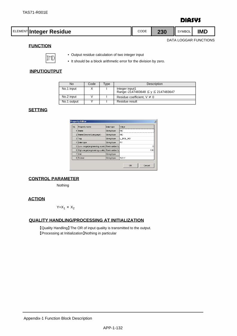
ELEMENT SYMBOLCODE
TAS71-R001E
Appendix-1 Function Block Description
APP-1-132
FUNCTION
INPUT/OUTPUT
SETTING
初期化時の処理CONTROL PARAMETERNothing
ACTION
Y=X1 × X2
QUALITY HANDLING/PROCESSING AT INITIALIZATION【Quality Handling】The OR of input quality is transmitted to the output.【Processing at Initialization】Nothing in particular
No Code Type DescriptionNo.1 input X I Integer input1
Range:-2147483648 ≦ y ≦ 2147483647No.2 input V I Residue coefficient, V ≠ 0No.1 output Y I Residue result
Integer Residue 230 IMD
• Output residue calculation of two integer input
• It should be a block arithmetic error for the division by zero.
DATA LOGGAR FUNCTIONS
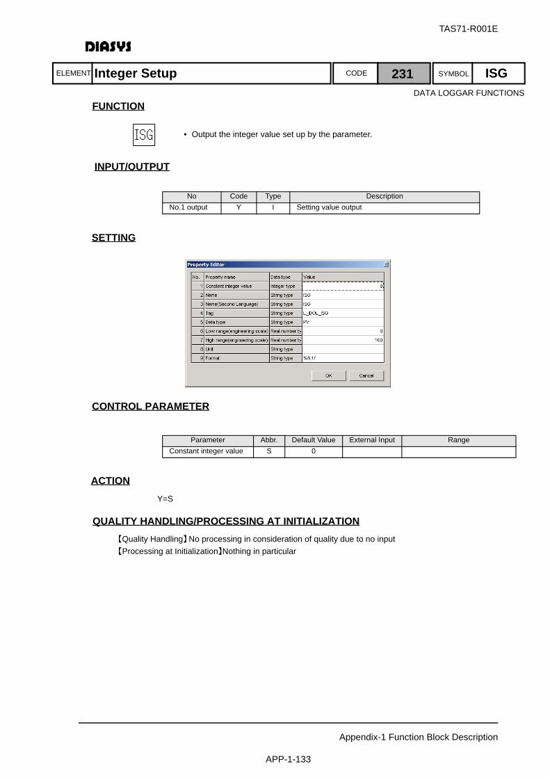
ELEMENT SYMBOLCODE
TAS71-R001E
Appendix-1 Function Block Description
APP-1-133
FUNCTION
INPUT/OUTPUT
SETTING
初期化時の処理CONTROL PARAMETER
ACTIONY=S
QUALITY HANDLING/PROCESSING AT INITIALIZATION【Quality Handling】No processing in consideration of quality due to no input【Processing at Initialization】Nothing in particular
No Code Type DescriptionNo.1 output Y I Setting value output
Parameter Abbr. Default Value External Input RangeConstant integer value S 0
Integer Setup 231 ISGDATA LOGGAR FUNCTIONS
• Output the integer value set up by the parameter.
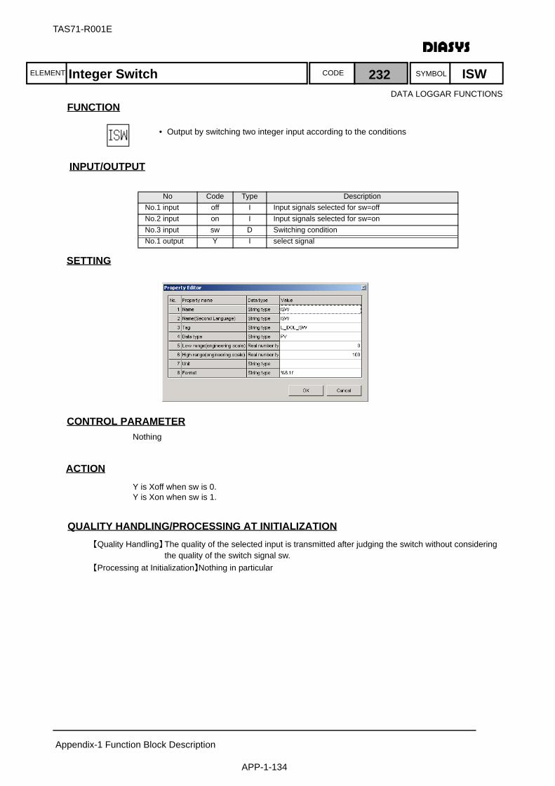
ELEMENT SYMBOLCODE
TAS71-R001E
Appendix-1 Function Block Description
APP-1-134
FUNCTION
INPUT/OUTPUT
SETTING
初期化時の処理CONTROL PARAMETERNothing
ACTIONY is Xoff when sw is 0.Y is Xon when sw is 1.
QUALITY HANDLING/PROCESSING AT INITIALIZATION【Quality Handling】The quality of the selected input is transmitted after judging the switch without considering
the quality of the switch signal sw.【Processing at Initialization】Nothing in particular
No Code Type DescriptionNo.1 input off I Input signals selected for sw=offNo.2 input on I Input signals selected for sw=onNo.3 input sw D Switching conditionNo.1 output Y I select signal
Integer Switch 232 ISW
• Output by switching two integer input according to the conditions
DATA LOGGAR FUNCTIONS
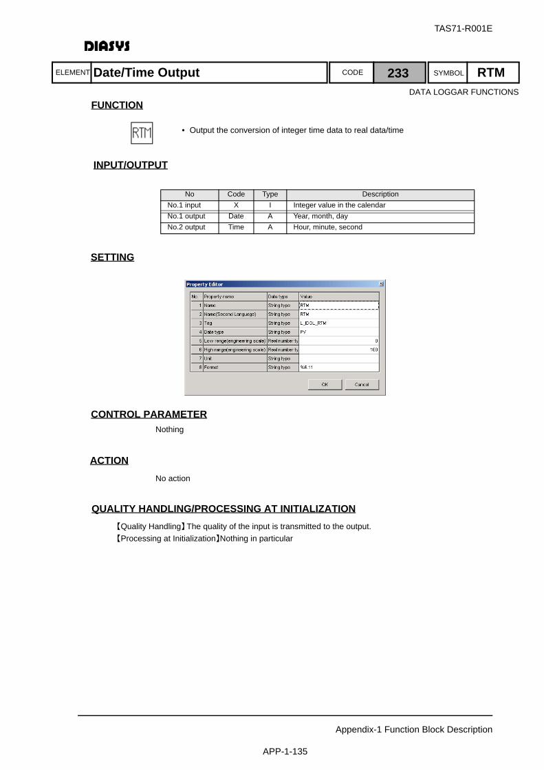
ELEMENT SYMBOLCODE
TAS71-R001E
Appendix-1 Function Block Description
APP-1-135
FUNCTION
INPUT/OUTPUT
SETTING
初期化時の処理CONTROL PARAMETERNothing
ACTIONNo action
QUALITY HANDLING/PROCESSING AT INITIALIZATION【Quality Handling】The quality of the input is transmitted to the output. 【Processing at Initialization】Nothing in particular
No Code Type DescriptionNo.1 input X I Integer value in the calendarNo.1 output Date A Year, month, dayNo.2 output Time A Hour, minute, second
Date/Time Output 233 RTMDATA LOGGAR FUNCTIONS
• Output the conversion of integer time data to real data/time
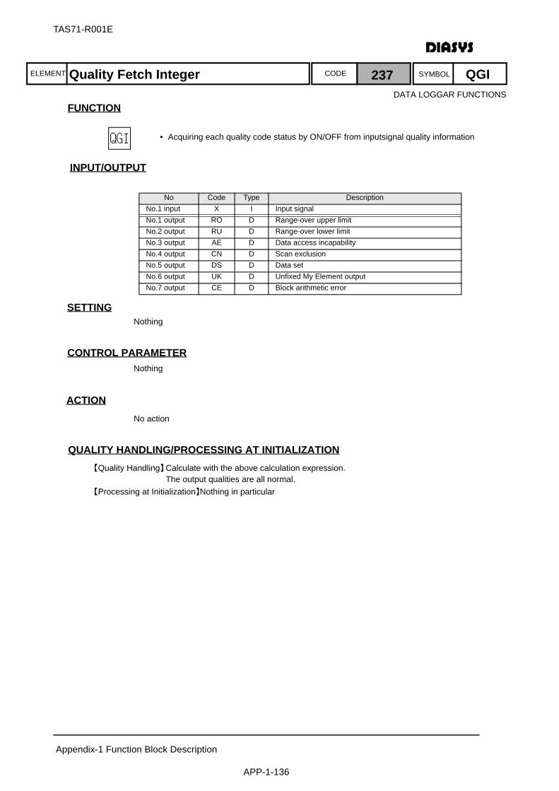
ELEMENT SYMBOLCODE
TAS71-R001E
Appendix-1 Function Block Description
APP-1-136
FUNCTION
INPUT/OUTPUT
SETTINGNothing
初期化時の処理CONTROL PARAMETERNothing
ACTIONNo action
QUALITY HANDLING/PROCESSING AT INITIALIZATION【Quality Handling】Calculate with the above calculation expression.
The output qualities are all normal. 【Processing at Initialization】Nothing in particular
No Code Type DescriptionNo.1 input X I Input signalNo.1 output RO D Range-over upper limitNo.2 output RU D Range-over lower limitNo.3 output AE D Data access incapabilityNo.4 output CN D Scan exclusionNo.5 output DS D Data setNo.6 output UK D Unfixed My Element outputNo.7 output CE D Block arithmetic error
Quality Fetch Integer 237 QGI
• Acquiring each quality code status by ON/OFF from inputsignal quality information
DATA LOGGAR FUNCTIONS
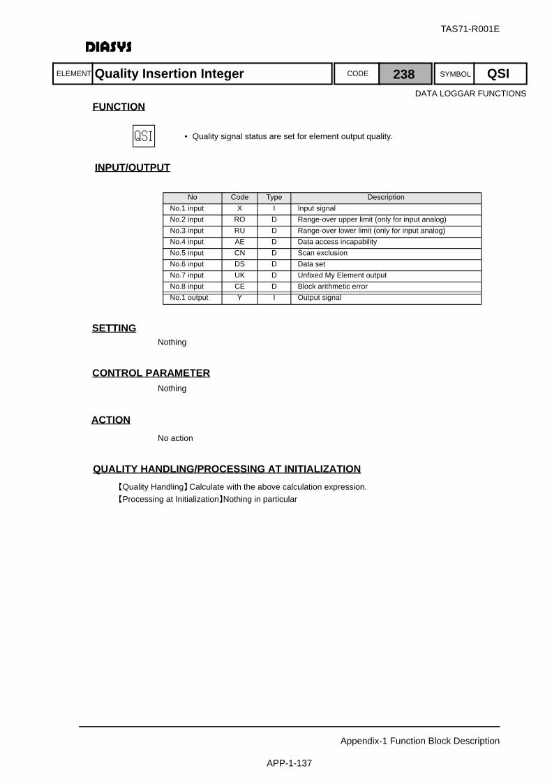
ELEMENT SYMBOLCODE
TAS71-R001E
Appendix-1 Function Block Description
APP-1-137
FUNCTION
INPUT/OUTPUT
SETTINGNothing
初期化時の処理CONTROL PARAMETERNothing
ACTIONNo action
QUALITY HANDLING/PROCESSING AT INITIALIZATION【Quality Handling】Calculate with the above calculation expression.【Processing at Initialization】Nothing in particular
No Code Type DescriptionNo.1 input X I Input signalNo.2 input RO D Range-over upper limit (only for input analog)No.3 input RU D Range-over lower limit (only for input analog)No.4 input AE D Data access incapabilityNo.5 input CN D Scan exclusionNo.6 input DS D Data setNo.7 input UK D Unfixed My Element outputNo.8 input CE D Block arithmetic errorNo.1 output Y I Output signal
Quality Insertion Integer 238 QSIDATA LOGGAR FUNCTIONS
• Quality signal status are set for element output quality.

ELEMENT SYMBOLCODE
TAS71-R001E
Appendix-1 Function Block Description
APP-1-138
FUNCTION
INPUT/OUTPUT
SETTINGNothing
初期化時の処理CONTROL PARAMETERNothing
ACTIONNo action
QUALITY HANDLING/PROCESSING AT INITIALIZATION【Quality Handling】No processing in consideration of quality【Processing at Initialization】Nothing in particular
No Code Type DescriptionNo.1 output Y D On-the-hour timing
On-The-Hour Data 239 LGT
• On-the-hour timing trigger is to be output.
• ON is output on the hour only for one arithmetic cycle.
• Used mainly for report logic creation.
DATA LOGGAR FUNCTIONS
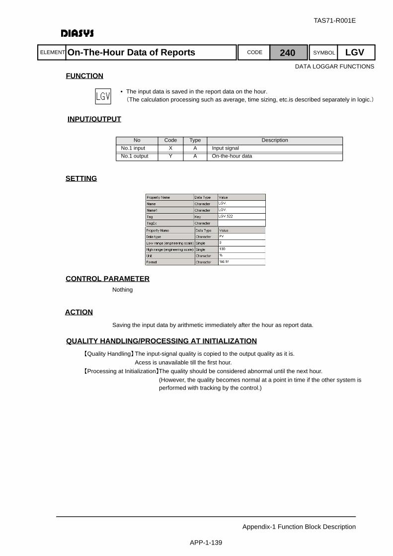
ELEMENT SYMBOLCODE
TAS71-R001E
Appendix-1 Function Block Description
APP-1-139
FUNCTION
INPUT/OUTPUT
SETTING
初期化時の処理CONTROL PARAMETERNothing
ACTIONSaving the input data by arithmetic immediately after the hour as report data.
QUALITY HANDLING/PROCESSING AT INITIALIZATION【Quality Handling】The input-signal quality is copied to the output quality as it is.
Acess is unavailable till the first hour.【Processing at Initialization】The quality should be considered abnormal until the next hour.
(However, the quality becomes normal at a point in time if the other system is performed with tracking by the control.)
No Code Type DescriptionNo.1 input X A Input signalNo.1 output Y A On-the-hour data
On-The-Hour Data of Reports 240 LGV
• The input data is saved in the report data on the hour.(The calculation processing such as average, time sizing, etc.is described separately in logic.)
DATA LOGGAR FUNCTIONS

ELEMENT SYMBOLCODE
TAS71-R001E
Appendix-1 Function Block Description
APP-1-140
FUNCTION
INPUT/OUTPUT
SETTING
初期化時の処理CONTROL PARAMETER
No Code Type DescriptionNo.1 input X D Input signalNo.2 input RST D External reset commandNo.3 input PH A Time-sizing setting value(h)(Parameter External Input)No.4 input PS A Time-sizing setting value(s)(Parameter External Input)No.5 input PC A Setting value for sizing of then umber of times
(Parameter External Input)No.1 output AH A Time sizing(hour)No.2 output AS A Time sizing(sec)No.3 output AC A Sizing of the number of timesNo.4 output RT1 A Year/Month/Day of sizing reset
(2 digits * for A.D yr. 10000+month*100+day)No.5 output RT2 A Hour/Minute/Second of sizing reset
(Hour*10000+minute*100+second)No.6 output PH0 A Time-sizing setting(hour)No.7 output PS0 A Time-sizing setting(sec)No.8 output PC0 A Setting for sizing of the number of timesNo.9 output RCM D Sizing reset command
Parameter Abbr. Default Value External Input RangeControl value for running time(h) PH 8760 Possible (365 日 )Control value for running time(s) PS 0 PossibleControl value for stating count PC 100 Possible
Maintenance Log 242 MLG
• Used for controlling the operation time and the number of startup times of an auxiliary device by combining with the maintenance log display function of OPS
• This element performs the setting of the maintenance log function which executes the sizing of operation time (ON time) and the number of startup times (ON trigger) according to the digital input in the auxiliary-device state.
• The maximum of 320 elements can be used for each MPS.
DATA LOGGAR FUNCTIONS
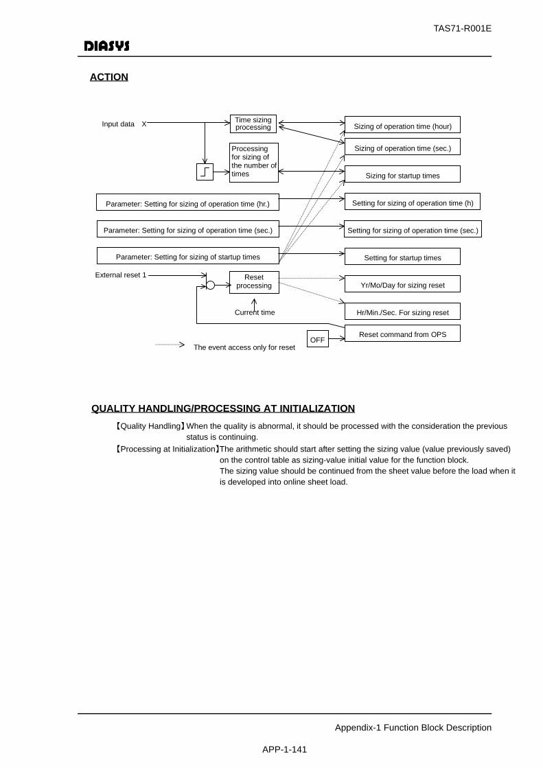
TAS71-R001E
Appendix-1 Function Block Description
APP-1-141
ACTION
QUALITY HANDLING/PROCESSING AT INITIALIZATION【Quality Handling】When the quality is abnormal, it should be processed with the consideration the previous
status is continuing.【Processing at Initialization】The arithmetic should start after setting the sizing value (value previously saved)
on the control table as sizing-value initial value for the function block.The sizing value should be continued from the sheet value before the load when it is developed into online sheet load.
Sizing of operation time (hour)
Parameter: Setting for sizing of operation time (hr.)
Input data X Time sizing processing
External reset 1 Reset processing Yr/Mo/Day for sizing reset
Sizing for startup times
Setting for startup times
Processing for sizing of the number of times
Current time
Sizing of operation time (sec.)
Hr/Min./Sec. For sizing reset
Reset command from OPS OFF
Setting for sizing of operation time (h)
Parameter: Setting for sizing of startup times
Parameter: Setting for sizing of operation time (sec.) Setting for sizing of operation time (sec.)
The event access only for reset
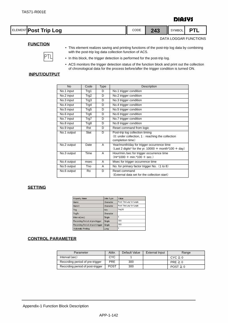
ELEMENT SYMBOLCODE
TAS71-R001E
Appendix-1 Function Block Description
APP-1-142
FUNCTION
INPUT/OUTPUT
SETTING
初期化時の処理CONTROL PARAMETER
No Code Type DescriptionNo.1 input Trg1 D No.1 trigger conditionNo.2 input Trg2 D No.2 trigger conditionNo.3 input Trg3 D No.3 trigger conditionNo.4 input Trg4 D No.4 trigger conditionNo.5 input Trg5 D No.5 trigger conditionNo.6 input Trg6 D No.6 trigger conditionNo.7 input Trg7 D No.7 trigger conditionNo.8 input Trg8 D No.8 trigger conditionNo.9 input Rst D Reset command from logicNo.1 output Stat D Post-trip log collection timing
(0: under collection, 1:reaching the collection completion time)
No.2 output Date A Year/month/day for trigger occurrence time(Last 2 digits* for the yr. 10000 + month*100 + day)
No.3 output Time A Hour/min./sec for trigger occurrence time(Hr*1000 + min.*100 + sec.)
No.4 output msec A Msec for trigger occurrence timeNo.5 output Tno A No. for primary factor trigger No.(1 to 8)No.6 output Ro D Reset command
(External data set for the collection start)
Parameter Abbr. Default Value External Input RangeInterval(sec) CYC 1 CYC ≧ 0Reccrding period of pre-trigger PRE 300 PRE ≧ 0Reccrding period of post-trigger POST 300 POST ≧ 0
Post Trip Log 243 PTL
• This element realizes saving and printing functions of the post-trip log data by combining with the post-trip log data collection function of ACS.
• In this block, the trigger detection is performed for the post-trip log.
• ACS monitors the trigger detection status of the function block and print out the collection of chronological data for the process before/after the trigger condition is turned ON.
DATA LOGGAR FUNCTIONS

TAS71-R001E
Appendix-1 Function Block Description
APP-1-143
ACTION
QUALITY HANDLING/PROCESSING AT INITIALIZATION【Quality Handling】The processing in consideration of quality is not performed for the trigger judgement
processing in this function block.The data collection of ACS post-trip log saves the data including the collection-data quality.If the collection data number exceeds 2400, it should be a block arithmetic error.
【Processing at Initialization】Nothing in particular.
Trigger condition1 S/R
Collection period after
Current time
Time
division
Reset command from ACS
Reset command from logic
Collection stop
:Trigger condition8
MDATrigger No
memory
Collection timing
Year/Month/Day
Hr/Min./Sec.
msec
Reset command
Primary trigger No
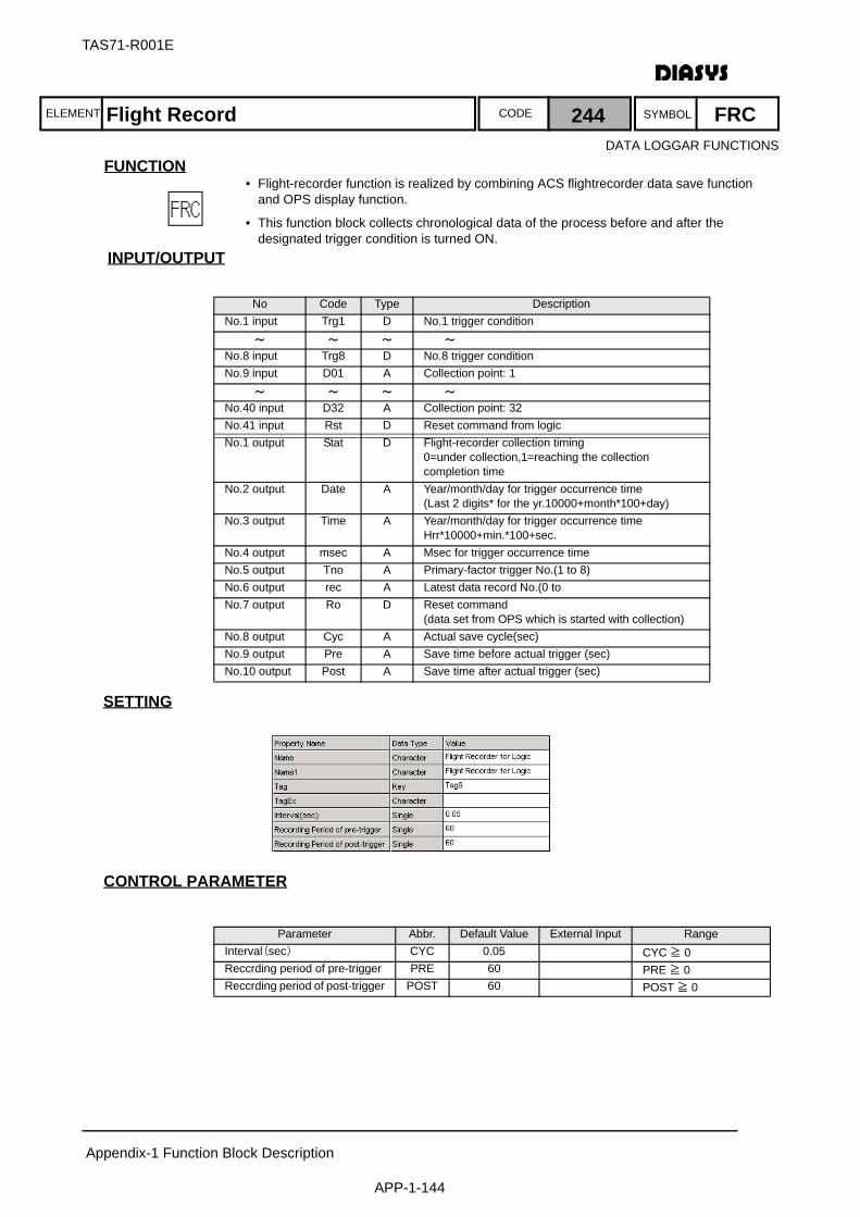
ELEMENT SYMBOLCODE
TAS71-R001E
Appendix-1 Function Block Description
APP-1-144
FUNCTION
INPUT/OUTPUT
SETTING
初期化時の処理CONTROL PARAMETER
No Code Type DescriptionNo.1 input Trg1 D No.1 trigger condition
~ ~ ~ ~
No.8 input Trg8 D No.8 trigger conditionNo.9 input D01 A Collection point: 1
~ ~ ~ ~
No.40 input D32 A Collection point: 32No.41 input Rst D Reset command from logicNo.1 output Stat D Flight-recorder collection timing
0=under collection,1=reaching the collection completion time
No.2 output Date A Year/month/day for trigger occurrence time(Last 2 digits* for the yr.10000+month*100+day)
No.3 output Time A Year/month/day for trigger occurrence timeHrr*10000+min.*100+sec.
No.4 output msec A Msec for trigger occurrence timeNo.5 output Tno A Primary-factor trigger No.(1 to 8)No.6 output rec A Latest data record No.(0 toNo.7 output Ro D Reset command
(data set from OPS which is started with collection)No.8 output Cyc A Actual save cycle(sec)No.9 output Pre A Save time before actual trigger (sec)No.10 output Post A Save time after actual trigger (sec)
Parameter Abbr. Default Value External Input RangeInterval(sec) CYC 0.05 CYC ≧ 0Reccrding period of pre-trigger PRE 60 PRE ≧ 0Reccrding period of post-trigger POST 60 POST ≧ 0
Flight Record 244 FRC
• Flight-recorder function is realized by combining ACS flightrecorder data save function and OPS display function.
• This function block collects chronological data of the process before and after the designated trigger condition is turned ON.
DATA LOGGAR FUNCTIONS

TAS71-R001E
Appendix-1 Function Block Description
APP-1-145
ACTION
QUALITY HANDLING/PROCESSING AT INITIALIZATION【Quality Handling】Collection-point data should be saved in the choronological data including the quality.
If the collection-data number exceeds 2400, it should be a block arithmetic error.【Processing at Initialization】The collection should be started from the blank state at the time of initialization
S/RTrigger condition1 Collection timing
Year/Month/Day
Hr/Min./Sec.
msec
Current time
Time
division
Reset command
Reset command from ACS Reset command from logic
Latest record No. Collection processing
Input data1
Input data 32:
Collection stop
Flight recorder
Collection data area
:Trigger condition8
MDA
Trigger No.
memory Primary trigger
Cycle
Time before
Time after trigger
Parameter cycle
Parameter - time before trigger
Parameter - time after trigger
Recalculation
by the arithmetic
cycle

ELEMENT SYMBOLCODE
TAS71-R001E
Appendix-1 Function Block Description
APP-1-146
FUNCTION
INPUT/OUTPUT
SETTING
初期化時の処理CONTROL PARAMETER
No Code Type DescriptionNo.1 input X D Time adjustment signalNo.1 output Y D Sets ON for time adjustment input and the THT time.No.2 output W A Time elapsed (seconds) since time adjustment was set to ONNo.3 output THT I Trigger hold time (sec)(Parameter External Input)No.4 output ITV I DI interval(Parameter External Input)No.5 output DIH I DI timing(hour)(Parameter External Input)No.6 output DIM I DI timing(min)(Parameter External Input)No.7 output DIS I DI timing(sec)(Parameter External Input)No.8 output TMN I Difference to permit(msec)(Parameter External Input)No.9 output TMX I Difference to force to set(msec)(Parameter External Input)No.10 output TOV I Difference not to permit(msec)(Parameter External Input)No.11 output TTN I Time adjustment rate(msec/min)(Parameter External Input)
Parameter Abbr. Default Value External Input RangeTrigger hold time(sec) THT 10 Possible 3 ≦ THT ≦ 20DI interval ITV 1 Possible (1: once/day, 2:once/hour,
other values:arithmetic error)DI timing(hour) DIH 0 Possible 0 ≦ DIH ≦ 23DI timing(min) DIM 5 Possible 5 ≦ DIM ≦ 55DI timing(sec) DIS 0 Possible 0 ≦ DIS ≦ 59Difference to permit(msec) TMN 1000 Possible 100 ≦ TMN ≦ 60000Difference to force to set(msec)
TMX 30000 Possible 10000 ≦ TMX ≦ 1200000
Difference not to permit(msec)
TOV 60000 Possible 60000 ≦ TOV ≦ 1200000
Time adjustment rate(msec/min)
TTN 600 Possible 600 . TMX .6000
Timer adjustment by DI 245 TAJ
• The element adjusts the time of the NTP server using the periodic ON pulses provided by the master clock or another equivalent device to the DI of MPS.
DATA LOGGAR FUNCTIONS
TAS71-R001E
Appendix-1 Function Block Description
APP-1-147
ACTIONOPS or ACS, which operates as the NTP server, monitors this time adjustment element in real timeand adjusts the time of all systems including MPS via NTP.(This element is not used to directly perform time adjustment on MPS.)
QUALITY HANDLING/PROCESSING AT INITIALIZATION【Quality Handling】The quality of input X is transmitted to output Y.
The quality of other outputs is always normal.If any of the parameters exceeds its range, the function block results in an arithmetic block error.
【Processing at Initialization】Time adjustment is performed when the input is changed from OFF to ON. However, if the input is initially set to ON, time adjustment is not performed.
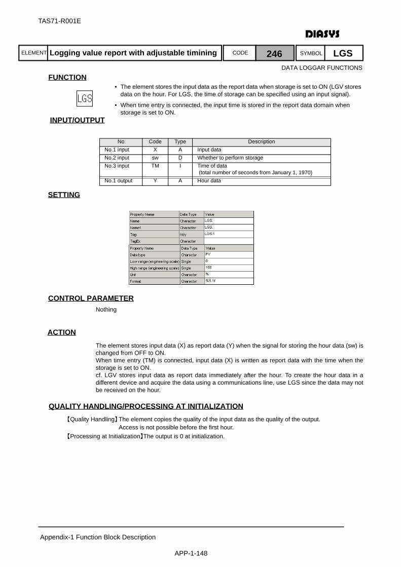
ELEMENT SYMBOLCODE
TAS71-R001E
Appendix-1 Function Block Description
APP-1-148
FUNCTION
INPUT/OUTPUT
SETTING
初期化時の処理CONTROL PARAMETERNothing
ACTIONThe element stores input data (X) as report data (Y) when the signal for storing the hour data (sw) ischanged from OFF to ON.When time entry (TM) is connected, input data (X) is written as report data with the time when thestorage is set to ON.cf. LGV stores input data as report data immediately after the hour. To create the hour data in adifferent device and acquire the data using a communications line, use LGS since the data may notbe received on the hour.
QUALITY HANDLING/PROCESSING AT INITIALIZATION【Quality Handling】The element copies the quality of the input data as the quality of the output.
Access is not possible before the first hour.【Processing at Initialization】The output is 0 at initialization.
No Code Type DescriptionNo.1 input X A Input dataNo.2 input sw D Whether to perform storageNo.3 input TM I Time of data
(total number of seconds from January 1, 1970)No.1 output Y A Hour data
Logging value report with adjustable timining 246 LGS
• The element stores the input data as the report data when storage is set to ON (LGV stores data on the hour. For LGS, the time of storage can be specified using an input signal).
• When time entry is connected, the input time is stored in the report data domain when storage is set to ON.
DATA LOGGAR FUNCTIONS
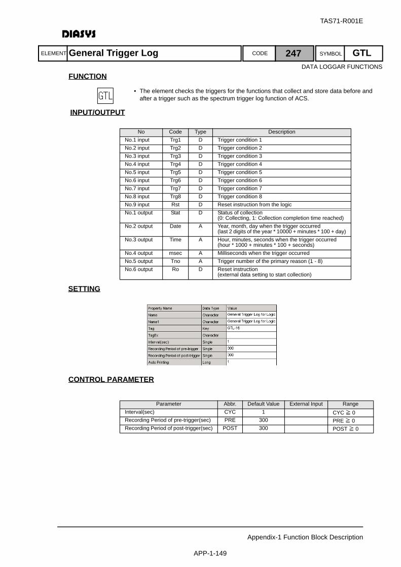
ELEMENT SYMBOLCODE
TAS71-R001E
Appendix-1 Function Block Description
APP-1-149
FUNCTION
INPUT/OUTPUT
SETTING
初期化時の処理CONTROL PARAMETER
No Code Type DescriptionNo.1 input Trg1 D Trigger condition 1No.2 input Trg2 D Trigger condition 2No.3 input Trg3 D Trigger condition 3No.4 input Trg4 D Trigger condition 4No.5 input Trg5 D Trigger condition 5No.6 input Trg6 D Trigger condition 6No.7 input Trg7 D Trigger condition 7No.8 input Trg8 D Trigger condition 8No.9 input Rst D Reset instruction from the logicNo.1 output Stat D Status of collection
(0: Collecting, 1: Collection completion time reached)No.2 output Date A Year, month, day when the trigger occurred
(last 2 digits of the year * 10000 + minutes * 100 + day)No.3 output Time A Hour, minutes, seconds when the trigger occurred
(hour * 1000 + minutes * 100 + seconds)No.4 output msec A Milliseconds when the trigger occurredNo.5 output Tno A Trigger number of the primary reason (1 - 8)No.6 output Ro D Reset instruction
(external data setting to start collection)
Parameter Abbr. Default Value External Input RangeInterval(sec) CYC 1 CYC ≧ 0Recording Period of pre-trigger(sec) PRE 300 PRE ≧ 0Recording Period of post-trigger(sec) POST 300 POST ≧ 0
General Trigger Log 247 GTL
• The element checks the triggers for the functions that collect and store data before and after a trigger such as the spectrum trigger log function of ACS.
DATA LOGGAR FUNCTIONS

TAS71-R001E
Appendix-1 Function Block Description
APP-1-150
ACTION
QUALITY HANDLING/PROCESSING AT INITIALIZATION【Quality Handling】None.【Processing at Initialization】None.
S/R
Collection time after the trigger
Trigger condition 1Status of collection
Year, month, day
Hour, minutes, seconds
Milliseconds
Currenttime
Time
division
Reset instruction
Reset instruction from ACS
Reset instruction from the logic Collection
stop
:Trigger condition 8
MDA
Store the trigger number
Primary trigger number

ELEMENT SYMBOLCODE
TAS71-R001E
Appendix-1 Function Block Description
APP-1-151
FUNCTION
INPUT/OUTPUT
SETTING
初期化時の処理CONTROL PARAMETERNothing
ACTIONNo action
QUALITY HANDLING/PROCESSING AT INITIALIZATION【Quality Handling】None.【Processing at Initialization】None.
No Code Type DescriptionNo.1 input A01 A Analog data 1
~ ~ ~ ~
No.32 input A32 A Analog data 32
Analog signals read by CARD 248 CAR
• The element reads up to 32 points of analog data from the logic.
• The element can read 32 points of analog data in a batch using the CARD system.
DATA LOGGAR FUNCTIONS

ELEMENT SYMBOLCODE
TAS71-R001E
Appendix-1 Function Block Description
APP-1-152
FUNCTION
INPUT/OUTPUT
SETTING
初期化時の処理CONTROL PARAMETERNothing
ACTIONNo action
QUALITY HANDLING/PROCESSING AT INITIALIZATION【Quality Handling】None.【Processing at Initialization】None.
No Code Type DescriptionNo.1 output CNT A See Chapter 4.No.2 output A01 A Analog data 1
~ ~ ~ ~
No.32 output A32 A Analog data 32
Analog signals written by CARD 249 CAW
• The element writes up to 32 points of analog data in the logic.
• The element can write 32 points of analog data in a batch using the CARD system.
DATA LOGGAR FUNCTIONS

ELEMENT SYMBOLCODE
TAS71-R001E
Appendix-1 Function Block Description
APP-1-153
FUNCTION
INPUT/OUTPUT
SETTING
初期化時の処理CONTROL PARAMETERNothing
ACTIONNo action
QUALITY HANDLING/PROCESSING AT INITIALIZATION【Quality Handling】None.【Processing at Initialization】None.
No Code Type DescriptionNo.1 input D01 D Digital data 1
~ ~ ~ ~
No.32 input D32 D Digital data 32
Digital signals read by CARD 250 CDR
• The element reads up to 32 points of digital data from the logic.
• The element can read 32 points of digital data in a batch using the CARD system.
DATA LOGGAR FUNCTIONS

ELEMENT SYMBOLCODE
TAS71-R001E
Appendix-1 Function Block Description
APP-1-154
FUNCTION
INPUT/OUTPUT
SETTING
初期化時の処理CONTROL PARAMETERNothing
ACTIONNo action
QUALITY HANDLING/PROCESSING AT INITIALIZATION【Quality Handling】None.【Processing at Initialization】None.
No Code Type DescriptionNo.1 output CNT A See Chapter 4.No.2 output D01 D Digital data 1
~ ~ ~ ~
No.32 output D32 D Digital data 32
Digital signals written by CARD 251 CDW
• The element writes up to 32 points of digital data to the logic.
• The element can write 32 points of digital data in a batch using the CARD system.
DATA LOGGAR FUNCTIONS

ELEMENT SYMBOLCODE
TAS71-R001E
Appendix-1 Function Block Description
APP-1-155
FUNCTION
INPUT/OUTPUT
SETTING
初期化時の処理CONTROL PARAMETER
ACTIONNo action
QUALITY HANDLING/PROCESSING AT INITIALIZATION【Quality Handling】The element outputs the quality data from general-purpose integer data domain LI.【Processing at Initialization】None.
No Code Type DescriptionNo.1 input No I Number (starting from 1), range: 1 ≦ No. ≦ 4000
(Parameter External Input)No.1 output Y I Data in the LI domain
Parameter Abbr. Default Value External Input RangeNumber No 1 Possible 1 ≦ No ≦ 4000
Common integer data read 252 LIR
• The element acquires data from general-purpose integer domain LI and outputs it to the logic.
• The element acquires the data of the specified point number in generalpurpose integer data domain LI and outputs it to the logic.
• A calculation error occurs if the point number is less than 0 or exceeds 4000.
DATA LOGGAR FUNCTIONS
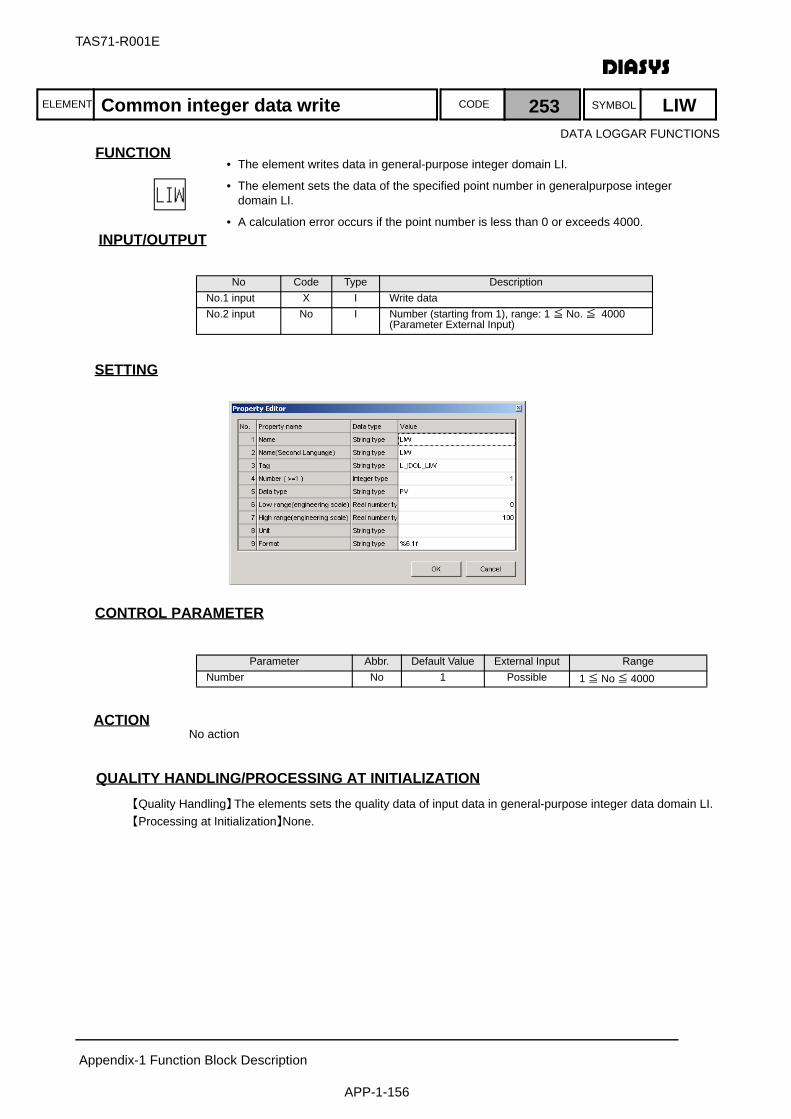
ELEMENT SYMBOLCODE
TAS71-R001E
Appendix-1 Function Block Description
APP-1-156
FUNCTION
INPUT/OUTPUT
SETTING
初期化時の処理CONTROL PARAMETER
ACTIONNo action
QUALITY HANDLING/PROCESSING AT INITIALIZATION【Quality Handling】The elements sets the quality data of input data in general-purpose integer data domain LI.【Processing at Initialization】None.
No Code Type DescriptionNo.1 input X I Write dataNo.2 input No I Number (starting from 1), range: 1 ≦ No. ≦ 4000
(Parameter External Input)
Parameter Abbr. Default Value External Input RangeNumber No 1 Possible 1 ≦ No ≦ 4000
Common integer data write 253 LIW
• The element writes data in general-purpose integer domain LI.
• The element sets the data of the specified point number in generalpurpose integer domain LI.
• A calculation error occurs if the point number is less than 0 or exceeds 4000.
DATA LOGGAR FUNCTIONS
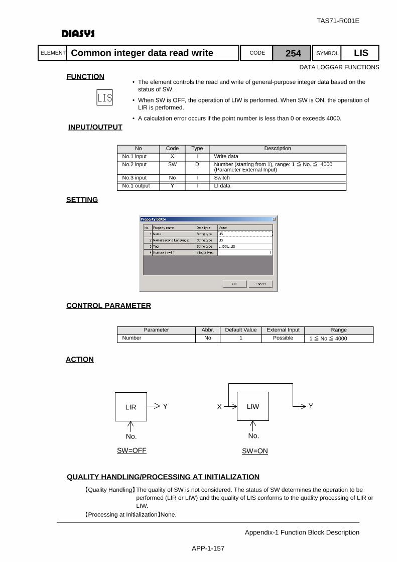
ELEMENT SYMBOLCODE
TAS71-R001E
Appendix-1 Function Block Description
APP-1-157
FUNCTION
INPUT/OUTPUT
SETTING
初期化時の処理CONTROL PARAMETER
ACTION
QUALITY HANDLING/PROCESSING AT INITIALIZATION【Quality Handling】The quality of SW is not considered. The status of SW determines the operation to be
performed (LIR or LIW) and the quality of LIS conforms to the quality processing of LIR or LIW.
【Processing at Initialization】None.
No Code Type DescriptionNo.1 input X I Write dataNo.2 input SW D Number (starting from 1), range: 1 ≦ No. ≦ 4000
(Parameter External Input)No.3 input No I SwitchNo.1 output Y I LI data
Parameter Abbr. Default Value External Input RangeNumber No 1 Possible 1 ≦ No ≦ 4000
LIR
No.
Y
SW=OFF
LIWX
No.
Y
SW=ON
Common integer data read write 254 LIS
• The element controls the read and write of general-purpose integer data based on the status of SW.
• When SW is OFF, the operation of LIW is performed. When SW is ON, the operation of LIR is performed.
• A calculation error occurs if the point number is less than 0 or exceeds 4000.
DATA LOGGAR FUNCTIONS
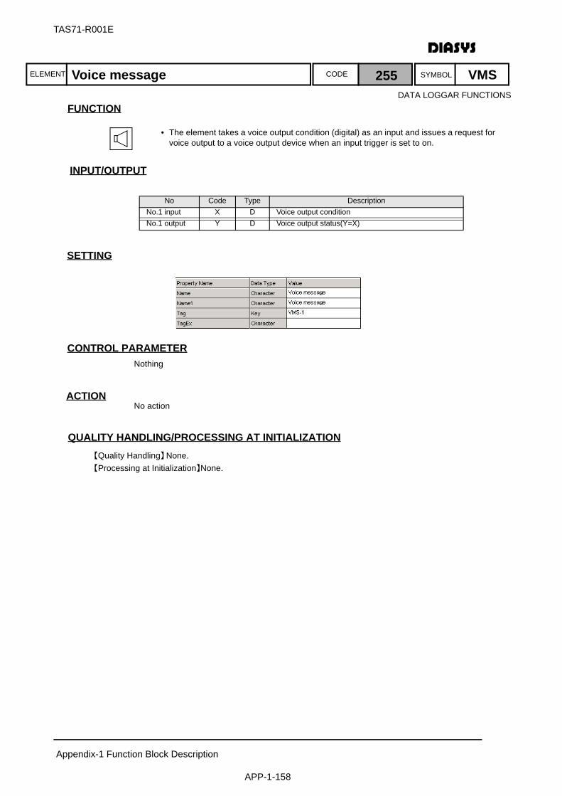
ELEMENT SYMBOLCODE
TAS71-R001E
Appendix-1 Function Block Description
APP-1-158
FUNCTION
INPUT/OUTPUT
SETTING
初期化時の処理CONTROL PARAMETERNothing
ACTIONNo action
QUALITY HANDLING/PROCESSING AT INITIALIZATION【Quality Handling】None.【Processing at Initialization】None.
No Code Type DescriptionNo.1 input X D Voice output conditionNo.1 output Y D Voice output status(Y=X)
Voice message 255 VMS
• The element takes a voice output condition (digital) as an input and issues a request for voice output to a voice output device when an input trigger is set to on.
DATA LOGGAR FUNCTIONS
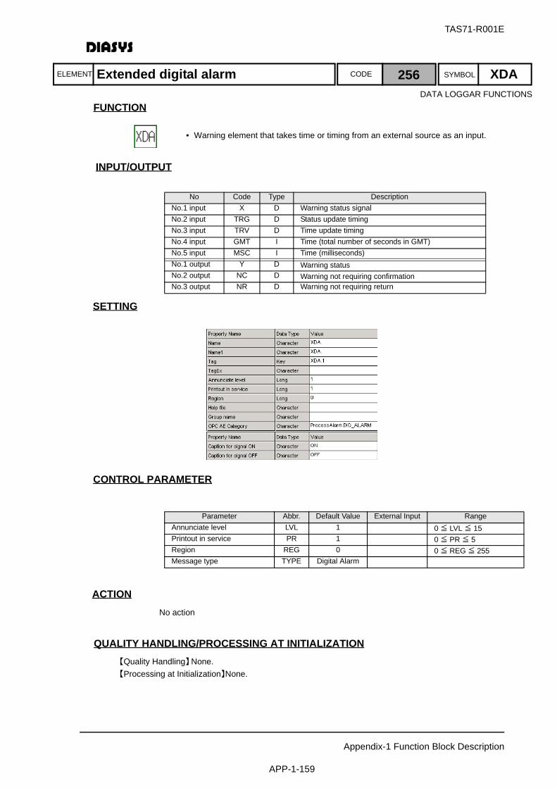
ELEMENT SYMBOLCODE
TAS71-R001E
Appendix-1 Function Block Description
APP-1-159
FUNCTION
INPUT/OUTPUT
SETTING
初期化時の処理CONTROL PARAMETER
ACTIONNo action
QUALITY HANDLING/PROCESSING AT INITIALIZATION【Quality Handling】None.【Processing at Initialization】None.
No Code Type DescriptionNo.1 input X D Warning status signalNo.2 input TRG D Status update timingNo.3 input TRV D Time update timingNo.4 input GMT I Time (total number of seconds in GMT)No.5 input MSC I Time (milliseconds)No.1 output Y D Warning statusNo.2 output NC D Warning not requiring confirmationNo.3 output NR D Warning not requiring return
Parameter Abbr. Default Value External Input RangeAnnunciate level LVL 1 0 ≦ LVL ≦ 15Printout in service PR 1 0 ≦ PR ≦ 5Region REG 0 0 ≦ REG ≦ 255Message type TYPE Digital Alarm
Extended digital alarm 256 XDA
• Warning element that takes time or timing from an external source as an input.
DATA LOGGAR FUNCTIONS
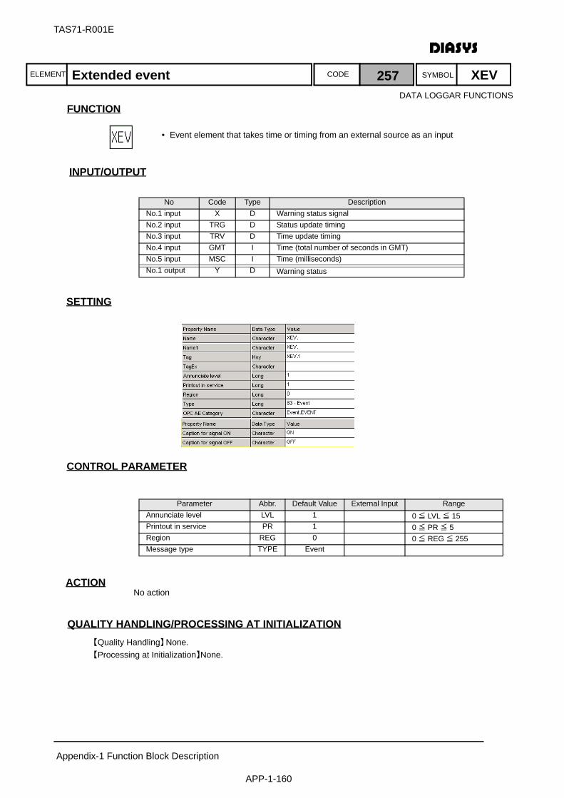
ELEMENT SYMBOLCODE
TAS71-R001E
Appendix-1 Function Block Description
APP-1-160
FUNCTION
INPUT/OUTPUT
SETTING
初期化時の処理CONTROL PARAMETER
ACTIONNo action
QUALITY HANDLING/PROCESSING AT INITIALIZATION【Quality Handling】None.【Processing at Initialization】None.
No Code Type DescriptionNo.1 input X D Warning status signalNo.2 input TRG D Status update timingNo.3 input TRV D Time update timingNo.4 input GMT I Time (total number of seconds in GMT)No.5 input MSC I Time (milliseconds)No.1 output Y D Warning status
Parameter Abbr. Default Value External Input RangeAnnunciate level LVL 1 0 ≦ LVL ≦ 15Printout in service PR 1 0 ≦ PR ≦ 5Region REG 0 0 ≦ REG ≦ 255Message type TYPE Event
Extended event 257 XEVDATA LOGGAR FUNCTIONS
• Event element that takes time or timing from an external source as an input

ELEMENT SYMBOLCODE
TAS71-R001E
Appendix-1 Function Block Description
APP-1-161
FUNCTION
INPUT/OUTPUT
SETTING
初期化時の処理CONTROL PARAMETER
ACTIONNo action
QUALITY HANDLING/PROCESSING AT INITIALIZATION【Quality Handling】The quality is always normal.【Processing at Initialization】None.
No Code Type DescriptionNo.1 output Y D Input signal
Parameter Abbr. Default Value External Input RangeNo. No 0 1 ≦ No ≦ 1024
System digital input for logical I/O assignment 301 SDI
• Digital input signal used by MPS in the system (not used in the usual logic)
SYSTEM FUNCTIONS
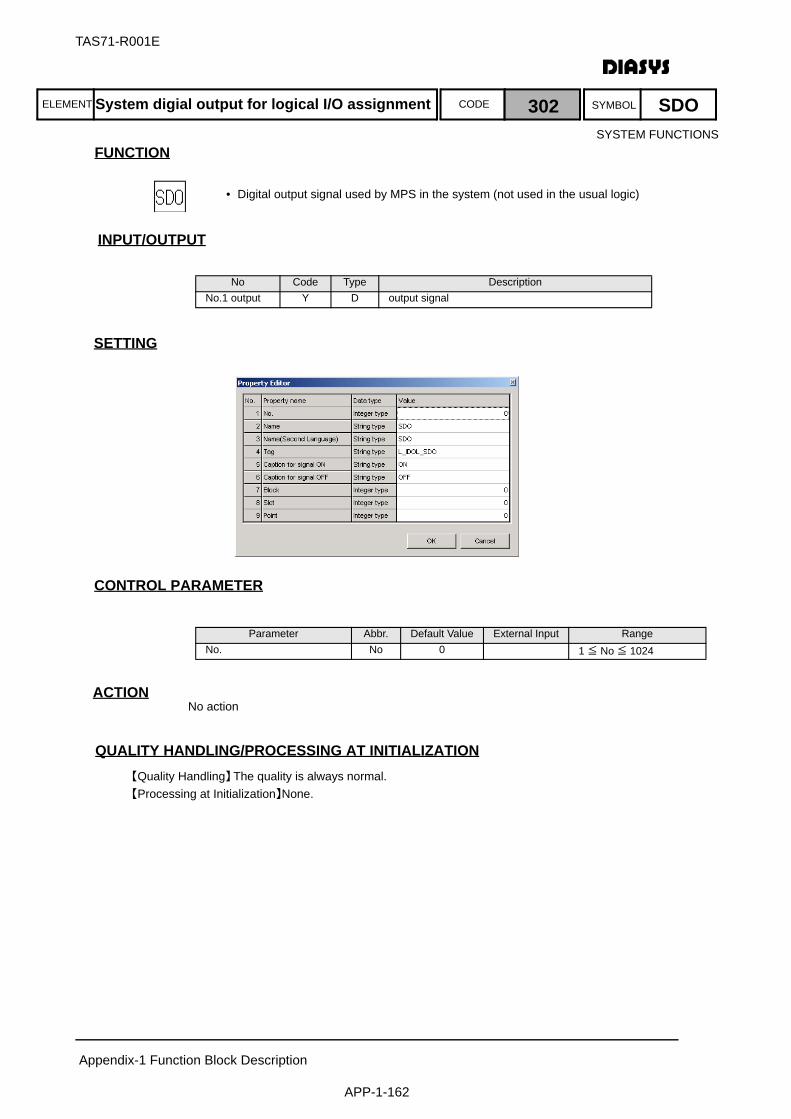
ELEMENT SYMBOLCODE
TAS71-R001E
Appendix-1 Function Block Description
APP-1-162
FUNCTION
INPUT/OUTPUT
SETTING
初期化時の処理CONTROL PARAMETER
ACTIONNo action
QUALITY HANDLING/PROCESSING AT INITIALIZATION【Quality Handling】The quality is always normal.【Processing at Initialization】None.
No Code Type DescriptionNo.1 output Y D output signal
Parameter Abbr. Default Value External Input RangeNo. No 0 1 ≦ No ≦ 1024
System digial output for logical I/O assignment 302 SDO
• Digital output signal used by MPS in the system (not used in the usual logic)
SYSTEM FUNCTIONS

ELEMENT SYMBOLCODE
TAS71-R001E
Appendix-1 Function Block Description
APP-1-163
FUNCTION
INPUT/OUTPUT
SETTING
初期化時の処理CONTROL PARAMETER
ACTIONNo action
QUALITY HANDLING/PROCESSING AT INITIALIZATION【Quality Handling】The quality is always normal.【Processing at Initialization】None.
No Code Type DescriptionNo.1 output Y A input signal
Parameter Abbr. Default Value External Input RangeNo. No 0 1 ≦ No ≦ 256
System analog input for logical I/O assignment 303 SAI
• Analog input signal used by MPS in the system (not used in the usual logic)
SYSTEM FUNCTIONS
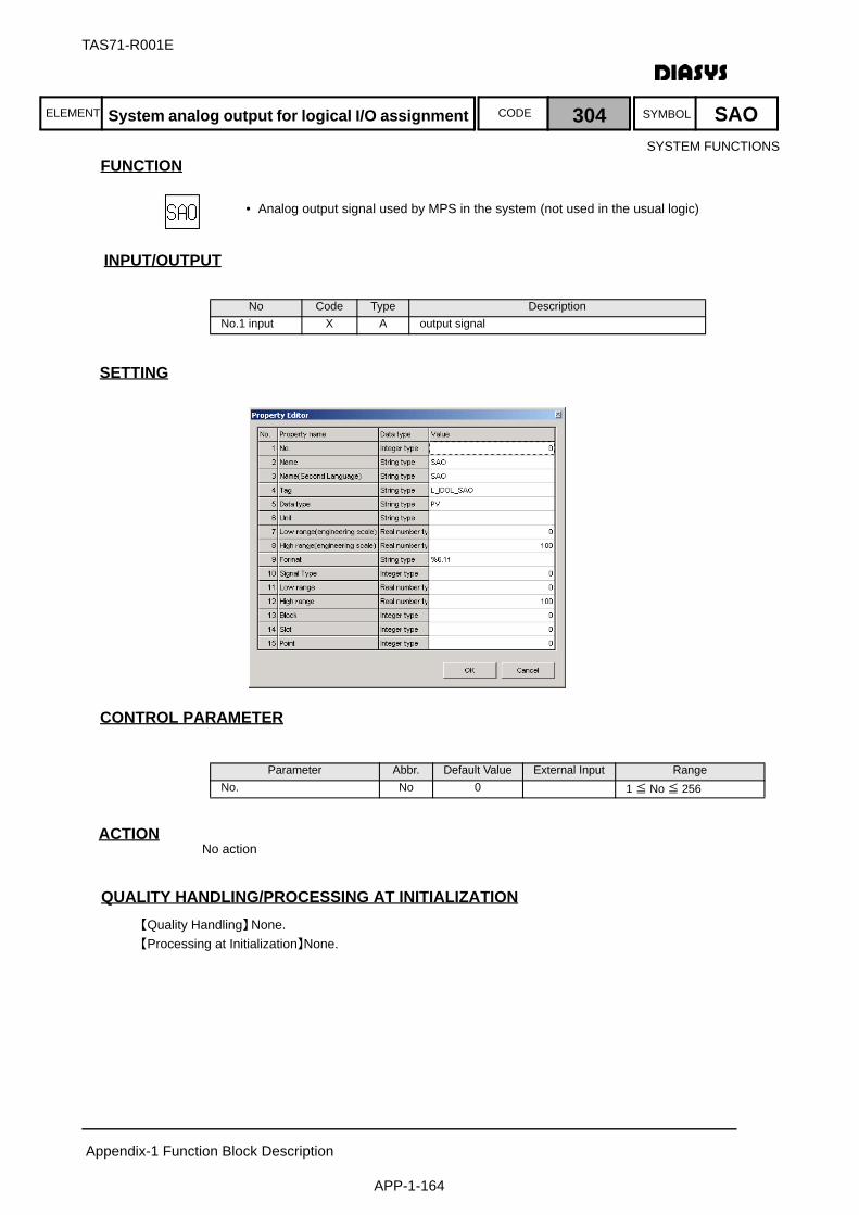
ELEMENT SYMBOLCODE
TAS71-R001E
Appendix-1 Function Block Description
APP-1-164
FUNCTION
INPUT/OUTPUT
SETTING
初期化時の処理CONTROL PARAMETER
ACTIONNo action
QUALITY HANDLING/PROCESSING AT INITIALIZATION【Quality Handling】None.【Processing at Initialization】None.
No Code Type DescriptionNo.1 input X A output signal
Parameter Abbr. Default Value External Input RangeNo. No 0 1 ≦ No ≦ 256
System analog output for logical I/O assignment 304 SAO
• Analog output signal used by MPS in the system (not used in the usual logic)
SYSTEM FUNCTIONS

ELEMENT SYMBOLCODE
TAS71-R001E
Appendix-1 Function Block Description
APP-1-165
FUNCTION
INPUT/OUTPUT
SETTING
初期化時の処理CONTROL PARAMETER
ACTIONNo action
QUALITY HANDLING/PROCESSING AT INITIALIZATION【Quality Handling】The quality is always normal.【Processing at Initialization】None.
No Code Type DescriptionNo.1 output Y I input signal
Parameter Abbr. Default Value External Input RangeNo. No 0 1 ≦ No ≦ 256
System integer input 305 SII
• Integer input signal used by MPS in the system (not used in the usual logic)
SYSTEM FUNCTIONS

ELEMENT SYMBOLCODE
TAS71-R001E
Appendix-1 Function Block Description
APP-1-166
FUNCTION
INPUT/OUTPUT
SETTING
初期化時の処理CONTROL PARAMETER
ACTIONNo action
QUALITY HANDLING/PROCESSING AT INITIALIZATION【Quality Handling】The quality is always normal.【Processing at Initialization】None.
No Code Type DescriptionNo.1 input X I output signal
Parameter Abbr. Default Value External Input RangeNo. No 0 1 ≦ No ≦ 256
System integer output 306 SIO
• Integer output signal used by MPS in the system (not used in the usual logic)
SYSTEM FUNCTIONS
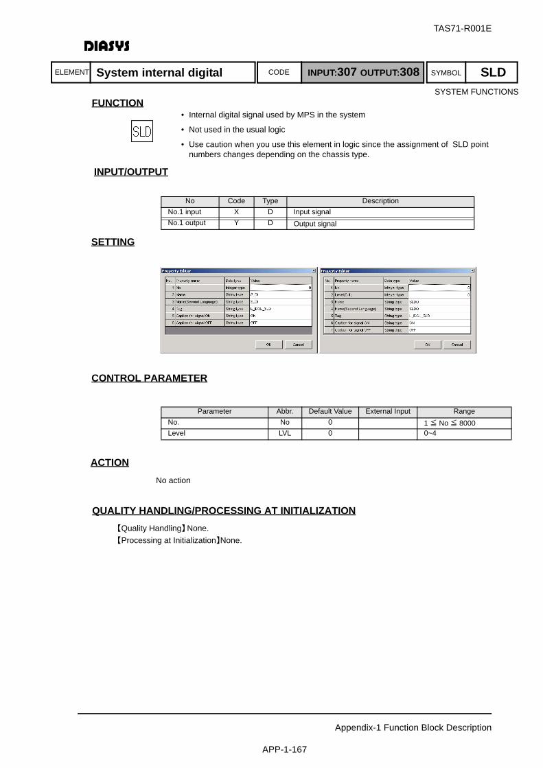
ELEMENT SYMBOLCODE
TAS71-R001E
Appendix-1 Function Block Description
APP-1-167
FUNCTION
INPUT/OUTPUT
SETTING
初期化時の処理CONTROL PARAMETER
ACTIONNo action
QUALITY HANDLING/PROCESSING AT INITIALIZATION【Quality Handling】None.【Processing at Initialization】None.
No Code Type DescriptionNo.1 input X D Input signalNo.1 output Y D Output signal
Parameter Abbr. Default Value External Input RangeNo. No 0 1 ≦ No ≦ 8000Level LVL 0 0~4
• Internal digital signal used by MPS in the system
• Not used in the usual logic
• Use caution when you use this element in logic since the assignment of SLD point numbers changes depending on the chassis type.
System internal digital INPUT:307 OUTPUT:308 SLDSYSTEM FUNCTIONS

ELEMENT SYMBOLCODE
TAS71-R001E
Appendix-1 Function Block Description
APP-1-168
FUNCTIONFUNCTION
INPUT/OUTPUT
SETTING
初期化時の処理CONTROL PARAMETER
ACTIONNo action
QUALITY HANDLING/PROCESSING AT INITIALIZATION【Quality Handling】The quality is always normal.【Processing at Initialization】None.
No Code Type DescriptionNo.1 input X A Input signalNo.1 output Y A Output signal
Parameter Abbr. Default Value External Input RangeNo. No 0 1 ≦ No ≦ 256
• Internal analog signal used by MPS in the system
• Not used in the usual logic
System internal analog INPUT:309 OUTPUT:310 SLASYSTEM FUNCTIONS
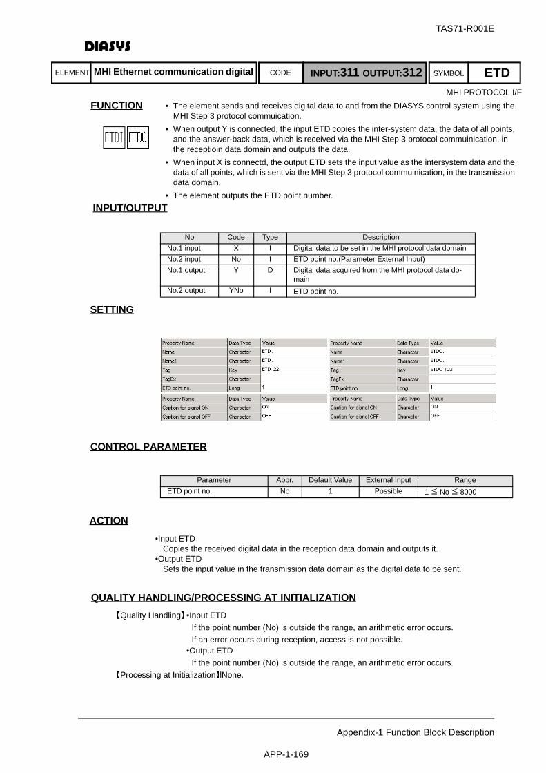
ELEMENT SYMBOLCODE
TAS71-R001E
Appendix-1 Function Block Description
APP-1-169
FUNCTION
INPUT/OUTPUT
SETTING
初期化時の処理CONTROL PARAMETER
ACTION•Input ETD
Copies the received digital data in the reception data domain and outputs it.•Output ETD
Sets the input value in the transmission data domain as the digital data to be sent.
QUALITY HANDLING/PROCESSING AT INITIALIZATION【Quality Handling】•Input ETD
If the point number (No) is outside the range, an arithmetic error occurs.If an error occurs during reception, access is not possible.
•Output ETDIf the point number (No) is outside the range, an arithmetic error occurs.
【Processing at Initialization】lNone.
No Code Type DescriptionNo.1 input X I Digital data to be set in the MHI protocol data domainNo.2 input No I ETD point no.(Parameter External Input)No.1 output Y D Digital data acquired from the MHI protocol data do-
mainNo.2 output YNo I ETD point no.
Parameter Abbr. Default Value External Input RangeETD point no. No 1 Possible 1 ≦ No ≦ 8000
• The element sends and receives digital data to and from the DIASYS control system using the MHI Step 3 protocol commuication.
• When output Y is connected, the input ETD copies the inter-system data, the data of all points, and the answer-back data, which is received via the MHI Step 3 protocol commuinication, in the receptioin data domain and outputs the data.
• When input X is connectd, the output ETD sets the input value as the intersystem data and the data of all points, which is sent via the MHI Step 3 protocol commuinication, in the transmission data domain.
• The element outputs the ETD point number.
MHI Ethernet communication digital INPUT:311 OUTPUT:312 ETDMHI PROTOCOL I/F
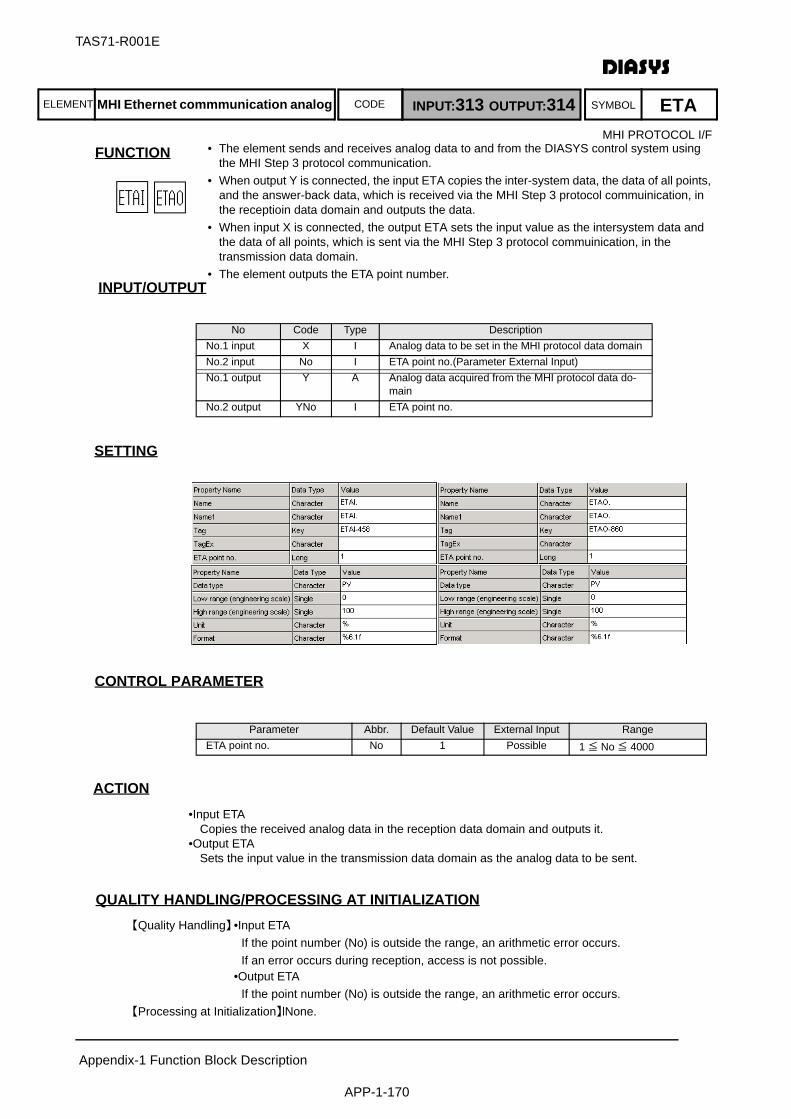
ELEMENT SYMBOLCODE
TAS71-R001E
Appendix-1 Function Block Description
APP-1-170
FUNCTION
INPUT/OUTPUT
SETTING
初期化時の処理CONTROL PARAMETER
ACTION•Input ETA
Copies the received analog data in the reception data domain and outputs it.•Output ETA
Sets the input value in the transmission data domain as the analog data to be sent.
QUALITY HANDLING/PROCESSING AT INITIALIZATION【Quality Handling】•Input ETA
If the point number (No) is outside the range, an arithmetic error occurs.If an error occurs during reception, access is not possible.
•Output ETAIf the point number (No) is outside the range, an arithmetic error occurs.
【Processing at Initialization】lNone.
No Code Type DescriptionNo.1 input X I Analog data to be set in the MHI protocol data domainNo.2 input No I ETA point no.(Parameter External Input)No.1 output Y A Analog data acquired from the MHI protocol data do-
mainNo.2 output YNo I ETA point no.
Parameter Abbr. Default Value External Input RangeETA point no. No 1 Possible 1 ≦ No ≦ 4000
MHI Ethernet commmunication analog INPUT:313 OUTPUT:314 ETAMHI PROTOCOL I/F
• The element sends and receives analog data to and from the DIASYS control system using the MHI Step 3 protocol communication.
• When output Y is connected, the input ETA copies the inter-system data, the data of all points, and the answer-back data, which is received via the MHI Step 3 protocol commuinication, in the receptioin data domain and outputs the data.
• When input X is connected, the output ETA sets the input value as the intersystem data and the data of all points, which is sent via the MHI Step 3 protocol commuinication, in the transmission data domain.
• The element outputs the ETA point number.

ELEMENT SYMBOLCODE
TAS71-R001E
Appendix-1 Function Block Description
APP-1-171
FUNCTION
INPUT/OUTPUT
SETTING
初期化時の処理CONTROL PARAMETERNothing
ACTIONNo action
QUALITY HANDLING/PROCESSING AT INITIALIZATION【Quality Handling】None.【Processing at Initialization】None.
No Code Type DescriptionNo.1 output RCV A Reception counter (0.0 - 9999.0)No.2 output PCH A P channel reception counter (0.0 - 9999.0)No.3 output QCH A Q channel reception counter (0.0 - 9999.0)No.4 output CNT D ControlNo.5 output STB D (Not used)No.6 output OFL D (Not used)No.7 output FL D Major system failureNo.8 output AF D (Not used)No.9 output AB D Minor system failureNo.10 output TOF D (Not used)No.11 output MAN D (Not used)No.12 output RED D (Not used)No.13 output IDA D (Not used)No.14 output IDB D (Not used)No.15 output NRA D (Not used)No.16 output NRB D (Not used)No.17 output INI D (Not used)No.18 output SDN D (Not used)No.19 output CMP D (Not used)
OPS station 315 OPS
• Each OPS periodically sends the system status packet to show its operating status.
• This block allows the logic to acquire the counter of the received system status packets of each OPS and the operating status sent by each OPS.
• The output of this block can be used to write the warning logic for indicating such as the abnormal OPS status.
SYSTEM FUNCTIONS

ELEMENT SYMBOLCODE
TAS71-R001E
Appendix-1 Function Block Description
APP-1-172
FUNCTION
INPUT/OUTPUT
SETTING
初期化時の処理CONTROL PARAMETERNothing
ACTIONNo action
QUALITY HANDLING/PROCESSING AT INITIALIZATION【Quality Handling】None.【Processing at Initialization】None.
No Code Type DescriptionNo.1 output RCV A Reception counter (0.0 - 9999.0)No.2 output PCH A P channel reception counter (0.0 - 9999.0)No.3 output QCH A Q channel reception counter (0.0 - 9999.0)No.4 output CNT D ControlNo.5 output STB D (Not used)No.6 output OFL D (Not used)No.7 output FL D Major system failureNo.8 output AF D (Not used)No.9 output AB D Minor system failureNo.10 output TOF D (Not used)No.11 output MAN D Upper limit of the long-term data registrationNo.12 output RED D (Not used)No.13 output IDA D (Not used)No.14 output IDB D (Not used)No.15 output NRA D (Not used)No.16 output NRB D (Not used)No.17 output INI D (Not used)No.18 output SDN D (Not used)No.19 output CMP D (Not used)
Accessory station 316 ACS
• ACS periodically sends the system status packet to show its operating status.
• This block allows the logic to acquire the counter of the received system status packets of each ACS and the operating status sent by each ACS.
• The output of this block can be used to write the warning logic for indicating such as the abnormal ACS status.
SYSTEM FUNCTIONS

ELEMENT SYMBOLCODE
TAS71-R001E
Appendix-1 Function Block Description
APP-1-173
FUNCTION
INPUT/OUTPUT
No Code Type DescriptionNo.1 output A_RCV A Reception counter of system A (0.0 - 9999.0)No.2 output B_RCV A Reception counter of system B (0.0 - 9999.0)No.3 output A_PCH A P channel reception counter of system A (0.0 - 9999.0)No.4 output A_QCH A Q channel reception counter of system A (0.0 - 9999.0)No.5 output B_PCH A P channel reception counter of system B (0.0 - 9999.0)No.6 output B_QCH A Q channel reception counter of system B (0.0 - 9999.0)No.7 output A_CNT D Control by system ANo.8 output A_STB D System A is standing by.No.9 output A_OFL D System A is offline.No.10 output A_FL D Major system failure in system ANo.11 output A_AF D Minor system failure in system A
(switchover to the other system)No.12 output A_AB D Minor system failure in system ANo.13 output A_TOF D Tracking is OFF in system A.No.14 output A_MAN D Manual function is being used in system A.No.15 output A_RED D System A of duplexed systemNo.16 output A_IDA D System A recognizes that system A is the active system.No.17 output A_IDB D System A recognizes that system B is the active system.No.18 output A_NRA D System A recognizes that the CPU is normal in the active
system.No.19 output A_NRB D System A recognizes that the CPU is normal in the
standby system.No.20 output A_INI D System A is being initialized.No.21 output A_SDN D System A shutdown is completed.No.22 output A_CMP D System A initialization is completed.No.23 output B_CNT D Control by system BNo.24 output B_STB D System B is standing by.No.25 output A_OFL D System B is offline.No.26 output A_FL D Major system failure in system BNo.27 output A_AF D Minor system failure in system B
(switchover to the other system)No.28 output A_AB D Minor system failure in system BNo.29 output A_TOF D Tracking is OFF in system B,No.30 output A_MAN D Manual function is being used in system B.No.31 output A_RED D System B of duplexed systemNo.32 output A_IDA D System B recognizes that system A is the active system.No.33 output A_IDB D System B recognizes that system B is the active system.No.34 output A_NRA D System B recognizes that the CPU is normal in the active
system.No.35 output A_NRB D System B recognizes that the CPU is normal in the
standby system.No.36 output A_INI D System B is being initialized.No.37 output A_SDN D System B shutdown is completed.No.38 output A_CMP D System B initialization is completed.
Multiple process station 317 MPS
• MPS periodicallys sends the system status packet to show its operating status.
• This block allows the logic to acquire the counter of the received system status packets of each MPS and the operating status sent by each MPS.
• When MPS is duplexed, the reception counter and the operating status of each CPU in each system (A or B) can be acquired.
SYSTEM FUNCTIONS

TAS71-R001E
Appendix-1 Function Block Description
APP-1-174
SETTING
初期化時の処理CONTROL PARAMETERNothing
ACTIONNo action
QUALITY HANDLING/PROCESSING AT INITIALIZATION【Quality Handling】None.【Processing at Initialization】None.
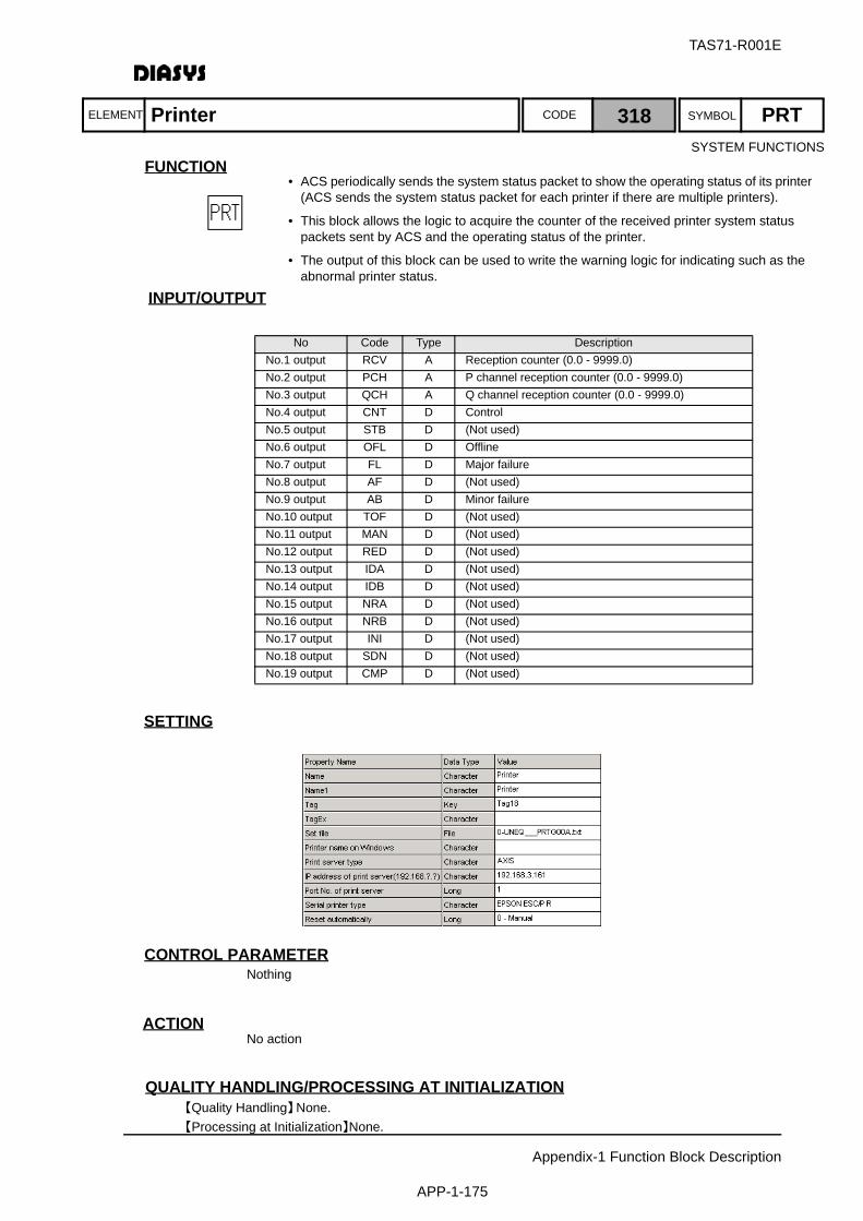
ELEMENT SYMBOLCODE
TAS71-R001E
Appendix-1 Function Block Description
APP-1-175
FUNCTION
INPUT/OUTPUT
SETTING
初期化時の処理CONTROL PARAMETERNothing
ACTIONNo action
QUALITY HANDLING/PROCESSING AT INITIALIZATION【Quality Handling】None.【Processing at Initialization】None.
No Code Type DescriptionNo.1 output RCV A Reception counter (0.0 - 9999.0)No.2 output PCH A P channel reception counter (0.0 - 9999.0)No.3 output QCH A Q channel reception counter (0.0 - 9999.0)No.4 output CNT D ControlNo.5 output STB D (Not used)No.6 output OFL D OfflineNo.7 output FL D Major failureNo.8 output AF D (Not used)No.9 output AB D Minor failureNo.10 output TOF D (Not used)No.11 output MAN D (Not used)No.12 output RED D (Not used)No.13 output IDA D (Not used)No.14 output IDB D (Not used)No.15 output NRA D (Not used)No.16 output NRB D (Not used)No.17 output INI D (Not used)No.18 output SDN D (Not used)No.19 output CMP D (Not used)
Printer 318 PRT
• ACS periodically sends the system status packet to show the operating status of its printer (ACS sends the system status packet for each printer if there are multiple printers).
• This block allows the logic to acquire the counter of the received printer system status packets sent by ACS and the operating status of the printer.
• The output of this block can be used to write the warning logic for indicating such as the abnormal printer status.
SYSTEM FUNCTIONS
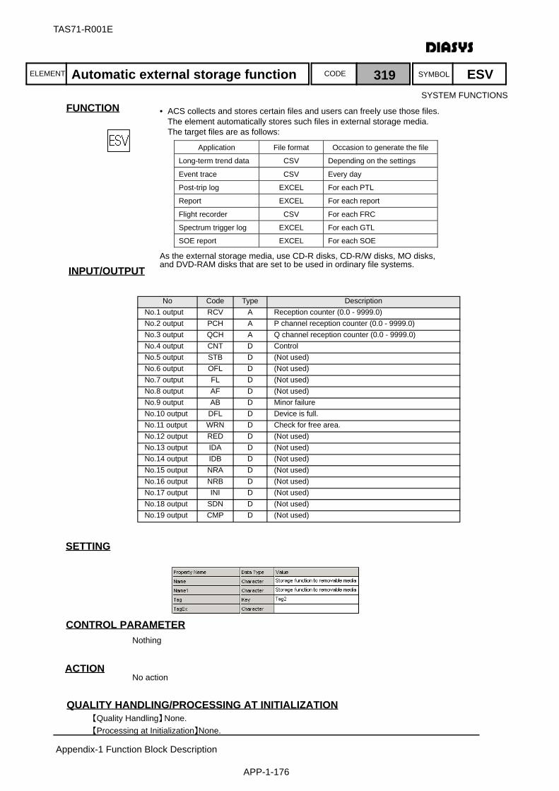
ELEMENT SYMBOLCODE
TAS71-R001E
Appendix-1 Function Block Description
APP-1-176
FUNCTION
INPUT/OUTPUT
SETTING
初期化時の処理CONTROL PARAMETERNothing
ACTIONNo action
QUALITY HANDLING/PROCESSING AT INITIALIZATION【Quality Handling】None.【Processing at Initialization】None.
No Code Type DescriptionNo.1 output RCV A Reception counter (0.0 - 9999.0)No.2 output PCH A P channel reception counter (0.0 - 9999.0)No.3 output QCH A Q channel reception counter (0.0 - 9999.0)No.4 output CNT D ControlNo.5 output STB D (Not used)No.6 output OFL D (Not used)No.7 output FL D (Not used)No.8 output AF D (Not used)No.9 output AB D Minor failureNo.10 output DFL D Device is full.No.11 output WRN D Check for free area.No.12 output RED D (Not used)No.13 output IDA D (Not used)No.14 output IDB D (Not used)No.15 output NRA D (Not used)No.16 output NRB D (Not used)No.17 output INI D (Not used)No.18 output SDN D (Not used)No.19 output CMP D (Not used)
Automatic external storage function 319 ESV
• ACS collects and stores certain files and users can freely use those files.The element automatically stores such files in external storage media. The target files are as follows:
As the external storage media, use CD-R disks, CD-R/W disks, MO disks,and DVD-RAM disks that are set to be used in ordinary file systems.
Application File format Occasion to generate the file
Long-term trend data CSV Depending on the settings
Event trace CSV Every day
Post-trip log EXCEL For each PTL
Report EXCEL For each report
Flight recorder CSV For each FRC
Spectrum trigger log EXCEL For each GTL
SOE report EXCEL For each SOE
SYSTEM FUNCTIONS

ELEMENT SYMBOLCODE
TAS71-R001E
Appendix-1 Function Block Description
APP-1-177
FUNCTION
INPUT/OUTPUT
SETTING
初期化時の処理CONTROL PARAMETER
ACTIONThe element outputs the value in the data domain of ETA without change when the switch signal isset to on (manual CRT operation mode).The element sets an input signal in the data domain of ETA and outputs the input value withoutchange when the switch signal is set to off (automated CRT operation mode).
QUALITY HANDLING/PROCESSING AT INITIALIZATION【Quality Handling】If the value of No is not within the range of 1 to 4000, the operation is the same as ETAI.
The quality of sw and No is not considered.The quality of input X is not transmitted to the output even if sw is off. Only data is set in the domain of ETA and the quality is not transmitted.When sw is on, the quality of data in the domain of ETA is output.
【Processing at Initialization】None.
No Code Type DescriptionNo.1 input X A Input dataNo.2 input sw D Switch
(O = manual CRT operation, 1 = automaited CRT operation)No.3 input No I ETA point no.(Parameter External Input)No.1 output Y A ETA point no.(Parameter External Input)
Parameter Abbr. Default Value External Input RangeETA Point no. No 1 Possible 1 ≦ No ≦ 4000
MHI PROTOCOL I/F
ETA with switch INPUT:320 OUTPUT:321 ETAS
• This element sends and receives analog data based on the MHI Step 3 protocol.
• The switch can change the direction of read and write. This element is used to switch CRT operations between automatic and manual.
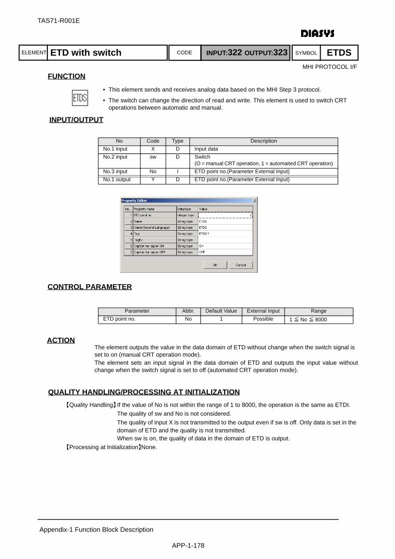
ELEMENT SYMBOLCODE
TAS71-R001E
Appendix-1 Function Block Description
APP-1-178
FUNCTION
INPUT/OUTPUT
初期化時の処理CONTROL PARAMETER
ACTIONThe element outputs the value in the data domain of ETD without change when the switch signal isset to on (manual CRT operation mode).The element sets an input signal in the data domain of ETD and outputs the input value withoutchange when the switch signal is set to off (automated CRT operation mode).
QUALITY HANDLING/PROCESSING AT INITIALIZATION【Quality Handling】If the value of No is not within the range of 1 to 8000, the operation is the same as ETDI.
The quality of sw and No is not considered.The quality of input X is not transmitted to the output even if sw is off. Only data is set in the domain of ETD and the quality is not transmitted.When sw is on, the quality of data in the domain of ETD is output.
【Processing at Initialization】None.
No Code Type DescriptionNo.1 input X D Input dataNo.2 input sw D Switch
(O = manual CRT operation, 1 = automaited CRT operation)No.3 input No I ETD point no.(Parameter External Input)No.1 output Y D ETD point no.(Parameter External Input)
Parameter Abbr. Default Value External Input RangeETD point no. No 1 Possible 1 ≦ No ≦ 8000
ETD with switch INPUT:322 OUTPUT:323 ETDSMHI PROTOCOL I/F
• This element sends and receives analog data based on the MHI Step 3 protocol.
• The switch can change the direction of read and write. This element is used to switch CRT operations between automatic and manual.
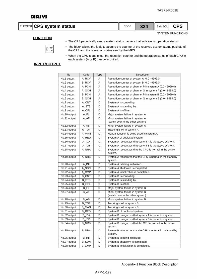
ELEMENT SYMBOLCODE
TAS71-R001E
Appendix-1 Function Block Description
APP-1-179
FUNCTION
INPUT/OUTPUT
No Code Type DescriptionNo.1 output A_RCV A Reception counter of system A (0.0 - 9999.0)No.2 output B_RCV A Reception counter of system B (0.0 - 9999.0)No.3 output A_PCH A Reception counter of channel P in system A (0.0 - 9999.0)No.4 output A_QCH A Reception counter of channel Q in system A (0.0 - 9999.0)No.5 output B_PCH A Reception counter of channel P in system B (0.0 - 9999.0)No.6 output B_QCH A Reception counter of channel Q in system B (0.0 - 9999.0)No.7 output A_CNT D System A is controlling.No.8 output A_STB D System A is standing by.No.9 output A_OFL D System A is offline.No.10 output A_FL D Major system failure in system ANo.11 output A_AF D Minor system failure in system A
(switch over to the other system)No.12 output A_AB D Minor system failure in system ANo.13 output A_TOF D Tracking is off in system A.No.14 output A_MAN D Manual function is being used in system A.No.15 output A_RED D System A of duplexed systemNo.16 output A_IDA D System A recognizes that system A is the active sys tem.No.17 output A_IDB D System A recognizes that system B is the active sys tem.No.18 output A_NRA D System A recognizes that the CPU is normal in the active
system.No.19 output A_NRB D System A recognizes that the CPU is normal in the stand by
system.No.20 output A_INI D System A is being in itialized.No.21 output A_SDN D System A shutdown is completed.No.22 output A_CMP D System A initialization is completed.No.23 output B_CNT D System B is controlling.No.24 output B_STB D System B is standing by.No.25 output B_OFL D System B is offline.No.26 output B_FL D Major system failure in system BNo.27 output B_AF D Minor system failure in system B
(switch over to the other system)No.28 output B_AB D Minor system failure in system BNo.29 output B_TOF D Tracking is off in system B.No.30 output B_MAN D Tracking is off in system B.No.31 output B_RED D System B of duplexed systemNo.32 output B_IDA D System B recognizes that system A is the active system.No.33 output B_IDB D System B recognizes that system B is the active system.No.34 output B_NRB D System B recognizes that the CPU is normal in the active
system.No.35 output B_NRA D System B recognizes that the CPU is normal in the stand by
system.No.36 output B_INI D System B is being initialized.No.37 output B_SDN D System B shutdown is completed.No.38 output B_CMP D System B initialization is completed.
CPS system status 324 CPSSYSTEM FUNCTIONS
• The CPS periodically sends system status packets that indicate its operation status.
• The block allows the logic to acquire the counter of the received system status packets of the CPS and the operation status sent by the MPS.
• When the CPS is duplexed, the reception counter and the operation status of each CPU in each system (A or B) can be acquired.
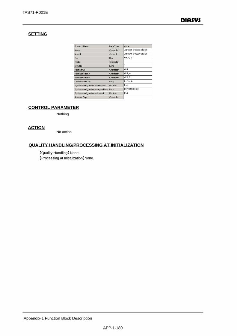
Appendix-1 Function Block Description
APP-1-180
TAS71-R001E
SETTING
初期化時の処理CONTROL PARAMETERNothing
ACTIONNo action
QUALITY HANDLING/PROCESSING AT INITIALIZATION【Quality Handling】None.【Processing at Initialization】None.
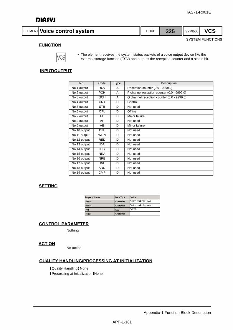
ELEMENT SYMBOLCODE
TAS71-R001E
Appendix-1 Function Block Description
APP-1-181
FUNCTION
INPUT/OUTPUT
SETTING
初期化時の処理CONTROL PARAMETERNothing
ACTIONNo action
QUALITY HANDLING/PROCESSING AT INITIALIZATION【Quality Handling】None.【Processing at Initialization】None.
No Code Type DescriptionNo.1 output RCV A Reception counter (0.0 - 9999.0)No.2 output PCH A P channel reception counter (0.0 - 9999.0)No.3 output QCH A Q channel reception counter (0.0 - 9999.0)No.4 output CNT D ControlNo.5 output STB D Not usedNo.6 output OFL D OfflineNo.7 output FL D Major failureNo.8 output AF D Not usedNo.9 output AB D Minor failureNo.10 output DFL D Not usedNo.11 output WRN D Not usedNo.12 output RED D Not usedNo.13 output IDA D Not usedNo.14 output IDB D Not usedNo.15 output NRA D Not usedNo.16 output NRB D Not usedNo.17 output INI D Not usedNo.18 output SDN D Not usedNo.19 output CMP D Not used
Voice control system 325 VCS
• The element receives the system status packets of a voice output device like the external storage function (ESV) and outputs the reception counter and a status bit.
SYSTEM FUNCTIONS

ELEMENT SYMBOLCODE
TAS71-R001E
Appendix-1 Function Block Description
APP-1-182
FUNCTION
INPUT/OUTPUT
SETTING
初期化時の処理CONTROL PARAMETERNothing
ACTIONNo action
QUALITY HANDLING/PROCESSING AT INITIALIZATION【Quality Handling】None.【Processing at Initialization】None.
No Code Type DescriptionNo.1 output RCV A Reception counter (0.0 - 9999.0)No.2 output PCH A P channel reception counter (0.0 - 9999.0)No.3 output QCH A Q channel reception counter (0.0 - 9999.0)No.4 output NOR D Normal (OR of channel 1 and channel 2)No.5 output B01 D ReservedNo.6 output B02 D ReservedNo.7 output FL D Major communication failure (Both channels have failed
when the communiation system is duplexed. One channel has failed when there is only one communication system.)
No.8 output B04 D ReservedNo.9 output AB D Minor communication failure (One channel has failed when
the communication system is duplexed.)No.10 output CH1 D Channel 1 has failed.No.11 output CH2 D Channel 2 is normal.No.12 output B08 D ReservedNo.13 output B09 D ReservedNo.14 output B10 D ReservedNo.15 output B11 D ReservedNo.16 output B12 D ReservedNo.17 output B13 D ReservedNo.18 output B14 D ReservedNo.19 output B15 D Reserved
Network Node 326 NND
• The element receives the system status packets of a network node and makes them displayable as system status components.
• The element receives the system status packets of a network node and makes them computable as logic elements.
SYSTEM FUNCTIONS

ELEMENT SYMBOLCODE
TAS71-R001E
Appendix-1 Function Block Description
APP-1-183
FUNCTION
INPUT/OUTPUT
SETTINGNothing
初期化時の処理CONTROL PARAMETERNothing
ACTIONNo action
QUALITY HANDLING/PROCESSING AT INITIALIZATION【Quality Handling】The quality is always normal.【Processing at Initialization】None.
No Code Type DescriptionNo.1 input X ED PB operation instructionNo.1 output Y D One-Shot signal
LOOP PLATES
PB operation 403 PB
• The element outputs the PB operation signal from OPS as a One-Shot signal.
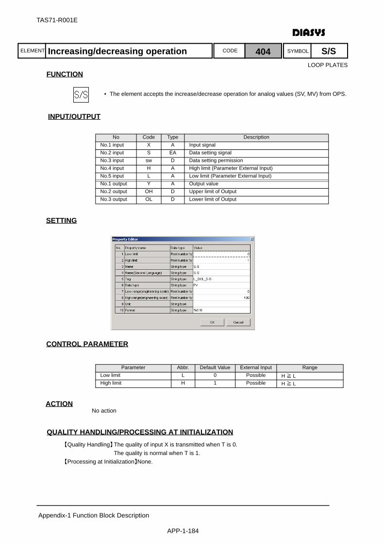
ELEMENT SYMBOLCODE
TAS71-R001E
Appendix-1 Function Block Description
APP-1-184
FUNCTION
INPUT/OUTPUT
SETTING
初期化時の処理CONTROL PARAMETER
ACTIONNo action
QUALITY HANDLING/PROCESSING AT INITIALIZATION【Quality Handling】The quality of input X is transmitted when T is 0.
The quality is normal when T is 1.【Processing at Initialization】None.
No Code Type DescriptionNo.1 input X A Input signalNo.2 input S EA Data setting signalNo.3 input sw D Data setting permissionNo.4 input H A High limit (Parameter External Input)No.5 input L A Low limit (Parameter External Input)No.1 output Y A Output valueNo.2 output OH D Upper limit of OutputNo.3 output OL D Lower limit of Output
Parameter Abbr. Default Value External Input RangeLow limit L 0 Possible H ≧ LHigh limit H 1 Possible H ≧ L
Increasing/decreasing operation 404 S/S
• The element accepts the increase/decrease operation for analog values (SV, MV) from OPS.
LOOP PLATES

ELEMENT SYMBOLCODE
TAS71-R001E
Appendix-1 Function Block Description
APP-1-185
FUNCTION
INPUT/OUTPUT
SETTING
初期化時の処理CONTROL PARAMETER
ACTIONNo action
QUALITY HANDLING/PROCESSING AT INITIALIZATION【Quality Handling】An arithmetic error occurs in the block when the following conditions are satisfied:
Upper limit of output (H) < lower limit of output (L)Length of time during which the input is not returned to the data setting signal after data is set (T) < 0
【Processing at Initialization】None.
No Code Type DescriptionNo.1 input X A Input signalNo.2 input S EA Data setting signalNo.3 input sw D Data setting permissionNo.4 input H A High limit (Parameter External Input)No.5 input L A Low limit (Parameter External Input)No.1 output Y A Output valueNo.2 output OH D Upper limit of OutputNo.3 output OL D Lower limit of Output
Parameter Abbr. Default Value External Input RangeUpper limit H 1 Possible H ≧ LLower limit L 0 Possible H ≧ LData set delay time T 1
MHI Ethernet increase/decrease operation data set 405 SSS
• The element receves an analog data setting instruction from a loop plate element and outputs a data setting instruction to the element that issued the data setting request.
MHI PROTOCOL I/F
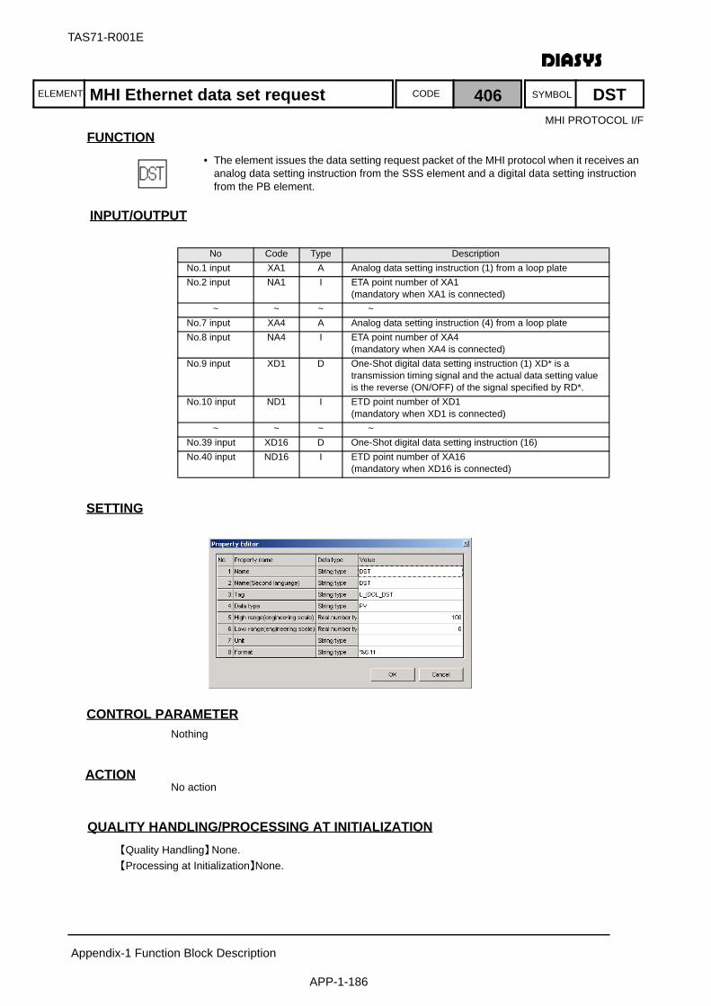
ELEMENT SYMBOLCODE
TAS71-R001E
Appendix-1 Function Block Description
APP-1-186
FUNCTION
INPUT/OUTPUT
SETTING
初期化時の処理CONTROL PARAMETERNothing
ACTIONNo action
QUALITY HANDLING/PROCESSING AT INITIALIZATION【Quality Handling】None.【Processing at Initialization】None.
No Code Type DescriptionNo.1 input XA1 A Analog data setting instruction (1) from a loop plateNo.2 input NA1 I ETA point number of XA1
(mandatory when XA1 is connected)~ ~ ~ ~
No.7 input XA4 A Analog data setting instruction (4) from a loop plateNo.8 input NA4 I ETA point number of XA4
(mandatory when XA4 is connected)No.9 input XD1 D One-Shot digital data setting instruction (1) XD* is a
transmission timing signal and the actual data setting value is the reverse (ON/OFF) of the signal specified by RD*.
No.10 input ND1 I ETD point number of XD1 (mandatory when XD1 is connected)
~ ~ ~ ~No.39 input XD16 D One-Shot digital data setting instruction (16)No.40 input ND16 I ETD point number of XA16
(mandatory when XD16 is connected)
MHI Ethernet data set request 406 DST
• The element issues the data setting request packet of the MHI protocol when it receives an analog data setting instruction from the SSS element and a digital data setting instruction from the PB element.
MHI PROTOCOL I/F
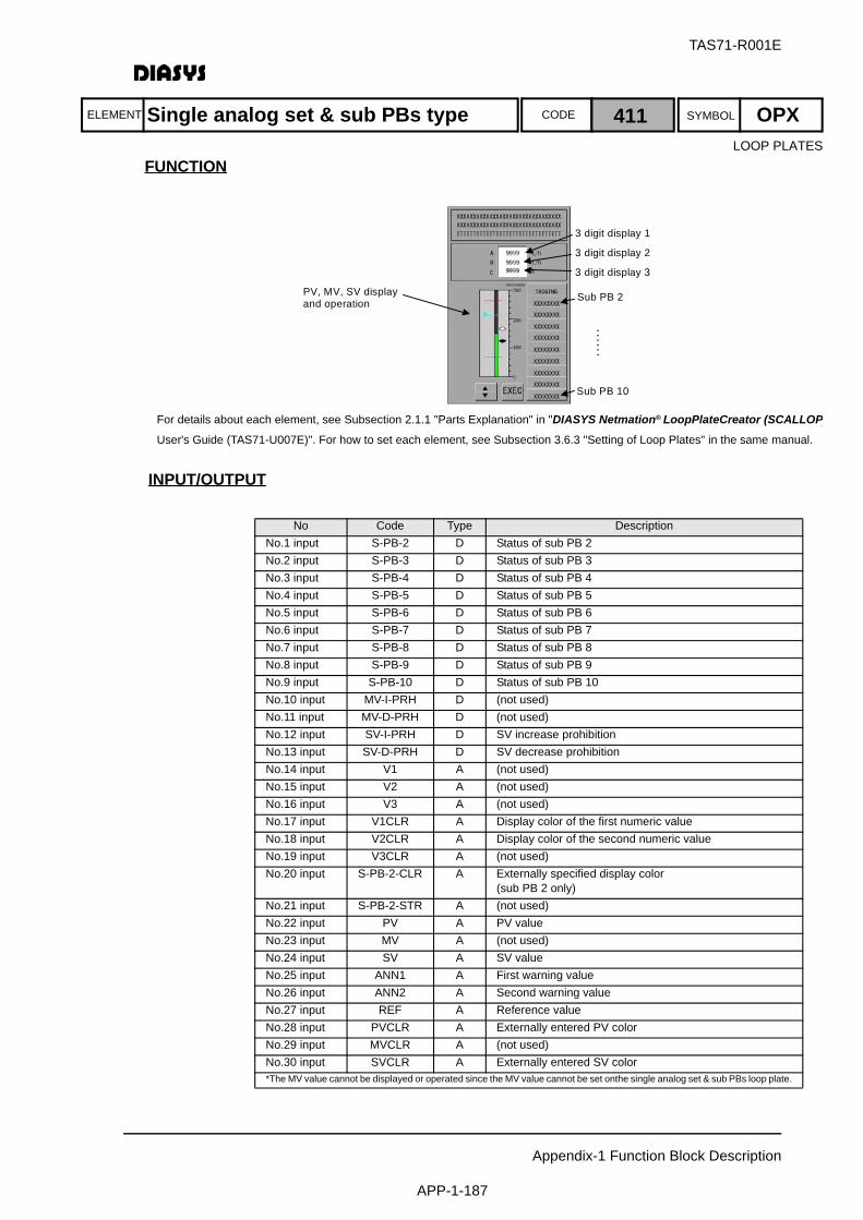
ELEMENT SYMBOLCODE
TAS71-R001E
Appendix-1 Function Block Description
APP-1-187
FUNCTION
INPUT/OUTPUT
No Code Type DescriptionNo.1 input S-PB-2 D Status of sub PB 2No.2 input S-PB-3 D Status of sub PB 3No.3 input S-PB-4 D Status of sub PB 4No.4 input S-PB-5 D Status of sub PB 5No.5 input S-PB-6 D Status of sub PB 6No.6 input S-PB-7 D Status of sub PB 7No.7 input S-PB-8 D Status of sub PB 8No.8 input S-PB-9 D Status of sub PB 9No.9 input S-PB-10 D Status of sub PB 10No.10 input MV-I-PRH D (not used)No.11 input MV-D-PRH D (not used)No.12 input SV-I-PRH D SV increase prohibitionNo.13 input SV-D-PRH D SV decrease prohibitionNo.14 input V1 A (not used)No.15 input V2 A (not used)No.16 input V3 A (not used)No.17 input V1CLR A Display color of the first numeric valueNo.18 input V2CLR A Display color of the second numeric valueNo.19 input V3CLR A (not used)No.20 input S-PB-2-CLR A Externally specified display color
(sub PB 2 only)No.21 input S-PB-2-STR A (not used)No.22 input PV A PV valueNo.23 input MV A (not used)No.24 input SV A SV valueNo.25 input ANN1 A First warning valueNo.26 input ANN2 A Second warning valueNo.27 input REF A Reference valueNo.28 input PVCLR A Externally entered PV colorNo.29 input MVCLR A (not used)No.30 input SVCLR A Externally entered SV color*The MV value cannot be displayed or operated since the MV value cannot be set onthe single analog set & sub PBs loop plate.
3 digit display 1
3 digit display 2 3 digit display 3
Sub PB 2
Sub PB 10
……
PV, MV, SV display and operation
For details about each element, see Subsection 2.1.1 "Parts Explanation" in "DIASYS Netmation® LoopPlateCreator (SCALLOP)User's Guide (TAS71-U007E)". For how to set each element, see Subsection 3.6.3 "Setting of Loop Plates" in the same manual.
Single analog set & sub PBs type 411 OPXLOOP PLATES
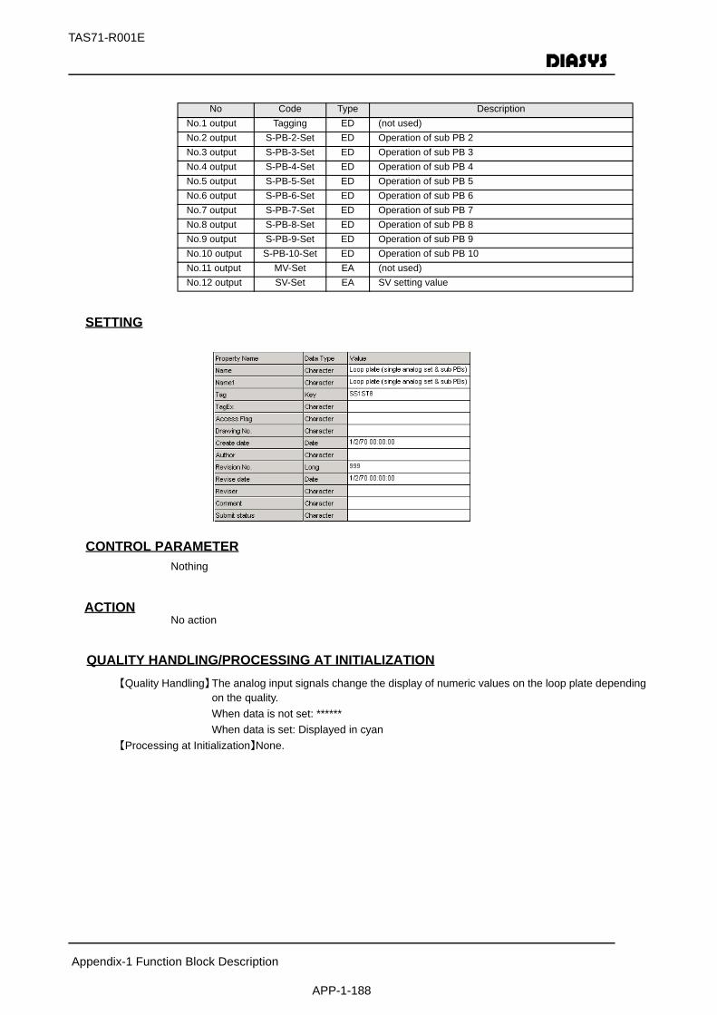
Appendix-1 Function Block Description
APP-1-188
TAS71-R001E
SETTING
初期化時の処理CONTROL PARAMETERNothing
ACTIONNo action
QUALITY HANDLING/PROCESSING AT INITIALIZATION【Quality Handling】The analog input signals change the display of numeric values on the loop plate depending
on the quality.When data is not set: ******When data is set: Displayed in cyan
【Processing at Initialization】None.
No Code Type DescriptionNo.1 output Tagging ED (not used)No.2 output S-PB-2-Set ED Operation of sub PB 2No.3 output S-PB-3-Set ED Operation of sub PB 3No.4 output S-PB-4-Set ED Operation of sub PB 4No.5 output S-PB-5-Set ED Operation of sub PB 5No.6 output S-PB-6-Set ED Operation of sub PB 6No.7 output S-PB-7-Set ED Operation of sub PB 7No.8 output S-PB-8-Set ED Operation of sub PB 8No.9 output S-PB-9-Set ED Operation of sub PB 9No.10 output S-PB-10-Set ED Operation of sub PB 10No.11 output MV-Set EA (not used)No.12 output SV-Set EA SV setting value

ELEMENT SYMBOLCODE
TAS71-R001E
Appendix-1 Function Block Description
APP-1-189
FUNCTION
INPUT/OUTPUT
No Code Type DescriptionNo.1 input S-PB-2 D Status of sub PB 2No.2 input S-PB-3 D Status of sub PB 3No.3 input S-PB-4 D Status of sub PB 4No.4 input S-PB-5 D Status of sub PB 5No.5 input S-PB-6 D Status of sub PB 6No.6 input S-PB-7 D Status of sub PB 7No.7 input S-PB-8 D Status of sub PB 8No.8 input S-PB-9 D Status of sub PB 9No.9 input S-PB-10 D Status of sub PB 10No.10 input MV-I-PRH D MV increase prohibitionNo.11 input MV-D-PRH D MV decrease prohibitionNo.12 input SV-I-PRH D SV increase prohibitionNo.13 input SV-D-PRH D SV decrease prohibitionNo.14 input V1 A (not used)No.15 input V2 A (not used)No.16 input V3 A (not used)No.17 input V1CLR A Display color of the first numeric valueNo.18 input V2CLR A Display color of the second numeric valueNo.19 input V3CLR A Display color of the third numeric valueNo.20 input S-PB-2-CLR A Externally specified display color
(sub PB 2 only)No.21 input S-PB-2-STR A (not used)No.22 input PV A PV valueNo.23 input MV A MV valueNo.24 input SV A SV valueNo.25 input ANN1 A First warning valueNo.26 input ANN2 A Second warning valueNo.27 input REF A Reference valueNo.28 input PVCLR A Externally entered PV colorNo.29 input MVCLR A Externally entered MV colorNo.30 input SVCLR A Externally entered SV color*The MV value cannot be displayed or operated since the MV value cannot be set onthe single analog set & sub PBs loop plate.
3 digit display 1
3 digit display 2
3 digit display 3
Sub PB 2
……
PV, MV, SV displayand operation
Sub PB 10
For details about each element, see Subsection 2.1.1 "Parts Explanation" in "DIASYS Netmation® LoopPlateCreator (SCALLOPUser's Guide (TAS71-U007E)". For how to set each element, see Subsection 3.6.3 "Setting of Loop Plates" in the same manual.
Multiple analog set & sub PBs type 412 OPXLOOP PLATES

Appendix-1 Function Block Description
APP-1-190
TAS71-R001E
SETTING
初期化時の処理CONTROL PARAMETERNothing
ACTIONNo action
QUALITY HANDLING/PROCESSING AT INITIALIZATION【Quality Handling】The analog input signals change the display of numeric values on the loop plate depending
on the quality.When data is not set: ******When data is set: Displayed in cyan
【Processing at Initialization】None.
No Code Type DescriptionNo.1 output Tagging ED (not used)No.2 output S-PB-2-Set ED Operation of sub PB 2No.3 output S-PB-3-Set ED Operation of sub PB 3No.4 output S-PB-4-Set ED Operation of sub PB 4No.5 output S-PB-5-Set ED Operation of sub PB 5No.6 output S-PB-6-Set ED Operation of sub PB 6No.7 output S-PB-7-Set ED Operation of sub PB 7No.8 output S-PB-8-Set ED Operation of sub PB 8No.9 output S-PB-9-Set ED Operation of sub PB 9No.10 output S-PB-10-Set ED Operation of sub PB 10No.11 output MV-Set EA MV setting valueNo.12 output SV-Set EA SV setting value
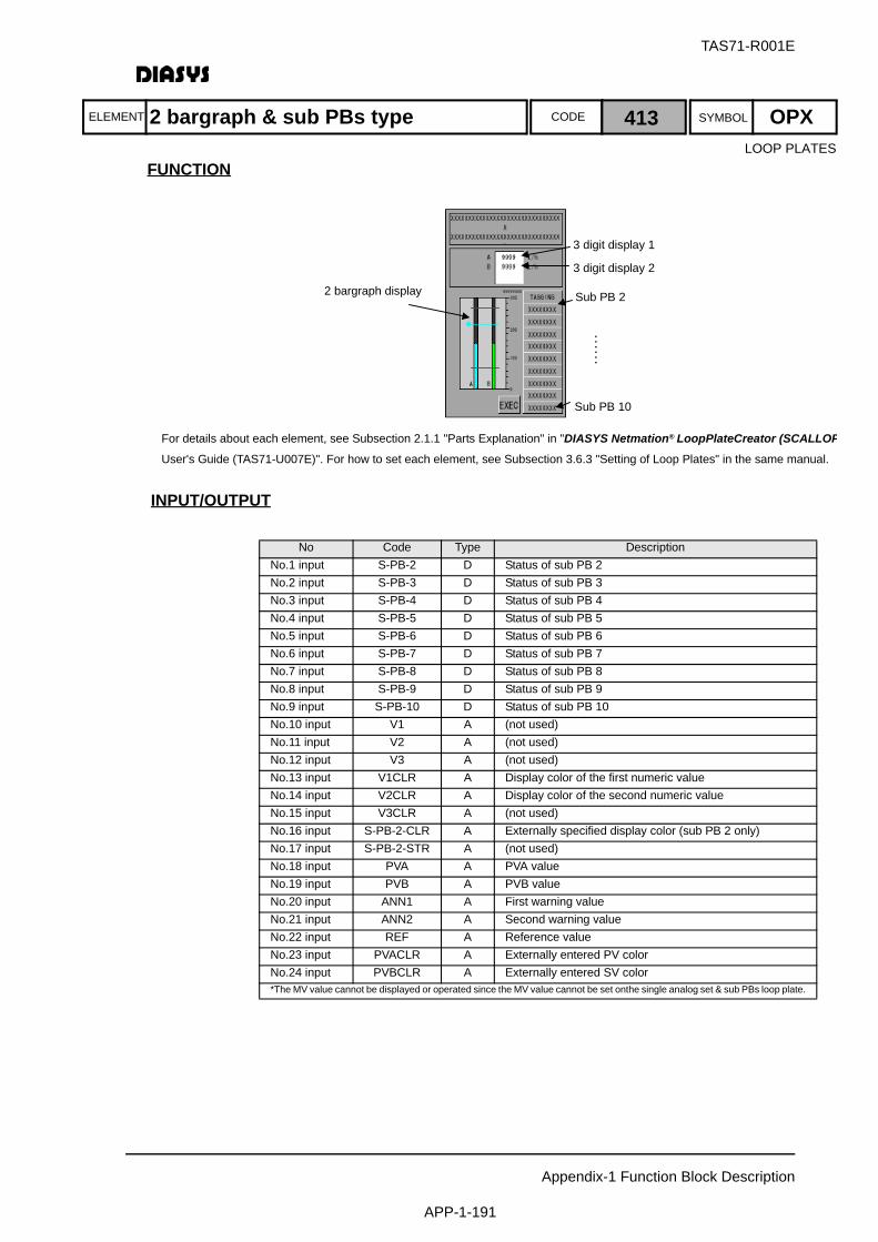
ELEMENT SYMBOLCODE
TAS71-R001E
Appendix-1 Function Block Description
APP-1-191
FUNCTION
INPUT/OUTPUT
No Code Type DescriptionNo.1 input S-PB-2 D Status of sub PB 2No.2 input S-PB-3 D Status of sub PB 3No.3 input S-PB-4 D Status of sub PB 4No.4 input S-PB-5 D Status of sub PB 5No.5 input S-PB-6 D Status of sub PB 6No.6 input S-PB-7 D Status of sub PB 7No.7 input S-PB-8 D Status of sub PB 8No.8 input S-PB-9 D Status of sub PB 9No.9 input S-PB-10 D Status of sub PB 10No.10 input V1 A (not used)No.11 input V2 A (not used)No.12 input V3 A (not used)No.13 input V1CLR A Display color of the first numeric valueNo.14 input V2CLR A Display color of the second numeric valueNo.15 input V3CLR A (not used)No.16 input S-PB-2-CLR A Externally specified display color (sub PB 2 only)No.17 input S-PB-2-STR A (not used)No.18 input PVA A PVA valueNo.19 input PVB A PVB valueNo.20 input ANN1 A First warning valueNo.21 input ANN2 A Second warning valueNo.22 input REF A Reference valueNo.23 input PVACLR A Externally entered PV colorNo.24 input PVBCLR A Externally entered SV color*The MV value cannot be displayed or operated since the MV value cannot be set onthe single analog set & sub PBs loop plate.
3 digit display 1
3 digit display 2
Sub PB 2 ……
2 bargraph display
Sub PB 10
For details about each element, see Subsection 2.1.1 "Parts Explanation" in "DIASYS Netmation® LoopPlateCreator (SCALLOPUser's Guide (TAS71-U007E)". For how to set each element, see Subsection 3.6.3 "Setting of Loop Plates" in the same manual.
LOOP PLATES
2 bargraph & sub PBs type 413 OPX

Appendix-1 Function Block Description
APP-1-192
TAS71-R001E
SETTING
初期化時の処理CONTROL PARAMETERNothing
ACTIONNo action
QUALITY HANDLING/PROCESSING AT INITIALIZATION【Quality Handling】The analog input signals change the display of numeric values on the loop plate depending
on the quality.When data is not set: ******When data is set: Displayed in cyan
【Processing at Initialization】None.
No Code Type DescriptionNo.1 output Tagging ED (not used)No.2 output S-PB-2-Set ED Operation of sub PB 2No.3 output S-PB-3-Set ED Operation of sub PB 3No.4 output S-PB-4-Set ED Operation of sub PB 4No.5 output S-PB-5-Set ED Operation of sub PB 5No.6 output S-PB-6-Set ED Operation of sub PB 6No.7 output S-PB-7-Set ED Operation of sub PB 7No.8 output S-PB-8-Set ED Operation of sub PB 8No.9 output S-PB-9-Set ED Operation of sub PB 9No.10 output S-PB-10-Set ED Operation of sub PB 10
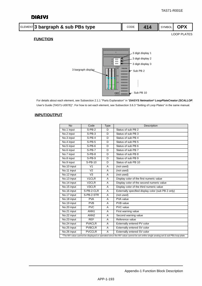
ELEMENT SYMBOLCODE
TAS71-R001E
Appendix-1 Function Block Description
APP-1-193
FUNCTION
INPUT/OUTPUT
No Code Type DescriptionNo.1 input S-PB-2 D Status of sub PB 2No.2 input S-PB-3 D Status of sub PB 3No.3 input S-PB-4 D Status of sub PB 4No.4 input S-PB-5 D Status of sub PB 5No.5 input S-PB-6 D Status of sub PB 6No.6 input S-PB-7 D Status of sub PB 7No.7 input S-PB-8 D Status of sub PB 8No.8 input S-PB-9 D Status of sub PB 9No.9 input S-PB-10 D Status of sub PB 10No.10 input V1 A (not used)No.11 input V2 A (not used)No.12 input V3 A (not used)No.13 input V1CLR A Display color of the first numeric valueNo.14 input V2CLR A Display color of the second numeric valueNo.15 input V3CLR A Display color of the third numeric valueNo.16 input S-PB-2-CLR A Externally specified display color (sub PB 2 only)No.17 input S-PB-2-STR A (not used)No.18 input PVA A PVA valueNo.19 input PVB A PVB valueNo.20 input PVC A PVC valueNo.21 input ANN1 A First warning valueNo.22 input ANN2 A Second warning valueNo.23 input REF A Reference valueNo.24 input PVACLR A Externally entered PV colorNo.25 input PVBCLR A Externally entered SV colorNo.26 input PVCCLR A Externally entered SV color*The MV value cannot be displayed or operated since the MV value cannot be set onthe single analog set & sub PBs loop plate.
3 digit display 1
3 digit display 2
3 digit display 3
Sub PB 2
……
3 bargraph display
Sub PB 10
For details about each element, see Subsection 2.1.1 "Parts Explanation" in "DIASYS Netmation® LoopPlateCreator (SCALLOP)User's Guide (TAS71-U007E)". For how to set each element, see Subsection 3.6.3 "Setting of Loop Plates" in the same manual.
LOOP PLATES
3 bargraph & sub PBs type 414 OPX

Appendix-1 Function Block Description
APP-1-194
TAS71-R001E
SETTING
初期化時の処理CONTROL PARAMETERNothing
ACTIONNo action
QUALITY HANDLING/PROCESSING AT INITIALIZATION【Quality Handling】The analog input signals change the display of numeric values on the loop plate depending
on the quality.When data is not set: ******When data is set: Displayed in cyan
【Processing at Initialization】None.
No Code Type DescriptionNo.1 output Tagging ED (not used)No.2 output S-PB-2-Set ED Operation of sub PB 2No.3 output S-PB-3-Set ED Operation of sub PB 3No.4 output S-PB-4-Set ED Operation of sub PB 4No.5 output S-PB-5-Set ED Operation of sub PB 5No.6 output S-PB-6-Set ED Operation of sub PB 6No.7 output S-PB-7-Set ED Operation of sub PB 7No.8 output S-PB-8-Set ED Operation of sub PB 8No.9 output S-PB-9-Set ED Operation of sub PB 9No.10 output S-PB-10-Set ED Operation of sub PB 10
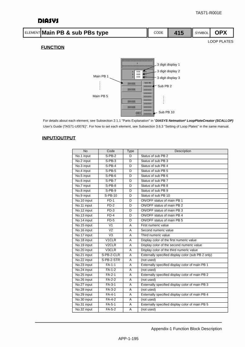
ELEMENT SYMBOLCODE
TAS71-R001E
Appendix-1 Function Block Description
APP-1-195
FUNCTION
INPUT/OUTPUT
No Code Type DescriptionNo.1 input S-PB-2 D Status of sub PB 2No.2 input S-PB-3 D Status of sub PB 3No.3 input S-PB-4 D Status of sub PB 4No.4 input S-PB-5 D Status of sub PB 5No.5 input S-PB-6 D Status of sub PB 6No.6 input S-PB-7 D Status of sub PB 7No.7 input S-PB-8 D Status of sub PB 8No.8 input S-PB-9 D Status of sub PB 9No.9 input S-PB-10 D Status of sub PB 10No.10 input FD-1 D ON/OFF status of main PB 1No.11 input FD-2 D ON/OFF status of main PB 2No.12 input FD-3 D ON/OFF status of main PB 3No.13 input FD-4 D ON/OFF status of main PB 4No.14 input FD-5 D ON/OFF status of main PB 5No.15 input V1 A First numeric valueNo.16 input V2 A Second numeric valueNo.17 input V3 A Third numeric valueNo.18 input V1CLR A Display color of the first numeric valueNo.19 input V2CLR A Display color of the second numeric valueNo.20 input V3CLR A Display color of the third numeric valueNo.21 input S-PB-2-CLR A Externally specified display color (sub PB 2 only)No.22 input S-PB-2-STR A (not used)No.23 input FA-1-1 A Externally specified display color of main PB 1No.24 input FA-1-2 A (not used)No.25 input FA-2-1 A Externally specified display color of main PB 2No.26 input FA-2-2 A (not used)No.27 input FA-3-1 A Externally specified display color of main PB 3No.28 input FA-3-2 A (not used)No.29 input FA-4-1 A Externally specified display color of main PB 4No.30 input FA-4-2 A (not used)No.31 input FA-5-1 A Externally specified display color of main PB 5No.32 input FA-5-2 A (not used)
3 digit display 1
3 digit display 2
3 digit display 3
Sub PB 2 ……
Main PB 1
Sub PB 10
Main PB 5
……
For details about each element, see Subsection 2.1.1 "Parts Explanation" in "DIASYS Netmation® LoopPlateCreator (SCALLOP) User's Guide (TAS71-U007E)". For how to set each element, see Subsection 3.6.3 "Setting of Loop Plates" in the same manual.
LOOP PLATES
Main PB & sub PBs type 415 OPX
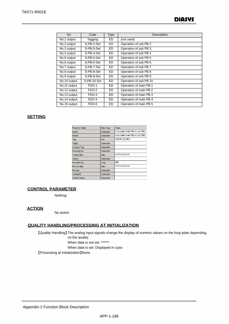
Appendix-1 Function Block Description
APP-1-196
TAS71-R001E
SETTING
初期化時の処理CONTROL PARAMETERNothing
ACTIONNo action
QUALITY HANDLING/PROCESSING AT INITIALIZATION【Quality Handling】The analog input signals change the display of numeric values on the loop plate depending
on the quality.When data is not set: ******When data is set: Displayed in cyan
【Processing at Initialization】None.
No Code Type DescriptionNo.1 output Tagging ED (not used)No.2 output S-PB-2-Set ED Operation of sub PB 2No.3 output S-PB-3-Set ED Operation of sub PB 3No.4 output S-PB-4-Set ED Operation of sub PB 4No.5 output S-PB-5-Set ED Operation of sub PB 5No.6 output S-PB-6-Set ED Operation of sub PB 6No.7 output S-PB-7-Set ED Operation of sub PB 7No.8 output S-PB-8-Set ED Operation of sub PB 8No.9 output S-PB-9-Set ED Operation of sub PB 9No.10 output S-PB-10-Set ED Operation of sub PB 10No.11 output FDO-1 ED Operation of main PB 1No.12 output FDO-2 ED Operation of main PB 2No.13 output FDO-3 ED Operation of main PB 3No.14 output FDO-4 ED Operation of main PB 4No.15 output FDO-5 ED Operation of main PB 5
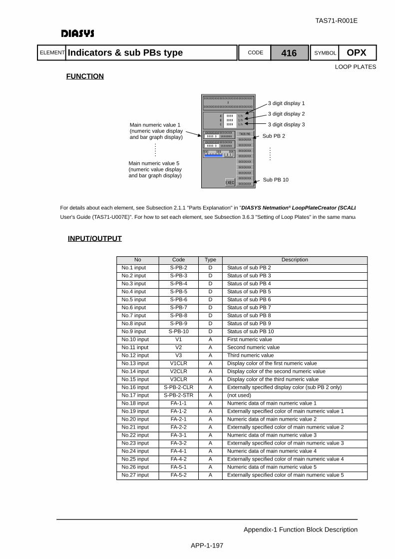
ELEMENT SYMBOLCODE
TAS71-R001E
Appendix-1 Function Block Description
APP-1-197
FUNCTION
INPUT/OUTPUT
No Code Type DescriptionNo.1 input S-PB-2 D Status of sub PB 2No.2 input S-PB-3 D Status of sub PB 3No.3 input S-PB-4 D Status of sub PB 4No.4 input S-PB-5 D Status of sub PB 5No.5 input S-PB-6 D Status of sub PB 6No.6 input S-PB-7 D Status of sub PB 7No.7 input S-PB-8 D Status of sub PB 8No.8 input S-PB-9 D Status of sub PB 9No.9 input S-PB-10 D Status of sub PB 10No.10 input V1 A First numeric valueNo.11 input V2 A Second numeric valueNo.12 input V3 A Third numeric valueNo.13 input V1CLR A Display color of the first numeric valueNo.14 input V2CLR A Display color of the second numeric valueNo.15 input V3CLR A Display color of the third numeric valueNo.16 input S-PB-2-CLR A Externally specified display color (sub PB 2 only)No.17 input S-PB-2-STR A (not used)No.18 input FA-1-1 A Numeric data of main numeric value 1No.19 input FA-1-2 A Externally specified color of main numeric value 1No.20 input FA-2-1 A Numeric data of main numeric value 2No.21 input FA-2-2 A Externally specified color of main numeric value 2No.22 input FA-3-1 A Numeric data of main numeric value 3No.23 input FA-3-2 A Externally specified color of main numeric value 3No.24 input FA-4-1 A Numeric data of main numeric value 4No.25 input FA-4-2 A Externally specified color of main numeric value 4No.26 input FA-5-1 A Numeric data of main numeric value 5No.27 input FA-5-2 A Externally specified color of main numeric value 5
3 digit display 1
3 digit display 2
3 digit display 3
Sub PB 2
……
Main numeric value 1(numeric value displayand bar graph display)
Sub PB 10
……
Main numeric value 5(numeric value displayand bar graph display)
For details about each element, see Subsection 2.1.1 "Parts Explanation" in "DIASYS Netmation® LoopPlateCreator (SCALLUser's Guide (TAS71-U007E)". For how to set each element, see Subsection 3.6.3 "Setting of Loop Plates" in the same manua
LOOP PLATES
Indicators & sub PBs type 416 OPX
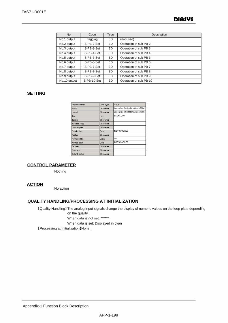
Appendix-1 Function Block Description
APP-1-198
TAS71-R001E
SETTING
初期化時の処理CONTROL PARAMETERNothing
ACTIONNo action
QUALITY HANDLING/PROCESSING AT INITIALIZATION【Quality Handling】The analog input signals change the display of numeric values on the loop plate depending
on the quality.When data is not set: ******When data is set: Displayed in cyan
【Processing at Initialization】None.
No Code Type DescriptionNo.1 output Tagging ED (not used)No.2 output S-PB-2-Set ED Operation of sub PB 2No.3 output S-PB-3-Set ED Operation of sub PB 3No.4 output S-PB-4-Set ED Operation of sub PB 4No.5 output S-PB-5-Set ED Operation of sub PB 5No.6 output S-PB-6-Set ED Operation of sub PB 6No.7 output S-PB-7-Set ED Operation of sub PB 7No.8 output S-PB-8-Set ED Operation of sub PB 8No.9 output S-PB-9-Set ED Operation of sub PB 9No.10 output S-PB-10-Set ED Operation of sub PB 10
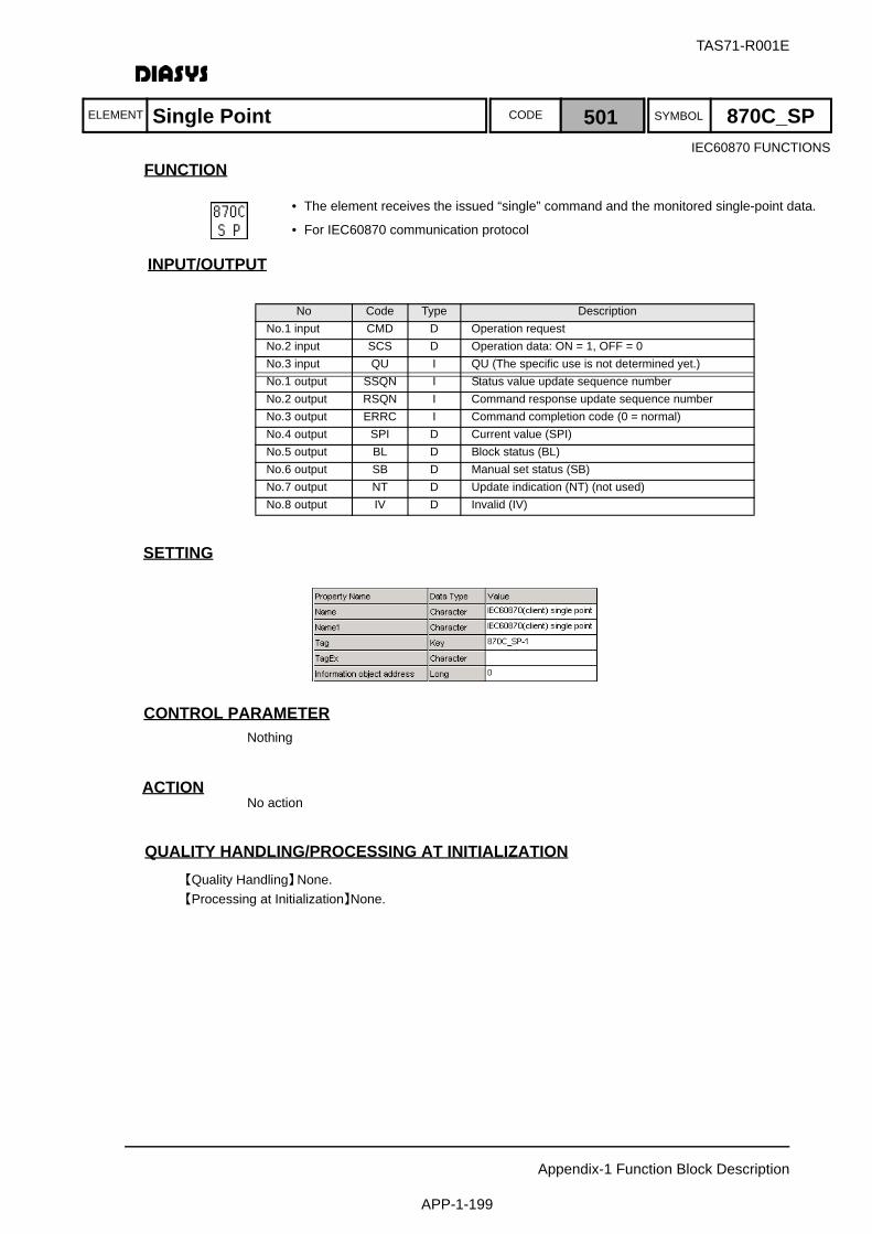
ELEMENT SYMBOLCODE
TAS71-R001E
Appendix-1 Function Block Description
APP-1-199
FUNCTION
INPUT/OUTPUT
SETTING
初期化時の処理CONTROL PARAMETERNothing
ACTIONNo action
QUALITY HANDLING/PROCESSING AT INITIALIZATION【Quality Handling】None.【Processing at Initialization】None.
No Code Type DescriptionNo.1 input CMD D Operation requestNo.2 input SCS D Operation data: ON = 1, OFF = 0No.3 input QU I QU (The specific use is not determined yet.)No.1 output SSQN I Status value update sequence numberNo.2 output RSQN I Command response update sequence numberNo.3 output ERRC I Command completion code (0 = normal)No.4 output SPI D Current value (SPI)No.5 output BL D Block status (BL)No.6 output SB D Manual set status (SB)No.7 output NT D Update indication (NT) (not used)No.8 output IV D Invalid (IV)
IEC60870 FUNCTIONS
Single Point 501 870C_SP
• The element receives the issued “single” command and the monitored single-point data.
• For IEC60870 communication protocol

ELEMENT SYMBOLCODE
TAS71-R001E
Appendix-1 Function Block Description
APP-1-200
FUNCTION
INPUT/OUTPUT
SETTING
初期化時の処理CONTROL PARAMETERNothing
ACTIONNo action
QUALITY HANDLING/PROCESSING AT INITIALIZATION【Quality Handling】None.【Processing at Initialization】None.
No Code Type DescriptionNo.1 input CMD D Operation requestNo.2 input DCS1 D Operation data (bit 0): ON = 0, OFF = 1No.3 input DCS2 D Operation data (bit 1): ON = 0, OFF = 1No.4 input QU I QU (The specific use is not determined yet.)No.1 output SSQN I Status value update sequence numberNo.2 output RSQN I Command response update sequence numberNo.3 output ERRC I Command completion code (0 = normal)No.4 output DPI1 D Current value (bit 0)No.5 output DPI2 D Current value (bit 1)No.6 output BL D Block status (BL)No.7 output SB D Manual set status (SB)No.8 output NT D Update indication (NT) (not used)No.9 output IV D Invalid (IV)
Double Point 502 870C_DP
• The element receives the issued “double” command and the monitored double-point data.
• For IEC60870 communication protocol
IEC60870 FUNCTIONS

ELEMENT SYMBOLCODE
TAS71-R001E
Appendix-1 Function Block Description
APP-1-201
FUNCTION
INPUT/OUTPUT
SETTING
初期化時の処理CONTROL PARAMETERNothing
ACTIONNo action
QUALITY HANDLING/PROCESSING AT INITIALIZATION【Quality Handling】None.【Processing at Initialization】None.
No Code Type DescriptionNo.1 input CMD D Operation requestNo.2 input SV I Set point value
(within the range of signed two-byte integers)No.3 input QL I QL (The specific use is not determined yet.)
No.1 output SSQN I Status value update sequence numberNo.2 output RSQN I Command response update sequence numberNo.3 output ERRC I Command completion code (0 = normal)No.4 output SVA I Current valueNo.5 output OV D Range over (OV)No.6 output BL D Block status (BL)No.7 output SB D Manual set status (SB)No.8 output NT D Update indication (NT) (not used)No.9 output IV D Invalid (IV)
Set Point 503 870C_ME
• The element receives the issued “set point” command and the monitored measured value and scaled value.
• The rules for converting data into integers must be defined beforehand.
• For IEC60870 communication protocol
IEC60870 FUNCTIONS
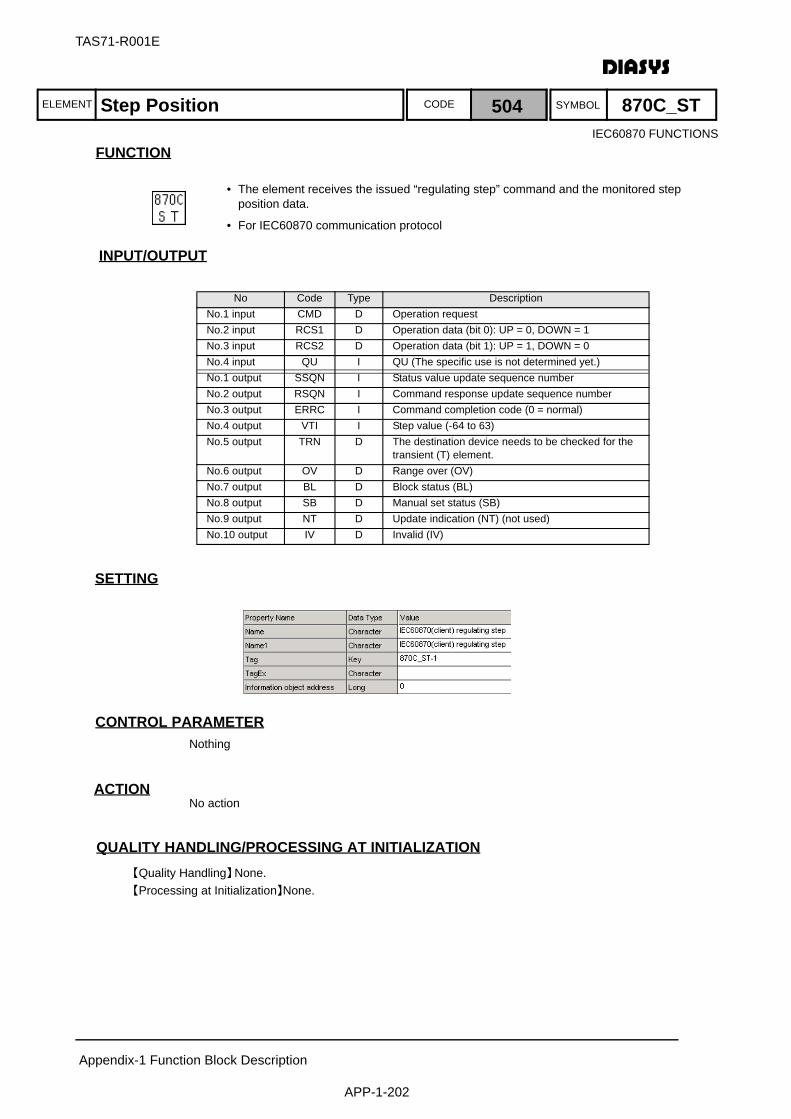
ELEMENT SYMBOLCODE
TAS71-R001E
Appendix-1 Function Block Description
APP-1-202
FUNCTION
INPUT/OUTPUT
SETTING
初期化時の処理CONTROL PARAMETERNothing
ACTIONNo action
QUALITY HANDLING/PROCESSING AT INITIALIZATION【Quality Handling】None.【Processing at Initialization】None.
No Code Type DescriptionNo.1 input CMD D Operation requestNo.2 input RCS1 D Operation data (bit 0): UP = 0, DOWN = 1No.3 input RCS2 D Operation data (bit 1): UP = 1, DOWN = 0No.4 input QU I QU (The specific use is not determined yet.)No.1 output SSQN I Status value update sequence numberNo.2 output RSQN I Command response update sequence numberNo.3 output ERRC I Command completion code (0 = normal)No.4 output VTI I Step value (-64 to 63)No.5 output TRN D The destination device needs to be checked for the
transient (T) element.No.6 output OV D Range over (OV)No.7 output BL D Block status (BL)No.8 output SB D Manual set status (SB)No.9 output NT D Update indication (NT) (not used)No.10 output IV D Invalid (IV)
Step Position 504 870C_ST
• The element receives the issued “regulating step” command and the monitored step position data.
• For IEC60870 communication protocol
IEC60870 FUNCTIONS
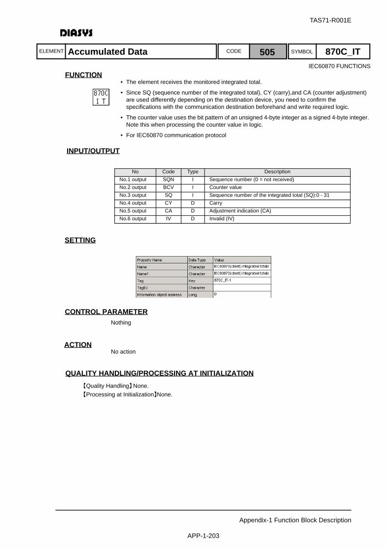
ELEMENT SYMBOLCODE
TAS71-R001E
Appendix-1 Function Block Description
APP-1-203
FUNCTION
INPUT/OUTPUT
SETTING
初期化時の処理CONTROL PARAMETERNothing
ACTIONNo action
QUALITY HANDLING/PROCESSING AT INITIALIZATION【Quality Handling】None.【Processing at Initialization】None.
No Code Type DescriptionNo.1 output SQN I Sequence number (0 = not received)No.2 output BCV I Counter valueNo.3 output SQ I Sequence number of the integrated total (SQ):0 - 31No.4 output CY D CarryNo.5 output CA D Adjustment indication (CA)No.6 output IV D Invalid (IV)
Accumulated Data 505 870C_IT
• The element receives the monitored integrated total.
• Since SQ (sequence number of the integrated total), CY (carry),and CA (counter adjustment) are used differently depending on the destination device, you need to confirm the specifications with the communication destination beforehand and write required logic.
• The counter value uses the bit pattern of an unsigned 4-byte integer as a signed 4-byte integer. Note this when processing the counter value in logic.
• For IEC60870 communication protocol
IEC60870 FUNCTIONS
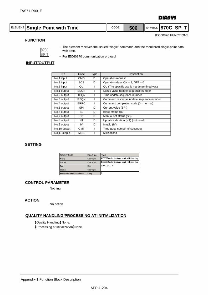
ELEMENT SYMBOLCODE
TAS71-R001E
Appendix-1 Function Block Description
APP-1-204
FUNCTION
INPUT/OUTPUT
SETTING
初期化時の処理CONTROL PARAMETERNothing
ACTIONNo action
QUALITY HANDLING/PROCESSING AT INITIALIZATION【Quality Handling】None.【Processing at Initialization】None.
No Code Type DescriptionNo.1 input CMD D Operation requestNo.2 input SCS D Operation data: ON = 1, OFF = 0No.3 input QU I QU (The specific use is not determined yet.)No.1 output SSQN I Status value update sequence numberNo.2 output TSQN I Time update sequence numberNo.3 output RSQN I Command response update sequence numberNo.4 output ERRC I Command completion code (0 = normal)No.5 output SPI D Current value (SPI)No.6 output BL D Block status (BL)No.7 output SB D Manual set status (SB)No.8 output NT D Update indication (NT) (not used)No.9 output IV D Invalid (IV)No.10 output GMT I Time (total number of seconds)No.11 output MSC I Millisecond
Single Point with Time 506 870C_SP_T
• The element receives the issued “single” command and the monitored single-point data with time.
• For IEC60870 communication protocol
IEC60870 FUNCTIONS
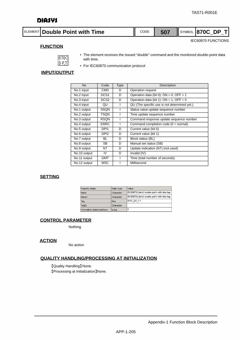
ELEMENT SYMBOLCODE
TAS71-R001E
Appendix-1 Function Block Description
APP-1-205
FUNCTION
INPUT/OUTPUT
SETTING
初期化時の処理CONTROL PARAMETERNothing
ACTIONNo action
QUALITY HANDLING/PROCESSING AT INITIALIZATION【Quality Handling】None.【Processing at Initialization】None.
No Code Type DescriptionNo.1 input CMD D Operation requestNo.2 input DCS1 D Operation data (bit 0): ON = 0, OFF = 1No.3 input DCS2 D Operation data (bit 1): ON = 1, OFF = 0No.4 input QU I QU (The specific use is not determined yet.)No.1 output SSQN I Status value update sequence numberNo.2 output TSQN I Time update sequence numberNo.3 output RSQN I Command response update sequence numberNo.4 output ERRC I Command completion code (0 = normal)No.5 output DPI1 D Current value (bit 0)No.6 output DPI2 D Current value (bit 1)No.7 output BL D Block status (BL)No.8 output SB D Manual set status (SB)No.9 output NT D Update indication (NT) (not used)No.10 output IV D Invalid (IV)No.11 output GMT I Time (total number of seconds)No.12 output MSC I Millisecond
IEC60870 FUNCTIONS
Double Point with Time 507 870C_DP_T
• The element receives the issued “double” command and the monitored double-point data with time.
• For IEC60870 communication protocol
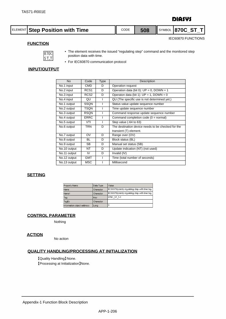
ELEMENT SYMBOLCODE
TAS71-R001E
Appendix-1 Function Block Description
APP-1-206
FUNCTION
INPUT/OUTPUT
SETTING
初期化時の処理CONTROL PARAMETERNothing
ACTIONNo action
QUALITY HANDLING/PROCESSING AT INITIALIZATION【Quality Handling】None.【Processing at Initialization】None.
No Code Type DescriptionNo.1 input CMD D Operation requestNo.2 input RCS1 D Operation data (bit 0): UP = 0, DOWN = 1No.3 input RCS2 D Operaton data (bit 1): UP = 1, DOWN = 0No.4 input QU I QU (The specific use is not determined yet.)No.1 output SSQN I Status value update sequence numberNo.2 output TSQN I Time update sequence numberNo.3 output RSQN I Command response update sequence numberNo.4 output ERRC I Command completion code (0 = normal)No.5 output VTI I Step value (-64 to 63)No.6 output TRN D The destination device needs to be checked for the
transient (T) element.No.7 output OV D Range over (OV)No.8 output BL D Block status (BL)No.9 output SB D Manual set status (SB)No.10 output NT D Update indication (NT) (not used)No.11 output IV D Invalid (IV)No.12 output GMT I Time (total number of seconds)No.13 output MSC I Millisecond
Step Position with Time 508 870C_ST_T
• The element receives the issued “regulating step” command and the monitored step position data with time.
• For IEC60870 communication protocol
IEC60870 FUNCTIONS

ELEMENT SYMBOLCODE
TAS71-R001E
Appendix-1 Function Block Description
APP-1-207
FUNCTION
INPUT/OUTPUT
SETTING
初期化時の処理CONTROL PARAMETERNothing
ACTIONNo action
QUALITY HANDLING/PROCESSING AT INITIALIZATION【Quality Handling】None.【Processing at Initialization】None.
No Code Type DescriptionNo.1 input CMD D Operation requestNo.2 input NV A Set valueNo.3 input QL I QL (The specific use is not determined yet.)No.1 output SSQN I Status value update sequence numberNo.2 output RSQN I Command response update sequence numberNo.3 output ERRC I Command completion code (0 = normal)No.4 output NVA A Current valueNo.5 output OV D Range over (OV)No.6 output BL D Block status (BL)No.7 output SB D Manual set status (SB)No.8 output NT D Update indication (NT) (not used)No.9 output IV D Invalid (IV)
IEC60870 FUNCTIONS
Normalized Value 509 870C_NV
• SThe element receives the issued “set normalized value” command and the monitored normalized value.
• The rules for normalizing data must be determined beforehand.
• For IEC60870 communication protocol

ELEMENT SYMBOLCODE
TAS71-R001E
Appendix-1 Function Block Description
APP-1-208
FUNCTION
INPUT/OUTPUT
SETTING
初期化時の処理CONTROL PARAMETERNothing
ACTIONNo action
QUALITY HANDLING/PROCESSING AT INITIALIZATION【Quality Handling】None.【Processing at Initialization】None.
No Code Type DescriptionNo.1 input CMD D Command transmission requestNo.2 input QOI I Query command modifier (0 to 255)No.1 output RSQN I Command response update sequence numberNo.2 output ERRC I Command completion code (0 = normal)
IEC60870 FUNCTIONS
Query Command 510 870C_IC
• The element issues a query command.
• For IEC60870 communication protocol
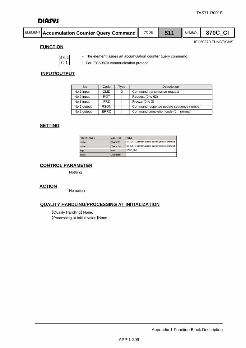
ELEMENT SYMBOLCODE
TAS71-R001E
Appendix-1 Function Block Description
APP-1-209
FUNCTION
INPUT/OUTPUT
SETTING
初期化時の処理CONTROL PARAMETERNothing
ACTIONNo action
QUALITY HANDLING/PROCESSING AT INITIALIZATION【Quality Handling】None.【Processing at Initialization】None.
No Code Type DescriptionNo.1 input CMD D Command transmission requestNo.2 input RQT I Request (0 to 63)No.3 input FRZ I Freeze (0 to 3)No.1 output RSQN I Command response update sequence numberNo.2 output ERRC I Command completion code (0 = normal)
IEC60870 FUNCTIONS
• The element issues an accumulation counter query command.
• For IEC60870 communication protocol
Accumulation Counter Query Command 511 870C_CI
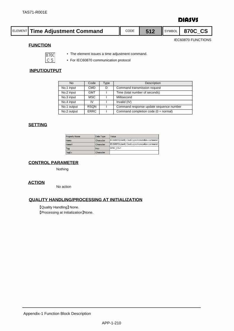
ELEMENT SYMBOLCODE
TAS71-R001E
Appendix-1 Function Block Description
APP-1-210
FUNCTION
INPUT/OUTPUT
SETTING
初期化時の処理CONTROL PARAMETERNothing
ACTIONNo action
QUALITY HANDLING/PROCESSING AT INITIALIZATION【Quality Handling】None.【Processing at Initialization】None.
No Code Type DescriptionNo.1 input CMD D Command transmission requestNo.2 input GMT I Time (total number of seconds)No.3 input MSC I MillisecondNo.4 input IV I Invalid (IV)No.1 output RSQN I Command response update sequence numberNo.2 output ERRC I Command completion code (0 = normal)
IEC60870 FUNCTIONS
Time Adjustment Command 512 870C_CS
• The element issues a time adjustment command.
• For IEC60870 communication protocol

ELEMENT SYMBOLCODE
TAS71-R001E
Appendix-1 Function Block Description
APP-1-211
FUNCTION
INPUT/OUTPUT
SETTING
初期化時の処理CONTROL PARAMETERNothing
ACTIONThe element supports the following DNP3.0 Object/Function Code:・ Analog Input(obj30)/Func Code=129(RESPONSE),130(UNSOLICITED RESPONSE)・ Analog Input Change(Obj32)/Func Code=129(RESPONSE),130(UNSOLICITED RESPONSE)
QUALITY HANDLING/PROCESSING AT INITIALIZATION【Quality Handling】None.【Processing at Initialization】None.
No Code Type DescriptionNo.1 output SSQN I Status update sequence numberNo.2 output FSQN I Quality update sequence numberNo.3 output TSQN I Time update sequence numberNo.4 output IVAL I Current value (integer)No.5 output RVAL A Current value (real number)No.6 output FLAG I Quality of the current valueNo.7 output GMT I Time of occurrence (total number of seconds)No.8 output MSEC I Time of occurrence (ms)
DNP FUNCTIONS
DNP Client Analog Input 513 DNPC_AI
• Communication element for the DNP3.0 client (AI)
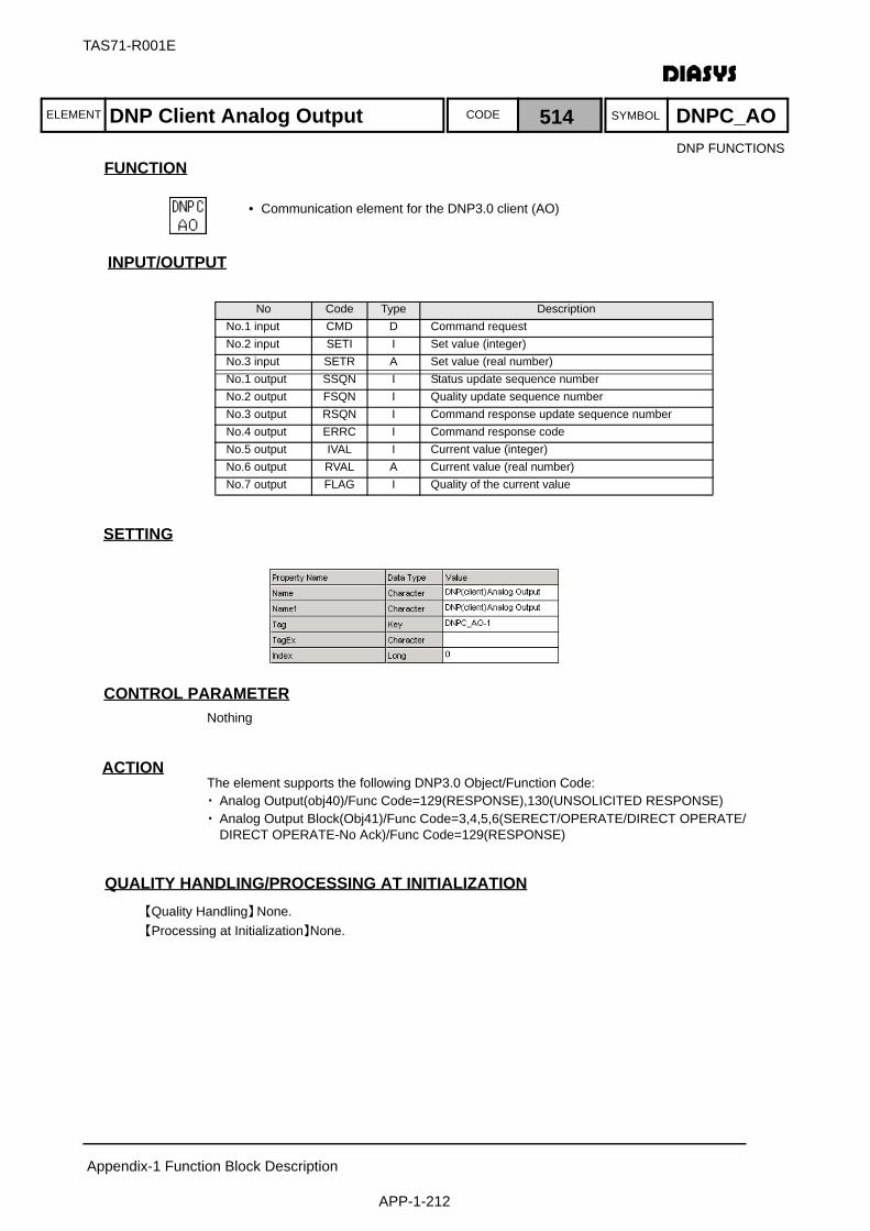
ELEMENT SYMBOLCODE
TAS71-R001E
Appendix-1 Function Block Description
APP-1-212
FUNCTION
INPUT/OUTPUT
SETTING
初期化時の処理CONTROL PARAMETERNothing
ACTIONThe element supports the following DNP3.0 Object/Function Code:・ Analog Output(obj40)/Func Code=129(RESPONSE),130(UNSOLICITED RESPONSE)・ Analog Output Block(Obj41)/Func Code=3,4,5,6(SERECT/OPERATE/DIRECT OPERATE/
DIRECT OPERATE-No Ack)/Func Code=129(RESPONSE)
QUALITY HANDLING/PROCESSING AT INITIALIZATION【Quality Handling】None.【Processing at Initialization】None.
No Code Type DescriptionNo.1 input CMD D Command requestNo.2 input SETI I Set value (integer)No.3 input SETR A Set value (real number)No.1 output SSQN I Status update sequence numberNo.2 output FSQN I Quality update sequence numberNo.3 output RSQN I Command response update sequence numberNo.4 output ERRC I Command response codeNo.5 output IVAL I Current value (integer)No.6 output RVAL A Current value (real number)No.7 output FLAG I Quality of the current value
DNP FUNCTIONS
DNP Client Analog Output 514 DNPC_AO
• Communication element for the DNP3.0 client (AO)
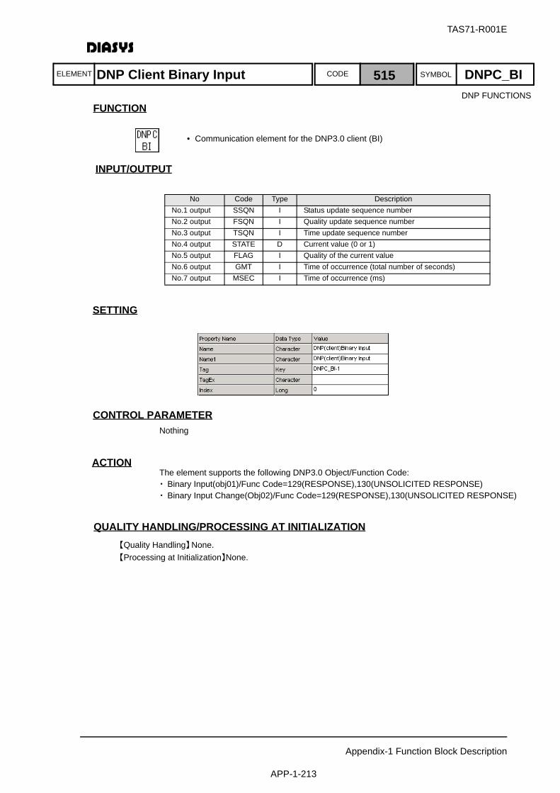
ELEMENT SYMBOLCODE
TAS71-R001E
Appendix-1 Function Block Description
APP-1-213
FUNCTION
INPUT/OUTPUT
SETTING
初期化時の処理CONTROL PARAMETERNothing
ACTIONThe element supports the following DNP3.0 Object/Function Code:・Binary Input(obj01)/Func Code=129(RESPONSE),130(UNSOLICITED RESPONSE)・Binary Input Change(Obj02)/Func Code=129(RESPONSE),130(UNSOLICITED RESPONSE)
QUALITY HANDLING/PROCESSING AT INITIALIZATION【Quality Handling】None.【Processing at Initialization】None.
No Code Type DescriptionNo.1 output SSQN I Status update sequence numberNo.2 output FSQN I Quality update sequence numberNo.3 output TSQN I Time update sequence numberNo.4 output STATE D Current value (0 or 1)No.5 output FLAG I Quality of the current valueNo.6 output GMT I Time of occurrence (total number of seconds)No.7 output MSEC I Time of occurrence (ms)
DNP FUNCTIONS
DNP Client Binary Input 515 DNPC_BI
• Communication element for the DNP3.0 client (BI)
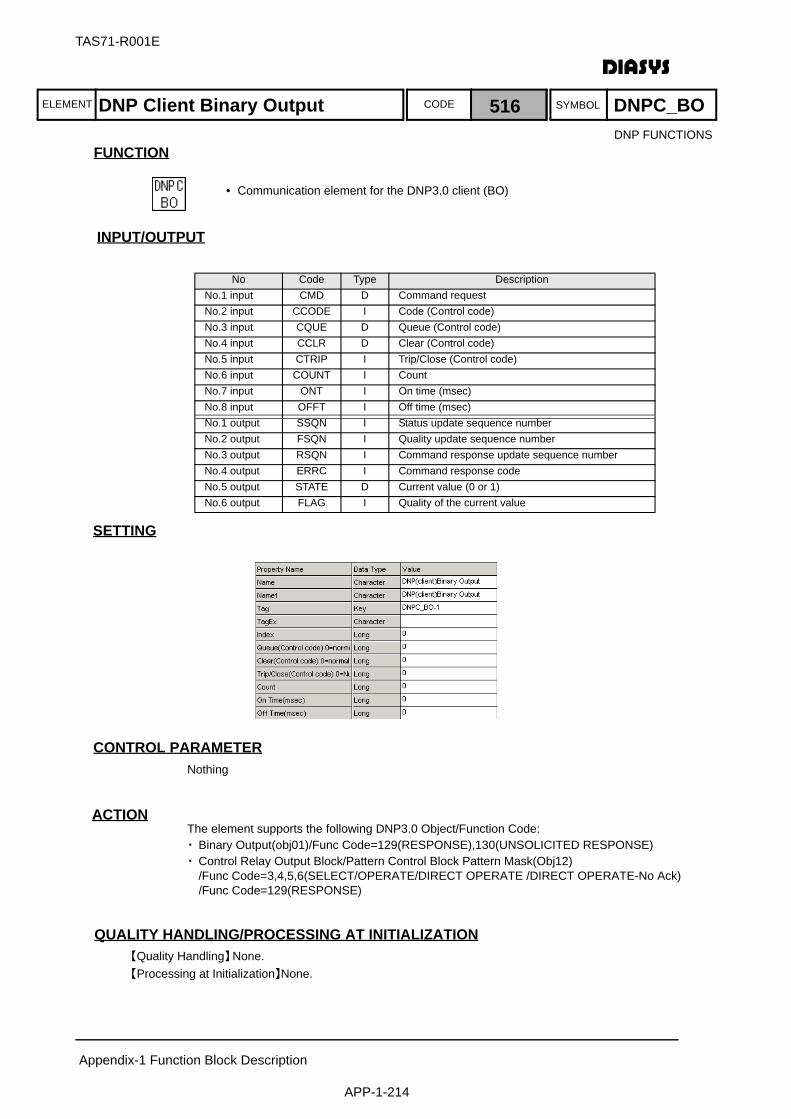
ELEMENT SYMBOLCODE
TAS71-R001E
Appendix-1 Function Block Description
APP-1-214
FUNCTION
INPUT/OUTPUT
SETTING
初期化時の処理CONTROL PARAMETERNothing
ACTIONThe element supports the following DNP3.0 Object/Function Code:・Binary Output(obj01)/Func Code=129(RESPONSE),130(UNSOLICITED RESPONSE)・Control Relay Output Block/Pattern Control Block Pattern Mask(Obj12)
/Func Code=3,4,5,6(SELECT/OPERATE/DIRECT OPERATE /DIRECT OPERATE-No Ack)/Func Code=129(RESPONSE)
QUALITY HANDLING/PROCESSING AT INITIALIZATION【Quality Handling】None.【Processing at Initialization】None.
No Code Type DescriptionNo.1 input CMD D Command requestNo.2 input CCODE I Code (Control code)No.3 input CQUE D Queue (Control code)No.4 input CCLR D Clear (Control code)No.5 input CTRIP I Trip/Close (Control code)No.6 input COUNT I CountNo.7 input ONT I On time (msec)No.8 input OFFT I Off time (msec)No.1 output SSQN I Status update sequence numberNo.2 output FSQN I Quality update sequence numberNo.3 output RSQN I Command response update sequence numberNo.4 output ERRC I Command response codeNo.5 output STATE D Current value (0 or 1)No.6 output FLAG I Quality of the current value
DNP FUNCTIONS
DNP Client Binary Output 516 DNPC_BO
• Communication element for the DNP3.0 client (BO)
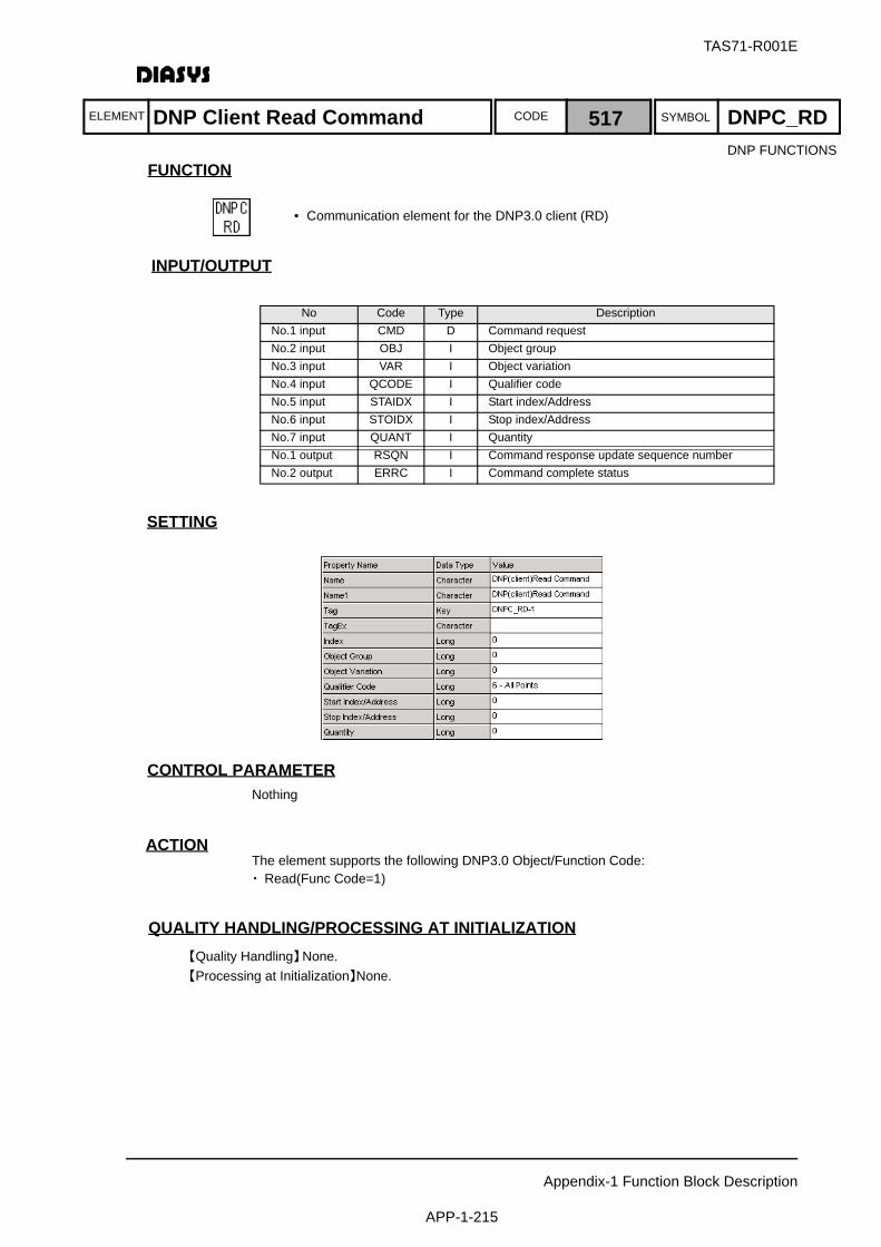
ELEMENT SYMBOLCODE
TAS71-R001E
Appendix-1 Function Block Description
APP-1-215
FUNCTION
INPUT/OUTPUT
SETTING
初期化時の処理CONTROL PARAMETERNothing
ACTIONThe element supports the following DNP3.0 Object/Function Code:・ Read(Func Code=1)
QUALITY HANDLING/PROCESSING AT INITIALIZATION【Quality Handling】None.【Processing at Initialization】None.
No Code Type DescriptionNo.1 input CMD D Command requestNo.2 input OBJ I Object groupNo.3 input VAR I Object variationNo.4 input QCODE I Qualifier codeNo.5 input STAIDX I Start index/AddressNo.6 input STOIDX I Stop index/AddressNo.7 input QUANT I QuantityNo.1 output RSQN I Command response update sequence numberNo.2 output ERRC I Command complete status
DNP FUNCTIONS
DNP Client Read Command 517 DNPC_RD
• Communication element for the DNP3.0 client (RD)

ELEMENT SYMBOLCODE
TAS71-R001E
Appendix-1 Function Block Description
APP-1-216
FUNCTION
INPUT/OUTPUT
SETTING
初期化時の処理CONTROL PARAMETERNothing
ACTIONThe element supports the following DNP3.0 Object/Function Code:・Analog Input(obj30)/Func Code=1(READ)・Analog Input Change(obj32)/Func Code=1(READ)
QUALITY HANDLING/PROCESSING AT INITIALIZATION【Quality Handling】None.【Processing at Initialization】None.
No Code Type DescriptionNo.1 input SND D Send requestNo.2 input FLAG I Quality of the current valueNo.3 input IVAL I Current value (integer)No.4 input RVAL A Current value (real number)No.5 input SFLAG I Quality of change eventNo.6 input SIVAL I Value of change event (Int)No.7 input SRVAL A Value of change event (Real)No.8 input GMT I Time of occur rence (total number of seconds)No.9 input MSEC I Time of occur rence (ms)No.1 output RSQN I Send complete sequence numberNo.2 output ERRC I Send complete code (0=normal)
DNP FUNCTIONS
DNP Server Analog Input 518 DNPS_AI
• Communication element for the DNP3.0 server (AI)
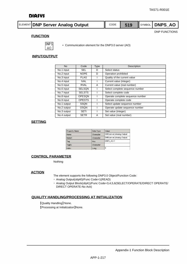
ELEMENT SYMBOLCODE
TAS71-R001E
Appendix-1 Function Block Description
APP-1-217
FUNCTION
INPUT/OUTPUT
SETTING
初期化時の処理CONTROL PARAMETERNothing
ACTIONThe element supports the following DNP3.0 Object/Function Code:・ Analog Output(obj40)/Func Code=1(READ)・ Analog Output Block(obj41)/Func Code=3,4,5,6(SELECT/OPERATE/DIRECT OPERATE/
DIRECT OPERATE-No Ack)
QUALITY HANDLING/PROCESSING AT INITIALIZATION【Quality Handling】None.【Processing at Initialization】None.
No Code Type DescriptionNo.1 input SEL D Select statusNo.2 input NOPE D Operation prohibitedNo.3 input FLAG I Quality of the current valueNo.4 input IVAL I Current value (integer)No.5 input RVAL A Current value (real number)No.6 input SELSQN I Select complete sequence numberNo.7 input SELSTS I Select complete codeNo.8 input OPESQN I Operate complete sequence numberNo.9 input OPESTS I Operate complete codeNo.1 output SSQN I Select update sequence numberNo.2 output OSQN I Operate update sequence numberNo.3 output SETI I Set value (integer)No.4 output SETR A Set value (real number)
DNP FUNCTIONS
DNP Server Analog Output 519 DNPS_AO
• Communication element for the DNP3.0 server (AO)
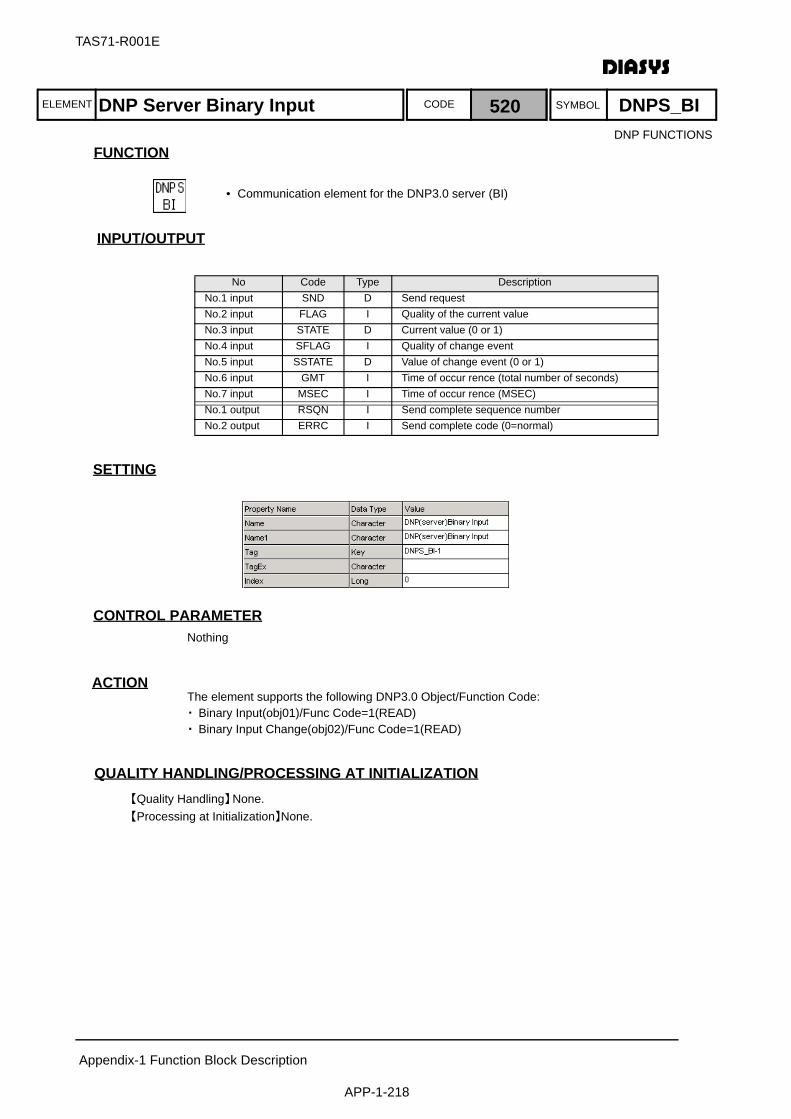
ELEMENT SYMBOLCODE
TAS71-R001E
Appendix-1 Function Block Description
APP-1-218
FUNCTION
INPUT/OUTPUT
SETTING
初期化時の処理CONTROL PARAMETERNothing
ACTIONThe element supports the following DNP3.0 Object/Function Code:・Binary Input(obj01)/Func Code=1(READ)・Binary Input Change(obj02)/Func Code=1(READ)
QUALITY HANDLING/PROCESSING AT INITIALIZATION【Quality Handling】None.【Processing at Initialization】None.
No Code Type DescriptionNo.1 input SND D Send requestNo.2 input FLAG I Quality of the current valueNo.3 input STATE D Current value (0 or 1)No.4 input SFLAG I Quality of change eventNo.5 input SSTATE D Value of change event (0 or 1)No.6 input GMT I Time of occur rence (total number of seconds)No.7 input MSEC I Time of occur rence (MSEC)No.1 output RSQN I Send complete sequence numberNo.2 output ERRC I Send complete code (0=normal)
DNP FUNCTIONS
DNP Server Binary Input 520 DNPS_BI
• Communication element for the DNP3.0 server (BI)

ELEMENT SYMBOLCODE
TAS71-R001E
Appendix-1 Function Block Description
APP-1-219
FUNCTION
INPUT/OUTPUT
SETTING
初期化時の処理CONTROL PARAMETERNothing
ACTIONThe element supports the following DNP3.0 Object/Function Code:・ Binary Output(obj10)/Func Code=1(READ)・ Control Relay Output Block/Pattern Control Block/Pattern Mask(obj12)
/Func Code=3,4,5,6(SELECT/OPERATE/DIRECT OPERATE/DIRECT OPERATE-No Ack)
QUALITY HANDLING/PROCESSING AT INITIALIZATION【Quality Handling】None.【Processing at Initialization】None.
No Code Type DescriptionNo.1 input SEL D Select statusNo.2 input NOPE D Operation prohibitedNo.3 input FLAG I Quality of the current valueNo.4 input STATE D Current value (0 or 1)No.5 input SELSQN I Select complete sequence numberNo.6 input SELSTS I Select complete codeNo.7 input OPESQN I Operate complete sequence numberNo.8 input OPESTS I Operate complete codeNo.1 output SSQN I Select update sequence numberNo.2 output OSQN I Operate update sequence numberNo.3 output CCODE I Code (Control code)No.4 output CTRIP I Trip/Close (Control code)No.5 output COUNT I CountNo.6 output ONT I On time (msec)No.7 output OFFT I Off time (msec)
DNP FUNCTIONS
DNP Server Binary Output 521 DNPS_BO
• Communication element for the DNP3.0 server (BO)
Appendix-1 Function Block Description
APP-1-220
TAS71-R001E
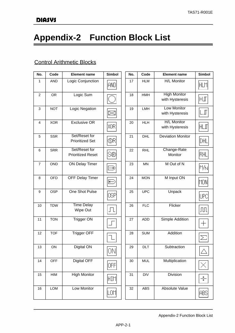
TAS71-R001E
Appendix-2 Function Block List
APP-2-1
Appendix-2 Function Block List
No. Code Element name Simbol
1 AND Logic Conjunction
2 OR Logic Sum
3 NOT Logic Negation
4 XOR Exclusive OR
5 SSR Set/Reset for Prioritized Set
6 SRR Set/Reset for Prioritized Reset
7 OND ON Delay Timer
8 OFD OFF Delay Timer
9 OSP One Shot Pulse
10 TDW Time Delay Wipe Out
11 TON Trigger ON
12 TOF Trigger OFF
13 ON Digital ON
14 OFF Digital OFF
15 HIM High Monitor
16 LOM Low Monitor
No. Code Element name Simbol
17 HLM H/L Monitor
18 HMH High Monitor with Hysteresis
19 LMH Low Monitor with Hysteresis
20 HLH H/L Monitor with Hysteresis
21 DHL Deviation Monitor
22 RHL Change-Rate Monitor
23 MN M Out of N
24 MON M Input ON
25 UPC Unpack
26 FLC Flicker
27 ADD Simple Addition
28 SUM Addition
29 DLT Subtraction
30 MUL Multiplication
31 DIV Division
32 ABS Absolute Value
Control Arithmetic Blocks

TAS71-R001E
Appendix-2 Function Block List
APP-2-2
No. Code Element name Simbol
33 ROT Square-Root Extraction
34 NEG Code Reversion
35 PWR Exponentiation
36 ZER Analog Zero Outut
37 INF Analog Maximum- Value Output
38 SG Fixed Value Setting
39 HSL High-Value Selection
40 LSL Low-Value Selection
41 MED Intermediate Value Selection
42 LMT Restriction of Upper/Lower Limit
43 LIN Linear Conversion
44 LAG Primary Delay
45 LLG Primary Progress/Delay
46 RLT Change-Rate Restriction Unit
47 MAV Move Average
48 DLY Dead Time
49 P Proportional Control
50 PR P with Range Conversion
No. Code Element name Simbol
51 PI Proportional Integral (CSR)
52 PIQ Proportional Integral (QSR)
53 D Differential Calculus
54 AM Analog Memory
55 FX Polyline Function
57 D/A Digital/Analog Conversion
59 PAC Pack
60 DT Arithmetic Cycle

TAS71-R001E
Appendix-2 Function Block List
APP-2-3
No. Code Element name Simbol
126 NLD Null Digital
127 NLA Null Analog
128 NLI Null Integer
129 THD Through Digital
130 THA Through Analog
131 THI Through Integer
132 RVD Arithmetic Order Reversed Digital
133 RVA Arithmetic Order Reversed Analog
134 RVI Arithmetic Order Reversed Integer
135 CAI Communication Analog Input
136 CAO Communication Analog Output
137 CDI Communication Digital Input
138 CDO Communication Digital Output
162 DI32 32 points digital input
163 DO32 32points digital output
164 AI8 8 points analog input
165 AO8 8 points analog output
166 RGA Register analog
No. Code Element name Simbol
101 SW Digital Switch
102 T Simple Analog Switch
103 TR Analog Switch with Rate
104 TRD Analog Switch with Differential Rate
105 OLD Previous Digital Value
106 OLA Previous Analog Value
107 DI Digital Input
108 AI Analog Input
109 PU Pulse Input
110 DO Digital Output
111 AO Analog Output
112113
CED Digital Connection between Sheet
114115
CEA Analog Conneccion between Sheet
116117
CEI Integer Connection between Sheet
118119
MCD Macro I/F Digital
120121
MCA Macro I/F Analog
122123
MCI Macro I/F Integer
124125
CID Connection Inside Sheet
Input/Output Blocks

TAS71-R001E
Appendix-2 Function Block List
APP-2-4
No. Code Element name Simbol
167 RGD Register digital
168 RGI Register integer
169 DG Digital constant
170 MD8 8 inputs intermediate

TAS71-R001E
Appendix-2 Function Block List
APP-2-5
No. Code Element name Simbol
201 DAN Digital Warning
202 AAN Analog Warning
203 EVT Event
204 SSD Dgital Operation Unit
205 QGD Quality Fetch Digital
206 QGA Quality Fetch Analog
207 QSD Quality Insertion Digital
208 QSA Quality Insertion Analog
209 AVE Average Value
210 ONT ON Time Sizing
211 ONC ON Number-of-Time Sizing
214 LDW Digital Write to All-Purpose Logic
215 LAW Analog Write to All-Purpose Logic
216 LDR Digital Read to All-Purpose Logic
217 LAR Analog Read to All-Purpose Logic
218 LDS Digital for All-Purpose Logic w/Switch
219 LAS Analog for All-Purpose Logic w/Switch
220 CLD Calendar
No. Code Element name Simbol
221 MSC Fetching msec
222 YMD Fetching Year/Month/Date/Hour/Minute/
Second/Week of the Day
223 CTM Time Creation
224 R2I Real/Integer Conversion
225 I2R Integer/Real Conversion
226 IAD Integer Addition
227 IDL Integer Subtraction
228 IML Integer Multiplication
229 IDV Integer Division
230 IMD Integer Residue
231 ISG Integer Setup
232 ISW Integer Switch
233 RTM Date/Time Output
237 QGI Quality Fetch Integer
238 QSI Quality Insertion Integer
239 LGT On-The-Hour Data
240 LGV On-The-Hour Data of Reports
242 MLG Maintenance Log
Data Logging Blocks
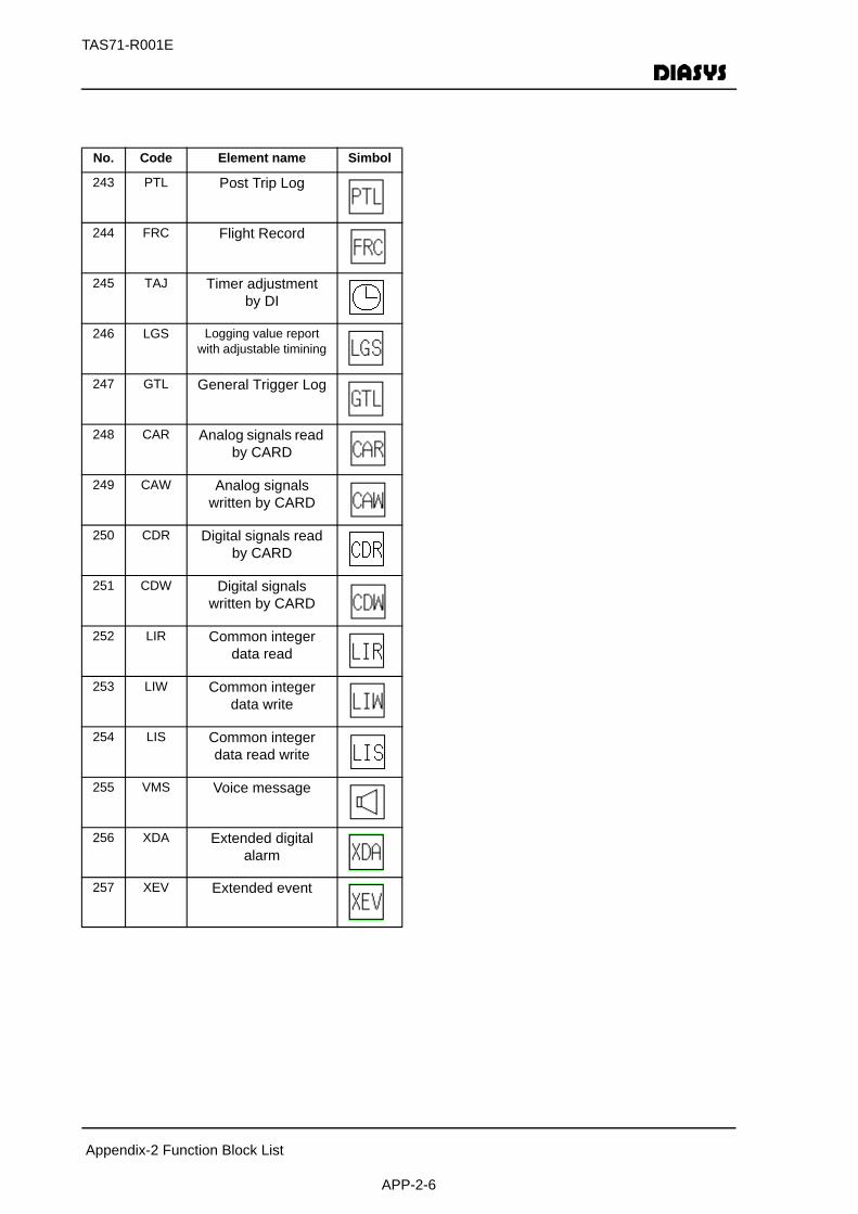
TAS71-R001E
Appendix-2 Function Block List
APP-2-6
No. Code Element name Simbol
243 PTL Post Trip Log
244 FRC Flight Record
245 TAJ Timer adjustmentby DI
246 LGS Logging value report with adjustable timining
247 GTL General Trigger Log
248 CAR Analog signals read by CARD
249 CAW Analog signals written by CARD
250 CDR Digital signals read by CARD
251 CDW Digital signals written by CARD
252 LIR Common integer data read
253 LIW Common integer data write
254 LIS Common integer data read write
255 VMS Voice message
256 XDA Extended digital alarm
257 XEV Extended event
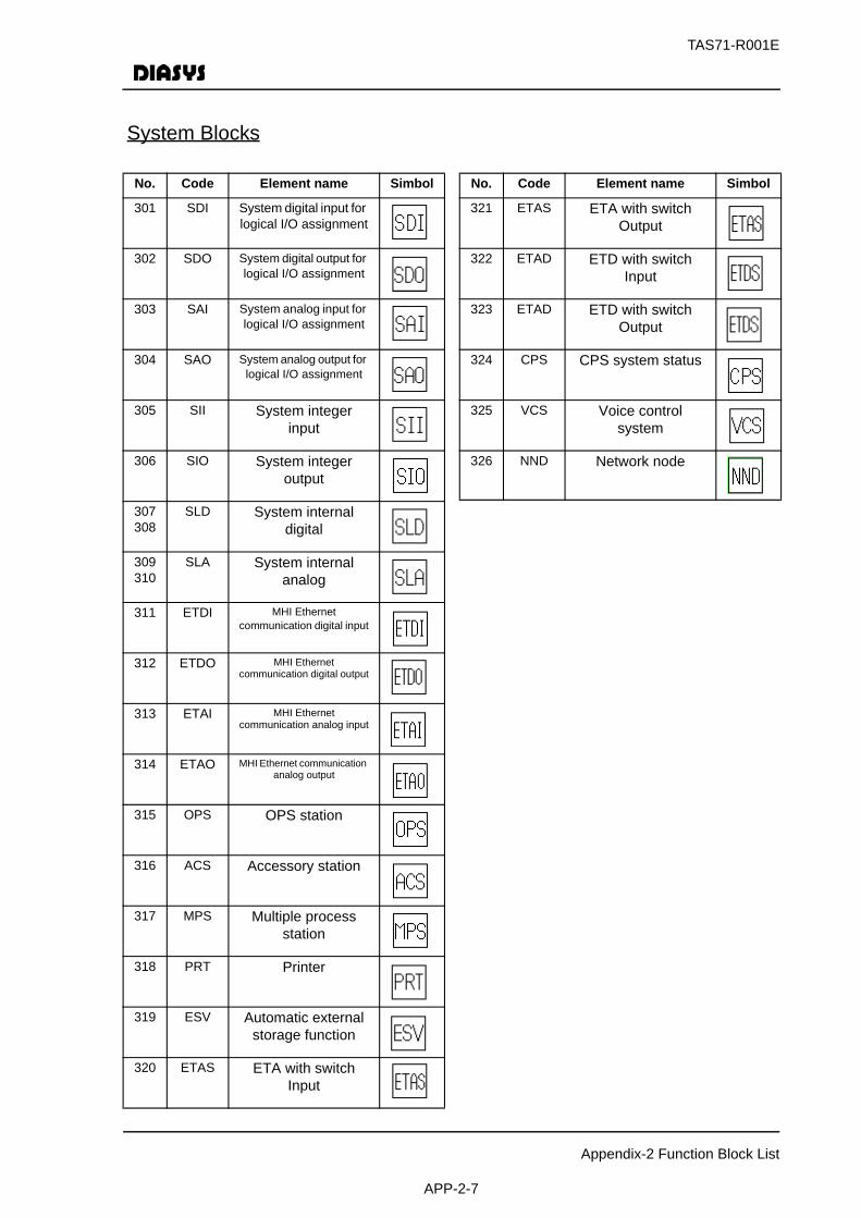
TAS71-R001E
Appendix-2 Function Block List
APP-2-7
No. Code Element name Simbol
301 SDI System digital input for logical I/O assignment
302 SDO System digital output for logical I/O assignment
303 SAI System analog input for logical I/O assignment
304 SAO System analog output for logical I/O assignment
305 SII System integer input
306 SIO System integer output
307308
SLD System internal digital
309310
SLA System internal analog
311 ETDI MHI Ethernet communication digital input
312 ETDO MHI Ethernet communication digital output
313 ETAI MHI Ethernet communication analog input
314 ETAO MHI Ethernet communication analog output
315 OPS OPS station
316 ACS Accessory station
317 MPS Multiple process station
318 PRT Printer
319 ESV Automatic external storage function
320 ETAS ETA with switch Input
No. Code Element name Simbol
321 ETAS ETA with switch Output
322 ETAD ETD with switch Input
323 ETAD ETD with switch Output
324 CPS CPS system status
325 VCS Voice control system
326 NND Network node
System Blocks

TAS71-R001E
Appendix-2 Function Block List
APP-2-8
No. Code Element name Simbol
403 PB PB operation
404 S/S Increasing/ decreasing operation
405 SSS MHI Ethernet increase/decrease operation data set
406 DST MHI Ethernet data set request
411 OPX Single analog set & sub PBs type
412 OPX Multiple analog set & sub PBs type
413 OPX 2 bargraph & sub PBs type
414 OPX 3 bargraph & sub PBs type
415 OPX Main PB & sub PBs type
416 OPX Indicators & sub PBs type
Operator Station Blocks
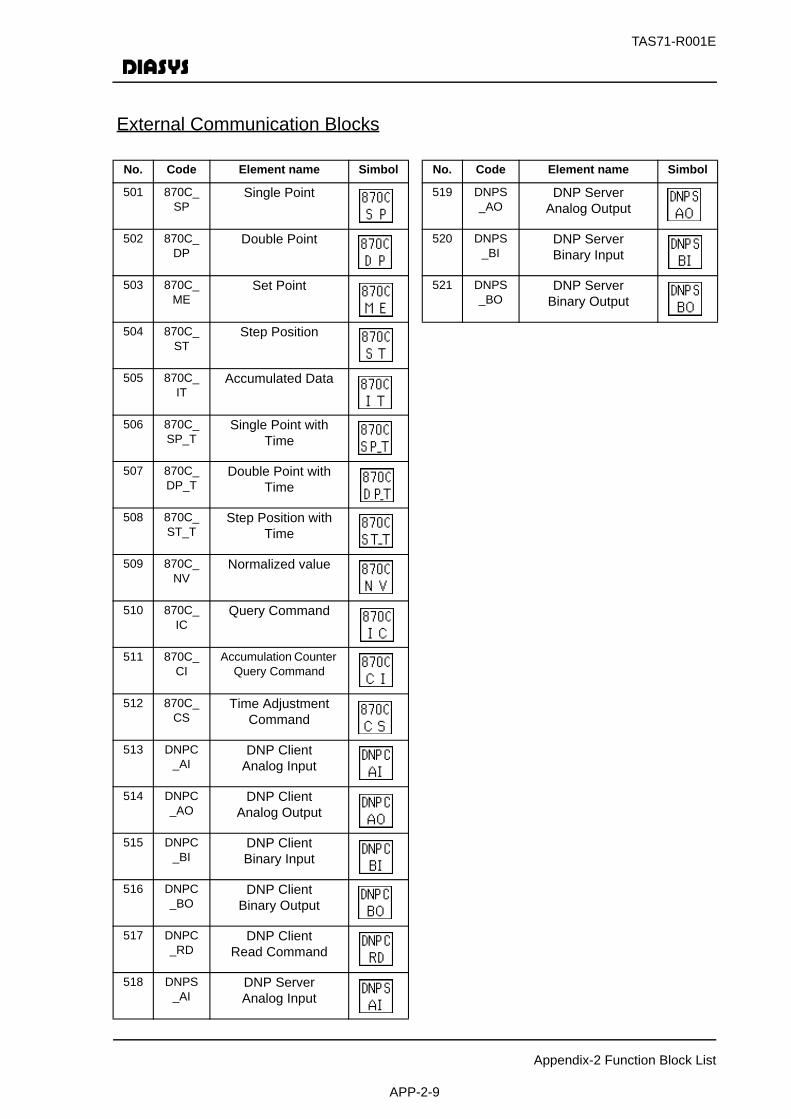
TAS71-R001E
Appendix-2 Function Block List
APP-2-9
No. Code Element name Simbol
501 870C_SP
Single Point
502 870C_DP
Double Point
503 870C_ME
Set Point
504 870C_ST
Step Position
505 870C_IT
Accumulated Data
506 870C_SP_T
Single Point with Time
507 870C_DP_T
Double Point with Time
508 870C_ST_T
Step Position with Time
509 870C_NV
Normalized value
510 870C_IC
Query Command
511 870C_CI
Accumulation Counter Query Command
512 870C_CS
Time Adjustment Command
513 DNPC_AI
DNP ClientAnalog Input
514 DNPC_AO
DNP ClientAnalog Output
515 DNPC_BI
DNP ClientBinary Input
516 DNPC_BO
DNP ClientBinary Output
517 DNPC_RD
DNP ClientRead Command
518 DNPS_AI
DNP ServerAnalog Input
No. Code Element name Simbol
519 DNPS_AO
DNP ServerAnalog Output
520 DNPS_BI
DNP ServerBinary Input
521 DNPS_BO
DNP ServerBinary Output
External Communication Blocks

TAS71-R001E
Appendix-2 Function Block List
APP-2-10
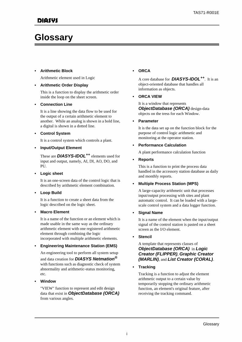
TAS71-R001E
Glossary
i
• Arithmetic BlockArithmetic element used in Logic
• Arithmetic Order DisplayThis is a function to display the arithmetic order inside the loop on the sheet screen.
• Connection LineIt is a line showing the data flow to be used for the output of a certain arithmetic element to another. While an analog is shown in a bold line, a digital is shown in a dotted line.
• Control SystemIt is a control system which controls a plant.
• Input/Output Element
These are DIASYS-IDOL++ elements used for input and output, namely, AI, DI, AO, DO, and PU.
• Logic sheetIt is an one-screen data of the control logic that is described by arithmetic element combination.
• Loop BuildIt is a function to create a sheet data from the logic described on the logic sheet.
• Macro ElementIt is a name of the function or an element which is made usable in the same way as the ordinary arithmetic element with one registered arithmetic element through combining the logic incorporated with multiple arithmetic elements.
• Engineering Maintenance Station (EMS)An engineering tool to perform all system setup and data creation for DIASYS Netmation® with functions such as diagnostic check of system abnormality and arithmetic-status monitoring, etc.
• Window"VIEW" function to represent and edit design data that exist in ObjectDatabase (ORCA) from various angles.
• ORCA
A core database for DIASYS-IDOL++. It is an object-oriented database that handles all information as objects.
• ORCA VIEWIt is a window that represents ObjectDatabase (ORCA) design-data objects on the tress for each Window.
• ParameterIt is the data set up on the function block for the purpose of control logic arithmetic and monitoring at the operator station.
• Performance CalculationA plant performance calculation function
• ReportsThis is a function to print the process data handled in the accessory station database as daily and monthly reports.
• Multiple Process Station (MPS)A large-capacity arithmetic unit that processes input/output processing with sites and plant automatic control. It can be loaded with a large-scale control system and a data logger function.
• Signal NameIt is a name of the element when the input/output signal of the control station is pasted on a sheet screen as the I/O element.
• StencilA template that represents classes of ObjectDatabase (ORCA) in Logic Creator (FLIPPER), Graphic Creator (MARLIN), and List Creator (CORAL).
• TrackingTracking is a function to adjust the element arithmetic output to a certain value by temporarily stopping the ordinary arithmetic function, an element's original feature, after receiving the tracking command.
Glossary
TAS71-R001E
Glossary
ii
MEMO
Netmation® TAS71-R001E Function Block Reference Guide
Related Documents