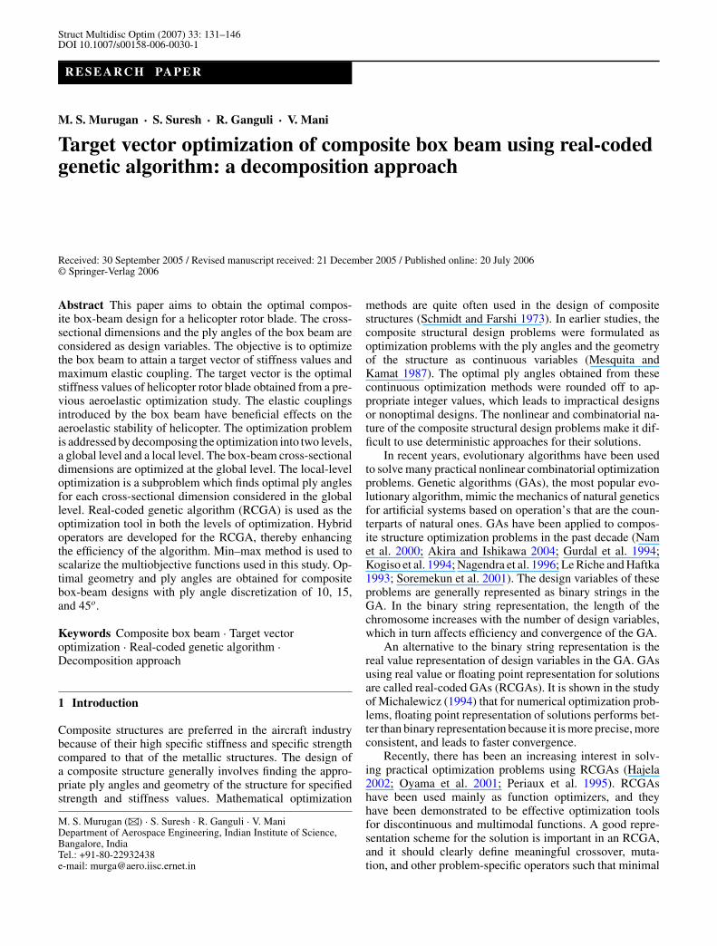
Struct Multidisc Optim (2007) 33: 131–146 DOI 10.1007/s00158-006-0030-1 RESEARCH PAPER M. S. Murugan · S. Suresh · R. Ganguli · V. Mani Target vector optimization of composite box beam using real-coded genetic algorithm: a decomposition approach Received: 30 September 2005 / Revised manuscript received: 21 December 2005 / Published online: 20 July 2006 © Springer-Verlag 2006 Abstract This paper aims to obtain the optimal compos- ite box-beam design for a helicopter rotor blade. The cross- sectional dimensions and the ply angles of the box beam are considered as design variables. The objective is to optimize the box beam to attain a target vector of stiffness values and maximum elastic coupling. The target vector is the optimal stiffness values of helicopter rotor blade obtained from a pre- vious aeroelastic optimization study. The elastic couplings introduced by the box beam have beneficial effects on the aeroelastic stability of helicopter. The optimization problem is addressed by decomposing the optimization into two levels, a global level and a local level. The box-beam cross-sectional dimensions are optimized at the global level. The local-level optimization is a subproblem which finds optimal ply angles for each cross-sectional dimension considered in the global level. Real-coded genetic algorithm (RCGA) is used as the optimization tool in both the levels of optimization. Hybrid operators are developed for the RCGA, thereby enhancing the efficiency of the algorithm. Min–max method is used to scalarize the multiobjective functions used in this study. Op- timal geometry and ply angles are obtained for composite box-beam designs with ply angle discretization of 10, 15, and 45 o . Keywords Composite box beam · Target vector optimization · Real-coded genetic algorithm · Decomposition approach 1 Introduction Composite structures are preferred in the aircraft industry because of their high specific stiffness and specific strength compared to that of the metallic structures. The design of a composite structure generally involves finding the appro- priate ply angles and geometry of the structure for specified strength and stiffness values. Mathematical optimization M. S. Murugan (B ) · S. Suresh · R. Ganguli · V. Mani Department of Aerospace Engineering, Indian Institute of Science, Bangalore, India Tel.: +91-80-22932438 e-mail: [email protected] methods are quite often used in the design of composite structures (Schmidt and Farshi 1973). In earlier studies, the composite structural design problems were formulated as optimization problems with the ply angles and the geometry of the structure as continuous variables (Mesquita and Kamat 1987). The optimal ply angles obtained from these continuous optimization methods were rounded off to ap- propriate integer values, which leads to impractical designs or nonoptimal designs. The nonlinear and combinatorial na- ture of the composite structural design problems make it dif- ficult to use deterministic approaches for their solutions. In recent years, evolutionary algorithms have been used to solve many practical nonlinear combinatorial optimization problems. Genetic algorithms (GAs), the most popular evo- lutionary algorithm, mimic the mechanics of natural genetics for artificial systems based on operation’s that are the coun- terparts of natural ones. GAs have been applied to compos- ite structure optimization problems in the past decade (Nam et al. 2000; Akira and Ishikawa 2004; Gurdal et al. 1994; Kogiso et al. 1994; Nagendra et al. 1996; Le Riche and Haftka 1993; Soremekun et al. 2001). The design variables of these problems are generally represented as binary strings in the GA. In the binary string representation, the length of the chromosome increases with the number of design variables, which in turn affects efficiency and convergence of the GA. An alternative to the binary string representation is the real value representation of design variables in the GA. GAs using real value or floating point representation for solutions are called real-coded GAs (RCGAs). It is shown in the study of Michalewicz (1994) that for numerical optimization prob- lems, floating point representation of solutions performs bet- ter than binary representation because it is more precise, more consistent, and leads to faster convergence. Recently, there has been an increasing interest in solv- ing practical optimization problems using RCGAs (Hajela 2002; Oyama et al. 2001; Periaux et al. 1995). RCGAs have been used mainly as function optimizers, and they have been demonstrated to be effective optimization tools for discontinuous and multimodal functions. A good repre- sentation scheme for the solution is important in an RCGA, and it should clearly define meaningful crossover, muta- tion, and other problem-specific operators such that minimal

Welcome message from author
This document is posted to help you gain knowledge. Please leave a comment to let me know what you think about it! Share it to your friends and learn new things together.
Transcript
Struct Multidisc Optim (2007) 33: 131–146DOI 10.1007/s00158-006-0030-1
RESEARCH PAPER
M. S. Murugan · S. Suresh · R. Ganguli · V. Mani
Target vector optimization of composite box beam using real-codedgenetic algorithm: a decomposition approach
Received: 30 September 2005 / Revised manuscript received: 21 December 2005 / Published online: 20 July 2006© Springer-Verlag 2006
Abstract This paper aims to obtain the optimal compos-ite box-beam design for a helicopter rotor blade. The cross-sectional dimensions and the ply angles of the box beam areconsidered as design variables. The objective is to optimizethe box beam to attain a target vector of stiffness values andmaximum elastic coupling. The target vector is the optimalstiffness values of helicopter rotor blade obtained from a pre-vious aeroelastic optimization study. The elastic couplingsintroduced by the box beam have beneficial effects on theaeroelastic stability of helicopter. The optimization problemis addressed by decomposing the optimization into two levels,a global level and a local level. The box-beam cross-sectionaldimensions are optimized at the global level. The local-leveloptimization is a subproblem which finds optimal ply anglesfor each cross-sectional dimension considered in the globallevel. Real-coded genetic algorithm (RCGA) is used as theoptimization tool in both the levels of optimization. Hybridoperators are developed for the RCGA, thereby enhancingthe efficiency of the algorithm. Min–max method is used toscalarize the multiobjective functions used in this study. Op-timal geometry and ply angles are obtained for compositebox-beam designs with ply angle discretization of 10, 15,and 45o.
Keywords Composite box beam · Target vectoroptimization · Real-coded genetic algorithm ·
Decomposition approach
1 Introduction
Composite structures are preferred in the aircraft industrybecause of their high specific stiffness and specific strengthcompared to that of the metallic structures. The design ofa composite structure generally involves finding the appro-priate ply angles and geometry of the structure for specifiedstrength and stiffness values. Mathematical optimization
M. S. Murugan (B) · S. Suresh · R. Ganguli · V. ManiDepartment of Aerospace Engineering, Indian Institute of Science,Bangalore, IndiaTel.: +91-80-22932438e-mail: [email protected]
methods are quite often used in the design of compositestructures (Schmidt and Farshi 1973). In earlier studies, thecomposite structural design problems were formulated asoptimization problems with the ply angles and the geometryof the structure as continuous variables (Mesquita andKamat 1987). The optimal ply angles obtained from thesecontinuous optimization methods were rounded off to ap-propriate integer values, which leads to impractical designsor nonoptimal designs. The nonlinear and combinatorial na-ture of the composite structural design problems make it dif-ficult to use deterministic approaches for their solutions.
In recent years, evolutionary algorithms have been usedto solve many practical nonlinear combinatorial optimizationproblems. Genetic algorithms (GAs), the most popular evo-lutionary algorithm, mimic the mechanics of natural geneticsfor artificial systems based on operation’s that are the coun-terparts of natural ones. GAs have been applied to compos-ite structure optimization problems in the past decade (Namet al. 2000; Akira and Ishikawa 2004; Gurdal et al. 1994;Kogiso et al. 1994; Nagendra et al. 1996; Le Riche and Haftka1993; Soremekun et al. 2001). The design variables of theseproblems are generally represented as binary strings in theGA. In the binary string representation, the length of thechromosome increases with the number of design variables,which in turn affects efficiency and convergence of the GA.
An alternative to the binary string representation is thereal value representation of design variables in the GA. GAsusing real value or floating point representation for solutionsare called real-coded GAs (RCGAs). It is shown in the studyof Michalewicz (1994) that for numerical optimization prob-lems, floating point representation of solutions performs bet-ter than binary representation because it is more precise, moreconsistent, and leads to faster convergence.
Recently, there has been an increasing interest in solv-ing practical optimization problems using RCGAs (Hajela2002; Oyama et al. 2001; Periaux et al. 1995). RCGAshave been used mainly as function optimizers, and theyhave been demonstrated to be effective optimization toolsfor discontinuous and multimodal functions. A good repre-sentation scheme for the solution is important in an RCGA,and it should clearly define meaningful crossover, muta-tion, and other problem-specific operators such that minimal
132 M. S. Murugan et al.
computational effort is involved in these procedures. The ge-netic operators defined are such that they direct the search to-wards the best possible solution zone. The quality of solutiondepends on the type of genetic operators used in the problem.Hybrid GA with different crossover and mutation operatorsat different stages of genetic process could provide effectivesolution to many practical problems. A detailed study on theeffect of hybrid crossover operators for RCGAs is presentedin the work of Herrera at al. 2002, 2003. More details abouthow GAs work for a given problem can be found in the liter-ature (Holland 1975; Goldberg 1989; David 1991).
The previous discussion showed that representation ofdesign variables is one way of increasing the efficiency ofGA. Another approach to enhance the efficiency focuseson discretization of the design space using decompositionof the actual problems into subproblems (Lee and Hajela1997; Sobieszczanski-Sobieski 1993). The design variablesinvolved in composite structural optimization are both realand discrete in nature. The representation of these real anddiscrete variables in a single string in the GA increasesthe cost of the search space. Therefore, decomposition ap-proaches have been tried in few composite optimizationstudies for increasing the efficiency (Antonio 1995, 2001).Antonio has used the bilevel strategies to decompose the opti-mization problem in two levels (Antonio 1995). The first levelmaximizes material efficiency using the ply angles as designvariables. The second level minimizes laminate weight withthe layer thickness as design variable using gradient-basedoptimization methods. A multilevel GA is developed withthe same bilevel strategy in the paper of Antonio (2001). Inthis work, the optimal ply angles are searched for a constantthickness at the first level. In the second level, optimal thick-ness is searched by fixing the optimal ply angles obtainedfrom the first level. That is, the two levels of genetic searchesare performed sequentially with different populations and fit-ness functions for faster convergence and increased efficiencyof the algorithm.
In the previous paragraphs, the methods for enhancing theefficiency of GA when applied to composite structural opti-mization are discussed. Other than that, an interesting issuein composite structural optimization is the objective functionof the study. Most of the composite structural optimizationstudies address the problem of minimizing or maximizingcertain structural characteristics using single objective opti-mization techniques. The structural characteristics generallyconsidered are weight, buckling load, stiffness, and strength(Song et al. 1995; Tauchert and Adibhatla 1984; Adali et al.1996; Park et al. 2001; Kumar and Tauchert 1992). How-ever, in some studies, the objective is to design the compos-ite structure for a specified design requirement rather thanmaximizing or minimizing its characteristics. For example, inaeroelastic optimization studies, optimization of whole struc-tural system is carried out using one-dimensional structuralproperties of each member of the system. A detailed cross-sectional analysis of each member of the system is avoidedin the aeroelastic optimization. This is because aircraft struc-tures are generally made of composites and cross-sectional
analysis of each composite structural member in a global op-timization is computationally expensive. In the later stages, atwo-dimensional cross section is designed to match the stiff-ness and/or strength requirements obtained from the globaloptimization (Chattopadhyay et al. 1991, 1995). These typesof cross-sectional design for specified requirements give riseto target vector optimization problems, which have been ad-dressed by very few researchers (Soykasap and Hodges 2000;Paik et al. 2002).
In this work, a composite box-beam cross section of ahelicopter rotor blade is optimized to meet the specific stiff-ness requirements using multiobjective optimization tech-nique and RCGA. The stiffness requirements of the rotorblade arise from a previous aeroelastic optimization study.The composite box-beam optimization in this paper differsfrom the previous composite structural optimization in threeways:
1. The objective of optimization is to find an optimal solutionto attain a target vector of stiffness values whereas mostof the previous work tried to maximize or minimize thecomposite structural characteristics. Therefore, the fitnessfunction used is the difference between the target vectorand the functional value.
2. The optimization problem is decomposed into global andlocal levels. In the global level, the overall geometry of thecomposite structure is optimized whereas the local levelfinds the optimal ply angle orientations for each geometryof the structure.
3. The design variables are encoded with the actual valuesinstead of using the binary strings in the algorithm. Thegenetic operators are designed for the real-coded repre-sentation. The proposed approach is used to optimize thecomposite box-beam structure to satisfy the specified stiff-ness values.
2 Problem formulation
Beam-type structures used in the aerospace vehicles are gen-erally made of I sections, Z sections, or box-beam cross sec-tions. The aeroelastic optimization studies of these beam-typestructures use the 1-D effective elastic stiffness values. De-signing the actual cross section for the optimal 1-D effectiveelastic stiffness values obtained from an aeroelastic optimiza-tion study is a complicated problem.
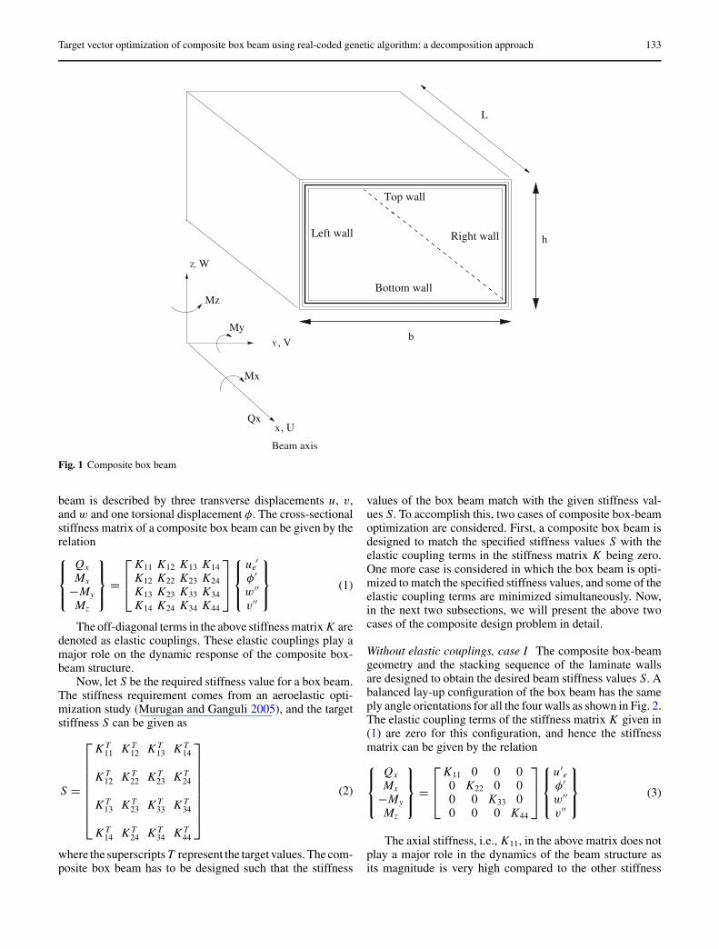
In this study, a composite box-beam design optimizationis carried out such that the optimal box-beam design satis-fies the stiffness requirements. These desirable beam stiff-ness values can come from an aeroelastic optimization studyin which the 1-D beam stiffness values are used as the de-sign variables. A direct analytical composite box-beam for-mulation presented by Smith and Chopra (1991) is used forpredicting the effective elastic stiffness of the composite boxbeam. The geometry and the coordinates of the compositebox beam are shown in Fig. 1. The deformation of the box
Target vector optimization of composite box beam using real-coded genetic algorithm: a decomposition approach 133
Left wall Right wall
Bottom wall
Top wall
h
b
L
Mx
, VY
Beam axis
X, U
WZ,
Mz
My
Qx
Fig. 1 Composite box beam
beam is described by three transverse displacements u, v,and w and one torsional displacement φ. The cross-sectionalstiffness matrix of a composite box beam can be given by therelation
Qx
Mx
−My
Mz
=
K11 K12 K13 K14K12 K22 K23 K24K13 K23 K33 K34K14 K24 K34 K44
ue′
φ′
w′′
v′′
(1)
The off-diagonal terms in the above stiffness matrix K aredenoted as elastic couplings. These elastic couplings play amajor role on the dynamic response of the composite box-beam structure.
Now, let S be the required stiffness value for a box beam.The stiffness requirement comes from an aeroelastic opti-mization study (Murugan and Ganguli 2005), and the targetstiffness S can be given as
S =
K T11 K T
12 K T13 K T
14
K T12 K T
22 K T23 K T
24
K T13 K T
23 K T33 K T
34
K T14 K T
24 K T34 K T
44
(2)
where the superscripts T represent the target values. The com-posite box beam has to be designed such that the stiffness
values of the box beam match with the given stiffness val-ues S. To accomplish this, two cases of composite box-beamoptimization are considered. First, a composite box beam isdesigned to match the specified stiffness values S with theelastic coupling terms in the stiffness matrix K being zero.One more case is considered in which the box beam is opti-mized to match the specified stiffness values, and some of theelastic coupling terms are minimized simultaneously. Now,in the next two subsections, we will present the above twocases of the composite design problem in detail.
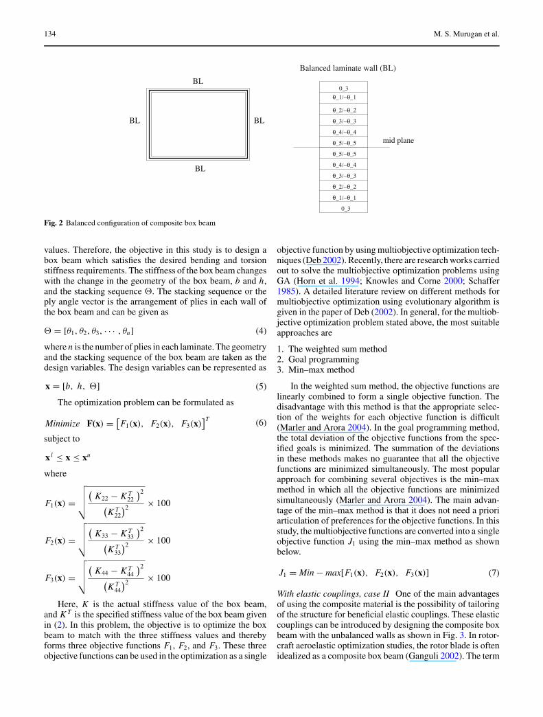
Without elastic couplings, case I The composite box-beamgeometry and the stacking sequence of the laminate wallsare designed to obtain the desired beam stiffness values S. Abalanced lay-up configuration of the box beam has the sameply angle orientations for all the four walls as shown in Fig. 2.The elastic coupling terms of the stiffness matrix K given in(1) are zero for this configuration, and hence the stiffnessmatrix can be given by the relation
Qx
Mx
−My
Mz
=
K11 0 0 00 K22 0 00 0 K33 00 0 0 K44
u′e
φ′
w′′
v′′
(3)
The axial stiffness, i.e., K11, in the above matrix does notplay a major role in the dynamics of the beam structure asits magnitude is very high compared to the other stiffness
134 M. S. Murugan et al.
0_3BL
BLBL
BL
θ_5/−θ_5
θ_4/−θ_4
θ_3/−θ_3
θ_2/−θ_2
θ_1/−θ_1
0_3
Balanced laminate wall (BL)
θ_1/−θ_1
θ_2/−θ_2
θ_3/−θ_3
θ_4/−θ_4
θ_5/−θ_5 mid plane
Fig. 2 Balanced configuration of composite box beam
values. Therefore, the objective in this study is to design abox beam which satisfies the desired bending and torsionstiffness requirements. The stiffness of the box beam changeswith the change in the geometry of the box beam, b and h,and the stacking sequence 2. The stacking sequence or theply angle vector is the arrangement of plies in each wall ofthe box beam and can be given as
2 = [θ1, θ2, θ3, · · · , θn] (4)
where n is the number of plies in each laminate. The geometryand the stacking sequence of the box beam are taken as thedesign variables. The design variables can be represented as
x = [b, h, 2] (5)
The optimization problem can be formulated as
Minimize F(x) =[F1(x), F2(x), F3(x)
]T (6)
subject to
x l≤ x ≤ xu
where
F1(x) =
√√√√(K22 − K T
22
)2(K T
22
)2 × 100
F2(x) =
√√√√(K33 − K T
33
)2(K T
33
)2 × 100
F3(x) =
√√√√(K44 − K T
44
)2(K T
44
)2 × 100
Here, K is the actual stiffness value of the box beam,and K T is the specified stiffness value of the box beam givenin (2). In this problem, the objective is to optimize the boxbeam to match with the three stiffness values and therebyforms three objective functions F1, F2, and F3. These threeobjective functions can be used in the optimization as a single
objective function by using multiobjective optimization tech-niques (Deb 2002). Recently, there are research works carriedout to solve the multiobjective optimization problems usingGA (Horn et al. 1994; Knowles and Corne 2000; Schaffer1985). A detailed literature review on different methods formultiobjective optimization using evolutionary algorithm isgiven in the paper of Deb (2002). In general, for the multiob-jective optimization problem stated above, the most suitableapproaches are
1. The weighted sum method2. Goal programming3. Min–max method
In the weighted sum method, the objective functions arelinearly combined to form a single objective function. Thedisadvantage with this method is that the appropriate selec-tion of the weights for each objective function is difficult(Marler and Arora 2004). In the goal programming method,the total deviation of the objective functions from the spec-ified goals is minimized. The summation of the deviationsin these methods makes no guarantee that all the objectivefunctions are minimized simultaneously. The most popularapproach for combining several objectives is the min–maxmethod in which all the objective functions are minimizedsimultaneously (Marler and Arora 2004). The main advan-tage of the min–max method is that it does not need a prioriarticulation of preferences for the objective functions. In thisstudy, the multiobjective functions are converted into a singleobjective function J1 using the min–max method as shownbelow.
J1 = Min − max[F1(x), F2(x), F3(x)] (7)
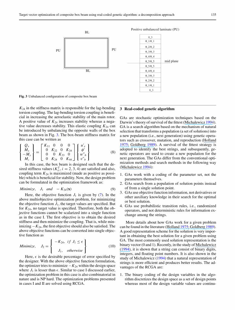
With elastic couplings, case II One of the main advantagesof using the composite material is the possibility of tailoringof the structure for beneficial elastic couplings. These elasticcouplings can be introduced by designing the composite boxbeam with the unbalanced walls as shown in Fig. 3. In rotor-craft aeroelastic optimization studies, the rotor blade is oftenidealized as a composite box beam (Ganguli 2002). The term
Target vector optimization of composite box beam using real-coded genetic algorithm: a decomposition approach 135
0_3
0_3
θ_5/θ_5
θ_4/θ_4
θ_3/θ_3
θ_2/θ_2
θ_1/θ_1
θ_2/θ_2
θ_3/θ_3
θ_4/θ_4
θ_5/θ_5
Positive unbalanced laminate (PU)BL
PU
BL
PU
mid plane
θ_1/θ_1
Fig. 3 Unbalanced configuration of composite box beam
K24 in the stiffness matrix is responsible for the lag-bendingtorsion coupling. The lag-bending torsion coupling is benefi-cial in increasing the aeroelastic stability of the main rotor.A positive value of K24 increases stability whereas a nega-tive value decreases stability. This elastic coupling K24 canbe introduced by unbalancing the opposite walls of the boxbeam as shown in Fig. 3. The box-beam stiffness matrix forthis case can be written as
Qx
Mx
−My
Mz
=
K11 0 0 00 K22 0 K240 0 K33 00 K24 0 K44
u′e
φ′
w′′b
v′′b
(8)
In this case, the box beam is designed such that the de-sired stiffness values (K T
ii , i = 2, 3, 4) are satisfied and also,coupling term K24 is maximized (made as positive as possi-ble) which is beneficial for stability. Now, the design problemcan be formulated in the optimization framework as:
Minimize, J1 and − K24(x) (9)
Here, the objective function J1 is given by (7). In theabove multiobjective optimization problem, for minimizingthe objective function J1, the target values are specified. Butfor K24, no target value is specified. Therefore, both the ob-jective functions cannot be scalarized into a single functionas in the case I. The first objective is to obtain the desiredstiffness and then minimize the coupling. That is, while min-imizing −K24, the first objective should also be satisfied. Theabove objective functions can be converted into single objec-tive function as
Minimize, J2 =
−K24, i f J1 ≤ ε
J1, otherwise
(10)
Here, ε is the desirable percentage of error specified bythe designer. With the above objective function formulation,the optimizer tries to minimize −K24 within the design spacewhere J1 is lesser than ε. Similar to case I discussed earlier,the optimization problem in this case is also combinatorial innature and is NP hard. The optimization problems presentedin cases I and II are solved using RCGA.
3 Real-coded genetic algorithm
GAs are stochastic optimization techniques based on theDarwin’s theory of survival of the fittest (Michalewicz 1994).GA is a search algorithm based on the mechanism of naturalselection that transforms a population (a set of solutions) intoa new population (i.e., next generation) using genetic opera-tors such as crossover, mutation, and reproduction (Holland1975; Goldberg 1989). A survival of the fittest strategy isadopted to identify the best strings, and subsequently, ge-netic operators are used to create a new population for thenext generation. The GAs differ from the conventional opti-mization methods and search methods in the following way(Michalewicz 1994):
1. GAs work with a coding of the parameter set, not theparameters themselves.
2. GAs search from a population of solution points insteadof from a single solution point.
3. GAs use objective function information, not derivatives orother auxiliary knowledge in their search for the optimalor best solution.
4. GAs use probabilistic transition rules, i.e., randomizedoperators, and not deterministic rules for information ex-change among the strings.
More details about how GAs work for a given problemcan be found in the literature (Holland 1975; Goldberg 1989).A good representation scheme for the solution is very impor-tant in obtaining the best solution for a given problem usingGA. The most commonly used solution representation is thebinary vector (0 and 1). Recently, in the study of Michalewicz(1994), it is shown that a string can consist of binary digits,integers, and floating point numbers. It is also shown in thestudy of Michalewicz (1994) that a natural representation ofstrings is more efficient and produces better results. The ad-vantages of the RCGA are:
1. The binary coding of the design variables in the algo-rithm discretizes the design space as a set of design pointswhereas most of the design variable values are continu-
136 M. S. Murugan et al.
ous in the design space. This preassigned constraint forthe design space may result in a local optimum.
2. A major disadvantage of the binary representation is thelength of the chromosome. The length of the chromosomeincreases exponentially with the increase in required dec-imal accuracy, which in turn reduces the efficiency of theGA.
3. The mapping between the real space and the binary spacecreates a problem for the crossover operator used in GAs.In the discrete variables case, the GA operators may pro-duce an invalid offspring and therefore, repair algorithmsare used to avoid the offspring’s falling outside the dis-crete regions.
The quality of solution in RCGA depends on the type ofgenetic operators used in the problem. A hybrid GA employsdifferent crossover and mutation operators at different stagesof the genetic process and can provide an effective solutionto many practical problems. A detailed study on the effectof hybrid operators for RCGA is presented in the work ofHerrera et al. (2003).
4 Decomposition of the problem
Now, we describe the hybrid RCGA-based design procedurefor the composite box-beam optimization problem. In thecomposite box-beam optimization, the geometry and the plyangle sequences are considered as the design variables. Thesedesign variables are represented in a single string in the pre-vious composite structure optimization studies. However, ifthe geometry of the box beam (b and h) is fixed, the box-beam stiffness still varies with the stacking sequence 2. Inthat case, the objective is to find only the optimal stackingsequence 2∗. Therefore, the composite box-beam optimiza-tion problem is decomposed into a global optimization and alocal optimization problem as given below:
Global optimization
Minimize F(b, h, 2∗) (11)
subject to
bl≤ b ≤ bu
hl≤ h ≤ hu
Here, 2∗ is the optimal stacking sequence for a given b and hwhich can be obtained from the stacking sequence optimiza-tion called as local optimization and defined below:
Local optimization For a given b and h,
Minimize F(2) (12)
subject to
2 ∈ (θ1, θ2, θ3, · · · , θk)
where k is the number of possible ply angles. In the aboveformulations, both the global and the local problems use the
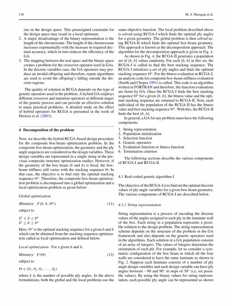
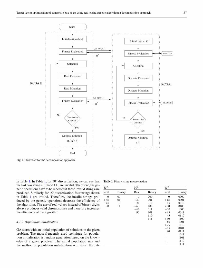
same objective function. The local problem described aboveis solved using RCGA-I which finds the optimal ply anglesfor a given geometry. The global problem is then solved us-ing RCGA-II which finds the optimal box-beam geometry.This approach is known as the decomposition approach. Thealgorithm for the decomposition approach is given in Fig. 4.
As shown in Fig. 4, the RCGA-II generates a populationset of {b, h} values randomly. For each {b, h} in this set, theRCGA-I is called to find the best stacking sequence. TheRCGA-I initializes a set of ply angles and finds the optimalstacking sequence 2∗. For the fitness evaluation in RCGA-I,an analysis code for composite box-beam stiffness evaluation(Smith and Chopra 1991) is called. This code is an algorithmwritten in FORTRAN and therefore, the function evaluationsare faster by GA. Once the RCGA-I finds the best stackingsequence 2∗ for a given {b, h}, the fitness value and the opti-mal stacking sequence are returned to RCGA-II. Now, eachindividual of the population of the RCGA-II has the fitnessvalue and best stacking sequence 2∗. With this, the RCGA-IIfinds the best {b, h}.
In general, a GA for any problem must have the followingcomponents:
1. String representation2. Population initialization3. Selection function4. Genetic operators5. Evaluation function or fitness function6. Termination criterion
The following sections describe the various componentsof RCGA-I and RCGA-II.
4.1 Real-coded genetic algorithm-I
The objective of the RCGA-I is to find out the optimal discretevalues of ply angle variables for a given box-beam geometry.The various components of RCGA-I are described below.
4.1.1 String representation
String representation is a process of encoding the discretevalues of the angles assigned to each ply in the laminate wallof the box. Each string in a population represents a possi-ble solution to the design problem. The string representationscheme depends on the structure of the problem in the GAframework and also depends on the genetic operators usedin the algorithms. Each solution in a GA population consistsof an array of integers. The values of integers determine theorientation of each ply. For example, let us consider a sym-metric configuration of the box beam in which all the fourwalls are considered to have the same laminate as shown inFig. 2. Suppose each laminate consists of n number of plyangle design variables and each design variable can have plyangles between −90 and 90◦ in steps of 30◦ (i.e, six possi-ble values). By using the binary values for string represen-tation, each possible ply angle can be represented as shown
Target vector optimization of composite box beam using real-coded genetic algorithm: a decomposition approach 137
Start
Initialization (b,h)
Selection
Real Crossover
Real Mutation
Fitness Evaluation
Fitness Evaluation
TerminationCriterion
Optimal Solution
(b*,h* *)Θ
Θ *
Call RCGA−I
Call RCGA−I
End
RCGA II
Θ *
Selection
Fitness Evaluation
Fitness Evaluation
TerminationCriterion
Optimal Solution
Θ Initialization
FEA Code
FEA Code
RCGAI
Θ *
Discrete Crossover
Discrete Mutation
YesYes
NoNo
Fig. 4 Flowchart for the decomposition approach
in Table 1. In Table 1, for 30o discretization, we can see thatthe last two strings 110 and 111 are invalid. Therefore, the ge-netic operations have to be repeated if these invalid strings areproduced. Similarly, for 150 discretization, four strings shownin Table 1 are invalid. Therefore, the invalid strings pro-duced by the genetic operations decrease the efficiency ofthe algorithm. The use of real values instead of binary digitsalways produces valid chromosomes and therefore increasesthe efficiency of the algorithm.
4.1.2 Population initialization
GA starts with an initial population of solutions to the givenproblem. The most frequently used technique for popula-tion initialization is random generation based on the knowl-edge of a given problem. The initial population size andthe method of population initialization will affect the rate
Table 1 Binary string representation
45o 30o 15o
Real Binary Real Binary Real Binary
0 00 0 000 0 0000+45 01 +30 001 +15 0001−45 10 −30 010 −15 0010
90 11 +60 100 +30 0100−60 011 −30 1000
90 101 +45 0011– 110 −45 0110– 111 +60 1100
−60 1001+75 1010−75 0101
90 0111– 1011– 1101– 1110– 1111
138 M. S. Murugan et al.
of convergence of the solution. In this problem, random se-lection of ply angles from the given set of angles is used toinitialize the stacking sequences.
4.1.3 Selection function
The probability of a solution being selected to generate newsolutions generally depends on the fitness of the solution.Usually, a solution with better fitness in a population has ahigher probability of being selected more than once. In theliterature, several schemes such as roulette wheel selectionand its extensions, scaling techniques and tournament andranking methods are presented for the selection process. Inthis work, the normalized geometric ranking method givenin the paper of Houck et al. (1996) is used for the selectionprocess.
4.1.4 Genetic operators
Genetic operators used in GAs are analogous to those whichoccur in the natural world: reproduction (crossover, or re-combination) and mutation. The probability of these opera-tors will affect the efficacy of the GA. The genetic operatorsfor RCGA-I are described below.
The crossover operator is a primary operator in GA. Therole of crossover is to recombine genetic information fromthe two selected solutions into even better solutions. Thecrossover operator improves the diversity of the population.The form of the crossover operator depends on the string rep-resentation. Now, we describe four different crossover oper-ators used in this problem. Let A and B be the two parentsselected for the crossover operation from the population andgiven as
A = {a1, a2, ...ai , ai+1, ...a j , a j+1, ..an/2}
B = {b1, b2, ...bi , bi+1, ...b j , b j+1, ..bn/2}(13)
where ai and bi are integers belonging to the possible plyangle set.
(a) Two crossover points: In this operator, two crossoverpoints i and j are selected ran-domly in the parents, where (i <j, i, j ≤ n/2) . The offspring pro-duced by swapping the selectedply angles between the crossoverpoints are
A′= {a1, a2, · · · , bi , bi+1, ...b j ,
a j+1, ..an/2}
B ′= {b1, b2, ...ai , ai+1, ...a j ,
b j+1, ..bn/2}
(14)
(b) Uniform crossover: In this operator, the crossoverpoints are selected randomly. Theply angles in the selected cross-over points are swapped between
the parents. Let the randomly se-lected crossover points be 2, i ,and j . The offspring produced aregiven below.
A′= {a1, b2, .., bi , ai+1, .., b j ,
a j+1, .., an/2}
B ′= {b1, a2, .., ai , bi+1, .., a j ,
b j+1, .., bn/2}
(15)
The mutation operators are used to avoid the local minimaand premature convergence of the algorithm by introducingdiversity in the population. The mutation operators used inthis study are explained below. Let A be the parent selectedfor the mutation operation.
A = {a1, a2, .., ai , .., a j , .., an/2}
(a) Swap mutation: In swap mutation, two mutationpoints are randomly selected. Theselected ply angles in the mutationpoints are swapped to generate thenew offspring. Let i and j be the mu-tation points selected. The offspringA′ produced is
A′= {a1, a2, · · · , a j , · · · , ai ,
· · · , an/2}
(b) Heuristic mutation: In this operator, a single mutationpoint is randomly selected. The plyangle in the selected mutation pointis replaced with a randomly selectedvalue from the possible set of val-ues. For example, let us consider thefollowing string for mutation opera-tion, and the mutation point is high-lighted in boldface.
A = {0, 15, 45, 0, 30, 90} (16)
Now the mutation point is replacedwith the randomly selected ply an-gle value, say 60. The offspring pro-duced by this operator is
A′= {0, 15, 60, 0, 30, 90} (17)
We have presented different crossover operators and mu-tation operators for RCGA-I. Each crossover operator findstwo new solutions, and mutation operators produce one newsolution. The type of genetic operator to be used depends ona particular problem. In fact, one type of genetic operatorwhich may perform well for a problem may not perform wellfor a different problem. Even in the same problem, one type ofcrossover may perform well in the earlier stages of the prob-lem and may not perform well in the later stages. This facthas been brought out in the no-free-lunch theorem (Wolpert
Target vector optimization of composite box beam using real-coded genetic algorithm: a decomposition approach 139
and Macready 1997). Hence, it is better to apply differentoperators simultaneously on the population for practical sit-uations. Hence, in this study, we have used a hybrid RCGA.In hybrid RCGA, the selected parents are used to generatemultiple offsprings using different crossover and mutationoperators. The offspring with the best fitness will replace theparents in the next generation.
A commonly used genetic operator is to reproduce theparents in the next generation. For this, we have used theelitist model discussed in the papers of Goldberg (1989) andDavid (1991). In this operator, the best solution generatedin the current generation is passed on to the population inthe next generation. In the elitism model, search operationis performed around the best solution of each generation,slightly perturbing its parameters and looking for a possibleimprovement (Goldberg 1989; Mitchell 1996). The elitismmodel is introduced to speed up the genetic search.
4.1.5 Fitness function
Fitness is the driving force in GA. In RCGA-I, the solutionsrepresent the possible angles of the plies in the laminate.Based on these angles, the stiffness values are calculated us-ing the composite box-beam code. Using these stiffness andthe desired values, the fitness of the solution is calculated.The GA will try to maximize the fitness, and hence for ourproblem, the fitness function is
f = −J1, for case I= −J2, for case II (18)
4.1.6 Termination criterion
The maximum number of generations is commonly used asthe termination criteria. Hence, in RCGA-I, the maximumnumber of generations is used to terminate the algorithm.
4.2 Real-coded genetic algorithm-II
The RCGA-II finds out the best geometry of the box beam.In this problem, the design variables are b and h and are real-valued in nature. In this problem, two real numbers are usedto represent the solution of the design variables b and h. LetX be the possible solution
X = [b1 b2] (19)
where b1 and b2 are real numbers. In RCGA-II, the selectionand termination functions are similar to the RCGA-I. Theparents in the population are randomly initialized and alsosatisfy the geometric constraints (bl ≤ b ≤ bu and hl ≤ h ≤
hu , where the subscript l represents the lower bound andu represents the upper bound). The main genetic operators
Table 2 Graphite/epoxy: materialproperties E1 (GPa) 141.5
E2 (GPa) 9.8G12 (GPa) 5.9ν 0.42ρ (kg/m3) 1,445.4
for this problem are defined such that the solution generatedalways satisfies the geometric constraints. Now we describethe genetic operators and the fitness function.
4.2.1 Genetic operators
Similar to RCGA-I, the various crossover and mutation op-erators are used. Let X and Y be the two parents selected forthe crossover operation.
X = [b1 b2]
Y = [h1 h2](20)
where bi and hi are real numbers.
(a) Averaging crossover: This crossover operator selects ascalar value α in the range of 0 ≤
α ≤ 1, and offsprings are producedby averaging as follows:
X ′= X + α(Y − X)
Y ′= Y + α(X − Y )
(21)
where X is less than Y . This op-erator always generates the off-spring that satisfies the geometricconstraints. The new offspring willhave values in between its parents.
(b) Heuristic crossover: This crossover operator selects arandom value α in the range of−1 ≤ α ≤ 1, and offsprings pro-duced by this operator are
X ′= X + ηcαδ
Y ′= Y + ηcαδ
(22)
where δ is half of the difference be-tween the upper and lower boundsof the individual design variables,and ηc is the crossover rate.
The mutation operators are used to introduce diversity inthe population. The mutation operators used in this study areexplained below. Let X be the parent selected for mutationoperation.
X = {b1, b2}
Table 3 Target stiffness valuesStiffness S
K22 (G J, N − m2) 20,419.79K33 (E Iy, N − m2) 38,364.46K44 (E Iz, N − m2) 82,916.73
140 M. S. Murugan et al.
Table 4 Ply angle discretization
Discretization case Ply angle
Discretization I [0,10,20,30,40,50,60,70,80,90]Discretization II [0,15,30,45,60,75,90]Discretization III [0,45,90]
(a) Heuristic mutation: In this operator, a single mutationpoint is randomly selected. The off-spring produced in this operation isdescribed below.
X ′= X + ηmαδ (23)
where ηm is the mutation rate.In this problem also, we have usedhybrid operators. The selected par-ent is used to generate more off-springs using the hybrid operators.The offspring with the better fitnessvalue will replace the parents in thenext generation.
4.2.2 Fitness function
In RCGA-II, the solution in the population represents thepossible values for b and h. For a given b and h, the RCGA-Iproduces the optimal stiffness values by calculating the bestpossible ply angles for the laminates. Hence, the fitness forany solution in RCGA-II is the best fitness value obtainedfrom RCGA-I and can be given as
f = −J1, for case I= −J2, for case II (24)
5 Numerical results
A single-celled composite box beam is optimized to providethe specified stiffness values. These stiffness values are ob-tained from an aeroelastic optimization study in which the1-D beam stiffness values were used as the design variables(Murugan and Ganguli 2005). An initial box-beam configu-ration which provides reasonable cross-sectional propertiesof the 1-D beam used in the aeroelastic optimization study(Smith and Chopra 1991) is selected. The selected box-beamconfiguration is optimized to provide the specified structuralstiffness. The initial design has an outer box width of 4.2 in.and an outer box height of 2.2 in. Each wall of this box beam
Table 5 GA parameters
Parameters RCGA-I RCGA-II
Population 30 30Generations 50 25Crossover probability 0.7 0.6Mutation probability 0.1 0.5
Table 6 Case I: no elastic coupling
Variables Discretization
I II III
Breadth (in.) 3.69 4.35 4.36Depth (in.) 2.27 2.58 2.65θ1 40 90 90θ2 50 90 90θ3 0 45 45θ4 40 75 90θ5 90 90 90Objective function, J1 0.25 2.55 5.08Average error (%) 0.19 1.85 4.60Mass (kg/m) 1.3820 1.6172 1.6366
has 26 plies, each ply having a thickness of 0.005 in. The pliesare made of graphite epoxy (AS413501-6), and its (graphiteepoxy) material properties are given in Table 2. The targetstiffness values are given in Table 3.
In the optimization process, each wall of the box beam isconsidered to have 26 plies. Considering the midplane sym-metry of the laminate, the maximum number of ply angledesign variables reduces from 26 to 13. Three plies at theouter edge of the wall are fixed with 0o plies to provide therequired axial stiffness. Therefore, out of 13 plies, five plyangles are considered as design variables for optimizing thebox beam as shown in Fig. 2. The stacking sequence of eachwall of the box beam can be written as
[03, ±θ1, ±θ2, ±θ3, ±θ4, ±θ5]s (25)
The ply angle vector 2 for optimization can be given as
2 = [ θ1, θ2, θ3, θ4, θ5] (26)
Now, let us consider that there are N choices for eachply angle design variable. With the N choices, there are N 5
possible laminate designs. The allowable discrete values forply angle design variables are given in Table 4. Three dif-ferent cases of discretization are considered in this study. Indiscretization I, the allowable ply angles are integer multi-ples of 10 between 0 and 90o. Similarly, discretization casesII and III consider 15 and 45o intervals, respectively. Thedesign variables, breadth b and height h, are constrained tohave an upper bound and a lower bound to avoid an infeasible
Table 7 For discretization I, near global solutions
Variables GA runs
1 2 3
Breadth (in.) 3.76 3.68 3.69Depth (in.) 2.30 2.28 2.27θ1 60 60 40θ2 0 40 50θ3 60 90 0θ4 90 40 40θ5 40 0 90J1 1.15 1.45 0.25Average error (%) 0.79 0.75 0.19Mass (kg/m) 1.4062 1.3820 1.3820
Target vector optimization of composite box beam using real-coded genetic algorithm: a decomposition approach 141
0
5
10
15
20
25
30
35
40
Breadth, b (inch)
height,h(inch)
Obj
ectiv
e fu
nctio
n, J
2.00
3.00
3.00
4.00
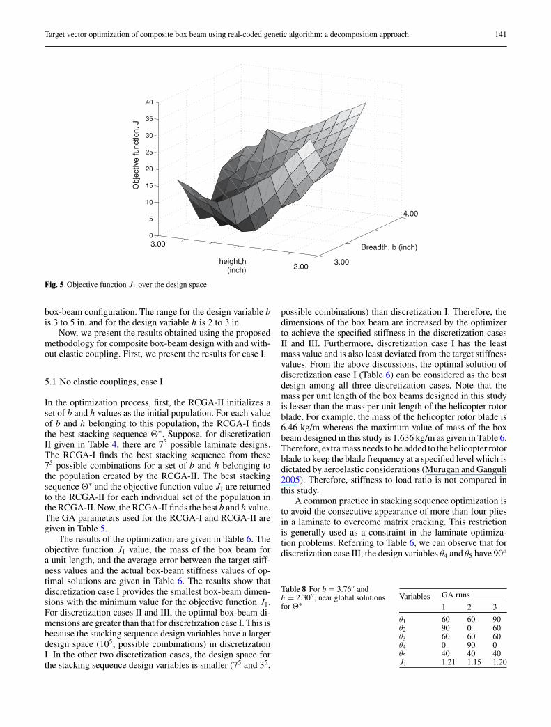
Fig. 5 Objective function J1 over the design space
box-beam configuration. The range for the design variable bis 3 to 5 in. and for the design variable h is 2 to 3 in.
Now, we present the results obtained using the proposedmethodology for composite box-beam design with and with-out elastic coupling. First, we present the results for case I.
5.1 No elastic couplings, case I
In the optimization process, first, the RCGA-II initializes aset of b and h values as the initial population. For each valueof b and h belonging to this population, the RCGA-I findsthe best stacking sequence 2∗. Suppose, for discretizationII given in Table 4, there are 75 possible laminate designs.The RCGA-I finds the best stacking sequence from these75 possible combinations for a set of b and h belonging tothe population created by the RCGA-II. The best stackingsequence 2∗ and the objective function value J1 are returnedto the RCGA-II for each individual set of the population inthe RCGA-II. Now, the RCGA-II finds the best b and h value.The GA parameters used for the RCGA-I and RCGA-II aregiven in Table 5.
The results of the optimization are given in Table 6. Theobjective function J1 value, the mass of the box beam fora unit length, and the average error between the target stiff-ness values and the actual box-beam stiffness values of op-timal solutions are given in Table 6. The results show thatdiscretization case I provides the smallest box-beam dimen-sions with the minimum value for the objective function J1.For discretization cases II and III, the optimal box-beam di-mensions are greater than that for discretization case I. This isbecause the stacking sequence design variables have a largerdesign space (105, possible combinations) in discretizationI. In the other two discretization cases, the design space forthe stacking sequence design variables is smaller (75 and 35,
possible combinations) than discretization I. Therefore, thedimensions of the box beam are increased by the optimizerto achieve the specified stiffness in the discretization casesII and III. Furthermore, discretization case I has the leastmass value and is also least deviated from the target stiffnessvalues. From the above discussions, the optimal solution ofdiscretization case I (Table 6) can be considered as the bestdesign among all three discretization cases. Note that themass per unit length of the box beams designed in this studyis lesser than the mass per unit length of the helicopter rotorblade. For example, the mass of the helicopter rotor blade is6.46 kg/m whereas the maximum value of mass of the boxbeam designed in this study is 1.636 kg/m as given in Table 6.Therefore, extra mass needs to be added to the helicopter rotorblade to keep the blade frequency at a specified level which isdictated by aeroelastic considerations (Murugan and Ganguli2005). Therefore, stiffness to load ratio is not compared inthis study.
A common practice in stacking sequence optimization isto avoid the consecutive appearance of more than four pliesin a laminate to overcome matrix cracking. This restrictionis generally used as a constraint in the laminate optimiza-tion problems. Referring to Table 6, we can observe that fordiscretization case III, the design variables θ4 and θ5 have 90o
Table 8 For b = 3.76′′ andh = 2.30′′, near global solutionsfor 2∗
Variables GA runs
1 2 3
θ1 60 60 90θ2 90 0 60θ3 60 60 60θ4 0 90 0θ5 40 40 40J1 1.21 1.15 1.20
142 M. S. Murugan et al.
020
4060
80100
0
20
40
60
80
1001
1.1
1.2
θ1
θ2
K22
/K22o
( T
orsi
onal
stif
fnes
s)
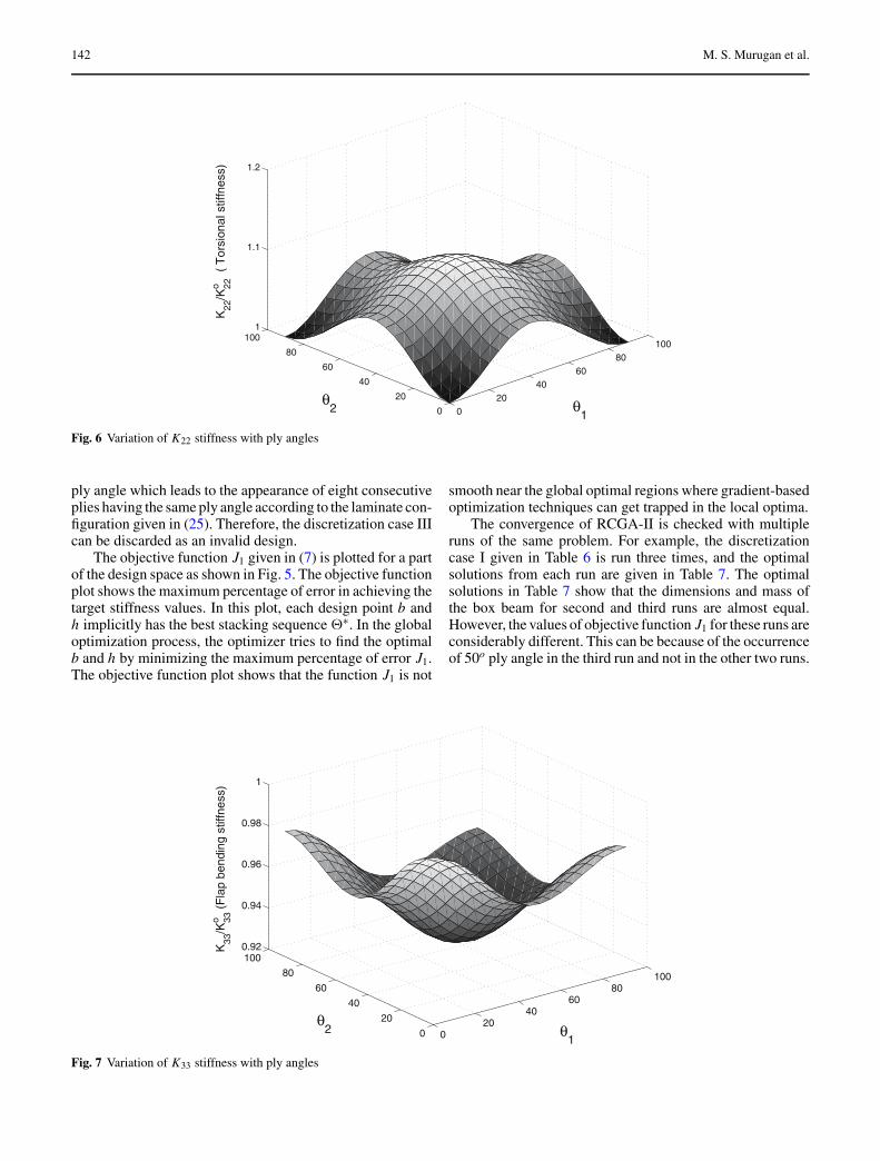
Fig. 6 Variation of K22 stiffness with ply angles
ply angle which leads to the appearance of eight consecutiveplies having the same ply angle according to the laminate con-figuration given in (25). Therefore, the discretization case IIIcan be discarded as an invalid design.
The objective function J1 given in (7) is plotted for a partof the design space as shown in Fig. 5. The objective functionplot shows the maximum percentage of error in achieving thetarget stiffness values. In this plot, each design point b andh implicitly has the best stacking sequence 2∗. In the globaloptimization process, the optimizer tries to find the optimalb and h by minimizing the maximum percentage of error J1.The objective function plot shows that the function J1 is not
smooth near the global optimal regions where gradient-basedoptimization techniques can get trapped in the local optima.
The convergence of RCGA-II is checked with multipleruns of the same problem. For example, the discretizationcase I given in Table 6 is run three times, and the optimalsolutions from each run are given in Table 7. The optimalsolutions in Table 7 show that the dimensions and mass ofthe box beam for second and third runs are almost equal.However, the values of objective function J1 for these runs areconsiderably different. This can be because of the occurrenceof 50o ply angle in the third run and not in the other two runs.
020
4060
80100
0
20
40
60
80
1000.92
0.94
0.96
0.98
1
θ1
θ2
K33
/K33o
(F
lap
bend
ing
stiff
ness
)
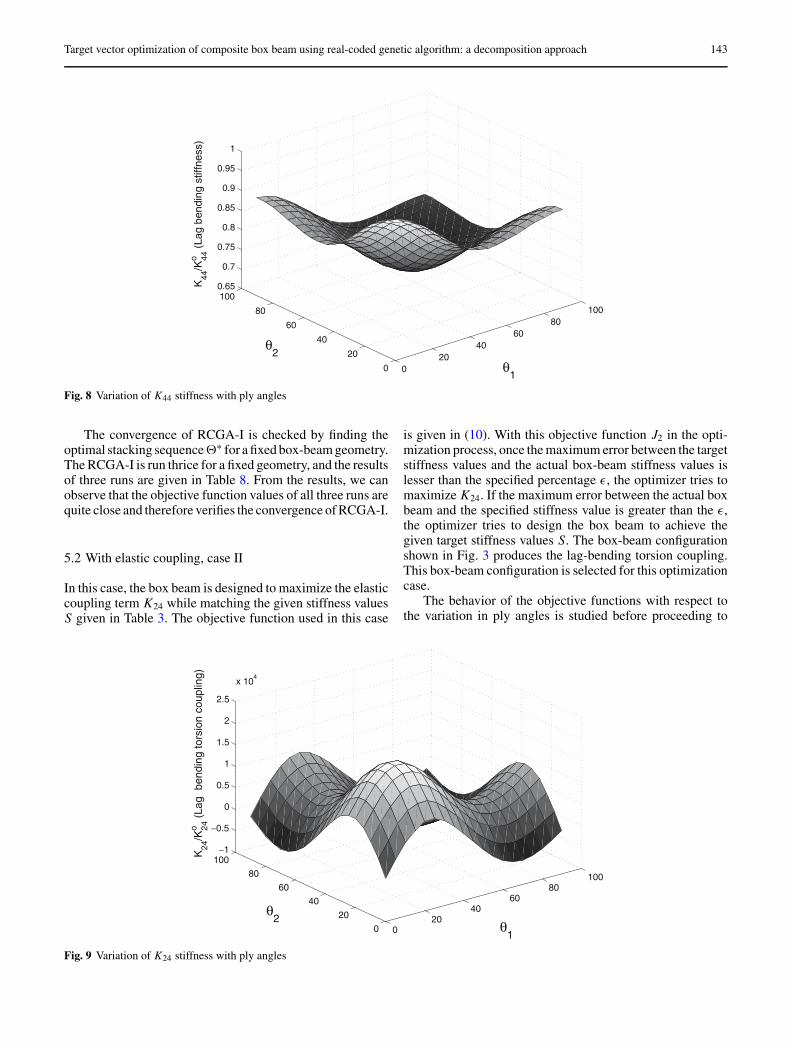
Fig. 7 Variation of K33 stiffness with ply angles
Target vector optimization of composite box beam using real-coded genetic algorithm: a decomposition approach 143
020
4060
80100
0
20
40
60
80
1000.65
0.7
0.75
0.8
0.85
0.9
0.95
1
K44
/K44o
(La
g be
ndin
g st
iffne
ss)
θ1
θ2
Fig. 8 Variation of K44 stiffness with ply angles
The convergence of RCGA-I is checked by finding theoptimal stacking sequence2∗ for a fixed box-beam geometry.The RCGA-I is run thrice for a fixed geometry, and the resultsof three runs are given in Table 8. From the results, we canobserve that the objective function values of all three runs arequite close and therefore verifies the convergence of RCGA-I.
5.2 With elastic coupling, case II
In this case, the box beam is designed to maximize the elasticcoupling term K24 while matching the given stiffness valuesS given in Table 3. The objective function used in this case
is given in (10). With this objective function J2 in the opti-mization process, once the maximum error between the targetstiffness values and the actual box-beam stiffness values islesser than the specified percentage ε, the optimizer tries tomaximize K24. If the maximum error between the actual boxbeam and the specified stiffness value is greater than the ε,the optimizer tries to design the box beam to achieve thegiven target stiffness values S. The box-beam configurationshown in Fig. 3 produces the lag-bending torsion coupling.This box-beam configuration is selected for this optimizationcase.
The behavior of the objective functions with respect tothe variation in ply angles is studied before proceeding to
020
4060
80100
0
20
40
60
80
100−1
−0.5
0
0.5
1
1.5
2
2.5
x 104
K24
/K24o
(La
g be
ndin
g to
rsio
n co
uplin
g)
θ1
θ2
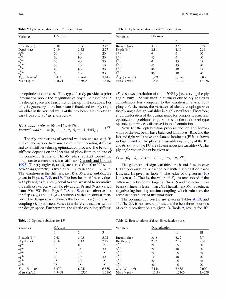
Fig. 9 Variation of K24 stiffness with ply angles
144 M. S. Murugan et al.
Table 9 Optimal solutions for 10o discretization
Variables GA runs
1 2 3
Breadth (in.) 3.80 3.56 3.43Depth (in.) 2.10 2.32 2.27θ BL
1 20 10 20θ BL
2 20 90 20θ BL
3 10 60 70θ PU
1 30 10 10θ PU
2 80 90 20θ PU
3 50 20 20K24 (N − m2) 2,434 4,969 7,144Mass (kg/m) 1.3674 1.3626 1.3189
the optimization process. This type of study provides a priorinformation about the magnitude of objective functions inthe design space and feasibility of the optimal solutions. Forthis, the geometry of the box beam is fixed, and two ply anglevariables in the vertical walls of the box beam are selected tovary from 0 to 90o as given below.
Horizontal walls = [03, ±153, ±452]s
Vertical walls = [03, θ1, θ1, θ2, θ2 ± 15, ±452]s(27)
The ply orientations of vertical wall are chosen with 0o
plies on the outside to ensure the minimum bending stiffnessand axial stiffness during optimization process. The bendingstiffness depends on the location of plies from midplane ofthe composite laminate. The 45o plies are kept toward themidplane to ensure the shear stiffness (Ganguli and Chopra1995). The ply angles θ1 and θ2 are varied from 0 to 90o whilebox-beam geometry is fixed as b = 3.78 in and h = 2.34 in.The variations in the stiffness, i.e., K22, K33, K44 andK24, aregiven in Figs. 6, 7, 8, and 9. The box beam stiffness valueswith ply angles θ1 and θ2 equal to zero are used to normalizethe stiffness values when the ply angles θ1 and θ2 are variedfrom -90 to 90◦. From Figs. 6, 7, 8, and 9, one can observe thatthe flap (K33) and lag (K44) stiffness varies in similar man-ner in the design space whereas the torsion (K22) and elasticcoupling (K24) stiffness varies in a different manner withinthe design space. Furthermore, the elastic coupling stiffness
Table 10 Optimal solutions for 15o
Variables GA runs
1 2 3
Breadth (in.) 3.63 3.63 3.52Depth (in.) 2.16 2.13 2.17θ BL
1 30 0 15θ BL
2 15 15 30θ BL
3 15 30 15θ PU
1 30 30 30θ PU
2 15 30 15θ PU
3 75 15 15K24 (N − m2) 5,979 6,241 6,558Mass (kg/m) 1.3408 1.3335 1.3165
Table 11 Optimal solutions for 45o discretization
Variables GA runs
1 2 3
Breadth (in.) 3.86 3.90 3.74Depth (in.) 2.11 2.10 2.31θ BL
1 0 0 90θ BL
2 45 0 90θ BL
3 0 45 45θ PU
1 45 45 90θ PU
2 90 90 45θ PU
3 90 90 90K24 (N − m2) 1,778 1,786 2,070Mass (kg/m) 1.3844 1.3917 1.4038
(K24) shows a variation of about 50% by just varying the plyangles only. The variation in stiffness due to ply angles isconsiderably less compared to the variation in elastic cou-plings. Furthermore, the variation of elastic couplings withthe ply angle design variables is highly nonlinear. Therefore,a full exploration of the design space for composite structureoptimization problems is possible with the multilevel-typeoptimization process discussed in the formulation.
Now, for the optimization process, the top and bottomwalls of the box beam have balanced laminates (BL), and theleft and right walls have unbalanced laminates (PU) as shownin Figs. 2 and 3. The ply angle variables θ1, θ2, θ3 of the BLand θ1, θ2, θ3 of the PU are chosen as design variables 2. Theply angle vector 2 can be given as
2 =[(θ1, θ2, θ3)
BL , (−θ1, −θ2, −θ3)PU
]The geometric design variables are b and h as in case
I. The optimization is carried out with discretization casesI, II, and III given in Table 4. The value of ε given in (10)is taken as 2. That is, the value of K24 is maximized if thedifference between the target stiffness S and the actual box-beam stiffness is lesser than 2%. The stiffness K24 introducesnegative lag-bending torsion coupling which enhances theaeroelastic stability of the rotor blade.
The optimization results are given in Tables 9, 10, and11. The GA is run several times, and the best three solutionsof each discretization are given. In Table 9, results for 10o
Table 12 Best solutions of three discretization cases
Variables Discretization
I II III
Breadth (in.) 3.43 3.52 3.74Depth (in.) 2.27 2.17 2.31θ BL
1 20 15 90θ BL
2 20 30 90θ BL
3 70 15 45θ PU
1 10 30 90θ PU
2 20 15 45θ PU
3 20 15 90K24 (N − m2) 7,144 6,558 2,070Mass (kg/m) 1.3189 1.3165 1.4038
Target vector optimization of composite box beam using real-coded genetic algorithm: a decomposition approach 145
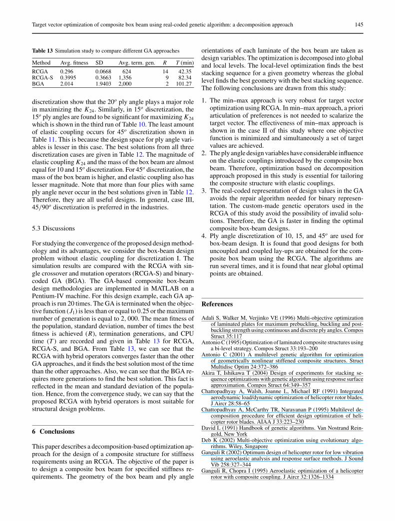
Table 13 Simulation study to compare different GA approaches
Method Avg. fitness SD Avg. term. gen. R T (min)
RCGA 0.296 0.0668 624 14 42.35RCGA-S 0.3995 0.3663 1,356 9 82.34BGA 2.014 1.9403 2,000 2 101.27
discretization show that the 20o ply angle plays a major rolein maximizing the K24. Similarly, in 15o discretization, the15o ply angles are found to be significant for maximizing K24which is shown in the third run of Table 10. The least amountof elastic coupling occurs for 45o discretization shown inTable 11. This is because the design space for ply angle vari-ables is lesser in this case. The best solutions from all threediscretization cases are given in Table 12. The magnitude ofelastic coupling K24 and the mass of the box beam are almostequal for 10 and 15o discretization. For 45o discretization, themass of the box beam is higher, and elastic coupling also haslesser magnitude. Note that more than four plies with sameply angle never occur in the best solutions given in Table 12.Therefore, they are all useful designs. In general, case III,45/90o discretization is preferred in the industries.
5.3 Discussions
For studying the convergence of the proposed design method-ology and its advantages, we consider the box-beam designproblem without elastic coupling for discretization I. Thesimulation results are compared with the RCGA with sin-gle crossover and mutation operators (RCGA-S) and binary-coded GA (BGA). The GA-based composite box-beamdesign methodologies are implemented in MATLAB on aPentium-IV machine. For this design example, each GA ap-proach is run 20 times. The GA is terminated when the objec-tive function (J1) is less than or equal to 0.25 or the maximumnumber of generation is equal to 2, 000. The mean fitness ofthe population, standard deviation, number of times the bestfitness is achieved (R), termination generations, and CPUtime (T ) are recorded and given in Table 13 for RCGA,RCGA-S, and BGA. From Table 13, we can see that theRCGA with hybrid operators converges faster than the otherGA approaches, and it finds the best solution most of the timethan the other approaches. Also, we can see that the BGA re-quires more generations to find the best solution. This fact isreflected in the mean and standard deviation of the popula-tion. Hence, from the convergence study, we can say that theproposed RCGA with hybrid operators is most suitable forstructural design problems.
6 Conclusions
This paper describes a decomposition-based optimization ap-proach for the design of a composite structure for stiffnessrequirements using an RCGA. The objective of the paper isto design a composite box beam for specified stiffness re-quirements. The geometry of the box beam and ply angle
orientations of each laminate of the box beam are taken asdesign variables. The optimization is decomposed into globaland local levels. The local-level optimization finds the beststacking sequence for a given geometry whereas the globallevel finds the best geometry with the best stacking sequence.The following conclusions are drawn from this study:
1. The min–max approach is very robust for target vectoroptimization using RCGA. In min–max approach, a prioriarticulation of preferences is not needed to scalarize thetarget vector. The effectiveness of min–max approach isshown in the case II of this study where one objectivefunction is minimized and simultaneously a set of targetvalues are achieved.
2. The ply angle design variables have considerable influenceon the elastic couplings introduced by the composite boxbeam. Therefore, optimization based on decompositionapproach proposed in this study is essential for tailoringthe composite structure with elastic couplings.
3. The real-coded representation of design values in the GAavoids the repair algorithm needed for binary represen-tation. The custom-made genetic operators used in theRCGA of this study avoid the possibility of invalid solu-tions. Therefore, the GA is faster in finding the optimalcomposite box-beam designs.
4. Ply angle discretization of 10, 15, and 45o are used forbox-beam design. It is found that good designs for bothuncoupled and coupled lay-ups are obtained for the com-posite box beam using the RCGA. The algorithms arerun several times, and it is found that near global optimalpoints are obtained.
References
Adali S, Walker M, Verjinko VE (1996) Multi-objective optimizationof laminated plates for maximum prebuckling, buckling and post-buckling strength using continuous and discrete ply angles. ComposStruct 35:117
Antonio C (1995) Optimization of laminated composite structures usinga bi-level strategy. Compos Struct 33:193–200
Antonio C (2001) A multilevel genetic algorithm for optimizationof geometrically nonlinear stiffened composite structures. StructMultidisc Optim 24:372–386
Akira T, Ishikawa T (2004) Design of experiments for stacking se-quence optimizations with genetic algorithm using response surfaceapproximation. Compos Struct 64:349–357
Chattopadhyay A, Walsh, Joanne L, Michael RF (1991) Integratedaerodynamic load/dynamic optimization of helicopter rotor blades.J Aircr 28:58–65
Chattopadhyay A, McCarthy TR, Narayanan P (1995) Multilevel de-composition procedure for efficient design optimization of heli-copter rotor blades. AIAA J 33:223–230
David L (1991) Handbook of genetic algorithms. Van Nostrand Rein-gold, New York
Deb K (2002) Multi-objective optimization using evolutionary algo-rithms. Wiley, Singapore
Ganguli R (2002) Optimum design of helicopter rotor for low vibrationusing aeroelastic analysis and response surface methods. J SoundVib 258:327–344
Ganguli R, Chopra I (1995) Aeroelastic optimization of a helicopterrotor with composite coupling. J Aircr 32:1326–1334
146 M. S. Murugan et al.
Goldberg DE (1989) Genetic algorithms in search, optimization andmachine learning. Addison-Wesley, New York
Gurdal Z, Haftka RT, Nagendra S (1994) Genetic algorithms for thedesign of laminated composite panels. SAMPE Journal 30(3):29–35
Hajela P (2002) Soft computing in multidisciplinary aerospace designnew directions for research. Prog Aerosp Sci 38:1–21
Herrera F, Lozano M, Sanchez AM (2002) Hybrid crossover operatorsfor real coded genetic algorithms: an experimental study. Softcomputing—a fusion of foundations, methodologies and applica-tions. Springer, Berlin Heidelberg New York
Herrera F, Lozano M, Snchez AM (2003) A taxonomy for the crossoveroperator for real-coded genetic algorithms: an experimental study.Int J Intell Syst 18:309–338
Holland HJ (1975) Adaptation in natural and artificial systems. Univer-sity of Michigan Press, Ann Arbor, MI
Horn J, Nafpliotis N, Goldberg DE (1994) A niched pareto genetic al-gorithm for multi-objective optimization. IEEE Proc Evol Comput1:82–87
Houck CR, Joines JA, Kay MG (1996) Genetic algorithm for functionoptimization: a Matlab implementation. ACM Trans Math Softw22:1–14
Knowles JD, Corne DW (2000) Approximating the nondominatedfront using the Pareto Archived Evolution Strategy. Evol Comput8(2):149–172
Kogiso N, Watson LT, Gurdal Z, Haftka RT (1994) Genetic algorithmswith local improvement for composite laminate design. StructOptim 7(4):207–218
Kumar N, Tauchert TR (1992) Multi-objective design of symmetricallylaminated plates. Trans ASME 114:620–625
Lee J, Hajela P (1997) GA’s in decomposition based design subsysteminteractions through immune network simulation. Struct MultidiscOptim 14:248–255
Le Riche R, Haftka RT (1993) Optimization of laminate stackingsequence for buckling load maximization by genetic algorithm.AIAA J 31(5):951–956
Marler RT, Arora JS (2004) Survey of multi-objective optimizationmethods for engineering. Struct Multidisc Optim 26:369–395
Mesquita L, Kamat MP (1987) Optimization of stiffened laminatedcomposite panels with frequency constraints. Eng Optim 11:77–86
Michalewicz Z (1994) Genetic algorithms + data structures = evolutionprograms. Springer, Berlin Heidelberg New York
Mitchell M (1996) An introduction to genetic algorithms. MIT Press,Cambridge, MA
Murugan S, Ganguli R (2005) Aeroelastic stability enhancement andvibration suppression in a composite helicopter rotor. J Aircr42:1013–1024
Nam C, Chattopadhyay A, Kim Y (2000) Optimal wing planform designfor aeroelastic control. AIAA J 38:1465–1470
Nagendra S, Jestin D, Gurdal Z, Haftka RT, Watson LT (1996) Improvedgenetic algorithms for the design of stiffened composite panels.Comput Struct 58(3):543–555
Oyama A, Obayashi S, Nakamura T (2001) Real-coded adaptive rangegenetic algorithm applied to transonic wing optimization. Appl SoftComput 1:179–187
Paik J, Volovoi V, Hodges D (2002) Cross-sectional sizing and op-timization of composite blades. AIAA-2002-1322, 43rd AIAA/ASME/ASCE/AHS/ASC structures, structural dynamics, and ma-terials conference, Denver, CO, 22–25 April 2002
Park JH, Hwang JH, Lee CS, Hwang W (2001) Stacking sequencedesign of composite laminates for maximum strength using geneticalgorithms. Compos Struct 52:217–231
Periaux J, Sefioui M, Stoufflet B, Mantel B, Laporte E (1995) Robust ge-netic algorithms for optimization problems in aerodynamic design.Genetic algorithms in engineering and computer science. Wiley,New York, pp 370–396
Schaffer JD (1985) Multiple objective optimization with vector evalu-ated genetic algorithms. Proceedings of the 1st International Con-ference on Genetic Algorithm, vol 1, pp 93–100
Schmidt LA, Farshi B (1973) Optimum laminate design for strengthand stiffness. Int J Numer Methods Eng 7:519–536
Smith EC, Chopra I (1991) Formulation and evaluation of an analyticalmodel for composite box-beams. J Am Helicopter Soc 36:23–35
Sobieszczanski-Sobieski J (1993) Two alternative ways for solving thecoordination problem in multilevel optimization. Struct MultidiscOptim 6:205–215
Song SR, Hwang W, Park HC, Han KS (1995) Optimum stackingsequence design of composite laminates for maximum strength.Mech Compos Mater 31:77–86
Soremekun G, Gurdal Z, Haftka RT, Watson LT (2001) Compositelaminate design optimization by genetic algorithm with generalizedelitist selection. Comput Struct 79(2):131–143
Soykasap O, Hodges DH (2000) Performance enhancement of a com-posite tilt rotor using aeroelastic tailoring. J Aircr 37:850–858
Tauchert TR, Adibhatla S (1984) Design of laminated plate for maxi-mum stiffness. J Compos Mater 18:58–69
Wolpert WG, Macready (1997) No free lunch theorems for optimiza-tion. IEEE Trans Evol Comput 11:67–82
Related Documents