www.powers.com 1 TECH MANUAL – MECHANICAL ANCHORS ©2021 POWERS – REV. F GENERAL INFORMATION SECTION CONTENTS MECHANICAL ANCHORS General Information...................... 1 Material Specifications ................. 2 Installation Specifications ............ 2 Reference Performance Data....... 4 Allowable Stress Design (ASD) Design Criteria................................ 5 Masonry Performance Data ......... 6 Strength Design Information....... 8 Strength Design Performance Data ........................ 10 Ordering Information .................. 11 PERMA-SEAL COATED CARBON STEEL TAPPER+ ANCHOR MATERIALS Carbon Steel with Perma-Seal Coating ANCHOR SIZE RANGE (TYP.) • 3/16" diameter x 1-1/4" to 4" lengths • 1/4" diameter x 1-1/4" to 6" lengths • 5/16" diameter x 1-3/4" to 6" lengths SUITABLE BASE MATERIALS • Normal-weight Concrete • Lightweight Concrete • Grouted Concrete Masonry, • Hollow Concrete Masonry (CMU) • Solid Brick Masonry • Wood This Product Available In ® Powers Design Assist ® Real-Time Anchor Design Software www.powersdesignassist.com CODE LISTED ICC-ES ESR-3068 UNCRACKED CONCRETE CODE LISTED ICC-ES ESR-3042 WOOD-TO-WOOD CODE LISTED ICC-ES ESR-3196 MASONRY CODE LISTED ICC-ES ESR-3213 CHEMICALLY TREATED LUMBER GENERAL INFORMATION TAPPER+ ® Concrete Screw Anchor PRODUCT DESCRIPTION The Tapper+ fastening system is a complete family of screw anchors for light to medium duty applications in concrete, masonry block, brick, and wood base materials. The Tapper+ is fast and easy to install and provides a neat, finished appearance. The Tapper+ screw anchor is engineered with matched tolerance drill bits and installation tools designed to meet the needs of the user and also provide optimum performance. The Tapper+ features a gimlet point for self-drilling into wood base materials without pre-drilling. The Tapper+ screw anchor is available in carbon steel with a Perma-Seal climate coating in several colors. Head styles include a slotted hex washer head, Phillips flat head, trim Phillips flat head and Hex flange washer head. GENERAL APPLICATIONS AND USES • Window installations • Storm shutters • Interior hand rails • Interior lighting fixtures • Metal door frames • Thresholds • Joint flashing • Screened Enclosures FEATURES AND BENEFITS + Available in several head styles + Several colors and finishes to match application + Removable (reusable in wood) + High-low thread design for greater stability and grip + Does not exert expansion forces + No hole spotting required + Good corrosion protection with Perma-Seal coating + Gimlet point for self drilling into wood base material APPROVALS • International Code Council, Evaluation Service (ICC-ES), ESR-3068 for uncracked concrete (including FBC supplement), ESR-3196 for masonry, ESR-3042 for wood, ESR-3213 for chemically treated lumber. • Code compliant with the 2012 IBC, 2012 IRC, 2009 IBC, 2009 IRC, 2006 IBC, and 2006 IRC. • Tested in accordance with ACI 355.2 and ICC-ES AC193 (including ASTM E 488) for use in structural concrete, ICC- ES AC106 for use in masonry, ICC-ES AC233 for use in wood, and ICC-ES AC257 for use in pressure treated lumber • Evaluated and qualified by an accredited independent testing labortatory for reliability against brittle failure, e.g. hydrogen embrittlement • Miami-Dade County Notice of Acceptance (NOA) 15-0629.06 GUIDE SPECIFICATIONS CSI Divisions: 03 16 00 - Concrete Anchors, 04 05 19.16 - Masonry Anchors, 05 05 19 - Post- Installed Concrete Anchors and 06 05 23 - Wood, Plastic, and Composite Fastenings. Concrete Screw Anchors shall be Tapper+ anchors as supplied by Powers Fasteners, Inc., Brewster, NY.

Welcome message from author
This document is posted to help you gain knowledge. Please leave a comment to let me know what you think about it! Share it to your friends and learn new things together.
Transcript

www.powers.com 1
TECH MAN
UAL – MECHAN
iCAL ANCHo
rs ©2021 Po
WErs – rEV. f
General InformatIon
SECTION CONTENTS
Mech
an
ica
l a
nch
or
s
General Information ......................1Material Specifications .................2Installation Specifications ............2Reference Performance Data .......4Allowable Stress Design (ASD) Design Criteria ................................5Masonry Performance Data .........6Strength Design Information .......8Strength Design Performance Data ........................10Ordering Information ..................11
PERMA-SEAL COATED CARBONSTEEL TAPPER+
ANCHOR MATERIALSCarbon Steel with Perma-Seal Coating
ANCHOR SIZE RANGE (TYP.)• 3/16" diameter x 1-1/4" to 4" lengths• 1/4" diameter x 1-1/4" to 6" lengths• 5/16" diameter x 1-3/4" to 6" lengths
SUITABLE BASE MATERIALS• Normal-weight Concrete• Lightweight Concrete• Grouted Concrete Masonry,• Hollow Concrete Masonry (CMU)• Solid Brick Masonry• Wood
This Product Available In
®
Powers Design Assist®
Real-Time Anchor Design Softwarewww.powersdesignassist.com
CODE LISTEDICC-eS eSr-3068
UNCRACKED CONCRETE
CODE LISTEDICC-eS eSr-3042 WOOD-TO-WOOD
CODE LISTEDICC-eS eSr-3196
MASONRY
CODE LISTEDICC-eS eSr-3213
CHEMICALLY TREATED LUMBER
GENERAL INFORMATION
TAPPER+®
Concrete Screw Anchor
PRODUCT DESCRIPTION
The Tapper+ fastening system is a complete family of screw anchors for light to medium duty applications in concrete, masonry block, brick, and wood base materials. The Tapper+ is fast and easy to install and provides a neat, finished appearance. The Tapper+ screw anchor is engineered with matched tolerance drill bits and installation tools designed to meet the needs of the user and also provide optimum performance. The Tapper+ features a gimlet point for self-drilling into wood base materials without pre-drilling.
The Tapper+ screw anchor is available in carbon steel with a Perma-seal climate coating in several colors. Head styles include a slotted hex washer head, Phillips flat head, trim Phillips flat head and Hex flange washer head.
GENERAL APPLICATIONS AND USES
• Window installations
• Storm shutters
• Interior hand rails
• Interior lighting fixtures
• Metal door frames
• Thresholds
• Joint flashing
• Screened Enclosures
FEATURES AND BENEFITS
+ Available in several head styles
+ Several colors and finishes to match application
+ Removable (reusable in wood)
+ High-low thread design for greater stability and grip
+ Does not exert expansion forces
+ No hole spotting required
+ Good corrosion protection with Perma-Seal coating
+ Gimlet point for self drilling into wood base material
APPROVALS
• International Code Council, Evaluation Service (ICC-ES), ESR-3068 for uncracked concrete (including FBC supplement), ESR-3196 for masonry, ESR-3042 for wood, ESR-3213 for chemically treated lumber.
• Code compliant with the 2012 IBC, 2012 IRC, 2009 IBC, 2009 IRC, 2006 IBC, and 2006 IRC.
• Tested in accordance with ACI 355.2 and ICC-ES AC193 (including ASTM E 488) for use in structural concrete, ICC- ES AC106 for use in masonry, ICC-ES AC233 for use in wood, and ICC-ES AC257 for use in pressure treated lumber
• Evaluated and qualified by an accredited independent testing labortatory for reliability against brittle failure, e.g. hydrogen embrittlement
• Miami-Dade County Notice of Acceptance (NOA) 15-0629.06
GUIDE SPECIFICATIONS
Csi Divisions: 03 16 00 - Concrete Anchors, 04 05 19.16 - Masonry Anchors, 05 05 19 - Post-installed Concrete Anchors and 06 05 23 - Wood, Plastic, and Composite fastenings. Concrete screw Anchors shall be Tapper+ anchors as supplied by Powers fasteners, inc., Brewster, NY.
www.powers.com 2
materIal SpeCIfICatIonS
TECH
MAN
UAL
– M
ECHA
NiC
AL A
NCH
ors
©20
21 P
oW
Ers
– r
EV. f
Mech
an
ica
l a
nch
or
sMATERIAL SPECIFICATIONSAnchor Component Perma-seal Tapper
Anchor Body Case hardened carbon steel
Coating/Plating/Finish Perma-seal coating (various colors)
INSTALLATION SPECIFICATIONS
Perma-Seal Carbon Steel Hex Head Tapper+
DimensionAnchor Diameter, d
3/16" 1/4" 5/16"
Tapper+ Drill Bit size, dbit (in.) 5/32" 3/16" 1/4"
fixture Clearance Hole, dh (in.) 1/4" 5/16" 5/16"
Head Height (in.) 7/64" 9/64" 1/4"
Hex Head Wrench/socket size 1/4" 5/16" 5/16"
Washer o.D., dw (in.) 11/32" 13/32" 9/16"
Washer Thickness, (in.) 1/32" 1/32" 1/16"
Perma-Seal Carbon Steel Flat Head Tapper+
DimensionAnchor Diameter, d
3/16" 1/4" 5/16"
Tapper+ Drill Bit size, dbit (in.) 5/32" 3/16" 1/4"
fixture Clearance Hole, dh (in.) 1/4" 5/16" 5/16"
Phillips Head o.D., (in.) 3/8" 1/2" 9/16"
Phillips Head Height, (in.) 9/64" 3/16" 9/32"
Phillips Bit size (No.) 2 3 3
INSTALLATION PROCEDURE
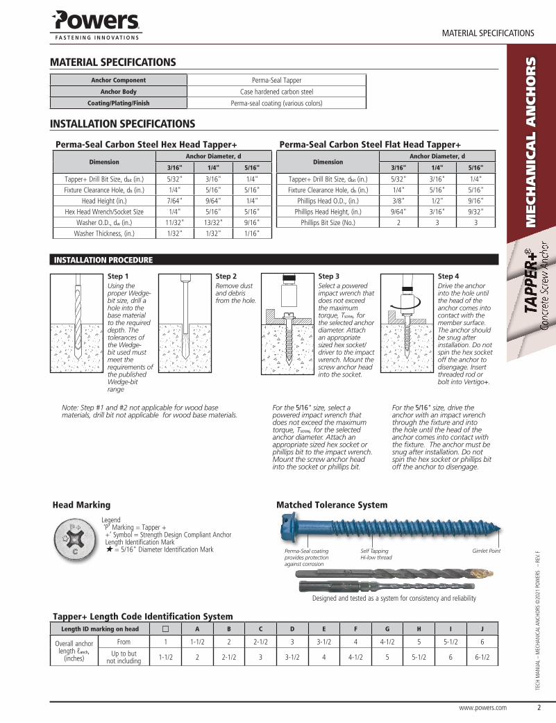
Step 1Using the proper Wedge-bit size, drill a hole into the base material to the required depth. The tolerances of the Wedge-bit used must meet the requirements of the published Wedge-bit range
Step 2Remove dust and debris from the hole.
Step 3Select a powered impact wrench that does not exceed the maximum torque, Tscrew, for the selected anchor diameter. Attach an appropriate sized hex socket/driver to the impact wrench. Mount the screw anchor head into the socket.
Step 4Drive the anchor into the hole until the head of the anchor comes into contact with the member surface. The anchor should be snug after installation. Do not spin the hex socket off the anchor to disengage. Insert threaded rod or bolt into Vertigo+.
Note: Step #1 and #2 not applicable for wood base materials, drill bit not applicable for wood base materials.
For the 5/16" size, select a powered impact wrench that does not exceed the maximum torque, Tscrew, for the selected anchor diameter. Attach an appropriate sized hex socket or phillips bit to the impact wrench. Mount the screw anchor head into the socket or phillips bit.
For the 5/16" size, drive the anchor with an impact wrench through the fixture and into the hole until the head of the anchor comes into contact with the fixture. The anchor must be snug after installation. Do not spin the hex socket or phillips bit off the anchor to disengage.
Head Marking
Legend ‘P’ Marking = Tapper + +’ symbol = strength Design Compliant Anchor Length identification Mark H = 5/16" Diameter identification Mark
Matched Tolerance System
Perma-Seal coating provides protection against corrosion
Self Tapping Hi-low thread
Gimlet Point
Designed and tested as a system for consistency and reliability
Tapper+ Length Code Identification SystemLength ID marking on head A B C D E F G H I J
overall anchor length ℓanch,
(inches)
from 1 1-1/2 2 2-1/2 3 3-1/2 4 4-1/2 5 5-1/2 6
Up to but not including 1-1/2 2 2-1/2 3 3-1/2 4 4-1/2 5 5-1/2 6 6-1/2

www.powers.com 3
TECH MAN
UAL – MECHAN
iCAL ANCHo
rs ©2021 Po
WErs – rEV. f
InStallatIon SpeCIfICatIonS
Mech
an
ica
l a
nch
or
s
Installation Table for Tapper+ in Concrete1,2
Anchor Property/Setting Information Notation UnitsNominal Anchor Size (in.)
3/16 1/4 5/16
Anchor outside diameter d in.(mm)
0.145(3.7)
0.185(4.7)
0.250(6.4)
Nominal drill bit diameter dbit in.
(mm)3/16
Tapper+ Bit 1/4
Tapper+ Bit5/16
Tapper+ Bit
Tapper+ bit tolerance range - in.0.170
to0.176
0.202to
0.207
0.255to
0.259
Minimum nominal embedment depth hnom in.
(mm)1-3/4(44.4)
1-3/4(44.4)
1-7/8(47.6)
Minimum hole depth ho in.
(mm)2
(50.8)2
(50.8)2-1/4(57)
Hex Head socket size - - 1/4 5/16 5/16
Phillips Bit size - - 2 3 3
Max impact Wrench Power (torque) Tscrewft-lbs(N-m) - - 115
(150)
For SI: 1 inch = 25.4 mm, 1 ft-lbf = 1.356 N-m.1. The minimum base material thickness must be 1.5hnom or 3", whichever is greater.2. See performance data in concrete for additional 5/16" Tapper+ embedment depths.
Installation Table for Tapper+ in Masonry
Anchor Property/Setting Information Notation UnitsNominal Anchor Size (in.)
3/16 1/4 5/16
Anchor outside diameter d in.(mm)
0.145(3.2)
0.185(4.7)
0.250(6.4)
Nominal drill bit diameter dbit in.
(mm)3/16
Tapper+ Bit 1/4
Tapper+ Bit5/16
Tapper+ Bit
Tapper+ bit tolerance range - in.0.170
to0.176
0.202to
0.207
0.255to
0.259
Minimum nominal embedment depth (Grout filled Masonry) hnom
in.(mm)
1-1/2(38.1)
1-1/2(38.1)
2-1/2(63.5)
Minimum hole depth (Grout filled Masonry) ho
in.(mm)
1-3/4(44.4)
1-3/4(44.4)
2-3/4(69.9)
Minimum nominal embedment depth (Hollow Masonry) hnom
in.(mm)
1(25.4)
1(25.4)
1-1/2(38.1)
Minimum hole depth (Hollow Masonry) ho
in.(mm)
1-1/4(31.8)
1-1/4(31.8)
1-3/4(44.5)
Hex Head socket size - - 1/4 5/16 5/16
Phillips Bit size - - 2 3 3
Installation Table for Tapper+ in Wood
Anchor Property/Setting Information Notation Units
Nominal Anchor Size (in.)
3/16 1/4
Anchor outside diameter d in.(mm)
0.145(3.7)
0.185(4.7)
Nominal drill bit diameter dbit in.
(mm)Pre-drilling is not required for Tapper+
into wood
Hex Head socket size - - 1/4 5/16
Phillips Bit size - - 2 3
Tapper+ Anchor Detail
lanch
dbit
dh t
hnomho
da
(Slotted hex head version pictured, flat head length measured from top of head to tip of anchor)

www.powers.com 4
referenCe performanCe Data
TECH
MAN
UAL
– M
ECHA
NiC
AL A
NCH
ors
©20
21 P
oW
Ers
– r
EV. f
Mech
an
ica
l a
nch
or
sREFERENCE PERFORMANCE DATA
Ultimate Load Capacities for Tapper+ in Normal-Weight Concrete1,2
NominalAnchor
Diameter d in.
Minimum Embed. Depth
hnom
in. (mm)
Minimum Concrete Compressive Strength
f’c = 2,500 psi (17.3 MPa)
f’c = 3,000 psi (20.7 MPa)
f’c = 4,000 psi (27.6 MPa)
f’c = 6,000 psi (41.4 MPa)
f’c = 8,000 psi (55.2 MPa)
Tension lbs. (kN)
Shear lbs. (kN)
Tension lbs. (kN)
Shear lbs. (kN)
Tension lbs. (kN)
Shear lbs. (kN)
Tension lbs. (kN)
Shear lbs. (kN)
Tension lbs. (kN)
Shear lbs. (kN)
3/16 1-3/4 (44.4)
1,240 (5.5)
985 (4.4)
1,310 (5.8)
985 (4.4)
1,430 (6.4)
985 (4.4)
1,615 (7.2)
985 (4.4)
1,760(7.8)
985(4.4)
1/4 1-3/4 (44.4)
1,855 (8.3)
1,500 (6.7)
1,995 (8.9)
1,500 (6.7)
2,235 (10.0)
1,500 (6.7)
2,630 (11.7)
1,500 (6.7)
2,995(13.3)
1,500(6.7)
5/16
1-3/4(49.2)
2,520(11.2)
2,000(8.9)
2,760(12.3)
2,000(8.9)
3,185(14.2)
2,720(12.1)
3,350(14.9)
2,720(12.1)
3,625(16.1)
2,720(12.1)
2-1/2(63.5)
3,365(15.0)
2,000(8.9)
3,625(16.1)
2,000(8.9)
3,625(16.1)
2,720(12.1)
3,625(16.1)
2,720(12.1)
3,625(16.1)
2,720(12.1)
3(76.2)
3,780(16.8)
2,000(8.9)
3,780(16.8)
2,000(8.9)
3,780(16.8)
2,720(12.1)
3,780(16.8)
2,720(12.1)
3,780(16.8)
2,720(12.1)
1. Tabulated load values are for anchors installed in concrete. Concrete compressive strength must be at the specified minimum at the time of installation.2. Ultimate load capacities must be reduced by a minimum safety factor of 4.0 or greater to determine allowable working load.
Allowable Load Capacities for Tapper+ in Normal-Weight Concrete1,2,3
NominalAnchor
Diameter d in.
Minimum Embed. Depth
hnom in.
(mm)
Minimum Concrete Compressive Strength
f’c = 2,500 psi (17.3 MPa)
f’c = 3,000 psi (20.7 MPa)
f’c = 4,000 psi (27.6 MPa)
f’c = 6,000 psi (41.4 MPa)
f’c = 8,000 psi (55.2 MPa)
Tension lbs. (kN)
Shear lbs. (kN)
Tension lbs. (kN)
Shear lbs. (kN)
Tension lbs. (kN)
Shear lbs. (kN)
Tension lbs. (kN)
Shear lbs. (kN)
Tension lbs. (kN)
Shear lbs. (kN)
3/16 1-3/4 (44.4)
310 (1.4)
245 (1.1)
325 (1.4)
245 (1.1)
360 (1.6)
245 (1.1)
400 (1.8)
245 (1.1)
440(2.0)
245(1.1)
1/4 1-3/4 (44.4)
460 (2.0)
375 (1.7)
495 (2.2)
375 (1.7)
555 (2.5)
375 (1.7)
655 (2.9)
375 (1.7)
750(3.3)
375(1.7)
5/16
1-3/4(49.2)
630(2.8)
500(2.2)
690(3.1)
500(2.2)
795(3.5)
680(3.0)
840(3.7)
680(3.0)
905(4.0)
680(3.0)
2-1/2(63.5)
840(3.7)
500(2.2)
905(4.0)
500(2.2)
905(4.0)
680(3.0)
905(4.0)
680(3.0)
905(4.0)
680(3.0)
3(76.2)
945(4.2)
500(2.2)
945(4.2)
500(2.2)
945(4.2)
680(3.0)
945(4.2)
680(3.0)
945(4.2)
680(3.0)
1. Allowable load capacities listed are calculated using and applied safety factor of 4.0. Consideration of safety factors of 10 or higher may be necessary depending on the application, such as life safety or overhead.
2. Linear interpolation may be used to determine allowable loads for intermediate compressive strengths. 3. Allowable load capacities are multiplied by reduction factors found when anchor spacing or edge distances are less than critical distances.

www.powers.com 5
TECH MAN
UAL – MECHAN
iCAL ANCHo
rs ©2021 Po
WErs – rEV. f
allowable StreSS DeSIGn (aSD) DeSIGn CrIterIa
Mech
an
ica
l a
nch
or
s
ALLOWABLE STRESS DESIGN (ASD) DESIGN CRITERIA
Spacing Reduction Factors - Tension (FnS)Diameter (in) 3/16 1/4 5/16
Minimum Spacing smin (in) 1 2 2
Minimum Embedment hnom (in) 1-3/4 1-3/4 1-7/8
Spac
ing
Dis
tanc
e (in
ches
)
3/4 - - -
1 0.68 - -
1-1/4 0.71 - -
1-1/2 0.74 - -
1-3/4 0.77 - -
2 0.80 0.80 0.83
2-1/4 0.83 0.83 0.86
2-1/2 0.86 0.86 0.89
2-3/4 0.89 0.89 0.93
3 0.92 0.92 0.96
3-1/2 0.98 0.98 1.00
4 1.00 1.00 1.00
Edge Distance Reduction Factors - Tension (FnC)Diameter (in) 3/16 1/4 5/16
Minimum Edge Distance cmin (in) 1-3/4 1-3/4 1-1/2
Minimum Embedment hnom (in) 1-3/4 1-3/4 1-7/8
Edge
Dis
tanc
e (in
ches
)
1-1/4 - - -
1-1/2 - - 0.60
1-3/4 0.58 0.58 0.70
2 0.67 0.67 0.80
2-1/4 0.75 0.75 0.90
2-1/2 0.83 0.83 1.00
2-3/4 0.92 0.92 1.00
3 1.00 1.00 1.00
Spacing Reduction Factors - Shear (FVS)Diameter (in) 3/16 1/4 5/16
Minimum Spacing smin (in) 1 2 2
Minimum Embedment hnom (in) 1-3/4 1-3/4 1-7/8
Spac
ing
Dis
tanc
e (in
ches
)
3/4 - - -
1 0.79 - -
1-1/4 0.81 - -
1-1/2 0.83 - -
1-3/4 0.85 - -
2 0.87 0.87 0.88
2-1/4 0.89 0.89 0.90
2-1/2 0.91 0.91 0.93
2-3/4 0.93 0.93 0.95
3 0.95 0.95 0.97
3-1/2 0.99 0.99 1.00
4 1.00 1.00 1.00
Edge Distance Reduction Factors - Shear (FVC)Diameter (in) 3/16 1/4 5/16
Minimum Edge Distance cmin (in) 1-3/4 1-3/4 1-1/2
Minimum Embedment hnom (in) 1-3/4 1-3/4 1-7/8
Edge
Dis
tanc
e (in
ches
)
1-1/4 - - -
1-1/2 - - 0.45
1-3/4 0.47 0.47 0.53
2 0.54 0.54 0.61
2-1/4 0.61 0.61 0.68
2-1/2 0.68 0.68 0.76
2-3/4 0.75 0.75 0.83
3 0.81 0.81 0.91
3-1/2 0.95 0.95 1.00
4 1.00 1.00 1.00
www.powers.com 6
maSonry performanCe Data
TECH
MAN
UAL
– M
ECHA
NiC
AL A
NCH
ors
©20
21 P
oW
Ers
– r
EV. f
Mech
an
ica
l a
nch
or
sMASONRY PERFORMANCE DATA
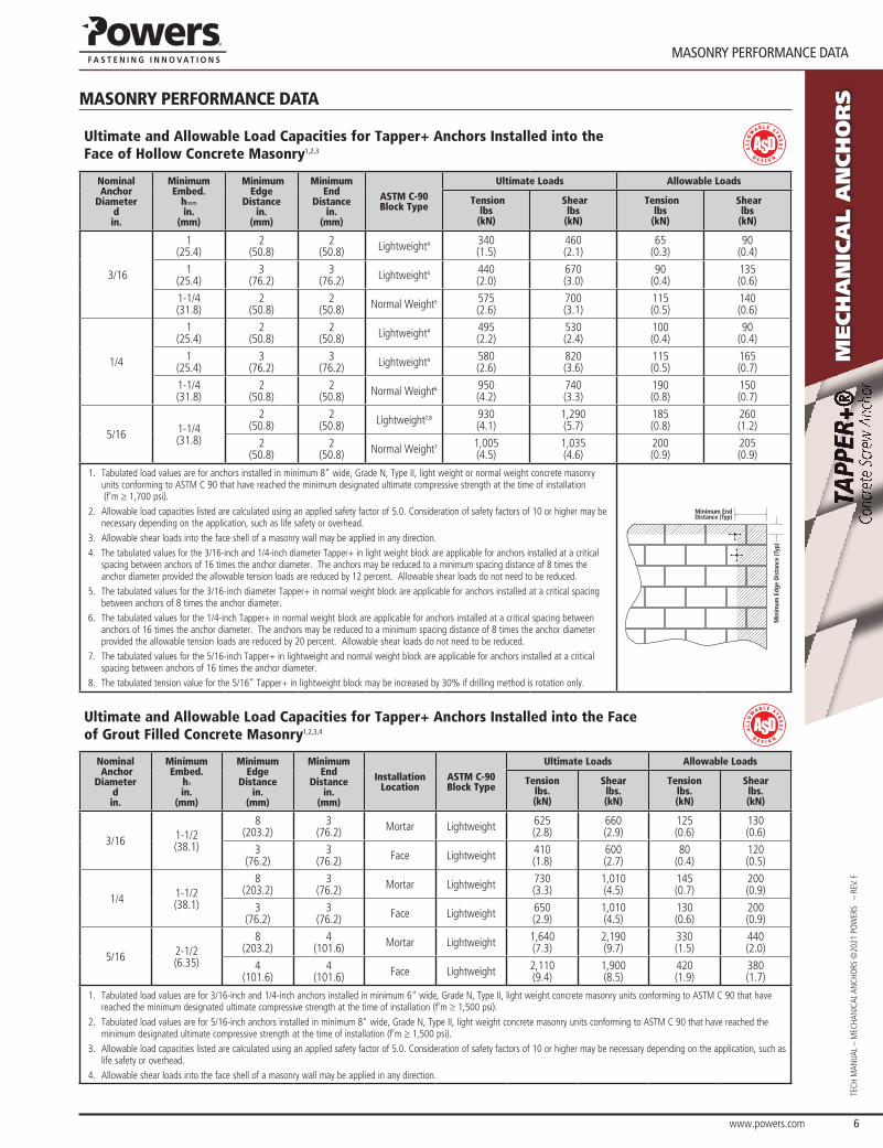
Ultimate and Allowable Load Capacities for Tapper+ Anchors Installed into the Face of Hollow Concrete Masonry1,2,3
Nominal Anchor
Diameter d in.
MinimumEmbed.
hnom
in. (mm)
MinimumEdge
Distance in.
(mm)
MinimumEnd
Distance in.
(mm)
ASTM C-90 Block Type
Ultimate Loads Allowable Loads
Tension lbs
(kN)
Shear lbs
(kN)
Tension lbs
(kN)
Shear lbs
(kN)
3/16
1(25.4)
2(50.8)
2(50.8) Lightweight4 340
(1.5)460 (2.1)
65 (0.3)
90 (0.4)
1(25.4)
3(76.2)
3(76.2) Lightweight4 440
(2.0)670(3.0)
90 (0.4)
135 (0.6)
1-1/4(31.8)
2(50.8)
2(50.8) Normal Weight5 575
(2.6)700(3.1)
115(0.5)
140(0.6)
1/4
1(25.4)
2 (50.8)
2 (50.8) Lightweight4 495
(2.2)530 (2.4)
100 (0.4)
90 (0.4)
1(25.4)
3(76.2)
3(76.2) Lightweight4 580
(2.6)820 (3.6)
115 (0.5)
165 (0.7)
1-1/4(31.8)
2(50.8)
2(50.8) Normal Weight6 950
(4.2)740(3.3)
190(0.8)
150(0.7)
5/16 1-1/4(31.8)
2(50.8)
2(50.8) Lightweight7,8 930
(4.1)1,290(5.7)
185(0.8)
260(1.2)
2(50.8)
2(50.8) Normal Weight7 1,005
(4.5)1,035(4.6)
200(0.9)
205(0.9)
1. Tabulated load values are for anchors installed in minimum 8" wide, Grade N, Type II, light weight or normal weight concrete masonry units conforming to ASTM C 90 that have reached the minimum designated ultimate compressive strength at the time of installation (f’m ≥ 1,700 psi).
2. Allowable load capacities listed are calculated using an applied safety factor of 5.0. Consideration of safety factors of 10 or higher may be necessary depending on the application, such as life safety or overhead.
3. Allowable shear loads into the face shell of a masonry wall may be applied in any direction. 4. The tabulated values for the 3/16-inch and 1/4-inch diameter Tapper+ in light weight block are applicable for anchors installed at a critical
spacing between anchors of 16 times the anchor diameter. The anchors may be reduced to a minimum spacing distance of 8 times the anchor diameter provided the allowable tension loads are reduced by 12 percent. Allowable shear loads do not need to be reduced.
5. The tabulated values for the 3/16-inch diameter Tapper+ in normal weight block are applicable for anchors installed at a critical spacing between anchors of 8 times the anchor diameter.
6. The tabulated values for the 1/4-inch Tapper+ in normal weight block are applicable for anchors installed at a critical spacing between anchors of 16 times the anchor diameter. The anchors may be reduced to a minimum spacing distance of 8 times the anchor diameter provided the allowable tension loads are reduced by 20 percent. Allowable shear loads do not need to be reduced.
7. The tabulated values for the 5/16-inch Tapper+ in lightweight and normal weight block are applicable for anchors installed at a critical spacing between anchors of 16 times the anchor diameter.
8. The tabulated tension value for the 5/16" Tapper+ in lightweight block may be increased by 30% if drilling method is rotation only.
Minimum End Distance (Typ)
Min
imum
Edg
e D
ista
nce
(Typ
)
Ultimate and Allowable Load Capacities for Tapper+ Anchors Installed into the Face of Grout Filled Concrete Masonry1,2,3,4
Nominal Anchor
Diameter d in.
MinimumEmbed.
hv in.
(mm)
MinimumEdge
Distance in.
(mm)
MinimumEnd
Distance in.
(mm)
Installation Location
ASTM C-90 Block Type
Ultimate Loads Allowable Loads
Tensionlbs. (kN)
Shearlbs. (kN)
Tensionlbs. (kN)
Shearlbs. (kN)
3/16 1-1/2(38.1)
8(203.2)
3(76.2) Mortar Lightweight 625
(2.8)660(2.9)
125(0.6)
130(0.6)
3(76.2)
3(76.2) face Lightweight 410
(1.8)600(2.7)
80(0.4)
120(0.5)
1/4 1-1/2(38.1)
8(203.2)
3(76.2) Mortar Lightweight 730
(3.3)1,010(4.5)
145(0.7)
200(0.9)
3(76.2)
3(76.2) face Lightweight 650
(2.9)1,010(4.5)
130(0.6)
200(0.9)
5/16 2-1/2(6.35)
8(203.2)
4(101.6) Mortar Lightweight 1,640
(7.3)2,190(9.7)
330(1.5)
440(2.0)
4(101.6)
4(101.6) face Lightweight 2,110
(9.4)1,900(8.5)
420(1.9)
380(1.7)
1. Tabulated load values are for 3/16-inch and 1/4-inch anchors installed in minimum 6" wide, Grade N, Type II, light weight concrete masonry units conforming to ASTM C 90 that have reached the minimum designated ultimate compressive strength at the time of installation (f’m ≥ 1,500 psi).
2. Tabulated load values are for 5/16-inch anchors installed in minimum 8" wide, Grade N, Type II, light weight concrete masonry units conforming to ASTM C 90 that have reached the minimum designated ultimate compressive strength at the time of installation (f’m ≥ 1,500 psi).
3. Allowable load capacities listed are calculated using an applied safety factor of 5.0. Consideration of safety factors of 10 or higher may be necessary depending on the application, such as life safety or overhead.
4. Allowable shear loads into the face shell of a masonry wall may be applied in any direction.

www.powers.com 7
TECH MAN
UAL – MECHAN
iCAL ANCHo
rs ©2021 Po
WErs – rEV. f
maSonry performanCe Data
Mech
an
ica
l a
nch
or
s
Ultimate and Allowable Load Capacities for Tapper+ Anchors Installed into the Tops of Grout Filled Concrete Masonry Walls1,2,3
Nominal Anchor
Diameter d in.
MinimumEmbed.
hnom
in. (mm)
MinimumEdge
Distance in.
(mm)
MinimumEnd
Distance in.
(mm)
ASTM C-90 Block Type
Ultimate Loads Allowable Loads
Tension lbs
(kN)
Shear lbs
(kN)
Tension lbs
(kN)
Shear lbs
(kN)
3/16 1.5(38.1)
1.5(38.1)
3(76.2) Lightweight 450
(2.0) 510(2.3)
90(0.4)
100(0.5)
1/4 1.5(38.1)
1.5(38.1)
3(76.2) Lightweight 825
(3.7) 780(3.5)
165(0.7)
155(0.7)
5/16 2(50.8)
1.75(44.5)
3(76.2) Lightweight 1,735
(7.7)800(3.6)
350(1.5)
160(0.7)
1. Tabulated load values are for 3/16-inch and 1/4-inch anchors installed in minimum 6" wide, Grade N, Type II, light weight concrete masonry units conforming to ASTM C 90 that have reached the minimum designated ultimate compressive strength at the time of installation (f’m ≥ 1,500 psi).
2. Tabulated load values are for 5/16-inch anchors installed in minimum 8" wide, Grade N, Type II, light weight concrete masonry units conforming to ASTM C 90 that have reached the minimum designated ultimate compressive strength at the time of installation (f’m ≥ 1,500 psi).
3. Allowable load capacities listed are calculated using an applied safety factor of 5.0. Consideration of safety factors of 10 or higher may be necessary depending on the application, such as life safety or overhead.
Top of Wall
Minimum End Distance (Typ)
Minimum Edge Distance (Typ)
Allowable Load Capacities for Tapper+ Anchors Installed in Clay Brick Masonry1,2,3,4
NominalAnchor
Diameter d in.
Minimum Embed.
hv in.
(mm)
Minimum Edge
Distance in.
(mm)
Minimum End
Distance in.
(mm)
Installation Location
Tension lbs. (kN)
Shear lbs. (kN)
3/16
1-1/2 (38.1)
1-3/4 (44.5)
1-3/4 (44.5)
face 380 (1.7)
165 (0.7)
Mortar Joint 300 (1.3)
190 (0.8)
1/4 face 605
(2.7)270 (1.2)
Mortar Joint 200 (0.9)
155 (0.7)
1. Tabulated load values are for anchors installed in multiple wythe, minimum Grade SW, solid clay brick masonry walls conforming to ASTM C 62. Mortar must be minimum Type N. Masonry compressive strength must be at the specified minimum at the time of installation (f’m ≥ 1,500 psi).
2. Allowable load capacities listed are calculated using and applied safety factor of 5.0. Consideration of safety factors of 10 or higher may be necessary depending upon the application such as lifesafety or overhead.
3. Allowable shear loads into the face or mortar joint of the brick masonry wall may be applied in any direction. 4. The tabulated values are applicable for anchors installed at a critical spacing between anchors of 12 times the anchor diameter.
Minimum End Distance (Typ)
Min
imum
Edg
e D
ista
nce
(Typ
)
Average Withdrawal Capacity and Average Bending Yield Moment of Tapper+ in Wood1
NominalAnchor
Diameter d in.
Minimum Embed.
hv
in. (mm)
Minimum Edge
Distance in.
(mm)
Withdrawal Capacity1
lbs. (kN)
Bending Yield psi
(MPa)
3/16
1 (25.4)
1-3/4 (44.5)
540 (2.4)
67,000 (464)
1-1/2 (38.1)
1-3/4 (44.5)
820 (3.7)
67,000 (464)
1/4
1 (25.4)
1-3/4 (44.5)
680 (3.0)
107,000 (740)
1-1/2 (38.1)
1-3/4 (44.5)
1,050 (4.7)
107,000 (740)
1. Tests in Douglas-Fir Larch with Specific Gravity of 0.42; screw oriented tangental to wood grain.
www.powers.com 8
StrenGth DeSIGn InformatIon
TECH
MAN
UAL
– M
ECHA
NiC
AL A
NCH
ors
©20
21 P
oW
Ers
– r
EV. f
Mech
an
ica
l a
nch
or
sSTRENGTH DESIGN INFORMATION
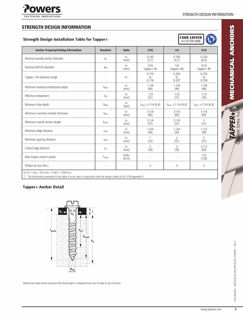
Strength Design Installation Table for Tapper+1 CODE LISTEDICC-eS eSr-3068
Anchor Property/Setting Information Notation Units 3/16 1/4 5/16
Nominal outside anchor diameter dain.
(mm)0.145(3.7)
0.185(4.7)
0.250(6.4)
Nominal drill bit diameter dbitin.
(mm)3/16
Tapper+ Bit1/4
Tapper+ Bit5/16
Tapper+ Bit
Tapper+ bit tolerance range - in.0.170
to0.176
0.202to
0.207
0.255to
0.259
Minimum nominal embedment depth hnomin.
(mm)1-3/4(44)
1-3/4(44)
1-7/8(48)
Effective embedment hefin.
(mm)1.23(31)
1.23(31)
1.10(76)
Minimum hole depth hholein.
(mm) hnom +1-1/4 (6.4) hnom +1-1/4 (6.4) hnom +1-1/4 (6.4)
Minimum concrete member thickness hminin.
(mm)3-1/4(83)
3-1/4(83)
3-1/4(83)
Minimum overall anchor length ℓanchin.
(mm)2-1/4(57)
2-1/4(57)
2(51)
Minimum edge distance cminin.
(mm)1-3/4(44)
1-3/4(44)
1-1/2(38)
Minimum spacing distance sminin.
(mm)1
(25)2
(51)2
(51)
Critical edge distance cacin.
(mm)3
(76)3
(76)2-1/2(64)
Max impact wrench power Tscrewft-lbs(N-m) - - 115
(150)
Phillips bit size (No.) - - 2 3 3
For SI: 1 inch = 25.4 mm, 1 ft-lbf = 1.356 N-m.1. The Information presented in this table is to be used in conjunction with the design criteria of ACI 318 Appendix D.
Tapper+ Anchor Detail
lanch
dbit
dh t
hnomho
hef
do
Slotted hex head version pictured, flat head length is measured from top of head to tip of anchor.
www.powers.com 9
TECH MAN
UAL – MECHAN
iCAL ANCHo
rs ©2021 Po
WErs – rEV. f
StrenGth DeSIGn InformatIon
Mech
an
ica
l a
nch
or
s
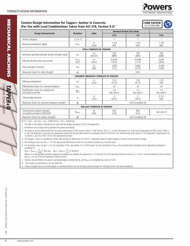
Tension Design Information for Tapper+ Anchor in Concrete (For Use with Load Combinations Taken from ACI 318, Section 9.2)1,2
CODE LISTEDICC-eS eSr-3068
Design Characteristic Notation UnitsNominal Anchor Size (Inch)
3/16 1/4 5/16
Anchor category 1,2 or 3 - 1 1 1
Nominal embedment depth hnomin.
(mm)1-3/4 (44)
1-3/4 (44)
1-7/8(48)
STEEL STRENGTH IN TENSION4
Minimum specified ultimate tensile strength (neck) futaksi
(N/mm2)100
(689)100
(689)100
(689)
Effective tensile stress area (neck) Ase,n
(Ase)8in2
(mm2)0.0162 (10.4)
0.0268 (17.3)
0.044(28.4)
steel strength in tension Nsalb
(kN)1,620 (7.2)
2,680 (12.0)
4,400(19.6)
reduction factor for steel strength3 f - 0.65
CONCRETE BREAKOUT STRENGTH IN TENSION7
Effective embedment hefin.
(mm)1.23
(31.2)1.23
(31.2)1.10(28)
Effectiveness factor for concrete breakout kuncr - 24 24 24
Modification factor for cracked and uncracked concrete5 Ψc,n - 1.0
see note 51.0
see note 51.0
see note 5
Critical edge distance cacin.
(mm)3
(76.2)3
(76.2)2-1/2(64)
reduction factor for concrete breakout strength3 f - 0.65 (Condition B)
PULLOUT STRENGTH IN TENSION7
Characteristic pullout strength, uncracked concrete (2,500 psi)6 Np,uncr
lb (kN)
635 (2.8)
940 (4.2) see note 9
reduction factor for pullout strength3 f - 0.65 (Condition B)
For SI: 1 inch = 25.4 mm, 1 ksi = 6.895 N/mm2, 1 lbf = 0.0044 kN.1. The data in this table is intended to be used with the design provisions of ACI 318 Appendix D.2. Installation must comply with published instructions and details.3. All values of f were determined from the load combinations of UBC Section 1605.2.1, UBC Section 1612.2.1, or ACI 318 Section 9.2. If the load combinations of UBC Section 1902.2
or ACI 318 Appendix C are used, the appropriate value of f must be determined in accordance with ACI 318 D.4.4. For reinforcement that meets ACI 318 Appendix D requirements for Condition A, see ACI 318 D. 4.3 for the appropriate f factor.
4. The Tapper+ anchor is considered a brittle steel element as defined by ACI 318 D.1. Tabulated values for steel strength in tension must be used for design.5. For all design cases use Ψc,n = 1.0. The appropriate effectiveness factor for uncracked concrete (kuncr) must be used.6. For all design cases use Ψc,p = 1.0. For calculation of Npn, see Section 4.1.3 of this report. For the calculation of Np,uncr, the nominal pullout strength can be adjusted by calculation
according to: Npn,f'c = Np,uncr ( f'c
2,500 )n (lbs, psi), Npn,f'c = Np,uncr (
f'c17.2 )n
(N,MPa)
Where f’c is the specified concrete compressive strength and whereby the exponent n = 0.3 for the 3/16-inch-diameter (4.8mm) anchors, n = 0.4 for 1/4-inch-diameter (6.4mm) anchors and n = 0.5 for 5/16-inch-diameter (7.9mm) anchors.
7. Anchors are permitted to be used in sand-lightweight provided that Nb, and Np,uncr are multiplied by a factor of 0.60.8. The notation in parenthesis is for the 2006 IBC.9. Pullout strength does not control design of indicated anchors. Do not calculate pullout strength for indicated anchor size and embedment.
www.powers.com 10
StrenGth DeSIGn performanCe Data
TECH
MAN
UAL
– M
ECHA
NiC
AL A
NCH
ors
©20
21 P
oW
Ers
– r
EV. f
Mech
an
ica
l a
nch
or
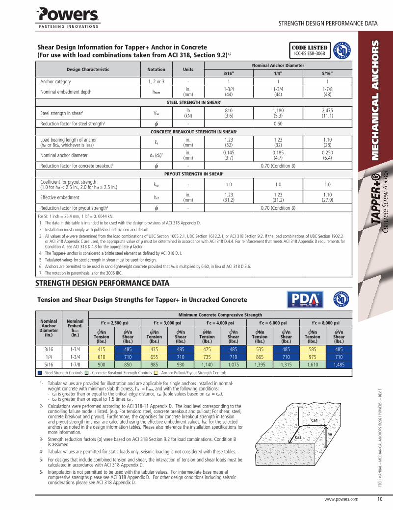
sShear Design Information for Tapper+ Anchor in Concrete(For use with load combinations taken from ACI 318, Section 9.2)1,2
CODE LISTEDICC-eS eSr-3068
Design Characteristic Notation UnitsNominal Anchor Diameter
3/16" 1/4" 5/16"
Anchor category 1, 2 or 3 - 1 1 1
Nominal embedment depth hnomin.
(mm)1-3/4(44)
1-3/4(44)
1-7/8(48)
STEEL STRENGTH IN SHEAR4
steel strength in shear5 Vsalb
(kN)810 (3.6)
1,180 (5.3)
2,475(11.1)
reduction factor for steel strength3 f - 0.60
CONCRETE BREAKOUT STRENGTH IN SHEAR6
Load bearing length of anchor (hef or 8do, whichever is less) ℓe
in. (mm)
1.23 (32)
1.23 (32)
1.10(28)
Nominal anchor diameter da (do)7 in. (mm)
0.145 (3.7)
0.185 (4.7)
0.250(6.4)
reduction factor for concrete breakout3 f - 0.70 (Condition B)
PRYOUT STRENGTH IN SHEAR6
Coefficient for pryout strength (1.0 for hef < 2.5 in., 2.0 for hef ≥ 2.5 in.) kcp - 1.0 1.0 1.0
Effective embedment hefin.
(mm)1.23
(31.2)1.23
(31.2)1.10
(27.9)
reduction factor for pryout strength3 f - 0.70 (Condition B)
For SI: 1 inch = 25.4 mm, 1 lbf = 0. 0044 kN.1. The data in this table is intended to be used with the design provisions of ACI 318 Appendix D.2. Installation must comply with published instructions and details.3. All values of f were determined from the load combinations of UBC Section 1605.2.1, UBC Section 1612.2.1, or ACI 318 Section 9.2. If the load combinations of UBC Section 1902.2
or ACI 318 Appendix C are used, the appropriate value of f must be determined in accordance with ACI 318 D.4.4. For reinforcement that meets ACI 318 Appendix D requirements for Condition A, see ACI 318 D.4.3 for the appropriate f factor.
4. The Tapper+ anchor is considered a brittle steel element as defined by ACI 318 D.1.5. Tabulated values for steel strength in shear must be used for design.6. Anchors are permitted to be used in sand-lightweight concrete provided that Vb is multiplied by 0.60, in lieu of ACI 318 D.3.6.7. The notation in parenthesis is for the 2006 IBC.
STRENGTH DESIGN PERFORMANCE DATA
Tension and Shear Design Strengths for Tapper+ in Uncracked Concrete®
NominalAnchor
Diameter(in.)
NominalEmbed.
hnom
(in.)
Minimum Concrete Compressive Strength
f'c = 2,500 psi f'c = 3,000 psi f'c = 4,000 psi f'c = 6,000 psi f'c = 8,000 psi
fNnTension
(lbs.)
fVnShear(lbs.)
fNnTension
(lbs.)
fVnShear(lbs.)
fNnTension
(lbs.)
fVnShear(lbs.)
fNnTension
(lbs.)
fVnShear(lbs.)
fNnTension
(lbs.)
fVnShear(lbs.)
3/16 1-3/4 415 485 435 485 475 485 535 485 585 485
1/4 1-3/4 610 710 655 710 735 710 865 710 975 710
5/16 1-7/8 900 850 985 930 1,140 1,075 1,395 1,315 1,610 1,485
■ - Steel Strength Controls ■ - Concrete Breakout Strength Controls ■ - Anchor Pullout/Pryout Strength Controls
1- Tabular values are provided for illustration and are applicable for single anchors installed in normal-weight concrete with minimum slab thickness, ha = hmin, and with the following conditions: - ca1 is greater than or equal to the critical edge distance, cac (table values based on ca1 = cac). - ca2 is greater than or equal to 1.5 times ca1.
2- Calculations were performed according to ACi 318-11 Appendix D. The load level corresponding to the controlling failure mode is listed. (e.g. for tension: steel, concrete breakout and pullout; for shear: steel, concrete breakout and pryout). furthermore, the capacities for concrete breakout strength in tension and pryout strength in shear are calculated using the effective embedment values, hef, for the selected anchors as noted in the design information tables. Please also reference the installation specifications for more information.
3- strength reduction factors (ø) were based on ACi 318 section 9.2 for load combinations. Condition B is assumed.
4- Tabular values are permitted for static loads only, seismic loading is not considered with these tables.
5- for designs that include combined tension and shear, the interaction of tension and shear loads must be calculated in accordance with ACi 318 Appendix D.
6- interpolation is not permitted to be used with the tabular values. for intermediate base material compressive strengths please see ACi 318 Appendix D. for other design conditions including seismic considerations please see ACi 318 Appendix D.
Ca1
Ca2ha
www.powers.com 11
TECH MAN
UAL – MECHAN
iCAL ANCHo
rs ©2021 Po
WErs – rEV. f
orDerInG InformatIon
Mech
an
ica
l a
nch
or
s
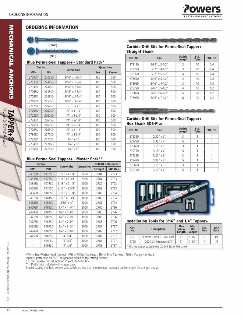
ORDERING INFORMATION
(HWH)
(PFH)
Blue Perma-Seal Tapper+ - Standard Pack*Cat No.
Screw SizeQuantities
HWH PFH Box Carton
2700sD 2740sD 3/16" x 1-1/4" 100 500
2702sD 2742sD 3/16" x 1-3/4" 100 500
2704sD 2744sD 3/16" x 2-1/4" 100 500
2706sD 2746sD 3/16" x 2-3/4" 100 500
2708sD 2748sD 3/16" x 3-1/4" 100 500
2710sD 2750sD 3/16" x 3-3/4" 100 500
2712sD 2752sD 3/16" x 4" 100 500
2720sD 2760sD 1/4" x 1-1/4" 100 500
2722sD 2762sD 1/4" x 1-3/4" 100 500
2724sD 2764sD 1/4" x 2-1/4" 100 500
2726sD 2766sD 1/4" x 2-3/4" 100 500
2728sD 2768sD 1/4" x 3-1/4" 100 500
2730sD 2770sD 1/4" x 3-3/4" 100 500
2732sD 2772sD 1/4" x 4" 100 500
2734sD 2774sD 1/4" x 5" 100 100
2736sD 2776sD 1/4" x 6" 100 100
Blue Perma-Seal Tapper+ - Master Pack**Cat No.
Screw Size QuantitiesDrill Bit References
HWH PFH Straight SDS Hex
9462sD 9476sD 3/16" x 1-1/4" 2000 2781 2793
9463sD 9477sD 3/16" x 1-3/4" 2000 2781 2793
9464sD 9478sD 3/16" x 2-1/4" 2000 2782 2793
9465sD 9479sD 3/16" x 2-3/4" 2000 2782 2793
9466sD 9480sD 3/16" x 3-1/4" 1000 2783 2794
9467sD 9481sD 3/16" x 3-3/4" 1000 2783 2794
9468sD 9482sD 3/16" x 4" 1000 2783 2794
9469sD 9483sD 1/4" x 1-1/4" 2000 2785 2796
9470sD 9484sD 1/4" x 1-3/4" 2000 2785 2796
9471sD 9485sD 1/4" x 2-1/4" 1000 2786 2796
9472sD 9486sD 1/4" x 2-3/4" 1000 2786 2796
9473sD 9487sD 1/4" x 3-1/4" 1000 2787 2797
9474sD 9488sD 1/4" x 3-3/4" 1000 2787 2797
9475sD 9489sD 1/4" x 4" 1000 2787 2797
- 9490sD 1/4" x 5" 1000 2788 2797
- 9491sD 1/4" x 6" 1000 2789 2797
Carbide Drill Bits for Perma-Seal Tapper+ Straight Shank
Cat. No. Size Usable Length
Std. Tube Wt./ 10
2781sD 5/32" x 3-1/2" 2 10 1/4
2782sD 5/32" x 4-1/2" 3 10 1/4
2783sD 5/32" x 5-1/2" 4 10 1/4
2785sD 3/16" x 3-1/2" 2 10 1/4
2786sD 3/16" x 4-1/2" 3 10 1/4
2787sD 3/16" x 5-1/2" 4 10 1/2
2788sD 3/16" x 6-1/2" 5 10 1/2
2789sD 3/16" x 7-1/2" 6 10 1/2
Carbide Drill Bits for Perma-Seal Tapper+ Hex Shank SDS-Plus
Cat. No. Size Usable Length
Std. Tube Wt./ 10
2793sD 5/32" x 5" 3 1 1
2794sD 5/32" x 7" 5 1 1
2796sD 3/16" x 5" 3 1 1
2797sD 3/16" x 7" 5 1 1
2793sD 5/32" x 5" 3 1 1
2794sD 5/32" x 7" 5 1 1
2796sD 3/16" x 5" 3 1 1
2797sD 3/16" x 7" 5 1 1
Installation Tools for 3/16" and 1/4" Tapper+
Cat. No. Description
Max Screw Length
Max Bit
Length
Std. Box
Wt./ Each
2791 *Combo TAPPEr 1000 Tool 4" 5-1/2" 1 3/4
2795 1000 sDs Extension (8") 6" 7-1/2" 1 1/2
* This tool cannot be used with SDS Drill Bits or PFH screws.
HWH = Hex Washer Head (slotted) ; PfH = Phillips flat Head ; TfH = Trim flat Head ; fHH = flange Hex Head.Tapper+ parts have an “sD” designation added to the catalog number.* - one Tapper+ drill bit included in each standard box.** - Drill bit not included with master pack.shaded catalog numbers denote sizes which are less than the minimum standard anchor length for strength design.

www.powers.com 12
orDerInG InformatIon
TECH
MAN
UAL
– M
ECHA
NiC
AL A
NCH
ors
©20
21 P
oW
Ers
– r
EV. f
Mech
an
ica
l a
nch
or
s
(HWH)
(PFH)
(FHH)
(TFH)
White Perma-Seal Tapper+ - Standard Pack*Cat No.
Screw SizeQuantities
HWH PFH FHH TFH Box Carton
2400sD 2440sD - - 3/16" x 1-1/4" 100 500
2402sD 2442sD - - 3/16" x 1-3/4" 100 500
2404sD 2444sD - - 3/16" x 2-1/4" 100 500
2406sD 2446sD - - 3/16" x 2-3/4" 100 500
2408sD 2448sD - - 3/16" x 3-1/4" 100 500
2410sD 2450sD - - 3/16" x 3-3/4" 100 500
2412sD 2449sD - - 3/16" x 4" 100 500
2420sD 2460sD - - 1/4" x 1-1/4" 100 500
2422sD 2462sD 8706sD 8710sD 1/4" x 1-3/4" 100 500
2424sD 2464sD 8707sD 8711sD 1/4" x 2-1/4" 100 500
2426sD 2466sD 8708sD 8712sD 1/4" x 2-3/4" 100 500
2428sD 2468sD 8709sD 8713sD 1/4" x 3-1/4" 100 500
2430sD 2470sD - 8714sD 1/4" x 3-3/4" 100 500
2435sD 2472sD - - 1/4" x 4" 100 500
White Perma-Seal Tapper+ - Master Pack**Cat No.
Screw Size QuantitiesDrill Bit References
HWH PFH Straight SDS Hex
- 9191sD 3/16" x 1-1/4" 2000 2781 2793
- 9192sD 3/16" x 1-3/4" 2000 2781 2793
- 9193sD 3/16" x 2-1/4" 2000 2782 2793
- 9194sD 3/16" x 2-3/4" 2000 2782 2793
- 9195sD 3/16" x 3-1/4" 1000 2783 2794
- 9196sD 3/16" x 3-3/4" 1000 2783 2794
- 9197sD 3/16" x 4" 1000 2783 2794
9923sD 9951sD 1/4" x 1-1/4" 2000 2785 2796
9924sD 9952sD 1/4" x 1-3/4" 2000 2785 2796
9925sD 9953sD 1/4" x 2-1/4" 1000 2786 2796
9926sD 9954sD 1/4" x 2-3/4" 1000 2786 2796
9927sD 9955sD 1/4" x 3-1/4" 1000 2787 2797
9928sD 9956sD 1/4" x 3-3/4" 1000 2787 2797
9929sD 9957sD 1/4" x 4" 1000 2787 2797
shaded catalog denote sizes which are less than the minimum standard anchor length for strength design.
flange Hex Head parts are not included in the scope of Esr-3068.
(HWH)
(PFH)
(FHH)
(TFH)
Silver Perma-Seal Tapper+ - Standard Pack*Cat No.
Screw SizeQuantities
HWH PFH FHH TFH Box Carton
- 2498sD - - 3/16" x 1-1/4" 100 500
- 2500sD - - 3/16" x 1-3/4" 100 500
- 2501sD - - 3/16" x 2-1/4" 100 500
- 2502sD - - 3/16" x 2-3/4" 100 500
- 2503sD - - 3/16" x 3-1/4" 100 500
- 2504sD - - 3/16" x 3-3/4" 100 500
- 2505sD - - 3/16" x 4" 100 500
2486sD 2506sD - - 1/4" x 1-1/4" 100 500
2488sD 2507sD 8715sD 8719sD 1/4" x 1-3/4" 100 500
2490sD 2508sD 8716sD 8720sD 1/4" x 2-1/4" 100 500
2492sD 2509sD 8717sD 8721sD 1/4" x 2-3/4" 100 500
2494sD 2510sD 8718sD 8722sD 1/4" x 3-1/4" 100 500
2495sD 2511sD - 8723sD 1/4" x 3-3/4" 100 500
2496sD 2512sD - - 1/4" x 4" 100 500
Silver Perma-Seal Tapper+ - Master Pack**Cat No.
Screw Size QuantitiesDrill Bit References
HWH PFH Straight SDS Hex
- 8757sD 3/16" x 1-1/4" 2000 2781 2793
- 8758sD 3/16" x 1-3/4" 2000 2781 2793
- 8759sD 3/16" x 2-1/4" 2000 2782 2793
- 8760sD 3/16" x 2-3/4" 2000 2782 2793
- 8761sD 3/16" x 3-1/4" 1000 2783 2794
- 8762sD 3/16" x 3-3/4" 1000 2783 2794
- 8763sD 3/16" x 4" 1000 2783 2794
8750sD 8764sD 1/4" x 1-1/4" 2000 2785 2796
8751sD 8765sD 1/4" x 1-3/4" 2000 2785 2796
8752sD 8766sD 1/4" x 2-1/4" 1000 2786 2796
8753sD 8767sD 1/4" x 2-3/4" 1000 2786 2796
8754sD 8768sD 1/4" x 3-1/4" 1000 2787 2797
8755sD 8769sD 1/4" x 3-3/4" 1000 2787 2797
8756sD 8770sD 1/4" x 4" 1000 2787 2797
(PFH)
(FHH)
Blue Perma-Seal Tapper+ - Standard Pack*Cat No.
Screw SizeQuantities
PFH FHH Box Carton
9975sD 9977sD 1/4" x 1-3/4" 100 500
9976sD 9978sD 1/4" x 2-1/4" 100 500
www.powers.com 13
TECH MAN
UAL – MECHAN
iCAL ANCHo
rs ©2021 Po
WErs – rEV. f
orDerInG InformatIon
Mech
an
ica
l a
nch
or
s
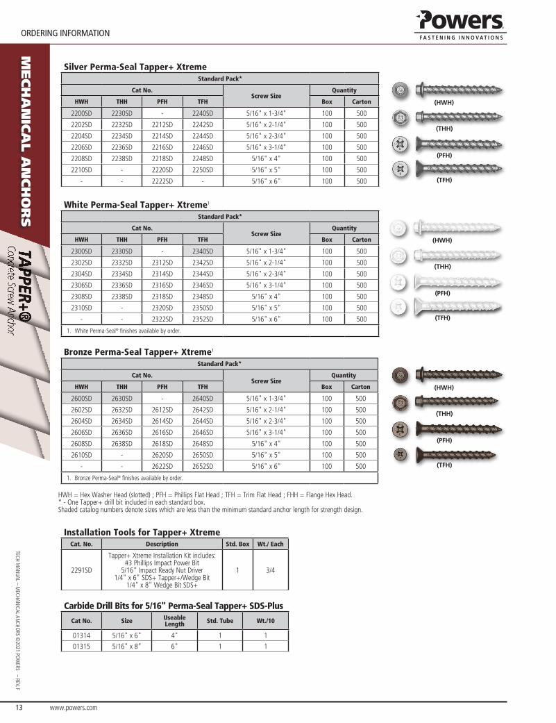
Silver Perma-Seal Tapper+ XtremeStandard Pack*
Cat No.Screw Size
Quantity
HWH THH PFH TFH Box Carton
2200sD 2230sD - 2240sD 5/16" x 1-3/4" 100 500
2202sD 2232sD 2212sD 2242sD 5/16" x 2-1/4" 100 500
2204sD 2234sD 2214sD 2244sD 5/16" x 2-3/4" 100 500
2206sD 2236sD 2216sD 2246sD 5/16" x 3-1/4" 100 500
2208sD 2238sD 2218sD 2248sD 5/16" x 4" 100 500
2210sD - 2220sD 2250sD 5/16" x 5" 100 500
- - 2222sD - 5/16" x 6" 100 500
(HWH)
(THH)
(PFH)
(TFH)
White Perma-Seal Tapper+ Xtreme1
Standard Pack*
Cat No.Screw Size
Quantity
HWH THH PFH TFH Box Carton
2300sD 2330sD - 2340sD 5/16" x 1-3/4" 100 500
2302sD 2332sD 2312sD 2342sD 5/16" x 2-1/4" 100 500
2304sD 2334sD 2314sD 2344sD 5/16" x 2-3/4" 100 500
2306sD 2336sD 2316sD 2346sD 5/16" x 3-1/4" 100 500
2308sD 2338sD 2318sD 2348sD 5/16" x 4" 100 500
2310sD - 2320sD 2350sD 5/16" x 5" 100 500
- - 2322sD 2352sD 5/16" x 6" 100 500
1. White Perma-Seal® finishes available by order.
(HWH)
(THH)
(PFH)
(TFH)
Bronze Perma-Seal Tapper+ Xtreme1
Standard Pack*
Cat No.Screw Size
Quantity
HWH THH PFH TFH Box Carton
2600sD 2630sD - 2640sD 5/16" x 1-3/4" 100 500
2602sD 2632sD 2612sD 2642sD 5/16" x 2-1/4" 100 500
2604sD 2634sD 2614sD 2644sD 5/16" x 2-3/4" 100 500
2606sD 2636sD 2616sD 2646sD 5/16" x 3-1/4" 100 500
2608sD 2638sD 2618sD 2648sD 5/16" x 4" 100 500
2610sD - 2620sD 2650sD 5/16" x 5" 100 500
- - 2622sD 2652sD 5/16" x 6" 100 500
1. Bronze Perma-Seal® finishes available by order.
(HWH)
(THH)
(PFH)
(TFH)
HWH = Hex Washer Head (slotted) ; PfH = Phillips flat Head ; TfH = Trim flat Head ; fHH = flange Hex Head.* - one Tapper+ drill bit included in each standard box.shaded catalog numbers denote sizes which are less than the minimum standard anchor length for strength design.
Installation Tools for Tapper+ XtremeCat. No. Description Std. Box Wt./ Each
2291sD
Tapper+ Xtreme installation Kit includes:#3 Phillips impact Power Bit
5/16" impact ready Nut Driver1/4" x 6" sDs+ Tapper+/Wedge Bit
1/4" x 8" Wedge Bit sDs+
1 3/4
Carbide Drill Bits for 5/16" Perma-Seal Tapper+ SDS-Plus
Cat No. Size Useable Length Std. Tube Wt./10
01314 5/16" x 6" 4" 1 1
01315 5/16" x 8" 6" 1 1
Related Documents