© KEMET Electronics Corporation • P.O. Box 5928 • Greenville, SC 29606 • 864-963-6300 • www.kemet.com T2072_T551 • 6/26/2018 1 One world. One KEMET Benefits • Includes F-Tech anode, which eliminates hidden defects in the dielectric • 100% simulated breakdown screening • Maximum operating temperature of +125°C • Polymer cathode technology • ≤ 0.0075 CV (µA) at rated voltage after 5 minutes • Extremely low ESR • High frequency and low temperature capacitance retention • 100% constant voltage conditioning (240 hours) • 100% surge current tested • Volumetrically efficient • Use at up to 80% of rated voltage • Non-ignition failure mode • Approximately 25% lighter than equivalent wet tantalum • T551 case dimensions equivalent to MIL-PRF-39006/22/25/30/31 • T556 surface mount design (see dimensions diagram) Overview The KEMET T551 axial leaded and T556 surface mount polymer hermetically sealed (PHS) devices are tantalum capacitors with a Ta anode and Ta 2 O 5 dielectric. A conductive, organic polymer replaces the traditionally used MnO 2 or wet electrolyte as the cathode plate of the capacitor. The result is very low ESR and improved capacitance retention at high frequency and low temperature. The PHS device also exhibits a benign failure mode, which eliminates the case breach that can occur in wet tantalum capacitors. Additionally, the part may be operated at voltages up to 80% of rated voltage, with equivalent or better reliability than traditional MnO 2 or wet tantalum capacitors operated at 50% of rated voltage. PHS capacitors molded also offer higher ripple current handling capability and a lower ESR range than wet tantalums. With reduced ESR and enhanced capacitance retention at higher frequencies and low temperatures, these parts provide the highest total capacitance and the most economical solution for high power applications, all within an approximately 25% lighter package than the equivalent wet tantalum capacitor. Tantalum Polymer Capacitors – Hermetically Sealed T551 Axial & T556 Surface Mount 125°C

Welcome message from author
This document is posted to help you gain knowledge. Please leave a comment to let me know what you think about it! Share it to your friends and learn new things together.
Transcript
© KEMET Electronics Corporation • P.O. Box 5928 • Greenville, SC 29606 • 864-963-6300 • www.kemet.com T2072_T551 • 6/26/2018 1One world. One KEMET
Benefits
• Includes F-Tech anode, which eliminates hidden defects in the dielectric
• 100% simulated breakdown screening• Maximum operating temperature of +125°C• Polymer cathode technology• ≤0.0075CV(µA)atratedvoltageafter5minutes• Extremely low ESR• High frequency and low temperature capacitance retention• 100%constantvoltageconditioning(240hours)• 100% surge current tested• Volumetricallyefficient• Use at up to 80% of rated voltage• Non-ignition failure mode• Approximately25%lighterthanequivalentwettantalum• T551 case dimensions equivalent to
MIL-PRF-39006/22/25/30/31• T556surfacemountdesign(seedimensionsdiagram)
Overview
The KEMET T551 axial leaded and T556 surface mount polymerhermeticallysealed(PHS)devicesaretantalumcapacitors with a Ta anode and Ta2O5dielectric.Aconductive, organic polymer replaces the traditionally used MnO2 or wet electrolyte as the cathode plate of the capacitor. The result is very low ESR and improved capacitance retention at high frequency and low temperature. The PHS device also exhibits a benign failure mode, which eliminates the case breach that can occur inwettantalumcapacitors.Additionally,thepartmaybe operated at voltages up to 80% of rated voltage, with equivalent or better reliability than traditional MnO2 or wet
tantalum capacitors operated at 50% of rated voltage.PHS capacitors molded also offer higher ripple current handling capability and a lower ESR range than wet tantalums. With reduced ESR and enhanced capacitance retention at higher frequencies and low temperatures, these parts provide the highest total capacitance and the most economical solution for high power applications, all within an approximately 25% lighter package than the equivalent wet tantalum capacitor.
Tantalum Polymer Capacitors – Hermetically Sealed
T551 Axial & T556 Surface Mount 125°C

© KEMET Electronics Corporation • P.O. Box 5928 • Greenville, SC 29606 • 864-963-6300 • www.kemet.com T2072_T551 • 6/26/2018 22
Tantalum Polymer Capacitors – Hermetically SealedT551 Axial & T556 Surface Mount 125°C
Applications
Typicalapplicationsincludehighvoltagepowermanagement,suchasbuck/boostconverters,filtering,hold-upcapacitors,and other high ripple current applications.
Ordering Information
T 551 B 107 M 025 A T 4251Capacitor
Class Series Case Size
Capacitance Code(pF)
Capacitance Tolerance
RatedVoltage (VDC)
Product Level Termination Finish Surge Option* Packaging*
T = Tantalum
551 = AxialLeaded PHS 556 = Surface MountPHS
B First two digits represent significant
figures.Thirddigitspecifiesnumber
of zeros.
K = ±10%M = ±20%
006 = 6.3 008 = 8 010 = 10 015 = 15 025 = 25 030 = 30 040 = 40 050 = 50 060 = 60
A=N/A T=100%tin(Sn)-platedH = Tin/lead (SnPb)soldercoated(5%Pbminimum)
4251 = Surge
current, 10 cycles, –55°C and
+85°C
Blank = Sleeved 0100 = Unsleeved 7200 = Tape & Reel 7293=Ammo7443=Ammo
* Only for T551 (Surge options/packaging)
Performance Characteristics
Item Performance CharacteristicsOperating Temperature −55°Cto125°C
Rated Capacitance Range 20to680μFat120Hz/25°C*
Capacitance Tolerance Ktolerance(10%),Mtolerance(20%)
RatedVoltageRange 6.3–60V
DF(120Hzat25°C) RefertoPartNumberElectricalSpecificationTable
ESR(100kHzat25°C) RefertoPartNumberElectricalSpecificationTable
Leakage Current RefertoPartNumberElectricalSpecificationTable (atratedvoltageupto+85°Cand66%ofratedvoltageappliedat125°C)
Packaging T551 according to MIL-PRF-39006, T556 bulk
KEMET does not recommend storage above 85°C.* Additional case sizes and capacitance/voltage are under development.

© KEMET Electronics Corporation • P.O. Box 5928 • Greenville, SC 29606 • 864-963-6300 • www.kemet.com T2072_T551 • 6/26/2018 33
Tantalum Polymer Capacitors – Hermetically SealedT551 Axial & T556 Surface Mount 125°C
Qualification - T551
Test Performed Method Reference Test ConditionsReliability and Environmental Tests
ACRippleLifeat85˚C MIL–PRF–39006 85˚C,40kHzripplecurrent,2,000hours
85˚CLife MIL–PRF–39006 85˚C,ratedvoltage,2,000hours
125˚CLife KEMET Standard 125°C, 0.66 x rated voltage, 2,000 hours
SurgeVoltage MIL–PRF–39006 85˚C,1.15xratedvoltage,1,000cycles,exceptdeltacapshallbe+10%/−20%
Surge Current MIL–PRF–39003 +25°C,10cycles(OptionA),OptionBavailable
Low Temperature Storage MIL–PRF–39006 −62˚Cfor72hoursfollowedby1hourat125˚C
ReverseVoltage KEMET Catalog 1Vfor8hoursmaximumat25°C,1Vfor2hoursmaximumat70°CPhysical, Mechanical and Process Tests
VisualandMechanicalExamination(Internaland
External)MIL–PRF–39006 Case dimensions, marking
Terminal Strength MIL–PRF–39006 Pull test and wire lead bend test
Resistance to Solvents MIL–PRF–39006 Immersionin(3)solvents
Resistance to Soldering Heat MIL–PRF–39006 Immersed to within 0.05 inch of capacitor body
Solderability MIL–PRF–39006 Depthofinsertioninfluxandsoldertowithin0.062inchofweldedjoint
ShockandVibration MIL–STD–202, Methods 213, 204
ShockMethod213,ConditionI,100gpeak,VibrationMethod204, ConditionD,20gpeak
Barometric Pressure (Reduced)
MIL–PRF–39006 150,000 feet for 5 minutes, voltage applied for 1 minute
SaltAtmosphere(Corrosion) MIL–PRF–39006 Subjectedtofinemistofsaltsolution
Moisture Resistance MIL–PRF–39006 65°C at 6 volts
DielectricWithstandingVoltage
MIL–PRF–39006 2,000VDC,60seconds,sleevingexaminedforevidenceofbreakdown
Insulation Resistance MIL–PRF–39003 500VDC,1minute,insulationresistancenotlessthan1,000MΩElectrical Characterization
Temperature Stability Reference MIL–PRF–39006 −55˚Cto105˚C
Frequency Scan KEMET Standard Impedance, ESR and capacitance versus frequency

© KEMET Electronics Corporation • P.O. Box 5928 • Greenville, SC 29606 • 864-963-6300 • www.kemet.com T2072_T551 • 6/26/2018 44
Tantalum Polymer Capacitors – Hermetically SealedT551 Axial & T556 Surface Mount 125°C
Qualification - T556
Test Performed Method Reference Test ConditionsReliability and Environmental Tests
105˚CLife KEMET Standard 105°C, 0.78 x rated voltage, 2,000 hours
SurgeVoltage MIL-PRF-39006 85˚C,1.15xratedvoltage,1,000cycles,exceptdeltacapshallbe+10%/–20%Physical, Mechanical and Process Tests
VisualandMechanicalExamination(Internaland
External)MIL-PRF-39003 Case dimensions, marking
Terminal Strength MIL-PRF-39006 Pull test and wire lead bend test
Resistance to Solvents MIL-PRF-39006 Immersionin(3)solvents
Resistance to Soldering Heat MIL-PRF-39006 Immersed to within 0.05 inch of capacitor body
Solderability MIL-PRF-39006 Depthofinsertioninfluxandsoldertowithin0.062inchofweldedjoint
ShockandVibration MIL-STD-202, Methods 213, 204
ShockMethod213,ConditionI,100gpeak,VibrationMethod204, ConditionD,20gpeak
Electrical CharacterizationTemperature Stability Reference MIL-PRF-39006 –55˚Cto105˚C
Environmental Compliance
RoHScompliant(6/6)accordingtoDirective2002/95/ECwhenorderedwith100%Sn.EpoxycompliantwithUL94V–0.

© KEMET Electronics Corporation • P.O. Box 5928 • Greenville, SC 29606 • 864-963-6300 • www.kemet.com T2072_T551 • 6/26/2018 55
Tantalum Polymer Capacitors – Hermetically SealedT551 Axial & T556 Surface Mount 125°C
Electrical Characteristics
ESR vs. Frequency
Capacitance vs. Frequency
0
20
40
60
80
100
120
10 100 1,000 10,000 100,000 1,000,000
Capa
cita
nce
(µF)
Frequency (Hz)
+125°C +85°C+50°C +25°C 0°C −25°C−55°C −80°C
0.0
0.1
1.0
10.0
10 100 1,000 10,000 100,000 1,000,000 10,000,000
ESR
(mOh
ms)
Frequency (Hz)
+125°C +85°C+50°C +25°C 0°C −25°C−55°C −80°C

© KEMET Electronics Corporation • P.O. Box 5928 • Greenville, SC 29606 • 864-963-6300 • www.kemet.com T2072_T551 • 6/26/2018 66
Tantalum Polymer Capacitors – Hermetically SealedT551 Axial & T556 Surface Mount 125°C
Dimensions – Inches (Millimeters)
T551
SIDE VIEW END VIEW
LM
1.50±0.250(38.10±6.35) D
+
J0.094 (2.39) Maximum
Case Code Case Size Uninsulated Case Insulated Case
MIL-PRF-39006 L ±0.031(0.79)
D +0.016(0.41) −0.015(0.38)
M ±0.002(0.05)
J maximum
D +0.016(0.41) −0.015(0.38)
L ±0.031(0.79)
B T2 0.650(16.51) 0.279(7.09) 0.025(0.64) 0.822(20.88) 0.289(7.34) 0.686(17.42)
Dimensions – MillimetersT556
H F
A
L
SIDE VIEW BOTTOM VIEWCATHODE (-) END VIEW
W
S S
Case Code Weight (g)L ±0.5 W ±0.5 H ±0.5 F ±0.5 S minimum Average
B Surface mount 24.5 8.5 9.1 4.2 3.0 5.54

© KEMET Electronics Corporation • P.O. Box 5928 • Greenville, SC 29606 • 864-963-6300 • www.kemet.com T2072_T551 • 6/26/2018 77
Tantalum Polymer Capacitors – Hermetically SealedT551 Axial & T556 Surface Mount 125°C
Table 1A – Ratings & Part Number Reference
Rated Voltage
Rated Capacitance
Case Size
KEMET Part Number
DC Leakage DF Maximum
ESRRipple
Current
(V) 85°C µF KEMET/EIA µA at 25°C Maximum/ 5 Minutes
% at 25°C120 Hz Max
mΩ at 25°C100 kHz
mArms at 85°C/40 kHz
6.3 140 B T551B147(1)006A(2) 6.3 5.0 120 1,5108 220 B T551B227(1)008A(2) 13.2 5.0 120 1,5108 680 B T551B687(1)008A(2) 40.8 5.0 90 1,750
10 100 B T551B107(1)010A(2) 7.5 5.0 140 1,40010 180 B T551B187(1)010A(2) 13.5 5.0 110 1,58010 560 B T551B567(1)010A(2) 42.0 5.0 90 1,75015 70 B T551B706(1)015A(2) 7.9 5.0 140 1,40015 120 B T551B127(1)015A(2) 13.5 5.0 110 1,58015 390 B T551B397(1)015A(2) 43.9 5.0 90 1,75025 50 B T551B506(1)025A(2) 9.4 5.0 170 1,27525 100 B T551B107(1)025A(2) 18.8 5.0 190 1,20030 40 B T551B406(1)030A(2) 9.0 5.0 170 1,27530 68 B T551B686(1)030A(2) 15.3 5.0 140 1,40040 100 B T551B107(1)040A(2) 30.0 5.0 150 1,35040 120 B T551B127(1)040A(2) 36.0 5.0 120 1,51050 25 B T551B256(1)050A(2) 9.4 5.0 170 1,27550 47 B T551B476(1)050A(2) 17.6 5.0 150 1,35050 100 B T551B107(1)050A(2) 37.5 5.0 130 1,45050 120 B T551B127(1)050A(2) 45.0 5.0 90 1,75060 20 B T551B206(1)060A(2) 9.0 5.0 200 1,17560 39 B T551B396(1)060A(2) 17.6 5.0 160 1,31060 100 B T551B107(1)060A(2) 45.0 5.0 100 1,660
(1) To complete KEMET part number, insert M for ±20% or K for ±10%. Designates capacitance tolerance. (2) To complete KEMET part number, insert T = 100% matte tin (Sn)-plated, H = standard solder coated (SnPb 5% Pb minimum). Designates termination finish. Refer to Ordering Information for additional detail. Higher voltage ratings and tighter tolerance product including ESR may be substituted within the same size at KEMET's option. Voltage substitution will be marked with the higher voltage rating. The 85°C 40 kHz ripple limit is based on the maximum allowed power at 85°C and the maximum expected ESR at 40 kHz. For this calculation, the 100 kHz ESR limit is multiplied by a factor of 1.3 to account for the frequency dependence of ESR.

© KEMET Electronics Corporation • P.O. Box 5928 • Greenville, SC 29606 • 864-963-6300 • www.kemet.com T2072_T551 • 6/26/2018 88
Tantalum Polymer Capacitors – Hermetically SealedT551 Axial & T556 Surface Mount 125°C
Table 1B – Ratings & Part Number Reference
Rated Voltage
Rated Capacitance
Case Size
KEMET Part Number
DC Leakage DF Maximum
ESRRipple
Current
(V) 85°C µF KEMET/EIA µA at 25°C Maximum/ 5 Minutes
% at 25°C120 Hz Max
mΩ at 25°C100 kHz
mArms at 85°C/40 kHz
6.3 140 B T556B147(1)006A(2) 6.3 5.0 120 1,5108 220 B T556B227(1)008A(2) 13.2 5.0 120 1,5108 680 B T556B687(1)008A(2) 40.8 5.0 90 1,750
10 100 B T556B107(1)010A(2) 7.5 5.0 140 1,40010 180 B T556B187(1)010A(2) 13.5 5.0 110 1,58010 560 B T556B567(1)010A(2) 42.0 5.0 90 1,75015 70 B T556B706(1)015A(2) 7.9 5.0 140 1,40015 120 B T556B127(1)015A(2) 13.5 5.0 110 1,58015 390 B T556B397(1)015A(2) 43.9 5.0 90 1,75025 50 B T556B506(1)025A(2) 9.4 5.0 170 1,27525 100 B T556B107(1)025A(2) 18.8 5.0 190 1,20030 40 B T556B406(1)030A(2) 9.0 5.0 170 1,27530 68 B T556B686(1)030A(2) 15.3 5.0 140 1,40040 100 B T556B107(1)040A(2) 30.0 5.0 150 1,35040 120 B T556B127(1)040A(2) 36.0 5.0 120 1,51050 25 B T556B256(1)050A(2) 9.4 5.0 170 1,27550 47 B T556B476(1)050A(2) 17.6 5.0 150 1,35050 100 B T556B107(1)050A(2) 37.5 5.0 130 1,45050 120 B T556B127(1)050A(2) 45.0 5.0 90 1,75060 20 B T556B206(1)060A(2) 9.0 5.0 200 1,17560 39 B T556B396(1)060A(2) 17.6 5.0 160 1,31060 100 B T556B107(1)060A(2) 45.0 5.0 100 1,660
(1) To complete KEMET part number, insert M for ±20% or K for ±10%. Designates capacitance tolerance. (2) To complete KEMET part number, insert T = 100% matte tin (Sn)-plated, H = standard solder coated (SnPb 5% Pb minimum). Designates termination finish. Refer to Ordering Information for additional detail. Higher voltage ratings and tighter tolerance product including ESR may be substituted within the same size at KEMET's option. Voltage substitution will be marked with the higher voltage rating. The 85°C 40 kHz ripple limit is based on the maximum allowed power at 85°C and the maximum expected ESR at 40 kHz. For this calculation, the 100 kHz ESR limit is multiplied by a factor of 1.3 to account for the frequency dependence of ESR.
© KEMET Electronics Corporation • P.O. Box 5928 • Greenville, SC 29606 • 864-963-6300 • www.kemet.com T2072_T551 • 6/26/2018 99
Tantalum Polymer Capacitors – Hermetically SealedT551 Axial & T556 Surface Mount 125°C
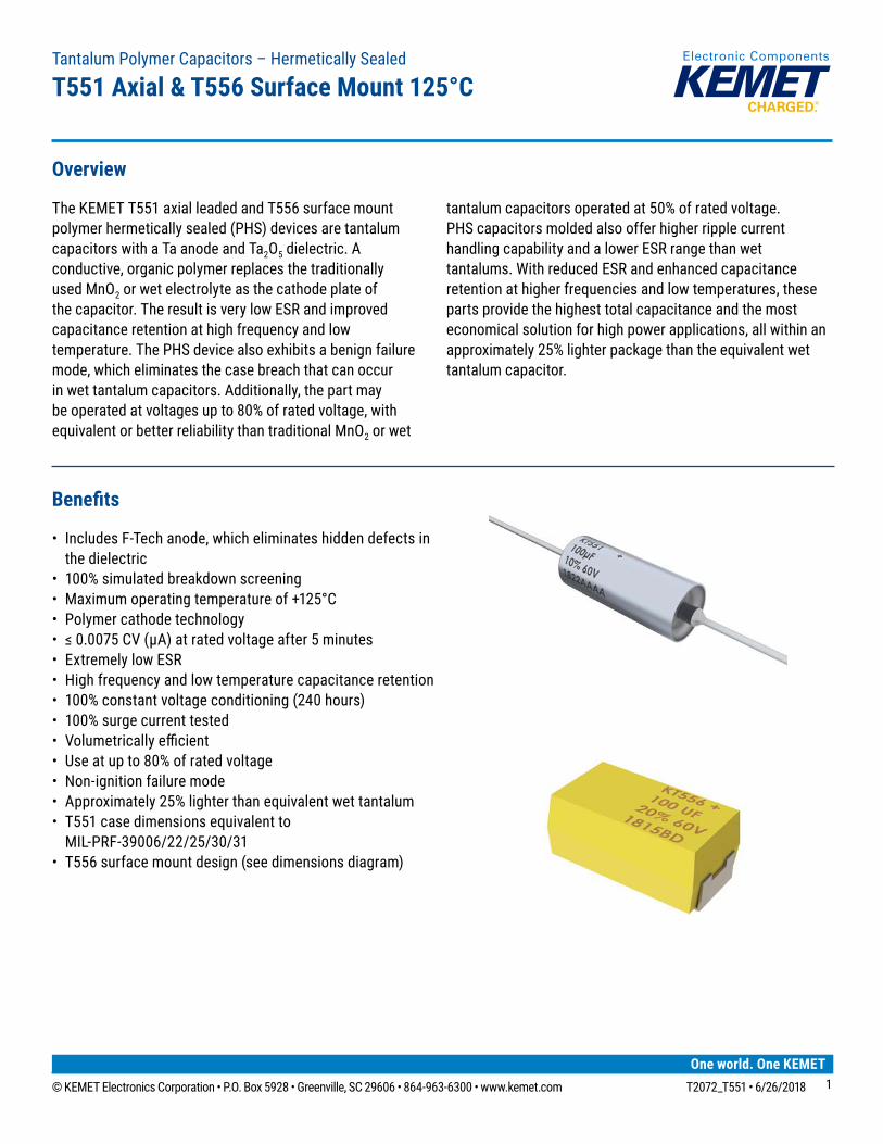
Recommended Voltage Derating Guidelines
−55°Cto85°C 85°C to 105°C 105°C to 125°C
%ChangeinworkingDCvoltage with temperature VR 78%ofVR 66%ofVR
Recommended maximum application voltage
(as%ofratedvoltage)80%ofVR 63%ofVR 53%ofVR
Ripple Current/Ripple Voltage
PermissibleACripplevoltageandcurrentarerelatedtoequivalentseriesresistance(ESR)andthepowerdissipationcapabilitiesofthedevice.PermissibleACripplevoltagethatmaybeappliedislimitedbytwocriteria: 1.ThepositivepeakACvoltageplustheDCbiasvoltage,ifany,mustnotexceedtheDCvoltageratingofthecapacitor. 2.ThenegativepeakACvoltageincombinationwithbiasvoltage,ifany,mustnotexceedtheallowablelimitsspecified
for reverse voltage.The maximum power dissipation by case size can be determined using the below left table. The maximum power dissipation rating stated in the table must be reduced with increasing environmental operating temperatures. Refer to the below right table for temperature compensation requirements.
Case Code
Maximum Power Dissipation (Pmax) mWatts at 25°C with +60°C Rise
KEMET MIL–PRF–39006/22/25/30/31 Case size
B* T2 715
* Applies to TH and SMD
Temperature Compensation Multipliers forMaximum Power Dissipation (Pmax)
T≤45°C 45°C<T≤85°C 85°C<T≤125°C1.00 0.70 0.10
T = Environmental temperature
Using the Pmax of the device, the maximum allowable rms ripple current or voltage may be determined.
I(max) = √Pmax/RE(max) = Z √Pmax/R
I = rms ripple current (amperes)E = rms ripple voltage (volts)Pmax = maximum power dissipation (watts)R = ESR at specified frequency (ohms)Z = Impedance at specified frequency (ohms)
The maximum power dissipation rating must be reduced with increasing environmental operating temperatures. Refer to the Temperature Compensation Multiplier table for details.
0%
20%
40%
60%
80%
100%
120%
−55 25 45 85 105 125
% W
orki
ng V
olta
ge
Temperature (°C)
% Change in working DC voltage with temperature
Recommended maximum application voltage (as % of rated voltage)
80%
66%
53%

© KEMET Electronics Corporation • P.O. Box 5928 • Greenville, SC 29606 • 864-963-6300 • www.kemet.com T2072_T551 • 6/26/2018 1010
Tantalum Polymer Capacitors – Hermetically SealedT551 Axial & T556 Surface Mount 125°C
Reverse Voltage
Solid tantalum polymer capacitors are polar devices and may be permanently damaged or destroyed if connected with thewrongpolarity.A small reverse voltageispermissiblefor time periodsperthebelowtable.KEMETcanofferlowercapacitanceinthisvoltagewithhigher reverse voltage capability.Inaddition,wecontinuetoimproveour capability forthischaracteristic.
Temperature Permissible Reverse Voltage25°C 1Vfor8hoursmaximum70°C 1Vfor2hoursmaximum
Soldering Process
0255075
100125150175200225250
1 2 3Time (Minutes)
Degr
ees
– Cº
4 5 6
Flux Zone Preheat Zone
Entrance to Solder Wave Exit from Solder Wave
Hot Air Debridging
Exit fromSolder
Machine
(Time in Wave – 2 to 4 Seconds)
Solder Wave PeakTemperature 260ºC
Entranceto SolderMachine
80ºCto 120ºC
Bottom SideTemperature
Range
Top SideNominal
150ºCMaximum
FreeAir
Cool
Entrance toIn-Line Cleaner
Exit fromIn-Line Cleaner(time in cleaner
may be less)
Immersion inCleaningVapor
Manual Solder Profile with Pre-heating
Gradual Preheat60 – 120 SecondsRecommend 2.5°C/second
Soldering
Maxim
um 3 seconds
Delta T < = 120ºC
Gradual Cooling
OptimumSolderWaveProfile HandSoldering(Manual)*
*T556 MUST be hand soldered only.
Mounting
WARNING: T555/T556 MUST BE HAND SOLDERED. THE USE OF STANDARD SMD PROCESSES FOR BOARD MOUNT WILL CAUSE IRREVERSIBLE DAMAGE TO THIS PRODUCT.
T556 SMDInhandsolderingtantalumpolymerSMTcapacitors,amanufacturercanutilizetwo(2)solderingmethodologiesthatinclude pre-heating or no pre-heating of the capacitors. KEMET recommends utilizing a pre-heating technique. However, due to the large temperature gradient between the capacitors and the tip of the soldering iron, extreme caution should be exercised in this process. The thermal stresses from the large thermal gradients and the propensity of the operator touching the tip of the soldering iron to the device can lead to mechanical and/or electrical damage.
When manually soldering, it is important the soldering process be carefully monitored and carried out so that the temperaturegradientfallswithintherecommendedconditionsabove(profile).

© KEMET Electronics Corporation • P.O. Box 5928 • Greenville, SC 29606 • 864-963-6300 • www.kemet.com T2072_T551 • 6/26/2018 1111
Tantalum Polymer Capacitors – Hermetically SealedT551 Axial & T556 Surface Mount 125°C
Mounting (cont'd.)
Process 1 (with preheating)
1)Utilize1.0mmthreadeutecticsolderwithsolderingfluxinthecore.Eitherarosin-basedornon-activatedfluxisrecommended.2)Thecapacitorsshallbepre-heatedsothatthetemperaturegradientbetweenthedevicesandthetipofthesolderingironisDeltaT<=120°Corbelow.3)Thetemperatureofthesolderirontipshouldnotexceed270°C.4)Therequiredamountofsoldershallbemeltedinadvanceonthesolderingtip.5)Aftersoldering,thecapacitorsshallbecooledgraduallyatroomambienttemperature.Forcedaircoolingisnotrecommended.
Process 2 (without preheating)
1)Solderingirontipshallneverdirectlytouchtheterminationegressorthecasebodyofthecapacitors.2)Landsaresufficientlypre-heatedwithasolderingirontipbeforeslidingthesolderingirontiptotheterminalelectrodeofthe capacitor for soldering.
Reference ConditionCase Size All
Temperature of soldering iron 270°C
Wattage 20 W maximum
Shape of soldering iron 3 mm maximum
Soldering time with soldering iron 3 seconds maximum
T551 Through-HoleAllencasedcapacitorswillpasstheresistancetosolderingheattestofMIL-STD-202,Method210,ConditionC.Thistestsimulates wave solder of topside board mount product. This demonstration of resistance to solder heat is in accordance withwhatisbelievedtobetheindustrystandard.Moreseveretreatmentmustbeconsideredreflectiveofanimpropersolderingprocess.Theabovefigureisarecommendedsolderwaveprofileforbothaxialandradialleadedsolidtantalumcapacitors.
Additional mounting recommendations (SMD and Through-Hole):
InordertoincreasetheboardmountintegrityofKEMET'sPolymerHermeticSealed(SMDorTHversion)relativetomechahical shock and vibration, KEMET recommends the use of an adhesive between the component and the PCB. This isdefinedintheSpaceApplicationElectronicHardwareAddendumtoJ-STD-001(RequirementsforSolderElectricalandElectronicAssemblies.)

© KEMET Electronics Corporation • P.O. Box 5928 • Greenville, SC 29606 • 864-963-6300 • www.kemet.com T2072_T551 • 6/26/2018 1212
Tantalum Polymer Capacitors – Hermetically SealedT551 Axial & T556 Surface Mount 125°C
Construction
T551Detailed Cross Section
Tantalum Wire
Solder
Ta2O5 Dielectric(First Layer)
Carbon(Third Layer)
Silver Paint(Fourth Layer)
Polymer(Second Layer)
Wire Lead (−)(100% Sn/SnPb)
Solder
SolderWire Lead (+)(100% Sn/SnPb)
Anode TubeHermetic Seal System (Glass Seal and Ring)
Brass Can
Tantalum
Hermetic Seal System (Ring)
Tantalum Wire
Tantalum Pellet (See Detail for
Layers)
Hermetic Seal System (Glass Seal)
Anode Tube
Wire Lead (−)(100% Sn/SnPb)
Wire Lead (+)(100% Sn/SnPb)
Brass CanInsulation
Sleeve
© KEMET Electronics Corporation • P.O. Box 5928 • Greenville, SC 29606 • 864-963-6300 • www.kemet.com T2072_T551 • 6/26/2018 1313
Tantalum Polymer Capacitors – Hermetically SealedT551 Axial & T556 Surface Mount 125°C
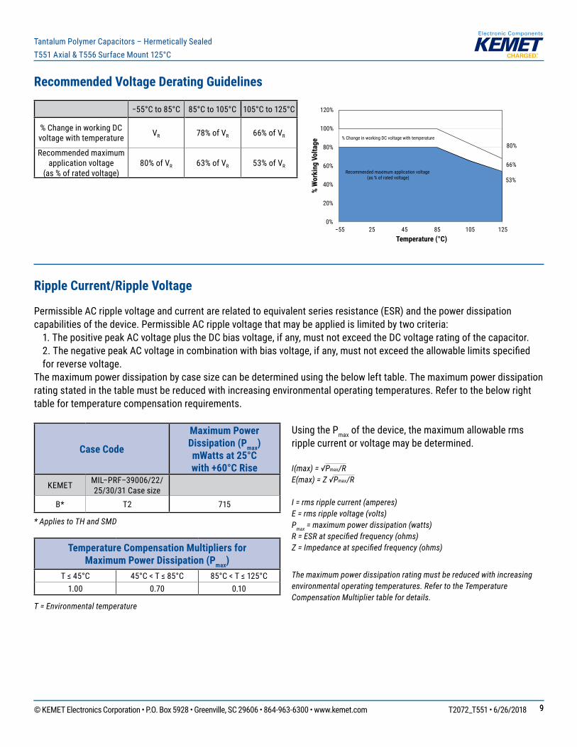
Capacitor Marking
T551
KT551 +100µF10% 60V1822AAAA
Polarity Mark
Rated Capacitance
B Case
Series
KEMET ID
4 Digit Date Code, Lot Code
CapacitanceTolerance,
Rated Voltage (VDC)
Date Code 3 Digit 4 Digit
Year
5 = 2015 6 = 2016 7 = 20178 = 20189 = 2019
15 = 2015 16 = 2016 17 = 201718 = 201819 = 2019
Week 01 = 1st week of the year to 52 = 52nd week of the year
T556
Polarity Mark
Series
Capacitance Tolerance
Capacitance
Rated Voltage4 Digit
Date Code, Lot Code
KEMETID
Date Code 3 Digit 4 Digit
Year
5 = 2015 6 = 2016 7 = 20178 = 20189 = 2019
15 = 2015 16 = 2016 17 = 201718 = 201819 = 2019
Week 01 = 1st week of the year to 52 = 52nd week of the year
© KEMET Electronics Corporation • P.O. Box 5928 • Greenville, SC 29606 • 864-963-6300 • www.kemet.com T2072_T551 • 6/26/2018 1414
Tantalum Polymer Capacitors – Hermetically SealedT551 Axial & T556 Surface Mount 125°C
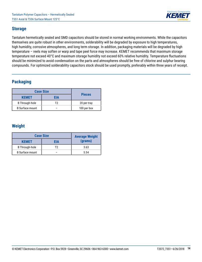
Storage
TantalumhermeticallysealedandSMDcapacitorsshouldbestoredinnormalworkingenvironments.Whilethecapacitorsthemselves are quite robust in other environments, solderability will be degraded by exposure to high temperatures, high humidity, corrosive atmospheres, and long term storage. In addition, packaging materials will be degraded by high temperature – reels may soften or warp and tape peel force may increase. KEMET recommends that maximum storage temperaturenotexceed40°Candmaximumstoragehumiditynotexceed60%relativehumidity.Temperaturefluctuationsshould be minimized to avoid condensation on the parts and atmospheres should be free of chlorine and sulphur bearing compounds. For optimized solderability capacitors stock should be used promptly, preferably within three years of receipt.
Packaging
Case SizePieces
KEMET EIAB Through-hole T2 20 per tray
B Surface mount – 100 per box
Weight
Case Size Average Weight (grams)KEMET EIA
B Through-hole T2 3.63
B Surface mount – 5.54

© KEMET Electronics Corporation • P.O. Box 5928 • Greenville, SC 29606 • 864-963-6300 • www.kemet.com T2072_T551 • 6/26/2018 1515
Tantalum Polymer Capacitors – Hermetically SealedT551 Axial & T556 Surface Mount 125°C
KEMET Electronics Corporation Sales Offi ces
Foracompletelistofourglobalsalesoffices,pleasevisitwww.kemet.com/sales.
DisclaimerAllproductspecifications,statements,informationanddata(collectively,the“Information”)inthisdatasheetaresubjecttochange.Thecustomerisresponsibleforchecking and verifying the extent to which the Information contained in this publication is applicable to an order at the time the order is placed.
AllInformationgivenhereinisbelievedtobeaccurateandreliable,butitispresentedwithoutguarantee,warranty,orresponsibilityofanykind,expressedorimplied.
StatementsofsuitabilityforcertainapplicationsarebasedonKEMETElectronicsCorporation’s(“KEMET”)knowledgeoftypicaloperatingconditionsforsuchapplications,butarenotintendedtoconstitute–andKEMETspecificallydisclaims–anywarrantyconcerningsuitabilityforaspecificcustomerapplicationoruse.TheInformationisintendedforuseonlybycustomerswhohavetherequisiteexperienceandcapabilitytodeterminethecorrectproductsfortheirapplication.Anytechnical advice inferred from this Information or otherwise provided by KEMET with reference to the use of KEMET’s products is given gratis, and KEMET assumes no obligation or liability for the advice given or results obtained.
AlthoughKEMETdesignsandmanufacturesitsproductstothemoststringentqualityandsafetystandards,giventhecurrentstateoftheart,isolatedcomponentfailuresmaystilloccur.Accordingly,customerapplicationswhichrequireahighdegreeofreliabilityorsafetyshouldemploysuitabledesignsorothersafeguards(suchasinstallationofprotectivecircuitryorredundancies)inordertoensurethatthefailureofanelectricalcomponentdoesnotresultinariskofpersonalinjuryorproperty damage.
Althoughallproduct–relatedwarnings,cautionsandnotesmustbeobserved,thecustomershouldnotassumethatallsafetymeasuresareindictedorthatothermeasures may not be required.
KEMET is a registered trademark of KEMET Electronics Corporation.
Related Documents