Electrical Distribution System Startup and Operation Type CONTINUOUS Document No. ETF-25B-001 Rev/Mod A-6 Release Date 01/14/2019 Page 1 of 32 Tank Farm Plant Operating Procedure Effluent Treatment Facility USQ Not Required – ETF is a < Hazard Category 3 Radiological Facility CHANGE HISTORY ( LAST 5 REV-MODS ) Rev-Mod Release Date Justification: Summary of Changes A-6 01/14/2019 DOE-0359 Change Implementation Updated Safety section regarding preventative maintenance and applicable ERA to use. Removed special tools, equipment, and supplies section. Added ERA (Electrical Risk Assessment) acronym and applicable site form. Clarify location of applicable ERA per Safety Section. A-5 10/02/2018 Incorporation of eDARF changes Identified typo at Step 5.2.2. Correction to step for allowing of proper work. Signature updates to DP-1 and DP-3 Data Sheets. Corrected identifiers in MCC-3 and DP-2 Data Sheets. A-4 09/27/2018 Operations Request Added new step 4.3.6 “IF Hanford Fire Department configured the RAFR and/or FACU ENSURE Hanford Fire Department (phone 373-2845) has been notified that outage is complete.“ Added Sub Step “SOM RECORD MSA/FSM work package number:” Added new step 5.2.40 “REQUEST Fire Systems Maintenance restore RAFR and/or FACU per MSA work package provided in Step 4.2.6.1” A-3 09/20/2018 Operations Request Added note ahead of Step 5.2.23 describing MDP positioning and updated breaker information in data sheets. A-2 05/02/2018 Address consistency for the ETFF and ETFS projects. Added admin procedure for Log Books to the performance documents. Modified Record section to be consistent with writer’s standard. For all Data Sheets, changed Special Instructions and references to be consistent with ETF requirements. Added new Section 5.1 for component lineup determination. Modified Data Sheets for consistency. Table of Contents Page 1.0 PURPOSE AND SCOPE ................................................................................................................ 3 1.1 Purpose................................................................................................................................ 3 1.2 Scope ................................................................................................................................... 3 2.0 INFORMATION............................................................................................................................. 3 2.1 Terms and Definitions......................................................................................................... 3 2.2 General Information ............................................................................................................ 3 3.0 PRECAUTIONS AND LIMITATIONS......................................................................................... 4 3.1 Personnel Safety.................................................................................................................. 4 3.2 Equipment Safety ................................................................................................................ 4 3.3 Radiation and Contamination Control ................................................................................ 5 3.4 Environmental Compliance ................................................................................................ 5 4.0 PREREQUISITES .......................................................................................................................... 6

Welcome message from author
This document is posted to help you gain knowledge. Please leave a comment to let me know what you think about it! Share it to your friends and learn new things together.
Transcript

Electrical Distribution System Startup and Operation
Type
CONTINUOUS Document No.
ETF-25B-001 Rev/Mod
A-6 Release Date
01/14/2019 Page
1 of 32
Tank Farm Plant Operating Procedure Effluent Treatment Facility
USQ Not Required – ETF is a < Hazard Category 3 Radiological Facility
CHANGE HISTORY ( LAST 5 REV-MODS )
Rev-Mod Release Date Justification: Summary of Changes
A-6 01/14/2019 DOE-0359 Change
Implementation
Updated Safety section regarding preventative maintenance and
applicable ERA to use. Removed special tools, equipment, and
supplies section. Added ERA (Electrical Risk Assessment)
acronym and applicable site form. Clarify location of applicable
ERA per Safety Section.
A-5 10/02/2018 Incorporation of eDARF
changes
Identified typo at Step 5.2.2. Correction to step for allowing of
proper work. Signature updates to DP-1 and DP-3 Data Sheets.
Corrected identifiers in MCC-3 and DP-2 Data Sheets.
A-4 09/27/2018 Operations Request
Added new step 4.3.6 “IF Hanford Fire Department configured
the RAFR and/or FACU ENSURE Hanford Fire Department
(phone 373-2845) has been notified that outage is complete.“
Added Sub Step “SOM RECORD MSA/FSM work package
number:” Added new step 5.2.40 “REQUEST Fire Systems
Maintenance restore RAFR and/or FACU per MSA work
package provided in Step 4.2.6.1”
A-3 09/20/2018 Operations Request Added note ahead of Step 5.2.23 describing MDP positioning
and updated breaker information in data sheets.
A-2 05/02/2018 Address consistency for the
ETFF and ETFS projects.
Added admin procedure for Log Books to the performance
documents. Modified Record section to be consistent with
writer’s standard. For all Data Sheets, changed Special
Instructions and references to be consistent with ETF
requirements. Added new Section 5.1 for component lineup
determination. Modified Data Sheets for consistency.
Table of Contents Page
1.0 PURPOSE AND SCOPE ................................................................................................................ 3
1.1 Purpose ................................................................................................................................ 3
1.2 Scope ................................................................................................................................... 3
2.0 INFORMATION............................................................................................................................. 3
2.1 Terms and Definitions......................................................................................................... 3
2.2 General Information ............................................................................................................ 3
3.0 PRECAUTIONS AND LIMITATIONS......................................................................................... 4
3.1 Personnel Safety.................................................................................................................. 4
3.2 Equipment Safety ................................................................................................................ 4
3.3 Radiation and Contamination Control ................................................................................ 5
3.4 Environmental Compliance ................................................................................................ 5
4.0 PREREQUISITES .......................................................................................................................... 6

Electrical Distribution System Startup and Operation
Type
CONTINUOUS Document No.
ETF-25B-001 Rev/Mod
A-6 Release Date
01/14/2019 Page
2 of 32
4.1 Performance Documents ..................................................................................................... 6
4.2 Field Preparations ............................................................................................................... 6
5.0 PROCEDURE ................................................................................................................................. 7
5.1 Component Lineup Determination ..................................................................................... 7
5.2 Startup from Facility De-Energized, Electrical Distribution System Shutdown, Safety
Shutdown, or Loss of AC Electrical Power ........................................................................ 7
5.3 Records ............................................................................................................................. 11
Data Sheet 1 – Distribution Panel 1 (DP-1) Startup Alignment ............................................................... 12
Data Sheet 2 – Distribution Panel 3 (DP-3) Startup Alignment ............................................................... 14
Data Sheet 3 – Distribution Panel 4 (DP-4) Startup Alignment ............................................................... 16
Data Sheet 4 – Main Switchgear (MSWGR-1) Startup Alignment .......................................................... 18
Data Sheet 5 – Main Switchgear 2 (MSWGR-2) Startup Alignment ....................................................... 19
Data Sheet 6 – Motor Control Center 1 (MCC-1) Startup Alignment ...................................................... 20
Data Sheet 7 – Motor Control Center 2 (MCC-2) Startup Alignment ...................................................... 21
Data Sheet 8 - Motor Control Center 3 (MCC-3) Startup Alignment ...................................................... 23
Data Sheet 9 – Motor Control Center 4 (MCC-4) Startup Alignment ...................................................... 24
Data Sheet 10 – Main Distribution Panel 1 (MDP-1) Startup Alignment ................................................ 25
Data Sheet 11 – Main Distribution Panel 2 (MDP-2) Startup Alignment ................................................ 26
Data Sheet 12 – Main Distribution Panel 3 (MDP-3) Startup Alignment ................................................ 27
Data Sheet 13 – Distribution Panel 2 (DP-2) Startup Alignment ............................................................. 28
Data Sheet 14 – Distribution Panel 5 (DP-5) Startup Alignment ............................................................. 30
Data Sheet 15 – Distribution Panel 6 (DP-6) Startup Alignment – Rm. 104 ........................................... 31

Electrical Distribution System Startup and Operation
Type
CONTINUOUS Document No.
ETF-25B-001 Rev/Mod
A-6 Release Date
01/14/2019 Page
3 of 32
1.0 PURPOSE AND SCOPE
1.1 Purpose
This procedure provides instructions for safe, efficient startup and normal operation
of the 480V/277V and 208V/120V electrical distribution systems.
1.2 Scope
This procedure involves instructions for steps for the startup from facility
de-energized, recovery from safety shutdown, and recovery from loss of AC electrical
power.
2.0 INFORMATION
2.1 Terms and Definitions
EFR - Environmental Field Representative
MTT - Main Treatment Train.
2.2 General Information
2.2.1 This procedure shall only be performed under one of the following
circumstances:
Facility has been shut down per ETF-25B-002, Electrical Distribution
System Shutdown
Facility safety shutdown per ETF-AOP-85B-001, Response to ETF
Safety Shutdown
Facility has experienced a loss of power; respond per ETF-AOP-85B-
006, Response to Loss of AC Electrical Power.

Electrical Distribution System Startup and Operation
Type
CONTINUOUS Document No.
ETF-25B-001 Rev/Mod
A-6 Release Date
01/14/2019 Page
4 of 32
3.0 PRECAUTIONS AND LIMITATIONS
3.1 Personnel Safety
3.1.1 All work will be performed in accordance with DOE-0359, Hanford Site
Electrical Safety Program.
3.1.2 Operation of Circuit Breakers, Electrical disconnect Switches, and Similar
Switching Equipment shall be performed by a qualified person.
3.1.3 Component operation requires completion of an Electrical Risk Assessment
(ERA).
3.1.4 Stored-energy devices (springs) operate power circuit breakers with
tremendous force. Use extreme caution when opening or closing breakers.
3.1.5 When the clean and inspects are current on the electrical equipment (breaker,
switchgear, disconnects, motor starters, etc.), the ERA for normal operating
condition is applicable, for those workers interacting with electrical
equipment.
3.1.5.1 Use safety glasses and leather gloves when manipulating
electrical components per the normal ERA.
3.1.6 When the clean and inspects are delinquent, the ERA for non-normal
operating condition is applicable, for those workers interacting with electrical
equipment.
3.2 Equipment Safety
3.2.1 Circuit breakers in panels and switchgear shall be operated one at a time to
avoid possible equipment damage.
3.2.2 Opening breaker LP-1 at MDP-1 de-energizes facility lighting, monitoring
and control system, and communication systems, and activates the UPS.
De-energizing breaker LP-1 (or any other breaker) is performed when
directed to do so by procedure or by the SOM.

Electrical Distribution System Startup and Operation
Type
CONTINUOUS Document No.
ETF-25B-001 Rev/Mod
A-6 Release Date
01/14/2019 Page
5 of 32
3.3 Radiation and Contamination Control
3.3.1 When this procedure is worked in radiological areas, an approved
radiological work permit (RWP) is required. If radiological conditions or
work performed falls outside the scope of the RWP, all work activities must
be discontinued until a new or revised RWP has been issued in accordance
with TFC-ESHQ-RP_RWP-C-03.
3.4 Environmental Compliance
3.4.1 In the event of a spill/leak/release, notify the SOM/FWS and respond per
ETF-ERP-85B-003, Emergency Spill or Release at ETF.

Electrical Distribution System Startup and Operation
Type
CONTINUOUS Document No.
ETF-25B-001 Rev/Mod
A-6 Release Date
01/14/2019 Page
6 of 32
4.0 PREREQUISITES
4.1 Performance Documents
The following documents may be needed to perform this procedure:
DOE-0359, Hanford Site Electrical Safety Program
ETF-25B-003, UPS Operation
ETF-55-001, Monitor and Control System Operations
TFC-OPS-OPER-C-17, Operating Logbooks
A-6007-595, Hanford Site Electrical Risk Assessment.
4.2 Field Preparations
4.2.1 ENSURE facility is ready for startup.
4.2.2 CHECK 13.8KV/480V transformers are energized.
4.2.3 ENSURE all distribution circuits are free of ground straps and/or personnel
grounds.
4.2.4 ENSURE communication is established between CRO and operators
performing task.
4.2.5 OBTAIN SOM permission prior to operating breakers.
4.2.6 IF Hanford Fire Department configured the RAFR and/or FACU ENSURE
Hanford Fire Department (phone 373-2845) has been notified that outage is
complete.
4.2.6.1 SOM RECORD MSA/FSM
work package number: _____________.
4.2.7 ENSURE proper PPE is available and consistent with the ERA described in
Section 3.1.

Electrical Distribution System Startup and Operation
Type
CONTINUOUS Document No.
ETF-25B-001 Rev/Mod
A-6 Release Date
01/14/2019 Page
7 of 32
5.0 PROCEDURE
Special Instructions
SOM or electrical engineer will direct which step the procedure may be started at depending on
how or why the plant was shut down.
All trips and resetting of protective devices must be recorded in ETF Control Room Logbook.
5.1 Component Lineup Determination
5.1.1 (SOM) DETERMINE which component lineup Checklists/Data sheets need
to be performed.
5.1.2 (SOM) IF components are known to be in the required position and do not
require verification, INITIAL/DATE AND DOCUMENT reason in the
comments section of the Checklist/Data Sheet.
5.1.3 (SOM) IF components are not in the required position because of an existing
process (i.e., LOTO, Caution Tag, Work Package, Administrative Lock,
Facility Tag or Status Seals), MARK N/A on the Checklist/Data Sheet AND
INITIAL/DATE AND DOCUMENT reason in the comments section of the
Checklist/Data Sheet.
5.2 Startup from Facility De-Energized, Electrical Distribution System
Shutdown, Safety Shutdown, or Loss of AC Electrical Power
NOTE - Steps 5.2.1 through 5.2.3 supplies power to the ETF lighting and energizes
receptacles.
5.2.1 CLOSE MAIN breaker for MSWGR-2.
5.2.2 CLOSE breaker for Panel MDP-1, at MSWGR-2.
5.2.3 CLOSE CKT-1 breaker for LP-1 at MDP-1.
NOTE - Steps 5.2.4 through 5.2.11 are for UPS, MCS, and communications system.
5.2.4 ENSURE UPS startup per ETF-25B-003.
5.2.5 ENSURE DP-1 startup alignment per Data Sheet 1 – Distribution Panel 1
(DP-1) Startup Alignment.
5.2.6 INITIAL Data Sheet 1 as verification of DP-1 breaker alignment.

Electrical Distribution System Startup and Operation
Type
CONTINUOUS Document No.
ETF-25B-001 Rev/Mod
A-6 Release Date
01/14/2019 Page
8 of 32
5.2 Startup from Facility De-Energized, Electrical Distribution System
Shutdown, Safety Shutdown, or Loss of AC Electrical Power (Cont.)
5.2.7 ENSURE DP-3 startup alignment per Data Sheet 2 – Distribution Panel 3
(DP-3) Startup Alignment.
5.2.8 INITIAL Data Sheet 2 as verification of DP-3 breaker alignment.
5.2.9 ENSURE DP-4 startup alignment per Data Sheet 3 – Distribution Panel 4
(DP-4) Startup Alignment.
5.2.10 INITIAL Data Sheet 3 as verification of DP-4 breaker alignment.
5.2.11 INITIATE start of the MCS per ETF-55-001.
NOTE - All systems must be in shutdown mode before proceeding.
5.2.12 WAIT, DO NOT PROCEED until directed by SOM.
NOTE - Steps 5.2.13 through 5.2.20 are performed by CRO.
5.2.13 ON graphic MTT, INITIATE AND CONFIRM MTT is shut down.
5.2.14 ON graphic EVAP, INITIATE AND CONFIRM evaporator is shut down.
5.2.15 ON graphic SWRT, INITIATE AND CONFIRM the following SWRTs are
shut down:
SWRT-A
SWRT-B.
5.2.16 ON graphic CONC, INITIATE AND CONFIRM the following are shut
down:
CT-A
CT-B.
5.2.17 ON graphic Dryer, INITIATE AND CONFIRM Thin Film Dryer is
shut down.
5.2.18 ON graphic Utility, INITIATE AND CONFIRM utility systems are all
shut down.
5.2.19 ON graphic EVAP, CONFIRM boiler has stopped.
5.2.20 IF boiler is in OPERATION, NOTIFY SOE to shut down boiler.
Electrical Distribution System Startup and Operation
Type
CONTINUOUS Document No.
ETF-25B-001 Rev/Mod
A-6 Release Date
01/14/2019 Page
9 of 32
5.2 Startup from Facility De-Energized, Electrical Distribution System
Shutdown, Safety Shutdown, or Loss of AC Electrical Power (Cont.)
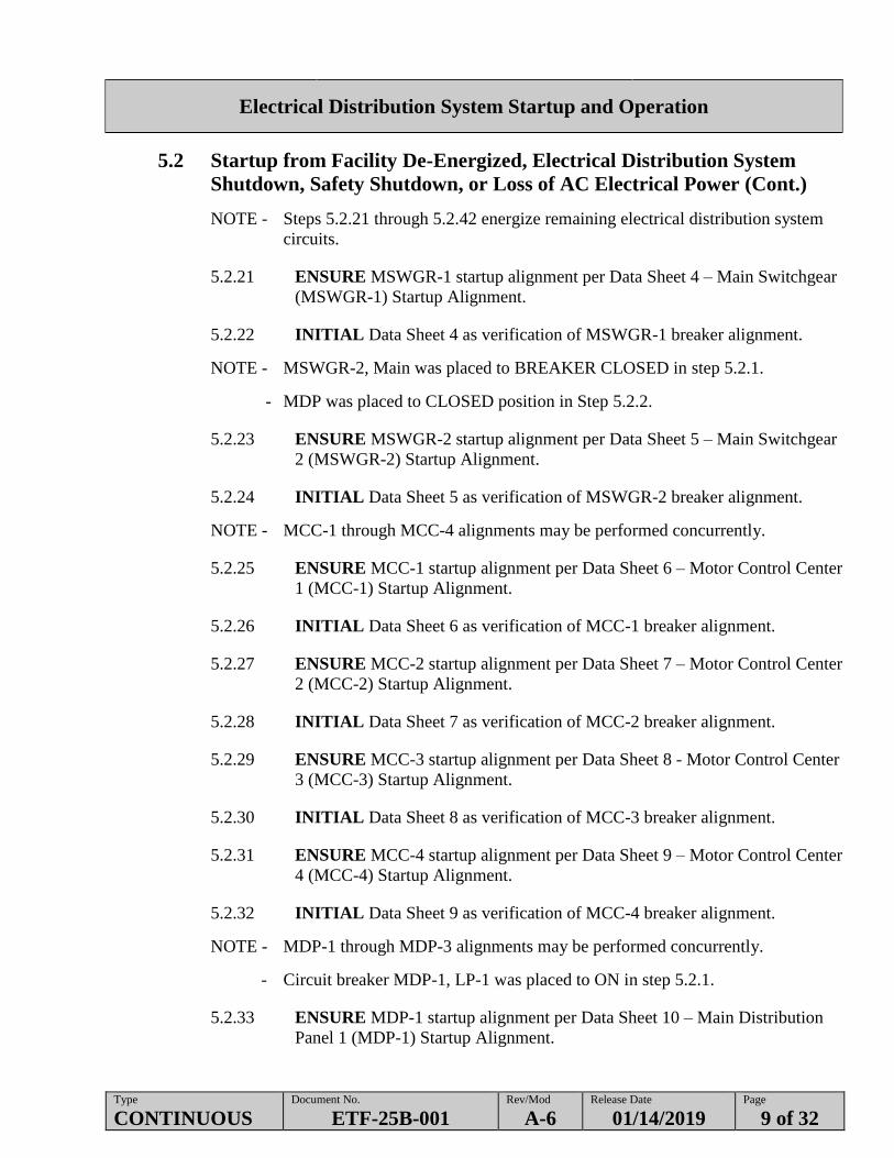
NOTE - Steps 5.2.21 through 5.2.42 energize remaining electrical distribution system
circuits.
5.2.21 ENSURE MSWGR-1 startup alignment per Data Sheet 4 – Main Switchgear
(MSWGR-1) Startup Alignment.
5.2.22 INITIAL Data Sheet 4 as verification of MSWGR-1 breaker alignment.
NOTE - MSWGR-2, Main was placed to BREAKER CLOSED in step 5.2.1.
- MDP was placed to CLOSED position in Step 5.2.2.
5.2.23 ENSURE MSWGR-2 startup alignment per Data Sheet 5 – Main Switchgear
2 (MSWGR-2) Startup Alignment.
5.2.24 INITIAL Data Sheet 5 as verification of MSWGR-2 breaker alignment.
NOTE - MCC-1 through MCC-4 alignments may be performed concurrently.
5.2.25 ENSURE MCC-1 startup alignment per Data Sheet 6 – Motor Control Center
1 (MCC-1) Startup Alignment.
5.2.26 INITIAL Data Sheet 6 as verification of MCC-1 breaker alignment.
5.2.27 ENSURE MCC-2 startup alignment per Data Sheet 7 – Motor Control Center
2 (MCC-2) Startup Alignment.
5.2.28 INITIAL Data Sheet 7 as verification of MCC-2 breaker alignment.
5.2.29 ENSURE MCC-3 startup alignment per Data Sheet 8 - Motor Control Center
3 (MCC-3) Startup Alignment.
5.2.30 INITIAL Data Sheet 8 as verification of MCC-3 breaker alignment.
5.2.31 ENSURE MCC-4 startup alignment per Data Sheet 9 – Motor Control Center
4 (MCC-4) Startup Alignment.
5.2.32 INITIAL Data Sheet 9 as verification of MCC-4 breaker alignment.
NOTE - MDP-1 through MDP-3 alignments may be performed concurrently.
- Circuit breaker MDP-1, LP-1 was placed to ON in step 5.2.1.
5.2.33 ENSURE MDP-1 startup alignment per Data Sheet 10 – Main Distribution
Panel 1 (MDP-1) Startup Alignment.

Electrical Distribution System Startup and Operation
Type
CONTINUOUS Document No.
ETF-25B-001 Rev/Mod
A-6 Release Date
01/14/2019 Page
10 of 32
5.2 Startup from Facility De-Energized, Electrical Distribution System
Shutdown, Safety Shutdown, or Loss of AC Electrical Power (Cont.)
5.2.34 INITIAL Data Sheet 10 as verification of MDP-1 breaker alignment.
5.2.35 ENSURE MDP-2 startup alignment per Data Sheet 11 – Main Distribution
Panel 2 (MDP-2) Startup Alignment.
5.2.36 INITIAL Data Sheet 11 as verification of MDP-2 breaker alignment.
5.2.37 ENSURE MDP-3 startup alignment per Data Sheet 12 – Main Distribution
Panel 3 (MDP-3) Startup Alignment.
5.2.38 INITIAL Data Sheet 12 as verification of MDP-3 breaker alignment.
5.2.39 REQUEST Fire Systems Maintenance restore RAFR and/or FACU per MSA
work package provided in Step 4.2.6.1.
5.2.40 ENSURE DP-2 startup alignment per Data Sheet 13 – Distribution Panel 2
(DP-2) Startup Alignment.
5.2.41 INITIAL Data Sheet 13 as verification of DP-2 breaker alignment.
5.2.42 ENSURE DP-5 startup alignment per Data Sheet 14 – Distribution Panel 5
(DP-5) Startup Alignment.
5.2.43 INITIAL Data Sheet 14 as verification of DP-5 breaker alignment.
5.2.44 ENSURE DP-6 startup alignment per Data Sheet 15 – Distribution Panel 6
(DP-6) Startup Alignment – Rm. 104.
5.2.45 INITIAL Data Sheet 15 as verification of DP-6 breaker alignment.
Electrical Distribution System Startup and Operation
Type
CONTINUOUS Document No.
ETF-25B-001 Rev/Mod
A-6 Release Date
01/14/2019 Page
11 of 32
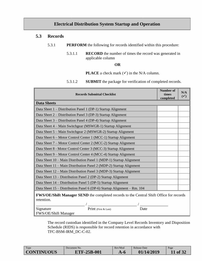
5.3 Records
5.3.1 PERFORM the following for records identified within this procedure:
5.3.1.1 RECORD the number of times the record was generated in
applicable column
OR
PLACE a check mark () in the N/A column.
5.3.1.2 SUBMIT the package for verification of completed records.
Records Submittal Checklist
Number of
times
completed
N/A
()
Data Sheets
Data Sheet 1 – Distribution Panel 1 (DP-1) Startup Alignment
Data Sheet 2 – Distribution Panel 3 (DP-3) Startup Alignment
Data Sheet 3 – Distribution Panel 4 (DP-4) Startup Alignment
Data Sheet 4 – Main Switchgear (MSWGR-1) Startup Alignment
Data Sheet 5 – Main Switchgear 2 (MSWGR-2) Startup Alignment
Data Sheet 6 – Motor Control Center 1 (MCC-1) Startup Alignment
Data Sheet 7 – Motor Control Center 2 (MCC-2) Startup Alignment
Data Sheet 8 - Motor Control Center 3 (MCC-3) Startup Alignment
Data Sheet 9 – Motor Control Center 4 (MCC-4) Startup Alignment
Data Sheet 10 – Main Distribution Panel 1 (MDP-1) Startup Alignment
Data Sheet 11 – Main Distribution Panel 2 (MDP-2) Startup Alignment
Data Sheet 12 – Main Distribution Panel 3 (MDP-3) Startup Alignment
Data Sheet 13 – Distribution Panel 2 (DP-2) Startup Alignment
Data Sheet 14 – Distribution Panel 5 (DP-5) Startup Alignment
Data Sheet 15 – Distribution Panel 6 (DP-6) Startup Alignment – Rm. 104
FWS/OE/Shift Manager SEND the completed records to the Central Shift Office for records
retention.
/ /
Signature Print (First & Last) Date
FWS/OE/Shift Manager
The record custodian identified in the Company Level Records Inventory and Disposition
Schedule (RIDS) is responsible for record retention in accordance with
TFC-BSM-IRM_DC-C-02.

Electrical Distribution System Startup and Operation
Type
CONTINUOUS Document No.
ETF-25B-001 Rev/Mod
A-6 Release Date
01/14/2019 Page
12 of 32
Data Sheet 1 – Distribution Panel 1 (DP-1) Startup Alignment
Sheet 1 of 2
Resp. Breaker
Number Breaker Name and Location
Required
Position Initials Date
Elec. 1 Recept Rms 100, 101 ON
Elec. 2 Recept Rms 100, 101, 107 ON
Elec. 3 Recept Rms103, 106 ON
Elec. 4 Recept Rms 114, 123 ON
Elec. 5 Recept Rms 115, 121, 127, 128 ON
Elec. 6 Recept Rms 116, 122, 126 ON
Elec. 7 Recept Rms 125, 129, 130, 131 ON
Elec. 8 Recept Rms 125, 131 ON
Elec. 9 Recept Rms 104, 105, 131 ON
Elec. 10 Recept Rms 201, 204, 206 ON
Elec. 11 Recept Rms 200, 206, 207, 208 ON
Elec. 12 Rectpt Rm 107 ON
Elec. 13 Recept Rms 132, 133, 134 ON
Elec. 14 Recept Rms 102, 111, 117, 118 ON
Elec. 15 Recept Rms 106, 113 ON
Elec. 16 Recept Rm 100 ON
Elec. 17 Recept Rm 100 ON
Elec. 18 Recept Rm 100 ON
Elec. 19 Recept Rm 100 ON
Elec. 20 Recept Rm 100 ON
(Continued on Next Sheet)

Electrical Distribution System Startup and Operation
Type
CONTINUOUS Document No.
ETF-25B-001 Rev/Mod
A-6 Release Date
01/14/2019 Page
13 of 32
Data Sheet 1 – Distribution Panel 1 (DP-1) Startup Alignment (Cont.)
Sheet 2 of 2
Resp. Breaker
Number Breaker Name and Location
Required
Position Initials Date
Elec. 21 Recept Rm 206 ON
Elec. 22/24/26/
28/30/32
25I-UPS-1 ON
Elec. 23/25/27 25I-UPS-1 (BY-PASS) ON
Elec. 29 Recept Rms 113, 114 ON
Elec. 31/33 Spare OFF
Elec. 34/36 Spare OFF
Elec. 35 Recept Rm 100 ON
Elec. 37 Recept Rm 100 ON
Elec. 38 Recept Rm 101 ON
Elec. 39 Recept Rms 203, 206 ON
Elec. 40 Recept Rm 122 ON
Elec. 41 Rectpt Rms 201, 202, 203 ON
Elec. 42 Recept Rms 131, 138 ON
COMMENTS:
/ / /
Signature Print (First & Last) Initials Date
Electrician
/ / /
Signature Print (First & Last) Initials Date
NCO
/ / /
Signature Print (First & Last) Initials Date
SOM Completion Review

Electrical Distribution System Startup and Operation
Type
CONTINUOUS Document No.
ETF-25B-001 Rev/Mod
A-6 Release Date
01/14/2019 Page
14 of 32
Data Sheet 2 – Distribution Panel 3 (DP-3) Startup Alignment
Sheet 1 of 2
Breaker
Number Breaker Name and Location Required Position Initials Date
N/A Main Circuit Breaker ON
1 JB-95C001 ON
2 IDP-1 ON
3 IDP-2 ON
4 IDP-3 ON
5 IDP-4 ON
6 IDP-5 ON
7 LCP-80C001 ON
8 LCU-4 ON
9 LCU-1 ON
10 LCU-5 ON
11 LCU-2A & 2B ON
12 LCU-6 ON
13 LCU-3 ON
14 IDP-6 ON
15 MCS-1 ON
16 Spare OFF
17 MCS-2 ON
18 JB-60D003 (UV Power) ON
19 Spare OFF
20 MCS-3 ON
21 LCU-H ON
22 CREWS ON
23 Spare OFF
(Continued on Next Sheet)

Electrical Distribution System Startup and Operation
Type
CONTINUOUS Document No.
ETF-25B-001 Rev/Mod
A-6 Release Date
01/14/2019 Page
15 of 32
Data Sheet 2 – Distribution Panel 3 (DP-3) Startup Alignment (Cont.)
Sheet 2 of 2
Breaker
Number Breaker Name and Location Required Position Initials Date
24 Spare OFF
25 Spare OFF
26 Spare OFF
27 Spare OFF
28 Spare OFF
29 Spare OFF
30 Spare OFF
COMMENTS:
/ / /
Signature Print (First & Last) Initials Date
Electrician
/ / /
Signature Print (First & Last) Initials Date
NCO
/ / /
Signature Print (First & Last) Initials Date
SOM Completion Review

Electrical Distribution System Startup and Operation
Type
CONTINUOUS Document No.
ETF-25B-001 Rev/Mod
A-6 Release Date
01/14/2019 Page
16 of 32
Data Sheet 3 – Distribution Panel 4 (DP-4) Startup Alignment
Sheet 1 of 2
Resp. Breaker
Number Breaker Name and Location
Required
Position Initials Date
NCO N/A Main Circuit Breaker ON
NCO 1 Communication Rm 207 ON
NCO 2 Communication Rm 207 ON
NCO 3 Communication Rm 207 ON
NCO 4 Communication Rm 207 ON
NCO 5 Communication Rm 207 ON
NCO 6 Communication Rm 207 ON
NCO 7 Communication Rm 207 ON
NCO 8 Server Cabinet “A” (RM 207) ON
NCO 9 Server Cabinet “B” (RM 207) ON
NCO 10 WHELEN Paging System ON
NCO 11 Communication Rm 124 ON
NCO 12 Communication Rm 124 ON
NCO 13 Spare OFF
NCO 14 MCS-4 (TEDF OCS) ON
SOE 15 45B-EVU-6 (PIC) ON
NCO 16 MCS-5 (TEDF OCS’s) ON
SOE 17 45B-EVU-8 (PIC) ON
NCO 18 MCS-6 (LERF/Load-In OCS) ON
SOE 19 45B-EVU-7 (PIC) ON
NCO 20 Blank N/A
SOE 21 JB-EVU-4-01 ON
NCO 22 UV Oxidizer #1 Compartment Fans ON
NCO 23 Blank N/A
NCO 24 UV/OX #2 Compartment Fans ON
(Continued on Next Sheet)

Electrical Distribution System Startup and Operation
Type
CONTINUOUS Document No.
ETF-25B-001 Rev/Mod
A-6 Release Date
01/14/2019 Page
17 of 32
Data Sheet 3 – Distribution Panel 4 (DP-4) Startup Alignment (Cont.)
Sheet 2 of 2
Resp. Breaker
Number Breaker Name and Location
Required
Position Initials Date
NCO 25 Blank N/A
NCO 26 Blank N/A
NCO 27 Blank N/A
NCO 28 Blank N/A
COMMENTS:
/ / /
Signature Print (First & Last) Initials Date
NCO
/ / /
Signature Print (First & Last) Initials Date
SOE
/ / /
Signature Print (First & Last) Initials Date
SOM Completion Review

Electrical Distribution System Startup and Operation
Type
CONTINUOUS Document No.
ETF-25B-001 Rev/Mod
A-6 Release Date
01/14/2019 Page
18 of 32
Data Sheet 4 – Main Switchgear (MSWGR-1) Startup Alignment
Resp. Breaker
Number
Breaker Name and
Location Required Position Initials Date
NCO F8X 628 MSWGR-1 Main CLOSED
NCO N/A MCC-1 CLOSED
NCO N/A 60I-C-1 Vapor Compressor OPEN
NCO N/A MCC-2 CLOSED
NCO N/A MCC-4 CLOSED
SOE N/A 65A-B-1 Dryer Boiler CLOSED
N/A N/A Blank N/A
NCO N/A MCC-3 CLOSED
N/A N/A Blank N/A
N/A N/A Blank N/A
COMMENTS:
/ / /
Signature Print (First & Last) Initials Date
NCO
/ / /
Signature Print (First & Last) Initials Date
SOE
/ / /
Signature Print (First & Last) Initials Date
SOM Completion Review

Electrical Distribution System Startup and Operation
Type
CONTINUOUS Document No.
ETF-25B-001 Rev/Mod
A-6 Release Date
01/14/2019 Page
19 of 32
Data Sheet 5 – Main Switchgear 2 (MSWGR-2) Startup Alignment
Resp. Breaker
Number Breaker Name and Location Required Position Initials Date
NCO F8X 627 MSWGR-2 Main CLOSED
NCO N/A Panel MDP-1 CLOSED
NCO N/A Panel MDP-2 CLOSED
NCO N/A Panel MDP-3 CLOSED
SOE N/A Central Station/AHU-No. 1/45B-E-1A CLOSED
SOE N/A Central Station/AHU-No. 1/45B-E-2A CLOSED
N/A N/A Blank N/A
SOE N/A Central Station/AHU-No. 2/45B-E-1B CLOSED
SOE N/A Central Station/AHU-No. 2/45B-E-2B CLOSED
N/A N/A Blank N/A
COMMENTS:
/ / /
Signature Print (First & Last) Initials Date
NCO
/ / /
Signature Print (First & Last) Initials Date
SOE
/ / /
Signature Print (First & Last) Initials Date
SOM Completion Review

Electrical Distribution System Startup and Operation
Type
CONTINUOUS Document No.
ETF-25B-001 Rev/Mod
A-6 Release Date
01/14/2019 Page
20 of 32
Data Sheet 6 – Motor Control Center 1 (MCC-1) Startup Alignment
Resp. Breaker
Number Breaker Name and Location
Required
Position Initials Date
NCO 1F 60F-P-2A 2nd R.O. Feed Tank Pump “A” ON
NCO 1O 60C-P-2A Effluent PH Adjustment Tank Pump
“A”
ON
NCO 2C 60C-P-2B Effluent PH Adjustment Tank Pump
“B”
ON
NCO 2I 60F-P-1A 1st R.O. Feed Tank Pump “A” ON
NCO 2Q 60H-E-1A Verification Tank “A” Heater ON
NCO 3C 60C-P-1A PH Adjustment Tank Pump “A” ON
NCO 3K 65C-P-3 4% H2SO4 Solution Feed Pump ON
NCO 3Q 60F-P-1B 1st R.O. Feed Tank Pump “B” ON
NCO 4C 65C-P-4 4% NaOH Solution Feed Pump ON
NCO 4I 60C-P-1B PH Adjustment Tank Pump “B” ON
NCO 4Q 60H-P-1 Verification Return Pump ON
NCO 5C 60E-P-1A Degasification Pump “A” ON
NCO 5I 60E-P-1B Degasification Pump “B” ON
NCO 5O 60F-P-2B 2nd R.O. Feed Tank Pump “B” ON
NCO 6C 60E-D-1 Degasification Blower ON
SOE 6I 45B-P-1B Chilled Water Pump “B” ON
COMMENTS:
/ / /
Signature Print (First & Last) Initials Date
NCO
/ / /
Signature Print (First & Last) Initials Date
SOE
/ / /
Signature Print (First & Last) Initials Date
SOM Completion Review
Electrical Distribution System Startup and Operation
Type
CONTINUOUS Document No.
ETF-25B-001 Rev/Mod
A-6 Release Date
01/14/2019 Page
21 of 32
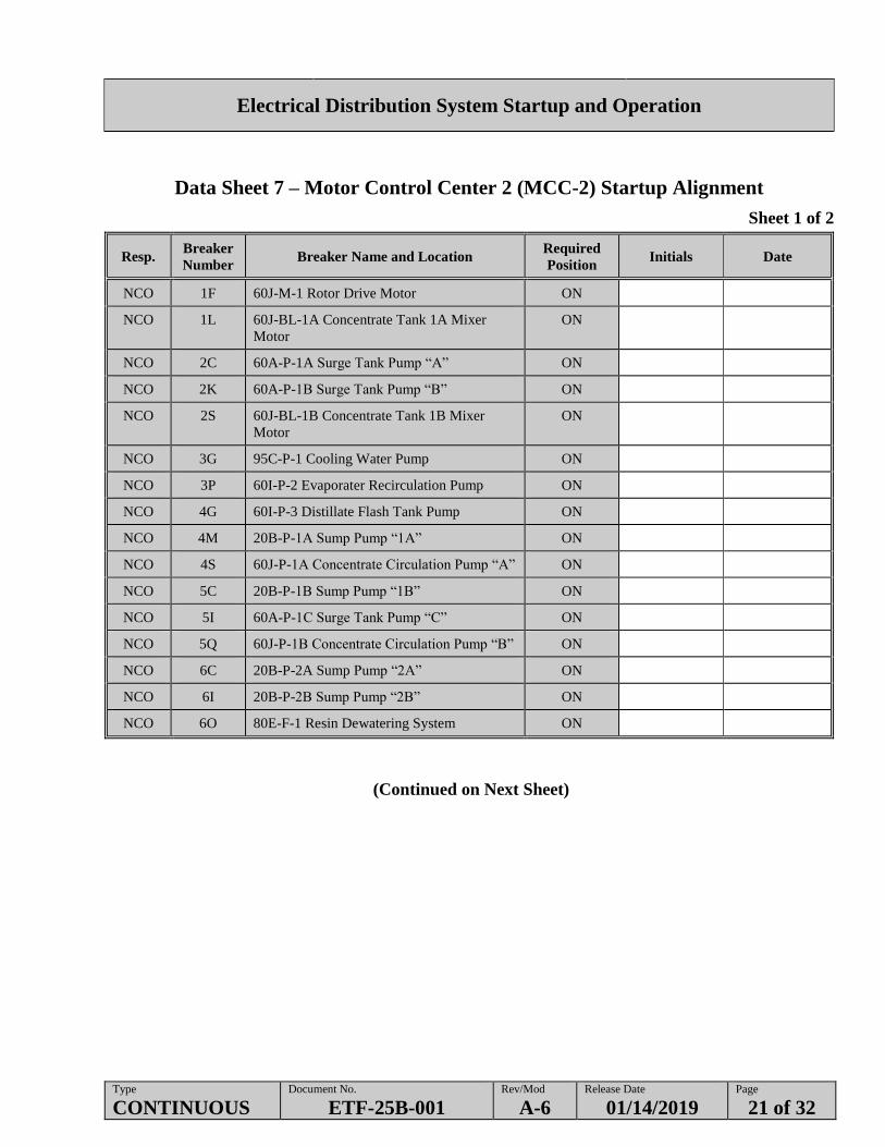
Data Sheet 7 – Motor Control Center 2 (MCC-2) Startup Alignment
Sheet 1 of 2
Resp. Breaker
Number Breaker Name and Location
Required
Position Initials Date
NCO 1F 60J-M-1 Rotor Drive Motor ON
NCO 1L 60J-BL-1A Concentrate Tank 1A Mixer
Motor
ON
NCO 2C 60A-P-1A Surge Tank Pump “A” ON
NCO 2K 60A-P-1B Surge Tank Pump “B” ON
NCO 2S 60J-BL-1B Concentrate Tank 1B Mixer
Motor
ON
NCO 3G 95C-P-1 Cooling Water Pump ON
NCO 3P 60I-P-2 Evaporater Recirculation Pump ON
NCO 4G 60I-P-3 Distillate Flash Tank Pump ON
NCO 4M 20B-P-1A Sump Pump “1A” ON
NCO 4S 60J-P-1A Concentrate Circulation Pump “A” ON
NCO 5C 20B-P-1B Sump Pump “1B” ON
NCO 5I 60A-P-1C Surge Tank Pump “C” ON
NCO 5Q 60J-P-1B Concentrate Circulation Pump “B” ON
NCO 6C 20B-P-2A Sump Pump “2A” ON
NCO 6I 20B-P-2B Sump Pump “2B” ON
NCO 6O 80E-F-1 Resin Dewatering System ON
(Continued on Next Sheet)

Electrical Distribution System Startup and Operation
Type
CONTINUOUS Document No.
ETF-25B-001 Rev/Mod
A-6 Release Date
01/14/2019 Page
22 of 32
Data Sheet 7 – Motor Control Center 2 (MCC-2) Startup Alignment (Cont.)
Sheet 2 of 2
Resp. Breaker
Number Breaker Name and Location
Required
Position Initials Date
NCO 7C 60J-E-4 Thin Film Dryer Heat Trace ON
NCO 7I 60J-P-3 Thin Film Dryer Distillate Pump ON
NCO 7O 60J-F-1 Vent Blower ON
NCO 8C 60J-P-2 Concentrate Feed Pump ON
NCO 8I 60I-P-1A Secondary Waste Feed Pump “A” ON
NCO 8Q 60I-P-1B Secondary Waste Feed Pump “B” ON
COMMENTS:
/ / /
Signature Print (First & Last) Initials Date
NCO
/ / /
Signature Print (First & Last) Initials Date
NCO
/ / /
Signature Print (First & Last) Initials Date
SOM Completion Review

Electrical Distribution System Startup and Operation
Type
CONTINUOUS Document No.
ETF-25B-001 Rev/Mod
A-6 Release Date
01/14/2019 Page
23 of 32
Data Sheet 8 - Motor Control Center 3 (MCC-3) Startup Alignment
Resp. Breaker
Number Breaker Name and Location
Required
Position Initials Date
NCO 1F 60H-E-1B Verification Tank “B” Heater ON
NCO 1O 95C-F-1A Cooling Tower Fan “A” ON
SOE 2G 1B-C-1 Air Compressor ON
SOE 3C 45A-F-1A RCA Exhaust Fan “A” ON
NCO 3L 65C-P-1 92% H2SO4 Storage Tank Pump ON
NCO 3R 95C-F-1B Cooling Tower Fan “B” ON
SOE 4C 65A-P-1 Boiler Feed Pump ON
NCO 4I 65C-P-2 50% NaOH Storage Tank Pump ON
NCO 4O 95B-P-1 Seal Water Pump ON
NCO 5C 45D-F-1A VOG Blower “A” ON
NCO 5I 45D-F-1B VOG Blower “B” ON
NCO 5O 95C-P-2 Cooling Water Blowdown Pump ON
NCO 6C 60H-P-2A Verification Transfer Pump “A” ON
NCO 6K 60H-P-2B Verification Transfer Pump “B” ON
NCO 6S 95C-E-2B Cooling Tower Heater “2B” ON
COMMENTS:
/ / /
Signature Print (First & Last) Initials Date
NCO
/ / /
Signature Print (First & Last) Initials Date
SOE
/ / /
Signature Print (First & Last) Initials Date
SOM Completion Review

Electrical Distribution System Startup and Operation
Type
CONTINUOUS Document No.
ETF-25B-001 Rev/Mod
A-6 Release Date
01/14/2019 Page
24 of 32
Data Sheet 9 – Motor Control Center 4 (MCC-4) Startup Alignment
Resp. Breaker
Number Breaker Name and Location
Required
Position Initials Date
SOE 1F 45A-F-1C RCA Exhaust Fan “C” ON
SOE 1O 45B-P-1A Chilled Water Pump “A” ON
SOE 2C 45B-F-1A Air Handling Unit Fan “A” ON
NCO 2K 60H-E-1C Verification Tank “C” Heater ON
NCO 2S Spare OFF
NCO 3C 60I-P-6 Silencer Drain Pump ON
SOE 3M 45B-F-6 AHU Fan Rm 139 (45B-EVU-10) ON
NCO 3S 60F-P-4 R.O. Cleaning Agent Feed System Unit “B” ON
NCO 4G 60I-P-7 Compressor Aux. Oil Pump ON
SOE 4M 45B-F-5 AHU Fan Rm 132 (45B-EVU-9) ON
NCO 4S 60I-P-4 Concentrate Transfer Pump ON
SOE 5C 45B-F-1B Air Handling Unit Fan “B” ON
SOE 5K 45A-F-1B RCA Exhaust Fan “B” ON
NCO 5T 95C-E-2A Cooling Tower Heater “2A” ON
NCO 6C 60A-E-1 Surge Tank Heater ON
NCO 6I 60F-P-3A R.O. Booster Pump “A” ON
NCO 6O 60F-P-3B R.O. Booster Pump “B” ON
COMMENTS:
/ / /
Signature Print (First & Last) Initials Date
NCO
/ / /
Signature Print (First & Last) Initials Date
SOE
/ / /
Signature Print (First & Last) Initials Date
SOM Completion Review

Electrical Distribution System Startup and Operation
Type
CONTINUOUS Document No.
ETF-25B-001 Rev/Mod
A-6 Release Date
01/14/2019 Page
25 of 32
Data Sheet 10 – Main Distribution Panel 1 (MDP-1) Startup Alignment
Resp. Breaker
Number Breaker Name and Location
Required
Position Initials Date
NCO 1 LP-1 ON
NCO 2 60D-UV-1 Lamp Drive B ON
NCO 3 25B-WR-1 Welding Recept ON
NCO 4 60D-UV-1 Lamp Drive A ON
NCO 5 Spare OFF
NCO 6 DP-2/DP-5 ON
NCO 7 20A-P-1/20A-P-2 Septic Pumps ON
NCO 8 19A-RD-1 Roll up Door ON
NCO 9 19A-RD-2 Roll up Door ON
NCO 10 Spare OFF
NCO 11 Load-In Station, Main Power ON
SOE 12 Air Compressor Canopy Fan 1B-F-1and JB-
1B001 Control Power
ON
SOE 13 45B-F-3 EVU-7 Fan ON
SOE 14 45B-E-4 EVU-7 Heater ON
N/A 15 Blank N/A
SOE 16 45B-E-3 EVU-6 Heater ON
N/A 17 Blank N/A
N/A 18 Blank N/A
N/A 19 Blank N/A
N/A 20 Blank N/A
N/A 21 Blank N/A
COMMENTS:
/ / /
Signature Print (First & Last) Initials Date
NCO
/ / /
Signature Print (First & Last) Initials Date
SOE
/ / /
Signature Print (First & Last) Initials Date
SOM Completion Review

Electrical Distribution System Startup and Operation
Type
CONTINUOUS Document No.
ETF-25B-001 Rev/Mod
A-6 Release Date
01/14/2019 Page
26 of 32
Data Sheet 11 – Main Distribution Panel 2 (MDP-2) Startup Alignment
Resp. Breaker
Number Breaker Name and Location
Required
Position Initials Date
NCO 1 25B-WR-2 Welding Recept ON
NCO 2 60D-UV-2 Lamp Drive B ON
SOE 3 Safety Shower/Eyewash Hot Water Htr. 95I-TK-4 ON
NCO 4 60D-UV-2 Lamp Drive A ON
NCO 5 Spare OFF
NCO 6 MO-148 MO-251 MO-269 ON
NCO 7 25E-HT-1 Heat Trace Panel #1 ON
NCO 8 45D-E-1 VOG Heater ON
NCO 9 DP-6 ON
NCO 10 JB-112 Lab Distilling Unit OFF
NCO 11 Spare OFF
NCO 12 25E-HT-2 Heat Trace Panel #2 ON
SOE 13 45B-HU-1 Control Room Humid OFF
SOE 14 45A-F16, 17, 18 Lab Hood Fans ON
NCO 15 65C-E-2 NAOH Tank Heater ON
SOE 16 45B-EVU-3 Support Area Cndsr ON
SOE 17 45B-E-5 EVU-8 Heater ON
NCO 18 Blank N/A
NCO 19 Blank N/A
NCO 20 Blank N/A
NCO 21 Blank N/A
COMMENTS:
/ / /
Signature Print (First & Last) Initials Date
NCO
/ / /
Signature Print (First & Last) Initials Date
SOE
/ / /
Signature Print (First & Last) Initials Date
SOM Completion Review

Electrical Distribution System Startup and Operation
Type
CONTINUOUS Document No.
ETF-25B-001 Rev/Mod
A-6 Release Date
01/14/2019 Page
27 of 32
Data Sheet 12 – Main Distribution Panel 3 (MDP-3) Startup Alignment
Resp. Breaker
Number Breaker Name and Location Required Position Initials Date
N/A 1 Blank N/A
NCO 2 XFMR / DP-9 ON
NCO 3 DP-7 and 2025E-25B-DS-001 ON
SOE 4 45B-EVU-2B Chiller ON
N/A 5 Blank N/A
SOE 6 45B-EVU-2A Chiller ON
NCO 7 19A-RD-3 Roll up Door ON
NCO 8 19A-RD-4 Roll up Door ON
NCO 9 60F-E-1A, 1B CIP Tank Heaters ON
NCO 10 PP-80C002 Drum Handling Pnl ON
SOE 11 45B-F-2 EVU-6 Fan ON
SOE 12 60I-B-1 EVAPORATOR Boiler
Unit
ON
SOE 13 45B-EVU-5 Control Room Cndsr ON
N/A 14 Blank N/A
SOE 15 45B-F-4 EVU-8 Fan ON
N/A 16 Blank N/A
N/A 17 Blank N/A
N/A 18 Blank N/A
N/A 19 Blank N/A
COMMENTS:
/ / /
Signature Print (First & Last) Initials Date
NCO
/ / /
Signature Print (First & Last) Initials Date
SOE
/ / /
Signature Print (First & Last) Initials Date
SOM Completion Review

Electrical Distribution System Startup and Operation
Type
CONTINUOUS Document No.
ETF-25B-001 Rev/Mod
A-6 Release Date
01/14/2019 Page
28 of 32
Data Sheet 13 – Distribution Panel 2 (DP-2) Startup Alignment
Sheet 1 of 2
Resp. Breaker
Number Breaker Name and Location
Required
Position Initials Date
N/A Main Circuit Breaker ON
NCO 1 60I-BL-1 (Mixer MTR) JB-60I007 ON
NCO 2 60I-P-5 (JB-60I006) ON
NCO 3 HEPA “C” Light ON
NCO 4 20B-P-3 Surge Pump ON
SOE 5 45A-F-2 (Fan) ON
NCO 6 20B-P-4 Verification Sump ON
SOE 7 45A-F-6 (Fan) ON
NCO 8 20B-P-5 Chem Sump ON
SOE 9 45A-F-7 (Fan) ON
NCO 10 20B-P-6 Chem Sump ON
SOE 11 45A-F-3 (Fan) ON
NCO 12 65C-P-5 ON
NCO 13 1D-D-1 (Dryer) ON
SOE 14 HEPA A Lights ON
SOE 15 45A-F-4 (Fan) ON
SOE 16 HEPA B Light ON
SOE 17 45A-F-5 (Fan) ON
NCO 18 65C-P-6 ON
NCO 19 60F-P-5 (JB-60F-P5-01) ON
NCO 20 Outside Lighting, Tank Area ON
(Continued on Next Sheet)

Electrical Distribution System Startup and Operation
Type
CONTINUOUS Document No.
ETF-25B-001 Rev/Mod
A-6 Release Date
01/14/2019 Page
29 of 32
Data Sheet 13 – Distribution Panel 2 (DP-2) Startup Alignment (Cont.)
Sheet 2 of 2
Resp. Breaker
Number Breaker Name and Location Required Position Initials Date
SOE 21 45B-EM-1A (Pump) OFF
SOE 22 Boiler Pre-heater 95D-E-01 ON
SOE 23 45B-EM-1B (Pump) OFF
NCO 24 Outside Receptacles and LTS, Tank Area ON
SOE 25 Hot Wtr Recirc Pump 95I-P-1 ON
NCO 26 65C-P-7 ON
NCO 27 65C-P-9 (Pump) ON
NCO 28 65C-P-8 ON
NCO 29 65C-P-10 (Pump) ON
NCO 30 FACP – Fire Alarm ON
NCO 31 Motor Heaters, Cooling Tower ON
NCO 32 RFAR – Fire Alarm ON
SOE 33/35 45B-EVU-4 (2-pole breaker) ON
NCO 34 Spare OFF
SOE 36/38 45B-EUH-1 Stairwell 130 Heater OFF
NCO 37/39/ 41 Lab Washer Rm 112 (3-pole breaker) ON
N/A 40 Blank N/A
N/A 42 Blank N/A
NCO NA Sub-feed DP-5 ON
COMMENTS:
/ / /
Signature Print (First & Last) Initials Date
NCO
/ / /
Signature Print (First & Last) Initials Date
SOE
/ / /
Signature Print (First & Last) Initials Date
SOM Completion Review

Electrical Distribution System Startup and Operation
Type
CONTINUOUS Document No.
ETF-25B-001 Rev/Mod
A-6 Release Date
01/14/2019 Page
30 of 32
Data Sheet 14 – Distribution Panel 5 (DP-5) Startup Alignment
Resp. Breaker
Number Breaker Name and Location
Required
Position Initials Date
NCO N/A DP-5 Main Circuit Breaker ON
NCO 1 FDAS ON
NCO 2 Receptacles, High Mezzanine OFF
NCO 3 AHU Lights/Receptacles ON
NCO 4 SP95C015 ON
NCO 5 Room 206 Receptacles ON
NCO 6 Recept ON
NCO 7/9 HVAC Stack Sampler (2-pole
breaker)
ON
NCO 8 SP60C228 ON
SOE 10 45B-EVU-2A and 2B, Heat Trace ON
NCO 11 Spare OFF
SOE 12 45B-EVU-1A and 1B, Heat Trace ON
COMMENTS:
/ / /
Signature Print (First & Last) Initials Date
NCO
/ / /
Signature Print (First & Last) Initials Date
SOE
/ / /
Signature Print (First & Last) Initials Date
SOM Completion Review

Electrical Distribution System Startup and Operation
Type
CONTINUOUS Document No.
ETF-25B-001 Rev/Mod
A-6 Release Date
01/14/2019 Page
31 of 32
Data Sheet 15 – Distribution Panel 6 (DP-6) Startup Alignment – Rm. 104
Sheet 1 of 2
Resp. Breaker
Number Breaker Name and Location Required Position Initials Date
NCO N/A DP-6 Main Circuit Breaker ON
NCO 1 Spare OFF
NCO 2 Spare OFF
NCO 3 Spare OFF
SOE 4 Hot Water Heater, Rm 103 ON
NCO 5 Spare OFF
NCO 6 Recept Rm 112 Refrigerator ON
NCO 7 Recept Rm 112 Power Strip ON
NCO 8 Recept Rm 112 Refrigerator ON
NCO 9 Recept Rm 112 Power Strip ON
NCO 10 Recept Rm 112 Refrigerator ON
SOE 11 Recept Rm 112 Hood Lights ON
NCO 12 Recept Rm 112 ON
NCO 13 RM 104 Shop Retractable Recept ON
SOE 14/16 Rm 112 Hood 208V Recpt (2-pole
breaker)
ON
NCO 15 Recept Rm 112 ON
NCO 17 SP60A008 ON
NCO 18 SP60D006 ON
NCO 19 Recept Rm 100 (Lunch Room) ON
NCO 20 SP60F280 ON
NCO 21 Deluge Air Compressor ON
(Continued on Next Sheet)

Electrical Distribution System Startup and Operation
Type
CONTINUOUS Document No.
ETF-25B-001 Rev/Mod
A-6 Release Date
01/14/2019 Page
32 of 32
Data Sheet 15 – Distribution Panel 6 (DP-6) Startup Alignment – Rm. 104 (Cont.)
Sheet 2 of 2
Resp. Breaker
Number Breaker Name and Location
Required
Position Initials Date
NCO 22/24 Heat Trace (Influent Recept-GFCI) (2-pole
breaker)
ON
NCO 23 SP60H144 ON
NCO 25 Recept Rm 134 ON
SOE 26 Heat Trace, Emergency Eye Wash ON
NCO 27 Recept Rm 101 ON
NCO 28 Grinder ON
NCO 29 Recept Rm 105 ON
NCO 30/32 Recept Rm 104, Pipe Threader, Sand Grinder,
Sand Blaster, Vacuum (2-pole Breaker)
ON
NCO 31 Recept Rm 104 ON
NCO 33/35 Recept Rm 104 Drill Press (2-pole Breaker) ON
NCO 34/36 Panel Board DP-8 Room 112 Lab (2-pole
Breaker
ON
NCO 37 Outdoor Recept and Surge LGT ON
NCO 39 Floodlights (East) ON
NCO 38/40/42 Rm 104 Power Saw (3-pole Breaker) ON
NCO 41 Floodlights (South) ON
COMMENTS:
/ / /
Signature Print (First & Last) Initials Date
NCO
/ / /
Signature Print (First & Last) Initials Date
SOE
/ / /
Signature Print (First & Last) Initials Date
SOM Completion Review
Related Documents