W EIGHT L IFTER Tailgates By THIEMAN WT20, 30 & 40 OWNERS MANUAL/PARTS LIST IMPORTANT! KEEP IN VEHICLE! ! PLEASE READ AND UNDERSTAND THE CONTENTS OF THIS MANUAL BEFORE OPERATING THE EQUIPMENT. TailgaTes, inc. 600 East Wayne Street Celina, Ohio 45822 Phone: 419-586-7727 Fax: 419-586-9724 HIEMAN NTEA THE ASSOCIATION FOR THE WORK TRUCK INDUSTRY TM M E M B E R

Welcome message from author
This document is posted to help you gain knowledge. Please leave a comment to let me know what you think about it! Share it to your friends and learn new things together.
Transcript

WEIGHTLIFTERTailgates By THIEMAN
WT20, 30 & 40OWNERS MANUAL/PARTS LIST
IMPORTANT! KEEP IN VEHICLE!!PLEASE READ AND UNDERSTAND THE CONTENTS OF THIS
MANUAL BEFORE OPERATING THE EQUIPMENT.
TailgaTes, inc.600 East Wayne StreetCelina, Ohio 45822
Phone: 419-586-7727 Fax: 419-586-9724
HIEMANNTEA
T H E A S S O C I A T I O N F O R T H E W O R K T R U C K I N D U S T R YTM
M E M B E R
TABLE OF CONTENTS
PAGE
PARTS ORDERING PROCEDURE ....................................................2
WARNINGS.........................................................................................3
OPERATING INSTRUCTIONS............................................................5
MAINTENANCE GUIDE......................................................................5
SEMI-ANNUAL INSPECTION .............................................................6
ELECTRICAL PICTORIALS ................................................................7
INSPECTION AND LOCATION OF DECALS......................................8
PLATFORM ASM.................................................................................9
TRUNNION, LIFT ARM, AND IDLER ARM ASM...............................10
PUMP ASM-GRAVITY DOWN, MANUAL CLOSE.............................11
PUMP ASM-POWER DOWN, POWER CLOSE................................12
PTO PUMP ASM, MANUAL CLOSE .................................................13
PTO PUMP ASM, POWER CLOSE ..................................................14
HYDRAULIC SCHEMATICS .............................................................15
TROUBLESHOOTING GUIDE.....................................................16-20
FOR YOUR RECORDSModel No. __________________________ Date Purchased _______________________
Serial No._________________________________________________________________NOTE: When Ordering Parts Be Sure To Include This Information!
PARTS ORDERING PROCEDURE
When ordering parts, please include all the information asked for below. If this information isnot available, a complete written description or sketch of the required part will help Thiemanidentify and deliver the needed part to you.
THE FOLLOWING INFORMATION MUST BE INCLUDED:
1. Serial Number - Thieman liftgate serial numbers can be found on the tag located on theright hand mounting plate.
2. Model Number and Capacity.3. Platform size and Material - Steel or Aluminum.4. Part number. 5. Description.6. Quantity required.
3.
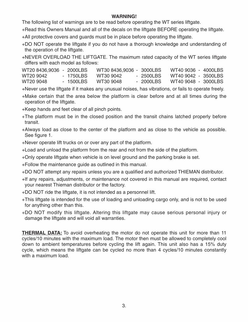
WARNING!The following list of warnings are to be read before operating the WT series liftgate.
+Read this Owners Manual and all of the decals on the liftgate BEFORE operating the liftgate.
+All protective covers and guards must be in place before operating the liftgate.
+DO NOT operate the liftgate if you do not have a thorough knowledge and understanding ofthe operation of the liftgate.
+NEVER OVERLOAD THE LIFTGATE. The maximum rated capacity of the WT series liftgatediffers with each model as follows:
WT20 8436,9036 - 2000LBS WT30 8436,9036 - 3000LBS WT40 9036 - 4000LBSWT20 9042 - 1750LBS WT30 9042 - 2500LBS WT40 9042 - 3500LBSWT20 9048 - 1500LBS WT30 9048 - 2000LBS WT40 9048 - 3000LBS
+Never use the liftgate if it makes any unusual noises, has vibrations, or fails to operate freely.
+Make certain that the area below the platform is clear before and at all times during theoperation of the liftgate.
+Keep hands and feet clear of all pinch points.
+The platform must be in the closed position and the transit chains latched properly beforetransit.
+Always load as close to the center of the platform and as close to the vehicle as possible.See figure 1.
+Never operate lift trucks on or over any part of the platform.
+Load and unload the platform from the rear and not from the side of the platform.
+Only operate liftgate when vehicle is on level ground and the parking brake is set.
+Follow the maintenance guide as outlined in this manual.
+DO NOT attempt any repairs unless you are a qualified and authorized THIEMAN distributor.
+If any repairs, adjustments, or maintenance not covered in this manual are required, contactyour nearest Thieman distributor or the factory.
+DO NOT ride the liftgate, it is not intended as a personnel lift.
+This liftgate is intended for the use of loading and unloading cargo only, and is not to be usedfor anything other than this.
+DO NOT modify this liftgate. Altering this liftgate may cause serious personal injury ordamage the liftgate and will void all warranties.
THERMAL DATA: To avoid overheating the motor do not operate this unit for more than 11cycles/10 minutes with the maximum load. The motor then must be allowed to completely cooldown to ambient temperatures before cycling the lift again. This unit also has a 15% dutycycle, which means the liftgate can be cycled no more than 4 cycles/10 minutes constantlywith a maximum load.
4.
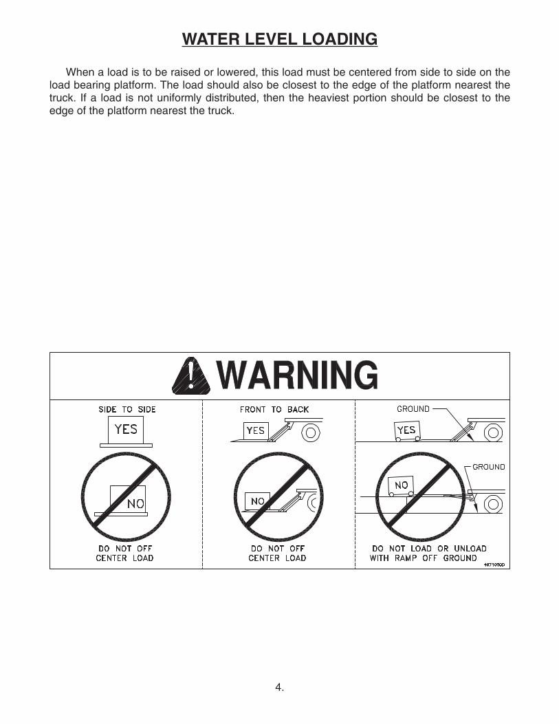
WATER LEVEL LOADING
When a load is to be raised or lowered, this load must be centered from side to side on theload bearing platform. The load should also be closest to the edge of the platform nearest thetruck. If a load is not uniformly distributed, then the heaviest portion should be closest to theedge of the platform nearest the truck.
5.
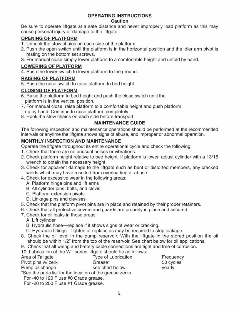
OPERATING INSTRUCTIONSCaution
Be sure to operate liftgate at a safe distance and never improperly load platform as this maycause personal injury or damage to the liftgate.
OPENING OF PLATFORM1. Unhook the stow chains on each side of the platform.2. Push the open switch until the platform is in the horizontal position and the idler arm pivot is
resting on the bottom set screws.3. For manual close simply lower platform to a comfortable height and unfold by hand.
LOWERING OF PLATFORM4. Push the lower switch to lower platform to the ground.
RAISING OF PLATFORM5. Push the raise switch to raise platform to bed height.
CLOSING OF PLATFORM6. Raise the platform to bed height and push the close switch until the platform is in the vertical position.
7. For manual close, raise platform to a comfortable height and push platform up by hand. Continue to raise platform completely.
8. Hook the stow chains on each side before transport.MAINTENANCE GUIDE
The following inspection and maintenance operations should be performed at the recommendedintervals or anytime the liftgate shows signs of abuse, and improper or abnormal operation.
MONTHLY INSPECTION AND MAINTENANCEOperate the liftgate throughout its entire operational cycle and check the following:1. Check that there are no unusual noises or vibrations.2. Check platform height relative to bed height. If platform is lower, adjust cylinder with a 13/16
wrench to obtain the necessary height.3. Check for apparent damage to the liftgate such as bent or distorted members, any cracked
welds which may have resulted from overloading or abuse.4. Check for excessive wear in the following areas:
A. Platform hinge pins and lift armsB. All cylinder pins, bolts, and clevisC. Platform extension pivotsD. Linkage pins and clevises
5. Check that the platform pivot pins are in place and retained by their proper retainers.6. Check that all protective covers and guards are properly in place and secured.7. Check for oil leaks in these areas:
A. Lift cylinderB. Hydraulic hose—replace if it shows signs of wear or cracking.C. Hydraulic fittings—tighten or replace as may be required to stop leakage.
8. Check the oil level in the pump reservoir. With the liftgate in the stored position the oilshould be within 1/2” from the top of the reservoir. See chart below for oil applications.
9. Check that all wiring and battery cable connections are tight and free of corrosion.10. Lubrication of the WT series liftgate should be as follows:Area of Tailgate Type of Lubrication FrequencyPivot pins w/ zerk Grease* 50 cyclesPump oil change see chart below yearly*See the parts list for the location of the grease zerks.For -40 to 120 F use #0 Grade grease.For -20 to 200 F use #1 Grade grease.
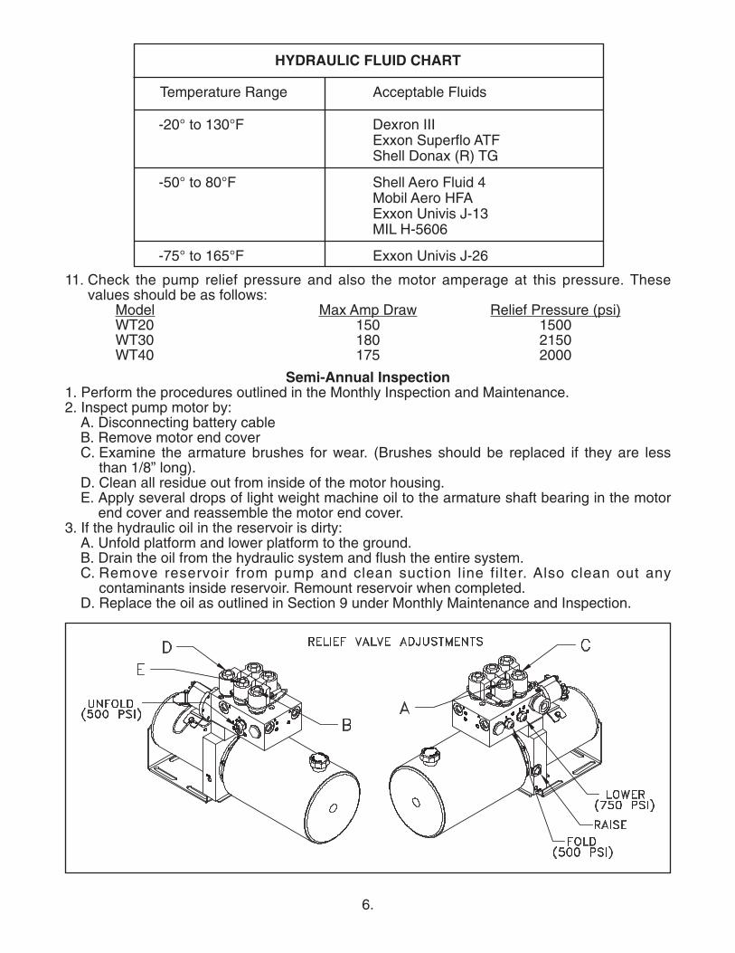
Dexron IIIExxon Superflo ATFShell Donax (R) TG
Shell Aero Fluid 4Mobil Aero HFAExxon Univis J-13MIL H-5606
Exxon Univis J-26
6.
-20° to 130°F
-50° to 80°F
-75° to 165°F
HYDRAULIC FLUID CHART
Temperature Range Acceptable Fluids
11. Check the pump relief pressure and also the motor amperage at this pressure. Thesevalues should be as follows:
Model Max Amp Draw Relief Pressure (psi)WT20 150 1500WT30 180 2150WT40 175 2000
Semi-Annual Inspection1. Perform the procedures outlined in the Monthly Inspection and Maintenance.2. Inspect pump motor by:
A. Disconnecting battery cableB. Remove motor end coverC. Examine the armature brushes for wear. (Brushes should be replaced if they are less
than 1/8” long).D. Clean all residue out from inside of the motor housing.E. Apply several drops of light weight machine oil to the armature shaft bearing in the motor
end cover and reassemble the motor end cover.3. If the hydraulic oil in the reservoir is dirty:
A. Unfold platform and lower platform to the ground.B. Drain the oil from the hydraulic system and flush the entire system.C. Remove reservoir from pump and clean suction line filter. Also clean out any
contaminants inside reservoir. Remount reservoir when completed.D. Replace the oil as outlined in Section 9 under Monthly Maintenance and Inspection.
7.
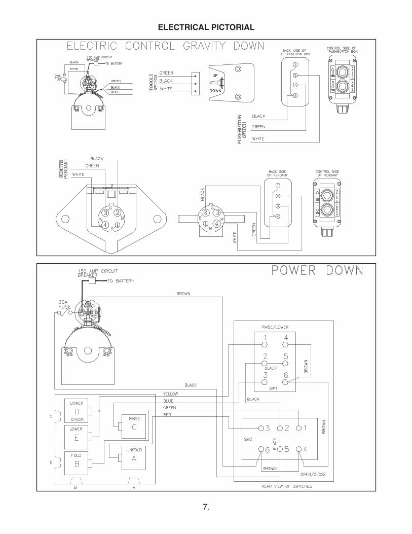
ELECTRICAL PICTORIAL
8.
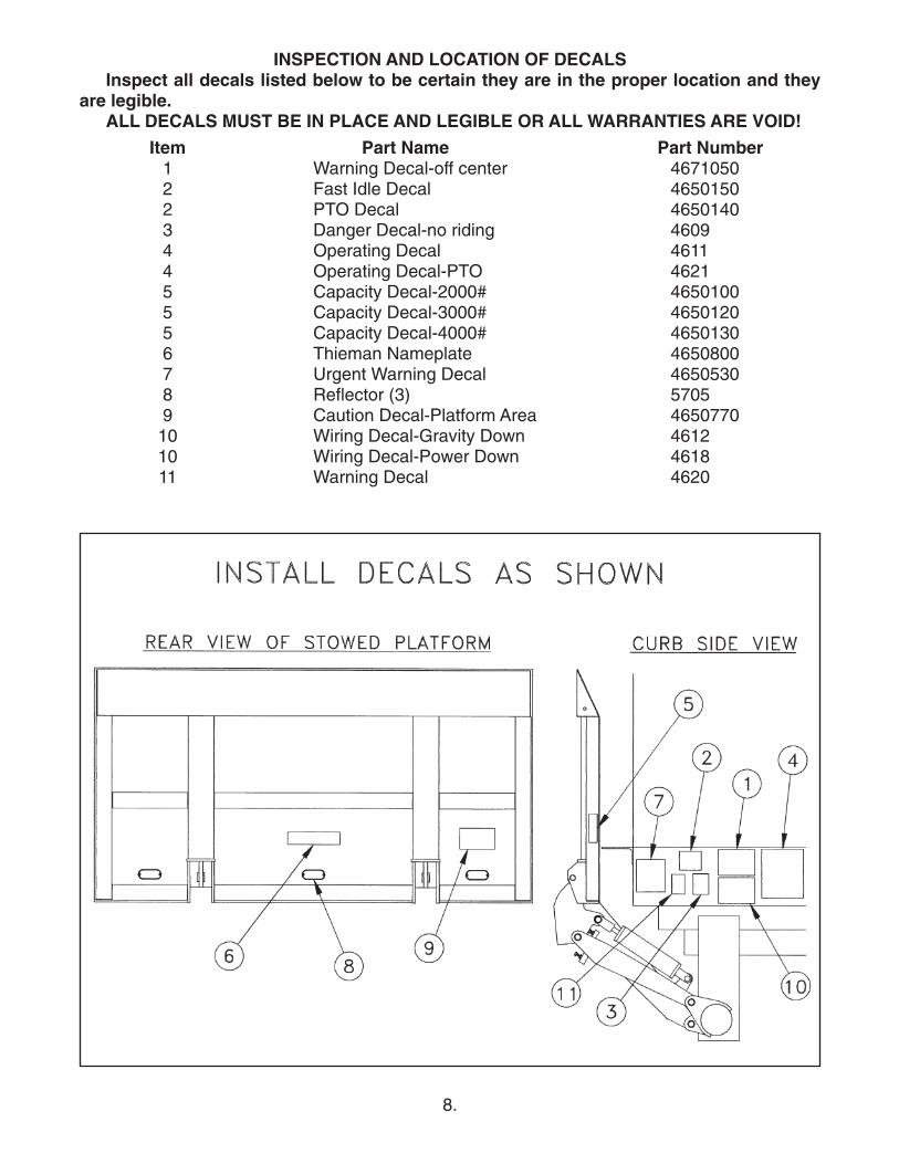
INSPECTION AND LOCATION OF DECALSInspect all decals listed below to be certain they are in the proper location and they
are legible.ALL DECALS MUST BE IN PLACE AND LEGIBLE OR ALL WARRANTIES ARE VOID!
Item Part Name Part Number1 Warning Decal-off center 46710502 Fast Idle Decal 46501502 PTO Decal 46501403 Danger Decal-no riding 46094 Operating Decal 46114 Operating Decal-PTO 46215 Capacity Decal-2000# 46501005 Capacity Decal-3000# 46501205 Capacity Decal-4000# 46501306 Thieman Nameplate 46508007 Urgent Warning Decal 46505308 Reflector (3) 57059 Caution Decal-Platform Area 465077010 Wiring Decal-Gravity Down 461210 Wiring Decal-Power Down 461811 Warning Decal 4620
9.
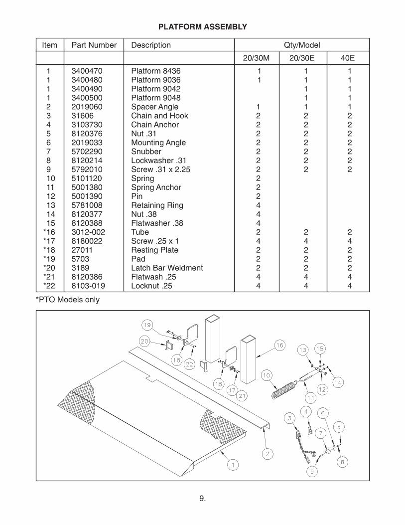
PLATFORM ASSEMBLY
Item Part Number Description Qty/Model
20/30M 20/30E 40E
1 3400470 Platform 8436 1 1 1 1 3400480 Platform 9036 1 1 1 1 3400490 Platform 9042 1 11 3400500 Platform 9048 1 1 2 2019060 Spacer Angle 1 1 13 31606 Chain and Hook 2 2 24 3103730 Chain Anchor 2 2 25 8120376 Nut .31 2 2 2 6 2019033 Mounting Angle 2 2 27 5702290 Snubber 2 2 28 8120214 Lockwasher .31 2 2 29 5792010 Screw .31 x 2.25 2 2 210 5101120 Spring 211 5001380 Spring Anchor 212 5001390 Pin 213 5781008 Retaining Ring 414 8120377 Nut .38 415 8120388 Flatwasher .38 4*16 3012-002 Tube 2 2 2*17 8180022 Screw .25 x 1 4 4 4*18 27011 Resting Plate 2 2 2*19 5703 Pad 2 2 2*20 3189 Latch Bar Weldment 2 2 2*21 8120386 Flatwash .25 4 4 4*22 8103-019 Locknut .25 4 4 4
*PTO Models only
10.
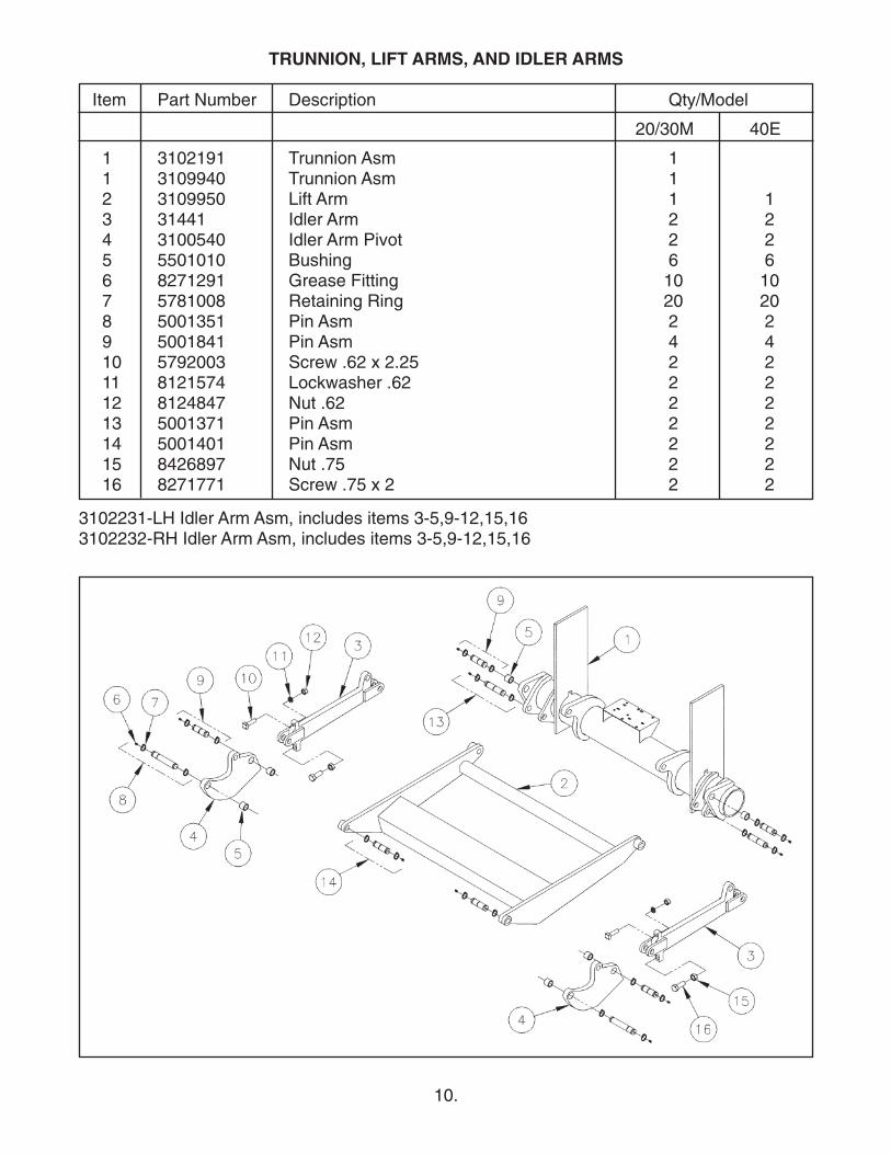
TRUNNION, LIFT ARMS, AND IDLER ARMS
Item Part Number Description Qty/Model
20/30M 40E
1 3102191 Trunnion Asm 11 3109940 Trunnion Asm 12 3109950 Lift Arm 1 13 31441 Idler Arm 2 24 3100540 Idler Arm Pivot 2 25 5501010 Bushing 6 66 8271291 Grease Fitting 10 107 5781008 Retaining Ring 20 208 5001351 Pin Asm 2 29 5001841 Pin Asm 4 4 10 5792003 Screw .62 x 2.25 2 211 8121574 Lockwasher .62 2 212 8124847 Nut .62 2 213 5001371 Pin Asm 2 214 5001401 Pin Asm 2 215 8426897 Nut .75 2 216 8271771 Screw .75 x 2 2 2
3102231-LH Idler Arm Asm, includes items 3-5,9-12,15,163102232-RH Idler Arm Asm, includes items 3-5,9-12,15,16
11.
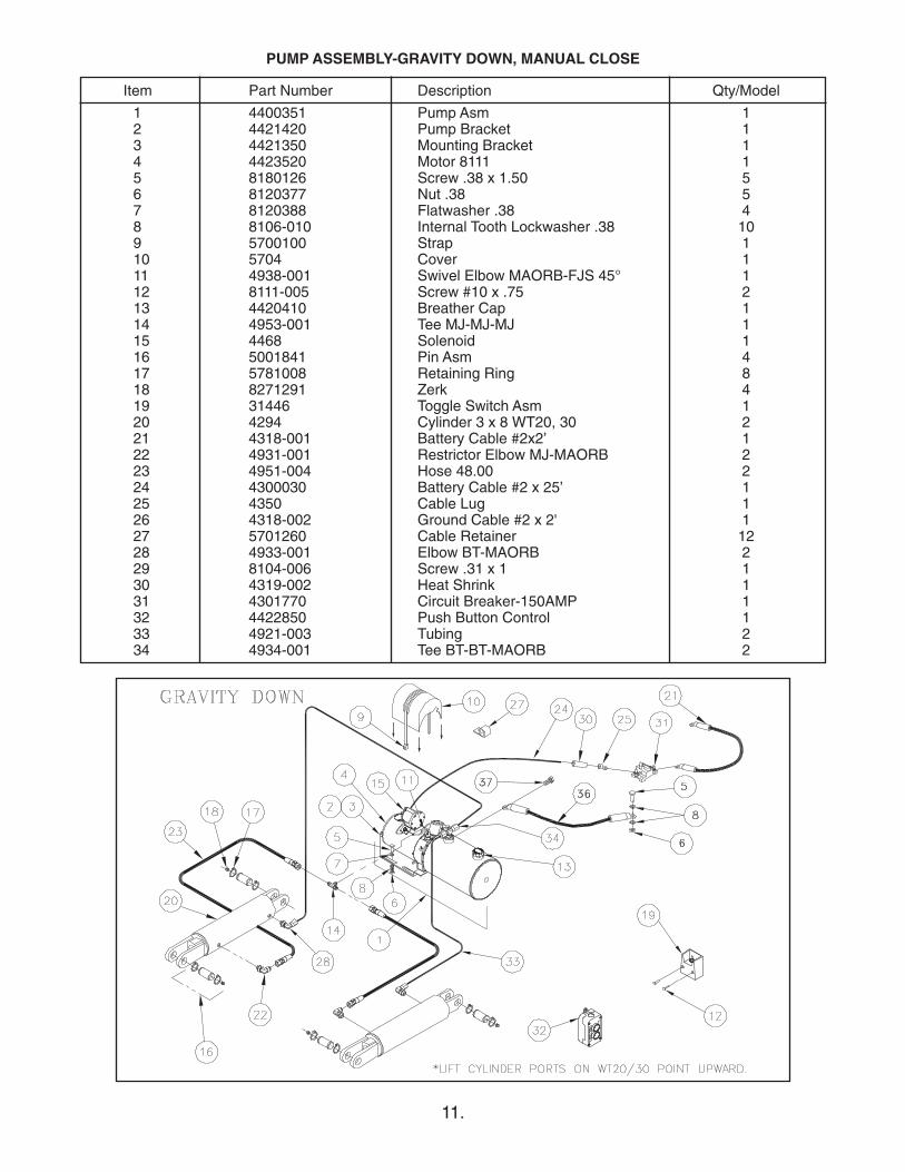
PUMP ASSEMBLY-GRAVITY DOWN, MANUAL CLOSE
Item Part Number Description Qty/Model
1 4400351 Pump Asm 12 4421420 Pump Bracket 13 4421350 Mounting Bracket 14 4423520 Motor 8111 15 8180126 Screw .38 x 1.50 56 8120377 Nut .38 57 8120388 Flatwasher .38 48 8106-010 Internal Tooth Lockwasher .38 109 5700100 Strap 110 5704 Cover 111 4938-001 Swivel Elbow MAORB-FJS 45° 112 8111-005 Screw #10 x .75 213 4420410 Breather Cap 114 4953-001 Tee MJ-MJ-MJ 115 4468 Solenoid 116 5001841 Pin Asm 417 5781008 Retaining Ring 818 8271291 Zerk 419 31446 Toggle Switch Asm 120 4294 Cylinder 3 x 8 WT20, 30 221 4318-001 Battery Cable #2x2’ 122 4931-001 Restrictor Elbow MJ-MAORB 223 4951-004 Hose 48.00 224 4300030 Battery Cable #2 x 25’ 125 4350 Cable Lug 126 4318-002 Ground Cable #2 x 2' 127 5701260 Cable Retainer 1228 4933-001 Elbow BT-MAORB 229 8104-006 Screw .31 x 1 130 4319-002 Heat Shrink 131 4301770 Circuit Breaker-150AMP 132 4422850 Push Button Control 133 4921-003 Tubing 234 4934-001 Tee BT-BT-MAORB 2
12.
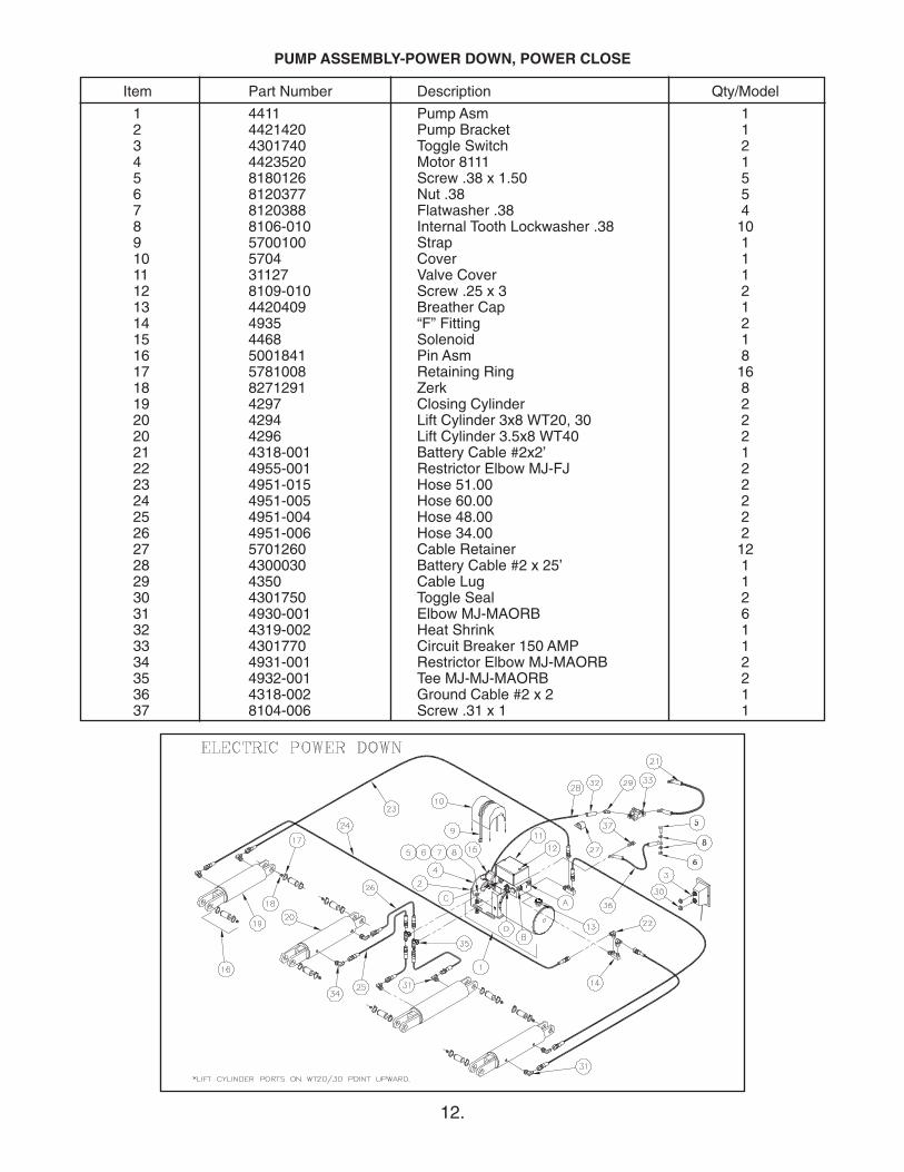
PUMP ASSEMBLY-POWER DOWN, POWER CLOSE
Item Part Number Description Qty/Model
1 4411 Pump Asm 12 4421420 Pump Bracket 13 4301740 Toggle Switch 24 4423520 Motor 8111 15 8180126 Screw .38 x 1.50 56 8120377 Nut .38 57 8120388 Flatwasher .38 48 8106-010 Internal Tooth Lockwasher .38 109 5700100 Strap 110 5704 Cover 111 31127 Valve Cover 112 8109-010 Screw .25 x 3 213 4420409 Breather Cap 114 4935 “F” Fitting 215 4468 Solenoid 116 5001841 Pin Asm 817 5781008 Retaining Ring 1618 8271291 Zerk 819 4297 Closing Cylinder 220 4294 Lift Cylinder 3x8 WT20, 30 220 4296 Lift Cylinder 3.5x8 WT40 221 4318-001 Battery Cable #2x2’ 122 4955-001 Restrictor Elbow MJ-FJ 223 4951-015 Hose 51.00 224 4951-005 Hose 60.00 225 4951-004 Hose 48.00 226 4951-006 Hose 34.00 227 5701260 Cable Retainer 1228 4300030 Battery Cable #2 x 25’ 129 4350 Cable Lug 130 4301750 Toggle Seal 231 4930-001 Elbow MJ-MAORB 632 4319-002 Heat Shrink 133 4301770 Circuit Breaker 150 AMP 134 4931-001 Restrictor Elbow MJ-MAORB 235 4932-001 Tee MJ-MJ-MAORB 236 4318-002 Ground Cable #2 x 2 137 8104-006 Screw .31 x 1 1
13.
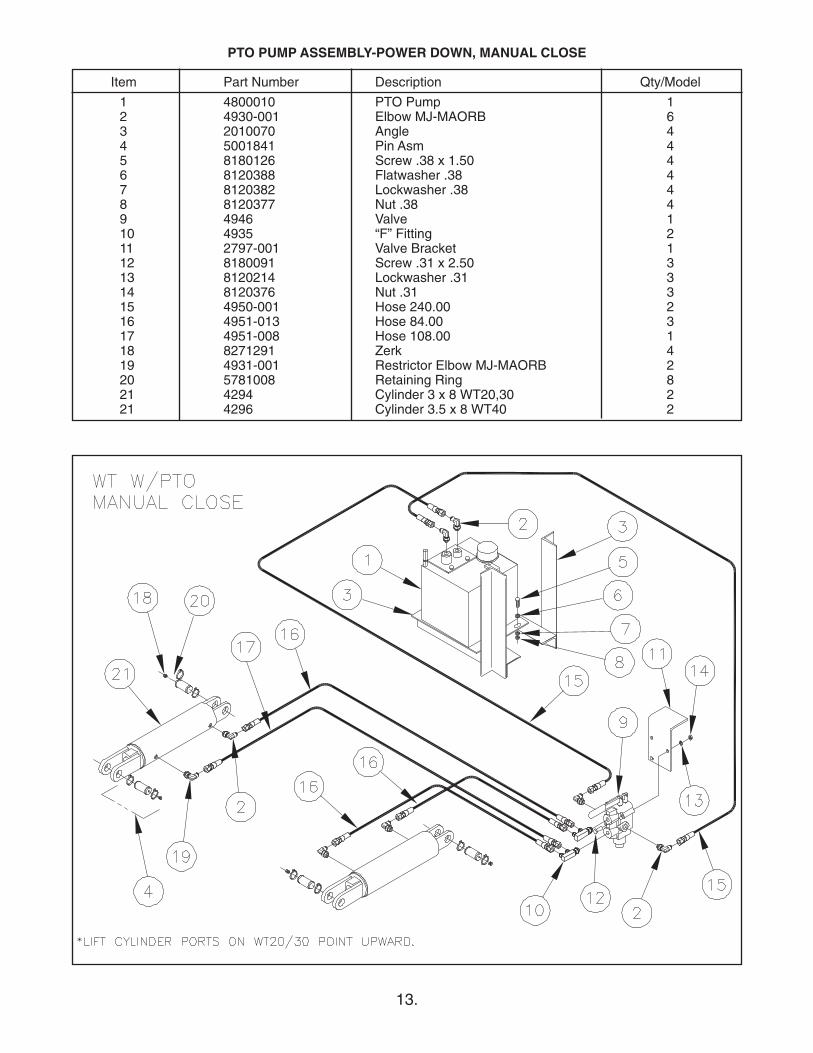
PTO PUMP ASSEMBLY-POWER DOWN, MANUAL CLOSE
Item Part Number Description Qty/Model
1 4800010 PTO Pump 12 4930-001 Elbow MJ-MAORB 63 2010070 Angle 44 5001841 Pin Asm 45 8180126 Screw .38 x 1.50 46 8120388 Flatwasher .38 47 8120382 Lockwasher .38 48 8120377 Nut .38 49 4946 Valve 110 4935 “F” Fitting 211 2797-001 Valve Bracket 112 8180091 Screw .31 x 2.50 313 8120214 Lockwasher .31 314 8120376 Nut .31 315 4950-001 Hose 240.00 216 4951-013 Hose 84.00 317 4951-008 Hose 108.00 118 8271291 Zerk 419 4931-001 Restrictor Elbow MJ-MAORB 220 5781008 Retaining Ring 821 4294 Cylinder 3 x 8 WT20,30 221 4296 Cylinder 3.5 x 8 WT40 2
14.
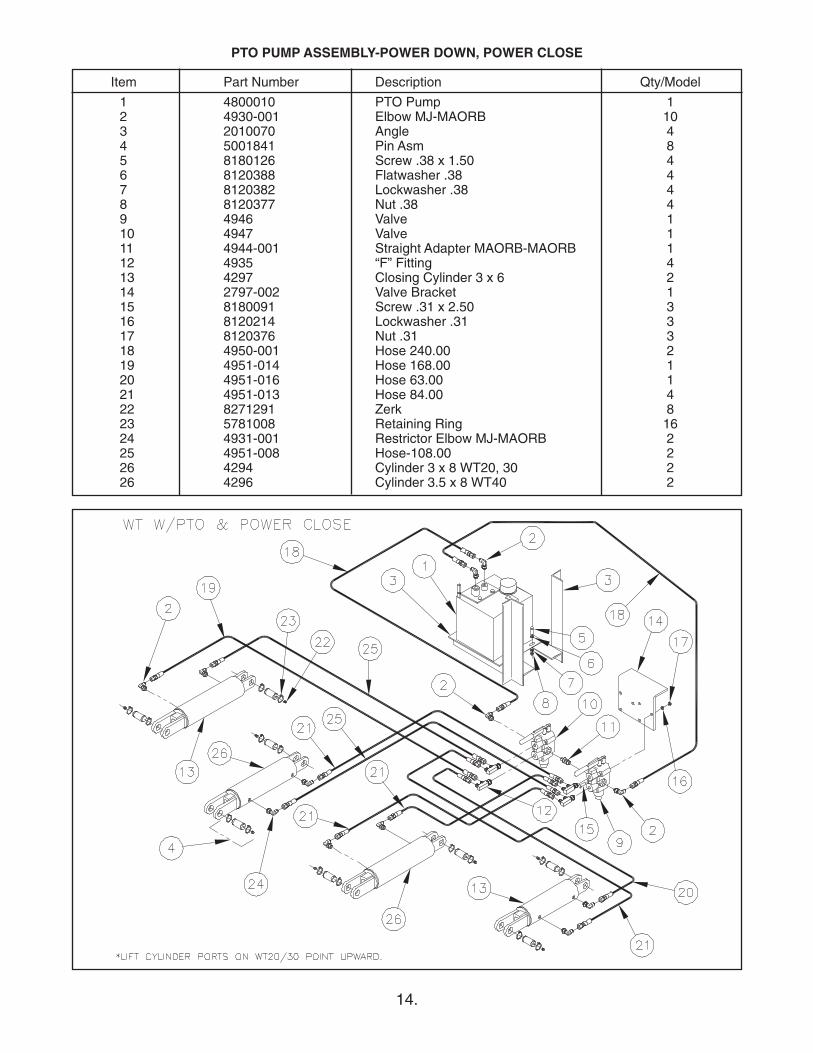
PTO PUMP ASSEMBLY-POWER DOWN, POWER CLOSE
Item Part Number Description Qty/Model
1 4800010 PTO Pump 12 4930-001 Elbow MJ-MAORB 103 2010070 Angle 44 5001841 Pin Asm 85 8180126 Screw .38 x 1.50 46 8120388 Flatwasher .38 47 8120382 Lockwasher .38 48 8120377 Nut .38 49 4946 Valve 110 4947 Valve 111 4944-001 Straight Adapter MAORB-MAORB 112 4935 “F” Fitting 413 4297 Closing Cylinder 3 x 6 214 2797-002 Valve Bracket 115 8180091 Screw .31 x 2.50 316 8120214 Lockwasher .31 317 8120376 Nut .31 318 4950-001 Hose 240.00 219 4951-014 Hose 168.00 120 4951-016 Hose 63.00 121 4951-013 Hose 84.00 422 8271291 Zerk 823 5781008 Retaining Ring 1624 4931-001 Restrictor Elbow MJ-MAORB 225 4951-008 Hose-108.00 226 4294 Cylinder 3 x 8 WT20, 30 226 4296 Cylinder 3.5 x 8 WT40 2
15.
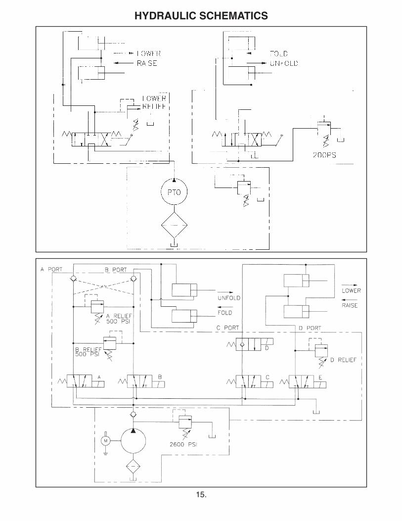
HYDRAULIC SCHEMATICS
16.
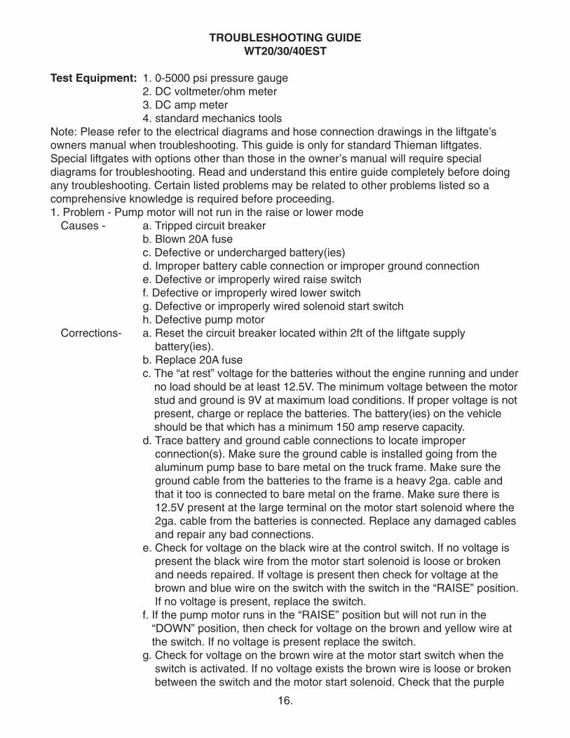
TROUBLESHOOTING GUIDEWT20/30/40EST
Test Equipment: 1. 0-5000 psi pressure gauge2. DC voltmeter/ohm meter3. DC amp meter4. standard mechanics tools
Note: Please refer to the electrical diagrams and hose connection drawings in the liftgate’sowners manual when troubleshooting. This guide is only for standard Thieman liftgates.Special liftgates with options other than those in the owner’s manual will require specialdiagrams for troubleshooting. Read and understand this entire guide completely before doingany troubleshooting. Certain listed problems may be related to other problems listed so acomprehensive knowledge is required before proceeding.1. Problem - Pump motor will not run in the raise or lower modeCauses - a. Tripped circuit breaker
b. Blown 20A fusec. Defective or undercharged battery(ies)d. Improper battery cable connection or improper ground connectione. Defective or improperly wired raise switchf. Defective or improperly wired lower switchg. Defective or improperly wired solenoid start switchh. Defective pump motor
Corrections- a. Reset the circuit breaker located within 2ft of the liftgate supplybattery(ies).
b. Replace 20A fusec. The “at rest” voltage for the batteries without the engine running and under
no load should be at least 12.5V. The minimum voltage between the motorstud and ground is 9V at maximum load conditions. If proper voltage is notpresent, charge or replace the batteries. The battery(ies) on the vehicleshould be that which has a minimum 150 amp reserve capacity.
d. Trace battery and ground cable connections to locate improperconnection(s). Make sure the ground cable is installed going from thealuminum pump base to bare metal on the truck frame. Make sure theground cable from the batteries to the frame is a heavy 2ga. cable andthat it too is connected to bare metal on the frame. Make sure there is12.5V present at the large terminal on the motor start solenoid where the2ga. cable from the batteries is connected. Replace any damaged cablesand repair any bad connections.
e. Check for voltage on the black wire at the control switch. If no voltage ispresent the black wire from the motor start solenoid is loose or brokenand needs repaired. If voltage is present then check for voltage at thebrown and blue wire on the switch with the switch in the “RAISE” position.If no voltage is present, replace the switch.
f. If the pump motor runs in the “RAISE” position but will not run in the“DOWN” position, then check for voltage on the brown and yellow wire atthe switch. If no voltage is present replace the switch.
g. Check for voltage on the brown wire at the motor start switch when theswitch is activated. If no voltage exists the brown wire is loose or brokenbetween the switch and the motor start solenoid. Check that the purple
17.
ground wire on the start solenoid is connected properly and there are noBad connections. If there is voltage on the brown wire and the coil doesnot energize or if there is No voltage present at the motor terminal thenreplace the start switch.
h. With the switch activated in the “RAISE” or “LOWER” position and themotor start solenoid is activated, check for voltage at the motor terminal.If voltage is present and the motor is not running, replace the motor.
2. Problem - Liftgate will not raise to bed with a load and the pump motor runningCauses - a. Low hydraulic fluid
b. Cylinders are plumbed incorrectly to pumpc. Overload conditiond. Defective raise solenoid coil or valvee. Improperly adjusted or defective main relief valvef. Lift cylinders are bypassing, liftgate is drifting downg. Broken hydraulic lineh. Clogged or disconnected suction linei. Defective pump
Corrections - a. Make sure the reservoir has the proper amount of fluid. Either check forthe fluid line through the plastic reservoir or for metal reservoirs removethe breather cap and check the fluid line through the fill hole. Thehydraulic fluid should be within 1/2” of the top of the reservoir with theliftgate in the stored position. Fill with Dexron III automatic transmissionfluid
b. Check that the cylinders and pump are plumbed together according to thedrawings in the liftgate owner’s manual. The B port on the pump (B isstamped in the aluminum pump base by this port) is the high pressureport and should connect to the rod end of the cylinders. The other port onthe cylinders are the low pressure lowering ports and should be plumbedto the A port on the pump (A is stamped in the aluminum pump base bythis port).
c. The power unit on the WT is equipped with a lifting relief valve to preventoverloading of the liftgate. The relief setting should be as follows:
WT20-1500psiWT30-2150psiWT40-2000 psi
d. With the “RAISE” switch engaged check for voltage on the blue wire atthe switch. If no voltage is present replace the switch. If voltage ispresent, with the “RAISE” switch engaged, check for voltage at the bluewire on the raise solenoid valve coil terminal at the pump. If no voltage ispresent, the blue wire from the “RAISE” switch is loose or broken andneeds repaired. If there is voltage (minimum of 9.5 volts) and the valve isnot opening to allow the gate to raise, either the raise coil is bad or theentire raise coil/valve assembly is bad. To check to see if the coil isdefective, remove the blue wire from the spade terminal on the raise coiland check for continuity between the spade terminal and the nut whichholds the coil on the valve stem. If continuity does not exist, replace thedefective coil, otherwise replace the defective raise coil/valve assembly.

18.
e. See section “c” above for relief valve setting. Plumb a pressure gaugeinto the high pressure circuit of the liftgate (those hoses connected to theB port on the pump). Remove all loads from the liftgate’s platform.Engage the “RAISE” switch until the liftgate is fully raised. Keep the“RAISE” switch engaged until the pump bypasses through the relief valveand note the pressure on the gauge at this time. If the rated reliefpressure is not present during relief, adjust the high pressure relief valvesetting as necessary. There are two relief valves on this pump so makesure to adjust only the high pressure relief setting at this time. The highpressure relief is the higher one on the aluminum pump base. If the reliefpressure is not attainable the relief valve must be cleaned and/orreplaced or the pump is defective. See part i below.
f. If the liftgate will not raise with a load on the platform but empty is raisingslowly or only partially, one or both of the cylinders may be bypassing. Tocheck for bypassing cylinders do the following. Lower the gate to theground to relieve all pressure from the cylinders. Disconnect bothcylinders from the liftarm. Press the “RAISE” switch until both cylindersare fully retracted. Disconnect the low pressure hoses from the power unitat the swivel fitting at the A port at the pump. Plug the newly openedend(s) of the swivel fitting. Put the loose ends of the disconnected hosesin a container to catch any oil, which comes out during this test. Press the“RAISE” switch for 15 to 20 seconds and watch for a steady stream offluid coming out of one of the disconnected hose ends into the container. Ifno steady stream of oil is present reconnect all hoses and press the“LOWER” switch until both cylinders are fully extended. Disconnect thehigh pressure hoses from the power unit at the swivel fitting at the B portat the pump. Plug the newly opened end(s) of the swivel fitting. Put theloose ends of the disconnected hoses in a container to catch any oil,which comes out during this test. Press the “LOWER” switch for 15 to 20seconds and watch for a steady stream of fluid coming out of one of thedisconnected hose ends into the container. Replace or rebuild anycylinder with fluid coming out of its disconnected hose end, as thisindicates fluid is bypassing the piston seals on the cylinder. Reconnectrebuilt or replaced cylinders and hoses as before.
g. Broken or punctured hydraulic lines and fittings must be replaced withcare to avoid injury from high pressure oil streams.
h. With the liftgate at the ground, disconnect the power unit and remove thereservoir. Check to see if the suction tube is clogged or has fallen out ofthe pump base. Clean the screen or reattach the suction tube asrequired. If all else fails replace the power unit, it is probably worn out.
3. Problem - Liftgate will not lower with the pump motor runningCauses - a. Defective lowering solenoid coil or valve
b. Clogged or defective hydraulic lines, fittings or flow controlsCorrections - a. With the “LOWER” switch engaged check for voltage on the yellow wire
at the switch. If no voltage is present replace the switch. If voltage ispresent, with the “LOWER” switch engaged, check for voltage at theyellow wire on the lower solenoid valve coil terminal. If no voltage is
19.
present, the red wire from the “LOWER” switch is loose or broken andneeds replaced. If there is voltage (minimum of 9.5 volts) and the valve isnot opening to allow the gate to lower, either the lower coil is bad or theentire lower coil/valve assembly is bad. To check to see if the coil isdefective, remove the yellow wire from the spade terminal on the lowercoil and check for continuity between the spade terminal and the nut,which holds the coil on the valve stem. If continuity does not exist,replace the defective coil, otherwise replace the defective lower coil/valveassembly.
b. Remove any obstruction in the hoses, fittings or flow controls or replaceany hose, fitting or flow control, which does not allow fluid to flow throughfreely.
4. Problem - Liftgate raises slowly - The raise speed of the WT20/30 on a 54” bed height whileempty at 70° F is approximately 10-12 seconds. The raise speed loaded for the sameconditions is approximately 22-23 seconds. The raise speed of the WT40 on a 54” bedheight while empty at 70° F is approximately 14-16 seconds. The raise speed loaded for thesame conditions is approximately 29-31 seconds. Causes - a. Overload condition
b. Cold weatherc. Partially blocked suction screend. Lift cylinders are bypassinge. Improperly adjusted or defective raise relief valvef. Low voltage and/or bad groundg. Worn out pump
Corrections - a. See section 2ab. Refer to Owner’s Manual for alternative oils to use for cold weather
conditions.c. Remove reservoir and clean or replace suction screen as necessary.d. See section 2fe. See section 2ef. The minimum voltage between the motor stud and ground is 9.5 volts atmaximum load conditions. See section 1b and 1c.
g. After all other corrections are performed it will be necessary to replacethe pump.
5. Problem - Foamy oil flowing from reservoir breatherCauses - a. Air is present in the systemCorrections - a. This can occur if the motor is not running as the liftgate is lowered. See
problem 1, part e and f. Also air can enter the system if the fluid level islow, see problem 2, part a, or if the suction tube is disconnected, seeproblem 2, part h. Also air may enter through fittings, which are nottightened properly, so check for any leaks around fittings or hoses. Oncethe source of the air is determined, the cylinders must be bled of all air.Most air can be removed from the system by lowering the gate to theground to relieve all pressure from the cylinders, unpinning the cylindersand cycling them back and forth several times from fully extended to fullyretracted and allowing the pump to bypass through the relief valves for afew seconds in each direction.
20.
Rev. 12/11 • 2.5C • MP74635
6. Problem - Liftgate will not close, but will raise and lowerCauses - a. Defective open/close switch (SW3)
b. Improperly adjusted or defective close relief valveCorrections - a. Check for voltage at the black wire on the open/close switch on terminal
#5. If no voltage is present the black wire from the motor start solenoid isloose or broken and needs repaired. If voltage is present then check forvoltage at the brown and green wire on the switch with the switch in the“CLOSE” position. If no voltage is present, replace the switch.
b. The closing relief valve should be set at 500 psi. Plumb a pressure gaugeinto the closing circuit of the liftgate (those hoses connected to the C porton the pump). Remove all loads from the liftgate’s platform. Engage the“CLOSE” switch until the liftgate is fully closed. If the platform will notclose then turn up the relief valve until it closes. Keep the “CLOSE” switchengaged until the pump bypasses through the relief valve and note thepressure on the gauge at this time. If the rated relief pressure is notpresent during relief, adjust the closing pressure relief valve setting asnecessary. There are four relief valves on this pump so make sure toadjust only the closing pressure relief setting at this time. See the reliefvalve adjustment diagram in the owner’s manual for the location of therelief valves. If the relief pressure is not attainable the relief valve must becleaned and/or replaced or the pump is defective.
7. Problem - Liftgate will not open, but will raise and lowerCauses - a. Defective open/close switch (SW3)
b. Improperly adjusted or defective opening relief valveCorrections - a. Check for voltage at the black wire on the open/close switch on terminal
#5. If no voltage is present the black wire from the motor start solenoid isloose or broken and needs repaired. If voltage is present then check forvoltage at the brown and red wire on the switch with the switch in the“OPEN” position. If no voltage is present, replace the switch.
b. The opening relief valve should be set at 500 psi. Plumb a pressuregauge into the opening circuit of the liftgate (those hoses connected tothe D port on the pump). Engage the “OPEN” switch until the liftgate isfully open. If the platform will not open then turn up the relief valve until itopens. Keep the “OPEN” switch engaged until the pump bypassesthrough the relief valve and note the pressure on the gauge at this time. Ifthe rated relief pressure is not present during relief, adjust the openingpressure relief valve setting as necessary. There are four relief valves onthis pump so make sure to adjust only the closing pressure relief settingat this time. See the relief valve adjustment diagram in the owner’smanual for the location of the relief valves. If the relief pressure is notattainable the relief valve must be cleaned and/or replaced or the pump isdefective.
If you have any questions or problems that are not covered in this guide please call Thieman’sEngineering Department at 1-800-524-5210.
Related Documents