TAIFUN ® from idea to product WERNERT - PUMPEN GMBH

Welcome message from author
This document is posted to help you gain knowledge. Please leave a comment to let me know what you think about it! Share it to your friends and learn new things together.
Transcript

TAIFUN® from idea to product
WERNERT - PUMPEN GMBH

Until now: two drivers for seal-less centrifugal pumps
• magnetic coupling
• asynchronous canned motor

Magnetic coupling - advantages
• no energy losses due to synchronous* driving principle when using non-metallic isolation shells.
• larger radial gaps don’t increase energy loss, lead only to necessity of stronger magnets.
• design of non-metallic pumps possible.
*outer and inner rotor show same speed

Magnetic coupling - disadvantages
broken isolation shell:
fluid contaminates atmosphere
= simple safety.
wasteful:- 4 roller bearings
- 1 asynchronous driver- 1 synchronous driver
Space requirement.
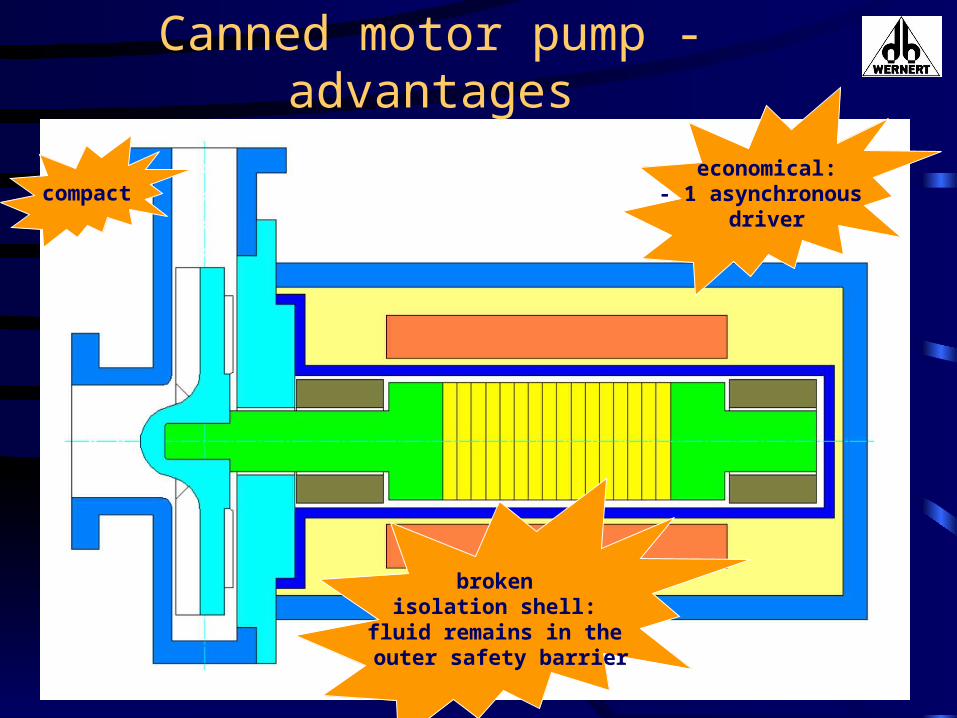
Canned motor pump - advantages
broken isolation shell:
fluid remains in the outer safety barrier
compacteconomical:
- 1 asynchronous driver

Canned motor pump - disadvantages
• energy losses due to asynchronous* driving principle ( eddy currents! )
• larger radial gaps ( required for SiC or PFA ) lead to higher energy losses = less efficiency.
• Heating up of the rotor does not allow using thermoplastics like PFA.
• Fluid is heated up.
*outer and inner rotor do not show same speed = slip

Forget this...
The way to TAIFUN
.... and the second skin for
improved safety.
Coils around theisolation shell...
Wow, that’s a lot of stuff....and this.

TAIFUN - the idea
The outer coils produce a rotating magnetic field for the inner rotor, which behaves like it would do in a magnetic coupled pump.
Designing non-metallic canned motor pumps becomes possible.

Excursus: electric coils
Coils, which are passed by electric current, will generate a magnetic field.
Alternating current will generate an alternating magnetic field.

Excursus: rotating magnetic field

Driving scheme TAIFUN
3 groups of coils:black,yellow, green.
All coils of same colour areparallel connected.
The coil groups are delta connected.

Simulation of a 60° turn
Starting point: full positive phase at coil 1
End point: full negative phase at coil 1+ -

Calculating the supply frequency
In one frequency’s half-period the rotor turns 60°.
Then a full period will lead to a 120° turn. For a full 360° turn 3 periods of the frequency are needed.
At 3000 rpm the system will need 9000 periods per minute, that is equal to 9000/ 60 s = 150 Hz.
Such frequencies need to be generated by a frequency converter.

Advantages of the TAIFUN concept
• Synchronous driver– no eddy-current losses and heating-up of
the rotor and the fluid.– excellent efficiency.– allows large radial gaps for non-metallics.
• Integrated driver– double hermetically tight.– compact design. – minimised mechanical losses.

Dimensions:Conventional vs. TAIFUN
Same scale
Same size50-32-200
Comparable electric motor15 kW
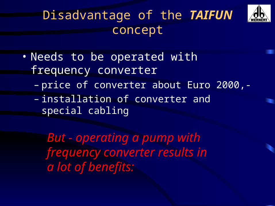
Disadvantage of the TAIFUN concept
• Needs to be operated with frequency converter– price of converter about Euro 2000,-– installation of converter and special cabling
But - operating a pump with frequency converter results in a lot of benefits:

Advantages of using frequency converters• Speed of pump is variable:
– Flow control by varying the speed • mostly energy efficient = money.• no throttle valves needed = money.• uncertainty of head calculation tolerated = no trouble.
– Impeller diameter keeps constant. Pump can replace any other of that type directly.
– Choice of design speed is free, e.g. 4375 rpm
• Converters intelligence is raising:– Today: Integrated power control– In future: Diagnostics and trend analyses.

Conditions: 7 Cent/kWh - Efficiency 45% - density of water
Example:Saving 1,0 bar plants throttling at 25 m³/h with TAIFUN pays back 4.300,- Euro in 5 years.

Prototypes test run on 7.5.1999

The developing team.
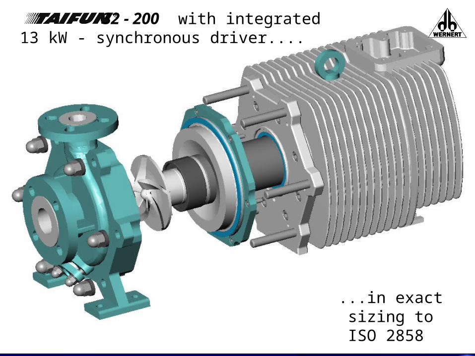
32 - 200 with integrated13 kW - synchronous driver....
...in exact sizing to
ISO 2858

Presentation at ACHEMA 2000

ATEX tests on 2./3. Juli 2001
Measuring the maximum surface temperatures

ATEX tests on 2./3. Juli 2001Dry run test
The Ax-lock designblocks the rotor after
approx. 30 sec , without damaging further parts. Spare part costs:
€ 245,-
Absolut tight without damaging
the inner savety zone

First TAIFUN in operation (3.8.2001)
BASF Pigment, Besigheim, Germany

Technical data TAIFUN 32-200
• Chemical pump to ISO 2858, size 50-32-200• No design variations• Fixed impeller diameter: 140 mm• Maximum driver torque: 25 Nm• Maximum fluid temperature: 150 °C (302°F)• Max. environmental temperature: 40 °C (104°F)• Integrated 13 kW driver certified to
II 2 G EEx de IIC T3-T6 ( PTB 01 ATEX 1094 )

Hydraulics TAIFUN 32 -200
• High speed = Low torque = less required magnetic mass and better hydraulic efficiency
• n = 1000 - 5000 rpm
• Q = 1 - 35 m³/h
• H = 5 - 80 m
• 3D - impeller for best inlet flow conditions
• NPSHmax < 3 m
• Etatotal,max = 45%

Performance curvesTAIFUN 32-200

Stator
Driver (Stator):
• „Forbidden zone“: assembly only by licensed electricians/ for opening special-tool required
• bearings not part of this zone

Outer cover
Outer cover:• Additional
O-Rings in case that the bearing zone breaks
• GGG 40.3 and steel

Outer and inner cover
• Flat seals EURO-GYLON blue
• PFA-lining• sleeves out
of siliconcarbide, not part of the bearings
Inner cover:

Rotor withbearings
• Magnets out of Samarium Cobalt
• Hollow shaft with PFA-lining
• impeller and adaptation piece out of massive PTFE
• O-Rings out of FFKM (Perfluorine-elastomer)
• rotating bearings out of siliconcarbide
Rotor:
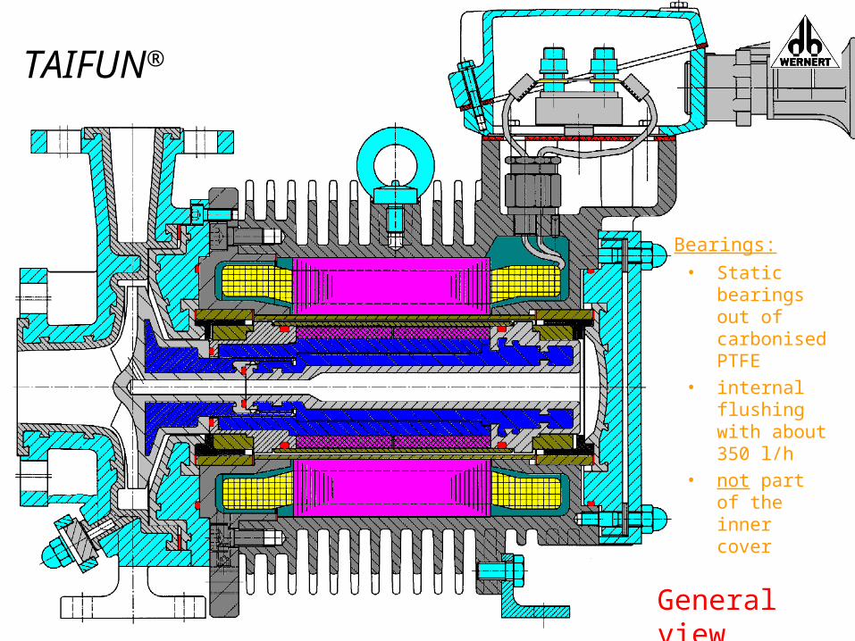
General view
TAIFUN®
• Static bearings out of carbonised PTFE
• internal flushing with about 350 l/h
• not part of the inner cover
Bearings:

TAIFUN - your plant standard
• Highest safety standard, due to two independent hermetically tight zones.
• Handles all corrosive and/ or toxic liquids up to 150 °C
• Only few sizes without variations and with fixed impeller diameter.
• Local flow conditions are adapted by energy saving speed control.
• Take it from stock, put it in place, start.

The end.