DIMENSIONS Specifications are subject to change without notice GENERAL DIMENSIONS (29.5 X 25 Tires) Feet Turning radius 4 wheel steer 21' 11-3/4" 6.7 2 wheel steer 39' 1/2" 11.9 8' 2-1/2" (2502) 10' 10-1/2" (3315) Meters (4120) 9' 2-1/4"(2800) 18' 1/2"(5500) 21' 11-3/4"(6700) 23' 7-1/2"(7200) 13' 6-1/4" 6' 1-7/8"(1875) 14.4 o 23' 7-1/3" (7200) 7' 10-1/2"(2400) 6' 7/8"(1850) 12' 11-1/2"(3950) 17.6 o 46' 8-1/4" (14230) Min. 37' 8-3/4" ~ Max. 144' 4-1/4" (11500 ~ 44000) 11' 4-1/2" (3470) 12' 5-1/2" (3800) 6' 7-3/4"(2025) 1 GR800XL-1 TADANO MODEL GR800XL-1 - 80 TON CAPACITY LIFTING CHARTS - Rough Terrain Cranes

Welcome message from author
This document is posted to help you gain knowledge. Please leave a comment to let me know what you think about it! Share it to your friends and learn new things together.
Transcript
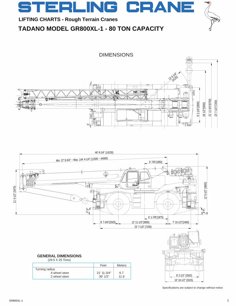
DIMENSIONS
Specifications are subject to change without notice
GENERAL DIMENSIONS (29.5 X 25 Tires)
FeetTurning radius 4 wheel steer 21' 11-3/4" 6.7 2 wheel steer 39' 1/2" 11.9 8' 2-1/2" (2502)
10' 10-1/2" (3315)
Meters
(4120)
9' 2-1
/4"(28
00)
18' 1
/2"(55
00)
21' 1
1-3/4"
(6700
)
23' 7
-1/2"
(7200
)
13' 6-1/4"
6' 1-7/8"(1875)
14.4 o
23' 7-1/3" (7200)7' 10-1/2"(2400)
6' 7/8"(1850)
12' 11-1/2"(3950)
17.6
o
46' 8-1/4" (14230)
Min. 37' 8-3/4" ~ Max. 144' 4-1/4" (11500 ~ 44000)
11' 4
-1/2"
(347
0)
12' 5
-1/2"
(380
0)
6' 7-3/4"(2025)
1GR800XL-1
TADANO MODEL GR800XL-1 - 80 TON CAPACITY
LIFTING CHARTS - Rough Terrain Cranes
SUPERSTRUCTURE SPECIFICATIONSBOOM DRUM - Grooved 15-3/4"(0.40m) root diameter x 22-3/4"Five section full power synchronized telescoping boom, (0.578m) wide. Wire rope: 436' of 3/4"diameter rope (133m of37.7'~144.4'(11.5m~44.0m), of round hexagonal box 19mm). Drum capacity: 1,096' (334m) 7 layers. Maximum lineconstruction with 7 sheaves, 15" (0.38m) root diameter, at boom pull (available): 18,200lbs. (8,260kg). Maximum line speed:head. The synchronization system consists of two telescope 585FPM (178m/min).cylinders, an extension cable and retraction cable. Hydraulic cylinder fitted with holding valve. Two easily removable wire rope guards, WIRE ROPE - Warrington seal wire, extra improved plow steel,rope dead end provided on both sides of boom head. Boom preformed, independent wire rope core, right regular lay.telescope sections are supported by wear pads both vertically and 3/4"(19 mm) 6X37 classhorizontally.Extension speed 106' 7-1/2" in 145 seconds. HOOK BLOCKS
BOOM ELEVATION - By a double acting hydraulic cylinderwith holding valve. Elevation -2.0o~80.7o, combination controls forhand or foot operation. Boom angle indicator.
6.2 ton (5.6 metric ton) - Weighted hook with swivel and
Automatic speed reduction and soft stop function.
safety latch, for 3/4"(19mm) wire rope.
Elevation speed -2.0o~80.7o in 77 seconds.
HYDRAULIC SYSTEM
JIB - Two stage bi-fold lattice type with 3.5o, 25o or 45o offset(tilt type). Single sheave, 15-5/8"(0.396m) root diameter, at the
PUMPS - Two variable piston pumps for crane functions.
head of both jib sections. Stored alongside base boom section.
Tandem gear pump for steering, swing and optional equipment.
Jib length is 32.5' (9.9m) or 58.1' (17.7m). Assist cylinders for
Powered by carrier engine. Pump disconnect for crane is
mounting and stowing are controlled at right side of superstructure.
engaged/ disengaged by rotary switch from operator's cab.
Self stowing jib mounting pins.
CONTROL VALVES - Multiple valves actuated by
pilot
AUXILIARY LIFTING SHEAVE (SINGLE TOP)
pressure with integral pressure relief valves.
Single sheave, 15-5/8"(0.396m) root diameter. Mounted to mainboom head for single line work (stowable).
RESERVOIR - 195 gallon (740 lit.) capacity. External sightlevel gauge.
ANTI-TWO BLOCK - Pendant type over-winding cut outdevice with audio-visual (FAILURE lamp/BUZZER) warning
FILTRATION - 26 micron return filter, full flow with bypass
system.
protection, located inside of hydraulic reservoir. Accessible foreasy replacement.
SWINGHydraulic axial piston motor driven through planetary swing
OIL COOLER - Air cooled fan type.
speed reducer. Continuous 360o full circle swing on ball bearingturntable at 2.3rpm. Equipped with manually locked/released
CAB AND CONTROLS
swing brake. A 360o positive swing lock for pick and carry andtravel modes, manually engaged in cab. Twin swing System:
Both crane and drive operations can be performed from one
Free swing or lock swing controlled by selector switch on front
cab mounted on rotating superstructure.
console.
Left side, 1 man type, steel construction with sliding door
HOIST
access and tinted safety glass windows opening at side. Doorwindow is powered control. Windshield glass and roof window
MAIN HOIST - Variable speed type with grooved drum
glass window are shatter-resistant. Tilt-telescoping steering
driven by hydraulic axial piston motor through winch speed
wheel. Adjustable control lever stands for swing, boom hoist,
reducer. Power load lowering and raising. Equipped with
boom telescoping, auxiliary hoist and main hoist. Control lever
automatic brake (neutral brake) and counterbalance valve.
stands can change neutral positions and tilt for easy access into
Controlled independently of main hoist. Equipped with cable
cab. 3 way adjustable operator's seat with high back, headrest
follower and drum rotation indicator.
and armrest. Engine throttle knob. Foot operated controls: boom hoist, boom telescoping, service brake and engine throttle. Hot
DRUM - Grooved 15-3/4"(0.40m) root diameter x 22-3/4"
water cab heater and air conditioning
(OPTIONAL).
(0.578m) wide. Wire rope: 797' of 3/4"diameter rope (243m of19mm). Drum capacity: 1,096' (334m) 7 layers. Maximum line
Dash-mounted engine start/stop, monitor lamps, cigarette lighter
pull (available): 18,200lbs. (8,260kg). Maximum line speed:
ashtray, drive selector switch, parking brake switch, steering
585FPM (178m/min).
mode select switch, power window switch, pump engaged/disengaged switch, swing brake switch, telescoping/auxiliary
AUXILIARY HOIST - Variable speed type with grooved drum
winch select switch, outrigger controls, main winch/auxiliary
driven by hydraulic axial piston motor through winch speed
winch selector switch, swing stop cancel switch, slow elevation
reducer. Power load lowering and raising. Equipped with
stop cancel switch and free swing / lock swing selector switch.
automatic brake (neutral brake) and counterbalance valve. Controlled independently of main hoist. Equipped with cable
Instruments - Torque converter oil temperature, engine water
follower and drum rotation indicator.
temperature, air pressure, fuel, speedometer, tachometer andhour meter. Hydraulic oil pressure is monitored and displayed on the AML-L display panel.
2GR800XL-1
Tadano electronic LOAD MOMENT INDICATOR system TADANO AML-L monitors outrigger extended length and(AML-L) including: automatically programs the corresponding "RATED LIFTING
Control lever lockout function with audible and visual CAPACITIES" table.pre-warning.Boom position indicator Operator's right hand console includes transmission gearOutrigger state indicator selector and sight level bubble. Upper console includes Boom angle / boom length / jib offset angle / load working light switch, roof washer and wiper switch, oilradius / rated lifting capacities / actual loads read out cooler switch, emergency outrigger set up key switch,Ratio of actual load moment to rated load moment drum indicator switch, jib equipped/removed select switch,indication boom emergency telescoping switch (2nd and 3rd-top) Automatic Speed Reduction and Soft Stop function and air conditioning control switch. Swing lock lever.on boom elevation and swing (swing range restricted only)Working condition register switch NOTE:Each crane motion speed is based on unladenLoad radius / boom angle / tip height / swing range conditions.preset functionExternal warning lamp
CARRIER SPECIFICATIONSTYPE - Rear engine, left hand steering, driving axle 2-way SUSPENSION - Front: Rigid mounted to frame. Rear: Pivotselected type by manual switch, 4x2 front drive, 4x4 front and mounted with hydraulic lockout device.rear drive.
BRAKE SYSTEMS - Service: Air over hydraulic disc brakes onFRAME - High tensile steel, all welded mono-box construction. all 4 wheels. Parking/Emergency: Spring applied-air released
brake acting on input shaft of front axle. Auxiliary: Electro-TRANSMISSION - Electronically controlled full automatic pneumatic operated exhaust brake.transmission. Torque converter driving full powershift withdriving axle selector. 6 forward and 2 reverse speeds, constant TIRES - 29.5-25 22PR(OR)mesh.
3 speeds - high range - 2 wheel drive; 4 wheel drive OUTRIGGERS - Four hydraulic, beam and jack outriggers.3 speeds - low range - 4 wheel drive Vertical jack cylinders equipped with integral holding valve. Each
outrigger beam and jack is controlled independently from cab.TRAVEL SPEED - 25 mph (40 km/h) Beams extend to 23' 7-1/2" (7.2 m) center-line and retract to
within 10' 10-1/2" (3.315 m) overall width with floats. Outrigger AXLE - Front: Full floating type, steering and driving axle with jack floats are attached thus eliminating the need of manually planetary reduction. Rear: Full floating type, steering and driving attaching and detaching them. Controls and sight bubble located axle with planetary reduction and non-spin rear differential. in superstructure cab. Four outrigger extension lengths are
provided with corresponding "RATED LIFTING CAPACITIES" forSTEERING- Hydraulic power steering controlled by steering crane duty in confined areas.wheel. Four steering modes available: 2 wheel front, 2 wheel Min. Extension 9' 2-1/4" center to centerrear, 4 wheel coordinated and 4 wheel crab . Mid. Extension 18' 1/2" center to center
Mid. Extension 21' 11-3/4" center to centerMax. Extension 23' 7-1/2" center to center
Float size(Diameter) 1' 7-11/16" (0.5m)
ENGINEModel Mitsubishi 6D16-TLEE Radiator Fin and tube core, thermostat controlledType Direct injection diesel Fan, in.(mm) Suction type, 6-blade, 23.6 (600) dia.No. of cylinders 6 Starting 24 voltCombustion 4 cycle, turbo charged and after cooled Charging 24 volt system, negative groundBoreXStroke, in.(mm) 4.646 X 4.528 (118X115) Battery 2-120 amp. HourDisplacement, cu. in (liters) 460 (7.545) Compressor, air, CFM(l /min) 9.2 CFM (260) at 2,800rpmAir inlet heater 24 volt preheat Horsepower (kW) Gross 223 (166) at 2,700rpmAir cleaner Dry type, replaceable element Torque, Max. ft-lb (kgm) 521 (72) at 1,300rpmOil filter Full flow with replaceable element Capacity, gal.(liters)Fuel filter Full flow with replaceable element Cooling water 3.4 (13)Fuel tank, gal.(liters) 79.2 (300), right side of carrier Lubrication 3.7 ~ 4.2 (14 ~ 16)Cooling Liquid pressurized, recirculating by-pass Fuel 79.2 (300)
3GR800XL-1
- Four section full power partially synchronized boom - Independently controlled outriggers37.7'~144.4' (11.5 m~44.0 m) - Four outrigger extension positions
- 32.5'~58.1' (9.9 m~17.7 m) bi-fold lattice jib (tilt type) - Self-storing outrigger padswith 3.5o, 25o or 45o pinned offsets and self storing pins. - Outrigger hose protection
- Auxiliary lifting sheave (single top) stowable - Mitsubishi 6D16-TLEE turbo charged after cooled engine- Variable speed main hoist with grooved drum, cable follower (223HP) with exhaust brake
and 797' of 3/4" cable. - Electronic controlled automatic transmission driven by torque- Variable speed auxiliary hoist with grooved drum, cable converter
follower and 436' of 3/4" cable. - 4 X 4 X 4 drive/steer- Drum rotation indicator (thumper type) main and auxiliary hoist - Non-spin rear differential- Anti-Two block device (overwind cutout) - Automatic rear axle oscillation lockout system- Boom angle indicator - 29.5-25 22PR (OR) tires- Tadano electronic load moment indicator system (AML-L) - Disc brakes- Outrigger extension length detector - Fenders- Electronic crane monitoring system - Air dryer- Tadano twin swing system and 360o positive swing lock - Water separator with filter- Self centering finger control levers with pilot control - Engine over-run alarm- Control pedals for boom hoist and boom telescoping - Back-up alarm- 3 way adjustable cloth seat with armrests, high back - Low oil pressure/high water temp. warning device (visual)
and seat belt - Rear steer centering light- Tilt-telescoping steering wheel - Air cleaner dust indicator- Tinted safety glass and sun visor - Full instrumentation package- Front windshield wiper and washer - Complete highway light package- Roof window wiper and washer - Flood lights and work lights- Power window (cab door) - Tool storage compartment- Rear view mirrors (right and left side) - Tire inflation kit- Mirror for main and auxiliary hoists - 24 volt electric system- Cigarette lighter and ashtray- Electric fan in cab
- 6.2 ton (5.6 metric ton) hook with swivel
- Cab floor mat- Towing hooks-Front and rear
- Pump disconnect in operator's cab- Lifting eyes
- Hydraulic oil cooler- Hook block tie down (front bumper)- Weighted hook storage compartment
OPTIONAL EQUIPMENT- 80 ton (72.6 metric ton) - 7 sheave with swivel hook and
safety latch for 3/4"(19 mm) wire rope
LINE SPEEDS AND PULLS DRUM WIRE ROPE CAPACITIES
F.P.M m/min Lbs. kgf Lbs. kgf Feet Meters Feet MetersHigh 378 115 18,200 8,260 15,200 6,880 123.0 37.5 123.0 37.5High 413 126 16,700 7,570 13,900 6,310 134.2 40.9 257.2 78.4High 448 136 15,400 6,990 12,800 5,820 145.3 44.3 402.6 122.7High 482 147 14,300 6,490 11,900 5,410 156.5 47.7 559.1 170.4High 502 157 13,400 6,060 11,100 5,050 167.7 51.1 726.7 221.5High 551 168 12,500 5,680 10,400 4,730 178.8 54.5 905.5 276.0High 585 178 11,800 5,350 9,800 4,460 190.0 57.9 1,095.5 333.9
1 Developed by machinery with each layer of wire rope, but not based DRUM DIMENSIONSon rope strength or other limitation in machinery or equipment. Inch mm
2 Line speeds based only on hook block, not loaded. Root diameter 15-3/4" 4003 Sixth layer and seventh layer of wire rope are not recommended Length 22-3/4" 578
for hoisting operations. Flange diameter 27-3/8" 6954 Permissible line pull may be affected by wire rope strength.
67th3 76th3
4th
12nd
5
Wireropelayer
STANDARD EQUIPMENT
5th
3rd234
Layer Speed
1st
HOISTING PERFORMANCE
Main and auxiliary drum grooved lagging
Line speeds2 Line pulls 3/4" (19mm) wire ropeAvailable1 Permissible4 Rope per layer Total wire rope
Main or auxiliary hoist - 15'-3/4" (0.4m) drum
- 50 ton (45.4 metric ton) - 4 sheave with swivel hook andsafety latch for 3/4"(19 mm) wire rope
- Hot water cab heater and air conditioner- Propane heater (less tank)
4GR800XL-1
Liftin
g Heig
ht in
feet
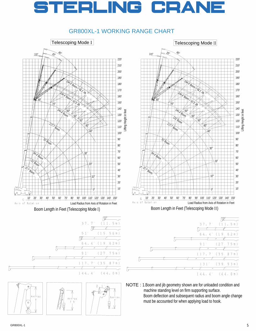
Telescoping Mode II
GR800XL-1 WORKING RANGE CHART
NOTE : 1.Boom and jib geometry shown are for unloaded condition and machine standing level on firm supporting surface. Boom deflection and subsequent radius and boom angle change must be accounted for when applying load to hook.
Telescoping Mode I
Liftin
g Heig
ht in
feet
150'
45o117.7' Boom
50o
70o
144.4' Boom + 58.1' Jib144.4' Boom + 32.5' Jib144.4' Boom
220'
210'
200'
190'
131' Boom
91' Boom
80o
37.7' Boom
64.4' Boom20o
160'
150'
10'
20'
30'
40'
50'
60'
70'
80'
90'
100'
110'
180'
120'
130'
140'
40o
10o
130'10' 20' 30' 40' 50' 60' 70' 80' 140'90' 100' 110' 120'
170'
30o
60o
55o
0o
25 o3.5o 45 o
Load Radius from Axis of Rotation in Feet
Boom Length in Feet (Telescoping Mode II)
50o
70o
144.4' Boom + 58.1' Jib144.4' Boom + 32.5' Jib144.4' Boom
220'
210'
200'
190'
117.7' Boom
91' Boom
80o
37.7' Boom
64.4' Boom
20o
160'
150'
10'
20'
30'
40'
50'
60'
70'
80'
90'
100'
110'
180'
120'
130'
140'
40o
10o
130'10' 20' 30' 40' 50' 60' 70' 80' 140'90' 100' 110' 120'
170'
30o
60o
55o
51' Boom
0o
45o
150'
25 o3.5o45 o
Boom Length in Feet (Telescoping Mode I)Load Radius from Axis of Rotation in Feet
5GR800XL-1
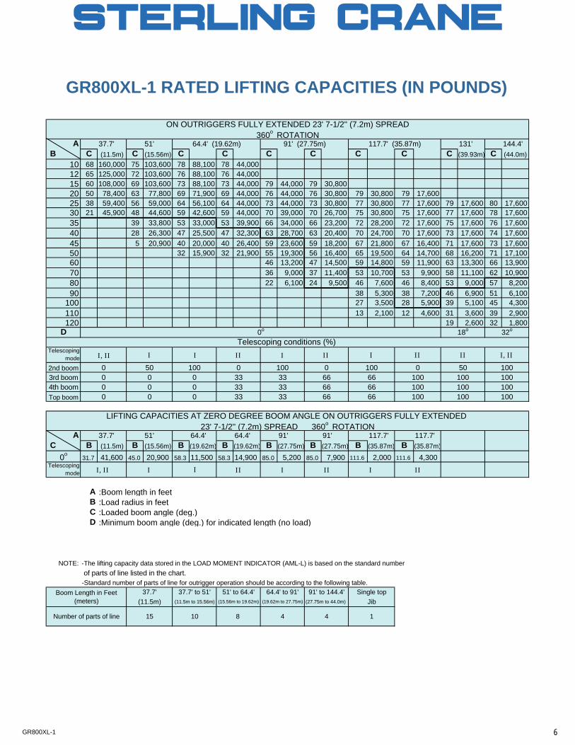
GR800XL-1 RATED LIFTING CAPACITIES (IN POUNDS)
A 37.7' 51' 131' 144.4' B C (11.5m) C (15.56m) C C C C C C C (39.93m) C (44.0m)
10 68 160,000 75 103,600 78 88,100 78 44,00012 65 125,000 72 103,600 76 88,100 76 44,00015 60 108,000 69 103,600 73 88,100 73 44,000 79 44,000 79 30,80020 50 78,400 63 77,800 69 71,900 69 44,000 76 44,000 76 30,800 79 30,800 79 17,60025 38 59,400 56 59,000 64 56,100 64 44,000 73 44,000 73 30,800 77 30,800 77 17,600 79 17,600 80 17,60030 21 45,900 48 44,600 59 42,600 59 44,000 70 39,000 70 26,700 75 30,800 75 17,600 77 17,600 78 17,60035 39 33,800 53 33,000 53 39,900 66 34,000 66 23,200 72 28,200 72 17,600 75 17,600 76 17,60040 28 26,300 47 25,500 47 32,300 63 28,700 63 20,400 70 24,700 70 17,600 73 17,600 74 17,60045 5 20,900 40 20,000 40 26,400 59 23,600 59 18,200 67 21,800 67 16,400 71 17,600 73 17,60050 32 15,900 32 21,900 55 19,300 56 16,400 65 19,500 64 14,700 68 16,200 71 17,10060 46 13,200 47 14,500 59 14,800 59 11,900 63 13,300 66 13,90070 36 9,000 37 11,400 53 10,700 53 9,900 58 11,100 62 10,90080 22 6,100 24 9,500 46 7,600 46 8,400 53 9,000 57 8,20090 38 5,300 38 7,200 46 6,900 51 6,100
100 27 3,500 28 5,900 39 5,100 45 4,300110 13 2,100 12 4,600 31 3,600 39 2,900120 19 2,600 32 1,800
D
Telescopingmode
2nd boom3rd boom4th boomTop boom
A 37.7' 51' 64.4' 64.4' 91' 91' 117.7' 117.7' C B (11.5m) B (15.56m) B (19.62m) B (19.62m) B (27.75m) B (27.75m) B (35.87m) B (35.87m)
0o31.7 41,600 45.0 20,900 58.3 11,500 58.3 14,900 85.0 5,200 85.0 7,900 111.6 2,000 111.6 4,300
Telescopingmode
A :Boom length in feetB :Load radius in feetC :Loaded boom angle (deg.)D :Minimum boom angle (deg.) for indicated length (no load)
NOTE: -The lifting capacity data stored in the LOAD MOMENT INDICATOR (AML-L) is based on the standard number of parts of line listed in the chart.-Standard number of parts of line for outrigger operation should be according to the following table.
ON OUTRIGGERS FULLY EXTENDED 23' 7-1/2'' (7.2m) SPREAD360o ROTATION
64.4' (19.62m) 91' (27.75m) 117.7' (35.87m)
0000
0o 18o
Telescoping conditions (%)I, II
32o
I I, III I
000
100
0
50
00
100
I
100333333
0
3333
4 4 1
LIFTING CAPACITIES AT ZERO DEGREE BOOM ANGLE ON OUTRIGGERS FULLY EXTENDED 23' 7-1/2'' (7.2m) SPREAD 360o ROTATION
II, II I
Jib
II
33
Number of parts of line 15 10 8
(11.5m to 15.56m) (15.56m to 19.62m)
100100
0100100100
50
(19.62m to 27.75m) (27.75m to 44.0m)
II10010010066
66 1000 100
66
II II II
666666
I
Boom Length in Feet(meters)
37.7' 37.7' to 51' 51' to 64.4' 64.4' to 91' 91' to 144.4' Single top(11.5m)
II
I
II
6GR800XL-1
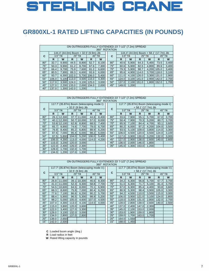
GR800XL-1 RATED LIFTING CAPACITIES (IN POUNDS)
R W R W R W R W R W R W80o 32.7 9,900 44.5 8,800 52.7 8,100 80o 40.6 5,900 64.3 5,400 73.5 3,40075o 50.3 9,900 61.2 8,700 67.6 7,300 75o 60.6 5,900 82.5 4,800 89.9 3,40070o 66.4 9,700 75.9 7,600 81.2 6,600 70o 79.3 5,900 98.7 4,200 105.0 3,40065o 80.5 7,900 89.3 6,600 93.9 6,000 65o 95.6 4,900 114.0 3,700 118.0 3,10060o 93.7 6,300 102.0 5,700 106.0 5,400 60o 111.0 4,100 126.0 3,300 131.0 2,90055o 106.0 5,100 113.0 4,500 116.0 4,300 55o 124.0 3,100 141.0 2,900 142.0 2,70050o 117.0 3,500 124.0 3,100 125.0 3,000 50o 137.0 2,100 151.0 1,800 152.0 1,70045o 127.0 2,200 133.0 2,000 134.0 2,000 45o 149.0 1,20040o 137.0 1,300 142.0 1,200
R W R W R W R W R W R W80o 26.1 12,300 37.7 11,000 44.8 8,400 80o 33.6 7,900 55.1 5,700 67.0 3,70075o 40.1 12,300 50.7 10,000 57.0 8,000 75o 50.4 7,900 70.3 5,200 80.7 3,70070o 53.6 12,100 62.9 8,800 68.5 7,400 70o 65.9 7,100 84.4 4,700 93.1 3,60065o 65.7 9,900 74.6 7,700 79.0 6,700 65o 80.2 6,000 97.2 4,200 104.0 3,50060o 76.9 8,400 85.2 6,800 88.9 6,200 60o 93.5 5,100 109.0 3,800 114.0 3,30055o 87.6 7,000 95.4 6,000 98.2 6,000 55o 106.0 4,500 120.0 3,500 124.0 3,10050o 97.5 5,800 104.0 5,200 106.0 5,400 50o 117.0 3,900 130.0 3,200 132.0 3,00045o 106.0 4,300 113.0 4,000 114.0 4,200 45o 127.0 2,900 138.0 2,600 140.0 2,60040o 115.0 3,200 120.0 3,000 40o 136.0 2,000 146.0 1,80035o 122.0 2,400 126.0 2,300 35o 145.0 1,300 153.0 1,20030o 128.0 1,700 132.0 1,70025o 134.0 1,200 137.0 1,200
R W R W R W R W R W R W80o 26.8 11,000 39.1 10,300 46.6 8,300 80o 34.2 6,300 56.8 5,700 67.7 3,70075o 41.0 11,000 52.3 9,300 58.8 7,700 75o 51.0 6,300 71.7 5,100 81.4 3,70070o 54.5 10,600 64.5 8,000 70.1 6,900 70o 67.0 6,300 85.4 4,400 93.8 3,60065o 66.3 8,600 75.9 7,000 80.4 6,200 65o 80.9 5,300 98.4 3,900 105.0 3,30060o 77.6 7,100 86.6 6,200 90.2 5,700 60o 94.2 4,500 110.0 3,500 115.0 3,00055o 88.4 5,900 96.5 5,300 98.9 5,200 55o 106.0 3,900 121.0 3,100 124.0 2,80050o 98.2 5,000 105.0 4,600 107.0 4,500 50o 118.0 3,300 131.0 2,800 132.0 2,70045o 107.0 4,300 113.0 4,100 114.0 4,000 45o 128.0 2,800 139.0 2,600 140.0 2,50040o 115.0 3,800 120.0 3,600 40o 137.0 2,400 147.0 2,30035o 122.0 3,400 127.0 3,300 35o 145.0 2,100 153.0 2,00030o 129.0 3,100 132.0 3,000 30o 153.0 1,900 159.0 1,80025o 134.0 2,800 137.0 2,800 25o 159.0 1,700 163.0 1,70020o 139.0 2,650 20o 164.0 1,55015o 142.0 2,500 15o 168.0 1,450
C :Loaded boom angle (deg.)R :Load radius in feetW :Rated lifting capacity in pounds
C
ON OUTRIGGERS FULLY EXTENDED 23' 7-1/2'' (7.2m) SPREAD360o ROTATION
ON OUTRIGGERS FULLY EXTENDED 23' 7-1/2'' (7.2m) SPREAD360o ROTATION
25o Tilt 45o Tilt
117.7' (35.87m) Boom (telescoping mode II)+ 32.5' (9.9m) Jib
117.7' (35.87m) Boom (telescoping mode II)+ 58.1' (17.7m) Jib
3.5o Tilt 45o TiltC
3.5o Tilt 25o Tilt 45o Tilt 3.5o Tilt
25o Tilt 45o Tilt 3.5o Tilt 25o Tilt
C
ON OUTRIGGERS FULLY EXTENDED 23' 7-1/2'' (7.2m) SPREAD360o ROTATION
C
3.5o Tilt 25o Tilt 45o Tilt
C
117.7' (35.87m) Boom (telescoping mode I)+ 32.5' (9.9m) Jib
117.7' (35.87m) Boom (telescoping mode I)+ 58.1' (17.7m) Jib
144.4' (44.0m) Boom + 58.1' (17.7m) Jib144.4' (44.0m) Boom + 32.5' (9.9m) Jib3.5o Tilt 25o Tilt 45o Tilt C
7GR800XL-1
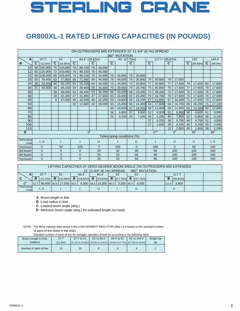
GR800XL-1 RATED LIFTING CAPACITIES (IN POUNDS)
A 37.7' 51' 131' 144.4' B C (11.5m) C (15.56m) C C C C C C C (39.93m) C (44.0m)
10 68 160,000 75 103,600 78 88,100 78 44,00012 65 125,000 72 103,600 76 88,100 76 44,00015 60 108,000 69 103,600 73 88,100 73 44,000 79 44,000 79 30,80020 50 78,400 63 77,800 69 71,900 69 44,000 76 44,000 76 30,800 79 30,800 79 17,60025 38 59,400 56 56,100 64 55,200 64 44,000 73 44,000 73 30,800 77 30,800 77 17,600 79 17,600 80 17,60030 21 40,300 48 39,200 59 38,400 59 44,000 70 39,000 70 26,700 75 30,800 75 17,600 77 17,600 78 17,60035 39 29,000 53 28,200 53 35,200 66 32,000 66 23,200 72 28,200 72 17,600 75 17,600 76 17,60040 28 22,200 47 21,400 47 27,600 63 24,900 63 20,400 70 24,700 70 17,600 73 17,600 74 17,60045 5 17,000 40 16,500 40 22,200 59 19,800 59 18,200 67 21,800 67 16,400 71 17,600 73 17,60050 32 12,800 32 18,000 55 15,900 56 16,400 64 17,800 64 14,700 68 16,200 71 17,10060 46 10,500 47 14,500 59 11,900 59 11,900 63 13,300 66 12,80070 36 6,800 37 9,900 52 8,000 53 9,900 58 9,600 61 8,90080 22 4,200 24 7,100 45 5,200 46 7,800 52 6,800 56 6,10090 37 3,200 38 5,700 46 4,700 51 4,000
100 27 1,600 28 4,100 39 3,100 45 2,400110 13 2,800 30 1,900 39 1,200
D
Telescopingmode
2nd boom3rd boom4th boomTop boom
A 37.7' 51' 64.4' 64.4' 91' 91' 117.7' C B (11.5m) B (15.56m) B (19.62m) B (19.62m) B (27.75m) B (27.75m) B (35.87m)
0o 31.7 36,400 45.0 17,000 58.3 9,000 58.3 14,300 85.0 3,200 85.0 6,000 111.6 2,500Telescoping
mode
A :Boom length in feetB :Load radius in feetC :Loaded boom angle (deg.)D :Minimum boom angle (deg.) for indicated length (no load)
NOTE: -The lifting capacity data stored in the LOAD MOMENT INDICATOR (AML-L) is based on the standard number of parts of line listed in the chart.-Standard number of parts of line for outrigger operation should be according to the following table.
II, II I I II
I, III II II II
100100
100
50100100100
0100
100100
66
100666666
0
666633
3333
0
3333
33
00
0
100
0
000
00
30o
Telescoping conditions (%)I, II0
39o27o 0o
II100 100
LIFTING CAPACITIES AT ZERO DEGREE BOOM ANGLE ON OUTRIGGERS MID EXTENDED 21' 11-3/4'' (6.7m) SPREAD 360o ROTATION
ON OUTRIGGERS MID EXTENDED 21' 11-3/4'' (6.7m) SPREAD360o ROTATION
64.4' (19.62m) 91' (27.75m) 117.7' (35.87m)
I50
0o
Boom Length in Feet(meters)
37.7' 37.7' to 51' 51' to 64.4' 64.4' to 91' 91' to 144.4' Single top(11.5m) (11.5m to 15.56m) (15.56m to 19.62m) (19.62m to 27.75m) (27.75m to 44.0m) Jib
4 4 1Number of parts of line 15 10 8
I I
II II
8GR800XL-1
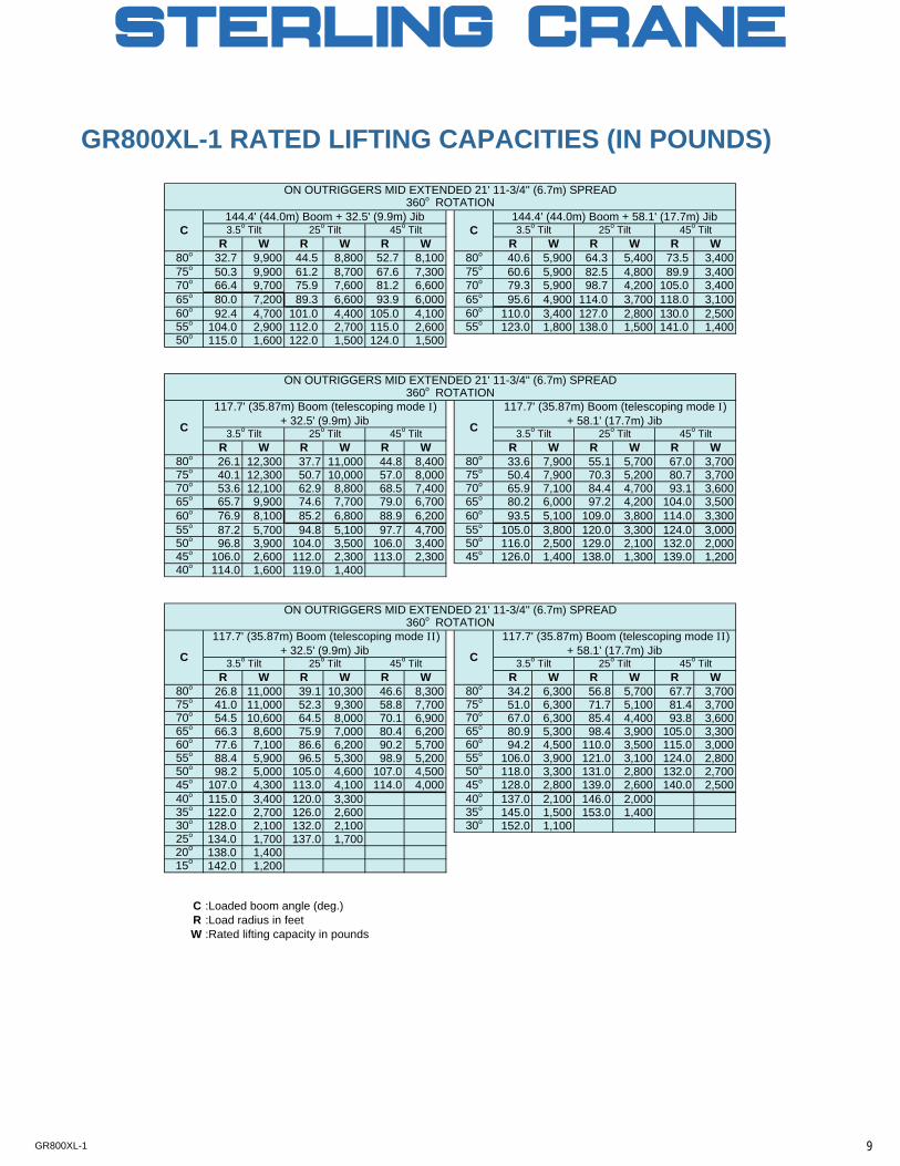
R W R W R W R W R W R W80o 32.7 9,900 44.5 8,800 52.7 8,100 80o 40.6 5,900 64.3 5,400 73.5 3,40075o 50.3 9,900 61.2 8,700 67.6 7,300 75o 60.6 5,900 82.5 4,800 89.9 3,40070o 66.4 9,700 75.9 7,600 81.2 6,600 70o 79.3 5,900 98.7 4,200 105.0 3,40065o 80.0 7,200 89.3 6,600 93.9 6,000 65o 95.6 4,900 114.0 3,700 118.0 3,10060o 92.4 4,700 101.0 4,400 105.0 4,100 60o 110.0 3,400 127.0 2,800 130.0 2,50055o 104.0 2,900 112.0 2,700 115.0 2,600 55o 123.0 1,800 138.0 1,500 141.0 1,40050o 115.0 1,600 122.0 1,500 124.0 1,500
R W R W R W R W R W R W80o 26.1 12,300 37.7 11,000 44.8 8,400 80o 33.6 7,900 55.1 5,700 67.0 3,70075o 40.1 12,300 50.7 10,000 57.0 8,000 75o 50.4 7,900 70.3 5,200 80.7 3,70070o 53.6 12,100 62.9 8,800 68.5 7,400 70o 65.9 7,100 84.4 4,700 93.1 3,60065o 65.7 9,900 74.6 7,700 79.0 6,700 65o 80.2 6,000 97.2 4,200 104.0 3,50060o 76.9 8,100 85.2 6,800 88.9 6,200 60o 93.5 5,100 109.0 3,800 114.0 3,30055o 87.2 5,700 94.8 5,100 97.7 4,700 55o 105.0 3,800 120.0 3,300 124.0 3,00050o 96.8 3,900 104.0 3,500 106.0 3,400 50o 116.0 2,500 129.0 2,100 132.0 2,00045o 106.0 2,600 112.0 2,300 113.0 2,300 45o 126.0 1,400 138.0 1,300 139.0 1,20040o 114.0 1,600 119.0 1,400
R W R W R W R W R W R W80o 26.8 11,000 39.1 10,300 46.6 8,300 80o 34.2 6,300 56.8 5,700 67.7 3,70075o 41.0 11,000 52.3 9,300 58.8 7,700 75o 51.0 6,300 71.7 5,100 81.4 3,70070o 54.5 10,600 64.5 8,000 70.1 6,900 70o 67.0 6,300 85.4 4,400 93.8 3,60065o 66.3 8,600 75.9 7,000 80.4 6,200 65o 80.9 5,300 98.4 3,900 105.0 3,30060o 77.6 7,100 86.6 6,200 90.2 5,700 60o 94.2 4,500 110.0 3,500 115.0 3,00055o 88.4 5,900 96.5 5,300 98.9 5,200 55o 106.0 3,900 121.0 3,100 124.0 2,80050o 98.2 5,000 105.0 4,600 107.0 4,500 50o 118.0 3,300 131.0 2,800 132.0 2,70045o 107.0 4,300 113.0 4,100 114.0 4,000 45o 128.0 2,800 139.0 2,600 140.0 2,50040o 115.0 3,400 120.0 3,300 40o 137.0 2,100 146.0 2,00035o 122.0 2,700 126.0 2,600 35o 145.0 1,500 153.0 1,40030o 128.0 2,100 132.0 2,100 30o 152.0 1,10025o 134.0 1,700 137.0 1,70020o 138.0 1,40015o 142.0 1,200
C :Loaded boom angle (deg.)R :Load radius in feetW :Rated lifting capacity in pounds
GR800XL-1 RATED LIFTING CAPACITIES (IN POUNDS)
144.4' (44.0m) Boom + 58.1' (17.7m) Jib144.4' (44.0m) Boom + 32.5' (9.9m) Jib3.5o Tilt 25o Tilt 45o Tilt CC
ON OUTRIGGERS MID EXTENDED 21' 11-3/4'' (6.7m) SPREAD360o ROTATION
C
3.5o Tilt 25o Tilt 45o Tilt
C
117.7' (35.87m) Boom (telescoping mode I)+ 32.5' (9.9m) Jib
117.7' (35.87m) Boom (telescoping mode I)+ 58.1' (17.7m) Jib
45o TiltC
3.5o Tilt 25o Tilt 45o Tilt 3.5o Tilt
25o Tilt 45o Tilt 3.5o Tilt 25o TiltC
ON OUTRIGGERS MID EXTENDED 21' 11-3/4'' (6.7m) SPREAD360o ROTATION
ON OUTRIGGERS MID EXTENDED 21' 11-3/4'' (6.7m) SPREAD360o ROTATION
25o Tilt 45o Tilt
117.7' (35.87m) Boom (telescoping mode II)+ 32.5' (9.9m) Jib
117.7' (35.87m) Boom (telescoping mode II)+ 58.1' (17.7m) Jib
3.5o Tilt
9GR800XL-1
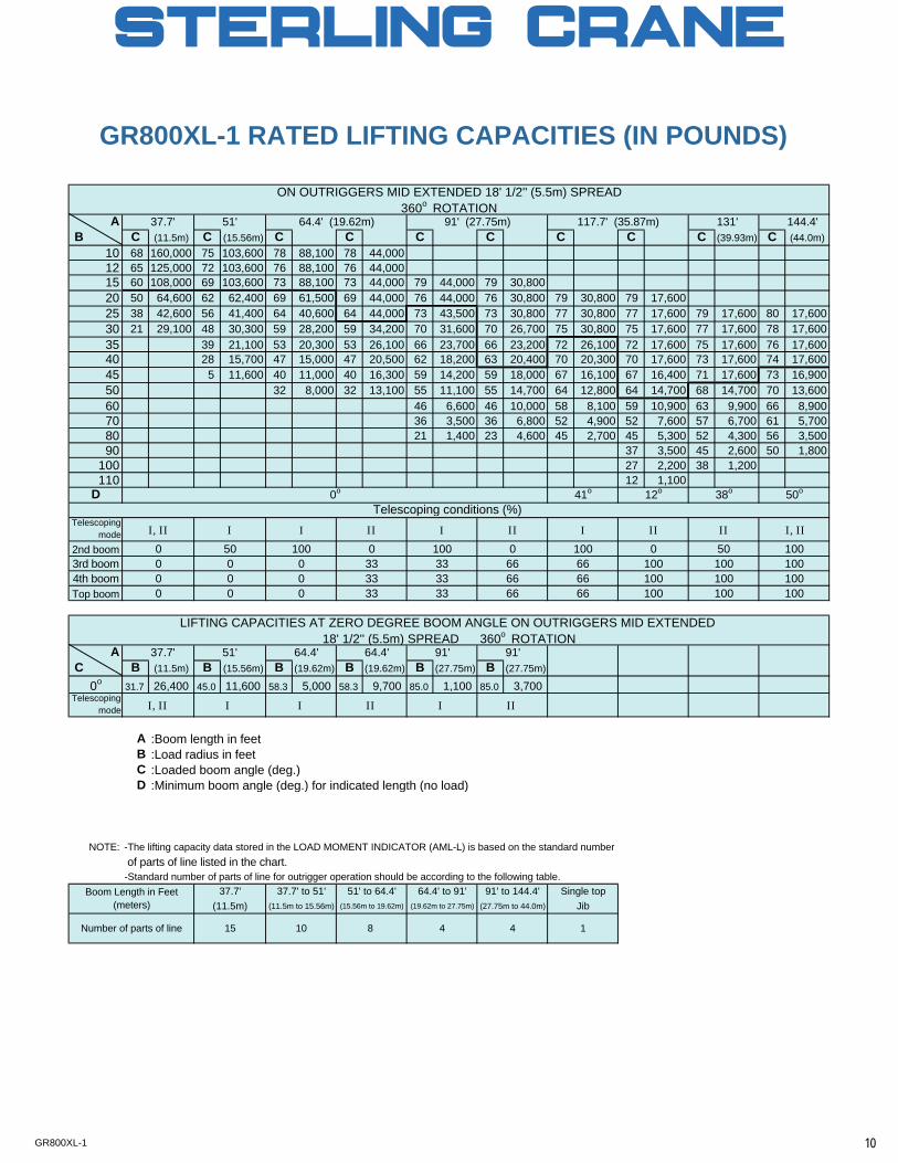
GR800XL-1 RATED LIFTING CAPACITIES (IN POUNDS)
A 37.7' 51' 131' 144.4' B C (11.5m) C (15.56m) C C C C C C C (39.93m) C (44.0m)
10 68 160,000 75 103,600 78 88,100 78 44,00012 65 125,000 72 103,600 76 88,100 76 44,00015 60 108,000 69 103,600 73 88,100 73 44,000 79 44,000 79 30,80020 50 64,600 62 62,400 69 61,500 69 44,000 76 44,000 76 30,800 79 30,800 79 17,60025 38 42,600 56 41,400 64 40,600 64 44,000 73 43,500 73 30,800 77 30,800 77 17,600 79 17,600 80 17,60030 21 29,100 48 30,300 59 28,200 59 34,200 70 31,600 70 26,700 75 30,800 75 17,600 77 17,600 78 17,60035 39 21,100 53 20,300 53 26,100 66 23,700 66 23,200 72 26,100 72 17,600 75 17,600 76 17,60040 28 15,700 47 15,000 47 20,500 62 18,200 63 20,400 70 20,300 70 17,600 73 17,600 74 17,60045 5 11,600 40 11,000 40 16,300 59 14,200 59 18,000 67 16,100 67 16,400 71 17,600 73 16,90050 32 8,000 32 13,100 55 11,100 55 14,700 64 12,800 64 14,700 68 14,700 70 13,60060 46 6,600 46 10,000 58 8,100 59 10,900 63 9,900 66 8,90070 36 3,500 36 6,800 52 4,900 52 7,600 57 6,700 61 5,70080 21 1,400 23 4,600 45 2,700 45 5,300 52 4,300 56 3,50090 37 3,500 45 2,600 50 1,800
100 27 2,200 38 1,200110 12 1,100
D
Telescopingmode
2nd boom3rd boom4th boomTop boom
A 37.7' 51' 64.4' 64.4' 91' 91' C B (11.5m) B (15.56m) B (19.62m) B (19.62m) B (27.75m) B (27.75m)
0o 31.7 26,400 45.0 11,600 58.3 5,000 58.3 9,700 85.0 1,100 85.0 3,700Telescoping
mode
A :Boom length in feetB :Load radius in feetC :Loaded boom angle (deg.)D :Minimum boom angle (deg.) for indicated length (no load)
NOTE: -The lifting capacity data stored in the LOAD MOMENT INDICATOR (AML-L) is based on the standard number of parts of line listed in the chart.-Standard number of parts of line for outrigger operation should be according to the following table.
LIFTING CAPACITIES AT ZERO DEGREE BOOM ANGLE ON OUTRIGGERS MID EXTENDED 18' 1/2'' (5.5m) SPREAD 360o ROTATION
ON OUTRIGGERS MID EXTENDED 18' 1/2'' (5.5m) SPREAD360o ROTATION
64.4' (19.62m) 91' (27.75m) 117.7' (35.87m)
I50
0o 38o
Telescoping conditions (%)I, II
0
50o41o 12o
II100 100
000
00
00
0
100
0
333333
0
3333
33100
66
100666666
0
6666 100
100100
50100100100
0100
100
I, IIII II II
I, II I I II I II
Boom Length in Feet(meters)
37.7' 37.7' to 51' 51' to 64.4' 64.4' to 91' 91' to 144.4' Single top(11.5m) (11.5m to 15.56m) (15.56m to 19.62m) (19.62m to 27.75m) (27.75m to 44.0m) Jib
4 4 1Number of parts of line 15 10 8
I I I
10GR800XL-1
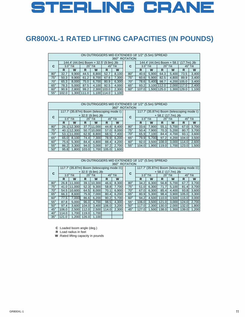
R W R W R W R W R W R W80o 32.7 9,900 44.5 8,800 52.7 8,100 80o 40.6 5,900 64.3 5,400 73.5 3,40075o 50.3 9,900 61.2 8,700 67.6 7,300 75o 60.6 5,900 82.5 4,800 89.9 3,40070o 65.3 8,000 75.0 6,700 80.9 6,300 70o 78.6 5,400 98.7 4,200 105.0 3,40065o 78.3 5,000 87.5 4,100 92.5 4,000 65o 93.2 3,100 112.0 2,000 117.0 2,40060o 90.9 2,800 99.2 2,300 103.0 2,300 60o 107.0 1,500 125.0 1,300 129.0 1,10055o 102.0 1,300 111.0 1,100 114.0 1,100
R W R W R W R W R W R W80o 26.1 12,300 37.7 11,000 44.8 8,400 80o 33.6 7,900 55.1 5,700 67.0 3,70075o 40.1 12,300 50.7 10,000 57.0 8,000 75o 50.4 7,900 70.3 5,200 80.7 3,70070o 53.1 11,000 62.9 8,800 68.5 7,400 70o 65.9 7,100 84.4 4,700 93.1 3,60065o 65.0 8,100 74.4 7,300 78.9 6,200 65o 79.9 5,700 97.2 4,200 104.0 3,50060o 75.6 5,300 84.4 4,800 88.4 4,200 60o 92.0 3,500 108.0 3,000 114.0 2,60055o 86.2 3,300 94.0 3,000 97.2 2,700 55o 104.0 1,900 119.0 1,700 123.0 1,50050o 95.8 1,800 103.0 1,700 105.0 1,600
R W R W R W R W R W R W80o 26.8 11,000 39.1 10,300 46.6 8,300 80o 34.2 6,300 56.8 5,700 67.7 3,70075o 41.0 11,000 52.3 9,300 58.8 7,700 75o 51.0 6,300 71.7 5,100 81.4 3,70070o 54.5 10,600 64.5 8,000 70.1 6,900 70o 67.0 6,300 85.4 4,400 93.8 3,60065o 66.3 8,600 75.9 7,000 80.4 6,200 65o 80.9 5,300 98.4 3,900 105.0 3,30060o 77.5 7,000 86.6 6,200 90.2 5,700 60o 94.2 4,500 110.0 3,500 115.0 3,00055o 87.8 5,000 96.0 4,700 98.5 4,300 55o 106.0 3,500 121.0 3,000 124.0 2,70050o 97.4 3,600 104.0 3,400 106.0 3,200 50o 117.0 2,300 130.0 2,000 132.0 1,80045o 106.0 2,500 112.0 2,500 114.0 2,300 45o 127.0 1,500 138.0 1,300 139.0 1,20040o 114.0 1,700 119.0 1,70035o 121.0 1,200 126.0 1,100
C :Loaded boom angle (deg.)R :Load radius in feetW :Rated lifting capacity in pounds
GR800XL-1 RATED LIFTING CAPACITIES (IN POUNDS)
C
ON OUTRIGGERS MID EXTENDED 18' 1/2'' (5.5m) SPREAD360o ROTATION
ON OUTRIGGERS MID EXTENDED 18' 1/2'' (5.5m) SPREAD360o ROTATION
25o Tilt 45o Tilt
117.7' (35.87m) Boom (telescoping mode II)+ 32.5' (9.9m) Jib
117.7' (35.87m) Boom (telescoping mode II)+ 58.1' (17.7m) Jib
3.5o Tilt 45o TiltC
3.5o Tilt 25o Tilt 45o Tilt 3.5o Tilt
25o Tilt 45o Tilt 3.5o Tilt 25o Tilt
C
ON OUTRIGGERS MID EXTENDED 18' 1/2'' (5.5m) SPREAD360o ROTATION
C
3.5o Tilt 25o Tilt 45o Tilt
C
117.7' (35.87m) Boom (telescoping mode I)+ 32.5' (9.9m) Jib
117.7' (35.87m) Boom (telescoping mode I)+ 58.1' (17.7m) Jib
144.4' (44.0m) Boom + 58.1' (17.7m) Jib144.4' (44.0m) Boom + 32.5' (9.9m) Jib3.5o Tilt 25o Tilt 45o Tilt C
11GR800XL-1
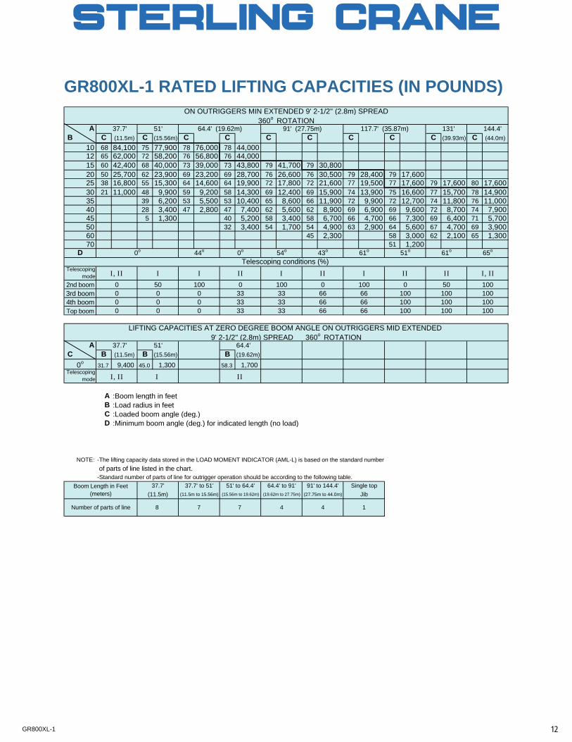
GR800XL-1 RATED LIFTING CAPACITIES (IN POUNDS)
A 37.7' 51' 131' 144.4' B C (11.5m) C (15.56m) C C C C C C C (39.93m) C (44.0m)
10 68 84,100 75 77,900 78 76,000 78 44,00012 65 62,000 72 58,200 76 56,800 76 44,00015 60 42,400 68 40,000 73 39,000 73 43,800 79 41,700 79 30,80020 50 25,700 62 23,900 69 23,200 69 28,700 76 26,600 76 30,500 79 28,400 79 17,60025 38 16,800 55 15,300 64 14,600 64 19,900 72 17,800 72 21,600 77 19,500 77 17,600 79 17,600 80 17,60030 21 11,000 48 9,900 59 9,200 58 14,300 69 12,400 69 15,900 74 13,900 75 16,600 77 15,700 78 14,90035 39 6,200 53 5,500 53 10,400 65 8,600 66 11,900 72 9,900 72 12,700 74 11,800 76 11,00040 28 3,400 47 2,800 47 7,400 62 5,600 62 8,900 69 6,900 69 9,600 72 8,700 74 7,90045 5 1,300 40 5,200 58 3,400 58 6,700 66 4,700 66 7,300 69 6,400 71 5,70050 32 3,400 54 1,700 54 4,900 63 2,900 64 5,600 67 4,700 69 3,90060 45 2,300 58 3,000 62 2,100 65 1,30070 51 1,200
D
Telescopingmode
2nd boom3rd boom4th boomTop boom
A 37.7' 51' 64.4' C B (11.5m) B (15.56m) B (19.62m)
0o 31.7 9,400 45.0 1,300 58.3 1,700Telescoping
mode
A :Boom length in feetB :Load radius in feetC :Loaded boom angle (deg.)D :Minimum boom angle (deg.) for indicated length (no load)
NOTE: -The lifting capacity data stored in the LOAD MOMENT INDICATOR (AML-L) is based on the standard number of parts of line listed in the chart.-Standard number of parts of line for outrigger operation should be according to the following table.
100100
100
50100100100
0100
10066
100666666
0
6666
3333
100
100000
000
100100
0 33
00
333333
0
ON OUTRIGGERS MIN EXTENDED 9' 2-1/2'' (2.8m) SPREAD360o ROTATION
64.4' (19.62m) 91' (27.75m) 117.7' (35.87m)
0o 0o 54o
LIFTING CAPACITIES AT ZERO DEGREE BOOM ANGLE ON OUTRIGGERS MID EXTENDED
50
61o
Telescoping conditions (%)
0
43o44o
9' 2-1/2'' (2.8m) SPREAD 360o ROTATION
65o61o 51o
Boom Length in Feet(meters)
37.7' 37.7' to 51' 51' to 64.4' 64.4' to 91' 91' to 144.4' Single top(11.5m) (11.5m to 15.56m) (15.56m to 19.62m) (19.62m to 27.75m) (27.75m to 44.0m) Jib
4 4 1Number of parts of line 8 7 7
I, II I I II I II I II II I, II
I, II I II
12GR800XL-1
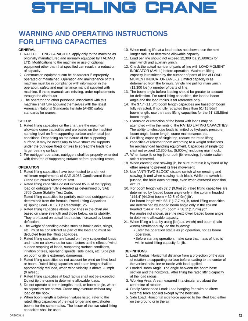
WARNING AND OPERATING INSTRUCTIONSFOR LIFTING CAPACITIESGENERAL 10. When making lifts at a load radius not shown, use the next1. RATED LIFTING CAPACITIES apply only to the machine as longer radius to determine allowable capacity.
originally manufactured and normally equipped by TADANO 11. Load per line should not exceed 12,300 lbs. (5,600kg) forLTD. Modifications to the machine or use of optional main winch and auxiliary winch.equipment other than that specified can result in a reduction 12. Check the actual number of parts of line with LOAD MOMENTof capacity. INDICATOR (AML-L) before operation. Maximum lifting
2. Construction equipment can be hazardous if improperly capacity is restricted by the number of parts of line of LOADoperated or maintained. Operation and maintenance of this MOMENT INDICATOR (AML-L). Limited capacity is asmachine must be in compliance with information in the determined from the formula, Single line pull for main winchoperation, safety and maintenance manual supplied with (12,300 lbs.) x number of parts of line.machine. If these manuals are missing, order replacements 13. The boom angle before loading should be greater to accountthrough the distributor. for deflection. For rated lifting capacities, the loaded boom
3. The operator and other personnel associated with this angle and the load radius is for reference only.machine shall fully acquaint themselves with the latest 14. The 37.7' (11.5m) boom length capacities are based on boomAmerican National Standards Institute (ANSI) safety fully retracted. If not fully retracted [less than 51'(15.56m)standards for cranes. boom length, use the rated lifting capacities for the 51' (15.56m)
boom length.SET UP 15. Extension or retraction of the boom with loads may be1. Rated lifting capacities on the chart are the maximum attempted within the limits of the RATED LIFTING CAPACITIES.
allowable crane capacities and are based on the machine The ability to telescope loads is limited by hydraulic pressure,standing level on firm supporting surface under ideal job boom angle, boom length, crane maintenance, etc.conditions. Depending on the nature of the supporting 16. For lifting capacity of single top, reduce the rated liftingsurface, it may be necessary to have structural supports capacities of relevant boom according to a weight reductionsunder the outrigger floats or tires to spread the loads to a for auxiliary load handling equipment. Capacities of single top larger bearing surface. shall not exceed 12,300 lbs. (5,600kg) including main hook.
2. For outrigger operation, outriggers shall be properly extended 17. When base jib or top jib or both jib removing, jib state switchwith tires free of supporting surface before operating crane. select removed.
18. When erecting and stowing jib, be sure to retain it by hand or byOPERATION other means to prevent its free movement.1. Rated lifting capacities have been tested to and meet 19. Use "ANTI-TWO BLOCK" disable switch when erecting and
minimum requirements of SAE J1063-Cantilevered Boom stowing jib and when stowing hook block. While the switch isCrane Structures Method of Test. pushed, the hoist does not stop, even when overwind condition
2. Rated lifting capacities do not exceed 85 % of the tipping occurs.load on outriggers fully extended as determined by SAE 20. For boom length with 32.5' (9.9m) jib, rated lifting capacities areJ765-Crane Stability Test Code. determined by loaded boom angle only in the column headedRated lifting capacities for partially extended outriggers are "144.4' (44.0m) boom + 32.5' (9.9m) jib". determined from the formula, Rated Lifting Capacities For boom length with 58.1' (17.7 m) jib, rated lifting capacities=(Tipping Load - 0.1 x Tip Reaction)/1.25. are determined by loaded boom angle only in the column
3. Rated lifting capacities above bold lines in the chart are headed "144.4' (44.0m) boom + 58.1' (17.7m) jib". based on crane strength and those below, on its stability. For angles not shown, use the next lower loaded boom angleThey are based on actual load radius increased by boom to determine allowable capacity. deflection. 21. When lifting a load by using jib (aux. winch) and boom (main
4. The weight of handling device such as hook blocks, slings, winch) simultaneously, do the following:etc., must be considered as part of the load and must be Enter the operation status as jib operation, not as boomdeducted from the lifting capacities. operation.
5. Rated lifting capacities are based on freely suspended loads Before starting operation, make sure that mass of load isand make no allowance for such factors as the effect of wind, within rated lifting capacity for jib.sudden stopping of loads, supporting surface conditions,inflation of tires, operating speeds, side loads, etc. Side pull DEFINITIONSon boom or jib is extremely dangerous. 1. Load Radius: Horizontal distance from a projection of the axis
6. Rated lifting capacities do not account for wind on lifted load of rotation to supporting surface before loading to the center ofor boom. Rated lifting capacities and boom length shall be the vertical hoist line or tackle with load applied.appropriately reduced, when wind velocity is above 20 mph 2. Loaded Boom Angle: The angle between the boom base(9 m/sec.). section and the horizontal, after lifting the rated lifting capacity
7. Rated lifting capacities at load radius shall not be exceeded. at the load radius.Do not tip the crane to determine allowable loads. 3. Working Area: Area measured in a circular arc about the
8. Do not operate at boom lengths, radii, or boom angle, where centerline of rotation.no capacities are shown. Crane may overturn without any 4. Freely Suspended Load: Load hanging free with no directload on the hook. external force applied except by the hoist line.
9. When boom length is between values listed, refer to the 5. Side Load: Horizontal side force applied to the lifted load eitherrated lifting capacities of the next longer and next shorter on the ground or in the air.booms for the same radius. The lesser of the two rated liftingcapacities shall be used.
13GR800XL-1
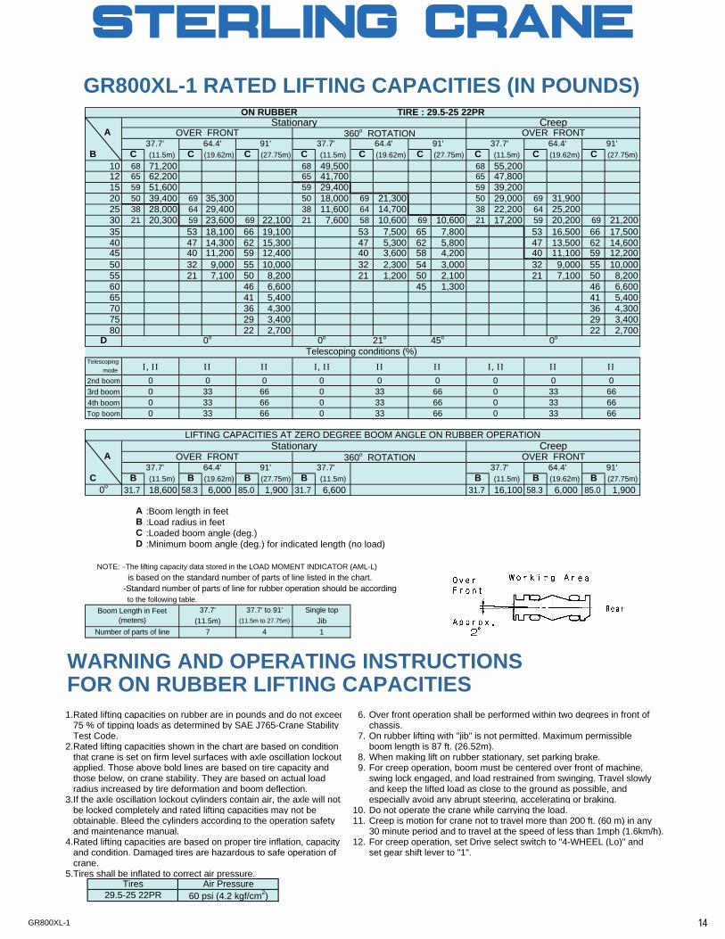
GR800XL-1 RATED LIFTING CAPACITIES (IN POUNDS)
A37.7' 64.4' 91' 37.7' 64.4' 91' 37.7' 64.4' 91'
B C (11.5m) C (19.62m) C (27.75m) C (11.5m) C (19.62m) C (27.75m) C (11.5m) C (19.62m) C (27.75m)10 68 71,200 68 49,500 68 55,20012 65 62,200 65 41,700 65 47,80015 59 51,600 59 29,400 59 39,20020 50 39,400 69 35,300 50 18,000 69 21,300 50 29,000 69 31,90025 38 28,000 64 29,400 38 11,600 64 14,700 38 22,200 64 25,20030 21 20,300 59 23,600 69 22,100 21 7,600 58 10,600 69 10,600 21 17,200 59 20,200 69 21,20035 53 18,100 66 19,100 53 7,500 65 7,800 53 16,500 66 17,50040 47 14,300 62 15,300 47 5,300 62 5,800 47 13,500 62 14,60045 40 11,200 59 12,400 40 3,600 58 4,200 40 11,100 59 12,20050 32 9,000 55 10,000 32 2,300 54 3,000 32 9,000 55 10,00055 21 7,100 50 8,200 21 1,200 50 2,100 21 7,100 50 8,20060 46 6,600 45 1,300 46 6,60065 41 5,400 41 5,40070 36 4,300 36 4,30075 29 3,400 29 3,40080 22 2,700 22 2,700
D
Telescoping mode
2nd boom3rd boom4th boomTop boom
A37.7' 64.4' 91' 37.7' 37.7' 64.4' 91'
C B (11.5m) B (19.62m) B (27.75m) B (11.5m) B (11.5m) B (19.62m) B (27.75m)0o 31.7 18,600 58.3 6,000 85.0 1,900 31.7 6,600 31.7 16,100 58.3 6,000 85.0 1,900
A :Boom length in feetB :Load radius in feetC :Loaded boom angle (deg.)D :Minimum boom angle (deg.) for indicated length (no load)
NOTE: -The lifting capacity data stored in the LOAD MOMENT INDICATOR (AML-L) is based on the standard number of parts of line listed in the chart.-Standard number of parts of line for rubber operation should be according to the following table.
ON RUBBER TIRE : 29.5-25 22PRStationary Creep
0o 21o 45o 0o
OVER FRONT 360o ROTATION OVER FRONT
OVER FRONT 360o ROTATION OVER FRONT
LIFTING CAPACITIES AT ZERO DEGREE BOOM ANGLE ON RUBBER OPERATION
0o
Stationary Creep
0 0 00 00 33 66 0 33 66 0 33 660 33 66 0
6633 66 0 33
0
660 33 66 0 33 66 0 33
37.7' to 91'
Telescoping conditions (%)
0 0 0
Single topJib1Number of parts of line 7 4
(11.5m) (11.5m to 27.75m)Boom Length in Feet
(meters)37.7'
WARNING AND OPERATING INSTRUCTIONSFOR ON RUBBER LIFTING CAPACITIES1.Rated lifting capacities on rubber are in pounds and do not exceed 6. Over front operation shall be performed within two degrees in front of 75 % of tipping loads as determined by SAE J765-Crane Stability chassis. Test Code. 7. On rubber lifting with "jib" is not permitted. Maximum permissible2.Rated lifting capacities shown in the chart are based on condition boom length is 87 ft. (26.52m). that crane is set on firm level surfaces with axle oscillation lockout 8. When making lift on rubber stationary, set parking brake. applied. Those above bold lines are based on tire capacity and 9. For creep operation, boom must be centered over front of machine, those below, on crane stability. They are based on actual load swing lock engaged, and load restrained from swinging. Travel slowly radius increased by tire deformation and boom deflection. and keep the lifted load as close to the ground as possible, and3.If the axle oscillation lockout cylinders contain air, the axle will not especially avoid any abrupt steering, accelerating or braking. be locked completely and rated lifting capacities may not be 10. Do not operate the crane while carrying the load. obtainable. Bleed the cylinders according to the operation safety 11. Creep is motion for crane not to travel more than 200 ft. (60 m) in any and maintenance manual. 30 minute period and to travel at the speed of less than 1mph (1.6km/h).4.Rated lifting capacities are based on proper tire inflation, capacity 12. For creep operation, set Drive select switch to "4-WHEEL (Lo)" and and condition. Damaged tires are hazardous to safe operation of set gear shift lever to "1". crane.5.Tires shall be inflated to correct air pressure.
Tires29.5-25 22PR
Air Pressure60 psi (4.2 kgf/cm2)
I, II II II I, II II II I, II II II
14GR800XL-1
WARNING AND OPERATING INSTRUCTIONSFOR USING THE LOAD MOMENT INDICATOR (AML-L)1. When operating crane on outriggers: When a load is lifted in the front position and then swung
Set P.T.O. switch to "ON". to the side area, make sure the value of the LOAD Press the outrigger mode select key to register for the MOMENT INDICATOR(AML-L) is below the 360o lifting outrigger operation. Press the set key, then the outrigger capacity.mode indicative symbol changes from flickering to lighting. (2) For creep operation.Press the boom mode select key to register the boom mode, The creep capacities are attainable only when boom isthen the boom mode indicative symbol changes from in the straight forward position of chassis and the over lighting to flickering. Each time the boom mode select key is front position symbol is on. If boom is not in the straight pressed, the mode changes. Press the set key to select forward position of chassis , never lift load.the status that corresponds to the actual state of the boom, 3. A swing does not automatically stop even if the crane then the boom mode indicative symbol changes from flickering becomes overloaded.to lighting. 4. During crane operation, make sure that the displays on frontWhen erecting and stowing jib, select the status of jib set panel are in accordance with actual operating conditions.(jib state indicative symbol flicker). 5. The displayed values of LOAD MOMENT INDICATOR
2. When operating crane on rubber: (AML-L) are based on freely suspended loads and make noSet P.T.O. switch to "ON". allowance for such factors as the effect of wind, suddenPress the outrigger mode select key. The on-tire mode stopping of loads, supporting surface conditions, inflation ofindicative symbol comes on. Each time the outrigger mode tire, operating speed, side loads, etc. select key is pressed the mode changes. Select the creep For safe operation, it is recommended when extending and operation, the on-tire mode indicative symbol flicker. lowering boom or swinging, lifting loads shall be Press the boom mode select key to register the boom mode. appropriately reduced.
However, pay attention to the following. 6. LOAD MOMENT INDICATOR (AML-L) is intended as an aid(1) For stationary operation. to the operator. Under no condition should it be relied upon
The front capacities are attainable only when the over front to replace use of capacity charts and operating instruction.position symbol comes on. When the boom is more than Sole reliance upon LOAD MOMENT INDICATOR (AML-L) 2 degrees from centered over front of chassis, 360o aids in place of good operating practice can cause an capacities are in effect. accident. The operator must exercise caution to assure
safety.
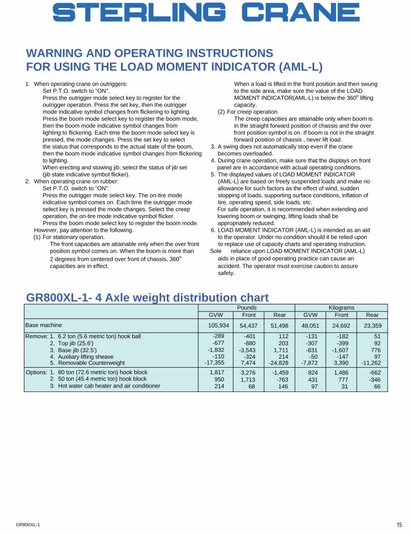
GR800XL-1- 4 Axle weight distribution chart
Base machine 54,437 51,498 48,051 24,692 23,359
Remove: 1. 6.2 ton (5.6 metric ton) hook ball -401 112 -131 -182 512. Top jib (25.6') -880 203 -307 -399 923. Base jib (32.5') -3,543 1,711 -831 -1,607 7764 . Auxiliary lifting sheave -324 214 -50 -147 97
1. 80 ton (72.6 metric ton) hook blockOptions:
3. Hot water cab heater and air conditioner 68 146 97 31 66
Pounds KilogramsGVW Front Rear GVW Front Rear
105,934
-289-677
-1,832-110
2142. 50 ton (45.4 metric ton) hook block
5 . Removable Counterweight 7,474 -24,828 -7,872 3,390 -11,262-17,355
1,713 -763 431 777 -3469503,276 -1,459 824 1,486 -6621,817
15GR800XL-1
16GR800XL-1
17GR800XL-1
Related Documents


