Tactile Navigation System Tactile Navigation System for the Blind & Visually for the Blind & Visually Impaired (VI) Impaired (VI) Presented by: Tim Giguere & Tim DeBellis Shannon Carswell & Tim Garvin

Tactile Navigation System for the Blind & Visually Impaired (VI) Presented by: Tim Giguere & Tim DeBellis Shannon Carswell & Tim Garvin.
Dec 20, 2015
Welcome message from author
This document is posted to help you gain knowledge. Please leave a comment to let me know what you think about it! Share it to your friends and learn new things together.
Transcript
Tactile Navigation System Tactile Navigation System for the Blind & Visually for the Blind & Visually
Impaired (VI)Impaired (VI)Presented by:
Tim Giguere & Tim DeBellisShannon Carswell & Tim Garvin
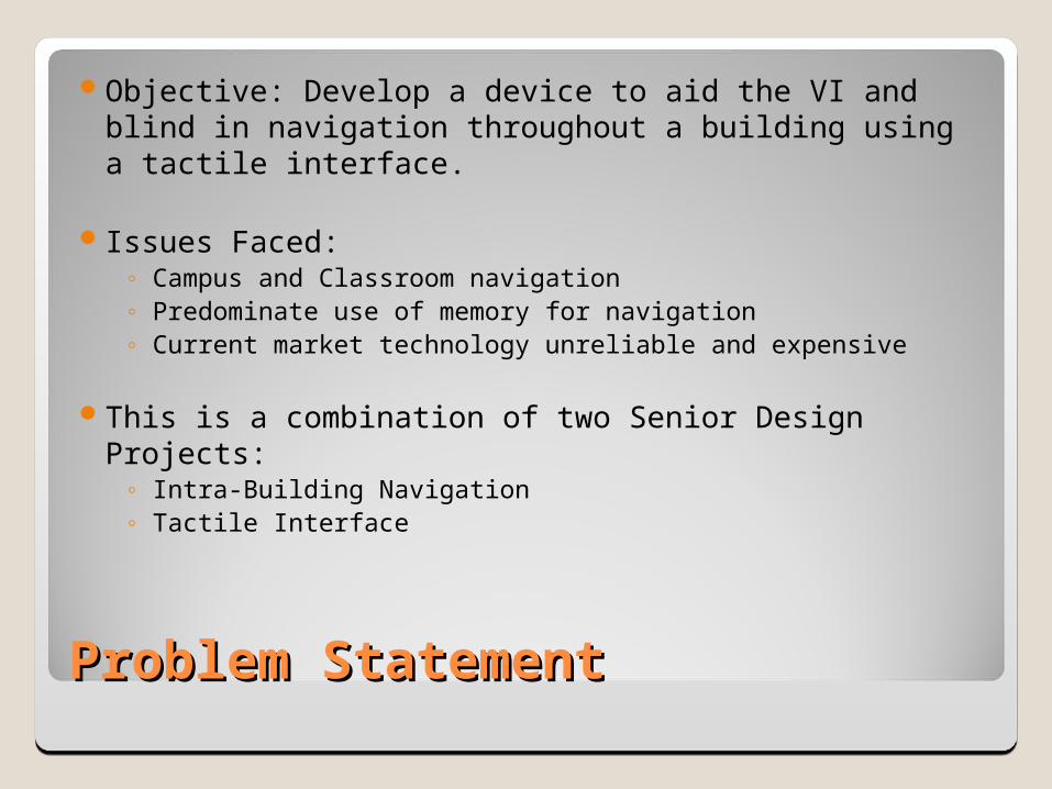
Problem StatementProblem Statement
Objective: Develop a device to aid the VI and blind in navigation throughout a building using a tactile interface.
Issues Faced:◦ Campus and Classroom navigation◦ Predominate use of memory for navigation◦ Current market technology unreliable and expensive
This is a combination of two Senior Design Projects:◦ Intra-Building Navigation ◦ Tactile Interface

Intra-Building Navigation: Functional Decomposition
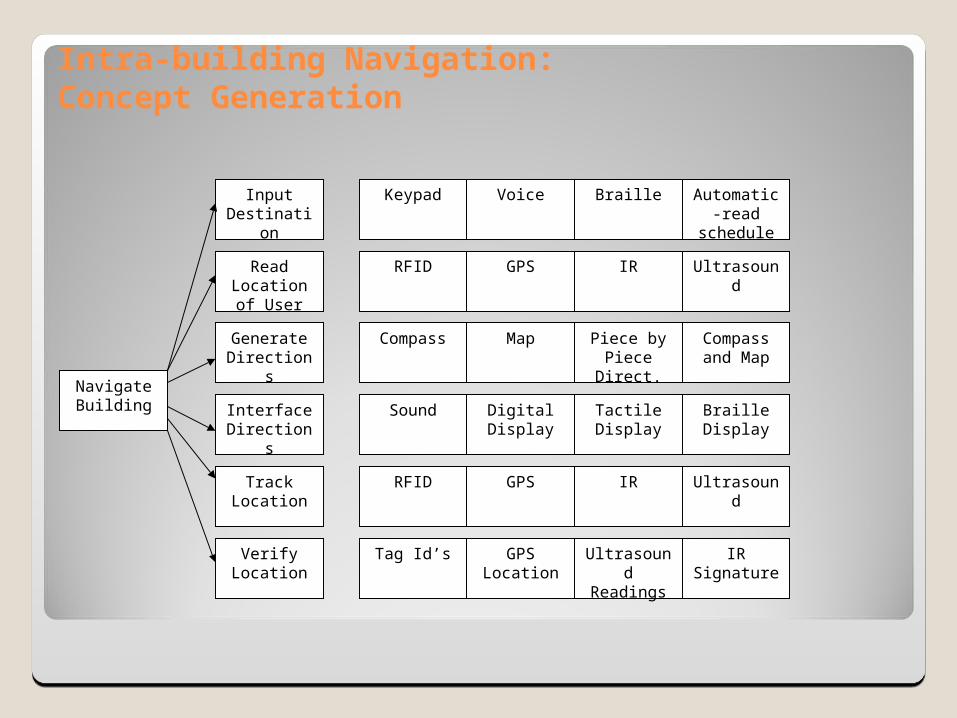
Intra-building Navigation:Concept Generation
Navigate Building Interface
Directions
Input Destination
Read Location of
User
Generate Directions
Track Location
Tag Id’s GPS Location
Verify Location
Ultrasound Readings
IR Signature
RFID GPS IR Ultrasound
Sound Digital Display
Tactile Display
Braille Display
Compass Map Piece by Piece Direct.
Compass and Map
RFID GPS IR Ultrasound
Keypad Voice Braille Automatic-read
schedule

Intra-Building Navigation: Concept SelectionStep #1 Screening
RFID IR
Web
Dog (REF)
2 RFID tags
RFID and IR
Aug. GPS
RFID and CompassSelection Criteria
Availability of parts + + + D + + - +
Distance 0 0 0 0 0 + 0
Cost of parts + + - A + + 0 +
Size + + + + + + +
Accuracy + + 0 T + + + +
Ease of Integration + + + + + + +
Cost of upkeep + + + U + + + +
Sum + 's 6.006.00 4.00 6.00 6.00 5.00 6.00
Sum 0's 1.001.00 2.00 M 1.00 1.00 1.00 1.00
Sum -'s 0 0 1 0 0 1 0
Net Score 6 6 3 6 6 4 6
Rank 1 1 3 1 1 2 1
Continue? YES YES NO DATUM YES YES NO YES

Intra-Building Navigation: Concept Selection
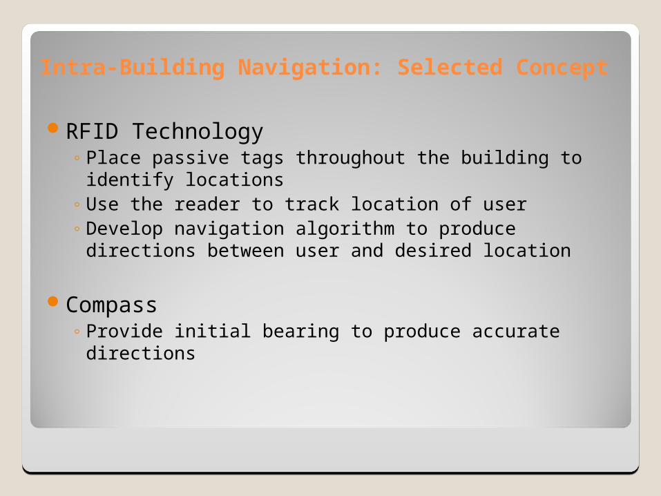
Intra-Building Navigation: Selected Concept
RFID Technology◦ Place passive tags throughout the building to identify
locations◦ Use the reader to track location of user◦ Develop navigation algorithm to produce directions
between user and desired location
Compass◦ Provide initial bearing to produce accurate directions

Intra-Building Navigation: RFID Testing and Results
Test Procedure:◦ Initial Read Range
USB Power Supply
◦ Surface◦ Height Placement◦ Engineering Specifications
Accurate Directions Repeatability
◦ Directions◦ Location Identification
Latency Mean Learning Time
Read Range for Alien 'G' Inlay with PS
0
10
20
30
40
50
600˚
15˚30˚
45˚
60˚
75˚
90˚
105˚
120˚
135˚
150˚165˚
180˚195˚210˚
225˚
240˚
255˚
270˚
285˚
300˚
315˚
330˚
345˚360˚
A50
A49
A48
Read Range for Alien "G" with USB
0
10
20
30
40
500˚
15˚30˚
45˚
60˚
75˚
90˚
105˚
120˚
135˚
150˚
165˚180˚195˚
210˚
225˚
240˚
255˚
270˚
285˚
300˚
315˚
330˚
345˚
360˚
A50
A49
A48

Intra-Building Navigation: Interface

Intra-Building Navigation: Navigation
‘Hybrid’ Algorithm◦Graph Traversal◦Area Navigation
B
A
C

Intra-Building Navigation: Navigation
‘Hybrid’ Algorithm◦Graph Traversal◦Area Navigation
B
A
C

System IntegrationSystem Integration
Develop a tactile interface that blind and VI individuals can use as a personal navigator
Device operation:◦Destination Input◦Entry to Internal Map comparison◦Directional information relay to user via tactile
meansDevice operation dependent on customer
needs.

Customer Needs Customer Needs
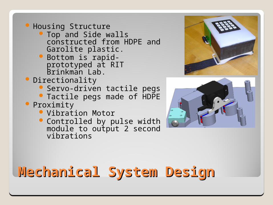
Mechanical System DesignMechanical System Design
Housing Structure Top and Side walls
constructed from HDPE and Garolite plastic.
Bottom is rapid-prototyped at RIT Brinkman Lab.
Directionality Servo-driven tactile pegs Tactile pegs made of HDPE
Proximity Vibration Motor Controlled by pulse width
module to output 2 second vibrations

Mechanical System Design Mechanical System Design AnalysisAnalysis
Stress Analysis◦ FEA models for compressive load
scenarios◦ Servo-arms tested under bending
with servo max stall torque. Fatigue Analysis
◦ Modified Goodman Criteria applied. Plastic component stresses
applied to research data for fatigue conditions
Vibration Analysis of Motor◦ Issue of human exposure levels.◦ 5 m/s^2 max for exposure time
allowed.◦ From testing, motor reaches
between 25 and 55 minutes of constant exposure

Electrical System DesignElectrical System Design
Built around an 8-bit PIC C-based microcontroller.
Motors controlled by PIC and driven by BJT network.
Keypad continuously polled in software, user entry stored in variable length string
String will eventually compared to internal map to provide directional info
6V rechargeable NiMH battery

Electrical System Design StrategyElectrical System Design Strategy
Individually test components for functionality
Prototype system using PIC development kit
Create ‘front end’ user inputs
Move design to PCB
Verify power levels
Tactile Team: Navigation Team:
Sponsors:
Advisor: Dr. Elizabeth DeBartolo
Shannon Carswell (EE)
Daniel Paris (EE)
Tim Garvin (CE)
Daniel Stanley (CE)
Christian Seemayer (EE)
Rob Proietti (ME)
William Kelly (ME)
Tim DeBellis (EE)
Tim Giguere (ME)
Related Documents