820 First Avenue South, Seattle, WA 98134, USA Tel: (800) 488-8291 / (206) 682-6048 Fax: (206) 682-5658 www.CoastalEnvironmental.com Wind Sensor Junction Box Tower Top 4 Solar Panels Case Main Case (2 Solar Panels, Lightning Sensor and Antenna) Laptop Case (Laptop, Radio and Antenna) Tower Base KamLock Connector Visibility Sensor Cloud Height Sensor (Ceilometer) Rain Gauge WEATHERPAK ® Set-Up Guide P/N: 0302-155-001, Rev. A Tactical Weather Station Set-Up Guide 1 ® This is a generic overview of a portable WEATHERPAK ® 3 meter tripod set-up. Your system may not include all of the components listed, or may have different components. Please refer to the assembly documentation provided with your system or contact Coastal for assistance.

Welcome message from author
This document is posted to help you gain knowledge. Please leave a comment to let me know what you think about it! Share it to your friends and learn new things together.
Transcript

820 First Avenue South, Seattle, WA 98134, USA Tel: (800) 488-8291 / (206) 682-6048 Fax: (206) 682-5658 www.CoastalEnvironmental.com
Wind Sensor
Junction Box
Tower Top
4 Solar Panels Case
Main Case (2 Solar Panels, Lightning Sensor and Antenna)
Laptop Case (Laptop, Radio and Antenna)
Tower Base
KamLock Connector
Visibility Sensor
Cloud Height Sensor(Ceilometer)
Rain Gauge
WEATHERPAK®
Set-Up Guide P/N: 0302-155-001, Rev. A
Tactical Weather Station Set-Up Guide 1
®
This is a generic overview of a portable WEATHERPAK® 3 meter tripod set-up. Your system may not include all of the components listed, or may have different components. Please refer to the assembly documentation provided with your system or contact Coastal for assistance.

820 First Avenue South, Seattle, WA 98134, USA Tel: (800) 488-8291 / (206) 682-6048 Fax: (206) 682-5658 www.CoastalEnvironmental.com
®
3. Carefully remove the WEATHERPAK® from its case by lifting only from the base of the wind sensor. To secure the WEATHERPAK® to the tower top, first remove the cap from the top of the KamLock connector. Line up the slot on the WEATHERPAK® bottom connector with the pin slot in the KamLock connector. Carefully, but firmly, seat the WEATHERPAK® into the KamLock (the fit is precision-machined and may require an extra push). Push the arms of the KamLock clamp down to assure proper installation.
4. Place the entire unit (upper tower section and WEATHERPAK®) onto the tripod and turn clockwise to secure.
3d3b 3c3a
WEATHERPAK® Case
Ceilometer Case
Laptop Case
Main Case4 Solar Panels Case
Tower Bag
SYSTEM CASES
Tactical Weather Station Set-Up Guide 2
Tower Set-Up
1. Select a level piece of ground about 4 meters in diameter. To avoid compass error, place the WEATHERPAK® at least 30 meters, laterally, from any mass of steel (trucks, buildings, etc). In other words, mounting on top of a van is OK, but right next to it is not an ideal location.
2. Assemble the lower tower section: Insert the three legs into the tower base and secure with a turn clockwise, forming a tripod. Place the tripod in the center of the 4-meter diameter area.
2
820 First Avenue South, Seattle, WA 98134, USA Tel: (800) 488-8291 / (206) 682-6048 Fax: (206) 682-5658 www.CoastalEnvironmental.com
5b 5c
®
6c 6d 6e
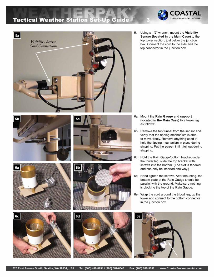
5a5. Using a 1/2” wrench, mount the Visibility
Sensor (located in the Main Case) to the top tower section, just below the junction box. Connect the cord to the side and the top connector in the junction box.
6a. Mount the Rain Gauge and support (located in the Main Case) to a tower leg as follows:
6b. Remove the top funnel from the sensor and verify that the tipping mechanism is able to move freely. Remove anything used to hold the tipping mechanism in place during shipping. Put the screen in if it fell out during shipping.
6c. Hold the Rain Gauge/bottom bracket under the tower leg; slide the top bracket with screws into the bottom. (The slot is tapered and can only be inserted one way.)
6d. Hand tighten the screws. After mounting, the bottom plate of the Rain Gauge should be parallel with the ground. Make sure nothing is blocking the top of the Rain Gauge.
6e. Wrap the cord around the tripod leg, up the tower and connect to the bottom connector in the junction box.
6a 6b
Tactical Weather Station Set-Up Guide 3
Visibility Sensor Cord Connections

820 First Avenue South, Seattle, WA 98134, USA Tel: (800) 488-8291 / (206) 682-6048 Fax: (206) 682-5658 www.CoastalEnvironmental.com
®
7e 7h
Center the lightning sensor on the top of the case lid. The white arrow on the top of the sensor should point to the back of the case. On each side attach a Velcro strap from the sensor to the case lid. Attach the sensor cord to the bottom row, far right connector on the front of the case.
Attach the “right” end bracket with the black lever.
Position the “right” end bracket (with the black lever) over the end of the rod extending from the front right of the case lid.
Push in as far as possible and swivel black lever to the right to tighten. For now, do not attach the “left” bracket.
7a 7b 7c 7d
Remove wing nuts from both screws in pole bracket with antenna mount. Line up bracket screws with pre-drilled holes in plate attached to case lid (left front). Push in.
From the inside of the case lid, replace wing nuts over both screws and hand tighten.
Repeat 7a through 7b for the other side.
Insert the antenna through the back of the antenna mount until the end of the pole is flush with the end of the mounting bracket. Make sure the antenna is vertical and hand tighten the screw.
Visibility Sensor
Lightning Sensor
Visibility/Lightning Sensor Cords
2 Solar Panels Antenna
AC Power Module
2 Pole Brackets (1 with Antenna
mount), 2 End Brackets
Rain Gauge & Mount
MAIN CASE
7f 7gLeft Right
Tactical Weather Station Set-Up Guide 4
Main Case Set-Up

820 First Avenue South, Seattle, WA 98134, USA Tel: (800) 488-8291 / (206) 682-6048 Fax: (206) 682-5658 www.CoastalEnvironmental.com
®
7k
Open up the solar panels as shown above. Lock the two panels by turning the attached screw.
Raise the 2 solar panels and line up the pins from the end bracket with the holes on the side of the solar panels. Push the solar panels until the pins are inserted into the holes as far as they go.
Repeat 7g, 7h and 7j to finish installing the other side of the solar panels. Adjust the solar panels to the proper angle for your location.*
Attach the cord from the back of the solar panels to the connector (second from right, top row) at the bottom front of the case.
7i 7j
Ceilometer
Antenna
Tower
2 Solar Panels (or AC Power Module)
4 Solar Panels Case
Lightning Sensor
MAIN CASE WIRING
7l
Tactical Weather Station Set-Up Guide 5
7m
Place the ceilometer on level ground near the main case; attach the cord to the bottom right connector on the sensor, and to the connector on the top left of the main case.
7n
Attach the tower to main case cord to the center connector of the tower’s junction box and to the main case’s lower row left connector.
*Solar Panel Tilt Angle From Horizontal
Latitude Summer Angle
Winter Angle
25° 2.3 41.130° 6.9 45.535° 11.6 49.840° 16.2 54.245° 20.9 58.650° 25.5 63.0

820 First Avenue South, Seattle, WA 98134, USA Tel: (800) 488-8291 / (206) 682-6048 Fax: (206) 682-5658 www.CoastalEnvironmental.com
®
8e 8f 8g 8hLeft Right
Attach the “left” small bracket with the black lever.
Position the “left” bracket over the end of the rod extending from the front left of the case lid.
Push in as far as possible and swivel black lever to the right.
For now, do not attach the “right” end bracket.
8a 8b 8c 8d
Remove wing nuts from both screws in bracket. Line up bracket screws with pre-drilled holes in plate attached to case lid.
Push in. From the inside of the case lid, replace wing nuts over both screws and hand tighten.
Repeat 8a through 8c for the other side.
4 Solar Panels
4 SOLAR PANELS CASE
2 Pole Brackets, 2 End Brackets
Tactical Weather Station Set-Up Guide 6
4 Solar Panels Case Set-Up
820 First Avenue South, Seattle, WA 98134, USA Tel: (800) 488-8291 / (206) 682-6048 Fax: (206) 682-5658 www.CoastalEnvironmental.com
8m 8n 8o 8p
8q 8r 8s 8t
®
8i 8j 8k 8l
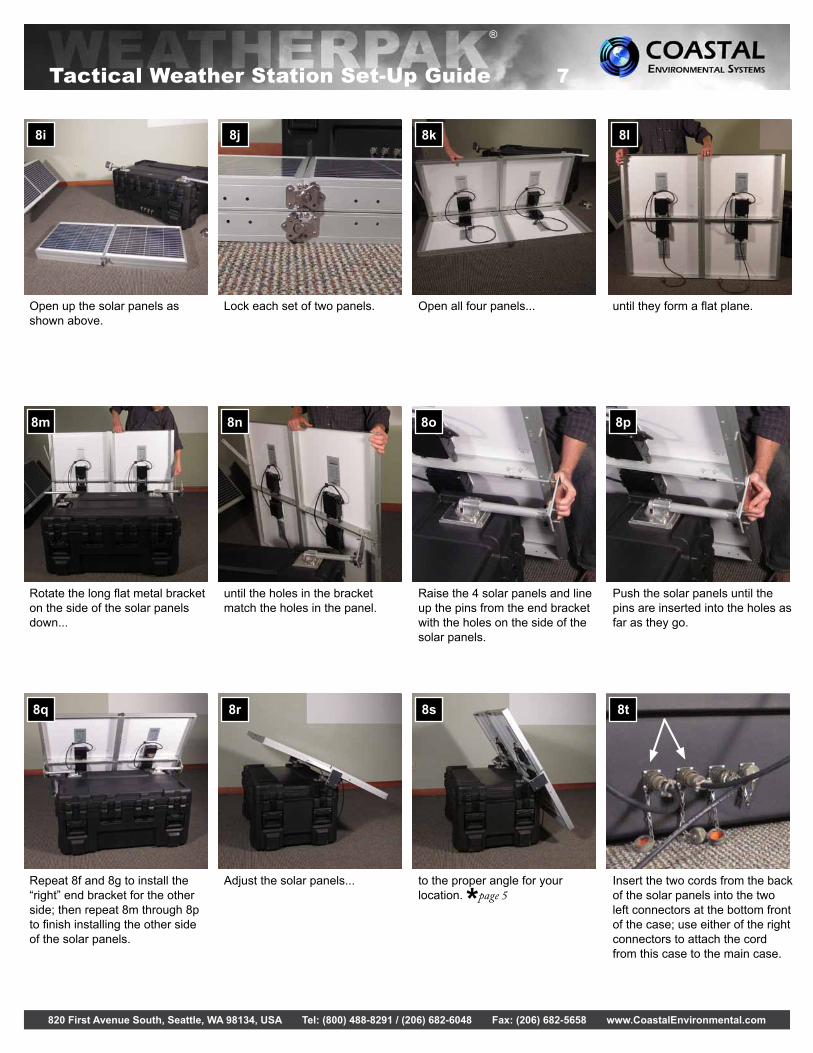
Open up the solar panels as shown above.
Lock each set of two panels. Open all four panels... until they form a flat plane.
Rotate the long flat metal bracket on the side of the solar panels down...
until the holes in the bracket match the holes in the panel.
Raise the 4 solar panels and line up the pins from the end bracket with the holes on the side of the solar panels.
Push the solar panels until the pins are inserted into the holes as far as they go.
Repeat 8f and 8g to install the “right” end bracket for the other side; then repeat 8m through 8p to finish installing the other side of the solar panels.
Adjust the solar panels... to the proper angle for your location. *page 5
Insert the two cords from the back of the solar panels into the two left connectors at the bottom front of the case; use either of the right connectors to attach the cord from this case to the main case.
Tactical Weather Station Set-Up Guide 7

820 First Avenue South, Seattle, WA 98134, USA Tel: (800) 488-8291 / (206) 682-6048 Fax: (206) 682-5658 www.CoastalEnvironmental.com
®
Tactical Weather Station Set-Up Guide 8
LAPTOP CASE
Laptop with Aviation
INTERCEPT® Software
Antenna
Iridium Radio
Laptop Case Set-Up
10. In the laptop case, the antenna is already connected to the radio. Mount the antenna so the green element points upward. Plug the laptop and radio power cords into 110-120V AC (50-60 Hz) power.
Using the AC Power Module (instead of Solar Panels)
9. Disconnect the cords from the main case to the 4 solar panels case, and to the two solar panels.
The AC power module has three connected cords. Plug one cord into the main case connector where the solar panel cord was plugged in (second from right, top row). Plug another AC power module cord into a 110-120V AC (50-60 Hz) outlet.
The AC power module also has a 110-120V AC (50-60 Hz) power cord to power the heaters on the cloud height sensor (ceilometer).
The AC power module can be used to charge the batteries in both the main case and the 4 solar panels case. Solar panels must be disconnected before the AC power module is connected. The batteries should be charged when placed into storage and every 6 months when in storage.
820 First Avenue South, Seattle, WA 98134, USA Tel: (800) 488-8291 / (206) 682-6048 Fax: (206) 682-5658 www.CoastalEnvironmental.com
®
Tactical Weather Station Set-Up Guide 9
Laptop & Software Procedures
11.1 Laptop Power on Procedure
a. Open the laptop and power it on.
b. If asked for a User Name and/or Password, the laptop was shipped with the following Windows default account used at startup:
User Name: admin
Password: Coastal1
c. (Windows 7 Users: Change Default Sleep Setting)
When running INTERCEPT® on Windows 7, the default sleep settings must be changed. If the computer is allowed to automatically sleep, INTERCEPT® stops logging data at that time.
Change Sleep Setting
a. Right click on the desktop and select Personalize.b. The Personalization page will open. On the lower right, click on Screen Saver.c. The Screen Saver Settings page opens. Click on Change Power Settings.d. The Power options page opens. On the left side, click on Change when the computer
sleeps.e. The Edit Plan settings page opens. Using the dropdown button next to put the computer to
sleep, change the option to Never.f. Click on Save Changes.
11.2 Launching INTERCEPT®
a. Double click on the desktop icon called “INTERCEPT”.
b. When prompted for a User Name and Password, use the following:
User Name: admin
Password: coastal
11.3 Changing System Settings Using Laptop
a. Close INTERCEPT®.
b. Stop the INTERCEPT® Service by double-clicking the desktop icon called “Services” (the location of Services is Start/Control Panel/System and Security/Administrative Tools/Services). When the services page opens, locate the Service called “CES INTERCEPT”. Right click on “CES INTERCEPT” and select “Stop”.
c. Double click the desktop icon labeled connect. This terminal emulator called ucon has been set up to use Com 1, 9600 bits per second, 8 data bits, No Parity, 1 Stop bit, No Flow Control.
d. Modem power should be on. Type ATDT00xxxxxxxxxxxx followed by the ENTER key, where xxxxxxxxxxxx is the telephone number of the remote system. Please refer to each remote system’s laptop label for the telephone number.
e. Wait for "CONNECT" to appear.
f. The terminal window will open and data may be seen scrolling on the screen. Type cmd.
g. Wait for the prompt “1>” to appear.
h. To set the barometer elevation, type setcfg NV.BE xxxx where xxxx is the elevation in feet followed by the ENTER key twice.
i. To set the field elevation, type setcfg NV.FE xxxx where xxxx is the elevation in feet followed by the ENTER key twice.

820 First Avenue South, Seattle, WA 98134, USA Tel: (800) 488-8291 / (206) 682-6048 Fax: (206) 682-5658 www.CoastalEnvironmental.com
®
Tactical Weather Station Set-Up Guide 10
j. To set the magnetic declination/deviation of the system location, type setcfg NV.MAGDEV xxxx where xxxx is the declination/deviation in whole degrees followed by the ENTER key twice.
k. After settings have been changed. Type restart followed by ENTER key twice.
l. Type +++, wait for "OK", then type ATH0 followed by the ENTER key. The modem should respond with "OK" once the call has been terminated, if not, cycle power to modem.
m. Start the INTERCEPT® Service by double-clicking the desktop icon called “Services” (the location of Services is Start/Control Panel/System and Security/Administrative Tools/Services). When the services page opens, locate the Service called “CES INTERCEPT”. Right click on “CES INTERCEPT” and select “Start”.
11.4 Changing System Time Using Laptop
a. Close INTERCEPT®.
b. Stop the INTERCEPT® Service by double-clicking the desktop icon called “Services” (the location of Services is Start/Control Panel/System and Security/Administrative Tools/Services). When the services page opens, locate the Service called “CES INTERCEPT”. Right click on “CES INTERCEPT” and select “Stop”.
c. Double click the desktop icon labeled connect. This terminal emulator called ucon has been set up to use Com 1, 9600 bits per second, 8 data bits, No Parity, 1 Stop bit, No Flow Control.
d. Modem power should be on. Type ATDT00xxxxxxxxxxxx followed by the ENTER key, where xxxxxxxxxxxx is the telephone number of the remote system.
e. Wait for "CONNECT" to appear.
f. The terminal window will open and data may be seen scrolling on the screen. Type cmd.
g. Wait for the prompt “1>” to appear.
h. Type setdate followed by the ENTER key twice. You will see this:
> setdate YYYY/MM/DD hh:mm:ss
"YYYY/MM/DD hh:mm:ss" will be filled with the current system time (ie. 2012/12/11 18:09:12). Use the back space key to edit the time displayed with the time you wish to set, then press the ENTER key twice.
i. Type q followed by the ENTER key twice.
j. Type +++, wait for "OK", then type ATH0 followed by ENTER key. The modem should respond with "OK" once the call has been terminated, if not, cycle power to modem.
k. Start the INTERCEPT® Service by double-clicking the desktop icon called “Services” (the location of Services is Start/Control Panel/System and Security/Administrative Tools/Services). When the services page opens, locate the Service called “CES INTERCEPT”. Right click on “CES INTERCEPT” and select “Start”.
Related Documents