Tactical Communications Using the IEEE 802.11 MAC Protocol John A. Stine Gustavo de Veciana Department of Electrical and Computer Engineering, The University of Texas at Austin, Austin, TX 78712 ABSTMCT This paper proposes a trafic management protocol built upon the 802.11 IU4C that is designed to provide the multiple qualities of service particular to tact~cal communications. Together, the protocols allow for the integration of voice and data trafic giving priority to voice without preempting data. Additional features allow for more efficient collection and dissemination of position information. The most attractive feature, however, is that the protocols allow mobile stations to conserve power, using one third to one j?fth the power used otherwise. The paper presents a study that seeks the design parameters, both at the physical and protocol level, for a network to support a company sized unit. In so doing we present a design methodology and validate the performance of the network using a simulation that is absolutely faithful to the protocol operation. We conduct a sensitivity analysis to explore the efects of the design parameters on network performance. 1. Introduction Over the past five years the Army has been attempting to develop a tactical wireless uetwork that connects computers throughout a maneuvering combat force. From the time of its conception there has been an urgency to demonstrate a working implementation. As a result, the network was conceived and designed around existing equipment. But the Army’s tactical radio, the Single Channel Ground Airborne Radio System (SINCGARS), was designed primarily for a single type use, i.e. single channel voice or data. The effort to combine digital and voice traffic using these radios forces the structure of the network to match that required for a pure voice network. On the surface this appears reasonable but voice and data traffic scale in different ways and this structure results in unnecessary overhead, excess complexity and an inefficient use of bandwidth. Multiplexing multiple voice nets onto a single digital channel offers solutions to these problems but up until just recently there have not been any commercial protocols for controlling medium access and for managing traffic. This paper proposes a traffic management protocol built upon the IEEE 802.11 Medium Access Control (MAC) protocol that is designed to support tactical communications over this type of digital channel. Besides solving many of the problems listed above, the combination also offers an astounding reduction in power consumption. The paper fwst expounds upon the limitations of using single voice channel radios to form a network in order to motivate the use of multiple voice net digital channels for tactical communications. It then provides a brief description of the 802.11 MAC and the proposed traffic management protocol. Finally, it presents the design and simulation of a single channel digital network to support a maneuver company using these protocols. The description of the simulation provides details of the traffic model and explains how various parameters of the protocols affect the performance of the network. The simulation demonstrates that a digital channel with a bandwidth that supports 110 kbps of traffic will easily support the demands of the company network and that using a simple power saving feature in the protocol will save the average end user more than 70% of the power that is consumed without this feature. 2. Traffic on Tactical Networks Figure 1 illustrates the traditional voice netsl at a company and below. Net A is the company command voice net and nets B through E are platoon nets. The bandwidth of each channel is just enough to support a simplex voice transmission. Users who want to transmit on the net wait until it is clear of voice transmissions and then transmit using push-to-talk access. In nets where the channel supports both voice and data transmission, voice users preempt data communications. Stations 6, 11, 16, and 21 are on two nets and have a radio for each. They serve as the gateway between the platoon and company command nets. In this network structure voice transmissions are confined to the channel on which they are broadcast but data may be routed to any other member of the n etwn-k. ----- (Y)Y \ w \/ Figure 1. Station Association Among Voice Nets The logical structure of the vctice nets would remain the same regardless of technology since they mirror the lines of command and control. Data transmissions, however, require broader dissemination. There are three different types of data transmissions: 1) Position information that is disseminated to all users. Individual stations automatically report their positions. These reports are collated for each channel and are then rebroadcast both up and down the network hierarchy; 2) Small data transmissions indicative of specially designed short reports used by military units. Their dissemination is report dependent and may be either broadcast or routed up and down the network hierarchy; 3) Larger data transmissions that are indicative of orders, larger text messages or map overlays. Again, their dissemination is tile dependent. Voice and data traffic patterns in these networks are correlated. During periods of intense activity both the demand for voice access and the quantity of diita transmissions increase. Voice, however, has a real time access requirement so it preempts data transmission. During voice transmissions, data will queue regardless of priority. The use of single voice net channels for building a wireless network results in three distinct disadvantages. First, since the channels are optimized to carry voice traffic the channels may not be sufficient to carty the data traffic. Second, since voice nets are hierarchical, data messages must be repeated 1 In this article, we use the words “net” and “network” to distinguish between the multicast groups for voice traffic and the grouping of all stations as a whole for both data and voice services. 0-7803-4902-4/98/$10.00 (c) 1998 IEEE

Welcome message from author
This document is posted to help you gain knowledge. Please leave a comment to let me know what you think about it! Share it to your friends and learn new things together.
Transcript
Tactical Communications Using the IEEE 802.11 MAC Protocol
John A. Stine
Gustavo de Veciana
Department of Electrical and Computer Engineering,
The University of Texas at Austin, Austin, TX 78712
ABSTMCT
This paper proposes a trafic management protocol built uponthe 802.11 IU4C that is designed to provide the multiplequalities of service particular to tact~cal communications.Together, the protocols allow for the integration of voice anddata trafic giving priority to voice without preempting data.Additional features allow for more efficient collection anddissemination of position information. The most attractivefeature, however, is that the protocols allow mobile stations toconserve power, using one third to one j?fth the power usedotherwise. The paper presents a study that seeks the designparameters, both at the physical and protocol level, for anetwork to support a company sized unit. In so doing we presenta design methodology and validate the performance of thenetwork using a simulation that is absolutely faithful to theprotocol operation. We conduct a sensitivity analysis to explorethe efects of the design parameters on network performance.
1. Introduction
Over the past five years the Army has been attemptingto develop a tactical wireless uetwork that connects computersthroughout a maneuvering combat force. From the time of itsconception there has been an urgency to demonstrate a workingimplementation. As a result, the network was conceived anddesigned around existing equipment. But the Army’s tacticalradio, the Single Channel Ground Airborne Radio System(SINCGARS), was designed primarily for a single type use, i.e.single channel voice or data. The effort to combine digital andvoice traffic using these radios forces the structure of thenetwork to match that required for a pure voice network. On thesurface this appears reasonable but voice and data traffic scale indifferent ways and this structure results in unnecessary overhead,excess complexity and an inefficient use of bandwidth.Multiplexing multiple voice nets onto a single digital channeloffers solutions to these problems but up until just recently therehave not been any commercial protocols for controlling mediumaccess and for managing traffic. This paper proposes a trafficmanagement protocol built upon the IEEE 802.11 MediumAccess Control (MAC) protocol that is designed to supporttactical communications over this type of digital channel.Besides solving many of the problems listed above, thecombination also offers an astounding reduction in powerconsumption.
The paper fwst expounds upon the limitations of usingsingle voice channel radios to form a network in order tomotivate the use of multiple voice net digital channels fortactical communications. It then provides a brief description ofthe 802.11 MAC and the proposed traffic management protocol.Finally, it presents the design and simulation of a single channeldigital network to support a maneuver company using theseprotocols. The description of the simulation provides details ofthe traffic model and explains how various parameters of theprotocols affect the performance of the network. The simulationdemonstrates that a digital channel with a bandwidth thatsupports 110 kbps of traffic will easily support the demands ofthe company network and that using a simple power savingfeature in the protocol will save the average end user more than70% of the power that is consumed without this feature.
2. Traffic on Tactical Networks
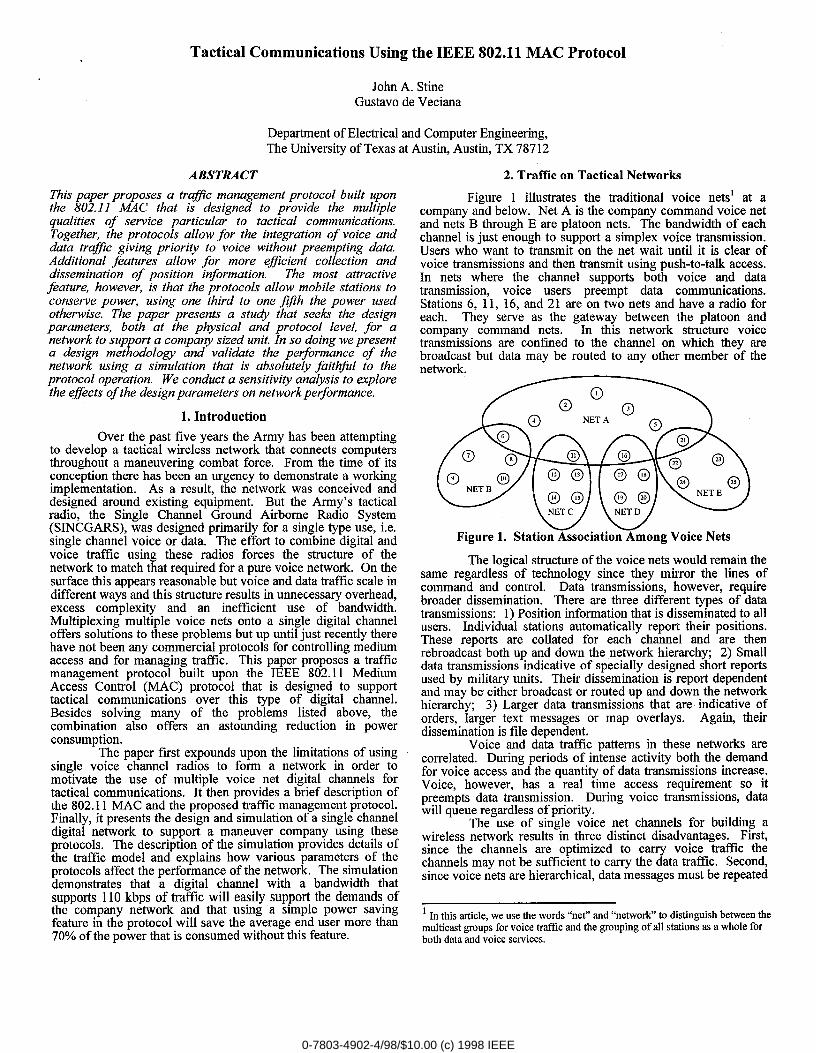
Figure 1 illustrates the traditional voice netsl at acompany and below. Net A is the company command voice netand nets B through E are platoon nets. The bandwidth of eachchannel is just enough to support a simplex voice transmission.Users who want to transmit on the net wait until it is clear ofvoice transmissions and then transmit using push-to-talk access.In nets where the channel supports both voice and datatransmission, voice users preempt data communications.Stations 6, 11, 16, and 21 are on two nets and have a radio foreach. They serve as the gateway between the platoon andcompany command nets. In this network structure voicetransmissions are confined to the channel on which they arebroadcast but data may be routed to any other member of then etwn-k.-----
(Y)Y\
w \/Figure 1. Station Association Among Voice Nets
The logical structure of the vctice nets would remain thesame regardless of technology since they mirror the lines ofcommand and control. Data transmissions, however, requirebroader dissemination. There are three different types of datatransmissions: 1) Position information that is disseminated to allusers. Individual stations automatically report their positions.These reports are collated for each channel and are thenrebroadcast both up and down the network hierarchy; 2) Smalldata transmissions indicative of specially designed short reportsused by military units. Their dissemination is report dependentand may be either broadcast or routed up and down the networkhierarchy; 3) Larger data transmissions that are indicative oforders, larger text messages or map overlays. Again, theirdissemination is tile dependent.
Voice and data traffic patterns in these networks arecorrelated. During periods of intense activity both the demandfor voice access and the quantity of diita transmissions increase.Voice, however, has a real time access requirement so itpreempts data transmission. During voice transmissions, datawill queue regardless of priority.
The use of single voice net channels for building awireless network results in three distinct disadvantages. First,since the channels are optimized to carry voice traffic thechannels may not be sufficient to carty the data traffic. Second,since voice nets are hierarchical, data messages must be repeated
1 In this article, we use the words “net” and “network” to distinguish between themulticast groups for voice traffic and the grouping of all stations as a whole forboth data and voice services.
0-7803-4902-4/98/$10.00 (c) 1998 IEEE
across many layers. Third, on account of the hierarchicalstructure of the network, the network itself becomes lessflexible. There is greater overhead associated with maintainingrouting tables and changing the topology is difficult. Topologychanges are necessary in military networks in order to supporttask organizing.
3. The 802.11 MAC
The 802.11 standard defines a generic MAC protocolfor wireless networking. This MAC protocol has two controlfimctions, a distributed coordination function (DCF) and a pointcoordination fimction (PCF). The difference between the two isthat in the DCF stations compete for access to the channel in aspecified contention process while in the PCF a single stationcalled the point coordinator (PC) manages station access.802.11 compliant networks may employ just the DCF or acombination of the PCF and the DCF. Achieving multiple QOSrequires that both control fimctions be used. The standard isvery explicit on the operation of the DCF. By contrast, it definesthe mechanism by which PC controls traffic but leaves trafficmanagement up to the implementer. When operating bothfunctions, the DCF and PCF alternate. The PCF always startson a defined period but the actual duration of the PCF and DCFmay vary. The period of time the DCF is operating is called thecontention period (CP) implying the stations in the net cancontend for access and the period of time the PCF is operating iscalled the contention flee period (CFP) implying the stationscannot contend for access.
3.1 Distributed Coordination Function. The DCF defines theprocedures by which all stations serviced by a single radiochannel can gain access to that channel to send data. It isdistributed in that the control is completely self contained at thestation attempting to send traffic. The DCF uses a carrier sensemultiple access - collision avoidance (CSMA-CA) schemewhere stations contend and gain access through a handshakeprocess after a random exponential backoff. A stationcontending for access listens for silence and then waits a randombackoff time before attempting to gain control of the medium. Ifno other station requests access before the backoff expires, thenthe contending station may attempt to gain access through one oftwo modes. In the fist, the station sends a request to send (RTS)t%nne. The receiving station upon hearing this request respondswith a clear to send (CTS) tlame. And finally, if there have beenno collisions, the sending station sends its data. In the second, ifthe data to be transmitted is sufficiently small, the station willattempt to send the data immediately. If successfidly received,the receiving station responds with an acknowledgement.
The key collision avoidance feature is a networkallocation vector (NAV) that is included in each RTS, CTS, data,and acknowledgment (ACK) frame. This vector predicts thelength of time until the stations complete the current transaction.Since both the sending and receiving stations transmit the NAV,all stations within listening range of either of these two stationswill know how long the medium will remain busy. Each stationin the net maintains a separate NAV timer which it updates uponhearing a transmission. This NAV timer serves as a mechanismto indicate to the station that the channel is busy even when itcannot monitor the transmissions of one of the parties in thecurrent data exchange.
3.2 Point Coordination Function. The PCF is a centralizedcontrol mechanism where a single station, the PC, controls allthe traffic on the network. The CSMA/CA mechanism of theDCF remains active during the PCF, but the PC is able to gaincontrol of the medium by transmitting prior to any ordinarystation in the network. This is accomplished using differentinterfi-ame spaces which will be described in greater detail later.At the start of the CFP, the PC transmits a NAV that extends
until the projected end of the CFP. So all stations who hear theNAV will not attempt to contend during the CFP. Once the PChas control, it then uses polling to manage transmissions of otherstations or it transmits data itself. The polls either direct stationsto send queued traffic or are used by the PC to gain informationfrom the polled station. The CFP will last until the PCbroadcasts an end of CFP message. At this time, monitoringstations will reset their internal NAV.
3.3 Power Saving Mechanism. In a network with both theDCF and PCF, beacons are transmitted by the PC to achieveproper synchronization. The beacon ccmsists of a timestamp anda traffic indication map (TIM), a bitmap indicating whichstations have traffic to be received. This beacon is transmitted ata regular interval but may be delayedl if a data transmission isongoing when it becomes due. The beacons are used in theimplementation of the power save features for the mobilestations. A significant amount of power can be saved if thereceiver is turned off when not needed. A mobile station with“limited traffic” that does not wa]nt to participate in thecontention period may enter the power save mode by notifyingthe point coordination station. A mob[le station operating in thepower save mode turns off its receiver and on a periodic basiswakes up to see if it has any traffic. If traffic is queued, itcontinues to listen , otherwise it returns to a sleep mode. Theperiod after which a source is requiredl to wake-up is referred toas the Delivery Traffic Indication Map (DTIM) period and isdefined as some integer number of beacons. The beacon that isbroadcast at this time is referred to as a DTIM. Upon hearingthe DTIM the power save station knows from the TIM whether itshould continue to monitor the channel in order to receive data.The power save stations remain awake until the TIM of asubsequent beacon no longer lists it as a pending recipient oftraffic.
-7 Time between beacons in units of time.
This M the time between DTIMs, the beaconswhen sleeping stations awaken to determine if
they have traffic. It is defined as an integer
I number of BeaconPeriods
aCFPPeriod I Time between the starts of subsequent CFPSadefined as an integm number of ‘aDTIMPeriods.
aMaxCFPDuration Maximum duration of the CFP defined in
units of time. It must occur between the startof subsequent CFI?S. The actual CFP maybe
shorter than this limit.
Table 1. Variables Affecting Transitions Between tbe CP and CFP
aDTIMPeriod = m
aCFPPeriod = n
+!’i!i:’~ ::”’ ‘T ‘)1
Figure 2. Network Timing
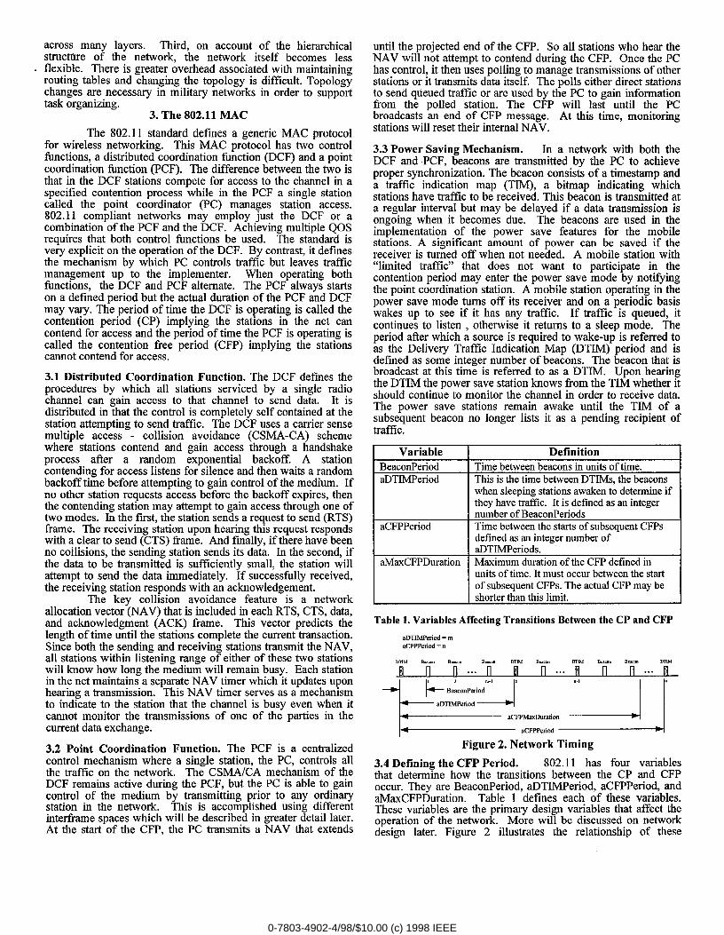
3.4 Defining the CFP Period. 802.11 has four variablesthat determine how the transitions between the CP and CFPoccur. They are BeaconPeriod, aDTIMPeriod, aCFPPeriod, andaMaxCFPDuration. Table 1 defines each of these variables.These variables are the primary design variables that affect theoperation of the network. More will be discussed on networkdesign later. Figure 2 illustrates the relationship of these
0-7803-4902-4/98/$10.00 (c) 1998 IEEE
variables. The CFP always starts at the beginning of theaCFPPeriod and the CP always ends at the end. The transition
- from the CFP to the CP may occur at any time after a minimumCFP UP to aCFPMaxDuration. The selection ofaCFPMaxDuration must allow a minimum duration CP.
3.4 Interframe Spaces. The key to the operation of both theDCF and the PCF is the use of different interfrarne spaces.Interframe spaces are predefmed periods of required silenceprior to transmission, Each type of transmission must wait for aspecific interfi-ame space. The duration of the interfi-ame spacedetermines the priority that the transmission has within theprotocol. For example, stations that want to contend for accessmust wait a longer interfi-ame space than a station that needs toacknowledge the receipt of a message. Similarly, the PC seizescontrol by using a shorter interframe space than that used by acontending station but longer than the inter frame space for anacknowledgement.
The 802.11 MAC defines four interframe spaces. Thefwst and shortest is the Short Interfiame Space (SIFS). The SIFSis the period of no transmission between the receipt and responseto a frame. It is the space that exist between the CTS and RTSframes, data frames and the subsequent ACK, and the pollingfizunes and responses during the operation of the pointcoordination fimction. The second, and next shortest in durationis the PCF Interfiame Space (PIFS). The PIFS is used by thepoint coordinator to send beacons and to seize and maintaincontrol of the medium during the contention free period. Thethird, and next longest in duration is the DCF Interframe Space(DIFS). This is the required duration of silence beforecontenders begin to count down their backoff timers. The fourthand longest is the Extended Interframe Space. It is used by astation waiting to contend instead of a DIFS when the traffic thatit last detected was not a valid MAC frame.
The duration of the fwst three of these interframe spacesis dependent on the physical layer. They are determined by twovalues, aSIFSTime and aSlotTime. The aSIFSTime is the time ittakes tiom the end of receipt of a message for a station toprocess the message and then respond with the fwst symbol ofthe preamble. The aSlotTime is the time it takes a station torecognize a channel is busy or idle plus the time it takes toprocess a frame, prepare a response, transmit it, and for it topropagate to the receiving station. The duration of the SIFS isaSIFSTirne. The PIFS is one aSlotTime longer than the SIFSand the DIFS is two aSlotTimes longer the SIFS. The EIFS isequivalent to the time it takes to transmit 8 consecutive ACKframes plus the duration of one SIFS and one DIFS.
3.5 Transmitting Data. In a network operating both the DCFand the PCF, data traffic may be sent in either the CP or theCFP. The choice of how to send the data is made by the sendingstation. It either contends to send data immediately to thereceiving station during the CP or it contends and requests thatthe PC mediate the transmission of the traffic during the CFP.The network is normally set up such that the stations willattempt to send data within the CP only if the tile size is lessthan some threshold called the Maximum MAC Service DataUnit Size(MaxMSDUsize). (The MaxMSDUSize is not definedby the 802.11 MAC and is added as a part of thisimplementation.) This threshold is chosen such that sufficienttime remains available during the CP for contending stations tocontend. When data is sent in the CP it may either befragmented or sent as a single transmission. Fragmentationoccurs when the message is larger than a second threshold calledaFragmentationThreshold. This threshold is used to minimizethe overall transmission time of the file when retransmission on
account of bit errors is considered. A third threshold exists forsending data during the CP called aRTSThreshold. This
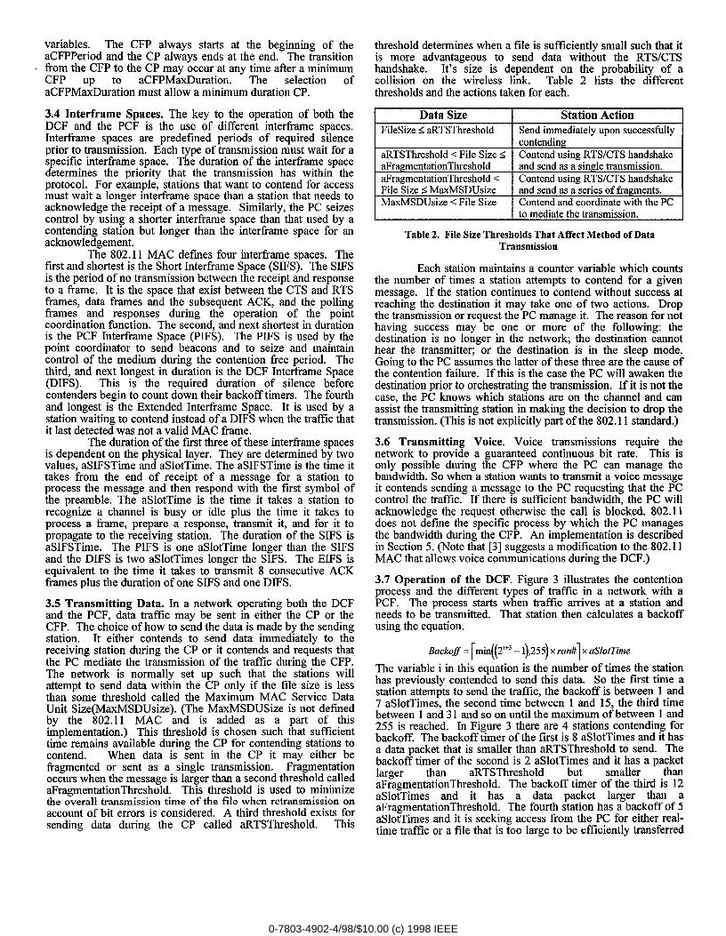
threshold determines when a file is sufficiently small such that itis more advantageous to send data without the RTS/CTShandshake. It’s size is dependent on the probability of acollision on the wireless link. Table 2 lists the differentthresholds and the actions taken for each.
Data Size
FileSize < aRTSThreshold ~I Send immediately upon successtirlly
-a Contend using RTSICTS handshake
Contend using RTSICTS handshakeFile Sizes MaxMSDUsize I and send as a-series of fragments.
MaxMSDUsize < File Size I Contend and coordinate with the PC
to mediate the transmission.
Table 2. File Size Thresholds That Affect Method of DataTransmission
Each station maintains a counter variable which countsthe number of times a station attempts to contend for a givenmessage. If the station continues to contend without success atreaching the destination it may take one of two actions. Dropthe transmission or request the PC manage it. The reason for nothaving success may be one or more of the following: thedestination is no longer in the network; the destination cannothear the transmitter; or the destination is in the sleep mode.Going to the PC assumes the latter of these three are the cause ofthe contention failure. If this is the case the PC will awaken thedestination prior to orchestrating the tmnsmission. If it is not thecase, the PC knows which stations are on the channel and canassist the transmitting station in making the decision to drop thetransmission. (This is not explicitly part of the 802.11 standard.)
3.6 Transmitting Voice. Voice transmissions require thenetwork to provide a guaranteed continuous bit rate. This isonly possible during the CFP where the PC can manage thebandwidth. So when a station wants tol transmit a voice messageit contends sending a message to the !PC requesting that the PCcontrol the traffic. If there is sufficient bandwidth, the PC willacknowledge the request otherwise the call is blocked. 802.11does not define the specific process by which the PC managesthe bandwidth during the CFP. An implementation is describedin Section 5. (Note that [3] suggests a lmodification to the 802.11MAC that allows voice communications during the DCF.)
3.7 Operation of the DCF. Figure 3 illustrates the contentionprocess and the different types of tiiiffic in a network with aPCF. The process starts when traffic arrives at a station andneeds to be transmitted. That station then calculates a backoffusing the equation.
Backofl = [min((2’+3 - 1),255) x ,ran#l x aSlotTime
The variable i in this equation is the number of times the stationhas previously contended to send this data. So the fwst time astation attempts to send the traffic, the backoff is between 1 and7 aSlotTimes, the second time between 1 and 15, the third timebetween 1 and31 and so on until the maximum of between 1 and255 is reached. In Figure 3 there are 4 stations contending forbackoff. The backoff timer of the first is 8 aSlotTimes and it hasa data packet that is smaller than aRTSThreshold to send. Thebackoff timer of the second is 2 aSlotTimes and it has a packetlarger than aRTSThreshold but smaller thanaFragmentationThreshold. The backc~ff timer of the third is 12aSlotTimes and it has a data packet larger than aaFragmentationThreshold. The fourth station has a backoff of 5aSlotTimes and it is seeking access from the PC for either real-time traffic or a file that is too large to be efficiently transferred
0-7803-4902-4/98/$10.00 (c) 1998 IEEE
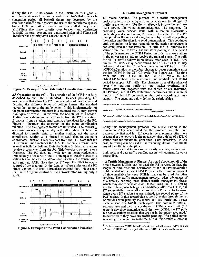
during the CP. Also shown in the illustration is a genericreceiving station and the point coordinator. Note that after eachcontention period all backoff timers are decreased by thesmallest backoff time, Observe the use of the interfiame spaces,Since CTS and ACK frames are transmitted only afteraSIFSTime they have priority over beacons and contentionbackoff. In turn, beacons are transmitted after aPIFSTime andtherefore have priority over contention backoff.
ALw B-,.
PointConhuuer
cr. AL .T, m AC.A Receiving
stationI
Tm’gdmm Tmmi.mTm. d
Figure 3. Example of the Distributed Coordination Function
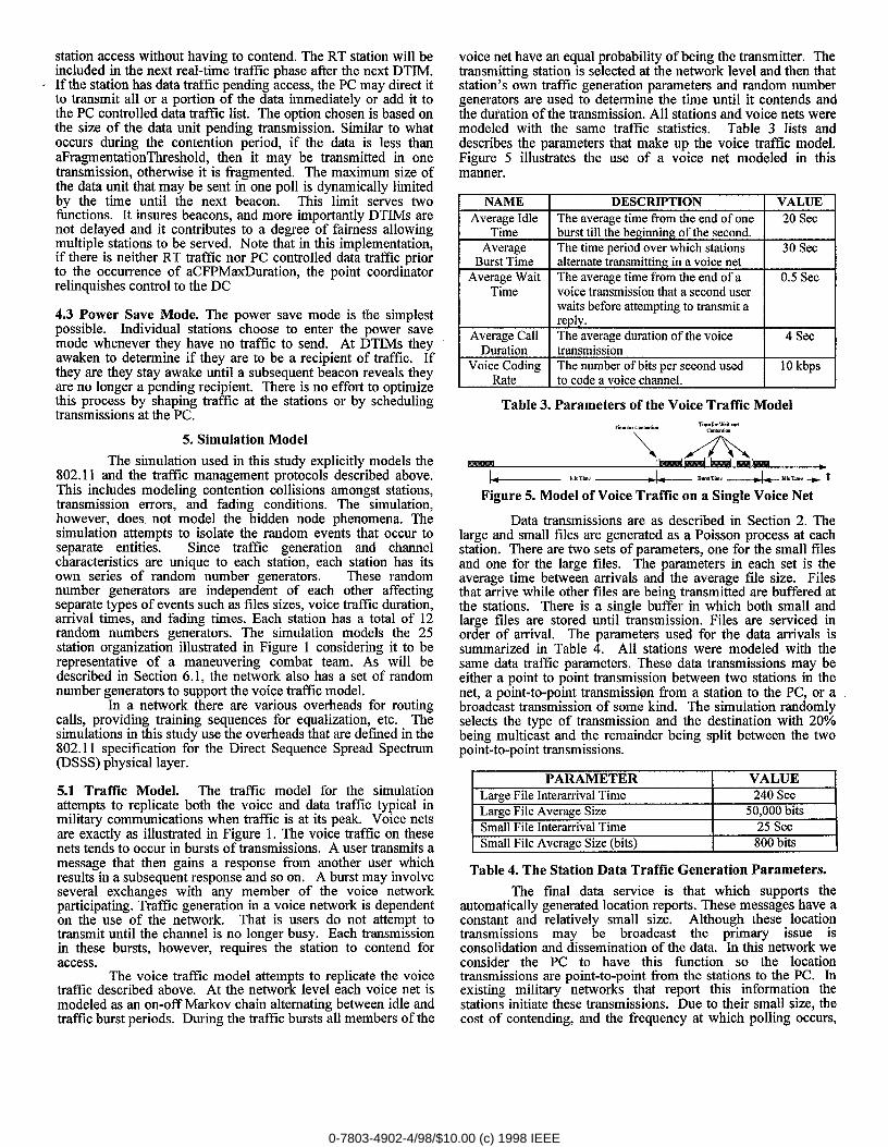
3.8 Operation of the PCF. The operation of the PCF is not fi.dlydescribed by the 802.11 standard. Besides providing themechanisms that allow the PC to seize control of the channel anddefining the different types of polling frames, the standardleaves the rest up to the implementer. In this implementation ofthe point coordination fi,mction it is assumed the PC may controlfive types of traffic. Traffic flom the one station to a second.Traffic tlom a station to the PC. Traffic from the PC to a station.Broadcast fi-om a station. And finally, a broadcast from the PC.Figure 4 illustrates the operation of the point coordinationfunction. The five types of traffic are illustrated. The followingtransmissions occur sequentially in the illustration. Station 1 isdirected to transfer data to another station, not the pointcoordinator. Station 2 is directed to send data to the pointcoordinator. Station 3 receives data from the PC. Note that thePC’s transmission includes the ACK to Station 2’s transmissionas well as both the Poll and Data for Station 3. Next, all stationsreceive a broadcast from the PC. This broadcast occurs in onefragment. The PC does not wait for an acknowledgement.Immediately after a SIFS the PC attempts to transmit data to astation but in this case the station does not hear the transmissionand sends no ACK. Note that the PC uses the PIFS to regaincontrol of the medium. In the final set of transmissions the PCdirects Station 3 to send a broadcast transmission. Note againthat the PC regains control of the network afler waiting only aPIFS.
Srariou 2
Station 3
Pointcontroller
A SeceivingWA.”
TWCIB-L=. Tm”.k”im Time~
Figure 4. Example of the Point Coordination Function
.
4. Traffic Management Protocol
4.1 Voice Service. The purpose of a traffic managementprotocol is to provide adequate quality of service for all types oftraffic in the network. The fust challenge is to provide real time(RT) service for voice communications. The sequence forproviding voice service starts with a station successiidlycontending and coordinating RT service from the PC. The PCthen provides the service during the PCF by periodically pollingthe station and directing it to send transmissions. This continuesuntil the station no longer responds or the station announces ithas completed the transmission. In turn, the PC removes thestation from the RT traffic list and stops polling it. The periodof the polls matches the DTIM Period~ in order to allow stationsin the power save mode to receive the transmissions. The pollsfor all RT traffic follow immediately after each DTIM. Anynumber of DTIMs may occur during the CFP but a DTIM maynot occur during the CP unless there is no RT traffic. TheaCFPMaxDuration is therefore chosen to occur sometime afterthe last DTIM in the CFP-CP cycle (See Figure 2.). The timefrom the last DTIM in the CFP-CP cycle to theaMaxCFPDuration is the maximum tiiie available each DTIMperiod to support RT traffic. The characteristics of the physicallayer (i.e. real-time traffic bit rate, packet overhead, andtransmission rate) together with the choice of aDTIMPeriod,aCFPPeriod, and aCFPMaxDuration determines the maximumnumber of the RT connections the point coordinator maysupport. The equations below define the relationships.
RITrrlJicBIIsPtvDTLM = RTBiIRate x aDTIMPeriud x BuIconPeti.d
~Elo,nme = (RWruflcBil,vPerD~+#OHBil,sP<rPak,l+#PulBil)d.m$m!.,,otia,e+t”~’~~
RTFr.m&ngth. aD72Wdcd x BeaconPeriod - (aCFPPwid x aD32Wwfcd x Be..onPeriod - aCFPA4u2huafi.n)
A4a#Ca//. = [(RTFram.btglh- ~meToTr.nsmttB.aconv)/R~ lot~m.j
Using this management protocol, tlhe DTIM Period is themaximum delay contributed by the protocol and the timebetween the fust and last RT slots is the maximum jitter. Weassume that the network is designed such that a delay of a DTIMPeriod plus the maximum jitter time is not excessive. In thiscase, buffering can be used at the receiving station to eliminateany of the effects of the jitter.
In an effort to give some priority to voice, stations withboth voice and data traffic pending access will contend for voiceaccess first.
4.2 Traffic Management Phases. As noted above, not all of thetime between DTIMs can be used for RT service. In fact, thelength of time after the occurrence of the aCFPMaxDurationuntil the start of the next CFP-CP cycl[e is the minimum amountof time available between DTIMs that can be used for otherservices. The traffic management protocol takes advantage ofthis time by defining three distinct traffic management phaseswhich may occur between each DTIM during the PCF. Duringthe f~st phase, which begins immediately after the DTIM, thePC sequentially directs all stations with RT traffic to transmit.Once every RT station has transmitted, the second phase of thePCF begins. In this second phase, the PC cycles through the listof stations with pending PC controlled data traffic and directseach to send one MPDU each cycle. This continues until allstations have sent their data or the next DTIM occurs. Finally, ifthere is any time remaining until the next DTIM, the PC pollsthe active stations (stations that are not in the power save mode)to determine if they have any traffic pending. If a polled stationis waiting to contend for real-time access, this feature allows the
2 In this discussion “DTIM Period” refers to the period between DTIMs in unitsof time. aDTIMPeriod is the period between DTTMs in number of beacons.
0-7803-4902-4/98/$10.00 (c) 1998 IEEE
station access without having to contend. The RT station will beincluded in the next real-time traffic phase atler the next DTIM.
- If the station has data traffic pending access, the PC may direct itto transmit all or a portion of the data immediately or add it tothe PC controlled data traffic list, The option chosen is based onthe size of the data unit pending transmission. Similar to whatoccurs during the contention period, if the data is less thanaFragmentationThreshold, then it may be transmitted in onetransmission, otherwise it is fragmented. The maximum size ofthe data unit that may be sent in one poll is dynamically limitedby the time until the next beacon. This limit serves twofunctions. It insures beacons, and more importantly DTIMs arenot delayed and it contributes to a degree of fairness allowingmultiple stations to be served. Note that in this implementation,if there is neither RT traffic nor PC controlled data traffic priorto the occurrence of aCFPMaxDuration, the point coordinatorrelinquishes control to the DC
4.3 Power Save Mode. The power save mode is the simplestpossible. Individual stations choose to enter the power savemode whenever they have no traffic to send. At DTIMs theyawaken to determine if they are to be a recipient of traffic. Ifthey are they stay awake until a subsequent beacon reveals theyare no longer a pending recipient. There is no effort to optimizethis process by shaping traffic at the stations or by schedulingtransmissions at the PC.
5. Simulation Model
The simulation used in this study explicitly models the802.11 and the traffic management protocols described above.This includes modeling contention collisions amongst stations,transmission errors, and fading conditions. The simulation,however, does not model the hidden node phenomena. Thesimulation attempts to isolate the random events that occur toseparate entities. Since traffic generation and channelcharacteristics are unique to each station, each station has itsown series of random number generators. These randomnumber generators are independent of each other affectingseparate types of events such as files sizes, voice traffic duration,arrival times, and fading times. Each station has a total of 12random numbers generators. The simulation models the 25station organization illustrated in Figure 1 considering it to berepresentative of a maneuvering combat team. As will bedescribed in Section 6.1, the network also has a set of randomnumber generators to support the voice traffic model.
In a network there are various overheads for routingcalls, providing training sequences for equalization, etc. Thesimulations in this study use the overheads that are defined in the802.11 specification for the Direct Sequence Spread Spectrum(DSSS) physical layer.
5.1 Traffic Model. The traffic model for the simulationattempts to replicate both the voice and data traffic typical inmilitary communications when traffic is at its peak. Voice netsare exactly as illustrated in Figure 1. The voice traffic on thesenets tends to occur in bursts of transmissions. A user transmits amessage that then gains a response from another user whichresults in a subsequent response and so on. A burst may involveseveral exchanges with any member of the voice networkparticipating. Traffic generation in a voice network is dependenton the use of the network. That is users do not attempt totransmit until the channel is no longer busy. Each transmissionin these bursts, however, requires the station to contend foraccess.
The voice traffic model attempts to replicate the voicetraffic described above. At the network level each voice net ismodeled as an on-off Markov chain alternating between idle andtraffic burst periods. During the traffic bursts all members of the
voice net have an equal probability of being the transmitter. Thetransmitting station is selected at the network level and then thatstation’s own traffic generation param~eters and random numbergenerators are used to determine the time until it contends andthe duration of the transmission. All stations and voice nets weremodeled with the same traffic statistics. Table 3 lists anddescribes the parameters that make up the voice traffic model.Figure 5 illustrates the use of a voice net modeled in thismanner.
-=
The average time from the end of oneburst tdl the be rerun of the second.
The time ueriod over which stations
W-alternate ksmittin in a voice net
The average time from the end of a
voice transmission that a second userwaits before attempting to transmit a
==
The average duration of the voice
Voice Coding The number of bits per second used
Table 3. Parameters of the Voice Traffic Model
“’x/’”n&~~
~ “’”me ~- ‘w*’h= -----1-- + tFigure 5. Model of Voice Traffic on a Single Voice Net
Data transmissions are as described in Section 2. Thelarge and small files are generated as a Poisson process at eachstation. There are two sets of parameters, one for the small filesand one for the large files. The parameters in each set is theaverage time between arrivals and the average tile size. Filesthat arrive while other files are being transmitted are buffered atthe stations. There is a single buffer in which both small andlarge tiles are stored until transmission. Files are serviced inorder of arrival. The parameters used for the data arrivals issummarized in Table 4. All stations were modeled with thesame data traffic parameters. These c[ata transmissions may beeither a point to point transmission between two stations in thenet, a point-to-point transmission from a station to the PC, or abroadcast transmission of some kind. The simulation randomlyselects the type of transmission and the destination with 20°/0being multicast and the remainder being split between the twopoint-to-point transmissions.
PARAMETER I VALUE 1
t Small File Average Size (bits)a
800 bits i
Table 4. The Station Data Traffic Generation Parameters.
The final data service is that which supports theautomatically generated location reports. These messages have aconstant and relatively small size. Although these locationtransmissions may be broadcast the primary issue isconsolidation and dissemination of the data. In this network weconsider the PC to have this function so the locationtransmissions are point-to-point ftom the stations to the PC. Inexisting military networks that report this information thestations initiate these transmissions. Due to their small size, thecost of contending, and the frequency at which polling occurs,
0-7803-4902-4/98/$10.00 (c) 1998 IEEE
we handle these reports in a different manner. Each stationmainfains a location buffer which is updated independently of
= the network operation. When a station is polled by the PC thestation adds the location currently stored in the buffer to theoverhead of its reply.
5.2 Error Model. The simulation uses an on-off Markov chainto model the effects of fading. The specific model is assuggested in [1].
6. Network Design
The objective in designing the network is to provide allthe services needed using the least bandwidth. At the physicallevel, the designer must select a voice encoding bit rate and thetransmission rate. At the MAC level the designer must select thethresholds for sending data and the timing parameters. Thefollowing is our design process.
6.1 Assume a voice bit rate, a maximum delay constraint,and an average BER. There are numerous voice encodingmethods. As an example the U.S. digital cellular system uses avector sum excited linear predictive coder (VSELP) thatoperates at a raw data rate of 7950 bitsfs. As an arbitrary yet notunrealistic number we chose 10 kbps. The maximum delay thevoice signals can tolerate is actually quite large. Thetransmissions are simplex without feedback to the sender. In aconversation, the delay manifests itself only in increasing thetime till a response is heard. We assume the delay is constrainedto 250 msec from transmission to receipt. In turn thiscontributes a maximum of 500 msec to the overall time from endof a transmission to the receipt of a response. The BER wechose comes directly from our error model which has an averageerror rate of about 5 x 10⁻⁵.
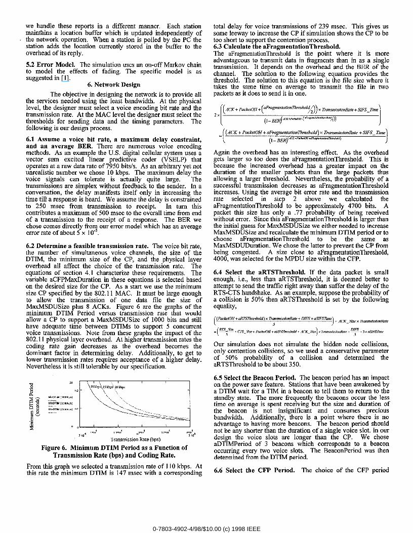
6.2 Determine a feasible transmission rate. The voice bit rate,the number of simultaneous voice channels, the size of theDTIM, the minimum size of the CP, and the physical layeroverhead all affect the choice of the transmission rate. Theequations of section 4.1 characterize these requirements. Thevariable aCFPMaxDuration in these equations is selected basedon the desired size for the CP. As a start we use the minimumsize CP specified by the 802.11 MAC. It must be large enoughto allow the transmission of one data file the size ofMaxMSDUSize plus 8 ACKS. Figure 6 are the graphs of theminimum DTIM Period versus transmission rate that wouldallow a CP to support a MaxMSDUSize of 1000 bits and stillhave adequate time between DTIMs to support 5 concurrentvoice transmissions. Note from these graphs the impact of the802.11 physical layer overhead. At higher transmission rates thecoding rate gain decreases as the overhead becomes thedominant factor in determining delay. Additionally, to get tolower transmission rates requires acceptance of a higher delay.Nevertheless it is still tolerable by our specification.
Transmission Rote (bps)
Figure 6. Minimum DTIM Period as a Function ofTransmission Rate (bps) and Coding Rate.
From this graph we selected a transmission rate of 110 kbps. Atthis rate the minimum DTIM is 147 msec with a corresponding
total delay for voice transmissions of 239 msec. This gives ussome leeway to increase the CP if simulation shows the CP to betoo short to support the contention process.6.3 Calculate the aFragmentationThreshold.The aFragmentationThreshold is the point where it is moreadvantageous to transmit data in fragments than in as a singletransmission. It depends on the overhead and the BER of thechannel. The solution to the following equation provides thethreshold, The solution to this equation is the file size where ittakes the same time on average to transmit the file in twopackets as it does to send it in one.
[
_ {ACK+Pa.k.tOH+@ragmntationThre.,hold) x Tb.wnis.siordbte ?=SIFS_Tinw
(1- BER~KK+Pm&~+”Fmwt#[<rll,”#~mtidd)
)
Again the overhead has an interesting effect. As the overheadgets larger so too does the aFragmentationThreshold. This isbecause the increased overhead has a greater impact on theduration of the smaller packets than the large packets thusallowing a larger threshold. Nevertheless, the probability of asuccessful transmission decreases as aFragmentationThresholdincreases. Using the average bit error rate and the transmissionrate selected in step 2 above we calculated theaFragmentationThreshold to be approximately 4700 bits. Apacket this size has only a .77 probability of being receivedwithout error. Since this aFragmentationThreshold is larger thanthe initial guess for MaxMSDUSize we either needed to increaseMaxMSDUSize and recalculate the minimum DTIM period or tochoose aFragmentationThreshold to be the same asMaxMSDUDuration. We chose the latter to prevent the CP frombeing congested. A size close to aFragmentationThreshold,4000, was selected for the MPDU size within the CFP.
6A Select the aRTSThreshold. If the data packet is smallenough, i.e., less than aRTSThreshol,d, it is deemed better toattempt to send the traffic right away than suffer the delay of theRTS-CTS handshake. As an example, suppose the probability ofa collision is 50’?40then aRTSThreshold is set by the followingequality,
fPa&,olf+drl-m —)+ AcK_sizcxrranwiwimfi,erushokl) x Transmissiod?ate + DIFS + aWFSTiine
-[’y” -. 5 )+ C7S Sb + P.ckdOH + .RTSThr&wld + ACK_Sim x Tnm.miwiod?ate + ~ + 3 x &WS7’hne
Our simulation does not simulate the hidden node collisions,only contention collisions, so we usedl a conservative parameterof 50°A probability of a collision and determined theaRTSThreshold to be about 350.
6.5 Select the Beacon Period. The beacon period has an impacton the power save feature. Stations that have been awakened bya DTIM wait for a TIM in a beacon to tell them to return to thestandby state. The more fi-equently the beacons occur the lesstime on average is spent receiving but the size and duration ofthe beacon is not insignificant and consumes preciousbandwidth, Additionally, there is a point where there is noadvantage to having more beacons. ‘The beacon period shouldnot be any shorter than the duration of a single voice slot. In ourdesign the voice slots are longer than the CP. We choseaDTIMPeriod of 3 beacons which corresponds to a beaconoccurring every two voice slots. The BeaconPeriod was thendetermined from the DTIM period.
6.6 Select the CFP Period. The choice of the CFP period
0-7803-4902-4/98/$10.00 (c) 1998 IEEE
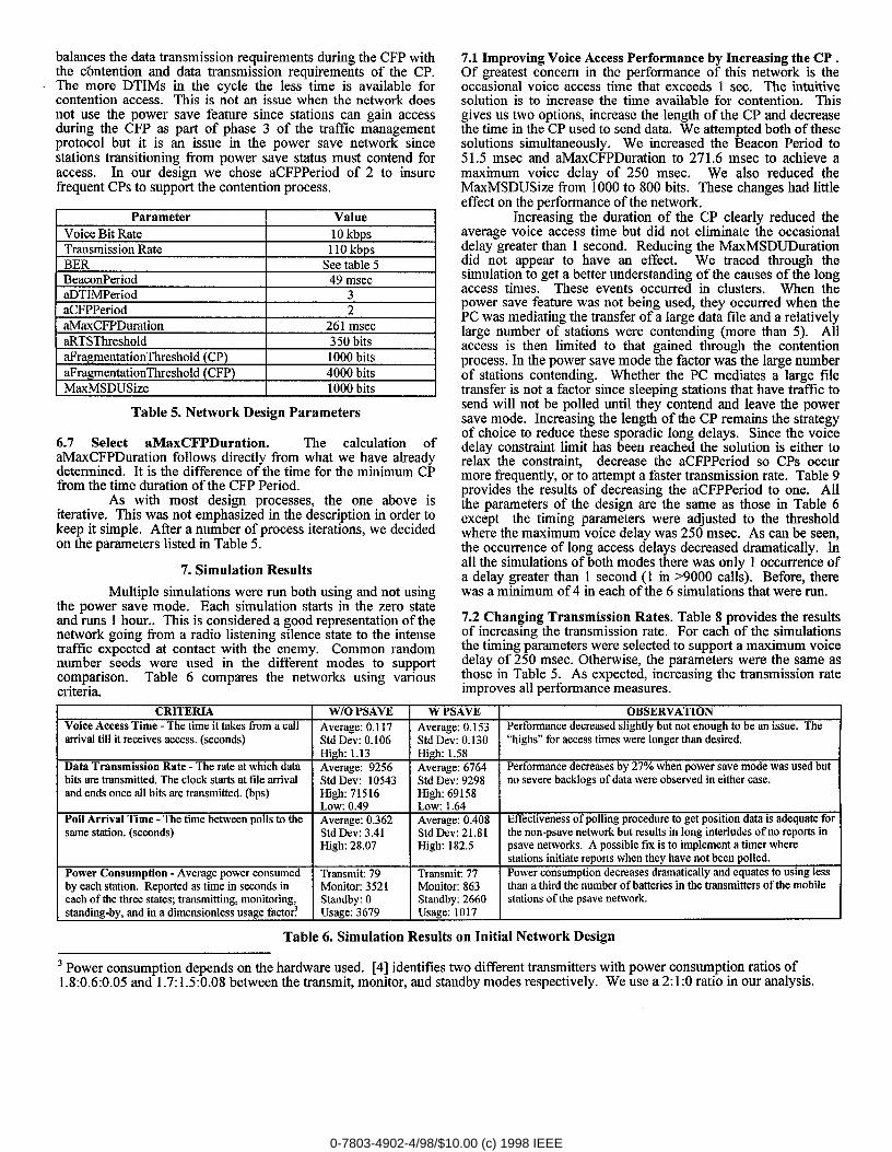
balances the data transmission requirements during the CFP withthe c?mtention and data transmission requirements of the CP.The more DTIMs in the cycle the less time is available forcontention access. This is not an issue when the network doesnot use the power save feature since stations can gain accessduring the CFP as part of phase 3 of the traffic managementprotocol but it is an issue in the power save network sincestations transitioning from power save status must contend foraccess. In our design we chose aCFPPeriod of 2 to insureffequent CPS to support the contention process.
Parameter ValueVoice Bit Rate 10 kbps
Transmission Rate 110 kbps
BER See table 5
BeaconPeriod 49 msecaDTIMPeriod 3
aCFPPeriod 2
aMaxCFPDuration 261 msec
aRTSThreshold 350 bits
aFragmentationThreshold (CP) 1000 bits
aFragmentationThreshold (CFP) 4000 bits
MaxMSDUSize 1000 bits
Table 5. Network Design Parameters
6.7 Select aMaxCFPDuration. The calculation ofaMaxCFPDuration follows directly from what we have alreadydetermined. It is the difference of the time for the minimum CPfrom the time duration of the CFP Period.
As with most design processes, the one above isiterative. This was not emphasized in the description in order tokeep it simple. After a number of process iterations, we decidedon the parameters listed in Table 5.
7. Simulation Results
Multiple simulations were run both using and not usingthe power save mode. Each simulation starts in the zero stateand runs 1 hour.. This is considered a good representation of thenetwork going from a radio listening silence state to the intensetraffic expected at contact with the enemy. Common randomnumber seeds were used in the different modes to supportcomparison. Table 6 compares the networks using variouscriteria.
7.1 Improving Voice Access Performance by Increasing the CP ,Of greatest concern in the performance of this network is theoccasional voice access time that exceeds 1 sec. The intuitivesolution is to increase the time available for contention. Thisgives us two options, increase the length of the CP and decreasethe time in the CP used to send data. We attempted both of thesesolutions simultaneously. We increased the Beacon Period to51.5 msec and aMaxCFPDuration to 271.6 msec to achieve amaximum voice delay of 250 msec. We also reduced theMaxMSDUSize from 1000 to 800 bits. These changes had littleeffect on the performance of the network.
Increasing the duration of the CP clearly reduced theaverage voice access time but did not eliminate the occasionaldelay greater than 1 second. Reducing the MaxMSDUDurationdid not appear to have an effect, We traced through thesimulation to get a better understanding of the causes of the longaccess times. These events occurred in clusters. When thepower save feature was not being used, they occurred when thePC was mediating the transfer of a large data file and a relativelylarge number of stations were contending (more than 5). Allaccess is then limited to that gained through the contentionprocess. In the power save mode the factor was the large numberof stations contending. Whether the PC mediates a large filetransfer is not a factor since sleeping stations that have traffic tosend will not be polled until they contend and leave the powersave mode. Increasing the length of the CP remains the strategyof choice to reduce these sporadic long delays. Since the voicedelay constraint limit has been reached the solution is either torelax the constraint, decrease the aCFPPeriod so CPS occurmore frequently, or to attempt a faster transmission rate. Table 9provides the results of decreasing the aCFPPeriod to one. Allthe parameters of the design are the same as those in Table 6except the timing parameters were adjusted to the thresholdwhere the maximum voice delay was 250 msec. As can be seen,the occurrence of long access delays clecreased dramatically. Inall the simulations of both modes there was only 1 occurrence ofa delay greater than 1 second (1 in >9000 calls). Before, therewas a minimum of 4 in each of the 6 simulations that were run.
7.2 Changing Transmission Rates. Table 8 provides the resultsof increasing the transmission rate. For each of the simulationsthe timing parameters were selected to support a maximum voicedelay of 250 msec. Otherwise, the parameters were the same asthose in Table 5. As expected, increasing the transmission rateimproves all performance measures.
CRITERIA WIO PSAVE W PSAVE OBSERVAIIONVoice Access Time - The time it takes from a call Average: 0.117 Average: 0.153 Performance decreased slightly but not enough to be an issue. Thearrival till it receives access. (seconds) Std Dev: 0.106 Std Dev: 0.130 “highs” for accesstimes were longer than desired.
High 1.13 High: 1.58Data Transmission Rate - The rateat which data Average: 9256 Average: 6764 Performance decreasesby 27% when power save mode was used butbits are transmitted. The clock starts at tile arrival Std Dev: 10543 Std Dev: 9298 no severe backlogs of data were observed in either case.and ends once all bits are transmitted. (bps) High: 71516 High: 69158
Lo~: 0.49 Lo&: 1.64Poll Arrival Time - The time between polls to the Average: 0.362 Average: 0.408 Effectiveness of polling procedure to get position data is adequate forsame station. (seconds) Std Dev: 3.41 Std Dev: 21.81 the non-psave network but results in long interludes of no reports in
High: 28.07 High: 182.5 psave networks. A possible fix is to implement a timer wherestations initiate reports when they have not been polled.
Power Consumption - Average power consumed Transmit 79 Trrmsmiti 77 Power consumption decreasesdramatically and equates to using lessbv each station. Re~orted as time in seconds in Monitor 3521 Monitor: 863 than a third the number of batteries in the transmitters of the mobileeach of the three states; transmitting, monitoring, Standby: O Standby: 2660 stations of the psave network.standhg-by, and in a dimensionless usage facto< Usage: 3679 Usage: 1017
Table 6. Simulation Results on Initial Network Design
3 Power consumption depends on the hardware used. [4] identifies two different transmitters with power consumption ratios of1.8:0.6:0.05 and 1.7:1.5:0.08 between the transmit, monitor, and standby modes respectively. We use a 2:1:0 ratio in our analysis.
0-7803-4902-4/98/$10.00 (c) 1998 IEEE
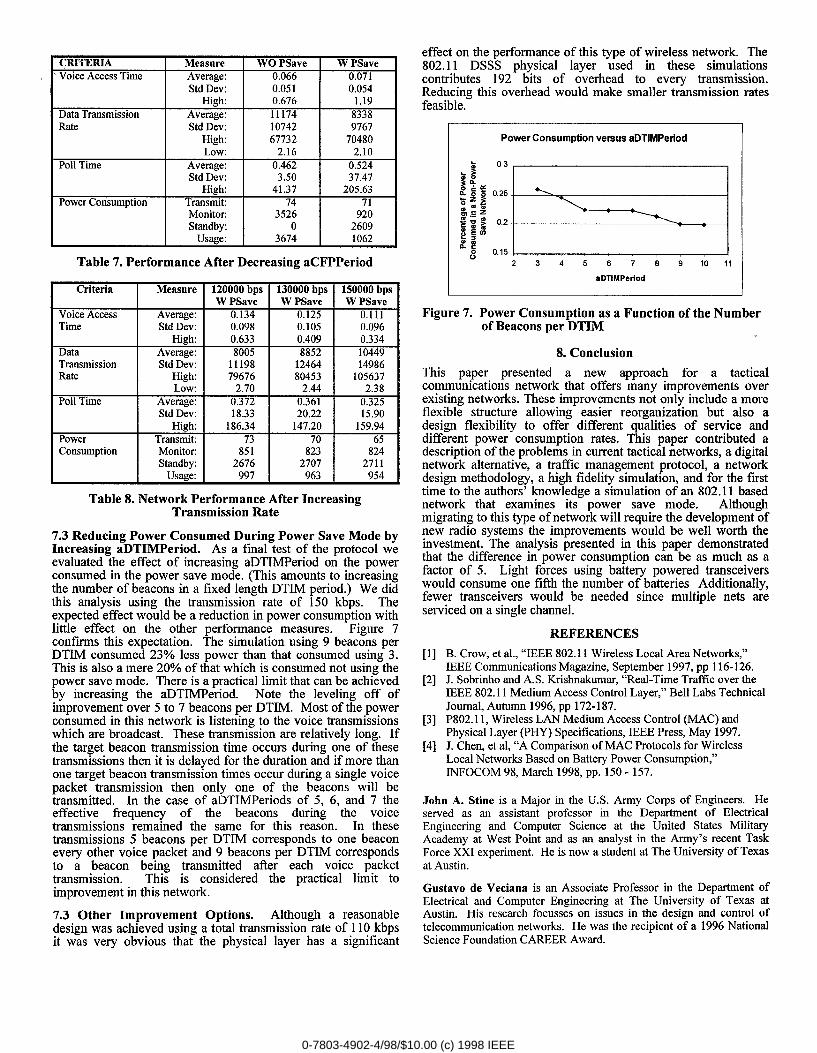
CRITERIA Measure WO PSave W PSaveVoice AccessTime Average: 0.066 0.071
Std Dev: 0.051 0.054
I H]gh: 0.676 I 1.19Data Transmission Average: I 11174 8338Rate I Std &: I 10742 I 9767
H]gh: 67732 70480
I Low: 2.16 I 2.10Poll Time Average: 0.462 0.524
Std Dev: 3.50 37.47High: 41.37 205.63
Power ConsumrXion Transmit 74 71
I Monitoc I 3526 I 920Standby: o 2609
Usage: I 3674 1062
Table 7. Performance After Decreasing aCFPPeriod
Criteria Measure 120000bps 130000bps 150000bpsW PSave W PSave W PSave
Voice Access Average: 0.134 0.125 0.111Time Std Dev: 0.098 0.105 0.096
H]gh: I 0.633 0.409 I 0.334Data I Average: I 8005 I 8852 10449Transmission I Std &: I 11198 I 12464 I 14986
Consumption Monitor 851 823 824Standby: 2676 2707 2711
Usatze: 997 963 954
Table 8. Network Performance After IncreasingTransmission Rate
7.3 Reducing Power Consumed During Power Save Mode byIncreasing aDTIMPeriod. As a final test of the protocol weevaluated the effect of increasing aDTIMPeriod on the powerconsumed in the power save mode. (This amounts to increasingthe number of beacons in a fixed length DTIM period.) We didthis analysis using the transmission rate of 150 kbps, Theexpected effect would be a reduction in power consumption withlittle effect on the other performance measures. Figure 7confms this expectation. The simulation using 9 beacons perDTIM consumed 23’% less power than that consumed using 3.This is also a mere 20% of that which is consumed not using thepower save mode. There is a practical limit that can be achievedby increasing the aDTIMPeriod. Note the leveling off ofimprovement over 5 to 7 beacons per DTIM. Most of the powerconsumed in this network is listening to the voice transmissionswhich are broadcast. These transmission are relatively long. Ifthe target beacon transmission time occurs during one of thesetransmissions then it is delayed for the duration and if more thanone target beacon transmission times occur during a single voicepacket transmission then only one of the beacons will betransmitted. In the case of aDTIMPeriods of 5, 6, and 7 theeffective tlequency of the beacons during the voicetransmissions remained the same for this reason. In thesetransmissions 5 beacons per DTIM corresponds to one beaconevery other voice packet and 9 beacons per DTIM correspondsto a beacon being transmitted after each voice packettransmission. This is considered the practical limit toimprovement in this network.
7.3 Other Improvement Options. Although a reasonabledesign was achieved using a total transmission rate of 110 kbpsit was very obvious that the physical layer has a significant
effect on the performance of this type of wireless network. The802.11 DSSS physical layer used in these simulationscontributes 192 bits of overhead to every transmission.Reducirw this overhead would make smaller transmission ratesfeasible.”
Power Consumption versus sDTIMPeriod
2345678 91011
aDTIMPwiod
Figure 7. Power Consum~tion as a Function of the Numberof Beacons per-DTIM
8. Conclusion
This paper presented a new alpproach for a tacticalcommunications network that offers many improvements overexisting networks. These improvements not only include a moreflexible structure allowing easier reorganization but also adesign flexibility to offer different qualities of service anddifferent power consumption rates. This paper contributed adescription of the problems in current tactical networks, a digitalnetwork alternative, a traffic management protocol, a networkdesign methodology, a high fidelity simulation, and for the f~sttime to the authors’ knowledge a simulation of an 802.11 basednetwork that examines its power save mode. Althoughmigrating to this type of network will require the development ofnew radio systems the improvements would be well worth theinvestment. The analysis presented in this paper demonstratedthat the difference in power consumption can be as much as afactor of 5. Light forces using battery powered transceiverswould consume one fifth the number of batteries Additionally,fewer transceivers would be neededl since multiple nets areserviced on a single channel.
REFERENCES
[1] B. Crow, et al., “IEEE 802.11 Wireless Local Area Networks,”IEEE Communications Magazine, September 1997, pp 116-126.
[2] J, Sobrinho and A.S. Krishnakumar, “Real-Time Traffic over theIEEE 802.11 Medium Access Control Layer,” Bell Labs TechnicalJournal, Autumn 1996, pp 172-187.
[3] P802.11, Wireless LAN Medium Access Control (MAC) andPhysical Layer (PHY) Specifications, IEEE Press,May 1997.
[4] J. Chen, et al, “A Comparison of MAC Protocols for WirelessLocal Networks Based on Battery Power Consumption:INFOCOM 98, March 1998, pp. 150-157.
John A. Stine is a Major in the U.S. Army Corps of Engineers. Heserved as an assistant professor in the Department of ElectricalEngineering and Computer Science at the United States MilitaryAcademy at West Point and as an analyst in the Army’s recent TaskForce XXI experiment. He is now a student at The University of Texas
at Austin.
Gustavo de Veciana is an Associate Prc)fessor in the Department ofElectrical and Computer Engineering at The University of Texas atAustin. His research focusses on issues in the design and control of
telecommunication networks. He was the recipient of a 1996 NationalScience Foundation CAREER Award.
0-7803-4902-4/98/$10.00 (c) 1998 IEEE
Related Documents