` Last updated November 2012 App 6 Security_Systems_Specifications_V4.13.doc Page 1 of 37 pages APPENDIX 6: UNSW INTEGRATED SECURITY SYSTEMS SPECIFICATIONS TABLE OF RELATED REFERENCES UNSW DESIGN & CONSTRUCTION REQUIREMENTS – WEB ENTRY PAGE SECTION A – INTRODUCTION SECTION B – DEVELOPMENT & PLANNING SECTION C – ARCHITECTURAL REQUIREMENTS SECTION D – EXTERNAL WORKS SECTION E.1 – HYDRAULIC SERVICES SECTION E.2 – MECHANICAL SERVICES SECTION E.3.1 – ELECTRICAL SERVICES SECTION E.3.2 – LIGHTING SECTION E.3.3 – SPECIAL SYSTEMS SECTION E.3.4 – HIGH VOLTAGE SECTION E.4 – COMMUNICATIONS SECTION E.5 – LIFTS SECTION E.6 – FUME CUPBOARDS SECTION F – SPECIFIC AREA REQUIREMENTS APPENDIX 1 – BUILDING AUTOMATION AND CONTROL SYSTEMS SPECIFICATION APPENDIX 2 – CONCRETE FOR STRUCTURES APPENDIX 3 – UNSW CONTROL SYSTEM STANDARDS HVAC APPENDIX 4 – DOCUMENT REQUIREMENTS APPENDIX 6 – SECURITY SYSTEMS A. INTEGRATED SECURITY SYSTEMS SPECIFICATION .......................................... 4 1 General…………………………………………………………………………………4 2. Functionality ..................................................................................................... 6 2.1. Overview ...................................................................................................................... 6 3. System Requirements ......................................................................................... 7 3.1. Overview ...................................................................................................................... 7 3.2. Field Hardware Architecture ......................................................................................... 8 4. Central Control and System Management Software ............................................. 9 4.1. Overview ...................................................................................................................... 9 5. Access Control, Security Alarm and I/O Programming ...................................... 11

Welcome message from author
This document is posted to help you gain knowledge. Please leave a comment to let me know what you think about it! Share it to your friends and learn new things together.
Transcript
` Last updated November 2012
App 6 Security_Systems_Specifications_V4.13.doc Page 1 of 37 pages
APPENDIX 6: UNSW INTEGRATED SECURITY SYSTEMS SPECIFICATIONS
TABLE OF RELATED REFERENCES
UNSW DESIGN & CONSTRUCTION REQUIREMENTS – WEB ENTRY PAGE
SECTION A – INTRODUCTION
SECTION B – DEVELOPMENT & PLANNING
SECTION C – ARCHITECTURAL REQUIREMENTS
SECTION D – EXTERNAL WORKS SECTION
E.1 – HYDRAULIC SERVICES SECTION
E.2 – MECHANICAL SERVICES SECTION
E.3.1 – ELECTRICAL SERVICES SECTION
E.3.2 – LIGHTING SECTION
E.3.3 – SPECIAL SYSTEMS SECTION
E.3.4 – HIGH VOLTAGE SECTION E.4 – COMMUNICATIONS SECTION
E.5 – LIFTS SECTION
E.6 – FUME CUPBOARDS SECTION F – SPECIFIC AREA REQUIREMENTS
APPENDIX 1 – BUILDING AUTOMATION AND CONTROL SYSTEMS
SPECIFICATION APPENDIX 2 – CONCRETE FOR STRUCTURES
APPENDIX 3 – UNSW CONTROL SYSTEM STANDARDS HVAC
APPENDIX 4 – DOCUMENT REQUIREMENTS
APPENDIX 6 – SECURITY SYSTEMS
A. INTEGRATED SECURITY SYSTEMS SPECIFICATION .......................................... 4
1 General…………………………………………………………………………………4 2. Functionality ..................................................................................................... 6
2.1. Overview ...................................................................................................................... 6 3. System Requirements ......................................................................................... 7
3.1. Overview ...................................................................................................................... 7 3.2. Field Hardware Architecture ......................................................................................... 8
4. Central Control and System Management Software ............................................. 9 4.1. Overview ...................................................................................................................... 9
5. Access Control, Security Alarm and I/O Programming ...................................... 11

` Last updated November 2012
App 6 Security_Systems_Specifications_V4.13.doc Page 2 of 37 pages
6. System Integration ........................................................................................... 11 7. Access Control Readers.................................................................................... 11
7.1. Overview .................................................................................................................... 11 8. Intelligent Field Controller (IFC) ....................................................................... 13
8.1. Overview .................................................................................................................... 13 9.1. Overview .................................................................................................................... 14
10. Digital Camera ................................................................................................ 15 10.1. Overview ................................................................................................................... 15 10.3. Image Motion Detection ......................................................................................... 16 10.4. Recording and Storing Images ................................................................................ 16 10.5. Viewing Images ...................................................................................................... 16 10.6. Digital Camera Hardware ....................................................................................... 17
11. Intercom (NA) .................................................................................................. 17 11.1. Overview ................................................................................................................... 17
12. Elevator Control and Management ................................................................... 18 12.1. Overview................................................................................................................ 18 12.3. High Level Interface ............................................................................................... 19 12.4. Elevator Access Management ................................................................................. 19
13. Access Cards and Tokens ................................................................................. 19 13.1. Overview................................................................................................................ 19
14. Cardholder Management ................................................................................. 20 15. Intruder Alarm System ....................................................................................221
15.1. Introduction .......................................................................................................... 221 16. Operator Management ..................................................................................... 26
16.1. Overview................................................................................................................ 26 17. Audit Trail & Reports ....................................................................................... 26
17.1. Overview................................................................................................................ 26 18. Photo ID Badging ............................................................................................ 27
18.1. Overview................................................................................................................ 27 18.2. Image Capture ........................................................................................................ 27 18.3. Image & Cardholder Data Storage .......................................................................... 28 18.4. Card Design ........................................................................................................... 28 18.5. Output Options ...................................................................................................... 28 18.6. Card Encoding ........................................................................................................... 29
19. Communications & Diagnostics ....................................................................... 29 19.1. Overview................................................................................................................ 29 19.2. Direct Connection ................................................................................................ 299 19.3. Remote Connection .............................................................................................. 299
B. DESIGN AND INSTALLATION STANDARD ..................................................... 30 1. General ........................................................................................................... 30 2. Approved System Integrators. ........................................................................... 30 3. System Operation ............................................................................................ 30
3.1. Overview .................................................................................................................... 30 4. Specifications .................................................................................................. 30
4.1. Equipment .................................................................................................................. 30 4.2. Wiring and Cable ........................................................................................................ 33 4.3. Conduits ..................................................................................................................... 35
` Last updated November 2012
App 6 Security_Systems_Specifications_V4.13.doc Page 3 of 37 pages
4.4. Cable Duct ................................................................................................................. 35 4.5. Fixings ........................................................................................................................ 35 4.6. Colour Cameras (Last Updated April 2008 ) ................................................................ 35 4.7. PTZ Camera and accessories. ..................................................................................... 35 4.8. Programming .............................................................................................................. 36 4.9. Testing & Commissioning ........................................................................................... 36
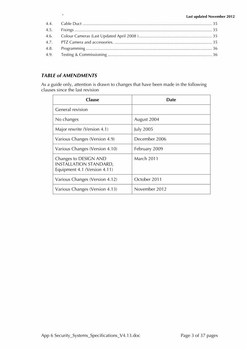
TABLE of AMENDMENTS
As a guide only, attention is drawn to changes that have been made in the following clauses since the last revision
Clause Date
General revision
No changes August 2004
Major rewrite (Version 4.1) July 2005
Various Changes (Version 4.9) December 2006
Various Changes (Version 4.10) February 2009
Changes to DESIGN AND INSTALLATION STANDARD, Equipment 4.1 (Version 4.11)
March 2011
Various Changes (Version 4.12) October 2011
Various Changes (Version 4.13) November 2012

` Last updated November 2012
App 6 Security_Systems_Specifications_V4.13.doc Page 4 of 37 pages

` Last updated November 2012
App 6 Security_Systems_Specifications_V4.13.doc Page 5 of 37 pages
The system and or devices are to be supplied with all equipment, hardware, software, cabling and ancillary services as required to provide an integrated system complete and functional in all respects. The tenderers are to familiarise themselves with all matters related to such requirement and to account for such in the tendered price.
Items clauses and/or products Marked (NA) are not required as part of this scope
It is the responsibility of the tenderer to obtain clarification of all matters in which doubt exists as to the exact intent of this document or in which a conflict appears to have arisen. Such information must be obtained before the closing and lodging of tenders.
The response shall clearly detail all pricing for components, cabling, installation, engineering, training, commissioning, setting to work, and 12 months comprehensive warranty.
Generally, equipment is located at:
Arthur Street, Kensington (5 Locations)
Botany Street, Randwick (8 Locations)
Cliffbrook Campus, Beach Street, Coogee
College of Fine Arts, Green Street, Paddington
David Philips Field, Daceyville
Eurimbla Avenue, Randwick (2 Locations)
High Street, Kensington (1 Location)
Kensington Campus, including the Command Centre (M11)
King Street, Manly Vale
L5 Building, Anzac Parade, Kensington
Rainbow Street, Kingsford (1 Location)
Randwick Campus, King Street, Randwick
Wentworth Street, Randwick
Western Campus, Anzac Parade, Kensington
The tenderer must include as part of the tender submission a complete, clause- by-clause response. Each clause is to be answered with one of the following statements:
Response Meaning
Complies The equipment/system offered complies fully in all respects with the specification clause.
Substantially Complies
The equipment/system offered does not comply fully but offers most or a substantial part of the requirements of the particular clause. Compliance in excess of 75% of the requirement qualifies for this category.
Partially Complies
The equipment/system offered provides only a part of the requirements of the clause. Less than 50% compliance with the clause should invoke this response.
Does Not Comply
The equipment/system offered does not provide any of the requirements of the particular clause.
Accepted The Tenderer understands and accepts the conditions imposed or enunciated by the particular clause, and has included provision for such in the tender.

` Last updated November 2012
App 6 Security_Systems_Specifications_V4.13.doc Page 6 of 37 pages
Response Meaning
Not Accepted
The Tenderer does not accept the condition imposed by the particular clause and as such is not included in the tender.
2. Functionality
2.1. Overview 2.1.1. The system shall provide a means to control access through nominated doors by
checking the access privileges stored in intelligent field controllers for access control tokens presented at such readers.
2.1.2. The system shall provide access control in elevators enabling the access of each cardholder to have access to any combination of floors over specified time periods. The interface to the elevator manufacturer’s equipment shall be by either low level interface (relay outputs) or by a high level interface (RS232).
2.1.3. The system shall monitor the condition of inputs. The system shall be able to be programmed to apply a variety of conditions to the way in which these inputs are monitored and shall enunciate the condition of such inputs in accordance with such programming.
2.1.4. The system shall provide a fully functional intruder alarm system including entry and exit delays where intruder detection sensors are connected to system inputs. The Intruder Alarm Systems component shall be fully integrated with the Access Control aspects of the system. It shall be possible to set (secure) or unset (insecure) areas from any access control reader associated with an area or via Remote Arming Terminals or as required from defined central control locations.
2.1.5. Specified system readers shall include an intercom function enabling a card reader user to talk to an operator as and when required, and an operator to talk directly to the card reader user. All intercom communications shall utilise the common Integrated Security system network and Communications cabling infrastructure, and be fully integrated with the access control system communications.
2.1.6. The system shall be able to provide images from any local or remote area via Digital Cameras that are an integral part of the system. All Cameras connected to the system shall utilise the common Integrated Security System network and communications cabling infrastructure, to provide images from any desired area within the system. Images shall be available on demand, and it shall be possible to initiate the image transmission from system wide events, time initiation or scheduling, or manual requests from system operators.
2.1.7. The system shall provide an integrated software facility for the design and production of photo ID cards.
2.1.8. The system shall be OPC enabled using Microsoft COM and DCOM enabling integration with other third party OPC enabled automation and business systems.
2.1.9. The operating system used by the system server shall either be Microsoft Windows® 2003 Server or XP Professional.
2.1.10. All system communications must be totally integrated on either existing or new LAN/WAN networks as defined by the attached configuration drawings. Connection to Intelligent Field Controllers (IFCs) shall be achieved using Ethernet cabling supporting 10baseT and TCP/IP protocols. Remote IFCs not connected to the network can be connected via TCP/IP and PSTN or via the Internet using a PSTN connection from a remote IFC to an Internet Service Provider.

` Last updated November 2012
App 6 Security_Systems_Specifications_V4.13.doc Page 7 of 37 pages
2.1.11. All system software upgrades shall be downloadable through the network to the IFC, Digital Cameras and readers with in-built digital Intercoms.
2.1.12. All data over the network between the IFC and the head end shall be encrypted using an asymmetrical encryption algorithm with a minimum encryption key length of 40 bits.
2.1.13 The encryption key shall be changed each time there is a new communication session between the IFC and the central control.
2.1.13A The system shall report all events to the operator(s) as configured and shall produce and maintain a log of all system events, alarms and Operator actions. The system shall provide a means for an operator to extract information relative to the event log and system configuration and produce this information in the form of printed reports, screen displays or ASCII files.
2.1.14. The system shall provide for a Windows based User Interface with Site Plans and interactive icons representing the location and real-time status of Access Control, and Alarm Monitoring equipment.
2.1.15. The system will provide emergency evacuation reporting.
2.1.16. The system shall be designed and manufactured by a reputable company who shall be certified under the ISO 9001 quality procedures.
2.1.17. All equipment shall have the following approvals:
FCC part 15
CE approval BS EN 50130-4 Alarm Systems Electromagnetic Compatibility (Immunity)
CE approval BS EN 55022 Emissions
Encoders and readers will also meet CE ETS 300 683 Short Range Devices
C-Tick AS/NZS 4251 Generic Emission Standard
C-Tick RFS29.
2.1.18. The system software shall be written in a fully structured, fully validated and commercially available language that provides a strictly controlled development environment.
2.1.19. The system shall employ a Microsoft SQL 2005 server database to store cardholder information and activity.
Comprehensive backup and archiving facilities shall be incorporated as an integral part of the system software.
The system shall include system division suitable for multi-tenanted buildings. Operators shall only be able to access those parts of the system which fall within their division and operator privileges.
The system shall allow for the connection of remote sites that do not have network connectivity via a PSTN connection using encrypted TCP/IP from the Internet Service Provider (ISP) on the remote site to the approved Internet service provider. The connection shall then be via an approved firewall through into the IT infrastructure for connectivity to the Central Server. Auto answer modems on the network infrastructure are a serious security risk and are therefore unacceptable.
2.1.20. IFC’s must support peer to peer communications for input and output communications between IFC’s. Systems that require the main server for communications between panels are unacceptable.
3. System Requirements
3.1. Overview 3.1.1. The system shall be in commercial operation with the same or similar

` Last updated November 2012
App 6 Security_Systems_Specifications_V4.13.doc Page 8 of 37 pages
configuration as detailed in this specification and shall be available for inspection. A reference list of such similarly configured systems and details of contact persons shall be submitted with the tender response.
3.1.2. The system described in this specification will be capable of the following capacity as a minimum.
Graphical Site Plans 2000
Access Readers 4000
Digital cameras 250
Elevators 50 elevators each with up to 75 levels
Supervised Alarm Inputs (4 state) 30,000
Output relays 20,000
Access Control Zones 4000
Schedules per day 100
Schedule categories 50
Holiday days 30
Operators 500
Concurrent Operator Sessions 40
Cardholders 900,000
Cardholder Issue Levels 15
Cardholder Personal Data Fields 64
3.2. Field Hardware Architecture 3.2.1. The system shall incorporate dedicated Intelligent Field Controllers (IFCs), which
communicate with and control the following equipment:
Card access readers
Elevator access equipment
Alarm monitoring Input/Output panels and equipment
Alarm response equipment
Digital smart cameras
Readers with intercoms. 3.2.2. The IFCs shall be intelligent in that in the event of failure of power or
communications to the central control, for whatever reason, the system shall continue to allow or deny access based on full security criteria. The IFC shall contain all the security and access parameters to operate completely independently from the central control server. Systems that rely on the central control PC for access decisions will not be considered.
3.2.3. The IFCs shall be intelligent in that in the event of failure of power or communications to the central control, for whatever reason, the system shall continue to allow or deny access based on full security criteria. The IFC shall contain all the security and access parameters to operate completely independently from the central control server. Systems that rely on the central control PC for access decisions will not be considered.
3.2.4. The IFC shall "concentrate" activity data for immediate transmission to the central control PC. The IFC shall hold all access and cardholder data.
3.2.5. The IFC shall be capable of holding up to 30,000 cardholder records in its standard configuration.

` Last updated November 2012
App 6 Security_Systems_Specifications_V4.13.doc Page 9 of 37 pages
3.2.6. In its standard configuration, each IFC shall be capable of buffering 5,000 events should communications fail with the central control.
3.2.7. Any failure of a card reader unit and its communications with the IFC shall be raised immediately as a high priority alarm and shall not cause the IFC or other units to stop or continue to allow or deny access correctly.
3.2.8. Communication between the IFC and the lower level units shall be encrypted.
3.2.9. The IFC shall contain a battery backed real time clock, synchronised on a regular basis with the main system Server.
3.2.10. The system shall monitor input circuits and enunciate whether the circuit is in Normal, Alarm, Open Circuit Tampered or Short Circuit Tampered.
3.2.11. The system shall separately monitor all enclosures to detect tampering and report low supply voltage conditions.
3.2.12. The IFC shall include tamper protection for the front and the back of the panel. The front panel shall be tamper protected for door open, and the rear of the panel to detect if the panel has been removed from the wall. This shall be an optical tamper detection. Mechanical tamper devices are not acceptable.
4. Central Control and System Management Software
4.1. Overview 4.1.1. The system shall use the Microsoft Windows® 2003/8 Server or XP/W7
Professional operating system. If SQL Server is used, the system server shall be Microsoft Windows® 2003/2008 Server.
4.1.2. The system shall be OPC enabled in accordance with the current OPC specification for OPC alarms and events. Refer to http://www.opcfoundation.org for Detailed Specification.
4.1.3. The central server shall employ a high quality Windows server and be a Microsoft approved model for operation with Windows 2003/8 Server.
4.1.4. The Server specifications, including processor speed, internal memory and hard disk size shall be specified by the supplier and must be sufficient to meet or exceed the specified system requirements.
4.1.5. The system shall support up to 40 PC based operator workstations simultaneously running on the operating system. Operator workstations running terminal emulation software will not be accepted.
4.1.6. The system shall automatically log all events within the system including intruder alarm set/unset events, access control events, alarm images from any Digital Camera, and operator actions and activity.
4.1.7. The central control software shall be easy to use, make extensive use of menus and windows and require a minimum of operator training to operate the system proficiently.
4.1.8. It should be possible to manage and monitor alarms, overrides, the general status of site items and open doors through the Graphical User Interface with the use of interactive real time dynamic site plans and icons.
4.1.9. A minimum of 2,000 graphical site plans must be available. All site plans stored on the server PC shall be automatically updated if amended at any of the networked workstations.
4.1.10. The following functions should, as a minimum, be able to be executed by clicking on a Site Plan icon:
View the current status of a Door, Input or Output.
Monitor and acknowledge an Alarm.

` Last updated November 2012
App 6 Security_Systems_Specifications_V4.13.doc Page 10 of 37 pages
Open an access controlled door.
Move from one plan to another plan.
View a Digital Camera.
Override an alarm or access zone state. 4.1.11. Each item shown on the Site Plan should be able to convey information about
the current state of that item.
4.1.12. The central control must be capable of receiving simultaneous alarm signals from a number of remote locations, without loss or excessive delay in their presentation to the operator. Any authorised operator should be allowed to acknowledge, view and/or process an alarm from any screen.
4.1.13. The central control shall be fitted with a real time clock, the accuracy of which shall be preserved over the period of main power supply failure. Synchronisation between the central control and Ethernet connected IFC’s shall be automatic, not requiring operator intervention.
4.1.14. Operator selection of processing tasks shall be via menu selections. Authorised Operators shall be able to process alarms, produce reports and modify database records without degrading system performance.
4.1.15. The following operational and monitoring facilities are required. This list contains the minimum required functionality:
The ability to program either a group or individual card readers with access control parameters, without affecting other card readers.
The ability to program the access criteria for individual Cardholders or groups of Cardholders.
The ability to store at least 64 non-access control data fields for each cardholder. The names of these “Personal Data” fields shall be user definable.
The ability to authorise or de-authorise a Cardholder in the system with the result reflected immediately throughout all readers in the system.
The ability to place a “Card Trace” against selected Cardholders so that an alarm is raised each and every time that cardholder presents their access card or token.
The ability to pre-program holidays so that different access criteria apply compared to normal working days. The system must have a capacity to set at least 30 holiday days.
The ability to define as many access zones as there are card readers fitted.
The ability to allow or disallow individual Cardholder access to any one, or group of card readers, in real time.
The ability to display the current status of all card readers, in real time.
The ability to log all system and operator activity to hard disk as they occur.
The ability to program alarm response instructions into the system so that these are presented to the Operator when processing an alarm event.
The ability to enable an Operator to enter messages against alarm events.
The ability to override (temporarily) a Cardholder’s, or group of Cardholders, pre-programmed access criteria.
4.1.16. The central control shall display a one-line plain language event message for every activity event (alarm or otherwise) occurring in the system. All activity logged shall be time and date stamped to the nearest second (hh:mm:ss). On having the appropriate operator authorisation it shall be possible to drill down into the properties of each component that makes up that event for future details. This includes but is not restricted to the following items:

` Last updated November 2012
App 6 Security_Systems_Specifications_V4.13.doc Page 11 of 37 pages
All card access attempts, successful or otherwise (unsuccessful attempts shall state the reason for the denial)
All door alarms
All operator activity including log on, log off, alarm response messages and any alteration of system data files
All alarm monitoring activations
All communications link failures
4.1.17. Communications between the central server and workstations shall be secured using the Microsoft COM/DCOM security facility.
4.1.18. Communications between the central server and IFC shall be encrypted.
5. Access Control, Security Alarm and I/O Programming 5.1.1. The system shall provide complete flexibility and be capable of programming an
unlimited combination of access control, security alarm and I/O parameters subject only to performance and memory limitations within the IFC.
5.1.2. For ease of programming Cardholders shall be grouped into access groups sharing the same access criteria.
5.1.3. Any cardholder or access group in the system shall be able to be programmed to have access to any combination of controlled doors in the system with each period of access for each door controlled to within the nearest minute.
6. System Integration 6.1.1. The system shall support OPC (OLE for Process Control) Alarms and Events
protocol to provide an open interface to allow integration with Building and Facilities Management, and Management Information Systems.
6.1.2. The OPC Interface shall allow third party OPC clients to access the security system’s events and field device data.
6.1.3. The system shall provide an XML interface to allow for the import, export, and synchronisation of data in an ongoing basis from other application directly into the Cardholder database both an on-line real time manner or in a batch oriented approach. A developer's kitset shall be readily available to allow for easy implementation.
6.1.4. The system shall provide an XML interface to allow for updating access control schedules.
6.1.5. A facility shall be provided in the system to allow for the real-time export of any alarm and event information to third party systems via customisable strings.
7. Access Control Readers
7.1. Overview 7.1.1. Reader technologies shall be Cardax Mifare proximity readers.
7.1.2. Each of these shall support:
7.1.3. Card plus PIN reader
7.1.4. Card only reader.
7.1.5. Combined Reader, PIN and Intercom (IDT) (NA)
7.1.6. The Card only reader option shall include beepers, and red and green LEDs, to provide feedback to users. A beeper shall give different beeps to indicate:
Access granted
Access denied

` Last updated November 2012
App 6 Security_Systems_Specifications_V4.13.doc Page 12 of 37 pages
7.1.7. A red LED shall flash red for access denied. A green LED shall flash green for access granted and shall show solid green when there is free access. A method of LED indication shall be required to indicate if a second card is needed for escort or dual authorisation modes.
7.1.8. An Intelligent Door Terminal (Card plus PIN reader option) shall include an LCD back-lit display with alpha numeric feedback indicating the access status of the zone controlled by the reader:
Secure
Shared PIN Number
Free Access/Access Granted
Access Denied
Card plus PIN
Wrong PIN
Dual Auth or Escort
Set Allowed
Set / Unset
Set Failed 7.1.9. The reader shall also include a beeper to give different beeps to indicate:
Access granted
Access denied
7.1.10. The Intelligent door terminals shall have an integrated Intercom with audio output being converted to digital data for transmission & compression through the card readers data connection to the IFC. (NA)
7.1.11. Readers with integrated PIN pad shall have back lighting on the keypad.
7.1.12. The Intelligent Door Terminals shall have keys numbered 0 to 9, clear entry (CE) and IN (enter), plus three function keys (F1 to F3) that can be programmed in the system set-up for Intercom activation, Door Control state change or Alarm Set/Unset. (NA)
7.1.13. The Intelligent Door Terminals shall support full bi-directional encrypted data communications. (NA)
7.1.14. Each reader shall be identified independently at the central control by means of a unique plain language descriptor. The central control plain language descriptor shall be at least 60 characters in length.
7.1.15. Controllers shall be capable of raising an alarm if the connection to the reader is broken.
7.1.16. Readers must comply with at least IP54 environmental protection rating. Provision shall be in the case of Proximity readers and Proximity plus PIN and Intercom readers to have a vandal resistant enclosure meeting an IP66 rating.
7.1.17. The IFC shall check entry based on ALL of the following criteria:
Correct facility code
Authorised card in database
Correct issue number
Authorised door / access zone
Authorised time of day
Correct PIN (If PIN entry is required)
Double entry (anti-passback).

` Last updated November 2012
App 6 Security_Systems_Specifications_V4.13.doc Page 13 of 37 pages
7.1.18. Any Cardholder entering an "anti-passback zone" controlled by a reader must exit from that zone by presenting their card to an exit reader.
7.1.19. The system shall include an optional “anti-passback” feature to allow Cardholders to re-enter the zone after a user-defined, pre-set time period has expired.
7.1.20. Every incorrect PIN attempt shall be notified at the central control as an alarm condition.
7.1.21. Each reader shall be capable of automatically switching the access mode at a door at different times of the day, based on control parameters received from the central control. The following access criteria modes are required:
7.1.22. Free access - Door is unlocked, no card entry required.
7.1.23. Secure access - Door is locked, a successful card attempt is required for valid entry. Door re-secures after access attempt.
7.1.24. Secure + PIN access - Door is locked, a successful card and correct PIN number attempt is required for valid entry. Door re-secures after access attempt.
7.1.25. Override from reader – Members of certain access groups shall be able to change the access and PINs mode of the door at certain times.
7.1.26. Dual Authorisation - access is granted when two different but legitimate cards are presented within a given time frame.
7.1.27. Escort – A second card is required to be presented from a cardholder who is nominated in the “Escort Access Group”.
7.1.28. Shared PIN Number – The system Operator determines what the PIN number will be and programs this into the system. Access is allowed through the door when the correct 4 digit PIN is pressed followed by the “Enter” key.
7.1.29. Cardholder access reporting to the central control and logging in the audit trail shall be configurable in two modes:
7.1.30. Only when there has been a successful presentation of a valid access card or token AND the door open sensor has detected that the door has actually been opened.
7.1.31. Whenever there has been a successful presentation of a valid access card irrespective of if the door has been opened.
7.1.32. Readers with integrated PIN pads shall provide an “Entry under Duress” facility.
7.1.33. Duress shall be initiated by the cardholder either by the addition of a unique number to their PIN number, or by incrementing the last digit of their PIN number by one.
7.1.34. There must be NO indication of a Duress entry at the reader.
7.1.35. A high priority “Duress Alarm” shall be displayed at the central operator station.
8. Intelligent Field Controller (IFC)
8.1. Overview 8.1.1. The IFC shall incorporate a 32-bit processor with at least 4 Megabytes of non-
volatile FLASH EEPROM. The IFC software shall incorporate boot code in a protected sector of the flash memory. All system software can be downloaded over the network for upgrades from the central control.
8.1.2. The IFC shall operate from a separate 13.6V DC supply.
8.1.3. The IFC shall continue to operate for at least 24 hours in the event of a mains supply failure.
8.1.4. The system shall be capable of automatically detecting and reporting a power

` Last updated November 2012
App 6 Security_Systems_Specifications_V4.13.doc Page 14 of 37 pages
failure, low battery and battery not connected.
8.1.5. IFCs shall be fitted with automatic restart facilities to enable them to resume processing following a power and backup failure.
8.1.6. IFCs shall be fitted with "watchdog" hardware and software to enable them to restart and resume normal processing, should the processing system ever be corrupted.
8.1.7. The IFC shall contain its own battery backed real time clock. The battery shall have a minimum life of ten years. The clock shall be synchronised with the central control’s clock at least once per hour. The accuracy shall be such that the time difference between IFCs shall not vary more than 0.5 second at any time.
9. Central Control
9.1. Overview 9.1.1. The IFC shall have an on board Ethernet (TCP/IP) connection and driver for
communications with the central control. The data speed for this connection should support both 10BaseT and 10Base2.
9.1.2. The IFC shall include a least one other RS 232 multi-communications ports.
9.1.3. The IFC shall support remote site dial-up.
9.1.4. During communications failure all access, valid or otherwise, and all alarm events shall be buffered at the IFC. The activity buffer shall be at least 5,000 events. The IFP shall transfer the buffered events to the central control automatically when the communications link is re-established.
9.1.5. It shall be possible to view the IFC status and configuration for commissioning and diagnostic purposes without the use of the central server software or other proprietary software. This may be achieved by the use of conventional WEB based browser. In high security applications, it must be possible to disable this feature at the IFC.
9.1.6. A separate alarm message shall be transmitted to the central control for each of the following alarm conditions. The alarm message shall be displayed in plain language text.
Tamper
Tamper Return to Normal
Unit Stopped Responding
Card error
Maintenance Warning
Alarm Sector State Change
User Set
User Unset
Card Trace
Wrong PIN
Access Denied
Duress
Zone Count Maximum
Zone Count Minimum
Door Open Too Long
Forced Door
` Last updated November 2012
App 6 Security_Systems_Specifications_V4.13.doc Page 15 of 37 pages
Door Not locked
Power Failure
System Reboot.
10. Digital Camera
10.1. Overview 10.1.1. The Digital Camera shall perform image compression, motion detection and
image security measures to prevent any tampering of the digital image to ensure its integrity for evidential purposes.
10.1.2. The Digital Camera shall be supplied with default settings all of which can be configured through the central control. Default settings include:
Live frame rate
Compression/picture quality
Default contrast
Default brightness
Recording frame rate
Pre-event frame store
Post event frame store
Motion detection area.
10.1.3. Images shall be colour and the camera shall have a minimum resolution of 480 lines and shall be capable of operating in the infrared spectrum.
10.1.4. The Digital Camera shall automatically adjust the electronic shutter for varying light conditions with a fixed aperture lens.
10.1.5. The Digital Camera shall be fully digital with no need for analogue video outputs or signal converters.
10.2. System Network/Transmitting Images:
10.2.1. The Digital Camera shall connect using the same communications, networks, and hardware as used by the rest of the integrated security systems. DVR’s shall be networked via the Security controlled CCTV secure VLAN.
10.2.2. The Digital Camera shall be set up so as to minimise the bandwidth requirements for the imaging system enabling it to work on existing company Intranet or Internet communication systems.
10.2.3. Images will be recorded and viewed on the main server and associated workstations.
10.2.4. The Digital Camera shall: (Last Updated December 2006)
Send images to the IFC at a compression rate of at least 35:1 to reduce the amount of traffic on the network. The maximum acceptable amount of network traffic it generates shall be 200kbps.
Be capable of compressing a full frame image at a minimum of 4 fps.
Be capable of transferring images at a minimum of 2 fps from the IFC through Ethernet and approximately 1 fps through a 56kbps dial-up connection.
The central control shall send commands to the Digital Camera including arming and disarming the Digital Camera.
Software upgrades shall be downloadable over the network from the central control through the IFC to the Digital Camera.
` Last updated November 2012
App 6 Security_Systems_Specifications_V4.13.doc Page 16 of 37 pages
10.3. Image Motion Detection 10.3.1. The Digital Camera shall include motion detection to enable the image
transmission to be event triggered. It may also be configured to be triggered by any access or alarm event within the system.
10.3.2. It shall be possible to define up to 10 separate motion detection areas within the camera field of view for each Digital Camera.
10.3.3. Each motion detection section can be set to be armed or disarmed in accordance with time schedules.
10.4. Recording and Storing Images 10.4.1. The server shall be capable of storing images sent concurrently from up to 10
Digital Cameras at a rate of 2 fps per camera, a total of 20 fps.
10.4.2. The nominal image size per frame shall be 6KBytes storage.
10.4.3. The Digital Camera shall buffer at least 20 images at a nominal compression rate of 6kbytes per image so that a request can be made to the Camera to send a user defined number of images immediately before and after an event.
10.4.4. It shall be possible to configure the central control so that images are linked with events and alarms.
10.4.5. It must be possible to configure which event sources trigger image storage for a particular Digital Camera. This configuration can be done at the central control.
10.4.6. It shall be possible to send up to 10 seconds of pre-event recorded images from the Digital Camera on an alarm (40 images).
10.4.7. It shall be possible to send up to 10 seconds of post-event recorded images from the Digital Camera on a record request (40 images).
10.4.8. The system shall provide security of images and prevent the tampering of images locally or globally (water marking). The Digital Camera shall provide watermarked images that are tamper proof and tied to date, time, Camera and system.
10.4.9. It shall be possible to archive to off-line storage the event log and image sequences.
10.4.10. It shall be possible to rewind and fast forward stored image sequences.
10.4.11. It shall be possible to print a single image from the image sequence.
10.4.12. It shall be possible to copy an image from an image sequence to the clipboard.
10.5. Viewing Images 10.5.1. The system shall enable viewing of the following to operator workstations:
Recorded images
Live images. 10.5.2. Stored images shall be retrievable from the log within 2 seconds.
10.5.3. It shall be possible to view live images from up to 4 Digital Cameras through one operator workstation. The operator must be able to digitally zoom the displayed image.
10.5.4. It shall be possible for up to 4 operator workstations to view the same camera at the same time.
10.5.5. The operator shall only be able to view images from those Digital Cameras that they are authorised to view.
10.5.6. The Digital Camera shall include on-board infrared illumination for image enhancement under poor lighting conditions.
` Last updated November 2012
App 6 Security_Systems_Specifications_V4.13.doc Page 17 of 37 pages
10.5.7. The contrast and brightness of images shall be automatically controlled by the Digital Camera but can also be manually adjusted by the operator.
10.5.8. It must be possible to electronically pan, tilt and rotate images at the workstation. These adjustments shall only adjust the way the images are processed on the workstation:
Digital Pan means that the smaller rectangular region can be shifted to the left and right of the centre of the original image.
Digital Tilt means that the smaller rectangular region can be shifted to above and below the centre of the original image.
Digital Rotate means that the image from the camera can be rotated about the centre of the image (e.g. to align the floor to the horizontal if the camera has been mounted on an angle.)
10.5.9. The operator may resize the viewing window at any time.
10.5.10. Viewing performance shall nominally be up to a total of 2 fps when viewing one camera down to 0.5 fps when viewing four cameras at full size.
10.5.11. It shall be possible to trade off frame rate with picture quality.
10.6. Digital Camera Hardware 10.6.1. It shall be possible to mount the Digital Camera at different angles on the wall, a
pole or an adjustable bracket.
10.6.2. A choice of lenses shall be provided with the Digital Camera to accommodate wide angle to narrow field viewing.
10.6.3. The Digital Camera shall be tamper proof with in-built tamper detection. Should either the power or the communications cables be disconnected from the Digital Camera, an alarm will be reported by the IFC.
10.6.4. The Digital Camera housing shall meet IP64 and be able to withstand regular cycling between –10 degrees and +55 degrees C ambient temperature at a rate of change less then + 20 degrees/hour. It shall operate at a humidity of up to 98% relative humidity (non-condensing).
10.6.5. The Digital Camera shall be powered by a nominal 13.6 V DC power supply and variations from 10 V to 20 V shall have no harmful effects. External connections shall include connections to the network via RS-485 and power (13.6 V) wires. An on-board serial port monitor connection shall also be provided to enable local alignment of the Digital Camera through a laptop PC
10.6.6. The Digital Camera unit shall periodically check itself for correct functioning. Any errors shall be reported to the central control.
11. Intercom (NA)
11.1. Overview 11.1.1. The Intercom shall be an integrated component of the Integrated Security System
enabling communication between an operator and cardholder/user.
11.1.2. The Intercom shall be totally integrated into the card reader with the audio signal being digitised and transmitted to the operator via the Integrated Security System’s digital communications network.
11.1.3. The reader with the Intercom shall be fully integrated into the Integrated Security System via connection to the IFC enabling communication between the cardholder and the operator.
11.1.4. It shall be possible to configure the Intercom through the central control including configuring:
` Last updated November 2012
App 6 Security_Systems_Specifications_V4.13.doc Page 18 of 37 pages
11.1.5. Microphone gain
11.1.6. Speaker volume at the operator workstation
11.1.7. Call button action.
11.1.8. The intercom shall use the same system and communications as the card readers and field devices.
11.1.9. It shall be possible for operators to use multiple intercoms connections with Intelligent Door Terminals concurrently.
11.1.10. The intercom system must be capable of digitising, compressing and transmitting continuous audio data (in the range of 300 to 3000 Hz).
11.1.11. Delays between the audio being received by the intercom and replayed on an operator workstation shall be negligible when the IFC to central control connection is running over standard Ethernet, with both nodes on the same segment.
11.1.12. The intercom shall operate in half duplex mode.
11.1.13. It shall be possible to turn the intercom function on and off via commands from the central control.
11.1.14. Use of the intercom shall be recorded as an event/alarm within the Integrated Security System, recording the:
identity of the operator
location of the intercom
time the intercom was used (Intercom off and on). 11.1.15. The operator shall be able to:
Adjust the speaker volume or microphone gain at any time during a conversation.
Access information about the status of an Intercom including the ability to turn an Intercom on through the central control system menu options, through a tree view of the system or through a site plan.
12. Elevator Control and Management
12.1. Overview 12.1.1. The system must provide fully integrated elevator control facilities. The elevator
control access equipment must communicate with the same central control as the door card readers.
12.1.2. The elevator control architecture shall comprise a card reader in each elevator car, reporting to elevator control interface equipment mounted in or near the elevator motor room. Reader type shall be the same as that used on access control doors.
12.1.3. The elevator control system shall be capable of controlling access independently in a number of elevator shafts simultaneously.
12.1.4. The elevator control system shall incorporate dedicated intelligence and a local database of authorised cardholders.
12.1.5. Each elevator reader shall be identified independently at the central control by means of a unique plain language descriptor. The central control plain language descriptor shall be at least 60 characters in length.
12.1.6. Each reader head shall be capable of raising an alarm if it stops communicating with its elevator controller or is removed from the elevator.
12.1.7. The elevator reader shall check entry based on ALL of the following criteria:
Correct facility code

` Last updated November 2012
App 6 Security_Systems_Specifications_V4.13.doc Page 19 of 37 pages
Authorised card in database
Correct issue number
Authorised level
Authorised time of day
Correct PIN (If PIN entry is required).
12.1.8. Each elevator car reader shall be capable of automatically switching the current access criteria at an elevator card at different times of the day, based on control parameters received from the central control. The following access criteria modes are required:
Free access - elevator level select button for that level is unlocked, no card entry required.
Secure access - Elevator level is locked. A successful card attempt is required for valid entry. Elevator level re-secures after access attempt
Secure + PIN access - Elevator level is locked, a successful card and correct PIN number attempt is required for valid entry. Elevator level re-secures after access attempt.
Dual Authorisation - access is granted when two different but legitimate cards are presented within a given time frame.
Escort – A second card is required to be presented from a cardholder who is nominated in the “Escort Access Group”.
Shared PIN Number – The system Operator determines what the PIN number will be and programs this into the system. Access is allowed at the elevator level when the correct 4 digit PIN is pressed followed by the “Enter” key.
12.2. Low Level Interface. 12.2.1. The interface between the access system elevator control equipment and the
actual elevator switching control equipment shall be via dry relay contacts.
12.2.2. The elevator control system shall provide one relay contact per elevator shaft per level for the system. This relay contact shall be used to interface with the elevator switching control equipment.
12.2.3. An input shall be provided for each level per elevator to indicate what level the user selected. On activation of this input all relays return to secure state.
12.3. High Level Interface 12.3.1. The interface between the access system elevator control equipment and the
actual elevator switching control equipment shall be via RS-232 connection.
12.3.2. The elevator control equipment will provide feedback as to which level was selected by the cardholder and only allow the one level to be selected per valid card swipe.
12.4. Elevator Access Management 12.4.1. The elevator control system shall be capable of setting individual levels to
public access (no card required) while other levels require a valid card access attempt.
12.4.2. Levels must be securable on a level-by-level basis, using command instructions transmitted from the central control.
12.4.3. The central control must provide operator override facilities to enable temporary override capability on a level by level basis.
12.4.4. The elevator control system shall continue to operate without performance degradation in the event of a communications link failure with the central
` Last updated November 2012
App 6 Security_Systems_Specifications_V4.13.doc Page 20 of 37 pages
control.
13. Access Cards and Tokens
13.1. Overview 13.1.1. Several access token technologies shall be proposed, such as Magnetic stripe,
Mifare Plus, Nedap and air-key transmitter
13.1.2. Magnetic stripe and Mifare Plus cards shall be passive.
13.1.3. Mifare Plus cards shall be of standard credit card size, being no larger than CR-80 and shall be direct printable using a dye-sublimation print process or be capable of accepting an adhesive label printed through such a process. All cards shall meet ISO standards. (NA)
13.1.4. If Smart Card is the chosen technology: (NA)
Smart Cards shall incorporate Mifare Plus technology.
The card number shall not be the card serial number, it must be a number specifically coded onto the card.
13.1.5. As well as CR80 sized cards, vehicle tokens and key-ring transponders should also be proposed as an alternative, where available. (NA)
13.1.6. The access token shall contain a unique facility code, unique cardholder identification number and issue level.
13.1.7. The access control token shall uniquely identify the cardholder to the access control system.
13.1.8. Access control information shall be stored on or in the access token in an encrypted manner.
13.1.9. During transmission of data between a proximity access token and a proximity reader, the data shall be encrypted. (NA)
13.1.10. All access control encoding data shall be invisible to the naked eye.
13.1.11. There shall be barriers employed to prevent the deciphering of access control data stored on the card using any readily available equipment. The tenderer shall document the barriers used.
13.1.12. There shall be barriers employed to prevent the copying or altering of access control data stored on the card using any readily available equipment. The tenderer shall document the barriers used.
13.1.13. Additional cards and access tokens shall be available and delivered on site within 24 hours of request.
13.1.14. The system shall be assigned a unique facility code worldwide, exclusively for this project.
13.1.15. The system shall be capable of uniquely recognising card or token numbers up to seven (7) digits in length.
13.1.16. The system shall be capable of uniquely recognising and handling up to 15 issue levels for each unique Card number ID.
13.1.17. Cards and access tokens shall be able to be encoded by the supplier according to the clients specifications, made known at the time of order. Cards and tokens supplied with manufacturer determined card numbers will not be acceptable. (NA)
13.1.18. It shall be possible to encode cards and tokens to allow operation of a user defined Personal Identification Number (PIN) and the card still be supplied ex
` Last updated November 2012
App 6 Security_Systems_Specifications_V4.13.doc Page 21 of 37 pages
stock as defined above.
13.1.19. As an alternative, pricing should be supplied for the supply of encoding software and hardware that enables the Client to encode their own cards and/or tokens on site. (NA)
14. Cardholder Management 14.1.1. The cardholder database shall be structured so that the name field is the key
field for each record. Use of the card number as the key field is not acceptable.
14.1.2. Each IFC shall cater for up to 30,000 cardholders in its standard configuration. The entire system should cater for up to 900,000 cardholders.
14.1.3. The system must allow at least 15 Issue Levels per card or token and must deny access and raise a stolen card alarm to the operator when a wrong issue level is presented to a reader.
14.1.4. Cardholders must be able to be issued with more than one access token of different description and different number (i.e. access card and vehicle token) whilst maintaining only one cardholder record in the database.
14.1.5. At least 64 user-definable “Personal Data” fields shall be provided which may be selectively reported on.
14.1.6. Personal Data Fields shall be able to be set up as either:
Text – User data may be entered.
Text List – User selects text from a pre-prepared list of text strings.
Numeric – User must enter numeric data.
Default Value – The field has a default value assigned.
Image – User assigns an image to the field. 14.1.7. Personal data Fields shall be able to be configured as:
Required field – Data must be entered.
Unique Values – Data must be unique form all other card records.
No Default Value – Default value disabled.
14.1.8. It shall be possible to “group” or “filter” cardholders for the purposes of editing access, generating reports and assigning operator privileges.
14.1.9. The following information fields shall be displayed on the Cardholder editing window:
The date when a cardholder record was created.
The date when the record was last modified and by whom.
14.1.10. For ease of programming Cardholders shall be grouped into access groups sharing the same access criteria and default personal data fields.
14.1.11. It shall be possible to enter an automatic expiry date for the card.
14.1.12. It shall be possible to program future start and end dates and time for a new cardholder’s access or any specific part of their access.
14.1.13. It shall be possible to allocate start and end dates and times for an Access Group’s access to a particular access zone.
14.1.14. Access shall have start and end dates and time to within one minute.

` Last updated November 2012
App 6 Security_Systems_Specifications_V4.13.doc Page 22 of 37 pages
15. Intruder Alarm System
15.1. Introduction
The system will incorporate a fully functional intruder alarm system. Any Inputs globally within the system can be utilized as intrusion alarm inputs and be connected to Intruder detection sensors. Likewise any outputs anywhere within the system can be used for intruder alarm purposes such as sounding remote sirens etc. There are to be sirens in the vicinity of the alarm system which sound locally in the event of an alarm activation unless specifically stated otherwise.
Arming and disarming the intrusion detection system is to be by either using card readers or remote arming terminals. A fundamental requirement is that it is not possible for personnel to enter an area protected by the intruder alarm system while it is in the armed state.
Authorized cardholders automatically unset and protected areas on authorized controlled access to those areas. Connection with Central Alarm Monitoring stations is via digital communicators connected directly to the field control panels. It is a fundamental requirement that panels communicates directly with each other independent of any central sever. (Peer to Peer communications.)
15.1.1. Input circuit shall be monitored by end of line resistors to provide detection of the following 4 states.
Alarm
Tamper
Open circuit
Short Circuit
15.1.2. Multiple inputs from detection devices covering the same region for control purposes are to be grouped into alarm zones. Alarm zones can be in any one of four states and shall handle alarms differently depending of the state. The first two shall be defined as set (armed) and unset (disarmed). The names of the other states shall be able to be defined at the central control for other purposes such as maintenance testing. Access control zones are to be able to be associated with alarm zones if required for setting and unsetting the alarms zones from access control readers.
15.1.3. Alarm priorities can be assigned to any of the four input states.
15.1.4. The system shall provide entry and exit delays for the setting and unsetting of alarms.
15.1.5. The entry delay shall be configurable from 0 to 5 minutes in steps of one second.
15.1.6. An optional audible warning must sound during the entry delay (from the time that the alarm occurs to the time that the Zone state is changed). It must be possible to designate specific card readers and remote arming terminals to sound entry delay warning beeps. Selected output relays should also be able to be operated during the entry delay period allowing suitable sounders to be connected at required locations.
15.1.7. An exit delay is to be provided to groups of inputs so that a change of state of an exit delayed zone is delayed by the exit delay period, which can be adjusted, from 5 seconds to 5 minutes in steps of one second.
15.1.8. An optional audible warning must sound during the exit delay (from the time that the alarm occurs to the time that the Zone state is changed). It must be possible to designate specific card readers and Remote Arming Terminals to

` Last updated November 2012
App 6 Security_Systems_Specifications_V4.13.doc Page 23 of 37 pages
sound exit delay-warning beeps. Selected output relays should also be able to be operated during the exit delay period allowing suitable sounders to be connected at required locations.
15.1.9. This applies to both manually and automatically changing the state of a zone – in the case of automatically changing the state of a zone the exit delay and audible warning gives people working late in the building time to unset the alarms or leave the building.
15.1.10. The system shall include Alarm Escalation. This new event shall correspond to the original alarm, but may have a different (usually higher) priority, and may cause a different set of alarm relays to switch and output via contact ID to Central Monitoring Station. Facility is to be provided with in the system to enable alarms to be escalated under the following conditions:
Escalate if alarm not acknowledged after (X) seconds
Escalate if in inactive state for (X) seconds
Escalate if zone contains (X) alarms
Escalate if two event from same point within (X) seconds.
Escalate if two events from different points in same zone within (x) seconds 15.1.11. It shall be possible to have automatic time based setting and unsetting of alarms.
15.1.12. It shall be possible to configure the system such that events (such as a card swipe or operation of a key switch connected to an input) can cause the state of a zone to be manually changed.
15.1.13. It shall be possible to authorise selected cardholders to be able to set and unset
15.1.14. Multiple alarm zones can be set and unset from a Remote Arming Terminal
15.1.15. Individual alarm zones can set and unset by operation of the Card plus PIN reader as an alarm panel.
15.1.16. All alarm occurrences shall be presented at the central control within 4 seconds of their occurrence at the remote field device.
15.1.17. All Alarm events shall be viewable from an Alarm Stack.
15.1.18. It shall be possible to view all alarm events by clicking on interactive Site Plan icons that, because of their changing audible and visual states, indicate the presence of alarms.
15.1.19. All alarm events arriving at the central control shall be "time stamped" with the time they occur and the time they were logged at the central control.
15.1.20. All alarm events shall have a user definable alarm priority assigned. A minimum of 10 alarm priority levels shall be provided.
15.1.21. Incoming Alarms shall be presented in the Alarm stack according to their assigned priority with the highest level at the top. Alarms with the same priority shall be presented in time order.
15.1.22. The priority of Alarms in the alarm stack shall be identifiable by a different text colour.
15.1.23. The central control must be able to control the actual priority assigned to any alarm activation throughout the day. This means alarm activation may be programmed as "Low Priority" during office hours and “High priority at all other times.
15.1.24. It shall be possible to nominate an Input (e.g. Smoke, Fire or Gas detection) as an “Evacuation Input” in which case certain doors within the Site will revert immediately to Free Access.
15.1.25. Operators shall have a 2-stage alarm processing mechanism available to them,

` Last updated November 2012
App 6 Security_Systems_Specifications_V4.13.doc Page 24 of 37 pages
being:
Acknowledge Alarm.
Process Alarm.
15.1.26. An Acknowledged alarm shall remain in the alarm stack and be easily identified as having been Acknowledged but not yet Processed.
15.1.27. A Processed alarm shall be cleared from the Alarm Stack. The central control shall record in the hard disk activity log that the operator has processed the alarm. An alarm is “Processed” by the operator selecting the “Process” button that is displayed on the alarm-viewing window.
15.1.28. An alarm shall not be able to be finally processed and cleared from the Alarm Window until the alarm cause has returned to the normal state.
15.1.29. The Alarm viewing window will display the pre programmed alarm instructions to the operator.
15.1.30. Alarm Instructions shall have the following features:
Default Alarm Instructions shall be able to be programmed and automatically applied to all events of a common type e.g. all wrong PIN events in the system for all readers.
Individual Alarm Instructions shall be able to be programmed and applied to individual alarm events.
A table of contact names, phone numbers or other frequently used volatile information shall be available when programming Alarm Instructions, and applied to Alarm Instructions from a pick list. When this table is maintained, all Alarm Instructions having links to the table will automatically be updated.
It shall be possible to cut, copy and paste Alarm Instructions between alarm events.
The Alarm window will allow the operator to enter a comment. Such comment will be date stamped by the system, and recorded against that alarm event in the audit trail.
15.1.31. The system shall provide relay output facilities that are system activated in response to alarm activations.
15.1.32. The system shall provided the following relay output functions:
Activate and latch relay in response to alarm. Relay to remain latched until alarm processed.
Activate relay for pre-set "pulse" time. Relay to return to "idle" after "pulse" time lapses.
Relay activation to "mirror" alarm input activation.
15.1.33. The system shall incorporate relay outputs that be activated by time, rather than alarm event. These outputs may be used to control lighting, heating, or to electronically lock or unlock non-monitored doors.
15.1.34. The system shall incorporate the feature of Multiple digital communicators for annunciating system alarms and events to Central Monitoring Stations. Digital communicators are to be connected directly to field controllers. They are able to communicate any device in the system anywhere to a Central Monitoring Station.
15.1.35. Digital communicators are to be able to communicate alarms across the complete system independent of system server.
15.1.36. System shall report and log the all Digital Communicator activity and reason for any failure to communicate.
15.1.37. System shall provide for up to two back up diallers on different controllers to provide automatic backup capability should the designated digital
` Last updated November 2012
App 6 Security_Systems_Specifications_V4.13.doc Page 25 of 37 pages
communicator fail to operate on the appropriate alarm condition.
15.1.38. Multiple remote arming terminals can be used anywhere in the system to remotely manage assigned Intruder alarm zones.
15.1.39. Remote arming terminals shall have the following functionality:
If authorized all cardholders Set and unset all or selected intruder alarms zones that have been assigned to that remote arming Terminal.
If authorized shall have the ability to acknowledge alarms.
If authorized will have the ability to shunt input for alarm zones.
If authorized have Remote arming terminals to provide system summary of status of all devices “covered” by the remote arming terminal.
15.1.40. Logging on to the remote arming terminal will be by presenting a valid card to a specific reader installed for this purpose. The reader associated with the Remote Arming Terminal must not be used for any other purpose other than accessing the RAT.
15.1.41. Only at the discretion of the UNSW Security Systems Officers, the remote arming terminal can also be accessed by any one of the following:
Entering a unique 4 digit PIN
Entering a unique 6 digit PIN
Presenting a valid card to a reader associated with the Remote Arming Terminal plus entering a 4 or 6 digit PIN on the Remote Arming Terminal.
15.1.42. Communications between the remote Arming Terminals and the controllers shall be encrypted to a strength equivalent to 128bit Triple AES.
15.1.43. Remote Arming Terminals shall be capable of being programmed to handle combination of up to any 30 alarm zones and their associated Inputs across a complete system.
15.1.44. Cardholder and groups of Cardholder can be assigned to operate any, or combination of any Remote Arming Terminals across a system.
15.1.45. Cardholders will only be able to see and operate the appropriate alarm zone information they are authorized to have access to.
15.1.46. The intruder alarm system shall provide a dependencies facility where by the an alarm zone does not go into the set state until the “Dependent” alarm zones are all in the set state.
15.1.47. Each group of cardholders in the system shall be able to be assigned any combination of the following privileges relating to operation of the intruder alarm component of the systems:
Unset intruder alarm zones
Set Intruder alarms zones
View status Alarms and inputs on Remote Arming Terminal.
Acknowledge Alarms
Shunt Inputs
Prompt for alarm zone selection
Force-arm alarm zones
Auto-isolate alarm zones

` Last updated November 2012
App 6 Security_Systems_Specifications_V4.13.doc Page 26 of 37 pages
16. Operator Management
16.1. Overview 16.1.1. The system must provide for at least 500 operator identifiers.
16.1.2. Operator establishment and maintenance shall be limited to assigned Senior Operators.
16.1.3. It shall be possible to force operators to change their password after a predetermined time.
16.1.4. It shall be possible to configure the system to only allow one logon per operator.
16.1.5. It must be possible to allow or deny Operators access to system menu functions. This includes the viewing of Cardholder Personal Data fields, Personal Notes and Images.
16.1.6. It must be possible to restrict Operator access to Cardholders based on system division.
16.1.7. Any menu option not available to an Operator should be greyed out.
16.1.8. It must be easy to define operator privileges for a group of operators and it must be easy to add an operator to the group.
16.1.9. Operator access to the system is to be restricted by means of an operator identifier and password.
16.1.10. Each operator shall have the authority to alter his own password, but not that of
17. Audit Trail & Reports
17.1. Overview 17.1.1. An electronic hard disk shall be used to record all system activity for archiving
purposes. Once archived it shall not be possible to alter data.
17.1.2. Every system activity event, whether valid access attempt, intruder alarm, camera activation or system activation, or alarm event, shall be time stamped with the time of occurrence and shall be recorded in the system activity log. Time stamping shall include the date, and be to the nearest second.
17.1.3. The central control shall provide an on-line facility to archive system data and event records to an archive file to free hard disk space for further activity logging.
17.1.4. All operator initiated actions shall be recorded in the audit trail. Each operator action event logged to audit trail shall be stamped with time of day and operator ID. The audit trail shall include all details of any change that an operator has carried out.
17.1.5. The central control shall provide historical reporting capabilities from the following sources of information:
System activity data
Cardholder's access
Cardholder Personal Data fields
Cardholder access groups
Site configuration and setup data.
17.1.6. The report generation facility shall be easy to use and based on a “wizard” style of parameter selection and preparation. The wizards shall provide features to simplify report generation by incorporating selections such as report for “yesterday”, “last week”, “last month” etc. This is for the purpose of quickly
` Last updated November 2012
App 6 Security_Systems_Specifications_V4.13.doc Page 27 of 37 pages
generating recurring, standard format, reports.
17.1.7. The parameters for producing the report must be fully user definable and must be capable of searching on any cardholder or access event criteria.
17.1.8. It shall be possible to produce an “Evacuation Report” upon request that will list all cardholders by their last known Access Zone.
17.1.9. The central control shall generate and format reports in "background". This means the operator must be able to process alarms, alter database parameters and perform other system changes while the report is being generated. Report generation must continue if the operator decides to perform any other task.
17.1.10. The central control shall have a screen preview function, so that reports can be previewed on-screen before they are printed.
17.1.11. Report formats shall be able to be saved for future use.
17.1.12. The central control shall have a "printer spooler" so that reports can be printed at any of the printers connected to the system.
17.1.13. The central control shall have a printer queue facility to enable reports to be queued if the target printer is off-line, busy, not connected or faulty.
18. Photo ID Badging
18.1. Overview 18.1.1. The system shall provide a means to electronically capture images, store those
images in an electronic database, integrate those images into a pre-designed ID card, from within the system, and produce an integrated and completely finished identification card within the nominated time frame. Images are defined as being one or more of the following:
Photographic image of the cardholder
Signature of the cardholder and/or authorising person
A fingerprint of the Cardholder
Organisation Logos or designs.
18.1.2. The system shall be capable of importing database information, on selected cardholders, from other systems and be capable of exporting that cardholder’s data, either with or without controlled alteration or amendment, to other databases.
18.1.3. The system shall have an integrated method of card design within the system software without the requirement of having to import background files from other software programs. The facility to import background images from other sources must also be available. This must include scanned logos and other graphical imagery if desired.
18.2. Image Capture 18.2.1. The system offered shall capture images in 24 bit colour and at least 640 x 480
pixel resolution using standard video capture hardware offering a TWAIN standard interface or a USB digital camera.
18.2.2. Images must be able to be “cropped” after capture to optimise the image size within the desirable image area. This movable “cropping” box must be user-definable as to size.
18.2.3. Images must be capable of being enhanced by the use of variable Contrast and Brightness controls and by the use of Smoothing and Sharpening controls from within the capture software after they have been captured. These controls must be easy to use from within the system software and once set, these controls must
` Last updated November 2012
App 6 Security_Systems_Specifications_V4.13.doc Page 28 of 37 pages
be capable of applying the same setting on subsequent image captures for different cardholders. Mouse operated “sliding” bars are preferred however numerical controls may be acceptable.
18.2.4. The image, once captured, must also be capable of being flipped and inverted as required before being printed or stored as per clause 16.3.1.
18.2.5. Up to three images per cardholder must be capable of being captured and stored within the system. Images may be defined as per section 16.1.1 above.
18.3. Image & Cardholder Data Storage 18.3.1. The system shall store images in the JPEG compression format. User definable
compression rates shall be easily selectable by the operator permitting, as a minimum, at least three levels of JPEG compression.
18.3.2. The system offered shall be capable of importing image files, for use in either card layout or cardholder images, from at least the following formats:
• JPEG, Windows BMP, TGA, CMP.
18.3.3. The card design must be capable of incorporating, storing, printing and displaying bar-code information and must support the following bar-code formats:
Code 39
Code 39 with checksum
Interleave 2 of 5
Interleave 2 of 5 with USS
Interleave 2 of 5 with OPC
18.4. Card Design 18.4.1. The system must have an integrated card design program. Systems offering only
a separate card design program where card design images must be created in alternate drawing programs and imported are not acceptable however the system offered must also be capable of using imported images as per clause
18.4.2. The card layout section of the system must be capable of user-selecting up to 16.7 million colours with a custom colour palette available.
18.4.3. Card design must be accomplished by the use of “grab and move” options using a mouse.
18.4.4. The system must be capable of using all of the common word processing fonts and must also be capable of normal text manipulation including, text sizing, left and right justification, centering, bolding, underlining & italicising.
18.4.5. The variable cardholder image files that are selected to incorporate into the card design must be user-definable as to size. Full size being defined as 30mm x 40mm. The sizing must be fully user configurable from 25% of full size up to 200% of full size, as a minimum, and must offer automatic aspect ratio adjustment throughout the size range.
18.5. Output Options 18.5.1. The system shall be capable of producing hard copy output of images and data
using any standard MS-Windows™ printer including laser, bubble-jet and dot-matrix printers.
18.5.2. The system shall produce photo ID cards using a single step hard-card colour MS-Windows compatible printer. Systems offering multi-stage production, any heat lamination or heat & pressure card production are not acceptable. The

` Last updated November 2012
App 6 Security_Systems_Specifications_V4.13.doc Page 29 of 37 pages
system shall be capable of printing directly onto Hi-Co magnetic stripe cards, Wiegand effect cards and proximity smart cards without damaging the properties of each card technology.
18.5.3. Cards must be capable of either landscape or portrait printing and Bar-codes must be capable of either vertical or horizontal orientation on the card when printed.
18.6. Card Encoding 18.6.1. The system shall provide facility to encode cards or tokens on an individual
basis.
18.6.2. The system shall provide facility to encode cards or tokens in batches of user definable quantity.
19. Communications & Diagnostics
19.1. Overview 19.1.1. The IFC shall communicate with remote devices (card readers, alarm
equipment, elevator readers) using a fully encrypted data communications protocol. Unencrypted ASCII text or similar data transmissions are not acceptable.
19.1.2. All communications between the IFCs and the remote devices must be check-digit coded to protect data from manipulation during transmission.
19.1.3. All communications links between the IFCs and the remote devices shall be monitored such that an alarm is raised at the central control if the data being transmitted is corrupted or tampered with in any way.
19.1.4. All communications between the IFC and the system PC shall be encrypted TCP/IP. Communications shall be on-line and monitored for interruption.
19.2. Direct Connection 19.2.1. All communications between the IFCs and the remote devices shall be "on-line"
at all times. Communications shall be as defined in Part A of this specification.
19.3. Remote Connection 19.3.1. Remote communication between the IFC’s and the remote devices shall use the
switched telephone network circuits.
19.3.2. Connection shall be via an ISP service.
19.3.3. Modems connected to the customer LAN are not permitted, however dialout directly from the Server is allowed provided the modem is fixed to “non-answer” mode.
19.3.4. The central control shall automatically restart full and complete processing after a power failure.
19.3.5. The central control shall provide a full diagnostic performance log to enable system engineers to monitor system performance in the event of a system malfunction.
19.3.6. The diagnostic performance log shall be stored in a separate file on hard disk from all other data files.
19.3.7. The diagnostic performance must be available without shutting down or "freezing the system".
19.3.8. The central control shall provide on-line system diagnostic facilities which enable authorised operators or systems engineers to monitor and then tune the

` Last updated November 2012
App 6 Security_Systems_Specifications_V4.13.doc Page 30 of 37 pages
system performance (communications network performance tuning, for example).
B. DESIGN AND INSTALLATION STANDARD
1. General
This standard covers the design and installation of field equipment pertaining to:
Building access control systems;
Equipment/Area alarm monitoring;
Closed circuit television monitoring (CCTV)
Personal protection devices
As a minimum requirement, all work shall comply with AUSTEL standards, AS3000 wiring rules and AS2201 Intruder Alarm Systems. In addition, UNSW Facilities Department shall specifically approve all design work. All equipment and services must be compatible with and meet the requirements in whole of Parts 1 & 2 of this specification. All tenderers need to show an existing track record working with Cardax equipment for at least 5 years and their employees are to be accredited by Cardax (International) Limited to work on both Cardax NT and Cardax FT equipment.
The successful tenderer will need to supply references showing that they have a proven ability to work on large, complex and integrated systems comparable to those installed at UNSW. Works in this contract are to be performed by direct employees of the successful tenderer. No Sub letting of any part of this contract is permitted (unless otherwise stated) without prior written approval of UNSW.
2. Approved System Integrators.
Refer to the University of New South Wales Security Services for the current list of Site approved systems integrators
3. System Operation
3.1. Overview 3.1.1. System is to provide Access Control for 24 hours entry to building via specific
entry points. Free egress for all system doors is to be maintained at all times. Building Systems will be closed and at predetermined times via accessed Time Zone allocation to the appropriate zone. After hours entry is gained via a valid user operating the designated access door.
3.1.2. All individual building equipment shall operate via card reader assigned to that building or area, eg. door free access/door secure and any Ancillary Reeds, Doors assigned to that zone.
3.1.3. Valid after hours entry shall not change the state of the ancillary equipment connected to the after hours entry.
3.1.4 All Electronic Security Controlled Doors must go to free access in the event of a fire alarm unless otherwise stated for individual doors.
3.1.5. Security Contractor to connect to fire panel alarm contact.
3.1.6. Valid exits shall be shunted so as not to report on the operator terminals during free access time periods.
3.1.7. External Doors other than the designated after hours entry shall indicate a door open alarm on the operator terminal, alarm to be timer controller from 0-180 sec for a valid egress. An unauthorised access shall generate an immediate

` Last updated November 2012
App 6 Security_Systems_Specifications_V4.13.doc Page 31 of 37 pages
alarm condition locally (sounder) and at the Command Centre.
3.1.8 All licenses pertaining to the security systems as a whole are to be supplied by the contractor.
4. Specifications
4.1. Equipment 4.1.1. Cardax FT Controller 6000 - eight door
4.1.2. Cardax FT High Density I/O expander
4.1.3. Gallagher T Series Readers – black colour
4.1.4. Cardax FT I/O expander
4.1.5. Cardax FT 8 input expander
4.1.6. Cardax FT G Bus URI (Universal Reader Interface)
4.1.7. Cardax Remote Arming Terminal (RAT), including log on reader
4.1.8. Inner Range systems (eg Concept 2000/3000/4000) are to be removed and replaced with Cardax FT equipment.
4.1.9. All associated equipment is to be Cardax compatible and contain the latest software configuration.
4.1.10 The CommCard solution is to be used for integration between Cardax FT and Salto off-line readers. Where this solution is used a workstation and encoder is to be provided by the contractor to enable ID/Access cards to be encoded to allow access to the accommodation.
4.1.11. Battery
7.2AH Gel batteries, Minimum 8 hours 4.1.12. Alarm Gathering Panels
4.1.13. Egress PIR
Dual element PIR with Mirror Optic Technology type for egress application. 4.1.14. Reed Switches
Sentrol type flush or surface mount where suitable.
Door Locking Mortice locks from the Lockwood 3500 series are always required to be fitted
to standard doors.
Magnetic Locks from the Padde EML 10 series are required to be fitted
to double doors.
Automated (Auto) Door locking is to be provided by Auto Door company. Where
access control is to be fitted to the door an options board is to be supplied.
If the auto door is on a fire egress path, fire panel connections are to be arranged
and installed by the auto door installation company.
The University recognises that other types of locks may be required in certain
circumstances. On these occasions the Security Systems staff must be consulted
for approval before locks, other than those described above are fitted to doors.
Details of the types of locks to be used, together with the University’s other
requirements concerning these locks are shown below:

` Last updated November 2012
App 6 Security_Systems_Specifications_V4.13.doc Page 32 of 37 pages
4.1.15. Electric Strikes
Padde ES2000 with monitored latch keeper
Installed by APPROVED specialist trades. 4.1.16. Magnetic Locks
Padde EML6 for single leaf doors
Padde EML10 for double leaf doors
Incorporating bond sense
LED on lock and 1500 LBS holding force.
To include appropriate mounting equipment for inward and outward swing doors.
Installed by APPROVED specialist trades 4.1.17. Mortice Locks
Lockwood 3500 series electric mortice lock with LED indicators on the handles on internal doors.
Locks to be fail safe for designated fire exits.
All other internal and external doors fail-safe or fail secure dependant upon application and verification by the Security Systems Manager.
Transfer hinges must be Abloi 8810 or Equivalent
Installed by APPROVED specialist trades.
4.1.18. Detectors
Dual Technology PIR & Microwave
Selectable pulse count and walk test facility
4.1.19. Breakglass
Green in colour, labelled emergency door release
Operation shall release door via fail-safe direct method irrespective of electronics status
Activation is to produce alarm condition on operation terminal. 4.1.20. Power Supplies
240V/12VDC
Power Box 13.8V DC (2.5A)
Power Box13.8V DC (5A)
Low voltage power supplies shall be self contained and installed within the secure equipment cabinets as per clause 2.09 above
The power supplies shall be a minimum 2 amp and shall have stand by batteries capable of sustaining continuous operation for at least 8 hours in the event of a mains supply failure
Power supplies to incorporate mains fail indication and battery low indication.
Maximum 2 x Cardax units per power supply, unless otherwise specified. Power supplies to locks should be separated from power supplies for control equipment
4.1.21. Emergency Exit Buttons

` Last updated November 2012
App 6 Security_Systems_Specifications_V4.13.doc Page 33 of 37 pages
GPO sized Green in colour marked push to exit with mushroom button.
4.1.22 Modems
Netcomm
4.1.23. Help Point Phones
Dallas Delta Model Sentry LP. (Housing supplied by UNSW). Installed Help Point to be visible through the University's CCTV network
Lightning Protection Lightning Protection is to be fitted to all external links to the MDR. Critec Type LSJK 3R - / 18.
The dimensions and location of equipment shown on drawings are indicative only and exact positions shall be determined on site. All Power Supplies, Termination Equipment etc should be located within the allocated Electrical Riser or Communications Riser, unless otherwise specified.
Equipment cabinets to be wired for tamper alarm:
On covers On Fixing to walls, racks, etc.
All doors to have 90° degree opening PIR’s monitor automatic doors
4.2. Wiring and Cable 4.2.1. All wiring shall be installed so that it can be readily removed, repaired or
replaced. At levels where there are no terminations, a loop of (2) two metres shall be provided.
4.2.2. Wiring shall be loop-in method. Joining of cables will not be accepted other than those within the tampered termination cabinets.
4.2.3. Where mechanical damage may occur cables shall be protected by conduit or cable duct.
4.2.4. All cables are to be pink sheathed and have stranded conductors.
4.2.5. Attention shall be paid to voltage drop calculations when determining cable sizes.
4.2.6. All multicore cables shall have a minimum of two spare cores over and above the requirements as set out in the table detailed in 4.2.13 below.
4.2.7. Cabling to detection devices including latch and magnetic lock monitoring shall be in two pair shielded cable and connected as described below in figure 4.2.13. In addition 1 x 24.020 fig 8 cable is to be run to all reed switch only doors.
4.2.8. Cables shall be appropriately labelled at both ends. eg Critchley or equivalent.
4.2.9. Communications cabling is to pass through equipment termination cabinets before termination to device.
4.2.10. Dedicated 240v mains supply by UNSW for all equipment from nominated distribution boards. Liaise with Security Systems Manager for appropriate locations and availability. (By others )
4.2.11. Fibre Optic cabling by UNSW.
4.2.12. Cable Support.
All cables shall be supported by one of the following: catenary, cable tray, cable duct or the like as approved by the superintendant and shall also be;
Suspended 600mm centres
Looming at 300mm centres
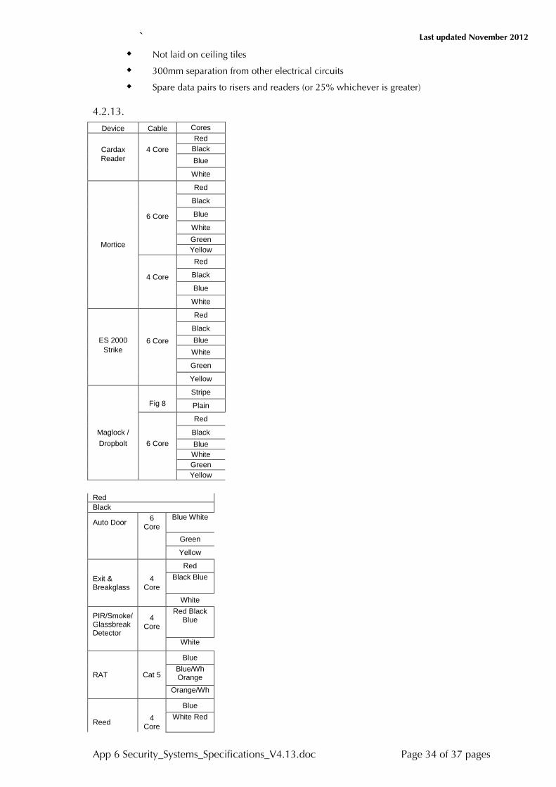
` Last updated November 2012
App 6 Security_Systems_Specifications_V4.13.doc Page 34 of 37 pages
Not laid on ceiling tiles
300mm separation from other electrical circuits
Spare data pairs to risers and readers (or 25% whichever is greater) 4.2.13.
Device Cable Cores
Cardax 4 Core Red
Black Reader Blue
White
Red
Black
6 Core Blue
White
Mortice Green Yellow
Red
4 Core Black
Blue
White
Red
Black ES 2000 6 Core Blue
Strike White
Green
Yellow
Stripe
Fig 8 Plain
Red
Maglock / Black Dropbolt 6 Core Blue
White Green Yellow
Red Black
Auto Door 6 Core
Blue White
Green
Yellow
Red
Exit & Breakglass
4 Core
Black Blue
White
PIR/Smoke/ Glassbreak Detector
4 Core
Red Black Blue
White
Blue
RAT Cat 5 Blue/Wh Orange
Orange/Wh
Blue
Reed 4 Core
White Red

` Last updated November 2012
App 6 Security_Systems_Specifications_V4.13.doc Page 35 of 37 pages
Black
Blue
Screamer 4 Core
White Red
Black
4.3. Conduits 4.3.1. Shall be rigid LD-UPVC. Minimum 25mm Diameter.
4.3.2. All fittings, draw boxes, bends and couplings are to be purpose made.
4.3.3. Shall be joined using an approved solvent cement.
4.3.4. Shall be secured using metal saddles spaced at 600mm (maximum) centres and within 150mm of all fittings.
4.3.5. Shall be installed so that cables can be drawn in at draw boxes only. Inspection elbows shall not be classified as draw points.
4.3.6. Shall be filled with cables to not more than 60% of its capacity.
4.4. Cable Duct 4.4.1. Shall be fitted with removable covers.
4.4.2. Shall be fitted with the manufacturer’s standard bends, elbows, couplings and reducers.
4.4.3. Shall be manufactured from extruded PVC.
4.4.4. Shall be filled with cables to not more than 60% of its capacity.
4.5. Fixings 4.5.1. Shall comprise metal thread screws or bolts into expanding type masonry
anchors for fixing to concrete or masonry.
4.5.2. Shall comprise tapered woodscrews for fixing to timber. (Full thread).
4.5.3. Shall comprise metal expanding anchors for fixings to gyprock.
4.6. Colour Cameras
Pick up element 1/3” CCD image sensor
Number of pixels 500 (H) x 582 (V)
Number of lines minimum
Sync mode 480 Internal
Scanning system 2:1 interlace
Resolution Horizontal 480 TV lines, Vertical 370 TV lines
Signal to noise ratio 48DB or greater
Video output 1.0 Vp.p 75ohm
Power 12vdc/24vac
Operating temperature - 10 to +60 degrees Celsius
Auto iris Lens
Minimum illumination 2.0 lux, F/1.4
4.7. PTZ Camera and accessories. 4.7.1. Colour PTZ
Integral Acrylic Dome to match existing

` Last updated November 2012
App 6 Security_Systems_Specifications_V4.13.doc Page 36 of 37 pages
Size 36cm/51cm
Internal Synchronization
CCIR Scanning system
450 TV lines minimum Resolution
Video input 1.0 Vp.p composite, sync negative
Input impedance 75ohm switchable
Input voltage 240VAC
Linearity - Horizontal within 10%, Vertical within 10%
Controls - Front ON/OFF with power, on lamp, Brightness, Contrast, V-Hold; H-Hold
4.7.2. DVR
Manufacturer Dallmeier - Leonardo
Video input 8, 16 or 24 Annalog and IP based video inputs
Audio recording
Alarm feature 8, 16 or 24 inputs
Digital Video Recording up to 12.5fps at 4CIF and 25fps at D1
DVI Digital output
Display modes – Full, Quad or Split
Hardware Configuration - 1.5TB HDD minimum storage
Remote Application - Up to 10 multi sites via LAN, Internet, ISDN and PSDN
PTZ control
Local and remote recording
Receive remote alarm alert 4.7.3. General
Camera and lens selection to cover area to be viewed as required
Alarm contacts to be connected to DVR from alarm point via access control system
DVR must be Multi Site in standard form
CCTV cable shall be RG59BU. Stranded Centre Conductor.
4.8. Programming 4.8.1. All operating system programming and data entry will be carried out by the
University of NSW or their nominated agent.
4.8.2. Detailed maps, cable schedules and drawings showing equipment zones, alarm inputs, locations etc must be made available to the Superintendent for approval prior to the connection of devices.
4.8.3. Client data access levels etc will be programmed by University of NSW.
4.9. Testing & Commissioning 4.9.1. The Contractor shall supply all labour, materials and equipment required to fully
test and commission the complete installation to the satisfaction of the Security Manager.
4.9.2. The Contractor shall repair or replace any equipment which fails to operate correctly or does not comply with this Specification.
4.9.3. The tests shall be carried out in the presence of the Security Systems Manager or his Superintendent.
` Last updated November 2012
App 6 Security_Systems_Specifications_V4.13.doc Page 37 of 37 pages
4.9.4. Written notice of intention to test shall be provided to the Security Manager not less than 10 days prior to the test date.
4.9.5. Electronic Plans in cad and pdf format will be supplied for all installations
Related Documents