Welcome message from author
This document is posted to help you gain knowledge. Please leave a comment to let me know what you think about it! Share it to your friends and learn new things together.
Transcript


2
3
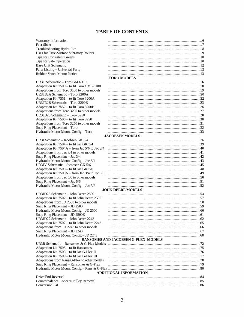
TABLE OF CONTENTS
Warranty Information .........................................................................................................6 Fact Sheet .........................................................................................................7 Troubleshooting Hydraulics .........................................................................................................8 Uses for True-Surface Vibratory Rollers .........................................................................................................9 Tips for Consistent Greens .......................................................................................................10 Tips for Safe Operation .......................................................................................................10 Base Unit Schematic .......................................................................................................12 Parts Listing – Universal Parts .......................................................................................................12
Rubber Shock Mount Notice .......................................................................................................13
TORO MODELS UR3T Schematic – Toro GM3-3100 .......................................................................................................16 Adaptation Kit 7500 – to fit Toro GM3-3100 .......................................................................................................18 Adaptations from Toro 3100 to other models .......................................................................................................19 UR3T32A Schematic – Toro 3200A .......................................................................................................20 Adaptation Kit 7551 – to fit Toro 3200A .......................................................................................................22 UR3T32B Schematic – Toro 3200B .......................................................................................................23
Adaptation Kit 7552 – to fit Toro 3200B .......................................................................................................26 Adaptations from Toro 3200 to other models .......................................................................................................27 UR3T325 Schematic – Toro 3250 .......................................................................................................28 Adaptation Kit 7506 – to fit Toro 3250 .......................................................................................................30 Adaptations from Toro 3250 to other models .......................................................................................................31 Snap Ring Placement – Toro .......................................................................................................32 Hydraulic Motor Mount Config – Toro .......................................................................................................33
JACOBSEN MODELS
UR3J Schematic – Jacobsen GK 3/4 .......................................................................................................36 Adaptation Kit 7504 – to fit Jac GK 3/4 .......................................................................................................39 Adaptation Kit 7504A – from Jac 5/6 to Jac 3/4 .......................................................................................................40 Adaptations from Jac 3/4 to other models .......................................................................................................41 Snap Ring Placement – Jac 3/4 .......................................................................................................42 Hydraulic Motor Mount Config – Jac 3/4 .......................................................................................................43 UR3JV Schematic – Jacobsen GK 5/6 .......................................................................................................45 Adaptation Kit 7503 – to fit Jac GK 5/6 .......................................................................................................48 Adaptation Kit 7503A – from Jac 3/4 to Jac 5/6 .......................................................................................................49
Adaptations from Jac 5/6 to other models .......................................................................................................50 Snap Ring Placement – Jac 5/6 .......................................................................................................51 Hydraulic Motor Mount Config – Jac 5/6 .......................................................................................................52
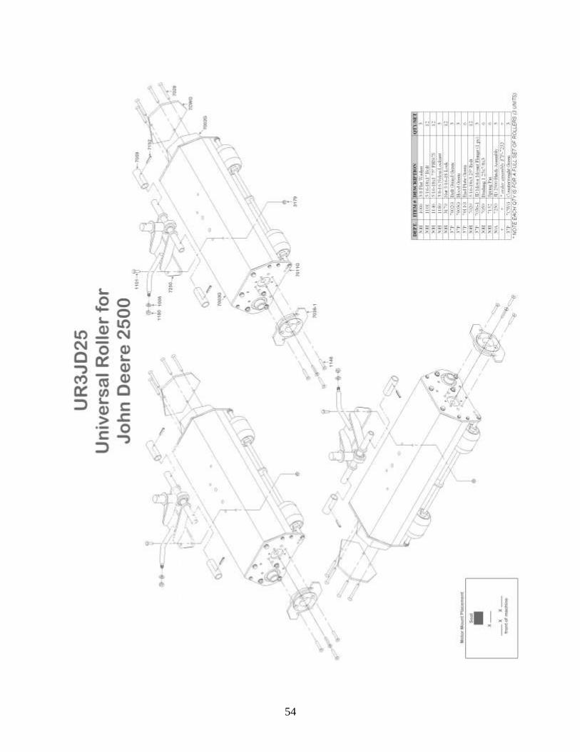
JOHN DEERE MODELS UR3JD25 Schematic – John Deere 2500 .......................................................................................................54 Adaptation Kit 7502 – to fit John Deere 2500 .......................................................................................................57 Adaptations from JD 2500 to other models .......................................................................................................58 Snap Ring Placement – JD 2500 .......................................................................................................59
Hydraulic Motor Mount Config – JD 2500 .......................................................................................................60 Snap Ring Placement – JD 2500E .......................................................................................................61 UR3JD22 Schematic – John Deere 2243 .......................................................................................................62 Adaptation Kit 7507 – to fit John Deere 2243 .......................................................................................................65 Adaptations from JD 2243 to other models .......................................................................................................66 Snap Ring Placement – JD 2243 .......................................................................................................67 Hydraulic Motor Mount Config – JD 2243 .......................................................................................................68
RANSOMES AND JACOBSEN G-PLEX MODELS
UR3R Schematic – Ransomes & G-Plex Models .......................................................................................................72 Adaptation Kit 7505 – to fit Ransomes .......................................................................................................75 Adaptation Kit 7508 – to fit Jac G-Plex II .......................................................................................................76 Adaptation Kit 7509 – to fit Jac G-Plex III .......................................................................................................77 Adaptations from Rans/G-Plex to other models .......................................................................................................78 Snap Ring Placement – Ransomes & G-Plex .......................................................................................................79 Hydraulic Motor Mount Config – Rans & G-Plex .......................................................................................................80
ADDITIONAL INFORMATION
Drive End Reversal .......................................................................................................84 Counterbalance Concern/Pulley Removal .......................................................................................................85 Conversion Kit .......................................................................................................86

4
INFORMATION ABOUT YOUR TRUE-SURFACE®
VIBRATORY GREENS ROLLING SYSTEM:
DATE PURCHASED: __________________
SERIAL NUMBER: __________________
OPERATION NOTES: ______________________
___________________________________________
___________________________________________
___________________________________________
___________________________________________
___________________________________________
To activate the warranty on your new rollers, please fill out and fax the
warranty page in this handbook; it is the loose page in the center of the
manual.
For parts or service, please call 800-443-8506.
Orders placed before Noon CST can be shipped UPS same day.
5
UNIVERSAL ROLLER INTRODUCTION
Congratulations on the purchase of your NEW True-Surface® Universal Vibratory Greens
Rolling System from Turfline, Inc.
Please review this owner's manual before unpacking the rollers.
It is imperative that you fill out and fax or mail back the warranty form to Turfline, Inc.
This will activate your product’s two year warranty.
Maintenance of these rollers is very minimal. There are two lubrication points on each
roller. They are located on each end of the roller. We recommend that you fill the bearing
cavity before using with a food grade, non-petroleum based grease to prevent any turf
damage due to grease dripping off the unit, although any type of lithium-based grease is
acceptable. Pump until grease is visible between the bearing and hub surfaces. When
using the rollers for dispersion of topdressing materials, there may be a need to purge the
bearings to remove sand and grit. Wipe off all excess grease from around the bearing.
The proper belt tension is 1/4" deflection. This is preset at the factory. If you need to
adjust the belt tension...loosen the three nuts that secure the roller bearing to EACH end
plate and adjust accordingly in the slotted holes. Retighten all of the six nuts, and replace
the belt guard.
In the enclosed manual you will find the following:
Installation Instructions
Parts drawings and numbers
Mounting Kit Conversions
Adaptation Kits
Warranty and safety information
If you have any technical questions or if you need to order parts, please call
Turfline, Inc. at 1-800-443-8506
Orders received by Noon CST will be shipped the same day via U.P.S. ground to
anywhere in the continental United States.
Thank you for choosing the best set of American-made rollers available!

6
WARRANTY INFORMATION To maintain superior warranty service, please call Turfline, Inc. before having work done on alleged
defective equipment. We strive to maintain excellent customer service and quality products; keeping us
informed of situations allows us to do so.
Within the industry, including the chat rooms of Turfnet and GCSAA., our company is known to be
expedient in servicing our warranteed products. Turfline, Inc.’s warranty policy is as follows:
Turfline, Inc. will either repair or replace any non-wear part of the True-Surface® Vibratory Greens Rolling
System which is defective in workmanship or material for a period of twenty four (24) months from the
date of delivery of the new product to the original end user determined by the warranty registration.
These items will be repaired or replaced free of charge and freight free. Warranties on used or ex-demo
equipment are limited to 90 days from date of purchase.
Turfline, Inc. will cover parts subject to normal maintenance routines as specified in the product’s Owner
Manual and parts subject to wear and tear during the correct operation of the product. These parts include, but are not limited to, shafts, bearings, belts, and rubber shock mounts (RSM’s) for a limited 90 days. The
90-day warranty on wear items specifically excludes used or ex-demo units.
Turfline, Inc. will not issue warranty credit for:
any item that has been damaged by accident, lack of reasonable care and protection, or lack of
suitable storage.
parts that have been altered or modified by anyone other than Turfline, Inc.
used parts that have been installed in place of failed parts.
parts that have been installed incorrectly by the end user or its agents.
parts that have not been maintained as per the Owner’s Manual.
service calls and overtime labor rates as Turfline, Inc. shall be contacted immediately upon encountering any problems.
any consequential loss, damage, or costs to the equipment caused by (or incidental to) failure of
any new part supplied with the original purchase or any new part supplied as a replacement for
any failed part.
Warranty Claims:
The final purchaser of the True-Surface® Vibratory Greens Rolling System must file a warranty claim with
Turfline, Inc. The final purchaser must provide written evidence detailing the product’s delivery date to that
purchaser and the reasons why the purchaser believes the product or part is defective in the categories of
faulty material or workmanship. The purchaser is to deliver the faulty product or part to Turfline, Inc. at
the purchaser’s expense to be reimbursed by Turfline, Inc. if found to be the responsible party. Acceptance
or rejection of the warranty claim is entirely at the discretion of Turfline, Inc.
Turfline, Inc.
712 Jefferson St., Ste. A
Moscow Mills, Mo 63362
1-800-443-8506 or +1-636-356-1210 ~ Please ask for the warranty department.
TURFLINE, INC. reserves the right to make improvements in design or changes in specifications without prior
notice and without prejudice or obligation to original design purchasers. No person or organization has the authority to modify the terms, conditions, or limitations of this warranty without the written consent of Turfline, Inc.

UNIVERAL ROLLER-FACT SHEET
Patented: US Patent No. 5,261,213
Specifications:
Weight: Average of 80 lbs per unit
Frame: One piece welded assembly, formed steel frame
Roller Tube: 5.5” O.D. tube, 3/16” wall, 22.5” roller length 1018 mild steel
Roller Hub: (2) Relubricatable flange mounted bushings 1.5” I.D.
Roller Shaft: 1” diameter 1045 mild steel, drilled and tapped for eccentric wts
Shaft bearings: Shielded type, anti-friction, maintenance free ball bearings.
Shaft Eccentric Speed: 3500 to 6000 RPMs
Easy installation:
Roller can be attached to Toro, Jacobsen, John Deere and Ransomes triplex mowers
within minutes.
Management Tool:
When incorporated into the general maintenance program, the system creates healthy
greens quicker; enables superintendents to dial-in specific speeds or stimp requirements;
can be used on contoured greens; adaptable to triplex greens mowers; does not need
specific training to operate; provides consistency to all greens.
Controllable Results:
Vibration allows you to stimp all greens within 2 to 4 inches by varying ground speed.
Customer Satisfaction: Two-year limited warranty
Distributors: Worldwide distribution
Shipment: Approximately 85 lbs each via UPS
Company Contacts:
John Humphrey – President/Owner
Terry Plemons – Director of Worldwide Sales
Ryan Jerome – Sales Account Executive
Michael Sprick – Sales Account Executive
Brad Everett – Production Manager
Randy Leitman – Product Engineer/Technical Support
For sales and service:
PHONE: 800-443-8506 FAX: 636-356-1218 www.true-surface.com

8
Troubleshooting Hydraulics and the True-Surface® Vibratory Rollers
We have found that when the hydraulic motor is spinning at less RPMs than the standard
factory specifications, there can be noise and/or excessive vibration issues with the True-
Surface Rollers. Please note that these rollers require a minimum of 1800 RPMs out of
your hydraulic motor to operate properly. A tachometer can be purchased from your
equipment dealer to determine what your RPMs are.
Troubleshooting this situation has shown that low hydraulic RPMs will cause excessively
loud operation and vibration. In addition, below-factory RPMs can place undue stress on
parts such as the rubber shock mounts (RSMs) and the bearings. If you find yourself
replacing these parts more than you would expect, or if the rollers appear to be violently
vibrating, this is probably due to inadequate RPMs.
This failure would not necessarily be noticeable while mowing the greens. It is a fact that
you can mow with much less RPMs and still provide a quality cut. The rollers are
designed to work at the factory output of 1800/2100 RPMs. This range covers all greens
mowers with hydraulic power sources. Loss of RPMs needs to be checked for on any
greensmower that appears to be having the aforementioned difficulties.
An alternative solution would be to install the greens rollers on a triplex that meets the
1800/2100 factory design criteria and leave the ‘weak’ unit to handling regular mowings
or to serve as a backup mower.
Please feel free to contact us at the Turfline Manufacturing Facility if you have any
further questions regarding this issue.
Brad Everett
Ph # (636) 356-1210
Manufacturing Supervisor

9
USES FOR YOUR TRUE-SURFACE®
VIBRATORY GREENS ROLLERS
True Putting Surfaces: Vibratory action trues the greens’ surface without damaging grass, eliminates footprints,
spike marks and ball marks, and energizes sand to conform to surface contour.
Grow-In: Vibratory action does not damage or pull-up new plants. It energizes the surface, reduces
the need for mowing, and makes greens playable earlier.
Sand Topdressing: Vibration following dragging or brushing virtually eliminates dry sand from the turf
canopy. Sand falls through the canopy just before the roller gets to it, thus minimizing
bruising and saving your reels and bed knives.
Dew Removal: The vibratory roller removes dew and trues the surface at the same time.
Aerification: Vibration enables dry topdressing to work itself into aerification holes and trues the
surface to allow acceptable ball play.
Integrated Pest Management: By rolling more and mowing less, plants are healthier. Raising the height of cut 20%
from .125” to .156” will increase the health of grass considerably and reduce potential
infiltration from various pests and diseases. Decreased use of fertilizers, fungicides,
pesticides and watering will generate savings. By alternating mowing and rolling, turf
becomes more resilient and can withstand more play which equals more dollars for your
course.

10
BE A SAFE OPERATOR
Think
Maintain Your Equipment
Use Your Equipment Only For Applications For Which It Was Created
The True-Surface® Vibratory Greens Rolling System was created to be used exclusively
on triplex mowers as a greens maintenance tool. Use of the rollers in an application other
than the one intended will void its warranty and could possibly cause equipment damage
and personal injury.
AVOID ACCIDENTS
Most accidents, whether they occur in the industry, on the farm, at home, or on the
highway are caused by human mistakes. Most accidents can be prevented by careful
operation and prevention.
TIPS FOR CONSISTENT GREENS
Golfers demand consistent greens. They want to make sure they have the same putting
conditions from green to green. Only the True-Surface® Vibratory Greens Rolling
System will provide consistent ball roll distance on all greens.
To obtain consistency with the vibratory greens rollers follow this EXAMPLE:
Rolling at the same speed you mow equals 12 inches of Ball Roll Distance (BRD), then
in order to achieve:
24 inches of BRD; roll at 1/2 the speed you mow;
18 inches of BRD; roll at 3/4 the speed you mow:
6 inches of BRD; roll at twice the speed you mow.
The variance of your greensmower’s RPM and ground speed will allow you to obtain
ANY desired results you require. This variable feature can ONLY be obtained with the
TRUE-SURFACE® Vibratory Greens Rolling System.
11
12
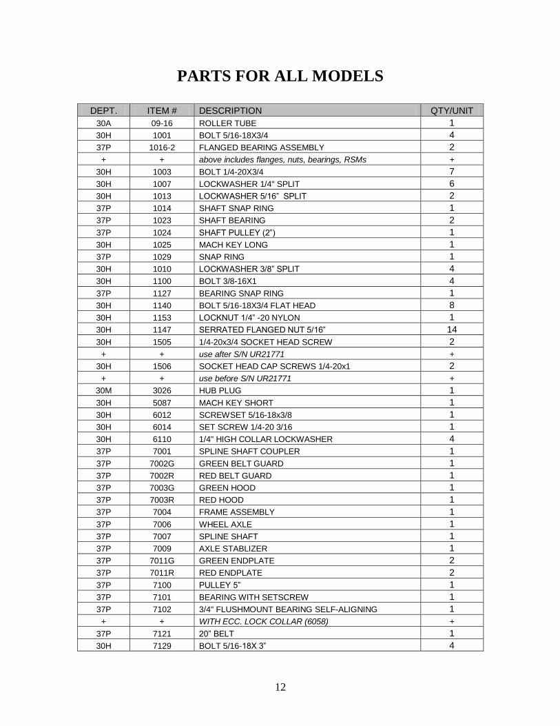
PARTS FOR ALL MODELS
DEPT. ITEM # DESCRIPTION QTY/UNIT
30A 09-16 ROLLER TUBE 1
30H 1001 BOLT 5/16-18X3/4 4
37P 1016-2 FLANGED BEARING ASSEMBLY 2
+ + above includes flanges, nuts, bearings, RSMs +
30H 1003 BOLT 1/4-20X3/4 7
30H 1007 LOCKWASHER 1/4" SPLIT 6
30H 1013 LOCKWASHER 5/16” SPLIT 2
37P 1014 SHAFT SNAP RING 1
37P 1023 SHAFT BEARING 2
37P 1024 SHAFT PULLEY (2”) 1
30H 1025 MACH KEY LONG 1
37P 1029 SNAP RING 1
30H 1010 LOCKWASHER 3/8” SPLIT 4
30H 1100 BOLT 3/8-16X1 4
37P 1127 BEARING SNAP RING 1
30H 1140 BOLT 5/16-18X3/4 FLAT HEAD 8
30H 1153 LOCKNUT 1/4” -20 NYLON 1
30H 1147 SERRATED FLANGED NUT 5/16” 14
30H 1505 1/4-20x3/4 SOCKET HEAD SCREW 2
+ + use after S/N UR21771 +
30H 1506 SOCKET HEAD CAP SCREWS 1/4-20x1 2
+ + use before S/N UR21771 +
30M 3026 HUB PLUG 1
30H 5087 MACH KEY SHORT 1
30H 6012 SCREWSET 5/16-18x3/8 1
30H 6014 SET SCREW 1/4-20 3/16 1
30H 6110 1/4" HIGH COLLAR LOCKWASHER 4
37P 7001 SPLINE SHAFT COUPLER 1
37P 7002G GREEN BELT GUARD 1
37P 7002R RED BELT GUARD 1
37P 7003G GREEN HOOD 1
37P 7003R RED HOOD 1
37P 7004 FRAME ASSEMBLY 1
37P 7006 WHEEL AXLE 1
37P 7007 SPLINE SHAFT 1
37P 7009 AXLE STABLIZER 1
37P 7011G GREEN ENDPLATE 2
37P 7011R RED ENDPLATE 2
37P 7100 PULLEY 5” 1
37P 7101 BEARING WITH SETSCREW 1
37P 7102 3/4" FLUSHMOUNT BEARING SELF-ALIGNING 1
+ + WITH ECC. LOCK COLLAR (6058) +
37P 7121 20” BELT 1
30H 7129 BOLT 5/16-18X 3” 4

13
PARTS FOR ALL MODELS (CONT.)
DEPT. ITEM # DESCRIPTION QTY/UNIT
37P 7150 BEARING HOUSING 1
37P 7158 LOCK COLLAR 4
37P 7178 SPRING PIN 1/4 X 1 1/8 1
37P 7300 ECCENTRIC WEIGHT 1
37P 7410 SHAFT SEAL 1
37P 7571 CASTER ASSEMBLY 2
+ + above includes collar, casters, & endcaps +
30M P001 HUB *Use part # 37P-09-001 or 37P-09-002N 1
30M P003 SHAFT *Use part # 30A-09-18 1
37P RSM RUBBER SHOCK MOUNTS 6
AVAILABLE KITS
DEPT. ITEM # DESCRIPTION QTY/UNIT
37P 09-001 HUB REPLACEMENT KIT-DRIVE END 1
+ + above includes hub, bolt, & bearing seal +
37P 09-002 N HUB REPLACEMENT KIT-NON DRIVE END 1
+ + above includes hub, bolt, & plug +
37P 09-19 SHAFT REPLACEMENT KIT 1
+ + above includes set screw, shaft pulley, shaft, +
+ + snap ring, & shaft bearing, 5/16-18x3/4 FHSCS +
37P 7300K ECCENTRIC WEIGHT REPLACEMENT KIT SQUARE 2
+ + above includes ecc. wt., bolt, & washer +
37P 7572 AXLE REPLACEMENT KIT 1
+ + includes caster assembly + wheel axle +
37P 7581 SPLINED SHAFT REPLACEMENT KIT 1
+ + above includes key, pin, coupler, & shaft +

14
RUBBER SHOCK MOUNT (RSM)
INSTALLATION NOTICE
This notice is to help prevent premature failure of the rubber shock mounts (RSM) due to
incorrect mounting. When mounting the RSM, always mount one side of the RSM to the
endplate of the roller first, install the serrated flange nut then tighten. Then mount the
bearing flanges on the opposite end and install the remaining serrated flange nuts, leaving
the nuts loose until the roller and frame are assembled. With roller in position and all
framework secure, tighten each of the RSM studs one-half round each. Repeat this
procedure until all three are tight. This will draw the two flanges together on the bearing
without misaligning the bearing with the roller hub.
VERY IMPORTANT: IF THREADED STUD ON THE RSM ROTATES WHILE
TIGHTENING THE FLANGED BEARING, ALWAYS TURN BACK (COUNTER
CLOCKWISE) TO RETURN THE RUBBER TO A RELAXED POSITION. IN
SOME INSTANCES, IT MAY BE NECESSARY TO USE PLIERS TO GENTLY
HOLD THE RUBBER AT THE BASE OF THE THREADED STUD TO
PREVENT TWISTING OF THE RUBBER.
NOTE: EXCESSIVE TWISTING DURING INSTALLATION OR LEAVING
THE RSM IN A TWISTED POSITION WILL CAUSE A PREMATURE RSM
FAILURE.

15

16

17
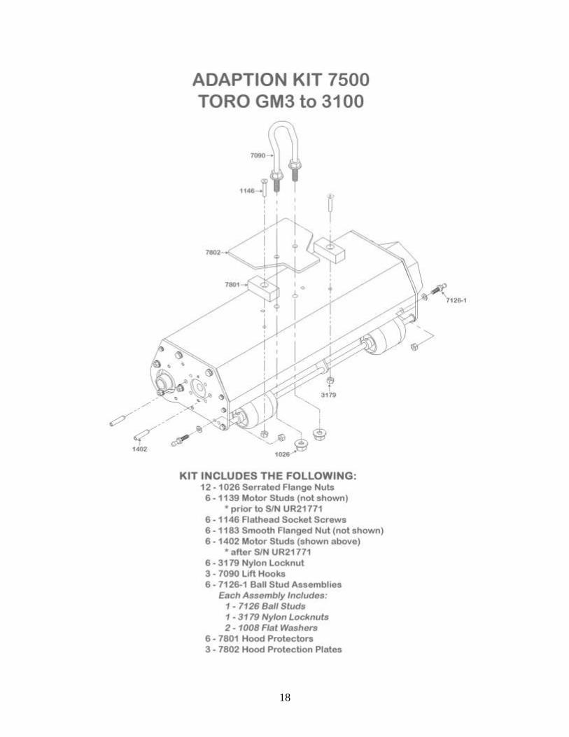
INSTALLATION OF UNIVERSAL ROLLER
TORO GM3, 3050, 3100, 3250
Tools required: 3/4” Combination wrench
9/16” Combination wrench
1) Read these instructions carefully and familiarize yourself with the parts and
assembly drawings before starting.
2) Unpack your new rollers.
3) Install the lift hook (7090) to each roller unit by removing one nut from each side
of the U-bolt and sliding the U-bolt through the hood protection plate and two
1/2" holes in the top of the roller.
4) Replace the nuts on the bottom and tighten. NOTE: Tighten evenly so that the
lift hook is perpendicular when secured. This hook is also height adjustable by
moving the nuts up or down on the hook to provide you the most desirable lift
height for your needs.
5) Remove the hydraulic motors from the cutting units.
6) Remove the cutting units from the machine.
7) Position the rollers under the machine with the small castor wheels of the roller
unit forward and lift arm of the machine passing through the lift hook.
8) Reconnect the ball couplers to the ball studs on both sides of the roller frame.
9) Loosen or remove (if necessary) the flanged nuts from the hydraulic motor
mounting studs on the drive side of the roller.
10) Wiggle the motor into place and secure with the flanged nuts.
11) Start the machine and check the lift height, ground clearance, and raised position
clearance between the roller and machine.
12) Adjust the lift hooks as necessary.
13) Check operation of the rollers.
18

19
ADAPTATIONS FROM TORO GM 3-3100 TO… TORO GM 3200A: Uses Adaptation Kit 7551 (see page 22). One Unit will require a drive-end reversal. This procedure is on page 84. This unit will then fit the right
front location. Refer to motor mounting instructions on page 33-34, then refer to page 20 to attach
necessary hardware. No shaft or motor mount change is necessary. Remove the four belt guard mounting
bolts and install one counterweight to each unit with the new 5/16” x 3-1/4” bolts provided and tighten.
TORO GM 3200B: Uses Adaptation Kit 7552 (see page 26).
One unit requires a drive-end reversal. This procedure is located on page 84. This unit will then fit the
front right location. Refer to page 33-34 for motor mounting instructions and then to page 23 for attaching
necessary hardware. No shaft or motor mount change is necessary. Remove the four belt guard mounting
bolts and install one counterweight to each unit with the new 5/16” x 3-1/4” bolts provided and tighten.
TORO 3250: Uses Adaptation Kit 7506 (see page 30). One unit requires a drive-end reversal. This procedure is on page 84. This unit will fit the right front unit.
Refer to page 33-34 for motor mounting instructions and then to page 28 for attaching necessary hardware.
No shaft or motor mount change is necessary. Remove the four belt guard mounting bolts and install one
counterweight to each unit with the new 5/16” x 3-1/4” bolts provided and tighten.
JOHN DEERE 2243: Uses Adaptation Kit 7507 (see page 65).
Two of the three units require Drive-End Reversal found on page 84. The remaining unit will then fit the
left front location on the JD 2243 mower. Refer to page 68-69 for motor mounting procedures, and to page
67 for drive shaft placement and adjustment. Finally, refer to unit mounting instructions and illustrations
for final attachments and hook-up (see page 62).
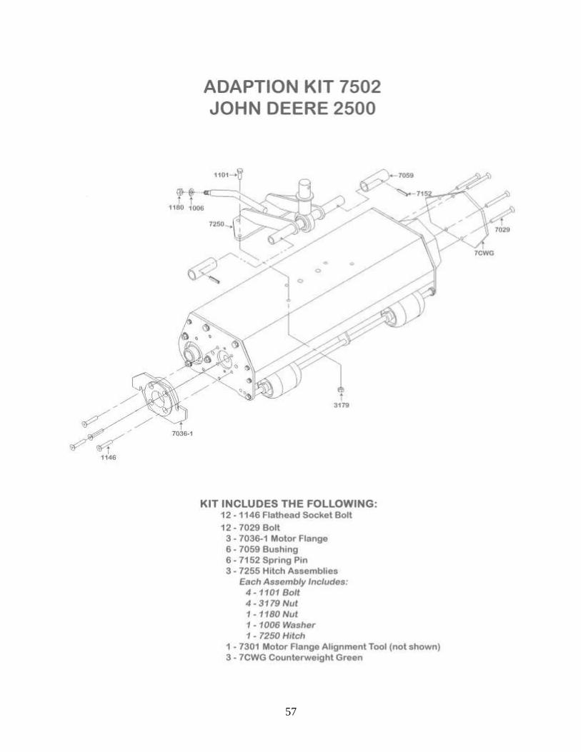
JOHN DEERE 2500: Uses Adaptation Kit 7502 (see page 57).
One of the three units requires Drive-End Reversal found on page 84. This unit will then fit the right front
location on the JD 2500 mower. Refer to page 60 for motor mounting procedures, and to page 59 for drive
shaft placement and adjustment. Finally, refer to unit mounting instructions and illustrations for final
attachments and hook-up (see page 54). Remove the four belt guard mounting bolts and install one
counterweight to each unit with the new 5/16” x 3-1/4” bolts provided and tighten.
JOHN DEERE 2500E: Uses Adaptation Kit 7502 plus Kit 7001-3MS (see page 57 & 61)
Use all the same procedures as for the Standard John Deere 2500 except for drive shaft placement. Refer to
page 61 for shaft placement and spline installation instructions.
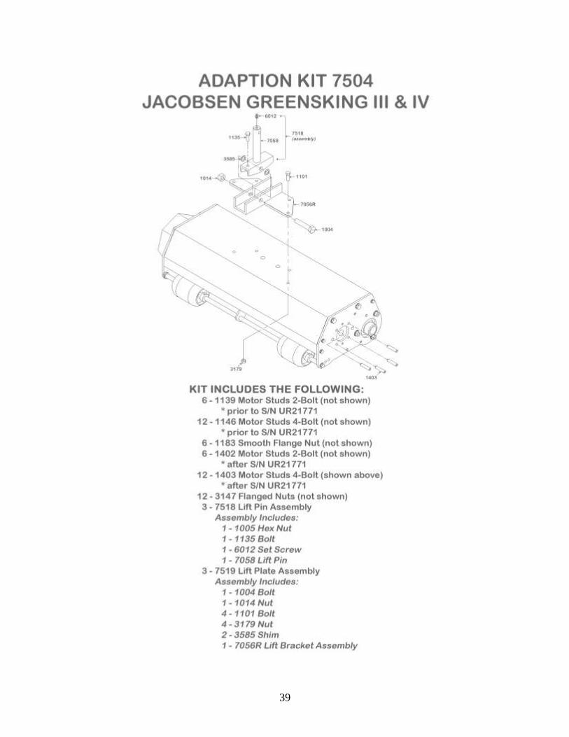
JACOBSEN GK III & IV: Uses Adaptation Kit 7504 (see page 39). Two of the three units require drive end reversal found on page 84. These will then fit the right and/or
center position on the machine. Refer to page 43-44 for motor mounting procedures, and refer to page 42
for drive shaft placement and adjustment, then refer to the unit mounting instructions and illustrations for
final attachments and hook-up (see page 36).
JACOBSEN GK V & VI: Uses Adaptation Kit 7503 (see page 48).
All three units require drive end reversal found on page 84. Refer then to page 51 for drive shaft placement
and adjustment. Refer to page 52, for motor mounting procedures, and then to Unit Mounting instructions
and illustrations for final attachments and hook-up (see page 45). Remove the four belt guard mounting
bolts and install one counterweight to each unit with the new 5/16” x 3-1/4” bolts provided and tighten.
RANSOMES: Uses Adaptation Kit 7505 (see page 75).
Drive end remains the same. Refer to page 80-81 for motor mounting procedure, then to page 79 for drive
shaft placement and adjustment. Refer then to Unit Mounting instructions and illustrations for final
attachments and hook-up (see page 72).
20
21
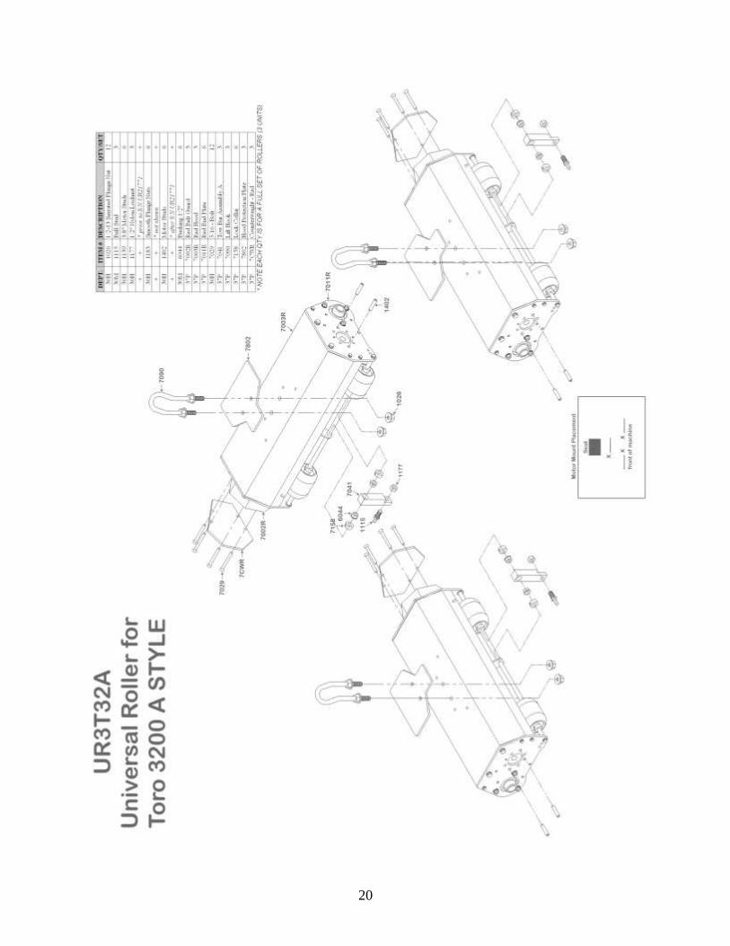
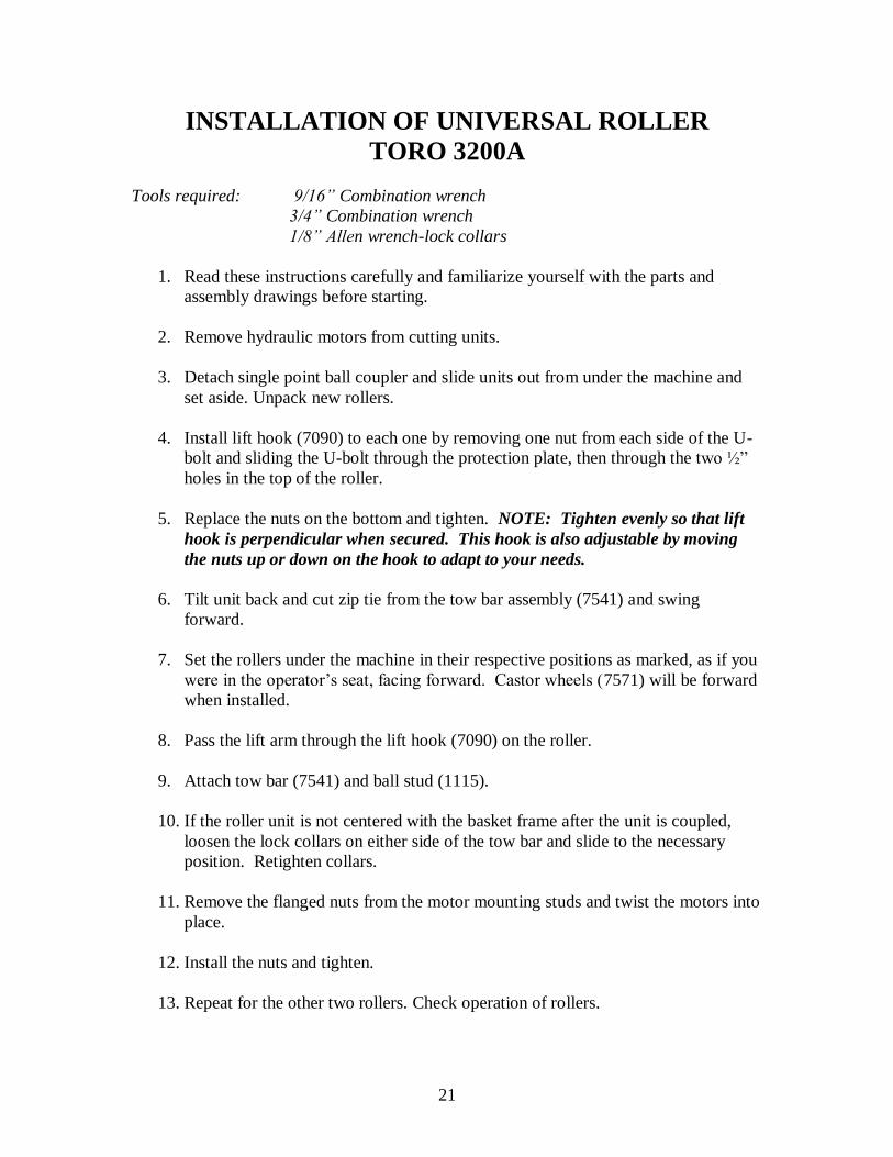
INSTALLATION OF UNIVERSAL ROLLER
TORO 3200A
Tools required: 9/16” Combination wrench
3/4” Combination wrench
1/8” Allen wrench-lock collars
1. Read these instructions carefully and familiarize yourself with the parts and
assembly drawings before starting.
2. Remove hydraulic motors from cutting units.
3. Detach single point ball coupler and slide units out from under the machine and
set aside. Unpack new rollers.
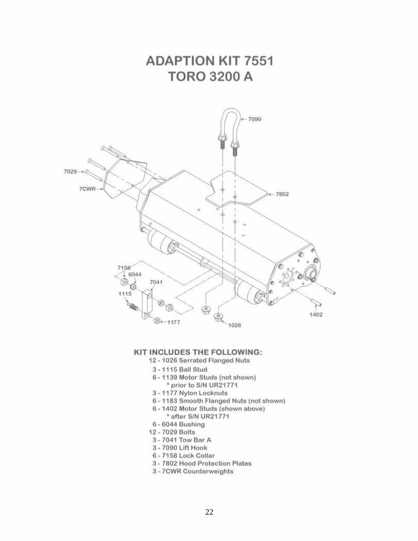
4. Install lift hook (7090) to each one by removing one nut from each side of the U-
bolt and sliding the U-bolt through the protection plate, then through the two ½”
holes in the top of the roller.
5. Replace the nuts on the bottom and tighten. NOTE: Tighten evenly so that lift
hook is perpendicular when secured. This hook is also adjustable by moving
the nuts up or down on the hook to adapt to your needs.
6. Tilt unit back and cut zip tie from the tow bar assembly (7541) and swing
forward.
7. Set the rollers under the machine in their respective positions as marked, as if you
were in the operator’s seat, facing forward. Castor wheels (7571) will be forward
when installed.
8. Pass the lift arm through the lift hook (7090) on the roller.
9. Attach tow bar (7541) and ball stud (1115).
10. If the roller unit is not centered with the basket frame after the unit is coupled,
loosen the lock collars on either side of the tow bar and slide to the necessary
position. Retighten collars.
11. Remove the flanged nuts from the motor mounting studs and twist the motors into
place.
12. Install the nuts and tighten.
13. Repeat for the other two rollers. Check operation of rollers.
22
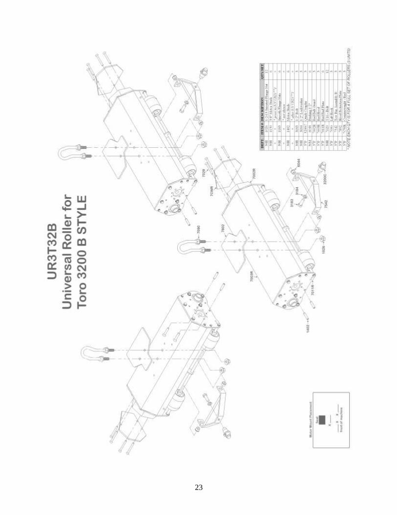
23

24
INSTALLATION OF UNIVERSAL ROLLER
TORO 3200B
Tools required: 9/16” Combination wrench
3/4” Combination wrench
1/8” Allen wrench-lock collars
1. Read these instructions carefully and familiarize yourself with the parts and
assembly drawings before starting.
2. Remove hydraulic motors from cutting units.
3. Detach single point ball coupler and slide units out from under the machine and
set aside.
4. Unpack new rollers.
5. Install lift hook (7090) to each one by removing one nut from each side of the
U-bolt and sliding the U-bolt through the protection plate, then through the two
½” holes in the top of the roller.
6. Replace the nuts on the bottom and tighten. NOTE: Tighten evenly so that lift
hook is perpendicular when secured. This hook is also height adjustable by
moving the nuts up or down on the hook to adapt to your needs.
7. Tilt unit back and cut zip tie from the tow bracket (7542).
8. Swing the bracket (7542) out from under the machine so that it points forward.
9. Remove the ball coupler (3200C) and bolt from Tow Bar and reattach with
coupler facing forward.
10. Set the rollers under the machine in their respective positions as marked, as if you
were in the operator’s seat, facing forward. Castor wheels (7571) will be forward
when installed.
11. Pass the lift arm through the lift hook (7090) on the roller.
12. Align ball coupler (3200C) so that the opening is facing toward the ball stud to
which it will be coupled.
13. Tighten mounting bolt.
14. Attach coupler.

25
INSTALLATION OF UNIVERSAL ROLLER
TORO 3200B (CONT.)
15. If the roller unit is not centered with the basket frame after the unit is coupled,
loosen the four lock collars on either side of the front wheels and adjust the
wheels, collars and tow bar to the necessary position. Retighten collars.
16. Remove the flanged nuts from the motor mounting studs and twist the motors into
place.
17. Install the nuts and tighten.
18. Repeat for the other two rollers.
19. Check operation of rollers.

26
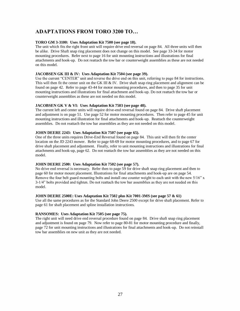
27
ADAPTATIONS FROM TORO 3200 TO… TORO GM 3-3100: Uses Adaptation Kit 7500 (see page 18). The unit which fits the right front unit will require drive end reversal on page 84. All three units will then
be alike. Drive Shaft snap ring placement does not change on this model. See page 33-34 for motor
mounting procedures. Refer next to page 16 for unit mounting instructions and illustrations for final
attachments and hook-up. Do not reattach the tow bar or counterweight assemblies as these are not needed
on this model.
JACOBSEN GK III & IV: Uses Adaptation Kit 7504 (see page 39).
Use the current “CENTER” unit and reverse the drive end on this unit, referring to page 84 for instructions.
This will then fit the center unit on the GK III & IV. Drive shaft snap ring placement and alignment can be
found on page 42. Refer to page 43-44 for motor mounting procedures, and then to page 35 for unit
mounting instructions and illustrations for final attachment and hook-up. Do not reattach the tow bar or
counterweight assemblies as these are not needed on this model.
JACOBSEN GK V & VI: Uses Adaptation Kit 7503 (see page 48).
The current left and center units will require drive-end reversal found on page 84. Drive shaft placement
and adjustment is on page 51. Use page 52 for motor mounting procedures. Then refer to page 45 for unit
mounting instructions and illustration for final attachments and hook-up. Reattach the counterweight
assemblies. Do not reattach the tow bar assemblies as they are not needed on this model.
JOHN DEERE 2243: Uses Adaptation Kit 7507 (see page 65).
One of the three units requires Drive-End Reversal found on page 84. This unit will then fit the center
location on the JD 2243 mower. Refer to page 68-69 for motor mounting procedures, and to page 67 for
drive shaft placement and adjustment. Finally, refer to unit mounting instructions and illustrations for final attachments and hook-up, page 62. Do not reattach the tow bar assemblies as they are not needed on this
model.
JOHN DEERE 2500: Uses Adaptation Kit 7502 (see page 57).
No drive end reversal is necessary. Refer then to page 59 for drive shaft snap ring placement and then to
page 60 for motor mount placement. Illustrations for final attachments and hook-up are on page 54.
Remove the four belt guard mounting bolts and install one counter weight to each unit with the new 5/16” x
3-1/4” bolts provided and tighten. Do not reattach the tow bar assemblies as they are not needed on this
model.
JOHN DEERE 2500E: Uses Adaptation Kit 7502 plus Kit 7001-3MS (see page 57 & 61)
Use all the same procedures as for the Standard John Deere 2500 except for drive shaft placement. Refer to page 61 for shaft placement and spline installation instructions.
RANSOMES: Uses Adaptation Kit 7505 (see page 75).
The right unit will need drive end reversal procedure found on page 84. Drive shaft snap ring placement
and adjustment is found on page 79. Now refer to page 80-81 for motor mounting procedure and finally,
page 72 for unit mounting instructions and illustrations for final attachments and hook-up. Do not reinstall
tow bar assemblies on new unit as they are not needed.
28

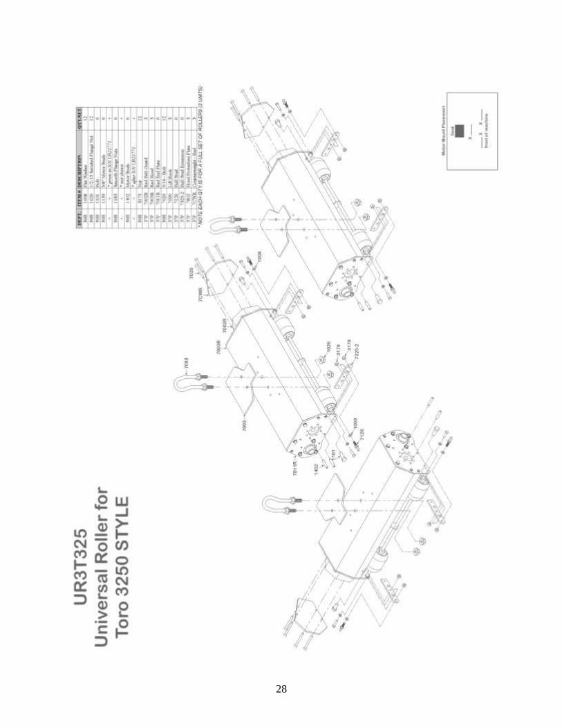
29
INSTALLATION OF UNIVERSAL ROLLER
TORO 3250
Tools required: 9/16” Combination wrench
3/4” Combination wrench
1/8” Allen wrench-lock collars
1. Read these instructions carefully and familiarize yourself with the parts and
assembly drawings before starting.
2. Remove hydraulic motors from cutting units.
3. Detach single point ball coupler and slide units out from under the machine and
set aside.
4. Unpack new rollers.
5. Install lift hook (7090) to each one by removing one nut from each side of the
U-bolt and sliding the U-bolt through the protection plate, then through the two
½” holes in the top of the roller.
6. Replace the nuts on the bottom and tighten. NOTE: Tighten evenly so that lift
hook is perpendicular when secured. This hook is also height adjustable by
moving the nuts up or down on the hook to adapt to your needs.
7. Set the rollers under the machine in their respective positions as marked, as if you
were in the operator’s seat, facing forward. Castor wheels (7571) will be forward
when installed.
8. Pass the lift arm through the lift hook (7090) on the roller.
9. Connect the ball couplers of the machine to the ball studs (7126) on the rollers.
10. Remove the flanged nuts from the motor mounting studs and twist the motors into
place.
11. Install the nuts and tighten.
12. Repeat for the other two rollers.
13. Check operation of rollers.

30

31
ADAPTATIONS FROM TORO 3250 TO… TORO GM 3-3100: Uses Adaptation Kit 7500 (see page 18). The unit which fits the right front unit will require drive end reversal on page 68. All three units will then
be alike. Drive Shaft snap ring placement does not change on this model. See page 33-34 for motor
mounting procedures. Refer next to page 16 for unit mounting instructions and illustrations for final
attachments and hook-up. Do not reattach the tow bar or counterweight assemblies as these are not needed
on this model.
JACOBSEN GK III & IV: Uses Adaptation Kit 7504 (see page 39).
Use the current “CENTER” unit and reverse the drive end on this unit, referring to page 84 for instructions.
This will then fit the center unit on the GK III & IV. Drive shaft snap ring placement and alignment can be
found on page 41. Refer to page 43 for motor mounting procedures, and then to page 36 for unit mounting
instructions and illustrations for final attachment and hook-up. Do not reattach the tow bar or
counterweight assemblies as these are not needed on this model.
JACOBSEN GK V & VI: Uses Adaptation Kit 7503 (see page 48).
The current left and center units will require drive-end reversal found on page 84. Drive shaft placement
and adjustment is on page 51. Use page 52 for motor mounting procedures. Then refer to page 45 for unit
mounting instructions and illustration for final attachments and hook-up. Reattach the counterweight
assemblies. Do not reattach the tow bar assemblies as they are not needed on this model.
JOHN DEERE 2243: Uses Adaptation Kit 7507 (see page 65).
One of the three units requires Drive-End Reversal found on page 84. This unit will then fit the center
location on the JD 2243 mower. Refer to page 68 for motor mounting procedures, and to page 67 for drive
shaft placement and adjustment. Finally, refer to unit mounting instructions and illustrations for final attachments and hook-up, page 62. Do not reattach the tow bar assemblies as they are not needed on this
model.
JOHN DEERE 2500: Uses Adaptation Kit 7502 (see page 57).
No drive end reversal is necessary. Refer then to page 59 for drive shaft snap ring placement and then to
page 60 for motor mount placement. Illustrations for final attachments and hook-up are on page 54.
Remove the four belt guard mounting bolts and install one counter weight to each unit with the new 5/16” x
3-1/4” bolts provided and tighten. Do not reattach the tow bar assemblies as they are not needed on this
model.
JOHN DEERE 2500E: Uses Adaptation Kit 7502 plus Kit 7001-3MS (see page 57 & 61)
Use all the same procedures as for the Standard John Deere 2500 except for drive shaft placement. Refer to page 61 for shaft placement and spline installation instructions.
RANSOMES: Uses Adaptation Kit 7505 (see page 75).
The right unit will need drive end reversal procedure found on page 84. Drive shaft snap ring placement
and adjustment is found on page 79. Now refer to page 80-81 for motor mounting procedure and finally,
page 72 for unit mounting instructions and illustrations for final attachments and hook-up. Do not reinstall
tow bar assemblies on new unit as they are not needed.

32
SNAP RING INSTALLATION INSTRUCTIONS
ALL TORO UNITS (See Base Unit Schematic for parts reference)
1. Select the required shaft position that corresponds to your triplex machine.
2. Remove shaft by turning roller upside down.
3. Remove belt guard (7002) and belt (7121).
4. Loosen set screw on pulley (7100) and bearing (7101).
5. Loosen set screw and lock collar on bearing (7102).
6. Tap shaft with rubber mallet to allow positioning of snap ring.
7. Install snap ring in its appropriate place and tap shaft into position indicated.
8. Retighten bearings.
9. Lock collar on bearing (7102) needs to be lock by rotating the direction at which
the shaft will be turning. With a punch, give one rap with a mallet to lock it into
place and tighten set screw.
10. Align pulleys and tighten set screw on pulley (7100).
11. Replace belt (7121) and belt guard (7002).

33
UNIVERSAL ROLLER HYDRAULIC MOTOR MOUNTING CONFIGURATIONS
2-BOLT
TORO – ALL
RANSOME – NEWER & G-PLEX II
JACOBSEN – SOME GK IV
AFTER S/N UR21771
With all other mounting hardware removed, the two 3/8” Motor Studs (1402) are
threaded through Endplate (7011) into the aluminum housing (7150) and are tightened to
provide threaded studs on the outside of endplate (7011) to attach hydraulic motors.

34
UNIVERSAL ROLLER HYDRAULIC MOTOR MOUNTING CONFIGURATIONS
2-BOLT
TORO – ALL
RANSOME – NEWER & G-PLEX II
JACOBSEN – SOME GK IV
PRIOR TO S/N UR21771
With all other mounting hardware removed, the two 3/8” Motor Studs (1139) are
threaded through the aluminum housing (7150) and are tightened to provide threaded
studs on the outside of endplate (7011) to attach hydraulic motors. NOTE: Due to
clearance, it may be necessary to remove endplate to install or remove these screws.

35
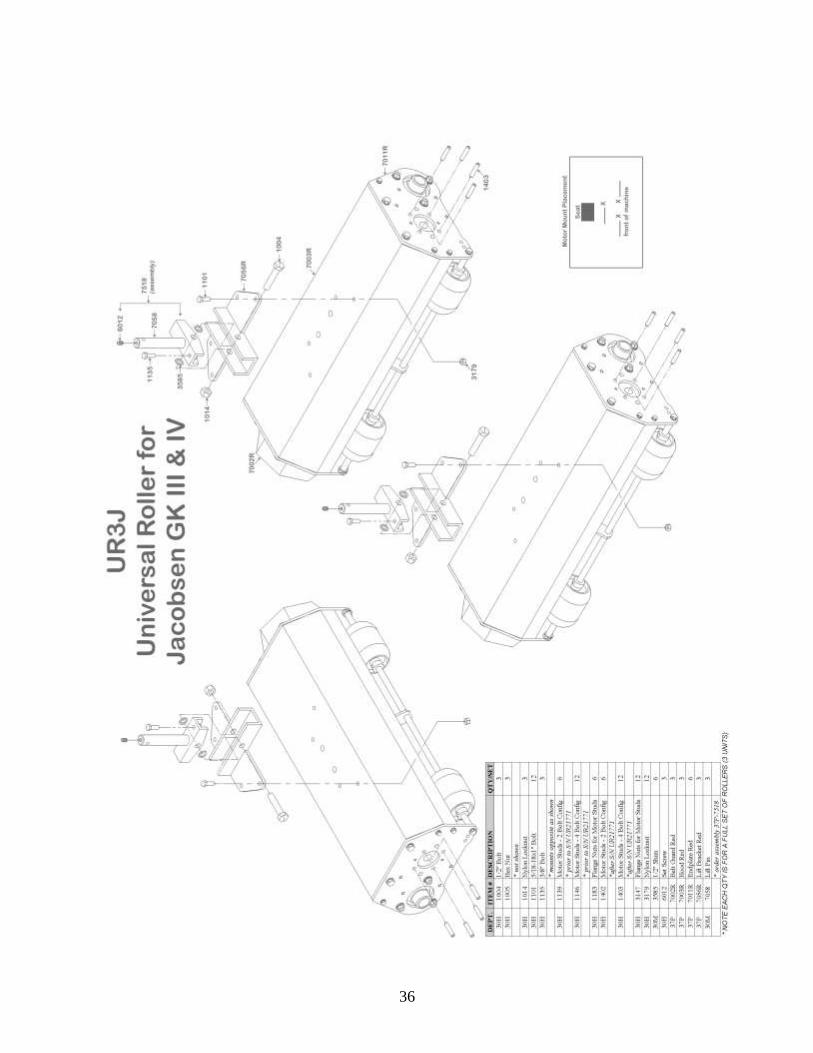
36
37
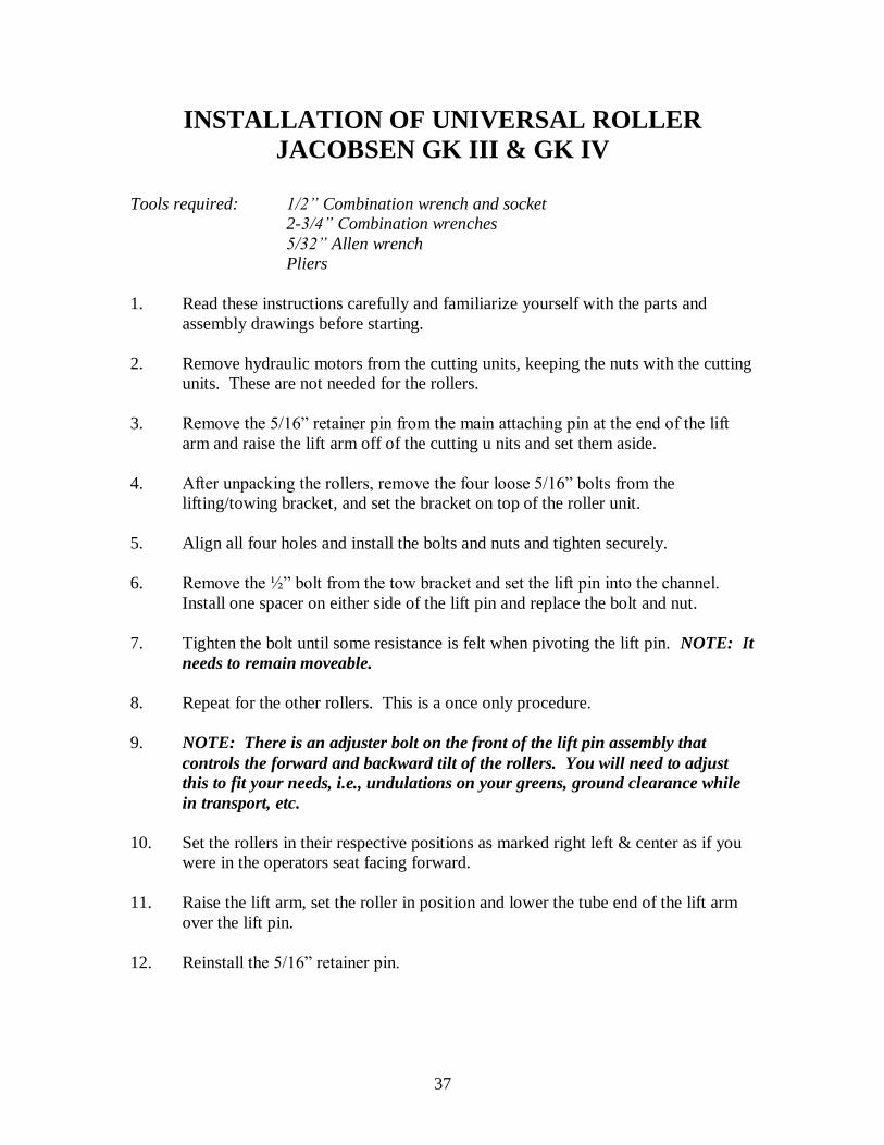
INSTALLATION OF UNIVERSAL ROLLER
JACOBSEN GK III & GK IV
Tools required: 1/2” Combination wrench and socket
2-3/4” Combination wrenches
5/32” Allen wrench
Pliers
1. Read these instructions carefully and familiarize yourself with the parts and
assembly drawings before starting.
2. Remove hydraulic motors from the cutting units, keeping the nuts with the cutting
units. These are not needed for the rollers.
3. Remove the 5/16” retainer pin from the main attaching pin at the end of the lift
arm and raise the lift arm off of the cutting u nits and set them aside.
4. After unpacking the rollers, remove the four loose 5/16” bolts from the
lifting/towing bracket, and set the bracket on top of the roller unit.
5. Align all four holes and install the bolts and nuts and tighten securely.
6. Remove the ½” bolt from the tow bracket and set the lift pin into the channel.
Install one spacer on either side of the lift pin and replace the bolt and nut.
7. Tighten the bolt until some resistance is felt when pivoting the lift pin. NOTE: It
needs to remain moveable.
8. Repeat for the other rollers. This is a once only procedure.
9. NOTE: There is an adjuster bolt on the front of the lift pin assembly that
controls the forward and backward tilt of the rollers. You will need to adjust
this to fit your needs, i.e., undulations on your greens, ground clearance while
in transport, etc.
10. Set the rollers in their respective positions as marked right left & center as if you
were in the operators seat facing forward.
11. Raise the lift arm, set the roller in position and lower the tube end of the lift arm
over the lift pin.
12. Reinstall the 5/16” retainer pin.
38
INSTALLATION OF UNIVERSAL ROLLER
JACOBSEN GK III & GK IV (CONT.)
13. Remove the hydraulic motor retainer nuts from the mounting studs.
14. Install the hydraulic motor and nuts. Some wiggling may be necessary to align
the splines.
15. Tighten the nuts.
16. Repeat for the other rollers.
17. Check operation of the rollers.
39
40

41
ADAPTATION FROM JACOBSEN GK III & IV TO… TORO GM 3- 3100: Uses Adaptation Kit 7500 (see page 18). Using page 84, reverse the drive ends on the Right and Center units. Refer to page 32 for drive shaft snap
ring placement and adjustment, page 33-34 for motor mounting procedures, and page 16 for unit mounting
instructions and illustrations for attaching hardware and machine hook-up.
TORO GM 3200 A: Uses Adaptation Kit 7551 (see page 22).
Reverse the drive end of the Center unit using the procedures on page 84. Then use page 32 for drive shaft
snap ring placement and adjustment. Next will be page 33-34 for motor mounting procedure and then page
20 for unit mounting instructions and illustrations for final attachments and hook-up. Remove the four belt
guard mounting bolts and install one counter weight to each unit with the new 5/16” x 3-1/4” bolts
provided and tighten.
TORO GM 3200 B: Uses Adaptation Kit 7552 (see page 26). Use the same procedure as for the Toro 3200A except for the motor mounting procedure. See page 33-34
for motor mounting procedure and then page 23 for unit mounting instructions and illustrations for final
attachments and hook-up.
TORO GM 3250: Uses Adaptation Kit 7506 (see page 30).
Reverse the drive end of the Center unit using the procedures on page 84. Then use page 32 for drive shaft
snap ring placement and adjustment. Next will be page 33-34 for motor mounting procedure and then page
28 for unit mounting instructions and illustrations for final attachments and hook-up. Remove the four belt
guard mounting bolts and install one counter weight to each unit with the new 5/16” x 3-1/4” bolts
provided and tighten.
JOHN DEERE 2243: Uses Adaptation Kit 7507 (see page 65).
No motor mount reversals required. Refer to page 68-69 for motor mounting procedures, and to page 67
for drive shaft placement and adjustment. Finally, refer to unit mounting instructions and illustrations for
final attachments and hook-up (see page 62).
JOHN DEERE 2500: Uses Adaptation Kit 7502 (see page 57).
Reverse the drive end of the Center unit using the procedures on page 84. Then use page 59 for drive shaft
placement and adjustment. Next, use page 60 for motor mounting procedures, and then page 54 for unit
mounting instructions and illustrations for final attachments and hook-up. Remove the four belt guard
mounting bolts and install one counter weight to each unit with the new 5/16” x 3-1/4” bolts provided and
tighten.
JOHN DEERE 2500E: Uses Adaptation Kit 7502 plus Kit 7001-3MS (see page 57 & 61)
Use all the same procedures as for the Standard John Deere 2500 except for drive shaft placement. Refer to
page 61 for shaft placement and spline installation instructions.
JACOBSEN GK V & VI: Uses Adaptation Kit 7503A (see page 39).
Reverse the drive end of the left unit using the procedures on page 84. Then use page 51 for drive shaft
snap ring placement and adjustment. Next, use page 52 for motor mounting procedures, and then page 45
for unit mounting instructions and illustrations for final attachments and hook-up. Remove the four belt
guard mounting bolts and install one counter weight to each unit with the new 5/16” x 3-1/4” bolts
provided and tighten.
RANSOMES: Uses Adaptation Kit 7505 (see page 75).
Reverse the drive end of the Right and Center units using the procedures on page 84. Then use page 79 for
drive shaft snap ring placement and adjustment. Next, use page 80-81 for motor mounting procedures, and
then page 72 for unit mounting instructions and illustrations for final attachments and hook-up. Remove the
four belt guard mounting bolts and install one counter weight to each unit with the new 5/16” x 3-1/4” bolts
provided and tighten.

42
SNAP RING INSTALLATION INSTRUCTIONS
FOR JACOBSEN III & IV
(See Base Unit Schematic for parts reference)
1. Select the required shaft position that corresponds to your triplex machine.
2. Remove belt guard (7002) and belt (7121).
3. Loosen set screw on pulley (7100) and bearing (7101).
4. Loosen set screw and lock collar on bearing (7102).
5. Tap shaft with rubber mallet to allow positioning of snap ring.
6. Install snap ring in its appropriate place and tap shaft into position indicated.
7. Retighten bearings.
8. Lock collar on bearing (7102) needs to be locked by rotating in the direction at
which the shaft will be turning. With a punch, give one rap in the predrilled hole
in lock collar in the same direction with a mallet to lock it into place and tighten
set screw.
9. Align pulleys and tighten set screw on pulley (7100).
10. Replace belt (7121) and belt guard (7002).

43
UNIVERSAL ROLLER
HYDRAULIC MOTOR MOUNTING CONFIGURATIONS
4-BOLT / 2-BOLT
JACOBSEN GK III & IV
RANSOMES (early models)
JOHN DEERE 2243
AFTER S/N UR21771
With all other mounting hardware removed, the four (1403) 5/16 Motor Studs thread
from the outside of the unit to the inside into the aluminum housing (7150) and are
tightened. The threaded portion outside the end-plate is to secure the hydraulic motor.
NOTE: Same procedure applies for the installation of the 2 (1402) 3/8 Motor Studs in
a 2-Bolt configuration.
44
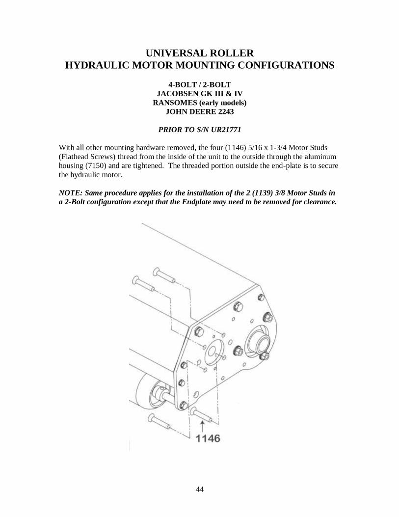
UNIVERSAL ROLLER
HYDRAULIC MOTOR MOUNTING CONFIGURATIONS
4-BOLT / 2-BOLT
JACOBSEN GK III & IV
RANSOMES (early models)
JOHN DEERE 2243
PRIOR TO S/N UR21771
With all other mounting hardware removed, the four (1146) 5/16 x 1-3/4 Motor Studs
(Flathead Screws) thread from the inside of the unit to the outside through the aluminum
housing (7150) and are tightened. The threaded portion outside the end-plate is to secure
the hydraulic motor.
NOTE: Same procedure applies for the installation of the 2 (1139) 3/8 Motor Studs in
a 2-Bolt configuration except that the Endplate may need to be removed for clearance.
45
46
INSTALLATION OF UNIVERSAL ROLLER
JACOBSEN GK V & VI
Tools required: 1/2” Combination wrench and socket
2-3/4” Combination wrenches
5/32” Allen wrench
Pliers
1. Read these instructions carefully and familiarize yourself with the parts and
assembly drawings before starting.
2. Remove hydraulic motors from the cutting units. Take care not to lose the splined
couplers. These are not needed for the rollers.
3. Remove the 5/16” retaining pin from the main attaching pin at the end of the lift
arms, and raise the lift arms off of the cutting units and set them aside.
4. After unpacking the rollers, remove the four loose 5/16” bolts from the
lifting/towing bracket, and set the bracket on top of the roller unit.
5. Align all four holes and install the bolts and nuts and tighten securely.
6. Remove the ½” bolt from the tow bracket and set the lift pin into the channel.
Adjuster bolt is positioned to the front of the units.
7. Install one spacer on either side of the lift pin and replace the bolt and nut.
8. Tighten the bolt until some resistance is felt when pivoting the lift pin. NOTE: It
needs to remain moveable.
9. Repeat for the other rollers. This is a one time procedure.
10. NOTE: There is an adjuster bolt on the front of the lift pin assembly that
controls the forward and backward tilt of the rollers. Adjust it to suit your
needs, i.e.: undulations on greens; ground clearance while in transport, etc.
11. Set the rollers under the machine. (The small caster wheels of the roller unit will
be to the front of the machine).
12. Raise the lift arm, set the roller in position and lower the tube end of the lift arm
over the lift pin and reinstall the 5/16” retainer pin.

47
INSTALLATION OF UNIVERSAL ROLLER
JACOBSEN GK V & VI (CONT.)
13. Remove the hairpin cotter from the motor clamps.
14. Open the clamp arms, twist and push the motor into position and close the clamps
and replace the hairpin cotter.
15. Repeat #10 thru # 12 for the other rollers.
16. Check operation of the rollers.

48

49
50
ADAPTATIONS FROM JACOBSEN GK V & VI TO…
TORO GM 3-3100: Uses Adaptation Kit 7500 (see page 18).
All three units require drive-end reversal, this procedure is found on page 84. Next, refer to page 32 for
drive shaft snap ring placement and adjustment. Then use page 33-34 for motor mounting procedures. For
final mounting hardware, attachment instructions and illustrations refer to page 16. Do not reinstall counter
weight onto new unit as it is not needed.
TORO 3200 A: Uses Adaptation Kit 7551 (see page 22).
Two of the units will require drive-end reversal; this procedure is on page 84. The unit not reversed will be
designated as the Right side. Refer to page 32 for drive shaft placement and adjustment. Page 33-34 will
show motor mounting procedures, and page 20, will include unit mounting instruction and illustrations for
final attachments and hook-up.
TORO 3200 B: Uses Adaptation Kit 7552 (see page 26).
Two of the units will require drive-end reversal; this procedure is on page 84. The unit not reversed will be
designated as the Right unit. Refer to page 32 for drive shaft snap ring placement and adjustment. Page
33-34 will show motor mounting procedures, and page 23 will include unit mounting instruction and
illustrations for final attachments and hook-up.
TORO 3250: Uses Adaptation Kit 7506 (see page 30).
Two of the units will require drive-end reversal; this procedure is on page 84. The unit not reversed will be
designated as the Right unit. Refer to page 32 for drive shaft placement and adjustment. Page 33-34 will
show motor mounting procedures, and page 28, will include unit mounting instruction and illustrations for
final attachments and hook-up.
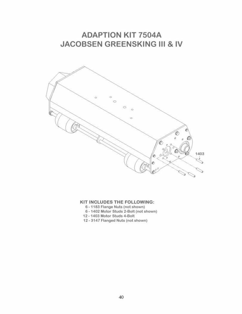
JACOBSEN GK III & IV: Uses Adaptation Kit 7504A (see page 40).
One unit will require drive-end reversal, instructions on page 84. This will be the left unit on GK III & IV.
Use page 42 to determine drive shaft snap ring placement and adjustment. Page 43-44 shows motor
mounting and procedures. Page 36 contains instructions and illustrations for final attachments and hook-
up. Do not reinstall counter weight onto new unit as it is not needed.
JOHN DEERE 2243: Uses Adaptation Kit 7507 (see page 65) .
One of the three units require Drive-End Reversal found on page 84. This unit will then fit the left front
location on the JD 2243 mower. Refer to page 68-69 for motor mounting procedures, and to page 67 for
drive shaft placement and adjustment. Finally, refer to unit mounting instructions and illustrations for final
attachments and hook-up (see page 62).
JOHN DEERE 2500: Uses Adaptation Kit 7502 (see page 57).
Two of the units will need drive-end reversal; this procedure is on page 84. These units will then fit the left
and center position on the JD 2500. Drive shaft placement will remain the same. Refer to page 60 for
motor mounting procedures, then to page 54 for unit mounting instructions and illustrations for final attachments and hook-up.
JOHN DEERE 2500E: Uses Adaptation Kit 7502 plus Kit 7001-3MS (see page 57 & 61)
Use all the same procedures as for the Standard John Deere 2500 except for drive shaft placement. Refer to
page 61 for shaft placement and spline installation instructions
RANSOMES: Uses Adaptation Kit 7505 (see page 75).
All three units will require the drive-end reversal procedure on page 84. Drive shaft snap ring placement
and adjustment is found on page 79. Next, refer to page 80-81 for motor mounting procedures, and then to
page 72 for unit mounting instructions and illustrations for final attachments and hook-up.

51
SNAP RING INSTALLATION INSTRUCTIONS
FOR JACOBSEN V & VI (See Base Unit Schematic for parts reference)
1. Select the required shaft position that corresponds to your triplex machine.
2. Remove shaft by turning roller upside down.
3. Remove belt guard (7002) and belt (7121).
4. Loosen set screw on pulley (7100) and bearing (7101).
5. Loosen set screw and lock collar on bearing (7102).
6. Tap shaft with rubber mallet to allow positioning of snap ring.
7. Install snap ring in its appropriate place and tap shaft into position indicated.
8. Retighten bearings.
9. Lock collar on bearing (7102) needs to be lock by rotating the direction at which
the shaft will be turning. With a punch, give one rap with a mallet to lock it into
place and tighten set screw.
10. Align pulleys and tighten set screw on pulley (7100).
11. Replace belt (7121) and belt guard (7002).
52
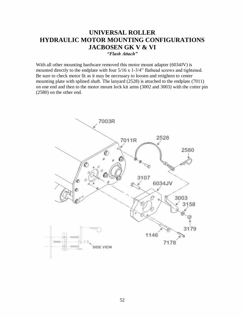
UNIVERSAL ROLLER
HYDRAULIC MOTOR MOUNTING CONFIGURATIONS
JACBOSEN GK V & VI “Flash Attach”
With all other mounting hardware removed this motor mount adapter (6034JV) is
mounted directly to the endplate with four 5/16 x 1-3/4” flathead screws and tightened.
Be sure to check motor fit as it may be necessary to loosen and retighten to center
mounting plate with splined shaft. The lanyard (2528) is attached to the endplate (7011)
on one end and then to the motor mount lock kit arms (3002 and 3003) with the cotter pin
(2580) on the other end.

53
54
55
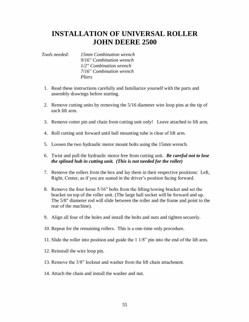
INSTALLATION OF UNIVERSAL ROLLER
JOHN DEERE 2500
Tools needed: 15mm Combination wrench
9/16" Combination wrench
1/2" Combination wrench
7/16" Combination wrench
Pliers
1. Read these instructions carefully and familiarize yourself with the parts and
assembly drawings before starting.
2. Remove cutting units by removing the 5/16 diameter wire loop pins at the tip of
each lift arm.
3. Remove cotter pin and chain from cutting unit only! Leave attached to lift arm.
4. Roll cutting unit forward until ball mounting tube is clear of lift arm.
5. Loosen the two hydraulic motor mount bolts using the 15mm wrench.
6. Twist and pull the hydraulic motor free from cutting unit. Be careful not to lose
the splined hub in cutting unit. (This is not needed for the roller)
7. Remove the rollers from the box and lay them in their respective positions: Left,
Right, Center, as if you are seated in the driver’s position facing forward.
8. Remove the four loose 5/16” bolts from the lifting/towing bracket and set the
bracket on top of the roller unit. (The large ball socket will be forward and up.
The 5/8" diameter rod will slide between the roller and the frame and point to the
rear of the machine).
9. Align all four of the holes and install the bolts and nuts and tighten securely.
10. Repeat for the remaining rollers. This is a one-time only procedure.
11. Slide the roller into position and guide the 1 1/8” pin into the end of the lift arm.
12. Reinstall the wire loop pin.
13. Remove the 3/8” locknut and washer from the lift chain attachment.
14. Attach the chain and install the washer and nut.
56
INSTALLATION OF UNIVERSAL ROLLER
JOHN DEERE 2500 (CONT.)
15. NOTE: Lift height will be determined by this chain. Your terrain and needs
will determine its position.
16. Install the Hydraulic motor by inserting retaining bolts into the cutouts.
17. Wiggle until the shaft splines line up.
18. Twist the motor into place and tighten the mounting bolts.
19. Repeat this procedure for the other rollers.
20. Check operation of rollers
57
58
ADAPTATIONS FROM JOHN DEERE 2500 TO…
TORO GM 3-3100: Uses Adaptation Kit 7500 (see page 18).
The right unit will require a drive-end reversal; this procedure is on page 84. Next, refer to page 32 for
drive shaft snap ring placement and adjustment. Then use page 33-34 for motor mounting procedures. For
final mounting hardware and attachment instructions and illustrations, refer to page 16. Do not reinstall
counter weight onto new unit as it is not needed.
TORO 3200 A: Uses Adaptation Kit 7551 (see page 22).
Drive ends are the same from the 2500 to these Toro models, no reversal required. Use page 32 for drive
shaft snap ring placement and adjustment. Refer next to page 33-34 for motor mounting procedures.
Finally, refer to page 20 for instructions and illustrations on final hardware attachment and unit hook-up.
TORO 3200 B: Uses Adaptation Kit 7552 (see page 26).
Drive ends are the same from the 2500 to these Toro models, no reversal required. Use page 32 for drive
shaft snap ring placement and adjustment. Refer next to page 33-34 for motor mounting procedures.
Finally, refer to page 23 for instructions and illustrations on final hardware attachment and unit hook-up.
TORO 3250: Uses Adaptation Kit 7506 (see page 30).
Drive ends are the same from the 2500 to these Toro models, no reversal required. Use page 32 for drive shaft snap ring placement and adjustment. Refer next to page 33-34 for motor mounting procedures.
Finally, refer to page 28 for instructions and illustrations on final hardware attachment and unit hook-up.
JACOBSEN GK III & IV: Uses Adaptation Kit 7504 (see page 39).
The center unit will require drive end reversal page 84. When completed, refer then to page 42 for drive
shaft snap ring placement and adjustment. Now see page 43-44 for motor mounting procedures, and
finally, for unit mounting hardware instructions and illustrations, refer to page 36. Do not reinstall
counterweight on new unit as it is not needed.
JACOBSEN GK V & VI: Uses Adaptation Kit 7503 (see page 48).
Left and Center units will require drive end reversal procedures found on page 84. Next will be shaft placement and adjustment on page 51. Refer then to page 52 for motor mounting procedures. Then page
45 for unit instructions and illustrations for final attachments and hook-up.
JOHN DEERE 2243: Uses Adaptation Kit 7507 (see page 65).
One of the three units requires Drive-End Reversal found on page 84. This unit will then fit the center
location on the JD 2273 mower. Refer to page 68-69 for motor mounting procedures, and to page 67 for
drive shaft placement and adjustment. Finally, refer to unit mounting instructions and illustrations for final
attachments and hook-up (see page 62).
JOHN DEERE 2500E: Add Kit 7001-3MS (see page 61)
Use all the same procedures as for the Standard John Deere 2500 except for drive shaft placement. Refer to page 61 for shaft placement and spline installation instructions.
RANSOMES: Uses Adaptation Kit 7505 (see page 75).
The right unit will need drive end reversal procedure found on page 84. Drive shaft snap ring placement
and adjustment is found on page 79. Now refer to page 80-81 for motor mounting procedure and finally,
page 72 for unit mounting instructions and illustrations for final attachments and hook-up.

59
SNAP RING INSTALLATION INSTRUCTIONS
FOR JOHN DEERE 2500 (See Base Unit Schematic for parts reference)
The following instructions apply to coupler replacement, or conversion from a different type
of machine to the John Deere 2500.
1. Turn roller unit upside down.
2. Remove belt guard (7002) and Belt (7121).
3. Loosen set on 5" pulley (7100) and remove pulley.
4. Loosen both set screws on bearing (7101) and lock collar on bearing (7102).
5. Insert a punch into hole in lock collar and tap it in the opposite direction that in would be rotating
to loosen the eccentric grip on the shaft, and slide it free of the bearing.
6. If snap ring on bearing is on the outside of the unit, use a rubber mallet to tap the shaft towards the
motor end until the snap ring can be removed. Then tap back in the opposite direction until it is free
of the (7101) bearing. In other cases, a socket, or tube slightly under 1 inch diameter can be used to tap shaft towards the belt side till it is free of the (7101) bearing.
7. Lift the coupler end of the shaft ( 7102 bearing will pivot within flange) until it can be pulled from
(7102) bearing.
8. Use a 1/4" punch and drive out roll pin joining coupler and shaft, and remove coupler. NOTE: on
internal spline couplers, a punch can be used inside the spline to tap the shaft free, on external
splines it may be necessary to heat the coupler slightly to aid in removal.
9. Install new coupler to shaft, light oil or anti-seize may be used, make sure holes will align, and tap
together, and install new roll pin.
10. Install snap ring (1127) into coupler groove and slide shaft back into bearing (7102). Push shaft
back down and align with the center of bearing (7101) and insert into bearing.
11. Slide shaft into bearing (7101) until snap ring is tight against bearing and tighten the bearing set screws. (See below)
12. Slide lock collar up to bearing (7102) be sure that recess of lock collar fits over and engages hub
on bearing, and turn in the direction that the shaft will be rotating until it is snug. Then using punch
and hammer, give lock collar one good tap in that same direction to lock bearing, collar and shaft
together, and tighten set screw.
13. Install pulley (7100) and belt (7121) align belt, and tighten set screw.
14. Replace belt guard and tighten.
15. Install internal spline coupler adaptor.
16. Align motor splines, slide and twist motor into place, and tighten mounting bolts
60
UNIVERSAL ROLLER
HYDRAULIC MOTOR MOUNTING CONFIGURATIONS
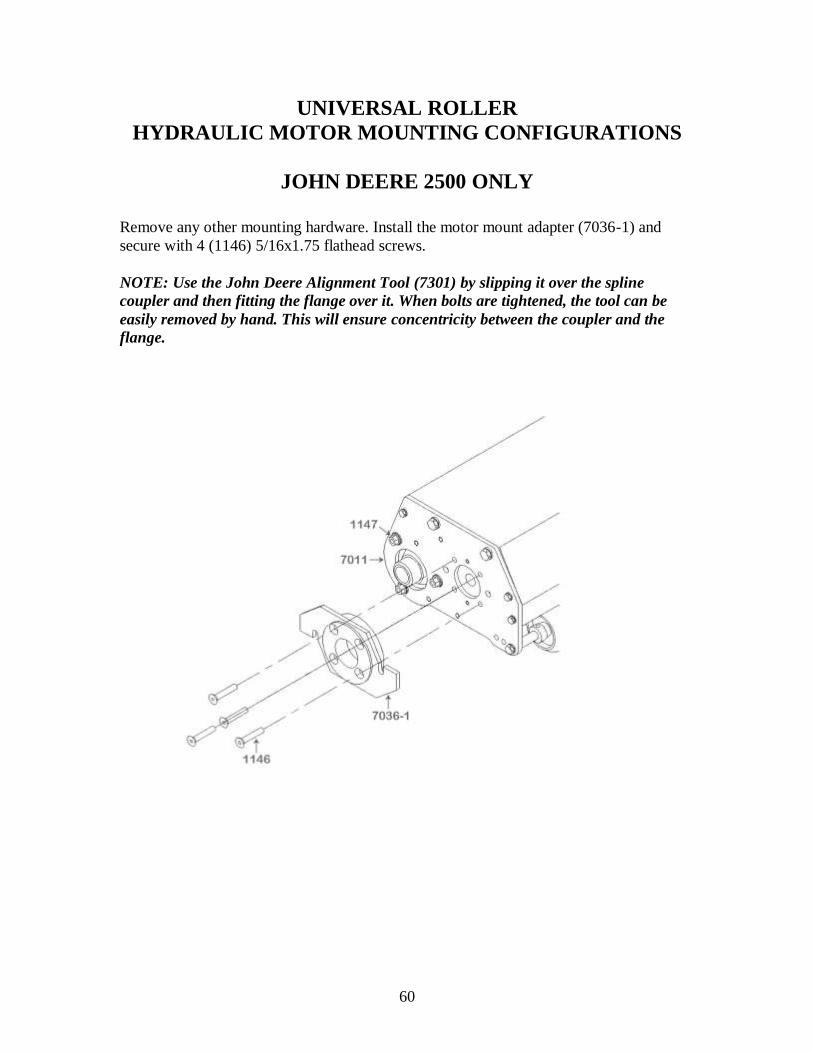
JOHN DEERE 2500 ONLY
Remove any other mounting hardware. Install the motor mount adapter (7036-1) and
secure with 4 (1146) 5/16x1.75 flathead screws.
NOTE: Use the John Deere Alignment Tool (7301) by slipping it over the spline
coupler and then fitting the flange over it. When bolts are tightened, the tool can be
easily removed by hand. This will ensure concentricity between the coupler and the
flange.
61
SNAP RING AND COUPLER PLACEMENT
INSTRUCTIONS FOR JOHN DEERE 2500E (See Base Unit Schematic for parts reference)
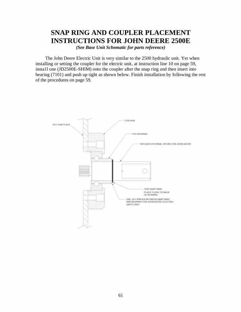
The John Deere Electric Unit is very similar to the 2500 hydraulic unit. Yet when
installing or setting the coupler for the electric unit, at instruction line 10 on page 59,
insta1l one (JD2500E-SHIM) onto the coupler after the snap ring and then insert into
bearing (7101) and push up tight as shown below. Finish installation by following the rest
of the procedures on page 59.
62
63
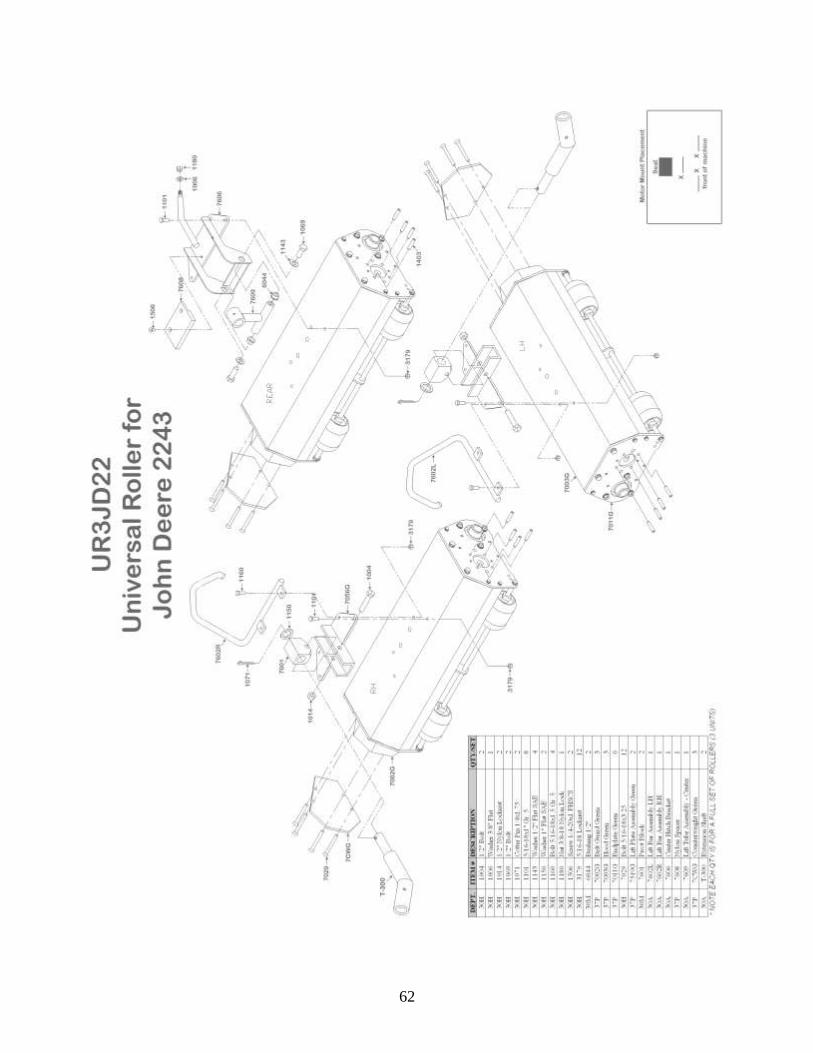
INSTALLATION OF THE UNIVERSAL ROLLER
JOHN DEERE 2243 Please be sure to keep all hardware with its unit.
Each unit of this particular model is different from the other two.
Tools needed: 1/2” Combination wrench
9/16" Combination wrench
2-3/4” Combination Wrench
1/2” Socket Ratchet & Extension
1) Read these instructions carefully and familiarize yourself with the parts and
assembly drawings before starting.
2) Remove all cutting units from the machine by removing the wire loop pin that
retains the tow bar of the cutting unit to the lift arm of the machine.
3) Remove the nuts from the hydraulic motors and slip them out of place.
4) Pull the cutting units out from under the machine.
5) Starting with the Left Unit, remove the four bolts (1101) from the Universal Lift
Bracket (7519G) and set the bracket into place on top of the roller unit.
6) Install the one inch bolts (1101) into the forward holes of the bracket.
7) Install the longer (1160) bolts into the tabs of the Lift Bar Assembly (7602R or
7602L) and into the rear holes of the Lift Bracket (7519G). Make sure the Lift
Bar Assembly hook is open to the motor mount side of the unit.
8) Tighten all four bolts.
9) Install the Extension Pin (T300) into the Pivot Block (7601).
10) Remove the bolt (1004) from the Lift Bracket (7519G) and set the Pivot
Block/Extension Pin combo down into the Lift Bracket. The Extension Pin
(T300) will be facing forward.
11) Reinstall bolt (1004) into the Lift Bracket and through the Pivot Block (7601).
12) Replace nut and tighten. DO NOT OVER TIGHTEN THE BOLT. THE PIVOT
BLOCK NEEDS TO REMAIN MOVABLE.
13) Repeat steps 1-11 with the right unit.
64
INSTALLATION OF THE UNIVERSAL ROLLER
JOHN DEERE 2243 (CONT.)
14) Slide the left and right units into position under the machine, allowing the lift bars
(7602 L and R) to pass over the guide roller on the lift arm of the greensmower.
15) Slide the downward angled lift arm pin of the greensmower into the tube end of
the Extension Pin (T300) and replace the wire loop pin.
16) Attach the hydraulic motors, securing with the four (1146) bolts. It may be
necessary to rotate the splined shaft to align the splines to allow the motor to fit.
17) Remove the four (1101) bolts from the Lifting Bracket-Center Unit (7606).
18) Set it into position on the center unit roller.
19) Replace bolts and nuts and tighten.
20) Slide roller into position under the mower.
21) Slide the lift arm pin from the mower through the Lift Bar Assembly tube (7609)
on the lifting bracket and replace the retaining pin.
22) Remove (1180) locknut and (1006) washer from the back of this bracket and
attach the lifting chain from the mower.
23) Replace locknut and washer. Chain length will have to be determined so the
roller is level in the raised position with enough slack to allow roller to follow the
contour of turf when lowered.
24) Attach the hydraulic motors as in step 16.
25) Check operation of rollers.
NOTE: Once installed, it is only necessary to remove loop pins and hydraulic motors
to switch from rolling to cutting units.

65
66
ADAPTATIONS FROM JOHN DEERE 2243 TO…
TORO GM 3-3100: Uses Adaptation Kit 7500 (see page 18).
Two of the units will require drive-end reversals. See procedures on page 84. These will become the right
and center units of the mower. Refer to page 32 for drive shaft placement and adjustment. Then use page
33-34 for motor mounting procedures. Refer next to page17 for unit mounting instructions and illustrations
for final attachments and hook-up.
TORO 3200 A: Uses Adaptation Kit 7551 (see page 22).
One unit will require drive-end reversal, procedures on page 84. This unit will then be designated as the
center unit. Drive Shaft placement and adjustment is on page 32. Next use page 33-34 for motor mounting
procedures. Then refer to page 20 for unit mounting instructions and illustrations for final attachments.
Remove the four belt guard mounting bolts and install one counter weight to each unit with the new 5/31” x
3-1/4” bolts provided and tighten.
TORO 3200 B: Uses Adaptation Kit 7552 (see page 26).
Follow same procedures as for Toro 3200B above, except to refer to page 23 for unit mounting instructions
and illustrations for final attachments.
TORO 3250: Uses Adaptation Kit 7506 (see page 30). One unit will require drive-end reversal, procedures on page 84. This unit will then be designated as the
center unit. Drive Shaft placement and adjustment is on page 32. Next use page 33-34 for motor mounting
procedures. Then refer to page 28 for unit mounting instructions and illustrations for final attachments.
Remove the four belt guard mounting bolts and install one counter weight to each unit with the new 5/31” x
3-1/4” bolts provided and tighten.
JACOBSEN GK III & IV: Uses Adaptation Kit 7504 (see page 39).
No drive-end or motor mount changes need to be made. Drive shaft placement will remain the same, so
refer to page 43-44 for motor mounting procedures, and then to page 36 for unit mounting instructions and
illustrations for final attachment and hook-up.
JACOBSEN GK V & VI: Uses Adaptation Kit 7503 (see page 48).
One unit will require drive-end reversal, procedures on page 84. This unit will then be designated as the
left unit. Drive shaft placement and adjustment is on page 51. Use page 52 for motor mounting
procedures. Then refer to page 45 for unit mounting instructions and illustration for final attachments and
hook-up. Remove the four belt guard mounting bolts and install one counter weight to each unit with the
new 5/31” x 3-1/4” bolts provided and tighten.
JOHN DEERE 2500: Uses Adaptation Kit 7502 (see page 57).
One unit will require drive-end reversal, procedures on page 84. This unit will then be designated as the
center unit. Refer then to page 59 for drive shaft placement and page 60 for motor mounting instructions.
See page 54 for final attachments and hook-up. Remove the four belt guard mounting bolts and install one counter weight to each unit with the new 5/31” x 3-1/4” bolts provided and tighten.
JOHN DEERE 2500E: Uses Adaptation Kit 7502 plus Kit 7001-3MS (see page 57 & 61)
Use all the same procedures as for the Standard John Deere 2500 except for drive shaft placement. Refer to
page 61 for shaft placement and spline installation instructions.
RANSOMES: Uses Adaptation Kit 7505 (see page 75).
One unit will require drive-end reversal, procedures on page 84. This unit will then be designated as the
center unit. Drive shaft snap ring placement and adjustment is found on page 79. Now refer to page 80-81
for motor mounting procedure and finally, page 72 for unit mounting instructions and illustrations for final
attachments and hook-up.
67
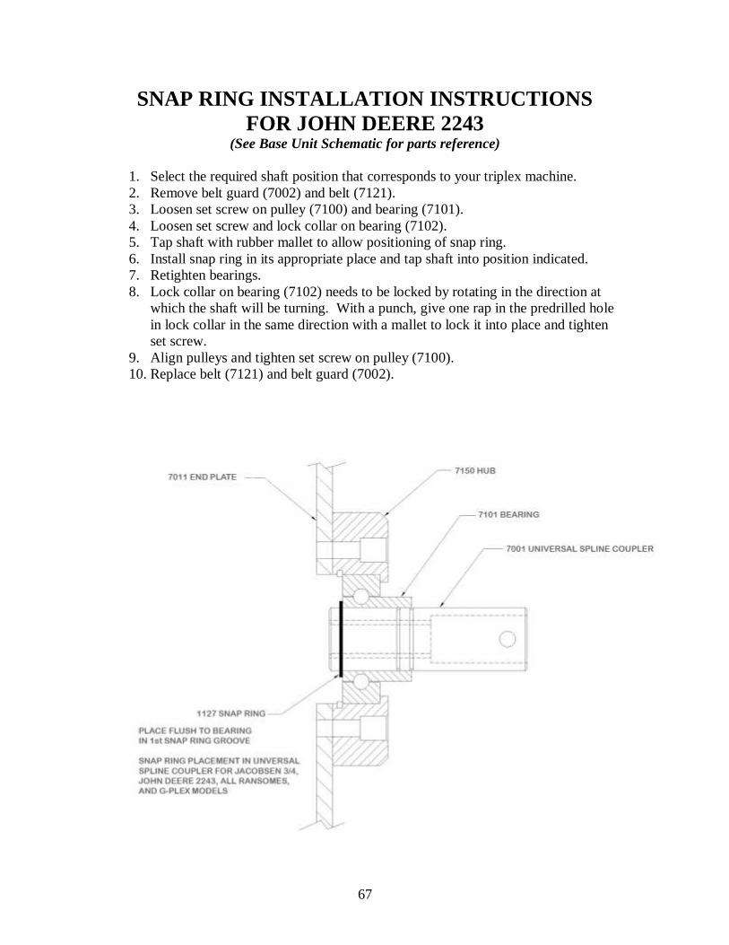
SNAP RING INSTALLATION INSTRUCTIONS
FOR JOHN DEERE 2243
(See Base Unit Schematic for parts reference)
1. Select the required shaft position that corresponds to your triplex machine.
2. Remove belt guard (7002) and belt (7121).
3. Loosen set screw on pulley (7100) and bearing (7101).
4. Loosen set screw and lock collar on bearing (7102).
5. Tap shaft with rubber mallet to allow positioning of snap ring.
6. Install snap ring in its appropriate place and tap shaft into position indicated.
7. Retighten bearings.
8. Lock collar on bearing (7102) needs to be locked by rotating in the direction at
which the shaft will be turning. With a punch, give one rap in the predrilled hole
in lock collar in the same direction with a mallet to lock it into place and tighten
set screw.
9. Align pulleys and tighten set screw on pulley (7100).
10. Replace belt (7121) and belt guard (7002).

68
UNIVERSAL ROLLER
HYDRAULIC MOTOR MOUNTING CONFIGURATIONS
4-BOLT / 2-BOLT
JACOBSEN GK III & IV
RANSOMES (early models)
JOHN DEERE 2243
AFTER S/N UR21771
With all other mounting hardware removed, the four (1403) 5/16 Motor Studs thread
from the outside of the unit to the inside into the aluminum housing (7150) and are
tightened. The threaded portion outside the end-plate is to secure the hydraulic motor.
NOTE: Same procedure applies for the installation of the 2 (1402) 3/8 Motor Studs in
a 2-Bolt configuration.
69
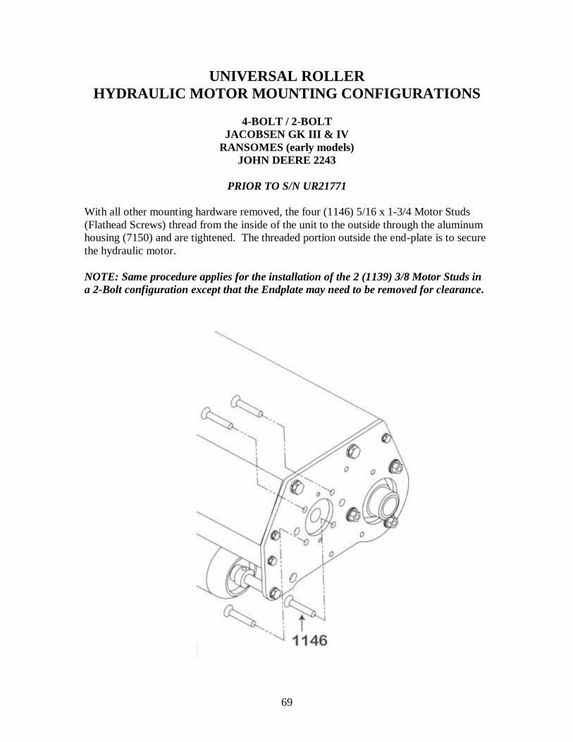
UNIVERSAL ROLLER
HYDRAULIC MOTOR MOUNTING CONFIGURATIONS
4-BOLT / 2-BOLT
JACOBSEN GK III & IV
RANSOMES (early models)
JOHN DEERE 2243
PRIOR TO S/N UR21771
With all other mounting hardware removed, the four (1146) 5/16 x 1-3/4 Motor Studs
(Flathead Screws) thread from the inside of the unit to the outside through the aluminum
housing (7150) and are tightened. The threaded portion outside the end-plate is to secure
the hydraulic motor.
NOTE: Same procedure applies for the installation of the 2 (1139) 3/8 Motor Studs in
a 2-Bolt configuration except that the Endplate may need to be removed for clearance.

70
This page left intentionally blank.

71

72

73
INSTALLATION OF UNIVERSAL ROLLER
RANSOMES MODELS
Your new units come with the parts to fit all styles of Ransomes Triplex Mowers.
Tools required: ½” combination wrench and socket
9/16” combination wrench
2-3/4” combination wrenches
5/32” Allen wrench
1. Read these instructions carefully and familiarize yourself with the parts and
assembly drawings before starting.
2. Loosen and/or remove the retaining nuts from the hydraulic motors on the cutting
units and remove motors. (Spline coupler and retaining nuts are not needed for
the roller, so keep them with the cutting unit).
3. Remove cover cap, and 3/8” retainer pin from the 1” vertical lift pin on cutting
unit, raise lift arm off of cutting unit and slide cutting unit out of the way.
4. After unpacking all the rollers, and identifying all hardware, remove the 5/16”
nuts from the four mounting bolts for lift plate (7086).
5. Install this plate as shown, replace bolts and nuts, and tighten securely.
6. Remove the 1/2” bolt from the lift plate.
7. Install lift pin (7517) as shown be sure that pivot limiter is forward.
8. Reinstall bolt, with one spacer on either side of lift pin, replace nut, and tighten
until some resistance is noticed, yet does not restrict the pivot action of lift pin.
9. NOTE: Generally all Ransomes Models will require this pin to be mounted in
the rear most hole of the lift plate, however; some early model Greens-Plex II
models require the center unit mounted in the forward hole.
10. On the belt guard side, remove the 3/8” bolt securing endplate to frame that is
located directly above the roller. Install rubber mount (7046) as indicated on
drawing.
11. On the opposite end of the roller, install Rubber Mount (7046). This is now the
center unit.
74
INSTALLATION OF UNIVERSAL ROLLER
RANSOMES MODELS (CONT.)
12. Install the remaining rubber mounts (7046), one per unit, on the other units. One
will go above the belt guard on the Right Unit. One will go above the hydraulic
motor location on the Left Unit.
13. Place rollers under machine in their respective positions; left, right, center.
14. Raise lift arm and tube and install over lift pin (7517).
15. Replace 3/8” retaining pin and cap.
16. Loosen and/or remove motor mount nuts, fit motor into place and replace nuts and
tighten.
17. Check that all rubber stops contact their respective position and do not interfere
with any of the mechanical working of the mower. Adjust if necessary.
18. Check operation of the rollers.
The pivot limiter on lift pin will need to be adjusted to fit your needs, i.e.
undulations on your greens, ground clearance while in transport, etc.
Other hardware included:
12-5/16” x 1-3/4” flathead screws with nuts are used for four bolt motor units.
Remove the two 3/8” studs from the aluminum housing, and thread and tighten the four
5/16” screws into the pre-tapped holes per each roller and secure motor on the outside
with the four units.
1” flat washers are needed in the event that your rollers twist, or travel at an angle.
Install these washers on the lift pin (7057) and under the lift arm tube so that the 3/8”
diameter retainer pin is as near the bottom of the V-groove in lift pin as possible. This
will control the twisting of the roller on the green.
Hydraulic motor spacer (7730) may be required between the endplate and
hydraulic motor due to the design of the motor on the new G-Plex II models. If there is a
gap between the motor and endplate when installing the motor and contact between these
two surfaces cannot be made by hand, then install one spacer to each roller.
DO NOT FORCE MOTOR INTO END PLATE WITH THE RETAINING UNITS.

75

76

77

78
ADAPTATIONS FROM RANSOMES TO…
TORO GM 3-3100: Uses Adaptation Kit 7500 (see page 18).
Drive-ends of all rollers remain the same. Refer to page 32 for drive shaft placement and adjustment. Then
use page 33-34 for motor mounting procedures. Refer next to page16 for unit mounting instructions and
illustrations for final attachments and hook-up.
TORO 3200 A: Uses Adaptation Kit 7551 (see page 22). One unit will require drive-end reversal, procedures on page 84. This unit will then be designated as the
right unit. Drive Shaft placement and adjustment is on page 30. Next use page 33-34 for motor mounting
procedures. Then refer to page 20 for unit mounting instructions and illustrations for final attachments.
Remove the four belt guard mounting bolts and install one counter weight to each unit with the new 5/16” x
3-1/4” bolts provided and tighten.
TORO 3200 B: Uses Adaptation Kit 7552 (see page 26).
Use the same procedure as for the Toro 3200A except for the motor mounting procedure. See page 33-34
for motor mounting procedure and then page 23 for unit mounting instructions and illustrations for final
attachments and hook-up.
TORO 3250: Uses Adaptation Kit 7506 (see page 30). One unit will require drive-end reversal, procedures on page 84. This unit will then be designated as the
right unit. Drive Shaft placement and adjustment is on page 32. Next use page 32-34 for motor mounting
procedures. Then refer to page 28 for unit mounting instructions and illustrations for final attachments.
Remove the four belt guard mounting bolts and install one counter weight to each unit with the new 5/16” x
3-1/4” bolts provided and tighten.
JACOBSEN GK III & IV: Uses Adaptation Kit 7504 (see page 39).
Two of the units will require drive-end reversal procedures on page 84. These two units will then be
designated for the Right and/or Center unit on the GK III & IV. Drive shaft placement will remain the
same, so refer to page 43-44 for motor mounting procedures, and then to page 36 for unit mounting
instructions and illustrations for final attachment and hook-up.
JACOBSEN GK V & VI: Uses Adaptation Kit 7503 (see page 48).
All three units require drive-end reversal found on page 84. Drive shaft placement and adjustment is on
page 51. Use page 52 for motor mounting procedures. Then refer to page 45 for unit mounting instructions
and illustration for final attachments and hook-up. Remove the four belt guard mounting bolts and install
one counter weight to each unit with the new 5/16” x 3-1/4” bolts provided and tighten.
JOHN DEERE 2243: Uses Adaptation Kit 7507 (see page 65).
Two of the three units require Drive-End Reversal found on page 84. The remaining unit will then fit the
left front location on the JD 2243 mower. Refer to page 68-69 for motor mounting procedures, and to page
67 for drive shaft placement and adjustment. Finally, refer to unit mounting instructions and illustrations for final attachments and hook-up (see page 62).
JOHN DEERE 2500: Uses Adaptation Kit 7502 (see page 57).
One unit will require drive-end reversal, procedures on page 84. This unit will then be designated as the
Right unit on the JD 2500. Refer then to page 59 for drive shaft placement and on page 60 for motor mount
configurations. Illustrations for final attachments and hook-up are on page 54. Remove the four belt guard
mounting bolts and install one counter weight to each unit with the new 5/16” x 3-1/4” bolts provided and
tighten.
JOHN DEERE 2500E: Uses Adaptation Kit 7502 plus Kit 7001-3MS (see page 57 & 61)
Use all the same procedures as for the Standard John Deere 2500 except for drive shaft placement. Refer to
page 61 for shaft placement and spline installation instructions

79
SNAP RING INSTALLATION INSTRUCTIONS
FOR ALL MODEL RANSOMES & G-PLEX
(See Base Unit Schematic for parts reference)
1. Select the required shaft position that corresponds to your triplex machine.
2. Remove belt guard (7002) and belt (7121).
3. Loosen set screw on pulley (7100) and bearing (7101).
4. Loosen set screw and lock collar on bearing (7102).
5. Tap shaft with rubber mallet to allow positioning of snap ring.
6. Install snap ring in its appropriate place and tap shaft into position indicated.
7. Retighten bearings.
8. Lock collar on bearing (7102) needs to be locked by rotating in the direction at
which the shaft will be turning. With a punch, give one rap in the predrilled hole
in lock collar in the same direction with a mallet to lock it into place and tighten
set screw.
9. Align pulleys and tighten set screw on pulley (7100).
10. Replace belt (7121) and belt guard (7002).
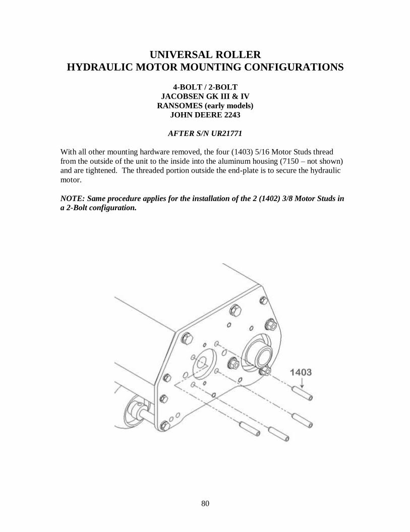
80
UNIVERSAL ROLLER
HYDRAULIC MOTOR MOUNTING CONFIGURATIONS
4-BOLT / 2-BOLT
JACOBSEN GK III & IV
RANSOMES (early models)
JOHN DEERE 2243
AFTER S/N UR21771
With all other mounting hardware removed, the four (1403) 5/16 Motor Studs thread
from the outside of the unit to the inside into the aluminum housing (7150 – not shown)
and are tightened. The threaded portion outside the end-plate is to secure the hydraulic
motor.
NOTE: Same procedure applies for the installation of the 2 (1402) 3/8 Motor Studs in
a 2-Bolt configuration.
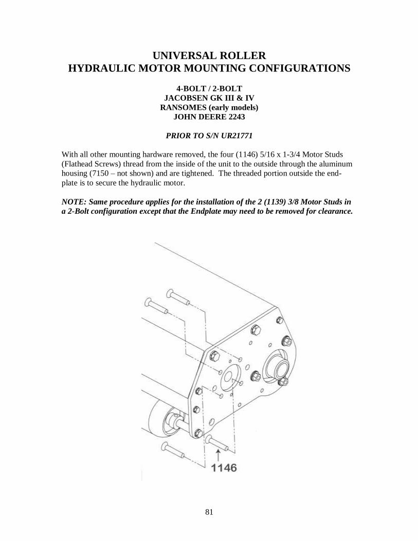
81
UNIVERSAL ROLLER
HYDRAULIC MOTOR MOUNTING CONFIGURATIONS
4-BOLT / 2-BOLT
JACOBSEN GK III & IV
RANSOMES (early models)
JOHN DEERE 2243
PRIOR TO S/N UR21771
With all other mounting hardware removed, the four (1146) 5/16 x 1-3/4 Motor Studs
(Flathead Screws) thread from the inside of the unit to the outside through the aluminum
housing (7150 – not shown) and are tightened. The threaded portion outside the end-
plate is to secure the hydraulic motor.
NOTE: Same procedure applies for the installation of the 2 (1139) 3/8 Motor Studs in
a 2-Bolt configuration except that the Endplate may need to be removed for clearance.

82
This page left intentionally blank.

83
UNIVERSAL ROLLER
84
DRIVE END REVERSAL
1. Remove belt guard and belt from the unit.
2. Loosen set screws on 5” and 2” pulleys and remove the pulleys.
3. Remove the nuts from motor mount studs, or the motor adapter plates, depending
on what model is being converted.
4. Remove the two ¼” screws that secure aluminum bearing housing to the endplate.
5. Remove the two 5/16” bolts and nuts from the flanged mounted drive shaft
bearing.
6. Remove the three hood bolts, one axle bolt, and the two endplate mount bolts
front the endplate that hold the aluminum housing.
7. Slide this endplate away from the unit.
8. Slide roller out of the opposite endplate, and rotate end for end.
9. Slip back through endplate still mounted to frame.
10. Rotate drive shaft in the same manner and replace.
11. Replace endplate over roller hub and drive shaft.
12. Install the two 3/8” bolts into frame.
13. Replace the axle bolt and the three hood bolts.
14. Replace the flathead ¼” screws into the aluminum housing.
15. Replace the 5/16” bolts and nuts into flange mounted bearing.
16. Replace the 5” and the 2” pulleys as they were on the opposite side.
17. Tighten set screws on both pulleys.
18. Install belt, check belt alignment, and adjust to ¼” deflection.
19. Replace belt guard, and motor mounting or adapter components.
20. Follow mounting procedure in the owner’s manual for the unit you are working
with.
85
NOTE TO NEW TRUE-SURFACE UNIVERSAL STYLE
VIBRATORY GREENS ROLLING SYSTEM OWNERS
Counterbalance concerns:
Due to the possibility of hydraulic hose and motor replacements and parts, and normal
wear of the lift systems of greensmowers, it may be necessary to counterbalance one end
of the roller.
If you notice any marking on the green due to premature roller drop on one side, please
check your hoses and fittings for added torque on the rollers. If this torque forces the end
of the roller down, then adjust the hose. If this doesn’t solve the problem, call us and ask
for a counterweight that will bolt to the belt guard. One or two weights per roller should
be sufficient.
Service Bulletin: Pulley Removal
Whenever the need arises either for scheduled service or parts replacement, and the
necessity arises to remove the 2” pulley (1024) from the roller shaft, care should be taken
when removing, and reinstalling this part to prevent possible pre-load on the shaft
bearings (1023) and premature bearing failure.
When removing this or any pulley, make sure that the securing element (ie. Set
screw, lock collar,…) is loosened or removed.
Second, clean as much dirt or rust from the shaft as possible in the direction that
you will be moving the pulley, and lubricate with some type of penetrating fluid
to assist in the movement of the pulley.
Third, if pulley will not move with sensible force, and/or a prying technique is
used, use a gear puller of the proper size to remove the pulley. ALWAYS DO
YOU BEST TO AVOID BEATING OR HAMMERING TO REMOVE ANY
PULLEY.
Fourth, as a last resort, heat applied to the pulley hub, close to the shaft, will
expand the pulley slightly and make removal easier. ALWAYS BE CAREFUL
WHEN USING HEAT, WATCH FOR FLAMMABLE OBJECTS AND
MATERIALS AND KEEP THEM CLEAR OF THE HEAT AREA.
When reinstalling the pulley, clean the shaft where pulley will rest, drive key, key slots,
inside of pulley, etc. Be sure to secure it with supplied set screw or lock collar.
Whenever the 2” pulley on the True-Surface roller is removed and replaced, the
possibility of pre-loading the bearings is present should hammering of the pulley out of or
into its position be used. This ‘pre-loading’ will lead to premature bearing failure, more
cost, and additional down time. You can avoid this by following the above steps for
pulley removal.
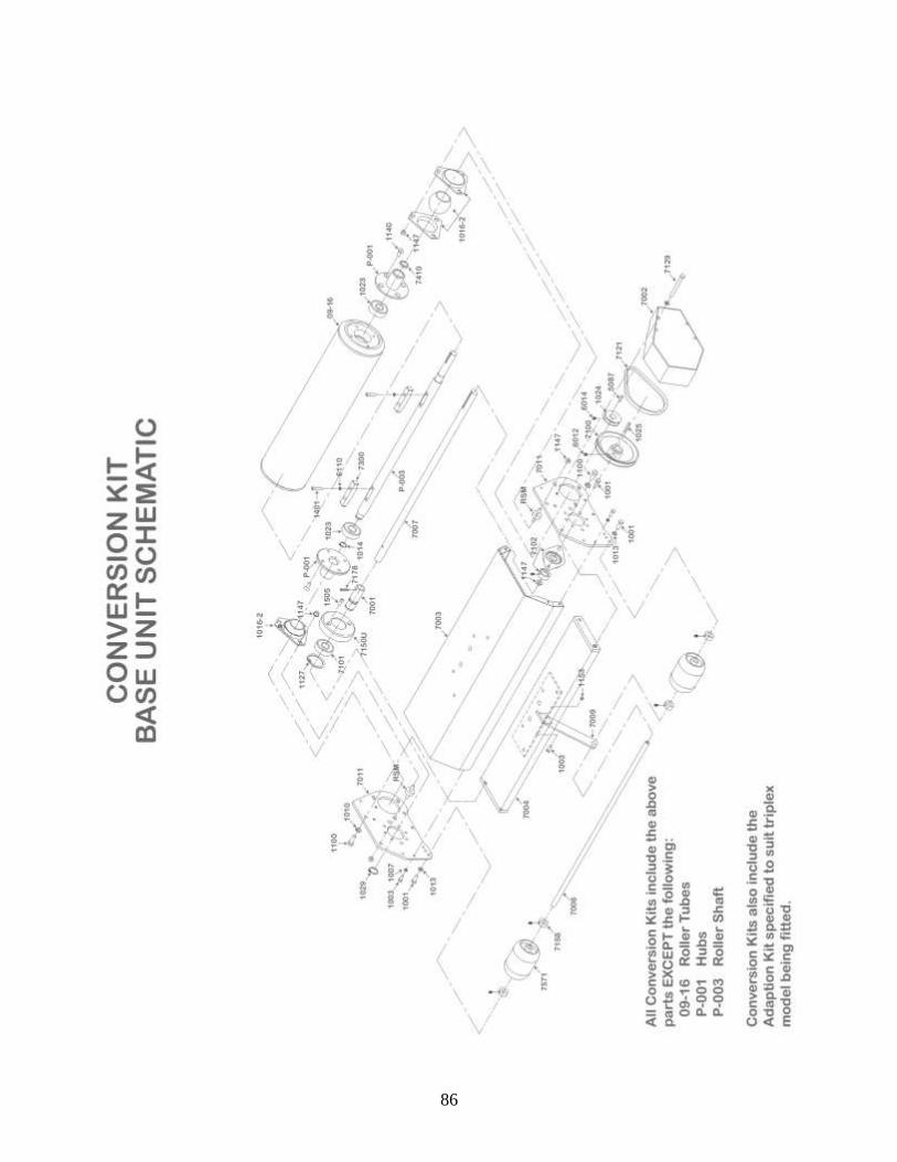
86

87
CONVERSION KIT INSTALLATION INSTRUCTIONS
1. Take old roller units and remove all hardware, frames, pulleys, etc. and set aside.
2. Open new kit boxes and find the bag of flathead/countersink screws (5/16” – 18 x ¾”) and one (1) countersink tool.
3. Remove the hubs (P-001) from both ends of the three rollers.
4. Using the countersink tool provided, countersink the four (4) holes in ALL hubs so
that the flathead screws will be flush when installed.
5. Remove Shaft (P-003).
6. Remove old bearing (1023) and old eccentric weights (09-191 and 09-192) from
shaft.
7. Locate new eccentric weights (7300), bolts and shaft bearings (1023) from
conversion box.
8. Install new eccentric weights onto shaft.
9. Install new shaft bearing on end of roller.
10. Reinstall shaft, fitting it through the shaft bearing.
11. Reinstall hubs with the new flathead screws and tighten.
12. Take the new Universal Roller Conversion kit and remove the four (4) bolts from the belt guard.
13. Loosen set screw and remove the five-inch pulley (7100) from the Roller Drive Shaft (7007).
14. Remove the two (2) bolts from the ¾” bearing flange (7102) and remove the one bolt
from the end of the Axle Shaft (7006).
15. Remove the three (3) bolts that secure the hood and the two (2) bolts that secure the
endplate to the frame.
16. Remove the drive-end endplate. NOTE: IT IS ONLY NECESSARY TO REMOVE
THIS ONE ENDPLATE ON EACH UNIT.
17. With the new framework upside down, insert the hub on the non-drive end into the
flanged bearing (7516) of the new Frame Assembly.
18. Reinstall the endplate so that the drive end of the roller passes through it’s flanged
bearing and the Roller Drive Shaft (7007) passes through the 2” hole, where it will
receive the pulley.

88
CONVERSION KIT INSTALLATION INSTRUCTIONS
(CONT.)
19. Reinstall the two (2) 3/8” bolts through the endplate and into the frame end and
tighten.
20. Reinstall the two (2) 5/16” bolts and nuts that secure ¾” bearing flange and tighten.
21. Using a ½” wrench, tighten the 6 serrated flange nuts (1027 - three on each side) on the roller flange bearings. Do this systematically so that the flange pulls evenly on
the spherical bearing. Spin the roller periodically to ensure that it will roll freely
when all nuts are secured.
22. Reinstall the 5” pulley into the Roller Drive Shaft (7007) so that the hub is facing the
endplate. Slide on as far as possible, leaving enough room to access the set screw. Once positioned, tighten the set screw.
23. Install the 2” pulley (1024) and key to the Roller Shaft (P-003).
24. Align with the 5” pulley and tighten set screw.
25. Install the Drive Belt (7121), first onto the 2” pulley, and then on to the 5” pulley. Leave ¼” deflection on the belt for proper adjustment. NOTE: Slotted holes are
provided on the endplates to shift the RSM’s if further adjustment is necessary to
align the belt on the pulleys.
26. Turn roller unit upright and reinstall the three (3) ¼” bolts into the hood and tighten.
27. Replace the belt guard with four (4) bolts and tighten.
28. Refer to the Installation Instructions in your Universal Roller Owner’s Manual for
your model of triplex mower to finish the installation process and to mount to your machine.

89
Mechanic’s Notes:

90
Thank you for purchasing the
True-Surface® Vibratory Greens
Rolling System!
Manufactured by:
Turfline, Inc 712 Jefferson St. Suite A
Moscow Mills, MO 63362
Phone: 1-800-443-8506
International Phone: +1-636-356-1210
Fax: 636-356-1218
Email: [email protected]
www.true-surface.com
Manual updated June 2006
Manual reprinted August 2010
Related Documents