TABLE OF CONTENTS Final Year Thesis 2001 Andrew McCandless iv TABLE OF CONTENTS PAGE SYNOPSIS i EXECUTIVE SUMMARY ii ACKNOWLEDGEMENTS iii TERMINOLOGY vi 1 INTRODUCTION 1 2 BACKGROUND 3 2.1 Some Examples of Omni-Directional Vehicles 3 2.2 Design Space Exploration 7 2.3 Existing Robot Design 11 2.4 Development of a Prototype Wheel 14 3 WHEEL DESIGN & CONSTRUCTION 19 3.1 Rollers 19 3.1.1 Roller Segment 19 3.1.2 Roller Disc 28 3.2 Hub Construction 29

Welcome message from author
This document is posted to help you gain knowledge. Please leave a comment to let me know what you think about it! Share it to your friends and learn new things together.
Transcript
TABLE OF CONTENTS
Final Year Thesis 2001 Andrew McCandless iv
TABLE OF CONTENTS
PAGE
SYNOPSIS i
EXECUTIVE SUMMARY ii
ACKNOWLEDGEMENTS iii
TERMINOLOGY vi
1 INTRODUCTION 1
2 BACKGROUND 3
2.1 Some Examples of Omni-Directional Vehicles 3
2.2 Design Space Exploration 7
2.3 Existing Robot Design 11
2.4 Development of a Prototype Wheel 14
3 WHEEL DESIGN & CONSTRUCTION 19
3.1 Rollers 19
3.1.1 Roller Segment 19
3.1.2 Roller Disc 28
3.2 Hub Construction 29
TABLE OF CONTENTS
Final Year Thesis 2001 Andrew McCandless v
4 CHASSIS DESIGN & CONSTRUCTION 32
4.1 Suspension Arm 32
4.1.1 Double wishbone suspension 32
4.1.2 Trailing/Leading arm suspension 32
4.2 Spring-Damper System 36
4.3 Central mount 37
4.4 Assembly 41
4.5 Modifications 42
5 PERFORMANCE EVALUATION 44
6 CONCLUSIONS 46
7 RECOMMENDATIONS 46
8 REFERENCES 47
9 BIBLIOGRAPHY 48
APPENDIX A Geometric Proof of Cylinder-Based Roller Profile 49
APPENDIX B Rubber Moulding Process 51
APPENDIX C Mechanical Design Drawings 58
THE UNIVERSITY OF WESTERN AUSTRALIA
DEPARTMENT OF MECHANICAL AND MATERIALS ENGINEERING
Final Year Thesis 2001
$QGUHZ 0F&DQGOHVV
6XSHUYLVRU� 'U 1DWKDQ 6FRWW
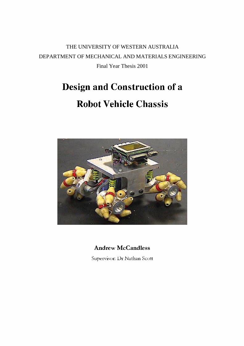
'HVLJQ DQG &RQVWUXFWLRQ RI D
5RERW 9HKLFOH &KDVVLV

LETTER OF TRANSMITTAL
Andrew McCandless
171 Derby Road
SHENTON PARK WA 6008
5 November 2001
Professor B. H. Brady
Executive Dean
Faculty of Engineering and Mathematical Sciences
University of Western Australia
CRAWLEY WA 6009
Dear Sir,
Final Year Thesis It is with great pleasure that I submit this thesis entitled “Design and Construction of a
Robot Vehicle Chassis” to the University of Western Australia as a requirement for a
Degree in Mechanical Engineering.
Yours sincerely,
Andrew McCandless

SYNOPSIS
Final Year Thesis 2001 Andrew McCandless i
SYNOPSIS
Omni directional vehicles have been studied and developed quite extensively in a number
of robotics laboratories around the world. Such vehicles are characterised by the ability to
move sideways and spin on the spot. Their extra maneuverability enables them to
navigate through narrow hallways, turn sharp corners and sidestep obstacles.
The Centre for Intelligent Information Processing Systems (CIIPS) developed an
omni-directional robot vehicle to develop software for navigating a maze, playing robot
soccer etc. Given the above abilities, this type of vehicle is well suited to these tasks.
After building the first chassis, the performance of the vehicle was observed to be less
than satisfactory, affecting the scope of the research and development that was possible.
The design and construction of a second chassis was commissioned so that further
research could be conducted. Once complete, tests were carried out showing an
improvement in performance over a wide range of surfaces.
This thesis describes the methodology used in the design and construction of the second
chassis, as well as a performance evaluation of the finished product.
EXECUTIVE SUMMARY
Final Year Thesis 2001 Andrew McCandless ii
EXECUTIVE SUMMARY
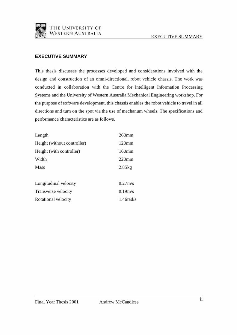
This thesis discusses the processes developed and considerations involved with the
design and construction of an omni-directional, robot vehicle chassis. The work was
conducted in collaboration with the Centre for Intelligent Information Processing
Systems and the University of Western Australia Mechanical Engineering workshop. For
the purpose of software development, this chassis enables the robot vehicle to travel in all
directions and turn on the spot via the use of mechanum wheels. The specifications and
performance characteristics are as follows.
Length 260mm
Height (without controller) 120mm
Height (with controller) 160mm
Width 220mm
Mass 2.85kg
Longitudinal velocity 0.27m/s
Transverse velocity 0.19m/s
Rotational velocity 1.46rad/s

ACKNOWLEDGEMENTS
Final Year Thesis 2001 Andrew McCandless iii
ACKNOWLEDGEMENTS
The successful completion of this project would not have been possible without
assistance from the following people, who I would like to sincerely thank,
To Dr Nathan Scott, for his unlimited enthusiasm, unique open-mindedness and
dedicated supervision.
To Ian Hamilton, Chris Ballan, Dennis Brown, Mike Cowell and Brian Sambell of the
Mechanical Engineering workshop, for their time and effort during the manufacture of
the chassis.
To Anna McLean, for her companionship, comradeship and tolerance over the months
and months of countless late nights.
To Tegan Douglas, for her support and editing assistance during the final stages of the
thesis.
To my Parents, David and Valerie McCandless, for giving me the support and
independence required to take on such a task.
Finally, to the Department of Mechanical Engineering, for accepting my transferal,
accrediting my past work and providing an outlet for my interests.
TERMINOLOGY
Final Year Thesis 2001 Andrew McCandless vi
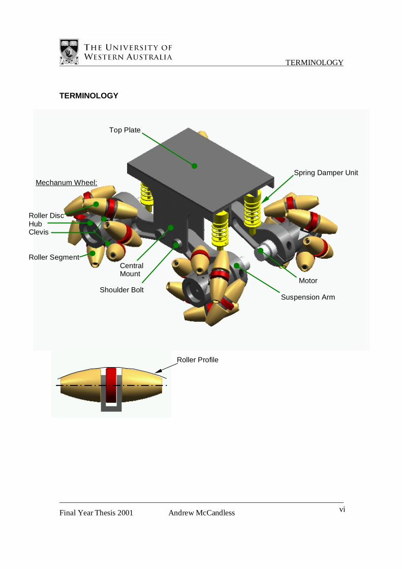
TERMINOLOGY
Mechanum Wheel:
Roller Disc Hub Clevis Roller Segment
Central Mount
Motor
Suspension Arm
Spring Damper Unit
Shoulder Bolt
Top Plate
Roller Profile
INTRODUCTION
Final Year Thesis 2001 Andrew McCandless 1
1 INTRODUCTION
Omni directional vehicles have been studied and developed extensively over the
last decade in a number of robotics laboratories around the world. Such vehicles are
characterised by the ability to move sideways and spin on the spot. This extra
maneuverability enables them to navigate through narrow hallways, turn sharp corners
and sidestep obstacles. Such capabilities have the potential to solve a number of
challenges in industry and society. For instance, a motorised wheelchair utilising this
technology would give the operator greater maneuverability and thus access to places
most able-bodied people take for granted. Also, current process for inspection of
hazardous areas involves expensive, time consuming safety procedures. These can be
avoided by using unmanned robot vehicles equipped with the ability to drive down
narrow corridors to get to the required location.
The Centre for Intelligent Information Processing Systems (CIIPS) took the more
humble approach of developing a robot vehicle to navigate a maze, play robot soccer etc.
Nevertheless, an omni directional vehicle is well suited to these tasks. The project began
with Professor Thomas Braunl, of CIIPS, who commissioned the manufacture of a highly
maneuverable, autonomous, omni-directional robot vehicle. However, after the chassis
was finished, the conclusion was soon reached that the robot vehicle was limited in the
range of surfaces that it could operate on. Professor Braunl requested Dr Nathan Scott, of
the Department of Mechanical and Materials Engineering, to develop a new wheel design
within the context of a third year Mechanical Engineering Project (630.350), or final year
thesis. The project was taken on by the Author as a third year Mechanical Engineering
Project in Semester 2, 1999, after which the new wheel design was developed. The
conclusion was reached that a full analysis and eventual re-design of the chassis would be
necessary if the CIIPS research in this field was to continue. Some additional work was
done developing a prototype for the wheel during 2000 and this is described in the
Background chapter. It is important to note that this work is not submitted as part of this
thesis, but should be recognised as work done previously on the overall project.

INTRODUCTION
Final Year Thesis 2001 Andrew McCandless 2
Having completed the new chassis, this thesis aims to describe in detail the
motivations, considerations and constraints behind the design, as well as the lessons
learnt and the procedures developed during its construction and performance evaluation.

BACKGROUND
Final Year Thesis 2001 Andrew McCandless 3
2 BACKGROUND
2.1 Some Examples of Omni Directional Vehicles
Current research into omni-directional vehicle movement takes a number of forms. The
design concepts of this project form part of the research involved with the use of wheels
that roll with two degrees of freedom. This research involves revolutionary ideas and
concepts that are likely to take years to fully develop, so research institutions are
reluctant to share ideas until the research is fully recognised as their own work. Thus only
the completed projects are available to the public. This section discusses some of the
different design ideas currently being investigated around the world.
2.1.1 Nasa’s OmniBot
The OmniBot project started with the objective to develop a highly maneuverable mobile
base that can enter hazardous environments and perform remote inspections. The vehicle
is being used to test remote control mediums and umbilical technologies for autonomous
control The OmniBot uses four brushless servomotors, each directly driving a mechanum
wheel that has rollers mounted around the outside of a central hub.
Figure 2.1.1 Photograph courtesy of NASA
The capabilities of the wheels are currently being evaluated over a range of surfaces and
speeds, and the sturdiness of the body is also being developed.

BACKGROUND
Final Year Thesis 2001 Andrew McCandless 4
2.1.2 The Vuton
The Vuton is a crawling platform that uses a
developed form of caterpillar track to perform omni
directional movement. Each link of the caterpillar
track has a barrel shaped roller that enables the
tracks to roll sideways. The difference between this
track and a conventional track is that each link
circumnavigates the loop in a fashion similar to an
escalator in the sense that they maintain a constant horizontal orientation (see Figure
2.1.2). Four caterpillar tracks are used, one on each side, and each individually driven by
its own motor. The use of these tracks gives the Vuton a payload capacity of around
1000kg, far exceeding any vehicles with the same weight. For this reason it is proposed
for use as a transport vehicle in factories, hospitals and warehouses. There is no evidence
of the Vuton possessing any compliance to traverse surface irregularities, but it boasts the
ability to run smoothly on carpet, linoleum, and even on fragile tatami mats without
leaving any damage.
2.1.3 The Killough Platform
The designs discussed previously, used free rollers supported on the outside of a driving
surface to achieve the desired two degree of freedom motion. The Killough platform,
however, uses spherical rollers that are driven on an axis through their centre,
Figure 2.1.2 The Vuton uses a revolutionary form of
caterpillar track, enabling a very large payload capacity.
Photographs courtesy of Shigeo Hirose, Shinichi Amano
BACKGROUND
Final Year Thesis 2001 Andrew McCandless 5
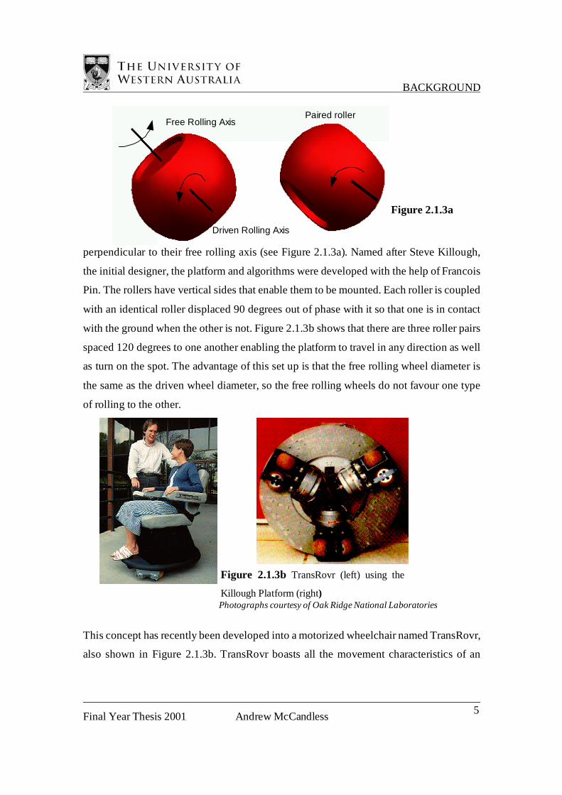
Free Rolling Axis
Driven Rolling Axis
Paired roller
Figure 2.1.3a
perpendicular to their free rolling axis (see Figure 2.1.3a). Named after Steve Killough,
the initial designer, the platform and algorithms were developed with the help of Francois
Pin. The rollers have vertical sides that enable them to be mounted. Each roller is coupled
with an identical roller displaced 90 degrees out of phase with it so that one is in contact
with the ground when the other is not. Figure 2.1.3b shows that there are three roller pairs
spaced 120 degrees to one another enabling the platform to travel in any direction as well
as turn on the spot. The advantage of this set up is that the free rolling wheel diameter is
the same as the driven wheel diameter, so the free rolling wheels do not favour one type
of rolling to the other.
This concept has recently been developed into a motorized wheelchair named TransRovr,
also shown in Figure 2.1.3b. TransRovr boasts all the movement characteristics of an
Figure 2.1.3b TransRovr (left) using the
Killough Platform (right) Photographs courtesy of Oak Ridge National Laboratories
BACKGROUND
Final Year Thesis 2001 Andrew McCandless 6
omni-directional vehicle, and keeps the wheels, power train and infrastructure hidden
within the platform.
2.1.4 Palm Robot Kit
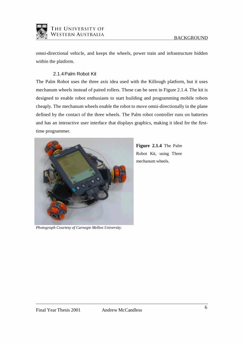
The Palm Robot uses the three axis idea used with the Killough platform, but it uses
mechanum wheels instead of paired rollers. These can be seen in Figure 2.1.4. The kit is
designed to enable robot enthusiasts to start building and programming mobile robots
cheaply. The mechanum wheels enable the robot to move omni-directionally in the plane
defined by the contact of the three wheels. The Palm robot controller runs on batteries
and has an interactive user interface that displays graphics, making it ideal for the first-
time programmer.
Photograph Courtesy of Carnegie Mellon University.
Figure 2.1.4 The Palm
Robot Kit, using Three
mechanum wheels.

BACKGROUND
Final Year Thesis 2001 Andrew McCandless 7
2.2 Design Space Exploration
The design of the vehicle included the use of mechanum wheels. These wheels have
rollers radially mounted around the outside. The rotational axes of these rollers must be
offset by some angle from the central axis of the wheel. The degree of this offset is
governed by a number of factors including the number of wheels and their location about
the chassis. For a standard four-wheel configured vehicle, the wheels have rollers with
rotational axes around 45 degrees to the wheel rotational axis. The radially located rollers
give the wheels an extra degree of freedom in their movement, so any wheel used
individually is practically useless because it has the option to roll forward or sideward.
When the wheels are used in conjunction with other wheels, they enable the robot to
move omni-directionally (see Figure 2.2.1).
Figure 2.2.1
Any given combination of robot transverse velocity and/or rotational velocity requires a
certain combination of wheel velocities. Some movements require all four wheels to be
engaged, others need only one or two. This is because even when a wheel is not turning,
it stil has a diagonally mounted free roller in contact with the ground, which is also able
to govern the vehicle’s movement. The necessary condition for the operation of the
vehicle is that all four wheels be in contact with the ground. Every driven wheel has
another driven counterpart, so if a wheel loses contact with the ground, then the vehicle
moves in a way which no longer matches the commands of the processor. Another
necessary condition for the wheels is that the rollers are the only part that can touch the
BACKGROUND
Final Year Thesis 2001 Andrew McCandless 8
ground. If any part of the central hub of the wheel touches, then the wheel loses its
second degree of freedom and no longer possesses its omni-directional characteristics.
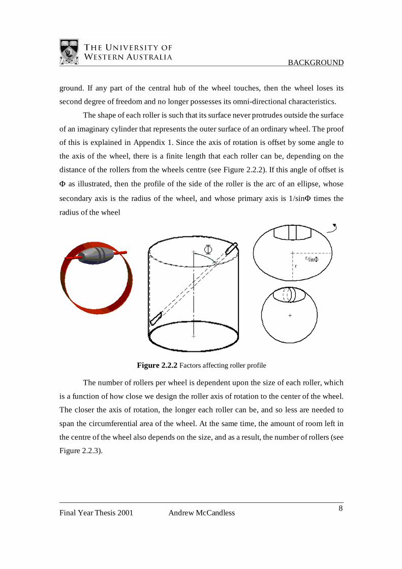
The shape of each roller is such that its surface never protrudes outside the surface
of an imaginary cylinder that represents the outer surface of an ordinary wheel. The proof
of this is explained in Appendix 1. Since the axis of rotation is offset by some angle to
the axis of the wheel, there is a finite length that each roller can be, depending on the
distance of the rollers from the wheels centre (see Figure 2.2.2). If this angle of offset is
Φ as illustrated, then the profile of the side of the roller is the arc of an ellipse, whose
secondary axis is the radius of the wheel, and whose primary axis is 1/sinΦ times the
radius of the wheel
Figure 2.2.2 Factors affecting roller profile
The number of rollers per wheel is dependent upon the size of each roller, which
is a function of how close we design the roller axis of rotation to the center of the wheel.
The closer the axis of rotation, the longer each roller can be, and so less are needed to
span the circumferential area of the wheel. At the same time, the amount of room left in
the centre of the wheel also depends on the size, and as a result, the number of rollers (see
Figure 2.2.3).

BACKGROUND
Final Year Thesis 2001 Andrew McCandless 9
Figure 2.2.3
The size of the rollers also has an effect upon performance of the wheel on a variety of
surfaces. Consider a basic step change in surface being ascended by a wheel of this type.
The height of step change that the wheel can successfully overcome is a function of the
roller minimum diameter. The larger the rollers are the greater the range of surface
deviations that can be overcome. Also as the size of the rollers increases, the slower they
spin, resulting in lower friction losses in the driving of the wheel. In summary, when
designing a new drive system for a robot of this kind, there exists a certain number of
rollers that makes the ideal compromise between having a small number of large rollers
per wheel, and having a large number of small rollers per wheel.
Whilst exploring the different combinations of roller geometry it is important to
also consider how the rollers are to be mounted. The bearing axes can be supported at the
edges, in the middle or anywhere in between. By supporting the rollers at the edges, the
bearing forces on the mounts are minimised because the force always acts between them,
keeping the mounts located in a low bending stress area. Bearing forces in a split central-
mounted roller are greater because the end bearings are subjected to the entire weight of
one wheel in the maximum bending stress scenario as illustrated in Figure 2.2.4.
Figure 2.2.4 The maximum
bending stress scenario for a central
supported roller.
Reaction Force

BACKGROUND
Final Year Thesis 2001 Andrew McCandless 10
Figure 2.2.5
Tighter tolerances and better bearings are needed so that the rollers still roll freely when
the maximum bending moment is applied. The key advantage of the central mounting
idea is that the mount can be considerably larger and still be far from the outer surface of
the wheel. Due to the geometry of the rollers being offset from the wheel axis, the
furthest point on the roller axis from the wheel
outer diameter, is the point at the middle of
the roller (see Figure 2.2.5). Mounting
the roller here ensures that the
rollers are the only part of the
wheel to touch the ground. As a
result, a compromise has to be
made to achieve good free rolling
characteristics as well as reliable
roller contact with the ground.
As mentioned earlier, another necessary condition for a vehicle of this kind is that the
wheels are in constant contact with the ground. With a three-wheeled vehicle this is
inevitable because three points define a plane, but with four or more wheels, it is
important to have a mechanism to ensure the wheels are always in contact. One way to do
this is to design a chassis with independent suspension, another is to incorporate a certain
level of compliance in each roller, either by making them soft and spongy or by making
them spring loaded. Sticking to conventional methods reduces the need for heavy
development, but newer, more novel ideas can prove to be more worthwhile. However,
one thing is necessary in all cases; as the wheels rotate, there has to be a smooth
transition from one roller to the next. Wheels that have suspension must remain in the
vertical plane, otherwise the end of one roller on one side of the wheel will not orbit
within a profile common with the end of the next roller on the other side of the wheel.
Compliant rollers must all squash and spring back to the same degree as each other so the
wheel does not jerk up and down along its path.

BACKGROUND
Final Year Thesis 2001 Andrew McCandless 11
2.3 Existing robot design
Figure 2.3.1 Small robot vehicles, designed for playing robot soccer
Gordon Menck from Subiaco college of TAFE and Richard Mauger, from CIIPS,
designed the first Omni-directional robot vehicle at the University of Western Australia.
It was constructed with motors made by Faulhaber, a German micro-drive manufacturer.
These motors have a built in gearbox transmission with a 9:1 speed reduction and an
axially aligned output shaft. These motors were used in the “Eye bot” mobile robot
vehicles, pictured in Figure 2.3.1, that play autonomous robot soccer. It was from using
these robots that the incentive to develop an omni-directional robot vehicle originated.
The size and weight of the proposed vehicle meant that further gear reduction was
necessary, so additional gearboxes were purchased with a 15:1 reduction ratio. When
used in conjunction with the motors, the overall reduction was 135:1. The addition of
these gearboxes also meant that the motor positions could be staggered to save room,
making the vehicle very compact (see Figure 2.3.2).
BACKGROUND
Final Year Thesis 2001 Andrew McCandless 12
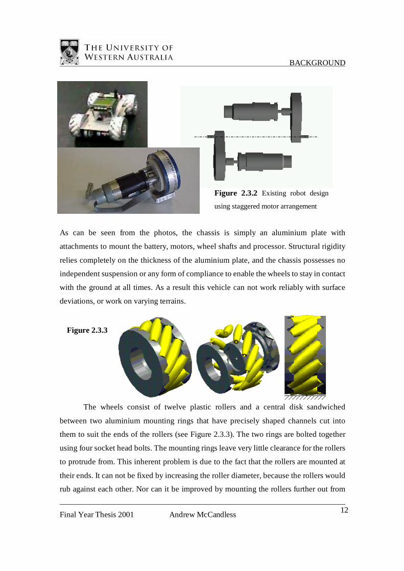
As can be seen from the photos, the chassis is simply an aluminium plate with
attachments to mount the battery, motors, wheel shafts and processor. Structural rigidity
relies completely on the thickness of the aluminium plate, and the chassis possesses no
independent suspension or any form of compliance to enable the wheels to stay in contact
with the ground at all times. As a result this vehicle can not work reliably with surface
deviations, or work on varying terrains.
The wheels consist of twelve plastic rollers and a central disk sandwiched
between two aluminium mounting rings that have precisely shaped channels cut into
them to suit the ends of the rollers (see Figure 2.3.3). The two rings are bolted together
using four socket head bolts. The mounting rings leave very little clearance for the rollers
to protrude from. This inherent problem is due to the fact that the rollers are mounted at
their ends. It can not be fixed by increasing the roller diameter, because the rollers would
rub against each other. Nor can it be improved by mounting the rollers further out from
Figure 2.3.2 Existing robot design
using staggered motor arrangement
Figure 2.3.3

BACKGROUND
Final Year Thesis 2001 Andrew McCandless 13
the wheel centre because they are already at their limit. Therefore it is imperative to only
operate these wheels on hard surfaces because if they sink any more than half a
millimetre the mounting rings start to touch the ground and the wheels lose their two-
degree-of-freedom characteristics. In addition, the rollers have trouble gripping on a wide
range of surfaces because they are made from a plastic known as Pactene. This polymer
is favoured in Mechanical engineering circles because of its machinability, which is
probably why it was used in this construction, but it has very low friction characteristics.
Attempts to operate the robot on some tables or benchtops resulted in the rollers slipping.
From the illustration it is apparent just how much material is used in these wheels.
They have an outside diameter of 100mm, weigh around 400g each and are driven by a
4mm shaft. Building the wheels and adapting the processor took up most of the
developmental focus and very little was considered about the operation of the wheels,
their kinematic requirements or the maximum rated torque of the gearboxes. As a result
the additional gearboxes burnt out after about four hours of cumulative use. The wheels
were too heavy, their moment of inertia was too high and consequently the required
torque to drive the wheels exceeded the gearbox specifications. To solve this problem, an
order was placed to get some more motors with a high built in reduction ratio similar to
the combined reduction of the previous drive system. This was chosen to be 121.5:1. In
the short term however, the processor still required research and the operation of the
vehicle was still very novel within the research lab, so more gearboxes were purchased to
complete the work on the programming.
When the new motors arrived the chassis was adapted to suit them, but it no
longer had the staggered motor configuration, so the vehicle became a lot wider.
Unfortunately the drive system is very fragile. The grub screws that are used to lock the
wheels on to the motor shafts are consistently wearing dimples into them because the
torque required to drive the wheels is too great for extensive use. The robot needs to be
continuously checked to see if all wheels are still connected to their shafts properly, and
the robot needs to be handled with the utmost of care.
As a first prototype the vehicle was successful in its operation. It displayed the
ability to carry out the full range of movement proposed during the projects conception.

BACKGROUND
Final Year Thesis 2001 Andrew McCandless 14
However, it is very limited in its applications and is restricted to only working on a
specially prepared test bench that is smooth and flat, with a hard, rubberised surface.
2.4 Development of a Prototype Wheel
Originally a request was made by Professor Thomas Braunl, from the Centre for
Intelligent Information Processing Systems (CIIPS), to Dr Nathan Scott, that a new form
of mechanum wheel be designed, due to the problems getting the existing wheels to
work properly on a wide range of surfaces. These problems were a result of both the
design, and the choice of materials. As mentioned previously, the design limited the
wheels to only working on hard, flat surfaces because the rollers were mounted at the
edges. On soft surfaces, the wheels were sinking in so that the mounting rings were
touching the ground, disabling their two dimensional kinematic properties. The new
wheel had to have the rollers offset at an angle of 45 degrees to the wheel axis to work
with existing programming and it was to be driven by the new high reduction Faulhaber
motors ordered from Germany.
Early design attempts were built around the idea that the less the number of
rollers, the larger each roller would be, improving the surface handling properties.
However, there exists a minimum number where the rollers are so big that they interfere
with adjacent rollers. Alleviating this problem by omitting interfering material was
investigated but it required a roller profile that was very intricate, requiring an
unjustifiable degree of manufacturing and development. After much deliberation, it was
decided that the most feasible minimum number of rollers per wheel was six. However, a
decision still had to be reached about how the rollers were to be mounted.
As discussed earlier, the ideal place to mount the rollers is in the center so that the
rollers can run on the ground freely without being fouled by any mounting arrangement.
However, there is good reason why it is not advisable to mount the rollers in the very
centre. When the tips of the rollers are in contact with the ground, a single central roller
mount would be subjected to a considerable bending and twisting twice every wheel
BACKGROUND
Final Year Thesis 2001 Andrew McCandless 15
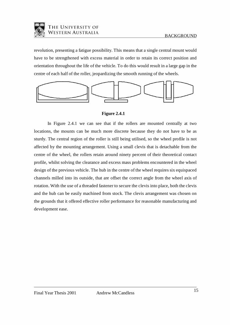
revolution, presenting a fatigue possibility. This means that a single central mount would
have to be strengthened with excess material in order to retain its correct position and
orientation throughout the life of the vehicle. To do this would result in a large gap in the
centre of each half of the roller, jeopardizing the smooth running of the wheels.
Figure 2.4.1
In Figure 2.4.1 we can see that if the rollers are mounted centrally at two
locations, the mounts can be much more discrete because they do not have to be as
sturdy. The central region of the roller is still being utilised, so the wheel profile is not
affected by the mounting arrangement. Using a small clevis that is detachable from the
centre of the wheel, the rollers retain around ninety percent of their theoretical contact
profile, whilst solving the clearance and excess mass problems encountered in the wheel
design of the previous vehicle. The hub in the centre of the wheel requires six equispaced
channels milled into its outside, that are offset the correct angle from the wheel axis of
rotation. With the use of a threaded fastener to secure the clevis into place, both the clevis
and the hub can be easily machined from stock. The clevis arrangement was chosen on
the grounds that it offered effective roller performance for reasonable manufacturing and
development ease.
BACKGROUND
Final Year Thesis 2001 Andrew McCandless 16
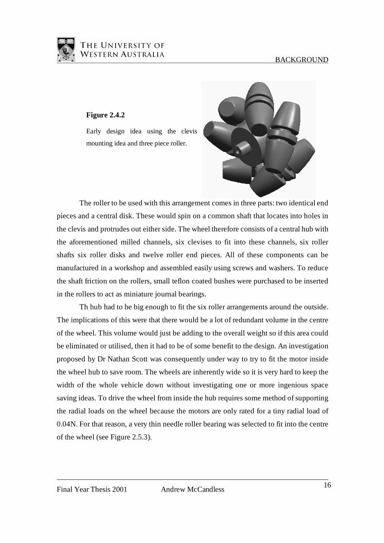
The roller to be used with this arrangement comes in three parts: two identical end
pieces and a central disk. These would spin on a common shaft that locates into holes in
the clevis and protrudes out either side. The wheel therefore consists of a central hub with
the aforementioned milled channels, six clevises to fit into these channels, six roller
shafts six roller disks and twelve roller end pieces. All of these components can be
manufactured in a workshop and assembled easily using screws and washers. To reduce
the shaft friction on the rollers, small teflon coated bushes were purchased to be inserted
in the rollers to act as miniature journal bearings.
Th hub had to be big enough to fit the six roller arrangements around the outside.
The implications of this were that there would be a lot of redundant volume in the centre
of the wheel. This volume would just be adding to the overall weight so if this area could
be eliminated or utilised, then it had to be of some benefit to the design. An investigation
proposed by Dr Nathan Scott was consequently under way to try to fit the motor inside
the wheel hub to save room. The wheels are inherently wide so it is very hard to keep the
width of the whole vehicle down without investigating one or more ingenious space
saving ideas. To drive the wheel from inside the hub requires some method of supporting
the radial loads on the wheel because the motors are only rated for a tiny radial load of
0.04N. For that reason, a very thin needle roller bearing was selected to fit into the centre
of the wheel (see Figure 2.5.3).
Figure 2.4.2
Early design idea using the clevis
mounting idea and three piece roller.

BACKGROUND
Final Year Thesis 2001 Andrew McCandless 17
The outer diameter of the motor is 24mm and the closest bearing size is 25mm, with an
outer diameter of 32mm. The rollers need a diameter of around 25mm to get six of them
to span the circumference of a 100mm diameter wheel. So the remaining 9mm either side
of the needle roller bearing had to fit a clevis to mount the roller, a shallow milled
channel, to locate the clevis, and some material to hold it all together.
After hours spent using a computer-modeling program, trying to fit the geometries
together, a final wheel design was completed that had an outer diameter of 96mm and
rollers with a maximum diameter of 26mm. The hub was 38mm in diameter with six
2.5mm channels milled into the outside, each locating a clevis 13mm wide to mount the
rollers. In order to fit the motor inside the needle roller bearing, a metal sleeve was
pressed on to the outer casing of the motor and then the outer diameter of the sleeve was
turned down to 25mm. Having established that the design was possible, drawings were
submitted to the workshop and the prototype was completed in October 2000.
Within the scope of this proposed wheel design, there was no capacity for
including compliance into the rollers themselves. This was because of the later
developments to the design proposal. Based on requests from Professor Braunl, there was
a need for larger, fewer rollers within a wheel of the same outer diameter or less as the
existing wheels. When tied in with the space-saving advantages of mounting the motors
in the centre, the combination left no room for developing the idea of compliant rollers.
Therefore these wheels need to operate on a chassis with independent suspension so that
they are always in contact with the ground.
Figure 2.5.3 The rear view of the new hub
design, showing the location of the needle roller
bearing

BACKGROUND
Final Year Thesis 2001 Andrew McCandless 18
Figure 2.5.4 The completed prototype

WHEEL DESIGN & CONSTRUCTION
Final Year Thesis 2001 Andrew McCandless 19
3 WHEEL DESIGN & CONSTRUCTION
3.1 Rollers
Figure 3.1.1
The preferred mounting arrangement of the rollers was explained in the previous chapter.
This arrangement splits up the rollers into three parts, two identical roller segments and a
central disc. The roller segments have a plastic core and a moulded rubber coating and
the discs are solid polyurethane rubber. Both the segments and the disc have teflon-
coated metal bushes pressed into them so that they can run on a shaft. The design is based
on a prototype wheel designed and developed in the year leading up to the start of this
thesis.
3.1.1 Roller Segment
Having completed the prototype wheel, the next step was to develop smaller,
lighter rollers to reduce the mass of the wheel. A good material to choose was plastic,
because it is readily available and light. The body of the roller does not require a lot of
strength, so the plastic is good to use for taking up the bulk of the volume. The prototype
wheel used aluminium rollers and as a result, weight-reducing holes were needed to try to
get the overall wheel mass down to an appreciable level. Development emphasis at the
time was placed on a quick manufacture and construction to test the initial design theories
of the improved wheel. These early ideas were successful, so the wheel design could be
improved further before final construction. If plastic was to be used for the rollers, then
they would need a high friction coating to achieve the necessary grip characteristics, and
Rubber Tyre
Plastic core
Teflon-coated
bush
WHEEL DESIGN & CONSTRUCTION
Final Year Thesis 2001 Andrew McCandless 20
the plastic had to be strong enough to fit the small Teflon bushes used to run on the shaft
as illustrated in Figure 3.1.1
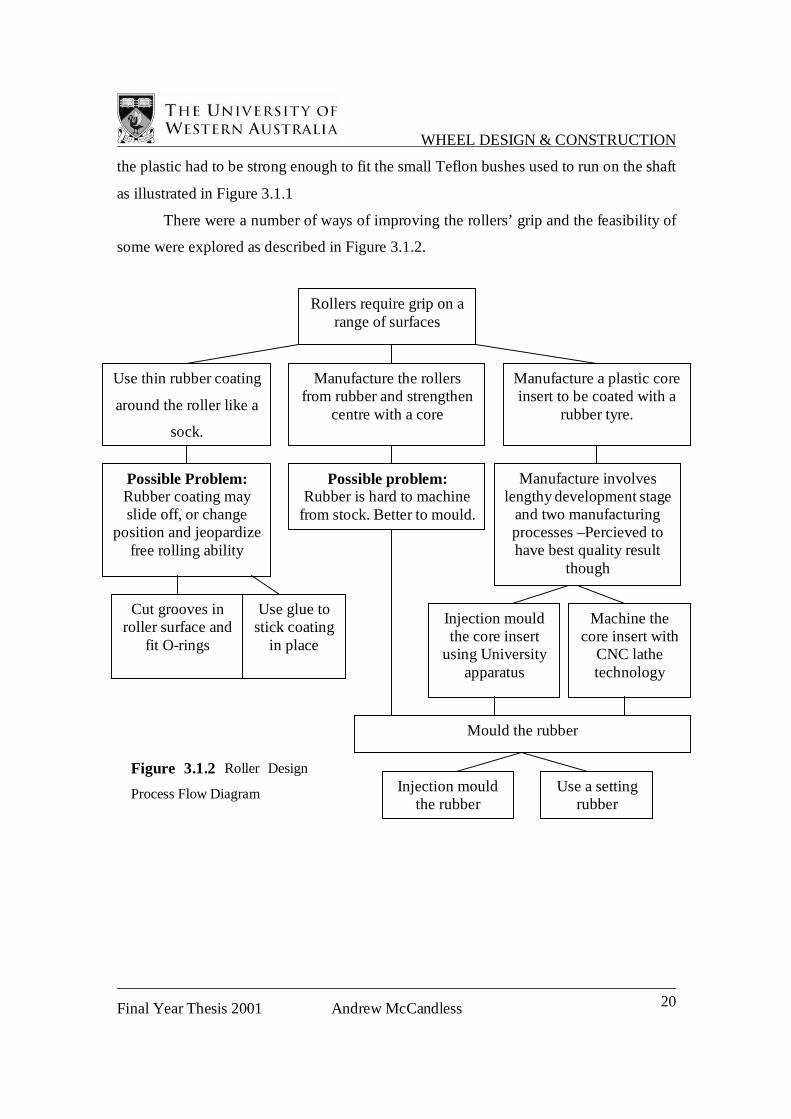
There were a number of ways of improving the rollers’ grip and the feasibility of
some were explored as described in Figure 3.1.2.
Rollers require grip on a range of surfaces
Use thin rubber coating
around the roller like a
sock.
Manufacture the rollers from rubber and strengthen
centre with a core
Manufacture a plastic coreinsert to be coated with a
rubber tyre.
Possible Problem: Rubber coating may slide off, or change
position and jeopardizefree rolling ability
Possible problem: Rubber is hard to machine
from stock. Better to mould.
Cut grooves in roller surface and
fit O-rings
Use glue to stick coating
in place
Manufacture involves lengthy development stage
and two manufacturing processes –Percieved to have best quality result
though
Injection mould the core insert
using University apparatus
Machine the core insert with
CNC lathe technology
Mould the rubber
Injection mould the rubber
Use a setting rubber
Figure 3.1.2 Roller Design
Process Flow Diagram
WHEEL DESIGN & CONSTRUCTION
Final Year Thesis 2001 Andrew McCandless 21
In the end the chosen proposal was to manufacture a core insert and then mould
rubber around it to form a tyre. Covering the roller with O-rings or a thin rubber tube was
considered undesirable because:
a) A collection of O-rings may not have provided a smooth enough roller surface.
b) The surface of a rubber film may have been difficult to keep concentric if it is glued,
and if it tears, it looks unsightly and is likely to need replacing.
c) Supply of uncommon O-ring diameters was perceived to be difficult.
Manufacturing the roller completely from rubber was also considered undesirable
because the roller would need to be made from a hard rubber to resist squashing. Hard
rubbers tend to lack grip on some surfaces, so the roller would have to make a
compromise between hardness and softness.
A composite construction of the roller was considered to be the best result
because it provides the desired surface characteristics and maintains the inner structure,
but ensures that the roller stays as one composite piece. The importance of a successful
end result greatly influenced this design decision because the vehicle had to look
impressive to the clients as well as perform well.
As stated in Figure 3.1.2, the successful proposal involved one of two options:
1. injection mould the core insert, or
2. machine a core insert from stock.
Both of these options made it possible to consider either injection-moulded rubber or
Room-Temperature-Vulcanising (RTV) rubber tyres. Ordinarily injection-moulding
would not be an option because the low output of parts and high cost of developing
moulds would not present a justifiable manufacturing scenario. However the Mechanical
and Materials Engineering Department has an experimental injection-moulding machine
that is part of tutorials in various manufacturing subjects.

WHEEL DESIGN & CONSTRUCTION
Final Year Thesis 2001 Andrew McCandless 22
Core design #1
Figure 3.1.3
This design was conceived with the intention of injection-moulding both the core and the
rubber coating. The fins are on the core to provide the rubber coating with some
geometry to locate onto so that it does not roll off like a sock. The fins still enable an easy
manufacture of the mould using a computer-numerically-controlled machining device.
Although a more intricate form of geometry would do a better job, this shape is easily cut
out of a block to make a mould. After the core is moulded, then the rubber around the
outside can be moulded using the core as an insert (see Figure 3.1.4).
Figure 3.1.4
WHEEL DESIGN & CONSTRUCTION
Final Year Thesis 2001 Andrew McCandless 23
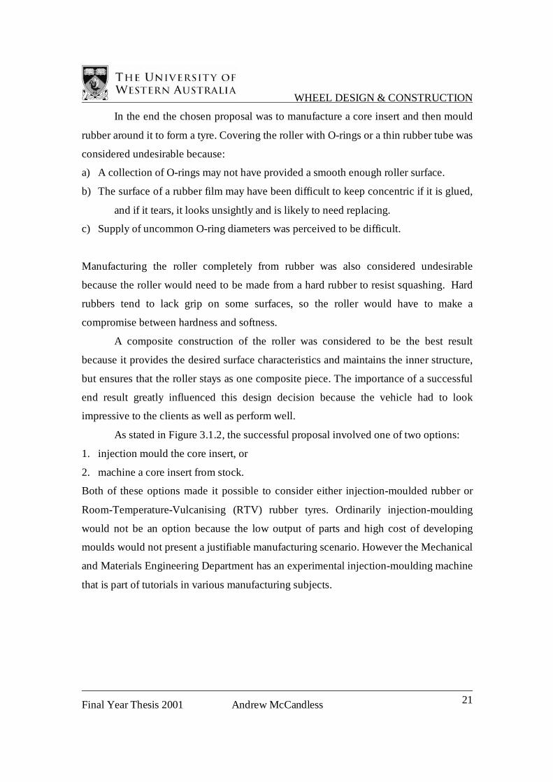
Core Design #2
Figure 3.1.5
The design for this core was intended to provide a keyway for the rubber tyre to locate
on. The core is not easily moulded because it would be hard to make a mould for the
injection-moulding process. The core is designed to be machined easily using a CNC
lathe. The outer profile is machined using two turning processes and then the chuck is
locked while a 3mm end mill carves the four channels on the outside. These channels
serve two functions:
a) They provide a keyway for the rubber to locate on, and
b) They allow the liquid rubber to flow more easily into the mould
When comparing the two proposals it is important to think about the costs
involved of both time and money. With around fifty of these rollers required for the
vehicle, the manufacturing processes involve repetition.
If the core is injection-moulded, then final production time is greatly reduced
because it is possible to produce one every two minutes, but set up requires a lot of
development. Tests have to be made to determine the optimum pressure, temperature and
dwell time, an allowable degree of shrinkage must be calculated to incorporate into the
roller geometry, then the mould has to be modeled with a computer package before being
machined and polished. An injection-moulding process for a low output run is difficult to
justify, especially with this object because it has to be moulded around a dummy shaft

WHEEL DESIGN & CONSTRUCTION
Final Year Thesis 2001 Andrew McCandless 24
and then ejected. Normally in industry, injection-moulding produces numbers of units in
the millions so that the cost of set up per unit is minimal.
If the core is machined, some set up time is required; first to set up a reliable
chuck arrangement and second to enter the commands into the CNC machine. However
this can be done in an afternoon, so the set up cost per unit is minimal even with a unit
output as low as five or ten. Production time, on the other hand, costs a lot more when
machining because the process takes longer. The overall cost per unit of a machining
operation is reasonably constant.
Hypothetical process comparison
No. of units produced
Injectionmoulding
Machining
Figure 3.1.6
Although this graph is schematic, it illustrates where and when either
manufacturing process is more appropriate. Minimising cost of manufacture was not so
important for this project because there was no need to turn a profit. However, since it is
the driving force behind most if not all industry, it is a good habit to get into, so the
decision was made for the core to be machined.
Having chosen the more appropriate design, the choice had to be made between
injection-moulding and using RTV rubber. RTV rubbers come in a range of hardness and
either set when poured from the tube, e.g. Shoe Goo, or have a resin and catalyst that
undergoes a chemical reaction (similar to epoxy resins).
WHEEL DESIGN & CONSTRUCTION
Final Year Thesis 2001 Andrew McCandless 25
The injection-moulding process presented certain significant difficulties:
◊ Staff at the university had not investigated injection-moulding rubber, and it was
believed that only a small number of rubber types could be used.
◊ Availability of these rubbers was not known.
◊ A set of high-pressure mould dies would have to be manufactured to match the
available injection-moulding machine, an exercise that generates a high cost per part.
The use of RTV rubbers on the other hand presented a number of advantages:
◊ The mould does not have to fit into any apparatus and thus can be a lot smaller.
◊ The mould is not required to withstand high temperatures or pressures, so it can be
made from a range of materials.
◊ The rubber is available from a local supplier (Kirkside Products of Osborne Park)
The disadvantages of RTV rubbers are that the process is a lot messier and more time
consuming. The compound uses a resin and a hardener mixed in with a ratio of 100:35 by
mass. The manufacturer stipulated that an accurate ratio was important, so because the
batch size was only 4-8g, a micro balance was required to measure the quantity of the
constituents. The scope of the moulding operation could not justify the expense of both
time and money to manufacture an injection mould and find a suitable rubber compound.
RTV rubber was chosen as the more suitable candidate.
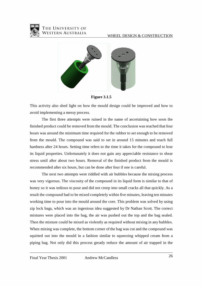
The mould for the rollers needed two things. A central pin to accurately locate the
core insert, and an escape hole for excess material to squeeze out. A prototype mould was
made initially to formulate a successful manufacturing process (see Figure 3.1.5) and
after several moulding attempts, a reliable quality control level was established.
WHEEL DESIGN & CONSTRUCTION
Final Year Thesis 2001 Andrew McCandless 26
Figure 3.1.5
This activity also shed light on how the mould design could be improved and how to
avoid implementing a messy process.
The first three attempts were ruined in the name of ascertaining how soon the
finished product could be removed from the mould. The conclusion was reached that four
hours was around the minimum time required for the rubber to set enough to be removed
from the mould. The compound was said to set in around 15 minutes and reach full
hardness after 24 hours. Setting time refers to the time it takes for the compound to lose
its liquid properties. Unfortunately it does not gain any appreciable resistance to shear
stress until after about two hours. Removal of the finished product from the mould is
recommended after six hours, but can be done after four if one is careful.
The next two attempts were riddled with air bubbles because the mixing process
was very vigorous. The viscosity of the compound in its liquid form is similar to that of
honey so it was tedious to pour and did not creep into small cracks all that quickly. As a
result the compound had to be mixed completely within five minutes, leaving ten minutes
working time to pour into the mould around the core. This problem was solved by using
zip lock bags, which was an ingenious idea suggested by Dr Nathan Scott. The correct
mixtures were placed into the bag, the air was pushed out the top and the bag sealed.
Then the mixture could be mixed as violently as required without mixing in any bubbles.
When mixing was complete, the bottom corner of the bag was cut and the compound was
squirted out into the mould in a fashion similar to squeezing whipped cream from a
piping bag. Not only did this process greatly reduce the amount of air trapped in the

WHEEL DESIGN & CONSTRUCTION
Final Year Thesis 2001 Andrew McCandless 27
rubber, but it also helped the liquid get into the mould quickly because it was forced
down the gap in a thin stream. The pouring time was reduced from ten minutes to a
manageable four minutes.
Shrinkage during setting was also encountered during this testing
phase and it was observed that the rubber would retract, sucking air back down into the
mould as it cured. The clean-up process of the excess was altered to leave two puddles
over the escape holes and the problem was no more. Also, the finished product was
consistently difficult to remove from the mould, and a tedious process was necessary for
successful removal. The mould was cooled down in a freezer, then dipped into hot water
to expand the mould while leaving the product cool, thus releasing the rubber from the
mould walls. This process took around ten minutes per roller, so it had to be improved.
Release agent was used eventually, which gave the surface finish dimples, but improved
the grip. The final glitch that was rectified was the back face of the roller segment that
ran against the side of the clevis. The rubber coating came around the back and was flush
with the face of the core and so was gripping on the side of the clevis, impeding the free
rolling of the segment. The lid of the mould was given an indent (see Figure 3.1.6), which
fixed the problem easily.
Escape holes
Indent
Figure 3.1.6
WHEEL DESIGN & CONSTRUCTION
Final Year Thesis 2001 Andrew McCandless 28
Now that the process was improved to enable simultaneous, reliable, manufacture of
multiple roller segments, the subsequent design was submitted and five more moulds
were manufactured. The moulding process was completed two weeks later.
For the benefit of all who are interested, a detailed set of instructions for the
rubber moulding process, including photographs, appears in Appendix B.
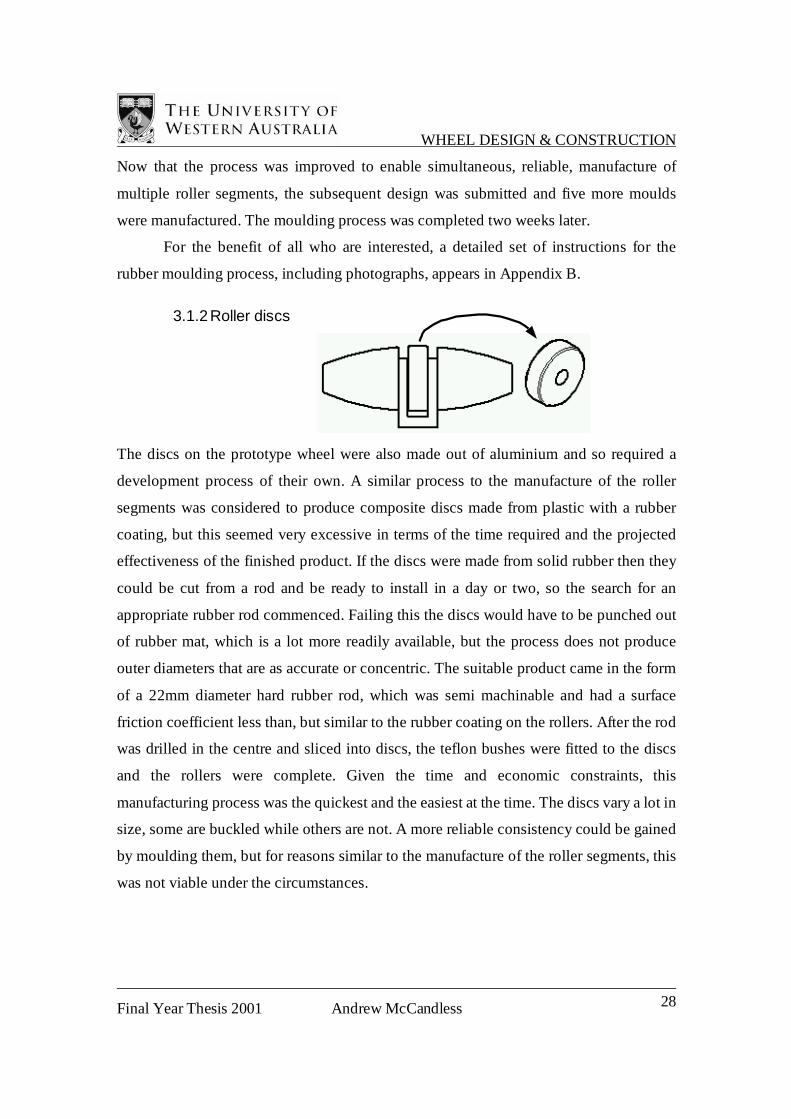
3.1.2 Roller discs
The discs on the prototype wheel were also made out of aluminium and so required a
development process of their own. A similar process to the manufacture of the roller
segments was considered to produce composite discs made from plastic with a rubber
coating, but this seemed very excessive in terms of the time required and the projected
effectiveness of the finished product. If the discs were made from solid rubber then they
could be cut from a rod and be ready to install in a day or two, so the search for an
appropriate rubber rod commenced. Failing this the discs would have to be punched out
of rubber mat, which is a lot more readily available, but the process does not produce
outer diameters that are as accurate or concentric. The suitable product came in the form
of a 22mm diameter hard rubber rod, which was semi machinable and had a surface
friction coefficient less than, but similar to the rubber coating on the rollers. After the rod
was drilled in the centre and sliced into discs, the teflon bushes were fitted to the discs
and the rollers were complete. Given the time and economic constraints, this
manufacturing process was the quickest and the easiest at the time. The discs vary a lot in
size, some are buckled while others are not. A more reliable consistency could be gained
by moulding them, but for reasons similar to the manufacture of the roller segments, this
was not viable under the circumstances.

WHEEL DESIGN & CONSTRUCTION
Final Year Thesis 2001 Andrew McCandless 29
3.2 Hub Construction
The hub design was finalised during the development of the prototype wheel. The design
changes to the rollers did not affect the dimensions of the central hub, so all that was
required was to submit the drawings to the mechanical engineering workshop. These
components were being manufactured at the time of the University of Western Australia
Open Day, so they were used as the demonstrational piece for the Wasino Automatic
lathe machine in the CAD/CAM centre of the Department of Mechanical and Materials
Engineering. A minor problem was encountered in the machining process that stands as
an interesting case study for those who submit designs to be produced on a CNC
machine.
Figure 3.3.1
Figure 3.3.1 shows the hub design with six milled channels equispaced around the
outside, and each channel has a hole located in the centre. When the first hub was
finished, a small lump was found on one wall of each channel, adjacent to the hole. This
lump, although very minor, was big enough to affect the fit of the clevis that was
supposed to locate in it. At first the problem was believed to be a calibration problem,
since the machine had not been re calibrated in a while, but closer inspection of the hub
revealed that each lump was exactly the same shape and size and location as its
counterparts. Since the lump was in line with the hole, it was speculated that the hole
might be in some way related to the reason why this lump appeared in the same location
on every channel. An analysis of the machine code was carried out to look at what was
happening during the process. The order of operations was such that the holes were being

WHEEL DESIGN & CONSTRUCTION
Final Year Thesis 2001 Andrew McCandless 30
drilled first and then the channels were milled. Because the channel was wider than the
milling cutter, the channel was being cut in two passes. However, most of the material
was being removed in the first pass, including the material containing the hole, and it was
during this pass that the lump was being formed.
Figure 3.3.2 The deflecting force in (2) is not as great as (1) or (3)
What was happening was that the tool was being deflected a small amount by the
cutting forces of the full-face milling operation. (see Figure 3.3.2) but when the tool got
to the hole, there was temporarily less material to remove and thus less deflecting force.
At this point the tool would relax a little closer to its neutral position, forming a lump on
the side of the channel, before being deflected fully again once the tool had milled past
the hole. The solution was to either swap the operations over so that the milling was done
before the holes, or to make the milling cutter plough through the center of the channel
first and then do a finishing pass of each side. Since all the code for the machining
operation was already written, it was easier to change the milling operation to
accommodate the hole, rather than rewrite all the code for the drilling operations. If the
problem was known before the code was written, it would easily have been avoided by
putting the drilling operation after the milling operation. Unfortunately no evidence of
this occurrence existed on the prototype or the test pieces used for writing the milling
code. The prototype was machined manually and it is likely that the order of operations
was different, and in the test runs the holes were not included. Any unsuspecting person
would deem them unnecessary.
Lump formed on this face
of the milled channel

WHEEL DESIGN & CONSTRUCTION
Final Year Thesis 2001 Andrew McCandless 31
By choosing this solution to the problem, not only was the lump prevented, but
also it gave the channel a better surface finish because the second and third passes
involved a lot less material removal. With the machining process now completely
rectified, the wheel hubs were completed in an afternoon and were ready for the
assembling of the wheel.
CHASSIS DESIGN & CONSTRUCTION
Final Year Thesis 2001 Andrew McCandless 32
4 CHASSIS DESIGN & CONSTRUCTION
4.1 Suspension arm
During the later stages of the new wheel design, the conclusion was reached that all these
improvements would achieve very little if the chassis possessed no suspension. If the
robot vehicle was to travel on a variety of surfaces, then the wheels would have to adjust
to any surface irregularities to make sure that they all remain in contact with the ground
at all times. An additional design constraint was added that the wheels had to remain in
the vertical plane so that each roller of each wheel maintains a smooth transition of
ground contact to the adjacent roller as the wheel rotates. This left two more common
suspension alternatives, Double wishbone suspension or trailing/leading arm suspension.
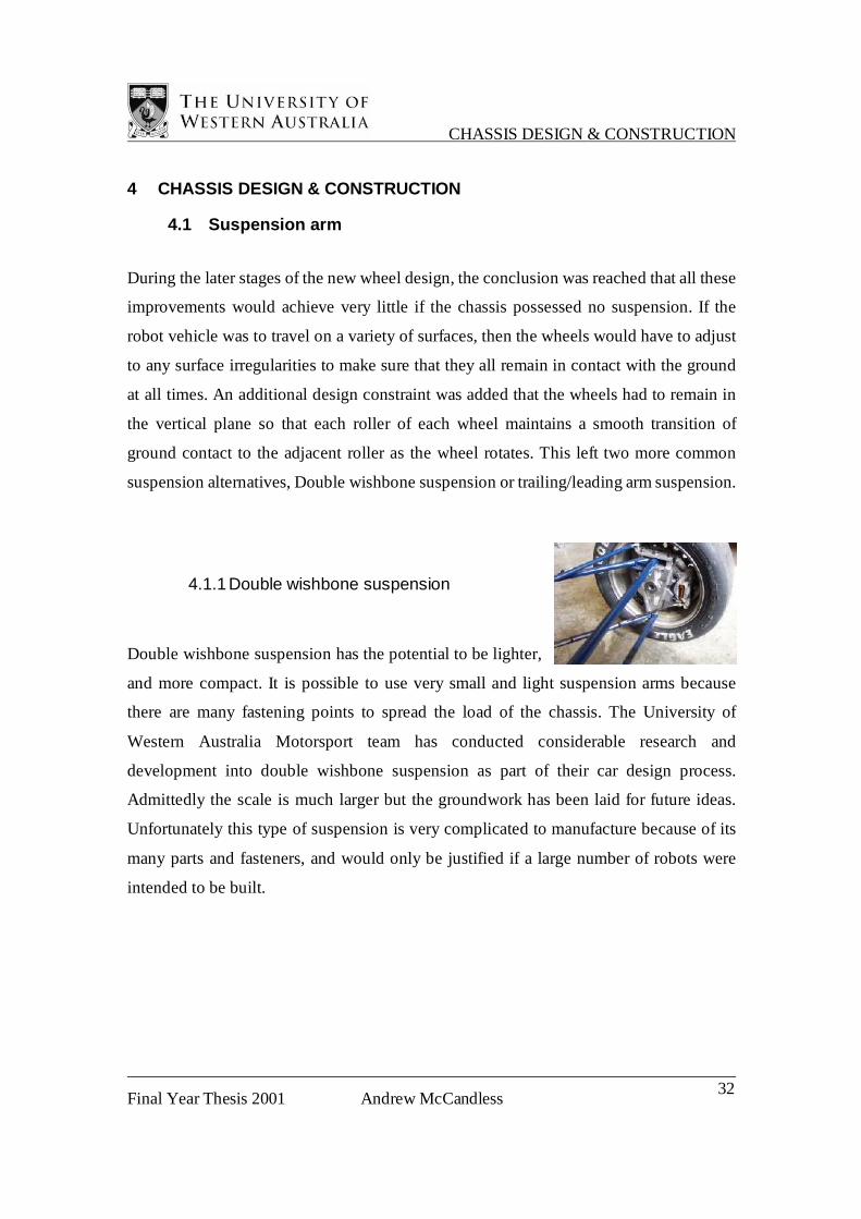
4.1.1 Double wishbone suspension
Double wishbone suspension has the potential to be lighter,
and more compact. It is possible to use very small and light suspension arms because
there are many fastening points to spread the load of the chassis. The University of
Western Australia Motorsport team has conducted considerable research and
development into double wishbone suspension as part of their car design process.
Admittedly the scale is much larger but the groundwork has been laid for future ideas.
Unfortunately this type of suspension is very complicated to manufacture because of its
many parts and fasteners, and would only be justified if a large number of robots were
intended to be built.

CHASSIS DESIGN & CONSTRUCTION
Final Year Thesis 2001 Andrew McCandless 33
4.1.2 Trailing/Leading arm suspension
Trailing arm suspension effectively has only two parts per
wheel, the arm and the spring. Not only that but the transmission of rotation to the wheels
can be mounted to the arm itself to reduce the complexities of driving the wheels, e.g.
motorcycle rear suspension. To resist buckling under the weight of the chassis, the arms
have to be quite thick and heavy, but the saving in manufacturing time and costs far
outweighs the disadvantages in small production numbers. Trailing arm suspension
seemed to offer more promise for fast and successful development so it was chosen.
Figure 4.1.1 shows an early design concept that used a small rubber toothed belt to
transmit the power to the wheels. This suspension arm enabled the motor to be mounted
on the same side as the wheels so they did not have to fit in the gap between the wheels.
Figure 4.1.1 Early design concept using miniature toothed belt to transmit drive to wheels
During the later developments of the wheel design, the motors became located in
the hub of the wheel and the base of the motor casing stuck out the back. This normally
redundant part of the motor was ideal for the motor to be mounted to a suspension arm.
Using a close-fitting cylindrical gripping surface, the suspension arm could clamp down
onto the motor casing using an adjustable screw (see Figure 4.1.2). From this point each
progessive design step remained based around this wheel mounting idea and the

CHASSIS DESIGN & CONSTRUCTION
Final Year Thesis 2001 Andrew McCandless 34
suspension arm became smaller and lighter as it came closer to being a finished product.
A brief summary of its conception is as follows.
First proposal
This was basically an attempt to conceptualise the geometry of the clamp and the
methods of mounting the arm onto the rest
of the chassis. However it required
complicated manufacture because of its
inherent three-dimensional geometry. The
pivoting shaft protruding out the side
could easily be swapped with a separate
attachable bolt.
Improved design
The subsequent design had some of the unnecessary material removed in order to save
weight and has a hole for attaching a shaft to it. Its geometry enabled this arm to be cut
from a flat slab. It was intended to be
fastened to a mounting flange with a set
screw and nut, which was also an
improvement, but it was quite long and still
retained a lot of “dead metal” i.e. metal
adding to the weight without adding
noticeable strength.
Outer casing of motor covered by sleeve
Motor Shaft
Back of motor
Figure 4.1.2 Tailing arm
clamping arrangement
CHASSIS DESIGN & CONSTRUCTION
Final Year Thesis 2001 Andrew McCandless 35
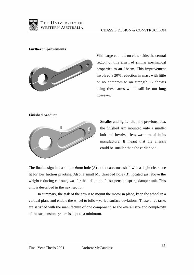
Further improvements
With large cut outs on either side, the central
region of this arm had similar mechanical
properties to an I-beam. This improvement
involved a 20% reduction in mass with little
or no compromise on strength. A chassis
using these arms would still be too long
however.
Finished product
Smaller and lighter than the previous idea,
the finished arm mounted onto a smaller
bolt and involved less waste metal in its
manufacture. It meant that the chassis
could be smaller than the earlier one.
The final design had a simple 6mm hole (A) that locates on a shaft with a slight clearance
fit for low friction pivoting. Also, a small M3 threaded hole (B), located just above the
weight reducing cut outs, was for the ball joint of a suspension spring damper unit. This
unit is described in the next section.
In summary, the task of the arm is to mount the motor in place, keep the wheel in a
vertical plane and enable the wheel to follow varied surface deviations. These three tasks
are satisfied with the manufacture of one component, so the overall size and complexity
of the suspension system is kept to a minimum.
CHASSIS DESIGN & CONSTRUCTION
Final Year Thesis 2001 Andrew McCandless 36
4.2 Spring Damper System
A number of suspension proposals were considered to use with the suspension arm. The
most simplistic idea was a flap of spring steel screwed into the pivoting end of the arm
and then fixed to the chassis. This would provide adequate surface tracking ability for the
application because the robot really does not go fast enough to require a separate
damping mechanism. However, it was foreseen that a number of different flaps would
have to be tested because at the time the mass of the complete vehicle could not be
estimated, and to calculate the required stiffness would use too much research time. One
choice of leaf spring leaves very little room for adjustment, so an arduous process of trial
and error would be necessary to ensure the idea worked. A torsion bar was considered as
well, but this had similar disadvantages to the leaf spring idea.
Because of the robot vehicle’s likeness to a radio-controlled (RC) car, both in size
and weight, considerations were made to use a mass-spring damper system, available
from a RC car manufacturer, for the suspension arms. This proposal had a number of
advantages. Firstly, the units were already manufactured and did not need to be modified
to suit the robot. Secondly, they could be very simply snap-fitted into place. All that was
required was to attach a small ball joint to each arm and another corresponding one to
each corner of the underside of the top plate that formed the body of the chassis. Thirdly,
they had a wide range of springs with different stiffness and a range of piston shapes for a
range of damping ratios. There was also a range of oil viscosity to further adjust the
damping ratio.
Because of the considerable time and effort required to design a new robot, there
was considerable pressure placed on the new design to work well. In recognition of the
design limitations of the initial robot, its replacement should be engineered so that any
limitations that exist with the new robot vehicle are not a result of the chassis design.
Based on the resources available and the given timeframe, it was decided that the use of
small spring damper kits was the optimal solution because it was guaranteed to work, it
could be adjusted and finely tuned, and its implementation would not render other ideas
unusable at a later stage.
CHASSIS DESIGN & CONSTRUCTION
Final Year Thesis 2001 Andrew McCandless 37
4.3 Suspension arm central mount
During the time of the suspension arms development, the method for its attachment and
the shape of the part that the arm attached to changed along with these developments.
There were, however, some fundamental design factors that were common to all designs.
The control circuit board assembly was to be connected to a flat plate in the centre of the
vehicle and there needed to be some extra room for future attachments to be connected.
Although a little draconian, the flat plate idea features frequently in the design of robots
from the CIIPS lab because if ideas change it is easy to mount new attachments. As
adaptability was an important feature in this project, using a flat plate seemed the logical
alterantive. The suspension arms were to protrude forward and aft from the central region
so that the front half of the chassis is symmetrical to the rear half. This design feature was
intended to make forward motion of the vehicle indiscernible from reverse motion. To
make flanges for the attachment of the arms, either the flat plate is bent around the edges
or another component is designed as an interface between the flat plate and the
suspension arms. Components machined from solid must not have a shape that requires
excessive machining, and components made from a standard cross section are limited, in
shape, to cross sections that are available from nearby sources.
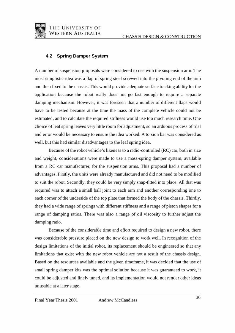
The earliest idea was designed in conjunction with a small strip of spring material
connecting the arm to the rest of the chassis. It is screwed up to the underneath of the
plate in two places (see Figure 4.3.1). Although short lived, this idea exhibits a crude, but
novel simplicity. The idea was aborted due to the necessary trial time needed to decide
the fastening method, the required stiffness of the strip and how to achieve sideways
Figure 4.3.1
CHASSIS DESIGN & CONSTRUCTION
Final Year Thesis 2001 Andrew McCandless 38
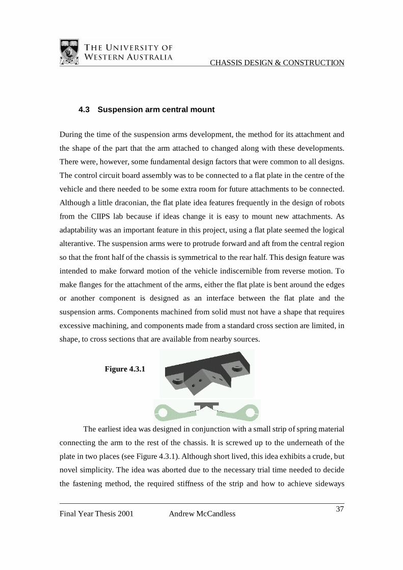
rigidity. From Figure 4.3.2 it can be seen that this type of rigidity is an important feature
of the chassis because in some modes of movement, wheels on opposite sides push in to
each other to create a net movement in a forward or backward direction
The ideas to follow were to use a bolt to connect the arm to a flange or between two
flanges. Using the sheet metal from the top plate to mount the bolt, there is a problem
with tolerance, because the bends have to be perfectly parallel to make sure the arms are
aligned properly. Also, the top plate need only be around 0.5mm thick to support the
processor, but to support the bearing loads from the bolt, it has to be around 1.5mm thick,
which is a little more difficult to bend accurately. The loads on a single flange may cause
it to elastically deform, resulting in the arms lacking sideways rigidity (see Figure 4.3.2.).
The arms are required to rotate freely in the vertical plane, but must be held in place so
they move very little in the other planes. Thus a very close fitting bolt must be used as the
bearing surface at the pivot point of the suspension arm.
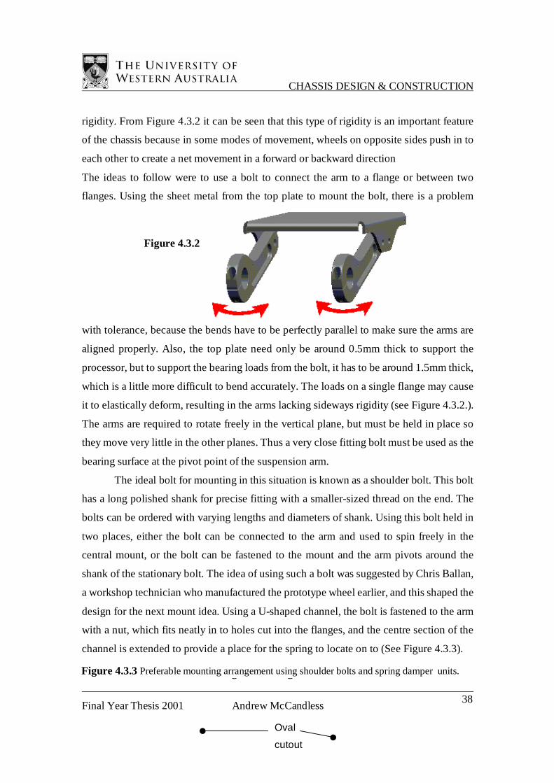
The ideal bolt for mounting in this situation is known as a shoulder bolt. This bolt
has a long polished shank for precise fitting with a smaller-sized thread on the end. The
bolts can be ordered with varying lengths and diameters of shank. Using this bolt held in
two places, either the bolt can be connected to the arm and used to spin freely in the
central mount, or the bolt can be fastened to the mount and the arm pivots around the
shank of the stationary bolt. The idea of using such a bolt was suggested by Chris Ballan,
a workshop technician who manufactured the prototype wheel earlier, and this shaped the
design for the next mount idea. Using a U-shaped channel, the bolt is fastened to the arm
with a nut, which fits neatly in to holes cut into the flanges, and the centre section of the
channel is extended to provide a place for the spring to locate on to (See Figure 4.3.3).
Figure 4.3.3Figure 4.3.3
Figure 4.3.2
Oval
cutout
Figure 4.3.3 Preferable mounting arrangement using shoulder bolts and spring damper units.
CHASSIS DESIGN & CONSTRUCTION
Final Year Thesis 2001 Andrew McCandless 39
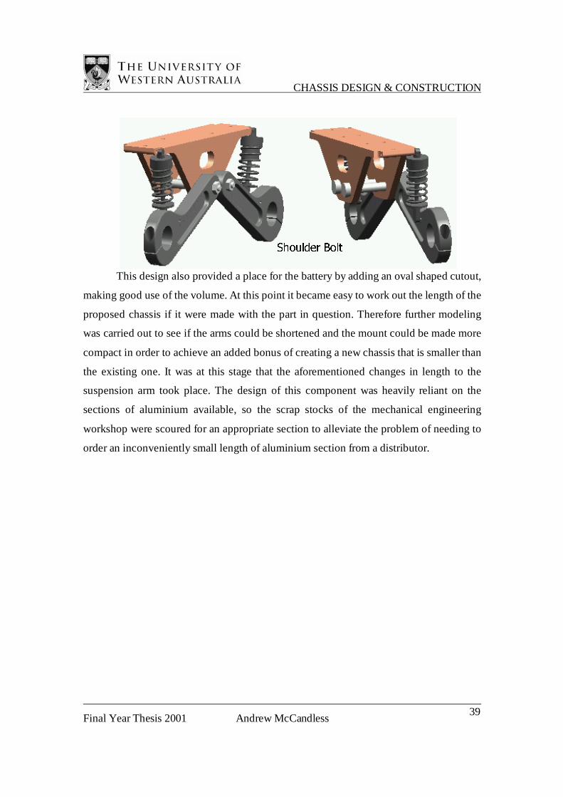
This design also provided a place for the battery by adding an oval shaped cutout,
making good use of the volume. At this point it became easy to work out the length of the
proposed chassis if it were made with the part in question. Therefore further modeling
was carried out to see if the arms could be shortened and the mount could be made more
compact in order to achieve an added bonus of creating a new chassis that is smaller than
the existing one. It was at this stage that the aforementioned changes in length to the
suspension arm took place. The design of this component was heavily reliant on the
sections of aluminium available, so the scrap stocks of the mechanical engineering
workshop were scoured for an appropriate section to alleviate the problem of needing to
order an inconveniently small length of aluminium section from a distributor.
6KRXOGHU %ROW
CHASSIS DESIGN & CONSTRUCTION
Final Year Thesis 2001 Andrew McCandless 40
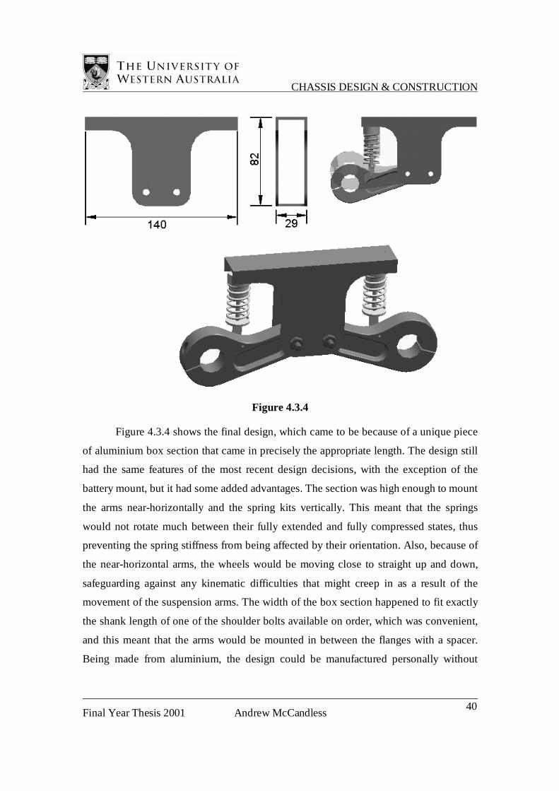
Figure 4.3.4
Figure 4.3.4 shows the final design, which came to be because of a unique piece
of aluminium box section that came in precisely the appropriate length. The design still
had the same features of the most recent design decisions, with the exception of the
battery mount, but it had some added advantages. The section was high enough to mount
the arms near-horizontally and the spring kits vertically. This meant that the springs
would not rotate much between their fully extended and fully compressed states, thus
preventing the spring stiffness from being affected by their orientation. Also, because of
the near-horizontal arms, the wheels would be moving close to straight up and down,
safeguarding against any kinematic difficulties that might creep in as a result of the
movement of the suspension arms. The width of the box section happened to fit exactly
the shank length of one of the shoulder bolts available on order, which was convenient,
and this meant that the arms would be mounted in between the flanges with a spacer.
Being made from aluminium, the design could be manufactured personally without
CHASSIS DESIGN & CONSTRUCTION
Final Year Thesis 2001 Andrew McCandless 41
commissioning the services of the Mechanical engineering workshop, saving
manufacturing costs.
4.4 Assembly
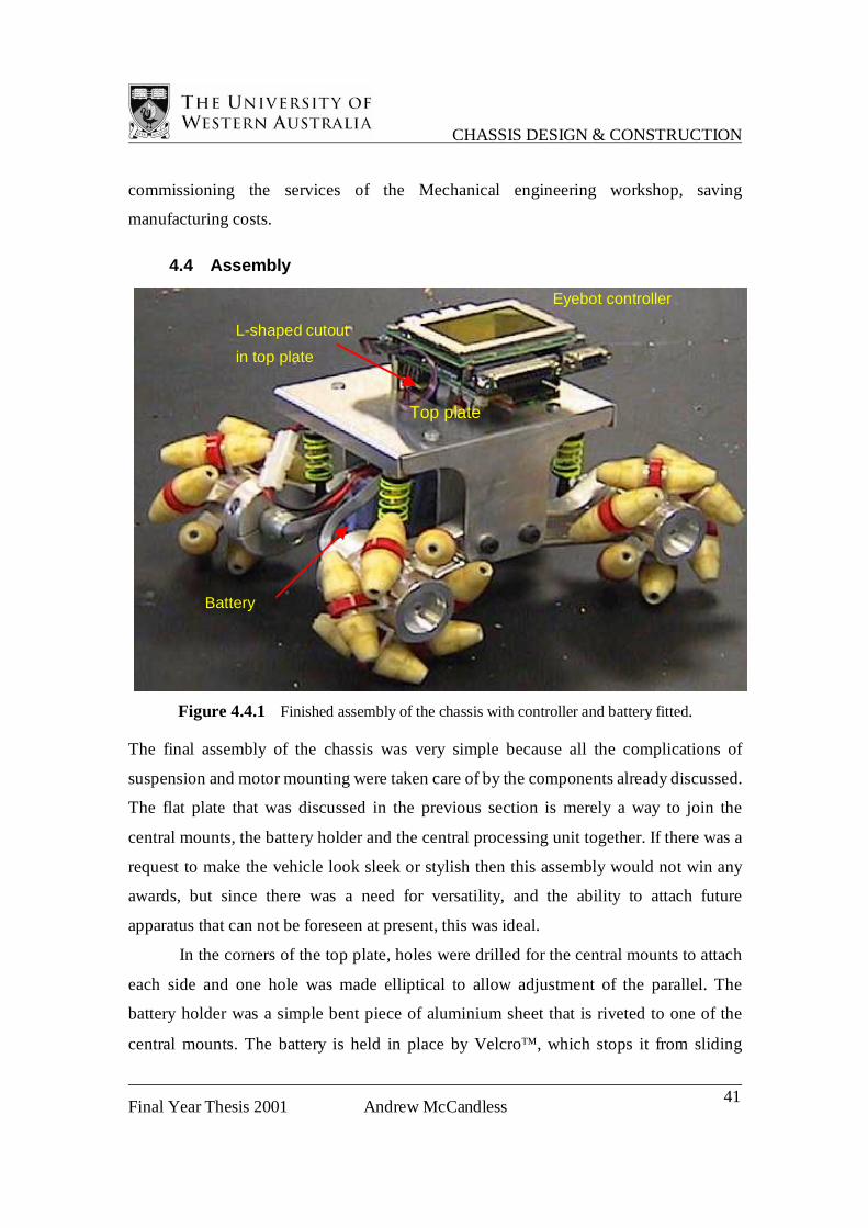
Figure 4.4.1 Finished assembly of the chassis with controller and battery fitted.
The final assembly of the chassis was very simple because all the complications of
suspension and motor mounting were taken care of by the components already discussed.
The flat plate that was discussed in the previous section is merely a way to join the
central mounts, the battery holder and the central processing unit together. If there was a
request to make the vehicle look sleek or stylish then this assembly would not win any
awards, but since there was a need for versatility, and the ability to attach future
apparatus that can not be foreseen at present, this was ideal.
In the corners of the top plate, holes were drilled for the central mounts to attach
each side and one hole was made elliptical to allow adjustment of the parallel. The
battery holder was a simple bent piece of aluminium sheet that is riveted to one of the
central mounts. The battery is held in place by Velcro, which stops it from sliding
L-shaped cutout
in top plate
Top plate
Battery
Eyebot controller
CHASSIS DESIGN & CONSTRUCTION
Final Year Thesis 2001 Andrew McCandless 42
forward and aft. Some screw holes were drilled for two mounting pillars on the central
processing unit to attach to, and an L-shaped cut out was made to provide access for the
motor cords to plug in. The top plate was been bent over at the edges to give the plate
some resistance to bending as well as giving the chassis a more pleasing appearance.
4.5 Modifications
Many modifications were made during the developmental stages of the various
components, but there were some things that had to wait until the vehicle was constructed
and tested before they were observed.
The Processor has a hardware testing function hardwired in to it, and upon testing
the response of the four motors, it was discovered that one had a poor connection.
Unfortunately this meant that the back of the motor had to be cut open and new wires
grafted to the damaged ones. In hindsight the conclusion was reached that the process of
fitting a sleeve to the outside of the motors is a very delicate process and should be done
slowly and methodically to ensure the wires are kept safe at all times. Had this been done
in the first place, a great deal of time and repair effort could have been saved.
In early photos a simple flat square piece of aluminium can be seen being used as
the top plate. The aluminium came from scrap and was thick enough to provide stiffness
to prevent sideways bending. This was intended to remain, but the location holes for the
processor and the cut outs were placed in a bad position, which left too little room for
attachments later. The Processor mounting position had been under scrutiny for some
time because the centre distance of the mounting pillars was such that the holes in the top
plate would not fit between the central mounts. The decision had been made to fit the
processor with the readout screen at right angles to the forward orientation of the chassis
and the holes and cut out were placed without proper consideration of other factors. A
new top plate was made, this time out of thinner aluminium, with the edges bent over to
increase stiffness and the processor located further aft for more room at the front. In order
for the programmers to understand which motors are plugged in to which ports (front-
right, rear-left etc.), the front of the robot was labeled.

CHASSIS DESIGN & CONSTRUCTION
Final Year Thesis 2001 Andrew McCandless 43
During the final tests of the assembled robot, it was observed that the motors
struggled with sideways movement. In this mode of movement, each wheel rotates in the
opposite direction the wheel on the opposing side. This propulsion relies on the torque of
the motors being transmitted as a sideways force via the rotation of the rollers, which
involves a high proportion of transmission losses. To reduce these transmission losses
some low friction washers were placed on ether side of the roller discs to reduce the
rubber contact with the inner face of the aluminium clevis. This helped but the motors
were still observed to struggle. It is an interesting case to study because the motors do not
have trouble using sideways movement to rotate the robot on the spot, but it is beyond the
scope of this project. This is mentioned in the performance evaluation.

CHASSIS DESIGN & CONSTRUCTION
Final Year Thesis 2001 Andrew McCandless 44
5 PERFORMANCE EVALUATION
The main focus of the design was to produce a chassis that would in no way hinder or
compromise the performance of the control system it was designed for. As a result the
suspension system was perhaps over engineered, giving the wheels a lot more suspension
travel than was necessary. Because the suspension system is so robust, the wheels can
overcome a step size of around 15mm in longitudinal motion. The vehicle has already
endured a heavy fall, which only bent one of the roller shafts. Fortunately there was a
spare, so nobody’s work was hindered for too long, but the fact that nothing else broke
speaks highly of the suspension system and needle roller bearing for absorption of motor
shaft radial loads.
Testing of the performance has been done on a number of surfaces ranging from
smooth surfaces (linoleum floors and tabletops) to rougher surfaces (carpet and bitumen)
as well as uneven surfaces (tiles and pavers). The forward motion of the vehicle is
unaffected by terrain, the suspension enables effortless handling of surface irregularities.
Transverse motion is more difficult for the robot to perform. On flat, smooth
surfaces, the transverse velocity is around seventy percent of the longitudinal velocity,
and on surfaces like carpet and matting this drops to about fifty percent. However,
because the rollers are orientated 45 degrees to the wheel axis, theoretically there should
be no reduction in velocity for transverse motion. Unfortunately the robot is slightly
under powered, and this is evident in its performance on carpet. Also, the vehicle does
not maintain a constant angular orientation during this movement, but this could be fixed
with a little adjustment.
Diagonal movement involves the operation of only the diagonally opposite wheels
and this has the effect of forcing the disengaged wheels to turn. Unfortunately the friction
of the rollers causes too much of a moment on the contacting roller, and this tends to
force the stationary wheel to turn. Hopefully this will be solved in the future by the use of
a feedback control system currently being developed in CIIPS.

CHASSIS DESIGN & CONSTRUCTION
Final Year Thesis 2001 Andrew McCandless 45
Rotational movement is performed with no difficulty at all. With the centre
wandering about 4.5mm per revolution, the positional accuracy is reasonable, and
hopefully will also improve with the addition of a feedback controller.
The specifications and performance characteristics are as follows:
Length 260mm
Height (without controller) 120mm
Height (with controller) 160mm
Width 220mm
Mass 2.85kg
Longitudinal velocity 0.27m/s
Transverse velocity 0.19m/s
Rotational velocity 1.46rad/s

CHASSIS DESIGN & CONSTRUCTION
Final Year Thesis 2001 Andrew McCandless 46
6 CONCLUSIONS
Overall the construction of this chassis was a success. Testing proved that its operation
on a range of surfaces was satisfactory, thus, far outperforming the previous model. Some
forms of motion presented problems, but there is room for adjustment and development
of software to overcome them. As well as improved performance characteristics, this
robot has a smaller wheel diameter, and is more compact and lighter than the first design.
7 RECOMMENDATIONS
The successful completion of this project has produced a reliable, robust foundation for
further research to take place CIIPS. Although it is a vast improvement on the vehicle
before it, there is much room for future improvement.
Firstly, the vehicle has some metal components that are heavy. If the Wheel hubs,
the clevises and the suspension arms were manufactured from a polymer, the overall
mass reduction would be around 1.2 kg1, almost half the existing mass. A considerable
improvement in performance is likely to be observed as a result.
Secondly, the roller shafts can be made with a retaining head at one end so that
the number of fasteners on the wheels is halved. This would make the vehicle cheaper
and less tedious to assemble and maintain.
Thirdly, grub screws were used to lock the shaft in place. A more sound method
of locking the motor shaft to the wheel hub would increase longevity and reduce
maintenance time.
Finally, an analysis of the roller friction should be performed to determine if the
Teflon coated bushes are necessary.
1 Unigraphics solutions Inc. Solid Edge Computer Program calculations
CHASSIS DESIGN & CONSTRUCTION
Final Year Thesis 2001 Andrew McCandless 47
8 REFERENCES
1. American Honda motor company 2002 XR650R, [Home page of 2002 XR650R],
[Online] Available:
http://www.hondamotorcycle.com/models/2002/index.html?model_number=XR650R
2. Braunl, T EyeBot Omni-Directional Vehicles, [Home page of Professor Braunl],
[Online] Available: http://www.ee.uwa.edu.au/~braunl/eyebot/robots/omni.html
3. National Aeronautical Space Agency OmniBot Mobile Base, [Online] Available:
http://technology.ksc.nasa.gov/WWWaccess/techreports/98report/09-ar/ar06.html
4. Oak Ridge National Laboratories A Revolutionary Wheelchair Concept, [Home page
of Oak Ridge National Laboratory-Review],
[Online]. Available: http://www.ornl.gov/ORNLReview/rev30-12/text/robotic.htm
5. Oak Ridge National Laboratories Technical Highlights-New Means of locomotion for
wheeled vehicles, [Home page of Oak Ridge National Laboratory-Technical
Highlights], [Online]
Available: http://www.ornl.gov/ORNLReview/rev26-34/text/tecmain.html
6. Omni-Directional Vehicle (The Vuton), [Home page of Hirose & Yoneda Robotics
Lab], [Online]. Available: http://mozu.mes.titech.ac.jp/research/mobile/vuton
7. Palm Pilot Robot Kit, [Home page of Carnegie Mellon School of Computer Science],
[Online] Available: http://www-2.cs.cmu.edu/~pprk/index.html
8. Unigraphics Solutions Inc. Solid Edge Computer Program Calculations, Dept.
Mechanical & Materials Engineering, University of Western Australia
CHASSIS DESIGN & CONSTRUCTION
Final Year Thesis 2001 Andrew McCandless 48
9 BIBLIOGRAPHY
Gere, J. M. &Timoshenko S, P. 1985 Mechanics of materials, 2nd SI ed, Wadsworth
International, Sydney
Shigley, J, E. 1986 Mechanical engineering design, McGraw-Hill, Sydney
Wright, D. 1999 Design and Analysis of Machine Elements Dept. Mechanical &
Materials Engineering, University of Western Australia
Stone, B. J. 1990 ‘Suppression of Self Excited Chatter’ Invited Lecture to Japan Machine
Tool Builders Association Dept. Mechanical & Materials Engineering, University of
Western Australia
Kirk, T. B. 2001, Manufacturing Technology 423 Lecture Notes, 2001 Dept. Mechanical
& Materials Engineering, University of Western Australia
Norton, M. P. 1989 Fundamentals of Noise and Vibration Analysis for Engineers
Cambridge University Press, Cambridge
McCandless, A. 1999 Mechanum Wheel Design, Dept. Mechanical & Materials
Engineering, University of Western Australia

APPENDIX
Final Year Thesis 2001 Andrew McCandless 49
APPENDIX A
Proof of Cylinder-Based Roller Profile
In Section 2.2, the roller profile is said to be based on the envelope of a cylindrical wheel.
For mechanum wheels of this type it is a necessity, otherwise the frontal projection of the
wheel is not a circle and the wheel does not roll smoothly. Consider two different wheel
envelopes: one cylindrical and the other spherical.
Cylindrical Envelope Spherical Envelope
For the purpose of this study, we define the two terms shown above: Edge Diameter and
Middle Diameter. Obviously they are the diameter of the wheel at the edge and at the
middle respectively. With a cylindrical envelope, these diameters are the same, whereas
with a spherical envelope they are not.
Edge Diameter
Middle Diameter
Figure A1

APPENDIX
Final Year Thesis 2001 Andrew McCandless 50
As shown in Figure A2, when Mechanum wheels use rollers orientated at any angle other
than 90 degrees, the roller length spans the width of the wheel envelope as well as
spanning a segment of the wheel diameter. If the rollers span the width, then the surface
of the middle part of the roller is some distance, equal to the radius of the Middle
Diameter, from the wheel axis. Likewise, the surface of the ends of the rollers is the
distance equal to the radius of the Edge Diameter from the wheel axis.
Now, if the rollers are spanning the circumference of the wheel, then the whole roller
profile must coincide with the wheel diameter, otherwise the wheel will not roll
smoothly.
This can only be done if the Edge Diameter is the same as the Middle Diameter.
Thus, the roller profile must be made to suit a cylindrical envelope.
Figure A2

APPENDIX
Final Year Thesis 2001 Andrew McCandless 51
APPENDIX B
Rubber Moulding Process
After days of developing the moulding process, it was put into a number of steps in order
to achieve a consistent result and produce more rollers at a time. The most moulds that
could be filled with rubber compound from the same batch was three because any more
would mean that the compound would be starting to set during the pouring of the final
mould. There were, however, five moulds completed by the mechanical workshop, so
two batches were done per moulding session. Before beginning it is important to make
sure that the are is clean, all the utensils and substances are all within arms reach and the
mould components are adequately coated in release agent. Once the reagents are
combined, the clock starts ticking, so anything that can be done prior to the mixing
should be completed.
When it is time to begin, the first task is to measure out the reagents. The ratio is
fairly critical, so a mass balance accurate to 1/100 of a gram is used. Because the amount
of compound required per mould is around 4 ml, this apparatus enables a level of three
significant figures, which is adequate. The mass of resin and hardener is calculated to
meet the prescribed 35:100 ratio and then the calculated amount of resin is poured into
the zip lock bag. The resin is by far the more viscous liquid, similar to honey. Being the
more difficult to measure accurately, it is put in first so that time can be spent getting the
right amount in. The hardener is thin enough to be administered using a syringe, making
it very quick and easy to add the precise amount. Figure 3.2.1 shows this being done.

APPENDIX
Final Year Thesis 2001 Andrew McCandless 52
Figure 3.2.1
Once the correct amounts of resin and hardener are added, the air is carefully coerced out
of the opening, as shown here in figure
3.2.2, and the bag is sealed. The bag is
then vigorously kneaded and squeezed to
mix the two reagents together. If any air is
left in the bag then it is of no consequence
because it is broken up into tiny bubbles
and dispersed throughout the mixture by
the kneading process. Particular attention
is paid to the corners where unmixed
reagent tends to dwell.
Figure 3.2.2

APPENDIX
Final Year Thesis 2001 Andrew McCandless 53
Once the reagents are mixed the compound is neatly pushed into one corner and the bag
is folded over to form a neat little parcel (see figure 3.2.3). The corner of the bag is cut
and the compound is squeezed out in a manner similar to that of a piping bag.
Figure 3.2.3
The core insert and locating pin are already placed in the mould and the compound is
poured down the gap located at one of the milled channels of the core (recall section
3.1.1). This, as mentioned previously, is made easy because the liquid is squirted from
the bag, getting it into the mould faster than it normally would under gravity alone. This
task is illustrated by figure 3.2.4.
Figure 3.2.4
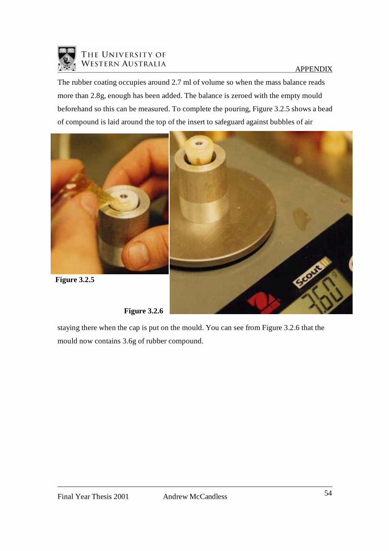
APPENDIX
Final Year Thesis 2001 Andrew McCandless 54
The rubber coating occupies around 2.7 ml of volume so when the mass balance reads
more than 2.8g, enough has been added. The balance is zeroed with the empty mould
beforehand so this can be measured. To complete the pouring, Figure 3.2.5 shows a bead
of compound is laid around the top of the insert to safeguard against bubbles of air
staying there when the cap is put on the mould. You can see from Figure 3.2.6 that the
mould now contains 3.6g of rubber compound.
Figure 3.2.6
Figure 3.2.5
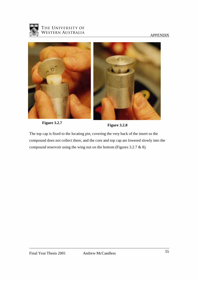
APPENDIX
Final Year Thesis 2001 Andrew McCandless 55
The top cap is fixed to the locating pin, covering the very back of the insert so the
compound does not collect there, and the core and top cap are lowered slowly into the
compound reservoir using the wing nut on the bottom (Figures 3.2.7 & 8).
Figure 3.2.8 Figure 3.2.7

APPENDIX
Final Year Thesis 2001 Andrew McCandless 56
The excess liquid flows out the sides and the escape holes as the wing nut is tightened
(Figure 3.2.9), and this is wiped off with a paper towel (Figure 3.2.10). Paper towels are
very important for wiping away any spillage and it is advisable to have a good stack of
around 15 to make sure they do not run out in the event of any spectacular fumbles.
Figure 3.2.9
Figure 3.2.10

APPENDIX
Final Year Thesis 2001 Andrew McCandless 57
In Figure 3.2.11 the puddles on top of the escape holes have been left until after the
compound has set. This is because some fluid is sucked back into the mould during
shrinkage and if this is wiped away before setting, then air is sucked back in.
Figure 3.2.11
Once the process was perfected then the roller segments were produced much more
reliably and they were very easy to extract from the moulds. If a roller segment moulding
process were to be industrialised, then it would most likely bear very little resemblance to
the process formulated here. However, since there was a low output of fifty units to be
made quickly and cheaply, this crude and hobby-like solution was both effective and
fulfilling.
APPENDIX
Final Year Thesis 2001 Andrew McCandless 58
APPENDIX C
Mechanical Design Drawings
C1 Mechanum Wheel Hub
C2 Roller Clevis
C3 Roller Segment Core
C4 Mould for Roller Tyre
C5 Locating Pin
C6 Roller Disc
C7 Roller Axle
C8 Suspension Arm
C9 Central Mount
C10 Top Plate
Related Documents


![McCandless Final Presentation[1]](https://static.cupdf.com/doc/110x72/55cf85cd550346484b917880/mccandless-final-presentation1.jpg)


