IOWA DOT ~ OFFICE OF BRIDGES AND STRUCTURES ~ LRFD BRIDGE DESIGN MANUAL ~ 4: 1 January 2018 TABLE OF CONTENTS ~ PRELIMINARY DESIGN OF CULVERTS 4 Preliminary Design of Culverts 4.1 General 4.1.1 Policy overview 4.1.2 Design information 4.1.3 Definitions 4.1.4 Abbreviations and notation 4.1.5 References 4.1.5.1 Direct 4.1.5.2 Indirect 4.2 General Culvert Design 4.2.1 Hydrology 4.2.2 Hydraulics 4.2.3 Culverts in Series 4.2.4 Bedding and Backfill 4.2.5 Settlement and Camber 4.2.6 Minimum Allowable Cover 4.2.7 High Fill Pipes 4.2.8 OD Standard Road Plans and Road Design Details 4.3 Culvert Plan Preparation 4.3.1 Pink Sheets 4.3.2 Pipe Sizes 4.3.3 Culvert Type 4.3.4 Horizontal Alignment 4.3.5 Vertical Alignment 4.3.6 Length Determination 4.4 Pipe Culverts 4.4.1 Extensions 4.4.2 Median Pipes 4.4.3 Cross Road Culvert Letdowns 4.4.4 Ditch Letdowns 4.4.5 Culvert Liners 4.4.6 Culvert Maintenance 4.4.7 Uplift of Culvert Inlets 4.4.8 Trenchless Construction 4.4.9 Slope Tapered Inlets for Pipes 4.4.10 Revetment for Pipes 4.5 Reinforced Concrete Boxes (RCB’s) and Designs 4.5.1 Cast in Place RCB Standard Sizes 4.5.2 Precast RCB’s 4.5.3 RCB Extensions 4.5.4 Flumes and Scour Floors 4.5.5 Drop Inlets 4.5.6 Slope Tapered Inlets for RCB’s 4.5.7 Bridge Replacements with RCB’s Using Flowable Mortar 4.5.8 Revetment for RCB’s 4.5.9 Grading control points 4.5.10 Stock Passes 4.5.11 Costs 4.5.12 Alternative Structure Type 4.5.13 Staging 4.6 Permits and Approvals 4.7 Submittals

Welcome message from author
This document is posted to help you gain knowledge. Please leave a comment to let me know what you think about it! Share it to your friends and learn new things together.
Transcript

IOWA DOT ~ OFFICE OF BRIDGES AND STRUCTURES ~ LRFD BRIDGE DESIGN MANUAL ~ 4: 1
January 2018
TABLE OF CONTENTS ~ PRELIMINARY DESIGN OF CULVERTS
4 Preliminary Design of Culverts 4.1 General
4.1.1 Policy overview 4.1.2 Design information 4.1.3 Definitions 4.1.4 Abbreviations and notation 4.1.5 References
4.1.5.1 Direct 4.1.5.2 Indirect
4.2 General Culvert Design 4.2.1 Hydrology 4.2.2 Hydraulics 4.2.3 Culverts in Series 4.2.4 Bedding and Backfill 4.2.5 Settlement and Camber 4.2.6 Minimum Allowable Cover 4.2.7 High Fill Pipes 4.2.8 OD Standard Road Plans and Road Design Details
4.3 Culvert Plan Preparation 4.3.1 Pink Sheets 4.3.2 Pipe Sizes 4.3.3 Culvert Type 4.3.4 Horizontal Alignment 4.3.5 Vertical Alignment 4.3.6 Length Determination
4.4 Pipe Culverts 4.4.1 Extensions 4.4.2 Median Pipes 4.4.3 Cross Road Culvert Letdowns 4.4.4 Ditch Letdowns 4.4.5 Culvert Liners 4.4.6 Culvert Maintenance 4.4.7 Uplift of Culvert Inlets 4.4.8 Trenchless Construction 4.4.9 Slope Tapered Inlets for Pipes 4.4.10 Revetment for Pipes
4.5 Reinforced Concrete Boxes (RCB’s) and Designs 4.5.1 Cast in Place RCB Standard Sizes 4.5.2 Precast RCB’s 4.5.3 RCB Extensions 4.5.4 Flumes and Scour Floors 4.5.5 Drop Inlets 4.5.6 Slope Tapered Inlets for RCB’s 4.5.7 Bridge Replacements with RCB’s Using Flowable Mortar 4.5.8 Revetment for RCB’s 4.5.9 Grading control points 4.5.10 Stock Passes 4.5.11 Costs 4.5.12 Alternative Structure Type 4.5.13 Staging
4.6 Permits and Approvals 4.7 Submittals

IOWA DOT ~ OFFICE OF BRIDGES AND STRUCTURES ~ LRFD BRIDGE DESIGN MANUAL ~ 4: 2
January 2018
4 Preliminary Design of Culverts
4.1 General
The following series of articles provides a set of guidelines for development of type, size and location (TS&L) plans for box culverts/structural designs and in the preparation of pink sheets and pipe plats for small culverts. Within these guidelines sound engineering judgment, including technical and economic analysis, must be applied in all situations. Additional information regarding preliminary design is also contained within BDM Chapters 1 and 7.
4.1.1 Policy overview
Within the Office of Bridges and Structures, the preliminary bridge design section develops the preliminary layouts for highway culverts and associated structures. For culverts/structures that require final design, the section assembles information and develops a preliminary situation plan sheet so that a designer in one of the final design sections can perform the structural design and develop final plans for a contract letting. For pipe culverts the section develops the layout in sufficient detail that the Office of Design can reference the information on their final road plans for a contract letting. The development of all preliminary culvert plans includes a number of tasks such as:
• Analyzing hydrology and hydraulics;
• Analyzing road geometrics;
• Determining the type, size, and location of structures;
• Developing a layout in the CADD system;
• Attending field reviews;
• Coordinating with other Iowa DOT offices
4.1.2 Design information
The designer will need to access information from several sources to perform preliminary design, including, but not limited to, the following:
• Plans for existing structures, including as-built plans, from Electronic Records Management System (ERMS);
• A new site survey from Office of Design;
• Aerial photographs from the Office of Design and/or web sites;
• Aerial agricultural photographs (drainage maps) from the Photogrammetry/Preliminary Survey Section in the Office of Design;
• Topographic maps from the Office of Bridges and Structures, the Office of Design and/or web sites;
• LiDAR data and
• Field exams. Plans for existing structures will give a good indication of the site when an existing structure was built, widened, and/or extended, and comparison with a new survey will indicate any site changes that have occurred since previous construction. The designer should make appropriate use of CADD to integrate support programs such as Geopak when developing type, size, and location (TS&L) and pipe plat plans.
IOWA DOT ~ OFFICE OF BRIDGES AND STRUCTURES ~ LRFD BRIDGE DESIGN MANUAL ~ 4: 3
January 2018
4.1.3 Definitions
Annual Exceedance Probability Discharge (AEPD) is an estimate of the flood discharge for the annual flood frequency recurrence intervals as determined by a regional regression analysis method described in USGS SIR 2013-5086. Base Flood is the flood having a one percent chance of being equaled or exceeded in any given year. This is the regulatory standard also referred to as the “100-year flood.” The base flood is the national standard used by the National Flood Insurance Program (NFIP) and all Federal agencies for the purposes of requiring the purchase of flood insurance and regulating new development. Base Flood Elevation (BFE) is the computed elevation to which floodwater is anticipated to rise during the base flood. BFEs are shown on Flood Insurance Rate Maps (FIRMS) and on the flood profiles. The BFE is the regulatory requirement for the elevation or floodproofing of structures. The relationship between the BFE and a structure’s elevation determines the flood insurance premium. Censored gage record includes discharges (low and high outliers) and historical flood discharges that the USGS may adjust or integrate for use in peak flow analysis. There are two types of censored data (1) annual peak discharges collected at gage sites for which the discharge is only known to be less than the minimum recordable discharge threshold, or (2) in the case of historical periods, annual peak discharges that are only known not to have exceeded a recorded historical flood discharge. Detailed Flood Insurance Study (FIS) analysis of a community’s flood prone areas which determines the 100-year flood elevation and floodway for certain streams. Electronic Reference Library (ERL) contains plans, specifications, and manuals and is available on the Iowa Department of Transportation’s web site. Electronic Records Management System (ERMS) has been developed to enable electronic use and management of documents within the Iowa Department of Transportation. ERMS includes aerial photographs, existing bridge plans, bridge inspection records, and other documents useful for preliminary bridge design. EMA/MGB is the method used in Scientific Investigations Report 2013-5086 to compute log-Pearson Type III exceedance probability analysis for streamgages evaluated for use in the development of the Iowa regional regression equations. The method allows for the integration of censored (low and high outliers) and historical peak-discharge data in the analysis. This is the method used in Bulletin 17C “Guidelines for Determining Flood Flow Frequency.” Expected moments algorithm (EMA) is an annual exceedance-probability analysis method used for continuous-record streamgages. EMA analysis method needs a consistent statistical test (MGB) to identify potentially influential low flows in an annual peak-discharge series to properly reduce the effect of low outliers. Floodway is the portion of the floodplain that must be left unobstructed for the conveyance of the 100-year flood. Flood Risk Reduction Project (FRRP) is typically defined as a Corps of Engineers designed flood protection levee system. Grading surface is the finished earthwork surface within the limits of project grading and the existing ground surface outside the limits of project grading. At locations where the finished earthwork surface represents non-earthen materials (rock revetment, concrete block mats, pavement etc.) plan details will define the grading surface relative to these materials. Earthwork quantities are calculated relative to the grading surface.

IOWA DOT ~ OFFICE OF BRIDGES AND STRUCTURES ~ LRFD BRIDGE DESIGN MANUAL ~ 4: 4
January 2018
Multiple Grubbs-Beck (MGB) test is a statistical method to identify low gage data outliers that depart substantially from the trend of the rest of the annual peak discharge data. Annual peak discharges identified as low outliers by the method are excluded from the dataset. EMA/MGB exceedance-probability analysis computed for the Scientific Investigations Report 2013-5086 used the MGB test for the development of the skew analysis and the Iowa regional regression equations.
Multi-region basin is a site drainage area that drains more than one hydrologic region (crosses a
hydrologic region boundary) as defined by a given USGS methodology for calculating annual exceedance
probability discharges.
Q50 is a flood that has a 2% statistical probability (chance) of being equaled or exceeded in any year.
Q100 is a flood that has a 1% statistical probability (chance) of being equaled or exceeded in any year. Revetment is a relatively general term for a facing that supports an embankment. Riprap is a more specific term for the layer of various sized rocks or broken concrete used to protect a streambank from erosion. With respect to streambank protection the terms revetment and riprap usually are interchangeable. Revetment Stone is the quarry industry’s product that may be used for streambank erosion protection. Section Leader is the supervisor of the Office of Bridges and Structures preliminary bridge section, final design section, or consultant coordination section. Shared use path is a bikeway physically separated from motorized vehicular traffic by an open space or a barrier and either within the highway right-of-way or within an independent right-of-way. Shared use paths may also be used by pedestrians, skaters, wheelchair users, joggers, and other non-motorized users. See AASHTO’s 1999 Guide for the Development of Bicycle Facilities [BDM 4.1.5.2]. Uncensored gage record includes peak discharge data at given gage site, exclusive of censored record. Uncensored data represents actual observed values, whereas censored data reflects historical or otherwise estimated data values. Statistics developed using only uncensored data will generally be presented as ‘period-of-record’ whereas statistics that include censored data generally be presented as ‘historical period’. Weighted Independent Estimate (WIE) is a method for weighting two independent estimates inversely proportional to their associated variances. Annual exceedance-probability discharges (AEPD) by the log-Pearson Type III estimate (EMA/MGB) and the regional regression equations are assumed to be independent and can be weighted by this method and the variance of the weighted estimate will be less than the variance of either of the independent estimates.
4.1.4 Abbreviations and notation
3R, Resurfacing, Restoration, Rehabilitation; a series of terms that refers to a Federal Highway Administration highway project funding program ADT, average daily traffic AEPD, annual exceedance-probability discharge B0, event code for Office of Bridges and Structures concept B1, event code for Office of Bridges and Structures layout B2, event code for structural/hydraulic design plans to Office of Design BNSF, Burlington Northern Santa-Fe Railway CFR, Code of Federal Regulations CIP, Cast in place CLOMR, Conditional Letter of Map Revision issued by FEMA

IOWA DOT ~ OFFICE OF BRIDGES AND STRUCTURES ~ LRFD BRIDGE DESIGN MANUAL ~ 4: 5
January 2018
CMP, corrugated metal pipe D50, median revetment stone diameter D0, event code for predesign concept D2, event code for design field exam DA, drainage area EMA, expected moments algorithm annual exceedance-probability analysis ERL, Electronic Reference Library ERMS, Electronic Records Management System FEMA, Federal Emergency Management Agency FHWA, Federal Highway Administration FIS, Flood Insurance Study HDPE, high density polyethylene HEC-2, U.S. Army Corps of Engineers Hydrologic Engineering Center hydraulic analysis software HEC-RAS, U.S. Army Corps of Engineers Hydrologic Engineering Center – River Analysis System hydraulic analysis software IAC, Iowa Administrative Code IFI, intermediate foundation improvement IHRB, Iowa Highway Research Board Iowa DNR, Iowa Department of Natural Resources Iowa DOT, Iowa Department of Transportation LOMR, Letter of Map Revision issued by FEMA LP3, log-Pearson Type III LT, left MCS, main-channel slope, a variable in USGS WRIR 03-4120 MGB, Multiple Grubbs-Beck low-outlier test n-coefficient, Manning’s Coefficient [BDM 3.2.2.3] NFIP, National Flood Insurance Program NHS, National Highway System NOAA, National Oceanic and Atmospheric Administration NRCS, Natural Resources Conservation Service PE, preliminary engineering PEP, polyethylene pipe POT, point on tangent Q2, Q50, Q100, Q200, Q500, estimated channel discharge at 2-, 50-, 100-, 200- or 500-year design flood frequency RCB, reinforced concrete box, a type of culvert RCP, reinforced concrete pipe ROW, right of way RRE, regional regression equation RT, right SI&A, Structure Inventory and Appraisal SIIMS, Structure Inventory and Inspection Management System SIR, scientific investigation report SUDAS, (Iowa) Statewide Urban Design and Specifications TS&L, type, size, and location UP or UPRR, Union Pacific Railroad USGS, United States Geological Survey WIE, weighted independent estimates WRIR, water-resources investigation report WSPRO, water surface profile software developed by the U.S. Geological Survey

IOWA DOT ~ OFFICE OF BRIDGES AND STRUCTURES ~ LRFD BRIDGE DESIGN MANUAL ~ 4: 6
January 2018
4.1.5 References
4.1.5.1 Direct
[IDOT PPM policy number] refers to a policy in the Iowa Department of Transportation Policies and Procedures Manual. [IDOT SS article] refers to Iowa Department of Transportation Standard Specifications for Highway and Bridge Construction, Series 2015 with article number. (Available on the Internet at: http://www.iowadot.gov/erl/index.html) [OD DM article, table, or figure] refers to the Office of Design, Highway Division Design Manual with article, table, or figure number. (Available on the Internet at: http://www.iowadot.gov/design/dmanual/manual.html?reload) [OD RDD sheet number] refers to the Office of Design, Highway Division “Road Design Details” with sheet number. Formerly the detail manual was referred to as the “green book.” (Available on the Internet at: http://www.iowadot.gov/design/desdet.htm) [OD SRP sheet number] refers to an Office of Design, Highway Division “Standard Road Plan” with sheet number. Formerly the plan manual was referred to as the “red book.” (Available on the Internet at: http://www.iowadot.gov/design/stdrdpln.htm)
4.1.5.2 Indirect
American Association for State Highway and Transportation Officials (AASHTO). A Policy on Design Standards—Interstate System, 5th Edition. Washington: AASHTO, 2005. American Association for State Highway and Transportation Officials (AASHTO). Guide for the Development of Bicycle Facilities, 3rd Edition. Washington: AASHTO, 1999. American Association for State Highway and Transportation Officials (AASHTO). Roadside Design Guide, 3rd Edition. Washington: AASHTO, 2002. BNSF Railway – Union Pacific Railroad. Guidelines for Railroad Grade Separation Projects. Union Pacific Railroad, Omaha, NE, 2007. (Available on the Union Pacific web site at: https://www.uprr.com/aboutup/operations/specs/attachments/grade_separation.pdf) Cronshey, R., R.H. McCuen, N. Miller, W. Rawls, S. Robbins, and D. Woodward. Urban Hydrology for Small Watersheds, 2nd Edition, 210-VI-TR-55. Washington: Natural Resources Conservation Service (NRCS), 1986. (Current edition of Technical Release 55 (TR-55); available on the U.S. Department of Agriculture web site at: http://www.wsi.nrcs.usda.gov/products/W2Q/H&H/Tools_Models/WinTR55.html) Eash, D.A., Barnes, K.K., and Veilleux, A.G., 2013, Methods for Estimating Annual Exceedance-Probability Discharges for Streams in Iowa Based on Data through Water Year 2010: U.S. Geological Survey Scientific Investigation Report 2013-5086 (Available on the U.S.G.S. website at http://pubs.usgs.gov/sir/2013/5086). Eash, David A. Techniques for Estimating Flood-Frequency Discharges for Streams in Iowa, WRIR 00-4233. Iowa City: U.S. Geological Survey (USGS), 2001. (Available on the Iowa USGS web site at http://ia.water.usgs.gov/pubs/reports/WRIR_00-4233.pdf)

IOWA DOT ~ OFFICE OF BRIDGES AND STRUCTURES ~ LRFD BRIDGE DESIGN MANUAL ~ 4: 7
January 2018
Eash, David A. Main-Channel Slopes of Selected Streams in Iowa for Estimation of Flood-Frequency Discharges, WRIR 03-4120. Iowa City: U.S. Geological Survey (USGS), 2003. (Available on the Iowa USGS web site at http://ia.water.usgs.gov/pubs/reports/WRIR_03-4120.pdf) Eash, David A. Comparisons of Estimates of Annual Exceedance-Probability Discharges for Small Drainage Basins in Iowa, Based on Data through Water Year 2013, SIR 2015-5055. U.S. Geological Survey (USGS), 2015. (Available on the USGS website at https://pubs.usgs.gov/sir/2015/5055/pdf/sir2015-5055.pdf) Federal Highway Administration. “Hydraulic Engineering” web page with links to publications and software. http://www.fhwa.dot.gov/engineering/hydraulics/index.cfm Golden Hills Resource Conservation and Development, Inc. Stream Stabilization in Western Iowa: Structure Elevation and Design Manual, Iowa DOT HR-385. 1998. (Available on the Iowa DOT web site at: http://www.iowadot.gov/operationsresearch/reports/reports_pdf/hr_and_tr/reports/hr385.pdf) Hadish, G.A., M. Braster, R.A. Lohnes, and C.P. Baumel. Stream Stabilization in Western Iowa, Iowa DOT HR-352. 1994. (Available on the Iowa DOT web site at: http://www.iowadot.gov/operationsresearch/reports/reports_pdf/hr_and_tr/reports/hr352.pdf) Iowa Administrative Code. Des Moines: Legislative Services Agency, 2004. (Available on the Internet at http://www.legis.state.ia.us/IAC.html) Iowa State University. SUDAS Standard Specifications. Iowa State University, Ames, IA, 2011. (Available on the SUDAS web site at: http://www.iowasudas.org/specs.cfm) Lagasse, P.F., J.D. Schall, and E.V. Richardson. Stream Stability at Highway Structures, Third Edition; Hydraulic Engineering Circular No. 20 (HEC-20). Washington: Federal Highway Administration (FHWA), 2001. (Available on the FHWA web site at: http://www.fhwa.dot.gov/engineering/hydraulics/library_listing.cfm) Lagasse, P.F., P.E. Clopper, J.E. Pagan-Ortiz, L.W. Zevenbergen, L.A. Arneson, J.D. Schall, and L.G. Girard. Bridge Scour and Stream Instability Countermeasures: Experience, Selection and Design Guidance, Volumes 1 and 2, Third Edition; Hydraulic Engineering Circular No. 23 (HEC-23). Washington: Federal Highway Administration (FHWA), 2009. (Available on the FHWA web site at: http://www.fhwa.dot.gov/engineering/hydraulics/library_listing.cfm) Lara, Oscar G. Method for Estimating the Magnitude and Frequency of floods at Ungaged Sites on Unregulated Rural Streams in Iowa, WRIR 87-4132. Iowa City: U.S. Geological Survey (USGS), 1987. Larimer, O.J. Drainage Areas of Iowa Streams. U.S. Geological Survey (USGS), Iowa Highway Research Board Bulletin No. 7 (Red Book). (Available on the Iowa DOT web site at: http://www.iowadot.gov/operationsresearch/reports/reports_pdf/hr_and_tr/reports/HR-29%20Final%20Report%201957.pdf) Norman, J.M., R.J. Houghtalen, and W.J. Johnston. Hydraulic Design of Highway Culverts, Second Edition; HDS No. 5. Washington: Federal Highway Administration (FHWA), 2001. (Available on the FHWA web site at: http://www.fhwa.dot.gov/engineering/hydraulics/library_listing.cfm) U.S. Department of Transportation, April 2012, Hydraulic Design Series Number 5, Hydraulic Design of Highway Culverts, Third Edition, FHWA Publication No. FHWA-HIF-12-026. (Available on the FHWA web site at: http://www.fhwa.dot.gov/engineering/hydraulics/library_arc.cfm?pub_number=7&id=13

IOWA DOT ~ OFFICE OF BRIDGES AND STRUCTURES ~ LRFD BRIDGE DESIGN MANUAL ~ 4: 8
January 2018
4.2 General Culvert Design
In the construction of rural highways in Iowa it is of primary importance that there be minimal diversion of surface water. Water entering the highway right of way in a draw (swale or ditch) should generally be carried through the highway embankment and discharged into the same draw. Although it is not possible to leave unchanged every square foot of watershed, this policy of “minimal diversion” shall be adhered to as closely as practical. The term “minimal” is difficult to quantify but may be viewed in terms of percentage change and of potential impacts to affected properties. For example, altering a 150-acre watershed to 152 acres may have minor effects on peak flow, but altering a 5-acre watershed to 10 acres may adversely affect farming practices on a given property. Basically, a 10% increase in watershed area due to diversion is usually acceptable. In much rarer instances, decreasing drainage area may also have an adverse impact. One actual example is a 7-acre watershed that was diverted to a much larger basin. During construction, the landowner made IDOT aware that the 7-acre watershed was a significant water supply source to a pond used for watering livestock. On highway relocations, be aware that field fences may have enough soil built up to create a “ridge” where water does not cross. In effect, these fences may create distinct watershed boundaries and become as important as any “natural” watershed boundary. Avoiding diversion in these instances must be considered when the highway relocation cuts through these fence “ridges”. Existing tile lines should also be considered in design. For example, if a tile line outlets into or near an existing culvert inlet, care should be taken to keep the same tile flowline elevation.
4.2.1 Hydrology
Reliable estimates of flood-frequency discharges are essential for the economical and proper design of culverts located over streams. For the design of culverts within a detailed FIS or with the potential for impacting insurable structures, use the 100-year discharge. For the design of crossroad (mainline) culverts and for most sideroad culverts (city or county roads) use a 50-year flood. For entrances and driveways, use a 10-year flood unless the mainline is adversely affected. For temporary culverts under a “runaround”, generally use the 5-year discharge. For rural basins with drainage areas less than two square miles (1280 acres) use the Iowa Runoff Chart (see commentary) or the Iowa DOT culvert program. For drainage basins between 2 and 20 square miles, WRIR 87-4132 may be used for the design of culverts. A thorough review of basin characteristics and history of flooding along with engineering judgement is needed when determining design discharges for small basins. For designer reference, accuracy of AEPD estimates for small drainage basins in Iowa using different calculation methodologies have been studied by the USGS. Results are presented in USGS SIR 2015-5055. For larger drainage areas, use USGS Scientific Investigation Report 2013-5086. The USGS has developed a web based program called “StreamStats” that calculates the estimated peak discharges from Report 2013-5086. The program will delineate a watershed from a point as long as the stream is shown as perennial flow (solid blue line) on a USGS topographic map. The designer may use LiDAR or other more accurate information to check the results for accuracy and to determine the appropriate drainage area.

IOWA DOT ~ OFFICE OF BRIDGES AND STRUCTURES ~ LRFD BRIDGE DESIGN MANUAL ~ 4: 9
January 2018
USGS Report 2013-5086 has defined three different regions for the state and utilizes a three-variable equation for each region. For basins that cross region boundaries (multi-region basins), StreamStats will provide an estimated peak discharge for each region within the basin and a weighted AEPD estimate per SIR 2013-5086 based on the ratio of the area of each contributory flood region to the total basin area (See BDM 3.2.2.1). If a proposed culvert is located within a drainage basin where 25% or more of the watershed is developed, urban hydrology should be considered. For urban basins with less than 160 acres, the Rational Method may be used for determining peak discharges. For urban basins larger than 160 acres, the design storm runoff may be analyzed by other methods such as TR-55 for watersheds up to 2000 acres. For basins larger than 2000 acres, TR-20, HEC-HMS or other programs may be used. When a proposed culvert site is located near a USGS stream gage, is within a detailed FIS or requires DNR approval the designer should refer to the Bridge Hydrology Section under BDM 3.2.2.1.
4.2.2 Hydraulics
For culvert hydraulics, use FHWA's publication, “Hydraulic Design of Highway Culverts,” Hydraulic Design Series No. 5 April 2012. Computer software such as the Iowa DOT culvert program, HY-8 or Haestad Methods’ “CulvertMaster” is also acceptable for analyzing computer hydraulics. The Iowa DOT culvert program is available on the DOT website: http://www.iowadot.gov/bridge/prelprog.htm. Check with the Office for approval of other software. Culverts should generally be designed to have one foot to two feet of head above the top of the opening at the design discharge. This can be exceeded in some instances if the culvert is under high fill and there is minimal flood damage potential upstream. For culverts with the potential to impact insurable structures, the Q100 design head should be minimized. For larger culverts where the drainage area requires a DNR permit or is located within a detailed Flood Insurance Study area, the design will be similar to what is required for bridges. When the upstream terrain is very flat, be aware that a calculated highwater may not be reached due to large available flood storage. In this circumstance, the designer may need to consider less culvert height and more width to accommodate flows at lower water surface levels. In some instances, a ditch dike may be needed at the inlet and sometimes outlet to prevent diversion when designing a culvert.
4.2.3 Culverts in Series
If two culverts in series are near each other, such as a mainline culvert and a culvert downstream under a ramp, generally keep the slope between the culverts to a minimum, perhaps 1% or less. This helps avoid erosion between the culverts. If a significantly steeper slope is unavoidable, a rock-lined ditch may be needed. The hydraulics of the culverts in series should be carefully checked to accurately determine the influence of one culvert on any upstream culverts.
4.2.4 Bedding and Backfill
All pipe culverts under primary and secondary roadways shall meet the Class “B” Bedding and Backfill requirements and for temporary pipes, entrances, driveways and levees or dikes, Class “C” Bedding and Backfill per OD SRP DR-101 should be used.

IOWA DOT ~ OFFICE OF BRIDGES AND STRUCTURES ~ LRFD BRIDGE DESIGN MANUAL ~ 4: 10
January 2018
For box culverts, the backfill requirements are shown on OD SRP DR-111.
4.2.5 Settlement and Camber
The Soils Section of the Office of Design provides estimated settlements for culverts on relocated or raised highway embankments. The estimated settlements for pipe culverts can be mitigated per OD SRP DR-102. The camber should be noted in the appropriate column on the pipe culvert bid tabulation 104-3. For box culverts where the settlement is estimated as 6 inches or greater, the culvert shall be cambered and bell joints shall be provided. Regardless of the estimated settlement, bell joints shall be provided when the fill is greater than 35 feet. Typically, when the settlement exceeds 6 inches, a precast RCB option is not allowed.
4.2.6 Minimum Allowable Cover
Minimum allowable cover for all concrete and metal pipes is 2 feet for roadway and 1 foot for entrance culverts. The top of the structure should be at or below the subgrade elevation within the roadway limits (outside to outside of shoulder). Minimum cover for culvert in a divided roadway for the median is one foot. When minimum cover cannot be obtained with a single round pipe, consider using low clearance pipe or twin pipes. Also, the designer may use a concrete pipe or a low clearance pipe with end wall. Other options include: partially burying a larger diameter pipe while providing an equivalent water area or recommending a cast-in-place drop inlet. Total cost of the various structure options considered shall also be a determining factor. Spacing for twin pipes shall be approximately 2 feet between the flared outside edges of the aprons. [Reference OD SRP DR 201-206]
4.2.7 High Fill Pipes
For culvert installations where maximum allowable cover is exceeded, as indicated on the OD SRP DR-104, pipe strength may be modified to account for the additional cover. While standard pipe strength ranges from 2000D to 3750D, the concrete pipe industry does provide higher pipe strengths of 4000D and above for high fill situations. Prior approval from the Section Leader is required.
4.2.8 OD Standard Road Plans and Road Design Details
See the commentary for guidelines on properly using the Road Design Standard Road Plans and Road Design Details.
4.3 Culvert Plan Preparation
The difference in plan details for pipe culverts and for RCB culverts may be confusing, so the following information will provide clarification. The plan and profile drawing for a pipe culvert is a plat plan (see Commentary for an example plat plan). The plan and profile for an RCB culvert or pipes with flumes or

IOWA DOT ~ OFFICE OF BRIDGES AND STRUCTURES ~ LRFD BRIDGE DESIGN MANUAL ~ 4: 11
January 2018
drop inlets will require final structure design and should be developed as a TS&L and typically consists of more detail than a plat plan (see Commentary for an example of an RCB TS&L). The primary purpose of culvert plat plans is to visually and graphically aid the designer in developing proper lengths and locations of culverts since individual cross sections commonly do not show the exact elevations or alignment of the drainage way. The completed drawings are often used during construction or in later years if drainage complaints arise. During the project design, the Office of Right of Way also uses the drawings to help determine right of way needs, and the Office of Design uses them as an aid to compute earthwork quantities. The plat plan or TS&L should include enough ground elevations and contours to accurately define the area. All draws, banks, existing structures (including flowlines and lengths), fence lines, tile lines, utilities, and other pertinent existing features should be shown. The proposed structure, including flowlines, lengths, skews and special features should be shown. See the culvert plan review checklist for information to include on plat plans for pipes and TS&L’s for RCB’s. Ground elevations should be shown along the drainage way at least 100 feet upstream and downstream of the culvert. Contours should be clearly labeled. Proposed toe of slope lines (fore slope, ditch lines, back slopes) should be shown at least 150 feet ahead and back of the culvert stationing. Both the plan and the profile view should be plotted with a 1”=40’ scale as measured on an 11”x17” drawing. (This refers only to the plotted scale and does not refer to any “working scales” as used while actually in a CADD file.) Do not use an exaggerated scale in the profile view. For the culvert layout in plan-view, the roadway should be oriented vertically. The profile view should be drawn as a projection along the centerline of the culvert. Therefore, for skewed culverts, the true length and fore slopes will not be represented on the profile view. For pipe culverts with concrete flumes, drop inlets or other features that require structural design, the plan should be developed as a TS&L. Sample plans may be found online with the review checklist for both pipes and RCBs. RCB and Pipe Culvert Checklists Pipe Culvert Examples_Checklist 051713.pdf RCB Culvert Example_Checklist_January 2014.pdf
4.3.1 Pink Sheets
Culvert "pink" sheets (IDOT Form 621001-E) have four primary purposes:
1. Provide field information such as culvert location, drainage area, existing culvert flowlines, etc. 2. Aid in the design process, including the computation of culvert lengths. 3. Develop the culvert bid tabulation for the final road plans. 4. Provide a permanent record for the culvert.
Pink sheets should be completely filled out with all applicable information. See the commentary for a sample pink sheet and an explanation on how to properly use the computation section on the pinks. Upon submittal of final grading plans by consultants, the completed pinks and plat plans shall be submitted to IDOT and kept as a permanent record for the culverts.

IOWA DOT ~ OFFICE OF BRIDGES AND STRUCTURES ~ LRFD BRIDGE DESIGN MANUAL ~ 4: 12
January 2018
4.3.2 Pipe Sizes
In general, concrete pipe culvert sizes will range from 18 to 84 inches in 6 inch increments. Minimum pipe size for roadways, side roads and ditch letdowns is 24 inches. This provides adequate opening for maintenance inspections and minimizes the potential for plugging with debris. Details for other available sizes and types are shown on [OD SRP DR-104]. For areas with low clearance or minimum cover, an arch pipe or smaller diameter twin pipe culverts can be used. See BDM 4.2.6 for information on minimum cover. For arch pipe equivalent diameters, refer to [OD SRP DR-202]. Preferred minimum size for median pipes for divided highways is 24 inches. In some instances, the median ditch may be too shallow to place a 24-inch pipe under the pavement and subbase, and D sections with various bevels may be used. For areas with minimal drainage or clearance restrictions such as a gore area, an 18-inch pipe may be used. A concrete apron with end wall may also be considered to provide additional clearance. Refer to [OD SRP DR-205] for details. Minimum pipe size for entrances is 18 inches. The site history of the existing culvert may provide useful information when sizing a proposed culvert. Survey crews should find this information and note it on the pink sheet. IDOT maintenance personnel may have information related to landowners' complaints or road overtopping, which may indicate a larger structure should be designed or the road grade needs to be raised. Any such history should be documented in project files or on the pink sheets.
4.3.3 Culvert Type
For most highway locations, concrete pipe is required under the road. For highway locations where there is less than 3000 ADT (Average Daily Traffic) and the highway is not an NHS (National Highway System) route, the culvert type used shall be bid as Unclassified Roadway Pipe (Coated CMP or HDPE pipe). For an extension of an existing concrete pipe culvert or small box, the extension will be bid as concrete pipe regardless of the ADT. The ADT is estimated for future 30-year traffic. Concrete pipe culverts shall be used under all highways with greater than 3000 ADT or designated as an NHS route, including county or city roadways. Corrugated metal pipe shall be specified for any temporary pipes used for construction staging purposes (aprons are generally not needed). Unclassified Entrance Pipes (Non-Coated CMP, HDPE or Concrete) shall be specified for entrances and driveways. Culverts under county or city roads should be replaced in-kind. When a new culvert is proposed under a side road, the local jurisdiction should be consulted for their preference regarding culvert type. New or replacement stock passes shall be 6’ x 7’ precast RCB. Existing stock passes can be extended utilizing OD RDD 510-4. Precast RCB’s are typically bid as an alternative to Cast-in-Place for single, twin and triple box culverts. See BDM 4.5.2 for more information.
4.3.4 Horizontal Alignment
Generally, culverts should be aligned with the waterway, especially on the outlet end. However, high skews should be avoided where possible to minimize costs. Culvert and excavation costs should be considered when selecting the alignment. The constructability of the culvert during traffic staging, including maintaining drainage during construction, may also be an important factor.

IOWA DOT ~ OFFICE OF BRIDGES AND STRUCTURES ~ LRFD BRIDGE DESIGN MANUAL ~ 4: 13
January 2018
4.3.5 Vertical Alignment
Generally, the slope of a pipe or box culvert should approximate the natural stream or draw slope. When the slope of a pipe culvert is 5% or steeper, give consideration to a culvert type such as OD SRP DR-611 or DR-641. When the slope of a box culvert exceeds approximately 2%, give consideration to some type of energy dissipater such as a drop inlet, impact basin or a flume outlet. Also, give consideration to putting in verticals breaks in the slope, such as a “broken back” culvert, to minimize outlet velocities.
4.3.6 Length Determination
The length of culvert is determined by either the clear zone or by matching the proposed cross section, such as the barnroof slope. See the commentary for design aid "Determining Culvert Lengths” which provides a more detailed explanation of how to determine this length and explains how to use the Computation Section on culvert pink sheets. See OD RDD 4311 for fore slope shaping and cover for extensions or spot replacement culverts. Calculated concrete pipe lengths will be rounded up to the nearest even-numbered foot. Calculated lengths of Unclassified pipes will be rounded up to the nearest foot. The length of cast-in-place (CIP) reinforced concrete box culverts shall be referenced from the back to back of parapet rounded up to the nearest foot. Precast box culvert barrel lengths (not the back to back of parapet) shall be rounded up to the nearest foot. The designer should note that our policy for determining box culvert length differs between precast and CIP. Culvert length for the CIP option is determined by the foreslope intercept with the top of parapet, while the length for the precast option is determined by the intercept with the top of box. For more information on precast box culvert layout requirements, refer to BDM article 4.5.2.
4.4 Pipe Culverts
4.4.1 Extensions
Existing RCBs and pipes shall generally be extended with an equivalent size and shape to closely approximate the hydraulic opening. For example, extend a 2’ x 2’ RCB with a 30” RCP culvert, and extend a 3’ x 2’ RCB with a 37” x 23” concrete arch pipe or a 36” RCP. For skewed RCBs, the pipe culvert should be cut to the skew angle of the headwall so the pipe can be placed flush with the face of the parapet. For headwalls with a skew angle greater than 30 degrees, it may be advantageous to cut the barrel of the RCB so that the pipe can be connected better with the RCB. Use OD SRP DR-122 to connect the RCB to the pipe with a Type “C-2” concrete adapter for pipe culvert connections. The largest RCB for extension with a pipe is 6’ x 6’. See chart below for appropriate pipe size extensions.
RCB EXTENSIONS WITH PIPES
RCB Width x Height Round Pipe Extension Size Low Clearance Pipe Extension Size
2' x 2' 30"
3' x 2' 36" 37" x 23"
3' x 3' 42"
IOWA DOT ~ OFFICE OF BRIDGES AND STRUCTURES ~ LRFD BRIDGE DESIGN MANUAL ~ 4: 14
January 2018
4' x 2' 52" x 32"
4' x 3' 48" 59" x 36"
4' x 4' 54"
5' x 3' 65" x 40"
5' x 4' 60"
5' x 5' 66"
5' x 6' 72"
6' x 4' 88" x 54"
6' x 5' 72"
6' x 6' 78"
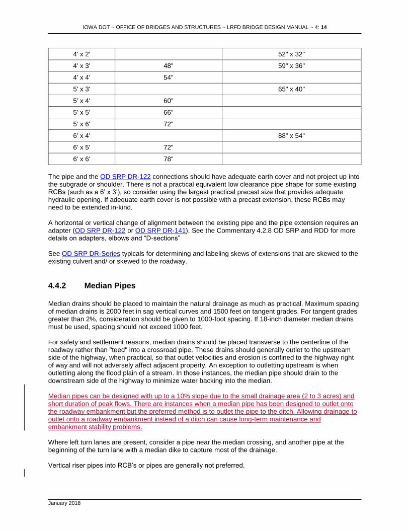
The pipe and the OD SRP DR-122 connections should have adequate earth cover and not project up into the subgrade or shoulder. There is not a practical equivalent low clearance pipe shape for some existing RCBs (such as a 6’ x 3’), so consider using the largest practical precast size that provides adequate hydraulic opening. If adequate earth cover is not possible with a precast extension, these RCBs may need to be extended in-kind. A horizontal or vertical change of alignment between the existing pipe and the pipe extension requires an adapter (OD SRP DR-122 or OD SRP DR-141). See the Commentary 4.2.8 OD SRP and RDD for more details on adapters, elbows and “D-sections” See OD SRP DR-Series typicals for determining and labeling skews of extensions that are skewed to the existing culvert and/ or skewed to the roadway.
4.4.2 Median Pipes
Median drains should be placed to maintain the natural drainage as much as practical. Maximum spacing of median drains is 2000 feet in sag vertical curves and 1500 feet on tangent grades. For tangent grades greater than 2%, consideration should be given to 1000-foot spacing. If 18-inch diameter median drains must be used, spacing should not exceed 1000 feet. For safety and settlement reasons, median drains should be placed transverse to the centerline of the roadway rather than "teed" into a crossroad pipe. These drains should generally outlet to the upstream side of the highway, when practical, so that outlet velocities and erosion is confined to the highway right of way and will not adversely affect adjacent property. An exception to outletting upstream is when outletting along the flood plain of a stream. In those instances, the median pipe should drain to the downstream side of the highway to minimize water backing into the median. Median pipes can be designed with up to a 10% slope due to the small drainage area (2 to 3 acres) and short duration of peak flows. There are instances when a median pipe has been designed to outlet onto the roadway embankment but the preferred method is to outlet the pipe to the ditch. Allowing drainage to outlet onto a roadway embankment instead of a ditch can cause long-term maintenance and embankment stability problems. Where left turn lanes are present, consider a pipe near the median crossing, and another pipe at the beginning of the turn lane with a median dike to capture most of the drainage. Vertical riser pipes into RCB’s or pipes are generally not preferred.

IOWA DOT ~ OFFICE OF BRIDGES AND STRUCTURES ~ LRFD BRIDGE DESIGN MANUAL ~ 4: 15
January 2018
4.4.3 Cross Road Culvert Letdowns
When the slope of a cross road culvert exceeds 5%, a letdown structure should be considered (see DR-641). Under Standard Road Plan DR-641, a concrete pipe is required under the roadway and either a coated CMP or HDPE can be used for the letdown. If a culvert diameter is greater than 42 inches, a concrete flume should be designed to outlet the drainage. Culvert letdowns larger than 42 inches have a greater potential for failure.
4.4.34.4.4 Ditch Letdowns
Designing the outlets of letdowns through an RCB wall or flume wall is not desirable due to potential cracking in these walls. Rather, the outlets can be set beyond the headwall or on top of the wingwall or flume wall. The pipes should be anchored to the wall if resting on top of it. Although the use of culvert letdowns is dependent on site conditions, a rough rule of thumb is that drainage areas of up to 10approximately 2-3 acres or less do not warrant culvert letdowns. In those instances, a riprap letdown could be considered. The existing site conditions often provide helpful information in deciding if a culvert is necessary. For example, if the existing side ditch does not have a letdown or any erosion problems, then the proposed project may not need one either. Consideration should be given in some circumstances to ditch treatments such as special ditch control, turf reinforced mat, erosion stone, or riprap. Cost, type of soil, ditch slope, drainage area, and the preferences of the local DOT maintenance personnel are all factors in determining the proper ditch treatment.
4.4.44.4.5 Culvert Liners
Some common problems with culverts approaching the end of their design lives include corrugated metal pipes that have rusted through, concrete pipes where joints have separated and soil is coming through the joints, and small box culverts with deteriorated floors and walls where concrete is spalling badly and reinforcing steel is exposed and corroded. Traditional solutions include open excavation and replacement, or jacking a new culvert alongside the existing one. However, another option is to push a liner, either metal or plastic, through the existing culvert and then grout the void between the liner and culvert. There are many important factors to consider when designing and installing a liner. Advantages of these types of liners are as follows: 1. Installation is quick, generally less than a day, which is significantly less than it takes to excavate,
remove, replace, cover, and place new pavement. 2. Traffic disruption is minimal, which is especially important for higher-traffic roads. 3. Equipment needs are minimal compared to conventional cut and cover. 4. Since open excavation is not needed, spot pavement replacement is not needed. 5. Potential settlement caused by excavating and then backfilling is eliminated. 6. Lining a pipe may be less expensive than open excavation or jacking, but comparisons should be
made at each site. Obviously, as fill heights increase, the costs of open excavation increase. 7. DOT maintenance forces may be able to install the liner, although contracting this work is also an
option. Disadvantages are as follows:

IOWA DOT ~ OFFICE OF BRIDGES AND STRUCTURES ~ LRFD BRIDGE DESIGN MANUAL ~ 4: 16
January 2018
1. If the culvert has some bends or poorly aligned joints, a liner may not work unless it is significantly smaller than the existing pipe. Metal or PVC liners will bend very little, if at all. Polyethylene liners can bend a small amount, but if bent or kinked too much, the strength of the pipe may be significantly reduced leading to cracking or buckling in the future.
2. Reduced hydraulic capacity is potentially one of the biggest drawbacks to liners. Each site should be reviewed in the field and for existing and proposed hydraulics. Examine the risks of potential flooding upstream, water over the road, and inadvertent diversion of drainage during high flows to a culvert in an adjacent watershed. A full hydraulic analysis of both the existing and liner culverts should be made, including inlet and outlet control calculations. At least one pipe liner manufacturer suggests that a smooth liner with a lower Manning’s n-value will give better hydraulics than an existing culvert with a higher n-value. However, this may not be true depending on site conditions, so the full hydraulic analysis is important.
3. Both corrugated metal and plastic liners are defined as flexible pipes and therefore do not have much strength to carry earth pressures without surrounding material, such as grout, to support them. Without this support, the liner can crush or fail over time. If the liner is installed in a concrete pipe where the joints have pulled apart slightly but the pipe itself is still in good condition, the existing concrete pipe may still carry the earth load for many years. However, if the culvert is in very poor structural condition, such as a badly corroded metal pipe, the liner will need to carry all the earth load. Therefore, the backfill material, i.e., grout, is critical. Do not underestimate the importance of this.
4. The life of the liner material may not be as long as the life of a concrete pipe installed by jacking or open excavation.
A higher headwater depth (2 to 4 feet above the top of the culvert) can be considered for culvert liners as long as the upstream flood plain has a low damage potential and the headwater elevation will not cause roadway overtopping.
4.4.54.4.6 Culvert Maintenance
{Text for this article will be added in the future}
4.4.64.4.7 Uplift of Culvert Inlets
For corrugated metal or polyethylene pipes with diameters of 48” and larger, cast-in-place headwalls, precast concrete aprons (OD SRP DR-201 ), or concrete collars should be considered on the inlet to prevent failure due to uplift forces. For 48” to 84” diameter culverts, an alternative is to use a concrete pipe instead of CMP.
4.4.74.4.8 Trenchless Construction
There are many situations where trenchless construction to replace a culvert is preferable to open cut construction especially on high ADT roadways or where out of distance detours are long. Most trenchless construction methods may have a higher dollar cost than that of their open cut counterparts. However, one needs to consider the benefits that trenchless construction provides and weigh all of the costs before deciding against using a trenchless technique (especially for excavations greater than 10 feet). Trenchless construction avoids the cost of pavement removal and replacement, dewatering, staging and traffic control. The benefits of trenchless construction also avoid inconvenience to the traveling public and lost business revenue caused by a closed roadway; minimizing utility conflicts; avoiding potential safety issues and other environmental impacts. The preferred method for jacking a culvert is from the downstream side to the upstream inlet. Trenchless construction can be performed from the upstream side of a highway if environmental or ROW issues dictate. However, for larger culverts (e.g. 54 inch or greater) and for grades of 2 percent or more, it may

IOWA DOT ~ OFFICE OF BRIDGES AND STRUCTURES ~ LRFD BRIDGE DESIGN MANUAL ~ 4: 17
January 2018
not be possible to jack from the upstream side. Consultation with the trenchless industry is recommended when a site requires jacking a culvert from the upstream side. The minimum temporary easement area for a jacking pit is 60 feet from the embankment and 50’ ahead and back for access and the storage of materials.
4.4.84.4.9 Slope Tapered Inlets for Pipes
Slope tapered inlets for pipe culverts can be used to reduce construction costs by reducing pipe sizes when the elevation difference between inlet and outlet is a least four to six feet. Cost savings may be realized when the culvert length is greater than 150 feet. Due to high velocities and large drop in elevation, most tapered inlet culverts will need a flume and a basin to dissipate energy. Design guidelines for slope tapered inlets for pipe culverts are shown in the commentary.
4.4.94.4.10 Revetment for Pipes
To address EPA/DNR storm water management regulations, the outlet of all pipe culverts will require revetment splash basins to minimize scour/erosion (OD SRP EC-301). The Office of Design will calculate revetment quantities for cross road culverts, median pipes and RCB’s extended with pipes. Splash basins for median pipes will depend upon the ditch grade they outlet to. Consultation with the Office of Design may be necessary when determining if a median pipe will require a splash basin.
4.5 Reinforced Concrete Boxes (RCB’s) and Designs
4.5.1 Cast in Place RCB Standard Sizes
The following standard box culvert sizes are measured in feet of clear Span x Height. Culvert sizes are available in 1’-0 increments with the sizes listed below. These standard sizes should be used whenever practical. No RCBs smaller than a 3’ x 3’ shall be used. Cast-In-Place Twin and Triple Culverts are multiple barrels sharing common interior walls, i.e. Twin 12 x 8 is two 12 foot spans with a height of 8 foot. SINGLE REINFORCED CONCRETE BOX CULVERT STANDARDS (span x height in feet):
3 X 3
4 X 4
5 X 3 5 X 4 5 X 5 5 X 6
6 X 3 6 X 4 6 X 5 6 X 6 6 X 7 6 X 8
8 X 4 8 X 5 8 X 6 8 X 7 8 X 8 8 X 9 8 X 10
10 X 4 10 X 5 10 X 6 10 X 7 10 X 8 10 X 9 10 X 10 10 X 11 10 X 12
12 X 4 12 X 5 12 X 6 12 X 7 12 X 8 12 X 9 12 X 10 12 X 11 12 X 12
Fill range for standard Cast-In-Place Single Box Culverts is 0 to 55 feet. Fill is defined as maximum depth of fill on top of the Culvert TWIN REINFORCED CONCRETE BOX CULVERT STANDARDS (span x height in feet)
8 X 4 8 X 5 8 X 6 8 X 7 8 X 8 8 X 9 8 X 10

IOWA DOT ~ OFFICE OF BRIDGES AND STRUCTURES ~ LRFD BRIDGE DESIGN MANUAL ~ 4: 18
January 2018
10 X 4 10 X 5 10 X 6 10 X 7 10 X 8 10 X 9 10 X 10 10 X 11 10 X 12
12 X 4 12 X 5 12 X 6 12 X 7 12 X 8 12 X 9 12 X 10 12 X 11 12 X 12
Fill range for standard Cast-In-Place Twin Box Culverts is 0 to 25 feet. TRIPLE REINFORCED CONCRETE BOX CULVERT STANDARDS (span x height in feet)
10 X 4 10 X 5 10 X 6 10 X 7 10 X 8 10 X 9 10 X 10 10 X 11 10 X 12
12 X 4 12 X 5 12 X 6 12 X 7 12 X 8 12 X 9 12 X 10 12 X 11 12 X 12
Fill range for standard Cast-In-Place Triple Box Culverts is 0 to 25 feet.
Standard RCB headwall skews (0, 15, 30 and 45) should be used in almost all cases, even when the
barrel is at a non-standard skew to the roadway. For example, if the barrel is skewed 20 to the roadway,
use a 15 standard headwall with additional barrel length to account for the corner that will be closer to the roadway. Exceptions would include when the RCB headwall is near the intersection of two roads, and the slope shaping and safety on both roads need to be considered.
4.5.2 Precast RCB’s
Unless otherwise specified, for primary road projects the office now allows both cast-in-place (CIP) and precast box culvert alternatives under the following project conditions:
• The culvert is an Iowa DOT standard size single, twin or triple box with standard size headwalls at both ends. For precast twin and triple box culverts use side-by-size standard size precast single boxes [SS 1082P],
• The barrel span or spans are each 6 to 12 feet,
• Design earth fill heights are in the range from 2 feet to 25 feet,
• The culvert is not placed directly on bedrock,
• Anticipated culvert settlement is less than 6 inches under these fill heights, and
• There are no conditions requiring bell joints or other details which are available only with cast-in place box culverts.
Projects meeting these requirements will require the designer to develop plans showing two alternate designs: one for cast-in-place, and one for precast. If the RCB is designed with a bend, drop inlet or scour floor, consult the Section Leader before proceeding with a precast TS&L plan. During development of the TS&L in the preliminary design stage, the settlement is not known and the precast option may be eliminated during final plan development. The designer should note that the length of a precast RCB will be longer since the fore slope will extend to the top of the box, not the top of parapet. The fore slope for a cast-in-place box culvert extends to the top of the parapet which makes it shorter than the precast box.
The list of precast single box sizes (span x height) provided below correspond with the box sizes developed for the CIP single box culvert standards, with spans less than 6 ft. being excluded. SINGLE PRECAST REINFORCED CONCRETE BOX CULVERT STANDARDS (span x height in feet):
6 X 3 6 X 4 6 X 5 6 X 6 6 X 7 6 X 8
8 X 4 8 X 5 8 X 6 8 X 7 8 X 8 8 X 9 8 X 10
10 X 4 10 X 5 10 X 6 10 X 7 10 X 8 10 X 9 10 X 10 10 X 11 10 X 12
12 X 4 12 X 5 12 X 6 12 X 7 12 X 8 12 X 9 12 X 10 12 X 11 12 X 12
Fill range for precast RCB’s is 2 feet to 25 feet.

IOWA DOT ~ OFFICE OF BRIDGES AND STRUCTURES ~ LRFD BRIDGE DESIGN MANUAL ~ 4: 19
January 2018
Standards for precast culvert end sections are available in 0, 15, 30 and 45 degree skews.
Following are the plan development guidelines for projects when precast concrete boxes are required or an alternate to cast-in-place culverts. Both the precast and cast-in-place would be considered alternates.
• If a single culvert structure is a candidate for either a precast or cast-in-place culvert, Preliminary Bridge will prepare the preliminary design (TS&L) for a cast-in-place culvert length and will provide dual dimensions for the precast length left and right and total length back to back of parapet (including “G” dimension). tThe final designer is responsible for determining the overall length for the precast culvert and preparing the precast option preliminary design (TS&L). Single box culverts do not require an additional TS&L in preliminary design since the headwall for the precast and cast-in-place RCB have parallel headwall wings.
• For a single culvert pedestrian or shared use path structure through roadway embankment where a cast in place flared headwall is proposed, the preliminary designer will prepare the (TS&L) for a CIP culvert. The final designer is responsible for preparing the precast option layout and TS&L sheet.
• If a twin or triple structure is a candidate for either a precast or cast-in-place culvert, Preliminary Bridge will prepare a preliminary design (TS&L) for each: a precast culvert length and a cast-in place culvert length. The twin/triple precast culvert will be laid out assuming side-by-side single precast culverts with parallel wing headwalls and six-inch gap between the structures. The cast-in-place alternates will be laid out with the standard flared wing headwalls. Each headwall layout requires separate shaping and rip-rap placement.
• Preliminary Bridge shall prepare the preliminary design (TS&L) for a single, twin, or triple precast culvert length when precast is required and cast-in-place is not an option.
Unless there is a critical upstream situation, hydraulic designers will typically analyze the flared headwall case for use in design headwater determination for both options. If a culvert is analyzed for the precast option, the entrance loss coefficient Ke = 0.4 should be used. The designer should note that our policy for determining culvert length differs between precast and CIP box culvert options. Culvert lengths for the CIP option are determined by the foreslope intercept with the top of parapet, while the lengths for the precast option are determined by the intercept with the bottom of parapet at the top of box. As a result, when the foreslope intercept governs the length, the precast option will be longer than the CIP option. However, when the clear zone governs, the precast and CIP option lengths may be similar, and the flattened foreslope may vary. The following guidelines are provided for a precast RCB layout:
• The overall back to back of parapet length will include the end to end of barrel length plus the additional end section barrel length at each end of the culvert (variable “G” as described below). The end to end of barrel length (excluding end section) should be rounded up to the nearest foot.
• The end section barrel length is provided in the LRFD precast reinforced concrete box culvert standards. The dimension is 6 inches for skews up to 7.5 degrees and is noted as variable “G” for higher skews. The layout should be based on Type 3 end section details.
• The overall length from back to back of parapet, the end to end barrel length, the additional barrel length as part of the end sections “G”, and the end section shall be dimensioned on the TSL.
• If the parapet of the end section is not parallel to the roadway (example a 15-degree skew standard end section with a 22-degree skewed barrel), then one corner of the parapet will be closer to the roadway than the centerline of the culvert.
o The culvert length shall be adjusted such that the closer corner is extended to the calculated length.
o For multi-barrel box culverts, parapet and curtain walls shall form one continuous line and shall not be staggered or offset. The designer shall adjust each culvert such that

IOWA DOT ~ OFFICE OF BRIDGES AND STRUCTURES ~ LRFD BRIDGE DESIGN MANUAL ~ 4: 20
January 2018
the closer corner is sufficiently extended. All of the barrels will be the same design length, but the distances right and left will be different for each barrel.
o An example layout for a 22-degree skew culvert with a 15-degree end section is provided in the commentary.
• For a single box trail or pedestrian structure, the use of flared, cast in place headwalls results in the identical calculated back to back of parapet length to the CIP option. A dual dimension on the CIP TSL is not required.
4.5.3 RCB Extensions
{Text for this article will be added in the future}
4.5.4 Flumes and Scour Floors
A flume/basin can be used when there is a significant elevation difference between the inlet and outlet of a culvert. A concrete flume basin should be used in lieu of a letdown structure when the pipe culvert is greater than 42 inches in diameter. If the slope of a box culvert is excessive (greater than 2%) then a flume may be considered depending upon site conditions to dissipate outlet velocities. The flow lines for flume basins are usually set approximately 5 feet below the bed of the waterway. This allows for the natural development of a scour hole which helps dissipate the energy above the basin and create a higher tail water elevation to contain the hydraulic jump. Adequate right of way should be purchased to encompass the scour hole. Riprap is generally not needed at flumes. Minimum cast-in-place flume length is determined by the parabolic length, L3, as shown in OB&S Final Design Manual. Maximum flume lengths should be limited to approximately 60 feet, if possible, in order to reduce settlement problems and joint separations. See the Final Design Manual for other dimensions and notes. When less than 3 feet of drop is needed on the outlet of short lengths of RCB extensions, consider using a “scour floor” in the headwall. A scour floor is a concrete extension of the apron at the bottom of the curtain wall elevation. Scour floors may also be used in situations where streambed degradation is anticipated. See the commentary for a sample sketch.
4.5.5 Drop Inlets
Cast-in-place drop inlets are used for minimum headwater depth situations for both RCB and pipe culverts. Drop inlets can minimize the ROW required by raising the ditch grade and also provide good energy dissipation within the culvert. These inlets provide a convenient method of carrying flow from drainage tile across the roadway by discharging the tile through the inlet wall. Generally, it is good practice to replace existing drop inlets in-kind in order to prevent an increase in headwater. See the commentary for design guidelines, a sample plan and profile, and a typical inlet detail. Design highwater elevation should not exceed the top of the butterfly wing, 3 feet maximum above the drop inlet [weir] flowline). This wing has two purposes: 1. To hold the fore slope soil, and 2. To serve as an anti-vortex device. Pipe railings are generally required on all drop inlets, even in rural areas, to prevent pedestrians from inadvertently falling into the culverts. In some urban areas, a grate over the drop inlet may also be needed to prevent deliberate entrance into the culvert, especially where pedestrian traffic is expected to be high or there is a large vertical drop, say greater than 6 feet.

IOWA DOT ~ OFFICE OF BRIDGES AND STRUCTURES ~ LRFD BRIDGE DESIGN MANUAL ~ 4: 21
January 2018
4.5.6 Slope Tapered Inlets for RCB’s
Slope tapered inlets on cast-in-place RCBs should be considered in some situations to reduce culvert costs and/or to create ponds for upstream landowners. The barrel size shall not be less than 50% of the inlet size. Also, to make construction simpler, the inlet dimensions shall be tapered only in the width, not in the height, e.g., a 12’ x 8’ inlet may be tapered to an 8’ x 8’ barrel section but not to an 8’ x 6’. Due to high velocities and large drop in elevation, most tapered inlet culverts will need a flume and a basin to dissipate energy. Design guidelines for slope tapered inlets are shown in the commentary.
4.5.7 Bridge Replacements with RCB’s Using Flowable Mortar
Reinforced concrete box culverts may be placed and buried under an existing bridge instead of replacing the bridge. If there is adequate height under the bridge, the space is filled first with floodable backfill and then flowable mortar [OD RDD 4317] or, if there is restricted height, the space is filled entirely with flowable mortar [OD RDD 4318]. The vertical clearance between the bridge and culvert needs to be verified. The elevation of the lowest beam (or slab) on the existing structure and the top of slab elevation of the proposed culvert need to be shown on the TS&L with the following criteria:
• For bridges with a beam spacing less than 6 feet, use a minimum clearance of 3 feet between the top of the culvert slab and the bottom of the lowest beam.
• For bridges with a beam spacing 6 feet or greater, use a minimum clearance of 1 foot between the top of the culvert slab and the bottom of the lowest beam.
For horizontal clearance, the designer shall also provide a minimum horizontal clearance of 1.5 feet between existing substructure components and the new culvert. If any of the clearances are less than the minimum shown above, the designer will need to consider other options such as:
• Burying the flowline if the hydraulics meet criteria
• Use of a precast culvert
• Closure of the road or staged construction with removal of the bridge to allow an RCB
The designer shall discuss these options with the Section Leader.
4.5.8 Revetment for RCB’s
To address EPA/DNR storm water management regulations, revetment shall be placed at the inlet and outlet for all new and replacement RCB’s. For RCB extensions, revetment will only be placed on the extended side. Determine the quantity of Class ‘E’ Revetment, engineering fabric and Class 10 channel excavation and show them in the quantity table on the TS&L. A typical section will be created and the revetment station and offset limits will be defined. Revetment quantity bid items for RCB projects will be included in the road sheets regardless if it is a Design or Bridge let project. Accordingly, the MicroStation cell for the revetment quantity table on the TS&L includes the note “QUANTITIES SHOWN FOR INFORMATION ONLY. SEE ROAD SHEETS.” For single cast-in-place RCB’s, revetment shall be placed to a width of three feet along the sides of the parallel wing walls up to the face of the parapet as shown in the LRFD Cast-in-Place Culvert Standard SS 1092. For single and multi-barrel precast box culverts, revetment shall be placed to a width of three feet along the sides of the parallel wing walls up to the face of the parapet and extend across the top of the parapet

IOWA DOT ~ OFFICE OF BRIDGES AND STRUCTURES ~ LRFD BRIDGE DESIGN MANUAL ~ 4: 22
January 2018
as shown in the LRFD Precast Culvert Standard PEP 1-13. For multi-barrel cast-in-place RCB’s, no revetment is required along the flared wing headwall. For all applications noted above, revetment should be placed in the stream channel and extend in the direction of flow normal to the headwall a minimum distance of 10’ as measured from the outermost tip of the headwall wing. If no additional ROW is being acquired, revetment should stay within existing ROW. Additional revetment may be needed to tie into the existing stream channel.
4.5.9 Grading control points
If channel shaping or special grading is required, the designer shall provide grading control on the TSL or Site Plan Sheet. The grading line work should match what is shown in the STRUCTURES model of the .str file and may be supplemented with stations, offsets and elevations labeled as “G” points. The purpose of the grading control is to communicate channel or special grading needs to Design, which will assist them in the preparation of the grading plans. Generally, channel grading control would be shown in one of two ways:
- By centerline stream – provide the alignment, profile, typical cross section and begin/end locations
- By toe of channel – provide a series of grading control points along each side of channel at the toe of slope
{An example showing grading control points on a culvert TS&L will be added in the future}
4.5.10 Stock Passes
The Office of Design will no longer use [OD RDD 510-4] for new stock passes. Instead, designers should use a 6’ X 7’ precast box culvert. Refer to PRCB 6-13 of the Office of Bridges and Structures Culvert Standards. Minimal fill height is 2’ and maximum is 25’ with exceptions of 40’ with approval of the Office of Bridges and Structures. With projects involving several Design RCB’s, a cast in place may be preferred. The [OD RDD 510-4] should be used for stock pass extensions only. When stock passes can be abandoned, a 24” concrete pipe may be placed in the stock pass and filled with Flowable mortar and abandoned. However, sometimes a considerable amount of drainage flows through the stock pass and the appropriate culvert size needs to be designed.
4.5.11 Costs
Cost Item Unit Cost (1), (2)
Staged culverts Add 10%
RCB Culvert (CIP), in close proximity or corridor projects $ 600 /yd3 (4)
RCB Culvert (CIP), individual projects or extensions $ 650 /yd3 (4) RCB Removal $40/cy
Mobilization 10%
Contingency B0 =20% (3)
D0, B1, D2 = 15% B2= 5%
Table notes:
IOWA DOT ~ OFFICE OF BRIDGES AND STRUCTURES ~ LRFD BRIDGE DESIGN MANUAL ~ 4: 23
January 2018
(1) Unit costs for new construction do not include mobilization, removal of an existing structure, extensive river or stream channel work, large quantities of riprap, clearing and grubbing, approach slabs, and other construction work not part of the bridge.
(2) Unit costs were current as of April 2014. (3) See abbreviations [BDM 4.1.4] for definitions of these event codes. (4) Unit cost includes concrete, reinforcing bars, minor grading and construction. Use the
same cost for precast boxes.
4.5.12 Alternative Structure Type
{Text for this article will be added in the future}
4.5.13 Staging
When an RCB is proposed to be constructed in stages, the preliminary designer should consider the following items:
• The staged culvert joint line should be normal to the culvert centerline. This is desired even if the culvert is on a skew to the roadway.
• The designer should establish the staged barrel lay lengths in whole foot increments, as measured from the back of parapet for cast in place culverts and the back of end section for precast culverts. Note that the variable dimension “G” from precast culvert parapet to back of end section can be obtained from the precast culvert standard sheets, and resulting back to back of parapet length may not be a foot increment.
• The staging joint line shall be at the same location for both precast and cast in place alternates. The following guidance is provided for temporary fill slopes (duration up to 2 years):
• For temporary embankment slopes that are 2:1, an RSS may not be needed for heights up to 15 feet.
• For temporary embankment slopes that are 2.5:1, an RSS may not be needed for heights up to 25 feet.
• If the temporary embankment slope for Stage 1 construction is steeper than 2:1, then an RSS will be required for any height.
For situations where sloping the staged fill may not be cost effective or practical, soil retainment may be considered. A method of retainment, such a sheet pile, may be considered adjacent to a box culvert. Above the culvert, vertical retainment with geotextile reinforcement may be considered for heights up to 6 feet. For higher fill heights or unique situations, contact Iowa DOT Soils Design section.
4.6 Permits and Approvals
Iowa Department of Natural Resources must approve new culverts if the drainage area is greater than two square miles in an urban (incorporated) area or 100 square miles in a rural (unincorporated) area. If the project is on a stream with a drainage area below DNR's thresholds and the community (city or county) is participating in the National Flood Insurance Program (NFIP), a hydraulic review and Record of Coordination with the community are necessary to ensure compliance with the NFIP. See BDM 3.2.10 for additional information. A Corps of Engineers 404 Permit may be necessary for most stream crossings and road work if a channel change or wetland is involved. IDOT’s Office of Location and Environment coordinates this effort.

IOWA DOT ~ OFFICE OF BRIDGES AND STRUCTURES ~ LRFD BRIDGE DESIGN MANUAL ~ 4: 24
January 2018
4.7 Submittals
Project Wise folder structure and CADD/pdf file submittals shall follow the policy guidelines available on the website:
Preliminary Bridge - Electronic Deliverable Format {Additional text for this article will be added in the future}
Related Documents