1 Version 1.1A June 2016 TABLE OF CONTENTS About Us………………………….….….…1 Product Specifications……………………1 Important Safety Information…………….2 Product Features………………………….4 Installation Checklist……………………...5 Water Vapor……………………………….7 Air for Combustion…………………….….8 Determining Fresh Air Flow……………...9 Installation Considerations…………………11 Connecting to Gas Supply .......................... 15 Unit Operation……………………………….17 Care and Maintenance….................. .........20 Troubleshooting…………...........................21 Illustrated Parts and Parts List...................23 Service Schedule, Registration and Contact Information............................ 26 ABOUT US We at Reecon strive to produce the highest quality Thermablaster heaters to warm our customers. We feel that a heater should look as good as it operates and work without a fuss. That is why we have developed our patent pending dual fuel heating system, which allows the use of either liquid propane or natural gas for some of our most popular products, without requiring any adjustments. Our product lines consist of vent free gas wall heaters, a direct vent gas wall heater line, kerosene and propane forced air heaters, electric industrial heaters, fireplace sets, as well as outdoor heating products. Through our innovative product design and customer first mentality, we strive to provide the best heaters for all needs, at a price that won’t break the bank. PRODUCT SPECIFICATIONS Model GLDF18T-VF Gas type Using natural gas Nominal Heat Input 38,000 Btu/hr Minimum Inlet Supply Pressure (W.C.) 6” Maximum Inlet Supply Pressure (W.C.) 9” Manifold Pressure (W.C.) 5.2” Nominal Input Pressure (W.C.) 7” Gas type Using propane gas Nominal Heat Input 32,000 Btu/hr Minimum Inlet Supply Pressure (W.C.) 8” Maximum Inlet Supply Pressure (W.C.) 14” Manifold Pressure (W.C.) 6” Nominal Input Pressure (W.C.) 11” Ignition Electric Pulse Package Dimension (H×W×D) 16.54”x20.67”x17.32” Heater Dimension (HxWxD) 15.70”x18”x12”

Welcome message from author
This document is posted to help you gain knowledge. Please leave a comment to let me know what you think about it! Share it to your friends and learn new things together.
Transcript
1
Version 1.1A June 2016
TABLE OF CONTENTS
About Us………………………….….….…1 Product Specifications……………………1 Important Safety Information…………….2 Product Features………………………….4 Installation Checklist……………………...5 Water Vapor……………………………….7 Air for Combustion…………………….….8 Determining Fresh Air Flow……………...9
Installation Considerations…………………11 Connecting to Gas Supply..........................15 Unit Operation……………………………….17 Care and Maintenance…...........................20 Troubleshooting…………...........................21 Illustrated Parts and Parts List...................23 Service Schedule, Registration and Contact Information............................26
ABOUT US We at Reecon strive to produce the highest quality Thermablaster heaters to warm our customers. We feel that a heater should look as good as it operates and work without a fuss. That is why we have developed our patent pending dual fuel heating system, which allows the use of either liquid propane or natural gas for some of our most popular products, without requiring any adjustments. Our product lines consist of vent free gas wall heaters, a direct vent gas wall heater line, kerosene and propane forced air heaters, electric industrial heaters, fireplace sets, as well as outdoor heating products. Through our innovative product design and customer first mentality, we strive to provide the best heaters for all needs, at a price that won’t break the bank.
PRODUCT SPECIFICATIONS
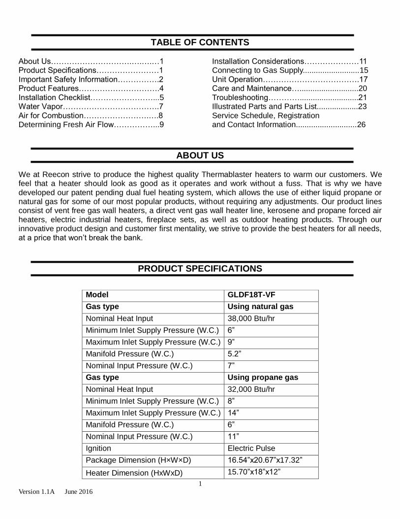
Model GLDF18T-VF
Gas type Using natural gas
Nominal Heat Input 38,000 Btu/hr
Minimum Inlet Supply Pressure (W.C.) 6”
Maximum Inlet Supply Pressure (W.C.) 9”
Manifold Pressure (W.C.) 5.2”
Nominal Input Pressure (W.C.) 7”
Gas type Using propane gas
Nominal Heat Input 32,000 Btu/hr
Minimum Inlet Supply Pressure (W.C.) 8”
Maximum Inlet Supply Pressure (W.C.) 14”
Manifold Pressure (W.C.) 6”
Nominal Input Pressure (W.C.) 11”
Ignition Electric Pulse
Package Dimension (H×W×D) 16.54”x20.67”x17.32”
Heater Dimension (HxWxD) 15.70”x18”x12”
2
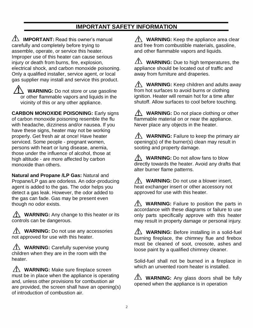
IMPORTANT SAFETY INFORMATION IMPORTANT: Read this owner’s manual
carefully and completely before trying to assemble, operate, or service this heater. Improper use of this heater can cause serious injury or death from burns, fire, explosion, electrical shock, and carbon monoxide poisoning. Only a qualified installer, service agent, or local gas supplier may install and service this product.
WARNING: Do not store or use gasoline
or other flammable vapors and liquids in the vicinity of this or any other appliance.
CARBON MONOXIDE POISONING: Early signs of carbon monoxide poisoning resemble the flu with headache, dizziness and/or nausea. If you have these signs, heater may not be working properly. Get fresh air at once! Have heater serviced. Some people - pregnant women, persons with heart or lung disease, anemia, those under the influence of alcohol, those at high altitude - are more affected by carbon monoxide than others.
Natural and Propane /LP Gas: Natural and Propane/LP gas are odorless. An odor-producing agent is added to the gas. The odor helps you detect a gas leak. However, the odor added to the gas can fade. Gas may be present even though no odor exists.
WARNING: Any change to this heater or its
controls can be dangerous.
WARNING: Do not use any accessories
not approved for use with this heater.
WARNING: Carefully supervise young children when they are in the room with the heater.
WARNING: Make sure fireplace screen must be in place when the appliance is operating and, unless other provisions for combustion air are provided, the screen shall have an opening(s) of introduction of combustion air.
WARNING: Keep the appliance area clear
and free from combustible materials, gasoline, and other flammable vapors and liquids.
WARNING: Due to high temperatures, the
appliance should be located out of traffic and away from furniture and draperies.
WARNING: Keep children and adults away
from hot surfaces to avoid burns or clothing ignition. Heater will remain hot for a time after shutoff. Allow surfaces to cool before touching.
WARNING: Do not place clothing or other
flammable material on or near the appliance. Never place any objects in the heater.
WARNING: Failure to keep the primary air
opening(s) of the burner(s) clean may result in sooting and property damage.
WARNING: Do not allow fans to blow
directly towards the heater. Avoid any drafts that alter burner flame patterns.
WARNING: Do not use a blower insert,
heat exchanger insert or other accessory not approved for use with this heater.
WARNING: Failure to position the parts in
accordance with these diagrams or failure to use only parts specifically approve with this heater may result in property damage or personal injury.
WARNING: Before installing in a solid-fuel
burning fireplace, the chimney flue and firebox must be cleaned of soot, creosote, ashes and loose paint by a qualified chimney cleaner. Solid-fuel shall not be burned in a fireplace in which an unvented room heater is installed.
WARNING: Any glass doors shall be fully
opened when the appliance is in operation
3
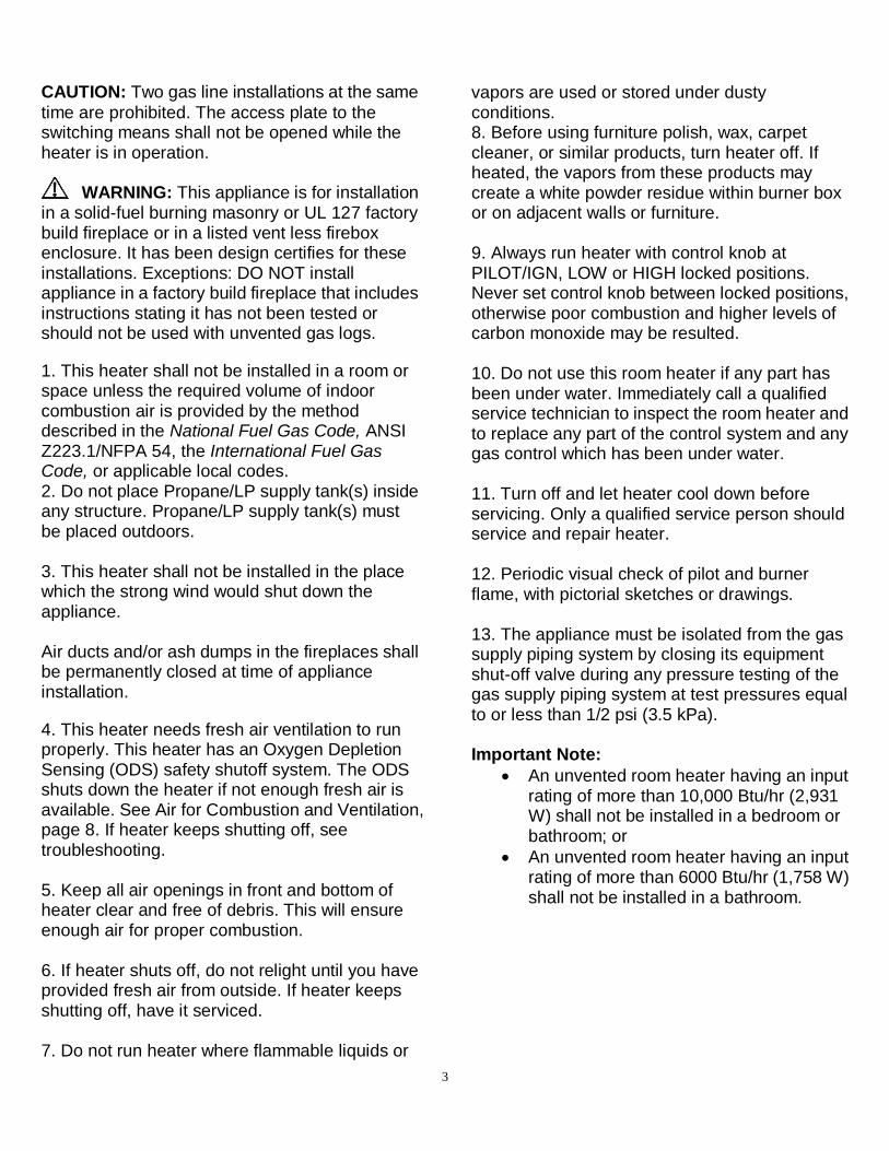
CAUTION: Two gas line installations at the same
time are prohibited. The access plate to the switching means shall not be opened while the heater is in operation.
WARNING: This appliance is for installation
in a solid-fuel burning masonry or UL 127 factory build fireplace or in a listed vent less firebox enclosure. It has been design certifies for these installations. Exceptions: DO NOT install appliance in a factory build fireplace that includes instructions stating it has not been tested or should not be used with unvented gas logs.
1. This heater shall not be installed in a room or space unless the required volume of indoor combustion air is provided by the method described in the National Fuel Gas Code, ANSI Z223.1/NFPA 54, the International Fuel Gas Code, or applicable local codes. 2. Do not place Propane/LP supply tank(s) inside any structure. Propane/LP supply tank(s) must be placed outdoors. 3. This heater shall not be installed in the place which the strong wind would shut down the appliance. Air ducts and/or ash dumps in the fireplaces shall be permanently closed at time of appliance installation.
4. This heater needs fresh air ventilation to run properly. This heater has an Oxygen Depletion Sensing (ODS) safety shutoff system. The ODS shuts down the heater if not enough fresh air is available. See Air for Combustion and Ventilation, page 8. If heater keeps shutting off, see troubleshooting. 5. Keep all air openings in front and bottom of heater clear and free of debris. This will ensure enough air for proper combustion. 6. If heater shuts off, do not relight until you have provided fresh air from outside. If heater keeps shutting off, have it serviced. 7. Do not run heater where flammable liquids or
vapors are used or stored under dusty conditions. 8. Before using furniture polish, wax, carpet cleaner, or similar products, turn heater off. If heated, the vapors from these products may create a white powder residue within burner box or on adjacent walls or furniture. 9. Always run heater with control knob at PILOT/IGN, LOW or HIGH locked positions. Never set control knob between locked positions, otherwise poor combustion and higher levels of carbon monoxide may be resulted. 10. Do not use this room heater if any part has been under water. Immediately call a qualified service technician to inspect the room heater and to replace any part of the control system and any gas control which has been under water. 11. Turn off and let heater cool down before servicing. Only a qualified service person should service and repair heater. 12. Periodic visual check of pilot and burner flame, with pictorial sketches or drawings. 13. The appliance must be isolated from the gas supply piping system by closing its equipment shut-off valve during any pressure testing of the gas supply piping system at test pressures equal to or less than 1/2 psi (3.5 kPa). Important Note:
An unvented room heater having an input rating of more than 10,000 Btu/hr (2,931 W) shall not be installed in a bedroom or bathroom; or
An unvented room heater having an input rating of more than 6000 Btu/hr (1,758 W) shall not be installed in a bathroom.

4
QUALIFIED INSTALLING AGENCY Only a qualified agency should install and replace gas piping, gas utilization equipment or accessories, repair and service the heater. The term “qualified agency” means any individual, firm, corporation, or company that either in person or through a representative is engaged in and is responsible for:
a) Installing, testing, or replacing gas piping or b) Connecting, installing, testing, repairing, or servicing equipment; that is experienced in such work; that is familiar with all precautions required; and that has complied with all the requirement of the authority having jurisdiction.
PRODUCT FEATURES
SAFETY PILOT
This heater has a pilot with an Oxygen Depletion Sensing (ODS) safety shutoff system. The ODS/pilot shuts off the heater if there is not enough fresh air.
PULSE IGNITION SYSTEM This heater is equipped with a battery powered electric pulse igniting system. No AC power supply required. Battery should be periodically checked and replaced accordingly. Use a “D” size (IEC R20 or LR20) 1.5 V battery only. GAS OPTIONS CAPABLE (Dual Fuel Models Only) (Models that start with GLDF)
If you have the dual fuel model, your heater is equipped to operate on either propane or natural gas. The heater will automatically identify your gas source without any manual changes. THERMOSTATIC CONTROL
These heaters have a control valve with a thermostat sensing bulb. This results in the greatest heater comfort and may result in lower gas bills. LOCAL CODES
Install and use heater with care. Follow all local codes. In the absence of local codes, use the latest edition of The National Fuel Gas Code, ANSI Z223.1/ NFPA 54.

5
INSTALLATION CHECKLIST Share this checklist with your professional installer
Manifold Pressure and Nominal Inlet Pressure for appropriate gas type o Using Natural Gas:
Minimum Inlet Pressure (W.C): 6” Manifold Pressure (W.C.): 5.2” Nominal Input Pressure (W.C.): 7”
o Using Propane Gas: Minimum Inlet Pressure (W.C): 8” Manifold Pressure (W.C.): 6” Nominal Input Pressure (W.C.): 11”
Clearances o 5” minimum from bottom of heater to Top Surface of Floor o 16” Minimum from sides to of Heater o 42” Minimum clearance from top surface of heater and up
Connected to gas supply using a 3/8th inch UNF inlet connection to a ½ inch gas pipe Unit is placed in a room that is a minimum of 1100 square feet. D size battery placed in heater. Adequate ventilation and fresh-air flow is appropriate for heater location The Air Shutter is pre-set for Liquid Propane use. If using Natural Gas, see Air Shutter section of
manual. Unit successfully tested
o Installed by: Company __________________________________________ Installer __________________________________________ Contact Info ________________________________________ Date ______________________________________________
Note to installer: Ensure that you are referencing the product manual for full details on each of the
installation steps, warnings and considerations. This list is to be used to confirm the steps as you move through the installation. Please leave this sheet with the user. *Do not attempt any modifications, repairs or replacements on this unit without first discussing with Thermablaster Technical Support. Doing so will void the product’s warranty. Professional Installation is required by all local and National codes.
Unit is not to be used as a central heating system

6
Preparing for Installation Before beginning assembly or operation of the product, make sure all parts are present. Compare parts with package contents list and diagram above. If any part is missing or damaged, do not attempt to assemble, install or operate the product. Contact customer service for replacement parts. Before installing heater, make sure you have the items listed below:
Figure 1 - Vent-Free Gas log
Control Knob Igniter Knob

7
UNPACKING
1. Remove heater from carton. 2. Remove all protective packaging applied to heater for shipping. 3. Check heater for any shipping damage. If heater is damaged, promptly inform dealer where you purchased heater. 4. Remove thread protective cup on the gas inlet pipe underneath the heater. 5. Install a D size battery. Battery must be removed if the heater is not in use for an extended period of time.
Figure 2 – Battery Cover
WATER VAPOR: A BY-PRODUCT OF UNVENTED ROOM HEATERS
Water vapor is a by-product of gas combustion. An unvented room heater produces approximately one (1) ounce (30 ml) of water for every 1,000 BTUs (0.3 KWs) of gas input per hour. Unvented room heaters are recommended as supplemental heat (a room) rather than a primary heat source (an entire house). In most supplemental heat applications, the water vapor does not create a problem. In most applications, the water vapor enhances the low humidity atmosphere experienced during cold weather. The following steps will help ensure that water vapor does not become a problem:
1. Be sure the heater is sized properly for the application, including ample combustion air and circulation air. 2. If high humidity is experienced, a dehumidifier may be used to help lower the water vapor content of the air. 3. Do not use an unvented room heater as the primary heat source.
8
AIR FOR COMBUSTION AND VENTILATION
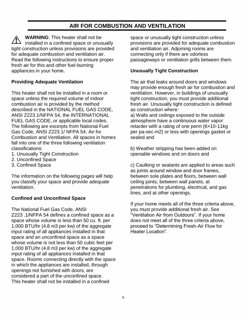
WARNING: This heater shall not be installed in a confined space or unusually
tight construction unless provisions are provided for adequate combustion and ventilation air. Read the following instructions to ensure proper fresh air for this and other fuel-burning appliances in your home. Providing Adequate Ventilation This heater shall not be installed in a room or space unless the required volume of indoor combustion air is provided by the method described in the NATIONAL FUEL GAS CODE, ANSI Z223.1/NFPA 54, the INTERNATIONAL FUEL GAS CODE, or applicable local codes. The following are excerpts from National Fuel Gas Code, ANSI Z223.1/ NFPA 54. Air for Combustion and Ventilation. All spaces in homes fall into one of the three following ventilation classifications: 1. Unusually Tight Construction 2. Unconfined Space 3. Confined Space The information on the following pages will help you classify your space and provide adequate ventilation. Confined and Unconfined Space
The National Fuel Gas Code, ANSI Z223 .1/NFPA 54 defines a confined space as a space whose volume is less than 50 cu. ft. per 1,000 BTU/hr (4.8 m3 per kw) of the aggregate input rating of all appliances installed in that space and an unconfined space as a space whose volume is not less than 50 cubic feet per 1,000 BTU/hr (4.8 m3 per kw) of the aggregate input rating of all appliances installed in that space. Rooms connecting directly with the space in which the appliances are installed, through openings not furnished with doors, are considered a part of the unconfined space. This heater shall not be installed in a confined
space or unusually tight construction unless provisions are provided for adequate combustion and ventilation air. Adjoining rooms are connecting only if there are odorless passageways or ventilation grills between them. Unusually Tight Construction The air that leaks around doors and windows may provide enough fresh air for combustion and ventilation. However, in buildings of unusually tight construction, you must provide additional fresh air. Unusually tight construction is defined as construction where: a) Walls and ceilings exposed to the outside atmosphere have a continuous water vapor retarder with a rating of one perm (6×10-11kg per pa-sec-m2) or less with openings gasket or sealed and b) Weather stripping has been added on openable windows and on doors and c) Caulking or sealants are applied to areas such as joints around window and door frames, between sole plates and floors, between wall ceiling joints, between wall panels, at penetrations for plumbing, electrical, and gas lines, and at other openings. If your home meets all of the three criteria above, you must provide additional fresh air. See “Ventilation Air from Outdoors”. If your home does not meet all of the three criteria above, proceed to “Determining Fresh-Air Flow for Heater Location”.
9
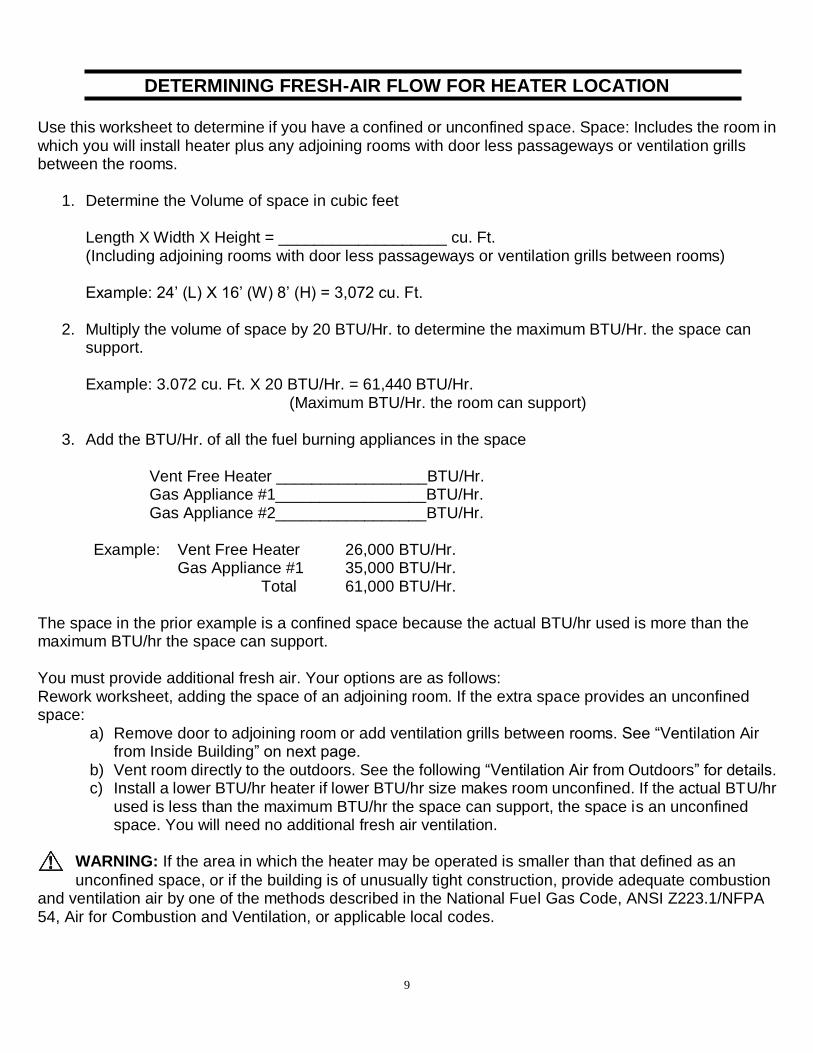
DETERMINING FRESH-AIR FLOW FOR HEATER LOCATION Use this worksheet to determine if you have a confined or unconfined space. Space: Includes the room in which you will install heater plus any adjoining rooms with door less passageways or ventilation grills between the rooms.
1. Determine the Volume of space in cubic feet Length X Width X Height = ___________________ cu. Ft. (Including adjoining rooms with door less passageways or ventilation grills between rooms) Example: 24’ (L) X 16’ (W) 8’ (H) = 3,072 cu. Ft.
2. Multiply the volume of space by 20 BTU/Hr. to determine the maximum BTU/Hr. the space can support. Example: 3.072 cu. Ft. X 20 BTU/Hr. = 61,440 BTU/Hr. (Maximum BTU/Hr. the room can support)
3. Add the BTU/Hr. of all the fuel burning appliances in the space
Vent Free Heater _________________BTU/Hr. Gas Appliance #1_________________BTU/Hr. Gas Appliance #2_________________BTU/Hr.
Example: Vent Free Heater 26,000 BTU/Hr. Gas Appliance #1 35,000 BTU/Hr. Total 61,000 BTU/Hr. The space in the prior example is a confined space because the actual BTU/hr used is more than the maximum BTU/hr the space can support. You must provide additional fresh air. Your options are as follows: Rework worksheet, adding the space of an adjoining room. If the extra space provides an unconfined space:
a) Remove door to adjoining room or add ventilation grills between rooms. See “Ventilation Air from Inside Building” on next page.
b) Vent room directly to the outdoors. See the following “Ventilation Air from Outdoors” for details. c) Install a lower BTU/hr heater if lower BTU/hr size makes room unconfined. If the actual BTU/hr
used is less than the maximum BTU/hr the space can support, the space is an unconfined space. You will need no additional fresh air ventilation.
WARNING: If the area in which the heater may be operated is smaller than that defined as an
unconfined space, or if the building is of unusually tight construction, provide adequate combustion and ventilation air by one of the methods described in the National Fuel Gas Code, ANSI Z223.1/NFPA 54, Air for Combustion and Ventilation, or applicable local codes.

10
WARNING: If the area in which the heater may be operated does not meet the required volume for
indoor combustion air, combustion and ventilation air shall be provided by one of the methods described in the National Fuel Gas Code, ANSI Z223.1/NFPA 54, the International Fuel Gas Code, or applicable local codes. Ventilation Air from Inside Building This fresh air would come from an adjoining unconfined space. When ventilating to an adjoining unconfined space, you must provide two permanent openings: one within 12 inches of the ceiling and one within 12 inches of the floor on the wall connecting the two spaces (Figure 3). You can also remove the door into adjoining room (see option 3, Figure 3). Follow the National Fuel Gas Code. ANSI Z223.1/NFPA 54, Air for Combustion and Ventilation for required size of ventilation grills or ducts. Ventilation Air from Outdoors
Provide extra fresh air by using ventilation grills or ducts. You must provide two permanent openings: one within 12 inches of the ceiling and one within 12 inches of the floor. Connect these items directly to the outdoors or spaces open to the outdoors. These spaces include attics and crawl spaces. Follow the National Fuel Gas Code, ANSI Z223.1/ NFPA 54, Air for Combustion and Ventilation for required size of ventilation grills or ducts.
IMPORTANT: Do not provide openings for inlet or outlet air into attic if attic has a thermostat-controlled power vent. Heated air entering the attic will activate the power vent. Rework
worksheet, adding the space of the adjoining unconfined space. The combined spaces must have enough fresh air to supply all appliances in both spaces.
Figure 3 - Ventilation Air from Inside Building NOTE: Base not included. Not for use in bedrooms or bathrooms.
Figure 4 - Ventilation Air from Outdoors
11
INSTALLATION CONSIDERATIONS This heater is intended for use as supplemental heat. Use this heater along with your primary heating system. Do not install this heater as your primary heat source. If you have a central heating system, you may run system’s circulating blower while using heater. This will help circulate the heat throughout the house. In the event of a power outage, you can use this heater as your primary heat source.
WARNING: A qualified service person must install heater. Follow all local codes.
WARNING: Never install the heater:
in a recreational vehicle where curtains, furniture, clothing, or other flammable objects are less than 36 inches from the
front, top, or sides of the heater in high traffic areas in windy or drafty areas
CAUTION: This heater creates warm air currents. These currents move heat to wall surfaces next to heater. Installing heater next to vinyl or cloth wall coverings or operating heater where impurities (such as tobacco smoke, aromatic candles, cleaning fluids, oil or kerosene lamps, etc.) in the air exist, may cause walls to discolor.
IMPORTANT: Vent-free heaters add moisture to the air. Although this is beneficial, installing heater in rooms without enough ventilation air may cause mildew to form too much moisture. See Air for Combustion and Ventilation. Check Gas Type Be sure your gas supply is right for your heater. Otherwise, call dealer where you bought the heater from for proper type heater. Clearances to Combustibles
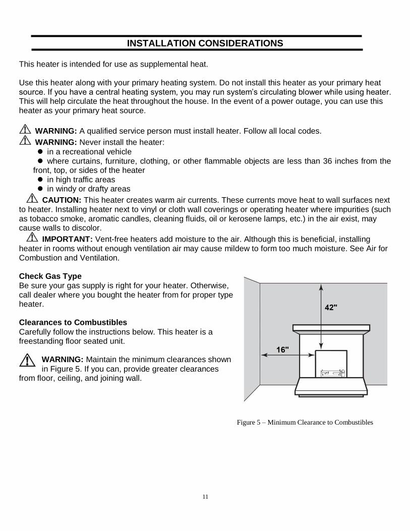
Carefully follow the instructions below. This heater is a freestanding floor seated unit.
WARNING: Maintain the minimum clearances shown
in Figure 5. If you can, provide greater clearances from floor, ceiling, and joining wall.
Figure 5 – Minimum Clearance to Combustibles
12
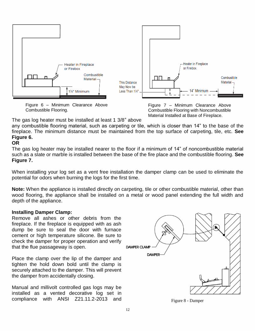
The gas log heater must be installed at least 1 3/8” above any combustible flooring material, such as carpeting or tile, which is closer than 14” to the base of the fireplace. The minimum distance must be maintained from the top surface of carpeting, tile, etc. See Figure 6. OR
The gas log heater may be installed nearer to the floor if a minimum of 14” of noncombustible material such as a slate or marble is installed between the base of the fire place and the combustible flooring. See Figure 7. When installing your log set as a vent free installation the damper clamp can be used to eliminate the potential for odors when burning the logs for the first time. Note: When the appliance is installed directly on carpeting, tile or other combustible material, other than
wood flooring, the appliance shall be installed on a metal or wood panel extending the full width and depth of the appliance. Installing Damper Clamp:
Remove all ashes or other debris from the fireplace. If the fireplace is equipped with as ash dump be sure to seal the door with furnace cement or high temperature silicone. Be sure to check the damper for proper operation and verify that the flue passageway is open. Place the clamp over the lip of the damper and tighten the hold down bold until the clamp is securely attached to the damper. This will prevent the damper from accidentally closing. Manual and millivolt controlled gas logs may be installed as a vented decorative log set in compliance with ANSI Z21.11.2-2013 and
Figure 6 – Minimum Clearance Above Combustible Flooring.
Figure 7 – Minimum Clearance Above Combustible Flooring with Noncombustible
Material Installed at Base of Fireplace.
Figure 8 - Damper
13
National Fuel Gas Code. When the gas logs are operated with the damper open, Non-Combustible material and minimum mantel requirements do not apply. Note: When installing your log set as a vented installation the damper clamp (Not Provided in hardware)
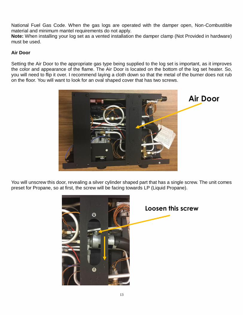
must be used. Air Door Setting the Air Door to the appropriate gas type being supplied to the log set is important, as it improves the color and appearance of the flame. The Air Door is located on the bottom of the log set heater. So, you will need to flip it over. I recommend laying a cloth down so that the metal of the burner does not rub on the floor. You will want to look for an oval shaped cover that has two screws.
You will unscrew this door, revealing a silver cylinder shaped part that has a single screw. The unit comes preset for Propane, so at first, the screw will be facing towards LP (Liquid Propane).
Air Door
Loosen this screw
14
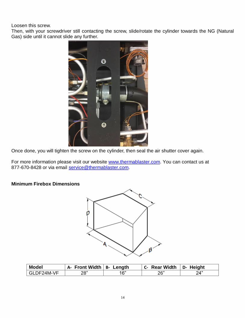
Loosen this screw. Then, with your screwdriver still contacting the screw, slide/rotate the cylinder towards the NG (Natural Gas) side until it cannot slide any further.
Once done, you will tighten the screw on the cylinder, then seal the air shutter cover again. For more information please visit our website www.thermablaster.com. You can contact us at 877-670-8428 or via email [email protected]. Minimum Firebox Dimensions
Model A- Front Width B- Length C- Rear Width D- Height
GLDF24M-VF 28” 16” 26” 24”
15
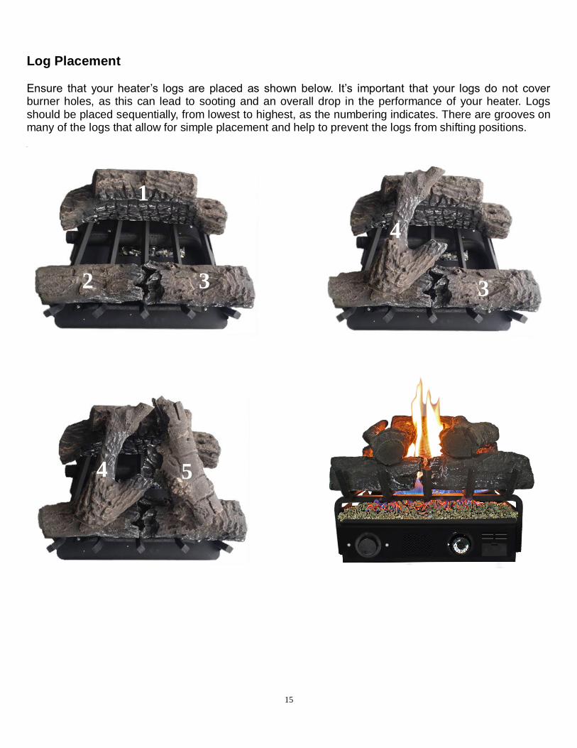
Log Placement Ensure that your heater’s logs are placed as shown below. It’s important that your logs do not cover burner holes, as this can lead to sooting and an overall drop in the performance of your heater. Logs should be placed sequentially, from lowest to highest, as the numbering indicates. There are grooves on many of the logs that allow for simple placement and help to prevent the logs from shifting positions.
2 3
4
5
1
3
4
16
CONNECTING TO GAS SUPPLY
WARNING: A qualified service technician must connect heater
to gas supply. Follow the heater specification and all local codes. Wrong gas supply may result improper operation, or damage on your heater, property or/and personal body.
WARNING: This appliance requires a 3/8-inch UNF (Unified National Fine) inlet connection to the pressure regulator.
WARNING: Never connect heater to private (non-utility) gas
wells. This gas is commonly known as wellhead gas. WARNING: Do not over-tighten gas connections.
CAUTION: Use only new, black iron or steel pipe. Internally tinned copper tubing may be used in certain areas. Check your local codes. Use pipe of 1/2-in. diameter or greater to allow proper gas
volume to heater. If pipe is too small, undue loss of pressure will occur. NATURAL GAS MODELS:
CAUTION: Check your gas line pressure before connecting heater to gas line. Gas line pressure must be no greater than 8 inches of water column. If gas line pressure is higher, damage on
appliance regulator could occur.
PROPANE MODELS: CAUTION: Never connect heater directly to the gas supply. This heater requires an external
regulator (not supplied). Install the external regulator between the heater and gas supply. CAUTION: Avoid damage to regulator. Hold gas regulator with wrench when connecting into gas
piping and/or fittings. CAUTION: Use pipe joint sealant that is resistant to gas (Propane or Natural Gas).
IMPORTANT: Install an equipment shutoff valve in an accessible location where the gas pipe goes
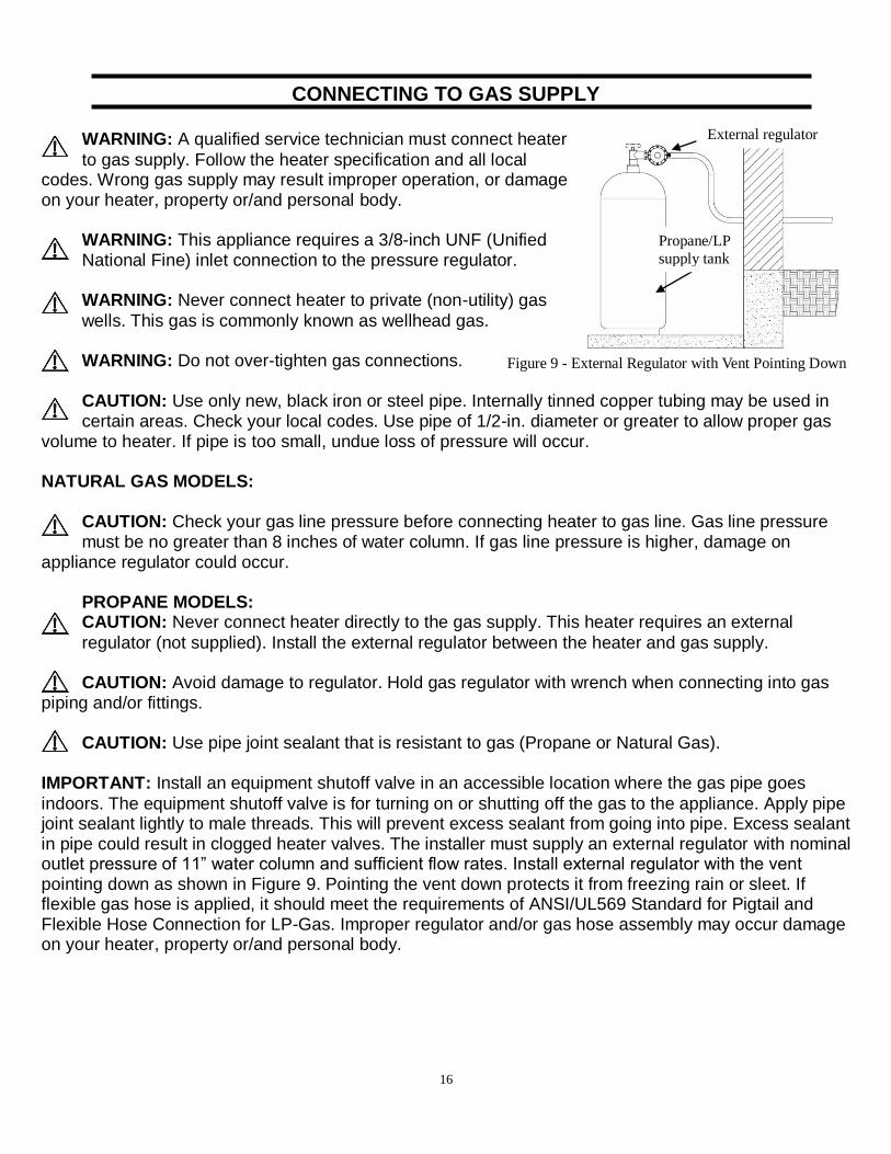
indoors. The equipment shutoff valve is for turning on or shutting off the gas to the appliance. Apply pipe joint sealant lightly to male threads. This will prevent excess sealant from going into pipe. Excess sealant in pipe could result in clogged heater valves. The installer must supply an external regulator with nominal outlet pressure of 11” water column and sufficient flow rates. Install external regulator with the vent pointing down as shown in Figure 9. Pointing the vent down protects it from freezing rain or sleet. If flexible gas hose is applied, it should meet the requirements of ANSI/UL569 Standard for Pigtail and Flexible Hose Connection for LP-Gas. Improper regulator and/or gas hose assembly may occur damage on your heater, property or/and personal body.
Propane/LP
supply tank
External regulator
Figure 9 - External Regulator with Vent Pointing Down
17
CAUTION: Two gas lines installation at the same time is forbidden. Do not the open cover while the
heater is running. CAUTION: To avoid gas leakage at the inlet of appliance regulator, a qualified installer or service technician must use steel or metal hex plug with sealant.
Changing from Liquid Propane to Natural Gas supply: 1. Your heater is equipped with a unique automatic gas source detection and configuration system,
allowing it to perform using both liquid propane and natural gas without any manual conversion. 2. Only a qualified installer or service technician can perform gas type conversion from between liquid
propane and natural gas supply. This is due to the type of connection and installation required external the heater.
CHECKING GAS CONNECTIONS
WARNING: Test all gas piping and connections for leaks after installing or servicing. Correct all
leaks at once. WARNING: Never use an open flame to check for a leak. Apply a mixture of liquid soap and water to
all joints. If bubbles form, there is a leak. Correct all leaks at once. Pressure Testing Gas Supply Piping System Test Pressures in Excess of 1/2 PSIG (3.5kPa)
1. Disconnect heater with its appliance main gas valve (control valve) and equipment shutoff valve from gas supply piping system. Pressures in excess of 1/2 PSIG will damage heater regulator. 2. Cap off open end of gas pipe where equipment shutoff valve was connected. 3. Pressurize supply piping system by either using compressed air or opening gas supply valve. 4. Check all joints of gas supply piping system. Apply mixture of liquid soap and water to gas joints. If bubbles form, there may be a leak. 5. Correct all leaks at once. 6. Reconnect heater and equipment shutoff valve to gas supply. Check reconnected fittings for leaks. Test Pressures Equal to or Less Than 1/2 PSIG (3.5 kPa) 1. Close equipment shutoff valve 2. Pressurize supply piping system by either using compressed air or opening natural supply tank valve. 3. Check all joints from gas meter to equipment shutoff valve. Apply mixture of liquid soap and water to gas joints. If bubbles form, there is a leak. 4. Correct all leaks at once. Pressure Testing Heater Gas Connections
1. Open equipment shutoff valve. 2. Open gas supply tank valve. 3. Make sure control knob of heater is in the OFF position. 4. Check all joints from equipment shutoff valve to control valve. Apply mixture of liquid soap and water to gas joints. If bubbles form, there may be a leak. 5. Correct all leaks at once.

18
UNIT OPERATION FOR YOUR SAFETY READ BEFORE LIGHTING
WARNING: If you do not follow these instructions exactly, a fire or explosion may result causing
property damage, personal injury or loss of life. 1. When lighting the pilot, follow these instructions exactly. 2. BEFORE LIGHTING, smell all around the appliance area for gas. Be sure to smell next to the floor
because some gas is heavier than air and will settle on the floor. 3. Use only your hand to push in or turn the gas control knob. Never use tools. If the knob will not push in
or turn by hand, don’t try to repair it, call a qualified service technician or gas supplier. Forced or attempted repair may result in a fire or explosion.
4. Do not use this appliance if any part has been under water. Immediately call a qualified service technician to inspect the appliance and to replace any part of the control system and any gas control which has been under water.
WHAT TO DO IF YOU SMELL GAS Open the window or door immediately. Do not try to light any appliance. Do not touch any electric switch, do not use any phone in your building. Immediately call your gas supplier from a neighbor’s phone. Follow the gas supplier’s instructions. If you cannot reach your gas supplier, call the fire department. LIGHTING INSTRUCTIONS Before Lighting:
1. Make sure the heater is properly installed and connected. Open the external safety shut off valve (not part of the heater) on gas inlet line to the heater.
2. Wait five (5) minutes to clear out air inside gas lines. Smell if there is any leakage.
IMPORTANT: If you smell any gas, do not try to light any appliances, do not touch electrical switches or use any phone in the building. Shut off the valve on gas inlet line immediately and contact gas supplier from a neighbor’s phone. Follow gas supplier’s instructions. If you can’t reach the gas supplier, call the fire department. Only when you make sure there is no gas leakage, go to the next step. Note: During first seasonal use, gas smell is expected to be more noticeable than in standard operation.
19
Ignition Process:
1. During the first seasonal operation, set the Control Knob to Pilot, then hold down on the Control Knob for 3-5 minutes. This allows the air in the manifests to clear completely. During normal operation, you will only need to hold the Control Knob down on Pilot for about 5 seconds.
2. With the Control Knob set to Pilot, push down on both the Igniter Button and the Control Knob simultaneously until ignition can be heard. Continue to hold down both buttons for at least 15 seconds, until the pilot is touching the thermocouple and is noticeably heated.
3. Release both buttons. Should the pilot go out, repeat steps 2 and 3.
4. Once the pilot flame is stable, turn the Control Knob counterclockwise from the Pilot setting
to the desired number setting. This should be done slowly in one motion, without stopping between positions. Knob will only turn if you have a stable pilot light. the heater will now operate normally.
5. Adjust the Control Knob to your desired heat setting. Room temperature will vary based on individual room size and installation.
Shutdown Process:
To stop the heater, shut off the safety valve on the gas inlet line. Next, turn the Control Knob to the OFF position.
Note: Adjustable temperature settings determine the length of time that the heater will operate at
maximum BTU to achieve desired temperature, not the actual flame height. INSPECTING BURNER Check pilot flame pattern and burner flame pattern often.
PILOT FLAME PATTERN Two pilot burners with ODS function for NAT and LP gas respectively are installed on burners two sides separately as shown in Figure. 11. The normal ODS pilot flame should have a correct pattern as shown in Figure. 12 in normal operation with exception during ignition stage.

20
Figure 10 – Control Panel
Figure 11 – Pilot System
Figure 12 – Pilot Blue Flame
21
CARE AND MAINTENANCE WARNING: Turn off heater and let cool before servicing
CAUTION: You must keep control areas, burner, and circulating air passageways of the heater
clean. Inspect these areas of heater before each use. Have heater inspected yearly by a qualified service technician. Heater may need more frequent cleaning due to excessive lint from carpeting, bedding material, pet hair, etc. Installation and repair should be done by a qualified service person. The appliance should be inspected before use and at least annually by a professional service person. More frequent cleaning be may require due to excessive lint from carpeting, bedding material, pet hair, etc. ODS/PILOT AND BURNER
Use a vacuum cleaner, pressurized air, or a small, soft bristled brush to clean. CLEANING BURNER PILOT AIR INLET HOLE We recommend that you clean the unit every 2,500 hours of operation or every three months. We also recommend that you keep the burner tube and pilot assembly clean and free of dust and dirt. To clean these parts, we recommend using compressed air no greater than 30 PSl. Your local computer store, hardware store, or home center may carry compressed air in a can. You can use a vacuum cleaner in the blow position. If using compressed air in a can, please follow the directions on the can. If you don’t follow directions on the can, you could damage the pilot assembly. 1. Shut off the unit, including the pilot. Allow the unit to cool for at least thirty minutes. 2. Inspect burner and pilot for dust and dirt. 3. Blow air through the ports/slots and holes in the burner. Also clean the pilot assembly. A yellow tip on the pilot flame indicates dust and dirt in the pilot assembly. There is a small pilot air inlet hole about two inches from where the pilot flame comes out of the pilot assembly (see Figure 11). With the unit off, lightly blow air through the air inlet hole. You may blow through a drinking straw if compressed air is not available. CABINET Air Passageways Use a vacuum cleaner or pressurized air to clean. Exterior
1) Use a soft cloth dampened with a mild soap and water mixture. 2) Wipe the cabinet to remove dust.
22
TROUBLESHOOTING
WARNING: If you smell gas:
Open the window and door immediately.
Shut off gas supply.
Do not try to light any appliance.
Do not touch any electrical switch; do not use any phone in your building.
Immediately call your gas supplier from a neighbor’s phone. Follow the gas supplier’s instructions.
If you cannot reach your gas supplier, call the fire department.
IMPORTANT: Operating heater where impurities in air exist may create odors. Cleaning supplies,
paint, paint remover, cigarette smoke, cements and glues, new carpet or textiles, etc., create fumes. These fumes may mix with combustion air and create odors.
WARNING: Only a qualified service technician should service and repair heater. CAUTION: Never use a wire, needle, or similar object to clean ODS/pilot. This can damage ODS/
pilot unit. Note: All troubleshooting items are listed in order of operation.
23
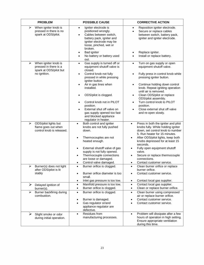
PROBLEM POSSIBLE CAUSE CORRECTIVE ACTION
When igniter knob is pressed in there is no spark at ODS/pilot.
Igniter electrode is positioned wrongly.
Cables between switch, battery pack, igniter and igniter electrode may be loose, pinched, wet or broken.
Bad igniter
No battery or battery used out.
Reposition igniter electrode.
Secure or replace cables between switch, battery pack, igniter and igniter electrode.
Replace igniter.
Install or replace battery.
When igniter knob is pressed in there is a spark at ODS/pilot but no ignition.
Gas supply is turned off or equipment shutoff valve is closed.
Control knob not fully pressed in while pressing igniter button.
Air in gas lines when installed.
ODS/pilot is clogged.
Control knob not in PILOT position.
External shut off valve on gas supply opened too fast and blocked appliance regulator in heater.
Turn on gas supply or open equipment shutoff valve.
Fully press in control knob while pressing igniter button.
Continue holding down control knob. Repeat igniting operation until air is removed.
Clean ODS/pilot or replace ODS/pilot assembly.
Turn control knob to PILOT position.
Close external shut off valve and re-open slowly.
ODS/pilot lights but flame goes out when control knob is released.
Both control and igniter knobs are not fully pushed down.
Thermocouples are not heated enough.
External shutoff valve of gas supply is not fully opened.
Thermocouple connections are loose or damaged.
Control valve damaged.
Press in both the igniter and pilot knobs fully. While holding igniter down, set control knob to number 5. Run heater for 15 minutes.
After ODS/pilot lights, keep both knobs depressed for at least 15 seconds.
Fully open equipment shutoff valve.
Secure or replace thermocouple connections.
Contact customer service.
Burner(s) does not light after ODS/pilot is lit stably
Burner orifice is clogged.
Burner orifice diameter is too small.
Inlet gas pressure is too low.
Clean burner orifice or replace burner orifice.
Contact customer service.
Contact local gas supplier.
Delayed ignition of burner(s).
Manifold pressure is too low.
Burner orifice is clogged.
Contact local gas supplier.
Clean or replace burner orifice.
Burner backfiring during combustion.
Burner orifice is clogged.
Burner is damaged.
Gas regulator or/and appliance regulator are defective.
Clean burner using compressed air or replace burner orifice.
Contact customer service.
Contact customer service.
Slight smoke or odor during initial operation.
Residues from manufacturing processes.
Problem will dissipate after a few hours of operation in high setting. Ensure appropriate ventilation during this time.
24
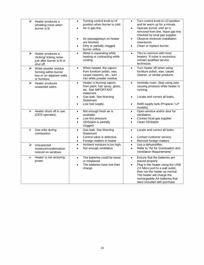
Heater produces a whistling noise when burner is lit.
Turning control knob to Hi position when burner is cold.
Air in gas line.
Air passageways on heater are blocked.
Dirty or partially clogged burner orifice.
Turn control knob to LO position and let warm up for a minute.
Operate burner until air is removed from line. Have gas line checked by local gas supplier.
Observe minimum installation clearances
Clean or replace burner.
Heater produces a clicking/ ticking noise just after burner is lit or shut off.
Metal is expanding while heating or contracting while cooling.
This is common with most heaters. If noise is excessive, contact qualified service technician.
White powder residue forming within burner box or on adjacent walls or furniture.
When heated, the vapors from furniture polish, wax, carpet cleaners, etc., turn into white powder residue.
Turn heater off when using furniture polish, wax, carpet cleaner, or similar products.
Heater produces unwanted odors.
Heater is burning vapors from paint, hair spray, glues, etc. See IMPORTANT statement.
Gas leak. See Warning Statement
Low fuel supply.
Ventilate room. Stop using odor causing products while heater is running.
Locate and correct all leaks,
Refill supply tank (Propane / LP models).
Heater shuts off in use (ODS operates).
Not enough fresh air is available.
Low line pressure.
ODS/pilot is partially clogged.
Open window and/or door for ventilation.
Contact local gas supplier.
Clean ODS/pilot
Gas odor during combustion
Gas leak. See Warning Statement
Control valve is defective.
Foreign matters in heater
Locate and correct all leaks.
Contact customer service.
Remove foreign matters
Unexpected moisture/condensation noticed on windows.
Ambient moisture is too high,
Not enough ventilation
Use a dehumidifier,
Refer to “Air for Combustion and Ventilation Requirements”
Heater is not receiving power
The batteries could be loose or misplaced
The batteries have lost their charge
Ensure that the batteries are placed properly
Plug in the heater using the USB 2.0 Micro port to a wall outlet, then run the heater as normal. The heater will charge the rechargeable AA batteries that were included with purchase

25
ILLUSTRATED PARTS (Model: GLDF18T-VF)
26
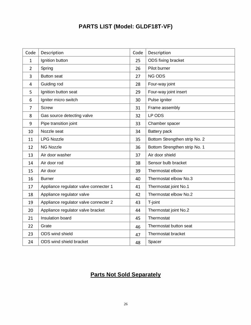
PARTS LIST (Model: GLDF18T-VF)
Code Description Code Description
1 Ignition button 25 ODS fixing bracket
2 Spring 26 Pilot burner
3 Button seat 27 NG ODS
4 Guiding rod 28 Four-way joint
5 Ignition button seat 29 Four-way joint insert
6 Igniter micro switch 30 Pulse igniter
7 Screw 31 Frame assembly
8 Gas source detecting valve 32 LP ODS
9 Pipe transition joint 33 Chamber spacer
10 Nozzle seat 34 Battery pack
11 LPG Nozzle 35 Bottom Strengthen strip No. 2
12 NG Nozzle 36 Bottom Strengthen strip No. 1
13 Air door washer 37 Air door shield
14 Air door rod 38 Sensor bulb bracket
15 Air door 39 Thermostat elbow
16 Burner 40 Thermostat elbow No.3
17 Appliance regulator valve connecter 1 41 Thermostat joint No.1
18 Appliance regulator valve 42 Thermostat elbow No.2
19 Appliance regulator valve connecter 2 43 T-joint
20 Appliance regulator valve bracket 44 Thermostat joint No.2
21 Insulation board 45 Thermostat
22 Grate 46 Thermostat button seat
23 ODS wind shield 47 Thermostat bracket
24 ODS wind shield bracket 48 Spacer
Parts Not Sold Separately

27
Questions about installation and initial operation should be directed to your installer. For all other concerns and questions, please reach out to our customer service team at 1-877-670-8428, by email at [email protected], or visit www.thermablaster.com
Annual Service Schedule
Service Performed Service Date
Please register your product online at www.thermablaster.com, or send in the registration form below to our office at: Reecon North America 2515 Liberty Ave Pittsburgh, PA 15222
-------------------------------------------------------------------------------------------------------- Contact Information Product Information
Name: Model:
Phone: Serial Number:
Email: Date of Purchase: Address:
Retailer Purchased From:
City: Installer Company:
State: Installer Phone:
Zip Code: Installer Zip Code: **All information above is required in order for our company to honor the warranty**
Comments:
Related Documents