• Heating • Daikin Altherma 45 • Daikin Altherma High Temperature • Outdoor units • ERSQ-AAY1 TABLE OF CONTENTS ERSQ-AAY1 1 Features . . . . . . . . . . . . . . . . . . . . . . . . . . . . . . . . . . . . . . . . . . . . . . . . . . . . . . . . . . . . 46 2 Specifications . . . . . . . . . . . . . . . . . . . . . . . . . . . . . . . . . . . . . . . . . . . . . . . . . . . . . . 47 Nominal Capacity and Nominal Input . . . . . . . . . . . . . . . . . . . . . . . . . . . . . . . 47 Technical Specifications . . . . . . . . . . . . . . . . . . . . . . . . . . . . . . . . . . . . . . . . . . . . 47 Electrical Specifications . . . . . . . . . . . . . . . . . . . . . . . . . . . . . . . . . . . . . . . . . . . . . 48 3 Capacity tables . . . . . . . . . . . . . . . . . . . . . . . . . . . . . . . . . . . . . . . . . . . . . . . . . . . . 49 Heating capacity tables . . . . . . . . . . . . . . . . . . . . . . . . . . . . . . . . . . . . . . . . . . . . . 49 4 Dimensional drawing & centre of gravity . . . . . . . . . . . . . . . . . . . . . . . 50 Dimensional drawing . . . . . . . . . . . . . . . . . . . . . . . . . . . . . . . . . . . . . . . . . . . . . . . . 50 Centre of gravity . . . . . . . . . . . . . . . . . . . . . . . . . . . . . . . . . . . . . . . . . . . . . . . . . . . . 51 5 Piping diagram . . . . . . . . . . . . . . . . . . . . . . . . . . . . . . . . . . . . . . . . . . . . . . . . . . . . . 52 6 Wiring diagram. . . . . . . . . . . . . . . . . . . . . . . . . . . . . . . . . . . . . . . . . . . . . . . . . . . . . 53 Wiring diagram . . . . . . . . . . . . . . . . . . . . . . . . . . . . . . . . . . . . . . . . . . . . . . . . . . . . . . 53 7 Sound data . . . . . . . . . . . . . . . . . . . . . . . . . . . . . . . . . . . . . . . . . . . . . . . . . . . . . . . . . 54 Sound pressure spectrum . . . . . . . . . . . . . . . . . . . . . . . . . . . . . . . . . . . . . . . . . . . 54 Sound power spectrum . . . . . . . . . . . . . . . . . . . . . . . . . . . . . . . . . . . . . . . . . . . . . 55 8 Operation range . . . . . . . . . . . . . . . . . . . . . . . . . . . . . . . . . . . . . . . . . . . . . . . . . . . 56

Welcome message from author
This document is posted to help you gain knowledge. Please leave a comment to let me know what you think about it! Share it to your friends and learn new things together.
Transcript

• Heating • Daikin Altherma 45
• Daikin Altherma High Temperature • Outdoor units • ERSQ-AAY1
TABLE OF CONTENTS
ERSQ-AAY1
1 Features . . . . . . . . . . . . . . . . . . . . . . . . . . . . . . . . . . . . . . . . . . . . . . . . . . . . . . . . . . . . 46
2 Specifications . . . . . . . . . . . . . . . . . . . . . . . . . . . . . . . . . . . . . . . . . . . . . . . . . . . . . . 47
Nominal Capacity and Nominal Input . . . . . . . . . . . . . . . . . . . . . . . . . . . . . . . 47
Technical Specifications . . . . . . . . . . . . . . . . . . . . . . . . . . . . . . . . . . . . . . . . . . . . 47
Electrical Specifications . . . . . . . . . . . . . . . . . . . . . . . . . . . . . . . . . . . . . . . . . . . . . 48
3 Capacity tables . . . . . . . . . . . . . . . . . . . . . . . . . . . . . . . . . . . . . . . . . . . . . . . . . . . . 49
Heating capacity tables . . . . . . . . . . . . . . . . . . . . . . . . . . . . . . . . . . . . . . . . . . . . . 49
4 Dimensional drawing & centre of gravity . . . . . . . . . . . . . . . . . . . . . . . 50
Dimensional drawing . . . . . . . . . . . . . . . . . . . . . . . . . . . . . . . . . . . . . . . . . . . . . . . . 50
Centre of gravity . . . . . . . . . . . . . . . . . . . . . . . . . . . . . . . . . . . . . . . . . . . . . . . . . . . . 51
5 Piping diagram . . . . . . . . . . . . . . . . . . . . . . . . . . . . . . . . . . . . . . . . . . . . . . . . . . . . . 52
6 Wiring diagram. . . . . . . . . . . . . . . . . . . . . . . . . . . . . . . . . . . . . . . . . . . . . . . . . . . . . 53
Wiring diagram . . . . . . . . . . . . . . . . . . . . . . . . . . . . . . . . . . . . . . . . . . . . . . . . . . . . . . 53
7 Sound data . . . . . . . . . . . . . . . . . . . . . . . . . . . . . . . . . . . . . . . . . . . . . . . . . . . . . . . . . 54
Sound pressure spectrum . . . . . . . . . . . . . . . . . . . . . . . . . . . . . . . . . . . . . . . . . . . 54
Sound power spectrum . . . . . . . . . . . . . . . . . . . . . . . . . . . . . . . . . . . . . . . . . . . . . 55
8 Operation range . . . . . . . . . . . . . . . . . . . . . . . . . . . . . . . . . . . . . . . . . . . . . . . . . . . 56

• Daikin Altherma High Temperature • Outdoor units • ERSQ-AAY1
• Heating • Daikin Altherma46
1 Features
41
Daikin Alth Heating ERSQ-AAY1 Outdoor uni • High temperature application: up to 80°C without electric heater
• Three phase large capacity outdoor unit
• Operation of unit guaranteed down to -20°C
• Cost effective alternative to a fossil fuel boiler
• Low energy bills and low CO2 emissions
• Easy to install
• Total solution for year round comfort
• Heating • Daikin Altherma 47
• Daikin Altherma High Temperature • Outdoor units • ERSQ-AAY1
2 Specifications
42
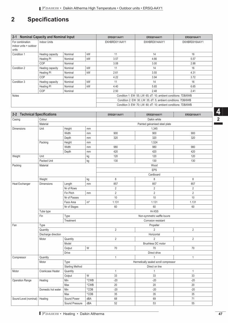
2-1 Nominal Capacity and Nominal Input ERSQ011AAY1 ERSQ014AAY1 ERSQ016AAY1
For combination
indoor units + outdoor
units
Indoor Units EKHBRD011AAY1 EKHBRD014AAY1 EKHBRD016AAY1
Condition 1 Heating capacity Nominal kW 11 14 16
Heating PI Nominal kW 3.57 4.66 5.57
COP Nominal 3.08 3.00 2.88
Condition 2 Heating capacity Nominal kW 11 14 16
Heating PI Nominal kW 2.61 3.55 4.31
COP Nominal 4.22 3.94 3.72
Condition 3 Heating capacity Nominal kW 11 14 16
Heating PI Nominal kW 4.40 5.65 6.65
COP Nominal 2.50 2.48 2.41
Notes Condition 1: EW: 55; LW: 65; dT: 10; ambient conditions: 7DB/6WB
Condition 2: EW: 30; LW: 35; dT: 5; ambient conditions: 7DB/6WB
Condition 3: EW: 70; LW: 80; dT: 10; ambient conditions: 7DB/6WB
2-2 Technical Specifications ERSQ011AAY1 ERSQ014AAY1 ERSQ016AAY1
Casing Colour Daikin white
Material Painted galvanised steel plate
Dimensions Unit Height mm 1,345
Width mm 900 900 900
Depth mm 320 320 320
Packing Height mm 1,524
Width mm 980 980 980
Depth mm 420 420 420
Weight Unit kg 120 120 120
Packed Unit kg 130 130 130
Packing Material Wood
EPS
Cardboard
Weight kg 8 8 8
Heat Exchanger Dimensions Length mm 857 857 857
Nr of Rows 2 2 2
Fin Pitch mm 2 2 2
Nr of Passes 10 10 10
Face Area m² 1.131 1.131 1.131
Nr of Stages 60 60 60
Tube type Hi-XSS
Fin Type Non-symmetric waffle louvre
Treatment Corrosion resistant
Fan Type Propeller
Quantity 2 2 2
Discharge direction Horizontal
Motor Quantity 2 2 2
Model Brushless DC motor
Output W 70 70 70
Drive Direct drive
Compressor Quantity 1 1 1
Motor Type Hermetically sealed scroll compressor
Starting Method Direct on line
Motor Crankcase Heater Quantity 1 1 1
Output W 33 33 33
Operation Range Heating Min °CWB -20 -20 -20
Max °CWB 20 20 20
Domestic hot water Min °CDB -20 -20 -20
Max °CDB 35 35 35
Sound Level (nominal) Heating Sound Power dBA 68 69 71
Sound Pressure dBA 52 53 55
• Daikin Altherma High Temperature • Outdoor units • ERSQ-AAY1
• Heating • Daikin Altherma48
2 Specifications
42
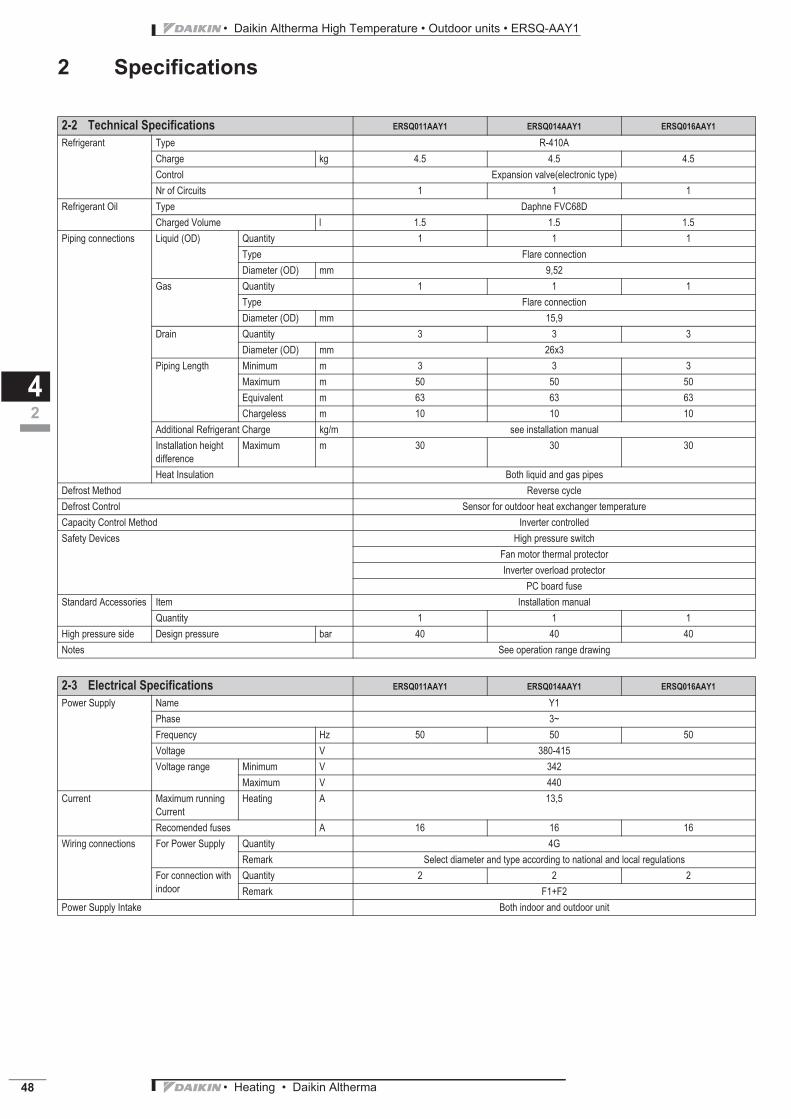
Refrigerant Type R-410A
Charge kg 4.5 4.5 4.5
Control Expansion valve(electronic type)
Nr of Circuits 1 1 1
Refrigerant Oil Type Daphne FVC68D
Charged Volume l 1.5 1.5 1.5
Piping connections Liquid (OD) Quantity 1 1 1
Type Flare connection
Diameter (OD) mm 9,52
Gas Quantity 1 1 1
Type Flare connection
Diameter (OD) mm 15,9
Drain Quantity 3 3 3
Diameter (OD) mm 26x3
Piping Length Minimum m 3 3 3
Maximum m 50 50 50
Equivalent m 63 63 63
Chargeless m 10 10 10
Additional Refrigerant Charge kg/m see installation manual
Installation height
difference
Maximum m 30 30 30
Heat Insulation Both liquid and gas pipes
Defrost Method Reverse cycle
Defrost Control Sensor for outdoor heat exchanger temperature
Capacity Control Method Inverter controlled
Safety Devices High pressure switch
Fan motor thermal protector
Inverter overload protector
PC board fuse
Standard Accessories Item Installation manual
Quantity 1 1 1
High pressure side Design pressure bar 40 40 40
Notes See operation range drawing
2-3 Electrical Specifications ERSQ011AAY1 ERSQ014AAY1 ERSQ016AAY1
Power Supply Name Y1
Phase 3~
Frequency Hz 50 50 50
Voltage V 380-415
Voltage range Minimum V 342
Maximum V 440
Current Maximum running
Current
Heating A 13,5
Recomended fuses A 16 16 16
Wiring connections For Power Supply Quantity 4G
Remark Select diameter and type according to national and local regulations
For connection with
indoor
Quantity 2 2 2
Remark F1+F2
Power Supply Intake Both indoor and outdoor unit
2-2 Technical Specifications ERSQ011AAY1 ERSQ014AAY1 ERSQ016AAY1
• Heating • Daikin Altherma 49
• Daikin Altherma High Temperature • Outdoor units • ERSQ-AAY1
3 Capacity tables
3 - 1 Heating capacity tables
43
3TW58842-1C
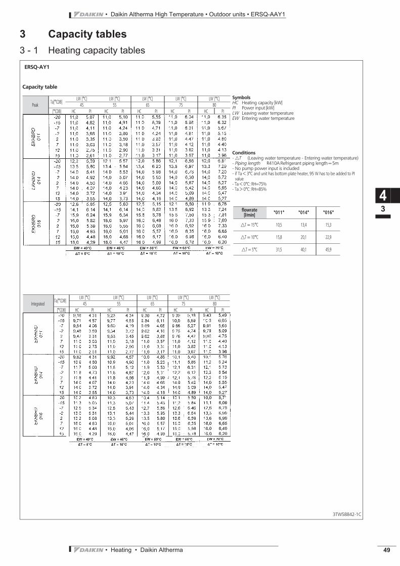
ERSQ-AY1
SymbolsHC Heating capacity [kW]PI Power input [kW]LW Leaving water temperatureEW Entering water temperature
PeakTa[°CDB]
LW [°C] LW [°C] LW [°C] LW [°C] LW [°C]
45 55 65 75 80
[°CDB] HC PI HC PI HC PI HC PI HC PI
Conditions- nT (Leaving water temperature - Entering water temperature)- Piping length R410ARefrigerant piping length= 5m- No pump power input is included- if Ta < 3°C and unit has bottom plate heater, 95 W has to be added to PIvalue
- Ta < 0°C: RH=75%- Ta > 0°C: RH=85%
Capacity table
IntegratedTa[°CDB]
LW [°C] LW [°C] LW [°C] LW [°C] LW [°C]
45 55 65 75 80
[°CDB] HC PI HC PI HC PI HC PI HC PI
flowrate[l/min]
*011* *014* *016*
nT = 15°C 10,5 13,4 15,3
nT = 10°C 15,8 20,1 22,9
nT = 5°C 31,5 40,1 45,9

• Daikin Altherma High Temperature • Outdoor units • ERSQ-AAY1
• Heating • Daikin Altherma50
4 Dimensional drawing & centre of gravity
4 - 1 Dimensional drawing
44
4TW57914-1
Hole for anchor bolt 4-M121. Gas pipe connection J15.9 flare2. Liquid connection pipe "9.5 flare3. Service port (in the unit)4. Electronic connection and grounding terminal MS (in switch box)5. Refrigerant piping intake6. Power supply wiring intake (knock hole J34)7. Control wiring intake (knock hole J27)8. Drain outlet
ERSQ011-016AA

• Heating • Daikin Altherma 51
• Daikin Altherma High Temperature • Outdoor units • ERSQ-AAY1
4 Dimensional drawing & centre of gravity
4 - 2 Centre of gravity
44
4TW58749-6
ERSQ011-016AAY1
Position of foundation bolt
• Daikin Altherma High Temperature • Outdoor units • ERSQ-AAY1
• Heating • Daikin Altherma52
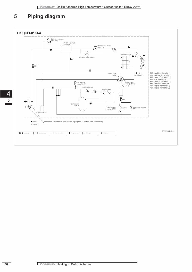
5 Piping diagram
45
3TW58745-1
ERSQ011-016AA
Heat exchanger
Compressor(MC1)
High pressuresensor (S1NPH)
Filter
Filter
Filter
Pressure regulating valve
4-way valve(Y1S)
Solenoid valve (Y3S)
Electronic expansionvalve (Y1E)
Electronic expansionvalve (Y3E)
Low pressuresensor (S1NPL)
Capillarytube
Service port
Double pipe heatexchanger
Stop valve (with service port on field piping side J 7.9mm flare connection)
Filter
High pressureswitch (S1PH)
Capillary tube
Accumulator
Solenoid valve (Y2S)
Heating
Defrost
Check valve Flare connection Screw connection Flange connection Pinched pipe Spinned pipe
Fan
R1T: Ambient thermistorR2T: Discharge thermistorR3T: Suction thermistor (1)R4T: Coil thermistorR5T: Suction thermistor (2)R6T: Subcool thermistorR7T: Liquid thermistor (1)R8T: Liquid thermistor (2)

• Heating • Daikin Altherma 53
• Daikin Altherma High Temperature • Outdoor units • ERSQ-AAY1
6 Wiring diagram
6 - 1 Wiring diagram
46
ERSQ-AY1
2TW58746-1C
A1P Printed circuit boardA2P Printed circuit board (INV)A3P Printed circuit board (Noise filter)BS1∼BS5 Push button switch
(Mode, set, return, test, reset)C1-C3 CapacitorDS1 DIP switchE1HC Crankcase heaterF1H Fuse (A 31.5A 500V)F2U Fuse (A 31.5A 500V)F3U Fuse (T 6.3A / 250V)F4U Fuse (T 6.3A / 250V)F5U Fuse (T 6.3A / 250V)F6U Fuse (T 5.0A / 250V)F7U Fuse (T 1.0A / 250V)F8U Fuse (F 1.0A / 250V)E7H Bottom plate heaterHAP (A1P) Pilot lamp (Service monitor-green)HAP (A2P) Pilot lamp (Service monitor-green)H1∼8P(A1P) Pilot lamp (Service monitor-orange)
(H2P)Prepare, Test --------- FlickeringMalfunction Detection -- Light up
K1M-K2M Magnetic contactorK1R (A1P) Magnetic relay (Y1S)K2R (A1P) Magnetic relay (Y2S)K3R (A1P) Magnetic relay (Y3S)K4R (A1P) Magnetic relay (E1HC)K5R (A2P) Magnetic relayL1R∼L3R ReactorL4R Reactor (For outdoor fan motor)M1C Motor (Compressor)M1F Motor (Upper fan)M2F Motor (Lower fan)PS Power supplyR1∼R2 ResistorR1T Thermistor (Air)R2T Thermistor (M1CDischarge)R3T Thermistor (Suction 1)R4T Thermistor (Subcool)R5T Thermistor (Suction 2)R6T Thermistor (Coil)R7T Thermistor (liquid 1)R8T Thermistor (liquid 2)R9T Thermistor (Power module)S1NPH Pressure sensor(high)S1NPL Pressure sensor(low)S1PH Pressure switch (high)V1R∼V2R Power moduleV3R Diode moduleX1M Terminal stripX2M Terminal strip (Control)Y1E Expansion valve (Main)Y3E Expansion valve (Subcool)Y1S 4 way valveY2S Solenoid valve (hot gas)Y3S Solenoid valve (U/L circuit)Z1C∼7C Noise filterZ1F∼3F Noise filterQ1DI Field earth leakage breaker(300mA)
Notes:1 This wiring diagram only applies to the outdoor unit2g: Field wiring3 D : Terminal F : Fixed connector Movable connectorR : Protective earth (screw) : Connectorp : Noiseless earth G : Terminal strip
4 When using the option adaptor, refer to the installation manual5 Refer to the ’operation caution label’ (on back of front plate) how to use BS1∼BS5 and DS1 switch.6 When operating, do not short circuit for protection device. (S1PH)7 Colors BLU: blue, BRN: brown, GRN: green, RED: red, WHT:white8 When using the central control system, connect outdoor-outdoor transmission F1-F2.9
: Option
Indoor BPH
Compressor terminalposition
Power supply3N∼
380 - 415V50Hz
Reactor terminal position
Only for bottomplate heater option
Indoor F1, F2
Arrow viewFront
Detail of El. Compo. Box
Layout of M1F,M2F,M1C,L13-3R,El.Comp.Box
El. Compo.Box
Outer shell

• Daikin Altherma High Temperature • Outdoor units • ERSQ-AAY1
• Heating • Daikin Altherma54
7 Sound data
7 - 1 Sound pressure spectrum
47
3TW58747-1
ERSQ011AAV1ERSQ011AAY1
HEATING
ERSQ014AAV1ERSQ014AAY1
HEATING
ERSQ016AAV1ERSQ016AAY1
HEATING
Soun
dpre
ssur
eleve
l(dB)
Soun
dpre
ssur
eleve
l(dB)
Soun
dpre
ssur
eleve
l(dB)
Octave band center frequency (Hz) Octave band center frequency (Hz) Octave band center frequency (Hz)
Notes:
1 Data is valid at free field condition (measured in a semi-anachoic room)
2 dBA = A-weighted sound power level (A-scale according to IEC)
3 Reference acoustic pressure 0dB = 20µPa
4 If sound is measured under actual installation conditions, the measuredvalue will be higher due to environmental noise and sound reflections.
Measuring location (discharge side)

• Heating • Daikin Altherma 55
• Daikin Altherma High Temperature • Outdoor units • ERSQ-AAY1
7 Sound data
7 - 2 Sound power spectrum
47
3TW58747-2
ERSQ011AAV1ERSQ011AAY1
HEATING
ERSQ014AAV1ERSQ014AAY1
HEATING
ERSQ016AAV1ERSQ016AAY1
HEATING
Soun
dpow
er leve
l(dB)
Soun
dpow
er leve
l(dB)
Soun
dleve
l(dB)
Octave band center frequency (Hz) Octave band center frequency (Hz) Octave band center frequency (Hz)
Notes:
1 dBA = A-weighted sound power level (A-scale according to IEC)
2 Reference acoustic pressure 0dB = 20µPa
3 Measured according to ISO 3744
pow
er

• Daikin Altherma High Temperature • Outdoor units • ERSQ-AAY1
• Heating • Daikin Altherma56
8 Operation range
48
3TW58843-1B
EKHBRD011-016AAERSQ011-016AA
Space heating mode
EKHTS-A
Startup area Continuous heatingoperation
Continuous heating operation
Startup area
operation possible, but no guarantee of capacity
ERRQ*(V1/Y1) units include special equipment (insulation, heater sheet, . . .) to ensure good operation in areas where lowambient temperature can occur together with high humidity conditionsIn such conditions ERQS*5V1/Y1) models may experience problems with severe ice build up on the aircooled coil.In case such conditions are expected the ERRQ*(V1/Y1) must be installed instead.These models contain countermeasures to prevent freeze up.
DHW operation
Tank temperature (°C)
Domestic hot water operation
operation possible, but no guarantee of capacity
Can be adjusted by field setting
Domestic hot water mode
Related Documents


![FOX II...FOX II Characteristics Balanced flue RLS system Energy efficiency Technical data Nominal heat output [kW] 8 Partial heat output [kW] 4 Room heating capacity (depending on](https://static.cupdf.com/doc/110x72/612f1c3e1ecc515869433c36/fox-ii-fox-ii-characteristics-balanced-flue-rls-system-energy-efficiency-technical.jpg)


![ProductInformation - mitsubishitech.co.ukmitsubishitech.co.uk/Data/Mr-Slim_Indoor/PLA-RP/2014/PLA-[Z]RP-B… · FEATURES INDOOR HeatingCapacity(kW)(nominal) 7.0(2.8-8.2) CoolingCapacity(kW)(nominal)](https://static.cupdf.com/doc/110x72/602951388bdbca70c66e4676/productinformation-zrp-b-features-indoor-heatingcapacitykwnominal-7028-82.jpg)