TABLE OF CONTENTS 1 P/N 1201006 COPYRIGHT 2015 W. S. DARLEY AND COMPANY Introduction 2 Safety 3 Power Take-Off (PTO) Safety Information 3 General Safety Information 4 Proper Matching of PTO 4 Cold Weather Operation of Powershift PTO 5 Rotating Auxiliary Driveshafts 5 Guarding Auxiliary Driveshafts 6 Using Set Screws 6 Installation 7 Detail Drawings 9 Vendor Information 15 10-Bolt Powershift PTOs 15 Safety Information 15 Schematics 18

Welcome message from author
This document is posted to help you gain knowledge. Please leave a comment to let me know what you think about it! Share it to your friends and learn new things together.
Transcript
Table of ConTenTs
1P/N 1201006CoPyright 2015 W. S. Darley aND ComPaNy
Introduction . . . . . . . . . . . . . . . . . . . . . . . . . . . . . . . . . . 2
Safety . . . . . . . . . . . . . . . . . . . . . . . . . . . . . . . . . . . . . . 3Power Take-Off (PTO) Safety Information . . . . . . . . . . . . . . . . . . . . . . . . . . . . . . . . 3
General Safety Information . . . . . . . . . . . . . . . . . . . . . . . . . . . . . . . . . . . . . . 4
Proper Matching of PTO . . . . . . . . . . . . . . . . . . . . . . . . . . . . . . . . . . . . . . . 4
Cold Weather Operation of Powershift PTO . . . . . . . . . . . . . . . . . . . . . . . . . . 5
Rotating Auxiliary Driveshafts . . . . . . . . . . . . . . . . . . . . . . . . . . . . . . . . . . . . 5
Guarding Auxiliary Driveshafts . . . . . . . . . . . . . . . . . . . . . . . . . . . . . . . . . . . 6
Using Set Screws . . . . . . . . . . . . . . . . . . . . . . . . . . . . . . . . . . . . . . . . . . . . 6
Installation . . . . . . . . . . . . . . . . . . . . . . . . . . . . . . . . . . . 7
Detail Drawings . . . . . . . . . . . . . . . . . . . . . . . . . . . . . . . . 9
Vendor Information . . . . . . . . . . . . . . . . . . . . . . . . . . . . 1510-Bolt Powershift P .T .O .s . . . . . . . . . . . . . . . . . . . . . . . . . . . . . . . . . . . . . . . . 15
Safety Information . . . . . . . . . . . . . . . . . . . . . . . . . . . . . . . . . . . . . . . . . . . 15
Schematics . . . . . . . . . . . . . . . . . . . . . . . . . . . . . . . . . 18
P/N 1201006CoPyright 2015 W. S. Darley aND ComPaNy2
NOTES

Safety
3P/N 1201006CoPyright 2015 W. S. Darley aND ComPaNy
!This is the safety alert symbol . It is used to alert you to potential physical injury hazards . Obey all safety messages that follow this symbol to avoid possible injury or death .
The words DANGER, WARNING, CAUTION, and NOTICE are used throughout this manual to highlight important information .
! DANGERindicates a hazardous situation that, if not avoided, will result in death or serious injury.
! WARNINGindicates a hazardous situation that, if not avoided, could result in death or serious injury.
! CAUTIONindicates a hazardous situation that, if not avoided, could result in minor or moderate injury.
NOTICEIndicates a situation that can cause damage to the engine, personal property, and/or the environment, or cause the equipment to operate improperly.
NOTE:N Indicates a procedure, practice, or condition that should be followed in order for the pump to function in the manner intended.
Power Take-Off (PTO) Safety InformationThese instructions are for your safety and the safety of the end user . Read them carefully until you understand them .
Important: Safety Information and Owner’s Manual
Chelsea Power Take-Offs are packaged with safety information, decals, instructions, and owner’s manual . These items are located in the envelope with the PTO mounting gaskets . Also, safety information and installation instructions are packaged with some individual parts and kits . Be sure to read the owner’s manual before installing or operating the PTO. Always install the safety information decals according to the instructions provided . Place the owner’s manual in the vehicle glove compartment .
! WARNING
!Verify that the Pto is properly selected to operate while the vehicle is in motion. if in doubt about the Pto specifications and capabilities, avoid operating the Pto when the vehicle is in motion. improper applications and/or operation can cause serious personal injury and premature failure of the vehicle, the driven equipment, and/or the Pto.
Always remember to disengage the PTO when the driven equipment is not in operation .

P/N 1201006CoPyright 2015 W. S. Darley aND ComPaNy4
Safety
General SafeTy InfOrmaTIOn
To prevent injury to yourself and/or damage to the equipment:
• Read carefully all owner’s manuals, service manuals, and/or other instructions .
• Always follow proper procedures, and use proper tools and safety equipment .
• Be sure to receive proper training .
• Never work alone while under a vehicle or while repairing or maintaining equipment .
• Always use proper components in the applications in which they are approved .
• Be sure to assemble components properly .
• Never use worn-out or damaged components .
• Always block any raised or moving device that may injure a person working on or under a vehicle .
• Never operate the controls of the Power Take-Off or other driven equipment from any position that could result in getting caught in the moving machinery .
PrOPer maTchInG Of PTO
! WARNING
!Equipment Hazard: always match the Power take-off to the vehicle transmission and the auxiliary equipment being powered. an improperly matched Power take-off could cause severe damage to the vehicle transmission, the auxiliary driveshaft, and/or to the auxiliary equipment being powered. Damaged components or equipment could malfunction, causing serious personal injury to the vehicle operator or to others nearby.
• Always refer to Chelsea catalogs, literature, and owner’s manuals . Follow Chelsea recommendations when selecting, installing, repairing, or operating a Power Take-Off .
• Never attempt to use a Power Take-Off not specifically recommended by Chelsea for the vehicle transmission .
• Always match the Power Take-Off’s specified output capabilities to the requirements of the equipment to be powered .
• Never use a Power Take-Off whose range of speed could exceed the maximum .
Safety
5P/N 1201006CoPyright 2015 W. S. Darley aND ComPaNy
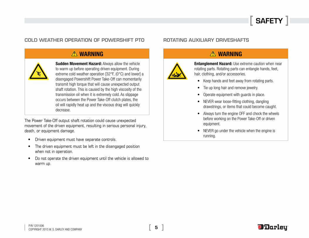
cOlD WeaTher OPeraTIOn Of POWerShIfT PTO
! WARNINGSudden Movement Hazard: always allow the vehicle to warm up before operating driven equipment. During extreme cold weather operation [32°F, (0°C) and lower] a disengaged Powershift Power take-off can momentarily transmit high torque that will cause unexpected output shaft rotation. this is caused by the high viscosity of the transmission oil when it is extremely cold. as slippage occurs between the Power take-off clutch plates, the oil will rapidly heat up and the viscous drag will quickly decrease.
The Power Take-Off output shaft rotation could cause unexpected movement of the driven equipment, resulting in serious personal injury, death, or equipment damage .
• Driven equipment must have separate controls .
• The driven equipment must be left in the disengaged position when not in operation .
• Do not operate the driven equipment until the vehicle is allowed to warm up .
rOTaTInG auxIlIary DrIVeShafTS
! WARNINGEntanglement Hazard: Use extreme caution when near rotating parts. rotating parts can entangle hands, feet, hair, clothing, and/or accessories.
• Keep hands and feet away from rotating parts.
• tie up long hair and remove jewelry.
• operate equipment with guards in place.
• NeVer wear loose-fitting clothing, dangling drawstrings, or items that could become caught.
• always turn the engine oFF and chock the wheels before working on the Power take-off or driven equipment.
• NeVer go under the vehicle when the engine is running.

P/N 1201006CoPyright 2015 W. S. Darley aND ComPaNy6
Safety
GuarDInG auxIlIary DrIVeShafTS
! WARNINGEntanglement Hazard: Never operate an auxiliary driveshaft without a guard installed. the manufacturer strongly recommends that a Power take-off (Pto) and a directly mounted pump be used to eliminate the auxiliary driveshaft whenever possible. if an auxiliary driveshaft is used and remains exposed after installation, it is the responsibility of the vehicle designer and Pto installer to install a guard.
uSInG SeT ScreWS
! WARNINGSnag Hazard: always use caution when working around an auxiliary driveshaft that square head set screws are installed to avoid snagging of your skin, hair and clothes.
auxiliary driveshafts may be installed with either recessed or protruding set screws. if you choose a square head set screw, you should be aware that it will protrude above the hub of the yoke and there may be a point where clothes, skin, hair, hands, etc. could be snagged. a socket head screw, which may not protrude above the hub of the yoke, does not permit the same amount of torquing as does a square head set screw. also, a square head set screw, if used with a lock wire, will prevent loosening of the screw caused by vibration. regardless of the choice made with respect to a set screw, an exposed rotating auxiliary driveshaft must be guarded.
INSTALLATION
7P/N 1201006CoPyright 2015 W. S. Darley aND ComPaNy
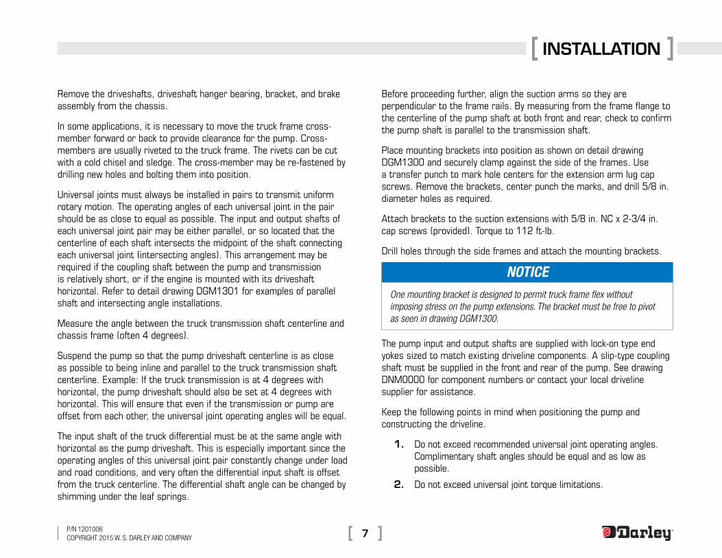
Remove the driveshafts, driveshaft hanger bearing, bracket, and brake assembly from the chassis .
In some applications, it is necessary to move the truck frame cross-member forward or back to provide clearance for the pump . Cross-members are usually riveted to the truck frame . The rivets can be cut with a cold chisel and sledge . The cross-member may be re-fastened by drilling new holes and bolting them into position .
Universal joints must always be installed in pairs to transmit uniform rotary motion . The operating angles of each universal joint in the pair should be as close to equal as possible . The input and output shafts of each universal joint pair may be either parallel, or so located that the centerline of each shaft intersects the midpoint of the shaft connecting each universal joint (intersecting angles) . This arrangement may be required if the coupling shaft between the pump and transmission is relatively short, or if the engine is mounted with its driveshaft horizontal . Refer to detail drawing DGM1301 for examples of parallel shaft and intersecting angle installations .
Measure the angle between the truck transmission shaft centerline and chassis frame (often 4 degrees) .
Suspend the pump so that the pump driveshaft centerline is as close as possible to being inline and parallel to the truck transmission shaft centerline . Example: If the truck transmission is at 4 degrees with horizontal, the pump driveshaft should also be set at 4 degrees with horizontal . This will ensure that even if the transmission or pump are offset from each other, the universal joint operating angles will be equal .
The input shaft of the truck differential must be at the same angle with horizontal as the pump driveshaft . This is especially important since the operating angles of this universal joint pair constantly change under load and road conditions, and very often the differential input shaft is offset from the truck centerline . The differential shaft angle can be changed by shimming under the leaf springs .
Before proceeding further, align the suction arms so they are perpendicular to the frame rails . By measuring from the frame flange to the centerline of the pump shaft at both front and rear, check to confirm the pump shaft is parallel to the transmission shaft .
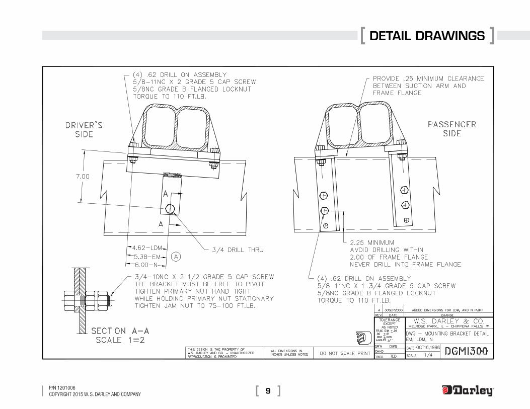
Place mounting brackets into position as shown on detail drawing DGM1300 and securely clamp against the side of the frames . Use a transfer punch to mark hole centers for the extension arm lug cap screws . Remove the brackets, center punch the marks, and drill 5/8 in . diameter holes as required .
Attach brackets to the suction extensions with 5/8 in . NC x 2-3/4 in . cap screws (provided) . Torque to 112 ft-lb .
Drill holes through the side frames and attach the mounting brackets .
NOTICEOne mounting bracket is designed to permit truck frame flex without imposing stress on the pump extensions. The bracket must be free to pivot as seen in drawing DGM1300.
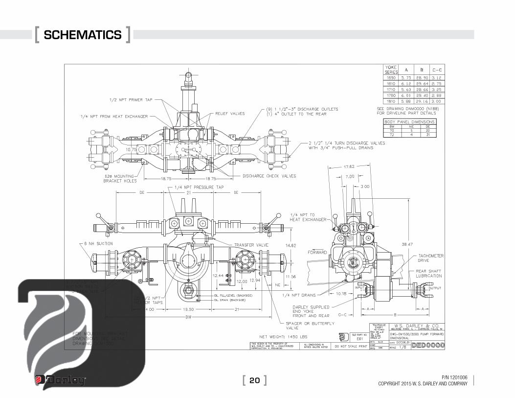
The pump input and output shafts are supplied with lock-on type end yokes sized to match existing driveline components . A slip-type coupling shaft must be supplied in the front and rear of the pump . See drawing DNM0000 for component numbers or contact your local driveline supplier for assistance .
Keep the following points in mind when positioning the pump and constructing the driveline .
1 . Do not exceed recommended universal joint operating angles . Complimentary shaft angles should be equal and as low as possible .
2 . Do not exceed universal joint torque limitations .

P/N 1201006CoPyright 2015 W. S. Darley aND ComPaNy8
INSTALLATION
3 . Do not exceed driveshaft speed/length limitations .
4 . Yokes on each coupling shaft must be in phase . When in phase, the slip yoke lugs (ears) and tube yoke lugs (ears) are in line .
Torque the bearing cap retaining bolts to the following specifications:
Full Round Tnd Yoke
Series Ohread Size Cap Screw Oorque (lb-ft)
1610 (5/16) .312-24 26-35
1710 (3/8) .375-24 38-48
1760 (3/8) .375-24 38-48
1810 (3/8) .375-24 38-48
1880 (7/16) .438-20 60-70
Quick Disconnect Half Round Tnd Yoke
Series Ohread Size Cap Screw Oorque (lb-ft)
1590 (3/8) .375-24 45-60
1610 (3/8) .375-24 45-60
1710 (1/2) .500-20 115-135
1760 (1/2) .500-20 115-135
1810 (1/2) .500-20 115-135
Lubricate universal joint cross using National Lubricating Grease Institute Extreme Pressure (NLGI EP) Grade 2 lubricating grease .
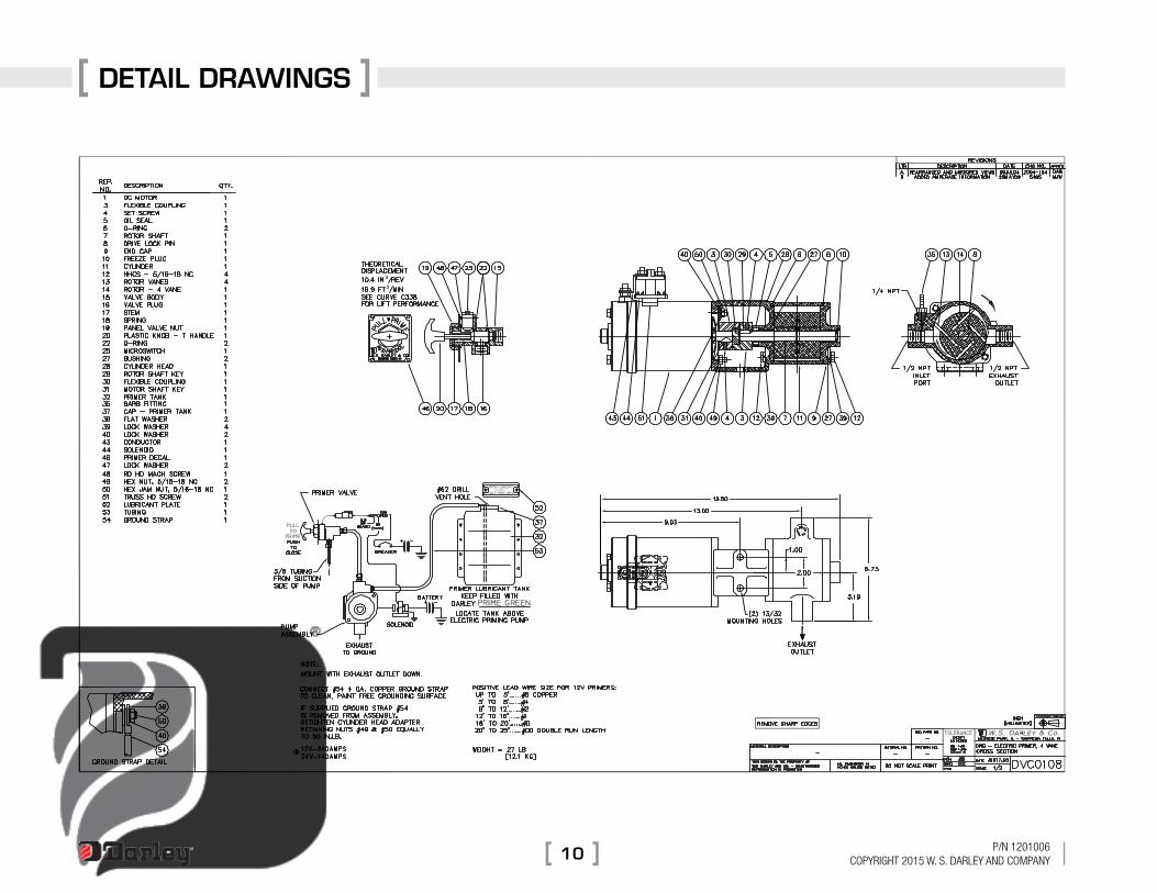
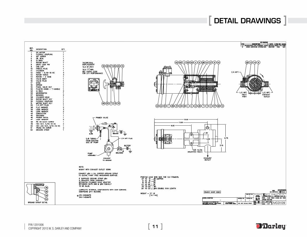
PRIMER CONNECTION: For 12 volt electric priming pump installation, see drawing DVC0108 . See drawing DVC0109 for oilless primer .
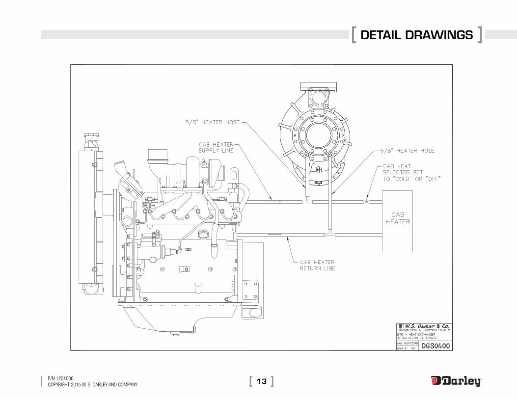
HEATER CONNECTION: Two tapped openings in the pump casing head are provided for circulating engine coolant through the heater jacket to prevent freezing in cold weather . Use no smaller than a 1/2 in . line for this connection .
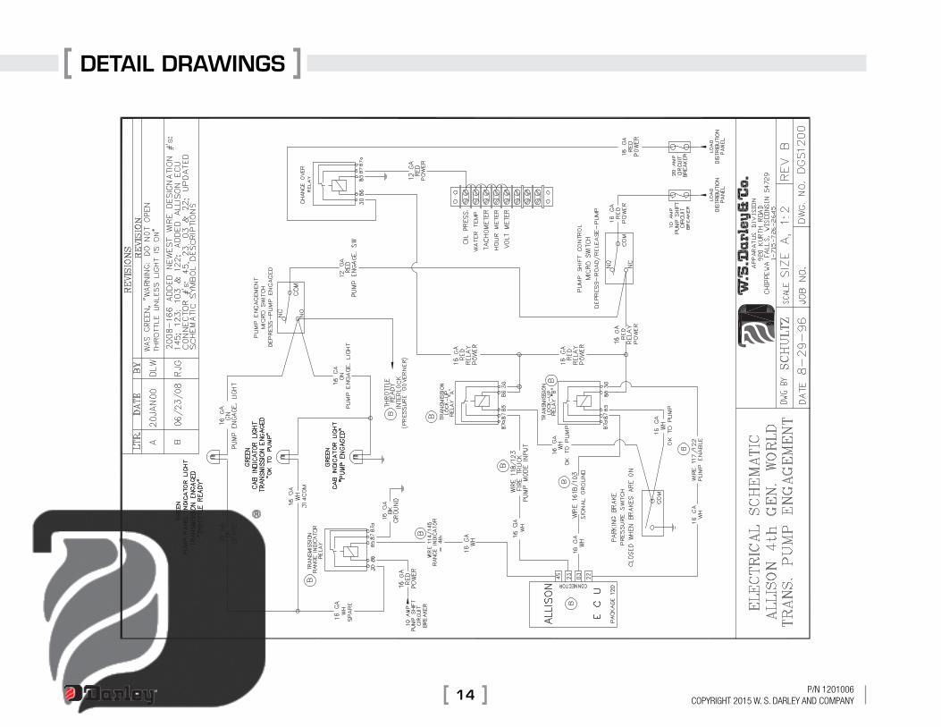
PUMP SHIFT INSTALLATION: For power shift installation, refer to drawing DGS1200 for automatic transmission wiring details .
ENGINE COOLING: Bypass radiator cooling water through the heat exchange (pump heater jacket) and fittings . See drawing DGS0400 .
DETAIL DRAWINGS
9P/N 1201006CoPyright 2015 W. S. Darley aND ComPaNy
P/N 1201006CoPyright 2015 W. S. Darley aND ComPaNy10
DETAIL DRAWINGS
DETAIL DRAWINGS
11P/N 1201006CoPyright 2015 W. S. Darley aND ComPaNy

P/N 1201006CoPyright 2015 W. S. Darley aND ComPaNy12
DETAIL DRAWINGS
DETAIL DRAWINGS
13P/N 1201006CoPyright 2015 W. S. Darley aND ComPaNy
P/N 1201006CoPyright 2015 W. S. Darley aND ComPaNy14
DETAIL DRAWINGS

Vendor InformatIon
15P/N 1201006CoPyright 2015 W. S. Darley aND ComPaNy
10-Bolt Powershift P .T .O .s*
SafeTy InfOrmaTIOn
These instructions are for your safety and the safety of the end user . Read them carefully until you understand them .
General Safety InformatIon
To prevent injury to yourself and/or damage to the equipment:
• Read carefully all owner’s manuals, service manuals, and/or other instructions .
• Always follow proper procedures, and use proper tools and safety equipment .
• Be sure to receive proper training .
• Never work alone while under a vehicle or while repairing or maintaining equipment .
• Always use proper components in applications for which they are approved .
• Be sure to assemble components properly .
• Never use wornout or damaged components .
• Always block any raised or moving device that may injure a person working on or under a vehicle .
• Never operate the controls of the Power Take-Off or other driven equipment from any position that could result in getting caught in the moving machinery .
ProPer matchInG of P.t.o.
! WARNINGa Power take-off must be properly matched to the vehicle transmission and to the auxiliary equipment being powered. an improperly matched Power take-off could cause severe damage to the vehicle transmission, the auxiliary driveshaft, and/or to the auxiliary equipment being powered. Damaged components or equipment could malfunction, causing serious personal injury to the vehicle operator or to others nearby.
To avoid personal injury and/or equipment damage:• Always refer to Chelsea catalogs, literature, and owner’s manuals .
Follow Chelsea recommendations when selecting, installing, repairing, or operating a Power Take-Off .
• Never attempt to use a Power Take-Off not specifically recommended by Chelsea for the vehicle transmission .
• Always match the Power Take-Off’s specified output capabilities to the requirements of the equipment to be powered .
• Never use a Power Take-Off whose range of speed could exceed the maximum .
cold Weather oPeratIon of PoWerShIft P.t.o.
! WARNINGDuring extreme cold weather operation [32°F (0°C) and lower], a disengaged Powershift Power take-off can momentarily transmit high torque that will cause unexpected output shaft rotation. this is caused by the high viscosity of the transmission oil when it is extremely cold. as slippage occurs between the Power take-off clutch plates, the oil will rapidly heat up and the viscous drag will quickly decrease.
*reprinted with permission from: Parker hannifin corporation, chelsea Products division Bulletin hy25-1380-m1/US, September 2014

P/N 1201006CoPyright 2015 W. S. Darley aND ComPaNy16
Vendor InformatIon
The Power Take-Off output shaft rotation could cause unexpected movement of the driven equipment, resulting in serious personal injury, death, or equipment damage .
To avoid personal injury or equipment damage:
• Driven equipment must have separate controls .
• The driven equipment must be left in the disengaged position when not in operation .
• Do not operate the driven equipment until the vehicle is allowed to warm up .
rotatInG aUxIlIary drIveShaftS
! WARNING• rotating auxiliary driveshafts are dangerous. you can
snag clothes, skin, hair, hands, etc. this can cause serious injury or death.
• Do not go under the vehicle when the engine is running.
• Do not work on or near an exposed shaft when the engine is running.
• Shut off the engine before working on the Power take-off or driven equipment.
• exposed rotating driveshafts must be guarded.
GUardInG aUxIlIary drIveShaftS
! WARNINGWe strongly recommend that a Power take-off and a directly mounted pump be used to eliminate the auxiliary driveshaft whenever possible. if an auxiliary driveshaft is used and remains exposed after installation, it is the responsibility of the vehicle designer and P.t.o. installer to install a guard.
USInG Set ScreWS
! WARNINGauxiliary driveshafts may be installed with either recessed or protruding set screws. if you choose a square head set screw, you should be aware that it will protrude above the hub of the yoke and may be a point where clothes, skin, hair, hands, etc. could be snagged. a socket head set screw, which may not protrude above the hub of the yoke, does not permit the same amount of torquing as does a square head set screw. also, a square head set screw, if used with a lock wire, will prevent loosening of the screw caused by vibration. regardless of the choice made with respect to a set screw, an exposed rotating auxiliary driveshaft must be guarded.
Important: Safety Information and Owner’s ManualChelsea Power Take-Offs are packaged with safety information decals, instructions and an owner’s manual . These items are located in the envelope with the P .T .O . mounting gaskets . Also, safety information and installation instructions are packaged with some individual parts and kits . Be sure to read the owner’s manual before installing or operating the P.T.O. Always install the safety information decals according to the instructions provided . Place the owner’s manual in the vehicle glove compartment .
Vendor InformatIon
17P/N 1201006CoPyright 2015 W. S. Darley aND ComPaNy
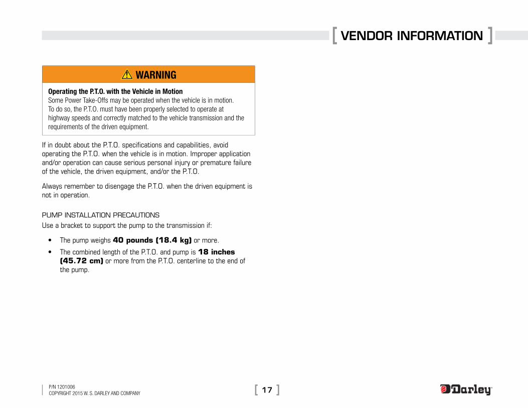
! WARNINGOperating the P.T.O. with the Vehicle in Motion Some Power take-offs may be operated when the vehicle is in motion. to do so, the P.t.o. must have been properly selected to operate at highway speeds and correctly matched to the vehicle transmission and the requirements of the driven equipment.
If in doubt about the P .T .O . specifications and capabilities, avoid operating the P .T .O . when the vehicle is in motion . Improper application and/or operation can cause serious personal injury or premature failure of the vehicle, the driven equipment, and/or the P .T .O .
Always remember to disengage the P .T .O . when the driven equipment is not in operation .
PUmP InStallatIon PrecaUtIonS
Use a bracket to support the pump to the transmission if:
• The pump weighs 40 pounds (18.4 kg) or more .
• The combined length of the P .T .O . and pump is 18 inches (45.72 cm) or more from the P .T .O . centerline to the end of the pump .

P/N 1201006CoPyright 2015 W. S. Darley aND ComPaNy18
SchematicS

SchematicS
19P/N 1201006CoPyright 2015 W. S. Darley aND ComPaNy
P/N 1201006CoPyright 2015 W. S. Darley aND ComPaNy20
SchematicS

SchematicS
21P/N 1201006CoPyright 2015 W. S. Darley aND ComPaNy
P/N 1201006CoPyright 2015 W. S. Darley aND ComPaNy22
SchematicS

SchematicS
23P/N 1201006CoPyright 2015 W. S. Darley aND ComPaNy

P/N 1201006CoPyright 2015 W. S. Darley aND ComPaNy24
SchematicS
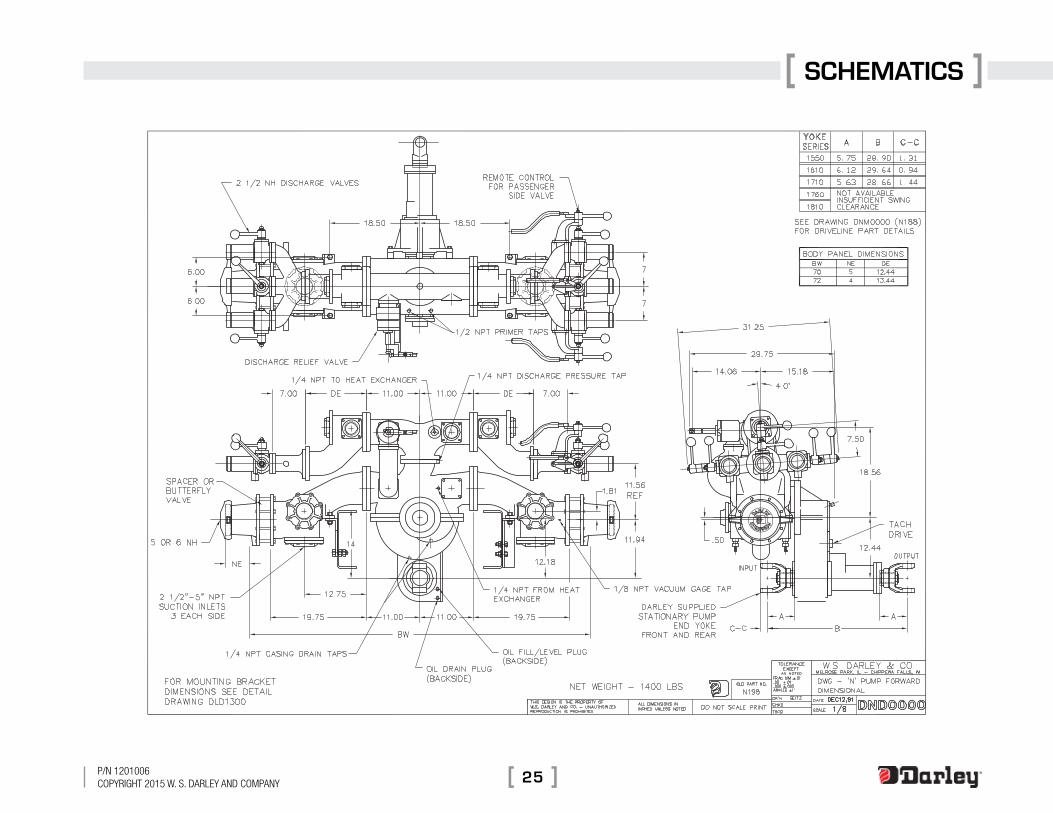
SchematicS
25P/N 1201006CoPyright 2015 W. S. Darley aND ComPaNy
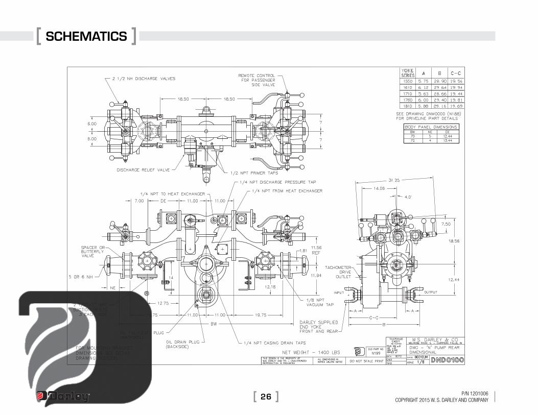
P/N 1201006CoPyright 2015 W. S. Darley aND ComPaNy26
SchematicS
Related Documents