Table of contents TOOL CLAMPING SYSTEMS ST-Power Draw Bar Bolt-on Type ASPK 8002 Power Draw Bar ASP 8005 Integrated Type ESP 8008 Clamping sets 8009 Accessories 8010 HSK-Built-in Clamping System HSK-C 8011 HSK-D 8016 HSK-Adaptors with Built-in Clamping System HSK-C 8017 HSK-D 8018 HSK-Spindle contour with clamping set HSK-C 8019 HSK-D 8019 HSK-Automatic Clamping Set HSK-Clamping Set - Standard 8020 HSK-Clamping Set - High Speed - with Guided Collet 8024 HSK-Clamping Set with Retaining Collet 8025 HSK Adaptors with Clamping System HSK-A/B 8026 HSK-Automatic clamping units HSK-Clamping unit 8027 HSK-Built-in Clamping Unit 8028 HSK-Clamping unit SUPER-LOCK SUPER-LOCK 8029 Stationary release unit Stationary release unit 8032 Stationary release unit with buffer stroke 8033 Turning Performance Turning Performance 8034 Tool mountings with HSK-C / HSK-A HSK-Tool blankes 8035 HSK-clamping chucks 8037 HSK-Drill chuck 8038 HSK-Slip-on cutter arbor 8039 HSK-Quick change tapping chuck 8040 HSK-Test Bar 8041 HSK-Adapter sleeves 8042 HSK-Adapter 8046 ABS-mounting with HSK-A shaft 8047 HSK-Plug 8048 Accessories 8048 Hydraulic clamping head Hydraulic clamping head 8049 Accessories 8050 Spring operated clamping head Spring operated clamping head 8051 Accessories 8052

Welcome message from author
This document is posted to help you gain knowledge. Please leave a comment to let me know what you think about it! Share it to your friends and learn new things together.
Transcript

Table of contentsTOOL CLAMPING SYSTEMS
ST-Power Draw BarBolt-on Type ASPK 8002Power Draw Bar ASP 8005Integrated Type ESP 8008Clamping sets 8009Accessories 8010HSK-Built-in Clamping SystemHSK-C 8011HSK-D 8016HSK-Adaptors with Built-in Clamping SystemHSK-C 8017HSK-D 8018HSK-Spindle contour with clamping setHSK-C 8019HSK-D 8019HSK-Automatic Clamping SetHSK-Clamping Set - Standard 8020HSK-Clamping Set - High Speed - with Guided Collet 8024HSK-Clamping Set with Retaining Collet 8025HSK Adaptors with Clamping SystemHSK-A/B 8026HSK-Automatic clamping unitsHSK-Clamping unit 8027HSK-Built-in Clamping Unit 8028HSK-Clamping unit SUPER-LOCKSUPER-LOCK 8029Stationary release unitStationary release unit 8032Stationary release unit with buffer stroke 8033Turning PerformanceTurning Performance 8034Tool mountings with HSK-C / HSK-AHSK-Tool blankes 8035HSK-clamping chucks 8037HSK-Drill chuck 8038HSK-Slip-on cutter arbor 8039HSK-Quick change tapping chuck 8040HSK-Test Bar 8041HSK-Adapter sleeves 8042HSK-Adapter 8046ABS-mounting with HSK-A shaft 8047HSK-Plug 8048Accessories 8048Hydraulic clamping headHydraulic clamping head 8049Accessories 8050Spring operated clamping headSpring operated clamping head 8051Accessories 8052
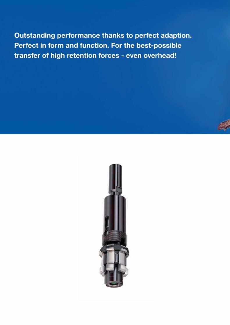
Outstanding performance thanks to perfect adaption. Perfect in form and function. For the best-possible transfer of high retention forces - even overhead!

TOOL CLAMPING SYSTEMS
ST-Power Draw Bar 8002
Manual HSK-clamping sets 8011
Automatic HSK-clamping sets 8020
Automatic HSK-clamping units 8027
SUPER-LOCK-clamping unit 8029
Stationary release unit 8032
Turning Performance 8034
Tool mountings with HSK-C / HSK-A 8035
Hydraulic clamping head 8049
Spring operated clamping head 8051

8002
Power Draw Bar
Functional description
of tools with taper mount and draw-in bolts
The RÖHM Power Draw Bar for automatic tool-change of tools with steep taper mounting is a complete unit. Its components like: Rotating distributor with piston for unclamping, wedge-type system with cup springs and draw bar with collet, allow an optimum in toll changing technique. In terms of operational reliability, quiet running, speeds and clamping force, the Röhm Power Draw Bar complies with all requirements of the practice. New developed wedge-type clamping system!When clamped, the power draw bar is positively locked through the wedge surface with high power transmission and high stiffness. Especially suitable for... ...machine tools with rotating spindle, high rotary frequency and high clamping force.
The Röhm-tool clamp is made in 3 basic types: Add-on clamper (the complete clamp is screwed down at the end of the spindle). Tool clamp (the wedge gearing is screwed down at the end of the spindle and the spring set enters into the spindle). Built-in clamp (the complete clamp is built into the spindle). Further designs on request!
Multiple clamping force transmission of cupspring force through guided wedge-element surfaces.
High safety against pull-out forces because of the self-locking wedge system
In case of power failure, tool remains firmly clamped
Power transmission during clamping and unclamping without any influence to the spindle bearings
Quick-acting clamping system, therefore short change-over time for tool change,
Compact design resulting in low rotating masses.
Technical features:
ST-P
ower
Dra
w B
ar
8003
The RÖHM Power Draw Bar for automatic tool-change of tools with steep taper mounting is a complete unit. Its components like: Rotating distributor with piston for unclamping, wedge-type system with cup springs and draw bar with collet, allow an optimum in toll changing technique. In terms of operational reliability, quiet running, speeds and clamping force, the Röhm Power Draw Bar complies with all requirements of the practice. New developed wedge-type clamping system!When clamped, the power draw bar is positively locked through the wedge surface with high power transmission and high stiffness. Especially suitable for... ...machine tools with rotating spindle, high rotary frequency and high clamping force.
The Röhm-tool clamp is made in 3 basic types: Add-on clamper (the complete clamp is screwed down at the end of the spindle). Tool clamp (the wedge gearing is screwed down at the end of the spindle and the spring set enters into the spindle). Built-in clamp (the complete clamp is built into the spindle). Further designs on request!
Power Draw Bar
Design principle/Technical features
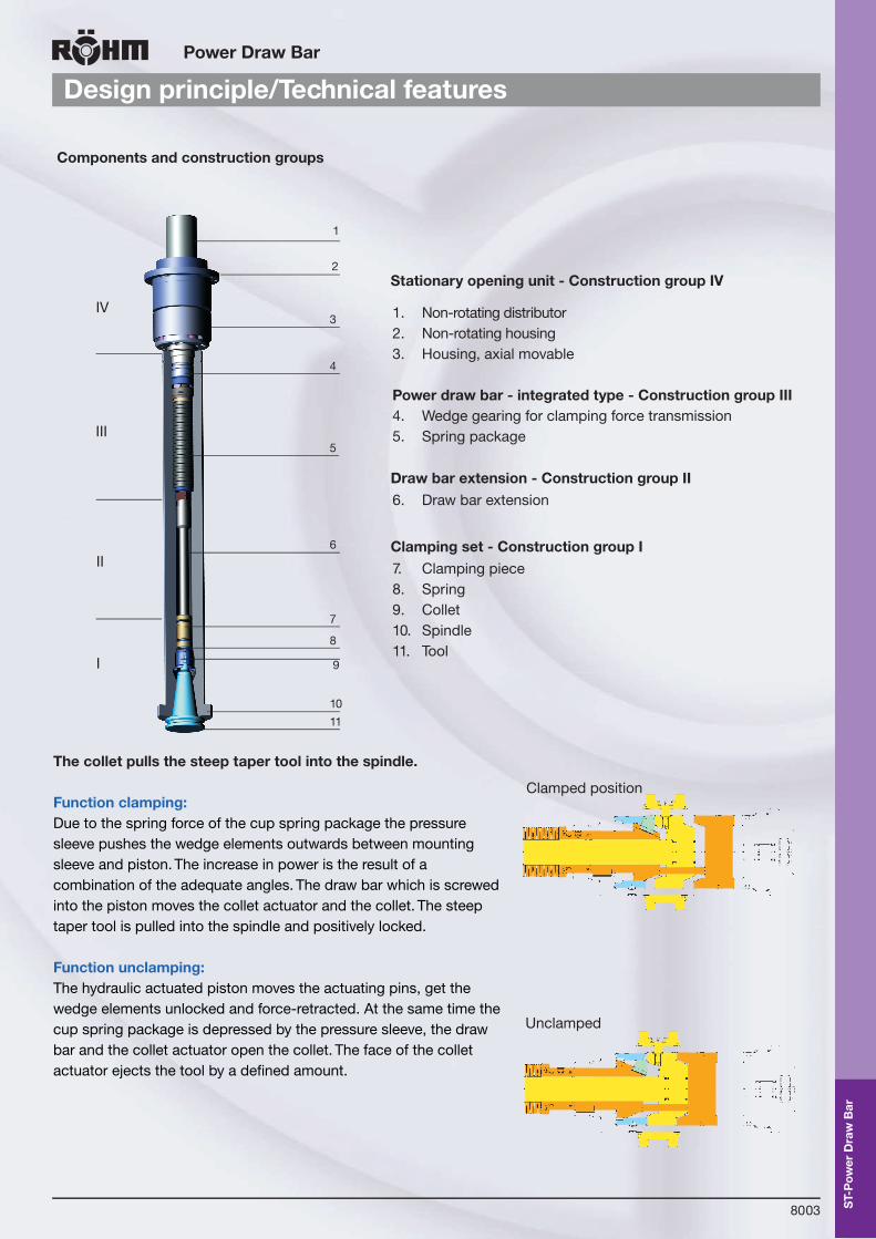
The collet pulls the steep taper tool into the spindle.
Function clamping:Due to the spring force of the cup spring package the pressure sleeve pushes the wedge elements outwards between mounting sleeve and piston. The increase in power is the result of a combination of the adequate angles. The draw bar which is screwedinto the piston moves the collet actuator and the collet. The steep taper tool is pulled into the spindle and positively locked.
Function unclamping:The hydraulic actuated piston moves the actuating pins, get the wedge elements unlocked and force-retracted. At the same time the cup spring package is depressed by the pressure sleeve, the draw bar and the collet actuator open the collet. The face of the collet actuator ejects the tool by a defined amount.
Components and construction groups
1. Non-rotating distributor 2. Non-rotating housing 3. Housing, axial movable
Power draw bar - integrated type - Construction group III4. Wedge gearing for clamping force transmission 5. Spring package
Stationary opening unit - Construction group IV
6. Draw bar extensionDraw bar extension - Construction group II
7. Clamping piece 8. Spring9. Collet 10. Spindle 11. Tool
Clamping set - Construction group I
25155-k008-043 30.04.2007 9:48 Uhr Seite 8043
Clamped position
Unclamped
IV
III
II
I
1
2
3
4
5
6
7
8
9
10
11
ST-P
ower
Dra
w B
ar
8004
ST-Power Draw Bar
Bolt-on Type ASPK
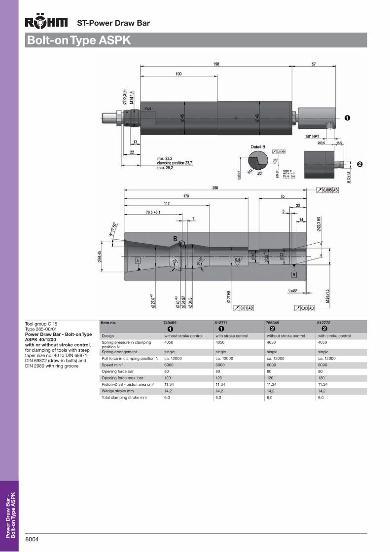
Tool group C 15Type 285-00/01 Power Draw Bar - Bolt-on Type ASPK 40/1200with or without stroke control,for clamping of tools with steep taper size no. 40 to DIN 69871, DIN 69872 (draw-in bolts) and DIN 2080 with ring groove
Item no. 749469 812771 766349 812772
Design without stroke control with stroke control without stroke control with stroke control
Spring pressure in clamping position N
4050 4050 4050 4050
Spring arrangement single single single single
Pull force in clamping position N ca. 12000 ca. 12000 ca. 12000 ca. 12000
Speed min-1 6000 6000 6000 6000
Opening force bar 80 80 80 80
Opening force max. bar 120 120 120 120
Piston-Ø 38 - piston area cm2 11,34 11,34 11,34 11,34
Wedge stroke mm 14,2 14,2 14,2 14,2
Total clamping stroke mm 6,0 6,0 6,0 6,0
1
2
1 1 2 2
Pow
er D
raw
Bar
-
Bol
t-on
Type
AS
PK
8005
ST-Power Draw Bar
Power Draw Bar ASP
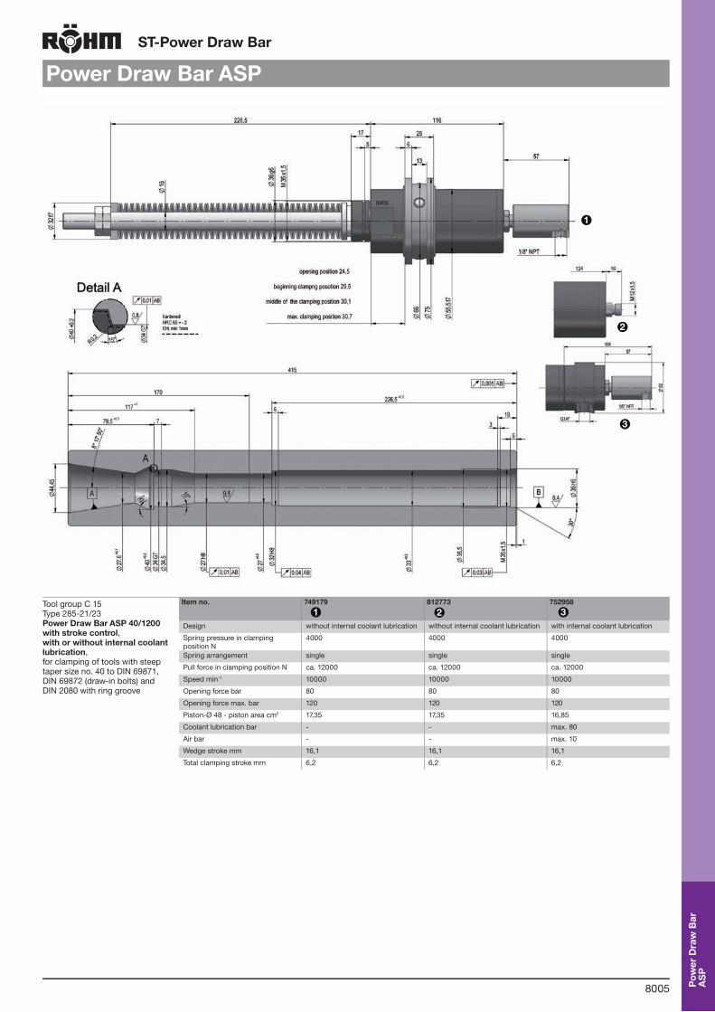
Tool group C 15Type 285-21/23 Power Draw Bar ASP 40/1200with stroke control, with or without internal coolant lubrication, for clamping of tools with steep taper size no. 40 to DIN 69871, DIN 69872 (draw-in bolts) and DIN 2080 with ring groove
Item no. 749179 812773 752958
Design without internal coolant lubrication without internal coolant lubrication with internal coolant lubrication
Spring pressure in clamping position N
4000 4000 4000
Spring arrangement single single single
Pull force in clamping position N ca. 12000 ca. 12000 ca. 12000
Speed min-1 10000 10000 10000
Opening force bar 80 80 80
Opening force max. bar 120 120 120
Piston-Ø 48 - piston area cm2 17,35 17,35 16,85
Coolant lubrication bar - - max. 80
Air bar - - max. 10
Wedge stroke mm 16,1 16,1 16,1
Total clamping stroke mm 6,2 6,2 6,2
1
2
3
1 2 3
Pow
er D
raw
Bar
A
SP
8006
ST-Power Draw Bar
Power Draw Bar ASPSkizze fehlt!
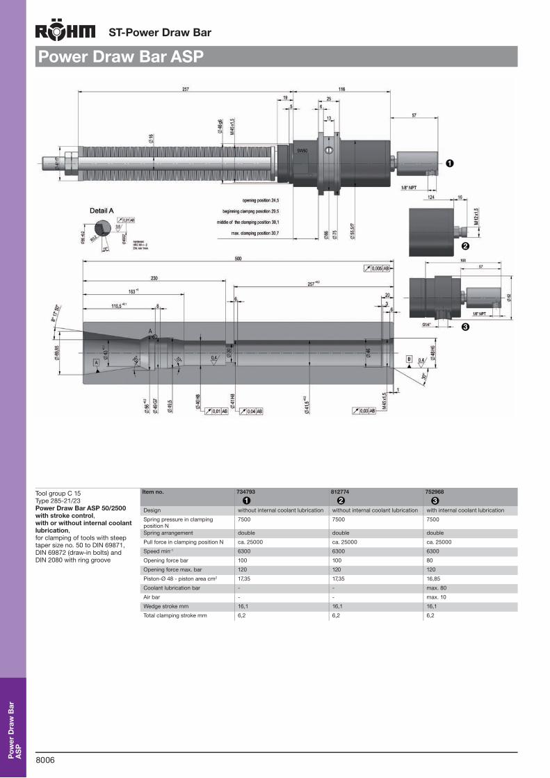
Tool group C 15Type 285-21/23 Power Draw Bar ASP 50/2500with stroke control, with or without internal coolant lubrication, for clamping of tools with steep taper size no. 50 to DIN 69871, DIN 69872 (draw-in bolts) and DIN 2080 with ring groove
Item no. 734793 812774 752968
Design without internal coolant lubrication without internal coolant lubrication with internal coolant lubrication
Spring pressure in clamping position N
7500 7500 7500
Spring arrangement double double double
Pull force in clamping position N ca. 25000 ca. 25000 ca. 25000
Speed min-1 6300 6300 6300
Opening force bar 100 100 80
Opening force max. bar 120 120 120
Piston-Ø 48 - piston area cm2 17,35 17,35 16,85
Coolant lubrication bar - - max. 80
Air bar - - max. 10
Wedge stroke mm 16,1 16,1 16,1
Total clamping stroke mm 6,2 6,2 6,2
1
2
3
1 2 3
Pow
er D
raw
Bar
A
SP
8007
ST-Power Draw Bar
Power Draw Bar ASPSkizze fehlt!
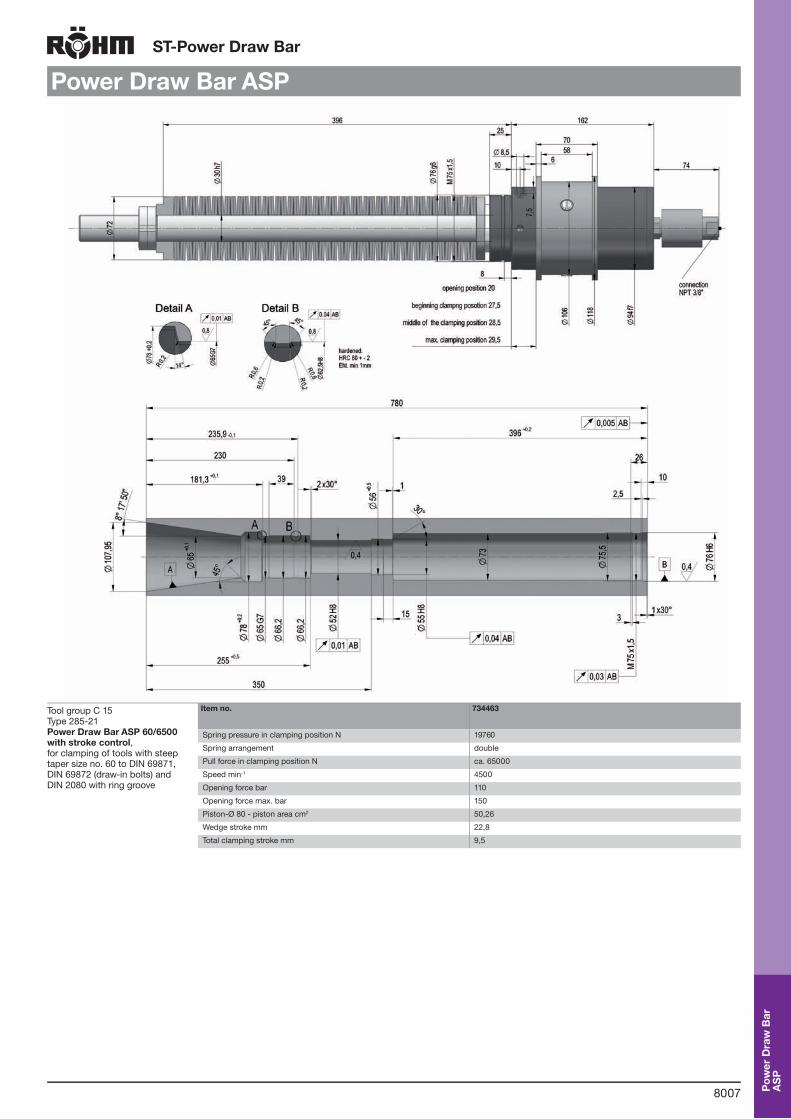
Tool group C 15Type 285-21 Power Draw Bar ASP 60/6500with stroke control, for clamping of tools with steep taper size no. 60 to DIN 69871, DIN 69872 (draw-in bolts) and DIN 2080 with ring groove
Item no. 734463
Spring pressure in clamping position N 19760
Spring arrangement double
Pull force in clamping position N ca. 65000
Speed min-1 4500
Opening force bar 110
Opening force max. bar 150
Piston-Ø 80 - piston area cm2 50,26
Wedge stroke mm 22,8
Total clamping stroke mm 9,5
Pow
er D
raw
Bar
A
SP

8008
ST-Power Draw Bar
Integrated Type ES PSkizze fehlt!
Tool group C 15Type 285-41/43 Power Draw Bar- Integrated Type ESP 40/1200with stroke control, with or without internal coolant lubrication, for clamping of tools with steep taper size no. 40 to DIN 69871, DIN 69872 (draw-in bolts) and DIN 2080 with ring groove
Item no. 766411 812776 812777
Design without internal coolant lubrication without internal coolant lubrication with internal coolant lubrication
Spring pressure in clamping position N
4000 4000 4000
Spring arrangement single single single
Pull force in clamping position N ca. 12000 ca. 12000 ca. 12000
Speed min-1 10000 10000 10000
Opening force bar 80 80 80
Opening force max. bar 120 120 120
Piston-Ø 38 - piston area cm2 11,34 11,34 10,84
Wedge stroke mm 14,2 14,2 14,2
Total clamping stroke mm 6,0 6,0 6,0
12
3
1 2 3
Pow
er D
raw
Bar
-
Inte
grat
ed Ty
pe E
SP

8009
ST-Power Draw Bar
Clamping sets
Tool group C 15Type 285-70 Clamping sets
Item no. Design D1 d 2 Draw-in force max. N
772091 SK 30 DIN 69871/72 19 M10x1,5 7500
707858 SK 40 DIN 69871/72 27 M 14x1,5 15000
756168 SK 40 DIN 2080 with ring groove 27 M 14x1,5 15000
756360 SK 50 DIN 69871/72 40 M 16x1,5 26000
760389 SK 50 DIN 2080 with ring groove 40 M 16x1,5 26000
760390 SK 60 DIN 69871/72 52 M 30x1,5 80000
Tool group C 15Type 285-71 Clamping sets IKZwith axial cooling lubricant feed
Item no. Design D1 d 2 Draw-in force max. N
756340 SK 40 DIN 69871/72 27 M 14x1,5 15000
760391 SK 50 DIN 69871/72 40 M 16 x1,5 26000
d 2
D 1
Tool group C 15Type 285-72 Clamping sets IKRwith radial coolant lubrication transfer
Item no. Design D1 d 2 Draw-in force max. N
760392 SK 40 DIN 69871/72 27 M 14x1,5 15000
760393 SK 50 DIN 69871/72 40 M 16 x1,5 26000
Pow
er D
raw
Bar
-
Cla
mpi
ng s
ets

8010
ST-Power Draw Bar
Accessories
Tool group C 15 Type 285-91 Socket wrench with through-hole Tool group C 15 Type 285-91 Socket wrench without through-hole
Item no. Size
772214 SK 30
756393 SK 40
760229 SK 50
747337 SK 60
Item no. Size
756396 SK 40-60
Tool group C15 Type 7023 Hexagon key Tool group A 34 Type 234-00 Draw-in Bolts DIN 69872 A
Item no. Size Length l1 Key-width SW
367665 SK 30 183 4
802094 SK 40 350 6
769078 SK 50/60 400 8
Item no. Size Thread
698582 SK 30 M 12
347325 SK 40 M 16
367315 SK 45 M 20
367316 SK 50 M 24
Tool group A 34 Type 234-05 Draw-in Bolts DIN 69872 B Tool group A 34 Type 234-10 Draw-in Bolts ISO 7388/II-B
Item no. Size Thread
698583 SK 30 M 12
698584 SK 40 M 16
698585 SK 45 M 20
698586 SK 50 M 24
Item no. Size Thread
367569 SK 40 M 12
698587 SK 45 M 16
698588 SK 50 M 20
Tool group A 34 Type 234-41 Draw-in Bolts MAS BT 1 (30°) Tool group A 34 Type 234-40 Draw-in Bolts MAS BT 2 (45°)
Item no. Size Thread
698592 SK 30 M 12
367320 SK 40 M 16
698593 SK 45 M 20
698594 SK 50 M 24
Item no. Size Thread
698589 SK 30 M 12
367319 SK 40 M 16
698590 SK 45 M 20
698591 SK 50 M 24
Tool group A 34 Type 234-50 Draw-in Bolts ANSI B5.50
Item no. Size Thread
620770 SK 40 M 16
698595 SK 45 M 20
620771 SK 50 M 24
Pow
er D
raw
Bar
-A
cces
sori
es

8011
Positive Taper Lock Clamping System
Functional description
For manual and automatic tool clamping
The task:Increase of efficiency, reduction of cost and change to "lean production“, however, optimizing quality at the same time. These are the present demands to modern manufacturing. In order to account for this development, the positive taper lock system was developed and tested as a common project of the industry and the TH Aachen. The positive taper lock system is the connection between the machine spindle and the tool. The specific demands, an advanced tool change system must fulfil, are:
Particularly high changing accuracy and repeatability
Safe transmission of high torques with a defined, radial location
High static and dynamic flexural strength
Particular suitability for high-speed operations in milling, drilling and turning machines
Reduction of weight and total length
Easy handling
Technical features:
Pos
itive
Tape
r Lo
ck
Cla
mpi
ng S
yste
m

8012
Positive Taper Lock Clamping System
Designs
Positive taper lock for automatic tool change
Werkzeu
gspa
nnsystem
eTo
ol c
lam
ping
syst
ems
Werkzeu
gspa
nnsystem
eTo
ol c
lam
ping
syst
ems
Werkzeu
gspa
nnsystem
eTo
ol c
lam
ping
syst
ems
Werkzeu
gspa
nnsystem
eTo
ol c
lam
ping
syst
ems
Werkzeu
gspa
nnsystem
eTo
ol c
lam
ping
syst
ems
Werkzeu
gspa
nnsystem
eTo
ol c
lam
ping
syst
ems
Form A Form B
Form C Form D
Form E Form F
Positive taper lock (version A) automatically-changeable tool adapter, torque transmission on positive taper lock, small square face with gripping channel. Applications: Machine tools (e.g. lathes, drilling and milling machines), high speed range, conventional material machining, torque transmission via milled driver within the spindle adapter.
Positive taper lock (version B)automatically-changeable tool adapter, torque transmission on collar via grooves, large square face with gripping channel. Applications:Machine tools (e.g. lathes, drilling and milling machines), medium speed range, heavy-duty material machining, torque transmission via driver keys, suitable for heavy-duty material machining (cutter heads).
Positive taper lock (version C)manually-changeable tool adapter, torque transmission on positive taper lock, small square face without gripping channel. Applications:Machine tools (e.g. lathes, drilling and milling machines), high speed range, conventional material machining, torque transmission via milled driver within the spindle adapter.
Positive taper lock (version D)manually-changeable tool adapter, torque transmission on collar via grooves, large square face without gripping channel. Applications: Machine tools (e.g. lathes, drilling and milling machines), medium speed range, heavy-duty material machining, torque transmission via driver keys, suitable for heavy-duty material machining (cutter heads).
Positive taper lock for automatic tool change and for high speeds (HSC)
Positive taper lock (version E)automatically-changeable tool adapter, torque transmission via collar and spherical surface, small square face with gripping channel. Applications:Machine tools (e.g. lathes, drilling and grinding machines), extremely high speed range (depending on diameter size), grinding work, wood machining, suitable for HSC, utilised for minimal material removal.
Positive taper lock (version F)automatically-changeable tool adapter, torque transmission via collar and spherical surface, large square face with gripping channel. Applications:Machine tools (e.g. lathes, drilling and grinding machines), extremely high speed range (depending on diameter size), grinding work, wood machining, suitable for HSC, utilised for minimal material removal.
Positive taper lock for manual tool change
For manual and automatic tool clamping
Pos
itive
Tape
r Lo
ck
Cla
mpi
ng S
yste
m

8013
Positive Taper Lock Clamping System
Technical features
Technical features:
Convincing strong design
Compact power flow
No clamping bore required in the taper, no dirt penetration possible during operation
Sealed central coolant supply
Steady clamping force due to four symmetric clamping surfaces
Automatic ejection of the tool during release
Perfectly suitable to be built into the spindle
The advantage of the positive taper lock clamping system originates in the combination of the plane surfaces, together with the expansion of the taper during the clamping operation. The precise adjustment of the nominal diameter of the taper creates an initial tension important for the quality of the HSK-system and can be measured by means of the axial play. For the clamping operation the clamping jaws are expanded by turning the adjusting screw. The axial forces FA and radial forces FR generated by the symmetric gripping slope built-up the necessary clamping force for the initial tension of the taper lock system over the entire taper surface and locating surface. Two T-nuts, gripping the tool at the end of the shank of the tool mounting, gua-rantee a positive radial location. When the jaws are released, the tool is ejected automatically. A compact power flow is important for the rigidity of the clamping system and improves the changing accuracy.
Joining position with locating surface
Clamping situation
Clamping situation with compact power flow
Positive Taper Lock System for manual tool clamping
Axial play
Tool- mounting
Tool
Tool- mounting Tool
Tool- mounting Tool
The RÖHM-clamping system was specially designed for the positive taper lock clamping taking particulary into account the necessity of manual clamping.
Pos
itive
Tape
r Lo
ck
Cla
mpi
ng S
yste
m

8014
Positive Taper Lock Clamping System
Assembling guide
For built-in clamping system HSK-C and HSK-D for manual tool clamping of hollow shaft tools to DIN 69893
Retaining ring
Adjusting screw
O-ring with support ring
Spacer washer
Clamping jaw
Clamping spindle
Guide bolt
Sealing ring
Pulling thread
Levering bevel
Clampind jaw
Lightly grease the clamping jaw seat on the guide pin, clamping bevels of the clamping jaws and the clamping spindle.
Screw the clamping spindle into one clamping jaw by approximately one turn.
Insert the clamping jaw with the clamping spindle into the guide pin.
Screw the second clamping jaw onto the clamping spindle also by approximately one turn. Hold the spindle to prevent it turning.
Move both clamping jaws inwards by turning the clamping spindle with an hexagonal key.
Check the seat of the clamping spindle - must be centred exactly between the clamping jaws.
Fit the front face sealing ring and press in.
Fit the spacer washer, then fit the support ring and the rear O-ring.
Assembling the clamping sets:
Fit or press in the clamping set into the spindle or adapter so that the clamping spindle access he-xagon aligns with the adjusting screw bore. Insert the adjusting screw into the clamping spindle hexagon or insert into the spindle bore and secure with the snap ring.
Installing the clamping sets:Direct installation of the built-in clamping set into spindles, clamping chuck or mounting adapters
Always use a closing plug when using a spindle or adapter fitted with a clamping set without tools.
With tool inserts subjected to low radial loads, e.g. drilling and friction operation, it is permissible to lower the maximum torques by approximately 25%.
When changing tools always clean the tool and the spindle taper with a taper wiper.
The clamping set should be regreased after prolonged use. These intervals depend on the tool changing frequency, the machining method and the coolant lubricant. Regreasing should, however, be performed at least every six months.
Notes on the use of the clamping set:
Remove the snap ring with a screwdriver on the dismantling bevel in the spindle or mounting adapter
Remove the adjusting screw.
When the jaws are released pull out the clamping set by the guide pin or, on newer versions, with the central pulling thread.
Dismantling:
Note:
Because of the face sealing at the tool (positive taper) the O-Ring mentioned in the German Standards DIN is idle and may be removed.
Pos
itive
Tape
r Lo
ck
Cla
mpi
ng S
yste
m
8015
HSK-Built-in Clamping System
HSK-C
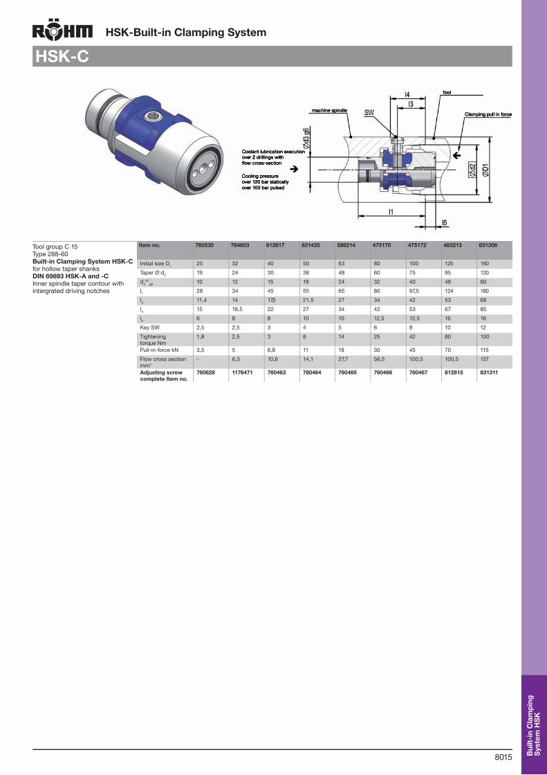
Tool group C 15Type 288-60 Built-in Clamping System HSK-Cfor hollow taper shanks DIN 69893 HSK-A and -C Inner spindle taper contour with intergrated driving notches
Item no. 760530 784603 812617 831435 586214 475170 475172 483213 831306
Initial size D1 25 32 40 50 63 80 100 125 160
Taper Ø d2 19 24 30 38 48 60 75 95 120
d3H7
g6 10 12 15 18 24 32 40 48 60
l1 28 34 45 55 65 80 97,5 124 160
l3 11,4 14 17,5 21,5 27 34 42 53 68
l4 15 18,5 22 27 34 42 53 67 85
l5 6 8 8 10 10 12,5 12,5 16 16
Key SW 2,5 2,5 3 4 5 6 8 10 12
Tightening torque Nm
1,8 2,5 3 8 14 25 42 80 100
Pull-in-force kN 3,5 5 6,8 11 18 30 45 70 115
Flow cross section mm2
- 6,3 10,6 14,1 27,7 56,5 100,5 100,5 157
Adjusting screw complete Item no.
760628 1176471 760463 760464 760465 760466 760467 812815 831311
Bui
lt-in
Cla
mpi
ng
Sys
tem
HS
K
8016
HSK-Built-in Clamping System
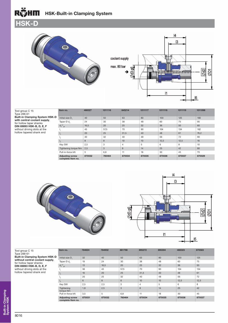
HSK-D
Tool group C 15Type 288-61 Built-in Clamping System HSK-Dwith central coolant supply, for hollow taper shanks DIN 69893 HSK-B, D, E, F without driving slots at the hollow tapered shank end
Item no. 466327 1011116 845214 1011117 1011118 1011119 1011098
Initial size D1 40 50 63 80 100 125 160
Taper Ø d2 24 30 38 48 60 75 95
d3H7
g6 16,5 20 25 32 36 50 60
l1 45 57,5 70 90 104 134 162
l3 20 25 31,5 40 48 61 76,2
l4 30 32 40 48 56 72 90
l5 8 8 10 10 12,5 12,5 16
Key SW 2,5 3 4 5 6 8 10
Tightening torque Nm 2,5 3 8 14 25 42 80
Pull-in-force kN 5 6,8 11 18 30 45 70
Adjusting screw complete Item no.
870032 760464 870034 870035 870036 870037 870029
Tool group C 15Type 288-61 Built-in Clamping System HSK-Dwithout central coolant supply, for hollow taper shanks DIN 69893 HSK-B, D, E, F without driving slots at the hollow tapered shank end
Item no. 784624 784932 881798 895272 895304 466323 870583
Initial size D1 32 40 50 63 80 100 125
Taper Ø d2 19 24 30 38 48 60 75
d3H7
g6 13 16,5 20 25 32 36 50
l1 36 45 57,5 70 90 104 134
l3 16 20 25 31,5 40 48 61
l4 20 25 32 40 48 56 72
l5 6 8 8 10 10 12,5 12,5
Key SW 2,5 2,5 3 4 5 6 8
Tightening torque Nm
1,8 2,5 3 8 14 25 42
Pull-in-force kN 3,5 5 6,8 11 18 30 45
Adjusting screw complete Item no.
870031 870032 760464 870034 870035 870036 870037
Bui
lt-in
Cla
mpi
ng
Sys
tem
HS
K

8017
HSK-Adaptors with Built-in Clamping System
HSK-C
Tool group C 15Type 288-70 Adaptors with Built-in Clamping System HSK-C, with adjusting screwwith central coolant supply, complete with built-in clamping system for taper DIN 69893 HSK-C and -A for manual tool change
Item no. 850333 795296 795297 795298 795299 795300 795301 850335 850337
Initial size D1 25 32 40 50 63 80 100 125 160
d1 37 40 50 63 80 100 123 148 190
Taper Ø d2 19 24 30 38 48 60 75 95 120
d3F7
g6 10 12 15 18 24 32 40 48 60
d4 3,4 3,4 4,5 5,5 6,5 9 11 13 17
d5g6 24 27 33,5 42 56 68 84 100 125
Ø-TK 29 32 40,5 52 66 82 102 125 160
l1 26 34 45 55 65 80 97,5 124 160
l2 22 26 34 41 50 64 76 97 126
l3 11,4 14 17,5 21,5 27 34 42 53 68
l4 15,5 19 23 28 35 44 54 68 86
l5 6 8 8 10 10 12,5 12,5 16 16
Adjusting screw complete Item no.
870022 870023 870024 870025 870026 870027 870028 870029 870030
Special customised versions are available on request
Tool group C 15Type 288-70 Adaptors with Built-in Clamping System HSK-C “high precision design”with central coolant supply, complete with built-in clamping system for taper DIN 69893 HSK-C and -A for manual tool change
Item no. 850322 820802 820803 820804 820805 820806 820807
Initial size D1 25 32 40 50 63 80 100
Adjusting screw complete Item no.
870022 870023 870024 870025 870026 870027 870028
dyn. balanced: G 2,5 DIN ISO 1940
Ada
ptor
s w
ith B
uilt-
in C
lam
ping
Sys
tem

8018
HSK-Adaptors with Built-in Clamping System
HSK-D
Tool group C 15Type 288-71 Adaptors with Built-in Clamping System HSK-D, with adjusting screwwithout central coolant supply, for hollow taper shanks DIN 69893 HSK-B, D, E, F without driving slots at the hollow tapered shank end
Item no. 895270 885912 895292 820518 895307 466325 466326
Initial size 32 40 50 63 80 100 125
D1 40 50 63 80 100 110 138
d1 27 33,5 42 56 68 72 100
Taper Ø d2 24 30 38 48 60 75 95
d3 13 16,5 20 25 32 36 50
d4 6 x M3 6 x M4 6 x M5 6 x M6 6 x M8 6 x M10 6 x M10
d6 19 24 30 38 48 60 75
Ø-TK 32 40,5 52 66 82 90 116
l1 16 20 24,5 30 34 44 59
l2 10 12 13 19,5 20 28 34
l3 16 20 25 31,5 40 48 61
l4 20 25 33 40 56 60 75
l5 6 8 8 10 10 12,5 12,5
high precision design on request
Tool group C 15Type 288-72 Adaptors with Built-in Clamping System HSK-D, with adjusting screwwith central coolant supply, for hollow taper shanks DIN 69893 HSK-B, D, E, F without driving slots at the hollow tapered shank end
Item no. 466329 466330 820471 806428 466331 820796
Initial size 40 50 63 80 100 125
high precision design on request
Ada
ptor
s w
ith B
uilt-
in C
lam
ping
Sys
tem
8019
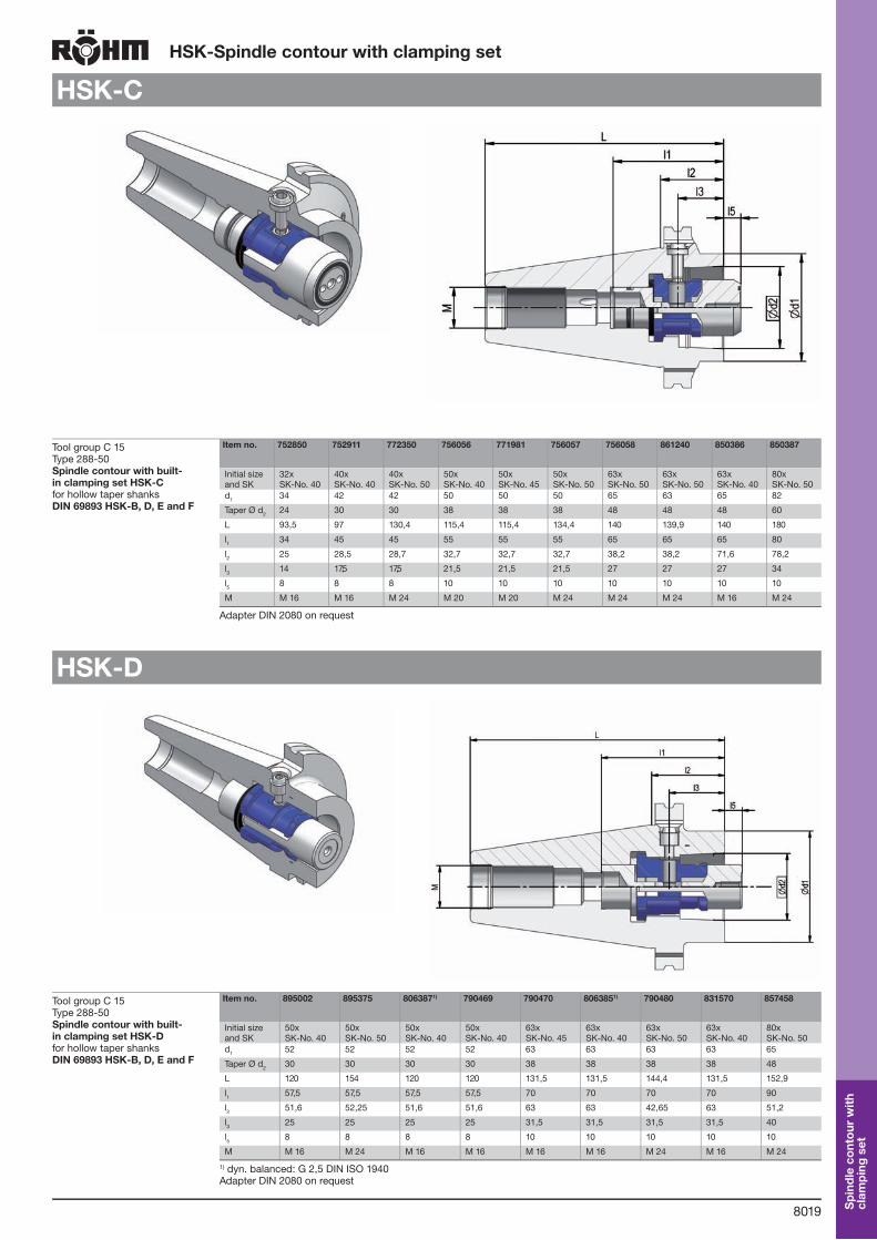
HSK-Spindle contour with clamping set
HSK-C
Tool group C 15Type 288-50 Spindle contour with built-in clamping set HSK-Cfor hollow taper shanks DIN 69893 HSK-B, D, E and F
Item no. 752850 752911 772350 756056 771981 756057 756058 861240 850386 850387
Initial size and SK
32xSK-No. 40
40xSK-No. 40
40xSK-No. 50
50xSK-No. 40
50xSK-No. 45
50xSK-No. 50
63xSK-No. 50
63xSK-No. 50
63xSK-No. 40
80xSK-No. 50
d1 34 42 42 50 50 50 65 63 65 82
Taper Ø d2 24 30 30 38 38 38 48 48 48 60
L 93,5 97 130,4 115,4 115,4 134,4 140 139,9 140 180
l1 34 45 45 55 55 55 65 65 65 80
l2 25 28,5 28,7 32,7 32,7 32,7 38,2 38,2 71,6 78,2
l3 14 17,5 17,5 21,5 21,5 21,5 27 27 27 34
l5 8 8 8 10 10 10 10 10 10 10
M M 16 M 16 M 24 M 20 M 20 M 24 M 24 M 24 M 16 M 24
Adapter DIN 2080 on request
HSK-D
Tool group C 15Type 288-50 Spindle contour with built-in clamping set HSK-Dfor hollow taper shanks DIN 69893 HSK-B, D, E and F
Item no. 895002 895375 8063871) 790469 790470 8063851) 790480 831570 857458
Initial size and SK
50xSK-No. 40
50xSK-No. 50
50xSK-No. 40
50xSK-No. 40
63xSK-No. 45
63xSK-No. 40
63xSK-No. 50
63xSK-No. 40
80xSK-No. 50
d1 52 52 52 52 63 63 63 63 65
Taper Ø d2 30 30 30 30 38 38 38 38 48
L 120 154 120 120 131,5 131,5 144,4 131,5 152,9
l1 57,5 57,5 57,5 57,5 70 70 70 70 90
l2 51,6 52,25 51,6 51,6 63 63 42,65 63 51,2
l3 25 25 25 25 31,5 31,5 31,5 31,5 40
l5 8 8 8 8 10 10 10 10 10
M M 16 M 24 M 16 M 16 M 16 M 16 M 24 M 16 M 24
1) dyn. balanced: G 2,5 DIN ISO 1940Adapter DIN 2080 on request
Spi
ndle
con
tour
with
cl
ampi
ng s
et
8020
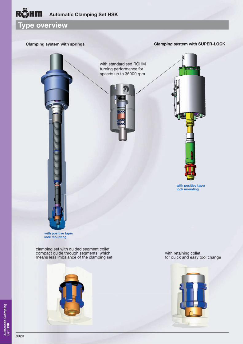
Automatic Clamping Set HSK
Type overview
Clamping system with springs Clamping system with SUPER-LOCK
Aut
omat
ic C
lam
ping
S
et H
SK
clamping set with guided segment collet, compact guide through segments, which means less imbalance of the clamping set
with retaining collet,for quick and easy tool change
with positive taperlock mounting
with positive taperlock mounting
with standardised RÖHMturning performance for speeds up to 36000 rpm

8021
Automatic Clamping Set HSK
Design principle
Aut
omat
ic C
lam
ping
S
et H
SK
Components and construction groups
Clamping unit - Construction group III1. Non-rotating distributor for coolant lubricant or air
2. Non-rotating distributor for hydraulic unclamping
3. Unclamping piston
4. Strike control ring
5. Spring package
6. Draw bar
Draw bar extension - Construction group II
7. Draw bar extension
Clamping set - Construction group I
8. Counter nut
9. Collet actuator
10. Collet
11. Spindle
12. Positive Taper Lock - tool HSK
Stationary opening unit - Construction group VI
1. Non-rotating distributor for coolant lubricant2. Connections for actuation, air blast3. Non-rotating housing4. Unclamping piston
Clamping unit SEH - Construction group III
5. Draw bar
6. Ring for stroke control
7. Spring package
8. Connecting pipe
Draw bar extension - Construction group II
9. Draw bar extension
Clamping set -Construction group I
10. Collet actuator
11. Collet
12. Counter nut
13. Spindle
14. Tool
For speeds up to 10000 rpm
For high speeds

8022
Automatic Clamping Set HSK
Technical features
For automatic tool clamping system of positive taper lock tools HSK to DIN 69893
Axial play
HSK tool
Spindle tool mounting
Joining position with locating surface
Clamping situation with locating surface
FR
HSK tool
Spindle tool mounting
Spindle tool mounting
HSK tool
Clamping situation with compact power flow
The automatic RÖHM positiv taper lock system was specially designed as complement for the manual positiv taper lock clamping. Following items were taken particularly into account:
Steady clamping force due the symmetric clamping surfaces of the clamping segments
Compact power flow resulting in high static and dynamic rigidity of the tool joint
High power amplification by transmission of the clamping set
Automatic lock by collet actuator in the clamping set
Forced controlled release of the collet by taper sleeve during the tool exchange
Automatic ejection of the tool by the collet actuator during release
Sealed central coolant supply system
Perfect suitable to be built into the spindles of machine tools and machining centers
The advantages of the positive taper lock system origi-nates in the combination of defined radial pretensioned taper and tool face stop. A safe transmission of the torque is archieved by the elastic deformation of the taper resulting in a gap-free connection with the tool. High interchanging and repeating accuracy is leading to increased production quality during the machining compared with the traditional machining. The clamping process is started by the spings and the movementmis transmitted by the draw bar to the clamping set in direction FZ. The clamping segments of the collet are pushed to the outside by the collet actu-ator. The clamping forces are multiple amplified by the angled arrangement of the contact areas. The produced axial forces FA and radial forces FR result in a pretensi-oned status of the positive taper on the entire taper area and, the axial contact area. The proportion of the axial contact force is over 80 % of the total clamping force. This explains the importance of the size of the axial contact area concerning the critical load and rigidity of the taper and hollow shank joint. See also DIN 69893 - Hollow taper shanks type B, D and F. Hollow taper shanks type A and C have two additional positive drive grooves at the end of the taper which interlock with the tool mounting and produce a form-locking, orientated radial positioning. During the release the tool will be positive unlocked and ejected from the tool spindle by the collet actuator and taper sleeve.
Aut
omat
ic C
lam
ping
S
et H
SK
8023
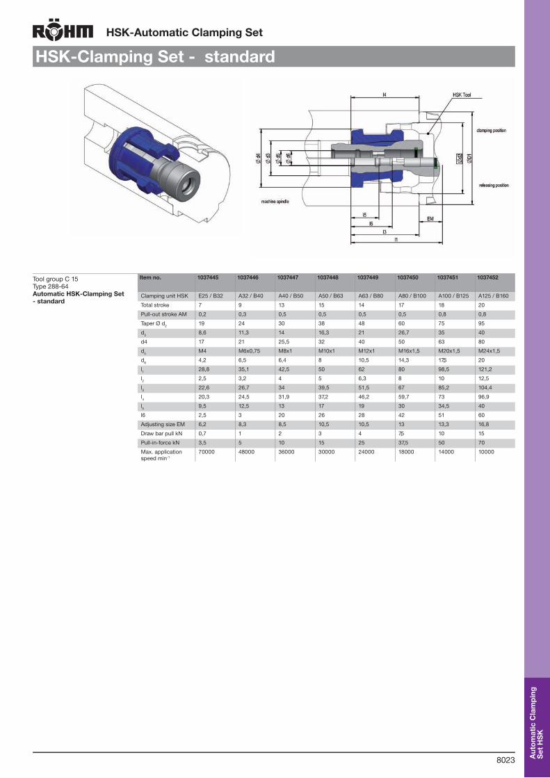
HSK-Automatic Clamping Set
HSK-Clamping Set - standard
Tool group C 15Type 288-64 Automatic HSK-Clamping Set - standard
Item no. 1037445 1037446 1037447 1037448 1037449 1037450 1037451 1037452
Clamping unit HSK E25 / B32 A32 / B40 A40 / B50 A50 / B63 A63 / B80 A80 / B100 A100 / B125 A125 / B160
Total stroke 7 9 13 15 14 17 18 20
Pull-out stroke AM 0,2 0,3 0,5 0,5 0,5 0,5 0,8 0,8
Taper Ø d2 19 24 30 38 48 60 75 95
d3 8,6 11,3 14 16,3 21 26,7 35 40
d4 17 21 25,5 32 40 50 63 80
d5 M4 M6x0,75 M8x1 M10x1 M12x1 M16x1,5 M20x1,5 M24x1,5
d6 4,2 6,5 6,4 8 10,5 14,3 17,5 20
l1 28,8 35,1 42,5 50 62 80 98,5 121,2
l2 2,5 3,2 4 5 6,3 8 10 12,5
l3 22,6 26,7 34 39,5 51,5 67 85,2 104,4
l4 20,3 24,5 31,9 37,2 46,2 59,7 73 96,9
l5 9,5 12,5 13 17 19 30 34,5 40
l6 2,5 3 20 26 28 42 51 60
Adjusting size EM 6,2 8,3 8,5 10,5 10,5 13 13,3 16,8
Draw bar pull kN 0,7 1 2 3 4 7,5 10 15
Pull-in-force kN 3,5 5 10 15 25 37,5 50 70
Max. application speed min-1
70000 48000 36000 30000 24000 18000 14000 10000
Aut
omat
ic C
lam
ping
S
et H
SK
8024
HSK-Automatic Clamping Set
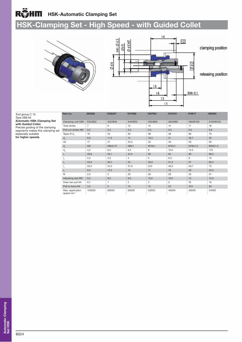
HSK-Clamping Set - High Speed - with Guided Collet
Tool group C 15Type 288-64 Automatic HSK-Clamping Set with Guided ColletPrecise guiding of the clamping segments makes this clamping set especially suitable for higher speeds.
Item no. 594332 1035347 1011063 1037501 1015151 474917 462324
Clamping unit HSK E25/B32 A32/B40 A40/B50 A50/B63 A63/B80 A80/B100 A100/B125
Total stroke 7 9 13 15 14 17 18
Pull-out stroke AM 0,2 0,3 0,5 0,5 0,5 0,5 0,8
Taper Ø d2 19 24 30 38 48 60 75
d3 8,6 11,3 14 16,3 21 26,7 35
d4 17 21 25,5 32 40 50 63
d5 M4 M6x0,75 M8x1 M10x1 M12x1 M16x1,5 M20x1,5
d6 4,2 6,5 6,4 8 10,5 14,3 17,5
l1 28,8 35,1 42,5 50 62 80 98,5
l2 2,5 3,2 4 5 6,3 8 10
l3 22,6 26,7 34 39,5 51,5 67 85,2
l4 20,3 24,5 31,9 37,2 46,2 59,7 73
l5 9,5 12,5 13 17 19 30 34,5
l6 2,5 3 20 26 28 42 51
Adjusting size EM 6,2 8,3 8,5 10,5 10,5 13 13,3
Draw bar pull kN 0,7 1 2 3 5 7,5 10
Pull-in-force kN 3,5 5 10 15 25 37,5 50
Max. application speed min-1
120000 80000 60000 50000 40000 30000 24000
Aut
omat
ic C
lam
ping
S
et H
SK

8025
HSK-Automatic Clamping Set
HSK-Clamping Set with Retaining Collet
Tool group C 15Type 288-64 Automatic HSK-Clamping Set with Retaining ColletSaving time while changing tools, this clamping set with retaining collet will enable you to make multiple steps at the same time window.
Item no. 1024067 1019609 1024145 1015265 1004827
Clamping unit HSK A40/B50 A50/B63 A63/B80 A80/B100 A100/B125
Total stroke 13 15 16 17 18
Pull-out stroke AM 0,5 0,5 0,5 0,5 0,8
Taper Ø d2 30 38 48 60 75
d3 15 18 21 27 36
d4 25,5 32 40 50 63
d5 M8x1 M10x1 M12x1 M16x1,5 M20x1,5
d6 6,4 8 10,5 14,3 17,5
d7 M20x1 M25x1 M33x1 M40x1 M53x1,5
l1 42,5 50 62 80 98,5
l2 4 5 6,3 8 10
l3 34 39,5 51,5 67 85,2
l4 31,85 37,15 46,2 59,7 73
l5 13 17 19 30 34,5
l6 20 26 28 42 51
l7 38 41,5 58,2 75 106
Adjusting size EM 8,5 10,5 10,5 13 13,3
Draw bar pull kN 2 3 4 6 10
Pull-in-force kN 10 15 25 37,5 50
Max. application speed min-1
48000 40000 32000 24000 20000
clamping set with clip retaining collet available on request
Aut
omat
ic C
lam
ping
S
et H
SK

8026
HSK Adaptors with Clamping System
HSK-A/B
Tool group C 15Type 288-74 Adaptors with clamping set HSK-A/Bfor hollow taper shanks according DIN 69893, form A and C (clamping set with increased clamping force elements)
Item no. 850282 850283 850284 850285 850286 850287 850288 850289
Initial size HSK-A/C 25 32 40 50 63 80 100 125
d1 37 40 50 63 80 100 125 148
Taper Ø d2 19 24 30 38 48 60 75 95
d3H7 10 12 15 18 24 32 40 48
d4 6xM3 6xM3 6xM4 6xM5 6xM6 6xM8 6xM10 6xM12
d5g6 24 27 33,5 42 56 68 84 100
d6 14 18 20 25 30 40 50 60
Ø-TK±0,1 29 32 40,5 52 66 82 102 125
l1 31 36 48 55 68 86 106 120
l2 8 9 13 15 17 22 26 27
l3 15,5 19 23 28 35 44 54 70
Draw bar pull kN 0,7 1 2 3 4 7,5 10 16
Pull-in-force kN 3,5 5 10 15 25 37,5 50 70
Total stroke mm 7 9 13 15 14 17 20 21
Clamping set HSK-A/B 1037445 1037446 1037447 1037448 1037449 1037450 1037451 1037452
high precision design: I3dyn. balanced: G 2,5 DIN ISO 1940
Ada
ptor
s w
ith H
SK

8027
HSK-Automatic clamping units
HSK-Clamping unitSkizze fehlt!
Tool group C 15Type 286-03 Automatic HSK-Clamping Unitfor hollow taper shanks HSK according DIN 69893 - for speeds up to 10000 rpm
Item no. 760437 760438 760439 760440 760441 760442
Clamping unit SEH 32/100 40/200 50/300 63/500 80/750 100/1000
A 36 40 48 55,5 65 84
B 44 48 60 68 77 97
C 48 48 62 62 67 67
D 25 32 36 36 48 70
E M 24 x 1,5 M 30 x 1,5 M 35 x 1,5 M 35 x 1,5 M 45 x 1,5 M 68 x 1,5
Ff7 21 26 32 32 41 39
G M 6 M 10 M 12 x 1,5 M 14 x 1,5 M 16 x 1,5 M 20 x 1,5
H 22 26 33 33 41,5 63
I 13 20 22 26 30 39
L 68 75 83,5 87 96 125
M 103 104 108 108 142 165
N 46 47 51 51 51 51
O 14 14 17 17 19 25
P 4 4 5 5 5 8
Q 104 167 193,4 261 264 279
Opening position 1,5 2 0,5 0,5 1,5 3
Clamping position R 6,5 10 8,5 8,5 12,5 15
S 30 34 38,5 39 45 60
T 5 5 6 6 6 9
U 3 4 6 6 6 5
V 15 15 18 18 20 26
Pull force kN 1 2 3 5 7,5 10
Max. opening force bar 80 80 80 80 80 120
Total stroke 9 13 16 16 18 20
Aut
omat
ic c
lam
ping
un
its H
SK

8028
HSK-Automatic clamping units
HSK-Built-in Clamping Unit
Tool group C 15Type 286-00 Automatic HSK Built-in Clamping Unitfor hollow taper shanks HSK according DIN 69893 - for speeds up to 40000 rpm
Item no. 870097 812953 857672 885929 881930 895037
Clamping unit SEH 32/100 40/200 50/300 63/500 80/750 100/1000
A 40 44 - 54 55 54
D 20 28 33 38 38 50
F 12 20 23 28 30 34
G M 6 x 0,75 M 10 x 1 M 12 x 1,5 M 14 x 1,5 M 16 x 1,5 M 18 x 1,5
H 17,8 24 29,5 33 36,3 42,5
L 13,25 - - 79 98 142
O 12 22 31,5 22 30 61,5
S 10,5 27 - 29 40 28,5
T 26,5 35 63,5 43 50 81,5
U - 4 8 10 8 10
V 94,5 147 173,5 169 183 246
W 18 30 39 33 40 35
X 153 237 163,5 275 292 394
Pull force kN 1 2 3 3,5 7,5 7,5
Total stroke 9 13 15 16 18 20
Aut
omat
ic c
lam
ping
un
its H
SK

8029
HSK-Clamping unit
SUPER-LOCK
Cla
mpi
ng u
nit
SU
PE
R-L
OC
K
If high balancing quality combined with static and dynamic stiffness are demanded from the cutting toolin heavy metal cutting operations or with extremely high rotational speeds, then the locking between hollowshank taper and the machine tool must meet enormous demands. Therefore, consistent and secureclamping elements are of utmost importance in the most challenging machining conditions, in order toensure operational reliability.RÖHM presents a new and innovative clamping technique with a springless locking unit for hollow shanktaper in machine tools: Self-locking without spring packet. This trend-setting principle not only improvesthe working procedure, but also distinctly facilitates space saving designs.
Space-saving and powerful: Super-Lock holds HSK totally without springsand compact design
Clamping without springs and additional retention forceHighest balancing qualitySpace saving due to compact designFront mounting in short spindlesApplicable to all HSK sizesSecure clamping even with large HSK tolerancesContinuous, secure and self-lockingOptimised for use with high speedsIdeal for HSC machiningHighly suitable for heavy-duty metal cuttingHigh stiffness combined with the RÖHM HSK clamping unit
Technical features:

8030
HSK-Clamping unit
SUPER-LOCK
Cla
mpi
ng u
nit
SU
PE
R-L
OC
K
Self-locking system suitable for HSC and heavy roughing
The Function of the Lock System Super Lock:The locking system Super Lock serves as a revolutionary connecting link between the HSK clampingunit and the control rod. Even with large HSK tolerances, the unit safely transfers the actuating force andguarantees the connection through mechanical self-locking.For the first time ever, the RÖHM Super Lock needs no springs and no additional retention force, due toa symmetrical collet chuck. The coupled HSK clamping unit is simply moved to the clamping position,and the system locks itself in approx. 0.2 seconds, self-latching on the conical surfaces of the draw boltand clamping sleeve.For releasing, the actuating force of less than 2000 N (example for HSK-A 63) unlocks the draw bolt,pushes the drawbar and therefore the pressure pad of the HSK clamping unit forward. The HSK tool isejected with less force than with spring systems, since there is no need to overcome the spring force.
Comparision of installation size:
Extremely short installation size: HSK 63: 216 mm
HSK-Clamping unit with Super-Lock
HSK-Clampint unitwith spring tension
Connection for HSK clamping unit Connection for push rod
Draw bolt
Guide sleeve
Collet chuckClamping sleeve
Draw bar

8031
HSK-Clamping unit SUPER-LOCK
SUPER-LOCK
Tool group C 15Type 288-69 Clamping unit “SUPER-LOCK”Self-locking mechanism without springs for automatic tool clamping
Item no. 1122572 1122574 1122718 1122725 1122569 1122731 1122581
HSK-A/E 25 32 40 50 63 80 100
D1 13,2 15,1 18,6 23,6 31 39 49
D3 11 12,5 16,4 20,4 25 31,2 40
D4 8 10 13 16 19 24 31
D5 6,2 8,2 10,3 12,5 14,4 17 21
G1 M14x0,5 M16x0,75 M20x1 M25x1 M33x1 M42x1,5 M52x2
G2 M4 M6x0,75 M8x1 M10x1 M12x1 M16x1,5 M20x1,5
G3 M6x0,75 M8x0,75 M10x1 M12x1,25 M14x1,5 M16x1,5 M20x2
H1 11,5 13,8 17,8 19,9 20 27,3 30,8
H2 16,3 17,5 22,8 26,3 28 38,1 42,4
L1 30 37 45 56 70,4 90 112
L2 15,4 14,5 20,4 23,7 27 44,3 55
L3 2,8 3,75 4,6 5,8 7,4 9,2 11,5
P 1 1,25 1,6 2 2,5 3,2 4
G M14x0,5 M16x0,75 M20x1 M25x1 M33x1 M42x1,5 M52x2
d2 19 24 30 38 48 60 75
d3 11 12,5 16,4 20,4 25 31,2 40
d4 13,2 15,1 18,6 23,6 31 39 49
l1 71 83,5 106,4 127,7 157 211 262
l2 2,5 3,2 4 5 6,3 8 10
l3 56 69 86 104 130 167 207
l4 32,25 36,7 45,9 57 70 88,1 10
l5 20,25 24,5 31,85 37,15 46,2 59,65 73
Clamping set 594332 1035347 1011063 1037501 1015151 474917 462324
F1 (N) 3500 5000 10000 15000 25000 37500 50000
F2 (N) 700 1000 2000 3000 5000 7500 10000
Max. application speed min-1
120000 80000 60000 50000 40000 30000 24000
Cla
mpi
ng u
nit
SU
PE
R-L
OC
K

8032
Stationary release unit
Stationary release unitSkizze fehlt!
Tool group C 15Type 285-85 Stationary release unitThis stationary release unit allows a fast stroke movement. - speed independent - through-hole for cleaning air in release position - connection for turning performance
Item no. 884136 850118 486841
Piston area(releasing) cm2 49,7 16,7 62,6
Max. opening force L bar 80 150 80
Max. clamping pressure S bar 80 150 80
Max. cleaning air B bar 10 10 10
Stroke 20 20 22
D 122 115 165
L1 120 117 121
L2 104 104 109
P G 1/4 M10x1 M10x1
W 20° -45° 45°
d1 70 70 100
d2 40 36 56
d3 48 48 48
Further technical data on request
Sta
tiona
ry r
elea
se
unit

8033
Stationary release unit
Stationary release unit with buffer stroke
Tool group C 15Type 285-85 Stationary release unit with buffer strokeTo avoid unnecessary wasting of stroke time a quick release movement over most of the total stroke will be followed by a slow movement of the release piston shortly before end of stroke to eject the tool without loosing any ejection force
Item no. 493997 1019534
Piston area (releasing) cm2 17,6 48,4
Max. opening force L bar 150 120
Max. clamping pressure S bar 150 120
Max. cleaning air B bar 10 10
Buffer stroke mm 2 2
Throttle diameter adjustable mm2 0-7 0-7
Throttle diameter fix mm2 2,8 2,8
Stroke 18 20
A 70 80
D 115 140
E 83 103
F 68 88
G 98 120
M 112 124
X 45 30
Y 4 x 90° 8 x 45°
Further technical data on request
min. 21
15
M
3
Hub -- stroke
ØD
ØE
Ø48
H7
M10
x1
B S
ØAh5
G±0,1
F±0,1
Y
S
LB
X
min. 21
15
M
3
ØD
ØE
Ø48
H7
M10
x1
B S
ØAh5
G±0,1
F±0,1
Y
S
LB
X
min. 21
15
M
3
Hub -- stroke
ØD
ØE
Ø48
H7
M10
x1
B S
ØAh5
G±0,1
F±0,1
Y
S
LB
X
min. 21
15
M
3
ØD
ØE
Ø48
H7
M10
x1
B S
ØAh5
G±0,1
F±0,1
Y
S
LB
X
Sta
tiona
ry r
elea
se
unit
8034
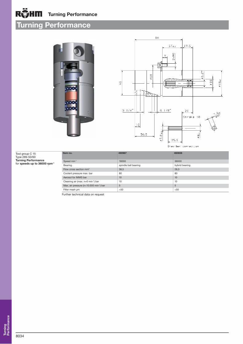
Turning Performance
Turning Performance
Tool group C 15Type 289-50/60 Turning Performancefor speeds up to 36000 rpm-1
Item no. 490967 460658
Speed min-1 18000 36000
Bearing spindle ball bearing hybrid bearing
Flow cross section mm2 38,5 28,3
Coolant pressure max. bar 80 80
Aerosol for IMMS bar 10 10
Cleaning air (max. n=0 min-1) bar 10 10
Max. air pressure (n<10.000 min-1) bar 5 5
Filter mesh µm <50 <50
Further technical data on request
Turn
ing
Per
form
ance

8035
Tool Mountings for Positive Taper Lock HSK-C / HSK-A
HSK-clamping chucks
For machining centers and transfer lines
HSK-C for manual tool change HSK-A for automatic tool change
Type 288-21Clamping chuck ESX/ER16
Type 288-21Clamping chuck ESX/ER 32
Type 288-20Tool blank
Type 135-48Drill chuck
Type 288-22Cutter arbor
Type 344-90Quick changetapping chuck
Type 288-30Test bar
Type 288-24Adaptor sleeves - DIN 1835-E
Type 288-23Adaptor sleeves - DIN 1835-B
Type 288-92Plug
Type 288-01Clamping chuck ESX/ER16
Type 288-01Clamping chuck ESX/ER 32
Type 288-00Tool blank
Type 135-47Drill chuck
Type 288-02Cutter arbor
Type 344-91Quick changetapping chuck
Type 288-10Test bar
Type 288-04Adaptor sleeves - DIN 1835-E
Type 288-03Adaptor sleeves - DIN 1835-B
Type 288-03Adaptor with HSK-A
Type 288-32ABS-Mounting
Type 288-31MK-Mounting
Other Positive Taper Lock HSK Design, i.e. E - F - B - D - on request
Tool
mou
ntin
gs w
ith
HS
K-C
/ H
SK
-A

8036
Tool mountings with HSK-C / HSK-A
HSK-Tool blankes
Positive Taper Lock including locating surface hardened with min. 670 +100HV30 Vickers (min. HRc58) Taper ground to DIN 69893. Shank part not hardened and ground for machining.
Technical features:- D* = Dimension data correspond to finished dimension- Delivered with overmeasure of 0,5 mm per diameter- Material: Alloyed hardened steel
Tool group C 19Type 288-00 Tool blankes HSK-A for automatic tool changefor self-producing of special tools
Item no. Initial size D1 A L D* d4 Weight kg
756342 32 150 166 40 24 4,5
756343 40 200 220 52 30 5,8
756344 50 200 225 63 38 8,1
756345 63 250 282 80 48 11
756346 80 250 290 80 60 15
756347 100 250 300 75 75 18
Positive Taper Lock including locating surface hardened with min. 670 +100HV30 Vickers (min. HRc58) Taper ground to DIN 69893. Shank part not hardened and ground for machining.
Technical features:- D* = Dimension data correspond to finished dimension- Delivered with overmeasure of 0,5 mm per diameter- Material: Alloyed hardened steel
Tool group C 15Type 288-20 Tool blankes HSK-C for manual tool changefor self-producing of special tools
Item no. Initial size D1 A L D* d4 Weight kg
749356 32 150 166 40 24 4,5
749357 40 200 220 52 30 5,8
749358 50 200 225 63 38 8,1
749359 63 250 282 80 48 11
749360 80 250 290 80 60 15
749361 100 250 300 95 75 18
d4D1
A
L
D
d4D
A
L
D1
Tool
mou
ntin
gs w
ith
HS
K-C
/ H
SK
-A

8037
Tool mountings with HSK-C / HSK-A
HSK-clamping chucks
D1d4
g
5
27
A
L
28
Permissible concentricity error of the positive taper lock HSK in relation to the collet mounting taper 0,003 mm. Supply: Clamping chuck with clamping ring and spindle through-drilled
Collets must be ordered separately Other sizes for HSK-clamping chuck on request
Tool group C 15Type 288-01 Clamping Chuck HSK-A for automatic tool changefor collets ER/ESX16 (DIN 6499) clamping capacity 0,5 to 10 mm
Item no. Initial size D1 A L d1 d4 g l1 v Weight kg
753210 50 100 125 28 38 M 10 27 5 0,5
753211 63 100 132 28 48 M 10 27 5 1
753212 63 160 192 28 48 M 10 27 5 1,7
753213 100 100 150 28 75 M 12 27 5 2,9
753214 100 160 210 28 75 M 12 27 5 3,4
D1d4
g
5
27
A
L
28
Permissible concentricity error of the positive taper lock HSK in relation to the collet mounting taper 0,003 mm. Supply: Clamping chuck with clamping ring and spindle through-drilled
Collets must be ordered separately Other sizes for HSK-clamping chuck on request
Tool group C 15Type 288-01 Clamping Chuck HSK-A for automatic tool changefor collets ER/ESX 32+40 (DIN 6499) clamping capacity 2 to 20 mm resp. 3 to 26 mm
Item no. Initial size D1 A L Clamping range d4 v Weight kg
749458 50 100 125 2-20 50 5 1
753215 63 100 132 2-20 50 5 1,3
753216 80 120 152 2-20 50 5 2,2
753217 100 100 150 2-20 50 5 2,7
753218 100 120 170 3-26 63 5 2,9
D1d4
28
5
27
A
L
g Permissible concentricity error of the positive taper lock HSK in relation to the collet mounting taper 0,003 mm. Supply: Clamping chuck with clamping ring and spindle through-drilled
Collets must be ordered separately Other sizes for HSK-clamping chuck on request
Tool group C 15Type 288-21 Clamping Chuck HSK-C for manual tool changefor collets ER/ESX16 (DIN 6499) clamping capacity 0,5 to 10 mm
Item no. Initial size D1 A L d1 d4 g l1 v Weight kg
749333 32 60 76 28 24 M 10 27 5 0,3
749334 40 60 80 28 30 M 10 27 5 0,4
749335 50 60 85 28 38 M 10 27 5 0,5
749336 63 60 92 28 48 M 10 27 5 1
749337 80 65 105 28 60 M 12 27 5 1
749338 100 65 115 28 75 M 12 27 5 2,9
Tool
mou
ntin
gs w
ith
HS
K-C
/ H
SK
-A

8038
Tool mountings with HSK-C / HSK-A
HSK-clamping chucks
D1d4
28
5
27
A
L
g Permissible concentricity error of the positive taper lock HSK in relation to the collet mounting taper 0,003 mm. Supply: Clamping chuck with clamping ring and spindle through-drilled
Collets must be ordered separately Other sizes for HSK-clamping chuck on request
Tool group C 15Type 288-21 Clamping Chuck HSK-C for manual tool changefor collets ER/ESX 32+40 (DIN 6499) clamping capacity 2 to 20 mm resp. 3 to 26 mm
Item no. Initial size D1 A L Clamping range d4 v Weight kg
749339 40 75 95 2-20 50 5 0,9
749340 50 75 100 2-20 50 5 1
749341 50 80 105 3-26 63 5 1,1
749342 63 75 107 2-20 50 5 1,3
749343 63 80 112 3-26 63 5 1,4
749344 80 80 120 2-20 50 5 2,2
749351 80 85 125 3-26 63 5 2,5
749352 100 80 130 2-20 50 5 2,7
749353 100 90 140 3-26 63 5 2,9
HSK-Drill chuck
Tool group A 34Type 135-47 Drill Chuck HSK-A for automatic tool change
d4D1
AL
D
Item no. Size Initial size D1
A L D d4 Clamping capacity
707611 13 50 114 139 50 38 1-13
707790 13 63 95 127 50 48 1-13
707791 13 100 100 150 50 75 1-13
753591 16 50 114,7 139,7 55 38 3-16
707792 16 63 95,7 127,7 55 48 3-16
707793 16 100 100,7 150,7 55 75 3-16
Tool group A 34Type 135-48 Drill-Chuck HSK-C for manual tool change
d4
AL
DD1
Item no. Size Initial size D1
A L D d4 Clamping capacity
753592 13 50 81,5 106,5 50 38 1-13
753593 13 63 81,5 113,5 50 48 1-13
753594 13 100 85 135 50 75 1-13
753595 16 50 82,2 107,2 55 38 3-16
753596 16 63 82,2 114,2 55 48 3-16
753597 16 100 85,7 135,7 55 75 3-16
Tool
mou
ntin
gs w
ith
HS
K-C
/ H
SK
-A

8039
Tool mountings with HSK-C / HSK-A
HSK-Slip-on cutter arbor
Tool group C 19Type 288-02 Slip-on cutter arbor HSK-A for automatic tool changefor cutter with longitudinal and transversal slots, cutter drive to DIN 138
Item no. Initial size D1
A1 A L d1 d2 d4 g l3 l4
756323 40 30 40 77 16 32 30 M 8 17 27
756324 40 28 40 79 22 40 30 M 10 19 31
756325 50 40 50 92 16 32 38 M 8 17 27
756326 50 38 50 94 22 40 38 M 10 19 31
756327 50 53 65 111 27 48 38 M 12 21 33
756328 50 51 65 114 32 58 38 M 16 24 38
756329 63 50 60 109 16 32 48 M 8 17 27
756330 63 48 60 111 22 40 48 M 10 19 31
756331 63 48 60 113 27 48 48 M 12 21 33
756332 63 46 60 116 32 58 48 M 16 24 38
756333 63 56 70 129 40 70 48 M 20 27 41
756334 100 50 60 127 16 32 75 M 8 17 27
756335 100 48 60 129 22 40 75 M 10 19 31
756336 100 48 60 131 27 48 75 M 12 21 33
756337 100 46 60 134 32 58 75 M 16 24 38
756338 100 56 70 147 40 70 75 M 20 27 41
756339 100 64 80 160 50 90 75 M 24 30 46
Supply: With draw-in bolt for milling cutter, feather with draw-off thread and driver ringCutter abor rings see DIN 2084
Tool group C 19Type 288-22 Slip-on cutter arbor HSK-C for manual tool changefor cutter with longitudinal and transversal slots, cutter drive to DIN 138
Item no. Initial size D1
A1 A L d1 d2 d4 g l3 l4
749408 40 20 30 67 16 32 30 M 8 17 27
749409 40 18 30 69 22 40 30 M 10 19 31
749410 50 26 36 78 16 32 38 M 8 17 27
749411 50 24 36 80 22 40 38 M 10 19 31
749412 50 34 52 98 27 48 38 M 12 21 33
749413 50 32 52 101 32 58 38 M 16 24 38
749414 63 36 46 95 16 32 48 M 8 17 27
749415 63 34 46 97 22 40 48 M 10 19 31
749416 63 34 46 99 27 48 48 M 12 21 33
749417 63 32 46 102 32 58 48 M 16 24 38
749418 63 42 56 115 40 70 48 M 20 27 41
749419 80 40 50 107 16 32 60 M 8 17 27
749420 80 38 50 109 22 40 60 M 10 19 31
749421 80 38 50 111 27 48 60 M 12 21 33
749422 80 36 50 114 32 58 60 M 16 24 38
749423 80 46 60 127 40 70 60 M 20 27 41
749424 80 54 70 140 50 90 60 M 24 30 46
749425 100 37 47 114 16 32 75 M 8 17 27
749426 100 35 47 22 40 75 M 10 19 31
749427 100 35 47 118 27 48 75 M 12 21 33
749428 100 33 47 121 32 58 75 M 16 24 38
749429 100 43 57 134 40 70 75 M 20 27 41
749430 100 41 67 137 50 90 75 M 24 30 46
Supply: With draw-in bolt for milling cutter, feather with draw-off thread and driver ringCutter abor rings see DIN 2084
d4
D1
A1 l4
l3A
L
d2d1h6
g
d4
A1
d2
l4
l3A
L
D1 d1h6
g
Tool
mou
ntin
gs w
ith
HS
K-C
/ H
SK
-A
8040
Tool mountings with HSK-C / HSK-A
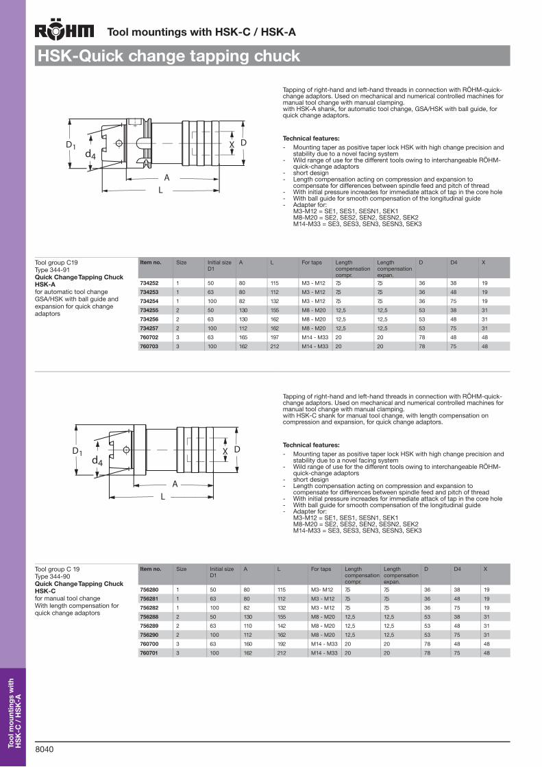
HSK-Quick change tapping chuck
d4D1 DX
AL
Tapping of right-hand and left-hand threads in connection with RÖHM-quick-change adaptors. Used on mechanical and numerical controlled machines for manual tool change with manual clamping. with HSK-A shank, for automatic tool change, GSA/HSK with ball guide, for quick change adaptors.
Technical features:- Mounting taper as positive taper lock HSK with high change precision and
stability due to a novel facing system- Wild range of use for the different tools owing to interchangeable RÖHM-
quick-change adaptors- short design- Length compensation acting on compression and expansion to
compensate for differences between spindle feed and pitch of thread- With initial pressure increades for immediate attack of tap in the core hole- With ball guide for smooth compensation of the longitudinal guide- Adapter for:
M3-M12 = SE1, SES1, SESN1, SEK1 M8-M20 = SE2, SES2, SEN2, SESN2, SEK2 M14-M33 = SE3, SES3, SEN3, SESN3, SEK3
Tool group C19Type 344-91 Quick Change Tapping Chuck HSK-A for automatic tool changeGSA/HSK with ball guide and expansion for quick change adaptors
Item no. Size Initial size D1
A L For taps Length compensation compr.
Length compensation expan.
D D4 X
734252 1 50 80 115 M3 - M12 7,5 7,5 36 38 19
734253 1 63 80 112 M3 - M12 7,5 7,5 36 48 19
734254 1 100 82 132 M3 - M12 7,5 7,5 36 75 19
734255 2 50 130 155 M8 - M20 12,5 12,5 53 38 31
734256 2 63 130 162 M8 - M20 12,5 12,5 53 48 31
734257 2 100 112 162 M8 - M20 12,5 12,5 53 75 31
760702 3 63 165 197 M14 - M33 20 20 78 48 48
760703 3 100 162 212 M14 - M33 20 20 78 75 48
d4
AL
DXD1
Tapping of right-hand and left-hand threads in connection with RÖHM-quick-change adaptors. Used on mechanical and numerical controlled machines for manual tool change with manual clamping. with HSK-C shank for manual tool change, with length compensation on compression and expansion, for quick change adaptors.
Technical features:- Mounting taper as positive taper lock HSK with high change precision and
stability due to a novel facing system- Wild range of use for the different tools owing to interchangeable RÖHM-
quick-change adaptors- short design- Length compensation acting on compression and expansion to
compensate for differences between spindle feed and pitch of thread- With initial pressure increades for immediate attack of tap in the core hole- With ball guide for smooth compensation of the longitudinal guide- Adapter for:
M3-M12 = SE1, SES1, SESN1, SEK1 M8-M20 = SE2, SES2, SEN2, SESN2, SEK2 M14-M33 = SE3, SES3, SEN3, SESN3, SEK3
Tool group C 19Type 344-90 Quick Change Tapping Chuck HSK-C for manual tool changeWith length compensation for quick change adaptors
Item no. Size Initial size D1
A L For taps Length compensation compr.
Length compensation expan.
D D4 X
756280 1 50 80 115 M3- M12 7,5 7,5 36 38 19
756281 1 63 80 112 M3 - M12 7,5 7,5 36 48 19
756282 1 100 82 132 M3 - M12 7,5 7,5 36 75 19
756288 2 50 130 155 M8 - M20 12,5 12,5 53 38 31
756289 2 63 110 142 M8 - M20 12,5 12,5 53 48 31
756290 2 100 112 162 M8 - M20 12,5 12,5 53 75 31
760700 3 63 160 192 M14 - M33 20 20 78 48 48
760701 3 100 162 212 M14 - M33 20 20 78 75 48
Tool
mou
ntin
gs w
ith
HS
K-C
/ H
SK
-A
8041
Tool mountings with HSK-C / HSK-A
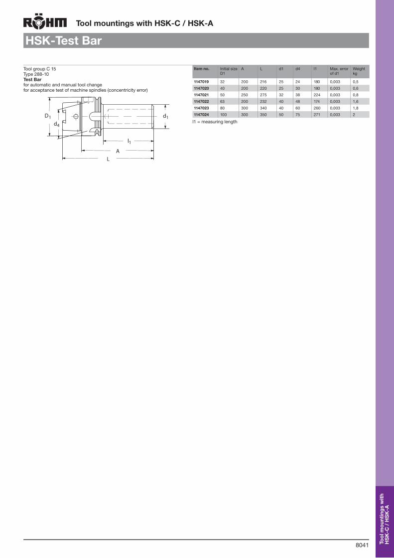
HSK-Test Bar
Tool group C 15Type 288-10 Test Bar for automatic and manual tool changefor acceptance test of machine spindles (concentricity error)
AL
l1
D1 d1d4
Item no. Initial size D1
A L d1 d4 l1 Max. error of d1
Weight kg
1147019 32 200 216 25 24 180 0,003 0,5
1147020 40 200 220 25 30 180 0,003 0,6
1147021 50 250 275 32 38 224 0,003 0,8
1147022 63 200 232 40 48 174 0,003 1,6
1147023 80 300 340 40 60 260 0,003 1,8
1147024 100 300 350 50 75 271 0,003 2
l1 = measuring length
Tool
mou
ntin
gs w
ith
HS
K-C
/ H
SK
-A
8042
Tool mountings with HSK-C / HSK-A
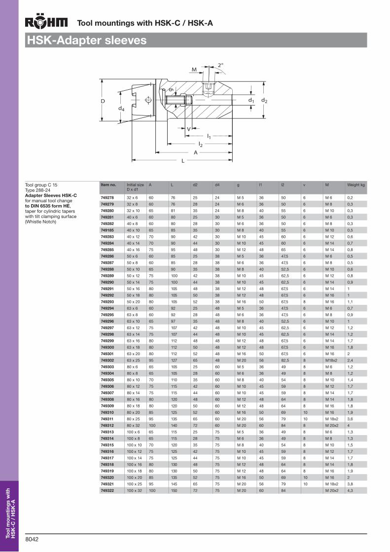
HSK-Adapter sleeves
Tool group C 15Type 288-24 Adapter Sleeves HSK-C for manual tool changeto DIN 6535 form HE, taper for cylindric tapers with tilt clamping surface (Whistle Notch)
Item no. Initial size D x d1
A L d2 d4 g l1 l2 v M Weight kg
749278 32 x 6 60 76 25 24 M 5 36 50 6 M 6 0,2
749279 32 x 8 60 76 28 24 M 6 36 50 6 M 8 0,3
749280 32 x 10 65 81 35 24 M 8 40 55 6 M 10 0,3
749281 40 x 6 60 80 25 30 M 5 36 50 6 M 6 0,3
749282 40 x 8 60 80 28 30 M 6 36 50 6 M 8 0,3
749185 40 x 10 65 85 35 30 M 8 40 55 6 M 10 0,5
749283 40 x 12 70 90 42 30 M 10 45 60 6 M 12 0,6
749284 40 x 14 70 90 44 30 M 10 45 60 6 M 14 0,7
749285 40 x 16 75 95 48 30 M 12 48 65 6 M 14 0,8
749286 50 x 6 60 85 25 38 M 5 36 47,5 6 M 6 0,5
749287 50 x 8 60 85 28 38 M 6 36 47,5 6 M 8 0,5
749288 50 x 10 65 90 35 38 M 8 40 52,5 6 M 10 0,6
749289 50 x 12 75 100 42 38 M 10 45 62,5 6 M 12 0,8
749290 50 x 14 75 100 44 38 M 10 45 62,5 6 M 14 0,9
749291 50 x 16 80 105 48 38 M 12 48 67,5 6 M 14 1
749292 50 x 18 80 105 50 38 M 12 48 67,5 6 M 16 1
749293 50 x 20 80 105 52 38 M 16 50 67,5 8 M 16 1,1
749294 63 x 6 60 92 25 48 M 5 36 47,5 6 M 6 0,7
749295 63 x 8 60 92 28 48 M 6 36 47,5 6 M 8 0,9
749296 63 x 10 65 97 35 48 M 8 40 52,5 6 M 10 1
749297 63 x 12 75 107 42 48 M 10 45 62,5 6 M 12 1,2
749298 63 x 14 75 107 44 48 M 10 45 62,5 6 M 14 1,2
749299 63 x 16 80 112 48 48 M 12 48 67,5 6 M 14 1,7
749300 63 x 18 80 112 50 48 M 12 48 67,5 6 M 16 1,8
749301 63 x 20 80 112 52 48 M 16 50 67,5 6 M 16 2
749302 63 x 25 95 127 65 48 M 20 56 82,5 8 M18x2 2,4
749303 80 x 6 65 105 25 60 M 5 36 49 8 M 6 1,2
749304 80 x 8 65 105 28 60 M 6 36 49 8 M 8 1,2
749305 80 x 10 70 110 35 60 M 8 40 54 8 M 10 1,4
749306 80 x 12 75 115 42 60 M 10 45 59 8 M 12 1,7
749307 80 x 14 75 115 44 60 M 10 45 59 8 M 14 1,7
749308 80 x 16 80 120 48 60 M 12 48 64 8 M 14 1,8
749309 80 x 18 80 120 50 60 M 12 48 64 8 M 16 1,8
749310 80 x 20 85 125 52 60 M 16 50 69 10 M 16 1,9
749311 80 x 25 95 135 65 60 M 20 56 79 10 M 18x2 3,6
749312 80 x 32 100 140 72 60 M 20 60 84 8 M 20x2 4
749313 100 x 6 65 115 25 75 M 5 36 49 8 M 6 1,3
749314 100 x 8 65 115 28 75 M 6 36 49 8 M 8 1,3
749315 100 x 10 70 120 35 75 M 8 40 54 8 M 10 1,5
749316 100 x 12 75 125 42 75 M 10 45 59 8 M 12 1,7
749317 100 x 14 75 125 44 75 M 10 45 59 8 M 14 1,7
749318 100 x 16 80 130 48 75 M 12 48 64 8 M 14 1,8
749319 100 x 18 80 130 50 75 M 12 48 64 8 M 16 1,9
749320 100 x 20 85 135 52 75 M 16 50 69 10 M 16 2
749321 100 x 25 95 145 65 75 M 20 56 79 10 M 18x2 3,8
749322 100 x 32 100 150 72 75 M 20 60 84 M 20x2 4,3
2°
l2
gL
A
l1V
Dd4
M
d1 d2
Tool
mou
ntin
gs w
ith
HS
K-C
/ H
SK
-A

8043
Tool mountings with HSK-C / HSK-A
HSK-Adapter sleeves
Tool group C 15Type 288-04 Adapter Sleeves HSK-A for automatic tool changeto DIN 1835 form E, taper for cylindric tapers with tilt clamping surface (Whistle Notch)
Item no. Initial size D x d1
A L d2 d4 g l1 v M Weight kg
469277 32 x 6 80 100 25 24 M 5 20 6 M 6 0,2
469278 32 x 8 80 100 28 24 M 6 20 6 M 8 0,3
469279 32 x 10 80 100 35 24 M 8 20 6 M 10 0,3
599090 40 x 6 80 100 25 30 M 5 20 6 M 6 0,3
599091 40 x 8 80 100 28 30 M 6 20 6 M 8 0,3
599092 40 x 10 80 100 35 30 M 8 20 6 M 10 0,5
599093 40 x 12 90 110 42 30 M 10 20 6 M 12 0,6
599094 40 x 14 90 110 44 30 M 10 20 6 M 14 0,7
599095 40 x 16 90 110 48 30 M 12 20 6 M 14 0,8
753157 50 x 6 80 105 25 38 M 5 25 6 M 6 0,5
753158 50 x 8 80 105 28 38 M 6 25 6 M 8 0,5
753159 50 x 10 80 105 35 38 M 8 25 6 M 10 0,6
753160 50 x 12 90 115 42 38 M 10 25 6 M 12 0,8
753161 50 x 14 90 115 44 38 M 10 25 6 M 14 0,9
753162 50 x 16 90 115 48 38 M 12 25 6 M 14 1
753163 50 x 18 90 115 50 38 M 12 25 6 M 16 1
753164 50 x 20 100 125 52 38 M 16 25 8 M 16 1,1
753165 63 x 6 80 112 25 48 M 5 32 6 M 6 0,7
753166 63 x 8 80 112 28 48 M 6 32 6 M 8 0,9
753167 63 x 10 80 112 35 48 M 8 32 6 M 10 1
753168 63 x 12 90 122 42 48 M 10 32 6 M 12 1,2
753169 63 x 14 90 122 44 48 M 10 32 6 M 14 1,2
753170 63 x 16 100 132 48 48 M 12 32 6 M 14 1,7
753171 63 x 18 100 132 50 48 M 12 32 6 M 16 1,8
753172 63 x 20 100 132 52 48 M 16 32 6 M 16 2
753173 63 x 25 110 142 65 48 M 20 32 8 M18x2 2,4
753174 63 x 32 110 142 M 20 32 M 20x2 -
469280 80 x 6 90 122 25 60 M 5 32 8 M 6 1,2
469281 80 x 8 90 122 28 60 M 6 36 8 M 8 1,2
469282 80 x 10 90 122 35 60 M 8 32 8 M 10 1,4
469283 80 x 12 100 132 42 60 M 10 32 8 M 12 1,7
469284 80 x 14 100 132 44 60 M 10 32 8 M 14 1,7
469285 80 x 16 100 132 48 60 M 12 32 8 M 14 1,8
469286 80 x 18 100 132 50 60 M 12 32 8 M 16 1,8
469287 80 x 20 110 142 52 60 M 16 32 8 M 16 1,9
469288 80 x 25 110 143 65 60 M 20 32 10 M 18x2 3,6
469289 80 x 32 120 152 72 60 M 20 32 10 M 20x2 4
753175 100 x 6 90 140 25 75 M 5 50 8 M 6 1,3
753176 100 x 8 90 140 28 75 M 6 50 8 M 8 1,3
753177 100 x 10 90 140 35 75 M 8 50 8 M 10 1,5
753178 100 x 12 100 150 42 75 M 10 50 8 M 12 1,7
753179 100 x 14 100 150 44 75 M 10 50 8 M 14 1,7
753180 100 x 16 100 150 48 75 M 12 50 8 M 14 1,8
753181 100 x 18 100 150 50 75 M 12 50 8 M 16 1,9
753182 100 x 20 110 160 52 75 M 16 50 8 M 16 2
753183 100 x 25 120 170 65 75 M 20 50 10 M 18x2 3,8
753184 100 x 32 120 170 72 75 M 20 50 10 M 20x2 4,3
469290 100 x 40 120 170 90 75 - 50 M 20x2 -
Dd4
2°M
l2
LA
l1
V
d1 d2
g
Tool
mou
ntin
gs w
ith
HS
K-C
/ H
SK
-A
8044
Tool mountings with HSK-C / HSK-A
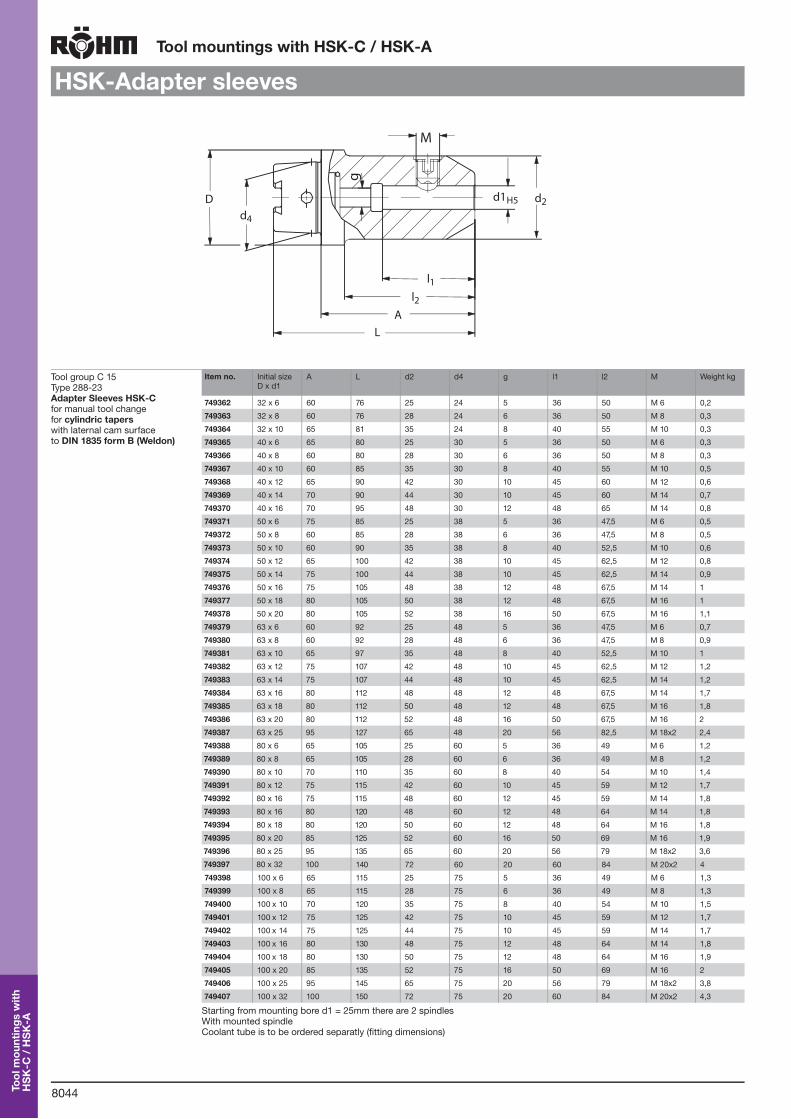
HSK-Adapter sleeves
Tool group C 15Type 288-23 Adapter Sleeves HSK-C for manual tool changefor cylindric tapers with laternal cam surface to DIN 1835 form B (Weldon)
Item no. Initial size D x d1
A L d2 d4 g l1 l2 M Weight kg
749362 32 x 6 60 76 25 24 5 36 50 M 6 0,2
749363 32 x 8 60 76 28 24 6 36 50 M 8 0,3
749364 32 x 10 65 81 35 24 8 40 55 M 10 0,3
749365 40 x 6 65 80 25 30 5 36 50 M 6 0,3
749366 40 x 8 60 80 28 30 6 36 50 M 8 0,3
749367 40 x 10 60 85 35 30 8 40 55 M 10 0,5
749368 40 x 12 65 90 42 30 10 45 60 M 12 0,6
749369 40 x 14 70 90 44 30 10 45 60 M 14 0,7
749370 40 x 16 70 95 48 30 12 48 65 M 14 0,8
749371 50 x 6 75 85 25 38 5 36 47,5 M 6 0,5
749372 50 x 8 60 85 28 38 6 36 47,5 M 8 0,5
749373 50 x 10 60 90 35 38 8 40 52,5 M 10 0,6
749374 50 x 12 65 100 42 38 10 45 62,5 M 12 0,8
749375 50 x 14 75 100 44 38 10 45 62,5 M 14 0,9
749376 50 x 16 75 105 48 38 12 48 67,5 M 14 1
749377 50 x 18 80 105 50 38 12 48 67,5 M 16 1
749378 50 x 20 80 105 52 38 16 50 67,5 M 16 1,1
749379 63 x 6 60 92 25 48 5 36 47,5 M 6 0,7
749380 63 x 8 60 92 28 48 6 36 47,5 M 8 0,9
749381 63 x 10 65 97 35 48 8 40 52,5 M 10 1
749382 63 x 12 75 107 42 48 10 45 62,5 M 12 1,2
749383 63 x 14 75 107 44 48 10 45 62,5 M 14 1,2
749384 63 x 16 80 112 48 48 12 48 67,5 M 14 1,7
749385 63 x 18 80 112 50 48 12 48 67,5 M 16 1,8
749386 63 x 20 80 112 52 48 16 50 67,5 M 16 2
749387 63 x 25 95 127 65 48 20 56 82,5 M 18x2 2,4
749388 80 x 6 65 105 25 60 5 36 49 M 6 1,2
749389 80 x 8 65 105 28 60 6 36 49 M 8 1,2
749390 80 x 10 70 110 35 60 8 40 54 M 10 1,4
749391 80 x 12 75 115 42 60 10 45 59 M 12 1,7
749392 80 x 16 75 115 48 60 12 45 59 M 14 1,8
749393 80 x 16 80 120 48 60 12 48 64 M 14 1,8
749394 80 x 18 80 120 50 60 12 48 64 M 16 1,8
749395 80 x 20 85 125 52 60 16 50 69 M 16 1,9
749396 80 x 25 95 135 65 60 20 56 79 M 18x2 3,6
749397 80 x 32 100 140 72 60 20 60 84 M 20x2 4
749398 100 x 6 65 115 25 75 5 36 49 M 6 1,3
749399 100 x 8 65 115 28 75 6 36 49 M 8 1,3
749400 100 x 10 70 120 35 75 8 40 54 M 10 1,5
749401 100 x 12 75 125 42 75 10 45 59 M 12 1,7
749402 100 x 14 75 125 44 75 10 45 59 M 14 1,7
749403 100 x 16 80 130 48 75 12 48 64 M 14 1,8
749404 100 x 18 80 130 50 75 12 48 64 M 16 1,9
749405 100 x 20 85 135 52 75 16 50 69 M 16 2
749406 100 x 25 95 145 65 75 20 56 79 M 18x2 3,8
749407 100 x 32 100 150 72 75 20 60 84 M 20x2 4,3
Starting from mounting bore d1 = 25mm there are 2 spindlesWith mounted spindleCoolant tube is to be ordered separatly (fitting dimensions)
d2Dd4
l1l2
AL
d1H5
M
g
Tool
mou
ntin
gs w
ith
HS
K-C
/ H
SK
-A
8045
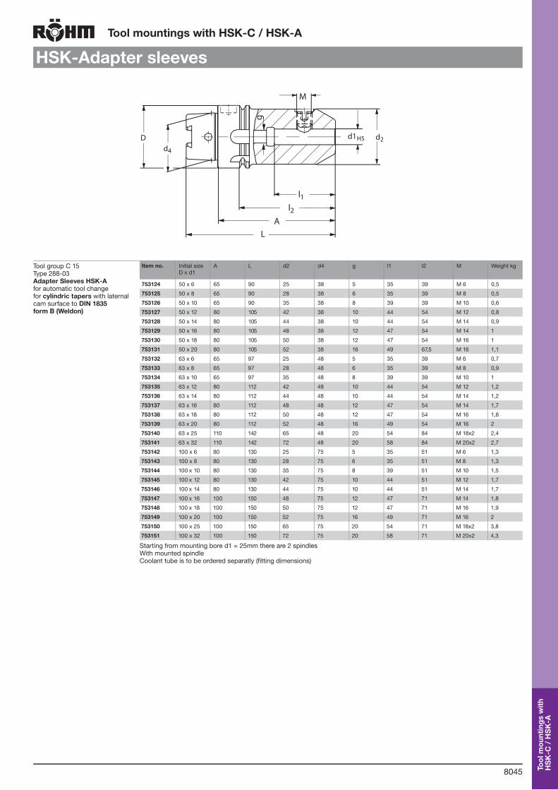
Tool mountings with HSK-C / HSK-A
HSK-Adapter sleeves
Tool group C 15Type 288-03 Adapter Sleeves HSK-A for automatic tool changefor cylindric tapers with laternal cam surface to DIN 1835 form B (Weldon)
Item no. Initial size D x d1
A L d2 d4 g l1 l2 M Weight kg
753124 50 x 6 65 90 25 38 5 35 39 M 6 0,5
753125 50 x 8 65 90 28 38 6 35 39 M 8 0,5
753126 50 x 10 65 90 35 38 8 39 39 M 10 0,6
753127 50 x 12 80 105 42 38 10 44 54 M 12 0,8
753128 50 x 14 80 105 44 38 10 44 54 M 14 0,9
753129 50 x 16 80 105 48 38 12 47 54 M 14 1
753130 50 x 18 80 105 50 38 12 47 54 M 16 1
753131 50 x 20 80 105 52 38 16 49 67,5 M 16 1,1
753132 63 x 6 65 97 25 48 5 35 39 M 6 0,7
753133 63 x 8 65 97 28 48 6 35 39 M 8 0,9
753134 63 x 10 65 97 35 48 8 39 39 M 10 1
753135 63 x 12 80 112 42 48 10 44 54 M 12 1,2
753136 63 x 14 80 112 44 48 10 44 54 M 14 1,2
753137 63 x 16 80 112 48 48 12 47 54 M 14 1,7
753138 63 x 18 80 112 50 48 12 47 54 M 16 1,8
753139 63 x 20 80 112 52 48 16 49 54 M 16 2
753140 63 x 25 110 142 65 48 20 54 84 M 18x2 2,4
753141 63 x 32 110 142 72 48 20 58 84 M 20x2 2,7
753142 100 x 6 80 130 25 75 5 35 51 M 6 1,3
753143 100 x 8 80 130 28 75 6 35 51 M 8 1,3
753144 100 x 10 80 130 35 75 8 39 51 M 10 1,5
753145 100 x 12 80 130 42 75 10 44 51 M 12 1,7
753146 100 x 14 80 130 44 75 10 44 51 M 14 1,7
753147 100 x 16 100 150 48 75 12 47 71 M 14 1,8
753148 100 x 18 100 150 50 75 12 47 71 M 16 1,9
753149 100 x 20 100 150 52 75 16 49 71 M 16 2
753150 100 x 25 100 150 65 75 20 54 71 M 18x2 3,8
753151 100 x 32 100 150 72 75 20 58 71 M 20x2 4,3
Starting from mounting bore d1 = 25mm there are 2 spindlesWith mounted spindleCoolant tube is to be ordered separatly (fitting dimensions)
Dd4
M
d2d1H5
l1l2
AL
g
Tool
mou
ntin
gs w
ith
HS
K-C
/ H
SK
-A

8046
Tool mountings with HSK-C / HSK-A
L
A1
A
d 4Dh1
0
d 1H4
d 2
d 3
Combinated design for clamping of tools with cylindrical shaft according to DIN 1835-B/DIN 6359-HB and DIN 1835-E/DIN 6359-HE
Technical features:- Delivery includes: Adaptor sleeve with special clamping screw and drilled
stop screw- Coolant tube must be ordered separately
Tool group C 15Type 288-03 Positive Taper Lock - Adapter with HSK-A shaftextendend, slim design, for automatic tool change
Item no. D x d1 x A A A1 L d2 d3 d4 Weight kg
469206 63x6x100 100 26 132 28 22 48 28
469207 63x6x160 160 26 192 33 22 48 33
469208 63x8x100 100 26 132 30 24 48 30
469209 63x8x160 160 26 192 35 24 48 35
469210 63x10x100 100 26 132 32 25 48 32
469211 63x10x160 160 26 192 39 25 48 39
469212 63x12x120 120 26 152 35 26 48 35
469213 63x12x160 160 26 192 43 26 48 43
469214 63x14x120 120 26 152 39 28 48 39
469215 63x14x160 160 26 192 46 28 48 46
469216 63x16x120 120 26 152 37 30 48 37
469217 63x16x160 160 26 192 44 30 48 44
469218 63x18x120 120 26 152 39 32 48 39
469219 63x18x160 160 26 192 46 32 48 46
469220 63x20x120 120 26 152 43 34 48 43
469221 63x20x160 160 26 192 50 34 48 50
HSK-Adapter
Tool group C 15Type 288-05 Adapter Sleeves Weldon / HSK-A, “COOL TOOL”for cylindric tapers with laternal cam surface acc. to DIN 1835 form B (Weldon milling reception) with coolant bores “COOL TOOL”
Item no. Taper A d2 d1 Clamp. diam. Weight kg
1063653 HSK 63 65 25 6 0,9
1063654 HSK 63 65 28 8 1,3
1063655 HSK 63 65 35 10 0,9
1063656 HSK 63 80 42 12 1,3
1063657 HSK 63 80 42 14 0,9
1063658 HSK 63 80 48 16 0,9
1063659 HSK 63 80 48 18 1,6
1063660 HSK 63 80 52 20 1
1063661 HSK 63 110 65 25 1,5
1063662 HSK 63 110 72 32 1
Balanced 2,5 n = 18000 min-1Supply: With built in location screw
Tool group C 15Type 0190-Y Clamping screw DIN 1835 Type B
Item no. Thread Clamping Ø
334568 M6 6
394398 M8 8
394399 M10 10
367146 M12 12+14
394013 M14 16+18
353374 M16 20
394014 M18x2 25
358839 M20x2x20 32
680503 M20x2x25 40
d 1d 2
A
HSK-Adapter sleeves
Tool
mou
ntin
gs w
ith
HS
K-C
/ H
SK
-A

8047
Tool mountings with HSK-C / HSK-A
ABS-mounting with HSK-A shaftDh1
0
d 2
Ød 1
A
L
A1
For tools with morse taper with drift lug DIN 228 part 2 form D, for automatic tool clamping High runout accurancy of the internal taper MK to the positive taper lock HSK ≤ 0,008 mm
Ejector for Morse Taper, see DIN 317
Tool group C 15Type 288-31 Morse Taper Mou nting with Positive Taper Lock HSK-A
Item no. D x MK x A Size MK A A1 L d1 d4 Weight kg
861534 50x1x100 1 100 26 125 25 38 1,5
861535 50x2x120 2 120 26 145 32 38 1,8
861536 50x3x140 3 140 26 165 40 38 1,9
861537 63x1x100 1 100 26 132 25 48 1,6
861538 63x2x120 2 120 26 152 32 48 2,0
861539 63x3x140 3 140 26 172 40 48 2,2
861540 63x4x160 4 160 26 192 48 48 2,5
861541 80x1x100 1 110 26 150 25 60 3,3
861542 80x2x120 2 120 26 160 32 60 3,6
861543 80x3x140 3 150 26 190 40 60 3,8
861544 80x4x160 4 170 26 210 48 60 4,4
861545 80x5x180 5 200 26 240 63 60 5,0
861546 100x1x110 1 110 29 160 25 75 3,4
861547 100x2x120 2 120 29 170 32 75 3,8
861548 100x3x150 3 150 29 200 40 75 4,0
861549 100x4x170 4 170 29 220 48 75 4,6
861550 100x5x200 5 200 29 250 63 75 5,2
Dh1
0
d 2
A
L
A1
Ød 3
Ød 1
For clamping of tools with cylindrical mounting, system ABS For automatic tool-change
Coolant tube must be ordered separately
Tool group C 15Type 288-31 ABS Mounting with HSK-A shaft
Item no. D x ABS x A A A1 L d1 d3 d4 Weight kg
1028685 50x25x50 50 26 75 13 25 38 0,5
1028686 50x32x50 50 26 75 16 32 38 0,4
1028687 50x40x60 60 26 85 20 40 38 0,6
1028688 50x50x70 70 26 95 28 50 38 0,9
1028689 63x25x50 50 26 82 13 25 48 0,9
1028690 63x32x50 50 26 82 16 32 48 0,9
1028691 63x40x60 60 26 92 20 40 48 1
1028692 63x50x70 70 26 102 28 50 48 1,2
1028693 63x63x80 80 26 112 34 63 48 1,5
1028694 63x80x100 80 26 112 46 80 48 1,5
1028695 100x25x60 60 29 110 13 25 75 2
1028696 100x32x60 60 29 110 16 32 75 2
1028697 100x40x80 80 29 130 20 40 75 2,3
1028698 100x50x80 80 29 130 28 50 75 2,5
1028699 100x63x80 80 29 130 34 63 75 2,8
1028700 100x80x90 90 29 140 46 80 75 3,8
1028701 100x100x100 100 29 150 56 100 75 4
Tool
mou
ntin
gs w
ith
HS
K-C
/ H
SK
-A

8048
Tool mountings with HSK-C / HSK-A
HSK-Plug
Tool group C 15Type 288-92 Positive Taper Lock - Plugwith HSK-C shaft to close the spindles of tools without tool equipment, for manual tool change
l1
d4D1
f1
L
Item no. Initial size HSK
D1 L d4 f1 l1
756351 32 34 26 24 10 16
756352 40 42 30 30 10 20
756353 50 52 37,5 38 12,5 25
756354 63 65 44,5 48 12,5 32
756355 80 82 56 60 16 40
756356 100 102 66 75 16 50
Accessories
Tool group C 15Type 288-66 Coolant duct completewith duct, screw cap and round sealing
l2
Ød5
Ød4
M
l1
Item no. Initial size d4/f8 d5 l1 l2 M
802512 32 6 3,5 5,5 26 M 10x1
802513 40 8 5 7,5 29,1 M 12x1
802514 50 10 6,4 9,5 32,7 M 16x1
802515 63 12 8 11,5 36 M 18x1
802516 80 14 10 13,5 39,6 M 20x1,5
802517 100 16 12 15,5 43,6 M 24x1,5
Tool group C 15Type 288-91 Box spanner for coolant duct
Ød
L
Item no. Initial size L d
802518 32 107 9
802519 40 111 11
802520 50 120 15
802521 63 122 17
802522 80 126 18,5
802523 100 141 22
Tool group C 15Type 7801-F Taper wiperfor cleaning both taper and face of positive taper lock spindles and mounting flanges
A1
L
ØD
Item no. HSK A1 D L
830688 HSK-32 11 45 135
830689 HSK-40 14 45 140
830690 HSK-50 17 53 145
830691 HSK-63 22 66 160
830692 HSK-80 28 83 180
830693 HSK-100 35 103 200
Tool group C 15Type 7023-F Tee handlefor the steel screw in manual HSK-Clamping Systems
Ll
B
SW
Item no. Initial size B L l Key-width SW
757437 25 70 127 100 2
757438 32 70 127 100 2,5
757439 40 70 133 100 3
338297 63 90 178 150 5
367666 80 90 185 150 6
381601 100 110 230 200 8
Tool
mou
ntin
gs w
ith
HS
K-C
/ H
SK
-A

8049
Hydraulic clamping head
Hydraulic clamping head
Tool group C 15Type 285-96 Hydraulic clamping headfor clamping pallets
Item no. 486816 850092 869832 489556
Size A 110 125 140 148
B 92 105 118 125
C 75 85 96 106
D 20 20 29,5 29,5
E 75 85 98 100
H 100 106,5 121,5 131
I 45 55 58 63
K 6,3 6,3 6,8 6,5
L 15 15 20 22
M 35 25 30 39,9
O 9 9 11 11
P 15 15 18 18
Q 8,5 8,5 11 11
Piston area: clamping cm2 16,7 24 37 28,9
Piston area: releasing cm2 23,7 31,2 44,2 33,3
Max. operating pressure bar 130 85 80 130
Pull-in-force N 21700 20400 29600 37500
Blast-air pressure bar 10 10 10 10
Weight kg 4 6 8 9
Sets can be aligned in height on request
Anzugsbolzendraw-in bolts
mounting �ange
D
E
H
IQ
P
C
B
A
K
M
L
O
SpannenLösenBlasluft
ClampingReleasingBlast airSensing
D
E
H
IQ
P
C
B
A
K
M
L
O
Application range:The hydraulic operated clamping device may be suitable for all existing sorts of pallet clampings. Preferable for very high repeatability i.e. at machining centres and transfer lines.
Function:The bottom side of the pallet - equipped with flanges and draw-in bolts - is placed on the reception tapers of the clamping heads and centered while the draw-in bolts are pushing back the spring loaded covers of the clamping heads. The pallet can either be loaded with a workpiece or not.When activating the hydraulic clamping terminal with an appropriate pressure the collet encloses the draw-in bolt by the stroke of the clamping piston and the pallet will be drawn against the reception taper and locked.The clamping position may be monitored via air sensing and the values can be processed by the machine control unit.During the clamping sequence pressurized air cleans the area of the collet and the reception taper.
Hyd
raul
ic c
lam
ping
he
ad
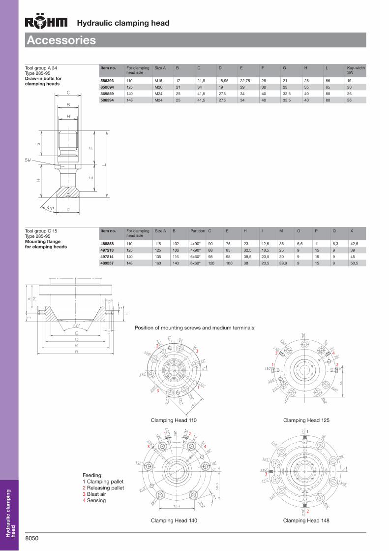
8050
Hydraulic clamping head
Accessories
Tool group A 34Type 285-95 Draw-in bolts for clamping heads
Item no. For clamping head size
Size A B C D E F G H L Key-width SW
586393 110 M16 17 21,9 18,95 22,75 28 21 28 56 19
850094 125 M20 21 34 19 29 30 23 35 65 30
869859 140 M24 25 41,5 27,5 34 40 33,5 40 80 36
586394 148 M24 25 41,5 27,5 34 40 33,5 40 80 36
Tool group C 15Type 285-95 Mounting flange for clamping heads
Item no. For clamping head size
Size A B Partition C E H I M O P Q X
488858 110 115 102 4x90° 90 75 23 12,5 35 6,6 11 6,3 42,5
497213 125 125 106 4x90° 88 85 32,5 18,5 25 9 15 9 39
497214 140 135 116 6x60° 98 98 38,5 23,5 30 9 15 9 45
489557 148 160 140 6x60° 120 100 38 23,5 39,9 9 15 9 50,5
1
2
3
3
21
3 4
1
2
3
1 2
43
Position of mounting screws and medium terminals:
Clamping Head 110 Clamping Head 125
Clamping Head 140 Clamping Head 148
Feeding:1 Clamping pallet2 Releasing pallet3 Blast air4 Sensing
Hyd
raul
ic c
lam
ping
he
ad

8051
Spring operated clamping head
Spring operated clamping head
Tool group C 15Type 285-96 Spring operated clamping headfor clamping pallets
Item no. 1108500 1099797
Size A 125 140
B 105 118
C 85 96
D 20 25
E 85 95
H 93 104
I 43 42
K 9,5 9,5
L 15 20
M 25 30
O 9 14
P 15 20
Q 8,5 13
Piston area: releasing cm2 44,1 56,7
Min. release pressure bar 40 40
Pull-in-force N 20000 40000
Blast-air pressure bar 10 10
Weight kg 4 6
Sets can be aligned in height on request
C
Q
H
I
E
D
M
LB
A
K
P
O
Application range:To supplement the fully hydraulic operated clamping heads a mechanically operated clamping head was developed by RÖHM.The advantages of the mechanically operated clamping head are the power amplification of the segment collet operated by coiled springs in a very rigid and fully ribbed housing. The mechanical lock of the segment collet provides a pull-out safety device without any additional elements. Only to release - and therefore during standstill - a hydraulic unit will be needed.
Function:The hydraulic operated clamping device may be suitable for all existing sorts of pallet clampings. Preferable for very high repeatability i.e. at machining centres and transfer lines.Immediately after switching off the release pressure the springs are activating the clamping process. The springs are moving the draw-in bolt via the release piston. The segment collet encloses the draw-in bolt and clamping wedges will multiply the effect of the springforce at the end of the stroke. Via the draw-in bolt the pallet is pulled onto the reception cone and than mechanically locked.The clamping position may be monitored via air sensing and the values can be processed by the machine control unit.During the clamping sequence pressurized air cleans the area of the collet and the reception taper.
Spr
ing
oper
ated
cl
ampi
ng h
ead

8052
Spring operated clamping head
Accessories
Tool group A 34Type 285-95 Draw-in bolts for clamping heads
Item no. For clamping head size
Size A B C D E F G H L Key-width SW
850094 125 M20 21 34 19 29 30 23 35 65 30
1116394 140 M24 25 38 23 34,7 40 32 40 80 30
Tool group C 15Type 285-95 Mounting flange for clamping heads
Item no. For clamping head size
Size A B C E H I M O P Q X
497213 125 125 106 88 85 32,5 18,5 25 9 15 9 39
1116393 140 135 116 98 95 38,5 23,5 30 9 15 9 45
Position of mounting screws and medium terminals:
Pull-out thread
Blast air connection
Pinning holes
Blast air connection
Pull-out thread
Clamping Head 125 Clamping Head 140
Spr
ing
oper
ated
cl
ampi
ng h
ead

8053
Notes
Not
es
Related Documents